Embed Size (px)
Citation preview
Group #9Lisandro osorioEvan KurniaMatthew KleinEdward Richards
Problem :
● There is a need for automated solutions with everyday machines and everyday activities.● Pet product market is rapidly increasing and there is a lack of available aquarium monitoring
solutions.● There is a lack of knowledge for first time aquarium owners, increasing the mortality rate of the
fish. ● With so many individual aquarium products available, it is hard for first time buyers to know
what products they actually need.
Solution● Our solution titled AquaEco will have features that reduce the labor and supervision required of the
consumer as much as possible.● The AquaEco device will provide information about the users current aquarium, including sensors and an
automatic fish feeder. Lighting, feeding and monitoring are our core aims in this solution. ● The device will communicate via WiFi with an application built with simplicity in mind. The application will
allow the user to completely control all aspects of the AquaEco system from anywhere in the world. ● The application will allow information on the aquatic life to be inputted. The application will then create
custom boundaries for the perfect living environment for the users aquatic life. The AquaEco system will collect data on the aquariums environment via the various sensors. If the environment begins to become dangerous for the aquatic life the AquaEco system will alert the user until conditions restabilize.
● To further assist users the application will feature the ability to set schedules for the fish feeder as well as the LED lights. The system will also feature simple “on/off” option for LED lights and a “click to feed” option which will activate the fish feeder

Requirements and specificationsType of requirement
Description
Hardware 1 The system’s dimensions should not exceed 16’’12’’ 6’’
Hardware 2 Sensors should provide accurate readings within1:30 of environmental change
Hardware 3 The fish feeder will handle depositing food at least 1 time per 30 minutes.
Hardware 4 The microcontroller should use the Wireless LAN 802.11b/g standard to communicate to a server
Hardware 5 Ph sensor, turbidity, and temperature sensors shouldbe accurate to within 7 percent
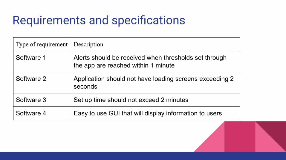
Requirements and specifications
Type of requirement Description
Software 1 Alerts should be received when thresholds set through the app are reached within 1 minute
Software 2 Application should not have loading screens exceeding 2 seconds
Software 3 Set up time should not exceed 2 minutes
Software 4 Easy to use GUI that will display information to users
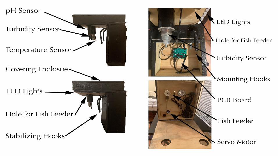
Enclosure
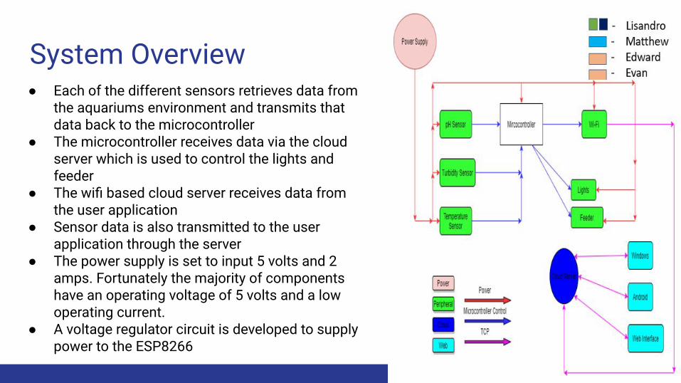
System Overview ● Each of the different sensors retrieves data from
the aquariums environment and transmits that data back to the microcontroller
● The microcontroller receives data via the cloud server which is used to control the lights and feeder
● The wifi based cloud server receives data from the user application
● Sensor data is also transmitted to the user application through the server
● The power supply is set to input 5 volts and 2 amps. Fortunately the majority of components have an operating voltage of 5 volts and a low operating current.
● A voltage regulator circuit is developed to supply power to the ESP8266
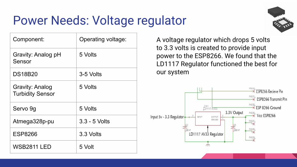
Power Needs: Voltage regulator Component: Operating voltage:
Gravity: Analog pH Sensor
5 Volts
DS18B20 3-5 Volts
Gravity: Analog Turbidity Sensor
5 Volts
Servo 9g 5 Volts
Atmega328p-pu 3.3 - 5 Volts
ESP8266 3.3 Volts
WSB2811 LED 5 Volt
A voltage regulator which drops 5 volts to 3.3 volts is created to provide input power to the ESP8266. We found that the LD1117 Regulator functioned the best for our system
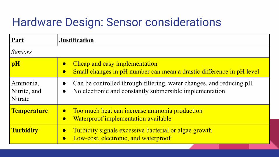
Hardware Design: Sensor considerationsPart Justification
Sensors
pH ● Cheap and easy implementation● Small changes in pH number can mean a drastic difference in pH level
Ammonia, Nitrite, and Nitrate
● Can be controlled through filtering, water changes, and reducing pH● No electronic and constantly submersible implementation
Temperature ● Too much heat can increase ammonia production● Waterproof implementation available
Turbidity ● Turbidity signals excessive bacterial or algae growth● Low-cost, electronic, and waterproof
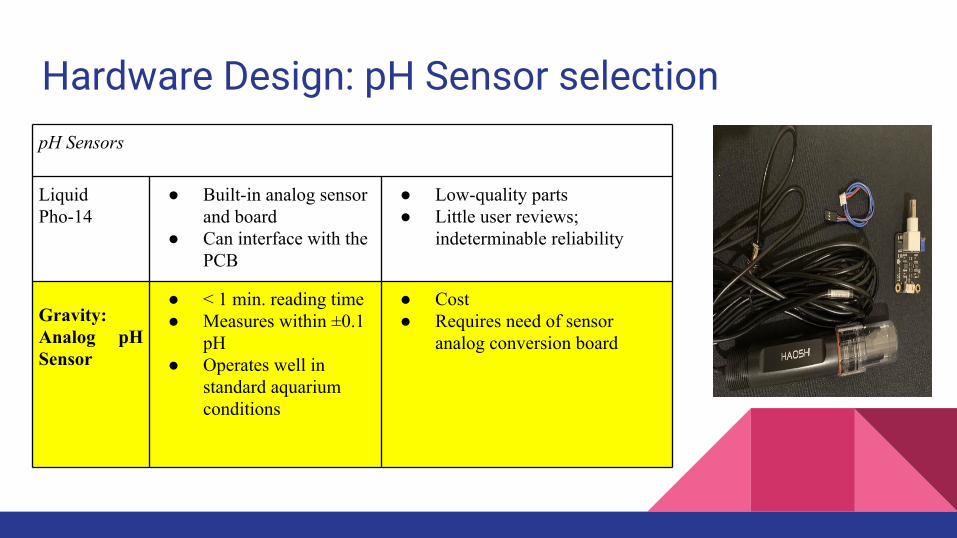
Hardware Design: pH Sensor selectionpH Sensors
Liquid Pho-14
● Built-in analog sensor and board
● Can interface with the PCB
● Low-quality parts● Little user reviews;
indeterminable reliability
Gravity: Analog pH Sensor
● < 1 min. reading time● Measures within ±0.1
pH● Operates well in
standard aquarium conditions
● Cost● Requires need of sensor
analog conversion board
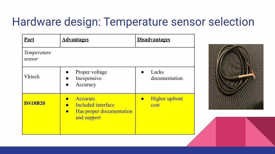
Hardware design: Temperature sensor selectionPart Advantages Disadvantages
Temperature sensor
Vktech ● Proper voltage● Inexpensive● Accuracy
● Lacks documentation
DS18B20 ● Accurate● Included interface● Has proper documentation
and support
● Higher upfront cost
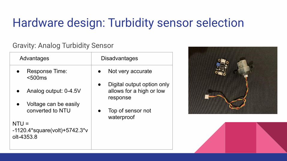
Hardware design: Turbidity sensor selection
Gravity: Analog Turbidity Sensor
Advantages Disadvantages
● Response Time: <500ms
● Analog output: 0-4.5V
● Voltage can be easily converted to NTU
NTU = -1120.4*square(volt)+5742.3*volt-4353.8
● Not very accurate
● Digital output option only allows for a high or low response
● Top of sensor not waterproof
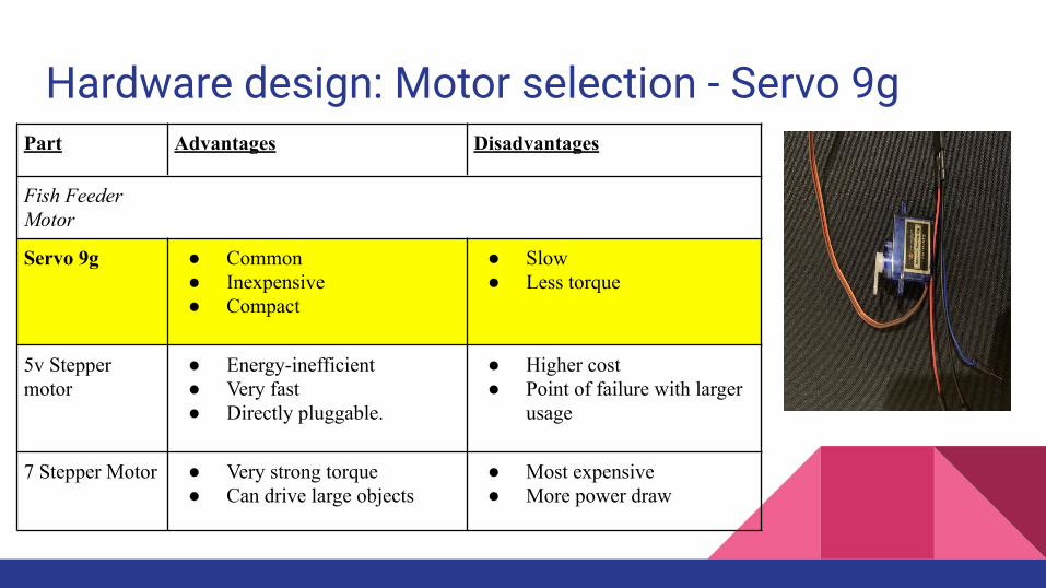
Hardware design: Motor selection - Servo 9gPart Advantages Disadvantages
Fish Feeder Motor
Servo 9g ● Common● Inexpensive● Compact
● Slow● Less torque
5v Stepper motor
● Energy-inefficient● Very fast● Directly pluggable.
● Higher cost● Point of failure with larger
usage
7 Stepper Motor ● Very strong torque● Can drive large objects
● Most expensive● More power draw

Hardware design: Hardware selection - LightingPart Advantages Disadvantages
Lighting
Incandescent ● Common● Inexpensive
● Produces a lot of unnecessary heat
● Energy inefficient
Fluorescent ● Energy-inefficient● Produces little heat● Longer lifespan
● Higher upfront cost with bulbs
LED ● Compact● Energy-efficient● Very long-lasting
● Higher upfront cost with bulbs
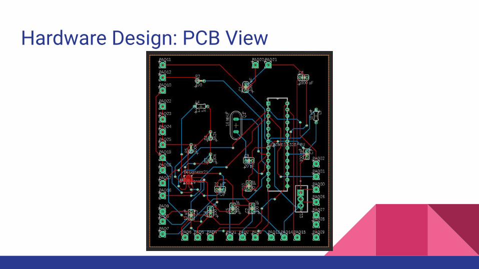
Hardware Design: PCB View
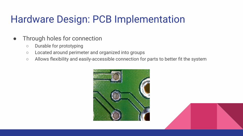
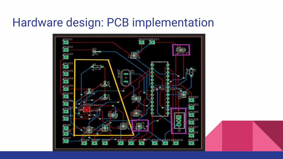
Hardware Design: PCB Implementation
● Through holes for connection○ Durable for prototyping○ Located around perimeter and organized into groups○ Allows flexibility and easily-accessible connection for parts to better fit the system
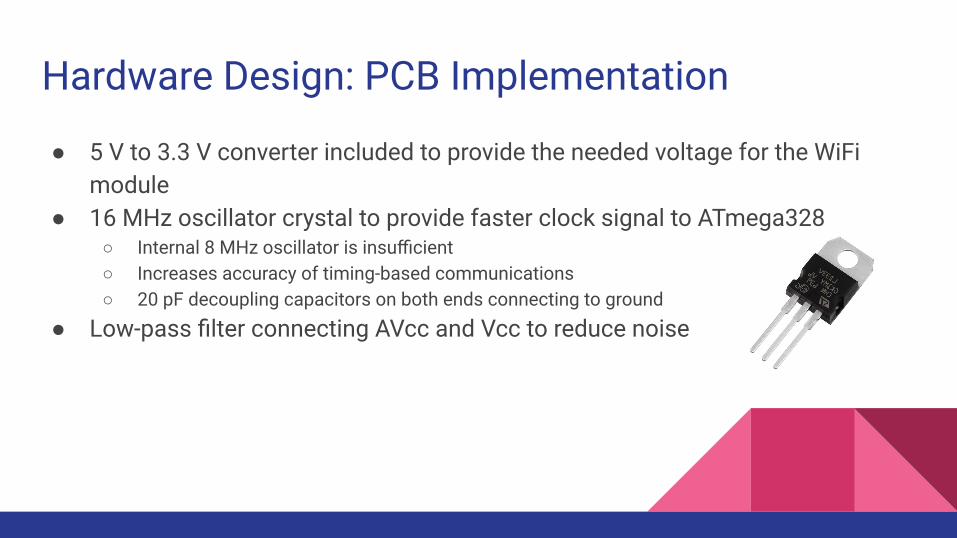
Hardware Design: PCB Implementation
● 5 V to 3.3 V converter included to provide the needed voltage for the WiFi module
● 16 MHz oscillator crystal to provide faster clock signal to ATmega328○ Internal 8 MHz oscillator is insufficient○ Increases accuracy of timing-based communications○ 20 pF decoupling capacitors on both ends connecting to ground
● Low-pass filter connecting AVcc and Vcc to reduce noise
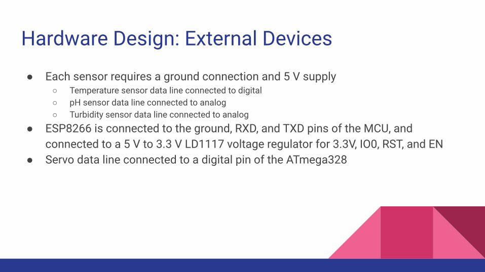
Hardware Design: External Devices
● Each sensor requires a ground connection and 5 V supply○ Temperature sensor data line connected to digital○ pH sensor data line connected to analog○ Turbidity sensor data line connected to analog
● ESP8266 is connected to the ground, RXD, and TXD pins of the MCU, and connected to a 5 V to 3.3 V LD1117 voltage regulator for 3.3V, IO0, RST, and EN
● Servo data line connected to a digital pin of the ATmega328
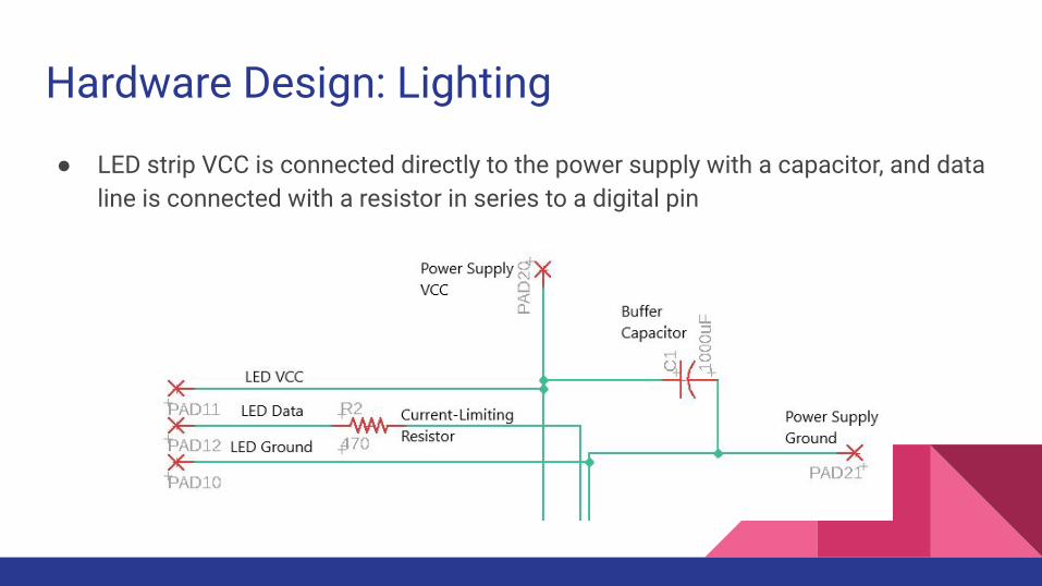
Hardware Design: Lighting
● LED strip VCC is connected directly to the power supply with a capacitor, and data line is connected with a resistor in series to a digital pin
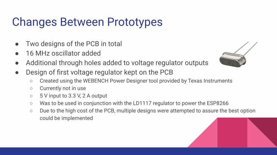
Changes Between Prototypes
● Two designs of the PCB in total● 16 MHz oscillator added● Additional through holes added to voltage regulator outputs● Design of first voltage regulator kept on the PCB
○ Created using the WEBENCH Power Designer tool provided by Texas Instruments○ Currently not in use○ 5 V input to 3.3 V, 2 A output○ Was to be used in conjunction with the LD1117 regulator to power the ESP8266○ Due to the high cost of the PCB, multiple designs were attempted to assure the best option
could be implemented
Hardware design: PCB implementation
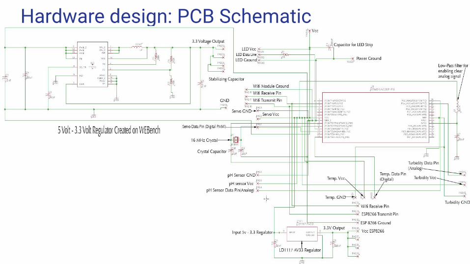
Hardware design: PCB Schematic
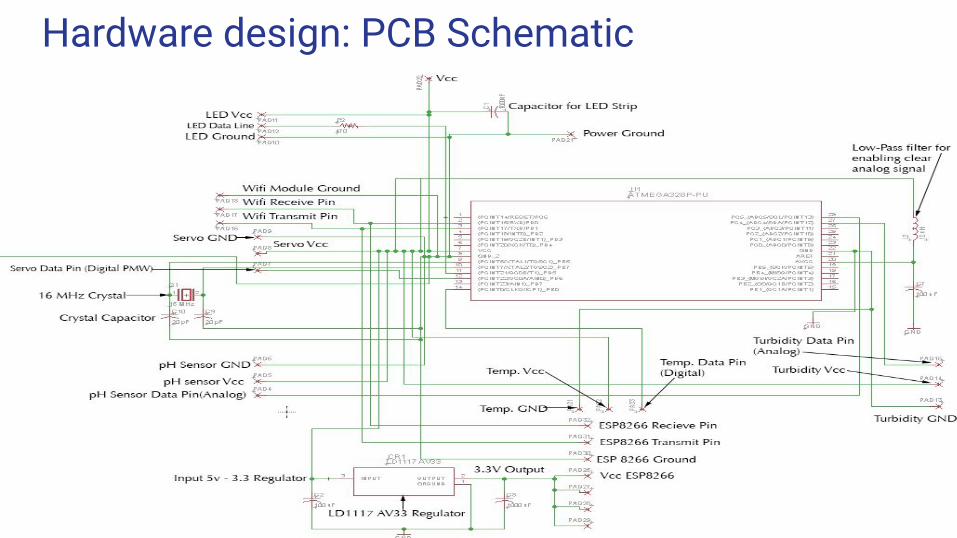
Hardware design: PCB Schematic
Hardware Design: Challenges
● Acquisition of needed components● Ensuring that all equipment and parts are functioning as anticipated● Testing the design for robustness and reliability● Developing a PCB and adjusting the design for additions● High cost of PCB
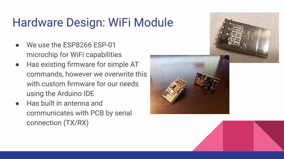
Hardware Design: WiFi Module
● We use the ESP8266 ESP-01 microchip for WiFi capabilities
● Has existing firmware for simple AT commands, however we overwrite this with custom firmware for our needs using the Arduino IDE
● Has built in antenna and communicates with PCB by serial connection (TX/RX)
Overview of PCB and WiFi Module
● The Atmega328P, which is mounted on the PCB, will control sensor readings, the lights, and the feeder, and will communicate with the ESP8266 chip using a serial connection
● ESP8266 chip will primarily manage updating data in the remote database and receiving updated instructions to send over UART to the PCB
Software Design Selections
● We chose to use the ESP8266 chip for our WiFi needs because it has a low cost
● It also has plenty of support from online hobbyist forums and with that comes a lot of reference information
● We can flash it with custom firmware using the arduino IDE● Our MCU for the PCB is the Atmega328P, which can also be programmed with
the Arduino IDE.
PCB Software
PCB Software handles:
1. Reading sensors approx. once per 5 seconds, and sending this data across serial to the ESP
2. Keeping track of what time of day it is ongoingly, with occasional updates/corrections from ESP
3. Activating the servo for the feeding mechanism at the assigned times4. Toggling the LEDs at the assigned times5. Receiving updated times from the ESP, and receiving instant
control commands for the feeder and lights6. Acknowledging data received from the ESP
ESP-01 Software
WiFi Module Software handles:
1. Receiving sensor readings from the PCB2. Updating the database with sensor readings, using PHP over HTTP3. Pulling user time settings from the database and relaying them to the PCB
over serial4. Sending instant control commands to the PCB for lights and feeder according
to flags set in the database5. Periodically updating the PCB with an accurate time pulled
from the internet
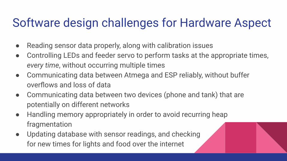
Software design challenges for Hardware Aspect
● Reading sensor data properly, along with calibration issues● Controlling LEDs and feeder servo to perform tasks at the appropriate times,
every time, without occurring multiple times● Communicating data between Atmega and ESP reliably, without buffer
overflows and loss of data● Communicating data between two devices (phone and tank) that are
potentially on different networks● Handling memory appropriately in order to avoid recurring heap
fragmentation● Updating database with sensor readings, and checking
for new times for lights and food over the internet
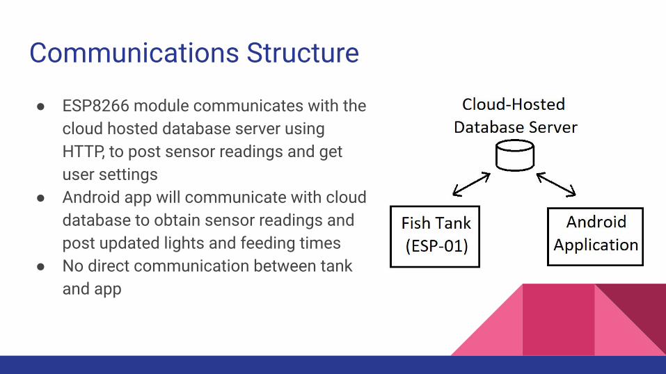
Communications Structure
● ESP8266 module communicates with the cloud hosted database server using HTTP, to post sensor readings and get user settings
● Android app will communicate with cloud database to obtain sensor readings and post updated lights and feeding times
● No direct communication between tank and app
Cloud Hosting: Heroku
Heroku is a cloud hosting website that is very stable and supports many different environments.
Supports PHP natively, and MySQL through addons.
Free tier helped lower costs.
Heroku Git enables fast deploy through terminal.
Heroku Logs gives a lot of information for easy debugging.
Overview of Database
We used MySql Server 5.5 which was available through ClearDB Heroku addon.
MySql offers relational database for easy structuring of our AquaEco identifiers and its components.
Tight integration with PHP language and MySQLI extension.
Decreased development time of API due to prior knowledge.
MySQLI offers prepared statements, and easy formatting of data.
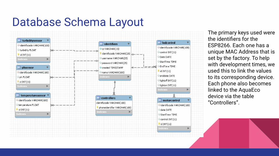
Database Schema LayoutThe primary keys used were the identifiers for the ESP8266. Each one has a unique MAC Address that is set by the factory. To help with development times, we used this to link the values to its corresponding device. Each phone also becomes linked to the AquaEco device via the table “Controllers”.
API
Uses the PHP language and MYSQLI Extension to handle the backend functionality.
Uses JSON to make HTTP requests and responses from the server easier to parse.
HTTP Get and Post requests used for receiving data and inserting data.
Developed to offload expensive and long times needed with direct querying in both the ESP8266 and Android side.
Phone Application
Phone applications offer tight integration with the operating system.
Access to notifications and widgets.
Increased phone performance.
Applications can be used offline.
Faster development tools and helpful UI building tools.
VS
Android Application
Android studio has been recently updated with new features and enhanced speedy building of application and works on windows.
Open source and free.
Built on java with years of documentation and bug helping.
Strong built in emulation tools and debugging.
Android has many different devices.
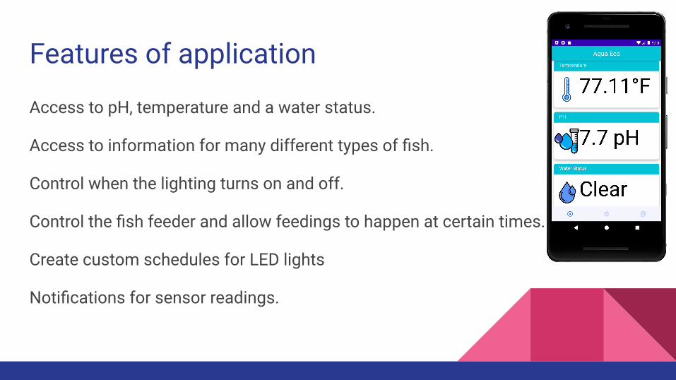
Features of application
Access to pH, temperature and a water status.
Access to information for many different types of fish.
Control when the lighting turns on and off.
Control the fish feeder and allow feedings to happen at certain times.
Create custom schedules for LED lights
Notifications for sensor readings.
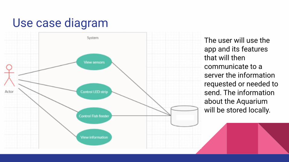
Use case diagramThe user will use the app and its features that will then communicate to a server the information requested or needed to send. The information about the Aquarium will be stored locally.
Android application Communication
Communication occurs using Asynchronous Okhttp3 calls to the web server.
Retrieving sensor data is done by sending a GET call and passing along the needed phone identifier that the user has selected.
To send data like a new time change, we issue a POST command to the api along with our new information and the identifier code.
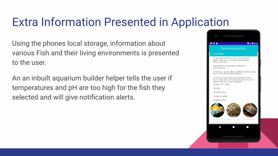
Extra Information Presented in Application
Using the phones local storage, information about various Fish and their living environments is presented to the user.
An an inbuilt aquarium builder helper tells the user if temperatures and pH are too high for the fish they selected and will give notification alerts.
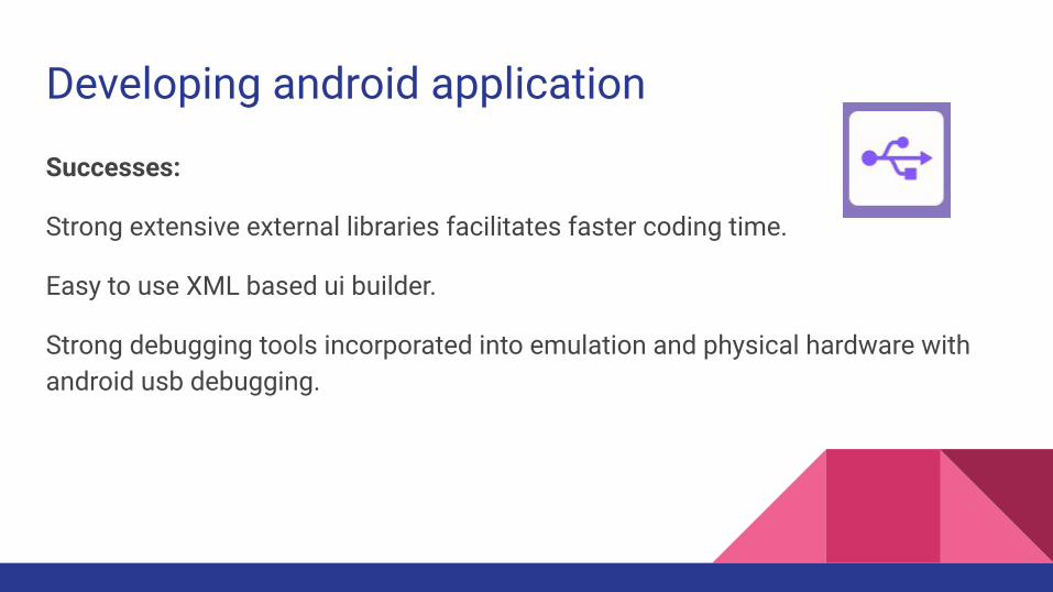
Developing android application
Successes:
Strong extensive external libraries facilitates faster coding time.
Easy to use XML based ui builder.
Strong debugging tools incorporated into emulation and physical hardware with android usb debugging.
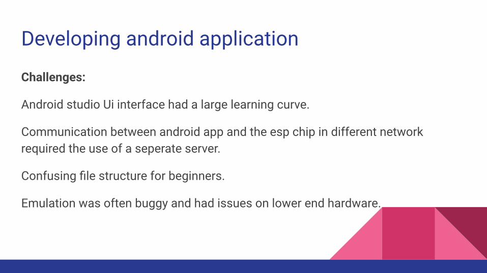
Developing android application
Challenges:
Android studio Ui interface had a large learning curve.
Communication between android app and the esp chip in different network required the use of a seperate server.
Confusing file structure for beginners.
Emulation was often buggy and had issues on lower end hardware.
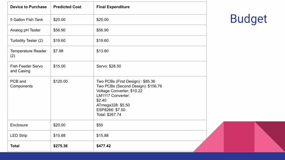
BudgetDevice to Purchase Predicted Cost Final Expenditure
5 Gallon Fish Tank $20.00 $25.00
Analog pH Tester $56.90 $56.90
Turbidity Tester (2) $19.60 $19.60
Temperature Reader (2)
$7.98 $13.80
Fish Feeder Servo and Casing
$15.00 Servo: $28.50
PCB and Components
$120.00 Two PCBs (First Design) : $85.36Two PCBs (Second Design): $156.76Voltage Converter: $10.22LM1117 Converter:$2.40ATmega328: $5.50 ESP8266: $7.50 Total: $267.74
Enclosure $20.00 $50
LED Strip $15.88 $15.88
Total $275.36 $477.42
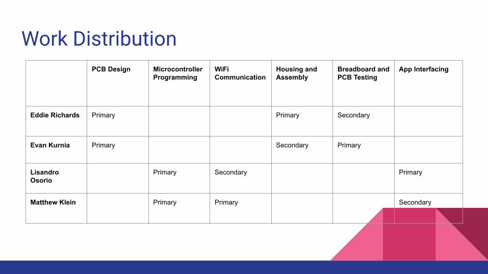
Work DistributionPCB Design Microcontroller
ProgrammingWiFi Communication
Housing and Assembly
Breadboard and PCB Testing
App Interfacing
Eddie Richards Primary Primary Secondary
Evan Kurnia Primary Secondary Primary
Lisandro Osorio
Primary Secondary Primary
Matthew Klein Primary Primary Secondary
Learned Skills
● Team dynamics and collaboration without much in person contact● Managing responsibility and and task assignment with optimal skill utilization● Brainstorming, critical thinking, and practical problem solving in a real
application environment● Developing proper documentation techniques● Researching relevant information to successfully make informed design
decisions● Following a well developed plan to its logical conclusion in a practical manner● Managing a nontrivial communications structure across
multiple devices
What we would change if we did it again
Here’s what we would change, improve, or add:
● Gather PCB components earlier for organization and testing● Not rush PCB fabrication times● Redesigned enclosure to be smaller with a more lightweight material● Redesigned fish feeder to deposit less food more accurately● Make the communications structure more efficient
Conclusion
The Aqua Eco: A Smart Aquarium gives the user the ability to experience all the joys of owning an aquarium while avoiding the headache that might arise by many solutions already on the market. By creating a system which solves the problems of lighting, feeding and monitoring the owner of the Aqua Eco system is able to sit back and relax, knowing their aquatic life is safe.