Embed Size (px)
Citation preview

1
Analytical Modeling of Optical Polarimetric Imaging Systems
2011 IEEE International Geoscience and Remote Sensing Symposium
Lingfei Meng: [email protected]
John P. Kerekes: [email protected]
Rochester Institute of Technology
29 July 2011This work was supported by the AFOSR under agreement FA9550-08-1-0028.

Outline
• Introduction− Background− Motivation
• Analytical Model of Optical Polarization− Scene Model− Sensor Model− Processing Model
• Application for Target Detection• Conclusions
2

Outline
• Introduction− Background− Motivation
• Analytical Model of Optical Polarization− Scene Model− Sensor Model− Processing Model
• Application for Target Detection• Conclusions
3

Polarization of Light
4
http://en.wikipedia.org/wiki/Polarizer
Circular polarization
Linear polarization
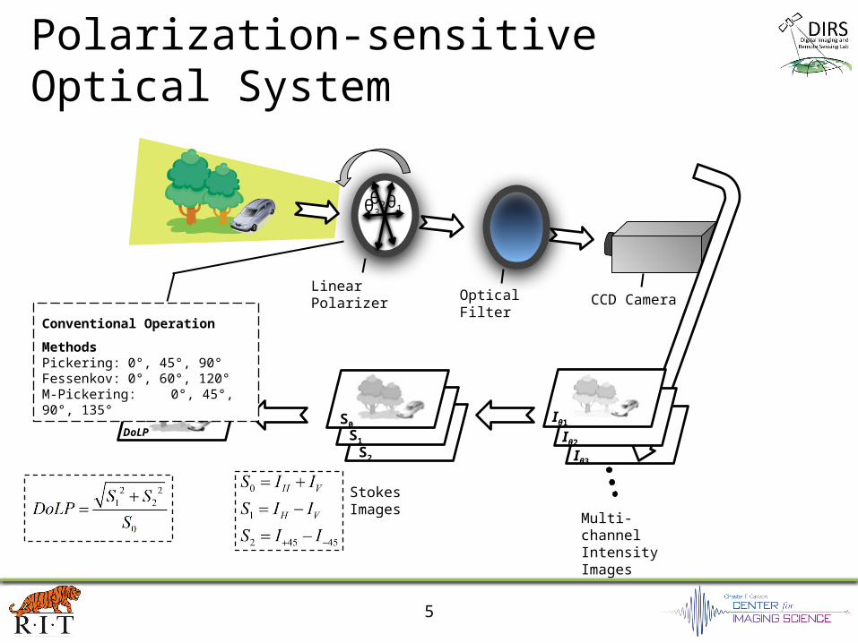
5
Iθ3
Optical Filter CCD CameraLinear Polarizer
Stokes Images
Multi-channel Intensity Images
θ1θ2θ3
Iθ2
Iθ1S1S2
S0DoLP
Conventional Operation MethodsPickering: 0°, 45°, 90°Fessenkov: 0°, 60°, 120°M-Pickering: 0°, 45°, 90°, 135°
Polarization-sensitive Optical System

6
Example of Polarization Imagery
Image was collected by Dr. Michael D. Presnar on May 25 2010.

7
Iθ3
Optical Filter CCD CameraLinear Polarizer
Stokes Images
Multi-channel Intensity Images
Iθ2
Iθ1S1S2
S0DoLP
Polarization-sensitive Optical System

Outline
• Introduction− Background− Motivation
• Analytical Model of Optical Polarization− Scene Model− Sensor Model− Processing Model
• Application for Target Detection• Conclusions
8

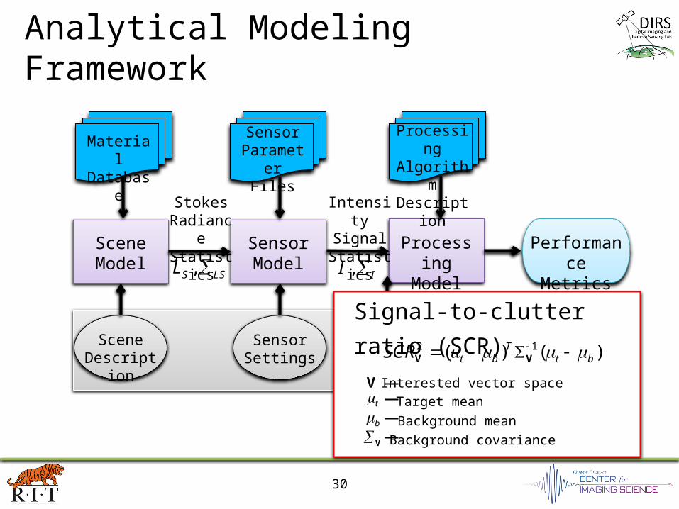
Analytical Modeling Framework
9
ProcessingModel
SensorModel
SceneModel
PerformanceMetrics
Material Database
Sensor Parameter
Files
Processing Algorithm
Description
SceneDescription
SensorSettings
ProcessingSettings
UserInputs
Stokes RadianceStatistics
Intensity Signal
Statistics
,S LSL , II
J.P. Kerekes and J.E. Baum, "Spectral Imaging System Analytical Model for Subpixel Object Detection," IEEE Transactions on Geoscience and Remote Sensing, vol. 40, no. 5, pp. 1088-1101, May 2002.

Characterize Material Reflectance• Bidirectional reflectance distribution function (BRDF)
10
( , )
( , )r r
i i
Lf
E
( , )i iE
( , )r rL
ir
i
r

Characterize Material Reflectance
• Polarimetric BRDF (pBRDF)The pBRDF can be expressed as the sum of a polarized specular component and an unpolarized diffuse component
11
00 01 02
10 11 12
20 21 22
f f f
f f f
f f f
F
M. W. Hyde, J. D. Schmidt, and M. J. Havrilla, “A geometrical optics polarimetric bidirectional reflectance distribution
function for dielectric and metallic surfaces,” Opt. Express, vol. 17, no. 24, pp. 22138–22153, Nov 2009.
0 00 01 02 0
1 10 11 12 1
2 20 21 22 2out in
S f f f S
L S f f f E S
S f f f S

12
Glass DoLP Concrete DoLP Vegetation DoLP
60i
80i
pBRDF Model Determined DoLP
0 0 0
0 0 0

13
Polar Coordinate Definition

14
Polar Coordinate Definition
Sensor zenith angle Radial coordinate

15
Polar Coordinate Definition
Relative azimuth angle Angular coordinate

16
Glass DoLP Concrete DoLP Vegetation DoLP
60i
80i
pBRDF Model Determined DoLP
0 0 0
0 0 0

17
• Direct solar reflected radiance
0 1 2 00 10 20cosr i sr r r
T TL L E fL f f L
• Surface reflected radiance from sky
• With the upwelled radiance , the total sensor reaching radiance can be found as
0 1 2 ,( , ) cosT
d i d i id d dL L dL L F L
0 1 2
T
u u u uL L LL
0 1 2
T
S d uS S rSL L L L L L L
• The solar illumination and polarized atmospheric radiance are computed using MODTRAN-P.
Modeling Sensor Reaching Radiance

18
MODTRAN-P Predicted Downwelled Radiance
MODTRAN-P Input Parameter Setting
Atmospheric Model 1976 US Standard
Haze Parameter Rural Extinction
Surface Meteorological Range 23 km
Scattering Type Single
Solar Zenith Angle 60°
Day of the Year 170
Center Wavelength 450 nm

19
S1
S2 DoLP
MODTRAN-P Predicted Downwelled RadianceS0
W/s
r/cm
2 /μm
Nor
mal
ized
Uni
t
Nor
mal
ized
Uni
tN
orm
aliz
ed U
nit

20
MODTRAN-P Predicted Skylight DoLP

MODTRAN-P Predicted Skylight DoLP
21

22
Sensor Reaching Radiance Statistics• Mean
For object surface viewed by the sensor over K pixels within a viewing angle range of
( , )r
,
1( )
r
r
S i Si rL LK
• Covariance matrix Variance due to viewing geometry
22,
1( )
1
r
r
g i Si r SiL LK
Covariance matrix of sensor reaching radiance
LS g v

Analytical Modeling Framework
23
ProcessingModel
SensorModel
SceneModel
PerformanceMetrics
Material Database
Sensor Parameter
Files
Processing Algorithm
Description
SceneDescription
SensorSettings
ProcessingSettings
UserInputs
Stokes RadianceStatistics
Intensity Signal
Statistics
,S LSL , II

Sensor Model
• System matrix
24
ψ1 ψiψN
m1
• Polarizer leakage effect
mi mN

• Sensor input radiance —> electrons —>output signal
25
2
· · · · ·( ) ·
1 4 #i t
i d e
L tI R d N g
f h c
• The total sensor noise can be expressed as
2ni e i cg I
• The covariance matrix of the N-channel signal is as
TI LS n M M
Sensor Model (cont.)

Analytical Modeling Framework
26
ProcessingModel
SensorModel
SceneModel
PerformanceMetrics
Material Database
Sensor Parameter
Files
Processing Algorithm
Description
SceneDescription
SensorSettings
ProcessingSettings
UserInputs
Stokes RadianceStatistics
Intensity Signal
Statistics
,S LSL , II

Processing Model
• Incident Stokes vector estimation
27
1S M I
TS I W W
• DoLP calculation 2 2
1 22
0
S SDoLP
S
2 2 22 2
1 22 1 20 1 22 2 2 2 2
0 0 1 2 0 1 2
,
2 iji ji
DoLP S S S
Si
j
Sj
S S S S
S S S S S S S
DoLP DoLP
S S
1( )W M

Outdoor Imagery Collection
28
0.05
0.1
0.15
0.2
0.25
0.3
0.35
White painted panel
Black painted panel
DoL
P

Model Validation
0 0.2 0.4 0.60
10
20
30
40
50
S1
Pro
babi
lity
Den
sity Black
White
−0.1 0 0.1 0.2 0.3 0.40
10
20
30
40
50
S2
BlackWhite
0 0.2 0.4 0.60
10
20
30
40
50
DoLP
BlackWhite
29
0 0.2 0.4 0.60
10
20
30
40
50
S1
Pro
babi
lity
Den
sity Black
White
−0.1 0 0.1 0.2 0.3 0.40
10
20
30
40
50
S2
BlackWhite
0 0.2 0.4 0.60
10
20
30
40
50
DoLP
BlackWhite
Realdata
Analyticalmodel
Analytical Modeling Framework
30
ProcessingModel
SensorModel
SceneModel
PerformanceMetrics
Material Database
Sensor Parameter
Files
Processing Algorithm
Description
SceneDescription
SensorSettings
ProcessingSettings
UserInputs
Stokes RadianceStatistics
Intensity Signal
Statistics
,S LSL , II
Signal-to-clutter ratio (SCR) 2 1( ) ( )T
t b t bSCR V V
t Target mean
b Background meanV Background covariance
V Interested vector space

Outline
• Introduction− Background− Motivation
• Analytical Model of Optical Polarization− Scene Model− Sensor Model− Processing Model
• Application for Target Detection• Conclusions
31

Adaptive Polarimetric Target Detector (APTD)
32
1, , N initial
Acquire Intensity & Stokes
Images
Stokes Vector Statistical Model
Searching Optimal Multi-channel
s.t. Max(SCRV)V
, vSS ,t bμ μ Stop Criterion
Meet?
Multi-channel Setting 1, , N optimal No
Intensity Images
Target Detection
Yes
Initial Multi-channel Setting
Stokes Parameter Images
Sensor Noise Calibration
L. Meng and J. P. Kerekes, Adaptive Target Detection with a Polarization-sensitive Optical System, Applied Optics, Vol. 50, Issue 13, pp. 1925-1932 (2011) .
0 0.1 0.2 0.3 0.4 0.50
0.2
0.4
0.6
0.8
1
Probability of False Alam (PFA)
Prob
abili
ty o
f D
etec
tion
(PD
)
APTDM−PickeringFessenkovPickering
0 0.1 0.2 0.3 0.4 0.50
0.2
0.4
0.6
0.8
1
Probability of False Alam (PFA)
Prob
abili
ty o
f D
etec
tion
(PD
)
APTDM−PickeringFessenkovPickering
ROC Curve Comparison
RX GLRT

Outline
• Introduction− Background− Motivation
• Analytical Model of Optical Polarization− Scene Model− Sensor Model− Processing Model
• Application for Target Detection• Conclusions
33

Conclusions
• An analytical model for optical polarization has been designed, and initial validations have shown encouraging results.
• A system performance metric based on signal-to-clutter ratio (SCR) has been suggested, and can be potentially used for system optimization.
34
Thank you!


![ROI in the age of keyword not provided [Mozinar]](https://img.pdfslide.us/doc/110x75/53eabc7a8d7f7289708b51f7/roi-in-the-age-of-keyword-not-provided-mozinar.jpg)