Embed Size (px)
Citation preview

Form RZ-NA-C-ER (Version C)
ENERGYRECOVERY
CATALOG®
BACKGROUNDReznor was founded in 1888 to manufacture the “Reznor” reflector heater, which used a luminous flame gas burner developed by George Reznor. This technological breakthrough was an immedi-ate success and hastened the expansion of gas heating in resi-dential and commercial applications. Technological development and innovation have been the hallmark of Reznor products through the years. The development of the forced air gas unit heater, the modular Thermocore® heat exchanger, and the high-efficiency, V3® Series Unit Heater with the Tcore2® single-burner and inno-vative heat exchanger system, have kept Reznor products at the forefront of technological advances in commercial and industrial gas heating. As a result of this pioneering role in the heating, makeup air, and ventilating equipment field, the products offered today are the most advanced in engineering design to satisfy a wide variety of applications.
FACILITIESReznor heaters were first manufactured and sold in Mercer, Pennsylvania (70 miles north of Pittsburgh) in 1888. Over the years, the company has grown and expanded. Today, with sales worldwide, Reznor products are being manufactured at facilities throughout North America and Europe.
PRODUCT SCOPEWell-equipped engineering laboratories for both product develop-ment and testing can be found at many of the manufacturing sites. All domestic lab sites are agency approved.
Reznor Products include a complete line of heating, makeup air, air conditioning and ventilating systems, using gas, oil, hot water/steam, or electric heating or cooling sources. Reznor catalogs are designed to aid the engineer, architect or contractor in specifying the correct equipment for all standard and special applications. Complete data is presented on unit heaters, duct furnaces, infrared heaters, makeup air systems, pre-engineered custom-designed systems, packaged cooling equipment, energy recovery and evaporative cooling modules. Consult your local Reznor Sales Representative for further assistance in specifying Reznor Equipment for your specific application.
SERVICESProduct service requirements are handled through contractors and/or distributors, with backup from local representatives and factory-based service team. Replacement parts inventories for both warranty and non-warranty requirements are maintained at service centers throughout the country and at the manufacturing facilities.
ETL Certified per UL 1995 and CSA 22.2 Typical Applications
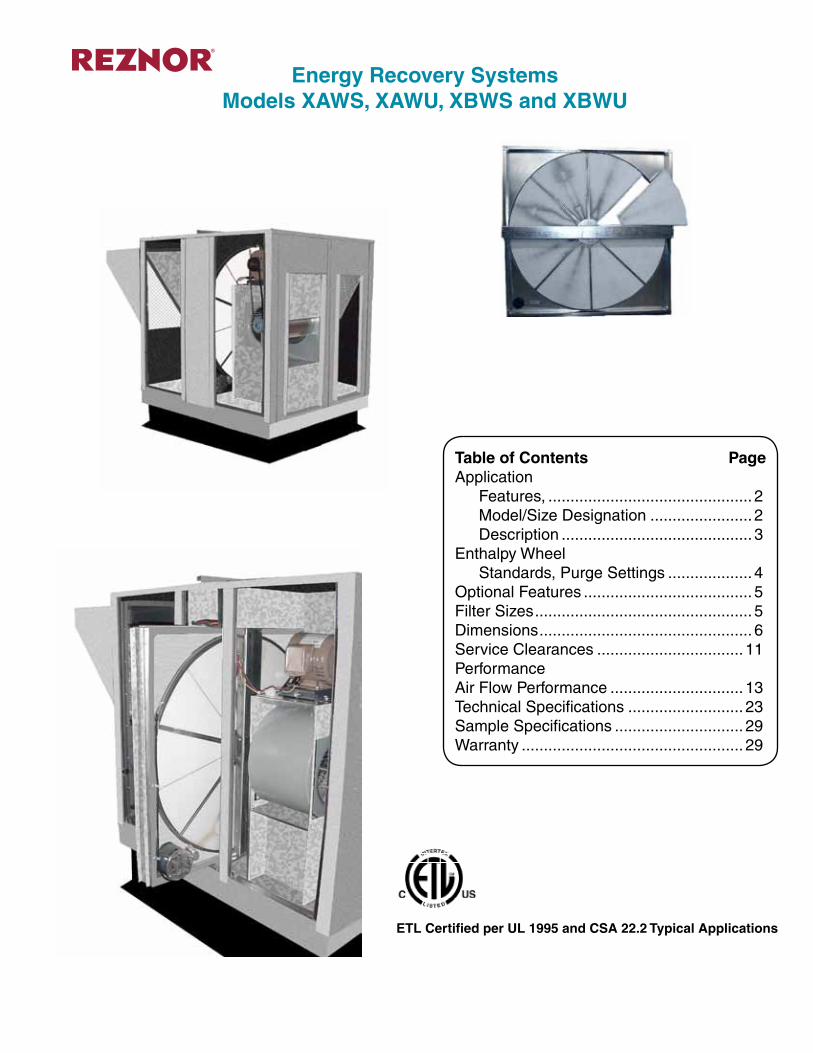
Table of Contents PageApplication Features, .............................................. 2 Model/Size Designation ....................... 2 Description ........................................... 3Enthalpy Wheel Standards, Purge Settings ................... 4Optional Features ...................................... 5Filter Sizes ................................................. 5Dimensions ................................................ 6Service Clearances ................................. 11PerformanceAir Flow Performance .............................. 13Technical Specifications .......................... 23Sample Specifications ............................. 29Warranty .................................................. 29
Energy Recovery SystemsModels XAWS, XAWU, XBWS and XBWU
Page __________ of __________
Form C-ER Page 2
Energy Recovery SystemsModels XAWS, XAWU, XBWS and XBWU
• Reduces cooling load at design temperatures up to 4 tons per 1000 cfm of outside air.
• Reduces heating load up to 12,000 BTUH per 400 cfm of outside air.
• Dry energy transfer. Moisture in supply (intake) air stream is transferred to exhaust air stream in a vapor state, eliminating condensate plumbing in the ventilator.
• Separate fused power supply.• Filters / mist eliminators are provided on the entering air openings of
the outdoor units.• Centrifugal blowers (both intake and exhaust) for high static capability
and low sound levels.• Heavy gauge galvanized steel cabinets.• Fully insulated cabinet.• ARI rated internal enthalpy wheel is provided.• Internal enthalpy wheel made of polymeric material with silica gel
impregnated into the material. The enthalpy wheel has a five year limited warranty.
• Internal enthalpy wheels are easily cleanable. Large wheels (36 inch diameter and above) are segmented into easily removable sections.
• All wheels are designed to easily slide in and out for easy servicing.• Continuous operation down to 10°F (-12°C) without defrost at
indoor relative humidity up to 40%. For temperatures below 10°F (-12°C), Optional Low Ambient Control Kit is required. Kit includes temperature sensor to shutoff power to unit before frost build up can occur on recovery wheel.
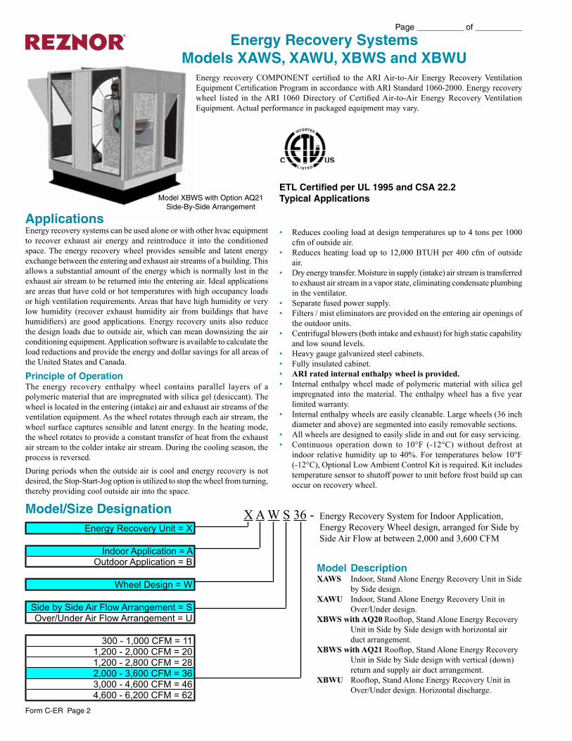
Model XBWS with Option AQ21Side-By-Side Arrangement
Energy recovery COMPONENT certified to the ARI Air-to-Air Energy Recovery Ventilation Equipment Certification Program in accordance with ARI Standard 1060-2000. Energy recovery wheel listed in the ARI 1060 Directory of Certified Air-to-Air Energy Recovery Ventilation Equipment. Actual performance in packaged equipment may vary.
ApplicationsEnergy recovery systems can be used alone or with other hvac equipment to recover exhaust air energy and reintroduce it into the conditioned space. The energy recovery wheel provides sensible and latent energy exchange between the entering and exhaust air streams of a building. This allows a substantial amount of the energy which is normally lost in the exhaust air stream to be returned into the entering air. Ideal applications are areas that have cold or hot temperatures with high occupancy loads or high ventilation requirements. Areas that have high humidity or very low humidity (recover exhaust humidity air from buildings that have humidifiers) are good applications. Energy recovery units also reduce the design loads due to outside air, which can mean downsizing the air conditioning equipment. Application software is available to calculate the load reductions and provide the energy and dollar savings for all areas of the United States and Canada.
Principle of OperationThe energy recovery enthalpy wheel contains parallel layers of a polymeric material that are impregnated with silica gel (desiccant). The wheel is located in the entering (intake) air and exhaust air streams of the ventilation equipment. As the wheel rotates through each air stream, the wheel surface captures sensible and latent energy. In the heating mode, the wheel rotates to provide a constant transfer of heat from the exhaust air stream to the colder intake air stream. During the cooling season, the process is reversed. During periods when the outside air is cool and energy recovery is not desired, the Stop-Start-Jog option is utilized to stop the wheel from turning, thereby providing cool outside air into the space.
X A W S 36 - Energy Recovery System for Indoor Application, Energy Recovery Wheel design, arranged for Side by Side Air Flow at between 2,000 and 3,600 CFM
Model/Size Designation
Model DescriptionXAWS Indoor, Stand Alone Energy Recovery Unit in Side
by Side design.XAWU Indoor, Stand Alone Energy Recovery Unit in
Over/Under design.XBWS with AQ20 Rooftop, Stand Alone Energy Recovery
Unit in Side by Side design with horizontal air duct arrangement.
XBWS with AQ21 Rooftop, Stand Alone Energy Recovery Unit in Side by Side design with vertical (down) return and supply air duct arrangement.
XBWU Rooftop, Stand Alone Energy Recovery Unit in Over/Under design. Horizontal discharge.
ETL Certified per UL 1995 and CSA 22.2 Typical Applications
Energy Recovery Unit = X
Indoor Application = AOutdoor Application = B
Wheel Design = W
Side by Side Air Flow Arrangement = SOver/Under Air Flow Arrangement = U
300 - 1,000 CFM = 111,200 - 2,000 CFM = 201,200 - 2,800 CFM = 282,000 - 3,600 CFM = 363,000 - 4,600 CFM = 464,600 - 6,200 CFM = 62
Form C-ER Page 3
Page __________ of __________
Reznor Energy Recovery Ventilators are supplied with filters before the Energy Recovery WheelThe type(s) of filters are determined by the Model. Model XBWS with Option AQ21 (Vertical/down return and supply air) has an aluminum mist eliminator filter for the intake air and a 2” pleated filter for the return air.Models XBWU and XBWS with Option AQ20 (horizontal return and supply air) aluminum mist eliminator filter for the intake air and a 2” pleated filter for the return air.Models XAWU and XAWS have a 2” pleated filter for both the return air and the intake air.
Reznor Energy Recovery Ventilators are supplied with fully tested blower assembliesSome of the features are as follows:
1. The blowers are housed within a sheet metal frame to insure reliable performance.
2. The blower motor is mounted on an adjustable motor mount that provides an easy method of adjusting the belts.
3. All blowers are equipped with adjustable sheave pulleys.4. The blower pulley and the motor pulley are aligned by a state of the
art “laser” alignment system.
Filter located before Energy Recovery Wheel
Blower Assembly for Energy Recovery System
Control System
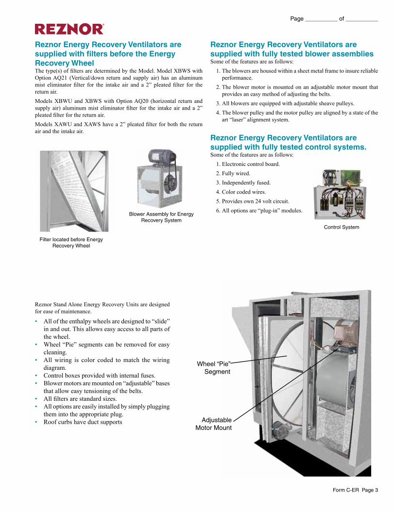
Reznor Stand Alone Energy Recovery Units are designed for ease of maintenance.
• All of the enthalpy wheels are designed to “slide” in and out. This allows easy access to all parts of the wheel.
• Wheel “Pie” segments can be removed for easy cleaning.
• All wiring is color coded to match the wiring diagram.
• Control boxes provided with internal fuses.• Blower motors are mounted on “adjustable” bases
that allow easy tensioning of the belts.• All filters are standard sizes.• All options are easily installed by simply plugging
them into the appropriate plug.• Roof curbs have duct supports
Wheel “Pie”Segment
AdjustableMotor Mount
Reznor Energy Recovery Ventilators are supplied with fully tested control systems.Some of the features are as follows:
1. Electronic control board.2. Fully wired.3. Independently fused.4. Color coded wires.5. Provides own 24 volt circuit.6. All options are “plug-in” modules.
Page __________ of __________
Form C-ER Page 4
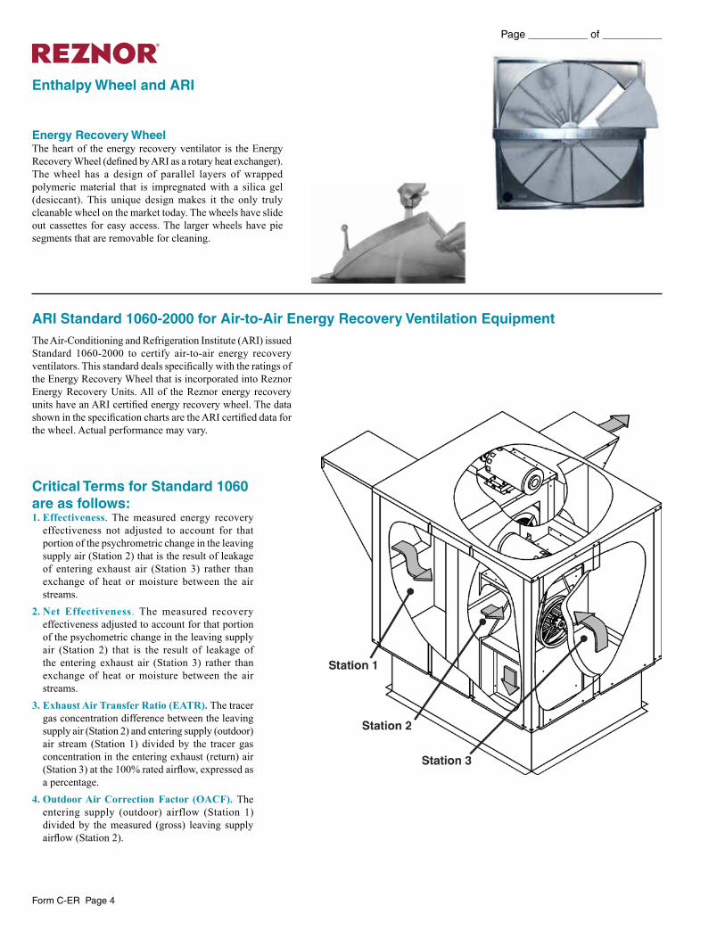
Critical Terms for Standard 1060 are as follows:1. Effectiveness. The measured energy recovery
effectiveness not adjusted to account for that portion of the psychrometric change in the leaving supply air (Station 2) that is the result of leakage of entering exhaust air (Station 3) rather than exchange of heat or moisture between the air streams.
2. Net Effectiveness. The measured recovery effectiveness adjusted to account for that portion of the psychometric change in the leaving supply air (Station 2) that is the result of leakage of the entering exhaust air (Station 3) rather than exchange of heat or moisture between the air streams.
3. Exhaust Air Transfer Ratio (EATR). The tracer gas concentration difference between the leaving supply air (Station 2) and entering supply (outdoor) air stream (Station 1) divided by the tracer gas concentration in the entering exhaust (return) air (Station 3) at the 100% rated airflow, expressed as a percentage.
4. Outdoor Air Correction Factor (OACF). The entering supply (outdoor) airflow (Station 1) divided by the measured (gross) leaving supply airflow (Station 2).
Enthalpy Wheel and ARI
The Air-Conditioning and Refrigeration Institute (ARI) issued Standard 1060-2000 to certify air-to-air energy recovery ventilators. This standard deals specifically with the ratings of the Energy Recovery Wheel that is incorporated into Reznor Energy Recovery Units. All of the Reznor energy recovery units have an ARI certified energy recovery wheel. The data shown in the specification charts are the ARI certified data for the wheel. Actual performance may vary.
ARI Standard 1060-2000 for Air-to-Air Energy Recovery Ventilation Equipment
Energy Recovery WheelThe heart of the energy recovery ventilator is the Energy Recovery Wheel (defined by ARI as a rotary heat exchanger). The wheel has a design of parallel layers of wrapped polymeric material that is impregnated with a silica gel (desiccant). This unique design makes it the only truly cleanable wheel on the market today. The wheels have slide out cassettes for easy access. The larger wheels have pie segments that are removable for cleaning.
Form C-ER Page 5
Page __________ of __________
Optional AccessoriesRoof Mounting Frame – A 14 or 24 inch (355 or 610 mm) roof curb is required to match supply and exhaust openings of the unit with the rooftop units. Reznor provides a full line of roof curbs to match the specified unit.Low Ambient Control Kit – This kit prevents frost formation on energy wheel heat transfer surfaces by terminating the intake blower operation when discharge air temperature falls below a field selectable temperature setting. Intake blower operation resumes operation after temperature rises above the adjustable temperature differential.Pressure Sensor – This measurement device determines airflow across the Enthalpy Wheel.Motorized Intake Air Damper – Damper mounts in the outdoor air intake hood. It opens when the unit is energized and closes when de-energized.Stop-Start-Jog – This function rotates the Enthalpy Wheel on a preset timer to prevent contamination of the wheel during economizer operation.Other Options• Unit Supply Voltage• Air Flow Arrangement (Model XBWS Only) Horizontal or Vertical
Supply and Return Air• Motors and Optional Drive Kits - Low, Medium or High RPM• Remote Control Console• Nonfused Main Unit Disconnect Switch
Cross Leakage (Purge Sectors)The issue of cross leakage in rotary wheel based energy recovery units used in space conditioning applications is often misunderstood. As a result, many systems are installed with purge sectors and the additional fan capacity required to allow these sectors to function when in fact they are unnecessary. A better understanding of the rational for the purge sector, and its history, allows us to dispense with the purge sector, its added first cost and continuing cost of operation.A purge sector minimizes the carry over cross leakage from the exhaust into the supply (outside air ) air stream by shunting a portion of the supply air back into the exhaust air stream across the seal separating the exhaust and supply. This is required in industrial applications where the exhaust carries contaminants. This typically results in air volume being 15% to 20% higher to get the desired air intake, and the cost associated with it.In space conditioning applications, where the ventilation is operating to maintain acceptable indoor air quality, there are no contaminants in concentrations of concern. Cross leakage in the energy recovery system results in a small amount of the exhaust air, typically less than 5% in balanced airflow, returning to the space. This is not contaminated air, as some would suggest. It is however air that effectively never left the space. The operation cost of moving this air is far less than that required for a purge sector. Do not use these units in applications that have concentrations of contaminants.
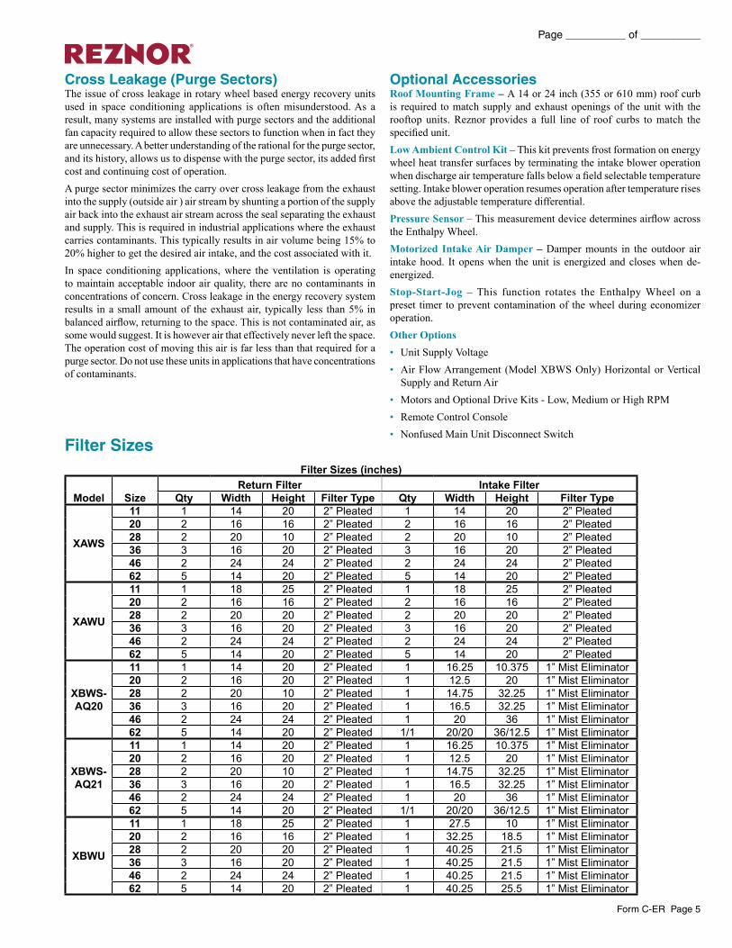
Filter SizesFilter Sizes (inches)
Model SizeReturn Filter Intake Filter
Qty Width Height Filter Type Qty Width Height Filter Type
XAWS
11 1 14 20 2” Pleated 1 14 20 2” Pleated20 2 16 16 2” Pleated 2 16 16 2” Pleated28 2 20 10 2” Pleated 2 20 10 2” Pleated36 3 16 20 2” Pleated 3 16 20 2” Pleated46 2 24 24 2” Pleated 2 24 24 2” Pleated62 5 14 20 2” Pleated 5 14 20 2” Pleated
XAWU
11 1 18 25 2” Pleated 1 18 25 2” Pleated20 2 16 16 2” Pleated 2 16 16 2” Pleated28 2 20 20 2” Pleated 2 20 20 2” Pleated36 3 16 20 2” Pleated 3 16 20 2” Pleated46 2 24 24 2” Pleated 2 24 24 2” Pleated62 5 14 20 2” Pleated 5 14 20 2” Pleated
XBWS-AQ20
11 1 14 20 2” Pleated 1 16.25 10.375 1” Mist Eliminator20 2 16 20 2” Pleated 1 12.5 20 1” Mist Eliminator28 2 20 10 2” Pleated 1 14.75 32.25 1” Mist Eliminator36 3 16 20 2” Pleated 1 16.5 32.25 1” Mist Eliminator46 2 24 24 2” Pleated 1 20 36 1” Mist Eliminator62 5 14 20 2” Pleated 1/1 20/20 36/12.5 1” Mist Eliminator
XBWS-AQ21
11 1 14 20 2” Pleated 1 16.25 10.375 1” Mist Eliminator20 2 16 20 2” Pleated 1 12.5 20 1” Mist Eliminator28 2 20 10 2” Pleated 1 14.75 32.25 1” Mist Eliminator36 3 16 20 2” Pleated 1 16.5 32.25 1” Mist Eliminator46 2 24 24 2” Pleated 1 20 36 1” Mist Eliminator62 5 14 20 2” Pleated 1/1 20/20 36/12.5 1” Mist Eliminator
XBWU
11 1 18 25 2” Pleated 1 27.5 10 1” Mist Eliminator20 2 16 16 2” Pleated 1 32.25 18.5 1” Mist Eliminator28 2 20 20 2” Pleated 1 40.25 21.5 1” Mist Eliminator36 3 16 20 2” Pleated 1 40.25 21.5 1” Mist Eliminator46 2 24 24 2” Pleated 1 40.25 21.5 1” Mist Eliminator62 5 14 20 2” Pleated 1 40.25 25.5 1” Mist Eliminator
Page __________ of __________
Form C-ER Page 6
�����������
���������
����������
�����������
�
�
� �
�
�
�
�
�
�
�
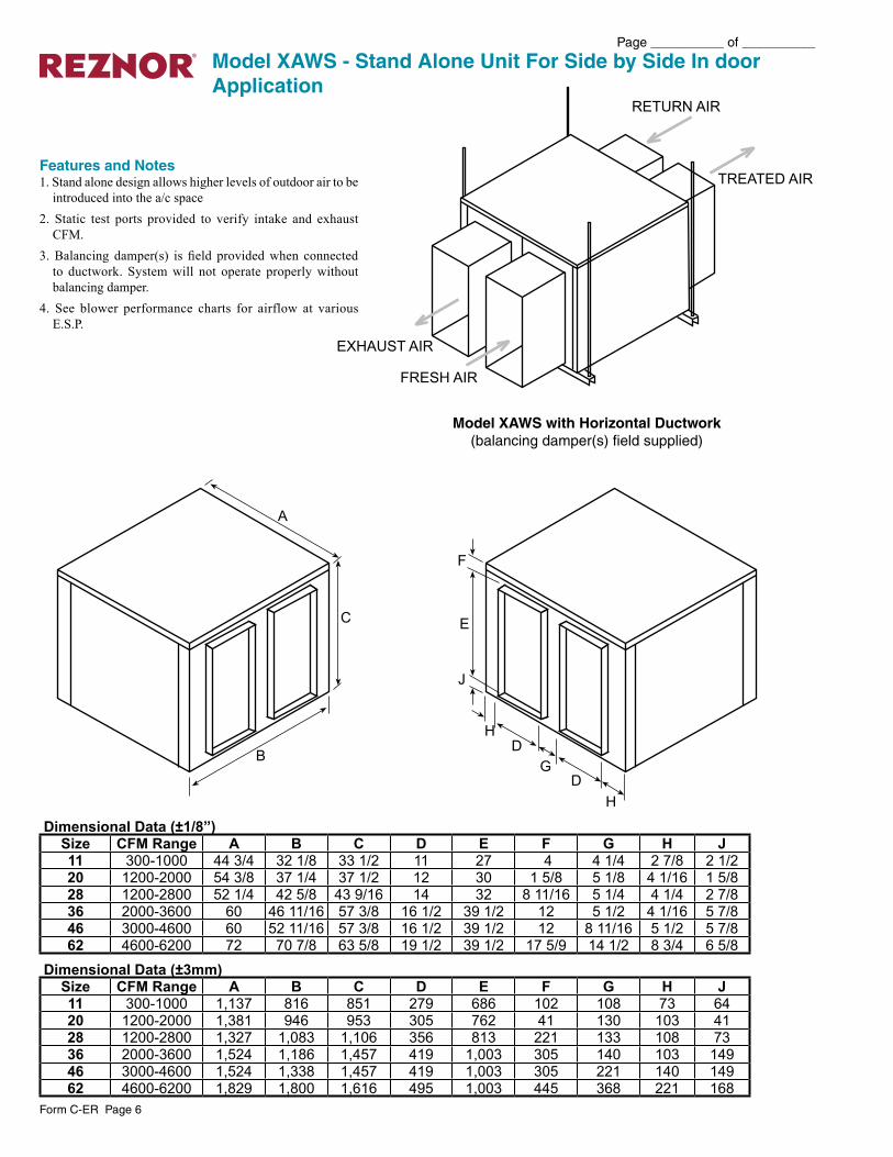
Model XAWS - Stand Alone Unit For Side by Side In door Application
Features and Notes1. Stand alone design allows higher levels of outdoor air to be
introduced into the a/c space2. Static test ports provided to verify intake and exhaust
CFM.3. Balancing damper(s) is field provided when connected
to ductwork. System will not operate properly without balancing damper.
4. See blower performance charts for airflow at various E.S.P.
Model XAWS with Horizontal Ductwork(balancing damper(s) field supplied)
Dimensional Data (±1/8”)Size CFM Range A B C D E F G H J11 300-1000 44 3/4 32 1/8 33 1/2 11 27 4 4 1/4 2 7/8 2 1/220 1200-2000 54 3/8 37 1/4 37 1/2 12 30 1 5/8 5 1/8 4 1/16 1 5/828 1200-2800 52 1/4 42 5/8 43 9/16 14 32 8 11/16 5 1/4 4 1/4 2 7/836 2000-3600 60 46 11/16 57 3/8 16 1/2 39 1/2 12 5 1/2 4 1/16 5 7/846 3000-4600 60 52 11/16 57 3/8 16 1/2 39 1/2 12 8 11/16 5 1/2 5 7/862 4600-6200 72 70 7/8 63 5/8 19 1/2 39 1/2 17 5/9 14 1/2 8 3/4 6 5/8
Dimensional Data (±3mm)Size CFM Range A B C D E F G H J11 300-1000 1,137 816 851 279 686 102 108 73 6420 1200-2000 1,381 946 953 305 762 41 130 103 4128 1200-2800 1,327 1,083 1,106 356 813 221 133 108 7336 2000-3600 1,524 1,186 1,457 419 1,003 305 140 103 14946 3000-4600 1,524 1,338 1,457 419 1,003 305 221 140 14962 4600-6200 1,829 1,800 1,616 495 1,003 445 368 221 168
Form C-ER Page 7
Page __________ of __________
����������
���������
�����������
�
�
�
�
�
�
�
�
�
�
�����������
�
�
�
�
�
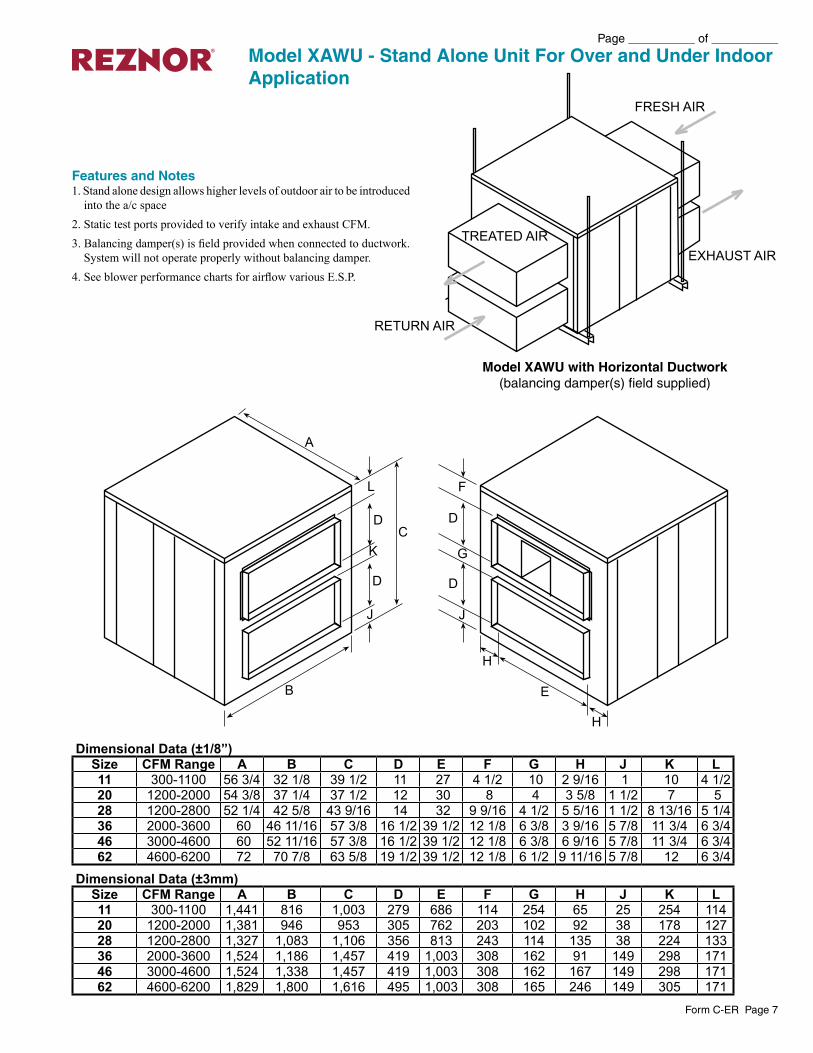
Features and Notes1. Stand alone design allows higher levels of outdoor air to be introduced
into the a/c space2. Static test ports provided to verify intake and exhaust CFM.3. Balancing damper(s) is field provided when connected to ductwork.
System will not operate properly without balancing damper.4. See blower performance charts for airflow various E.S.P.
Model XAWU with Horizontal Ductwork(balancing damper(s) field supplied)
Model XAWU - Stand Alone Unit For Over and Under Indoor Application
Dimensional Data (±1/8”)Size CFM Range A B C D E F G H J K L11 300-1100 56 3/4 32 1/8 39 1/2 11 27 4 1/2 10 2 9/16 1 10 4 1/220 1200-2000 54 3/8 37 1/4 37 1/2 12 30 8 4 3 5/8 1 1/2 7 528 1200-2800 52 1/4 42 5/8 43 9/16 14 32 9 9/16 4 1/2 5 5/16 1 1/2 8 13/16 5 1/436 2000-3600 60 46 11/16 57 3/8 16 1/2 39 1/2 12 1/8 6 3/8 3 9/16 5 7/8 11 3/4 6 3/446 3000-4600 60 52 11/16 57 3/8 16 1/2 39 1/2 12 1/8 6 3/8 6 9/16 5 7/8 11 3/4 6 3/462 4600-6200 72 70 7/8 63 5/8 19 1/2 39 1/2 12 1/8 6 1/2 9 11/16 5 7/8 12 6 3/4
Dimensional Data (±3mm)Size CFM Range A B C D E F G H J K L11 300-1100 1,441 816 1,003 279 686 114 254 65 25 254 11420 1200-2000 1,381 946 953 305 762 203 102 92 38 178 12728 1200-2800 1,327 1,083 1,106 356 813 243 114 135 38 224 13336 2000-3600 1,524 1,186 1,457 419 1,003 308 162 91 149 298 17146 3000-4600 1,524 1,338 1,457 419 1,003 308 162 167 149 298 17162 4600-6200 1,829 1,800 1,616 495 1,003 308 165 246 149 305 171
Page __________ of __________
Form C-ER Page 8
�
�
�
�
�
�
�
�
�
�
�
�
�
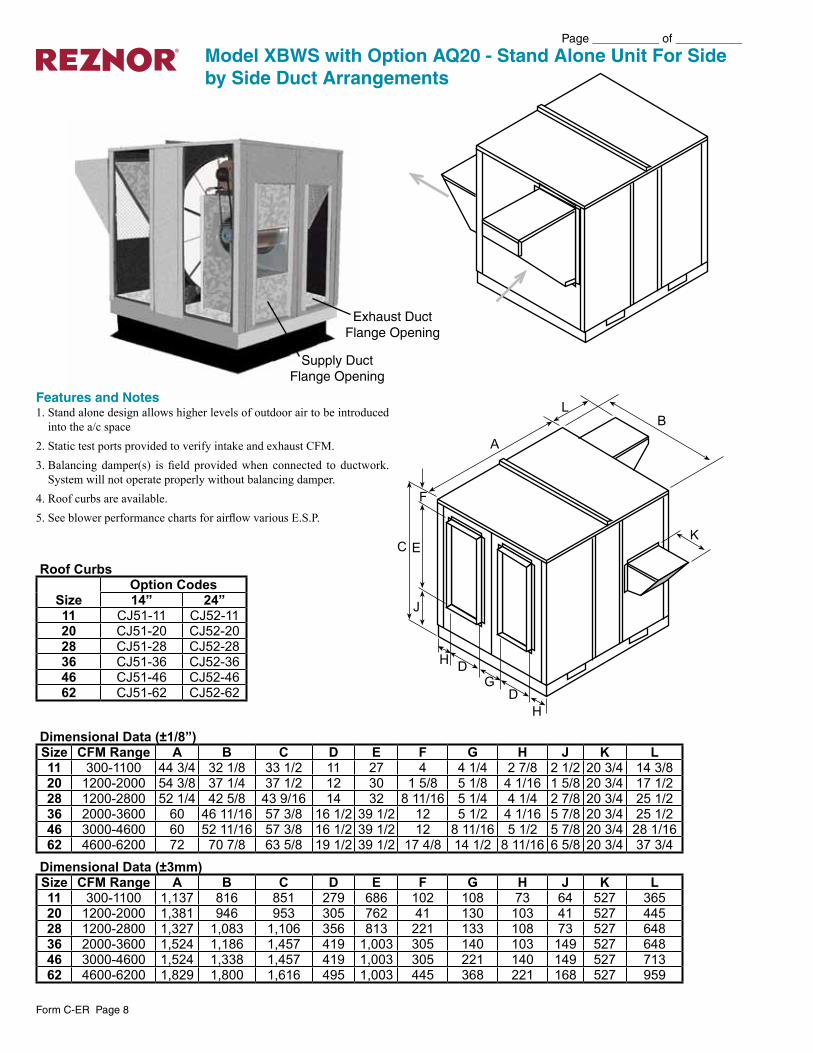
Model XBWS with Option AQ20 - Stand Alone Unit For Side by Side Duct Arrangements
Features and Notes1. Stand alone design allows higher levels of outdoor air to be introduced
into the a/c space2. Static test ports provided to verify intake and exhaust CFM.3. Balancing damper(s) is field provided when connected to ductwork.
System will not operate properly without balancing damper.4. Roof curbs are available.5. See blower performance charts for airflow various E.S.P.
Exhaust Duct Flange Opening
Supply Duct Flange Opening
Roof Curbs
SizeOption Codes14” 24”
11 CJ51-11 CJ52-1120 CJ51-20 CJ52-2028 CJ51-28 CJ52-2836 CJ51-36 CJ52-3646 CJ51-46 CJ52-4662 CJ51-62 CJ52-62
Dimensional Data (±1/8”)Size CFM Range A B C D E F G H J K L11 300-1100 44 3/4 32 1/8 33 1/2 11 27 4 4 1/4 2 7/8 2 1/2 20 3/4 14 3/820 1200-2000 54 3/8 37 1/4 37 1/2 12 30 1 5/8 5 1/8 4 1/16 1 5/8 20 3/4 17 1/228 1200-2800 52 1/4 42 5/8 43 9/16 14 32 8 11/16 5 1/4 4 1/4 2 7/8 20 3/4 25 1/236 2000-3600 60 46 11/16 57 3/8 16 1/2 39 1/2 12 5 1/2 4 1/16 5 7/8 20 3/4 25 1/246 3000-4600 60 52 11/16 57 3/8 16 1/2 39 1/2 12 8 11/16 5 1/2 5 7/8 20 3/4 28 1/1662 4600-6200 72 70 7/8 63 5/8 19 1/2 39 1/2 17 4/8 14 1/2 8 11/16 6 5/8 20 3/4 37 3/4
Dimensional Data (±3mm)Size CFM Range A B C D E F G H J K L11 300-1100 1,137 816 851 279 686 102 108 73 64 527 36520 1200-2000 1,381 946 953 305 762 41 130 103 41 527 44528 1200-2800 1,327 1,083 1,106 356 813 221 133 108 73 527 64836 2000-3600 1,524 1,186 1,457 419 1,003 305 140 103 149 527 64846 3000-4600 1,524 1,338 1,457 419 1,003 305 221 140 149 527 71362 4600-6200 1,829 1,800 1,616 495 1,003 445 368 221 168 527 959
Form C-ER Page 9
Page __________ of __________
������������
��������������
����������������������������������
������������������������������������
� �
�
�
�������������
���������������
��
��
�
�
��������
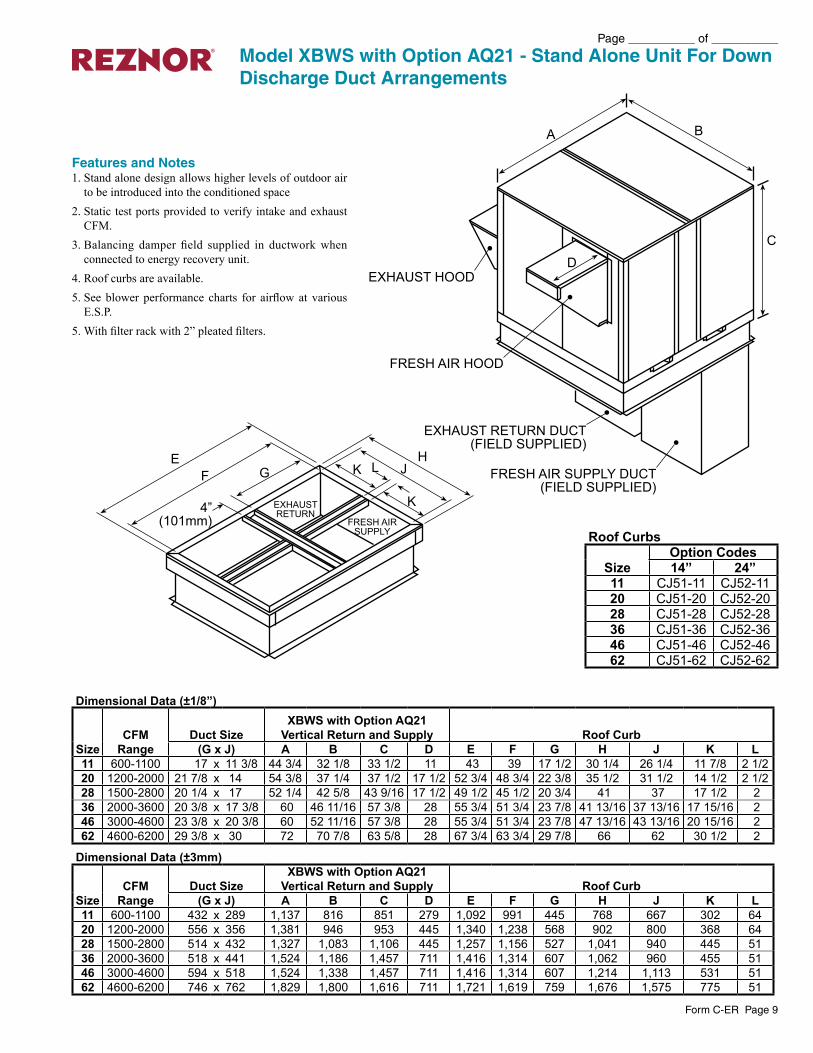
Model XBWS with Option AQ21 - Stand Alone Unit For Down Discharge Duct Arrangements
Features and Notes1. Stand alone design allows higher levels of outdoor air
to be introduced into the conditioned space2. Static test ports provided to verify intake and exhaust
CFM.3. Balancing damper field supplied in ductwork when
connected to energy recovery unit.4. Roof curbs are available.5. See blower performance charts for airflow at various
E.S.P.5. With filter rack with 2” pleated filters.
Dimensional Data (±1/8”)
SizeCFM
Range Duct Size
XBWS with Option AQ21 Vertical Return and Supply Roof Curb
(G x J) A B C D E F G H J K L11 600-1100 17 x 11 3/8 44 3/4 32 1/8 33 1/2 11 43 39 17 1/2 30 1/4 26 1/4 11 7/8 2 1/220 1200-2000 21 7/8 x 14 54 3/8 37 1/4 37 1/2 17 1/2 52 3/4 48 3/4 22 3/8 35 1/2 31 1/2 14 1/2 2 1/228 1500-2800 20 1/4 x 17 52 1/4 42 5/8 43 9/16 17 1/2 49 1/2 45 1/2 20 3/4 41 37 17 1/2 236 2000-3600 20 3/8 x 17 3/8 60 46 11/16 57 3/8 28 55 3/4 51 3/4 23 7/8 41 13/16 37 13/16 17 15/16 246 3000-4600 23 3/8 x 20 3/8 60 52 11/16 57 3/8 28 55 3/4 51 3/4 23 7/8 47 13/16 43 13/16 20 15/16 262 4600-6200 29 3/8 x 30 72 70 7/8 63 5/8 28 67 3/4 63 3/4 29 7/8 66 62 30 1/2 2
Dimensional Data (±3mm)
SizeCFM
Range Duct Size
XBWS with Option AQ21 Vertical Return and Supply Roof Curb
(G x J) A B C D E F G H J K L11 600-1100 432 x 289 1,137 816 851 279 1,092 991 445 768 667 302 6420 1200-2000 556 x 356 1,381 946 953 445 1,340 1,238 568 902 800 368 6428 1500-2800 514 x 432 1,327 1,083 1,106 445 1,257 1,156 527 1,041 940 445 5136 2000-3600 518 x 441 1,524 1,186 1,457 711 1,416 1,314 607 1,062 960 455 5146 3000-4600 594 x 518 1,524 1,338 1,457 711 1,416 1,314 607 1,214 1,113 531 5162 4600-6200 746 x 762 1,829 1,800 1,616 711 1,721 1,619 759 1,676 1,575 775 51
Roof Curbs
SizeOption Codes14” 24”
11 CJ51-11 CJ52-1120 CJ51-20 CJ52-2028 CJ51-28 CJ52-2836 CJ51-36 CJ52-3646 CJ51-46 CJ52-4662 CJ51-62 CJ52-62
Page __________ of __________
Form C-ER Page 10
� �
�
�
�
�
�
�
�
��
�
�
�
�
��
������ ������� �����
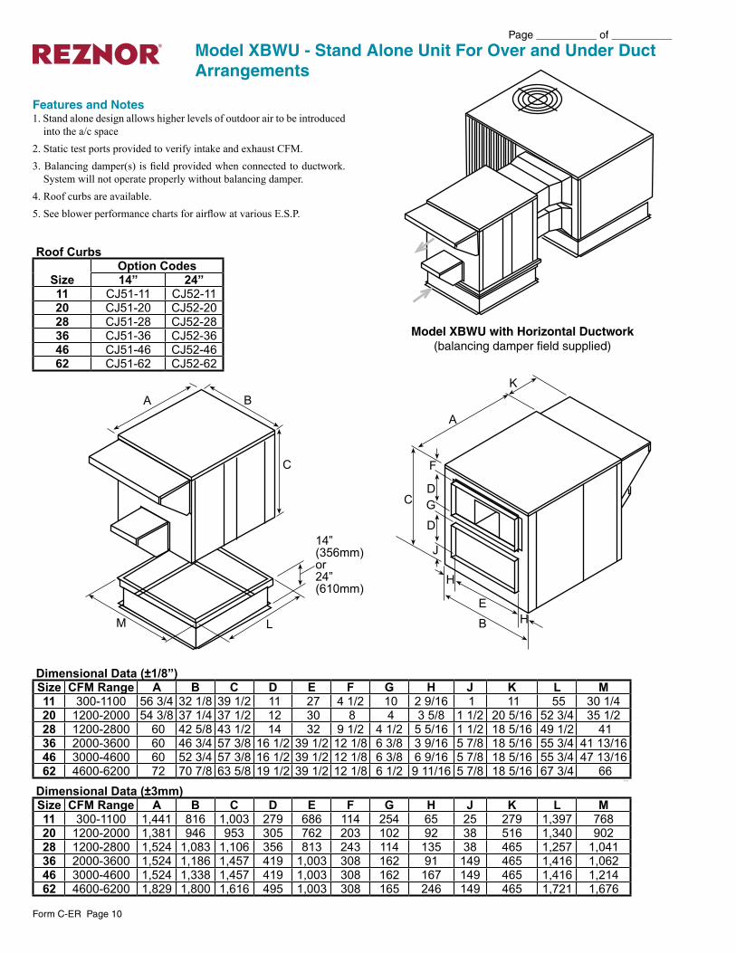
Model XBWU - Stand Alone Unit For Over and Under Duct Arrangements
Features and Notes1. Stand alone design allows higher levels of outdoor air to be introduced
into the a/c space2. Static test ports provided to verify intake and exhaust CFM.3. Balancing damper(s) is field provided when connected to ductwork.
System will not operate properly without balancing damper.4. Roof curbs are available.5. See blower performance charts for airflow at various E.S.P.
Model XBWU with Horizontal Ductwork(balancing damper field supplied)
Roof Curbs
SizeOption Codes14” 24”
11 CJ51-11 CJ52-1120 CJ51-20 CJ52-2028 CJ51-28 CJ52-2836 CJ51-36 CJ52-3646 CJ51-46 CJ52-4662 CJ51-62 CJ52-62
Dimensional Data (±1/8”)Size CFM Range A B C D E F G H J K L M11 300-1100 56 3/4 32 1/8 39 1/2 11 27 4 1/2 10 2 9/16 1 11 55 30 1/420 1200-2000 54 3/8 37 1/4 37 1/2 12 30 8 4 3 5/8 1 1/2 20 5/16 52 3/4 35 1/228 1200-2800 60 42 5/8 43 1/2 14 32 9 1/2 4 1/2 5 5/16 1 1/2 18 5/16 49 1/2 4136 2000-3600 60 46 3/4 57 3/8 16 1/2 39 1/2 12 1/8 6 3/8 3 9/16 5 7/8 18 5/16 55 3/4 41 13/1646 3000-4600 60 52 3/4 57 3/8 16 1/2 39 1/2 12 1/8 6 3/8 6 9/16 5 7/8 18 5/16 55 3/4 47 13/1662 4600-6200 72 70 7/8 63 5/8 19 1/2 39 1/2 12 1/8 6 1/2 9 11/16 5 7/8 18 5/16 67 3/4 66
66 1/32
Dimensional Data (±3mm)Size CFM Range A B C D E F G H J K L M11 300-1100 1,441 816 1,003 279 686 114 254 65 25 279 1,397 76820 1200-2000 1,381 946 953 305 762 203 102 92 38 516 1,340 90228 1200-2800 1,524 1,083 1,106 356 813 243 114 135 38 465 1,257 1,04136 2000-3600 1,524 1,186 1,457 419 1,003 308 162 91 149 465 1,416 1,06246 3000-4600 1,524 1,338 1,457 419 1,003 308 162 167 149 465 1,416 1,21462 4600-6200 1,829 1,800 1,616 495 1,003 308 165 246 149 465 1,721 1,676
Form C-ER Page 11
Page __________ of __________
�
�
�
�
�����������������
��������
����������
����� ���
���������
�
�
�
�
�����������������
��������
����������
����� ���
���������
�
�
�
�
����������
�����������
���������� ��
���
���� ���
���
�������� ��
���
�
�
�
�
����������
����������������
���� ������
�
�
�
�
����������
�����������
���������� ��
���
���� ���
���
�������� ��
���
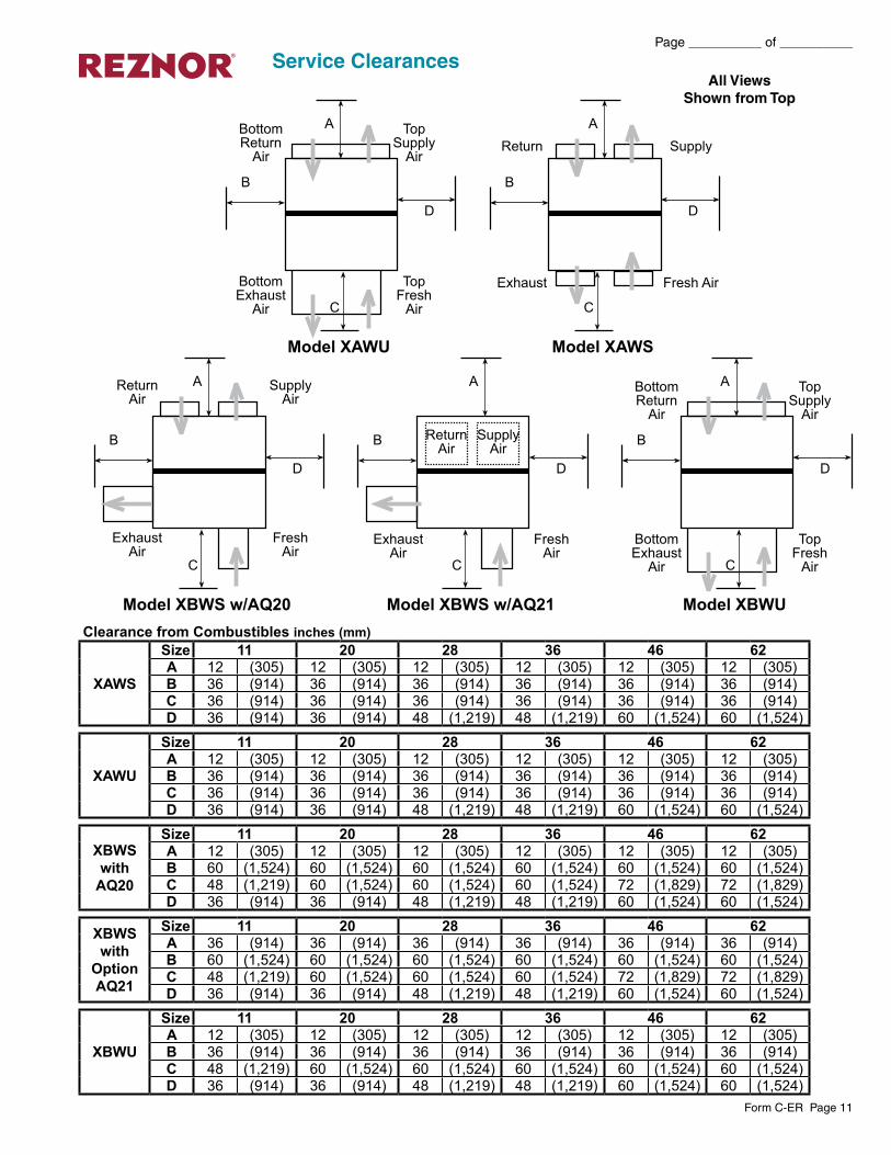
Service ClearancesAll Views
Shown from Top
Clearance from Combustibles inches (mm)
XAWS
Size 11 20 28 36 46 62A 12 (305) 12 (305) 12 (305) 12 (305) 12 (305) 12 (305)B 36 (914) 36 (914) 36 (914) 36 (914) 36 (914) 36 (914)C 36 (914) 36 (914) 36 (914) 36 (914) 36 (914) 36 (914)D 36 (914) 36 (914) 48 (1,219) 48 (1,219) 60 (1,524) 60 (1,524)
XAWU
Size 11 20 28 36 46 62A 12 (305) 12 (305) 12 (305) 12 (305) 12 (305) 12 (305)B 36 (914) 36 (914) 36 (914) 36 (914) 36 (914) 36 (914)C 36 (914) 36 (914) 36 (914) 36 (914) 36 (914) 36 (914)D 36 (914) 36 (914) 48 (1,219) 48 (1,219) 60 (1,524) 60 (1,524)
XBWS with
AQ20
Size 11 20 28 36 46 62A 12 (305) 12 (305) 12 (305) 12 (305) 12 (305) 12 (305)B 60 (1,524) 60 (1,524) 60 (1,524) 60 (1,524) 60 (1,524) 60 (1,524)C 48 (1,219) 60 (1,524) 60 (1,524) 60 (1,524) 72 (1,829) 72 (1,829)D 36 (914) 36 (914) 48 (1,219) 48 (1,219) 60 (1,524) 60 (1,524)
XBWS with
Option AQ21
Size 11 20 28 36 46 62A 36 (914) 36 (914) 36 (914) 36 (914) 36 (914) 36 (914)B 60 (1,524) 60 (1,524) 60 (1,524) 60 (1,524) 60 (1,524) 60 (1,524)C 48 (1,219) 60 (1,524) 60 (1,524) 60 (1,524) 72 (1,829) 72 (1,829)D 36 (914) 36 (914) 48 (1,219) 48 (1,219) 60 (1,524) 60 (1,524)
XBWU
Size 11 20 28 36 46 62A 12 (305) 12 (305) 12 (305) 12 (305) 12 (305) 12 (305)B 36 (914) 36 (914) 36 (914) 36 (914) 36 (914) 36 (914)C 48 (1,219) 60 (1,524) 60 (1,524) 60 (1,524) 60 (1,524) 60 (1,524)D 36 (914) 36 (914) 48 (1,219) 48 (1,219) 60 (1,524) 60 (1,524)
Page __________ of __________
Form C-ER Page 12
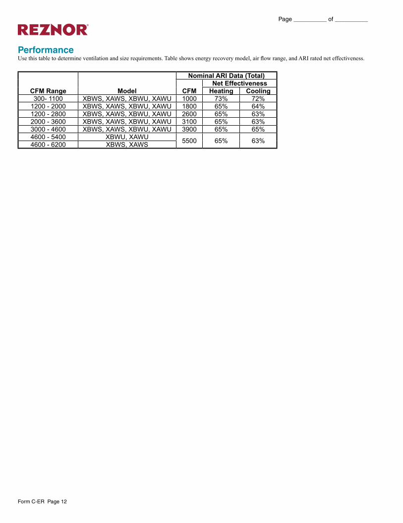
PerformanceUse this table to determine ventilation and size requirements. Table shows energy recovery model, air flow range, and ARI rated net effectiveness.
CFM Range Model
Nominal ARI Data (Total)
CFMNet Effectiveness
Heating Cooling 300- 1100 XBWS, XAWS, XBWU, XAWU 1000 73% 72%
1200 - 2000 XBWS, XAWS, XBWU, XAWU 1800 65% 64%1200 - 2800 XBWS, XAWS, XBWU, XAWU 2600 65% 63%2000 - 3600 XBWS, XAWS, XBWU, XAWU 3100 65% 63%3000 - 4600 XBWS, XAWS, XBWU, XAWU 3900 65% 65%4600 - 5400 XBWU, XAWU 5500 65% 63%4600 - 6200 XBWS, XAWS
Form C-ER Page 13
Page __________ of __________
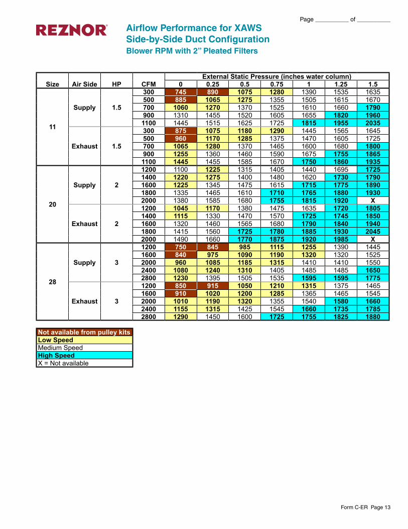
Airflow Performance for XAWSSide-by-Side Duct ConfigurationBlower RPM with 2” Pleated Filters
Not available from pulley kitsLow SpeedMedium SpeedHigh SpeedX = Not available
Size Air Side HP CFMExternal Static Pressure (inches water column)
0 0.25 0.5 0.75 1 1.25 1.5
11
Supply 1.5
300 745 890 1075 1280 1390 1535 1635500 885 1065 1275 1355 1505 1615 1670700 1060 1270 1370 1525 1610 1660 1790900 1310 1455 1520 1605 1655 1820 19601100 1445 1515 1625 1725 1815 1955 2035
Exhaust 1.5
300 875 1075 1180 1290 1445 1565 1645500 960 1170 1285 1375 1470 1605 1725700 1065 1280 1370 1465 1600 1680 1800900 1255 1360 1460 1590 1675 1755 18651100 1445 1455 1585 1670 1750 1860 1935
20
Supply 2
1200 1100 1225 1315 1405 1440 1695 17251400 1220 1275 1400 1480 1620 1730 17901600 1225 1345 1475 1615 1715 1775 18901800 1335 1465 1610 1710 1765 1880 19302000 1380 1585 1680 1755 1815 1920 X
Exhaust 2
1200 1045 1170 1380 1475 1635 1720 18051400 1115 1330 1470 1570 1725 1745 18501600 1320 1460 1565 1680 1790 1840 19401800 1415 1560 1725 1780 1885 1930 20452000 1490 1660 1770 1875 1920 1985 X
28
Supply 3
1200 750 845 985 1115 1255 1390 14451600 840 975 1090 1190 1320 1320 15252000 960 1085 1185 1315 1410 1410 15502400 1080 1240 1310 1405 1485 1485 16502800 1230 1395 1505 1535 1595 1595 1775
Exhaust 3
1200 850 915 1050 1210 1315 1375 14651600 910 1020 1200 1285 1365 1465 15452000 1010 1190 1320 1355 1540 1580 16602400 1155 1315 1425 1545 1660 1735 17852800 1290 1450 1600 1725 1755 1825 1880
Page __________ of __________
Form C-ER Page 14
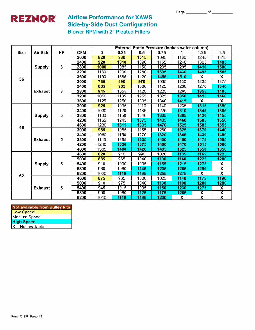
Airflow Performance for XAWSSide-by-Side Duct ConfigurationBlower RPM with 2” Pleated Filters
Size Air Side HP CFMExternal Static Pressure (inches water column)
0 0.25 0.5 0.75 1 1.25 1.5
36
Supply 3
2000 820 930 1015 1095 1160 1245 13152400 920 1010 1090 1155 1240 1305 14052800 1000 1085 1150 1235 1295 1410 15003200 1130 1200 1260 1395 1430 1495 15653600 1190 1385 1420 1455 1510 X X
Exhaust 3
2000 780 890 970 1065 1130 1235 12752400 885 965 1060 1125 1230 1270 13402800 945 1055 1120 1225 1265 1355 14053200 1050 1135 1255 1325 1350 1415 14603600 1125 1250 1305 1340 1415 X X
46
Supply 5
3000 925 1035 1110 1140 1235 1315 13503400 1030 1120 1185 1225 1310 1345 13853800 1100 1150 1240 1335 1385 1420 14554200 1165 1245 1375 1435 1460 1505 15504600 1230 1315 1335 1470 1525 1585 1655
Exhaust 5
3000 985 1085 1155 1280 1325 1370 14403400 1060 1150 1270 1320 1365 1430 14803800 1145 1265 1335 1400 1450 1475 15054200 1240 1330 1375 1460 1470 1515 15604600 1305 1400 1420 1485 1525 1550 1650
62
Supply 5
4600 820 910 990 1020 1135 1165 12255000 885 965 1040 1100 1160 1225 12805400 910 1000 1095 1155 1215 1275 X5800 960 1060 1145 1205 1265 1290 X6200 1020 1110 1195 1255 1275 X X
Exhaust 5
4600 875 935 1000 1025 1140 1175 11905000 910 975 1040 1130 1190 1200 12805400 945 1015 1095 1150 1230 1275 X5800 990 1060 1125 1175 1265 X X6200 1010 1110 1195 1200 X X X
Not available from pulley kitsLow SpeedMedium SpeedHigh SpeedX = Not available
Form C-ER Page 15
Page __________ of __________
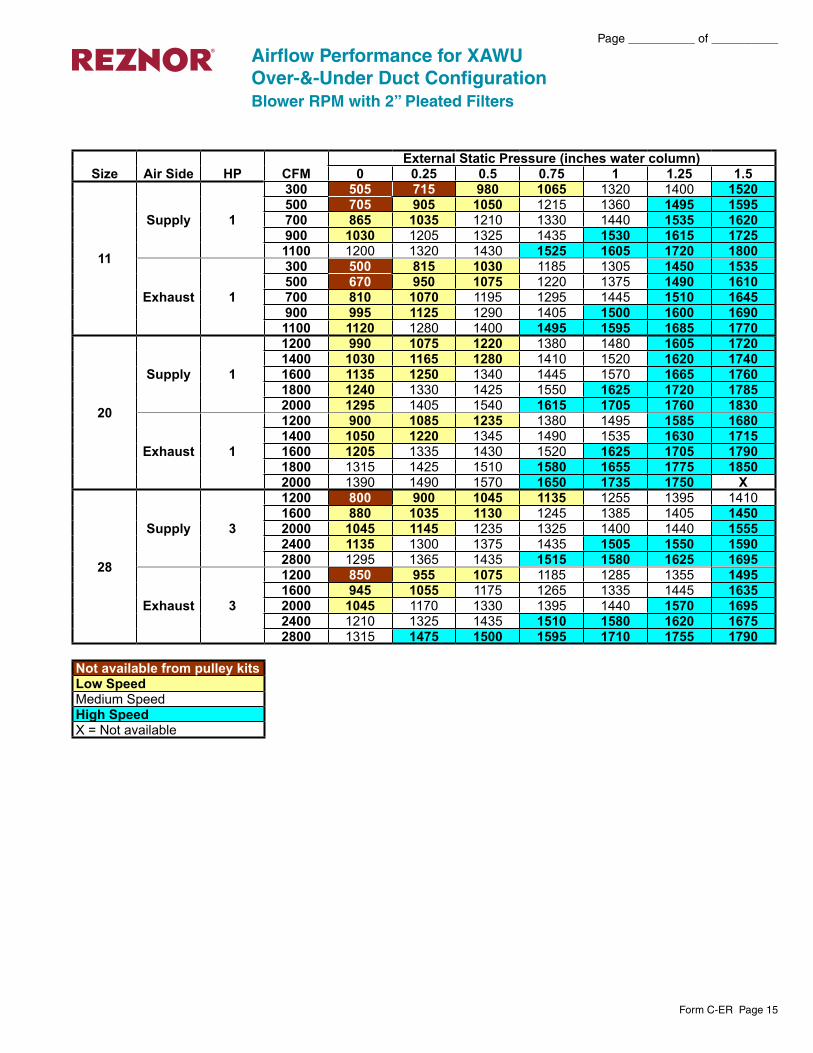
Airflow Performance for XAWUOver-&-Under Duct ConfigurationBlower RPM with 2” Pleated Filters
Size Air Side HP CFMExternal Static Pressure (inches water column)
0 0.25 0.5 0.75 1 1.25 1.5
11
Supply 1
300 505 715 980 1065 1320 1400 1520500 705 905 1050 1215 1360 1495 1595700 865 1035 1210 1330 1440 1535 1620900 1030 1205 1325 1435 1530 1615 17251100 1200 1320 1430 1525 1605 1720 1800
Exhaust 1
300 500 815 1030 1185 1305 1450 1535500 670 950 1075 1220 1375 1490 1610700 810 1070 1195 1295 1445 1510 1645900 995 1125 1290 1405 1500 1600 16901100 1120 1280 1400 1495 1595 1685 1770
20
Supply 1
1200 990 1075 1220 1380 1480 1605 17201400 1030 1165 1280 1410 1520 1620 17401600 1135 1250 1340 1445 1570 1665 17601800 1240 1330 1425 1550 1625 1720 17852000 1295 1405 1540 1615 1705 1760 1830
Exhaust 1
1200 900 1085 1235 1380 1495 1585 16801400 1050 1220 1345 1490 1535 1630 17151600 1205 1335 1430 1520 1625 1705 17901800 1315 1425 1510 1580 1655 1775 18502000 1390 1490 1570 1650 1735 1750 X
28
Supply 3
1200 800 900 1045 1135 1255 1395 14101600 880 1035 1130 1245 1385 1405 14502000 1045 1145 1235 1325 1400 1440 15552400 1135 1300 1375 1435 1505 1550 15902800 1295 1365 1435 1515 1580 1625 1695
Exhaust 3
1200 850 955 1075 1185 1285 1355 14951600 945 1055 1175 1265 1335 1445 16352000 1045 1170 1330 1395 1440 1570 16952400 1210 1325 1435 1510 1580 1620 16752800 1315 1475 1500 1595 1710 1755 1790
Not available from pulley kitsLow SpeedMedium SpeedHigh SpeedX = Not available
Page __________ of __________
Form C-ER Page 16
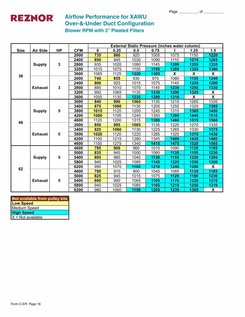
Airflow Performance for XAWUOver-&-Under Duct ConfigurationBlower RPM with 2” Pleated Filters
Size Air Side HP CFMExternal Static Pressure (inches water column)
0 0.25 0.5 0.75 1 1.25 1.5
36
Supply 3
2000 735 860 920 1005 1075 1150 12202400 850 945 1030 1090 1110 1215 12652800 935 1020 1080 1145 1200 1255 13353200 1015 1075 1105 1195 1285 1325 13803600 1065 1125 1220 1305 X X X
Exhaust 3
2000 740 855 930 970 1080 1155 12402400 800 925 1015 1075 1145 1225 12802800 885 1010 1070 1140 1235 1255 13303200 950 1065 1135 1230 1290 1325 X3600 1055 1130 1235 1280 1310 X X
46
Supply 5
3000 840 990 1065 1135 1215 1265 13353400 875 1060 1130 1205 1255 1320 13853800 1015 1120 1200 1245 1315 1365 14504200 1080 1195 1240 1350 1395 1445 15104600 1120 1200 1315 1380 1460 1515 1560
Exhaust 5
3000 850 995 1065 1135 1220 1270 13353400 925 1060 1130 1225 1265 1330 13753800 1020 1120 1220 1285 1325 1370 14304200 1100 1215 1280 1345 1400 1435 14804600 1150 1275 1340 1415 1475 1520 1565
62
Supply 5
4600 795 900 960 1010 1090 1135 11655000 835 945 1000 1060 1135 1155 12305400 895 985 1040 1130 1155 1220 12655800 940 1025 1085 1145 1225 1250 13006200 990 1070 1105 1210 1245 1290 X
Exhaust 5
4600 780 910 900 1045 1085 1135 11855000 825 945 1015 1075 1125 1180 12305400 890 990 1065 1105 1170 1220 12705800 940 1025 1085 1165 1215 1250 13106200 980 1060 1150 1205 1235 1305 X
Not available from pulley kitsLow SpeedMedium SpeedHigh SpeedX = Not available

Form C-ER Page 17
Page __________ of __________
A Mist Eliminator Filter in Intake Hood.B Barometric Hood with 2” Pleated Filters
Airflow Performance for XBWS with Option AQ20Side-by-Side Duct ConfigurationBlower RPM with 2” Pleated Filters
Size Air Side HP CFMExternal Static Pressure (inches water column)
0 0.25 0.5 0.75 1 1.25 1.5
11
SupplyA 1.5
300 690 815 1020 1205 1365 1480 1590500 785 1015 1200 1320 1460 1565 1670700 990 1190 1315 1455 1560 1665 1715900 1150 1310 1450 1555 1660 1680 17951100 1305 1440 1550 1655 1740 1815 1895
ExhaustB 1.5
300 725 900 1150 1285 1415 1515 1640500 895 1145 1275 1410 1510 1545 1720700 1140 1270 1405 1505 1590 1715 1815900 1320 1435 1585 1665 1705 1810 19301100 1495 1580 1660 1755 1880 X X
20
SupplyA 2
1200 1065 1285 1375 1415 1495 1580 16851400 1140 1330 1410 1440 1555 1660 17601600 1290 1400 1480 1545 1670 1745 18351800 1395 1470 1540 1665 1735 1800 18802000 1460 1530 1650 1725 1795 1870 1960
ExhaustB 2
1200 1175 1290 1430 1520 1680 1765 18501400 1245 1425 1515 1675 1755 1830 19201600 1400 1505 1670 1750 1825 1910 19801800 1495 1660 1740 1820 1900 1975 20902000 1645 1730 1815 1895 1965 2080 2170
28
SupplyA 3
1200 745 955 1070 1210 1370 1465 15501600 880 1065 1205 1305 1460 1540 15952000 1060 1200 1290 1445 1530 1585 16802400 1190 1335 1440 1490 1575 1670 17552800 1300 1460 1550 1645 1705 1750 1800
ExhaustB 3
1200 785 900 1025 1170 1270 1355 14001600 895 1020 1155 1240 1330 1390 14902000 1015 1150 1235 1325 1380 1475 15902400 1140 1285 1365 1420 1510 1595 16402800 1280 1345 1455 1540 1575 1670 1745
Not available from pulley kitsLow SpeedMedium SpeedHigh SpeedX = Not available
Page __________ of __________
Form C-ER Page 18
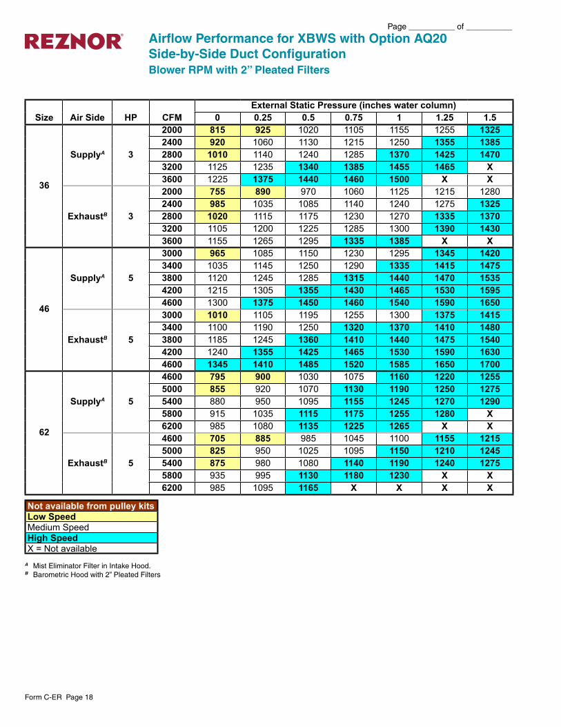
A Mist Eliminator Filter in Intake Hood.B Barometric Hood with 2” Pleated Filters
Airflow Performance for XBWS with Option AQ20Side-by-Side Duct ConfigurationBlower RPM with 2” Pleated Filters
Size Air Side HP CFMExternal Static Pressure (inches water column)
0 0.25 0.5 0.75 1 1.25 1.5
36
SupplyA 3
2000 815 925 1020 1105 1155 1255 13252400 920 1060 1130 1215 1250 1355 13852800 1010 1140 1240 1285 1370 1425 14703200 1125 1235 1340 1385 1455 1465 X3600 1225 1375 1440 1460 1500 X X
ExhaustB 3
2000 755 890 970 1060 1125 1215 12802400 985 1035 1085 1140 1240 1275 13252800 1020 1115 1175 1230 1270 1335 13703200 1105 1200 1225 1285 1300 1390 14303600 1155 1265 1295 1335 1385 X X
46
SupplyA 5
3000 965 1085 1150 1230 1295 1345 14203400 1035 1145 1250 1290 1335 1415 14753800 1120 1245 1285 1315 1440 1470 15354200 1215 1305 1355 1430 1465 1530 15954600 1300 1375 1450 1460 1540 1590 1650
ExhaustB 5
3000 1010 1105 1195 1255 1300 1375 14153400 1100 1190 1250 1320 1370 1410 14803800 1185 1245 1360 1410 1440 1475 15404200 1240 1355 1425 1465 1530 1590 16304600 1345 1410 1485 1520 1585 1650 1700
62
SupplyA 5
4600 795 900 1030 1075 1160 1220 12555000 855 920 1070 1130 1190 1250 12755400 880 950 1095 1155 1245 1270 12905800 915 1035 1115 1175 1255 1280 X6200 985 1080 1135 1225 1265 X X
ExhaustB 5
4600 705 885 985 1045 1100 1155 12155000 825 950 1025 1095 1150 1210 12455400 875 980 1080 1140 1190 1240 12755800 935 995 1130 1180 1230 X X6200 985 1095 1165 X X X X
Not available from pulley kitsLow SpeedMedium SpeedHigh SpeedX = Not available
Form C-ER Page 19
Page __________ of __________
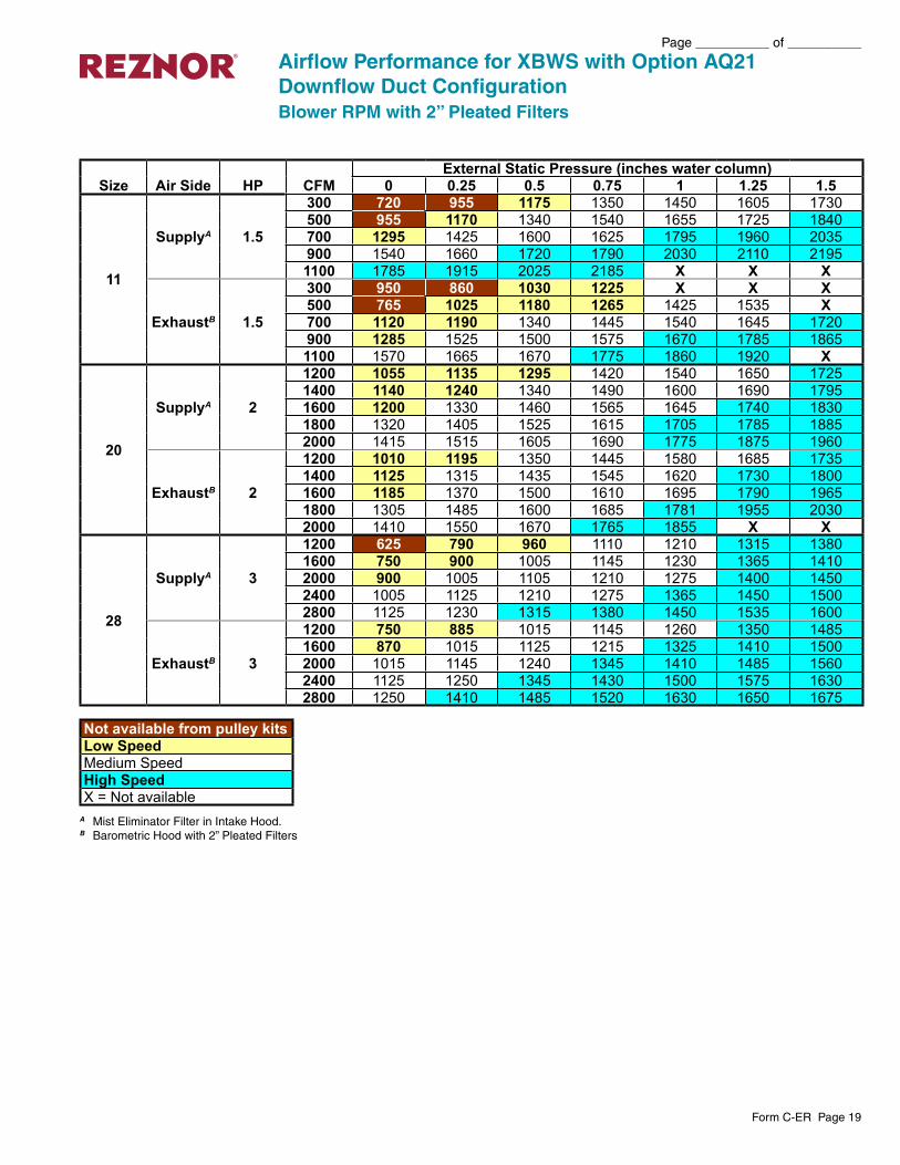
A Mist Eliminator Filter in Intake Hood.B Barometric Hood with 2” Pleated Filters
Airflow Performance for XBWS with Option AQ21Downflow Duct ConfigurationBlower RPM with 2” Pleated Filters
Size Air Side HP CFMExternal Static Pressure (inches water column)
0 0.25 0.5 0.75 1 1.25 1.5
11
SupplyA 1.5
300 720 955 1175 1350 1450 1605 1730500 955 1170 1340 1540 1655 1725 1840700 1295 1425 1600 1625 1795 1960 2035900 1540 1660 1720 1790 2030 2110 21951100 1785 1915 2025 2185 X X X
ExhaustB 1.5
300 950 860 1030 1225 X X X500 765 1025 1180 1265 1425 1535 X700 1120 1190 1340 1445 1540 1645 1720900 1285 1525 1500 1575 1670 1785 18651100 1570 1665 1670 1775 1860 1920 X
20
SupplyA 2
1200 1055 1135 1295 1420 1540 1650 17251400 1140 1240 1340 1490 1600 1690 17951600 1200 1330 1460 1565 1645 1740 18301800 1320 1405 1525 1615 1705 1785 18852000 1415 1515 1605 1690 1775 1875 1960
ExhaustB 2
1200 1010 1195 1350 1445 1580 1685 17351400 1125 1315 1435 1545 1620 1730 18001600 1185 1370 1500 1610 1695 1790 19651800 1305 1485 1600 1685 1781 1955 20302000 1410 1550 1670 1765 1855 X X
28
SupplyA 3
1200 625 790 960 1110 1210 1315 13801600 750 900 1005 1145 1230 1365 14102000 900 1005 1105 1210 1275 1400 14502400 1005 1125 1210 1275 1365 1450 15002800 1125 1230 1315 1380 1450 1535 1600
ExhaustB 3
1200 750 885 1015 1145 1260 1350 14851600 870 1015 1125 1215 1325 1410 15002000 1015 1145 1240 1345 1410 1485 15602400 1125 1250 1345 1430 1500 1575 16302800 1250 1410 1485 1520 1630 1650 1675
Not available from pulley kitsLow SpeedMedium SpeedHigh SpeedX = Not available
Page __________ of __________
Form C-ER Page 20
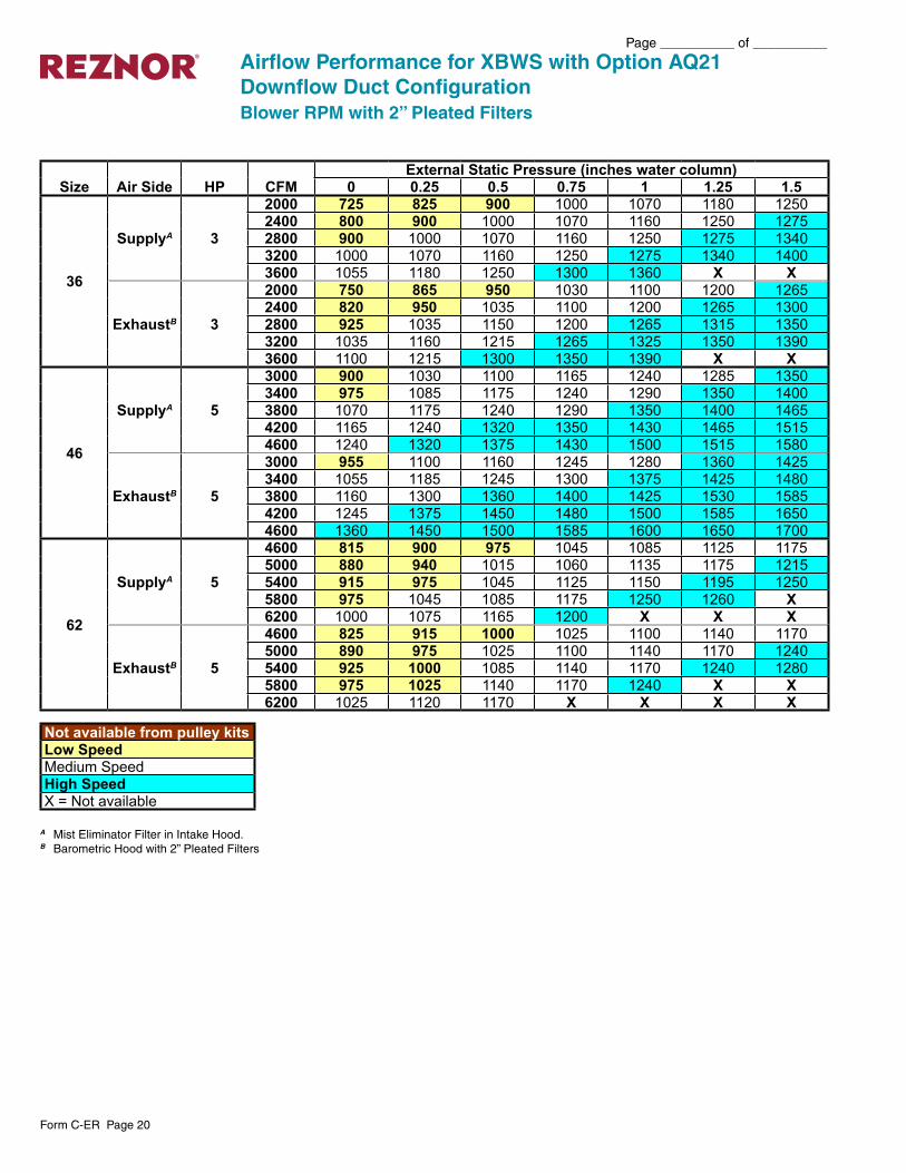
A Mist Eliminator Filter in Intake Hood.B Barometric Hood with 2” Pleated Filters
Airflow Performance for XBWS with Option AQ21Downflow Duct ConfigurationBlower RPM with 2” Pleated Filters
Size Air Side HP CFMExternal Static Pressure (inches water column)
0 0.25 0.5 0.75 1 1.25 1.5
36
SupplyA 3
2000 725 825 900 1000 1070 1180 12502400 800 900 1000 1070 1160 1250 12752800 900 1000 1070 1160 1250 1275 13403200 1000 1070 1160 1250 1275 1340 14003600 1055 1180 1250 1300 1360 X X
ExhaustB 3
2000 750 865 950 1030 1100 1200 12652400 820 950 1035 1100 1200 1265 13002800 925 1035 1150 1200 1265 1315 13503200 1035 1160 1215 1265 1325 1350 13903600 1100 1215 1300 1350 1390 X X
46
SupplyA 5
3000 900 1030 1100 1165 1240 1285 13503400 975 1085 1175 1240 1290 1350 14003800 1070 1175 1240 1290 1350 1400 14654200 1165 1240 1320 1350 1430 1465 15154600 1240 1320 1375 1430 1500 1515 1580
ExhaustB 5
3000 955 1100 1160 1245 1280 1360 14253400 1055 1185 1245 1300 1375 1425 14803800 1160 1300 1360 1400 1425 1530 15854200 1245 1375 1450 1480 1500 1585 16504600 1360 1450 1500 1585 1600 1650 1700
62
SupplyA 5
4600 815 900 975 1045 1085 1125 11755000 880 940 1015 1060 1135 1175 12155400 915 975 1045 1125 1150 1195 12505800 975 1045 1085 1175 1250 1260 X6200 1000 1075 1165 1200 X X X
ExhaustB 5
4600 825 915 1000 1025 1100 1140 11705000 890 975 1025 1100 1140 1170 12405400 925 1000 1085 1140 1170 1240 12805800 975 1025 1140 1170 1240 X X6200 1025 1120 1170 X X X X
Not available from pulley kitsLow SpeedMedium SpeedHigh SpeedX = Not available

Form C-ER Page 21
Page __________ of __________
A Mist Eliminator Filter in Intake Hood.B Barometric Hood with 2” Pleated Filters
Airflow Performance for XBWUOver-&-Under Duct ConfigurationBlower RPM with 2” Pleated Filters
Size Air Side HP CFMExternal Static Pressure (inches water column)
0 0.25 0.5 0.75 1 1.25 1.5
11
SupplyA 1.5
300 525 810 995 1045 1300 1440 1525500 635 930 1030 1210 1385 1480 1605700 805 1025 1205 1335 1435 1560 1635900 945 1200 1325 1430 1555 1625 17201100 1195 1320 1420 1550 1620 1715 1795
ExhaustB 1.5
300 650 915 1070 1275 1385 1500 1625500 800 1065 1155 1330 1475 1565 1685700 940 1165 1325 1470 1520 1675 1730900 1160 1320 1465 1555 1665 1720 18551100 1305 1460 1580 1660 1715 1810 1955
20
SupplyA 1
1200 840 1020 1190 1260 1465 1565 16851400 945 1135 1265 1360 1485 1595 17201600 1040 1210 1310 1420 1535 1625 17451800 1145 1290 1395 1465 1570 1690 17652000 1250 1385 1450 1525 1630 1760 1820
ExhaustB 1
1200 935 1125 1275 1410 1525 1640 17601400 1015 1220 1320 1460 1570 1690 17951600 1120 1270 1405 1565 1655 1745 18301800 1250 1400 1535 1650 1745 1820 18802000 1305 1530 1645 1735 1815 1870 1930
28
SupplyA 3
1200 750 905 975 1075 1185 1345 14301600 805 950 1070 1170 1325 1420 14852000 945 1095 1145 1260 1385 1435 15252400 1065 1175 1280 1380 1460 1515 16102800 1195 1300 1400 1455 1520 1605 1665
ExhaustB 3
1200 850 975 1115 1225 1310 1395 14751600 945 1105 1205 1300 1385 1460 15602000 1150 1285 1315 1395 1490 1575 16202400 1275 1425 1485 1515 1605 1685 17652800 1415 1520 1595 1640 1720 1825 1935
Not available from pulley kitsLow SpeedMedium SpeedHigh SpeedX = Not available
Page __________ of __________
Form C-ER Page 22
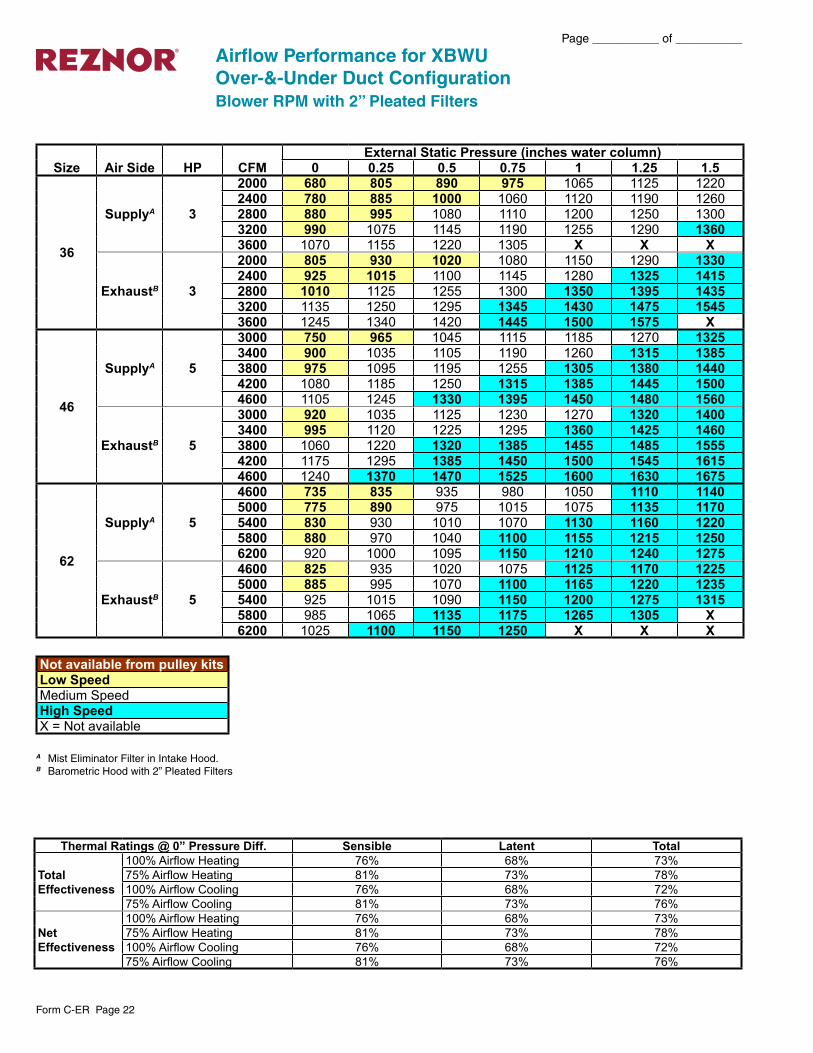
A Mist Eliminator Filter in Intake Hood.B Barometric Hood with 2” Pleated Filters
Airflow Performance for XBWUOver-&-Under Duct ConfigurationBlower RPM with 2” Pleated Filters
Size Air Side HP CFMExternal Static Pressure (inches water column)
0 0.25 0.5 0.75 1 1.25 1.5
36
SupplyA 3
2000 680 805 890 975 1065 1125 12202400 780 885 1000 1060 1120 1190 12602800 880 995 1080 1110 1200 1250 13003200 990 1075 1145 1190 1255 1290 13603600 1070 1155 1220 1305 X X X
ExhaustB 3
2000 805 930 1020 1080 1150 1290 13302400 925 1015 1100 1145 1280 1325 14152800 1010 1125 1255 1300 1350 1395 14353200 1135 1250 1295 1345 1430 1475 15453600 1245 1340 1420 1445 1500 1575 X
46
SupplyA 5
3000 750 965 1045 1115 1185 1270 13253400 900 1035 1105 1190 1260 1315 13853800 975 1095 1195 1255 1305 1380 14404200 1080 1185 1250 1315 1385 1445 15004600 1105 1245 1330 1395 1450 1480 1560
ExhaustB 5
3000 920 1035 1125 1230 1270 1320 14003400 995 1120 1225 1295 1360 1425 14603800 1060 1220 1320 1385 1455 1485 15554200 1175 1295 1385 1450 1500 1545 16154600 1240 1370 1470 1525 1600 1630 1675
62
SupplyA 5
4600 735 835 935 980 1050 1110 11405000 775 890 975 1015 1075 1135 11705400 830 930 1010 1070 1130 1160 12205800 880 970 1040 1100 1155 1215 12506200 920 1000 1095 1150 1210 1240 1275
ExhaustB 5
4600 825 935 1020 1075 1125 1170 12255000 885 995 1070 1100 1165 1220 12355400 925 1015 1090 1150 1200 1275 13155800 985 1065 1135 1175 1265 1305 X6200 1025 1100 1150 1250 X X X
Thermal Ratings @ 0” Pressure Diff. Sensible Latent Total
Total Effectiveness
100% Airflow Heating 76% 68% 73%75% Airflow Heating 81% 73% 78%100% Airflow Cooling 76% 68% 72%75% Airflow Cooling 81% 73% 76%
Net Effectiveness
100% Airflow Heating 76% 68% 73%75% Airflow Heating 81% 73% 78%100% Airflow Cooling 76% 68% 72%75% Airflow Cooling 81% 73% 76%
Not available from pulley kitsLow SpeedMedium SpeedHigh SpeedX = Not available
Form C-ER Page 23
Page __________ of __________
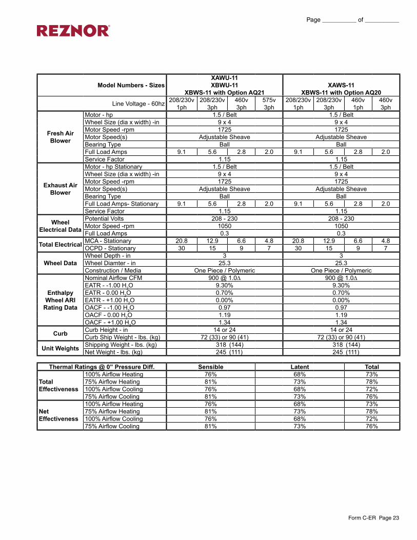
Model Numbers - SizesXAWU-11 XBWU-11
XBWS-11 with Option AQ21XAWS-11
XBWS-11 with Option AQ20
Line Voltage - 60hz 208/230v 1ph
208/230v 3ph
460v 3ph
575v 3ph
208/230v 1ph
208/230v 3ph
460v 1ph
460v 3ph
Fresh Air Blower
Motor - hp 1.5 / Belt 1.5 / Belt Wheel Size (dia x width) -in 9 x 4 9 x 4Motor Speed -rpm 1725 1725Motor Speed(s) Adjustable Sheave Adjustable SheaveBearing Type Ball BallFull Load Amps 9.1 5.6 2.8 2.0 9.1 5.6 2.8 2.0Service Factor 1.15 1.15
Exhaust Air Blower
Motor - hp Stationary 1.5 / Belt 1.5 / BeltWheel Size (dia x width) -in 9 x 4 9 x 4Motor Speed -rpm 1725 1725Motor Speed(s) Adjustable Sheave Adjustable SheaveBearing Type Ball BallFull Load Amps- Stationary 9.1 5.6 2.8 2.0 9.1 5.6 2.8 2.0Service Factor 1.15 1.15
Wheel Electrical Data
Potential Volts 208 - 230 208 - 230Motor Speed -rpm 1050 1050Full Load Amps 0.3 0.3
Total Electrical MCA - Stationary 20.8 12.9 6.6 4.8 20.8 12.9 6.6 4.8OCPD - Stationary 30 15 9 7 30 15 9 7
Wheel Data Wheel Depth - in 3 3Wheel Diamter - in 25.3 25.3Construction / Media One Piece / Polymeric One Piece / Polymeric
Enthalpy Wheel ARI
Rating Data
Nominal Airflow CFM 900 @ 1.0∆ 900 @ 1.0∆EATR - -1.00 H2O 9.30% 9.30%EATR - 0.00 H2O 0.70% 0.70%EATR - +1.00 H2O 0.00% 0.00%OACF - -1.00 H2O 0.97 0.97OACF - 0.00 H2O 1.19 1.19OACF - +1.00 H2O 1.34 1.34
Curb Curb Height - in 14 or 24 14 or 24Curb Ship Weight - lbs. (kg) 72 (33) or 90 (41) 72 (33) or 90 (41)
Unit Weights Shipping Weight - lbs. (kg) 318 (144) 318 (144)Net Weight - lbs. (kg) 245 (111) 245 (111)
Thermal Ratings @ 0” Pressure Diff. Sensible Latent Total
Total Effectiveness
100% Airflow Heating 76% 68% 73%75% Airflow Heating 81% 73% 78%100% Airflow Cooling 76% 68% 72%75% Airflow Cooling 81% 73% 76%
Net Effectiveness
100% Airflow Heating 76% 68% 73%75% Airflow Heating 81% 73% 78%100% Airflow Cooling 76% 68% 72%75% Airflow Cooling 81% 73% 76%

Page __________ of __________
Form C-ER Page 24
Specifications and Electrical Data - 1200 through 2000 CFMModel Numbers - Sizes All Models - Size 20
Line Voltage - 60hz 208/230v 3ph 460v 3ph 575v 3ph
Fresh Air Blower
Motor - hp 1 / Belt Wheel Size (dia x width) -in 9 x 9Motor Speed -rpm 1725Motor Speed(s) Adjustable SheaveBearing Type BallFull Load Amps 6.0 2.6 2.4Service Factor 1.15
Exhaust Air Blower
Motor - hp Stationary 1 / BeltWheel Size (dia x width) -in 9 x 9Motor Speed -rpm 1725Motor Speed(s) Adjustable SheaveBearing Type BallFull Load Amps- Stationary 6.0 2.6 2.4Service Factor 1.15
Wheel Electrical
Data
Potential Volts 208 - 230Motor Speed -rpm 1050Full Load Amps 0.3
Total Electrical
MCA - Stationary 13.8 6.2 5.7OCPD - Stationary 20 9 8
Wheel Data Wheel Depth - in 3Wheel Diamter - in 30.346Construction / Media One Piece / Polymeric
Enthalpy Wheel ARI
Rating Data
Nominal Airflow CFM 1600 @ .95∆EATR - -1.00 H2O 7.80%EATR - 0.00 H2O 0.40%EATR - +1.00 H2O 0.00%OACF - -1.00 H2O 0.97OACF - 0.00 H2O 1.16OACF - +1.00 H2O 1.29
Curb Curb Height - in 14 or 24Curb Ship Weight - lbs. (kg) 82 (37) or 101 (46)
Unit Weights Shipping Weight - lbs. (kg) 425 (193)Net Weight - lbs. (kg) 345 (156)
Thermal Ratings @ 0” Pressure Diff. Sensible Latent Total
Total Effectiveness
100% Airflow Heating 68% 60% 65%75% Airflow Heating 72% 67% 71%100% Airflow Cooling 68% 60% 64%75% Airflow Cooling 72% 67% 70%
Net Effectiveness
100% Airflow Heating 68% 60% 65%75% Airflow Heating 72% 67% 71%100% Airflow Cooling 68% 60% 64%75% Airflow Cooling 72% 67% 70%

Form C-ER Page 25
Page __________ of __________
Specifications and Electrical Data - 1200 through 2800 CFMModel Numbers - Sizes All Models - Size 28
Line Voltage - 60hz 208/230v 3ph 460v 3ph 575v 3ph
Fresh Air Blower
Motor - hp 3 / Belt Wheel Size (dia x width) -in 10 x 10Motor Speed -rpm 1725Motor Speed(s) Adjustable SheaveBearing Type BallFull Load Amps 9.4 4.3 3.2Service Factor 1.15
Exhaust Air Blower
Motor - hp Stationary 3 / Belt Wheel Size (dia x width) -in 10 x 10Motor Speed -rpm 1725Motor Speed(s) Adjustable SheaveBearing Type BallFull Load Amps- Stationary 9.4 4.3 3.2Service Factor 1.15
Wheel Electrical
Data
Motor - hp (1 phase) 0.05Potential Volts 200 / 208 - 230Motor Speed -rpm 825Full Load Amps 0.6
Total Electrical
MCA - Stationary 21.8 10.3 7.8OCPD - Stationary 30 12 10
Wheel Data Wheel Depth - in 3Wheel Diamter - in 37.759Construction / Media Segmented Pies/Polymeric
Enthalpy Wheel ARI
Rating Data
Nominal Airflow CFM 2600 @ .95∆EATR - -1.00 H2O 6.10%EATR - 0.00 H2O 0.40%EATR - +1.00 H2O 0.00%OACF - -1.00 H2O 0.99OACF - 0.00 H2O 1.13OACF - +1.00 H2O 1.23
Curb Curb Height - in 14 or 24Curb Ship Weight - lbs. (kg) 83 (38) or 102 (46)
Unit Weights Shipping Weight - lbs. (kg) 470 (213)Net Weight - lbs. (kg) 395 (179)
Thermal Ratings @ 0” Pressure Diff. Sensible Latent Total
Total Effectiveness
100% Airflow Heating 68% 60% 65%75% Airflow Heating 74% 67% 71%100% Airflow Cooling 68% 60% 63%75% Airflow Cooling 74% 67% 70%
Net Effectiveness
100% Airflow Heating 68% 60% 65%75% Airflow Heating 74% 67% 71%100% Airflow Cooling 68% 60% 63%75% Airflow Cooling 74% 67% 70%
Page __________ of __________
Form C-ER Page 26
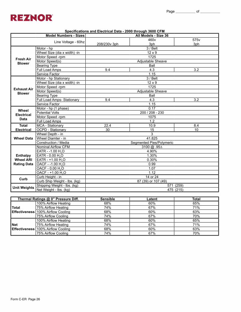
Specifications and Electrical Data - 2000 through 3600 CFMModel Numbers - Sizes All Models - Size 36
Line Voltage - 60hz 208/230v 3ph460v 3ph
575v 3ph
Fresh Air Blower
Motor - hp 3 / Belt Wheel Size (dia x width) -in 12 x 9Motor Speed -rpm 1725Motor Speed(s) Adjustable SheaveBearing Type BallFull Load Amps 9.4 4.3 3.2Service Factor 1.15
Exhaust Air Blower
Motor - hp Stationary 3 / Belt Wheel Size (dia x width) -in 12 x 9Motor Speed -rpm 1725Motor Speed(s) Adjustable SheaveBearing Type BallFull Load Amps- Stationary 9.4 4.3 3.2Service Factor 1.15
Wheel Electrical
Data
Motor - hp (1 phase) 0.17Potential Volts 200 / 208 - 230Motor Speed -rpm 1075Full Load Amps 1.2
Total Electrical
MCA - Stationary 22.4 10.9 8.4OCPD - Stationary 30 15 10
Wheel Data Wheel Depth - in 3Wheel Diamter - in 41.825Construction / Media Segmented Pies/Polymeric
Enthalpy Wheel ARI
Rating Data
Nominal Airflow CFM 3100 @ .95∆EATR - -1.00 H2O 4.90%EATR - 0.00 H2O 1.30%EATR - +1.00 H2O 0.30%OACF - -1.00 H2O 0.99OACF - 0.00 H2O 1.07OACF - +1.00 H2O 1.12
Curb Curb Height - in 14 or 24Curb Ship Weight - lbs. (kg) 87 (39) or 107 (49)
Unit Weights Shipping Weight - lbs. (kg) 571 (259)Net Weight - lbs. (kg) 475 (215)
Thermal Ratings @ 0” Pressure Diff. Sensible Latent Total
Total Effectiveness
100% Airflow Heating 68% 60% 65%75% Airflow Heating 74% 67% 71%100% Airflow Cooling 68% 60% 63%75% Airflow Cooling 74% 67% 70%
Net Effectiveness
100% Airflow Heating 68% 60% 65%75% Airflow Heating 74% 67% 71%100% Airflow Cooling 68% 60% 63%75% Airflow Cooling 74% 67% 70%
Form C-ER Page 27
Page __________ of __________
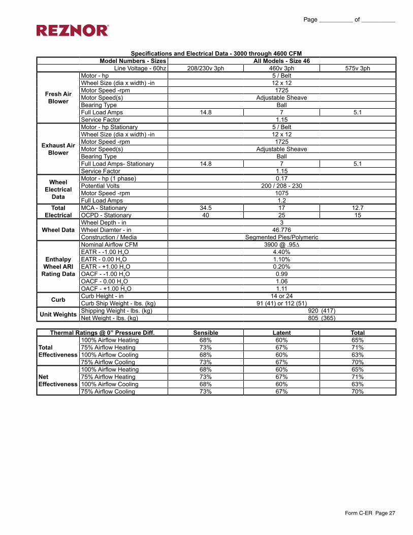
Specifications and Electrical Data - 3000 through 4600 CFMModel Numbers - Sizes All Models - Size 46
Line Voltage - 60hz 208/230v 3ph 460v 3ph 575v 3ph
Fresh Air Blower
Motor - hp 5 / Belt Wheel Size (dia x width) -in 12 x 12Motor Speed -rpm 1725Motor Speed(s) Adjustable SheaveBearing Type BallFull Load Amps 14.8 7 5.1Service Factor 1.15
Exhaust Air Blower
Motor - hp Stationary 5 / Belt Wheel Size (dia x width) -in 12 x 12Motor Speed -rpm 1725Motor Speed(s) Adjustable SheaveBearing Type BallFull Load Amps- Stationary 14.8 7 5.1Service Factor 1.15
Wheel Electrical
Data
Motor - hp (1 phase) 0.17Potential Volts 200 / 208 - 230Motor Speed -rpm 1075Full Load Amps 1.2
Total Electrical
MCA - Stationary 34.5 17 12.7OCPD - Stationary 40 25 15
Wheel Data Wheel Depth - in 3Wheel Diamter - in 46.776Construction / Media Segmented Pies/Polymeric
Enthalpy Wheel ARI
Rating Data
Nominal Airflow CFM 3900 @ .95∆EATR - -1.00 H2O 4.40%EATR - 0.00 H2O 1.10%EATR - +1.00 H2O 0.20%OACF - -1.00 H2O 0.99OACF - 0.00 H2O 1.06OACF - +1.00 H2O 1.11
Curb Curb Height - in 14 or 24Curb Ship Weight - lbs. (kg) 91 (41) or 112 (51)
Unit Weights Shipping Weight - lbs. (kg) 920 (417)Net Weight - lbs. (kg) 805 (365)
Thermal Ratings @ 0” Pressure Diff. Sensible Latent Total
Total Effectiveness
100% Airflow Heating 68% 60% 65%75% Airflow Heating 73% 67% 71%100% Airflow Cooling 68% 60% 63%75% Airflow Cooling 73% 67% 70%
Net Effectiveness
100% Airflow Heating 68% 60% 65%75% Airflow Heating 73% 67% 71%100% Airflow Cooling 68% 60% 63%75% Airflow Cooling 73% 67% 70%
Page __________ of __________
Form C-ER Page 28
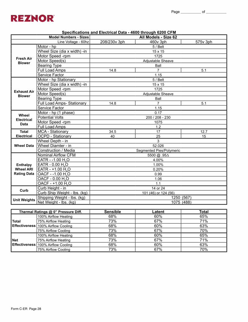
Specifications and Electrical Data - 4600 through 6200 CFMModel Numbers - Sizes All Models - Size 62
Line Voltage - 60hz 208/230v 3ph 460v 3ph 575v 3ph
Fresh Air Blower
Motor - hp 5 / Belt Wheel Size (dia x width) -in 15 x 15Motor Speed -rpm 1725Motor Speed(s) Adjustable SheaveBearing Type BallFull Load Amps 14.8 7 5.1Service Factor 1.15
Exhaust Air Blower
Motor - hp Stationary 5 / Belt Wheel Size (dia x width) -in 15 x 15Motor Speed -rpm 1725Motor Speed(s) Adjustable SheaveBearing Type BallFull Load Amps- Stationary 14.8 7 5.1Service Factor 1.15
Wheel Electrical
Data
Motor - hp (1 phase) 0.17Potential Volts 200 / 208 - 230Motor Speed -rpm 1075Full Load Amps 1.2
Total Electrical
MCA - Stationary 34.5 17 12.7OCPD - Stationary 40 25 15
Wheel Data Wheel Depth - in 3Wheel Diamter - in 52.026Construction / Media Segmented Pies/Polymeric
Enthalpy Wheel ARI
Rating Data
Nominal Airflow CFM 5500 @ .95∆EATR - -1.00 H2O 4.00%EATR - 0.00 H2O 1.00%EATR - +1.00 H2O 0.20%OACF - -1.00 H2O 0.99OACF - 0.00 H2O 1.06OACF - +1.00 H2O 1.1
Curb Curb Height - in 14 or 24Curb Ship Weight - lbs. (kg) 101 (46) or 124 (56)
Unit Weights Shipping Weight - lbs. (kg) 1250 (567)Net Weight - lbs. (kg) 1075 (488)
Thermal Ratings @ 0” Pressure Diff. Sensible Latent Total
Total Effectiveness
100% Airflow Heating 68% 60% 65%75% Airflow Heating 73% 67% 71%100% Airflow Cooling 68% 60% 63%75% Airflow Cooling 73% 67% 70%
Net Effectiveness
100% Airflow Heating 68% 60% 65%75% Airflow Heating 73% 67% 71%100% Airflow Cooling 68% 60% 63%75% Airflow Cooling 73% 67% 70%

Form C-ER Page 29
Page __________ of __________
Limited WarrantyReznor warrants to the original owner-user that this Reznor product will be free from defects in material or workmanship. This warranty is limited to twelve (12) months from the date of original installation, whether or not actual use begins on that date, or eighteen (18) months from date of shipment by Reznor, whichever occurs first.
Limitations and ExclusionsReznor, LLC obligations under this warranty and the sole remedy for its breach are limited to repair, at its manufacturing facility, of any part or parts of its Reznor products which prove to be defective; or, in its sole discretion, replacement of such products. All returns of defective parts or products must include the product model number and serial number, and must be made through an authorized Reznor distributor or arranged through Reznor Customer Service. Authorized returns must be shipped prepaid. Repaired or replacement parts will be shipped by Reznor, LLC F.O.B. shipping point.1. The warranty provided herein does not cover charges for labor or other costs incurred in the troubleshooting, repair, removal, installation, service
or handling of parts or complete products.2. All claims under the warranty provided herein must be made within ninety (90) days from the date of discovery of the defect. Failure to notify
Reznor, LLC of a warranted defect within ninety (90) days of its discovery voids Reznor, LLC obligations hereunder.3. The warranty provided herein shall be void and of no effect in the event that (a) the product has been operated outside its designed output capac-
ity (heating, cooling, airflow); (b) the product has been subjected to misuse, neglect, accident, improper or inadequate maintenance, corrosive environments, environments containing airborne contaminants (silicone, aluminum oxide, etc.), or excessive thermal shock; (c) unauthorized modifications are made to the product; (d) the product is not installed or operated in compliance with the manufacturer’s printed instructions; (e) the product is not installed and operated in compliance with applicable building, mechanical, plumbing and electrical codes; or (f) the serial number of the product has been altered, defaced or removed.
4. The warranty provided herein is for repair or replacement only. Reznor, LLC shall not be liable for any loss, cost, damage, or expense of any kind arising out of a breach of the warranty. Further, Reznor, LLC shall not be liable for any incidental, consequential, exemplary, special, or punitive damages, nor for any loss of revenue, profit or use, arising out of a breach of this warranty or in connection with the sale, maintenance, use, operation or repair of any Reznor product. In no event will Reznor, LLC be liable for any amount greater than the purchase price of a defective product. The disclaimers of liability included in this paragraph 4 shall remain in effect and shall continue to be enforceable in the event that any remedy herein shall fail of its essential purpose.
5. THIS WARRANTY IS THE SOLE AND EXCLUSIVE WARRANTY FOR REZNOR PRODUCTS, AND IS IN LIEU OF ALL OTHER EXPRESS AND IMPLIED WARRANTIES. REZNOR, LLC SPECIFICALLY DISCLAIMS ALL OTHER EXPRESS AND IMPLIED WARRANTIES, INCLUDING, BUT NOT LIMITED TO, ALL IMPLIED WARRANTIES OF MERCHANTABILITY AND FITNESS FOR A PARTICULAR PURPOSE. No person or entity is authorized to bind Reznor, LLC to any other warranty, obligation or liability for any Reznor product. Installation, operation or use of the Reznor product for which this warranty is issued shall constitute acceptance of the terms hereof.
Prepared for the guidance of architects, consulting engineers, and mechanical contractors.General – Furnish and install Reznor Energy Recovery Unit Model (XAWU, XAWS, XBWS, XBWU).Approvals – The unit will contain an energy recovery component rated in accordance with ARI Standard 1060-2000 with ratings certified by ARI.Cabinet – Cabinet shall be G90 galvanized material. Cabinet panels where conditioned air is handled shall be fully insulated to prevent sweating and minimize sound. Openings shall be provided for power connections. Lifting devices will be provided for rigging. Test ports shall be provided so airflow can be measured across the energy recovery wheel.Intake Air Blower – Unit shall contain a centrifugal blower. It shall have ball bearings and adjustable belt drive. Motor mount base shall permit ease of motor changeover and belt tension adjustment.Exhaust Air Blower – Unit shall contain a centrifugal blower. It shall have ball bearings and adjustable belt drive. Motor mount base shall permit ease of motor changeover and belt tension adjustment. Energy Recovery Wheel – The energy recovery device shall be a rotary heat exchanger per ARI Standard 1060 description. The device will be an enthalpy wheel coated with a silica gel desiccant by a process without the use of binders or adhesives which may plug the desiccant aperture. The substrate shall be a lightweight polymer. Desiccant shall not dissolve or deliquesce in the presence of water or high humidity. The wheel shall be easily cleanable with standard coil cleaning solution. The wheel will be easily removable from the cabinet for cleaning. The wheel will be provided with removable segments for cleaning and maintenance. All diameter and perimeter seals shall be provided. The energy recovery cassette shall be Underwriters Laboratories Recognized Component for electrical and fire safety.
Barometric Relief Dampers – Barometric relief dampers will be provided in the exhaust air to prevent air infiltration when the unit is de-energized.Support – Rooftop units will be supported by the roof curb.. Horizontal units will be provided with support brackets for hanging.Filters – All units shall be provided with mist eliminator type filters in the intake air hood and 2” pleated filters before the wheel on the exhaust side of rooftop models. Indoor units shall have 2” pleated filters on both the supply and exhaust before the wheel.Power Connection – The unit shall be provided with a single point power connection for high voltage.Options:Optional Roof Mounting Frame – Furnish and install the optional roof mounting frame to maintain proper height above the roof.Optional Low Ambient Kit – Furnish and install the optional low ambient kit to prevent frost formation on the energy recovery wheel.Optional Motorized Intake Air Damper – Furnish and install the optional motorized intake air damper.Optional Stop-Start-Jog – Furnish and install the optional stop-start-jog controls.
Sample Specifications

Reznor® is your global source for heating, ventilating and air conditioning equipment.
For more information on Reznor HVAC Equipment,contact your local Reznor Representative by calling
800-695-1901.Or, find us on the internet at
www.ReznorHVAC.com
Reznor® is registered in at least the United States.© 2014 Reznor, LLC.All rights reserved. Printed in U.S.A.0614 POD OG Form No. C-ER (Version C.5)
Form C-ER Page 33
Page __________ of __________
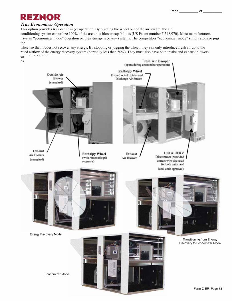
True Economizer OperationThis option provides true economizer operation. By pivoting the wheel out of the air stream, the airconditioning system can utilize 100% of the a/c units blower capabilities (US Patent number 5,548,970). Most manufacturershave an “economizer mode” operation on their energy recovery systems. The competitors “economizer mode” simply stops or jogs thewheel so that it does not recover any energy. By stopping or jogging the wheel, they can only introduce fresh air up to therated airflow of the energy recovery system (normally less than 50%). They must also have both intake and exhaust blowers energized. Not allpackaged units can have the pivoting wheel design due to a/c unit arrangement.
Energy Recovery Mode
Economizer Mode
Transitioning from Energy Recovery to Economizer Mode