Embed Size (px)
Citation preview

Form 413, Mfg No. 145085, Page 1
APPLIES TO: Installation/Operation/Service
INSTALLATION FORM RGM 413 (Version C)Obsoletes Form RGM 413-B
Model Series PGBL, RGBL, CRGBL, RPBL
Packaged Blower/Furnace Systems
Installation REFERENCES: Optional Roof Curbs - Installation Form RGM 400C(in addition to component Optional Outside Air Hood - Installation Form RGM 400WH or 400Hmanufacturer's information Optional Evaporative Cooling Module - Installation Form RGM 400ECin the Owner's Envelope) Optional Cooling Coil Cabinet (Option AU2, AU3, AU11, AU12, AU13, or AU14)
1) If mounting a cooling coil cabinet indoors or outdoors, follow instructions in this booklet.2) If suspending a cooling coil cabinet indoors (requires special curb cap), consult the factory.
Service REFERENCE: Replacement Parts Form RGM 707
Index (by page number)Adjusting Blower Speed ............................ 20Optional Air Flow Proving Switch ........... 20Belts ........................................................... 20Blower Motors ........................................... 20Blower Rotation ........................................ 20Burner Air Adjustment ............................. 27Burner Rack Removal ............................... 35Burners ...................................................... 27Carryover System ...................................... 27Check Installation and Start-Up ................ 27Chlorine ....................................................... 7Cleaning Pilot and Main Burners ............. 35Cleaning the Heat Exchanger .................... 35Clearances ................................................... 6Combustion Air Requirements ................... 6Control Locations ....................................... 19Optional Cooling Coil Cabinet .................. 32Optional Dampers and Controls ................ 34Dimensions .................................................. 2Disconnect Switch ..................................... 17
Duct Connections ...................................... 15Optional Ductstat ....................................... 23Electrical Supply and Connections ........... 18Optional Electronic Modulation ............... 24Optional Evaporative Cooling Module .... 30Fan Control ................................................ 22Optional Dirty Filter Switch ..................... 21Filter Arrangements ................................... 37Filters ......................................................... 21Gas Piping and Pressures .......................... 16GENERAL .................................................. 1HAZARD INTENSITY LEVELS ............... 2Optional High Ambient Limit Control ..... 22Ignition Controller ..................................... 26Installation Codes ........................................ 2Limit Control (High Temperature) ............ 22Location of Standard and Optional
Controls ................................................ 19MAINTENANCE ...................................... 35Optional Mechanical Modulation ............. 24
Mounting Furnaces (Indoor) ........................ 7Mounting Outdoor Models .......................... 8Optional Equipment ................................... 29100% Outside Air Hood ............................ 29Pilot and Ignition Systems ........................ 26Reverse Flow, Limit Control ..................... 22Roof Curb Assembly and Installation ....... 10Screened Air Hood for 30% Outside Air
Opening ............................................... 29SERVICE ................................................... 35Optional 4-foot Stack Extension ............... 14Start-Up ..................................................... 27Suspending Furnaces .................................. 7Troubleshooting ......................................... 38Optional Two-Stage Operation ................. 22Uncrating ..................................................... 6Valve ........................................................... 22Venting ....................................................... 10Optional Vertical Flue Discharge .............. 14Warranty ....................................................... 2
Model CharacteristicsSeries
Designation Installation VentThermal
Efficiency
PGBL Indoor Power 80%RGBL Gravity 78%
CRGBL Outdoor 80%RPBL Power 80%
FOR YOUR SAFETYIf you smell gas:1. Open windows.2. Don't touch electrical switches.3. Extinguish any open flame.4. Immediately call your gas supplier.
FOR YOUR SAFETYThe use and storage of gasoline or otherflammable vapors and liquids in open containersin the vicinity of this appliance is hazardous.
WARNING: Gas-fired appliances are notdesigned for use in hazardous atmospherescontaining flammable vapors or combustibledust, in atmospheres containing chlorinated orhalogenated hydrocarbons, or in applicationswith airborne silicone substances. See HazardLevels, Page 2.
WARNING: Improper installation, adjustment,alteration, service, or maintenance can causeproperty damage, injury or death. Read theinstallation, operation, and maintenanceinstructions thoroughly before installing orservicing this equipment.
GENERALInstallation should be done by a qualified agency in accordancewith the instructions in this manual and in compliance with all codesand requirements of authorities having jurisdiction. The instruc-tions in this manual apply to the packaged systems listed below.
Table of Contents Paragraph No. Page No.Installation and Operation .................................... 1-27 ........................... 1-27Check Installation and Start-Up ............................ 28 ........................... 27-28Optional Equipment. ............................................ 29-33 ......................... 29-35Service/Maintenance/Troubleshooting ................ 34-39 ......................... 35-40
�����������������

Form 413, Mfg No. 145085, Page 2
HAZARD INTENSITY LEVELS
1. DANGER: Failure to comply will result in severe personal injury or death and/or property damage.
2. WARNING: Failure to comply could result in severe personal injury or death and/or property damage.
3. CAUTION: Failure to comply could result in minor personal injury and/or property damage.
1. Approval and InstallationCodes
The models covered in this manual are design certified or approvedduct furnaces that are factory assembled with air handing components,creating a unified packaged furnace/blower system. The packaged sys-tems are design-certified to ANSI and C.G.A. Standards by the Cana-dian Standards Association for installation in the United States andCanada. The furnaces are approved for use with either natural or pro-pane gas. The type of gas for which the furnace is equipped and thecorrect firing rate are shown on the rating plate attached to the unit.Electrical characteristics are shown on both the motor nameplate andthe unit rating plate.
These units must be installed in accordance with local building codes.In the absence of local codes, in the United States, the unit must beinstalled in accordance with the National Fuel Gas Code (latest edi-tion). A Canadian installation must be in accordance with the CAN/CGA B149.1 and B149.2 Installation Code for Gas Burning Appli-ances and Equipment. These codes are available from CSA Informa-tion Services, 1-800-463-6727. Local authorities having jurisdictionshould be consulted before installation is made to verify local codesand installation procedure requirements.
Clearances from the heater and vent to construction or material in stor-age must conform with the National Fuel Gas Code ANSI Z223.1a(latest edition) pertaining to gas-burning devices, and such materialmust not attain a temperature over 160°F by continued use of the heater.
Special Installations (Aircraft Hangars/Garages)Installations in aircraft hangars should be in accordance with ANSI/NFPA No. 409 (latest edition), Standard for Aircraft Hangars; in pub-lic garages in accordance with ANSI/NFPA No. 88A (latest edition),Standard for Parking Structures; and for repair garages in accordancewith ANSI/NFPA No. 88B (latest edition), Standard for Repair Ga-rages. ANSI/NFPA-88 (latest edition) specifies overhead heaters mustbe installed at least eight feet above the floor. In Canada, installationsin aircraft hangars should be in accordance with the requirements ofthe enforcing authorities, and in public garages in accordance with CAN/CGA B149 codes.
WARNING: To ensure safety, follow the lightinginstructions located on the outlet box cover platein the heater section of the packagedfurnace assembly.
WARRANTY: Warranty is void if......a. Packaged furnaces are used in atmospheres containing flam-
mable vapors or atmospheres containing chlorinated or ha-logenated hydrocarbons or any contaminant (silicone, alu-
minium oxide, etc.) that adheres to the spark ignition flamesensing probe.
b. Wiring is not in accordance with the diagram furnished withthe heater.
c. Unit is installed without proper clearances to combustiblematerials or without proper ventilation and air for combus-
tion. (See Paragraphs 5 and 6.)d. Furnace air throughput is not adjusted within the range
specified on the rating plate.
3. Package Arrangements andDimensions
Key:Blower Cabinet
Furnace Section(s)
Figure 1A - Package Arrangements by Model and Size
Model/SizePGBL 400RGBL 400CRGBL 400RPBL 400
Downturn Note: To provide complete information, the drawingsand dimensions illustrate both the indoor and outdoor system withand without an optional downturn plenum cabinet. Indoor installa-tions requiring vertical discharge will most often have a field-fabri-cated downturn nozzle instead of the factory-installed plenum cabi-net.
Model/SizesPGBL 800RGBL 500, 600, 700, 800CRGBL 500, 600, 700, 800RPBL 500, 600, 700, 800
Model/SizesPGBL 1200RGBL 1050, 1200CRGBL 1050, 1200RPBL 1050, 1200
2. WarrantyRefer to limited warranty information on the warranty card in the"Owner's Envelope".

Form 413, Mfg No. 145085, Page 3
Figure 1B - Dimensions (inches), Indoor Model PGBL
Gas Connection
Air Openings: DimensionsStandard Horizontal Air Inlet
19-1/2 x B
Optional Return Air Opening (bottom)
19-1/2 x B
Standard Horizontal Discharge Air Opening
18 x E
Optional Discharge Air Opening (with Downturn Plenum)
19-1/2 x B
PGBL 400, 800, 1200
A 58-7/8
B 47-5/8C 56-1/8E 45-1/2
Dimension Key:A Width of Cabinet
B Width of Optional Downturn Plenum Discharge Air
Opening, Width of Standard Horizontal Air Inlet
Opening, Width of Optional Return Air (Bottom ) Opening
C Width of the Curb Cap
E Width of Standard Horizontal Discharge Air Opening
F Overall Length of Inside of Curb Cap
G Distance between Optional Return Air Bottom Opening and Optional Downturn Plenum Discharge Air Opening
N Length of Flue Collection Box
P Distance from Control Side to Vent Connection Centerline
R Distance from the Discharge End of the Cabinet Top to Vent Connection Centerline
(Only one gas connection; seethe Table at the bottom of the
page)
Suspension Dimensions H, J, K, L, M
Approximate Size Drawing Approximate Distance from the End of the Curb Cap on the BlowerGas Location End of the System
Connection 400 1 7 ft + 5 to 6 inches NOTE: The gas line is manifolded requiring onlyLocations 800 2 8 ft + 7 to 8 inches one supply connection. The gas connection is at
1200 3 9 ft + 2 to 3 inches curb cap “height” on the control side of the system.
Optional Suspension Dimensions No. of Vent Dimensions
Size Downturn F G H J K L M Hangers N P R S T
400 No 83-1/2 - 54-3/8 59-1/2 27-1/8 - - 6 14-1/16 17-15/16 7-15/16 8-7/8 8-3/4
Yes 107-1/2 60-5/16 54-3/8 59-1/2 51-1/4 - - 6 14-1/16 17-15/16 31-15/16 8-7/8 8-3/4
800 No 109-1/2 - 54-3/8 59-1/2 53-1/4 - - 6 40-1/16 18-1/2 41-5/16 13-3/4 12-1/4Yes 133-1/2 86-5/16 54-3/8 59-1/2 - 50-1/4 27 8 40-1/16 18-1/2 65-5/16 13-3/4 12-1/4
1200 No 135-1/2 - 54-3/8 59-1/2 79-1/4 - - 6 66-1/16 18-1/2 67-5/16 13-3/4 12-1/4
Yes 159-1/2 112-5/16 54-3/8 59-1/2 - 76-1/4 27-1/8 8 66-1/16 18-1/2 91-5/16 13-3/4 12-1/4
Top ViewofFurnaceSections
Top LeftSide View
Flue Collection Box
Vent Outlet Diameter - Size400, 6"; 800, 8"; 1200, 8"

Form 413, Mfg No. 145085, Page 4
Figure 1C - Dimensions, Outdoor Models
Gas ConnectionLocation (see Note)
GAS CONNECTION NOTE: Gas line is manifoldedrequiring only one supply connection. See Table atthe bottom of the page for approximate connection lo-cation as measured from the blower end of the system.
Dimension Key:A Width of Cabinet F Overall Length of Inside of Curb Cap
B Width of Optional Downturn Plenum Discharge Air Opening, Width of Standard Horizontal Air Inlet Opening,
G Distance between Optional Return Air Bottom Opening and Optional Downturn Plenum Discharge Air Opening
Width of Optional Return Air (Bottom ) Opening H Inside diameter of the vent cap collar
C Width of the Curb Cap J Approximate height between top of unit and bottom of vent cap
E Width of Standard Horizontal Discharge Air Opening K Approximate height of the vent cap
Models SizeOptional
DownturnF G
400 No 83-1/2All Yes 107-1/2 60-5/16Outdoor 500, 600, No 109-1/2
700, 800 Yes 133-1/2 86-5/161050, No 135-1/21200 Yes 159-1/2 112-5-16
Model Size A B C E Vent CapH J K
RGBL 500 47-1/8 36-5/8 45-1/8 34-1/2 10 3 11-13/16600 47-1/8 36-5/8 45-1/8 34-1/2 12 12 14-1/8
700, 1050 53-3/8 42-1/8 50-5/8 40 12 12 14-1/8400, 800, 1200 58-7/8 47-5/8 56-1/8 45-1/2 12 12 14-1/8
CRGBL 500, 600 47-1/8 36-5/8 45-1/8 34-1/2 10 3 11-13/16700, 1050 53-3/8 42-1/8 50-5/8 40 12 12 14-1/8
400, 800, 1200 58-7/8 47-5/8 56-1/8 45-1/2 12 12 14-1/8RPBL 500, 600 47-1/8 36-5/8 45-1/8 34-1/2
700, 1050 53-3/8 42-1/8 50-5/8 40 None400, 800, 1200 58-7/8 47-5/8 56-1/8 45-1/2
Air Openings: DimensionsStandard Horizontal Air Inlet 19-1/2 x BOptional Return Air Opening (bottom) 19-1/2 x BStandard Horizontal Discharge Air Opening 18 x EOptional Discharge Air Opening (with Downturn Plenum) 19-1/2 x B
Approximate Size Drawing Approximate Distance from the End of the Curb Cap on the BlowerGas Location End of the System
Connection 400 1 7 ft + 5 to 6 inches NOTE: The gas line is manifolded requiring onlyLocations 500, 600, 700, 800 2 8 ft + 7 to 8 inches one supply connection. The gas connection is at
1050, 1200 3 9 ft + 2 to 3 inches curb cap “height” on the control side of the system.
3. Package Arrangements and Dimensions (cont'd)

Form 413, Mfg No. 145085, Page 5
Refrigerant R22 (DX) Coil Cabinet - Options AU3, AU13, AU14
Discharge Damper Note: The two-position discharge dampers in OptionAU12 and AU14 fit in the discharge air opening. The damper motor fitsinside the downturn plenum cabinet.
Dimensions (inches ± 1/8)
Chilled Water Cooling Coil Cabinet in Options AU 2, AU11, AU12
Downturn Plenum Cabinet attached to either type ofCooling Coil Cabinet Furnace Size 500, 600
700, 1050
400, 800, 1200
A 47-3/4 53-1/4 58-3/4B 34-1/2 40 45-1/2C 45-1/8 50-5/8 56-1/8D 56-3/8 62 67-3/8
Without Downturn 59-3/8 64-7/8 70-3/8With Downturn 83-3/8 88-7/8 94-3/8
Without Downturn 57-3/8 63 68-3/8With Downturn 81-3/8 87 92-3/8
G 29-1/8 31-7/8 34-5/8J 45-1/8 50-5/8 56-1/8
E
F
Figure 1D - Optional Cooling Coil Cabinets with and without Downturn Plenum Cabinet - Option AU
NOTE: For total length of an outdoor system with a cooling coil cabi-net, add length dimension to length of standard outdoor blower/furnaceon page 4. Cooling coil cabinet is shipped separately and attached in thefield. See page 9 for roof curb dimensions.Total length of an indoor system with a cooling coil cabinet depends onhow the system is installed. If the blower/furnace is suspended, a specialcurb cap and a field-installed transition duct are required. Contact yourSales Representative to receive specific information. If an indoor sys-tem is mounted, add the cabinet length to the blower/furnace length onpage 3.

Form 413, Mfg No. 145085, Page 6
4. Uncrating and PreparationThis furnace was test operated and inspected at the factory prior to crat-ing and was in operating condition. If the equipment has incurred anydamage in shipment, file a claim with the transporting agency.Check the rating plate for the gas specifications and electrical character-istics of the furnace to be sure that they are compatible with the gas andelectric supplies at the installation site. Read this booklet and becomefamiliar with the installation requirements of your particular model. Ifyou do not have knowledge of local requirements, check with the localgas company or any other local agencies who might have requirementsconcerning this installation.Before beginning, make preparations for necessary supplies, tools, andmanpower.Check to see if there are any field-installed options that need to be as-sembled to the furnace prior to installation.Option Parts -- Some gas control options will have parts either shippedloose with the heater or shipped separately. If your unit is equipped withany of the following gas control options, be sure these parts are availableat the job site.
Other shipped-separate options could include a gas shutoff valve, a ther-mostat, a different control switch, an evaporative cooling module, anevaporative cooling module drain and fill kit, a control console, a verti-cal vent terminal, a gas supply regulator, a screened outside air hood, aroof curb, a cooling coil cabinet, or a disconnect switch.
5. ClearancesProvide clearance to combustibles as shown in the table. Clearance isalso required to sides of the furnace for combustion air space and forconvenient installation and burner control system service.
6.Combustion Air Requirements6A. Indoor ModelsThe duct furnaces in this packaged system are designed to take com-bustion air from the space in which the furnace is installed. Combus-tion air enters through the screened air intakes located in each fur-nace section access door. The air that enters into the combustion pro-cess is then vented to the outdoors. Sufficient air must enter the equip-ment location to replace the air exhausted through the vent system.Modern construction methods involve the greater use of insulation,improved vapor barriers and weather-stripping, with the result thatbuildings generally are much tighter structurally than they have beenin the past. The combustion air supply for gas-fired equipment can beaffected by these construction conditions because infiltration thatwould have existed in the past may not be adequate. Extensive use ofexhaust fans aggravates the situation. In the past the filtration of out-side air assumed in heat loss calculations (one air change per hour)was assumed to be sufficient. However, current construction meth-ods may now require the introduction of outside air through wall open-ings or ducts.Requirements for combustion air and ventilation air depend uponwhether the unit is located in a confined or unconfined space. An"unconfined space" is defined as a space whose volume is not lessthan 50 cubic feet per 1000 BTUH of the installed appliance. Underall conditions, enough air must be provided to ensure there will notbe a negative pressure condition within the equipment room or space.A positive seal must be made in all return-air connections and ducts.Even a slight leak can create a negative pressure condition in a con-fined space and affect combustion.
WARNING: These indoor furnaces are designedto take combustion air from the space in whichthe furnace is installed and are not designed forconnection to outside combustion air intakeducts. Use of outside air ducts voids thewarranty and could cause hazardous operation.See Hazard Levels, page 2.
Indoor Furnace Located in a Confined SpaceDo not install a unit in a confined space without providing wall open-ings leading to and from the space. Provide openings near the floorand ceiling for ventilation and air for combustion as shown in Figure2, depending on the combustion air source as noted in Items 1, 2 and3.
Add total BTUH of all appliances in the confined space and divide byfigures below for square inch free area size of each (top and bottom)opening.
1. Air from inside the building -- openings 1 square inch free areaper 1000 BTUH. Never less than 100 square inches free area for eachopening. See (1) in Figure 2.
2. Air from outside through duct -- openings 1 square inch free areaper 2000 BTUH. See (2) in Figure 2.
3. Air direct from outside -- openings 1 square inch free area per4000 BTUH. See (3) in Figure 2.
NOTE: For further details on supplying combustion air to confinedspace, see National Fuel Gas Code ANSI Z223.1a (latest edition)5.3.3.
Figure 2 -Confined Space: Aspace whosevolume is less than50 cubic feet per1000 BTUH of theinstalled applianceinput rating
REQUIRED CLEARANCESIndoor Side Opposite Controls, Top, Flue Connection - 6";Models Control Side - 56"; Furnace Bottom - 6"Outdoor Control Side - 56"; *Furnace Bottom - 0"Models Top to Overhangs - 6"* When installed on a roof curb on a combustible roof, the roof area enclosed within the curb must be either ventilated, left open, or covered with non-com-bustible material which has an "R" value of at least 5.0. See Figure 8, page 9.
Opt AG Shipped-Separate Components7 Thermostat, P/N 48033
10 Thermostat, P/N 9191911 Thermostat, P/N 93435
3, 6, 8, 13 Control Switch, P/N 29054 Remote Temperature Selector, P/N 48042 Control Switch, P/N 29054 Remote Temperature Selector, P/N 115848 Stage Adder Module, P/N 115849 (one furnace - 1; two furnaces - 3; three furnaces - 5) Control Switch, P/N 29054 Remote Temperature Selector, P/N 115848 Stage Adder Module, P/N 115849 (one furnace - 1; two furnaces - 3; three furnaces - 5) Remote Display Module, P/N 115852 Control Switch, P/N 29054 Remote Temperature Selector, P/N 115848 Stage Adder Module, P/N 115849 (two furnaces - 1; three furnaces - 2) Control Switch, P/N 29054 Remote Temperature Selector, P/N 115848 Stage Adder Module, P/N 115849 (two furnaces - 1; three furnaces - 2) Remote Display Module, P/N 115852 Control Switch, P/N 29054
39 Remote Temperature Selector, P/N 174849
18, 20
(If an optional remote console is ordered, the control witch is mounted on the console.)
Makeup Air -- Gas Control Options
9
15
16
17, 19
Heating -- Gas Control Options

Form 413, Mfg No. 145085, Page 7
6B. Combustion Air for Gravity-Vented,Outdoor Models
Combustion air enters through the screened air intakes located in thefurnace section access doors.
6C. Combustion Air for Power-Vented,Outdoor Models
The combustion air and fluegas openings are carefully de-signed screened openings lo-cated on the side of the unitjust above the control accesspanel. Location of the flueopening directly above the airintake is designed to discour-age recirculation of combus-tion products. See Figure 3.
6D. Chlorine -- AllModelsThe presence of chlorine vapors in the combustion air of gas-fired heat-ing equipment presents a potential corrosion hazard. Chlorine will,when exposed to flame, precipitate from the compound, usually freonor degreaser vapors, and go into solution with any condensation that ispresent in the heat exchanger or associated parts. The result is hydro-chloric acid which readily attacks all metals including 300 grade stain-less steel.Care should be taken to separate these vapors from the combustionprocess. This may be done by wise location of the furnace with regardto exhausters or prevailing wind direction. Remember, chlorine isheavier than air. This fact should be kept in mind when determininginstallation locations of heating equipment and building exhaust sys-tems.
7. Suspending/Mounting7A. Suspending/Mounting Indoor ModelsBefore installing the furnace/blower package, check thesupporting structure to verifythat it has sufficient load-car-rying capacity to support theweight of the unit. These weights are for blower/furnace section(s) only;if included, add the weight of an optional cooling coil cabinet or evapo-rative cooling module.
INSTALLATION NOTES: If installing as a makeup air system withan evaporative cooling module, the module is shipped separatelyand must be mounted (blower/furnace section may be either mountedor suspended). Follow the installation instructions included with themodule; a field-supplied transition duct may be required. An evapo-rative cooling module ranges in weight from 375-520 lbs.Or, if the system includes a cooling coil cabinet, the cabinet is shippedseparately for field attachment. A cooling coil cabinet with a coil canweigh as much as 1020 lbs. If the system is mounted, provide suffi-cient support and attach according to the instructions in Paragraph32. If the system is to be suspended, the cooling coil cabinet must beordered with a special curb cap. Contact your Sales Representative orthe factory for information about suspending a cooling coil cabinet.Installation may require a field-supplied transition duct.
WARNING: Unit must be level for proper operation.Do not place or add additional weight to thesuspended unit. See Hazard Levels, page 2.
Suspending Furnaces (Refer to Figure 4)This system is equipped with a load-bearing curb cap which forms anintegral part of the unit. The curb cap is welded at all joints and has
Figure 3 - Combustion AirIntakes, Outdoor Power-
Vented Models
Do not enclose the area underneath the furnace; leavespace for ventilation.
Figure 5B - Cross-Support Locations for Indoor Systemswhen the wooden 4x4 rails supporting the length of thesystem are supported by additional structure
Figure 5A - Mounting Support Dimensions
Figure 4 -Support RodDetail
Required at allSuspension Points
suspension holes at each corner and hanger brackets on the sides. SeeFigure 1B, page 3, for the number of suspension points and suspensiondimensions.Each suspension location requires a 1/2" threaded rod as illustrated inFigure 4.
Mounting FurnacesPrior to installation, be sure that the method of support is in agreementwith all local building codes. NOTE: The curb cap is not designed tobe placed directly on a flat surface.Whether the field-supplied rails are being mounted directly on a sur-face or being placed "up" on additional structure, the horizontal lengthof the system should be supported by two 4x4 treated wooden rails.Cut the rails to the appropriate length (Dimension "A") in Figure 5A.
Space the 4x4 wooden rails (See "B" Dimension, Figure 5A) so thatthe curb cap "skirt" will fit over the edge of the boards with the railssetting inside the horizontal length of the curb cap.
If the rails are being laid directly on a surface, position them as shownin Figure 5A. Set the system on the rails, leaving the "ends" under-neath open for ventilation.
Stan
dard
Hea
ter(
s) a
nd
Blo
wer
Pac
kage
Wit
h O
ptio
n A
Q5
or A
Q8
Dow
ntur
n P
lenu
m C
abin
et
Wit
h O
ptio
n A
U
Coo
ling
Coi
l C
abin
et
Wit
h O
ptio
n A
U
Coo
ling
Coi
l C
abin
et a
nd
Dow
ntur
n
Ple
num
All
Con
figu
rati
ons
"A" "A" "A" "A" "B"400 82-1/4" 106-1/4" 139-5/8" 163-5/8" 54-1/2"
800 108-1/4" 132-1/4" 171-1/4" 195-1/4" 54-1/2"1200 134-1/4" 158-1/4" 202-5/8" 226-5/8" 54-1/2"
Siz
e
Approximate Net Weight (lbs) -Indoor Packaged Systems
Size 400 800 1200
Weight 849 1245 1565

Form 413, Mfg No. 145085, Page 8
Whether the supports are being mounted directly on the roof or beingplaced "up" on additional structure, the horizontal length of the systemshould be supported by two 4x4 treated wooden rails. Cut the rails tothe appropriate length (Dimension "A") in Figure 6A. (NOTE: Althoughdimensions are included for units with a downturn plenum cabinet, it isstrongly recommended that a full roof curb be used on an installationwith a downturn plenum cabinet and/or a bottom return air duct.)
Space the 4x4 wooden rails (See "B" Dimension, Figure 6A) so thatthe curb cap "skirt" will fit over the edge of the boards with the railssetting inside the horizontal length of the curb cap.
If the rails are being laid directly on the roof, position them as shownin Figure 6A. Set the system on the rails, leaving the "ends" under-neath open for ventilation.
If the treated wooden rails are not being placed directly on the roofsurface, cross-supports should be placed underneath the rails at theends of the unit and at all cabinet "joints" (between the blower cabinetand the heater section and between the furnace and the optional down-turn plenum cabinet). See Figure 6B.
The field-supplied, weather-resistant cross-support structure must beadequate for the weight of the system, and all cross-supports shouldrun the entire width of the system supporting the 4x4 wooden rails atthe recommended locations. Do not enclose the area under the furnace;leave space for ventilation. See warning on page 9.
7B. Mounting Outdoor ModelsRigging - Lifting holes are provided for rigging. Use spreader barswhen lifting to prevent chains or cables from damaging the unit. If theunit is being mounted on a roof curb, apply caulking to the roof curbprior to lifting the unit to the roof and setting it on the curb. See Figure8, page 9. If the system includes an outside air hood, a cooling coilcabinet, or an evaporative cooling module, attach them after the sys-tem is in place.
When selecting a location for an outdoor installation, position the unitso that the air inlet will not be facing into the prevailing wind.
Approximate Net Weight - Outdoor Systems (blower andfurnace sections only)
Size 400 500 600 700 800 1050 1200
Wt (lbs) 849 1104 1104 1184 1245 1476 1565If the system includes a cooling coil cabinet, the cooling coil cabinetmust be lifted to the roof separately, set on the roof curb (or field-provided supports), and attached to the furnace.
Approximate Net Weight (lbs) - Optional Cooling Coil Cabinet(includes approximate weight of a coil with 12fpi)
Size 500, 600 700, 1050 400, 800, 1200DX 661 753 848DX with Downturn 813 914 1018
Chilled Water 654 746 841
Chilled Water w/Downturn 806 907 1011
Figure 6B - Cross-Support Locations for OutdoorSystems when the wooden 4x4 rails supporting the lengthof the system are supported by additional structure
Figure 6A - Mounting Support Dimensions
• A structure height of at least 12" is recommended in snowareas.
• Do not enclose the area underneath the furnace; leave spacefor ventilation.
Curb Cap Base - Outdoor systems are equipped with a load bearingcurb cap which forms an integral part of the unit. This curb cap iswelded at all joints and has a "skirt" which fits over a roof curb toprovide a weatherproof installation. Four holes are provided at the curbcap corners for lifting the unit. These holes do not interfere with unitweatherproofing. The curb cap is not designed to be placed directlyon the roof surface. The system may be mounted on an optional roofcurb purchased with the unit, a field-supplied roof curb, or field-sup-plied supports. If the system has a downturn plenum and/or a bottomreturn air opening, a roof curb is recommended to provide a weather-proof installation as well as more workable clearances for ductwork.
Mounting on Field-Supplied Supports (withouta roof curb)Prior to installation, be sure that the method of support is in agreementwith all local building codes and is suited to the climate. If consideringthis type of installation in snow areas, it is recommended that the 4x4wooden rails underneath the system be on cross-support structure atleast 12" higher than the roof surface (see cross support locations inFigure 6B).
7. Suspending/Mounting (cont'd)7A. Indoor Models (cont'd)
Stan
dard
H
eate
r(s)
and
B
low
er P
acka
ge
Wit
h O
ptio
n A
Q5
or A
Q8
D
ownt
urn
Ple
num
Cab
inet
Wit
h O
ptio
n A
U
Coo
ling
Coi
l C
abin
et
Wit
h O
ptio
n A
U
Coo
ling
Coi
l C
abin
et a
nd
Dow
ntur
n P
lenu
m
All
Con
figu
rati
ons
"A" "A" "A" "A" "B"400 82-1/4" 106-1/4" 150-1/4" 174-1/4" 54-1/2"
500/600 108-1/4" 132-1/4" 165-1/4" 189-1/4" 43-9/16"700 108-1/4" 132-1/4" 170-3/4" 194-3/4" 49-1/16"800 108-1/4" 132-1/4" 176-1/4" 200-1/4" 54-1/2"1050 134-1/4" 158-1/4" 196-3/4" 220-3/4" 49-1/16"1200 134-1/4" 158-1/4" 202-1/4" 226-1/4" 54-1/2"
Siz
e
If the wooden rails are not placed directly on a surface, cross-supportsshould be placed underneath the rails at the ends of the unit and at allcabinet "joints" (between the blower cabinet and the heater section,between each heater section, and between the furnace and an optionaldownturn plenum cabinet). See Figure 5B. The field-supplied, cross-support structure must be adequate for the weight of the unit, and allcross-supports should run the entire width of the unit, supporting the4x4 wooden rails at all recommended locations. Do not enclose thearea under the furnace; leave space for ventilation.
WARNINGS: Do not close or block the openingsunder each end of a system mounted on 4x4treated wooden rails; the space under the furnaceMUST be left open for ventilation.If cross supports are used under the 4x4 rails, donot enclose the area under the furnace; leave openspace for ventilation.

Form 413, Mfg No. 145085, Page 9
Mounting on a Roof CurbWhether using an optional roof curb sup-plied with the system or a field-suppliedcurb, the curb must be secure, square andlevel. The top surface of the roof curb mustbe caulked with 1/4" x 1-1/4" sealant tapeor two 1/4" beads of suitable sealant. Theunit must be sealed to the curb to preventwater leakage into the curb area due towind blown rain and capillary action Ex-cept for the curb assembly details, the in-formation and requirements in this sectionapply to all curbs. See Figure 8 and thecurb installation instructions on page 10.
Bottom Duct Connections - The blowersection and optional downturn plenumhave duct flanges for connection to returnair and supply air ducts. Duct openingsizes and curb spacing shown in Figure 7is for currently manufactured curbs thatare available from the system manufac-turer.
Figure 7 - Duct Opening Dimensions (inches) in Relation to Roof Curb Option
• 1-5/8" is themeasurement fromduct opening toinside edge of roofcurb.
• Duct openingsshould be 1" largerthan the duct sizefor installationclearance.
Figure 8 - OptionalRoof Curb
IMPORTANT:Top surface of curbMUST be sealed.See instructions onpage 10.
* Illustration is shown with an Option AQ5 or AQ8 downturn plenum. The systemcan have a variety of configurations which affect installation.
• If the system does not have a downturn plenum, the discharge is horizontal.• Downturn plenum Options AQ5 and AQ8 are factory installed to be lifted to
the roof and set on the roof curb as part of the packaged system.• If the system has an Option AU2 or AU3 cooling coil cabinet, the discharge is
horizontal. If the system has an AU11, AU12, AU13, AU14 cooling coil cabinet,there is a downturn plenum with vertical discharge. Options AU2, AU3, AU11,AU12, AU13, and AU14 are not factory installed. Options AU2, AU3, AU11,AU12, AU13, and AU14 must be lifted to the roof separately from the pack-aged system, set on the roof curb, and attached to the furnace.
WARNINGS: Do not close or block the openings under each end of a system mounted on 4x4 treatedwooden rails; the space under the furnace MUST be left open for ventilation.If cross supports are used under the 4x4 rails, do not enclose the area under the furnace; leave openspace for ventilation.
IMPORTANT: Areaenclosed by the roof curb
must comply with clearanceto combustible materials. If roof is
constructed of combustible materials,area within curb must be either
ventilated, left open, or covered withnon-combustible material which has an"R" value of at least 5.0. If area withincurb is left open, higher radiated sound
levels may result.
������
������
������
������
������
������
������� �������
�� ������
���������
���������
������
������
400 500, 600 700 800 1050 120047-5/8 36-5/8 42-1/8 47-5/8 42-1/8 47-5/8
With Downturn AQ5or AQ8 (no cooling coil)
60 86 86 86 112 112
With Cooling Coil Cabinet with DownturnOptions AU11, AU12, AU13, AU14
127-17/32 142-17/32 148-1/32 153-17/32 174-1/32 179-17/32
G
HS ize

Form 413, Mfg No. 145085, Page 10
Roof Curb Dimensions (Refer to Figure 8, page 9)
8. Venting8A. Venting Indoor Model PGBL Power Vented
Units
DANGER: Failure to provide proper ventingcould result in death, serious injury, and/orproperty damage. This unit must be installed witha vent connection and proper vent to the outsideof the building. Follow the installation codes listedin Paragraph 1 and the venting recommendationsbelow.
Model PGBL indoor packaged system is equipped with a motorizedvent exhauster and requires a field-installed horizontal or vertical ventsystem which terminates with a vent cap outside of the building.
Specific Venting Requirements for ModelPGBL Units (read all before installing)1. Venter (Flue) Outlet• If the pipe used in the vent run is larger than
the diameter of the venter outlet (See VentLength Tables, page 11), make the transitionat the venter outlet.
• A minimum of 12" of straight pipe is requiredat the venter outlet (or transition fitting) before installing an elbowin the vent system. An elbow should never be attached directly tothe venter.
2. Vent Pipe - Use only one of the flue pipe diameters listed in the VentLength Tables (page 11) for the furnace size being installed. The typeof vent pipe required depends on the construction of the building andthe vent configuration.� If a horizontal vent system runs through non-combustible con-
struction, use either minimum 26-gauge, single-wall vent pipe orvent pipe approved for a Category III appliance.
� If a horizontal vent system runs through combustible construc-tion, use double-wall vent pipe that is approved for a Category IIIappliance.
� If at least half of the equivalent length of the vent system is verti-cal and runs through non-combustible construction, use eithersingle-wall vent pipe, double-wall (Type B) vent pipe, or vent pipeapproved for a Category III appliance.
� If at least half of the equivalent length of the vent system is verti-cal and runs through combustible construction, use either double-wall type B vent pipe or double-wall vent pipe approved for a Cat-egory III appliance.
3. Vent Length Tables - Use the "Tables of Permissible Vent Lengths"on page 11 as a guideline in designing an appropriate vent system. Thetables list required vent pipe diameter and maximum vent length runsfor systems with one, two, or three furnace sections. Since all ventsystems require a vent cap, the vent cap is calculated into the tables.
Instructions for Using "Tables of PermissibleVent Lengths for Model PGBL" (See illustratedexample in Figure 9)(KEY: measurements are in feet; X = not applicable for this system)
1) Determine overall venting system arrangement.
� Size of Unit - One, Two or Three Furnace Sections
� Total Horizontal Length
� Total Vertical Length
� Total Number of 90o Elbows (45o Elbow = 1/2 of 90o)2) Determine required vent pipe diameter. There are two tables each
for a system with one furnace section, a system with two furnacesections, and a system with three furnace sections -- a table with
Roof Curb Assembly and InstallationInstructions (Refer to Figure 8, page 9)Curbs are shipped unassembled. Field assembly and mounting on theroof are the responsibility of the installer. All required hardware neces-sary to complete the assembly is supplied. Before installing roof curb,verify that the size is correct for the system being installed.1. Position curb cross rails and curb side rails as illustrated. If there
are two side pieces to a side, fasten them with splice plates andhardware as illustrated in the splicing detail drawing. Join the cor-ners as illustrated in the corner detail.
2. Check the assembly for squareness. Adjust the roof curb so that thediagonal measurements are equal within a tolerance of + or - 1/8".
3. Level the roof curb. To ensure a good weathertight seal between thecurb cap and the roof curb, the roof curb must be leveled in bothdirections with no twist end to end. Shim level as required andsecure curb to roof deck before proceeding with flashing.
4. Install field-supplied flashing.5. Before placing the unit into position, apply furnished 1/4"x 1-1/4"
foam sealant tape to top surface of curb, making good butt joint atcorners. The unit must be sealed to the curb to prevent water leak-age into the curb area due to blown rain and capillary action.
Size Outlet
400 6" dia800 8" dia
1200 8" dia
7. Suspending/Mounting (cont'd)7B. Outdoor System on a Roof Curb (cont'd)
*Applies to Models with prefix "C" **C and D are roof opening dimensions.*** Field installed means that the cooling coil cabinet with or without thedownturn is factory assembled and shipped separately. The roof curb is sizedto accommodate the complete length of the system. The shipped-separate cool-ing coil cabinet with or without a downturn must be lifted to the roof sepa-rately from the packaged system, set on the roof curb, and attached to thefurnace section (see instructions in Paragraph 32, page 32).
S ize 400 500/600 700 800 1050 1200
A 82-1/4 108-1/4 108-1/4 108-1/4 134-1/4 134-1/4B 54-1/2 43-9/16 49-1/16 54-1/2 49-1/16 54-1/2C*** 78-1/2 104-1/2 104-1/2 104-1/2 130-1/2 130-1/2D*** 50-13/16 39-13/16 45-5/16 50-13/16 45-5/16 50-13/16E 56-1/8 45-1/8 50-5/8 56-1/8 50-5/8 56-1/8F 83-3/4 109-3/4 109-3/4 109-3/4 135-3/4 135-3/4
Wt 150 167 173 179 202 208
A 106-1/4 132-1/4 132-1/4 132-1/4 158-1/4 158-1/4B 54-1/2 43-9/16 49-1/16 54-1/2 49-1/16 54-1/2C*** 102-1/2 128-1/2 128-1/2 128-1/2 154-1/2 154-1/2D*** 50-13/16 39-13/16 45-5/16 50-13/16 45-5/16 50-13/16E 56-1/8 45-1/8 50-5/8 56-1/8 50-5/8 56-1/8F 107-3/4 133-3/4 133-3/4 133-3/4 159-3/4 159-3/4Wt 177 193 199 205 228 234
A 150-1/4 165-1/4 170-3/4 176-1/4 196-3/4 202-1/4B 54-1/2 43-9/16 49-1/16 54-1/2 49-1/16 54-1/2C*** 146-1/2 161-1/2 167 172-1/2 193 198-1/2D*** 50-13/16 39-13/16 45-5/16 50-13/16 45-5/16 50-13/16E 56-1/8 45-1/8 50-5/8 56-1/8 50-5/8 56-1/8F 151-1/32 166-1/32 171-17/32 177-1/32 197-17/32 203-1/32Wt 227 231 243 255 271 282
A 174-1/4 189-1/4 194-3/4 200-1/4 220-3/4 226-1/4B 54-1/2 43-9/16 49-1/16 54-1/2 49-1/16 54-1/2C*** 170-1/2 185-1/2 191 196-1/2 217 222-1/2D*** 50-13/16 39-13/16 45-5/16 50-13/16 45-5/16 50-13/16E 56-1/8 45-1/8 50-5/8 56-1/8 50-5/8 56-1/8F 170-1/32 190-1/32 195-17/32 201-1/32 221-17/32 227-1/32Wt 253 257 269 280 296 308
Option CJ1 - Roof Curb for RGBL/RPBL**
Option CJ2 - Roof Curb for RGBL/RPBL** with Factory-Installed Downturn Plenum Option AQ5 or AQ8
Option CJ4 - Roof Curb for RGBL/RPBL** with Field-Installed **** Cooling Coil Cabinet Option AU2 or AU3
Option CJ5 - Roof Curb for RGBL/RPBL** with Field-Installed **** Cooling Coil Cabinet with Downturn Plenum Cabinet Option AU11,
AU12, AU13 or AU14

Form 413, Mfg No. 145085, Page 11
Figure 9 - VentingSystem Example
Type of Unit Size 800
Horizontal Length 5' + 5' + 15' = 25'
Vertical Length 5' + 25' = 30'
Number of 90o Elbows 1 + 1/2 + 1/2 + 1 = 3
Vent System Example
Table 1A - System with ONE Furnace Section (Size 400) with 6" Diameter Vent Pipe
Vertical Maximum Horizontal DistanceHeight Number of 90o Elbows
3 2 1 00-39 5 20 35 X
40-59 10 20 X X60-79 10 X X X80-90 X X X 0
Table 1B - System with O NE Furnace Section (Size 400) wi th 7" Diameter Vent Pipe (Use a taper-type connection at
the venter outle t to increase vent pipe diameter. )Vertical Maximum Horizontal DistanceHeight Number of 90o Elbows
6 5 4 3 2 1 0
0-9 10 30 50 70 90 110 X10-29 20 40 60 75 90 110 X30-39 25 45 60 75 90 100 X40-49 25 45 60 65 80 90 X50-59 25 45 60 65 70 80 X60-79 15 40 45 50 50 60 X80-99 10 15 20 25 30 40 X
100-119 X X X 10 15 20 X120-140 X X X X X X 0
Table 2B - System with TWO Furnace Sections (Size 800) with 10" Diameter Vent Pipe (Use taper-type
connection at the venter outlet to increase vent pipe diameter.)
Vertical Maximum Horizontal DistanceHeight Number of 90o Elbows
4 3 2 1 00-4 40 70 90 120 X5-9 45 75 95 125 X
10-19 50 80 100 120 X20-29 55 85 105 120 X30-39 60 90 110 110 X40-49 65 90 90 90 X50-79 70 70 70 70 X80-99 100 50 50 50 X
100-119 30 30 30 30 X120-140 X X X X 0
Table 3A - System with THREE Furnace Sections (Size 1200) with 8" Diameter Vent Pipe
Vertical Maximum Horizontal DistanceHe ight Number of 90o Elbows
2 1 0
0-4 5 25 X5-9 5 20 X
10-19 X 15 X20-29 X 10 X30-39 X 5 X40-60 X X 0
Table 2A - System with TWO Furnace Sections (Size 800) with 8" Diameter Vent Pipe
Vertical Maximum Horizontal DistanceHe ight Number of 90o Elbows
2 1 0
0-9 10 35 X10-39 12 38 X40-79 15 40 X
80-100 X X 0
Table 3B - System with THREE Furnace Sections (Size 1200) with 10" Diameter Vent Pipe (Use taper-type connection at the venter outlet to increase vent
pipe diameter.)Vertical Maximum Horizontal DistanceHeight Number of 90o Elbows
4 3 2 1 0
0-4 40 70 90 120 X5-9 45 75 95 125 X
10-19 50 80 100 120 X20-29 55 85 105 120 X30-39 60 90 110 110 X40-49 65 90 90 90 X50-79 70 50 70 70 X80-99 100 50 50 50 X
100-119 30 30 30 30 X120-140 X X X X 0
Vent Length Tables for PGBL 400 using either6" or 7" diameter pipe
Vent Length Tables for PGBL 800 using either8" or 10" diameter pipe
Vent Length Tables for PGBL 1200 using either8" or 10" diameter pipe
standard diameter vent pipe size for that model and a table with a larger-than-standard diameter vent pipe for that model. If the vent arrangementrequires the use of the larger vent pipe size, the vent pipe diameter must be increased using a taper-type "enlarger" at the venter outlet.
3) If the proposed venting arrangement exceeds maximum values shown in the Tables, reevaluate vent pipe routing for the possibility of a shortersystem.

Form 413, Mfg No. 145085, Page 12
8A. Venting Indoor Model PGBL Units (cont'd)How to Apply the Tables to Determine Vent Pipe Size Neededfor Vent System illustrated in Figure 9:1) System Parameters -
� Size 800 (two furnace sections)� 5'+ 5' + 15' = 25' Total Horizontal Length� 5' + 25' = 30' Total Vertical Length� 1 + 1/2 + 1/2 + 1 = 3 Elbows
2) Select the Tables for a system with two furnace sections - Tables2A and 2B.
3) Determine which Table applies to the Application - Since thevent system arrangement in the example requires three elbows,the table for 8" diameter pipe (Table 2A) cannot be used be-cause the maximum number of elbows allowed with 8" diam-eter pipe is two. Table 2B for 10" diameter pipe indicates thatwith three elbows and 30' of vertical pipe, up to 90' of horizon-tal pipe can be used. Since the example requires only a total of25' of horizontal pipe, this system "fits" the parameters of theTable, and the pipe system can be installed as designed, using10" diameter pipe.
Figure 10A - Vertical Vent Terminal Arrangements (for Horizontal Arrangements, see page 13)
4. Vent System Joints - Vent system joints depend on the type of pipebeing used (See "Vent Pipe" requirements, page 10).
• If using single wall, 26-gauge or heavier galvanized pipe, secureslip-fit connections using sheet metal screws or rivets. Seal pipejoints either with tape suitable for 550oF (such as Option FA1, P/N98266) or high-temperature silicone sealant.
• If using Category III vent pipe, follow pipe manufacturer's instruc-tions for joining pipe sections. When attaching Category III pipe tothe venter outlet or the vent cap, make secure, sealed joints follow-ing a procedure that best suits the style of Category III pipe beingused.
• If using double-wall (Type B) vent pipe (at least 1/2 of the equiva-lent length must be vertical), follow the pipe manufacturer's instruc-tions for joining pipe sections. For joining double-wall pipe to theventer outlet collar, single-wall pipe, and/or the vent cap, followthe instructions below:
Instructions for attaching double-wall (Type B) vent pipe to theventer outlet, a single-wall pipe run, or to the vent cap (usethese instructions for either full length double-wall or terminalonly):
Hardware and Sealant Required: 3/4" long sheetmetal screws; anda tube of RTV
1) Look for the "flow" arrow on the vent pipe; attach according tothe arrow. Slide the pipe so that the venter outlet, the single-wallpipe, or the vent cap is inside the double-wall pipe.
2) Drill a hole through the pipe into the outlet collar, the single-wall pipe, or the vent cap. (Hole should be slightly smaller than thesheet metal screw being used.) Using a 3/4" long sheet metal screw,attach the pipe. Do not overtighten. Repeat, drilling and insertingtwo additional screws evenly spaced (120o apart) around the pipe.
3) Use RTV to seal any gaps. If there is an annular opening, run alarge bead of RTV in the opening. The bead of RTV must be largeenough to seal the opening, but it is not necessary to fill the fullvolume of the annular area.
5. Vent System Support - Lateral runs should be supported every sixfeet using a non-combustible material, such as strap steel or chain. Donot rely on the heater for support of either horizontal or vertical ventpipe.
6. Condensation - Single-wall vent pipe exposed to cold air or runthrough unheated areas must be insulated. Where extreme conditionsare anticipated, install a means of condensate disposal.
7. Vent Terminal (Pipe and Vent Cap) - The vent system must beterminated with a suitable vent cap that is the same size as the vent run.Heaters approved for installation in the United States that are orderedwith an optional vent cap and all heaters approved for installation inCanada have a vent cap shipped with the heater. If the "standard" size(Vent Length Tables 1A, 2A, or 3A) of vent pipe is used, install thevent cap provided. If a vent cap is not included or if a non-standardsize (Vent Length Table 1B. 2B, or 3B) of vent pipe is used, a field-provided cap must be used. If the vent cap is field-supplied, use a TypeL Breidert Air-x-hauster® vent cap. A different style vent cap couldcause nuisance problems or unsafe conditions. (Type L Air-x-hauster®
is a trademark of The G. C. Breidert Company.)
See the illustrations in Figures 10A or 10B for requirements of verticaland horizontal vent termination. The vent terminal section may be ei-ther single-wall or double-wall vent pipe. If double-wall pipe is usedin the vent terminal with a single-wall vent run, follow the instructionsin "Vent System Joints" to attach the vent cap and to connect the double-wall pipe to the single-wall vent pipe run.

Form 413, Mfg No. 145085, Page 13
Figure 10B - Horizontal Vent Terminal Arrangements
Horizontal Vent TerminalClearances
Model Furnace Vent Cap ExtensionSections Size P/N Size P/N
RGBL400 1 12" 61875 12" 20524RGBL500 2 10" 61866 NoneRGBL600 2 12" 61875 12" 20524RGBL700 2 12" 61875 12" 20524RGBL800 2 12" 61875 12" 20524RGBL1050 3 12" 61875 12" 20524RGBL1200 3 12" 61875 12" 20524CRGBL400 1 12" 61875 12" 20524CRGBL500 2 10" 61866 NoneCRGBL600 2 10" 61866 NoneCRGBL700 2 12" 61875 12" 20524CRGBL800 2 12" 61875 12" 20524CRGBL1050 3 12" 61875 12" 20524CRGBL1200 3 12" 61875 12" 20524
8B. Venting Outdoor Model RGBL Gravity-Vented Units
NOTES: Maintain the required 12" clearancefrom the wall to the vent terminal cap for sta-bility under wind conditions.
Products of combustion can cause discolora-tion of some building finishes and deteriora-tion of masonry materials. Applying a clearsilicone sealant that is normally used to pro-tect concrete driveways can protect masonrymaterials. If discoloration is an esthetic prob-lem, relocate the vent or install a vertical vent.
StructureMinimum Clearances for Horizontal
Vent Termination Location (all directions unless specified)
Forced air inlet within 10 ft (3.1m) 3 ft (0.9m) above Combustion air inlet of another appliance 6 ft (1.8m)Door, window, or gravity air inlet (any 4 ft (1.2m) horizontallybuilding opening) 4 ft (1.2m) below
3 ft (0.9m) aboveElectric meter, gas meter * and relief equipment 4 ft (1.2m) horizontallyGas regulator * 3 ft (0.9m) Adjoining building or parapet 6 ft (1.8m)Grade (ground level) 7 ft (2.1m) above
*Do not terminate the vent directly above a gas meter or service regulator.
WARNING: For best operation, this gravity-vented furnaceshould be located on a roof or slab with at least 10 feet radiusbetween the center of the vent cap and obstructions such aswalls, parapets or cupolas. See Hazard Levels, page 2.
These gravity-vent systems have a balanced flue system in which combustion air entersthrough hooded intakes located in the furnace side panels and is discharged at the top ofthe furnace by means of an approved weather-protected gravity vent cap. Each furnacesection requires a vent cap. All furnaces (except high efficiency Sizes 500 and 600 andstandard efficiency Size 500) require an extension collar between the heater outlet andthe vent cap. The vent cap and extension are supplied with the system and must be fieldinstalled.
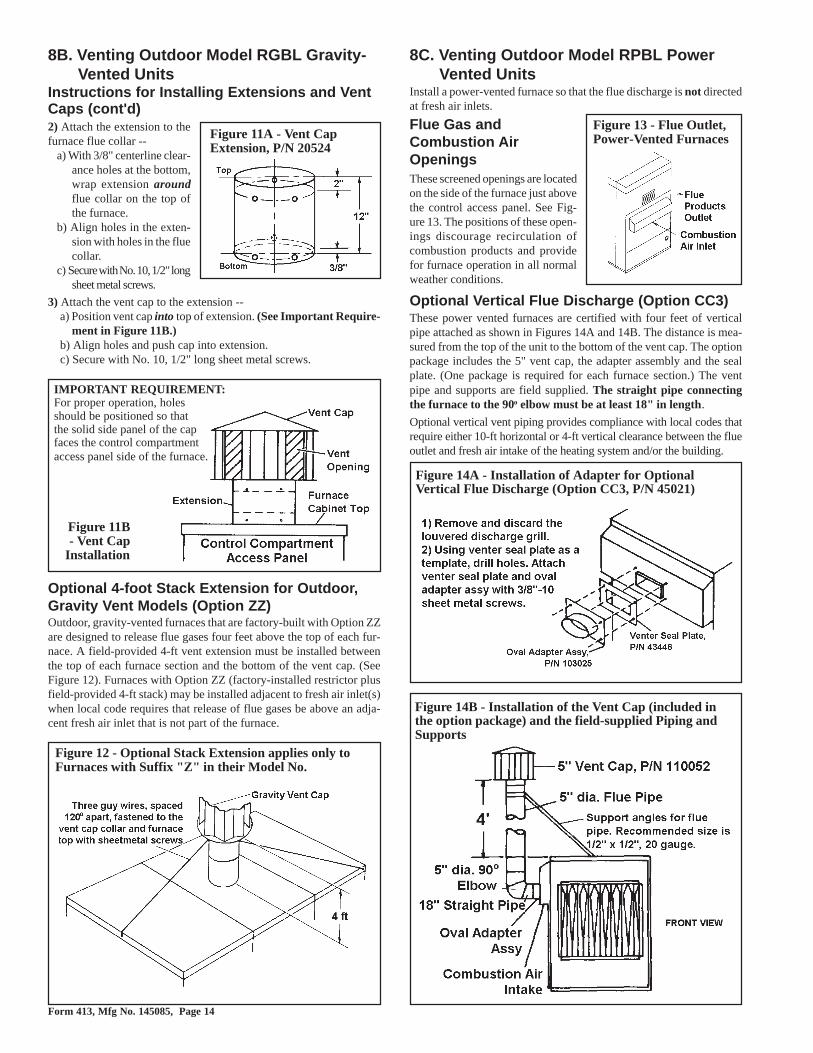
Instructions for Installing Extensions and Vent Caps (SeeFigures 11A and 11B, page 14)1. Unpacking -- Gravity vent cap extension is packed inside the vent cap and must be
removed before installing. Remove the extension from the inside of the cap.
Form 413, Mfg No. 145085, Page 14
2) Attach the extension to thefurnace flue collar --
a) With 3/8" centerline clear-ance holes at the bottom,wrap extension aroundflue collar on the top ofthe furnace.
b) Align holes in the exten-sion with holes in the fluecollar.
c) Secure with No. 10, 1/2" longsheet metal screws.
3) Attach the vent cap to the extension --a) Position vent cap into top of extension. (See Important Require-
ment in Figure 11B.)b) Align holes and push cap into extension.c) Secure with No. 10, 1/2" long sheet metal screws.
Optional 4-foot Stack Extension for Outdoor,Gravity Vent Models (Option ZZ)Outdoor, gravity-vented furnaces that are factory-built with Option ZZare designed to release flue gases four feet above the top of each fur-nace. A field-provided 4-ft vent extension must be installed betweenthe top of each furnace section and the bottom of the vent cap. (SeeFigure 12). Furnaces with Option ZZ (factory-installed restrictor plusfield-provided 4-ft stack) may be installed adjacent to fresh air inlet(s)when local code requires that release of flue gases be above an adja-cent fresh air inlet that is not part of the furnace.
Figure 11A - Vent CapExtension, P/N 20524
Figure 11B- Vent Cap
Installation
IMPORTANT REQUIREMENT:For proper operation, holesshould be positioned so thatthe solid side panel of the capfaces the control compartmentaccess panel side of the furnace.
Figure 12 - Optional Stack Extension applies only toFurnaces with Suffix "Z" in their Model No.
8C. Venting Outdoor Model RPBL PowerVented Units
Install a power-vented furnace so that the flue discharge is not directedat fresh air inlets.
Flue Gas andCombustion AirOpeningsThese screened openings are locatedon the side of the furnace just abovethe control access panel. See Fig-ure 13. The positions of these open-ings discourage recirculation ofcombustion products and providefor furnace operation in all normalweather conditions.
Figure 13 - Flue Outlet,Power-Vented Furnaces
Optional Vertical Flue Discharge (Option CC3)These power vented furnaces are certified with four feet of verticalpipe attached as shown in Figures 14A and 14B. The distance is mea-sured from the top of the unit to the bottom of the vent cap. The optionpackage includes the 5" vent cap, the adapter assembly and the sealplate. (One package is required for each furnace section.) The ventpipe and supports are field supplied. The straight pipe connectingthe furnace to the 90o elbow must be at least 18" in length.
Optional vertical vent piping provides compliance with local codes thatrequire either 10-ft horizontal or 4-ft vertical clearance between the flueoutlet and fresh air intake of the heating system and/or the building.
Figure 14A - Installation of Adapter for OptionalVertical Flue Discharge (Option CC3, P/N 45021)
Figure 14B - Installation of the Vent Cap (included inthe option package) and the field-supplied Piping andSupports
8B. Venting Outdoor Model RGBL Gravity-Vented Units
Instructions for Installing Extensions and VentCaps (cont'd)

Form 413, Mfg No. 145085, Page 15
Figure 16A - Connecting Ductwork (with removablepanels) to the Furnace(1) Flanges on the heat exchanger (furnace) turn out as shown.
(2) Shape duct connection as shown -- "U" on top and bottom; "L"on sides.
(3) Slide "U" over top and bottom heat exchanger flange.
(4) Form "U" channels to seal sides.
(5) Drill and lock with sheetmetal screws.
Figure 16B -"U" ChannelDuct Connection
9. Duct ConnectionsRequirements and Suggestions for Connectingand Installing Ducts• Type of Ductwork - The type of duct installation to be used de-
pends in part on the type of construction of the roof (whether woodjoist, steelbar joist, steel truss, pre-cast concrete) and the ceiling(whether hung, flush, etc.).
• Ductwork Material - Rectangular duct should be constructed ofnot lighter than No. 26 U.S. gauge galvanized iron or No. 24 B & Sgauge aluminum.
• Ductwork Structure - All duct sections 24 inches or wider, andover 48 inches in length, should be cross broken on top and bottomand should have standing seams or angle-iron braces. Joints shouldbe S and drive strip, or locked.
• Through Masonry Walls - No warm air duct should come in con-tact with masonry walls. Insulate around all air duct through ma-sonry walls with not less than 1/2" (1" is recommended) of insula-tion.
• Through Unheated Space - Insulate all exposed warm air ductspassing through an unheated space with at least 1/2" (1" is recom-mended) of insulation.
• Duct Supports - Suspend all ducts securely from adjacent build-ings members. Do not support ducts from unit duct connections.
• Duct Sizing - Proper sizing of the supply air ductwork is necessaryto ensure a satisfactory heating installation. The recognized author-ity for such information is the Air Conditioning Contractors Asso-ciation, 1228 17th Street N.W., Washington, D.C. 20036. A manualcovering duct sizing in detail may be purchased directly from them.
CAUTION: An external duct system static pressurenot within the limits shown on the rating plate, orimproper motor pulley or belt adjustment, mayoverload the motor. See Hazard Levels, page 2.
• Removable Panels - The ducts should have removable access pan-els on both upstream and downstream sides of the furnace. Theseopenings must be accessible when the furnace is in service andshould be a minimum of 6" x 10" in size so smoke or reflected lightmay be observed inside the casing to indicate the presence of leaksin the heat exchanger. The covers for the openings must be attachedin such a manner as to prevent leakage. See Figure 16A.
• Horizontal Discharge Duct Length - For all installations with ahorizontal discharge, a minimum horizontal duct run of 24" is rec-ommended before turns or branches are made in the duct system toreduce losses at the furnace outlet.
• Supply Air Duct/Furnace Horizontal Connection - The seal be-tween the furnace and the duct must be mechanical. Duct connec-tion should be made with "U" type flanges on the top and bottom ofthe connecting duct. Slide the duct over the flanges of the heatergiving an airtight fit. Provide "U" type channels for the other sideflanges to ensure tight joints. Use sheetmetal screws to fasten ductsand "U" channels to the furnace flange. See Figures 16A and 16B.
Figure 15 - Duct ConnectionDimensions (inches) for Systems
with Horizontal Discharge
Size G
500, 600 34-1/2700, 1050 40400, 800,
120045-1/2
(See Paragraph 3 for bottom ductconnection sizes.)
CAUTION: Joints where supply air ducts attachto the furnace must be sealed securely to preventair leakage into drafthood or burner rack area.Leakage can cause poor combustion, pilot problems,shorten heat exchanger life and cause poorperformance. See Hazard levels, page 2.• Bottom Duct/Furnace Connections - On outdoor models, insert
ducts from below roof deck through roof opening into the heater.Form 1" flanges, fold over, and fasten with sheetmetal screws in-side heater. Gain access to the unit by removing side panels fromthe blower and downturn plenum sections. Ducts must be attachedand sealed to provide airtight connections.
• Return Air Duct/Furnace Connection - All return air ducts shouldbe attached and sealed to return air flanges to provide airtight con-nection.
• Return Air Duct/Grill Size - Make certain that return air ductingor grills have a free area equal to the return duct size connection.

Form 413, Mfg No. 145085, Page 16
10. Gas Piping and Pressures
Gas Connection to Single-Stage Valve (Gas Connection is Not Gas Supply Line S ize)
Model S ize 400 500 600 700 800 1050 1200 Natural 1" 1-1/4" 1-1/4" 1-1/4" 1-1/4" 1-1/4" 1-1/4"
Propane 1" 1-1/4" 1-1/4" 1-1/4" 1-1/4" 1-1/4" 1-1/4"
Gas ConnectionThese systems are composed of one, two, or three ductfurnaces assembled in a series. When there are two or threefurnace sections, the gas train is manifolded so that onlyone field connection is required. At the field connection,there is a factory installed adapter with a 1/8" N.P.T.plugged hole for connecting a pressure test gauge. Eachfurnace section has its own manual shutoff valve. The gasconnection is piped along the bottom. See Figure 17 forgas train manifold arrangement and connection location.
WARNING
This appliance is equipped for a maximum gas supply pressure of 1/2 pound, 8 ounces, or 14 incheswater column. Supply pressure higher than 1/2 pound requires installation of an additional serviceregulator external to the unit.
PRESSURE TESTING SUPPLY PIPINGTest Pressures Above 1/2 PSI: Disconnect the heater and manual valve from the gas supply line which is to be tested. Cap or plug the supplyline.
Test Pressures Below 1/2 PSI: Before testing, close the manual valve on the heater.
Unit with Three Furnace Sections
Unit with TwoFurnaceSections
Unit with OneFurnaceSection
Figure 17 - GasSupply Connection
All piping must be in accordance with requirements out-lined in the National Fuel Gas Code ANSI/Z223.1a (lat-est edition) or CAN/CGA-B149.1 and B149.2 (See Para-graph 1). Gas supply piping installation should conformwith good practice and with local codes.
Furnaces for natural gas are orificed for operation withgas having a heating value of 1000 (+ or - 50) BTUH percubic ft. If the gas at the installation does not meet thisspecification, consult the factory for proper orificing.
Pipe joint compounds (pipe dope) shall be resistant tothe action of liquefied petroleum gas or any other chemi-cal constituents of the gas being supplied.The National Fuel Gas Code requires the installation of atrap with a minimum 3" drip leg. Local codes may requirea minimum drip leg longer than 3" (typically 6").
After all connections are made, disconnect the pilot sup-ply at the control valve and bleed the system of air. Re-connect the pilot line and leak-test all connections by brush-ing on a leak-detecting solution.
WARNING: All components of a gassupply system must be leak tested priorto placing equipment in service.NEVER TEST FOR LEAKS WITH ANOPEN FLAME. Failure to complycould result in personal injury, propertydamage or death.

Form 413, Mfg No. 145085, Page 17
Sizing Gas Supply Lines
Capacity of Piping - Cubic Feet per Hour based on 0.3" w.c. Pressure DropSpecific Gravity for Natural Gas -- 0.6 (Natural Gas -- 1000 BTU/Cubic Ft)
Specific Gravity for Propane Gas -- 1.6 (Propane Gas -- 2550 BTU/Cubic Ft)
Length Diameter of Pipeof 1" 1-1/4" 1-1/2" 2" 2-1/2"
Pipe Natural Propane Natural Propane Natural Propane Natural Propane Natural Propane20' 350 214 730 445 1100 671 2100 1281 3300 201330' 285 174 590 360 890 543 1650 1007 2700 164740' 245 149 500 305 760 464 1450 885 2300 140350' 215 131 440 268 670 409 1270 775 2000 122060' 195 119 400 244 610 372 1105 674 1850 112970' 180 110 370 226 560 342 1050 641 1700 103780' 170 104 350 214 530 323 990 604 1600 97690' 160 98 320 195 490 299 930 567 1500 915
100' 150 92 305 186 460 281 870 531 1400 854125' 130 79 275 168 410 250 780 476 1250 763150' 120 73 250 153 380 232 710 433 1130 689175' 110 67 225 137 350 214 650 397 1050 641200' 100 61 210 128 320 195 610 372 980 598
Note: When sizing supply lines, consider possibilities of future expansion and increased requirements. Refer to National Fuel Gas Code for additional information on line sizing.
Manifold or Orifice Pressure SettingsMeasuring manifold gas pressure cannot be done until the heater is inoperation. It is included in the steps of the "Check-Test-Start" proce-dure in Paragraph 28. The following warnings and instructions apply.(NOTE: These instructions and pressures do not apply to a Model RPBL400 furnace with electronic modulation Option AG39 or AG40; seeParagraph 24.)
WARNING: Manifold gas pressure must neverexceed 3.5" w.c. for natural gas and 10" w.c. forpropane gas.
For Natural Gas: Manifold gas pressure is regulated by the combina-tion valve to 3.5" w.c. Inlet pressure to the valve must be a minimum of5" w.c. or as noted on the rating plate and a maximum of 14" w.c.For Propane Gas: Manifold gas pressure is regulated by the combina-tion valve to 10" w.c. Inlet pressure to the valve must be a minimum of11" w.c. and a maximum of 14" w.c.Before attempting to measure or adjust manifold gas pressure, the inlet(supply) pressure must be within the specified range for the gas beingused both when the heater is in operation and on standby. Incorrectinlet pressure could cause excessive manifold gas pressure immedi-ately or at some future time.
Instructions to Check Manifold Pressure:1) With the manual valve (on the combination valve) positioned to
prevent flow to the main burners, connect a manometer to the 1/8"pipe outlet pressure tap in the valve. NOTE: A manometer (fluid-filled gauge) is recommended rather than a spring type gauge dueto the difficulty of maintaining calibration of a spring type gauge.
2) Open the valve and operate the heater. Measure the gas pressure tothe manifold. Normally adjustments should not be necessary to thefactory preset regulator.
3) If adjustment is necessary, set pressure to correct settings by turningthe regulator screw IN (clockwise) to increase pressure. Turn regu-lator screw OUT (counterclockwise) to decrease pressure.
Consult the valve manufacturer's literature provided with the furnacefor more detailed information.

Form 413, Mfg No. 145085, Page 18
Figure 18 - DisconnectSwitch Locations
11. Electrical Supply and ConnectionsAll electrical wiring and connections, including electrical groundingMUST be made in accordance with the National Electric Code ANSI/NFPA No. 70 (latest edition) or, in Canada, the Canadian ElectricalCode, Part I-C.S.A. Standard C22.1. In addition, the installer shouldbe aware of any local ordinances or gas company requirements thatmight apply.
Check the rating plate on the heater for the supply voltage and currentrequirements. A separate line voltage supply with fused disconnectswitch should be run directly from the main electrical panel to the fur-nace, making connection to leads in the junction box. All external wir-ing must be within approved conduit and have a minimum temperaturerise rating of 60°C. Conduit from the disconnect switch must be run soas not to interfere with the service panels of the furnace.
If the heater has field-installed options that require electrical connec-tions, consult the instruction sheet and wiring diagram supplied in theoption package.
CAUTION: If any of the original wire as suppliedwith the appliance must be replaced, it must bereplaced with wiring material having atemperature rating of at least 105oC, except forsensor lead wires which must be 150oC. SeeHazard Levels, page 2.
Specific wiring diagrams that include standard and factory-installedoptions are included with the heater.
WARNING: If you turn off the power supply,turn off the gas. See Hazard Levels, page 2.
Thermostat and Other Optional ControlsA thermostat is not standard equipment but is an installation require-ment. Use either an optional thermostat available with the system or afield-supplied thermostat. Install according to the thermostatmanufacturer's instructions.A 24 volt thermostat must be used to actuate low voltage gas controls.If line voltage from the thermostat to the unit is desired, consult thefactory representative.Wiring between the thermostat and the heater must be suitable for atemperature rise rating of 60°C. Labeled thermostat leads are providedin the heater junction box for connection of thermostat wiring.Thermostats should be located five feet above the floor on an insidewall, not in the path of warm or cold air currents and not in corners
where air may be pocketed. Do NOT install on cold air walls. Forspecific connection details, refer to the instructions with the thermo-stat.If more than one unit is cycled from one thermostat, separately acti-vated relays must be substituted at unit thermostat connections.
CAUTION: Make sure the thermostat has anadequate VA rating for the total requirements. Addcoil rating of all relays and match thermostat rating.See Hazard Levels, page 2.
There are a variety of optional controls available as part of the gas andair control options. Check the wiring diagram and literature supplied
with the unit for operation of factory-installed optional controls. SeeFigure 19 for location of standard and optional controls.Optional shipped-separate heating and makeup air controls could in-clude a single or two-stage thermostat, system switches, selectrastat,freezestat, an automatic night setback device, a Maxitrol temperatureselector, a potentiometer, a pressure null switch, or a combination ofthese controls. Install controls according to the manufacturer's instruc-tions packaged with the heater.A selection of control consoles are available with certain appropriatecombinations of controls factory mounted. All consoles are remote andinclude indicator lights for the blower and burner, an off/on systemswitch, and terminal block wiring.
Disconnect SwitchA disconnect switch is a required part of this installation. Switches areavailable, as options or parts, or may be purchased locally. When or-dered as an optional component, the disconnect switch is shipped sepa-rately.The disconnect switch may be fusible or non-fusible. When providingor replacing fuses in a fusible disconnect switch, use dual element timedelay fuses and size according to 1.25 times the maximum total inputamps. When installing, be careful that the conduit and switch housingare clear of furnace panels and inspection plates. Allow at least fourfeet of service room between the switch and removable panels. SeeFigure 18 for suggested locations.
Fan Control Heater .12Time Delay Relay Heater .1Relay Coil .12
Motor Contactor Coil .33
24 Volt Controls - Maximum Amps
Single-Stage Valve .6Two-Stage Valve .6Maxitrol System .5Spark Ignition System .1

Form 413, Mfg No. 145085, Page 19
Figure 19 - Location of Standard andOptional Controls (Key is on page 19)
43
44(Illustration shows a smallerType "B" blower cabinet;controls are in the samelocations for the Type "BL"cabinet used on these largercapacity systems.)
Venter Assembly onIndoor Power-VentedSystem
30. Blower Motor31. Optional Control Relays (as re-
quired, 8 maximum)32. Auto Reset Reverse Flow Limit33. Optional Return Air Firestat34. Low Voltage Terminal Strip35. Line Voltage Terminal Strip36. Control Transformer37. Control Transformer (as required)38. Optional Damper Motor Trans-
former39. Low Voltage Connection (field)40. Optional Air Proving Switch41. Venter Assembly (outdoor power-
vented)42. Vent Cap (gravity-vented)43. Venter Assembly (indoor power-
vented)44. Combustion Air Pressure Switch (in-
door power-vented models; for out-door models, see Item 2)
1. Optional Auto Reset Freezestat2. Combustion Air Pressure Switch
(outdoor power-vented models; forindoor models, see Item 44)
3. Optional Discharge Air Firestat4. Ignition Controller5. Optional Maxitrol Discharge Air
Sensor (Opt AG8 or 9)6. Optional Two-Stage Controller
(Opt AG3) or Maxitrol Amplifier(Opt AG7, 8, or 9)
7. Optional Main Low Gas PressureSwitch
8. Optional Pilot High Gas PressureSwitch
9. Optional Main High Gas PressureSwitch
10. Time Delay Relay (power-vented)11A. Limit Control (disc type limit con-
trol)11B. Limit Control (capillary type limit
control)12. Fan Control
Key to Control Locations in Figure 19:13. Optional Freezestat Time Delay Re-
lay14. Line Voltage Terminal Block15. Low Voltage Terminal Block16. Freezestat Relay17. Optional Dirty Filter Pressure Switch18. Line Voltage Connection (field)19. Optional Convenience Outlet and
Outlet Transformer20. Blower Motor Contactor or Starter21. Optional High Ambient Limit Con-
trol22. Optional Outside Air or Return Air
Controller23. Optional Mixed Air Controller24. Optional Potentiometer25. Optional Return Air Dampers26. Optional Two Position or Modulat-
ing Damper Motor27. Optional Outside Air Damper28. Optional Potentiometer29. Optional Filters

Form 413, Mfg No. 145085, Page 20
(3) CapScrews
Figure 21 - Split Taper Bushing
(2) Push-Off Holes
12. Blowers, Belts and DrivesCheck belt tension.Proper belt tension isimportant to the longlife of the belt andmotor. A loose beltwill cause wear andslippage. Too muchtension will cause ex-cessive motor andblower bearing wear. Adjust the belt tension by turning the adjustingscrew on the motor base until the belt can be depressed 3/4". (SeeFigure 20.) After correct tension is achieved, re-tighten the locknut onthe adjustment screw. Be sure that the belt is aligned in the pulleys.
Adjusting Blower SpeedThe system is set at the factory for the RPM required to meet the CFMand external static pressure specified on the order. If estimated externalstatic pressure is incorrect, or changes were made to the duct system,the blower RPM may have to be adjusted.Motors are equipped with adjustable pitch pulleys which permit ad-justment of blower speed. To make adjustments to units with lessthan a 5HP motor, follow these instructions.1. Turn off the gas and the electric power.2. Loosen belt tension and remove the belt.3. Loosen the set screw on the side of the pulley away from the motor.4. To increase the blower speed, decreasing outlet temperature, turn
the adjustable half of the pulley inward. To decrease the blowerspeed, increasing the outlet temperature, turn the adjustable halfof the pulley outward. One turn of the pulley will change the speed8-10%.
5. Tighten the set screw on the flat portion of the pulley shaft.6. Replace the belt and adjust the belt tension. Adjust tension by turn-
ing the adjusting screw on the motor base until the belt can be de-pressed 3/4". (See Figure 20.) Re-tighten the lock nut on the adjust-ing screw. Be sure that the belts are aligned in the pulley groovesproperly and are not angled from pulley to pulley.
7. Turn on the gas and electric. Light the heater following the instruc-tions on the lighting instruction plate.
8. Check the motor amps with an amp meter. The maximum motoramp rating on the motor nameplate must not be exceeded.
9. When service is complete, check for proper operation.
For units with 5 HP and larger motor, follow these instructions foradjusting RPM:1. Turn off the gas and the electric power.2. Slack off all belt tension by moving motor towards driven shaft
until belts are free of grooves. For easiest adjustment, remove thebelts from the grooves.
3. On the outer locking ring, locate the two locking screws that aredirectly across from each other. Loosen these two screws, but donot remove them. Do not loosen any other screws.
4. Adjust sheave to desired pitch diameter by turning the outer lock-ing ring. One complete turn of the outer locking ring will result in.233" change in pitch diameter. To decrease blower speed, increasediameter; to increase blower speed, decrease diameter.
CAUTION: Sheaves should not be adjusted ineither direction to the point where movable andstationary flanges are in contact.
5. After completing adjustment, tighten both locking screws in theouter locking ring (loosened in Step 2.).
6. Replace belts and move motor away from the driven shaft to applysufficient belt tension to prevent slippage. (See Figure 20.) Properbelt tension is important to the long life of the belt and motor. Aloose belt will cause wear and slippage. Too much tension will causeexcessive motor and blower bearing wear. Be sure that the belts are
Figure 20 - Check Belt Tension
aligned in the pulley grooves and are not angled from pulley topulley.
7. Check motor amps with an amp meter. The maximum motor amprating on the nameplate must not be exceeded.
8. When service is complete, check for proper operation.
Blower PulleySome blower pulleys require the use of a split taper bushing in theblower pulley. These split taper bushings must be loosened in order toremove the pulley. Follow these instructions to loosen the bushing:a) Notice that there are
three cap screws inthe bushing and twoholes without screws,called push-off holes.(See Figure 21.)
b) Remove the three capscrews.
c) Put two of the capscrews into the twopush-off holes.Tighten these twoscrews evenly untilthe pulley is loos-ened.
d) Pulley may now be removed from the shaft.
Blower BearingsThe blower bearings on systems with less than a 10 HP motor (stan-dard blower) are permanently lubricated cartridge ball bearings and donot require greasing.
The blower bearings on systems equipped with 10-20 HP motor arepillow block ball bearings and are equipped with a grease fitting.(NOTE: Units manufactured prior to 1/91 with a 10 HP motor mayhave permanently lubricated ball bearings.) These bearings should belubricated twice a year with a high temperature, moisture-resistantgrease. (Type NLGI-1 or -2 standard grease is recommended.) Be sureto clean the grease fitting before adding grease. Add grease with ahandgun until a slight bead of grease forms at the seal. Be careful notto unseat the seal by overlubricating. NOTE: If unusual environmentalconditions exist (temperatures below 32oF or above 200oF; moisture;or contaminants), more frequent lubrication is required.
CAUTION: If the blower is unused for more thanthree months, bearings with a grease fitting shouldbe purged with new grease prior to start-up.
Blower RotationEach blower housing is marked for proper rotation. Rotation may bechanged on single-phase motors by re-wiring in the motor terminalbox. Three-phase motors may be reversed by interchanging two wireson the 3-phase supply connections.
Optional Air Flow Proving Switch (Makeup Aironly) - Outdoor Models with Option BW1The optional air flow proving switch ensures that the circulating airblower is functionally providing an adequate amount of air flow priorto the unit being fired. The switch is a single pole/normally open de-vice which closes when an increase in pressure above the setpoint issensed in the circulating air blower. The switch is located in the blowerjunction box. (See Figure 19, Item 40).
Contacts are set to close at .10" w.c. (+.05" or -.02" w.c.).
13. Blower MotorsUse an amp meter to check motor amps. The chart on the right lists fullload amps for various HP's and voltages. Amps may be adjusted down-ward by reducing blower RPM or increasing duct system static pres-sure.

Form 413, Mfg No. 145085, Page 21
Full Load Amps - Blower Motors (Open)(Single Speed- Average Values)
HP115V 1PH
208V 1PH
230V 1PH
208V 3PH
230V 3PH
460V 3PH
575V 3PH
1 13.0 7.5 6.5 3.7 3.2 1.6 1.1
1-1/2 15.0 8.3 7.5 5.6 5.0 2.7 1.6
2 20.4 11.3 10.2 7.0 6.6 3.3 2.1
3 14.0 12.4 9.0 8.6 4.2 3.6
5 28.0 26.0 13.4 13.2 6.6 5.4
7-1/2 35.0 32.0 22.5 19.4 9.7 7.8
10 42.0 38.0 30.0 26.0 13.0 10.4
15 43.1 39.0 19.5 16.020 58.7 53.0 26.5 21.2
14. FiltersThese packaged systems are equipped with a combination blower/fil-ter cabinet. Filter rack and filters are optional equipment. Filters areavailable in 1" or 2", disposable, permanent or pleated disposable styles.(Note: See Paragraph 38 for filter arrangements and replacement infor-mation.)Filter Ranges - Disposable, 0 to 400 FPM; Pleated Disposable, 0 to500 FPM; Permanent, 0 to 600 FPM
This chart can be used for sizing line wiring but should not be interpreted as the exact motor amps. See the motor rating plate for exact motorspecifications.
Heater Filter Pressure Drops (" w.c.) Size CFM Disposable Permanent Pleated
1" 2" 1" 2" 1" 2"3300 0.01 0.02 0.02 0.03 0.04 0.03
400 4000 0.02 0.03 0.04 0.05 0.09 0.065000 0.03 0.04 0.06 0.08 0.15 0.106000 0.05 0.06 0.08 0.12 0.21 0.147000 0.06 0.08 0.11 0.16 0.28 0.198000 0.08 0.10 0.15 0.21 0.37 0.259000 0.11 0.13 0.19 0.26 0.46 0.31
10000 N/A N/A 0.23 0.33 0.57 0.3911000 N/A N/A 0.28 0.40 0.69 0.47
12000 N/A N/A 0.34 0.48 0.82 0.5613000 N/A N/A 0.40 0.56 N/A N/A14000 N/A N/A 0.46 0.65 N/A N/A
3700 0.02 0.04 0.03 0.04 0.09 0.06500 4000 0.04 0.05 0.04 0.06 0.12 0.08600 5000 0.06 0.08 0.07 0.10 0.18 0.12
6000 0.08 0.12 0.10 0.14 0.25 0.177000 0.10 0.16 0.14 0.20 0.35 0.23
8000 N/A N/A 0.18 0.25 0.46 0.319000 N/A N/A 0.22 0.31 0.59 0.40
10000 N/A N/A 0.28 0.39 N/A N/A11000 N/A N/A 0.33 0.46 N/A N/A12500 N/A N/A 0.43 0.60 N/A N/A
5200 0.04 0.06 0.06 0.08 0.14 0.10700 6000 0.04 0.06 0.08 0.10 0.22 0.15
7000 0.06 0.08 0.10 0.14 0.30 0.208000 0.08 0.10 0.14 0.18 0.39 0.279000 N/A N/A 0.18 0.24 0.49 0.33
10000 N/A N/A 0.22 0.30 0.61 0.4111000 N/A N/A 0.26 0.36 N/A N/A12000 N/A N/A 0.32 0.42 N/A N/A13000 N/A N/A 0.38 0.50 N/A N/A
Optional Dirty Filter SwitchThe optional dirty filter pressure switch is used to provide warningto the user by energizing an indicator light on a remotely locatedcontrol console. The light indicates that the filters are in need ofcleaning or changing. The adjustable, single-pole/normally opendifferential switch closes when an increase in pressure differentialabove the setpoint is sensed across the filter bank.This switch is located in the furnace section. See Figure 19, Item17. The switch setpoint must be manually set.Instructions for Setting Dirty Filter SwitchWith clean filters in place, blower doors closed, and blower in op-eration, decrease pressure setting by adjusting set screw on switchclockwise until the filter light is energized or screw is bottomedout. At that point, adjust the set screw three full turns counterclock-wise or until the screw is top-ended. At that setpoint the filter lightwill be activated at approximately 50% filter blockage.
Heater Filter Pressure Drops (" w.c.) Size CFM Disposable Permanent Pleated
1" 2" 1" 2" 1" 2"5900 0.04 0.05 0.07 0.10 0.18 0.12
800 6000 0.05 0.06 0.08 0.12 0.21 0.147000 0.06 0.08 0.11 0.16 0.28 0.198000 0.08 0.10 0.15 0.21 0.37 0.259000 0.11 0.13 0.19 0.26 0.46 0.31
10000 N/A N/A 0.23 0.33 0.57 0.3911000 N/A N/A 0.28 0.40 0.69 0.4712000 N/A N/A 0.34 0.48 0.82 0.5613000 N/A N/A 0.40 0.56 N/A N/A
6500 0.04 0.06 0.08 0.10 0.14 0.081050 7000 0.06 0.08 0.10 0.14 0.18 0.12
8000 0.08 0.10 0.14 0.18 0.24 0.16
9000 N/A N/A 0.18 0.24 0.30 0.210000 N/A N/A 0.22 0.30 0.36 0.2411000 N/A N/A 0.26 0.36 N/A N/A12000 N/A N/A 0.32 0.42 N/A N/A13000 N/A N/A 0.38 0.50 N/A N/A
7400 0.06 0.08 0.11 0.16 0.28 0.191200 8000 0.08 0.10 0.15 0.21 0.37 0.25
9000 0.11 0.13 0.19 0.26 0.46 0.3110000 N/A N/A 0.23 0.33 0.57 0.3911000 N/A N/A 0.28 0.40 0.69 0.47
12000 N/A N/A 0.34 0.48 0.82 0.5613000 N/A N/A 0.40 0.56 N/A N/A
Type of Filter *Average Efficiency *Average Arrestance
Disposable 1" Less than 20% 75%2" Less than 20% 80%
Permanent 1" Less than 20% 53% to 60%2" Less than 20% 64% to 67%
Pleated 1" 30% to 35% 90% to 93%Disposable 2" 30% to 35% 90% to 93%*Tested in accordance with ASHRAE 52-76 Test Standard.

Form 413, Mfg No. 145085, Page 22
19. Optional High Ambient LimitControl - Makeup Air
The optional high ambient limit control functions to shutoff the burnerwhen the entering outside air reaches a set temperature. The temperaturesetting is field adjustable from 0-100oF. For location, see Figure 19, Item21.
20. Operating ValveAll furnaces are equipped with a 24-volt combination valve which includesthe automatic electric on/off valve controlled by the room thermostat, thepressure regulator, the safety pilot valve, and the manual shutoff valve.The standard gas valve allows for single-stage control from a single-stage,24-volt thermostat.
WARNING: The operating valve is the prime safetyshutoff. All gas supply lines must be free of dirt or scalebefore connecting the unit to ensure positive closure.See Hazard Levels, page 2.
21. Optional Two-Stage Operation- Heating Only Application
The standard combination control valve is replaced with a two-stage com-bination gas control valve providing for low fire or high fire operationcontrolled by a two-stage thermostat. First stage (low fire) is factory set(not field adjustable). Both high and low stages are controlled by a servoregulator, maintaining constant gas input under wide variations in gas sup-ply pressure. The two-stage thermostat, thermostat installation instructions,and gas valve manufacturer's control specifications are included with theheater. Follow these instructions and the wiring diagram. Two-stage heat-ing control is identified as Option AG11.
22. Optional Two-Stage Operation- Makeup Air Application
On systems with more than one furnace section, there are two methods ofachieving multiple-stage makeup air operation. In addition, for each ofthese methods, there are two types of control mechanisms. Consult thewiring diagram on the furnace to identify the optional control system.
The first method, identified by Options AG3, AG15, or AG16, is com-parable to the two-stage heating units. Instead of control from a two-stageroom thermostat, the outlet air temperature is monitored and the two-stagegas valve is controlled by a two-stage ductstat. When the discharge airtemperature drops to the setpoint, low fire is energized. If low fire cannotsatisfy the ductstat setting, high fire is energized. Since the packaged sys-tems may include two or three furnace sections, and each section is equippedwith a two-stage gas valve, the operation stages increase with the numberof furnace sections. Set the ductstats as indicated in Table 4A.
The second method of multiple-stage makeup air operation is applicableonly to systems that include two or three furnace sections. On systems
15. Fan Control1. The fan control provides the following:
(a) A 45-second delay of blower operation to prevent the dis-charge of cold air.
(b) Blower operation as long as the unit is hot.2. The fan control provides additional safety by keeping the blower
in operation in the event that the gas valve fails to close whenthe thermostat is satisfied.
3. To be sure that the blower can continue to operate, the powersupply to the furnace MUST NOT be interrupted except whenservicing the unit.
4. If the customer wants the furnace off at night, the gas valve cir-cuit should be opened by a single pole switch wired in serieswith the thermostat. Some thermostats are provided with thisfeature. Multiple units controlled from a single thermostat areshut off in the same manner. For proper operation, be sure thefan control wiring is observed.
The fan control contains a built-in heater to control delay times.For proper operation, refer to the wiring diagram furnished withthe furnace. For location, see Figure 19, Item 12.
16. High Temperature LimitEach furnace is equipped with a non-adjustable high temperaturelimit switch which shuts off the gas in the event of motor failure,lack of air due to dirty filters, or restrictions at the inlet or outlet ofthe unit. See Paragraph 28, "Check Installation after Start-up", forchecking operation of high temperature limit controls.
Effective with models manufactured beginning 1/97, the furnacefarthest downstream in each system is also equipped with a linear-type limit control. The switch is mounted on a bracket on the bot-tom of the junction box with the capillary sensor extending acrossthe discharge opening of the furnace.
For locations, see Figure 19, Items 11A and 11B.
17. Reverse Flow, Limit ControlThe furnace is factory equipped with an automatic reset reverseflow limit control. This control is located in the blower compart-ment, mounted in the blower junction box adjacent to the blowerinlet opening, and is wired in series with the main limit controlmounted on the heat exchanger duct side. For location, See Figure19, Item 32.
In case of belt breakage or motor failure, the limit control will beopened by the high temperatures caused by reverse flow from theheat exchanger to the blower compartment, thus breaking the cir-cuit to the electric gas valve and preventing burner operation.
18. Combustion Air ProvingSwitch - Power-VentedModels
The combustion air proving switch ensures that proper combustionair flow is available. The switch is a single-pole, double-throwswitch, which senses pressure caused by the flow of combustion airfrom the venter. The switch is designed to close when a decreasingpressure is sensed in the outlet duct of the gas collection box. Forlocations, see Figure 19, Items 2 and 44.On start-up when the furnace is cold, the sensing pressure is at themost negative level, and as the furnace and the flue system warm-up, the sensing pressure becomes less negative. After the systemhas reached equilibrium (approximately 20 minutes), the sensingpressure levels off. If a restriction or excessive flue length or turnscause the sensing pressure to become less than the switch setpoint,the pressure switch will function to shut off the main burners. Themain burners will remain off until the system has cooled and/or theflue system resistance is reduced. The table below gives approxi-
mate water column negative pressure readings and switch setpoints for sealevel operating conditions.
Start-up Cold -1.0" to -1.5" w.c.
Equilibrium -.70" to -.80" w.c.
Factory Setpoint -.58 ± .05" w.c.
DANGER: Safe operation requires proper ventingflow. Never bypass the combustion air provingswitch or attempt to operate the unit without theventer running and proper flow in the vent system.Hazardous condition could result. See HazardLevels, page 2.

Form 413, Mfg No. 145085, Page 23
Dial has no temperature markings. Pin onadjustment screw pointing to "B" equalsapproximately 70oF.
Figure 22 -DuctstatControl(Mounted ininvertedposition)
Figure 23 - Remote Temperature Selector (A350),Stage-Adder Module (S350), and Optional DisplayModule for Ductstat in Two-Stage Makeup Air ControlOptions (Option AG15, 16, 17, 18, 19, 20)
with two furnaces, this optional control system is identified as OptionAG4, AG17, or AG18. On packaged systems with three furnace sec-tions, this optional control method is identified as Option AG5, AG19,or AG20. Each furnace in the package is equipped with a single-stagegas valve. The single-stage gas valves are staged by two-stage ductstats.The furnaces are staged in sequence, starting with the furnace nearestthe blower. This concept will achieve two-stage control on packagedsystems with two furnaces and three-stage control on systems with threefurnaces. Set the ductstats as indicated in Table 4B.
The two types of ductstat control mechanisms used in these multiple-stage systems are either --(1) the complete ductstat (including the sensor and temperature selec-
tor) installed in the furnace discharge (Option AG3, AG4, and AG5)or
(2) a sensing probe only installed in the heater discharge with the sens-ing probe electrically connected to a remote electronic temperatureselector. The remote electronic temperature selection option is avail-able with or without a display module. Options AG15, 17, and 19do not have a display module; Options AG16, 18 and 20 are identi-cal with the addition of the display module.
The makeup air control options with the complete two-stage ductstat(Options AG3, AG4, AG5) installed in the heater discharge use a duct-stat (See Figure 22) with an adjustable range from 60° to 110°F with afixed differential of 2-1/2°. Due to different CFM settings and outsideair temperatures, the average downstream outlet temperature may notmatch the ductstat setting exactly. After the installation is complete, re-adjust the setpoint of the ductstat(s) to achieve the desired averageoutlet air temperature. In general, makeup air applications are usuallyadjusted to discharge in outlet air temperature between 65°F and 75°F.See Tables 4A and 4B for recommended settings and staging sequence.
Two stage makeup air options that are controlled from a sensing probewith a remote electronic temperature selector have a temperature oper-ating range to 130°F. The sensing probe and remote modules are shippedseparately for field installation. Follow the wiring diagram with theunit and the manufacturer's instructions for wiring and installing theremote modules. CAUTION: Make sure heat/cool selector switch isset on "HEAT".Depending on the staging provided, there will be one module for se-lecting temperature and one to five stage-adder modules. The digitaldisplay module is optional. See Figure 23. See Tables 4A and 4B forrecommended differential settings and staging sequence.
See Figure 24 for a general location of the factory-installed sensor witheither the factory-mounted or the remote ductstat selector option.
Operation: The differential setting and offset degrees allow the controls to adapt to any adjustment in temperature selection range (50-130oF).
Options AG15 and AG16 -- Adjust the setpoint and the differential of the temperature selector (Johnson #A350). Adjust the offset potentiom-eter on each of the stage adder modules (Johnson #S350). The settings listed below will provide the same sequence of staging as shown abovefor Option AG3. Follow the manufacturer's instructions provided. IMPORTANT: Set the temperature selector and each stage adder moduleto "HEAT". Follow the wiring diagram to obtain proper sequencing.
Table 4A -- RECOMMENDED SETTINGS for Staging Application - Options AG3, AG15, AG16Option No. of Ductstat Settings -- Set each ductstat control (See Figure 22) in furnace "order"
Furnaces 1st 2nd 3rd Sequence of Staging with these settingsAG3 1 70oF 66oF High Stage � 70oF Low Stage � 74oF Shutdown
2 70oF 64oF 60oF High Stage Both Furnaces � 64oF Low Stage 2nd Furnace �68oF Shutdown 2nd furnace � 70oF Low Stage 1st furnace �74oF Shutdown 1st furnace
3 70oF 66oF 62oF 58oF High Stage All Furnaces � 62oF Low Stage 3rd Furnace �66oF Shutdown 3rd furnace; Low Stage 2nd Furnace � 70oF Shutdown 2nd furnace; Low Stage 1st Furnace � 74oF Shutdown 1st furnace
Option No. of Temperature Selector (A350) Stage Adder (S350) Offset SettingsFurnaces Setpoint Differential (Refer to illustrations in Figure 23.)
AG15 1 74oF 8o 4o
and 2 74oF 14o 10o 6o 4o
AG16 3 74oF 16o 12o 8o 8o 4o 4o

Form 413, Mfg No. 145085, Page 24
24. Optional ElectronicModulation
The type and capability of the electronic modulation system, dependson the option selected. Electronic modulation options are identified bya suffix to the Serial No. printed on the heater rating plate. AG7 isidentified as MV-1; AG8 is identified as MV-3; AG9 is identified asMV-4; AG21 is identified as MV-A; AG39 is identified as MP-1; andAG40 is identified as MP-2. AG39 and AG40 are available only onModel RPBL 400.
24A. Electronic Modulation between 50%and 100% Firing Rate (Options AG7,AG8, AG9)
Depending on the heat requirements as established by the thermistorsensor, the burner modulates between 100% and 50% firing. The ther-mistor is a resistor that is temperature sensitive in that as the surround-ing temperature changes, the Ohms resistance changes through the ther-mistor. This change is monitored by the solid state control center (am-plifier) which furnishes varying DC current to the modulating valve toadjust the gas input.Each modulating valve is basically a regulator with electrical means ofraising and lowering the discharge pressure. When no DC current is fedto this device, it functions as a gas pressure regulator, supplying 3.5"w.c. pressure to the main operating valve.Refer to the wiring diagram supplied with the furnace for proper wiringconnections. Electronic modulation for heating controlled by a spe-cially designed room thermostat (60°-85°F) is identified as Option AG7.Electronic modulation control systems for makeup air applications con-trolled by a duct sensor and temperature selector (55-90°F) are identi-fied as either Option AG8 or Option AG9. The temperature selectorsetting for Option AG8 is on the amplifier; Option AG9 has a remotetemperature selector. Both systems are available with an override ther-mostat.
24B. Computer Controlled Electronic Modu-lation between 50% and 100% FiringRate (Option AG21)
With this option the furnace is equippedwith a Maxitrol A200 signal conditionerwhich operates much the same way as theamplifier above to control the regulatorvalve. The conditioner accepts an input sig-nal of either 4-20 milliamps or 0-10 voltsfrom a customer-supplied control device
Figure 25 - Maxitrolconditioner isOption AG21 andAG40
Options AG17, AG18, AG19 and AG20 -- Adjust the setpoint and the differential of the temperature selector (Johnson #A350). Adjust theoffset potentiometer on each of the stage adder modules (Johnson #S350). The settings listed below will provide the same sequence of stagingas shown above for Option AG4 and AG5. Follow the manufacturer's instructions provided. IMPORTANT: Set the temperature selector andeach stage adder module to "HEAT". Follow the wiring diagram to obtain proper sequencing.
Operation: The differential setting and offset degrees allow the controls to adapt to any adjustment in temperature selection range (50-130oF).
Table 4B -- RECOMMENDED SETTINGS for Staging Application - Options AG4, AG5, AG17, AG18, AG19, AG20Option No. of Ductstat Settings -- Set each Ductstat (See Figure 22) in furnace "order"
Furnaces 1st 2nd Sequence of Staging with these settingsAG4 2 70oF 66oF Full Rate Both Furnaces �� 70oF Shutdown 1st Furnace �
74oF Shutdown 2nd furnaceAG5 3 70oF 64oF 60oF Full Rate All Furnaces �� 68oF Shutdown 3rd and 2nd Furnace
� 74oF Shutdown 1st furnace
Option No. of Temperature Selector (A350) Stage Adder (S350) Offset SettingsFurnaces Setpoint Differential (Refer to illustrations in Figure 23.)
AG17/18 2 74oF 8o 4o
AG19/20 3 74oF 10o 6o 6o
23. Optional MechanicalModulation - Makeup AirApplication (Available on Size400 only)
The mechanical modulation valve regulates the flow of gas to the mainburner, depending on the demands of the sensing bulb which is lo-cated in the airstream adjacent to the heat exchanger. Inputs are variedfrom 50% through 100% of full rate in direct response to the modulat-ing control sensing element and depending on the temperature of out-side air being forced through the furnace. Outlet air or return air tem-perature can be maintained within a range of 50oF to 100oF (OptionAG6) and is adjustable at the mechanical modulating valve.
Refer to the manufacturer's specification and operating sheet in theheater instruction envelope accompanying the furnace.
Mechanical modulating gas control is available with bypass. With thebypass option, the unit is equipped with a single-stage valve and relay.On call from a remote override thermostat, the single-stage bypass gasvalve cycles on at 100% fire. Optional mechanical modulation con-trols with full fire bypass are identified as Option AG13 (50-100oF).(See Figure 24 for a general location of the factory-installed sensor.)
Figure 24 - DuctTemperature SensorLocation
1. Remove access panel in ductworkadjacent to control compartmentaccess panel.
2. Element is retained by springclips.
3. Round gasket and metal retain-ing plate provide airtight seal forcapillary and must be removed toremove the element.
22. Optional Two-Stage Operation (cont'd)

Form 413, Mfg No. 145085, Page 25
such as a computer. With the dip switches on the conditioner in the "on"positions, the conditioner accepts a 4-20 milliamp signal. In the "off"positions, the conditioner accepts a 0-10V signal. The conditioner con-verts the signal to the 0 to 20 volt DC current required to control themodulating valve. Temperature selection is through the computer soft-ware.
24C. Electronic Modulation between 25% and100% Firing Rate, Option AG39 (patentpending) - Available only on Model RPBL400,natural gas
A Model RPBL 400 equipped with electronic modulation Option AG39has a 25% turndown ratio. The furnace will ignite at any input rate in theavailable range and will maintain average thermal efficiencies equal to orgreater than the thermal efficiency at full fire.
Maximum MBH Inlet Pressure Gas SupplyModel Turndown Input to Modulating Pressure
% Range Valve RequiredRPBL 400 25 100-400 4.4" w.c. 6" w.c.
Furnaces with Option AG39 have stainless steel burners, a stainless steelheat exchanger, and a stainless steel bottom pan. The gas train includes asingle-stage gas valve, a modulating valve, and two gas pressure switches.The burner rack is equipped with one flash carryover and a regulated gaslighter tube system. The carryover lighter tube receives its gas supplythrough the regulator, simultaneously with the gas to the burner. Controlof the system is through a Maxitrol #ES410A amplifier with a corre-sponding remote temperature dial (Maxitrol #ES410TD).
Description of Operation of Option AG39The gas supply (see pressure requirement in the table above) connects tothe single-stage gas valve. To compensate for additional pressure loss
������������������� ��
�� ��� !���"����
�!������ ����#��"����
$�!%�����#&��'�$��##���
�'! �()(! ��*����
�+���'+�+
,��-����#�&��'$��##�����'! �(.����'�*�����+/��'+�+
Figure 26 - OptionAG39 Manifold
Arrangement
Note: Arrangement may vary slightlydepending on gas valve; componentsare the same.
through the modulating valve, the single-stage gas valve has a cus-tom outlet pressure setting higher than when it is used on a standardgas manifold. The pilot tubing connects to the pilot port on the single-stage gas valve. When the valve receives a call for heat from theamplifier and pilot is established, gas flow from the single-stage valvegoes to both the modulating valve and the regulated lighter tube sys-tem. When the signal from the amplifier to the modulating valve,requires less-than-high fire operation, the modulating valve func-tions to lessen the gas flow to the burner to reduce the input rate tothat required to maintain the desired temperature. When the inputrate is reduced enough to decrease the gas pressure to 1.1" w.c., theprimary gas pressure switch in the manifold activates the solenoidthat controls the bypass damper in the venter/combustion air system.The bypass damper opens diverting some of the incoming air di-rectly into the flue duct, reducing airflow through the burner. Safetyswitches monitor the position of the bypass damper. When the gaspressure increases above 1.1" w.c., the bypass damper closes.
Is there 24 voltsbetween Terminal #2 on #1
Time Delay Relay andTerminal 7?
Go toTroubleshootingChart for heater.
Is there 24 voltsbetween Terminal 85 and
Terminal 7?
Is there 24 voltsbetween Terminal 84 and
Terminal 7?
Is there 24 voltsbetween Terminal 88 and
Terminal 7?
Replace #1 TimeDelay Relay.
Check combustion airbypass damper.
IF damper is OPEN, the combustion damper end switches are out of adjustment ordefective. Note: To replace or adjust the combustion damper end switches, the venter
assembly and outlet duct assembly must be removed.
IF damperis CLOSED, is there
line voltage between Terminal 3on the Combustion Damper
Relay and TerminalL2?
Either the combustiondamper actuator is defectiveor the bypass damper door
linkage is defective.
Replace theCombustion Damper
Relay.
Replace the primarymanifold gas pressure
switch.
Is there 24 voltsbetween Terminal 89 and
Terminal 7?
Replace primarymanifold gaspressure switch.
Replace #2Time Delay
Relay.
YES NO
YES
NO
YES
NO
YES
NO
YES NO
YES
NO
Troubleshooting Guide for Checking Bypass Combustion Air Damper Safety Circuit on ModelRPBL400 with Option AG39 or AG40
Symptom: Mainburners areinoperative(assumes that 24 voltsis available betweenTerminal 2 andTerminal 7).
General Instructions:For each step, checkto ensure that thewiring is not defectiveand that the wiringconnections aresecure.

Form 413, Mfg No. 145085, Page 26
Figure 28 - Spark Pilot; maintain spark gap of 7/64"
CAUTION: Due to high voltage on pilot spark wireand pilot electrode, do not touch when energized. SeeHazard Levels, page 2.
If no spark occurs, check the following:a) Voltage between blue and white terminals (non-lockout type pilot)
and Terminals 2 and 5 (lockout type pilot) on the ignition controllershould be at least 20 volts and no higher than 32 volts. Refer toTroubleshooting (Paragraph 39) if no voltage is observed.
b) Short to ground in the high tension lead and/or ceramic insulator.c) Pilot spark gap should be approximately 7/64". (See Figure 28.)
NOTE: When checking for spark with the pilot burner assembly re-moved from the burner rack, the pilot assembly must be grounded tothe heater for proper spark.
24D. Computer Controlled ElectronicModulation between 25% and 100%Firing Rate, Option AG40 (patentpending) - Available only on Model RPBL400,natural gas
With this option the furnace is equipped with a Maxitrol A200 signalconditioner (see illustration in Figure 25) which accepts an input sig-nal of either 4-20 milliamps or 0-10 volts from a customer-suppliedcontrol device such as a computer. With the dip switches on the condi-tioner in the "on" positions, the conditioner accepts a 4-20 milliampsignal. In the "off" positions, the conditioner accepts a 0-10V signal.The conditioner converts the signal to the 0 to 20 volt DC current re-quired to control the modulating valve. The heater functions and isequipped in the same way as described in Paragraph 24C (Option AG39)except that with computer control the temperatures are selected throughthe software and there is no temperature selector or duct sensor.
SparkPilot
Flash CarryoverMainBurner
Figure 27 - Burner Rack
25. Pilot and Ignition SystemsThe horizontal pilot is located in the control end of the burner rack andis accessible after the control compartment panel has been removed.All pilots are target type with lint-free features. Pilot gas pressure shouldbe the same as supply line pressure. (See Paragraph 10.) If required,adjust the pilot flame length to approximately 1-1/4" with pilot adjust-ment screw in control valve body. See the valve manufacturer's in-structions.
All models have a standard spark ignition pilot system; lockout is op-tional. Refer to the wiring diagram supplied with the furnace for pilotsystem identification -- spark pilot without lockout is Option AH2;
and spark pilot with lockout is Option AH3.
Intermittent Spark Ignition Safety Pilot Systems - There are twotypes of intermittent spark pilots. The standard type (identified as AH2)shuts off the pilot gas flow between cycles. The other type (identifiedas AH3) not only shuts off the pilot gas flow between cycles but alsohas a lockout device that stops the gas flow to the pilot if the pilot failsto light in 120 seconds. This lockout feature requires manual reset byinterruption of the thermostat circuit.
Propane units require the spark ignition system with the lockout de-vice.
Refer to the wiring diagram supplied with the heater for pilot systemidentification and proper wiring.Ignition Controller - As part of the intermittent safety pilot system,the ignition controller provides the high voltage spark to ignite thepilot gas and also acts as the flame safety device. After ignition of thepilot gas, the ignition controller electronically senses the pilot flame. Alow voltage DC electrical signal is imposed on the separate metal probein the pilot assembly. The metal probe is electrically insulated fromground. The pilot flame acts as a conduction path to ground complet-ing the DC circuit and proving pilot flame. With pilot flame proven,the ignition controller energizes the main gas valve.
Combustion Air Pressure Switch SettingThis uniquely designed modulation system requires combustion air pres-sure settings different from the standard system. The approximate set-tings for the combustion air proving switch at sea-level operation are:
Sizes Startup Equilibrium Factoryw/AG39 Cold at Full Rate Setting400 -1.2"w.c.±0.2 -0.95"w.c.±0.1 -.75"w.c.±0.5
Sensor LocationFor the convenience of the installer, the duct temperature sensor isfactory installed in the cabinet leg (See Figure 20). Although the sen-sor has a mixing tube, at this distance from the discharge it does notreceive a true mix, so the temperature read by the sensor will be slightlyhigher than the actual air entering the ductwork. The system will pro-vide comfort level heat if the selector is set slightly lower to compen-sate for this reading. The offset temperature will vary with the applica-tion. If a direct correlation of these two temperatures is required, movethe duct sensor to a location in the ductwork about 10-12 feet from thefurnace discharge.
24. Optional ElectronicModulation (cont'd)
24C. Electronic Modulation between 25%and 100% Firing Rate, Option AG39(cont'd)
Wiring and ServiceFor wiring, consult the wiring diagram attached to the furnace. Allwires in the electrical box connecting the modulation controls must be150°C.This is a unique system which includes custom-built components andcustom settings. If service is required, follow the general troubleshoot-ing guide and the special troubleshooting guide on page 25.between the cycles and the other not only shuts off the pilot gas flow

Form 413, Mfg No. 145085, Page 27
28. Check Installation and Start-UpCheck the installation prior to start-up:� Be certain the electrical supply matches voltage rating of the furnace. (Refer to the rating plate.)
� Check all field wiring against the wiring diagram. Be sure that wire gauges are as required for the electrical load.
� Be certain that the electrical entrances are sealed against the weather.
� Check that fuses or circuit breakers are in place and sized correctly.
� Check clearances from combustibles. Requirements are shown in Paragraph 5.
� Check piping for leaks and proper gas line pressure. Bleed gas lines of trapped air. See Paragraph 10.
a) Turn manual shutoff valve to OFF position.
b) Turn gas supply ON.
c) Observe gas meter for movement, or
d) Attach pressure gauge readable to .1" w.c. and after turning gas on for ten seconds, turn gas supply off. No change in pressureshould occur over a three-minute period.
e) If either c) or d) above indicate a leak, locate leak by brushing a soapy solution on all fittings. Bubbles will appear at a leak. Repairand repeat tests.
� Check to make sure that combustion air and flue discharge openings are free from obstructions.
� Be sure that vent cap is installed properly. If required, vent cap extension must be installed; see Paragraph 8B.
� Check blower pulley and motor pulley to be sure they are secure to the shafts. Check belt tension and alignment. See Paragraph 12.
� If the furnace is equipped with outside air and return air dampers, adjust the damper linkage. See Paragraph 33, Figure 41C.
Start-Up� Turn electric and gas supply on to the furnace. Adjust the thermostat or ductstat so that a call for heat exists. Observe for complete
sequencing of safety pilot and ignition.
If the above conditions are normal and no spark occurs, replace theignition controller.
If the main gas valve fails to open with a normal full size pilot flameestablished, check for the following:a) Voltage between black and brown leads on the main gas valve is 20
to 32 VAC and there is no main gas flow with the built-in manualvalve in FULL OPEN position -- the main valve is defective.
b) No voltage between black and brown leads on the main gas valve -- check for disconnected or shorted flame sensor lead or flame sen-sor probe.
When the above conditions are normal and the main gas flow is stilloff, the ignition controller is probably defective. Do not attempt toservice the ignition controller; it does not contain any replaceable com-ponents.
26. Burners and CarryoverSystem
These duct furnaces have individually formed steel burners with accu-rately die-formed ports to give controlled flame stability without lift-ing or flashback with either natural or propane gas. The burners arelightweight and factory mounted in an assembly which permits them tobe removed as a unit for inspection or service.Natural gas burners are equipped with a gas lighter tube carryover onthe orifice end of the burner rack and a flash carryover on the otherend. Propane gas burners are equipped with one flash carryover and aregulated gas lighter tube system.During regular service, check the main burner ports, the carryover as-semblies, and the orifices for cleanliness.
27. Burner Air AdjustmentBurner air shutters are not normally required on natural gas furnaces.Air shutters are required on propane gas units and may require adjust-ment.Before making any adjustments to the air shutters, allow the furnace tooperate for about fifteen minutes with the air shutters open. The slottedscrew on the end of the manifold bracket moves the air shutters andadjusts all burners simultaneously. Turning the screw clockwise opensthe shutters; counterclockwise closes the shutters. After the furnacehas been in operation for 15 minutes, close the air shutters observingthe flame for yellow-tipping. Open the shutters until the yellow disap-pears. A limited amount of yellow-tipping is permissible for propanegas. Natural gas should not display any yellow-tipping.
When making the adjustment, close the air shutters no more than isnecessary to eliminate the problem condition.
DANGER: Failure to install and/or adjust airshutters according to directions could causeproperty damage, personal injury, and or death.

Form 413, Mfg No. 145085, Page 28
Operating Sequence for Gravity-Vented Models1. Set the thermostat switch at its lowest setting.2. Turn on power, main and pilot manual gas valves.3. Set thermostat at desired setting.4. On call for heat by the thermostat, the pilot gas valve and spark
gap are energized to produce a pilot flame on each operatingcycle. The sensing probe proves the presence of the pilot flameand energizes the safety switch portion of the control. The switchaction de-energizes the spark gap and energizes the main valve.The main gas ignites and the unit fires at full rate. NOTE: If theflame is extinguished during main burner operation, the safetyswitch closes the main valve and recycles the spark gap. On unitequipped with a G770NGC-4 controller which includes lockoutcontrol, if the pilot is not established within 120 seconds (ap-proximately), the unit locks out and must be reset by interrupt-ing the power to the control circuit (see the lighting instructionplate on the furnace).
5. Fan control senses heat exchanger temperature, energizing theblower motor.
6. Set the thermostat switch at lowest setting for shutdown. Fancontrol keeps the blower motor on while unit is hot.
Operating Sequence -- Power-Vented Models (indoor and out-door)1. Set the thermostat switch at its lowest setting.2. Turn on power, main and manual gas valves.3. Set thermostat switch at desired setting.4. Thermostat calls for heat
(a) The venter motor is energized after 15-second (approximate)time delay.(b) Venter flow switches from normally closed to normally opencontacts, energizing the pilot gas valve and spark to produce apilot flame on each operating cycle. The sensing probe provesthe presence of the pilot flame and energizes the safety switchportion of the control. The switch action de-energizes the pilotspark and energizes the main valve. The main gas ignites and theunit fires at full rate.
5. Fan control senses heat exchanger temperature, energizing theblower motor.
6. If the flame is extinguished during main burner operation, thesafety switch closes the main valve and recycles the spark. Onunit equipped with a G770NGC-4 controller which includes lock-out control, if the pilot is not established within 120 seconds(approximately), the unit locks out and must be reset by inter-rupting the power to the control circuit (see the lighting instruc-tion plate on the furnace).
7. Thermostat is satisfied.(a) Solenoid gas valve de-energized(b) Pilot gas valve de-energized.(c) Ignition controller de-energized(d) Time delay relay keeps venter motor on for approximately 1-1/2 minutes (post purge).
8. To shut down, set the thermostat to lowest setting. Fan controlkeeps blower on while unit is hot.
DANGER: The gas burner in this gas-firedequipment is designed and equipped to providesafe and economically controlled completecombustion. However, if the installation does notpermit the burner to receive the proper supplyof combustion air, complete combustion may notoccur. The result is incomplete combustion whichproduces carbon monoxide, a poisonous gas thatcan cause death. Safe operation of indirect-firedgas burning equipment requires a properlyoperating vent system which vents all flueproducts to the outside atmosphere. FAILURETO PROVIDE PROPER VENTING WILLRESULT IN A HEALTH HAZARD WHICHCOULD CAUSE SERIOUS PERSONALINJURY OR DEATH.Always comply with the combustion airrequirements in the installation codes andinstructions. Combustion air at the burnershould be regulated only by manufacturer-provided equipment. NEVER RESTRICT OROTHERWISE ALTER THE SUPPLY OFCOMBUSTION AIR TO ANY HEATER. Indoorunits installed in a confined space must besupplied with air for combustion as required byCode and in Paragraph 6A of this heaterinstallation manual. MAINTAIN THE VENTSYSTEM IN STRUCTURALLY SOUND ANDPROPERLY OPERATING CONDITION.
Check installation after start-up:� With the unit in operation, measure manifold gas pressure.
Manifold pressure for natural gas should be 3.5" w.c. and10" w.c. for propane gas. See Paragraph 10.
� Turn the unit off and on, pausing two minutes between eachcycle. Observe for smooth ignition. On two-stage or modu-lating burner systems, manipulate temperature adjustmentslowly up and down to see if control is sequencing or modu-lating properly. Raising temperature setting drives burner onor to full fire.
�Observe burner flame at full fire. Natural gas flame should beabout 1-1/2" in height with blue coloring. Propane gas flameshould be approximately the same length with blue coloring.Yellow tipping may appear on propane gas. If yellow extendsbeyond 1/2 to 3/4", adjust air shutters. See Paragraph 27.
�Close all panels tightly. With the heater on, check limit con-trol by completely blocking off distribution air. The limit con-trol should open within a few minutes, shutting off the gassupply to the main burners.
�If equipped with a dirty filter switch, set the switch so that theindicator light will activate at approximately 50% filter block-age. Follow the instructions in Paragraph 14.
� Place "Owner's Envelope" containing Limited Warranty Card,this booklet, and any optional information in an accessiblelocation near the heater. Follow the instructions on the enve-lope.
28. Check Installation and Start-Up (cont'd)Start-Up (cont'd)

Form 413, Mfg No. 145085, Page 29
30. Screened Air Hood for 30%Outside Air Opening, Part ofInlet Air Options AR6 & AR7(Outdoor models)
The outside air hood included in the air inlet options that have a 30%outside air opening (Option AR6 or AR7) is shipped separately forfield installation. Instructions for attaching are packaged with the airhood.
Installation Instructions - 30% Outside Air Hood1. On the inlet air side of the blower cabinet, remove the factory in-
stalled screws attaching the blower cabinet top.2. Slide the air hood top flange underneath the lip of the blower cabi-
net top and the sides into the vertical slots. The air hood flangemust be between the blower cabinet top and the cabinet endpanel.
3. Reinsert all of the sheet metal screws.
OPTIONAL EQUIPMENT29. 100% Outside Air Hood
(outdoor models)Outside air hood (Option AS2) is a weatherized, screened hood de-signed to be field assembled and installed around the horizontal inletair opening of the blower cabinet. The air hood includes a louver as-sembly (U.S. Patent 4,999,037) designed to help eliminate moisturefrom the inlet air. Complete installation instructions are packaged withthe air hood option.
CAUTION: It is recommended that the inlet tothe outside air hood NOT be facing into theprevailing wind. Allow 14" minimum clearancefrom the bottom of the air hood to the mountingsurface.
NOTE: Either a manufacturer designed optional air inlet hood as shownin Paragraph 29 or an evaporative cooling module as shown in Para-graph 31 is required to ensure complete weather resistance.
Installation Instructions - 100% Outside AirHoodRefer to Figure 28. All screw ends except those across the bottom shouldbe inside the air hood.To avoid possible damage, it is recommended that the outside air hoodbe installed after the system has been placed on the roof. The air hoodshould be installed before the heater is operated. Do not install thehood while the system (furnace or blower) is in operation.1. Top Panel -- On the air inlet side of the blower cabinet, remove the
factory-installed screws attaching the blower cabinet top. Slide theair hood top panel underneath the edge of the blower cabinet top.The edge of the air hood top panel must be between the blowercabinet top and the end panel. Reinsert all of the sheet metal screws.
2. Side Panels -- Slide the air hood right side panel into the groove inthe blower cabinet end panel. Be sure that the side panel is under-neath and to the inside of the air hood top panel. Attach to theblower cabinet and the air hood top using the required number ofsheet metal screws. Repeat with the left side panel.
3. Bottom Panel -- Position the air hood bottom panel so that it is tothe inside of the two side panels and above the factory-installedsupport angle. Attach to the side panels.If the bottom panel does not rest tightly against the support angle,follow these instructions to adjust the position of the support angle:
a) Slightly loosen (do not remove the screws).
b) Slide the support angle up so that it is against the bottom panel.
c) Tighten the screws.
Figure 29 -Dimensions ofOptional OutsideAir Hood
The width of the out-side air hood is thesame as the width ofthe blower cabinet.
SizeWidth of
Outside Air Hood
400 58-7/8"500, 600 47-7/8"
700, 1050 53-3/8"800, 1200 58-7/8"
Size Top PanelBottom Panel
Louver Assembly
400 100232 100239 103778500, 600 100230 100237 103776
700, 1050 100231 100238 103777 800, 1200 100232 100239 103778
Figure 30 - Assembly Drawing of Option AS2 OutsideAir hood
Attach the support angle to the air hood bottom panel. The bottompanel of the air hood and the support angle should be tight to-gether; do not draw with the sheet metal screws.
4. Louver Assembly -- With the intake screen toward the inside ofthe hood, position the pre-assembled vertical louver assembly inthe inlet opening of the air hood. Using the remaining sheet metalscrews, attach the louver assembly to the air hood side panels usingthe holes provided.

Form 413, Mfg No. 145085, Page 30
Figure 31 - Installation of Air Hood on Cabinets with30% Outside Air Opening Options
31. Optional Evaporative CoolingModule
Evaporative cooling provides excellent comfort cooling at low initialequipment and installation costs and low operating and maintenancecosts. Direct evaporative cooling works solely on the principle that wa-ter in direct contact with a moving airstream will eventually evaporate ifthe droplets have long enough exposure. This evaporative cooling mod-ule uses wetted rigid cellulose or glass fiber media to retain water inorder to allow time for evaporation.The evaporative cooling module for these systems is factory assembledbut is not attached to the blower cabinet at the factory. It is shippedseparately for field attachment to the system blower cabinet. The basesupport for the cooling module and the transitional ductwork betweenthe cooling module and the blower cabinet inlet are shipped separatelyand must be field assembled and installed. Complete installation/op-eration instructions including water and electrical connections, op-tional controls, and troubleshooting are included with the evapora-tive cooling module package.Included in the cooling module booklet is a preparation checklist. Allitems in that checklist should be consulted prior to beginning installa-tion of the optional evaporative cooling module. Four of those items arelisted below.� Make certain the supporting platform is capable of handling the ad-
ditional load of a full cooling module reservoir.Weights of Evaporative Cooling Module - With Wet Media andFull Reservoir (lbs.)Module with 6" rigid cellulose media (Opt AS3) ..... 349 lbsModule with 12" rigid cellulose media (Opt AS4) .. 431 lbsModule with 6" rigid glass fiber media (Opt AS5) ... 420 lbsModule with 12" rigid glass fiber media (Opt AS8) . 514 lbs
� Make certain the surface is level and free of debris where coolingmodule will be mounted.
� Provide a weather-resistant, solid wood or metal base under coolingmodule support legs.
� Make certain that there will be adequate clearance between the bot-tom of the reservoir and the mounting surface to allow for drain andoverflow pipe connections.
Evaporative Cooling Module MaintenanceMedia -- Over time, excessive amounts of mineral deposits will be-gin to build up on the media. Annually, scale and dirt should be washedoff the entering surface of the media. Remove the pad retainers andscreen (See Steps 1-3 and 6-8 of Media Replacement Instructions).Clean the media using a garden hose, mild soap, and a soft bristledbrush. When the media becomes too clogged with mineral depositsand dirt that it cannot be cleaned, the pads should be replaced. Theaverage pad life expectancy is approximately three cooling seasons.
Select the correct replacement part numbers and order replacementmedia pads from your distributor. Follow the instructions below andremove and replace pads as shown in Figures 34 and 35.
Instructions for Replacing Evaporative CoolingMedia (Figures 34 and 35)1. Remove the three sheet metal screws that hold the top pad retainer
in place. Release the top pad retainer from the cooling module.2. Remove the three sheet metal screws that hold the bottom pad
retainer in place. Release bottom pad retainer from the cooling module.3. Disengage the screen retainers from the sides of the media.4. Disengage inlet screen from media pads and remove.5. Slide all media pads horizontally away from the cooling module
until clear of bottom reservoir pan. Dispose of properly.6. Replace media by sliding media pads over both support rails until
back stop is encountered. Media must be placed as shown in Fig-ure 35.
7. Center screen on the incoming air side of the media.
Provide solid, level surface formounting cooling coil cabinetbase.
Figure 32 - Field-Assembled Base for OptionalEvaporative Cooling Module
The optional evaporative cooling module is equipped with high effi-ciency pad media of either 6" or 12" rigid cellulose (Option AS3 or4) or 6" or 12" rigid glass fiber (Option AS5 or 6). Six-inch mediaprovides 68% efficiency; 12" media provides 90% efficiency. Effi-ciency values are stated at maximum allowable CFM without the ad-dition of a moisture elimination pad with an inlet dry bulb tempera-ture of 95oF and inlet wet bulb temperature of 65oF. The evaporativecooling efficiency is a function of inlet temperature and of face veloc-ity through the media. The stated cooling efficiency will rise with thedecrease of CFM and the increase of inlet temperature. Moisture elimi-nation pads (Option ASA1) may be used on all units but are requiredon units with over 11,200 CFM (950 FPM). Instructions for fieldinstallation of the optional moisture elimination pad are included withthe cooling module.
WARNING: Water reservoir (outdoor system)must be drained and pump motor turned offwhen outside temperature falls below 32oF.Pump must never be operated without water inthe reservoir. See Hazard Levels, page 2.
WARNING: Disconnect all power to the unitbefore doing any maintenance. Failure to do socan cause electrical shock, personal injury ordeath.

Form 413, Mfg No. 145085, Page 31
Figure 34 -Removal andReplacementofEvaporativeCoolingModuleMedia
Media Pad Replacement Part No. (each) Sizes Rigid Cellulose Rigid Glass Fiber
(inches) 6" 12" 6" 12"
48 x 12 4 107190 107194 107199 10720148 x 8-5/8 1 107191 107195 107200 107202
Qty
Figure 33 -Optional
EvaporativeCooling
Module isfactory-
assembledfor field
attachment tothe blower
cabinet (ductand base are
shippedknocked down
for fieldassembly)Blower Cabinet
CoolingModuleand Base C
onne
ctin
gD
uct
Figure 35 - Media must be installed with 45o angle slopingdownward toward the incoming outside air.
IMPORTANT: The media is made up of two differentsheets of cooling material. Each sheet has its own uniqueangle. When replacing the cooling media, BE CERTAINthat the 45o angle slopes downward toward the incomingoutside air (as illustrated above). If the media is notinstalled properly, water blowoff from the media padswill occur.
8. Replace the two side screen retainers by fitting them betweenthe side of the media pad and the side of the cooling module.The retainers should fit snugly, pinching the screen againstthe media pads.
9. Replace the bottom pad retainer by securing the retainer be-tween the pad and the reservoir pan. Fasten with the threesheet metal screws removed in Step 2.
10.Replace the top pad retainer by securing the retainer betweenthe pad and top of the cooling module. Fasten with the threesheet metal screws removed in Step 1.
Water Feed Line and Distribution Piping – Annually, the watersupply line and the water distribution line (either PVC pipe orwater sock) should be flushed of debris and contaminants.1. Remove the media pads following the instructions above.2. Remove the water feed line from the downstream side of the
ball valve and unscrew the water bleed line barbed hose fit-ting.
3. Force a fresh water supply up through the water inlet hose andthoroughly flush the distribution line.
4. Re-assemble, being careful to install media with air flow di-rection as shown in Figure 35.
Water Pump and Inlet Basket Screen (Does not apply to mod-ule with optional timed metering system.) – Annually, the pumpand inlet basket should be removed, disassembled and cleaned.
WARNING: Do not expose pump motor or anypart of the electrical box to water. Evaporativecooling pump is NOT submersible.
1. Disconnect the power supply to the unit.2. Remove the junction box door and disconnect the two power
supply wires from the terminal block inside the junction box.3. Disconnect the water feed line hose from the upstream side of
the ball valve.4. Unscrew the four sheet metal screws holding the junction box
to the cooling module. Remove the junction box-pump-floatswitch assembly.
5. Dislodge the inlet basket screen from the pump and clean anybuild-up of debris and dirt. Carefully remove the base coverplate from the bottom of the pump. Using a mild soap solu-tion, wash all deposits from the inside of the pump and re-move all debris from the impeller.
6. Reassemble the pump. Replace the parts in exact reverse or-der, being careful that everything is returned to its proper po-sition.
Pump
Junction Box (Note:Only 208V unit willhave a transformer inthe junction box.)
FloatSwitch
PumpMotor
To clean the pump,carefully removeboth the basket andthe snap-on coverplate
Figure 36 - Remove Junction Box, Pump andFloat Switch as an Assembly
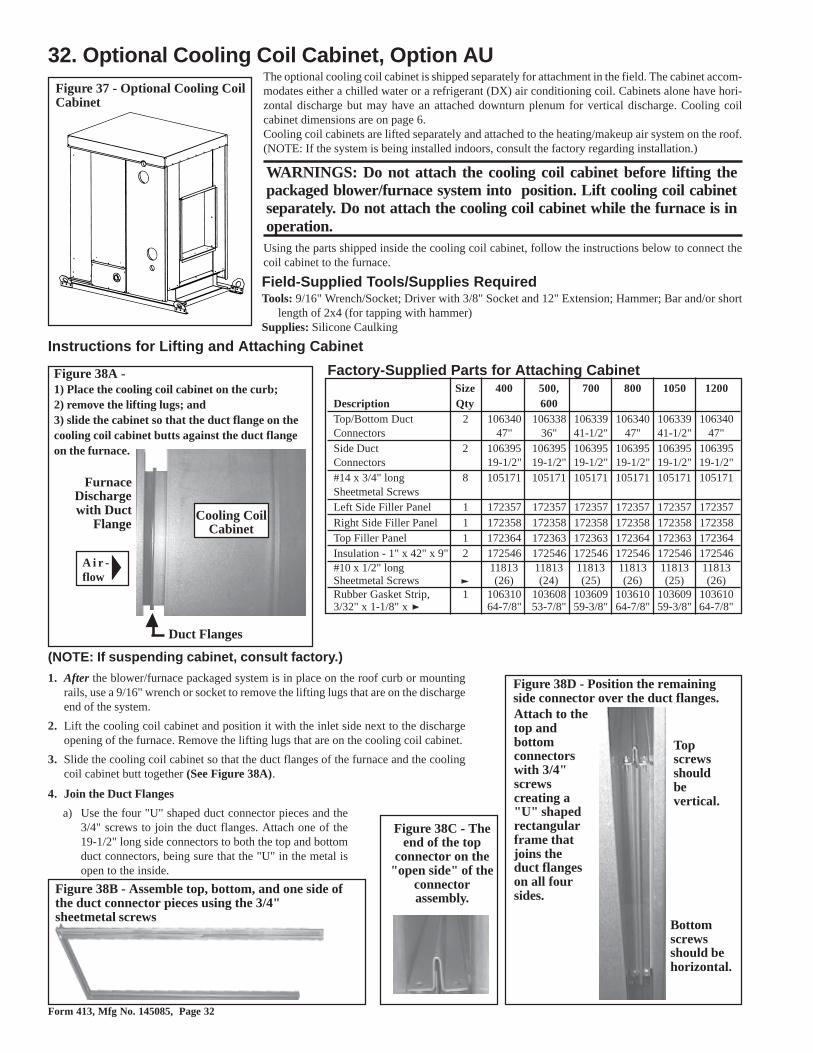
Form 413, Mfg No. 145085, Page 32
32. Optional Cooling Coil Cabinet, Option AUFigure 37 - Optional Cooling CoilCabinet
Field-Supplied Tools/Supplies RequiredTools: 9/16" Wrench/Socket; Driver with 3/8" Socket and 12" Extension; Hammer; Bar and/or short
length of 2x4 (for tapping with hammer)Supplies: Silicone Caulking
The optional cooling coil cabinet is shipped separately for attachment in the field. The cabinet accom-modates either a chilled water or a refrigerant (DX) air conditioning coil. Cabinets alone have hori-zontal discharge but may have an attached downturn plenum for vertical discharge. Cooling coilcabinet dimensions are on page 6.Cooling coil cabinets are lifted separately and attached to the heating/makeup air system on the roof.(NOTE: If the system is being installed indoors, consult the factory regarding installation.)
WARNINGS: Do not attach the cooling coil cabinet before lifting thepackaged blower/furnace system into position. Lift cooling coil cabinetseparately. Do not attach the cooling coil cabinet while the furnace is inoperation.Using the parts shipped inside the cooling coil cabinet, follow the instructions below to connect thecoil cabinet to the furnace.
Instructions for Lifting and Attaching Cabinet
Figure 38D - Position the remainingside connector over the duct flanges.
Topscrewsshouldbevertical.
Figure 38C - Theend of the top
connector on the"open side" of the
connectorassembly.
Figure 38A -1) Place the cooling coil cabinet on the curb;2) remove the lifting lugs; and3) slide the cabinet so that the duct flange on thecooling coil cabinet butts against the duct flangeon the furnace.
Figure 38B - Assemble top, bottom, and one side ofthe duct connector pieces using the 3/4"sheetmetal screws
Factory-Supplied Parts for Attaching CabinetSize 400 500, 700 800 1050 1200
Description Qty 600Top/Bottom Duct 2 106340 106338 106339 106340 106339 106340Connectors 47" 36" 41-1/2" 47" 41-1/2" 47"Side Duct 2 106395 106395 106395 106395 106395 106395Connectors 19-1/2" 19-1/2" 19-1/2" 19-1/2" 19-1/2" 19-1/2"#14 x 3/4" long 8 105171 105171 105171 105171 105171 105171Sheetmetal ScrewsLeft Side Filler Panel 1 172357 172357 172357 172357 172357 172357Right Side Filler Panel 1 172358 172358 172358 172358 172358 172358Top Filler Panel 1 172364 172363 172363 172364 172363 172364Insulation - 1" x 42" x 9" 2 172546 172546 172546 172546 172546 172546#10 x 1/2" long 11813 11813 11813 11813 11813 11813Sheetmetal Screws (26) (24) (25) (26) (25) (26)Rubber Gasket Strip, 1 106310 103608 103609 103610 103609 1036103/32" x 1-1/8" x 64-7/8" 53-7/8" 59-3/8" 64-7/8" 59-3/8" 64-7/8"
Bottomscrewsshould behorizontal.
FurnaceDischargewith Duct
Flange
Duct Flanges
A i r -flow
Cooling CoilCabinet
Attach to thetop andbottomconnectorswith 3/4"screwscreating a"U" shapedrectangularframe thatjoins theduct flangeson all foursides.
(NOTE: If suspending cabinet, consult factory.)
1. After the blower/furnace packaged system is in place on the roof curb or mountingrails, use a 9/16" wrench or socket to remove the lifting lugs that are on the dischargeend of the system.
2. Lift the cooling coil cabinet and position it with the inlet side next to the dischargeopening of the furnace. Remove the lifting lugs that are on the cooling coil cabinet.
3. Slide the cooling coil cabinet so that the duct flanges of the furnace and the coolingcoil cabinet butt together (See Figure 38A).
4. Join the Duct Flanges
a) Use the four "U" shaped duct connector pieces and the3/4" screws to join the duct flanges. Attach one of the19-1/2" long side connectors to both the top and bottomduct connectors, being sure that the "U" in the metal isopen to the inside.

Form 413, Mfg No. 145085, Page 33
b) Position the assembled connectors so that the horizontal screw holes will be in thetop piece at the open side (See Figure 38C). In this position, insert the assembledtop and bottom connectors into the space between the furnace and cooling coil cabi-net.
Tap with a hammer first on the side, then on the top, and last on the bottom of theassembled duct connector until it is seated over the duct flanges.
c) Position the remaining side connector. Use the driver extension to insert the screwsthat attach the side connector to the top and bottom connectors. See Figure 38D.
5. Prepare Cabinets to Install Filler Panels (See Figure 38E.)a) At the side corners of both the cooling coil cabinet and the furnace, remove the
factory-installed screws that attach the cabinet tops.b) Across the edge of the cooling coil cabinet, remove the row of screws that attach the
top.
Figure 38F -Side FillerPanelInstalled
Attach side filler panelwith sheet metal screws.
Figure 38G - Top Filler Panel Installed
Cooling CoilCabinet with
Downturn PlenumFurnaceSection
with DoorPanel
Removed Before the top filler panel is attached, remove thebacking and adhere the gasket strip along the bottom ofthe outside edge so that any gaps between the top fillerpanel and the top panel of the furnace section aresealed.
Filler must be underneaththe top panel.
6. Install the Cabinet Side Filler Panels (SeeFigure 38F.)Place a piece of the supplied insulation againstthe inner panel of the cooling coil cabinet. Slidethe filler panel into place and attach with 1/2"sheetmetal screws. Repeat on the other side.NOTE: It may be easier to slide the filler pan-els in place with the door panels removed.
7. Install the Cabinet Top Filler Panel (See Fig-ure 38G)a) Remove the backing from the gasket strip,
and adhere it along the edge of the bottomof the top filler panel.
b) Slide the filler panel underneath the edgeof the cooling coil cabinet top (NOTE: Theedge of the top panel may have to be pulledout slightly to slide the panel underneath.)The filler panel must be between the cool-ing coil cabinet top and end panel to pre-vent water from leaking into the cabinet.Attach with 1/2" screws.
8. Reinsert Screws and Apply Caulkinga) Reinsert any remaining screws removed in
Step 5. Check for gaps between the top andside filler panels; apply caulking as needed.
b) Apply silicone caulking where the coolingcabinet curb cap meets the furnace curb cap.
9. The cooling coil cabinet is installed. Followthe instructions provided by the cooling coilmanufacturer to make cooling coil connections.
Figure 38E -To installside and topfiller panels,removescrews fromtop cornersof bothcabinets andthe entirerow acrossthe coolingcoil cabinet.
b) Remove row of screwsa)
Removecornerscrews
a) Removecornerscrews
Cooling Coil MaintenanceThe cooling coil cabinet is designed with easily removable panels on both sides of thecabinet to provide access for inspection and cleaning. Inspect the coil during routine main-tenance and whenever the filters are changed. Check the cooling coil for build up of debris;clean as required.

Form 413, Mfg No. 145085, Page 34
1. Damper Motor2. Return Air Damper3. Potentiometer4. Potentiometer5. Mixed Air Controller6. Warm-up Control7. Outside Air Damper8. Damper Motor Transformer
Figure 39A - Location of Controls for 30%Outside Air Hood and Damper Options(AR6 or AR7) - Outdoor Models only
Figure 39B - ControlLocations for 100%
Outside Air and 100%Return Air Damper
Options
Damper Linkage -- When units are equipped with dampers, the dampersare closed during shipment. When there are both return air and outside airdampers, the return damper linkage must be adjusted prior to use.
1. Loosen the set screw on the return air damper rod at the damper arm.
2. Manually open the return air dampers. While the dampers are opening,the damper rod and arm will automatically move to their correct posi-tions.
3. Tighten the set screw.Figure 39C -Example ofOutside Airand Return AirDamper Linkage
NOTE: These illustrations are intended to show location only of various air con-trol accessories and do not represent suggested combinations of acces-sories.
33. Optional Dampers and Controls (See the wiring diagram supplied with the unit.)
Pressure Null Switch (Used to control Outside Air Dampers in Inlet Air Option AR23)
Figure 40 - PressureNull Switch (used
with Inlet AirOption AR23)
ing pressure, reverse the functions of the high and low pressure taps. In eithercase, be sure that the outdoor vent is protected from the wind and screenedfrom insects.
4. Adjustment of the Switch - The "HIGH" actuation point of the null switch isindicated on a calibrated scale secured to the transparent range screw enclo-sure. Building pressure is set by turning the adjustment screw. The "Low"actuation point is set by adjusting the span of the null by turning the spanadjustment screw. The span range is .01 to .03" w.c.
IMPORTANT: To eliminate shipping damage to the switch contacts, the manu-facturer reduced the span adjustment to zero before shipping. The span should
The pressure null switch used in Option AR23 is a Dwyer#1640-0 with a range of .01-.20" w.c. It is shipped separatelyfor field installation. Refer to the following paragraphs andthe manufacturer's installation instructions included with theswitch.Description and Application - The pressure null switch is adiaphragm operated differential pressure switch used inmakeup air applications to control building pressure. It main-tains a selected positive or negative pressure setpoint bychanging the amount of outside air being introduced to thebuilding through the modulating outside air dampers. As morepressure is required in the building, the pressure null switchactivates the damper motor driving the outside air dampertowards the full open position and the recirculated air dampertowards the closed position. Conversely, as less pressure isrequired, the switch drives the dampers in the opposite di-rection.Installation Instructions for Pressure Null Switch1. Select an indoor location free from excessive vibration
where oil or water will not drip onto the switch and whereambient temperature will be within a range of -30oF (dryair) to 110oF.
2. Mount the switch with the diaphragm in a verticalplane. The switch is position sensitive and is calibratedto operate properly when the diaphragm is vertical. Mountswitch securely.
3. Connect the pressure taps on the top of the switch tosources of air pressure differential. Metal tubing with 1/4" O.D. is recommended, but any tubing system whichwill not unduly restrict the air flow may be used. To main-tain a positive building pressure, vent the low pressuretap to the outdoors and allow the high pressure tap tomonitor building pressure. To maintain a negative build-
Form 413, Mfg No. 145085, Page 35
SERVICE AND MAINTENANCE
WARNING: If you turn off the power supply, turn off the gas. See Hazard Levels, page 2.This unit will operate with a minimum of maintenance. To ensure long life and satisfactory performance, a furnace that is operating under normalconditions should be inspected every four months. If the furnace is operating in an area where an unusual amount of dust or soot or other impuritiesare present in the air, more frequent inspection is recommended. When servicing, follow standard safety procedures as well as those specificinstructions and warnings mentioned in this manual.
The following procedures should be carried out at least annually (See Paragraphs 34-38 for specific instructions.):
� Clean all dirt and grease from the primary and secondary combustion air openings.
� Clean the heat exchanger(s) both internally and externally.
� Check the pilot burner and main burners for scale, dust, or lint accumulation. Clean as needed.� Check the vent system for soundness. Replace any parts that do not appear sound.� Check the wiring for any damaged wire. Replace damaged wiring. (See Paragraph 11 for replacement wiring requirements.)
NOTE: Use only factory-authorized replacement parts.
be adjusted prior to using the switch. (If the switch has been installed, disconnect the vent tube so that the null switch is in a neutral position.)Remove the electrical box cover and while observing the contacts, turn the span adjustment screw slowly in a clockwise direction. Continue turningthe adjustment screw until you are able to see gaps between the common and both the low and high contacts. A minimum gap provides the greatestsensitivity. The wider the gap the lower the sensitivity.
5. See the wiring diagram included with the furnace to make electrical connections.
34. Burner Rack RemovalInstructions
Instructions apply to all furnace sections.1. Turn off the gas supply.2. Turn off the electric supply.3. Remove control access side panel.4. Disconnect the pilot tubing and flame sensor lead.5. Mark and disconnect electric valve leads.6. Uncouple the union in the gas supply.7. Remove sheet metal screws in the top corners of the burner rack
assembly.8. Pull "drawer-type" burner rack out of the furnace.
To disassemble the burner rack:1. Remove Carryover System (the type of carryover system depends on
the model and type of gas)Natural Gas - If the burner rack has a flash carryover on the "mani-fold end" of the burner rack, remove that flash carryover. If the burnerrack has a carryover lighter tube, break the lighter tube connection atthe orifice and remove the supply tubing, the drip shield, and thelighter tube.Propane Gas - All propane burner racks have a regulated lightertube carryover. Break the lighter tube connection at the regulator andremove the lighter tube orifice supply tubing; remove the retainingscrews in the drip shield and the shield; remove the screws and slideout the lighter tube.
2. Pull main burners horizontally away from injection opening and liftout.
3. Remove manifold bracket screws and remove manifold.4. Change main burner orifices, if necessary.5. Remove screws and lift out pilot burner.Follow the instructions in Paragraph 34 to clean. To re-assemble andreplace, reverse the above procedures being careful not to create anyunsafe conditions.
CAUTION: When cleaning, wearing eye protectionis recommended.
35. Cleaning Pilot and MainBurners
In the event the pilot flame is short and/or yellow, check the pilotorifice for blockage caused by lint or dust accumulation. Remove thepilot orifice and clean with air pressure. DO NOT REAM THE ORI-FICE. Check and clean the aeration slot in the pilot burner.Clean the metal sensing probe and the pilot hood with an emery clothand wipe off the ceramic insulator. Check the spark gap; spark gapshould be maintained to 7/64". After the pilot is cleaned, blow any dirtaway with compressed air.Main burners may be cleaned using air pressure. Use an air nozzle toblow out scale and dust accumulation from the burner ports. Alter-nately blow through the burner ports and the venturi. Use a fine wireto dislodge any stubborn particles. Do not use anything that mightchange the port size.
Clean the burner rack carryover systems with air pressure.
36. Cleaning the Heat ExchangerTo clean the outer surfaces (circulating air side) of the heat exchanger,gain access by removing the inspection panels in the ductwork or re-move the ductwork. Use a brush and/or an air hose to remove accumu-lated dust and grease deposits from the heat exchanger tubes and thebaffles.Gain access to the inner surfaces (combustion air side) of the heatexchanger by removing the burner rack and also following the appro-priate instructions below. An air hose; an 18-24" long, 1/2" diameterfurnace brush (or heavy wire with steel wool securely attached); a flash-light; and a mirror are needed. The required procedure depends on thedate of manufacturer and whether or not the furnace is rated for high(80%) efficiency. Furnaces designed to provide high efficiency heat-ing have "V" shaped baffles in the top of each heat exchanger tube.Follow these instructions to remove these baffles when cleaning theinner surfaces of the heat exchanger.NOTE: High efficiency furnaces manufactured prior to 3/95 have a"C" prefix in their model designation. All furnaces manufactured be-ginning 3/95 are designed for high efficiency and include these heatexchanger "V" baffles.

Form 413, Mfg No. 145085, Page 36
Instructions to Remove Heat Exchanger "V" Baffles:Outdoor, Gravity Vent Models (See Figure 39)1) Remove the ends of the flue gas collection box. On the control side of the
furnace, remove the block-off plate to gain access to the collection box end.2) Remove the flue diverter. Remove the screw at each end and slide the flue
diverter out of the furnace.3) Pull the "V" baffles out of the heat exchanger.Outdoor, Power Vent Models1) Remove the ends of the flue gas collection box. On the control side of the
furnace, remove the venter assembly and the flue outlet duct to gain accessto the collection box end.
2) Sizes 500 and 600 -- Remove one of the tube baffle retaining angles oneach inside wall of the collection box. Each tube baffle angle has one screw.Sizes 400, 700, 800, 1050 and 1200 -- Remove the inner baffle from theflue collection box. On the control side, align the inner baffle with the slotin the collection box edge. Pull the inner baffle until it clears the heat ex-changer. Remove the screw at each end and slide the flue diverter out of thefurnace.
3) Pull the "V" baffles out of the heat exchanger.Indoor, Power Vent Models1) Remove the ends of the "internal" flue gas collection box. On the control
side of the furnace, remove the block-off plate to gain access to the collec-tion box end.
2) Remove the flue diverter. Remove the screw at each end and slide the fluediverter out of the furnace.
3) Pull the "V" baffles out of the heat exchanger.All Models -- Clean the inner surfaces of the heat exchanger from beneath
using the brush to "scrub" the tube walls to remove any accumulated dust, rustand/or soot. Clean the "V" tubes and re-assemble the heat exchanger and thefurnace.
Check the furnace for proper operation.
Figure 41 - Remove "V" Baffles to Clean Inner Surface ofHeat Exchanger Tubes
37. Blower BearingsThe blower bearings on models with less than a 10 HP motor(standard blower) are permanently lubricated cartridge ball bear-ings and do not require greasing.
The blower bearings on models equipped with 10-20 HP mo-tor are pillow block ball bearings and are equipped with a greasefitting. (NOTE: Models with 10 HP motor manufactured priorto 1/91 have permanently lubricated ball bearings.) The pillowblock bearings with a grease fitting should be lubricated twicea year with a high temperature, moisture-resistant grease (TypeNLGI-1 or -2 standard grease is recommended). Be sure toclean the grease fitting before adding grease. Add grease witha handgun until a slight bead of grease forms at the seal. Becareful not to unseat the seal by overlubricating. NOTE: If un-usual environmental conditions exist (temperatures below 32°For above 200oF; moisture; or contaminants), more frequent lu-brication is required.
CAUTION: If the blower is unused formore than three months, bearings with agrease fitting should be purged with newgrease prior to start-up.
36. Cleaning the Heat Exchanger(cont'd)

Form 413, Mfg No. 145085, Page 37
38. Filter Arrangements and Replacement FiltersQuantity and Size of Optional Filters
Type 400, 800, 1200 500, 600 700, 1050Disposable (2) 16 x 16, (1) 16 x 25 (1) 16 x 25, (1) 16 x 20 (2) 16 x 25, (4) 12 x 30,1" or 2" (4) 12 x 25, (4) 12 x 30 (4) 12 x 20, (4) 12 x 25 (4) 12 x 20
Permanent (2) 16 x 16, (8) 12 x 16 (1) 16 x 20, (4) 12 x 20 (2) 16 x 25 1" or 2" (1) 16 x 25, (4) 12 x 26 (1) 16 x 25, (4) 12 x 26 (8) 12 x 26 Pleated (2) 16 x 16, (4) 12 x 25 (1) 16 x 20, (1) 16 x 25 (2) 16 x 25, (4) 12 x 32,1" or 2" (1) 16 x 25, (4) 12 x 32 (4) 12 x 20, (4) 12 x 25 (4) 12 x 20
The arrangements in Figures 42A - 44C applyto outdoor models manufactured beginning 9/91 (Serial No. Date Code AQ1) and to the in-door models in this booklet.
The instructions and arrangements in Figure45A-C at the bottom of the page apply to theoutdoor models in this booklet that were manu-factured prior to 9/91.

Form 413, Mfg No. 145085, Page 38
39. TroubleshootingTROUBLE PROBABLE CAUSE REMEDYVenter motor 1. No power to the furnace. 1. Turn on power, check supply fuses or circuit breaker.will not start 2. No 24-volt power to venter relay. 2. Turn up thermostat, check control transformer output. Check for loose or
improper wire connections.3. Venter relay defective. 3. Replace.4. Defective motor or capacitor. 4. Replace defective part.
Pilot will 1. M anual valve not open. 1. Open manual valve.not light 2. Air in gas line. 2. Bleed gas line.(Venter 3. Dirt in pilot orifice. 3. Remove and clean with compressed air or solvent (do not ream). operating 4. Gas pressure too high or too low. 4. Adjust supply pressure. (See Paragraph 10). on power- 5. Kinked pilot tubing. 5. Replace tubing.vented 6. Pilot valve does not open. 6. If 24 volt available at valve, replace valve. models) 7. No spark: 7.
a) Loose wire connections a) Be certain all wires connections are solid.b) Transformer failure. b) Be certain 24 volts is available. c) Incorrect spark gap. c) M aintain spark gap at 7/64".d) Spark cable shorted to ground. d) Replace worn or grounded spark cable. e) Spark electrode shorted to ground. e) Replace pilot if ceramic spark electrode is cracked or grounded. f) Drafts affecting pilot. f) M ake sure all panels are in place and tightly secured to prevent drafts at pilot. g) Ignition control not grounded. g) M ake certain ignition control is grounded to furnace chassis.h) Faulty ignition controller. h) Replace ignition controller.8. Optional lockout device interrupting control circuit by above causes.
8. Reset lockout by interrupting control at thermostat.
9. Faulty combustion air proving switch. 9. Replace combustion air proving switch. 10. Activated blocked vent switch (indoor system) 10. Correct venting problem. Reset switch.
Pilot lights, 1. M anual valve not open. 1. Open manual valve.main valve 2. M ain valve not operating. 2.will not open a) Defective valve. a) If 24 volt is measured at valve connections and valve remains closed, replace
valve.b) Loose wire connections. b) Check and tighten all wiring connections.3. Ignition control does not power main valve. 3.a) Loose wire connections. a) Check and tighten all wiring connections.b) Flame sensor grounded. (Pilot lights - spark continues)
b)Be certain flame sensor lead is not grounded or insulation or ceramic is not cracked. Replace as required.
c) Gas pressure incorrect. c) Adjust gas pressure. (See Paragraph 10.)d) Cracked ceramic at sensor. d) Replace sensor.e) Faulty ignition controller. e) See Paragraph 25. If all checks indicate no other cause, replace ignition
controller. Do not attempt to repair the ignition controller. This device has no field replaceable parts.
f) Poor microamp signal f) Adjust pilot regulatorNo heat 1. Dirty filters in blower system.. 1. Clean or replace filters.(Heater 2. Incorrect manifold pressure or orifices. 2. Check manifold pressure (See Paragraph 10).Operating) 3. Cycling on limit control. 3.Check air throughput (See Paragraph 12).
4. Improper thermostat location or adjustment. 4. See thermostat manufacturer's instructions. 5. Belt slipping on blower 5. Adjust belt tension
Cold air 1. Fan control improperly wired 1. Connect as per wiring diagram. On Startup 2. Defective fan control. 2. Replace fan control. During 3. Incorrect manifold pressure. 3. Check manifold line pressure (See Paragraph 10). Operation 4. Blower set for too low temperature rise. 4. Slow down blower or increase static pressure.Motor will 1. Circuit open 1. Check wiring and connections.not run 2. Fan Control inoperative 2. Replace fan control.
3. Contactor inoperative 3. Replace contactor.4. Defective motor. 4. Replace motor.
Motor turns 1. Fan control heater element improperly wired. 1. Connect as per wiring diagramon and off 2. Defective fan control 2. Replace fan controlwhile burner 3. M otor overload device cycling 3. Check motor load against motor rating place. Replace motor or overload device.is operating 4. 3-phase motor rotating in opposite direction 4. Interchange two legs of supply connections.Motor cuts 1. Improper motor pulley adjustment 1. See instructions on air throughput (See Paragraph 12).out on 2. Improper static pressure on duct system 2. Adjust dampers in duct system.overload 3. Low voltage 3. Check power supply.

Form 413, Mfg No. 145085, Page 39
MAINTENANCE AND TROUBLESHOOTING REFERENCES:� For additional maintenance and service information, refer to specific paragraphs in the Installation and
Operating Section or the Optional Equipment Section of this booklet. (See Index on page 1.)
� For Troubleshooting and additional information about the optional evaporative cooling module, refer toForm RGM 400-EC (formerly RGM 412/413-EC), installation manual shipped with the evaporativecooling module.
� For Troubleshooting Guide for Optional Electronic Modulation Gas Control Options with 20% Turn-down (Option AG39 or AG40), see page 25
� For replacement parts, refer to Form RGM 707.
39. Troubleshooting (cont'd)

Form 413, Mfg No. 145085, Page 40
FIRST: Contact the installer.
Name _______________________________________________________________________________________
Address ________________________________________________________________________________________
________________________________________________________________________________________
________________________________________________________________________________________
Phone ________________________________________________________________________________________
SECOND: Contact the nearest distributor (See Yellow Pages). If no listing,contact Authorized Factory Representative, 1-800-695-1901 (Press 1).
THIRD: Contact: REZNOR®/ Thomas & Betts Corporation
150 McKinley Avenue
Mercer, PA 16137
Phone: (724) 662-4400
Model No. ____________________________________________
Unit Serial No. ________________________________________
Date of Installation ____________________________________
FOR SERVICE OR REPAIR, FOLLOW THESE STEPS IN ORDER:
©2000 Thomas & Betts Corporation, All rights reserved. Printed in the U.S.A.
MANUFACTURER OF GAS, OIL, ELECTRIC HEATING AND VENTILATING SYSTEMS
Trademark Note: Reznor® is registered in the United States and other countries.
5/00 3M YL 8855 Form 413 (Version C.1)