Embed Size (px)
Citation preview

Form 706, Page 1
IMPORTANT1. Always include complete heater model and serial number so that
any specification change can be considered for parts shipment. Itcan save time and expense.
2. Specifications are subject to change without notice.3. We reserve the right to substitute functional replacements.4. Order by Part No.; not Heater Option Designation.
APPLIES TO: Replacement Parts
Model CAUA and CasedCooling Coil Model ACU
Parts Form RZ 706
REZNORMERCER, PA. USA 16137
UNIT HEATERCATEGORY III
ANSI Z83.8 [ AA ] - [ A ] CGA 2.6 [ AA' ] -M [ A' ] UNIT HEATER
MODEL [ B ] [ C ]
SERIAL NO. [ D ] HP[ E ] VOLTS [ E ] PH [ E ] HZ MAXIMUM TOTAL INPUT [ E ] AMPS
TYPE OF GAS: [ F ]ORIFICE SIZE [ J ] DRILL HAS BEEN FACTORY ADJUSTED
FOR USE AT [ H ] FEET [ I ] METERS OF ALTITUDE.
SEA LEVEL ALT. ADJUSTED
NORMAL INPUT [ S ] [ K ]BTU/HR.
THERMAL OUTPUT CAPACITY [ T ] [ L ]BTU/HR.
MINIMUM INPUT (-2 MODELS) [ U ] [ M ]BTU/HR.
NORMAL MANIFOLD PRESSURE [ N ] IN.W.C.
MIN. PERMISSIBLE GAS SUPPLY PRESSURE
FOR PURPOSE IF INPUT ADJUSTMENT [ O ] IN.W.C.
EQUIPPED FOR OPERATION AT AN AIRFLOW OF[ W ] SCFM
AGAINST A STATIC PRESSURE OF [ X ] IN. W.C.
DRIVE NO. [ Y ]
CLEARANCES TO COMBUSTIBLE CONSTRUCTION: TOP-3", FLUE
CONNECTION-6", LEFT SIDE-0", RIGHT SIDE-0", BOTTOM-0", REAR 0"
THIS UNIT MAY BE USED WITH DUCTS.
FILTERS, WHEN USED, MUST BE INSTALLED EXTERNAL TO THE
FURNACE CASING.
Rating Plate Sample
Rating Plate Key:AA/A = Date of ANSI Standard
AA1/A1 = Date of CGA Standard
B = Model No.
C = Month and Year ofManufacture
D = Blower Motor HP
E = Volts, Phase, andMaximum Input Amps
F = Natural or Propane Gas
H/I = Elevation (Feet/Meters)
J = Orifice Size
S = BTU Input Sea Level
K = BTU Input AltitudeAdjusted
T = BTU Thermal Output SeaLevel
Index .................................................... PageBase, Inlet .................................................................................... 19
Blowers and Components .............................................................. 8
Burner Rack ................................................................................... 4
Cabinet Parts, Cased Cooling Coil .............................................. 18
Cabinet Parts, Furnace/Blower ...................................................... 2
Concentric Adapter (separated-combustion installation) .............. 4
Contactor ....................................................................................... 6
Cooling Coil ................................................................................ 18
Dampers and Controls (Mixing Box) .......................................... 16
Discharge Plenum ........................................................................ 19
Drives (Belt Drive) ................................................................. 11-14
Electrical Components ................................................................... 6
Filter Cabinet ............................................................................... 15
Filter Racks (Mixing Box) .......................................................... 16
Filters (Filter Cabinet) ................................................................. 15
Filters (Mixing Box) .................................................................... 16
Flame Rollout Switch .................................................................... 6
Heat Exchanger ............................................................................. 4
Ignition Board ................................................................................ 6
Limit Control ................................................................................. 6
Linkage (Damper Motor) ............................................................ 16
Linkage (Direct-Drive Blower Motor) .......................................... 8
Manifold ........................................................................................ 4
Mixing Box .................................................................................. 16
Motor (Blower), Belt Drive ...................................................... 8-11
Motor (Blower), Direct Drive ....................................................... 6
Pressure Switch ............................................................................. 6
Relays ............................................................................................ 6
Serial Number Designation ........................................................... 2
Starters and Overloads .............................................................. 8-11
Transformer ................................................................................... 6
Vent Cap (Same as Option CC1) ................................................... 4
Vent/Combustion Air Kit (Same as Options CC2 and CC6) ......... 4
Venter ............................................................................................. 3
Vibration Isolators ......................................................................... 3
L = BTU Thermal OutputAltitude Adjusted
U = BTU Minimum Input SeaLevel (with 2-stage gasvalve, -2 Model)
M = BTU Minimum InputAltitude Adjusted (with 2-stage gas valve, -2 Model)
N = Manifold Pressure (3.5w.c. Natural Gas; 10 w.c.Propane Gas)
O = Minimum Gas supplyPressure (5.0 w.c. NaturalGas; 11.0 w.c. PropaneGas)
W = SCFM Airflow
X = inches w.c. Static Pressure
Y = Drive No.
Model CAUAUpflow Furnace/Blower Unit witha Cased CoolingCoil
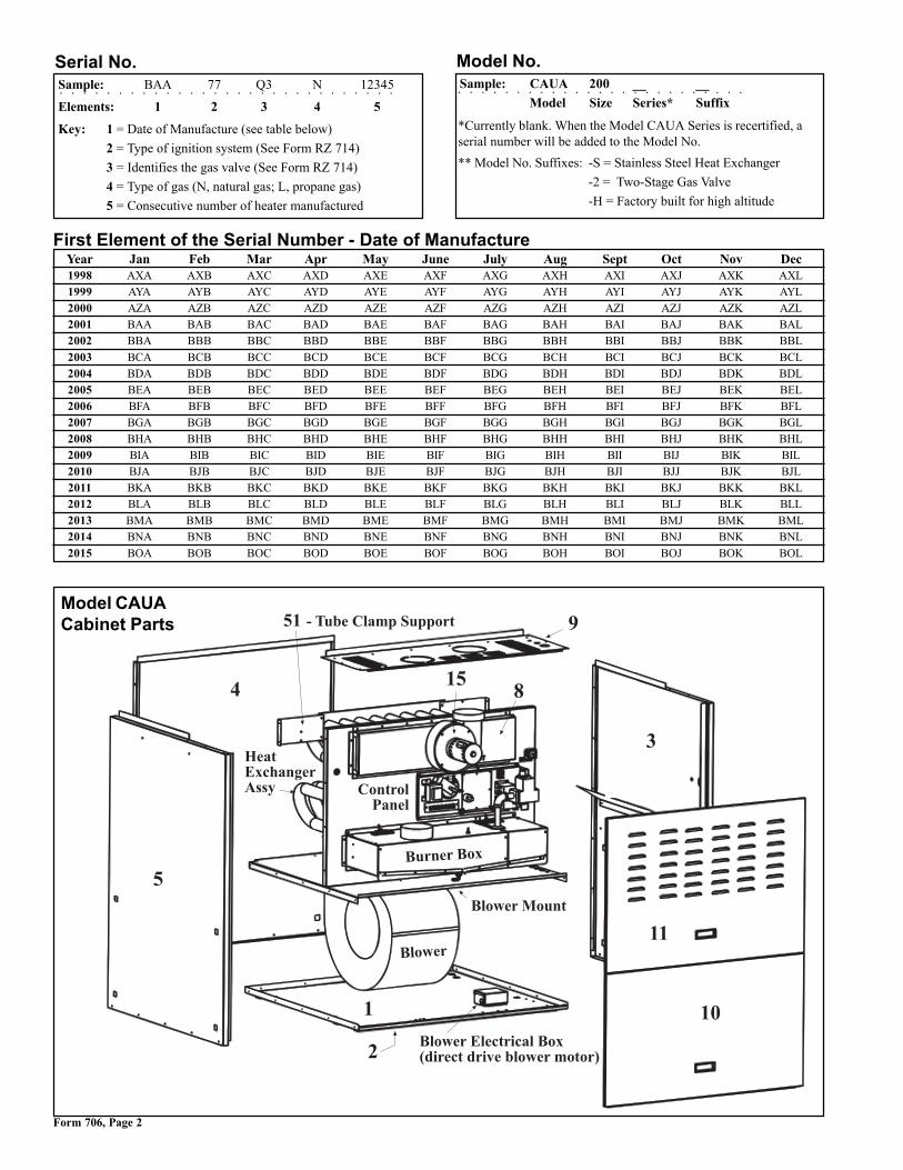
Form 706, Page 2
First Element of the Serial Number - Date of ManufactureYear Jan Feb Mar Apr May June July Aug Sept Oct Nov Dec1998 AXA AXB AXC AXD AXE AXF AXG AXH AXI AXJ AXK AXL
1999 AYA AYB AYC AYD AYE AYF AYG AYH AYI AYJ AYK AYL
2000 AZA AZB AZC AZD AZE AZF AZG AZH AZI AZJ AZK AZL
2001 BAA BAB BAC BAD BAE BAF BAG BAH BAI BAJ BAK BAL
2002 BBA BBB BBC BBD BBE BBF BBG BBH BBI BBJ BBK BBL
2003 BCA BCB BCC BCD BCE BCF BCG BCH BCI BCJ BCK BCL
2004 BDA BDB BDC BDD BDE BDF BDG BDH BDI BDJ BDK BDL
2005 BEA BEB BEC BED BEE BEF BEG BEH BEI BEJ BEK BEL
2006 BFA BFB BFC BFD BFE BFF BFG BFH BFI BFJ BFK BFL
2007 BGA BGB BGC BGD BGE BGF BGG BGH BGI BGJ BGK BGL
2008 BHA BHB BHC BHD BHE BHF BHG BHH BHI BHJ BHK BHL
2009 BIA BIB BIC BID BIE BIF BIG BIH BII BIJ BIK BIL
2010 BJA BJB BJC BJD BJE BJF BJG BJH BJI BJJ BJK BJL
2011 BKA BKB BKC BKD BKE BKF BKG BKH BKI BKJ BKK BKL
2012 BLA BLB BLC BLD BLE BLF BLG BLH BLI BLJ BLK BLL
2013 BMA BMB BMC BMD BME BMF BMG BMH BMI BMJ BMK BML
2014 BNA BNB BNC BND BNE BNF BNG BNH BNI BNJ BNK BNL
2015 BOA BOB BOC BOD BOE BOF BOG BOH BOI BOJ BOK BOL
Serial No.
○ ○ ○ ○ ○ ○ ○ ○ ○ ○ ○ ○ ○ ○ ○ ○ ○ ○ ○ ○ ○ ○ ○ ○ ○ ○ ○ ○ ○
Sample: BAA 77 Q3 N 12345
Elements: 1 2 3 4 5
Key: 1 = Date of Manufacture (see table below)
2 = Type of ignition system (See Form RZ 714)
3 = Identifies the gas valve (See Form RZ 714)
4 = Type of gas (N, natural gas; L, propane gas)
5 = Consecutive number of heater manufactured
Model No.
○ ○ ○ ○ ○ ○ ○ ○ ○ ○ ○ ○ ○ ○ ○ ○ ○ ○ ○ ○ ○ ○ ○ ○ ○
Sample: CAUA 200 __ __
Model Size Series* Suffix
*Currently blank. When the Model CAUA Series is recertified, aserial number will be added to the Model No.
** Model No. Suffixes: -S = Stainless Steel Heat Exchanger
-2 = Two-Stage Gas Valve
-H = Factory built for high altitude
�
�
����������� ��������� �
�
��
���
�
�� �
������������ !
"�����"��
"��#��$����
"��#�
"��#�������%����"��&'%����'�%(����#�� ����)
������*���
Model CAUACabinet Parts

Form 706, Page 3
Cabinet Parts and Venter AssemblyCode Description Qty 150 200 250 300 350 4001 Bottom Panel 1 160133 160133 160134 160134 -- --
Bottom Panel - Front Half 1 -- -- -- -- 170198 170198Bottom Panel - Rear Half (unit without inlet base) 1 -- -- -- -- 170199 170199Bottom Panel - Rear Half (unit with inlet base) 1 -- -- -- -- 176361 176361
1A Insulation for Bottom Panel, Code 1 1 177624 177624 177627 177627 177628 1776282 Cabinet Supports (legs) - with direct drive motor 2 161155 161155 161156 161156 161156 161156
Cabinet Supports (legs) - with belt drive motor 1 161155 161155 161156 161156 161156 1611562 166748 166748 166749 166749 166749 166749
3 Left Side Panel Assy (includes panel, insulation, 1 163183 163184 163451 163452 163453 164516hole plug, and air deflector)
3A Left Side Panel only 1 160125 160125 160125 160125 160126 1601263B 5/8" Hole Plug, Heyco #DP625 1 111096 111096 111096 111096 111096 1110963C Air Deflector 1 164701 164700 164701 165017 164701 1647003D Insulation in Left Side Panel Assembly, Code 3 1 177622 177622 177622 177622 177626 1776264 Rear Panel Assy (includes panel and insulation) 1 163170 163170 163171 163171 163172 1631725 Right Side Panel Assy (includes panel, insulation, 1 175274 175275 175276 175277 175278 175279
bushing, hole plug, and air deflector)5A Right Side Panel only 1 160123 160123 160123 160123 160124 1601245B Air Deflector 1 164701 164700 164701 165017 164701 1647005C Insulation in Right Side Panel Assy, Code 5 1 177622 177622 177622 177622 177626 177626
1 160896 160896 160896 160896 163173 1631735D 1/2” Bushing 1 29871 29871 29871 29871 29871 298715E 5/8" Hole Plug, Heyco #DP625 1 111096 111096 111096 111096 111096 1110966 Tube for Limit Control Capillary (not illustrated) 1 165030, 51" long 165031, 55-1/2" long 165032, 62-5/8" long7 Limit Bracket 1 141676 141676 141676 141676 141676 1416768 Flue Wrapper Assy (including gaskets) 1 160186 160187 160188 160189 160190 1601918A Top/Bottom Gaskets for Flue Wrapper Assy 2 147651 147651 147651 147651 147651 1476518B Side Gasket for Flue Wrapper Assy 2 161160 161160 161161 161161 161162 1611629 Top Panel 1 160130 160130 160131 160194 160132 16013210 Btm Access Door Assy (insulated door w/handle) 1 165046 165046 165047 165047 165047 165047
11 Top Access Door Assy (door panel with handle) 1 165048 165048 165049 165049 165049 165049
12 Vibration Isolator Kit (same as Option PC4) 1 166769 166769 166769 166769 166770 166770
12A Vibration Isolator (black isolator pad for under 4 166720 166720 166720 166720 166721 166721each corner), Kinetics Model #RCB-120 (black with orange marking) #RCB-220(green mrkng)
15 Venter Housing Assy (includes housing, 1 164539 164540 164540 164541 164697 164697collar, and static pressure tap)
16 Venter Gasket (not illustrated) 1 155650 155650 155650 155650 155649 15564917 Venter Motor and Wheel Assy (includes 17A-G) 1 174010 162895 162895 162895 164542 16454217A Venter Motor, Magnetek 1 161416 161416 161416 161416 134974 134974
#JE1F025N #JE1J009N17B Fan, PM Motor Co., 2.25" dia x 3/8" bore 1 141570 141570 141570 141570 141570 14157017C Spirol Spacer, #3 x 3/4" long 4 97721 97721 97721 97721 97721 9772117D Venter Motor Support Ring 1 125346 125346 125346 125346 125346 12534617E Venter Motor Plate 1 151515 160930 160930 160930 160930 16093017F Kep Nut, #8-32 4 31522 31522 31522 31522 31522 3152217G Wheel, 2" x 6-1/4" dia, 3/8" bore 1 135980 135980 135980 135980 135980 13598018 Venter Motor Plate Gasket 1 155652 155652 155652 155652 155652 155652
�+
�+�
�+,�+� �+-
�+.
�+"&���'�#%��������#�!�/�� � ����)
Code 17 - Venter Motorand Wheel Assembly
Code 12A - VibrationIsolator Pad
Code 12, Vibration IsolatorKit, same as Option PC4,
includes four pads.

Form 706, Page 4
Code Description Qty 150, 200 250, 300, 350, 40019 Vent Cap (same as Option CC1) 1 111849, 5” 111849, 5” 111850, 6”20 Vertical Vent/Combustion Air Kit 1 157156 54444 54444
(same as Option CC2)20A Concentric Adapter Assembly 1 155392 68404 6840420B Exhaust Cap Assembly 1 155631, 4” 53326, 5” 53326, 5”20C Inlet Air Cap Assembly 1 155635, 6” 53330, 8” 53330, 8”20D Rubber Seal (blue) for Exhaust Pipe 1 164492, 4” 164493, 5” 164493, 5”20E Clear Sealant, 3 oz tube, D.C. #732 1 53335 53335 5333521 Horizontal Vent/Combustion Air Kit 1 157158 82131 82131
(same as Option CC6)21A Concentric Adapter Assembly 1 155392 68404 6840421B Exhaust Cap Assembly 1 155096 53316 5331621C Inlet Guard Assembly 1 151755 124940 12494021D Screws, #10-16 x 1/2" long 4 37661 37661 3766121E Rubber Seal (blue) for Exhaust Pipe 1 164492, 4” 164493, 5” 164493, 5”21F Clear Sealant, 3 oz tube, D.C. #732 1 53335 53335 53335
Vent Cap and Vent/Combustion Air Kits (for separated combustion installation)
Code 19 -Vent Cap
Codes 20A and 21A - Concentric Adapter Assembly for Separated-Combustion
Codes 20B -Exhaust Capfor VerticalSeparated-Combustion
Codes 20C -Inlet AirCap forVerticalSeparated-Combustion
Codes 21B -ExhaustCap forHorizontalSeparated-Combustion
Codes 21C -Inlet Air Guardfor HorizontalSeparated-Combustion
Collar for attachingthe combustion airpipe from the heater
Opening for vent pipe from theheater. Seal with rubber gasket.The vent pipe extends throughthe box.
Important NOTE: Concentricadapter boxes manufactured priorto 2/01 had a collar on the "heaterconnection side" to attach the ventpipe. There was a factory-installedlength of vent pipe through the box.If replacing a concentric adapterbox manufactured prior to 2/01, thefield-supplied vent pipe must be ex-tended through the new box. Code20D or 21E, rubber gasket, is re-quired to seal the opening aroundthe vent pipe as it extends into thebox.
Collar for attaching the outside portionof the combustion air pipe (the vent piperuns concentric through the outsideportion of the combustion air pipe)
View of Heater Connection Side View of Vent Terminal Connection Side
Burner Box and Heat ExchangerCode Description Qty 150 200 250 300 350 40024 Burner Box 1 193997 193997 193998 193998 193999 19399925 Drain Hole Seal 1 165741 165741 165741 165741 165741 16574126 Manifold 1 151787 151788 160931 160932 160933 16093427 Burner/Manifold Support 2 160437 160437 160928 160928 160928 16092828 Burner Orifices (sea level) > 8 10 13 15 12 14
Natural Gas 164866 11833 11833 11833 11835 458702.1MM #44 #44 #44 #37 #38
Propane Gas 97359 11830 97359 11830 9789 616531.25MM #55 1.25MM #55 #53 1.55MM
29 Burner Rack Assy (including burners and support rack) 1 163104 163105 163106 163107 163108 16310929A Burner Support Rack 1 160625 160625 160626 160626 160627 16062729B Burner, Beckett > 8 10 13 15 12 14
164870 164870 164870 164870 164869 164869#RZ11 #RZ10
30 Burner Box Air Baffle - Left (inside the burner box) 1 -- -- -- -- 166317 16631731 Burner Box Air Baffle - Right (inside the burner box) 1 -- -- -- -- 166318 16631832 Burner Box Gasket - Front Bottom 2 162806 162806 162807 162807 162808 16280833 Burner Box Gasket - Front Side 2 162800 162800 162800 162800 169939 16993934 Burner Box Gasket - Top Side 2 162801 162801 162801 162801 162801 16280135 Burner Box Gasket - Side 2 162809 162809 162809 162809 169940 16994036 Burner Box Gasket - Bottom Rear 2 161171 161171 161172 161172 161173 161173

Form 706, Page 5
Code Description Qty 150 200 250 300 350 400*37 Burner Box Cover - Right Half Assy (including cover, gaskets, 1 175280 175281 175282 175283 175284 175285
and viewport)37A Burner Box Cover Right Half Gasket - Top 1 162803 162803 162803 162803 169938 16993837B Burner Box Cover Right Half Gasket - Front 1 162804 162804 162804 162804 162804 16280437C Burner Box Cover Right Half Gasket - Right 1 162811 162811 162812 162812 162813 162813*38 Burner Box Cover - Left Half (Sizes 150-300 include collar) 1 194003 194004 194024 194025 160936 16093739 Burner Box Cover Gasket - Left 1 162814 162814 162815 162815 162816 16281640 Air Inlet Box (on top of the burner box, Sizes 350 and 400) 1 -- -- -- -- 166315 16631541 Air Inlet Box Gasket - Side 2 -- -- -- -- 169937 16993742 Air Inlet Box Gasket - Front 1 -- -- -- -- 169936 16993643 Air Inlet Cover with inlet air collar 1 -- -- -- -- 166530 16653044 Viewport Gasket (left side) 1 116037 116037 116037 116037 116037 11603745 Viewport (left side) 1 115984 115984 115984 115984 115984 11598446 Viewport Retainer (left side) 1 142711 142711 142711 142711 142711 14271147 Static Pressure Tap, TDI #AA3743 2 116043 116043 116043 116043 116043 11604348 Burner Front Cover 1 194124 194124 194125 194125 194126 19412649 Burner Cover Gasket 1 194127 194127 194128 194128 194132 19413250 Burner Condensate Drain Kit (for use with cooling coil) 1 165951 165951 165951 165951 165951 16595151 Tube Clamp Support (see illustration on page 2) 2 163435 163436 163437 163438 163439 16344052 Replacement Heat Exchanger Assy - Aluminized Steel 1 169963 169964 169965 169966 169967 169968
Replacement Heat Exchanger Assy - Stainless Steel 1 169969 169970 169971 169972 169973 169974
0��1����.�� �� �� 1��������2
������'
-� �3��(
0�+
"�����"�����'"�����4��2
��
�1
��
�'�1����5% %��������#%�����%����!
3%#�/�� ����"���� ������������ �������������� �����������������������������������
������������
��
�'���6,��%��7%�6�%����' 89�!��*:;�������, ��%��%����������1������1�/���������/��:�<�=>,>����%����������1��������?�;!����.%��%��6��:�<�;*�����:�<����%������������1�����:�<�;*��"�� �;����������+���+���:�<�5��2���6���6��@"������������1���������%���A� ������������������;!����A%���% 6��@"�B�C���$��������+��1���������"� �%��6��!����"�1����
0�� 0�+
Model CAUA Burner Box andHeat Exchanger
*IMPORTANT: Burner box covers were rede-signed for easier access. If replacing burner boxcovers (Code 37 or 38) on a unit manufactured priorto 1/01, it is necessary to order the right side (Code37), the left side (Code 38), left side gasket (Code39), the front cover (Code 48) and the burner covergasket (Code 49).

Form 706, Page 6
Electrical Components (See page 9 for belt-drive blower motors and starters and page 15 for damper controls.)
Code Description Location 150 200 250 300 350 40060 Flame Sensor, Channel Products 1259-85 Burner Box 147165 147165 147165 147165 147165 14716561 Limit Control, Thermodisc #10H11 Right Side 148588 148588 164792 164792 148588 148588
(See page 4) 270°F, 60" 300°F, 54" 270°F, 60"
62 Spark Electrode, Channel Products #1659-92 Burner Box 147166 147166 147166 147166 147166 14716663 Spark Electrode Boot Burner Box 156032 156032 156032 156032 156032 15603264 Ignition Cable, RAM - P/N 147167, #HV96005; Burner 147167 148085 147167 148085 147167 148085
P/N 148085, #HV96009 Box 12" 18" 12" 18" 12" 18"65 Flame Rollout Switch, TOD #35TX46 Burner 112752 112752 121275 121275 112752 112752
Box 225°F 225°F 275°F 275°F 225°F 225°F66 Transformer, Products Unlimited Control 164328 164328 164328 164328 164328 164328
#400-09V28CH80, 40VA, 208/230V to 24V Panel67 Transformer, Hevi-Duty #HS1B250, 480/240, Control 166740 166740 166740 166740 166740 166740
.25 KVA Enclosed Panel68 Transformer, Hevi-Duty #HS10B250, 575/240, Control 113556 113556 113556 113556 113556 113556
.25 KVA Enclosed Panel69 Transformer Bracket Control Panel 164518 164518 164518 164518 164518 16451870 Transformer, 208/240 to 24V, 40VA, BE21539001 Mixing Box 103497 103497 103497 103497 103497 10349771 Ignition Board, 230V, J/C #G822KCC-5401 D Control Panel 193804 193804 193804 193804 193804 193804
(For unit mfgd before 8/00, order Ignition Control Conversion Kit, P/N 178436)72 Pressure Switch, .75", 0 - 4000 ft elevation Control Panel 173317 173317 173317 173317 173317 17331773 Pressure Switch for High Altitude above 4000 ft, Control Panel 173318 173318 173318 173318 173318 173318
.70" w.c.74 7-Pole Terminal Strip (Thermostat) Control Panel 164544 164544 164544 164544 164544 16454475 Terminal Strip, Doran #5959-7 Control Panel 164545 164545 164545 164545 164545 16454576 Locking Wire Saddle, LWS-A-3-01 Control Panel 123606 123606 123606 123606 123606 12360677 Terminal Block, KT3 (Supply Wiring) Control Panel 144972 144972 144972 144972 144972 14497278 End Mounting Adapter, KAD Control Panel 144973 144973 144973 144973 144973 14497379 Silicon Rubber Tubing, 6" lg (switch to venter) Control Panel 148986 148986 148986 148986 148986 14898680 Silicon Rubber Tubing (switch to burner) Control 174399 174399 174400 174400 174400 174400
Panel 13" lg 13" lg 18" lg 18" lg 18" lg 18" lg81 Blower Electrical Box (with direct-drive motor) Blower Compartment 164702 164702 164702 164702 164702 16470282 Blwr Electrical Box Cover (w/direct-drive motor) (see page 2) 164703 164703 164703 164703 164703 16470383 Contactor, Products Unlimited, 1 phase, Control 164791 164791 164791 164791 164791 164791
#3100-20U380, 20 amp, 2 pole PanelContactor, 3 phase, Furnas # 41NB30AGP122 Control Panel 119627 119627 119627 119627 119627 119627
84 Blower Motor, Direct Drive, 1HP, 3 speed, Blower 164329 164329 164329 164329 164329 164329A.O.Smith #98AC006 Compartment
85 Capacitor Clamp, AO Smith #614587 Blower Compartment 171528 171528 171528 171528 171528 17152886 Capacitor Clamp Felt, AO Smith #166A729H01 Blower Compartment 171529 171529 171529 171529 171529 17152987 Capacitor Boot, Syntex #M-78 Blower Compartment 103182 103182 103182 103182 103182 10318288 Door Interlock Switch, McGill #0815-9011 Blwr Cmprtmnt Door 116023 116023 116023 116023 116023 11602389 RBM Relay, SPST, W/R #134-20102-101 Control Panel 98118 98118 98118 98118 98118 9811890 RBM Relay, SPDT, Products Unltd 9400-04Q180 Control Panel 103317 103317 103317 103317 103317 103317
+�:+�
11�1�
+�
+�
������������6���� �����
++ +�
Electrical Control Panel

Form 706, Page 7
Code 83
Code 89 - RBM Relay, SPST, 24V,W/R #134-20102-101, P/N 98118(Same as Option BG2)
Code 90 - RBM Relay, SPDT,24V, Products Unlimited 9400-04Q180, P/N 103317, (Same asOption BG3)
Code 88 - DoorInterlock Switch,McGill #0815-
9011, P/N 116023
Code 61 - ManualReset Limit Control,Thermodisc #10H11,
P/N 148588 (60"capillary, 270oF) and
P/N 164792(54"capillary, 300oF)
Code 62 - SparkElectrode, ChannelProducts #1659-92,
P/N 147166
Code 64 - IgnitionCable
Code 65 - FlameRollout Switch, TOD
#35TX46
Code 66 - Transformer,Products Unlimited#400-09V28CH80,40VA, 208/230V to24V, P/N 164328
Code 67 -Transformer,Hevi-Duty#HS1B250,480/240,P/N 166740
Code 68 -Transformer,Hevi-Duty#HS10B250,575/240,P/N 113556Code 69 - Transformer
Bracket, P/N 164518
Code 71 - Ignition Board, 230V, J/CG822KCC-5401D, P/N 193804
Code 72 - PressureSwitch, .75"w.c.,P/N 173317(replaces 164327)
Code 73 - Pressure Switch for High Altitude,.70"w.c., P/N 173318 (replaces 164793)
Code 74 - 7 Pole UnitTerminal Strip Control Panel,
P/N 164544
Code 75 - ThermostatTerminal Strip, Doran#5959-7, P/N 164545
Code 63 - SparkElectrode Boot,P/N 156032
RAM #HV96005,12", P/N 147167RAM #HV96009,18", P/N 148085
225oF, P/N 121275275oF, P/N 112752
Code 70 -Transformer, 208/
240V to 24V, 40 VA,BE21539001, (usedin Optional Mixing
Box),P/N 103497
Code 76 -Locking WireSaddle, LWS-
A-3-01,P/N 123606
Code 77 - TerminalBlock, KT3, P/N 144972
Code 78 -End MountingAdapter, KAD,P/N 144973
Code 60 - FlameSensor, Channel
Products 1259-85,P/N 147165
Code 85 -Capacitor Clamp,AO Smith #614587,P/N 171528
Code 86 - CapacitorClamp Felt, AO Smith#166A729H01,P/N 171529
Code 87 -Capacitor Boot,Syntex # M-78,P/N 103182
Code 84 - Blower Motor with Capacitor, Direct Drive,1 HP, 3 speed, A.O.Smith #98AC006, P/N 164329
1- phaseContactor,ProductsUnlimited#3100-20U380,20 amp, 2 pole,1 phase,P/N 164791
3 phase, Contactor, Furnas#41NB30AGP122, P/N 119627
For unitmfgd before8/00, orderIgnitionControlConversionKit,P/N 178436
NOTE: Foroptionalbelt-drivemotors andstarters, seepages 9-11.

Form 706, Page 8
Blower and Linkage Components for Model CAUA with a Direct-Drive Blower MotorQuantities other than one are in parenthesis.
Code Description 150 200 250 300 350 400101 Blower Mount Assy (includes 101A-E) 163174 163175 163176 163177 164517 164517
- see illustration on page 2101A Blower Mount 160136 163425 160175 160175 160176 160176101B Blower Mounting Angle Support (2)160179 (2)160179 (4)160179 (4)160179 (4)170200 (4)170200101C Blower Mount Brace 160628 160629 (2)160628 (2)160628 (2)160628 (2)160628101D Hole Plug, Heyco #DP8753703, 7/8" (2)16452 (2)16452 (2)16452 (2)16452 (2)16452 (2)16452101E Air Baffle (2)163426 (2)163426 (2)163430 (2)163430 164699 164699102 Blower with Housing and Mounting Angles 163428 163429 (2)163428 (2)163428 (2)163428 (2)163428
(includes Codes 102A-C)102A Blower, Lau DD12-9-A and DD12-12-A 164323, 9” 164324, 12” (2)164323, 9” (2)164323, 9” (2)164323, 9” (2)164323, 9”102B Blower Mounting Angle (left) 166149 166149 166149 (2)166149 (2)166149 (2)166149102C Blower Mounting Angle (right) 166150 166150 166150 (2)166150 (2)166150 (2)166150103 Blower Motor (See Code 84 , page 6) 164329 164329 (2)164329 (2)164329 (2)164329 (2)164329104 Motor Band, Triangle #TR4171 51221 51221 (2)51221 (2)51221 (2)51221 (2)51221105 Motor Support Arm, Triangle #TR8053B (3)164325 (3)164325 (6)164325 (3)164325 (3)164325 (3)164325106 Inlet Restrictor 165178 165179 (2)165178 (2)165180 (2)165181 (2)165179104 Inlet Restrictor Mounting Bracket (3)165182 (3)165182 (6)165182 (6)165182 (6)165182 (6)165182
Code Description 150 200 250 300 350 400100 Gas Conversion Kits Natural to Propane, single-stage valve 170813 170814 170815 170816 170817 170818
(application by Natural to Propane, 2-stage valve 170824 170825 170826 170844 170827 170828valve code) Propane to Natural, single-stage valve 170808 170809 170810 170810 170811 170812
Propane to Natural, 2-stage valve 170819 170820 170821 170821 170822 170823
Gas Conversion Kits
Blower and Components for Model CAUA with an Optional Belt-Drive Blower MotorQuantities other than one are in parenthesis.
Code Description 150 200 250 300 350 400105 Blower Mount Assy (includes 105A-E) 163174 163175 166744 166745 164517 164517105A Blower Mount 160136 163425 166320 166320 160176 160176105B Blower Mounting Angle Support (2)160179 (2)160179 (4)160179 (4)160179 (4)170200 (4)170200105C Blower Mount Brace 160628 160629 (2)166319 (2)166319 (2)160628 (2)160628105D Hole Plug, Heyco #DP8753703, 7/8" (2)16452 (2)16452 (2)16452 (2)16452 (2)16452 (2)16452105E Air Baffle (2)163426 (2)163426 (2)163430 (2)163430 164699 164699106 Blower Housing with Mounting Angles - 169917 169918 -- -- -- --
single blower sizes (includes 106A-C)106A Blower, Lau 100657 1360 -- -- -- --
#A12-9AC #A12-12AC106B Blower Mounting Angle (left side) 166149 166149 -- -- -- --106C Blower Mounting Angle (right side) 166150 166150 -- -- -- --107 Right Blower Housing with Mounting Angles -- -- 169914 169914 169916 169916
- dual blower sizes (includes 107A-C )107A Blower, Lau -- -- 24230 24230 166784 166784
#2A10-10A02 #2A10-10A02 #2A12-9AR #2A12-9AR107B Blower Mounting Angle (left side) -- -- 166149 166149 166149 166149107C Blower Mounting Angle (right side) -- -- 166150 166150 166150 166150108 Left Blower Housing with Mounting Angles -- -- 169913 169913 169915 169915
- dual blower sizes (includes 108A-C )108A Blower, Lau -- -- 24229 24229 166785 166785
#2A10-10A01 #2A10-10A01 #2A12-9AL #2A12-9AL108B Blower Mounting Angle (left side) -- -- 166149 166149 166149 166149108C Blower Mounting Angle (right side) -- -- 166150 166150 166150 166150109 Blower Shaft, OEM Corp, 1” x 44-5/8” -- -- 10121 10121 10121 10121110 Blower Bearings, Fafnir #RCSM-1 -- -- (2)10437 (2)10437 (2)10437 (2)10437111 Blower Motor Mounting Plate Assembly 166127 166127 166127 166127 166127 166127

Form 706, Page 9
Replacement Belt-Driven Motors (See Code 84, page 7, for standard 1HP direct-drivemotor.)Motors in the tables on pages 9-11 that are highlighted in gray do not have internaloverload protection and must be used with the motor starter and overload listed in thetable. The starters and overloads for the motors not hightlighted are optional. See Code83, page 6, for contactors for motors with internal overloads.
Replacement IEC Starters and Overloads (listed by motor)When ordering a replacement IEC starter (contactor) or overload, check the manufacturer'snumber on both parts. If the number is different than that listed, both components mustbe replaced. IEC Starter (contactor) and overload are mounted on rail, P/N 111387. Re-placement holding coils are listed on page 11.
Replacement Belt-Driven Blower Motors and Starters
IECAdjustableOverload
IEC Starter(Contactor)
Code 112 - Open Dripproof, Belt-Drive MotorsReznor Contactor Reznor Reznor
Type HP Mfr FLA Mfr No. P/N Volt Ph GE # P/N GE # min max P/NOpen 1/3 Century 3.2 F153 115862 208 1 CL00A310T-L 151150 RTA1-K 2.50 4.10 151190Open 1/3 Century 2.8 F153 115862 240 1 CL00A310T-S 151147 RTA1-K 2.50 4.10 151190Open 1/3 Century 1.4 H260 115863 208 3 CL00A310T-L 151150 RTA1-G 1.00 1.50 151187Open 1/3 Century 1.6 H260 115863 240 3 CL00A310T-S 151147 RTA1-H 1.30 1.90 151188Open 1/3 Century 0.8 H260 115863 480 3 CL00A310T-S 151147 RTA1-F 0.65 1.10 151186
Open 1/2 A.O.Smith 5.1 327P828 102627 208 1 CL00A310T-L 151150 RTA1-L 4.00 6.30 151191Open 1/2 A.O.Smith 4.4 327P828 102627 240 1 CL00A310T-S 151147 RTA1-L 4.00 6.30 151191Open 1/2 Century 3 H880 159183 208 3 CL00A310T-L 151150 RTA1-K 2.50 4.10 151190Open 1/2 Century 2.5 H880 159183 240 3 CL00A310T-S 151147 RTA1-K 1.90 2.70 151190Open 1/2 Century 1 H880 159183 480 3 CL00A310T-S 151147 RTA1-H 0.65 1.10 151188
Open 3/4 A.O.Smith 6.3 312P629 93548 208 1 CL00A310T-L 151150 RTA1-M 5.50 8.50 151192Open 3/4 A.O.Smith 5.5 312P629 93548 240 1 CL00A310T-S 151147 RTA1-L 4.00 6.30 151191Open 3/4 A.O.Smith 2.9 312P696 36951 208 3 CL00A310T-L 151150 RTA1-K 2.50 4.10 151190Open 3/4 A.O.Smith 2.6 312P696 36951 240 3 CL00A310T-S 151147 RTA1-K 2.50 4.10 151190Open 3/4 A.O.Smith 1.3 312P696 36951 480 3 CL00A310T-S 151147 RTA1-G 1.00 1.50 151187
Open 1 A.O.Smith 7.5 327P297 13685 208 1 CL00A310T-L 151150 RTA1-M 5.50 8.50 151192Open 1 A.O.Smith 6.5 327P297 13685 240 1 CL00A310T-S 151147 RTA1-M 5.50 8.50 151192Open 1 A.O.Smith 3.7 312P703 36580 208 3 CL00A310T-L 151150 RTA1-K 2.50 4.10 151190Open 1 A.O.Smith 3.2 312P703 36580 240 3 CL00A310T-S 151147 RTA1-K 2.50 4.10 151190Open 1 A.O.Smith 1.6 312P703 36580 480 3 CL00A310T-S 151147 RTA1-H 1.30 1.90 151188Open 1 Century 1.1 E1006 158175 575 3 CL00A310T-S 151147 RTA1-G 1.00 1.50 151187
Open 1.5 A.O.Smith 8.3 311P763 4082 208 1 CL00A310T-L 151150 RTA1-N 8.00 12.00 151193Open 1.5 A.O.Smith 7.5 311P763 4082 240 1 CL00A310T-S 151147 RTA1-M 5.50 8.50 151192Open 1.5 Century 5.6 H884 115859 208 3 CL00A310T-L 151150 RTA1-L 4.00 6.30 151191Open 1.5 Century 5 H884 115859 240 3 CL00A310T-S 151147 RTA1-L 4.00 6.30 151191Open 1.5 Century 2.7 H884 115859 480 3 CL00A310T-S 151147 RTA1-J 1.90 2.70 151189Open 1.5 Century 1.6 E1007 158162 575 3 CL00A310T-S 151147 RTA1-H 1.30 1.90 151188
Open 2 Century 10 V102 105528 208 1 CL01A310T-L 151155 RTA1-N 8.00 12.00 151193Open 2 Century 10.2 V102 105528 240 1 CL01A310T-S 151152 RTA1-P 10.00 16.00 151194Open 2 Century 7 H886 159327 208 3 CL00A310T-L 151150 RTA1-M 5.50 8.50 151192Open 2 Century 6.6 H886 159327 240 3 CL00A310T-S 151147 RTA1-M 5.50 8.50 151192Open 2 Century 3.5 H886 159327 480 3 CL00A310T-S 151147 RTA1-K 2.50 4.10 151190Open 2 Century 2.1 E1008 158176 575 3 CL00A310T-S 151147 RTA1-J 1.90 2.70 151189
Open 3 Century 14 B735 111560 208 1 CL02A310T-L 151159 RTA1-P 10.00 16.00 151194Open 3 Century 12.4 B735 111560 240 1 CL01A310T-S 151152 RTA1-P 10.00 16.00 151194Open 3 Century 9 H845 159185 208 3 CL00A310T-L 151150 RTA1-N 8.00 12.00 151193Open 3 Century 8.6 H845 159185 240 3 CL00A310T-S 151147 RTA1-N 8.00 12.00 151193Open 3 Century 4.3 H845 159185 480 3 CL00A310T-S 151147 RTA1-L 4.00 6.30 151191Open 3 Century 3.6 181532-01 120019 575 3 CL00A310T-S 151147 RTA1-K 2.50 4.10 151190
Open 5 Century 28 V211 111562 208 1 CL04A310M-L 151169 RTA1-V 25.00 32.00 151199Open 5 Century 26 V211 111562 240 1 CL04A310M-S 151166 RTA1-V 25.00 32.00 151199Open 5 Century 13.4 181159-01 113371 208 3 CL01A310T-L 151155 RTA1-P 10.00 16.00 151194Open 5 Century 13.2 8-181159-01 113371 240 3 CL01A310T-S 151152 RTA1-P 10.00 16.00 151194Open 5 Century 6.6 8-181159-01 113371 480 3 CL01A310T-S 151152 RTA1-M 5.50 8.50 151192Open 5 Century 5.4 8-181533-01 120020 575 3 CL01A310T-S 151152 RTA1-L 4.00 6.30 151191
Motor Overload

Form 706, Page 10
Replacement Belt-Driven Blower Motors and Starters (cont’d)
Code 114 - Premium Efficiency, Belt-Drive Motors
Code 113 - Totally Enclosed, Belt-Drive Motors
Reznor Contactor Reznor ReznorType HP Mfr FLA Mfr No. P/N Volt Ph GE # P/N GE # min max P/NTEFC 1/3 Century 2.3 C151 159501 208 1 CL00A310T-L 151150 RTA1-J 1.90 2.70 151189TEFC 1/3 Century 2.4 C151 159501 240 1 CL00A310T-S 151147 RTA1-J 1.90 2.70 151189TEFC 1/3 Century 1.2 H261 105567 208 3 CL00A310T-L 151150 RTA1-G 1.00 1.50 151187TEFC 1/3 Century 1.2 H261 105567 240 3 CL00A310T-S 151147 RTA1-G 1.00 1.50 151187TEFC 1/3 Century 0.6 H261 105567 480 3 CL00A310T-S 151147 RTA1-D 0.40 0.65 151184
TEFC 1/2 Century 3.5 C613 159184 208 1 CL00A310T-L 151150 RTA1-K 2.50 4.10 151190TEFC 1/2 Century 3.6 C613 159184 240 1 CL00A310T-S 151147 RTA1-K 2.50 4.10 151190TEFC 1/2 Century 2.3 119851 16077 208 3 CL00A310T-L 151150 RTA1-J 1.90 2.70 151189TEFC 1/2 Century 2 119851 16077 240 3 CL00A310T-S 151147 RTA1-J 1.90 2.70 151189TEFC 1/2 Century 1 119851 16077 480 3 CL00A310T-S 151147 RTA1-F 0.65 1.10 151186TEFC 1/2 Century 0.7 H276 105568 575 3 CL00A310T-S 151147 RTA1-F 0.65 0.90 151186
TEFC 3/4 Century 5.4 F353 115860 208 1 CL00A310T-L 151150 RTA1-L 4.00 6.30 151191TEFC 3/4 Century 5.5 F353 115860 240 1 CL00A310T-S 151147 RTA1-L 4.00 6.30 151191TEFC 3/4 Century 2 142198 20371 208 3 CL00A310T-L 151150 RTA1-J 1.90 2.70 151189TEFC 3/4 Century 2.2 142198 20371 240 3 CL00A310T-S 151147 RTA1-J 1.90 2.70 151189TEFC 3/4 Century 1.1 142198 20371 480 3 CL00A310T-S 151147 RTA1-F 0.65 1.10 151186TEFC 3/4 Century 0.8 H461 105569 575 3 CL00A310T-S 151147 RTA1-F 0.65 1.10 151186
TEFC 1 Century 6.5 159105 174993 240 1 CL00A310T-S 151147 RTA1-M 5.50 8.50 151192TEFC 1 Century 3.3 8-159223-01 16080 208 3 CL00A310T-L 151150 RTA1-K 2.50 4.10 151190TEFC 1 Century 3.4 8-159223-01 16080 240 3 CL00A310T-S 151147 RTA1-K 2.50 4.10 151190TEFC 1 Century 1.7 8-159223-01 16080 480 3 CL00A310T-S 151147 RTA1-H 1.30 1.90 151188TEFC 1 Century 1.4 H525 105570 575 3 CL00A310T-S 151147 RTA1-G 1.00 1.50 151187
TEFC 1 1/2 A.O.Smith 9.5 311P402 94347 208 1 CL00A310T-L 151150 RTA1-N 8.00 12.00 151193TEFC 1 1/2 A.O.Smith 8.2 311P402 94347 240 1 CL00A310T-S 151147 RTA1-N 8.00 12.00 151193TEFC 1 1/2 Century 4.3 362272 101286 208 3 CL00A310T-L 151150 RTA1-L 4.00 6.30 151191TEFC 1 1/2 Century 4.4 362272 101286 240 3 CL00A310T-S 151147 RTA1-L 4.00 6.30 151191TEFC 1 1/2 Century 2.2 362272 101286 480 3 CL00A310T-S 151147 RTA1-J 1.90 2.70 151189TEFC 1 1/2 Century 1.6 E127 105665 575 3 CL00A310T-S 151147 RTA1-H 1.30 1.90 151188
TEFC 2 Century 12 K200 105572 240 1 CL01A310T-S 151152 RTA1-P 10.00 16.00 151194TEFC 2 Century 6.5 E166 158165 208 3 CL00A310T-L 151150 RTA1-M 5.50 8.50 151192TEFC 2 Century 5.8 E166 158165 240 3 CL00A310T-S 151147 RTA1-L 4.00 6.30 151191TEFC 2 Century 2.9 E166 158165 480 3 CL00A310T-S 151147 RTA1-K 2.50 4.10 151190TEFC 2 Century 2.3 E169 158166 575 3 CL00A310T-S 151147 RTA1-J 1.90 2.70 151189
TEFC 3 Century 15 K222 111564 240 1 CL02A310T-S 151157 RTA1-P 10.00 16.00 151194TEFC 3 BALD 8.5 M3559T 159330 208 3 CL00A310T-L 151150 RTA1-N 8.00 12.00 151193TEFC 3 BALD 8.2 M3559T 159330 240 3 CL00A310T-S 151147 RTA1-N 8.00 12.00 151193TEFC 3 BALD 4.1 M3559T 159330 480 3 CL00A310T-S 151147 RTA1-L 4.00 6.30 151191TEFC 3 Century 3 E272 158168 575 3 CL00A310T-S 151147 RTA1-K 2.50 4.10 151190
TEFC 5 Century 13.2 E241 155048 208 3 CL01A310T-L 151155 RTA1-P 10.00 16.00 151194TEFC 5 Century 12 E241 155048 240 3 CL01A310T-S 151152 RTA1-P 10.00 16.00 151194TEFC 5 Century 6 E241 155048 480 3 CL01A310T-S 151152 RTA1-L 4.00 6.30 151191TEFC 5 Century 4.8 E273 158170 575 3 CL01A310T-S 151152 RTA1-L 4.00 6.30 151191TEFC 5 Century 22.8 K223 111567 240 1 CL04A310M-S 151166 RTA1-U 21.00 26.00 151198
Motor Overload
Reznor Contactor Reznor ReznorType HP Mfr FLA Mfr No. P/N Volt Ph GE # P/N GE # min max P/NPrem 1 Century 3.1 E103 105659 208 3 CL00A310T-L 151150 RTA1-K 2.50 4.10 151190Prem 1 Century 2.7 E1015 159328 240 3 CL00A310T-S 151147 RTA1-K 2.50 4.10 151190Prem 1 Century 1.35 E1015 159328 480 3 CL00A310T-S 151147 RTA1-G 1.00 1.50 151187Prem 1 Century 1.1 E1006 158175 575 3 CL00A310T-S 151147 RTA1-G 1.00 1.50 151187
Prem 1 1/2 Century 4.5 E104 105662 208 3 CL00A310T-L 151150 RTA1-L 4.00 6.30 151191Prem 1 1/2 Century 3.9 E1016 159329 240 3 CL00A310T-S 151147 RTA1-K 2.50 4.10 151190Prem 1 1/2 Century 1.95 E1016 159329 480 3 CL00A310T-S 151147 RTA1-J 1.90 2.70 151189Prem 1 1/2 Century 1.6 E1007 158162 575 3 CL00A310T-S 151147 RTA1-H 1.30 1.90 151188
Motor Overload

Form 706, Page 11
Components of Belt DrivesThe drive components include the belt, the motor pulley, the blower pulley,and bushings, if required. The table at the right identifies the RPM range ofthe drive option. Drive options are listed by AM No. (pages 11 and 12).Belt Tension - Check belt tension. Proper belt tension is important to thelong life of the belt and motor. A loose belt will cause wear and slippage.Too much tension will cause excessive motor and blower bearing wear.
If adjustment is required, adjust belt tension by means of the adjusting screwon the motor base until the belt can be depressed 1/2" to 3/4". Tighten thelock nut on the adjusting screw. Be sure the belt is aligned in the pulleys.
Drive Table for Open Dripproof Motors
Reznor Contactor Reznor ReznorType HP Mfr FLA Mfr No. P/N Volt Ph GE # P/N GE # min max P/NPrem 2 Century 6 E105 105664 208 3 CL00A310T-L 151150 RTA1-L 4.00 6.30 151191Prem 2 Century 5.8 E1017 159027 240 3 CL00A310T-S 151147 RTA1-L 4.00 6.30 151191Prem 2 Century 2.9 E1017 159027 480 3 CL00A310T-S 151147 RTA1-K 2.50 4.10 151190Prem 2 Century 2.1 E1008 158176 575 3 CL00A310T-S 151147 RTA1-J 1.90 2.70 151189
Prem 3 BALD 8.3 35L405S489G3 159186 208 3 CL00A310T-L 151150 RTA1-N 8.00 12.00 151193Prem 3 BALD 7.4 B-EM3158T 159028 240 3 CL00A310T-S 151147 RTA1-M 8.00 12.00 151192Prem 3 BALD 3.7 B-EM3158T 159028 480 3 CL00A310T-S 151147 RTA1-K 2.50 4.10 151190Prem 3 BALD 3 35L405S709G1 159030 575 3 CL00A310T-S 151147 RTA1-K 2.50 4.10 151190
Prem 5 Century 11.6 E204 159029 240 3 CL02A310T-S 151157 RTA1-P 10.00 16.00 151194Prem 5 Century 5.8 E204 159029 480 3 CL02A310T-S 151157 RTA1-M 5.50 8.50 151192Prem 5 BALD 4.8 M3613T-5 111602 575 3 CL02A310T-S 151157 RTA1-L 4.00 6.30 151191
Motor Overload
OPT ........ RPM RangeAM2 ....... 451-500AM3 ....... 501-550AM4 ....... 551-600AM5 ....... 601-650AM6 ....... 651-700AM7 ....... 701-750AM8 ....... 751-800AM9 ....... 801-850
OPT ........ RPM RangeAM17 ..... 1201-1250AM18 ..... 1251-1300AM19 ..... 1301-1350AM20 ..... 1351-1400AM21 ..... 1401-1450AM22 ..... 1451-1500
AM23 ..... 1501-1550
OPT ........ RPM RangeAM10 ..... 851-900AM11 ..... 901-950AM12 ..... 951-1000AM13 ..... 1001-1050AM14 ..... 1051-1100AM15 ..... 1101-1150AM16 ..... 1151-1200
Code 115 - Replacement Holding Coils for Starter OverloadsFor Use with
Reznor Contactors Begin-Voltage GE # P/N ning with GE#
24 LB1A-C 151280
120 LB1A-J 151281 CL00;
208 LB1A-L 151282 CL01;
230 LB1A-S 151283 CL02;
460 LB1A-U 151284 CL25
575 LB1A-Y 151285
For Use withReznor Contactors Begin-
Voltage GE # P/N ning with GE#
24 LB3A-C 151286
120 LB3A-J 151287
208 LB3A-L 151288 CL04;
230 LB3A-S 151289 CL45
460 LB3A-U 151290
575 LB3A-Y 151291
For Use withReznor Contactors Begin-
Voltage GE # P/N ning with GE#
208 LB4A-L 151292 CL06; CL07;
230 LB4A-S 151293 CL08;
460 LB4A-U 151294 CL09
Unit AM NumbersSize HP Voltage Opt No. (See Key on page 11.) P/N Mfr No. Bore P/N Mfr No. Bore P/N Mfr No.
1/3 AK2,3,5,6,7 AL3 AM1, AM2, AM3, AM4 4074 1VL34 1/2" 19111 AK84 1" 50472 A45AM5, AM6 4074 1VL34 1/2" 18797 AK64 1" 101412 A42
1/2 AK2,3,5,6,7 AL4 AM5, AM6, AM7, AM8 13580 1VL34 5/8" 18797 AK64 1" 101412 A42150 3/4 AK2,3,5,6,7 AL5 AM7, AM7, AM9, AM10, AM11 13580 1VL34 5/8" 135202 AK54 1" 16019 A40
1 AK2,3,5,6,7 AL6 AM10, AM11, AM12, AM13 13580 1VL34 5/8" 105481 AK46 1" 105493 A391 AK8 AL6 AM10, AM11, AM12, AM13 110125 1VP34 7/8" 105481 AK46 1" 105493 A39
1-1/2 AK2,3,5,6,7 AL7 AM11, AM12, AM13, AM14, AM15, AM16 7962 1VL40 5/8" 135202 AK54 1" 101412 A421-1/2 AK8 AL7 AM11, AM12, AM13, AM14, AM15, AM16 106748 1VL40 7/8" 135202 AK54 1" 101412 A42
2 AK2,3,5,6,7,8 AL8 AM17 106748 1VL40 7/8" 135200 AK51 1" 50500 A41
1/3 AK2,3,5,6,7 AL3 AM3 4074 1VL34 1/2" 19111 AK84 1" 50472 A451/2 AK2,3,5,6,7 AL4 AM5, AM6, AM7 13580 1VL34 5/8" 105483 AK69 1" 50470 A43
200 3/4 AK2,3,5,6,7 AL5 AM6, AM7, AM8, AM9, AM10 13580 1VL34 5/8" 105482 AK56 1" 50500 A411 AK2,3,5,6,7 AL6 AM7, AM8, AM9, AM10, AM11 13580 1VL34 5/8" 105482 AK56 1" 50500 A411 AK8 AL6 AM7, AM8, AM9, AM10, AM11 110125 1VP34 7/8" 105482 AK56 1" 50500 A41
1-1/2 AK2,3,5,6,7 AL7 AM9, AM10, AM11, AM12, AM13, AM14 7962 1VL40 5/8" 115716 AK59 1" 50470 A431-1/2 AK8 AL7 AM9, AM10, AM11, AM12, AM13, AM14 106748 1VL40 7/8" 115716 AK59 1" 50470 A43
2 AK2,3,5,6,7,8 AL8 AM13, AM14, AM15, AM16 106748 1VL40 7/8" 135202 AK54 1" 101412 A42
1/3 AK2,3,5,6,7 AL3 AM3 4074 1VL34 1/2" 19111 AK84 1" 50473 A461/2 AK2,3,5,6,7 AL4 AM4, AM5, AM6, AM7 13580 1VL34 5/8" 135279 AK66 1" 101412 A423/4 AK2,3,5,6,7 AL5 AM6, AM7, AM8, AM9, AM10 13580 1VL34 5/8" 115716 AK59 1" 101412 A421 AK2,3,5,6,7 AL6 AM7, AM8, AM9, AM10, AM11 13580 1VL34 5/8" 135202 AK54 1" 50500 A41
250 1 AK8 AL6 AM7, AM8, AM9, AM10, AM11 110125 1VP34 7/8" 135202 AK54 1" 50500 A411-1/2 AK2,3,5,6,7 AL7 AM9, AM10, AM11, AM12 7962 1VL40 5/8" 18797 AK64 1" 52966 A44
AM13, AM14, AM15 7962 1VL40 5/8" 135202 AK54 1" 101412 A421-1/2 AK8 AL7 AM9, AM10, AM11, AM12 106748 1VL40 7/8" 18797 AK64 1" 52966 A44
AM13, AM14, AM15 106748 1VL40 7/8" 135202 AK54 1" 101412 A42
Motor Motor Pulley Blower Pulley Belt

Form 706, Page 12
Drive Table for Open Dripproof Motors (cont’d)Components of Belt Drives (cont’d)
Drive Table for Totally Enclosed Motors
Unit AM NumbersSize HP Voltage Opt No. (See Key on page 11.) P/N Mfr No. Bore P/N Mfr No. Bore P/N Mfr No.
1/3 AK2,3,5,6,7 AL20 AM1, AM2, AM3, AM4 4074 1VL34 1/2" 19111 AK84 1" 50472 A45AM5, AM6 4074 1VL34 1/2" 18797 AK64 1" 101412 A42
1/2 AK2,3,5,6,7,8 AL21 AM5, AM6, AM7, AM8 13580 1VL34 5/8" 18797 AK64 1" 101412 A42150 3/4 AK2,3,5,6,7,8 AL22 AM7, AM7, AM9, AM10, AM11 13580 1VL34 5/8" 135202 AK54 1" 16019 A40
1 AK3,5,6,7,8 AL23 AM10, AM11, AM12, AM13 13580 1VL34 5/8" 105481 AK46 1" 105493 A391-1/2 AK2,3,5,6,7 AL24 AM11, AM12, AM13, AM14, AM15, AM16 7962 1VL40 5/8" 135202 AK54 1" 101412 A421-1/2 AK8 AL24 AM11, AM12, AM13, AM14, AM15, AM16 106748 1VL40 7/8" 135202 AK54 1" 101412 A42
2 AK3 AL25 AM17 110151 1VP44 1-1/8" 135202 AK54 1" 101412 A422 AK5,6,7,8 AL25 AM17 106748 1VL40 7/8" 135200 AK51 1" 50500 A41
Motor Motor Pulley Blower Pulley Belt
Unit AM NumbersSize HP Voltage Opt No. (See Key on page 11.) P/N Mfr No. Bore P/N Mfr No. Bore P/N Mfr No.
250 2 AK2,3,5,6,7,8 AL8 AM13, AM14, AM15, AM16. AM17, AM18 106748 1VL40 7/8" 111689 AK49 1" 50500 A41cont'd 3 AK2,3 AL9 AM17, AM18, AM19, AM20, AM21, AM22 7962 1VL40 5/8" 19111 AK84 1" 50474 A47
3 AK5,6,7,8 AL9 AM17, AM18, AM19, AM20, AM21, AM22 106748 1VL40 7/8" 19111 AK84 1" 50474 A47
1/3 AK2,3,5,6,7 AL3 AM3 4074 1VL34 1/2" 111609 AK99 1" 50475 A491/2 AK2,3,5,6,7 AL4 AM4, AM5 13580 1VL34 5/8" 19111 AK84 1" 50473 A463/4 AK2,3,5,6,7 AL5 AM5, AM6, AM7, AM8 13580 1VL34 5/8" 135279 AK66 1" 50470 A431 AK2,3,5,6,7 AL6 AM7, AM8, AM9, AM10, AM11, AM12 13580 1VL34 5/8" 135202 AK54 1" 16019 A401 AK8 AL6 AM7, AM8, AM9, AM10, AM11, AM12 110125 1VP34 7/8" 135202 AK54 1" 16019 A40
300 1-1/2 AK2,3,5,6,7 AL7 AM9, AM10, AM11, AM12, AM13, AM14 13580 1VL34 5/8" 111689 AK49 1" 16019 A401-1/2 AK8 AL7 AM9, AM10, AM11, AM12, AM13, AM14 110125 1VP34 7/8" 111689 AK49 1" 16019 A40
2 AK2,3,5,6,7,8 AL8 AM10, AM11, AM12, AM13 106748 1VL40 7/8" 115716 AK59 1" 50470 A43AM14, AM15. AM16 106758 1VL44 7/8" 105482 AK56 1" 101412 A42
3 AK2,3 AL9 AM15, AM16, AM17, AM18, AM19, AM20 105476 1VL44 5/8" 111609 AK99 1" 88558 A503 AK5,6,7,8 AL9 AM15, AM16, AM17, AM18, AM19, AM20 106758 1VL44 7/8" 111609 AK99 1" 88558 A505 AK2,3 AL10 AM20, AM21, AM22, AM23 111681 1VP50 1-1/8" 111609 AK99 1" 50475 A495 AK5,6,7,8 AL10 AM20, AM21, AM22, AM23 37451 1VM50 7/8" 111609 AK99 1" 50475 A49
3/4 AK2,3,5,6,7 AL5 AM2, AM3, AM4 13580 1VL34 5/8" 19111 AK84 1" 50476 A581 AK2,3,5,6,7 AL6 AM4, AM5, AM6, AM7 13580 1VL34 5/8" 18797 AK64 1" 16131 A541 AK8 AL6 AM4, AM5, AM6, AM7 110125 1VP34 7/8" 18797 AK64 1" 16131 A54
1-1/2 AK2,3,5,6,7 AL7 AM6, AM7, AM8, AM9, AM10 13580 1VL34 5/8" 115716 AK59 1" 16130 A531-1/2 AK8 AL7 AM6, AM7, AM8, AM9, AM10 110125 1VP34 7/8" 115716 AK59 1" 16130 A53
2 AK2,3,5,6,7,8 AL8 AM7, AM8, AM9 106758 1VL44 7/8" 19111 AK84 1" 92402 A59350 AM10, AM11, AM12 106758 1VL44 7/8" 135279 AK66 1" 16133 A56
3 AK2,3 AL9 AM8, AM9, AM10 7962 1VL40 5/8" 50520 AK134 1" 92408 A68AM11, AM12, AM13, AM14 7962 1VL40 5/8" 16153 AK104 1" 16137 A62
3 AK5,6,7,8 AL9 AM8, AM9, AM10 106748 1VL40 7/8" 50520 AK134 1" 92408 A68AM11, AM12, AM13, AM14 106748 1VL40 7/8" 16153 AK104 1" 16137 A62
5 AK2,3 AL10 AM13, AM14, AM15, AM16 111681 1VP50 1-1/8" 50520 AK134 1" 16558 A69AM17, AM18, AM19 110151 1VP44 1-1/8" 111609 AK99 1" 16137 A62
5 AK5,6,7,8 AL10 AM13, AM14, AM15, AM16 37451 1VM50 7/8 50520 AK134 1" 16558 A69AM17, AM18, AM19 106758 1VL44 7/8 111609 AK99 1" 16137 A62
3/4 AK2,3,5,6,7 AL5 AM3 13580 1VL34 5/8" 19111 AK84 1" 50476 A581 AK2,3,5,6,7 AL6 AM4, AM5, AM6, AM7 13580 1VL34 5/8" 18797 AK64 1" 16131 A541 AK8 AL6 AM4, AM5, AM6, AM7 110125 1VP34 7/8" 18797 AK64 1" 16131 A54
1-1/2 AK2,3,5,6,7 AL7 AM6, AM7, AM8, AM9, AM10 13580 1VL34 5/8" 115716 AK59 1" 16130 A531-1/2 AK8 AL7 AM6, AM7, AM8, AM9, AM10 110125 1VP34 7/8" 115716 AK59 1" 16130 A53
2 AK2,3,5,6,7,8 AL8 AM7, AM8, AM9 106758 1VL44 7/8" 19111 AK84 1" 92402 A59400 AM10, AM11 106758 1VL44 7/8" 135279 AK66 1" 16133 A56
3 AK2,3 AL9 AM8, AM9, AM10 7962 1VL40 5/8" 50520 AK134 1" 92408 A68AM11, AM12, AM13, AM14, AM15 7962 1VL40 5/8" 16153 AK104 1" 16137 A62
3 AK5,6,7,8 AL9 AM8, AM9, AM10 106748 1VL40 7/8" 50520 AK134 1" 92408 A68AM11, AM12, AM13, AM14, AM15 106748 1VL40 7/8" 16153 AK104 1" 16137 A62
5 AK2,3 AL10 AM12, AM14, AM15, AM16 111681 1VP50 1-1/8" 50520 AK134 1" 16558 A69AM17, AM18, AM19 110151 1VP44 1-1/8" 111609 AK99 1" 16137 A62
5 AK5,6,7,8 AL10 AM12, AM14, AM15, AM16 37451 1VM50 7/8 50520 AK134 1" 16558 A69AM17, AM18, AM19 106758 1VL44 7/8 111609 AK99 1" 16137 A62
Motor Motor Pulley Blower Pulley Belt

Form 706, Page 13
Unit AM NumbersSize HP Voltage Opt No. (See Key on page 11.) P/N Mfr No. Bore P/N Mfr No. Bore P/N Mfr No.
1/3 AK2,3,5,6,7 AL20 AM3 4074 1VL34 1/2" 19111 AK84 1" 50472 A451/2 AK2,3,5,6,7,8 AL21 AM5, AM6, AM7 13580 1VL34 5/8" 105483 AK69 1" 50470 A43
200 3/4 AK2,3,5,6,7,8 AL22 AM6, AM7, AM8, AM9, AM10 13580 1VL34 5/8" 105482 AK56 1" 50500 A411 AK3,5,6,7,8 AL23 AM7, AM8, AM9, AM10, AM11 13580 1VL34 5/8" 105482 AK56 1" 50500 A41
1-1/2 AK2,3,5,6,7 AL24 AM9, AM10, AM11, AM12, AM13, AM14 7962 1VL40 5/8" 115716 AK59 1" 50470 A431-1/2 AK8 AL24 AM9, AM10, AM11, AM12, AM13, AM14 106748 1VL40 7/8" 115716 AK59 1" 50470 A43
2 AK3 AL25 AM13, AM14, AM15, AM16 110151 1VP40 1-1/8" 105482 AK56 1" 50470 A432 AK5,6,7,8 AL25 AM13, AM14, AM15, AM16 106748 1VL40 7/8" 135202 AK54 1" 101412 A42
1/3 AK2,3,5,6,7 AL20 AM3 4074 1VL34 1/2" 19111 AK84 1" 50473 A461/2 AK2,3,5,6,7,8 AL21 AM4, AM5, AM6, AM7 13580 1VL34 5/8" 135279 AK66 1" 101412 A423/4 AK2,3,5,6,7,8 AL22 AM6, AM7, AM8, AM9, AM10 13580 1VL34 5/8" 115716 AK59 1" 101412 A42
250 1 AK3,5,6,7,8 AL23 AM7, AM8, AM9, AM10, AM11 13580 1VL34 5/8" 135202 AK54 1" 50500 A411-1/2 AK2,3,5,6,7 AL24 AM9, AM10, AM11, AM12 7962 1VL40 5/8" 18797 AK64 1 52966 A44
AM13, AM14, AM15 7962 1VL40 5/8" 135202 AK54 1" 101412 A421-1/2 AK8 AL24 AM9, AM10, AM11, AM12 106748 1VL40 7/8" 18797 AK64 1 52966 A44
AM13, AM14, AM15 106748 1VL40 7/8" 135202 AK54 1" 101412 A422 AK3 AL25 AM13, AM14, AM15, AM16. AM17, AM18 110151 1VP44 1-1/8" 105482 AK56 1" 50470 A432 AK5,6,7,8 AL25 AM13, AM14, AM15, AM16. AM17, AM18 106748 1VL40 7/8" 111689 AK49 1" 50500 A413 AK3,8 AL26 AM17, AM18, AM19, AM20, AM21, AM22 Drive to meet these specifications is not available.3 AK5,6,7 AL26 AM17, AM18, AM19, AM20, AM21, AM22 106748 1VL40 7/8" 19111 AK84 1" 50474 A47
1/3 AK2,3,5,6,7 AL20 AM3 4074 1VL34 1/2" 111609 AK99 1" 50475 A491/2 AK2,3,5,6,7,8 AL21 AM4, AM5 13580 1VL34 5/8" 19111 AK84 1" 50473 A463/4 AK2,3,5,6,7,8 AL22 AM5, AM6, AM7, AM8 13580 1VL34 5/8" 135279 AK66 1" 50470 A431 AK3,5,6,7,8 AL23 AM7, AM8, AM9, AM10, AM11, AM12 13580 1VL34 5/8" 135202 AK54 1" 16019 A40
300 1-1/2 AK2,3,5,6,7 AL24 AM9, AM10, AM11, AM12, AM13, AM14 13580 1VL34 5/8" 111689 AK49 1" 16019 A401-1/2 AK8 AL24 AM9, AM10, AM11, AM12, AM13, AM14 110125 1VP34 7/8" 111689 AK49 1" 16019 A40
2 AK3 AL25 AM10, AM11, AM12, AM13 110151 1VP44 1-1/8" 18797 AK64 1" 52966 A44AM14, AM15. AM16 110151 1VP44 1-1/8" 105482 AK56 1" 101412 A42
2 AK5,6,7,8 AL25 AM10, AM11, AM12, AM13 106748 1VL40 7/8" 115716 AK59 1" 50470 A43AM14, AM15. AM16 106758 1VL44 7/8" 105482 AK56 1" 101412 A42
3 AK3,8 AL26 AM15, AM16, AM17, AM18, AM19, AM20 110151 1VP44 1-1/8" 111609 AK99 1" 88558 A503 AK5,6,7 AL26 AM15, AM16, AM17, AM18, AM19, AM20 106748 1VL44 7/8" 111609 AK99 1" 88558 A505 AK3,5,6,7,8 AL27 AM20, AM21, AM22, AM23 111681 1VP50 1-1/8" 111609 AK99 1" 50475 A49
3/4 AK2,3,5,6,7,8 AL22 AM2, AM3, AM4 13580 1VL34 5/8" 19111 AK84 1" 50476 A581 AK2,3,5,6,7,8 AL23 AM4, AM5, AM6, AM7 13580 1VL34 5/8" 18797 AK64 1" 16131 A54
1-1/2 AK2,3,5,6,7 AL24 AM6, AM7, AM8, AM9, AM10 13580 1VL34 5/8" 115716 AK59 1" 16130 A531-1/2 AK8 AL24 AM6, AM7, AM8, AM9, AM10 110125 1VP34 7/8" 115716 AK59 1" 16130 A53
2 AK3 AL25 AM7, AM8, AM9 110151 1VP44 1-1/8" 19111 AK84 1" 92402 A59350 AM10, AM11, AM12 110151 1VP44 1-1/8" 135279 AK66 1" 16133 A56
2 AK5,6,7,8 AL25 AM7, AM8, AM9 106758 1VL44 7/8" 19111 AK84 1" 92402 A59AM10, AM11, AM12 106758 1VL44 7/8" 135279 AK66 1" 16133 A56
3 AK3,8 AL26 AM8, AM9, AM10 110151 1VP44 1-1/8" 113372 AK144 1" 114257 A70AM11, AM12, AM13, AM14 111681 1VP50 1-1/8" 113372 AK144 1" 124347 A71
3 AK5,6,7 AL26 AM8, AM9, AM10 106748 1VL40 7/8 50520 AK134 1" 92408 A68AM11, AM12, AM13, AM14 106748 1VL40 7/8 16153 AK104 1" 16137 A62
5 AK3,5,6,7,8 AL27 AM13, AM14, AM15, AM16 111681 1VP50 1-1/8" 50520 AK134 1" 16558 A69AM17, AM18, AM19 110151 1VP44 1-1/8" 111609 AK99 1" 16137 A62
3/4 AK2,3,5,6,7,8 AL22 AM3 13580 1VL34 5/8" 19111 AK84 1" 50476 A581 AK2,3,5,6,7,8 AL23 AM4, AM5, AM6, AM7 13580 1VL34 5/8" 18797 AK64 1" 16131 A54
1-1/2 AK2,3,5,6,7 AL24 AM6, AM7, AM8, AM9, AM10 13580 1VL34 5/8" 115716 AK59 1" 16130 A531-1/2 AK8 AL24 AM6, AM7, AM8, AM9, AM10 110125 1VL34 7/8" 115716 AK59 1" 16130 A53
2 AK3 AL25 AM7, AM8, AM9 110151 1VL44 1-1/8" 19111 AK84 1" 92402 A59400 AM10, AM11 110151 1VL44 1-1/8" 135279 AK66 1" 16133 A56
2 AK5,6,7,8 AL25 AM7, AM8, AM9 106758 1VL44 7/8" 19111 AK84 1" 92402 A59AM10, AM11 106758 1VL44 7/8" 135279 AK66 1" 16133 A56
3 AK3,8 AL26 AM8, AM9, AM10, AM11 110151 1VP44 1-1/8" 113272 AK144 1" 114257 A70AM12, AM13, AM14, AM15 111681 1VP50 1-1/8" 50520 AK134 1" 16558 A69
3 AK5,6,7 AL26 AM8, AM9, AM10 106748 1VL40 7/8" 50520 AK134 1" 92408 A68AM11, AM12, AM13, AM14, AM15 106748 1VL40 7/8" 16153 AK104 1" 16137 A62
5 AK3,5,6,7,8 AL27 AM12, AM14, AM15, AM16 111681 1VP50 1-1/8" 50520 AK134 1" 16558 A69AM17, AM18, AM19 110151 1VP44 1-1/8" 111609 AK99 1" 16137 A62
Motor Motor Pulley Blower Pulley Belt
Drive Table for Totally Enclosed Motors (cont’d)

Form 706, Page 14
Components of Belt Drives (cont’d)Drive Table for Premium Efficient Blower MotorsUnit AM NUMBERSSize HP Voltage Opt No. (See Key on page 11.) P/N Mfr No. Bore P/N Mfr No. Bore P/N Mfr No.
1 AK,5,6,7,8 AL36 AM10, AM11, AM12, AM13 110125 1VP34 7/8" 105481 AK46 1" 105493 A39150 1-1/2 AK5,6,7,8 AL37 AM11, AM12, AM13, AM14, AM15, AM16 106748 1VL40 7/8" 135202 AK54 1" 101412 A42
2 AK5,6,7,8 AL38 AM17 106748 1VL40 7/8" 135200 AK51 1" 50500 A41
1 AK,5,6,7,8 AL36 AM7, AM8, AM9, AM10, AM11 13580 1VL34 5/8" 105482 AK56 1" 50500 A41200 1-1/2 AK5,6,7,8 AL37 AM9, AM10, AM11, AM12, AM13, AM14 106748 1VL40 7/8" 115716 AK59 1" 50470 A43
2 AK5,6,7,8 AL38 AM13, AM14, AM15, AM16 106748 1VL40 7/8" 135202 AK54 1" 101412 A42
1 AK5,6,7,8 AL36 AM7, AM8, AM9, AM10, AM11 110125 1VP34 7/8" 135202 AK54 1" 50500 A411-1/2 AK5,6,7,8 AL37 AM9, AM10, AM11, AM12 106748 1VL40 7/8" 18797 AK64 1 52966 A44
250 AM13, AM14, AM15 106748 1VL40 7/8" 135202 AK54 1" 101412 A422 AK5,6,7,8 AL38 AM13, AM14, AM15, AM16. AM17, AM18 106748 1VL40 7/8" 111689 AK49 1" 50500 A413 AK5,6,7,8 AL39 AM17, AM18, AM19, AM20, AM21, AM22 106748 1VL40 7/8" 19111 AK84 1" 50474 A47
1 AK5,6,7,8 AL36 AM7, AM8, AM9, AM10, AM11, AM12 110125 1VP34 7/8" 135202 AK54 1" 16019 A401-1/2 AK5,6,7,8 AL37 AM9, AM10, AM11, AM12, AM13, AM14 110125 1VP34 7/8" 111689 AK49 1" 16019 A40
300 2 AK5,6,7,8 AL38 AM10, AM11, AM12, AM13 106748 1VL40 7/8" 115716 AK59 1" 50470 A43AM14, AM15. AM16 106758 1VL44 7/8" 105482 AK56 1" 101412 A42
3 AK5,6,7,8 AL39 AM15, AM16, AM17, AM18, AM19, AM20 106758 1VL44 7/8" 111609 AK99 1" 88558 A505 AK5,6,7,8 AL40 AM20, AM21, AM22, AM23 111681 1VP50 1-1/8" 111609 AK99 1" 50475 A49
1 AK5,6,7,8 AL36 AM4, AM5, AM6, AM7 110125 1VP34 7/8" 18797 AK64 1" 16131 A541-1/2 AK5,6,7,8 AL37 AM6, AM7, AM8, AM9, AM10 110125 1VP34 7/8" 115716 AK59 1" 16130 A53
2 AK5,6,7,8 AL38 AM7, AM8, AM9 106758 1VL44 7/8" 19111 AK84 1" 92402 A59350 AM10, AM11, AM12 106758 1VL44 7/8" 135279 AK66 1" 16133 A56
3 AK5,6,7,8 AL39 AM8, AM9, AM10 106748 1VL40 7/8 50520 AK134 1" 92408 A68AM11, AM12, AM13, AM14 106748 1VL40 7/8 16153 AK104 1" 16137 A62
5 AK5,6,7,8 AL40 AM13, AM14, AM15, AM16 111681 1VP50 1-1/8" 50520 AK134 1" 16558 A69AM17, AM18, AM19 110151 1VP44 1-1/8" 111609 AK99 1" 16137 A62
1 AK5,6,7,8 AL36 AM4, AM5, AM6, AM7 110125 1VP34 7/8" 18797 AK64 1" 16131 A541-1/2 AK5,6,7,8 AL37 AM6, AM7, AM8, AM9, AM10 110125 1VP34 7/8" 115716 AK59 1" 16130 A53
2 AK5,6,7,8 AL38 AM7, AM8, AM9 106758 1VL44 7/8" 19111 AK84 1" 92402 A59400 AM10, AM11 106758 1VL44 7/8" 135279 AK66 1" 16133 A56
3 AK5,6,7,8 AL39 AM8, AM9, AM10 106748 1VL40 7/8" 50520 AK134 1" 92408 A68AM11, AM12, AM13, AM14, AM15 106748 1VL40 7/8" 16153 AK104 1" 16137 A62
5 AK5,6,7,8 AL40 AM12, AM14, AM15, AM16 111681 1VP50 1-1/8" 50520 AK134 1" 16558 A69AM17, AM18, AM19 110151 1VP44 1-1/8" 111609 AK99 1" 16137 A62
BeltBlower PulleyMotor PulleyMotor

Form 706, Page 15
Return Air Filter CabinetsIf a complete cabinet package is ordered, assembly is required.
���
���
���
���
���
��+
��1
���
���
���
���
������
���
���
���
���
��+
��1
Codes 120 - 125
Codes 126 - 128
Filter Cabinet Options CW 4, 5, 6, 7, 12,and 11 assembled with a Horizontal Inlet
Filter Cabinet Options CW 4, 5, 6, 7, 12,and 11 assembled with a Vertical (up) Inlet
Filter Cabinet OptionsCW 8, 9, and 10 may only
be assembled with aHorizontal Inlet
Filter Cabinet Packages and Components by Option (order parts by P/N; not Option No.)
Code For Model CAUA
120 Option CW4 (with 2" pleated filters) - Pkg P/N 121 Option CW5 (with 2" permanent filters) - Pkg P/N 122 Option CW6 (for field-supplied 2" filters) - Pkg P/N 123 Option CW7 (with 2" pleated filters) - Pkg P/N 124 Option CW12 (with 2" permanent filters) - Pkg P/N 125 Option CW11 (for field-supplied 2" filters) - Pkg P/N 126 Option CW8 (with 2" pleated filters) - Pkg P/N 127 Option CW9 (with 2" permanent filters) - Pkg P/N 128 Option CW10 (for field-supplied 2" filters) - Pkg P/N
Component Usage by Filter Cabinet Inlet
Location (CW 8, 9, 10
Components is horizontal only)
Qty P/N
Qty P/N
Qty P/N
Qty P/N
Qty P/N
129 Bottom Panel Vertical & Horizontal 1 160925 1 160926 1 160925 1 160926 1 164537
130 Side Panel Vertical & Horizontal 1 160634 1 160634 1 160634 1 160634 1 164536
131 Rear or Top Inlet Panel (w/duct flange) Vertical & Horizontal 1 160927 1 164520 1 160927 1 164520 1 164533
132 Top Panel or Bottom Rear Panel Vertical & Horizontal 1 160630 1 160631 1 160630 1 160631 1 164537
133 Top Rear Panel Vertical & Horizontal 1 160632 1 160633 1 160632 1 160633 --
134 Door Panel Assy (w/handle and latch) Vertical & Horizontal 1 165033 1 165033 1 165033 1 165033 1 166148
135 Door Channel Vertical & Horizontal 2 160635 2 160635 2 160635 2 160635 1 164535
136 Filter Support Horizontal Inlet only 2 160636 2 165018 2 160636 2 165018 2 164704
137 Filter Support Channel Horizontal Inlet only 2 160923 2 160924 2 160923 2 160924 2 164532
138 Filter Support Vertical Inlet Only 2 164524 2 164525 2 164524 2 164525 --
139 Filter Channel Assy Vertical & Horizontal 1 165035 1 165036 1 165035 1 165036 1 166147
140 Sheetmetal Screws #10-32 x 1/2" long Vertical & Horizontal 54 113275 54 113275 54 113275 54 113275 20 113275
141 Corner Braces for CW 4, 5, 6, 7, 12, 11 Vertical & Horizontal 2 166151 2 166151 2 166151 2 166151 --
142 2" Permanent Filters* in Options CW5, CW12, and CW9 4 104103 6 104103 4 104103 6 104103 4 114325
143 2" Pleated Filters* in Options CW4, CW7, and CW8 4 104109 6 104109 4 104109 6 104109 2 114324
166153 166156
166155 166158166154 166157
A ttaches to Side or R ear - H orizontal Inlet O nly
166159166160166161
166157166153 166156
Filter C abinet A ttaches to Side of H eater -
H orizontal or Vertical Inlet
Filter C abinet A ttaches to R ear of H eater -
H orizontal or Vertical Inlet
166155 166158166154
150/200150/200/ 250/300
350/400 150/200250/300/ 350/400
��������������������������������
*Filter DimensionsP/N Size
104103 16 x 16
114325 12 x 16
104109 16 x 16
114324 12 x 32
Code 144 -ReplacementDoor Latch Kit,P/N 112974

Form 706, Page 16
�'����$%�%���"����/%�����%��
D�� %'��%��'���������� ����������%��#%���'� �� ������������ ��/���� %�%������
4������%����� ��������%���������%����������������������/���� %�%������&��������%��% �����')
4������%����� ���������%���������%������������������������/��� %�%�������&��������%���% �����')
Mixing Box (Outside and Return Air)Complete mixing box packages are shipped assembled for field installation.
Code Mixing Box Configuration Same as 150-200 250-400150 Top Outside Air Opening with Dampers/Rear or Bottom Return Air Opening without Dampers Opt GA1 167226 167227151 Rear Outside Air Opening with Dampers/Top or Bottom Return Air Opening without Dampers Opt GA2 167228 167229152 Bottom Outside Air Opening with Dampers/Top or Rear Return Air Opening without Dampers Opt GA3 167230 167231153 Bottom Outside Air Opening with Dampers/Rear Return Air Opening with Dampers Opt GA4 171277 171278154 Bottom Outside Air Opening with Dampers/Top Return Air Opening with Dampers Opt GA5 171279 171280155 Rear Outside Air Opening with Dampers/Top Return Air Opening with Dampers Opt GA6 171281 171282156 Rear Outside Air Opening with Dampers/Bottom Return Air Opening with Dampers Opt GA7 171283 171284157 Top Outside Air Opening with Dampers/Rear Return Air Opening with Dampers Opt GA8 171285 171286158 Top Outside Air Opening with Dampers/Bottom Return Air Opening with Dampers Opt GA9 171287 171288
Mixing Box ComponentsCode Description 150-200 250-400159 Top/Bottom Panel - open 170192 169952160 Top/Bottom Panel - solid 171768 171767161 Top/Bottom Panel with Duct Connection 170612 170616162 Top Panel w/Duct Connection & Damper Support 170623 170625163 Top Panel w/Damper & Damper Support 170624 170626164 Bottom Panel with Damper 170627 170628165 Front (end) Panel - open 169945 169943166 Front (end) Panel - solid 171766 171765167 Front (end) Panel with Damper 170613 170617168 Rear Panel 169949 169948169 Door Channel (2)169942 (2)169942170 Door with Handle (2)170620 (2)170620171 Door Stop (2)169950 (2)169950172 Damper Support (2)173429 (2)173429173 Cabinet Leg (used on boxes with a solid bottom) (2)161155 (2)161156
Code 174 - Filter Rack and Filters for MixingBoxesComponent Description 150-200 250-400Filter Channel Assy 165035 165036Filter Bracket Support (2)169947 (2)169947Filter Assy Right Support 170195 170195Filter Assy Left Support 170196 170196Filter Support 160636 165018Filter Support 170190 170189Filter Support Channel (2)160923 (2)160924Filter Blockoff Plate 123226 (2)1143372" Pleated, 16" x 16" (2)104109 (6)1041092" Pleated, 16" x 20" (2)104110 --2" Permanent, 16" x 16" (2)104103 (6)1041032" Permanent, 16" x 20" (2)101620 --
�'����$%�%���"����/%�����%��
D�� %'��%�'���������� ���������%��#%���'� �� �����������/��� %�%�����
4������%����� ���������%���������%������������������������ �/���� %�%�������&��������%��% �����')
4������%����� ���������%���������%������������������������ �/���� %�%�������&��������%��% �����')
�'����$%�%���"����/%�����%��
D�� %'��%��'���������� ���������%��������'� �� �����������/���� %�%������
4������%����� ��������%���������%����������������������� �/���� %�%������&��������%��% �����')
4������%����� ���������%���������%������������������������ �/���� %�%�������&��������%��% �����')
Code 187 - Damper Motor for 2-Position Damper (open/closed), W/R
3405-21 with one end switch, P/N 66276
Code 188 - Modulating Damper Motor,M/H M9175D1014 with two end
switches, P/N 115682
Damper Linkage
Damper Controls - Controls apply to Mixing Boxes; transformer is on page 8.Damper Controls by Option
Code195
Code194
Code196

Form 706, Page 17
Code 198 - Potentiometer,M/H 112894FA, P/N 16110
Code 199 - Mixed Air Controller,M/H T991-1004, P/N 16109
Code 200 - Outside Air Controller,J/C#A19AAF-120, P/N 126170
Code Description P/NGB2 GB2 GB3 GB30 GB31 GB32
GC1A & B
GC2 GC2A
& B with GA1-3
185 Electrical Enclosure 171770 X X X X X X186 Enclosure Cover 171771 X X X X X X187 2-Position Damper Motor, W/R #3405-21 66276 X X X
188 Optional Modulating Damper Motor, #M9175D1014 (2 end switches)
115682 X X X
189 Damper Rod, 1/4 x 9-1/2 " Lg 114467 X(GA4,5,6,7)
X(GA4,5,6,7)
X(GA4,5,6,7)
190 Damper Rod, 1/4 x 11 " Lg 14226 X(GA1) X(GA4,5,6,7)
X(GA4,5,6,7)
191 Damper Rod, 1/4 x 19 " Lg 171773 X(GA4,6,8,9)
X(GA4,6,8,9)
X(GA4,6,8,9)
192 Damper Rod, 1/4 x 22 " Lg 26299 X(GA2,3) X(GA4,6,8,9)
X(GA5,7,8,9)
X(GA4,6,8,9)
X(GA5,7,8,9)
X(GA5,7,8,9)
193 Damper Rod, 1/4 x 24 " Lg 171774 X(GA5,7,8,9)
X(GA5,7,8,9)
194 Crank Arm, W/R #135-0002 66277 X X X
195 Ball and Socket, M/H #27518 12636 (2)X X(2) (4)X (4)X (4)X (4)X
196 Crank Arm M/H #221455A 116209 X X X
197 Damper Arm Adjustment Plate 115687 X X X X X
198 Potentiometer, M/H #112894FA 16110 X X X
199 Mixed Air Controller, M/H #T991A-1004 16109 X X X X
200 Outdoor Air Controller, J/C#A19AAF-120 126170 X X X
201 Bulbholder 171772 X X X X X
with GA4-9

Form 706, Page 18
Model ACU Cased Cooling Coil ACUA ACUA ACUA ACUB ACUB ACUB ACUC ACUC ACUC
○ ○ ○ ○ ○ ○ ○ ○ ○ ○ ○ ○ ○ ○ ○ ○ ○ ○ ○ ○ ○ ○ ○ ○ ○ ○ ○ ○ ○ ○ ○ ○ ○ ○ ○ ○ ○ ○ ○ ○ ○ ○ ○ ○ ○ ○ ○ ○ ○ ○ ○ ○ ○ ○ ○ ○ ○ ○ ○ ○ ○ ○ ○ ○ ○ ○
with 060 with 072 with 090 with 090 with 120 with 150 with 120 with 150 with 180
Model CAUA 150/200 150/200 150/200 250/300 250/300 250/300 350/400 350/400 350/400with Option C060 C072 C090 C090 C120 C150 C120 C150 C180
Code Description210 Cabinet Inner Assembly 164749 164749 164749 164750 164750 164750 164751 164751 164751211 Cabinet Back Assembly 165988 165988 165988 165989 165989 165989 165990 165990 165990212 Cabinet Right Side Assembly 165991 165991 165991 165991 165991 165991 165992 165992 165992213 Cabinet Left Side Assembly 165993 165993 165993 165993 165993 165993 165994 165994 165994214 Cabinet Top Front 164735 164735 164735 164736 164736 164736 164736 164736 164736215 Cabinet Panel Assy 165995 174862 165996 165996 165996 165996 165997 165997 165997
(includes 215A-D plus insulation)215A Cabinet Panel only 164724 164724 164725 164725 164725 164725 164726 164726 164726215B Grommet Kennerd #375-C, 3/8" 165171 -- (2)165171 (2)165171 (2)165171 -- (2)165171 -- --
Kennerd #500, 1/2" -- 111067 -- -- -- (2)111067 -- (2)111067 (2)111067Kennerd #1020-T, 7/8" 102607 102607 (2)102607 (2)102607 (2)102607 (2)102607 (2)102607 (2)102607 (2)102607
215C Drain Cover Gasket 164705 164705 164705 164705 164705 164705 164705 164705 164705215D Drain Cover Plate 164706 164706 164706 164706 164706 164706 164706 164706 164706216 Door Assembly 165998 165998 165998 165999 165999 165999 166000 166000 166000217 Coil Clamp (not illustrated) (2) 171276 171276 171276 171276 171276 171276 171276 171276 171276218 "A" Coil - DX Cooling Coil 165151 165152 174854 174855 165155 165156 165157 165158 165159
5 ton 6 ton 7.5 ton 7.5 ton 10 ton 12.5 ton 10 ton 12.5 ton 15 ton219 Replacement Thermal Expansion Valves (check the type of fitting before ordering replacement valve) - Sizes 060 and 072 have one thermal
expansion valve; Sizes 090, 120, 150 and 180 have two thermal expansion valvesP/N 193815, Heatcraft #99078603, replacement valve with threaded fittingP/N 176302, Parker-Hannifin #HAE5VX100B15, replacement valve with sweat fitting
���
�����1
���
���
������
ModelACU
CasedCooling
Coil
ModelCAUA
UpflowFurnace/
Blower
Cased Cooling Coil Model ACU or Option C
*The cased cooling coil for a CAUA 350 or 400 may include a factory-attacheddischarge plenum (Option CD62); see page 19.
Heater/Coil Cross-Reference Table by Model CAUA and Cased CoilOption C or Model ACUA, ACUB, or ACUC Cased Cooling Coil
CAUA 150 and 200 CAUA 250 and 300 CAUA 350* and 400*
ACUA 060 / Opt C060 ACUB 090 / Opt C090 ACUC 120 / Opt C120
ACUA 072 / Opt C072 ACUB 120 / Opt C120 ACUC 150 / Opt C150
ACUA 090 / Opt C090 ACUB150 / Opt C150 ACUC 180 / Opt C180
ACUA 060 and Option C060 - a cased 5-ton "A" coil.
ACUA 072 and Option C072 - a cased 6-ton "A" coil.
ACUA, ACUB 090 and Option C090 - a cased 7.5-ton, dualcircuit "A" coil.
ACUB, ACUC 120 and Option C120 - a cased 10-ton, dualcircuit "A" coil.
ACUB, ACUC 150 and Option C150 - a cased 12-ton, dualcircuit "A" coil.
ACUC 180 and Option C180 - a cased 15-ton, dual circuit"A" coil.
218

Form 706, Page 19
Screened Discharge Plenum
Code Description 350/400
230 Screened Discharge Plenum Package (Same as Option CD60) 176351
231 Screened Discharge Plenum with Blockoff Plates 176364Package (Same as Option CD61)
232 Screened Discharge Plenum for High Velocity Discharge 176365(with cooling coil, page 17) (Same as Option CD62)
Components: Applies to Option
233 Cabinet Inner Assembly CD60, CD61, CD62 164751
234 Cabinet Back with Insulation CD60, CD61, CD62 165990
235 Cabinet Right Side with Insulation CD60, CD61, CD62 165992
236 Cabinet Left Side with Insulation CD60, CD61, CD62 165994
237 Cabinet Top Front CD60, CD61, CD62 164736
238 Cabinet Panel with Insulation CD60, CD61 176360
CD62 165997
239 Access Door with Insulation CD60, CD61, CD62 166000
240 Cabinet Top CD60, CD61, CD62 176340
241 Corner Post CD60, CD61, CD62 (2)176339
CD60, CD61, CD62 (2)176335
242 Center Post CD60, CD61, CD62 (2)176338
243 Screens for Ends CD60, CD61, CD62 (4)176357
244 Screens for Sides CD60, CD61, CD62 (2)176358
245 Screen Retainers CD60, CD61, CD62 (4)176342
CD60, CD61, CD62 (12)176341
CD60, CD61, CD62 (8)176356
246 Discharge Blockoff (side full) CD61 176366
247 Discharge Blockoff (end full) CD61 (2)176367
248 Discharge Blockoff (side half) CD62 (4)176368
249 Discharge Blockoff (end half) CD62 (2)176369
Model CAUA with OptionalDischarge Plenum and Inlet Base
Inlet Base - Applies to CAUA Sizes 350 and 400
Code Description 350/400
260 Base Ends (2)176333
261 Base Sides (2)176335
262 Leveler (4)176347
263 Corner Post (4)176332
264 Center Post (side) (2)176330
265 Center Post (end) (2)176331
266 Base Top Rail (side) (2)176337
267 Top Rail (end) (2)176336
268 Inner Leg (4)176334
269 Mounting Plate (4)176344
270 Top Filler Panel (8)176345
271 Bottom Filler Panel (8)176346
272 Filter Guard (8)176303
273 Filter Guard Receiver (16) 176511
274 1” Filters, 16” x 25” Disposable (8)16447
Permanent (8)101609
Pleated Disposable (8)104107
Inlet Base and Discharge Plenum - Apples to CAUA Sizes 350 and 400
DischargePlenum
InletBase
234235
240244
243
261260
263
265264
272/273
ModelCAUA350 or400
241
242

Form 706, Page 20
©2001 Thomas & Betts Corporation, All rights reserved. Printed in U.S.A.
MANUFACTURER OF GAS, OIL, ELECTRIC HEATING AND VENTILATING SYSTEMS
Trademark Note: Reznor® is registered in the United States and other countries.
(800) 695-1901; www.ReznorOnLine.com
4/01 POD Form 706 (Version .1)