Embed Size (px)
Citation preview
�
INFRARED HEATINGHANDBOOK
Form RZ-NA-IRHB
$4.95 U.S
1
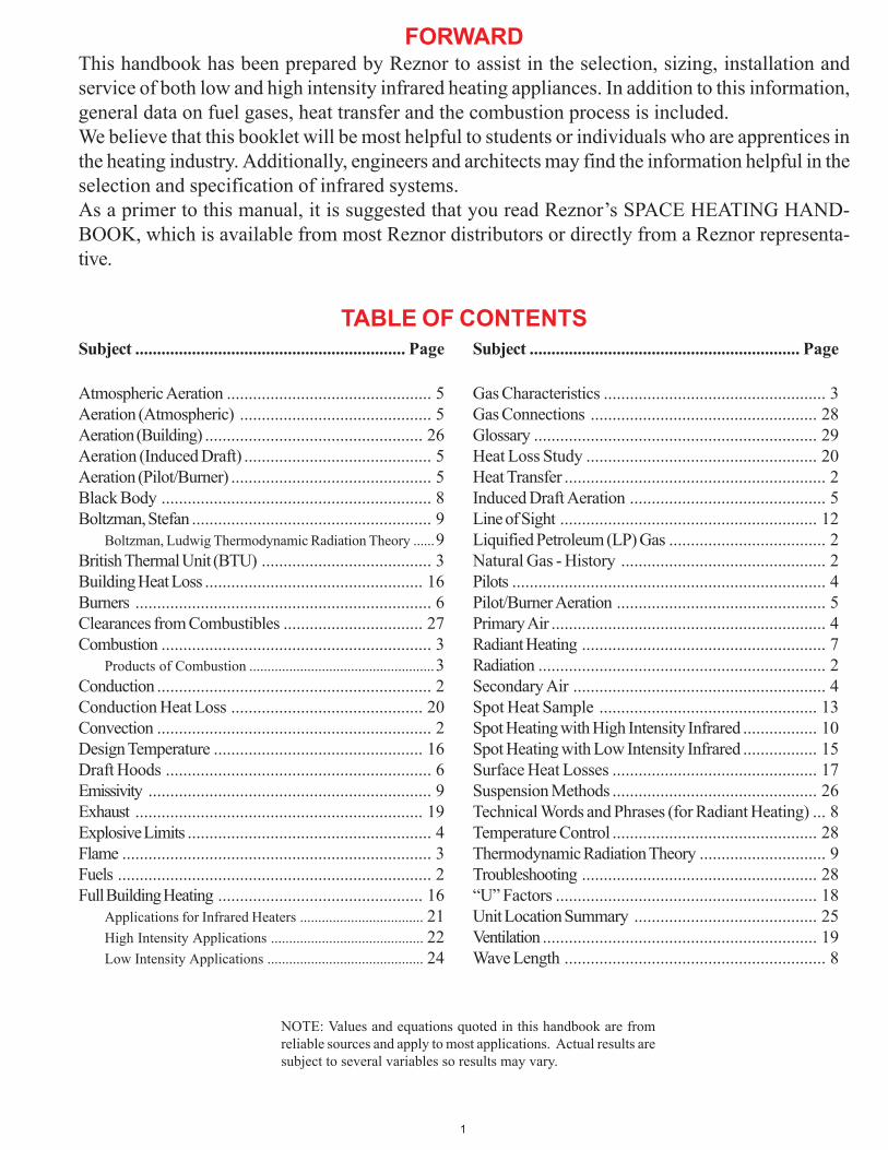
FORWARDThis handbook has been prepared by Reznor to assist in the selection, sizing, installation andservice of both low and high intensity infrared heating appliances. In addition to this information,general data on fuel gases, heat transfer and the combustion process is included.We believe that this booklet will be most helpful to students or individuals who are apprentices inthe heating industry. Additionally, engineers and architects may find the information helpful in theselection and specification of infrared systems.As a primer to this manual, it is suggested that you read Reznor’s SPACE HEATING HAND-BOOK, which is available from most Reznor distributors or directly from a Reznor representa-tive.
TABLE OF CONTENTSSubject .............................................................. Page
Atmospheric Aeration ............................................... 5Aeration (Atmospheric) ............................................ 5Aeration (Building) .................................................. 26Aeration (Induced Draft) ........................................... 5Aeration (Pilot/Burner) .............................................. 5Black Body .............................................................. 8Boltzman, Stefan ....................................................... 9
Boltzman, Ludwig Thermodynamic Radiation Theory ......9British Thermal Unit (BTU) ....................................... 3Building Heat Loss .................................................. 16Burners .................................................................... 6Clearances from Combustibles ................................ 27Combustion .............................................................. 3
Products of Combustion ...................................................3Conduction ............................................................... 2Conduction Heat Loss ............................................ 20Convection ............................................................... 2Design Temperature ................................................ 16Draft Hoods ............................................................. 6Emissivity ................................................................. 9Exhaust .................................................................. 19Explosive Limits ........................................................ 4Flame ....................................................................... 3Fuels ........................................................................ 2Full Building Heating ............................................... 16
Applications for Infrared Heaters .................................. 21High Intensity Applications .......................................... 22Low Intensity Applications ........................................... 24
Subject .............................................................. Page
Gas Characteristics ................................................... 3Gas Connections .................................................... 28Glossary ................................................................. 29Heat Loss Study ..................................................... 20Heat Transfer ............................................................ 2Induced Draft Aeration ............................................. 5Line of Sight ........................................................... 12Liquified Petroleum (LP) Gas .................................... 2Natural Gas - History ............................................... 2Pilots ........................................................................ 4Pilot/Burner Aeration ................................................ 5Primary Air ............................................................... 4Radiant Heating ........................................................ 7Radiation .................................................................. 2Secondary Air .......................................................... 4Spot Heat Sample .................................................. 13Spot Heating with High Intensity Infrared ................. 10Spot Heating with Low Intensity Infrared ................. 15Surface Heat Losses ............................................... 17Suspension Methods ............................................... 26Technical Words and Phrases (for Radiant Heating) ... 8Temperature Control ............................................... 28Thermodynamic Radiation Theory ............................. 9Troubleshooting ...................................................... 28“U” Factors ............................................................ 18Unit Location Summary .......................................... 25Ventilation ............................................................... 19Wave Length ............................................................ 8
NOTE: Values and equations quoted in this handbook are fromreliable sources and apply to most applications. Actual results aresubject to several variables so results may vary.
2
HEAT TRANSFER
There are three modes of transferring heat. They are Convection,Conduction and Radiation.
CONVECTION
The dictionary defines convection as follows: Transference ofheat by moving masses of matter, as by currents in gases or liq-uids, caused by differences in density and the action of gravity.
When a difference in density occurs, the mass of the specific unitvolume changes causing a change in weight. When air is heated,its density changes in that its mass becomes less per unit volume.
When air comes in contact with a hot surface, it heats and be-comes less dense. Due to the change in mass, the heated, less-denseair rises.
An example of heat transfer by convection is the old potbelliedstove, or in more modern times, the finned tube used in residentialhot water heating systems. Cooler air, when it comes in contactwith the finned tube, warms and becomes less dense. It then risesand as it does, creates a void into which more cool air moves. Thiscontinuing process creates a circular air pattern across the finnedtube warming all the air in the space. Modern gas-fired convectionheating equipment does not depend solely on gravity but uses anair mover in the form of a fan or blower to circulate the air, hasten-ing warm-up of the space.
CONDUCTION
The transmission of heat through a conductor. When two objectsare in contact with each other, and barring any other phenom-enon, the two objects should be the same temperature. If they arenot, the heat from the hottest flows to the object that is the coolest,until both objects attain the same temperature. From this we mightsay that heat flows down hill (Heat always flows toward the coolestobjects). While conduction is not normally used in the heatingindustry, it does appear in the appliances that are used to supplyheat. For example, conduction very often is used to convey heatto sensing devices within the appliance, that provide such thingsas high heat limiting of the appliance temperature.
A good example of conduction is in cooking utensils, where heatis applied to one side of the utensil and the surface then conductsthis heat to the food inside for proper preparation. A more dra-matic example of conduction is found when one touches a hotsurface with the bare finger. The transfer of heat through conduc-tion is very vivid to the individual owning the finger.
RADIATION
The transmission of heat through rays emitting from a hot surface.The best example of radiation is the sun. The extreme tempera-tures of the sun emits rays which travel through space and areabsorbed by Earth. The earth’s proximity to the sun results inextreme warmth at the equator because the rays are generally at aright angle to this area. Since the earth is spherical in shape, therays from the sun tend to deflect off the earth’s surface as theyapproach the north and south poles. Consequently, with less heatabsorption, colder climates result.
In the gas heating industry, radiation has been in use for a muchlonger time than convection. As early as the 1920’s gas heaterswere used for spot heating in residences and commercial build-ings. Heat was supplied by a gas flame and was reflected frompolished surfaces designed to broadcast the heat rays through-
out the space. These polished surfaces were soon replaced byclay blocks with highly irregular surfaces which, when heated, dida more efficient job of distributing the heat rays, through radia-tion.
This handbook will deal primarily with radiation principles andradiant heating appliances.
FUELS
Over the centuries, man has used many forms of fuel to provideheat for his own comfort. Beginning with prehistoric man, we wouldhave to assume that his preference for fuels would most likelyhave been wood. The next prominent fuel would have been coal. Itmay surprise you to know, however, that natural gas was discov-ered and used by the Chinese 2500 years ago. Although we arenot certain of its use, we do know that they transported the natu-ral gas through bamboo poles, and can assume that the flame mayhave found some ritualistic use in their villages.
Other energies that were gradually harnessed by mankind are: Oil,Electricity, Liquefied Petroleum Gases, Nuclear, Geothermal, andfinally, Solar Energy (Back to the sun).
BRIEF HISTORY OF NATURAL GAS
At this point we want to expand somewhat on the history of natu-ral gas since most infrared heaters are fueled by this particular gasand to a lesser degree, LP gases.
Modern natural gas began in United States in 1821 when WilliamHart dug the first gas well (a depth of 27 feet) near Fredonia, NewYork. The gas was distributed for use in illumination of homes andoffices. For the next 35 to 40 years, wells sprung up throughoutthe eastern states and by 1900 there were gas wells in 17 states.The gas industry had essentially begun. Today nearly all of thelower 48 states and Alaska have gas wells, and all have immensedistribution networks to supply natural gas to nearly every vil-lage, town and city in the USA.
Natural gas, in addition to being the most economical form of fuelenergy, also has clean effluents and is the most dependable of allthe fuels. Supplies of natural gas are in such quantities that it willbe reliable as a source of energy, well into the 21st century. Inaddition to active fields, there are huge quantities yet to be tappedwhich should fill our requirements beyond the middle of the 21stcentury. Add to this the increasing availability of liquefied naturalgas (LNG) from foreign producers, and it appears that natural gaswill be our major fuel source for many years to come.
LIQUEFIED PETROLEUM GASES
One of the by-products of oil refining is LP gas. This fuel is ex-tracted during the cracking process. It is then pressurized until itbecomes a liquid. It is in this liquid form that LP gases are trans-ported to the end user. The most common of these liquid gases ispropane, although butane is sometimes available, and is restrictedfor use in warmer climates. When the storage vessel or tank istapped, the gas vapor over the liquid is released for use in the gasburning process. The pressure within the vessel maintains mostof the gas in liquid form, but as the vapors are drawn off, the liquidwill boil and generate more gas.
Therefore, the demand rate determines the size of the storagevessel that will be needed for each application.
3
BTU (BRITISH THERMAL UNIT)
A British Thermal Unit (BTU) is defined as the amount of heatrequired to raise one pound of water, one degree Fahrenheit. Hereare a few expressions that refer to BTU’s and will be found in thefollowing text.
BTUH British Thermal Unit - per Hour
BTU/FT3 British Thermal Unit - per cubic foot.
BTUH/FT2 British Thermal Unit - per hour - per square foot.
BTUH/FT2/°F British Thermal Unit - per hour - per square foot- per degree Fahrenheit
GAS CHARACTERISTICS
In order to properly size gas piping and orifices, the characteris-tics of the gas in use must be known. Here then is the pertinentdata as it relates to the most popular gaseous fuels:
HEAT CONTENT
SPECIFICFUEL BTU/FT3 GRAVITY
Natural gas 1020 BTU .65
Propane gas 2550 BTU 1.52
Butane gas 3200 BTU 1.95
The specific gravity is the weight of the gas as compared to air.(Specific gravity of air = 1 ) Therefore, you will note that the LPgases are heavier than air and that Natural gas is lighter than air.This is important to know because should the gas inadvertentlyescape during service, installation or the remote possibility ofcontrol failure, knowledge of the fuel characteristics is helpful indetermining suitable purging to clear the space of potential explo-sive conditions.
Specific gravity is also important, along with BTU content andgas supply pressure, to properly size the main burner orifices. Themanufacturer will publish correct orifice sizes for each unit in aservice manual, making it unnecessary to do these calculations inthe field. Further to this, each gas fired appliance has the propergas orifice when it leaves the factory, providing that correct gascharacteristics have been supplied to the manufacturer by thepurchaser.
COMBUSTION
Combustion, by definition, is the rapid oxidation of solids, gasesor liquids. It is therefore safe to assume that combustion cannottake place without the presence of oxygen. In the following text,we will deal with the controlled use of air (oxygen) for propercombustion of gaseous fuels. Such control is accomplished in thedesign of the gas burning equipment, both in the pilot/burnerconfigurations and in the design of the combustion air and fluegas passageways found in and around each gas heating appli-ance.
Further, we will discuss pilot/burner aeration, by means of eitheratmospheric pressures or by power assist using blowers or ex-hausters.
FLAME
There are three ingredients needed to create a flame. They are:Fuel, air, and heat. Fuel is required to supply the carbon, air isrequired to supply the oxygen, and heat is required to raise the mixto its ignition temperature.
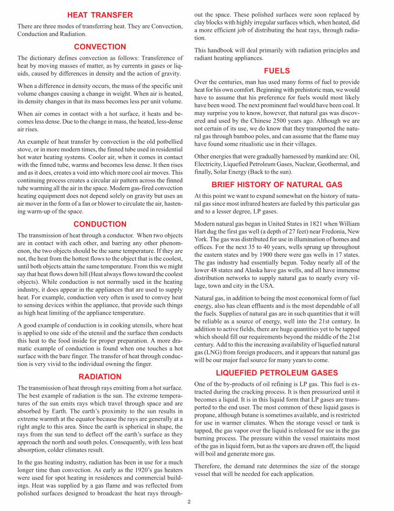
Natural gas is composed primarily of methane having a chemicalformula of CH
4 (C = Carbon and H = Hydrogen). Each molecule of
methane consists of one atom of carbon and four atoms of hydro-gen. Thus, methane in natural gas can provide the carbon re-quired to create a flame. Air which consists of 21% oxygen pro-vides the second ingredient required to create a flame. These twogases (natural gas and air) contain other ingredients but for thepurpose of illustrating the resultant chemical formula when com-plete combustion occurs, only carbon, hydrogen and oxygen willbe used. Fig. 1 shows the chemical transition that occurs whenmethane burns. Note that the combustion effluents contain car-bon dioxide (CO
2) and water (H
2O).
O O O O HH O
HH OOxygen
Heat
Methane Combustion Products
Carbon Dioxide
Water Vapor
HCH
H
H
C OO
CompleteCombustion
FIG. 1 - Complete combustion - forms only water and carbon dioxide.
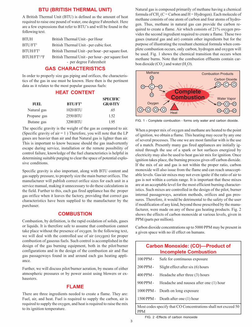
When a proper mix of oxygen and methane are heated to the pointof ignition, we obtain a flame. This heating may occur by any oneof several processes. The one we are most familiar with is the useof a match. Presently many gas fired appliances are initially ig-nited through the use of a spark or hot surfaces energized byelectricity may also be used to heat gas/air mix for ignition. Onceignition takes place, the burning process gives off carbon dioxide.If the mix of air and gas is not within the proper ratio, carbonmonoxide will also issue from the flame and can reach unaccept-able levels. Gas/air mixes may not even ignite if the ratio of air togas is not within a certain range. It is important that these mixesare at an acceptable level for the most efficient burning character-istics. Such mixes are controlled in the design of the pilot, burnerinternal passageways, aeration methods, orifices and gas pres-sures. Therefore, it would be detrimental to the safety of the userif modification of any kind, beyond those prescribed by the manu-facturer, were made on any of these gas heating products. Fig. 2shows the effects of carbon monoxide at various levels, given inPPM (parts per million).
Carbon dioxide concentrations up to 5000 PPM may be present ina given space with no ill effect on humans.
FIG. 2 -Effects of carbon monoxide
Carbon Monoxide: (CO)—Product ofIncomplete Combustion
100 PPM - Safe for continuous exposure
200 PPM - Slight effect after six (6) hours
400 PPM - Headache after three (3) hours
900 PPM - Headache and nausea after one (1) hour
1000 PPM - Death on long exposure
1500 PPM - Death after one (1) hour
Most codes specify that CO Concentrations shall not exceed 50PPM
4
Gas
Stainless SteelBurner Head
SecondaryAir Slot
Flame Sensor
PilotOrifice
FIG. 6 - Secondary air pilot
EXPLOSIVE LIMITS
When natural gas and air are joined together, the mix may or maynot oxidize. For instance, if natural gas in the mix is between 4%and 14%, there is potential for explosion or burning, dependinghow the mix is handled. In a heating appliance the combination ofburner, pilot and aeration design will cause the mix to burn undercontrolled conditions. If the mix is simply in a space such as aroom, and it by some means is ignited, it most likely will explode.When the mix is outside the 4% to 14% limits, there will be noignition, consequently no flame or explosion. This points out theimportance of creating a proper mix within the gas burning appli-ance and also points out the hazards of allowing gas to escapeindiscriminately into a confined area. (Fig. 3)
Natural Gas
0% to 4% gas
4% to 14% gas
14% to 100% gas
no combustion(not enough gas)
no combustion(not enough oxygen)
combustion
FIG. 3 -Flammability limits of natural gas.
Propane Gas
0% to 1.6% gas
1.6% to 5.6% gas
5.6% to 100% gas
no combustion(not enough gas)
no combustion(not enough oxygen)
combustion
FIG. 4 -Flammability limits of propane gas
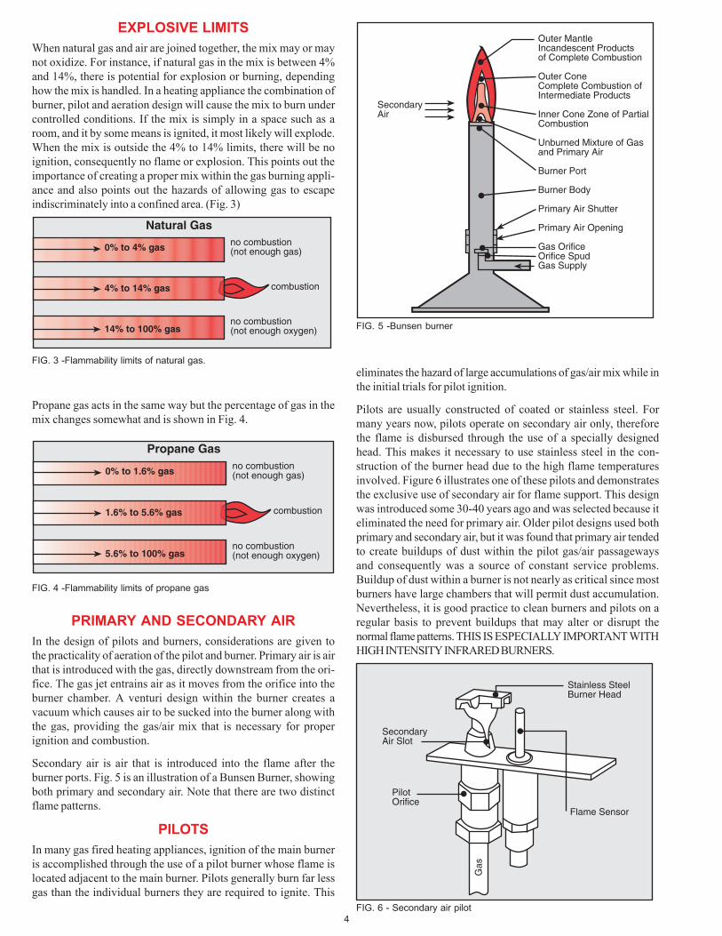
Outer MantleIncandescent Productsof Complete Combustion
Outer ConeComplete Combustion ofIntermediate Products
Inner Cone Zone of PartialCombustion
Unburned Mixture of Gasand Primary Air
Burner Port
Burner Body
Primary Air Shutter
Primary Air Opening
Gas OrificeOrifice SpudGas Supply
SecondaryAir
FIG. 5 -Bunsen burner
Propane gas acts in the same way but the percentage of gas in themix changes somewhat and is shown in Fig. 4.
eliminates the hazard of large accumulations of gas/air mix while inthe initial trials for pilot ignition.
Pilots are usually constructed of coated or stainless steel. Formany years now, pilots operate on secondary air only, thereforethe flame is disbursed through the use of a specially designedhead. This makes it necessary to use stainless steel in the con-struction of the burner head due to the high flame temperaturesinvolved. Figure 6 illustrates one of these pilots and demonstratesthe exclusive use of secondary air for flame support. This designwas introduced some 30-40 years ago and was selected because iteliminated the need for primary air. Older pilot designs used bothprimary and secondary air, but it was found that primary air tendedto create buildups of dust within the pilot gas/air passagewaysand consequently was a source of constant service problems.Buildup of dust within a burner is not nearly as critical since mostburners have large chambers that will permit dust accumulation.Nevertheless, it is good practice to clean burners and pilots on aregular basis to prevent buildups that may alter or disrupt thenormal flame patterns. THIS IS ESPECIALLY IMPORTANT WITHHIGH INTENSITY INFRARED BURNERS.
PRIMARY AND SECONDARY AIR
In the design of pilots and burners, considerations are given tothe practicality of aeration of the pilot and burner. Primary air is airthat is introduced with the gas, directly downstream from the ori-fice. The gas jet entrains air as it moves from the orifice into theburner chamber. A venturi design within the burner creates avacuum which causes air to be sucked into the burner along withthe gas, providing the gas/air mix that is necessary for properignition and combustion.
Secondary air is air that is introduced into the flame after theburner ports. Fig. 5 is an illustration of a Bunsen Burner, showingboth primary and secondary air. Note that there are two distinctflame patterns.
PILOTS
In many gas fired heating appliances, ignition of the main burneris accomplished through the use of a pilot burner whose flame islocated adjacent to the main burner. Pilots generally burn far lessgas than the individual burners they are required to ignite. This
5
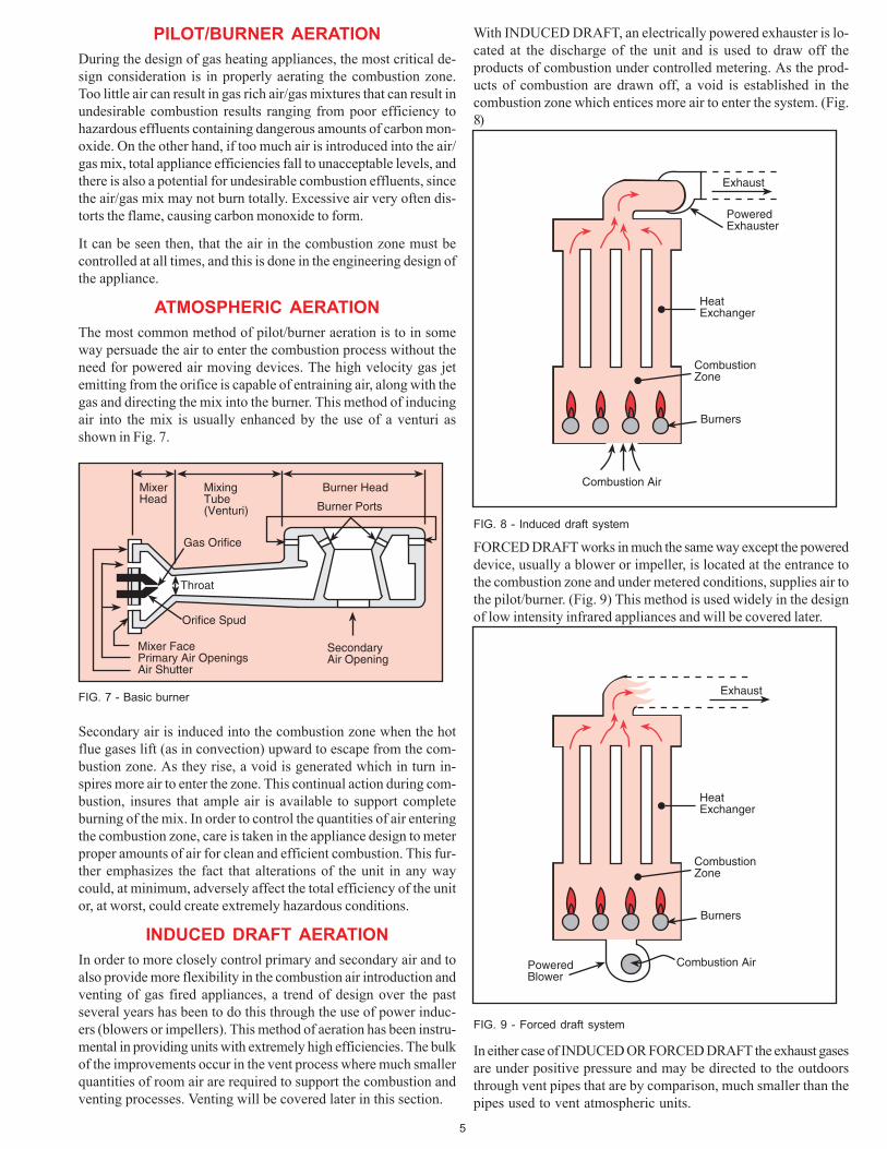
With INDUCED DRAFT, an electrically powered exhauster is lo-cated at the discharge of the unit and is used to draw off theproducts of combustion under controlled metering. As the prod-ucts of combustion are drawn off, a void is established in thecombustion zone which entices more air to enter the system. (Fig.8)
PILOT/BURNER AERATION
During the design of gas heating appliances, the most critical de-sign consideration is in properly aerating the combustion zone.Too little air can result in gas rich air/gas mixtures that can result inundesirable combustion results ranging from poor efficiency tohazardous effluents containing dangerous amounts of carbon mon-oxide. On the other hand, if too much air is introduced into the air/gas mix, total appliance efficiencies fall to unacceptable levels, andthere is also a potential for undesirable combustion effluents, sincethe air/gas mix may not burn totally. Excessive air very often dis-torts the flame, causing carbon monoxide to form.
It can be seen then, that the air in the combustion zone must becontrolled at all times, and this is done in the engineering design ofthe appliance.
ATMOSPHERIC AERATION
The most common method of pilot/burner aeration is to in someway persuade the air to enter the combustion process without theneed for powered air moving devices. The high velocity gas jetemitting from the orifice is capable of entraining air, along with thegas and directing the mix into the burner. This method of inducingair into the mix is usually enhanced by the use of a venturi asshown in Fig. 7.
Exhaust
HeatExchanger
CombustionZone
Burners
Combustion AirPoweredBlower
FIG. 8 - Induced draft system
Orifice Spud
Mixer FacePrimary Air OpeningsAir Shutter
Throat
Gas Orifice
MixerHead
MixingTube(Venturi)
Burner Head
Burner Ports
SecondaryAir Opening
FIG. 7 - Basic burner
Secondary air is induced into the combustion zone when the hotflue gases lift (as in convection) upward to escape from the com-bustion zone. As they rise, a void is generated which in turn in-spires more air to enter the zone. This continual action during com-bustion, insures that ample air is available to support completeburning of the mix. In order to control the quantities of air enteringthe combustion zone, care is taken in the appliance design to meterproper amounts of air for clean and efficient combustion. This fur-ther emphasizes the fact that alterations of the unit in any waycould, at minimum, adversely affect the total efficiency of the unitor, at worst, could create extremely hazardous conditions.
INDUCED DRAFT AERATION
In order to more closely control primary and secondary air and toalso provide more flexibility in the combustion air introduction andventing of gas fired appliances, a trend of design over the pastseveral years has been to do this through the use of power induc-ers (blowers or impellers). This method of aeration has been instru-mental in providing units with extremely high efficiencies. The bulkof the improvements occur in the vent process where much smallerquantities of room air are required to support the combustion andventing processes. Venting will be covered later in this section.
FORCED DRAFT works in much the same way except the powereddevice, usually a blower or impeller, is located at the entrance tothe combustion zone and under metered conditions, supplies air tothe pilot/burner. (Fig. 9) This method is used widely in the designof low intensity infrared appliances and will be covered later.
In either case of INDUCED OR FORCED DRAFT the exhaust gasesare under positive pressure and may be directed to the outdoorsthrough vent pipes that are by comparison, much smaller than thepipes used to vent atmospheric units.
Exhaust
PoweredExhauster
HeatExchanger
CombustionZone
Burners
Combustion Air
FIG. 9 - Forced draft system
6
DraftHood
HotCombustion Gases
RoomAir
VentPipe
FIG. 10 - Typical draft hood
PrimaryCone
SecondaryCone
MixerPorts
Secondary Air
Primary Air
Gas
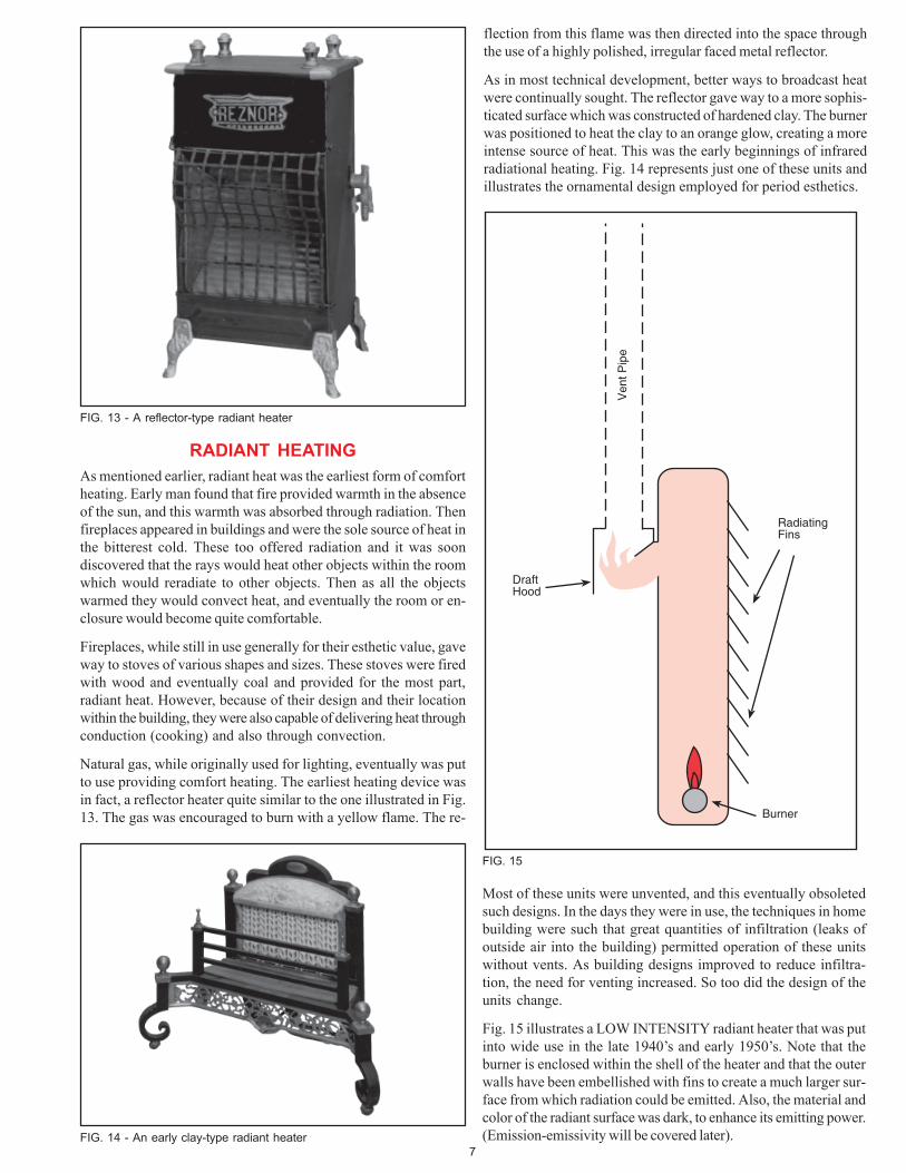
FIG. 11 - Typical horizontal burner FIG. 12 - High-intensity burners have these basic parts.
Orifice Mixing Section
Ceramic Block with Minute Drilled PortsFlame
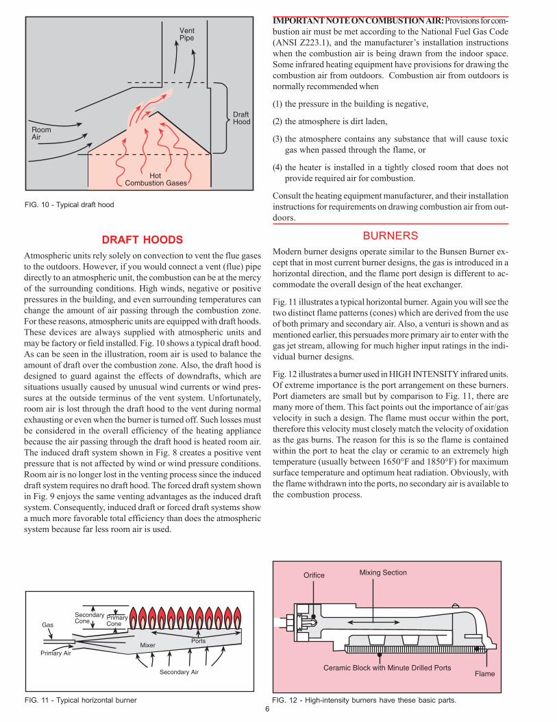
DRAFT HOODS
Atmospheric units rely solely on convection to vent the flue gasesto the outdoors. However, if you would connect a vent (flue) pipedirectly to an atmospheric unit, the combustion can be at the mercyof the surrounding conditions. High winds, negative or positivepressures in the building, and even surrounding temperatures canchange the amount of air passing through the combustion zone.For these reasons, atmospheric units are equipped with draft hoods.These devices are always supplied with atmospheric units andmay be factory or field installed. Fig. 10 shows a typical draft hood.As can be seen in the illustration, room air is used to balance theamount of draft over the combustion zone. Also, the draft hood isdesigned to guard against the effects of downdrafts, which aresituations usually caused by unusual wind currents or wind pres-sures at the outside terminus of the vent system. Unfortunately,room air is lost through the draft hood to the vent during normalexhausting or even when the burner is turned off. Such losses mustbe considered in the overall efficiency of the heating appliancebecause the air passing through the draft hood is heated room air.The induced draft system shown in Fig. 8 creates a positive ventpressure that is not affected by wind or wind pressure conditions.Room air is no longer lost in the venting process since the induceddraft system requires no draft hood. The forced draft system shownin Fig. 9 enjoys the same venting advantages as the induced draftsystem. Consequently, induced draft or forced draft systems showa much more favorable total efficiency than does the atmosphericsystem because far less room air is used.
IMPORTANT NOTE ON COMBUSTION AIR: Provisions for com-bustion air must be met according to the National Fuel Gas Code(ANSI Z223.1), and the manufacturer’s installation instructionswhen the combustion air is being drawn from the indoor space.Some infrared heating equipment have provisions for drawing thecombustion air from outdoors. Combustion air from outdoors isnormally recommended when
(1) the pressure in the building is negative,
(2) the atmosphere is dirt laden,
(3) the atmosphere contains any substance that will cause toxicgas when passed through the flame, or
(4) the heater is installed in a tightly closed room that does notprovide required air for combustion.
Consult the heating equipment manufacturer, and their installationinstructions for requirements on drawing combustion air from out-doors.
BURNERS
Modern burner designs operate similar to the Bunsen Burner ex-cept that in most current burner designs, the gas is introduced in ahorizontal direction, and the flame port design is different to ac-commodate the overall design of the heat exchanger.
Fig. 11 illustrates a typical horizontal burner. Again you will see thetwo distinct flame patterns (cones) which are derived from the useof both primary and secondary air. Also, a venturi is shown and asmentioned earlier, this persuades more primary air to enter with thegas jet stream, allowing for much higher input ratings in the indi-vidual burner designs.
Fig. 12 illustrates a burner used in HIGH INTENSITY infrared units.Of extreme importance is the port arrangement on these burners.Port diameters are small but by comparison to Fig. 11, there aremany more of them. This fact points out the importance of air/gasvelocity in such a design. The flame must occur within the port,therefore this velocity must closely match the velocity of oxidationas the gas burns. The reason for this is so the flame is containedwithin the port to heat the clay or ceramic to an extremely hightemperature (usually between 1650°F and 1850°F) for maximumsurface temperature and optimum heat radiation. Obviously, withthe flame withdrawn into the ports, no secondary air is available tothe combustion process.
7
flection from this flame was then directed into the space throughthe use of a highly polished, irregular faced metal reflector.
As in most technical development, better ways to broadcast heatwere continually sought. The reflector gave way to a more sophis-ticated surface which was constructed of hardened clay. The burnerwas positioned to heat the clay to an orange glow, creating a moreintense source of heat. This was the early beginnings of infraredradiational heating. Fig. 14 represents just one of these units andillustrates the ornamental design employed for period esthetics.
DraftHood
Burner
RadiatingFins
Ven
t Pip
e
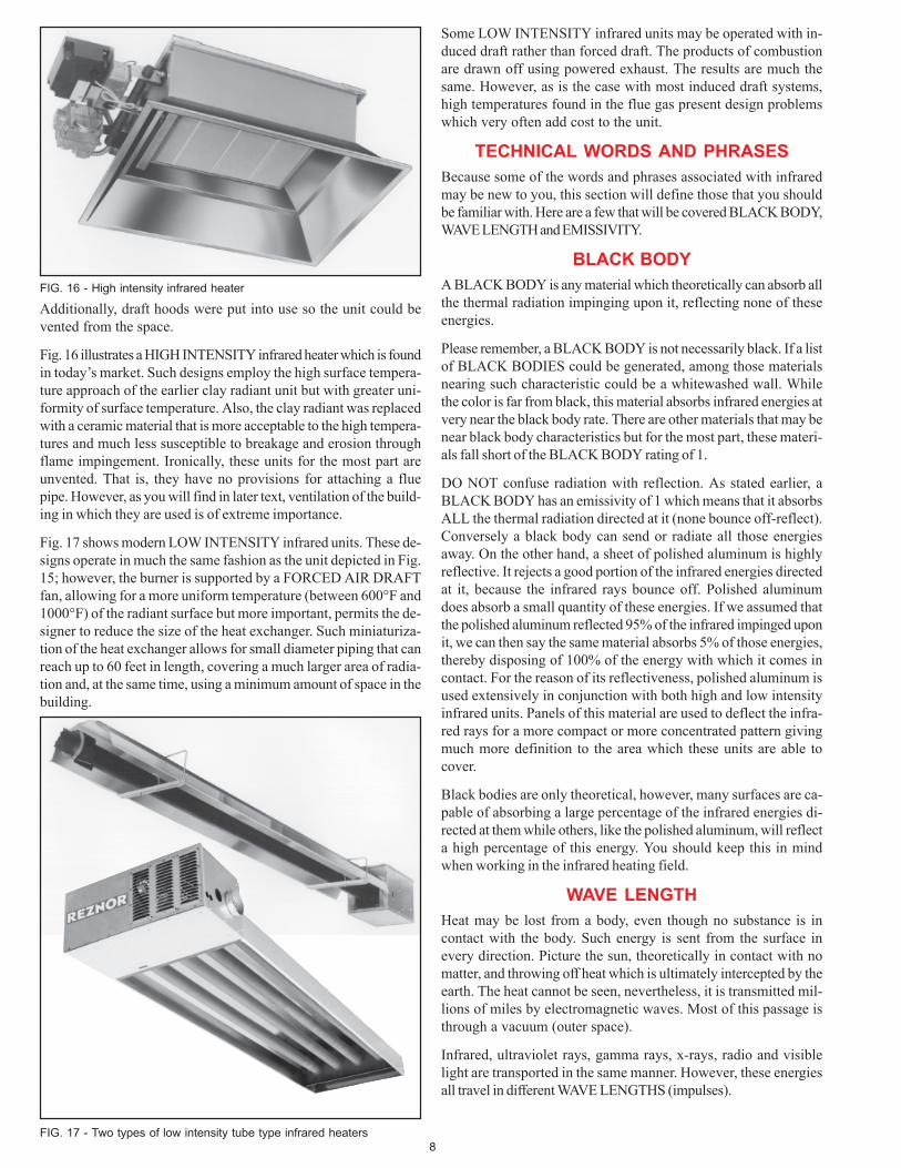
FIG. 15
FIG. 14 - An early clay-type radiant heater
FIG. 13 - A reflector-type radiant heater
RADIANT HEATING
As mentioned earlier, radiant heat was the earliest form of comfortheating. Early man found that fire provided warmth in the absenceof the sun, and this warmth was absorbed through radiation. Thenfireplaces appeared in buildings and were the sole source of heat inthe bitterest cold. These too offered radiation and it was soondiscovered that the rays would heat other objects within the roomwhich would reradiate to other objects. Then as all the objectswarmed they would convect heat, and eventually the room or en-closure would become quite comfortable.
Fireplaces, while still in use generally for their esthetic value, gaveway to stoves of various shapes and sizes. These stoves were firedwith wood and eventually coal and provided for the most part,radiant heat. However, because of their design and their locationwithin the building, they were also capable of delivering heat throughconduction (cooking) and also through convection.
Natural gas, while originally used for lighting, eventually was putto use providing comfort heating. The earliest heating device wasin fact, a reflector heater quite similar to the one illustrated in Fig.13. The gas was encouraged to burn with a yellow flame. The re-
Most of these units were unvented, and this eventually obsoletedsuch designs. In the days they were in use, the techniques in homebuilding were such that great quantities of infiltration (leaks ofoutside air into the building) permitted operation of these unitswithout vents. As building designs improved to reduce infiltra-tion, the need for venting increased. So too did the design of theunits change.
Fig. 15 illustrates a LOW INTENSITY radiant heater that was putinto wide use in the late 1940’s and early 1950’s. Note that theburner is enclosed within the shell of the heater and that the outerwalls have been embellished with fins to create a much larger sur-face from which radiation could be emitted. Also, the material andcolor of the radiant surface was dark, to enhance its emitting power.(Emission-emissivity will be covered later).
8
Some LOW INTENSITY infrared units may be operated with in-duced draft rather than forced draft. The products of combustionare drawn off using powered exhaust. The results are much thesame. However, as is the case with most induced draft systems,high temperatures found in the flue gas present design problemswhich very often add cost to the unit.
TECHNICAL WORDS AND PHRASES
Because some of the words and phrases associated with infraredmay be new to you, this section will define those that you shouldbe familiar with. Here are a few that will be covered BLACK BODY,WAVE LENGTH and EMISSIVITY.
BLACK BODY
A BLACK BODY is any material which theoretically can absorb allthe thermal radiation impinging upon it, reflecting none of theseenergies.
Please remember, a BLACK BODY is not necessarily black. If a listof BLACK BODIES could be generated, among those materialsnearing such characteristic could be a whitewashed wall. Whilethe color is far from black, this material absorbs infrared energies atvery near the black body rate. There are other materials that may benear black body characteristics but for the most part, these materi-als fall short of the BLACK BODY rating of 1.
DO NOT confuse radiation with reflection. As stated earlier, aBLACK BODY has an emissivity of 1 which means that it absorbsALL the thermal radiation directed at it (none bounce off-reflect).Conversely a black body can send or radiate all those energiesaway. On the other hand, a sheet of polished aluminum is highlyreflective. It rejects a good portion of the infrared energies directedat it, because the infrared rays bounce off. Polished aluminumdoes absorb a small quantity of these energies. If we assumed thatthe polished aluminum reflected 95% of the infrared impinged uponit, we can then say the same material absorbs 5% of those energies,thereby disposing of 100% of the energy with which it comes incontact. For the reason of its reflectiveness, polished aluminum isused extensively in conjunction with both high and low intensityinfrared units. Panels of this material are used to deflect the infra-red rays for a more compact or more concentrated pattern givingmuch more definition to the area which these units are able tocover.
Black bodies are only theoretical, however, many surfaces are ca-pable of absorbing a large percentage of the infrared energies di-rected at them while others, like the polished aluminum, will reflecta high percentage of this energy. You should keep this in mindwhen working in the infrared heating field.
WAVE LENGTH
Heat may be lost from a body, even though no substance is incontact with the body. Such energy is sent from the surface inevery direction. Picture the sun, theoretically in contact with nomatter, and throwing off heat which is ultimately intercepted by theearth. The heat cannot be seen, nevertheless, it is transmitted mil-lions of miles by electromagnetic waves. Most of this passage isthrough a vacuum (outer space).
Infrared, ultraviolet rays, gamma rays, x-rays, radio and visiblelight are transported in the same manner. However, these energiesall travel in different WAVE LENGTHS (impulses).
FIG. 17 - Two types of low intensity tube type infrared heaters
FIG. 16 - High intensity infrared heater
Additionally, draft hoods were put into use so the unit could bevented from the space.
Fig. 16 illustrates a HIGH INTENSITY infrared heater which is foundin today’s market. Such designs employ the high surface tempera-ture approach of the earlier clay radiant unit but with greater uni-formity of surface temperature. Also, the clay radiant was replacedwith a ceramic material that is more acceptable to the high tempera-tures and much less susceptible to breakage and erosion throughflame impingement. Ironically, these units for the most part areunvented. That is, they have no provisions for attaching a fluepipe. However, as you will find in later text, ventilation of the build-ing in which they are used is of extreme importance.
Fig. 17 shows modern LOW INTENSITY infrared units. These de-signs operate in much the same fashion as the unit depicted in Fig.15; however, the burner is supported by a FORCED AIR DRAFTfan, allowing for a more uniform temperature (between 600°F and1000°F) of the radiant surface but more important, permits the de-signer to reduce the size of the heat exchanger. Such miniaturiza-tion of the heat exchanger allows for small diameter piping that canreach up to 60 feet in length, covering a much larger area of radia-tion and, at the same time, using a minimum amount of space in thebuilding.
9
A WAVE LENGTH is the distance measured in the progression of awave from one point to the next point, much the same as the wavesin the ocean as they travel across the surface of the water.
Infrared wave lengths are measured in microns (A micron is 0.000001or 1/1,000,000 of a meter.)
By comparison, visible light travels in wave lengths of .4 to .8microns, while infrared travels within a range of .8 to 400 microns.From a practical standpoint, infrared heating wave lengths are foundin the 2 to 20 micron range, however, infrared heating devices oper-ate most efficiently within the 2 to 7 micron range.
Infrared rays do not lose their energy until they are intercepted byliquids or solids. Air does not absorb the rays, therefore, none ofthe energy is lost to air. This would explain the fact that wheninfrared heating is in use, it can be noted that upon start up, the airin the space is slow to heat. The air is finally warmed as the heatedobjects within range of the infrared source give off some of theirheat through convection.
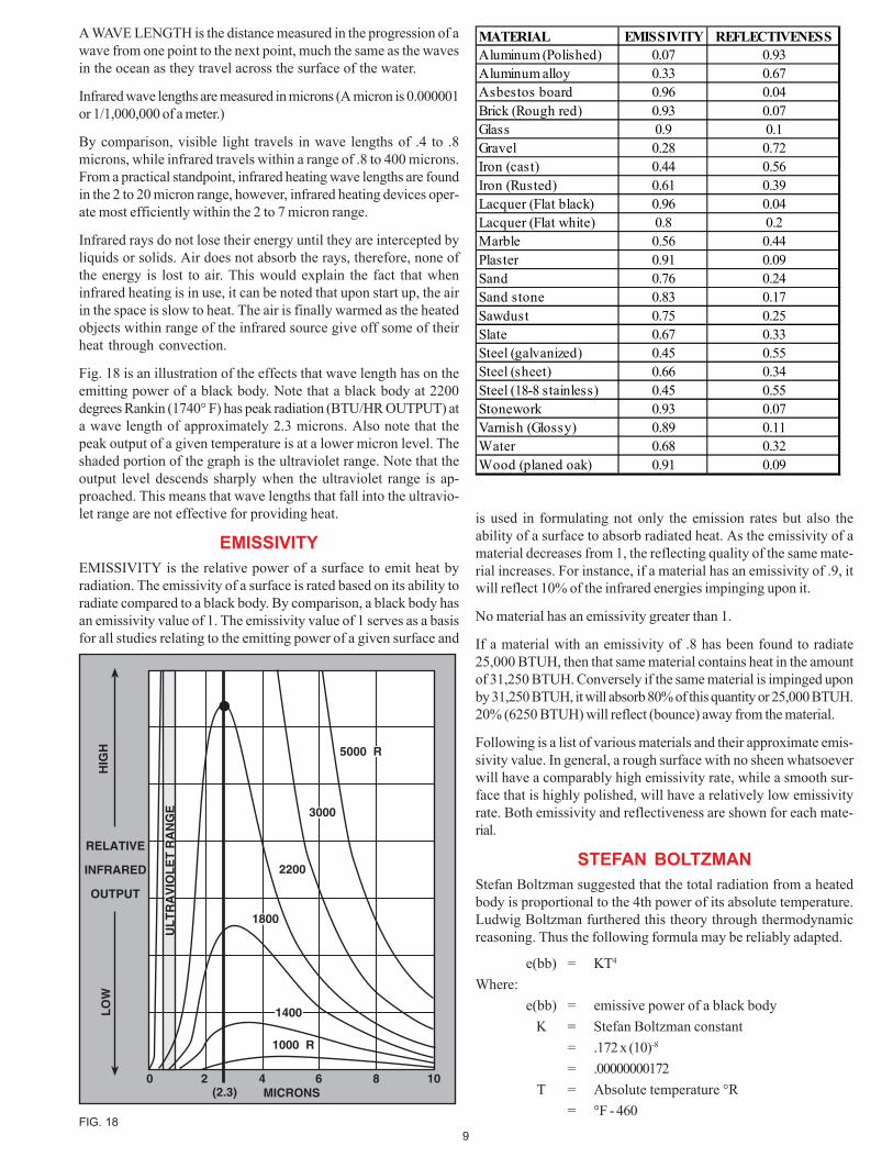
Fig. 18 is an illustration of the effects that wave length has on theemitting power of a black body. Note that a black body at 2200degrees Rankin (1740° F) has peak radiation (BTU/HR OUTPUT) ata wave length of approximately 2.3 microns. Also note that thepeak output of a given temperature is at a lower micron level. Theshaded portion of the graph is the ultraviolet range. Note that theoutput level descends sharply when the ultraviolet range is ap-proached. This means that wave lengths that fall into the ultravio-let range are not effective for providing heat.
EMISSIVITY
EMISSIVITY is the relative power of a surface to emit heat byradiation. The emissivity of a surface is rated based on its ability toradiate compared to a black body. By comparison, a black body hasan emissivity value of 1. The emissivity value of 1 serves as a basisfor all studies relating to the emitting power of a given surface and
RELATIVE
INFRARED
OUTPUT
1000 R
2200
5000 R
3000
1800
1400
0 2(2.3)
4 6 8 10
UL
TR
AV
IOL
ET
RA
NG
E
MICRONS
LO
WH
IGH
FIG. 18
is used in formulating not only the emission rates but also theability of a surface to absorb radiated heat. As the emissivity of amaterial decreases from 1, the reflecting quality of the same mate-rial increases. For instance, if a material has an emissivity of .9, itwill reflect 10% of the infrared energies impinging upon it.
No material has an emissivity greater than 1.
If a material with an emissivity of .8 has been found to radiate25,000 BTUH, then that same material contains heat in the amountof 31,250 BTUH. Conversely if the same material is impinged uponby 31,250 BTUH, it will absorb 80% of this quantity or 25,000 BTUH.20% (6250 BTUH) will reflect (bounce) away from the material.
Following is a list of various materials and their approximate emis-sivity value. In general, a rough surface with no sheen whatsoeverwill have a comparably high emissivity rate, while a smooth sur-face that is highly polished, will have a relatively low emissivityrate. Both emissivity and reflectiveness are shown for each mate-rial.
STEFAN BOLTZMAN
Stefan Boltzman suggested that the total radiation from a heatedbody is proportional to the 4th power of its absolute temperature.Ludwig Boltzman furthered this theory through thermodynamicreasoning. Thus the following formula may be reliably adapted.
e(bb) = KT4
Where:
e(bb) = emissive power of a black body
K = Stefan Boltzman constant
= .172 x (10)-8
= .00000000172
T = Absolute temperature °R
= °F - 460
MATERIAL EMISSIVITY REFLECTIVENESSAluminum (Polished) 0.07 0.93Aluminum alloy 0.33 0.67Asbestos board 0.96 0.04Brick (Rough red) 0.93 0.07Glass 0.9 0.1Gravel 0.28 0.72Iron (cast) 0.44 0.56Iron (Rusted) 0.61 0.39Lacquer (Flat black) 0.96 0.04Lacquer (Flat white) 0.8 0.2Marble 0.56 0.44Plaster 0.91 0.09Sand 0.76 0.24Sand stone 0.83 0.17Sawdust 0.75 0.25Slate 0.67 0.33Steel (galvanized) 0.45 0.55Steel (sheet) 0.66 0.34Steel (18-8 stainless) 0.45 0.55Stonework 0.93 0.07Varnish (Glossy) 0.89 0.11Water 0.68 0.32Wood (planed oak) 0.91 0.09
10
-30 -20 -10 0 10 20 30 40 50 60AIR & SURROUNDING TEMP. - FOR HEAVY CLOTHING
70
SURFACEHEATLOSSES
400
350
300
250
AIR & SURROUNDING TEMP. - FOR NORMAL CLOTHING
200
150
100
50
0-30 -20 -10
SU
RF
AC
E H
EA
T L
OS
S -
BT
UH
/FT
2
0 10 20 30 40 50 60 70
2 MPH
3 MPH
4 MPH
5 MPH
10 MP
H
15 MP
H
STILL AIR or 1 MPH
ACTIVITY ADJUSTMENTAt rest +19Light bench work 0Mod. heavy work -10Heavy work -36
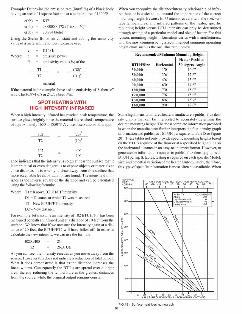
FIG.19 - Surface heat loss nomograph
Example: Determine the emission rate (btu/ft2/h) of a black bodyhaving an area of 1 square foot and at a temperature of 1600°F.
e(bb) = KT4
e(bb) = .00000000172 x (1600 - 460)4
e(bb) = 30,974 btuh/ft2
Using the Stefan Boltzman constant and adding the emissivityvalue of a material, the following can be used:
e = KT4 x E
Where: e = emissive power
E = emissivity value (%) of the
When you recognize the distance/intensity relationship of infra-red heat, it is easier to understand the importance of the correctmounting height. Because BTU intensities vary with the size, sur-face temperatures, and infrared patterns of the heater, specificmounting height versus BTU intensity can only be determinedthrough testing of a particular model and size of heater. For thisreason, mounting height information varies with manufacturers,with the most common being a recommended minimum mountingheight chart such as the one illustrated below.
Recommended Minimum Mounting HeightHeater Position
BTUH/Size Horizontal 30 degree Angle30,000 11’0" 10’0"50,000 13’6" 12’6"60,000 14’6'’ 13’0"90,000 16’0" 14’6"100,000 17’0" 15’0"120,000 17’6" 15’6"150,000 18’6" 15’7"160,000 19’0" 17’0"
T1 (D2)2
T2 (D1)2
=
102 (20)2
T2 (10)2
102 400T2 100
=
=
material
If the material in the example above had an emissivity of .8, then “e”would be 30,974 x .8 or 24,779 btu/ft2/hr.
SPOT HEATING WITHHIGH INTENSITY INFRARED
When a high intensity infrared has reached peak temperature, thesurface glows brightly since the material has reached a temperatureof approximately 1650 to 1850°F. A close observation of this appli-
ance indicates that the intensity is so great near the surface that itis impractical or even dangerous to expose objects or materials atclose distance. It is when you draw away from this surface thatmore acceptable levels of radiation are found. The intensity dimin-ishes as the inverse square of the distance and can be calculatedusing the following formula:
Where T1 = Known BTUH/FT2 intensity
D1 = Distance at which T1 was measured
T2 = New BTUH/FT2 intensity
D2 = New distance
For example, let’s assume an intensity of 102 BTUH/FT2 has beenmeasured beneath an infrared unit at a distance of 10 feet from thesurface. We know that if we measure the intensity again at a dis-tance of 20 feet, the BTUH/FT2 will have fallen off. In order tocalculate the new intensity, we can use the formula:
10200/400 = 26
T2 = 26 BTUH
As you can see, the intensity recedes as you move away from thesource. However this does not indicate a reduction of total output.What it does demonstrate is that as the distance increases thefocus widens. Consequently the BTU’s are spread over a largerarea, thereby reducing the temperature at the greatest distancesfrom the source, while the original output remains constant.
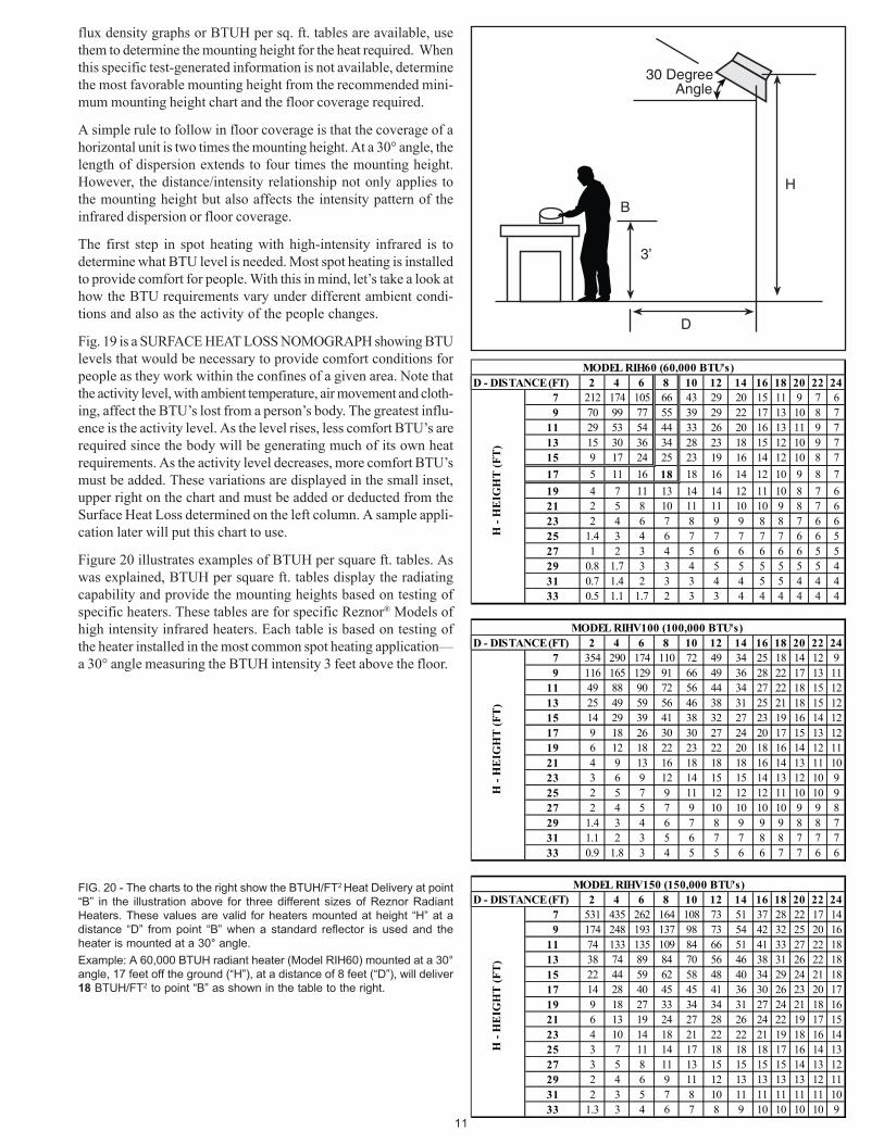
Some high intensity infrared heater manufacturers publish flux den-sity graphs that can be interpreted to accurately determine thedesired mounting height. The most complete information providedis when the manufacturer further interprets the flux density graphinformation and publishes a BTUH per square ft. table (See Figure20). These tables not only provide specific mounting heights basedon the BTU’s required at the floor or at a specified height but alsothe horizontal distance in an easy-to-interpret format. However, togenerate the information required to publish flux density graphs orBTUH per sq. ft. tables, testing is required on each specific Model,size, and potential variation of the heater. Unfortunately, therefore,this type of specific information is most often not available. When
11
flux density graphs or BTUH per sq. ft. tables are available, usethem to determine the mounting height for the heat required. Whenthis specific test-generated information is not available, determinethe most favorable mounting height from the recommended mini-mum mounting height chart and the floor coverage required.
A simple rule to follow in floor coverage is that the coverage of ahorizontal unit is two times the mounting height. At a 30° angle, thelength of dispersion extends to four times the mounting height.However, the distance/intensity relationship not only applies tothe mounting height but also affects the intensity pattern of theinfrared dispersion or floor coverage.
The first step in spot heating with high-intensity infrared is todetermine what BTU level is needed. Most spot heating is installedto provide comfort for people. With this in mind, let’s take a look athow the BTU requirements vary under different ambient condi-tions and also as the activity of the people changes.
Fig. 19 is a SURFACE HEAT LOSS NOMOGRAPH showing BTUlevels that would be necessary to provide comfort conditions forpeople as they work within the confines of a given area. Note thatthe activity level, with ambient temperature, air movement and cloth-ing, affect the BTU’s lost from a person’s body. The greatest influ-ence is the activity level. As the level rises, less comfort BTU’s arerequired since the body will be generating much of its own heatrequirements. As the activity level decreases, more comfort BTU’smust be added. These variations are displayed in the small inset,upper right on the chart and must be added or deducted from theSurface Heat Loss determined on the left column. A sample appli-cation later will put this chart to use.
Figure 20 illustrates examples of BTUH per square ft. tables. Aswas explained, BTUH per square ft. tables display the radiatingcapability and provide the mounting heights based on testing ofspecific heaters. These tables are for specific Reznor® Models ofhigh intensity infrared heaters. Each table is based on testing ofthe heater installed in the most common spot heating application—a 30° angle measuring the BTUH intensity 3 feet above the floor.
H
3’
D
30 DegreeAngle
B
FIG. 20 - The charts to the right show the BTUH/FT2 Heat Delivery at point
“B” in the illustration above for three different sizes of Reznor Radiant
Heaters. These values are valid for heaters mounted at height “H” at a
distance “D” from point “B” when a standard reflector is used and the
heater is mounted at a 30° angle.
Example: A 60,000 BTUH radiant heater (Model RIH60) mounted at a 30°
angle, 17 feet off the ground (“H”), at a distance of 8 feet (“D”), will deliver
18 BTUH/FT2 to point “B” as shown in the table to the right.
MODEL RIH60 (60,000 BTU's)D - DISTANCE (FT) 2 4 6 8 10 12 14 16 18 20 22 24
7 212 174 105 66 43 29 20 15 11 9 7 69 70 99 77 55 39 29 22 17 13 10 8 7
11 29 53 54 44 33 26 20 16 13 11 9 713 15 30 36 34 28 23 18 15 12 10 9 715 9 17 24 25 23 19 16 14 12 10 8 7
17 5 11 16 18 18 16 14 12 10 9 8 7
19 4 7 11 13 14 14 12 11 10 8 7 621 2 5 8 10 11 11 10 10 9 8 7 623 2 4 6 7 8 9 9 8 8 7 6 625 1.4 3 4 6 7 7 7 7 7 6 6 527 1 2 3 4 5 6 6 6 6 6 5 529 0.8 1.7 3 3 4 5 5 5 5 5 5 431 0.7 1.4 2 3 3 4 4 5 5 4 4 433 0.5 1.1 1.7 2 3 3 4 4 4 4 4 4
MODEL RIHV100 (100,000 BTU's) D - DISTANCE (FT) 2 4 6 8 10 12 14 16 18 20 22 24
7 354 290 174 110 72 49 34 25 18 14 12 99 116 165 129 91 66 49 36 28 22 17 13 11
11 49 88 90 72 56 44 34 27 22 18 15 1213 25 49 59 56 46 38 31 25 21 18 15 1215 14 29 39 41 38 32 27 23 19 16 14 1217 9 18 26 30 30 27 24 20 17 15 13 1219 6 12 18 22 23 22 20 18 16 14 12 1121 4 9 13 16 18 18 18 16 14 13 11 1023 3 6 9 12 14 15 15 14 13 12 10 925 2 5 7 9 11 12 12 12 11 10 10 927 2 4 5 7 9 10 10 10 10 9 9 829 1.4 3 4 6 7 8 9 9 9 8 8 731 1.1 2 3 5 6 7 7 8 8 7 7 733 0.9 1.8 3 4 5 5 6 6 7 7 6 6
MODEL RIHV150 (150,000 BTU's)D - DISTANCE (FT) 2 4 6 8 10 12 14 16 18 20 22 24
7 531 435 262 164 108 73 51 37 28 22 17 149 174 248 193 137 98 73 54 42 32 25 20 16
11 74 133 135 109 84 66 51 41 33 27 22 1813 38 74 89 84 70 56 46 38 31 26 22 1815 22 44 59 62 58 48 40 34 29 24 21 1817 14 28 40 45 45 41 36 30 26 23 20 1719 9 18 27 33 34 34 31 27 24 21 18 1621 6 13 19 24 27 28 26 24 22 19 17 1523 4 10 14 18 21 22 22 21 19 18 16 1425 3 7 11 14 17 18 18 18 17 16 14 1327 3 5 8 11 13 15 15 15 15 14 13 1229 2 4 6 9 11 12 13 13 13 13 12 1131 2 3 5 7 8 10 11 11 11 11 11 1033 1.3 3 4 6 7 8 9 10 10 10 10 9
H -
HE
IGH
T (
FT
)H
- H
EIG
HT
(F
T)
H -
HE
IGH
T (
FT
)
12
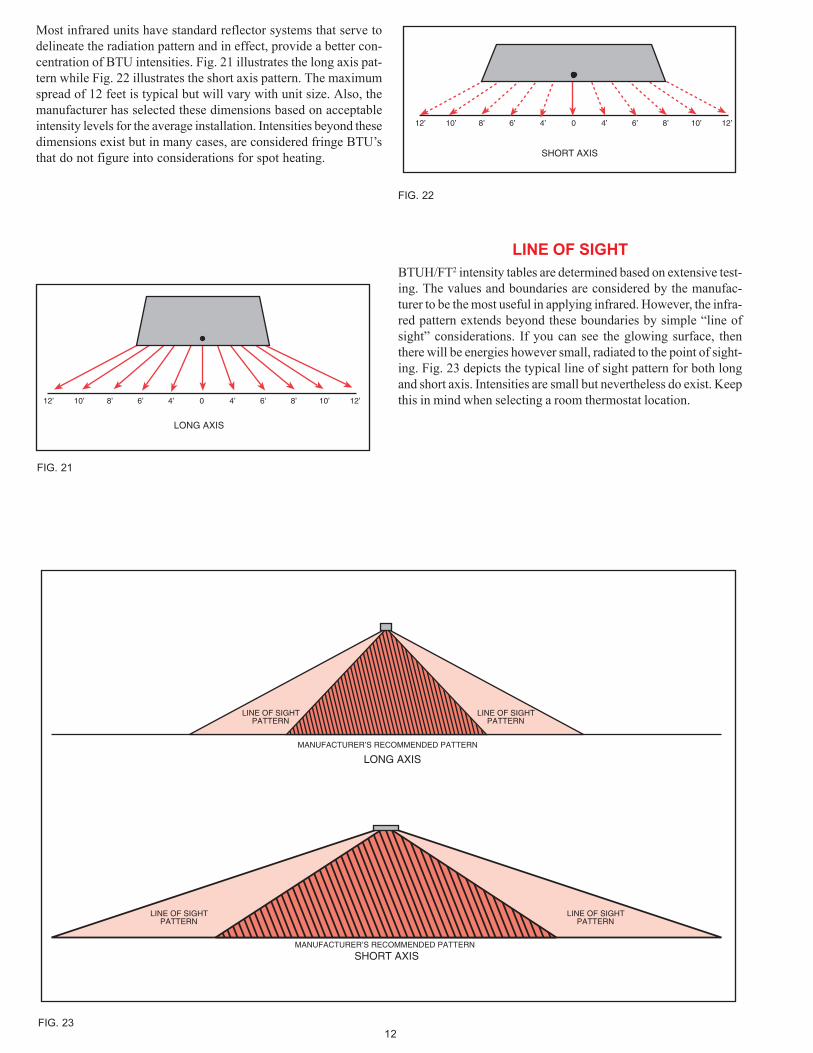
LINE OF SIGHT
BTUH/FT2 intensity tables are determined based on extensive test-ing. The values and boundaries are considered by the manufac-turer to be the most useful in applying infrared. However, the infra-red pattern extends beyond these boundaries by simple “line ofsight” considerations. If you can see the glowing surface, thenthere will be energies however small, radiated to the point of sight-ing. Fig. 23 depicts the typical line of sight pattern for both longand short axis. Intensities are small but nevertheless do exist. Keepthis in mind when selecting a room thermostat location.
12’ 10’ 8’ 6’ 4’ 0 12’10’8’6’4’
SHORT AXIS
FIG. 22
LONG AXIS
12’ 10’ 8’ 6’ 4’ 0 12’10’8’6’4’
FIG. 21
LINE OF SIGHTPATTERN
MANUFACTURER’S RECOMMENDED PATTERN
LINE OF SIGHTPATTERN
LINE OF SIGHTPATTERN
MANUFACTURER’S RECOMMENDED PATTERN
LINE OF SIGHTPATTERN
LONG AXIS
SHORT AXIS
FIG. 23
Most infrared units have standard reflector systems that serve todelineate the radiation pattern and in effect, provide a better con-centration of BTU intensities. Fig. 21 illustrates the long axis pat-tern while Fig. 22 illustrates the short axis pattern. The maximumspread of 12 feet is typical but will vary with unit size. Also, themanufacturer has selected these dimensions based on acceptableintensity levels for the average installation. Intensities beyond thesedimensions exist but in many cases, are considered fringe BTU’sthat do not figure into considerations for spot heating.
13
-30 -20 -10 0 10 20 30 40 50 60AIR & SURROUNDING TEMP. - FOR HEAVY CLOTHING
70
SURFACEHEATLOSSES
400
350
300
250
AIR & SURROUNDING TEMP. - FOR NORMAL CLOTHING
200
150
100
50
0-30 -20 -10
SU
RF
AC
E H
EA
T L
OS
S -
BT
UH
/FT
2
0 10 20 30 40 50 60 70
2 MPH
3 MPH
4 MPH
5 MPH
10 MP
H
15 MP
H
STILL AIR or 1 MPH
ACTIVITY ADJUSTMENTAt rest +19Light bench work 0Mod. heavy work -10Heavy work -36
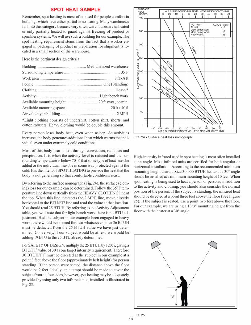
FIG. 24 - Surface heat loss nomograph
3’
FIG. 25
SPOT HEAT SAMPLE
Remember, spot heating is most often used for people comfort inbuildings which have either partial or no heating. Many warehousesfall into this category because very often warehouses are unheatedor only partially heated to guard against freezing of product orsprinkler systems. We will use such a building for our example. Thespot heating requirement stems from the fact that a worker en-gaged in packaging of product in preparation for shipment is lo-cated in a small section of the warehouse.
Here is the pertinent design criteria:
Building ................................................ Medium sized warehouse
Surrounding temperature ...................................................... 35°F
Work area ........................................................................ 8 ft x 8 ft
People .................................................................. One (Standing)
Clothing ........................................................................... Heavy*
Activity ............................................................. Light bench work
Available mounting height ...............................20 ft. max., no min.
Available mounting space ............................................20 ft x 40 ft
Air velocity in building ..................................................... 2 MPH
*Light clothing consists of undershirt, cotton shirt, shorts, andcotton trousers. Heavy clothing would be double this amount.
Every person loses body heat, even when asleep. As activitiesincrease, the body generates additional heat which warms the indi-vidual, even under extremely cold conditions.
Most of this body heat is lost through convection, radiation andperspiration. It is when the activity level is reduced and the sur-rounding temperature is below 70°F, that some type of heat must beadded or the individual must be in some way protected against thecold. It is the intent of SPOT HEATING to provide the heat that thebody is not generating so that comfortable conditions exist.
By referring to the surface nomograph (Fig. 24), the surface (cloth-ing) loss for our example can be determined. Follow the 35°F tem-perature line down vertically from the HEAVY CLOTHING line atthe top. When this line intersects the 2 MPH line, move directlyhorizontal to the BTU/FT2 line and read the value at that location.You should read 25 BTUH. By referring to the Activity Adjustmenttable, you will note that for light bench work there is no BTU ad-justment. Had the subject in our example been engaged in heavywork, there would be no need for heat whatsoever since 36 BTUHmust be deducted from the 25 BTUH value we have just deter-mined. Conversely, if our subject would be at rest, we would beadding 19 BTU to the 25 BTU already determined.
For SAFETY OF DESIGN, multiply the 25 BTUH by 120%, giving aBTU/FT2 value of 30 as our target intensity requirement. Therefore30 BTUH/FT2 must be directed at the subject in our example at apoint 3 feet above the floor (approximately belt height) for personstanding. If the person were seated, the distance above the floorwould be 2 feet. Ideally, an attempt should be made to cover thesubject from all four sides, however, spot heating may be adequatelyprovided by using only two infrared units, installed as illustrated inFig. 25.
High-intensity infrared used in spot heating is most often installedat an angle. Most infrared units are certified for both angular orhorizontal installation. According to the recommended minimummounting height chart, a Size 30,000 BTUH heater at a 30° angleshould be installed at a minimum mounting height of 10 feet. Whenspot heating is being used to heat a person or persons, in additionto the activity and clothing, you should also consider the normalposition of the person. If the subject is standing, the infrared heatshould be directed at a point three feet above the floor (See Figure25). If the subject is seated, use a point two feet above the floor.For our example, we are using a 13’3" mounting height from thefloor with the heater at a 30° angle.
14
8
9
10
11
12
13
14
15
16
17
18
19
20
21
22
23
24
25
26
27
28
"0"
1 2 3 4 5 6 7 8 9 10 11 12 13 14 15 16
INFRARED UNIT AT 30 ANGULAR MOUNTINGH
EIG
HT
(F
T)
- F
rom
the
targ
et le
vel
DISTANCE FROM TARGET (FT)
FIG. 26
FIG. 27 - End view - two unit application
3 F
T
13-1
/4 F
T
6 FT 6 FT
FLOOR
CL
12’
CL
12’
TARGET
MOUNTING HEIGHT
REMAINS AT 13-1/4 FEET
(Floor to Radiant Surface)
FIG. 28 - Plan View - four unit application
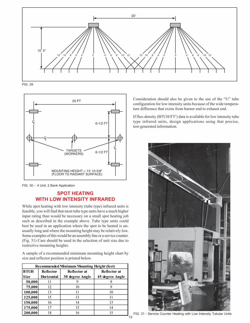
If you wish to guarantee coverage for all four sides of the subjectand have elected to use four units rather than two, refer to Fig. 28for a plan view of the four unit layout. Remember, the same heightof 13 1/4 feet is used with either 2 or 4 units.
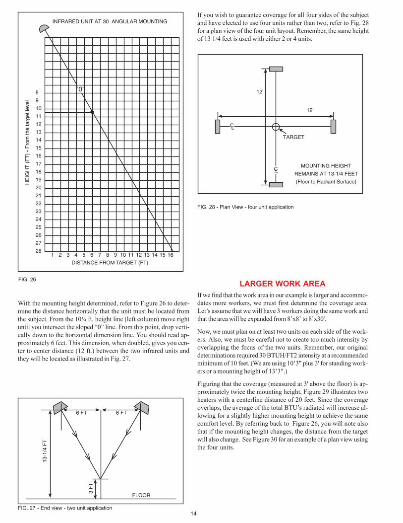
With the mounting height determined, refer to Figure 26 to deter-mine the distance horizontally that the unit must be located fromthe subject. From the 10¼ ft. height line (left column) move rightuntil you intersect the sloped “0” line. From this point, drop verti-cally down to the horizontal dimension line. You should read ap-proximately 6 feet. This dimension, when doubled, gives you cen-ter to center distance (12 ft.) between the two infrared units andthey will be located as illustrated in Fig. 27.
LARGER WORK AREA
If we find that the work area in our example is larger and accommo-dates more workers, we must first determine the coverage area.Let’s assume that we will have 3 workers doing the same work andthat the area will be expanded from 8’x8’ to 8’x30'.
Now, we must plan on at least two units on each side of the work-ers. Also, we must be careful not to create too much intensity byoverlapping the focus of the two units. Remember, our originaldeterminations required 30 BTUH/FT2 intensity at a recommendedminimum of 10 feet. (We are using 10’3" plus 3' for standing work-ers or a mounting height of 13’3".)
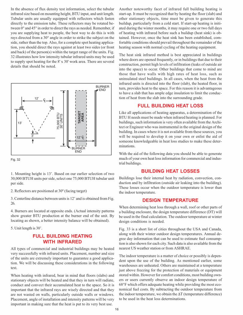
Figuring that the coverage (measured at 3' above the floor) is ap-proximately twice the mounting height, Figure 29 illustrates twoheaters with a centerline distance of 20 feet. Since the coverageoverlaps, the average of the total BTU’s radiated will increase al-lowing for a slightly higher mounting height to achieve the samecomfort level. By referring back to Figure 26, you will note alsothat if the mounting height changes, the distance from the targetwill also change. See Figure 30 for an example of a plan view usingthe four units.
15
20 FT
CL
6-1/2 FT
6-1/2 FTCL
CL
TARGETS(WORKERS)
MOUNTING HEIGHT = 13’ 10-5/8"(FLOOR TO RADIANT SURFACE)
FIG. 30 - 4 Unit, 2 Bank Application
SPOT HEATINGWITH LOW INTENSITY INFRARED
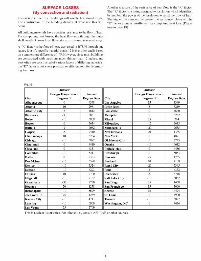
While spot heating with low intensity (tube type) infrared units isfeasible, you will find that most tube type units have a much higherinput rating than would be necessary on a small spot heating jobsuch as described in the example above. Tube type units couldbest be used in an application where the spot to be heated is un-usually long and where the mounting height may be relatively low.Some examples of this would be an assembly line or a service counter.(Fig. 31) Care should be used in the selection of unit size due torestrictive mounting heights.
A sample of a recommended minimum mounting height chart bysize and reflector position is printed below.
10’ 3"12’ 12’10’8’6’4’8’10’12’ 6’ 4’ 0 10’ 8’ 6’ 4’ 0 4’ 8’ 10’ 12’6’
20’
FIG. 29
FIG. 31 - Service Counter Heating with Low Intensity Tubular Units
Consideration should also be given to the use of the “U” tubeconfiguration for low intensity units because of the wide tempera-ture difference that exists from burner end to exhaust end.
If flux-density (BTUH/FT2) data is available for low intensity tubetype infrared units, design applications using that precise,test-generated information.
Recommended Minimum Mounting Height (feet)BTUH Reflector Reflector at Reflector atSize Horizontal 30 degree Angle 45 degree Angle
50,000 11 9 875,000 12 10 9
100,000 13 11 10125,000 15 13 11150,000 16 14 13175,000 17 15 14200,000 18 16 15
16
Another noteworthy facet of infrared full building heating isstart-up. It must be recognized that by heating the floor (slab) andother stationary objects, time must be given to generate thisbuildup, particularly from a cold start. If start-up heating is initi-ated during the winter months, it may require one or two full daysof heating with infrared before such a buildup (heat sink) is ob-tained. However, once the heat sink has been established, com-fortable conditions should prevail throughout the remainder of theheating season with normal cycling of the heating equipment.
The heat sink infrared method is best appreciated in buildingswhere doors are opened frequently, or in buildings that due to theirconstruction, permit high levels of infiltration (leaks of outside airinto the space) to occur. Other buildings that come to mind arethose that have walls with high rates of heat loss, such asuninsulated steel buildings. In all cases, when the heat from theinfrared units is directed into the floor (slab), the heated floor, inturn, provides heat to the space. For this reason it is advantageousto have a slab that has ample edge insulation to limit the conduc-tion of heat from the slab into the surrounding grade.
FULL BUILDING HEAT LOSS
Like all applications of heating apparatus, a determination of theBTU H needs must be made when infrared heating is planned. Forbuildings, such information is very often available from the Archi-tect or Engineer who was instrumental in the original design of thebuilding. In cases where it is not available from these sources, youwill be required to develop it on your own or enlist the aid ofsomeone knowledgeable in heat loss studies to make these deter-minations.
With the aid of the following data you should be able to generatemuch of your own heat loss information for commercial and indus-trial buildings.
BUILDING HEAT LOSSES
Buildings lose their internal heat by radiation, convection, con-duction and by infiltration (outside air leaking into the building).These losses occur when the outdoor temperature is lower thanthe indoor temperature.
DESIGN TEMPERATURE
When determining heat loss through a wall, roof or other parts ofa building enclosure, the design temperature difference (DT) willbe used in the final calculation. The outdoor temperature at winterdesign conditions is needed.
Fig. 33 is a short list of cities throughout the USA and Canada,along with their winter outdoor design temperatures. Annual de-gree day information that can be used to estimate fuel consump-tion is also shown for each city. Such data is also available from thenearest US weather station or from ASHRAE.
The indoor temperature is a matter of choice or possibly is depen-dent upon the use of the building. As mentioned earlier, somewarehouses are unheated. Others are maintained at a temperaturejust above freezing for the protection of materials or equipmentstored within. However for comfort conditions, most building own-ers or users currently observe an indoor design temperature of68°F which offers adequate heating while providing the most eco-nomical fuel costs. By subtracting the outdoor temperature fromthe indoor temperature, we obtain the ∆T (temperature difference)to be used in the heat loss determinations.
3’
13’
12’
75,0
00 B
TU
30’ U
NIT
S
BURNEREND
BURNEREND
CL
12’ CL
TAR
GE
TA
RE
A
Fig. 32
In the absence of flux density test information, select the tubularinfrared size based on mounting height, BTU input, and unit length.Tubular units are usually equipped with reflectors which fastendirectly to the emission tube. These reflectors may be rotated be-tween 0° and 45° in order to direct the rays as needed. Remember, ifyou are supplying heat to people, the best way to do this is withrays directed from a 30° angle in order to strike the subject on theside, rather than the top. Also, for a complete spot heating applica-tion, you should direct the rays against at least two sides (or frontand back) of the person(s) within the target range of the units. Fig.32 illustrates how low intensity tubular infrared units may be usedto supply spot heating for the 8' x 30' work area. There are severaldetails that should be noted.
1. Mounting height is 13’. Based on our earlier selection of two30,000 BTUH units per side, select one 75,000 BTUH tubular unitper side.
2. Reflectors are positioned at 30º (facing target)
3. Centerline distance between units is 12’ and is obtained from Fig.26.
4. Burners are located at opposite ends. (Actual intensity patternsshow greater BTU production at the burner end of the unit. Bylocating as shown, a better intensity balance will be obtained).
5. Unit length is 30’.
FULL BUILDING HEATINGWITH INFRARED
All types of commercial and industrial buildings may be heatedvery successfully with infrared units. Placement, number and sizeof the units are extremely important to guarantee a good applica-tion. We will be discussing these considerations in the followingtext.
When heating with infrared, bear in mind that floors (slabs) andstationary objects will be heated and that they in turn will radiate,conduct and convect their accumulated heat to the space. So it isimportant that the infrared rays are wisely directed and that theyare not wasted on walls, particularly outside walls or windows.Placement, angle of installation and intensity patterns will be veryimportant in making sure that the heat is put to its very best use.
17
SURFACE LOSSES(By convection and radiation)
The outside surface of all buildings will lose the heat stored inside.The construction of the building dictates at what rate this willoccur.
All building materials have a certain resistance to the flow of heat.For computing heat losses, the heat flow rate through the outershell must be known. Heat flow rates are expressed in several ways.
A “K” factor is the flow of heat, expressed in BTUH through onesquare foot of a specific material that is 12 inches thick and is basedon a temperature difference of 1°F. However, since most buildingsare constructed with partitions much thinner than 12 inches, andvery often are constructed of various layers of differing materials,the “K” factor is not a very practical or efficient tool for determin-ing heat loss.
Outdoor OutdoorDesign Temperature Annual Design Temperature Annual
City Degrees F Degree Days City Degrees F Degree DaysAlbuquerque 0 4348 Los Angeles 35 1349Atlanta 10 2961 Little Rock 5 3219Atlantic City 5 4812 Louisville 0 4660Bismarck -30 8851 Memphis 0 3232Boise -10 5809 Miami 35 214Boston 0 5634 Milwaukee -15 7635Buffalo -5 7062 Minneapolis -20 7635Casper -20 7410 New Orleans 20 1385Chattanooga 10 3254 New York 0 4871Chicago -10 5882 Oklahoma City 0 3725Cincinnati 0 4410 Omaha -10 6612Cleveland 0 6351 Philadelphia 0 4486Columbus -10 5211 Pittsburgh 0 5053Dallas 0 2363 Phoenix 25 1765Des Moines -15 6588 Portland 10 4109Denver -10 5524 Rapid City -20 7345Detroit -10 6293 Reno -5 6332El Paso 10 2700 Rochester -5 6748Flagstaff -10 7152 Salt Lake City -10 6052Great Falls -35 7750 San Diego 35 1458Houston 20 1278 San Francisco 35 3000Indianapolis -10 5699 Seattle 15 4424Jacksonville 25 1239 St. Louis 0 4900Kansas City -10 4711 Toronto -10 6827Lansing -10 6909 Washington, D.C. 0 4424Las Vegas 25 2709
This is a select list of cities. For other cities, consult ASHRAE or other sources.
Another measure of the resistance of heat flow is the “R” factor.The “R” factor is a rating assigned to insulation which identifies,by number, the power of the insulation to resist the flow of heat.The higher the number, the greater the resistance. However, the“R” factor alone is insufficient for computing heat loss. (Pleaseturn to page 18)
Fig. 33
18
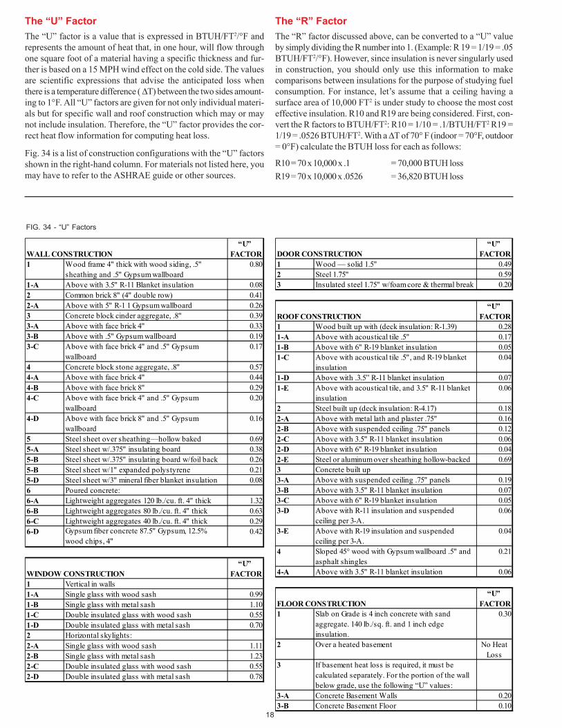
The “U” Factor
The “U” factor is a value that is expressed in BTUH/FT2/°F andrepresents the amount of heat that, in one hour, will flow throughone square foot of a material having a specific thickness and fur-ther is based on a 15 MPH wind effect on the cold side. The valuesare scientific expressions that advise the anticipated loss whenthere is a temperature difference ( ∆T) between the two sides amount-ing to 1°F. All “U” factors are given for not only individual materi-als but for specific wall and roof construction which may or maynot include insulation. Therefore, the “U” factor provides the cor-rect heat flow information for computing heat loss.
Fig. 34 is a list of construction configurations with the “U” factorsshown in the right-hand column. For materials not listed here, youmay have to refer to the ASHRAE guide or other sources.
FIG. 34 - “U” Factors
“U” WALL CONSTRUCTION FACTOR1 Wood frame 4" thick with wood siding, .5"
sheathing and .5" Gypsum wallboard0.80
1-A Above with 3.5" R-11 Blanket insulation 0.082 Common brick 8" (4" double row) 0.412-A Above with 5" R-1 1 Gypsum wallboard 0.263 Concrete block cinder aggregate, .8" 0.393-A Above with face brick 4" 0.333-B Above with .5" Gypsum walIboard 0.193-C Above with face brick 4" and .5" Gypsum
wallboard0.17
4 Concrete block stone aggregate, .8" 0.574-A Above with face brick 4" 0.444-B Above with face brick 8" 0.294-C Above with face brick 4" and .5" Gypsum
wallboard0.20
4-D Above with face brick 8" and .5" Gypsum wallboard
0.16
5 Steel sheet over sheathing—hollow baked 0.695-A Steel sheet w/.375" insulating board 0.385-B Steel sheet w/.375" insulating board w/foil back 0.265-B Steel sheet w/1" expanded polystyrene 0.215-D Steel sheet w/3" mineral fiber blanket insulation 0.086 Poured concrete:6-A Lightweight aggregates 120 lb./cu. ft. 4" thick 1.326-B Lightweight aggregates 80 lb./cu. ft. 4" thick 0.636-C Lightweight aggregates 40 lb./cu. ft. 4" thick 0.296-D Gypsum fiber concrete 87.5" Gypsum, 12.5%
wood chips, 4"0.42
“U” WINDOW CONSTRUCTION FACTOR1 Vertical in walls1-A Single glass with wood sash 0.991-B Single glass with metal sash 1.101-C Double insulated glass with wood sash 0.551-D Double insulated glass with metal sash 0.702 Horizontal skylights:2-A Single glass with wood sash 1.112-B Single glass with metal sash 1.232-C Double insulated glass with wood sash 0.552-D Double insulated glass with metal sash 0.78
“U” DOOR CONSTRUCTION FACTOR1 Wood — solid 1.5" 0.492 Steel 1.75" 0.593 Insulated steel 1.75" w/foam core & thermal break 0.20
“U” ROOF CONSTRUCTION FACTOR1 Wood built up with (deck insulation: R-1.39) 0.281-A Above with acoustical tile .5" 0.171-B Above with 6" R-19 blanket insulation 0.051-C Above with acoustical tile .5", and R-19 blanket
insulation0.04
1-D Above with .3.5” R-11 blanket insulation 0.071-E Above with acoustical tile, and 3.5" R-11 blanket
insulation0.06
2 Steel built up (deck insulation: R-4.17) 0.182-A Above with metal lath and plaster .75" 0.162-B Above with suspended ceiling .75" panels 0.122-C Above with 3.5" R-11 blanket insulation 0.062-D Above with 6" R-19 blanket insulation 0.042-E Steel or aluminum over sheathing hollow-backed 0.693 Concrete built up3-A Above with suspended ceiling .75" panels 0.193-B Above with 3.5" R-11 blanket insulation 0.073-C Above with 6" R-19 blanket insulation 0.053-D Above with R-11 insulation and suspended
ceiling per 3-A.0.06
3-E Above with R-19 insulation and suspended ceiling per 3-A.
0.04
4 Sloped 45° wood with Gypsum wallboard .5" and asphalt shingles
0.21
4-A Above with 3.5" R-11 blanket insulation 0.06
“U” FLOOR CONSTRUCTION FACTOR1 Slab on Grade is 4 inch concrete with sand
aggregate. 140 lb./sq. ft. and 1 inch edge insulation.
0.30
2 Over a heated basement No Heat Loss
3 If basement heat loss is required, it must be calculated separately. For the portion of the wall below grade, use the following “U” values:
3-A Concrete Basement Walls 0.203-B Concrete Basement Floor 0.10
The “R” Factor
The “R” factor discussed above, can be converted to a “U” valueby simply dividing the R number into 1. (Example: R 19 = 1/19 = .05BTUH/FT2/°F). However, since insulation is never singularly usedin construction, you should only use this information to makecomparisons between insulations for the purpose of studying fuelconsumption. For instance, let’s assume that a ceiling having asurface area of 10,000 FT2 is under study to choose the most costeffective insulation. R10 and R19 are being considered. First, con-vert the R factors to BTUH/FT2: R10 = 1/10 = .1/BTUH/FT2 R19 =1/19 = .0526 BTUH/FT2. With a ∆T of 70° F (indoor = 70°F, outdoor= 0°F) calculate the BTUH loss for each as follows:
R10 = 70 x 10,000 x .1 = 70,000 BTUH loss
R19 = 70 x 10,000 x .0526 = 36,820 BTUH loss
19
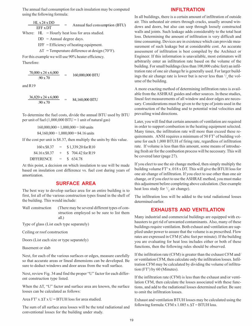
HL x 24 x DDEFF x DT
= Annual fuel consumption (BTU)
70,000 x 24 x 6,000.90 x 70
= 160,000,000 BTU
36,820 x 24 x 6,000.90 x 70
= 84,160,000 BTU
The annual fuel consumption for each insulation may be computedusing the following formula:
and R19
To determine the fuel costs, divide the annual BTU used by BTUper unit of fuel (1,000,000 BTU = 1 unit of natural gas)
160,000,000 ÷ 1,000,000 = 160 units
84,160,000 ÷ 1,000,000 = 84.16 units
If the cost per unit is $8.37, then multiply the units by this value.
160 x $8.37 = $ 1,339.20 for R10
84.16 x $8.37 + $ 704.42 for R19
DIFFERENCE = $ 634.78
At this point, a decision on which insulation to use will be madebased on insulation cost difference vs. fuel cost during years ofamortization.
SURFACE AREA
The best way to develop surface area for an entire building is tofirst, list all of the various construction types found in the shell ofthe building. This would include:
Wall construction (There may be several different types of con-struction employed so be sure to list themall.)
Type of glass (List each type separately)
Ceiling or roof construction
Doors (List each size or type separately)
Basement or slab
Next, for each of the various surfaces or edges, measure carefullyso that accurate areas or lineal dimensions can be developed. Besure to deduct windows and door areas from the wall surface.
Next, review Fig. 34 and find the proper “U” factor for each differ-ent construction type listed.
When the ∆T, “U” factor and surface area are known, the surfacelosses can be calculated as follows:
Area FT2 x ∆T x U = BTUH loss for area studied.
The sum of all surface area losses will be the total radiational andconventional losses for the building under study.
INFILTRATION
In all buildings, there is a certain amount of infiltration of outsideair. This unheated air enters through cracks, usually around win-dows and doors, but also can seep through loosely constructedwalls and joints. Such leakage adds considerably to the total heatloss. Determining the amount of infiltration is very difficult andtime consuming. Devices are in existence which can provide mea-surement of such leakage but at considerable cost. An accurateassessment of infiltration is best compiled by the Architect orEngineer. If this information is unavailable, most estimators willarbitrarily enter an infiltration rate based on the volume of thebuilding. For small buildings (less than 100,000 cubic feet) an infil-tration rate of one air change/hr is generally used. For larger build-ings the air change rate is lower but is never less than 1/
3 the vol-
ume of the building.
A more exacting method of determining infiltration rates is avail-able from the ASHRAE guides and other sources. In these studies,lineal feet measurements of all window and door edges are neces-sary. Considerations must be given to the type of joints used in theconstruction of the building and to potential wind velocities andprevailing wind directions.
Later, you will find that certain amounts of ventilation are requiredin order to support combustion in the heating equipment selected.Many times, the infiltration rate will more than exceed these re-quirements. ANSI requires a minimum of 50 FT3 of building vol-ume for each 1,000 BTUH of firing rate, regardless of infiltrationrate. If volume is less than this amount, some means of introduc-ing fresh air for the combustion process will be necessary. This willbe covered later (page 27).
If you elect to use the air change method, then simply multiply thebuilding volume FT3 x .018 x DT. This will give the BTUH loss forone air change of infiltration. If you elect to use other than one airchange, or if you elect to use the ASHRAE method, you must makethis adjustment before completing above calculation. (See exampleheat loss study for 1/
2 air change).
The infiltration loss will be added to the total radiational lossesdetermined earlier.
EXHAUSTS AND VENTILATION
Many industrial and commercial buildings are equipped with ex-hausters to get rid of unwanted contaminants. Also, many of thesebuildings require ventilation. Both exhaust and ventilation are sup-plied under power to assure that the volume is as prescribed. Flowrates are expressed in CFM (Cubic feet per minute). If the buildingyou are evaluating for heat loss includes either or both of thesefunctions, then the following rules should be observed.
If the infiltration rate (CFM) is greater than the exhaust CFM and/or ventilation CFM, then calculate only the infiltration losses. Infil-tration CFM may be calculated by dividing the volume of infiltra-tion (FT3) by 60 (Minutes).
If the infiltration rate (CFM) is less than the exhaust and/or venti-lation CFM, then calculate the losses associated with these func-tions, and add to the radiational losses determined earlier. Be sureto omit the infiltration losses.
Exhaust and ventilation BTUH losses may be calculated using thefollowing formula: CFM x 1.085 x ∆T = BTUH loss.
Where: HL = Hourly heat loss for area studied.
DD = Annual degree days.
EFF = Efficiency of heating equipment.
∆T = Temperature difference at design (70°F).
For this example we will use 90% heater efficiency.
Therefore:
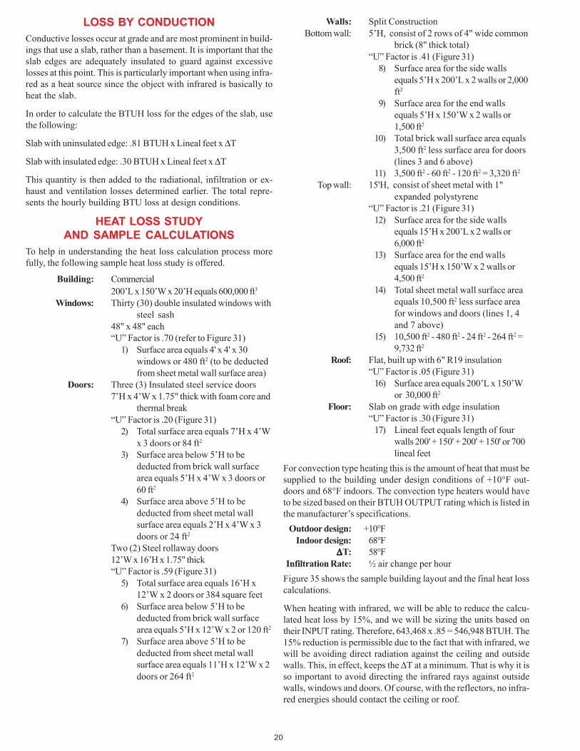
20
LOSS BY CONDUCTION
Conductive losses occur at grade and are most prominent in build-ings that use a slab, rather than a basement. It is important that theslab edges are adequately insulated to guard against excessivelosses at this point. This is particularly important when using infra-red as a heat source since the object with infrared is basically toheat the slab.
In order to calculate the BTUH loss for the edges of the slab, usethe following:
Slab with uninsulated edge: .81 BTUH x Lineal feet x ∆T
Slab with insulated edge: .30 BTUH x Lineal feet x ∆T
This quantity is then added to the radiational, infiltration or ex-haust and ventilation losses determined earlier. The total repre-sents the hourly building BTU loss at design conditions.
HEAT LOSS STUDYAND SAMPLE CALCULATIONS
To help in understanding the heat loss calculation process morefully, the following sample heat loss study is offered.
Building: Commercial200’L x 150’W x 20’H equals 600,000 ft3
Windows: Thirty (30) double insulated windows withsteel sash
48" x 48" each“U” Factor is .70 (refer to Figure 31)
1) Surface area equals 4' x 4' x 30windows or 480 ft2 (to be deductedfrom sheet metal wall surface area)
Doors: Three (3) Insulated steel service doors7’H x 4’W x 1.75" thick with foam core and
thermal break“U” Factor is .20 (Figure 31)
2) Total surface area equals 7’H x 4’Wx 3 doors or 84 ft2
3) Surface area below 5’H to bededucted from brick wall surfacearea equals 5’H x 4’W x 3 doors or60 ft2
4) Surface area above 5’H to bededucted from sheet metal wallsurface area equals 2’H x 4’W x 3doors or 24 ft2
Two (2) Steel rollaway doors12’W x 16’H x 1.75" thick“U” Factor is .59 (Figure 31)
5) Total surface area equals 16’H x12’W x 2 doors or 384 square feet
6) Surface area below 5’H to bededucted from brick wall surfacearea equals 5’H x 12’W x 2 or 120 ft2
7) Surface area above 5’H to bededucted from sheet metal wallsurface area equals 11’H x 12’W x 2doors or 264 ft2
Walls: Split ConstructionBottom wall: 5’H, consist of 2 rows of 4" wide common
brick (8" thick total)“U” Factor is .41 (Figure 31)
8) Surface area for the side wallsequals 5’H x 200’L x 2 walls or 2,000ft2
9) Surface area for the end wallsequals 5’H x 150’W x 2 walls or1,500 ft2
10) Total brick wall surface area equals3,500 ft2 less surface area for doors(lines 3 and 6 above)
11) 3,500 ft2 - 60 ft2 - 120 ft2 = 3,320 ft2
Top wall: 15'H, consist of sheet metal with 1"expanded polystyrene
“U” Factor is .21 (Figure 31)12) Surface area for the side walls
equals 15’H x 200’L x 2 walls or6,000 ft2
13) Surface area for the end wallsequals 15’H x 150’W x 2 walls or4,500 ft2
14) Total sheet metal wall surface areaequals 10,500 ft2 less surface areafor windows and doors (lines 1, 4and 7 above)
15) 10,500 ft2 - 480 ft2 - 24 ft2 - 264 ft2 =9,732 ft2
Roof: Flat, built up with 6" R19 insulation“U” Factor is .05 (Figure 31)
16) Surface area equals 200’L x 150’Wor 30,000 ft2
Floor: Slab on grade with edge insulation“U” Factor is .30 (Figure 31)
17) Lineal feet equals length of fourwalls 200' + 150' + 200' + 150' or 700lineal feet
For convection type heating this is the amount of heat that must besupplied to the building under design conditions of +10°F out-doors and 68°F indoors. The convection type heaters would haveto be sized based on their BTUH OUTPUT rating which is listed inthe manufacturer’s specifications.
Outdoor design: +10°FIndoor design: 68°F
∆∆∆∆∆T: 58°FInfiltration Rate: ½ air change per hour
Figure 35 shows the sample building layout and the final heat losscalculations.
When heating with infrared, we will be able to reduce the calcu-lated heat loss by 15%, and we will be sizing the units based ontheir INPUT rating. Therefore, 643,468 x .85 = 546,948 BTUH. The15% reduction is permissible due to the fact that with infrared, wewill be avoiding direct radiation against the ceiling and outsidewalls. This, in effect, keeps the ∆T at a minimum. That is why it isso important to avoid directing the infrared rays against outsidewalls, windows and doors. Of course, with the reflectors, no infra-red energies should contact the ceiling or roof.
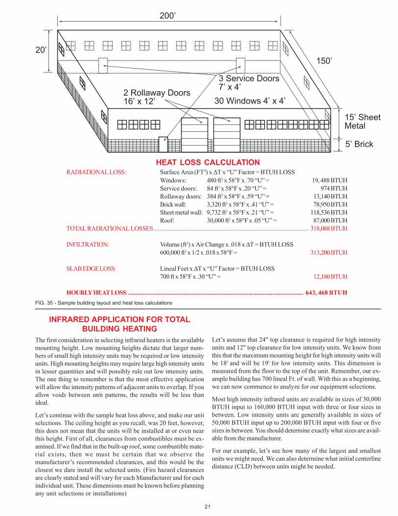
21
����
�������
��������
��������
��������������������
���� ������������������� ����� !�����������
INFRARED APPLICATION FOR TOTALBUILDING HEATING
The first consideration in selecting infrared heaters is the availablemounting height. Low mounting heights dictate that larger num-bers of small high intensity units may be required or low intensityunits. High mounting heights may require large high intensity unitsin lesser quantities and will possibly rule out low intensity units.The one thing to remember is that the most effective applicationwill allow the intensity patterns of adjacent units to overlap. If youallow voids between unit patterns, the results will be less thanideal.
Let’s continue with the sample heat loss above, and make our unitselections. The ceiling height as you recall, was 20 feet, however,this does not mean that the units will be installed at or even nearthis height. First of all, clearances from combustibles must be ex-amined. If we find that in the built-up roof, some combustible mate-rial exists, then we must be certain that we observe themanufacturer’s recommended clearances, and this would be theclosest we dare install the selected units. (Fire hazard clearancesare clearly stated and will vary for each Manufacturer and for eachindividual unit. These dimensions must be known before planningany unit selections or installations)
Let’s assume that 24" top clearance is required for high intensityunits and 12" top clearance for low intensity units. We know fromthis that the maximum mounting height for high intensity units willbe 18' and will be 19' for low intensity units. This dimension ismeasured from the floor to the top of the unit. Remember, our ex-ample building has 700 lineal Ft. of wall. With this as a beginning,we can now commence to analyze for our equipment selections.
Most high intensity infrared units are available in sizes of 30,000BTUH input to 160,000 BTUH input with three or four sizes inbetween. Low intensity units are generally available in sizes of50,000 BTUH input up to 200,000 BTUH input with four or fivesizes in between. You should determine exactly what sizes are avail-able from the manufacturer.
For our example, let’s see how many of the largest and smallestunits we might need. We can also determine what initial centerlinedistance (CLD) between units might be needed.
HEAT LOSS CALCULATIONRADIATIONAL LOSS: Surface Area (FT2) x ∆T x “U” Factor = BTUH LOSS
Windows: 480 ft2 x 58°F x .70 “U” = 19, 488 BTUHService doors: 84 ft2 x 58°F x .20 “U” = 974 BTUHRollaway doors: 384 ft2 x 58°F x .59 “U” = 13,140 BTUHBrick wall: 3,320 ft2 x 58°F x .41 “U” = 78,950 BTUHSheet metal wall: 9,732 ft2 x 58°F x .21 “U” = 118,536 BTUHRoof: 30,000 ft2 x 58°F x .05 “U” = 87,000 BTUH
TOTAL RADIATIONAL LOSSES ............................................................................................... 318,088 BTUH
INFILTRATION: Volume (ft3) x Air Change x .018 x ∆T = BTUH LOSS600,000 ft3 x 1/2 x .018 x 58°F = 313,200 BTUH
SLAB EDGE LOSS: Lineal Feet x ∆T x “U” Factor = BTUH LOSS700 ft x 58°F x .30 “U” = 12,180 BTUH
HOURLY HEAT LOSS ............................................................................................................ 643, 468 BTUH
FIG. 35 - Sample building layout and heat loss calculations
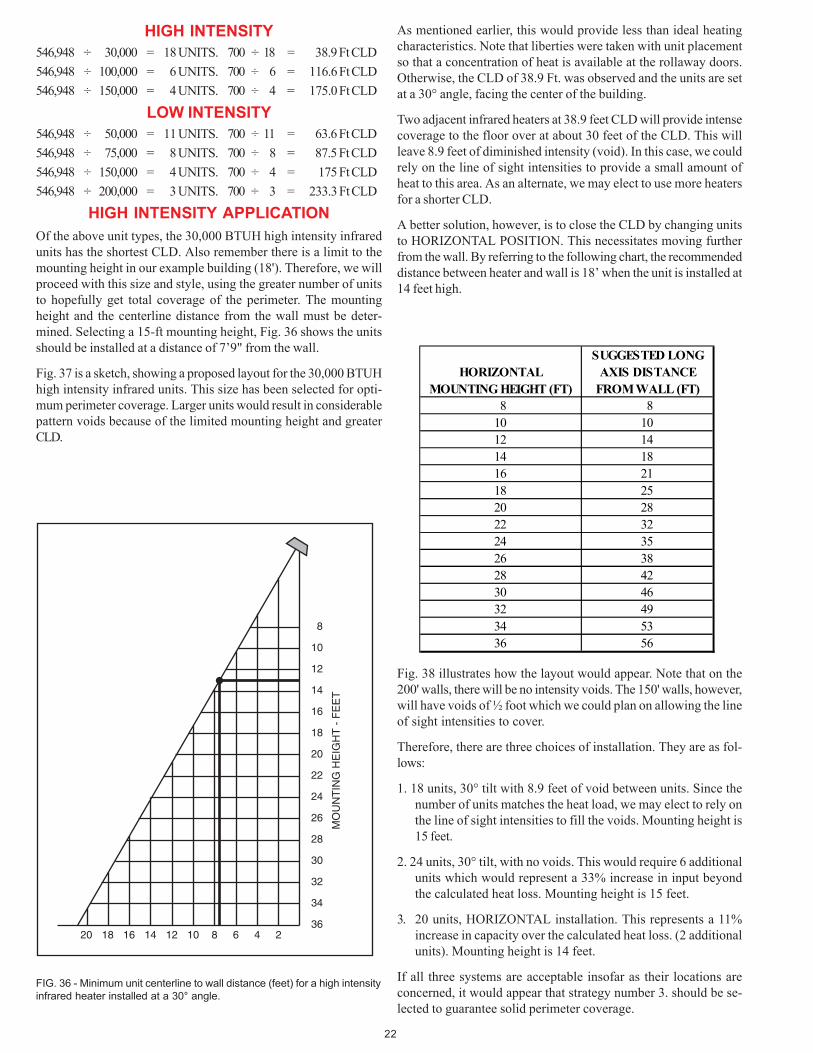
22
8
10
12
14
16
18
20
22
24
26
28
30
32
34
3620 18 16 14 12 10 8 6 4 2
MO
UN
TIN
G H
EIG
HT
- F
EE
T
FIG. 36 - Minimum unit centerline to wall distance (feet) for a high intensity
infrared heater installed at a 30° angle.
SUGGESTED LONGHORIZONTAL AXIS DISTANCE
MOUNTING HEIGHT (FT) FROM WALL (FT)8 8
10 1012 1414 1816 2118 2520 2822 3224 3526 3828 4230 4632 4934 5336 56
HIGH INTENSITY
546,948 ÷ 30,000 = 18 UNITS. 700 ÷ 18 = 38.9 Ft CLD
546,948 ÷ 100,000 = 6 UNITS. 700 ÷ 6 = 116.6 Ft CLD
546,948 ÷ 150,000 = 4 UNITS. 700 ÷ 4 = 175.0 Ft CLD
LOW INTENSITY
546,948 ÷ 50,000 = 11 UNITS. 700 ÷ 11 = 63.6 Ft CLD
546,948 ÷ 75,000 = 8 UNITS. 700 ÷ 8 = 87.5 Ft CLD
546,948 ÷ 150,000 = 4 UNITS. 700 ÷ 4 = 175 Ft CLD
546,948 ÷ 200,000 = 3 UNITS. 700 ÷ 3 = 233.3 Ft CLD
HIGH INTENSITY APPLICATION
Of the above unit types, the 30,000 BTUH high intensity infraredunits has the shortest CLD. Also remember there is a limit to themounting height in our example building (18'). Therefore, we willproceed with this size and style, using the greater number of unitsto hopefully get total coverage of the perimeter. The mountingheight and the centerline distance from the wall must be deter-mined. Selecting a 15-ft mounting height, Fig. 36 shows the unitsshould be installed at a distance of 7’9" from the wall.
Fig. 37 is a sketch, showing a proposed layout for the 30,000 BTUHhigh intensity infrared units. This size has been selected for opti-mum perimeter coverage. Larger units would result in considerablepattern voids because of the limited mounting height and greaterCLD.
As mentioned earlier, this would provide less than ideal heatingcharacteristics. Note that liberties were taken with unit placementso that a concentration of heat is available at the rollaway doors.Otherwise, the CLD of 38.9 Ft. was observed and the units are setat a 30° angle, facing the center of the building.
Two adjacent infrared heaters at 38.9 feet CLD will provide intensecoverage to the floor over at about 30 feet of the CLD. This willleave 8.9 feet of diminished intensity (void). In this case, we couldrely on the line of sight intensities to provide a small amount ofheat to this area. As an alternate, we may elect to use more heatersfor a shorter CLD.
A better solution, however, is to close the CLD by changing unitsto HORIZONTAL POSITION. This necessitates moving furtherfrom the wall. By referring to the following chart, the recommendeddistance between heater and wall is 18’ when the unit is installed at14 feet high.
Fig. 38 illustrates how the layout would appear. Note that on the200' walls, there will be no intensity voids. The 150' walls, however,will have voids of ½ foot which we could plan on allowing the lineof sight intensities to cover.
Therefore, there are three choices of installation. They are as fol-lows:
1. 18 units, 30° tilt with 8.9 feet of void between units. Since thenumber of units matches the heat load, we may elect to rely onthe line of sight intensities to fill the voids. Mounting height is15 feet.
2. 24 units, 30° tilt, with no voids. This would require 6 additionalunits which would represent a 33% increase in input beyondthe calculated heat loss. Mounting height is 15 feet.
3. 20 units, HORIZONTAL installation. This represents a 11%increase in capacity over the calculated heat loss. (2 additionalunits). Mounting height is 14 feet.
If all three systems are acceptable insofar as their locations areconcerned, it would appear that strategy number 3. should be se-lected to guarantee solid perimeter coverage.
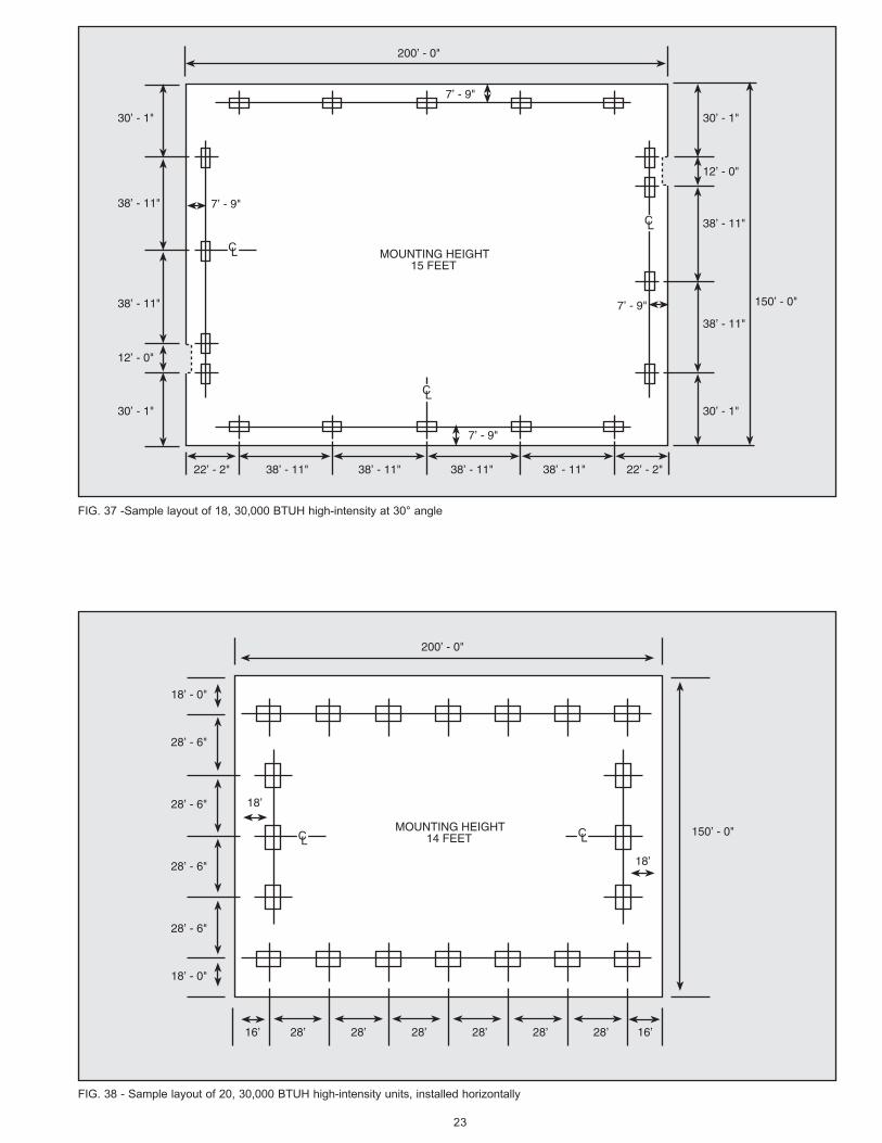
23
FIG. 37 -Sample layout of 18, 30,000 BTUH high-intensity at 30° angle
MOUNTING HEIGHT15 FEET
7’ - 9"
CL
CL
CL
22’ - 2" 38’ - 11" 22’ - 2"38’ - 11" 38’ - 11" 38’ - 11"
200’ - 0"
30’ - 1"
30’ - 1"
12’ - 0"
38’ - 11"
38’ - 11"
30’ - 1"
30’ - 1"
12’ - 0"
38’ - 11"
38’ - 11"
150’ - 0"
7’ - 9"
7’ - 9"
7’ - 9"
FIG. 38 - Sample layout of 20, 30,000 BTUH high-intensity units, installed horizontally
CLCL
200’ - 0"
150’ - 0"
18’
16’28’16’ 28’28’28’28’28’
18’ - 0"
18’ - 0"
28’ - 6"
28’ - 6"
28’ - 6"
28’ - 6"
18’
MOUNTING HEIGHT14 FEET
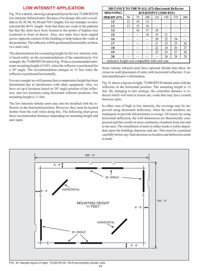
24
FIG. 39 -Sample layout of eight, 75,000 BTUH, 40-ft low-intensity tubular units
MOUNTING HEIGHT11 FEET
CL
CLCL
200’ - 0"
150’ - 0"
8’ - 6"
8’ - 6"
8’ - 6"
8’ - 6"
30 ANGLE
30 ANGLE
HORIZONTAL
HORIZONTAL
LOW INTENSITY APPLICATION
Fig. 39 is a sketch, showing a proposed layout for size 75,000 BTUHlow intensity infrared units. Because of its design, this unit is avail-able in 20, 30, 40, 50, 60 and 70 Ft. lengths. For our example, we haveselected the 40 Ft. length. Note that there are voids in the patternsbut that the units have been located at the points of highest loss(centered in front of doors). Also, two units have been angledacross opposite corners of the building to help reduce the voids atthe perimeter. The reflectors will be positioned horizontally on thesetwo units only.
The determination for a mounting height for the low intensity unit,is based solely on the recommendations of the manufacturer. Forexample, the 75,000 BTUH unit in Fig. 39 has a recommended mini-mum mounting height of 10 Ft. when the reflector is positioned fora 30° angle. The recommendation changes to 12 feet when thereflector is positioned horizontally.
For our example we will assume that a compromise height has beendetermined due to interference with other equipment. Also, wehave set up 6 locations based on 30° angle position of the reflec-tors, and two locations using horizontal reflector positions. Ourmounting height is 11 feet.
The low intensity tubular units may also be installed with the re-flectors in the horizontal position. However, they must be locatedfurther from the wall when doing this. The following chart givesthese recommended distances depending on mounting height andunit input.
DISTANCE TO THE WALL (FT)-Horizontal ReflectorMOUNTING BTUH INPUT (1000 BTU)HEIGHT (FT) 50 75 100 125 150 175 200
12 12 14 15 — — — —13 13 15 16 — — — —14 — 16 17 18 — — —15 — — 18 19 21 — —16 — — — 20 22 24 —17 — — — 21 23 25 2618 — — — 22 24 26 2719 — — — 23 25 27 2820 — — — — 26 28 29
— indicates height not compatible with unit size.
Some tubular infrared units have optional shields that allow forcloser-to-wall placement of units with horizontal reflectors. Con-sult manufacturer’s information.
Fig. 41 shows a layout of eight, 75,000 BTUH tubular units with thereflectors in the horizontal position. The mounting height is 13feet. By changing to this strategy, the centerline distance is re-duced which will tend to lessen any voids that may have existedbetween units.
In either case of high or low intensity, the coverage may be im-proved using horizontal deflection, when the unit numbers areinadequate to provide full perimeter coverage. Of course, by usinghorizontal deflection, the wall dimensions are theoretically com-pressed and this results in more continuity of pattern from one unitto the next. The installation of units in either mode is solely depen-dent upon the building character and use. This must be examinedcarefully before any final decision on location and deflection modeis made.
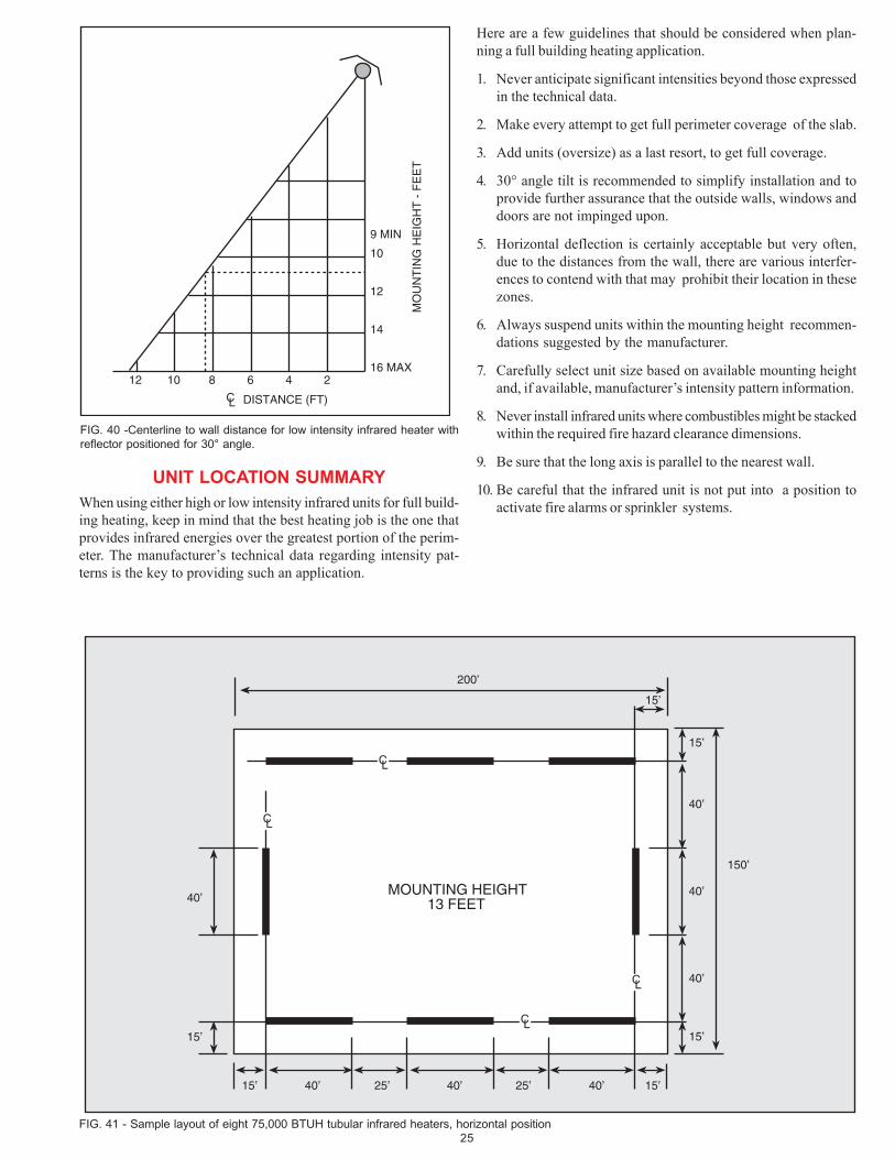
25
200’
150’
CL
CL
CL
CL
15’
40’
40’
40’
15’
15’
15’40’25’25’ 40’40’15’
15’
40’MOUNTING HEIGHT
13 FEET
FIG. 41 - Sample layout of eight 75,000 BTUH tubular infrared heaters, horizontal position
Here are a few guidelines that should be considered when plan-ning a full building heating application.
1. Never anticipate significant intensities beyond those expressedin the technical data.
2. Make every attempt to get full perimeter coverage of the slab.
3. Add units (oversize) as a last resort, to get full coverage.
4. 30° angle tilt is recommended to simplify installation and toprovide further assurance that the outside walls, windows anddoors are not impinged upon.
5. Horizontal deflection is certainly acceptable but very often,due to the distances from the wall, there are various interfer-ences to contend with that may prohibit their location in thesezones.
6. Always suspend units within the mounting height recommen-dations suggested by the manufacturer.
7. Carefully select unit size based on available mounting heightand, if available, manufacturer’s intensity pattern information.
8. Never install infrared units where combustibles might be stackedwithin the required fire hazard clearance dimensions.
9. Be sure that the long axis is parallel to the nearest wall.
10. Be careful that the infrared unit is not put into a position toactivate fire alarms or sprinkler systems.
FIG. 40 -Centerline to wall distance for low intensity infrared heater with
reflector positioned for 30° angle.
MO
UN
TIN
G H
EIG
HT
- F
EE
T
9 MIN
10
12
14
16 MAX12 10 8 6 4 2
DISTANCE (FT)CL
UNIT LOCATION SUMMARY
When using either high or low intensity infrared units for full build-ing heating, keep in mind that the best heating job is the one thatprovides infrared energies over the greatest portion of the perim-eter. The manufacturer’s technical data regarding intensity pat-terns is the key to providing such an application.
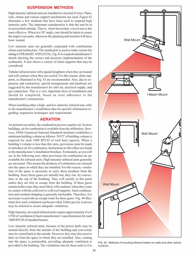
26
SUSPENSION METHODS
High intensity infrared units are installed in a myriad of ways. Pipes,rods, chains and various support mechanisms are used. Figure 42illustrates a few methods that have been used to suspend highintensity units. The important consideration is that the unit be atits prescribed attitude. That is, when horizontal, a level unit is themost effective. When at a 30° angle, care should be taken to assurethe angle is accurate, otherwise the planning and location will havebeen wasted.
Low intensity units are generally suspended with combinationchains and turnbuckles. The turnbuckle is used to make certain thetubing is STRAIGHT AND LEVEL. Fig. 43 is a typical manufacturer’ssketch showing the correct and incorrect implementation of theturnbuckle. It also shows a variety of chain supports that may beconsidered.
Tubular infrared units will expand (lengthen) when they are heatedand will contract when they are cooled. For this reason, chain sup-ports, as illustrated in Fig. 43 are recommended. Also, due to ex-pansion and contraction, special arrangements and hardware aresuggested by the manufacturer for inlet air, electrical supply, andgas connection. This is a very important facet of installation andshould be completed, based on total adherence to themanufacturer’s instructions.
When installing either a high- and low-intensity infrared unit, referto the manufacturer’s installation data for specific information re-garding suspension techniques and requirements.
AERATION
As pointed out earlier, the combustion process requires air. In mostbuildings, air for combustion is available from the infiltration. How-ever, ANSI (American National Standards Institute) establishes aminimum building volume as follows: 50 FT3 of building volume isrequired for each 1000 BTUH of total heat capacity. When abuilding’s volume is less than this ratio, provisions must be madeto introduce air for combustion. Instructions to this effect are foundin the manufacturer’s installation brochure. Fortunately, as you willsee in the following text, other provisions for combustion air areavailable for infrared units. High intensity infrared units generallyare unvented. This means the products of combustion are releasedinto the space in which they are installed. For this reason, ventila-tion of the space is necessary to carry these products from thebuilding. Since these gases are initially hot, they rise, by convec-tion, to the top of the building. They will stratify at this pointunless they are free to escape from the building. If these gasesremain in this zone, they most likely will condense when they comein contact with the cold roof or cold roof supports. Such condensa-tion and resultant dripping is generally intolerable. Therefore, it isnecessary to provide an escape route for these gases. Fig. 44 illus-trates how such ventilation can be provided. Either gravity or powermay be enlisted to assure adequate ventilation.
High intensity, unvented infrared units require approximately 4 to 6CFM of ventilation (Check manufacturer’s specifications) for each1000 BTUH of installed heaters.
Low intensity infrared units, because of the power draft, may beaerated directly from the outside of the building and converselymay be vented back to the outside. However, they may also receivetheir air from the space in which they are installed. Also, ventinginto the space is permissible, providing adequate ventilation isprovided to the building. The ventilation rate for these units is 4 to
Wall Mount
I-Beam Mount
Wall Mount
Wall Mount
FIG. 42 - Methods of mounting infrared heaters on walls and other vertical
surfaces.
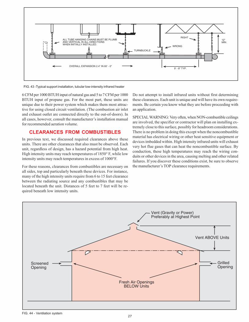
27
6 CFM per 1000 BTUH input of natural gas and 5 to 7 CFM per 1000BTUH input of propane gas. For the most part, these units areunique due to their power system which makes them most attrac-tive for using closed circuit ventilation. (The combustion air inletand exhaust outlet are connected directly to the out-of-doors). Inall cases, however, consult the manufacturer’s installation manualfor recommended aeration volume.
CLEARANCES FROM COMBUSTIBLES
In previous text, we discussed required clearances above theseunits. There are other clearances that also must be observed. Eachunit, regardless of design, has a hazard potential from high heat.High intensity units may reach temperatures of 1850° F, while lowintensity units may reach temperatures in excess of 1000°F.
For these reasons, clearances from combustibles are necessary onall sides, top and particularly beneath these devices. For instance,many of the high intensity units require from 6 to 15 feet clearancebetween the radiating source and any combustibles that may belocated beneath the unit. Distances of 5 feet to 7 feet will be re-quired beneath low intensity units.
Do not attempt to install infrared units without first determiningthese clearances. Each unit is unique and will have its own require-ments. Be certain you know what they are before proceeding withan application.
SPECIAL WARNING: Very often, when NON-combustible ceilingsare involved, the specifier or contractor will plan on installing ex-tremely close to this surface, possibly for headroom considerations.There is no problem in doing this except when the noncombustiblematerial has electrical wiring or other heat sensitive equipment ordevices imbedded within. High intensity infrared units will exhaustvery hot flue gases that can heat the noncombustible surface. Byconduction, these high temperatures may reach the wiring con-duits or other devices in the area, causing melting and other relatedfailures. If you discover these conditions exist, be sure to observethe manufacturer’s TOP clearance requirements.
FIG. 43 -Typical support installation, tubular low-intensity infrared heater
ALL TUBE HANGING CHAINS MUST BE PLUMBAND VERTICAL IN ALL DIRECTIONSWHEN INITIALLY INSTALLED.
OVERALL EXPANSION 2.4" IN 60’ - 0"
TURNBUCKLE
RIGHT
WRONG
9’ - 8" TYP.
12"MIN.
Vent (Gravity or Power)Preferably at Highest Point
Vent ABOVE Units
GrilledOpening
ScreenedOpening
Fresh Air OpeningsBELOW Units
FIG. 44 - Ventilation system
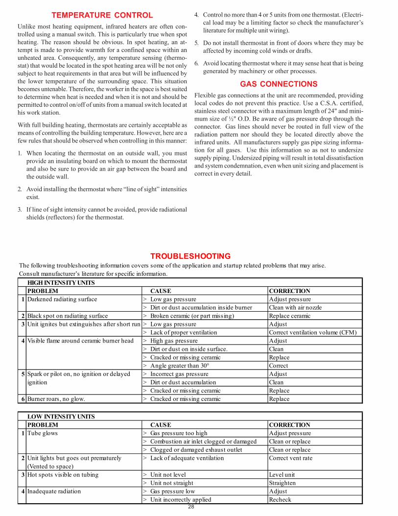
28
TROUBLESHOOTINGThe following troubleshooting information covers some of the application and startup related problems that may arise.Consult manufacturer’s literature for specific information.
HIGH INTENSITY UNITSPROBLEM CAUSE CORRECTION
1 Darkened radiating surface > Low gas pressure Adjust pressure> Dirt or dust accumulation inside burner Clean with air nozzle
2 Black spot on radiating surface > Broken ceramic (or part missing) Replace ceramic3 > Low gas pressure Adjust
> Lack of proper ventilation Correct ventilation volume (CFM)4 > High gas pressure Adjust
> Dirt or dust on inside surface. Clean> Cracked or missing ceramic Replace> Angle greater than 30° Correct
5 > Incorrect gas pressure Adjust> Dirt or dust accumulation Clean> Cracked or missing ceramic Replace
6 Burner roars, no glow. > Cracked or missing ceramic Replace
LOW INTENSITY UNITSPROBLEM CAUSE CORRECTION
1 Tube glows > Gas pressure too high Adjust pressure> Combustion air inlet clogged or damaged Clean or replace> Clogged or damaged exhaust outlet Clean or replace
2 Unit lights but goes out prematurely (Vented to space)
> Lack of adequate ventilation Correct vent rate
3 Hot spots visible on tubing > Unit not level Level unit> Unit not straight Straighten
4 Inadequate radiation > Gas pressure low Adjust> Unit incorrectly applied Recheck
Unit ignites but extinguishes after short run
Visible flame around ceramic burner head
Spark or pilot on, no ignition or delayed ignition
TEMPERATURE CONTROL
Unlike most heating equipment, infrared heaters are often con-trolled using a manual switch. This is particularly true when spotheating. The reason should be obvious. In spot heating, an at-tempt is made to provide warmth for a confined space within anunheated area. Consequently, any temperature sensing (thermo-stat) that would be located in the spot heating area will be not onlysubject to heat requirements in that area but will be influenced bythe lower temperature of the surrounding space. This situationbecomes untenable. Therefore, the worker in the space is best suitedto determine when heat is needed and when it is not and should bepermitted to control on/off of units from a manual switch located athis work station.
With full building heating, thermostats are certainly acceptable asmeans of controlling the building temperature. However, here are afew rules that should be observed when controlling in this manner:
1. When locating the thermostat on an outside wall, you mustprovide an insulating board on which to mount the thermostatand also be sure to provide an air gap between the board andthe outside wall.
2. Avoid installing the thermostat where “line of sight” intensitiesexist.
3. If line of sight intensity cannot be avoided, provide radiationalshields (reflectors) for the thermostat.
4. Control no more than 4 or 5 units from one thermostat. (Electri-cal load may be a limiting factor so check the manufacturer’sliterature for multiple unit wiring).
5. Do not install thermostat in front of doors where they may beaffected by incoming cold winds or drafts.
6. Avoid locating thermostat where it may sense heat that is beinggenerated by machinery or other processes.
GAS CONNECTIONS
Flexible gas connections at the unit are recommended, providinglocal codes do not prevent this practice. Use a C.S.A. certified,stainless steel connector with a maximum length of 24" and mini-mum size of ½" O.D. Be aware of gas pressure drop through theconnector. Gas lines should never be routed in full view of theradiation pattern nor should they be located directly above theinfrared units. All manufacturers supply gas pipe sizing informa-tion for all gases. Use this information so as not to undersizesupply piping. Undersized piping will result in total dissatisfactionand system condemnation, even when unit sizing and placement iscorrect in every detail.
29
GLOSSARY
ANNUAL DEGREE DAYS: The total number of outdoor degrees Fbelow the indoor design temperature (65°). Using the average de-viation for each day, over a 365 day period.
ANSI: American National Standards Institute.
ASHRAE: American Society of Heating, Refrigeration and AirConditioning Engineers
BLACK BODY: Matter which absorbs all the infrared energiesimpinged upon it.
BTU: British Thermal Unit. The amount of heat required to raisethe temperature of one pound of water, one degree Fahrenheit.
BTU/FT2: British thermal unit per square foot
BTU/FT3: British thermal unit per cubic foot
BTUH: British thermal unit per hour
BUTANE: Fuel gas that is a derivative of oil cracking process.
COMBUSTION: Rapid oxidation of fuel when mixed with oxygenand ignited.
CONDUCTION: Heat being transmitted by physical contact.
CONVECTION: Transference of heat by moving masses of mat-ter, as by currents in gases or liquids, caused by differences indensity and the action of gravity.
DELTA T (∆∆∆∆∆T): Temperature difference.
DENSITY: Mass per specific unit volume.
DRAFT HOOD: Device used to balance combustion over a com-bustion zone and stabilize unit efficiency in the face of varyingvent conditions.
ELECTROMAGNETIC WAVE: An electrical impulse that trans-mits radio signals, infrared, visible light and other such energies.
EMISSIVITY: The power of a matter to emit heat.
EXHAUST GASES: Products of combustion
FLUX DENSITY: A measure of infrared intensity at a given dis-tance from the infrared source.
FORCED DRAFT: Furnishing burner aeration by pushing air intothe combustion zone under power.
INDUCED DRAFT: Evacuating a combustion zone under power,thereby causing fresh air to enter the combustion zone.
INFILTRATION: Air that enters a building indiscriminately throughcracks in the building shell.
K FACTOR: A measure of the amount of heat (BTU/FT2) thatpasses through one square foot of material that is 12" thick, in onehour, with one degree Fahrenheit difference between the two sides.
LONG AXIS: Imaginary center of infrared source running the lengthof the infrared radiating surface.
METHANE: A colorless, odorless gas that constitutes the majorportion of all fuel gases.
NATURAL GAS: Fuel gas containing methane and other elements.
PRIMARY AIR: Air introduced with the gas before the flame.
PROPANE: A fuel gas that is derived from the petroleum crackingprocess.
R FACTOR: A measure of the resistance to the flow of heat. Thegreater the factor (number), the higher the resistance.
RADIATION: The flow of heat transmitted by electromagnet waves.
REFLECTION: When infrared energies bounce off a surface (aredeflected)
SECONDARY AIR: Air that is introduced into the flame after igni-tion has occurred.
SHORT AXIS: Imaginary center of infrared source that runs acrossthe width of a radiating surface.
SPECIFIC GRAVITY: The weight of gas when compared to theweight of air. (Weight of air given as 1.0)
SPOT HEATING: Supplying heat to a specific area located in abuilding that is essentially unheated.
U FACTOR: Amount of heat that will move through one squarefoot of a specifically defined surface in one hour with one degree Fof temperature difference between the two sides.
VENTILATION: The introduction of fresh air into a building, un-der power, and exhausting a like amount back to the atmosphere.

©2001 Thomas & Betts Corporation Printed in U.S.A. All rights reserved.
Reznor is registered in at least the U.S.
15M 6/01 YL FORM RZ-NA-IRHB (Version 0.1)