Embed Size (px)
Citation preview
Page 1
Installation/Operation Form RGM-417-BObsoletes Form RGM 417-A
APPLIES TO: Models OH, OB
WARNING: Improper installation, adjustment,alteration, service, or maintenance can causeproperty damage, injury or death. Read theinstallation, operation, and maintenanceinstructions thoroughly before installing orservicing this equipment.
Mfg P/N 120390
Index by Page No.Air Throw ............................................. 3Blowers and Drives - Blower
Model Only ...................................... 10Boost Pump Assembly (Options DA1, DA2) ......................... 7Boost Pump Pressure Switch (Option DF1) ..................................... 8Burner Pump...................................... 11Burner Pump Lift Capacity ................. 6Check-Test-Startup Procedure ........... 12Cleaning Combustion Chamber, Heat Exchanger and Flue Pipe ........ 15Cleaning End Cone ............................ 16Cleaning Exterior Surface ................. 17Clearances ............................................. 3Air for Combustion ............................. 3Combustion Air Band and Air Shutter Settings ............................... 13Dimensions .......................................... 2
Draft Inducer Relay (Option DH1) ..... 5Draft Regulator Requirements ............. 5Discharge Duct (Blower Model only) ................................................... 4Inlet Air Duct (Blower Model only) .... 4Electrical Ratings .................................. 9Electrical Supply and Connections ...... 9Electrodes and Nozzle Location ......... 10Fan and Limit Controls ...................... 11Fuel Specifications .............................. 3GENERAL ........................................... 1HAZARD INTENSITY LEVELS ....... 2Installation Codes ................................ 2Location ............................................... 3Maintenance Requirements ............... 15Motors ................................................ 10Primary Control System .................... 12Removing Burner .............................. 16Removing Fuel Line Assembly ......... 16
Table of ContentsPara. No. Page No.
Heater Installation and Operation 1-26 1-12Check-Test-Start 27 12-14Storage Tank 28 14Maintenance/Service/Troubleshooting 29-34 15-19
OIL-FIRED UNITHEATERS
FOR YOUR SAFETYThe use and storage of gasoline or otherflammable vapors and liquids in opencontainers in the vicinity of this appliance ishazardous.
1. WarrantyRefer to the limited warranty information on the Warranty Card in the"Owner's Envelope.
GeneralInstallation should be done by a qualified agency in accordance withthe instructions in this manual and in compliance with all codes andrequirements of authorities having jurisdiction. The instructions inthis manual apply to the oil-fired unit heaters listed below. WARRANTY: Warranty is void if......
a. Wiring is not in accordance with diagram furnished withthe heater.
b. Heater is operated in presence of chlorinated vapors.
c. Air through heater is not in accordance with rating plate.
d. Ducts are attached to fan models.
Loop Supply System............................ 7Pressurized Supply System.................. 7Single Pipe Supply System .................. 6Two-Pipe Supply System ...................... 7Supply Lines ........................................ 6Suspending the Unit ............................ 3Fuel Tank .............................................. 6Storage Tank ...................................... 14Thermostat ......................................... 10Troubleshooting Guide - High Temperature Limit Cycles ............... 19Troubleshooting Oil Burner .............. 17Uncrating/Shipping Damage ............... 2Check Valve ......................................... 9Oil Safety Valve (OSV) (Option DC1) ..................................... 8Solenoid Valve (Option DD1) ............. 8Venting .................................................. 5Warranty ............................................... 1
REFERENCE: Replacement Parts, Form RGM 723
Model Characteristics
OHSuspended, Indoor, Oil-Fired Unit Heater with a Propeller Fan; Requires a Vent Pipe/Chimney with a Barometric Draft Regulator
OBSuspended, Indoor, Oil-Fired Unit Heater with a Blower (may be connected to ductwork); Requires a Vent Pipe/Chimney with a Barometric Draft Regulator
Form 417, Page 2
HAZARD INTENSITY LEVELS1. DANGER: Failure to comply will result in severe personal injury or death and/or property damage.2. WARNING: Failure to comply could result in severe personal injury or death and/or property damage.3. CAUTION: Failure to comply could result in minor personal injury and/or property damage.
WARNING: This appliance is not designedfor use in hazardous atmospheres containingflammable vapors or combustible dust, oratmospheres containing chlorinated orhalogenated hydrocarbons.
2. Installation CodesThis heater is for commercial or industrial use only. In the UnitedStates, the installation must be in accordance with the Standard forthe Installation of Oil Burning Equipment NFPA 31, the NationalElectrical Code NFPA 70, and the requirements of the inspectionauthorities having jurisdiction. In Canada, the installation must bein accordance with CSA Standard B139-M91, Installation Codefor Oil Burning Equipment; CSA Standard C22.1, Canadian Elec-tric Code, Part 1; and with requirements of local regulatory au-thorities.
This heater should be installed only by an experienced installer.The installer should be trained and thoroughly familiar with theinstallation of oil-fired appliances.
Prior to beginning installation, become familiar with your model ofheater and its particular installation requirements.
3. Uncrating/Shipping DamageImmediately upon uncrating the unit, check for any damage that may havebeen incurred in shipment; and if any damage is found, file a claim withthe transporting agency. The unit was inspected and tested at the factoryprior to crating and was in operating condition at that time.To prevent damage to the painted cabinet, it is recommended that the cratebottom be left in place until after the unit has been suspended. This appliesto both blower and fan models.To protect the unit during shipping, the blower model has special supportsthat must be removed before installation. Follow these instructions to re-move:1) Blower Support Legs -- Remove the two blower support legs and screws2) Motor Shipping Block -- Remove the wooden block located under the
motor bracket. Find the two rubber pads in the parts package. Placethese pads on the ends of the motor bracket bolts.
3) Motor Shipping Plate -- Underneath the belt guard, there is a smallmetal plate attached between the motor and the blower housing. Re-move the belt guard. Remove the metal shipping plate and the screws.Replace the belt guard.
Packaged and shipped with all CSA approved units is a barometric draftregulator and a cleaning rake base. The cleaning rake base is also includedwith UL approved units. The installation could include a variety of shipped-separate options. Be sure that all optional components to be used in theinstallation are at the job site.
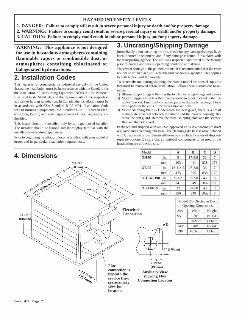
4. Dimensions
32-1/8"(816mm)
29-1/16" (738mm)
A
17" (432mm)
2-9/16"(68 mm)
CB
14-7/16"(367mm)
ElectricalConnection
Flueconnection isbeneath theservice tray;see auxiliaryview forlocation.
Auxiliary Viewshowing Flue
Connection Locaton
D
7" (178mm)
7-19/32"(193mm)
Model A B C DOH 95 in. 8 17-3/8 33 7
mm 203 441 838 178
OB 95 in. 18-11/16 27-3/8 33 7
mm 475 695 838 178
OH 140/190 in. 9-1/2 37-3/8 43 8
mm 241 949 1092 203
OB 140/190 in. 22 37-3/8 43 8
mm 559 949 1092 8
Model OB Discharge DuctOpening Dimensions
Size Width Height
95 30" 16-1/4"
762mm 413mm
140/ 40" 16-1/4"
190 1016mm 413mm
Page 3
5. Fuel SpecificationsThe burner in this oil-fired heater is designed and orificed for use with#2 fuel oil (140,000 BTU/gallon) at 100 psig. However, the followingsubstitute fuels may be used:
#1 fuel oil - 132,000 BTU/gallon
Kerosene (domestic only; do not use foreign) - 132,000 BTU/gallon
#1 diesel fuel - 132,000 BTU/gallon
#2 diesel fuel - 140,000 BTU/gallon
Due to higher viscosity, some #1 oils's BTU/gallon capacity may be128,000 to 130,000 BTU/gallon. Check BTU content of substitute fuelto determine burner input.• Size 95 burns an average of .85 gallons per hour.• Size 140 burns an average of 1.25 gallons per hour.• Size 190 burns an average of 1.65 gallons per hour.
CAUTION: Do not attempt to burn paper orgarbage in this heater.
6. Location and Air ThrowThese oil-fired unit heaters should be installed in such a manner as toderive maximum efficiency and a minimum of heat loss to the outsideenvironment. As a rule, single heaters should be suspended over anarea of low heat loss with output air directed toward the area of thegreatest heat loss. Where two or more heaters are used in a commoninstallation, heaters should be arranged around the outside walls andblowing parallel to them. Heaters may be arranged in a supporting con-secutive air pattern so that the output of one blows beneath the air-intake side of another. In installations where there are concentratedheat loss areas, a combination of single and multiple arrangements isdesirable. See illustrations in Figure 1.
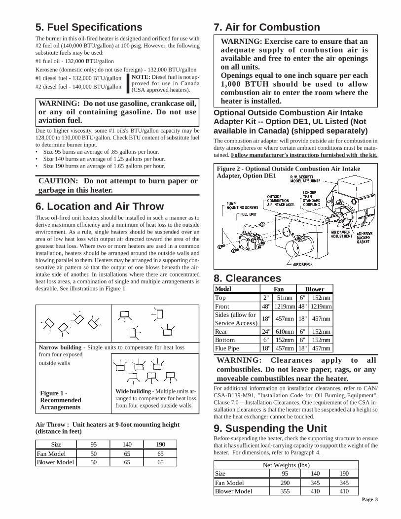
7. Air for CombustionWARNING: Exercise care to ensure that anadequate supply of combustion air isavailable and free to enter the air openingson all units.Openings equal to one inch square per each1,000 BTUH should be used to allowcombustion air to enter the room where theheater is installed.
Optional Outside Combustion Air IntakeAdapter Kit -- Option DE1, UL Listed (Notavailable in Canada) (shipped separately)The combustion air adapter will provide outside air for combustion indirty atmospheres or where certain ambient conditions must be main-tained. Follow manufacturer's instructions furnished with the kit.
Figure 2 - Optional Outside Combustion Air IntakeAdapter, Option DE1
8. Clearances
WARNING: Clearances apply to allcombustibles. Do not leave paper, rags, or anymoveable combustibles near the heater.
For additional information on installation clearances, refer to CAN/CSA-B139-M91, "Installation Code for Oil Burning Equipment",Clause 7.0 -- Installation Clearances. One requirement of the CSA in-stallation clearances is that the heater must be suspended at a height sothat the heat exchanger cannot be touched.
9. Suspending the UnitBefore suspending the heater, check the supporting structure to ensurethat it has sufficient load-carrying capacity to support the weight of theheater. For dimensions, refer to Paragraph 4.
NOTE: Diesel fuel is not ap-proved for use in Canada(CSA approved heaters).
WARNING: Do not use gasoline, crankcase oil,or any oil containing gasoline. Do not useaviation fuel.
Wide building - Multiple units ar-ranged to compensate for heat lossfrom four exposed outside walls.
Figure 1 -RecommendedArrangements
Air Throw : Unit heaters at 9-foot mounting height(distance in feet)
Narrow building - Single units to compensate for heat lossfrom four exposed
outside walls
Size 95 140 190
Fan Model 50 65 65Blower Model 50 65 65 Net Weights (lbs)
Size 95 140 190
Fan Model 290 345 345Blower Model 355 410 410
Model Top 2" 51mm 6" 152mmFront 48" 1219mm 48" 1219mmSides (allow for Service Access)
18" 457mm 18" 457mm
Rear 24" 610mm 6" 152mmBottom 6" 152mm 6" 152mmFlue Pipe 18" 457mm 18" 457mm
Fan Blower
Form 417, Page 4
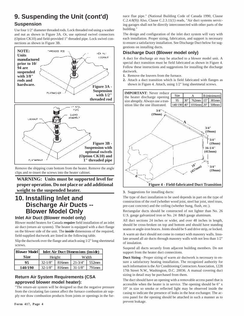
9. Suspending the Unit (cont'd)SuspensionUse four 1/2" diameter threaded rods. Lock threaded rod using a washerand nut as shown in Figure 3A. Or, use optional swivel connectors(Option CK10) and field-provided 1" threaded pipe. Lock swivel con-nections as shown in Figure 3B.
Figure 3B -Suspension withoptional swivels
(Option CK10) and1" threaded pipe
Remove the shipping crate bottom from the heater. Remove the angleclips and re-insert the screws into the heater cabinet.
WARNING: Units must be supported level forproper operation. Do not place or add additionalweight to the suspended heater.
10. Installing Inlet andDischarge Air Ducts --Blower Model Only
Inlet Air Duct (Blower model only)Blower model heaters for Canada require field installation of an inletair duct (return air system). The heater is equipped with a duct flangeon the blower side of the unit. The inside dimensions of the required,field-supplied ductwork are listed in the following table.
Slip the ductwork over the flange and attach using 1/2" long sheetmetalscrews.
Return Air System Requirements (CSAapproved blower model heater):"The return-air system will be designed so that the negative pressurefrom the circulating fan cannot affect the furnace combustion air sup-ply nor draw combustion products from joints or openings in the fur-
nace flue pipe." (National Building Code of Canada 1990, ClauseC.2.4.8(9)) Also, Clause C.2.3.11(1) reads, "Air duct systems servic-ing garages shall not be directly interconnected with other parts of thebuilding."
The design and configuration of the inlet duct system will vary witheach installation. Proper sizing, fabrication, and support is necessaryto ensure a satisfactory installation. See Discharge Duct below for sug-gestions on installing ducts.
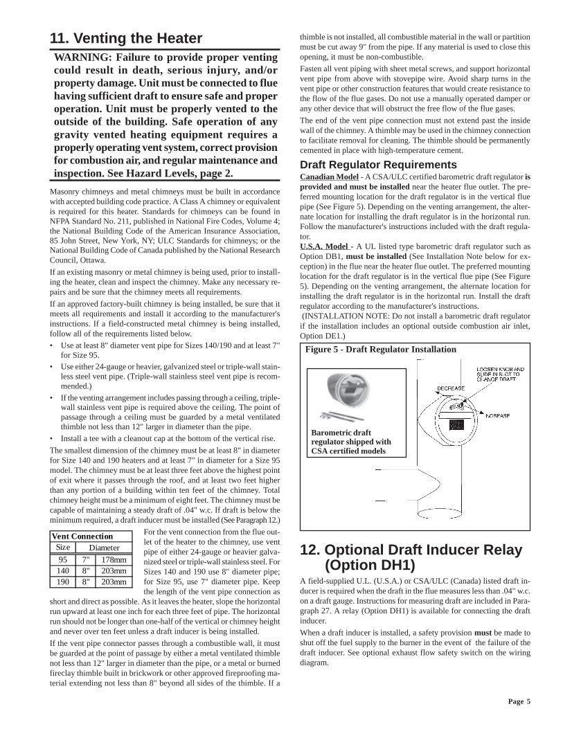
Discharge Duct (Blower model only)A duct for discharge air may be attached to a blower model unit. Aspecial duct transition must be field fabricated as shown in Figure 4.Follow these instructions and suggestions for installing the dischargeductwork.1. Remove the louvers from the furnace.2. Attach a duct transition which is field fabricated with flanges as
shown in Figure 4. Attach, using 1/2" long sheetmetal screws.
3. Suggestions for installing ducts:
The type of duct installation to be used depends in part on the type ofconstruction of the roof (whether wood joist, steel bar joist, steel truss,pre-cast concrete) and the ceiling (whether hung, flush, etc.).
Rectangular ducts should be constructed of not lighter than No. 26U.S. gauge galvanized iron or No. 24 B&S gauge aluminum.
All duct sections 24 inches or wider, and over 48 inches in length,should be cross-broken on top and bottom and should have standingseams or angle-iron braces. Joints should be S and drive strip, or locked.
A warm air duct should not come in contact with masonry walls. Insu-late around all air ducts through masonry walls with not less than 1/2"of insulation.
Suspend all ducts securely from adjacent building members. Do notsupport from the heater duct connections.
Duct Sizing - Proper sizing of warm air ductwork is necessary to en-sure a satisfactory heating installation. The recognized authority forsuch information is the Air Conditioning Contractors Association, 122817th Street N.W., Washington, D.C. 20036. A manual covering ductsizing in detail may be purchased from them.
The duct should have an opening with a removable access panel that isaccessible when the heater is in service. The opening should be 6" x10" in size so smoke or reflected light may be observed inside thecasing to indicate the presence of leaks in the heat exchanger. The ac-cess panel for the opening should be attached in such a manner as toprevent leakage.
Figure 3A -Suspension
with 1/2"threaded rod
NOTE:Unitsmanufacturedprior to 10/94 aresuspendedwith 3/8"rods andhardware.
IMPORTANT: Never reducethe heater discharge openingsize abruptly. Always use a tran-sition like the one illustrated.
Figure 4 - Field-fabricated Duct Transition
Blower ModelSize
95 32-1/8" 816mm 21-3/4" 552mm140/190 32-1/8" 816mm 31-1/8" 791mm
Height WidthInlet Air Duct Dimensions (inside)
Size
95 30" 762mm 15" 381mm140/190 40" 1016mm 20" 508mm
A B (minimum)
B
18"
(457mm) 3/4"(19mm)
3/4"(19mm)
16-1/4"(413mm)
3/4"(19mm)
3/4"(19mm)
A
Page 5
thimble is not installed, all combustible material in the wall or partitionmust be cut away 9" from the pipe. If any material is used to close thisopening, it must be non-combustible.
Fasten all vent piping with sheet metal screws, and support horizontalvent pipe from above with stovepipe wire. Avoid sharp turns in thevent pipe or other construction features that would create resistance tothe flow of the flue gases. Do not use a manually operated damper orany other device that will obstruct the free flow of the flue gases.
The end of the vent pipe connection must not extend past the insidewall of the chimney. A thimble may be used in the chimney connectionto facilitate removal for cleaning. The thimble should be permanentlycemented in place with high-temperature cement.
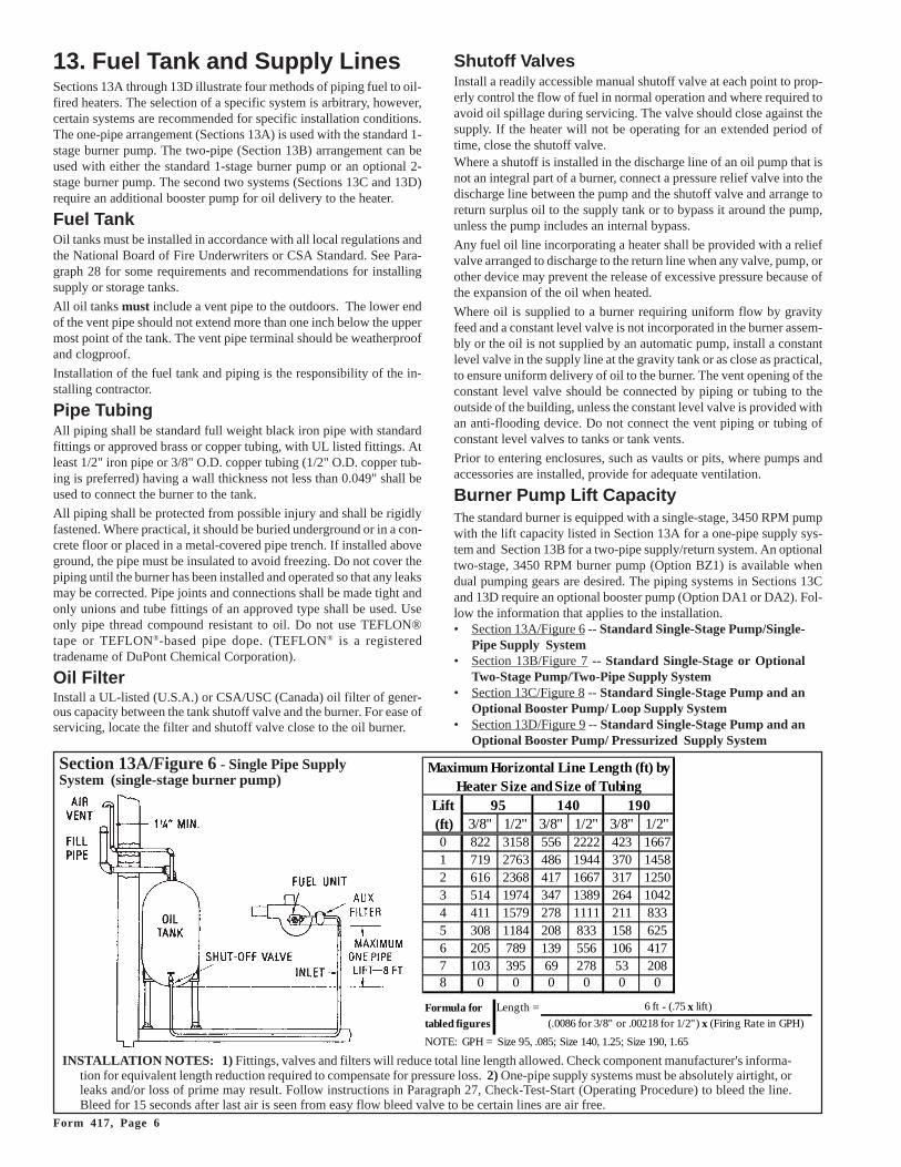
Draft Regulator RequirementsCanadian Model - A CSA/ULC certified barometric draft regulator isprovided and must be installed near the heater flue outlet. The pre-ferred mounting location for the draft regulator is in the vertical fluepipe (See Figure 5). Depending on the venting arrangement, the alter-nate location for installing the draft regulator is in the horizontal run.Follow the manufacturer's instructions included with the draft regula-tor.U.S.A. Model - A UL listed type barometric draft regulator such asOption DB1, must be installed (See Installation Note below for ex-ception) in the flue near the heater flue outlet. The preferred mountinglocation for the draft regulator is in the vertical flue pipe (See Figure5). Depending on the venting arrangement, the alternate location forinstalling the draft regulator is in the horizontal run. Install the draftregulator according to the manufacturer's instructions. (INSTALLATION NOTE: Do not install a barometric draft regulatorif the installation includes an optional outside combustion air inlet,Option DE1.)
12. Optional Draft Inducer Relay(Option DH1)
A field-supplied U.L. (U.S.A.) or CSA/ULC (Canada) listed draft in-ducer is required when the draft in the flue measures less than .04" w.c.on a draft gauge. Instructions for measuring draft are included in Para-graph 27. A relay (Option DH1) is available for connecting the draftinducer.
When a draft inducer is installed, a safety provision must be made toshut off the fuel supply to the burner in the event of the failure of thedraft inducer. See optional exhaust flow safety switch on the wiringdiagram.
11. Venting the HeaterWARNING: Failure to provide proper ventingcould result in death, serious injury, and/orproperty damage. Unit must be connected to fluehaving sufficient draft to ensure safe and properoperation. Unit must be properly vented to theoutside of the building. Safe operation of anygravity vented heating equipment requires aproperly operating vent system, correct provisionfor combustion air, and regular maintenance andinspection. See Hazard Levels, page 2.
Masonry chimneys and metal chimneys must be built in accordancewith accepted building code practice. A Class A chimney or equivalentis required for this heater. Standards for chimneys can be found inNFPA Standard No. 211, published in National Fire Codes, Volume 4;the National Building Code of the American Insurance Association,85 John Street, New York, NY; ULC Standards for chimneys; or theNational Building Code of Canada published by the National ResearchCouncil, Ottawa.
If an existing masonry or metal chimney is being used, prior to install-ing the heater, clean and inspect the chimney. Make any necessary re-pairs and be sure that the chimney meets all requirements.
If an approved factory-built chimney is being installed, be sure that itmeets all requirements and install it according to the manufacturer'sinstructions. If a field-constructed metal chimney is being installed,follow all of the requirements listed below.
• Use at least 8" diameter vent pipe for Sizes 140/190 and at least 7"for Size 95.
• Use either 24-gauge or heavier, galvanized steel or triple-wall stain-less steel vent pipe. (Triple-wall stainless steel vent pipe is recom-mended.)
• If the venting arrangement includes passing through a ceiling, triple-wall stainless vent pipe is required above the ceiling. The point ofpassage through a ceiling must be guarded by a metal ventilatedthimble not less than 12" larger in diameter than the pipe.
• Install a tee with a cleanout cap at the bottom of the vertical rise.
The smallest dimension of the chimney must be at least 8" in diameterfor Size 140 and 190 heaters and at least 7" in diameter for a Size 95model. The chimney must be at least three feet above the highest pointof exit where it passes through the roof, and at least two feet higherthan any portion of a building within ten feet of the chimney. Totalchimney height must be a minimum of eight feet. The chimney must becapable of maintaining a steady draft of .04" w.c. If draft is below theminimum required, a draft inducer must be installed (See Paragraph 12.)
For the vent connection from the flue out-let of the heater to the chimney, use ventpipe of either 24-gauge or heavier galva-nized steel or triple-wall stainless steel. ForSizes 140 and 190 use 8" diameter pipe;for Size 95, use 7" diameter pipe. Keepthe length of the vent pipe connection as
short and direct as possible. As it leaves the heater, slope the horizontalrun upward at least one inch for each three feet of pipe. The horizontalrun should not be longer than one-half of the vertical or chimney heightand never over ten feet unless a draft inducer is being installed.
If the vent pipe connector passes through a combustible wall, it mustbe guarded at the point of passage by either a metal ventilated thimblenot less than 12" larger in diameter than the pipe, or a metal or burnedfireclay thimble built in brickwork or other approved fireproofing ma-terial extending not less than 8" beyond all sides of the thimble. If a
Barometric draftregulator shipped withCSA certified models
Figure 5 - Draft Regulator Installation
Vent ConnectionSize
95 7" 178mm140 8" 203mm190 8" 203mm
Diameter
Form 417, Page 6
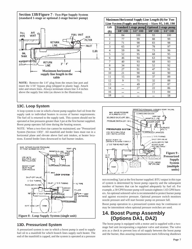
13. Fuel Tank and Supply LinesSections 13A through 13D illustrate four methods of piping fuel to oil-fired heaters. The selection of a specific system is arbitrary, however,certain systems are recommended for specific installation conditions.The one-pipe arrangement (Sections 13A) is used with the standard 1-stage burner pump. The two-pipe (Section 13B) arrangement can beused with either the standard 1-stage burner pump or an optional 2-stage burner pump. The second two systems (Sections 13C and 13D)require an additional booster pump for oil delivery to the heater.
Fuel TankOil tanks must be installed in accordance with all local regulations andthe National Board of Fire Underwriters or CSA Standard. See Para-graph 28 for some requirements and recommendations for installingsupply or storage tanks.
All oil tanks must include a vent pipe to the outdoors. The lower endof the vent pipe should not extend more than one inch below the uppermost point of the tank. The vent pipe terminal should be weatherproofand clogproof.
Installation of the fuel tank and piping is the responsibility of the in-stalling contractor.
Pipe TubingAll piping shall be standard full weight black iron pipe with standardfittings or approved brass or copper tubing, with UL listed fittings. Atleast 1/2" iron pipe or 3/8" O.D. copper tubing (1/2" O.D. copper tub-ing is preferred) having a wall thickness not less than 0.049" shall beused to connect the burner to the tank.
All piping shall be protected from possible injury and shall be rigidlyfastened. Where practical, it should be buried underground or in a con-crete floor or placed in a metal-covered pipe trench. If installed aboveground, the pipe must be insulated to avoid freezing. Do not cover thepiping until the burner has been installed and operated so that any leaksmay be corrected. Pipe joints and connections shall be made tight andonly unions and tube fittings of an approved type shall be used. Useonly pipe thread compound resistant to oil. Do not use TEFLON®tape or TEFLON®-based pipe dope. (TEFLON® is a registeredtradename of DuPont Chemical Corporation).
Oil FilterInstall a UL-listed (U.S.A.) or CSA/USC (Canada) oil filter of gener-ous capacity between the tank shutoff valve and the burner. For ease ofservicing, locate the filter and shutoff valve close to the oil burner.
Shutoff ValvesInstall a readily accessible manual shutoff valve at each point to prop-erly control the flow of fuel in normal operation and where required toavoid oil spillage during servicing. The valve should close against thesupply. If the heater will not be operating for an extended period oftime, close the shutoff valve.Where a shutoff is installed in the discharge line of an oil pump that isnot an integral part of a burner, connect a pressure relief valve into thedischarge line between the pump and the shutoff valve and arrange toreturn surplus oil to the supply tank or to bypass it around the pump,unless the pump includes an internal bypass.
Any fuel oil line incorporating a heater shall be provided with a reliefvalve arranged to discharge to the return line when any valve, pump, orother device may prevent the release of excessive pressure because ofthe expansion of the oil when heated.
Where oil is supplied to a burner requiring uniform flow by gravityfeed and a constant level valve is not incorporated in the burner assem-bly or the oil is not supplied by an automatic pump, install a constantlevel valve in the supply line at the gravity tank or as close as practical,to ensure uniform delivery of oil to the burner. The vent opening of theconstant level valve should be connected by piping or tubing to theoutside of the building, unless the constant level valve is provided withan anti-flooding device. Do not connect the vent piping or tubing ofconstant level valves to tanks or tank vents.
Prior to entering enclosures, such as vaults or pits, where pumps andaccessories are installed, provide for adequate ventilation.
Burner Pump Lift CapacityThe standard burner is equipped with a single-stage, 3450 RPM pumpwith the lift capacity listed in Section 13A for a one-pipe supply sys-tem and Section 13B for a two-pipe supply/return system. An optionaltwo-stage, 3450 RPM burner pump (Option BZ1) is available whendual pumping gears are desired. The piping systems in Sections 13Cand 13D require an optional booster pump (Option DA1 or DA2). Fol-low the information that applies to the installation.• Section 13A/Figure 6 -- Standard Single-Stage Pump/Single-
Pipe Supply System• Section 13B/Figure 7 -- Standard Single-Stage or Optional
Two-Stage Pump/Two-Pipe Supply System• Section 13C/Figure 8 -- Standard Single-Stage Pump and an
Optional Booster Pump/ Loop Supply System• Section 13D/Figure 9 -- Standard Single-Stage Pump and an
Optional Booster Pump/ Pressurized Supply System
INSTALLATION NOTES: 1) Fittings, valves and filters will reduce total line length allowed. Check component manufacturer's informa-tion for equivalent length reduction required to compensate for pressure loss. 2) One-pipe supply systems must be absolutely airtight, orleaks and/or loss of prime may result. Follow instructions in Paragraph 27, Check-Test-Start (Operating Procedure) to bleed the line.Bleed for 15 seconds after last air is seen from easy flow bleed valve to be certain lines are air free.
Section 13A/Figure 6 - Single Pipe SupplySystem (single-stage burner pump)
Maximum Horizontal Line Length (ft) by Heater Size and Size of Tubing
Lift 95 140 190 (ft) 3/8" 1/2" 3/8" 1/2" 3/8" 1/2"
0 822 3158 556 2222 423 16671 719 2763 486 1944 370 14582 616 2368 417 1667 317 12503 514 1974 347 1389 264 10424 411 1579 278 1111 211 8335 308 1184 208 833 158 6256 205 789 139 556 106 4177 103 395 69 278 53 2088 0 0 0 0 0 0
Formula for Length = 6 ft - (.75 x lift)
tabled figures (.0086 for 3/8" or .00218 for 1/2") x (Firing Rate in GPH)
NOTE: GPH = Size 95, .085; Size 140, 1.25; Size 190, 1.65
Page 7
Section 13B/Figure 7 - Two-Pipe Supply System(standard 1-stage or optional 2-stage burner pump)
13C. Loop SystemA loop system is one in which a boost pump supplies fuel oil from thesupply tank to individual heaters in excess of burner requirements.The fuel oil is returned to the supply tank. This system should not beoperated at line pressures greater than 3 psi at the first burner supplied.Boost pump operates full time during the heating season.
NOTE: When a two-foot rise cannot be maintained, use "PressurizedSystem (Section 13D)". All manifold and feeder lines must run in ahorizontal plane and elevate above fuel unit intakes, at heater loca-tions. Extend feeder lines downward to fuel burner intakes.
13D. Pressurized SystemA pressurized system is one in which a boost pump is used to supplyfuel oil to a manifold for which branch lines supply each heater. Theend of the manifold is capped, and the system is operated at a pressure
Figure 8 - Loop Supply System (single unit)
Figure 9 -Pressurized
SupplySystem
(multipleunits)
not exceeding 3 psi at the first burner supplied. BTU output in this typeof system is determined by boost pump capacity and the subsequentnumber of burners that can be supplied adequately by fuel oil. Forexample, a 30 GPH booster pump will sustain eighteen 1.65 GPH burn-ers. An optional solenoid valve is recommended to protect burner pumpseal against excessive pressure. Optional pressure switch monitorsnozzle pressure and will start booster pump on pressure fall.
Boost pump operation in a pressurized system may be continuous ormay be intermittent when optional pressure switches are used.
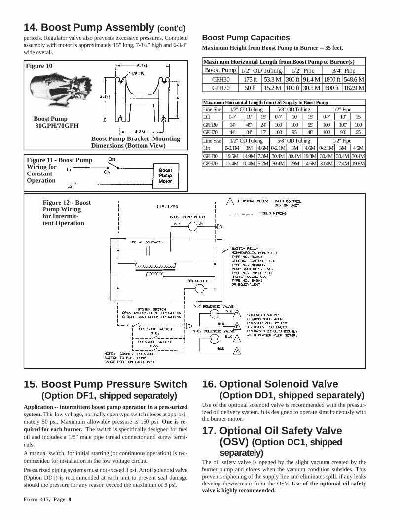
14. Boost Pump Assembly(Options DA1, DA2)
The boost pump is equipped with a motor and is supplied with a two-stage fuel unit incorporating a regulator valve and strainer. The valveacts as a check to prevent loss of oil supply between the boost pumpand the burner, thus assuring instantaneous starts following shutdown
Maximum horizontalsupply line length in the
table
Lift
NOTE: Remove the 1/4" plug from the return line port andinsert the 1/16" bypass plug (shipped in plastic bag). Attachinlet and return lines. Always terminate return line 3-4 inchesabove the supply line inlet (as shown in the illustration).
Maximum Horizontal Supply Line Length (ft) for Two-Line System (Supply and Return) -- Sizes 95, 140, 190
Lift Standard 1-stage pump Optional 2-stage pump
(ft) 3/8" OD 1/2" OD 3/8" OD 1/2" OD
0 84 100 93 1001 77 99 88 992 71 98 83 983 65 97 78 974 59 96 73 965 52 95 68 956 46 94 63 947 40 93 68 938 34 92 52 929 27 91 47 91
10 21 90 42 9011 15 89 37 8912 9 71 32 8813 49 27 8714 27 22 8616 11 8418 58
Form 417, Page 8
periods. Regulator valve also prevents excessive pressures. Completeassembly with motor is approximately 15" long, 7-1/2" high and 6-3/4"wide overall.
14. Boost Pump Assembly (cont'd)
Figure 10
Boost Pump Bracket MountingDimensions (Bottom View)
Boost Pump 30GPH/70GPH
Boost Pump CapacitiesMaximum Height from Boost Pump to Burner -- 35 feet.
Figure 11 - Boost PumpWiring forConstantOperation
Figure 12 - BoostPump Wiringfor Intermit-tent Operation
15. Boost Pump Pressure Switch(Option DF1, shipped separately)
Application -- intermittent boost pump operation in a pressurizedsystem. This low voltage, normally open type switch closes at approxi-mately 50 psi. Maximum allowable pressure is 150 psi. One is re-quired for each burner. The switch is specifically designed for fueloil and includes a 1/8" male pipe thread connector and screw termi-nals.
A manual switch, for initial starting (or continuous operation) is rec-ommended for installation in the low voltage circuit.
Pressurized piping systems must not exceed 3 psi. An oil solenoid valve(Option DD1) is recommended at each unit to prevent seal damageshould the pressure for any reason exceed the maximum of 3 psi.
16. Optional Solenoid Valve(Option DD1, shipped separately)
Use of the optional solenoid valve is recommended with the pressur-ized oil delivery system. It is designed to operate simultaneously withthe burner motor.
17. Optional Oil Safety Valve(OSV) (Option DC1, shippedseparately)
The oil safety valve is opened by the slight vacuum created by theburner pump and closes when the vacuum condition subsides. Thisprevents siphoning of the supply line and eliminates spill, if any leaksdevelop downstream from the OSV. Use of the optional oil safetyvalve is highly recommended.
Maximum Horizontal Length from Boost Pump to Burner(s)
Boost Pump
GPH30 175 ft 53.3 M 300 ft 91.4 M 1800 ft 548.6 MGPH70 50 ft 15.2 M 100 ft 30.5 M 600 ft 182.9 M
1/2" OD Tubing 1/2" Pipe 3/4" Pipe
Maximum Horizontal Length from Oil Supply to Boost Pump
Line Size 1/2" OD Tubing 5/8" OD Tubing 1/2" PipeLift 0-7' 10' 15' 0-7' 10' 15' 0-7' 10' 15'
GPH30 64' 49' 24' 100' 100' 65' 100' 100' 100'GPH70 44' 34' 17' 100' 95' 48' 100' 90' 65'
Line Size 1/2" OD Tubing 5/8" OD Tubing 1/2" PipeLift 0-2.1M 3M 4.6M 0-2.1M 3M 4.6M 0-2.1M 3M 4.6M
GPH30 19.5M 14.9M 7.3M 30.4M 30.4M 19.8M 30.4M 30.4M 30.4MGPH70 13.4M 10.4M 5.2M 30.4M 29M 14.6M 30.4M 27.4M 19.8M
Page 9
������������� ��� �
����
����
����
��������������
������
�������
������
�������
�
� �
�������� � �� ������ ���� ��
�
�
�
�� ������ ���� ��
��������
������ ����� �
�������� ��������
�
�
�
��
������������� ��
�� ������
�
� ���
��������� �������� � ���������
�������������� �
�� � � � !
�����������������
�������������������"��#������������
��#�����
�
���
� �
������
� �
��
������������� ���
�� ������
��������
�� ��������� ���"����� ����
��
�
��#�����
$
����"��#���������� �������
������� �%��� �������� � �
���
���������
�!
��������� ��
�
�� ������ ���� ��
�������������&�������� ������%
�� ����������
������������
�
�
���� ��������������#�� ������%
���� ������������������#�� ������%
��'���(��������"'!
�
����� �
�� ���)����������� ����������������������������� �� �������������� �����������*� ��� ������������� ����������� ��������"������ ����� ������ �������� ���� ������%�� �������� ���������� ����� *������� ������������ ��������������� ��������
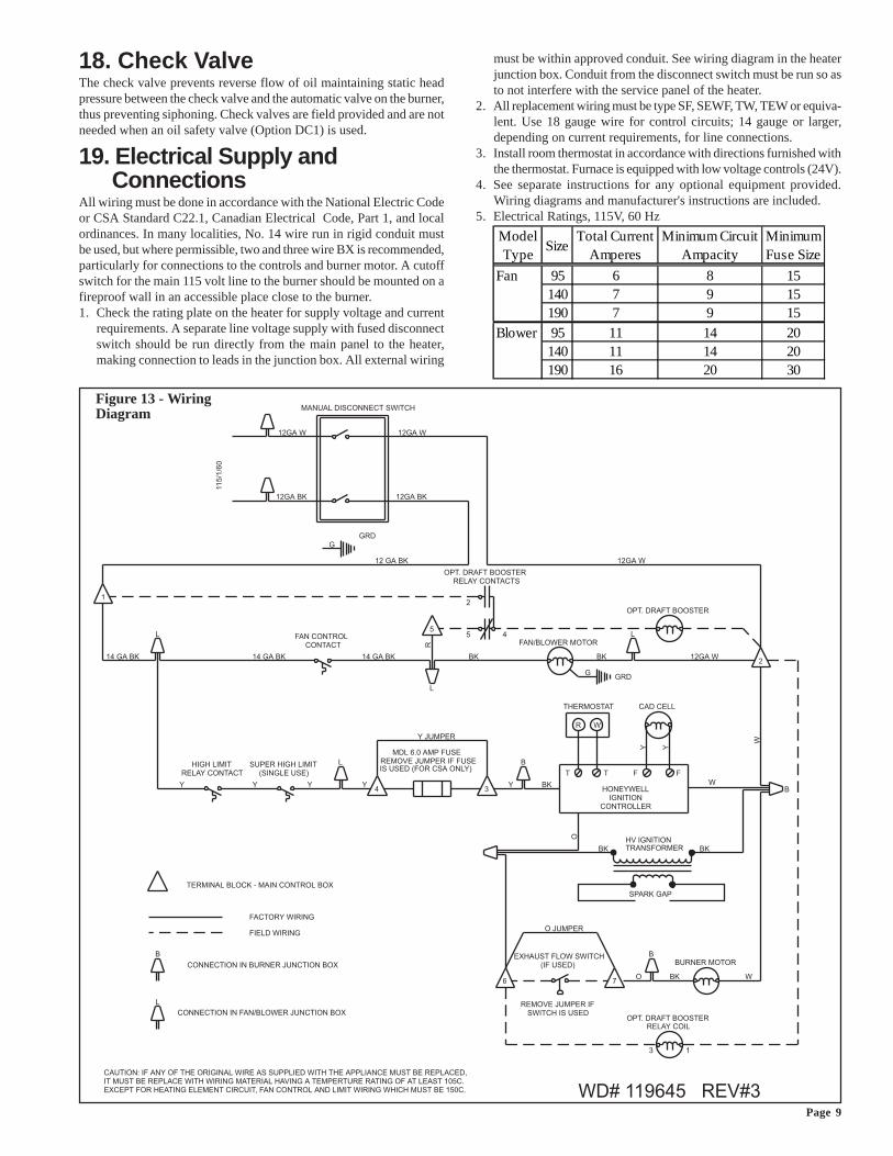
18. Check ValveThe check valve prevents reverse flow of oil maintaining static headpressure between the check valve and the automatic valve on the burner,thus preventing siphoning. Check valves are field provided and are notneeded when an oil safety valve (Option DC1) is used.
19. Electrical Supply andConnections
All wiring must be done in accordance with the National Electric Codeor CSA Standard C22.1, Canadian Electrical Code, Part 1, and localordinances. In many localities, No. 14 wire run in rigid conduit mustbe used, but where permissible, two and three wire BX is recommended,particularly for connections to the controls and burner motor. A cutoffswitch for the main 115 volt line to the burner should be mounted on afireproof wall in an accessible place close to the burner.1. Check the rating plate on the heater for supply voltage and current
requirements. A separate line voltage supply with fused disconnectswitch should be run directly from the main panel to the heater,making connection to leads in the junction box. All external wiring
must be within approved conduit. See wiring diagram in the heaterjunction box. Conduit from the disconnect switch must be run so asto not interfere with the service panel of the heater.
2. All replacement wiring must be type SF, SEWF, TW, TEW or equiva-lent. Use 18 gauge wire for control circuits; 14 gauge or larger,depending on current requirements, for line connections.
3. Install room thermostat in accordance with directions furnished withthe thermostat. Furnace is equipped with low voltage controls (24V).
4. See separate instructions for any optional equipment provided.Wiring diagrams and manufacturer's instructions are included.
5. Electrical Ratings, 115V, 60 Hz
Figure 13 - WiringDiagram
Model Type
SizeTotal Current
AmperesMinimum Circuit
AmpacityMinimum Fuse Size
Fan 95 6 8 15140 7 9 15190 7 9 15
Blower 95 11 14 20140 11 14 20190 16 20 30
Form 417, Page 10
20. ThermostatUse either an optional thermostat supplied with the heater or a field-supplied thermostat. A 24-volt thermostat is required to actuate thelow voltage controls on this heater. A line voltage thermostat can beused when wired for low voltage use. Do not attempt to wire relaysor other accessories to the thermostat connections as these are notload terminals.The thermostat should be located five feet above the floor on an insidewall, not in the path of warm or cold air currents, nor in corners whereair may be pocketed. DO NOT install on or directly suspend from theheater. DO NOT install the thermostat on a cold, outside wall. Forspecific connection details and instructions on setting the heat antici-pator, refer to manufacturer's instructions with the thermostat.
CAUTION: Make sure the thermostat has anadequate VA rating for the total requirements.
21. MotorsBoth the fan motor on a heater equipped with a fan and the blowermotor on a blower model are totally enclosed and are equipped withinternal overload protection.
Use an amp meter to check blower motor amps. The above chart listsfull load amps for standard equipment. Blower motor amps may beadjusted downward by reducing blower RPM or by increasing ductsystem static pressure.
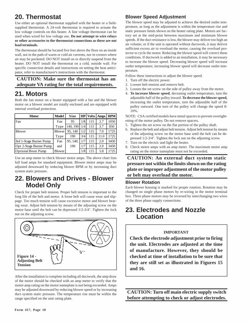
22. Blowers and Drives - BlowerModel Only
Check for proper belt tension. Proper belt tension is important to thelong life of the belt and motor. A loose belt will cause wear and slip-page. Too much tension will cause excessive motor and blower bear-ing wear. Adjust belt tension by means of the adjusting screw on themotor base until the belt can be depressed 1/2-3/4". Tighten the locknut on the adjusting screw.
After the installation is complete including all ductwork, the amp drawof the motor should be checked with an amp meter to verify that themotor amp rating on the motor nameplate is not being exceeded. Ampsmay be adjusted downward by reducing blower speed or by increasingduct system static pressure. The temperature rise must be within therange specified on the unit rating plate.
Blower Speed AdjustmentThe blower speed may be adjusted to achieve the desired outlet tem-perature, as long as the adjustment is within the temperature rise andstatic pressure limits shown on the heater rating plate. Motors are fac-tory set at the mid-point between maximum and minimum blowerspeeds. If the duct resistance is low, the blower may deliver too high anair volume; or if the unit is operated without ductwork, it may deliversufficient excess air to overload the motor, causing the overload pro-tector to cycle the motor. Reducing the blower speed will correct theseconditions. If ductwork is added to an installation, it may be necessaryto increase the blower speed. Decreasing blower speed will increaseoutlet temperature; increasing blower speed will decrease outlet tem-perature.
Follow these instructions to adjust the blower speed.1. Turn off the electric power.2. Loosen belt tension and remove belt.3. Loosen the set screw on the side of pulley away from the motor.4. To increase blower speed, deceasing outlet temperature, turn the
adjustable half of the pulley inward. To decrease the blower speed,increasing the outlet temperature, turn the adjustable half of thepulley outward. One turn of the pulley will change the speed 8-10%.
NOTE: CSA certified models have metal spacers to prevent overtight-ening of the motor pulley. Do not remove spacers.5. Tighten the set screw on the flat portion of the pulley shaft.6. Replace the belt and adjust belt tension. Adjust belt tension by means
of the adjusting screw on the motor base until the belt can be de-pressed 1/2-3/4". Tighten the lock nut on the adjusting screw.
7. Turn on the electric and light the heater.8. Check motor amps with an amp meter. The maximum motor amp
rating on the motor nameplate must not be exceeded.
CAUTION: An external duct system staticpressure not within the limits shown on the ratingplate or improper adjustment of the motor pulleyor belt may overload the motor.
Blower RotationEach blower housing is marked for proper rotation. Rotation may bechanged on single phase motors by re-wiring in the motor terminalbox. Three phase motors may be reversed by interchanging two wiresof the three phase supply connections.
23. Electrodes and NozzleLocation
Figure 14 -Adjusting BeltTension
IMPORTANT
Check the electrode adjustment prior to firingthe unit. Electrodes are adjusted at the timeof manufacture. However, they should bechecked at time of installation to be sure thatthey are still set as illustrated in Figures 15and 16.
CAUTION: Turn off main electric supply switchbefore attempting to check or adjust electrodes.
Motor Model Size HP Volts Amps RPM
Fan Fan 95 1/8 115 2.7 1050
Type 140, 190 1/4 115 3.7 850Blower Blower 95, 140 1/2 115 7.0 1725
Type 190 3/4 115 11.0 1725
Std 1-Stage Burner Pump Fan 95, 140, 1/7 115 2.0 3450Opt 2-Stage Burner Pump and 190 1/7 115 2.0 3450
Optional Boost Pump Blower 1/8 115 5.8 1725
Page 11
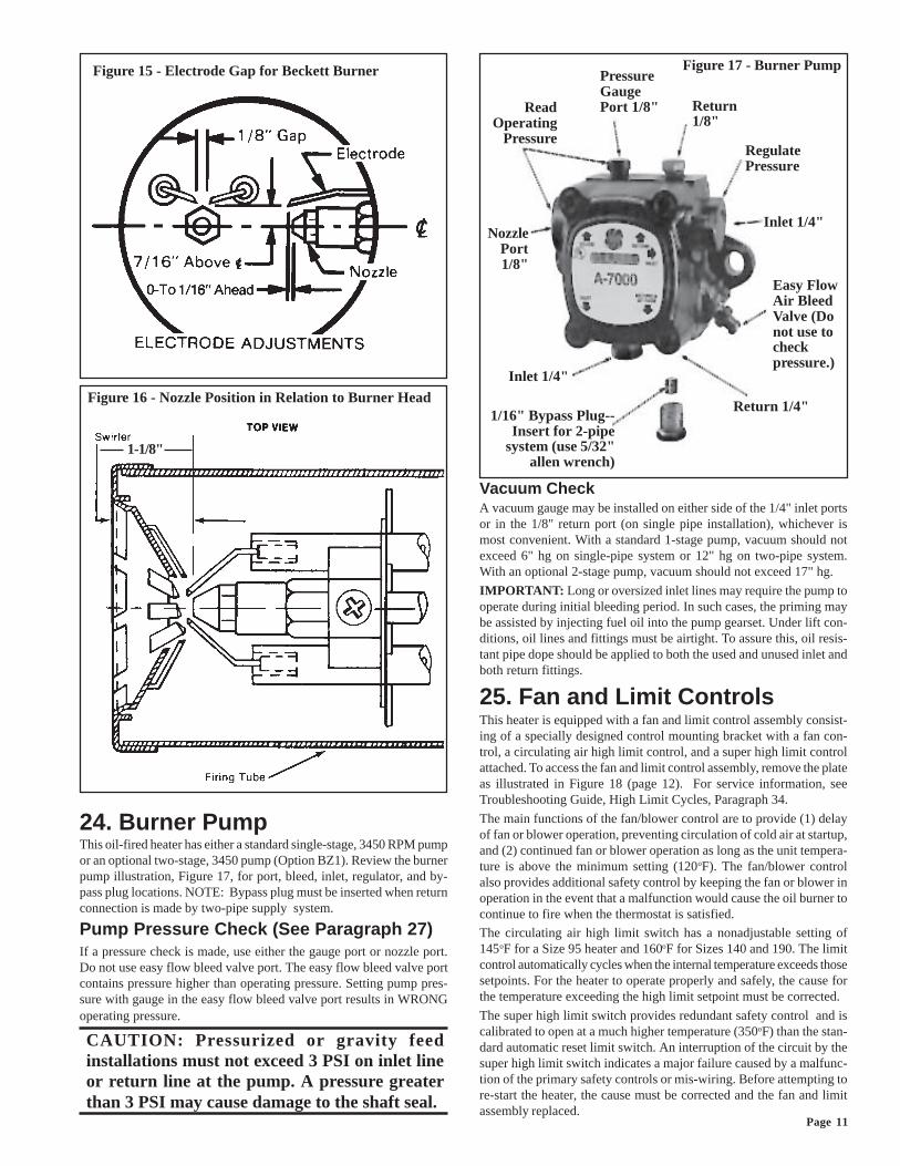
Figure 16 - Nozzle Position in Relation to Burner Head
Figure 17 - Burner PumpFigure 15 - Electrode Gap for Beckett Burner
1/16" Bypass Plug--Insert for 2-pipe
system (use 5/32"allen wrench)
Inlet 1/4"
Return 1/4"
Easy FlowAir BleedValve (Donot use tocheckpressure.)
Inlet 1/4"
RegulatePressure
Return1/8"
PressureGaugePort 1/8"Read
OperatingPressure
NozzlePort1/8"
24. Burner PumpThis oil-fired heater has either a standard single-stage, 3450 RPM pumpor an optional two-stage, 3450 pump (Option BZ1). Review the burnerpump illustration, Figure 17, for port, bleed, inlet, regulator, and by-pass plug locations. NOTE: Bypass plug must be inserted when returnconnection is made by two-pipe supply system.
Pump Pressure Check (See Paragraph 27)If a pressure check is made, use either the gauge port or nozzle port.Do not use easy flow bleed valve port. The easy flow bleed valve portcontains pressure higher than operating pressure. Setting pump pres-sure with gauge in the easy flow bleed valve port results in WRONGoperating pressure.
CAUTION: Pressurized or gravity feedinstallations must not exceed 3 PSI on inlet lineor return line at the pump. A pressure greaterthan 3 PSI may cause damage to the shaft seal.
Vacuum CheckA vacuum gauge may be installed on either side of the 1/4" inlet portsor in the 1/8" return port (on single pipe installation), whichever ismost convenient. With a standard 1-stage pump, vacuum should notexceed 6" hg on single-pipe system or 12" hg on two-pipe system.With an optional 2-stage pump, vacuum should not exceed 17" hg.
IMPORTANT: Long or oversized inlet lines may require the pump tooperate during initial bleeding period. In such cases, the priming maybe assisted by injecting fuel oil into the pump gearset. Under lift con-ditions, oil lines and fittings must be airtight. To assure this, oil resis-tant pipe dope should be applied to both the used and unused inlet andboth return fittings.
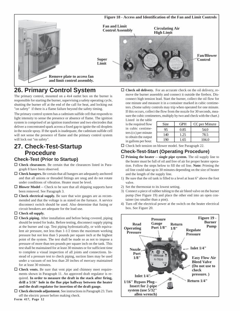
25. Fan and Limit ControlsThis heater is equipped with a fan and limit control assembly consist-ing of a specially designed control mounting bracket with a fan con-trol, a circulating air high limit control, and a super high limit controlattached. To access the fan and limit control assembly, remove the plateas illustrated in Figure 18 (page 12). For service information, seeTroubleshooting Guide, High Limit Cycles, Paragraph 34.
The main functions of the fan/blower control are to provide (1) delayof fan or blower operation, preventing circulation of cold air at startup,and (2) continued fan or blower operation as long as the unit tempera-ture is above the minimum setting (120oF). The fan/blower controlalso provides additional safety control by keeping the fan or blower inoperation in the event that a malfunction would cause the oil burner tocontinue to fire when the thermostat is satisfied.
The circulating air high limit switch has a nonadjustable setting of145oF for a Size 95 heater and 160oF for Sizes 140 and 190. The limitcontrol automatically cycles when the internal temperature exceeds thosesetpoints. For the heater to operate properly and safely, the cause forthe temperature exceeding the high limit setpoint must be corrected.
The super high limit switch provides redundant safety control and iscalibrated to open at a much higher temperature (350oF) than the stan-dard automatic reset limit switch. An interruption of the circuit by thesuper high limit switch indicates a major failure caused by a malfunc-tion of the primary safety controls or mis-wiring. Before attempting tore-start the heater, the cause must be corrected and the fan and limitassembly replaced.
1-1/8"
Form 417, Page 12
26. Primary Control SystemThe primary control, mounted on a 4x4 outlet box on the burner isresponsible for starting the burner, supervising a safety operating cycle,shutting the burner off at the end of the call for heat, and locking out"on safety" if there is a flame failure beyond the safety timing.
The primary control system has a cadmium sulfide cell that responds tolight intensity to sense the presence or absence of flame. The ignitionsystem is comprised of an ignition transformer and two electrodes thatdeliver a concentrated spark across a fixed gap to ignite the oil dropletsin the nozzle spray. If the spark is inadequate, the cadmium sulfide cellwill not sense the presence of flame and the primary control systemwill lock out "on safety".
27. Check-Test-StartupProcedure
Check-Test (Prior to Startup)� Check clearances. Be certain that the clearances listed in Para-
graph 8 have been observed.� Check hangers. Be certain that all hangers are adequately anchored
and that all unions or threaded fittings are snug and do not rotateunder conditions of vibration. Heater must be level.
� Blower Model -- Check to be sure that all shipping supports havebeen removed. See Paragraph 3.
� Check electrical supply. Be sure that wire gauges are as recom-mended and that the voltage is as stated on the furnace. A servicedisconnect switch should be used. Also determine that fusing orcircuit breakers are adequate for the load use.
� Check oil supply.� Check piping. After installation and before being covered, piping
should be tested for leaks. Before testing, disconnect supply pipingat the burner and cap. Test piping hydrostatically, or with equiva-lent air pressure, not less than 1-1/2 times the maximum workingpressure but not less than 5 pounds per square inch at the highestpoint of the system. The test shall be made so as not to impose apressure of more than ten pounds per square inch on the tank. Thistest shall be maintained for at least 30 minutes or for sufficient timeto complete a visual inspection of all joints and connections. In-stead of a pressure test to check piping, suction lines may be usedunder a vacuum of not less than 20 inches of mercury maintainedfor at least 30 minutes.
� Check vents. Be sure that vent pipe and chimney meet require-ments shown in Paragraph 11. An approved draft regulator is re-quired. In order to measure the draft in the stack after firing,drill a 5/16" hole in the flue pipe halfway between the heaterand the draft regulator for insertion of the draft gauge.
� Check electrode adjustment. See instructions in Paragraph 23. Turnoff the electric power before making check.
� Check oil delivery. For an accurate check on the oil delivery, re-move the burner assembly and connect it outside the firebox. Dis-connect high tension lead. Start the burner, collect the oil flow forone minute and measure it in a container marked in cubic centime-ters. (Some safety controls may trip when operated for one minute.If this occurs, collect the flow from the nozzle for 30 seconds, mea-sure the cubic centimeters, multiply by two and check with the chart.)Listed in the tableis the required flowin cubic centime-ters (cc) per minuteto obtain the outputin gallons per hour.
� Check belt tension on blower model. See Paragraph 22.
Check-Test-Start (Operating Procedure)� Priming the heater -- single pipe system. The oil supply line to
the heater must be full of oil and free of air for proper heater opera-tion. Follow the steps below to fill the oil line. Note: Priming theoil line could take up to 30 minutes depending on the size of heaterand the length of the supply line.
1) Be sure that the oil tank is filled to a level at least 6" above the footvalve.
2) Set the thermostat to its lowest setting.3) Connect a piece of rubber tubing to the air bleed valve on the burner
pump (See Figure 19) and place the other end into an open con-tainer (no smaller than a pint).
4) Turn off the electrical power at the switch on the heater electricalbox. See Figure 20.
PressureGaugePort 1/8"
Return1/8" Regulate
Pressure
Inlet 1/4"
Easy Flow AirBleed Valve(Do not use tocheckpressure. )
Return 1/4"Inlet 1/4"
NozzlePort1/8"
Figure 19 -Burner
Pump
1/16" Bypass Plug--Insert for 2-pipe
system (use 5/32"allen wrench)
ReadOperating
Pressure
Remove plate to access fanand limit control assembly.
Circulating AirHigh Limit
Fan/BlowerControl
Figure 18 - Access and Identification of the Fan and Limit Controls
Fan and LimitControl Assembly
SuperLimit
Size GPH CC per Minute
95 0.85 54.0140 1.25 78.5190 1.65 104.0
Page 13
that was drilled in the flue pipe halfway between the furnace andthe draft regulator. Flue draft measurement must be a negative .03-.04" w.c.
If there is insufficient draft, it will create a back pressure result-ing in oil fumes in the building and/or pulsating when the burnerstarts and stops. It may cause excess deposits of soot. To correctthis problem, the height of the chimney may need increased and/ora UL listed draft inducer may be used. If a draft inducer is used,provision must be made to shut off the fuel supply to the burner inthe event of the failure of the draft inducer.
If there is too much draft, it could cause ignition problems, er-ratic burner, and loss of thermal efficiency. To correct this
problem, adjust the barometric damper regulator to reduce the draft.
�Check combustion air shutter and air band settings. The heateris shipped from the factory with the settings shown in the table inFigure 21. Ordinarily, these settings will result in a CO2 level shownin the tabled ranges. However, certain field conditions may requirea change. In order to determine if the air setting needs to be ad-justed, a smoke tester and CO2 analyzer are required.
Air Adjustment Procedure:1) Service and clean the burner, combustion chamber, and heat ex-
changer if necessary.2) Operate the unit for at least 10 minutes.3) Adjust the overfire draft to read between -0.01" to -0.02" w.c. Draft
readings in the breaching will be higher depending on the flue pas-sages of the heater. The more restrictive and lengthy the flue, thehigher the draft necessary to obtain accepted overfire conditions.
4) Follow the instructions of the manufacturer of the smoke tester andtake a smoke reading. Adjust the combustion air to obtain a pre-liminary reading of about a No. 3 smoke spot. Then readjust the airuntil a reading between No. 0 and No. 1 (trace smoke) is achieved.Do not open the air adjustment more than absolutely necessary toobtain a trace or No. 0 smoke spot.
5) Follow the instructions of the manufacturer of the CO2 gas analyzer
and take a CO2 sample. Open the air shutter until the CO2 levellowers by 1%. The CO2 reading should fall within the range speci-fied in the table shown in Figure 21. Your burner is now set foroptimum but stable efficiency.
CAUTION: If there is a backdraft or downdraft,do not continue operation of the heater until thesituation is corrected. Equipment and/orproperty damage could result. Back pressure(backdraft or downdraft) may be caused by thechimney being lower than surrounding objects,such as buildings, hills, trees, rooftops, etc. Itmay be caused by an exhaust fan in the building.The air intake in the room where the heater isinstalled must be sufficient size so that there isno change in the draft reading in the flue withthe exhaust fan running.
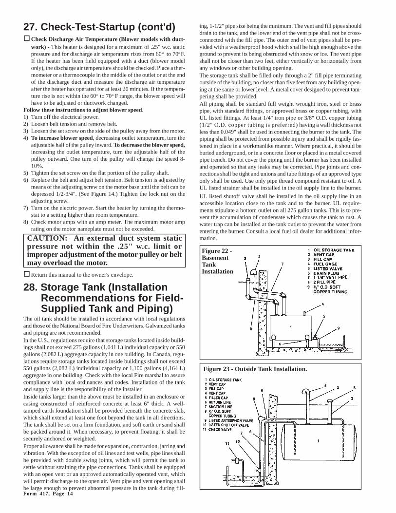
PrimaryControl
with ResetButton
5) Using a 3/8" wrench, loosen the air bleed valve two or three turns.6) Set the thermostat well above room temperature.
7) Turn the electric power on. Burner pump will operate.8) Oil will run into the container when the air has been bled from the
line. (While operating under these conditions, the heater will notlight because the pressure valve in the pump will not open.) If theprimary control activates to shut down the pump before the line isbled, push the reset button. (See Figure 20). It may be necessary topush the reset button several times while bleeding off air. Wait threeto four minutes between pushes of the reset button to allow theinternal bimetal strip to cool down. The pump will run for 45 sec-onds each time.
9) After all of the air is bled from the line, close the bleeder valve.Turn the main power off.
�Priming the Unit -- two-pipe supply system. Install a pressuregauge and turn the burner on. The system will vent itself throughthe return line. Flame will appear as soon as the air has been elimi-nated.
�Check and adjust nozzle pressure.1) Install a pressure gauge (125 psig minimum) into the pressure gauge
port on the burner pump. (See Figure 19.)2) The air shutter was preset at the factory. Verify the air shutter set-
ting on the burner with the chart in Figure 21. All other controlsshould be in normal position.
3) Turn off the electrical power.4) Set the thermostat to above room temperature.5) The pump will start and the burner ignite. With the burner ignited,
check the oil pressure and adjust, if necessary, to a pressure of 100pounds.
�Check draft. Prior to continued operation, check to be sure thatthere is sufficient draft for proper combustion. A draft of negative.01" w.c. is required over the fire. When firing, the draft measure-ment in the stack should be a negative .03-.04" w.c.
Instructions for measuring draft:1) To measure draft over the fire, remove the metal plug in the ob-
servation door (See Figure 21).2) Insert air pressure gauge (such as Dwyer pressure gauge). Draft
measurement gauge must read a negative .01".3) If measurement is not correct, adjust draft regulator until measure-
ment is correct.4) Replace plug.5) To measure flue draft, insert air pressure gauge in the 5/16" hole
Figure 20 - Heater Controls
BurnerElectricalSwitch
AirBand
Observation Door
AirShutter
Figure 21 - CombustionAir Band and Air
Shutter SettingsSize Air Air CO2
Shutter Band Range95 #6 #0 9-11%140 #6 #0 10-12%190* #7-1/2 #0 11-13%*Size 190 manufactured before 6/96had same settings as Size 140.
Form 417, Page 14
ing, 1-1/2" pipe size being the minimum. The vent and fill pipes shoulddrain to the tank, and the lower end of the vent pipe shall not be cross-connected with the fill pipe. The outer end of vent pipes shall be pro-vided with a weatherproof hood which shall be high enough above theground to prevent its being obstructed with snow or ice. The vent pipeshall not be closer than two feet, either vertically or horizontally fromany windows or other building opening.The storage tank shall be filled only through a 2" fill pipe terminatingoutside of the building, no closer than five feet from any building open-ing at the same or lower level. A metal cover designed to prevent tam-pering shall be provided.All piping shall be standard full weight wrought iron, steel or brasspipe, with standard fittings, or approved brass or copper tubing, withUL listed fittings. At least 1/4" iron pipe or 3/8" O.D. copper tubing(1/2" O.D. copper tubing is preferred) having a wall thickness notless than 0.049" shall be used in connecting the burner to the tank. Thepiping shall be protected from possible injury and shall be rigidly fas-tened in place in a workmanlike manner. Where practical, it should beburied underground, or in a concrete floor or placed in a metal coveredpipe trench. Do not cover the piping until the burner has been installedand operated so that any leaks may be corrected. Pipe joints and con-nections shall be tight and unions and tube fittings of an approved typeonly shall be used. Use only pipe thread compound resistant to oil. AUL listed strainer shall be installed in the oil supply line to the burner.
UL listed shutoff valve shall be installed in the oil supply line in anaccessible location close to the tank and to the burner. UL require-ments stipulate a bottom outlet on all 275 gallon tanks. This is to pre-vent the accumulation of condensate which causes the tank to rust. Awater trap can be installed at the tank outlet to prevent the water fromentering the burner. Consult a local fuel oil dealer for additional infor-mation.
Figure 22 -BasementTankInstallation
Figure 23 - Outside Tank Installation.
�Check Discharge Air Temperature (Blower models with duct-work) - This heater is designed for a maximum of .25" w.c. staticpressure and for discharge air temperature rises from 60 o to 70o F.If the heater has been field equipped with a duct (blower modelonly), the discharge air temperature should be checked. Place a ther-mometer or a thermocouple in the middle of the outlet or at the endof the discharge duct and measure the discharge air temperatureafter the heater has operated for at least 20 minutes. If the tempera-ture rise is not within the 60o to 70o F range, the blower speed willhave to be adjusted or ductwork changed.
Follow these instructions to adjust blower speed.1) Turn off the electrical power.2) Loosen belt tension and remove belt.3) Loosen the set screw on the side of the pulley away from the motor.4) To increase blower speed, decreasing outlet temperature, turn the
adjustable half of the pulley inward. To decrease the blower speed,increasing the outlet temperature, turn the adjustable half of thepulley outward. One turn of the pulley will change the speed 8-10%.
5) Tighten the set screw on the flat portion of the pulley shaft.6) Replace the belt and adjust belt tension. Belt tension is adjusted by
means of the adjusting screw on the motor base until the belt can bedepressed 1/2-3/4". (See Figure 14.) Tighten the lock nut on theadjusting screw.
7) Turn on the electric power. Start the heater by turning the thermo-stat to a setting higher than room temperature.
8) Check motor amps with an amp meter. The maximum motor amprating on the motor nameplate must not be exceeded.
�Return this manual to the owner's envelope.
28. Storage Tank (InstallationRecommendations for Field-Supplied Tank and Piping)
The oil tank should be installed in accordance with local regulationsand those of the National Board of Fire Underwriters. Galvanized tanksand piping are not recommended.In the U.S., regulations require that storage tanks located inside build-ings shall not exceed 275 gallons (1,041 L) individual capacity or 550gallons (2,082 L) aggregate capacity in one building. In Canada, regu-lations require storage tanks located inside buildings shall not exceed550 gallons (2,082 L) individual capacity or 1,100 gallons (4,164 L)aggregate in one building. Check with the local Fire marshal to assurecompliance with local ordinances and codes. Installation of the tankand supply line is the responsibility of the installer.Inside tanks larger than the above must be installed in an enclosure orcasing constructed of reinforced concrete at least 6" thick. A well-tamped earth foundation shall be provided beneath the concrete slab,which shall extend at least one foot beyond the tank in all directions.The tank shall be set on a firm foundation, and soft earth or sand shallbe packed around it. When necessary, to prevent floating, it shall besecurely anchored or weighted.Proper allowance shall be made for expansion, contraction, jarring andvibration. With the exception of oil lines and test wells, pipe lines shallbe provided with double swing joints, which will permit the tank tosettle without straining the pipe connections. Tanks shall be equippedwith an open vent or an approved automatically operated vent, whichwill permit discharge to the open air. Vent pipe and vent opening shallbe large enough to prevent abnormal pressure in the tank during fill-
27. Check-Test-Startup (cont'd)
CAUTION: An external duct system staticpressure not within the .25" w.c. limit orimproper adjustment of the motor pulley or beltmay overload the motor.
Page 15
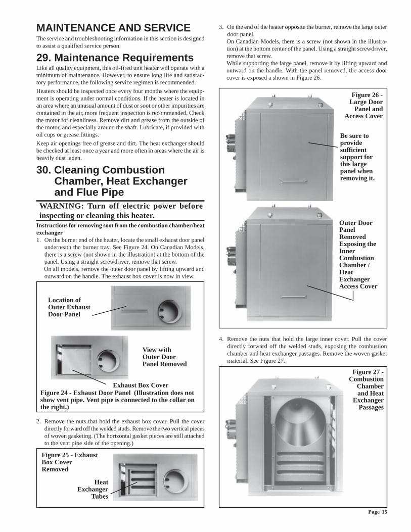
Location ofOuter ExhaustDoor Panel
View withOuter DoorPanel Removed
Exhaust Box CoverFigure 24 - Exhaust Door Panel (Illustration does notshow vent pipe. Vent pipe is connected to the collar onthe right.)
Figure 25 - ExhaustBox CoverRemoved
HeatExchanger
Tubes
3. On the end of the heater opposite the burner, remove the large outerdoor panel.On Canadian Models, there is a screw (not shown in the illustra-tion) at the bottom center of the panel. Using a straight screwdriver,remove that screw.While supporting the large panel, remove it by lifting upward andoutward on the handle. With the panel removed, the access doorcover is exposed a shown in Figure 26.
4. Remove the nuts that hold the large inner cover. Pull the coverdirectly forward off the welded studs, exposing the combustionchamber and heat exchanger passages. Remove the woven gasketmaterial. See Figure 27.
Figure 27 -Combustion
Chamberand Heat
ExchangerPassages
MAINTENANCE AND SERVICEThe service and troubleshooting information in this section is designedto assist a qualified service person.
29. Maintenance RequirementsLike all quality equipment, this oil-fired unit heater will operate with aminimum of maintenance. However, to ensure long life and satisfac-tory performance, the following service regimen is recommended.
Heaters should be inspected once every four months where the equip-ment is operating under normal conditions. If the heater is located inan area where an unusual amount of dust or soot or other impurities arecontained in the air, more frequent inspection is recommended. Checkthe motor for cleanliness. Remove dirt and grease from the outside ofthe motor, and especially around the shaft. Lubricate, if provided withoil cups or grease fittings.
Keep air openings free of grease and dirt. The heat exchanger shouldbe checked at least once a year and more often in areas where the air isheavily dust laden.
30. Cleaning CombustionChamber, Heat Exchangerand Flue Pipe
WARNING: Turn off electric power beforeinspecting or cleaning this heater.
Instructions for removing soot from the combustion chamber/heatexchanger1. On the burner end of the heater, locate the small exhaust door panel
underneath the burner tray. See Figure 24. On Canadian Models,there is a screw (not shown in the illustration) at the bottom of thepanel. Using a straight screwdriver, remove that screw.On all models, remove the outer door panel by lifting upward andoutward on the handle. The exhaust box cover is now in view.
2. Remove the nuts that hold the exhaust box cover. Pull the coverdirectly forward off the welded studs. Remove the two vertical piecesof woven gasketing. (The horizontal gasket pieces are still attachedto the vent pipe side of the opening.)
Be sure toprovidesufficientsupport forthis largepanel whenremoving it.
Figure 26 -Large Door
Panel andAccess Cover
Outer DoorPanelRemovedExposing theInnerCombustionChamber /HeatExchangerAccess Cover
Form 417, Page 16
stiff wire brush. Check the end cone for deterioration and replace ifdeterioration exists.
4) When cleaning/service is completed, place the mounting plate gas-ket (NOTE: If gasket is damaged it should be replaced.) on thestuds. Align the burner mounting plate with the bolts and slide thetube into the heater. Attach the mounting plate with the three nuts.
5) Reconnect the yellow wires to the ignition controller.
32. Removing Fuel Line Assembly toService Nozzle and SparkElectrodes
In order to service the oil nozzle and spark electrodes, it is necessary toremove the fuel line assembly.
Instructions for Removing Fuel Line Assembly1. Loosen the connection nut (where line connects to the burner) one
or two turns.2. Disconnect the fuel connection assembly by loosening the 5/16"
inverted flare fitting. Pull the fuel connection assembly clear of theburner housing.
3. Remove the two screws retaining the spark transformer cover to theburner housing. Lift the hinged transformer to its open position.
4. The fuel line assembly may now be removed. Pull the assembly upslightly and toward the rear of the burner housing.
Oil Nozzle Replacement -- With the fuel line assembly removed, use abox wrench to remove the oil nozzle. Replace the oil nozzle with theidentical nozzle. See table below for nozzle selection. Do not substi-tute nozzles. Substitution of nozzle could cause an operational prob-lem and/or a safety problem.
Replacement Burner NozzlesSize Reznor P/N Delavan Nozzle Type
95 32437 0.85, 80o, B
140* 146815 1.25, 70o, B
190* 146816 1.35, 70o, B
*These replacement nozzle sizes apply to heaters manufactured be-ginning 6/96. Always check the nozzle for size and replace withan identical nozzle.
When replacing the nozzle, inspect electrodes and check electrode ad-justment before reassembling the heater.
Servicing/Replacing Spark Electrodes --Remove any carbon forma-tion on the spark electrodes. Check the electrodes for deterioration andthe insulators for cracks or damage. Replace the electrode assembliesif any damage or deterioration exists. After service or replacement,check the position of the electrodes. Adjust the electrode location pre-cisely. Refer to Figure 30.
Figure 29 - Burner Endof Heater
Burner Removal1) Remove three
nuts attachingburner mountingplate.
2) Slide burner tubeout and rotate.
3) Use service tray tosupport burner.
BurnerMounting Plate(replace gasket ifdeteriorated.)
Figure 30 - Electrode Adjustment
Figure 28 - Attach threadedrod to metal piece provided tomake a heat exchangercleaning "rake"
30. Cleaning Combustion Chamber,Heat Exchanger & Flue Pipe (cont'd)
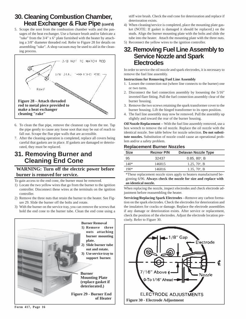
5. Scrape the soot from the combustion chamber walls and the pas-sages of the heat exchanger. Use a furnace brush and/or fabricate a"rake" from the 3/4" x 6" plate furnished with the heater by attach-ing a 3/8" diameter threaded rod. Refer to Figure 28 for details onassembling "rake". A shop vacuum may be used to aid in the clean-ing process.
6. To clean the flue pipe, remove the cleanout cap from the tee. Tapthe pipe gently to cause any loose soot that may be out of reach tofall out. Scrape the flue pipe walls that are accessible.
7. After the cleaning operation is completed, replace all covers beingcareful that gaskets are in place. If gaskets are damaged or deterio-rated, they must be replaced.
31. Removing Burner andCleaning End Cone
WARNING: Turn off the electric power beforeburner is removed for service.
To gain access to the end cone, the burner must be removed.1) Locate the two yellow wires that go from the burner to the ignition
controller. Disconnect these wires at the terminals on the ignitioncontroller.
2) Remove the three nuts that retain the burner to the heater. See Fig-ure 29. Slide the burner off the bolts and rotate.
3) With the burner on the service tray, you can remove the screws thathold the end cone to the burner tube. Clean the end cone using a
Page 17
34. TroubleshootingThis oil-fired heater has been designed andmanufactured to provide trouble free opera-tion. However, as with any type of mechani-cal equipment, it can fail. For your safety, ifthere is a problem, contact a qualified serviceperson.
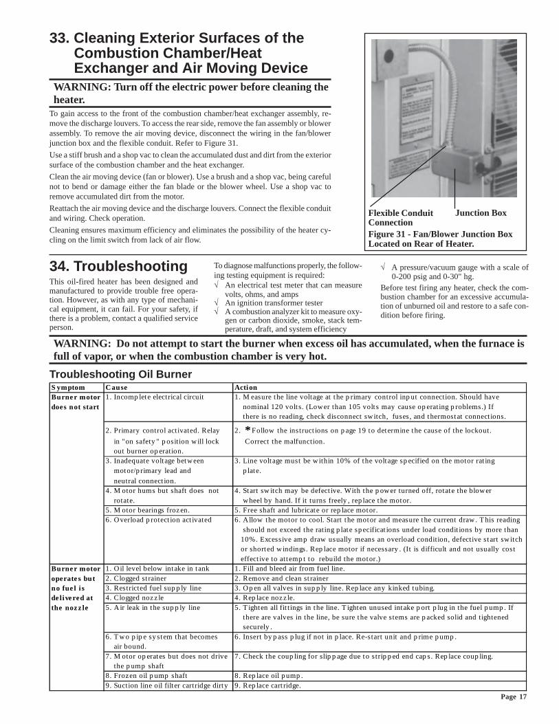
Junction BoxFlexible ConduitConnectionFigure 31 - Fan/Blower Junction BoxLocated on Rear of Heater.
33. Cleaning Exterior Surfaces of theCombustion Chamber/HeatExchanger and Air Moving Device
WARNING: Turn off the electric power before cleaning theheater.
To gain access to the front of the combustion chamber/heat exchanger assembly, re-move the discharge louvers. To access the rear side, remove the fan assembly or blowerassembly. To remove the air moving device, disconnect the wiring in the fan/blowerjunction box and the flexible conduit. Refer to Figure 31.
Use a stiff brush and a shop vac to clean the accumulated dust and dirt from the exteriorsurface of the combustion chamber and the heat exchanger.
Clean the air moving device (fan or blower). Use a brush and a shop vac, being carefulnot to bend or damage either the fan blade or the blower wheel. Use a shop vac toremove accumulated dirt from the motor.
Reattach the air moving device and the discharge louvers. Connect the flexible conduitand wiring. Check operation.
Cleaning ensures maximum efficiency and eliminates the possibility of the heater cy-cling on the limit switch from lack of air flow.
To diagnose malfunctions properly, the follow-ing testing equipment is required:√ An electrical test meter that can measure
volts, ohms, and amps√ An ignition transformer tester√ A combustion analyzer kit to measure oxy-
gen or carbon dioxide, smoke, stack tem-perature, draft, and system efficiency
√ A pressure/vacuum gauge with a scale of0-200 psig and 0-30" hg.
Before test firing any heater, check the com-bustion chamber for an excessive accumula-tion of unburned oil and restore to a safe con-dition before firing.
WARNING: Do not attempt to start the burner when excess oil has accumulated, when the furnace isfull of vapor, or when the combustion chamber is very hot.
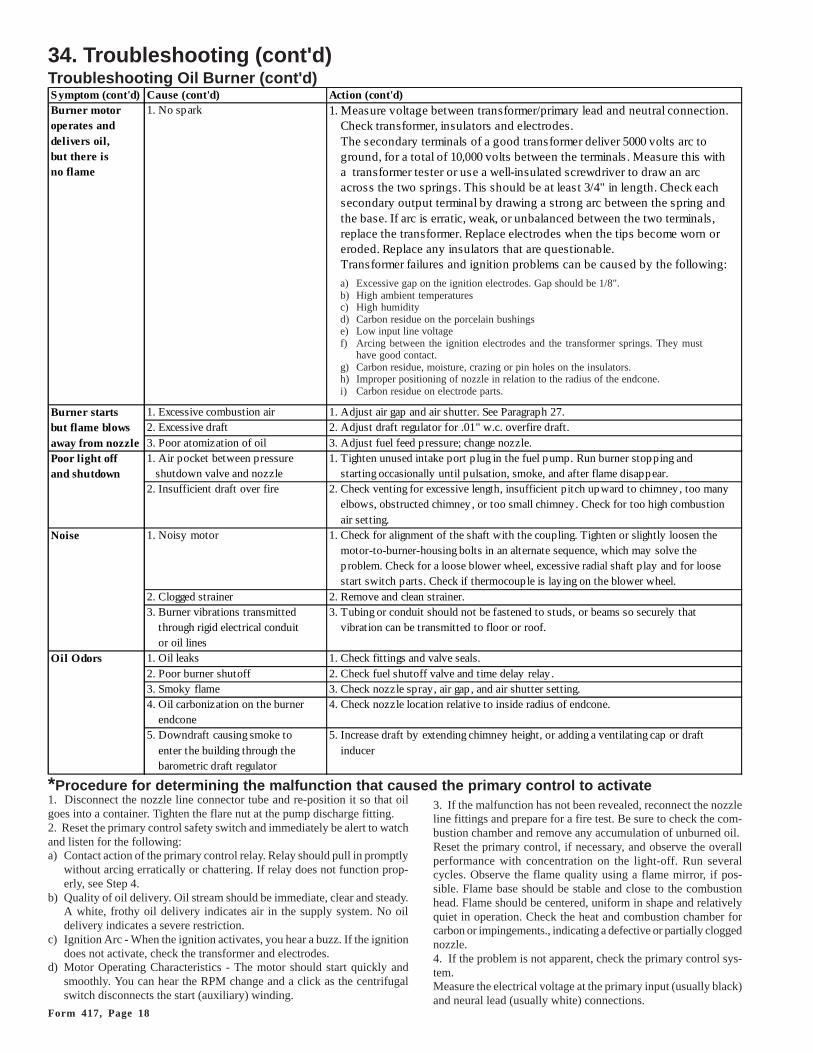
Troubleshooting Oil BurnerS ymptom C ause ActionBurne r motor 1. Incomp lete electrical circuit 1. M easure the line voltage at the p rimary control inp ut connection. Should havedoes not start nominal 120 volt s. (Low er than 105 volt s may cause op erating p roblems.) If
there is no reading, check disconnect sw itch, fuses, and thermostat connect ions.
2. Primary control activated. Relay 2. *Follow the instruct ions on p age 19 to determine the cause of the lockout.
in "on safety " p osition w ill lock Correct the malfunction. out burner op eration.3. Inadequate volt age betw een 3. Line volt age must be w ithin 10% of the volt age sp ecified on the motor rat ing motor/p rimary lead and p late.
neutral connect ion.4. M otor hums but shaft does not 4. Start sw itch may be defect ive. With the p ow er turned off, rotate the blow er rotate. w heel by hand. If it turns freely , rep lace the motor.5. M otor bearings froz en. 5. Free shaft and lubricate or rep lace motor.6. O verload p rotect ion act ivated 6. A llow the motor to cool. Start the motor and measure the current draw . T his reading
should not exceed the rating p late sp ecificat ions under load condit ions by more than 10%. Excessive amp draw usually means an overload condition, defective st art sw itch or shorted w indings. Rep lace motor if necessary . (It is difficult and not usually cost effect ive to att emp t to rebuild the motor.)
Burne r motor 1. O il level below intake in t ank 1. Fill and bleed air from fuel line.operate s but 2. Clogged st rainer 2. Remove and clean st rainerno fue l i s 3. Restricted fuel sup p ly line 3. O p en all valves in sup p ly line. Rep lace any kinked tubing.de live red at 4. Clogged noz z le 4. Rep lace noz z le.the noz z le 5. A ir leak in the sup p ly line 5. T ighten all fit t ings in the line. T ighten unused intake p ort p lug in the fuel p ump . If
there are valves in the line, be sure the valve stems are p acked solid and tightened securely .
6. T w o p ip e sy stem that becomes 6. Insert by p ass p lug if not in p lace. Re-start unit and p rime p ump . air bound.7. M otor op erates but does not drive 7. Check the coup ling for slip p age due to s trip p ed end cap s. Rep lace coup ling. the p ump shaft8. Frozen oil p ump shaft 8. Rep lace oil p ump .9. Suction line oil filt er cartridge dirty 9. Rep lace cart ridge.
Form 417, Page 18
1. Disconnect the nozzle line connector tube and re-position it so that oilgoes into a container. Tighten the flare nut at the pump discharge fitting.2. Reset the primary control safety switch and immediately be alert to watchand listen for the following:a) Contact action of the primary control relay. Relay should pull in promptly
without arcing erratically or chattering. If relay does not function prop-erly, see Step 4.
b) Quality of oil delivery. Oil stream should be immediate, clear and steady.A white, frothy oil delivery indicates air in the supply system. No oildelivery indicates a severe restriction.
c) Ignition Arc - When the ignition activates, you hear a buzz. If the ignitiondoes not activate, check the transformer and electrodes.
d) Motor Operating Characteristics - The motor should start quickly andsmoothly. You can hear the RPM change and a click as the centrifugalswitch disconnects the start (auxiliary) winding.
3. If the malfunction has not been revealed, reconnect the nozzleline fittings and prepare for a fire test. Be sure to check the com-bustion chamber and remove any accumulation of unburned oil.Reset the primary control, if necessary, and observe the overallperformance with concentration on the light-off. Run severalcycles. Observe the flame quality using a flame mirror, if pos-sible. Flame base should be stable and close to the combustionhead. Flame should be centered, uniform in shape and relativelyquiet in operation. Check the heat and combustion chamber forcarbon or impingements., indicating a defective or partially cloggednozzle.4. If the problem is not apparent, check the primary control sys-tem.Measure the electrical voltage at the primary input (usually black)and neural lead (usually white) connections.
*Procedure for determining the malfunction that caused the primary control to activate
a) Excessive gap on the ignition electrodes. Gap should be 1/8".b) High ambient temperaturesc) High humidityd) Carbon residue on the porcelain bushingse) Low input line voltagef) Arcing between the ignition electrodes and the transformer springs. They must
have good contact.g) Carbon residue, moisture, crazing or pin holes on the insulators.h) Improper positioning of nozzle in relation to the radius of the endcone.i) Carbon residue on electrode parts.
34. Troubleshooting (cont'd)Troubleshooting Oil Burner (cont'd)Symptom (cont'd) Cause (cont'd) Action (cont'd)Burner motor 1. No spark 1. Measure voltage between transformer/primary lead and neutral connection.operates and Check transformer, insulators and electrodes.delivers oil, The secondary terminals of a good transformer deliver 5000 volts arc tobut there is ground, for a total of 10,000 volts between the terminals . Measure this withno flame a transformer tester or use a well-insulated screwdriver to draw an arc
across the two springs. This should be at least 3/4" in length. Check each secondary output terminal by drawing a strong arc between the spring and the base. If arc is erratic, weak, or unbalanced between the two terminals, replace the transformer. Replace electrodes when the tips become worn or eroded. Replace any insulators that are questionable. Transformer failures and ignition problems can be caused by the following:
Burner starts 1. Excessive combustion air 1. Adjust air gap and air shutter. See Paragraph 27.but flame blows 2. Excessive draft 2. Adjust draft regulator for .01" w.c. overfire draft.away from nozzle 3. Poor atomization of oil 3. Adjust fuel feed pressure; change nozzle.Poor light off 1. Air pocket between pressure 1. Tighten unused intake port p lug in the fuel pump. Run burner stopping andand shutdown shutdown valve and nozzle starting occasionally until pulsation, smoke, and after flame disappear.
2. Insufficient draft over fire 2. Check venting for excessive length, insufficient pitch upward to chimney, too many elbows, obstructed chimney, or too small chimney. Check for too high combustion air setting.
Noise 1. Noisy motor 1. Check for alignment of the shaft with the coupling. Tighten or slightly loosen the motor-to-burner-housing bolts in an alternate sequence, which may solve the p roblem. Check for a loose blower wheel, excessive radial shaft play and for loose start switch parts. Check if thermocouple is laying on the blower wheel.
2. Clogged strainer 2. Remove and clean strainer.3. Burner vibrations transmitted 3. Tubing or conduit should not be fastened to studs, or beams so securely that through rigid electrical conduit vibration can be transmitted to floor or roof. or oil lines
Oil Odors 1. Oil leaks 1. Check fittings and valve seals.2. Poor burner shutoff 2. Check fuel shutoff valve and time delay relay .3. Smoky flame 3. Check nozzle spray, air gap , and air shutter setting.4. Oil carbonization on the burner 4. Check nozzle location relative to inside radius of endcone. endcone5. Downdraft causing smoke to 5. Increase draft by extending chimney height, or adding a ventilating cap or draft enter the building through the inducer barometric draft regulator
Page 19
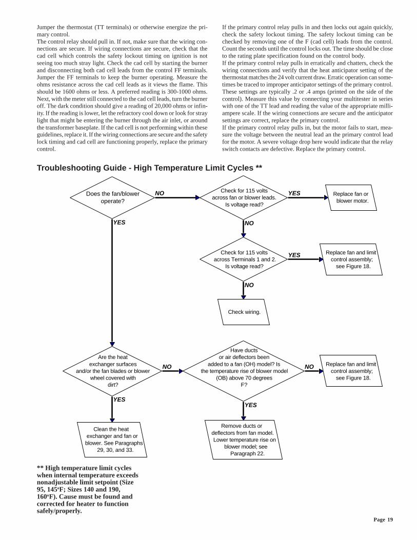
Does the fan/bloweroperate?
Are the heatexchanger surfaces
and/or the fan blades or blowerwheel covered with
dirt?
Clean the heatexchanger and fan orblower. See Paragraphs
29, 30, and 33.
Have ductsor air deflectors been
added to a fan (OH) model? Isthe temperature rise of blower model
(OB) above 70 degreesF?
Remove ducts ordeflectors from fan model.Lower temperature rise on
blower model; seeParagraph 22.
Replace fan and limitcontrol assembly;
see Figure 18.
Check for 115 voltsacross fan or blower leads.
Is voltage read?
Replace fan orblower motor.
Check for 115 volts across Terminals 1 and 2.
Is voltage read?
Replace fan and limitcontrol assembly;
see Figure 18.
Check wiring.
YES
NO
YES
NO
YES
NO
YES
NO
YES
NO
Jumper the thermostat (TT terminals) or otherwise energize the pri-mary control.The control relay should pull in. If not, make sure that the wiring con-nections are secure. If wiring connections are secure, check that thecad cell which controls the safety lockout timing on ignition is notseeing too much stray light. Check the cad cell by starting the burnerand disconnecting both cad cell leads from the control FF terminals.Jumper the FF terminals to keep the burner operating. Measure theohms resistance across the cad cell leads as it views the flame. Thisshould be 1600 ohms or less. A preferred reading is 300-1000 ohms.Next, with the meter still connected to the cad cell leads, turn the burneroff. The dark condition should give a reading of 20,000 ohms or infin-ity. If the reading is lower, let the refractory cool down or look for straylight that might be entering the burner through the air inlet, or aroundthe transformer baseplate. If the cad cell is not performing within theseguidelines, replace it. If the wiring connections are secure and the safetylock timing and cad cell are functioning properly, replace the primarycontrol.
If the primary control relay pulls in and then locks out again quickly,check the safety lockout timing. The safety lockout timing can bechecked by removing one of the F (cad cell) leads from the control.Count the seconds until the control locks out. The time should be closeto the rating plate specification found on the control body.If the primary control relay pulls in erratically and chatters, check thewiring connections and verify that the heat anticipator setting of thethermostat matches the 24 volt current draw. Erratic operation can some-times be traced to improper anticipator settings of the primary control.These settings are typically .2 or .4 amps (printed on the side of thecontrol). Measure this value by connecting your multitester in serieswith one of the TT lead and reading the value of the appropriate milli-ampere scale. If the wiring connections are secure and the anticipatorsettings are correct, replace the primary control.If the primary control relay pulls in, but the motor fails to start, mea-sure the voltage between the neutral lead an the primary control leadfor the motor. A severe voltage drop here would indicate that the relayswitch contacts are defective. Replace the primary control.
** High temperature limit cycleswhen internal temperature exceedsnonadjustable limit setpoint (Size95, 145oF; Sizes 140 and 190,160oF). Cause must be found andcorrected for heater to functionsafely/properly.
Troubleshooting Guide - High Temperature Limit Cycles **
Form 417, Page 20
CAUTION: DO NOT TAMPER WITH THEUNIT OR CONTROLS. CALL YOUR
SERVICE PERSON.
©2000 Thomas & Betts Corporation, All rights reserved. Printed in the U.S.A.
MANUFACTURER OF GAS, OIL, ELECTRIC HEATING AND VENTILATING SYSTEMS
1/00 1M M Form 417-B.1
FOR SERVICE OR REPAIR, FOLLOW THESE STEPS IN ORDER:
FIRST: Contact the installer.
Name _______________________________________________________________________________________
Address ________________________________________________________________________________________
________________________________________________________________________________________
________________________________________________________________________________________
Phone ________________________________________________________________________________________
SECOND: Contact the nearest distributor (See telephone Yellow Pages.)
THIRD: Contact: REZNOR®/Thomas & Betts Corporation
150 McKinley Avenue
Mercer, PA 16137
Phone: (724) 662-4400
Model No. ______________________________________________________________________________________________
Unit Serial No. __________________________________________________________________________________________
Date of Installation _______________________________________________________________________________________