Embed Size (px)
Citation preview

Form 705, Page 1
IMPORTANT1. Always include complete heater model and serial number so
that any specification change can be considered for parts ship-ment. It can save time and expense.
2. Specifications are subject to change without notice.3. We reserve the right to substitute functional replacements.4. Order either by Kit or Component Part No.
Replacement Parts
APPLIES TO: Replacement Parts forModels listed in the Index including
Models with prefix "C" , "H", and "HC"
REFERENCES:Replacement Parts and Service Forms,
Form RZ-NA701, Pilots702, Thermostats and Accessories703, Gas Conversion704, Burner Rack Carryover and Lighter
Tubes707, Parts for Model Series RG and RP 713, Fan and Limit Controls
CP18, Convert Model Series X and RX withG60 to G770
CP19, Convert Model Series RPV with G60 toG770
Installation/Operation Forms for currentlymanufactured Models, Form RZ-NA
401, Models RX and RPV403, Model XE422, Model X
* Replacement parts for obsolete unit heaters are limited. Cabinet parts are not available. ** Not available for Model UA.
***714, Serial Nos., Gas Valves, IgnitionControllers, and Maxitrol Gas Controls
721, Power Venter for Model Series X and XE739, Parts for Model PAKCP1, Convert Model Series X and RX withG19 or T32 to G770
CP3, Convert Model Series RPV with G29 toG770
CP16, Pressure Switch Kit for Model SeriesRPV
Form RZ-NA 705 (Version A)Obsoletes Form RGM 705-6
Index Reference Indoor Outdoor
by Page No. Duct Furnace
Packaged Systems
Unit Heaters
(O bsolete)Evaporat ive Cooler
(O bsolete)
Model Series Designations (including Models with prefix "C", "H", or "HC")
X XE/XJ RX RPV RXE/RXJRPBE/RPVE/
RPVJ/REB/REBJUA/XA/ XB* RAM
Baffles (Heat Exchanger) 10 10 10 10 10 10 -- --Blower -- 11 -- -- 11 11 -- --Burner Rack and Carryovers 8 8 8 8 8 8 8** --Cabinet Parts (Blower) -- 12 -- -- 13 13 -- --Cabinet Parts (Heater) 4 4 4 6 4 4, 6 -- 28Carryover Regulator 8 8 8 8 8 8 -- --Condensate Drain Kit 27 27 27 27 -- -- -- --Contactor -- 14 -- -- 14 14 -- --Damper and Damper Controls -- 20-21 -- -- 20-21 20-21 -- --Door Latch Kit -- 13 -- -- 13 13 -- --Downturn Plenum Cabinet -- -- -- -- 20 20 -- --Drives -- 19 -- -- 19 19 -- --Electrical Components 22-25 22-25 22-25 22-25 22-25 22-25 -- 28Fan Blades -- -- -- -- -- -- 18 --Fill & Drain Kits (Option CT) -- -- -- -- -- -- -- 28Filters and Filter Racks -- 12 -- -- 13 13 -- 28Firestat -- 23 -- -- 23 23 -- --Flue Restrictors -- -- 6 -- 6 6 -- --Freezestat -- 24 -- -- 24 24 -- --Heat Exchanger 10 10 10 10 10 10 -- --Limit Controls & Shields 22 22 22 22 22 22 -- --Manifolds 8 8 8 8 8 8 -- --Motors (Blower or Fan) -- 14-16 -- -- 16-18 16-18 18 --Pilots 26 26 26 27 26 26-27 26 --Pressure Switch (air proving) -- -- 24 24 24 24 -- --Pressure Switch (combustion air) -- -- -- 7, 22 -- 7, 22 -- --Pressure Switch (dirty filter) -- 24 -- -- 24 24 -- --Pressure Switch (gas) 23 23 23 23 23 23 -- --Relays 23-24 23-24 23-24 23-24 23-24 23-24 23-24 --Remote Console (Option RC) 25 25 25 25 25 25 -- --Serial Number Designation 2 2 2 2 2 2 2 --Starters & Starter Heaters -- 14-16 -- -- 16-18 16-18 -- --Switch, Blocked Vent 22 22 -- -- -- -- -- --Switches, Disconnect & Toggle 25 25 25 25 25 25 25 --Tape for Curbs -- -- 27 27 27 27 -- --Transformer 24 24 24 24 24 24 -- --***Valves (Shutoff) 8 8 8 8 8 8 8 --Venters -- -- -- 6 -- 6 -- --Vertical Vent Kit (Option CC3) -- -- -- 6 -- 6 -- --Weatherhood (Outside air hood) -- -- -- -- 20 20 -- --Z-Baffles (Option ZZ) -- -- 4-5 -- 4-5 -- -- --
Packaged Systems (Models discontinued as of 1990)
OutdoorIndoor
Duct Furnaces

Form 705, Page 2
Blower Cabinet Rating Plate on Certified Packaged Units (see table on page 3)Key to Cabinet Rating Plate
A = Standard
B = Model
C = Date of Manufacture
D = Motor Horsepower
E = Volts/Phase/Hertz/Amps
F = SCFM
REZNORMERCER, PA., U.S.A. 16137
PACKAGED DUCT FURNACE
FOR INDUSTRIAL/COMMERCIAL USE ONLY
DESIGN CERTIFIED FOR A.G.A REQUIREMENTS UNDER
[ A ] PACKAGED DUCT FURNACE STANDARD
MODEL [ B ] [ C ]
SERIAL NO. [ D ] HP
[ E ] VOLTS [ E ] PH [ E ] HZ MAXIMUM TOTAL INPUT [ E ] AMPS
IF EQUIPPED WITH R.E.C. OPTION, ADD [ V ] AMPS
EQUIPPED FOR OPERATION AT AN AIR FLOW OF [ F ] SCFM
AGAINST A STATIC PRESSURE OF [ G ] INCHES WATER COLUMN.
DRIVE NO. [ H ] WIRING DIAGRAM [ I ]
SEE MANUFACTURER'S INSTRUCTIONS FOR OTHER AIR FLOW
CAPACITIES.
FILTERS, WHEN USED, MUST BE INSTALLED EXTERNAL TO THE
HEATING CASING.
REFER TO THE RATING PLATE OF THE DUCT FURNACE FOR
ADDITIONAL INFORMATION.
REZNORMERCER, PA. USA 16137
DUCT FURNACECATEGORY IFOR INDUSTRIAL/COMMERCIAL USE ONLY
ANSI Z83.8 [ AA ] - [ A ] CGA 2.6 [ AA' ] -M [ A' ] DUCT FURNACE
MODEL [ B ] [ C ]
SERIAL NO. [ D ][ E ] VOLTS [ E ] PH [ E ] HZ MAXIMUM TOTAL INPUT [ E ] AMPS
TYPE OF GAS: [ F ] [ G ]ORIFICE SIZE [ J ] DRILL HAS BEEN FACTORY ADJUSTED
FOR USE AT [ H ] FEET [ I ] METERS OF ALTITUDE.
ALT. ADJUSTED
NORMAL INPUT [ K ]BTU/HR.
OUTPUT CAPACITY [ L ]BTU/HR.
MINIMUM INPUT(2,M,MB,MV MODELS) [ M ]BTU/HR.
NORMAL MANIFOLD PRESSURE [ N ] IN.W.C.
MIN. PERMISSIBLE GAS SUPPLY PRESSURE
FOR PURPOSE OF INPUT ADJUSTMENT. [ O ] IN.W.C.
MAXIMUM THROUGHPUT [ P ] C.F.M.
MINIMUM THROUGHPUT [ Q ] C.F.M.
CLEARANCES TO COMBUSTIBLE CONSTRUCTION: VENT CAP-10' , BOTTOM- 3",
FLUE CONNECTION-6", SERVICE SIDE- WIDTH OF UNIT, OPPOSITE SIDE-6"
THIS UNIT SHALL BE INSTALLED ON THE POSITIVE PRESSURE SIDE OF THE
AIR CIRCULATING BLOWER.
THIS UNIT MAY BE INSTALLED DOWNSTREAM FROM A REFRIGERATION
SYSTEM (USE DRAIN OPTION CS1).
THIS UNIT MAY BE USED WITH DUCTS.
THIS UNIT IS FOR OUTDOOR INSTALLATION ONLY.
MINIMUM OPERATIONAL AMBIENT AIR TEMPERATURE: -40 DEG. F
THIS UNIT IS FOR USE WITH NATURAL GAS AND PROPANE. A
CONVERSION KIT AS SUPPLIED BY THE MANUFACTURER, SHALL BE
USED TO CONVERT THIS DUCT FURNACE TO THE ALTERNATE FUEL.
FOR ALTERNATE INSTALLATIONS USE THE LATEST EDITIONS OF THE
APPROPRIATE STANDARD LISTED BELOW:
FOR AIRCRAFT HANGERS USE STANDARD ANSI/NFPA 409
FOR PARKING STRUCTURES USE STANDARD ANSI/NFPA 88A
FOR REPAIR GARAGES USE STANDARD ANSI/NFPA 88B
SEA LEVEL
[ R ]
[ S ]
[ T ]
Duct Furnace Rating Plate
De-Coding a Serial No.Sample: S AZJ 66 K1 N 12345 MV3
1 | 2 | 3 | 4 | 5 | 6 | 71 = Stainless steel heat exchanger (with an aluminized heat
exchanger, there is no letter suffix2 = Date code (see page 3)3 = Pilot code (Reference Form RZ 714)4 = Valve code (Reference Form RZ 714)5 = N is natural gas; L is propane gas6 = Consecutive number7 = Maxitrol system (optional)
Key to Duct Furnace Rating PlateA = StandardB = Model and SizeC = Date of ManufacturerD = Serial No.E = Volts/PH/Hz/AmpsF & G = Natural or Propane GasH & I = AltitudeJ = Orifice Drill SizeK = Normal Input (altitude
adjusted)L = Thermal Output (altitude
adjusted)
M = Minimum Input (altitudeadjusted)
N = Normal Manifold PressureO = Minimum Gas Supply
PressureP = Maximum Air ThroughputQ = Minimum Air ThroughputR = Normal Input (sea level)S = Thermal Output (sea level)T = Minimum Input (sea level)
Replacement Parts Tag - Each unit has a replacement parts tag thatincludes the Model No. and the Serial No. as well as a list oforiginal common replacement parts. Always provide the full modeland serial numbers when ordering replacement parts.
Identification Plate on Blower Cabinets Manufactured Prior toPackage Certification (see dates on page 3)
HP Codes
MODEL NUMBER SERIAL NUMBER
DRIVE NO. WIRING DIAGRAM NO.
CFM _____ AT____ IN. W.C. MAX. E.S.P. AND ____ HP
VOLTS PHASE HERTZ AMPERES
Single-Speed Motors 2-Speed MotorsCode HP Code HP
05 1 20 1/.4406 1-1/2 21 1.5/.6807 2 22 2/.8808 3 23 3/1.309 5 24 5/2.211 7-1/2 25 7.5/3.312 15 26 10/4.413 1014 20
G = Static Pressure (w.c.)
H = Drive AM Option Code
I = Wiring Diagram No.

Form 705, Page 3
First Element of the Serial Number (See page 2) - Date of ManufactureYear Jan Feb Mar Apr May June July Aug Sept Oct Nov Dec1963 OA OB OC OD OE OF OG OH OI OJ OK OL1964 PA PB PC P D P E PF PG P H P I PJ P K P L1965 QA QB QC QD QE QF QG QH QI QJ QK QL1966 RA RB RC RD RE RF RG RH RI RJ RK RL1967 SA SB SC SD SE SF SG SH SI SJ SK SL1968 TA T B T C T D T E T F TG T H T I TJ T K T L1969 UA UB UC UD UE UF UG UH UI UJ UK UL1970 VA VB VC VD VE VF VG VH VI VJ VK VL1971 WA WB WC WD W E WF WG WH W I WJ WK W L1972 XA XB XC XD XE XF XG XH XI XJ XK XL1973 YA YB YC YD YE YF YG YH YI YJ YK YL1974 ZA ZB ZC ZD ZE ZF ZG ZH ZI ZJ ZK ZL1975 AAA AAB AAC AAD AAE AAF AAG AAH AAI AAJ AAK AAL1976 ABA ABB ABC ABD ABE ABF ABG ABH ABI ABJ ABK ABL1977 ACA ACB ACC ACD ACE ACF ACG ACH ACI ACJ ACK ACL1978 ADA ADB ADC ADD ADE ADF ADG ADH ADI ADJ ADK ADL1979 AEA AEB AEC AED AEE AEF AEG AEH AEI AEJ AEK AEL1980 AFA AFB AFC AFD AFE AFF AFG AFH AFI AFJ AFK AFL1981 AGA AGB AGC AGD AGE AGF AGG AGH AGI AGJ AGK AGL1982 AHA AHB AHC AHD AHE AHF AHG AHH AHI AHJ AHK AHL1983 AIA AIB AIC AID AIE AIF AIG AIH AII AIJ AIK AIL1984 AJA AJB AJC AJD AJE AJF AJG AJH AJI AJJ AJK AJL1985 AKA AKB AKC AKD AKE AKF AKG AKH AKI AKJ AKK AKL1986 ALA ALB ALC ALD ALE ALF ALG ALH ALI ALJ ALK ALL1987 AMA AMB AMC AMD AME AMF AMG AMH AMI AMJ AMK AML1988 ANA ANB ANC AND ANE ANF ANG ANH ANI ANJ ANK ANL1989 AOA AOB AOC AOD AOE AOE AOG AOH AOI AOJ AOK AOL1990 APA APB APC APD APE APF APG APH API APJ APK APL1991 AQA AQB AQC AQD AQE AQF AQG AQH AQI AQJ AQK AQL1992 ARA ARB ARC ARD ARE ARF ARG ARH ARI ARJ ARK ARL1993 ASA ASB ASC ASD ASE ASF ASG ASH ASI ASJ ASK ASL1994 ATA ATB ATC ATD ATE ATF ATG ATH ATI ATJ ATK ATL1995 AUA AUB AUC AUD AUE AUF AUG AUH AUI AUJ AUK AUL1996 AVA AVB AVC AVD AVE AVF AVG AVH AVI AVJ AVK AVL1997 AWA AWB AWC AWD AWE AWF AWG AWH AWI AWJ AWK AWL1998 AXA AXB AXC AXD AXE AXF AXG AXH AXI AXJ AXK AXL1999 AYA AYB AYC AYD AYE AYF AYG AYH AYI AYJ AYK AYL2000 AZA AZB AZC AZD AZE AZF AZG AZH AZI AZJ AZK AZL2001 BAA BAB BAC BAD BAE BAF BAG BAH BAI BAJ BAK BAL2002 BBA BBB BBC BBD BBE BBF BBG BBH BBI BBJ BBK BBL2003 BCA BCB BCC BCD BCE BCF BCG BCH BCI BCJ BCK BCL2004 BDA BDB` BDC BDD BDE BDF BDG BDH BDI BDJ BDK BDL2005 BEA BEB BEC BED BEE BEF BEG BEH BEI BEJ BEK BEL2006 BFA BFB BFC BFD BFE BFF BFG BFH BFI BFJ BFK BFL2007 BGA BGB BGC BGD BGE BGF BGG BGH BGI BGJ BGK BGL2008 BHA BHB BHC BHD BHE BHF BHG BHH BHI BHJ BHK BHL2009 BIA BIB BIC BID BIE BIF BIG BIH BII BIJ BIK BIL2010 BJA BJB BJC BJD BJE BJF BJG BJH BJI BJJ BJK BJL2011 BKA BKB BKC BKD BKE BKF BKG BKH BKI BKJ BKK BKL2012 BLA BLB BLC BLD BLE BLF BLG BLH BLI BLJ BLK BLL2013 BMA BMB BMC BMD BME BMF BMG BMH BMI BMJ BMK BML2014 BNA BNB BNC BND BNE BNF BNG BNH BNI BNJ BNK BNL2015 BOA BOB BOC BOD BOE BOF BOG BOH BOI BOJ BOK BOL
Date Duct Furnace Series was Introduced orRecertifiedThe series is identified in the Model No. of the unit. The number following themodel of the heater is the series number (Example: RX300-6; "6" is the Series No.).Replacement parts may be affected by the introduction of a new series.
Models Series 3 Series 5 Series 6 Series 7 Series 8
RPV 5/76 1/82 11/86 -- 5/95
CRPV -- 1/85 11/86 -- --
X -- 6/80 5/84 8/90 5/95
CX -- -- 8/84 -- --
RX -- 6/80 8/84 -- 5/95
CRX -- -- 1/85 -- 5/95
Date of Packaged Unit CertificationModel IntroducedXE 3/96
Discontinued Models in this booklet:(H)CRPV(H)CX(H)CXE(H)(C)RXERXJ
(H)(C)REB(H)(C)RPBE(H)(C)RPVERPVJ
REBJUAXAXBRAM

Form 705, Page 4
��
�
�
�
�
�
�
��
�
�
�� ����
CODES 1-10 ExteriorFurnace Cabinet Partsfor Indoor ModelSeries X (also thefurnace section ofModel Series XE)
CODES 15-33 Exterior Furnace Cabinet Parts for OutdoorModel Series RX (also the furnace section of Model SeriesRXE, RXJ, REB, and REBJ)
CODES 11-14 Drafthood Parts forIndoor Model Series X (also thefurnace section of Model Series XE)
CODES 34-37 Flue Collection Partsfor Outdoor Model Series RX (alsothe furnace section of Model SeriesRXE, RXJ, REB, and REBJ)
��
��
�� ��
��
������
���
�
��
��
��
����
��
��
�� �� ��
��
��
��
�
�
����
�� ����
NOTE: Effective 4/91, all Model X and XEunits include a blocked vent switch requiringmounting holes in the drafthood side (Code14B). If the drafthood side is being replacedin a unit not equipped with the blocked ventswitch, a patch plate with gasket must coverthe blocked vent switch mounting holes.
CODE 15A - Vent CapExtension for ModelSeries RX
���
Code Description1 Flue Collar Assembly X Series
CX Series 62 Draft Hood & Top Assy X Series
w/ Flue Collar CX Series 63 Flue Collar Support4 Hanger connector5 Right Front & Left Rear Corner Legs Prior to Series 6
5A Left Rear Corner leg Series 6 & 85B Right Rear Corner Leg Series 6 & 86 Left Front & Right Rear Corner Legs7 Bottom Front & Rear Panel 8 Casing Side Panel Doors9 Heater Bottom Pan Aluminized
409 Stainless10 Top Back11 Draft Hood Rear Baffle Prior to Series 6 Series 6 & 8
12 Draft Hood Front Baffle Prior to Series 6 Series 6 & 8
13 Draft Hood Right Side Prior to Series 6Series 6 & 8
14 Draft Hood Left Side Prior to Series 6Series 6 & 8
15 Vent Cap
15A Vent Cap Extension - See Table below16 Hex Head Bolt 7/16 x 117 Lift Eye
18 Casing Top Assembly (includes insulation)
Casing Top Assembly - Series 5W & 6W (wide cabinet)19 Hanger Angle20 Top Front & Back21 Left Rear Corner Leg
Left Rear Corner Leg - Series 5W & 6W (wide cabinet)22 Right Rear Corner Leg
Right Rear Corner Leg - Series 5W & 6W (wide cabinet)23 Left Front Corner Leg
Left Front Corner Leg - Series 5W & 6W (wide cabinet)24 Right Front Corner Leg
Right Front Corner Leg - Series 5W & 6W (wide cabinet)25 Left Casing Assembly with Combustion Air Screen Assembly26 Right Casing Assembly with Combustion Air Screen Assembly27 Combustion Air Inlet Shield28 Combustion Air Inlet Screen29 Combustion Air Inlet Angle30 Bottom Front & Rear Panel 31 Heater Bottom Pan Aluminized
409 Stainless Heater Bottom Pan - Series Aluminized
5W & 6W (wide cabinet) 409 Stainless32 Corner Panel33 Reznor Name Plate34 Flue Restrictor - See Type RX, HRX prior to Series 6
& Size on page 6. RX, HRX Series 6RX, HRX Series 8
CRX, HCRX - All 35 "Z" Baffle used w/ optional RX, HRX prior to Series 6
extended stack (Option ZZ) - See RX, HRX Series 6Type & Size on page 6. RX, HRX Series 8
CRX, HCRX - All
36 Flue Collar Prior to Series 6
Series 6 & 8
37 Flue Collection Box Prior to Series 6w/ Flue Collar RX Series 6 & 8
CRX Series 6 & 838 Louver Frame w/ Horizontal Louvers Apply to Model XE39 Horizontal Louver Only See the illustration40 Vertical Louver Only on page 6.41 Support Feet (not illustrated) Apply to Model X
Furnace Exte nsionModel S iz es S eries He ight P/N
RX, HRX
300, 350, 400
Prior to Series 8 & Series 8
12" 20524
C RX, HC RX
350Prior to Series 8
& Series 8 12" 20524
400 Prior to Series 8 7-1/4" 12018
400 Series 8 12" 20524
�� ��

Form 705, Page 5
Code 75 100 125 150 175 200 225 250 300 D-300 350 4001 55197 9918 9882 9842 9842 12727 12727 86047 86047 86047 86049 86049
55197 9918 9882 -- 9842 -- 12727 9803 86047 -- 86047 860492 55196 20830 20831 20832 20832 20833 20833 86059 86059 86063 86060 86061
55196 20830 20831 20831 20832 -- 20833 85533 86059 -- 86062 860613 9848 9848 9848 9848 9848 9691 9691 9691 9691 9691 9691 96914 9557(2) 9557(2) 9557(2) 9557(2) 9557(2) 9557(2) 9557(2) 9557(2) 9557(2) 9557(2) 9557(2) 9557(2)5 10309(2) 10309(2) 10309(2) 10309(2) 10309(2) 10311(2) 10311(2) 10311(2) 10311(2) 10311(2) 10311(2) 10311(2)
5A 11004 11004 11004 11004 11004 11006 11006 11006 11006 11006 11006 110065B 10309 10309 10309 10309 10309 10311 10311 10311 10311 10311 10311 103116 10310(2) 10310(2) 10310(2) 10310(2) 10310(2) 10312(2) 10312(2) 10312(2) 10312(2) 10312(2) 10312(2) 10312(2)7 67693(2) 9926(2) 9889(2) 9850(2) 9850(2) 9810(2) 9810(2) 9771(2) 9771(2) 9542(2) 9735(2) 9542(2)8 11819(2) 11819(2) 11819(2) 11819(2) 11819(2) 11849(2) 11849(2) 11849(2) 11849(2) 11849(2) 11849(2) 11849(2)9 15244 15244 15248 14618 14618 14624 14624 14625 14625 14632 15249 14632
15978 15978 26167 15979 15979 15980 15980 15981 15981 15982 26168 1598210 9916 9916 9880 9840 9840 9801 9801 9762 9762 9684 9729 968411 67676 67676 67678 67679 67679 67680 67680 67682 67682 -- 67684 67686 85778 85778 85782 85786 85786 85790 85790 85793 85793 85799 85796 85799
12 85802 85803 85806 85804 85805 67699 17486 67701 17507 67044 17525 17540 85802 85803 85536 85804 85805 67699 17486 67701 17507 67044 17525 17540
13 17374 17374 17374 17374 17374 17484 17484 17484 17484 -- 17484 1748485807 85807 85807 85807 85807 17484 17484 17484 17484 17484 17484 17484
14 17373 17373 17373 17373 17373 17483 17483 17483 17483 -- 17483 1748385808 85808 85808 85808 85808 17483 17483 17483 17483 17483 17483 17483
15 110053-6" 110053-6" 61857-8" 61857-8" 61857-8" 61866-10" 61866-10" 61866-10" RX-61875-12" 61875-12" 61875-12" 61875-12"CRX-61866-10"
15A16 16251(2) 16251(2) 16251(2) 16251(2) 16251(2) 16251(2) 16251(2) 16251(2) 16251(2) 16251(2) 16251(2) 16251(2)17 11026(2) 11026(2) 11026(2) 11026(2) 11026(2) 11026(2) 11026(2) 11026(2) 11026(2) 11026(2) 11026(2) 11026(2)18 10847 10847 10866 10873 10873 10881 10881 10890 RX-11107 10904 10897 10904
CRX-10365690838 90838 -- -- -- -- -- -- -- -- -- --
19 11012(2) 11012(2) 11012(2) 11012(2) 11012(2) 11012(2) 11012(2) 11012(2) 11012(2) 11012(2) 11012(2) 11012(2)20 67708(2) 67708(2) 10869(2) 10869(2) 10869(2) 10886(2) 10886(2) 10892(2) 10892(2) 10906(2) 10900(2) 10906(2)21 11004 11004 11004 11004 11004 11006 11006 11006 11006 11006 11006 11006
90842 90842 -- -- -- -- -- -- -- -- -- --22 10310 10310 10310 10310 10310 10312 10312 10312 10312 10312 10312 10312
90840 90840 -- -- -- -- -- -- 0 -- -- --23 11003 11003 11003 11003 11003 11005 11005 11005 11005 11005 11005 11005
90843 90843 -- -- -- -- -- -- -- -- -- --24 10309 10309 10309 10309 10309 10311 10311 10311 10311 10311 10311 10311
90841 90841 -- -- -- -- -- -- -- -- -- --25 67710 67710 55291 14613 14613 14621 14621 14621 14621 14621 14621 1462126 67713 67713 55292 17254 17254 11052 11052 11052 11052 11052 11052 1105227 10851 10851 10851 10851 10851 10851 10851 10851 10851 10851 10851 1085128 -- -- -- 148396 148396 148396 148396 148396 148396 148396 148396 14839629 12649 12649 12649 10850 10850 10850 10850 10850 10850 10850 10850 1085030 67693(2) 67693(2) 9889(2) 9850(2) 9850(2) 9810(2) 9810(2) 9771(2) 9771(2) 9542(2) 9735(2) 9542(2)31 15244 15244 15248 14618 14618 14624 14624 14625 14625 14632 15249 14632
-- -- 15978 15979 15979 15980 15980 15981 15981 15982 26168 15982 15248 15248 -- -- -- -- -- -- -- -- -- --
15978 15978 -- -- -- -- -- -- -- -- -- --32 15029 15029 15029 15029 15029 15029 15029 15029 15029 15029 15029 150293334 55290 -- -- -- -- 13145 13148 -- 14935 -- -- --
86435 -- 86440 86444 86446 86454 86456 86444 86465 -- 15599 86465136738 136739 86440 136740 136741 86493 136742 86493 86454 -- -- --86492 86479 89205 -- 89206 -- 89208 89209 89210 -- 86488 86490
35 15580 45476 15584 15588 15590 15593 15596 15599 15601 -- 15603 1561186491 86492 15584 86485 86493 86488 14935 15599 15601 15601 86494 86495
136743 136744 136745 136746 86493 89212 15596 86454 136747 -- 86495 8649586496 89211 15584 -- 86485 -- 86488 89212 86497 -- 86498 89213
36 12012 12012 12013 12013 12013 12014 12014 12014 RX-12015 -- 12015 12015CRX-12014
12011 12011 86474 86474 86474 12014 12014 12014 RX-12015 12015 12015 12015CRX-12014
37 55289 10854 10862 10870 10870 10876 19832 10887 11104 -- 10893 1090186430 86436 86437 86441 86445 86447 86455 86457 86463 87148 86466 8647086476 86478 86480 -- 86482 -- 89207 86484 86486 -- 86487 86489
38 39711 39711 10018 10016 10016 10014 10014 10012 10012 10001 10010 1000139 9923(5) 9923(5) 9887(5) 9847(5) 9847(5) 9808(5) 9808(5) 9679(10) 9679(10) 9553(10) 9733(10) 9553(10)40 9554(3) 9554(3) 9554(4) 9554(6) 9554(6) 9554(8) 9554(8) 9554(10) 9554(10) 9554(14) 9554(12) 9554(14)41 10680(4) 10680(4) 10680(4) 10680(4) 10680(4) 10680(4) 10680(4) 10680(4) 10680(4) 10680(4) 10680(4) 10680(4)
P/N 121264 (replaces 9538)

Form 705, Page 6
��������������������������� �!"�"�����#��$��%
���"���&�!������������"'(!�����"%
�)��*�+%
����"�����,�-�.��������"'(!�����"%
�������//%�0� ��1#������������"'(!�����"%
23����"���� ��((4���������������"�0��������������������
��/.!(������ �5���$�
0!��� ����1��(��� ���!������*6� �//��"�"�(�7���(�����8���������1�!1������"'(!�����"%
Code 81 - VerticalVent Kit, P/N45021 (Same asOption CC3)
NOTE:Supportangles and allpiping arefieldsupplied.
CODES 38, 39 & 40 -Optional Louvers for ModelSeries XE (P/N's are onpages 4 and 5)
� �
��
Codes 34 and35 - FlueRestrictorsfor Model RX,pages 4 and 5
������9
�
������:
��
�
��
����
��
��
�
�� ��
�
��
��
��
��
�� ����
����
��
��
�
��
��
�
��
�
�� �� ������� ���
CODES 45-60 Exterior Furnace Cabinet Parts for OutdoorModel Series RPV (also the furnace section of Model SeriesRPVE, RPBE, and RPVJ)
"D" Type
"S" Type
CODES 61-78 Flue Collection Box and Ventercomponents for Model Series RPV 3, 5, 6 and 8
Venter motor capacitor is notavailable from Reznor115V requires 1, 4MFD 370 VAC capacitor230V requires 1, 4MFD 370 VAC capacitor460V requires 2, 2MFD 370 VAC capacitors
Code 80 - Pressure Switch Kit, P/N 93033, for RPVSeries 3 and 5 (to replace sail switch with pressureswitch)
Wire Assembly,P/N 93034
PressureSwitch,P/N 125133
Also 4-3/4"AluminumTubing,P/N 114240(notillustrated)
Sensing Tube, P/N 92777
Palnuts,P/N 24468
Screws,P/N 11813
CompressionElbow,
P/N 18224
70
7576
73
74
72
P/N Type Size P/N Type Size P/N Type Size13145 S 4-1/2 x 11 86446 S 2-3/4 x 7-1/2 89206 S 3-5/8 x 7-1/213148 S 2-1/2 x 11 86454 D 7 x 7 89208 D 6-7/8 x 6-7/814935 S 7-3/4 x 7-3/4 86456 D 6-5/8 x 6-5/8 89209 D 6-3/8 x 6-3/815580 S 4-5/8 x 4-5/8 86465 S 8-1/4 x 8-1/4 89210 S 3 x 7-1/215584 S 6-7/16 x 6-7/16 86479 S 1-3/4 x 5-3/4 89211 S 4-3/4 x 4-7/1615588 D 6-1/8 x 6-1/8 86485 D 6-1/4 x 6-1/4 89212 D 7-3/4 x 7-3/415590 D 5-7/8 x 5-7/8 86488 S 8 x 8 89213 S 8-5/8 x 8-5/815593 D 7-13/16 x 7-13/16 86490 S 4-7/8 x 11-3/4 136738 D 3-3/8 x 3-3/815596 D 7-5/8 x 7-5/8 86491 S 4-7/16 x 4-7/16 136740 D 5-1/8 x 5-1/815599 D 7-1/2 x 7-1/2 86492 S 4-1/4 x 4-1/4 136741 D 4-13/16 x 4-13/1615601 S 9-1/4 x 9-1/4 86493 D 6 x 6 136742 D 4-1/2 x 4-1/215603 D 8-7/8 x 8-7/8 86494 S 8-7/8 x 8-7/8 136743 D 4-5/8 x 4-5/815611 D 8-1/2 x 8-1/2 86495 S 8-1/2 x 8-1/2 136744 D 4-1/4 x 4-1/455290 S 3 x 5-3/4 86496 S 4-3/4 x 4-3/4 136745 D 6-3/8 x 6-3/886435 S 4-1/8 x 4-1/8 86497 D 7-3/8 x 7-3/8 136746 D 6-1/8 x 6-1/886440 D 5-5/8 x 5-5/8 86498 S 9 x 9 136747 D 9-1/8 x 9-1/886444 S 3-1/2 x 7-1/2 89205 D 5-3/4 x 5-3/4
Form 705, Page 7
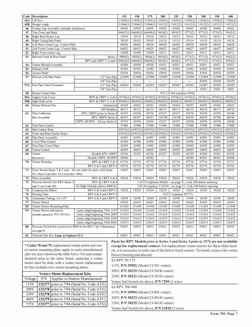
* Codes 78 and 79, replacement venter motor and ven-ter motor mounting plate, apply to units manufacturedafter the dates shown in the table below. For units manu-factured prior to the dates listed, replacing a ventermotor must be done with a venter motor replacementkit that includes new motor mounting plates.
Parts for RPV Models prior to Series 3 and Series 5 prior to 1976 are not availableexcept for replacement venters. For replacement venter motors for these older mod-els, it is necessary to order one of the below listed venters. To install, remove the venterblower housing and discard.
for RPV 50-175
115V, P/N 29992 (Model LV301 venter)
208V, P/N 30229 (Model LV301B venter)
230V, P/N 30231 (Model LV301H venter)
Venter Sail Switch for above, P/N 7299 (2-wire)
for RPV 200-400
115V, P/N 29994 (Model LV401 venter)
208V, P/N 30233 (Model LV401B venter)
230V, P/N 30235 (Model LV401H venter)
Venter Sail Switch for above, P/N 13925 (2-wire)
Code Description 125 150 175 200 225 250 300 350 40045A Lift Eye 11026(2) 11026(2) 11026(2) 11026(2) 11026(2) 11026(2) 11026(2) 11026(2) 11026(2)45B Hanger Angle 31904(2) 31904(2) 31904(2) 11012(2) 11012(2) 11012(2) 11012(2) 11012(2) 11012(2)
46 Casing Top Assembly (includes insulation) 43936 43939 43939 43942 43942 43945 43945 43948 4395147 Top Front and Back 64667(2) 64669(2) 64669(2) 9810(2) 9810(2) 9771(2) 9771(2) 9735(2) 9542(2)
48 Right Rear Heater Leg 10310 10310 10310 10312 10312 10312 10312 10312 10312
49 Right Casing Side Panel 30145 30145 30145 14114 14114 14114 14114 14114 1411450 Left Rear Corner Leg - Control Side 68426 68426 68426 68428 68428 68428 68428 68428 68428
51 Left Front Corner Leg - Control Side 68425 68425 68425 68427 68427 68427 68427 68427 6842752 Right Front corner Leg 10309 10309 10309 10311 10311 10311 10311 10311 10311
53 Bottom Front & Rear Panel Series 3 9889(2) 9850(2) 9850(2) 9810(2) 9810(2) 9771(2) 9771(2) 9735(2) 9542(2)RPV and CRPV 5, 6 and 8 64662(2) 64664(2) 64664(2) 9810(2) 9810(2) 9771(2) 9771(2) 9735(2) 9542(2)
54 Venter Shroud Assembly 43920 43920 43920 43921 43921 43921 43921 43921 43921
55 Exhaust Grill 41992 41992 41992 41992 41992 41992 41992 41992 4199256 Access Panel 43954 43954 43954 43954 43954 43954 43954 43954 43954
57 Bottom Left Side Panel 1/2" Gas Pipe 123999 123999 123999 123999 123999 123999 123999 123999 1239993/4" Gas Pipe -- -- -- -- -- -- 43429 43429 43429
57A Gas Pipe Vinyl Grommet 1/2" Gas Pipe 102607 102607 102607 102607 102607 102607 102607 102607 1026073/4" Gas Pipe -- -- -- -- -- -- 15021 15021 15021
58 Reznor Name Plate
59A Lighter Cole Cover RPV & CRPV 5, 6 & 8 10756(2) 10756(2) 10756(2) 10756(2) 10756(2) 10756(2) 10756(2) 10756(2) 10756(2)
59B Sight Hole cover RPV & CRPV 5, 6 & 8 88688(2) 88688(2) 88688(2) 88688(2) 88688(2) 88688(2) 88688(2) 88688(2) 88688(2)60 Heater Bottom Pan Aluminized 43432 43433 43433 43434 43434 43435 43435 43436 43437
409 Stainless 48111 48112 48112 48113 48113 48114 48114 48115 4811661 Flue Collection RPV, HRPV prior to Series 8 43535 43536 43536 43537 43537 43538 43538 43539 43540
Box Assembly RPV, HRPV Series 8 88353 88357 88357 136748 136748 88359 88359 92798 88348CRPV, HCRPV - All (no Series 8) 43535 43536 43536 43537 43537 43538 43538 43539 43540
62 Flue Duct Gasket 31900 31900 31900 31900 31900 31900 31900 31900 31900
63 Side Gasket Strip 62933(2) 62933(2) 62933(2) 62933(2) 62933(2) 62933(2) 62933(2) 62933(2) 62933(2)64 Front and Rear Gasket Strips 62922(2) 62922(2) 62924(2) 62926(2) 62926(2) 62928(2) 62928(2) 62928(2) 62928(2)
65 Flue Duct Assembly 41991 41991 41991 41991 41991 41991 41991 41991 4199166 Cover Plate Gasket 41996 41996 41996 41996 41996 41996 41996 41996 41996
67 Flue Duct Cover Plate 41995 41995 41995 41995 41995 41995 41995 41995 41995
68 Venter Gasket 44695 44695 44695 44695 44695 44695 44695 44695 4469569 Venter Models RPV, HRPV 43254 43255 43256 43257 43258 43259 43260 43261 62594
Restrictor Models CRPV, HCRPV 88506 -- 68382 -- -- 68386 88507 88507 8850870 Venter Housing RPV & CRPV 3 & 5 67716 67716 67716 67716 67716 67716 67716 67716 67717
RPV 6 & 8 and CRPV 6 92778 92778 92778 92778 92778 92778 92778 92778 92792
71 43847 43847 43847 43847 43847 43847 43847 43847 43847
72 Wire Assembly RPV & CRPV 6 & 8 93034 93034 93034 93034 93034 93034 93034 93034 93034RPV & CRPV 6 & 8
for High Altitude (above 4000 ft)
74 Compression Elbow RPV 6 & 8 and CRPV 6 18224 18224 18224 18224 18224 18224 18224 18224 1822475 Sensing Tube RPV 6 & 8 and CRPV 6
76 Aluminum Tubing, 1/4 x 18" RPV 6 & 8 and CRPV 6 10349 10349 10349 10349 10349 10349 10349 10349 1034977 Venter Wheel 43425 43425 43425 43425 43425 43425 43425 43425 43814
78* Venter M otor Mounting Plate 131445 131445 131445 131445 131445 131445 131445 131445 131448
79* Venter M otor (all motors (units mfgd beginning 7/94) 115V 131410 131410 131410 131410 131410 131410 131410 131410 131410include capacitor, P/N 103181) (units mfgd beginning 7/94) 208V 131415 131415 131415 131415 131415 131415 131415 131415 131415
(units mfgd beginning 7/94) 230V 131415 131415 131415 131415 131415 131415 131415 131415 131415(units mfgd beginning 3/94) 460V 125673 125673 125673 125673 125673 125673 125673 125673 125673
80 93033 93033 93033 93033 93033 93033 93033 93033 93033
81 Vertical Vent Kit, Same as Option CC3 45021 45021 45021 45021 45021 45021 45021 45021 45021
73 Pressure Switch (for RPV Series 3 and 5; see Code 80)
Pressure Switch Kit (sea level to 4000 ft) for RPV 3 & 5 (illustrated on page 6)
133117 (replaces 92777)
Flow Switch Series 3 & 5 only - Do not order for units with Serial No. Date Code after ALJ (October 1986)
P/N 121264 (replaces 9538)
125133 (replaces 68266) - see page 21, Code 304 before selecting125134 (replaces 113234) - see page 21, Code 304 before selecting
Venter Motor Replacement Kits Voltage P/N Applies to Heaters Manufactured
115V 132377 prior to 7/94 (Serial No. Code ATG)208V 132378 prior to 7/94 (Serial No. Code ATG)230V 132378 prior to 7/94 (Serial No. Code ATG)460V 132379 prior to 3/94 (Serial No. Code ATC)575V 132377 prior to 7/94 (Serial No. Code ATG)
Form 705, Page 8
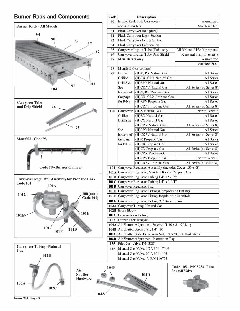
Carryover Tubeand Drip Shield
Carryover Regulator Assembly for Propane Gas -Code 101
Carryover Tubing - NaturalGas
AirShutterHardware
Burner Rack - All Models
Burner Rack and Components
Manifold - Code 98
Code 99 - Burner Orifices
Code 105 - P/N 3284, PilotShutoff Valve
9490 93
92
10395104
96
95
97
101A
101B
101C 101D
101E
101F
101G 100 (not inCode 101)
102A
102B
102C
104A
104B
104D
Code Description90 Burner Rack with Carryovers Aluminized
and Air Shutters Stainless Steel91 Flash Carryover (one piece)92 Flash Carryover Right Section93 Flash Carryover Center Section94 Flash Carryover Left Section95 Carryover Lighter Tube (Tube only) All RX and RPV; X propane;96 Carryover Lighter Tube Drip Shield X natural prior to Series 897 Main Burner only Aluminized
Stainless Steel98 Manifold (less orifices)99 Burner (H)X, RX Natural Gas All Series
Orifice (H)CX, CRX Natural Gas All SeriesDrill Size (H)RPV Natural Gas All SeriesSee (H)CRPV Natural Gas All Series (no Series 8)bottom of (H)X, RX Propane Gas All Seriesthe page (H)CX, CRX Propane Gas All Seriesfor P/N's. (H)RPV Propane Gas All Series
(H)CRPV Propane Gas All Series (no Series 8)100 Carryover (H)X Natural Gas Prior to Series 8
Orifice (H)RX Natural Gas All SeriesDrill Size (H)CX Natural Gas All Series
(H)CRX Natural Gas All Series (no Series 8)See (H)RPV Natural Gas All Seriesbottom of (H)CRPV Natural Gas All Series (no Series 8)the page (H)X Propane Gas All Seriesfor P/N's. (H)RX Propane Gas All Series
(H)CX Propane Gas All Series (no Series 8)(H)CRX Propane Gas All Series(H)RPV Propane Gas Prior to Series 8(H)CRPV Propane Gas All Series (no Series 8)
101 Carryover Regulator Assembly (includes Codes 133A-G)101A Carryover Regulator, Maxitrol RV-12, Propane Gas101B Carryover Regulator Tubing 1/4" x 5-1/2"101C Carryover Regulator Tubing 1/4" x 1-1/4"101D Carryover Regulator Tag101E Carryover Regulator Fitting (Compression Fitting)101F Carryover Regulator Fitting, Regulator to Manifold
101G Carryover Regulator Fitting, 90o Brass Elbow102A Carryover Tubing, Natural Gas 102B Brass Elbow102C Compression Fitting103 Burner Rack Isinglass
104A Air Shutter Adjustment Screw, 1/4-20 x 2-1/2" long104B Air Shutter Screw Nut, 1/4" -20104C Air Shutter Slide Tinnerman Nut, 1/4"-20 (not illustrated)104D Air Shutter Adjustment Instruction Tag135 Pilot Gas Valve, P/N 3284
136 Manual Gas Valve, 1/2", P/N 17019
Manual Gas Valve, 3/4", P/N 1105
Manual Gas Valve,1", P/N 110755

Form 705, Page 9
Code 106 -Shutoff Valves
Code 75 100 125 150 175 200 225 250 300 D300 350 40090 65971 65972 65973 65974 65974 65975 65975 65976 65976 65978 65977 65978
65979 65980 65981 65982 65982 65983 65983 65984 65984 65986 65985 6598691 63128 63128 63131 63131 63138 -- -- -- -- -- -- --92 -- -- -- -- -- 63148 63148 63141 63141 63152 63148 6315293 -- -- -- -- -- -- -- 63156 63156 68071 68071 6807194 63144 63144 63144 63144 63144 63144 6314495 9899 9899 9859 9821 9821 9783 9783 9747 9747 9520 9711 952096 15015 15015 15014 15013 15013 15012 15012 15011 15011 14957 15010 1495797 85218(4) 85218(4) 85218(5) 85218(7) 85218(7) 85218(9) 85218(9) 85218(12) 85218(12) 85218(16) 85218(14) 85218(16)
87954(4) 87954(4) 87954(5) 87954(7) 87954(7) 87954(9) 87954(9) 87954(12) 87954(12) 87954(16) 87954(14) 87954(16)98 86338 86338 86339 86340 86340 86342 86342 86343 86343 86345 86344 8634599 45 41 41 43 41 43 41 44 41 45 41 41
45 43 43 -- 43 -- 43 45 43 43 43-- -- 42 44 42 43 42 44 42 42 42 42-- -- 43 -- 43 -- 43 45 43 43 43
1.20mm 1.45mm 1.45mm 55 1.45mm 55 1.45mm 55 1.45mm 1.20mm 1.45mm 1.45mm1.20mm 55 55 -- 55 55 55 1.20mm 55 55 55 55
-- -- 1.45mm 55 1.45mm 55 1.45mm 55 1.45mm 1.45mm 1.50mm 1.45mm-- -- 55 55 55 55 1.20mm 55 55 -- 55
100 70 70 70 65 65 59 59 59 59 -- 54 5470 70 70 65 65 59 59 59 59 -- 54 5470 70 70 65 65 59 59 59 59 -- 54 5470 70 70 65 65 59 59 59 59 -- 54 54-- -- 65 65 65 65 65 59 59 -- 54 52-- -- 66 66 66 66 65 59 59 -- 54 5270 70 70 65 65 65 65 59 56 56 56 5670 70 70 65 65 65 65 59 56 56 56 5670 70 70 65 65 65 65 59 56 56 56 5670 70 70 65 65 65 65 59 56 56 56 56-- -- 70 65 65 65 65 59 59 59 57 56
70 65 65 65 65 59 59 59 57 56101 100712 100712 100712 100712 100712 100712 100712 100712 100712 100712 100712 100712
101A 11294 11294 11294 11294 11294 11294 11294 11294 11294 11294 11294 11294101B 9681 9681 9681 9681 9681 9681 9681 9681 9681 9681 9681 9681101C 11892 11892 11892 11892 11892 11892 11892 11892 11892 11892 11892 11892101D 11935 11935 11935 11935 11935 11935 11935 11935 11935 11935 11935 11935101E 9664 9664 9664 9664 9664 9664 9664 9664 9664 9664 9664 9664101F 1436 1436 1436 1436 1436 1436 1436 1436 1436 1436 1436 1436101G 18224(2) 18224(2) 18224(2) 18224(2) 18224(2) 18224(2) 18224(2) 18224(2) 18224(2) 18224(2) 18224(2) 18224(2)102A 93389 93389 93389 93389 93389 93389 93389 93389 93389 93389 93389 93389102B 93388 93388 93388 93388 93388 93388 93388 93388 93388 93388 93388 93388102C 9664 9664 9664 9664 9664 9664 9664 9664 9664 9664 9664 9664103 10756(2) 10756(2) 10756(2) 10756(2) 10756(2) 10756(2) 10756(2) 10756(2) 10756(2) 10756(2) 10756(2) 10756(2)
104A 10653 10653 10653 10653 10653 10653 10653 10653 10653 10653 10653 10653104B 10650(2) 10650(2) 10650(2) 10650(2) 10650(2) 10650(2) 10650(2) 10650(2) 10650(2) 10650(2) 10650(2) 10650(2)104C 10651 10651 10651 10651 10651 10651 10651 10651 10651 10651 10651 10651104D 11934 11934 11934 11934 11934 11934 11934 11934 11934 11934 11934 11934
Main Burner Orifice Drill Size to P/N - see Code 99Size 41 42 43 44 45 55 1.20MM 1.45MM 1.50MMP/N 11792 84437 11828 11833 38678 11830 63003 61652 93410
Carryover Orifice Drill Size to P/N - see Code 100Size 70 65 59 57 56 54P/N 9870 9680 10370 38274 9791 9792
P/N 17019,1/2" Shutoff Valve(with union, P/N 15971)
P/N 1105, 3/4" ShutoffValve (with union P/N 15972)
P/N 110755, 1" Shutoff
Reference: For replacement electric gas valve, seeForm RGM 714.

Form 705, Page 10
Heat Exchanger and ComponentsHeat Exchanger Directional Air BafflesModels X, CX, RX, CRX, RPV, CRPV Series 5, 6, 7 and 8 andpackaged systems with these duct furnaces as components areequipped with a heat exchanger directional air baffle assembly as shownin the illustration on the left below.
When replacing a heat exchanger, check to see if the baffle assembly canbe salvaged. If the baffle assembly cannot be salvaged, it will be neces-sary to order the parts (Codes 108-113) in the quantities listed andassemble and install replacement baffles. (These parts must be orderedseparately and installed in the field. Baffles cannot be factory installed.)
Models HX, HCX, HRX, HCRX, HRPV, HCRPV Series 5, 6, 7, and8 and packaged systems with "H" or "HC" suffix are equippedwith only a rear top baffle support (Code 111) and a rear top baffle(Code 112) as shown in the lower left illustration. If these parts cannotbe salvaged, order and install replacements.
These parts must be ordered separately and installed in the field.
������
���
��
���� #����#( ��( ���
���
0 ��(
���
���
��
�� ����
0 ��(
���
���
��� �
Code 105 - HeatExchanger
Code 108-113DirectionalAir Baffles
Code Description Qty 75, 100 125 150, 175 200, 225 250, 300 350 D300, 400105 Heat X, CX - Aluminized Steel 1 9895 9855 9817 9779 9743 9707 9514
Exchanger X, CX - 409 Stainless Steel 1 19429 19430 19431 19432 19433 19434 19435X, CX - 321 Stainless Steel 1 19438 19439 19440 19441 19442 19443 19444
RX, CRX - Aluminized Steel 1 44301 44304 44307 44310 44313 44316 44319RX, CRX - 409 Stainless Steel 1 44302 44305 44308 44311 44314 44317 44320RX, CRX - 321 Stainless Steel 1 44303 44306 44309 44312 44315 44318 44321
RPV, CRPV - Aluminized Steel 1 -- 44304 44307 44310 44313 44316 44319RPV, CRPV - 409 Stainless Steel 1 -- 44305 44308 44311 44314 44317 44320RPV, CRPV - 321 Stainless Steel 1 -- 44306 44309 44312 44315 44318 44321
106 Burner Rack Slide Rail All Models Series 5, 6, 7, & 8 2 9897 9857 9819 9781 9745 9709 9517107 Burner Rack Back Brace All Models Series 5, 6, 7, & 8 1 9525 9525 9525 9525 9525 9525 9525108 Bracket for Bottom X, RX, RPV Series 5, 6, 7, and 8 1 55101 55101 55101 55101 55101 55101 55101
Baffle Support (2) (2) (2) (2) (4) (4) (4)109 Finger Baffle X, RX, RPV Series 5, 6, 7, and 8 45399 45399 45399 45399 45399 45399 45399
(3) (3) (6) (8) (11) (13) (15)110 Bottom Baffle Support X, RX, RPV Series 5, 6, 7, and 8 1 46478 46484 46489 46494 46499 46504 46509111 Rear Top Baffle Support All Models Series 5, 6, 7, & 8 1 55103 55104 55106 55108 55110 55112 55114112 Rear Top Baffle All Models Series 5, 6, 7, and 8 1 55228 55229 55231 55233 55235 55237 55239
Series 5W and 6W 1 55228 55228 -- -- -- -- --113 Side Finger Baffle X, RX, RPV Series 5, 6, 7, and 8 2 55128 55128 55128 55128 55128 55128 55128114 Heat Exchanger Series 8 - All Models 85727 85727 85727 85727 85727 85727 85727
Tube Baffles (4) (4) (7) (9) (12) (14) (16)("V" Type Baffles) Prior to Series 8 - "C" 85727 85727 85727 85727 85727 85727 85727
Models Only (4) (4) (7) (9) (12) (14) (16)
Form 705, Page 11
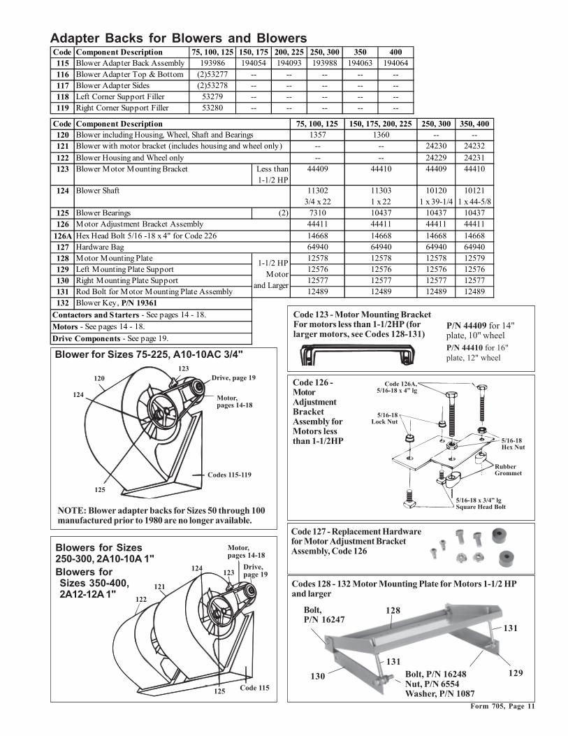
Adapter Backs for Blowers and Blowers
���
���
������
9 �3�����1���
+��� ���1�(���'�
��"�(����'��
���
���
��� ��"�����
��� ���
+��� ���1�(���'�
9 �3����1���
Blower for Sizes 75-225, A10-10AC 3/4"
Blowers for Sizes250-300, 2A10-10A 1"Blowers forSizes 350-400,2A12-12A 1"
NOTE: Blower adapter backs for Sizes 50 through 100manufactured prior to 1980 are no longer available.
Code 123 - Motor Mounting BracketFor motors less than 1-1/2HP (forlarger motors, see Codes 128-131)
Code 127 - Replacement Hardwarefor Motor Adjustment BracketAssembly, Code 126
Code 126 -MotorAdjustmentBracketAssembly forMotors lessthan 1-1/2HP
Codes 128 - 132 Motor Mounting Plate for Motors 1-1/2 HPand larger
Bolt,P/N 16247
Bolt, P/N 16248Nut, P/N 6554Washer, P/N 1087
130 129
131
128
131
��"�����������'��8�����1
����'�;� $��!�
����'�<�8��!�
6!..� = �//��
����'��8�������10>!� ��<��"�:���
P/N 44409 for 14"plate, 10" wheelP/N 44410 for 16"plate, 12" wheel
Code Component Description 75, 100, 125 150, 175 200, 225 250, 300 350 400115 Blower Adapter Back Assembly 193986 194054 194093 193988 194063 194064
116 Blower Adapter Top & Bottom (2)53277 -- -- -- -- --117 Blower Adapter Sides (2)53278 -- -- -- -- --118 Left Corner Support Filler 53279 -- -- -- -- --119 Right Corner Support Filler 53280 -- -- -- -- --
Code Component Description 75, 100, 125 150, 175, 200, 225 250, 300 350, 400120 Blower including Housing, Wheel, Shaft and Bearings 1357 1360 -- --121 -- -- 24230 24232
122 Blower Housing and Wheel only -- -- 24229 24231123 Blower Motor Mounting Bracket Less than
1-1/2 HP 44409 44410 44409 44410
124 Blower Shaft 11302 11303 10120 101213/4 x 22 1 x 22 1 x 39-1/4 1 x 44-5/8
125 Blower Bearings (2) 7310 10437 10437 10437126 44411 44411 44411 44411
126A Hex Head Bolt 5/16 -18 x 4" for Code 226 14668 14668 14668 14668127 Hardware Bag 64940 64940 64940 64940128 Motor Mounting Plate 12578 12578 12578 12579129 Left Mounting Plate Support 12576 12576 12576 12576130 Right Mounting Plate Support 12577 12577 12577 12577131 Rod Bolt for Motor Mounting Plate Assembly 12489 12489 12489 12489132 Blower Key, P/N 19361
Contactors and Starters - See pages 14 - 18.
Motors - See pages 14 - 18.
Drive Components - See page 19.
Motor Adjustment Bracket Assembly
1-1/2 HP Motor
and Larger
Blower with motor bracket (includes housing and wheel only)

Form 705, Page 12
Optional Indoor Blower Cabinet - Models(C)XE, (C)HXE, and XJ
�� ����
���
������
���
���
���
���
���
���
�����
���
������
�����
��
&����
���
���
&����
&����
&����
Blower Cabinets - Indoor Models
Standard Indoor Blower Cabinet - BasicModels XE, XJ
������
���
��� ��
���
���
���
���
���
���
&���� &���� ��
��
���
���
�����
���
&����
&����
�� ����
Code Component Description Cabinet 75, 100, 125 150, 175 200, 225 250, 300 350 400149 Standard 12545 12546 12547 12548 12549 12550
Optional 17046 17055 17063 17066 17120 17123150 Hanger Assembly All 9557 9557 9557 9557 9557 9557151 Cabinet Top and Bottom Standard 11522 11529 11197 11564 11574 11583152 Cabinet Top Optional 11825 11842 11767 11856 11862 11777153 Blower Cabinet Door Standard 51041 51041 51042 51042 51042 51042
Optional 84221 84221 84222 84222 84222 84222154 Blower Cabinet End panel Optional 12075 12411 11540 12414 12029 11589155 Hanger Support All 10219 10219 10219 10219 10219 10219156 Filter Support All 19704 19710 19717 19723 19729 19736157 Intermediate Filter Stops All 19708 19715 19721 19727 19734 19742158 Filter Stops or Blockoffs - Top/Btm All -- 104086/104086 -- -- 19733/19733 19740/19741159 Cabinet Bottom Inlet Cap Optional 12513 12514 11538 12515 12516 11587160 Cabinet Bottom Left Side Optional 11203 11203 11203 11203 11203 11203161 Left Corner Support All 11517 11517 11210 11210 11210 11210162 Rear Bottom Section Optional 11526 11533 11392 11571 11580 11393163 Right Corner Leg All 11519 11519 19982 19982 19982 19982164 Cabinet Bottom Right Side Optional 11204 11204 11204 11204 11204 11204165 Insulation for End Panel Optional 51053 51054 12327 12328 26103 12329166 Insulation for Bottom Panel Optional 11155 11162 11167 11176 11180 11184167 Duct Connecting Angle Standard 11523 11530 11536 11567 11576 11584168 Hole Plug for Bottom Panel Standard 82413 82413 82413 82413 82413 82413169 Right Rear Corner Support Standard 11518 11518 11211 11211 11211 11211170 Filter Rack Assembly All 24501 24503 24505 24507 24509 24511171 (2) 20x20 (2) 20x25 (2) 16x20 (2) 20x20 (1) 20x20 (3) 16x25
(2) 16x25 (2) 20x25 (3) 20x25 (2) 20x25 1" disposable 16448 16446 16445 16448 16448 16447
16447 16446 16446 164462" disposable 104098 104100 104097 104098 104098 104099
104099 104100 104100 1041001" permanent 101608 101610 101607 101608 101608 101609
101609 101610 101610 1016012" permanent 101621 101623 101620 101621 101621 101622
101622 101623 101623 1016231" pleated 104106 104108 104105 104106 104106 104107
104107 104108 104108 1041082" pleated 104111 104113 104110 104111 104111 104112
104112 104113 104113 104113
Fltr Qty and Size
Replacement Filters - apply to std and opt indoor cabinets
P/N's
Complete Blower Cabinet (less filter rack and filters)
���������������������������������������������������������������������
���������������������������������������������������������������������
���������������������������������������������������������������������
���������������������������������������������������������������������
���������������������������������������������������������������������
���������������������������������������������������������������������
Blower cabinet for Models XC, XE and XJ manufactured prior toAugust 1975 are not available.
Form 705, Page 13
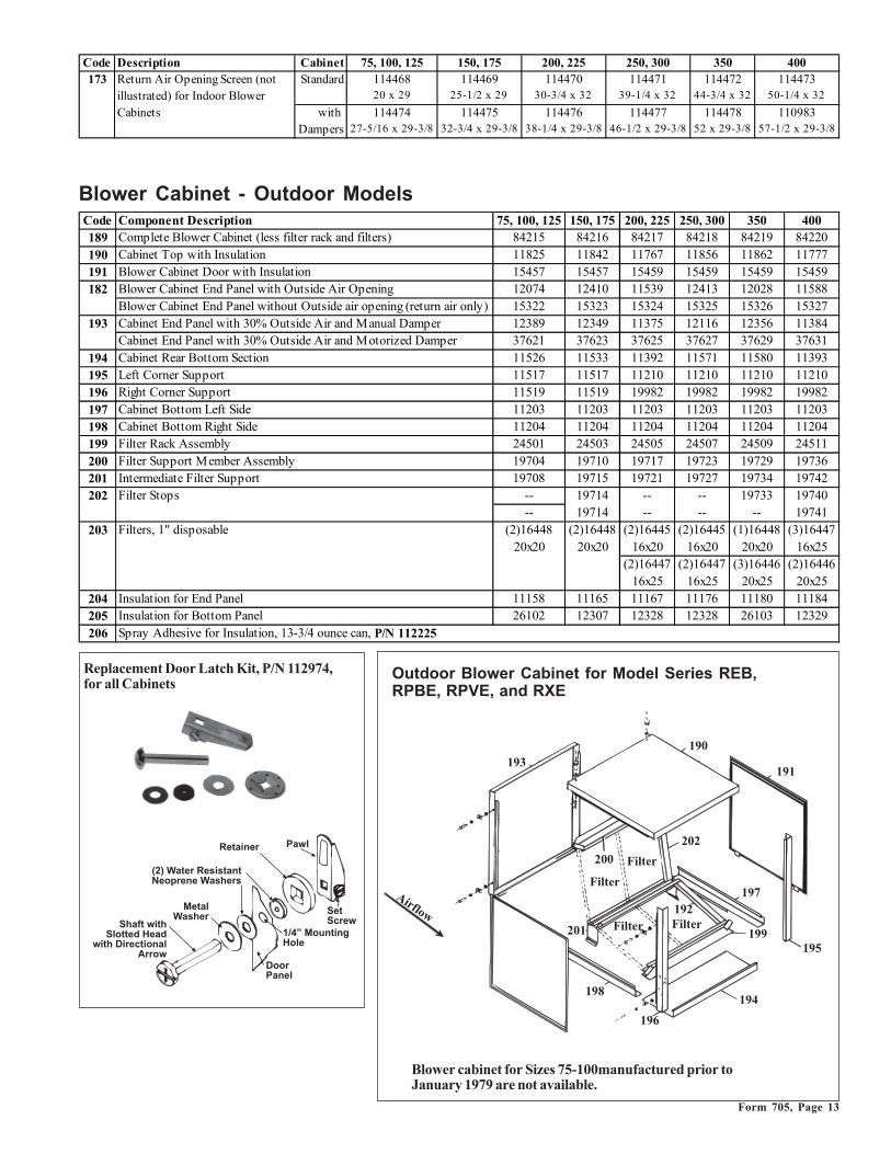
Blower Cabinet - Outdoor Models
����
��
������
��
��
��
���
��&����
&����
&����
&����
�
���
�� ����
Outdoor Blower Cabinet for Model Series REB,RPBE, RPVE, and RXE
Code Component Description 75, 100, 125 150, 175 200, 225 250, 300 350 400189 Complete Blower Cabinet (less filter rack and filters) 84215 84216 84217 84218 84219 84220190 Cabinet Top with Insulation 11825 11842 11767 11856 11862 11777191 Blower Cabinet Door with Insulation 15457 15457 15459 15459 15459 15459182 Blower Cabinet End Panel with Outside Air Opening 12074 12410 11539 12413 12028 11588
Blower Cabinet End Panel without Outside air opening (return air only) 15322 15323 15324 15325 15326 15327193 Cabinet End Panel with 30% Outside Air and Manual Damper 12389 12349 11375 12116 12356 11384
Cabinet End Panel with 30% Outside Air and Motorized Damper 37621 37623 37625 37627 37629 37631194 Cabinet Rear Bottom Section 11526 11533 11392 11571 11580 11393195 Left Corner Support 11517 11517 11210 11210 11210 11210196 Right Corner Support 11519 11519 19982 19982 19982 19982197 Cabinet Bottom Left Side 11203 11203 11203 11203 11203 11203198 Cabinet Bottom Right Side 11204 11204 11204 11204 11204 11204199 Filter Rack Assembly 24501 24503 24505 24507 24509 24511200 Filter Support Member Assembly 19704 19710 19717 19723 19729 19736201 Intermediate Filter Support 19708 19715 19721 19727 19734 19742202 Filter Stops -- 19714 -- -- 19733 19740
-- 19714 -- -- -- 19741203 Filters, 1" disposable (2)16448 (2)16448 (2)16445 (2)16445 (1)16448 (3)16447
20x20 20x20 16x20 16x20 20x20 16x25(2)16447 (2)16447 (3)16446 (2)16446
16x25 16x25 20x25 20x25204 Insulation for End Panel 11158 11165 11167 11176 11180 11184205 Insulation for Bottom Panel 26102 12307 12328 12328 26103 12329206 Spray Adhesive for Insulation, 13-3/4 ounce can, P/N 112225
Code Description Cabinet 75, 100, 125 150, 175 200, 225 250, 300 350 400173 Standard 114468 114469 114470 114471 114472 114473
20 x 29 25-1/2 x 29 30-3/4 x 32 39-1/4 x 32 44-3/4 x 32 50-1/4 x 32
with 114474 114475 114476 114477 114478 110983Dampers 27-5/16 x 29-3/8 32-3/4 x 29-3/8 38-1/4 x 29-3/8 46-1/2 x 29-3/8 52 x 29-3/8 57-1/2 x 29-3/8
Return Air Opening Screen (not illustrated) for Indoor Blower Cabinets
������������������� �����������
����
�������
��� �! "���#$ ��
% �����
!���������
����������� ���&�$��&
����%��� ���� �
������
Replacement Door Latch Kit, P/N 112974,for all Cabinets
Blower cabinet for Sizes 75-100manufactured prior toJanuary 1979 are not available.

Form 705, Page 14
Replacement NEMA Starters and ContactorsAll systems in this book manufactured prior to 9/91 were equipped with aNEMA motor starter or contactor.
Replacement Motors and Starters
IEC AdjustableOverload
IEC Starter(Contactor)
IEC Starter (contactor) and overload are mounted onrail, P/N 111387
Replacement motor contactor, #425CXX-11,is P/N 122376 with 24 volt coil for 115, 208,230, or 460 supply voltage. Motors in thetables that are not highlighted have either a mo-tor contactor or an optional starter.
NEMA Motor StartersP/N Size Type Coil Voltage39919 0 Open 24 Volt37953 0 Enclosed 200/208 Volt37954 0 Enclosed 230 Volt37955 0 Enclosed 460 volt39920 1 Open 24 Volt39921 2 Open 24 Volt39922 3 Open 24 VoltHolding Coils for NEMA StartersP/N Size Coil Voltage48531 0/1 24 Volt48507 0/1 115 Volt48509 0/1 208 Volt73795 0/1 230 Volt48512 0/1 460 Volt73601 0/1 575 Volt95093 3 24 Volt
Auxiliary Contact for NEMA StartersP/N Starter Size
38088 0, 1, 2 Normally OpenContact
Motor ContactorP/N Voltage Coil Voltage
Contactor mounted in Boxwith Cover95527 115V 115 Volt
95528 230V 230 Volt
95526 460V 24 Volt
Contactor only (less case)
93662 115 115 Volt
93663 230 230 Volt
122376 115,208 24 Volt230,460
Replacement Holding Coils for IEC StartersReznor For Use with Contactors
Voltage GE # P/N Beginning with GE#
24 LB1A-C 151280 CL00; CL01; CL02; CL25
120 LB1A-J 151281 CL00; CL01; CL02; CL25
208 LB1A-L 151282 CL00; CL01; CL02; CL25
230 LB1A-S 151283 CL00; CL01; CL02; CL25
460 LB1A-U 151284 CL00; CL01; CL02; CL25
575 LB1A-Y 151285 CL00; CL01; CL02; CL25
24 LB3A-C 151286 CL04; CL45
120 LB3A-J 151287 CL04; CL45
Reznor For Use with ContactorsVoltage GE # P/N Beginning with GE#
208 LB3A-L 151288 CL04; CL45
230 LB3A-S 151289 CL04; CL45
460 LB3A-U 151290 CL04; CL45
575 LB3A-Y 151291 CL04; CL45
208 LB4A-L 151292 CL06; CL07; CL08; CL09
230 LB4A-S 151293 CL06; CL07; CL08; CL09
460 LB4A-U 151294 CL06; CL07; CL08; CL09
Replacement IEC Starters and Overloads (P/N's are listed inthe motor tables) - When ordering a replacement IEC starter(contactor) or overload, check the manufacturer's number onboth parts. If the number is different than that listed, both com-ponents must be replaced.Motors that are highlighted in gray in the motor tables do nothave internal overload protection and must be used with the IECmotor starter and overload listed in the table.
If the motor has a NEMA starter, see the replacement parts onthe right.
Motors and Starters for Model XE (for rooftop models, see page 16; for other models, see page 18)Motors that are highlighted in gray do not have internal overload protection and must be used with the motor starter and overload listed.
Motor Reznor Replaces Contactor Reznor O verload ReznorType HP Mfr FLA Mfr No. P/N P/N V ph GE # P/N GE # Min Max P/N
O PEN 1/4 A.O.Smith 5.1 316P260 93545 120 1 CL00A310T -1 151275 RTA1-L 4.00 6.30 151191O PEN 1/4 A.O.Smith 2.1 325P163 115790 85087 208 1 CL00A310T -1 151275 RTA1-J 1.90 2.70 151189O PEN 1/4 A.O.Smith 2.3 325P163 115790 85087 240 1 CL00A310T -1 151275 RTA1-J 1.90 2.70 151189O PEN 1/4 Century 1.1 H200 115864 208 3 CL00A310T -1 151275 RTA1-G 1.00 1.50 151187O PEN 1/4 Century 1.4 H200 115864 240 3 CL00A310T -1 151275 RTA1-G 1.00 1.50 151187
O PEN 1/4 Century 0.75 H200 115864 480 3 CL00A310T -1 151275 RTA1-F 0.65 1.10 151186O PEN 1/3 A.O.Smith 5.5 316P308 93546 120 1 CL00A310T -1 151275 RTA1-L 4.00 6.30 151191O PEN 1/3 Century 3.2 F153 115862 7802 208 1 CL00A310T -1 151275 RTA1-K 2.50 4.10 151190O PEN 1/3 Century 2.8 F153 115862 7802 240 1 CL00A310T -1 151275 RTA1-K 2.50 4.10 151190O PEN 1/3 Century 1.4 H260 115863 208 3 CL00A310T -1 151275 RTA1-G 1.00 1.50 151187O PEN 1/3 Century 1.6 H260 115863 240 3 CL00A310T -1 151275 RTA1-H 1.30 1.90 151188
O PEN 1/3 Century 0.8 H260 115863 480 3 CL00A310T -1 151275 RTA1-F 0.65 1.10 151186O PEN 1/2 Century 8.8 327P828 102627 120 1 CL00A310T -1 151275 RTA1-N 8.00 12.00 151193O PEN 1/2 A.O.Smith 5.1 327P828 102627 208 1 CL00A310T -1 151275 RTA1-L 4.00 6.30 151191O PEN 1/2 A.O.Smith 4.4 327P828 102627 240 1 CL00A310T -1 151275 RTA1-L 4.00 6.30 151191O PEN 1/2 Century 2.1 H880 159183 13443 208 3 CL00A310T -1 151275 RTA1-J 1.90 2.70 151189O PEN 1/2 Century 2 H880 159183 13443 240 3 CL00A310T -1 151275 RTA1-K 1.90 2.70 151190
O PEN 1/2 Century 1 H880 159183 13443 480 3 CL00A310T -1 151275 RTA1-H 0.65 1.10 151188O PEN 3/4 A.O.Smith 11 312P629 93548 120 1 CL01A310T -1 151276 RTA1-P 10.00 16.00 151194O PEN 3/4 A.O.Smith 6.3 312P629 93548 208 1 CL00A310T -1 151275 RTA1-M 5.50 8.50 151192O PEN 3/4 A.O.Smith 5.5 312P629 93548 240 1 CL00A310T -1 151275 RTA1-L 4.00 6.30 151191

Form 705, Page 15
Motors and Starters for Model XE - cont'd (for rooftop models, see page 16; for other models, see page 18)Motors that are highlighted in gray do not have internal overload protection and must be used with the motor starter and overload listed.
Motor Reznor Replaces Contactor Reznor O verload ReznorType HP Mfr FLA Mfr No. P/N P/N V ph GE # P/N GE # Min Max P/N
O PEN 3/4 A.O.Smith 2.9 312P696 36951 208 3 CL00A310T-1 151275 RTA1-K 2.50 4.10 151190O PEN 3/4 A.O.Smith 2.6 312P696 36951 240 3 CL00A310T-1 151275 RTA1-K 2.50 4.10 151190
O PEN 3/4 A.O.Smith 1.3 312P696 36951 480 3 CL00A310T-1 151275 RTA1-G 1.00 1.50 151187O PEN 1 A.O.Smith 13 327P297 13685 120 1 CL01A310T-1 151276 RTA1-P 10.00 16.00 151194O PEN 1 A.O.Smith 7.5 327P297 13685 208 1 CL00A310T-1 151275 RTA1-M 5.50 8.50 151192O PEN 1 A.O.Smith 6.5 327P297 13685 240 1 CL00A310T-1 151275 RTA1-M 5.50 8.50 151192O PEN 1 A.O.Smith 3.7 312P703 36580 208 3 CL00A310T-1 151275 RTA1-K 2.50 4.10 151190O PEN 1 A.O.Smith 3.2 312P703 36580 240 3 CL00A310T-1 151275 RTA1-K 2.50 4.10 151190O PEN 1 A.O.Smith 1.6 312P703 36580 480 3 CL00A310T-1 151275 RTA1-H 1.30 1.90 151188
O PEN 1 Century 1.4 E101656 158175 105533 575 3 CL00A310T-1 151275 RTA1-G 1.00 1.50 151187O PEN 1.5 Century 15 C688 105527 120 1 CL02A310T-1 151277 RTA1-P 10.00 16.00 151194O PEN 1.5 A.O.Smith 8.3 311P763 4082 208 1 CL00A310T-1 151275 RTA1-N 8.00 12.00 151193O PEN 1.5 A.O.Smith 7.5 311P763 4082 240 1 CL00A310T-1 151275 RTA1-M 5.50 8.50 151192O PEN 1.5 Century 5.6 H884 115859 16081 208 3 CL00A310T-1 151275 RTA1-L 4.00 6.30 151191O PEN 1.5 Century 5 H884 115859 16081 240 3 CL00A310T-1 151275 RTA1-L 4.00 6.30 151191O PEN 1.5 Century 2.7 H884 115859 16081 480 3 CL00A310T-1 151275 RTA1-J 1.90 2.70 151189
O PEN 1.5 Century 2 E101657 158162 105534 575 3 CL00A310T-1 151275 RTA1-J 1.90 2.70 151189O PEN 2 Century 20.4 V102 105528 120 1 CL25A310T-1 151278 RTA1-T 17.50 22.00 151197O PEN 2 Century 10 V102 105528 208 1 CL00A310T-1 151275 RTA1-N 8.00 12.00 151193O PEN 2 Century 10.2 V102 105528 240 1 CL01A310T-1 151276 RTA1-P 10.00 16.00 151194O PEN 2 Century 7 H886 159327 13697 208 3 CL01A310T-1 151276 RTA1-M 5.50 8.50 151192O PEN 2 Century 6.6 H886 159327 13697 240 3 CL01A310T-1 151276 RTA1-M 5.50 8.50 151192O PEN 2 Century 3.3 H886 159327 13697 480 3 CL01A310T-1 151276 RTA1-K 2.50 4.10 151190
O PEN 2 Century 2.4 E101658 158176 105535 575 3 CL01A310T-1 151276 RTA1-J 1.90 2.70 151189O PEN 3 Century 9.1 H845 159185 31693 208 3 CL01A310T-1 151276 RTA1-N 8.00 12.00 151193O PEN 3 Century 8.4 H845 159185 31692 240 3 CL01A310T-1 151276 RTA1-N 8.00 12.00 151193O PEN 3 Century 4.2 H845 159185 31692 480 3 CL01A310T-1 151276 RTA1-L 4.00 6.30 151191
O PEN 3 Century 3.6 181532-01 120019 575 3 CL01A310T-1 151276 RTA1-K 2.50 4.10 151190O PEN 5 Century 13.4 181159-01 113371 85748 208 3 CL01A310T-1 151276 RTA1-P 10.00 16.00 151194O PEN 5 Century 13.2 8-181159-01 113371 85748 240 3 CL01A310T-1 151276 RTA1-P 10.00 16.00 151194O PEN 5 Century 6.6 8-181159-01 113371 85748 480 3 CL01A310T-1 151276 RTA1-M 5.50 8.50 151192
O PEN 5 Century 5.4 8-181533-01 120020 105829 575 3 CL01A310T-1 151276 RTA1-L 4.00 6.30 151191
Motor Reznor Replaces Contactor Reznor O verload ReznorType HP Mfr FLA Mfr No. P/N P/N V ph GE # P/N GE # Min Max P/NTEFC 1/4 Century 3.6 STOCK #904 105566 120 1 CL01A310T-1 151276 RTA1-K 2.50 4.10 151190TEFC 1/4 Century 2.2 108152 16074 208 1 CL01A310T-1 151276 RTA1-J 1.90 2.70 151189TEFC 1/4 Century 1.9 108152 16074 240 1 CL01A310T-1 151276 RTA1-H 1.30 1.90 151188TEFC 1/4 Century 1.6 125439 16075 208 3 CL01A310T-1 151276 RTA1-H 1.30 1.90 151188TEFC 1/4 Century 1.4 125439 16075 240 3 CL01A310T-1 151276 RTA1-G 1.00 1.50 151187
TEFC 1/4 Century 0.7 125439 16075 480 3 CL01A310T-1 151276 RTA1-F 0.65 1.10 151186TEFC 1/3 Century 4.6 E316 159331 120 1 CL01A310T-1 151276 RTA1-L 4.00 6.30 151191TEFC 1/3 Century 2.3 E317 159332 208 1 CL01A310T-1 151276 RTA1-J 1.90 2.70 151189TEFC 1/3 Century 2.4 E317 159332 240 1 CL01A310T-1 151276 RTA1-J 1.90 2.70 151189TEFC 1/3 Century 1.2 E324 158164 208 3 CL01A310T-1 151276 RTA1-G 1.00 1.50 151187TEFC 1/3 Century 1.2 H261 105567 240 3 CL01A310T-1 151276 RTA1-G 1.00 1.50 151187
TEFC 1/3 Century 0.6 H261 105567 480 3 CL01A310T-1 151276 RTA1-D 0.40 0.65 151184TEFC 1/2 Century 7 E318 159333 120 1 CL01A310T-1 151276 RTA1-M 5.50 8.50 151192TEFC 1/2 Century 3.4 E319 159334 208 1 CL01A310T-1 151276 RTA1-K 2.50 4.10 151190TEFC 1/2 Century 3.5 E319 159334 240 1 CL01A310T-1 151276 RTA1-K 2.50 4.10 151190TEFC 1/2 Century 2.3 E325 158163 208 3 CL01A310T-1 151276 RTA1-J 1.90 2.70 151189TEFC 1/2 Century 2 119851 16077 240 3 CL01A310T-1 151276 RTA1-J 1.90 2.70 151189TEFC 1/2 Century 1 119851 16077 480 3 CL01A310T-1 151276 RTA1-F 0.65 1.10 151186
TEFC 1/2 Century 0.7 H276 105568 575 3 CL01A310T-1 151276 RTA1-F 0.65 1.10 151186TEFC 3/4 Century 11 F353 115860 120 1 CL01A310T-1 151276 RTA1-P 10.00 16.00 151194TEFC 3/4 Century 5.4 F353 115860 208 1 CL01A310T-1 151276 RTA1-L 4.00 6.30 151191TEFC 3/4 Century 5.5 F353 115860 240 1 CL01A310T-1 151276 RTA1-L 4.00 6.30 151191TEFC 3/4 Century 2 142198 20371 208 3 CL01A310T-1 151276 RTA1-J 1.90 2.70 151189TEFC 3/4 Century 2.2 142198 20371 240 3 CL01A310T-1 151276 RTA1-J 1.90 2.70 151189TEFC 3/4 Century 1.1 142198 20371 480 3 CL01A310T-1 151276 RTA1-F 0.65 1.10 151186
TEFC 3/4 Century 0.8 H461 105569 575 3 CL01A310T-1 151276 RTA1-F 0.65 1.10 151186

Form 705, Page 16
Motors and Starters for Model XE - cont'd (for rooftop models, see below; for other models, see page 18)Motors that are highlighted in gray do not have internal overload protection and must be used with the motor starter and overload listed.
Motors and Starters for Rooftop Models (for indoor Model XE, go to page 14; for other models, see page18)Motors that are highlighted in gray do not have internal overload protection and must be used with the motor starter and overload listed.
Motor Reznor Replaces Contactor Reznor O verload ReznorType HP Mfr FLA Mfr No. P/N P/N V ph GE # P/N GE # Min Max P/N
O PEN 1/4 A.O.Smith 5.1 316P260 93545 120 1 CL00A310T-J 151146 RTA1-L 4 6.3 151191O PEN 1/4 A.O.Smith 2.1 325P163 115790 85087 208 1 CL00A310T-L 151150 RTA1-J 1.9 2.7 151189O PEN 1/4 A.O.Smith 2.3 325P163 115790 85087 240 1 CL00A310T-S 151147 RTA1-J 1.9 2.7 151189O PEN 1/4 Century 1.1 H200 115864 208 3 CL00A310T-L 151150 RTA1-G 1 1.5 151187O PEN 1/4 Century 1.4 H200 115864 240 3 CL00A310T-S 151147 RTA1-G 1 1.5 151187
O PEN 1/4 Century 0.75 H200 115864 480 3 CL00A310T-U 151148 RTA1-F 0.6 1.1 151186O PEN 1/3 A.O.Smith 5.5 316P308 93546 120 1 CL00A310T-J 151146 RTA1-L 4 6.3 151191O PEN 1/3 Century 3.2 F153 115862 7802 208 1 CL00A310T-L 151150 RTA1-K 2.5 4 151190O PEN 1/3 Century 2.8 F153 115862 7802 240 1 CL00A310T-S 151147 RTA1-K 2.5 4 151190O PEN 1/3 Century 1.4 H260 115863 208 3 CL00A310T-L 151150 RTA1-G 1 1.5 151187O PEN 1/3 Century 1.6 H260 115863 240 3 CL00A310T-S 151147 RTA1-H 1.3 1.9 151188
O PEN 1/3 Century 0.8 H260 115863 480 3 CL00A310T-U 151148 RTA1-F 0.6 1.1 151186O PEN 1/2 Century 8.8 327P828 102627 120 1 CL00A310T-J 151146 RTA1-N 7 10 151193O PEN 1/2 A.O.Smith 5.1 327P828 102627 208 1 CL00A310T-L 151150 RTA1-L 4 6.3 151191O PEN 1/2 A.O.Smith 4.4 327P828 102627 240 1 CL00A310T-S 151147 RTA1-L 4 6.3 151191O PEN 1/2 Century 3 H880 159183 13443 208 3 CL00A310T-L 151150 RTA1-K 2.5 4 151190O PEN 1/2 Century 2.5 H880 159183 13443 240 3 CL00A310T-S 151147 RTA1-K 2.5 4 151190
O PEN 1/2 Century 1 H880 159183 13443 480 3 CL00A310T-U 151148 RTA1-G 1 1.5 151187
O PEN 3/4 A.O.Smith 11 312P629 93548 120 1 CL01A310T-J 151151 RTA1-P 10 16 151194O PEN 3/4 A.O.Smith 6.3 312P629 93548 208 1 CL00A310T-L 151150 RTA1-M 5.5 7.5 151192O PEN 3/4 A.O.Smith 5.5 312P629 93548 240 1 CL00A310T-S 151147 RTA1-L 4 6.3 151191O PEN 3/4 A.O.Smith 2.9 312P696 36951 208 3 CL00A310T-L 151150 RTA1-K 2.5 4 151190O PEN 3/4 A.O.Smith 2.6 312P696 36951 240 3 CL00A310T-S 151147 RTA1-K 2.5 4 151190
O PEN 3/4 A.O.Smith 1.3 312P696 36951 480 3 CL00A310T-U 151148 RTA1-G 1 1.5 151187
O PEN 1 A.O.Smith 13 327P297 13685 120 1 CL01A310T-J 151151 RTA1-P 10 16 151194O PEN 1 A.O.Smith 7.5 327P297 13685 208 1 CL00A310T-L 151150 RTA1-M 5.5 7.5 151192O PEN 1 A.O.Smith 6.5 327P297 13685 240 1 CL00A310T-S 151147 RTA1-M 5.5 7.5 151192O PEN 1 A.O.Smith 3.7 312P703 36580 208 3 CL00A310T-L 151150 RTA1-K 2.5 4 151190O PEN 1 A.O.Smith 3.2 312P703 36580 240 3 CL00A310T-S 151147 RTA1-K 2.5 4 151190O PEN 1 A.O.Smith 1.6 312P703 36580 480 3 CL00A310T-U 151148 RTA1-H 1.3 1.9 151188
O PEN 1 Century 1.1 E1006 158175 105533 575 3 CL00A310T-Y 151149 RTA1-G 1 1.5 151187
Motor Reznor Replaces Contactor Reznor O verload ReznorType HP Mfr FLA Mfr No. P/N P/N V ph GE # P/N GE # Min Max P/NTEFC 1 Century 12 159105 174993 120 1 CL01A310T-1 151276 RTA1-P 10.00 16.00 151194TEFC 1 Century 6.2 159105 174993 208 1 CL00A310T-1 151275 RTA1-M 5.50 8.50 151192TEFC 1 Century 6 159105 174993 240 1 CL00A310T-1 151275 RTA1-M 5.50 8.50 151192TEFC 1 Century 3.3 8-159223-01 16080 208 3 CL00A310T-1 151275 RTA1-K 2.50 4.10 151190TEFC 1 Century 3.4 8-159223-01 16080 240 3 CL00A310T-1 151275 RTA1-K 2.50 4.10 151190TEFC 1 Century 1.7 8-159223-01 16080 480 3 CL00A310T-1 151275 RTA1-H 1.30 1.90 151188
TEFC 1 Century 1.4 H525 105570 575 3 CL00A310T-1 151275 RTA1-G 1.00 1.50 151187TEFC 1 1/2 A.O.Smith 16.4 311P402 94347 120 1 CL02A310T-1 151277 RTA1-S 14.50 18.00 151196TEFC 1 1/2 A.O.Smith 9.5 311P402 94347 208 1 CL00A310T-1 151275 RTA1-N 8.00 12.00 151193TEFC 1 1/2 A.O.Smith 8.2 311P402 94347 240 1 CL00A310T-1 151275 RTA1-N 8.00 12.00 151193TEFC 1 1/2 Century 4.3 362272 101286 208 3 CL00A310T-1 151275 RTA1-L 4.00 6.30 151191TEFC 1 1/2 Century 4.4 362272 101286 240 3 CL00A310T-1 151275 RTA1-L 4.00 6.30 151191TEFC 1 1/2 Century 2.2 362272 101286 480 3 CL00A310T-1 151275 RTA1-J 1.90 2.70 151189
TEFC 1 1/2 Century 1.8 E127 105665 575 3 CL00A310T-1 151275 RTA1-H 1.30 1.90 151188TEFC 2 Century 24 K200 105572 120 1 CL04A310M-1 151279 RTA1-U 21.00 26.00 151198TEFC 2 Century 12 K200 105572 240 1 CL01A310T-1 151276 RTA1-P 10.00 16.00 151194TEFC 2 Century 6.5 E166 158165 208 3 CL00A310T-1 151275 RTA1-M 5.50 8.50 151192TEFC 2 Century 5.6 E166 158165 240 3 CL00A310T-1 151275 RTA1-L 4.00 6.30 151191TEFC 2 Century 2.8 E166 158165 480 3 CL00A310T-1 151275 RTA1-K 2.50 4.10 151190
TEFC 2 Century 2.2 E169 158166 575 3 CL00A310T-1 151275 RTA1-J 1.90 2.70 151189TEFC 3 Century 8.5 M3559T 159330 208 3 CL00A310T-1 151275 RTA1-N 8.00 12.00 151193TEFC 3 Century 8.2 M3559T 159330 240 3 CL00A310T-1 151275 RTA1-N 8.00 12.00 151193TEFC 3 Century 4.1 M3559T 159330 480 3 CL00A310T-1 151275 RTA1-L 4.00 6.30 151191TEFC 3 Century 3.1 E272 158168 575 3 CL00A310T-1 151275 RTA1-K 2.50 4.10 151190

Form 705, Page 17
Motor Reznor Replaces Contactor Reznor Overload ReznorType HP Mfr FLA Mfr No. P/N P/N V ph GE # P/N GE # Min Max P/N
OPEN 1.5 Century 15 C688 105527 120 1 CL02A310T-J 151156 RTA1-P 10 16 151194OPEN 1.5 A.O.Smith 8.3 311P763 4082 208 1 CL00A310T-L 151150 RTA1-N 7 10 151193OPEN 1.5 A.O.Smith 7.5 311P763 4082 240 1 CL00A310T-S 151147 RTA1-M 5.5 7.5 151192OPEN 1.5 Century 5.6 H884 115859 16081 208 3 CL00A310T-L 151150 RTA1-L 4 6.3 151191OPEN 1.5 Century 5 H884 115859 16081 240 3 CL00A310T-S 151147 RTA1-L 4 6.3 151191OPEN 1.5 Century 2.7 H884 115859 16081 480 3 CL00A310T-U 151148 RTA1-J 1.9 2.7 151189
OPEN 1.5 Century 1.6 E1007 158162 105534 575 3 CL00A310T-Y 151149 RTA1-H 1.3 1.9 151188OPEN 2 Century 20.4 V102 105528 120 1 CL25A310T-J 151160 RTA1-T 17.5 22 151197OPEN 2 Century 10 V102 105528 208 1 CL01A310T-L 151155 RTA1-N 7 10 151193OPEN 2 Century 10.2 V102 105528 240 1 CL01A310T-S 151152 RTA1-P 10 16 151194OPEN 2 Century 7 H886 159327 13697 208 3 CL00A310T-L 151150 RTA1-M 5.5 7.5 151192OPEN 2 Century 6.6 H886 159327 13697 240 3 CL00A310T-S 151147 RTA1-M 5.5 7.5 151192OPEN 2 Century 3.5 H886 159327 13697 480 3 CL00A310T-U 151148 RTA1-K 2.5 4 151190
OPEN 2 Century 2.1 E1008 158176 105535 575 3 CL00A310T-Y 151149 RTA1-J 1.9 2.7 151189OPEN 3 Century 14 B735 111560 31693 208 1 CL02A310T-L 151159 RTA1-P 10 16 151194OPEN 3 Century 12.4 B735 111560 31692 240 1 CL01A310T-S 151152 RTA1-P 10 16 151194OPEN 3 Century 9 H845 159185 31692 208 3 CL00A310T-L 151150 RTA1-N 7 10 151193OPEN 3 Century 8.6 H845 159185 240 3 CL00A310T-S 151147 RTA1-N 7 10 151193OPEN 3 Century 4.3 H845 159185 480 3 CL00A310T-U 151148 RTA1-L 4 6.3 151191
OPEN 3 Century 3.6 181532-01 120019 575 3 CL00A310T-Y 151149 RTA1-K 2.5 4 151190OPEN 5 Century 28 V211 111562 208 1 CL04A310M-L 151169 RTA1-V 25 32 151199OPEN 5 Century 26 V211 111562 111563 240 1 CL04A310M-S 151166 RTA1-V 25 32 151199OPEN 5 Century 13.4 181159-01 113371 85748 208 3 CL01A310T-L 151155 RTA1-P 10 16 151194OPEN 5 Century 13.2 8-181159-01 113371 85748 240 3 CL01A310T-S 151152 RTA1-P 10 16 151194OPEN 5 Century 6.6 8-181159-01 113371 85748 480 3 CL00A310T-U 151148 RTA1-M 5.5 7.5 151192
OPEN 5 Century 5.4 8-181533-01 120020 105829 575 3 CL00A310T-Y 151149 RTA1-L 4 6.3 151191
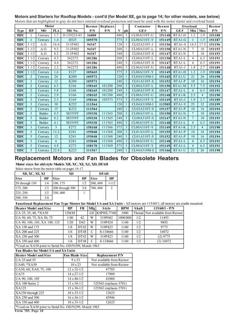
Motors and Starters for Rooftop Models - cont'd (for Model XE, go to page 14; for other models, see page 18)Motors that are highlighted in gray do not have internal overload protection and must be used with the motor starter and overload listed.
Reznor Replaces Contactor Reznor O verload ReznorType HP Mfr FLA Mfr No. P/N P/N V ph GE # P/N GE # Min Max P/NTEFC 1/4 Century 3.6 ST OCK #904 105566 120 1 CL00A310T -J 151146 RTA1-K 2.5 4 151190TEFC 1/4 Century 2.2 108152 16074 208 1 CL00A310T -L 151150 RTA1-J 1.9 2.7 151189TEFC 1/4 Century 1.9 108152 16074 240 1 CL00A310T -S 151147 RTA1-H 1.3 1.9 151188TEFC 1/4 Century 1.6 125439 16075 208 3 CL00A310T -L 151150 RTA1-H 1.3 1.9 151188TEFC 1/4 Century 1.4 125439 16075 240 3 CL00A310T -S 151147 RTA1-G 1 1.5 151187TEFC 1/4 Century 0.7 125439 16075 480 3 CL00A310T -U 151148 RTA1-F 0.6 1.1 151186TEFC 1/3 Century 4.6 ST OCK #906 115861 120 1 CL00A310T -J 151146 RTA1-L 4 6.3 151191TEFC 1/3 Century 2.3 C151 159501 102293 208 1 CL00A310T -L 151150 RTA1-J 1.8 2.7 151189TEFC 1/3 Century 2.4 C151 159501 102293 240 1 CL00A310T -S 151147 RTA1-J 1.8 2.7 151189TEFC 1/3 Century 1.2 H261 105567 208 3 CL00A310T -L 151150 RTA1-G 1 1.5 151187TEFC 1/3 Century 1.2 H261 105567 240 3 CL00A310T -S 151147 RTA1-G 1 1.5 151187TEFC 1/3 Century 0.6 H261 105567 480 3 CL00A310T -U 151148 RTA1-D 0.4 0.63 151184TEFC 1/2 Century 7.2 C613 159184 31273 120 1 CL00A310T -J 151146 RTA1-M 5.5 7.5 151192TEFC 1/2 Century 3.5 C613 159184 31273 208 1 CL00A310T -L 151150 RTA1-K 2.5 4 151190TEFC 1/2 Century 3.6 C613 159184 31273 240 1 CL00A310T -S 151147 RTA1-K 2.5 4 151190TEFC 1/2 Century 2.3 119851 16077 208 3 CL00A310T -L 151150 RTA1-J 1.9 2.7 151189TEFC 1/2 Century 2 119851 16077 240 3 CL00A310T -S 151147 RTA1-J 1.9 2.7 151189TEFC 1/2 Century 1 119851 16077 480 3 CL00A310T -U 151148 RTA1-F 0.6 1.1 151186TEFC 1/2 Century 0.7 H276 105568 575 3 CL00A310T -Y 151149 RTA1-F 0.63 0.9 151186TEFC 3/4 Century 11 F353 115860 120 1 CL01A310T -J 151151 RTA1-P 10 16 151194TEFC 3/4 Century 5.4 F353 115860 208 1 CL00A310T -L 151150 RTA1-L 4 6.3 151191TEFC 3/4 Century 5.5 F353 115860 240 1 CL00A310T -S 151147 RTA1-L 4 6.3 151191TEFC 3/4 Century 2 142198 20371 208 3 CL00A310T -L 151150 RTA1-J 1.9 2.7 151189TEFC 3/4 Century 2.2 142198 20371 240 3 CL00A310T -S 151147 RTA1-J 1.9 2.7 151189TEFC 3/4 Century 1.1 142198 20371 480 3 CL00A310T -U 151148 RTA1-F 0.6 1.1 151186TEFC 3/4 Century 0.8 H461 105569 575 3 CL00A310T -Y 151149 RTA1-F 0.6 1.1 151186TEFC 1 Century 12 159105 174993 43270 120 1 CL01A310T -J 151151 RTA1-P 10 16 151194TEFC 1 Century 6.2 159105 174993 208 1 CL00A310T -S 151147 RTA1-M 5.5 7.5 151192TEFC 1 Century 6 159105 174993 43270 240 1 CL00A310T -S 151147 RTA1-M 5.5 7.5 151192TEFC 1 Century 3.3 8-159223-01 16080 208 3 CL00A310T -L 151150 RTA1-K 2.5 4 151190TEFC 1 Century 3.4 8-159223-01 16080 240 3 CL00A310T -S 151147 RTA1-K 2.5 4 151190
Motor
Form 705, Page 18
Reznor Replaces Contactor Reznor Overload ReznorType HP Mfr FLA Mfr No. P/N P/N V ph GE # P/N GE # Min Max P/NTEFC 1 Century 1.7 8-159223-01 16080 480 3 CL00A310T-U 151148 RTA1-H 1.3 1.9 151188TEFC 1 Century 1.4 H525 105570 575 3 CL00A310T-Y 151149 RTA1-G 1 1.5 151187TEFC 1 1/2 A.O. 16.4 311P402 94347 120 1 CL02A310T-J 151156 RTA1-S 14.5 17.5 151196TEFC 1 1/2 A.O. 9.5 311P402 94347 208 1 CL00A310T-L 151150 RTA1-N 7 10 151193TEFC 1 1/2 A.O. 8.2 311P402 94347 240 1 CL00A310T-S 151147 RTA1-N 7 10 151193TEFC 1 1/2 Century 4.3 362272 101286 208 3 CL00A310T-L 151150 RTA1-L 4 6.3 151191TEFC 1 1/2 Century 4.4 362272 101286 240 3 CL00A310T-S 151147 RTA1-L 4 6.3 151191TEFC 1 1/2 Century 2.2 362272 101286 480 3 CL00A310T-U 151148 RTA1-J 1.9 2.7 151189TEFC 1 1/2 Century 1.6 E127 105665 575 3 CL00A310T-Y 151149 RTA1-H 1.3 1.9 151188TEFC 2 Century 24 K200 105572 120 1 CL04A310M-J 151165 RTA1-U 21 26 151198TEFC 2 Century 12 K200 105572 240 1 CL01A310T-S 151152 RTA1-P 10 16 151194TEFC 2 Century 6.5 E166 158165 101288 208 3 CL00A310T-L 151150 RTA1-M 5.5 7.5 151192TEFC 2 Century 5.8 E166 158165 101288 240 3 CL00A310T-S 151147 RTA1-L 4 6.3 151191TEFC 2 Century 2.9 E166 158165 101288 480 3 CL00A310T-U 151148 RTA1-K 2.5 4 151190TEFC 2 Century 2.3 E169 158166 105573 575 3 CL00A310T-Y 151149 RTA1-J 1.9 2.7 151189TEFC 3 Century 30 K222 111564 120 1 CL04A310M-J 113505 RTA1-V 25 32 151199TEFC 3 Century 15 K222 111564 240 1 CL02A310T-S 151157 RTA1-P 10 16 151194TEFC 3 Baldor 8.5 M3559T 159330 111565 208 3 CL00A310T-L 151150 RTA1-N 7 10 151193TEFC 3 Baldor 8.2 M3559T 159330 111565 240 3 CL00A310T-S 151147 RTA1-N 7 10 151193TEFC 3 Baldor 4.1 M3559T 159330 111565 480 3 CL00A310T-U 151148 RTA1-L 4 6.3 151191TEFC 3 Century 3 E272 158168 111566 575 3 CL00A310T-Y 151149 RTA1-K 2.5 4 151190TEFC 5 Century 13.2 E241 155048 111568 208 3 CL01A310T-L 151155 RTA1-P 10 16 151194TEFC 5 Century 12 E241 155048 111568 240 3 CL01A310T-S 151152 RTA1-P 10 16 151194TEFC 5 Century 6 E241 155048 111568 480 3 CL00A310T-U 151148 RTA1-L 4 6.3 151191TEFC 5 Century 4.8 E273 158170 111569 575 3 CL00A310T-Y 151149 RTA1-L 4 6.3 151191TEFC 5 Century 22.8 K223 111567 240 1 CL04A310M-S 151166 RTA1-U 21 26 151198
Motor
Replacement Motors and Fan Blades for Obsolete HeatersMotor sizes for old style Models XB, XC, XE, XJ, XD, DFAH Select motor from the motor table on pages 16-17.
Size HP Size HP Size HP
50 through 150 1/4 100, 175 1/2 500, 600 1-1/2
175, 200 1/3 200 through 300 3/4 700, 800 2
225, 250 1/2 350, 400 1
300, 350 3/4
XB, XC, XE, XJ XD DFAH
Functional Replacement Fan Type Motors for Model UA and XA Units - All motors are 115/60/1; all motors are cradle mounted.Heater Model and Size HP FR Mfg Style RPM Shaft 115/60/1 - P/NUA 25, 35, 40, *XA50 12MM GE KSPIEL774H 1000 Thread Not available from ReznorUA 50, 60, 75, XA 50, 75 1/40 42 W 319P602 1000/800 1/2 11493UA 90, 100, 105, XA 100, 125 1/20 D42 W 319P424 1140 1/2 9892XA 150 and 175 1/8 DT42 W 319P423 1140 1/2 9775XA 200 and 225 1/6 DT48 C 8-134666 1140 1/2 16072XA 250 and 300 1/8 DT42 W 319P423 1140 1/2 (2) 9775XA 350 and 400 1/6 DT48 C 8-134666 1140 1/2 (2) 16072*Used on XA50 prior to Serial No. OD/N299, March 1963Fan Blades for Model UA and XA UnitsHeater Model and SizeUA 25 and 35UA40, *XA50UA50, 60; XA0, 75, 100UA75UA 90, 100, 105XA 100 Series 2XA125XA250 through 225XA 250 and 300XA 350 and 400*Used on XA50 prior to Serial No. OD/N299, March 1963
18 x 33-1/2 12625
9 x 3310 x 23
12 x 32-1/214 x 27-1/214 x 40-1/215 x 38-1/215 x 38-1/218 x 33-1/2
477851790941004
16 x 36-1/2
125563 (replaces 3701)125563 (replaces 3701)
1262545946
Fan Blade SizeNot available from Reznor
Replacement P/N
Not available from Reznor
Motors and Starters for Rooftop Models - cont'd (for Model XE, go to page 14; for other models, see below)Motors that are highlighted in gray do not have internal overload protection and must be used with the motor starter and overload listed.

Form 705, Page 19
Option RPM Option RPM Option RPM Option RPM Option RPM Option RPMAM2 451-500 AM7 701-750 AM12 951-1000 AM17 1201-1250 AM22 1451-1500 AM26 1651-1700AM3 501-550 AM8 751-800 AM13 1001-1050 AM18 1251-1300 AM23 1501-1550 AM27 1701-1750AM4 551-600 AM9 801-850 AM14 1051-1100 AM19 1301-1350 AM24 1551-1600 AM28 1751-1800AM5 601-650 AM10 851-900 AM15 1101-1150 AM20 1351-1400 AM25 1601-1650 AM29 1801-1850AM6 651-700 AM11 901-950 AM16 1151-1200 AM21 1401-1450
Drive Components
AM2, AM3 116396 AL84 3/4 4074 1VL34 1/2 6183 4L420AM4 116395 AL74 3/4 4074 1VL34 1/2 7948 4L400AM5, AM6, AM7 116394 AL64 3/4 4074 1VL34 1/2 7949 4L390AM8, AM9, AM10, AM11, AM12, AM13 116393 AL54 3/4 4074 1VL34 1/2 10960 4L370AM5, AM6 AM7, AM8, AM9, AM10 116394 AL64 3/4 7962 1VL40 5/8 7948 4L400AM11, AM12, AM13 116395 AL74 3/4 13013 1VM50 5/8 50472 A45AM14,AM15,AM16 116394 AL64 3/4 13013 1VM50 5/8 50470 A43AM17,AM18,AM19,AM20,AM21 116393 AL54 3/4 13013 1VM50 5/8 50500 A41AM2,AM3 116400 AL84 1 4074 1VL34 1/2 6185 4L450AM4,AM5 116399 AL74 1 4074 1VL34 1/2 3938 4L430AM6, AM7,AM8,AM9 116399 AL74 1 13491 1VL40 1/2 6184 4L440AM2 116402 AL204 1 7962 1VL40 5/8 65403 A48AM3,AM4 116401 AL94 1 7962 1VL40 5/8 3185 4L450AM5 116402 AL104 1 13013 1VM50 5/8 12365 4L510AM6, AM7 116399 AL74 1 7962 1VL40 5/8 3184 4L440AM8 116401 AL94 1 13013 1VM50 5/8 50474 A47AM9,AM10 116398 AL64 1 7962 1VL40 5/8 3938 4L430AM11, AM12, AM13 116399 AL74 1 13013 1VM50 5/8 3938 4L430AM12 116399 AL74 1 13013 1VM50 5/8 50474 A47AM13,AM14,AM15,AM16 116398 AL64 1 13013 1VM50 5/8 50474 A47AM17,AM18,AM19,AM20,AM21 116397 AL54 1 13013 1VM50 5/8 52966 A44
3AM13,AM14,1M15,AM16,AM17,AM18,AM19,AM20,AM21
116403 AL114 1 37451 1VM50 7/8 65404 A51
5 AM13 116404 AL124 1 37451 1VM50 7/8 50513 A52AM3 116399 AL74 1 13580 1VL34 5/8 6184 4L440AM4,AM5 116400 AL84 1 7962 1VL40 5/8 3938 4L430AM6,AM7 116399 AL74 1 7962 1VL40 5/8 6182 4L410AM8,AM9,AM10 116400 AL84 1 13013 1VM50 5/8 6185 4L450AM11,AM12,AM13 116399 AL74 1 13013 1VM50 5/8 50472 A45AM14,1M15,AM16 116398 AL64 1 13013 1VM50 5/8 50470 A3AM17,AM18,AM19,AM20,AM21 116397 AL54 1 13013 1VM50 5/8 50500 A41
3 AM13,AM14,1M15,AM16,AM17,AM18,AM19 116403 AL114 1 37451 1VM50 7/8 65403 A48
250, 300
1/2, 3/4, 1, 1-1/2,
2
1/4 and 1/3
150, 175,
200, 225
150, 175, 200, 225,
350, 400
1/2, 3/4, 1, 1-1/2,
2
Model Size
Motor HP Blower Pulley
75, 100, 125
1/4 and 1/3
1/2, 3/4, 1, 1-1/2,
2
Motor Pulley V-BeltDrive Components
RPM Option No. (See Key below drive chart)
Drive Key:

Form 705, Page 20
Outside Air Hood, Dampers, and Inlet Air Controls
Hood and Damper for30% Opening
Code 250 - OutsideAir Hood 30% Hood
(Codes 254-258)
Code 252,Damper Blade
Code 260, Hand QuadrantCode 261, Support
Code Component Description 75, 100, 125 150, 175 200, 225 250, 300 350 400
250 Outside Air Hood (Same as Option AS2) 12077 12400 11543 12416 12031 11590
251 Damper Assembly for 100% Damper Opening 105421 105422 105423 105424 105425 105426252 Damper Single Blade, 30% Opening 37710 37711 37712 37713 37714 37715253 Damper Support Frame - 30% Outside Air, Motorized Damper 37610 37611 37612 37613 37614 37615254 Air Inlet Shield Top, 30% Outside Air, Manual Damper 12392 12293 11378 12119 12359 11387
Air Inlet Shield Top, 30% Outside Air, Motorized Damper 37655 37656 37657 37658 37659 37660
255 Air Inlet Shield Right End, 30% Outside Air 11380 11380 11380 11380 11380 11380Air Inlet Shield Left End, 30% Outside Air 11379 11379 11379 11379 11379 11379
256 Air Inlet Shield Screen, 30% Outside Air, Manual Damper 12394 11755 11382 12121 12361 11389Air Inlet Shield Screen, 30% Outside Air, Motorized Damper 37634 37635 37636 37637 37638 37639
257 Air Inlet Shield Screen Retaining Angle, 30% Outside Air, Manual Damper 12395 12343 11383 12122 12362 11390Air Inlet Shield Screen Retaining Angle, 30% Outside Air, Motorized Damper 37648 37649 37650 37651 37652 37653
258 Screen Clamp Angle, 30% Outside Air, Manual Damper 20253 20254 20255 20256 20257 20258Screen Clamp Angle, 30% Outside Air, Motorized Damper 37641 37642 37643 37644 37645 37646
Downturn Plenum Cabinet - Outdoor Models
���
���
���
���
���
��� ���
���
���
�� ����
*Cabinet complete as shown
Size P/N
75-125 17046
150-175 17055
200-225 17063
250-300 17066
350 17120
400 17123
*Plenum cabinet for Sizes 75-100 manufactured prior toJanuary 1979 is not available.
Downturn Plenum Cabinet for Outdoor Model Series REB, RPBE, RPVE, and RXE
Code Component Description 75, 100, 125 150, 175 200, 225 250, 300 350 400220 Cabinet Top 12302 12305 11800 12311 12317 11805221 Side Panel with Insulation222 Door Panel Gasket223 End Panel with Insulation 15324 15325 15326 15327224 Left Corner Support225 Cabinet Rear Bottom 11521 11528 11535 11563 11573 11582226 Right Corner Support227 Bottom Left & Right Side
206662063982442 82443
11512
1532211517 11210
11518 11211

Form 705, Page 21
Dampers for 100% Openings Codes 264-266,ModulatingDamperMotor
Codes 262-263 -Two-PositionDamperMotor
P/N 115681, M/H 9175 A1015, lessend switch (replaces P/N 53928- seeNote below)P/N 115682, M/H 9175 D1014, op-tional damper motor with 2 endswitches (replaces P/N 96767)
P/N 66276, W/R #3405-21,with one end switchP/N 97385, Optional DamperMotor, W/R #3402-9 with twoend switches
White/RodgersDamperLinkage
Minneapolis HoneywellDamper Linkage
NOTE: When replacing Honeywell damper motor, Reznor P/N 53928, which is no longeravailable from the manufacturer, it is necessary to change the crank arm. Order P/N 116209,Honeywell #221455A, to use with replacement motor, P/N 115681. If the unit has bothoutside and return dampers, order the replacement motor, the new crank arm, a 12" return airdamper rod (P/N 11561), and a damper arm support plate (P/N 115687).
Code 277, P/N 16110,Potentiometer
Code 278, P/N 16109,Mixed Air Controller
Code 279, P/N 126170, Outside Air Controller
Grommet Clamp,P/N 39224
(replaces P/N 16108)
269
270
271
272
273B 273A274
268274
273A - used with motors 53928,87059 & 96767; 273B used withmotors 115682, 115683 & 115681.
251
251
NOTE: For damper motor transformer, see page 24, Code 335.
Components by Option Description - Option AR__Code Description of Inlet Air Control Parts P/N 6 7 8 9 11 12 13 14 15 16 17 18260 Hand Quadrant #14004728-001 103502 X X
261 Manual Damper Control Bracket 143182 X X
262 2-Position Damper Motor (with 1 end switch) 66276 X X X X
263 2-Position Damper Motor #W/R-3402-9 (2 end switches) 97385 X X X X
264 Modulating Damper Motor #M9175A1051 (less end switch) 115681 X X X X X X
265 Modulating Damper Motor #M9175D1014 (2 end switches) 115682 X X X X X X
266 Floating Modulating Damper Motor #M619AB1011 115683267A Damper Rod 1/4 x 12 " Long 11561 X X
267B Damper Rod 1/4 x 18 " Long 11560 X X X X
268 Damper Rod Arm W-R #135-0007 66278 X
269A Crank Arm W/R #135-0002 66277 X X X
269B Crank Arm W/R #135-0003 112553 X X X
271 Damper Arm M/H #2026S 12635 X X X (2) X (2) X (2) X X (2) X (2) X X (2)
272 Ball and Socket M/H #27518 12636 X X(2) X(2) X (4) X (4) X (4) X (4) X (4) X (4) X (4) X (4)
273A Crank Arm and Clip M/H #7616BR 20874 X X X X X X
273B Crank Arm M/H #221455A 116209 X X X X X X
274 Damper Arm Support Plate 14225 X X X
275 Damper Motor Support Assembly 100315 X X X X X X X X X X
276 Air Controller Support Bracket 103758 X X X X X X
277 Potentiometer M/H #112894FA 16110 X X X
278 Mixed Air Control M/H #T991A-1004 16109 X X X X
279 Outdoor Air Controller J/C#A19AAF-120 126170 X X X
280 Damper Arm Adjustment Plate 115687 X X X X X
281 Auxiliary End Switch only for all M/H Damper Motors, #Q607B1067
113963
282 Auxiliary Switch Kit (2 switches), M/H 220736B 145881

Form 705, Page 22
Outlet Boxes and Electrical ComponentsOutlet Boxfor ModelSeries X, RX(see note)
Outlet Box RPV Series 3 Outlet BoxRPV Series5, 6 an d 8
P/N 12229 - used on X and RXSeries units
P/N 9704 - used on RPV Series unitsP/N 54151- used on X and RX Seriesunits
Code 303 -Blocked Vent Switch
Cover Extension for XE 75 and 100, P/N 135440Outlet Box only, P/N 24612Outlet Box Cover only, P/N 24616
Outlet Box only, P/N 24612Outlet Box Cover only, P/N 24616
Outlet Boxonly,P/N 24612Outlet BoxCover only,P/N 24616
Outlet Boxfor X, RX,XE, RXE,REB Series5, 6 and 8
Terminalblockswere notused onRPV unitsprior toSeries 3.
333
302
300NOTE: This outlet box andcover was used on X and RXSeries units manufactured before 6/91. Beginning 6/91, X and RXunits have the same outlet box, P/N 24612, and cover, P/N 24616,as the other models.
Limit Control
P/N 50417,Opens 125oF,Closes 105oF
P/N 50418,Opens 145oF
Code 300 Code 301 - Limit Shield Code 302 -Fan Control,P/N 10357
320
333
302 315
Patch Plate,P/N 9814
300Fuse Holder, P/N 60241, on CGA
units mfgd prior to 11/89
Code 304 - Combustion Air Pressure Switch (Same as Code 73, page 7)
P/N 68266, TrideltaFS4100-4871, set-point 0.58±.05" w.c. - order when switchis on the wall abovethe electrical box
P/N 125133, TridelaFS688-1621 setpoint0.58±.05" w.c.- order when switchis mounted inside theelectrical box
If replacing P/N 68266 with P/N 125133, it isnecessary to re-locate the pressure switch. Or-der sensing tube, P/N 171750, for the venterassembly and sensing tube, P/N 133117, to con-nect to the switch. Mount switch inside theelectrical box; plug holes in wall with screws.
RP Models manufactured prior to 12/91 (Se-rial No. Date Code AQL) order replacementpressure switch kit, P/N 93033 (see Code 80,page 6)
For altitudes above 4000 ft, orderP/N 113234, setpoint 0.52±.05"
For altitudes above 4000 ft, order P/N 125134,setpoint 0.52±.05"
Gasket,P/N 17083
Models Size Setting Color Code Switch Gasket Models Size Setting Color Code Switch GasketX 75 150°F White 112753 103256 CX 75 150°F White 112753 103256HX 100 200°F Blue 136736 103256 HCX 100 175°F Green 112754 103256XE 125 200°F Blue 136736 103256 CXE 125 175°F Green 112754 103256HXE 150 150°F White 112753 103256 HCXE
175 175°F Green 112754 103256 175 175°F Green 112754 103256200 175°F Green 112754 103256225 175°F Green 112754 103256 225 175°F Green 112754 103256250 150°F White 112753 103256 250 150°F White 112753 103256300 175°F Green 112754 103256 300 175°F Green 112754 103256
D300 150°F White 112753 103256 D300 150°F White 112753 103256350 175°F Green 112754 103256 350 175°F Green 112754 103256400 200°F Blue 136736 103256 400 175°F Green 112754 103256

Form 705, Page 23
Code 317 - P/N 11606, TimeDelay Relay, 30 second
delay, 24 volt coil(Same as Option BH2)
A B C
Code 305 - Firestat, P/N 42782, Honeywell#L4029E1029, Manual Reset Opens at 200°F
P/N 121041, FirestatGasket (used with firstatwheninstalled less cover
P/N 120021, FirestatSheild (used withdischarge firestat only)
Code 306 - IgnitionConroller, P/N 97782,
J/C G67BG-5
Code 307 - Ignition Conroller,P/N 97547, J/C G770NGC-4Timing cycle 120 second lockout
Code 308 - Discharge Air Sensor,P/N 48041, Maxitrol TS-121
See Form 714 for Maxitrol systems andspecific temperature ranges
Gaslet, P/N 104138
Code 309, Two-stage ductstat,P/N 41700, HoneywellT678A1015, 60-110°F,Capillary Lenth 5 ft
Code 312- RemoteElectronicDuctstat
Ductstat Sensor Holder,#TE6001-1, P/N 115850
0#���/����6�������1������
=�($��
0��(� �������� 4
0��(� �: � $����2?-@����������
���� �������������������������������*%
Code 310Bracket, P/N 104156 (used with Essex
brand P/N 41700); P/N 100260 (used withHoneywell brand P/N 41700 - see Code 309)
Gasket, P/N 7726Retaining Plate, P/N 7727
Code 311
Ductstat Sensor,#SET A99BC-25C,P/N 115851(Used in Options AG15-AG20with Code 312)
A = Ductstat Temperature Selector Module, J/CA350AA-1C, P/N 115848 (used in Options AG 15-20)
B = Stage Adder Module, J/C S350AA-1C, P/N 115849(used in Options AG 15-20)
C = Digital Temperature Display Module, J/C D350AA-1C, P/N 115852 (used in Options AG 16, 18, and 20)
Code 313 - Low Pressure GasSwitch (normally open switch)
For natural gasunits, P/N 93849,Autunes RLGP#803112701
For propane gasunts, P/N 149176,Autunes RLGP#803112703
Bracket,P/N 149397
Code 314 - High GasPressure Switch, Autunes
HGP-AM1,P/N 93850 (normally closed
switch)
Vent Limiter, MaxitrolA1209, P/N 123481
Code 315 - TimeDelay Ralay,P/N 46233,
TI 60000GO-17
20-seconddelay
Code 316 - FreezestatRelay, P/N 103317,
Products Unlimited 9400-04Q180
BulbHolder,P/N100260
CableStrap,P/N 16227
1 = N. C.2 = COM4 = N. O.H = CoilH = Coil

Form 705, Page 24
KVA 200/208 220/240/440/480 277 575.25 19807 11279 113556.50 19808* 11100 14993*.75 24453* 11217 14994*1.0 24454* 16065 14995*1.5 24455* 24392* 14996*2.0 24456* 26628* 14997*3.0 24465* 26630* 14998*5.0 24466* 26631* 15003**Special order
Code 336 - KVATransformer(Primary as listed;120V Secondary)
Electrical Components (cont'd)
Code 335 - Control and Damper Transformer
P/N 103054, 225/24/20VA,Basler #BE121625-WAR
P/N 103055, 115/24/40VA,Baseler BE141650-WAA
P/N 103497, 208/230/24/40VA,Basler #BE2153900
P/N 103498, 460/24/40VA,Basler #BE23975001
Code 319, Summer/Winter Switch(used in Options BF4 and CH1)
P/N 3745 (6 Amp) Sizes 75 - 200P/N 8336 (10 Amp) Sizes 225 - 400
Code 318, P/N 131450,ECO Device, 306°F (with
screw, P/N 82632)
Mounting Plate - X andXE Series, P/N 82633
Code 320 - Time DelayRelay, T&B Agastat
TM1ULA, P/N 89661
Used in freezestat circuit
Codes 321A and 321BTerminalBlock,P/N144972
TerminalBlockAdapter, P/N144973
Code 322 - Heat Shields
United States,P/N 10188
Canada,P/N 63818
Code 323 - Dirty FilterSwitch, P/N 105507, TriDelta
AP4434, Field adjustable
Contacts will close @.17to 5.0" w.c. ± .06
Code 324
Fuse Holder, P/N 38635
Fuses2.5 Amps, P/N 61542
5 Amp, P/N 90335
8 Amp, P/N 38636
Code 325, ConvenienceOutlet, P/N 96912
Code 326 -ConvenienceOutletTransformer
P/N Volts IN Volts OUT VA86991 208 115 250
86985 230-460 115 300
105202 230-460-575 115 300
Code 327 - RBM Relay,P/N 14747, #84-20102-101
SPST
(One required onRPV prior to Se-ries 3. Two re-quired on Series 3;one is locking re-lay, one is venterrelay.)
Code 328 - Post Purge Relay, P/N 11886,Thermodisc 32711, for all RPV units prior to
Series 5
Code 329 -Relay,P/N 98118,Exxex 134-20102-101,24V coil
Code 333 - Controllerfor freezestat, highambient limit, outsideair and return air,P/N 126170, J/CA19AAF-12C, 25-225°F(replaces P/N 16108)
Code 330 - SPDT Relay, 24Vcoil, P/N 18549, #RBM 84-
20103-301 (Same as Option BG3and part of Option BG5)
Code 334 - Blower AirflowSwitch, P/N 112107, TrideltaFP6605, N.O. non-adjustablesetpoint .175" w.c.
(Air proving switch,Option BW1)
Bulb Bracket,P/N 100260
Code 331 - ReverseFlow Limit, P/N
103323, #60T11-313154, auto reset
Code 332 - High Fire Relay, P/N103930, Elecronic Time Delay
REaly, Syracuse Electronics #TIR-024A152 (replaces P/N 28164)
Used onModels withModel No.Suffix Y
P/N 46233 TimeDelay Relay
Coil = A ___________ H
Coil = B ___________ H
COM = 1 __________ 5
N.O. = 2 ___________ 4
N. C. = 3 ___________ 2
Grommet Clamp, P/N 131993Cable Clamp, P/N 132065

Form 705, Page 25
Code 400, Console Box
�'���
����'������
�'�����
�'�����
�'����'�����
Knockout Hole Locations in Console Box(measured from centerlines)
Switches - Disconnect and Toggle
Description Outdoor Same as Indoor Same as30Amp 300V Non-fusible 40269 Option CP5 40267 Option CP1
30 Amp 300V Fusibible 87147 Option CP6 40268 Option CP2 (less fuses)
30 Amp 600V Non-fusible 50367 Option CP7 50365 Option CP3
30 Amp 600V Fusible 50368 Option CP8 50366 Option CP4 (less fuses)
Code 337 - Disconnect Switches Code 338 - DPDT 3-positionToggle, P/N 40277, Switch in 4x4
box, same as Option CN1
Code 339 - DPDT 3-positionToggle, P/N 101900 (replaces
P/N 21816) used in Option CN1and Remote Console OptionsRC5, RC6, RC7,RC8, RC10,
RC11, RC12
Code 340 - DPST 2-positionToggle, P/N 39732, Switch
in 2x4 box,same as Option CN2
Code 341 - DPST 2-positonToggle, P/N 101902 (replacesP/N 16816) used in Options
CN2 AG3, AG6, AG8, AG9 andRemote Console Option RC12
Code 342 - SPDT 2-position Toggle, P/N
39733, Switch in 2x4 box,same as Option CN3
Code 343 - SPDT 2-positonToggle, P/N 101901 (replacesP/N 1052) used in Options CN3,CN4 and Remote Console OptionRC13, RC4, RC7, RC8, RC11
Code 344 - SPST On/Off ToggleSwitch in 2x4 box, P/N 39748same as Option CN4NOTE: When replacing SPST switch with SPDTswitch, make wiring connections at appropriatetwo terminals for switch to function properly.
401
402
403
Code Description P/N400 Remote Console Box - 10-1/16 x 4-5/8 x 2-5/8 107010
Remote Console Box - 15-1/16 x 4-5/8 x 2-5/8 107011401 Mounting Ring for 10-1/16" long box 107014
Mounting Ring for 15-1/16" long box 107015402 Light for Red Lens, Solico #5TD1L-R-B5 101889403 SPDT Switch, Cutler Hammer #7505K6 101901404 DPDT Switch, Cutler Hammer #7561K6 101900405 Single-Stage Heating Thermostat 91919406 Two-Stage Heating Thermostat 93435
Single-Stage Heating/Cooling Thermostat 73411Two-Stage Heating/Cooling Thermostat 93437
407 Potentiometer (See Code 277, page 21) 16110
Remote Console Components by Option - Options RC1-RC12Component Function In Options CodeBlower On Light Lights when blower is operating RC 1-12 402Burner On Light Lights when burners are lit RC 1-12 402Dirty Filter Light Lights when the pressure switch indicates that filters need to be
cleaned or replacedRC 2, 4, 6, 8, 12
402
On/Off Control Switch
On position energizes the unit for thermostat control. "Off" position de-energizes the unit and closes optional automatically controlled outside air dampers.
RC3, 4, 7, 8, 11, 12
403
Summer/Winter/Off Control Switch
Summer position energizes the blower only. Winter position energizes the unit for thermostat control. "Off" position de-energizes the unit and closes optional automatically controleld outside air dampers.
RC 5, 6, 10 404
Heat/Vent/Cool Control Switch
Heat position energizes the unit for thermostat control. "Vent" position energizes the blower and opens optional automatically controlled outside air dampers. "Cool" position energizes the blower, the dampers, and the cooling unit.
RC 7, 8, 11, 12 404
Cooling Light Lights when cooling system is operating RC 7, 9, 11, 12 402
Optional Remote ConsoleOptional RC style remote console includes a mounting ring so that the console may be either recessed or wall mounted. The box is of 16 gauge steelwith knockout holes for field wiring. The cover is made of plastic with custom engraving. Order replacement parts for Option RC remote consoleby part number.
Options RCOptional Control
Length* Height* Depth
1, 2, 3, 4, 5, 6, 7, 8, 9, 10, 12
without 10-3/4" 6-1/2" 2-5/8"
1, 2, 3, 4, 5, 6, 9 with 10-3/4" 6-1/2" 2-5/8"7, 8, 10, 12 with 15-3/4" 6-1/2" 2-5/8"
11with & without
15-3/4" 6-1/2" 2-5/8"
Console Dimensions (wall mounted - not recessed)
*Subtract 5/8" when recessing console (not using wall-mounting ring)

Form 705, Page 26
3
4
2
1
2 3
4 1
2
3
4
1
CODE 450 - HorizontalMatch Lit Pilot - Starting9/73 for Models X, XA,XB, XC, XD, XE, XG, XJ,PAK, DFAH, HX, HXE,CX, CXE, HCX, HCXE,CPAK; Also used on XL,XLB, CXL, CXLB 125-400
CODE 451 - Horizontal Spark Pilots for ModelsStarting 9/73 for X, XA, XB, XC, XD, XE, XG, XJ, PAK, DFAH, CX, CXE, CPAKRX, REB, RXE, RXJ, CRX, CREB, CRXE, RPAK, CRPAK; SC, SCA, SCB, SCE, SCJ
Prior to Series 6; RPV, RPVE, RPBE, RPVAK, CRPV, CRPVE, CRPBE, CRPVAKSeries 6; RG, CRG, RP, CRP, RGB, CRGB, RPB, CRPB, RGBL, CRGBL, RPBL,CRPBL, SSCBL XL, XLB, CXL, CXLB 125-400
This pilot is also used on:EEXL, EEXLB, CEEXL, CEEXLB 125-400; EEDU, HEEDU prior to Series 6
RCG 2 through 5 ton with horizontal pilot
NOTES:– Horizontal spark pilots for ignition systems other
than G60, G65, G67 and G770 are no longer avail-able.
– Kits also apply to models listed with the prefix"H"
*Included in all kits. Used only with the above modelsequipped with any Model G60 ignition controller, aModel G67BG-2, or a Model G67NG-2. Not usedwith ignition controller Models G67BG-5 andG770NGC-4. See Instructions on page 4.– This pilot replaces Baso #J991HXW, natural gas
P/N 45150, propane P/N 45141; #J994HXW,natural gas P/N 47303, propane P/N 47384. Maybe used as a substitution for J993HXW andJ999HXW.
CODE 452 - VerticalMatch Lit Pilot forModels X, XA, XB,XC, XD, XE, XG, XJ,PAK, DFAH prior to9/73
*See instructions on page 27.
Replacement Pilots
CODE 453 -Horizontal MatchLit Pilot for ModelUA (also ModelsXL, XLB, CXL,CXLB 30 - 105
Replacement Natural Gas - P/N 110863Pilot Kits Propane Gas - P/N 110864
Code P/N Component Description
1 9661 Natural Gas Pilot Assy with orifice; less pilot tubing, less thermocouple (Baso J915HHA6221)
30126 Propane Gas Pilot Assy with orifice; less pilot tubing, less thermocouple (Baso J915HHA4211)
2 44048 Natural Gas Orifice only, #6221
42089 Propane Gas Orifice only, #4211
3 7671 Pilot Tubing, 26" lg9664 Nut with breakaway ferrule
(2 required when replacing pilot tubing)
4 84761 Thermocouple, TC2, 24" lg
Replacement Natural Gas - P/N 110861Pilot Kits Propane Gas - P/N 110862Code P/N Component Description
1 61145 Natural Gas Pilot Assy with orifice, high tension lead, flame probe; less pilot tubing, less flame sensor lead (Baso #J992HXW7221)
61146 Propane Gas Pilot Assy with orifice, high tension lead, flame probe; less pilot tubing, less flame sensor lead (Baso #J992HXW9817)
2 63088 Natural Gas Orifice only, #722137801 Propane Gas Orifice only, #4209
3 5145 Pilot Tubing, 22" lg 9664 Nut with breakaway ferrule (2 required when replacing pilot tubing)
4 50450 Sensor lead, 16" lg5* 112647 Crimp-on, 90o Rajah terminal connector6* 112648 90o Boot Terminal Protector
2
3
4
5*
6*1
Replacement Natural Gas - P/N 110859Pilot Kits Propane Gas - P/N 110860
Code P/N Component Description
1 17890 Natural Gas Pilot with orifice; less pilot tubing, less thermocouple (Baso #J963HXA6218)46136 Propane Gas Pilot with orifice; less pilot tubing, less thermocouple (Baso #J963HXA4211)
2 46392 Natural Gas Orifice only, #621842089 Propane Gas Orifice only, #4211 This pilot
3 7671 Pilot Tubing, 26" lg for X Series may be used 9664 Nut with breakaway ferrule (2 required when replacing pilot tubing) in place of
3A 5145 Pilot Tubing, 22" lg for XL, XLB, CXL, CXLB 125-400 GC 9664 Nut with breakaway ferrule (2 required when replacing pilot tubing) #26C23114.
4 84761 Thermocouple TC2, 24" lg for X Series4A 84760 Thermocouple TC2, 18" lg for XL, XLB, CXL, CXLB 125-400
Replacement Natural Gas - P/N 110855Pilot Kits Propane Gas - P/N 110856
Code P/N Component Description
1 40964 Natural Gas Pilot Assembly with orifice; less pilot tubing, less thermocouple (Baso #J999HKA4213)
40420 Propane Gas Pilot Assembly with orifice; less pilot tubing, less thermocouple (Baso #J999HKA4207)
2 40966 Natural Gas Orifice only, #4213 40965 Propane Gas Orifice only, #4207
3 5145 Pilot Tubing, 22" long9664 Nut with breakaway ferrule (2 required when replacing
pilot tubing)4 84761 Thermocouple, TC2-24" long

Form 705, Page 27
4
5
7*6*
2
*See Instructions below.
NOTE: Vertical spark pilots for ignition systems otherthan G60 and G67 are no longer available.
CODE 454 - Vertical Spark Pilot for Models RPV, RPBE, RPVE, RPVJ, RPVAK, HRPV, HRPBE, HRPVE, CRPV, HCRPV,CRPBE, HCRPBE, CRPVE, HCRPVE; CRPVAK prior to Series 6 and RCG 7-12/, 10 ton equipped with G60 or G67 ignitionController
1
Miscellaneous Parts
Condensate Drain Kit, P/N 31765(Same as Option CS1)
Tawny Beige Touch-UpPAINT
10 oz Spray Can,P/N 37919
1 gallon can,P/N 37708
Replacement Natural Gas - P/N 110865Pilot Kits Propane Gas - P/N 110866
Code P/N Component Description
1 41775 Natural Gas Pilot Assy with orifice, high tension lead; less pilot tubing, less flame probe, less sensor lead (Baso #J999HHW6221)
44673 Propane Gas Pilot Assy with orifice, high tension lead; less pilot tubing, less flame probe, less sensor lead (Baso #J999HHW4209)
2 44048 Natural Gas Orifice only, #622137801 Propane Gas Orifice only, #4209
3 92848 Sensor lead assembly, 16" lg and 21" lg wires (not illustrated)4 43594 (2) Flame probe Y75BA-35 44678 Bracket Y59DD-1
6* 112647 Crimp-on, 90o Rajah terminal connector7* 112648 90o Boot Terminal Protector8 7671 Pilot tubing 26" lg (not illustrated)
9664 Nut with breakaway ferrule (2 required when replacing pilot tubing)
ProtectiveBoot, P/N112648
Effective with replacement pilots pur-chased 9/91, these parts are required (inthe kit or separately) when the replace-ment pilot is for heater Models listed inCODES 451 and 454 equipped with aModel G60 or G67BG-NG-2 ignitioncontroller. (Note: These parts are not re-quired when the ignition controller is aModel G67BG-5 or G770NGC-4.)
Crimp-on, 90o RajahTerminal Connector,P/N 112647
1. Identify the ignitor wire attached to thepilot electrode. Slip the 90o protective booton to the wire, as illustrated .
2. On the "open" leg of the 90o crimp-on ter-minal (P/N 112647), locate a flat, triangu-lar spike tab punched in the metal. Withthe tip of a small, straight screwdriver,force the spike tab toward the inside ofthe connector. Straighten the tab to a verti-cal position.
3. Insert the ignitor wire into that same con-nector leg (just to the 90o bend) and pushthe wire onto the protruding spike tab,making sure that the tab penetrates theinsulation. (Do not strip the ignitor wire.)Using a crimping tool or pliers, squeezethe sides of the terminal to form a "C"shape. The ignitor wire should now befirmly held by the terminal.
Step 1 - SlipBoot over End ofWire
Install boot andterminal onignitor wire
Step 2 & 3 -Attach 90o,Crimp-onTerminal
Step 4 - Attach toIgnition Controller
Instructions for connecting ignitor lead on replacement spark pilots to Model G60 and G67 ignitioncontrollers (applies to Pilot Kits in CODES 451 and 454):
4. Slide the protective boot over the terminal. Hold-ing the boot, attach the 90o Rajah terminal to theignitor lead Rajah connector on the Model G60or G67BG/NG-2 ignition controller.
Tapes for Curb Cap and Roof CurbP/N 66302, 1/4" x 1-1/4" x 50' for roof curb
P/N 80013, 1/4" x 4" x 50' for curb cap
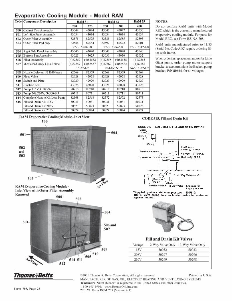
Form 705, Page 28
CODE 515, Fill and Drain Kit
NOTES:
Do not confuse RAM units with ModelREC which is the currently manufacturedevaporative cooling module. For parts forModel REC, see Form RZ-NA 708.
RAM units manufactured prior to 11/83(Serial No. Code AIK) require ordering fil-ter with frame.
When ordering replacement motor for LittleGiant pump, order pump motor supportbracket to accommodate the Beckett pumpbracket, P/N 80664, for all voltages.
Evaporative Cooling Module - Model RAM
©2001 Thomas & Betts Corporation, All rights reserved. Printed in U.S.A.MANUFACTURER OF GAS, OIL, ELECTRIC HEATING AND VENTILATING SYSTEMSTrademark Note: Reznor® is registered in the United States and other countries.1-800-695-1901; www.ReznorOnLine.com7/01 YL Form RGM 705 (Version A.1)
Fill and Drain Kit ValvesVoltage 2-Way Valve Only 3-Way Valve Only
115V 50032 50033
208V 50297 50296
230V 50299 50298
500
502and503
504501
505
RAM Evaporative Cooling Module - Inlet View
501
500
504
506 and507
508
509510
511512
514505
RAM Evaporative Cooling Module -Inlet View with Outer Filter AssemblyRemoved
Air Flow
Air Flow
Code Component Description RAM 55
200 225 250 300 400500 Cabinet Top Assembly 43044 43044 43047 43047 43050501 Left Side Panel Assembly 43034 43034 43034 43034 43034502 Outer Filter Assembly 82575 82575 82585 82585 82593503 Outer Filter Pad only 82584 82584 82592 82592 82601
27-3/16x42-1/8504 Right Side Panel Assembly 43040 43040 43040 43040 43040505 Bottom Pan Assembly 43025 43025 43030 43030 43032506 Filter Assembly (4)82552 (4)82552 (4)82558 (4)82558 (4)82563507 Media Pad Only Less Frame (4)82557 (4)82557 (4)82562 (4)82562 (4)82567
24-5/16x32-1/2508 Nozzle Delavan 1/2 K40 brass 82569 82569 82569 82569 82569509 Float Valve 42928 42928 42928 42928 42928510 Switch and Plate 42929 42929 42929 42929 42929
511 Junction box 43028 43028 43028 43028 43028512 Pump 115V, G500-S-3 80710 80710 80710 80710 80710513 Pump 208/230V, G-500-S-3 80711 80711 80711 80711 80711514 Complete Nozzle Kit Less Pump 82568 82568 82572 82572 82573515 Fill and Drain Kit 115V 50031 50031 50031 50031 50031
Fill and Drain Kit 208V 50823 50823 50823 50823 50823Fill and Drain Kit 230V 50824 50824 50824 50824 50824
15x32-1/2 19-1/8x32-1/2
RAM 31 RAM 42
27-3/16x28-3/8 27-3/16x36-5/8