Embed Size (px)
DESCRIPTION
Fracture mrchanics
Citation preview
XFEM Analysis of a
University of Florida, Gainesville, FL
This series of tutorials demonstrates how to build and analyze a cracked solid body using the Extended
Finite Element (XFEM) functionality present in Abaqus/CAE 6.11
the creation of a static analysis to extract qu
mixed-mode stress intensity factors.
may request energy release rate or stress intensity factor output created from contour integral
work around is presented to extract the energy release rate for a two
VCCT propagation model and the output request ENRRTXFEM.
The Extended Finite Element Method (XFEM) allows discontinuities to be modeled independe
finite element mesh. This removes the requirement for the modeling domain and mesh to correspond to
one another explicitly. This modeling technique allows for cracks to be arbitrarily inserted into an
existing model.
Here, an edge crack in a finite plate is modeled according to two approaches, a two
three-dimensional model. As of the 6.11 release of Abaqus/CAE, it is not possible to extract energy
release rate or stress intensity factors from a two
is presented where the energy release rate may be estimated according to a VCCT propagation model.
To create a static analysis, the critical energies for VCCT propagation will be made artificially high to
prevent propagation. For the three-
factors may be extracted from a static crack using contour integrals.
1 Graduate Research Assistant, Mechanical and Aerospace Engineering,
2 Associate Professor, Mechanical and Aerospace Engineering,
1
XFEM Analysis of a Plate with an Edge Crack
Matthew Pais1, Nam-Ho Kim
2
University of Florida, Gainesville, FL
This series of tutorials demonstrates how to build and analyze a cracked solid body using the Extended
Finite Element (XFEM) functionality present in Abaqus/CAE 6.11-1. The series of tutorials will begin with
the creation of a static analysis to extract quantities of interest including the energy release rate and
mode stress intensity factors. Note that in Abaqus/CAE 6.11-1 only three-dimensional geometries
may request energy release rate or stress intensity factor output created from contour integral
work around is presented to extract the energy release rate for a two-dimensional geometry using a
VCCT propagation model and the output request ENRRTXFEM.
The Extended Finite Element Method (XFEM) allows discontinuities to be modeled independe
finite element mesh. This removes the requirement for the modeling domain and mesh to correspond to
This modeling technique allows for cracks to be arbitrarily inserted into an
ite plate is modeled according to two approaches, a two-dimensional and a
dimensional model. As of the 6.11 release of Abaqus/CAE, it is not possible to extract energy
release rate or stress intensity factors from a two-dimensional XFEM analysis. Therefore, a work around
is presented where the energy release rate may be estimated according to a VCCT propagation model.
To create a static analysis, the critical energies for VCCT propagation will be made artificially high to
-dimensional model, the energy release rate or stress intensity
factors may be extracted from a static crack using contour integrals.
Graduate Research Assistant, Mechanical and Aerospace Engineering, [email protected], www.matthewpais.com
Associate Professor, Mechanical and Aerospace Engineering, [email protected], www.mae.ufl.edu/nkim
This series of tutorials demonstrates how to build and analyze a cracked solid body using the Extended
1. The series of tutorials will begin with
energy release rate and
dimensional geometries
may request energy release rate or stress intensity factor output created from contour integrals. Here, a
dimensional geometry using a
The Extended Finite Element Method (XFEM) allows discontinuities to be modeled independent of the
finite element mesh. This removes the requirement for the modeling domain and mesh to correspond to
This modeling technique allows for cracks to be arbitrarily inserted into an
dimensional and a
dimensional model. As of the 6.11 release of Abaqus/CAE, it is not possible to extract energy
refore, a work around
is presented where the energy release rate may be estimated according to a VCCT propagation model.
To create a static analysis, the critical energies for VCCT propagation will be made artificially high to
dimensional model, the energy release rate or stress intensity
www.matthewpais.com
www.mae.ufl.edu/nkim
2
XFEM Analysis of a Two-Dimensional Cracked Body Programs Utilized: Abaqus/CAE 6.11-1
First we will create the uncracked domain as a part. We will then create a second part which will contain
the crack in either two-dimensions (wire) or three-dimensions (shell). The part defining the crack does
not need to be meshed.
Creating the Uncracked Domain
• Open Abaqus/CAE 6.11-1 or later.
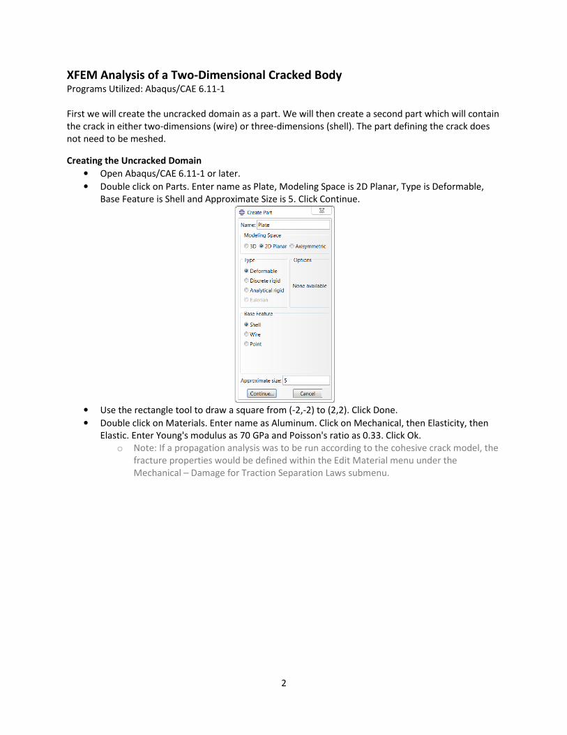
• Double click on Parts. Enter name as Plate, Modeling Space is 2D Planar, Type is Deformable,
Base Feature is Shell and Approximate Size is 5. Click Continue.
• Use the rectangle tool to draw a square from (-2,-2) to (2,2). Click Done.
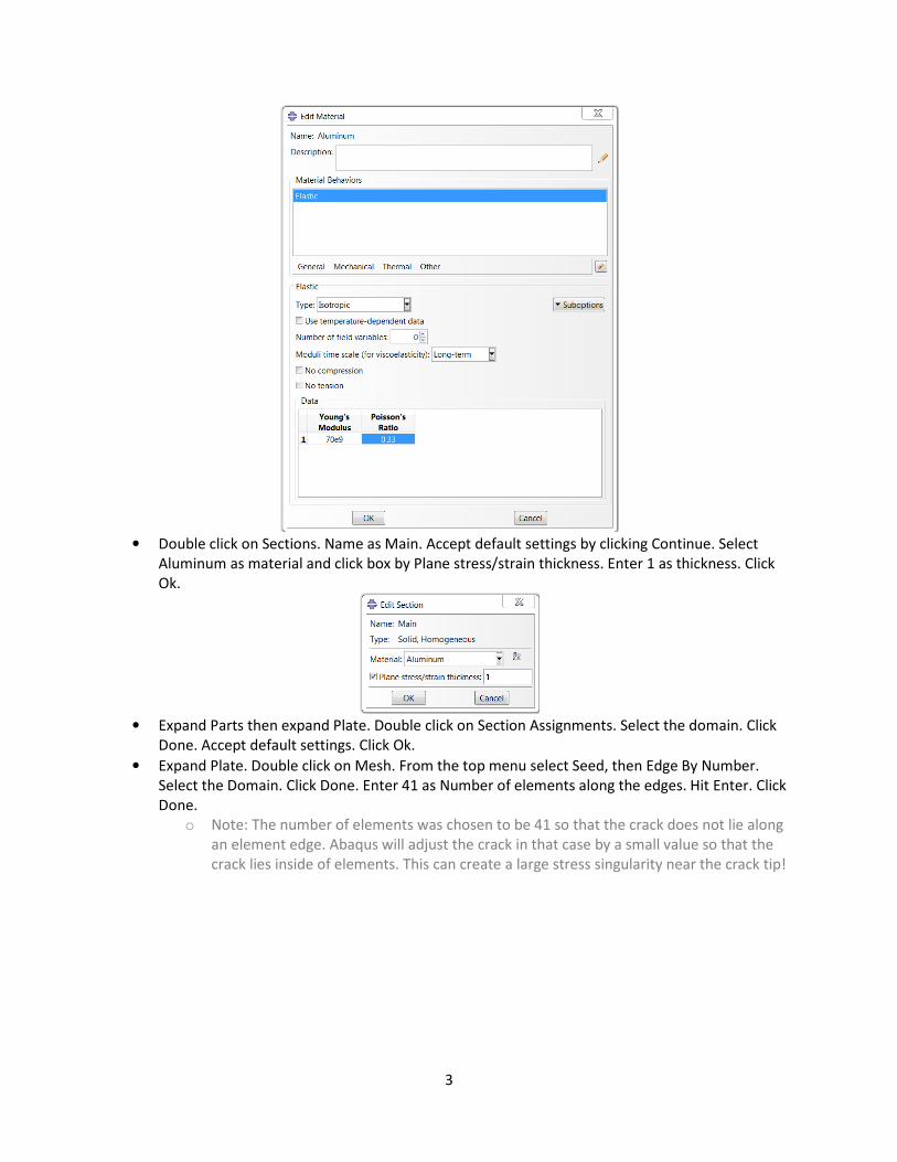
• Double click on Materials. Enter name as Aluminum. Click on Mechanical, then Elasticity, then
Elastic. Enter Young's modulus as 70 GPa and Poisson's ratio as 0.33. Click Ok.
o Note: If a propagation analysis was to be run according to the cohesive crack model, the
fracture properties would be defined within the Edit Material menu under the
Mechanical – Damage for Traction Separation Laws submenu.
3
• Double click on Sections. Name as Main. Accept default settings by clicking Continue. Select
Aluminum as material and click box by Plane stress/strain thickness. Enter 1 as thickness. Click
Ok.
• Expand Parts then expand Plate. Double click on Section Assignments. Select the domain. Click
Done. Accept default settings. Click Ok.
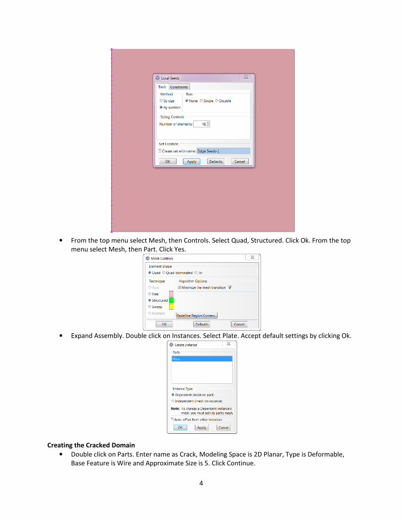
• Expand Plate. Double click on Mesh. From the top menu select Seed, then Edge By Number.
Select the Domain. Click Done. Enter 41 as Number of elements along the edges. Hit Enter. Click
Done.
o Note: The number of elements was chosen to be 41 so that the crack does not lie along
an element edge. Abaqus will adjust the crack in that case by a small value so that the
crack lies inside of elements. This can create a large stress singularity near the crack tip!
4
• From the top menu select Mesh, then Controls. Select Quad, Structured. Click Ok. From the top
menu select Mesh, then Part. Click Yes.
• Expand Assembly. Double click on Instances. Select Plate. Accept default settings by clicking Ok.
Creating the Cracked Domain
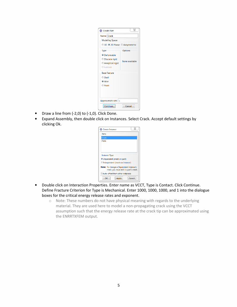
• Double click on Parts. Enter name as Crack, Modeling Space is 2D Planar, Type is Deformable,
Base Feature is Wire and Approximate Size is 5. Click Continue.
5
• Draw a line from (-2,0) to (-1,0). Click Done.
• Expand Assembly, then double click on Instances. Select Crack. Accept default settings by
clicking Ok.
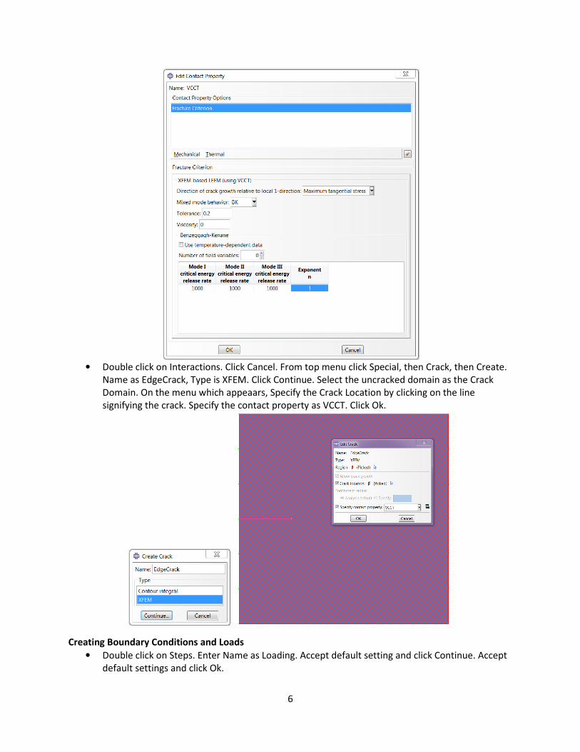
• Double click on Interaction Properties. Enter name as VCCT, Type is Contact. Click Continue.
Define Fracture Criterion for Type is Mechanical. Enter 1000, 1000, 1000, and 1 into the dialogue
boxes for the critical energy release rates and exponent.
o Note: These numbers do not have physical meaning with regards to the underlying
material. They are used here to model a non-propagating crack using the VCCT
assumption such that the energy release rate at the crack tip can be approximated using
the ENRRTXFEM output.
6
• Double click on Interactions. Click Cancel. From top menu click Special, then Crack, then Create.
Name as EdgeCrack, Type is XFEM. Click Continue. Select the uncracked domain as the Crack
Domain. On the menu which appeaars, Specify the Crack Location by clicking on the line
signifying the crack. Specify the contact property as VCCT. Click Ok.
Creating Boundary Conditions and Loads
• Double click on Steps. Enter Name as Loading. Accept default setting and click Continue. Accept
default settings and click Ok.

7
• Double click on Loads. Enter name as TopPressure, Category is Mechanical, Type is Pressure.
Click Continue. Select the top edge of the domain. Click Done. Enter -1 as Magnitude, other
settings are default. Click Ok.
• Repeat step 2 for the bottom edge of the domain, entering the name as BottomPressure.
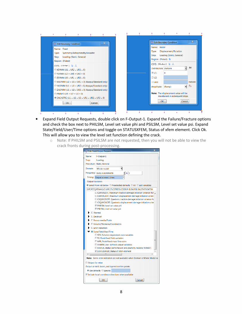
• Double click on BCs. Enter name as Fixed, Step is Initial, Category is Mechanical, Types for
Selected Step is Symmetry/Antisymmetry/Encastre. Click on the bottom right corner of the
domain. Click Done. Select Encastre. Click Ok.
• Repeat step 4 for the top right corner of the domain. Enter name as Roller. Set U1 equal to zero.
8
• Expand Field Output Requests, double click on F-Output-1. Expand the Failure/Fracture options
and check the box next to PHILSM, Level set value phi and PSILSM, Level set value psi. Expand
State/Field/User/Time options and toggle on STATUSXFEM, Status of xfem element. Click Ok.
This will allow you to view the level set function defining the crack.
o Note: If PHILSM and PSILSM are not requested, then you will not be able to view the
crack fronts during post-processing.
9
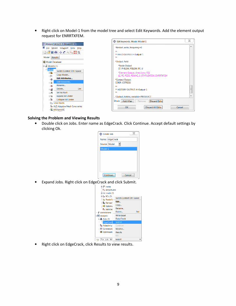
• Right click on Model-1 from the model tree and select Edit Keywords. Add the element output
request for ENRRTXFEM.
Solving the Problem and Viewing Results
• Double click on Jobs. Enter name as EdgeCrack. Click Continue. Accept default settings by
clicking Ok.
• Expand Jobs. Right click on EdgeCrack and click Submit.
• Right click on EdgeCrack, click Results to view results.
10
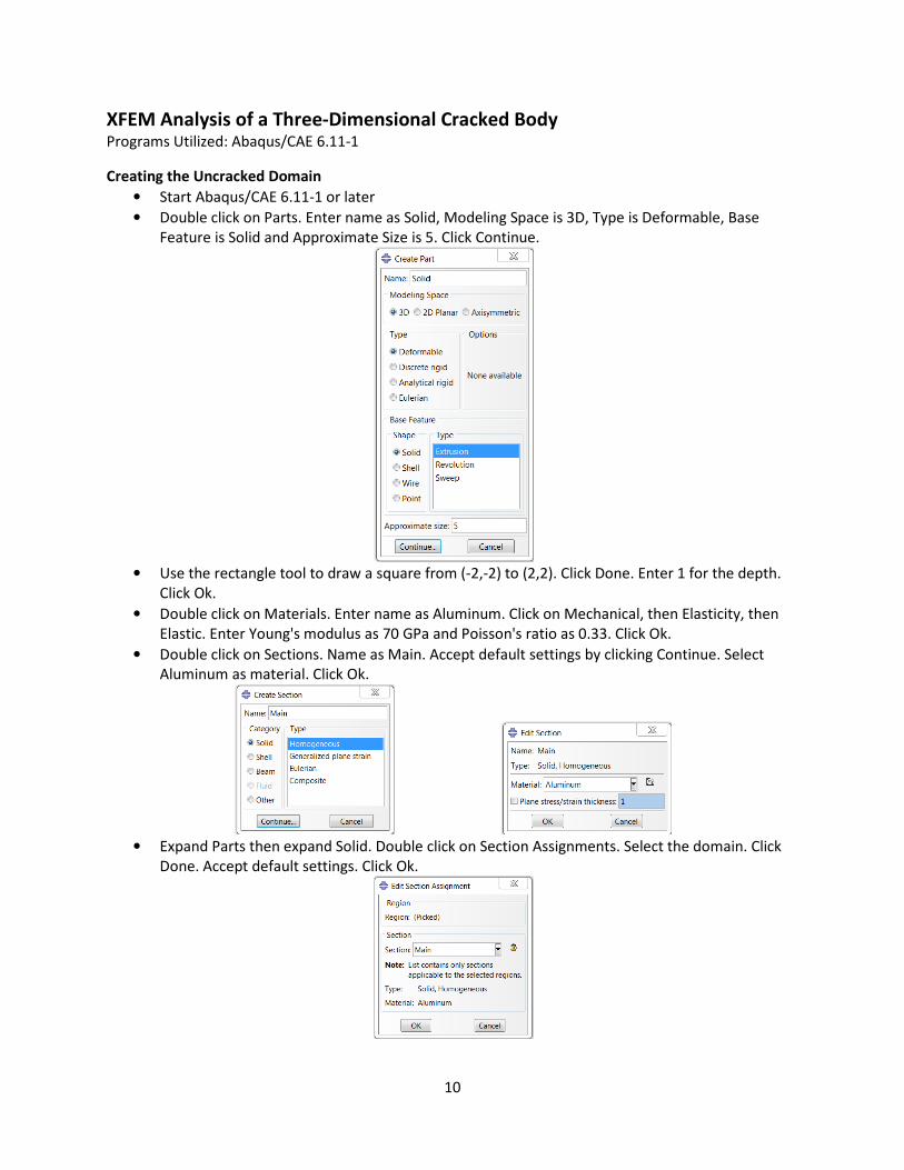
XFEM Analysis of a Three-Dimensional Cracked Body Programs Utilized: Abaqus/CAE 6.11-1
Creating the Uncracked Domain
• Start Abaqus/CAE 6.11-1 or later
• Double click on Parts. Enter name as Solid, Modeling Space is 3D, Type is Deformable, Base
Feature is Solid and Approximate Size is 5. Click Continue.
• Use the rectangle tool to draw a square from (-2,-2) to (2,2). Click Done. Enter 1 for the depth.
Click Ok.
• Double click on Materials. Enter name as Aluminum. Click on Mechanical, then Elasticity, then
Elastic. Enter Young's modulus as 70 GPa and Poisson's ratio as 0.33. Click Ok.
• Double click on Sections. Name as Main. Accept default settings by clicking Continue. Select
Aluminum as material. Click Ok.
• Expand Parts then expand Solid. Double click on Section Assignments. Select the domain. Click
Done. Accept default settings. Click Ok.
11
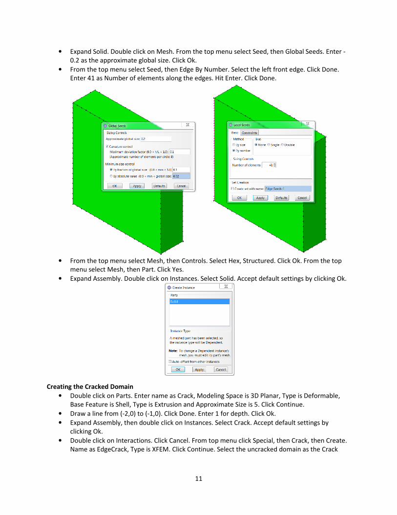
• Expand Solid. Double click on Mesh. From the top menu select Seed, then Global Seeds. Enter -
0.2 as the approximate global size. Click Ok.
• From the top menu select Seed, then Edge By Number. Select the left front edge. Click Done.
Enter 41 as Number of elements along the edges. Hit Enter. Click Done.
• From the top menu select Mesh, then Controls. Select Hex, Structured. Click Ok. From the top
menu select Mesh, then Part. Click Yes.
• Expand Assembly. Double click on Instances. Select Solid. Accept default settings by clicking Ok.
Creating the Cracked Domain
• Double click on Parts. Enter name as Crack, Modeling Space is 3D Planar, Type is Deformable,
Base Feature is Shell, Type is Extrusion and Approximate Size is 5. Click Continue.
• Draw a line from (-2,0) to (-1,0). Click Done. Enter 1 for depth. Click Ok.
• Expand Assembly, then double click on Instances. Select Crack. Accept default settings by
clicking Ok.
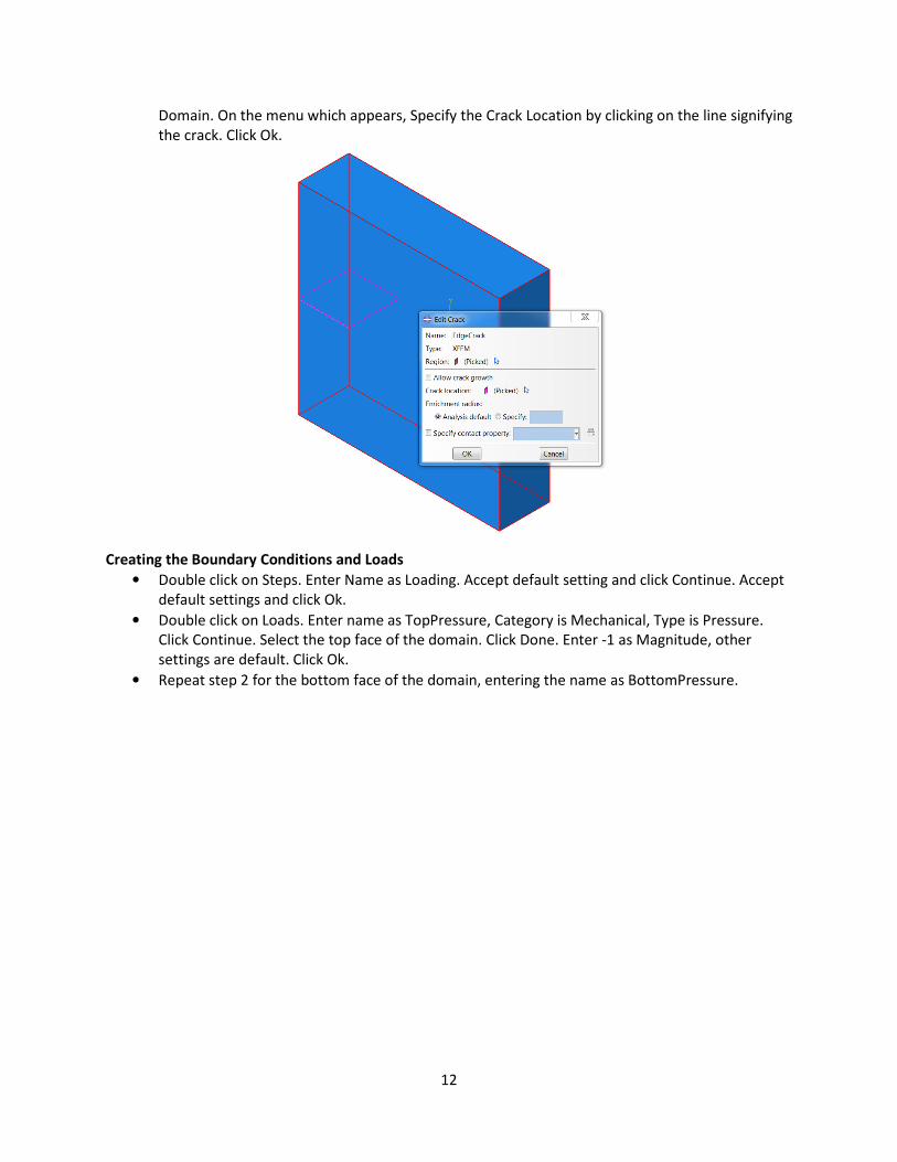
• Double click on Interactions. Click Cancel. From top menu click Special, then Crack, then Create.
Name as EdgeCrack, Type is XFEM. Click Continue. Select the uncracked domain as the Crack
12
Domain. On the menu which appears, Specify the Crack Location by clicking on the line signifying
the crack. Click Ok.
Creating the Boundary Conditions and Loads
• Double click on Steps. Enter Name as Loading. Accept default setting and click Continue. Accept
default settings and click Ok.
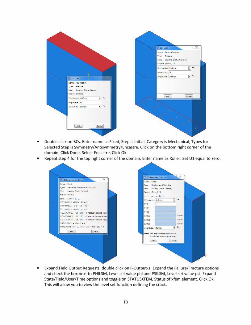
• Double click on Loads. Enter name as TopPressure, Category is Mechanical, Type is Pressure.
Click Continue. Select the top face of the domain. Click Done. Enter -1 as Magnitude, other
settings are default. Click Ok.
• Repeat step 2 for the bottom face of the domain, entering the name as BottomPressure.
13
• Double click on BCs. Enter name as Fixed, Step is Initial, Category is Mechanical, Types for
Selected Step is Symmetry/Antisymmetry/Encastre. Click on the bottom right corner of the
domain. Click Done. Select Encastre. Click Ok.
• Repeat step 4 for the top right corner of the domain. Enter name as Roller. Set U1 equal to zero.
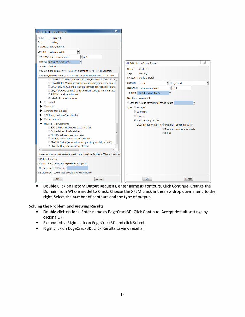
• Expand Field Output Requests, double click on F-Output-1. Expand the Failure/Fracture options
and check the box next to PHILSM, Level set value phi and PSILSM, Level set value psi. Expand
State/Field/User/Time options and toggle on STATUSXFEM, Status of xfem element. Click Ok.
This will allow you to view the level set function defining the crack.
14
• Double Click on History Output Requests, enter name as contours. Click Continue. Change the
Domain from Whole model to Crack. Choose the XFEM crack in the new drop down menu to the
right. Select the number of contours and the type of output.
Solving the Problem and Viewing Results
• Double click on Jobs. Enter name as EdgeCrack3D. Click Continue. Accept default settings by
clicking Ok.
• Expand Jobs. Right click on EdgeCrack3D and click Submit.
• Right click on EdgeCrack3D, click Results to view results.