Embed Size (px)
Citation preview
INTERNATIONAL JOURNAL FOR NUMERICAL METHODS IN ENGINEERING
Int. J. Numer. Meth. Engng 2009; 00:1–36 Prepared using nmeauth.cls [Version: 2002/09/18 v2.02]
Fracture in magnetoelectroelastic materials using the extended
finite element method
R. Rojas-Dıaz1, N. Sukumar2, A. Saez1,∗and F. Garcıa-Sanchez3
1 Departamento de Mecanica de los Medios Continuos, Escuela Tecnica Superior de Ingenieros, Universidad
de Sevilla, 41092-Sevilla, Spain.
2 Department of Civil and Environmental Engineering, University of California, Davis, CA 95616, USA.
3 Departamento de Ingeniera Civil, de Materiales y Fabricacion, ETS de Ingenieros Industriales, 29013
Malaga
SUMMARY
Static fracture analyses in two-dimensional linear magnetoelectroelastic solids is studied by means
of the extended finite element method (X-FEM). In the X-FEM, crack modeling is facilitated by
adding a discontinuous function and the crack-tip asymptotic functions to the standard finite element
approximation using the framework of partition of unity. In this study, media possessing fully coupled
piezoelectric, piezomagnetic and magnetoelectric effects are considered. New enrichment functions
for cracks in transversely isotropic magnetoelectroelastic materials are derived, and the computation
of fracture parameters using the domain form of the contour interaction integral is presented. The
convergence rates in energy for topological and geometric enrichments are studied. Excellent accuracy
∗Correspondence to: A. Saez, Departamento de Mecanica de los Medios Continuos, Escuela Superior
de Ingenieros, Universidad de Sevilla, Camino de los Descubrimientos S/N, 41092-Sevilla, Spain. E-mail:
Received 00
Copyright c© 2009 John Wiley & Sons, Ltd. Revised 00
Accepted 00
2 R. ROJAS-DIAZ, N. SUKUMAR, A. SAEZ, F. GARCIA-SANCHEZ
of the proposed formulation is demonstrated on benchmark crack problems through comparisons
with both analytical solutions and numerical results obtained by the dual boundary element method.
Copyright c© 2009 John Wiley & Sons, Ltd.
key words: partition of unity enrichment, X-FEM, magnetoelectroelasticity, interaction integral
1. INTRODUCTION
The use of magnetoelectroelastic (MEE) materials is receiving increasing attention due to the
inherent coupling among mechanical, electric and magnetic fields. Such coupling provides new
technological possibilities in novel multifunctional devices, such as electromagnetic transducers,
actuators, and sensors. Natural MEE single-phase materials are rare, and their electromagnetic
coupling is either relatively weak or it occurs at low temperatures for practical applications.
In contrast, composites that combine both piezomagnetic and piezoelectric phases typically
show much larger electromagnetic response above room temperature. Such electromagnetic
coupling is a new product property of the resulting composite, since it is absent in both the
piezoelectric and piezomagnetic phases when considered alone. A review on the current status
of MEE composites can be found in the work by Nan et al. [1].
Fracture mechanics of this class of materials is relevant to predict the structural integrity
and in-service working conditions of MEE devices. However, as compared to the anisotropic
or piezoelectric cases, relatively limited work has been done when it comes to analyze fracture
phenomena in magnetoelectroelastic materials. Related to static fracture, Gao et al. [2–5]
analyzed some basic problems analytically, whereas in the works by Sih et al. [6–8] and
Song and Sih [9] the influence of both electromagnetic fields and the volume fraction of
Copyright c© 2009 John Wiley & Sons, Ltd. Int. J. Numer. Meth. Engng 2009; 00:1–36
Prepared using nmeauth.cls
FRACTURE IN MAGNETOELECTROELASTIC MATERIALS USING THE X-FEM 3
the magnetoelectroelastic composite on crack initiation and growth are analysed. Wang and
Mai [10, 11] derived the expressions for the magnetoelectroelastic asymptotic fields, as well
as path-independent integrals. Using such path independent integrals, fracture behaviour
of magnetoelectroelastic solids was analyzed by Tian and Rajapakse [12]. All these studies
present analytical procedures that are limited to problems with relatively simple geometries
and loading conditions.
Several numerical methods have been proposed to solve static fracture mechanics problems
in magnetoelectroelastic solids. A dual boundary element (BE) formulation was presented by
Garcıa-Sanchez et al. [13], whereas Sladek et al. [14] proposed a meshless local Petrov-Galerkin
approach. In contrast, limited work has been done so far to model MEE structures using
finite element methods (FEM). Buchanan [15] applied FEM to obtain the multiphase material
properties. Garcia Lage et al. [16] developed a partial mixed layerwise finite element model
for the static and free vibration analysis of MEE laminated plate structures. Bhangale and
Ganesan [17] presented a semi-analytical FEM for the static analysis of functionally graded,
anisotropic and linear MEE plates. This work was further extended by Rajesh et al. [18] to the
case of free vibrations of plates and by Annigeri et al. [19] to the problem of free vibrations
of clamped-clamped cylindrical shells. More recently, Daga et al. [20] analyzed the sensory
response of MEE materials bonded on the top surface of a mild steel beam under transient
mechanical loading using finite elements and Simoes Moita et al. [21] proposed a FE model
based on third-order shear deformation theory, for static and free vibration analysis of plate
structures integrating piezoelectric/piezomagnetic layers.
Related to fracture applications, different crack-face boundary conditions were analysed by
Wang and Mai [22] using a classical finite element approach, in which the mesh boundaries
Copyright c© 2009 John Wiley & Sons, Ltd. Int. J. Numer. Meth. Engng 2009; 00:1–36
Prepared using nmeauth.cls
4 R. ROJAS-DIAZ, N. SUKUMAR, A. SAEZ, F. GARCIA-SANCHEZ
must align with the crack path. Additionally, mesh refinement or singular elements such as
quarter-point elements are also necessary near the crack-tip to capture the stress singularity.
To circumvent these difficulties, the extended finite element method (X-FEM) is a powerful
alternative in computational fracture. In the X-FEM, the crack discontinuity is represented by
enriching the classical finite element approximation by discontinuous and near-tip asymptotic
functions via the framework of partition of unity. The X-FEM has been successfully applied to
solve crack problems by Moes et al. [23] in isotropic media, Sukumar et al. [24] in bimaterials,
Asadpoure and Mohammadi [25] in orthotropic materials, and Bechet et al. [26] in piezoelectric
media. It is well-established in the literature (for example, see Fries and Belytscho [27]) that
the X-FEM with near-tip enrichment is more accurate and efficient than conventional FEM
with no enrichment.
In this paper, we present extended finite element analyses for fracture in two-dimensional in-
plane transversely isotropic MEE materials. The governing equations are stated in Section 2,
and the crack-tip asymptotic fields (used to design the enrichment functions) in MEE materials
are provided in Section 3. The extended finite element formulation is presented in Section 4,
and new crack-tip enrichment functions for MEE materials are derived in Section 5. The
computation of fracture parameters using the domain form of the contour interaction integral
is described in Section 6, and supportive numerical fracture results for the extended stress
intensity factors are presented in Section 7 to validate the formulation. We close with the
main findings from this study in Section 8.
Copyright c© 2009 John Wiley & Sons, Ltd. Int. J. Numer. Meth. Engng 2009; 00:1–36
Prepared using nmeauth.cls
FRACTURE IN MAGNETOELECTROELASTIC MATERIALS USING THE X-FEM 5
2. GOVERNING EQUATIONS FOR LINEAR MAGNETOELECTROELASTICITY
For a composite material in which both piezoelectric and elastomagnetic phases coexist,
the interaction among the electric, magnetic and mechanical fields leads to the following
constitutive equations for the resulting linear MEE solid [28]:
σij = cijklεkl − elijEl − hlijHl (1a)
Di = eiklεkl + ǫilEl + βilHl (1b)
Bi = hiklεkl + βilEl + γilHl (1c)
where σij are the components of the Cauchy stress tensor, Di are the electric displacements, and
Bi are the magnetic inductions. In addition, εij are the components of the small-strain elastic
tensor, and Ei and Hi are the electric and magnetic fields, respectively. In (1), Cijkl, ǫil and
γil are the elastic stiffness tensor, the dielectric permittivities and the magnetic permeabilities,
respectively, whereas elij , hlij and βil are the piezoelectric, piezomagnetic and electromagnetic
coupling coefficients, respectively.
Small displacement gradients are assumed, so that the linearized strain-displacement
relations hold. The electric and the magnetic fields are the gradient of the electric potential φ
and the magnetic potential ϕ, respectively
εij =1
2(ui,j + uj,i) (2a)
Ei = −φ,i (2b)
Hi = −ϕ,i (2c)
where ui are the elastic displacement components. The summation rule on repeated indices is
implied unless otherwise stated and a comma stands for partial differentiation.
Copyright c© 2009 John Wiley & Sons, Ltd. Int. J. Numer. Meth. Engng 2009; 00:1–36
Prepared using nmeauth.cls
6 R. ROJAS-DIAZ, N. SUKUMAR, A. SAEZ, F. GARCIA-SANCHEZ
The equilibrium equations for static loading are given by
σij,j = −fmechi (3a)
Di,i = fe (3b)
Bi,i = fm (3c)
where fmechi are the body forces and fe and fm are the electric charge density and the electric
current density, respectively.
Following the notation first introduced by Barnett and Lothe [29] for piezoelectricity, a
generalized displacement vector is defined by extending the elastic displacement vector with
the electric and magnetic potentials as
uI =
ui I=1,2,3
φ I=4
ϕ I=5
(4)
and a generalized stress tensor is defined by the extension of the elastic stresses with the
electric displacements and the magnetic inductions as
σiJ =
σij J=1,2,3
Di J=4
Bi J=5
(5)
so that the linear MEE problem can be formulated in an elastic-like fashion. The constitutive
equations (1) may be recast is a more compact form to yield
σiJ = ciJKluK,l (6)
where the lowercase subscripts (elastic) vary from 1 to 3, whereas the uppercase ones
(extended) vary from 1 to 5. The material properties have been grouped together into a
Copyright c© 2009 John Wiley & Sons, Ltd. Int. J. Numer. Meth. Engng 2009; 00:1–36
Prepared using nmeauth.cls
FRACTURE IN MAGNETOELECTROELASTIC MATERIALS USING THE X-FEM 7
generalized elasticity tensor defined as
ciJKl =
cijkl J,K = 1, 2, 3
elij J = 1, 2, 3; K = 4
hlij J = 1, 2, 3; K = 5
eikl J = 4; K = 1, 2, 3
−ǫil J,K = 4
−βil J = 4; K = 5
hikl J = 5; K = 1, 2, 3
−βil J = 5; K = 4
−γil J,K = 5
(7)
3. GENERALIZED DISPLACEMENT FIELDS AROUND A CRACK IN A
MAGNETOELECTROELASTIC SOLID
The asymptotic terms of the generalized displacement fields in the vicinity of a crack tip
must be included in the extended formulation of the finite element to describe the crack-
discontinuity. To this end, we next derive such asymptotic crack-tip fields in the vicinity of a
crack in a MEE material, based on Laurent’s series expansions.
In this wor,k we consider transversely isotropic MEE media under generalized plane strain
Copyright c© 2009 John Wiley & Sons, Ltd. Int. J. Numer. Meth. Engng 2009; 00:1–36
Prepared using nmeauth.cls
8 R. ROJAS-DIAZ, N. SUKUMAR, A. SAEZ, F. GARCIA-SANCHEZ
conditions. In such a case, the constitutive relations (6) may be further reduced to [30]
ε11
ε22
2ε12
E1
E2
H1
H2
=
a11 a12 0 0 b21 0 d21
a12 a22 0 0 b22 0 d22
0 0 a33 b13 0 d13 0
0 0 −b13 δ11 0 ∆11 0
−b21 −b22 0 0 δ22 0 ∆22
0 0 −d13 ∆11 0 ζ11 0
−d21 −d22 0 0 ∆22 0 ζ22
σ11
σ22
σ12
D1
D2
B1
B2
(8)
where the terms in the matrix are listed in appendix A.
The equilibrium equations in the absence of generalized body forces are
∂σ11
∂x1+
∂σ12
∂x2= 0,
∂σ12
∂x1+
∂σ22
∂x2= 0 (9a)
∂D1
∂x1+
∂D2
∂x2= 0 (9b)
∂B1
∂x1+
∂B2
∂x2= 0 (9c)
and the compatibility conditions are
∂2ε11
∂x22
+∂2ε22
∂x21
= 2∂2ε12
∂x1∂x2(10a)
∂E1
∂x2− ∂E2
∂x1= 0 (10b)
∂H1
∂x2− ∂H2
∂x1= 0 (10c)
Let us now introduce the potential functions U , χ and ϑ defined by
σ11 = U(x1, x2),22, σ22 = U(x1, x2),11, σ12 = −U(x1, x2),12 (11a)
D1 = χ(x1, x2),2, D2 = −χ(x1, x2),1 (11b)
B1 = ϑ(x1, x2),2, B2 = −ϑ(x1, x2),1 (11c)
Copyright c© 2009 John Wiley & Sons, Ltd. Int. J. Numer. Meth. Engng 2009; 00:1–36
Prepared using nmeauth.cls
FRACTURE IN MAGNETOELECTROELASTIC MATERIALS USING THE X-FEM 9
The equilibrium equations (9) are automatically satisfied because of the definitions in (11).
Substituting (8) into (10) and expressing the stresses, the electric displacements and the
magnetic inductions by the potentials in (11) leads to
a11U,2222 + a22U,1111 + (2a12 + a33)U,1122 − (b21 + b13)χ,122
−b22χ,111 − (d21 + d13)ϑ,122 − d22ϑ,111 = 0
(12a)
(b21 + b13)U,122 + b22U,111 + δ11χ,22 + δ22χ,11 + ∆11ϑ,22 + ∆22ϑ,11 = 0 (12b)
(d21 + d13)U,122 + d22U,111 + ∆11χ,22 + ∆22χ,11 + ζ11ϑ,22 + ζ22ϑ,11 = 0 (12c)
so that on defining the following operators
L4 = a22∂4
∂x41
+ a11∂4
∂x42
+ (2a11 + a33)∂4
∂x21∂x2
2
(13a)
L3 = b22∂3
∂x31
+ (b21 + b13)∂3
∂x1∂x22
(13b)
M3 = d22∂3
∂x31
+ (d21 + d13)∂3
∂x1∂x22
(13c)
L2 = δ22∂2
∂x21
+ δ11∂2
∂x22
(13d)
M2 = ∆22∂2
∂x21
+ ∆11∂2
∂x22
(13e)
P2 = ζ22∂2
∂x21
+ ζ11∂2
∂x22
(13f)
the compatibility equations can be reduced to the following partial differential equation of
eighth order for U(x1, x2) (see Reference [31] for details)
[L4(L2P2 − M22 ) + L3(L3P2 − 2M3M2) + L2M
23 ]U = 0 (14)
whose solution can be derived in the form
U(x1, x2) = U(x1 + µx2) with µ = Re(µ) + iIm(µ) (15)
Substitution of (15) into (14) leads to the following eighth order characteristic equation for
Copyright c© 2009 John Wiley & Sons, Ltd. Int. J. Numer. Meth. Engng 2009; 00:1–36
Prepared using nmeauth.cls
10 R. ROJAS-DIAZ, N. SUKUMAR, A. SAEZ, F. GARCIA-SANCHEZ
the complex roots µi
[a11µ4 + (2a12 + a33)µ
2 + a22][(∆11µ2 + ∆22)
2 − (δ11µ2 + δ22)(ζ11µ
2 + ζ22)]
−[(b21 + b13)µ2 + b22]
2(ζ11µ2 + ζ22) − [(d21 + d13)µ
2 + d22]2(δ11µ
2 + δ22)
+2[(b21 + b13)µ2 + b22][(d21 + d13)µ
2 + d22](∆11µ2 + ∆22) = 0
(16)
The general solution for U(x1, x2) can be constructed by means of the eight roots µi, which
are actually four conjugate complex pairs, as
U(x1, x2) =
8∑
i=1
Ui(x1 + µix2) (17)
The potentials χ(x1, x2) and ϑ(x1, x2) can be derived from U(x1, x2) by combining
equations (8), (10) and (11) (see References [31] and [26] for details), so that all the
magnetoelectromechanical variables can be obtained by means of the potential U(x1, x2).
x1
x2
r
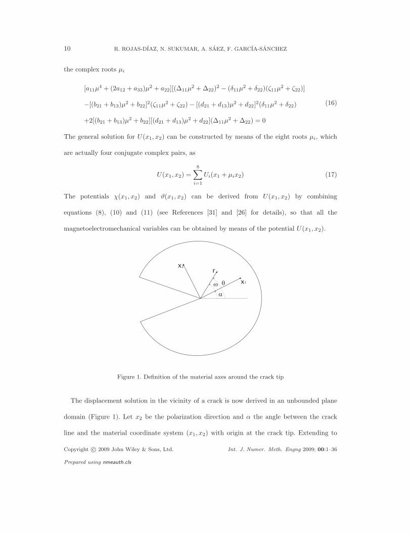
Figure 1. Definition of the material axes around the crack tip
The displacement solution in the vicinity of a crack is now derived in an unbounded plane
domain (Figure 1). Let x2 be the polarization direction and α the angle between the crack
line and the material coordinate system (x1, x2) with origin at the crack tip. Extending to
Copyright c© 2009 John Wiley & Sons, Ltd. Int. J. Numer. Meth. Engng 2009; 00:1–36
Prepared using nmeauth.cls
FRACTURE IN MAGNETOELECTROELASTIC MATERIALS USING THE X-FEM 11
the MEE case the procedure presented in Reference [26] for piezoelectrics, the potential U in
equation (17) is expanded in a Laurent-like series:
U(x1, x2) =∑
k
8∑
i=1
di(λk)(x1 + µix2)λk+2 (18)
where di(λk) are complex free coefficients of the series expansion to be determined and λk
are generally complex and represent the number of roots of the solvability equation for the
crack faces boundary conditions considered. In this paper, we will focus on traction-free cracks
with electric and magnetic impermeable crack face boundary conditions, i.e., with zero normal
electric displacement and magnetic induction on the crack faces [22].
On considering a polar coordinate system with the origin at the crack tip, the real potential
U(r, θ) in (18) can be rewritten as
U(r, θ) =
4∑
i=1
di(λ)r(cos(θ − α) + µi sin(θ − α))λ+2 +
4∑
i=1
di(λ)r(cos(θ − α) + µi sin(θ − α))λ+2
where λ is one of the λk in (18) and it is assumed to be real.
The real representation of each term in (18) for each µi leads to expressions of the form
eipλ+2 cos [(λ + 2)(κ +
π
2)] + fip
λ+2 sin [(λ + 2)(κ +π
2)] (19a)
with
p = r√
(|µK |2 − 1)(sin ω)2 + Re(µi)(sin 2ω) (19b)
κ = arctan1 + Re(µi) tan(ω)
|Im(µi)| tan(ω)(19c)
di(λ) = ei(λ) + ifi(λ) (19d)
ω = θ − α (19e)
Copyright c© 2009 John Wiley & Sons, Ltd. Int. J. Numer. Meth. Engng 2009; 00:1–36
Prepared using nmeauth.cls
12 R. ROJAS-DIAZ, N. SUKUMAR, A. SAEZ, F. GARCIA-SANCHEZ
where ei and fi are eight unknown coefficients. As pointed out by Bechet et al. [26] for
piezoelectricity, an infinite number of λk may be obtained as
λ1 = −1/2, λ2 = 0, λ3 = 1/2, λ4 = 1 . . . (20)
for impermeable crack-face boundary conditions. The first root λ1 = −1/2 generates
four independent eigenvectors (and their respective conjugate complex pairs) so that four
independent singular eigenfunctions, which incorporate the classical 1/√
r crack tip singularity,
can be constructed. These independent eigenfunctions can be used for obtaining the enrichment
functions for the X-FEM.
It is noteworthy to point that these enrichment functions depend on the angle ω = θ − α
and hence, the enrichment functions can be calculated for every poling direction with respect
to the crack line.
4. EXTENDED FINITE ELEMENT FORMULATION
The extended finite element method [23, 32] is a technique to simulate crack discontinuities
without the need for the crack to conform to the finite element mesh. To this end, additional
(enrichment) functions are added to the classical finite element approximation through the
framework of partition of unity [33]. The crack interior is represented by a discontinuous
(Heaviside) function and the crack-tip is modeled by the asymptotic crack-tip functions.
4.1. Crack modeling and selection of enriched nodes
Consider a crack Γc = Γ−c ∪Γ+
c located inside a domain Ω ⊂ R2 with boundary Γ. The domain
is discretized by finite elements, and let N denote the nodal set. Generalized displacements
are prescribed on Γu, whereas generalized tractions are imposed on Γt, so that Γ = Γu ∪ Γt
Copyright c© 2009 John Wiley & Sons, Ltd. Int. J. Numer. Meth. Engng 2009; 00:1–36
Prepared using nmeauth.cls
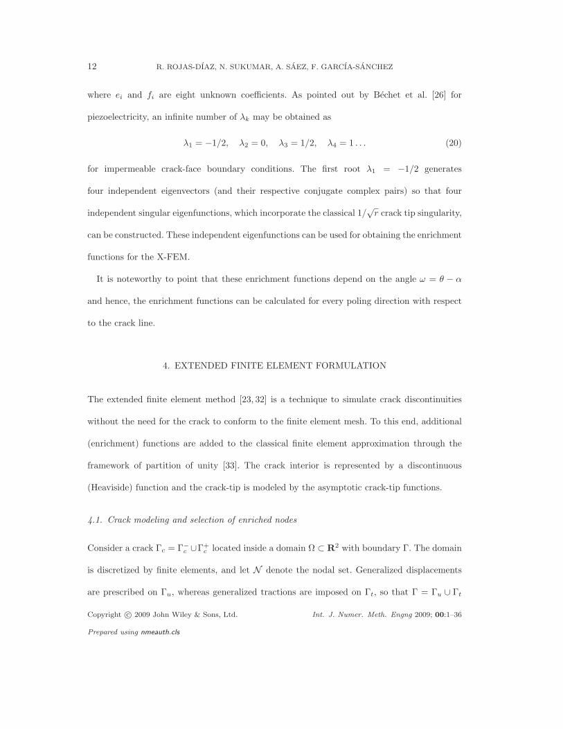
FRACTURE IN MAGNETOELECTROELASTIC MATERIALS USING THE X-FEM 13
Figure 2. Boundary value problem with an internal crack.
(Figure 2). The displacement approximation (trial function) in the X-FEM is written as [23]
uh(x) =
∑
i∈NNi(x)ui +
∑
j∈NH
Nj(x)H(x)aj +∑
k∈NCT
Nk(x)∑
α
Fα(x)bαk (21)
where Ni is the standard finite element shape function associated with node i, ui is the vector
of nodal degrees of freedom defined in classical finite elements, and aj and bαk are the added set
of degrees of freedom in the elements containing the crack. H(x) is the generalized Heaviside
function, which enables the modeling of a crack that fully cuts a finite element, and Fα are the
crack-tip enrichment functions. In a MEE solid, the variables that appear in (21) are defined in
an extended way, so ui and aj are 4-component vectors and bαk is a 32-component vector, since
four nodal variables (u1, u2, φ, ϕ) and eight enrichment functions are involved. In isotropic
elastic materials bαk is an 8-component vector, since only two nodal variables (u1, u2) and four
enrichment functions are needed to describe all the possible deformation states in the vicinity
of the crack-tip [23].
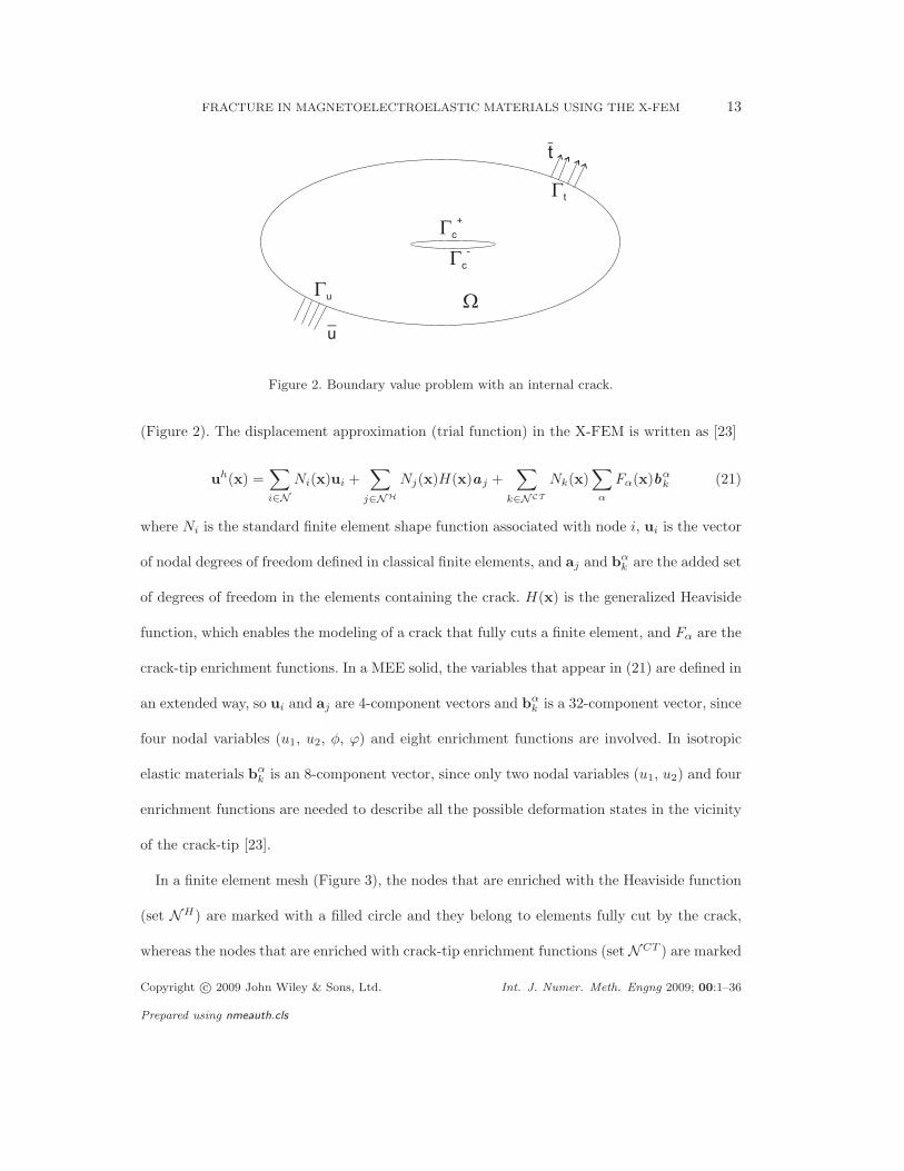
In a finite element mesh (Figure 3), the nodes that are enriched with the Heaviside function
(set NH) are marked with a filled circle and they belong to elements fully cut by the crack,
whereas the nodes that are enriched with crack-tip enrichment functions (set NCT ) are marked
Copyright c© 2009 John Wiley & Sons, Ltd. Int. J. Numer. Meth. Engng 2009; 00:1–36
Prepared using nmeauth.cls
14 R. ROJAS-DIAZ, N. SUKUMAR, A. SAEZ, F. GARCIA-SANCHEZ
Figure 3. Node selection for topological enrichment.
with a square and they belong to elements that contain the crack tip.
4.2. Weak formulation and discrete equations
Let u be the mechanical displacement and σ the mechanical stress tensor, whereas u and σ
are, respectively, the extended displacement vector and the extended stress tensor. The weak
form (principle of virtual work) for a continuous problem in a MEE solid is given by
∫
Ω
σ : δε dΩ −∫
Ω
D : δE dΩ −∫
Ω
B : δH dΩ =
∫
Γt
tmech · δudΓ −
∫
Γt
te · δφ dΓ −
∫
Γt
tm · δϕ dΓ
+
∫
Ω
fmech · δu dΩ −
∫
Ω
fe · δφ dΩ −
∫
Ω
fm · δϕ dΩ. (22)
Since the MEE problem can be expressed in an elastic-like way, (22) can be rewritten as
∫
Ω
σ : δε dΩ =
∫
Γt
t · δu + dΓ +
∫
Ω
f · δu dΩ (23)
by using the extended variables notation introduced in Section 2. In (23), t are the prescribed
extended tractions and f is the extended volume forces vector.
Copyright c© 2009 John Wiley & Sons, Ltd. Int. J. Numer. Meth. Engng 2009; 00:1–36
Prepared using nmeauth.cls
FRACTURE IN MAGNETOELECTROELASTIC MATERIALS USING THE X-FEM 15
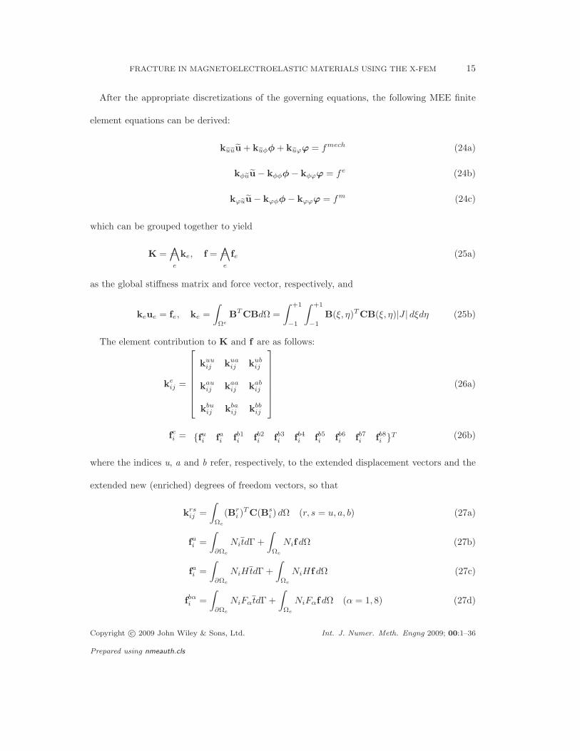
After the appropriate discretizations of the governing equations, the following MEE finite
element equations can be derived:
keueuu + keuφφ + keuϕϕ = fmech (24a)
kφeuu − kφφφ − kφϕϕ = fe (24b)
kϕeuu − kϕφφ − kϕϕϕ = fm (24c)
which can be grouped together to yield
K =∧
e
= ke, f =∧
e
= fe (25a)
as the global stiffness matrix and force vector, respectively, and
keue = fe, ke =
∫
Ωe
BTCBdΩ =
∫ +1
−1
∫ +1
−1
B(ξ, η)TCB(ξ, η)|J | dξdη (25b)
The element contribution to K and f are as follows:
keij =
kuuij k
uaij k
ubij
kauij k
aaij k
abij
kbuij k
baij k
bbij
(26a)
fei = fui f
ai f
b1i f
b2i f
b3i f
b4i f
b5i f
b6i f
b7i f
b8i T (26b)
where the indices u, a and b refer, respectively, to the extended displacement vectors and the
extended new (enriched) degrees of freedom vectors, so that
krsij =
∫
Ωe
(Bri )
TC(Bs
i ) dΩ (r, s = u, a, b) (27a)
fui =
∫
∂Ωe
NitdΓ +
∫
Ωe
Nif dΩ (27b)
fai =
∫
∂Ωe
NiHtdΓ +
∫
Ωe
NiHf dΩ (27c)
fbαi =
∫
∂Ωe
NiFαtdΓ +
∫
Ωe
NiFαf dΩ (α = 1, 8) (27d)
Copyright c© 2009 John Wiley & Sons, Ltd. Int. J. Numer. Meth. Engng 2009; 00:1–36
Prepared using nmeauth.cls
16 R. ROJAS-DIAZ, N. SUKUMAR, A. SAEZ, F. GARCIA-SANCHEZ
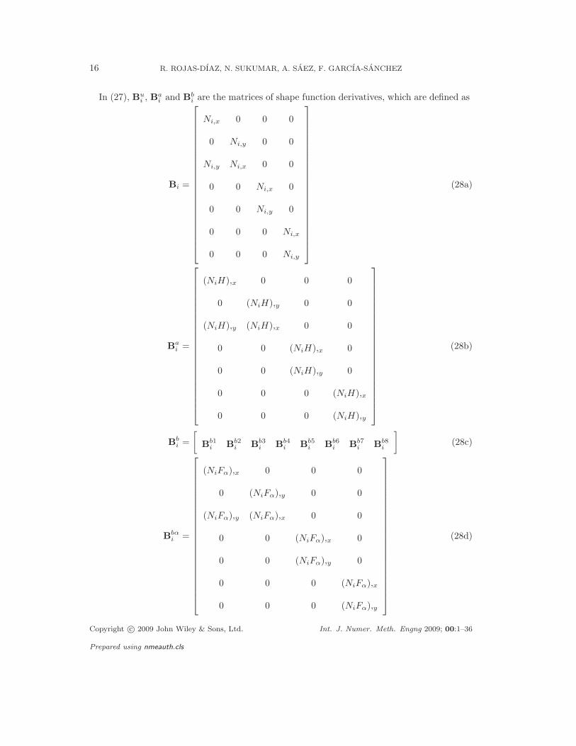
In (27), Bui , B
ai and B
bi are the matrices of shape function derivatives, which are defined as
Bi =
Ni,x 0 0 0
0 Ni,y 0 0
Ni,y Ni,x 0 0
0 0 Ni,x 0
0 0 Ni,y 0
0 0 0 Ni,x
0 0 0 Ni,y
(28a)
Bai =
(NiH),x 0 0 0
0 (NiH),y 0 0
(NiH),y (NiH),x 0 0
0 0 (NiH),x 0
0 0 (NiH),y 0
0 0 0 (NiH),x
0 0 0 (NiH),y
(28b)
Bbi =
[B
b1i B
b2i B
b3i B
b4i B
b5i B
b6i B
b7i B
b8i
](28c)
Bbαi =
(NiFα),x 0 0 0
0 (NiFα),y 0 0
(NiFα),y (NiFα),x 0 0
0 0 (NiFα),x 0
0 0 (NiFα),y 0
0 0 0 (NiFα),x
0 0 0 (NiFα),y
(28d)
Copyright c© 2009 John Wiley & Sons, Ltd. Int. J. Numer. Meth. Engng 2009; 00:1–36
Prepared using nmeauth.cls
FRACTURE IN MAGNETOELECTROELASTIC MATERIALS USING THE X-FEM 17
5. ENRICHMENT FUNCTIONS
The asymptotic displacement fields in the vicinity of the the crack-tip in an unbounded MEE
domain were derived in Section 3. From them, a set of elementary functions that span the
asymptotic fields can be obtained for any orientation of the crack and loading combination.
While for isotropic and piezoelectric materials, only four or six functions, respectively, are
necessary to describe all the possible generalized displacement states near the crack tip, for
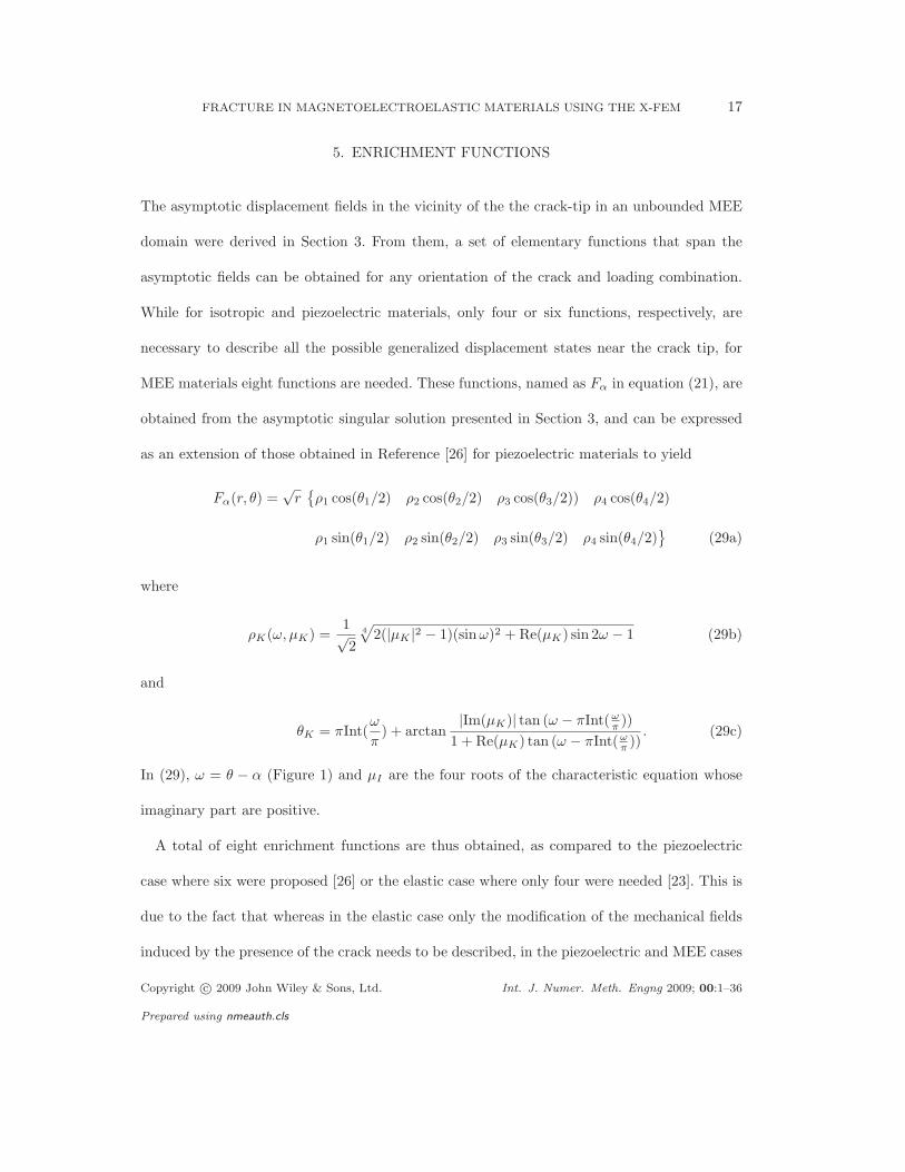
MEE materials eight functions are needed. These functions, named as Fα in equation (21), are
obtained from the asymptotic singular solution presented in Section 3, and can be expressed
as an extension of those obtained in Reference [26] for piezoelectric materials to yield
Fα(r, θ) =√
rρ1 cos(θ1/2) ρ2 cos(θ2/2) ρ3 cos(θ3/2)) ρ4 cos(θ4/2)
ρ1 sin(θ1/2) ρ2 sin(θ2/2) ρ3 sin(θ3/2) ρ4 sin(θ4/2)
(29a)
where
ρK(ω, µK) =1√2
4
√2(|µK |2 − 1)(sin ω)2 + Re(µK) sin 2ω − 1 (29b)
and
θK = πInt(ω
π) + arctan
|Im(µK)| tan (ω − πInt(ωπ))
1 + Re(µK) tan (ω − πInt(ωπ))
. (29c)
In (29), ω = θ − α (Figure 1) and µI are the four roots of the characteristic equation whose
imaginary part are positive.
A total of eight enrichment functions are thus obtained, as compared to the piezoelectric
case where six were proposed [26] or the elastic case where only four were needed [23]. This is
due to the fact that whereas in the elastic case only the modification of the mechanical fields
induced by the presence of the crack needs to be described, in the piezoelectric and MEE cases
Copyright c© 2009 John Wiley & Sons, Ltd. Int. J. Numer. Meth. Engng 2009; 00:1–36
Prepared using nmeauth.cls
18 R. ROJAS-DIAZ, N. SUKUMAR, A. SAEZ, F. GARCIA-SANCHEZ
the crack also affects the electric field and the electric and magnetic fields, respectively. In the
same way, the characteristic equation of the material (16) leads to eight roots µI in the MEE
case, whereas the corresponding characteristic equations for piezoelectric and elastic materials
lead to six and four roots, respectively.
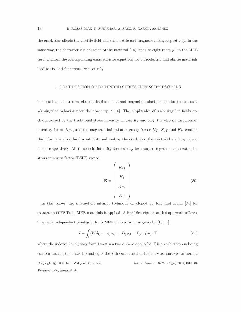
6. COMPUTATION OF EXTENDED STRESS INTENSITY FACTORS
The mechanical stresses, electric displacements and magnetic inductions exhibit the classical
√r singular behavior near the crack tip [2, 10]. The amplitudes of such singular fields are
characterized by the traditional stress intensity factors KI and KII , the electric displacemet
intensity factor KIV , and the magnetic induction intensity factor KV . KIV and KV contain
the information on the discontinuity induced by the crack into the electrical and magnetical
fields, respectively. All these field intensity factors may be grouped together as an extended
stress intensity factor (ESIF) vector:
K =
KII
KI
KIV
KV
(30)
In this paper, the interaction integral technique developed by Rao and Kuna [34] for
extraction of ESIFs in MEE materials is applied. A brief description of this approach follows.
The path independent J-integral for a MEE cracked solid is given by [10,11]
J =
∫
Γ
(Wδ1j − σijui,1 − Djφ,1 − Bjϕ,1)nj dΓ (31)
where the indexes i and j vary from 1 to 2 in a two-dimensional solid, Γ is an arbitrary enclosing
contour around the crack tip and nj is the j-th component of the outward unit vector normal
Copyright c© 2009 John Wiley & Sons, Ltd. Int. J. Numer. Meth. Engng 2009; 00:1–36
Prepared using nmeauth.cls
FRACTURE IN MAGNETOELECTROELASTIC MATERIALS USING THE X-FEM 19
to it, and W is the electromagnetic enthalpy density, which for a linear MEE material can be
expressed as
W =1
2(σijεij − DjEj − BjHj) (32)
Equation (31) may be transformed into an equivalent domain expression by applying the
divergence theorem:
J =
∫
A
(σijui,1+Djφ,1+Bjϕ,1−Wδ1j)q,j dA+
∫
A
(σijui,1+Djφ,1+Bjϕ,1−Wδ1j),jq dA (33)
where A is the area inside the contour Γ and q is an arbitrary smoothing function such that
it is unity at the crack tip and zero on the boundary Γ. The second term in (33) vanishes in
homogeneous MEE materials, yielding
J =
∫
A
(σijui,1 + Djφ,1 + Bjϕ,1 − Wδ1j)q,j dA. (34)
Equations (32) and (34) can be rewritten in terms of the extended variables defined in (4) and
(5) as
J =
∫
A
(σIjuI,1 − Wδ1j)q,j dA, W =1
2σIjεIj . (35)
Let us now consider two independent equilibrium states for the cracked body. The first one
corresponding to the the state under study and the second one corresponding to an auxiliary
state, which may be selected as the near-tip extended displacement field for any of the extended
opening fracture modes. In this work, for the sake of convenience, the asymptotic fields are
expressed in terms of the generalized Stroh’s formalism [29,35]. If a polar coordinates system
(r, θ) with the origin at the crack tip is used, the extended displacement fields can be written
as
uI(r, θ) =
√2
πRe(KNAIMB−1
MN
√r (cos θ + µM sin θ)
)(36)
Copyright c© 2009 John Wiley & Sons, Ltd. Int. J. Numer. Meth. Engng 2009; 00:1–36
Prepared using nmeauth.cls
20 R. ROJAS-DIAZ, N. SUKUMAR, A. SAEZ, F. GARCIA-SANCHEZ
whereas the stresses fields can be expressed as
σIj(r, θ) = (−1)j
√1
2πRe
(KNBIMB−1
MN
δj1µM + δj2√r (cos θ + µM sin θ)
)(37)
where the summation over N comprises all the fracture modes KI , KII , KIV and KV . In (36)
and (37), the tensors A and B, which depend on the materials properties, can be computed
from the following eigenvalue problem:
−L−1
M −L−1
Z − MTL−1
M −MTL−1
AM
BM
= µM
AM
BM
(no sum on M) (38)
with L, M and Z being the tensors defined in Stroh’s formalism as
Z := C1IJ1, M := C2IJ1, L := C2IJ2 (39)
The superposition of these two states produces another equilibrium state for which the J-
integral is
J (S) =
∫
A
((σ1Ij +σ2
Ij)(u1I,1 +u2
I,1)−WSδ1j)q,jdA, W (S) =1
2[(σ
(1)Ij +σ
(2)Ij )(ε
(1)Ij + ε
(2)Ij )] (40)
The J-integral in (40) can be decomposed into
J (S) = J (1) + J (2) + M (1,2) (41)
where M is the interaction integral, defined as
M (1,2) =
∫
A
(σ(1)Ij u
(2)I,1 + σ
(2)Ij u
(1)I,1 − W (1,2)δ1j)q,jdA (42)
with
W (1,2) =1
2(σ
(1)Ij ε
(2)Ij + σ
(2)Ij ε
(1)Ij ) (43)
The elecromagnetomechanical J-integral can be expressed in terms of the extended stress
intensity factors as [34]
J =1
2KMYMNKN (44)
Copyright c© 2009 John Wiley & Sons, Ltd. Int. J. Numer. Meth. Engng 2009; 00:1–36
Prepared using nmeauth.cls
FRACTURE IN MAGNETOELECTROELASTIC MATERIALS USING THE X-FEM 21
where YMN is the (5 × 5) Irwin matrix, which depends on the material properties
YMN = ℜ(i · AMαB−1Mα)
where A and B are defined in (38).
For two-dimensional problems, one can write for any equilibrium state
J = 12K2
IIY11 + 12K2
I Y22 + 12K2
IV Y44 + 12K2
V Y55 + KIKIIY12
+KIKIV Y24 + KIKV Y25 + KIIKIV Y14 + KIIKV Y15 + KIV KV Y45
(45)
Substituting this expression into (41), the interaction integral can be rewritten as
M (1,2) = K(1)II K
(2)II Y11 + K
(1)I K
(2)I Y22 + K
(1)IV K
(2)IV Y44 + K
(1)V K
(2)V Y55
+(K(1)I K
(2)II + K
(1)II K
(2)I )Y12 + (K
(1)I K
(2)IV + K
(1)IV K
(2)I )Y24 + (K
(1)I K
(2)V + K
(1)V K
(2)I )Y25
+(K(1)II K
(2)IV + K
(II)IV K
(2)I )Y14 + (K
(1)II K
(2)V + K
(1)V K
(2)II )Y15 + (K
(1)IV K
(2)V + K
(II)V K
(2)IV )Y45
(46)
The individual extended stress intensity factors are evaluated by solving the system of linear
algebraic equations obtained from (46) by choosing appropriate auxiliary states. For instance,
if auxiliary state is taken so that K(2)I = 1 and K
(2)II = 0, K
(2)IV = 0, K
(2)V = 0, (46) can be
reduced to
M (1,I) = K(1)I Y22 + K
(1)II Y12 + K
(1)IV Y24 + K
(1)V Y25 (47)
Similarly, other three equations can be obtained as
M (1,II) = K(1)I Y12 + K
(1)II Y11 + K
(1)IV Y14 + K
(1)V Y15
M (1,IV ) = K(1)I Y24 + K
(1)II Y14 + K
(1)IV Y44 + K
(1)V Y45
M (1,V ) = K(1)I Y25 + K
(1)II Y15 + K
(1)IV Y45 + K
(1)V Y55
Therefore, the determination of the extended stress intensity factors is reduced to solving
Copyright c© 2009 John Wiley & Sons, Ltd. Int. J. Numer. Meth. Engng 2009; 00:1–36
Prepared using nmeauth.cls
22 R. ROJAS-DIAZ, N. SUKUMAR, A. SAEZ, F. GARCIA-SANCHEZ
the following system of linear equations:
M (1,II)
M (1,I)
M (1,D)
M (1,B)
= Y
K(1)II
K(1)I
K(1)IV
K(1)V
(48)
7. NUMERICAL EXAMPLES
Several static crack problems in MEE media are solved to validate the formulation. The
first example corresponds to a Griffith crack in a MEE solid subjected to a combined far
field magneto-electro-mechanical uniform loading. The exact solution for this problem was
first reported by Gao et al. [2]. This analytical solution will be the basis to characterize the
convergence of the newly derived MEE enrichment functions. Additional examples involving
finite cracked domains are presented as well. In this case no analytical solutions are available
in the literature and the numerical boundary element results previously presented by Garcıa-
Sachez et al. [13] will be adopted as the benchmark reference solution for comparison purposes.
In Reference [13], this BE formulation yielded very accurate results—validation was done
against analytical solutions for a Griffith crack and two interacting cracks under remote loading
in an infinite MEE medium. In all the numerical simulations, a MEE composite material
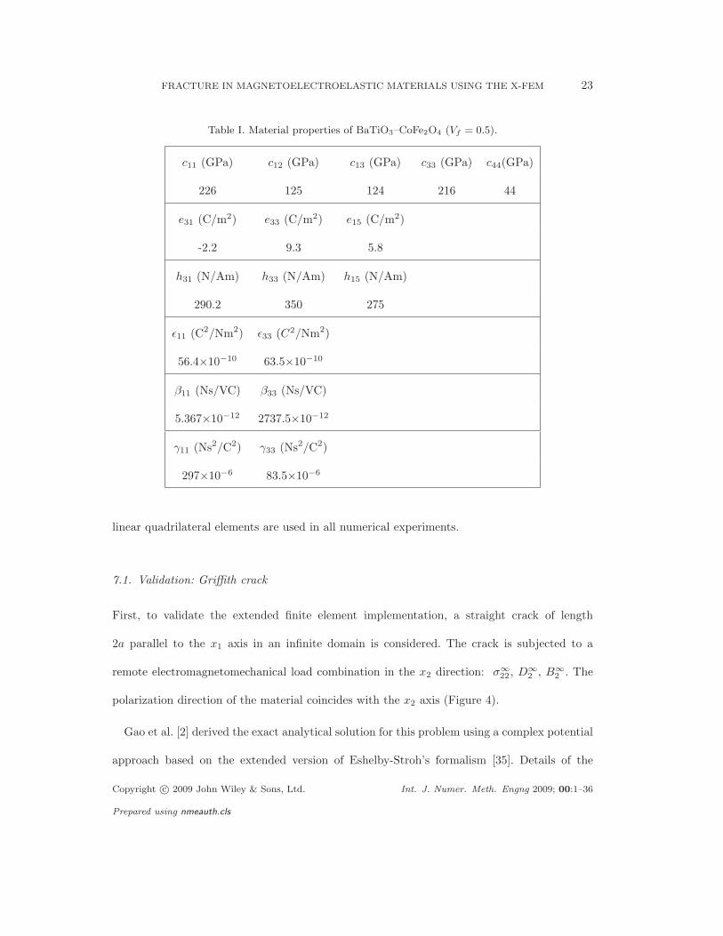
BaTiO3–CoFe2O4 with a volume fraction Vf = 0.5 is considered. The material properties are
listed in Table I.
Furthermore, a 2× 2 Gauss quadrature rule is used in every non-enriched element, whereas
for non-partitioned enriched elements a 5×5 Gauss rule is used. For enriched elements that are
partitioned into subtriangles, a seven point Gauss rule is used in each subtriangle. Moreover,
Copyright c© 2009 John Wiley & Sons, Ltd. Int. J. Numer. Meth. Engng 2009; 00:1–36
Prepared using nmeauth.cls
FRACTURE IN MAGNETOELECTROELASTIC MATERIALS USING THE X-FEM 23
Table I. Material properties of BaTiO3–CoFe2O4 (Vf = 0.5).
c11 (GPa) c12 (GPa) c13 (GPa) c33 (GPa) c44(GPa)
226 125 124 216 44
e31 (C/m2) e33 (C/m2) e15 (C/m2)
-2.2 9.3 5.8
h31 (N/Am) h33 (N/Am) h15 (N/Am)
290.2 350 275
ǫ11 (C2/Nm2) ǫ33 (C2/Nm2)
56.4×10⁻¹⁰ 63.5×10⁻¹⁰
β11 (Ns/VC) β33 (Ns/VC)
5.367×10⁻¹² 2737.5×10−12
γ11 (Ns2/C2) γ33 (Ns2/C2)
297×10−6 83.5×10⁻⁶
linear quadrilateral elements are used in all numerical experiments.
7.1. Validation: Griffith crack
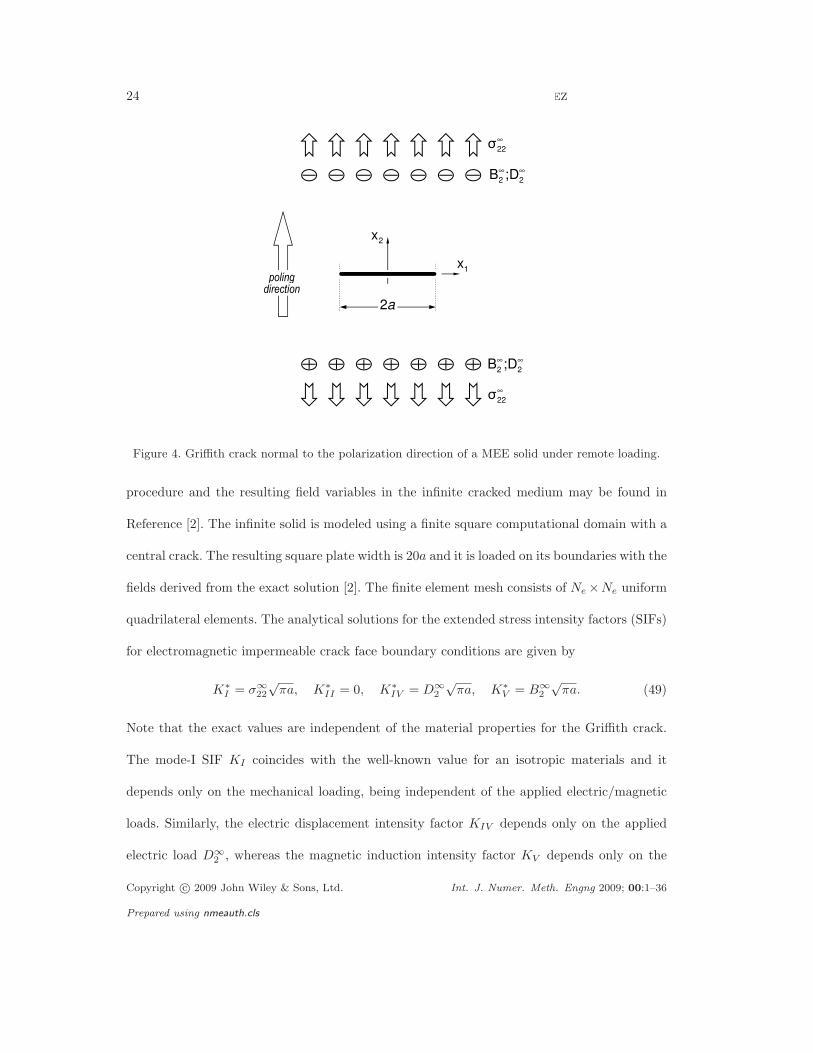
First, to validate the extended finite element implementation, a straight crack of length
2a parallel to the x1 axis in an infinite domain is considered. The crack is subjected to a
remote electromagnetomechanical load combination in the x2 direction: σ∞22 , D∞
2 , B∞2 . The
polarization direction of the material coincides with the x2 axis (Figure 4).
Gao et al. [2] derived the exact analytical solution for this problem using a complex potential
approach based on the extended version of Eshelby-Stroh’s formalism [35]. Details of the
Copyright c© 2009 John Wiley & Sons, Ltd. Int. J. Numer. Meth. Engng 2009; 00:1–36
Prepared using nmeauth.cls
24 R. ROJAS-DIAZ, N. SUKUMAR, A. SAEZ, F. GARCIA-SANCHEZ
Figure 4. Griffith crack normal to the polarization direction of a MEE solid under remote loading.
procedure and the resulting field variables in the infinite cracked medium may be found in
Reference [2]. The infinite solid is modeled using a finite square computational domain with a
central crack. The resulting square plate width is 20a and it is loaded on its boundaries with the
fields derived from the exact solution [2]. The finite element mesh consists of Ne ×Ne uniform
quadrilateral elements. The analytical solutions for the extended stress intensity factors (SIFs)
for electromagnetic impermeable crack face boundary conditions are given by
K∗I = σ∞
22
√πa, K∗
II = 0, K∗IV = D∞
2
√πa, K∗
V = B∞2
√πa. (49)
Note that the exact values are independent of the material properties for the Griffith crack.
The mode-I SIF KI coincides with the well-known value for an isotropic materials and it
depends only on the mechanical loading, being independent of the applied electric/magnetic
loads. Similarly, the electric displacement intensity factor KIV depends only on the applied
electric load D∞2 , whereas the magnetic induction intensity factor KV depends only on the
Copyright c© 2009 John Wiley & Sons, Ltd. Int. J. Numer. Meth. Engng 2009; 00:1–36
Prepared using nmeauth.cls
FRACTURE IN MAGNETOELECTROELASTIC MATERIALS USING THE X-FEM 25
applied magnetic load B∞2 .
To obtain the X-FEM numerical results two enrichment strategies are adopted:
• The conventional X-FEM approach using a topological enrichment with the eight newly
derived functions. In this case only the nodes belonging to elements enclosing the crack
tip are enriched (Figure 3).
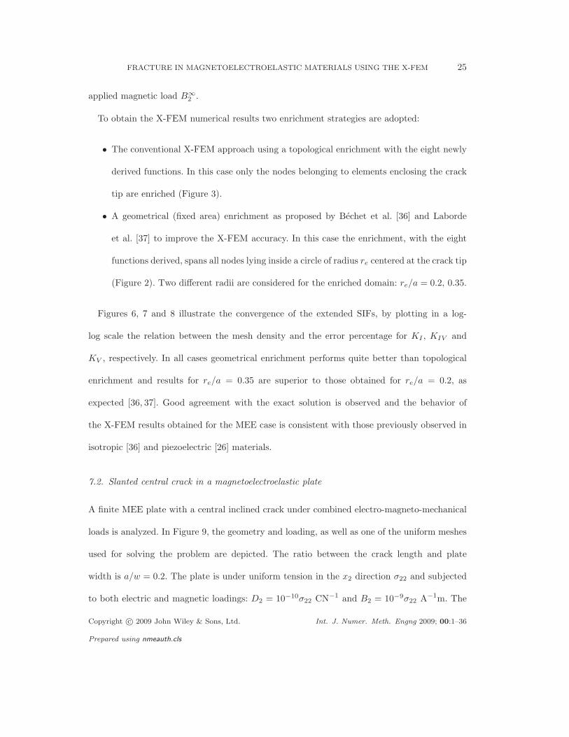
• A geometrical (fixed area) enrichment as proposed by Bechet et al. [36] and Laborde
et al. [37] to improve the X-FEM accuracy. In this case the enrichment, with the eight
functions derived, spans all nodes lying inside a circle of radius re centered at the crack tip
(Figure 2). Two different radii are considered for the enriched domain: re/a = 0.2, 0.35.
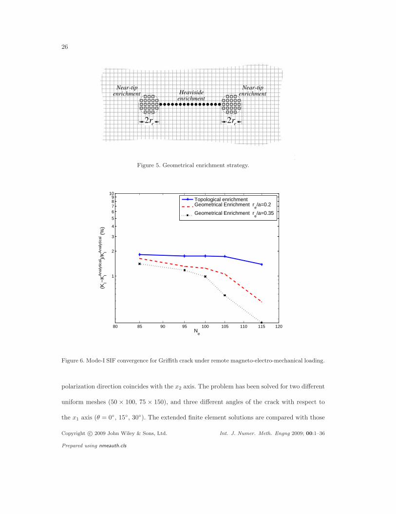
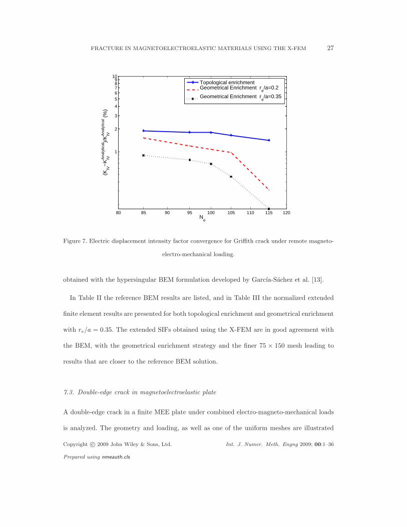
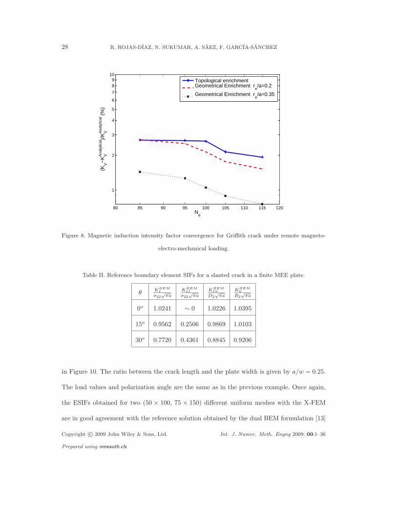
Figures 6, 7 and 8 illustrate the convergence of the extended SIFs, by plotting in a log-
log scale the relation between the mesh density and the error percentage for KI , KIV and
KV , respectively. In all cases geometrical enrichment performs quite better than topological
enrichment and results for re/a = 0.35 are superior to those obtained for re/a = 0.2, as
expected [36, 37]. Good agreement with the exact solution is observed and the behavior of
the X-FEM results obtained for the MEE case is consistent with those previously observed in
isotropic [36] and piezoelectric [26] materials.
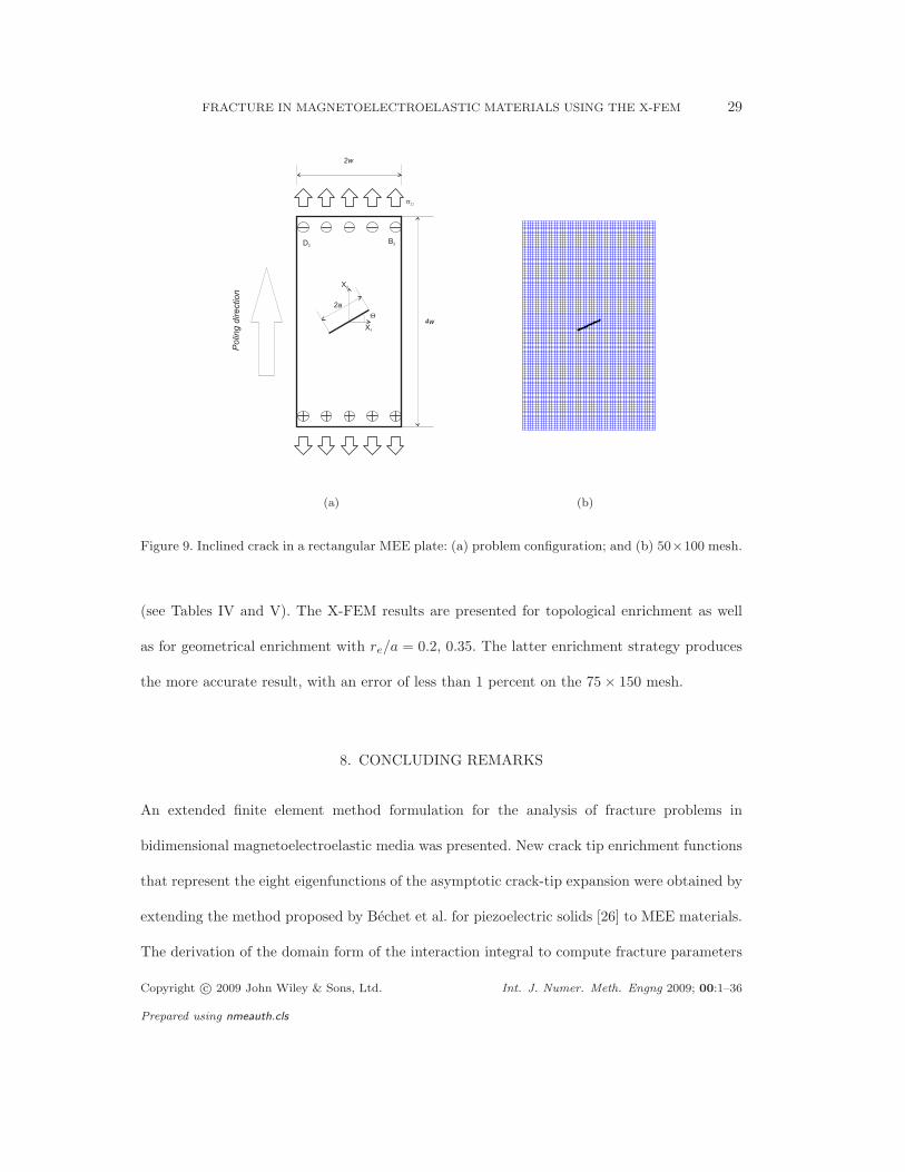
7.2. Slanted central crack in a magnetoelectroelastic plate
A finite MEE plate with a central inclined crack under combined electro-magneto-mechanical
loads is analyzed. In Figure 9, the geometry and loading, as well as one of the uniform meshes
used for solving the problem are depicted. The ratio between the crack length and plate
width is a/w = 0.2. The plate is under uniform tension in the x2 direction σ22 and subjected
to both electric and magnetic loadings: D2 = 10−10σ22 CN−1 and B2 = 10−9σ22 A−1m. The
Copyright c© 2009 John Wiley & Sons, Ltd. Int. J. Numer. Meth. Engng 2009; 00:1–36
Prepared using nmeauth.cls
26 R. ROJAS-DIAZ, N. SUKUMAR, A. SAEZ, F. GARCIA-SANCHEZ
Figure 5. Geometrical enrichment strategy.
80 85 90 95 100 105 110 115 120
1
2
3
4
5
6789
10
(KI−
KIA
naly
tical
)/K
IAna
lytic
al (
%)
Ne
Topological enrichmentGeometrical Enrichment r
e/a=0.2
Geometrical Enrichment re/a=0.35
Figure 6. Mode-I SIF convergence for Griffith crack under remote magneto-electro-mechanical loading.
polarization direction coincides with the x2 axis. The problem has been solved for two different
uniform meshes (50 × 100, 75 × 150), and three different angles of the crack with respect to
the x1 axis (θ = 0, 15, 30). The extended finite element solutions are compared with those
Copyright c© 2009 John Wiley & Sons, Ltd. Int. J. Numer. Meth. Engng 2009; 00:1–36
Prepared using nmeauth.cls
FRACTURE IN MAGNETOELECTROELASTIC MATERIALS USING THE X-FEM 27
80 85 90 95 100 105 110 115 120
1
2
3
4
56789
10
(KIV
−K
IVAna
lytic
al)/
KIVA
naly
tical
(%
)
Ne
Topological enrichmentGeometrical Enrichment r
e/a=0.2
Geometrical Enrichment re/a=0.35
Figure 7. Electric displacement intensity factor convergence for Griffith crack under remote magneto-
electro-mechanical loading.
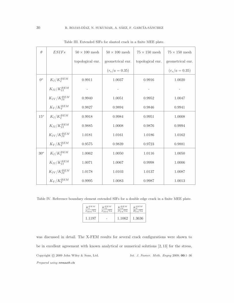
obtained with the hypersingular BEM formulation developed by Garcıa-Sachez et al. [13].
In Table II the reference BEM results are listed, and in Table III the normalized extended
finite element results are presented for both topological enrichment and geometrical enrichment
with re/a = 0.35. The extended SIFs obtained using the X-FEM are in good agreement with
the BEM, with the geometrical enrichment strategy and the finer 75 × 150 mesh leading to
results that are closer to the reference BEM solution.
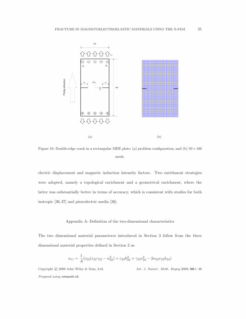
7.3. Double-edge crack in magnetoelectroelastic plate
A double-edge crack in a finite MEE plate under combined electro-magneto-mechanical loads
is analyzed. The geometry and loading, as well as one of the uniform meshes are illustrated
Copyright c© 2009 John Wiley & Sons, Ltd. Int. J. Numer. Meth. Engng 2009; 00:1–36
Prepared using nmeauth.cls
28 R. ROJAS-DIAZ, N. SUKUMAR, A. SAEZ, F. GARCIA-SANCHEZ
80 85 90 95 100 105 110 115 120
1
2
3
4
5
6
7
89
10
(KV−
KVA
naly
tical
)/K
VAna
lytic
al (
%)
Ne
Topological enrichmentGeometrical Enrichment r
e/a=0.2
Geometrical Enrichment re/a=0.35
Figure 8. Magnetic induction intensity factor convergence for Griffith crack under remote magneto-
electro-mechanical loading.
Table II. Reference boundary element SIFs for a slanted crack in a finite MEE plate.
θKBEM
I
σ22
√πa
KBEM
II
σ22
√πa
KBEM
IV
D2
√πa
KBEM
V
B2
√πa
0o 1.0241 ∼ 0 1.0226 1.0395
15o 0.9562 0.2506 0.9869 1.0103
30o 0.7720 0.4361 0.8845 0.9206
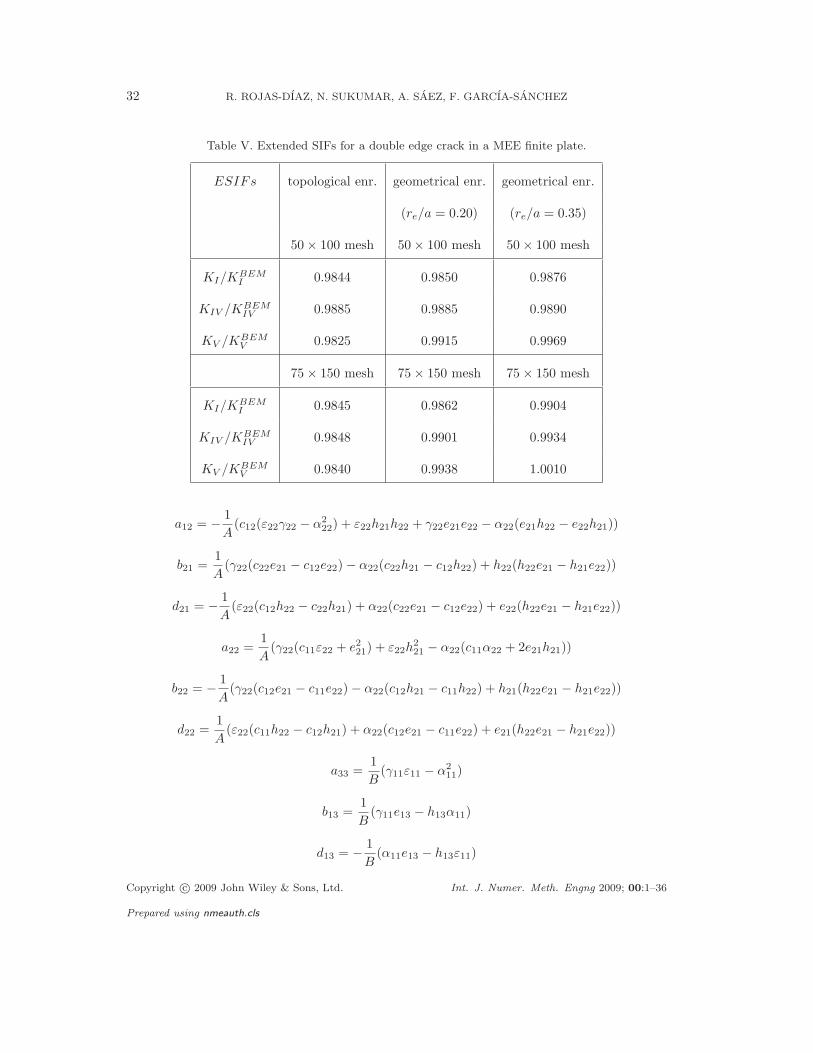
in Figure 10. The ratio between the crack length and the plate width is given by a/w = 0.25.
The load values and polarization angle are the same as in the previous example. Once again,
the ESIFs obtained for two (50 × 100, 75 × 150) different uniform meshes with the X-FEM
are in good agreement with the reference solution obtained by the dual BEM formulation [13]
Copyright c© 2009 John Wiley & Sons, Ltd. Int. J. Numer. Meth. Engng 2009; 00:1–36
Prepared using nmeauth.cls
FRACTURE IN MAGNETOELECTROELASTIC MATERIALS USING THE X-FEM 29
X1
X2
2a
4w
2w
Po
ling
dire
ctio
nD
2B
2
Q
s22
(a) (b)
Figure 9. Inclined crack in a rectangular MEE plate: (a) problem configuration; and (b) 50×100 mesh.
(see Tables IV and V). The X-FEM results are presented for topological enrichment as well
as for geometrical enrichment with re/a = 0.2, 0.35. The latter enrichment strategy produces
the more accurate result, with an error of less than 1 percent on the 75 × 150 mesh.
8. CONCLUDING REMARKS
An extended finite element method formulation for the analysis of fracture problems in
bidimensional magnetoelectroelastic media was presented. New crack tip enrichment functions
that represent the eight eigenfunctions of the asymptotic crack-tip expansion were obtained by
extending the method proposed by Bechet et al. for piezoelectric solids [26] to MEE materials.
The derivation of the domain form of the interaction integral to compute fracture parameters
Copyright c© 2009 John Wiley & Sons, Ltd. Int. J. Numer. Meth. Engng 2009; 00:1–36
Prepared using nmeauth.cls
30 R. ROJAS-DIAZ, N. SUKUMAR, A. SAEZ, F. GARCIA-SANCHEZ
Table III. Extended SIFs for slanted crack in a finite MEE plate.
θ ESIFs 50 × 100 mesh 50 × 100 mesh 75 × 150 mesh 75 × 150 mesh
topological enr. geometrical enr. topological enr. geometrical enr.
(re/a = 0.35) (re/a = 0.35)
0o KI/KBEMI 0.9911 1.0037 0.9916 1.0020
KII/KBEMII - - - -
KIV /KBEMIV 0.9940 1.0051 0.9952 1.0047
KV /KBEMV 0.9827 0.9894 0.9846 0.9941
15o KI/KBEMI 0.9918 0.9984 0.9951 1.0008
KII/KBEMII 0.9885 1.0008 0.9876 0.9994
KIV /KBEMIV 1.0181 1.0161 1.0186 1.0162
KV /KBEMV 0.9575 0.9839 0.9723 0.9881
30o KI/KBEMI 1.0062 1.0050 1.0116 1.0050
KII/KBEMII 1.0071 1.0067 0.9998 1.0006
KIV /KBEMIV 1.0178 1.0103 1.0137 1.0087
KV /KBEMV 0.9995 1.0083 0.9987 1.0013
Table IV. Reference boundary element extended SIFs for a double edge crack in a finite MEE plate.
KBEM
I
σ22
√πa
KBEM
II
σ22
√πa
KBEM
IV
D2
√πa
KBEM
V
B2
√πa
1.1197 - 1.1062 1.3636
was discussed in detail. The X-FEM results for several crack configurations were shown to
be in excellent agreement with known analytical or numerical solutions [2, 13] for the stress,
Copyright c© 2009 John Wiley & Sons, Ltd. Int. J. Numer. Meth. Engng 2009; 00:1–36
Prepared using nmeauth.cls
FRACTURE IN MAGNETOELECTROELASTIC MATERIALS USING THE X-FEM 31
X1
X2a a
4w
2w
Po
ling
dire
ctio
nD
2B
2
s22
(a) (b)
Figure 10. Double-edge crack in a rectangular MEE plate: (a) problem configuration; and (b) 50×100
mesh.
electric displacement and magnetic induction intensity factors. Two enrichment strategies
were adopted, namely a topological enrichment and a geometrical enrichment, where the
latter was substantially better in terms of accuracy, which is consistent with studies for both
isotropic [36,37] and piezoelectric media [26].
Appendix A: Definition of the two-dimensional characteristics
The two dimensional material parameteres introduced in Section 3 follow from the three
dimensional material properties defined in Section 2 as
a11 =1
A(c22(ε22γ22 − α2
22) + ε22h222 + γ22e
222 − 2α22e22h22)
Copyright c© 2009 John Wiley & Sons, Ltd. Int. J. Numer. Meth. Engng 2009; 00:1–36
Prepared using nmeauth.cls
32 R. ROJAS-DIAZ, N. SUKUMAR, A. SAEZ, F. GARCIA-SANCHEZ
Table V. Extended SIFs for a double edge crack in a MEE finite plate.
ESIFs topological enr. geometrical enr. geometrical enr.
(re/a = 0.20) (re/a = 0.35)
50 × 100 mesh 50 × 100 mesh 50 × 100 mesh
KI/KBEMI 0.9844 0.9850 0.9876
KIV /KBEMIV 0.9885 0.9885 0.9890
KV /KBEMV 0.9825 0.9915 0.9969
75 × 150 mesh 75 × 150 mesh 75 × 150 mesh
KI/KBEMI 0.9845 0.9862 0.9904
KIV /KBEMIV 0.9848 0.9901 0.9934
KV /KBEMV 0.9840 0.9938 1.0010
a12 = − 1
A(c12(ε22γ22 − α2
22) + ε22h21h22 + γ22e21e22 − α22(e21h22 − e22h21))
b21 =1
A(γ22(c22e21 − c12e22) − α22(c22h21 − c12h22) + h22(h22e21 − h21e22))
d21 = − 1
A(ε22(c12h22 − c22h21) + α22(c22e21 − c12e22) + e22(h22e21 − h21e22))
a22 =1
A(γ22(c11ε22 + e2
21) + ε22h221 − α22(c11α22 + 2e21h21))
b22 = − 1
A(γ22(c12e21 − c11e22) − α22(c12h21 − c11h22) + h21(h22e21 − h21e22))
d22 =1
A(ε22(c11h22 − c12h21) + α22(c12e21 − c11e22) + e21(h22e21 − h21e22))
a33 =1
B(γ11ε11 − α2
11)
b13 =1
B(γ11e13 − h13α11)
d13 = − 1
B(α11e13 − h13ε11)
Copyright c© 2009 John Wiley & Sons, Ltd. Int. J. Numer. Meth. Engng 2009; 00:1–36
Prepared using nmeauth.cls
FRACTURE IN MAGNETOELECTROELASTIC MATERIALS USING THE X-FEM 33
δ11 =1
B(γ11c33 + h2
13)
∆11 = − 1
B(α11c33 + e13h13)
δ22 =1
A(γ22(c11c22 − c2
12) + c11h222 + c22h
221 − 2c12h12h22)
∆22 = − 1
A(α22(c11c22 − c2
12) + c11e22h22 + c22e21h21 − c12(e22h21 + e21h22))
ζ11 =1
B(ε11c33 + e2
13)
ζ22 =1
A(ε22(c11c22 − c2
12) + c11e222 + c22e
221 − 2c12e12e22)
where the Voigt notation has been used and
A = (c11c22 − c212)(ε22γ22 − α2
22) + e221(c22γ22 + h2
22) + e222(c11γ22 + h2
21)
+2α22(e21(c12h22 − c22h21) + e22(c12h21 − c11h22)) − 2e21e22(c12γ22 + h21h22)
+ε22(c11h222 + c22h
221 − c12h21h22)
and
B = ε11(c33γ11 + h132) − α11(c33α11 + 2e13h13) + γ11e213
REFERENCES
1. C.-W. Nan, M. I. Bichurin, S. Dong, D. Viehland, and G. Srinivasan, Multiferroic magnetoelectric
composites: Historical perspective, status, and future directions, Journal of Applied Physics,
103(3):031101, 2008.
2. C.F. Gao, H. Kessler, and H. Balke, Crack problems in magnetoelectroelastic solids. Part I: exact solution
of a crack, International Journal of Enginering Science, 41:969–981, 2003.
3. C. F. Gao, H. Kessler, and H. Balke, Crack problems in magnetoelectroelastic solids. Part II: General
solution of collinear cracks, International Journal of Enginering Science, 41:983–994, 2003.
4. C. F. Gao, P. Tong, and T. Y. Zhang, Interfacial crack problems in magneto-electroelastic solids,
International Journal of Enginering Science, 41:2105–2121, 2003.
Copyright c© 2009 John Wiley & Sons, Ltd. Int. J. Numer. Meth. Engng 2009; 00:1–36
Prepared using nmeauth.cls
34 R. ROJAS-DIAZ, N. SUKUMAR, A. SAEZ, F. GARCIA-SANCHEZ
5. C. F. Gao, P. Tong, and T. Y. Zhang, Fracture mechanics for a mode III crack in a magnetoelectroelastic
solid, International Journal of Solids and Structures, 41:6613–6629, 2004.
6. G. C. Sih and Z. F. Song, Magnetic and electric poling effects associated with crack growth in BaTiO3–
CoFe2O4 composite, Theoretical and Applied Fracture Mechanics, 39:209–227, 2003.
7. G. C. Sih and Z. F. Song, Piezomagnetic and piezoelectric poling effects on mode I and II crack initiation
behaviour of magnetoelectroelastic materials composite, Theoretical and Applied Fracture Mechanics,
40:161–186, 2003.
8. G. C. Sih and H. Y. Yu, Volume fraction effect of magnetoelectroelastic composite on enhancement and
impediment of crack growth, Composite structures, 68:1–11, 2005.
9. Z. F. Song and G. C. Sih, Crack initiation behavior in magnetoelectroelastic composite under in-plane
deformation, Theoretical and Applied Fracture Mechanics, 39:189–207, 2003.
10. B. L. Wang and Y. W. Mai, Crack tip field in piezoelectric/piezomagnetic media, European Journal of
Mechanics - A/Solids, 22:591–602, 2003.
11. B. L. Wang and Y. W. Mai, Fracture of piezoelectromagnetic materials, Mechanics Research
Communications, 31: 65–73, 2004.
12. W. Y. Tian and R. K. N. D. Rajapakse, Fracture analysis of magnetoelectroelastic solids by using path
independent integrals, International Journal of Fracture, 131:311–335, 2005.
13. F. Garcıa-Sanchez, R. Rojas-Dıaz, A. Saez, and Ch. Zhang, Fracture of magnetoelectroelastic composite
materials using boundary element method (BEM), Theoretical and Applied Fracture Mechanics,
47(3):192–204, 2007.
14. J. Sladek, V. Sladek, P. Solek, and E. Pan, Fracture analysis of cracks in magneto-electro-elastic solids by
the MLPG, Computational Mechanics, 42:697–714, 2008.
15. G. R. Buchanan, H. Kessler, and H. Balke, Layered versus multiphase magneto-electro-elastic composites,
Composites Part B: Engineering, 35(5):413–420, 2004.
16. R. M. Garcia Lage, C. M. Mota Soares, and C. A. Mota Soares, Layerwise partial mixed finite element
analysis of magneto-electro-elastic plates, Computers and Structures, 82: 1293–1301, 2004.
17. R. K. Bhangale and N. Ganesan, Static analysis of simply supported functionally graded and layered
magneto-electro-elastic plates, 43:3230–3253, 2006.
18. R. K. Bhangale and N. Ganesan, Free vibration of simply supported functionally graded and layered
magneto-electro-elastic plates by finite element method, Journal of Sound and Vibration, 294:1016–1038,
2006.
Copyright c© 2009 John Wiley & Sons, Ltd. Int. J. Numer. Meth. Engng 2009; 00:1–36
Prepared using nmeauth.cls
FRACTURE IN MAGNETOELECTROELASTIC MATERIALS USING THE X-FEM 35
19. A. R. Annigeri, N. Ganesan, and S. Swarnamani, Free vibrations of clamped-clamped magneto-electro-
elastic cylindrical shells, Journal of Sound and Vibration, 292:300–314, 2006.
20. A. Daga, N. Ganesan, and K. Shankar, Behaviour of magneto-electro-elastic sensors under transient
mechanical loading, Sensors and Actuators A: Physical, 150:46–55, 2009.
21. J. M. Simoes Moita, C. M. Mota Soares, and C. A. Mota Soares, Analyses of magneto-electro-elastic plates
using a higher order finite element model, Composite Structures, 91:421–426, 2009.
22. B. Wang and Y. W. Mai, Self-consistent analysis of coupled magnetoelectroelastic fracture. Theoretical
investigation and finite element verigfication, Computer Methods in Applied Mechanics and Engineering,
196:2044-2054, 2007.
23. N. Moes, J. Dolbow, and T. Belytschko. A finite element method for crack growth without remeshing,
International Journal for Numerical Methods in Engineering, 46:131-150, 1999.
24. N. Sukumar, Z. Y. Huang, J.-H. Prvost, and Z. Suo, Partition of unity enrichment for bimaterial interface
cracks, International Journal for Numerical Methods in Engineering, 59:1075–1102, 2004
25. A. Asadpoure and S. Mohammadi. Developing new enrichment functions for crack simulation in orthotropic
media by the extended finite element method. International Journal for Numerical Methods in Engineering,
69:2150-2172, 2007.
26. E. Bechet, M. Scherzer, and M. Kuna, Application of the X-FEM to the fracture of piezoelectric materials,
International Journal for Numerical Methods in Engineering, 77:1535–1565, 2009.
27. T. P. Fries and T. Belytschko, The extended/generalized finite element method: An overview of the
method and its applications, International Journal for Numerical Methods in Engineering, 2010. DOI:
10.1002/nme.2914.
28. A. K. Soh and J. X. Liu, On the Constitutive Equations of Magnetoelectroelastic Solids, Journal of
Intelligent Material Systems and Structures, 16: 597–602, 2005.
29. D. M. Barnett and J. Lothe, 1975 Dislocations and Line Charges in Anisotropic Piezoelectric Insulators,
Phys. Stat. Sol., 67(b):105–111, 1975.
30. W. Y. Tian and R. K. N. D. Rajapakse, Theoretical modelling of a conducting crack in a
magnetoelectroelastic solid, International Journal of Applied Electromagnetics and Mechanics, 22:141–
158, 2005.
31. H. Sosa, Plane problems in piezoelectric media with defects, International Journal of Solids and Structures,
28:491–505, 1991.
32. T. Belytschko and T. Black, Elastic crack growth in finite elements with minimal remeshing, International
Copyright c© 2009 John Wiley & Sons, Ltd. Int. J. Numer. Meth. Engng 2009; 00:1–36
Prepared using nmeauth.cls
36 R. ROJAS-DIAZ, N. SUKUMAR, A. SAEZ, F. GARCIA-SANCHEZ
Journal for Numerical Methods in Engineering, 45:601-620, 1999.
33. I. Babuska and J. M. Melenk. The partition of unity method. International Journal for Numerical Methods
in Engineering, 4:607–632, 1997.
34. B. N. Rao and M. Kuna, Interaction integrals for fracture analysis of functionally graded
magnetoelectroelastic materials, International Journal of Fracture, 153:15–37, 2008.
35. A. N. Stroh, Dislocations and cracks in anisotropic elasticity, Philos. Mag., 3:625–646, 1958.
36. E. Bechet, H. Minnebo, N. Moes, and B. Burgardt, Improved implementation and robustness study of the
X-FEM for stress analysis around cracks, International Journal for Numerical Methods in Engineering,
64:1033–1056, 2005.
37. P. Laborde, J. Pommier, Y. Renard, and M. Salan, High-order extended finite element method for cracked
domains, International Journal for Numerical Methods in Engineering, 64:354-381, 2005.
Copyright c© 2009 John Wiley & Sons, Ltd. Int. J. Numer. Meth. Engng 2009; 00:1–36
Prepared using nmeauth.cls