Embed Size (px)
Citation preview
Solar Access to Public Capital (SAPC)Working Group
Best Practices in PV System Operations and MaintenanceVersion 1.0, March 2015
NREL is a national laboratory of the U.S. Department of Energy Office of Energy Efficiency and Renewable EnergyOperated by the Alliance for Sustainable Energy, LLC
NREL is a national laboratory of the U.S. Department of Energy Office of Energy Efficiency & Renewable Energy Operated by the Alliance for Sustainable Energy, LLC This report is available at no cost from the National Renewable Energy Laboratory (NREL) at www.nrel.gov/publications.
Contract No. DE-AC36-08GO28308
National Renewable Energy Laboratory 15013 Denver West Parkway Golden, CO 80401 303-275-3000 • www.nrel.gov
SAPC Best Practices in PV Operations and Maintenance Version 1.0, March 2015 Period of Performance January 1, 2014 — December 31, 2015 T.J. Keating SunSpec Alliance San Jose, California
A. Walker and K. Ardani National Renewable Energy Laboratory Golden, Colorado
NREL Technical Monitor: Michael Mendelsohn Prepared under Subcontract No. LXL-3-23341-01
Subcontract Report NREL/SR-6A20-63235 March 2015
This publication received minimal editorial review at NREL.
NOTICE
This report was prepared as an account of work sponsored by an agency of the United States government. Neither the United States government nor any agency thereof, nor any of their employees, makes any warranty, express or implied, or assumes any legal liability or responsibility for the accuracy, completeness, or usefulness of any information, apparatus, product, or process disclosed, or represents that its use would not infringe privately owned rights. Reference herein to any specific commercial product, process, or service by trade name, trademark, manufacturer, or otherwise does not necessarily constitute or imply its endorsement, recommendation, or favoring by the United States government or any agency thereof. The views and opinions of authors expressed herein do not necessarily state or reflect those of the United States government or any agency thereof.
This report is available at no cost from the National Renewable Energy Laboratory (NREL) at www.nrel.gov/publications.
Available electronically at http://www.osti.gov/scitech
Available for a processing fee to U.S. Department of Energy and its contractors, in paper, from:
U.S. Department of Energy Office of Scientific and Technical Information P.O. Box 62 Oak Ridge, TN 37831-0062 phone: 865.576.8401 fax: 865.576.5728 email: mailto:[email protected]
Available for sale to the public, in paper, from:
U.S. Department of Commerce National Technical Information Service 5285 Port Royal Road Springfield, VA 22161 phone: 800.553.6847 fax: 703.605.6900 email: [email protected] online ordering: http://www.ntis.gov/help/ordermethods.aspx
Cover Photo from iStock 000014394067
NREL prints on paper that contains recycled content.
iii
This report is available at no cost from the National Renewable Energy Laboratory (NREL) at www.nrel.gov/publications.
Disclaimer The attached Best Practices document was developed through an industry-organizing process convened by the National Renewable Energy Laboratory (NREL). The process was open to a wide array of industry members to get a broad range of perspectives. The document represents the result of long discussions and negotiations on a variety of topic areas of interest to the participating stakeholders. The document does not reflect NREL’s or the U.S. Department of Energy’s endorsement of any activity or group of activities. Rather, the document is designed to provide a reasonable protocol associated with photovoltaics (PV) system operations and maintenance supported by the industry stakeholder process in order to improve the energy and cash flow production capability of the PV generating assets in the field.
iv
This report is available at no cost from the National Renewable Energy Laboratory (NREL) at www.nrel.gov/publications.
Acknowledgments The authors would like to thank the following contributors to this report.
Interviewees Mark Berger, NextGrid Technologies Ross Biesemeyer, First Solar Sarah Disch, Wells Fargo David Kenny, Sunrun Jean Paul La Marche, Main Street Power Marco Lopez, Alectris
Dirk Michaels, K & L Gates Rue Philips, TRUE South Laks Sanpath, NRG Greg Sellers, Clean Power Finance Andrew Truitt, Truitt RE Consulting Leigh Zanone, Meteocontrol
Working Group Roster Rob Andrews, Calama Consulting Will Arnold, GTRI Brian Boler, Clean Power Research Gary Buchanan, Borrego Solar Tommy Cleveland, NC Solar Center Ben Compton, SolPatrol Sarah Disch, Wells Fargo John Dise, Clean Power Finance Roger Hill, Sandia National
Laboratories Tim (TJ) Keating, SunSpec Alliance Jason Kechijian, SolBright George Kelly, Sunset Technology Inc. Geoff Klise, Sandia National
Laboratories Jaya Krishna Mallineni, Arizona State
University
Mark Liffman, Clean Power Finance Robert Margolis, NREL Michael Mendelsohn, NREL Richard Pizzella, HSB Mike Robinson, EDF-RE Ben Searl, New Energy Structures Dan Seif, Rocky Mountain Institute Jürgen Sutterlüti , PV Systems Group Mani Tamizh-Mani, TUV Rheinland James Tong, Clean Power Finance Andrew Truitt, Truitt RE Consulting Sarah Truitt, NREL Henry Tsai, NC Solar Center Jason Uppal, SunShot Solar Outreach Partnership Bassil Youakim, Bank of America Thomas Yurysta, Optony, Inc.
v
This report is available at no cost from the National Renewable Energy Laboratory (NREL) at www.nrel.gov/publications.
Table of Contents 1 Introduction ........................................................................................................................................... 1
1.1 Solar Access to Public Capital and the O&M Collaborative ........................................................ 1 1.2 Purpose .......................................................................................................................................... 1 1.3 How to Use This Document .......................................................................................................... 1 1.4 Complementary SAPC Documents ............................................................................................... 1
2 Change Log for Commercial PPA Background: O&M and the Financing of PV Assets ............... 3 3 Scope and Prerequisites for a Successful O&M Program ............................................................... 5
3.1 Scope of PV O&M Best Practices Guide ...................................................................................... 5 3.2 Prerequisites for a Successful O&M Program .............................................................................. 5
4 Definitions ............................................................................................................................................. 6 5 System Performance and O&M Plans ................................................................................................ 8
5.1 Planning for PV System Performance ........................................................................................... 8 5.2 The PV O&M Plan ...................................................................................................................... 10 5.3 Use of O&M Plan ........................................................................................................................ 11 5.4 Preventive/Scheduled Maintenance ............................................................................................ 13 5.5 Corrective Maintenance .............................................................................................................. 13 5.6 Inverter ........................................................................................................................................ 13 5.7 PV Module Degradation Rate ..................................................................................................... 14 5.8 Example Work Statements .......................................................................................................... 14
6 O&M Provider Qualifications and Responsibilities ......................................................................... 15 6.1 Qualifications of Service Providers ............................................................................................. 15 6.2 Financial Solvency ...................................................................................................................... 15 6.3 Health and Safety ........................................................................................................................ 16 6.4 Insurance ..................................................................................................................................... 16 6.5 Redundancy in Service Providers ................................................................................................ 17
7 System Monitoring ............................................................................................................................. 18 7.1 Data Presentation ......................................................................................................................... 18 7.2 Quality of Monitoring Equipment ............................................................................................... 18 7.3 Transparency of Measurement Protocols and Procedures ........................................................... 19
8 O&M Supporting Systems and Implementation Strategies ........................................................... 20 8.1 Instrumentation ............................................................................................................................ 20 8.2 Workflow and Decision Support Software ................................................................................. 20 8.3 O&M Implementation Strategies ................................................................................................ 21 8.4 O&M Contract and Performance Warranties .............................................................................. 22
9 The PV O&M Cost Model Overview and Use ................................................................................... 23 10 Current PV O&M Cost Survey Information ...................................................................................... 25 References and Resources ...................................................................................................................... 26 Appendix A. System Performance Guarantee Example Calculation (without shade correction) .... 28 Appendix B. Service Descriptions for Preventative Maintenance Selections Available in the
PV O&M Cost Model Tool .................................................................................................................. 32 Appendix C. Service Descriptions for Corrective Maintenance Selections Available in the PV
O&M Cost Model ................................................................................................................................. 38 Appendix D. PV O&M Service Category, Scope of Work, Salary, and Qualifications ........................ 42 Appendix E. Examples of Scope of Work Documents .......................................................................... 44
1
This report is available at no cost from the National Renewable Energy Laboratory (NREL) at www.nrel.gov/publications.
1 Introduction 1.1 Solar Access to Public Capital and the O&M Collaborative The following Photovoltaics (PV) Operations and Maintenance (O&M) Best Practices Guide is one of several work products developed by the Solar Access to Public Capital (SAPC) working group, which works to open capital market investment. SAPC membership includes over 450 leading solar developers, financiers and capital managers, law firms, rating agencies, accounting and engineering firms, and other stakeholders engaged in solar asset deployment. SAPC activities are directed toward foundational elements necessary to pool project cash flows into tradable securities: standardization of power purchase and lease contracts for residential and commercial end customers; development of performance and credit data sets to facilitate investor due diligence activities; comprehension of risk perceived by rating agencies; and the development of best practice guides for PV system installation and O&M in order to encourage high-quality system deployment and operation that may improve lifetime project performance and energy production.
This PV O&M Best Practices Guide was developed by the PV O&M Collaborative, a subgroup of SAPC comprised of a variety of solar industry leaders in numerous fields of practice. The guide was developed over roughly one year of direct engagement by the subcommittee and two working group comment periods.
1.2 Purpose This PV O&M Best Practices Guide is designed to improve solar asset transparency for investors and rating agencies, provide an industry framework for quality management, and reduce transaction costs in the solar asset securitization process. The PV O&M Best Practices Guide is intended to outline the minimum requirements for third-party ownership providers (“Providers”). Adherence to the guide is voluntary. Providers that adhere to the guide are responsible for self-certifying that they have fulfilled the guide requirements.
1.3 How to Use This Document This document is best viewed on a computer or tablet in order to take full advantage of the embedded, clickable hyperlinks that lead to further information and additional resources. Each hyperlink is fully cited in the References and Resources section beginning on page 26.
1.4 Complementary SAPC Documents This O&M Best Practices Guide is designed to be used together with several other SAPC documents such as standardized solar contract templates. Current versions are available from the National Renewable Energy Laboratory (NREL) SAPC working group at https://financeRE.nrel.gov.
The SAPC PV System Installation Best Practices Guide, which was assembled by another SAPC working group, includes requirements for installing contractor qualifications, design guidelines, system inspections, and system documentation, all of which are also directly applicable to on-going PV O&M.
2
This report is available at no cost from the National Renewable Energy Laboratory (NREL) at www.nrel.gov/publications.
The SAPC working group provides standard residential lease and commercial power purchase agreement (PPA) contracts available for use by developers, customers, and third-party finance providers in the solar industry. These documents are designed to improve consumer transparency, reduce transaction costs in the solar asset contracting process, and facilitate the pooling of the associated cash flows so that they may be securitized and sold in the capital markets.
The following standard contracts may be downloaded from https://financere.nrel.gov/finance/solar_securitization_public_capital_finance.
Residential Contracts 1. 0% Down Residential Lease – Aggregated Business Model (for vertically integrated
developers and installers)
2. 0% Down Residential Lease – Disaggregated Business Model (for developers with a network of installation partners, or third-party finance providers that are discrete entities)
3. Residential PPA Agreement – Aggregated Business Model
4. Residential PPA Agreement – Disaggregated Business Model
Commercial Contracts
1. Commercial PPA version 1.0
2. Commercial PPA version 1.1.
3
This report is available at no cost from the National Renewable Energy Laboratory (NREL) at www.nrel.gov/publications.
2 Change Log for Commercial PPA Background: O&M and the Financing of PV Assets
An effective O&M program enhances the likelihood a system will perform at or above its projected production rate and cost over time. It therefore reinforces confidence in the long-term performance and revenue capacity of an asset. O&M practices and approaches are not standard and are implemented in various proprietary methods. This increases the cost and the perception of risks to funding sources and investors, and it also reduces the ability to pool solar assets for securitizations. Specific consequences of variations in O&M practices include:
1. Performance metrics are defined differently. A system characterized by a guarantee to deliver 1,000 MWh/year would be difficult to compare and bundle with another that has a guarantee to be operational 90% of the time. Investors need clear performance metrics and evaluation methods.
2. Practices and delivery of O&M services also differ, and investors need to know that an existing system has been maintained according to standard definitions and criteria.
3. Differences in types of systems and also geographic location and climate conditions can also confound securitization. Investors want to know how much it will cost to perform required O&M and secure the performance of the investment. Cost estimates must be uniform and predictable so that they can be bundled, yet they should reflect the factors that cause O&M costs to vary from site to site.
Many investors are more interested in reducing risk than maximizing internal rate of return (IRR). Investors would prefer 5% IRR with 100% certainty over 10% IRR with 50% certainty, although the two are of statistically equivalent value. Investors will make an investment decision based on mitigating performance risk with effective O&M, and then the financing rates are determined mainly through competition from other banks. Standardization of O&M practices will facilitate both investor analyses of risk factors as well as securitization of PV asset cash flows. Risk reduced by effective O&M will enable banks to qualify more projects, and that will eventually increase competition and reduce borrowing costs.
While PV systems may have different origins, they can be pooled together in portfolios if they adhere to clear, industry-accepted business and technical guidelines regarding O&M. Industry groups important to this effort include the Institute for Building Technology and Safety (IBTS), the SunSpec Alliance, and the North American Board of Certified Energy Practitioners (NABCEP). National and international standards developing organizations (SDOs) important to this effort include the American National Standards Institute (ANSI), the Institute of Electrical and Electronics Engineers (IEEE), the International Electrotechnical Commission (IEC), and ASTM International (formerly known as the American Society for Testing and Materials).
Two SDOs—ASTM International and the IEC—are coordinating directly with NREL and Sandia National Laboratories to develop O&M standards, with drafts being made available to working group members. These standards are primarily technical in nature and focus on life cycle management, design for O&M guidelines, and detailed maintenance processes and procedures. Representatives from ASTM International and the IEC were involved in the development of these best practices, and a coordination meeting was held in San Francisco in

4
This report is available at no cost from the National Renewable Energy Laboratory (NREL) at www.nrel.gov/publications.
March of 2014. This document is offered as what is referred to in the standards making process as “research,” to be considered as the IEC and ASTM International committees develop the language of the standards.
5
This report is available at no cost from the National Renewable Energy Laboratory (NREL) at www.nrel.gov/publications.
3 Scope and Prerequisites for a Successful O&M Program
3.1 Scope of PV O&M Best Practices Guide This document is targeted at fleets of third-party-owned, grid-connected PV systems of the following size classes:
• Residential rooftop (typically less than 10 kW)
• Commercial and industrial rooftops and shade structures (10 kW to 1,000 kW)
• Ground-mounted systems (often greater than 1,000 kW).
3.2 Prerequisites for a Successful O&M Program Borrowing from classroom grades, where “A” is best, it is possible to bring a PV system earning a “D” grade up to a “C” or “B” with effective O&M, but it is not possible to earn an “A” unless O&M was a consideration in the design of a system. Also, O&M might not be able to save a failing system in the problems are intrinsic to the design or products used. O&M issues should be considered in design, engineering, and construction in order to:
1. Select low- or no-maintenance alternatives when available
2. Make use of connected inverters for remote testing, software configurations and/or updates, and remote resets
3. Provide required access to and clearance around equipment for maintenance (EPRI 2010)
4. Enable third-party inspection and commissioning of original EPC installations to spot operation problems before acceptance (EPRI 2010)
5. Conform to the evaluation and quality assurance protocol detailed in the SAPC PV System Installation Best Practices Guide (applicable to residential systems)
6. Apply IEC 62446: Grid Connected Photovoltaic Systems-Minimum Requirements for System Documentation, Commissioning Tests, and Inspections (2009), which requires documentation of the system, array testing, and whole-system performance test1 (applicable to commercial, industrial, and field systems). Commissioning is the link between the EPC contractor and the operator.
1 Other commissioning guides are also available.
6
This report is available at no cost from the National Renewable Energy Laboratory (NREL) at www.nrel.gov/publications.
4 Definitions For the purposes of this document, key terms are defined below.
Asset Management is a systematic process of planning, operating, maintaining, upgrading, and replacing assets effectively with minimum risk and at the expected levels of service over the assets’ life cycles; it therefore contains all of O&M. Business services operations such as billings and collections from PPA- and lease-based systems customers generally fall within asset management, but are not typically part of O&M (Department of Transportation [DOT] 1999).
PV Operations includes the following five areas:
1. Administration of Operations: Ensures effective implementation and control of O&M activities including archival of as-built drawings, equipment inventories, owners and operating manuals, and warranties. It also includes keeping records of performance and O&M measures, preparing scopes of work and selection criteria for service providers, contracting with suppliers and service providers, paying invoices, preparing budget, and securing funding and contingency plans for O&M activities.
2. Conducting Operations: Ensures efficient, safe, and reliable process operations including making decisions about maintenance actions based on cost/benefit analysis. This includes serving as a point of contact for personnel regarding operation of the PV system; coordinating with others regarding system operation; inspecting work and approving invoices. Meanwhile, operations include any day to day operation of the system to maximize power delivery, manage curtailments, or adjust settings such as power factor.
3. Directions for the Performance of Work: Specifies the rules and provisions to ensure that maintenance is performed safely and efficiently, including the formalization and enforcement of: safety policy (including training for DC and AC safety, rooftop safety, minimum manning requirements, arc flash, lock-out tag-out, etc.); work hours; site access, laydown areas, and parking; and any other stipulations under which work is performed. This includes confirming and enforcing qualifications of service providers. This also includes compliance with any environmental or facility-level policies regarding handling controlled materials such as solvents, weed killer, and insecticide.
4. Monitoring: Maintains monitoring system and analysis of resulting data to remain informed on system status. Includes comparing results of system monitoring to benchmark expectation and providing reports to facility stakeholders.
5. Operator Knowledge, Protocols, Documentation: Ensures that operator knowledge, training, and performance will support safe and reliable plant operation. Information such as electrical drawings, part specifications, manuals, performance information, and records must be deliberately maintained.
PV Maintenance includes the following four types of maintenance procedures:
1. Administration of Maintenance: Ensures effective implementation, control, and documentation of maintenance activities and results. Administration includes establishing budgets and securing funds for preventive maintenance, establishing reserves or lines of credit for corrective maintenance, planning activities to avoid conflict with system
7
This report is available at no cost from the National Renewable Energy Laboratory (NREL) at www.nrel.gov/publications.
operation or operations at the customer site, correspondence with customers, selection and contracting with service suppliers and equipment manufacturers, record keeping, enforcement of warranties, providing feedback to designers of new systems, and reporting on system performance and the efficacy of the O&M program.
2. Preventative Maintenance: Scheduling and frequency of preventative maintenance is set by the operations function and is influenced by a number of factors, such as equipment type, environmental conditions (marine, snow, pollen, humidity, dust, wildlife, etc.) of the site, and warranty terms. Scheduled maintenance is often carried out at intervals to conform to the manufacturer recommendations as required by the equipment warranties.
3. Corrective Maintenance: Required to repair damage or replace failed components. It is possible to perform some corrective maintenance such as inverter resets or communications resets remotely; also, less urgent corrective maintenance tasks can be combined with scheduled, preventative maintenance tasks.
4. Condition-based Maintenance: Condition-based maintenance is the practice of using real-time information from data loggers to schedule preventative measures such as cleaning, or to head off corrective maintenance problems by anticipating failures or catching them early. Because the measures triggered by condition are the same as preventative and corrective measures, they are not listed separately. Rather, condition-based maintenance affects when these measures occur, with the promise of lowering the frequency of preventative measures and reducing the impacts and costs of corrective measures.
8
This report is available at no cost from the National Renewable Energy Laboratory (NREL) at www.nrel.gov/publications.
5 System Performance and O&M Plans The PV O&M plan should be considered within the context of the performance period required for a residential or commercial PV system to generate a sufficient return on investment.
The PV O&M life cycle begins with planning, system design, procurement of equipment, and construction. The life cycle ends with provision for decommissioning or disposal of the system. The asset life (approximately 25 years) is considered the performance period even though ownership may change multiple times during that period.
The cost of the monitoring program can range from minimal (e.g., checking the total electricity generated as reported by the inverter once per year) to exceeding $100k in high accuracy monitoring equipment that is watched daily for signs of problems or needed cleaning. As discussed below and in the appendices, the monitoring program is chosen to align with the expected increased revenue as it would depend on the size of the system and the logistical details.
A system owner is likely to seek a performance contract where a specified performance indicator, such as MWh/year energy delivery, is guaranteed. Indicators that account for changes in weather, force majeure, and anticipated degradation are recommended (such as the performance ratio as described in Appendix A).
The scope of work for the performance contract is called a performance work statement. An example Performance Work Statement—based on the key performance indicator of 80% of system nameplate rating and corrected for balance of system efficiency and conditions—is included in Appendix E.
5.1 Planning for PV System Performance Many performance indicators have been proposed; select a type of key performance indicator that minimizes cost but ensures optimal system performance under varying conditions.
Examples of key performance indicators (KPI) include:
1. “Availability” (or “uptime”) refers to the percentage of time that a condition is met—usually that the entire system is at full operating capability and not impaired for any reason. However, there are details that can be segmented and that should be explicitly documented:
A. Is the availability affected by the grid interaction (grid down, power reduction, or planned shutdowns to avoid grid instabilities) or by the plant itself (shutdowns for planned O&M downtime due to malfunction)?
B. Does availability refer to the complete systems or “blocks” within systems? For example, a 2-MW plant may consist of four 500 kW “blocks” and one may be down while the other three continue to operate.
C. Availability can also be specific to the components or subsystems within a system. For example, there may be a KPI for one service provider to maintain a
9
This report is available at no cost from the National Renewable Energy Laboratory (NREL) at www.nrel.gov/publications.
given availability for the tracking system and a separate KPI for another provider regarding uptime of the inverter.
2. “Energy Delivery” refers to the measured MWh/year energy delivery; Adjusted Energy Guarantee is discussed in IEC 61724 and NREL report Analysis of Photovoltaic System Energy Performance Evaluation Method.
3. “Specific Performance” refers to energy delivery normalized by plant rated capacity, in units of kWh/kW/year.
4. Percent of system rating, corrected for conditions, or percent of a computer model prediction.
5. “Performance ratio” as described in IEC 61724 or ASTM E2848 – 13 Standard Test Method for Reporting Photovoltaic Non-Concentrator System Performance. Recommendations are provided in the NREL report Weather-Corrected Performance Ratio. Appendix A presents an example of such a description of how performance ratio is applied.
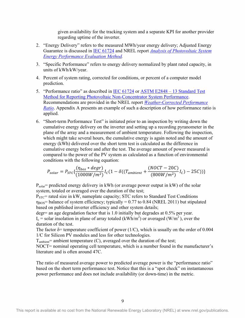
6. “Short-term Performance Test” is initiated prior to an inspection by writing down the cumulative energy delivery on the inverter and setting up a recording pyranometer in the plane of the array and a measurement of ambient temperature. Following the inspection, which might take several hours, the cumulative energy is again noted and the amount of energy (kWh) delivered over the short term test is calculated as the difference in cumulative energy before and after the test. The average amount of power measured is compared to the power of the PV system as calculated as a function of environmental conditions with the following equation:
𝑃𝑠𝑜𝑜𝑜𝑜 = 𝑃𝑆𝑆𝑆{(𝜂𝑏𝑜𝑠 ∗ 𝑑𝑑𝑑𝑑)(1000𝑊/𝑚2)
𝐼𝑆(1 − 𝛿((𝑇𝑜𝑎𝑏𝑎𝑎𝑎𝑎 +(𝑁𝑁𝑁𝑇 − 20𝑁)
(800𝑊/𝑚2)𝐼𝑆) − 25𝑁))}
Psolar= predicted energy delivery in kWh (or average power output in kW) of the solar system, totaled or averaged over the duration of the test; PSTC= rated size in kW, nameplate capacity; STC refers to Standard Test Conditions ηBOS= balance of system efficiency; typically = 0.77 to 0.84 (NREL 2011) but stipulated based on published inverter efficiency and other system details; degr= an age degradation factor that is 1.0 initially but degrades at 0.5% per year. Ic = solar insolation in plane of array totaled (kWh/m2) or averaged (W/m2 ), over the duration of the test. The factor δ= temperature coefficient of power (1/C), which is usually on the order of 0.004 1/C for Silicon PV modules and less for other technologies. Tambient= ambient temperature (C), averaged over the duration of the test; NOCT= nominal operating cell temperature, which is a number found in the manufacturer’s literature and is often around 47C. The ratio of measured average power to predicted average power is the “performance ratio” based on the short term performance test. Notice that this is a “spot check” on instantaneous power performance and does not include availability (or down-time) in the metric.
10
This report is available at no cost from the National Renewable Energy Laboratory (NREL) at www.nrel.gov/publications.
O&M managers should consider how to allocate risk associated with inaccuracy of the calculation of performance ratio or error in the implementation of the evaluation method. For example, dirt on a pyranometer will exaggerate performance ratio. Thus, exclusions such as clipping (high AC/DC ratio), force majeure, specific representations made by the O&M provider, and underlying solar resource considerations should be specified in calculations and the evaluation method.
5.2 The PV O&M Plan The PV O&M plan prepared by the EPC firm and/or the developer and accepted by the asset manager is the only long-term operations plan for a PV system. The O&M manager retains in the plan archive all the initial planning, warranty, design, and other system specification documents, and also revises the plan as the system is constructed, maintained, and modified over time. The O&M plan provides the specific measures to achieve the level of performance specified by the Key Performance Indicators in the Performance Work Statement.
An O&M plan can accommodate different system configuration by including all the descriptions and measures for systems and adding the terms “if applicable”—for example, “lubricate tracking ring gear, if applicable.” However, the scope of work and cost estimate for suppliers should itemize the measures to be performed based on system details affecting maintenance, such as the number and types of different inverters, fixed rack vs. tracker, rooftop vs. ground mount, transformer vs. transformerless system, etc. A documented PV system O&M plan for a system or fleet of systems should include the following (depending on system size, complexity, and investment):
List of responsible party contact information including site owner and off-taker of power, as well as emergency numbers.
System descriptions with as-built drawings, specifications, site plans, photo records and any special safety considerations. Documents should include single line (overview) and detailed (schematics, drawings and installed components: “cut sheets” and warranties) identification for easy access.
Performance estimates and insolation/shade studies, including a description of nominal conditions to make it easier to see malfunctions or deviations.
Chronological O&M log: work order and task tracking to include initial commission report, inspection reports, and ongoing O&M history.
Descriptions of operational indicators, meters, and error messages; description of any physical monitoring setup and procedures by which performance data is to be archived and reported; and procedures by which data are regularly examined for system diagnostics and analytics.
List of preventative maintenance measures that need to be performed to maintain warranties and to optimize system energy delivery, and the schedule for each; this should include details such as cost and current supplier of each preventative maintenance measure and special instructions such as hours that work is to be performed, access to site, and locations where vehicles may be parked and equipment staged.
11
This report is available at no cost from the National Renewable Energy Laboratory (NREL) at www.nrel.gov/publications.
Procedure for responding to alerts from monitoring diagnostics, error messages, or complaints from the building owner.
Troubleshooting guide with common problems and sequence to approach solving each problem.
Criteria to decide to repair or replace a component (refer to specific replacement parts in “list of all equipment and suppliers of each”). Criteria to decide whether to “cannibalize” a string of modules to source replacement modules or to order new.
Procedures for re-acceptance testing following a repair.
List of all equipment with make, model, and serial numbers and map of placement in system (to spot trends in manufacturing defects); for each piece, a supplier of replacement part (vendor) should be listed.
Inventory of spare parts kept onsite, or easily accessed by maintenance crew, and process for determining when other spare parts need to be ordered based on component failure history.
Operator manuals associated with any of the equipment, including emergency shut-down and normal operating procedures.
All warranties from system installer and equipment manufacturers.
Reports from commissioning, inspection and ongoing work orders, and repair.
Contracts for preventative maintenance, service, and other operations documents, including contacts for each, and specified response times and availability (24 x 7).
Budget for O&M program including costs for monitoring and diagnostics, preventative maintenance, corrective maintenance, and minimum exposure (line of credit) if replacement of inverter or more expensive corrective maintenance is needed.
5.3 Use of O&M Plan Following construction and commissioning, the O&M plan is the only surviving operational plan that contains the complete history of the plant in its archive. Therefore, it is critical to ensure the O&M plan is well-documented and safely archived.
Ensure, by establishing a well-organized directory, that a well-documented and maintained O&M plan is available for each system in the fleet, along with a preventive maintenance schedule.
Maintain a tracking log for customer-driven alerts for corrective maintenance and any measures taken on a system. Up-to-date document service histories for each installation should also be included.
Maintain the O&M plan in an online mobile work order management system (there are dozens). Use such a ticketing system to record work.
Include decommissioning in the PV O&M plan and/or asset management.
12
This report is available at no cost from the National Renewable Energy Laboratory (NREL) at www.nrel.gov/publications.
5.3.1 O&M Plan for Residential/Small Commercial PV Systems The residential and small commercial O&M focus is on fleet performance goals rather than individual systems; meeting performance warranties of individual systems to meet customer satisfaction goals should be balanced against cost and cash flow optimization. These PV systems are typically simple, small, and geographically spread out over different metropolitan areas and states. The aim of the operations team is to minimize “truck rolls” and efficiently schedule any needed work.
Use the SAPC PV System Installation Best Practices Guide, which includes requirements for design guidelines, system inspections, and system documentation.
Key considerations for an O&M plan:
o Small commercial and residential onsite inspections are the responsibility of the contract off-taker (small commercial) or homeowner (residential). Often the small size precludes the use of automated monitoring (although developments, such as microinverter communications, are making automated and remote monitoring more feasible).
o Any inspection of fleets of small systems is usually on a representative sample rather than every system.
o Performance guarantees should consider typical amounts of malfunction (e.g., one string fuse) and soiling to ensure insignificant corrections can be deferred, and module cleaning and snow removal (by turbofan) is not provided. Treat extreme soiling situations as corrective maintenance.
o Provide a manual to the homeowner with contact information and description of operational indicators and procedures he/she can do, including clear documentation that states the customer is responsible for maintaining original insolation/shade study results by completing routine bush and shrub trimming.
5.3.2 O&M Plan for Larger Commercial and Industrial PV Systems O&M focus for commercial and industrial PV is more on the performance of individual systems rather than fleets and meeting performance warranties. The investment and revenue of large systems justifies more detailed monitoring for anomalies in performance and increased communications and sensors to trigger performance or corrective maintenance activities and alerts. Module cleaning, snow removal, tree trimming, etc., should be included in the O&M plan and schedule of services and based on the plant environment (dusty, etc.) and financial and performance goals. The PV O&M cost tool supports modeling of different regimes (see Appendix B). One of two reference modules could be cleaned to compare and evaluate the effect of cleaning; this information could be used to trigger a cleaning based on cost.
1. Key considerations for an O&M plan for a system larger than 100 kW:
Emphasize automated monitoring with diagnostics to push error alerts triggering corrective maintenance.
Emphasize analytics (analysis of performance information) to optimize condition-based O&M, such as cleaning.
13
This report is available at no cost from the National Renewable Energy Laboratory (NREL) at www.nrel.gov/publications.
Provide manuals for the plant landowner and off-taker with contact information and descriptions of their participation and responsibilities, self-inspection of the system, and what conditions necessitate the O&M provider to be notified of problems.
Provide a shelter onsite for workers to meet and look at plans. 5.4 Preventive/Scheduled Maintenance Preventative maintenance maximizes system output, prevents more expensive failures from occurring, and maximizes the life of a PV system. Preventative maintenance must be balanced by financial cost to the project. Therefore, the goal is to manage the optimum balance between cost of scheduled maintenance, yield, and cash flow through the life of the system. Preventative maintenance protocols depend on system size, design, complexity, and environment. A comprehensive list of these protocols is supported by the PV O&M Cost Model included in Appendix B.
5.5 Corrective Maintenance Lost revenue accrues while a system is down or when output is reduced. Repairs should be delayed only if there is an opportunity to do the repair more efficiently in the near future. Response time for alerts or corrective action for the O&M function should be specified as part of the contract but will be typically 10 days or less for non-safety related corrective maintenance service. For small residential systems, a fleet operator may make repairs only when enough work has accumulated to justify a truck roll to the area, or at the next regularly scheduled preventative/inspection of a site. Appendix C contains service descriptions for corrective maintenance selections available in the PV O&M Cost Model. This cost model (described in Section 9) provides an estimated prediction of the corrective maintenance costs from year to year, but it is impossible to accurately predict specifically when and where failures will occur. The model has the ability to utilize fault and failure probabilities of specific components, if known.
Additional considerations:
The O&M plan should include how to perform corrective maintenance quickly in response to field failures, including how funds may be used from a reserve or line of credit.
Response time and urgency of repair specified in the O&M plan should balance cost of a “truck roll” with lost revenue. Consider system size, geographic location, spare parts inventory, other scheduled maintenance, fleet performance requirements, and cost of response.
Faults or conditions that introduce a safety problem should be addressed as soon as possible, even if the recovered revenue is small.
5.6 Inverter Inverter reliability continues to increase, with 10-year warranties now commonly available and 20-year extended warranties/service plans also gaining prevalence. However, a sound O&M plan should account for inverter failure because it is one of the most frequent causes of PV system
14
This report is available at no cost from the National Renewable Energy Laboratory (NREL) at www.nrel.gov/publications.
performance loss (EPRI 2010). (See Appendix C for corrective maintenance choices for both string and central inverters.2)
Additional steps:
1. Decide whether inverter is to be replaced or repaired based on inverter size, type, and associated cost. Replacement is preferred over repair when spare parts availability and lead time trigger an upgrade.
2. Include remote monitoring to confirm inverter status, reset inverter, and diagnose problems.
3. In remote locations, it is advisable to stock component replacements onsite, especially for equipment commonly in need of repair, such as driver boards. Replacement micro-inverters should also be stored onsite.
5.7 PV Module Degradation Rate When comparing measured performance to predicted performance, it is important to consider the expected degradation in PV module output over time in the prediction. While involving a lot of variability before the year 2000, degradation rates are more uniform now among types and manufactures and often on the order of 0.5% per year (Jordan and Kurtz 2012). This is not to be confused with the failure rate of modules. PV module failures are rare, with reported failure rate of 0.025% per year to 0.1% per year (Dhere 2005), depending on the source.
Compare measured and predicted performance using a module degradation value given by manufacturer. If no value is available, assume default value of 0.5% per year for new crystalline silicon products. Degradation is calculated based on the age of the system at the time of evaluation, but for life cycle cost analysis a degradation factor of 0.94 provides an estimate of the degradation levelized over a 25 year lifetime with a 5% discount rate. 5.8 Example Work Statements A contract to implement an O&M plan or part of an O&M plan should include a complete list of obligations under the contract. Examples of commercial system work statements are detailed in Appendix E; the statements contain a maintenance “Schedule of Services” typically found as an addendum to an O&M contract comprising a fixed contract fee, with provision for an added time and materials cost adder for non-warranty corrective maintenance. Schedules are included for commercial rooftop and ground mount systems.
2 The selection for string inverters assumes replacement or swap as the most common corrective action. For central inverters, numerous subsystem repairs to the inverter are supported, assuming that each is repaired independently.
15
This report is available at no cost from the National Renewable Energy Laboratory (NREL) at www.nrel.gov/publications.
6 O&M Provider Qualifications and Responsibilities PV O&M personnel, service category, scope of work, salary, and qualifications for the following roles are detailed in Appendix D: administrator/management; designer; cleaner; tree trimmer; pest control; roofing; structural engineer; mechanic; master electrician; journeyman electrician; network/IT; inspection; inverter specialist; PV module/array specialist; and utilities locator. These roles are defined in the PV O&M Cost Model for work calculations, but can be customized by the user for different pay rates, roles, and local work conditions and context.
6.1 Qualifications of Service Providers Most electricians work on AC building systems, and even a master electrician may be unfamiliar with DC-based PV systems. PV-specific qualifications include:
Licensed electrical contractor
NABCEP PV Installer certification and/or UL Photovoltaic (PV) System Installation Certification
Experience with medium-voltage electrical systems
Experience with DC power systems
Familiarity with sections of the National Electric Code specific to PV (section 690)
Certification by the North American Energy Reliability Corporation (NERC) (necessary for positions that affect the power grid).
These electrical qualifications are essential, but each O&M service category has required qualifications. For example, certifications to apply herbicides and insecticides may be required for those removing weeds and infestations, as listed in Appendix D for each job category.
6.2 Financial Solvency Contractors should provide documentation that communicates the financial solvency of the O&M Service Provider. The purpose of references is to determine if the contractor is in financial distress. Financial distress of the installation contractor or O&M service provider could have a negative impact on the level of system quality and the timeliness and quality of delivered O&M services.
These references should be made available to financing sources upon request. Examples of documentation include:
Audited financial statements
Bank references
Supplier references
Bond ability/bank letter of credit
Credit rating matrix.
16
This report is available at no cost from the National Renewable Energy Laboratory (NREL) at www.nrel.gov/publications.
6.3 Health and Safety Health and safety issues include all of those involved in construction or electrical maintenance work, plus some that are specific to photovoltaic systems. Roof fall protection, arc-flash protection, lock-out-tag-out, and dehydration and heat stress are of special importance to workers providing maintenance of photovoltaic systems.
Verify that the contractor utilizes a company health and safety manual, which establishes appropriate rules and procedures concerning reporting of health and safety problems, injuries, unsafe conditions, risk assessment, and first aid and emergency response.
Ensure that the contractor and its employees meet the following standards from the Company Accreditation Handbook.
Contractor site supervisor should have a minimum of an OSHA 30 certification; all site personnel should have an OSHA 10 certification.
All site personnel must be equipped with complete personal protective equipment (PPE) for the task, including fall protection from roofs and arc-flash protection for working on live circuits.
The contractor must maintain an OSHA total case incident rate (TCIR) of 5.00 or less or similar rate based on a substantially equivalent, accepted measure used to report workplace injuries.
6.4 Insurance O&M program best practices can have a positive impact on reducing insurance losses, thus reducing premiums paid for insurance. An insurance engineer and underwriter should be engaged to evaluate a facility (or the design for a yet-built system), including the O&M program, to quantify loss potential and estimate insurance coverage and costs. This review also provides a better understanding of risks that might impact the performance of a PV plant.
Mitigate liability and risks through contracts that clearly articulate the insurance requirements to O&M service providers. Concepts related to insurance include:
Normal Loss Expected (NLE), which determines the dollar amount of the deductible for an item which can be expected to occur, such as inverter replacement, without an insurance claim.
Probable Maximum Loss (PML), which determines the premium paid on a portfolio over time.
Maximum Foreseeable Loss (MFS), which sets dollar limits on coverage and represents the worst-case loss scenario.
• Confirm that the contracting company maintains current and appropriate business insurances, including:
Property insurance: coverage commensurate with value of buildings, equipment, or improvements to a property
17
This report is available at no cost from the National Renewable Energy Laboratory (NREL) at www.nrel.gov/publications.
General liability: $1,000,000 per occurrence, $2,000,000 aggregate; covers negligence claims, settlements, and legal costs
Inland marine insurance: insures against loss of equipment not on the property premises
Workman’s compensation: $1,000,000 each accident, each employee, policy limit
Professional liability insurance: insures against errors and omissions often required by board of directors
Commercial vehicle insurance: insurance for owned and rented vehicles; or personal vehicles used on company business
Warranty insurance: equipment warranty issued by manufacturer but backed up by an insurance company in the event that the module or inverter company goes out of business
Commercial general liability insurance: in a form or forms covering all installations undertaken by Installer and all subcontractors, written on an occurrence basis, including coverage for products and completed operations, independent contractors, premises and operations, personal injury, broad form property damage, and blanket contractual liability, in an amount at least equal to $1,000,000 per occurrence, $2,000,000 in the aggregate for completed operations, and $2,000,000 general aggregate
Business interruption insurance: covers lost revenue due to downtime caused by covered event.
6.5 Redundancy in Service Providers Investor confidence is increased if a “hot back-up” service provider is available. This second service provider would be paid a fee to be available and to have the capability (products and training) to perform O&M on the system should a current O&M service provider fail to perform. This second company could be hired to perform capacity and energy tests and provide a check on the decisions of the current O&M service provider.
18
This report is available at no cost from the National Renewable Energy Laboratory (NREL) at www.nrel.gov/publications.
7 System Monitoring There are three main areas of best practices for system monitoring: data presentation, quality of monitoring equipment, and transparency of measurement protocols and procedures. The approach to monitoring and associated cost depends on the revenue associated with the performance of the asset. IEC 61724 classifies monitoring systems (A, B, C); the O&M related to monitoring depends on the system class.
7.1 Data Presentation In the field of PV plant operations, operations quality is determined by a) the ratio of the amount of energy harvested to the potential amount of energy available for a particular plant and b) plant equipment availability over time. Given this definition, keeping the plant up and running at its peak operating point requires accurate performance measurements, the ability to easily pinpoint issues, and prompt cost-effective repair of defects. Active plant monitoring is essential and the quality of the monitoring system itself is fundamental to the overall quality of the plant.
Additional considerations:
For data presentation, at a minimum, the system data should be presented daily, monthly, and annually.
Daily feeds of previous day, month-to-date, and year-to-date production values should be developed and stored.
O&M plans should be built to notify actionable personnel on critical production or safety issues within 5 days, depending on what the anomaly is and with consideration of safety issues.
Complete loss of production and non-communication should be reported on a daily basis.
Systems producing lower-than-forecasted energy correlated to local weather/insolation conditions should be reported on a weekly or monthly basis. Using intervals smaller than a week increases the possibility of false positives and usually does not provide business value.
7.2 Quality of Monitoring Equipment Use open standards for information and data communication throughout the plant, fleet, and enterprise.
Ensure that the monitoring system addresses the following:
Transparency of measurement protocols and procedures (See Section 7.3)
Auditability of measurement protocols and procedures
Maintainability of hardware and software by a variety of service providers, including calibration and servicing requirements
Ability of systems to share information with stakeholders
Ability to ensure “operational continuity” (backup and restore)
19
This report is available at no cost from the National Renewable Energy Laboratory (NREL) at www.nrel.gov/publications.
Support of third-party access for custom application development
Security of software and applications.
7.3 Transparency of Measurement Protocols and Procedures The benefits of adopting open standards for information and communication are well-established. As it relates to the quality of the solar monitoring system, open standards are applied at four levels:
1. Device communication and plant sensor readings
2. Data collection and storage at the plant
3. Information transmission from the plant to the information data store
4. Information access to the data store from applications.
While high-quality monitoring systems can be built with proprietary methods that encourage lock-in to a single vendor, a standard information model used across all four levels ensures high fidelity and eliminates poor or inconsistent mappings from one model to another. A standard information model allows systems to be compared to one another, independent of the monitoring vendor.
The SunSpec Alliance standard information models, combined with standard transport protocols such as Modbus, Ethernet, WiFi, and Zigbee (radio) are recommended, with support information models as defined in IEC 61850 and/or Smart Energy Profile 2.0. SunSpec standards are harmonized with both of these technologies.
20
This report is available at no cost from the National Renewable Energy Laboratory (NREL) at www.nrel.gov/publications.
8 O&M Supporting Systems and Implementation Strategies
8.1 Instrumentation Utilize the following instrumentation, depending on type and size of the installation:
1. A high-accuracy “Revenue Grade” AC meter on the combined output of the plant with uncertainty of ±0.5%, which is typically required for all plants where third-party financing is involved
2. Inverter-direct monitoring (no external AC meter) with an uncertainty of ±5% for systems <100 kW
3. Onsite environmental sensors that measure irradiance and temperature for systems >100 kW
4. A back-of-module temperature sensor with an uncertainty of ±1°C and an ambient temperature sensor with an uncertainty of ±1°C (IEC 61724)
5. A dedicated or shared network connection such as a cellular, dedicated broadband backhaul or virtual private network
6. Onsite data storage.
8.2 Workflow and Decision Support Software For plants where onsite environmental sensing equipment is not practical (i.e., most residential plants), irradiance and ambient temperature measurements should be supplied by a nearby weather station or estimated from satellite data. These proxies for actual irradiance measurements may only be accurate to <±25% and temperatures to ±5°C, which increases uncertainty but is currently acceptable in the residential setting as opposed to onsite measurements for such small systems.
A dedicated network connection such as a cellular, dedicated broadband backhaul, or virtual private network is required for plants that are greater than 100 kW. For smaller plants, where it is not practical to implement a dedicated network connection, a shared network connection may be used, but this raises the service risk profile considerably. In fact, shared Internet Protocol (IP) network outages have been reported by industry-leading vendors as the number one source of service calls. Where possible, a dedicated network connection is highly recommended.
Onsite data storage is required to prevent data loss during communication network outages. The amount of storage needed depends on the expected mean-time-to-repair should an outage occur. An amount of storage that is equal to two times the highest recorded communications outage is recommended. Best results are seen in which three months of storage is installed. Six months of storage is recommended.
Standard data encryption techniques should be employed to protect the confidentiality and integrity of the data in transit over wide area networks. For example, the SunSpec Alliance Logger Upload protocol specifies the use of Transport Layer Security standards (e.g., https, SSL) for data transmission over the IP-based networks.
21
This report is available at no cost from the National Renewable Energy Laboratory (NREL) at www.nrel.gov/publications.
All asset management and O&M management strategies and systems must achieve the following:
1. Document archive for complete plant documentation upkeep and reference
2. Customer/plant interaction tracking logs
3. System/portfolio analysis
4. Budget tracking
5. Trouble ticket or incident tracking
6. Mobile work order flow management and documentation systems.
Fleet management and aggregation requires the development or adoption of software systems termed enterprise asset management (EAM); these are specialized workflow platforms similar to enterprise resource planning (ERP) software.
EAM/O&M software platforms and services are available from several companies including Meteocontrol, Alectris, Draker Labs, TruSouth, and others, while several large fleet operators such as SolarCity and First Solar have developed their own custom platform. Deployment of these software platforms, which are now a requirement for large fleet operators, enables tight resource control to optimize O&M cost, especially administration and document cost.
8.3 O&M Implementation Strategies The asset owner or asset manager should allocate sufficient internal resources and secure any required external resources to implement the O&M Plan.
Operating and maintaining a fleet of PV systems requires active resource management and data acquisition and analysis by the asset and operation manager(s).
The choices for resourcing O&M are:
1. Use the engineering, procurement, and construction (EPC) company, or the installer who built and warrants the system
2. Bring the O&M service in-house
3. Outsource the service to a specialized third-party O&M provider.
Often, a mix of these three strategies is chosen, depending on the provider’s business model, system composition (either commercial or residential), fleet geographic density/distribution, and strengths of the available resources in-house.
For commercial systems, the EPC/installer O&M model is common because most early failures will be warranted and the provider can perform routine maintenance at the same time. One disadvantage of this model is that the EPC/installer may lack dedicated O&M resources, and thus O&M activities will compete with higher-margin installation and construction business. As warranties expire, the dedicated third-party O&M model gets more attractive because fleets can be combined or allocated to specialists who may have many systems in geographic concentrations to gain cost advantages.
22
This report is available at no cost from the National Renewable Energy Laboratory (NREL) at www.nrel.gov/publications.
For residential systems, “vertically integrated” developers/installers are using more in-house services because they can gain an advantage in providing uniform quality across the whole PV system life cycle. Meanwhile, developers using the “partner” residential model—in which the finance and development company partner with an installer—rely on the installer for O&M services and/or a dedicated third-party O&M provider as needed.
8.4 O&M Contract and Performance Warranties Detailed contract terms are beyond the scope of this document. However, it is important to define the parameters for the O&M of a PV project during its life. As stated earlier, these conditions must, as a minimum, cover the maintenance requirements to ensure compliance with the individual component warranties and EPCs or the installer’s contract warranties.
Most contracts will specify a fixed cost for standard maintenance and agreed-upon response time, with additional fees for corrective maintenance and non-covered services.
It is normal for third-party-owned systems to provide a warranty guaranteeing the energy yield output and/or the availability of the PV system. The SAPC Residential Lease contains such warranties. It is also possible for the system warranty to include targets for the energy yield. In fact, these warranties are also available from third parties, O&M contractors, and insurance companies. The agreed limits are often based on the independently verified energy yield report, produced at the time of commissioning. For an example calculation method, see Appendix A.
To summarize, important items to observe regarding warranty coverage include:
Examine the parameters for the O&M of a PV project (maintenance requirements) during its life, which are required to keep the warranty in effect and identify issues that may void the warranty
Examine the warranty in terms of key performance indicators (plant availability, specific energy delivery, and performance ratio)
Ensure at the conclusion of an installer warranty, which may be only 1–10 years, that any equipment warranties (which may be as long as 25 years for PV modules) transfer to the responsible O&M provider.
23
This report is available at no cost from the National Renewable Energy Laboratory (NREL) at www.nrel.gov/publications.
9 The PV O&M Cost Model Overview and Use The PV O&M Cost Model (version 1.0), with separate models for commercial rooftop, residential, and ground-mount PV systems; user selections for central or string inverter selections and maintenance switches; and warranty/service plan modeling switches, is available from NREL and SunSpec.org as a standalone Excel spreadsheet tool for O&M cost modeling and planning. 3
The model contains selections of scheduled and corrective maintenance tasks, which are also detailed in Appendices B and C. A list of job roles, requirements, and sample costs are included in Appendix D. As noted above, the model allows customization of all these variables to suit system configuration, job time estimates, failure rates, and local costs.
Administrative and preventative maintenance measures are on defined schedule intervals (for example, once per year) whereas corrective maintenance measures are scheduled according to a failure distribution curve (Weibull distribution) for each measure. Selection by the user of environmental conditions (bird populations, pollen, snow, etc.) can also trigger measures such as additional cleanings.
Administration and analysis tasks assume manual systems and therefore can be tailored to conform to automated workflow tools and document-keeping systems.
The spreadsheet is not locked down, so users can modify it, but because it is a spreadsheet, careless use can break it. The developers and contributors to the spreadsheet bear no responsibility for the accuracy or usefulness of the tool or results. It should be compatible with versions of MS Excel 2010 or newer.
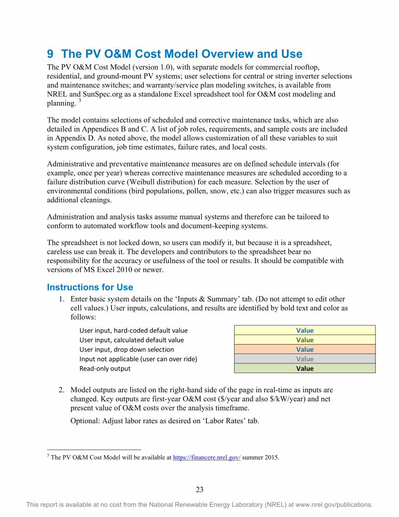
Instructions for Use 1. Enter basic system details on the ‘Inputs & Summary’ tab. (Do not attempt to edit other
cell values.) User inputs, calculations, and results are identified by bold text and color as follows:
2. Model outputs are listed on the right-hand side of the page in real-time as inputs are changed. Key outputs are first-year O&M cost ($/year and also $/kW/year) and net present value of O&M costs over the analysis timeframe.
Optional: Adjust labor rates as desired on ‘Labor Rates’ tab.
3 The PV O&M Cost Model will be available at https://financere.nrel.gov/ summer 2015.
User input, hard-coded default value ValueUser input, calculated default value ValueUser input, drop down selection ValueInput not applicable (user can over ride) ValueRead-only output Value
24
This report is available at no cost from the National Renewable Energy Laboratory (NREL) at www.nrel.gov/publications.
Optional: Adjust detailed measures (e.g., intervals for prescribed measures, failure distributions for corrective maintenance, labor, hardware costs, etc.) on ‘Residential Details’ or ‘Commercial Details’ page, depending on system type.
3. Note: Exercise caution when modifying values on these sheets because they are pre-populated based on SunSpec Alliance best practice data and national labor rates (U.S. Bureau of Labor Statistics). A warning message will appear on the top of the page if the corresponding system type is not selected on the Inputs & Summary tab.
4. The ‘Reports’ tab provides several summaries; it is read-only.
5. The ‘Cash Flow’ tab provides detailed cash flow; it is read-only.
6. The ‘Cleaning’ tab is a stand-alone tool used to calculate recommended panel cleaning intervals. This tab is not connected to any other model tab. Use it to determine interval value for the ‘array cleaning’ activity on system type tabs.
Note: The model is for informational purposes only; no warranty or fitness for any use is provided by the SunSpec Alliance or NREL.
25
This report is available at no cost from the National Renewable Energy Laboratory (NREL) at www.nrel.gov/publications.
10 Current PV O&M Cost Survey Information The Federal Energy Management Program (FEMP) has tabulated O&M costs for grid-tied distributed generation (DG) scale systems varying from $21 +/- $20 /kW/year for systems < 10kW to $19 +/- $10 /kW/year for large systems >1 MW (see NREL 2013). In 2010, EPRI reported costs of $6/kW/year to $27/kW/year ( <1% to 5% of installed cost per year) for systems less than 1 MW and costs of $47 to $60/kW/year for larger utility-scale systems depending on PV type and fixed or tracking mounts (EPRI 2010). An early study reports O&M costs of $12/kW/yr, or at 0.17% of capital cost without tracking and 0.35% of initial cost with tracking (Mortensen 2001).
Another estimate approximates O&M of PV systems at $40/kW/year (approximately 0.5% of initial cost per year for these early systems), about half of which amortizes inverter replacements (Wiser et al. 2009).
Data collected by Tucson Electric Power from 2002 to 2006 (Tucson Electric Power 2007) reports annual preventative maintenance at 0.04 to 0.08% of initial cost per year and corrective/reactive unplanned maintenance at 0.01 to 0.22% of initial cost per year. The average combined cost for these utility-scale ground-mounted systems was 0.16%/year. Notice that the costs are not evenly distributed, with several years of low cost punctuated by a year of high cost when the inverter is replaced.
Arizona Public Service reports 0.35% of initial cost for O&M exclusive of inverter replacements (Moore et al. 2008) for large grid connected systems. For small off-grid systems with batteries, Arizona Public Service reports that the average annual O&M cost is 5% to 6% of the initial capital cost (Canada et al. 2005) and that travel time and mileage account for 42% of the unscheduled maintenance cost of these remote systems.
Members of the working group have discussed these results and are currently recommending 0.5% for large systems and 1% of system initial cost per year for small systems as a reasonable expectation of PV system O&M costs.
These heuristics inform an expectation of PV system O&M cost. The PV O&M Cost Model allows a customized, if not more accurate, estimate of system cost based on system type and components and also on environmental conditions. Survey data on cost and backup services providers is being correlated with model test data to “calibrate” the cost model. The cost model can also lay out year-by-year fluctuations in O&M cost based on scheduled intervals for preventative measures, failure distributions that increase with age, and inflation in the cost of O&M services.
26
This report is available at no cost from the National Renewable Energy Laboratory (NREL) at www.nrel.gov/publications.
References and Resources ASTM International. (2013). ASTM E2848-13, Standard Test Method for Reporting Photovoltaic Non-Concentrator System Performance. West Conshohocken, PA: ASTM International. Canada, S.; Moore, L.; Post, H.; Strachan, J. (2005). “Operation and maintenance field experience for off-grid residential photovoltaic systems.” Progress in Photovoltaics: Research and Applications (13:1); pp. 67-74.
Dhere, N.G. (2005). “Reliability of PV modules and balance-of-system components.” Conference Record of the Thirty-First IEEE Photovoltaic Specialist Conference (IEEE Cat. No. 05CH37608)); pp. 1570-15761576.
Dierauf, T.; Growitz, A.; Kurtz, S.; Becerra Cruz, J.L.; Riley, E.; Hansen, C. (2013). Weather-Corrected Performance Ratio. NREL/TP-5200-57991. Golden, CO: NREL. Accessed December 2014: http://www.nrel.gov/docs/fy13osti/57991.pdf.
Electric Power Research Institute (EPRI). (2010). Addressing Solar Photovoltaic Operations and Maintenance Challenges –A Survey of Current Knowledge and Practices. Accessed November 2014: http://www.smartgridnews.com/artman/uploads/1/1021496AddressingPVOaMChallenges7-2010_1_.pdf.
Golnas, A. (2013). “PV System Reliability: An Operator’s Perspective.” IEEE Journal of Photovoltaics (3:1); pp. 416-421.
International Electrotechnical Commission (IEC). (1998). “IEC 61724 ed1.0.” Geneva, Switzerland: IEC. Accessed November 2014: http://webstore.iec.ch/webstore/webstore.nsf/standards/IEC%2061724!opendocument.
IEC. (2003). “P-IEC/TR 61850-1 ed1.0.” Geneva, Switzerland: IEC. Accessed November 2014: http://webstore.iec.ch/webstore/webstore.nsf/ArtNum_PK/30525.
IEC. (2009). “IEC 62446 ed1.0.” Geneva, Switzerland: IEC. Accessed December 2014: http://webstore.iec.ch/Webstore/webstore.nsf/ArtNum_PK/42990!opendocument&preview=1.
Jordan, D.; Kurtz, S. (2012). Photovoltaic Degradation Rates—An Analytical Review. NREL/JA-5200-51664. Golden, CO: NREL. Accessed December 2014: http://www.nrel.gov/docs/fy12osti/51664.pdf.
Kurtz, S.; Newmiller, J.; Kimber, A.; Flottemesch, R.; Riley, E.; Dierauf, T.; McKee, J.; Krishnani, P. (2013). Analysis of Photovoltaic System Energy Performance Evaluation Method. NREL/TP-5200-60628. Golden, CO: NREL. Accessed December 2014: http://www.nrel.gov/docs/fy14osti/60628.pdf.
Moore, L.M.; Post, H.N. (2008). “Five years of operating experience at a large, utility-scale photovoltaic generating plant.” Progress in Photovoltaics: Research and Applications (16:3); pp. 249-259.
27
This report is available at no cost from the National Renewable Energy Laboratory (NREL) at www.nrel.gov/publications.
NABCEP. (undated). “Find A Certified Professional.” Clifton Part, NY: NABCEP. Accessed February 2015: http://www.nabcep.org/certified-installer-locator.
NABCEP. (2013). Company Accreditation Handbook, Version 2.0. Clifton Part, NY: NABCEP. Accessed February 2015: http://www.nabcep.org/wp-content/uploads/2012/04/nabcep_handbook_final.pdf.
National Fire Protection Association (NFPA). (2014). “NFPA 70: National Electrical Code.” Quincy, MA: NFPA. Accessed February 2015: http://www.nfpa.org/codes-and-standards/document-information-pages?mode=code&code=70.
National Renewable Energy Laboratory (NREL). (2013). “Distributed Generation Energy Technology Operations and Maintenance Costs.” Updated September 2013. Accessed February 2015: http://www.nrel.gov/analysis/tech_cost_om_dg.html.
North American Electric Reliability Corporation (NERC). (2013). “Training, Education, and System Operator Certification.” Atlanta, GA: NERC. Accessed February 2015: http://www.nerc.com/pa/Train/Pages/default.aspx.
SunSpec Alliance. (2015). “SunSpec Alliance Specifications.” San Jose, CA: SunSpec Alliance. Accessed February 2015: http://sunspec.org/sunspec-alliance-specifications-4/.
U.S. Department of Transportation (DOT). (1999). Asset Management Primer. U.S. Department of Transportation Federal Highway Administration Office of Asset Management. Accessed November 2014: https://www.fhwa.dot.gov/infrastructure/asstmgmt/amprimer.pdf.
U.S. Department of Labor Occupational Health and Safety Administration (OSHA). (2013). “Data and Statistics.” Washington, D.C.: OSHA. Accessed February 2015: https://www.osha.gov/oshstats/index.html.
Wiser, R.; Barbose, G.; Peterman, C. (2009). Tracking the Sun: The Installed Cost of Photovoltaics in the U.S. from 1998-2007. Berkeley, CA: LBNL. Accessed December 2014: http://emp.lbl.gov/sites/all/files/REPORT%20LOW%20RES%20lbnl-1516e.pdf.
ZigBee Alliance. (2014). “Standards: ZigBee Smart Energy 1.2 Revision 4.” San Ramon, CA: ZigBee. Accessed November 2014: http://zigbee.org/download/standards-zigbee-smart-energy-1-2-revision-4/.
28
This report is available at no cost from the National Renewable Energy Laboratory (NREL) at www.nrel.gov/publications.
Appendix A. System Performance Guarantee Example Calculation (without shade correction) EXHIBIT
COMMERCIAL SYSTEM: SYSTEM PERFORMANCE GUARANTEE
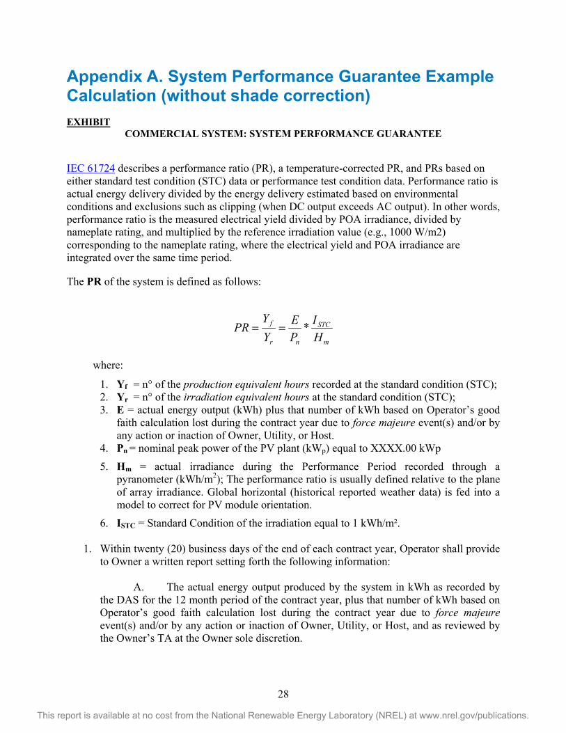
IEC 61724 describes a performance ratio (PR), a temperature-corrected PR, and PRs based on either standard test condition (STC) data or performance test condition data. Performance ratio is actual energy delivery divided by the energy delivery estimated based on environmental conditions and exclusions such as clipping (when DC output exceeds AC output). In other words, performance ratio is the measured electrical yield divided by POA irradiance, divided by nameplate rating, and multiplied by the reference irradiation value (e.g., 1000 W/m2) corresponding to the nameplate rating, where the electrical yield and POA irradiance are integrated over the same time period.
The PR of the system is defined as follows:
where:
1. Yf = n° of the production equivalent hours recorded at the standard condition (STC); 2. Yr = n° of the irradiation equivalent hours at the standard condition (STC); 3. E = actual energy output (kWh) plus that number of kWh based on Operator’s good
faith calculation lost during the contract year due to force majeure event(s) and/or by any action or inaction of Owner, Utility, or Host.
4. Pn = nominal peak power of the PV plant (kWp) equal to XXXX.00 kWp
5. Hm = actual irradiance during the Performance Period recorded through a pyranometer (kWh/m2); The performance ratio is usually defined relative to the plane of array irradiance. Global horizontal (historical reported weather data) is fed into a model to correct for PV module orientation.
6. ISTC = Standard Condition of the irradiation equal to 1 kWh/m².
1. Within twenty (20) business days of the end of each contract year, Operator shall provide to Owner a written report setting forth the following information:
A. The actual energy output produced by the system in kWh as recorded by
the DAS for the 12 month period of the contract year, plus that number of kWh based on Operator’s good faith calculation lost during the contract year due to force majeure event(s) and/or by any action or inaction of Owner, Utility, or Host, and as reviewed by the Owner’s TA at the Owner sole discretion.
m
STC
nr
f
HI
PE
YY
PR *==
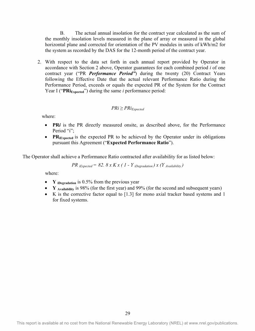
29
This report is available at no cost from the National Renewable Energy Laboratory (NREL) at www.nrel.gov/publications.
B. The actual annual insolation for the contract year calculated as the sum of the monthly insolation levels measured in the plane of array or measured in the global horizontal plane and corrected for orientation of the PV modules in units of kWh/m2 for the system as recorded by the DAS for the 12-month period of the contract year.
2. With respect to the data set forth in each annual report provided by Operator in accordance with Section 2 above, Operator guarantees for each combined period i of one contract year (“PR Performance Period”) during the twenty (20) Contract Years following the Effective Date that the actual relevant Performance Ratio during the Performance Period, exceeds or equals the expected PR of the System for the Contract Year I (“PRiExpected”) during the same i performance period:
PRi ≥ PRiExpected
where:
• PRi is the PR directly measured onsite, as described above, for the Performance Period “i”;
• PRiExpected is the expected PR to be achieved by the Operator under its obligations pursuant this Agreement (“Expected Performance Ratio”).
The Operator shall achieve a Performance Ratio contracted after availability for as listed below:
PR iExpected = 82. 8 x K x ( 1 - Y iDegradation ) x (Y Availability ) where:
• Y iDegradation is 0.5% from the previous year • Y Availability is 98% (for the first year) and 99% (for the second and subsequent years) • K is the corrective factor equal to [1.3] for mono axial tracker based systems and 1
for fixed systems.
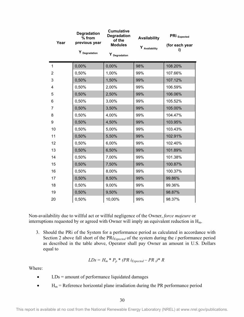
30
This report is available at no cost from the National Renewable Energy Laboratory (NREL) at www.nrel.gov/publications.
Year
Degradation % from
previous year
Y Degradation
Cumulative Degradation
of the Modules
Y Degradation
Availability
Y Availability
PRi Expected
(for each year i)
1 0,00% 0,00% 98% 108.20%
2 0,50% 1,00% 99% 107.66%
3 0,50% 1,50% 99% 107.12%
4 0,50% 2,00% 99% 106.59%
5 0,50% 2,50% 99% 106.06%
6 0,50% 3,00% 99% 105.52%
7 0,50% 3,50% 99% 105.00%
8 0,50% 4,00% 99% 104.47%
9 0,50% 4,50% 99% 103.95%
10 0,50% 5,00% 99% 103.43%
11 0,50% 5,50% 99% 102.91%
12 0,50% 6,00% 99% 102.40%
13 0,50% 6,50% 99% 101.89%
14 0,50% 7,00% 99% 101.38%
15 0,50% 7,50% 99% 100.87%
16 0,50% 8,00% 99% 100.37%
17 0,50% 8,50% 99% 99.86%
18 0,50% 9,00% 99% 99.36%
19 0,50% 9,50% 99% 98.87%
20 0,50% 10,00% 99% 98.37%
Non-availability due to willful act or willful negligence of the Owner, force majeure or interruptions requested by or agreed with Owner will imply an equivalent reduction in Hm.
3. Should the PRi of the System for a performance period as calculated in accordance with Section 2 above fall short of the PRiExpected of the system during the i performance period as described in the table above, Operator shall pay Owner an amount in U.S. Dollars equal to
LDs = Hm * Pp * (PR iExpected – PR i)* R
Where:
• LDs = amount of performance liquidated damages
• Hm = Reference horizontal plane irradiation during the PR performance period
31
This report is available at no cost from the National Renewable Energy Laboratory (NREL) at www.nrel.gov/publications.
• Pp = Installed nameplate capacity of the plant (kWp)
• PR = PR measured on the plant during the reference period
• PR iExpected= is the PR expected as defined in Section 1
• R = Average post-time of day (TOD) PPA contracted revenue per unit of electricity
generated, equal to _____$/kWh.
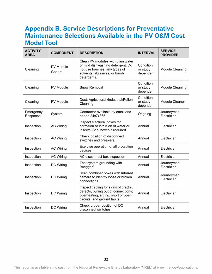
32
This report is available at no cost from the National Renewable Energy Laboratory (NREL) at www.nrel.gov/publications.
Appendix B. Service Descriptions for Preventative Maintenance Selections Available in the PV O&M Cost Model Tool ACTIVITY AREA COMPONENT DESCRIPTION INTERVAL SERVICE
PROVIDER
Cleaning PV Module General
Clean PV modules with plain water or mild dishwashing detergent. Do not use brushes, any types of solvents, abrasives, or harsh detergents.
Condition or study dependent
Module Cleaning
Cleaning PV Module Snow Removal Condition or study dependent
Module Cleaning
Cleaning PV Module Dust: Agricultural /Industrial/Pollen Cleaning
Condition or study dependent
Module Cleaner
Emergency Response System Contractor available by email and
phone 24x7x365 Ongoing Journeyman Electrician
Inspection AC Wiring Inspect electrical boxes for corrosion or intrusion of water or insects. Seal boxes if required.
Annual Electrician
Inspection AC Wiring Check position of disconnect switches and breakers. Annual Electrician
Inspection AC Wiring Exercise operation of all protection devices. Annual Electrician
Inspection AC Wiring AC disconnect box inspection Annual Electrician
Inspection DC Wiring Test system grounding with "megger" Annual Journeyman
Electrician
Inspection DC Wiring Scan combiner boxes with Infrared camera to identify loose or broken connections
Annual Journeyman Electrician
Inspection DC Wiring
Inspect cabling for signs of cracks, defects, pulling out of connections; overheating, arcing, short or open circuits, and ground faults.
Annual Electrician
Inspection DC Wiring Check proper position of DC disconnect switches. Annual Electrician
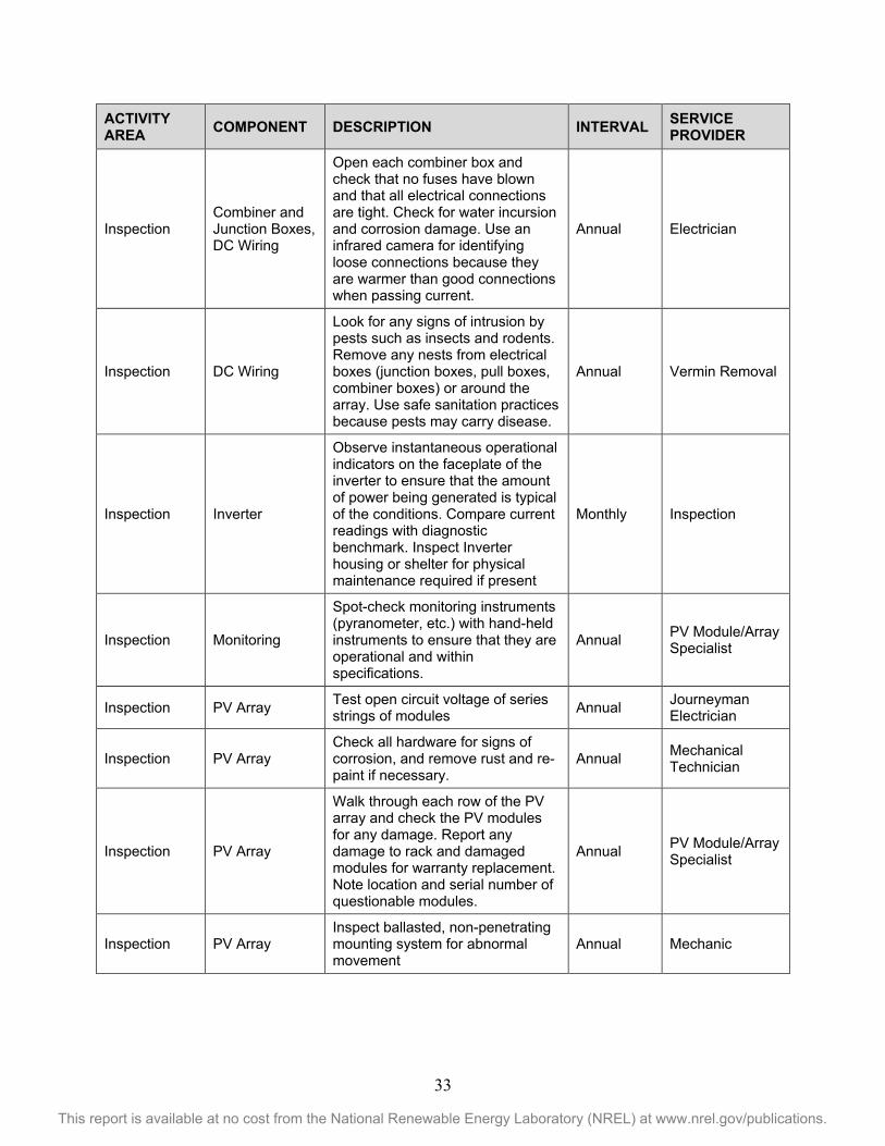
33
This report is available at no cost from the National Renewable Energy Laboratory (NREL) at www.nrel.gov/publications.
ACTIVITY AREA COMPONENT DESCRIPTION INTERVAL SERVICE
PROVIDER
Inspection Combiner and Junction Boxes, DC Wiring
Open each combiner box and check that no fuses have blown and that all electrical connections are tight. Check for water incursion and corrosion damage. Use an infrared camera for identifying loose connections because they are warmer than good connections when passing current.
Annual Electrician
Inspection DC Wiring
Look for any signs of intrusion by pests such as insects and rodents. Remove any nests from electrical boxes (junction boxes, pull boxes, combiner boxes) or around the array. Use safe sanitation practices because pests may carry disease.
Annual Vermin Removal
Inspection Inverter
Observe instantaneous operational indicators on the faceplate of the inverter to ensure that the amount of power being generated is typical of the conditions. Compare current readings with diagnostic benchmark. Inspect Inverter housing or shelter for physical maintenance required if present
Monthly Inspection
Inspection Monitoring
Spot-check monitoring instruments (pyranometer, etc.) with hand-held instruments to ensure that they are operational and within specifications.
Annual PV Module/Array Specialist
Inspection PV Array Test open circuit voltage of series strings of modules Annual Journeyman
Electrician
Inspection PV Array Check all hardware for signs of corrosion, and remove rust and re-paint if necessary.
Annual Mechanical Technician
Inspection PV Array
Walk through each row of the PV array and check the PV modules for any damage. Report any damage to rack and damaged modules for warranty replacement. Note location and serial number of questionable modules.
Annual PV Module/Array Specialist
Inspection PV Array Inspect ballasted, non-penetrating mounting system for abnormal movement
Annual Mechanic
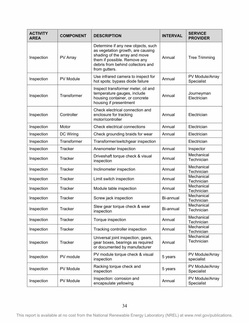
34
This report is available at no cost from the National Renewable Energy Laboratory (NREL) at www.nrel.gov/publications.
ACTIVITY AREA COMPONENT DESCRIPTION INTERVAL SERVICE
PROVIDER
Inspection PV Array
Determine if any new objects, such as vegetation growth, are causing shading of the array and move them if possible. Remove any debris from behind collectors and from gutters.
Annual Tree Trimming
Inspection PV Module Use infrared camera to inspect for hot spots; bypass diode failure Annual PV Module/Array
Specialist
Inspection Transformer
Inspect transformer meter, oil and temperature gauges, include housing container, or concrete housing if presentment
Annual Journeyman Electrician
Inspection Controller Check electrical connection and enclosure for tracking motor/controller
Annual Electrician
Inspection Motor Check electrical connections Annual Electrician
Inspection DC Wiring Check grounding braids for wear Annual Electrician
Inspection Transformer Transformer/switchgear inspection Electrician
Inspection Tracker Anenometer Inspection Annual Inspector
Inspection Tracker Driveshaft torque check & visual inspection Annual
Mechanical Technician
Inspection Tracker Inclinometer inspection Annual Mechanical Technician
Inspection Tracker Limit switch inspection Annual Mechanical Technician
Inspection Tracker Module table inspection Annual Mechanical Technician
Inspection Tracker Screw jack inspection Bi-annual Mechanical Technician
Inspection Tracker Slew gear torque check & wear inspection Bi-annual
Mechanical Technician
Inspection Tracker Torque inspection Annual Mechanical Technician
Inspection Tracker Tracking controller inspection Annual Mechanical Technician
Inspection Tracker Universal joint inspection, gears, gear boxes, bearings as required or documented by manufacturer
Annual Mechanical Technician
Inspection PV module PV module torque check & visual inspection 5 years PV Module/Array
specialist
Inspection PV Module Racking torque check and inspection 5 years PV Module/Array
Specialist
Inspection PV Module Inspection: corrosion and encapsulate yellowing Annual PV Module/Array
Specialist
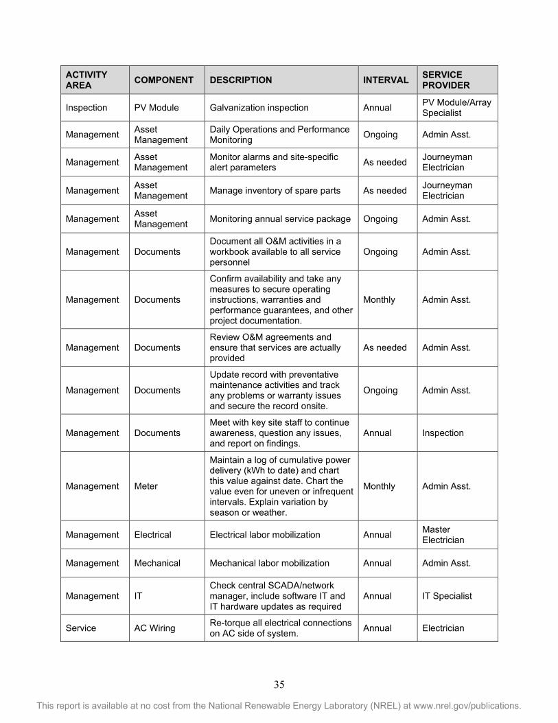
35
This report is available at no cost from the National Renewable Energy Laboratory (NREL) at www.nrel.gov/publications.
ACTIVITY AREA COMPONENT DESCRIPTION INTERVAL SERVICE
PROVIDER
Inspection PV Module Galvanization inspection Annual PV Module/Array Specialist
Management Asset Management
Daily Operations and Performance Monitoring Ongoing Admin Asst.
Management Asset Management
Monitor alarms and site-specific alert parameters As needed Journeyman
Electrician
Management Asset Management Manage inventory of spare parts As needed Journeyman
Electrician
Management Asset Management Monitoring annual service package Ongoing Admin Asst.
Management Documents Document all O&M activities in a workbook available to all service personnel
Ongoing Admin Asst.
Management Documents
Confirm availability and take any measures to secure operating instructions, warranties and performance guarantees, and other project documentation.
Monthly Admin Asst.
Management Documents Review O&M agreements and ensure that services are actually provided
As needed Admin Asst.
Management Documents
Update record with preventative maintenance activities and track any problems or warranty issues and secure the record onsite.
Ongoing Admin Asst.
Management Documents Meet with key site staff to continue awareness, question any issues, and report on findings.
Annual Inspection
Management Meter
Maintain a log of cumulative power delivery (kWh to date) and chart this value against date. Chart the value even for uneven or infrequent intervals. Explain variation by season or weather.
Monthly Admin Asst.
Management Electrical Electrical labor mobilization Annual Master Electrician
Management Mechanical Mechanical labor mobilization Annual Admin Asst.
Management IT Check central SCADA/network manager, include software IT and IT hardware updates as required
Annual IT Specialist
Service AC Wiring Re-torque all electrical connections on AC side of system. Annual Electrician
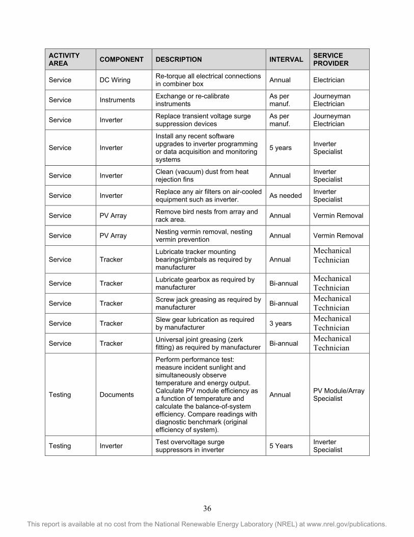
36
This report is available at no cost from the National Renewable Energy Laboratory (NREL) at www.nrel.gov/publications.
ACTIVITY AREA COMPONENT DESCRIPTION INTERVAL SERVICE
PROVIDER
Service DC Wiring Re-torque all electrical connections in combiner box Annual Electrician
Service Instruments Exchange or re-calibrate instruments
As per manuf.
Journeyman Electrician
Service Inverter Replace transient voltage surge suppression devices
As per manuf.
Journeyman Electrician
Service Inverter
Install any recent software upgrades to inverter programming or data acquisition and monitoring systems
5 years Inverter Specialist
Service Inverter Clean (vacuum) dust from heat rejection fins Annual Inverter
Specialist
Service Inverter Replace any air filters on air-cooled equipment such as inverter. As needed Inverter
Specialist
Service PV Array Remove bird nests from array and rack area. Annual Vermin Removal
Service PV Array Nesting vermin removal, nesting vermin prevention Annual Vermin Removal
Service Tracker Lubricate tracker mounting bearings/gimbals as required by manufacturer
Annual Mechanical Technician
Service Tracker Lubricate gearbox as required by manufacturer Bi-annual
Mechanical Technician
Service Tracker Screw jack greasing as required by manufacturer Bi-annual
Mechanical Technician
Service Tracker Slew gear lubrication as required by manufacturer 3 years
Mechanical Technician
Service Tracker Universal joint greasing (zerk fitting) as required by manufacturer Bi-annual
Mechanical Technician
Testing Documents
Perform performance test: measure incident sunlight and simultaneously observe temperature and energy output. Calculate PV module efficiency as a function of temperature and calculate the balance-of-system efficiency. Compare readings with diagnostic benchmark (original efficiency of system).
Annual PV Module/Array Specialist
Testing Inverter Test overvoltage surge suppressors in inverter 5 Years Inverter
Specialist
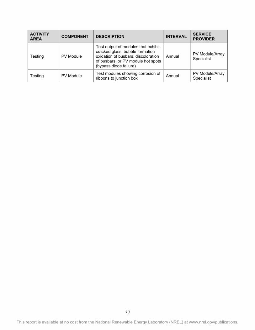
37
This report is available at no cost from the National Renewable Energy Laboratory (NREL) at www.nrel.gov/publications.
ACTIVITY AREA COMPONENT DESCRIPTION INTERVAL SERVICE
PROVIDER
Testing PV Module
Test output of modules that exhibit cracked glass, bubble formation oxidation of busbars, discoloration of busbars, or PV module hot spots (bypass diode failure)
Annual PV Module/Array Specialist
Testing PV Module Test modules showing corrosion of ribbons to junction box Annual PV Module/Array
Specialist
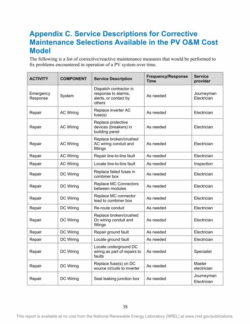
38
This report is available at no cost from the National Renewable Energy Laboratory (NREL) at www.nrel.gov/publications.
Appendix C. Service Descriptions for Corrective Maintenance Selections Available in the PV O&M Cost Model The following is a list of corrective/reactive maintenance measures that would be performed to fix problems encountered in operation of a PV system over time.
ACTIVITY COMPONENT Service Description Frequency/Response Time
Service provider
Emergency Response System
Dispatch contractor in response to alarms, alerts, or contact by others
As needed Journeyman Electrician
Repair AC Wiring Replace inverter AC fuse(s) As needed Electrician
Repair AC Wiring Replace protective devices (breakers) in building panel
As needed Electrician
Repair AC Wiring Replace broken/crushed AC wiring conduit and fittings
As needed Electrician
Repair AC Wiring Repair line-to-line fault As needed Electrician
Repair AC Wiring Locate line-to-line fault As needed Inspection
Repair DC Wiring Replace failed fuses in combiner box As needed Electrician
Repair DC Wiring Replace MC Connectors between modules As needed Electrician
Repair DC Wiring Replace MC connector lead to combiner box As needed Electrician
Repair DC Wiring Re-route conduit As needed Electrician
Repair DC Wiring Replace broken/crushed Dc wiring conduit and fittings
As needed Electrician
Repair DC Wiring Repair ground fault As needed Electrician
Repair DC Wiring Locate ground fault As needed Electrician
Repair DC Wiring Locate underground DC wiring as part of repairs to faults
As needed Specialist
Repair DC Wiring Replace fuse(s) on DC source circuits to inverter As needed Master
electrician
Repair DC Wiring Seal leaking junction box As needed Journeyman Electrician
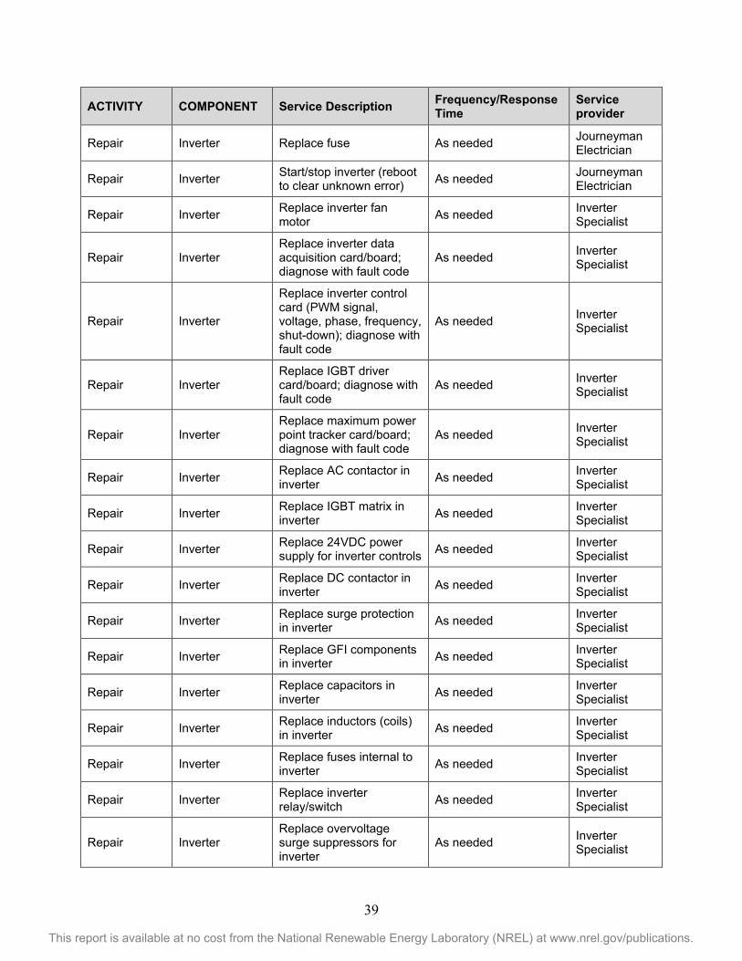
39
This report is available at no cost from the National Renewable Energy Laboratory (NREL) at www.nrel.gov/publications.
ACTIVITY COMPONENT Service Description Frequency/Response Time
Service provider
Repair Inverter Replace fuse As needed Journeyman Electrician
Repair Inverter Start/stop inverter (reboot to clear unknown error) As needed Journeyman
Electrician
Repair Inverter Replace inverter fan motor As needed Inverter
Specialist
Repair Inverter Replace inverter data acquisition card/board; diagnose with fault code
As needed Inverter Specialist
Repair Inverter
Replace inverter control card (PWM signal, voltage, phase, frequency, shut-down); diagnose with fault code
As needed Inverter Specialist
Repair Inverter Replace IGBT driver card/board; diagnose with fault code
As needed Inverter Specialist
Repair Inverter Replace maximum power point tracker card/board; diagnose with fault code
As needed Inverter Specialist
Repair Inverter Replace AC contactor in inverter As needed Inverter
Specialist
Repair Inverter Replace IGBT matrix in inverter As needed Inverter
Specialist
Repair Inverter Replace 24VDC power supply for inverter controls As needed Inverter
Specialist
Repair Inverter Replace DC contactor in inverter As needed Inverter
Specialist
Repair Inverter Replace surge protection in inverter As needed Inverter
Specialist
Repair Inverter Replace GFI components in inverter As needed Inverter
Specialist
Repair Inverter Replace capacitors in inverter As needed Inverter
Specialist
Repair Inverter Replace inductors (coils) in inverter As needed Inverter
Specialist
Repair Inverter Replace fuses internal to inverter As needed Inverter
Specialist
Repair Inverter Replace inverter relay/switch As needed Inverter
Specialist
Repair Inverter Replace overvoltage surge suppressors for inverter
As needed Inverter Specialist
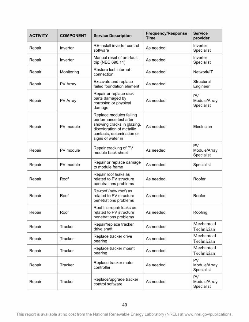
40
This report is available at no cost from the National Renewable Energy Laboratory (NREL) at www.nrel.gov/publications.
ACTIVITY COMPONENT Service Description Frequency/Response Time
Service provider
Repair Inverter RE-install inverter control software As needed Inverter
Specialist
Repair Inverter Manual reset of arc-fault trip (NEC 690.11) As needed Inverter
Specialist
Repair Monitoring Restore lost internet connection As needed Network/IT
Repair PV Array Excavate and replace failed foundation element As needed Structural
Engineer
Repair PV Array
Repair or replace rack parts damaged by corrosion or physical damage
As needed PV Module/Array Specialist
Repair PV module
Replace modules failing performance test after showing cracks in glazing, discoloration of metallic contacts, delamination or signs of water in
As needed Electrician
Repair PV module Repair cracking of PV module back sheet As needed
PV Module/Array Specialist
Repair PV module Repair or replace damage to module frame As needed Specialist
Repair Roof Repair roof leaks as related to PV structure penetrations problems
As needed Roofer
Repair Roof Re-roof (new roof) as related to PV structure penetrations problems
As needed Roofer
Repair Roof Roof tile repair leaks as related to PV structure penetrations problems
As needed Roofing
Repair Tracker Repair/replace tracker drive shaft As needed
Mechanical Technician
Repair Tracker Replace tracker drive bearing As needed
Mechanical Technician
Repair Tracker Replace tracker mount bearing As needed
Mechanical Technician
Repair Tracker Replace tracker motor controller As needed
PV Module/Array Specialist
Repair Tracker Replace/upgrade tracker control software As needed
PV Module/Array Specialist
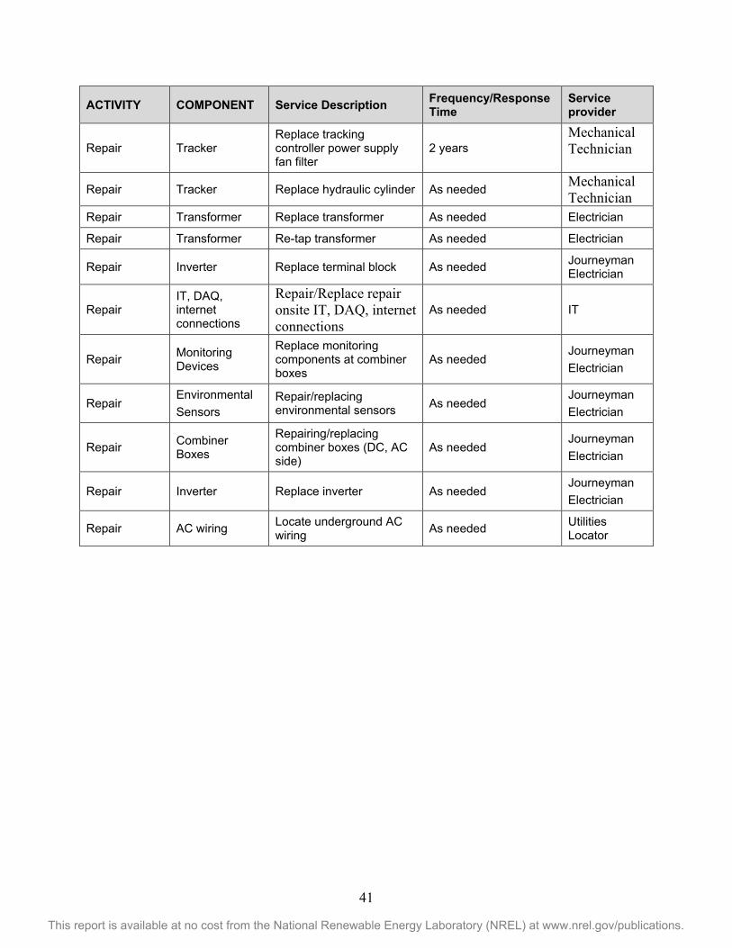
41
This report is available at no cost from the National Renewable Energy Laboratory (NREL) at www.nrel.gov/publications.
ACTIVITY COMPONENT Service Description Frequency/Response Time
Service provider
Repair Tracker Replace tracking controller power supply fan filter
2 years Mechanical Technician
Repair Tracker Replace hydraulic cylinder As needed Mechanical Technician
Repair Transformer Replace transformer As needed Electrician
Repair Transformer Re-tap transformer As needed Electrician
Repair Inverter Replace terminal block As needed Journeyman Electrician
Repair IT, DAQ, internet connections
Repair/Replace repair onsite IT, DAQ, internet connections
As needed IT
Repair Monitoring Devices
Replace monitoring components at combiner boxes
As needed Journeyman Electrician
Repair Environmental Sensors
Repair/replacing environmental sensors As needed
Journeyman Electrician
Repair Combiner Boxes
Repairing/replacing combiner boxes (DC, AC side)
As needed Journeyman Electrician
Repair Inverter Replace inverter As needed Journeyman Electrician
Repair AC wiring Locate underground AC wiring As needed Utilities
Locator
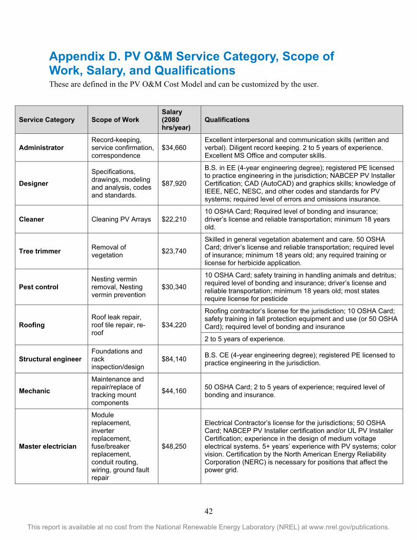
42
This report is available at no cost from the National Renewable Energy Laboratory (NREL) at www.nrel.gov/publications.
Appendix D. PV O&M Service Category, Scope of Work, Salary, and Qualifications These are defined in the PV O&M Cost Model and can be customized by the user.
Service Category Scope of Work Salary (2080 hrs/year)
Qualifications
Administrator Record-keeping, service confirmation, correspondence
$34,660 Excellent interpersonal and communication skills (written and verbal). Diligent record keeping. 2 to 5 years of experience. Excellent MS Office and computer skills.
Designer Specifications, drawings, modeling and analysis, codes and standards.
$87,920
B.S. in EE (4-year engineering degree); registered PE licensed to practice engineering in the jurisdiction; NABCEP PV Installer Certification; CAD (AutoCAD) and graphics skills; knowledge of IEEE, NEC, NESC, and other codes and standards for PV systems; required level of errors and omissions insurance.
Cleaner Cleaning PV Arrays $22,210 10 OSHA Card; Required level of bonding and insurance; driver’s license and reliable transportation; minimum 18 years old.
Tree trimmer Removal of vegetation $23,740
Skilled in general vegetation abatement and care. 50 OSHA Card; driver’s license and reliable transportation; required level of insurance; minimum 18 years old; any required training or license for herbicide application.
Pest control Nesting vermin removal, Nesting vermin prevention
$30,340
10 OSHA Card; safety training in handling animals and detritus; required level of bonding and insurance; driver’s license and reliable transportation; minimum 18 years old; most states require license for pesticide
Roofing Roof leak repair, roof tile repair, re-roof
$34,220
Roofing contractor’s license for the jurisdiction; 10 OSHA Card; safety training in fall protection equipment and use (or 50 OSHA Card); required level of bonding and insurance
2 to 5 years of experience.
Structural engineer Foundations and rack inspection/design
$84,140 B.S. CE (4-year engineering degree); registered PE licensed to practice engineering in the jurisdiction.
Mechanic Maintenance and repair/replace of tracking mount components
$44,160 50 OSHA Card; 2 to 5 years of experience; required level of bonding and insurance.
Master electrician
Module replacement, inverter replacement, fuse/breaker replacement, conduit routing, wiring, ground fault repair
$48,250
Electrical Contractor’s license for the jurisdictions; 50 OSHA Card; NABCEP PV Installer certification and/or UL PV Installer Certification; experience in the design of medium voltage electrical systems. 5+ years’ experience with PV systems; color vision. Certification by the North American Energy Reliability Corporation (NERC) is necessary for positions that affect the power grid.
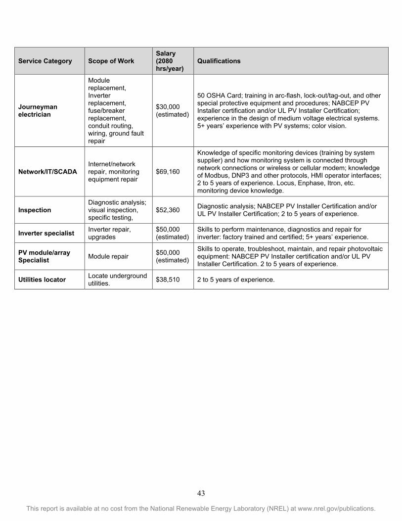
43
This report is available at no cost from the National Renewable Energy Laboratory (NREL) at www.nrel.gov/publications.
Service Category Scope of Work Salary (2080 hrs/year)
Qualifications
Journeyman electrician
Module replacement, Inverter replacement, fuse/breaker replacement, conduit routing, wiring, ground fault repair
$30,000 (estimated)
50 OSHA Card; training in arc-flash, lock-out/tag-out, and other special protective equipment and procedures; NABCEP PV Installer certification and/or UL PV Installer Certification; experience in the design of medium voltage electrical systems. 5+ years’ experience with PV systems; color vision.
Network/IT/SCADA Internet/network repair, monitoring equipment repair
$69,160
Knowledge of specific monitoring devices (training by system supplier) and how monitoring system is connected through network connections or wireless or cellular modem; knowledge of Modbus, DNP3 and other protocols, HMI operator interfaces; 2 to 5 years of experience. Locus, Enphase, Itron, etc. monitoring device knowledge.
Inspection Diagnostic analysis; visual inspection, specific testing,
$52,360 Diagnostic analysis; NABCEP PV Installer Certification and/or UL PV Installer Certification; 2 to 5 years of experience.
Inverter specialist Inverter repair, upgrades
$50,000 (estimated)
Skills to perform maintenance, diagnostics and repair for inverter: factory trained and certified; 5+ years’ experience.
PV module/array Specialist Module repair $50,000
(estimated)
Skills to operate, troubleshoot, maintain, and repair photovoltaic equipment: NABCEP PV Installer certification and/or UL PV Installer Certification. 2 to 5 years of experience.
Utilities locator Locate underground utilities. $38,510 2 to 5 years of experience.
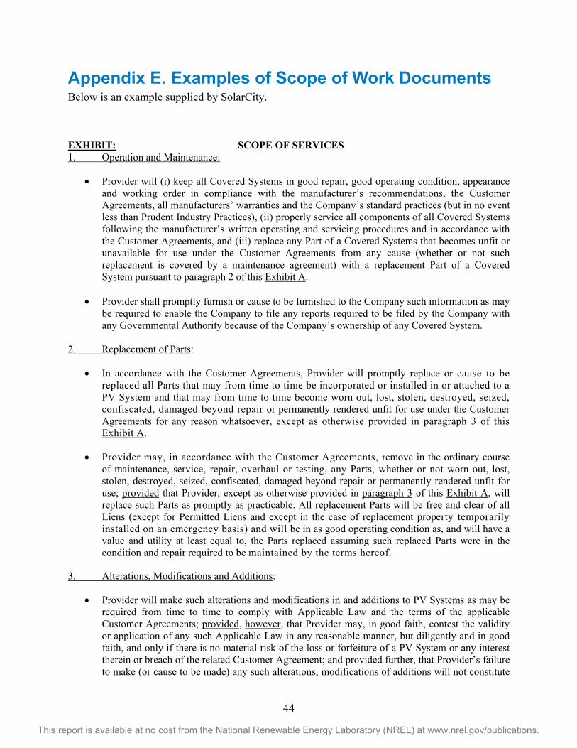
44
This report is available at no cost from the National Renewable Energy Laboratory (NREL) at www.nrel.gov/publications.
Appendix E. Examples of Scope of Work Documents Below is an example supplied by SolarCity.
EXHIBIT: SCOPE OF SERVICES 1. Operation and Maintenance:
• Provider will (i) keep all Covered Systems in good repair, good operating condition, appearance and working order in compliance with the manufacturer’s recommendations, the Customer Agreements, all manufacturers’ warranties and the Company’s standard practices (but in no event less than Prudent Industry Practices), (ii) properly service all components of all Covered Systems following the manufacturer’s written operating and servicing procedures and in accordance with the Customer Agreements, and (iii) replace any Part of a Covered Systems that becomes unfit or unavailable for use under the Customer Agreements from any cause (whether or not such replacement is covered by a maintenance agreement) with a replacement Part of a Covered System pursuant to paragraph 2 of this Exhibit A.
• Provider shall promptly furnish or cause to be furnished to the Company such information as may
be required to enable the Company to file any reports required to be filed by the Company with any Governmental Authority because of the Company’s ownership of any Covered System.
2. Replacement of Parts:
• In accordance with the Customer Agreements, Provider will promptly replace or cause to be replaced all Parts that may from time to time be incorporated or installed in or attached to a PV System and that may from time to time become worn out, lost, stolen, destroyed, seized, confiscated, damaged beyond repair or permanently rendered unfit for use under the Customer Agreements for any reason whatsoever, except as otherwise provided in paragraph 3 of this Exhibit A.
• Provider may, in accordance with the Customer Agreements, remove in the ordinary course of maintenance, service, repair, overhaul or testing, any Parts, whether or not worn out, lost, stolen, destroyed, seized, confiscated, damaged beyond repair or permanently rendered unfit for use; provided that Provider, except as otherwise provided in paragraph 3 of this Exhibit A, will replace such Parts as promptly as practicable. All replacement Parts will be free and clear of all Liens (except for Permitted Liens and except in the case of replacement property temporarily installed on an emergency basis) and will be in as good operating condition as, and will have a value and utility at least equal to, the Parts replaced assuming such replaced Parts were in the condition and repair required to be maintained by the terms hereof.
3. Alterations, Modifications and Additions:
• Provider will make such alterations and modifications in and additions to PV Systems as may be required from time to time to comply with Applicable Law and the terms of the applicable Customer Agreements; provided, however, that Provider may, in good faith, contest the validity or application of any such Applicable Law in any reasonable manner, but diligently and in good faith, and only if there is no material risk of the loss or forfeiture of a PV System or any interest therein or breach of the related Customer Agreement; and provided further, that Provider’s failure to make (or cause to be made) any such alterations, modifications of additions will not constitute
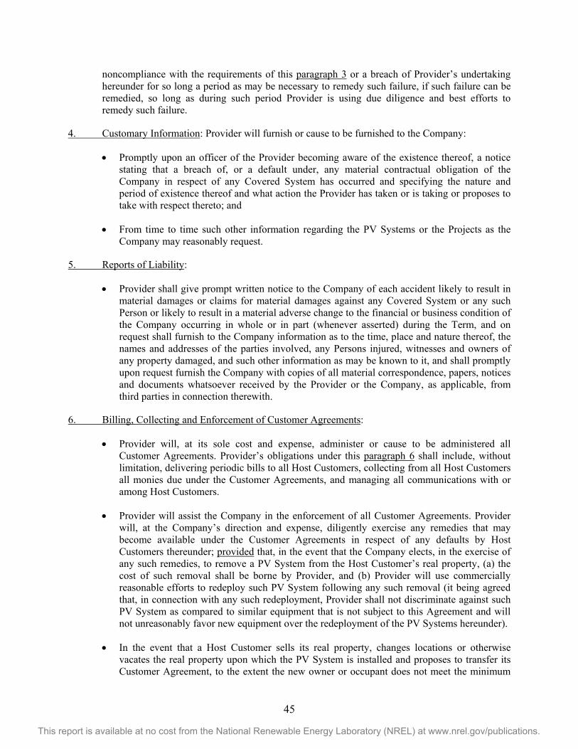
45
This report is available at no cost from the National Renewable Energy Laboratory (NREL) at www.nrel.gov/publications.
noncompliance with the requirements of this paragraph 3 or a breach of Provider’s undertaking hereunder for so long a period as may be necessary to remedy such failure, if such failure can be remedied, so long as during such period Provider is using due diligence and best efforts to remedy such failure.
4. Customary Information: Provider will furnish or cause to be furnished to the Company:
• Promptly upon an officer of the Provider becoming aware of the existence thereof, a notice stating that a breach of, or a default under, any material contractual obligation of the Company in respect of any Covered System has occurred and specifying the nature and period of existence thereof and what action the Provider has taken or is taking or proposes to take with respect thereto; and
• From time to time such other information regarding the PV Systems or the Projects as the Company may reasonably request.
5. Reports of Liability:
• Provider shall give prompt written notice to the Company of each accident likely to result in material damages or claims for material damages against any Covered System or any such Person or likely to result in a material adverse change to the financial or business condition of the Company occurring in whole or in part (whenever asserted) during the Term, and on request shall furnish to the Company information as to the time, place and nature thereof, the names and addresses of the parties involved, any Persons injured, witnesses and owners of any property damaged, and such other information as may be known to it, and shall promptly upon request furnish the Company with copies of all material correspondence, papers, notices and documents whatsoever received by the Provider or the Company, as applicable, from third parties in connection therewith.
6. Billing, Collecting and Enforcement of Customer Agreements:
• Provider will, at its sole cost and expense, administer or cause to be administered all Customer Agreements. Provider’s obligations under this paragraph 6 shall include, without limitation, delivering periodic bills to all Host Customers, collecting from all Host Customers all monies due under the Customer Agreements, and managing all communications with or among Host Customers.
• Provider will assist the Company in the enforcement of all Customer Agreements. Provider will, at the Company’s direction and expense, diligently exercise any remedies that may become available under the Customer Agreements in respect of any defaults by Host Customers thereunder; provided that, in the event that the Company elects, in the exercise of any such remedies, to remove a PV System from the Host Customer’s real property, (a) the cost of such removal shall be borne by Provider, and (b) Provider will use commercially reasonable efforts to redeploy such PV System following any such removal (it being agreed that, in connection with any such redeployment, Provider shall not discriminate against such PV System as compared to similar equipment that is not subject to this Agreement and will not unreasonably favor new equipment over the redeployment of the PV Systems hereunder).
• In the event that a Host Customer sells its real property, changes locations or otherwise vacates the real property upon which the PV System is installed and proposes to transfer its Customer Agreement, to the extent the new owner or occupant does not meet the minimum
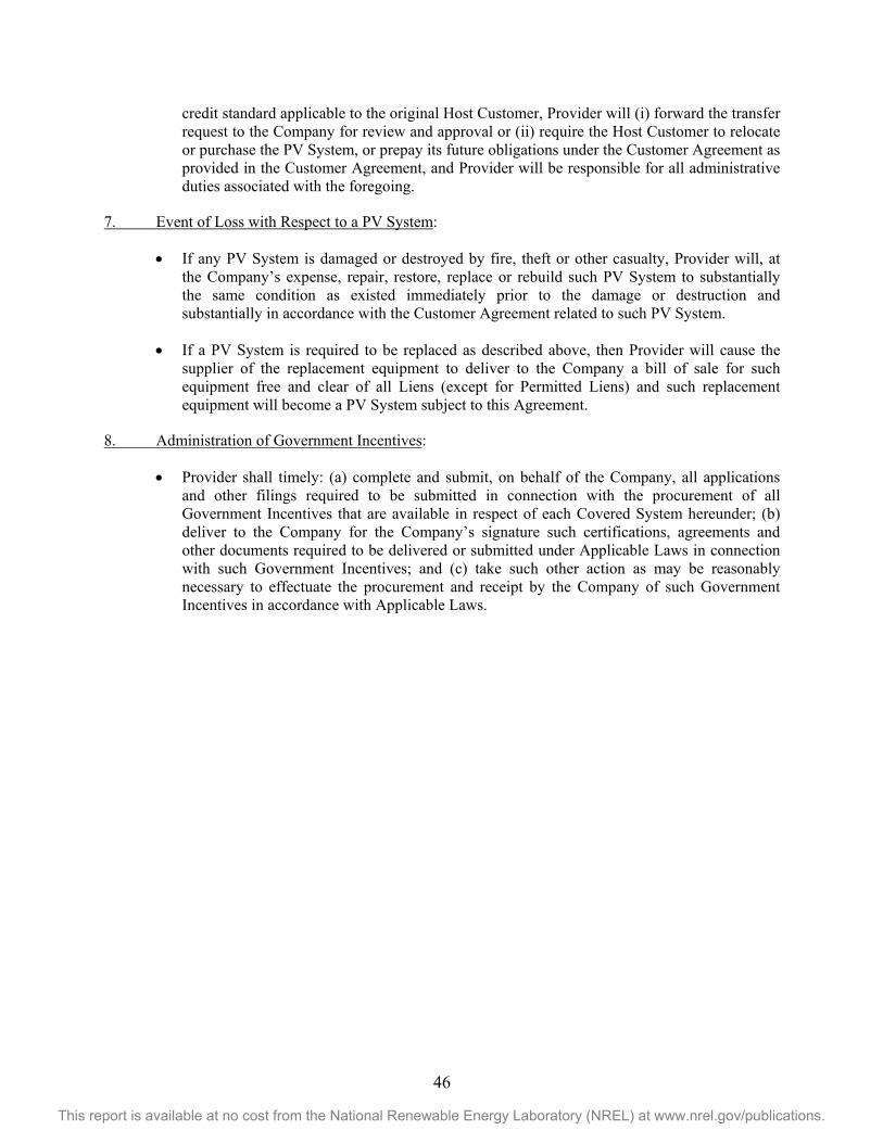
46
This report is available at no cost from the National Renewable Energy Laboratory (NREL) at www.nrel.gov/publications.
credit standard applicable to the original Host Customer, Provider will (i) forward the transfer request to the Company for review and approval or (ii) require the Host Customer to relocate or purchase the PV System, or prepay its future obligations under the Customer Agreement as provided in the Customer Agreement, and Provider will be responsible for all administrative duties associated with the foregoing.
7. Event of Loss with Respect to a PV System:
• If any PV System is damaged or destroyed by fire, theft or other casualty, Provider will, at the Company’s expense, repair, restore, replace or rebuild such PV System to substantially the same condition as existed immediately prior to the damage or destruction and substantially in accordance with the Customer Agreement related to such PV System.
• If a PV System is required to be replaced as described above, then Provider will cause the supplier of the replacement equipment to deliver to the Company a bill of sale for such equipment free and clear of all Liens (except for Permitted Liens) and such replacement equipment will become a PV System subject to this Agreement.
8. Administration of Government Incentives:
• Provider shall timely: (a) complete and submit, on behalf of the Company, all applications and other filings required to be submitted in connection with the procurement of all Government Incentives that are available in respect of each Covered System hereunder; (b) deliver to the Company for the Company’s signature such certifications, agreements and other documents required to be delivered or submitted under Applicable Laws in connection with such Government Incentives; and (c) take such other action as may be reasonably necessary to effectuate the procurement and receipt by the Company of such Government Incentives in accordance with Applicable Laws.
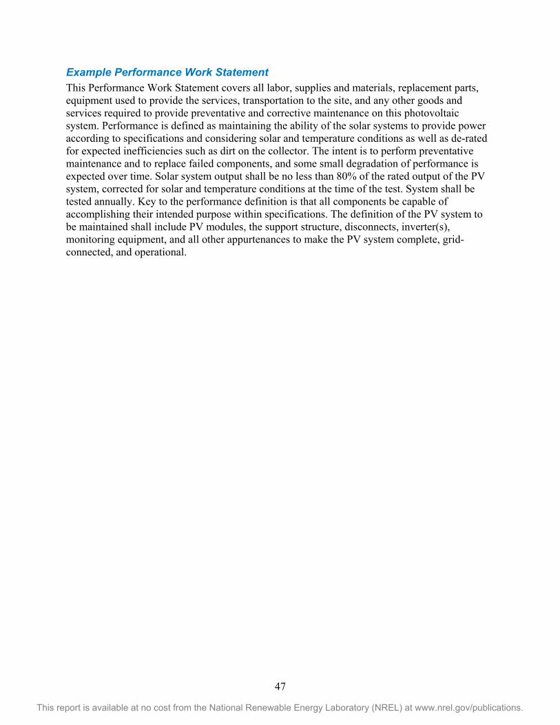
47
This report is available at no cost from the National Renewable Energy Laboratory (NREL) at www.nrel.gov/publications.
Example Performance Work Statement This Performance Work Statement covers all labor, supplies and materials, replacement parts, equipment used to provide the services, transportation to the site, and any other goods and services required to provide preventative and corrective maintenance on this photovoltaic system. Performance is defined as maintaining the ability of the solar systems to provide power according to specifications and considering solar and temperature conditions as well as de-rated for expected inefficiencies such as dirt on the collector. The intent is to perform preventative maintenance and to replace failed components, and some small degradation of performance is expected over time. Solar system output shall be no less than 80% of the rated output of the PV system, corrected for solar and temperature conditions at the time of the test. System shall be tested annually. Key to the performance definition is that all components be capable of accomplishing their intended purpose within specifications. The definition of the PV system to be maintained shall include PV modules, the support structure, disconnects, inverter(s), monitoring equipment, and all other appurtenances to make the PV system complete, grid-connected, and operational.
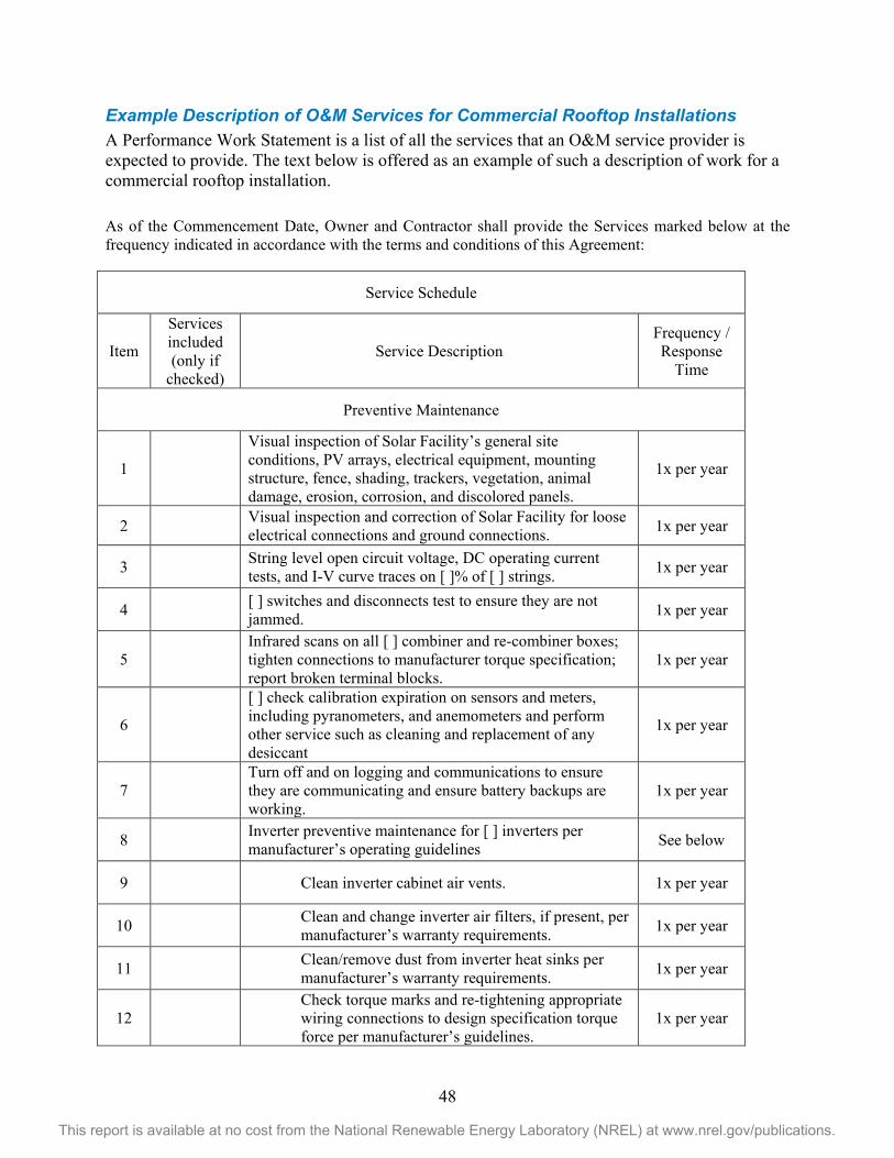
48
This report is available at no cost from the National Renewable Energy Laboratory (NREL) at www.nrel.gov/publications.
Example Description of O&M Services for Commercial Rooftop Installations A Performance Work Statement is a list of all the services that an O&M service provider is expected to provide. The text below is offered as an example of such a description of work for a commercial rooftop installation.
As of the Commencement Date, Owner and Contractor shall provide the Services marked below at the frequency indicated in accordance with the terms and conditions of this Agreement:
Service Schedule
Item
Services included (only if
checked)
Service Description Frequency / Response
Time
Preventive Maintenance
1
Visual inspection of Solar Facility’s general site conditions, PV arrays, electrical equipment, mounting structure, fence, shading, trackers, vegetation, animal damage, erosion, corrosion, and discolored panels.
1x per year
2 Visual inspection and correction of Solar Facility for loose electrical connections and ground connections. 1x per year
3 String level open circuit voltage, DC operating current tests, and I-V curve traces on [ ]% of [ ] strings. 1x per year
4 [ ] switches and disconnects test to ensure they are not jammed. 1x per year
5 Infrared scans on all [ ] combiner and re-combiner boxes; tighten connections to manufacturer torque specification; report broken terminal blocks.
1x per year
6
[ ] check calibration expiration on sensors and meters, including pyranometers, and anemometers and perform other service such as cleaning and replacement of any desiccant
1x per year
7 Turn off and on logging and communications to ensure they are communicating and ensure battery backups are working.
1x per year
8 Inverter preventive maintenance for [ ] inverters per manufacturer’s operating guidelines See below
9 Clean inverter cabinet air vents. 1x per year
10 Clean and change inverter air filters, if present, per manufacturer’s warranty requirements. 1x per year
11 Clean/remove dust from inverter heat sinks per manufacturer’s warranty requirements. 1x per year
12 Check torque marks and re-tightening appropriate wiring connections to design specification torque force per manufacturer’s guidelines.
1x per year
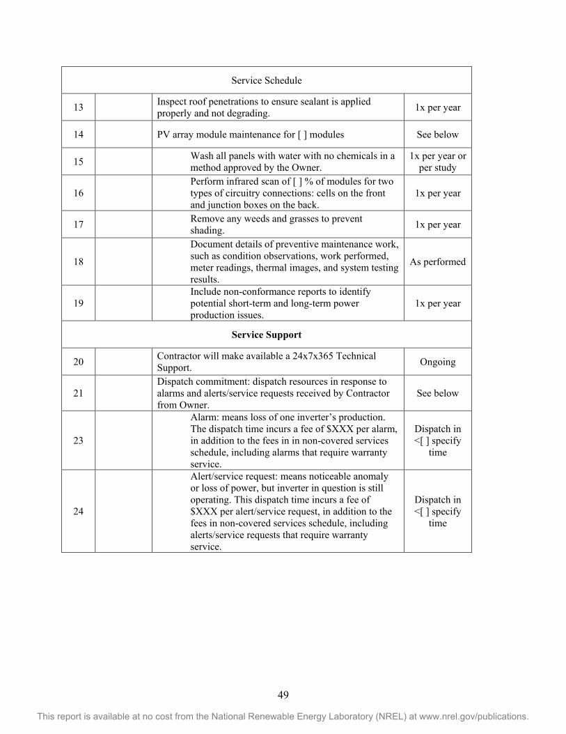
49
This report is available at no cost from the National Renewable Energy Laboratory (NREL) at www.nrel.gov/publications.
Service Schedule
13 Inspect roof penetrations to ensure sealant is applied properly and not degrading. 1x per year
14 PV array module maintenance for [ ] modules See below
15 Wash all panels with water with no chemicals in a method approved by the Owner.
1x per year or per study
16 Perform infrared scan of [ ] % of modules for two types of circuitry connections: cells on the front and junction boxes on the back.
1x per year
17 Remove any weeds and grasses to prevent shading. 1x per year
18
Document details of preventive maintenance work, such as condition observations, work performed, meter readings, thermal images, and system testing results.
As performed
19 Include non-conformance reports to identify potential short-term and long-term power production issues.
1x per year
Service Support
20 Contractor will make available a 24x7x365 Technical Support. Ongoing
21 Dispatch commitment: dispatch resources in response to alarms and alerts/service requests received by Contractor from Owner.
See below
23
Alarm: means loss of one inverter’s production. The dispatch time incurs a fee of $XXX per alarm, in addition to the fees in in non-covered services schedule, including alarms that require warranty service.
Dispatch in <[ ] specify
time
24
Alert/service request: means noticeable anomaly or loss of power, but inverter in question is still operating. This dispatch time incurs a fee of $XXX per alert/service request, in addition to the fees in non-covered services schedule, including alerts/service requests that require warranty service.
Dispatch in <[ ] specify
time
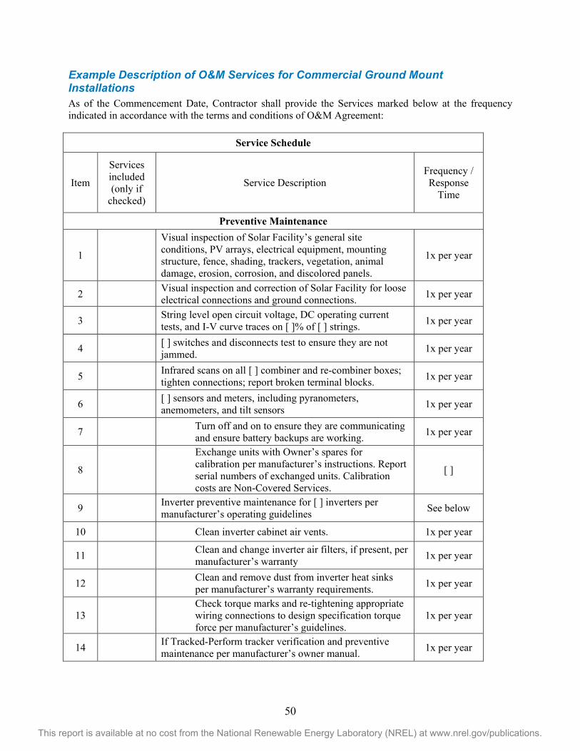
50
This report is available at no cost from the National Renewable Energy Laboratory (NREL) at www.nrel.gov/publications.
Example Description of O&M Services for Commercial Ground Mount Installations As of the Commencement Date, Contractor shall provide the Services marked below at the frequency indicated in accordance with the terms and conditions of O&M Agreement:
Service Schedule
Item
Services included (only if
checked)
Service Description Frequency / Response
Time
Preventive Maintenance
1
Visual inspection of Solar Facility’s general site conditions, PV arrays, electrical equipment, mounting structure, fence, shading, trackers, vegetation, animal damage, erosion, corrosion, and discolored panels.
1x per year
2 Visual inspection and correction of Solar Facility for loose electrical connections and ground connections. 1x per year
3 String level open circuit voltage, DC operating current tests, and I-V curve traces on [ ]% of [ ] strings. 1x per year
4 [ ] switches and disconnects test to ensure they are not jammed. 1x per year
5 Infrared scans on all [ ] combiner and re-combiner boxes; tighten connections; report broken terminal blocks. 1x per year
6 [ ] sensors and meters, including pyranometers, anemometers, and tilt sensors 1x per year
7 Turn off and on to ensure they are communicating and ensure battery backups are working. 1x per year
8
Exchange units with Owner’s spares for calibration per manufacturer’s instructions. Report serial numbers of exchanged units. Calibration costs are Non-Covered Services.
[ ]
9 Inverter preventive maintenance for [ ] inverters per manufacturer’s operating guidelines See below
10 Clean inverter cabinet air vents. 1x per year
11 Clean and change inverter air filters, if present, per manufacturer’s warranty 1x per year
12 Clean and remove dust from inverter heat sinks per manufacturer’s warranty requirements. 1x per year
13 Check torque marks and re-tightening appropriate wiring connections to design specification torque force per manufacturer’s guidelines.
1x per year
14 If Tracked-Perform tracker verification and preventive maintenance per manufacturer’s owner manual. 1x per year
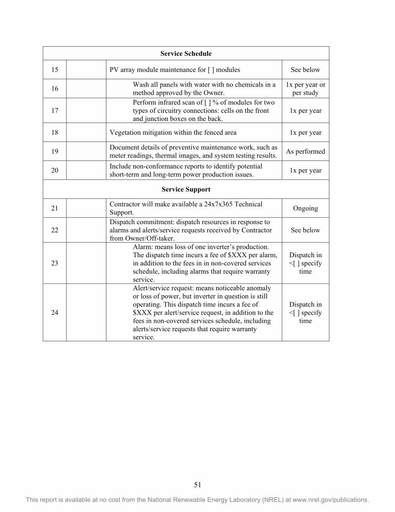
51
This report is available at no cost from the National Renewable Energy Laboratory (NREL) at www.nrel.gov/publications.
Service Schedule
15 PV array module maintenance for [ ] modules See below
16 Wash all panels with water with no chemicals in a method approved by the Owner.
1x per year or per study
17 Perform infrared scan of [ ] % of modules for two types of circuitry connections: cells on the front and junction boxes on the back.
1x per year
18 Vegetation mitigation within the fenced area 1x per year
19 Document details of preventive maintenance work, such as meter readings, thermal images, and system testing results. As performed
20 Include non-conformance reports to identify potential short-term and long-term power production issues. 1x per year
Service Support
21 Contractor will make available a 24x7x365 Technical Support. Ongoing
22 Dispatch commitment: dispatch resources in response to alarms and alerts/service requests received by Contractor from Owner/Off-taker.
See below
23
Alarm: means loss of one inverter’s production. The dispatch time incurs a fee of $XXX per alarm, in addition to the fees in in non-covered services schedule, including alarms that require warranty service.
Dispatch in <[ ] specify
time
24
Alert/service request: means noticeable anomaly or loss of power, but inverter in question is still operating. This dispatch time incurs a fee of $XXX per alert/service request, in addition to the fees in non-covered services schedule, including alerts/service requests that require warranty service.
Dispatch in <[ ] specify
time