Embed Size (px)
Citation preview

IMPORTANT
1. Always lnQu09 OOfflP4ttt Matte m0($tl ,11~ &tflill number so t~t any n,ecl1JC,1t!on ci.,ngt <:an bt conaldtred tor part, ah!pmtnt, H c&n w .,..1im• ,11nd -.itpens&.
2. $p$,c:lf,<;•1lon1 &ubj9'Ct 10 cNlnr,e without not lot,
J.. W• reMl'Yt 1ht ri¢'il to subtiltute fll!'IICttOl'ltl ..-.c.emenl&.
4. Qn:klr by Pilr\ Numbtf. Do not<WO$r t,yOpt;on Numkr,
Form P-XL
XL, XLB, EEXL, EEXLB, CXL, CXLB,
CEEXL, CEEXLB OBSOLETES PARTS FORll 727-7
OBSOlETES F'ORM 727.f
I REZNOR8 MERCER ••• ,. , ,, I APPLIES TO:
INDEX I~/~ II' ;(I I e I ; / tf'c%4:'~ REFERENCE BY PAGE NUMBER Blower tl)Q C<ll'r.c>onGni& - Silil 30-10$ Blower •net COl'r,pontnlS - SUe 125,-400 Blower C.blntt - Sites JO, 105 Burner Raicb at1d Cltrryovef$ - Sb:•s 30•10S 1$
Burner R.acb ind C• rryovlt'S - Sizes 1&400 1$ Cabin« P1rts ... Drafltloodt ... EC0Deri0t 19 Fu and Components • Fan ConfJ'OI I~ 19 fkle eame AS9ettlb1ies- Sites »105 ' lil~rKi,s ., Hee• &ctiangers Batttes ,. Hea, Exctiangers ano Related Pafla 12·13 Limit Conlrol 13. 19 M04ors 6 OvttttBox ,, 0111$tt NoulM 22 Pt!O!S 17-18 Rating Plate 2 Replacetnerrt Put• Ttig 2 5eriM Numbtt lnf(),m,ation 2-3 &in<1mer.l/lin.ter -Swi1cfl •• TNl~IOffl'lers (ConltolJ 20 TraMfo,me,rs (KVA} 20 Velvet (Shu.tort) ,. VtMer (PoW$1'&0) and C<lmc)onetlts - Slt6s 31HO& V•n1er (Poweted) and Cotnponents - Sizes 126-400 Vt n191' a11C1 Venier Aelel)~ft For Cltavlty lMil8 23
AdcltfotlM Refit,___: Fonn 701, R~nt Pilots FOl'WI 7CY2, Rtf)fac:ement n,effllostats Ferm 70'3, ConvMlng to Other Gases
7
••• 21
" 10 ... ••• "
13, 19
' ., " 1~t3
13, 19 , .. 19 22
1M8
2 2
2-3
•• 20 20
••
23
Form 713, Replacement F•n and Limit Ccntrob F'orm 714, Replaoe,m,ent OU Va!Wls F'orm 721, Vent&rt anel Adfptef'S eo, Grrvlty Uni1s F"orm CP· 14, ~ ConYff'lionGG5 to 0770
,. 16
••• .., •
13. Ul
23
" 12-13 13, 19
• 19 22
17-18
2 2
2'3 .. 20 20
" 10 11
Form CP-115, )gnttion Con\l9f'&kln 060M.G to 067 t0770 ForM CP· 19, 9')1,tion (;ony~ 080PFM to 0770
7 7 7 ... ... ... 21 21 ,. •• •• 15 15 16 16 16 16 16
••• ... ... . .. ... • •• ... ... ... . ..
19 19
• 8 13. 19 13, 19 13. 19 13. 19 13. 19
5 • ., 23 23 ., ., " 14 " " 1•
12-13 12-13 12"•13 12-13 12·13 13, 19 13, 19 13,, 19 13,. 19 13. 19 , .. • , .. • , ..
19 19 19 .. 19 22 22 22 22 22
17+18 17-18 17-18 1M8 17-18 2 2 2 2 2 2 2 2 2 2
2-3 2-3 2-3 2-3 2-3 ,, 1• 19 19 19 20 20 20 20 20 20 20 20 20 20
•• , . " •• .. 10 10 10 11 11 11 ., .,
.....
ITEMS THAT ARE HIGHLIGHTED ARE POPULAR ITEMSITEMS WITH CONVERSATION BUBBLE GIVE MORE INFORMATION

EXAMPLE OF A REPLACEMENT PARTS TAG
REZNOR MERCER, PA 16137
COMMON REPLACEMENT PARTS FOR: MODEL: CEEXL170-3 SERIAL NUMBER: AMF62J7N35109 WHEN ORDERING PART, ALWAYS GIVE THE FULL MODEL NUMBER ANO SERIAL NUMBER.
FAN OR BLOWER MOTOR • . . . . . . . . . . . . . . . . . 055681 FAN BLADE • . . • . . . • • • • • • • • • • • • • • • . • . . • . . 045946 FAN CONTROL • • . . • . . . . . • . • . • • • • . • • . • • • • 093629 LIMIT CONTROL . • • • . . . • . . . • . . • . . • . • . . • • • 085449 TRANSFORMER • • . • • • . . • • . • • . . • . . . • • . • • . . 050674 PILOT • . . • • . . . • . • • • . • • • . • • • • • • • • • • . • • . . 061145 GAS VALVE • • . . . • . • . . • • . . . • . • • • • • • • • • • • • 089370 SPARK IGNITION • • • • . . • • . . • . . • • . . . • • . . • . • 089314 VENTER MOTOR • . • • • • • • • . • • . • • • . . • . . • • . . 061069 VENTER WHEEL • . • • . • . . • • • • • • • • • • • • • • • • • 029791 VENT RELAY ($PST) . . • . • . . • . . • • • • • • • • • • • • 014747 PRESSURE SWITCH • . • . • . . • . . • • . . • • . . • . . . 061147 HEAT EXCHANGER • • . • • • . • • • . . • • . • • . . • . . . 094301
WARNING ALL PARTS ARE FOR USE WITH THE FUEL INOENTIFIED ON THE UNIT RATING PLATE. IF THE UNIT HAS BEEN CONVERTED TO OTHER FUELS, CHECK WITH DEALER FOR PROPER FUEL-CARRYING PARTS. INSTALLATION OF IMPROPER PARTS CAN CAUSE DEATH OR INJURY OR PROPERTY LOSS.
Replacement parts tags are found on unit heaters manufactured after March 1986 (Code ALC). Replacement parts lags are for your convenience in identifying replacement part numbers. Always give the full Model No., Serial No., and Part No. when ordering replace~ ment parts.
Page 2
EXAMPLE OF A RATING PLATE
REZNOR MERCER, PA 16137
UNIT HEATER FOR INDUSTRIAL/COMMERCIAL USE. DESIGN CERTIFIED UNDER ANS Z83. 8-1985 UNIT HEATER
MODEL CEEXL 170-3 JUNE 1987 SERIAL NUMBER AMF62J7N35109 115 VOLTS 1PH. 60 HZ MAX. TOTAL INPUT
TYPE OF GAS NATURAL 4.3AMPS
NORMAL INPUT 170000 BTU/HR 136000 BTU/HR
BTU/HR 3.51N. W.C. 5.0IN.W.C.
THERMAL OUTPUT CAPACITY MINIMUM INPUT (-2, -M, -MV MODELS) NORMAL MANIFOLD PRESSURE MINIMUM GAS SUPPLY PRESSURE
CLEARANCES TO COMBUSTIBLE CONSTRUCTION: TOP-6", FLUE CONNECTION- 6", LEFT SIDE-18", RIGHT SIDE-18", BOTTOM-12" EXCEPT WHEN SUPPLIED WITH OPT. DOWNTURN NOZZLE BOTTOM IS-42" INSTALLATION OF THIS HEATER IN PARKING STRUCTURES SHALL BE IN ACCORDANCE WITH NFPA NO. 88A-1985 STANDARD FOR PARKING STRUCTURES. IN REPAIR GARAGES IN ACCORDANCE WITH NFPA NO. 886-1985 STANDARD FOR REPAIR GARAGES ANO IN AIRCRAFT HANGARS IN ACCORDANCE WITH ANSI/NFPA NO. 409-1985 STANDARD FOR AIRCRAFT HANGARS. THIS UNIT IS NOT FOR USE WITH DUCTS. THIS UNIT IS NOT FOR USE WITH FILTERS.
SERIAL NO. EXPLANATION 31 Example of Serial Number for Units made
from 1963 through 1974. Elements in Serial Numbers.
ADA 31 A4 N 6 9 3 Example of Serial Number for Units made starting in 1975.
2 3 4 5 Elements in Serial Numbers.
Element 1: Element 2: Element 3: Element 4:
Element 5:
ELEMENTS IN SERIAL NUMBER Determine date of manufacture. To determine type of safety pilot or pilot system used. To determine type of electric valve used. Type of gas that heater was built to burn. O= Dual fuel, natural and propane L= Propane N= Natural Consecutive number of heater made. Used for identification purposes only.

FIRST ELEMENT OF SERIAL NUMBER - DATE OF MANUFACTURE
YEAR JAN. FEB. MAR. APR. MAY JUNE JULY AUG. SEPT. OCT. NOV. DEC.
1968 TA TB TC TD TE TF TG TH Tl TJ TK TL 1969 UA UB UC UD UE UF UG UH UI UJ UK UL 1970 VA VB vc VD VE VF VG VH VI VJ VK VL 1971 WA WB WC WD WE WF WG WH WI WJ WK WL 1972 XA XB XC XD XE XF XG XH XI XJ XK XL 1973 YA YB YC YD YE YF YG YH YI YJ YK YL
1974 ZA ZB zc ZD ZE ZF ZG ZH ZI ZJ ZK ZL 1975 AAA AAB AAC AAD AAE AAF AAG AAH AAI AAJ AAK AAL
1976 ABA ABB ABC ABD ABE ABF ABG ABH ABI ABJ ABK ABL
1977 ACA ACB ACC ACD ACE ACF ACG ACH ACI ACJ ACK ACL
1978 ADA ADB ADC ADD ADE ADF ADG ADH ADI ADJ ADK ADL
1979 AEA AEB AEC AED AEE AEF AEG AEH AEI AEJ AEK AEL
1980 AFA AFB AFC AFD AFE AFF AFG AFH AFI AFJ AFK AFL
1981 AGA AGB AGC AGD AGE AGF AGG AGH AGI AGJ AGK AGL
1982 AHA AHB AHC AHD AHE AHF AHG AHH AHi AHJ AHK AHL
1983 AIA AIB AIC AID AIE AIF AIG AIH All AIJ AIK AIL 1984 AJA AJB AJC AJD AJE AJF AJG AJH AJI AJJ AJK AJL 1985 AKA AKB AKC AKD AKE AKF AKG AKH AKI AKJ AKK AKL 1986 'ALA ALB ALC ALD ALE ALF ALG ALH ALI ALJ ALK ALL 1987 AMA AMB AMC AMD AME AMF AMG AMH AMI AMJ AMK AML 1988 ANA ANB ANC AND ANE ANF ANG ANH ANI ANJ ANK ANL
*Models XL, CXL, XLS, CXLB 10-year limited warranty on heat exchangers began January 1986. Models CEEXL, CEEXLB-10-year limited warranty on heat exchangers and 5-year limited warranty on operational parts began January 1986.
INTRODUCTION DATES FOR MANUFACTURE OF SERIES 3 AND 5 Series changes indicate when that Model was re-approved by either A.G.A. or C.G.A, Re-approvals some1imes change replacememt parts. Models not listed have only been manufactured in one series to date.
A.G.A. Date of Introduction C.G.A. Dates of Introduction
Models Serles 3 Series 5 Models Series 3 Series 5
XL30-105' AGI (9181) AMG (7187) XL45-105 AHi (9182)
XL 125-400 AGI (9/81) AMI (9187) XL 125-400 AHC (3/82) AMJ (10187)
XLB30-105 All units manufactured prior to 7 /87 AMG (7187)
XLB125-400 AGI (9/81) AJO (4/84)
CXL30-105 All units manufactured prior to 7 /87 AMG (7187)
CXL140-400 All units manufactured prior to 9/87 AMI (9187)
CXLB30-105 All units manufactured prior to 7 /87 AMG (7/87)
CEEXL 125-400 All units manufactured prior to 9/86 ALI (9186)
CEEXLB125-400 All units manufactured prior to 9/86 ALI (9186)
·xL45-1 manufactured between ADG (7178) and AGI (9/81)
Page3

BASIC EXTERIOR PARTS
@
© SIZES 30-105
5
@
@
Unless a specific model is indicated in the description, part numbers for basic exterior parts apply to all models.
CODE DESCRIPTION 30 1 Draft hood assembly for XL, XLB units 52594
1A Draft hood assembly for CXL, CXLB (not illustrated) 86738
16 Flue collection box, EEXL 67855
1C Flue collection box, CEEXL (not illustrated) 67855
2 Draft hood right angle XL, XLB, CXL, CXLB 47818
3 Draft hood left angle XL, XLB, CXL, CXLB 47714
4 Left side panel 47728
5 Right side panel 47731
6 Top front panel 52632
7 Horizontal louver frame with louvers 52600
7A Vertical louver assembly 54594
8 Bottom front panel 52597
9 Bottom pan only ©52589
10 Fan and limit access door 82486
11 Control cover, sizes 125-400 N/A
12 Pilot cover plate 47766
13 Rear panel (fan back) 52630
@ Applies to A.GA XL45 prior to XL45 Series 1 and to C.G.A. XL45 prior to Series 3.
(D Applies to models prior to XL Series 3.
(D Applies to C.G.A. XL45 prior to XL Series 3 with four burners.
45 52594
(D44709
86738
67855
87254
47818
47714
47728
47731
52632 (j) 47751
52600 (j) 47743
54594 (j) 49352
52597 (j) 47734
52589 (j)(j)47698
82486
N/A
47766
52630 ffi 47754 47755
© Not available for XL30 with two burners and not available for XL45 prior to XL45 Series 1.
Page4
SIZE
60 75 105 47709 64094 64096
(D 47719 (j) 47721 (D47724
47709 86741 86744
67859 67861 67863
87261 87267 87273
47818 47818 47818
47714 47714 47714
47728 47728 47728
47731 47731 47731
47751 47752 47753
47743 47747 47749
49352 49355 49357
47734 47737 47740
47698 47700 47702
82486 82486 82486
N/A N/A N/A
47766 47766 47766
67724 67726 67728 47755 47756 47757

FLUE COLLECTION BOX - MODEL EEXL @VERTICAL LOUVER ASSEMBLY, SAME AS OPTION C01
TOP LOUVER SUPPORT
BOTTOM LOUVER SUPPORT
Unless a specific model is indicated in the description, part numbers for basic exterior parts apply to all models. SIZE
CODE 125 140 150 170 200 225 250 300 350 400
1 53112 45741 45755 45755 45763 52936 52944 45790 45798 45805 1A N/A 85015 N/A 85022 85027 85033 85038 85042 85045 85051 18 61024 61028 N/A 61030 61033 61036 61039 61042 61045 61048 1C 87340 87346 N/A 87350 87356 87362 87368 87374 87376 87378 2 45745 45745 45745 45745 45745 45745 45745 45745 45745 45745 3 45745 45745 45745 45745 45745 45745 45745 45745 45745 45745 4 45851 45851 45851 45851 45851 45851 45851 45851 45851 45851 5 61589 61589 61589 61589 61589 61589 61589 61589 61589 61589 6 48548 48548 48549 48549 48550 48551 48552 48553 48554 48555 7 45718 45718 45723 45723 45725 45727 45729 45731 45733 45735 7A 45425 45425 45426 45426 45427 45428 45429 45430 45431 45432 8 45691 45691 45693 45693 45695 45697 45699 45701 45703 45705 9 45682 45682 45684 45684 45685 45686 45687 45688 45689 45690 10 82486 82486 82486 82486 82486 82486 82486 82486 82486 82486 11 45854 45854 45856 45856 45858 45860 45862 45864 45866 45868 12 48652 48652 45737 45737 45737 45737 45737 45737 45737 45737 13 54631 54631 54634 54634 54636 85127 85129 54638 54640 85131
FLUE BAFFLE ASSEMBLIES -Sizes 30-105 (Gravity Vented Units only)
SIZE MODEL 30 45 60 75 105 XL 63046 52593 64849 64850 64851
•54549 XLB 63046 52593 80929 80932 80935 CXL 86733 86734 86735 86736 86737 CXLB 86733 87049 87052 87055 86764 *XL45 nrior tn c:- ..... riAS 1 FLUE BAFFLE ASSEMBLY
Pages
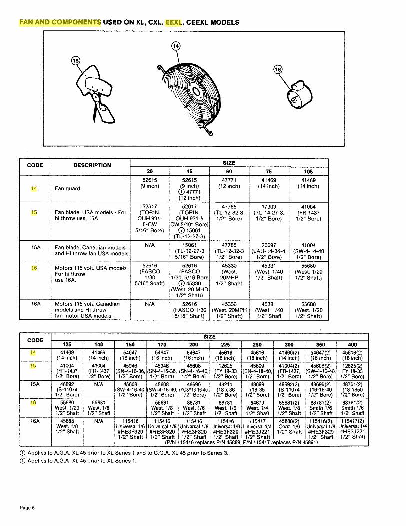
FAN AND COMPONENTS USED ON XL, CXL, EEXL, CEEXL MODELS
CODE DESCRIPTION SIZE
30 45 60 75 105 .
52615 52615 47771 41469 41469
14 Fan guard (9 inch) (15inch) (12 inch) (14 inch) (14 inch) 47771
(12 inch)
52617 52617 47785 17909 41004 15 Fan blade, USA models - For (TORIN. (TORIN. (TL-12-32-3, (TL-14-27-3, (FR-1437
hi throw use, 15A. OUH 931- OUH 931-5 1/2" Bore) 1/2" Bore) 1/2" Bore) 5-CW CW 5/16" Bore)
5/16" Bore) (j) 15061 (TL-12-27-3)
15A Fan blade, Canadian models N/A 15061 47785 20697 41004
and Hi throw fan USA models. (TL-12-27-3 (TL-12-32-3 (LAU-14-34-4, (SW-4-14-40 5/16" Bore) 1/2" Bore) 112" Bore) 1/2" Bore)
16 Motors 115 volt, USA models 52616 52616 45330 45331 55680
For hi throw (FASCO (FASCO (West. (West. 1/40 (West. 1/20
use 16A. 1/30 1/3Qt16 Bore 20MHP 1/2" Shaft) 1/2" Shaft) 5116" Shaft) 2 45330 1/2" Shaft)
(West. 20 MHD 1/2" Shaft)
16A Motors 115 volt, Canadian N/A 52616 45330 45331 55680 models and Hi throw (FASCO 1/30 (West. 20MPH (West. 1/40 (West. 1120 fan motor USA models. 5/16" Shaft) 1/2" Shaft) 1/2" Shaft 1/2" Shaft)
CODE SIZE
125 140 150 170 200 225 250 300 350 14 41469 41469 54647 54647 54647 45616 45616 41469(2) 54647(2)
(14 inch) (14 inch) (16 inch) (16 inch) (16 inch) (18 inch) (18 inch) (14 inch) (16 inch)
15 41004 41004 45946 45946 45608 12625 45609 41004(2) 45608(2) (FR-1437 (FR-1437 (SN-4-16-36, (SN-4-16-36, (SN-4-16-40, (FY 18-33 (SN-4-18-40, (FR-1437, (SW-4-16-40,
112" Bore) 1/2" Bore) 1/2" Bore) 1/2" Bore) 1/2" Bore) 1/2" Bore) 1/2" Bore) 1/2" Bore) 1/2" Bore)
15A 48692 N/A 45608 45608 48696 43211 48699 48692(2) 48696(2) (S-11074 (SW-4-16-40, (SW-4-16-40, (Y08Y16-16-40, (18 X 36 (18-35 (S-11074 (16-16-40
1/2" Bore) 1/2" Bore) 1/2" Bore) 1/2" Bore) 1/2" Bore) 1/2" Bore) 1/2" Bore) 1/2" Bore)
16 55680 55681 55681 88781 88781 64679 55681(2) 88781(2) West. 1/20 West 1/8 West 1/8 West 1/6 West 1/6 West 1/4 West. 1/8 Smith 1/6 1/2" Shaft 1/2" Shaft 1/2" Shaft 1/2" Shaft 1/2" Shaft 1/2" Shaft 1/2" Shaft 1/2" Shaft
16A 45888 N/A 115416 115416 115416 115416 115417 45888(2) 115416(2) West. 1/8 Universal 1/6 Universal 1/6 Universal 1/6 Universal 1/6 Universal 1/4 Cent. 1/6 Universal 1/6 1/2" Shaft #HE3F320 #HE3F320 #HE3F320 #HE3F320 #HE3J221 1/2" Shaft #HE3F320
1/2" Shaft 1/2" Shaft 1/2" Shaft 1/2" Shaft 1/2" Shaft 1/2" Shaft (P/N 115416 replaces P/N 45889; P/N 115417 replaces P/N 45891)
CD Applies to A.G.A. XL 45 prior to XL Series 1 and to C.G.A. XL 45 prior to Series 3.
CD Applies to A.G.A. XL 45 prior to XL Series 1.
Page6
400 45616(2) (18 inch)
12625(2) FY 18-33
1/2" Bore)
48701(2) (18-1850
1/2" Bore)
88781(2) Smith 1/6 1/2" Shaft
115417(2) Universal 1/4 #HE3J221 1/2" Shaft

BLOWER AND COMPONENTS USED ON XLB, EEXLB, CXLB, CEEXLB 30 THRU 105
@ BLOWER ADAPTER FOR SIZES 30-105
•
18 @
CODE DESCRIPTION SIZE
30 45 60 75 105
17 Blower for XLB, CXLB, EEXLB, CEEXLB 30 thru 105 82111 82111 82111 43607 43607 (includes housing and wheel)
18 Blower motor direct drive, 115V 100491 100491 100491 100490 100490 (1/6 HP) (1/6 HP) (1/6 HP) (1/3 HP) (1/3 HP)
19 Blower motor mounting band 51221 51221 51221 51221 51221
20 Blower motor support arm (3 required) 51223 51223 51223 51223 51223
21 Washer 1V8" 0.0. x V4" 1.0., 20 Ga. 82450 82450 82450 82450 82450
22 Screw #14 x 11/4 " Lg. 82451 82451 82451 82451 82451
101917 101917 101917 101918 101918 Ron ken Ron ken Ronken Renken Ron ken
23 Capacitor #P71A12505K05 #P71A12505KOS #P71A12505K05 #P91A12755K05 #f>91A12755K05 (replaces (replaces (replaces (replaces (replaces 43614) 43614) 43614) 82095) 82095)
24 Capacitor end cap 82113 82113 82113 82113 82113
25 Capacitor strap bracket 82114 82114 82114 82114 82114
26 Blower adapter back assembly (includes baffle) 80949 80949 80957 80957 80957
Page7

BLOWER COMPONENTS USED ON XLB, EEXLB 125 THRU 400 AND CXLB, CEEXLB 140 THRU 400
SIZE 125 THRU 250 SIZE 125 THRU 400
CODE 29A - RUBBER FEET AND HARDWARE
CODE DESCRIPTION SIZE
125 140 170 200 225 250 300 350 400 27 Belt Guard 38530 38530 38535 38535 38535 38535 38539 38539 38539 28 Blower including shaft, bearings, housing, 1357 1357 1380 1360 1360 50232 NIA NIA NIA
& wheel Lau Lau Lau Lau Lau Lau A10-10AC A10-10AC A12-12AC A12-12AC A12-12AC 027172-01
28A Left Blower
} NIA NIA NIA NIA NIA NIA 53094 53094 53096
Do not include Lau Lau Lau shaft and 027173-01 027173-01 027173-02
288 beanngs NIA NIA NIA NIA NIA NIA 53098 53098 53100 Right Blower Lau Lau Lau
027174-01 027174-01 027174-02 29 Blower motor mounting bracket 44409 44409 44410 44410 44410 44410 44410 44410 44410 29A Rubber Feet and Hardware NIA NIA NIA NIA NIA NIA 64940 64940 64940 30 Motor pulley, adjustable 13491 13491 13580 13580 7962 7962 13580 7962 7962
Brown in~ IVL4D-1/
Brown in~ IVL4D-1/
Browning 1VL34-5/
Browning IVL34·5/8
Brownini IVL40-5/
Brownini IVL40-5/
Browninj 1Vl34-5/
Browning IVL40-5/8
Browning IVL40-5/8
31 Mo1or -11511180 CEEXLB 93546 93546 93547 93547 93548 93548 93546 13685 NIA West. West. West West. West. West. West. West.
113 HP 113 HP 1/2 HP 112 HP 314HP 3/4 HP 3/4 HP 1 HP 11511160 XLB 93545 93545 93546 93546 93547 93547 93548 13685 13685
West. West. West. West. West. West. West. West. West 1/4 HP 114 HP 113 HP 113 HP 112 HP 1/2 HP 314 HP 1 HP 1 HP
11511160 CXLB NIA 93546 93547 93547 93548 93546 93548 13685 13685 West. West. West. West. West. West West. West.
113HP 112 HP 112 HP 314HP 314HP 314 HP 1 HP 1 HP 11511160 CEEXLB and 115861 115861 31273 31273 115880 115860 115880 43270 43270
EEXLB- (Replaces (Replaces Gould Gould (Replaces (Replaces (Replaces Gould Gould Canadian 13450) 13450) 112 HP 112 HP 10463) 10463) 10463) 1 HP 1 HP
113 HP 1/3 HP 314HP 314 HP 314 HP 20811180 CEEXLB 115862 115862 93547 93547 93548 93548 93548 13685 NIA
(Replaces (Replaces West. West. West. West West. West 7802) 7802) 112 HP 112 HP 314 HP 314 HP 3/4HP 1 HP 1/3HP 1/3HP
20811180 XLB 115790 115790 115862 115862 93547 I 93547 93548 13665 13685 (Replaces (Replaces Replaces Replaces West. West. West. West West.
85087) 85087) 7802) 7802) 112 HP 112 HP 3/4 HP 1 HP 1 HP 114 HP 114 HP 113 HP 113 HP
20811160 CXLB NIA 115682 93547 93547 93548 93546 93548 13685 13685 (Replaces West. West West. West. West West. West.
7802) 112 HP 112 HP 314 HP 314 HP 314 HP 1 HP 1 HP 1/3 HP
Pages

@ 27 BELT GUARD XLB 125 Same as Option AZ6.
Support feet are removed for shipping and must be field installed.
CODE DESCRIPTION
31 Motor -230/1 /60 CEEXLB
230/1 /60 XLB
230/1/60 EEXLB and CEEXLB Canadian
208/3/60 CEEXLB
208/3/60 XLB, CXLB
208/3/60 EEXLB and CEEXLB Canadian
230/3/60 CEEXLB
208/3/60 XLB, CXLB
230/3/60 EEXLB and CEEXLB Canadian
480/3/60 CEEXLB
480/3/60 XLB. CXLB
480/3/60 EEXLB and CEEXLB Canadian
32 V-Belts
33 Blower mounting adapter back assembly (All sizes require only one.)
34 Blower shaft, shafts supplied in longer lengths, cut off excess
35 Blower pulley
36 Blower bearings (Ball)
37 Shipping foot - not required for operation
38 Motor adjustment bracket assembly
39A Motor contactor assembly for 115 volt unit (115V holding coil)
398 Motor contactor assembly for 230 volt unit (230V holding coil)
39G Motor contactor assembly for 460 volt unit {24V holdino coil\
125
115862 (Replaces
7802) 1/3 HP
115790 (replaces
85087) 1/4 HP
31273 Gould 1/2 HP
13443 Gould 1/2 HP
13443 Gould 1/2 HP
16077 Gould 1/2 HP
13443 Gould 1/2 HP
13443 Gould 1/2 HP
16077 Gould 1/2 HP
13443 Gould 1/2 HP
13443 Gould 1/2 HP
16077 Gould 1/2 HP
6184 Browning
4L440
67619
11302 3/4x1To/4"
50455 Browning
SAK 80-3/4"
7310(2) Sea!master SCA·3/4"
44411
CODE39
SIZE
140 170 200 225 250
115862 93547 93547 93548 93548 {Replaces West. West. West. West.
7802) 1/3 HP
1/2 HP 1/2 HP 3/4 HP 3/4HP
115790 115862 115862 93547 93547 (replaces (replaces (replaces West. West.
85087~ 7802) 7802) 1/2 HP 1/2HP 1/4 H 1/2 HP 1/2 HP
31273 31273 31273 115860 115860 Gould Gould Gould (Replaces (Replaces 1/2 HP 1/2 HP i/2 HP 10463) 10463)
1/2HP 1/2HP 13443 13443 13443 38951 36951 Gould Gould Gould West. West. 1/2 HP 1/2 HP 1/2 HP 3/4HP 3/4HP
13443 13443 13443 13443 13443 Gould Gould Gould Gould Gould 1/2 HP 1/2 HP 1/2 HP 1/2 HP 1/2 HP
16077 16077 16077 20371 20371 Gould Gould Gould Gould Gould 1/2HP 1/2 HP 1/2 HP 3/4 HP 3/4HP
13443 13443 13443 36951 36951 Gould Gould Gould West. West. 1/2 HP 1/2 HP 1/2 HP 3/4 HP 3/4HP
13443 13443 13443 13443 13443 Gould Gould Gould Gould Gould 1/2 HP 1/2 HP 1/2 HP 1/2 HP 1/2HP
16077 16077 16077 20371 20371 Gould Gould Gould Gould Gould 1/2 HP 1/2 HP 1/2 HP 3/4 HP 3/4 HP
13443 13443 13443 36951 36951 Gould Gould Gould West West. 1/2 HP 1/2 HP 1/2 HP 3/4 HP 3/4HP
13443 13443 13443 13443 13443 Gould Gould Gould Gould Gould 1/2 HP 1/2 HP 1/2 HP 1/2 HP 1/2HP
16077 16077 16077 20371 20371 Gould Gould Gould Gould Gould 1/2 HP 1/2 HP 1/2 HP 3/4 HP 3/4HP
6184 52966 52966 7808 7808 Browning Browning Browning Browning Browning
4L440 A44 A44 4L480 4L480
67619 67622 67625 67628 67631
11302 11303 11303 11303 11303 3/4X173/4" 1"x19" 1"x19" 1"x19" 1"x19"
50455 50460 50460 50458 50458 Browning Browning Browning Browning Browning
SAK SAK SAK SAK SAK 80-3/4" 70-1" 70-1" 80-1" 80-1"
7310(2) 10437(2) 10437(2) 10437(2) 10437(2) Sea!master Sea/master Sealmaster Sealmaster Seal master SCA·3/4" SCA-16-1" SCA-16-1"' lCA-16-1" lCA-16-1"
44411 44411 44411 44411 44411
Available on sizes 125-300 as is required for your application. (Contactor may be manufactured by either Gould or Furnas.)
MOTOR CONTACTOR WITH COVER REMOVED
300 350 400
93548 13685 4082 West. West. Gould
3/4 HP 1 HP 1-1/2 HP
93548 13685 13685 West. West. West.
3/4 HP 1 HP 1 HP
115860 43270 43270 (Replaces Gould Gould
10463) 1 HP 1 HP 1/2 HP
36951 36580 115859 West West. (Replaces
3/4 HP 1 HP 16081) 1-1/2 HP
36951 36580 38580 West. West. West. 3/4 HP 1 HP 1 HP
20371 16080 16080 Gould Gould Gould 3/4 HP 1 HP 1 HP
36951 36580 115859 West. West. (replaces
3/4 HP 1 HP 1608~ 11/2 P
36951 38580 36580 West. West. West.
3/4 HP 1 HP 1 HP
20371 16080 16080 Gould Gould Gould 3/4 HP 1 HP 1 HP
36951 38580 115859 West. West. (Replaces 3/4 HP 1 HP 16081)
1 1/2HP
36951 38580 36580 West. West. West.
3/4 HP 1 HP 1 HP
20371 16080 16080 Gould Gould Gould 3/4 HP 1 HP 1 HP
52966 7808 7808 Browning Browning Browning
A44 4L480 4L480
67632 67635 67636
10121 10121 10121 1"x34" 1"x391/4" 1"x446/8 "
50460 50458 50458 Browning Browning Browning
SAK SAK SAK 70·1" 80·1" 80-1"
10437(2) 10437(2) 10437(2) Sealmaster Seal master Sealmaster SCA-16-1" SCA-16-1"' CR-16--1"
44411 44411 44411
95527 95527
95528 95528
95526 95526
Page9

VENTERS AND COMPONENTS USED ON EEXL, CEEXL, EEXLB, CEEXLB 30-105
MODEL EEXL, CEEXL, EEXLB, CEEXLB 30-105 VENTER
Pressure Switch Guard Not Illustrated. See Description Code 52.
CODE DESCRIPTION
40 Exhaust pipe assembly only
41 Compression fitting
42 Venter support
43 Venter assembly complete. 115 volt. Less pressure switch, less pressure switch tubing, less venter support - EEXL
43A Same as 43 - CEEXL
438 Same as 43 - EEXLB
43C Same as 43 - CEEXL8
44 Venter motor only, 115 volt - EEXL, CEEXL
44A Venter motor only, 115 volt - EEXLB, CEEXLB
45 Venter fan blade
46 Venter blower wheel
47 Venter junction box
48 Venter junction box cover
49 Venter relay
50 Pressure switch
51 Pressure switch tubing, with two male fittings
52 Pressure switch guard used on size 30 - 105 (Not illustrated).
53A Venter blower housing with outlet collar
538 Inlet collar only for venter blower housing
54 Venl cap - EEXL, EEXLB, CEEXL, CEEXLB
55A Bracket
558 Nuts
SSC Spacers (Hex Pins)
Fuseholder assembly - Canadian units only. Located in
56 venter junction box on EEXL, EEXLB models. In main junction box on XLB models. Mounted near control transformer on XL models.
* For CGA certified EEXL models.
Page 10
30 45 67993 67993
1436(2) 1436(2)
68033 68033
68269 68270
68269 68270
82011 82016
82011 87232
68002 68002
61069 61069
68005 68005
68006 68006
68008 68008
29596 29596
14747 14747
68031 68031
68035 68035
65162 65162
67998 67998
67995 67995
110051-4" 110051-4"
68003 68003
45947(4) 45947(4)
68004(4) 68004(4)
60241
I 60241
SIZE
60 67993 I
1436(2)
68033
68270 74362'
68270
82016
87232
68002 61069'
61069
68005
68006
68008
29596
14747
68031
68035
65162
67998
67995
110051-4"
68003
45947(4)
68004(4)
80241 I
EEXL, EEXLB, CEEXL, CEEXLB VENT CAP Same as Option CC1
®
75 105 67993 67993
1436(2) 1436(2)
68033 68033
68271 68272 74365' 74367'
68271 68271
82018 82020
82019 82019
68002 68002 61069' 61069'
61069 61069
68005 68005
68006 68006
68008 68008
29596 29596
14747 14747
68031 68031
68035 68035
65162 65162
67998 67998
67995 67995
110051-4" 110051-4"
68003 68003
45947(4) 45947(4)
68004(4) 68004(4)
60241 60241

VENTERS AND COMPONENTS USED ON EEXL, CEEXL, EEXLB, CEEXLB 125-400
MODELS 125-400 VENTER EEXL, EEXLB, CEEXL, CEEXLB VENT CAP Same as Option CC1 @@A
CODE DESCRIPTION CODE DESCRIPTION
57 Exhaust collar and pipe assembly with 1/4 tube x 1/8 616 Venter motor only, 208 volt - EEXL6, CEEXL6 pipe fitting and spoiler where required. - EEXL 61C Venter motor only, 230 volt - EEXL6, CEEXL6
57A Same as 57 - EEXLB 62 Venter fan blade
576 Same as 57 - CEEXL 63 Venter blower wheel
57C Same as 57 - CEEXL6 64 Venter junction box
58 Compression Fitting 65 Venter junction box cover
59 Venter support angle (not illustrated). 66 Venter relay
59A Venter support - size 125-250. Requires 59. 67 Pressure switch
60 Venter assembly complete. 115 volt. Less pressure switch, 68 Pressure switch tubing (not illustrated) less pressure switch tubing, less venter support - EEXL 69 Pressure switch mounting bracket
60A Same as 60 - EEXL6 70 Venter blower housing
606 Same as 60 - CEEXL 71 Vent cap - EEXL, EEXL6
60C Same as 60 - CEEXL6 71A Vent cap - CEEXL, CEEXL6
61 Venter motor only, 115 volt - EEXL, CEEXL 72 Bracket
61A Venter motor only, 115 volt - EEXL6, CEEXL6 73 Fuseholder assembly - Canadian units only. Located in venter junction box on EEXL, EEXLB models.
CODE SIZE
125 140 150 170 200 225 250 300 350 400 57 61051 61051 61051 61051 61051 61054 61051 61056 61056 61056 57A 61051 61051 61051 61051 61051 61054 61051 61779 61779 61779 576 87326 87329 87326 87326 87326 87330 87326 87332 87335 95660 57C 87326 87329 87326 87326 87326 87330 87326 87337 87339 95681 58 1436(2) 1436(2) 1436(2) 1436(2) 1436(2) 1436(2) 1436(2) 1436(2) 1436(2) 1436(2) 59 62544 62544 62544 62544 62544 62544 62544 62497 62497 62497 59A 62545 62545 62545 62545 62545 62545 62545 N/A N/A N/A 60 61063 61063 61063 61063 61063 61071 61071 61074 61074 61074 60A 61063 61063 N/A 61063 61063 61071 61071 61074 61074 61074 606 61063 61063 61071 61071 61071 61071 61071 61074 61074 61074 60C 61063 61063 61071 61071 61071 61071 61071 61074 61074 62820 61 61069 61069 61069 61069 61069 61069 61069 87434* 87434* 87434* -61A 61069 61069 61069 61069 61069 61069 61069 87434* 87434* 87434* 616 62814 62814 62814 62814 62814 62814 62814 30249 30249 30249 61C 62814 62814 62814 62814 62814 62814 62814 29571 29571 29571 62 29793 29793 29793 29793 29793 29793 29793 29793 29793 29793 63 29791 29791 29791 29791 29791 29791 29791 29792 29792 29792 64 29595 29595 29595 29595 29595 29595 29595 29595 29595 29595 65 29596 29596 29596 29596 29596 29596 29596 29596 29596 29596 66 14747 14747 14747 14747 14747 14747 14747 14747 14747 14747 67 61147 61147 61147 61147 61147 61147 61147 61147 61147 61147 68 61163 61163 61163 61163 61163 61163 61163 61164 61164 61164 69 61070 61070 61070 61070 61070 61070 61070 61070 61070 61070 70 61064 61064 61072 61072 61072 61072 61072 61075 61075 61075 71 110051-4" 110051-4" 110051-4" 110051-4" 110051-4" 110052-5" 110052-5" 110053-6" 110053-6" 110053-6" 71A 110051-4" 110051-4" 110052-5" 110052-5" 110052-5" 110052-5" 110052-5" 110053-6" 110053-6" 110053-6" 72 31393 31393 31393 31393 31393 31393 31393 31393 31393 31393 73 60241 60241 60241 60241 60241 60241 60241 60241 60241 60241
*Does not include capacitor, P/N 87435.
Page 11

REPLACEMENT HEAT EXCHANGERS AND RELATED INTERNAL BODY PARTS
c::c:§:§~~'l---78 (See page 14)
75
CODE DESCRIPTION MODELS
74 Aluminized Heat Exchanger XL, CXL, EEXL Assembly. For Models 30-105, the number in parenthesis after the part number is the number of CEEXL tubes. Heat exchangers for Models 125-400 include fan and limit XLB,CXLB control factory installed for the specific model heater. Control settings are shown in parenthesis below the part numbers. Drafthood
CEEXLB
gaskets are included in Models EEXLB 125-400.
74A Stainless Steel (409) Heat XL, CXL, EEXL Exchanger Assembly. For Models 30-105, the number in parenthesis is the number of tubes. Heat CEEXL exctiangers for Models 125-400 include fan and limit XLB,CXLB controls factory installed for spe-cific model heater. Control settings are shown in parenthesis below the part numbers. Drafthood
CEEXLB
gaskets are included in Models EEXLB 125-400.
*Applies to C.G.A. units.
Page 12
30
52571(3)
52571(3)
80941(3)
80941 (3)
80941 (3)
80784(3)
80784(3)
82239(3)
82239(3)
82239(3)
Codes 74, 74A- Heat Exchanger Assembly (Size 125-400)
SIZE
45 60 75 105
52571(3) 51218(4r 47683(5) 47686(7) 47680(4)
51218(4r 52571 (3) 47680(4) 47683(5) 47686(7)
80941(3) 51278(4) 47683(5) 47686(7)
80941(3) 51278(4) 47683(5) 47686(7)
80941 (3) 51278(4) 47683(5) 47686(7)
80784(3) 80786(4). 80788(4) 80790(5) 80792(7)
80786(4)· 80784(3) 80788(4) 80790(5) 80792(7)
82239(3) 80786(4) 80790(5) 80792(7)
82239(3) 80786(4) 80790(5) 80792(7)
82239(3) 80786(4) 80790(5) 80792(7)
HEAT EXCHANGER ARE N/A FOR THIS ENTIRE SERIES
HEAT EXCHANGERS ARE N/A FOR THIS ENTIRE SERIES

Heat Exchanger Assembly (Codes 74 and 74A) Showing Fan and Limit Controls
Setting PIN Fan 150° 93629 Control 170"' 93631
Umit 160° 82091
Control 180" 45602 200° 85449
CODE MODELS 125 140 74 94292 94292
XL, CXL, EEXL (F150, (F150, L180J L180)
94300 94300 CEEXL (F150, (F150,
L200) L200)
94305 94305 XLB,CXLB (F170, (F170,
L200) L200)
94305 94305 CEEXLB (F170, (F170,
L200) L200)
94292 94292 EEXLB (F150, (F150,
L180) L180)
74A 94319 94319 XL, CXL, EEXL (F150, (F150,
L180) L180)
94327 94327 CEEXL (F150, (F150,
L200) L200)
94332 94332 XLB, CXLB (F170, (F170,
L200) L200)
94332 94332 CEEXLB (F170, (F170,
L200) L200)
94319 94319 EEXLB (F150, (F150,
L180) L180)
CODE DESCRIPTION
75 Left and Right Side Support 45628(2) 45628(2)
76 Rear Burner Support 45632 45632
77 Baffle 46217 46217
150
94293 (F150, L 180)
94301 (F150, L200)
N/A
N/A
N/A
94320 (F150, L180)
94328 (F150, L200)
N/A
N/A
NIA
45628(2)
45639
46218
Heat Exchanger Assembly (Codes 74 and 74A) Showing Drafthood Gaskets
Drafthood Gaskets
Size
125, 140 150,170
200 225 250 300 350 400
SIZES
170 200 225
94293 94294 94295 (F150, (F150, (F150, L 180) L180) L 180)
94301 94294 94295 (F150, (F150, (F150, L200) L180) L180)
94306 94307 94308 (F170, (F170, (F170, L200) L180) L180)
94306 94313 94314 (F170, (F170, (F170, L200) L200) L200)
94293 94294 94295 (F150, (F150, (F150, L180) L180) L180)
94320 94321 94322 (F150, (F150, (F150, L180) L180) L180)
94328 94321 94322 (F150, (F150, (F150, L200) L200) L180)
94333 94334 94335 (F170, (F170, (F170, L200) L 180) L180)
94333 94340 94341 (F170, (F170, (F170, L200) L200) L200)
94320 94321 94322 (F150, (F150, (F150, L180) L200) L180)
45628(2) 45628(2) 45628(2)
45639 45646 45653
46218 46219 46220
Drafthood Gaskets No. P/N No. P/N
2 85472 2 62922 2 85472 2 62923 2 85472 2 62924 2 85472 2 62925 2 85472 2 62926 2 85472 2 62927 2 85472 2 62929 2 85472 2 62931
250 300 350 400
94296 94297 94298 94299 (F150, (F150, (F150, (F150, L180) L180) L180) L180)
94296 94302 94303 94304 (F150, (F150, (F150, (F150, L180) L200) L200) L200)
94309 94310 94311 94312 (F170, (F150, (F150, (F150, L160) L160) L160) L160)
94315 94316 94317 94318 (F170, (F150, (F150, (F150, L200) L180) L180) L180)
94296 94316 94317 94318 (F150, (F150, (F150, (F150, L180) L180) L180) L180)
94323 94324 94325 94326 (F150, (F150, (F150, (F150, L180) L180) L180) L180)
94323 94329 94330 94331 (F150, (F150, (F150, (F150, L180) L200) L200) L200)
94336 94337 94338 94339 (F170, (F150, (F150, (F150, L160) L160) L160) L160)
94342 94343 94344 94345 (F170, (F150, (F150, (F150, L200) L180) L180) L180)
94323 94343 94344 94345 (F150, (F150, (F150, (F150, L180) L180) L180) L180)
45628(2) 45628(2) 45628(2) 45628(2)
45660 45667 45674 45681
46221 I 46222 46223 46224
Models CXL, CXLB, CEEXLB are also equipped with "V" shaped tube baffles. When replacing heat exchangers in these models, check to see 1f the "V"baffle can be salvaged. If they cannot be salvaged, it will be necessary to order "V" type baffles, Code No. 78, page 14. If replacement heat exchangers are for Canadian Models, see Code No. 79, page 14.
Page 13

78. HEAT EXCHANGER "V" SHAPED TUBE BAFFLE
78. Heat Exchanger "V" Shaped Tube Baffles
MODELS
SIZE CXL CXLB CEEXL, CEEXLB
P/N P/N P/N
30 N/A N/A N/A 45 N/A 86676(3) 86676(3)
60 N/A 86676(4) 86676(4)
75 N/A 86676(5) 86676(5)
100 N/A N/A N/A 105 N/A 86676(7) 86676(7)
125 N/A N/A N/A 140 85727(5) 85727(5) 85727(5)
150 N/A N/A N/A 170 85727(6) 85727(6) 85727(6)
'V" Shaped Heat Exchanger Tube Baffle 175 N/A N/A N/A 200 85727(7) 85727(7) 85727(7)
225 85727(8) 85727(8) 85727(8)
250 85727(9) 85727(9) '87207(9)
300 85727(11) 85727(11) '87207(11)
350 85727(13) 85727(13) '87207(13)
400 85727(15) 85727(15) '87207(15)
Number In Parenthesis is number required. NI A = Nol Applicable
·"V" baffle with turbulator
79. HEAT EXCHANGER BAFFLES FOR CANADIAN MODELS
Page 14
! /t<Oi'!IZOf<TAL ff IIAl'fl.£
' 1 /
REAR VIEW OF UNIT WlTH FAit &ACK Rl<MOYED
Canadian XL 125 through 400 units were originally equipped with a vertical baffle and a horizontal baffle, as shown below. When replacing heat exchangers on Canadian XL units, check to see if the vertical and horizontal baffles can be salvaged. If not, it will be necessary to order these baffles as indicated below and to
field-install same in the replacement heat exchanger, as they cannot be factory installed.
SIZE
125 150 170 200 225 250 300 350 400
I Vertical P/N 48533 48533 48533 48533 48533 48533 48537 48537 48537
I Horizontal P/N 48534 48535 48535 48534 48534 48534 48534 48534 48534
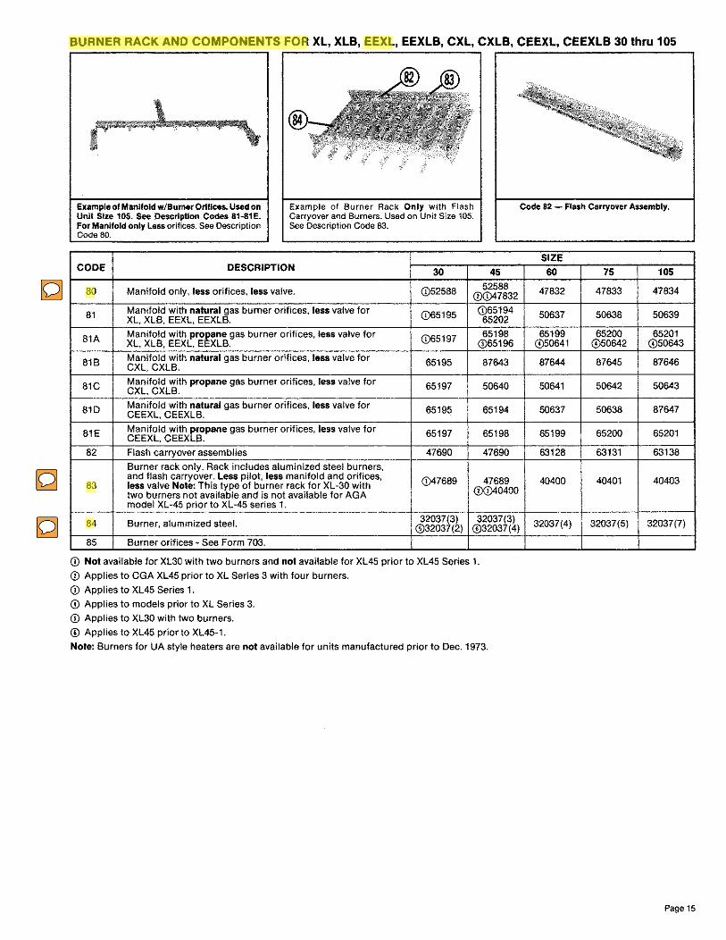
BURNER RACK AND COMPONENTS FOR XL, XLB, EEXL, EEXLB, CXL, CXLB, CEEXL, CEEXLB 30 thru 105
Example of Manifold w/Burner Orifices. Used on Unit Size 105. See Description Codes 81-81E. For Manifold only Less orifices. See Description Code 80.
®
Example of Burner Rack Only with Flash Carryover and Burners. Used on Unit Size 105. See Description Code 83.
CODE DESCRIPTION 30 45 52588 80 Manifold only, less orifices, less valve. (D52588 (D(D47832
81 Manifold with natural gas burner orifices, less valve for (D65195 (D65194 XL, XLB, EEXL, EEXLB. 65202
81A Manifold with propane gas burner orifices, less valve for (D65197 65198 XL, XLB, EEXL, EEXLB. (D65196
818 Manifold with natural gas burner orifices, less valve for 65195 87643 CXL, CXLB.
81C Manifold with propane gas burner orifices, less valve for CXL, CXLB. 65197 50640
810 Manifold with natural gas burner orifices, less valve for 65195 65194 CEEXL, CEEXLB.
81E Manifold with propane gas burner orifices, less valve for CEEXL, CEEXLB. 65197 65198
82 Flash carryover assemblies 47690 47690
Burner rack only. Rack includes aluminized steel burners, and flash carryover. Less pilot, less manifold and orifices, (D47689 47689 83 less valve Note: This type of burner rack for XL-30 with (D(D40400 two burners not available and is not available for AGA model XL-45 prior to XL-45 series 1.
84 Burner, alumlnized steel. 32037(3) ©32037(2)
32037(3) ©32037(4)
85 Burner orifices - See Form 703.
(D Not available for XL30 with two burners and not available for XL45 prior to XL45 Series 1.
© Applies to CGA XL45 prior to XL Series 3 with four burners.
Q) Applies to XL45 Series 1.
© Applies to models prior to XL Series 3.
© Applies to XL30 with two burners.
© Applies to XL45 prior to XL45-1.
Note: Burners for UA style heaters are not available for units manufactured prior to Dec. 1973.
Code 82 - Flash Carryover Assembly.
SIZE
60 75 105
47832 47833 47834
50637 50638 50639
65199 65200 65201 ©50641 ©50642 ©50643
87644 87645 87646
50641 50642 50643
50637 50638 87647
65199 65200 65201
63128 63131 63138
40400 40401 40403
32037(4) 32037(5) 32037(7)
Page 15

BURNER RACK AND COMPONENTS FOR XL, XLB, EEXL, EEXLB 125 THRU 400 AND CXL, CXLB, CEEXL, CEEXLB 125 thru 400
Example of Manifold with burner Orifices. Used on XL, EEXL, XLB, EEXLB 125. See Description Codes 87-87E. For Manifold Only Less Orifices. See Description Code 86.
CODE DESCRIPTION
86 Manifold only, less orifices, less valve
87 Manifold with natural &as burner orifices, less valve for XL, XLB, EEXL, EE LB
87A Manifold with propane gas burner orifices, less valve forXL,XLB,EEXL,EEXLB
876 Manifold with natural gas burner orifices, less valve for CXL, CXLB
87C Manifold with propane gas burner orifices, less valve for CXL, CXLB
87D Manifold with natural gas burner orifices, less valve for CEEXL, CEEXLB
87E Manifold with proeane gas burner orifices, less valve for CEEXL, CEEX B
88 Flash carryover assemblies
88L Left flash carryover assembly. Sizes 225-400 require one each left and right carryover assembly.
CODE 125 140 150 170
86 84765 84765 84766 84766
87 47224 47225 65216 47226
87A 65207 65208 65217 65209 (1)47233 (j)47234 (1)47235
87B N/A 87649 N/A 87650
87C N/A 87657 N/A 87658
87D 47224 47225 N/A 47226
87E 65207 65208 N/A 65209
88 63131 63131 51545 63134
88L N/A N/A N/A N/A
88R N/A N/A N/A N/A
88C N/A N/A N/A N/A
89 67871 67871 67872 67872
89A 67451 67451 67452 67452
90 85218(5) 85218(5) 85218(6) 85218(6)
90A 87954(5) 87954(5) 87954(6) 87954(6)
91 46171 46171 46172 46172
@Applies to Models prior to XL Series 3.
Page 16
Example of Burner Rack Only. Less Manifold and Orifices, Less Pilot, With Air Shutters Used on XL, EEXL, XLB, EEXLB 125. See Description Codes 90 and 90A.
CODE DESCRIPTION
88R Right flash carryover assembly. Sizes 225-400 require one each left and right carryover assembly.
88C Center flash carryover assembly. Sizes 350 and 400 require one each left, right and center carryover assembly.
89 Burner rack only. Rack tncludes aluminized steel burners, flash carryover, and burner air shutters (on sizes 125 thru 400). Less pilot, less manifold and orifices, less valve.
89A Burner rack only. Same as 89 except equipped with stainless steel burners.
90 Burner, aluminized steel.
90A Burner, stainless steel.
91 Burner air shutters
92 Burner orifices - See Form 703.
SIZE
200 225 250 300 350 400 84767 84768 84770 84771 84772 84773
47227 47228 65206 47230 47231 47232
65210 65211 65212 65213 65214 65215 (j)47236 (1)47237 (1)47238 (1)47239 (1)47240 (j)47241
87651 87652 87653 87654 87655 87656
87659 87660 87661 87662 87663 87664
87665 87666 87667 47230 47231 87668
65210 65211 47238 65213 65214 65215
63138 N/A N/A N/A N/A N/A
N/A 63144 63144 63144 63144 63144
NIA 63141 63148 63152 63148 63152
N/A N/A N/A N/A 63156 63156
67873 67874 67875 67876 67877 67878
67453 67454 67455 67456 67457 67458
85218(7) 85218(8) 85218(9) 85218(11) 85218(13) 85218(15)
87954(7) 87954(8) 87954(9) 87954(11) 87954(13) 87954(15)
46173 46174 46175 46176 46177 46178

PILOTS HORIZONTAL MATCH LIT PILOTS
93. FOR XL, XLB, CXL, CXLB 30 THRU 105
Baso #J999HKA
Replacement Kits (includes Codes 93, 95, 96)
Code Oescrl tlon Natural Pilot w/Orifi-ce
93 Propane Pilot w/Orifice
94 Natural Pilot Orlffce only (4213) Propane Pilot Orifice only (4207)
95 Thermocouple, TC2-24" Pilot Tubing 22'' Lg.
N81ul'81
110855
........ 110856
PIN
40964 40420 40966 40965 84761 5145
97. FOR XL, XLB, CXL, CXLB 125 THRU 400
Replace-N•tural ment Kits
(includes Codes 97, 110859 99, 100)
Baso #J963HXA
Code Descrl tlon Natural Pilot w/Orifice
97 Propane Pilot w/Orifice
98 Natural Pilot Orifice {6218) only Propane Pilot Orifice (4211) only
99 Thermocouple, TC2-18"
100 Pilot Tubing 22" Lg. Nut with breakawa Ferrule 2 re uired)
Substitution - Complete Propane Pilot Must be Used in
........ 110880
PIN 17890 46136 46392 42089 84760 5145 9664
96 Nut with breakaway Ferrule (2 required) 9664 Place of General Controls #26C23114
NOTE: Match Lit PIiots are used on XL, XLB, CXL, CXLB units with heater serial number safely pilot code 31.
HORIZONTAL SPARK PILOTS
101. EEXL, EEXLB, CEEXL, CEEXLB 30 THRU 105 AND XL, CXL, CXLB, XLB 30 THRU 105 WITH OPTIONS AH2 AND AH3.
Replat:1.lmen! Kits (includes Codes 101, 103, 104. 105) 110857 110858 P/N93974
Style 4709 P/N93973 Style 7715
Now -.1eng111 of lheN ol'llloM. A....--,.iorillcMmu.tbelhl•lype.
Buo #J983HKW-n15 102 - Orlllces
Code Descrl on PIN
Natural Pilot w/Orifice (Less Pilot Tubing and Flame 93971 101 Sensor Lead)
Propane Pilot w/Orlfice (Less Pilot Tubing and Flame Sensor Lead) (#J983HKW-4709) 93972
102 Natural Pilot Orifice only (7715) 93973 Propane Pilot Orifice only (4709) 93974
103 Pilot Tubing 22" Lg. 5145 Nut with breakaway Ferrule (2 required) 9664
104 Sensor Lead 16" Lg. 50450
106. EEXL, EEXLB, CEEXL, CEEXLB AND XL, CXL, XLB, CXLB 125 THRU 400 WITH OPTIONS AH2 AND AH3.
* 110A
' Natural -P/N63397,Stykl7223 Propane- PIN 37801, S1yle4209
107 - Orifices
Baso #J992HXW with BuUt~ln Flame Probe
Rep!t1cemeo1 Kits (include Codes 106, 108, 109, 110) 110861 110662
Code Descrl tlon PIN
106 Natural Pilot w/Orifice 61145 Propane Pilot w/Orifice 61146
107 Natural Pilot Orlflce only (7223) 63397 Propane Pilot Orifice only (4209) 37601
106 Pilot Tubing 22" lg 5145 Nut with breakaway Ferrule (2 required) 9664
109 Sensor Lead 16" 50450 110A* Crimp-on, 90° Rajah terminal connector See !Mtructfons 112647
Above Pilot Replaces Baso ltJ987HKW, Natural Gas P/N 50449 and 1108* 90° Boot terminal rotector on page 18
· 112648 Propane P/N 51330 and General Controls #26C27113, Natural Gas Above Pilot Replaces Baso #J994HXW, Natural PIN 47303 and Propane
105 Flame Probe Y75BA-3 43594
P/N 73614 and Propane Gas P/N 73615. PIN 47384 and Baso J991XXW Natural PIN 45410 and Propane P/N 45141
NOTE: Spark Pilots are used on EEXL, EEXLB, CEEXL, CEESLB and XL, XLB, CXL, CXLB unlls with heater serial number safety pilot codu 40, 41.
Page 17

INSTRUCTIONS for connecting ignilor lead on replacement spark pilots Code 106
\ Crimp.on, 90° Rajah
Terminal Connector, PIN 112547
Protective Boot,
P/N 112648
Effective with replacement pilots purchased September 1991, these parts are required (in the kit or separately) when the replacement spark pilot is tor Sizes 125-400.
1. Identify the ignitor wire attached to the pilot electrode. Slip the 90° protective boot on to the wire, as illustrated. __ _.
2. On the "open" leg of the 90° crimp-on terminal {P/N 112647), locate a flat, triangular spike tab pre-punched in the metal. With the tip of a small, straight screwdriver, force the spike tab toward the inside of the connector. Straighten the tab to a vertical position.
3. Insert the igniter wire into that same connector leg (just to the 90° bend) and push the wire onto the protruding spike tab, making sure that the tab penetrates the insulation. (Do not strip the igniter wire.) Using a crimping tool or pliers, squeeze the sides of the terminal to form a "C" shape. The igniter wire should now be firmly held by the terminal.
4. Slide the protective boot over the terminal. Holding the boot, attach the 90° Rajah terminal to the ignitor lead Rajah connector on the Model G60 or G67BG/NG-2 Ignition Controller.
Page 18
Attach to / lgnlllon
Controller (Slep4)
'-...Attach 90°, Crimp-on Terminal
(Steps 2 and 3)
+--Slip Boot over End of Wire
(Step 1)
Protective Boot and Terminal installed on the "!gnitlon Controller end" of the !gnitor Wire
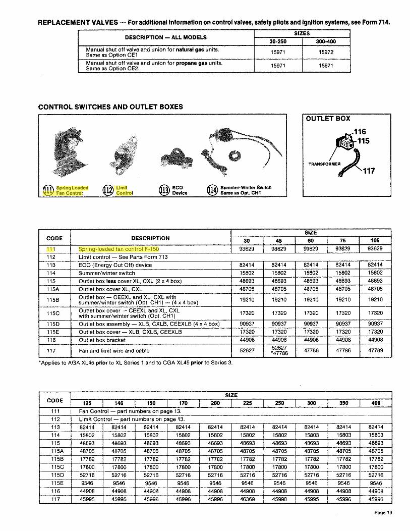
REPLACEMENT VALVES - For additional information on control valves, safety pilots and ignition systems, see Form 714.
DESCRIPTION - ALL MODELS 30-250
Manual shut off valve and union for natural gas units. 15971 Same as Option CE1
Manual shut off valve and union for propane gas units. 15971 Same as Option CE2.
CONTROL SWITCHES AND OUTLET BOXES
0
ti,,\ Spring Loaded ~ Fan Control
~ Limit ~ Control
ittA\ Summer-Winter Switch ~ Same as Opt. CH1
CODE DESCRIPTION 30 45
111 Spring-loaded fan control F-150 93629 93629
112 Limit control - See Parts Form 713
113 ECO (Energy Cut Off) device 82414 82414
114 Summer/winter switch 15802 15802
115 Outlet box less cover XL, CXL (2 x 4 box) 48693 48693
115A Outlet box cover XL, CXL 48705 48705
1156 Outlet box - CEEXL and XL, CXL with 19210 19210 summer/winter switch (Opt. CH1) - (4 x 4 box)
115C Outlet box cover - CEEXL and XL, CXL 17320 17320 with summer/winter switch (Opt. CH1)
1150 Outlet box assembly - XL6, CXL6, CEEXL6 (4 x 4 box) 90937 90937
115E Outlet box cover - XL6, CXL6, CEEXLB 17320 17320
116 Outlet box bracket 44908 44908
117 Fan and limit wire and cable 52627 52627 ·47786
* Applies to AGA XL45 prior to XL Series 1 and to CGA XL45 prior to Series 3.
SIZE CODE 125 140 150 170 200 225 250
111 Fan Control - part numbers on page 13.
112 Limit Control - part numbers on page 13.
113 82414 82414 82414 82414 82414 82414 82414
114 15802 15802 15802 15802 15802 15802 15802
115 48693 48693 48693 48693 48693 48693 48693
115A 48705 48705 48705 48705 48705 48705 48705
1156 17782 17782 17782 17782 17782 17782 17782
115C 17800 17800 17800 17800 17800 17800 17800
1150 52716 52716 52716 52716 52716 52716 52716
115E 9546 9546 9546 9546 9546 9546 9546
116 44908 44908 44908 44908 44908 44908 44908
117 45995 45995 45996 45996 45996 46369 45998
SIZES
300-400
15972
15971
OUTLET BOX
116
~115
TRANSFORMER~~
~117
SIZE
60 75 I 105
93629 93629 93629
82414 82414 82414
15802 15802 15802
48693 48693 48693
48705 48705 48705
19210 19210 19210
17320 17320 17320
90937 90937 90937
17320 17320 17320
44908 44908 44908
47786 47786 47789
300 350 400
82414 82414 82414
15803 15803 15803
48693 48693 48693
48705 48705 48705
17782 17782 17782
17800 17800 17800
52716 52716 52716
9546 9546 9546
44908 44908 44908
45995 45996 45996
Page 19

DESCRIPTION OF CONTROL TRANSFORMERS FOR ALL MODELS AND SIZES
Transformer, 115/24/20VA
Transformer, 115/24/40VA, used on units equipped with a combination of options that require a 40VA transformer.
Transformer, 220/24/20VA
Transformer, 208/220/24/40VA, used on units equipped with a combination of options that require a 40VA transformer.
Transformer, 480/24/40VA
KVA Transformers (Option CG and CF)
X4 X2 X3 X1
L>l.J IN
fXlouT H1 H3 H2 H4
Volts Volts In Out
Yoll>
480
240
240
120
480 or 240 240 or 120
480 or 240 240 or 120
480 or 240 240 or 120
480 or 240 240 or 120
Page 20
connections line
H2H3 H1-H4
H1 H3, H2H4 H1-H4
X2 X3 X1-X4
X1 X3, X2 X4 X1-X4
KVA Manufacturer and Number
.50 Westinghouse 6E191
Westinghouse .75 6E192
1.0 Westinghouse 6E193
1.5 Westinghouse 6E194
PART NO.
103054 (replaces 50674)
Basler #BE121625-WAR
103055 (replaces 60368)
Basler #BE141650-WAA
62822
103497 (replaces 60369)
Basler #BE21539001
103498 (replaces 60370)
Basler #BE23975001
Dimensions, Inches 2 Kva and Below, Single Phase
Kva Dimension Net
Wt.: A A1 B C Lbs.
'I, 71/16 63/a 47/a 45Al 13
% 73/aCD 61Y1s<D 6 51/i 20
8'1,(j) 71l/1s© 6 Sl/2 26
1% 9%0 81o/16© 6% 61/a 36
(DAdd "1" to above dimensions A and Al for Catalog Numbers 6E 218, GE 219, 6E 220, 6E 221, 6E 215.
Reznor Applies To: Part No.
11100 XL, CXL 30-225 with gravity venting
EEXL, CEEXL 30-225 11217 XL, CXL 30-225 with optional power venter
XL, CXL 250-300 with gravity venting EEXL, CEEXL 250-300
16065 XL, CXL 250-300 with optional power venter XL, CXL 350-400 with gravity venting
24392 EEXL. CEEXL 350-400 XL CXL 350-400 with o tional ower venter

BLOWER CABINET FOR XLB, CXLB, EEXLB, CEEXLB 30 THRU 105
CODE DESCRIPTION 30-45 60 75 105 • • A Top & Bottom 82178 82179 82180 82181
/'' • B Left Front Leg 82182 82182 82182 82182 ,..,-;~;/
Right Front ,,:/ C 82183 82183 82183 82183
r-,/:/ Leg
ii D Rear Leg 82184 82184 82184 82184 il 11- E Stop 82185 82185 82185 82185 "
• ii F Snap Bushing 29871 29871 29871 29871 I, G Hole Plug 82413 82413 82413 82413
C H Door 82176 82176 82176 82176
J Plastic Plug 82177 82177 82177 82177
K Screw #10-lh 11813(22) 11813(22) 11813(22} 11813(24) •
J Filter Includes filter N/A 82204 82205 82206
~ Rack Assy Filter only N/A 82189 82190 82191
• Complete Blower Cab- 82200 82201 82202 82203 inet Assembl
Page 21
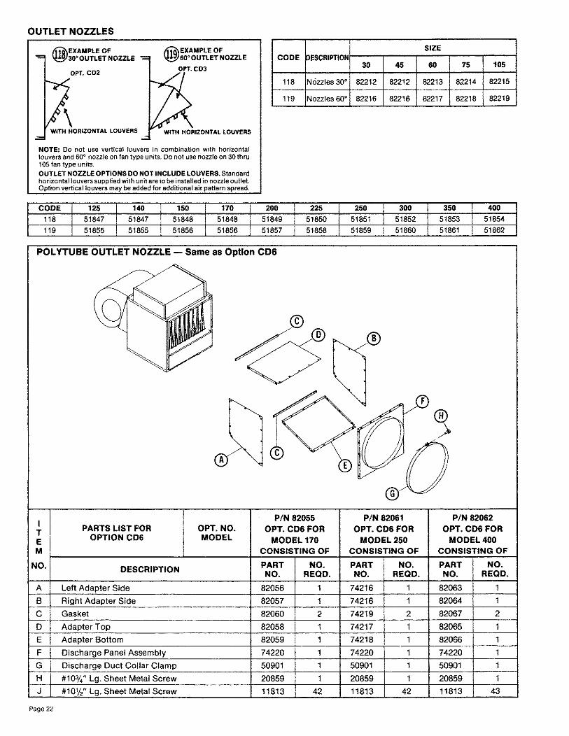
OUTLET NOZZLES
11tt)\EXAMPLE OF ~30"'0UTLET NOZZLE
OPT. CO2
\ WITH HORIZONTAL LOUVERS
IWI\EXAMPLE OF ~60• OUTLET NOZZLE
OPT.C03
NOTE: Do not use vertical louvers in combination with horizontal louvers and 60° nozzle on fan type units. Do not use nozzle on 30 thru 105 fan type units.
OUTLET NOZZLE OPTIONS DO NOT INCLUDE LOUVERS. Standard horizontal louvers supplied with unit are to be installed in nozzle outlet. Option vertical louvers may be added for additional air pattern spread.
CODE 125 140 150 170 118 51847 51847 51848 51848 119 51855 51855 51856 51856
CODE DESCRIPTION
118 NOzzles 30°
119 Nozzles 60°
200 225 51849 51850 51857 51858
POL YTUBE OUTLET NOZZLE - Same as Option CD6
A
I P/N 82055
T PARTS LIST FOR OPT.NO. OPT.CDS FOR
E OPTION CD& MODEL MODEL 170 M CONSISTING OF
NO. DESCRIPTION PART NO. NO. REQD.
A Left Adapter Side 82056 1
B Right Adapter Side 82057 1
C Gasket 82060 2
D Adapter Top 82058
E Adapter Bottom 82059 1
F Discharge Panel Assembly 74220 1
G Discharge Duct Collar Clamp 50901 1
H #10%" Lg. Sheet Metal Screw 20859 1
J #101/," Lg. Sheet Metal Screw 11813 42
Page 22
SIZE
30 45 60 75 105
82212 82212 82213 82214 82215
82216 82216 82217 82218 82219
250 300 350 400 51851 51852 51853 51854
51859 51860 51861 51862
P/N 82061 P/N 82062 OPT.CDS FOR OPT.CDS FOR
MODEL250 MODEL400 CONSISTING OF CONSISTING OF
PART NO. PART NO. NO. REQD. NO. REQD.
74216 1 82063 1
74216 1 82064 1
74219 2 82067 2
74217 82065 1
74218 82066 1
74220 1 74220 1
50901 1 50901 1
20859 1 20859 1
11813 42 11813 43

VENTERS AND VENTER ADAPTERS FOR USE WITH GRAVITY VENTED UNITS - XL, CXL, XLB, CXLB
DELUXE VENTER Venter Adapter must be added. Series V301 used on gravity vented heater sizes 30-300 Series V401 used on gravity vented heater sizes 350-400
SIZE P/N V301 (115V) 29991 V3018 C208V) 30228 V301 H £230V\ 30230 LV301 l115/24V1 29992 LV3018 {208/24V) 30229 L V301 H l230/24V\ 30231
V401 t115V\ 29993 V401 B (208V) 30232 V401 H (230V) 30234
LV401 (115/24V) 29994
LV401 B (208/24V) 30233
L V401 H (230/24V) 30235
NOTE: Venter adapters MUST be used to connect Venter to heater flue. Alt adapters have built-in restrictorto control combustion gas flow through the heat exchanger for greatest efficiency.
EXAMPLE OF VENTER OPTION
EXAMPLE OF VENTER ADAPTER
• ----=---./ 4" AO.
OVERALL Inches
SERIES HIGH WIDE LONG
301 7' 10 7'
401 105/8
HANGER KITS 120. TWO-POINT PIPE HANGER KIT FOR XL, CXL, EEXL, CEEXL 30 thru
105. SAME AS OPTION CK1 (P/N 50703) Kit includes 1" pipe couplings and 6" 3/8-16 bolts to extend swivel coupling above draft diverter.
TWO-POINT HANGER KIT FOR XL, CXL, EEXL, CEEXL 125 THRU 400, SAME AS OPTION CK2 (P/N 46240) Kit includes 2 swivel hangers and 2 hanger brackets.
CODE
120 121
CODE
120 -·----.. ·-121
A
HANGER (
METAL BRACKET ONLY 46238
DESCRIPTION
Two-point Hanger Kit -- XL, CXL, EEXL, CEEXL
Four-point Hanger Kit - All Models
125 140 150 170 46240 46~40 46240 46240 53032 53032 53032 53032
200 46240 53032
VENTER ADAPTERS
SIZE PART NO.
30 6838
45 6838
60 6838
75 6534
105 20901
125 6539
140 6539
150 6539
170 6542
200 6542
225 12730 -250 12730
300 24017
350 46163
400 46163
121. FOUR-POINT PIPE HANGER KIT FOR ALL MODEL UNIT HEATERS, SIZES 30-105, SAME AS OPTION CK3 (P/N 74142) Kit Includes (4) 1'" female couplings and (4) 3/8-10 x 6" long rods (with lockwashern and nuts) to extend swivel coupling above draft diverter. FOUR-POINT PIPE HANGER KIT FOR ALL MODEL UNIT HEATERS, SIZES 125-400, SAME AS OPTION CK6 (PIN 53032) Kit Includes (4) 1" female pipe couplings and (4) 3/8-10 x 12" long rods (with lockwashers and nuts) to extend swivel coupling above draft diverter.
Note: Order replacement parts by Re.i:nor part number.
SIZE
30 45 60 75 105 50703 50703 50703 50703 50703 --· 74142 74142 74142 74142 74142
SIZE
225 250 300 350 400 46240 46240 46240 46240 46240 53032 53032 53032 53032 53032
Page 23

~ REZNOR®MERCER,PA16137 19~ ... :ie/J,, tu), afw,,t Page 24
©~992 Thomas & Betts Corporation, All rights reserved Printed in U.S.A. MANUFACTURER OF GAS, OIL, ELECTRIC HEATING AND VENTILATING SYSTEMS 5M~992WE