Embed Size (px)
Citation preview
Form I-OH, PN 120390 R4, Page 1
�Form I-OH (Version C)
Obsoletes Form I-OH (Version B)
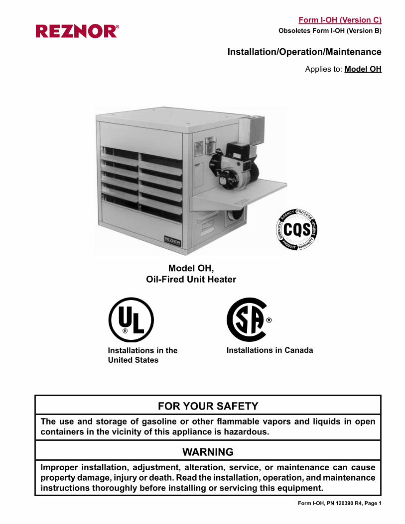
Installation/Operation/Maintenance
Applies to: Model OH
Installations in the United States
Installations in Canada
FOR YOUR SAFETYThe use and storage of gasoline or other flammable vapors and liquids in open containers in the vicinity of this appliance is hazardous.
WARNING Improper installation, adjustment, alteration, service, or maintenance can cause property damage, injury or death. Read the installation, operation, and maintenance instructions thoroughly before installing or servicing this equipment.
Model OH, Oil-Fired Unit Heater
���
����������
������� �����
�
�������
����
��
�����
��� �
�����
��
��������
�������
Form I-OH, PN 120390 R4, Page 2
WARNING: This appliance is not designed for use in hazard-ous atmospheres containing flammable vapors or combus-tible dust, or atmospheres containing chlorinated or haloge-nated hydrocarbons.
1. General Installation should be done by a qualified agency in accordance with the instructions in this manual and in compliance with all codes and requirements of authorities hav-ing jurisdiction. The instructions in this manual apply to Reznor Model OH, Oil-Fired Unit Heater. Model OH has a propeller fan for air delivery and requires a vent with a barometric draft regulator.
1.1 Hazard Labels and Notices
There are warning labels on the unit and throughout this manual. For your safety, read the definitions below and comply with all boxes labeled CAUTION, WARNING, and DANGER during installation, operation, maintenance, and service of this heater.
Definitions of Hazard Intensity Levels in this Manual
HAZARD INTENSITY LEVELS1. DANGER: Failure to comply will result in severe personal injury or death
and/or property damage.2. WARNING: Failure to comply could result in severe personal injury or
death and/or property damage. 3. CAUTION: Failure to comply could result in minor personal injury and/or
property damage.
1. General .......................................................... 21.1 Hazard Labels and Notices ............................ 21.2 General Information ........................................ 31.3 Warranty .......................................................... 31.4 Installation Codes ........................................... 3
2. Location ........................................................ 32.1 Arrangement .................................................... 32.2 Throw ............................................................... 4
3. Receiving, Uncrating, and Moving .............. 4
4. Clearances and Dimensions ........................ 44.1 Clearances ....................................................... 44.2 Dimensions ..................................................... 5
5. Suspension or Mounting .............................. 55.1 Weight .............................................................. 55.2 Hanging the Heater ......................................... 55.3 Mounting the Heater ....................................... 6
6. Mechanical .................................................... 66.1 Fuel Tank and Supply Lines........................... 66.2 Venting and Combustion Air .........................11
7. Electrical Supply and Connections ........... 137.1 General .......................................................... 137.2 Supply and Line Wiring ................................ 137.3 Wiring Diagrams ........................................... 147.4 Major Components ....................................... 157.5 Control Wiring ............................................... 17
8. Commissioning and Startup ..................... 178.1 Checklist Prior to Startup ............................ 178.2 Check-Test-Start (Operating Procedure) .... 18
9. Maintenance and Service ........................... 209.1 Maintenance Requirements ......................... 209.2 Maintenance Procedures ............................. 209.3 Troubleshooting ............................................ 24
INDEX ............................................................... 27
Table of Contents
Form I-OH, PN 120390 R4, Page 3
1.4 Installation Codes
1.3 Warranty Refer to the limited warranty information in the "Literature Bag"
WARRANTY: Warranty is void if......
a. Wiring is not in accordance with diagram furnished with the heater.b. Heater is operated in presence of chlorinated vapors.c. Ducts are attached to fan models.
This heater is for commercial or industrial use only. In the United States, the installation must be in accordance with the Standard for the Installation of Oil Burning Equipment NFPA 31, the National Electrical Code NFPA 70, and the requirements of the inspec-tion authorities having jurisdiction. Model OH units for installation in the United States have a UL logo on the rating plate.In Canada, the installation must be in accordance with CSA Standard B139, Installa-tion Code for Oil Burning Equipment; CSA Standard C22.1, Canadian Electric Code, Part 1; and with requirements of local regulatory authorities. Model OH units for instal-lation in Canada have a CSA logo on the rating plate.This heater should be installed by a trained installer who is thoroughly familiar with the installation of oil-fired appliances. Prior to beginning installation, become familiar with the heater and its particular instal-lation requirements.
1.2 General Information
Fuel Specifications The burner in this oil-fired heater is designed and orificed for use with #2 fuel oil (140,000 BTU/gallon) at 100 psig. However, the following substitute fuels may be used:
#1 fuel oil - 132,000 BTU/gallonKerosene (domestic only; do not use foreign) - 132,000 BTU/gallon#1 diesel fuel - 132,000 BTU/gallon (see NOTE)#2 diesel fuel - 140,000 BTU/gallon (see NOTE)NOTE: Diesel fuel is not approved for use in Canada.
WARNING: Do not use gasoline, crankcase oil, or any oil containing gasoline. Do not use aviation fuel.Due to higher viscosity, some #1 oils's BTU/gallon capacity may be 128,000 to 130,000 BTU/gallon. Check BTU content of substitute fuel to determine burner input.• Size 95 burns an average of .85 gallons per hour.• Size 140 burns an average of 1.25 gallons per hour.• Size 190 burns an average of 1.65 gallons per hour.
CAUTION: Do not attempt to burn paper or garbage in this heater.
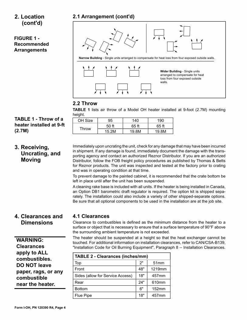
2. Location 2.1 ArrangementThese oil-fired unit heaters should be installed in such a manner as to derive maximum efficiency and a minimum of heat loss to the outside environment. As a rule, single heaters should be suspended over an area of low heat loss with output air directed toward the area of the greatest heat loss. Where two or more heaters are used in a common installation, heaters should be arranged around the outside walls and blow-ing parallel to them. Heaters may be arranged in a supporting consecutive air pattern so that the output of one blows beneath the air-intake side of another. In installations where there are concentrated heat loss areas, a combination of single and multiple arrangements is desirable. See illustrations in FIGURE 1.
Form I-OH, PN 120390 R4, Page 4
4. Clearances and Dimensions
3. Receiving, Uncrating, and Moving
TABLE 1 lists air throw of a Model OH heater installed at 9-foot (2.7M) mounting height.
OH Size 95 140 190
Throw 50 ft 65 ft 65 ft15.2M 19.8M 19.8M
2.2 Throw
Immediately upon uncrating the unit, check for any damage that may have been incurred in shipment. If any damage is found, immediately document the damage with the trans-porting agency and contact an authorized Reznor Distributor. If you are an authorized Distributor, follow the FOB freight policy procedures as published by Thomas & Betts for Reznor products. The unit was inspected and tested at the factory prior to crating and was in operating condition at that time.To prevent damage to the painted cabinet, it is recommended that the crate bottom be left in place until after the unit has been suspended. A cleaning rake base is included with all units. If the heater is being installed in Canada, an Option DB1 barometric draft regulator is required. The option kit is shipped sepa-rately. The installation could also include a variety of other shipped-separate options. Be sure that all optional components to be used in the installation are at the job site.
4.1 ClearancesClearance to combustibles is defined as the minimum distance from the heater to a surface or object that is necessary to ensure that a surface temperature of 90°F above the surrounding ambient temperature is not exceeded.The heater should be suspended at a height so that the heat exchanger cannot be touched. For additional information on installation clearances, refer to CAN/CSA-B139, "Installation Code for Oil Burning Equipment", Paragraph 8 -- Installation Clearances.
TABLE 2 - Clearances (inches/mm)Top 2" 51mmFront 48" 1219mmSides (allow for Service Access) 18" 457mmRear 24" 610mmBottom 6" 152mmFlue Pipe 18" 457mm
WARNING: Clearances apply to ALL combustibles. DO NOT leave paper, rags, or any combustible near the heater.
Narrow Building - Single units arranged to compensate for heat loss from four exposed outside walls.
Wider Building - Single units arranged to compensate for heat loss from four exposed outside walls.
FIGURE 1 - Recommended Arrangements
TABLE 1 - Throw of a heater installed at 9-ft (2.7M)
2. Location (cont'd)
2.1 Arrangement (cont'd)
Form I-OH, PN 120390 R4, Page 5
�������������
�������
����
��������������
���������������
��������������������������������������������������������������������������
��������������������
�������������������������������������
��������
������
������
����
�
��
��
���������
���������������
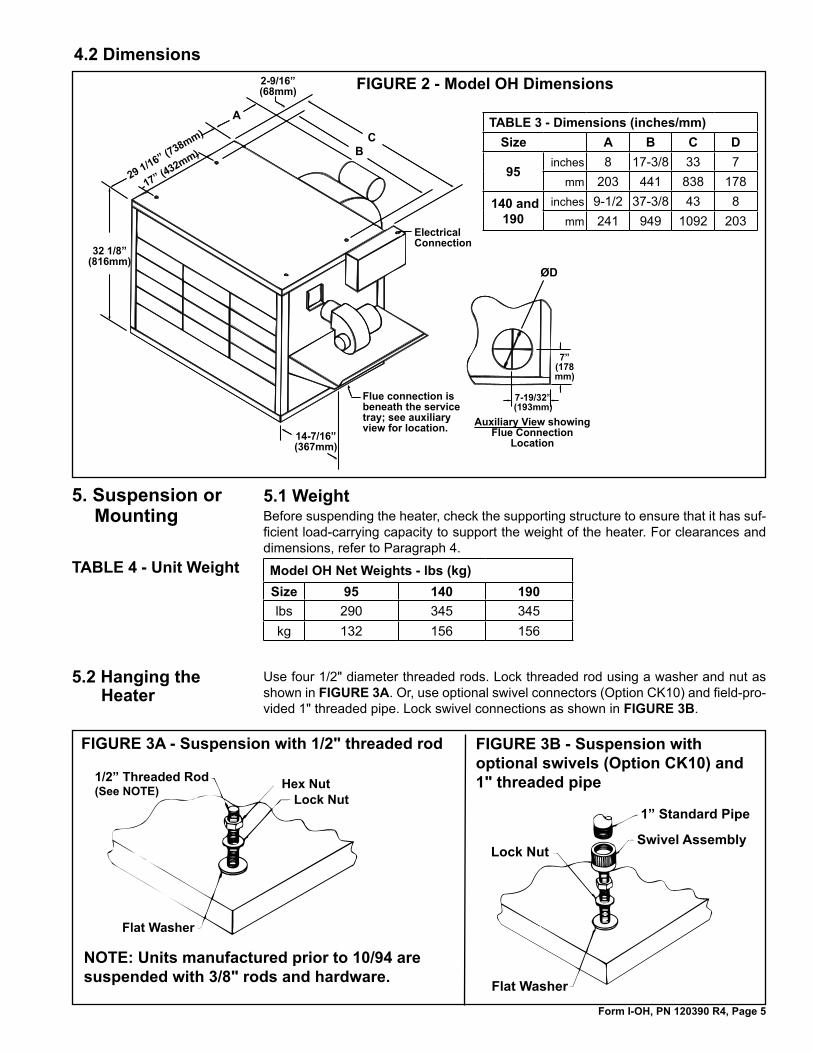
4.2 DimensionsFIGURE 2 - Model OH Dimensions
TABLE 3 - Dimensions (inches/mm)Size A B C D
95inches 8 17-3/8 33 7
mm 203 441 838 178
140 and 190
inches 9-1/2 37-3/8 43 8mm 241 949 1092 203
5. Suspension or Mounting
5.1 WeightBefore suspending the heater, check the supporting structure to ensure that it has suf-ficient load-carrying capacity to support the weight of the heater. For clearances and dimensions, refer to Paragraph 4.
Model OH Net Weights - lbs (kg)Size 95 140 190lbs 290 345 345kg 132 156 156
TABLE 4 - Unit Weight
FIGURE 3A - Suspension with 1/2" threaded rod
1/2” Threaded Rod(See NOTE)
Flat Washer
Hex NutLock Nut
NOTE: Units manufactured prior to 10/94 are suspended with 3/8" rods and hardware.
5.2 Hanging the Heater
Use four 1/2" diameter threaded rods. Lock threaded rod using a washer and nut as shown in FIGURE 3A. Or, use optional swivel connectors (Option CK10) and field-pro-vided 1" threaded pipe. Lock swivel connections as shown in FIGURE 3B.
Lock Nut
1” Standard Pipe
Swivel Assembly
Flat Washer
FIGURE 3B - Suspension with optional swivels (Option CK10) and 1" threaded pipe
Form I-OH, PN 120390 R4, Page 6
Remove the shipping crate bottom from the heater. Remove the angle clips that attached the shipping crate to the heater. Re-insert the screws into the heater cabinet.
WARNING: Units must be supported level for proper operation. Do not place or add additional weight to the suspended heater.
5.3 Mounting the Heater
6. Mechanical 6.1 Fuel Tank and Supply LinesFour methods of piping fuel to an oil-fired heater are illustrated in this Paragraph. Piping system selection depends on the application but certain systems are recom-mended for specific installation conditions.
The one-pipe arrangement (Paragraph 6.1.1) is used with the standard 1-stage burner pump. The two-pipe (Paragraph 6.1.2) arrangement can be used with either the standard 1-stage burner pump or an optional 2-stage burner pump. The loop and pressurized systems (Paragraphs 6.1.3 and 6.1.4) may be used when installing more than one heater and require an additional booster pump for oil delivery.
Fuel TankOil tanks must be installed in accordance with all local regulations and the National Board of Fire Underwriters or CSA Standard. All oil tanks must include a vent pipe to the outdoors. The lower end of the vent pipe should not extend more than one inch below the upper most point of the tank. The vent pipe terminal should be weatherproof and clogproof. Installation of the fuel tank and piping is the responsibility of the installing contractor.
Pipe TubingAll piping shall be standard full weight black iron pipe with standard fittings or approved brass or copper tubing, with UL listed fittings. At least 1/2" iron pipe or 3/8" O.D. cop-per tubing (1/2" O.D. copper tubing is preferred) having a wall thickness not less than 0.049" shall be used to connect the burner to the tank.All piping shall be protected from possible injury and shall be rigidly fastened. Where practical, it should be buried underground or in a concrete floor or placed in a metal-covered pipe trench. If installed above ground, the pipe must be insulated to avoid freezing. Do not cover the piping until the burner has been installed and operated so that any leaks may be detected and corrected. Pipe joints and connections shall be made tight and only unions and tube fittings of an approved type shall be used. Use only pipe thread compound resistant to oil. Do not use TEFLON® tape or TEFLON®-based pipe dope. (TEFLON® is a registered trademark of E. I. DuPont de Nemours and Company).
Oil FilterInstall a UL-listed (U.S.A.) or CSA/USC (Canada) oil filter of generous capacity between the tank shutoff valve and the burner. For ease of servicing, locate the filter and shutoff valve close to the oil burner.
Shutoff Valve Install a readily accessible manual shutoff valve at each point to properly control the flow of fuel in normal operation and where required to avoid oil spillage during servic-ing. The valve should close against the supply. If the heater will not be operating for an extended period of time, close the shutoff valve.Where a shutoff is installed in the discharge line of an oil pump that is not an integral
•
•
•
5. Suspension or Mounting (cont'd)
5.2 Hanging the Heater (cont'd)
If ordered with an optional workbench fuel tank (Option OT) and heater stand (Option HS), follow the recommendations with the tank and in Paragraph 6.1 for positioning the tank. Follow the instructions shipped with the stand to assemble the parts. Set the Model OH heater on the stand to create a unified structure. Follow the stand instructions to secure the unit.
Form I-OH, PN 120390 R4, Page 7
part of a burner, connect a pressure relief valve into the discharge line between the pump and the shutoff valve and arrange to return surplus oil to the supply tank or to bypass it around the pump, unless the pump includes an internal bypass.Any fuel oil line incorporating a heater shall be provided with a relief valve arranged to discharge to the return line when any valve, pump, or other device may prevent the release of excessive pressure because of the expansion of the oil when heated.Where oil is supplied to a burner requiring uniform flow by gravity feed and a constant level valve is not incorporated in the burner assembly or the oil is not supplied by an automatic pump, install a constant level valve in the supply line at the gravity tank or as close as practical, to ensure uniform delivery of oil to the burner. The vent opening of the constant level valve should be connected by piping or tubing to the outside of the building, unless the constant level valve is provided with an anti-flooding device. Do not connect the vent piping or tubing of constant level valves to tanks or tank vents.Prior to entering enclosures, such as vaults or pits, where pumps and accessories are installed, provide for adequate ventilation.
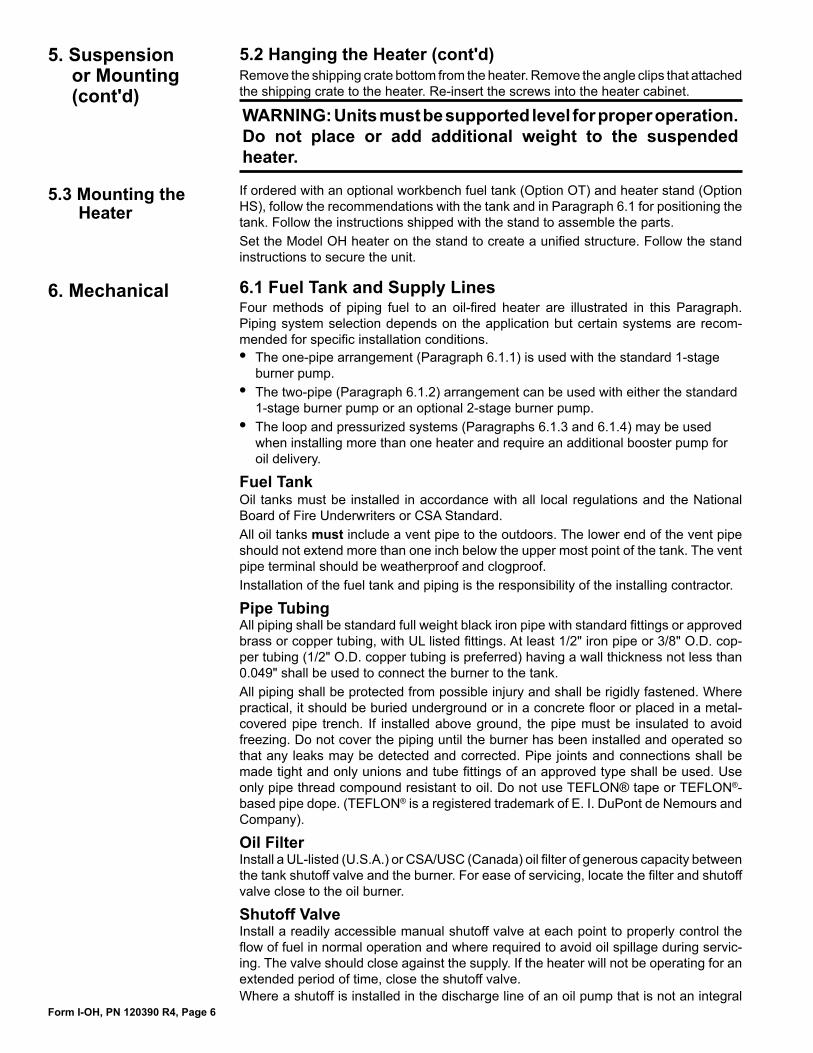
6.1.1 Standard Single Stage Burner Pump with Single Supply PipeThe standard burner is equipped with a single-stage, 3450 RPM pump with the lift capacity shown in FIGURE 4. Maximum lift is 8 ft (2.4M). Fittings, valves and filters will reduce total line length allowed. Check component manufacturer's information for equivalent length reduction required to compensate for pressure loss. A one-pipe sup-ply system must be absolutely airtight, or leaks and/or loss of prime may result. Follow instructions in Paragraph 8.2, Check-Test-Start (Operating Procedure) to bleed the line. Bleed for 15 seconds after last air is seen from easy flow bleed valve to be certain lines are air free.
�������������������������
���������������
���������������
�����
�������������
�������
�����������������������������
�������
FIGURE 4 - Single Pipe Supply System (single-stage burner pump)
Maximum Horizontal Line Length (ft) by Heater Size and Size of Tubing
Maximum Horizontal Line Length (M) by Heater Size and Size of Tubing
Lift 95 140 190 Lift 95 140 190(ft) 3/8" 1/2" 3/8" 1/2" 3/8" 1/2" (M) 3/8" 1/2" 3/8" 1/2" 3/8" 1/2"
0 822 3158 556 2222 423 1667 0.0 251 963 169 677 129 508
1 719 2763 486 1944 370 1458 0.3 219 842 148 593 113 444
2 616 2368 417 1667 317 1250 0.6 188 722 127 508 97 381
3 514 1974 347 1389 264 1042 0.9 157 902 106 423 80 318
4 411 1579 278 1111 211 833 1.2 125 481 85 339 64 254
5 308 1184 208 833 158 625 1.5 94 361 63 254 48 191
6 205 789 139 556 106 417 1.8 62 240 42 169 32 127
7 103 395 69 278 53 208 2.1 31 120 21 85 16 63
8 0 0 0 0 0 0 2.4 0 0 0 0 0 0
Length =6 ft - (.75 X Lift)
(.0086 for 3/8" tubing or .00218 for 1/2" tubing) X (Firing Rate in GPH - OH95, .085;
OH140, 1.25; OH190, 1.35)
Formula for determining figures (ft) in TABLE 5 above.
TABLE 5 - Maximum Horizontal Line Length (ft/M) with a Single Pipe Supply System
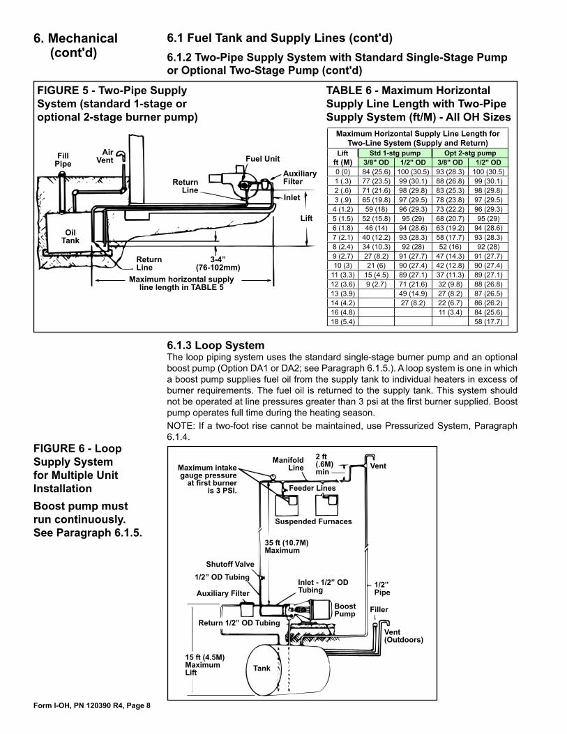
6.1.2 Two-Pipe Supply System with Standard Single-Stage Pump or Optional Two-Stage Pump A two-pipe supply system may be used with the standard burner pump or with a two-stage pump if Option BZ1 was ordered. The two-stage pump provides dual pumping gears. To install the two-pipe supply system, remove the 1/4" plug from the return line port and insert the 1/16" bypass plug (Shipped with the burner pump; see FIGURE 17, page 17.). Attach the inlet and return lines. Always terminate the return line 3 to 4 inches (76 to 102mm) above the supply line inlet. See FIGURE 5.
Form I-OH, PN 120390 R4, Page 8
6. Mechanical (cont'd)
6.1 Fuel Tank and Supply Lines (cont'd)
FIGURE 5 - Two-Pipe Supply System (standard 1-stage or optional 2-stage burner pump)
���������
���������������
�����
����
��������������
����������
�����������
����
�������
�����������������������������������������������
����������
Maximum Horizontal Supply Line Length for Two-Line System (Supply and Return)
Lift Std 1-stg pump Opt 2-stg pumpft (M) 3/8" OD 1/2" OD 3/8" OD 1/2" OD 0 (0) 84 (25.6) 100 (30.5) 93 (28.3) 100 (30.5)1 (.3) 77 (23.5) 99 (30.1) 88 (26.8) 99 (30.1)2 (.6) 71 (21.6) 98 (29.8) 83 (25.3) 98 (29.8)3 (.9) 65 (19.8) 97 (29.5) 78 (23.8) 97 (29.5)
4 (1.2) 59 (18) 96 (29.3) 73 (22.2) 96 (29.3)5 (1.5) 52 (15.8) 95 (29) 68 (20.7) 95 (29)6 (1.8) 46 (14) 94 (28.6) 63 (19.2) 94 (28.6)7 (2.1) 40 (12.2) 93 (28.3) 58 (17.7) 93 (28.3)8 (2.4) 34 (10.3) 92 (28) 52 (16) 92 (28)9 (2.7) 27 (8.2) 91 (27.7) 47 (14.3) 91 (27.7)10 (3) 21 (6) 90 (27.4) 42 (12.8) 90 (27.4)
11 (3.3) 15 (4.5) 89 (27.1) 37 (11.3) 89 (27.1)12 (3.6) 9 (2.7) 71 (21.6) 32 (9.8) 88 (26.8)13 (3.9) 49 (14.9) 27 (8.2) 87 (26.5)14 (4.2) 27 (8.2) 22 (6.7) 86 (26.2)16 (4.8) 11 (3.4) 84 (25.6)18 (5.4) 58 (17.7)
6.1.3 Loop SystemThe loop piping system uses the standard single-stage burner pump and an optional boost pump (Option DA1 or DA2; see Paragraph 6.1.5.). A loop system is one in which a boost pump supplies fuel oil from the supply tank to individual heaters in excess of burner requirements. The fuel oil is returned to the supply tank. This system should not be operated at line pressures greater than 3 psi at the first burner supplied. Boost pump operates full time during the heating season.NOTE: If a two-foot rise cannot be maintained, use Pressurized System, Paragraph 6.1.4.
FIGURE 6 - Loop Supply System for Multiple Unit InstallationBoost pump must run continuously. See Paragraph 6.1.5.
������������
����������������
������������
����������������������������
������������������������
��������
��������������
���������������
���������������������
��������������������
����������������
��������������
�������������
���������������������
����������������������� ����
������������������
TABLE 6 - Maximum Horizontal Supply Line Length with Two-Pipe Supply System (ft/M) - All OH Sizes
6.1.2 Two-Pipe Supply System with Standard Single-Stage Pump or Optional Two-Stage Pump (cont'd)
Form I-OH, PN 120390 R4, Page 9
All manifold and feeder lines must run in a horizontal plane at an elevation above the fuel intakes of the units. Extend feeder lines downward to fuel burner intakes.
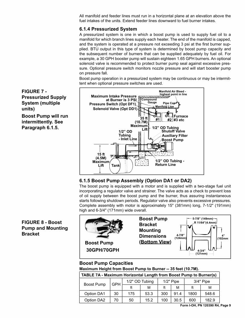
6.1.4 Pressurized SystemA pressurized system is one in which a boost pump is used to supply fuel oil to a manifold for which branch lines supply each heater. The end of the manifold is capped, and the system is operated at a pressure not exceeding 3 psi at the first burner sup-plied. BTU output in this type of system is determined by boost pump capacity and the subsequent number of burners that can be supplied adequately by fuel oil. For example, a 30 GPH booster pump will sustain eighteen 1.65 GPH burners. An optional solenoid valve is recommended to protect burner pump seal against excessive pres-sure. Optional pressure switch monitors nozzle pressure and will start booster pump on pressure fall.Boost pump operation in a pressurized system may be continuous or may be intermit-tent when optional pressure switches are used.
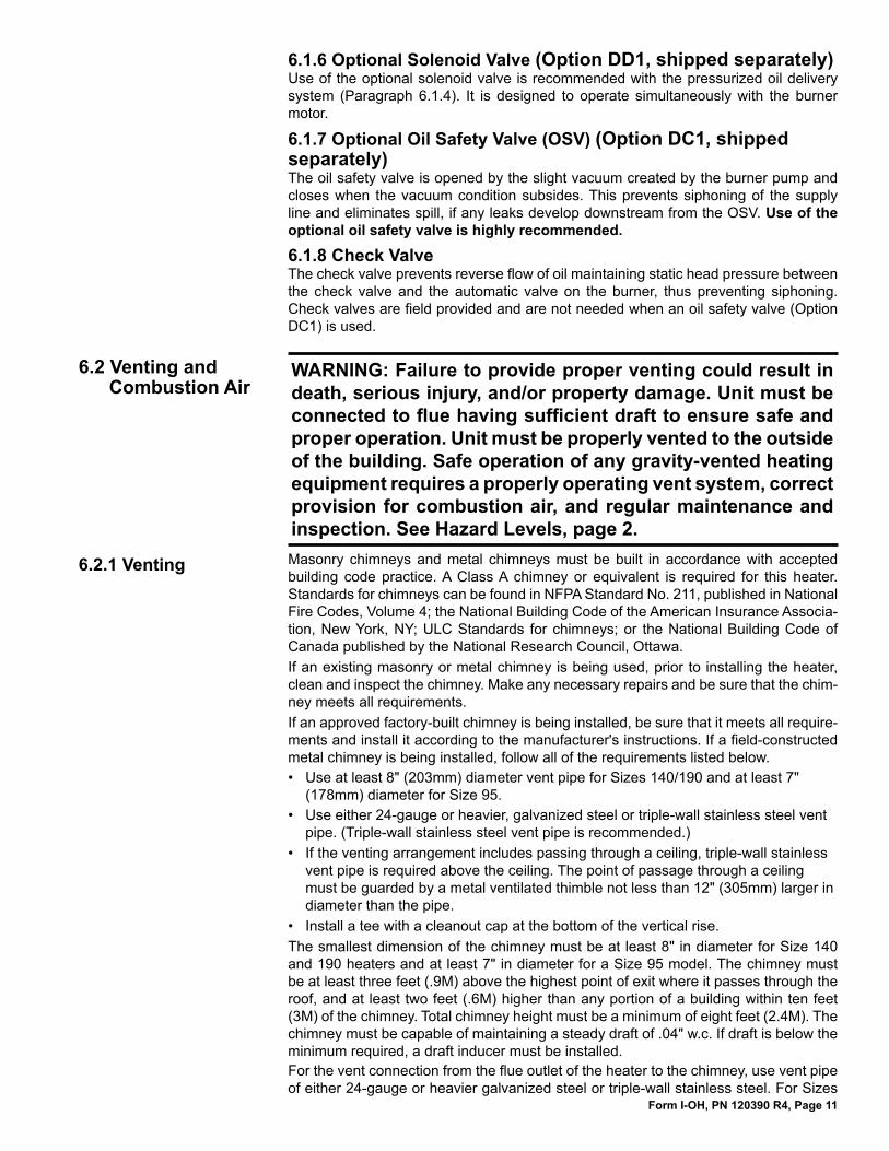
6.1.5 Boost Pump Assembly (Option DA1 or DA2)The boost pump is equipped with a motor and is supplied with a two-stage fuel unit incorporating a regulator valve and strainer. The valve acts as a check to prevent loss of oil supply between the boost pump and the burner, thus assuring instantaneous starts following shutdown periods. Regulator valve also prevents excessive pressures. Complete assembly with motor is approximately 15" (381mm) long, 7-1/2" (191mm) high and 6-3/4" (171mm) wide overall.
������������������������������������������
�������������
�����������������������������������������
���������������������
�����������������
���������������������������
���������������������������������������
��������������
����
�����������
�����������
������������
�����������
�������������������������������������������������
�������������������������
FIGURE 7 - Pressurized Supply System (multiple units)Boost Pump will run intermittently. See Paragraph 6.1.5.
FIGURE 8 - Boost Pump and Mounting Bracket
��������������
�������������
���������
�������������
���������������Boost Pump Bracket Mounting Dimensions (Bottom View)Boost Pump
30GPH/70GPH
TABLE 7A - Maximum Horizontal Length from Boost Pump to Burner(s)
Boost Pump GPH1/2" OD Tubing 1/2" Pipe 3/4" Pipe
ft M ft M ft M
Option DA1 30 175 53.3 300 91.4 1800 548.6Option DA2 70 50 15.2 100 30.5 600 182.9
Boost Pump CapacitiesMaximum Height from Boost Pump to Burner -- 35 feet (10.7M).
Form I-OH, PN 120390 R4, Page 10
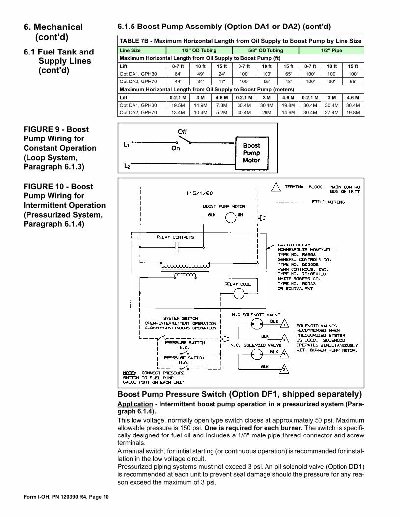
FIGURE 9 - Boost Pump Wiring for Constant Operation (Loop System, Paragraph 6.1.3)
FIGURE 10 - Boost Pump Wiring for Intermittent Operation (Pressurized System, Paragraph 6.1.4)
TABLE 7B - Maximum Horizontal Length from Oil Supply to Boost Pump by Line SizeLine Size 1/2" OD Tubing 5/8" OD Tubing 1/2" Pipe
Maximum Horizontal Length from Oil Supply to Boost Pump (ft)Lift 0-7 ft 10 ft 15 ft 0-7 ft 10 ft 15 ft 0-7 ft 10 ft 15 ftOpt DA1, GPH30 64' 49' 24' 100' 100' 65' 100' 100' 100'Opt DA2, GPH70 44' 34' 17' 100' 95' 48' 100' 90' 65'
Maximum Horizontal Length from Oil Supply to Boost Pump (meters)Lift 0-2.1 M 3 M 4.6 M 0-2.1 M 3 M 4.6 M 0-2.1 M 3 M 4.6 MOpt DA1, GPH30 19.5M 14.9M 7.3M 30.4M 30.4M 19.8M 30.4M 30.4M 30.4MOpt DA2, GPH70 13.4M 10.4M 5.2M 30.4M 29M 14.6M 30.4M 27.4M 19.8M
6. Mechanical (cont'd)
6.1 Fuel Tank and Supply Lines (cont'd)
Boost Pump Pressure Switch (Option DF1, shipped separately)Application - Intermittent boost pump operation in a pressurized system (Para-graph 6.1.4). This low voltage, normally open type switch closes at approximately 50 psi. Maximum allowable pressure is 150 psi. One is required for each burner. The switch is specifi-cally designed for fuel oil and includes a 1/8" male pipe thread connector and screw terminals. A manual switch, for initial starting (or continuous operation) is recommended for instal-lation in the low voltage circuit. Pressurized piping systems must not exceed 3 psi. An oil solenoid valve (Option DD1) is recommended at each unit to prevent seal damage should the pressure for any rea-son exceed the maximum of 3 psi.
6.1.5 Boost Pump Assembly (Option DA1 or DA2) (cont'd)
Form I-OH, PN 120390 R4, Page 11
WARNING: Failure to provide proper venting could result in death, serious injury, and/or property damage. Unit must be connected to flue having sufficient draft to ensure safe and proper operation. Unit must be properly vented to the outside of the building. Safe operation of any gravity-vented heating equipment requires a properly operating vent system, correct provision for combustion air, and regular maintenance and inspection. See Hazard Levels, page 2.
6.2 Venting and Combustion Air
6.1.6 Optional Solenoid Valve (Option DD1, shipped separately)Use of the optional solenoid valve is recommended with the pressurized oil delivery system (Paragraph 6.1.4). It is designed to operate simultaneously with the burner motor.
6.1.7 Optional Oil Safety Valve (OSV) (Option DC1, shipped separately)The oil safety valve is opened by the slight vacuum created by the burner pump and closes when the vacuum condition subsides. This prevents siphoning of the supply line and eliminates spill, if any leaks develop downstream from the OSV. Use of the optional oil safety valve is highly recommended.
6.1.8 Check ValveThe check valve prevents reverse flow of oil maintaining static head pressure between the check valve and the automatic valve on the burner, thus preventing siphoning. Check valves are field provided and are not needed when an oil safety valve (Option DC1) is used.
6.2.1 Venting Masonry chimneys and metal chimneys must be built in accordance with accepted building code practice. A Class A chimney or equivalent is required for this heater. Standards for chimneys can be found in NFPA Standard No. 211, published in National Fire Codes, Volume 4; the National Building Code of the American Insurance Associa-tion, New York, NY; ULC Standards for chimneys; or the National Building Code of Canada published by the National Research Council, Ottawa.If an existing masonry or metal chimney is being used, prior to installing the heater, clean and inspect the chimney. Make any necessary repairs and be sure that the chim-ney meets all requirements. If an approved factory-built chimney is being installed, be sure that it meets all require-ments and install it according to the manufacturer's instructions. If a field-constructed metal chimney is being installed, follow all of the requirements listed below. • Use at least 8" (203mm) diameter vent pipe for Sizes 140/190 and at least 7"
(178mm) diameter for Size 95.• Use either 24-gauge or heavier, galvanized steel or triple-wall stainless steel vent
pipe. (Triple-wall stainless steel vent pipe is recommended.)• If the venting arrangement includes passing through a ceiling, triple-wall stainless
vent pipe is required above the ceiling. The point of passage through a ceiling must be guarded by a metal ventilated thimble not less than 12" (305mm) larger in diameter than the pipe.
• Install a tee with a cleanout cap at the bottom of the vertical rise.The smallest dimension of the chimney must be at least 8" in diameter for Size 140 and 190 heaters and at least 7" in diameter for a Size 95 model. The chimney must be at least three feet (.9M) above the highest point of exit where it passes through the roof, and at least two feet (.6M) higher than any portion of a building within ten feet (3M) of the chimney. Total chimney height must be a minimum of eight feet (2.4M). The chimney must be capable of maintaining a steady draft of .04" w.c. If draft is below the minimum required, a draft inducer must be installed.For the vent connection from the flue outlet of the heater to the chimney, use vent pipe of either 24-gauge or heavier galvanized steel or triple-wall stainless steel. For Sizes
Form I-OH, PN 120390 R4, Page 12
140 and 190 use 8" diameter pipe; for Size 95, use 7" diameter pipe. Keep the length of the vent pipe connection as short and direct as possible. As it leaves the heater, slope the horizontal run upward at least one inch for each three feet of pipe. The horizontal run should not be longer than one-half of the vertical or chimney height and never over ten feet (3M) unless a draft inducer is being installed. If the vent pipe connector passes through a combustible wall, it must be guarded at the point of passage by either a metal ventilated thimble not less than 12" (305mm) larger in diameter than the pipe, or a metal or burned fireclay thimble built in brickwork or other approved fireproofing material extending not less than 8" (203mm) beyond all sides of the thimble. If a thimble is not installed, all combustible material in the wall or partition must be cut away 9" (229mm) from the pipe. If any material is used to close this opening, it must be non-combustible. Fasten all vent piping with sheetmetal screws and support horizontal vent pipe from above with noncombustible straps. Avoid sharp turns in the vent pipe or other construc-tion features that would create resistance to the flow of the flue gases. Do not use a manually operated damper or any other device that will obstruct the free flow of the flue gases.The end of the vent pipe connection must not extend past the inside wall of the chim-ney. A thimble may be used in the chimney connection to facilitate removal for cleaning. The thimble should be permanently cemented in place with high-temperature cement.
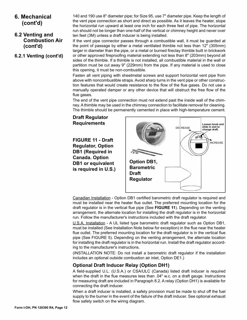
Draft Regulator Requirements
6. Mechanical (cont'd)
6.2 Venting and Combustion Air (cont'd)
��������������������������������������������
��������
��������
Option DB1, Barometric Draft Regulator
FIGURE 11 - Draft Regulator, Option DB1 (Required in Canada. Option DB1 or equivalent is required in U.S.)
6.2.1 Venting (cont'd)
Canadian Installation - Option DB1 certified barometric draft regulator is required and must be installed near the heater flue outlet. The preferred mounting location for the draft regulator is in the vertical flue pipe (See FIGURE 11). Depending on the venting arrangement, the alternate location for installing the draft regulator is in the horizontal run. Follow the manufacturer's instructions included with the draft regulator.U.S.A. Installation - A UL listed type barometric draft regulator such as Option DB1, must be installed (See Installation Note below for exception) in the flue near the heater flue outlet. The preferred mounting location for the draft regulator is in the vertical flue pipe (See FIGURE 5). Depending on the venting arrangement, the alternate location for installing the draft regulator is in the horizontal run. Install the draft regulator accord-ing to the manufacturer's instructions.(INSTALLATION NOTE: Do not install a barometric draft regulator if the installation includes an optional outside combustion air inlet, Option DE1.)
Optional Draft Inducer Relay (Option DH1)A field-supplied U.L. (U.S.A.) or CSA/ULC (Canada) listed draft inducer is required when the draft in the flue measures less than .04" w.c. on a draft gauge. Instructions for measuring draft are included in Paragraph 8.2. A relay (Option DH1) is available for connecting the draft inducer.When a draft inducer is installed, a safety provision must be made to shut off the fuel supply to the burner in the event of the failure of the draft inducer. See optional exhaust flow safety switch on the wiring diagram.
Form I-OH, PN 120390 R4, Page 13
6.2.2 Combustion Air WARNING: Exercise care to ensure that an adequate supply of combustion air is available and free to enter the air openings on all units.Openings equal to one inch square per each 1,000 BTUH should be used to allow combustion air to enter the room where the heater is installed.
���������������������������
���������������������
��������������������
����������
������������������
���������
�����������������������������������
������������������
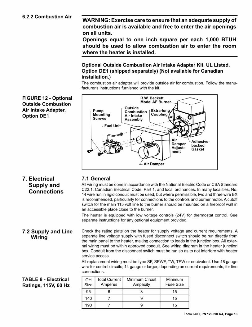
FIGURE 12 - Optional Outside Combustion Air Intake Adapter, Option DE1
Optional Outside Combustion Air Intake Adapter Kit, UL Listed, Option DE1 (shipped separately) (Not available for Canadian installation.)The combustion air adapter will provide outside air for combustion. Follow the manu-facturer's instructions furnished with the kit.
7. Electrical Supply and Connections
7.1 GeneralAll wiring must be done in accordance with the National Electric Code or CSA Standard C22.1, Canadian Electrical Code, Part 1, and local ordinances. In many localities, No. 14 wire run in rigid conduit must be used, but where permissible, two and three wire BX is recommended, particularly for connections to the controls and burner motor. A cutoff switch for the main 115 volt line to the burner should be mounted on a fireproof wall in an accessible place close to the burner.The heater is equipped with low voltage controls (24V) for thermostat control. See separate instructions for any optional equipment provided.
7.2 Supply and Line Wiring
TABLE 8 - Electrical Ratings, 115V, 60 Hz
Check the rating plate on the heater for supply voltage and current requirements. A separate line voltage supply with fused disconnect switch should be run directly from the main panel to the heater, making connection to leads in the junction box. All exter-nal wiring must be within approved conduit. See wiring diagram in the heater junction box. Conduit from the disconnect switch must be run so as to not interfere with heater service access.All replacement wiring must be type SF, SEWF, TW, TEW or equivalent. Use 18 gauge wire for control circuits; 14 gauge or larger, depending on current requirements, for line connections.
OH Size
Total Current Amperes
Minimum Circuit Ampacity
Minimum Fuse Size
95 6 8 15140 7 9 15190 7 9 15
Form I-OH, PN 120390 R4, Page 14
115/
1/60
7.3 Wiring Diagrams
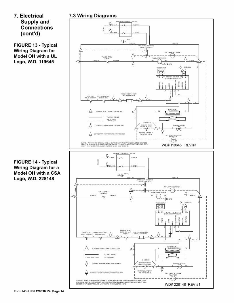
FIGURE 13 - Typical Wiring Diagram for Model OH with a UL Logo, W.D. 119645
FIGURE 14 - Typical Wiring Diagram for a Model OH with a CSA Logo, W.D. 228148
7. Electrical Supply and Connections (cont'd)
Form I-OH, PN 120390 R4, Page 15
7.4 Major ComponentsMotors - See electrical characteristics in TABLE 9. The fan motor is totally enclosed and is equipped with internal overload protection.Motor Size HP Volts Amps RPM
Fan95 1/8 115 2.7 1050
140, 190 1/4 115 3.7 850140, 190 3/4 115 11 1725
Std 1-Stage Burner Pump95, 140,
190
1/7 115 2 3450Opt 2-Stage Burner Pump 1/7 115 2 3450Optional Boost Pump 1/8 115 5.8 1725
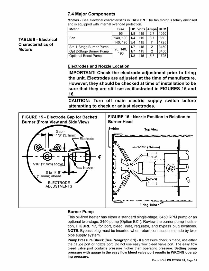
Electrodes and Nozzle LocationIMPORTANT: Check the electrode adjustment prior to firing the unit. Electrodes are adjusted at the time of manufacture. However, they should be checked at time of installation to be sure that they are still set as illustrated in FIGURES 15 and 16.CAUTION: Turn off main electric supply switch before attempting to check or adjust electrodes.
FIGURE 16 - Nozzle Position in Relation to Burner Head
FIGURE 15 - Electrode Gap for Beckett Burner (Front View and Side View)
�����������������
���������
����������������
�������������
������������������
��������������������
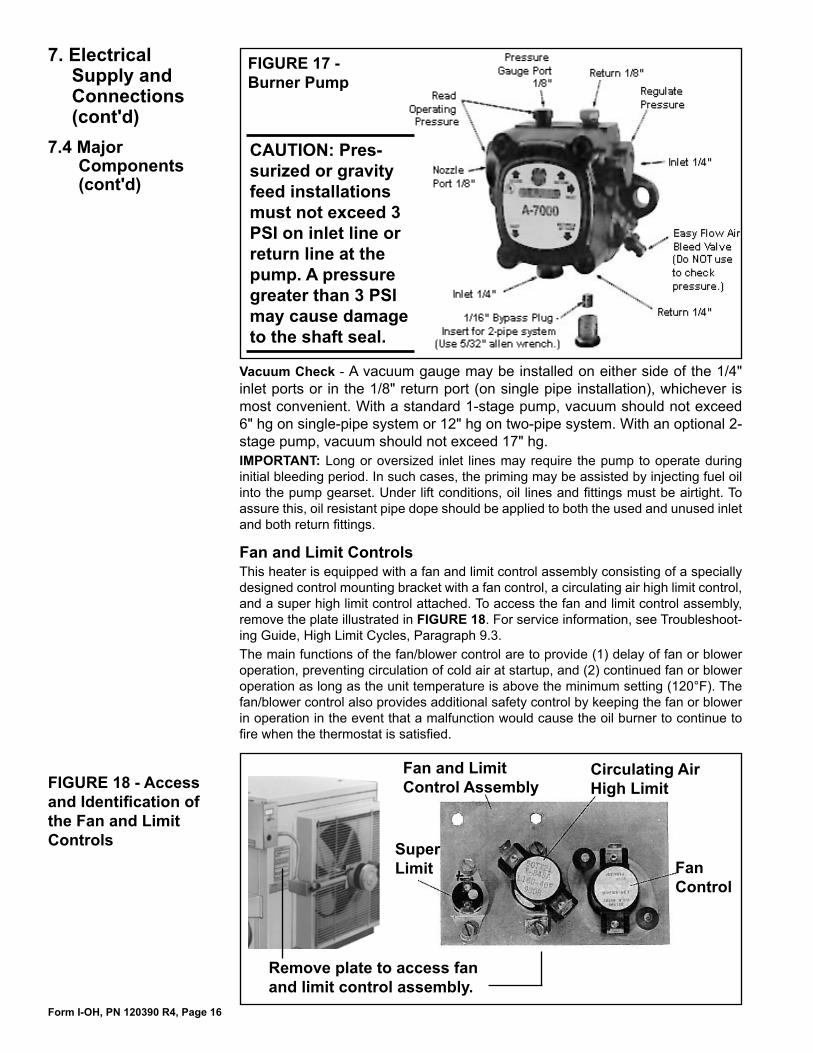
Burner PumpThis oil-fired heater has either a standard single-stage, 3450 RPM pump or an optional two-stage, 3450 pump (Option BZ1). Review the burner pump illustra-tion, FIGURE 17, for port, bleed, inlet, regulator, and bypass plug locations. NOTE: Bypass plug must be inserted when return connection is made by two-pipe supply system.Pump Pressure Check (See Paragraph 8.1) - If a pressure check is made, use either the gauge port or nozzle port. Do not use easy flow bleed valve port. The easy flow bleed valve port contains pressure higher than operating pressure. Setting pump pressure with gauge in the easy flow bleed valve port results in WRONG operat-ing pressure.
TABLE 9 - Electrical Characteristics of Motors
Form I-OH, PN 120390 R4, Page 16
FIGURE 17 - Burner Pump
Vacuum Check - A vacuum gauge may be installed on either side of the 1/4" inlet ports or in the 1/8" return port (on single pipe installation), whichever is most convenient. With a standard 1-stage pump, vacuum should not exceed 6" hg on single-pipe system or 12" hg on two-pipe system. With an optional 2-stage pump, vacuum should not exceed 17" hg.IMPORTANT: Long or oversized inlet lines may require the pump to operate during initial bleeding period. In such cases, the priming may be assisted by injecting fuel oil into the pump gearset. Under lift conditions, oil lines and fittings must be airtight. To assure this, oil resistant pipe dope should be applied to both the used and unused inlet and both return fittings.
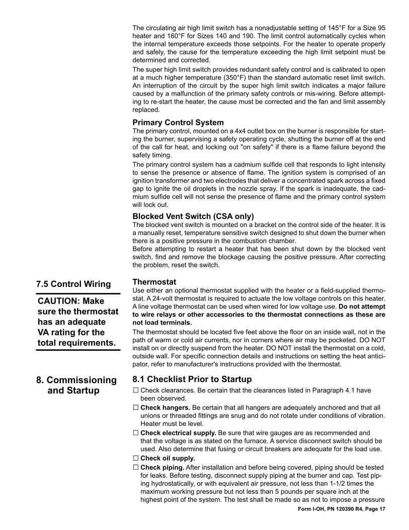
Fan and Limit ControlsThis heater is equipped with a fan and limit control assembly consisting of a specially designed control mounting bracket with a fan control, a circulating air high limit control, and a super high limit control attached. To access the fan and limit control assembly, remove the plate illustrated in FIGURE 18. For service information, see Troubleshoot-ing Guide, High Limit Cycles, Paragraph 9.3.The main functions of the fan/blower control are to provide (1) delay of fan or blower operation, preventing circulation of cold air at startup, and (2) continued fan or blower operation as long as the unit temperature is above the minimum setting (120°F). The fan/blower control also provides additional safety control by keeping the fan or blower in operation in the event that a malfunction would cause the oil burner to continue to fire when the thermostat is satisfied.
Remove plate to access fan and limit control assembly.
Circulating Air High Limit
Fan Control
FIGURE 18 - Access and Identification of the Fan and Limit Controls
Fan and Limit Control Assembly
Super Limit
7. Electrical Supply and Connections (cont'd)
7.4 Major Components (cont'd)
CAUTION: Pres-surized or gravity feed installations must not exceed 3 PSI on inlet line or return line at the pump. A pressure greater than 3 PSI may cause damage to the shaft seal.
Form I-OH, PN 120390 R4, Page 17
Primary Control SystemThe primary control, mounted on a 4x4 outlet box on the burner is responsible for start-ing the burner, supervising a safety operating cycle, shutting the burner off at the end of the call for heat, and locking out "on safety" if there is a flame failure beyond the safety timing.The primary control system has a cadmium sulfide cell that responds to light intensity to sense the presence or absence of flame. The ignition system is comprised of an ignition transformer and two electrodes that deliver a concentrated spark across a fixed gap to ignite the oil droplets in the nozzle spray. If the spark is inadequate, the cad-mium sulfide cell will not sense the presence of flame and the primary control system will lock out.
Blocked Vent Switch (CSA only)The blocked vent switch is mounted on a bracket on the control side of the heater. It is a manually reset, temperature sensitive switch designed to shut down the burner when there is a positive pressure in the combustion chamber. Before attempting to restart a heater that has been shut down by the blocked vent switch, find and remove the blockage causing the positive pressure. After correcting the problem, reset the switch.
7.5 Control Wiring ThermostatUse either an optional thermostat supplied with the heater or a field-supplied thermo-stat. A 24-volt thermostat is required to actuate the low voltage controls on this heater. A line voltage thermostat can be used when wired for low voltage use. Do not attempt to wire relays or other accessories to the thermostat connections as these are not load terminals.The thermostat should be located five feet above the floor on an inside wall, not in the path of warm or cold air currents, nor in corners where air may be pocketed. DO NOT install on or directly suspend from the heater. DO NOT install the thermostat on a cold, outside wall. For specific connection details and instructions on setting the heat antici-pator, refer to manufacturer's instructions provided with the thermostat.
8. Commissioning and Startup
8.1 Checklist Prior to StartupCheck clearances. Be certain that the clearances listed in Paragraph 4.1 have been observed.Check hangers. Be certain that all hangers are adequately anchored and that all unions or threaded fittings are snug and do not rotate under conditions of vibration. Heater must be level.Check electrical supply. Be sure that wire gauges are as recommended and that the voltage is as stated on the furnace. A service disconnect switch should be used. Also determine that fusing or circuit breakers are adequate for the load use.Check oil supply.Check piping. After installation and before being covered, piping should be tested for leaks. Before testing, disconnect supply piping at the burner and cap. Test pip-ing hydrostatically, or with equivalent air pressure, not less than 1-1/2 times the maximum working pressure but not less than 5 pounds per square inch at the highest point of the system. The test shall be made so as not to impose a pressure
□□
□
□□
The circulating air high limit switch has a nonadjustable setting of 145°F for a Size 95 heater and 160°F for Sizes 140 and 190. The limit control automatically cycles when the internal temperature exceeds those setpoints. For the heater to operate properly and safely, the cause for the temperature exceeding the high limit setpoint must be determined and corrected.The super high limit switch provides redundant safety control and is calibrated to open at a much higher temperature (350°F) than the standard automatic reset limit switch. An interruption of the circuit by the super high limit switch indicates a major failure caused by a malfunction of the primary safety controls or mis-wiring. Before attempt-ing to re-start the heater, the cause must be corrected and the fan and limit assembly replaced.
CAUTION: Make sure the thermostat has an adequate VA rating for the total requirements.
Form I-OH, PN 120390 R4, Page 18
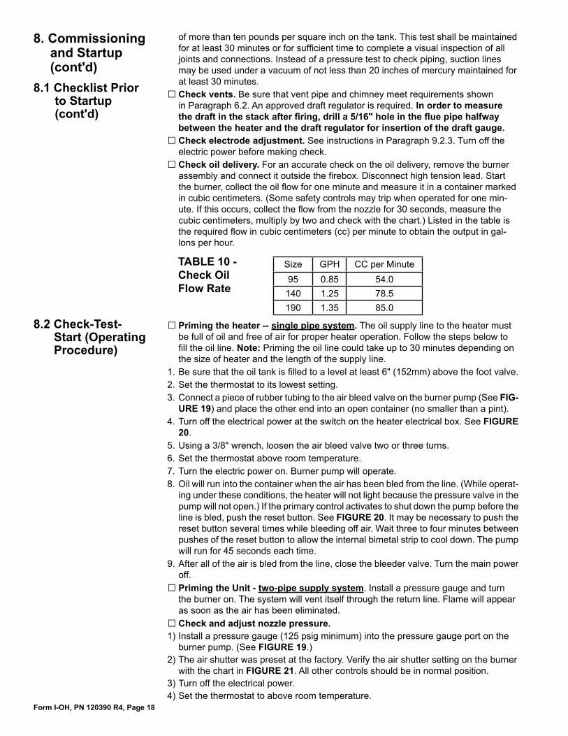
of more than ten pounds per square inch on the tank. This test shall be maintained for at least 30 minutes or for sufficient time to complete a visual inspection of all joints and connections. Instead of a pressure test to check piping, suction lines may be used under a vacuum of not less than 20 inches of mercury maintained for at least 30 minutes.Check vents. Be sure that vent pipe and chimney meet requirements shown in Paragraph 6.2. An approved draft regulator is required. In order to measure the draft in the stack after firing, drill a 5/16" hole in the flue pipe halfway between the heater and the draft regulator for insertion of the draft gauge.Check electrode adjustment. See instructions in Paragraph 9.2.3. Turn off the electric power before making check.Check oil delivery. For an accurate check on the oil delivery, remove the burner assembly and connect it outside the firebox. Disconnect high tension lead. Start the burner, collect the oil flow for one minute and measure it in a container marked in cubic centimeters. (Some safety controls may trip when operated for one min-ute. If this occurs, collect the flow from the nozzle for 30 seconds, measure the cubic centimeters, multiply by two and check with the chart.) Listed in the table is the required flow in cubic centimeters (cc) per minute to obtain the output in gal-lons per hour.
□
□□
8.2 Check-Test-Start (Operating Procedure)
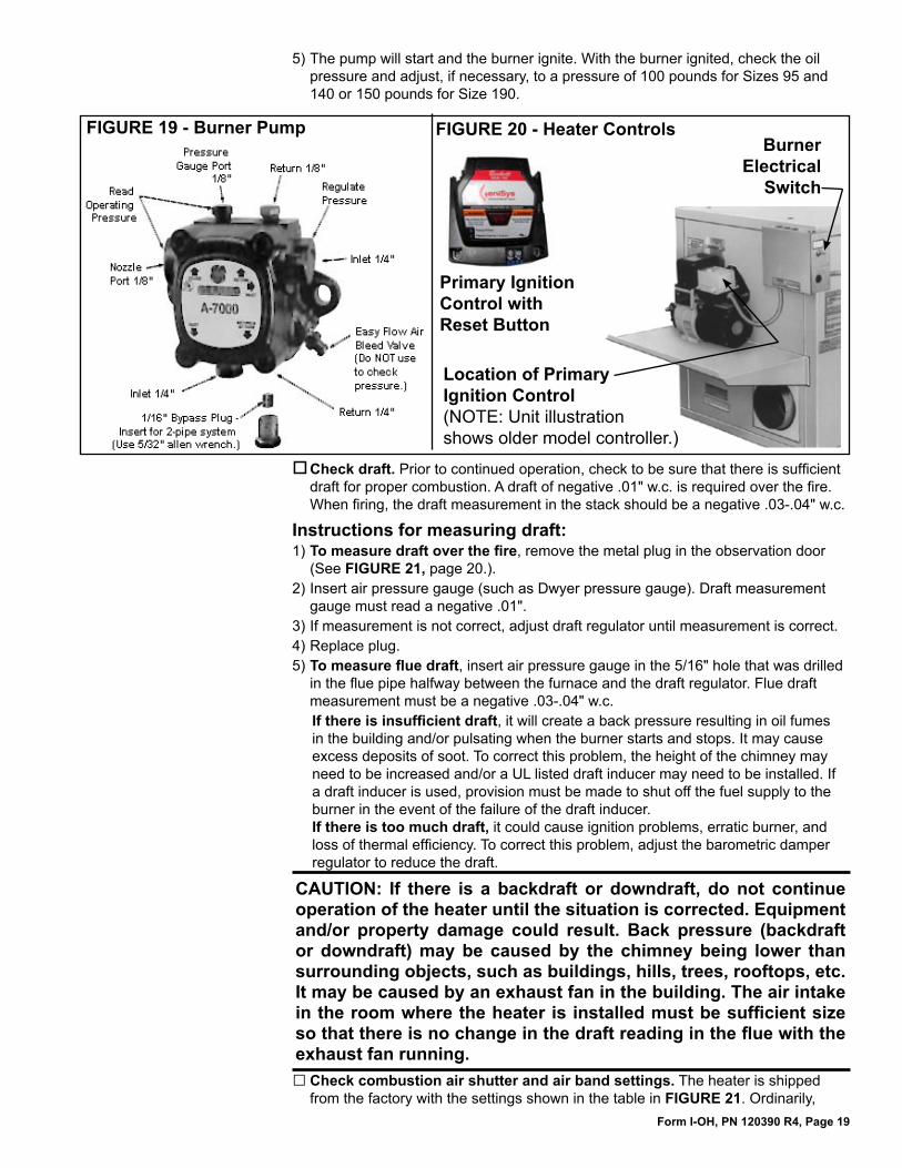
Priming the heater -- single pipe system. The oil supply line to the heater must be full of oil and free of air for proper heater operation. Follow the steps below to fill the oil line. Note: Priming the oil line could take up to 30 minutes depending on the size of heater and the length of the supply line.Be sure that the oil tank is filled to a level at least 6" (152mm) above the foot valve.Set the thermostat to its lowest setting.Connect a piece of rubber tubing to the air bleed valve on the burner pump (See FIG-URE 19) and place the other end into an open container (no smaller than a pint). Turn off the electrical power at the switch on the heater electrical box. See FIGURE 20. Using a 3/8" wrench, loosen the air bleed valve two or three turns.Set the thermostat above room temperature.Turn the electric power on. Burner pump will operate. Oil will run into the container when the air has been bled from the line. (While operat-ing under these conditions, the heater will not light because the pressure valve in the pump will not open.) If the primary control activates to shut down the pump before the line is bled, push the reset button. See FIGURE 20. It may be necessary to push the reset button several times while bleeding off air. Wait three to four minutes between pushes of the reset button to allow the internal bimetal strip to cool down. The pump will run for 45 seconds each time. After all of the air is bled from the line, close the bleeder valve. Turn the main power off.Priming the Unit - two-pipe supply system. Install a pressure gauge and turn the burner on. The system will vent itself through the return line. Flame will appear as soon as the air has been eliminated.Check and adjust nozzle pressure.
1) Install a pressure gauge (125 psig minimum) into the pressure gauge port on the burner pump. (See FIGURE 19.)
2) The air shutter was preset at the factory. Verify the air shutter setting on the burner with the chart in FIGURE 21. All other controls should be in normal position.
3) Turn off the electrical power.4) Set the thermostat to above room temperature.
□
1.2.3.
4.
5.6.7.8.
9.
□
□
8. Commissioning and Startup (cont'd)
8.1 Checklist Prior to Startup (cont'd)
Size GPH CC per Minute95 0.85 54.0
140 1.25 78.5190 1.35 85.0
TABLE 10 - Check Oil Flow Rate
Form I-OH, PN 120390 R4, Page 19
5) The pump will start and the burner ignite. With the burner ignited, check the oil pressure and adjust, if necessary, to a pressure of 100 pounds for Sizes 95 and 140 or 150 pounds for Size 190.
Burner Electrical
Switch
FIGURE 19 - Burner Pump
Check draft. Prior to continued operation, check to be sure that there is sufficient draft for proper combustion. A draft of negative .01" w.c. is required over the fire. When firing, the draft measurement in the stack should be a negative .03-.04" w.c.
Instructions for measuring draft:1) To measure draft over the fire, remove the metal plug in the observation door
(See FIGURE 21, page 20.).2) Insert air pressure gauge (such as Dwyer pressure gauge). Draft measurement
gauge must read a negative .01".3) If measurement is not correct, adjust draft regulator until measurement is correct.4) Replace plug.5) To measure flue draft, insert air pressure gauge in the 5/16" hole that was drilled
in the flue pipe halfway between the furnace and the draft regulator. Flue draft measurement must be a negative .03-.04" w.c.If there is insufficient draft, it will create a back pressure resulting in oil fumes in the building and/or pulsating when the burner starts and stops. It may cause excess deposits of soot. To correct this problem, the height of the chimney may need to be increased and/or a UL listed draft inducer may need to be installed. If a draft inducer is used, provision must be made to shut off the fuel supply to the burner in the event of the failure of the draft inducer.If there is too much draft, it could cause ignition problems, erratic burner, and loss of thermal efficiency. To correct this problem, adjust the barometric damper regulator to reduce the draft.
CAUTION: If there is a backdraft or downdraft, do not continue operation of the heater until the situation is corrected. Equipment and/or property damage could result. Back pressure (backdraft or downdraft) may be caused by the chimney being lower than surrounding objects, such as buildings, hills, trees, rooftops, etc. It may be caused by an exhaust fan in the building. The air intake in the room where the heater is installed must be sufficient size so that there is no change in the draft reading in the flue with the exhaust fan running.
Check combustion air shutter and air band settings. The heater is shipped from the factory with the settings shown in the table in FIGURE 21. Ordinarily,
□
Location of Primary Ignition Control (NOTE: Unit illustration shows older model controller.)
FIGURE 20 - Heater Controls
Primary Ignition Control with Reset Button
Form I-OH, PN 120390 R4, Page 20
9. Maintenance and Service
The service and troubleshooting information in this section is designed to assist a qualified service person.
9.1 Maintenance RequirementsLike all quality equipment, this oil-fired unit heater will operate with a minimum of main-tenance. However, to ensure long life and satisfactory performance, the following ser-vice regimen is recommended.Heaters should be inspected once every four months where the equipment is operating under normal conditions. If the heater is located in an area where an unusual amount of dust or soot or other impurities are contained in the air, more frequent inspection is recommended. Check the motor for cleanliness. Remove dirt and grease from the outside of the motor, and especially around the shaft. Keep air openings free of grease and dirt. The heat exchanger should be checked at least once a year and more often in areas where the air is heavily dust laden.
9.2 Maintenance Procedures
9.2.1 Cleaning Combustion Chamber, Heat Exchanger, and Flue PipeWARNING: Turn off electric power before inspecting or cleaning this heater.
Instructions for removing soot from the combustion chamber/heat exchanger
On the burner end of the heater, locate the small exhaust door panel underneath the burner tray. See FIGURE 22. On Canadian Models, there is a screw (not shown
1.
8.2 Check-Test-Start (Operating Procedure cont'd)
8. Commissioning and Startup (cont'd)
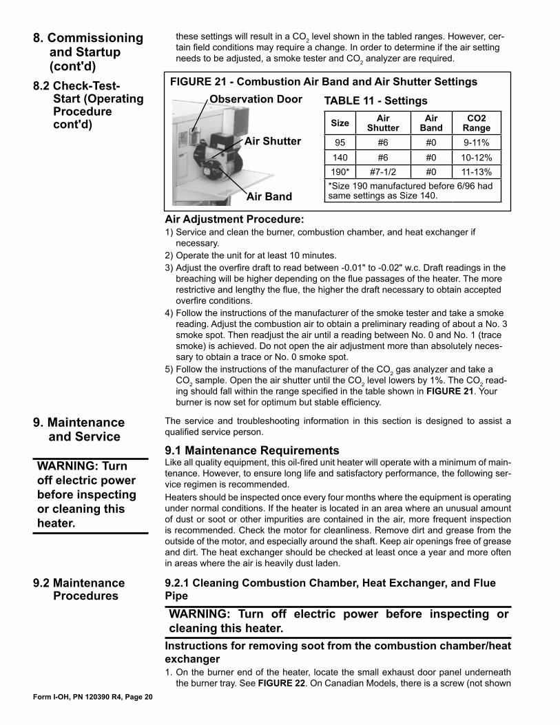
Air Band
Observation Door
Air Shutter
FIGURE 21 - Combustion Air Band and Air Shutter Settings
Size Air Shutter
Air Band
CO2 Range
95 #6 #0 9-11%140 #6 #0 10-12%190* #7-1/2 #0 11-13%*Size 190 manufactured before 6/96 had same settings as Size 140.
TABLE 11 - Settings
these settings will result in a CO2 level shown in the tabled ranges. However, cer-tain field conditions may require a change. In order to determine if the air setting needs to be adjusted, a smoke tester and CO2 analyzer are required.
Air Adjustment Procedure:1) Service and clean the burner, combustion chamber, and heat exchanger if
necessary.2) Operate the unit for at least 10 minutes.3) Adjust the overfire draft to read between -0.01" to -0.02" w.c. Draft readings in the
breaching will be higher depending on the flue passages of the heater. The more restrictive and lengthy the flue, the higher the draft necessary to obtain accepted overfire conditions.
4) Follow the instructions of the manufacturer of the smoke tester and take a smoke reading. Adjust the combustion air to obtain a preliminary reading of about a No. 3 smoke spot. Then readjust the air until a reading between No. 0 and No. 1 (trace smoke) is achieved. Do not open the air adjustment more than absolutely neces-sary to obtain a trace or No. 0 smoke spot.
5) Follow the instructions of the manufacturer of the CO2 gas analyzer and take a CO2 sample. Open the air shutter until the CO2 level lowers by 1%. The CO2 read-ing should fall within the range specified in the table shown in FIGURE 21. Your burner is now set for optimum but stable efficiency.
WARNING: Turn off electric power before inspecting or cleaning this heater.
Form I-OH, PN 120390 R4, Page 21
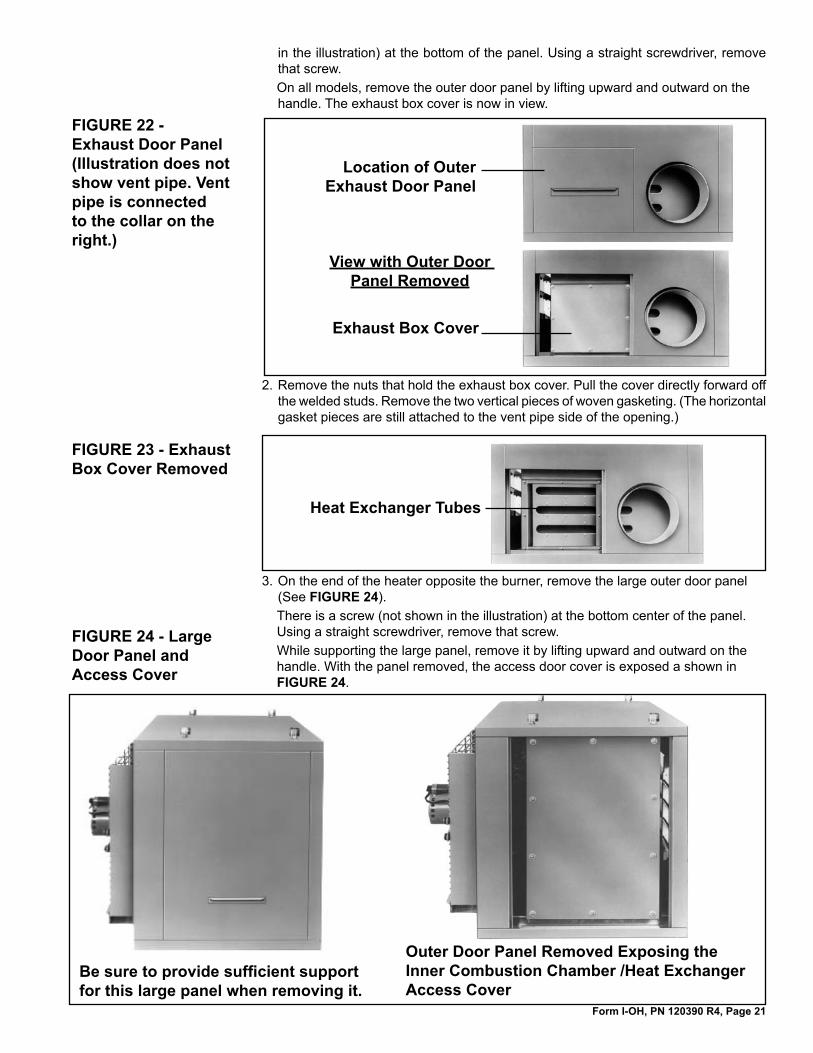
Location of Outer Exhaust Door Panel
View with Outer Door Panel Removed
Exhaust Box Cover
FIGURE 22 - Exhaust Door Panel (Illustration does not show vent pipe. Vent pipe is connected to the collar on the right.)
in the illustration) at the bottom of the panel. Using a straight screwdriver, remove that screw.On all models, remove the outer door panel by lifting upward and outward on the handle. The exhaust box cover is now in view.
Remove the nuts that hold the exhaust box cover. Pull the cover directly forward off the welded studs. Remove the two vertical pieces of woven gasketing. (The horizontal gasket pieces are still attached to the vent pipe side of the opening.)
2.
FIGURE 23 - Exhaust Box Cover Removed
Heat Exchanger Tubes
3. On the end of the heater opposite the burner, remove the large outer door panel (See FIGURE 24).There is a screw (not shown in the illustration) at the bottom center of the panel. Using a straight screwdriver, remove that screw.While supporting the large panel, remove it by lifting upward and outward on the handle. With the panel removed, the access door cover is exposed a shown in FIGURE 24.
Be sure to provide sufficient support for this large panel when removing it.
Outer Door Panel Removed Exposing the Inner Combustion Chamber /Heat Exchanger Access Cover
FIGURE 24 - Large Door Panel and Access Cover
Form I-OH, PN 120390 R4, Page 22
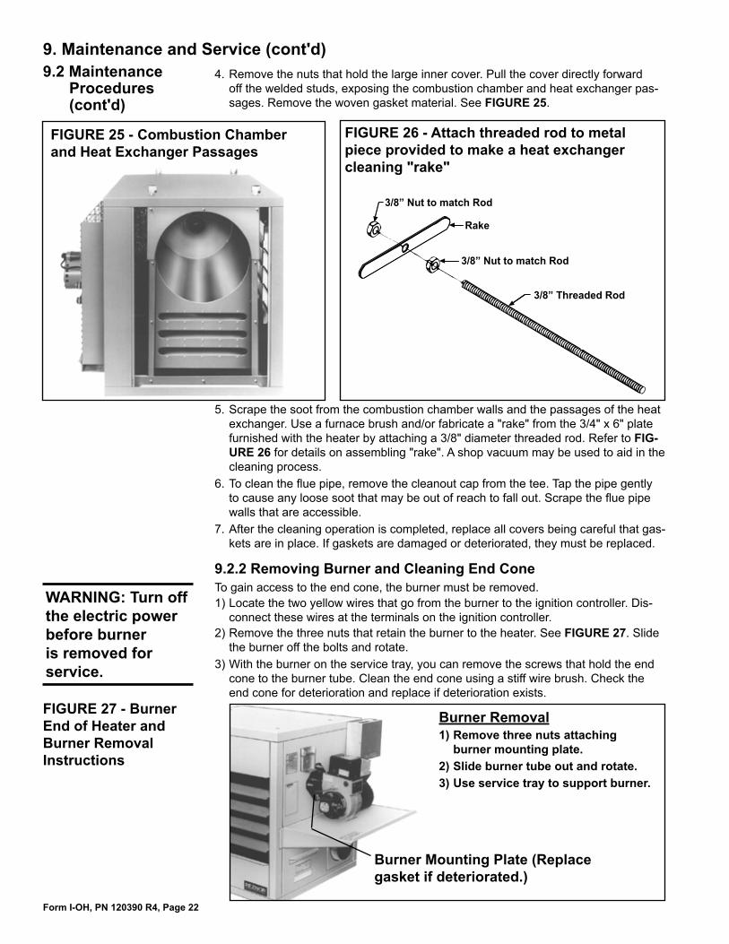
FIGURE 25 - Combustion Chamber and Heat Exchanger Passages
���������������������
���������������������
����
�����������������
FIGURE 26 - Attach threaded rod to metal piece provided to make a heat exchanger cleaning "rake"
9.2.2 Removing Burner and Cleaning End Cone
Burner Removal1) Remove three nuts attaching
burner mounting plate. 2) Slide burner tube out and rotate. 3) Use service tray to support burner.
Burner Mounting Plate (Replace gasket if deteriorated.)
FIGURE 27 - Burner End of Heater and Burner Removal Instructions
9. Maintenance and Service (cont'd)9.2 Maintenance
Procedures (cont'd)
WARNING: Turn off the electric power before burner is removed for service.
To gain access to the end cone, the burner must be removed.1) Locate the two yellow wires that go from the burner to the ignition controller. Dis-
connect these wires at the terminals on the ignition controller.2) Remove the three nuts that retain the burner to the heater. See FIGURE 27. Slide
the burner off the bolts and rotate.3) With the burner on the service tray, you can remove the screws that hold the end
cone to the burner tube. Clean the end cone using a stiff wire brush. Check the end cone for deterioration and replace if deterioration exists.
4. Remove the nuts that hold the large inner cover. Pull the cover directly forward off the welded studs, exposing the combustion chamber and heat exchanger pas-sages. Remove the woven gasket material. See FIGURE 25.
5. Scrape the soot from the combustion chamber walls and the passages of the heat exchanger. Use a furnace brush and/or fabricate a "rake" from the 3/4" x 6" plate furnished with the heater by attaching a 3/8" diameter threaded rod. Refer to FIG-URE 26 for details on assembling "rake". A shop vacuum may be used to aid in the cleaning process.
6. To clean the flue pipe, remove the cleanout cap from the tee. Tap the pipe gently to cause any loose soot that may be out of reach to fall out. Scrape the flue pipe walls that are accessible.
7. After the cleaning operation is completed, replace all covers being careful that gas-kets are in place. If gaskets are damaged or deteriorated, they must be replaced.
Form I-OH, PN 120390 R4, Page 23
�����������������
���������
����������������
�������������
������������������
��������������������
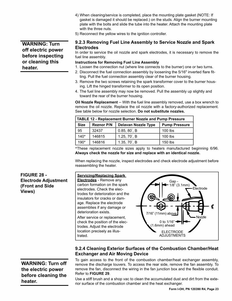
FIGURE 28 - Electrode Adjustment (Front and Side Views)
Servicing/Replacing Spark Electrodes - Remove any carbon formation on the spark electrodes. Check the elec-trodes for deterioration and the insulators for cracks or dam-age. Replace the electrode assemblies if any damage or deterioration exists. After service or replacement, check the position of the elec-trodes. Adjust the electrode location precisely as illus-trated.
4) When cleaning/service is completed, place the mounting plate gasket (NOTE: If gasket is damaged it should be replaced.) on the studs. Align the burner mounting plate with the bolts and slide the tube into the heater. Attach the mounting plate with the three nuts.
5) Reconnect the yellow wires to the ignition controller.
9.2.3 Removing Fuel Line Assembly to Service Nozzle and Spark ElectrodesIn order to service the oil nozzle and spark electrodes, it is necessary to remove the fuel line assembly.Instructions for Removing Fuel Line Assembly1. Loosen the connection nut (where line connects to the burner) one or two turns.2. Disconnect the fuel connection assembly by loosening the 5/16" inverted flare fit-
ting. Pull the fuel connection assembly clear of the burner housing.3. Remove the two screws retaining the spark transformer cover to the burner hous-
ing. Lift the hinged transformer to its open position.4. The fuel line assembly may now be removed. Pull the assembly up slightly and
toward the rear of the burner housing.Oil Nozzle Replacement -- With the fuel line assembly removed, use a box wrench to remove the oil nozzle. Replace the oil nozzle with a factory-authorized replacement. See table below for nozzle selection. Do not substitute nozzles.
TABLE 12 - Replacement Burner Nozzle and Pump PressureSize Reznor P/N Delavan Nozzle Type Pump Pressure95 32437 0.85, 80°, B 100 lbs140* 146815 1.25, 70°, B 100 lbs190* 146816 1.35, 70°, B 150 lbs
*These replacement nozzle sizes apply to heaters manufactured beginning 6/96. Always check the nozzle for size and replace with an identical nozzle.
When replacing the nozzle, inspect electrodes and check electrode adjustment before reassembling the heater.
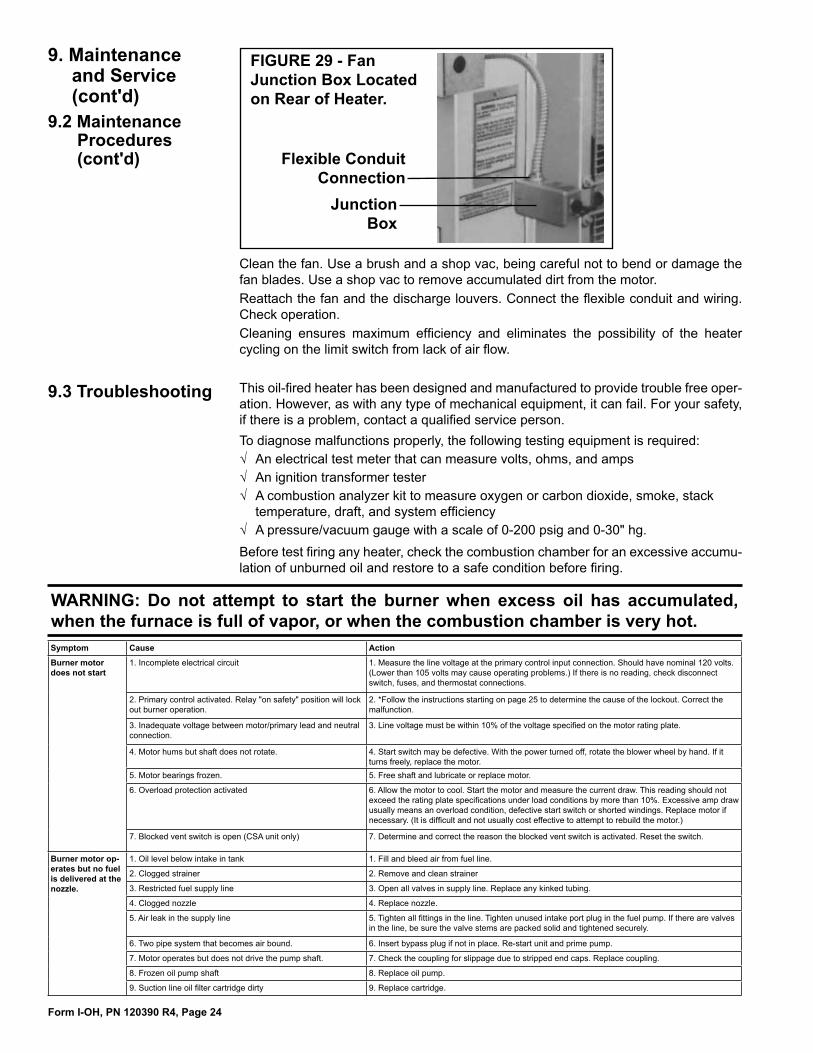
9.2.4 Cleaning Exterior Surfaces of the Combustion Chamber/Heat Exchanger and Air Moving DeviceTo gain access to the front of the combustion chamber/heat exchanger assembly, remove the discharge louvers. To access the rear side, remove the fan assembly. To remove the fan, disconnect the wiring in the fan junction box and the flexible conduit. Refer to FIGURE 29.Use a stiff brush and a shop vac to clean the accumulated dust and dirt from the exte-rior surface of the combustion chamber and the heat exchanger.
WARNING: Turn off the electric power before cleaning the heater.
WARNING: Turn off electric power before inspecting or cleaning this heater.
Form I-OH, PN 120390 R4, Page 24
Junction Box
Flexible Conduit Connection
FIGURE 29 - Fan Junction Box Located on Rear of Heater.
Clean the fan. Use a brush and a shop vac, being careful not to bend or damage the fan blades. Use a shop vac to remove accumulated dirt from the motor.Reattach the fan and the discharge louvers. Connect the flexible conduit and wiring. Check operation.Cleaning ensures maximum efficiency and eliminates the possibility of the heater cycling on the limit switch from lack of air flow.
This oil-fired heater has been designed and manufactured to provide trouble free oper-ation. However, as with any type of mechanical equipment, it can fail. For your safety, if there is a problem, contact a qualified service person.To diagnose malfunctions properly, the following testing equipment is required:√ An electrical test meter that can measure volts, ohms, and amps√ An ignition transformer tester√ A combustion analyzer kit to measure oxygen or carbon dioxide, smoke, stack
temperature, draft, and system efficiency√ A pressure/vacuum gauge with a scale of 0-200 psig and 0-30" hg.Before test firing any heater, check the combustion chamber for an excessive accumu-lation of unburned oil and restore to a safe condition before firing.
9.3 Troubleshooting
WARNING: Do not attempt to start the burner when excess oil has accumulated, when the furnace is full of vapor, or when the combustion chamber is very hot.
9. Maintenance and Service (cont'd)
9.2 Maintenance Procedures (cont'd)
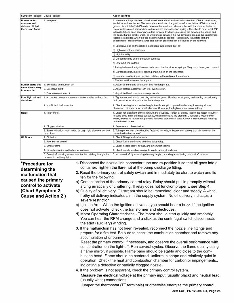
Symptom Cause Action
Burner motor does not start
1. Incomplete electrical circuit 1. Measure the line voltage at the primary control input connection. Should have nominal 120 volts. (Lower than 105 volts may cause operating problems.) If there is no reading, check disconnect switch, fuses, and thermostat connections.
2. Primary control activated. Relay "on safety" position will lock out burner operation.
2. *Follow the instructions starting on page 25 to determine the cause of the lockout. Correct the malfunction.
3. Inadequate voltage between motor/primary lead and neutral connection.
3. Line voltage must be within 10% of the voltage specified on the motor rating plate.
4. Motor hums but shaft does not rotate. 4. Start switch may be defective. With the power turned off, rotate the blower wheel by hand. If it turns freely, replace the motor.
5. Motor bearings frozen. 5. Free shaft and lubricate or replace motor.
6. Overload protection activated 6. Allow the motor to cool. Start the motor and measure the current draw. This reading should not exceed the rating plate specifications under load conditions by more than 10%. Excessive amp draw usually means an overload condition, defective start switch or shorted windings. Replace motor if necessary. (It is difficult and not usually cost effective to attempt to rebuild the motor.)
7. Blocked vent switch is open (CSA unit only) 7. Determine and correct the reason the blocked vent switch is activated. Reset the switch.
Burner motor op-erates but no fuel is delivered at the nozzle.
1. Oil level below intake in tank 1. Fill and bleed air from fuel line.
2. Clogged strainer 2. Remove and clean strainer
3. Restricted fuel supply line 3. Open all valves in supply line. Replace any kinked tubing.
4. Clogged nozzle 4. Replace nozzle.
5. Air leak in the supply line 5. Tighten all fittings in the line. Tighten unused intake port plug in the fuel pump. If there are valves in the line, be sure the valve stems are packed solid and tightened securely.
6. Two pipe system that becomes air bound. 6. Insert bypass plug if not in place. Re-start unit and prime pump.
7. Motor operates but does not drive the pump shaft. 7. Check the coupling for slippage due to stripped end caps. Replace coupling.
8. Frozen oil pump shaft 8. Replace oil pump.
9. Suction line oil filter cartridge dirty 9. Replace cartridge.
Form I-OH, PN 120390 R4, Page 25
Symptom (cont'd) Cause (cont'd) Action (cont'd)
Burner motor operates and delivers oil, but there is no flame.
1. No spark 1. Measure voltage between transformer/primary lead and neutral connection. Check transformer, insulators and electrodes. The secondary terminals of a good transformer deliver 5000 volts arc to ground, for a total of 10,000 volts between the terminals. Measure this with transformer tester or use a well-insulated screwdriver to draw an arc across the two springs. This should be at least 3/4" in length. Check each secondary output terminal by drawing a strong arc between the spring and the base. If arc is erratic, weak, or unbalanced between the two terminals, replace the transformer. Replace electrodes when the tips become worn or eroded. Replace any insulators that are questionable. Transformer failures and ignition problems can be caused by the following:
a) Excessive gap on the ignition electrodes. Gap should be 1/8".
b) High ambient temperatures
c) High humidity
d) Carbon residue on the porcelain bushings
e) Low input line voltage
f) Arcing between the ignition electrodes and the transformer springs. They must have good contact.
g) Carbon residue, moisture, crazing or pin holes on the insulators.
h) Improper positioning of nozzle in relation to the radius of the endcone.
I) Carbon residue on electrode parts.
Burner starts but flame blows away from nozzle.
1. Excessive combustion air 1. Adjust air band and air shutter. See Paragraph 8.2.
2. Excessive draft 2. Adjust draft regulator for .01" w.c. overfire draft.
3. Poor atomization of oil 3. Adjust fuel feed pressure; change nozzle.
Poor light off and shutdown.
1. Air pocket between pressure shutdown valve and nozzle 1. Tighten unused intake port plug in the fuel pump. Run burner stopping and starting occasionally until pulsation, smoke, and after flame disappear.
2. Insufficient draft over fire 2. Check venting for excessive length, insufficient pitch upward to chimney, too many elbows, obstructed chimney, or too small chimney. Check for too high combustion air setting.
Noise 1. Noisy motor 1. Check for alignment of the shaft with the coupling. Tighten or slightly loosen the motor-to-burner-housing bolts in an alternate sequence, which may solve the problem. Check for a loose blower wheel, excessive radial shaft play and for loose start switch parts. Check if thermocouple is laying on the blower wheel.
2. Clogged strainer 2. Remove and clean strainer.
3. Burner vibrations transmitted through rigid electrical conduit or oil lines.
3. Tubing or conduit should not be fastened to studs, or beams so securely that vibration can be transmitted to floor or roof.
Oil Odors 1. Oil leaks 1. Check fittings and valve seals.
2. Poor burner shutoff 2. Check fuel shutoff valve and time delay relay.
3. Smoky flame 3. Check nozzle spray, air gap, and air shutter setting.
4. Oil carbonization on the burner endcone 4. Check nozzle location relative to inside radius of endcone.
5. Downdraft causing smoke to enter the building through the barometric draft regulator.
5. Increase draft by extending chimney height, or adding a ventilating cap or draft inducer.
*Procedure for determining the malfunction that caused the primary control to activate (Chart Symptom 2; Cause and Action 2 )
1. Disconnect the nozzle line connector tube and re-position it so that oil goes into a container. Tighten the flare nut at the pump discharge fitting.
2. Reset the primary control safety switch and immediately be alert to watch and lis-ten for the following:
a) Contact action of the primary control relay. Relay should pull in promptly without arcing erratically or chattering. If relay does not function properly, see Step 4.
b) Quality of oil delivery. Oil stream should be immediate, clear and steady. A white, frothy oil delivery indicates air in the supply system. No oil delivery indicates a severe restriction.
c) Ignition Arc - When the ignition activates, you should hear a buzz. If the ignition does not activate, check the transformer and electrodes.
d) Motor Operating Characteristics - The motor should start quickly and smoothly. You can hear the RPM change and a click as the centrifugal switch disconnects the start (auxiliary) winding.
3. If the malfunction has not been revealed, reconnect the nozzle line fittings and prepare for a fire test. Be sure to check the combustion chamber and remove any accumulation of unburned oil. Reset the primary control, if necessary, and observe the overall performance with concentration on the light-off. Run several cycles. Observe the flame quality using a flame mirror, if possible. Flame base should be stable and close to the com-bustion head. Flame should be centered, uniform in shape and relatively quiet in operation. Check the heat and combustion chamber for carbon or impingements., indicating a defective or partially clogged nozzle.
4. If the problem is not apparent, check the primary control system.Measure the electrical voltage at the primary input (usually black) and neutral lead (usually white) connections.Jumper the thermostat (TT terminals) or otherwise energize the primary control.
Form I-OH, PN 120390 R4, Page 26
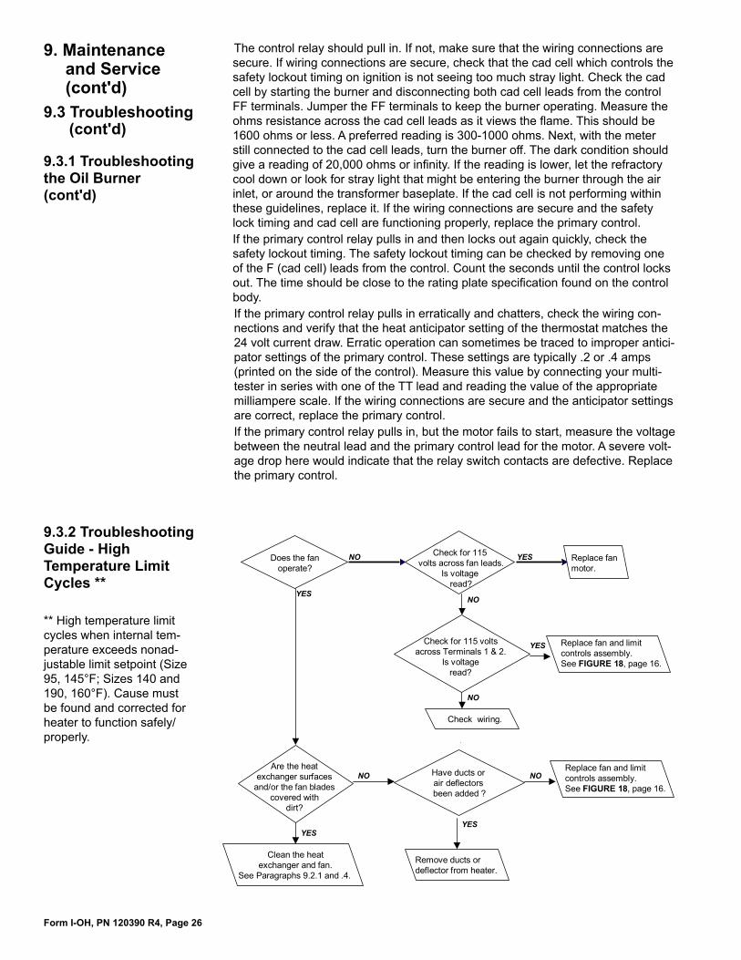
Does the fanoperate?
Are the heatexchanger surfaces
and/or the fan bladescovered with
dirt?
Clean the heatexchanger and fan.
See Paragraphs 9.2.1 and .4.
Remove ducts ordeflector from heater.
Check for 115volts across fan leads.
Is voltageread?
Replace fanmotor.
Check for 115 voltsacross Terminals 1 & 2.
Is voltageread?
Replace fan and limitcontrols assembly.See FIGURE 18, page 16.
Check wiring.
YES
NO
YES
NO
YES
NO
YES
NO
YES
NO
Have ducts orair deflectorsbeen added ?
Replace fan and limitcontrols assembly.See FIGURE 18, page 16.
** High temperature limit cycles when internal tem-perature exceeds nonad-justable limit setpoint (Size 95, 145°F; Sizes 140 and 190, 160°F). Cause must be found and corrected for heater to function safely/properly.
9.3.2 Troubleshooting Guide - High Temperature Limit Cycles **
9.3.1 Troubleshooting the Oil Burner (cont'd)
9. Maintenance and Service (cont'd)
9.3 Troubleshooting (cont'd)
The control relay should pull in. If not, make sure that the wiring connections are secure. If wiring connections are secure, check that the cad cell which controls the safety lockout timing on ignition is not seeing too much stray light. Check the cad cell by starting the burner and disconnecting both cad cell leads from the control FF terminals. Jumper the FF terminals to keep the burner operating. Measure the ohms resistance across the cad cell leads as it views the flame. This should be 1600 ohms or less. A preferred reading is 300-1000 ohms. Next, with the meter still connected to the cad cell leads, turn the burner off. The dark condition should give a reading of 20,000 ohms or infinity. If the reading is lower, let the refractory cool down or look for stray light that might be entering the burner through the air inlet, or around the transformer baseplate. If the cad cell is not performing within these guidelines, replace it. If the wiring connections are secure and the safety lock timing and cad cell are functioning properly, replace the primary control.If the primary control relay pulls in and then locks out again quickly, check the safety lockout timing. The safety lockout timing can be checked by removing one of the F (cad cell) leads from the control. Count the seconds until the control locks out. The time should be close to the rating plate specification found on the control body.If the primary control relay pulls in erratically and chatters, check the wiring con-nections and verify that the heat anticipator setting of the thermostat matches the 24 volt current draw. Erratic operation can sometimes be traced to improper antici-pator settings of the primary control. These settings are typically .2 or .4 amps (printed on the side of the control). Measure this value by connecting your multi-tester in series with one of the TT lead and reading the value of the appropriate milliampere scale. If the wiring connections are secure and the anticipator settings are correct, replace the primary control.If the primary control relay pulls in, but the motor fails to start, measure the voltage between the neutral lead and the primary control lead for the motor. A severe volt-age drop here would indicate that the relay switch contacts are defective. Replace the primary control.
Form I-OH, PN 120390 R4, Page 27
AAir Shutter Settings 20
BBlocked Vent Switch 17Boost Pump Assembly (Option DA1, DA2)
9Boost Pump Capacities 9Boost Pump Pressure Switch 10Boost Pump Wiring for Constant Operation
10Boost Pump Wiring for Intermittent Opera-
tion 10Burner Pump 15,19Burner Pump Lift Capacity 7
CCheck-Test-Start (Operating Procedure) 18Check-Test-Startup Procedure 17Checklist Prior to Startup 17Check Valve 11Cleaning Combustion Chamber, Heat
Exchanger and Flue 20Cleaning End Cone 22Cleaning Exterior Surface 23Clearances 4Combustion Air 13Combustion Air Band and Air Shutter
Settings 20Contact 28Control Wiring 17
DDimensions 5Draft Inducer Relay (Option DH1) 12Draft Regulator Requirements 12
EElectrical Ratings 13Electrical Supply and Connections 13Electrode Adjustment 23Electrodes and Nozzle Location 15
FFan and Limit Controls 16Fuel Specifications 3Fuel Tank 6
GGENERAL 2
HHanging the Heater 5Hazard Labels 2
IInstallation Codes 3
LLocation 3
MMaintenance Requirements 20Motors 15Mounting the Heater 6
NNozzle Replacement 23
OOil Filter 6
PPipe Tubing 6Primary Control System 17
RRemoving Burner 22Removing Fuel Line Assembly 23
SShutoff Valve 6Single Pipe Supply System 7Loop Supply System 8Pressurized Supply System 9Two-Pipe Supply System 8Supply Lines 6Suspending the Unit 5
TFuel Tank 6Thermostat 17Throw 4Troubleshooting 24Troubleshooting Guide - High Temperature
Limit Cycles 26Troubleshooting Oil Burner 26
UUncrating/Shipping Damage 4
VOil Safety Valve (OSV) (Option DC1,
shipped separately 11Solenoid Valve (Option DD1, shipped
separately) 11Venting 11
WWarranty 3Weight 5Supply and Line Wiring 13Wiring Diagrams 14
INDEX
Form I-OH, PN 120390 R4, Page 28
CAUTION: DO NOT TAMPER WITH THE UNIT OR CONTROLS. CALL YOUR SERVICE PERSON.
www.RezSpec.com(800) 695-1901©2011 Thomas & Betts Corporation, All rights reserved. Trademark Note: Reznor® is registered in at least the United States.All other trademarks are the property of their respective owners.3/11 Form I-OH (Version C)
Installer: Name ________________________________________________________ Company ________________________________________________________ Address ________________________________________________________ ________________________________________________________ ________________________________________________________ Phone _________________________________
Distributor (company from which the unit was purchased): Company ________________________________________________________ Contact ________________________________________________________ Address ________________________________________________________ ________________________________________________________ ________________________________________________________ Phone _________________________________
Model ________________ Serial No.______________________________Date of Installation ____________
SPECIFIC INSTALLATION NOTES: (i.e. Location, Amps, Temperature, Voltage, Adjustments, Warranty, etc.)
________________________________________________________________________________________
________________________________________________________________________________________
________________________________________________________________________________________
________________________________________________________________________________________
________________________________________________________________________________________
BUILDING OWNER OR MAINTENANCE PERSONNEL:
For service or repairContact the installer listed above. If you need additional assistance, contact the Reznor Distributor listed above.For more information, contact your Reznor Representative by calling 800-695-1901.
Reznor/Thomas & Betts 150 McKinley Avenue Mercer, PA 16137
•••
INSTALLER MUST COMPLETE THE FOLLOWING: