Embed Size (px)
Citation preview
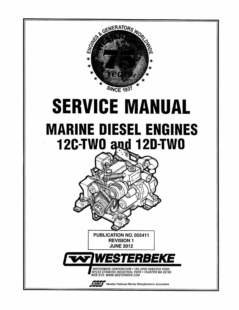
SERVICE MANUAL MARINE DIESEL ENGINES
12C-TWO 120-TWO
PUBLICATION NO. 055411 REVISION 1 JUNE 2012
J'~ rWESTERBEKE J WESTERBEKE CORPORATION • 150 JOHN HANCOCK ROAD J M'(LES STANDISH INDUSTRIAL PARK • TAUNTON MA 02780
WEB SITE: WWW. WESTERBEKE.COM
NMMA Member National Marine Manufacturers Association --
A wARNING
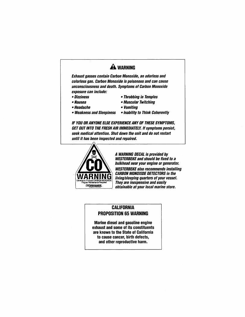
Exhaust gasses contain Carbon Monoxide, an odorless and colorless gas. Carbon Monoxide is poisonous and can cause unconsciousness and death. Symptoms of Carbon Monoxide exposure can include: •Dizziness • Throbbing in Temples •Nausea •Headache
• Muscular Twitching • Vomiting
• Weakness and Sleepiness • Inability to Think Coherently
IF YOU OR ANYONE ELSE EXPERIENCE ANY OF THESE SYMPTOMS, GET OUT INTO THE FRESH AIR IMMEDIATELY. If symptoms persist, seek medical attention. Shut down the unit and do not restart until it has been inspected and repaired.
A WARNING DECAL is provided by WESTERBEKE and should be fixed to a bulkhead near your engine or generator. WESTERBEKE also recommends installing
.... ~~~~~\ CARBON MONOXIDE DETECTORS in the living/sleeping quarters of your vessel. They are inexpensive and easily
L~~~~-_j obtainable at your local marine store.
CALIFORNIA PROPOSITION 65 WARNING
Marine diesel and gasoline engine exhaust and some of its constituents are known to the State of California
to cause cancer, birth defects, and other reproductive harm.
SAFETY INSTRUCTIONS INTRODUCTION Read this safety manual carefully. Most accidents are caused by failure to follow fundamental rules and precautions. Know when dangerous conditions exist and take the necessary precautions to protect yourself, your personnel, and your machinery. The following safety instructions are in compliance with the American Boat and Yacht Council (ABYC) standards.
PREVENT ELECTRIC SHOCK
A WARNING: Do not touch AC electrical connections while engine is running. Lethal voltage is present at these connections!
• Do not operate this machinery without electrical enclosures and covers in place.
• Shut off electrical power before accessing electrical equipment.
• Use insulated mats whenever working on electrical equipment.
• Make sure your clothing and skin are dry, not damp (particularly shoes) when handling electrical equipment.
• Remove wristwatch and all jewelry when working on electrical equipment.
• Do noit connect utility shore power to vessel's AC circuits, except through a ship-to-shore double throw transfer switch. Damage to vessel's AC generator may result if this procedure is not followed.
• Electrical shock results from handling a charged capacitor. Discharge capacitor by shorting tenninals together.
PREVENT BURNS - HOT ENGINE
A WARNING: Do not touch hot engine parts or exhaust system components. A running engine gets very hot!
• Always check the engine coolant level at the coolant recovery tank.
A WARNING: Steam can cause injury or death!
• In case of an engine overheat, allow the engine to cool before touching the engine or checking the coolant.
PREVENT BURNS - FIRE
A WARNING: Fire can cause injury or death!
• Prevent flash fires. Do not smoke or permit flames or sparks to occur near the carburetor, fuel line, filter, fuel pump, or other potential sources of spilled fuel or fuel vapors. Use a suitable container to catch all fuel when removing the fuel lines, fuel filters, or other fuel system components ..
• Do not opeerate with a Coast Guard Approved flame anester removed. Backfire can cause severe injury or death.
• Do not operate with the air cleaner/silencer removed. Backfire can cause severe injury or death.
• Do not smoke or permit flames or sparks to occur near the fuel system. Keep the compartment and the engine/generator clean and free of debris to minimize the chances of fire. Wipe up all spilled fuel and engine oil.
• Be aware - Diesel and gasoline will bum.
PREVENT BURNS - EXPLOSION
A WARNING: Explosions from fuel vapors can cause injury or death!
• Follow re-fueling safety instructions. Keep the vessel's hatches closed when fueling. Open and ventilate cabin after fueling. Check below for fumes/vapor before running the blower. Run the blower for four minutes before starting your engine.
• All fuel vapors are highly explosive. Use extreme care when handling and storing fuels. Store fuel in a well-ventilated area away from spark-producing equipment and out of the reach of children.
• Do not fill the fuel tank(s) while the engine is running.
• Shut off the fuel service valve at the engine when servicing the fuel system. Take care in catching any fuel that might spill. DO NOT allow any smoking, open flames, or other sources of fire near the fuel system or engine when servicing. Ensure proper ventilation exists when servicing the fuel system.
• Do not alter or modify the fuel system.
• Be sure all fuel supplies have a positive shutoff valve.
• Be certain fuel line fittings are adequately tightened and free of leaks.
• Make sure a fire extinguisher is installed nearby and is properly maintained. Be familiar with its proper use. Extinguishers rated ABC by the NFPA are appropriate for all applications encountered in this environment.
SAFETY INSTRUCTIONS ACCIDENTAL STARTING
A WARNING: Accidental starting can cause injury or death!
• To prevent accidental starting when servicing the generator, remove the 8 amp fuse from the control panel.
• Disconnect the battery cables before servicing the engine/ generator. Remove the negative lead first and reconnect it last.
• Make certain all personnel are clear of the engine before starting.
• Make certain all covers, guards, and hatches are re-installed before starting the engine.
BATTERY EXPLOSION ~----------------------------------------~ -4
A WARNING: Battery explosion can cause injury or death!
• Do not smoke or allow an open flame near the battery being serviced. Lead acid batteries emit hydrogen, a highly explosive gas, which can be ignited by electrical arcing or by lit tobacco products. Shut off all electrical equipment in the vicinity to prevent electrical arcing during servicing.
• Never connect the negative(-) battery cable to the positive ( +) connection terminal of the starter solenoid. Do not test the battery condition by shorting the terminals together. Sparks could ignite battery gases or fuel vapors. Ventilate any compartment containing batteries to prevent accumulation of explosive gases. To avoid sparks, do not disturb the battery charger connections while the battery is being charged.
• Avoid contacting the terminals with tools, etc., to prevent bums or sparks that could cause an explosion. Remove wristwatch, rings, and any other jewelry before handling the battery.
• Always tum the battery charger off before disconnecting the battery connections. Remove the negative lead first and reconnect it last when disconnecting the battery.
BATTERY ACID
A WARNING: Sulfuric acid in batteries can cause severe injury or death!
• When servicing the battery or checking the electrolyte level, wear rubber gloves, a rubber apron, and eye protection. Batteries contain sulfuric acid, which is destructive. If it comes in contact with your skin, wash it off at once with water. Acid may splash on the skin or into the eyes inadvertently when removing electrolyte caps.
. . II
A WARNING: Carbon monoxide (CO) is a deadly gas!
• Ensure that the exhaust system is adequate to expel gases discharged from the engine. Check the exhaust system regularly for leaks and make sure the exhaust manifolds are securely attached and no warping exists. Pay close attention to the manifold, water injection elbow, and exhaust pipe nipple.
• Be sure the unit and its surroundings are well ventilated.
• In addition to routine inspection of the exhaust system, install a carbon monoxide detector. Consult your boat builder or dealer for installation of approved detectors.
• For additional information, refer to ABYC T-22 (educational information on Carbon Monoxide).
A WARNING: Carbon monoxide (CO) is an invisible odorless gas. Inhalation produces flu·like symptoms, nausea or death!
• Do not use copper tubing in exhaust systems. Exhaust sulfur causes rapid deterioration of copper tubing resulting in exhaust/water leakage.
• Do not install exhaust outlet where exhaust can be drawn through portholes, vents, or air conditioners. If the engine exhaust discharge outlet is near the waterline. water could enter the exhaust discharge outlet and close or restrict the flow of exhaust. Avoid overloading the craft.
• Although diesel engine exhaust gases are not as toxic as exhaust fumes from gasoline engines, carbon monoxide gas is present in diesel exhaust fumes. Some of the symptoms or signs of carbon monoxide inhalation or poisoning are:
Vomiting Muscular twitching
Dizziness Intense headache
Throbbing in temples Weakness and sleepiness
AVOID MOVING PARTS
A WARNING: Rotating parts can cause injury or death!
• Do not service the engine while it is running. If a situation arises in which it is absolutely necessary to make operating adjustments, use extreme care to avoid touching moving parts and hot exhaust system components.
SAFETY INSTRUCTIONS • Do not wear loose clothing or jewelry when servicing
equipment; tie back long hair and avoid wearing loose jackets, shirts, sleeves, rings, necklaces or bracelets that could be caught in moving parts.
• Make sure all attaching hardware is properly tightened. Keep protective shields and guards in their respective places at all times.
• Do not check fluid levels or the drive belt's tension while the engine is operating.
• Stay clear of the drive shaft and the transmission coupling when the engine is running; hair and clothing can easily be caught in these rotating parts.
HAZARDOUS NOISE
A WARNING: High noise levels can cause hearing loss!
• Never operate an engine without its muffler installed.
• Do not run an engine with the air intake (silencer) removed.
• Do not run engines for long periods with their enclosures open.
A WARNING: Do not work on machinery when you are mentally or physically incapacitated by fatigue!
OPERATORS MANUAL Many of the preceding safety tips and warnings are repeated in your Operators Manual along with other cautions and notes to highlight critical information. Read your manual carefully, maintain your equipment, and follow all safety procedures.
GASOLINE ENGINE AND GENERATOR INSTALLATIONS Preparations to install a gasoline engine or generator should begin with a thorough examination of the American Boat and Yacht Council's (ABYC) standards. These standards are from a combination of sources including the USCG and the NFPA.
Sections of the AB YC standards of particular interest are:
H-2 Ventilation H-24 Gasoline Fuel Systems P-1 Exhaust Systems P-4 Inboard Engines E-9 DC Electrical Systems
All installations must comply with the Federal Code of Regulations (FCR).
ABYC, NFPA AND USCG PUBLICATIONS FOR INSTALLING DIESEL ENGINES Read the following ABYC, NFPA and USCG publications for safety codes and standards. Follow their recommendations when installing your engine.
ABYC (American Boat and Yacht Council) "Safety Standards for Small Craft"
Order from:
ABYC 3069 Solomon's Island Rd. Edgewater, MD 21037
NFPA (National Fire Protection Association) "Fire Protection Standard for Motor Craft"
Order from:
NFPA 11 Tracy Drive Avon Industrial Park Avon, MA 02322
USCG (United States Coast Guard) "USCG 33CFR183"
Order from:
U.S. Government Printing Office Washington, D.C. 20404
Engines & Generators
iii
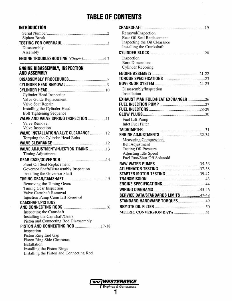
TABLE OF CONTENTS INTRODUCTION
Serial Number .......................................................... 2 Siphon Break
TESTING FOR OVERHAUL ........................................... 3 Disassembly Assembly
ENGINE TROUBLESHOOTING (Charts) ................... A-7
ENGINE DISASSEMBLY, INSPECTION AND ASSEMBLY DISASSEMBLY PROCEDURES ..................................... 8 CYLINDER HEAD REMOVAL ........................................ 9 CYLINDER HEAD ....................................................... 10
Cylinder Head Inspection Valve Guide Replacement Valve Seat Repair Installing the Cylinder Head Bolt Tightening Sequence
VALVE AND VALVE SPRING INSPECTION ................. 11 Valve Removal Valve Inspection
VALVE INSTALLATIONNALVE CLEARANCE ............... 12 Torquing the Cylinder Head Bolts
VALVE CLEARANCE ................................................... 12 VALVE ADJUSTMENT/INJECTION TIMING ................ 13
Timing Adjustment
GEAR CASE/GOVERNOR ............................................ 14 Front Oil Seal Replacement Governor Shaft/Disassembly Inspection Installing the Governor Shaft
TIMING GEAR/CAMSHAFT ........................................ 15 Removing the Timing Gears Timing Gear Inspection Valve Camshaft Removal Injection Pump Camshaft Removal
CAMSHAFT/PISTONS AND CONNECTING RODS .......................................... 16
Inspecting the Camshaft Installing the Camshaft/Gears Piston and Connecting Rod Disassembly
PISTON AND CONNECTING ROD ......................... 17-18 Inspection Piston Ring End Gap Piston Ring Side Clearance Installation Installing the Piston Rings Installing the Piston and Connecting Rod
CRANKSHAFT ............................................................ 19 Removal/Inspection Rear Oil Seal Replacement Inspecting the Oil Clearance Installing the Crankshaft
CYLINDER BLOCK ..................................................... 20 Inspection Bore Dimensions Cylinder Reboring
ENGINE ASSEMBLY .............................................. 21-22 TORQUE SPECIFICATIONS ........................................ 23 GOVERNOR SYSTEM ........................................... 24-25
Disassembly/Inspection Installation
EXHAUST MANIFOLD/HEAT EXCHANGER ................. 26 FUEL INJECTION PUMP ............................................ 27 FUEL INJECTORS ................................................. 28-29 GLOW PLUGS ........ .-................................................... 30
Fuel Lift Pump Inlet Fuel Filter
TACHOMETER ............................................................ 31 ENGINE ADJUSTMENTS ....................................... 32-34
Measuring Compression Belt Adjustment Testing Oil Pressure Adjusting Idle Speed Fuel Run/Shut-Off Solenoid
RAW WATER PUMPS .......................................... 35-36 ATLERNATOR TESTING ........................................ 37-38 STARTER MOTOR TESTING ................................. 39-42 TRANSMISSION ...................................................... .43 ENGINE SPECIFICATIONS ......................................... .44 WIRING DIAGRAMS ............................................ .45-46 SERVICE DATA/STANDARDS LIMITS .................. .47-48 STANDARD HARDWARE TORQUES .......................... .49 REMOTE OIL FILTER ................................................. 50 METRIC CONVERSION DATA ............................... 51
Engines & Generators
1
INTRODUCTION
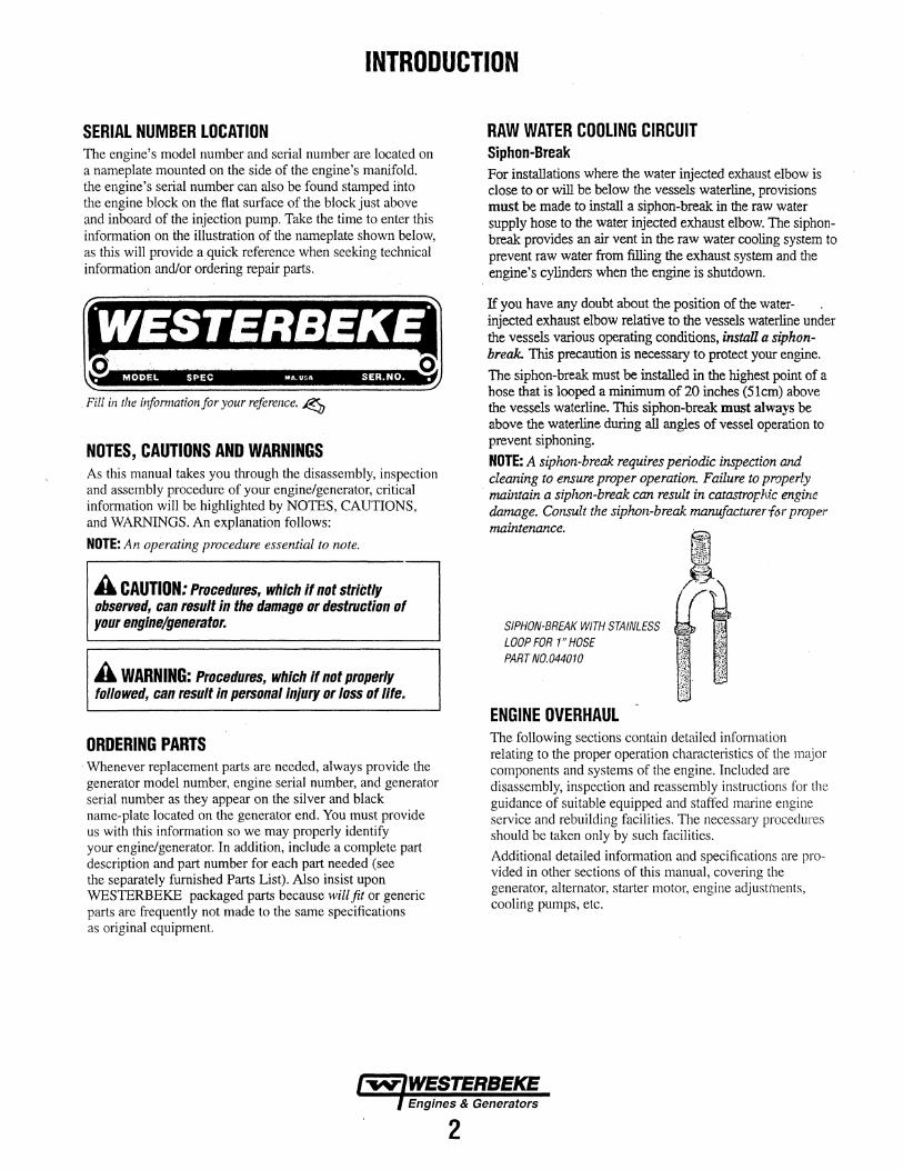
SERIAL NUMBER LOCATION The engine's model number and serial number are located on a nameplate mounted on the side of the engine's manifold. the engine's serial number can also be found stamped ihto the engine block on the flat surface of the block just above and inboard of the injection pump. Take the time to enter this information on the illustration of the nameplate shown below, as this will provide aquick reference when seeking technical information and/or ordering repair parts.
• MODEL SPEC MA USA SER.NO. •
. Fill in the infonnation for your reference. ~
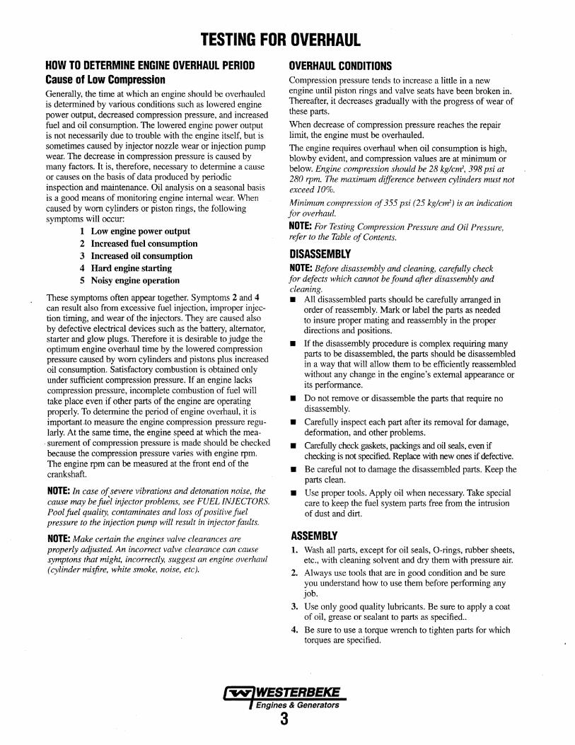
NOTES, CAUTIONS AND WARNINGS As this manual takes you through the disassembly, inspection and assembly procedure of your engine/generator, critical information will be highlighted by NOTES, CAUTIONS, and WARNINGS. An explanation follows:
NOTE: An operating procedure essential to note.
A CAUTION: Procedures1 which if not strictly observed1 can result in the damage or destruction of your engine/generator.
A WARNING: Procedures~ which if not properly followed1 can result in personal injury or loss of life.
ORDERING PARTS · Whenever replacement parts are needed, always provide the generator model number, engine serial number, and generator serial number as they appear on the silver and black name-plate located on the generator end. You must provide us with this information so we may properly identify your engine/generator. In addition, include a complete part description and part number for each part needed (see the separately furnished Parts List). Also insist upon WESTERBEKE packaged parts because will fit or generic parts are frequently not made to the same specifications as original equipment.
2
RAW WATER COOLING CIRCUIT Siphon-Break For installations where the water injected exhaust elbow is close to or will be below the vessels waterline, provisions must be made to install a siphon-break in the raw water supply hose to the water injected exhaust elbow. The siphonbreak provides an air vent in the raw water cooling system to prevent raw water from filling the exhaust system and the engine's cylinders when the engine is shutdown.
If you have any doubt about the position of the waterinjected exhaust elbow relative to the vessels waterline under the vessels various operating conditions, install a siphonbreak. This precaution is necessary to protect your engine.
The siphon-break must be installed in the highest point of a hose that is looped a minimum of 20 inches (51cm) above the vessels waterline. Tiris siphon-break must always be above the waterline during all angles of vessel operation to prevent siphoning.
NOTE: A siphon-break requires periodic inspection and cleaning to ensure proper operation. Failure to properly maintain a siplwn-break can result in catastrophic engine damage. Consult the siphon-break rnanufacturerf<>r proper maintenance.
SIPHON-BREAK WITH STAINLESS LOOP FOR 1" HOSE PART N0.044010
ENGINE OVERHAUL The following sections contain detailed information relating to the proper operation characteristics of the major components and systems of the engine. Included are disassembly, inspection and reassembly instructions for the guidance of suitable equipped and staffed mmine engine service and rebuilding facilities. The necessary procedures should be taken only by such facilities.
Additional detailed information and specifications are provided in other sections of this manual, covering the generator, alternator, starter motor, engine adjustments, cooling pumps, etc.
TESTING FOR OVERHAUL HOW TO DETERMINE ENGINE OVERHAUL PERIOD Cause of Low Compression Generally, the time at which an engine should be overhauled is determined by various conditions such as lowered engine power output, decreased compression pressure, and increased fuel and oil consumption. The lowered engine power output is not necessarily due to trouble with the engine itself, but is sometimes caused by injector nozzle wear or injection pump wear. The decrease in compression pressure is caused by many factors. It is, therefore, necessary to determine a cause or causes on the basis of data produced by periodic inspection and maintenance. Oil analysis on a seasonal basis is a good means of monitoring engine internal wear. When caused by worn cylinders or piston rings, the following symptoms will occur:
1 Low engine power output 2 Increased fuel consumption 3 Increased oil consumption 4 Hard engine starting 5 Noisy engine operation
These symptoms often appear together. Symptoms 2 and 4 can result also from excessive fuel injection, improper injection timing, and wear of the injectors. They are caused also by defective electrical devices such as the battery, alternator, starter and glow plugs. Therefore it is desirable to judge the optimum engine overhaul time by the lowered compression pressure caused by worn cylinders and pistons plus increased oil consumption. Satisfactory combustion is obtained only under sufficient compression pressure. If an engine lacks compression pressure, incomplete combustion of fuel will take place even if other parts of the engine are operating properly. To determine the period of engine overhaul, it is important.to measure the engine compression pressure regularly. At the same time, the engine speed at which the measurement of compression pressure is made should be checked because the compression pressure varies with engine rpm. The engine rpm can be measured at the front end of the crankshaft.
NOTE: In case of severe vibrations and detonation noise, the cause may be fu~l injector problems, see FUEL INJECTORS. Pool fuel quality, contaminates and loss of positive fuel pressure to the injection pump will result in injector faults.
NOTE: Make certain the engines valve clearances are properly adjusted. An incorrect valve clearance can cause symptons that might, incorrectly, suggest an engine overhaul (cylinder misfire, white smoke, noise, etc).
OVERHAUL CONDITIONS Compression pressure tends to increase a little in a new engine until piston rings and valve seats have been broken in. Thereafter, it decreases gradually with the progress of wear of these parts.
When decrease of compression pressure reaches the repair limit, the engine must be overhauled.
The engine requires overhaul when oil consumption is high, blowby evident, and compression values are at minimum or below. Engine compression should be 28 kg/cm2, 398 psi at 280 rpm. The maximum difference between cylinders must not exceed 10%.
Minimum compression of 355 psi (25 kg/cm2) is an indication for overhaul.
NOTE: For Testing Compression Pressure and Oil Pressure, refer to the Table of Contents.
DISASSEMBLY NOTE: Before disassembly and cleaning, carefully check for defects which cannot be found after disassembly and cleaning. • All disassembled parts should be carefully arranged in
order of reassembly. Mark or label the parts as needed to insure proper mating and reassembly in the proper directions and positions.
• If the disassembly procedure is complex requiring many parts to be disassembled, the parts should be disassembled in a way that will allow them to be efficiently reassembled without any change in the engine's external appearance or its performance.
• Do not remove or disassemble the parts that require no disassembly.
• Carefully inspect each part after its removal for damage, deformation, and other problems.
• Carefully check gaskets, packings and oil seals, even if checking is not specified. Replace with new ones if defective.
• Be careful not to damage the disassembled parts. Keep the parts clean.
• Use proper tools. Apply oil when necessary. Take special care to keep the fuel system parts free from the intrusion of dust and dirt.
ASSEMBLY 1. Wash all parts, except for oil seals, 0-rings, rubber sheets,
etc., with cleaning solvent and dry them with pressure air.
2. Always use tools that are in good condition and be sure you understand how to use them before performing any job.
3. Use only good quality lubricants. Be sure to apply a coat of oil, grease or sealant to parts as specified ..
4. Be sure to use a torque wrench to tighten parts for which torques are specified.
Engines & Generators
3
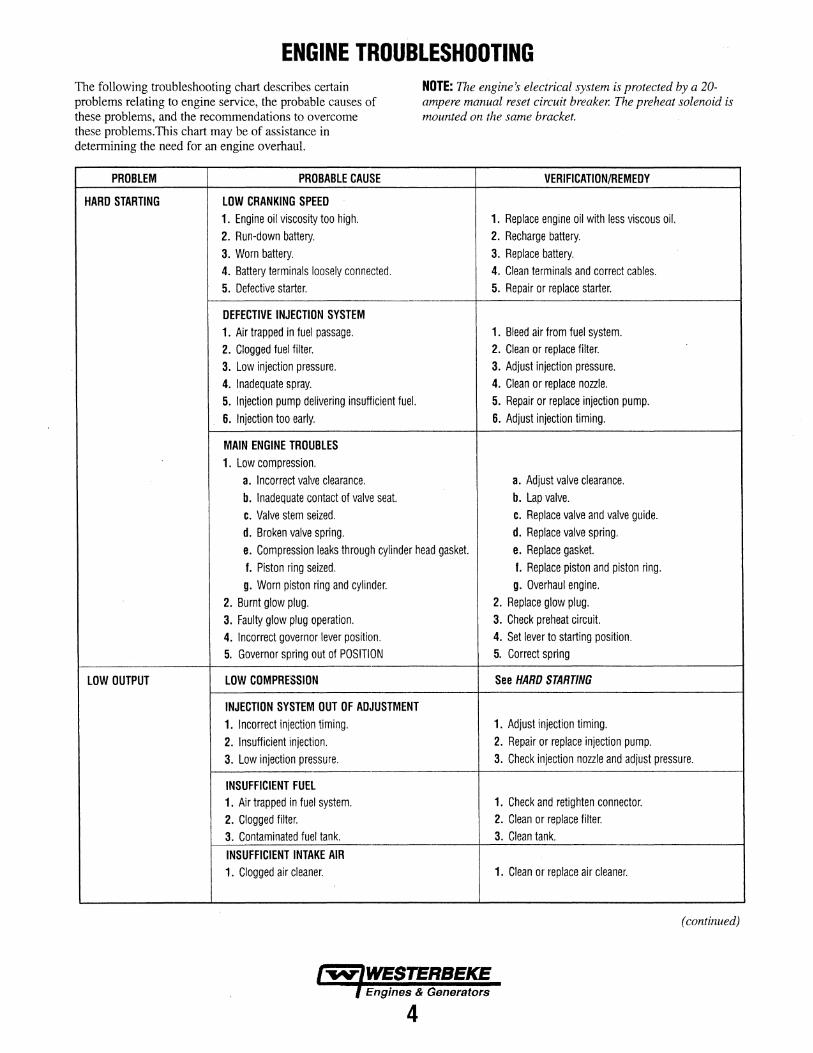
ENGINE TROUBLESHOOTING The following troubleshooting chart describes certain problems relating to engine service, the probable causes of these problems, and the recommendations to overcome these problems. This chart may be of assistance in determining the need for an engine overhaul.
PROBLEM PROBABLE CAUSE
HARD STARTING LOW CRANKING SPEED 1. Engine oil viscosity too high. 2. Run-down battery. 3. Worn battery. 4. Battery terminals loosely connected. 5. Defective starter.
DEFECTIVE INJECTION SYSTEM 1. Air trapped in fuel passage. 2. Clogged fuel filter. 3. Low injeCtion pressure. 4. Inadequate spray. 5. Injection pump delivering insufficient fuel. 6. Injection too early.
MAIN ENGINE TROUBLES 1. Low compression.
a. Incorrect valve clearance. b. Inadequate contact of valve seat. c. Valve stem seized. d. Broken valve spring.
NOTE: The engine~ electrical system is protected by a 20-ampere manual reset circuit breaker. The preheat solenoid is mounted on the same bracket.
VERIFICATION/REMEDY
1. Replace engine oil with less viscous oil. 2. Recharge battery. 3. Replace battery. 4. Clean terminals and correct cables. 5. Repair or replace starter.
1. Bleed air from fuel system. 2. Clean or replace filter. 3. Adjust injection pressure. 4. Clean or replace noule. 5. Repair or replace injection pump. 6. Adjust injection timing.
a. Adjust valve clearance. b. Lap valve. c. Replace valve and valve guide. d. Replace valve spring.
e. Compression leaks through cylinder head gasket. e. Replace gasket. f. Piston ring seized. f. Replace piston and piston ring. g. Worn piston ring and cylinder. g. Overhaul engine.
2. Burnt glow plug. 2. Replace glow plug. 3. Faulty glow plug operation. 3. Check preheat circuit. 4. Incorrect governor lever position. 4. Set lever to starting position. 5. Governor spring out of POSITION 5. Correct spring
LOW OUTPUT LOW COMPRESSION See HARD STARTING
INJECTION SYSTEM OUT OF ADJUSTMENT 1. Incorrect injection timing. 1. Adjust injection timing. 2. Insufficient injection. 2. Repair or replace injection pump. 3. Low injection pressure. 3. Check injection noule and adjust pressure.
INSUFFICIENT FUEL 1. Air trapped in fuel system. 1. Check and retighten connector. 2. Clogged filter. 2. Clean or replace filter. 3. Contaminated fuel tank. 3. Clean tank.
INSUFFICIENT INTAKE AIR 1. Clogged air cleaner. 1. Clean or replace air cleaner.
(continued)
Engines & Generators
4
ENGINE TROUBLESHOOTING
PROBLEM PROBABLE CAUSE VERI Fl CAT I 0 N/REM EDY
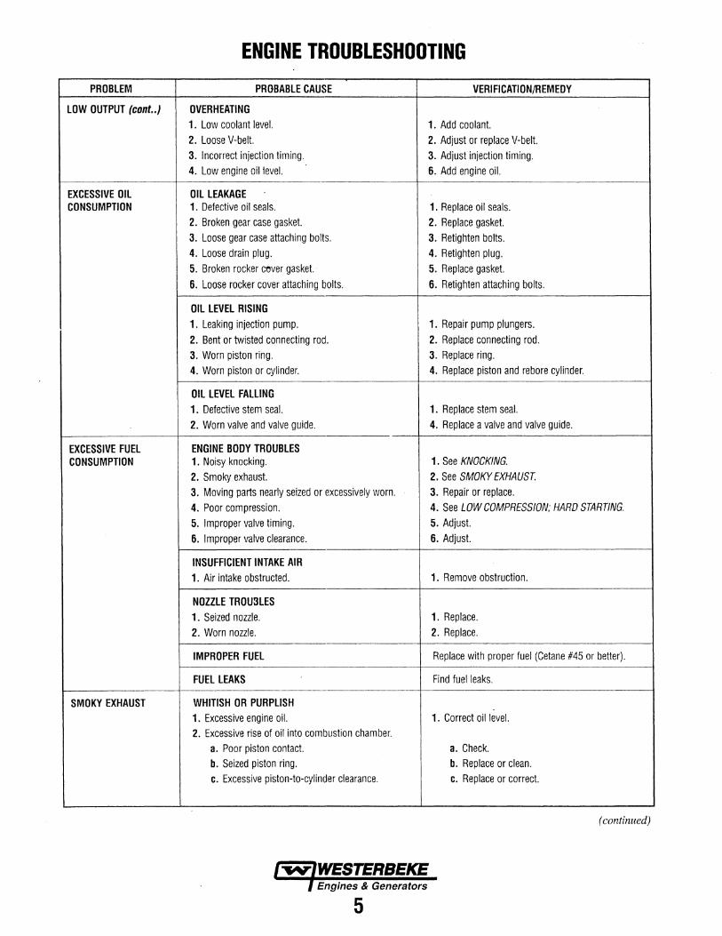
LOW OUTPUT (cont .. ) OVERHEATING 1. Low coolant level. 1. Add coolant. 2. Loose V-belt. 2. Adjust or replace V-belt. 3. Incorrect injection timing. 3. Adjust injection timing. 4. Low engine oil level. 6. Add engine oil.
EXCESSIVE OIL OIL LEAKAGE CONSUMPTION 1. Defective oil seals. 1. Replace oil seals.
2. Broken gear case gasket. 2. Replace gasket. 3. Loose gear case attaching bolts. 3. Retighten bolts. 4. Loose drain plug. 4. Retighten plug. 5. Broken rocker cever gasket. 5. Replace gasket. 6. Loose rocker cover attaching bolts. 6. Retighten attaching bolts.
OIL LEVEL RISING 1. Leaking injection pump. 1. Repair pump plungers. 2. Bent or twisted connecting rod. 2. Replace connecting rod. 3. Worn piston ring. 3. Replace ring. 4. Worn piston or cylinder. 4. Replace piston and rebore cylinder.
OIL LEVEL FALLING 1. Defective stem seal. 1. Replace stem seal. 2. Worn valve and valve guide. 4. Replace a valve and valve guide.
EXCESSIVE FUEL ENGINE BODY TROUBLES CONSUMPTION 1. Noisy knocking. 1. See KNOCKING.
2. Smoky exhaust. 2. See SMOKY EXHAUST 3. Moving parts nearly seized or excessively worn. 3. Repair or replace. 4. Poor compression. 4. See LOW COMPRESSION; HARD STARTING.
5. Improper valve timing. 5. Adjust. 6. Improper valve clearance. 6. Adjust.
INSUFFICIENT INTAKE AIR 1. Air intake obstructed. 1. Remove obstruction.
NOZZLE TROU3LES 1. Seized nozzle. 1. Replace. 2. Worn nozzle. 2. Replace.
IMPROPER FUEL Replace with proper fuel (Cetane #45 or better).
FUEL LEAKS Find fuel leaks.
SMOKY EXHAUST WHITISH OR PURPLISH 1. Excessive engine oil. 1. Correct oil level. 2. Excessive rise of oil into combustion chamber.
a. Poor piston contact. a. Check. b. Seized piston ring. b. Replace or clean. c. Excessive piston-to-cylinder clearance. c. Replace or correct.
(continued)
5
ENGINE TROUBLESHOOTING
PROBLEM PROBABLE CAUSE VERIFICATION/REMEDY
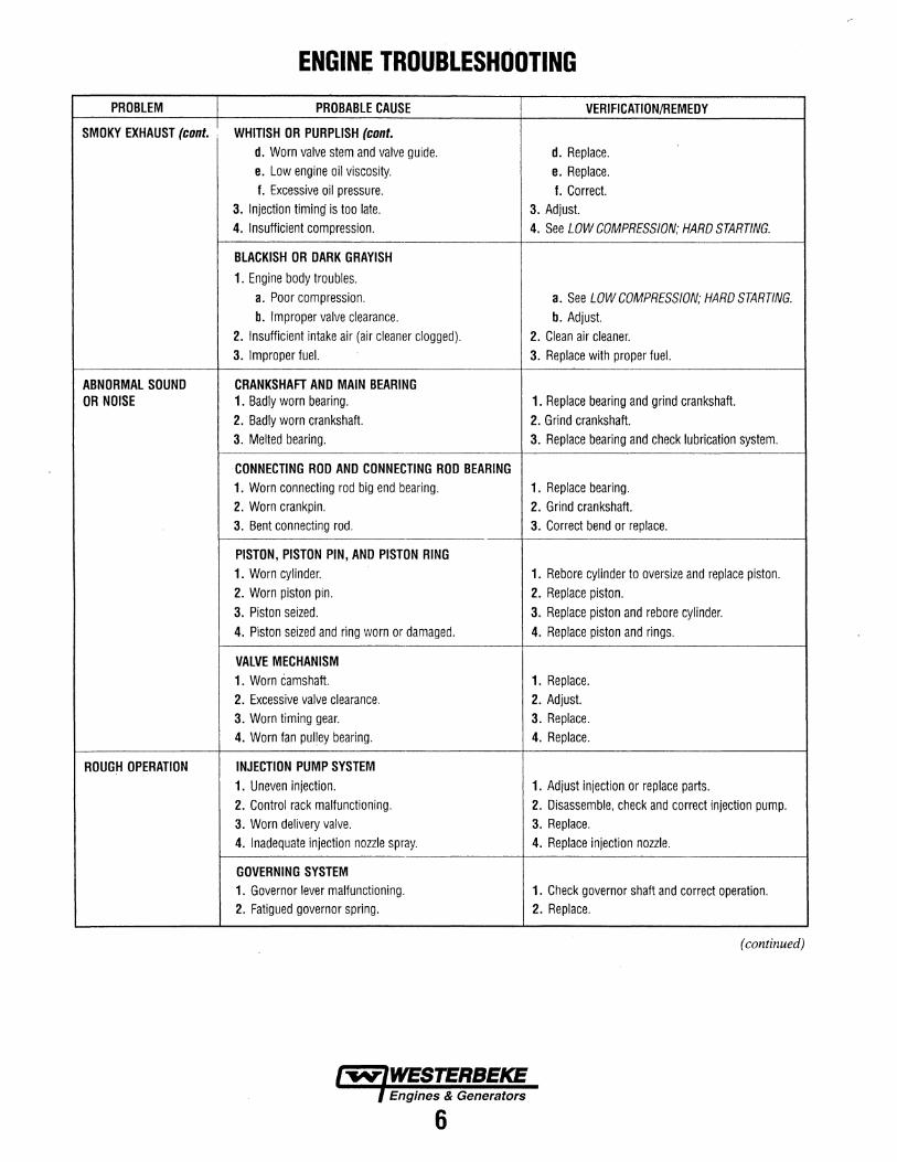
SMOKY EXHAUST (cont. 1 WHITISH OR PURPLISH (cont. d. Worn valve stem and valve guide. d. Replace. e. Low engine oil viscosity. e. Replace. f. Excessive oil pressure. f. Correct.
3. Injection timing is too late. 3. Adjust. 4. Insufficient compression. 4. See LOW COMPRESSION; HARD STARTING.
BLACKISH OR DARK GRAYISH
1. Engine body troubles. a. Poor compression. a. See LOW COMPRESSION; HARD STARTING. b. Improper valve clearance. b. Adjust.
2. Insufficient intake air (air cleaner clogged). 2. Clean air cleaner. 3. Improper fuel. 3. Replace with proper fuel.
ABNORMAL SOUND CRANKSHAFT AND MAIN BEARING OR NOISE 1. Badly worn bearing. 1. Replace bearing and grind crankshaft.
2. Badly worn crankshaft. 2. Grind crankshaft. 3. Melted bearing. 3. Replace bearing and check lubrication system.
CONNECTING ROD AND CONNECTING ROD BEARING 1. Worn connecting rod big end bearing. 1. Replace bearing. 2. Worn crankpin. 2. Grind crankshaft. 3. Bent connecting rod. 3. Correct bend or replace.
PISTON, PISTON PIN, AND PISTON RING 1. Worn cylinder. 1. Rebore cylinder to oversize and replace piston. 2. Worn piston pin. 2. Replace piston. 3. Piston seized. 3. Replace piston and rebore cylinder. 4. Piston seized and ring worn or damaged. 4. Replace piston and rings.
VALVE MECHANISM 1. Worn camshaft. 1. Replace. 2. Excessive valve clearance. 2. Adjust. 3. Worn timing gear. 3. Replace. 4. Worn fan pulley bearing. 4. Replace.
ROUGH OPERATION INJECTION PUMP SYSTEM 1. Uneven injection. 1. Adjust injection or replace parts. 2. Control rack malfunctioning. 2. Disassemble, check and correct injection pump. 3. Worn delivery valve. 3. Replace. 4. Inadequate injection nozzle spray. 4. Replace injection nozzle.
GOVERNING SYSTEM 1. Governor lever malfunctioning. 1. Check governor shaft and correct operation. 2. Fatigued governor spring. 2. Replace.
(continued)
6
ENGINE TROUBLESHOOTING
PROBLEM PROBABLE CAUSE
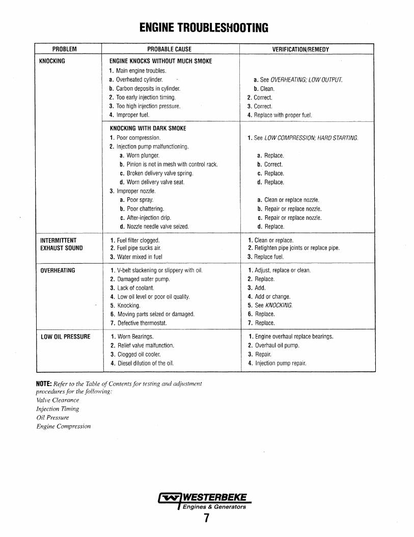
KNOCKING ENGINE KNOCKS WITHOUT MUCH SMOKE ! 1. Main engine troubles.
a. Overheated cylinder. '
b. Carbon deposits in cylinder.
I 2. Too early injection timing. I 3. Too high injection pressure. I
I 4. Improper fuel.
KNOCKING WITH DARK SMOKE 1. Poor compression. 2. Injection pump malfunctioning.
a. Worn plunger. b. Pinion is not in mesh with control rack. c. Broken delivery valve spring. d. Worn delivery valve seat.
3. Improper nozzle. a. Poor spray. b. Poor chattering. c. After-injection drip. d. Nozzle needle valve seized.
INTERMITTENT 1. Fuel filter clogged. EXHAUST SOUND 2. Fuel pipe sucks air.
3. Water mixed in fuel
OVERHEATING 1. V-belt slackening or slippery with oil. 2. Damaged water pump. 3. Lack of coolant. 4. Low oil level or poor oil quality. 5. Knocking. 6. Moving parts seized or damaged. 7. Defective thermostat.
LOW OIL PRESSURE 1. Worn Bearings. 2. Relief valve malfunction. 3. Clogged oil cooler. 4. Diesel dilution of the oil.
NOTE: Refer to the Table of Contents for testing and adjustment procedures for the following:
Valve Clearance
Injection Timing
Oil Pressure
Engine Compression
7
VERIFICATION/REMEDY
a. See OVERHEATING; LOW OUTPUT.
b. Clean. 2. Correct. 3. Correct. 4. Replace with proper fuel.
1. See LOW COMPRESSION; HARD STARTING.
a. Replace. b. Correct. c. Replace. d. Replace.
a. Clean or replace nozzle. b. Repair or replace nozzle. c. Repair or replace nozzle. d. Replace.
1. Clean or replace. 2. Retighten pipe joints or replace pipe. 3. Replace fuel.
1. Adjust, replace or clean. 2. Replace. 3. Add. 4. Add or change. 5. See KNOCKING. 6. Replace. 7. Replace.
1. Engine overhaul replace bearings. 2. Overhaul oil pump. 3. Repair. 4. Injection pump repair.
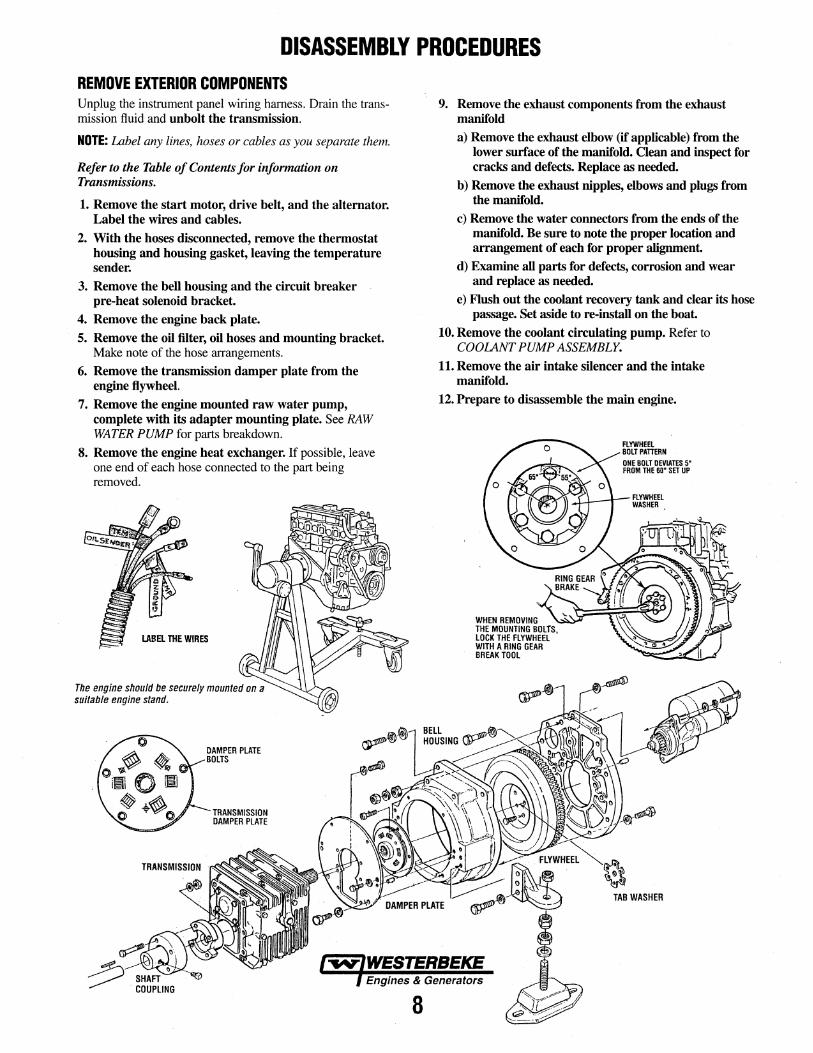
DISASSEMBLY PROCEDURES REMOVE EXTERIOR COMPONENTS Unplug the instrument panel wiring harness. Drain the transmission fluid and unbolt the transmission.
NOTE: Label any lines, hoses or cables as you separate them.
Refer to the Table of Contents for information on Transmissions.
1. Remove the start motor, drive belt, and the alternator. Label the wires and cables.
2. With the hoses disconnected, remove the thermostat housing and housing gasket, leaving the temperature sender.
3. Remove the bell housing and the circuit breaker pre-heat solenoid bracket.
4. Remove the engine back plate.
5. Remove the oil filter, oil hoses and mounting bracket. Make note of the hose arrangements.
6. Remove the transmission damper plate from the engine flywheel.
7. Remove the engine mounted raw water pump, complete with its adapter mounting plate. See RAW WATER PUMP for parts breakdown.
8. Remove the engine heat exchanger. If possible, leave one end of each hose connected to the part being removed.
LABa THE WIRES
The engine should be securely mounted on a suitable engine stand.
TRANSMISSION DAMPER PLATE
8
9. Remove the exhaust components from the exhaust manifold
a) Remove the exhaust elbow (if applicable) from the lower surface of the manifold. Clean and inspect for cracks and defects. Replace as needed.
b) Remove the exhaust nipples, elbows and plugs from the manifold.
c) Remove the water connectors from the ends of the manifold. Be sure to note the proper location and arrangement of each for proper alignment.
d) Examine all parts for defects, corrosion and wear and replace as needed.
e) Flush out the coolant recovery tank and clear its hose passage. Set aside to re-install on the boat.
10. Remove the coolant circulating pump. Refer to COOLANT PUMP ASSEMBLY.
11. Remove the air intake silencer and the intake manifold.
12. Prepare to disassemble the main engine.
WHEN REMOVING THE MOUNTING BOLTS, LOCK THE FLYWHEEL WITH A RING GEAR BREAK TOOL
TAB WASHER
CYLINDER HEAD REMOVAL
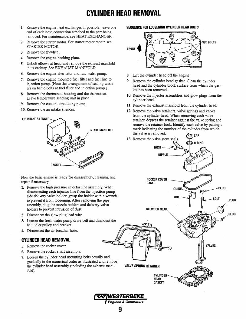
1. Remove the engine heat exchanger. If possible, leave one end of each hose connection attached to the part being removed. For maintenance, see HEAT EXCHANGER.
2. Remove the starter motor. For starter motor repair, see STARTER MOTOR
3. Remove the flywheel.
4. Remove the engine backing plate.
5. Unbolt elbows at head and remove the exhaust manifold in its entirety. See EXHAUST MANIFOLD.
6. Remove the engine alternator and raw water pump.
7. Remove the engine mounted fuel filter and fuel line to injection pump. (Note the arrangement of sealing washers on banjo bolts at fuel filter and injection pump.)
8. Remove the thermostat housing and the thermostat. Leave temperature sending unit in place.
9. Remove the coolant circulating pump.
10. Remove the air intake silencer.
INTAKE MANIFOLD
Now the basic engine is ready for disassembly, cleaning, and repair if necessary.
1. Remove the high pressure injector line assembly. When disconnecting each injector line from the injection pump side delivery valve holder, grasp the holder with a wrench to prevent it from loosening. After removing the pipe assembly, plug the nozzle holders and delivery valve holders to prevent intrusion of dust.
2. Disconnect the glow plug lead wire.
3. Loosen the fresh water pump drive belt and dismount the belt, idler pulley and bracket.
4. Disconnect the air breather hose.
CYLINDER HEAD REMOVAL 5. Remove the rocker cover.
6. Remove the rocker shaft assembly.
7. Loosen the cylinder head mounting bolts equally and gradually in the numerical order as illustrated and remove the cylinder head assembly (including the exhaust manifold).
9
SEQUENCE FOR LOOSENING CYUNDER HEAD BOLTS
SUB !JOLTS
FRONT~
8. Lift the cylinder head off the engine.
9. Remove the cylinder head gasket. Clean the cylinder head and the cylinder block surface from which the gasket has been removed.
10. Remove the injector assemblies and glow plugs from the cylinder head.
11. Remove the exhaust manifold from the cylinder head.
12. Remove the valve retainers, valve springs and valves from the cylinder head. When removing each valve retainer, depress the retainer against the valve spring and remove the retainer lock. Identify each valve by putting a mark indicating the number of the cylinder from which the valve is removed. ~CAP
13. Remove the valve stem seal. s __ · ~ ~ '.\:,YJ D-RING
HOSE~ I
NIPPLE-----/
ROCKER COVER GASKET
VALVE SPRING RETAINER
CYLINDER HEAD GASKET
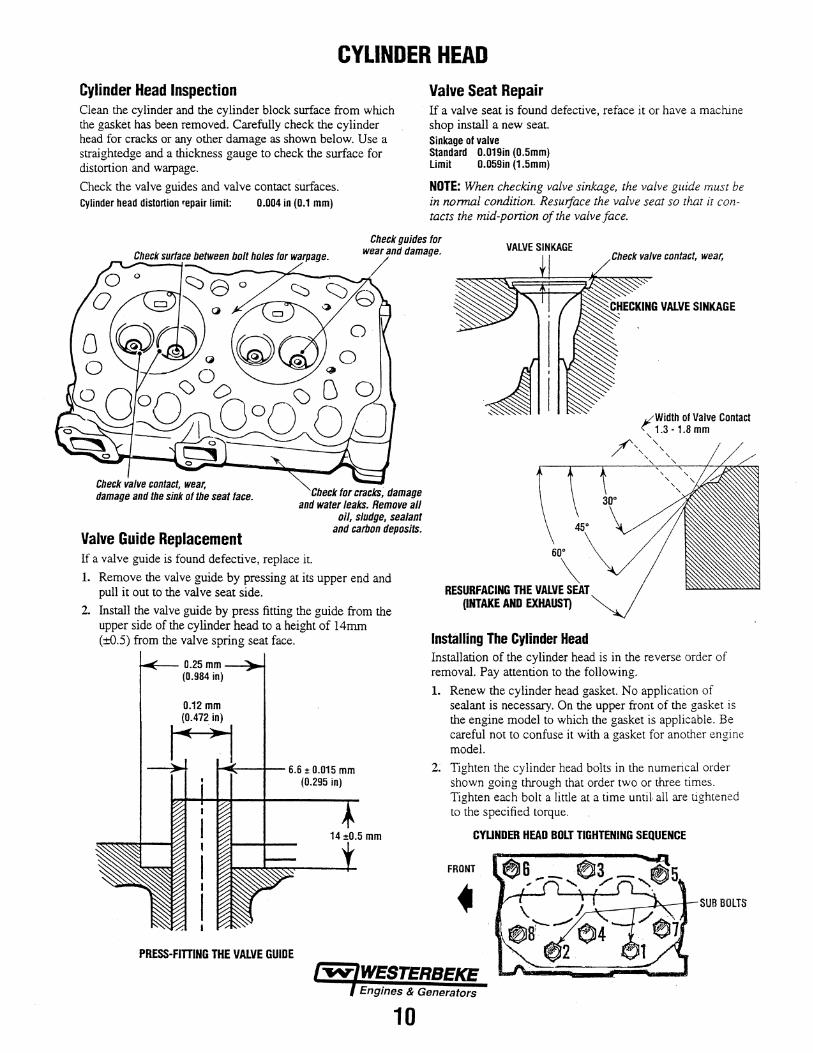
CYLINDER HEAD Cylinder Head Inspection Clean the cylinder and the cylinder block surface from which the gasket has been removed. Carefully check the cylinder head for cracks or any other damage as shown below. Use a straightedge and a thickness gauge to check the surface for distortion and warpage.
Check the valve guides and valve contact surfaces. Cylinder head distortion repair limit: 0.004 in {0.1 mm)
Valve Seat Repair If a valve seat is found defective, reface it or have a machine shop install a new seat. Sinkage of valve Standard 0.019in (0.5mm) Limit 0.059in (1.5mm)
NOTE: When checking valve sinkage, the valve guide must be in normal condition. Resurface the valve seat so that it contacts the mid-ponion ofthe valve face.
Check guides for wear and damage.
/ VALVE SINKAGE
Check valve contact, wear, damage and the sink of the seat face.
Valve Guide Replacement
Check for cracks; damage and water leaks. Remove all
oil, sludge, sealant and carbon deposits.
If a valve guide is found defective, replace it.
1. Remove the valve guide by pressing at its upper end and pull it out to the valve seat side.
2. Install the valve guide by press fitting the guide from the upper side of the cylinder head to a height of 14mm (±0.5) from the valve spring seat face.
D.25mm-~-f (0.984 in)
0.12 mm (0.472 in)
....,.l:--+-- 6.6 :1:0.015 mm (0.295 in)
PRESS-ATTING THE VALVE GUIDE
so·
\ RESURFACING THE VALVE SEAT
(INTAKE AND EXHAUST)
Installing The Cylinder Head
f'Width of Valve Contact , 1.3-1.8mm
/', ',
Installation of the cylinder head is in the reverse order of removal. Pay attention to the following.
1. Renew the cylinder head gasket. No application of sealant is necessary. On the upper front of the gasket is the engine model to which the gasket is applicable. Be careful not to confuse it with a gasket for another engine model.
2; Tighten the cylinder head bolts in the numerical order shown going through that order two or three times. Tighten each bolt a little at a time untiJ. all are tightened to the specified torque.
CYUNDER HEAD BOLT TIGHTENING SEQUENCE
FRONT
I'WIWESTERBEKE l Engines & Generators
10
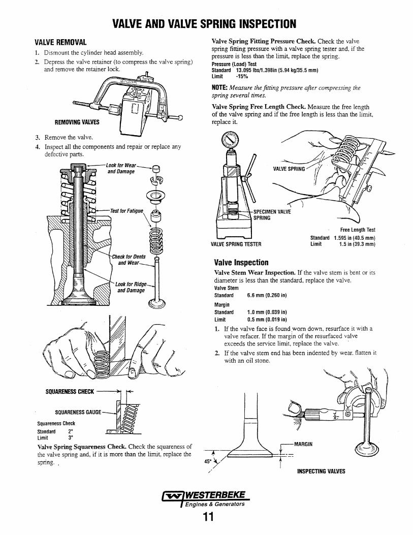
VALVE AND VALVE SPRING INSPECTION VALVE REMOVAL 1. Dismount the cylinder head assembly.
2. Depress the valve retainer (to compress the valve spring) and remove the retainer lock.
REMOVING VALVES
3. Remove the valve.
4. Inspect all the components and repair or replace any defective parts.
SQUARENESS CHECK ---'~
SQUARENESS GAUGE
Squareness Check
Standard 2• Limit 3•
Valve Spring Squareness Check. Check the squareness of the valve spring and, if it is more than the limit, replace the spring ..
Valve Spring Fitting Pressure Check. Check the valve spring fitting pressure with a valve spring tester and, if the pressure is less than the limit, replace the spring. Pressure (load) Test Standard 13.0951bs/1.398in (5.94 kg/35.5 mm) limit -15%
NOTE: Measure the fitting pressure after compressing the spring several times.
Valve Spring Free Length Check. Measure the free length of the valve spring and if the free length is less than the limit, replace it.
VAlVE SPRING TESTER
Free length Test
Standard 1.595 in (40.5 mm) limit 1.5 in (39.3 mm)
Valve Inspection Valve Stem Wear Inspection. If the valve stem is bent or its diameter is less than the standard, replace the valve. Valve Stem Standard
Margin Standard limit
6.6 mm (0.260 in)
1.0 mm (0.039 in) 0.5 mm (0.019 in)
1. If the valve face is found .worn down. resurface it with a valve refacer. If the margin of the resurfaced valve exceeds the service limit, replace the valve.
2. If the valve stem end has been indented by wear. flatten it with an oil stone.
·---:r--45. }/C:::::;:::::=:::::=::::::l:=l=-=
/ INSPECTING VALVES
WESTERBEKE Engines & Generators
11
VALVE INSTALLATION /VALVE ADJUSTMENT /INJECTION TIMING
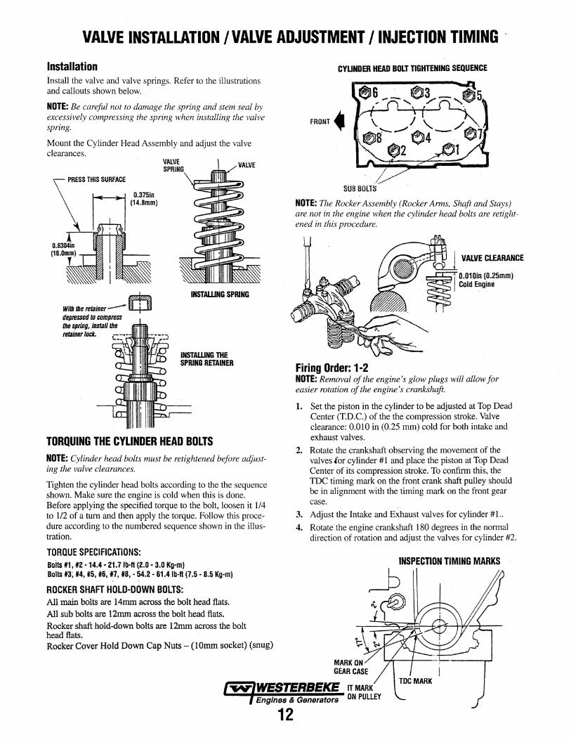
Installation Install the valve and valve springs. Refer to the illustrations and callouts shown below.
NOTE: Be careful not to damage the spring and stem seal by excessively compressing the spring when installing the valve spring.
Mount the Cylinder Head Assembly and adjust the valve clearances.
D.375in · (14.Bmm)
Witlllhe retainer--0 depresud to compress lhe spring,. instaU lhe retainer lock.
INSTALLING SPRING
INSTAlliNG THE SPRING RETAINER
TORQUING THE CYLINDER HEAD BOLTS NOTE: Cylinder head bolts must be retightened before adjusting the valve clearances.
Tighten the cylinder head bolts according to the the sequence shown. Make sure the engine is cold when this is done. Before applying the specified torque to the bolt, loosen it 1/4 to 1/2 of a turn and then apply the torque. Follow this procedure according to the numbered sequence shown in the illustration.
TORQUE SPECIFICATIONS: Bolts 11, #2 ·14.4 • 21.71b·fl (2.0 • 3.0 Kg-m) Bolts #3; #4, #5, 116, 111, 118, • 54;2 • 61.41b-ft (7 .5 • 8.5 Kg~m)
ROCKER SHAFT HOLD-DOWN BOLTS: All main bolts are 14mm across the bolt head flats. All sub bolts are 12mm across the bolt head flats. Rocker shaft hold-down bolts are 12mm across the bolt head flats. Rocker Cover Hold Down Cap Nuts- (lOmm socket) (snug)
CYUNDER HEAD BOLT TIGHTENING SEQUENCE
FRONT~.
SUB BOLTS
NOTE: The Rocker Assembly (Rocker Arms, Shaft and Stays) are not in the engine when the cylinder head bolts are retightened in tliis procedure.
VALVE CLEARANCE
Firing Order: 1·2 NOTE: Removal of the engine's glow plugs will allow for easier rotation of the engine's crankshaft.
1. Set the piston in the cylinder to be adjusted at Top Dead Center (T.D.C.) of the the compression stroke. Valve clearance: 0.010 in (0.25 nun) cold for both intake and exhaust valves.
2. Rotate the crankshaft observing the movement of the valves for cylinder #1 and place the piston at Top Dead Center of its compression stroke. To confirm this, the TDC timing mark on the front crank shaft pulley should be in alignment with the timing mark on the front gear case.
3. Adjust the Intake and Exhaust valves for cylinder #1..
4. Rotate the engine crankshaft 180 degrees in the normal direction of rotation and adjust the valves for cylinder #2.
Engines & Generators
12
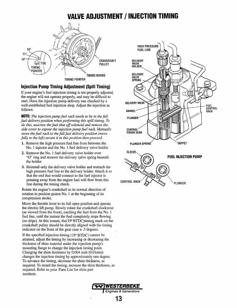
VALVE ADJUSTMENT /INJECTION TIMING
19°
CRANKSHAFT PUllEY
TIMING MARKS TIMING POINTER
Injection Pump Timing Adjustment (Spill Timing) If your engine's fuel injection timing is not properly adjusted, the engine will not operate properly, and may be difficult to start. Have the injection pump delivery rate checked by a well-established fuel injection shop. Adjust the injection as follows:
NOTE: The injection pump fuel rack needs to be in the full fuel delivery position when perfonning this spill timing. To do this, unscrew the fuel shut off solenoid and remove the side cover to expose the injection pump fuel rack. Manually move the fuel rack to the full fuel delivery position (move fully to the left) secure it in this position then proceed.
1. Remove the high pressure fuel line from between the No. 1 injector and the No. 1 fuel delivery valve holder.
2. Remove the No. 1 fuel delivery valve holder over "0" ring and remove the delivery xalve spring beneath the holder.
3. Reinstall only the delivery valve holder and reattach the high pressure fuel line to the delivery holder. Attach it so that the end that would connect to the fuel injector is pointing away from the engine fuel will flow from this line during the timirig check.
Rotate the.engine's crankshaft in its normal direction of rotation to position piston No. 1 at the beginning of itS compression stroke. Move the throttle lever to its full open position and operate the electric lift pump. Slowly rotate the crankshaft clockwise (as viewed from the front), catching the fuel from the No. 1 fuel line, until the instant the fuel completely stops flowing (no drips). At this instant, the(19" BTDC)timing mark on the crankshaft pulley should be directly aligned with the timing indicator on the front of the gear case ± .5 degrees.
If the specified injection timing ( 19" BTDC) cannot be attained, adjust the timing by increasing or decreasing the thickness of shim material under the injection pump's mounting flange to change the injection timing point. Changing the shim thickness by 0.004 inch (0.01mm) changes the injection timing by approximately one degree. To advance the timing, decrease the shim thickness, as required. To retard the timing, increase the shim thickness, as. required. Refer to your Parts List for shim part numbers.
13
FUEL INJECTION PUMP
PlUNGER
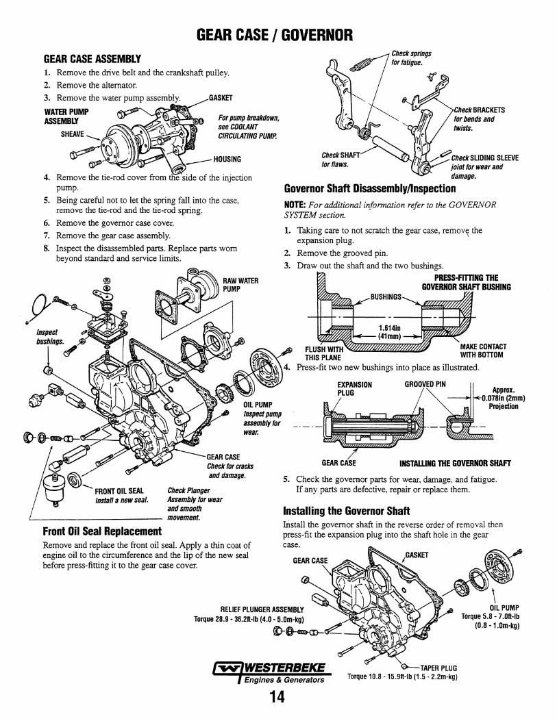
GEAR CASE I GOVERNOR GEAR CASE ASSEMBLY 1. Remove the drive belt and the crankshaft pulley.
2. Remove the alternator.
3. Remove the water pump assembly. GASKET
WATER PUMP ASSEMBLY
SHEAVE --.. ·~ •1 ~ .
For pump breakdown, see COOLANT CIRCULAnNG PUMP.
~- ~'-~1/JJff>..~.....-
4. Remove the tie-rod cover from ffie side of the injection pump.
5. Being careful not to let the spring fall into the case, remove the tie-rod and the tie-rod spring.
6. Remove the governor case cover.
7. Remove the gear case assembly.
8. Inspect the disassembled parts. Replace parts worn beyond standard and service limits.
wear.
and damage.
Check Plunger Assembly for wear and smooth
L------------- movement.
Front Oil Seal Replacement
Check springs tor fatigue.
Check BRACKETS for bends and twists.
'W'~ l~~
Check SHAFT,........- ~ ':1 /~Check SLIDING SLEEVE for flaws. 1 joint for wear and
damage.
Governor Shaft Disassembly/Inspection NOTE: For additional information refer to the GOVERNOR SYSTEM section.
1. Taking care to not scratch the gear case, remove the expansion plug. \
2. Remove the grooved pin.
3. Draw out the shaft and the two bushings.
FLUSH WITH THIS PLANE
PRESS·Fm'ING THE GOVERNOR SHAFT BUSHING
Press-fit two new bushings into place as illustrated.
EXPANSION PLUG
GROOVED PIN
INSTAWNG THE GOVERNOR SHAFT
5. Check the governor parts for wear, damage, and fatigue. If any parts are defective, repair or replace them.
Installing the Governor Shaft Install the governor shaft in the reverse order of removal then press-fit the expansion plug into the shaft hole in the gear
Remove and replace the front oil seal. Apply a thin coat of case. engine oil to the circumference and the lip of the new seal before press-fitting it to the gear case cover.
14
0--TAPER PLUG Torque 10.8 ·15.9H·Ib (1.5- 2.2m-kg)
OIL PUMP Torque 5.8 - 7 .OH-Ib
(0.8 - 1.0m-kg)
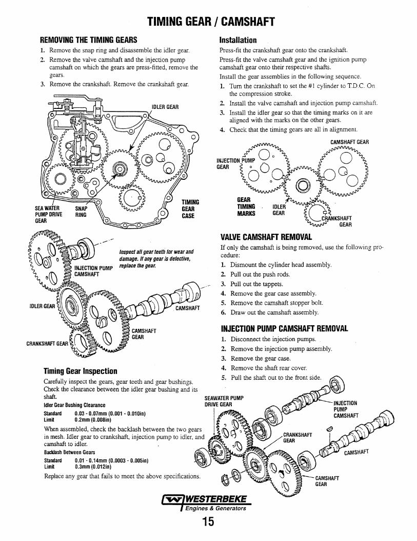
TIMING GEAR I CAMSHAFT REMOVING THE TIMING GEARS 1. Remove the snap ring and disassemble the idler gear.
2. Remove the valve camshaft and the injection pump camshaft on which the gears are press-fitted, remove the gears.
3. Remove the crankshaft. Remove the crankshaft gear.
-.-
Timing Gear Inspection
TIMING GEAR CASE
Inspect all gear teelli tor wear and damage. If any gear is defective, replace the gear.
Carefully inspect the gears, gear teeth and gear bushings. Check the clearance between the idler gear bushing and its shaft. Idler Gear Bushing Clearance
standard 0.03- 0.07mm (0.001 - 0.010in) Limit 0.2mm (O.OOSin)
When assembled, check the backlash between the two gears in mesh. Idler gear to crankshaft, injection pump to idler, and camshaft to idler. Backlash Between Gears
Standard 0.01 • 0.14mm (0.0003- 0.005in) 0.3mm (0.012in)
15
Installation Press-fit the crankshaft gear onto the crankshaft.
Press-fit the valve camshaft gear and the ignition pump camshaft gear onto their respective shafts.
Install the gear assemblies in the following sequence.
1. Turn the crankshaft to set the #1 cylinder to T.D.C. On the compression stroke.
2. Install the valve camshaft and injection pump camshaft.
3. Install the idler gear so that the timing marks on it are aligned with the marks on the other gears.
4. Check that the timing gears are all in alignment.
GEAR TIMING MARKS
VALVE CAMSHAFT REMOVAL If only the camshaft is being removed, use the following procedure:
1. Dismount the cylinder head assembly.
2. Pull out the push rods.
3. Pull out the tappets.
4. Remove the gear case assembly.
5. Remove the camshaft stopper bolt.
6. Draw out the camshaft assembly.
INJECTION PUMP CAMSHAFT REMOVAL 1. Disconnect the injection pumps.
2. Remove the injection pump assembly.
3. Remove the gear case.
4. Remove the shaft rear cover.
5. Pull the shaft out to the front side.
.INJECTION PUMP CAMSHAFT
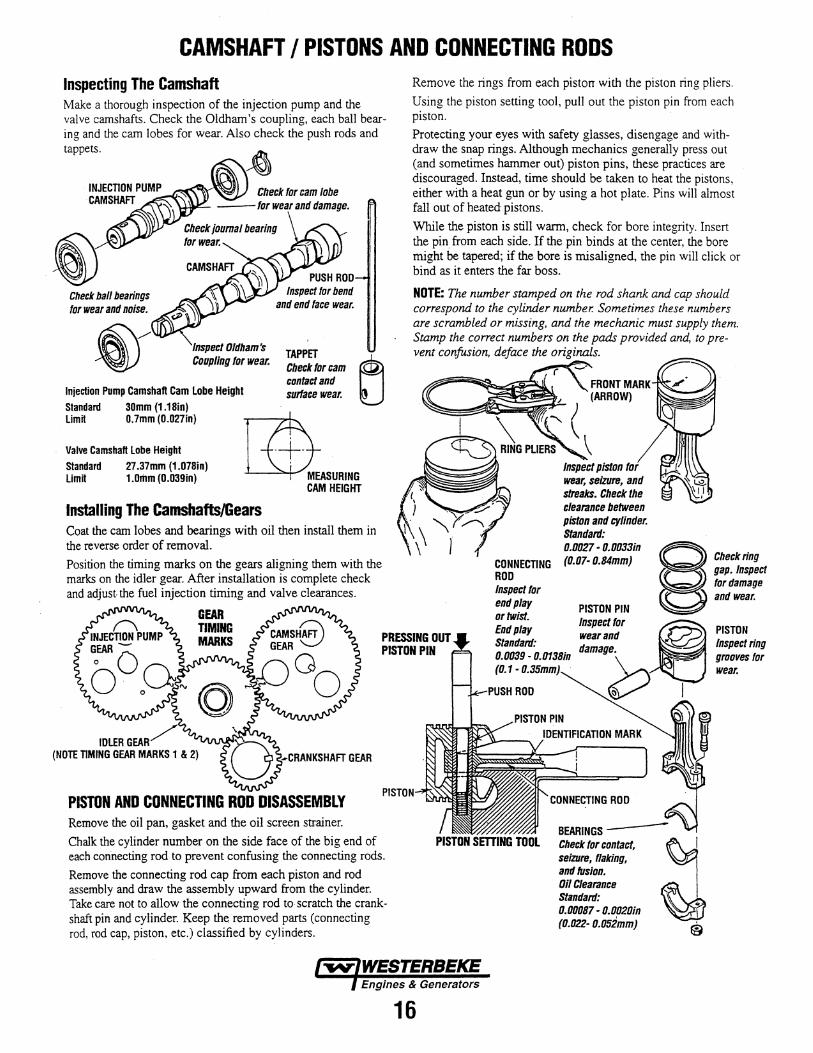
CAMSHAFT I PISTONS AND CONNECTING RODS Inspecting The Camshaft Make a thorough inspection of the injection pump and the valve camshafts. Check the Oldham's coupling, each ball bearing and the cam lobes for wear. Also check the push rods and tappets.
Check ball bearings for wear and noise.
Check for cam lobe -for wear and damage.
Inspect Oldham's Coupling for wear. TAPPET
Check for cam contact and surface wear. Injection Pump Camshaft Cam Lobe Height
Standard 30mm (1.18in) Limit 0.7mm (0.027in)
Valve Camshaft Lobe Height Standard 27.37mm (1.078in) Limit 1.0rtlm (O.D39in)
r7t\ t..m:ASURING
CAM HEIGHT
Installing The Camshafts/Gears Coat the cam lobes and bearings with oil then install them in the reverse order of removal.
Position the timing marks on the gears aligning them with the marks on the idler gear. After installation is complete check and adjust the fuel injection timing and valve clearances.
Remove the rings from each pistorr with the piston ring pliers. Using the piston setting tool, pull out the piston pin from each piston. Protecting your eyes with safety glasses, disengage and withdraw the snap rings. Although mechanics generally press out (and sometimes hammer out) piston pins, these practices are discouraged. Instead, time should be taken to heat the pistons, either with a heat gun or by using a hot plate. Pins will almost fall out of heated pistons.
While the piston is still warm, check for bore integrity. Insert the pin from each side. If the pin binds at the center, the bore might be tapered; if the bore is misaligned, the pin will click or bind as it enters the far boss.
NOTE: The number stamped on the rod shank and cap should correspond to the cylinder number. Sometimes these numbers are scrambled or missing, and the mechanic must supply them. Stamp the correct numbers on the pads provided and, to prevent confusion, deface the originals.
CONNECTING ROD Inspect for end play or twist.
Inspect piston for wear, seizure, and streaks. Check the clearance between piston and cylinder. Standarrl: 0.0027 • 0.0033/n (0.07· 0.84mm)
PISTON PIN
§ ~:;~~n~;!ct for damage and wear.
PRESSING OUT PISTON PIN
End play Standard: 0.0039- 0.0138/n (0.1 - 0.35mm)
Inspect lor ~ PISTON wear and damage. Inspect ring
grooves for
IDLER GEAR/ (NOTE TIMING GEAR MARKS 1 & 2) -CRANKSHAFT GEAR
PISTON AND CONNECTING ROD DISASSEMBLY PISTON
Remove the oil pan, gasket and the oil screen strainer.
Chalk the cylinder number on the side face of the big end of each connecting rod to prevent confusing the connecting rods.
Remove the connecting rod cap from each piston and rod assembly and draw the assembly upward from the cylinder. Take care not to allow the connecting rod to scratch the crankshaft pin and cylinder. Keep the removed parts (connecting rod, rod cap, piston, etc.) classified by cylinders.
16
- wear.
o I
BEARINGS-PISTON SETTING TOOL Check tor contact,
seiziJre, flaking, and fusion. Oil Clearance Standard: 0.00087 • 0.0020/n {0.022- o.osimm)
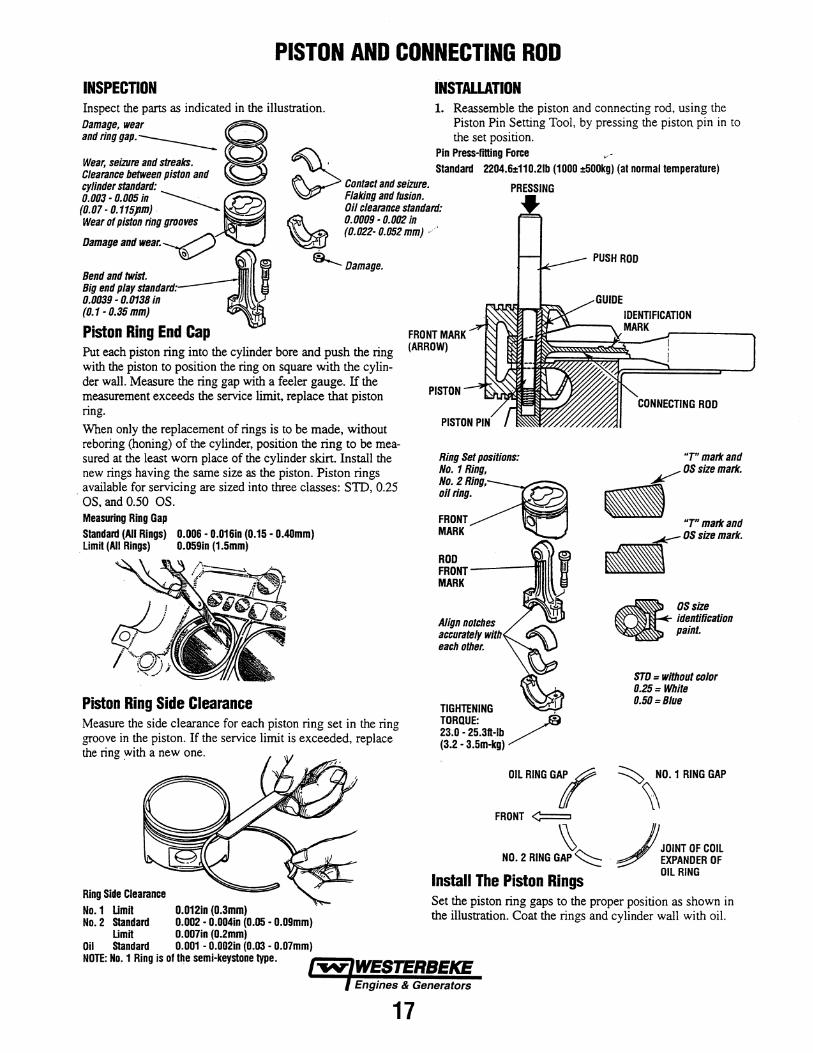
PISTON AND CONNECTING ROD INSPECTION
Put each piston ring into the cylinder bore and push the ring with the piston to position the ring on square with the cylinder wall. Measure the ring gap with a feeler gauge. If the measurement exceeds the service limit, replace that piston ring.
When only the replacement of rings is to be made, without reboring (honing) of the cylinder, position the ring to be measured at the least worn place of the cylinder skirt. Install the new rings having the same size as the piston. Piston rings
. available for servicing are sized into three classes: SID, 0.25 OS, and 0.50 OS. Measuring Ring Gap Standard (All Rings) 0.006 • O.D16in (0.15- 0.40mm) Limit (All Rings) 0.059in (1.5mm)
Piston Ring Side Clearance Measure the side clearance for each piston ring set in the ring groove in the piston. If the service limit is exceeded, replace the ring ~ith a new one.
Ring Side Clearance No. 1 Limit 0.012in (0.3mm) No. 2 Standard 0.002 • 0.004in (0.05 • 0.09mm)
Limit 0.007in (0.2mm) Oil Standard 0.001 • 0.002in (0.03 • 0.07mm) NOTE: No. 1 Ring is of the semi-keystone type. ~111111111111-.
INSTALLATION
PUSH ROD
FRONT MARK (ARROW)
PISTON
Ring Set positions: No.1 Ring, No. 2R::=@"ng, oil ring.
FRONT MARK
ROD FRONT -----111111 MARK
Align notches accurately with each other.
TIGHTENING , TORQUE: / 23.0 • 25.3ft·lb (3.2 • 3.5m-kg)
OILRING'l
FRONT~
~ NO.2 RING GAP~
Install The Piston Rings
"T"markand ~OS size mark.
- "T" mark and
... ""'mad<
OS size identiOcation paint.
STO = without color 0.25= White 0.50=Biue
~ NO. 1 RING GAP
~ JJ JOINT OF COIL
/ EXPANDER OF OIL RING
Set the piston ring gaps to the proper position as shown in the illustration. Coat the rings and cylinder wall with oil.
17
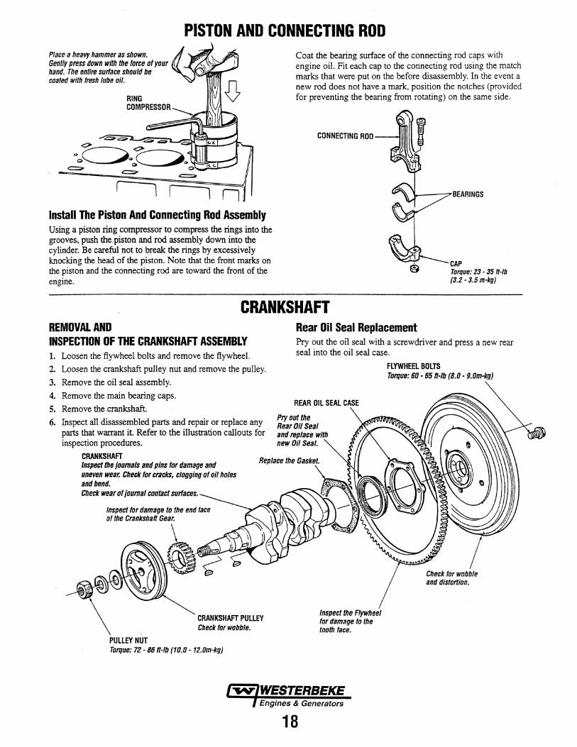
PISTON AND CONNECTING ROD Place a heavy hammer as shown. Gently press down with the Ioree of your hand. The entire surface should be coated with fresh lube oil.
l l Install The Piston And Connecting Rod Assembly Using a piston ring compressor to compress the rings into the grooves, push the piston and rod assembly down into the cylinder. Be careful not to break the rings by excessively knocking the head of the piston. Note that the front marks on the piston and the connecting rod are toward the front of the engine.
Coat the bearing surface of the connecting rod caps with engine oil. Fit each cap to the connecting rod using the match marks that were put on the before disassembly. In the event a new rod does not have a mark, position the notches (provided for preventing the bearing from rotating) on the same side ..
CAP Torque: 23 - 35 ft-lb (3.2 - 3.5 m-kg)
CRANKSHAFT REMOVAL AND INSPECTION OF THE CRANKSHAFT ASSEMBLY 1. Loosen the flywheel bolts and remove the flywheel.
2. Loosen the crankshaft pulley nut and remove the pulley.
3. Remove the oil seal assembly.
4. Remove the main bearing caps.
5. Remove the crankshaft.
6. Inspect all disassembled parts and repair or replace any parts that warrant it Refer to the illustration callouts for inspection procedures.
CRANKSHAFT Inspect the journals and pins for damage and uneven wear. Check for crac/c$, clogging of o/1 holes and b(Jnd. Check wear of joumat contact surfaces.
Inspect for damage to the end face of the Crankshaft Gear.
\
Check for wobble.
PULLEY NUT Torque: 72- 86 R-Ib (10.0- 12.0m-kg)
Rear Oil Seal Replacement Pry out the oil seal with a screwdriver and press a new rear seal into the oil seal case.
Pryoutthe Rear Oil Seal and replace with new Oil Seal.
18
FLYWHEEL BOLTS Torque: 60- 65 R-Ib (8.0 • 9.0m·kg)
Check for wobble and distortion.
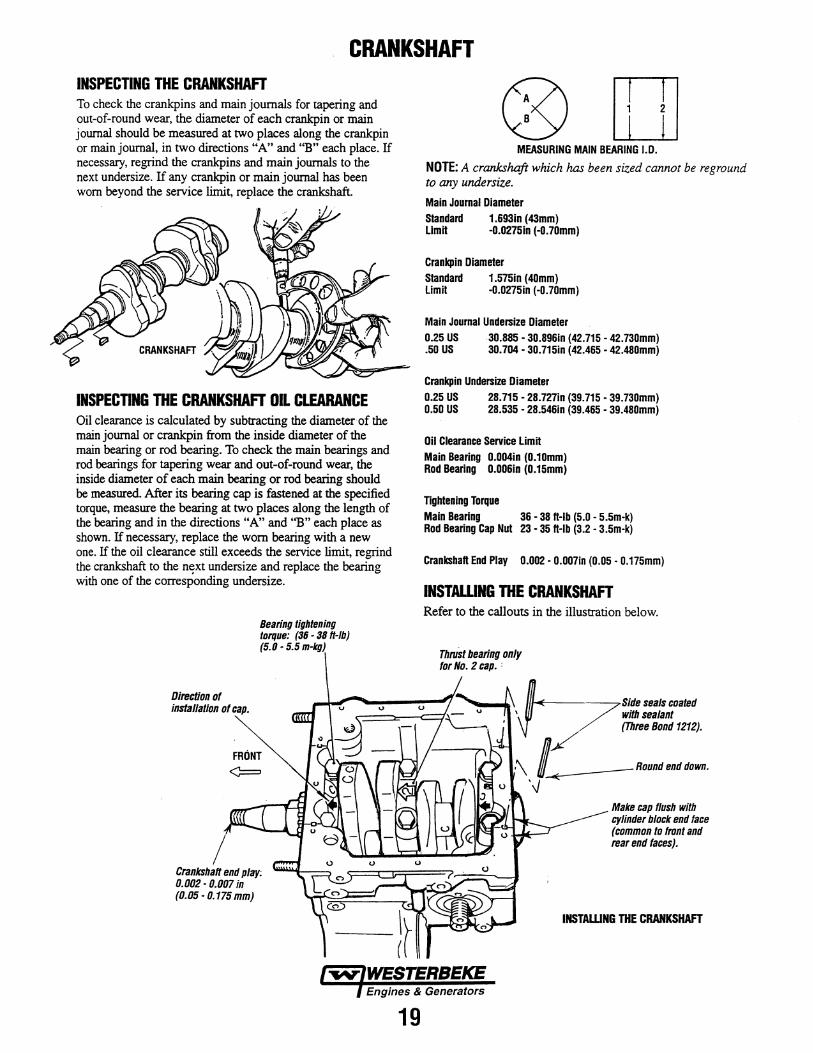
CRANKSHAFT INSPECTING THE CRANKSHAFT To check the crankpins and main journals for tapering and out-of-round wear, the diameter of each crankpin or main journal should be measured at two places along the crankpin or main journal, in two directions "A" and "B" each place. If necessary, regrind the crankpins and main journals to the next undersize. If any crankpin or main journal has been worn beyond the service limit, replace the crankshaft.
INSPECTING THE CRANKSHAFT OIL CLEARANCE Oil clearance is calculated by subtracting the diameter of the main journal or crankpin from the inside diameter of the main bearing or rod bearing. To check the main bearings and rod bearings for tapering wear and out-of-round wear, the inside diameter of each main bearing or rod bearing should be measured. After its bearing cap is fastened at the specified torque, measure the bearing at two places along the length of the bearing and in the directions "A" and "B" each place as shown. If necessary, replace the worn bearing with a new one. If the oil clearance still exceeds the service limit, regrind the crankshaft to the next undersize and replace the bearing with one of the corresponding undersize.
Direction of installation of cap.
Bearing tightening torque: (36 - 38 ft-lb) (5.0- 5.5 m-kg)
FRONT ¢:=
Crankshaft end play; 0.002 - 0.007 in (0.05- 0.175 mm)
19
®[] MEASURING MAIN BEARING J.D.
NOTE: A crankshaft which has been sized cannot be reground to any undersize.
Main Journal Diameter Standard 1.693in (43mm) Limit -o.0275in (-D.7Dmm)
Crankpin Diameter Standard 1.575in (4Dmm) Limit -o.0275in (-0.7Dmm)
Main Journal Undersize Diameter 0.25 US 30.885- 30.896in (42.715- 42.73Dmm) .50 US 30.704- 30.715in (42.465 • 42.48Dmm)
Crankpin Undersize Diameter 0.25 US 28.715 • 28.727in (39.715- 39.73Dmm) 0.50 US 28.535 • 28.5461n (39.465 • 39.48Dmm)
Oil Clearance Service LimH Main Bearing D.OD4in (0.1Dmm) Rod Bearing O.OD6in (0.15mm)
Tightening Torque
Main Bearing 36 • 38 ft·lb (5.0 - 5.5m-k) Rod Bearing Cap Nut 23 - 35 ft-lb (3.2 • 3.5m-k)
Crankshaft End Play 0.002- D.DD7in (0.05- 0.175mm)
INSTALLING THE CRANKSHAFT Refer to the callouts in the illustration below.
ThrUst bearing only for No. 2 cap. :
~-• bS/desealscoated ' with sealant
• (Three Bond 1212). \ J: _.-........ \j~
Make cap /lush with cylinder block end face (common to front and rear end faces).
INSTAWNG THE CRANKSHAFT
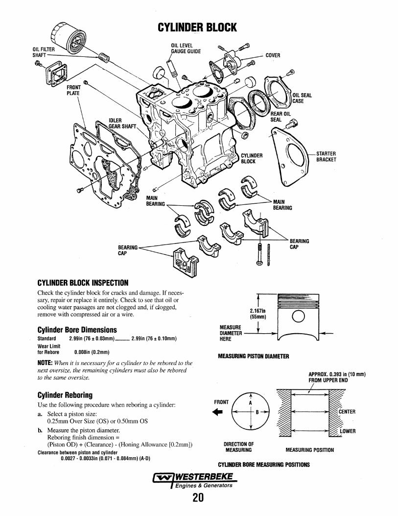
CYLINDER BLOCK
BEARING ~-----k~ CAP
CYLINDER BLOCK INSPECTION Check the cylinder block for cracks and damage. If necessary, repair or replace it entirely. Check to see that oil or cooling water passages are not clogged and, if clogged, remove with compressed air or a wire.
Cylinder Bore Dimensions Standard Wear Limit for Rebore
2.99in (76 ± 0.03mm) __ 2.99in (76 ± 0.10mm)
0.008in (0.2mm)
NOTE: When it is necessary for a cylinder to be rebored to the next oversize, the remaining cylinders must also be rebored · to the same oversize.
Cylinder Reboring Use the following procedure when reboring a cylinder:
a. Select a piston size: 0.25mm Over Size (OS) or 0.50mm OS
b. Measure the piston diameter. Reboring finish dimension = (Piston OD) +(Clearance)- (Honing Allowance [0.2mm])
Clearance between piston and cylinder 0.0027 - 0.0033in (0.071 - 0.084mm) (A-D)
20
rt-----lf-'---,.. BEARING CAP
STARTER BRACKET
2.1c-·~o~-.-· -__
(55mm)
MEASURE DIAMETER----'--~ .---HERE
MEASURING PISTON DIAMETER
FRONTm ·w DIRECTION OF MEASURING
APPROX. 0.393 in (10 mm) FROM UPPER END
MEASURING POSITION
CYUNDER BORE MEASURING POSITIONS
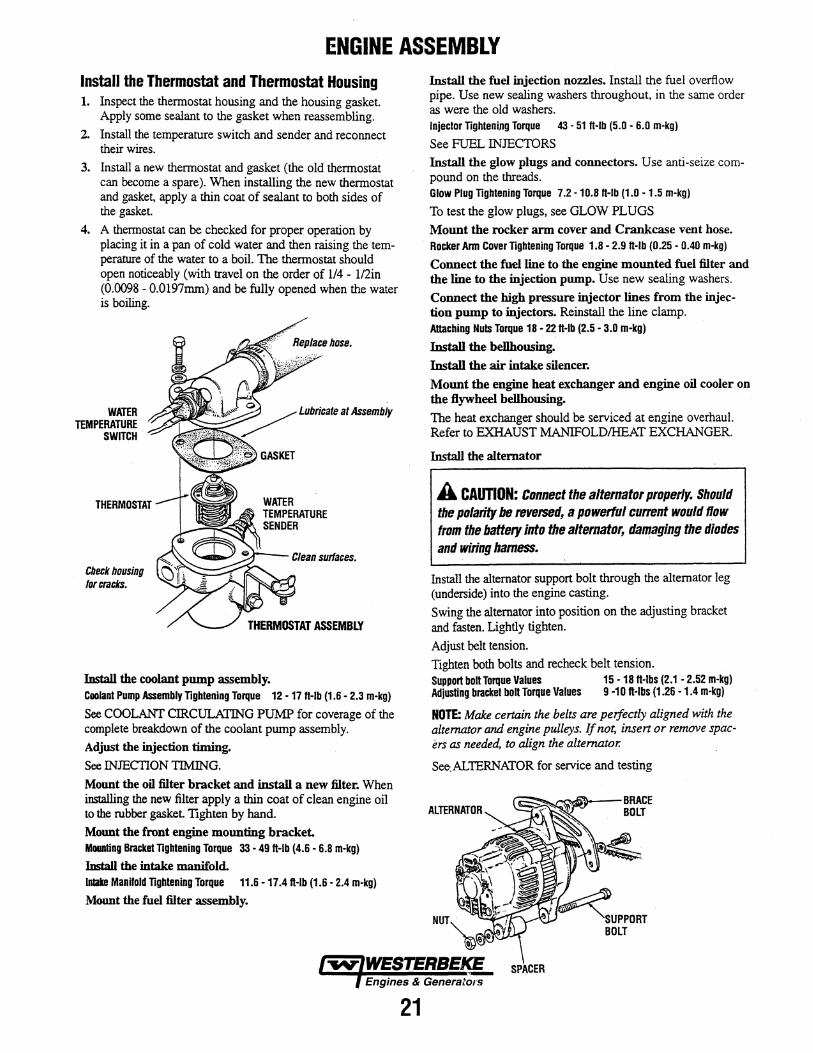
ENGINE ASSEMBLY Install the Thermostat and Thermostat Housing 1. Inspect the thermostat housing and the housing gasket.
Apply some sealant to the gasket when reassembling.
2. Install the temperature switch and sender and reconnect their wires.
3. Install a new thermostat and gasket (the old thermostat can become a spare). When installing the new thermostat and gasket, apply a thin coat of sealant to both sides of the gasket.
4. A thermostat can be checked for proper operation by placing it in a pan of cold water and then raising the temperature of the water to a boil. The thermostat should open noticeably (with travel on the order of 114- l/2in (0.0098- 0.0197mm) and be fully opened when the water is boiling.
WATER TEMPERATURE
SWITCH
THERMOSTAT
Check housing tor cracks.
Install the coolant pump assembly.
Lubricate at Assembly
Coolant Pump Assembly Tightening Torque 12 - 11 ft·lb (1.6- 2.3 m-kg)
See COOLANf CIRCULATING PUMP for coverage of the complete breakdown of the coolant pump assembly.
Adjust the injection timing.
See INJECTION TIMING.
Mount the oil filter bracket and install a new filter. When installing the new filter apply a thin coat of clean engine oil to the rubber gasket. Tighten by hand.
Mount the front engine mounting bracket. Mounting Bracket Tightening Torque 33 - 49 ft-lb (4.6 - 6.8 m-kg)
Install the intake manifold. lnlake Manifold Tightening Torque 11.6 - 17.4 n-Ib (1.6 • 2.4 m-kg)
Mount the fuel filter assembly.
21
Install the fuel injection nozzles. Install the fuel overflow pipe. Use new sealing washers throughout, in the same order as were the old washers. Injector Tightening Torque 43 • 51 ft-lb (5.0 - 6.0 m-kg)
See FUEL INJECTORS
Install the glow plugs and connectors. Use anti-seize compound on the threads. Glow Plug Tightening Torque 7.2- 10.8 ft-lb (1.0- 1.5 m-kg)
To test the glow plugs, see GLOW PLUGS
Mount the rocker arm cover and Crankcase vent hose. Rocker Arm Cover Tightening Torque 1.8 - 2.9 ft·lb (0.25 - 0.40 m-kg)
Connect the fuel line to the engine mounted fuel filter and the line to the injection pump. Use new sealing washers.
Connect the high pressure injector lines from the injection pump to injectors. Reinstall the line clamp. Attaching Nuts Torque 18- 22 fl-lb (2.5- 3.0 m-kg)
Install the bellhousing.
Install the air intake silencer.
Mount the engine heat exchanger and engine oil cooler on the flywheel bellhousing.
The heat exchanger should be serviced at engine overhaul. Refer to EXHAUST MANIFOLD/HEAT EXCHANGER.
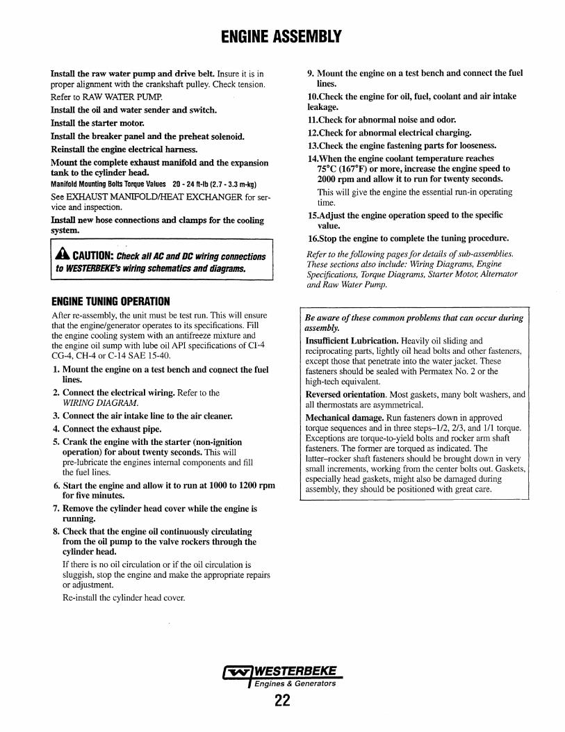
Install the alternator
A CAUTION: Connect the alternator properly. Should the polarity be reversed, a powerful current would flow from the battery into the alternator, damaging the diodes and wiring harness.
Install the alternator support bolt through the alternator leg (underside) into the engine casting.
Swing the alternator into position on the adjusting bracket and fasten. Lightly tighten.
Adjust belt tension.
Tighten both bolts and recheck belt tension. Support bolt Torque Values 15-18 fl-lbs (2.1 -2.52 m-kg) Adjusting bracket bolt Torque Values 9 ·1 0 n-Ibs (1.26 -1.4 m-kg)
NOTE: Make certain the belts are peifectly aligned with the alternator and engine pulleys. If not, insert or remove spacers as needed, to align the alternator.
See-.AL1ERNATOR for service and testing
ENGINE ASSEMBLY
Install the raw water pump and drive belt. Insure it is in proper alignment with the crankshaft pulley. Check tension.
Refer to RAW WATER PUMP.
Install the oil and water sender and switch.
Install the starter motor.
Install the breaker panel and the preheat solenoid.
Reinstall the engine electrical harness.
Mount the complete exhaust manifold and the expansion tank to the cylinder head. Manifold Mounting Bolts Torque Values 20 - 24 H-lb (2. 7 - 3.3 m-kg)
See EXHAUST MANIFOLD/HEAT EXCHANGER for service and inspection.
Install new hose connections and clamps for the cooling system.
A CAUTION: Check all AC and DC wiring connections to WESTERBEKE's wiring schematics and diagrams.
ENGINE TUNING OPERATION After re-assembly, the unit must be test run. This will ensure that the engine/generator operates to its specifications. Fill the engine cooling system with an antifreeze mixture and the engine oil sump with lube oil API specifications of CI-4 CG-4, CH-4 or C-14 SAE 15-40.
1. Mount the engine on a test bench and cm;mect the fuel lines.
2. Connect the electrical wiring. Refer to the WIRING DIAGRAM.
3. Connect the air intake line to the air cleaner.
4. Connect the exhaust pipe.
5. Crank the engine with the starter (non-ignition operation) for about twenty seconds. This will pre-lubricate the engines internal components and fill the fuel lines.
6. Start the engine and allow it to run at 1000 to 1200 rpm for five minutes.
7. Remove the cylinder head cover while the engine is running.
8. Check that the engine oil continuously circulating from the oil pump to the valve rockers through the cylinder head.
If there is no oil circulation or if the oil circulation is sluggish, stop the engine and make the appropriate repairs or adjustment.
Re-install the cylinder head cover.
22
9. Mount the engine on a test bench and connect the fuel lines.
10.Check the engine for oil, fuel, coolant and air intake leakage.
11.Check for abnormal noise and odor.
12.Check for abnormal electrical charging.
13.Check the engine fastening parts for looseness.
14.When the engine coolant temperature reaches 75°C (167°F) or more, increase the engine speed to 2000 rpm and allow it to run for twenty seconds.
This will give the engine the essential run-in operating time.
15.Adjust the engine operation speed to the specific value.
16.Stop the engine to complete the tuning procedure.
Refer to the following pages for details of sub-assemblies. These sections also include: Wiring Diagrams, Engine Specifications, Torque Diagrams, Starter Motor, Alternator and Raw Water Pump.
Be aware of these common problems that can occur during assembly.
Insufficient Lubrication. Heavily oil sliding and reciprocating parts, lightly oil head bolts and other fasteners, except those that penetrate into the water jacket. These fasteners should be sealed with Permatex No. 2 or the high-tech equivalent.
Reversed orientation. Most gaskets, many bolt washers, and all thermostats are asymmetrical.
Mechanical damage. Run fasteners down in approved torque sequences and in three steps-1/2, 2/3, and 1/1 torque. Exceptions are torque-to-yield bolts and rocker arm shaft fasteners. The former are torqued as indicated. The latter-rocker shaft fasteners should be brought down in very small increments, working from the center bolts out. Gaskets, especially head gaskets, might also be damaged during assembly, they should be positioned with great care.
TORQUE SPECIFICATIONS .. COMPONENT FHB(M-KG)
Alternator Bracket .......................... 27 - 38 (3.8 - 5.3)
Back Plate ...................................... 24 - 35 (3.3 - 4.8)
Connecting Rod Cap M8 (14) ...... 23- 28.2 (3.2- 3.5)
Cooiant Pump ................................ 12- 17 (1.6 - 2.4)
Coolant Pump Pulley .•.................... 12 -17 (1.6- 2.4)
Coolant Temperature Sender ........ 9 - 13 (1.2 - 1.8)
Coolant Temperature Switch .......... 9 - 13 (1.2 - 1.8)
Crankshaft Pulley Nut, M16 (24) .. 72 - 86 (1 0 - 12)
*Cylinder Head Bolts (wet) M8 (12) Bolts 1, 2, 3 ................ 14 -21 (2.0- 3.0) M1 0 (14) Bolts 4- 11 .............. 54 - 61 (7.8- 8.5)
Cylinder Head Cover ...................... 2 - 3 (0.3 - 0.45)
Engine Mounts .............................. 23 - 34 (3.2 - 4. 7)
Exhaust Manifold ............................ 20- 24 (2.7- 3.3)
Fuel Solenoid Locknut M30 (36) .................................... 28.9- 36.2 (4.0- 5.0)
Flywheel bolt M1 0 (17) .................. 61 - 68 (8.5 - 9.5)
Glow Plug, M1 0 (12) ...................... 11 - 14.5 (1.5 - 2.0)
Glow Plug Lead Wire Frtting Nut, . M4 (7) ........................................ 0.7 -1.0 (0.1 - 0.15)
Governor Assembly Relief Plunger Assembly ......... 28.9- 36.2 (4.0 - 5.0) Taper Plug ................................... 11 - 23 (1.5 - 2.2)
Idler Gear Thrust Plate .................. 15 - 23 (2.2 - 3.2)
Injection Nozzle to Body ................ 25.3- 36.2 (3.5- 4.0)
Injection Pipe Flare Nut .................. 18 - 22 (2.5 - 3.0)
Injection Pipe Nut, M12 (17) ........ 18 - 25 (2.5 - 3.5)
Injection Pump Delivery Valve Holder M16 (17) .................................... 25.3 - 28.2 (3.5 - 3.9)
Injection Pump Drive Gear Lock Nut ........................................ 29- 51 (4.0- 7.0)
NOTE: Hardware listed is metric, with values given as follows: Flywheel Bolt, M1 0 (17)
M1 0 indicates Metric, 1 Omm thread diameter; (17) indicates 17mm across the flats ofthe bolt head.
*(wet) indicates that the bolts (if removed) are to have a thin oil film wiped on them before they are retorqued.lfthe bolts have not been removed and need only to be retorqued, then no oil is needed.
COMPONENT FT-LB (M-KG)
Injection Pump Hollow Screw M10 (14) ................................... .7.2- 10.8 (1.0- 1.5)
Injectors .......................................... 36 - 38 (5.0 - 6.0)
Intake Manifold .............................. 12 -17 (1.6- 2.4)
Main Bearing Cap .......................... 36 - 38 (5.0 - 5.5)
Nozzle Holder (fitting to engine), M20 (21) .................................... 36.1 - 43.3 (5.0 - 6.0)
Nozzle Retaining Nut, M16 (21) .................................... 25.3 - 28.9 (3.5 - 4.0)
Nozzle Union Color Fixing Nut, M12 (17) .................................... 18.0- 21.6 (2.5 -3.0)
Oil Drain Hose Plug M18 (19) ...... 36.1 - 43.3 (5.0 - 6.0)
Oil Filter M20 (17) ................................... .7.9- 9.4 (1.1- 1.3)
Oil Pan Bolts ........•......................... 12 - 17 (1.6 - 2.3)
Oil Pressure Sender ...................... 9- 13 (1.2 -1.8)
Oil Pressure Switch ........................ 9 - 13 (1.2 - 1.8)
Oil Relief Plug ................................ 28.9- 36.1 (4.0- 5.0)
Rear Oil Seal Cap ............................ 11 - 14 (1.5 - 2.0)
Rocker Arm Assembly .................. 11 - 15 (1.5 - 2.2)
Rocker Arm Cover .......................... 1.8- 2.9 (0.25- 0.40)
Rocker Cover Nut, M6 (1 0) .......... 3.6 - 5.0 (0.5 - 0. 7)
Rocker Shaft Hold-down Bolt, M8 (12) ...................................... 10.8 -15.9 (1.5- 2.2)
Thermostat Housing ...................... 6 - 8 (0.8 - 1.1)
Timing Gear Case ....................... ~ .. 12- 17 (1.6 - 2.4)
Torque Spring Set Locknut ............ 6 - 9 (0.8 - 1.2)
Water Temperature Gauge Joint M16 (17) .................................... 14.4- 21.6 (4.0- 5.0)
23
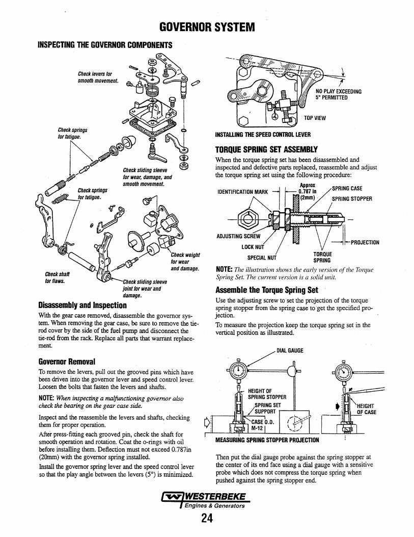
GOVERNOR SYSTEM INSPECTING THE GOVERNOR COMPONENTS
Check levers for smooth movement.
Check springs for fatigue.
Check sliding sleeve for wear. damage, and smooth movement.
Check sliding sleeve joint for wear and damage.
Check weight for wear and damage.
Disassembly and Inspection With the gear case removed, disassemble the governor system. When removing the gear case, be sure to remove the tierod cover by the side of the fuel pump and disconnect the tie-rod from the rack. Replace all parts that warrant replacement.
Governor Removal To remove the levers, pull out the grooved pins which have been driven into the governor lever and speed control lever. Loosen the bolts that fasten the levers and shafts.
NOTE: When inspecting a malfunctioning governor also check the bearing on the gear case side.
Inspect and the reassemble the levers and shafts, checking them for proper operation. After press-fitting each grooved pin, check the shaft for smooth operation and rotation. Coat the o-rings with oil before installing them. Deflection must not exceed 0.787in (20mm) with the governor spring installed. Install the governor spring lever and the speed control lever so that the play angle between the levers (5°) is minimized.
24
INSTAWNG THE SPEED CONTROL LEVER
TORQUE SPRING SET ASSEMBLY When the torque spring set has been disassembled and inspected and defective parts replaced, reassemble and adjust the torque spring set using the following procedure:
Approx I--; 0.7~~if_ /SPRING CASE
I ~ (2/ /PRING STOPPER
ADJUSTING SCREW
SPECIAL NUT
NOTE: The illustration shows the early version of the Torque Spring Set. The current version is a solid unit.
Assemble the Torque Spring Set Use the adjusting screw to set the projection of the torque spring stopper from the spring case to ·get the specified projection.
To measure the projection keep the torque spring set in the vertical position as illustrated.
I
MEASURING SPRING STOPPER PROJECTION
Then put the dial gauge probe against the spring stopper at the center of its end face using a dial gauge with a sensitive probe which does not compress the torque spring when pushed against the spring stopper end.
GOVERNOR SYSTEM
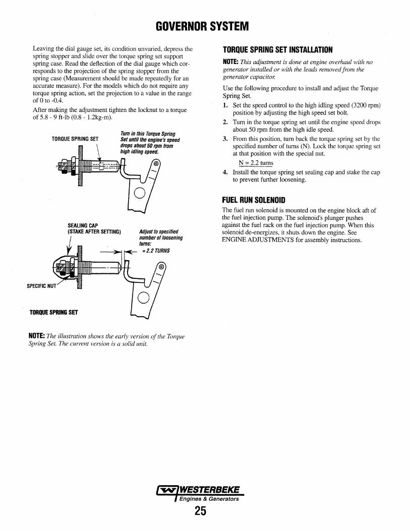
Leaving the dial gauge set, its condition unvaried, depress the spring stopper and slide over the torque spring set support spring case. Read the deflection of the dial gauge which corresponds to the projection of the spring stopper from the spring case (Measurement should be made repeatedly for an accurate measure). For the models which do not require any torque spring action, set the projection to a value in the range ofO to -0.4.
After making the adjustment tighten the locknut to a torque of 5.8 - 9 ft-lb (0.8 - 1.2kg-m).
TORQUE SPRING SET
SEALING CAP
Tum in this Torque Spring Set until the engine's speed drops about 50 rpm from high idling speed.
(STAKE AFTER SETTING) Adjust to specified number of loosening tums:
=2.2 TURNS
SPECIFIC
TORQUE SPRING SET
NOTE: The illustration shows the early version of the Torque Spring Set. The current version is a solid unit.
25
TORQUE SPRING SET INSTALLATION NOTE: This adjustment is done at engine overhaul with no generator installed or with the leads removed from the generator capacitor.
Use the following procedure to install and adjust the Torque Spring Set.
1. Set the speed control to the high idling speed (3200 rpm) position by adjusting the high speed set bolt.
2. Tum in the torque spring set until the engine speed drops about 50 rpm from the high idle speed.
3. From this position, tum back the torque spring set by the specified number of turns (N). Lock the torque spring set at that position with the special nut.
N = 2.2 turns
4. Install the torque spring set sealing cap and stake the cap to prevent further loosening.
FUEL RUN SOLENOID The fuel run solenoid is mounted on the engine block aft of the fuel injection pump. The solenoid's plunger pushes against the fuel rack on the fuel injection pump. When this solenoid de-energizes, it shuts down the engine. See ENGINE ADJUSTMENTS for assembly instructions.
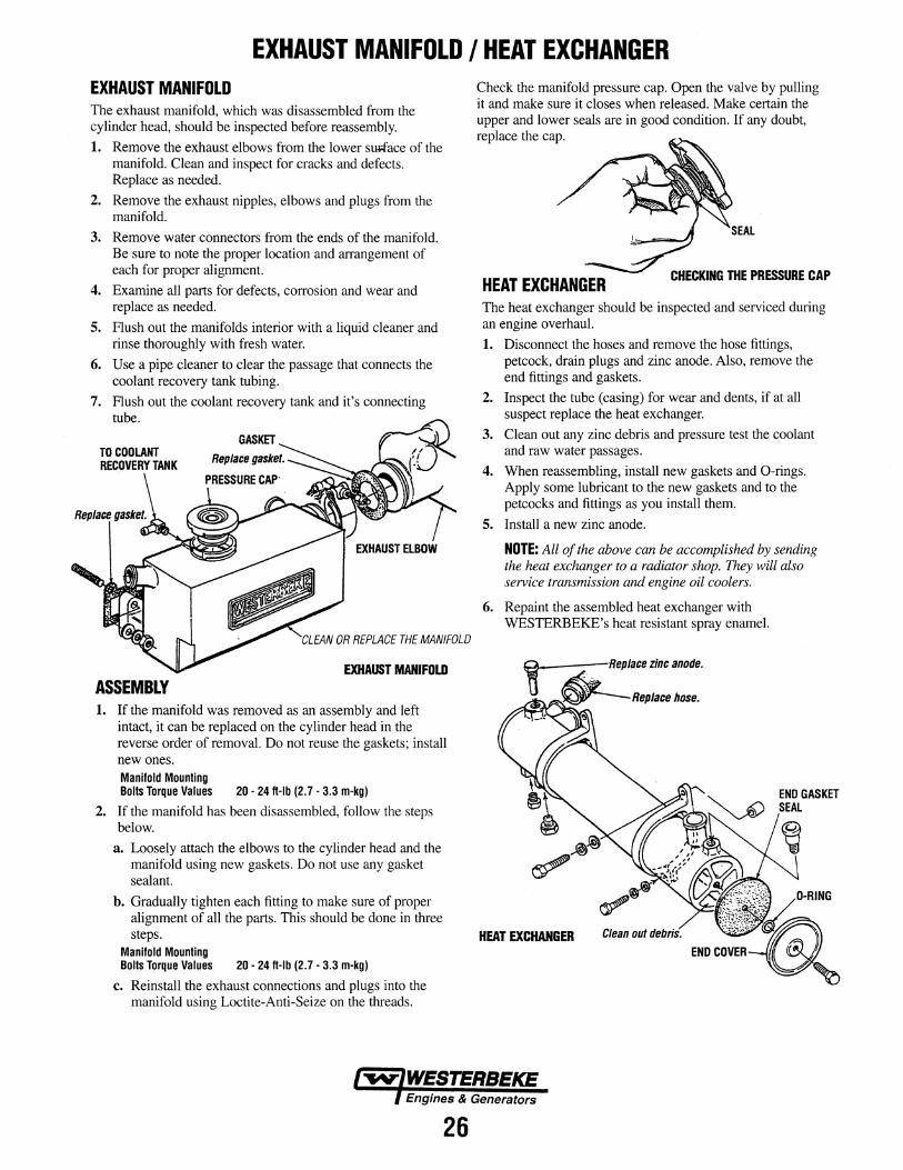
EXHAUST MANIFOLD I HEAT EXCHANGER EXHAUST MANIFOLD The exhaust manifold, which was disassembled from the cylinder head, should be inspected before reassembly.
1. Remove the exhaust elbows from the lower sllRace of the manifold. Clean and inspect for cracks and defects. Replace as needed.
2. Remove the exhaust nipples, elbows and plugs from the manifold.
3. Remove water connectors from the ends of the manifold. Be sure to note the proper location and arrangement of each for proper alignment.
4. Examine all parts for defects, corrosion and wear and replace as needed.
5. Flush out the manifolds interior with a liquid cleaner and rinse thoroughly with fresh water.
6. Use a pipe cleaner to clear the passage that connects the coolant recovery tank tubing.
7. Flush out the coolant recovery tank and it's connecting tube.
CLEAN OR REPLACE THE MANIFOLD
EXHAUST MANIFOLD ASSEMBLY 1. If the manifold was removed as an assembly and left
intact, it can be replaced on the cylinder head in the reverse order of removal. Do not reuse the gaskets; install new ones. Manifold Mounting Bolts Torque Values 20 · 24 ft-lb (2. 7 - 3.3 m-kg)
2. If the manifold has been disassembled, follow the steps below.
a. Loosely attach the elbows to the cylinder head and the manifold using new gaskets. Do not use any gasket sealant.
b. Gradually tighten each fitting to make sure of proper alignment of all the parts. This should be done in three steps.
Manifold Mounting Bolts Torque Values 20 - 24 ft-lb (2. 7 - 3.3 m-kg)
c. Reinstall the exhaust connections and plugs into the manifold using Loctite-Anti-Seize on the threads.
26
Check the manifold pressure cap. Open the valve by pulling it and make sure it closes when released. Make certain the upper and lower seals are in good condition. If any doubt, replace the cap.
HEAT EXCHANGER CHECKING THE PRESSURE CAP
The heat exchanger should be inspected and serviced during an engine overhaul.
1. Disconnect the hoses and remove the hose fittings, petcock, drain plugs and zinc anode. Also, remove the end fittings and gaskets.
2. Inspect the tube (casing) for wear and dents, if at all suspect replace the heat exchanger.
3. Clean out any zinc debris and pressure test the coolant and raw water passages.
4. When reassembling, install new gaskets and 0-rings. Apply some lubricant to the new gaskets and to the petcocks and fittings as you install them.
5. Install a new zinc anode.
NOTE: All of the above can be accomplished by sending the heat exchanger to a radiator shop. They will also service transmission and engine oil coolers.
6. Repaint the assembled heat exchanger with WESTERBEKE's heat resistant spray enamel.
t
HEAT EXCHANGER
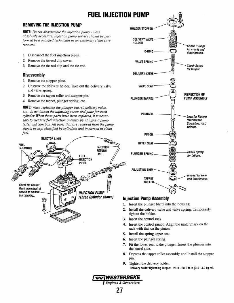
FUEL INJECTION PUMP REMOVING THE INJECTION PUMP NOTE: Do not disassemble the injection pump unless absolutely necessary. Injection pump service should be performed by a qualified technician in an extremely clean environment.
1. Disconnect the fuel injection pipes.
2. Remove the tie-rod clip cover.
3. Remove the tie-rod clip and the tie-rod.
Disassembly 1. Remove the stopper plate.
2. Unscrew the delivery holder. Take out the delivery valve and valve spring.
3. Remove the tappet roller and stopper pin.
4. Remove the tappet, plunger spring, etc.
NOTE: When replacing the plunger barrel, delivery valve, etc., do not loosen the adjusting screw and plate for each cylinder. When those parts have been replaced, it is necessary to measure fuel injection quantity by utilizing a pump tester and cam box. All pans that are removed from the pump should be kept classified by cylinders and immersed in clean fuel.
Check the Control Rack movement. It should be smooth (no catching).
/NJECTIIJII PUMP i (Three Cylinder shown)
27
DELIVERY VALVE-HOLDER
VALVE SEAT
PLUNGER BARREL
PLUNGER----
TAPPET ROLLER
Injection Pump Assembly
-----Check Spring tor fatigue.
INSPECTION OF PUMP ASSEMBLY
Scratches, rust, seizure.
__.....--Inspect tor wear ...,....- and interference.
1. Insert the plunger barrel into the housing.
2. Install the delivery valve and valve spring. Temporarily tighten the holder.
3. Insert the control rack.
4. Insert the control pinion. Align the matchmark on the rack with that on the pinion.
5. Install the spring upper seat.
6. Insert the plunger spring.
7. Fit the lower seat to the plunger. Insert the plunger into the barrel side.
8. Depress the tappet roller assembly and install the stopper pin.
9. Tighten the delivery holder. Delivery holder tightening Torque: 25.3- 28.2 ft-lb (3.5- 3.9 kg-m).
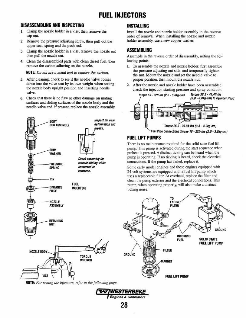
FUEL INJECTORS DISASSEMBLING AND INSPECTING 1. Oamp the nozzle holder in a vise, then remove the
cap nut.
2. Remove the pressure adjusting screw, then pull out the upper seat, spring and the push rod.
3. Clamp the nozzle holder in a vise, remove the nozzle nut then pull the nozzle out.
4. Clean the disassembled parts with clean diesel fuel, then remove the carbon adhering on the nozzle.
NOTE: Do not use a metal tool to remove the carbon.
5. After cleaning, check to see if the needle valve comes down into the valve seat by its own weight when setting the nozzle body upright position and inserting needle valve.
6. Check that there is no flaw or other damage on mating surfaces and sliding surfaces of the nozzle body and the needle valve and, if present, replace the nozzle assembly.
BODY SUB ASSEMBLY
v:::. .---SPRING
~ PIN I
~DISTANCE I PIECE
.__NOZZLE B. ASSEMBLY
RETAINING NUT
Inspect tor wear. deformation and breaks.
I
Check assembly for smooth sliding while immersed in kerosene.
FUEL INJECTOR
TORQUE WRENCH
NOTE: For testing the injectors, refer to the following page.
INSTALLING Install the nozzle and nozzle holder assembly in the reverse order of removal. When installing the nozzle and nozzle holder assembly, use a new copper washer.
ASSEMBLING Assemble in the reverse order of disassembly, noting the following points:
1. To assemble the nozzle and nozzle holder, first assemble the pressure adjusting nut side, and temporarily tighten the nut Mount the nozzle and set the needle valve to proper position, then mount the nozzle nut.
2. After the nozzle and nozzle holder have been assembled, check the injection starting pressure and spray condition.
Torque 18- 22n-1bs (2.5- 3.Dkg-cm) Torque 36.2- 43.4n-lbs -i- (5.0·6 ........ }10Cyfimlerllnd
Torque
Fuel Pipe Connections Torque 18- 22n-1bs (2.5- 3.Dkg-cm)
FUEL LIFT PUMPS There is no maintenance required for the solid state fuel lift pump. This pump is activated during the start sequence when preheat is pressed. A distinct ticking can be heard when the pump is operating. If no ticking is heard, check the electrical connections. If the pump has failed, replace it.
Some early model engines and those engines equipped with 24 volt systems are equipped with a fuel lift pump which uses a replaceable filter. At overhaul, replace the filter and clean the pump exterior and the electrical connections. This pump, when operating properly, will also make a distinct ticking noise.
FUEL LIFT PUMP
28
SOLID STATE FUEL LIFT PUMP
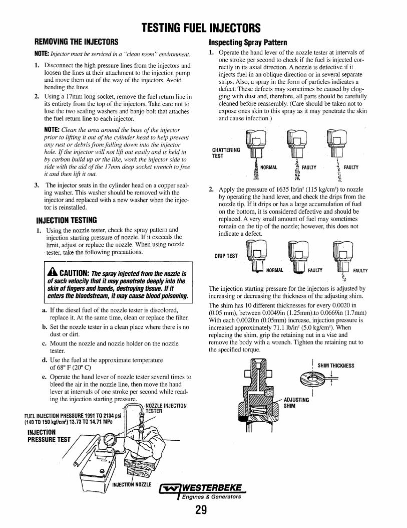
TESTING FUEL INJECTORS REMOVING THE INJECTORS NOTE: Injector must be serviced in a "clean room" environment.
1. Disconnect the high pressure lines from the injectors and loosen the lines at their attachment to the injection pump and move them out of the way of the injectors. Avoid bending the lines.
2. Using a 17mm long socket, remove the fuel return line in its entirety from the top of the injectors. Take care not to lose the two sealing washers and banjo bolt that attaches the fuel return line to each injector.
NOTE: Clean the area around the base of the injector prior to lifting it out of the cylinder head to help prevent any rust or debris from falling down into the injector hole. If the injector will not lift out easily and is held in by carbon build up or the like, work the injector side to side with the aid of the 17mm deep socket wrench to free it and then lift it out.
3. The injector seats in the cylinder head on a copper sealing washer. This washer should be removed with the injector and replaced with a new washer when the injector is reinstalled.
INJECTION TESTING 1. Using the nozzle tester, check the spray pattern and
injection starting pressure of nozzle. If it exceeds the limit, adjust or replace the nozzle. When using nozzle
·tester, take the following precautions:
A CAUTION: The spray injected from the nozzle is of such velocity that it may penetrate deeply into the skin of fingers and hands, destroying tissue. If it enters the bloodstream, it may cause blood poisoning.
a. If the diesel fuel of the nozzle tester is discolored, replace it. At the same time, clean or replace the filter.
b. Set the nozzle tester in a clean place where there is no dust or dirt.
c. Mount the nozzle and nozzle holder on the nozzle tester.
d. Use the fuel at the approximate temperature of 68° F (200 C)
e. Operate the hand lever of nozzle tester several times to bleed the air in the nozzle line, then move the hand lever at intervals of one stroke per second while reading the injection starting pres~ure.
FUEL INJECTION PRESSURE 1991 TO 2134 psi : (140 TO 150 kgf/cm2) 13.73 TO 14.71 MPa
INJECTION
PRESSURE'/?~
·.NOZZLE INJECTION TESTER
v
29
Inspecting Spray Pattern 1. Operate the hand lever of the nozzle tester at intervals of
one stroke per second to check if the fuel is injected correctly in its axial direction. A nozzle is defective if it injects fuel in an oblique direction or in several separate strips. Also, a spray in the form of particles indicates a defect. These defects may sometimes be caused by clogging with dust and, therefore, all parts should be carefully cleaned before reassembly. (Care should be taken not to expose ones skin to this spray as it may penetrate the skin and cause infection.)
CHATIERING TEST
··~ ij ·~ FAULTY . ·l FAULTY
~~ \\ .~~ .,,
r,·.
2. Apply the pressure of 1635 lb/in2 (115 kg/cm2) to nozzle by operating the hand lever, and check the drips from the nozzle tip. If it drips or has a large accumulation of fuel on the bottom, it is considered defective and should be replaced. A very small amount of fuel may sometimes remain on the tip of the nozzle; however, this does not indicate a defect.
DRIP TEST ~NORMAL ~ ""'LTY ~FAULTY !\· ~i~
The injection starting pressure for the injectors is adjusted by increasing or decreasing the thickness of the adjusting shim.
The shim has 10 different thicknesses for every 0.0020 in (0.05 mm), between 0.0049in (1.25mm).to 0.0669in (1.7mm) With each 0.0020in (0.05mm) increase, injection pressure is increased approximately 7l.llb/in2 (5.0 kg/cm2). When replacing the shim, grip the retaining nut in a vise and remove the body with a wrench. Tighten the retaining nut to the specified torque.
! SHIM THICKNESS
~ ~
ADJUSTING SHIM
I
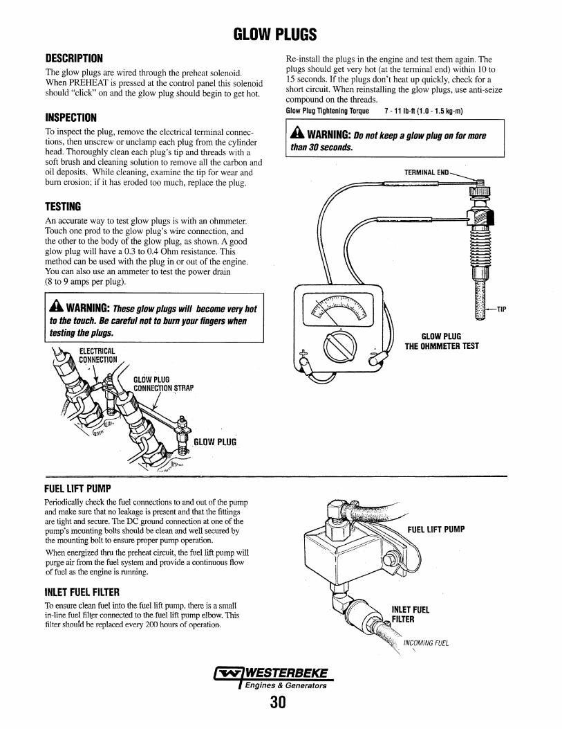
GLOW PLUGS DESCRIPTION The glow plugs are wired through the preheat solenoid. When PREHEAT is pressed at the control panel this solenoid should "click" on and the glow plug should begin to get hot.
INSPECTION To inspect the plug, remove the electrical terminal connections, then unscrew or unclamp each plug from the cylinder head. Thoroughly clean each plug's tip and threads with a soft brush and cleaning solution to remove all the carbon and oil deposits. While cleaning, examine the tip for wear and bum erosion; if it has eroded too much, replace the plug.
TESTING An accurate way to test glow plugs is with an ohmmeter. Touch one prod to the glow plug's wire connection, and the other to the body of the glow plug, as shown. A good glow plug will have a 0.3 to 0.4 Ohm resistance. This method can be used with the plug in or out of the engine. You can also use an ammeter to test the power drain (8 to 9 amps per plug).
A WARNING: These glow plugs will become very hot to the touch. Be careful not to burn your fingers when testing the plugs.
_GLOW PLUG
FUEL LIFT PUMP Periodically check the fuel connections to and out of the pump and make sure that no leakage is present and that the fittings are tight and secure. The DC ground connection at one of the pump's mounting bolts should be clean and well secured by the mounting bolt to ensure proper pump operation.
When energized thru the preheat circuit, the fuel lift pump will purge air from the fuel system and provide a continuous flow of fuel as the engine is nmning.
INLET FUEL FILTER To ensure clean fuel into the fuel lift pump, there is a small in-line fuel filt~r connected to the fuel lift pump elbow. This filter shoufd be replaced every 200 hours of operation-.
30
Re-install the plugs in the engine and test them again. The plugs should get very hot (at the terminal end) within 10 to 15 seconds. If the plugs don't heat up quickly, check for a short circuit. When reinstalling the glow plugs, use anti-seize compound on the threads. Glow Plug Tightening Torque 7 -11 lb-fl (1.0 -1.5 kg-m)
A WARNING: Do not keep a glow plug on for more than 30 seconds.
TERMINAL END
GLOWPWG THE OHMMETER TEST
TIP
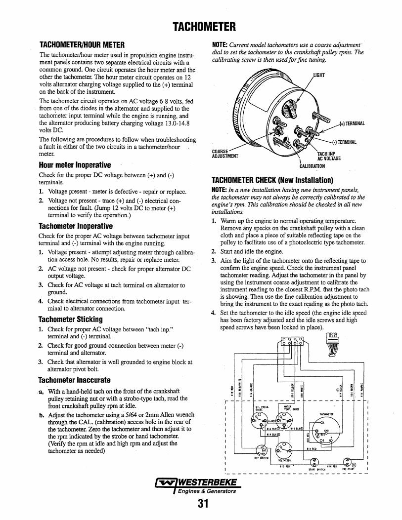
TACHOMETER TACHOMETER/HOUR METER The tachometer/hour meter used in propulsion engine instrument panels contains two separate electrical circuits with a common ground. One circuit operates the hour meter and the other the tachometer. The hour meter circuit operates on 12 volts alternator charging voltage supplied to the ( +) terminal on the back of the instrument.
The tachometer circuit operates on AC voltage 6-8 volts, fed from ~ne of the diodes in the alternator and supplied to the tachometer input terminal while the engine is running, and the alternator producing battery charging voltage 13.0-14.8 volts DC.
The following are procedures to follow when troubleshooting a fault in either of the two circuits in a tachometer/hour meter.
Hour meter Inoperative Check for the proper DC voltage between ( +) and (-) terminals. 1. Voltage present - meter is defective - repair or replace.
2. Voltage not present - trace ( +) and (-) electrical connections for fault. (Jump 12 volts DC to meter(+) terminal to verify the operation.)
Tachometer Inoperative Check for the proper AC voltage between tachometer input terminal and (-) terminal with the engine running. 1. Voltage present - attempt adjusting meter through calibra
tion access hole. No results, repair or replace meter.
2. AC voltage not present - check for proper alternator DC output voltage.
3. Check for AC voltage at tach terminal on alternator to ground.
4. Check electrical connections from tachometer input terminal to alternator connection.
Tachometer Sticking 1. Check for proper AC voltage between "tach inp."
terminal and (-) terminal.
2. Check for good ground connection between meter (-) terminal and alternator.
3. Check that alternator is well grounded to engine block at alternator pivot bolt.
Tachometer Inaccurate -a~ With a hand-held tach on the front of the crankshaft
pulley retaining nut or with a strobe-type tach, read the front crankshaft pulley rpm at idle.
b. Adjust the tachometer using a 5/64 or 2mm Allen wrench through the CAL. (calibration) access hole in the rear of the tachometer. Zero the tachometer and then adjust it to the rpm indicated by the strobe or hand tachometer. (Verify the rpm at idle and high rpm and adjust the tachometer as needed)
31
NOTE: Current model tachometers use a coarse adjustment· · dial to set the tachometer to the crankshaft pulley rprils. The calibrating screw is then used for fine tuning.
TACHOMETER CHECK (New Installation) NOTE: In a new installation having new instrument panels, the tachometer may not always be correctly calibrated to the engine's rpm. This calibration should be checked in all new installations. 1. Warm up the engine to normal operating temperature.
Remove any specks on the crankshaft pulley with a clean cloth and place a piece of suitable reflecting tape on the pulley to facilitate use of a photoelectric type tachometer.
2. Start and idle the engine.
3. Aim the light of the tachometer onto the reflecting tape to confirm the engine speed. Check the instrument panel tachometer reading. Adjust the tachometer in the panel by using the instrument coarse adjustment to calibrate the instrument reading to the closest R.P.M. that the photo tach is showing. Then use the fine calibration adjustment to bring the instrument to the exact r~ading as the photo tach.
4. Set the tachometer to the idle speed (the engine idle speed has been factory adjusted and the idle screws and high speed screws have been locked in place).
' "'
iil e ! ~ "' (j)2 I j e i - - - - - - - -
r - - - - - - - -
L-~~r---~~~~~£V@ stAIIT SIITCH PI£•START
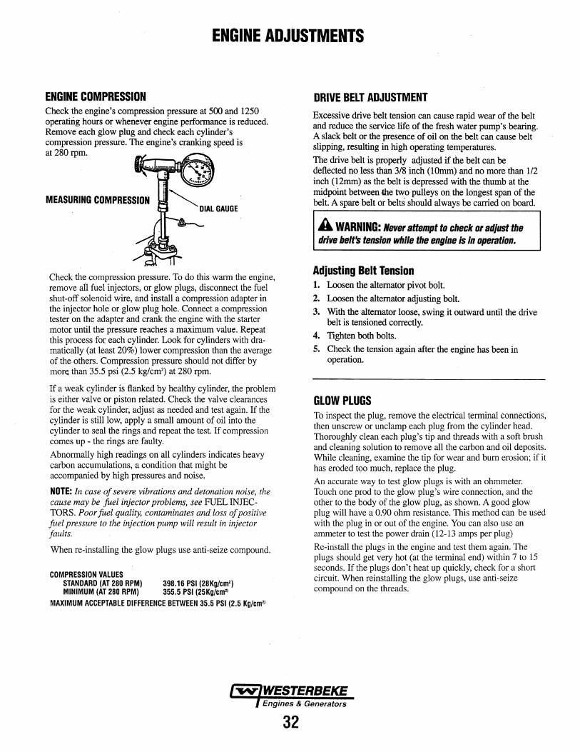
ENGINE ADJUSTMENTS
ENGINE COMPRESSION Check the engine's compression pressure at 500 and 1250 operating hours or whenever engine performance is reduced. Remove each glow plug and check each cylinder's compression pressure. The engine's cranking speed is at 280 rpm.
MEASURING COMPRESSION
Check the compression pressure. To do this warm the engine, remove ail fuel injectors, or glow plugs, disconnect the fuel shut-off solenoid wire, and install a compression adapter in the injector hole or glow plug hole. Connect a compression tester on the adapter and crank the engine with the starter motor until the pressure reaches a maximum value. Repeat this process for each cylinder. Look for cylinders with dramatically (at least 20%) lower compression than the average of the others. Compression pressure should not differ by more than 35.5 psi (2.5 kg/cm2) at 280 rpm.
If a weak cylinder is flanked by healthy cylinder, the problem is either valve or piston related. Check the valve clearances for the weak cylinder, adjust as needed and test again. If the cylinder is still low, apply a small amount of oil into the cylinder to seal the rings and repeat the test. If compression comes up - the rings are faulty.
Abnormally high readings on all cylinders indicates heavy carbon accumulations, a condition that might be accompanied by high pressures and noise.
NOTE: In case of severe vibrations and detonation noise, the cause may be fuel injector problems, see FUEL INJECTORS. Poor fuel quality, contaminates and loss of positive fuel pressure to the injection pump will result in injector faults.
When re-installing the glow plugs use anti-seize compound.
COMPRESSION VALUES STANDARD (AT 280 RPM) 398.16 PSI (28Kg/cm') MINIMUM (AT 280 RPM) 355.5 PSI (25Kg/cm'~
MAXIMUM ACCEPTABLE DIFFERENCE BETWEEN 35.5 PSI (2.5 Kg/em''
32
DRIVE BELT ADJUSTMENT Excessive drive belt tension can cause rapid wear of the belt and reduce the service life of the fresh water pump's bearing. A slack belt or the presence of oil on the belt can cause belt slipping, resulting in high operating temperatures.
The drive belt is properly adjusted if the belt can be deflected no less than 3/8 inch (lOmm) and no more than 112 inch (12mm) as the belt is depressed with the thumb at the midpoint between U'le two pulleys on the longest span of the beli. A spare belt or beltS should always be carried on board.
A WARNING: Never attempt to check or adjust the drive belt's tension while the engine is In operation.
Adjusting Belt Tension 1. Loosen the alternator pivot bolt.
2. Loosen the alternator adjusting bolt.
3. With the alternator loose, swing it outward until the drive belt is tensioned correctly.
4. Tighten both bolts.
5. Check the tension again after the engine has been in operation.
GLOW PLUGS To inspect the plug, remove the electrical terminal connections, then unscrew or unclamp each plug from the cylinder head. Thoroughly clean each plug's tip and threads with a soft brush and cleaning solution to remove all the carbon and oil deposits. While cleaning, examine the tip for wear and bum erosion; if it has eroded too much, replace the plug.
An accurate way to test glow plugs is with an ohmmeter. Touch one prod to the glow plug's wire connection, and the other to the body of the glow plug, as shown. A good glow plug will have a 0.90 ohm resistance. This method can be used with the plug in or out of the engine. You can also use an ammeter to test the power drain (12-13 amps per plug)
Re-install the plugs in the engine and test them again. The plugs should get very hot (at the terminal end) within 7 to 15 seconds. If the plugs don't heat up quickly, check for a short circuit. When reinstalling the glow plugs, use anti-seize compound on the threads.
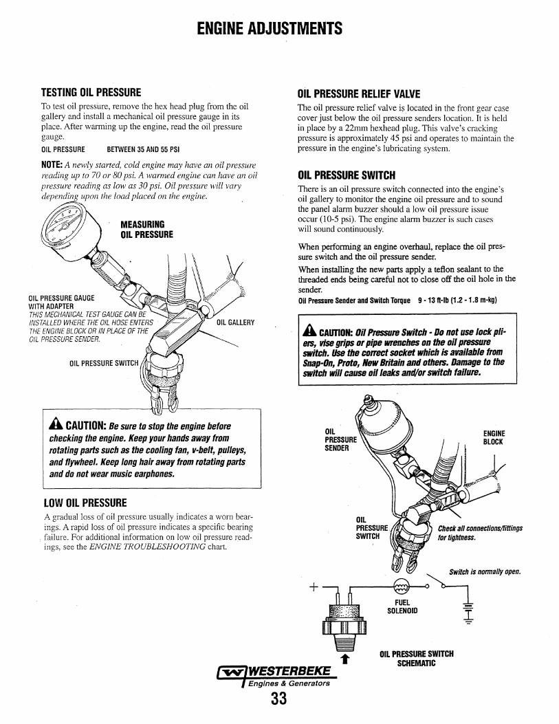
ENGINE ADJUSTMENTS
TESTING OIL PRESSURE To test oil pressure, remove the hex head plug from the oil gallery and install a mechanical oil pressure gauge in its place. After warming up the engine, read the oil pressure gauge.
OIL PRESSURE BETWEEN 35 AND 55 PSI
NOTE: A newly started, cold engine may have an oil pressure reading up to 70 or 80 psi. A warmed engine can have an oil pressure reading as low as 30 psi. Oil pressure will vary depending upon the load placed on the engine.
OIL PRESSURE GAUGE WITH ADAPTER
MEASURING OIL PRESSURE
THIS MECHANICAL TEST GAUGE CAN BE INSTALLED WHERE THE OIL HOSE ENTERS · THE ENGINE BLOCK OR IN PLACE OF THE OIL PRESSURE SENDER.
A CAUTION: Be sure to stop the engine before checking the engine. Keep your hands away from rotating parts such as the cooling fan, v-belt, p_ulleys, and flywheel. Keep long hair away from rotating parts and do not wear music earphones.
LOW OIL PRESSURE A gradual loss of oil pressure usually indicates a worn bearings. A rapid loss of oil pressure indicates a specific bearing
. failure. For additional information on low oil pressure read, ings, see the ENGINE TROUBLESHOOTING chart. .
33
OIL PRESSURE RELIEF VALVE The oil pressure relief valve is located in the front gear case cover just below the oil pressure senders location. It is held in place by a 22mrn hexhead plug. This valve's cracking pressure is approximately 45 psi and operates to maintain the pressure in the engine's lubricating system.
OIL PRESSURE SWITCH There is an oil pressure switch connected into the engine's oil gallery to monitor the engine oil pressure and to sound the panel alarm buzzer should a low oil pressure issue occur (10-5 psi). The engine alarm buzzer is such cases will sound continuously.
When performing an engine overhaul, replace the oil pressure switch and the oil pressure sender.
When installing the new parts apply a teflon sealant to the threaded ends being careful not to close off the oil hole in the sender. Oil Pressure Sender and Switch Torque 9 -13 ft·lb (1.2 -1.8 m-kg)
A CAUTION: Oil Pressure Switch ·Do not use lock plietS, vise grips or pipe wrenches on the oil pressure switch. Use the correct socket which is available from Snap-On, Proto, New Britain and othetS. Damage to the switch will cause oil leaks and/or switch failure.
+
OIL PRESSURE SENDER
Check all connections/finings tor tightness.
OIL PRESSURE SWITCH SCHEMATIC

ENGINE ADJUSTMENTS
ENGINE IDLING SPEED The engine idling speed is pre-set at the factory but once the boat is operating in the water other variables such as propeller size, shaft length, ahd the transmission can affect the idle speed.
\\ THROTILE CONTROL
The normal idle speed for these engine models is 1000-1200 rpm at normal engine operating temperatures. Where ever in this rpm range the engine operates the smoothest, does not stall when the throttle is restarted and no damper chatter is produces. ·
ADJUSTING THE IDLE SPEED 1. Loosen the locknut on the idle adjustment bolt on the
fuel injection pump. 2. Adjust the bolt so that the throttle control lever will
hold the engine at a quiet idle (1000-1200 rpm). 3. Tighten the locknut. 4. Race the engine several times to ensure the idle speed
remains as set.
OPTIONAL FUEL RUN/SHUT-OFF SOLENOID The fuel run solenoid is mounted in a threaded hole on the engine's block just aft of and below the engine's injection pump. Proceed as follows when installing a replacement or new fuel run solenoid.
1. Visual access to the fuel injection pump's fuel rack is needed. To obtain this, 'remove the shut off lever and gasket just below the fuel injection pump.
2. Thread the locknut onto the solenoid and then apply a small amount of Teflon sealant to the threads on the solenoid
3. Thread the solenoid into the hole on the engine and observe the solenoid plunger through the cover opening. ~ Allow the plunger to contact the fuel rack and move fully
lEVER
into the injection pump. Do not thread further so as to FUEL RUN push the plunger into the solenoid. SOLENOID
4. Back the solenoid out 1/4 - 1/2 of a tum and secure it in position with the locknut LOCKNUT TORQUE VALUE 28.9-36.2 FT-LB (4.0-5.0 M-KG)
5. Properly connect the three electrical leads from the solenoid. Two of the connections plug into the engine harness and the third grounds to the engine block at an adjacent inbmird threaded hole with an 8mm bolt.
6. Re-assemble the shut-off lever with gasket and test run the unit. Make certain the unit stops when the solenoid is deenergized. If it does not and only goes to idle. Thread the solenoid in 1/8 - 1/4 tum till shut-off is obtained.
FUEL RUN SOLENOID
34
FUEL RUN SOLENOID PUSH TYPE VOLTAGE: 10V- 15V DC Coil resistance is 1.6 n :t 10% (at 20" C). STROKE: 0.394 :t 0.0197in (10 :t 0.5mm).
0.394 :t 0.0197in (10 :t 0.5mm)
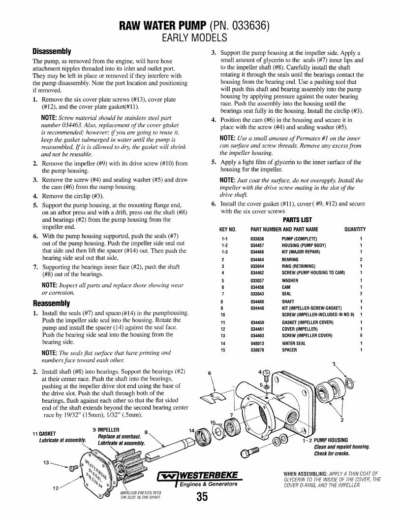
RAW WATER PUMP (PN. 033636) EARLY MODELS
Disassembly The pump, as removed from the engine, will have hose attachment nipples threaded into its inlet and outlet port. They may be left in place or removed if they interfere with the pump disassembly. Note the port location and positioning if removed.
1. Remove the six cover plate screws (#13), cover plate (#12), and the cover plate gasket(#ll).
NOTE: Screw material should be stainless steel part number 034463. Also, replacement of the cover gasket is recommended; however; if you are going to reuse it, keep the gasket submerged in water until the pump is reassembled. If is is allowed to dry, the gasket will shrink and not be reusable.
2. Remove the impeller (#9) with its drive screw (#10) from the pump housing.
3. Remove the screw (#4) and sealing washer (#5) and draw the cam (#6) from the oump housing.
4. Remove the circlip (#3).
5. Support the pump housing, at the mounting flange end, on an arbor press and with a drift, press out the shaft (#8) and bearings (#2) from the pump housing from the impeller end.
6. With the pump housing supported, push the seals (#7) out of the pump housing. Push the impeller side seal out that side and then lift the spacer (#14) out. Then pushthe bearing side seal out that side,
7. Supporting the bearings inner face (#2), push the shaft (#8) out of the bearings.
NOTE: Inspect all parts and replace those showing wear or corrosion.
Reassembly 1. Install the seals (#7) and spaceJ(#14) in the pumphousing.
Push the impeller side seal into the housing. Rotate the pump and install the spacer (14) against the seal face. Push the bearing side seal into the housing from the bearing side.
NOTE: The seals flat suiface that have printing and numbers face toward eaxh other.
2. Install shaft (#8) into bearings. Support the bearings (#2) at their center race. Push the shaft into the bearings, pushing at the impeller drive slot end using the base of the drive slot. Push the shaft through both of the bearings, flush against each other so that the flat sided end of the shaft extends beyond the second bearing center race by 19/32" (15mm), 1132" (.5mm).
11 GASKET 9IMPEllER 8
Lubricate at ass~~mbtv.
12
35
3. Support the pump housing at the impeller side. Apply a small amount of glycerin to the seals (#7) inner lips and to the impeller shaft (#8). Carefully install the shaft rotating it through the seals until the bearings contact the housing from the bearing end. Use a pushing tool that will push this shaft and bearing assembly into the pump housing by applying pressure against the outer bearing race. Push the assembly into the housing until the bearings seat fully in the housing. Install the circlip (#3).
4. Position the cam (#6) in the housing and secure it in place with the screw (#4) and sealing washer (#5).
NOTE: Use a small amount of Permatex #1 on the inner can suiface and screw threads. Remove any excess from the impeller housing.
5. Apply a light film of glycerin to the inner surface of the housing for the impeller.
NOTE: Just coat the suiface, do not overapply. Install the impeller with the drive screw mating in the slot of the drive shaft.
6. Install the cover gasket (#11), cover( #9, #12) and secure with the six cover screws·
KEY NO.
1-1 1-2 1-3
2 3 4
5 6 7
8 9 10
11 12 13
14 15
PARTS LIST PART NUMBER AND PART NAME QUANTITY
033636 034457 034466
034464 033044 034462
033037 034456 033043
034460 034440
034459 034461 034463
048013 038679
PUMP (COMPLETE) HOUSIN.G (PUMP BODY) KIT (MAJOR REPAIR)
BEARING 2 RING (RETAINING) SCREW (PUMP HOUSING TO CAM)
WASHER CAM SEAL 2
SHAFT 1 KIT (IMPELLER-SCREW-GASKET) SCREW (IMPELLER-INCLUDED IN N0.9) 1
GASKET (IMPELLER COVER) COVER (IMPELLER) SCREW (IMPELLER COVER) 6
WATER SEAL SPACER
1-2 PUMP HOUSING Clean and repaint housing. Check tor cracks.
WHEN ASSEMBLING: APPLY A THIN COAT OF GLYCERIN TO THE INSIDE OF THE COVER, THE COVER 0-RING, ANO THE IMPELLER
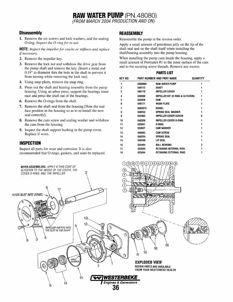
RAW WATER PUMP (PN.48080) (FROM MARCH 2004 PRODUCTION AND ON)
Disassembly 1. Remove the six screws and lock washers, and the sealing
0-ring. Inspect the 0-ring for re-use.
NOTE: Inspect the impeller for cracks or stiffness and replace if necessary.
2. Remove the impeller key.
3. Remove the lock nut and withdraw the drive gear from the pump shaft and remove the key. [Insert a metal rod 0.19" in diameter thru the hole in the shaft to prevent it from turning while removing the lock nut].
4. Using snap pliers, remove the snap ring.
5. Press out the shaft and bearing assembly from the pump housing. Using an arbor press, support the bearings inner race and press the shaft out of the bearings.
6. Remove the 0-rings from the shaft.
7. Remove the shaft seal from the housing.[Note the seal face position in the housing so as to re-install the new seal correctly].
8. Remove the cam screw and sealing washer and withdraw the cam from the housing.
9. Inspect the shaft support bushing in the pump cover. Replace if worn.
INSPECTION
REASSEMBLY Reassemble the pump in the reverse order.
Apply a small amount of petroleum jelly on the lip of the shaft seal and on the shaft itself when installing the shaft/bearing assembly into the pump housing.
When installing the pump cam inside the housing, apply a small amount of Permatex # 1 to the inner surface of the cam and to the securing screw threads. Remove any excess.
KEY NO.
2 3
4 5 6
7 8 9
10 11 12
13 14 15
16
PARTS LIST PART NUMBER AND PART NAME QUANTITY
0480809 049172 049170
048500 033458 049171
0302575 048253 034463
048359 033041 033037
046662 048254 049169
034464
RAW WATER PUMP SHAFT IMPELLER COVER
IMPELLER KIT (O·RING & GLYCERIN) CAM WEAR PLATE
DOWEL SPRING SEAL WASHER IMPELLER COVER SCREW
IMPELLER COVER D-RING D-RING CAM WASHER
CAM SCREW SPRING SEAL LIP SEAL
BALL BEARING
1 6
2
Inspect all parts for wear and corrosion. It is also 17 033045 RETAINING INTERNAL RING
recommended that 0-rings, -gaskets, and seals be replaced. 18
WHEN ASSEMBLING: APPLY A THIN COAT OF GLYCERIN TO THE INSIDE OF THE COVER, THE COVER 0-RING, AND THE IMPELLER
033044 RETAINING EXTERNAL RING
EXPLODED VIEW REPAIR PARTS ARE AVAILABLE FROM YOUR WESTERBEKE DEALER
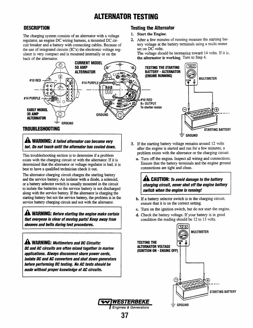
ALTERNATOR TESTING DESCRIPTION The charging system consists of an alternator with a voltage regulator, an engine DC wiring harness, a mounted DC circuit breaker and a battery with connecting cables. Because of the use of integrated circuits (IC's) the electronic voltage regulator is very compact and is mounted internally or on the back of the alternator.
#10 RED
CURRENT MODEL 50 AMP ALTERNATOR
Testing the Alternator 1. Start the Engine. 2. After a few minutes of running measure the starting bat
tery voltage at the battery terminals using a multi-meter set on DC volts. The voltage should be increasing toward 14 volts. If it is, the alternator is working. Tum to Step 4.
TESTING THE STARTING BATTERY - ALTERNATOR {ENGINE RUNNING)
MULTIMETER
#14 PURPLE ~~~~~~#10 RED
EARLY MODEL 35AMP ALTERNATOR
= GROUND
TROUBLESHOOTING
A WARNING: A failed alternator can become very bot. Do not touch until the alternator has cooled down.
This troubleshooting section is to determine if a problem exists with the charging circuit or with the alternator. If it is determined that the alternator or voltage regulator is bad, it is best to have a qualified technician check it out. The alternator charging circuit charges the starting battery and the service battery. An isolator with a diode, a solenoid, or a battery selector switch is usually mounted in the circuit to isolate the batteries so the service battery is not discharged along with the service battery. If the alternator is charging the starting battery but not the service battery, the problem is in the service battery charging circuit and not with.the alternator.
A WARNING~ Before starting the engine make certain that everyone is clear of moving parts! Keep away from sheaves and belts during test procedures.
A WARNING: Multimeters and DC Circuits: DC and AC circuits are often mixed together in marine applications. Always disconnect shore power cords, isolate DC and AC converters and shut down generators before pertonning DC testing. No AC tests should be made without proper knowledge of AC circuits.
37
B+ OUTPUT To starter motor
3. If the starting battery voltage remains around 12 volts after the engine is started and run for a few minutes, a problem exists with the alternator or the charging circuit.
a. Turn off the engine. Inspect all wiring and connections. Ensure that the battery terminals and the engine ground connections are tight and clean.
A CAUTION: To avoid damage to the battery charging circuit, never shut off the engine battery switch when the engine is running!
b. If a battery selector switch is in the charging circuit, ensure that it is on the correct setting.
c. Turn on the ignition switch, but do not start the engine. d. Check the battery voltage. If your battery is in good
condition the reading should be 12 to 13 volts.
cmJ
0 TESTING THE COM
ALTERNATOR VOLTAGE {IGNITION ON - ENGINE OFF)
MULTIMffiR
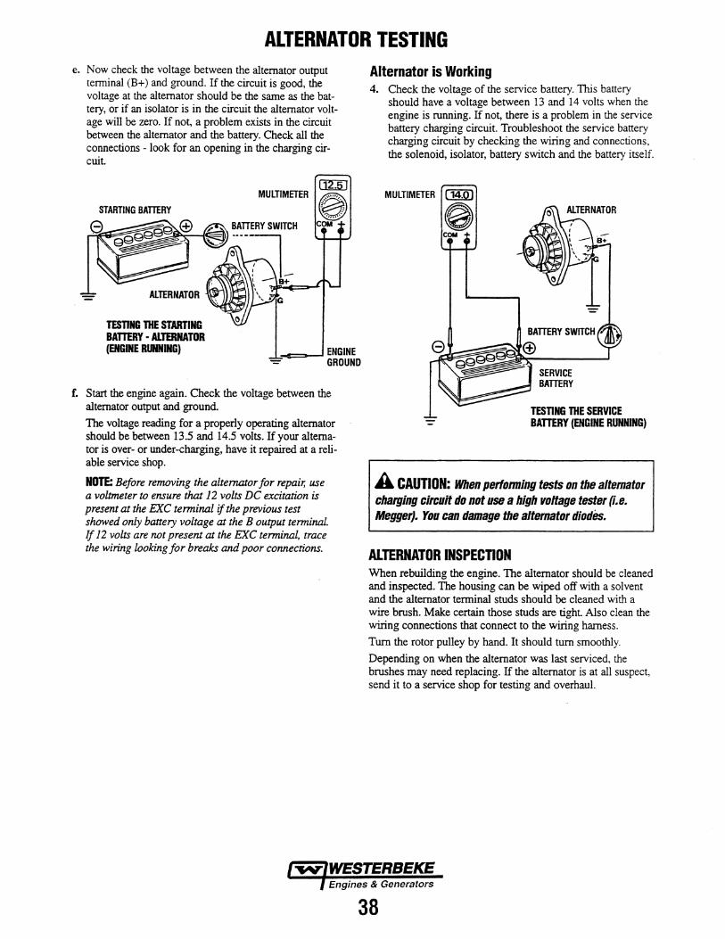
ALTERNATOR TESTING e. Now check the voltage between the alternator output
terminal (B+) and ground. If the circuit is good, the voltage at the alternator should be the same as the battery, or if an isolator is in the circuit the alternator voltage will be zero. If not, a problem exists in the circuit between the alternator and the battery. Check all the connections - look for an opening in the charging circuit
STARTING BAmRY
ALTERNATOR
TESTING 11IE STARTING BATTERY • ALTERNATOR (ENGINE RUNNING}
MULTIMETER
..c::~--1 ENGINE GROUND
£ Start the engine again. Check the voltage between the alternator output and ground.
The voltage reading for a properly operating alternator should be between 13.5 and 14.5 volts. If your alternator is over- or under-charging, have it repaired at a reliable service shop.
NOTE: Before removing the alternator for repair, use a voltmeter to ensure that 12 volts DC excitation is present at the EXC terminal if the previous test showed only battery voltage at the B output terminal. If 12 volts are not present at the EXC terminal, trace the wiring looking for breaks and poor connections.
Alternator is Working 4. Check the voltage of the service battery. This battery
should have a voltage between 13 and 14 volts when the engine is running. If not, there is a problem in the service battery charging circuit. Troubleshoot the service ba~ery chargina circuit by checking the wiring and connections, the sole~oid, isolator, battery switch and the battery itself.
MULTIMETER CKQ)
0 COM
SERVICE BAmRY
TESnNG THE SERVICE BATTERY (ENGINE RUNNING)
A CAUTION: When perfonning tests on the altemator charging circuit do not use a high voltage tester (i.e. Megger}. You can damage the alternator diodes.
ALTERNATOR INSPECTION When rebuilding the engine. The alternator should be cleaned and inspected. The housing can be wiped off with a solvent and the alternator terminal studs should be cleaned with a wire brush. Make certain those studs are tight. Also clean the wiring connections that connect to the wiring harness.
Tum the rotor pulley by hand. It should tum smoothly.
Depending on when the alternator was last serviced, the brushes may need replacing. If the alternator is at all suspect, send it to a service shop for testing and overhaul.
38
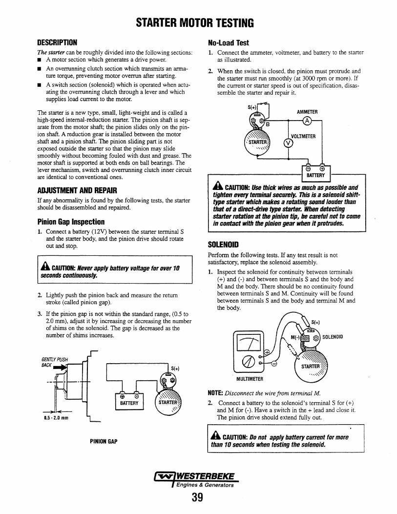
STARTER MOTOR TESTING
DESCRIPTION The starter can be roughly divided into the following sections: • A motor section which generates a drive power.
• An overrunning clutch section which transmits an armature torque, preventing motor overrun after starting.
• A switch section (solenoid) which is operated when actuating the overrunning clutch through a lever and which supplies load current to the motor.
The starter is a new type, small, light-weight and is called a high-speed internal-reduction starter. The pinion shaft is separate from the motor shaft; the pinion slides only on the pinion shaft. A reduction gear is installed between the motor shaft and a pinion shaft. The pinion sliding part is not exposed outside the starter so that the pinion may slide smoothly without becoming fouled with dust and grease. The motor shaft is supported at both ends on ball bearings. The lever mechanism, switch and overrunning clutch inner circuit are identical to conventional ones.
ADJUSTMENT AND REPAIR If any abnormality is found by the following tests, the starter should be disassembled and repaired.
Pinion Gap Inspection 1. Connect a battery (12V) between the starter terminalS
and the starter body, and the pinion drive should rotate out and stop.
A CAUTION: Never apply battery voltage for over 10 seconds continuously.
2. Lightly push the pinion back and measure the return stroke (called pinion gap).
3. If the pinion gap is not within the standard range, (0.5 to 2.0 mm), adjust it by increasing or decreasing the number of shims on the solenoid. The gap is decreased as the number of shims increases.
PINION GAP
39
No-Load Test 1. Connect the ammeter, voltmeter, and battery to the starter
as illustrated.
2. When the switch is closed, the pinion must protrude and the starter must run smoothly (at 3000 rpm or more). If the current or starter speed is out of specification, disassemble the starter and repair it.
e ~----------------------1 ~TnRY
A CAUTION: Use thick wires as much as possible and tighten every tenninal securely. This is a solenoid shift· type staffer which makes a rotating sound louder than that of a direct-drive type starter. When detecting starter rotation at the pinion tip, be careful not to come in contact with the pinion gear when it protrudes.
SOLENOID Perform the following tests. If any test result is not satisfactory, replace the solenoid assembly.
1. Inspect the solenoid for continuity between terminals (+)and(-) and between terminals Sand the body and M and the body. There should be no continuity found between terminals S and M. Continuity will be found between terminals S and the body and terminal M and the body.
MULTIMETER
NOTE: Disconnect the wire from terminal M.
2. Connect a battery to the solenoid's terminal S for ( +) and M for (-). Have a switch in the + lead and close it. The pinion drive should extend fully out.
A CAUTION: Do not apply battery current for more than 10 seconds when testing the solenoid.
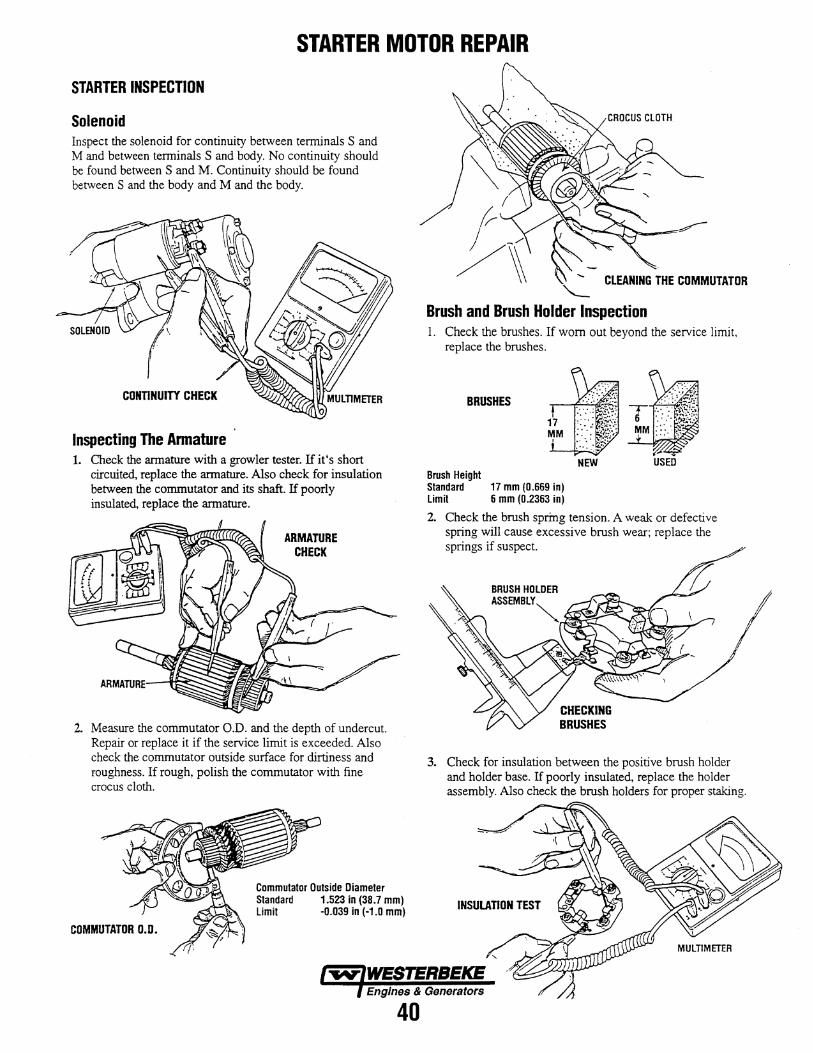
STARTER MOTOR REPAIR
STARTER INSPECTION
Solenoid Inspect the solenoid for continuity between terminals S and M and between tenninals S and body. No continuity should be found between S and M. Continuity should be found between S and the body and M and the body.
CONTINUITY CHECK
Inspecting The Armature 1. Check the armature with a growler tester. Hit's short
circuited, replace the armature. Also check for insulation between the commutator and its shaft. If poorly insulated, replace the armature.
ARMATURE CHECK
2. Measure the commutator O.D. and the depth of undercut. Repair or replace it if the service limit is exceeded. Also check the commutator outside surface for dirtiness and roughness. If rough, polish the commutator with fine crocus cloth.
Commutator Outside Diameter Standard 1.523 in (38.7 mm) Limit -0.039 in (·1.0 mm)
COMMUTATOR D.O.
"Brush and Brush Holder Inspection 1. Check the brushes. If worn out beyond the service limit,
replace the brushes.
BRUSHES
Brush Height Standard 17 mm (0.669 in) Limit 6 mm (0.2363 in)
2. Check the brush spring tension. A weak or defective spring will cause excessive brush wear; replace the springs if suspect.
BRUSH HOLDER
ASSEMBLY~ C>..l,;)"""'~'
3. Check for insulation between the positive brush holder and holder base. If poorly insulated, replace the holder assembly. Also check the brush holders for proper staking.
Engines & Generators
40
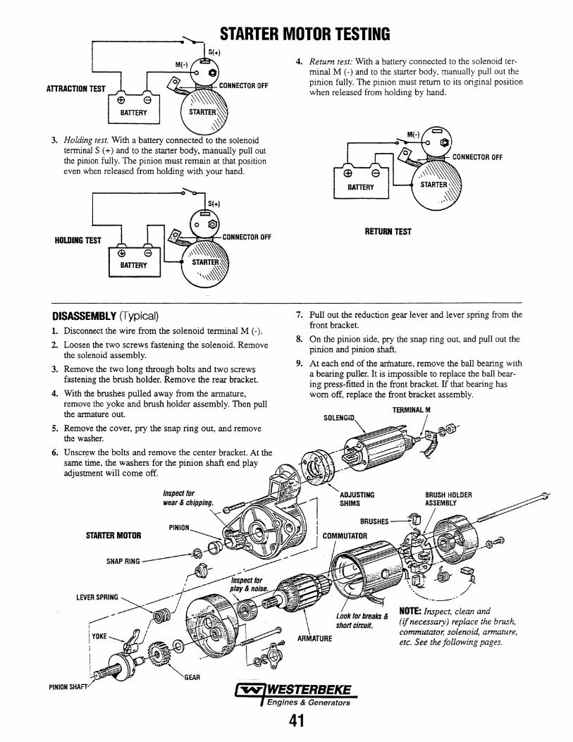
STARTER MOTOR TESTING
AITRACTION TEST
3. Holding test. With a battery connected to the solenoid terminal S ( +) and to the starter body, manually pull out the pinion fully. The pinion must remain at that position even when released from holding with your hand.
HOLDING TEST
DISASSEMBLY (Typical) 1. Disconnect the wire from the solenoid terminal M (-).
2. Loosen the two screws fastening the solenoid. Remove the solenoid assembly.
3. Remove the two long through bolts and two screws fastening the brush holder. Remove the rear bracket.
4. With the brushes pulled away from the armature, remove the yoke and brush holder assembly. Then pull the armature out.
5. Remove the cover, pry the snap ring out, and remove the washer.
6. Unsc~w the bolts and remove the center bracket. At the same time, the washers for the pinion shaft end play adjustment will come off.
STARTER MOTOR
PINION
4. Return test: With a battery connected to the solenoid terminal M (-) and to the starter body, manually pull out the pinion fully. The pinion must return to its original position when released from holding by hand.
RETURN TEST
7. Pull out the reduction gear lever and lever spring from the front bracket.
8. On the pinion side, pry the snap ring out, and pull out the pinion and pinion shaft.
9. At each end of the arfnature, remove the ball bearing with a bearing puller. It is impossible to replace the ball bearing press-fitted in the front bracket. If that bearing has worn off, replace the front bracket assembly.
41
""-.ADJUSTING SHIMS
NOTE: Inspect, clean arul (if necessary) replace the brush, commutator, solenoid, armature, etc. See the following pages.
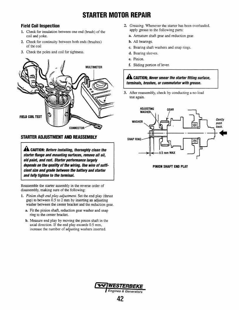
STARTER MOTOR REPAIR Field Coil Inspection 1. Check for insulation between one end (brush) of the
coil and yoke.
2. Check for continuity between both ends (brushes) of the coil
3. Check the poles and coil for tightness.
FIW COIL TEST
STARTER ADJUSTMENT AND REASSEMBLY
A CAUTION: Before installing. thoroughly clean the starter flange and mounting surfaces. remove all oil, old paint. and rust. Starter perfonnance largely depends on the quality of the wiring. Use wire of sufficient size and grade between the battery and starter and fully tighten to the tenninal.
Reassemble the starter assembly in the reverse order of disassembly, making sure of the following:
1. Pinion shaft end play adjustment. Set the end play (thrust gap) to between 0.5 to 2 mrn by inserting an adjusting washer between the center bracket and the reduction gear.
a. Fit the pinion shaft, reduction gear washer and snap ring to the center bracket.
b. Measure end play by moving the pinion shaft in the axial direction. If the end play exceeds 0.5 mm, increase the number of adjusting washers inserted.
2. Greasing. Whenever the starter has been overhauled, apply grease to the following parts:
a. Armature shaft gear and reduction gear.
b. All bearings.
c. Bearing shaft washers and snap rings.
d. Bearing sleeves.
e. Pinion.
f. Sliding portion of lever.
A CAUTION:. Never smear the starter fitting surface, tenninals, brushes, or commutator with grease.
3. After reassembly, check by conducting a no-load test again.
GEAR
SNAP RING
PINION SHAFT END PLAY
l""fiV'fWESTERBEKE Engines & Generators
42
TRANSMISSION
For Transmission Service and Maintenance, refer to your Transmission manual or WESTERBEKES 12C/12D Operators Manual. To re-build a transmission, contact an authorized Transmission Service Center.
HURTWZF Marine Transmission
ZF Industries Marine US Headquarters 3131 SW 42"d Street Fort Lauderdale, FL 33312 Tel: 954-581-4040 Website: www.zf-marine.com
BW/JS Marine Transmissions
Westerbeke Corporation 150 John Hancock Road Taunton, MA 02780 Tel: 508-823-7677 Website: www. westerbeke.com
PRM Marine Transmissions
Newage Transmission Limited Barlow Road Coventry CV2 2LD England Tel: +44 (0) 24 7661 1845 Website: www.newage-pnn.co.uk
NOTE: If the transmission is not being re-built, it should be visually inspected. Flush out and pressure test the oil cooler and replace the coolant hoses. Inspect and lubricate the gear shift linkage and the propeller shaft coupling. Clean and repaint the transmission and change the transmission fluid.
43
12C AND 120 TWO ENGINE SPECIFICATIONS
Engine Type
Governor
Valve Mechanism
Combustion Chamber
Bore & Stroke
Piston Displacement
Firing Order
Direction of Rotation
Maximum Torque
Compression Ratio
Compression Pressure
Valve Seat Angle
Valve Clearance (engine cold)
Dimensions
Inclination
Dry Weight
Fuel Consumption
Idle Speed
Cruise Speed
SPECIFICATIONS Diesel, four-cycle, two-cylinder, fresh watercooled, vertical in-line. 12 Hp @ 3000 rpm maximum
Mechanical, centrifugal weight type
Overhead
Swirl chamber type
2.99 x 2.76 inches (76 x 70 mm)
38.75 cubic inches (0.635 liters)
1 - 2
Clockwise, when viewed from the front.
30 lb-ft (4.15 kg-m) at 2200 rpm
23:1
398 psi (28 kg/em') at 280 rpm
Intake 45• Exhaust 45•
Intake 0.010 inches (0.25) Exhaust 0.010 inches (0.25)
Height: 19.75 (501.65) Width: 17.22 inches ( 437 .3) Length: 25 inches (635)
Continuous 14 • Temporary 25• (not to exceed 30 min.)
228 lbs (1 03.4 kgs)
0.8 us gph (3.0 lph) at 3000 rpm (approximate)
1000-1200 rpm
2000 - 2500 rpm
ELECTRICAL SYSTEM Starting .Battery
Battery Capacity
Starting Aid
Starter Motor
DC No-Load Current
Cold Cranking Current
Alternator
Regulator
12 Volt, (-) negative ground
600 - 800 CCA (Cold Cranking Amps)
Glow plugs, sheathed type
12 Volt, 1.2 Kw, solenoid, actuator shift
100 Amps at 11.5 VoiJs (3000 rpm, min)
125 Amps at 10 Volts (805 rpm, min)
12 Volt DC, 50 Amps
Internal regulator, built into alternator
44
LUBRICATION SYSTEM General
Operating Oil Pressure (engine hot)
Oil Grade
Oil Filter (Pn.#036920)
Sump Capacity (including filter)
General
Fuel
Injection Pump
Engine Timing (Spill Timing)
Injection Pressure
Nozzle
Air cleaner
Air Flow (engine combustion)
Lift Pump (~N #039275)
General
Operating Temperature
Fresh Water Pump (PN# 037015)
Raw Water Pump (PN# 033636)
Raw Water Flow (measured before discharge into exhaust elbow)
System Capacity (Fresh Water)
Pressure type by Trochoid pump, gear-driven, with external pressure valve relie·f
15-45 psi (1.0-3.1 kg/em')
API Specification CF, CF-4, CG-4, CH-4 or Cl-4 SAE 15W-40 (all season).
Full flow, paper element, spin on
3.0 U.S. qts (2.8 liters)
FUEL SYSTEM Open flow, self-bleeding
No.2 diesel (cetane rating of 45 or higher)
In-line plunger type (BOSCH)
19• ± 1• BTDC Static
1991 psi (140 kg/cm2)
Th rattle type
Metal screen type-cleanable
34 cfm (0.96 cmm)
12 voltDC lift capacity of 5' (1.5 mm) wet
COOLING SYSTEM Fresh water-cooled block, thermostaticallycontrolled with heat exchanger
170 -190• F (77- sa· C)
Centrifugal type, metal impeller, belt-driven
Positive displacement, rubber impeller, mechanically-driven
11.1 US gmp (421pm) at 3000 rpm-approx.
2.9 US qts (2.71iters)
TRANSMISSIONS JS Model
PRM 80 BW7
2.05:1 reduction (See Transmission pages)
2.0:1 reduction 2.05:1 reduction
ZF 2.04:1 reduction Propeller Rotation Right hand turning - Standard Transmission Propeller Shaft 3/4" diameter (minimum)
,------1 SEE NOTE 2
1~1 I I I I .J
+iu:D_ ~-==-ll.A.I.I.EJl..l
5I
WIRING DIAGRAM #39144
I •10 RED I
1--------------------------------J
< ~
~
- - --
,--
KEYSWJTCH
I L--------++--:=:==.-':~{~~~ -- -------------
1 I I B B L ~ I ___________________ __! ~-~ BL ~
45
ADMIRAL PANEL
114 f'NK
CAPTAIN PANEL
18
--_I
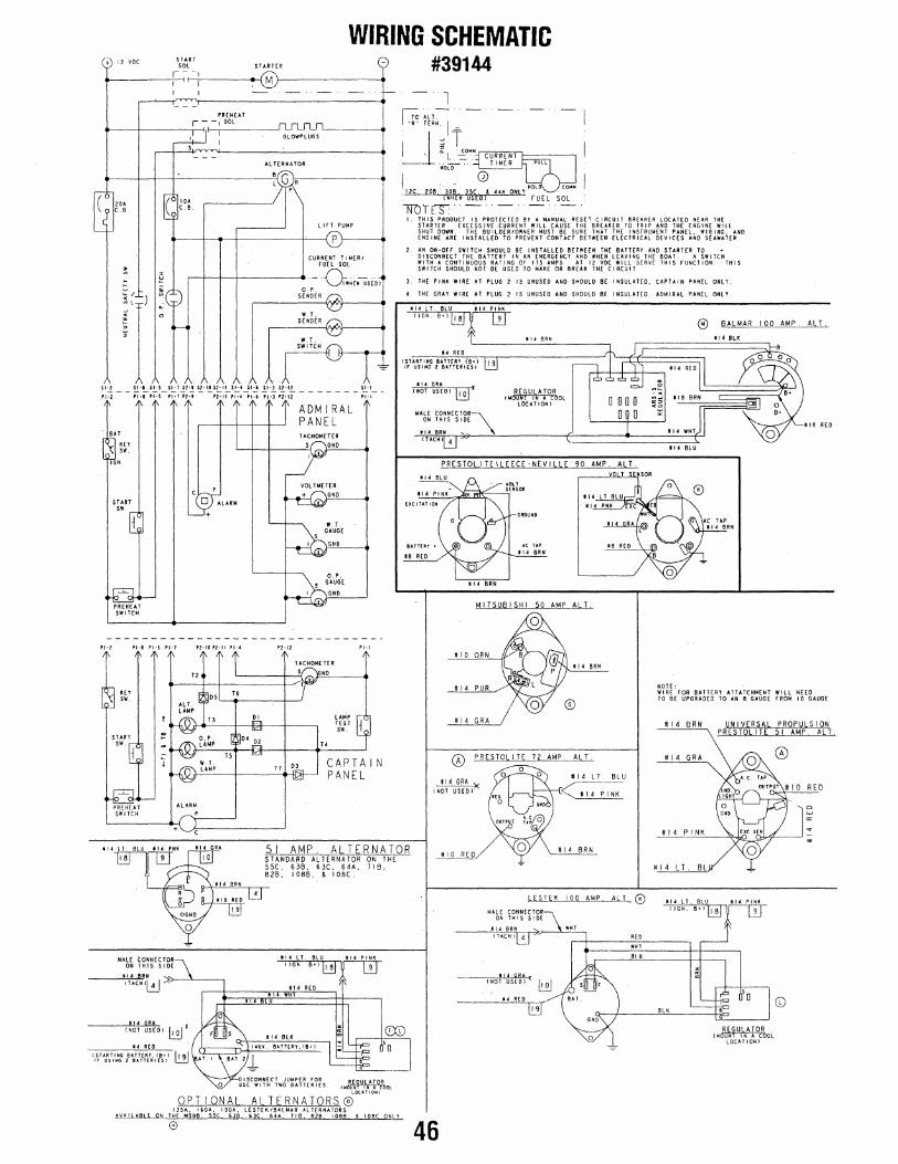
WIRING SCHEMATIC #39144 + IZ VOC START -
SOL STARHR r- --~
M I I I I - -- - - ---r- l
PREHEAT r- - 1 SOL
=P~~ s -
Al T[RNATOR
~~LT-~ -R~ T[RM. I .::. I I ~ T ~ Q. L. :~·~14~cCiu:iiniiiRTENNTTl-------,
"No~ .. TIMER
~~·: ( Jl" t c. e.
LIFT PUMP
j 12c zoe -· JO~ Jsc ~ '" ONLY m : rwHEN usEbl FUEl SOL
lWltS: I THIS PRODUCT IS PROTECTED BY A MANU.\l RESET CIRCUIT I!REAII'[II LOCATED NEAR TN[
STARTER. EXCESSIVE CURRENT WILL CAUSE THE BREAKER TO TRIP AND HI( ENGINE WILL SHUT DOWN. THE BUILDER/OWNER MUST BE SURE THAT THE INSTRUMENT PAN£l, WIRING. AND
~
rr ~
~
0 ,______.
\
BAT
'" ,._ IGN
START sw
,,._l ,1·1 ,.., 11·1
'" sw.
PREHEAT SWITCH
ALARM
\ l
P2·1Z
p
CURRENT T 11-4[111 FUEL SOL
·- ·0wHfiUs£.or s~N~ER t::;;.,
w.r \C.) SENDER t:::l:.\.
'<J w. T.
SWITCH
ADMIRAL PANEL TACHOMEHR
s GNO
GNO
GNO
L.o4r TEST sw_
l =
Pl·l
CAPTAIN PANEL
ENGINE ARE INSTALLED TO PREVENT CONTACT 6ElWEEN fl[CTRICAL Q(VIC[S AND S£AWATER.
2 AN ON-OH SWITCH SHOULD BE INSTAll£0 BETWEEN THE BATT(RY AND STARTER TO DISCONNECT THE BATTERY IN AN EMERGENCY AND WHEN LEAVING THE BO.t.T. A SWITCH WITH A CONTINUOUS RATING OF 115 AMPS AT IZ VDC WILL SERVE THIS F"UNCTION. THIS SWITCH SHOULD NOT BE USED TO MAK£ OR BREAK TH£ CIRCUIT.
J. THE PINK WIRE AT PLUG 2 IS UNUSED AND SHOULD BE INSULATED, CAPTAIN PANEL ONLY.
4 THE GRAY WIRE AT PLUG 2 IS UNUSED AND SHOULD 8£ INSULA T£0. ADMIRAL PAN[l ONLY.
1114LT. BLU 114 PINK
14 R£11 !STARTING BATT[RY.(Stl lr USING l BATTERIES I
!14 GRA INOT US[Ol ~IC
MALE CONNECTOR\ ON THIS SIDE
114 BRN ..._. !TA.CHl -4
BATTEIIT •
18 RED
114 BRN.
tl4 BRN
NOTE: ·
118 RED
114 PUR WI R[ roR BATTERY ATTATCHMENT WILL NEED
AlT.
#14 LT. BLU
< # 14 PINK
TO BE UPGRADED TO AN 8 GAUGE FROM I 0 GAUGE
#14 BRN UNIVERSAL PROPULSION PRESTOLITE 51 AMP. ALT.
#14 GRA
RED
#14 PINK
51 AMP. ALTERNATOR STANDARD AlTERNATOR ON THE 55C, 636, 6JC, 64A, 716, 826, I OBB, & I OBC.
114 lT. BLU 114 PINK
114 RED
!14 Gl!.!. CNOT USED I ~X
14 R£0
114 Blll
UUX B.ITT[IlY,!B•I
guc~~~~c ~w6u=~i~c~9~ s. o•!oi~uiLli 0eRooL
OPTIONAl ALTERNATORs@"""" /JSA, 160A, 190A, LESTEK/BALMAR ALTERNATORS
AY,lllABLE ON THE MSDB 55C 6JB 6JC 64A liB 828 10!18 & IOBC ONLY.
0
# 14 L T, BL
46
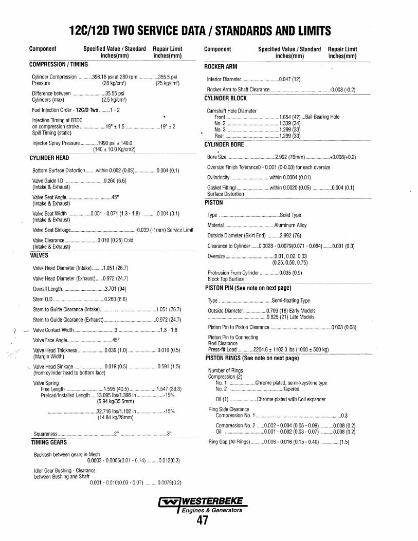
12C/12D TWO SERVICE DATA I STANDARDS AND LIMITS Component Specified Value I Standard Repair Limit
inches(mm) inches(mm) ---
COMPRESSION I TIMING
Cylinder Compression ........... 398.16 psi at 280 rpm ................ 355.5 psi ·Pressure (28 kg/em') (25 kg/em')
Difference between ........................... 35.55 psi Cylinders (max) (2.5 kg/em')
Fuel Injection Order -12C/D Two ......... 1- 2
Injection liming at BTDC on compression stroke ..................... 19° ± 1.5 ............................ 19° ± 2 Spill liming (static)
Injector Spray Pressure .............. 1990 psi± 140.0 (140 ± 10.0 Kg/cm2)
CYLINDER HEAD
Bottom Surface Distortion ........ within 0.002 (0.05) .................. 0.004 (0.1)
Valve Guide 1.0 ................................ 0.260 (6.6) (Intake & Exhaust)
Valve Seat Angle ................................... .45° (Intake & Exhaust)
Valve Seat Width .................. 0.051 - 0.071 (1.3 - 1.8) ............ 0.004 (0.1) (Intake & Exhaust)
Valve Seat Sinkage ..................................................... -0.039 (-1mm) Service Limit
Valve Clearance ........................... O.o10 (0.25) Cold (Intake & Exhaust)
VAlVES
Valve Head Diameter (lntake) ......... 1.051 (26.7)
Valve Head Diameter (Exhaust) ...... 0.972 (24.7)
Overall Length ................................... 3.701 (94)
Stem O.D .......................................... 0.260 (6.6)
Stem to Guide Clearance (Intake) ............................................. 1.051 (26.7)
Stem to Guide Clearance (Exhaust) .......................................... 0.972 (24.7)
Valve Contact Width ................................. 3 .................................. 1.3 - 1.8
Valve Face Angle .................................... .45°
Valve Head Thickness ...................... 0.039 (1.0) .............. :· ......... 0.019 (0.5) (Margin Width)
·,. Valve Head Sinkage ........................ O.o19 (0.5) ........................ 0.591 (1.5) (from cylinder head to bottom face)
Valve Spring Free Length .............................. 1.595 ( 40.5) ...................... 1.54 7 (39.3) Preload/Installed Length .... 13.095 lbs/1.398 in ...................... -15%
(5.94 kg/35.5mm)
........................................ 32.7161bs/1.102 in ...................... -15% (14.84 kg/28mm)
Squareness .............................................. 2° ...................................... 3°
TIMING GEARS
Backlash between gears in Mesh 0.0003- 0.0005(0.01 - 0.14) .......... 0.012(0.3)
Idler Gear Bushing - Clearance between Bushing and Shaft
0.001 - 0 01 0(0.03 - 0.07) .......... 0.0078(0.2)
Component Specified Value I Standard Repair limit lnches(mm) inches(mm)
ROCKER ARM
Interior Diameter ............................... 0.047 (12)
Rocker Arm to Shaft Clearance ................................................ -0.008 (-0.2)
CYLINDER BlOCK
Camshaft Hole Diameter Front... ......................................... 1.654 (42) , .. Ball Bearing Hole No.2 .......................................... 1.339 (34) No. 3 .......................................... 1.299 (33) Rear ............................................ 1.299 (33)
CYLINDER BORE . Bore Size ........................................ 2.992 (76mm) .................... +0.008(+0.2)
Oversize Finish ToleranceO - 0.001 (0-0.03) for each oversize
Cylindricity ............................ : ... within 0.0004 (0.01)
Gasket Fitting/ ........................... within 0.0020 (0.05) ................ 0.004 (0.1) Surface Distortion
PISTON
Type ................................................. Solid Type
Materiai ......................................... Aiuminum Alloy
Outside Diameter (Skirt End) .......... 2.992 (76)
Clearance to Cylinder ...... 0.0028- 0.0079(0.071 - 0.084) ........ 0.001 (0.3)
Oversize ...... : ................................. 0.01, 0.02. 0.03 (0.25, 0.50, 0.75)
Protrusion From Cylinder ................ 0.035 (0.9) Block Top Surface
PISTON PIN (See note on next page)
Type .......................................... Semi-floating Type
Outside Diameter. .................. 0.709 (18) Early Models ................................................ 0.825 (21) Late Models
Piston Pin to Piston Clearance ................................................. 0.003 (0.08)
Piston Pin to Connecting Rod Clearance Press-fit Load ............. 2204.6 ± 1102.31bs (1000 ± 500 kg)
PISTON RINGS (See note on next page)
Number of Rings Compression (2)
No. 1 ...................... Chrome plated, semi-keystone type No. 2 ............................................ Tapered
Oil (1) ...................... Chrome plated with Coil expander
Ring Sid~ Clearance Compression No. 1 ...................................................................... 0.3
Compression No. 2 ...... 0.002 - 0.004 (0.05 - 0.09) ......... .0.008 (0.2) Oil ............................... .0.001 - 0.002 (0.03 - 0.07) .......... 0.008 (0.2)
Ring Gap (All Rings) ........... 0.006- 0.016 (0.15- 0.40) ................ (1.5)
Engines & Generators
47
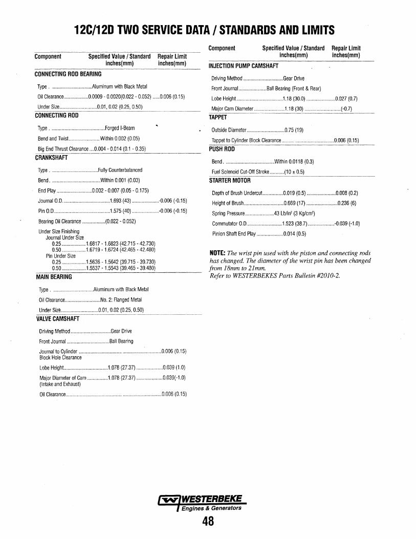
12C/12D TWO SERVICE DATA I STANDARDS AND LIMITS
Component Specified Value I Standard Repair limit inches(mm) inches(mm)
-------------------------- ----~
CONNECTING ROD BEARING
Type .................................. Aluminum with Black Metal
Oil Clearance .................... 0.0009- 0.0020(0.022- 0.052) ...... 0 006 (0.15)
Under Size ............................... 0.01, 0.02 (0.25, 0.50) ____________________ ____c ____ ____c ____ ~---------
CONNECTING ROD
Type ........................................ .Forged 1-Beam
Bend and Twist.. ........................ Within 0.002 (0.05)
Big End Thrust Clearance .... 0.004 - 0.014 (0.1 - 0.35)
CRANKSHAFT
Type ....................................... Fully Counterbalanced
Bend ........................................ .Within 0.001 (0.03)
End Play ............................. 0.002- 0.007 (0.05- 0.175)
Journal 0.0 ....................................... 1.693 (43) ...................... -0.006 (-0.15)
Pin O.D .............................................. 1.575 (40) ...................... -0.006 (-0.15)
Bearing Oil Clearance ................... (0.022- 0.052)
Under Size Rnishing Journal Under Size
0.25 .................... 1.6817- 1.6823 (42.715- 42.730) 0.50 .................... 1.6719- 1.6724 (42.465- 42.480)
Pin Under Size 0.25 .................... 1.5636- 1.5642 (39.715- 39.730) 0.50 .................... 1.5537 -1.5543 (39.465- 39.480)
MAIN BEARING
Type .................................. Aluminum with Black Metal
Oil Clearance ............................. No. 2: Flanged Metal
Under Size ............................... 0.01, 0.02 (0.25, 0.50)
VAlVE CAMSHAFT
Driving Method ................................. Gear Drive
Front Journal ................................... Ball Bearing
Journal to Cylinder ................................................................... 0.006 (0.15) Block Hole Clearance
Lobe Height.. .................................. 1.078 (27.37) ...................... 0.039 (1.0)
Major Diameter of Cam ................. 1.078 (27.37) ...................... 0.039( -1.0) (Intake and Exhaust)
Oil Clearance .............................................................................. 0.006 (0.15)
Component Specified Value I Standard Repair limit inches(mm) inches(mm)
INJECTION PUMP CAMSHAFT
Driving Method ................................. Gear Drive
Front Journai. ...................... Ball Bearing (Front & Rear)
Lobe Height.. ........ ; .......................... 1.18 (30.0) ........................ 0.027 (0.7)
Major Cam Diameter ......................... 1.18 (30) .............................. (-0.7) ---------·~
TAPPET
Outside Diameter ............................... 0.75 (1 9)
Tappet to Cylinder Block Clearance .......................................... 0.006 (0.15)
PUSH ROD
Bend ........................................ .Within 0.0118 (0.3)
Fuel Solenoid Cut-Off Stroke ............ (10 ± 0.5)
STARTER MOTOR
Depth of Brush Undercut.. ............... 0.019 (0.5) ........................ 0.008 (0.2)
Height of Brush ................................. 0.669 (17) .......................... 0.236 (6)
Spring Pressure ........................ 43 Lb/in' (3 Kg/em')
Commutator 0.0 ............................. 1.523 (38.7) ...................... -0.039 (-1.0)
Pinion Shaft End Play ...................... 0.014 (0.5)
NOT£: T'ae wrist pin used with the piston and connecting rods has changed. The diameter of the wrist pin has been changed from 18mm to 21 mm. Refer to WESTERBEKES Parts Bulletin #2010-2.
48
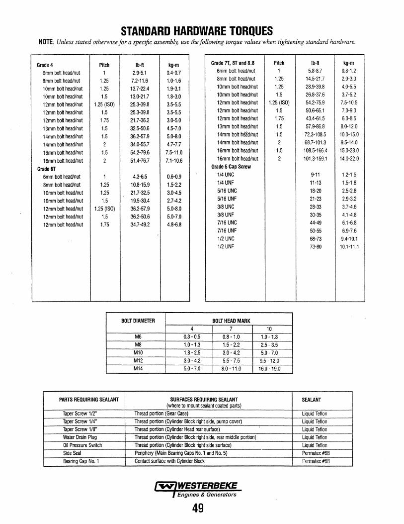
STANDARD HARDWARE TORQUES NOTE: Unless stated otherwise for a specific assembly, use the following torque values when tightening standard hardware.
Grade 4 Pilch I b-It kg-m Grade 7T, 8T and 8.8 Pitch I b-It kg-m
6mm bolt head/nut 1 2.9-5.1 0.4-0.7 6mm bolt head/nut 1 5.8-8.7 0.8-1.2
8mm bolt head/nut 1.25 7.2-11.6 1.0-1.6 8mm bolt head/nut 1.25 14.5-21.7 2.0-3.0
1 Omm bolt head/nut 1.25 13.7-22.4 1.9-3.1 10mm bolt head/nut 1.25 28.9-39.8 4.0-5.5
1 Omm bolt head/nut 1.5 13.0-21.7 1.8-3.0 10mm bolt head/nut 1.5 26.8-37.6 3.7-5.2
12mm bolt head/nut 1.25 (ISO) 25.3-39.8 3.5-5.5 12mm bolt head/nut 1.25 (ISO) 54.2-75.9 7.5-10.5
12mm bolt head/nut 1.5 25.3-39.8 3.5-5.5 12mm bolt head/nut 1.5 50.6-65.1 7.0-9.0
12mm bolt head/nut 1.75 21.7-36.2 3.0-5.0 12mm bolt head/nut 1.75 43.4-61.5 6.0-8.5
13mm bolt head/nut 1.5 32.5-50.6 4.5-7.0 13mm bolt head/nut 1.5 57.9-86.8 8.0-12.0
14mm bolt head/nut 1.5 36.2-57.9 5.0-8.0 14mm bolt heail/nut 1.5 72.3-108.5 10.0-15.0
14mm bolt head/nut 2 34.0-55.7 4.7-7.7 14mm bolt head/nut 2 68.7-101.3 9.5-14.0
16mm bolt head/nut 1.5 54.2-79.6 7.5-11.0 16mm bolt head/nut 1.5 108.5-166.4 15.0-23.0
16mm bolt head/nut 2 51.4-76.7 7.1-10.6 16mm bolt head/nut 2 101.3-159.1 14.0-22.0
Grade 6T Grade 5 Cap Screw
6mm bolt head/nut 1 4.3-6.5 0.6-0.9 1/4 UNC 9-11 1.2-1.5
8mm bolt head/nut 1.25 10.8-15.9 1.5-2.2 1/4 UNF 11-13 1.5-1.8
·1 Omm bolt head/nut 1.25 21.7-32.5 3.0-4.5 5/16 UNC 18-20 2.5-2.8
10mm bolt head/nut 1.5 19.5-30.4 2.7-4.2 5116 UNF 21-23 2.9-3.2
12mm bolt head/nut 1.25 (ISO) 36.2-57.9 5.0-8.0 318 UNC 28-33 3.7-4.6
12mm bolt head/nut 1.5 36.2-50.6 5.0-7.0 318 UNF 30-35 4.1-4.8
12mm bolt head/nut 1.75 34.7-49.2 4.8-6.8 7/16 UNC 44-49 6.1-6.8 7/16 UNF 50-55 6.9-7.6 112 UNC 68-73 9.4-10.1 112 UNF 73-80 10.1-11.1
BOLT DIAMETER BOLT HEAD MARK 4 7 10
M6 0.3-0.5 0.8-1.0 1.0-1.3 MB 1.0-1.3 1.5-2.2 2.5-3.5 M10 1.8-2.5 3.0-4.2 5.0-7.0 M12 3.0-4.2 5.5-7.5 9.5-12.0 M14 5.0-7.0 8.0-11.0 16.0- 19.0
PARTS REQUIRING SEAlANT SURFACES REQUIRING SEAlANT SEALANT (where to mount sealant coated parts)
Taper Screw 112" Thread portion (Gear Gase) Liquid Teflon Taper Screw 1/4" Thread portion (Cylinder Block right side, pump cover) Liquid Teflon Taper Screw 1/8" Thread portion (Cylinder Head rear surface) Liquid Teflon Water Drain Plug Thread portion {Cylinder Block right side, rear middle portion) Liquid Teflon Oil Pressure Switch Thread portion {Cylinder Block right side surface) Liquid Teflon Side Seal Periphery (Main Bearing Caps No. 1 and No. 5) Permatex #6B Bearing Cap No. 1 Contact surface with Cylinder Block Permatex #68
49
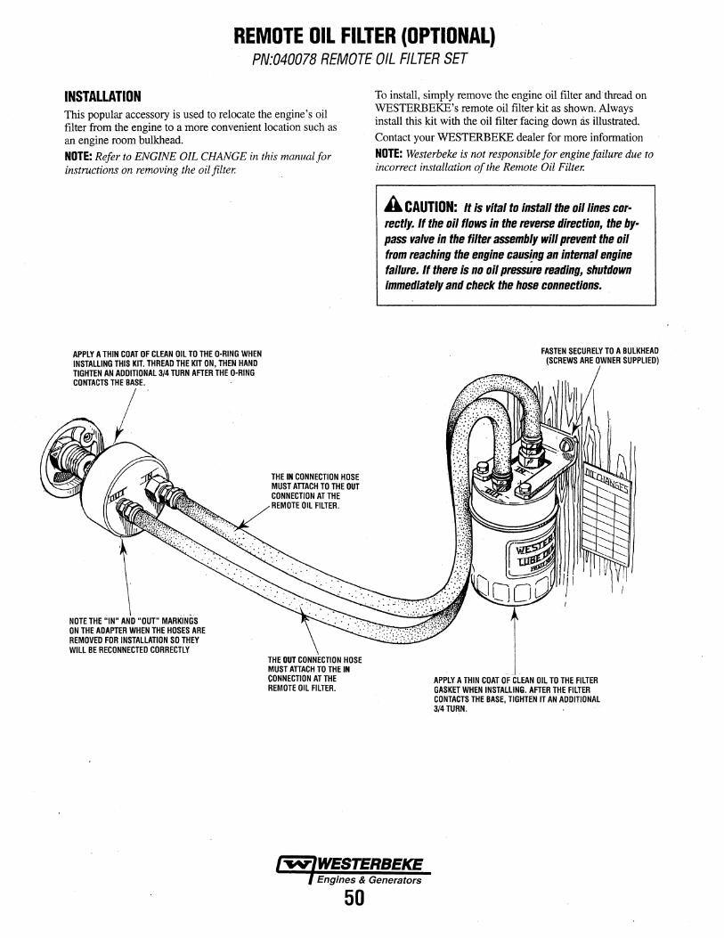
REMOTE OIL FILTER (OPTIONAL) PN:040078 REMOTE OIL FILTER SET
INSTALLATION This popular accessory is used to relocate the engine's oil filter from the engine to a more convenient location such as an engine room bulkhead.
NOTE: Refer to ENGINE OIL CHANGE in this manual for instructions on removing the oil filter.
APPLY A THIN COAT OF CLEAN OIL TO THE O·RING WHEN INSTALLING THIS KIT. THREAD THE KIT ON, THEN HAND TIGHTEN AN ADDITIONAL3/4 TURN AFTER THE D-RING CONTACTS THE BASE.
NOTE THE ''IN" AND "OUT" MARKiNGS ON THE ADAPTER WHEN THE HOSES ARE REMOVED FOR INSTALLATION SO THEY WILL BE RECONNECTED CORRECTLY
THE IN CONNECTION HOSE MUST ATTACH TO THE OUT CONNECTION ATTHE REMOTE OIL FILTER.
THEOUT HOSE MUST ATTACH TO THE IN CONNECTION AT THE REMOTE OIL FILTER.
50
To install, simply remove the engine oil filter and thread on WESTERBEKE's remote oil filter kit as shown. Always install this kit with the oil filter facing down as illustrated.
Contact your WESTERBEKE dealer for more information
NOTE: Westerbeke is not responsible for engine failure due to incorrect installation of the Remote Oil Filter.
A CAUTION: .. It Is vital to Install the oil lines correctly. If the oil flows in the reverse direction, the bypass valve in the filter assembly will prevent the oil from reaching the engine causing an internal engine failure. If there is no oil pressure reading, shutdown immediately and check the hose connections.
FASTEN SECURELY TO A BULKHEAD (SCREWS ARE OWNER SUPPLIED)
APPLY A THIN COAT OF CLEAN OIL TO THE FILTER GASKET WHEN INSTALLING. AFTER THE FILTER CONTACTS THE BASE, TIGHTEN IT AN ADDITIONAL 3/4 TURN,
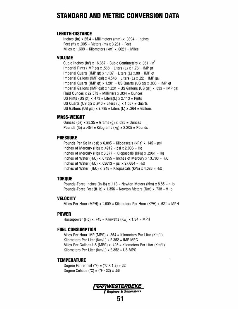
STANDARD AND METRIC CONVERSION DATA
LENGTH-DISTANCE Inches (in) x 25.4 =Millimeters (mm) x .0394 = Inches Feet (ft) x .305 = Meters (m) x 3.281 = Feet Miles x 1.609 = Kilometers (km) x .0621 = Miles
VOLUME Cubic Inches (in3) x 16.387 = Cubic Centim~ters x .061 =in 3
Imperial Pints (IMP pt) x .568 =Liters (L) x 1.76 = IMP pt Imperial Quarts (IMP qt) x 1.137 = Liters (L) x.88 = IMP qt Imperial Gallons (IMP gal) x 4.546 = Liters (L) x .22 = IMP gal Imperial Quarts (IMP qt) x 1.201 =US Quarts (US qt) x .833 = IMP qt Imperial Gallons (IMP gal) x 1.201 =US Gallons (US gal) x .833 = IMP gal Fluid Ounces x 29.573 = Milliliters x .034 = Ounces US Pints (US pt) x .473 = Liters(L) x 2.113 = Pints US Quarts (US qt) x .946 = Liters (L) x 1.057 = Quarts US Gallons (US gal) x 3.785 =Liters (L) x .264 =Gallons
MASS-WEIGHT Ounces (oz) x 28.35 =Grams (g) x .035 =Ounces Pounds (lb) x .454 = Kilograms (kg) x 2.205 = Pounds
PRESSURE Pounds Per Sq In (psi) x 6.895 = Kilopascals (kPa) x .145 =psi Inches of Mercury (Hg) x .4912 = psi x 2.036 = Hg Inches of Mercury (Hg) x 3.377 = Kilopascals (kPa) x .2961 = Hg Inches of Water (H20) x .07355 = Inches of Mercury x 13.783 = H20 Inches of Water (H20) x .03613 = psi x 27.684 = H20 Inches of Water (H20) x .248 = Kilopascals (kPa) x 4.026 = H20
TORQUE Pounds-Force Inches (in-lb) x .113 = Newton Meters (Nm) x 8.85 =in-lb Pounds-Force Feet (ft-lb) x 1.356 =Newton Meters (Nm) x .738 = ft-lb
VELOCITY Miles Per Hour (MPH) x 1.609 = Kilometers Per Hour (KPH) x .621 =MPH
POWER Horsepower (Hp) x .745 =Kilowatts (Kw) x 1.34 =MPH
FUEL CONSUMPTION Miles Per Hour IMP (MPG) x .354 = Kilometers Per Liter (Km/L) Kilometers Per Liter (Km/L) x 2.352 = IMP MPG Miles Per Gallons US (MPG) x .425 = Kilometers Per Liter (Km/L) Kilometers Per Liter (Km/L) x 2.352 = US MPG
TEMPERATURE Degree Fahrenheit (°F) = (°C X 1.8) + 32 Degree Celsius (0 C} = (°F - 32) x .56
51


I~? i·ii#;l =1#.1Si
6/2012-1164