Embed Size (px)
Citation preview
M E M O R A N D U M
TO: National Electrical Code® Correlating Committee
FROM: Sarah Caldwell, Technical Committee Administrator
DATE: April 2, 2019
SUBJECT: NEC® Second Draft Correlating Committee FINAL Ballot
Results (A2019 Cycle)
According to the final ballot results, all Second Correlating Revisions and the
Ballot to Forward the National Electrical Code® through the Development Process
received the necessary affirmative votes to pass ballot.
Second Correlating Revisions (SCRs):
12 Members Eligible to Vote
0 Members Not Returned
Ballot to Forward the NEC® through the Development Process:
12 Members Eligible to Vote
0 Members Not Returned
The attached report shows the number of affirmative, negative, and abstaining
votes as well as the explanation of the vote for each Second Correlating
Revision.
To pass ballot, each Second Correlating Revision requires: (1) simple majority of
those eligible to vote and (2) an affirmative vote of 3/4 of ballots returned. See
Sections 3.3.4.3.(c) and 4.4.11.5 of the Regulations Governing the Development
of NFPA Standards.
Second Correlating Revision No. 76-NFPA 70-2019 [ Global Comment ]
This document must be checked in before creating an SCR Delete 430.246
Supplemental Information
File Name Description Approved
NEC_Global_SCR-76_New_section_being_deleted_with_an_SCR.docx For ballot
Submitter Information Verification
Committee: NEC-P11
Submittal Date: Fri Mar 01 10:36:38 EST 2019
Committee Statement
CommitteeStatement:
The Correlating Committee has deleted 430.246 to correlate with CMP-5 action on SR7760.
Committee Comment No. 7658-NFPA 70-2018 [Global Comment]
Ballot Results
This item has passed ballot
12 Eligible Voters
0 Not Returned
12 Affirmative All
0 Affirmative with Comments
0 Negative with Comments
0 Abstention
Affirmative All
Brunssen, James E.
Dressman, Kevin L.
Hickman, Palmer L.
Hittinger, David L.
Holub, Richard A.
Johnston, Michael J.
Kovacik, John R.
Manche, Alan
McDaniel, Roger D.
Porter, Christine T.
Straniero, George A.
Williams, David A.
National Fire Protection Association Report https://submittals.nfpa.org/TerraViewWeb/ContentFetcher?commentPar...
1 of 144 4/2/2019, 11:09 AM
430.246 Size of Equipment Grounding Conductors. (A) General.
Copper, aluminum, or copper-clad aluminum equipment grounding conductors of the wire type shall not be smaller than shown in Table 430.252, but in no case shall they be required to be larger than the circuit conductors supplying the equipment. Where a cable tray, a raceway, or a cable armor or sheath is used as the equipment grounding conductor, as provided in 250.118 and 250.134(1), it shall comply with 250.4(A)(5) or (B)(4).
Equipment grounding conductors shall be permitted to be sectioned within a multiconductor cable, provided the combined circular mil area complies with Table 430.252.
(B) Increased in Size.
Where ungrounded conductors are increased in size from the minimum size that has sufficient ampacity for the intended installation, wire-type equipment grounding conductors, where installed, shall be increased in size proportionately, according to the circular mil area of the ungrounded conductors.
(C) Multiple Circuits.
Where a single equipment grounding conductor is run with multiple circuits in the same raceway, cable, or cable tray, it shall be sized in accordance with Table 430.252 based on the largest overcurrent device protecting conductors in the raceway, cable, or cable tray. Equipment grounding conductors installed in cable trays shall meet the minimum requirements of 392.10(B)(1)(c).
(D) Motor Circuits.
Equipment grounding conductors for motor circuits shall be sized in accordance with 430.246(D)(1) or (D)(2).
(1) General.
The equipment grounding conductor size shall not be smaller than determined by 430.246(A) based on the rating of the branch circuit short-circuit and ground-fault protective device.
(2) Instantaneous-Trip Circuit Breaker and Motor Short-Circuit Protector.
Where the overcurrent device is an instantaneous trip circuit breaker or a motor short-circuit protector, the equipment grounding conductor shall be sized not smaller than that given by 430.246(A) using the maximum permitted rating of a dual element time-delay fuse selected for branch circuit short-circuit and ground-fault protection in accordance with 430.52(C)(1), Exception No. 1.
(E) Flexible Cord and Fixture Wire.
The equipment grounding conductor in a flexible cord with the largest circuit conductor 10 AWG or smaller, and the equipment grounding conductor used with fixture wires of any size in accordance with 240.5, shall not be smaller than 18 AWG copper and shall not be smaller than the circuit conductors. The equipment grounding conductor in a flexible cord with a circuit conductor larger than 10 AWG shall be sized in accordance with Table 430.252.
(F) Conductors in Parallel.
For circuits of parallel conductors as permitted in 310.10(G), the equipment grounding conductor shall be installed in accordance with 430.246(F)(1) or (F)(2).
(1) Conductor Installations in Raceways, Auxiliary Gutters, or Cable Trays.
(a) Single Raceway or Cable Tray. If conductors are installed in parallel in the same raceway or cable tray, a single wire-type conductor shall be permitted as the equipment grounding conductor. The wire-type equipment grounding conductor shall be sized in accordance with 430.246, based on the overcurrent protective device for the feeder or branch circuit. Wire-type equipment grounding conductors installed in cable trays shall meet the minimum requirements of 392.10(B)(1)(c). Metal raceways or auxiliary gutters in accordance with 250.118 or cable trays complying with 392.60(B) shall be permitted as the equipment grounding conductor.
(b) Multiple Raceways. If conductors are installed in parallel in multiple raceways, wire-type equipment grounding conductors, where used, shall be installed in parallel in each raceway. The equipment grounding conductor installed in each raceway shall be sized in compliance with 430.246 based on the overcurrent protective device for the feeder or
branch circuit. Metal raceways or auxiliary gutters in accordance with 250.118 or cable trays complying with 392.60(B) shall be permitted as the equipment grounding conductor.
(2) Multiconductor Cables.
(a) If multiconductor cables are installed in parallel, the equipment grounding conductor(s) in each cable shall be connected in parallel.
(b) If multiconductor cables are installed in parallel in the same raceway, auxiliary gutter, or cable tray, a single equipment grounding conductor that is sized in accordance with 430.246 shall be permitted to be connected together in parallel with the equipment grounding conductors provided within the multiconductor cables.
(c) Equipment grounding conductors installed in cable trays shall meet the minimum requirements of 392.10(B)(1)(c). Cable trays complying with 392.60(B), metal raceways in accordance with 250.118, or auxiliary gutters shall be permitted as the equipment grounding conductor.
(d) Except as provided in 430.246(F)(2)(b) for raceway or cable tray installations, the equipment grounding conductor in each multiconductor cable shall be sized in accordance with 430.246 based on the overcurrent protective device for the feeder or branch circuit.
(G) Motor Feeder Taps.
Equipment grounding conductors run with motor feeder taps shall not be smaller than shown in Table 430.252 based on the rating of the overcurrent device ahead of the motor feeder but shall not be required to be larger than the tap conductors.
Second Correlating Revision No. 34-NFPA 70-2019 [ Global Input ]
Update following section references:
230.209 – Update reference from Ar cle 280 to Ar cle 242.
646.3(I) – Update reference from Ar cle 285 to Ar cle 242.
694.7(D) – Update reference from "Part II of Ar cle 285" to "Part II of Ar cle 242".
Submitter Information Verification
Committee: NEC-AAC
Submittal Date: Wed Feb 20 15:17:50 EST 2019
Committee Statement
CommitteeStatement:
The Correlating Committee updated the references for correlation. Articles 280 and 285 havebeen replaced by Article 242.
Ballot Results
This item has passed ballot
12 Eligible Voters
0 Not Returned
12 Affirmative All
0 Affirmative with Comments
0 Negative with Comments
0 Abstention
Affirmative All
Brunssen, James E.
Dressman, Kevin L.
Hickman, Palmer L.
Hittinger, David L.
Holub, Richard A.
Johnston, Michael J.
Kovacik, John R.
Manche, Alan
McDaniel, Roger D.
Porter, Christine T.
Straniero, George A.
Williams, David A.
National Fire Protection Association Report https://submittals.nfpa.org/TerraViewWeb/ContentFetcher?commentPar...
2 of 144 4/2/2019, 11:09 AM
Second Correlating Revision No. 43-NFPA 70-2019 [ Global Input ]
Renumber Parts IV, V and VI in sequence in Article 800 to reflect deletion of Part III.
Delete Part IV of Article 805 and renumber Parts V and VI in sequence.
Reinsert title to Part V of Article 820.
Relocate 830.93 to Part IV Grounding Methods of Article 830.
Submitter Information Verification
Committee: NEC-AAC
Submittal Date: Thu Feb 21 09:04:47 EST 2019
Committee Statement
CommitteeStatement:
The Correlating Committee noted and revised the arrangement of parts in these articles. TheNEC does not use gaps in numbering between article parts.
Ballot Results
This item has passed ballot
12 Eligible Voters
0 Not Returned
11 Affirmative All
1 Affirmative with Comments
0 Negative with Comments
0 Abstention
Affirmative All
Dressman, Kevin L.
Hickman, Palmer L.
Hittinger, David L.
Holub, Richard A.
Johnston, Michael J.
Kovacik, John R.
Manche, Alan
McDaniel, Roger D.
Porter, Christine T.
Straniero, George A.
Williams, David A.
Affirmative with Comment
Brunssen, James E.
By eliminating Part III and renumbering Parts IV, V and VI in Article 800, and deleting Part IV in Article 805 andrenumbering Parts V and VI, the parallelism between Articles 770, 800, 805, 820, 830 and 840 has beendestroyed. This long-standing parallelism promoted NEC usability that is no longer there.
National Fire Protection Association Report https://submittals.nfpa.org/TerraViewWeb/ContentFetcher?commentPar...
3 of 144 4/2/2019, 11:09 AM
Second Correlating Revision No. 50-NFPA 70-2019 [ Global Input ]
See attached file for cross reference updates to Annex B.
Supplemental Information
File Name Description Approved
CC-2020-SR-mtg-TG_3-Informative_Annex_B.docx For ballot
Submitter Information Verification
Committee: NEC-AAC
Submittal Date: Thu Feb 21 10:12:36 EST 2019
Committee Statement
CommitteeStatement:
The Correlating Committee has revised Annex B to correct and simplify the numbering andcross referencing within the annex.
See attachment
Ballot Results
This item has passed ballot
12 Eligible Voters
0 Not Returned
12 Affirmative All
0 Affirmative with Comments
0 Negative with Comments
0 Abstention
Affirmative All
Brunssen, James E.
Dressman, Kevin L.
Hickman, Palmer L.
Hittinger, David L.
Holub, Richard A.
Johnston, Michael J.
Kovacik, John R.
Manche, Alan
McDaniel, Roger D.
Porter, Christine T.
Straniero, George A.
Williams, David A.
National Fire Protection Association Report https://submittals.nfpa.org/TerraViewWeb/ContentFetcher?commentPar...
4 of 144 4/2/2019, 11:09 AM
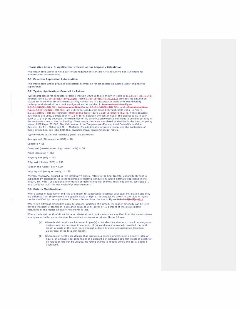
Informative Annex B Application Information for Ampacity Calculation
This informative annex is not a part of the requirements of this NFPA document but is included for informational purposes only.
B.1 Equation Application Information.
This informative annex provides application information for ampacities calculated under engineering supervision.
B.2 Typical Applications Covered by Tables.
Typical ampacities for conductors rated 0 through 2000 volts are shown in Table B.310.15(B)(2)(1)B.2(1) through Table B.310.15(B)(2)(10)B.2(10). Table B.310.15(B)(2)(11)B.2(11) provides the adjustment factors for more than three current-carrying conductors in a raceway or cable with load diversity. Underground electrical duct bank configurations, as detailed in Informational Note Figure B.310.15(B)(2)(3)B.2(2), Informational Note Figure B.310.15(B)(2)(4)B.2(3), and Informational Note Figure B.310.15(B)(2)(5)B.2(4), are utilized for conductors rated 0 through 5000 volts. In Figure B.310.15(B)(2)(2)B.2(1) through Informational Note Figure B.310.15(B)(2)(5)B.2(4), where adjacent duct banks are used, a separation of 1.5 m (5 ft) between the centerlines of the closest ducts in each bank or 1.2 m (4 ft) between the extremities of the concrete envelopes is sufficient to prevent derating of the conductors due to mutual heating. These ampacities were calculated as detailed in the basic ampacity paper, AIEE Paper 57-660, The Calculation of the Temperature Rise and Load Capability of Cable Systems, by J. H. Neher and M. H. McGrath. For additional information concerning the application of these ampacities, see IEEE STD 835, Standard Power Cable Ampacity Tables.
Typical values of thermal resistivity (Rho) are as follows:
Average soil (90 percent of USA) = 90
Concrete = 55
Damp soil (coastal areas, high water table) = 60
Paper insulation = 550
Polyethylene (PE) = 450
Polyvinyl chloride (PVC) = 650
Rubber and rubber-like = 500
Very dry soil (rocky or sandy) = 120
Thermal resistivity, as used in this informative annex, refers to the heat transfer capability through a substance by conduction. It is the reciprocal of thermal conductivity and is normally expressed in the units°C-cm/watt. For additional information on determining soil thermal resistivity (Rho), see IEEE STD 442, Guide for Soil Thermal Resistivity Measurements.
B.3 Criteria Modifications.
Where values of load factor and Rho are known for a particular electrical duct bank installation and they are different from those shown in a specific table or figure, the ampacities shown in the table or figure can be modified by the application of factors derived from the use of Figure B.310.15(B)(2)(1)B.3.
Where two different ampacities apply to adjacent portions of a circuit, the higher ampacity can be used beyond the point of transition, a distance equal to 3 m (10 ft) or 10 percent of the circuit length calculated at the higher ampacity, whichever is less.
Where the burial depth of direct burial or electrical duct bank circuits are modified from the values shown in a figure or table, ampacities can be modified as shown in (a) and (b) as follows.
(a) Where burial depths are increased in part(s) of an electrical duct run to avoid underground obstructions, no decrease in ampacity of the conductors is needed, provided the total length of parts of the duct run increased in depth to avoid obstructions is less than 25 percent of the total run length.
(b) Where burial depths are deeper than shown in a specific underground ampacity table or figure, an ampacity derating factor of 6 percent per increased 300 mm (foot) of depth for all values of Rho can be utilized. No rating change is needed where the burial depth is decreased.
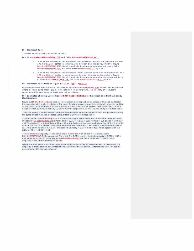
B.4 Electrical Ducts.
The term electrical duct(s) is defined in 311.2.
B.5 Table B.310.15(B)(2)(6)B.2(6) and Table B.310.15(B)(2)(7)B.2(7).
(a) To obtain the ampacity of cables installed in two electrical ducts in one horizontal row with 190-mm (7.5-in.) center-to-center spacing between electrical ducts, similar to Figure B.310.15(B)(2)(2)B.2(1), Detail 1, multiply the ampacity shown for one duct in Table B.310.15(B)(2)(6)B.2(6) and Table B.310.15(B)(2)(7)B.2(7) by 0.88.
(b) To obtain the ampacity of cables installed in four electrical ducts in one horizontal row with 190-mm (7.5-in.) center-to-center spacing between electrical ducts, similar to Figure B.310.15(B)(2)(2)B.2(1), Detail 2, multiply the ampacity shown for three electrical ducts in Table B.310.15(B)(2)(6)B.2(6) and Table B.310.15(B)(2)(7)B.2(7) by 0.94.
B.6 Electrical Ducts Used in Figure B.310.15(B)(2)(2)B.2(1).
If spacing between electrical ducts, as shown in Figure B.310.15(B)(2)(2)B.2(1), is less than as specified where electrical ducts enter equipment enclosures from underground, the ampacity of conductors contained within such electrical ducts need not be reduced.
B.7 Examples Showing Use of Figure B.310.15(B)(2)(1)B.3 for Electrical Duct Bank Ampacity Modifications.
Figure B.310.15(B)(2)(1)B.3 is used for interpolation or extrapolation for values of Rho and load factor for cables installed in electrical ducts. The upper family of curves shows the variation in ampacity and Rho at unity load factor in terms of I1, the ampacity for Rho = 60, and 50 percent load factor. Each curve is designated for a particular ratio I2/I1, where I2 is the ampacity at Rho = 120 and 100 percent load factor.
The lower family of curves shows the relationship between Rho and load factor that will give substantially the same ampacity as the indicated value of Rho at 100 percent load factor.
As an example, to find the ampacity of a 500-kcmil copper cable circuit for six electrical ducts as shown in Table B.310.15(B)(2)(5)B.2(5): At the Rho = 60, LF = 50, I1 = 583; for Rho = 120 and LF = 100, I2 = 400. The ratio I2/I1 = 0.686. Locate Rho = 90 at the bottom of the chart and follow the 90 Rho line to the intersection with 100 percent load factor where the equivalent Rho = 90. Then follow the 90 Rho line to I2/I1 ratio of 0.686 where F = 0.74. The desired ampacity = 0.74 × 583 = 431, which agrees with the table for Rho = 90, LF = 100.
To determine the ampacity for the same circuit where Rho = 80 and LF = 75, using Figure B.310.15(B)(2)(1)B.3, the equivalent Rho = 43, F = 0.855, and the desired ampacity = 0.855 × 583 = 498 amperes. Values for using Figure B.310.15(B)(2)(1)B.3 are found in the electrical duct bank ampacity tables of this informative annex.
Where the load factor is less than 100 percent and can be verified by measurement or calculation, the ampacity of electrical duct bank installations can be modified as shown. Different values of Rho can be accommodated in the same manner.
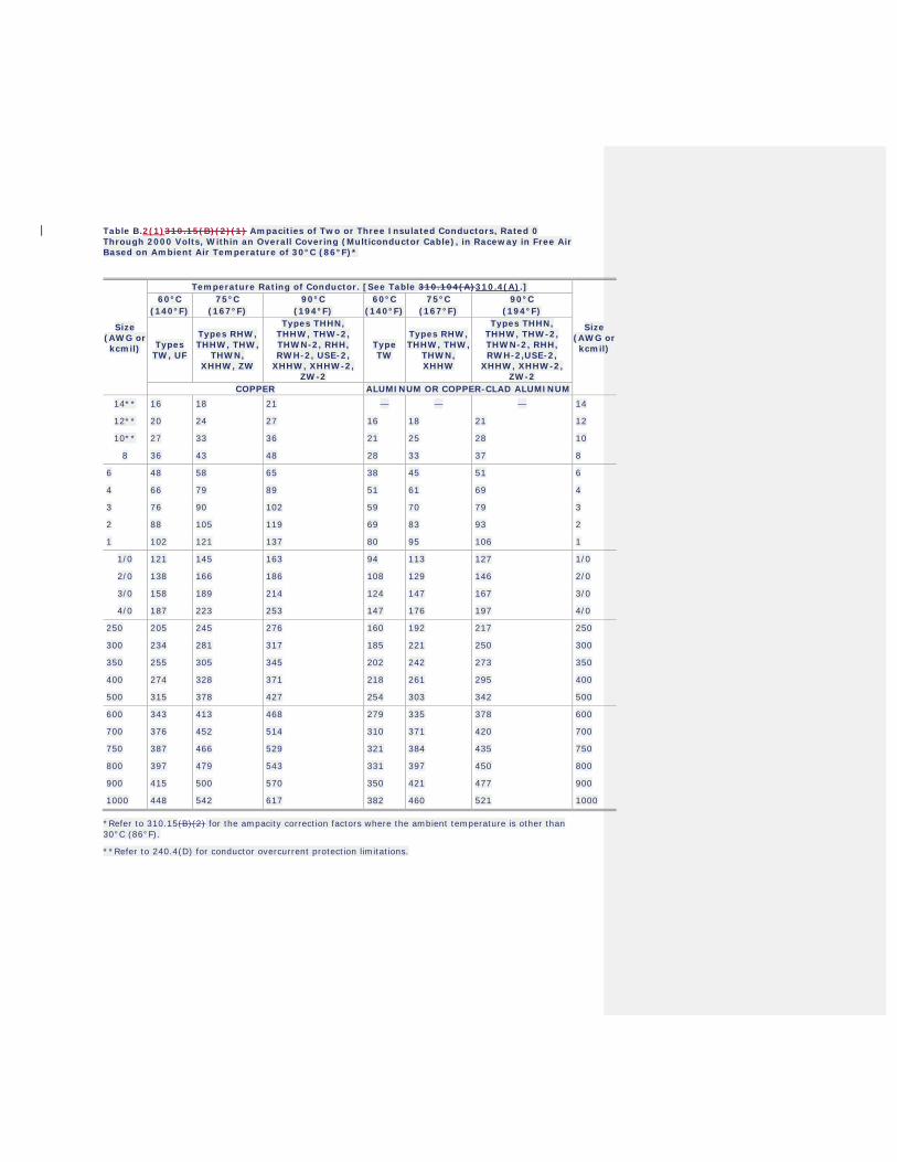
Table B.2(1)310.15(B)(2)(1) Ampacities of Two or Three Insulated Conductors, Rated 0 Through 2000 Volts, Within an Overall Covering (Multiconductor Cable), in Raceway in Free Air Based on Ambient Air Temperature of 30°C (86°F)*
Size (AWG or kcmil)
Temperature Rating of Conductor. [See Table 310.104(A)310.4(A).]
Size (AWG or kcmil)
60°C .
(140°F) 75°C
.
(167°F) 90°C
.
(194°F) 60°C
.
(140°F) 75°C
.
(167°F) 90°C
.
(194°F)
Types TW, UF
Types RHW, THHW, THW,
THWN, XHHW, ZW
Types THHN, THHW, THW-2, THWN-2, RHH, RWH-2, USE-2,
XHHW, XHHW-2, ZW-2
Type TW
Types RHW, THHW, THW,
THWN, XHHW
Types THHN, THHW, THW-2, THWN-2, RHH, RWH-2,USE-2,
XHHW, XHHW-2, ZW-2
COPPER ALUMINUM OR COPPER-CLAD ALUMINUM 14** 16 18 21 — — — 14
12** 20 24 27 16 18 21 12
10** 27 33 36 21 25 28 10
8 36 43 48 28 33 37 8
6 48 58 65 38 45 51 6
4 66 79 89 51 61 69 4
3 76 90 102 59 70 79 3
2 88 105 119 69 83 93 2
1 102 121 137 80 95 106 1
1/0 121 145 163 94 113 127 1/0
2/0 138 166 186 108 129 146 2/0
3/0 158 189 214 124 147 167 3/0
4/0 187 223 253 147 176 197 4/0
250 205 245 276 160 192 217 250
300 234 281 317 185 221 250 300
350 255 305 345 202 242 273 350
400 274 328 371 218 261 295 400
500 315 378 427 254 303 342 500
600 343 413 468 279 335 378 600
700 376 452 514 310 371 420 700
750 387 466 529 321 384 435 750
800 397 479 543 331 397 450 800
900 415 500 570 350 421 477 900
1000 448 542 617 382 460 521 1000
*Refer to 310.15(B)(2) for the ampacity correction factors where the ambient temperature is other than 30°C (86°F).
**Refer to 240.4(D) for conductor overcurrent protection limitations.
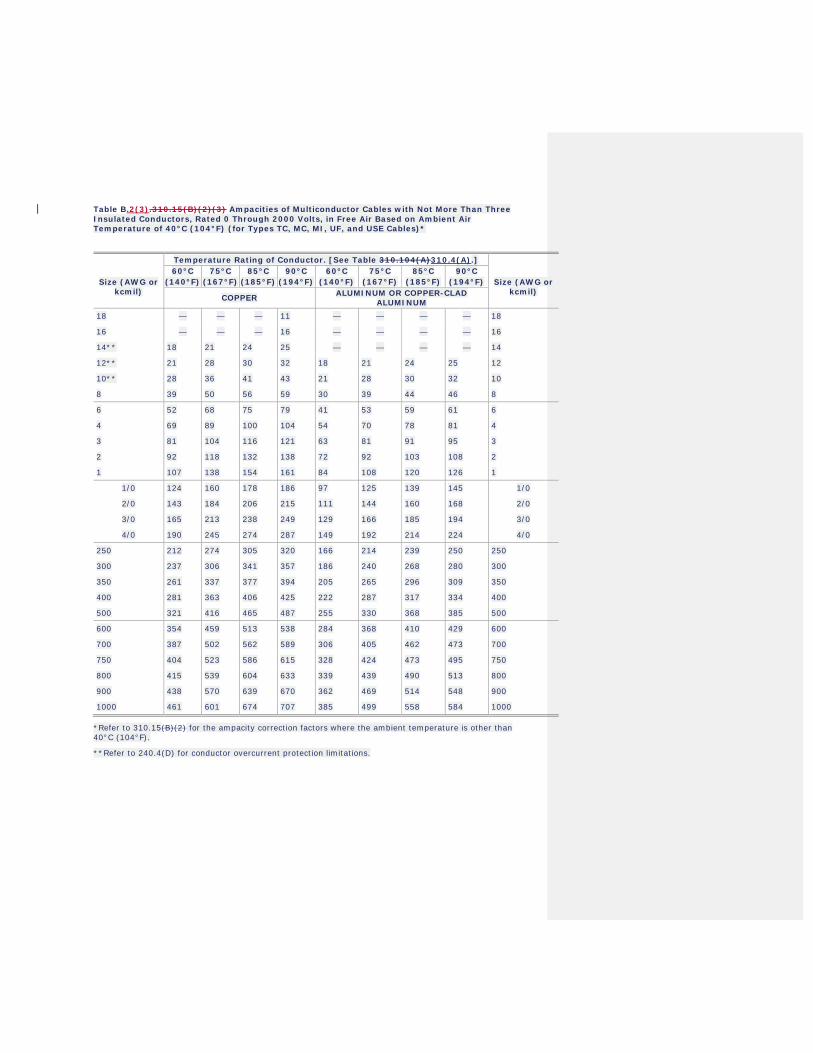
Table B.2(3).310.15(B)(2)(3) Ampacities of Multiconductor Cables with Not More Than Three Insulated Conductors, Rated 0 Through 2000 Volts, in Free Air Based on Ambient Air Temperature of 40°C (104°F) (for Types TC, MC, MI, UF, and USE Cables)*
Temperature Rating of Conductor. [See Table 310.104(A)310.4(A).]
Size (AWG or kcmil)
60°C .
(140°F) 75°C
.
(167°F) 85°C
.
(185°F) 90°C
.
(194°F) 60°C
.
(140°F) 75°C
.
(167°F) 85°C
.
(185°F) 90°C
.
(194°F) Size (AWG or kcmil)
COPPER ALUMINUM OR COPPER-CLAD ALUMINUM
18 — — — 11 — — — — 18
16 — — — 16 — — — — 16
14** 18 21 24 25 — — — — 14
12** 21 28 30 32 18 21 24 25 12
10** 28 36 41 43 21 28 30 32 10
8 39 50 56 59 30 39 44 46 8
6 52 68 75 79 41 53 59 61 6
4 69 89 100 104 54 70 78 81 4
3 81 104 116 121 63 81 91 95 3
2 92 118 132 138 72 92 103 108 2
1 107 138 154 161 84 108 120 126 1
1/0 124 160 178 186 97 125 139 145 1/0
2/0 143 184 206 215 111 144 160 168 2/0
3/0 165 213 238 249 129 166 185 194 3/0
4/0 190 245 274 287 149 192 214 224 4/0
250 212 274 305 320 166 214 239 250 250
300 237 306 341 357 186 240 268 280 300
350 261 337 377 394 205 265 296 309 350
400 281 363 406 425 222 287 317 334 400
500 321 416 465 487 255 330 368 385 500
600 354 459 513 538 284 368 410 429 600
700 387 502 562 589 306 405 462 473 700
750 404 523 586 615 328 424 473 495 750
800 415 539 604 633 339 439 490 513 800
900 438 570 639 670 362 469 514 548 900
1000 461 601 674 707 385 499 558 584 1000
*Refer to 310.15(B)(2) for the ampacity correction factors where the ambient temperature is other than 40°C (104°F).
**Refer to 240.4(D) for conductor overcurrent protection limitations.
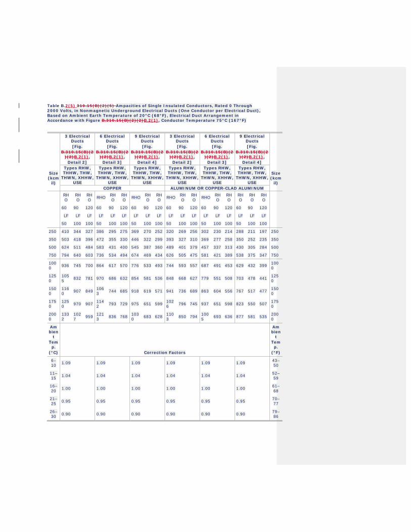
Table B.2(5) 310.15(B)(2)(5) Ampacities of Single Insulated Conductors, Rated 0 Through 2000 Volts, in Nonmagnetic Underground Electrical Ducts (One Conductor per Electrical Duct), Based on Ambient Earth Temperature of 20°C (68°F), Electrical Duct Arrangement in Accordance with Figure B.310.15(B)(2)(2)B.2(1), Conductor Temperature 75°C (167°F)
3 Electrical Ducts
.
[Fig. .
B.310.15(B)(2)(2)B.2(1),
.
Detail 2]
6 Electrical Ducts
.
[Fig. .
B.310.15(B)(2)(2)B.2(1),
.
Detail 3]
9 Electrical Ducts
.
[Fig. .
B.310.15(B)(2)(2)B.2(1),
.
Detail 4]
3 Electrical Ducts
.
[Fig. .
B.310.15(B)(2)(2)B.2(1),
.
Detail 2]
6 Electrical Ducts
.
[Fig. .
B.310.15(B)(2)(2)B.2(1),
.
Detail 3]
9 Electrical Ducts
.
[Fig. .
B.310.15(B)(2)(2)B.2(1),
.
Detail 4]
Size (kcm
il)
Types RHW, THHW, THW,
THWN, XHHW, USE
Types RHW, THHW, THW,
THWN, XHHW, USE
Types RHW, THHW, THW,
THWN, XHHW, USE
Types RHW, THHW, THW,
THWN, XHHW, USE
Types RHW, THHW, THW,
THWN, XHHW, USE
Types RHW, THHW, THW,
THWN, XHHW, USE
Size (kcm
il) COPPER ALUMINUM OR COPPER-CLAD ALUMINUM
RHO
RHO
RHO RHO RH
O RHO RHO RH
O RHO RHO RH
O RHO RHO RH
O RHO
RHO
RHO
RHO
60 90 120 60 90 120 60 90 120 60 90 120 60 90 120 60 90 120
LF LF LF LF LF LF LF LF LF LF LF LF LF LF LF LF LF LF
50 100 100 50 100 100 50 100 100 50 100 100 50 100 100 50 100 100
250 410 344 327 386 295 275 369 270 252 320 269 256 302 230 214 288 211 197 250
350 503 418 396 472 355 330 446 322 299 393 327 310 369 277 258 350 252 235 350
500 624 511 484 583 431 400 545 387 360 489 401 379 457 337 313 430 305 284 500
750 794 640 603 736 534 494 674 469 434 626 505 475 581 421 389 538 375 347 750
1000 936 745 700 864 617 570 776 533 493 744 593 557 687 491 453 629 432 399 100
0
1250
1055 832 781 970 686 632 854 581 536 848 668 627 779 551 508 703 478 441 125
0
1500
1160 907 849 106
3 744 685 918 619 571 941 736 689 863 604 556 767 517 477 1500
1750
1250 970 907 114
2 793 729 975 651 599 1026 796 745 937 651 598 823 550 507 175
0
2000
1332
1027 959 121
3 836 768 1030 683 628 110
3 850 794 1005 693 636 877 581 535 200
0
Ambien
t .
Temp.
.
(°C) Correction Factors
Ambien
t .
Temp.
.
(°F)
6–10 1.09 1.09 1.09 1.09 1.09 1.09 43–
50
11–15 1.04 1.04 1.04 1.04 1.04 1.04 52–
59
16–20 1.00 1.00 1.00 1.00 1.00 1.00 61–
68
21–25 0.95 0.95 0.95 0.95 0.95 0.95 70–
77
26–30 0.90 0.90 0.90 0.90 0.90 0.90 79–
86

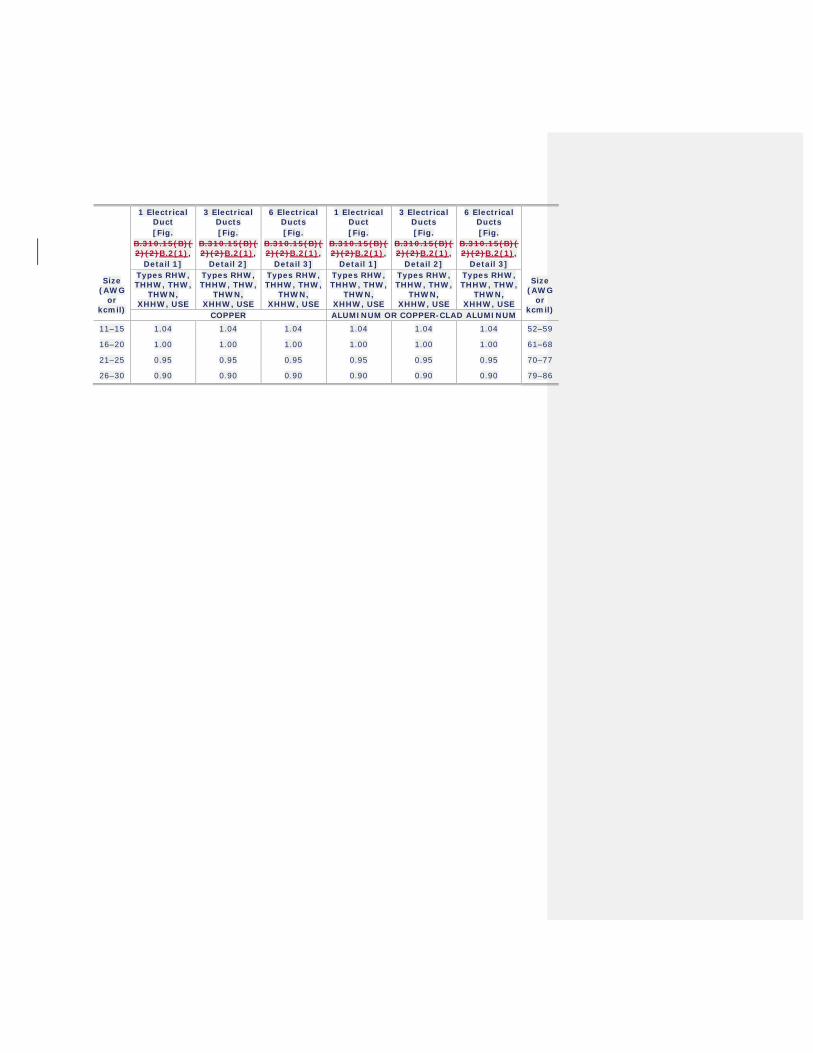
Table B.2(6)310.15(B)(2)(6) Ampacities of Three Insulated Conductors, Rated 0 Through 2000 Volts, Within an Overall Covering (Three-Conductor Cable) in Underground Electrical Ducts (One Cable per Electrical Duct) Based on Ambient Earth Temperature of 20°C (68°F), Electrical Duct Arrangement in Accordance with Figure B.310.15(B)(2)(2)B.2(1), Conductor Temperature 75°C (167°F)
Size (AWG
or kcmil)
1 Electrical Duct
.
[Fig. .
B.310.15(B)(2)(2)B.2(1),
.
Detail 1]
3 Electrical Ducts
.
[Fig. B.310.15(B)(2)(2)B.2(1),
.
Detail 2]
6 Electrical Ducts
.
[Fig. .
B.310.15(B)(2)(2)B.2(1),
.
Detail 3]
1 Electrical Duct
.
[Fig. .
B.310.15(B)(2)(2)B.2(1),
.
Detail 1]
3 Electrical Ducts
.
[Fig. .
B.310.15(B)(2)(2)B.2(1),
.
Detail 2]
6 Electrical Ducts
.
[Fig. .
B.310.15(B)(2)(2)B.2(1),
.
Detail 3]
Size (AWG
or kcmil) Types RHW,
THHW, THW, THWN,
XHHW, USE
Types RHW, THHW, THW,
THWN, XHHW, USE
Types RHW, THHW, THW,
THWN, XHHW, USE
Types RHW, THHW, THW,
THWN, XHHW, USE
Types RHW, THHW, THW,
THWN, XHHW, USE
Types RHW, THHW, THW,
THWN, XHHW, USE
COPPER ALUMINUM OR COPPER-CLAD ALUMINUM
RHO
RHO
RHO
RHO
RHO
RHO
RHO
RHO
RHO
RHO
RHO
RHO
RHO
RHO
RHO
RHO
RHO
RHO
60 90 120 60 90 120 60 90 120 60 90 120 60 90 120 60 90 120
LF LF LF LF LF LF LF LF LF LF LF LF LF LF LF LF LF LF
50 100 100 50 100 100 50 100 100 50 100 100 50 100 100 50 100 100
8 58 54 53 56 48 46 53 42 39 45 42 41 43 37 36 41 32 30 8
6 77 71 69 74 63 60 70 54 51 60 55 54 57 49 47 54 42 39 6
4 101 93 91 96 81 77 91 69 65 78 72 71 75 63 60 71 54 51 4
2 132 121 118 126 105 100 119 89 83 103 94 92 98 82 78 92 70 65 2
1 154 140 136 146 121 114 137 102 95 120 109 106 114 94 89 107 79 74 1
1/0 177 160 156 168 137 130 157 116 107 138 125 122 131 107 101 122 90 84 1/0
2/0 203 183 178 192 156 147 179 131 121 158 143 139 150 122 115 140 102 95 2/0
3/0 233 210 204 221 178 158 205 148 137 182 164 159 172 139 131 160 116 107 3/0
4/0 268 240 232 253 202 190 234 168 155 209 187 182 198 158 149 183 131 121 4/0
250 297 265 256 280 222 209 258 184 169 233 207 201 219 174 163 202 144 132 250
350 363 321 310 340 267 250 312 219 202 285 252 244 267 209 196 245 172 158 350
500 444 389 375 414 320 299 377 261 240 352 308 297 328 254 237 299 207 190 500
750 552 478 459 511 388 362 462 314 288 446 386 372 413 314 293 374 254 233 750
1000 628 539 518 579 435 405 522 351 321 521 447 430 480 361 336 433 291 266 1000
AmbientTem
p. .
(°C)
Correction Factors
AmbientTem
p. .
(°F)
6–10 1.09 1.09 1.09 1.09 1.09 1.09 43–50
11–15 1.04 1.04 1.04 1.04 1.04 1.04 52–59
16–20 1.00 1.00 1.00 1.00 1.00 1.00 61–68
21–25 0.95 0.95 0.95 0.95 0.95 0.95 70–77
26–30 0.90 0.90 0.90 0.90 0.90 0.90 79–86

Table B.2(7)310.15(B)(2)(7) Ampacities of Three Single Insulated Conductors, Rated 0 Through 2000 Volts, in Underground Electrical Ducts (Three Conductors per Electrical Duct) Based on Ambient Earth Temperature of 20°C (68°F), Electrical Duct Arrangement in Accordance with Figure B.310.15(B)(2)(2)B.2(1), Conductor Temperature 75°C (167°F)
1 Electrical Duct
.
[Fig. .
B.310.15(B)(2)(2)B.2(1),
.
Detail 1]
3 Electrical Ducts
.
[Fig. .
B.310.15(B)(2)(2)B.2(1),
.
Detail 2]
6 Electrical Ducts
.
[Fig. .
B.310.15(B)(2)(2)B.2(1),
.
Detail 3]
1 Electrical Duct
.
[Fig. .
B.310.15(B)(2)(2)B.2(1),
.
Detail 1]
3 Electrical Ducts
.
[Fig. .
B.310.15(B)(2)(2)B.2(1),
.
Detail 2]
6 Electrical Ducts
.
[Fig. .
B.310.15(B)(2)(2)B.2(1),
.
Detail 3]
Size (AWG
or kcmil)
Types RHW, THHW, THW,
THWN, XHHW, USE
Types RHW, THHW, THW,
THWN, XHHW, USE
Types RHW, THHW, THW,
THWN, XHHW, USE
Types RHW, THHW, THW,
THWN, XHHW, USE
Types RHW, THHW, THW,
THWN, XHHW, USE
Types RHW, THHW, THW,
THWN, XHHW, USE
Size (AWG
or kcmil)
COPPER ALUMINUM OR COPPER-CLAD ALUMINUM
RHO
RHO
RHO
RHO
RHO
RHO
RHO
RHO
RHO
RHO
RHO
RHO
RHO
RHO
RHO
RHO
RHO
RHO
60 90 120 60 90 120 60 90 120 60 90 120 60 90 120 60 90 120
LF LF LF LF LF LF LF LF LF LF LF LF LF LF LF LF LF LF
50 100 100 50 100 100 50 100 100 50 100 100 50 100 100 50 100 100
8 63 58 57 61 51 49 57 44 41 49 45 44 47 40 38 45 34 32 8
6 84 77 75 80 67 63 75 56 53 66 60 58 63 52 49 59 44 41 6
4 111 100 98 105 86 81 98 73 67 86 78 76 79 67 63 77 57 52 4
3 129 116 113 122 99 94 113 83 77 101 91 89 83 77 73 84 65 60 3
2 147 132 128 139 112 106 129 93 86 115 103 100 108 87 82 101 73 67 2
1 171 153 148 161 128 121 149 106 98 133 119 115 126 100 94 116 83 77 1
1/0 197 175 169 185 146 137 170 121 111 153 136 132 144 114 107 133 94 87 1/0
2/0 226 200 193 212 166 156 194 136 126 176 156 151 165 130 121 151 106 98 2/0
3/0 260 228 220 243 189 177 222 154 142 203 178 172 189 147 138 173 121 111 3/0
4/0 301 263 253 280 215 201 255 175 161 235 205 198 219 168 157 199 137 126 4/0
250 334 290 279 310 236 220 281 192 176 261 227 218 242 185 172 220 150 137 250
300 373 321 308 344 260 242 310 210 192 293 252 242 272 204 190 245 165 151 300
350 409 351 337 377 283 264 340 228 209 321 276 265 296 222 207 266 179 164 350
400 442 376 361 394 302 280 368 243 223 349 297 284 321 238 220 288 191 174 400
500 503 427 409 460 341 316 412 273 249 397 338 323 364 270 250 326 216 197 500
600 552 468 447 511 371 343 457 296 270 446 373 356 408 296 274 365 236 215 600
700 602 509 486 553 402 371 492 319 291 488 408 389 443 321 297 394 255 232 700
750 632 529 505 574 417 385 509 330 301 508 425 405 461 334 309 409 265 241 750
800 654 544 520 597 428 395 527 338 308 530 439 418 481 344 318 427 273 247 800
900 692 575 549 628 450 415 554 355 323 563 466 444 510 365 337 450 288 261 900
1000 730 605 576 659 472 435 581 372 338 597 494 471 538 385 355 475 304 276 1000
AmbientTem
p. .
(°C)
Correction Factors
AmbientTem
p. .
(°F)
6–10 1.09 1.09 1.09 1.09 1.09 1.09 43–50
1 Electrical Duct
.
[Fig. .
B.310.15(B)(2)(2)B.2(1),
.
Detail 1]
3 Electrical Ducts
.
[Fig. .
B.310.15(B)(2)(2)B.2(1),
.
Detail 2]
6 Electrical Ducts
.
[Fig. .
B.310.15(B)(2)(2)B.2(1),
.
Detail 3]
1 Electrical Duct
.
[Fig. .
B.310.15(B)(2)(2)B.2(1),
.
Detail 1]
3 Electrical Ducts
.
[Fig. .
B.310.15(B)(2)(2)B.2(1),
.
Detail 2]
6 Electrical Ducts
.
[Fig. .
B.310.15(B)(2)(2)B.2(1),
.
Detail 3]
Size (AWG
or kcmil)
Types RHW, THHW, THW,
THWN, XHHW, USE
Types RHW, THHW, THW,
THWN, XHHW, USE
Types RHW, THHW, THW,
THWN, XHHW, USE
Types RHW, THHW, THW,
THWN, XHHW, USE
Types RHW, THHW, THW,
THWN, XHHW, USE
Types RHW, THHW, THW,
THWN, XHHW, USE
Size (AWG
or kcmil)
COPPER ALUMINUM OR COPPER-CLAD ALUMINUM 11–15 1.04 1.04 1.04 1.04 1.04 1.04 52–59
16–20 1.00 1.00 1.00 1.00 1.00 1.00 61–68
21–25 0.95 0.95 0.95 0.95 0.95 0.95 70–77
26–30 0.90 0.90 0.90 0.90 0.90 0.90 79–86

Table B.2(8)310.15(B)(2)(8) Ampacities of Two or Three Insulated Conductors, Rated 0 Through 2000 Volts, Cabled Within an Overall (Two- or Three-Conductor) Covering, Directly Buried in Earth, Based on Ambient Earth Temperature of 20°C (68°F), Electrical Duct Arrangement in Accordance with Figure B.310.15(B)(2)(2)B.2(1), 100 Percent Load Factor, Thermal Resistance (Rho) of 90
Size (AWG
or kcmil)
1 Cable .
[Fig. B.310.15(B)(2)(2)B.
2(1), .
Detail 5]
2 Cables .
[Fig. B.310.15(B)(2)(2)B.
2(1), .
Detail 6]
1 Cable .
[Fig. B.310.15(B)(2)(2)B.
2(1), .
Detail 5]
2 Cables .
[Fig. B.310.15(B)(2)(2)B.
2(1), .
Detail 6] Size
(AWG or
kcmil)
60°C .
(140°F)
75°C .
(167°F)
60°C .
(140°F)
75°C .
(167°F)
60°C .
(140°F)
75°C .
(167°F)
60°C .
(140°F)
75°C .
(167°F)
TYPES TYPES
UF RHW, THHW, THW, THWN, XHHW, USE
UF RHW, THHW, THW, THWN, XHHW, USE
UF RHW, THHW, THW, THWN, XHHW, USE
UF RHW, THHW, THW, THWN, XHHW, USE
COPPER ALUMINUM OR COPPER-CLAD ALUMINUM 8 64 75 60 70 51 59 47 55 8
6 85 100 81 95 68 75 60 70 6
4 107 125 100 117 83 97 78 91 4
2 137 161 128 150 107 126 110 117 2
1 155 182 145 170 121 142 113 132 1
1/0 177 208 165 193 138 162 129 151 1/0
2/0 201 236 188 220 157 184 146 171 2/0
3/0 229 269 213 250 179 210 166 195 3/0
4/0 259 304 241 282 203 238 188 220 4/0
250 — 333 — 308 — 261 — 241 250
350 — 401 — 370 — 315 — 290 350
500 — 481 — 442 — 381 — 350 500
750 — 585 — 535 — 473 — 433 750
1000 — 657 — 600 — 545 — 497 1000
Ambient
Temp. .
(°C)
Correction Factors
Ambient
Temp. .
(°F)
6–10 1.12 1.09 1.12 1.09 1.12 1.09 1.12 1.09 43–50
11–15 1.06 1.04 1.06 1.04 1.06 1.04 1.06 1.04 52–59
16–20 1.00 1.00 1.00 1.00 1.00 1.00 1.00 1.00 61–68
21–25 0.94 0.95 0.94 0.95 0.94 0.95 0.94 0.95 70–77
26–30 0.87 0.90 0.87 0.90 0.87 0.90 0.87 0.90 79–86
Note: For ampacities of Type UF cable in underground electrical ducts, multiply the ampacities shown in the table by 0.74.
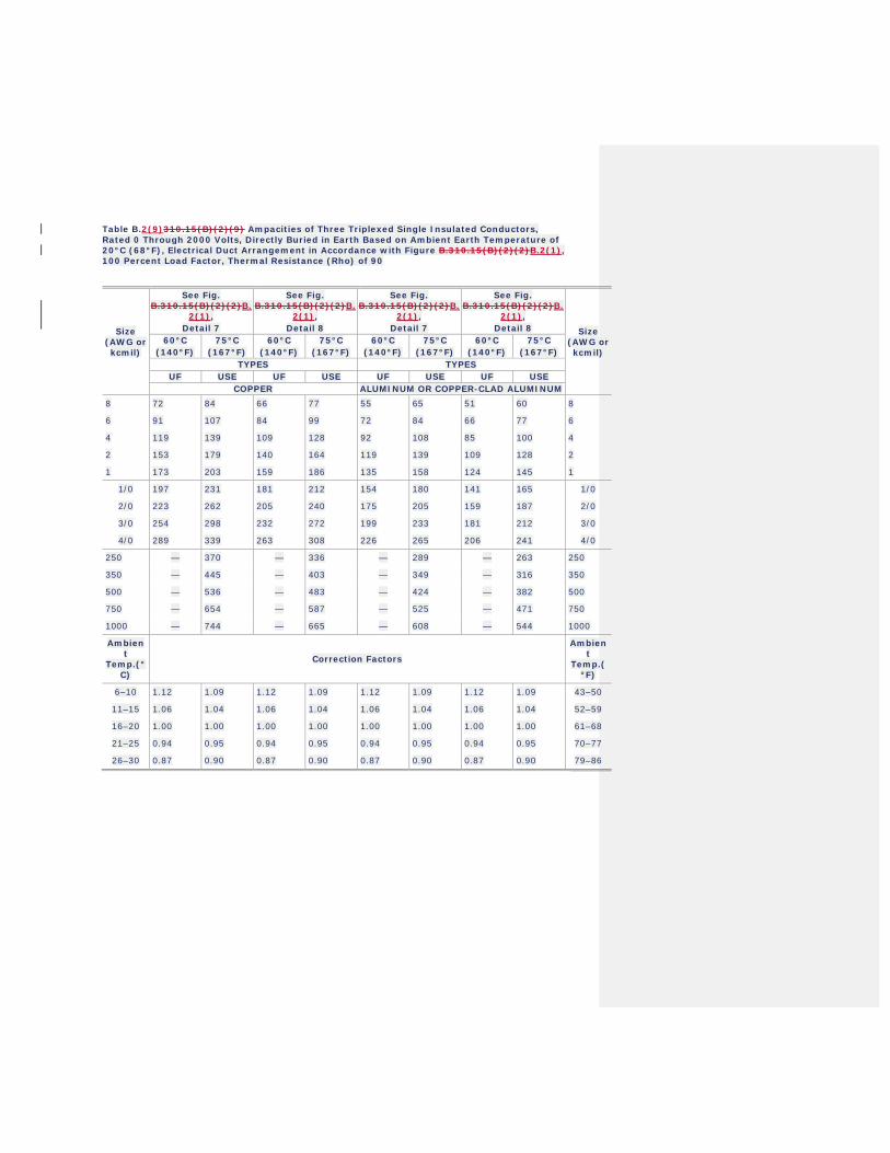
Table B.2(9)310.15(B)(2)(9) Ampacities of Three Triplexed Single Insulated Conductors, Rated 0 Through 2000 Volts, Directly Buried in Earth Based on Ambient Earth Temperature of 20°C (68°F), Electrical Duct Arrangement in Accordance with Figure B.310.15(B)(2)(2)B.2(1), 100 Percent Load Factor, Thermal Resistance (Rho) of 90
Size (AWG or kcmil)
See Fig. B.310.15(B)(2)(2)B.
2(1), .
Detail 7
See Fig. B.310.15(B)(2)(2)B.
2(1), .
Detail 8
See Fig. B.310.15(B)(2)(2)B.
2(1), .
Detail 7
See Fig. B.310.15(B)(2)(2)B.
2(1), .
Detail 8 Size (AWG or kcmil)
60°C .
(140°F) 75°C
.
(167°F) 60°C
.
(140°F) 75°C
.
(167°F) 60°C
.
(140°F) 75°C
.
(167°F) 60°C
.
(140°F) 75°C
.
(167°F) TYPES TYPES
UF USE UF USE UF USE UF USE COPPER ALUMINUM OR COPPER-CLAD ALUMINUM
8 72 84 66 77 55 65 51 60 8
6 91 107 84 99 72 84 66 77 6
4 119 139 109 128 92 108 85 100 4
2 153 179 140 164 119 139 109 128 2
1 173 203 159 186 135 158 124 145 1
1/0 197 231 181 212 154 180 141 165 1/0
2/0 223 262 205 240 175 205 159 187 2/0
3/0 254 298 232 272 199 233 181 212 3/0
4/0 289 339 263 308 226 265 206 241 4/0
250 — 370 — 336 — 289 — 263 250
350 — 445 — 403 — 349 — 316 350
500 — 536 — 483 — 424 — 382 500
750 — 654 — 587 — 525 — 471 750
1000 — 744 — 665 — 608 — 544 1000
Ambient
Temp.(°C)
Correction Factors
Ambient
Temp.(°F)
6–10 1.12 1.09 1.12 1.09 1.12 1.09 1.12 1.09 43–50
11–15 1.06 1.04 1.06 1.04 1.06 1.04 1.06 1.04 52–59
16–20 1.00 1.00 1.00 1.00 1.00 1.00 1.00 1.00 61–68
21–25 0.94 0.95 0.94 0.95 0.94 0.95 0.94 0.95 70–77
26–30 0.87 0.90 0.87 0.90 0.87 0.90 0.87 0.90 79–86
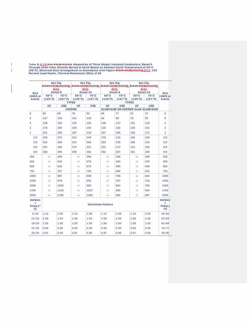
Table B.2(10)310.15(B)(2)(10) Ampacities of Three Single Insulated Conductors, Rated 0 Through 2000 Volts, Directly Buried in Earth Based on Ambient Earth Temperature of 20°C (68°F), Electrical Duct Arrangement in Accordance with Figure B.310.15(B)(2)(2)B.2(1), 100 Percent Load Factor, Thermal Resistance (Rho) of 90
Size (AWG or kcmil)
See Fig. B.310.15(B)(2)(2)B.
2(1), .
Detail 9
See Fig. B.310.15(B)(2)(2)B.
2(1), .
Detail 10
See Fig. B.310.15(B)(2)(2)B.
2(1), .
Detail 9
See Fig. B.310.15(B)(2)(2)B.
2(1), .
Detail 10 Size (AWG or kcmil)
60°C .
(140°F) 75°C
.
(167°F) 60°C
.
(140°F) 75°C
.
(167°F) 60°C
.
(140°F) 75°C
.
(167°F) 60°C
.
(140°F) 75°C
.
(167°F) TYPES TYPES
UF USE UF USE UF USE UF USE COPPER ALUMINUM OR COPPER-CLAD ALUMINUM
8 84 98 78 92 66 77 61 72 8
6 107 126 101 118 84 98 78 92 6
4 139 163 130 152 108 127 101 118 4
2 178 209 165 194 139 163 129 151 2
1 201 236 187 219 157 184 146 171 1
1/0 230 270 212 249 179 210 165 194 1/0
2/0 261 306 241 283 204 239 188 220 2/0
3/0 297 348 274 321 232 272 213 250 3/0
4/0 336 394 309 362 262 307 241 283 4/0
250 — 429 — 394 — 335 — 308 250
350 — 516 — 474 — 403 — 370 350
500 — 626 — 572 — 490 — 448 500
750 — 767 — 700 — 605 — 552 750
1000 — 887 — 808 — 706 — 642 1000
1250 — 979 — 891 — 787 — 716 1250
1500 — 1063 — 965 — 862 — 783 1500
1750 — 1133 — 1027 — 930 — 843 1750
2000 — 1195 — 1082 — 990 — 897 2000
Ambient
Temp.(°C)
Correction Factors
Ambient
Temp.(°F)
6–10 1.12 1.09 1.12 1.09 1.12 1.09 1.12 1.09 43–50
11–15 1.06 1.04 1.06 1.04 1.06 1.04 1.06 1.04 52–59
16–20 1.00 1.00 1.00 1.00 1.00 1.00 1.00 1.00 61–68
21–25 0.94 0.95 0.94 0.95 0.94 0.95 0.94 0.95 70–77
26–30 0.87 0.90 0.87 0.90 0.87 0.90 0.87 0.90 79–86
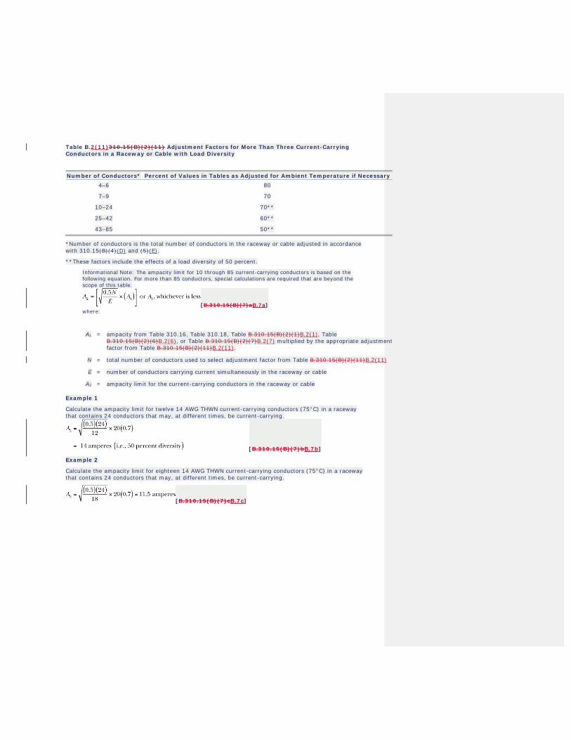
Table B.2(11)310.15(B)(2)(11) Adjustment Factors for More Than Three Current-Carrying Conductors in a Raceway or Cable with Load Diversity
Number of Conductors* Percent of Values in Tables as Adjusted for Ambient Temperature if Necessary 4–6 80
7–9 70
10–24 70**
25–42 60**
43–85 50**
*Number of conductors is the total number of conductors in the raceway or cable adjusted in accordance with 310.15(B)(4)(D) and (5)(E).
**These factors include the effects of a load diversity of 50 percent.
Informational Note: The ampacity limit for 10 through 85 current-carrying conductors is based on the following equation. For more than 85 conductors, special calculations are required that are beyond the scope of this table.
[B.310.15(B)(7)aB.7a] where:
A1 = ampacity from Table 310.16, Table 310.18, Table B.310.15(B)(2)(1)B.2(1), Table B.310.15(B)(2)(6)B.2(6), or Table B.310.15(B)(2)(7)B.2(7) multiplied by the appropriate adjustment factor from Table B.310.15(B)(2)(11)B.2(11).
N = total number of conductors used to select adjustment factor from Table B.310.15(B)(2)(11)B.2(11)
E = number of conductors carrying current simultaneously in the raceway or cable
A2 = ampacity limit for the current-carrying conductors in the raceway or cable
Example 1
Calculate the ampacity limit for twelve 14 AWG THWN current-carrying conductors (75°C) in a raceway that contains 24 conductors that may, at different times, be current-carrying.
[B.310.15(B)(7)bB.7b]
Example 2
Calculate the ampacity limit for eighteen 14 AWG THWN current-carrying conductors (75°C) in a raceway that contains 24 conductors that may, at different times, be current-carrying.
[B.310.15(B)(7)cB.7c]
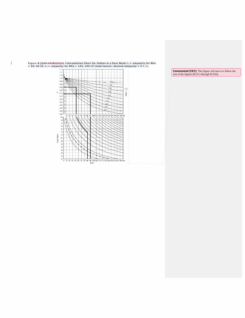
Figure B.3310.15(B)(2)(1) Interpolation Chart for Cables in a Duct Bank.I1 = ampacity for Rho = 60, 50 LF; I2 = ampacity for Rho = 120, 100 LF (load factor); desired ampacity = F × I1.
Commented [CK1]: This figure will move to follow the rest of the figures [B.2(1) through B.2(4)].
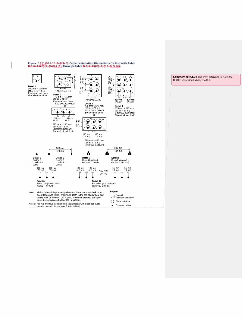
Figure B.2(1)310.15(B)(2)(2) Cable Installation Dimensions for Use with Table B.310.15(B)(2)(5)B.2(5) Through Table B.310.15(B)(2)(10)B.2(10).
Commented [CK2]: The cross-reference in Note 2 to B.310.15(B)(5) will change to B.5.
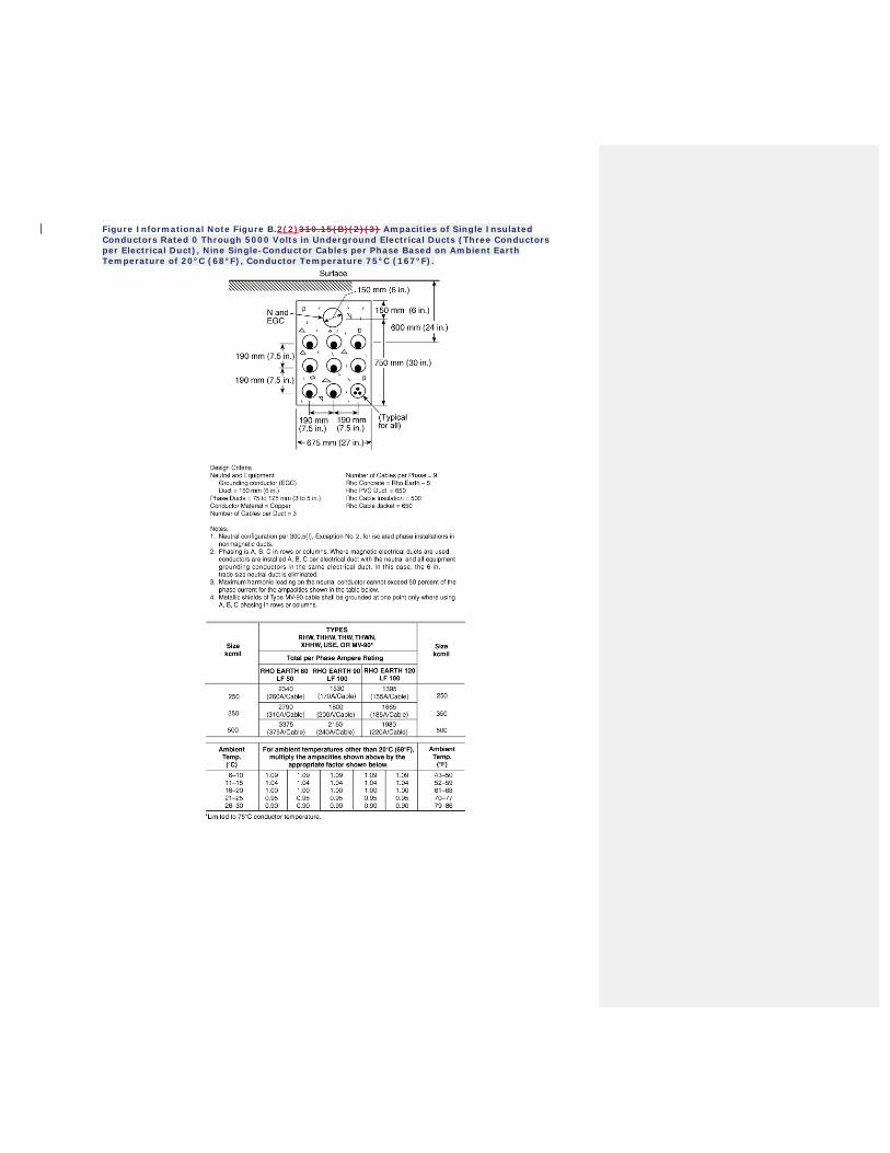
Figure Informational Note Figure B.2(2)310.15(B)(2)(3) Ampacities of Single Insulated Conductors Rated 0 Through 5000 Volts in Underground Electrical Ducts (Three Conductors per Electrical Duct), Nine Single-Conductor Cables per Phase Based on Ambient Earth Temperature of 20°C (68°F), Conductor Temperature 75°C (167°F).
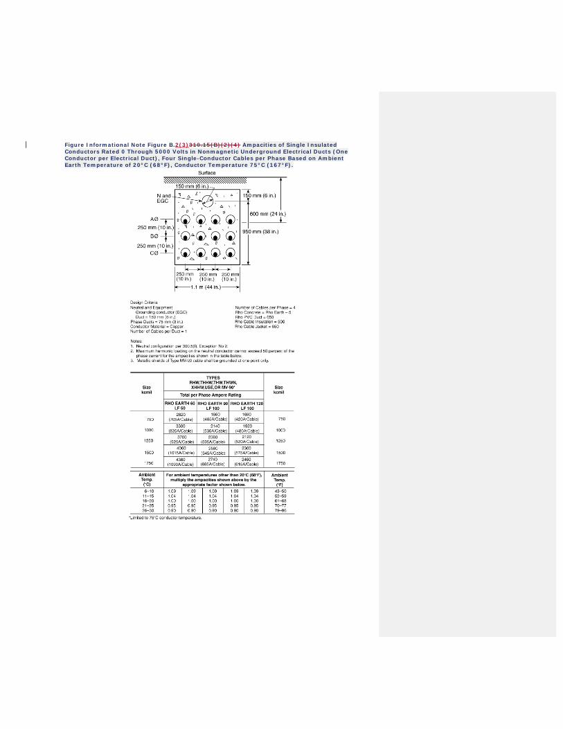
Figure Informational Note Figure B.2(3)310.15(B)(2)(4) Ampacities of Single Insulated Conductors Rated 0 Through 5000 Volts in Nonmagnetic Underground Electrical Ducts (One Conductor per Electrical Duct), Four Single-Conductor Cables per Phase Based on Ambient Earth Temperature of 20°C (68°F), Conductor Temperature 75°C (167°F).
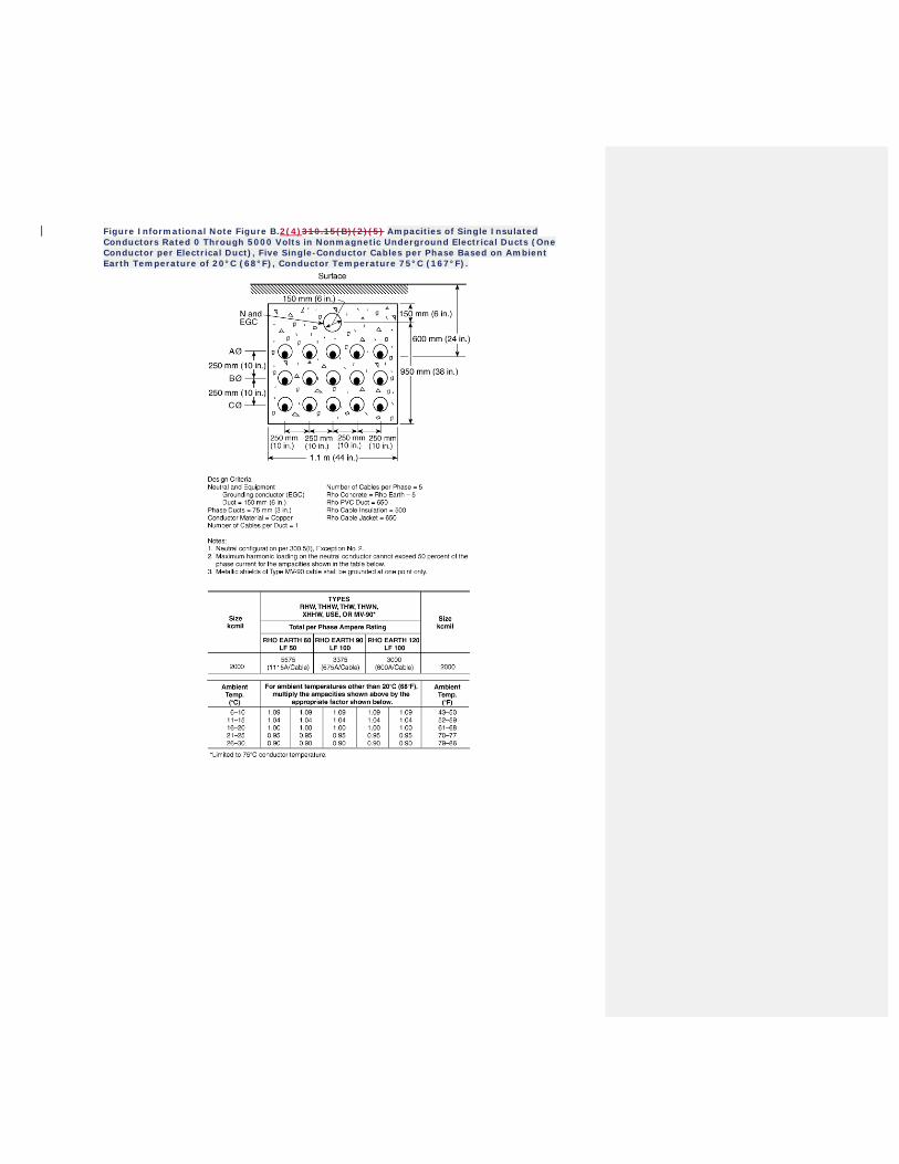
Figure Informational Note Figure B.2(4)310.15(B)(2)(5) Ampacities of Single Insulated Conductors Rated 0 Through 5000 Volts in Nonmagnetic Underground Electrical Ducts (One Conductor per Electrical Duct), Five Single-Conductor Cables per Phase Based on Ambient Earth Temperature of 20°C (68°F), Conductor Temperature 75°C (167°F).
Second Correlating Revision No. 52-NFPA 70-2019 [ Global Input ]
Update all references to Articles 310 and 311 throughout the NEC.
Submitter Information Verification
Committee: NEC-AAC
Submittal Date: Thu Feb 21 10:49:54 EST 2019
Committee Statement
CommitteeStatement:
The Correlating Committee notes that Article 310 was extensively revised for the 2020 NEC. Thisrevision resulted in the creation of a new Article 311 and the deletion of Article 328. Article 310 isextensively referenced throughout the NEC. Therefore, updating the references is important.
Ballot Results
This item has passed ballot
12 Eligible Voters
0 Not Returned
12 Affirmative All
0 Affirmative with Comments
0 Negative with Comments
0 Abstention
Affirmative All
Brunssen, James E.
Dressman, Kevin L.
Hickman, Palmer L.
Hittinger, David L.
Holub, Richard A.
Johnston, Michael J.
Kovacik, John R.
Manche, Alan
McDaniel, Roger D.
Porter, Christine T.
Straniero, George A.
Williams, David A.
National Fire Protection Association Report https://submittals.nfpa.org/TerraViewWeb/ContentFetcher?commentPar...
5 of 144 4/2/2019, 11:09 AM
Second Correlating Revision No. 77-NFPA 70-2019 [ Global Input ]
1. Move the following definitions from 555.2 to Article 100 and place in alpha order:
Electrical Datum Plane.
A specified distance above a water level above which electrical equipment can be installed and electrical
connections can be made. (CMP-7)
Pier.
A structure extending over the water and supported on a fixed foundation (fixed pier), or on flotation (floating
pier), that provides access to the water. [303:3.3.17] (CMP-7)
Pier, Fixed.
Pier constructed on a permanent, fixed foundation, such as on piles, that permanently establishes the elevation
of the structure deck with respect to land. [303:3.3.17.2] (CMP-7)
Pier, Floating.
Pier designed with inherent flotation capability that allows the structure to float on the water surface and rise
and fall with water level changes. [303:3.3.17.3] (CMP-7)
2. Relocate the existing defintion of "electrical datum plane" from Article 100 to 682.5 and revise to read as
follows:
682.5 Electrical Datum Plane Distances. The electrical datum plane shall consist of one of the
following:
(1) In land areas subject to tidal fluctuation, the electrical datum plane shall be ahorizontal plane 600 mm (2 ft) above the highest tide level for the area occurringunder normal circumstances, that is, highest high tide.
(2) In land areas not subject to tidal fluctuation, the electrical datum plane shall be ahorizontal plane 600 mm (2 ft) above the highest water level for the area occurringunder normal circumstances.
(3) In land areas subject to flooding, the electrical datum plane based on (1) or (2)above shall be a horizontal plane 600 mm (2 ft) above the point identified as theprevailing high water mark or an equivalent benchmark based on seasonal orstorm-driven flooding from the authority having jurisdiction.
The electrical datum plane for floating structures and landing stages that are (a)installed to permit rise and fall response to water level, without lateral movement, and(b) that are so equipped that they can rise to the datum plane established for (1) or (2)above, shall be a horizontal plane 750 mm (30 in.) above the water level at the floatingstructure or landing stage and a minimum of 300 mm (12 in.) above the level of thedeck.
Submitter Information Verification
Committee: NEC-AAC
Submittal Date: Mon Mar 04 12:47:16 EST 2019
Committee Statement
CommitteeStatement:
The Correlating Committee relocated the definitions of Electrical Datum Plane and Pier to Article100 as they are used in more than one article. Additionally, the definitions of "Pier, Fixed" and "Pier,Floating" are relocated to Article 100 so they are associated with the general definition of Pier. The
National Fire Protection Association Report https://submittals.nfpa.org/TerraViewWeb/ContentFetcher?commentPar...
6 of 144 4/2/2019, 11:09 AM
correlating committee moved the existing definition of "electrical datum plane" from Article 100 to682.5 and converted it into mandatory text for correlation and to avoid duplication.
Ballot Results
This item has passed ballot
12 Eligible Voters
0 Not Returned
12 Affirmative All
0 Affirmative with Comments
0 Negative with Comments
0 Abstention
Affirmative All
Brunssen, James E.
Dressman, Kevin L.
Hickman, Palmer L.
Hittinger, David L.
Holub, Richard A.
Johnston, Michael J.
Kovacik, John R.
Manche, Alan
McDaniel, Roger D.
Porter, Christine T.
Straniero, George A.
Williams, David A.
National Fire Protection Association Report https://submittals.nfpa.org/TerraViewWeb/ContentFetcher?commentPar...
7 of 144 4/2/2019, 11:09 AM
Second Correlating Revision No. 14-NFPA 70-2019 [ Definition: Feeder. ]
Feeder.
All circuit conductors between the service equipment, the source of a separately derived system, or otherpower supply source and the final branch-circuit overcurrent device. (CMP-2 10 )
Submitter Information Verification
Committee: NEC-AAC
Submittal Date: Wed Feb 20 09:39:49 EST 2019
Committee Statement
CommitteeStatement:
The Correlating Committee reassigns this definition to CMP-10 as a result of the shift inpurview from CMP-2 to CMP-10.
Ballot Results
This item has passed ballot
12 Eligible Voters
0 Not Returned
12 Affirmative All
0 Affirmative with Comments
0 Negative with Comments
0 Abstention
Affirmative All
Brunssen, James E.
Dressman, Kevin L.
Hickman, Palmer L.
Hittinger, David L.
Holub, Richard A.
Johnston, Michael J.
Kovacik, John R.
Manche, Alan
McDaniel, Roger D.
Porter, Christine T.
Straniero, George A.
Williams, David A.
National Fire Protection Association Report https://submittals.nfpa.org/TerraViewWeb/ContentFetcher?commentPar...
8 of 144 4/2/2019, 11:09 AM
Second Correlating Revision No. 72-NFPA 70-2019 [ Definition: Fitting. ]
Fitting.
A means for connecting raceway, cable, or cord to an enclosure, box, or raceway system. An accessorysuch as a locknut, bushing, or other part of a wiring system that is intended primarily to perform amechanical rather than an electrical function. (CMP-1)
Submitter Information Verification
Committee: NEC-AAC
Submittal Date: Thu Feb 21 14:57:12 EST 2019
Committee Statement
CommitteeStatement:
The Correlating Committee has changed this language back to the language from the 2017edition for correlation and consistency with how this impacts requirements elsewhere in thecode.
Committee Comment No. 7928-NFPA 70-2018 [Definition: Fitting.]
Ballot Results
This item has passed ballot
12 Eligible Voters
0 Not Returned
12 Affirmative All
0 Affirmative with Comments
0 Negative with Comments
0 Abstention
Affirmative All
Brunssen, James E.
Dressman, Kevin L.
Hickman, Palmer L.
Hittinger, David L.
Holub, Richard A.
Johnston, Michael J.
Kovacik, John R.
Manche, Alan
McDaniel, Roger D.
Porter, Christine T.
Straniero, George A.
Williams, David A.
National Fire Protection Association Report https://submittals.nfpa.org/TerraViewWeb/ContentFetcher?commentPar...
9 of 144 4/2/2019, 11:09 AM
Second Correlating Revision No. 15-NFPA 70-2019 [ Definition: Habitable Room. ]
Habitable Room.
A room in a building for living, sleeping, eating, or cooking, but excluding bathrooms, toilet rooms, closets,hallways, storage or utility spaces, and similar areas. (CMP-2)
Submitter Information Verification
Committee: NEC-AAC
Submittal Date: Wed Feb 20 09:42:42 EST 2019
Committee Statement
Committee Statement: The Correlating Committee assigns the definition of habitable room to CMP-2.
Ballot Results
This item has passed ballot
12 Eligible Voters
0 Not Returned
12 Affirmative All
0 Affirmative with Comments
0 Negative with Comments
0 Abstention
Affirmative All
Brunssen, James E.
Dressman, Kevin L.
Hickman, Palmer L.
Hittinger, David L.
Holub, Richard A.
Johnston, Michael J.
Kovacik, John R.
Manche, Alan
McDaniel, Roger D.
Porter, Christine T.
Straniero, George A.
Williams, David A.
National Fire Protection Association Report https://submittals.nfpa.org/TerraViewWeb/ContentFetcher?commentPar...
10 of 144 4/2/2019, 11:09 AM
Second Correlating Revision No. 22-NFPA 70-2019 [ Definition: Information Technology
Equipment Room. ]
Information Technology Equipment Room.
A room within the information technology equipment area that contains the information technologyequipment. [75:3.3.9 3.3.14 ] (CMP-12)
Submitter Information Verification
Committee: NEC-AAC
Submittal Date: Wed Feb 20 10:50:42 EST 2019
Committee Statement
Committee Statement: The Correlating Committee updated the reference to NFPA 75.
Committee Comment No. 7835-NFPA 70-2018 [Definition: Information Technology Equipment Room.]
Ballot Results
This item has passed ballot
12 Eligible Voters
0 Not Returned
12 Affirmative All
0 Affirmative with Comments
0 Negative with Comments
0 Abstention
Affirmative All
Brunssen, James E.
Dressman, Kevin L.
Hickman, Palmer L.
Hittinger, David L.
Holub, Richard A.
Johnston, Michael J.
Kovacik, John R.
Manche, Alan
McDaniel, Roger D.
Porter, Christine T.
Straniero, George A.
Williams, David A.
National Fire Protection Association Report https://submittals.nfpa.org/TerraViewWeb/ContentFetcher?commentPar...
11 of 144 4/2/2019, 11:09 AM
Second Correlating Revision No. 16-NFPA 70-2019 [ Definition: Laundry Area. ]
Laundry Area.
An area containing or designed to contain a laundry tray, clothes washer, or clothes dryer. (CMP-2)
Submitter Information Verification
Committee: NEC-AAC
Submittal Date: Wed Feb 20 09:44:12 EST 2019
Committee Statement
Committee Statement: The Correlating Committee assigns the definition of laundry area to CMP-2.
Ballot Results
This item has passed ballot
12 Eligible Voters
0 Not Returned
12 Affirmative All
0 Affirmative with Comments
0 Negative with Comments
0 Abstention
Affirmative All
Brunssen, James E.
Dressman, Kevin L.
Hickman, Palmer L.
Hittinger, David L.
Holub, Richard A.
Johnston, Michael J.
Kovacik, John R.
Manche, Alan
McDaniel, Roger D.
Porter, Christine T.
Straniero, George A.
Williams, David A.
National Fire Protection Association Report https://submittals.nfpa.org/TerraViewWeb/ContentFetcher?commentPar...
12 of 144 4/2/2019, 11:09 AM
Second Correlating Revision No. 9-NFPA 70-2019 [ Definition: Reconditioned. ]
Supplemental Information
File Name Description Approved
NEC_SCR-9_New_definition_being_deleted_with_SCR.docx For ballot
Submitter Information Verification
Committee: NEC-AAC
Submittal Date: Tue Feb 19 12:05:56 EST 2019
Committee Statement
CommitteeStatement:
The Correlating Committee has assigned purview of this definition to CMP-10 and isdeleting alternate definitions.
Committee Comment No. 8227-NFPA 70-2018 [Detail]
Ballot Results
This item has passed ballot
12 Eligible Voters
0 Not Returned
12 Affirmative All
0 Affirmative with Comments
0 Negative with Comments
0 Abstention
Affirmative All
Brunssen, James E.
Dressman, Kevin L.
Hickman, Palmer L.
Hittinger, David L.
Holub, Richard A.
Johnston, Michael J.
Kovacik, John R.
Manche, Alan
McDaniel, Roger D.
Porter, Christine T.
Straniero, George A.
Williams, David A.
National Fire Protection Association Report https://submittals.nfpa.org/TerraViewWeb/ContentFetcher?commentPar...
13 of 144 4/2/2019, 11:09 AM
Definition added at SR stage is being deleted at SCR stage. Reconditioned. Electromechanical systems, equipment, apparatus, or components that are restored to operating conditions. This process differs from normal servicing of equipment that remains within a facility or replacement of listed equipment on a one-to-one basis. (CMP-9)
Informational Note: The term reconditioned is frequently referred to as rebuilt, refurbished, or remanufactured.
Second Correlating Revision No. 17-NFPA 70-2019 [ Definition: Surge Arrester. ]
Surge Arrester.
A protective device for limiting surge voltages by discharging or bypassing surge current; it also preventscontinued flow of follow current while remaining capable of repeating these functions. (CMP-5 10 )
Submitter Information Verification
Committee: NEC-AAC
Submittal Date: Wed Feb 20 09:45:58 EST 2019
Committee Statement
CommitteeStatement:
The Correlating Committee reassigns this definition to CMP-10 as a result of the shift inpurview from CMP-5 to CMP-10.
Ballot Results
This item has passed ballot
12 Eligible Voters
0 Not Returned
12 Affirmative All
0 Affirmative with Comments
0 Negative with Comments
0 Abstention
Affirmative All
Brunssen, James E.
Dressman, Kevin L.
Hickman, Palmer L.
Hittinger, David L.
Holub, Richard A.
Johnston, Michael J.
Kovacik, John R.
Manche, Alan
McDaniel, Roger D.
Porter, Christine T.
Straniero, George A.
Williams, David A.
National Fire Protection Association Report https://submittals.nfpa.org/TerraViewWeb/ContentFetcher?commentPar...
14 of 144 4/2/2019, 11:09 AM
Second Correlating Revision No. 18-NFPA 70-2019 [ Definition: Surge-Protective Device
(SPD). ]
Surge-Protective Device (SPD).
A protective device for limiting transient voltages by diverting or limiting surge current; it also preventscontinued flow of follow current while remaining capable of repeating these functions and is designated asfollows:
Type 1: Permanently connected SPDs intended for installation between the secondary of the servicetransformer and the line side of the service disconnect overcurrent device.
Type 2: Permanently connected SPDs intended for installation on the load side of the service disconnectovercurrent device, including SPDs located at the branch panel.
Type 3: Point of utilization SPDs.
Type 4: Component SPDs, including discrete components, as well as assemblies. (CMP-5 10 )
Informational Note: For further information on Type 1, Type 2, Type 3, and Type 4 SPDs, seeUL 1449, Standard for Surge Protective Devices.
Submitter Information Verification
Committee: NEC-AAC
Submittal Date: Wed Feb 20 09:46:45 EST 2019
Committee Statement
CommitteeStatement:
The Correlating Committee reassigns this definition to CMP-10 as a result of the shift inpurview from CMP-5 to CMP-10.
Ballot Results
This item has passed ballot
12 Eligible Voters
0 Not Returned
12 Affirmative All
0 Affirmative with Comments
0 Negative with Comments
0 Abstention
Affirmative All
Brunssen, James E.
Dressman, Kevin L.
Hickman, Palmer L.
Hittinger, David L.
Holub, Richard A.
Johnston, Michael J.
Kovacik, John R.
Manche, Alan
McDaniel, Roger D.
National Fire Protection Association Report https://submittals.nfpa.org/TerraViewWeb/ContentFetcher?commentPar...
15 of 144 4/2/2019, 11:09 AM

Porter, Christine T.
Straniero, George A.
Williams, David A.
National Fire Protection Association Report https://submittals.nfpa.org/TerraViewWeb/ContentFetcher?commentPar...
16 of 144 4/2/2019, 11:09 AM

Second Correlating Revision No. 6-NFPA 70-2019 [ New Definition after Definition:
Receptacle Outlet. ]
Supplemental Information
File Name Description Approved
NEC_SCR-6_New_definition_being_deleted_with_SCR.docx For ballot
Submitter Information Verification
Committee: NEC-AAC
Submittal Date: Tue Feb 19 12:01:17 EST 2019
Committee Statement
CommitteeStatement:
The Correlating Committee has assigned purview of this definition to CMP-10 and isdeleting alternate definitions.
Ballot Results
This item has passed ballot
12 Eligible Voters
0 Not Returned
11 Affirmative All
0 Affirmative with Comments
1 Negative with Comments
0 Abstention
Affirmative All
Brunssen, James E.
Dressman, Kevin L.
Hickman, Palmer L.
Hittinger, David L.
Johnston, Michael J.
Kovacik, John R.
Manche, Alan
McDaniel, Roger D.
Porter, Christine T.
Straniero, George A.
Williams, David A.
Negative with Comment
Holub, Richard A.
I support the removal of the "duplicated" definitions, however, I still have significant reservation about thisaccepted definition. I believe the definition of Reconditioned accepted here creates problems with the existing
National Fire Protection Association Report https://submittals.nfpa.org/TerraViewWeb/ContentFetcher?commentPar...
17 of 144 4/2/2019, 11:09 AM

requirements for labeling of reconditioned equipment found in 110.21(A)(2). I have concerns that "removal" of thelisting mark may not be clearly understood and that persons may not understand how to remove the listing markand may in fact remove the nameplates or obliterate them on the equipment, making maintenance much moredifficult. I believe adding a nameplate indicating it has been reconditioned is more than adequate. Finally, I believethe definition needs to clearly allow for repair, either on-site or at an original manufacturer or other repair facility aslong as they are repairing with OEM parts without this equipment being considered "reconditioned". I don't believethis is clear with the current definition.
National Fire Protection Association Report https://submittals.nfpa.org/TerraViewWeb/ContentFetcher?commentPar...
18 of 144 4/2/2019, 11:09 AM
New definition added at SR stage is being deleted at SCR stage
100, Reconditioned.
Devices and equipment that are restored to conditions as recommended by the manufacturer's instructions for installation and use in conformity with this Code. (CMP-1)
Informational Note: Reconditioning differs from normal and routine servicing of equipment. The term “reconditioned” is commonly referred to as “rebuilt,” “refurbished,” or “remanufactured".
Second Correlating Revision No. 7-NFPA 70-2019 [ New Definition after Definition:
Receptacle Outlet. ]
Supplemental Information
File Name Description Approved
NEC_SCR-7_New_definition_being_deleted_with_SCR.docx For ballot
Submitter Information Verification
Committee: NEC-AAC
Submittal Date: Tue Feb 19 12:03:41 EST 2019
Committee Statement
CommitteeStatement:
The Correlating Committee has assigned purview of this definition to CMP-10 and isdeleting alternate definitions.
Ballot Results
This item has passed ballot
12 Eligible Voters
0 Not Returned
11 Affirmative All
0 Affirmative with Comments
1 Negative with Comments
0 Abstention
Affirmative All
Brunssen, James E.
Dressman, Kevin L.
Hickman, Palmer L.
Hittinger, David L.
Johnston, Michael J.
Kovacik, John R.
Manche, Alan
McDaniel, Roger D.
Porter, Christine T.
Straniero, George A.
Williams, David A.
Negative with Comment
Holub, Richard A.
I support the removal of the "duplicated" definitions, however, I still have significant reservation about thisaccepted definition. I believe the definition of Reconditioned accepted here creates problems with the existing
National Fire Protection Association Report https://submittals.nfpa.org/TerraViewWeb/ContentFetcher?commentPar...
19 of 144 4/2/2019, 11:09 AM

requirements for labeling of reconditioned equipment found in 110.21(A)(2). I have concerns that "removal" of thelisting mark may not be clearly understood and that persons may not understand how to remove the listing markand may in fact remove the nameplates or obliterate them on the equipment, making maintenance much moredifficult. I believe adding a nameplate indicating it has been reconditioned is more than adequate. Finally, I believethe definition needs to clearly allow for repair, either on-site or at an original manufacturer or other repair facility aslong as they are repairing with OEM parts without this equipment being considered "reconditioned". I don't believethis is clear with the current definition.
National Fire Protection Association Report https://submittals.nfpa.org/TerraViewWeb/ContentFetcher?commentPar...
20 of 144 4/2/2019, 11:09 AM
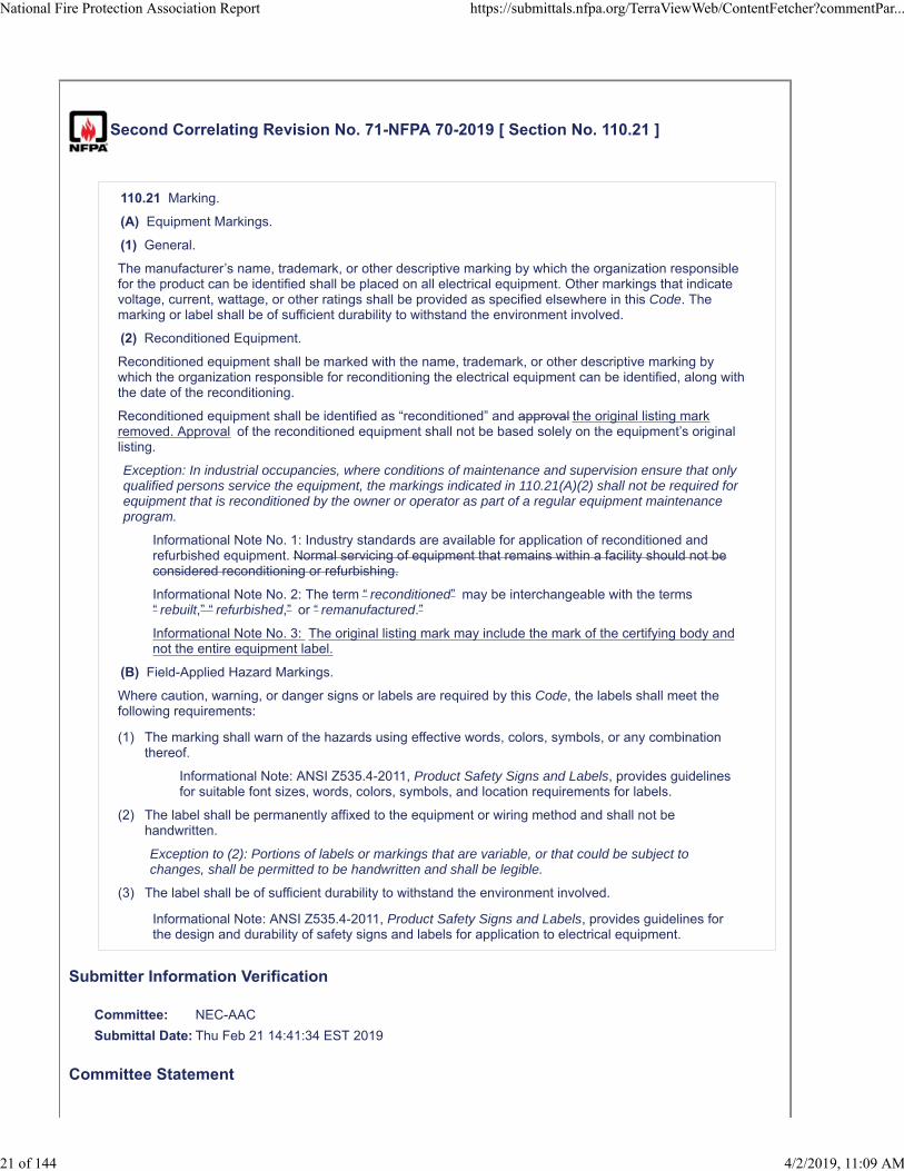
Second Correlating Revision No. 71-NFPA 70-2019 [ Section No. 110.21 ]
110.21 Marking.
(A) Equipment Markings.
(1) General.
The manufacturer’s name, trademark, or other descriptive marking by which the organization responsiblefor the product can be identified shall be placed on all electrical equipment. Other markings that indicatevoltage, current, wattage, or other ratings shall be provided as specified elsewhere in this Code. Themarking or label shall be of sufficient durability to withstand the environment involved.
(2) Reconditioned Equipment.
Reconditioned equipment shall be marked with the name, trademark, or other descriptive marking bywhich the organization responsible for reconditioning the electrical equipment can be identified, along withthe date of the reconditioning.
Reconditioned equipment shall be identified as “reconditioned” and approval the original listing markremoved. Approval of the reconditioned equipment shall not be based solely on the equipment’s originallisting.
Exception: In industrial occupancies, where conditions of maintenance and supervision ensure that onlyqualified persons service the equipment, the markings indicated in 110.21(A)(2) shall not be required forequipment that is reconditioned by the owner or operator as part of a regular equipment maintenanceprogram.
Informational Note No. 1: Industry standards are available for application of reconditioned andrefurbished equipment. Normal servicing of equipment that remains within a facility should not beconsidered reconditioning or refurbishing.
Informational Note No. 2: The term “ reconditioned” may be interchangeable with the terms“ rebuilt,” “ refurbished,” or “ remanufactured.”
Informational Note No. 3: The original listing mark may include the mark of the certifying body andnot the entire equipment label.
(B) Field-Applied Hazard Markings.
Where caution, warning, or danger signs or labels are required by this Code, the labels shall meet thefollowing requirements:
(1) The marking shall warn of the hazards using effective words, colors, symbols, or any combinationthereof.
Informational Note: ANSI Z535.4-2011, Product Safety Signs and Labels, provides guidelinesfor suitable font sizes, words, colors, symbols, and location requirements for labels.
(2) The label shall be permanently affixed to the equipment or wiring method and shall not behandwritten.
Exception to (2): Portions of labels or markings that are variable, or that could be subject tochanges, shall be permitted to be handwritten and shall be legible.
(3) The label shall be of sufficient durability to withstand the environment involved.
Informational Note: ANSI Z535.4-2011, Product Safety Signs and Labels, provides guidelines forthe design and durability of safety signs and labels for application to electrical equipment.
Submitter Information Verification
Committee: NEC-AAC
Submittal Date: Thu Feb 21 14:41:34 EST 2019
Committee Statement
National Fire Protection Association Report https://submittals.nfpa.org/TerraViewWeb/ContentFetcher?commentPar...
21 of 144 4/2/2019, 11:09 AM
CommitteeStatement:
The Correlating Committee deleted the last sentence of IN No.1 for compliance with the NECStyle Manual and to correlate with the action on the new definition of "Reconditioned".
SR-8079-NFPA 70-2018
Ballot Results
This item has passed ballot
12 Eligible Voters
0 Not Returned
11 Affirmative All
0 Affirmative with Comments
1 Negative with Comments
0 Abstention
Affirmative All
Brunssen, James E.
Dressman, Kevin L.
Hickman, Palmer L.
Hittinger, David L.
Johnston, Michael J.
Kovacik, John R.
Manche, Alan
McDaniel, Roger D.
Porter, Christine T.
Straniero, George A.
Williams, David A.
Negative with Comment
Holub, Richard A.
I have concerns that "removal" of the listing mark may not be clearly understood and that persons may notunderstand how to remove the listing mark and may in fact remove the nameplates or obliterate them on theequipment, making maintenance much more difficult. I believe adding a nameplate indicating it has beenreconditioned is more than adequate. Finally, I believe the definition needs to clearly allow for repair, either on-siteor at an original manufacturer or other repair facility as long as they are repairing with OEM parts without thisequipment being considered "reconditioned". I don't believe this is clear with the current definition.
National Fire Protection Association Report https://submittals.nfpa.org/TerraViewWeb/ContentFetcher?commentPar...
22 of 144 4/2/2019, 11:09 AM
Second Correlating Revision No. 13-NFPA 70-2019 [ Section No. 210.19(A)(1) ]
Global SCR-52
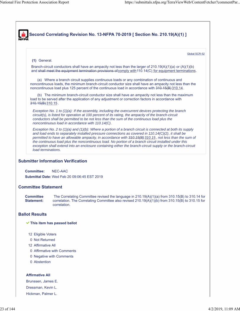
(1) General.
Branch-circuit conductors shall have an ampacity not less than the larger of 210.19(A)(1)(a) or (A)(1)(b)and shall meet the equipment termination provisions ofcomply with110.14(C) for equipment terminations.
(a) Where a branch circuit supplies continuous loads or any combination of continuous andnoncontinuous loads, the minimum branch-circuit conductor size shall have an ampacity not less than thenoncontinuous load plus 125 percent of the continuous load in accordance with 310.15(B) 310.14 .
(b) The minimum branch-circuit conductor size shall have an ampacity not less than the maximumload to be served after the application of any adjustment or correction factors in accordance with310.15(B) 310.15 .
Exception No. 1 to (1)(a): If the assembly, including the overcurrent devices protecting the branchcircuit(s), is listed for operation at 100 percent of its rating, the ampacity of the branch-circuitconductors shall be permitted to be not less than the sum of the continuous load plus thenoncontinuous load in accordance with 110.14(C).
Exception No. 2 to (1)(a) and (1)(b): Where a portion of a branch circuit is connected at both its supplyand load ends to separately installed pressure connections as covered in 110.14(C)(2), it shall bepermitted to have an allowable ampacity, in accordance with 310.15(B) 310.15 , not less than the sum ofthe continuous load plus the noncontinuous load. No portion of a branch circuit installed under thisexception shall extend into an enclosure containing either the branch-circuit supply or the branch-circuitload terminations.
Submitter Information Verification
Committee: NEC-AAC
Submittal Date: Wed Feb 20 09:06:45 EST 2019
Committee Statement
CommitteeStatement:
The Correlating Committee revised the language in 210.19(A)(1)(a) from 310.15(B) to 310.14 forcorrelation. The Correlating Committee also revised 210.19(A)(1)(b) from 310.15(B) to 310.15 forcorrelation.
Ballot Results
This item has passed ballot
12 Eligible Voters
0 Not Returned
12 Affirmative All
0 Affirmative with Comments
0 Negative with Comments
0 Abstention
Affirmative All
Brunssen, James E.
Dressman, Kevin L.
Hickman, Palmer L.
National Fire Protection Association Report https://submittals.nfpa.org/TerraViewWeb/ContentFetcher?commentPar...
23 of 144 4/2/2019, 11:09 AM

Hittinger, David L.
Holub, Richard A.
Johnston, Michael J.
Kovacik, John R.
Manche, Alan
McDaniel, Roger D.
Porter, Christine T.
Straniero, George A.
Williams, David A.
National Fire Protection Association Report https://submittals.nfpa.org/TerraViewWeb/ContentFetcher?commentPar...
24 of 144 4/2/2019, 11:09 AM
Second Correlating Revision No. 33-NFPA 70-2019 [ Section No. 230.72 ]
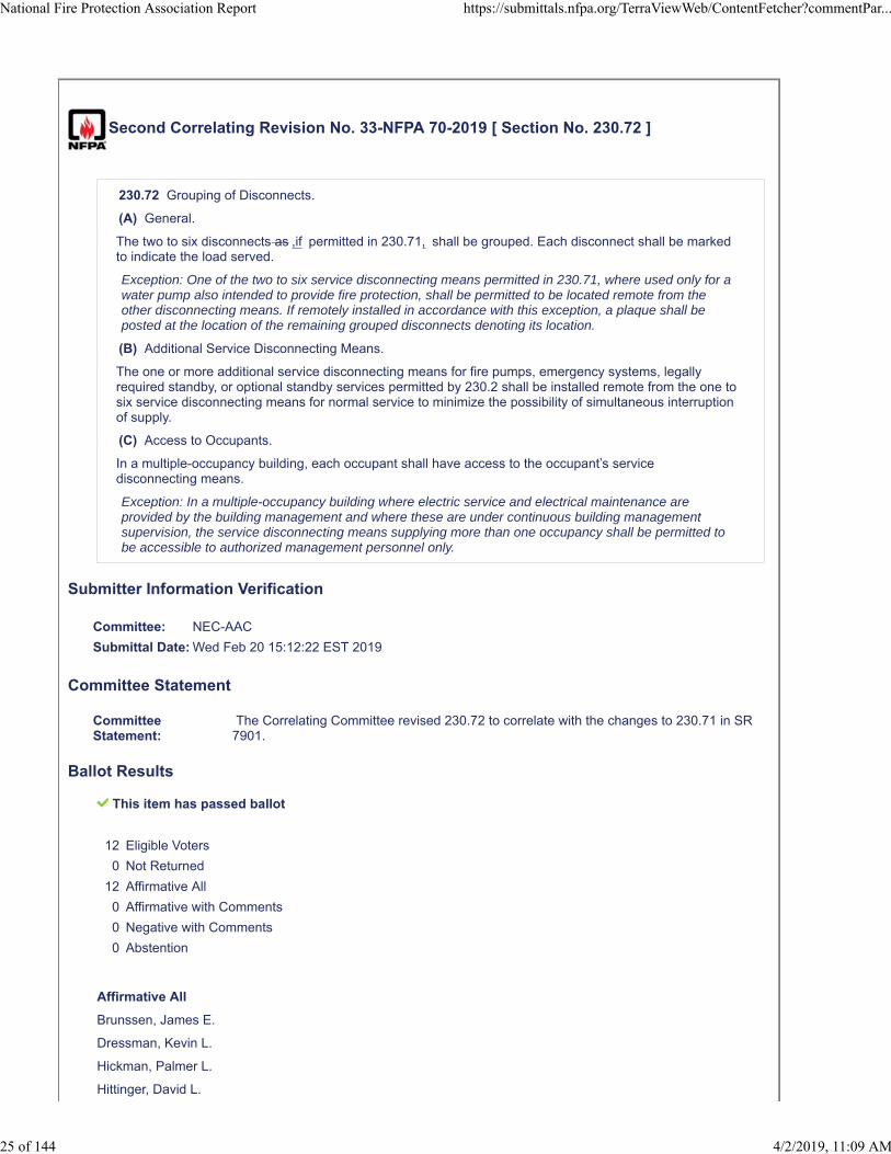
230.72 Grouping of Disconnects.
(A) General.
The two to six disconnects as ,if permitted in 230.71, shall be grouped. Each disconnect shall be markedto indicate the load served.
Exception: One of the two to six service disconnecting means permitted in 230.71, where used only for awater pump also intended to provide fire protection, shall be permitted to be located remote from theother disconnecting means. If remotely installed in accordance with this exception, a plaque shall beposted at the location of the remaining grouped disconnects denoting its location.
(B) Additional Service Disconnecting Means.
The one or more additional service disconnecting means for fire pumps, emergency systems, legallyrequired standby, or optional standby services permitted by 230.2 shall be installed remote from the one tosix service disconnecting means for normal service to minimize the possibility of simultaneous interruptionof supply.
(C) Access to Occupants.
In a multiple-occupancy building, each occupant shall have access to the occupant’s servicedisconnecting means.
Exception: In a multiple-occupancy building where electric service and electrical maintenance areprovided by the building management and where these are under continuous building managementsupervision, the service disconnecting means supplying more than one occupancy shall be permitted tobe accessible to authorized management personnel only.
Submitter Information Verification
Committee: NEC-AAC
Submittal Date: Wed Feb 20 15:12:22 EST 2019
Committee Statement
CommitteeStatement:
The Correlating Committee revised 230.72 to correlate with the changes to 230.71 in SR7901.
Ballot Results
This item has passed ballot
12 Eligible Voters
0 Not Returned
12 Affirmative All
0 Affirmative with Comments
0 Negative with Comments
0 Abstention
Affirmative All
Brunssen, James E.
Dressman, Kevin L.
Hickman, Palmer L.
Hittinger, David L.
National Fire Protection Association Report https://submittals.nfpa.org/TerraViewWeb/ContentFetcher?commentPar...
25 of 144 4/2/2019, 11:09 AM

Holub, Richard A.
Johnston, Michael J.
Kovacik, John R.
Manche, Alan
McDaniel, Roger D.
Porter, Christine T.
Straniero, George A.
Williams, David A.
National Fire Protection Association Report https://submittals.nfpa.org/TerraViewWeb/ContentFetcher?commentPar...
26 of 144 4/2/2019, 11:09 AM
Second Correlating Revision No. 5-NFPA 70-2019 [ Section No. 250.122 ]
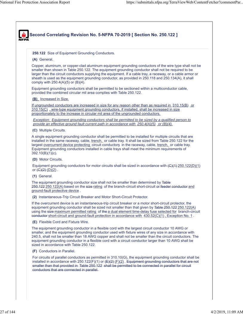
250.122 Size of Equipment Grounding Conductors.
(A) General.
Copper, aluminum, or copper-clad aluminum equipment grounding conductors of the wire type shall not besmaller than shown in Table 250.122. The equipment grounding conductor shall not be required to belarger than the circuit conductors supplying the equipment. If a cable tray, a raceway, or a cable armor orsheath is used as the equipment grounding conductor, as provided in 250.118 and 250.134(A), it shallcomply with 250.4(A)(5) or (B)(4).
Equipment grounding conductors shall be permitted to be sectioned within a multiconductor cable,provided the combined circular mil area complies with Table 250.122.
(B) Increased in Size.
If ungrounded conductors are increased in size for any reason other than as required in 310.15(B) or310.15(C) , wire-type equipment grounding conductors, if installed, shall be increased in sizeproportionately to the increase in circular mil area of the ungrounded conductors.
Exception: Equipment grounding conductors shall be permitted to be sized by a qualified person toprovide an effective ground fault current path in accordance with 250.4(A)(5) or (B)(4).
(C) Multiple Circuits.
A single equipment grounding conductor shall be permitted to be installed for multiple circuits that areinstalled in the same raceway, cable, trench, or cable tray. It shall be sized from Table 250.122 for thelargest overcurrent device protecting circuit conductors in the raceway, cable, trench, or cable tray.Equipment grounding conductors installed in cable trays shall meet the minimum requirements of392.10(B)(1)(c).
(D) Motor Circuits.
Equipment grounding conductors for motor circuits shall be sized in accordance with (C)(1) 250.122(D)(1)or (C)(2) (D)(2) .
(1) General.
The equipment grounding conductor size shall not be smaller than determined by Table250.122 250.122(A) based on the size rating of the branch-circuit short-circuit or feeder conductor andground-fault protective device .
(2) Instantaneous-Trip Circuit Breaker and Motor Short-Circuit Protector.
If the overcurrent device is an instantaneous-trip circuit breaker or a motor short-circuit protector, theequipment grounding conductor shall be sized not smaller than that given by Table 250.122 250.122(A)using the size maximum permitted rating of the a dual element time-delay fuse selected for branch-circuitconductor short-circuit and ground-fault protection in accordance with 430.52(C)(1) , Exception No. 1 .
(E) Flexible Cord and Fixture Wire.
The equipment grounding conductor in a flexible cord with the largest circuit conductor 10 AWG orsmaller, and the equipment grounding conductor used with fixture wires of any size in accordance with240.5, shall not be smaller than 18 AWG copper and shall not be smaller than the circuit conductors. Theequipment grounding conductor in a flexible cord with a circuit conductor larger than 10 AWG shall besized in accordance with Table 250.122.
(F) Conductors in Parallel.
For circuits of parallel conductors as permitted in 310.10(G), the equipment grounding conductor shall beinstalled in accordance with 250.122(F)(1) or (E)(2) (F)(2) . Equipment grounding conductors that are notsmaller than that provided in Table 250.122 shall be permitted to be connected in parallel for circuitconductors that are connected in parallel.
National Fire Protection Association Report https://submittals.nfpa.org/TerraViewWeb/ContentFetcher?commentPar...
27 of 144 4/2/2019, 11:09 AM

(1) Conductor Installations in Raceways, Auxiliary Gutters, or Cable Trays.
(a) Single Raceway or Cable Tray, Auxiliary Gutter, or Cable Tray. Equipment grounding conductorsfor If circuit conductors that are connected in parallel in the same raceway, auxiliary gutter, or cable tray, asingle wire-type conductor shall be installed in compliance permitted as the equipment groundingconductor. The wire-type equipment grounding conductor shall be sized in accordance with one of thefollowing: 250.122 , based on the overcurrent protective device for the feeder or branch circuit.
(0) An equipment grounding conductor shall be installed with each set of circuit conductors that areconnected in parallel. The wire-type equipment grounding conductor for each set shall be sized inaccordance with Table 250.122 .
(0) A single wire-type equipment grounding conductor shall be installed and sized in accordance withTable 250.122 , based on the total circular mil area of the largest set of circuit conductors for anyphase that is connected in parallel. Where the total area does not result in a standard sizeconductor, the next larger conductor shall be selected from Chapter 9, Table 8.
(b) Multiple Raceways. If conductors are installed in parallel in multiple raceways, and areconnected in parallel, a wire-type equipment grounding conductors, where conductor, if used, shall beinstalled in parallel in each raceway and shall be connected in parallel . The equipment groundingconductor installed in each raceway shall be sized in compliance accordance with 250.122 based on thelargest rating of the overcurrent protective device for the feeder or branch circuit conductor in the raceway.Metal raceways or auxiliary gutters in accordance with 250.118 or cable trays complying with 392.60(B)shall be permitted as the equipment grounding conductor .
(c) Wire-Type Equipment Grounding Conductors in Cable Trays . Wire-type equipment groundingconductors installed in cable trays shall meet the minimum requirements of 392.10(B)(1)(c).
(d) Metal Raceways, Auxiliary Gutters, or Cable Trays. Metal raceways or auxiliary gutters inaccordance with 250.188 250.118 or cable trays complying with 392.60(B) shall be permitted as theequipment grounding conductor.
(2) Multiconductor Cables.
(a) Except as provided in 250.122(F)(2) (c) for raceway or cable tray installations, the equipmentgrounding conductor in each multiconductor cable shall be sized in accordance with 250.122 based onthe overcurrent protective device for the feeder or branch circuit.
(b) If circuit conductors of multiconductor cables are connected in parallel, the equipment groundingconductor(s) in each cable shall be connected in parallel.
(c) The If multiconductor cables are paralleled in the same raceway, auxiliary gutter, or cable tray, asingle equipment grounding conductor in each multiconductor cable shall be that is sized incompliance accordance with Table 250.122 250.122 shall be permitted in combination with the equipmentgrounding conductors provided within the multiconductor cables and shall all be connected together .
(d) Equipment grounding conductors installed in cable trays shall meet the minimum requirements of392.10(B)(1)(c). Cable trays complying with 392.60(B), metal raceways in accordance with 250.118, orauxiliary gutters shall be permitted as the equipment grounding conductor.
National Fire Protection Association Report https://submittals.nfpa.org/TerraViewWeb/ContentFetcher?commentPar...
28 of 144 4/2/2019, 11:09 AM

(G) Feeder Taps.
National Fire Protection Association Report https://submittals.nfpa.org/TerraViewWeb/ContentFetcher?commentPar...
29 of 144 4/2/2019, 11:09 AM
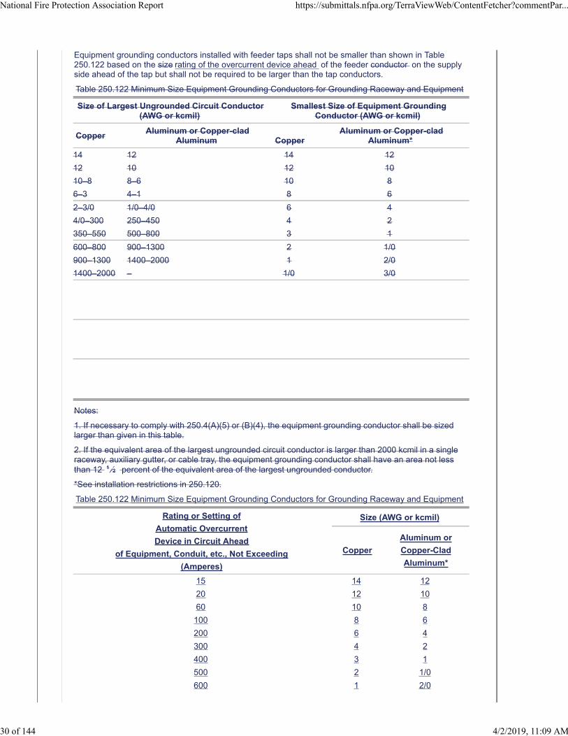
Equipment grounding conductors installed with feeder taps shall not be smaller than shown in Table250.122 based on the size rating of the overcurrent device ahead of the feeder conductor on the supplyside ahead of the tap but shall not be required to be larger than the tap conductors.
Table 250.122 Minimum Size Equipment Grounding Conductors for Grounding Raceway and Equipment
Size of Largest Ungrounded Circuit Conductor(AWG or kcmil)
Smallest Size of Equipment GroundingConductor (AWG or kcmil)
CopperAluminum or Copper-clad
Aluminum CopperAluminum or Copper-clad
Aluminum*
14 12 14 12
12 10 12 10
10–8 8–6 10 8
6–3 4–1 8 6
2–3/0 1/0–4/0 6 4
4/0–300 250–450 4 2
350–550 500–800 3 1
600–800 900–1300 2 1/0
900–1300 1400–2000 1 2/0
1400–2000 – 1/0 3/0
Notes:
1. If necessary to comply with 250.4(A)(5) or (B)(4), the equipment grounding conductor shall be sizedlarger than given in this table.
2. If the equivalent area of the largest ungrounded circuit conductor is larger than 2000 kcmil in a singleraceway, auxiliary gutter, or cable tray, the equipment grounding conductor shall have an area not lessthan 12 1 ⁄2 percent of the equivalent area of the largest ungrounded conductor.
*See installation restrictions in 250.120.
Table 250.122 Minimum Size Equipment Grounding Conductors for Grounding Raceway and Equipment
Rating or Setting of
Automatic Overcurrent
Device in Circuit Ahead
of Equipment, Conduit, etc., Not Exceeding
(Amperes)
Size (AWG or kcmil)
Copper
Aluminum or
Copper-Clad
Aluminum*
15 14 12
20 12 10
60 10 8
100 8 6
200 6 4
300 4 2
400 3 1
500 2 1/0
600 1 2/0
National Fire Protection Association Report https://submittals.nfpa.org/TerraViewWeb/ContentFetcher?commentPar...
30 of 144 4/2/2019, 11:09 AM
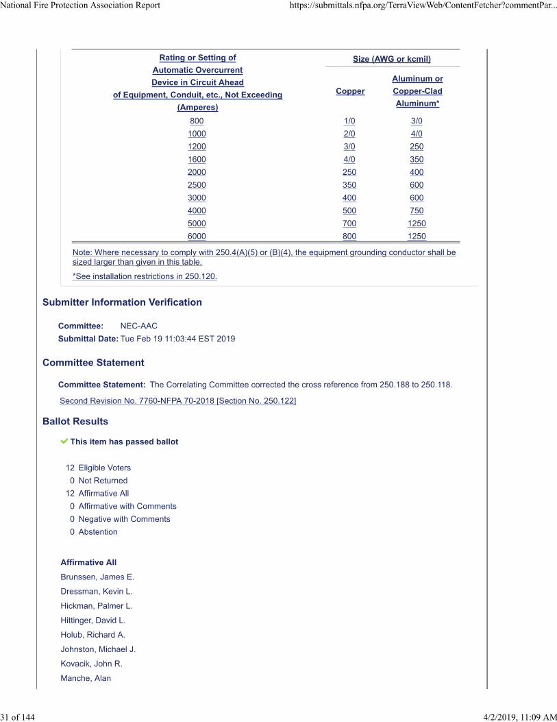
Rating or Setting of
Automatic Overcurrent
Device in Circuit Ahead
of Equipment, Conduit, etc., Not Exceeding
(Amperes)
Size (AWG or kcmil)
Copper
Aluminum or
Copper-Clad
Aluminum*
800 1/0 3/0
1000 2/0 4/0
1200 3/0 250
1600 4/0 350
2000 250 400
2500 350 600
3000 400 600
4000 500 750
5000 700 1250
6000 800 1250
Note: Where necessary to comply with 250.4(A)(5) or (B)(4), the equipment grounding conductor shall besized larger than given in this table.
*See installation restrictions in 250.120.
Submitter Information Verification
Committee: NEC-AAC
Submittal Date: Tue Feb 19 11:03:44 EST 2019
Committee Statement
Committee Statement: The Correlating Committee corrected the cross reference from 250.188 to 250.118.
Second Revision No. 7760-NFPA 70-2018 [Section No. 250.122]
Ballot Results
This item has passed ballot
12 Eligible Voters
0 Not Returned
12 Affirmative All
0 Affirmative with Comments
0 Negative with Comments
0 Abstention
Affirmative All
Brunssen, James E.
Dressman, Kevin L.
Hickman, Palmer L.
Hittinger, David L.
Holub, Richard A.
Johnston, Michael J.
Kovacik, John R.
Manche, Alan
National Fire Protection Association Report https://submittals.nfpa.org/TerraViewWeb/ContentFetcher?commentPar...
31 of 144 4/2/2019, 11:09 AM

McDaniel, Roger D.
Porter, Christine T.
Straniero, George A.
Williams, David A.
National Fire Protection Association Report https://submittals.nfpa.org/TerraViewWeb/ContentFetcher?commentPar...
32 of 144 4/2/2019, 11:09 AM
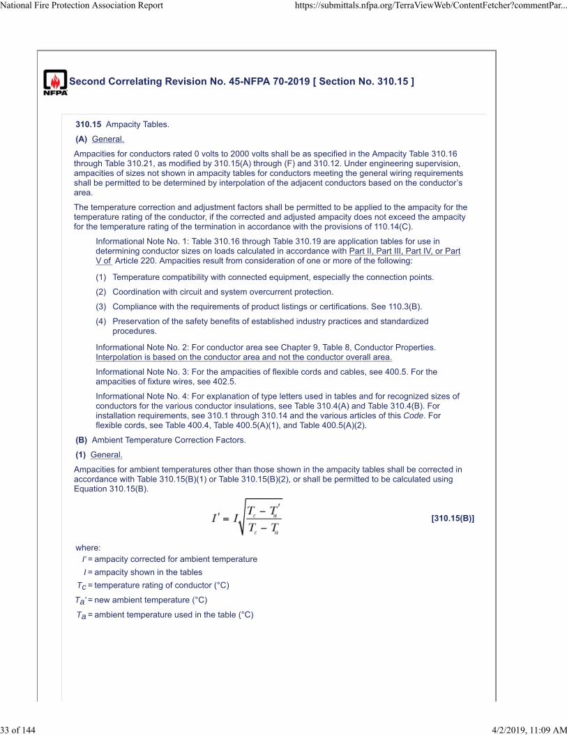
Second Correlating Revision No. 45-NFPA 70-2019 [ Section No. 310.15 ]
310.15 Ampacity Tables.
(A) General.
Ampacities for conductors rated 0 volts to 2000 volts shall be as specified in the Ampacity Table 310.16through Table 310.21, as modified by 310.15(A) through (F) and 310.12. Under engineering supervision,ampacities of sizes not shown in ampacity tables for conductors meeting the general wiring requirementsshall be permitted to be determined by interpolation of the adjacent conductors based on the conductor’sarea.
The temperature correction and adjustment factors shall be permitted to be applied to the ampacity for thetemperature rating of the conductor, if the corrected and adjusted ampacity does not exceed the ampacityfor the temperature rating of the termination in accordance with the provisions of 110.14(C).
Informational Note No. 1: Table 310.16 through Table 310.19 are application tables for use indetermining conductor sizes on loads calculated in accordance with Part II, Part III, Part IV, or PartV of Article 220. Ampacities result from consideration of one or more of the following:
(1) Temperature compatibility with connected equipment, especially the connection points.
(2) Coordination with circuit and system overcurrent protection.
(3) Compliance with the requirements of product listings or certifications. See 110.3(B).
(4) Preservation of the safety benefits of established industry practices and standardizedprocedures.
Informational Note No. 2: For conductor area see Chapter 9, Table 8, Conductor Properties.Interpolation is based on the conductor area and not the conductor overall area.
Informational Note No. 3: For the ampacities of flexible cords and cables, see 400.5. For theampacities of fixture wires, see 402.5.
Informational Note No. 4: For explanation of type letters used in tables and for recognized sizes ofconductors for the various conductor insulations, see Table 310.4(A) and Table 310.4(B). Forinstallation requirements, see 310.1 through 310.14 and the various articles of this Code. Forflexible cords, see Table 400.4, Table 400.5(A)(1), and Table 400.5(A)(2).
(B) Ambient Temperature Correction Factors.
(1) General.
Ampacities for ambient temperatures other than those shown in the ampacity tables shall be corrected inaccordance with Table 310.15(B)(1) or Table 310.15(B)(2), or shall be permitted to be calculated usingEquation 310.15(B).
[310.15(B)]
where:I' = ampacity corrected for ambient temperature
I = ampacity shown in the tables
Tc = temperature rating of conductor (°C)
Ta' = new ambient temperature (°C)
Ta = ambient temperature used in the table (°C)
National Fire Protection Association Report https://submittals.nfpa.org/TerraViewWeb/ContentFetcher?commentPar...
33 of 144 4/2/2019, 11:09 AM
(2) Rooftop.
National Fire Protection Association Report https://submittals.nfpa.org/TerraViewWeb/ContentFetcher?commentPar...
34 of 144 4/2/2019, 11:09 AM
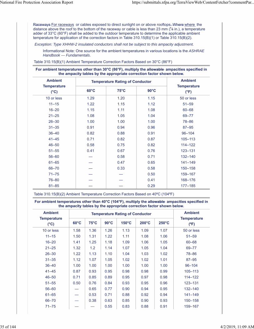
Raceways For raceways or cables exposed to direct sunlight on or above rooftops. Where where thedistance above the roof to the bottom of the raceway or cable is less than 23 mm (7⁄8 in.), a temperatureadder of 33°C (60°F) shall be added to the outdoor temperature to determine the applicable ambienttemperature for application of the correction factors in Table 310.15(B)(1) or Table 310.15(B)(2).
Exception: Type XHHW-2 insulated conductors shall not be subject to this ampacity adjustment.
Informational Note: One source for the ambient temperatures in various locations is the ASHRAEHandbook — Fundamentals.
Table 310.15(B)(1) Ambient Temperature Correction Factors Based on 30°C (86°F)
For ambient temperatures other than 30°C (86°F), multiply the allowable ampacities specified inthe ampacity tables by the appropriate correction factor shown below.
Ambient
Temperature
(°C)
Temperature Rating of Conductor Ambient
Temperature
(°F)60°C 75°C 90°C
10 or less 1.29 1.20 1.15 50 or less
11–15 1.22 1.15 1.12 51–59
16–20 1.15 1.11 1.08 60–68
21–25 1.08 1.05 1.04 69–77
26–30 1.00 1.00 1.00 78–86
31–35 0.91 0.94 0.96 87–95
36–40 0.82 0.88 0.91 96–104
41–45 0.71 0.82 0.87 105–113
46–50 0.58 0.75 0.82 114–122
51–55 0.41 0.67 0.76 123–131
56–60 — 0.58 0.71 132–140
61–65 — 0.47 0.65 141–149
66–70 — 0.33 0.58 150–158
71–75 — — 0.50 159–167
76–80 — — 0.41 168–176
81–85 — — 0.29 177–185
Table 310.15(B)(2) Ambient Temperature Correction Factors Based on 40ºC (104ºF)
For ambient temperatures other than 40°C (104°F), multiply the allowable ampacities specified inthe ampacity tables by the appropriate correction factor shown below.
Ambient
Temperature
(°C)
Temperature Rating of Conductor Ambient
Temperature
(ºF)60°C 75°C 90°C 150°C 200°C 250°C
10 or less 1.58 1.36 1.26 1.13 1.09 1.07 50 or less
11–15 1.50 1.31 1.22 1.11 1.08 1.06 51–59
16–20 1.41 1.25 1.18 1.09 1.06 1.05 60–68
21–25 1.32 1.2 1.14 1.07 1.05 1.04 69–77
26–30 1.22 1.13 1.10 1.04 1.03 1.02 78–86
31–35 1.12 1.07 1.05 1.02 1.02 1.01 87–95
36–40 1.00 1.00 1.00 1.00 1.00 1.00 96–104
41–45 0.87 0.93 0.95 0.98 0.98 0.99 105–113
46–50 0.71 0.85 0.89 0.95 0.97 0.98 114–122
51–55 0.50 0.76 0.84 0.93 0.95 0.96 123–131
56–60 — 0.65 0.77 0.90 0.94 0.95 132–140
61–65 — 0.53 0.71 0.88 0.92 0.94 141–149
66–70 — 0.38 0.63 0.85 0.90 0.93 150–158
71–75 — — 0.55 0.83 0.88 0.91 159–167
National Fire Protection Association Report https://submittals.nfpa.org/TerraViewWeb/ContentFetcher?commentPar...
35 of 144 4/2/2019, 11:09 AM
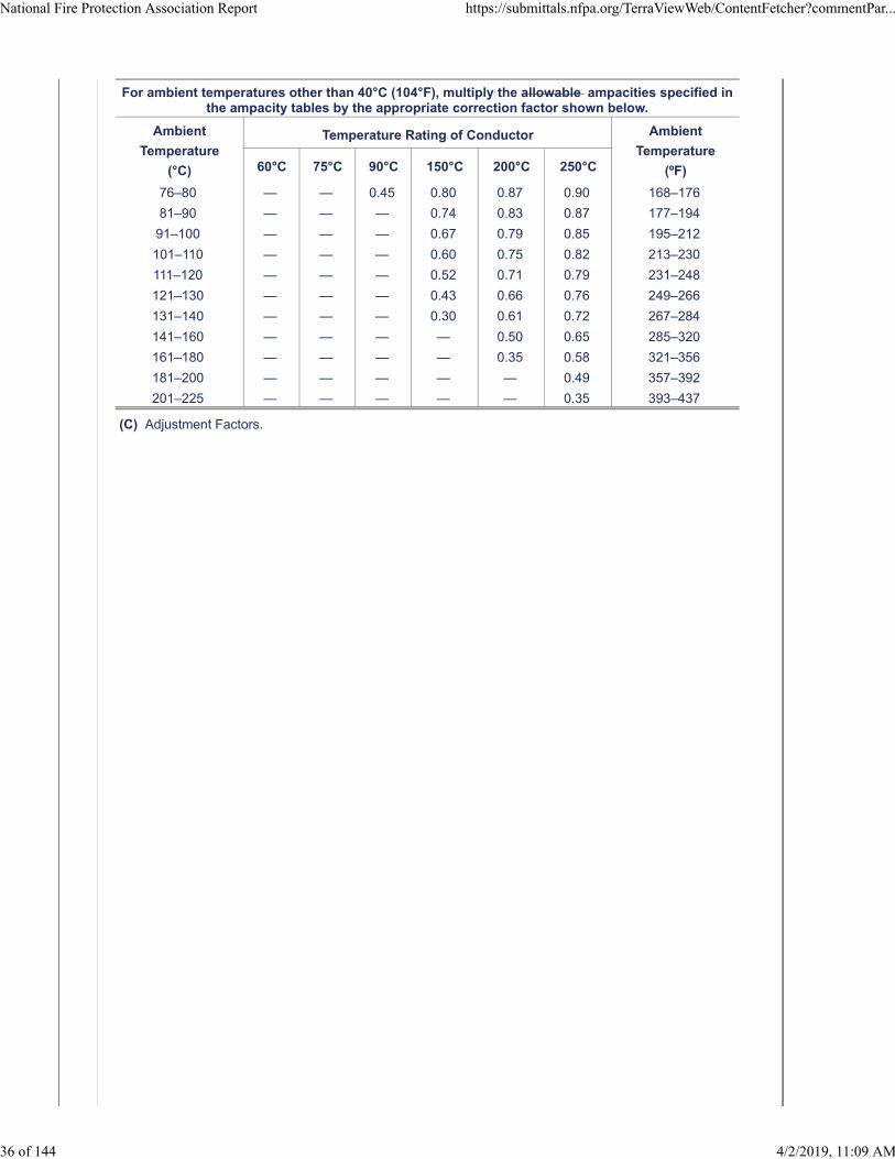
For ambient temperatures other than 40°C (104°F), multiply the allowable ampacities specified inthe ampacity tables by the appropriate correction factor shown below.
Ambient
Temperature
(°C)
Temperature Rating of Conductor Ambient
Temperature
(ºF)60°C 75°C 90°C 150°C 200°C 250°C
76–80 — — 0.45 0.80 0.87 0.90 168–176
81–90 — — — 0.74 0.83 0.87 177–194
91–100 — — — 0.67 0.79 0.85 195–212
101–110 — — — 0.60 0.75 0.82 213–230
111–120 — — — 0.52 0.71 0.79 231–248
121–130 — — — 0.43 0.66 0.76 249–266
131–140 — — — 0.30 0.61 0.72 267–284
141–160 — — — — 0.50 0.65 285–320
161–180 — — — — 0.35 0.58 321–356
181–200 — — — — — 0.49 357–392
201–225 — — — — — 0.35 393–437
(C) Adjustment Factors.
National Fire Protection Association Report https://submittals.nfpa.org/TerraViewWeb/ContentFetcher?commentPar...
36 of 144 4/2/2019, 11:09 AM
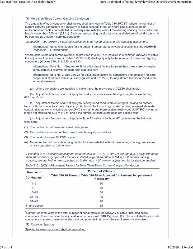
(1) More than Three Current-Carrying Conductors.
The ampacity of each conductor shall be reduced as shown in Table 310.15(C)(1) where the number ofcurrent-carrying conductors in a raceway or cable exceeds three, or where single conductors ormulticonductor cables not installed in raceways are installed without maintaining spacing for a continuouslength longer than 600 mm (24 in.). Each current-carrying conductor of a paralleled set of conductors shallbe counted as a current-carrying conductor.
Exception: Type XHHW-2 insulated conductors shall not be subject to this ampacity adjustment.
Informational Note: One source for the ambient temperatures in various locations is the ASHRAEHandbook — Fundamentals .
Where conductors of different systems, as provided in 300.3, are installed in a common raceway or cable,the adjustment factors shown in Table 310.15(C)(1) shall apply only to the number of power and lightingconductors (Articles 210, 215, 220, and 230).
Informational Note No. 1: See Annex B for adjustment factors for more than three current-carryingconductors in a raceway or cable with load diversity.
Informational Note No. 2: See 366.23 for adjustment factors for conductors and ampacity for barecopper and aluminum bars in auxiliary gutters and 376.22(B) for adjustment factors for conductorsin metal wireways.
(a) Where conductors are installed in cable trays, the provisions of 392.80 shall apply.
(b) Adjustment factors shall not apply to conductors in raceways having a length not exceeding600 mm (24 in.).
(c) Adjustment factors shall not apply to underground conductors entering or leaving an outdoortrench if those conductors have physical protection in the form of rigid metal conduit, intermediate metalconduit, rigid polyvinyl chloride conduit (PVC), or reinforced thermosetting resin conduit (RTRC) having alength not exceeding 3.05 m (10 ft), and if the number of conductors does not exceed four.
(d) Adjustment factors shall not apply to Type AC cable or to Type MC cable under the followingconditions:
(1) The cables do not have an overall outer jacket.
(2) Each cable has not more than three current-carrying conductors.
(3) The conductors are 12 AWG copper.
(4) Not more than 20 current-carrying conductors are installed without maintaining spacing, are stacked,or are supported on “bridle rings.”
Exception to (4): If cables meeting the requirements in 310.15(C)(1)(d)(1) through (C)(1)(d)(3) with morethan 20 current-carrying conductors are installed longer than 600 mm (24 in.) without maintainingspacing, are stacked, or are supported on bridle rings, a 60 percent adjustment factor shall be applied.
Table 310.15(C)(1) Adjustment Factors for More Than Three Current-Carrying Conductors
Number of
Conductors*
Percent of Values in
Table 310.16 Through Table 310.19 as Adjusted for Ambient Temperature ifNecessary
4–6 80
7–9 70
10–20 50
21–30 45
31–40 40
41 and above 35
*Number of conductors is the total number of conductors in the raceway or cable, including spareconductors. The count shall be adjusted in accordance with 310.15(E) and (F). The count shall not includeconductors that are connected to electrical components that cannot be simultaneously energized.
(2) Raceway Spacing.
Spacing between raceways shall be maintained.
National Fire Protection Association Report https://submittals.nfpa.org/TerraViewWeb/ContentFetcher?commentPar...
37 of 144 4/2/2019, 11:09 AM
(D) Bare or Covered Conductors.
Where bare or covered conductors are installed with insulated conductors, the temperature rating of thebare or covered conductor shall be equal to the lowest temperature rating of the insulated conductors forthe purpose of determining ampacity.
(E) Neutral Conductor.
Neutral conductors shall be considered current carrying in accordance with any of the following:
(1) A neutral conductor that carries only the unbalanced current from other conductors of the same circuitshall not be required to be counted when applying the provisions of 310.15(C)(1).
(2) In a 3-wire circuit consisting of two phase conductors and the neutral conductor of a 4-wire, 3-phase,wye-connected system, a common conductor carries approximately the same current as the line-to-neutral load currents of the other conductors and shall be counted when applying the provisions of310.15(C)(1).
(3) On a 4-wire, 3-phase wye circuit where the major portion of the load consists of nonlinear loads,harmonic currents are present in the neutral conductor; the neutral conductor shall therefore beconsidered a current-carrying conductor.
(F) Grounding or Bonding Conductor.
A grounding or bonding conductor shall not be counted when applying the provisions of 310.15(C)(1).
Submitter Information Verification
Committee: NEC-AAC
Submittal Date: Thu Feb 21 09:47:59 EST 2019
Committee Statement
CommitteeStatement:
The Correlating Committee has revised the action on SR 7650 to comply with the NEC StyleManual, Section 4.1.1.
Committee Comment No. 7650-NFPA 70-2018 [Section No. 310.15]
Ballot Results
This item has passed ballot
12 Eligible Voters
0 Not Returned
12 Affirmative All
0 Affirmative with Comments
0 Negative with Comments
0 Abstention
Affirmative All
Brunssen, James E.
Dressman, Kevin L.
Hickman, Palmer L.
Hittinger, David L.
Holub, Richard A.
Johnston, Michael J.
Kovacik, John R.
Manche, Alan
McDaniel, Roger D.
National Fire Protection Association Report https://submittals.nfpa.org/TerraViewWeb/ContentFetcher?commentPar...
38 of 144 4/2/2019, 11:09 AM

Porter, Christine T.
Straniero, George A.
Williams, David A.
National Fire Protection Association Report https://submittals.nfpa.org/TerraViewWeb/ContentFetcher?commentPar...
39 of 144 4/2/2019, 11:09 AM
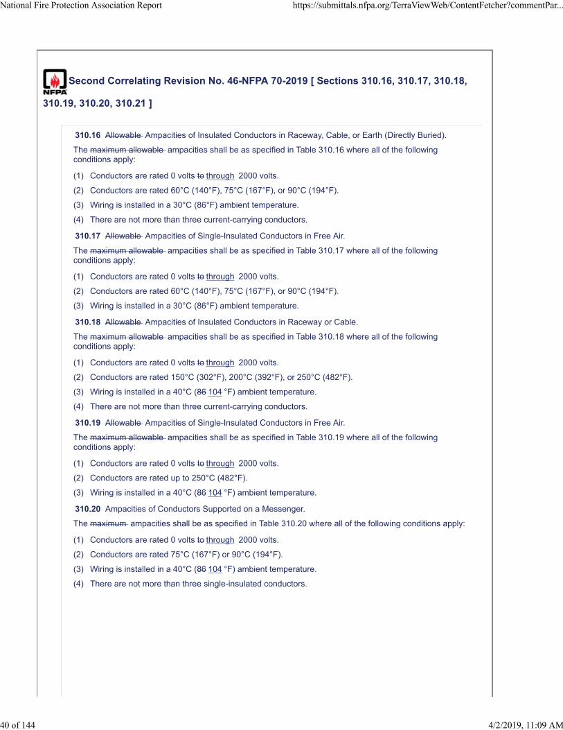
Second Correlating Revision No. 46-NFPA 70-2019 [ Sections 310.16, 310.17, 310.18,
310.19, 310.20, 310.21 ]
310.16 Allowable Ampacities of Insulated Conductors in Raceway, Cable, or Earth (Directly Buried).
The maximum allowable ampacities shall be as specified in Table 310.16 where all of the followingconditions apply:
(1) Conductors are rated 0 volts to through 2000 volts.
(2) Conductors are rated 60°C (140°F), 75°C (167°F), or 90°C (194°F).
(3) Wiring is installed in a 30°C (86°F) ambient temperature.
(4) There are not more than three current-carrying conductors.
310.17 Allowable Ampacities of Single-Insulated Conductors in Free Air.
The maximum allowable ampacities shall be as specified in Table 310.17 where all of the followingconditions apply:
(1) Conductors are rated 0 volts to through 2000 volts.
(2) Conductors are rated 60°C (140°F), 75°C (167°F), or 90°C (194°F).
(3) Wiring is installed in a 30°C (86°F) ambient temperature.
310.18 Allowable Ampacities of Insulated Conductors in Raceway or Cable.
The maximum allowable ampacities shall be as specified in Table 310.18 where all of the followingconditions apply:
(1) Conductors are rated 0 volts to through 2000 volts.
(2) Conductors are rated 150°C (302°F), 200°C (392°F), or 250°C (482°F).
(3) Wiring is installed in a 40°C (86 104 °F) ambient temperature.
(4) There are not more than three current-carrying conductors.
310.19 Allowable Ampacities of Single-Insulated Conductors in Free Air.
The maximum allowable ampacities shall be as specified in Table 310.19 where all of the followingconditions apply:
(1) Conductors are rated 0 volts to through 2000 volts.
(2) Conductors are rated up to 250°C (482°F).
(3) Wiring is installed in a 40°C (86 104 °F) ambient temperature.
310.20 Ampacities of Conductors Supported on a Messenger.
The maximum ampacities shall be as specified in Table 310.20 where all of the following conditions apply:
(1) Conductors are rated 0 volts to through 2000 volts.
(2) Conductors are rated 75°C (167°F) or 90°C (194°F).
(3) Wiring is installed in a 40°C (86 104 °F) ambient temperature.
(4) There are not more than three single-insulated conductors.
National Fire Protection Association Report https://submittals.nfpa.org/TerraViewWeb/ContentFetcher?commentPar...
40 of 144 4/2/2019, 11:09 AM
310.21 Ampacities of Bare or Covered Conductors in Free Air.
National Fire Protection Association Report https://submittals.nfpa.org/TerraViewWeb/ContentFetcher?commentPar...
41 of 144 4/2/2019, 11:09 AM

The maximum ampacities shall be as specified in Table 310.21 where all of the following conditions apply:
(1) Wind velocity is 610 mm/sec (2 ft/sec).
(2) Conductors are 80°C (176°F) total conductor temperature.
(3) Wiring is installed in a 40°C (86 104 °F) ambient temperature.
Table 310.16 (Ampacities of Insulated Conductors with Not More Than Three Current-CarryingConductors in Raceway, Cable, or Earth (Directly Buried)
SizeAWG
orkcmil
Temperature Rating of Conductor [See Table 310.4(A)]
SizeAWG
orkcmil
60°C(140°F)
75°C(167°F)
90°C (194°F)60°C
(140°F)75°C
(167°F)90°C (194°F)
TypesTW, UF
TypesRHW,
THHW,THW,
THWN,XHHW,XHWN,
USE, ZW
Types TBS, SA,SIS, FEP, FEPB,MI, PFA, RHH,RHW-2, THHN,THHW, THW-2,
THWN-2, USE-2,XHH, XHHW,
XHHW-2, XHWN,XHWN-2, XHHN, Z,
ZW-2
TypesTW, UF
TypesRHW,
THHW,THW,
THWN,XHHW,XHWN,
USE
Types TBS, SA, SIS,THHN, THHW,
THW-2, THWN-2,RHH, RHW-2,
USE-2, XHH, XHHW,XHHW-2, XHWN,
XHWN-2,ZW-2 XHHN
COPPERALUMINUM OR COPPER-CLAD
ALUMINUM
18** — — 14 — — — —
16** — — 18 — — — —
14** 15 20 25 — — — —
12** 20 25 30 15 20 25 12**
10** 30 35 40 25 30 35 10**
8 40 50 55 35 40 45 8
6 55 65 75 40 50 55 6
4 70 85 95 55 65 75 4
3 85 100 115 65 75 85 3
2 95 115 130 75 90 100 2
1 110 130 145 85 100 115 1
1/0 125 150 170 100 120 135 1/0
2/0 145 175 195 115 135 150 2/0
3/0 165 200 225 130 155 175 3/0
4/0 195 230 260 150 180 205 4/0
250 215 255 290 170 205 230 250
300 240 285 320 195 230 260 300
350 260 310 350 210 250 280 350
400 280 335 380 225 270 305 400
500 320 380 430 260 310 350 500
600 350 420 475 285 340 385 600
700 385 460 520 315 375 425 700
750 400 475 535 320 385 435 750
800 410 490 555 330 395 445 800
900 435 520 585 355 425 480 900
1000 455 545 615 375 445 500 1000
1250 495 590 665 405 485 545 1250
1500 525 625 705 435 520 585 1500
1750 545 650 735 455 545 615 1750
2000 555 665 750 470 560 630 2000
National Fire Protection Association Report https://submittals.nfpa.org/TerraViewWeb/ContentFetcher?commentPar...
42 of 144 4/2/2019, 11:09 AM
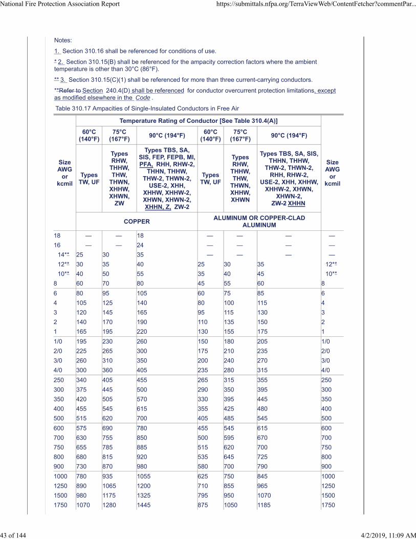
Notes:
1. Section 310.16 shall be referenced for conditions of use.
* 2. Section 310.15(B) shall be referenced for the ampacity correction factors where the ambienttemperature is other than 30°C (86°F).
** 3. Section 310.15(C)(1) shall be referenced for more than three current-carrying conductors.
**Refer to Section 240.4(D) shall be referenced for conductor overcurrent protection limitations, exceptas modified elsewhere in the Code .
Table 310.17 Ampacities of Single-Insulated Conductors in Free Air
SizeAWG
orkcmil
Temperature Rating of Conductor [See Table 310.4(A)]
SizeAWG
orkcmil
60°C(140°F)
75°C(167°F)
90°C (194°F)60°C
(140°F)75°C
(167°F)90°C (194°F)
TypesTW, UF
TypesRHW,
THHW,THW,
THWN,XHHW,XHWN,
ZW
Types TBS, SA,SIS, FEP, FEPB, MI,PFA, RHH, RHW-2,
THHN, THHW,THW-2, THWN-2,
USE-2, XHH,XHHW, XHHW-2,XHWN, XHWN-2,XHHN, Z, ZW-2
TypesTW, UF
TypesRHW,
THHW,THW,
THWN,XHHW,XHWN
Types TBS, SA, SIS,THHN, THHW,
THW-2, THWN-2,RHH, RHW-2,
USE-2, XHH, XHHW,XHHW-2, XHWN,
XHWN-2,ZW-2 XHHN
COPPERALUMINUM OR COPPER-CLAD
ALUMINUM
18 — — 18 — — — —
16 — — 24 — — — —
14** 25 30 35 — — — —
12** 30 35 40 25 30 35 12**
10** 40 50 55 35 40 45 10**
8 60 70 80 45 55 60 8
6 80 95 105 60 75 85 6
4 105 125 140 80 100 115 4
3 120 145 165 95 115 130 3
2 140 170 190 110 135 150 2
1 165 195 220 130 155 175 1
1/0 195 230 260 150 180 205 1/0
2/0 225 265 300 175 210 235 2/0
3/0 260 310 350 200 240 270 3/0
4/0 300 360 405 235 280 315 4/0
250 340 405 455 265 315 355 250
300 375 445 500 290 350 395 300
350 420 505 570 330 395 445 350
400 455 545 615 355 425 480 400
500 515 620 700 405 485 545 500
600 575 690 780 455 545 615 600
700 630 755 850 500 595 670 700
750 655 785 885 515 620 700 750
800 680 815 920 535 645 725 800
900 730 870 980 580 700 790 900
1000 780 935 1055 625 750 845 1000
1250 890 1065 1200 710 855 965 1250
1500 980 1175 1325 795 950 1070 1500
1750 1070 1280 1445 875 1050 1185 1750
National Fire Protection Association Report https://submittals.nfpa.org/TerraViewWeb/ContentFetcher?commentPar...
43 of 144 4/2/2019, 11:09 AM
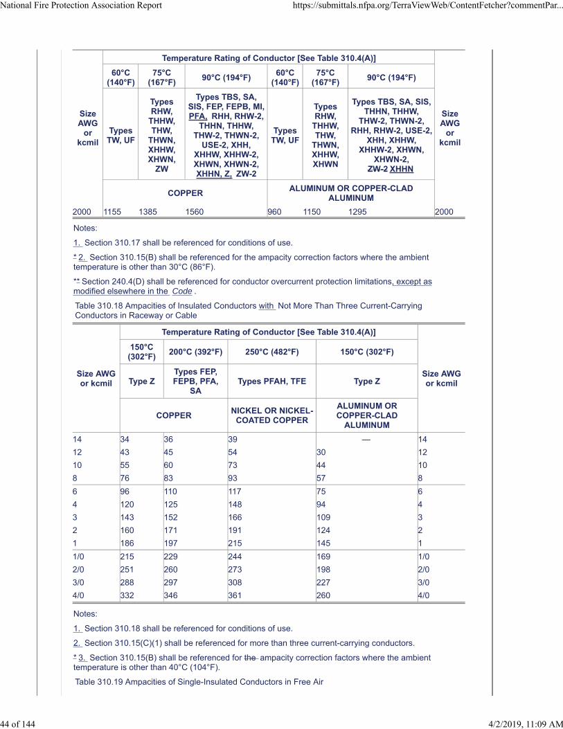
SizeAWG
orkcmil
Temperature Rating of Conductor [See Table 310.4(A)]
SizeAWG
orkcmil
60°C(140°F)
75°C(167°F)
90°C (194°F)60°C
(140°F)75°C
(167°F)90°C (194°F)
TypesTW, UF
TypesRHW,
THHW,THW,
THWN,XHHW,XHWN,
ZW
Types TBS, SA,SIS, FEP, FEPB, MI,PFA, RHH, RHW-2,
THHN, THHW,THW-2, THWN-2,
USE-2, XHH,XHHW, XHHW-2,XHWN, XHWN-2,XHHN, Z, ZW-2
TypesTW, UF
TypesRHW,
THHW,THW,
THWN,XHHW,XHWN
Types TBS, SA, SIS,THHN, THHW,
THW-2, THWN-2,RHH, RHW-2, USE-2,
XHH, XHHW,XHHW-2, XHWN,
XHWN-2,ZW-2 XHHN
COPPERALUMINUM OR COPPER-CLAD
ALUMINUM
2000 1155 1385 1560 960 1150 1295 2000
Notes:
1. Section 310.17 shall be referenced for conditions of use.
* 2. Section 310.15(B) shall be referenced for the ampacity correction factors where the ambienttemperature is other than 30°C (86°F).
** Section 240.4(D) shall be referenced for conductor overcurrent protection limitations, except asmodified elsewhere in the Code .
Table 310.18 Ampacities of Insulated Conductors with Not More Than Three Current-CarryingConductors in Raceway or Cable
Size AWGor kcmil
Temperature Rating of Conductor [See Table 310.4(A)]
Size AWGor kcmil
150°C(302°F)
200°C (392°F) 250°C (482°F) 150°C (302°F)
Type ZTypes FEP,FEPB, PFA,
SATypes PFAH, TFE Type Z
COPPERNICKEL OR NICKEL-
COATED COPPER
ALUMINUM ORCOPPER-CLAD
ALUMINUM
14 34 36 39 — 14
12 43 45 54 30 12
10 55 60 73 44 10
8 76 83 93 57 8
6 96 110 117 75 6
4 120 125 148 94 4
3 143 152 166 109 3
2 160 171 191 124 2
1 186 197 215 145 1
1/0 215 229 244 169 1/0
2/0 251 260 273 198 2/0
3/0 288 297 308 227 3/0
4/0 332 346 361 260 4/0
Notes:
1. Section 310.18 shall be referenced for conditions of use.
2. Section 310.15(C)(1) shall be referenced for more than three current-carrying conductors.
* 3. Section 310.15(B) shall be referenced for the ampacity correction factors where the ambienttemperature is other than 40°C (104°F).
Table 310.19 Ampacities of Single-Insulated Conductors in Free Air
National Fire Protection Association Report https://submittals.nfpa.org/TerraViewWeb/ContentFetcher?commentPar...
44 of 144 4/2/2019, 11:09 AM
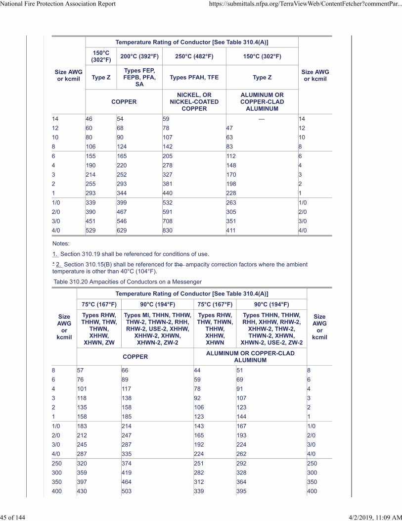
Size AWGor kcmil
Temperature Rating of Conductor [See Table 310.4(A)]
Size AWGor kcmil
150°C(302°F)
200°C (392°F) 250°C (482°F) 150°C (302°F)
Type ZTypes FEP,FEPB, PFA,
SATypes PFAH, TFE Type Z
COPPERNICKEL, OR
NICKEL-COATEDCOPPER
ALUMINUM ORCOPPER-CLAD
ALUMINUM
14 46 54 59 — 14
12 60 68 78 47 12
10 80 90 107 63 10
8 106 124 142 83 8
6 155 165 205 112 6
4 190 220 278 148 4
3 214 252 327 170 3
2 255 293 381 198 2
1 293 344 440 228 1
1/0 339 399 532 263 1/0
2/0 390 467 591 305 2/0
3/0 451 546 708 351 3/0
4/0 529 629 830 411 4/0
Notes:
1. Section 310.19 shall be referenced for conditions of use.
* 2. Section 310.15(B) shall be referenced for the ampacity correction factors where the ambienttemperature is other than 40°C (104°F).
Table 310.20 Ampacities of Conductors on a Messenger
SizeAWG
orkcmil
Temperature Rating of Conductor [See Table 310.4(A)]
SizeAWG
orkcmil
75°C (167°F) 90°C (194°F) 75°C (167°F) 90°C (194°F)
Types RHW,THHW, THW,
THWN,XHHW,
XHWN, ZW
Types MI, THHN, THHW,THW-2, THWN-2, RHH,RHW-2, USE-2, XHHW,
XHHW-2, XHWN,XHWN-2, ZW-2
Types RHW,THW, THWN,
THHW,XHHW,XHWN
Types THHN, THHW,RHH, XHHW, RHW-2,
XHHW-2, THW-2,THWN-2, XHWN,
XHWN-2, USE-2, ZW-2
COPPERALUMINUM OR COPPER-CLAD
ALUMINUM
8 57 66 44 51 8
6 76 89 59 69 6
4 101 117 78 91 4
3 118 138 92 107 3
2 135 158 106 123 2
1 158 185 123 144 1
1/0 183 214 143 167 1/0
2/0 212 247 165 193 2/0
3/0 245 287 192 224 3/0
4/0 287 335 224 262 4/0
250 320 374 251 292 250
300 359 419 282 328 300
350 397 464 312 364 350
400 430 503 339 395 400
National Fire Protection Association Report https://submittals.nfpa.org/TerraViewWeb/ContentFetcher?commentPar...
45 of 144 4/2/2019, 11:09 AM

SizeAWG
orkcmil
Temperature Rating of Conductor [See Table 310.4(A)]
SizeAWG
orkcmil
75°C (167°F) 90°C (194°F) 75°C (167°F) 90°C (194°F)
Types RHW,THHW, THW,
THWN, XHHW,XHWN, ZW
Types MI, THHN, THHW,THW-2, THWN-2, RHH,RHW-2, USE-2, XHHW,
XHHW-2, XHWN,XHWN-2, ZW-2
Types RHW,THW, THWN,
THHW,XHHW,XHWN
Types THHN, THHW,RHH, XHHW, RHW-2,
XHHW-2, THW-2,THWN-2, XHWN,
XHWN-2, USE-2, ZW-2
COPPERALUMINUM OR COPPER-CLAD
ALUMINUM
500 496 580 392 458 500
600 553 647 440 514 600
700 610 714 488 570 700
750 638 747 512 598 750
800 660 773 532 622 800
900 704 826 572 669 900
1000 748 879 612 716 1000
Notes:
1. Section 310.20 shall be referenced for conditions of use.
* 2. Section 310.15(B) shall be referenced for the ampacity correction factors where the ambienttemperature is other than 40°C (104°F).
3. Section 310.15(C)(1) shall be referenced for more than three current-carrying conductors.
Table 310.21 Ampacities of Bare or Covered Conductors in Free Air
Copper Conductors AAC Aluminum Conductors
Bare Covered Bare Covered
AWG orkcmil
AmperesAWG or
kcmilAmperes
AWG orkcmil
AmperesAWG or
kcmilAmperes
8 98 8 103 8 76 8 80
6 124 6 130 6 96 6 101
4 155 4 163 4 121 4 127
2 209 2 219 2 163 2 171
1/0 282 1/0 297 1/0 220 1/0 231
2/0 329 2/0 344 2/0 255 2/0 268
3/0 382 3/0 401 3/0 297 3/0 312
4/0 444 4/0 466 4/0 346 4/0 364
250 494 250 519 266.8 403 266.8 423
300 556 300 584 336.4 468 336.4 492
500 773 500 812 397.5 522 397.5 548
750 1000 750 1050 477.0 588 477.0 617
1000 1193 1000 1253 556.5 650 556.5 682
— — — — 636.0 709 636.0 744
— — — — 795.0 819 795.0 860
— — — — 954.0 920 — —
— — — — 1033.5 968 1033.5 1017
— — — — 1272 1103 1272 1201
— — — — 1590 1267 1590 1381
— — — — 2000 1454 2000 1527
Note: Section 310.20 310.21 shall be referenced for conditions of use.
Submitter Information Verification
National Fire Protection Association Report https://submittals.nfpa.org/TerraViewWeb/ContentFetcher?commentPar...
46 of 144 4/2/2019, 11:09 AM
Committee: NEC-AAC
Submittal Date: Thu Feb 21 09:52:53 EST 2019
Committee Statement
CommitteeStatement:
The Correlating Committee modifies the action on SR 7651 to comply with the NEC StyleManual and global revisions throughout the code.
Second Revision No. 7651-NFPA 70-2018 [Sections 310.16, 310.17, 310.18, 310.19, 310.20, 310.21]
Ballot Results
This item has passed ballot
12 Eligible Voters
0 Not Returned
12 Affirmative All
0 Affirmative with Comments
0 Negative with Comments
0 Abstention
Affirmative All
Brunssen, James E.
Dressman, Kevin L.
Hickman, Palmer L.
Hittinger, David L.
Holub, Richard A.
Johnston, Michael J.
Kovacik, John R.
Manche, Alan
McDaniel, Roger D.
Porter, Christine T.
Straniero, George A.
Williams, David A.
National Fire Protection Association Report https://submittals.nfpa.org/TerraViewWeb/ContentFetcher?commentPar...
47 of 144 4/2/2019, 11:09 AM
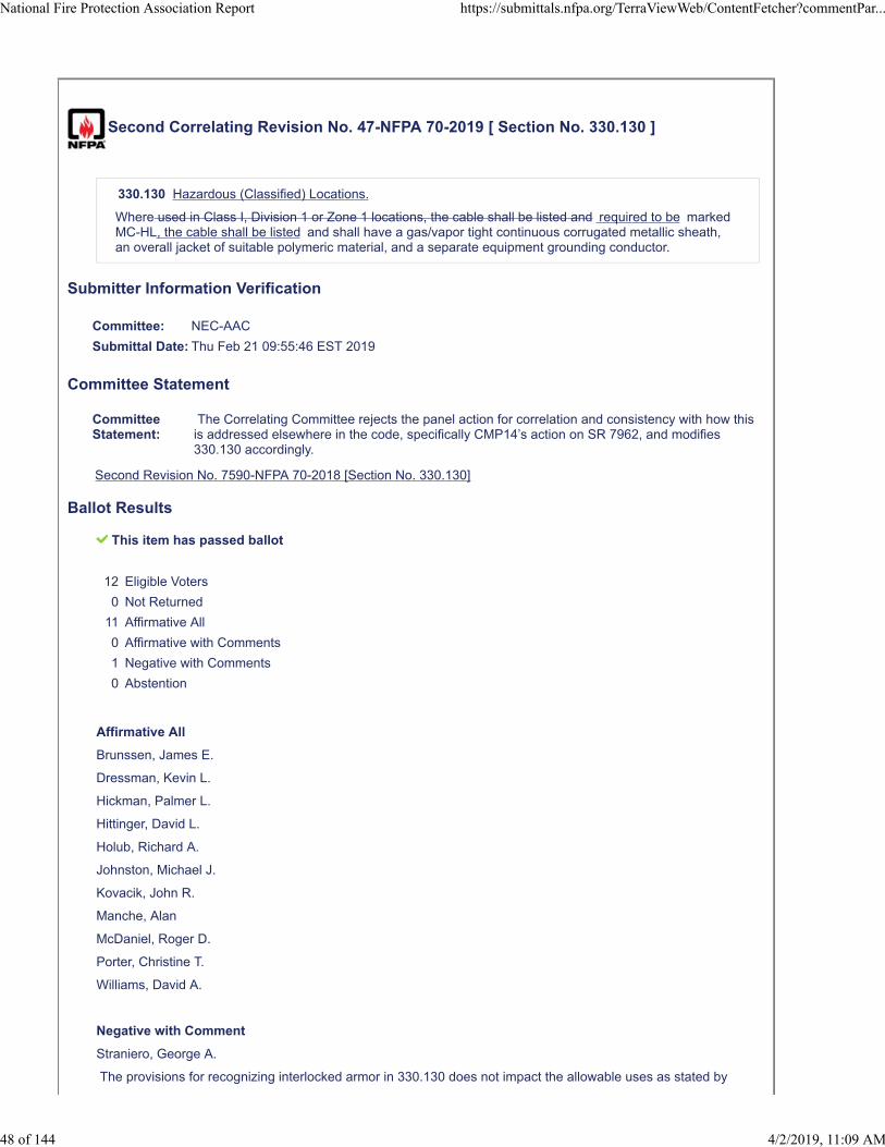
Second Correlating Revision No. 47-NFPA 70-2019 [ Section No. 330.130 ]
330.130 Hazardous (Classified) Locations.
Where used in Class I, Division 1 or Zone 1 locations, the cable shall be listed and required to be markedMC-HL, the cable shall be listed and shall have a gas/vapor tight continuous corrugated metallic sheath,an overall jacket of suitable polymeric material, and a separate equipment grounding conductor.
Submitter Information Verification
Committee: NEC-AAC
Submittal Date: Thu Feb 21 09:55:46 EST 2019
Committee Statement
CommitteeStatement:
The Correlating Committee rejects the panel action for correlation and consistency with how thisis addressed elsewhere in the code, specifically CMP14’s action on SR 7962, and modifies330.130 accordingly.
Second Revision No. 7590-NFPA 70-2018 [Section No. 330.130]
Ballot Results
This item has passed ballot
12 Eligible Voters
0 Not Returned
11 Affirmative All
0 Affirmative with Comments
1 Negative with Comments
0 Abstention
Affirmative All
Brunssen, James E.
Dressman, Kevin L.
Hickman, Palmer L.
Hittinger, David L.
Holub, Richard A.
Johnston, Michael J.
Kovacik, John R.
Manche, Alan
McDaniel, Roger D.
Porter, Christine T.
Williams, David A.
Negative with Comment
Straniero, George A.
The provisions for recognizing interlocked armor in 330.130 does not impact the allowable uses as stated by
National Fire Protection Association Report https://submittals.nfpa.org/TerraViewWeb/ContentFetcher?commentPar...
48 of 144 4/2/2019, 11:09 AM

CMP 14 and therefore does not create a conflict. Interlocked armor would only be allowed where permitted in 501.
National Fire Protection Association Report https://submittals.nfpa.org/TerraViewWeb/ContentFetcher?commentPar...
49 of 144 4/2/2019, 11:09 AM
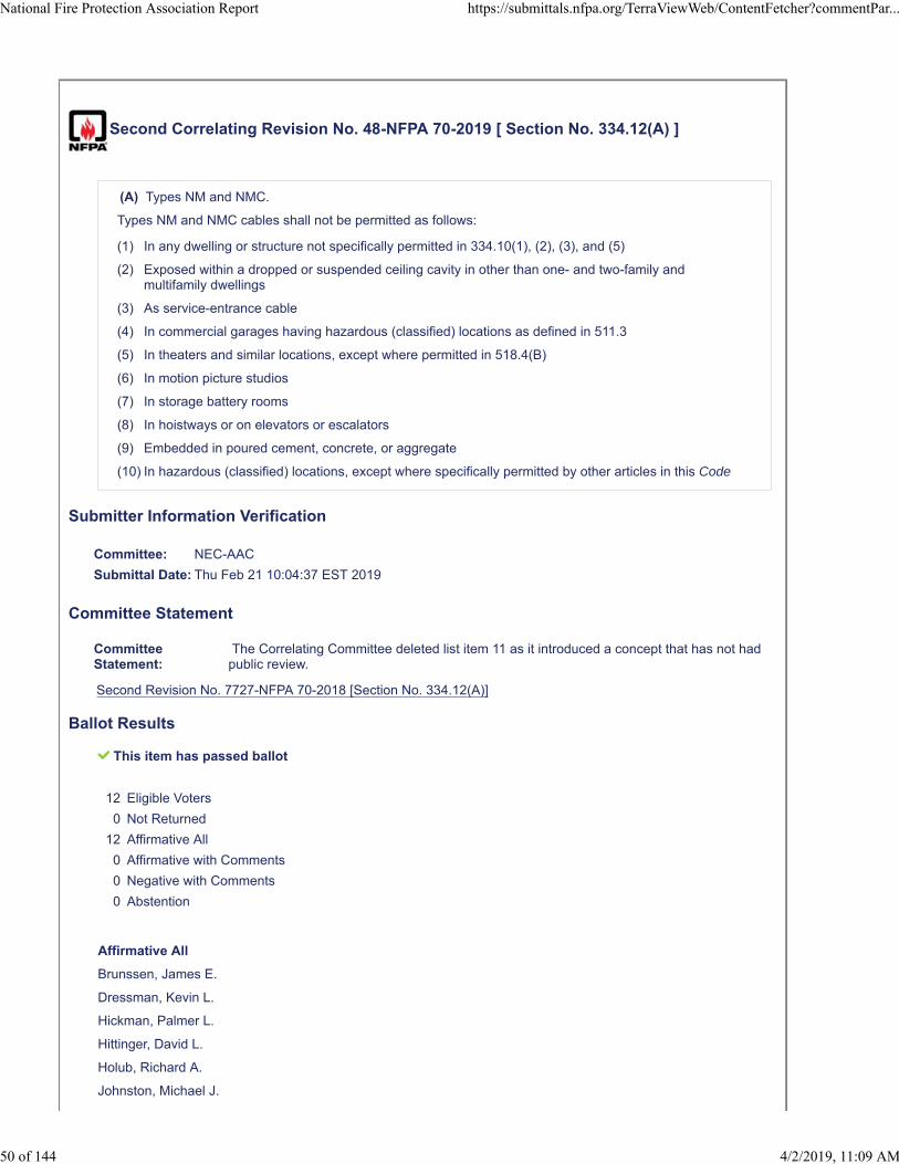
Second Correlating Revision No. 48-NFPA 70-2019 [ Section No. 334.12(A) ]
(A) Types NM and NMC.
Types NM and NMC cables shall not be permitted as follows:
(1) In any dwelling or structure not specifically permitted in 334.10(1), (2), (3), and (5)
(2) Exposed within a dropped or suspended ceiling cavity in other than one- and two-family andmultifamily dwellings
(3) As service-entrance cable
(4) In commercial garages having hazardous (classified) locations as defined in 511.3
(5) In theaters and similar locations, except where permitted in 518.4(B)
(6) In motion picture studios
(7) In storage battery rooms
(8) In hoistways or on elevators or escalators
(9) Embedded in poured cement, concrete, or aggregate
(10) In hazardous (classified) locations, except where specifically permitted by other articles in this Code
Submitter Information Verification
Committee: NEC-AAC
Submittal Date: Thu Feb 21 10:04:37 EST 2019
Committee Statement
CommitteeStatement:
The Correlating Committee deleted list item 11 as it introduced a concept that has not hadpublic review.
Second Revision No. 7727-NFPA 70-2018 [Section No. 334.12(A)]
Ballot Results
This item has passed ballot
12 Eligible Voters
0 Not Returned
12 Affirmative All
0 Affirmative with Comments
0 Negative with Comments
0 Abstention
Affirmative All
Brunssen, James E.
Dressman, Kevin L.
Hickman, Palmer L.
Hittinger, David L.
Holub, Richard A.
Johnston, Michael J.
National Fire Protection Association Report https://submittals.nfpa.org/TerraViewWeb/ContentFetcher?commentPar...
50 of 144 4/2/2019, 11:09 AM

Kovacik, John R.
Manche, Alan
McDaniel, Roger D.
Porter, Christine T.
Straniero, George A.
Williams, David A.
National Fire Protection Association Report https://submittals.nfpa.org/TerraViewWeb/ContentFetcher?commentPar...
51 of 144 4/2/2019, 11:09 AM
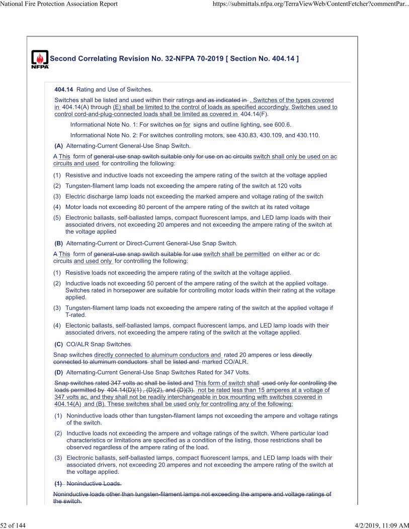
Second Correlating Revision No. 32-NFPA 70-2019 [ Section No. 404.14 ]
404.14 Rating and Use of Switches.
Switches shall be listed and used within their ratings and as indicated in . Switches of the types coveredin 404.14(A) through (E) shall be limited to the control of loads as specified accordingly. Switches used tocontrol cord-and-plug-connected loads shall be limited as covered in 404.14(F).
Informational Note No. 1: For switches on for signs and outline lighting, see 600.6.
Informational Note No. 2: For switches controlling motors, see 430.83, 430.109, and 430.110.
(A) Alternating-Current General-Use Snap Switch.
A This form of general-use snap switch suitable only for use on ac circuits switch shall only be used on accircuits and used for controlling the following:
(1) Resistive and inductive loads not exceeding the ampere rating of the switch at the voltage applied
(2) Tungsten-filament lamp loads not exceeding the ampere rating of the switch at 120 volts
(3) Electric discharge lamp loads not exceeding the marked ampere and voltage rating of the switch
(4) Motor loads not exceeding 80 percent of the ampere rating of the switch at its rated voltage
(5) Electronic ballasts, self-ballasted lamps, compact fluorescent lamps, and LED lamp loads with theirassociated drivers, not exceeding 20 amperes and not exceeding the ampere rating of the switch atthe voltage applied
(B) Alternating-Current or Direct-Current General-Use Snap Switch.
A This form of general-use snap switch suitable for use switch shall be permitted on either ac or dccircuits and used only for controlling the following:
(1) Resistive loads not exceeding the ampere rating of the switch at the voltage applied.
(2) Inductive loads not exceeding 50 percent of the ampere rating of the switch at the applied voltage.Switches rated in horsepower are suitable for controlling motor loads within their rating at the voltageapplied.
(3) Tungsten-filament lamp loads not exceeding the ampere rating of the switch at the applied voltage ifT-rated.
(4) Electonic ballasts, self-ballasted lamps, compact fluorescent lamps, and LED lamp loads with theirassociated drivers, not exceeding the ampere rating of the switch at the voltage applied.
(C) CO/ALR Snap Switches.
Snap switches directly connected to aluminum conductors and rated 20 amperes or less directlyconnected to aluminum conductors shall be listed and marked CO/ALR.
(D) Alternating-Current General-Use Snap Switches Rated for 347 Volts.
Snap switches rated 347 volts ac shall be listed and This form of switch shall used only for controlling theloads permitted by 404.14(D)(1) , (D)(2), and (D)(3). not be rated less than 15 amperes at a voltage of347 volts ac, and they shall not be readily interchangeable in box mounting with switches covered in404.14(A) and (B). These switches shall be used only for controlling any of the following:
(1) Noninductive loads other than tungsten-filament lamps not exceeding the ampere and voltage ratingsof the switch.
(2) Inductive loads not exceeding the ampere and voltage ratings of the switch. Where particular loadcharacteristics or limitations are specified as a condition of the listing, those restrictions shall beobserved regardless of the ampere rating of the load.
(3) Electronic ballasts, self-ballasted lamps, compact fluorescent lamps, and LED lamp loads with theirassociated drivers, not exceeding 20 amperes and not exceeding the ampere rating of the switch atthe voltage applied.
(1) Noninductive Loads.
Noninductive loads other than tungsten-filament lamps not exceeding the ampere and voltage ratings ofthe switch.
National Fire Protection Association Report https://submittals.nfpa.org/TerraViewWeb/ContentFetcher?commentPar...
52 of 144 4/2/2019, 11:09 AM
(2) Inductive Loads.
Inductive loads not exceeding the ampere and voltage ratings of the switch. Where particular loadcharacteristics or limitations are specified as a condition of the listing, those restrictions shall beobserved regardless of the ampere rating of the load.
The ampere rating of the switch shall not be less than 15 amperes at a voltage rating of 347 volts ac.Flush-type snap switches rated 347 volts ac shall not be readily interchangeable in box mounting withswitches identified in 404.14(A) and (B).
(3) Lighting Loads.
Electronic ballasts, self-ballasted lamps, compact fluorescent lamps, and LED lamp loads with theirassociated drivers, not exceeding 20 amperes and not exceeding the ampere rating of the switch at thevoltage applied.
The ampere rating of the switch shall not be less than 15 amperes at a voltage rating of 347 volts ac.Flush-type snap switches rated 347 volts ac shall not be readily interchangeable in box mounting withswitches identified in 404.14(A) and (B).
(E) Dimmer and Electronic Control Switches.
General-use dimmer switches shall be used only to control permanently installed incandescent luminairesunless listed for the control of other loads and installed accordingly. Other electronic control switches,such as timing switches and occupancy sensors, shall be used to control permanently connected loads.They shall be marked by their manufacturer with their current and voltage ratings and used for loads thatdo not exceed their ampere rating at the voltage applied.
(F) Cord- and Plug-Connected Loads.
Where a snap switch or control device is used to control cord-and-plug-connected equipment on ageneral-purpose branch circuit, each snap switch or control device controlling receptacle outlets or cordconnectors that are supplied by permanently connected cord pendants shall be rated at not less than therating of the maximum permitted ampere rating or setting of the overcurrent device protecting thereceptacles or cord connectors, as provided in 210.21(B).
Informational Note: See 210.50(A) and 400.10(A)(1) for equivalency to a receptacle outlet of a cordconnector that is supplied by a permanently connected cord pendant.
Exception: Where a snap switch or control device is used to control not more than one receptacle on abranch circuit, the switch or control device shall be permitted to be rated at not less than the rating of thereceptacle.
Supplemental Information
File Name Description Approved
Final_Text_for_404.14_SR-8170_.docx For staff use--clean version
Submitter Information Verification
Committee: NEC-AAC
Submittal Date: Wed Feb 20 14:40:08 EST 2019
Committee Statement
CommitteeStatement:
The Correlating Committee revised the text to comply with the NEC® Style Manual relativeto list items
Committee Comment No. 8170-NFPA 70-2018 [Section No. 404.14]
Ballot Results
This item has passed ballot
12 Eligible Voters
0 Not Returned
12 Affirmative All
National Fire Protection Association Report https://submittals.nfpa.org/TerraViewWeb/ContentFetcher?commentPar...
53 of 144 4/2/2019, 11:09 AM
0 Affirmative with Comments
0 Negative with Comments
0 Abstention
Affirmative All
Brunssen, James E.
Dressman, Kevin L.
Hickman, Palmer L.
Hittinger, David L.
Holub, Richard A.
Johnston, Michael J.
Kovacik, John R.
Manche, Alan
McDaniel, Roger D.
Porter, Christine T.
Straniero, George A.
Williams, David A.
National Fire Protection Association Report https://submittals.nfpa.org/TerraViewWeb/ContentFetcher?commentPar...
54 of 144 4/2/2019, 11:09 AM
Second Correlating Revision No. 11-NFPA 70-2019 [ Section No. 408.56 ]
408.56 Minimum Spacings.
The distance between uninsulated metal parts, busbars, and other uninsulated live parts shall not be lessthan specified in Table 408.56.
Where close proximity does not cause excessive heating, parts of the same polarity at switches, enclosedfuses, and so forth shall be permitted to be placed as close together as convenience in handling will allow.
Exception: The distance shall be permitted to be less than that specified in Table 408.56 at circuitbreakers and switches and in listed components installed in switchboards, switchgear, and panelboards.
Table 408.56 Minimum Spacings Between Bare Metal Parts
AC or DC Voltage
Opposite Polarity Where Mountedon the Same Surface
Opposite Polarity WhereHeld Free in Air
Live Parts toGround*
mm in. mm in. mm in.
Not over 125 volts,nominal
19.1 3⁄4 12.7 1⁄2 12.7 1⁄2
Not over 250 volts,nominal
31.8 11⁄4 19.1 3⁄4 12.7 1⁄2
Not over 1000 volts,nominal
50.8 2 25.4 1 25.4 1
*For spacing between live parts and doors of cabinets, see the dimensions in 312.11(A)(1), (2), and (3)shall apply .
Submitter Information Verification
Committee: NEC-AAC
Submittal Date: Wed Feb 20 08:32:57 EST 2019
Committee Statement
CommitteeStatement:
The Correlating Committee added the word "shall" in order to create mandatory languagewhich is required for table notes.
Committee Comment No. 8188-NFPA 70-2018 [Section No. 408.56]
Ballot Results
This item has passed ballot
12 Eligible Voters
0 Not Returned
12 Affirmative All
0 Affirmative with Comments
0 Negative with Comments
0 Abstention
Affirmative All
Brunssen, James E.
Dressman, Kevin L.
Hickman, Palmer L.
National Fire Protection Association Report https://submittals.nfpa.org/TerraViewWeb/ContentFetcher?commentPar...
55 of 144 4/2/2019, 11:09 AM

Hittinger, David L.
Holub, Richard A.
Johnston, Michael J.
Kovacik, John R.
Manche, Alan
McDaniel, Roger D.
Porter, Christine T.
Straniero, George A.
Williams, David A.
National Fire Protection Association Report https://submittals.nfpa.org/TerraViewWeb/ContentFetcher?commentPar...
56 of 144 4/2/2019, 11:09 AM
Second Correlating Revision No. 49-NFPA 70-2019 [ Section No. 422.17 ]
422.17 Protection of Combustible Material.
Each electrically heated appliance that is intended by size, weight, and service to be located in a fixedposition shall be placed so as to provide ample protection between the appliance and adjacentcombustible material.
Submitter Information Verification
Committee: NEC-AAC
Submittal Date: Thu Feb 21 10:08:07 EST 2019
Committee Statement
CommitteeStatement:
The Correlating Committee revised the action on SR 7880 to comply with the NEC StyleManual section 4.1 which prohibits redundant use of references.
Second Revision No. 7880-NFPA 70-2018 [Section No. 422.17]
Ballot Results
This item has passed ballot
12 Eligible Voters
0 Not Returned
12 Affirmative All
0 Affirmative with Comments
0 Negative with Comments
0 Abstention
Affirmative All
Brunssen, James E.
Dressman, Kevin L.
Hickman, Palmer L.
Hittinger, David L.
Holub, Richard A.
Johnston, Michael J.
Kovacik, John R.
Manche, Alan
McDaniel, Roger D.
Porter, Christine T.
Straniero, George A.
Williams, David A.
National Fire Protection Association Report https://submittals.nfpa.org/TerraViewWeb/ContentFetcher?commentPar...
57 of 144 4/2/2019, 11:09 AM
Second Correlating Revision No. 51-NFPA 70-2019 [ Section No. 424.36 ]
424.36 Clearances of Wiring in Ceilings.
Wiring located above heated ceilings shall be spaced not less than 50 mm (2 in.) above the heatedceiling. The ampacity of conductors shall be calculated on the basis of an assumed ambient temperatureof at least not less than 50°C (122°F), applying the correction factors shown in the 0–2000 volt ampacitytables of Article 310 in accordance with 310.15(B)(1) . If this wiring is located above thermal insulationhaving a minimum thickness of 50 mm (2 in.), it shall be subject to the ambient correction of Table310.15(B)(2) (a) in accordance with 310.15(B)(1) .
Submitter Information Verification
Committee: NEC-AAC
Submittal Date: Thu Feb 21 10:43:23 EST 2019
Committee Statement
CommitteeStatement:
The Correlating Committee revised the panel action for correlation and consistency with howreferences are addressed elsewhere in the code.
Second Revision No. 8010-NFPA 70-2018 [Section No. 424.36]
Ballot Results
This item has passed ballot
12 Eligible Voters
0 Not Returned
12 Affirmative All
0 Affirmative with Comments
0 Negative with Comments
0 Abstention
Affirmative All
Brunssen, James E.
Dressman, Kevin L.
Hickman, Palmer L.
Hittinger, David L.
Holub, Richard A.
Johnston, Michael J.
Kovacik, John R.
Manche, Alan
McDaniel, Roger D.
Porter, Christine T.
Straniero, George A.
Williams, David A.
National Fire Protection Association Report https://submittals.nfpa.org/TerraViewWeb/ContentFetcher?commentPar...
58 of 144 4/2/2019, 11:09 AM
Second Correlating Revision No. 54-NFPA 70-2019 [ Section No. 424.44(E) ]
(E) Ground-Fault Circuit-Interrupter Protection.
Ground In addition to the requirements in 210.8 , ground -fault circuit-interrupter protection for personnelshall be provided for cables installed in electrically heated floors of bathrooms and , kitchens, and inhydromassage bathtub locations.
Submitter Information Verification
Committee: NEC-AAC
Submittal Date: Thu Feb 21 10:59:20 EST 2019
Committee Statement
Committee Statement: The Correlating Committee modifies SR 8012 to correct a grammatical error.
Second Revision No. 8012-NFPA 70-2018 [Section No. 424.44(E)]
Ballot Results
This item has passed ballot
12 Eligible Voters
0 Not Returned
12 Affirmative All
0 Affirmative with Comments
0 Negative with Comments
0 Abstention
Affirmative All
Brunssen, James E.
Dressman, Kevin L.
Hickman, Palmer L.
Hittinger, David L.
Holub, Richard A.
Johnston, Michael J.
Kovacik, John R.
Manche, Alan
McDaniel, Roger D.
Porter, Christine T.
Straniero, George A.
Williams, David A.
National Fire Protection Association Report https://submittals.nfpa.org/TerraViewWeb/ContentFetcher?commentPar...
59 of 144 4/2/2019, 11:09 AM
Second Correlating Revision No. 55-NFPA 70-2019 [ Section No. 424.94 ]
424.94 Clearances of Wiring in Ceilings.
Wiring located above heated ceilings shall be spaced not less than 50 mm (2 in.) above the heatedceiling. The ampacity shall be calculated on the basis of an assumed ambient temperature of at least notless than 50°C (122°F), applying the correction factors given in the 0–2000 volt ampacity tables of Article310 in accordance with 310.15(B)(1) . If this wiring is located above thermal insulations insulation havinga minimum thickness of 50 mm (2 in.), it shall be subject to the ambient correction of Table 310.15(B)(2) (a) in accordance with 310.15(B)(1) .
Submitter Information Verification
Committee: NEC-AAC
Submittal Date: Thu Feb 21 11:00:55 EST 2019
Committee Statement
CommitteeStatement:
The Correlating Committee revised the panel action for correlation and consistency with howreferences are addressed elsewhere in the code.
Committee Comment No. 8016-NFPA 70-2018 [Section No. 424.94]
Ballot Results
This item has passed ballot
12 Eligible Voters
0 Not Returned
12 Affirmative All
0 Affirmative with Comments
0 Negative with Comments
0 Abstention
Affirmative All
Brunssen, James E.
Dressman, Kevin L.
Hickman, Palmer L.
Hittinger, David L.
Holub, Richard A.
Johnston, Michael J.
Kovacik, John R.
Manche, Alan
McDaniel, Roger D.
Porter, Christine T.
Straniero, George A.
Williams, David A.
National Fire Protection Association Report https://submittals.nfpa.org/TerraViewWeb/ContentFetcher?commentPar...
60 of 144 4/2/2019, 11:09 AM
Second Correlating Revision No. 56-NFPA 70-2019 [ Section No. 424.95 ]
424.95 Location of Branch-Circuit and Feeder Wiring in Walls.
(A) Exterior Walls.
Wiring methods shall comply with Article 300 and 310.14(A)(3).
(B) Interior Walls.
The ampacity of any wiring behind heating panels or heating panel sets located in interior walls orpartitions shall be calculated on the basis of an assumed ambient temperature of 40°C (104°F), applyingthe correction factors given in the 0–2000 volt ampacity tables of Article 310 in accordance with310.15(B)(1) .
Submitter Information Verification
Committee: NEC-AAC
Submittal Date: Thu Feb 21 11:04:19 EST 2019
Committee Statement
CommitteeStatement:
The Correlating Committee revised the panel action for correlation and consistency with howreferences are addressed elsewhere in the code.
Second Revision No. 7854-NFPA 70-2018 [Section No. 424.95]
Ballot Results
This item has passed ballot
12 Eligible Voters
0 Not Returned
12 Affirmative All
0 Affirmative with Comments
0 Negative with Comments
0 Abstention
Affirmative All
Brunssen, James E.
Dressman, Kevin L.
Hickman, Palmer L.
Hittinger, David L.
Holub, Richard A.
Johnston, Michael J.
Kovacik, John R.
Manche, Alan
McDaniel, Roger D.
Porter, Christine T.
Straniero, George A.
Williams, David A.
National Fire Protection Association Report https://submittals.nfpa.org/TerraViewWeb/ContentFetcher?commentPar...
61 of 144 4/2/2019, 11:09 AM

National Fire Protection Association Report https://submittals.nfpa.org/TerraViewWeb/ContentFetcher?commentPar...
62 of 144 4/2/2019, 11:09 AM
Second Correlating Revision No. 57-NFPA 70-2019 [ Section No. 425.1 ]
425.1 Scope.
This article covers fixed industrial process heating employing electric resistance or electrode heatingtechnology. For the purpose of this article, heating equipment shall includes boilers, electrode boilers,duct heaters, strip heaters, immersion heaters, process air heaters, or other fixed electric equipment usedfor industrial process heating. This article shall does not apply to heating and room air conditioning forpersonnel spaces covered by Article 424, fixed heating equipment for pipelines and vessels covered byArticle 427, induction and dielectric heating equipment covered by Article 665, and industrial furnacesincorporating silicon carbide, molybdenum, or graphite process heating elements, and electric resistanceor electrode heating technology covered by Article 424.90.
Submitter Information Verification
Committee: NEC-AAC
Submittal Date: Thu Feb 21 11:06:08 EST 2019
Committee Statement
CommitteeStatement:
The Correlating Committee advises that article scope statements are the responsibility of theCorrelating Committee and the Correlating Committee revised the panel action to correctgrammatical errors.
Second Revision No. 7942-NFPA 70-2018 [Section No. 425.1]
Ballot Results
This item has passed ballot
12 Eligible Voters
0 Not Returned
12 Affirmative All
0 Affirmative with Comments
0 Negative with Comments
0 Abstention
Affirmative All
Brunssen, James E.
Dressman, Kevin L.
Hickman, Palmer L.
Hittinger, David L.
Holub, Richard A.
Johnston, Michael J.
Kovacik, John R.
Manche, Alan
McDaniel, Roger D.
Porter, Christine T.
Straniero, George A.
Williams, David A.
National Fire Protection Association Report https://submittals.nfpa.org/TerraViewWeb/ContentFetcher?commentPar...
63 of 144 4/2/2019, 11:09 AM
Second Correlating Revision No. 58-NFPA 70-2019 [ Definition: Impedance Heating
System. ]
Impedance Heating System.
A system in which heat is generated in an object, such as a pipe, or rod, or combination of pipes androds such objects serving as a heating element , by causing current to flow through the pipe or rod suchobjects by direct connection to an ac voltage source from an isolating transformer. The pipe or rod shallbe permitted to be In some installations the object is embedded in the surface to be heated, orconstitutes the exposed components component to be heated.
Submitter Information Verification
Committee: NEC-AAC
Submittal Date: Thu Feb 21 11:08:08 EST 2019
Committee Statement
CommitteeStatement:
The Correlating Committee removed mandatory language from the definition and fixed agrammatical error.
Ballot Results
This item has passed ballot
12 Eligible Voters
0 Not Returned
12 Affirmative All
0 Affirmative with Comments
0 Negative with Comments
0 Abstention
Affirmative All
Brunssen, James E.
Dressman, Kevin L.
Hickman, Palmer L.
Hittinger, David L.
Holub, Richard A.
Johnston, Michael J.
Kovacik, John R.
Manche, Alan
McDaniel, Roger D.
Porter, Christine T.
Straniero, George A.
Williams, David A.
National Fire Protection Association Report https://submittals.nfpa.org/TerraViewWeb/ContentFetcher?commentPar...
64 of 144 4/2/2019, 11:09 AM
Second Correlating Revision No. 35-NFPA 70-2019 [ Section No. 430.96 ]
430.96 Grounding.
Multisection motor control centers shall be connected together with an equipment grounding conductor oran equivalent equipment grounding bus sized in accordance with Table 250.122. Equipment groundingconductors shall be connected to this equipment grounding bus or to a grounding termination pointprovided in a single-section motor control center.
Supplemental Information
File Name Description Approved
NEC_SCR-35_New_Table_being_deleted_with_SCR.docx For ballot
Submitter Information Verification
Committee: NEC-AAC
Submittal Date: Wed Feb 20 15:43:54 EST 2019
Committee Statement
CommitteeStatement:
The Correlating Committee has restored the text to the 2017 text of this section to correlatewith CMP-5 action on SR 7760, Table 250.122.
Committee Comment No. 7609-NFPA 70-2018 [Section No. 430.96]
Ballot Results
This item has passed ballot
12 Eligible Voters
0 Not Returned
12 Affirmative All
0 Affirmative with Comments
0 Negative with Comments
0 Abstention
Affirmative All
Brunssen, James E.
Dressman, Kevin L.
Hickman, Palmer L.
Hittinger, David L.
Holub, Richard A.
Johnston, Michael J.
Kovacik, John R.
Manche, Alan
McDaniel, Roger D.
Porter, Christine T.
Straniero, George A.
National Fire Protection Association Report https://submittals.nfpa.org/TerraViewWeb/ContentFetcher?commentPar...
65 of 144 4/2/2019, 11:09 AM

Williams, David A.
National Fire Protection Association Report https://submittals.nfpa.org/TerraViewWeb/ContentFetcher?commentPar...
66 of 144 4/2/2019, 11:09 AM
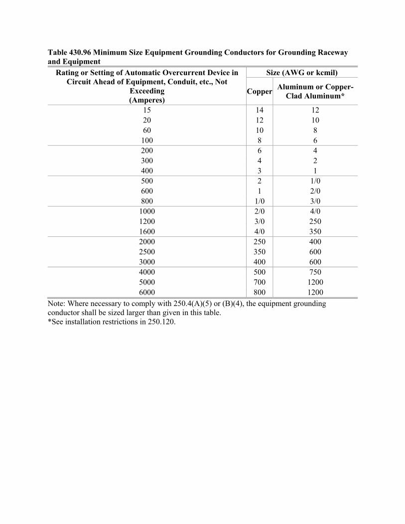
Table 430.96 Minimum Size Equipment Grounding Conductors for Grounding Raceway and Equipment
Rating or Setting of Automatic Overcurrent Device in Circuit Ahead of Equipment, Conduit, etc., Not
Exceeding (Amperes)
Size (AWG or kcmil)
Copper Aluminum or Copper-
Clad Aluminum*
15 14 12 20 12 10 60 10 8 100 8 6 200 6 4 300 4 2 400 3 1 500 2 1/0 600 1 2/0 800 1/0 3/0 1000 2/0 4/0 1200 3/0 250 1600 4/0 350 2000 250 400 2500 350 600 3000 400 600 4000 500 750 5000 700 1200 6000 800 1200
Note: Where necessary to comply with 250.4(A)(5) or (B)(4), the equipment grounding conductor shall be sized larger than given in this table. *See installation restrictions in 250.120.
Second Correlating Revision No. 12-NFPA 70-2019 [ Sections 450.23(A), 450.23(B) ]
(A) Indoor Installations.
Indoor installations shall be permitted in accordance with one of the following:
(1) In Type I or Type II buildings, in areas where all of the following requirements are met:
a. The transformer is rated 35,000 volts or less.
b. No combustible materials are stored.
c. A liquid confinement area is provided.
d. The installation complies with all the restrictions provided for in the listing of the liquid.
Informational Note: Such restrictions may can include, but are not limited to, maximumpressure of the tank, use of a pressure relief valve, appropriate fuse types, and propersizing of overcurrent protection.
(2) An If an automatic fire extinguishing system and a liquid confinement area is present , provided thetransformer is rated 35,000 volts or less
(3) Section If the installation complies with 450.26
(B) Outdoor Installations.
Less-flammable liquid-filled transformers shall be permitted to be installed outdoors, attached to, adjacentto, or on the roof of buildings, where if installed in accordance with (1) or (2).
(1) For Type I and Type II buildings, the installation shall comply with all the restrictions provided for inthe listing of the liquid.
Informational Note No. 1: Installations adjacent to combustible material, fire escapes, or doorand window openings may can require additional safeguards such as those listed in 450.27.
Informational Note No. 2: Such restrictions may can include, but are not limited to: maximumpressure of the tank, use of a pressure relief valve, appropriate fuse types, and proper sizing ofovercurrent protection.
(2) In accordance with 450.27.
Informational Note No. 1: As used in this section, Type I and Type II buildings refers to Type Iand Type II building construction as defined in NFPA 220-2018, Standard on Types of BuildingConstruction. Combustible materials refers to those materials not classified as noncombustibleor limited-combustible as defined in NFPA 220-2018, Standard on Types of BuildingConstruction.
Informational Note No. 2: See definition of Listed in Article 100.
Submitter Information Verification
Committee: NEC-AAC
Submittal Date: Wed Feb 20 08:37:02 EST 2019
Committee Statement
CommitteeStatement:
The Correlating Committee revised the text by changing "where" to "if" in the requirements and"may" to "can" in Information Note No. 1 to conform to the NEC Style Manual.
Committee Comment No. 8203-NFPA 70-2018 [Sections 450.23(A), 450.23(B)]
Ballot Results
This item has passed ballot
National Fire Protection Association Report https://submittals.nfpa.org/TerraViewWeb/ContentFetcher?commentPar...
67 of 144 4/2/2019, 11:09 AM
12 Eligible Voters
0 Not Returned
12 Affirmative All
0 Affirmative with Comments
0 Negative with Comments
0 Abstention
Affirmative All
Brunssen, James E.
Dressman, Kevin L.
Hickman, Palmer L.
Hittinger, David L.
Holub, Richard A.
Johnston, Michael J.
Kovacik, John R.
Manche, Alan
McDaniel, Roger D.
Porter, Christine T.
Straniero, George A.
Williams, David A.
National Fire Protection Association Report https://submittals.nfpa.org/TerraViewWeb/ContentFetcher?commentPar...
68 of 144 4/2/2019, 11:09 AM
Second Correlating Revision No. 37-NFPA 70-2019 [ Section No. 502.10(A)(1) ]
(1) General.
In Class II, Division 1 locations, the following wiring methods shall be permitted:
(1) Threaded rigid metal conduit (Type RMC) or threaded steel intermediate metal conduit (Type IMC) .
(2) Type MI cable with termination fittings listed for the location. Type MI cable shall be installed andsupported in a manner to avoid tensile stress at the termination fittings.
(3) In industrial establishments with limited public access, where the conditions of maintenance andsupervision ensure that only qualified persons service the installation, Type MC-HL cable, listed foruse in Class II, Division 1 locations, with a gas/vaportight continuous corrugated metallic sheath, anoverall jacket of suitable polymeric material, a separate equipment grounding conductor(s) inaccordance with 250.122, and provided with termination fittings listed for the location, shall bepermitted.
(4) Optical fiber cable Types OFNP, OFCP, OFNR, OFCR, OFNG, OFCG, OFN, and OFC shall bepermitted to be installed in raceways in accordance with 502.10(A). Optical fiber cables shall besealed in accordance with 502.15.
(5) In industrial establishments with restricted public access, where the conditions of maintenance andsupervision ensure that only qualified persons service the installation, listed Type ITC-HL cable with agas/vaportight continuous corrugated metallic sheath and an overall jacket of suitable polymericmaterial, and terminated with fittings listed for the application, and installed in accordance with theprovisions of Article 727 727.4 .
(6) In industrial establishments with restricted public access, where the conditions of maintenance andsupervision ensure that only qualified persons service the installation, for applications limited to 600volts nominal or less, and where the cable is not subject to physical damage, and terminated withfittings listed for the location, listed Type TC-ER-HL cable. When installed in ladder, ventilated trough,or ventilated channel cable trays, cables shall be installed in a single layer, with a space not less thanthe larger cable diameter between the two adjacent cables, unless otherwise protected against dustbuildup resulting in increased heat, Type TC-ER-HL cable shall be installed in accordance with336.10, including the restrictions of 336.10(7) .
Informational Note: See the information on construction, testing, and marking of cables andcable fittings in ANSI/UL 2225-2013, Cables and Cable-Fittings for Use in Hazardous(Classified) Locations.
(7) In industrial establishments with restricted public access, where the conditions of maintenance andsupervision ensure that only qualified persons service the installation, listed Type P cable with metalbraid armor, with an overall jacket, terminated with fittings listed for the location and installed inaccordance with Article 337 337.10 . When installed in ladder, ventilated trough, or ventilated channelcable trays, cables shall be installed in a single layer, with a space not less than the larger cablediameter between the two adjacent cables, unless otherwise protected against dust buildup resultingin increased heat.
Informational Note No. 1: For information on construction, testing, and marking of Type Pcable, see ANSI/UL 1309-2017, Marine Shipboard Cable.
Informational Note No. 2: For information on construction, testing, and marking of cable fittings,see ANSI/UL 2225-2013, Cables and Cable-Fittings for Use in Hazardous (Classified)Locations.
Submitter Information Verification
Committee: NEC-AAC
Submittal Date: Wed Feb 20 15:53:15 EST 2019
Committee Statement
Committee The Correlating Committee deleted the unnecessary words "the provisions of" to align with
National Fire Protection Association Report https://submittals.nfpa.org/TerraViewWeb/ContentFetcher?commentPar...
69 of 144 4/2/2019, 11:09 AM
Statement: Global direction to delete the term throughout the NEC.
Committee Comment No. 7932-NFPA 70-2018 [Section No. 502.10(A)(1)]
Ballot Results
This item has passed ballot
12 Eligible Voters
0 Not Returned
10 Affirmative All
2 Affirmative with Comments
0 Negative with Comments
0 Abstention
Affirmative All
Dressman, Kevin L.
Hickman, Palmer L.
Hittinger, David L.
Holub, Richard A.
Johnston, Michael J.
Manche, Alan
McDaniel, Roger D.
Porter, Christine T.
Straniero, George A.
Williams, David A.
Affirmative with Comment
Brunssen, James E.
The last sentence of 502.10(A)(1)(6) is a run-on sentence and, I believe, punctuated incorrectly. I believe thatthere should be a period after "heat" and the phrase beginning with "Type TC-ER-HL cable" should be a newsentence.
Kovacik, John R.
I agree with Jim Brunssens's comment. There is an error and it should be fixed. Whether fixed or not, it doesn’tchange the two requirements in that long sentence.
National Fire Protection Association Report https://submittals.nfpa.org/TerraViewWeb/ContentFetcher?commentPar...
70 of 144 4/2/2019, 11:09 AM
Second Correlating Revision No. 38-NFPA 70-2019 [ New Section after 517.2 ]
Supplemental Information
File Name Description Approved
NEC_SCR-38_New_section_being_deleted_with_SCR.docx For ballot
Submitter Information Verification
Committee: NEC-AAC
Submittal Date: Wed Feb 20 16:16:48 EST 2019
Committee Statement
CommitteeStatement:
The Correlating Committee deleted this section. In accordance with 3.4.3(a) and (b) of theRegulations Governing the Development of NFPA Standards, this new section has been deleted toresolve a potential conflict within or between NFPA standards and overlapping functions in TechnicalCommittee scopes. Requirements for reconditioned electrical distribution equipment are notoccupancy specific and are under the purview of other Code-Making Panels with expertise in thespecific equipment areas. The construction, operation, maintenance, and reconditioning of electricaldistribution equipment are installation issues rather than performance issues.
Ballot Results
This item has passed ballot
12 Eligible Voters
0 Not Returned
12 Affirmative All
0 Affirmative with Comments
0 Negative with Comments
0 Abstention
Affirmative All
Brunssen, James E.
Dressman, Kevin L.
Hickman, Palmer L.
Hittinger, David L.
Holub, Richard A.
Johnston, Michael J.
Kovacik, John R.
Manche, Alan
McDaniel, Roger D.
Porter, Christine T.
Straniero, George A.
Williams, David A.
National Fire Protection Association Report https://submittals.nfpa.org/TerraViewWeb/ContentFetcher?commentPar...
71 of 144 4/2/2019, 11:09 AM

National Fire Protection Association Report https://submittals.nfpa.org/TerraViewWeb/ContentFetcher?commentPar...
72 of 144 4/2/2019, 11:09 AM
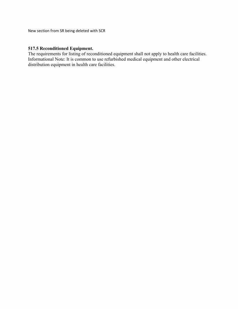
New section from SR being deleted with SCR
517.5 Reconditioned Equipment. The requirements for listing of reconditioned equipment shall not apply to health care facilities. Informational Note: It is common to use refurbished medical equipment and other electrical distribution equipment in health care facilities.
Second Correlating Revision No. 39-NFPA 70-2019 [ New Section after 517.21 ]
Supplemental Information
File Name Description Approved
NEC_SCR-39_New_section_being_deleted_with_SCR.docx For ballot
Submitter Information Verification
Committee: NEC-AAC
Submittal Date: Wed Feb 20 16:59:01 EST 2019
Committee Statement
CommitteeStatement:
The Correlating Committee deleted the section to resolve potential conflicts with the NEC inaccordance with 3.4.3(a) and (b) of the Regulations Governing the Development of NFPA Standards.CMP-2 has purview over general load calculations that are occupancy based throughout the NEC.The Fire Protection Research Foundation has initiated a research project that will seek to provide thenecessary data and analytics to support appropriate demand and loading of electrical receptacles,including all peak demand, focused on 120 volts, 15 or 20 amps receptacle circuits for general officeareas, conference rooms, cubicles within occupancies, educational facilities, and healthcare facilities.This research project data will further seek to address the following occupancy area loading concernsfound in the CMP-2 panel statement as follows; various health care facilities, hospitals with trauma oremergency, data for departments associated only with health care facilities portion of the building,geographic diversity, identification of normal, critical and life safety branches, the impact from adisaster scenario that increases demand on the electrical system, loading impact on the life span ofelectrical equipment, and when major events occur and a hospital is under full operation. TheCorrelating Committee is appointing a task group between CMP-2, CMP-15 and CorrelatingCommittee members to formulate public inputs for the 2023 NEC to address concerns in the CMP-2panel statement for PC-2192 utilizing data from a Fire Protection Research Foundation researchproject. The Correlating Committee directs that the substantiation (ASHE or other data) used todevelop this proposed section should be coordinated with the NFPA research project data in additionto the ongoing work of the Correlating Committee appointed energy task group.
Committee Comment No. 7908-NFPA 70-2018 [New Section after 517.21]
Ballot Results
This item has passed ballot
12 Eligible Voters
0 Not Returned
12 Affirmative All
0 Affirmative with Comments
0 Negative with Comments
0 Abstention
Affirmative All
Brunssen, James E.
Dressman, Kevin L.
Hickman, Palmer L.
National Fire Protection Association Report https://submittals.nfpa.org/TerraViewWeb/ContentFetcher?commentPar...
73 of 144 4/2/2019, 11:09 AM

Hittinger, David L.
Holub, Richard A.
Johnston, Michael J.
Kovacik, John R.
Manche, Alan
McDaniel, Roger D.
Porter, Christine T.
Straniero, George A.
Williams, David A.
National Fire Protection Association Report https://submittals.nfpa.org/TerraViewWeb/ContentFetcher?commentPar...
74 of 144 4/2/2019, 11:09 AM
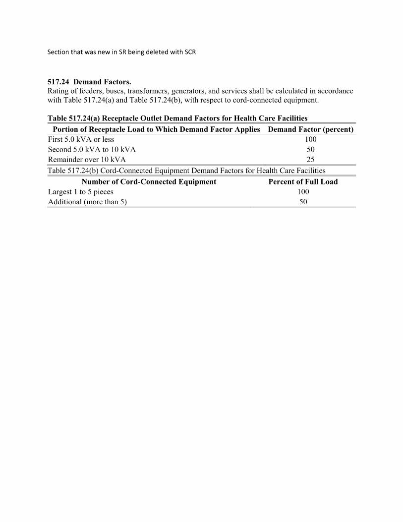
Section that was new in SR being deleted with SCR
517.24 Demand Factors. Rating of feeders, buses, transformers, generators, and services shall be calculated in accordance with Table 517.24(a) and Table 517.24(b), with respect to cord-connected equipment. Table 517.24(a) Receptacle Outlet Demand Factors for Health Care Facilities
Portion of Receptacle Load to Which Demand Factor Applies Demand Factor (percent) First 5.0 kVA or less 100 Second 5.0 kVA to 10 kVA 50 Remainder over 10 kVA 25
Table 517.24(b) Cord-Connected Equipment Demand Factors for Health Care Facilities
Number of Cord-Connected Equipment Percent of Full Load Largest 1 to 5 pieces 100 Additional (more than 5) 50
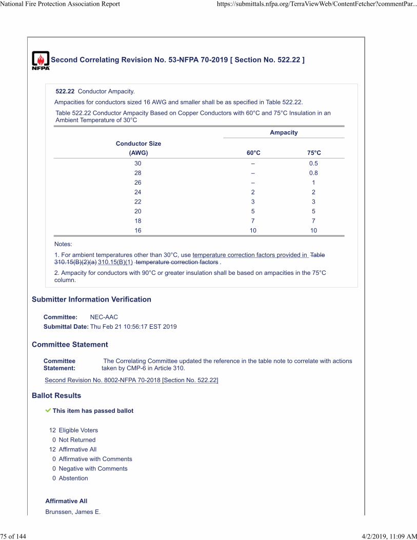
Second Correlating Revision No. 53-NFPA 70-2019 [ Section No. 522.22 ]
522.22 Conductor Ampacity.
Ampacities for conductors sized 16 AWG and smaller shall be as specified in Table 522.22.
Table 522.22 Conductor Ampacity Based on Copper Conductors with 60°C and 75°C Insulation in anAmbient Temperature of 30°C
Ampacity
Conductor Size
(AWG) 60°C 75°C
30 – 0.5
28 – 0.8
26 – 1
24 2 2
22 3 3
20 5 5
18 7 7
16 10 10
Notes:
1. For ambient temperatures other than 30°C, use temperature correction factors provided in Table310.15(B)(2)(a) 310.15(B)(1) temperature correction factors .
2. Ampacity for conductors with 90°C or greater insulation shall be based on ampacities in the 75°Ccolumn.
Submitter Information Verification
Committee: NEC-AAC
Submittal Date: Thu Feb 21 10:56:17 EST 2019
Committee Statement
CommitteeStatement:
The Correlating Committee updated the reference in the table note to correlate with actionstaken by CMP-6 in Article 310.
Second Revision No. 8002-NFPA 70-2018 [Section No. 522.22]
Ballot Results
This item has passed ballot
12 Eligible Voters
0 Not Returned
12 Affirmative All
0 Affirmative with Comments
0 Negative with Comments
0 Abstention
Affirmative All
Brunssen, James E.
National Fire Protection Association Report https://submittals.nfpa.org/TerraViewWeb/ContentFetcher?commentPar...
75 of 144 4/2/2019, 11:09 AM

Dressman, Kevin L.
Hickman, Palmer L.
Hittinger, David L.
Holub, Richard A.
Johnston, Michael J.
Kovacik, John R.
Manche, Alan
McDaniel, Roger D.
Porter, Christine T.
Straniero, George A.
Williams, David A.
National Fire Protection Association Report https://submittals.nfpa.org/TerraViewWeb/ContentFetcher?commentPar...
76 of 144 4/2/2019, 11:09 AM
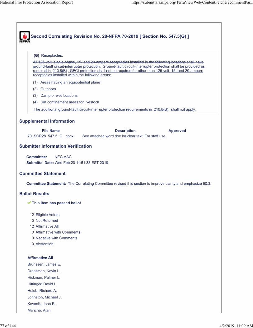
Second Correlating Revision No. 28-NFPA 70-2019 [ Section No. 547.5(G) ]
(G) Receptacles.
All 125-volt, single-phase, 15- and 20-ampere receptacles installed in the following locations shall haveground-fault circuit-interrupter protection: Ground-fault circuit-interrupter protection shall be provided asrequired in 210.8(B) . GFCI protection shall not be required for other than 125-volt, 15- and 20-amperereceptacles installed within the following areas:
(1) Areas having an equipotential plane
(2) Outdoors
(3) Damp or wet locations
(4) Dirt confinement areas for livestock
The additional ground-fault circuit-interrupter protection requirements in 210.8(B) shall not apply.
Supplemental Information
File Name Description Approved
70_SCR28_547.5_G_.docx See attached word doc for clear text. For staff use.
Submitter Information Verification
Committee: NEC-AAC
Submittal Date: Wed Feb 20 11:51:38 EST 2019
Committee Statement
Committee Statement: The Correlating Committee revised this section to improve clarity and emphasize 90.3.
Ballot Results
This item has passed ballot
12 Eligible Voters
0 Not Returned
12 Affirmative All
0 Affirmative with Comments
0 Negative with Comments
0 Abstention
Affirmative All
Brunssen, James E.
Dressman, Kevin L.
Hickman, Palmer L.
Hittinger, David L.
Holub, Richard A.
Johnston, Michael J.
Kovacik, John R.
Manche, Alan
National Fire Protection Association Report https://submittals.nfpa.org/TerraViewWeb/ContentFetcher?commentPar...
77 of 144 4/2/2019, 11:09 AM

McDaniel, Roger D.
Porter, Christine T.
Straniero, George A.
Williams, David A.
National Fire Protection Association Report https://submittals.nfpa.org/TerraViewWeb/ContentFetcher?commentPar...
78 of 144 4/2/2019, 11:09 AM
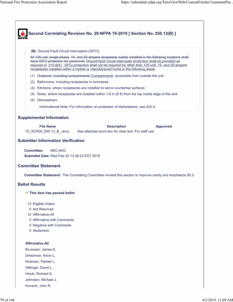
Second Correlating Revision No. 29-NFPA 70-2019 [ Section No. 550.13(B) ]
(B) Ground-Fault Circuit Interrupters (GFCI).
All 125-volt, single-phase, 15- and 20-ampere receptacle outlets installed in the following locations shallhave GFCI protection for personnel: Ground-fault circuit-interrupter protection shall be provided asrequired in 210.8(A) . GFCI protection shall not be required for other than 125-volt, 15- and 20-amperereceptacles installed within a mobile or manufactured home in the following areas:
(1) Outdoors, including compartments Compartments accessible from outside the unit
(2) Bathrooms, including receptacles in luminaires
(3) Kitchens, where receptacles are installed to serve countertop surfaces
(4) Sinks, where receptacles are installed within 1.8 m (6 ft) from the top inside edge of the sink
(5) Dishwashers
Informational Note: For information on protection of dishwashers, see 422.5.
Supplemental Information
File Name Description Approved
70_SCR29_550.13_B_.docx See attached word doc for clear text. For staff use
Submitter Information Verification
Committee: NEC-AAC
Submittal Date: Wed Feb 20 13:38:23 EST 2019
Committee Statement
Committee Statement: The Correlating Committee revised this section to improve clarity and emphasize 90.3.
Ballot Results
This item has passed ballot
12 Eligible Voters
0 Not Returned
12 Affirmative All
0 Affirmative with Comments
0 Negative with Comments
0 Abstention
Affirmative All
Brunssen, James E.
Dressman, Kevin L.
Hickman, Palmer L.
Hittinger, David L.
Holub, Richard A.
Johnston, Michael J.
Kovacik, John R.
National Fire Protection Association Report https://submittals.nfpa.org/TerraViewWeb/ContentFetcher?commentPar...
79 of 144 4/2/2019, 11:09 AM

Manche, Alan
McDaniel, Roger D.
Porter, Christine T.
Straniero, George A.
Williams, David A.
National Fire Protection Association Report https://submittals.nfpa.org/TerraViewWeb/ContentFetcher?commentPar...
80 of 144 4/2/2019, 11:09 AM
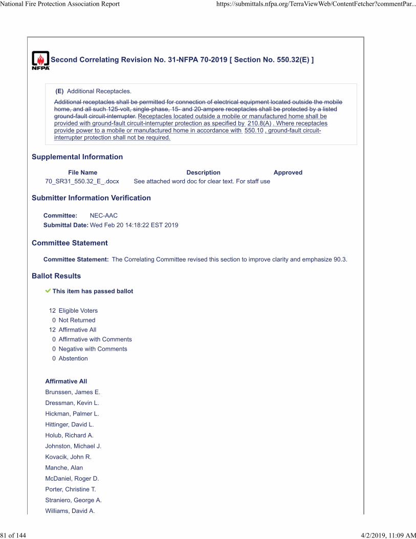
Second Correlating Revision No. 31-NFPA 70-2019 [ Section No. 550.32(E) ]
(E) Additional Receptacles.
Additional receptacles shall be permitted for connection of electrical equipment located outside the mobilehome, and all such 125-volt, single-phase, 15- and 20-ampere receptacles shall be protected by a listedground-fault circuit-interrupter. Receptacles located outside a mobile or manufactured home shall beprovided with ground-fault circuit-interrupter protection as specified by 210.8(A) . Where receptaclesprovide power to a mobile or manufactured home in accordance with 550.10 , ground-fault circuit-interrupter protection shall not be required.
Supplemental Information
File Name Description Approved
70_SR31_550.32_E_.docx See attached word doc for clear text. For staff use
Submitter Information Verification
Committee: NEC-AAC
Submittal Date: Wed Feb 20 14:18:22 EST 2019
Committee Statement
Committee Statement: The Correlating Committee revised this section to improve clarity and emphasize 90.3.
Ballot Results
This item has passed ballot
12 Eligible Voters
0 Not Returned
12 Affirmative All
0 Affirmative with Comments
0 Negative with Comments
0 Abstention
Affirmative All
Brunssen, James E.
Dressman, Kevin L.
Hickman, Palmer L.
Hittinger, David L.
Holub, Richard A.
Johnston, Michael J.
Kovacik, John R.
Manche, Alan
McDaniel, Roger D.
Porter, Christine T.
Straniero, George A.
Williams, David A.
National Fire Protection Association Report https://submittals.nfpa.org/TerraViewWeb/ContentFetcher?commentPar...
81 of 144 4/2/2019, 11:09 AM
Second Correlating Revision No. 30-NFPA 70-2019 [ Section No. 551.71(F) ]
(F) GFCI Protection.
Ground-fault circuit-interrupter protection shall be provided as required in 210.8(B) . GFCI protectionshall not be required for other than 125-volt, 15- and 20-ampere receptacles used in the recreationalvehicle site equipment.
Informational Note No. 1: Appliances used within the recreational vehicle can create leakagecurrent levels at the supply receptacle(s) that could exceed the limits of a Class A GFCI device.
Informational Note No. 2: The definition of a power supply assembly in 551.2 and the definitionof a feeder in Article 100 clarifies that the power supply cord to a recreational vehicle isconsidered a feeder.
(1)
All 125-volt, single-phase, 15- and 20-ampere receptacles shall have listed ground-fault circuit-interrupter protection for personnel.
(2)
Thirty- and 50-ampere receptacles used in recreational vehicle site equipment shall not be required tomeet the requirements of 210.8(B) .
Supplemental Information
File Name Description Approved
70_SCR30_551.71_F_.docx See attached word doc for clear text. For staff use
Submitter Information Verification
Committee: NEC-AAC
Submittal Date: Wed Feb 20 14:10:38 EST 2019
Committee Statement
Committee Statement: The Correlating Committee revised this section to improve clarity and emphasize 90.3.
Ballot Results
This item has passed ballot
12 Eligible Voters
0 Not Returned
12 Affirmative All
0 Affirmative with Comments
0 Negative with Comments
0 Abstention
Affirmative All
Brunssen, James E.
Dressman, Kevin L.
Hickman, Palmer L.
Hittinger, David L.
National Fire Protection Association Report https://submittals.nfpa.org/TerraViewWeb/ContentFetcher?commentPar...
82 of 144 4/2/2019, 11:09 AM

Holub, Richard A.
Johnston, Michael J.
Kovacik, John R.
Manche, Alan
McDaniel, Roger D.
Porter, Christine T.
Straniero, George A.
Williams, David A.
National Fire Protection Association Report https://submittals.nfpa.org/TerraViewWeb/ContentFetcher?commentPar...
83 of 144 4/2/2019, 11:09 AM

Second Correlating Revision No. 20-NFPA 70-2019 [ Section No. 610.14(A) ]
National Fire Protection Association Report https://submittals.nfpa.org/TerraViewWeb/ContentFetcher?commentPar...
84 of 144 4/2/2019, 11:09 AM

(A) Ampacity.
National Fire Protection Association Report https://submittals.nfpa.org/TerraViewWeb/ContentFetcher?commentPar...
85 of 144 4/2/2019, 11:09 AM
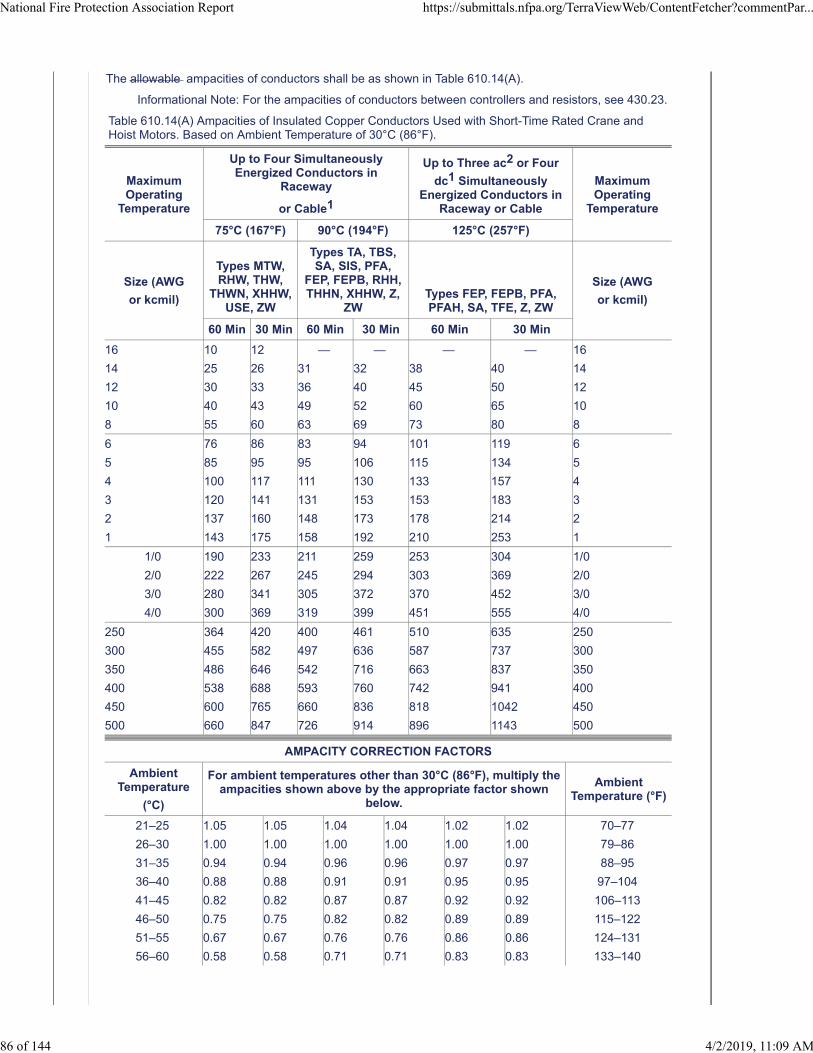
The allowable ampacities of conductors shall be as shown in Table 610.14(A).
Informational Note: For the ampacities of conductors between controllers and resistors, see 430.23.
Table 610.14(A) Ampacities of Insulated Copper Conductors Used with Short-Time Rated Crane andHoist Motors. Based on Ambient Temperature of 30°C (86°F).
MaximumOperating
Temperature
Up to Four SimultaneouslyEnergized Conductors in
Raceway
or Cable1
Up to Three ac2 or Four
dc1 SimultaneouslyEnergized Conductors in
Raceway or Cable
MaximumOperating
Temperature
75°C (167°F) 90°C (194°F) 125°C (257°F)
Size (AWG
or kcmil)
Types MTW,RHW, THW,
THWN, XHHW,USE, ZW
Types TA, TBS,SA, SIS, PFA,
FEP, FEPB, RHH,THHN, XHHW, Z,
ZWTypes FEP, FEPB, PFA,PFAH, SA, TFE, Z, ZW
Size (AWG
or kcmil)
60 Min 30 Min 60 Min 30 Min 60 Min 30 Min
16 10 12 — — — — 16
14 25 26 31 32 38 40 14
12 30 33 36 40 45 50 12
10 40 43 49 52 60 65 10
8 55 60 63 69 73 80 8
6 76 86 83 94 101 119 6
5 85 95 95 106 115 134 5
4 100 117 111 130 133 157 4
3 120 141 131 153 153 183 3
2 137 160 148 173 178 214 2
1 143 175 158 192 210 253 1
1/0 190 233 211 259 253 304 1/0
2/0 222 267 245 294 303 369 2/0
3/0 280 341 305 372 370 452 3/0
4/0 300 369 319 399 451 555 4/0
250 364 420 400 461 510 635 250
300 455 582 497 636 587 737 300
350 486 646 542 716 663 837 350
400 538 688 593 760 742 941 400
450 600 765 660 836 818 1042 450
500 660 847 726 914 896 1143 500
AMPACITY CORRECTION FACTORS
AmbientTemperature
(°C)
For ambient temperatures other than 30°C (86°F), multiply theampacities shown above by the appropriate factor shown
below.
AmbientTemperature (°F)
21–25 1.05 1.05 1.04 1.04 1.02 1.02 70–77
26–30 1.00 1.00 1.00 1.00 1.00 1.00 79–86
31–35 0.94 0.94 0.96 0.96 0.97 0.97 88–95
36–40 0.88 0.88 0.91 0.91 0.95 0.95 97–104
41–45 0.82 0.82 0.87 0.87 0.92 0.92 106–113
46–50 0.75 0.75 0.82 0.82 0.89 0.89 115–122
51–55 0.67 0.67 0.76 0.76 0.86 0.86 124–131
56–60 0.58 0.58 0.71 0.71 0.83 0.83 133–140
National Fire Protection Association Report https://submittals.nfpa.org/TerraViewWeb/ContentFetcher?commentPar...
86 of 144 4/2/2019, 11:09 AM
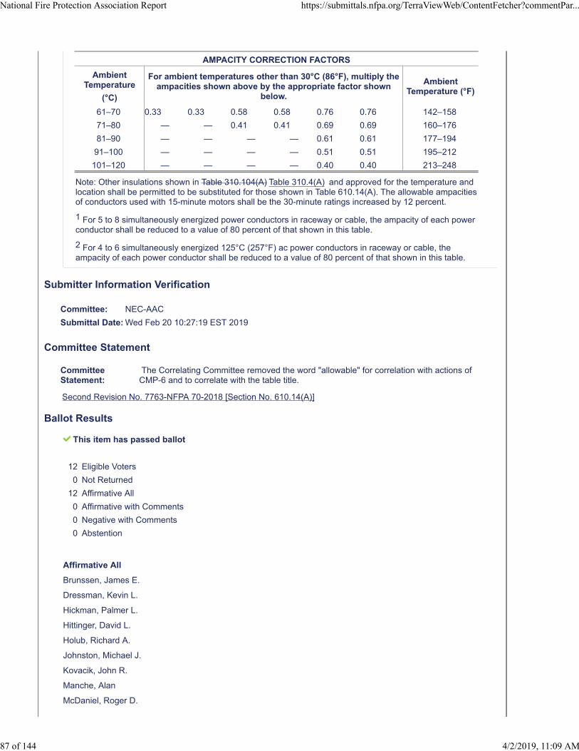
AMPACITY CORRECTION FACTORS
AmbientTemperature
(°C)
For ambient temperatures other than 30°C (86°F), multiply theampacities shown above by the appropriate factor shown
below.
AmbientTemperature (°F)
61–70 0.33 0.33 0.58 0.58 0.76 0.76 142–158
71–80 — — 0.41 0.41 0.69 0.69 160–176
81–90 — — — — 0.61 0.61 177–194
91–100 — — — — 0.51 0.51 195–212
101–120 — — — — 0.40 0.40 213–248
Note: Other insulations shown in Table 310.104(A) Table 310.4(A) and approved for the temperature andlocation shall be permitted to be substituted for those shown in Table 610.14(A). The allowable ampacitiesof conductors used with 15-minute motors shall be the 30-minute ratings increased by 12 percent.
1 For 5 to 8 simultaneously energized power conductors in raceway or cable, the ampacity of each powerconductor shall be reduced to a value of 80 percent of that shown in this table.
2 For 4 to 6 simultaneously energized 125°C (257°F) ac power conductors in raceway or cable, theampacity of each power conductor shall be reduced to a value of 80 percent of that shown in this table.
Submitter Information Verification
Committee: NEC-AAC
Submittal Date: Wed Feb 20 10:27:19 EST 2019
Committee Statement
CommitteeStatement:
The Correlating Committee removed the word "allowable" for correlation with actions ofCMP-6 and to correlate with the table title.
Second Revision No. 7763-NFPA 70-2018 [Section No. 610.14(A)]
Ballot Results
This item has passed ballot
12 Eligible Voters
0 Not Returned
12 Affirmative All
0 Affirmative with Comments
0 Negative with Comments
0 Abstention
Affirmative All
Brunssen, James E.
Dressman, Kevin L.
Hickman, Palmer L.
Hittinger, David L.
Holub, Richard A.
Johnston, Michael J.
Kovacik, John R.
Manche, Alan
McDaniel, Roger D.
National Fire Protection Association Report https://submittals.nfpa.org/TerraViewWeb/ContentFetcher?commentPar...
87 of 144 4/2/2019, 11:09 AM

Porter, Christine T.
Straniero, George A.
Williams, David A.
National Fire Protection Association Report https://submittals.nfpa.org/TerraViewWeb/ContentFetcher?commentPar...
88 of 144 4/2/2019, 11:09 AM
Second Correlating Revision No. 21-NFPA 70-2019 [ Section No. 625.42 ]
625.42 Rating.
The power transfer equipment shall have sufficient rating to supply the load served. Electric vehiclecharging loads shall be considered to be continuous loads for the purposes of this article. Service andfeeder shall be sized in accordance with the product ratings. Where an automatic load managementsystem is used, the maximum equipment load on a service and feeder shall be the maximum loadpermitted by the automatic load management system.
Adjustable settings shall only be allowed permitted on fixed-in-place equipment only . If adjustments havean impact on the rating label, those changes shall be in accordance with manufacturer’s instructions, andthe adjusted rating shall appear with sufficient durability to withstand the environment involved on therating label. Electric vehicle supply equipment with restricted access to an ampere adjusting means shallbe permitted to have an ampere rating(s) that is ratings that are equal to the adjusted current setting.Sizing the service and feeder to match the adjusting means is allowed shall be permitted . Restrictedaccess shall prevent the user from gaining access to the adjusting means. Examples of restricted accessare as follows Restricted access shall be accomplished by at least one of the following :
(1) Removable cover or door that is secured by screw(s) or bolt(s) and must be removed to access theadjusting means A cover or door that requires the use of a tool to open
(1) Bolted equipment enclosure doors
(2) Locked doors accessible only to qualified personnel
(3) Password protected commissioning software accessible only to qualified personnel
Submitter Information Verification
Committee: NEC-AAC
Submittal Date: Wed Feb 20 10:40:13 EST 2019
Committee Statement
CommitteeStatement:
The Correlating Committee revised the text to correlate with standard method to identifylist items.
Second Revision No. 7802-NFPA 70-2018 [Section No. 625.42]
Ballot Results
This item has passed ballot
12 Eligible Voters
0 Not Returned
12 Affirmative All
0 Affirmative with Comments
0 Negative with Comments
0 Abstention
Affirmative All
Brunssen, James E.
Dressman, Kevin L.
Hickman, Palmer L.
Hittinger, David L.
National Fire Protection Association Report https://submittals.nfpa.org/TerraViewWeb/ContentFetcher?commentPar...
89 of 144 4/2/2019, 11:09 AM

Holub, Richard A.
Johnston, Michael J.
Kovacik, John R.
Manche, Alan
McDaniel, Roger D.
Porter, Christine T.
Straniero, George A.
Williams, David A.
National Fire Protection Association Report https://submittals.nfpa.org/TerraViewWeb/ContentFetcher?commentPar...
90 of 144 4/2/2019, 11:09 AM
Second Correlating Revision No. 59-NFPA 70-2019 [ Section No. 680.5 ]
680.5 Ground-Fault Circuit Interrupters.
Ground-fault circuit interrupters (GFCIs) shall be self-contained units, circuit-breaker or receptacle types,or other listed types. The GFCI requirements in this article, unless otherwise noted, are in addition to therequirements in 210.8 .
Submitter Information Verification
Committee: NEC-AAC
Submittal Date: Thu Feb 21 11:22:08 EST 2019
Committee Statement
CommitteeStatement:
The Correlating Committee revised the action on SR 8103 be rewritten to comply with theNEC Style Manual, 4.1.1.
Second Revision No. 8103-NFPA 70-2018 [Section No. 680.5]
Ballot Results
This item has passed ballot
12 Eligible Voters
0 Not Returned
12 Affirmative All
0 Affirmative with Comments
0 Negative with Comments
0 Abstention
Affirmative All
Brunssen, James E.
Dressman, Kevin L.
Hickman, Palmer L.
Hittinger, David L.
Holub, Richard A.
Johnston, Michael J.
Kovacik, John R.
Manche, Alan
McDaniel, Roger D.
Porter, Christine T.
Straniero, George A.
Williams, David A.
National Fire Protection Association Report https://submittals.nfpa.org/TerraViewWeb/ContentFetcher?commentPar...
91 of 144 4/2/2019, 11:09 AM
Second Correlating Revision No. 60-NFPA 70-2019 [ Section No. 680.6 ]
680.6 Bonding and Equipment Grounding.
Electrical equipment shall be grounded bonded in accordance with Parts V, VI, Part V of Article 250 andshall meet the equipment grounding requirements of Parts VI and VII of Article 250 and . The equipmentshall be connected by the wiring methods in Chapter 3, except as modified by this article. Equipment tobe grounded includes, but is not limited to, the following subject to these requirements includes shallinclude the following:
(1) Through-wall lighting assemblies and underwater luminaires, other than those low-voltage lightingproducts listed for the application without an equipment grounding conductor
(2) All electrical equipment located within 1.5 m (5 ft) of the inside wall of the specified body of water
(3) All electrical equipment associated with the recirculating system of the specified body of water
(4) Junction boxes
(5) Transformer and power supply enclosures
(6) Ground-fault circuit interrupters
(7) Panelboards that are not part of the service equipment and that supply any electrical equipmentassociated with the specified body of water
Submitter Information Verification
Committee: NEC-AAC
Submittal Date: Thu Feb 21 11:24:02 EST 2019
Committee Statement
CommitteeStatement:
The Correlating Committee revised the action on SR 8067 to comply with 4.1.1 of the NECStyle Manual and corrected grammatical errors.
Second Revision No. 8067-NFPA 70-2018 [Section No. 680.6]
Ballot Results
This item has passed ballot
12 Eligible Voters
0 Not Returned
12 Affirmative All
0 Affirmative with Comments
0 Negative with Comments
0 Abstention
Affirmative All
Brunssen, James E.
Dressman, Kevin L.
Hickman, Palmer L.
Hittinger, David L.
Holub, Richard A.
Johnston, Michael J.
National Fire Protection Association Report https://submittals.nfpa.org/TerraViewWeb/ContentFetcher?commentPar...
92 of 144 4/2/2019, 11:09 AM

Kovacik, John R.
Manche, Alan
McDaniel, Roger D.
Porter, Christine T.
Straniero, George A.
Williams, David A.
National Fire Protection Association Report https://submittals.nfpa.org/TerraViewWeb/ContentFetcher?commentPar...
93 of 144 4/2/2019, 11:09 AM
Second Correlating Revision No. 61-NFPA 70-2019 [ Section No. 680.14 ]
680.14 Wiring Methods in Corrosive Environment.
Wiring methods in the areas described in 680.14(A) a corrosive environment shall be listed and identifiedfor use in such areas. Rigid metal conduit, intermediate metal conduit, rigid polyvinyl chloride conduit, andreinforced thermosetting resin conduit shall be considered to be resistant to the corrosive environment.specified in 680.14(A) .
(A) General.
Areas where pool sanitation chemicals are stored, as well as areas with circulation pumps, automaticchlorinators, filters, open areas under decks adjacent to or abutting the pool structure, and similarlocations shall be considered to be a corrosive environment. The air in such areas shall be consideredto be laden with acid, chlorine, and bromine vapors, or any combination of acid, chlorine, or brominevapors, and any liquids or condensation in those areas shall be considered to be laden with acids,chlorine, and bromine vapors, or any combination of acid, chlorine, or bromine vapors.
(B) Wiring Methods.
Wiring methods in the areas described in 680.14(A) shall be listed and identified for use in such areas.Rigid metal conduit, intermediate metal conduit, rigid polyvinyl chloride conduit, and reinforcedthermosetting resin conduit shall be considered to be resistant to the corrosive environment specified in680.14(A) .
Submitter Information Verification
Committee: NEC-AAC
Submittal Date: Thu Feb 21 11:28:44 EST 2019
Committee Statement
Committee Statement: The Correlating Committee corrected the grammar in this section by adding the word "in".
Second Revision No. 8142-NFPA 70-2018 [Section No. 680.14]
Ballot Results
This item has passed ballot
12 Eligible Voters
0 Not Returned
10 Affirmative All
2 Affirmative with Comments
0 Negative with Comments
0 Abstention
Affirmative All
Dressman, Kevin L.
Hickman, Palmer L.
Hittinger, David L.
Holub, Richard A.
Johnston, Michael J.
Manche, Alan
National Fire Protection Association Report https://submittals.nfpa.org/TerraViewWeb/ContentFetcher?commentPar...
94 of 144 4/2/2019, 11:09 AM
McDaniel, Roger D.
Porter, Christine T.
Straniero, George A.
Williams, David A.
Affirmative with Comment
Brunssen, James E.
The title of 680.14 is grammatically incorrect. It should state: "Wiring Methods in Corrosive Environments" or"Wiring Methods in a Corrosive Environment". The second suggestion is consistent with the text of theaccompanying paragraph.
Kovacik, John R.
I agree with Jim Brunssens's comment. There is an error and it should be fixed. Either of Jim's suggested titleswould work. However, it seems like the title should be “Wiring Methods in Corrosive Environments”
National Fire Protection Association Report https://submittals.nfpa.org/TerraViewWeb/ContentFetcher?commentPar...
95 of 144 4/2/2019, 11:09 AM
Second Correlating Revision No. 62-NFPA 70-2019 [ Section No. 680.22(A) ]
(A) Receptacles.
(1) Required Receptacle, Location.
Where a permanently installed pool is installed, no fewer than one 125-volt, 15- or 20-ampere receptacleon a general-purpose branch circuit shall be located not less than 1.83 m (6 ft) from, and not more than6.0 m (20 ft) from, the inside wall of the pool. This receptacle shall be located not more than 2.0 m (6 ft6 in.) above the floor, platform, or grade level serving the pool.
(2) Circulation and Sanitation System, Location.
Receptacles that provide power for water-pump motors or for other loads directly related to the circulationand sanitation system shall be located at least 1.83 m (6 ft) from the inside walls of the pool. Thesereceptacles shall have GFCI protection and be of the grounding type.
(3) Other Receptacles, Location.
Other receptacles shall be not less than 1.83 m (6 ft) from the inside walls of a pool.
(4) GFCI Protection.
All 15- and 20-ampere, single-phase, 125-volt receptacles located within 6.0 m (20 ft) of the inside walls ofa pool shall be provided with the following: protected by a Class A ground-fault circuit interrupter. Alsosee 680.22(A)(5) .
(0) Ground-fault circuit interrupter.
(0) At least one GFCI-protected receptacle on a general-purpose branch circuit shall be located withina pool equipment room.
(0) All receptacles within a pool equipment room shall be GFCI protected.
(5) Pool Equipment Room.
At least one GFCI-protected 125-volt, 15- or 20- ampere receptacle on a general-purpose circuit shallbe located within a pool equipment room, and all other receptacles supplied by branch circuits rated 150volts or less to ground within a pool equipment room shall be GFCI protected.
(6) Measurements.
In determining the dimensions in this section addressing receptacle spacings, the distance to bemeasured shall be the shortest path the supply cord of an appliance connected to the receptacle wouldfollow without piercing a floor, wall, ceiling, doorway with hinged or sliding door, window opening, or othereffective permanent barrier.
Submitter Information Verification
Committee: NEC-AAC
Submittal Date: Thu Feb 21 11:30:15 EST 2019
Committee Statement
Committee Statement: The Correlating Committee corrected the acronym to "GFCI".
Second Revision No. 8128-NFPA 70-2018 [Section No. 680.22(A)]
Ballot Results
This item has passed ballot
12 Eligible Voters
0 Not Returned
National Fire Protection Association Report https://submittals.nfpa.org/TerraViewWeb/ContentFetcher?commentPar...
96 of 144 4/2/2019, 11:09 AM

12 Affirmative All
0 Affirmative with Comments
0 Negative with Comments
0 Abstention
Affirmative All
Brunssen, James E.
Dressman, Kevin L.
Hickman, Palmer L.
Hittinger, David L.
Holub, Richard A.
Johnston, Michael J.
Kovacik, John R.
Manche, Alan
McDaniel, Roger D.
Porter, Christine T.
Straniero, George A.
Williams, David A.
National Fire Protection Association Report https://submittals.nfpa.org/TerraViewWeb/ContentFetcher?commentPar...
97 of 144 4/2/2019, 11:09 AM
Second Correlating Revision No. 63-NFPA 70-2019 [ Section No. 680.23(F)(1) ]
(1) Wiring Methods.
Where branch-circuit wiring on the supply side of enclosures and junction boxes connected to conduitsrun to underwater luminaires are installed in corrosive environments as described in 680.2, the wiringmethod of that portion of the branch circuit shall be as required in accordance with 680.14 or shall beliquidtight flexible nonmetallic conduit . Wiring methods installed in corrosive environments as described in680.14 shall contain an insulated copper equipment grounding conductor sized in accordance with250.122, but not smaller than 12 AWG.
Where installed in noncorrosive environments, branch circuits shall comply with the general requirementsin Chapter 3.
Exception: Where connecting to transformers or power supplies for pool lights, liquidtight flexible metalconduit shall be permitted. The length shall not exceed 1.8 m (6 ft) for any one length or exceed 3.0 m(10 ft) in total length used.
Submitter Information Verification
Committee: NEC-AAC
Submittal Date: Thu Feb 21 11:35:42 EST 2019
Committee Statement
CommitteeStatement:
The Correlating Committee revised the action on SR 8088 to correlate with the action onSR 8142.
Second Revision No. 8088-NFPA 70-2018 [Section No. 680.23(F)(1)]
Ballot Results
This item has passed ballot
12 Eligible Voters
0 Not Returned
12 Affirmative All
0 Affirmative with Comments
0 Negative with Comments
0 Abstention
Affirmative All
Brunssen, James E.
Dressman, Kevin L.
Hickman, Palmer L.
Hittinger, David L.
Holub, Richard A.
Johnston, Michael J.
Kovacik, John R.
Manche, Alan
McDaniel, Roger D.
Porter, Christine T.
National Fire Protection Association Report https://submittals.nfpa.org/TerraViewWeb/ContentFetcher?commentPar...
98 of 144 4/2/2019, 11:09 AM

Straniero, George A.
Williams, David A.
National Fire Protection Association Report https://submittals.nfpa.org/TerraViewWeb/ContentFetcher?commentPar...
99 of 144 4/2/2019, 11:09 AM
Second Correlating Revision No. 64-NFPA 70-2019 [ Section No. 680.25(A) ]
(A) Feeders.
Where feeders are installed in corrosive environments as described in 680.2 , Corrosive Environment ,the wiring method of that portion of the feeder shall be as required in accordance with 680.14 or shall beliquidtight flexible nonmetallic conduit . Wiring methods installed in corrosive environments as describedin 680.14 shall contain an insulated copper equipment grounding conductor sized in accordance withTable 250.122, but not smaller than 12 AWG.
Where installed in noncorrosive environments, feeders shall comply with the general requirements inChapter 3.
Submitter Information Verification
Committee: NEC-AAC
Submittal Date: Thu Feb 21 11:37:48 EST 2019
Committee Statement
CommitteeStatement:
The Correlating Committee revised the action on SR 8084 to correlate with the action onSR 8142.
Second Revision No. 8084-NFPA 70-2018 [Section No. 680.25(A)]
Ballot Results
This item has passed ballot
12 Eligible Voters
0 Not Returned
12 Affirmative All
0 Affirmative with Comments
0 Negative with Comments
0 Abstention
Affirmative All
Brunssen, James E.
Dressman, Kevin L.
Hickman, Palmer L.
Hittinger, David L.
Holub, Richard A.
Johnston, Michael J.
Kovacik, John R.
Manche, Alan
McDaniel, Roger D.
Porter, Christine T.
Straniero, George A.
Williams, David A.
National Fire Protection Association Report https://submittals.nfpa.org/TerraViewWeb/ContentFetcher?commentPar...
100 of 144 4/2/2019, 11:09 AM
Second Correlating Revision No. 26-NFPA 70-2019 [ Definition: Pier. ]
Pier.
A structure extending over the water and supported on a fixed foundation, or on flotation, that providesaccess to the water.
Submitter Information Verification
Committee: NEC-AAC
Submittal Date: Wed Feb 20 11:16:52 EST 2019
Committee Statement
CommitteeStatement:
The Correlating Committee relocated the definition of Pier to Article 100 since the term is used inseveral Articles. Therefore, the definition in Article 682 is no longer needed. The definition will beunder the purview of Panel 7.
Ballot Results
This item has passed ballot
12 Eligible Voters
0 Not Returned
12 Affirmative All
0 Affirmative with Comments
0 Negative with Comments
0 Abstention
Affirmative All
Brunssen, James E.
Dressman, Kevin L.
Hickman, Palmer L.
Hittinger, David L.
Holub, Richard A.
Johnston, Michael J.
Kovacik, John R.
Manche, Alan
McDaniel, Roger D.
Porter, Christine T.
Straniero, George A.
Williams, David A.
National Fire Protection Association Report https://submittals.nfpa.org/TerraViewWeb/ContentFetcher?commentPar...
101 of 144 4/2/2019, 11:09 AM
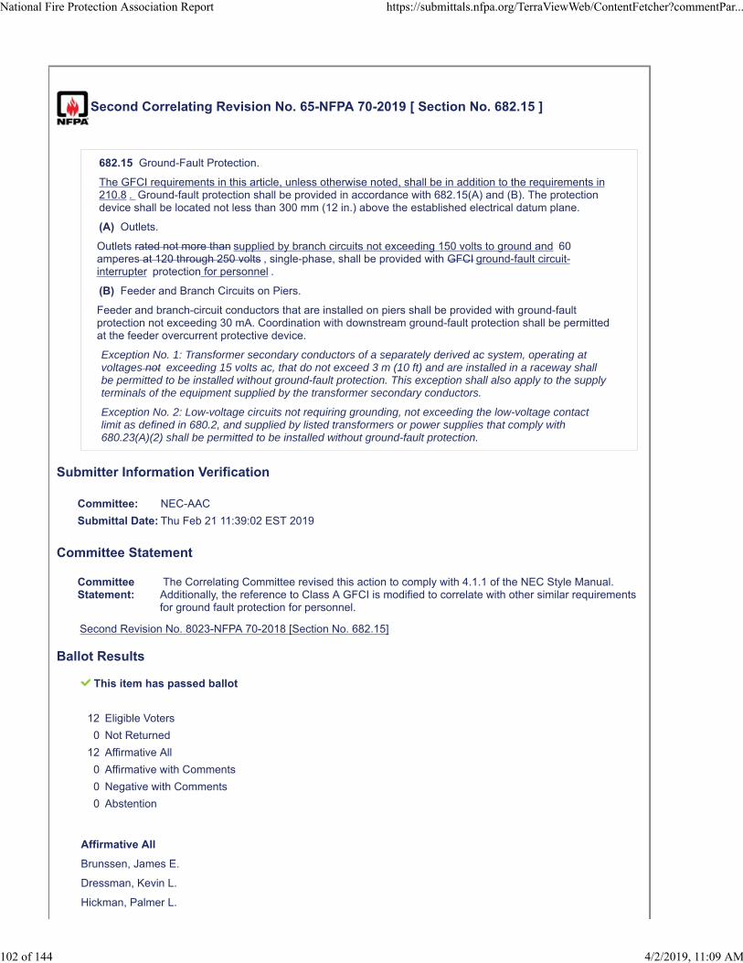
Second Correlating Revision No. 65-NFPA 70-2019 [ Section No. 682.15 ]
682.15 Ground-Fault Protection.
The GFCI requirements in this article, unless otherwise noted, shall be in addition to the requirements in210.8 . Ground-fault protection shall be provided in accordance with 682.15(A) and (B). The protectiondevice shall be located not less than 300 mm (12 in.) above the established electrical datum plane.
(A) Outlets.
Outlets rated not more than supplied by branch circuits not exceeding 150 volts to ground and 60amperes at 120 through 250 volts , single-phase, shall be provided with GFCI ground-fault circuit-interrupter protection for personnel .
(B) Feeder and Branch Circuits on Piers.
Feeder and branch-circuit conductors that are installed on piers shall be provided with ground-faultprotection not exceeding 30 mA. Coordination with downstream ground-fault protection shall be permittedat the feeder overcurrent protective device.
Exception No. 1: Transformer secondary conductors of a separately derived ac system, operating atvoltages not exceeding 15 volts ac, that do not exceed 3 m (10 ft) and are installed in a raceway shallbe permitted to be installed without ground-fault protection. This exception shall also apply to the supplyterminals of the equipment supplied by the transformer secondary conductors.
Exception No. 2: Low-voltage circuits not requiring grounding, not exceeding the low-voltage contactlimit as defined in 680.2, and supplied by listed transformers or power supplies that comply with680.23(A)(2) shall be permitted to be installed without ground-fault protection.
Submitter Information Verification
Committee: NEC-AAC
Submittal Date: Thu Feb 21 11:39:02 EST 2019
Committee Statement
CommitteeStatement:
The Correlating Committee revised this action to comply with 4.1.1 of the NEC Style Manual.Additionally, the reference to Class A GFCI is modified to correlate with other similar requirementsfor ground fault protection for personnel.
Second Revision No. 8023-NFPA 70-2018 [Section No. 682.15]
Ballot Results
This item has passed ballot
12 Eligible Voters
0 Not Returned
12 Affirmative All
0 Affirmative with Comments
0 Negative with Comments
0 Abstention
Affirmative All
Brunssen, James E.
Dressman, Kevin L.
Hickman, Palmer L.
National Fire Protection Association Report https://submittals.nfpa.org/TerraViewWeb/ContentFetcher?commentPar...
102 of 144 4/2/2019, 11:09 AM

Hittinger, David L.
Holub, Richard A.
Johnston, Michael J.
Kovacik, John R.
Manche, Alan
McDaniel, Roger D.
Porter, Christine T.
Straniero, George A.
Williams, David A.
National Fire Protection Association Report https://submittals.nfpa.org/TerraViewWeb/ContentFetcher?commentPar...
103 of 144 4/2/2019, 11:09 AM
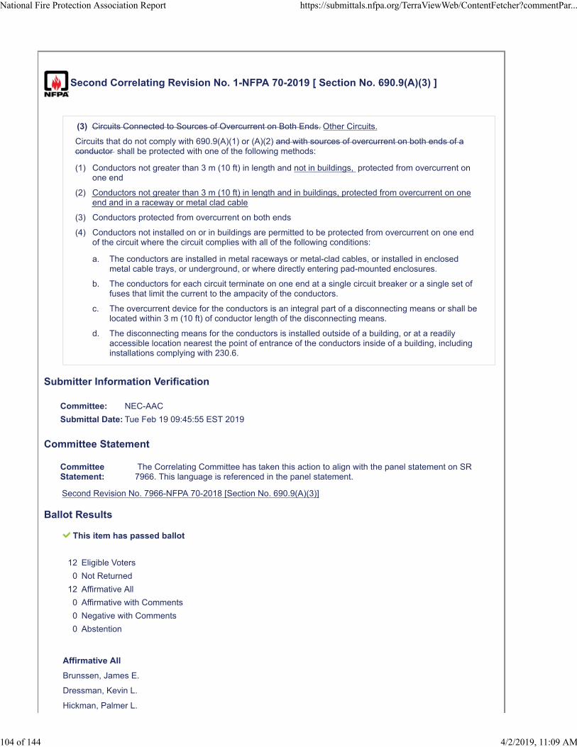
Second Correlating Revision No. 1-NFPA 70-2019 [ Section No. 690.9(A)(3) ]
(3) Circuits Connected to Sources of Overcurrent on Both Ends. Other Circuits.
Circuits that do not comply with 690.9(A)(1) or (A)(2) and with sources of overcurrent on both ends of aconductor shall be protected with one of the following methods:
(1) Conductors not greater than 3 m (10 ft) in length and not in buildings, protected from overcurrent onone end
(2) Conductors not greater than 3 m (10 ft) in length and in buildings, protected from overcurrent on oneend and in a raceway or metal clad cable
(3) Conductors protected from overcurrent on both ends
(4) Conductors not installed on or in buildings are permitted to be protected from overcurrent on one endof the circuit where the circuit complies with all of the following conditions:
a. The conductors are installed in metal raceways or metal-clad cables, or installed in enclosedmetal cable trays, or underground, or where directly entering pad-mounted enclosures.
b. The conductors for each circuit terminate on one end at a single circuit breaker or a single set offuses that limit the current to the ampacity of the conductors.
c. The overcurrent device for the conductors is an integral part of a disconnecting means or shall belocated within 3 m (10 ft) of conductor length of the disconnecting means.
d. The disconnecting means for the conductors is installed outside of a building, or at a readilyaccessible location nearest the point of entrance of the conductors inside of a building, includinginstallations complying with 230.6.
Submitter Information Verification
Committee: NEC-AAC
Submittal Date: Tue Feb 19 09:45:55 EST 2019
Committee Statement
CommitteeStatement:
The Correlating Committee has taken this action to align with the panel statement on SR7966. This language is referenced in the panel statement.
Second Revision No. 7966-NFPA 70-2018 [Section No. 690.9(A)(3)]
Ballot Results
This item has passed ballot
12 Eligible Voters
0 Not Returned
12 Affirmative All
0 Affirmative with Comments
0 Negative with Comments
0 Abstention
Affirmative All
Brunssen, James E.
Dressman, Kevin L.
Hickman, Palmer L.
National Fire Protection Association Report https://submittals.nfpa.org/TerraViewWeb/ContentFetcher?commentPar...
104 of 144 4/2/2019, 11:09 AM
Hittinger, David L.
Holub, Richard A.
Johnston, Michael J.
Kovacik, John R.
Manche, Alan
McDaniel, Roger D.
Porter, Christine T.
Straniero, George A.
Williams, David A.
National Fire Protection Association Report https://submittals.nfpa.org/TerraViewWeb/ContentFetcher?commentPar...
105 of 144 4/2/2019, 11:09 AM

Second Correlating Revision No. 23-NFPA 70-2019 [ Section No. 700.16(B) ]
(B) System Reliability.
Emergency lighting systems shall be designed and installed so that the failure of any illumination sourcecannot leave in total darkness any space that requires emergency illumination. Control devices in theemergency lighting system shall be listed for use in emergency systems. Listed unit equipment inaccordance with 700.12(F) shall be considered as meeting the provisions of this section.
Informational Note: 700.23 through 700.26 provide requirements for applications of emergencysystem control devices.
Submitter Information Verification
Committee: NEC-AAC
Submittal Date: Wed Feb 20 10:59:44 EST 2019
Committee Statement
Committee Statement: The Correlating Committee changed "or" to "for" to correct a grammatical error.
Second Revision No. 7607-NFPA 70-2018 [Section No. 700.16(B)]
Ballot Results
This item has passed ballot
12 Eligible Voters
0 Not Returned
12 Affirmative All
0 Affirmative with Comments
0 Negative with Comments
0 Abstention
Affirmative All
Brunssen, James E.
Dressman, Kevin L.
Hickman, Palmer L.
Hittinger, David L.
Holub, Richard A.
Johnston, Michael J.
Kovacik, John R.
Manche, Alan
McDaniel, Roger D.
Porter, Christine T.
Straniero, George A.
Williams, David A.
National Fire Protection Association Report https://submittals.nfpa.org/TerraViewWeb/ContentFetcher?commentPar...
106 of 144 4/2/2019, 11:09 AM
Second Correlating Revision No. 2-NFPA 70-2019 [ Section No. 705.12(B) ]
(B) Bus or Conductor Ampere Rating.
National Fire Protection Association Report https://submittals.nfpa.org/TerraViewWeb/ContentFetcher?commentPar...
107 of 144 4/2/2019, 11:09 AM
One hundred twenty-five percent of the The power source output circuit current multiplied by 125 percentshall be used in ampacity calculations for the following: 705.12(B)(1) through (B)(3).
(0) Where the power source output connection is made to a feeder, the feeder shall have an ampacitygreater than or equal to 125 percent of the power-source output circuit current. Where the power-source output connection is made to a feeder at a location other than the opposite end of the feederfrom the primary source overcurrent device, that portion of the feeder on the load side of the powersource output connection shall be protected by one of the following:
0. The feeder ampacity shall be not less than the sum of the primary source overcurrent deviceand 125 percent of the power-source output circuit current.
0. An overcurrent device at the load side of the power source connection point shall be rated notgreater than the ampacity of the feeder.
(0) Where power source output connections are made at feeders, all taps shall be sized based on thesum of 125 percent of all power source(s) output circuit current(s) and the rating of the overcurrentdevice protecting the feeder conductors for sizing tap conductors using the calculations in240.21(B) .
(0) One of the following methods shall be used to determine the ratings of busbars:
(0) The sum of 125 percent of the power source(s) output circuit current and the rating of theovercurrent device protecting the busbar shall not exceed the ampacity of the busbar.
(0) Where two sources, one a primary power source and the other another power source, arelocated at opposite ends of a busbar that contains loads, the sum of 125 percent of the power-source(s) output circuit current and the rating of the overcurrent device protecting the busbar shallnot exceed 120 percent of the ampacity of the busbar. The busbar shall be sized for the loadsconnected in accordance with Article 220 . A permanent warning label shall be applied to thedistribution equipment adjacent to the back-fed breaker from the power source that displays thefollowing or equivalent wording:
WARNING: POWER SOURCE OUTPUT CONNECTION —DO NOT RELOCATE THISOVERCURRENT DEVICE.
The warning sign(s) or label(s) shall comply with 110.21(B) .
(0) The sum of the ampere ratings of all overcurrent devices on panelboards, both load andsupply devices, excluding the rating of the overcurrent device protecting the busbar, shall notexceed the ampacity of the busbar. The rating of the overcurrent device protecting the busbar shallnot exceed the rating of the busbar. Permanent warning labels shall be applied to distributionequipment displaying the following or equivalent wording:
WARNING: THIS EQUIPMENT FED BY MULTIPLE SOURCES. TOTAL RATING OF ALLOVERCURRENT DEVICESEXCLUDING MAIN SUPPLY OVERCURRENT DEVICESHALLNOT EXCEED AMPACITY OF BUSBAR.
The warning sign(s) or label(s) shall comply with 110.21(B) .
(0) A connection at either end of a center-fed panelboard in dwellings shall be permittedwhere the sum of 125 percent of the power-source(s) output circuit current and the rating of theovercurrent device protecting the busbar does not exceed 120 percent of the current rating of thebusbar.
(0) Connections shall be permitted on switchgear, switchboards, and panelboards inconfigurations other than those permitted in 705.12(B) (3)(a) through (d) where designed underengineering supervision that includes available fault-current and busbar load calculations.
(0) Connections shall be permitted on busbars that supply feed-through lugs and conductorsconnected to the lugs opposite the main source of supply. The ampacity of the busbar andconnected feeders shall not be less than the sum of the primary source overcurrent device and 125percent of the power-source output circuit current.
Informational Note to a: This general rule assumes no limitation in the number of the loads orsources applied to busbars or their locations.
National Fire Protection Association Report https://submittals.nfpa.org/TerraViewWeb/ContentFetcher?commentPar...
108 of 144 4/2/2019, 11:09 AM
(1) Feeders.
Where the power source output connection is made to a feeder, the feeder shall have an ampacity greaterthan or equal to 125 percent of the power-source output circuit current. Where the power-source outputconnection is made to a feeder at a location other than the opposite end of the feeder from the primarysource overcurrent device, that portion of the feeder on the load side of the power source outputconnection shall be protected by one of the following:
(1) The feeder ampacity shall be not less than the sum of the primary source overcurrent device and125 percent of the power-source output circuit current.
(2) An overcurrent device at the load side of the power source connection point shall be rated not greaterthan the ampacity of the feeder.
(2) Taps.
Where power source output connections are made at feeders, all taps shall be sized based on the sum of125 percent of all power source(s) output circuit current(s) and the rating of the overcurrent deviceprotecting the feeder conductors for sizing tap conductors using the calculations in 240.21(B).
(3) Busbars.
One of the following methods shall be used to determine the ratings of busbars:
(1) The sum of 125 percent of the power source(s) output circuit current and the rating of the overcurrentdevice protecting the busbar shall not exceed the ampacity of the busbar.
Informational Note: This general rule assumes no limitation in the number of the loads orsources applied to busbars or their locations.
(2) Where two sources, one a primary power source and the other another power source, are located atopposite ends of a busbar that contains loads, the sum of 125 percent of the power-source(s) outputcircuit current and the rating of the overcurrent device protecting the busbar shall not exceed120 percent of the ampacity of the busbar. The busbar shall be sized for the loads connected inaccordance with Article 220. A permanent warning label shall be applied to the distribution equipmentadjacent to the back-fed breaker from the power source that displays the following or equivalentwording:
WARNING:
POWER SOURCE OUTPUT CONNECTION—
DO NOT RELOCATE THIS OVERCURRENT DEVICE.
The warning sign(s) or label(s) shall comply with 110.21(B).
(3) The sum of the ampere ratings of all overcurrent devices on panelboards, both load and supplydevices, excluding the rating of the overcurrent device protecting the busbar, shall not exceed theampacity of the busbar. The rating of the overcurrent device protecting the busbar shall not exceedthe rating of the busbar. Permanent warning labels shall be applied to distribution equipmentdisplaying the following or equivalent wording:
WARNING:
THIS EQUIPMENT FED BY MULTIPLE SOURCES.
TOTAL RATING OF ALL OVERCURRENT DEVICES
EXCLUDING MAIN SUPPLY OVERCURRENT DEVICE
SHALL NOT EXCEED AMPACITY OF BUSBAR.
The warning sign(s) or label(s) shall comply with 110.21(B).
(4) A connection at either end of a center-fed panelboard in dwellings shall be permitted where the sumof 125 percent of the power-source(s) output circuit current and the rating of the overcurrent deviceprotecting the busbar does not exceed 120 percent of the current rating of the busbar.
(5) Connections shall be permitted on switchgear, switchboards, and panelboards in configurations otherthan those permitted in 705.12(B)(3)(a) (1) through (d) (B)(3)(4) where designed under engineeringsupervision that includes available fault-current and busbar load calculations.
(6) Connections shall be permitted on busbars of panelboards that supply feed-through lugs andconductors connected to the lugs opposite the main source of supply. feed-through conductors. Thefeed-through conductors shall be sized in accordance with 705.12(B)(1) . Where an overcurrentdevice is installed at the supply end of the feed-through conductors, the busbar in the supplyingpanelboard shall be permitted to be sized in accordance with 705.12(B)(3) (1) through 705.12(B)(3) (3). The ampacity of the busbar and connected feeders shall not be less than the sum of theprimary source overcurrent device and 125 percent of the power-source output circuit current.
National Fire Protection Association Report https://submittals.nfpa.org/TerraViewWeb/ContentFetcher?commentPar...
109 of 144 4/2/2019, 11:09 AM

Submitter Information Verification
Committee: NEC-AAC
Submittal Date: Tue Feb 19 10:07:05 EST 2019
Committee Statement
CommitteeStatement:
The Correlating Committee has taken this action on SR 8148 to correct a circularreference.
Committee Comment No. 8148-NFPA 70-2018 [Section No. 705.12(B)]
Ballot Results
This item has passed ballot
12 Eligible Voters
0 Not Returned
12 Affirmative All
0 Affirmative with Comments
0 Negative with Comments
0 Abstention
Affirmative All
Brunssen, James E.
Dressman, Kevin L.
Hickman, Palmer L.
Hittinger, David L.
Holub, Richard A.
Johnston, Michael J.
Kovacik, John R.
Manche, Alan
McDaniel, Roger D.
Porter, Christine T.
Straniero, George A.
Williams, David A.
National Fire Protection Association Report https://submittals.nfpa.org/TerraViewWeb/ContentFetcher?commentPar...
110 of 144 4/2/2019, 11:09 AM

Second Correlating Revision No. 3-NFPA 70-2019 [ Section No. 705.12 [Excluding any
Sub-Sections] ]
The output of an interconnected electric power source shall be permitted to be connected to the load sideof the service disconnecting means of the other source(s) at any distribution equipment on the premises.Where distribution equipment, including switchgear, switchboards, or panelboards, is or feeders are fedsimultaneously by a primary source(s) of electricity and one or more other power source(s) and wherethis distribution equipment is are capable of supplying multiple branch circuits or feeders, or both, theinterconnecting provisions for other power sources equipment shall comply with 705.12(A) through (E).Where a power control system (PCS) is installed in accordance with 705.13 , the setting of the PCScontroller shall be considered the power-source output circuit current in 705.12(A) through (E).
Submitter Information Verification
Committee: NEC-AAC
Submittal Date: Tue Feb 19 10:11:20 EST 2019
Committee Statement
CommitteeStatement:
The Correlating Committee corrected the action on SR 8184 to comply with the NEC StyleManual. The phrase Power Control System is added before PCS because it is the first time thatPCS is used.
Second Revision No. 8184-NFPA 70-2018 [Section No. 705.12 [Excluding any Sub-Sections]]
Ballot Results
This item has passed ballot
12 Eligible Voters
0 Not Returned
12 Affirmative All
0 Affirmative with Comments
0 Negative with Comments
0 Abstention
Affirmative All
Brunssen, James E.
Dressman, Kevin L.
Hickman, Palmer L.
Hittinger, David L.
Holub, Richard A.
Johnston, Michael J.
Kovacik, John R.
Manche, Alan
McDaniel, Roger D.
Porter, Christine T.
Straniero, George A.
Williams, David A.
National Fire Protection Association Report https://submittals.nfpa.org/TerraViewWeb/ContentFetcher?commentPar...
111 of 144 4/2/2019, 11:09 AM

National Fire Protection Association Report https://submittals.nfpa.org/TerraViewWeb/ContentFetcher?commentPar...
112 of 144 4/2/2019, 11:09 AM
Second Correlating Revision No. 24-NFPA 70-2019 [ Section No. 706.1 ]
706.1 Scope.
This article applies to all energy storage systems (ESS) having a capacity greater than 3.6 MJ (1 kWh)that may be stand-alone or interactive with other electric power production sources. These systems areprimarily intended to store and provide energy during normal operating conditions.
Informational Note No. 1: For batteries rated in ampere hours, kWh is equal to the nominal ratedvoltage times ampere-hour rating divided by 1000.
Informational Note No. 2: There can be a subtle distinction between a battery storing energy andan energy storage system. A battery storing energy is not necessarily an ESS. See Article 480 .An ESS can be comprised of batteries storing energy. See Article 706 .
Informational Note No. 3: The following standards are frequently referenced for the installation ofenergy storage systems:
(1) NFPA 111-2016, Standard on Stored Electrical Energy Emergency and Standby Systems
(1) NFPA 855 , Standard for the Installation of Stationary Energy Storage Systems
(1) IEEE 484-2008, Recommended Practice for Installation Design and Installation of VentedLead-Acid Batteries for Stationary Applications
(1) IEEE 485-1997, Recommended Practice for Sizing Vented Lead-Acid Storage Batteries forStationary Applications
(1) IEEE 1145-2007, Recommended Practice for Installation and Maintenance of Nickel-Cadmium Batteries for Photovoltaic (PV) Systems
(1) IEEE 1187-2002, Recommended Practice for Installation Design, and Installation of Valve-Regulated Lead-Acid Batteries for Stationary Applications
(1) IEEE 1578-2007, Recommended Practice for Stationary Battery Electrolyte SpillContainment and Management
(1) IEEE 1635/ASHRAE 21-2012, Guide for the Ventilation and Thermal Management ofBatteries for Stationary Applications
(2) NECA 416-2016 , Recommended Practice for Installing Energy Storage Systems (ESS)
(3) UL 810A, Electrochemical Capacitors
(4) UL 1973, Standard for Batteries for Use in Stationary, Vehicle Auxiliary Power, and LightElectric Rail (LER) Applications
(5) UL 1989, Standard for Standby Batteries
(6) UL 9540, Standard for Safety Energy Storage Systems and Equipment
(6) UL Subject 1974, Standard for Evaluation of Repurposed Batteries
(7) UL Subject 2436, Spill Containment For Stationary Lead Acid Battery Systems
Submitter Information Verification
Committee: NEC-AAC
Submittal Date: Wed Feb 20 11:06:49 EST 2019
Committee Statement
CommitteeStatement:
The Correlating Committee relocated the last sentence to a new section 706.8 because itcontained a requirement. The informational note reference to NFPA 855 was deleted as thatstandard has not been issued.
Second Revision No. 7683-NFPA 70-2018 [Section No. 706.1]
National Fire Protection Association Report https://submittals.nfpa.org/TerraViewWeb/ContentFetcher?commentPar...
113 of 144 4/2/2019, 11:09 AM
Ballot Results
This item has passed ballot
12 Eligible Voters
0 Not Returned
12 Affirmative All
0 Affirmative with Comments
0 Negative with Comments
0 Abstention
Affirmative All
Brunssen, James E.
Dressman, Kevin L.
Hickman, Palmer L.
Hittinger, David L.
Holub, Richard A.
Johnston, Michael J.
Kovacik, John R.
Manche, Alan
McDaniel, Roger D.
Porter, Christine T.
Straniero, George A.
Williams, David A.
National Fire Protection Association Report https://submittals.nfpa.org/TerraViewWeb/ContentFetcher?commentPar...
114 of 144 4/2/2019, 11:09 AM
Second Correlating Revision No. 25-NFPA 70-2019 [ New Section after 706.7 ]
706.8 Storage Batteries.
Storage batteries not associated with an ESS shall comply with Article 480 .
Submitter Information Verification
Committee: NEC-AAC
Submittal Date: Wed Feb 20 11:10:34 EST 2019
Committee Statement
CommitteeStatement:
The Correlating Committee relocates this requirement from new text added in 706.1 toconform with the NEC Style Manual.
Ballot Results
This item has passed ballot
12 Eligible Voters
0 Not Returned
12 Affirmative All
0 Affirmative with Comments
0 Negative with Comments
0 Abstention
Affirmative All
Brunssen, James E.
Dressman, Kevin L.
Hickman, Palmer L.
Hittinger, David L.
Holub, Richard A.
Johnston, Michael J.
Kovacik, John R.
Manche, Alan
McDaniel, Roger D.
Porter, Christine T.
Straniero, George A.
Williams, David A.
National Fire Protection Association Report https://submittals.nfpa.org/TerraViewWeb/ContentFetcher?commentPar...
115 of 144 4/2/2019, 11:09 AM
Second Correlating Revision No. 4-NFPA 70-2019 [ Section No. 710.2 ]
710.2 Definitions.
Stand-Alone (Islanded)Island Mode.
The mode when a multimode inverter or microgrid is disconnected from the electric power productionand distribution network primary power source.
Informational Note: For isolated stand-alone systems and isolated microgrids, stand-alone orislanded mode is the primary mode of operation. Isolated microgrids are distinguished frominterconnected microgrids, which are defined in 705.2.
Submitter Information Verification
Committee: NEC-AAC
Submittal Date: Tue Feb 19 10:30:13 EST 2019
Committee Statement
CommitteeStatement:
The Correlating Committee deleted this section because the definition has been moved toArticle 100.
Ballot Results
This item has passed ballot
12 Eligible Voters
0 Not Returned
12 Affirmative All
0 Affirmative with Comments
0 Negative with Comments
0 Abstention
Affirmative All
Brunssen, James E.
Dressman, Kevin L.
Hickman, Palmer L.
Hittinger, David L.
Holub, Richard A.
Johnston, Michael J.
Kovacik, John R.
Manche, Alan
McDaniel, Roger D.
Porter, Christine T.
Straniero, George A.
Williams, David A.
National Fire Protection Association Report https://submittals.nfpa.org/TerraViewWeb/ContentFetcher?commentPar...
116 of 144 4/2/2019, 11:09 AM

Second Correlating Revision No. 75-NFPA 70-2019 [ Section No. 725.3(C) ]
(C) Ducts, Plenums, and Other Air-Handling Spaces.
Class 1, Class 2, and Class 3 circuits installed in ducts, plenums, or other space used for environmentalair shall comply with 300.22.
Exception No. 1: Class 2 and Class 3 cables selected in accordance with Table 725.154 and installed inaccordance with 725.135(B) and 300.22(B), Exception shall be permitted to be installed in ductsspecifically fabricated for environmental air.
Exception No. 2: Class 2 and Class 3 cables selected in accordance with Table 725.154 and installed inaccordance with 725.135(C) shall be permitted to be installed in other spaces used for environmental air(plenums).
Submitter Information Verification
Committee: NEC-AAC
Submittal Date: Thu Feb 21 16:12:28 EST 2019
Committee Statement
CommitteeStatement:
The Correlating Committee reinserted the comma for correlation with how exceptions arereferred to in the rest of the NEC.
Second Revision No. 7936-NFPA 70-2018 [Section No. 725.3(C)]
Ballot Results
This item has passed ballot
12 Eligible Voters
0 Not Returned
12 Affirmative All
0 Affirmative with Comments
0 Negative with Comments
0 Abstention
Affirmative All
Brunssen, James E.
Dressman, Kevin L.
Hickman, Palmer L.
Hittinger, David L.
Holub, Richard A.
Johnston, Michael J.
Kovacik, John R.
Manche, Alan
McDaniel, Roger D.
Porter, Christine T.
Straniero, George A.
Williams, David A.
National Fire Protection Association Report https://submittals.nfpa.org/TerraViewWeb/ContentFetcher?commentPar...
117 of 144 4/2/2019, 11:09 AM
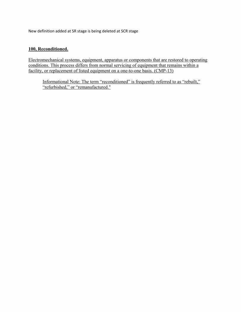
New definition added at SR stage is being deleted at SCR stage
100, Reconditioned.
Electromechanical systems, equipment, apparatus or components that are restored to operating conditions. This process differs from normal servicing of equipment that remains within a facility, or replacement of listed equipment on a one-to-one basis. (CMP-13)
Informational Note: The term “reconditioned” is frequently referred to as “rebuilt,” “refurbished,” or “remanufactured."
Second Correlating Revision No. 73-NFPA 70-2019 [ Section No. 760.3(L) ]
(L) Cable Routing Assemblies.
Power-limited fire alarm cables shall be permitted to be installed in plenum cable routing assemblies, risercable routing assemblies, and general-purpose cable routing assemblies selected in accordance withTable 805.154(c) Table 800.154(c) , listed in accordance with the provisions of 800.182, and installed inaccordance with 805.110(C) 800.110(C) and 805.113 800.113 .
(M) Communications Raceways.
Power-limited fire alarm cables shall be permitted to be installed in plenum communications raceways,riser communications raceways, and general-purpose communications raceways selected in accordancewith Table 805.154(b) Table 800.154(b) , listed in accordance with the provisions of 800.182, and installedin accordance with 805.113 800.113 and 362.24 through 362.56, where the requirements applicable toelectrical nonmetallic tubing apply.
Submitter Information Verification
Committee: NEC-AAC
Submittal Date: Thu Feb 21 15:36:40 EST 2019
Committee Statement
CommitteeStatement:
The Correlating Committee removed “the provisions of” for correlation and consistency withhow this is addressed elsewhere in the code.
Second Revision No. 8034-NFPA 70-2018 [Section No. 760.3(L)]
Ballot Results
This item has passed ballot
12 Eligible Voters
0 Not Returned
12 Affirmative All
0 Affirmative with Comments
0 Negative with Comments
0 Abstention
Affirmative All
Brunssen, James E.
Dressman, Kevin L.
Hickman, Palmer L.
Hittinger, David L.
Holub, Richard A.
Johnston, Michael J.
Kovacik, John R.
Manche, Alan
McDaniel, Roger D.
Porter, Christine T.
National Fire Protection Association Report https://submittals.nfpa.org/TerraViewWeb/ContentFetcher?commentPar...
118 of 144 4/2/2019, 11:09 AM

Straniero, George A.
Williams, David A.
National Fire Protection Association Report https://submittals.nfpa.org/TerraViewWeb/ContentFetcher?commentPar...
119 of 144 4/2/2019, 11:09 AM
Second Correlating Revision No. 74-NFPA 70-2019 [ New Section after 760.35 ]
Supplemental Information
File Name Description Approved
NEC_SCR-74_New_section_being_deleted_with_SCR.docx For ballot
Submitter Information Verification
Committee: NEC-AAC
Submittal Date: Thu Feb 21 15:59:39 EST 2019
Committee Statement
CommitteeStatement:
The Correlating Committee deleted the section for multiple reasons as follows. Surge protectivedevices are required to be listed in 242.8. The vague phrase "listed for the purpose" is to be avoidedto comply with the NEC Style Manual because the text does not explain the purpose. Theinformational note following the definition for surge protective devices references UL 1449, howeverthe appropriate standard for protective devices for fire alarm circuits is UL 497B. These protectivedevices in UL 497B are referred to as "isolated loop circuit protectors".
Committee Comment No. 8009-NFPA 70-2018 [New Section after 760.35]
Ballot Results
This item has passed ballot
12 Eligible Voters
0 Not Returned
12 Affirmative All
0 Affirmative with Comments
0 Negative with Comments
0 Abstention
Affirmative All
Brunssen, James E.
Dressman, Kevin L.
Hickman, Palmer L.
Hittinger, David L.
Holub, Richard A.
Johnston, Michael J.
Kovacik, John R.
Manche, Alan
McDaniel, Roger D.
Porter, Christine T.
Straniero, George A.
Williams, David A.
National Fire Protection Association Report https://submittals.nfpa.org/TerraViewWeb/ContentFetcher?commentPar...
120 of 144 4/2/2019, 11:09 AM

New section that was added at SR being deleted with SCR 760.36 Surge Protection. If a surge protective device is installed with fire alarm circuit wire and cable, it shall be listed for the purpose.
Second Correlating Revision No. 40-NFPA 70-2019 [ Section No. 770.24 ]
770.24 Mechanical Execution of Work.
Optical fiber cables shall be installed in a neat and workmanlike manner. Cables installed exposed on thesurface of ceilings and sidewalls shall be supported by the building structure in such a manner that thecable will not be damaged by normal building use. Such cables shall be secured by hardware, includingstraps, staples, cable ties, hangers, or similar fittings, designed and installed so as not to damage thecable. The installation shall also conform to 300.4 and 300.11. Nonmetallic cable ties and othernonmetallic cable accessories used to secure and support cables in other spaces used for environmentalair (plenums) shall be listed as having low smoke and heat release properties in accordance with300.22(C).
Informational Note No. 1: Accepted industry practices are described in ANSI/NECA/BICSI568-2006, Standard for Installing Commercial Building Telecommunications Cabling ;ANSI/NECA/FOA 301-2016, Standard for Installing and Testing Fiber Optic Cables; ANSI/TIA-568.0-D-2015, Generic Telecommunications Cabling for Customer Premises, ; and ANSI/TIA568.3-D-2016, Optical Fiber Cabling and Components Standard.
Informational Note No. 2: See NFPA 90A-2018, Standard for the Installation of Air-Conditioning andVentilating Systems, for discrete combustible components installed in accordance with 300.22(C).
Informational Note No. 3: Paint, plaster, cleaners, abrasives, corrosive residues, or othercontaminants may result in an undetermined alteration of optical fiber cable properties.
Submitter Information Verification
Committee: NEC-AAC
Submittal Date: Thu Feb 21 08:51:31 EST 2019
Committee Statement
CommitteeStatement:
The Correlating Committee removed the reference to ANSI/NECA/BICSI 568-2006 inInformational Note 1 to correlate with SR-8047 in 110.12(C).
Ballot Results
This item has passed ballot
12 Eligible Voters
0 Not Returned
12 Affirmative All
0 Affirmative with Comments
0 Negative with Comments
0 Abstention
Affirmative All
Brunssen, James E.
Dressman, Kevin L.
Hickman, Palmer L.
Hittinger, David L.
Holub, Richard A.
Johnston, Michael J.
National Fire Protection Association Report https://submittals.nfpa.org/TerraViewWeb/ContentFetcher?commentPar...
121 of 144 4/2/2019, 11:09 AM

Kovacik, John R.
Manche, Alan
McDaniel, Roger D.
Porter, Christine T.
Straniero, George A.
Williams, David A.
National Fire Protection Association Report https://submittals.nfpa.org/TerraViewWeb/ContentFetcher?commentPar...
122 of 144 4/2/2019, 11:09 AM
Second Correlating Revision No. 41-NFPA 70-2019 [ Section No. 800.24 ]
800.24 Mechanical Execution of Work.
Circuits and equipment shall be installed in a neat and workmanlike manner. Cables installed exposed onthe surface of ceilings and sidewalls shall be supported by the building structure in such a manner that thecable will not be damaged by normal building use. Such cables shall be secured by hardware, includingstraps, staples, cable ties, hangers, or similar fittings, designed and installed so as not to damage thecable. The installation shall also conform to 300.4(D) 300.4 and 300.11. Nonmetallic cable ties and othernonmetallic cable accessories used to secure and support cables in other spaces used for environmentalair (plenums) shall be listed as having low smoke and heat release properties in accordance with805.170(C). See 830.24 and 840.24 for additional provisions pertaining to Articles 830 and 840 .
Informational Note No. 1: Accepted industry practices are described in ANSI/NECA/BICSI568-2006, Standard for Installing Commercial Building Telecommunications Cabling; ANSI/TIA-568.1- D-2015, Commercial Building Telecommunications Infrastructure Standard; ANSI/TIA-569-D-2015, Telecommunications Pathways and Spaces; ANSI/TIA-570-C-2012, ResidentialTelecommunications Infrastructure Standard; ANSI/TIA-1005-A-2012, TelecommunicationsInfrastructure Standard for Industrial Premises; ANSI/ TIA-1179-2010, Healthcare FacilityTelecommunications Infrastructure Standard; ANSI/TIA-4966-2014, TelecommunicationsInfrastructure Standard for Educational Facilities; and other ANSI-approved installation standards.
Informational Note No. 2: See NFPA 90A-2018, Standard for the Installation of Air-Conditioning andVentilating Systems, for discrete combustible components installed in accordance with 300.22(C).
Informational Note No. 3: Paint, plaster, cleaners, abrasives, corrosive residues, or othercontaminants may result in an undetermined alteration of wire and cable properties.
Submitter Information Verification
Committee: NEC-AAC
Submittal Date: Thu Feb 21 08:54:21 EST 2019
Committee Statement
CommitteeStatement:
The Correlating Committee removed the reference to ANSI/NECA/BICSI 568-2006 inInformational Note 1 to correlate with SR-8047 in 110.12(C).
Ballot Results
This item has passed ballot
12 Eligible Voters
0 Not Returned
11 Affirmative All
1 Affirmative with Comments
0 Negative with Comments
0 Abstention
Affirmative All
Dressman, Kevin L.
Hickman, Palmer L.
Hittinger, David L.
Holub, Richard A.
National Fire Protection Association Report https://submittals.nfpa.org/TerraViewWeb/ContentFetcher?commentPar...
123 of 144 4/2/2019, 11:09 AM
Johnston, Michael J.
Kovacik, John R.
Manche, Alan
McDaniel, Roger D.
Porter, Christine T.
Straniero, George A.
Williams, David A.
Affirmative with Comment
Brunssen, James E.
The Committee Statement should also indicate that "300.4(D)" was revised to indicate "300.4" to correct an error.(This revision was made during the 2017 revision cycle.)
National Fire Protection Association Report https://submittals.nfpa.org/TerraViewWeb/ContentFetcher?commentPar...
124 of 144 4/2/2019, 11:09 AM
Second Correlating Revision No. 42-NFPA 70-2019 [ Section No. 800.53 ]
800.53 Separation from Lightning Conductors.
Where practicable, a separation of at least 1.8 m (6 ft) shall be maintained between lightning conductorsand all communication wires and cables and CATV type coaxial cables on buildings.
Informational Note No. 1: For additional information regarding overhead (aerial) wires andcables, see ANSI C2-2017 National Electrical Safety Code, Part 2, Safety Rules for OverheadLines .
Informational Note No. 2: Specific separation distances may be calculated from the sideflashequation in NFPA 780 -2017, Standard for the Installation of Lightning Protection Systems.
Submitter Information Verification
Committee: NEC-AAC
Submittal Date: Thu Feb 21 08:57:23 EST 2019
Committee Statement
CommitteeStatement:
The Correlating Committee revised the text for clarity and usability. The Correlating Committeeclarified that the separation was from the lightning conductors rather than separation betweencommunication and CATV conductors.
Ballot Results
This item has passed ballot
12 Eligible Voters
0 Not Returned
12 Affirmative All
0 Affirmative with Comments
0 Negative with Comments
0 Abstention
Affirmative All
Brunssen, James E.
Dressman, Kevin L.
Hickman, Palmer L.
Hittinger, David L.
Holub, Richard A.
Johnston, Michael J.
Kovacik, John R.
Manche, Alan
McDaniel, Roger D.
Porter, Christine T.
Straniero, George A.
Williams, David A.
National Fire Protection Association Report https://submittals.nfpa.org/TerraViewWeb/ContentFetcher?commentPar...
125 of 144 4/2/2019, 11:09 AM
Second Correlating Revision No. 66-NFPA 70-2019 [ Section No. 800.154 ]
National Fire Protection Association Report https://submittals.nfpa.org/TerraViewWeb/ContentFetcher?commentPar...
126 of 144 4/2/2019, 11:09 AM

800.154 Applications of Listed Communications Wires, Cables, and Raceways, and Listed CableRouting Assemblies.
National Fire Protection Association Report https://submittals.nfpa.org/TerraViewWeb/ContentFetcher?commentPar...
127 of 144 4/2/2019, 11:09 AM
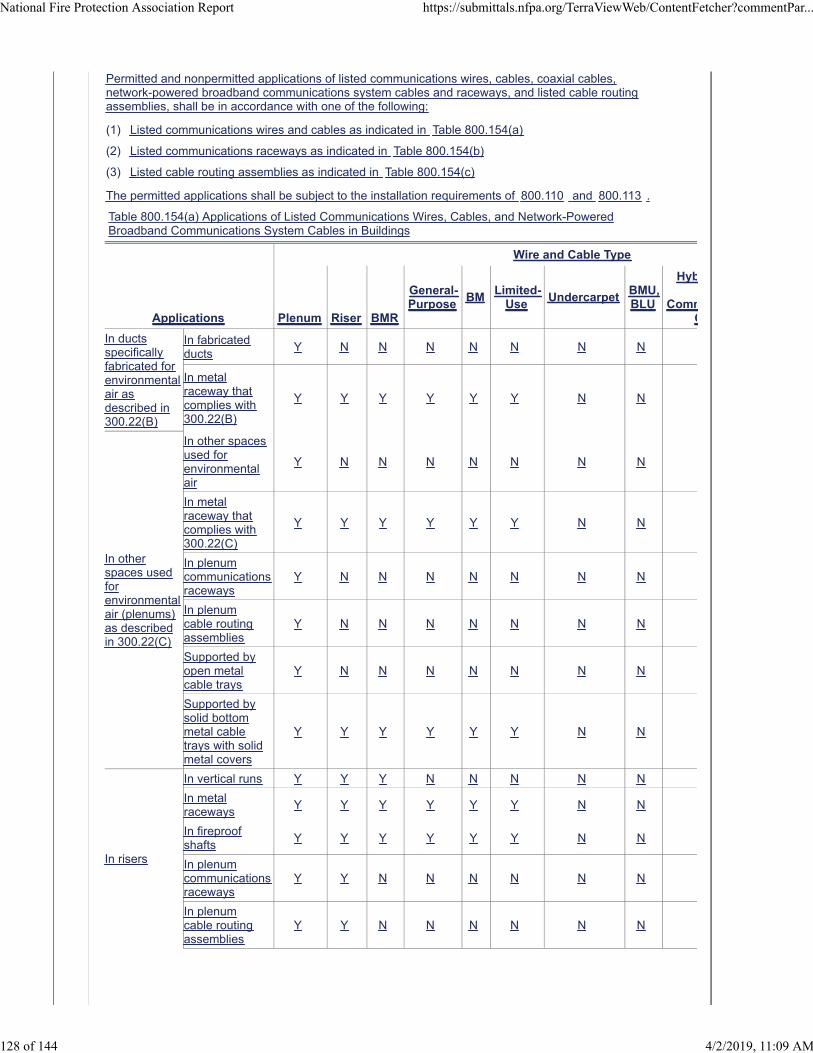
Permitted and nonpermitted applications of listed communications wires, cables, coaxial cables,network-powered broadband communications system cables and raceways, and listed cable routingassemblies, shall be in accordance with one of the following:
(1) Listed communications wires and cables as indicated in Table 800.154(a)
(2) Listed communications raceways as indicated in Table 800.154(b)
(3) Listed cable routing assemblies as indicated in Table 800.154(c)
The permitted applications shall be subject to the installation requirements of 800.110 and 800.113 .
Table 800.154(a) Applications of Listed Communications Wires, Cables, and Network-PoweredBroadband Communications System Cables in Buildings
Applications
Wire and Cable Type
Plenum Riser BMR
General-Purpose
BMLimited-
UseUndercarpet
BMU,BLU
Hyb
CommC
In ductsspecificallyfabricated forenvironmentalair asdescribed in300.22(B)
In fabricatedducts
Y N N N N N N N
In metalraceway thatcomplies with300.22(B)
Y Y Y Y Y Y N N
In otherspaces usedforenvironmentalair (plenums)as describedin 300.22(C)
In other spacesused forenvironmentalair
Y N N N N N N N
In metalraceway thatcomplies with300.22(C)
Y Y Y Y Y Y N N
In plenumcommunicationsraceways
Y N N N N N N N
In plenumcable routingassemblies
Y N N N N N N N
Supported byopen metalcable trays
Y N N N N N N N
Supported bysolid bottommetal cabletrays with solidmetal covers
Y Y Y Y Y Y N N
In risers
In vertical runs Y Y Y N N N N N
In metalraceways
Y Y Y Y Y Y N N
In fireproofshafts
Y Y Y Y Y Y N N
In plenumcommunicationsraceways
Y Y N N N N N N
In plenumcable routingassemblies
Y Y N N N N N N
National Fire Protection Association Report https://submittals.nfpa.org/TerraViewWeb/ContentFetcher?commentPar...
128 of 144 4/2/2019, 11:09 AM
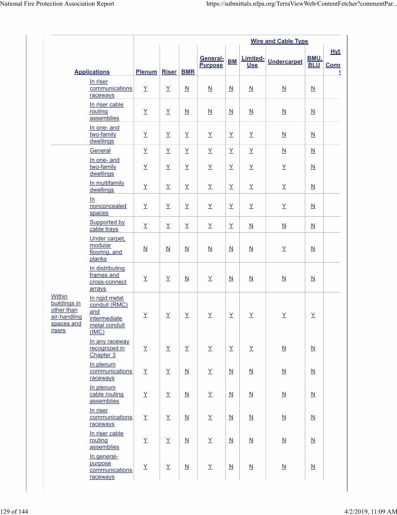
Applications
Wire and Cable Type
Plenum Riser BMR
General-Purpose
BMLimited-
UseUndercarpet
BMU,BLU
Hyb
CommC
In risercommunicationsraceways
Y Y N N N N N N
In riser cableroutingassemblies
Y Y N N N N N N
In one- andtwo-familydwellings
Y Y Y Y Y Y N N
Withinbuildings inother thanair-handlingspaces andrisers
General Y Y Y Y Y Y N N
In one- andtwo-familydwellings
Y Y Y Y Y Y Y N
In multifamilydwellings
Y Y Y Y Y Y Y N
Innonconcealedspaces
Y Y Y Y Y Y Y N
Supported bycable trays
Y Y Y Y Y N N N
Under carpet,modularflooring, andplanks
N N N N N N Y N
In distributingframes andcross-connectarrays
Y Y N Y N N N N
In rigid metalconduit (RMC)andintermediatemetal conduit(IMC)
Y Y Y Y Y Y Y Y
In any racewayrecognized inChapter 3
Y Y Y Y Y Y N N
In plenumcommunicationsraceways
Y Y N Y N N N N
In plenumcable routingassemblies
Y Y N Y N N N N
In risercommunicationsraceways
Y Y N Y N N N N
In riser cableroutingassemblies
Y Y N Y N N N N
In general-purposecommunicationsraceways
Y Y N Y N N N N
National Fire Protection Association Report https://submittals.nfpa.org/TerraViewWeb/ContentFetcher?commentPar...
129 of 144 4/2/2019, 11:09 AM
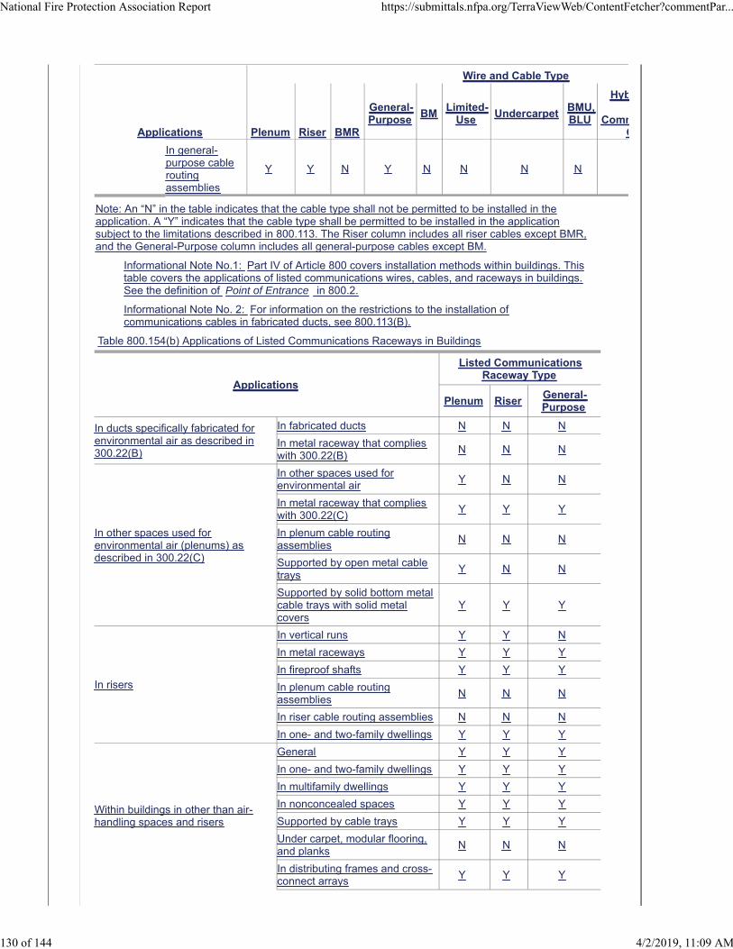
Applications
Wire and Cable Type
Plenum Riser BMR
General-Purpose
BMLimited-
UseUndercarpet
BMU,BLU
Hyb
CommC
In general-purpose cableroutingassemblies
Y Y N Y N N N N
Note: An “N” in the table indicates that the cable type shall not be permitted to be installed in theapplication. A “Y” indicates that the cable type shall be permitted to be installed in the applicationsubject to the limitations described in 800.113. The Riser column includes all riser cables except BMR,and the General-Purpose column includes all general-purpose cables except BM.
Informational Note No.1: Part IV of Article 800 covers installation methods within buildings. Thistable covers the applications of listed communications wires, cables, and raceways in buildings.See the definition of Point of Entrance in 800.2.
Informational Note No. 2: For information on the restrictions to the installation ofcommunications cables in fabricated ducts, see 800.113(B).
Table 800.154(b) Applications of Listed Communications Raceways in Buildings
Applications
Listed CommunicationsRaceway Type
Plenum RiserGeneral-Purpose
In ducts specifically fabricated forenvironmental air as described in300.22(B)
In fabricated ducts N N N
In metal raceway that complieswith 300.22(B)
N N N
In other spaces used forenvironmental air (plenums) asdescribed in 300.22(C)
In other spaces used forenvironmental air
Y N N
In metal raceway that complieswith 300.22(C)
Y Y Y
In plenum cable routingassemblies
N N N
Supported by open metal cabletrays
Y N N
Supported by solid bottom metalcable trays with solid metalcovers
Y Y Y
In risers
In vertical runs Y Y N
In metal raceways Y Y Y
In fireproof shafts Y Y Y
In plenum cable routingassemblies
N N N
In riser cable routing assemblies N N N
In one- and two-family dwellings Y Y Y
Within buildings in other than air-handling spaces and risers
General Y Y Y
In one- and two-family dwellings Y Y Y
In multifamily dwellings Y Y Y
In nonconcealed spaces Y Y Y
Supported by cable trays Y Y Y
Under carpet, modular flooring,and planks
N N N
In distributing frames and cross-connect arrays
Y Y Y
National Fire Protection Association Report https://submittals.nfpa.org/TerraViewWeb/ContentFetcher?commentPar...
130 of 144 4/2/2019, 11:09 AM
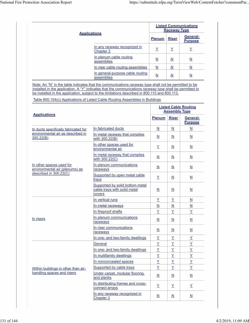
Applications
Listed CommunicationsRaceway Type
Plenum RiserGeneral-Purpose
In any raceway recognized inChapter 3
Y Y Y
In plenum cable routingassemblies
N N N
In riser cable routing assemblies N N N
In general-purpose cable routingassemblies
N N N
Note: An “N” in the table indicates that the communications raceway type shall not be permitted to beinstalled in the application. A “Y” indicates that the communications raceway type shall be permitted tobe installed in the application, subject to the limitations described in 800.110 and 800.113.
Table 800.154(c) Applications of Listed Cable Routing Assemblies in Buildings
Applications
Listed Cable RoutingAssembly Type
Plenum Riser General-Purpose
In ducts specifically fabricated forenvironmental air as described in300.22(B)
In fabricated ducts N N N
In metal raceway that complieswith 300.22(B)
N N N
In other spaces used forenvironmental air (plenums) asdescribed in 300.22(C)
In other spaces used forenvironmental air
Y N N
In metal raceway that complieswith 300.22(C)
N N N
In plenum communicationsraceways
N N N
Supported by open metal cabletrays
Y N N
Supported by solid bottom metalcable trays with solid metalcovers
N N N
In risers
In vertical runs Y Y N
In metal raceways N N N
In fireproof shafts Y Y Y
In plenum communicationsraceways
N N N
In riser communicationsraceways
N N N
In one- and two-family dwellings Y Y Y
Within buildings in other than air-handling spaces and risers
General Y Y Y
In one- and two-family dwellings Y Y Y
In multifamily dwellings Y Y Y
In nonconcealed spaces Y Y Y
Supported by cable trays Y Y Y
Under carpet, modular flooring,and planks
N N N
In distributing frames and cross-connect arrays
Y Y Y
In any raceway recognized inChapter 3
N N N
National Fire Protection Association Report https://submittals.nfpa.org/TerraViewWeb/ContentFetcher?commentPar...
131 of 144 4/2/2019, 11:09 AM
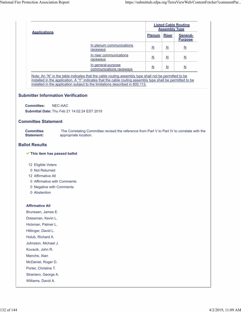
Applications
Listed Cable RoutingAssembly Type
Plenum Riser General-Purpose
In plenum communicationsraceways
N N N
In riser communicationsraceways
N N N
In general-purposecommunications raceways
N N N
Note: An “N” in the table indicates that the cable routing assembly type shall not be permitted to beinstalled in the application. A “Y” indicates that the cable routing assembly type shall be permitted to beinstalled in the application subject to the limitations described in 800.113.
Submitter Information Verification
Committee: NEC-AAC
Submittal Date: Thu Feb 21 14:02:24 EST 2019
Committee Statement
CommitteeStatement:
The Correlating Committee revised the reference from Part V to Part IV to correlate with theappropriate location.
Ballot Results
This item has passed ballot
12 Eligible Voters
0 Not Returned
12 Affirmative All
0 Affirmative with Comments
0 Negative with Comments
0 Abstention
Affirmative All
Brunssen, James E.
Dressman, Kevin L.
Hickman, Palmer L.
Hittinger, David L.
Holub, Richard A.
Johnston, Michael J.
Kovacik, John R.
Manche, Alan
McDaniel, Roger D.
Porter, Christine T.
Straniero, George A.
Williams, David A.
National Fire Protection Association Report https://submittals.nfpa.org/TerraViewWeb/ContentFetcher?commentPar...
132 of 144 4/2/2019, 11:09 AM

Second Correlating Revision No. 44-NFPA 70-2019 [ Section No. 820.44(A) ]
(A) On Poles and In-Span, Above Roofs, On Masts, or Between Buildings .
Where coaxial cables and electric light or power conductors are supported by the same pole or are runparallel to each other in-span, the conditions described in 820.44(A)(1) through 820.44(A)(4) shall bemet. Where coaxial cables are installed on poles and in-span, above roofs, on masts, or betweenbuildings, they shall comply with 800.44 .
(1) Relative Location.
Where practicable, the coaxial cables shall be located below the electric light or power conductors.
(1) Attachment to Cross-Arms.
Coaxial cables shall not be attached to cross-arm that carries electric light or power conductors.
(1) Climbing Space.
The climbing space through coaxial cables shall comply with the requirements of 225.14(D) .
(1) Clearance.
Lead-in or overhead (aerial) -drop coaxial cables from a pole or other support, including the point ofinitial attachment to a building or structure, shall be kept away from electric light, power, Class 1, ornon–power-limited fire alarm circuit conductors so as to avoid the possibility of accidental contact.
Exception: Where proximity to electric light, power, Class 1, or non–power-limited fire alarm circuitconductors cannot be avoided, the installation shall provide clearances of not less than 300 mm(12 in.) from electric light, power, Class 1, or non–power-limited fire alarm circuit conductors. Theclearance requirement shall apply at all points along the drop, and it shall increase to 1.0 m (40 in.) atthe pole.
Submitter Information Verification
Committee: NEC-AAC
Submittal Date: Thu Feb 21 09:25:59 EST 2019
Committee Statement
Committee Statement: The Correlating Committee corrected the reference from 820.44 to 800.44.
Ballot Results
This item has passed ballot
12 Eligible Voters
0 Not Returned
12 Affirmative All
0 Affirmative with Comments
0 Negative with Comments
0 Abstention
Affirmative All
Brunssen, James E.
Dressman, Kevin L.
Hickman, Palmer L.
Hittinger, David L.
National Fire Protection Association Report https://submittals.nfpa.org/TerraViewWeb/ContentFetcher?commentPar...
133 of 144 4/2/2019, 11:09 AM

Holub, Richard A.
Johnston, Michael J.
Kovacik, John R.
Manche, Alan
McDaniel, Roger D.
Porter, Christine T.
Straniero, George A.
Williams, David A.
National Fire Protection Association Report https://submittals.nfpa.org/TerraViewWeb/ContentFetcher?commentPar...
134 of 144 4/2/2019, 11:09 AM
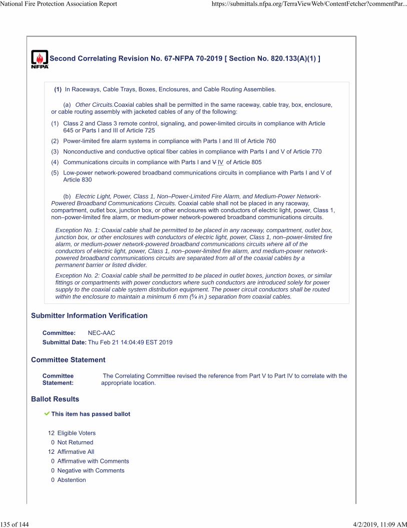
Second Correlating Revision No. 67-NFPA 70-2019 [ Section No. 820.133(A)(1) ]
(1) In Raceways, Cable Trays, Boxes, Enclosures, and Cable Routing Assemblies.
(a) Other Circuits.Coaxial cables shall be permitted in the same raceway, cable tray, box, enclosure,or cable routing assembly with jacketed cables of any of the following:
(1) Class 2 and Class 3 remote control, signaling, and power-limited circuits in compliance with Article645 or Parts I and III of Article 725
(2) Power-limited fire alarm systems in compliance with Parts I and III of Article 760
(3) Nonconductive and conductive optical fiber cables in compliance with Parts I and V of Article 770
(4) Communications circuits in compliance with Parts I and V IV of Article 805
(5) Low-power network-powered broadband communications circuits in compliance with Parts I and V ofArticle 830
(b) Electric Light, Power, Class 1, Non–Power-Limited Fire Alarm, and Medium-Power Network-Powered Broadband Communications Circuits. Coaxial cable shall not be placed in any raceway,compartment, outlet box, junction box, or other enclosures with conductors of electric light, power, Class 1,non–power-limited fire alarm, or medium-power network-powered broadband communications circuits.
Exception No. 1: Coaxial cable shall be permitted to be placed in any raceway, compartment, outlet box,junction box, or other enclosures with conductors of electric light, power, Class 1, non–power-limited firealarm, or medium-power network-powered broadband communications circuits where all of theconductors of electric light, power, Class 1, non–power-limited fire alarm, and medium-power network-powered broadband communications circuits are separated from all of the coaxial cables by apermanent barrier or listed divider.
Exception No. 2: Coaxial cable shall be permitted to be placed in outlet boxes, junction boxes, or similarfittings or compartments with power conductors where such conductors are introduced solely for powersupply to the coaxial cable system distribution equipment. The power circuit conductors shall be routedwithin the enclosure to maintain a minimum 6 mm (1⁄4 in.) separation from coaxial cables.
Submitter Information Verification
Committee: NEC-AAC
Submittal Date: Thu Feb 21 14:04:49 EST 2019
Committee Statement
CommitteeStatement:
The Correlating Committee revised the reference from Part V to Part IV to correlate with theappropriate location.
Ballot Results
This item has passed ballot
12 Eligible Voters
0 Not Returned
12 Affirmative All
0 Affirmative with Comments
0 Negative with Comments
0 Abstention
National Fire Protection Association Report https://submittals.nfpa.org/TerraViewWeb/ContentFetcher?commentPar...
135 of 144 4/2/2019, 11:09 AM
Affirmative All
Brunssen, James E.
Dressman, Kevin L.
Hickman, Palmer L.
Hittinger, David L.
Holub, Richard A.
Johnston, Michael J.
Kovacik, John R.
Manche, Alan
McDaniel, Roger D.
Porter, Christine T.
Straniero, George A.
Williams, David A.
National Fire Protection Association Report https://submittals.nfpa.org/TerraViewWeb/ContentFetcher?commentPar...
136 of 144 4/2/2019, 11:09 AM
Second Correlating Revision No. 68-NFPA 70-2019 [ Section No. 830.3(B) ]
(B) Output Circuits.
As appropriate for the services provided, the output circuits derived from the network interface unit shallcomply with the requirements of the following:
(1) Installations of communications circuits — Part V IV of Article 805
(2) Installations of community antenna television and radio distribution circuits — Part V of Article 820
Exception: Where protection is provided in the output of the NIU 830.90(B)(3) shall apply.
(3) Installations of optical fiber cables — Part V of Article 770
(4) Installations of Class 2 and Class 3 circuits — Part III of Article 725
(5) Installations of power-limited fire alarm circuits — Part III of Article 760
Submitter Information Verification
Committee: NEC-AAC
Submittal Date: Thu Feb 21 14:06:08 EST 2019
Committee Statement
CommitteeStatement:
The Correlating Committee revised the reference from Part V to Part IV to correlate with theappropriate location.
Ballot Results
This item has passed ballot
12 Eligible Voters
0 Not Returned
12 Affirmative All
0 Affirmative with Comments
0 Negative with Comments
0 Abstention
Affirmative All
Brunssen, James E.
Dressman, Kevin L.
Hickman, Palmer L.
Hittinger, David L.
Holub, Richard A.
Johnston, Michael J.
Kovacik, John R.
Manche, Alan
McDaniel, Roger D.
Porter, Christine T.
Straniero, George A.
National Fire Protection Association Report https://submittals.nfpa.org/TerraViewWeb/ContentFetcher?commentPar...
137 of 144 4/2/2019, 11:09 AM

Williams, David A.
National Fire Protection Association Report https://submittals.nfpa.org/TerraViewWeb/ContentFetcher?commentPar...
138 of 144 4/2/2019, 11:09 AM
Second Correlating Revision No. 69-NFPA 70-2019 [ Section No. 830.133 ]
830.133 Installation of Network-Powered Broadband Communications Cables and Equipment.
Cable and equipment installations within buildings shall comply with 830.133(A)and (B), as applicable.
(A) Separation of Conductors.
(1) In Raceways, Cable Trays, Boxes, Enclosures, and Cable Routing Assemblies.
(a) Low- and Medium-Power Network-Powered Broadband Communications Circuit Cables. Low-and medium-power network-powered broadband communications cables shall be permitted in the sameraceway, cable tray, box, enclosure, or cable routing assembly.
(b) Low-Power Network-Powered Broadband Communications Circuit Cables with Other Circuits.Low-power network-powered broadband communications cables shall be permitted in the same raceway,cable tray, box, enclosure, or cable routing assembly with jacketed cables of any of the following circuits:
(1) Class 2 and Class 3 remote-control, signaling, and power-limited circuits in compliance with Parts Iand III of Article 725
(2) Power-limited fire alarm systems in compliance with Parts I and III of Article 760
(3) Communications circuits in compliance with Parts I and V IV of Article 805
(4) Nonconductive and conductive optical fiber cables in compliance with Parts I and V of Article 770
(5) Community antenna television and radio distribution systems in compliance with Parts I and V ofArticle 820
(c) Medium-Power Network-Powered Broadband Communications Circuit Cables with Optical FiberCables and Other Communications Cables. Medium-power network-powered broadband communicationscables shall not be permitted in the same raceway, cable tray, box, enclosure, or cable routing assemblywith conductors of any of the following circuits:
(1) Communications circuits in compliance with Parts I and V IV of Article 805
(2) Conductive optical fiber cables in compliance with Parts I and V of Article 770
(3) Community antenna television and radio distribution systems in compliance with Parts I and V ofArticle 820
(d) Medium-Power Network-Powered Broadband Communications Circuit Cables with Other Circuits.Medium-power network-powered broadband communications cables shall not be permitted in the sameraceway, cable tray, box, enclosure, or cable routing assembly with conductors of any of the followingcircuits:
(1) Class 2 and Class 3 remote-control, signaling, and power-limited circuits in compliance with Parts Iand III of Article 725
(2) Power-limited fire alarm systems in compliance with Parts I and III of Article 760
(e) Electric Light, Power, Class 1, Non–Powered Broadband Communications Circuit Cables.Network-powered broadband communications cable shall not be placed in any raceway, cable tray,compartment, outlet box, junction box, or similar fittings with conductors of electric light, power, Class 1, ornon–power-limited fire alarm circuit cables.
Exception No. 1: Where all of the conductors of electric light, power, Class 1, non–power-limited firealarm circuits are separated from all of the network-powered broadband communications cables by apermanent barrier or listed divider.
Exception No. 2: Power circuit conductors in outlet boxes, junction boxes, or similar fittings orcompartments where such conductors are introduced solely for power supply to the network-poweredbroadband communications system distribution equipment. The power circuit conductors shall be routedwithin the enclosure to maintain a minimum 6 mm (1⁄4 in.) separation from network-powered broadbandcommunications cables.
National Fire Protection Association Report https://submittals.nfpa.org/TerraViewWeb/ContentFetcher?commentPar...
139 of 144 4/2/2019, 11:09 AM
(2) Other Applications.
Network-powered broadband communications cable shall be separated at least 50 mm (2 in.) fromconductors of any electric light, power, Class 1, and non–power-limited fire alarm circuits.
Exception No. 1: Separation shall not be required where: (1) all of the conductors of electric light, power,Class 1, and non–power-limited fire alarm circuits are in a raceway, or in metal-sheathed, metal-clad,nonmetallic-sheathed, Type AC, or Type UF cables, or (2) all of the network-powered broadbandcommunications cables are encased in a raceway.
Exception No. 2: Separation shall not be required where the network-powered broadbandcommunications cables are permanently separated from the conductors of electric light, power, Class 1,and non–power-limited fire alarm circuits by a continuous and firmly fixed nonconductor, such asporcelain tubes or flexible tubing, in addition to the insulation on the wire.
(B) Support of Network-Powered Broadband Communications Cables.
Raceways shall be used for their intended purpose. Network-powered broadband communications cablesshall not be strapped, taped, or attached by any means to the exterior of any conduit or raceway as ameans of support.
Submitter Information Verification
Committee: NEC-AAC
Submittal Date: Thu Feb 21 14:07:30 EST 2019
Committee Statement
CommitteeStatement:
The Correlating Committee revised the reference from Part V to Part IV to correlate with theappropriate location.
Ballot Results
This item has passed ballot
12 Eligible Voters
0 Not Returned
12 Affirmative All
0 Affirmative with Comments
0 Negative with Comments
0 Abstention
Affirmative All
Brunssen, James E.
Dressman, Kevin L.
Hickman, Palmer L.
Hittinger, David L.
Holub, Richard A.
Johnston, Michael J.
Kovacik, John R.
Manche, Alan
McDaniel, Roger D.
Porter, Christine T.
Straniero, George A.
Williams, David A.
National Fire Protection Association Report https://submittals.nfpa.org/TerraViewWeb/ContentFetcher?commentPar...
140 of 144 4/2/2019, 11:09 AM
Second Correlating Revision No. 70-NFPA 70-2019 [ Section No. 840.3(B) ]
(B) Output Circuits.
As appropriate for the services provided, the output circuits derived from the network terminal shall complywith the requirements of the following:
(1) Installations of communications circuits — Part V IV of Article 805
(2) Installations of premises (within buildings) community antenna television and radio distribution circuits— Part V of Article 820
(3) Installations of optical fiber cables — Part V of Article 770
(4) Installations of Class 2 and Class 3 circuits — Part III of Article 725
Informational Note: See 725.121 for information on the classification of information technologyequipment circuits.
(5) Installations of power-limited fire alarm circuits — Part III of Article 760
Submitter Information Verification
Committee: NEC-AAC
Submittal Date: Thu Feb 21 14:11:13 EST 2019
Committee Statement
CommitteeStatement:
The Correlating Committee revised the reference from Part V to Part IV to correlate with theappropriate location.
Ballot Results
This item has passed ballot
12 Eligible Voters
0 Not Returned
12 Affirmative All
0 Affirmative with Comments
0 Negative with Comments
0 Abstention
Affirmative All
Brunssen, James E.
Dressman, Kevin L.
Hickman, Palmer L.
Hittinger, David L.
Holub, Richard A.
Johnston, Michael J.
Kovacik, John R.
Manche, Alan
McDaniel, Roger D.
Porter, Christine T.
National Fire Protection Association Report https://submittals.nfpa.org/TerraViewWeb/ContentFetcher?commentPar...
141 of 144 4/2/2019, 11:09 AM

Straniero, George A.
Williams, David A.
National Fire Protection Association Report https://submittals.nfpa.org/TerraViewWeb/ContentFetcher?commentPar...
142 of 144 4/2/2019, 11:09 AM
Second Correlating Revision No. 19-NFPA 70-2019 [ Definition: Feeder Neutral
Conductor ]
Feeder Neutral Conductor
(see 220.61)
Because 210.11(B) does not apply to these buildings, the load cannot be assumed to be evenly distributedacross phases. Therefore the maximum imbalance must be assumed to be the full lighting load in thiscase, or 11,600 VA. (11,600 VA / ÷ 277 V = 42 amperes A .) The ability of the neutral-to-return fault current[see 250.32(B) Exception No. 2] is not a factor in this calculation.
Because the neutral runs between the main switchboard and the building panelboard, likely terminating ona busbar at both locations, and not on overcurrent devices, the effects of continuous loading can bedisregarded in evaluating its terminations [see 215.2(A)(1) Exception No. 2]. That calculation is (11,600 VA÷ 277 V = 42 amperes A ), to be evaluated under the 75°C column of Table 310.16. The minimum size ofthe neutral might seem to be 8 AWG, but that size would not be sufficient to be depended upon in theevent of a line-to-neutral fault [see 215.2(A)(1) 215.2(A)(2) , second paragraph]. Therefore, because theminimum size equipment grounding conductor for a 150 ampere circuit wired with 2/0 AWG conductors ,as covered in Table 250.122, is 6 AWG, that is the minimum neutral size required for this feeder.
Submitter Information Verification
Committee: NEC-AAC
Submittal Date: Wed Feb 20 10:19:30 EST 2019
Committee Statement
CommitteeStatement:
The Correlating Committee revised example D3(a) to correlate with the CMP-5 actions on250.122.
Committee Comment No. 7596-NFPA 70-2018 [Definition: Feeder Neutral Conductor]
Ballot Results
This item has passed ballot
12 Eligible Voters
0 Not Returned
12 Affirmative All
0 Affirmative with Comments
0 Negative with Comments
0 Abstention
Affirmative All
Brunssen, James E.
Dressman, Kevin L.
Hickman, Palmer L.
Hittinger, David L.
Holub, Richard A.
Johnston, Michael J.
Kovacik, John R.
National Fire Protection Association Report https://submittals.nfpa.org/TerraViewWeb/ContentFetcher?commentPar...
143 of 144 4/2/2019, 11:09 AM

Manche, Alan
McDaniel, Roger D.
Porter, Christine T.
Straniero, George A.
Williams, David A.
National Fire Protection Association Report https://submittals.nfpa.org/TerraViewWeb/ContentFetcher?commentPar...
144 of 144 4/2/2019, 11:09 AM