Embed Size (px)
Citation preview

Technical Committee on
Private Water Supply Piping Systems
M E M O R A N D U M
DATE: July 24, 2013 TO: Principal and Alternate Members of the Technical Committee on Private Water Supply Piping Systems FROM: Matt Klaus, Principal Fire Protection Engineer/NFPA Staff Liaison SUBJECT: AUT-PRI AGENDA PACKAGE – A2015 First Draft Meeting ________________________________________________________________________ Enclosed is the agenda for the First Draft meeting for NFPA 13, Standard for the Installation of
Sprinkler Systems, NFPA 24, Standard for the Installation of Private Fire Service Mains and
Their Appurtenances, and NFPA 291 Recommended Practice for Fire Flow Testing and Marking
of Hydrants. NFPA 13, 24 and 291 have entered the Annual 2015 revision cycle and will
produce 2016 Editions. It is imperative that you review the attached public input in advance,
with your ideas and substantiations for your views. If you have alternate suggestions for text
changes, please come prepared with the words and respective substantiation.
For administrative questions, please feel free to contact Elena Carroll at (617) 984-7952.
For technical questions, please feel free to contact Matt Klaus at (617) 984-7448. You can
also reach either of us via e-mail at [email protected] or [email protected]. We look forward
to meeting everyone in Nashville, TN at the Union Station Hotel, Autograph Collection.

Table of Contents
Part 1 - Meeting Agenda
Part 2 - Committee Address List
Part 3 – New Process Worksheets
Part 4 – A2012 ROC Meeting Minutes
Part 5 - A2015 Key Dates
Part 6- PRI Public Input

Technical Committee on Private Water Supply Piping Systems
First Draft Meeting
August 14 - 15, 2013 Union Station Hotel, Autograph Collection
1001 Broadway Nashville, TN 37203
AGENDA
Wednesday, August 14, 2013
1. Call to Order – 8:00 AM 2. Introductions of Members and Staff 3. Review and Approval of A2012 ROC Meeting Minutes 4. Review of A2015 Revision Cycle and Meeting Schedule 5. Review of Distributed Material and Workload
b. Overview of Public Input c. Overview of Potential Committee First Revisions
6. NFPA 24 Rewrite Task Group Report 7. Review Public Input
Thursday, August 15, 2013
1. Reconvene for Task Group Reports and Public Input Review 2. Adjourn (TBD)
PART 2 –
COMMITTEE ADDRESS LIST

Address List No PhonePrivate Water Supply Piping Systems AUT-PRI
Automatic Sprinkler Systems
Matthew J. Klaus07/17/2013
AUT-PRIKenneth W. WagonerChairParsley Consulting Engineers350 West 9th Avenue, Suite 206Escondido, CA 92025-5053
SE 8/5/2009AUT-PRI
James B. BigginsPrincipalGlobal Risk Consultants Corporation15732 West Barr RoadManhattan, IL 60442-9012Alternate: William J. Gotto
SE 1/1/1996
AUT-PRIPhillip A. BrownPrincipalAmerican Fire Sprinkler Association, Inc.12750 Merit Drive, Suite 350Dallas, TX 75251Alternate: Jeffrey J. Rovegno
IM 10/6/2000AUT-PRI
James A. CharrettePrincipalAllan Automatic Sprinkler Corp. of So. California3233 Enterprise StreetBrea, CA 92821National Fire Sprinkler AssociationInstaller/MaintainerAlternate: Ronald N. Webb
IM 7/26/2007
AUT-PRIFlora F. ChenPrincipalHayward Fire Department, California777 B StreetHayward, CA 94541
E 10/20/2010AUT-PRI
Stephen A. Clark, Jr.PrincipalAllianz Risk Consulting, LLC1003 Reece DriveHoschton, GA 30548Alternate: Andrew C. Higgins
I 1/14/2005
AUT-PRIJeffry T. DudleyPrincipalNational Aeronautics & Space Administration503 Glenbrook CircleRockledge, FL 32955
U 10/20/2010AUT-PRI
Byron E. EllisPrincipalEntergy Corporation5564 Essen Lane, Mail Code L-ESSN-2MBaton Rouge, LA 70809Edison Electric Institute
U 7/23/2008
AUT-PRIBrandon W. FrakesPrincipalXL Global Asset Protection Services196 Shady Grove LaneAdvance, NC 27006Alternate: Mark A. Bowman
I 1/15/2004AUT-PRI
David B. FullerPrincipalFM Global1151 Boston Providence TurnpikePO Box 9102Norwood, MA 02062-9102
I 7/26/2007
AUT-PRIRobert M. GagnonPrincipalGagnon Engineering2660 Daisy RoadWoodbine, MD 21797
SE 4/1/1994AUT-PRI
Tanya M. GlumacPrincipalLiberty Mutual Property20 Riverside RoadWeston, MA 02493-2231Alternate: Luke Hilton
I 1/10/2008
AUT-PRILaMar HaywardPrincipal3-D Fire Protection, Inc.PO Box 50845Idaho Falls, ID 83405
IM 8/2/2010AUT-PRI
Alan R. LagunaPrincipalMerit Sprinkler Company, Inc.930 Kenner AvenuePO Box 1447Kenner, LA 70062-1447
IM 10/3/2002
1

Address List No PhonePrivate Water Supply Piping Systems AUT-PRI
Automatic Sprinkler Systems
Matthew J. Klaus07/17/2013
AUT-PRIJohn LakePrincipalCity of Gainesville306 NE 6th Avenue, Building BPO Box 490, Station 9Gainesville, FL 32602-0490
E 1/31/2001AUT-PRI
George E. LaverickPrincipalUL LLC333 Pfingsten RoadNorthbrook, IL 60062-2096Alternate: Michael G. McCormick
RT 4/15/2004
AUT-PRIJames M. MaddryPrincipalJames M. Maddry, P.E.3680 Foxfire PlaceMartinez, GA 30907
SE 1/1/1991AUT-PRI
Kevin D. MaughanPrincipalTyco Fire Protection Products1467 Elmwood AvenueCranston, RI 02910Alternate: Cliff Hartford
M 1/14/2005
AUT-PRIBob D. MorganPrincipalFort Worth Fire Department1000 Throckmorton StreetFort Worth, TX 76102
E 8/2/2010AUT-PRI
David S. MowrerPrincipalBabcock & Wilcox Technical Services, LLCY-12 National Security ComplexPO Box 2009, MS-8107Oak Ridge, TN 37831-8107Alternate: Austin L. Smith
U 1/1/1982
AUT-PRIDale H. O'DellPrincipalNational Automatic Sprinkler Fitters LU 66914698 Stallion TrailsVictorville, CA 92392United Assn. of Journeymen & Apprentices of thePlumbing & Pipe Fitting IndustryAlternate: Charles W. Ketner
L 8/2/2010AUT-PRI
Adam P. OlomonPrincipalAon/RRS/Schirmer Engineering6455 South Shore Blvd., Suite 400League City, TX 77573
I 8/2/2010
AUT-PRIShawn C. OlsonPrincipalClackamas County Fire District #12930 SE Oak Grove BoulevardMilwaukie, OR 97267
E 10/18/2011AUT-PRI
Sam P. SalwanPrincipalEnvironmental Systems Design, Inc.175 West Jackson Blvd., Suite 1400Chicago, IL 60604Alternate: Martin Ramos
SE 1/1/1989
AUT-PRIDaniel SanchezPrincipalCity of Los AngelesBuilding & Safety201 North Figueroa Street, Suite 400Los Angeles, CA 90012
E 10/29/2012AUT-PRI
James R. SchifilitiPrincipalFire Safety Consultants, Inc.2420 Alft Lane, Suite 100Elgin, IL 60124Illinois Fire Prevention Association
IM 1/18/2001
AUT-PRIPeter T. SchwabPrincipalWayne Automatic Fire Sprinklers, Inc.222 Capitol CourtOcoee, FL 34761-3033
IM 7/29/2005
2

Address List No PhonePrivate Water Supply Piping Systems AUT-PRI
Automatic Sprinkler Systems
Matthew J. Klaus07/17/2013
AUT-PRIJ. William SheppardPrincipalSheppard & Associates, LLC24756 Tudor LaneFranklin, MI 48025Alternate: Larry Keeping
SE 1/1/1984AUT-PRI
Scott M. TwelePrincipalThe RJA Group, Inc.Rolf Jensen & Associates, Inc.591 Camino de la Reina, Suite 1025San Diego, CA 92108Alternate: James A. Zimmerman
SE 10/20/2010
AUT-PRIJon R. AckleyVoting AlternateDalmatian Fire, Inc.5670 West 73rd StreetIndianapolis, IN 46278National Fire Sprinkler AssociationDesign
M 10/29/2012AUT-PRI
Michael LarsenVoting AlternateAmway Inc.7575 FultonAda, MI 49355Voting Alt.
U 03/07/2013
AUT-PRIMark A. BowmanAlternateXL Global Asset Protection Services13467 Chevington DrivePickerington, OH 43147Principal: Brandon W. Frakes
I 1/15/2004AUT-PRI
William J. GottoAlternateGlobal Risk Consultants Corporation100 Walnut Avenue, 5th FloorClark, NJ 07066Principal: James B. Biggins
SE 8/5/2009
AUT-PRICliff HartfordAlternateTyco Fire Protection2034 Falkey RoadPhelps, NY 14532Principal: Kevin D. Maughan
M 10/4/2007AUT-PRI
Andrew C. HigginsAlternateAllianz Risk Consultants, LLC38 Kilbride DrivePinehurst, NC 28374Principal: Stephen A. Clark, Jr.
I 3/21/2006
AUT-PRILuke HiltonAlternateLiberty Mutual Property13830 Ballantyne Corporate Place, Suite 525Charlotte, NC 20277-2711Principal: Tanya M. Glumac
I 10/1/1996AUT-PRI
Larry KeepingAlternateProfessional Loss Control3413 Wolfedale Road, Suite 6Mississauga, ON L5C 1V8 CanadaPrincipal: J. William Sheppard
SE 03/07/2013
AUT-PRICharles W. KetnerAlternateNational Automatic Sprinkler Fitters LU 669Joint Apprenticeship & Training Committee7050 Oakland Mills RoadColumbia, MD 20732United Assn. of Journeymen & Apprentices of thePlumbing & Pipe Fitting IndustryPrincipal: Dale H. O'Dell
L 8/2/2010AUT-PRI
Michael G. McCormickAlternateUL LLC333 Pfingsten RoadNorthbrook, IL 60062-2096Principal: George E. Laverick
RT 10/20/2010
3

Address List No PhonePrivate Water Supply Piping Systems AUT-PRI
Automatic Sprinkler Systems
Matthew J. Klaus07/17/2013
AUT-PRIMartin RamosAlternateEnvironmental Systems Design, Inc.175 West Jackson Blvd., Suite 1400Chicago, IL 60604Principal: Sam P. Salwan
SE 3/15/2007AUT-PRI
Jeffrey J. RovegnoAlternateMr. Sprinkler Fire Protection100 Derek PlaceRoseville, CA 95678American Fire Sprinkler AssociationPrincipal: Phillip A. Brown
IM 8/5/2009
AUT-PRIAustin L. SmithAlternateBabcock & Wilcox Y-12, LLCPO Box 2009, MS 8107Oak Ridge, TN 37831-8107Principal: David S. Mowrer
U 3/1/2011AUT-PRI
Ronald N. WebbAlternateS.A. Comunale Company, Inc.2900 Newpark DriveBarberton, OH 44203National Fire Sprinkler AssociationInstaller/MaintainerPrincipal: James A. Charrette
IM 8/2/2010
AUT-PRIJames A. ZimmermanAlternateThe RJA Group, Inc.600 West Fulton Street, Suite 500Chicago, IL 60661-1242Principal: Scott M. Twele
SE 03/05/2012AUT-PRI
Frans AlferinkNonvoting MemberWavin Overseas7700 Ad DedemsvaartRollepaal 19Dedemsvaart, OV 7701 BR Netherlands
U 10/29/2012
AUT-PRIMatthew J. KlausStaff LiaisonNational Fire Protection Association1 Batterymarch ParkQuincy, MA 02169-7471
12/16/2010
4

PART 3 –
NEW PROCESS WORKSHEETS

March 13, 2012
TERMS New Terms Old Terms
Input Stage – Stage where Public Input is sought to develop the First Draft.
Report on Proposals (ROP) Stage
Public Input (PI) – A recommended change submitted for consideration by the Technical Committee. Each Public Input (PI) shall include new, modified or deleted text as appropriate and technical substantiation to support the recommended change.
Download a Public Input Form for documents in Fall 2013 and subsequent cycles
Proposal
First Draft Meeting ROP Meeting
First Revision (FR) – Proposed changes to the text of an NFPA Standard developed by the responsible Committee(s) in the Input Stage. Each First Revision shall contain the new, modified or deleted text as appropriate. A First Revision shall be established through a Meeting Vote and shall only require a simple majority to proceed to ballot. Only First Revisions that pass ballot will show in the First Draft. Each First Revision shall contain a Committee Statement that substantiates the proposed change to the document.
Committee Proposal or Accepted Public Proposal
Committee Input (CI) – A CI can be established during the First Draft Technical Committee meeting (without balloting) in order to highlight the concept to obtain public comment; often used for newer ideas, topics that aren’t fully fleshed out or controversial topics. A Committee Input (CI) can also be a First Revision (FR) that fails to receive support of the technical committee through letter ballot. Committee Inputs shall maintain the original FR Committee Statement and shall contain a notification to the reviewer documenting that the CI represents a failed FR.
“Trial Balloon” or an Accepted Proposal (or Committee Proposal) that Failed Ballot
Committee Statement (CS) – A Committee Statement is the committee’s response to a Public Input (PI), Public Comment (PC) or the committee’s technical substantiation for a proposed First Revision. A committee statement shall be established through a Meeting Vote and shall only require a simple majority to proceed.
Committee Statement
First Draft Report – The First Draft Report documents the Input Stage; it shall contain the First Draft, Public Input, Committee Input, Committee and Correlating Committee Statements, Correlating Input, Correlating Notes and Ballot Statements.
ROP
First Draft – The draft of the proposed new or revised standard showing in legislative text all First Revisions and First Correlating Revisions that have passed ballot.
ROP Draft
Correlating Committee (CC) Technical Correlating Committee
Correlating Committee Statement – The Correlating Committee’s response to a Public Input (PI), Committee Input (CI), Public Comment (PC) or the Correlating Committee’s technical substantiation for a correlating change to proposed Revision or a correlative CCFR. It shall be established through a Meeting Vote and shall only require a simple majority to proceed.
TCC Note
Correlating Committee First Revision (CCFR) – Correlating Committee First Revisions are proposed revisions to the Technical Committee’s First Revisions that are required to correlate the proposed document. Each CCFR shall contain a Correlating Committee Statement that substantiates the Revision. A CCFR shall be established through a Meeting Vote and shall only require a simple majority to proceed to letter ballot. CCFRs that fail to receive CC support through letter ballot shall not be published as part of the First Draft.
TCC Note
Technical Committee First Draft meeting - Spring 2012 Page 2 of 34 V.2 3/13/2012

Comment Stage Report on Comments (ROC) Stage
Public Comment – Changes submitted by the public during public Comment Stage.
Public Comment
Second Draft Meeting ROC Meeting
Second Revision (SR) – Similar to First Revision, but in the Comment Stage. Proposed changes to the text by the TC that have passed ballot.
Committee Comment or Accepted Public Comment
Committee Comment – A Committee Comment shall be a Second Revision (SR) that fails to receive support of the TC through ballot. Committee Comments shall maintain the original Committee Statement and shall contain a notification to the reviewer documenting that the Committee Comment represents a failed SR.
Committee Comment that failed ballot
Committee Action – An action by a TC to accept or reject a Comment. This occurs only in the Comment Stage and the action itself is not balloted.
Committee Action
Second Draft Report – The Second Draft Report documents the Comment Stage; it shall contain the Second Draft, Public Comments with corresponding Committee Actions and Committee Statements, Committee Comments, Correlating Revisions and Ballot Statements.
ROC
Second Draft – The draft of the proposed new or revised standard showing in legislative text all Second Revisions and Second Correlating Revisions that have passed ballot.
ROC Draft
Technical Committee First Draft meeting - Spring 2012 Page 3 of 34 V.2 3/13/2012

NEW PROCESS ACTIONS AND MOTIONS
New Process Actions and Motions‐ Final‐ 2/13/2012
Possible Action 1: Resolve PIs, (no change to Section)
Action Required Sample MotionsStep One: Committee generates a statement to respond to (resolve)
each PI #
I make a motion (move) to resolve PI#___ with the following committee statement: Approval by a meeting vote (simple majority) and not subject to ballot (Regs 4.3.7.3 & 4.3.7.3.2)
Possible Action 2: Create First Revision ‐ Change to a Section
Action Required Sample MotionsStep One: (1st option)
Committee generates a First Revision I make a motion (move) to revise Section ___ as follows:………… Approval by a meeting vote (simply majority) and final approval through ballot (Regs 4.3.9.2.3)
Step Two: (1st option)
Committee generates a statement substantiating the change.
Approval by a meeting vote (simply majority) (Regs 4.3.7.3)
Step One: (2nd option)
Committee generates a First Revision using one or more PIs as the starting point.
I make a motion to revise Section __ using PI#__ as the basis for change. Approval by a meeting vote (simply majority) and final approval through ballot (Regs 4.3.9.2.3)
Step Two: (2nd option)
If the revision is associated with one or more PIs the committee generates a statement to respond to (resolve) each PI
I make a motion (move) to resolve PIs # through ## with the following statement: Approval by a meeting vote (simply majority) and not subject to ballot (Regs 4.3.7.3 &
4.3.7.3.1)
Possible Action 3: Create Committee Input – (Trial Balloon/Placeholder)
Action Required Sample Motions Step One:
Committee generates a Committee Input (proposed revision) for public consideration and solicitation of Public Comments
I make a motion (move) to create a CI with a proposed revision to X.X.X as follows: Approval by a meeting vote (simply majority) and not subject to ballot (Regs 4.3.8)
Step Two: Committee generates a statement to explain the intent and why it is seeking public consideration and soliciting Public Comments
Approval by a meeting vote (simply majority) (Regs 4.3.7.1)
Technical Committee First Draft meeting - Spring 2012 Page 8 of 34 V.2 3/13/2012

PART 4 –
A2012 ROC MEETING MINUTES

NFPA Technical Committee on Private Water Supply Piping
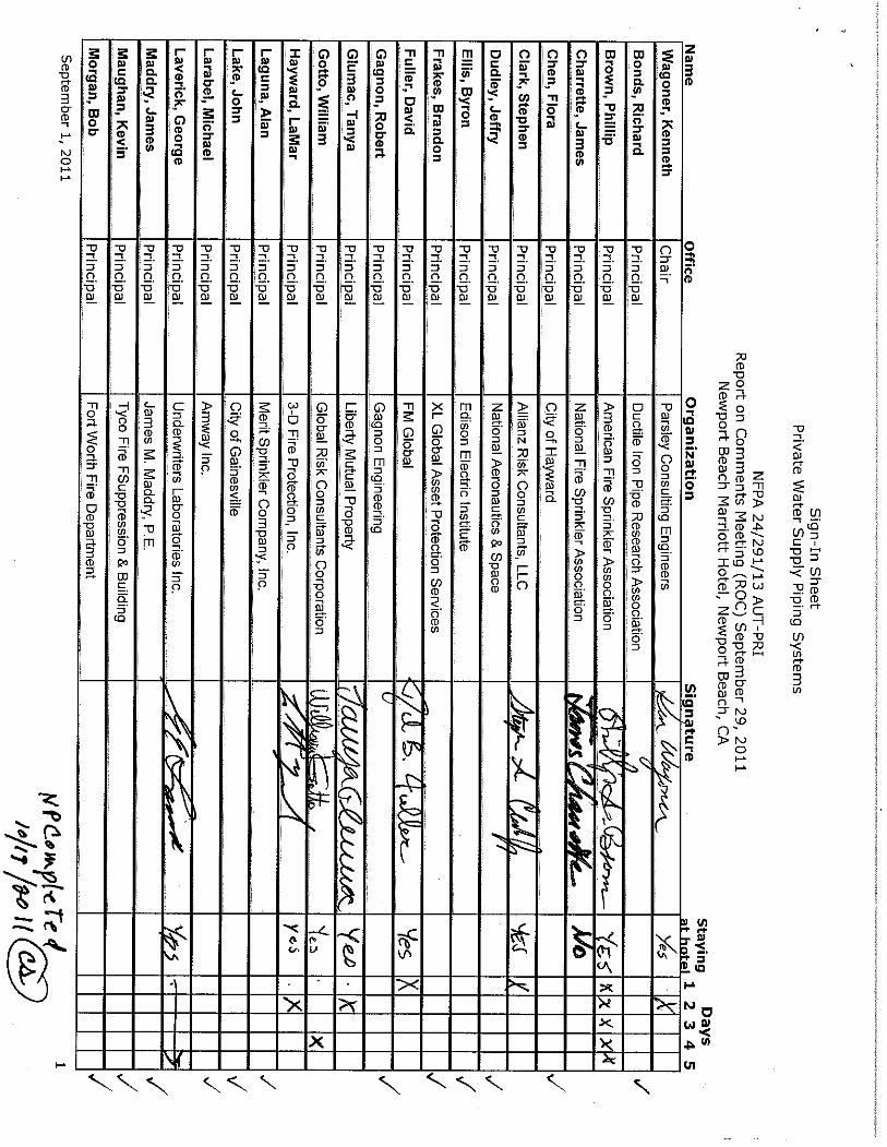
ROC Meeting
Newport Beach Marriott
Newport Beach, California September 29, 2011
MEETING MINUTES
1. Call to Order. TC Chair Ken Wagoner called the meeting to order at 8:00.
2. Self-Introductions of members and guests. Members of the committee introduced themselves and reviewed the contact information. The meeting attendance list is attached to these minutes.
3. Review of Distributed Meeting Materials. Staff Liaison Matt Klaus provided
an overview of the agenda materials that were sent to the committee and posted on the committee web page.
4. Approval of A12-ROP Draft Meeting Minutes. The minutes of the A12-ROP Meeting were reviewed and approved without modification.
5. Review of Meeting Procedures and Revision Process. Matt Klaus gave a presentation on the overall meeting guidelines and the NFPA Regulations Governing TC operations.
6. Work Load . TC Chair Ken Wagoner discussed the logistics for the meeting and
the process to complete the ROC meeting.
7. Public and Committee Comments. The committee then processed the comments. See the ROC for the official actions on the proposals.
8. New Business:
a. The TC plans to form an inter-committee task group with the SSD TC to address “held” comments on water supply data and hydrant flow testing. Staff to send a request to the FPRF for a code fund project (completed).
b. The TC developed a new task group to work on an off-cycle rewrite of
NFPA 24. The task group roster is as follows:

Karl Weigand Pete Schwab Jim Biggins Jim Charrette George Laverick Phil Brown David Fuller
9. Adjournment. Meeting adjourned at 2:30 pm.


PART 5 –
A2015 KEY DATES

2015 ANNUAL REVISION CYCLE *Public Input Dates may vary according to standards and schedules for Revision Cycles may change. Please check the NFPA Website for the most up‐to‐date information on Public Input Closing Dates and schedules at
www.nfpa.org/document # (i.e. www.nfpa.org/101) and click on the Next Edition tab.
Process Stage
Process Step
Dates for
TC
Dates forTC with CC
Public Input Closing Date* 7/8/2013 7/8/2013
Final Date for TC First Draft Meeting 12/13/2013 9/13/2013
Public Input Posting of First Draft and TC Ballot 1/31/2014 10/25/2013
Stage Final date for Receipt of TC First Draft ballot 7/21/2014 11/15/2013
(First Draft) Final date for Receipt of TC First Draft ballot ‐ recirc 2/28/2014 11/22/2013
Posting of First Draft for CC Meeting 11/29/2013
Final date for CC First Draft Meeting 1/10/2014
Posting of First Draft and CC Ballot 1/31/2014
Final date for Receipt of CC First Draft ballot 2/21/2014
Final date for Receipt of CC First Draft ballot ‐ recirc 2/28/2014
Post First Draft Report for Public Comment 3/7/2014 3/7/2014
Public Comment Closing Date for Paper Submittal* 4/11/2014 4/11/2014
Public Comment Closing Date for Online Submittal (e‐PC)* 5/16/2014 5/16/2014
Final Date to Publish Notice of Consent Documents (Standards that received no Comments)
5/30/2014 5/30/2014
Appeal Closing Date for Consent Standards (Standards that received no Comments)
6/13/2014 6/13/2014
Final date for TC Second Draft Meeting 10/31/2014 7/25/2014
Comment Posting of Second Draft and TC Ballot 12/12/2014 9/5/2014
Stage Final date for Receipt of TC Second Draft ballot 1/2/2015 9/26/2014
(Second Final date for receipt of TC Second Draft ballot ‐ recirc 1/9/2015 10/3/2014
Draft) Posting of Second Draft for CC Meeting 10/10/2014
Final date for CC Second Draft Meeting 11/21/2014
Posting of Second Draft for CC Ballot 12/12/2014
Final date for Receipt of CC Second Draft ballot 1/2/2015
Final date for Receipt of CC Second Draft ballot ‐ recirc 1/9/2015
Post Second Draft Report for NITMAM Review 1/16/2015 1/16/2015
Tech Session Notice of Intent to Make a Motion (NITMAM) Closing Date 3/6/2015 3/6/2015
Preparation Posting of Certified Amending Motions (CAMs) and Consent Standards
5/1/2015 5/1/2015
(& Issuance) Appeal Closing Date for Consent Standards 5/16/2015 5/16/2015
SC Issuance Date for Consent Standards 5/26/2015 5/26/2015
Tech Session Association Meeting for Standards with CAMs 6/22‐25/2016 6/22‐25/2016
Appeals and Appeal Closing Date for Standards with CAMs 7/15/2015 7/15/2015
Issuance SC Issuance Date for Standards with CAMs 8/20/2015 8/20/2015
Approved___ October 18, 2011 _ Revised__March 7, 2013_____________

PART 6 – NFPA 13
PUBLIC INPUT

Public Input No. 492-NFPA 13-2013 [ Section No. 9.3.7.1 [Excluding any Sub-Sections] ]
Where seismic protection is provided, C-type clamps (including beam and large flange clamps) used to attach hangers to the building structure shall be equipped with a restraining strap unless the provisions of 9.3.7.1.1 are satisfied. C-type clamps with or without restraining straps shall not be used to attach hangers of any pipe for which lateral bracing has been omitted per the provisions of 9.3.5.5.10 or any pipe attached to that pipe.
Statement of Problem and Substantiation for Public Input
Where lateral bracing is omitted, piping will be subject to large and repeated lateral deflections that could damage or displace c-clamp hangers on the pipe for which the bracing is omitted or on the attached pipe (e.g., branch lines attached to a cross main).
Related Public Inputs for This Document
Related Input Relationship
Open Public Input No. 489-NFPA 13-2013 [Section No. 9.3.5.5.10]
Submitter Information Verification
Submitter Full Name: Christopher Deneff Organization: FM Global Submittal Date: Fri May 31 10:34:15 EDT 2013
Public Input No. 444-NFPA 13-2013 [ Section No. 10.7.2 ]
10.7.2 The torquing of bolted joints shall be checked be checked against manufacturer's requirments . [ 24: 10.7.2]
Statement of Problem and Substantiation for Public Input
By requiring checking torque against manufacturer's requirements will ensure that proper torquing is achieved.
Submitter Information Verification
Submitter Full Name: John Campbell Organization: Telgian Corporation
Submittal Date: Wed May 29 15:56:25 EDT 2013
Public Input No. 446-NFPA 13-2013 [ New Section after 10.7.4 ]
10.7.4.1 Plugs shall be recorded as to their location.
10.7.4.2 Plugs shall be verified to be removed prior to recommencement of work.
Statement of Problem and Substantiation for Public Input
the installation of plugs is important, but so is the tracking of where they are installed and their removal to ensure that the piping is not blocked when placed in service.
Submitter Information
Verification
Submitter Full Name: John Campbell

Organization: Telgian Corporation
Submittal Date: Wed May 29 15:58:53 EDT 2013
Public Input No. 448-NFPA 13-2013 [ Section No. 10.8.3.1.4.4 ]
10.8.3.1.4.4
The diameter of holes shall be 1 ⁄ 8 in. (3.2 mm) larger than that of rods or bolts . [ 24: 10.8.3.1.4.4]
Statement of Problem and Substantiation for Public Input
provides clarification for use of bolts
Submitter Information Verification
Submitter Full Name: John Campbell Organization: Telgian Corporation
Submittal Date: Wed May 29 16:01:56 EDT 2013
Public Input No. 450-NFPA 13-2013 [ Section No. 10.8.3.3.1 ]
10.8.3.3.1
The strap shall be 3 ⁄ 4 in. (19.1 mm) thick and 2 1 ⁄ 2 in. (63.5 mm) wide , regardless of pipe diameter . [ 24: 10.8.3.3.1]
Statement of Problem and Substantiation for Public Input
provides definition regarding the size of piping vs. the size of the straps
Submitter Information Verification
Submitter Full Name: John Campbell Organization: Telgian Corporation Submittal Date: Wed May 29 16:07:17 EDT 2013
Public Input No. 452-NFPA 13-2013 [ New Section after 10.8.3.4 ]
10.8.3.4.1 Material selected shall be compatible with the piping material to be installed.
Statement of Problem and Substantiation for Public Input
material compatibility is necessary to avoid potential electrolysis between dissimilar metals
Submitter Information Verification
Submitter Full Name: John Campbell Organization: Telgian Corporation Submittal Date: Wed May 29 16:15:20 EDT 2013
Public Input No. 453-NFPA 13-2013 [ New Section after 10.10.2.4.1 ]

10.10.2.4.1.1 Opening and closing of hydrants shall be completed under both static pressure (no flow) and flow conditions.
Statement of Problem and Substantiation for Public Input
by adding that the hydrant has to be operated under no flow and flow conditions, ensures proper operation of the hydrant
Submitter Information Verification
Submitter Full Name: John Campbell Organization: Telgian Corporation Submittal Date: Wed May 29 16:22:46 EDT 2013
Public Input No. 192-NFPA 13-2013 [ Section No. 11.1.2 ]
11.1.2* Adjacent Hazards or Design Methods. For buildings with two or more adjacent hazards or design methods, the following shall apply:
(1) Where areas are not physically separated by a barrier or partition capable of delaying heat from a fire in one
area from fusing sprinklers in the adjacent area, the required sprinkler protection for the more demanding design basis shall extend 15 ft (4.6 m) beyond its perimeter.
(2) The requirements of 11.1.2 (1) shall not apply where the areas are separated by a barrier partition that is capable of preventing delaying heat from a fire in one area from fusing sprinklers in the adjacent area.
(3) The requirements of 11.1.2 (1) shall not apply to the extension of more demanding criteria from an upper ceiling level to beneath a lower ceiling level where the difference in height between the ceiling levels is at least 2 ft (0.6 m).
Statement of Problem and Substantiation for Public Input
The terminology between sections 11.1.2(1) and 11.1.2(2) needs to be consistent. One currently uses the terminology "delay" while the other uses the term "prevent". Since "prevent" has a more permanent connotation, its use here is inappropriate. All we are trying to do is delay the operation of sprinklers in the remote area until sprinklers over the fire have had a chance to open.
Submitter Information Verification
Submitter Full Name: Roland Asp Organization: National Fire Sprinkler Association Affilliation: NFSA E&S Committee Submittal Date: Thu Apr 18 16:16:42 EDT 2013

PART 6(A) –
NFPA 24
GLOBAL INPUT

Public Input No. 57-NFPA 24-2013 [ Global Input ]
NOTE: This proposal appeared as Comment 24-24 (Log #CC5) which was held from
the A12 ROC on Proposal 24-1.
Correlate Annex C and D through extract (or copy) from NFPA 291.
Additional Proposed Changes
File Name Description Approved
Open 24_PI_57_Held_Comment_24-24_TC_AUT- PRI_.pdf Held Comment 24-24
Statement of Problem and Substantiation for Public Input
This will provide consistency between the two documents.
Submitter Information Verification
Submitter Full Name: TC on AUT-PRI Organization: TC on Private Water Supply Piping Systems Submittal Date: Thu May 23 11:46:43 EDT 2013

PART 6(B) –
NFPA 24
PUBLIC INPUT - BODY

Public Input No. 60-NFPA 24-2013 [ Section No. 2.3.3 ]
2.3.3 AWWA Publications. American Water Works Association, 6666 West Quincy Avenue, Denver, CO 80235.
AWWA C104, Cement Mortar Lining for Ductile Iron Pipe and Fittings for Water, 2008.
AWWA C105, Polyethylene Encasement for Ductile Iron Pipe Systems, 2005.
AWWA C110, Ductile Iron and Gray Iron Fittings, 2008.
AWWA C111, Rubber-Gask et Joints for Ductile Iron Pressure Pipe and Fittings, 2000.
AWWA C115, Flanged Ductile Iron Pipe with Ductile Iron or Gray Iron Threaded Flanges, 2005.
AWWA C116, Protective Fusion-Bonded Epoxy Coatings for the Interior and Exterior Surfaces of Ductile-Iron and Gray-Iron Fittings for Water Supply Service, 2003.
AWWA C150, Thick ness Design of Ductile Iron Pipe, 2008.
AWWA C151, Ductile Iron Pipe, Centrifugally Cast for Water, 2002.
AWWA C153, Ductile-Iron Compact Fittings for Water Service, 2006.
AWWA C200, Steel Water Pipe 6 in. and Larger, 2005.
AWWA C203, Coal-Tar Protective Coatings and Linings for Steel Water Pipelines Enamel and Tape — Hot Applied, 2002.
AWWA C205, Cement-Mortar Protective Lining and Coating for Steel Water Pipe 4
in. and Larger — Shop Applied, 2007.
AWWA C206, Field Welding of Steel Water Pipe, 2003.
AWWA C207, Steel Pipe Flanges for Waterwork s Service — Sizes 4 in. Through 144 in., 2007.
AWWA C208, Dimensions for Fabricated Steel Water Pipe Fittings, 2007.
AWWA C300, Reinforced Concrete Pressure Pipe, Steel-Cylinder Type, 2004.
AWWA C301, Prestressed Concrete Pressure Pipe, Steel-Cylinder Type, 2007.
AWWA C302, Reinforced Concrete Pressure Pipe, Non-Cylinder Type, 2004.
AWWA C303, Reinforced Concrete Pressure Pipe, Steel-Cylinder Type, Pretensioned, 2002.
AWWA C400, Standard for Asbestos-Cement Distribution Pipe, 4 in. Through 16
in. (100 mm through 400 mm), for Water Distribution Systems, 2003.
AWWA C401, Standard for the Selection of Asbestos-Cement Pressure Pipe 4 in.
through 16 in. (100 mm through 400 mm), 2003.
AWWA C600, Standard for the Installation of Ductile Iron Water Mains and Their Appurtenances, 2005.
AWWA C602, Cement-Mortar Lining of Water Pipe Lines 4 in. and Larger — in Place, 2006.
AWWA C603, Standard for the Installation of Asbestos-Cement Pressure Pipe,

2005.
AWWA C900, Polyvinyl Chloride (PVC) Pressure Pipe, 4 in. Through 12 in., for Water Distribution, 2007.
AWWA C905, AWWA Standard for Polyvinyl Chloride (PVC) Pressure Pipe and
Fabricated Fittings, 14 in. Through 48 in. (350 mm Through 1,200 mm), 2010.
AWWA C906, Polyethylene (PE) Pressure Pipe and Fittings, 4 in. (100 mm) Through 63 in. (1575 mm) for Water Distribution, 2007.
AWWA C909, Molecularly Oriented Polyvinyl Chloride (PVCO) Pressure Pipe, 4 IN through24 IN. (100 MM through 600 MM ), for Water Wastewater, and Reclaimed Water Service,03/01/2010
AWWA M11, A Guide for Steel Pipe Design and Installation, 4th edition, 2004.
Statement of Problem and Substantiation for Public Input
PVC-O solves the problem of the low impact of PVC-U at low temperatures and the problem that PVC-u is more sensitive to water hammer. PVC-O is not. This type of pipe is in use all over the world, produced by a number of different companies and with a good track record. The pipe is in use since approx. 1990. Several of our customers have asked to use this pipe also for fire fighting lines, but it failes to be registered in NFPA24
Submitter Information Verification
Submitter Full Name: Frans Alferink Organization: Wavin Overseas Affilliation: S2renginieros, Bogota, Colombia. Antonio Yesid Lopez Submittal Date: Thu May 23 14:32:52 EDT 2013
Public Input No. 1-NFPA 24-2012 [ Section No. 3.3.15.2 ]
3.3.15.2 Indicating Valve. A valve that has components that show if the valve is open or closed. Examples are outside screw and yoke (OS&Y) gate valves and underground gate valves with indicator posts.
Statement of Problem and Substantiation for Public Input
Examples belong in the annex. Another PI places the language in the annex.
Submitter Information Verification
Submitter Full Name: Peter Schwab Organization: Wayne Automatic Fire Sprinkler Submittal Date: Wed Dec 12 16:40:06 EST 2012

Public Input No. 65-NFPA 24-2013 [ Section No. 4.1.3 ]
4.1.3 Working plans shall be drawn to an indicated scale on sheets of uniform size, with a plan of each floor as applicable, and shall include the following items that pertain to the design of the system:
(1) Name of owner
(2) Location, including street address
(3) Point of compass
(4) A graphic representation of the scale used on all plans
(5) Name and address of contractor
(6) Size and location of all water supplies
(7) Size and location of standpipe risers, hose outlets, hand hose, monitor nozzles, and related equipment
(8) The following items that pertain to private fire service mains:
(a) Size
(b) Length
(c) Location
(d) Weight
(e) Material
(f) Point of connection to city main
(g) Sizes, types, and locations of valves, valve indicators, regulators, meters, and valve pits
(h) Depth at which the top of the pipe is laid below grade
(i) Method of restraint
(9) The following items that pertain to hydrants:
(a) Size and location, including size and number of outlets and whether outlets are to be equipped with independent gate valves
(b) Thread size and coupling adapter specifications if different from National Standard Hose Threads as defined by NFPA 1963
(c) Whether hose houses and equipment are to be provided, and by whom
(d) Static and residual hydrants used in flow
(e) Method of restraint
(10) Size, location, and piping arrangement of fire department connections
Statement of Problem and Substantiation for Public Input
Specifying National Standard identifies the specific type of thread that should be the standard for hydrants. Hdyrants that utilize hose threads other than National Standard should be idenfied on the drawings
Submitter Information Verification

Submitter Full Name: John Campbell Organization: Telgian Corporation Submittal Date: Wed May 29 16:31:48 EDT 2013
Public Input No. 56-NFPA 24-2013 [ New Section after 5.1.2 ]
NOTE: This proposal appeared as Comment 24-1 (Log #3) which was held from the A12 ROC on Proposal 24-4. Do not take the action in Proposal 24-4. Instead, revise section 5.1.3 and insert an annex note as follows:
5.1.3* Where the volume and pressure available from a water supply are determined through a waterflow test, an adjustment shall be made to the test data to account for daily and seasonal fluctuations.
A.5.1.3 Flow tests that are run during the middle of a business day often do not account for peak water demands at other times of the day or water use during other times of year. Under ideal circumstances, NFPA 24 would have a specific value to apply to all situations, but that is not practical given the wide variations of water supplies in use and the variations of when waterflow tests are conducted. Waterflow tests conducted close to peak water usage times would need less of an adjustment than waterflow tests conducted during low water usage times. Consultation with the water authority may be necessary to determine an appropriate adjustment factor. Use of 24 hour gages at a hydrant can be helpful in determining day to day fluctuations. In addition, the user should also consider other water usage factors such as simultaneous industrial use, the potential for future demand on the system in the area of the test (depending on how well developed the area already is) and other conditions that would affect the water supply.
Additional Proposed Changes
File Name Description Approved
Open 24_PI_56_Held_Comment_24-1_Kelly_.pdf Held Comment 24-1
Statement of Problem and Substantiation for Public Input
While some of the material currently in section 5.1.3 is more appropriate in the annex, the basic concept of requiring some adjustment to the data is still needed in the body of the standard. It is completely irresponsible to conduct a waterflow test at a hydrant at a time of very low water
demand and believe that you are going to have all of that flow and pressure available when a fire occurs a few hours later during a regular and known peak demand time.
As proposed, the rule would only apply in those situations where the waterflow test is being performed and would not apply to the development of water supply data from other sources.
The concept of evaluating the water supply for possible interruptions from flood or ice conditions has been intentionally dropped from the language because this does not have to do with the flow or pressure available. This concept should be a part of the determination as to whether the water supply is “reliable” enough to use at all, which is a completely different concept and should not be tied to evaluating data from a flow test.
Submitter Information Verification
Submitter Full Name: KEVIN KELLY Organization: [ Not Specified ] Submittal Date: Thu May 23 11:37:20 EDT 2013

Public Input No. 43-NFPA 24-2013 [ Section No. 5.2.1 ]
5.2.1 Private Fire Service Mains. Pipe smaller than 6 in. (152 mm) in diameter shall not be installed as a private service main supplying hydrants. A minimum 8 in. (203.2mm) diameter pipe
shall be utilized for systems supplying multiple fire hydrants unless it can
be demonstrated that a smaller main will provide the proposed and future
development with adequate pressure and fire-flow.
Statement of Problem and Substantiation for Public Input
Makes this standard compatible with AWWA and other regional standards. Fire hydrants should only be connected to water mains adequately sized to carry necessary fire flows. Private fire service mains that serve residential, industrial, or commercial developments may require larger mains to assure adequate pressure and fire-flow for current and future development needs.
Submitter Information Verification
Submitter Full Name: Doug Hohbein Organization: Northcentral Fire Code Develop Submittal Date: Tue Apr 02 22:42:17 EDT 2013

Public Input No. 66-NFPA 24-2013 [ Section No. 5.3.2 ]
5.3.2 Where meters are required by other authorities, they shall be listed for fire service .
Statement of Problem and Substantiation for Public Input
provides consistency with other NFPA standards on equipment being listed for fire service
Submitter Information Verification
Submitter Full Name: John Campbell Organization: Telgian Corporation Submittal Date: Wed May 29 16:33:56 EDT 2013
Public Input No. 67-NFPA 24-2013 [ New Section after 5.8 ]
5.8.1* Suction Screening shall be removable or an in situ cleaning shall be provided. [20: 4.14.8.3]
5.8.2 Screens shall be so arranged that they can be cleaned or repaired without disturbing the intake pipe. [20: 4.14.8.5]
5.8.3 Mesh screens shall be brass, copper, Monel, stainless steel, or other equivalent corrosion-resistant metallic material wire screen of 0.50 in. (12.7 mm) maximum mesh and No. 10 B&S gauge. [20: 4.14.8.6]
5.8.4 Where flat panel mesh screens are used, the wire shall be secured to a metal frame sliding vertically at the entrance to the intake. [20: 4.14.8.7]
5.8.5 Where the screens are located in a sump or depression, they shall be equipped with a debris-lifting rake. [20: 4.14.8.8]
5.8.6 Periodically, the screens shall be removed for inspection, and accumulated debris shall be removed.
5.8.7 Coninuous slot screens shall be brass, copper, Monel, stainless steel, or other equivalent corrosion-resistant metallic material of 0.125 in. (3.2 mm) maximum slot and profile wire construction. [20: 4.14.8.10]
5.8.8 Screens shall have at least 62.5 percent open area. [20: 4.14.8.11]
5.8.9 Where zebra mussel infestation is present or reasonably anticipated, the screens shall be constructed of a material with demonstrated resistance to zebra mussel attachment or coated with a material with demonstrated resistance to zebra mussel attachment. [20: 4.14.8.12]
5.8.10 The overall area of the screen shall be at least 1.6 times the net screen opening area. [20: 4.14.8.13]
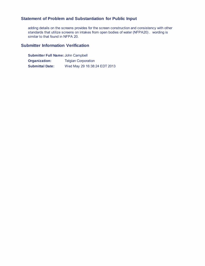
Statement of Problem and Substantiation for Public Input
adding details on the screens provides for the screen construction and consistency with other standards that utilize screens on intakes from open bodies of water (NFPA20) . wording is similar to that found in NFPA 20.
Submitter Information Verification
Submitter Full Name: John Campbell Organization: Telgian Corporation Submittal Date: Wed May 29 16:38:24 EDT 2013

Public Input No. 47-NFPA 24-2013 [ Section No. 5.9.1 [Excluding any
Sub-Sections] ]
Where a fire department connection is required by other standards and when the authority having jurisdiction requires it to be at a remote fire department connection, for systems requiring one by another standard, a location remote from the building, the fire department connection shall be provided as described in Section 5.9.
Additional Proposed Changes
File Name Description Approved
Open LK_NFPA_24-2013_Proposal_1_of_5.docx Cover Sheet
Statement of Problem and Substantiation for Public Input
This proposed revision is strictly editorial, as the current text is a bit awkward.
Submitter Information Verification
Submitter Full Name: Larry Keeping Organization: Professional Loss Control Submittal Date: Mon May 13 13:37:40 EDT 2013
Public Input No. 48-NFPA 24-2013 [ Section No. 5.9.1.4 ]
5.9.1.4 Fire department connections shall be equipped with listed plugs or caps that are secured and arranged for easy removal by fire departments.
Additional Proposed Changes
File Name Description Approved
Open LK_NFPA_24-2013_Proposal_2_of_5.docx Cover Sheet
Statement of Problem and Substantiation for Public Input
There is no need to utilize listed plugs or caps for a fire department connection. Often, the nice new brass ones that come with a listed FDC go missing and have to be replaced. To avoid repetitions of such losses, one option that building owners may choose is to replace them with vandal resistant “break away” or “knock off” caps, which are economical, unattractive to brass scavengers and they generally make poor ash trays. These devices are not usually listed and they do not need to be, because components such as FDC caps and plugs do not affect system performance.
Submitter Information Verification

Submitter Full Name: Larry Keeping Organization: Professional Loss Control Submittal Date: Mon May 13 13:39:34 EDT 2013
Public Input No. 44-NFPA 24-2013 [ New Section after 5.9.1.5 ]
5.9.1.6 The AHJ shall have the authority to require locking fire department
connection ( FDC ) plugs or caps on all water-based fire protection systems. (1:13)
Statement of Problem and Substantiation for Public Input
Makes this standard compatible with NFPA 1 Chapter 13 and gives AHJ's the ability to require locking caps for FDC’s on private water systems where jurisdictions do not utilize NFPA 1.
Submitter Information Verification
Submitter Full Name: Doug Hohbein Organization: Northcentral Fire Code Develop Submittal Date: Tue Apr 02 22:43:26 EDT 2013
Public Input No. 68-NFPA 24-2013 [ Section No. 5.9.2.1 ]
5.9.2.1 The fire department connection(s) shall use an NH internal threaded swivel fitting(s) with an NH standard thread(s) , except as modified by 5 . 9.2.3.
Statement of Problem and Substantiation for Public Input
As currently written, the section contradicts the previous (unmodified) section 4.1.3(9)(b). By allowing for an exception for the use of non-standard threads, clarification is provided.
Submitter Information Verification
Submitter Full Name: John Campbell Organization: Telgian Corporation Submittal Date: Wed May 29 16:57:00 EDT 2013

Public Input No. 17-NFPA 24-2012 [ New Section after 5.9.3.2 ]
5.9.3.2.1
Control valves shall be permitted to be installed downstream of the point where the fire department connection piping connects to the system piping.
A.5.9.3.2.1
Figure A.5.9.3.2.1(a) and Figure A.5.9.3.2.1(b) depict fire department connections to the underground pipe.
Add Annex Figures A.5.9.3.2.1 (a) and A.5.9.3.2.1 (b) as taken from NFPA 13 A.8.17.2.4.4 (a) and A.17.2.4.4 (b)
Additional Proposed Changes
File Name Description Approved
Open FDC_s.JPG FDC's connected to underground as taken from NFPA 13
Statement of Problem and Substantiation for Public Input
Clarifies that valves can be downstream of FDC's and correlates with NFPA 13.
Submitter Information Verification
Submitter Full Name: Peter Schwab Organization: Wayne Automatic Fire Sprinkler Submittal Date: Thu Dec 13 13:16:34 EST 2012

Control valve
Building
""-System piping
Provide vatve access as required
FIGURE A.8.17.2.4.4(a) Fire Department Connection Con
nected to Underground Piping (Sample 1).
Control valves
"'-.Systempiping
Provide valve access as r9CJ,Iired
FIGURE A.8.17.2.4.4(b) Fire Department Connection Con nected to Underground Piping (Sample 2).

Public Input No. 89-NFPA 24-2013 [ Section No. 5.9.3.2 ]
5.9.3.2
No shutoff valve shall be permitted in the piping from the fire department
connection piping to the point that the fire department connection piping
connects to the system piping fire service main .
Additional Proposed Changes
File Name Description Approved
Open 24_Brown.pdf Cover Sheet
Statement of Problem and Substantiation for Public Input
The use of the term "system piping" has caused confusion on just where a fire department connection (fdc) can be installed. They read this as meaning that you cannot have any shutoff valve between the fdc and the system sprinkler system. Thus the arrangement shown in Figure A.3.3.11 would not be allowed sense there is two shutoff valves shown between the fdc and the sprinklered building. The term "fire service main" is used in Figure A.5.9(b).
Submitter Information Verification
Submitter Full Name: Phillip Brown Organization: American Fire Sprinkler Association Submittal Date: Mon Jun 03 11:27:30 EDT 2013

Public Input No. 18-NFPA 24-2012 [ New Section after 5.9.4.2 ]
5.9.4.2.1
The automatic drip shall be permitted to be buried where permitted by the authority having jurisdiction.
5.9.4.2.2
Where the automatic drip is buried as allowed by 5.9.4.2.1, the outlet shall discharge into a bed of crushed stone or pea gravel.
Statement of Problem and Substantiation for Public Input
The 2013 edition was modified to require access to the ball drip. Many AHJ's require that fire department connections (FDC) are remote. NFPA suggests that the check valve for the FDC be located as close to the connection to the system as possible. This could leave long sections of underground piping with no pressure. This piping could get cut and one will not know about it until an NFPA 25 inspection is performed or the fire department pumps into the connection. Many AHJ's want water brought as close to the FDC as possible to avoid this situation. By requiring access to the ball drip, this could require a vault or deep meter box costing hundreds of dollars. This new section gives the AHJ an allowance to require the automatic drip close to the FDC and still have water on the underground piping for supervision.
Submitter Information Verification
Submitter Full Name: Peter Schwab Organization: Wayne Automatic Fire Sprinkler Submittal Date: Thu Dec 13 13:46:36 EST 2012

Public Input No. 19-NFPA 24-2012 [ Section No. 5.9.4.3 ]
5.9.4.3 An automatic drip shall not be required in areas where the piping is not subject to freezing.
Statement of Problem and Substantiation for Public Input
There are many areas in the country where the temperature of the air will dip below 32 degrees Fahrenheit but will never last long enough to freeze a 4" or 6" pipe. Technically this means that freezing has been achieved because water freezes at 32° FH. This change gives allowance for these climate areas.
Submitter Information Verification
Submitter Full Name: Peter Schwab Organization: Wayne Automatic Fire Sprinkler Submittal Date: Thu Dec 13 13:55:14 EST 2012
Public Input No. 45-NFPA 24-2013 [ Section No. 5.9.4.3 ]
5.9.4.3 An automatic drip shall not be required in on fire department connections for systems located in areas not subject to freezing.
Statement of Problem and Substantiation for Public Input
As presently written, this requirement may be confused as to mean that the location of the automatic drip cannot be in an area where it would freeze. In actuality, the automatic drip is not required on any part of a system that is located in a geographical area that is not subject to freezing climates.
Submitter Information Verification
Submitter Full Name: John Chartier Organization: Northeastern Regional Fire Cod Submittal Date: Thu Apr 11 08:24:44 EDT 2013
Public Input No. 22-NFPA 24-2012 [ New Section after 5.9.5.1 ]
5.9.5.2 Fire department connections shall not be connected on the suction side of fire pumps.
Statement of Problem and Substantiation for Public Input

This is important information that should be located in this section. Renumber accordingly.
Submitter Information Verification
Submitter Full Name: Peter Schwab Organization: Wayne Automatic Fire Sprinkler Submittal Date: Thu Dec 13 15:25:43 EST 2012
Public Input No. 69-NFPA 24-2013 [ Section No. 5.9.5.1 ]
5.9.5.1 * Fire Remote fire department connections shall be located at the nearest point of fire department apparatus accessibility or at a location approved by the authority having jurisdiction.
Statement of Problem and Substantiation for Public Input
the section needs to be specific in that it is referencing remote fire department connections. Fire department connections mounted on buildings are under the jurisdiction of NFPA 13. Identifying "remote" keeps the informatoin specific to remotely located hydrants.
Submitter Information Verification
Submitter Full Name: John Campbell Organization: Telgian Corporation Submittal Date: Wed May 29 16:59:34 EDT 2013
Public Input No. 70-NFPA 24-2013 [ Section No. 5.9.5.2 ]
5.9.5.2 * Fire Remote fire department connections shall be located and arranged so that hose lines can be attached to the inlets without interference.
Statement of Problem and Substantiation for Public Input
the section needs to be specific in that it is referencing remote fire department connections. Fire department connections mounted on buildings are under the jurisdiction of NFPA 13. Identifying "remote" keeps the informatoin specific to remotely located hydrants.
Submitter Information Verification
Submitter Full Name: John Campbell Organization: Telgian Corporation Submittal Date: Wed May 29 17:02:34 EDT 2013

Public Input No. 71-NFPA 24-2013 [ Section No. 5.9.5.3 ]
5.9.5.3 *
Each fire remote fire department connection shall be designated by a sign as follows:
(1) The sign shall have raised or engraved letters at least 1 in. (25.4 mm) in height on a plate or fitting.
(2)
* The sign shall indicate the type of system for which the connection is intended.
Statement of Problem and Substantiation for Public Input
the section needs to be specific in that it is referencing remote fire department connections. Fire department connections mounted on buildings are under the jurisdiction of NFPA 13. Identifying "remote" keeps the informatoin specific to remotely located hydrants.
Submitter Information Verification
Submitter Full Name: John Campbell Organization: Telgian Corporation Submittal Date: Wed May 29 17:03:18 EDT 2013

Public Input No. 21-NFPA 24-2012 [ Section No. 5.9.5.4 ]
5.9.5.4 Where the system demand pressure exceeds 150 psi (10.3 bar), the sign required by 5.9.5.3 a sign located at the fire department connection shall indicate the required design inlet pressure.
Statement of Problem and Substantiation for Public Input
Almost all the fire department connection plates indicating the connection type (autosprinkler, standpipe or both) are bought directly from the fire department connection manufacturers. Engraving these with the required inlet pressure is impractical. Also, since the sign referred to requires one inch high letters, it could be construed that the pressure information should also be the same size. In the fire sprinkler business, when a higher pressure requirement must be posted, we have custom made signs produced and placed on or at the FDC.
Submitter Information Verification
Submitter Full Name: Peter Schwab Organization: Wayne Automatic Fire Sprinkler Submittal Date: Thu Dec 13 15:11:57 EST 2012

Public Input No. 72-NFPA 24-2013 [ Section No. 5.9.5.5 ]
5.9.5.5
Where a fire remote fire department connection only supplies a portion(s) of the building, a sign shall be attached to indicate the portion(s) of the building supplied.
Statement of Problem and Substantiation for Public Input
the section needs to be specific in that it is referencing remote fire department connections. Fire department connections mounted on buildings are under the jurisdiction of NFPA 13. Identifying "remote" keeps the informatoin specific to remotely located hydrants.
Submitter Information Verification
Submitter Full Name: John Campbell Organization: Telgian Corporation Submittal Date: Wed May 29 17:04:07 EDT 2013

Public Input No. 49-NFPA 24-2013 [ Section No. 6.1.1 ]
6.1.1 All Except as permitted by 6.2.1, all valves controlling connections to water supplies and to supply pipes to sprinklers water-based fire protection systems shall be listed indicating valves.
Additional Proposed Changes
File Name Description Approved
Open LK_NFPA_24-2013_Proposal_3_of_5.docx Cover Sheet
Statement of Problem and Substantiation for Public Input
During the previous revision cycle the words “listed indicating” were deleted from 6.2.1. This created a conflict whereby 6.1.1 and 6.2.5 call for listed indicating valves on water supplies, but 6.2.1 does not. The proposed text is offered as a resolution to this conflict. Additionally the modification to 6.2.1 would require the configuration to be acceptable to the AHJ and the proposed Annex text would offer an explanation for the matter. Also, in 6.1.1 the specific reference to “sprinklers” was revised to “water-based fire protection systems”, since private fire service mains supply other types of systems as well.
Submitter Information Verification
Submitter Full Name: Larry Keeping Organization: Professional Loss Control Submittal Date: Mon May 13 13:40:56 EDT 2013

Public Input No. 73-NFPA 24-2013 [ New Section after 6.2.1 ]
Type your content here ...
6.2.1.1 When more than one valve is installed in a water system, all valves shall be of the same opening direction.
Statement of Problem and Substantiation for Public Input
addresses the possibility of installing different opening direction valves in the same system by requiring that all valves be of the same operating characteristic
Submitter Information Verification
Submitter Full Name: John Campbell Organization: Telgian Corporation Submittal Date: Wed May 29 17:05:09 EDT 2013
Public Input No. 50-NFPA 24-2013 [ Section No. 6.2.1 ]
6.2.1 * At least one approved control valve shall be installed in each source of water supply.
Additional Proposed Changes
File Name Description Approved
Open LK_NFPA_24-2013_Proposal_3_of_5.docx Cover Sheet
Statement of Problem and Substantiation for Public Input
During the previous revision cycle the words “listed indicating” were deleted from 6.2.1. This created a conflict whereby 6.1.1 and 6.2.5 call for listed indicating valves on water supplies, but 6.2.1 does not. The proposed text is offered as a resolution to this conflict. Additionally the modification to 6.2.1 would require the configuration to be acceptable to the AHJ and the proposed Annex text would offer an explanation for the matter. Also, in 6.1.1 the specific reference to “sprinklers” was revised to “water-based fire protection systems”, since private fire service mains supply other types of systems as well.
Submitter Information Verification
Submitter Full Name: Larry Keeping Organization:
Professional Loss Control Submittal Date: Mon May 13 13:42:33 EDT 2013

Public Input No. 88-NFPA 24-2013 [ Section No. 6.2.2 ]
6.2.2
No shutoff valve shall be permitted in the piping from the fire department
connection to the point that the fire department connection piping connects
to the system piping fire service main .
Additional Proposed Changes
File Name Description Approved
Open 24_Brown.pdf Cover Sheet
Statement of Problem and Substantiation for Public Input
The use of the term "system piping" has caused confusion on just where a fire department connection (fdc) can be installed. They read this as meaning that you cannot have any shutoff valve between the fdc and the system sprinkler system. Thus the arrangement shown in Figure A.3.3.11 would not be allowed sense there is two shutoff valves shown between the fdc and the sprinklered building. The term "fire service main" is used in Figure A.5.9(b).
Submitter Information Verification
Submitter Full Name: Phillip Brown Organization: American Fire Sprinkler Association Submittal Date: Mon Jun 03 11:24:43 EDT 2013
Public Input No. 51-NFPA 24-2013 [ Section No. 6.2.5 ]
6.2.5* In a connection serving as one source of supply, listed indicating valves or post indicator valves control valves in accordance with 6.1.1 and 6.2.1 shall be installed on both sides of all check valves required in 6.2.3.
Additional Proposed Changes
File Name Description Approved
Open LK_NFPA_24-2013_Proposal_3_of_5.docx Cover Sheet
Statement of Problem and Substantiation for Public Input
During the previous revision cycle the words “listed indicating” were deleted from 6.2.1. This created a conflict whereby 6.1.1 and 6.2.5 call for listed indicating valves on water supplies, but 6.2.1 does not. The proposed text is offered as a resolution to this conflict. Additionally the modification to 6.2.1 would require the configuration to be acceptable to the AHJ and the proposed Annex text would offer an explanation for the matter.

Also, in 6.1.1 the specific reference to “sprinklers” was revised to “water-based fire protection systems”, since private fire service mains supply other types of systems as well.
Submitter Information Verification
Submitter Full Name: Larry Keeping Organization:
Professional Loss Control Submittal Date: Mon May 13 13:43:38 EDT 2013

Public Input No. 74-NFPA 24-2013 [ Section No. 6.2.8 ]
6.2.8 * The following requirements shall apply where a gravity tank is located on a building:
(1) Both control valves shall be outside screw and yoke or listed indicating
valves.
(2) All fittings inside the building, except the drain tee and heater connections, shall be under the control of a listed valve.
Exception: Welded fittings do not require a control valve.
Statement of Problem and Substantiation for Public Input
welded fittings should not require a control valve as they by their very nature, are typically not removed
Submitter Information Verification
Submitter Full Name: John Campbell Organization: Telgian Corporation Submittal Date: Wed May 29 17:07:32 EDT 2013
Public Input No. 29-NFPA 24-2012 [ Section No. 7.1.1 [Excluding any
Sub-Sections] ]
Hydrants shall be of an approved type and have not less than a 6 in. (152 mm) diameter connection with the mains. be listed for fire protection.
Statement of Problem and Substantiation for Public Input
This standard requires valves to be listed. Hydrants are a vital component of private fire service mains and they should be listed as well. Listed hydrants are readily available and are not cost prohibitive. The minimum pipe size requirement has been deleted as it is located in 5.2.1 which is more appropriate. The only instance where a hydrant should not have to be listed is a draft hydrant which is outside the scope of this standard.
Submitter Information Verification
Submitter Full Name: Peter Schwab Organization: Wayne Automatic Fire Sprinkler Submittal Date: Thu Dec 13 16:34:50 EST 2012

Public Input No. 30-NFPA 24-2012 [ Section No. 7.1.1.1 [Excluding any
Sub-Sections] ]
A valve shall be installed in the in each hydrant connection.
Statement of Problem and Substantiation for Public Input
Clarifies that each hydrant shall have its own isolation valve.
Submitter Information Verification
Submitter Full Name: Peter Schwab Organization: Wayne Automatic Fire Sprinkler Submittal Date: Thu Dec 13 16:41:20 EST 2012
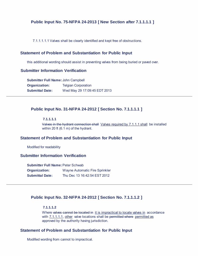
Public Input No. 75-NFPA 24-2013 [ New Section after 7.1.1.1.1 ]
7.1.1.1.1.1 Valves shall be clearly identified and kept free of obstructions.
Statement of Problem and Substantiation for Public Input
this additional wording should assist in preventing valves from being buried or paved over.
Submitter Information Verification
Submitter Full Name: John Campbell Organization: Telgian Corporation Submittal Date: Wed May 29 17:09:45 EDT 2013
Public Input No. 31-NFPA 24-2012 [ Section No. 7.1.1.1.1 ]
7.1.1.1.1 Valves in the hydrant connection shall Valves required by 7.1.1.1 shall be installed within 20 ft (6.1 m) of the hydrant.
Statement of Problem and Substantiation for Public Input
Modified for readability
Submitter Information Verification
Submitter Full Name: Peter Schwab Organization: Wayne Automatic Fire Sprinkler Submittal Date: Thu Dec 13 16:42:54 EST 2012
Public Input No. 32-NFPA 24-2012 [ Section No. 7.1.1.1.2 ]
7.1.1.1.2 Where valves cannot be located in it is impractical to locate valves in accordance with 7.1.1.1.1, other valve locations shall be permitted where permitted as approved by the authority having jurisdiction.
Statement of Problem and Substantiation for Public Input
Modified wording from cannot to impractical.

Submitter Information Verification
Submitter Full Name: Peter Schwab Organization: Wayne Automatic Fire Sprinkler Submittal Date: Thu Dec 13 16:45:13 EST 2012

Public Input No. 33-NFPA 24-2012 [ Section No. 7.1.3 ]
7.1.3 2.1 Where local fire department connections do not conform to NFPA 1963, the authority having jurisdiction shall designate the connection to be used.
Statement of Problem and Substantiation for Public Input
Manual of Style.
Submitter Information Verification
Submitter Full Name: Peter Schwab Organization: Wayne Automatic Fire Sprinkler Submittal Date: Thu Dec 13 16:55:39 EST 2012
Public Input No. 34-NFPA 24-2012 [ Section No. 7.2.4 ]
7.2.4 3.1 Where hydrants cannot be located in accordance with 7.2.3, locations closer than 40 ft (12.2 m) from the building or wall hydrants shall be permitted to be used where permitted where approved by the authority having jurisdiction.
Statement of Problem and Substantiation for Public Input
Renumbered as appropriate and modified wording for readability.
Submitter Information Verification
Submitter Full Name: Peter Schwab Organization: Wayne Automatic Fire Sprinkler Submittal Date: Thu Dec 13 16:58:47 EST 2012
Public Input No. 35-NFPA 24-2012 [ Section No. 7.2.5 ]
7.2.5 Hydrants shall not be installed installed adjacent to retaining walls at less than the equivalent depth of burial from retaining walls where burial found in 10.4.4 where there is danger of frost through the walls.
Statement of Problem and Substantiation for Public Input
Reworded to give user guidance as to where to find burial depths. 10.4.4 will be renumbered in another PI to conform to manual of style.

Submitter Information Verification
Submitter Full Name: Peter Schwab Organization: Wayne Automatic Fire Sprinkler Submittal Date: Thu Dec 13 17:05:35 EST 2012
Public Input No. 36-NFPA 24-2012 [ Section No. 7.3 ]
7.3 Installation. 7.3.1* Hydrants shall be set on flat stones or concrete slabs and shall be provided with small stones (or the equivalent) , concrete slabs, or approved equivalent.
7.3.2
Small stones or an approved equivalent shall be placed about the drain to ensure drainage.
7.3.2 2.1 Where soil is of such a nature that the hydrants hydrant will not drain properly with the arrangement specified in 7.3.1 2 , or where groundwater stands at levels above that of the above the drain, the hydrant drain shall be plugged at the time of installation. 7.3.2.1 2 If
Hydrants with the drain
is
plugged
, hydrants
that are
in service in cold climates shall be pumped out after usage. 7.3.2.2 Such hydrants 3 Hydrants with the drain plugged shall be marked to indicate the need for pumping out after usage. 7.3.3* The center of a hose outlet shall be not less than 18 in. (457 mm) above final grade or, where located in a hose house, .
7.3.3.1
The center of a hose outlet shall not be more than 36 in. (914 mm) above final grade.
7.3.3.2
The center of a hose outlet located in a hose house shall not be less than 12 in. (305 mm) above the floor.
7.3.4 Hydrants shall be fastened to piping and anchored be restrained in accordance

with the requirements of Chapter 10. 7.3.5 Hydrants shall be protected if subject to mechanical damage. 7.3.6 5.1 The means of hydrant protection shall be arranged in a manner so that it does not interfere with the connection to, or operation of, hydrants the hydrant .
7.3.7 The following shall not be installed in the service stub between a fire hydrant and private water supply piping:
(1) Check valves
(2) Detector check valves
(3) Backflow prevention valves
(4) Other similar appurtenances
Statement of Problem and Substantiation for Public Input
Modified numbering to meet manual of style. Added a maximum height requirement that is shown on Annex Figure A.7.3.1 (b). Modified wording for readability.
Submitter Information Verification
Submitter Full Name: Peter Schwab Organization: Wayne Automatic Fire Sprinkler Submittal Date: Fri Dec 14 08:47:58 EST 2012
Public Input No. 76-NFPA 24-2013 [ New Section after 7.3.3 ]
Type your content here .
7.3.4 the center of a hose outlet shall not be greater than 48 in (1.2 m) above final grade, or where located in a hose house, 24 in (610 mm) above the floor.
Renumber subsequent sections accordingly.
Statement of Problem and Substantiation for Public Input

Minimum heights are provided in the previous section. Maximum heights should be provided to prevent installations that prevent proper use of the device.
Submitter Information Verification
Submitter Full Name: John Campbell Organization: Telgian Corporation Submittal Date: Wed May 29 17:11:23 EDT 2013
Public Input No. 77-NFPA 24-2013 [ Section No. 7.3.4 ]
7.3. 4 5 Hydrants shall be fastened to piping and anchored in accordance with the requirements of Chapter 10 .
Statement of Problem and Substantiation for Public Input
renumbering based on comment provided for new 7.3.4
Submitter Information Verification
Submitter Full Name: John Campbell Organization: Telgian Corporation Submittal Date: Wed May 29 17:13:53 EDT 2013
Public Input No. 78-NFPA 24-2013 [ Section No. 7.3.5 ]
7.3. 5 6 Hydrants shall be protected if subject to mechanical damage.
Statement of Problem and Substantiation for Public Input
renumbering based on comment provided for new 7.3.4
Submitter Information Verification
Submitter Full Name: John Campbell Organization: Telgian Corporation Submittal Date: Wed May 29 17:14:51 EDT 2013

Public Input No. 55-NFPA 24-2013 [ Section No. 7.3.6 ]
7.3.6 The means of hydrant protection shall be arranged in a manner that does not interfere with the connection to, or operation of, hydrants.
Statement of Problem and Substantiation for Public Input
2006 Fire code section 508.5.6 states that hydrants subject to impact by motor vehicles, shall be provided with guard posts or other approved means that comply with section 312.
Section 312 states that the spacing between posts shall not exceed 4 (four) foot on center and not less than 3 (three) feet from protected object. The demensions stated have been investgated numerous times in the field to confirm that it is not possible to provide the protection required using 4 (four) posts.
Currently architects/designers are calling for the use of 4 posts, it is not possible to maintain the 4 foot on center between posts and the 3 foot clearance from the protected object without adding an additional post.
This concern is usually handled through the architect of record for the project, but it comes with a change order/additional cost to the owner.
Submitter Information Verification
Submitter Full Name: Manuel C Rios Organization: Clark County School District Submittal Date: Fri May 17 09:52:50 EDT 2013
Public Input No. 79-NFPA 24-2013 [ Section No. 7.3.6 ]
7.3. 6 7 The means of hydrant protection shall be arranged in a manner that does not interfere with the connection to, or operation of, hydrants.
Statement of Problem and Substantiation for Public Input
renumbering based on comment provided for new 7.3.4
Submitter Information Verification
Submitter Full Name: John Campbell Organization: Telgian Corporation Submittal Date: Wed May 29 17:15:22 EDT 2013
Public Input No. 80-NFPA 24-2013 [ Section No. 7.3.7 ]
7.3. 7 8

The following shall not be installed in the service stub between a fire hydrant and private water supply piping:
(1) Check valves
(2) Detector check valves
(3) Backflow prevention valves
(4) Other similar appurtenances
Statement of Problem and Substantiation for Public Input
renumbering based on comment provided for new 7.3.4
Submitter Information Verification
Submitter Full Name: John Campbell Organization: Telgian Corporation Submittal Date: Wed May 29 17:16:00 EDT 2013
Public Input No. 53-NFPA 24-2013 [ Section No. 8.1.2 ]
8.1.2 Hose shall be stored so it is accessible and is protected from the weather by storing .
8.1.2.1 Hose shall be permitted to be stored in hose houses or by placing hose reels or hose carriers in weatherproof enclosures.
Additional Proposed Changes
File Name Description Approved
Open LK_NFPA_24-2013_Proposal_4_of_5.docx Cover Sheet
Statement of Problem and Substantiation for Public Input
This proposed revision editorial in nature, to clarify the intent. It is common practice for some industrial fire brigades to store their hose at their fire halls and/or on their fire trucks, but as written the current text seems to imply that it is mandatory to put the hose in hose houses or on reels or carriers in weatherproof enclosures.
Submitter Information Verification
Submitter Full Name: Larry Keeping Organization:
Professional Loss Control Submittal Date: Mon May 13 13:46:06 EDT 2013

Public Input No. 81-NFPA 24-2013 [ Section No. 8.3.1 ]
8.3.1 Hose houses shall be of substantial construction on foundations stable foundations .
Statement of Problem and Substantiation for Public Input
adding "stable" ensures that the hose houses are not installed on loose soils
Submitter Information Verification
Submitter Full Name: John Campbell Organization: Telgian Corporation Submittal Date: Wed May 29 17:17:04 EDT 2013
Public Input No. 38-NFPA 24-2012 [ Section No. 10.1 ] 10.1* Piping Materials.
10.1.1* Listing.
Piping shall be listed for fire protection service or All piping used in private fire service mains shall be in accordance with Section 10.1.1
10.1.1.1
Piping used in private fire service mains shall comply with the standards in Table 10.1.1.
10.1.1.2
Piping not shown in Table 10.1.1 shall be specifically listed for use in private fire service mains.
Table 10.1.1 Manufacturing Standards for Underground Pipe
Materials and Dimensions Standard Ductile Iron
Cement Mortar Lining for Ductile Iron Pipe and Fittings for Water AWWA
C104
Polyethylene Encasement for Ductile Iron Pipe Systems AWWA
C105
Ductile Iron and Gray Iron Fittings, 3 in. Through 48 in., for Water and Other Liquids AWWA
C110
Rubber-Gasket Joints for Ductile Iron Pressure Pipe and Fittings AWWA
C111
Flanged Ductile Iron Pipe with Ductile Iron or Gray Iron Threaded Flanges AWWA
C115
Protective Fusion-Bonded Epoxy Coatings for the Interior and Exterior Surfaces of Ductile-Iron and
Gray-Iron Fittings for Water Supply Service
AWWA
C116
Thickness Design of Ductile Iron Pipe AWWA
C150
Ductile Iron Pipe, Centrifugally Cast for Water AWWA
C151
Ductile-Iron Compact Fittings for Water Service AWWA
C153

Materials and Dimensions Standard
Standard for the Installation of Ductile Iron Water Mains and Their Appurtenances AWWA
C600
Steel
Steel Water Pipe 6 in. and Larger AWWA
C200
Coal-Tar Protective Coatings and Linings for Steel Water Pipelines Enamel and Tape — Hot Applied AWWA
C203
Cement-Mortar Protective Lining and Coating for Steel Water Pipe 4 in. and Larger — Shop Applied AWWA
C205
Field Welding of Steel Water Pipe AWWA
C206
Steel Pipe Flanges for Waterworks Service — Sizes 4 in. Through 144 in. AWWA
C207
Dimensions for Fabricated Steel Water Pipe Fittings AWWA
C208
A Guide for Steel Pipe Design and Installation AWWA
M11
Concrete
Reinforced Concrete Pressure Pipe, Steel-Cylinder Type AWWA
C300
Prestressed Concrete Pressure Pipe, Steel-Cylinder Type AWWA
C301
Reinforced Concrete Pressure Pipe, Non-Cylinder Type AWWA
C302
Reinforced Concrete Pressure Pipe, Steel-Cylinder Type, Pretensioned AWWA
C303
Standard for Asbestos-Cement Distribution Pipe, 4 in. Through 16 in., for Water Distribution Systems AWWA
C400
Standard for the Selection of Asbestos-Cement Pressure Pipe AWWA
C401
Cement-Mortar Lining of Water Pipe Lines 4 in. and Larger — in Place AWWA
C602
Standard for the Installation of Asbestos-Cement Water Pipe AWWA
C603
Plastic
Polyvinyl Chloride (PVC) Pressure Pipe, 4 in. Through 12 in., for Water Distribution AWWA
C900
Polyvinyl Chloride (PVC) Pressure Pipe, 14 in. Through 48 in., for Water Distribution AWWA
C905
Polyethylene (PE) Pressure Pipe and Fittings, 4 in. (100 mm) Through 63 in. (1575 mm) for Water
Distribution
AWWA
C906
Copper
Specification for Seamless Copper Tube ASTM B 75
Specification for Seamless Copper Water Tube ASTM B 88

Materials and Dimensions Standard
Requirements for Wrought Seamless Copper and Copper-Alloy Tube ASTM B
251
10.1.2 Steel Pipe.
Steel piping pipe shall not be used for general underground service unless in private fire service mains execpt as permitted in 10.1.2.1 and 10.1.2.2.
10.1.2.1
Steel pipe shall be permitted to be used in private fire service whens when specifically listed for such
service use.
10.1.3 Steel Pipe Used with Fire Department Connections.
Where externally coated and wrapped and internally galvanized, steel pipe shall 2.2 Steel pipe installed in accordance with 10.1.2.2 shall be permitted to be used between the check valve and the outside hose coupling for the hose coupling(s) on the fire department connection.
10.1.
4 2.2.1
Steel pipe shall be internally galvanized.
10.1.2.2.2
Steel pipe shall be wrapped and coated with approved materials to prevent corrosion.
10.1.3* Pipe Type and Class.
The requirements of 10.1.3 shall be considered when selecting the type and class of pipe
for a particular underground installation shall be determined through consideration of the following factors:
1. Fire resistance of the pipe
2. Maximum system working pressure
3. Depth at which the pipe is to be installed
4. Soil conditions
5. Corrosion
6. Susceptibility of pipe to other external loads, including earth loads, installation beneath buildings, and traffic or vehicle loads
10.1.5* Working Pressure.
Piping, fittings, and other system components shall be rated for the maximum system working pressure to which they are exposed but shall not be rated at less than 150 psi (10 bar).
10.1.6* Lining of Buried Pipe.
10.1.6.1 Unless the requirements of 10.1.6.2 are met, all ferrous metal pipe
to be used.
10.1.3.1
The fire resistance of the pipe shall be considered when piping passes above grade.
10.1.3.1.1
Piping acceptable for underground shall be permitted to extend 24 in. (0.6m) through the floor or wall into the building without regards to 10.1.3.1.
10.1.3.2
The maximum system working pressure shall be considered.
10.1.3.2.1
When a fire department connection is installed, the pressure from the fire department connection shall not be considered as part of the system working pressure.
10.1.3.3

The depth of bury of the pipe and susceptibility to earth loads and traffic or vehicle loads shall be considered.
10.1.3.4
The type of soil and potential for corrosion shall be considered.
10.1.4* Working Pressure.
All pipe used in private fire service mains shall be rated at a minimum of 150 psi (10 bar).
10.1.4.1
When the system working pressure exceeds 150 psi (10 bar), piping shall be rated for the maximum system working pressure.
10.1.5* Lining of Buried Pipe.
10.1.5.1
Except as permitted in 10.1.2.2, all ferrous metal piping shall be lined in accordance with the applicable standards inTable 10.1.1.
10.1.6.2
Steel pipe utilized in fire department connections and protected in accordance with the requirements of 10.1.3 shall not be required to be internally lined.
Statement of Problem and Substantiation for Public Input
Modified to follow manual of style. Eliminated some repetitive text. Added allowance for piping to extend into building for riser connection to correlate with NFPA 13 (6.3.1.1.1).
Submitter Information Verification
Submitter Full Name: Peter Schwab
Organization: Wayne Automatic Fire Sprinkler
Submittal Date: Tue Dec 18 08:44:36 EST 2012
Public Input No. 59-NFPA 24-2013 [ Section No. 10.1.1 ] 10.1.1* Listing. Piping shall be listed for fire protection service or shall comply with the standards in Table 10.1.1.
Table 10.1.1 Manufacturing Standards for Underground Pipe
Materials and Dimensions Standard Ductile Iron
Cement Mortar Lining for Ductile Iron Pipe and Fittings for Water AWWA
C104
Polyethylene Encasement for Ductile Iron Pipe Systems AWWA
C105
Ductile Iron and Gray Iron Fittings, 3 in. Through 48 in., for Water and Other Liquids AWWA
C110
Rubber-Gasket Joints for Ductile Iron Pressure Pipe and Fittings AWWA
C111
Flanged Ductile Iron Pipe with Ductile Iron or Gray Iron Threaded Flanges AWWA
C115
Protective Fusion-Bonded Epoxy Coatings for the Interior and Exterior Surfaces of Ductile-Iron and
Gray-Iron Fittings for Water Supply Service
AWWA
C116
Thickness Design of Ductile Iron Pipe AWWA
C150
Ductile Iron Pipe, Centrifugally Cast for Water AWWA
C151

Materials and Dimensions Standard
Ductile-Iron Compact Fittings for Water Service AWWA
C153
Standard for the Installation of Ductile Iron Water Mains and Their Appurtenances AWWA
C600
Steel
Steel Water Pipe 6 in. and Larger AWWA
C200
Coal-Tar Protective Coatings and Linings for Steel Water Pipelines Enamel and Tape — Hot Applied AWWA
C203
Cement-Mortar Protective Lining and Coating for Steel Water Pipe 4 in. and Larger — Shop Applied AWWA
C205
Field Welding of Steel Water Pipe AWWA
C206
Steel Pipe Flanges for Waterworks Service — Sizes 4 in. Through 144 in. AWWA
C207
Dimensions for Fabricated Steel Water Pipe Fittings AWWA
C208
A Guide for Steel Pipe Design and Installation AWWA
M11
Concrete
Reinforced Concrete Pressure Pipe, Steel-Cylinder Type AWWA
C300
Prestressed Concrete Pressure Pipe, Steel-Cylinder Type AWWA
C301
Reinforced Concrete Pressure Pipe, Non-Cylinder Type AWWA
C302
Reinforced Concrete Pressure Pipe, Steel-Cylinder Type, Pretensioned AWWA
C303
Standard for Asbestos-Cement Distribution Pipe, 4 in. Through 16 in., for Water Distribution Systems AWWA
C400
Standard for the Selection of Asbestos-Cement Pressure Pipe AWWA
C401
Cement-Mortar Lining of Water Pipe Lines 4 in. and Larger — in Place AWWA
C602
Standard for the Installation of Asbestos-Cement Water Pipe AWWA
C603
Plastic
Polyvinyl Chloride (PVC) Pressure Pipe, 4 in. Through 12 in., for Water Distribution AWWA
C900
Polyvinyl Chloride (PVC) Pressure Pipe, 14 in. Through 48 in., for Water Distribution AWWA
C905
Polyethylene (PE) Pressure Pipe and Fittings, 4 in. (100 mm) Through 63 in. (1575 mm) for Water
Distribution
AWWA
C906

Materials and Dimensions Standard
Molecularly Oriented Polyvinyl Chloride (PVCO) Pressure Pipe, 4 IN through24 IN. (100 MM through
600 MM ), for Water Wastewater, and Reclaimed Water Service
AWWA
C909
Copper
Specification for Seamless Copper Tube ASTM B 75
Specification for Seamless Copper Water Tube ASTM B 88
Requirements for Wrought Seamless Copper and Copper-Alloy Tube ASTM B
251
Statement of Problem and Substantiation for Public Input
Molecular Modified PVC pipes (PVC-O) have a higher resistance against imoact and water hammer effects. It is not sensitive in installation, also not when installed at low temperatures. So the PVC-O pipe is more robust then our PVC-U and hence it should be included in the list.
Related Public Inputs for This Document
Related Input Relationship
Open Public Input No. 60-NFPA 24-2013
[Section No. 2.3.3]
One is related to the reference to the relevant standard., the
order to include in the list of material
Submitter Information Verification
Submitter Full Name: Frans Alferink
Organization: Wavin Overseas, The Netherlands / Pavco Colombia
Affilliation: S2rEnginieros, Bogota Colombia, Mr. Antonio Yesid Lopez
Submittal Date: Thu May 23 12:38:17 EDT 2013
Public Input No. 39-NFPA 24-2012 [ Section No. 10.2 ] 10.2 Fittings.
All fittings used in private fire service mains shall be in accordance with section 10.2.
10.2.1*
Buried Buried Fittings
. Fittings shall be of an approved type with joints and pressure class ratings 10.2.1.1
All buried fittings used in private fire service mains shall be approved.
10.2.1.2
Fittings specifically listed for use in private fire service mains shall be permitted to be used.
10.2.1.2.1
When listed fittings are used, they shall be installed in accordance with their listing limitations, including installation instructions.
10.2.1.3
Buried fittings shall have the same pressure class rating as the pipe.
10.2.1.4
Buried fittings shall be compatible with the pipe used.
10.2.2 Standard Fittings.
10.2.2.
1 1
All fittings used in private fire service mains installed aboveground shall be in accordance with 10.2.2.

10.2.2.2
Fittings shall meet the standards in Table 10.2.2.12 or shall be in accordance with 10.2.32.4.
Table 10.2.2.1 Fittings 2 Fittings Materials and Dimensions
Materials and Dimensions Standard Cast Iron
Gray Iron Threaded Fittings, Classes 125 and 250 ASME B16.4
Gray Iron Pipe Flanges and Flanged Fittings, Classes 12, 125, and 250 ASME B16.1
Malleable Iron
Malleable Iron Threaded Fittings, Class 150 and 300 ASME B16.3
Steel
Factory-Made Wrought Steel Buttweld Fittings ASME B16.9
Buttwelding Ends ASME
B16.25
Specification for Piping Fittings of Wrought Carbon Steel and Alloy Steel for Moderate and Elevated
Temperatures ASTM A 234
Pipe Flanges and Flanged Fittings, NPS 1⁄2 Through 24 ASME B16.5
Forged Steel Fittings, Socket Welded and Threaded ASME
B16.11
Copper
Wrought Copper and Bronze Solder Joint Pressure Fittings ASME
B16.22
Cast Bronze Solder Joint Pressure Fittings ASME
B16.18
10.2.2.2
In addition to the standards in Table 10.2.2.2, CPVC fittings shall also be 3 CPVC fittings shall be in accordance with 10.2.32.4 and with the portions of the ASTM standards specified in Table 10.2.2.23 that apply to fire protection service.
Table 10.2.2.2 Specially 3 Specially Listed Fittings Materials and Dimensions
Materials and Dimensions Standard Chlorinated Polyvinyl Chloride (CPVC) Specification for Schedule 80 CPVC Threaded Fittings ASTM F 437
Specification for Schedule 40 CPVC Socket-Type Fittings ASTM F 438
Specification for Schedule 80 CPVC Socket-Type Fittings ASTM F 439
10.2.3 Special Listed Fittings2.
Other types of fittings investigated for suitability in automatic sprinkler installations and listed for this service, including, but not limited to, polybutylene, CPVC, and steel differing from that provided in Table 4 Fittings specifically listed for use in fire protection systems shall be permitted to be used.
10.2.2.4.1
When listed fittings are used, they shall be
permitted when installed in accordance with their listing limitations, including installation instructions.
10.2.4 Pressure Limits3 Working Pressure.
Listed fittings shall be permitted for the system pressures as specified in their listings, but not less than All fittings used in private fire service mains shall be rated at a minimum of 150 psi (10 bar).
10.2.3.1
When the system working pressure exceeds 150 psi (10 bar), fittings shall be rated for the maximum system working pressure.
Statement of Problem and Substantiation for Public Input
Modified for manual of style

Submitter Information Verification
Submitter Full Name: Peter Schwab
Organization: Wayne Automatic Fire Sprinkler
Submittal Date: Tue Dec 18 09:49:47 EST 2012
Public Input No. 87-NFPA 24-2013 [ Section No. 10.4.5 ]
10.4.5 Pipe under railroad tracks shall be buried at a minimum depth of 4 ft (1.2
m) , the owner/operator of the railroad track must be contacted for their
requirements .
Additional Proposed Changes
File Name Description Approved
Open 24_Brown.pdf Cover Sheet
Statement of Problem and Substantiation for Public Input
It is not unusual for a user/operator of a railroad track to require a minimum of 10 ft from top of rail to top of pipe passing under their rail. This could be a very costly error for the installer if they failed to contact the owner/operator of the railroad track.
Submitter Information Verification
Submitter Full Name: Phillip Brown Organization: American Fire Sprinkler Association Submittal Date: Mon Jun 03 11:19:51 EDT 2013
Public Input No. 54-NFPA 24-2013 [ Section No. 13.2 ]
13.2 Mains Not Supplying Hydrants. For mains that do not supply hydrants, sizes smaller than 6 in. (152 mm) shall be permitted to be used, subject to the following restrictions:
(1) The main shall supply only the following types of systems:
(a) Automatic sprinkler systems
(b) Open sprinkler systems
(c) Water spray fixed systems
(d) Foam systems
(e) Class II standpipe Standpipe systems
(2) Hydraulic calculations shall show that the main is able to supply the total demand at the appropriate pressure.
(3) Systems that are not hydraulically calculated shall have a main at least as large as the riser.

Additional Proposed Changes
File Name Description Approved
Open LK_NFPA_24-2013_Proposal_5_of_5.docx Cover Sheet
Statement of Problem and Substantiation for Public Input
This change is proposed to align 13.2 (e) with the text of 5.2.2 (e), which was revised during the last cycle to delete the “Class II” reference. As discussed then, there should not be a requirement which specifies a 6” minimum water supply for all Class I & III standpipes. NFPA 14 requires that all new standpipes be hydraulically calculated, so this standard should not dictate a minimum size for the private fire service mains that supply them.
Submitter Information Verification
Submitter Full Name: Larry Keeping Organization: Professional Loss Control Submittal Date: Mon May 13 13:47:41 EDT 2013

PART 6(C) –
NFPA 24
PUBLIC INPUT - ANNEX

Public Input No. 2-NFPA 24-2012 [ New Section after A.3.3.11 ]
A.3.3.15.2
Examples are outside screw and yoke (OS&Y) gate valves and underground gate valves with indicator posts.
Statement of Problem and Substantiation for Public Input
Examples belong in the annex.
Related Public Inputs for This Document
Related Input Relationship
Open Public Input No. 1-NFPA 24-2012 [Section No. 3.3.15.2]
Submitter Information Verification
Submitter Full Name: Peter Schwab Organization: Wayne Automatic Fire Sprinkler Submittal Date: Wed Dec 12 16:43:47 EST 2012

Public Input No. 28-NFPA 24-2012 [ Section No. A.3.4.1.3 ]
A.3.4.1.3 Private Fire Hydrant. Where connected to a public water system, the private hydrants are supplied by a private service main that begins at the point of service designated by the authority having jurisdiction, usually at a manually operated valve near the property line.
Statement of Problem and Substantiation for Public Input
The term "Point of Service" is a legally defined term in the State of Florida. This use of that term causes some confusion. Removing the phrase of service does not change the intent of this section.
Submitter Information Verification
Submitter Full Name: Peter Schwab Organization: Wayne Automatic Fire Sprinkler Submittal Date: Thu Dec 13 16:25:46 EST 2012

Public Input No. 27-NFPA 24-2012 [ Section No. A.4.1 ]
A.4.1
Underground mains should be designed so that the system can be extended with a minimum of expensewith minimum expense. Possible future plant expansion future expansion should also be considered and the piping designed so that it is not covered by buildingsfuture buildings.
Statement of Problem and Substantiation for Public Input
Modified wording for readability.
Submitter Information Verification
Submitter Full Name: Peter Schwab
Organization: Wayne Automatic Fire Sprinkler
Submittal Date: Thu Dec 13 16:23:17 EST 2012
Public Input No. 24-NFPA 24-2012 [ Section No. A.5.4 ]
A.5.4 Where connections are made from public waterworks systems, such systems should be guarded against possible contamination as follows (see AWWA M14 or
local plumbing code or consult the local water purveyor ):
(1) For private fire service mains with direct connections from public waterworks mains only or with fire pumps installed in the connections from the street mains, no tanks or reservoirs, no physical connection from other water supplies, no antifreeze or other additives of any kind, and with all drains discharging to atmosphere, dry well, or other safe outlets, an approved double check valve assembly is recommended.
(2) For private fire service mains with direct connections from the public water supply main plus one or more elevated storage tanks or fire pumps taking suction from aboveground covered reservoirs or tanks (all storage facilities are filled or connected to public water only, and the water in the tanks is to be maintained in a potable condition), an approved double check valve assembly is recommended.
(3) For private fire service mains directly supplied from public mains with an auxiliary water supply, such as a pond or river on or available to the premises and dedicated to fire department use; or for systems supplied from public mains and interconnected with auxiliary supplies, such as pumps taking suction from reservoirs exposed to contamination or rivers and ponds; driven wells, mills, or other industrial water systems; or for systems or portions of systems where antifreeze or other solutions are used, an approved reduced- pressure zone-type backflow preventer is recommended.
(4) For private fire service mains with fire department connections located within 1750 ft (533.4 m) of a non potable water source, an approved reduced- pressure zone-type backflow preventer is recommended.
Statement of Problem and Substantiation for Public Input
This is an AWWA requirement that is being increasingly enforced. Since this standard includes

annex language on backflow prevention, this should be added.
Submitter Information Verification
Submitter Full Name: Peter Schwab Organization: Wayne Automatic Fire Sprinkler Submittal Date: Thu Dec 13 15:35:10 EST 2012
Public Input No. 82-NFPA 24-2013 [ New Section after A.5.6 ]
Type your content here ...
A.5.8.1 In the selection of screen material, consideration should be given to prevention of fouling from aquatic growth. Antifouling is best accomplished with brass or copper wire. [20: A.4.14.8]
Statement of Problem and Substantiation for Public Input
adding the detail on the screens provided consistency with other NFPA standards that address screens on intakes from open bodies of water (NFPA20). Wording is consistent with NFPA 20.
Submitter Information Verification
Submitter Full Name: John Campbell Organization: Telgian Corporation Submittal Date: Wed May 29 17:19:39 EDT 2013

Public Input No. 25-NFPA 24-2012 [ Section No. A.5.6 ]
A.5.6 A fire pump installation consisting of pump, driver, and suction supply, when of adequate capacity and reliability and properly located, makes a good supply makes an acceptable supply . An automatically controlled fire pump taking or pumps taking water from a water main of adequate capacity, or taking draft under a head from a reliable storage of adequate capacity, is permitted to be, under certain conditions, accepted by the authority having jurisdiction as a single supply.
Statement of Problem and Substantiation for Public Input
Acceptable is a better term than good. added language to indicate that some occupancies will utilize more than one pump.
Related Public Inputs for This Document
Related Input Relationship
Open Public Input No. 13-NFPA 24-2012 [Section No. 5.6]
Submitter Information Verification
Submitter Full Name: Peter Schwab Organization: Wayne Automatic Fire Sprinkler Submittal Date: Thu Dec 13 15:49:11 EST 2012
Public Input No. 83-NFPA 24-2013 [ Section No. A.5.9 ]
A.5.9
The fire department connection should be located not less than 18 in. (457 mm) and not more than 4 ft (1.2 m) above the level of the adjacent grade or access level. Typical A typical fire department connections areconnection is shown in Figure A.5.9(a) and Figure A. 5.9(b). Where a hydrant is not available, other water supply sources such as a natural body of water, a tank, or a reservoir should be utilized. The water authority should be consulted when a nonpotable water supply is proposed as a suction source for the fire department.
Figure A.5.9(a) Typical
Fire Department Connection.

Figure A.5.9(b) Typical City Water Pit — Valve Arrangement with Fire Department Connection.

Statement of Problem and Substantiation for Public Input
Figure 5.9(a) as currently shown shows a fire department connection supplied by piping interior to a building, which falls under the jurisdiction of NFPA 13. This standard addresses remote fire department connections and as such, removing the figure eliminates confusion on piping of these devices.
Submitter Information Verification
Submitter Full Name: John Campbell
Organization: Telgian Corporation
Submittal Date: Wed May 29 17:22:59 EDT 2013
Public Input No. 20-NFPA 24-2012 [ Section No. A.5.9.5.2 ]
A.5.9.5.2 Obstructions to fire department connections include, but are not limited to, buildings, fences, posts, landscaping, other fire department connections, gas fire protection equipment, gas meters, and electrical equipment.
Additional Proposed Changes
File Name Description Approved
Open PIV.jpg Blocked FDC
Statement of Problem and Substantiation for Public Input
It is common to see a Yard PIV obstruct a fire department connection.
Submitter Information Verification
Submitter Full Name: Peter Schwab Organization: Wayne Automatic Fire Sprinkler Submittal Date: Thu Dec 13 14:52:34 EST 2012


Public Input No. 23-NFPA 24-2012 [ Section No. A.5.9.5.3 ]
A. 5.9.5. 3 6 Where a fire department connection services multiple buildings, structures, or locations, a sign should shall be provided indicating the buildings, structures, or locations served.
Statement of Problem and Substantiation for Public Input
This information should not be in the annex. This proposal moves it into the body of the standard. It is understood that fire departments should perform preplanning and know the purpose of the FDC's prior to a fire event. However, a sign indicating such helps facilitate a response at 3:00 am in the morning.
Submitter Information Verification
Submitter Full Name: Peter Schwab Organization: Wayne Automatic Fire Sprinkler Submittal Date: Thu Dec 13 15:30:57 EST 2012

Public Input No. 26-NFPA 24-2012 [ Section No. A.5.9.5.3(2) ]
A.5.9.5.3(2) Examples for wording of signs are:
AUTOSPKR
AUTO SPKR
OPEN SPKR
.
STANDPIPE
AND STANDPIPE -
SPRINKLER
DRY STANDPIPE
STANDPIPE-AUTO SPKR
Statement of Problem and Substantiation for Public Input
Updated list with terms commonly found on different manufacturers' websites.
Submitter Information Verification
Submitter Full Name: Peter Schwab Organization: Wayne Automatic Fire Sprinkler Submittal Date: Thu Dec 13 15:54:43 EST 2012

Public Input No. 52-NFPA 24-2013 [ New Section after A.6.1.5 ]
A.6.2.1 A connection to a municipal water supply may utilize a non-indicating tapping sleeve and valve as the valve controlling the water supply.
Additional Proposed Changes
File Name Description Approved
Open LK_NFPA_24-2013_Proposal_3_of_5.docx Cover Sheet
Statement of Problem and Substantiation for Public Input
During the previous revision cycle the words “listed indicating” were deleted from 6.2.1. This created a conflict whereby 6.1.1 and 6.2.5 call for listed indicating valves on water supplies, but 6.2.1 does not. The proposed text is offered as a resolution to this conflict. Additionally the modification to 6.2.1 would require the configuration to be acceptable to the AHJ and the proposed Annex text would offer an explanation for the matter. Also, in 6.1.1 the specific reference to “sprinklers” was revised to “water-based fire protection systems”, since private fire service mains supply other types of systems as well.
Submitter Information Verification
Submitter Full Name: Larry Keeping Organization:
Professional Loss Control Submittal Date: Mon May 13 13:44:47 EDT 2013
Public Input No. 40-NFPA 24-2013 [ Section No. A.10.4.1 ]
A.10.4.1
The following documents apply to the installation of pipe and fittings:
1. AWWA C603, Standard for the Installation of Asbestos-Cement Pressure Pipe
2. AWWA C600, Standard for the Installation of Ductile-Iron Water Mains and Their Appurtenances
3. AWWA M11, A Guide for Steel Pipe Design and Installation
4. AWWA M41, Ductile Iron Pipe and Fittings
5. Concrete Pipe Handbook, American Concrete Pipe Association
6. Handbook of PVC Pipe, Uni-Bell PVC Pipe Association
7. Installation Guide for Ductile Iron Pipe, Ductile Iron Pipe Research Association
8. Thrust Restraint Design for Ductile Iron Pipe, Ductile Iron Pipe Research Association
As there is normally no circulation of water in private fire mains, they require greater depth of covering than do public mains. Greater depth is required in a loose gravelly soil (or in rock) than in compact soil containing large quantities of clay. The recommended depth of cover above the top of underground yard mains is shown in Figure A.10.4.1.
Figure A.10.4.1 Recommended Depth of Cover (in feet) Above Top of Underground Yard Mains.

Statement of Problem and Substantiation for Public Input
Modify Figure A.10.4.1. This program does not allow for easy manipulation of figures so I will explain the change in the substantiation. Currently there are gradient lines separating the bury depths (IE: 2.5-3, 3.5-4, 4.5-5, etc. However, tehre are no clear lines drawn for the following separations (3'-3.5', 4'-4.5', 5'-5.5', 6'-6.5', 7'-7.5'). Either additional lines should be drawn or the numbers north of the existing lines need to be increaded by 6".
Submitter Information Verification
Submitter Full Name: Peter Schwab
Organization: Wayne Automatic Fire Sprinkler
Submittal Date: Thu Jan 17 08:47:10 EST 2013
Public Input No. 61-NFPA 24-2013 [ Section No. A.10.6.3.1 ]
A.10.6.3.1
Items such as sidewalks or patios should not be included as they are no different from roadways. See Figure A.10.6.3.1.
Figure A.10.6.3.1 Riser Entrance Location.

[Replace existing figure with new Figure A.10.6.3.1]
Additional Proposed Changes
File Name Description Approved Open Figure_A-10-6-3-1.tif
New figure to replace existing Figure A.10.6.3.1 ✓
Statement of Problem and Substantiation for Public Input
The figure needs to be revised. The pipe leading up to the transition to the riser does not need to be ductile iron. Any type of acceptable underground should be permitted. This is consistent with the change to NFPA 24 last cycle to allow up to 24 inches of pipe above ground to make the transition to the riser.
Submitter Information Verification
Submitter Full Name: Roland Asp
Organization: National Fire Sprinkler Association
Affilliation: NFSA E&S Committee
Submittal Date: Fri May 24 16:13:28 EDT 2013

Public Input No. 84-NFPA 24-2013 [ Section No. A.10.6.3.1 ]
A.10.6.3.1
Items such as sidewalks or patios should not be included as they are no different from roadways. See Figure A.10.6.3.1.
Figure A.10.6.3.1 Riser Entrance Location.
Statement of Problem and Substantiation for Public Input
need to provide an annular space around the lead-in piping penetrating the floor to conform with the clearance requirements in NFPA 13
Submitter Information Verification
Submitter Full Name: John Campbell
Organization: Telgian Corporation
Submittal Date: Wed May 29 17:27:54 EDT 2013

Public Input No. 62-NFPA 24-2013 [ Section No. A.10.6.4 ]
A.10.6.4
The individual piping standards should be followed for load and bury depth, accounting for the load and stresses imposed by the building foundation.
Figure A.10.6.4 shows location where pipe joints would be prohibited.
[Revise figure as shown in proposed new Figure A.10.6.4]
Figure A.10.6.4 Pipe Joint Location in Relation to Foundation Footings.
Additional Proposed Changes
File Name Description Approved Open Figure_A-10-6-4.tif
New Figure A.10.6.4 to replace old one ✓
Statement of Problem and Substantiation for Public Input
The figure needs to be revised. The pipe leading up to the transition to the riser does not need to be ductile iron. Any type of acceptable underground should be permitted. This is consistent with the change to NFPA 24 last cycle to allow up to 24 inches of pipe above ground to make the transition to the riser.
Submitter Information Verification
Submitter Full Name: Roland Asp
Organization: National Fire Sprinkler Association
Affilliation: NFSA E&S Committee
Submittal Date: Fri May 24 16:17:53 EDT 2013

No
System riser
Acceptable
Material
fittings Joint reetralnt
Acceptable pipe malarial
FIGL'REA.I0.6.4 PipeJoint Location in Relation to Founda tion Footings.

Public Input No. 85-NFPA 24-2013 [ Section No. A.10.6.4 ]
A.10.6.4
The individual piping standards should be followed for load and bury depth, accounting for the load and stresses imposed by the building foundation.
Figure A.10.6.4 shows location where pipe joints would be prohibited.
Figure A.10.6.4 Pipe Joint Location in Relation to Foundation Footings.
Statement of Problem and Substantiation for Public Input
need to provide an annular space around the lead-in piping penetrating the floor to conform with the clearance requirements in NFPA 13
Submitter Information Verification
Submitter Full Name: John Campbell
Organization: Telgian Corporation
Submittal Date: Wed May 29 17:29:05 EDT 2013
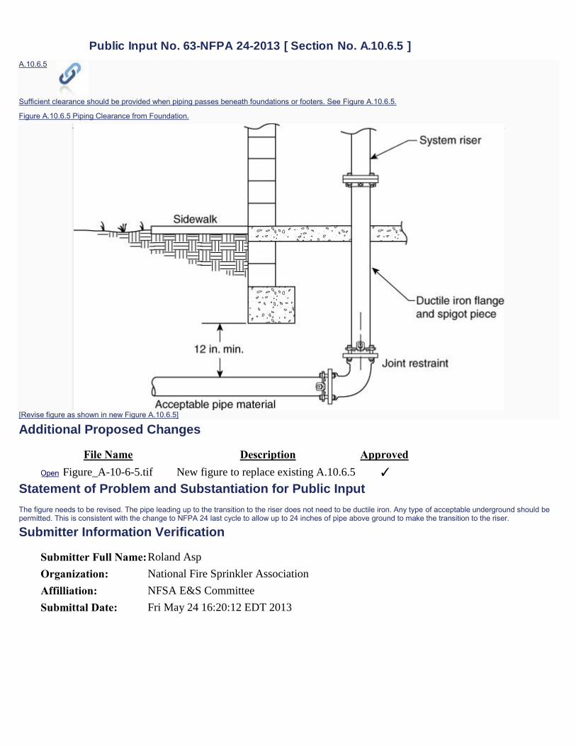
Public Input No. 63-NFPA 24-2013 [ Section No. A.10.6.5 ] A.10.6.5
Sufficient clearance should be provided when piping passes beneath foundations or footers. See Figure A.10.6.5.
Figure A.10.6.5 Piping Clearance from Foundation.
[Revise figure as shown in new Figure A.10.6.5]
Additional Proposed Changes
File Name Description Approved Open Figure_A-10-6-5.tif
New figure to replace existing A.10.6.5 ✓
Statement of Problem and Substantiation for Public Input
The figure needs to be revised. The pipe leading up to the transition to the riser does not need to be ductile iron. Any type of acceptable underground should be permitted. This is consistent with the change to NFPA 24 last cycle to allow up to 24 inches of pipe above ground to make the transition to the riser.
Submitter Information Verification
Submitter Full Name: Roland Asp
Organization: National Fire Sprinkler Association
Affilliation: NFSA E&S Committee
Submittal Date: Fri May 24 16:20:12 EDT 2013

System riser
Acceptable
Material
121n.min.
Acceptable pi!Je material
Joint restraint
fiGUREA.l0.6.5 Piping Clearance from Fotmdation.

Public Input No. 86-NFPA 24-2013 [ Section No. A.10.6.5 ]
A.10.6.5
Sufficient clearance should be provided when piping passes beneath foundations or footers. See Figure A.10.6.5.
Figure A.10.6.5 Piping Clearance from Foundation.
Statement of Problem and Substantiation for Public Input
need to provide an annular space around the lead-in piping penetrating the floor to conform with the clearance requirements in NFPA 13
Submitter Information Verification
Submitter Full Name: John Campbell
Organization: Telgian Corporation
Submittal Date: Wed May 29 17:29:51 EDT 2013

Public Input No. 64-NFPA 24-2013 [ Section No. A.10.8.3 ]
A.10.8.3
A method for providing thrust restraint is the use of restrained joints. A restrained joint is a special type of joint that is designed to provide longitudinal restraint. Restrained joint systems function in a manner similar to that of thrust blocks, insofar as the reaction of the entire restrained unit of piping with the soil balances the thrust forces.
The objective in designing a restrained joint thrust restraint system is to determine the length of pipe that must be restrained on each side of the focus of the thrust force. This will be a function of the pipe size, the internal pressure, the depth of cover, and the characteristics of the solid surrounding the pipe.
The following documents apply to the design, calculation, and determination of restrained joint systems:
1. Thrust Restraint Design for Ductile Iron Pipe, Ductile Iron Pipe Research Association
2. AWWA M41, Ductile Iron Pipe and Fittings
3. AWWA M9, Concrete Pressure Pipe
4. AWWA M11, A Guide for Steel Pipe Design and Installation
5. Thrust Restraint Design Equations and Tables for Ductile Iron and PVC Pipe, EBAA Iron, Inc.
Figure A.10.8.3 shows an example of a typical connection to a fire protection system riser utilizing restrained joint pipe.
[Revise figure as shown in new Figure A.10.8.3]
Figure A.10.8.3 Typical Connection to Fire Protection System Riser Illustrating Restrained Joints.
Additional Proposed Changes
File Name Description Approved Open Figure_A-10-8-3.tiff
New figure to replace existing Figure A.10.8.3 ✓
Statement of Problem and Substantiation for Public Input
The figure needs to be revised. The pipe leading up to the transition to the riser does not need to be ductile iron. Any type of acceptable underground should be permitted. This is consistent with the change to NFPA 24 last cycle to allow up to 24 inches of pipe above ground to make the transition to the riser.
Submitter Information Verification
Submitter Full Name: Roland Asp
Organization: National Fire Sprinkler Association
Affilliation: NFSA E&S Committee
Submittal Date: Fri May 24 16:23:05 EDT 2013

System riser
Acceptable
Material
Fire
Acceptable
Material
F1GUREA.l0.8.3 'I)pical Connection to Fire Protection Sys
tem Ri er Illmtrating Restrained Joints.

PART 6 –
NFPA 291 PUBLIC INPUT

Public Input No. 3-NFPA 291-2013 [ Section No. 3.3 ]
3.3 General Definitions. 3.3.1 Rated Capacity. The flow available from a hydrant at the designated residual pressure (rated pressure), either measured or calculated. 3.3.2 Residual Pressure. The pressure that exists in the distribution system, measured at the residual hydrant at the time the flow readings are taken at the flow hydrants. 3.3.3 Static Pressure. The pressure that exists at a given point under normal distribution system conditions measured at the residual hydrant with no hydrants flowing.
3.3.4 US National Grid
An alphanumeric point reference system that has been overlaid on the Universal Transverse Mercator (UTM) numerical grid. Every modest size home in a discrete area (city) can be described using 8-digits (e.g., 1234 5678). By adding a two-letter prefix (e.g., XX 1234 5678) the location is uniquely identified regionally (state-wide). US National Grid is functionally identical to Military Grid Reference System (MGRS), used by US military and NATIO since 1949. In the case of hydrants, an 8-digit coordinate would uniquely identify the location and it could be used to calculate approximate distances, when necessary.
Statement of Problem and Substantiation for Public Input
Defines what US National Grid is and how it can benefit hydrant location information.
Related Public Inputs for This Document
Related Input Relationship
Open Public Input No. 2-NFPA 291-2013 [Chapter A] main input and definition
Submitter Information Verification
Submitter Full Name: Albert Studt Organization: URS Federal Technical Services Submittal Date: Wed Jan 02 15:56:44 EST 2013
PART 6(C) –
NFPA 291
PUBLIC INPUT - ANNEX

PART 6(C) –
PART 6(C) –
Public Input No. 2-NFPA 291-2013 [ Chapter A ]
Annex A Explanatory Material Annex A is not a part of the recommendations of this NFPA document but is included for informational purposes only. This annex contains explanatory material, numbered to correspond with the applicable text paragraphs. A.3.2.1 Authority Having Jurisdiction (AHJ). The phrase “authority having jurisdiction,” or its acronym AHJ, is used in NFPA documents in a broad manner, since jurisdictions and approval agencies vary, as do their responsibilities. Where public safety is primary, the authority having jurisdiction may be a federal, state, local, or other regional department or individual such as a fire chief; fire marshal; chief of a fire prevention bureau, labor department, or health department; building official; electrical inspector; or others having statutory authority. For insurance purposes, an insurance inspection department, rating bureau, or other insurance company representative may be the authority having jurisdiction. In many circumstances, the property owner or his or her designated agent assumes the role of the authority having jurisdiction; at government installations, the commanding officer or departmental official may be the authority having jurisdiction. A.3.2.2 Listed. The means for identifying listed equipment may vary for each organization concerned with product evaluation; some organizations do not recognize equipment as listed unless it is also labeled. The authority having jurisdiction should utilize the system employed by the listing organization to identify a listed product. A.4. 11.2 Consider US National Grid coordinates for Location of hydrants, in addition
to any other standard description. A coordinate to a precision of eight
digits equates to an area of 10 meters square (33' x 33'). In practically all
cases, this will uniquely define the hydrant. Two oordinates can also be
used for distance calculations between hydrants. Example: 17R NM 3877 4016
A.4. 13.1 When flow test data are needed, such data should not be more than 5 years old since conditions in the piping and system demands can change. It is not the intent of 4.13.1 to require routine 5-year testing of each hydrant if there is no immediate need for flow test data or if test data less than 5 years old are available from an adjacent hydrant on the same grid.

Statement of Problem and Substantiation for Public Input
The preferred coordinate system designed for land based operations is US National Grid. It is the standard for Florida, Minnesota, FEMA, DHS, etc.and is effectively the same system used by the military since 1949. The system uses no decimals, degrees, minutes, seconds and is scalable. 3 digits equates to and area of 100 meters square and 4 digits equates to an area of 10 meters square (33 feet x 33 feet). Practically everywhere, there would be only one hydrant per 10 meter square. Using simple math the distance between hydrants can be determined. Example: Hydrant1 at 17R NM 3877 4015, Hydrant2 at 17R NM 3877 4034. If easting and northing were not the same, use Pythagoras's theorem. In this case easting is the same, 3877 - 3877 = 0, 4034 - 4015 = 19 (10s) or 190 meters. Conversion to feet is easily done. US National Grid is widely available in GPS and smart phone applications.. It can be in the hands of hydrant testers for no cost in most cases. http://www.fgdc.gov/usng http://www.mngeo.state.mn.us/committee/emprep/download/USNG/index.html Summary: a technical enhancement for location identification
Submitter Information Verification
Submitter Full Name: Albert Studt Organization: URS Federal Technical Services Submittal Date: Wed Jan 02 15:28:56 EST 2013