Embed Size (px)
Citation preview
Committee on NFPA 15
M E M O R A N D U M
TO: NFPA Technical Committee on Water Spray Fixed Systems
FROM: Jeanne Moreau-Correia
DATE: February 8, 2010
SUBJECT: NFPA 15 A11 ROP Letter Ballot
The ROP letter ballot for NFPA 15 is attached. The ballot is for formally voting on
whether or not you concur with the committee’s actions on the proposals. Reasons must
accompany all negative and abstention ballots.
Please do not vote negatively because of editorial errors. However, please bring such
errors to my attention for action.
Please complete and return your ballot as soon as possible but no later than Monday,
February 22, 2010. As noted on the ballot form, please submit the ballot to Jeanne
Moreau-Correia, e-mail to [email protected] or fax to 617-984-7110.
The return of ballots is required by the Regulations Governing Committee Projects.
Attachment: Proposals
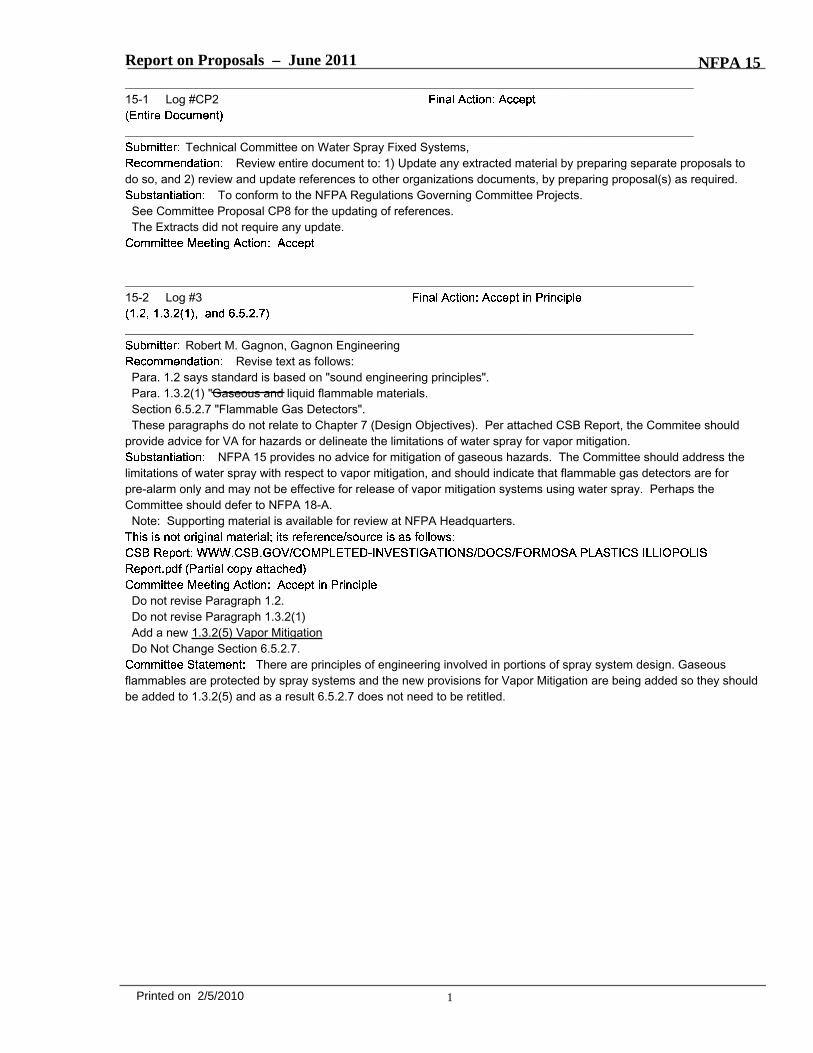
Report on Proposals – June 2011 NFPA 15_______________________________________________________________________________________________15-1 Log #CP2
_______________________________________________________________________________________________Technical Committee on Water Spray Fixed Systems,
Review entire document to: 1) Update any extracted material by preparing separate proposals todo so, and 2) review and update references to other organizations documents, by preparing proposal(s) as required.
To conform to the NFPA Regulations Governing Committee Projects.See Committee Proposal CP8 for the updating of references.The Extracts did not require any update.
_______________________________________________________________________________________________15-2 Log #3
_______________________________________________________________________________________________Robert M. Gagnon, Gagnon Engineering
Revise text as follows:Para. 1.2 says standard is based on "sound engineering principles".Para. 1.3.2(1) "Gaseous and liquid flammable materials.Section 6.5.2.7 "Flammable Gas Detectors".These paragraphs do not relate to Chapter 7 (Design Objectives). Per attached CSB Report, the Commitee should
provide advice for VA for hazards or delineate the limitations of water spray for vapor mitigation.NFPA 15 provides no advice for mitigation of gaseous hazards. The Committee should address the
limitations of water spray with respect to vapor mitigation, and should indicate that flammable gas detectors are forpre-alarm only and may not be effective for release of vapor mitigation systems using water spray. Perhaps theCommittee should defer to NFPA 18-A.Note: Supporting material is available for review at NFPA Headquarters.
Do not revise Paragraph 1.2.Do not revise Paragraph 1.3.2(1)Add a new 1.3.2(5) Vapor MitigationDo Not Change Section 6.5.2.7.
There are principles of engineering involved in portions of spray system design. Gaseousflammables are protected by spray systems and the new provisions for Vapor Mitigation are being added so they shouldbe added to 1.3.2(5) and as a result 6.5.2.7 does not need to be retitled.
1Printed on 2/5/2010
Report on Proposals – June 2011 NFPA 15_______________________________________________________________________________________________15-3 Log #CP8
_______________________________________________________________________________________________Technical Committee on Water Spray Fixed Systems,
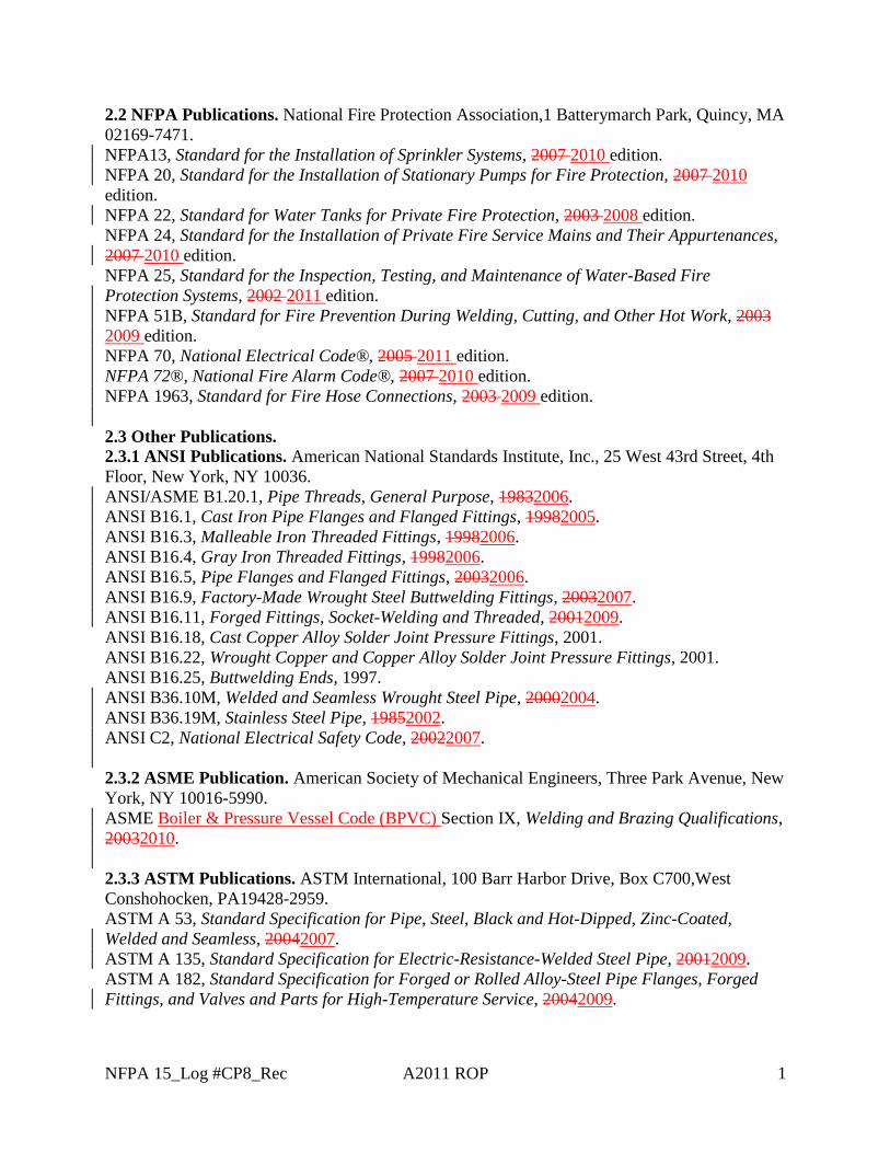
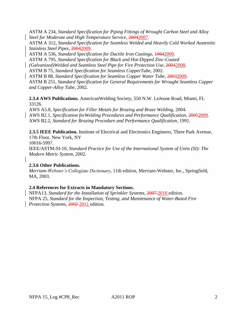
Revise Chapter 2 as follows:
****INCLUDE 15_LCP8_Rec HERE****
Update of Chapter to include the most recent editions of referenced standards.
_______________________________________________________________________________________________15-4 Log #5
_______________________________________________________________________________________________David R. Hague, Liberty Mutual Property
A liquid that has a closed-cup flash point at or above 100°F (37.8°C). [30, 2003]
A liquid that has a closed-cup flashpoint at or above 100°F (37.8°C) and below 140°F (60°C). [30,2003]
A liquid that has a closed-cup flash point at or above 140°F (60°C), but below 200°F (93°C). [30,2003]
A liquid that has a closed-cup flash point below 200°F (93°C). [30, 2003]A liquid that has a closed-cup flash point that is below 100°F (37.8°C) and a maximum
vapor pressure of 40 psia (2068.6 mm Hg) at 100°F (37.8°C). [30, 2003]
A liquid that has a closed-cup flash point below 100°F (37.8°C) and a Reid vapor pressure notexceeding 40 psia (2068.6 mm Hg) at 100°F (37.8°C). [30, 2003]
A liquid that has a closed-cup flash point below 73°F (22.8°C) and a boiling point below 100°F(37.8°C). [30, 2003]
A liquid that has a closed-cup flash point below 73°F (22.8°C) and a boiling point at or above100°F (37.8°C). [30, 2003]
A liquid that has a closed-cup flash point at or above 73°F (22.8°C) but below 100°F (37.8°C).Coordinates definitions with the NFPA Glossary of Terms.
Accept defined terms 3.3.2 and 3.3.10.Move Section 3.3.2.1 to Annex 3.3.2Move Section 3.3.10.1 to Annex for 3.3.10And renumber definitions accordingly.
The definitions are extracted from NFPA 30 and the Annex language further explains the terms.
2Printed on 2/5/2010
NFPA 15_Log #CP8_Rec A2011 ROP 1
2.2 NFPA Publications. National Fire Protection Association,1 Batterymarch Park, Quincy, MA
02169-7471.
NFPA13, Standard for the Installation of Sprinkler Systems, 2007 2010 edition.
NFPA 20, Standard for the Installation of Stationary Pumps for Fire Protection, 2007 2010
edition.
NFPA 22, Standard for Water Tanks for Private Fire Protection, 2003 2008 edition.
NFPA 24, Standard for the Installation of Private Fire Service Mains and Their Appurtenances,
2007 2010 edition.
NFPA 25, Standard for the Inspection, Testing, and Maintenance of Water-Based Fire
Protection Systems, 2002 2011 edition.
NFPA 51B, Standard for Fire Prevention During Welding, Cutting, and Other Hot Work, 2003
2009 edition.
NFPA 70, National Electrical Code®, 2005 2011 edition.
NFPA 72®, National Fire Alarm Code®, 2007 2010 edition.
NFPA 1963, Standard for Fire Hose Connections, 2003 2009 edition.
2.3 Other Publications.
2.3.1 ANSI Publications. American National Standards Institute, Inc., 25 West 43rd Street, 4th
Floor, New York, NY 10036.
ANSI/ASME B1.20.1, Pipe Threads, General Purpose, 19832006.
ANSI B16.1, Cast Iron Pipe Flanges and Flanged Fittings, 19982005.
ANSI B16.3, Malleable Iron Threaded Fittings, 19982006.
ANSI B16.4, Gray Iron Threaded Fittings, 19982006.
ANSI B16.5, Pipe Flanges and Flanged Fittings, 20032006.
ANSI B16.9, Factory-Made Wrought Steel Buttwelding Fittings, 20032007.
ANSI B16.11, Forged Fittings, Socket-Welding and Threaded, 20012009.
ANSI B16.18, Cast Copper Alloy Solder Joint Pressure Fittings, 2001.
ANSI B16.22, Wrought Copper and Copper Alloy Solder Joint Pressure Fittings, 2001.
ANSI B16.25, Buttwelding Ends, 1997.
ANSI B36.10M, Welded and Seamless Wrought Steel Pipe, 20002004.
ANSI B36.19M, Stainless Steel Pipe, 19852002.
ANSI C2, National Electrical Safety Code, 20022007.
2.3.2 ASME Publication. American Society of Mechanical Engineers, Three Park Avenue, New
York, NY 10016-5990.
ASME Boiler & Pressure Vessel Code (BPVC) Section IX, Welding and Brazing Qualifications,
20032010.
2.3.3 ASTM Publications. ASTM International, 100 Barr Harbor Drive, Box C700,West
Conshohocken, PA19428-2959.
ASTM A 53, Standard Specification for Pipe, Steel, Black and Hot-Dipped, Zinc-Coated,
Welded and Seamless, 20042007.
ASTM A 135, Standard Specification for Electric-Resistance-Welded Steel Pipe, 20012009.
ASTM A 182, Standard Specification for Forged or Rolled Alloy-Steel Pipe Flanges, Forged
Fittings, and Valves and Parts for High-Temperature Service, 20042009.
NFPA 15_Log #CP8_Rec A2011 ROP 2
ASTM A 234, Standard Specification for Piping Fittings of Wrought Carbon Steel and Alloy
Steel for Moderate and High Temperature Service, 20042007.
ASTM A 312, Standard Specification for Seamless Welded and Heavily Cold Worked Austenitic
Stainless Steel Pipes, 20042009.
ASTM A 536, Standard Specification for Ductile Iron Castings, 19842009.
ASTM A 795, Standard Specification for Black and Hot-Dipped Zinc-Coated
(Galvanized)Welded and Seamless Steel Pipe for Fire Protection Use, 20042008.
ASTM B 75, Standard Specification for Seamless CopperTube, 2002.
ASTM B 88, Standard Specification for Seamless Copper Water Tube, 20032009.
ASTM B 251, Standard Specification for General Requirements for Wrought Seamless Copper
and Copper-Alloy Tube, 2002.
2.3.4 AWS Publications. AmericanWelding Society, 550 N.W. LeJeune Road, Miami, FL
33126.
AWS A5.8, Specification for Filler Metals for Brazing and Braze Welding, 2004.
AWS B2.1, Specification forWelding Procedures and Performance Qualification, 20052009.
AWS B2.2, Standard for Brazing Procedure and Performance Qualification, 1991.
2.3.5 IEEE Publication. Institute of Electrical and Electronics Engineers, Three Park Avenue,
17th Floor, New York, NY
10016-5997.
IEEE/ASTM-SI-10, Standard Practice for Use of the International System of Units (SI): The
Modern Metric System, 2002.
2.3.6 Other Publications.
Merriam-Webster’s Collegiate Dictionary, 11th edition, Merriam-Webster, Inc., Springfield,
MA, 2003.
2.4 References for Extracts in Mandatory Sections.
NFPA13, Standard for the Installation of Sprinkler Systems, 2007 2010 edition.
NFPA 25, Standard for the Inspection, Testing, and Maintenance of Water-Based Fire
Protection Systems, 2002 2011 edition.
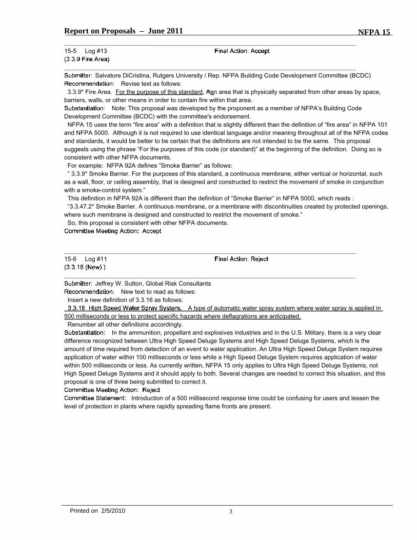
Report on Proposals – June 2011 NFPA 15_______________________________________________________________________________________________15-5 Log #13
_______________________________________________________________________________________________Salvatore DiCristina, Rutgers University / Rep. NFPA Building Code Development Committee (BCDC)
Revise text as follows:3.3.9* Fire Area. For the purpose of this standard, Aan area that is physically separated from other areas by space,
barriers, walls, or other means in order to contain fire within that area.Note: This proposal was developed by the proponent as a member of NFPA’s Building Code
Development Committee (BCDC) with the committee's endorsement.NFPA 15 uses the term “fire area” with a definition that is slightly different than the definition of “fire area” in NFPA 101
and NFPA 5000. Although it is not required to use identical language and/or meaning throughout all of the NFPA codesand standards, it would be better to be certain that the definitions are not intended to be the same. This proposalsuggests using the phrase “For the purposes of this code (or standard)” at the beginning of the definition. Doing so isconsistent with other NFPA documents.For example: NFPA 92A defines “Smoke Barrier” as follows:“ 3.3.9* Smoke Barrier. For the purposes of this standard, a continuous membrane, either vertical or horizontal, such
as a wall, floor, or ceiling assembly, that is designed and constructed to restrict the movement of smoke in conjunctionwith a smoke-control system.”This definition in NFPA 92A is different than the definition of “Smoke Barrier” in NFPA 5000, which reads :“3.3.47.2* Smoke Barrier. A continuous membrane, or a membrane with discontinuities created by protected openings,
where such membrane is designed and constructed to restrict the movement of smoke.”So, this proposal is consistent with other NFPA documents.
_______________________________________________________________________________________________15-6 Log #11
_______________________________________________________________________________________________Jeffrey W. Sutton, Global Risk Consultants
New text to read as follows:Insert a new definition of 3.3.16 as follows:
A type of automatic water spray system where water spray is applied in500 milliseconds or less to protect specific hazards where deflagrations are anticipated.Renumber all other definitions accordingly.
In the ammunition, propellant and explosives industries and in the U.S. Military, there is a very cleardifference recognized between Ultra High Speed Deluge Systems and High Speed Deluge Systems, which is theamount of time required from detection of an event to water application. An Ultra High Speed Deluge System requiresapplication of water within 100 milliseconds or less while a High Speed Deluge System requires application of waterwithin 500 milliseconds or less. As currently written, NFPA 15 only applies to Ultra High Speed Deluge Systems, notHigh Speed Deluge Systems and it should apply to both. Several changes are needed to correct this situation, and thisproposal is one of three being submitted to correct it.
Introduction of a 500 millisecond response time could be confusing for users and lessen thelevel of protection in plants where rapidly spreading flame fronts are present.
3Printed on 2/5/2010
Report on Proposals – June 2011 NFPA 15_______________________________________________________________________________________________15-7 Log #10
_______________________________________________________________________________________________Jeffrey W. Sutton, Global Risk Consultants
Revise the definition in 3.3.17 as follows:A type of automatic water spray system where water spray is rapidly
applied in 100 milliseconds or less to protect specific hazards where deflagrations are anticipated.In the ammunition, propellant and explosives industries and in the U.S. Military, there is a very clear
difference recognized between Ultra High Speed Deluge Systems and High Speed Deluge Systems, which is theamount of time required from detection of an event to water application. An Ultra High Speed Deluge System requiresapplication of water within 100 milliseconds or less while a High Speed Deluge System requires application of waterwithin 500 milliseconds or less. As currently written, NFPA 15 only applies to Ultra High Speed Deluge Systems, notHigh Speed Deluge Systems and it should apply to both. Several changes are needed to correct this situation, and thisproposal is one of three being submitted to correct it.
See Committee Action/Statement on 15- (Log #11) and 15- (Log #12).
_______________________________________________________________________________________________15-8 Log #4
_______________________________________________________________________________________________Raul Bustos Carrillo, ICA Fluor Daniel
Revise and delete text to read as follows:Where steel pipe listed in Table 5.3.1 is joined by threaded fittings or by fittings used with pipe having cut
grooves, the minimum wall thickness shall be in accordance with Schedule 30 [in pipe sizes 8 in. (203 mm) and larger]or Schedule 40 [in pipe sizes less than 8 in. (203 mm)] for pressures up to 300 psi (20.7 bar).
"Screwed unions shall not be used on pipe larger than 2 in. (50 mm)."Due to the fact that both paragraphs seam to be against each other, it would be desirable to delete
paragraph 5.4.8.1. Paragraph 5.3.3 does not limit threaded fittings.There is not a technical limitation to limit the use of threaded connections, because low working pressure, besides that
are acceptable for small sizes.
The language of 5.3.3 is already in the current edition of NFPA 15 and will remain.Screwed unions must be limited because of their lack of removability when required.
_______________________________________________________________________________________________15-9 Log #CP3
_______________________________________________________________________________________________Technical Committee on Water Spray Fixed Systems,
Delete the current 5.3.10.1 and replace with the following:All pipe, including specially listed pipe allowed by 5.3.5, shall be marked continuously along its length by the
manufacturer in such a way as to properly identify the type of pipe.5.3.10.1 All pipe, including specially listed pipe allowed by 5.3.5, shall be marked along its length by the manufacturer
in such a way as to properly identify the type of pipe.5.3.10.2 The marking shall be visible on every piece of pipe over 2 ft (610 mm) long.A.5.3.10.1 Where approved, the pipe identification can be covered with paint or other protective coatings before
installation.The proposal correlates to the requirements that were revised in the 2010 edition of NFPA 13 Section
6.3.8.1, 6.3.8.1 and A.6.3.8.1.
4Printed on 2/5/2010
Report on Proposals – June 2011 NFPA 15_______________________________________________________________________________________________15-10 Log #CP6
_______________________________________________________________________________________________Technical Committee on Water Spray Fixed Systems,
Replace language of current 5.5.3 with the language on Grooved Joining Methods (6.5.3) from the2010 edition of NFPA 13 as follows:
Pipe joined with grooved fittings shall be joined by a listed combination of fittings, gaskets, and grooves.Grooves cut or rolled on pipe shall be dimensionally compatible with the fittings.
Pipe joined with grooved couplings shall be joined by a listed combination of couplings, gaskets, and groovedimensions.
Grooved connections of fittings and valves, and grooves cut or rolled on pipe shall be dimensionallycompatible with thecouplings.
Grooved couplings, including gaskets used on preaction and deluge systems, shall be listed for dry pipeservice.
It is not the intent to require a listed combination of couplings, fittings, or valves.Material strength and pressure rating should be considered when determining compatibility.
Correlation with revisions in NFPA 13, 2010 edition.
_______________________________________________________________________________________________15-11 Log #CP4
_______________________________________________________________________________________________Technical Committee on Water Spray Fixed Systems,
Delete the current 5.11.4 and replace with the following:Piping to the water-motor-operated devices shall have corrosion resistance equal to or better than galvanized
ferrouspipe and fittings and shall be of a size not less than 3/4 in. (20 mm).
All piping to water motor-operated devices shall be galvanized steel, brass, copper, or other approved metalliccorrosion-resistant material of not less than 3/4 in. (20 mm) nominal pipe size.
Piping between the water spray system and a pressure actuated alarm-initiating device shall be galvanizedsteel,brass, copper, or other approved metallic corrosion-resistant material of not less than 3/8 in. (10 mm) nominal pipe size.Renumber remaining sections.
The proposal correlates to the requirements that were revised in the 2010 edition of NFPA 13 Sections6.9.3.3, and 6.9.3.4.
5Printed on 2/5/2010
Report on Proposals – June 2011 NFPA 15_______________________________________________________________________________________________15-12 Log #14
_______________________________________________________________________________________________E. Parks Moore, S & S Sprinkler Company, LLC
Revise text to read as follows:
***Insert 15_L14_Table6.3.2.2.1_R***
The current table’s information is limited and does not provide adequate guidance for support or largerdiameter piping that is often encountered on larger fixed spray systems. This requires the need for involvement of aprofessional engineer to provide hanger designs and calculations for what should be a simple pre-engineered solution.The attached proposed table expands the allowable pipe stand diameter to include 4” and 6” pipe. It also includesguidelines for supporting 6” and 8” system piping. The values provided account for allowable compression stress andbuckling load utilizing 5 X the maximum weight of water filled pipe plus 250 pounds.
The committee realizes that larger pipe sizes are not addressed. The substantiation is notsufficient for the information that has been proposed. A task group has been formed to explore this issue and develop acomment for the committees consideration with appropriate substantiation for the revision.
_______________________________________________________________________________________________15-13 Log #8
_______________________________________________________________________________________________David R. Hague, Liberty Mutual Property
Revise text as follows:Remote manual actuation devices shall be located so as to be conspicuous, unobstructed and accessible
during an emergency.Provides guidance for the proper location of remote manual actuation devices.
_______________________________________________________________________________________________15-14 Log #9
_______________________________________________________________________________________________David R. Hague, Liberty Mutual Property
Add new text as follows:The operable part of each remote manual actuation device shall be not less than 31/2 ft. (1.1m) and not more
than 41/2 ft. (1.37m) above grade or floor level.Provides guidance for the proper location of remote manual actuation devices.
6Printed on 2/5/2010
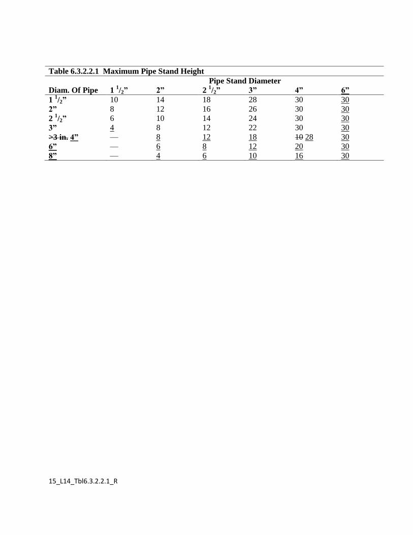
15_L14_Tbl6.3.2.2.1_R
Table 6.3.2.2.1 Maximum Pipe Stand Height
Pipe Stand Diameter
Diam. Of Pipe 1 1/2” 2” 2
1/2” 3” 4” 6”
1 1/2” 10 14 18 28 30 30
2” 8 12 16 26 30 30
2 1/2” 6 10 14 24 30 30
3” 4 8 12 22 30 30
>3 in. 4” — 8 12 18 10 28 30
6” — 6 8 12 20 30
8” — 4 6 10 16 30
Report on Proposals – June 2011 NFPA 15_______________________________________________________________________________________________15-15 Log #2
_______________________________________________________________________________________________Robert M. Gagnon, Gagnon Engineering
Revise text as follows:● Emulsification is undefined in NFPA 15. The Committee should defer to NFPA 18-A.● Dilution is undefined in NFPA 15.● "Other Factors" is unclear and unenforceable.
The Committee should define emulsification (an emulsion is "a suspension of small globules of oneliquid in a second liquid with which the first will not mix").Dilution defined is: "The process of making weaker or less concentrated".Other Factors: Delete or define.
The submitter has not provided specific definitions or the necessity for the terms so the defaultat this time would be to use the dictionary term.
7Printed on 2/5/2010
Report on Proposals – June 2011 NFPA 15_______________________________________________________________________________________________15-16 Log #CP5
_______________________________________________________________________________________________Technical Committee on Water Spray Fixed Systems,
Revise Section 7.5 Prevention of Fire to read as follows:
Water spray systems designed for extinguishment, exposure protection, or control of burning can disperseflammable gases for fire prevention. When designing water spray systems primarily for dispersion of flammable gases(for fire prevention), the following should be considered:(1) Spray nozzles should be of the size and type to discharge a dense spray into the area of possible flammable vapor
release at sufficient velocity to rapidly dilute the flammable vapors to a level below the lower flammable limit.(2) Spray nozzles should be positioned to provide coverage of potential leak sources such as flanges, flexible
connections, pumps, valves, vessels, containers, and so forth.(3) The physical properties of the chemicals involved (including water solubility) in the hazard should also be
considered.(4) Personnel should be notified upon vapor release.(5) Impairment procedures in accordance with NFPA 25 should be used for all water spray systems.
A fire risk analysis shall be conducted. The following are some of the factors that shall beconsidered in determining the extent and method of fire protection required for vapor mitigation:(1) Importance to continuity of operation(2) Size, type, location and construction of equipment(3) Physical properties of the chemicals involved(4) Water supply(5) Value of equipment(6) Climate(7) Water delivery time(8) Environment(9) Access for firefighting(10) Projected flammable liquid or material spill pattern(11) Potential for flammable vapor release(12) Proximity of personnel to hazard area(13) Protection of system actuation valve from fire and explosion(14) Blast containment and pressure relief(15) Protection of electrical circuits, including explosion proof equipment(16) Potential for fire spread beyond hazard area(17) Required replacement time for process equipment(18) Potential for business interruption(19) Notification of personnel upon vapor detection
Due to the unique characteristics of each fire risk, this standard does not provide comprehensive designcriteria for vapor mitigation in all types of hazardous locations. Technology in this area is under constant development.The user of this standard should recognize the complexity of fire protection requirements for hazardous locations. Thedesigner is responsible for demonstrating the validity of the design approach.
The system shall be designed to operate as intended within the necessary time and shall discharge water forthe duration needed time necessary to dissolve, dilute, disperse, or cool flammable vapor, gases, or hazardousmaterials.
The duration of release of the flammable materials shall be included in the determination of the water sprayduration time.
The minimum net rate of application shall be based upon field experience with the product or upon actual testdata.
Flammable gas detection shall be accomplished with detectors in accordance with Section 6.5.2.7.Personnel shall be notified upon receipt of any detection signal in accordance with
NFPA 72.This proposal is in response to recommendation 04-10-IL-R5 from the report of the Formosa Plastics
Vinyl Chloride Monomer Explosion of April 23, 2004 in Illiopolis, IL published by the U.S. Chemical Safety and HazardInvestigation Board (attached). The recommendation as found on p. 49 of the report, reads as follows:
8Printed on 2/5/2010
Report on Proposals – June 2011 NFPA 15"04-10-I-IL-R5 Revise NFPA 15, Standard for Water Spray Fixed Systems for Fire Protection, to provide additional
design guidance for deluge systems designed to prevent or mitigate fires and explosions. Include informationconcerning the limitations of using deluge systems for this purpose."The revised language for Section 7.5 is intended to provide the user with additional guidance on the application of
water spray systems specifically intended for vapor mitigation and also provides guidance on the approach needed toconduct a fire risk analysis for such applications.
_______________________________________________________________________________________________15-17 Log #7
_______________________________________________________________________________________________David R. Hague, Liberty Mutual Property
Add the word "friction" to Section 8.5.3.5 as follows:The friction loss of all fittings shall be calculated where a change in direction of the flow occurs, as follows:
(1) The friction loss for a tee or a cross shall be calculated where the flow direction change occurs, based upon theequivalent pipe length for the smaller size of the tee or cross in the path of the turn. Friction Loss for that portion of theflow that passes straight through the run of a tee or a cross shall not be included.(2) The friction loss of reducing elbows shall be calculated based upon the equivalent length value in feet of the
smallest outlet.(3) Friction loss shall be excluded for tapered reducers and for the fitting directly supplying the spray nozzle.
Provides consistent wording - editorial.
9Printed on 2/5/2010
Report on Proposals – June 2011 NFPA 15_______________________________________________________________________________________________15-18 Log #6
_______________________________________________________________________________________________David R. Hague, Liberty Mutual Property
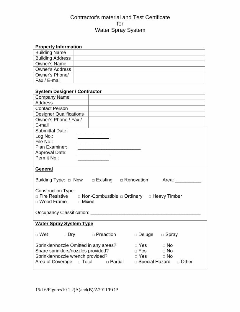
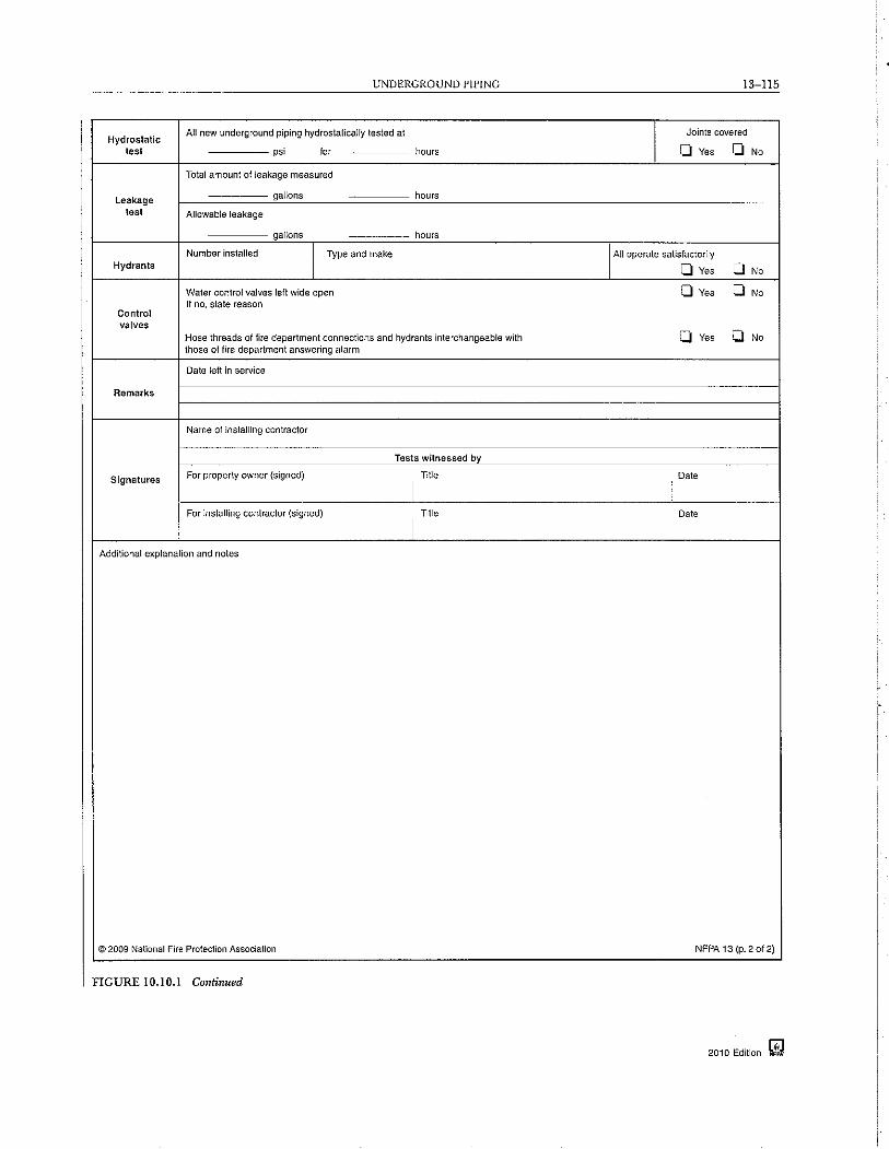
.The contractor shall prepare and submit a set of as-built drawings and hydraulic calculations of the system, and
maintenance and instruction bulletins., and the applicable parts of theThe installing contractor shall complete the following:
(1) Notify the authority having jurisdiction and the property owner or the property owner's authorized representative ofthe time and date that testing will be performed(2) Perform all required acceptance tests as required by this chapter(3) Complete and sign the contractor's material and test certificate(s) as indicted in Figures 10.1.2 (A) & (B)
contractor's material and test certificates covering material and tests certifying that the work has been completed andtested in accordance with approved plans and specifications.
*****Insert Figure 10.1.2(A) Here " "*****
*****Insert Figure 10.1.2(B) Here " " (from NFPA13)*****
*****Insert Figures 10.1.2(A)and(B) here 15_L6_Fig10.1.2(A)and(B)_R.doc*****
Clarifies commissioning requirements for water spray systems and coordinates these requirementswith that of other systems standards such as NFPA 13 & 24.
Remove the term Dry anywhere it appears in the form and add Ultra High Speed in those sections.Dry systems are not used for water spray systems and Ultra High Speed is and should be
included in the form.
10Printed on 2/5/2010
Contractor's material and Test Certificate for
Water Spray System
15/L6/Figures10.1.2(A)and(B)/A2011/ROP
Property Information
Building Name
Building Address
Owner's Name
Owner's Address
Owner's Phone/ Fax / E-mail
System Designer / Contractor
Company Name
Address
Contact Person
Designer Qualifications
Owner's Phone / Fax / E-mail
Submittal Date: ____________ Log No.: ____________ File No.: ____________ Plan Examiner: ________________________ Approval Date: ____________ Permit No.: ____________
General Building Type: □ New □ Existing □ Renovation Area: __________ Construction Type: □ Fire Resistive □ Non-Combustible □ Ordinary □ Heavy Timber □ Wood Frame □ Mixed Occupancy Classification: __________________________________________
Water Spray System Type □ Wet □ Dry □ Preaction □ Deluge □ Spray Sprinkler/nozzle Omitted in any areas? □ Yes □ No Spare sprinklers/nozzles provided? □ Yes □ No Sprinkler/nozzle wrench provided? □ Yes □ No Area of Coverage: □ Total □ Partial □ Special Hazard □ Other
Contractor's material and Test Certificate for
Water Spray System
15/L6/Figures10.1.2(A)and(B)/A2011/ROP
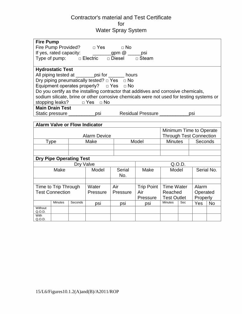
Fire Pump Fire Pump Provided? □ Yes □ No If yes, rated capacity: _______gpm @ _____psi Type of pump: □ Electric □ Diesel □ Steam
Hydrostatic Test All piping tested at _______psi for ______ hours Dry piping pneumatically tested? □ Yes □ No Equipment operates properly? □ Yes □ No Do you certify as the installing contractor that additives and corrosive chemicals, sodium silicate, brine or other corrosive chemicals were not used for testing systems or stopping leaks? □ Yes □ No
Main Drain Test Static pressure __________psi Residual Pressure ___________psi
Alarm Valve or Flow Indicator
Alarm Device
Minimum Time to Operate Through Test Connection
Type Make Model Minutes Seconds
Dry Pipe Operating Test
Dry Valve Q.O.D.
Make Model Serial No.
Make Model Serial No.
Time to Trip Through Test Connection
Water Pressure
Air Pressure
Trip Point Air Pressure
Time Water Reached Test Outlet
Alarm Operated Properly
Minutes Seconds psi psi psi Minutes Sec Yes No Without Q.O.D.
With Q.O.D.
Contractor's material and Test Certificate for
Water Spray System
15/L6/Figures10.1.2(A)and(B)/A2011/ROP
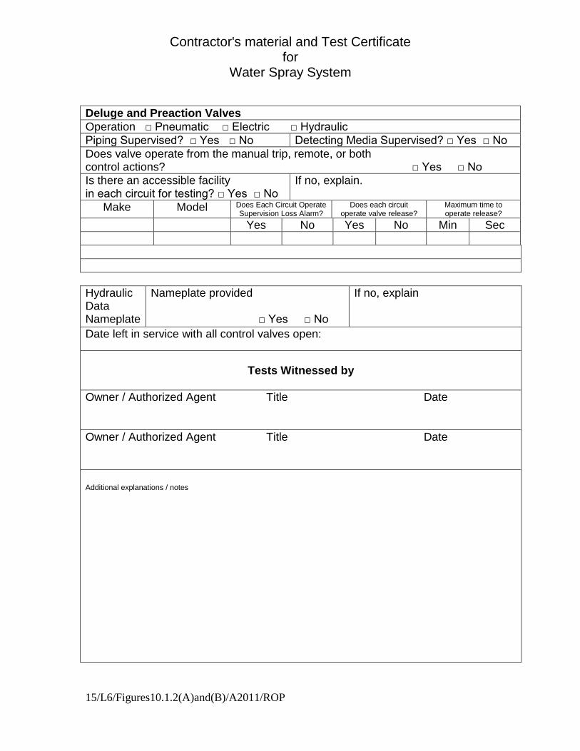
Deluge and Preaction Valves
Operation □ Pneumatic □ Electric □ Hydraulic
Piping Supervised? □ Yes □ No Detecting Media Supervised? □ Yes □ No
Does valve operate from the manual trip, remote, or both control actions? □ Yes □ No
Is there an accessible facility in each circuit for testing? □ Yes □ No
If no, explain.
Make Model Does Each Circuit Operate Supervision Loss Alarm?
Does each circuit operate valve release?
Maximum time to operate release?
Yes No Yes No Min Sec
Hydraulic Data Nameplate
Nameplate provided □ Yes □ No
If no, explain
Date left in service with all control valves open:
Tests Witnessed by
Owner / Authorized Agent Title Date
Owner / Authorized Agent Title Date
Additional explanations / notes
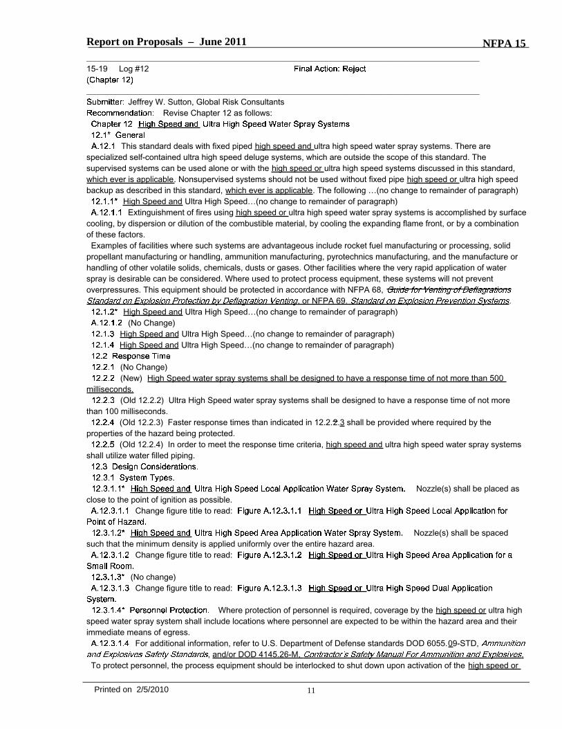
Report on Proposals – June 2011 NFPA 15_______________________________________________________________________________________________15-19 Log #12
_______________________________________________________________________________________________Jeffrey W. Sutton, Global Risk Consultants
Revise Chapter 12 as follows:
This standard deals with fixed piped high speed and ultra high speed water spray systems. There arespecialized self-contained ultra high speed deluge systems, which are outside the scope of this standard. Thesupervised systems can be used alone or with the high speed or ultra high speed systems discussed in this standard,which ever is applicable. Nonsupervised systems should not be used without fixed pipe high speed or ultra high speedbackup as described in this standard, which ever is applicable. The following …(no change to remainder of paragraph)
High Speed and Ultra High Speed…(no change to remainder of paragraph)Extinguishment of fires using high speed or ultra high speed water spray systems is accomplished by surface
cooling, by dispersion or dilution of the combustible material, by cooling the expanding flame front, or by a combinationof these factors.Examples of facilities where such systems are advantageous include rocket fuel manufacturing or processing, solid
propellant manufacturing or handling, ammunition manufacturing, pyrotechnics manufacturing, and the manufacture orhandling of other volatile solids, chemicals, dusts or gases. Other facilities where the very rapid application of waterspray is desirable can be considered. Where used to protect process equipment, these systems will not preventoverpressures. This equipment should be protected in accordance with NFPA 68,
, or NFPA 69. .High Speed and Ultra High Speed…(no change to remainder of paragraph)
(No Change)High Speed and Ultra High Speed…(no change to remainder of paragraph)High Speed and Ultra High Speed…(no change to remainder of paragraph)
(No Change)(New) High Speed water spray systems shall be designed to have a response time of not more than 500
milliseconds.(Old 12.2.2) Ultra High Speed water spray systems shall be designed to have a response time of not more
than 100 milliseconds.(Old 12.2.3) Faster response times than indicated in 12.2.2.3 shall be provided where required by the
properties of the hazard being protected.(Old 12.2.4) In order to meet the response time criteria, high speed and ultra high speed water spray systems
shall utilize water filled piping.
Nozzle(s) shall be placed asclose to the point of ignition as possible.
Change figure title to read:
Nozzle(s) shall be spacedsuch that the minimum density is applied uniformly over the entire hazard area.
Change figure title to read:
(No change)Change figure title to read:
Where protection of personnel is required, coverage by the high speed or ultra highspeed water spray system shall include locations where personnel are expected to be within the hazard area and theirimmediate means of egress.
For additional information, refer to U.S. Department of Defense standards DOD 6055.09-STD,, and/or DOD 4145.26-M, .
To protect personnel, the process equipment should be interlocked to shut down upon activation of the high speed or
11Printed on 2/5/2010
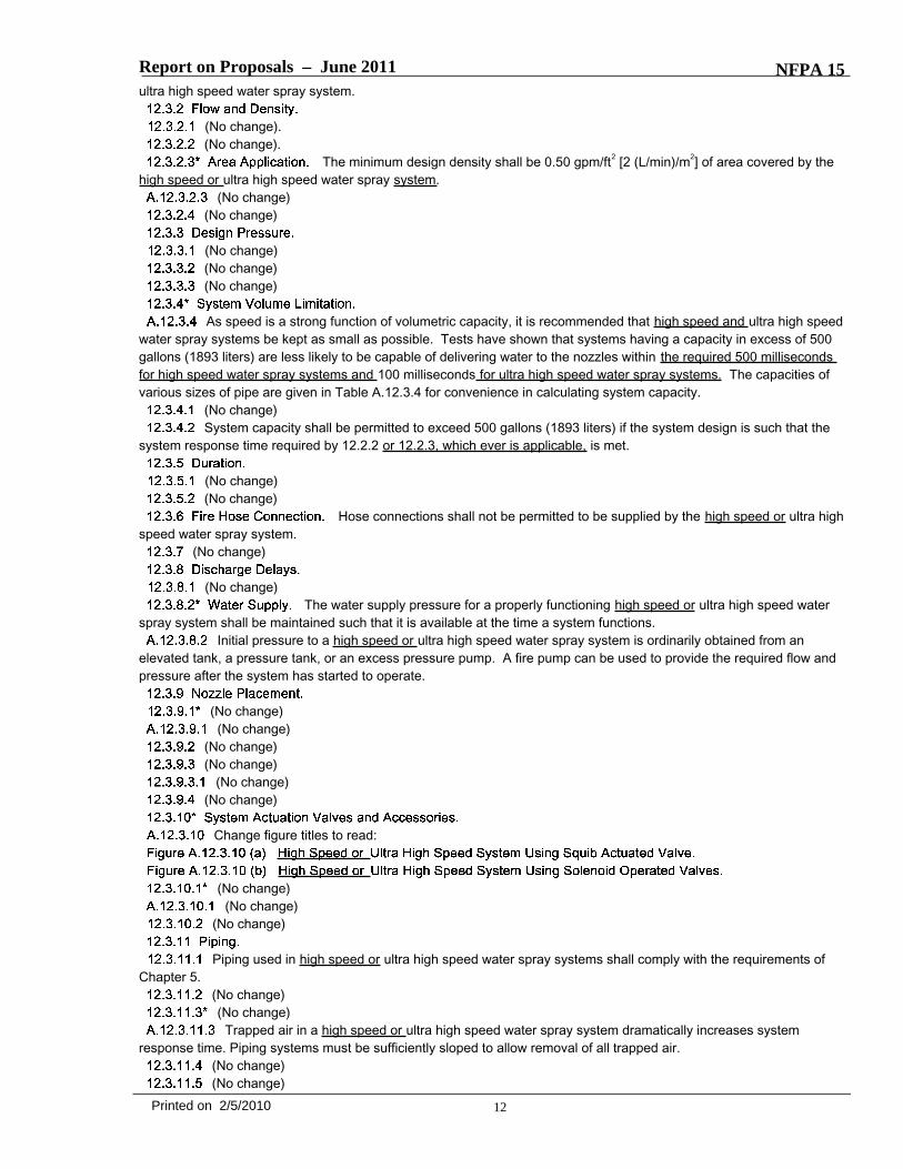
Report on Proposals – June 2011 NFPA 15ultra high speed water spray system.
(No change).(No change).
The minimum design density shall be 0.50 gpm/ft2 [2 (L/min)/m2] of area covered by thehigh speed or ultra high speed water spray system.
(No change)(No change)
(No change)(No change)(No change)
As speed is a strong function of volumetric capacity, it is recommended that high speed and ultra high speedwater spray systems be kept as small as possible. Tests have shown that systems having a capacity in excess of 500gallons (1893 liters) are less likely to be capable of delivering water to the nozzles within the required 500 millisecondsfor high speed water spray systems and 100 milliseconds for ultra high speed water spray systems. The capacities ofvarious sizes of pipe are given in Table A.12.3.4 for convenience in calculating system capacity.
(No change)System capacity shall be permitted to exceed 500 gallons (1893 liters) if the system design is such that the
system response time required by 12.2.2 or 12.2.3, which ever is applicable, is met.
(No change)(No change)
Hose connections shall not be permitted to be supplied by the high speed or ultra highspeed water spray system.
(No change)
(No change)The water supply pressure for a properly functioning high speed or ultra high speed water
spray system shall be maintained such that it is available at the time a system functions.Initial pressure to a high speed or ultra high speed water spray system is ordinarily obtained from an
elevated tank, a pressure tank, or an excess pressure pump. A fire pump can be used to provide the required flow andpressure after the system has started to operate.
(No change)(No change)
(No change)(No change)
(No change)(No change)
Change figure titles to read:
(No change)(No change)
(No change)
Piping used in high speed or ultra high speed water spray systems shall comply with the requirements ofChapter 5.
(No change)(No change)
Trapped air in a high speed or ultra high speed water spray system dramatically increases systemresponse time. Piping systems must be sufficiently sloped to allow removal of all trapped air.
(No change)(No change)
12Printed on 2/5/2010
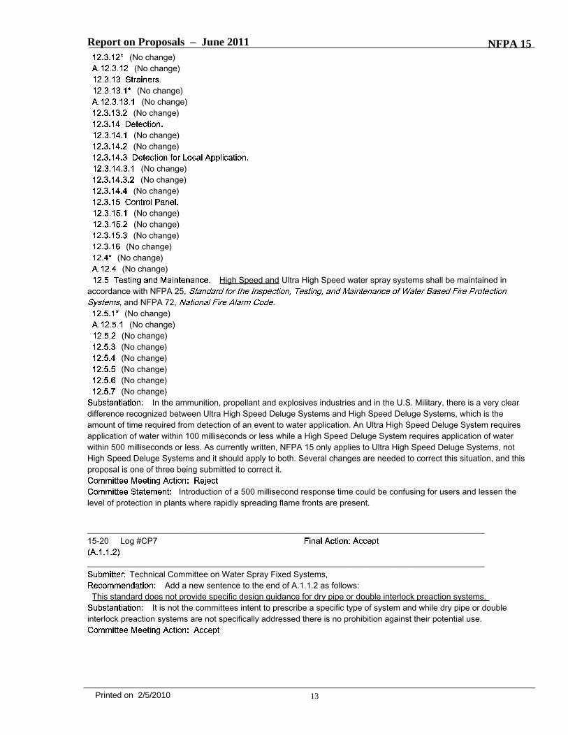
Report on Proposals – June 2011 NFPA 15(No change)
(No change)
(No change)(No change)
(No change)
(No change)(No change)
(No change)(No change)
(No change)
(No change)(No change)(No change)
(No change)(No change)
(No change)High Speed and Ultra High Speed water spray systems shall be maintained in
accordance with NFPA 25,, and NFPA 72, .
(No change)(No change)
(No change)(No change)(No change)(No change)(No change)(No change)
In the ammunition, propellant and explosives industries and in the U.S. Military, there is a very cleardifference recognized between Ultra High Speed Deluge Systems and High Speed Deluge Systems, which is theamount of time required from detection of an event to water application. An Ultra High Speed Deluge System requiresapplication of water within 100 milliseconds or less while a High Speed Deluge System requires application of waterwithin 500 milliseconds or less. As currently written, NFPA 15 only applies to Ultra High Speed Deluge Systems, notHigh Speed Deluge Systems and it should apply to both. Several changes are needed to correct this situation, and thisproposal is one of three being submitted to correct it.
Introduction of a 500 millisecond response time could be confusing for users and lessen thelevel of protection in plants where rapidly spreading flame fronts are present.
_______________________________________________________________________________________________15-20 Log #CP7
_______________________________________________________________________________________________Technical Committee on Water Spray Fixed Systems,
Add a new sentence to the end of A.1.1.2 as follows:This standard does not provide specific design guidance for dry pipe or double interlock preaction systems.
It is not the committees intent to prescribe a specific type of system and while dry pipe or doubleinterlock preaction systems are not specifically addressed there is no prohibition against their potential use.
13Printed on 2/5/2010
Report on Proposals – June 2011 NFPA 15_______________________________________________________________________________________________15-21 Log #1
_______________________________________________________________________________________________KWANG-HOON KO, POSCO E&C
Code 15, Annex B, figure 8.2(m) Hydraulic Calculation sheetAt the point of nozzle identification & location “F”, the note is described as q=381.6(109.2/64.4)^1/2, Would you please
check a numeral of 381.6?It is not clear to using some numeral.
Change the following in Figure B.2(b)Pt = 64.4 gpm to psiPt = 25.4 gpm to psiPt = 28.5 gpm to psi.
It appears that the reference to GPM should be PSI and perhaps that is what caused theconfusion on the part of the submitter.The figure is used to illustrate pressure differential for velocity analysis at a specific junction in the system.
14Printed on 2/5/2010