Embed Size (px)
Citation preview
Technical Committee on Piping Systems
(HEA-PIP)
M E M O R A N D U M
DATE: May 20, 2016
TO: Principal and Alternate Members of the Technical Committee on Piping Systems
(HEA-PIP)
FROM: Jon Hart, Staff Liaison
SUBJECT: AGENDA PACKAGE– NFPA 99 Second Draft Meeting (A2017)
________________________________________________________________________
Enclosed is the agenda for the NFPA 99 Second Draft meeting of the Technical Committee on
Piping Systems, which will be held on Monday, June 6 through Tuesday, June 7, 2016 at the
Crowne Plaza Dallas Downtown, in Dallas, TX. Please review the attached Public Comments
in advance, and if you have alternate suggestions, please come prepared with proposed language
and respective substantiation.
If you have any questions prior to the meeting, please do not hesitate to contact me at:
Office: (617) 984-7470
Email: [email protected]
For administrative questions, please contact Elena Carroll at (617) 984-7952.
I look forward to working with everyone.
Technical Committee on Piping Systems
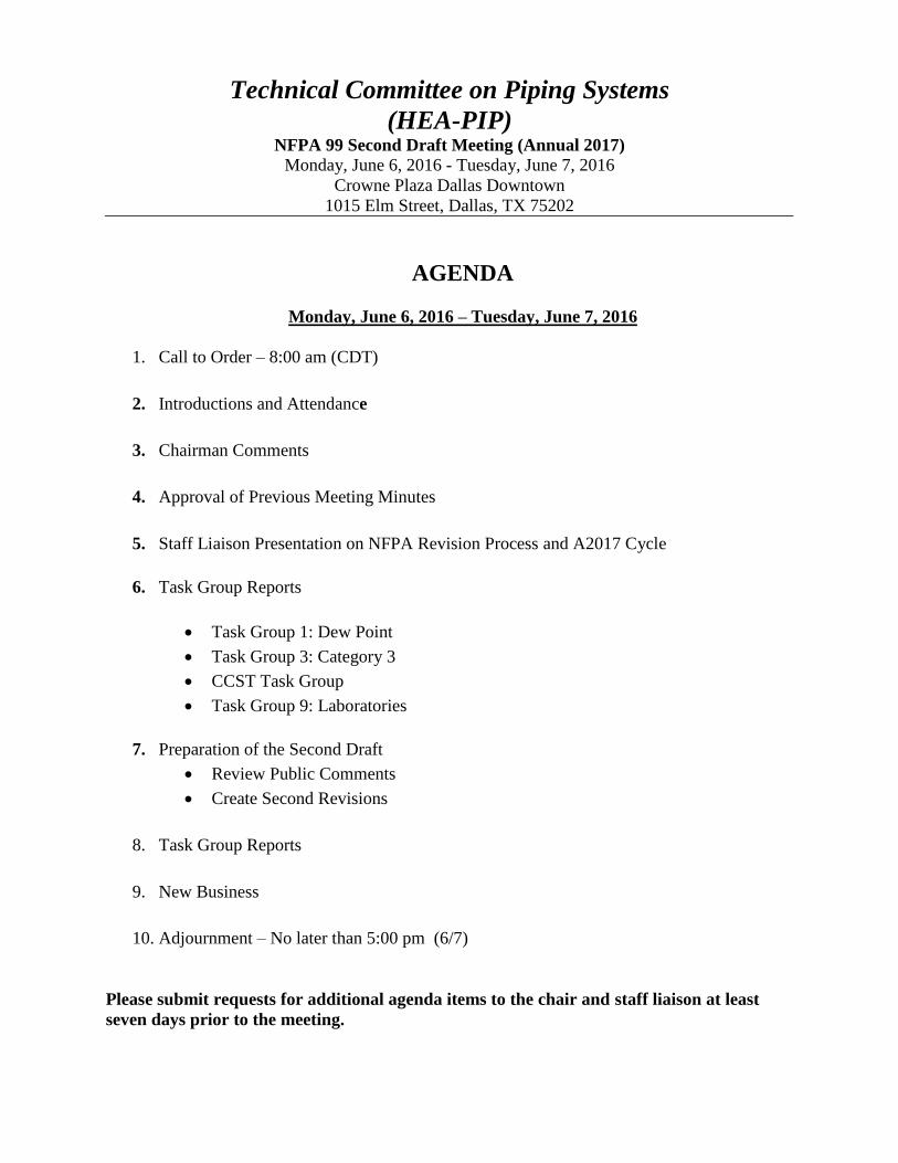
(HEA-PIP) NFPA 99 Second Draft Meeting (Annual 2017)
Monday, June 6, 2016 - Tuesday, June 7, 2016
Crowne Plaza Dallas Downtown 1015 Elm Street, Dallas, TX 75202
AGENDA
Monday, June 6, 2016 – Tuesday, June 7, 2016
1. Call to Order – 8:00 am (CDT)
2. Introductions and Attendance
3. Chairman Comments
4. Approval of Previous Meeting Minutes
5. Staff Liaison Presentation on NFPA Revision Process and A2017 Cycle
6. Task Group Reports
Task Group 1: Dew Point
Task Group 3: Category 3
CCST Task Group
Task Group 9: Laboratories
7. Preparation of the Second Draft
Review Public Comments
Create Second Revisions
8. Task Group Reports
9. New Business
10. Adjournment – No later than 5:00 pm (6/7)
Please submit requests for additional agenda items to the chair and staff liaison at least
seven days prior to the meeting.
Technical Committee on Piping Systems
(HEA-PIP) NFPA 99 Second Draft Meeting (Annual 2017)
Monday, June 6, 2016 - Tuesday, June 7, 2016
Crowne Plaza Dallas Downtown 1015 Elm Street, Dallas, TX 75202
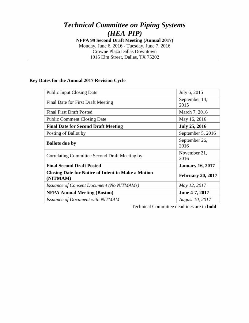
Key Dates for the Annual 2017 Revision Cycle
Public Input Closing Date July 6, 2015
Final Date for First Draft Meeting September 14,
2015
Final First Draft Posted March 7, 2016
Public Comment Closing Date May 16, 2016
Final Date for Second Draft Meeting July 25, 2016
Posting of Ballot by September 5, 2016
Ballots due by September 26,
2016
Correlating Committee Second Draft Meeting by November 21,
2016
Final Second Draft Posted January 16, 2017
Closing Date for Notice of Intent to Make a Motion
(NITMAM) February 20, 2017
Issuance of Consent Document (No NITMAMs) May 12, 2017
NFPA Annual Meeting (Boston) June 4-7, 2017
Issuance of Document with NITMAM August 10, 2017
Technical Committee deadlines are in bold.

Technical Committee Roster
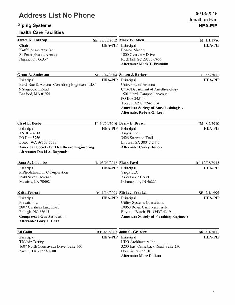
Address List No PhonePiping Systems HEA-PIP
Health Care Facilities
Jonathan Hart05/13/2016
HEA-PIP
James K. Lathrop
ChairKoffel Associates, Inc.81 Pennsylvania AvenueNiantic, CT 06357
SE 03/05/2012HEA-PIP
Mark W. Allen
PrincipalBeacon Medaes1800 Overview DriveRock hill, SC 29730-7463Alternate: Mark T. Franklin
M 1/1/1986
HEA-PIP
Grant A. Anderson
PrincipalBard, Rao & Athanas Consulting Engineers, LLC9 Stagecoach RoadBoxford, MA 01921
SE 7/14/2004HEA-PIP
Steven J. Barker
PrincipalUniversity of ArizonaCOM/Department of Anesthesiology1501 North Campbell AvenuePO Box 245114Tucson, AZ 85724-5114American Society of AnesthesiologistsAlternate: Robert G. Loeb
C 8/9/2011
HEA-PIP
Chad E. Beebe
PrincipalASHE - AHAPO Box 5756Lacey, WA 98509-5756American Society for Healthcare EngineeringAlternate: David A. Dagenais
U 10/20/2010HEA-PIP
Barry E. Brown
PrincipalAirgas, Inc.3426 Starwood TrailLilburn, GA 30047-2445Alternate: Corky Bishop
IM 8/2/2010
HEA-PIP
Dana A. Colombo
PrincipalPIPE/National ITC Corporation2540 Severn AvenueMetairie, LA 70002
L 03/05/2012HEA-PIP
Mark Fasel
PrincipalViega LLC7338 Jackie CourtIndianapolis, IN 46221
M 12/08/2015
HEA-PIP
Keith Ferrari
PrincipalPraxair, Inc.2807 Gresham Lake RoadRaleigh, NC 27615Compressed Gas AssociationAlternate: Gary L. Bean
M 1/16/2003HEA-PIP
Michael Frankel
PrincipalUtility Systems Consultants10860 Royal Caribbean CircleBoynton Beach, FL 33437-4219American Society of Plumbing Engineers
SE 7/1/1995
HEA-PIP
Ed Golla
PrincipalTRI/Air Testing1607 North Cuernavaca Drive, Suite 500Austin, TX 78733-1600
RT 4/3/2003HEA-PIP
John C. Gregory
PrincipalHDR Architecture Inc.3200 East Camelback Road, Suite 250Phoenix, AZ 85018Alternate: Marc Dodson
SE 3/1/2011
1
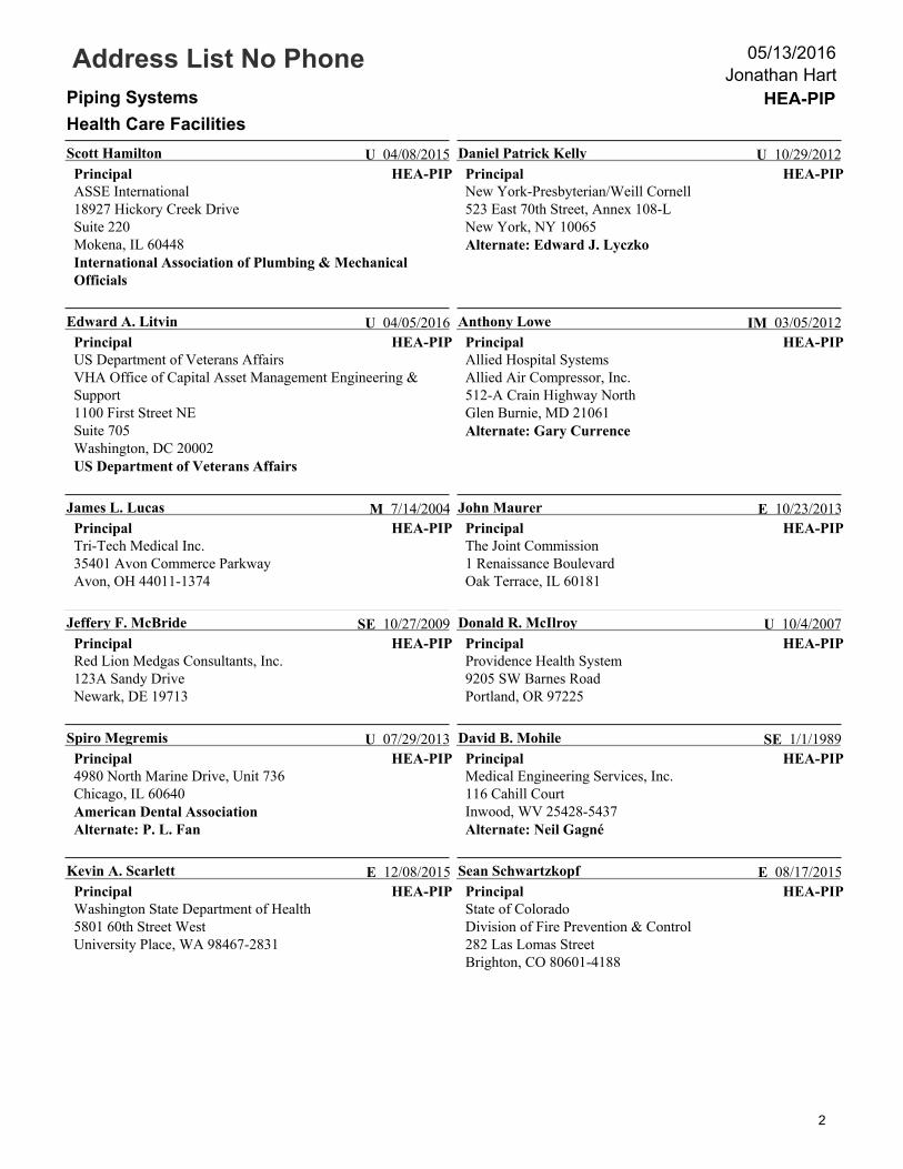
Address List No PhonePiping Systems HEA-PIP
Health Care Facilities
Jonathan Hart05/13/2016
HEA-PIP
Scott Hamilton
PrincipalASSE International18927 Hickory Creek DriveSuite 220Mokena, IL 60448International Association of Plumbing & MechanicalOfficials
U 04/08/2015HEA-PIP
Daniel Patrick Kelly
PrincipalNew York-Presbyterian/Weill Cornell523 East 70th Street, Annex 108-LNew York, NY 10065Alternate: Edward J. Lyczko
U 10/29/2012
HEA-PIP
Edward A. Litvin
PrincipalUS Department of Veterans AffairsVHA Office of Capital Asset Management Engineering &Support1100 First Street NESuite 705Washington, DC 20002US Department of Veterans Affairs
U 04/05/2016HEA-PIP
Anthony Lowe
PrincipalAllied Hospital SystemsAllied Air Compressor, Inc.512-A Crain Highway NorthGlen Burnie, MD 21061Alternate: Gary Currence
IM 03/05/2012
HEA-PIP
James L. Lucas
PrincipalTri-Tech Medical Inc.35401 Avon Commerce ParkwayAvon, OH 44011-1374
M 7/14/2004HEA-PIP
John Maurer
PrincipalThe Joint Commission1 Renaissance BoulevardOak Terrace, IL 60181
E 10/23/2013
HEA-PIP
Jeffery F. McBride
PrincipalRed Lion Medgas Consultants, Inc.123A Sandy DriveNewark, DE 19713
SE 10/27/2009HEA-PIP
Donald R. McIlroy
PrincipalProvidence Health System9205 SW Barnes RoadPortland, OR 97225
U 10/4/2007
HEA-PIP
Spiro Megremis
Principal4980 North Marine Drive, Unit 736Chicago, IL 60640American Dental AssociationAlternate: P. L. Fan
U 07/29/2013HEA-PIP
David B. Mohile
PrincipalMedical Engineering Services, Inc.116 Cahill CourtInwood, WV 25428-5437Alternate: Neil Gagné
SE 1/1/1989
HEA-PIP
Kevin A. Scarlett
PrincipalWashington State Department of Health5801 60th Street WestUniversity Place, WA 98467-2831
E 12/08/2015HEA-PIP
Sean Schwartzkopf
PrincipalState of ColoradoDivision of Fire Prevention & Control282 Las Lomas StreetBrighton, CO 80601-4188
E 08/17/2015
2
Address List No PhonePiping Systems HEA-PIP
Health Care Facilities
Jonathan Hart05/13/2016
HEA-PIP
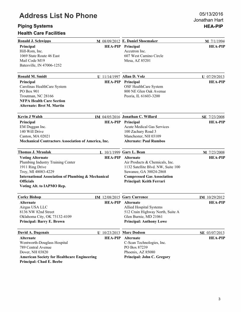
Ronald J. Schwipps
PrincipalHill-Rom, Inc.1069 State Route 46 EastMail Code M19Batesville, IN 47006-1252
M 08/09/2012HEA-PIP
E. Daniel Shoemaker
PrincipalAccutron Inc.607 West Camino CircleMesa, AZ 85201
M 7/1/1994
HEA-PIP
Ronald M. Smidt
PrincipalCarolinas HealthCare SystemPO Box 901Troutman, NC 28166NFPA Health Care SectionAlternate: Bret M. Martin
U 11/14/1997HEA-PIP
Allan D. Volz
PrincipalOSF HealthCare System800 NE Glen Oak AvenuePeoria, IL 61603-3200
U 07/29/2013
HEA-PIP
Kevin J Walsh
PrincipalEM Duggan Inc.140 Will DriveCanton, MA 02021Mechanical Contractors Association of America, Inc.
IM 04/05/2016HEA-PIP
Jonathan C. Willard
PrincipalAcute Medical Gas Services100 Zachary Road 3Manchester, NH 03109Alternate: Paul Rumbos
SE 7/23/2008
HEA-PIP
Thomas J. Mraulak
Voting AlternatePlumbing Industry Training Center1911 Ring DriveTroy, MI 48083-4229International Association of Plumbing & MechanicalOfficialsVoting Alt. to IAPMO Rep.
L 10/1/1999HEA-PIP
Gary L. Bean
AlternateAir Products & Chemicals, Inc.1132 Satellite Blvd. NW, Suite 100Suwanee, GA 30024-2868Compressed Gas AssociationPrincipal: Keith Ferrari
M 7/23/2008
HEA-PIP
Corky Bishop
AlternateAirgas USA LLC8136 NW 82nd StreetOklahoma City, OK 73132-4109Principal: Barry E. Brown
IM 12/08/2015HEA-PIP
Gary Currence
AlternateAllied Hospital Systems512 Crain Highway North, Suite AGlen Burnie, MD 21061Principal: Anthony Lowe
IM 10/29/2012
HEA-PIP
David A. Dagenais
AlternateWentworth-Douglass Hospital789 Central AvenueDover, NH 03820American Society for Healthcare EngineeringPrincipal: Chad E. Beebe
U 10/23/2013HEA-PIP
Marc Dodson
AlternateC-Scan Technologies, Inc.PO Box 87239Phoenix, AZ 85080Principal: John C. Gregory
SE 03/07/2013
3
Address List No PhonePiping Systems HEA-PIP
Health Care Facilities
Jonathan Hart05/13/2016
HEA-PIP
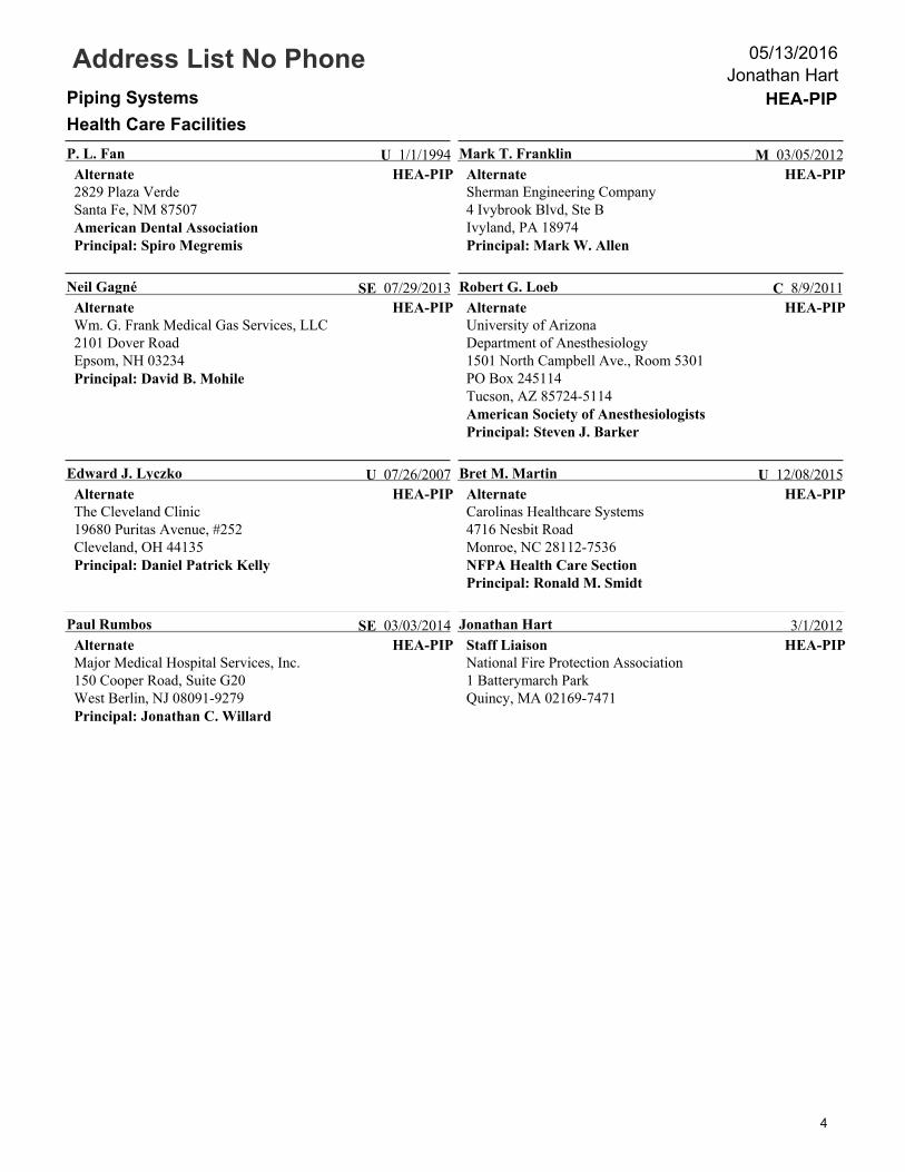
P. L. Fan
Alternate2829 Plaza VerdeSanta Fe, NM 87507American Dental AssociationPrincipal: Spiro Megremis
U 1/1/1994HEA-PIP
Mark T. Franklin
AlternateSherman Engineering Company4 Ivybrook Blvd, Ste BIvyland, PA 18974Principal: Mark W. Allen
M 03/05/2012
HEA-PIP
Neil Gagné
AlternateWm. G. Frank Medical Gas Services, LLC2101 Dover RoadEpsom, NH 03234Principal: David B. Mohile
SE 07/29/2013HEA-PIP
Robert G. Loeb
AlternateUniversity of ArizonaDepartment of Anesthesiology1501 North Campbell Ave., Room 5301PO Box 245114Tucson, AZ 85724-5114American Society of AnesthesiologistsPrincipal: Steven J. Barker
C 8/9/2011
HEA-PIP
Edward J. Lyczko
AlternateThe Cleveland Clinic19680 Puritas Avenue, #252Cleveland, OH 44135Principal: Daniel Patrick Kelly
U 07/26/2007HEA-PIP
Bret M. Martin
AlternateCarolinas Healthcare Systems4716 Nesbit RoadMonroe, NC 28112-7536NFPA Health Care SectionPrincipal: Ronald M. Smidt
U 12/08/2015
HEA-PIP
Paul Rumbos
AlternateMajor Medical Hospital Services, Inc.150 Cooper Road, Suite G20West Berlin, NJ 08091-9279Principal: Jonathan C. Willard
SE 03/03/2014HEA-PIP
Jonathan Hart
Staff LiaisonNational Fire Protection Association1 Batterymarch ParkQuincy, MA 02169-7471
3/1/2012
4

Technical Committee
Distribution
05/13/2016
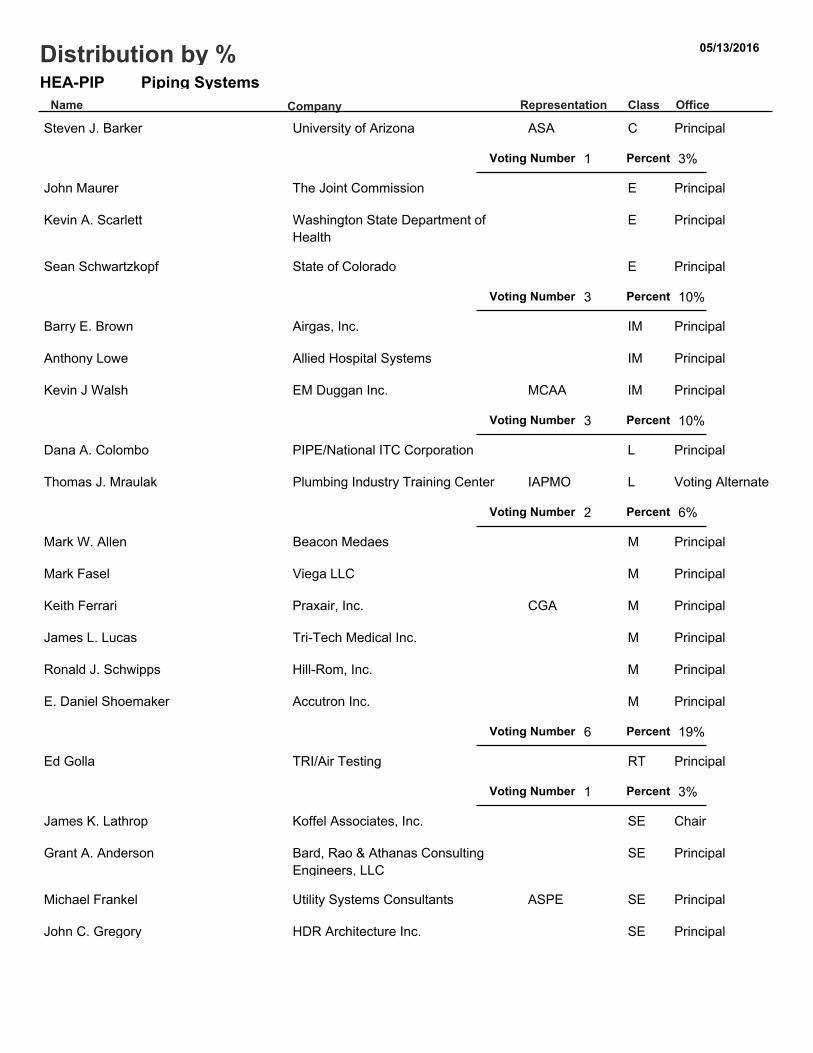
Piping SystemsHEA-PIPName Representation Class Office
Distribution by %
Company
Steven J. Barker University of Arizona ASA C Principal
1Voting Number Percent 3%
John Maurer The Joint Commission E Principal
Kevin A. Scarlett Washington State Department ofHealth
E Principal
Sean Schwartzkopf State of Colorado E Principal
3Voting Number Percent 10%
Barry E. Brown Airgas, Inc. IM Principal
Anthony Lowe Allied Hospital Systems IM Principal
Kevin J Walsh EM Duggan Inc. MCAA IM Principal
3Voting Number Percent 10%
Dana A. Colombo PIPE/National ITC Corporation L Principal
Thomas J. Mraulak Plumbing Industry Training Center IAPMO L Voting Alternate
2Voting Number Percent 6%
Mark W. Allen Beacon Medaes M Principal
Mark Fasel Viega LLC M Principal
Keith Ferrari Praxair, Inc. CGA M Principal
James L. Lucas Tri-Tech Medical Inc. M Principal
Ronald J. Schwipps Hill-Rom, Inc. M Principal
E. Daniel Shoemaker Accutron Inc. M Principal
6Voting Number Percent 19%
Ed Golla TRI/Air Testing RT Principal
1Voting Number Percent 3%
James K. Lathrop Koffel Associates, Inc. SE Chair
Grant A. Anderson Bard, Rao & Athanas ConsultingEngineers, LLC
SE Principal
Michael Frankel Utility Systems Consultants ASPE SE Principal
John C. Gregory HDR Architecture Inc. SE Principal
5 13 16
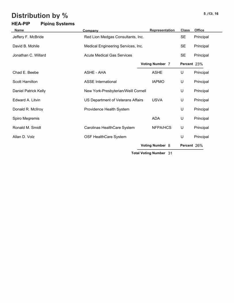
Piping SystemsHEA-PIPName Representation Class Office
Distribution by %
Company
Jeffery F. McBride Red Lion Medgas Consultants, Inc. SE Principal
David B. Mohile Medical Engineering Services, Inc. SE Principal
Jonathan C. Willard Acute Medical Gas Services SE Principal
7Voting Number Percent 23%
Chad E. Beebe ASHE - AHA ASHE U Principal
Scott Hamilton ASSE International IAPMO U Principal
Daniel Patrick Kelly New York-Presbyterian/Weill Cornell U Principal
Edward A. Litvin US Department of Veterans Affairs USVA U Principal
Donald R. McIlroy Providence Health System U Principal
Spiro Megremis ADA U Principal
Ronald M. Smidt Carolinas HealthCare System NFPA/HCS U Principal
Allan D. Volz OSF HealthCare System U Principal
8Voting Number Percent 26%
31Total Voting Number

Previous Meeting Minutes
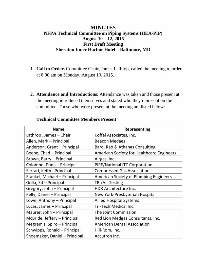
MINUTES NFPA Technical Committee on Piping Systems (HEA-PIP)
August 10 – 12, 2015
First Draft Meeting
Sheraton Inner Harbor Hotel – Baltimore, MD
1. Call to Order. Committee Chair, James Lathrop, called the meeting to order
at 8:00 am on Monday, August 10, 2015.
2. Attendance and Introductions: Attendance was taken and those present at
the meeting introduced themselves and stated who they represent on the
committee. Those who were present at the meeting are listed below:
Technical Committee Members Present
Name Representing
Lathrop , James – Chair Koffel Associates, Inc.
Allen, Mark – Principal Beacon Medaes Anderson, Grant – Principal Bard, Rao & Athanas Consulting
Beebe, Chad – Principal American Society for Healthcare Engineers Brown, Barry – Principal Airgas, Inc
Colombo, Dana – Principal PIPE/National ITC Corporation Ferrari, Keith –Principal Compressed Gas Association
Frankel, Michael – Principal American Society of Plumbing Engineers
Golla, Ed – Principal TRI/Air Testing Gregory, John – Principal HDR Architecture Inc.
Kelly, Daniel – Principal New York-Presbyterian Hospital Lowe, Anthony – Principal Allied Hospital Systems
Lucas, James – Principal Tri-Tech Medical Inc.
Maurer, John – Principal The Joint Commission McBride, Jeffery – Principal Red Lion Medgas Consultants, Inc.
Megremis, Spiro – Principal American Dental Association Schwipps, Ronald – Principal Hill-Rom, Inc.
Shoemaker, Daniel – Principal Accutron Inc.
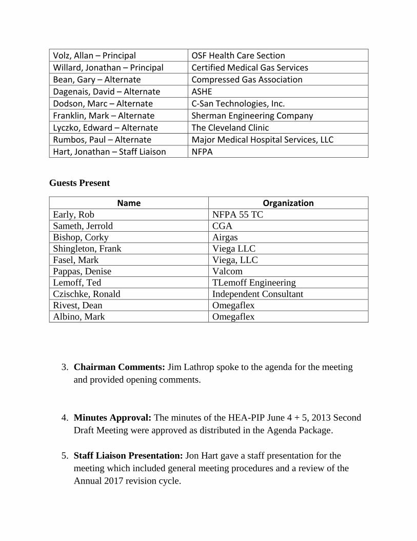
Volz, Allan – Principal OSF Health Care Section
Willard, Jonathan – Principal Certified Medical Gas Services Bean, Gary – Alternate Compressed Gas Association
Dagenais, David – Alternate ASHE Dodson, Marc – Alternate C-San Technologies, Inc.
Franklin, Mark – Alternate Sherman Engineering Company
Lyczko, Edward – Alternate The Cleveland Clinic Rumbos, Paul – Alternate Major Medical Hospital Services, LLC
Hart, Jonathan – Staff Liaison NFPA
Guests Present
Name Organization Early, Rob NFPA 55 TC
Sameth, Jerrold CGA
Bishop, Corky Airgas
Shingleton, Frank Viega LLC
Fasel, Mark Viega, LLC
Pappas, Denise Valcom
Lemoff, Ted TLemoff Engineering
Czischke, Ronald Independent Consultant
Rivest, Dean Omegaflex
Albino, Mark Omegaflex
3. Chairman Comments: Jim Lathrop spoke to the agenda for the meeting
and provided opening comments.
4. Minutes Approval: The minutes of the HEA-PIP June 4 + 5, 2013 Second
Draft Meeting were approved as distributed in the Agenda Package.
5. Staff Liaison Presentation: Jon Hart gave a staff presentation for the
meeting which included general meeting procedures and a review of the
Annual 2017 revision cycle.
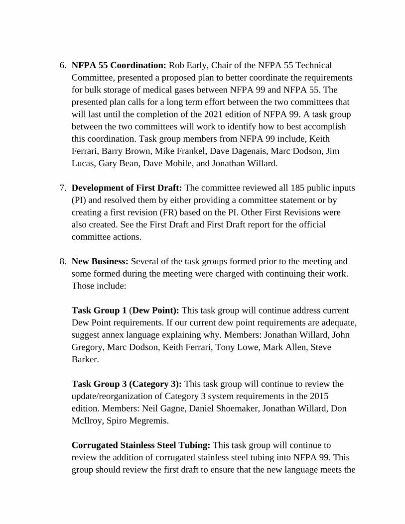
6. NFPA 55 Coordination: Rob Early, Chair of the NFPA 55 Technical
Committee, presented a proposed plan to better coordinate the requirements
for bulk storage of medical gases between NFPA 99 and NFPA 55. The
presented plan calls for a long term effort between the two committees that
will last until the completion of the 2021 edition of NFPA 99. A task group
between the two committees will work to identify how to best accomplish
this coordination. Task group members from NFPA 99 include, Keith
Ferrari, Barry Brown, Mike Frankel, Dave Dagenais, Marc Dodson, Jim
Lucas, Gary Bean, Dave Mohile, and Jonathan Willard.
7. Development of First Draft: The committee reviewed all 185 public inputs
(PI) and resolved them by either providing a committee statement or by
creating a first revision (FR) based on the PI. Other First Revisions were
also created. See the First Draft and First Draft report for the official
committee actions.
8. New Business: Several of the task groups formed prior to the meeting and
some formed during the meeting were charged with continuing their work.
Those include:
Task Group 1 (Dew Point): This task group will continue address current
Dew Point requirements. If our current dew point requirements are adequate,
suggest annex language explaining why. Members: Jonathan Willard, John
Gregory, Marc Dodson, Keith Ferrari, Tony Lowe, Mark Allen, Steve
Barker.
Task Group 3 (Category 3): This task group will continue to review the
update/reorganization of Category 3 system requirements in the 2015
edition. Members: Neil Gagne, Daniel Shoemaker, Jonathan Willard, Don
McIlroy, Spiro Megremis.
Corrugated Stainless Steel Tubing: This task group will continue to
review the addition of corrugated stainless steel tubing into NFPA 99. This
group should review the first draft to ensure that the new language meets the
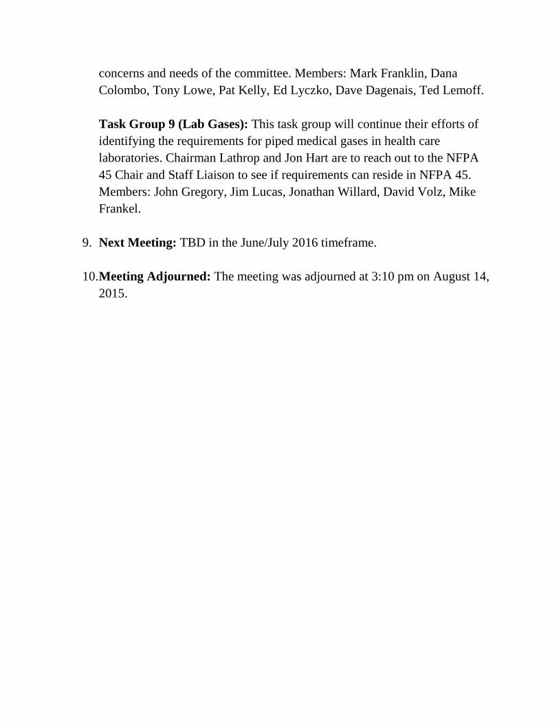
concerns and needs of the committee. Members: Mark Franklin, Dana
Colombo, Tony Lowe, Pat Kelly, Ed Lyczko, Dave Dagenais, Ted Lemoff.
Task Group 9 (Lab Gases): This task group will continue their efforts of
identifying the requirements for piped medical gases in health care
laboratories. Chairman Lathrop and Jon Hart are to reach out to the NFPA
45 Chair and Staff Liaison to see if requirements can reside in NFPA 45.
Members: John Gregory, Jim Lucas, Jonathan Willard, David Volz, Mike
Frankel.
9. Next Meeting: TBD in the June/July 2016 timeframe.
10. Meeting Adjourned: The meeting was adjourned at 3:10 pm on August 14,
2015.

Public Comments
Public Comment No. 46-NFPA 99-2016 [ Section No. 3.3.22 ]
3.3.22* Central Supply System.
The complete source of supply for a medical gas or vacuum system or a medical support gas system. A central supply system includes two ormore supply sources (see 3.1.167)
Statement of Problem and Substantiation for Public Comment
This will clarify the relationship between these two overlapping and potentially confusing definitions.
Related ItemFirst Revision No. 601-NFPA 99-2015 [Global Input]
Submitter Information Verification
Submitter Full Name: Mark AllenOrganization: Beacon MedaesStreet Address:City:State:Zip:Submittal Date: Mon Mar 28 14:39:19 EDT 2016
National Fire Protection Association Report http://submittals.nfpa.org/TerraViewWeb/ContentFetcher?commentPara...
4 of 145 5/17/2016 3:43 PM
Public Comment No. 53-NFPA 99-2016 [ Section No. 3.3.124 ]
3.3.124 Oxygen Concentrator Unit.
An engineered assembly of components that operate A United States Food and Drug Administration (FDA) approved and registered deviceused to separate air into constituent gases, typically providing oxygen 93 USP 93% as a drug product.
Statement of Problem and Substantiation for Public Comment
Oxygen concentrators, when used to supply oxygen 93% for drug applications, are medical devices as defined in the Federal Food Drug and Cosmetic Act and must meet specific requirements. A medical device is “an” instrument, apparatus, implement, machine, contrivance, implant, in vito reagent, or similar or related article, including a component part or accessory which is intended for use in the diagnosis of disease or other conditions, or in the cure, mitigation, treatment, or prevention of disease, in man or other animals.
Related ItemFirst Revision No. 106-NFPA 99-2015 [New Section after 3.3.119]
Submitter Information Verification
Submitter Full Name: Karen KoenigOrganization: CGAStreet Address:City:State:Zip:Submittal Date: Mon Apr 11 08:33:42 EDT 2016
National Fire Protection Association Report http://submittals.nfpa.org/TerraViewWeb/ContentFetcher?commentPara...
5 of 145 5/17/2016 3:43 PM
Public Comment No. 71-NFPA 99-2016 [ New Section after 3.3.129 ]
Oxygen 93 USPOxygen complying with Oxygen 93 USP Monograph
Statement of Problem and Substantiation for Public Comment
A separate definition is needed as there are two different USP Monographs. Oxygen, USP has an assay specification of “not less than 99.0% Oxygen” where Oxygen 93%, USP has an assay specification of “93% ± 3% Oxygen. Although they are both contained in the USP they are not the same but are two distinctly different drugs with different “strengths” and must be separate.
Related ItemFirst Revision No. 107-NFPA 99-2015 [Section No. 3.3.124]
Submitter Information Verification
Submitter Full Name: Karen KoenigOrganization: CGAStreet Address:City:State:Zip:Submittal Date: Mon Apr 18 10:12:36 EDT 2016
National Fire Protection Association Report http://submittals.nfpa.org/TerraViewWeb/ContentFetcher?commentPara...
6 of 145 5/17/2016 3:43 PM
Public Comment No. 70-NFPA 99-2016 [ Section No. 3.3.129 ]
3.3.129 Oxygen USP.
Oxygen complying with oxygen USP or oxygen 93 USP monograph .
Statement of Problem and Substantiation for Public Comment
First Revision 107 as currently written and noted in 99:3.3.129 will result in the gas being mislabeled as a drug and that there are two different monographs that are not interchangeable. Oxygen, USP has an assay specification of “not less than 99.0% Oxygen” where Oxygen 93%, USP has an assay specification of “93% ± 3% Oxygen. Although they are both contained in the USP they are not the same but are two distinctly different drugs with different “strengths” and must be separate.
Related ItemFirst Revision No. 107-NFPA 99-2015 [Section No. 3.3.124]
Submitter Information Verification
Submitter Full Name: Karen KoenigOrganization: CGAStreet Address:City:State:Zip:Submittal Date: Mon Apr 18 10:10:19 EDT 2016
National Fire Protection Association Report http://submittals.nfpa.org/TerraViewWeb/ContentFetcher?commentPara...
7 of 145 5/17/2016 3:43 PM

Public Comment No. 37-NFPA 99-2016 [ Section No. 5.1.3.3.1.11 ]
5.1.3.3.1.11
If indoors, and containing gases other than medical air or oxygen, the central supply location shall be equipped with an oxygen monitor that shallindicate when the oxygen level in the room is below 19.5 percent. The monitor shall have the following:
The oxygen sensor mounted on or near the central supply systemA visual
a
visual and audible annunciator outside the main entrance to the room .
Statement of Problem and Substantiation for Public Comment
Instructions to place the oxygen monitor on the manifold will most likely result in nuisance alarms. Placement of the sensor should be such that the room ventilation does not allow false alarms.
Related ItemFirst Revision No. 901-NFPA 99-2015 [New Section after 5.1.3.3.1.10]Public Input No. 59-NFPA 99-2015 [Section No. 5.1.3.1.8]Public Input No. 393-NFPA 99-2015 [Section No. 5.1.3.3.2]
Submitter Information Verification
Submitter Full Name: Karen KoenigOrganization: CGAStreet Address:City:State:Zip:Submittal Date: Mon Mar 21 09:42:52 EDT 2016
National Fire Protection Association Report http://submittals.nfpa.org/TerraViewWeb/ContentFetcher?commentPara...
11 of 145 5/17/2016 3:43 PM
Public Comment No. 51-NFPA 99-2016 [ Section No. 5.1.3.3.1.11 ]
5.1.3.3.1.11
If indoors, and containing gases other than medical air or oxygen, the central supply location shall be equipped with an oxygen monitor that shallindicate when the oxygen level in the room is below 19.5 percent. The monitor shall have the following:
(1) The oxygen sensor mounted on or near the central supply system
(2) A visual and audible annunciator outside the main entrance to the room
Statement of Problem and Substantiation for Public Comment
The proposal is a good safety precaution; however, the storage locations for medical gas cylinders should not be considered a permit-required confined spaces (29 CFR 1910.146). Also, a concern is whether the oxygen monitor will continuously activate an alarm (nuisance alarms) if the oxygen monitor sensor(s) are placed too close to any oxygen (or other medical gases/medical support gases) containers that may off gas as part of the standard design and operation of the container (ex. liquid containers – dewars) and not allowing the air exchanges from the ventilation system to dilute the vented gas as the ventilation system was designed to do.
Related Public Comments for This Document
Related Comment RelationshipPublic Comment No. 52-NFPA 99-2016 [Section No. 5.1.3.3.1.12]
Related ItemFirst Revision No. 901-NFPA 99-2015 [New Section after 5.1.3.3.1.10]
Submitter Information Verification
Submitter Full Name: Karen KoenigOrganization: CGAStreet Address:City:State:Zip:Submittal Date: Mon Apr 11 08:27:15 EDT 2016
National Fire Protection Association Report http://submittals.nfpa.org/TerraViewWeb/ContentFetcher?commentPara...
12 of 145 5/17/2016 3:43 PM
Public Comment No. 38-NFPA 99-2016 [ Section No. 5.1.3.3.1.12 ]
5.1.3.3.1.12
If indoors, and containing oxygen, the central supply location shall be equipped with an oxygen monitor that indicates when the oxygen level inthe room is above 23.5 percent. The oxygen monitor shall have the following:
The oxygen sensor mounted on or near the central supply system,A visual
a
visual and audible annunciator outside the main entrance to the room.
Statement of Problem and Substantiation for Public Comment
Instructions to place the oxygen monitor on the manifold will most likely result in nuisance alarms. Placement of the sensor should be such that the room ventilation does not allow false alarms.
Related ItemFirst Revision No. 901-NFPA 99-2015 [New Section after 5.1.3.3.1.10]Public Input No. 59-NFPA 99-2015 [Section No. 5.1.3.1.8]Public Input No. 393-NFPA 99-2015 [Section No. 5.1.3.3.2]
Submitter Information Verification
Submitter Full Name: Karen KoenigOrganization: CGAStreet Address:City:State:Zip:Submittal Date: Mon Mar 21 09:49:15 EDT 2016
National Fire Protection Association Report http://submittals.nfpa.org/TerraViewWeb/ContentFetcher?commentPara...
13 of 145 5/17/2016 3:43 PM
Public Comment No. 52-NFPA 99-2016 [ Section No. 5.1.3.3.1.12 ]
5.1.3.3.1.12
If indoors, and containing oxygen, the central supply location shall be equipped with an oxygen monitor that indicates when the oxygen level inthe room is above 23.5 percent. The oxygen monitor shall have the following:
(1) The oxygen sensor mounted on or near the central supply system,
(2) A visual and audible annunciator outside the main entrance to the room.
Statement of Problem and Substantiation for Public Comment
The proposal is a good safety precaution; however, the storage locations for medical gas cylinders should not be considered a permit-required confined spaces (29 CFR 1910.146). Also, a concern is whether the oxygen monitor will continuously activate an alarm (nuisance alarms) if the oxygen monitor sensor(s) are placed too close to any oxygen (or other medical gases/medical support gases) containers that may off gas as part of the standard design and operation of the container (ex. liquid containers – dewars) and not allowing the air exchanges from the ventilation system to dilute the vented gas as the ventilation system was designed to do.
Related Public Comments for This Document
Related Comment RelationshipPublic Comment No. 51-NFPA 99-2016 [Section No. 5.1.3.3.1.11]
Related ItemFirst Revision No. 901-NFPA 99-2015 [New Section after 5.1.3.3.1.10]
Submitter Information Verification
Submitter Full Name: Karen KoenigOrganization: CGAStreet Address:City:State:Zip:Submittal Date: Mon Apr 11 08:29:32 EDT 2016
National Fire Protection Association Report http://submittals.nfpa.org/TerraViewWeb/ContentFetcher?commentPara...
14 of 145 5/17/2016 3:43 PM
Public Comment No. 76-NFPA 99-2016 [ Section No. 5.1.3.3.1.12 ]
5.1.3.3.1.12
If indoors, and containing oxygen, the central supply location shall be equipped with an oxygen monitor that indicates when the oxygen level inthe room is above 23.5 percent. The oxygen monitor shall have the following:
(1) The oxygen sensor mounted on or near the central supply system,
(2) A visual and audible annunciator outside the main entrance to the room.
Statement of Problem and Substantiation for Public Comment
The NFPA Directory states that the NFPA standards content "...shall also base its recommendations on one or more of the following factors: fire experience, research data, engineering fundamentals, or other such information as may be available" There was no technical justification submitted for this change and there have been no known incidents where the absence of any monitor or alarm has led to any hazard. Without compelling evidence to support the change this should be removed from the draft.
Related ItemFirst Revision No. 901-NFPA 99-2015 [New Section after 5.1.3.3.1.10]
Submitter Information Verification
Submitter Full Name: Chad BeebeOrganization: ASHE - AHAStreet Address:City:State:Zip:Submittal Date: Tue Apr 26 20:39:41 EDT 2016
National Fire Protection Association Report http://submittals.nfpa.org/TerraViewWeb/ContentFetcher?commentPara...
15 of 145 5/17/2016 3:43 PM
Public Comment No. 50-NFPA 99-2016 [ Section No. 5.1.3.3.2 ]
5.1.3.3.2 * Design and Construction.
Locations for central supply systems and the storage of positive-pressure gases shall meet the following requirements:
(1) They shall be constructed with access to move cylinders, equipment, and so forth, in and out of the location on hand trucks complying with11.4.3.1.1.
(2) They shall be provided with lockable doors or gates or otherwise able to be secured.
(3) If outdoors, they shall be provided with an enclosure (e.g., wall or fencing) constructed of noncombustible materials .
(4) If outdoors and greater than 200 ft2, they shall be provided with a minimum of two entry/exits.
(5) If outdoors, bulk cryogenic liquid systems shall be provided with a minimum of two entry/exits.
(6) If indoors, they shall have interior finishes of noncombustible or limited-combustible materials.
(7)
(8)
(9) They Fuel fired equipment shall be heated by indirect means if heat is required not be located in the room.
(10)
(11) They shall be provided with racks, chains, or other fastenings to secure all cylinders from falling, whether connected, unconnected, full, orempty.
(12)
(13) They shall have racks, shelves, and supports, where provided, constructed of noncombustible materials or limited-combustible materials.
(14) They shall protect electrical devices from physical damage.
(15)
(16) They shall be designed to meet the operational requirements of 5.1.3.2 with regard to room temperature.
Statement of Problem and Substantiation for Public Comment
First I wish to thank the committee and express appreciation for the proposed clarification to "indirect" allowing electric.
I have seen med gas certifiers require design changes after equipment is installed due to different interpretations of what indirect means. For this reason I request the committee remove the "indirect" requirement or further clarify the intent of "indirect" because I believe the use of the word will still be confusing to users. Since the standard chooses to use the word "indirect" in lieu of alternative language stating "heating shall be by hot water, steam or electric" it implies that there are other design elements associated with "indirect" heating other than "hot water, steam or electric". As an example some med gas certifiers have interpreted that a unit heater would need to be located entirely outside of the room to count as "indirect". In addition, since the annex states "examples of indirect heating include..." the standard further implies there are other acceptable methods of heat that are indirect other than those listed; for example, a user could interpret that an "indirect gas fired heater" is an indirect form of heat and is acceptable while a "direct gas fired heater" would not be acceptable. I'm not certain that the previous example's interpretation is the true intent of the committee when utilizing the word "indirect". My personal interpretation of this requirement and the intent of the "indirect" term is that the committee does not want a piece of heating equipment with an open flame to be located within the room, thus my suggestion to require that "fuel fired equipment shall not be located in the room" and remove the indirect requirement. If the intent of the standard is that there are other design elements associated with the use of the term "indirect" I request they be further clarified to assist the users of the standard in meeting the intent of the language.
I am also proposing language that addresses the proposed revision to the annex requirement limiting heating elements to 212 degrees F. I am unaware of how the committee arrived at this value but suggest that if a higher value is acceptable it be permitted. As explicitly stated in the annex the intent of the committee is to allow steam heating, however as I would interpret the standard a limit on the heater element to 212 degrees F would effectively remove steam as a viable heating source. 0 psi steam will be at 212 degrees and as a practical matter can not be used because not exceeding the maximum temperature cannot be assured from a design perspective. The suggested value of 266 degrees F. is based on the temperature of steam at 25 PSI, with the intent to allow 15 PSI steam with a safety relief valve setting of up to 25 PSI. Any higher value as deemed appropriate by the committee above 212 or 266 degrees F is appreciated.
Due to formatting errors while entering this comment the next requirement in the standard is shown as revised. I made no recommended changes to that requirement.
Related ItemPublic Input No. 520-NFPA 99-2015 [Section No. 5.1.3.3.2]
Submitter Information Verification
Submitter Full Name: Matthew T SciarrettiOrganization: Heapy EngrStreet Address:City:State:Zip:
* If indoors, the room shall be separated from the rest of the building by walls and floors having a one-hour fire resistance rating with doorsand other opening protectives having a 3�4 -hour fire protection rating.
* They shall comply with NFPA 70 for ordinary locations.
*
. If heat is required the maximum allowable temperature of the in-room heating element shall be 266 ° F .
* They shall be supplied with electrical power compliant with the requirements for essential electrical systems as described in Chapter 6.
* They shall allow access by delivery vehicles and management of cylinders.
National Fire Protection Association Report http://submittals.nfpa.org/TerraViewWeb/ContentFetcher?commentPara...
16 of 145 5/17/2016 3:43 PM

Submittal Date: Wed Mar 30 09:45:59 EDT 2016
National Fire Protection Association Report http://submittals.nfpa.org/TerraViewWeb/ContentFetcher?commentPara...
17 of 145 5/17/2016 3:43 PM
Public Comment No. 55-NFPA 99-2016 [ New Section after 5.1.3.5.11.1 ]
5.1.3.5.11.2Oxygen concentrator supply units shall be installed by personnel meeting the requirements in CGA M-1 section 6.2.
Statement of Problem and Substantiation for Public Comment
There are currently no requirements for the installers of oxygen concentrator units. CGA M-1 addresses those qualifications. An oxygen concentrator is considered a medical device and is subject to FDA regulatory requirements.
Related ItemFirst Revision No. 609-NFPA 99-2015 [New Section after 5.1.3.5.10]
Submitter Information Verification
Submitter Full Name: Karen KoenigOrganization: CGAStreet Address:City:State:Zip:Submittal Date: Mon Apr 11 08:41:55 EDT 2016
National Fire Protection Association Report http://submittals.nfpa.org/TerraViewWeb/ContentFetcher?commentPara...
18 of 145 5/17/2016 3:43 PM
Public Comment No. 54-NFPA 99-2016 [ Section No. 5.1.3.5.11.1 ]
5.1.3.5.11.1
Oxygen concentrator supply units for use with medical gas pipelines shall produce oxygen meeting the requirements of Oxygen 93 USP orOxygen USP 93% .
Statement of Problem and Substantiation for Public Comment
The name in the official USPC monographs is Oxygen 93 Percent.
Related ItemFirst Revision No. 609-NFPA 99-2015 [New Section after 5.1.3.5.10]
Submitter Information Verification
Submitter Full Name: Karen KoenigOrganization: CGAStreet Address:City:State:Zip:Submittal Date: Mon Apr 11 08:40:08 EDT 2016
National Fire Protection Association Report http://submittals.nfpa.org/TerraViewWeb/ContentFetcher?commentPara...
19 of 145 5/17/2016 3:43 PM
Public Comment No. 56-NFPA 99-2016 [ Section No. 5.1.3.5.11.6 ]
5.1.3.5.11.6
The supply air to the concentrators shall be of a quality to ensure the oxygen concentrator unit can produce oxygen complying with meet therequirements in 5.1.3. 5 6 . 11.1 and shall not be subject to normally anticipated contamination (e.g., vehicle or other exhausts, gas leakage,discharge from vents, flooding, and so forth). 3.11.
Statement of Problem and Substantiation for Public Comment
This is the requirement for the medical air compressor intake. The same quality requirements apply to the feed for medical air and the oxygen concentrator. There is no need to have a second set of requirements.
Related ItemFirst Revision No. 609-NFPA 99-2015 [New Section after 5.1.3.5.10]
Submitter Information Verification
Submitter Full Name: Karen KoenigOrganization: CGAStreet Address:City:State:Zip:Submittal Date: Mon Apr 11 08:44:33 EDT 2016
National Fire Protection Association Report http://submittals.nfpa.org/TerraViewWeb/ContentFetcher?commentPara...
20 of 145 5/17/2016 3:43 PM
Public Comment No. 57-NFPA 99-2016 [ Section No. 5.1.3.5.11.12 ]
5.1.3.5.11.12
An outlet valve shall be provided to isolate all components of the oxygen concentrator from the pipeline with the following characteristics:
(1) The valve shall have both manual and automatic actuation with visual indication of open or closed,
(2) The valve shall close automatically whenever the oxygen concentrator unit is not producing oxygen of a concentration equal to that in5.1.3.5.11.1,
(3) Continuing operation of the oxygen concentrator supply unit through the vent mode shall be permitted with the isolating valve closed.
(4) The isolating valve, when automatically closed due to low concentration product being produced outside of the specification for Oxygen93% , shall require manual reset to ensure the oxygen concentrator supply unit is examined prior to return to service,
(5) Closing the isolating valve, whether automatically or manually, shall activate an alarm signal at the master alarms (see 5.1.9.2) indicatingthat the oxygen concentrator supply unit is disconnected.
Statement of Problem and Substantiation for Public Comment
The specification for oxygen 93% is no less than (NLT) 90.0% and no greater than (NGT) 96% by volume of oxygen. The 1% difference between the USPC NLT and NGT spec is due to the ±0.5 percent accuracy of the monitor.
Related ItemFirst Revision No. 609-NFPA 99-2015 [New Section after 5.1.3.5.10]
Submitter Information Verification
Submitter Full Name: Karen KoenigOrganization: CGAStreet Address:City:State:Zip:Submittal Date: Mon Apr 11 08:46:49 EDT 2016
National Fire Protection Association Report http://submittals.nfpa.org/TerraViewWeb/ContentFetcher?commentPara...
21 of 145 5/17/2016 3:43 PM
Public Comment No. 58-NFPA 99-2016 [ Section No. 5.1.3.5.11.13 ]
5.1.3.5.11.13
The oxygen concentrator supply unit shall be provided with an oxygen concentration monitor with the following characteristics:
(1) The monitor shall be capable of monitoring 99 percent oxygen concentration with ±0.5 percent accuracy,
(2) The monitor shall continuously display the oxygen concentration and shall activate local alarm and master alarms per 5.1.3.9.4 when aconcentration lower than 91 percent, or greater than 95 percent is observed.
(3) It shall be permitted to insert the monitor into the pipeline without a demand check.
Statement of Problem and Substantiation for Public Comment
The specification for oxygen 93% is no less than (NLT) 90.0% and no greater than (NGT) 96% by volume of oxygen. The 1% difference between the USPC NLT and NGT spec is due to the ±0.5 percent accuracy of the monitor.
Related ItemFirst Revision No. 609-NFPA 99-2015 [New Section after 5.1.3.5.10]
Submitter Information Verification
Submitter Full Name: Karen KoenigOrganization: CGAStreet Address:City:State:Zip:Submittal Date: Mon Apr 11 08:49:32 EDT 2016
National Fire Protection Association Report http://submittals.nfpa.org/TerraViewWeb/ContentFetcher?commentPara...
22 of 145 5/17/2016 3:43 PM
Public Comment No. 4-NFPA 99-2016 [ Section No. 5.1.3.8.1.2 ]
5.1.3.8.1.2
If WAGD is produced by the medical–surgical vacuum source, the following shall apply:
(1) The medical–surgical vacuum source shall comply with 5.1.3.7.
(2) The total concentration of oxidizers (oxygen and nitrous oxide) of oxygen shall be maintained below 23.6 percent, or the vacuum pumpshall comply with 5.1.3.8.2.1.
(3) The medical–surgical vacuum source shall be sized to accommodate the additional volume.
Statement of Problem and Substantiation for Public Comment
The most common oxidizers that are present in combined use vacuum pump systems include gases such as nitrous oxide (N2O) and carbon dioxide (CO2). According to Wikipedia, N2O will decompose exothermically into nitrogen and oxygen, at a temperature of approximately 1070 °F, while CO2 requires much higher temperatures. If a system is exposed to such an environment, there are likely plenty of other problems to worry about. Not to mention, the cost of monitoring oxidizers is much more expensive than simply monitoring the oxygen concentration. So is dedicating an entire vacuum pump system that is required to be made from inert materials specifically WAGD purposes. The ability for health care facilities to monitor their vacuum pumps oxygen concentration would permit a similar standard for safety as well as offer a much more economical means for providing the same service. This could also more easily apply to existing systems, making them much safer for combined use scenarios. Any feedback would be appreciated. Thank you for your time.
Related ItemPublic Input No. 4-NFPA 99-2015 [Chapter 5 [WAGD Source Requirements]]
Submitter Information Verification
Submitter Full Name: Kyle JusselOrganization: Medical Air Systems IncStreet Address:City:State:Zip:Submittal Date: Wed Mar 02 11:35:50 EST 2016
National Fire Protection Association Report http://submittals.nfpa.org/TerraViewWeb/ContentFetcher?commentPara...
23 of 145 5/17/2016 3:43 PM
Public Comment No. 60-NFPA 99-2016 [ Section No. 5.1.3.9.2 ]
5.1.3.9.2 Arrangement and Redundancies.
. Oxygen central supply systems using concentrator(s) shall be permitted to consist of two or three supply sources, as follows:If two supplysources are provided, one shall be an the following:
(1) An oxygen concentrator supply unit and the second shall be a cylinder cylinders containing Oxygen 93% attached to a headercomplying with 5.1.3.5.10 with sufficient cylinder connections for an average day's supply. Container manifolds as per 5.1.3.5.13 shall notbe used.
(2) If three supply sources are provided, each shall be capable of independently supplying the full system demand in the event of theunavailability of one or both of the other sources.The three sources shall be permitted to be any of the following:
(3) An oxygen A second oxygen concentrator supply system complying with 5.1.3.5.11 .
(4) A cylinder header complying with 5.1.3.5.10 with containing Oxygen 93% with sufficient cylinder connections for an averageday's supply. Container manifolds as per 5.1.3.5.10(9) shall not be used.
(5) A cryogenic liquid supply system complying with 5.1.3.5.13 or 5.1.3.5.14 , where the concentrator unit shall only operate as asecondary or reserve and never as the primary supply.
(6) Use of oxygen concentrator supply systems as all three sources shall without cylinder backup shall only be permitted after a documentedrisk analysis by the governing authority of the healthcare facility indicating understanding of the inherent risks and defining how those risksshall be mitigated.
(7) An isolation valve and automatic check valve shall be provided to isolate each of the three sources from the others and from the pipeline.The valves in 5.1.3.5.10(4) , 5.1.3.5.10(6) , 5.1.3.5.11.11 , and 5.1.3.5.11.12 shall be permitted to be used for this purpose.
(8) Each of the three supply sources shall be provided with a pressure relief valve complying with 5.1.3.5.6 on the source side of itsrespective isolating valve.
(9) The three supply sources shall join to the pipeline systems through control arrangements with at least the following characteristics:
(a) Able to maintain stable pressures within the limits of Table 5.1.11
(b) Able to flow 100 percent of the peak calculated demand
(c) Redundant, such that each component of the control mechanism can be isolated for service or replacement while maintainingnormal operation
(d) The cascade of sources described in 5.1.3.9.3
(e) Protected against overpressure (see 5.1.3.5.6 )
(10) A pressure relief valve shall be provided in the common line between the sources and the line pressure controls.
(11) A source valve as required in 5.1.4.2 shall be provided on the patient side of the line pressure controls.
(12) A gauge and switch or sensor shall be located between the three sources and the line pressure controls to monitor the pressure feedingthe line pressure controls.
(13) An oxygen concentration monitor, sampling the gas on the patient side of the line pressure controls and on the source side of the sourcevalve, shall be provided with the following characteristics:
(a) The monitor shall be capable of monitoring 99 percent oxygen concentration with ±0.5 percent accuracy,
(b) The monitor shall be attached to the pipeline through a demand check complying with 5.1.8.2.3 ,
(c) The monitor shall continuously display the oxygen concentration and shall activate local alarm and master alarms indicating lowoxygen concentration NLT 91% concentration.
(d) The monitor shall continuously display the oxygen concentration and shall activate local alarm and master alarms indicating NGT95% oxygen concentration .
(14) A DN8 (NPS 1/4) valved sample port shall be provided on the patient side of the line pressure controls and source side of the sourcevalve for sampling the oxygen. .
(15) An auxiliary source connection shall be provided complying with 5.1.3.5.7
(16) Electrical installation and wiring shall conform to the requirements of NFPA 70
(17) Emergency electrical service for all components of the oxygen supply system shall conform to the requirements of the essential electricalsystem as described in Chapter 6.
Statement of Problem and Substantiation for Public Comment
1. A system supplying oxygen 93% cannot be backed up with product meeting the USPC requirements for oxygen (NLT 99.0% oxygen by volume). 2. A system supplying oxygen 99% cannot be backed up with product meeting the USPC requirements for 93% oxygen. 3. These are the limits for oxygen 93% and the specified monitor.
Related ItemFirst Revision No. 640-NFPA 99-2015 [New Section after 5.1.3.8.5]
Submitter Information Verification
National Fire Protection Association Report http://submittals.nfpa.org/TerraViewWeb/ContentFetcher?commentPara...
24 of 145 5/17/2016 3:43 PM

Submitter Full Name: Karen KoenigOrganization: CGAStreet Address:City:State:Zip:Submittal Date: Mon Apr 11 08:55:43 EDT 2016
National Fire Protection Association Report http://submittals.nfpa.org/TerraViewWeb/ContentFetcher?commentPara...
25 of 145 5/17/2016 3:43 PM
Public Comment No. 61-NFPA 99-2016 [ Section No. 5.1.3.9.4.1 ]
5.1.3.9.4.1
For each oxygen concentrator supply source in the system, the supply source's concentration monitor (see 5.1.3.5.11.10 ) shall be able toperform the following:
(1) Indicate low oxygen concentration when a concentration lower than 91 percent is observed
(2) Indicate high oxygen concentration when a concentration greater than 95 percent is observed
(3) Activate a local alarm (see 5.1.9.5 )
(4) Activate an alarm signal at the master alarm (see 5.1.9.2 ) indicating that the oxygen concentration from that supply source is low
(5) Activate an alarm signal at the master alarm ( see 5.1.9.2 ) indicating that the oxygen concentration from that supply source is high
(6) Activate the automatic isolating valve for that oxygen concentrator supply source (see 5.1.3.5.11.12 ) to prevent supply from that oxygenconcentrator supply source.
(7) Close the automatic isolating valve for that oxygen concentrator supply source (see 5.1.3.5.11.12 ), which shall activate an alarm signal atthe master alarm (see 5.1.9.2 ) indicating that the oxygen concentrator supply source is disconnected.
Statement of Problem and Substantiation for Public Comment
1. These are the limits for oxygen 93% and the specified monitor.2. The reserve supply should never be less than 24 hours as required elsewhere in NFPA 99.
Related ItemFirst Revision No. 640-NFPA 99-2015 [New Section after 5.1.3.8.5]
Submitter Information Verification
Submitter Full Name: Karen KoenigOrganization: CGAStreet Address:City:State:Zip:Submittal Date: Mon Apr 11 09:03:45 EDT 2016
National Fire Protection Association Report http://submittals.nfpa.org/TerraViewWeb/ContentFetcher?commentPara...
26 of 145 5/17/2016 3:43 PM
Public Comment No. 62-NFPA 99-2016 [ Section No. 5.1.3.9.4.2 ]
5.1.3.9.4.2
For the entire oxygen central supply system, the system concentration monitor [see 5.1.3.9.2(10) ] shall be able to perform the following:
(1) Indicate low oxygen concentration when a concentration lower than 90 percent 91 percent is observed
(2) Indicate high oxygen concentration when a concentration greater than 91 percent is observed
(3) Activate a local alarm (see 5.1.9.5 )
(4) Activate an alarm signal at the master alarm (see 5.1.9.2 ) indicating the oxygen concentration is low
(5) Activate an alarm signal at the master alarm ( see 5.1.9.2 ) indicating the oxygen concentration is high
Statement of Problem and Substantiation for Public Comment
The reserve supply should never be less than 24 hours as required elsewhere in NFPA 99.
Related ItemFirst Revision No. 640-NFPA 99-2015 [New Section after 5.1.3.8.5]
Submitter Information Verification
Submitter Full Name: Karen KoenigOrganization: CGAStreet Address:City:State:Zip:Submittal Date: Mon Apr 11 09:06:37 EDT 2016
National Fire Protection Association Report http://submittals.nfpa.org/TerraViewWeb/ContentFetcher?commentPara...
27 of 145 5/17/2016 3:43 PM
Public Comment No. 63-NFPA 99-2016 [ Section No. 5.1.3.9.4.3 ]
5.1.3.9.4.3
For each header source (see 5.1.3.5.10 ) in the supply system, local signals and alarms shall be provided as follows:
(1) A pressure gauge for delivery pressure,
(2) A means to activate an alarm signal at the master alarm (see 5.1.9.2 ) indicating the oxygen cylinders are in use
(3) A means to activate an alarm signal at the master alarm (see 5.1.9.2 ) indicating the oxygen cylinder contents are low when the contentsare at or below 12 24 hours average supply
Statement of Problem and Substantiation for Public Comment
The reserve supply should never be less than 24 hours as required elsewhere in NFPA 99.
Related ItemFirst Revision No. 640-NFPA 99-2015 [New Section after 5.1.3.8.5]
Submitter Information Verification
Submitter Full Name: Karen KoenigOrganization: CGAStreet Address:City:State:Zip:Submittal Date: Mon Apr 11 09:09:41 EDT 2016
National Fire Protection Association Report http://submittals.nfpa.org/TerraViewWeb/ContentFetcher?commentPara...
28 of 145 5/17/2016 3:43 PM
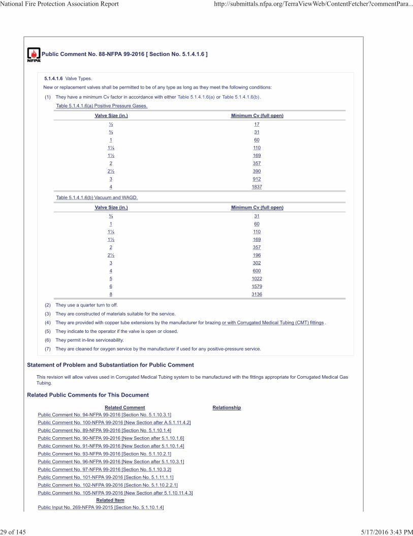
Public Comment No. 88-NFPA 99-2016 [ Section No. 5.1.4.1.6 ]
5.1.4.1.6 Valve Types.
New or replacement valves shall be permitted to be of any type as long as they meet the following conditions:
(1) They have a minimum Cv factor in accordance with either Table 5.1.4.1.6(a) or Table 5.1.4.1.6(b).
Table 5.1.4.1.6(a) Positive Pressure Gases.
Valve Size (in.) Minimum Cv (full open)
½ 17¾ 311 60
1¼ 1101½ 1692 357
2½ 3903 9124 1837
Table 5.1.4.1.6(b) Vacuum and WAGD.
Valve Size (in.) Minimum Cv (full open)
¾ 311 60
1¼ 1101½ 1692 357
2½ 1963 3024 6005 10226 15798 3136
(2) They use a quarter turn to off.
(3) They are constructed of materials suitable for the service.
(4) They are provided with copper tube extensions by the manufacturer for brazing or with Corrugated Medical Tubing (CMT) fittings .
(5) They indicate to the operator if the valve is open or closed.
(6) They permit in-line serviceability.
(7) They are cleaned for oxygen service by the manufacturer if used for any positive-pressure service.
Statement of Problem and Substantiation for Public Comment
This revision will allow valves used in Corrugated Medical Tubing system to be manufactured with the fittings appropriate for Corrugated Medical Gas Tubing.
Related Public Comments for This Document
Related Comment RelationshipPublic Comment No. 94-NFPA 99-2016 [Section No. 5.1.10.3.1]Public Comment No. 100-NFPA 99-2016 [New Section after A.5.1.11.4.2]Public Comment No. 89-NFPA 99-2016 [Section No. 5.1.10.1.4]Public Comment No. 90-NFPA 99-2016 [New Section after 5.1.10.1.6]Public Comment No. 91-NFPA 99-2016 [New Section after 5.1.10.1.4]Public Comment No. 93-NFPA 99-2016 [Section No. 5.1.10.2.1]Public Comment No. 96-NFPA 99-2016 [New Section after 5.1.10.3.1]Public Comment No. 97-NFPA 99-2016 [Section No. 5.1.10.3.2]Public Comment No. 101-NFPA 99-2016 [Section No. 5.1.11.1.1]Public Comment No. 102-NFPA 99-2016 [Section No. 5.1.10.2.2.1]Public Comment No. 105-NFPA 99-2016 [New Section after 5.1.10.11.4.3]
Related ItemPublic Input No. 269-NFPA 99-2015 [Section No. 5.1.10.1.4]
National Fire Protection Association Report http://submittals.nfpa.org/TerraViewWeb/ContentFetcher?commentPara...
29 of 145 5/17/2016 3:43 PM

Submitter Information Verification
Submitter Full Name: Theodore LemoffOrganization: TLemoff EngineeringAffilliation: Omega FlexStreet Address:City:State:Zip:Submittal Date: Fri May 13 10:32:21 EDT 2016
National Fire Protection Association Report http://submittals.nfpa.org/TerraViewWeb/ContentFetcher?commentPara...
30 of 145 5/17/2016 3:43 PM
Public Comment No. 47-NFPA 99-2016 [ Section No. 5.1.4.6 ]
substitute all the text in 5.1.4.6
Zone Valves.
as follows:
5.1.4.6.1
All station outlets/inlets shall be supplied through a zone valve . Zone valves shall be placed as follows:
The zone valve shall be placed
5.1.4.6.2 *
Zone valves shall be
1. such that a wall intervenes between the valve and outlets/inlets that it controls.
The zone valve shall serve only outlets/inlets located on that same story.
The zone valve shall not be located in a room with station outlets/inlets that it controls.
2. readily operable from a standing position
.
5.1.4.6.
3
Zone valves shall be so arranged that shutting off the supply of medical gas or vacuum to one zone will not affect the supply of medical gas orvacuum to another zone or the rest of the system
.
5.1.4.6.4
A pressure/vacuum indicator shall be provided on the station outlet/inlet side of each zone valve.
5.1.4.6.5
Zone valve boxes shall be
installed where they are visible and accessible at all times.
5.1.
4.
6.6 Zone valve boxes shall
not be installed where they can be hidden from plain view, such as behind normally open or normally closed doors or
otherwise hidden from plain view
behind carts .
5.
1.4.6.7 Zone valve boxes shall
not be located in a room with station outlets/inlets that it controls.
6. not be located in
closed or locked
rooms, areas, or closets which can be closed or locked .
5.1.4.6.
8
2
A zone valve in each medical gas or vacuum line shall be
located immediately outside each vital life-support area,
provided for each Category 1 Space, and anesthetizing location
of
for moderate sedation, deep sedation, or general anesthesia
, in each medical gas or vacuum line, or both, and located
specific for the occupancy. These zone valves shall:
1. be located immediately outside the area controlled.
2. be located so as to be readily accessible in an emergency.
National Fire Protection Association Report http://submittals.nfpa.org/TerraViewWeb/ContentFetcher?commentPara...
31 of 145 5/17/2016 3:43 PM
5.1.4.6.
9 All
3
Piping on the patient side of zone valves shall be arranged to provide:
1. that shutting off the supply of medical gas or vacuum to one zone will not affect the supply of medical gas or vacuum toanother zone or the rest of the system.
2. service only to outlets/inlets located on that same floor.
3. that all gas delivery columns, hose reels, ceiling tracks, control panels, pendants, booms, or other special installations
shall be
are located
downstream
patient side of the zone valve.
5.1.4.6.
10 Zone valves shall be so arranged that shutting off the supply of gas to any one operating room or anesthetizing location will not affect theothers
4
A pressure/vacuum indicator shall be provided on the station outlet/inlet side of each zone valve .
Additional Proposed Changes
File Name Description Approved5.1.4.6_text.docx Complete wording - Terraview did not accept this cleanly
Statement of Problem and Substantiation for Public Comment
In the First Draft wording there are redundant clauses (5.1.4.3.6 and 5.1.4.6.10) and there is an unnecessary requirement in 5.1.4.6.8 - "vital life support area" which is not defined and theoretically covered by "category 1 space" as added in the First Draft. The clauses have been reordered in the proposal to make them flow better and more cleanly.
Related ItemFirst Revision No. 649-NFPA 99-2015 [Section No. 5.1.4.6.2]First Revision No. 111-NFPA 99-2015 [Global Input]
Submitter Information Verification
Submitter Full Name: Mark AllenOrganization: Beacon MedaesStreet Address:City:State:Zip:Submittal Date: Mon Mar 28 15:38:43 EDT 2016
National Fire Protection Association Report http://submittals.nfpa.org/TerraViewWeb/ContentFetcher?commentPara...
32 of 145 5/17/2016 3:43 PM
FR 649
FR 111
5.1.4.6.1
All station outlets/inlets shall be supplied through a zone valve. Zone valves shall be placed as follows:
1. such that a wall intervenes between the valve and outlets/inlets that it controls.
2. readily operable from a standing position 3. installed where they are visible and accessible at all times. 4. not be installed where they can be hidden from plain view, such as behind normally open or normally closed doors or behind carts. 5. not be located in a room with station outlets/inlets that it controls. 6. not be located in rooms, areas, or closets which can be closed or locked.
5.1.4.6.2
A zone valve in each medical gas or vacuum line shall be provided for each Category 1 Space, and anesthetizing location for moderate sedation, deep sedation, or general anesthesia specific for the occupancy. These zone valves shall: 1. be located immediately outside the area controlled. 2. be located so as to be readily accessible in an emergency. 5.1.4.6.3 Piping on the patient side of zone valves shall be arranged to provide:
1. that shutting off the supply of medical gas or vacuum to one zone will not affect the supply of medical gas or vacuum to another zone or the rest of the system.
2. service only to outlets/inlets located on that same floor.
3. that all gas delivery columns, hose reels, ceiling tracks, control panels, pendants, booms, or other special installations are located patient side of the zone valve.
5.1.4.6.4 A pressure/vacuum indicator shall be provided on the station outlet/inlet side of each zone valve.
Public Comment No. 48-NFPA 99-2016 [ Section No. 5.1.6.1 ]
5.1.6.1
Manufactured assemblies shall be pretested by the manufacturer prior to arrival at the installation site in accordance with the following:
(1) Initial blowdown test per 5.1.12.2.2
(2) Initial pressure test per 5.1.12.2.3
(3) Piping purge test per 5.1.12.2.5
(4) Standing pressure test per 5.1.12.2.6 or 5.1.12.2.7, except as permitted under 5.1.6.2
(5) Operational pressure test per 5.1.12.4.10, except that the test gas is permitted to be in accordance with the manufacturer'srecommendations process requirements.
Statement of Problem and Substantiation for Public Comment
Wording better reflects the sense of the paragraph.
Related ItemFirst Revision No. 647-NFPA 99-2015 [Section No. 5.1.6.1]
Submitter Information Verification
Submitter Full Name: Mark AllenOrganization: Beacon MedaesStreet Address:City:State:Zip:Submittal Date: Mon Mar 28 16:06:03 EDT 2016
National Fire Protection Association Report http://submittals.nfpa.org/TerraViewWeb/ContentFetcher?commentPara...
33 of 145 5/17/2016 3:43 PM
Public Comment No. 49-NFPA 99-2016 [ Section No. 5.1.6.9 ]
5.1.6.9
Hose or flexible connectors employed in manufactured assemblies shall be labeled by stenciling or adhesive markers that identify the patientmedical gas, the support gas, or the vacuum system and include the following:
(1) Name of the gas or vacuum system or the chemical symbol per Table 5.1.11
(2) Gas or vacuum system color code per Table 5.1.11
(3) Where positive-pressure piping systems operate at pressures other than the standard gauge pressure in Table 5.1.11, the operatingpressure in addition to the name of the gas.
(4) The date of manufacture.
Statement of Problem and Substantiation for Public Comment
The requirement for checking and changing these hoses is now included in 5.1.14.2.3.1. Dating the hoses would make this easier.
Related ItemFirst Revision No. 645-NFPA 99-2015 [New Section after 5.1.6.7]
Submitter Information Verification
Submitter Full Name: Mark AllenOrganization: Beacon MedaesStreet Address:City:State:Zip:Submittal Date: Mon Mar 28 16:15:00 EDT 2016
National Fire Protection Association Report http://submittals.nfpa.org/TerraViewWeb/ContentFetcher?commentPara...
34 of 145 5/17/2016 3:43 PM
Public Comment No. 59-NFPA 99-2016 [ Section No. 5.1.9.5.4 ]
5.1.9.5.4
The following functions shall be monitored at each local alarm site:
(1) Low medical air reserve capacity, to indicate when the medical air source is operating under a demand that could not be managed if onecompressor ceased to operate
(2) High carbon monoxide level, to indicate when the carbon monoxide level in the medical air system is 10 ppm or higher
(3) Medical air dew point high, to indicate when the line pressure dew point is greater than 2°C (35°F)
(4) Low medical vacuum reserve capacity, to indicate when the medical vacuum source is operating under a demand that could not bemanaged if one pump ceased to operate
(5) Low WAGD reserve capacity, to indicate when the WAGD source is operating under a demand that could not be managed if one producerceased to operate
(6) Instrument air dew point high, to indicate when the line pressure dew point is greater than �30°C (�22°F)
(7) Low instrument air reserve capacity, if instrument air is provided by a source with more than one compressor, to indicate when theinstrument air source is operating under a demand that could not be managed if one compressor ceased to operate
(8) For compressor systems using liquid ring compressors or compressors with water-cooled components, high water in the receiver tank, toindicate when the water level in the receiver tank has reached a level determined to be detrimental to the operation of the system
(9) For compressor systems using liquid ring compressors, high water in the separator
(10) For compressor systems using other than liquid ring compressors, high discharge air temperature
(11) Proportioning systems high/low indicator when the oxygen concentration is outside the 19.5 percent to 23.5 percent oxygen range
(12) Proportion systems reserve system in operation
(13) When oxygen is supplied from an oxygen central supply system using concentrators (see 5.1.3.9), the following signals shall be providedat the system's local alarm site(s):
(a) For each cylinder header used as a source, an alarm indication that the header is in use
(b) For each cylinder header used as a source, an alarm indication that the cylinder contents are below an average day's supply
(c) If the source in use changes because of a failure to appropriately supply the system, an alarm indication indicating an unexpectedoxygen supply change has occurred
(d) An alarm indication that the pressure in the common line on the source side of the line pressure controls is low
(e) An alarm indication that the that oxygen concentration from the supply system is below 90 percent
(f) An alarm indication that the that oxygen concentration from the supply system is above 95 percent.
Statement of Problem and Substantiation for Public Comment
The specification for oxygen 93% is no less than (NLT) 90.0% and no greater than (NGT) 96% by volume of oxygen. The 1% difference between the USPC NLT and NGT spec is due to the ±0.5 percent accuracy of the monitor.
Related ItemFirst Revision No. 630-NFPA 99-2015 [Section No. 5.1.9.5.4]
Submitter Information Verification
Submitter Full Name: Karen KoenigOrganization: CGAStreet Address:City:State:Zip:Submittal Date: Mon Apr 11 08:52:53 EDT 2016
National Fire Protection Association Report http://submittals.nfpa.org/TerraViewWeb/ContentFetcher?commentPara...
35 of 145 5/17/2016 3:43 PM
Public Comment No. 23-NFPA 99-2016 [ Section No. 5.1.10.1 ]
5.1.10.1 Piping Materials for Field-Installed Positive Pressure Medical Gas Systems.
5.1.10.1.1
Tubes, valves, fittings, station outlets, and other piping components in medical gas systems shall have been cleaned for oxygen service by themanufacturer prior to installation in accordance with the mandatory requirements of CGA G-4.1, Cleaning Equipment for Oxygen Service,except that fittings shall be permitted to be cleaned by a supplier or agency other than the manufacturer.
5.1.10.1.2
Each length of tube shall be delivered plugged or capped by the manufacturer and kept sealed until prepared for installation.
5.1.10.1.3
Fittings, valves, and other components shall be delivered sealed and labeled and kept sealed until prepared for installation.
5.1.10.1.4*
Tubes shall be hard-drawn seamless copper in accordance with ASTM B 819, Standard Specification for Seamless Copper Tube for MedicalGas Systems, medical gas tube, Type L, except Type K shall be used where operating pressures are above a gauge pressure of 1275 kPa (185psi) and the pipe sizes are larger than DN80 [NPS 3 (3 1�8 in. O.D.)].
5.1.10.1.5
ASTM B 819, Standard Specification for Seamless Copper Tube for Medical Gas Systems, medical gas tube shall be identified by themanufacturer's markings “OXY,” “MED,” “OXY/MED,” “OXY/ACR,” or “ACR/MED” in blue (Type L) or green (Type K).
5.1.10.1.6
The installer shall furnish documentation certifying that all installed piping materials comply with the requirements of 5.1.10.1.1.
Additional Proposed Changes
File Name Description ApprovedCCN_8.pdf 99_CC Note 8
Statement of Problem and Substantiation for Public Comment
This Public Comment appeared as CC Note No. 8 in the First Draft Report.The Correlating Committee is directing HEA-PIP that in regards to the addition of CSST, that if the material is determined to be allowed in medical gas or vacuum system, then the full set of safe installation requirements must be included. An incomplete set of requirements will create correlation issues in the second draft.
Related ItemCorrelating Committee Note No. 8-NFPA 99-2015 [Section No. 5.1.10.1]
Submitter Information Verification
Submitter Full Name: Tc On Hea-AacOrganization: CC on Health Care FacilitiesStreet Address:City:State:Zip:Submittal Date: Wed Mar 16 08:15:59 EDT 2016
National Fire Protection Association Report http://submittals.nfpa.org/TerraViewWeb/ContentFetcher?commentPara...
36 of 145 5/17/2016 3:43 PM
Public Comment No. 91-NFPA 99-2016 [ New Section after 5.1.10.1.4 ]
TITLE OF NEW CONTENT5.1.10.1.5 Medical tubing with a non-metallic jacket shall have a flame spread index of 25 or less, and smoke density rating of 50 or less asdetermined by the Test Method for Surface Burning Characteristics of Building Materials, ASTM E84.
Statement of Problem and Substantiation for Public Comment
This comment resubmits PI 270, which was rejected and recommends that it be applicable to all tubing coated with non-metallic materials. PI 270 included the following Substantiation:
“A new 5.1.10.1.5 is added to provide a minimum flame spread index and smoke developed index for the plastic jacket of medical tubing using ASTM E84, which is widely used for these measurements. The values are identical to those used for Corrugated Stainless Steel Tubing used for fuel gas service. These values are compliant with the flame and smoke indices for Class A interior finishes in NFPA 101, Life Safety Code®. Class A is the most stringent class of interior finish materials in the Life Safety Code®”
The text is revised to be applicable to any tubing coated with a non-metallic jacket. While the submitter of the comment is not aware of any such coated tubing in use now, it is reasonably that a manufacturer of copper tubing might offer such tubing with a colored coated that would be specific for each medical gas. The substantiation provided with PI 270 remains valid, and the committee is encouraged to establish this high level of fire safety for all tubing with a non-metallic jacket that might be used for medical gases.
Related Public Comments for This Document
Related Comment RelationshipPublic Comment No. 88-NFPA 99-2016 [Section No. 5.1.4.1.6]Public Comment No. 90-NFPA 99-2016 [New Section after 5.1.10.1.6]Public Comment No. 93-NFPA 99-2016 [Section No. 5.1.10.2.1]Public Comment No. 94-NFPA 99-2016 [Section No. 5.1.10.3.1]Public Comment No. 96-NFPA 99-2016 [New Section after 5.1.10.3.1]Public Comment No. 97-NFPA 99-2016 [Section No. 5.1.10.3.2]Public Comment No. 100-NFPA 99-2016 [New Section after A.5.1.11.4.2]Public Comment No. 102-NFPA 99-2016 [Section No. 5.1.10.2.2.1]Public Comment No. 105-NFPA 99-2016 [New Section after 5.1.10.11.4.3]Public Comment No. 89-NFPA 99-2016 [Section No. 5.1.10.1.4]Public Comment No. 101-NFPA 99-2016 [Section No. 5.1.11.1.1]
Related ItemPublic Input No. 270-NFPA 99-2015 [New Section after 5.1.10.1.5]
Submitter Information Verification
Submitter Full Name: Theodore LemoffOrganization: TLemoff EngineeringAffilliation: Omega FlexStreet Address:City:State:Zip:Submittal Date: Fri May 13 11:03:25 EDT 2016
National Fire Protection Association Report http://submittals.nfpa.org/TerraViewWeb/ContentFetcher?commentPara...
37 of 145 5/17/2016 3:43 PM
Public Comment No. 89-NFPA 99-2016 [ Section No. 5.1.10.1.4 ]
5.1.10.1.4*
Tubes shall be one of the following:
(1) hard-drawn seamless copper in accordance with ASTM B 819, Standard Specification for Seamless Copper Tube for Medical Gas Systems,medical gas tube, Type L, except Type K shall be used where operating pressures are above a gauge pressure of 1275 kPa (185 psi) and thepipe sizes are larger than DN80 [NPS 3 (3 1�8 in. O.D.)].
(2) Listed Corrugated Medical Tubing (CMT) fabricated from copper alloy No. 51000 strip meeting ASTM B103, Standard Specification forPhospor Bronze Plate, Sheet, and Strip, and Rolled Bar, with a design margin of 3.5, coated with a non-metallic sheath marked with themanufacturer's marking.
Additional Proposed Changes
File Name Description ApprovedParticulate_Testing_of_Corrugated_Medical_Tubing_and_Copper_Type_L_Tubing.pdf
Statement of Problem and Substantiation for Public Comment
This comment follows up on a similar proposal to allow Corrugated Stainless Steel Medical Tubing, a new product for medical gas systems. The proposal was accepted by the committee at the first draft meeting and subsequently failed the letter ballot. Most of the committee members who voted negatively on the letter ballot stated reasons for rejection included concerns that the proposed material would not have the antibacterial properties of copper, and the possibility of water and particles being trapped in the convolutions of the tubing and being retained during the proscribed cleaning. These are valid concerns, and the comment addresses these. Specifically:
1. The tubing material has been changed to copper alloy with 95% copper.
2. Testing was conducted at Omega Flex’s facilities to determine if CMT could be cleaned by purging, along with a similar run of Type L copper tubing. These tests showed that CMT could be cleaned using an air purge as required by NFPA 99, and that the level of cleanliness was equal to that of the copper tubing run tested. See the Test Report submitted with this comment.
Several committee members voted negatively because of concerns over using mechanical fittings as an option to brazing. This is confusing as the Code has allowed mechanical fittings for some time. Specifically, NFPA 99-2015, allows:• Axially swaged fittings to be used to join copper or stainless steel tubing without restriction in paragraph 5.1.10.7. • Threaded fittings in very limited locations in paragraph 5.1.10.8.• Special fittings, which include listed gas fittings that provide a permanent joint and sealing integrity of a brazed joint, and dielectric fittings which can be a union in paragraph 5.1.10.9.
Other technical reasons for rejection included a statement that mechanical joints should not be allowed in sealed walls, potential for noise or harmonic vibration, the longevity of the tubing as compared to copper tubing which has been in use for the past 100 years.• NFPA 99 contains no restriction on where fittings can be located. It is noted that at least one manufacturer of axially swaged fittings states that their fittings can be used anywhere as needed, which includes in sealed wall spaces, stating in their on-line catalog that the fittings can be used to add branches to a medical gas piping systems “as fast as you can drain the lines” citing NFPA 99-2005 paragraph 5.1.10.7 (4).• Testing by Omega Flex has not shown any noise or harmonic vibration from flowing air through various lengths of CMT, up to 350 ft. • Similar tubing made of stainless steel has been in use piping fuel gas into buildings in the U. S. for over 30 years. While there have been problems, none have been aging related.
The proposed tubing is now called Corrugated Medical Gas Tubing (CMT), to differentiate it from the previously proposed Corrugated Stainless Steel Medical Tubing, and is made from bronze rather than stainless steel. By constructing the tubing from bronze there is sufficient copper (95%) to provide essentially identical antibacterial activity. ASTM B103, is specified for the strip form of the material from which the tubing is fabricated because there is no standard for the corrugated tubing shape. The alloy specified, copper alloy 51000, is 95% copper and 5% tin, with only traces of other elements such as lead, tin zinc, iron, and phosphorus. Other alloys are allowed in ASTM B103 that include lead, and lower amounts of copper that are not being recommended for CMT.• Fittings. The fittings that will be listed are swaged fittings requiring special, readily available tools to install. • Fittings Requirements. The fittings will be brass and will be axially swaged to provide gas tightness and pull-out resistance. The listing requirements for the fittings will incorporate the current requirements of NFPA 99 in 5.1.10.7.1 for axially swaged fittings. • Fewer Fittings. A significant advantage of CMT over the hard copper tubing currently required by NFPA 99 is that CMT is shipped in 250 ft rolls, considerably longer than the 20 ft. lengths of hard copper tubing normally available. Longer lengths of the corrugated tubing result in fewer joints, with correspondingly less potential contamination. Longer lengths of CMT are also available also on special order.• Seismic Resistance. CMT, being semi-flexible is inherently seismic resistant, the product will move and flex during a seismic event, unlike rigid tubing which is prone to rupture during such event. • Simpler Installation. Contractors will benefit from a simpler installation, and there is less possibility for contamination. Corrugated Medical Tubing (CSMT). The tubing has a bronze corrugated tube coated with a plastic sheath which is printed with the necessary information. The tubing and fittings must be listed. • Listing. Listing means that the product or system has been evaluated to a set of construction and performance requirements that demonstrate its suitability for the application and will be under continued factory inspection for as long as the listing is maintained.• UL Fact Finding Report. An example of a test program that was developed to show the durability of a new tubing system with respect to the mechanical, thermal, and sealing integrity required for this application was provided as part of a Fact Finding Investigation by UL. The issuance of the Fact Finding Report does not constitute an endorsement of any proposed amendment and in no way implies Listing, Classification or other recognition by UL and does not authorize the use of UL Listing or Classification Marks or any other reference to Underwriters Laboratories Inc. on, or in connection with, the product. While the tests described in this Fact Finding Report were performed on a stainless steel corrugated tubing product, it does show the type of tests that could be contained in a UL standard. Once the corrugated medical gas tubing with fittings is allowed in the code, UL can then develop a final
National Fire Protection Association Report http://submittals.nfpa.org/TerraViewWeb/ContentFetcher?commentPara...
38 of 145 5/17/2016 3:43 PM
set of requirements for listing. The test requirements may be as outlined in the previous Fact Finding Report, or may be modified to ensure the requirements address all of the pertinent items of the revised code including the copper alloy tubing material.
While these comments address corrugated tubing product made from bronze, there have been numerous installations of stainless steel corrugated medical gas tubing in Europe over the last 8 years, which demonstrate proof of concept of a corrugated tubing system, and two additional installations are pending in Africa. These installations were purged and determined to be acceptable for service prior to use, and there have been no reports of contamination issues since installation. These systems are located at:
List of MediTrac InstallationsDate Installed Location Media Size Installed Total LengthOct-2007 Wiener Neustadt Hospital, Vienna Medical Oxygen 1/2" and 3/4" 600 ftFeb-2008 Hanusch Krankenhaus, Vienna Medical Oxygen 3/4" and 1" 800 ftSep-2008 Wiener Neustadt Hospital Expansion, Vienna Medical Oxygen 1/2" and 3/4" 500 ftSep-2009 Astra Zeneca Laboratory, Macclesdield, UK High Purity Nitrogen 1-1/4" 300 ftJun-2012 Johannesburg, South Africa Medical Oxygen 1/2" and 3/4" 400 ftAug-2014 Johannesburg, South Africa Medical Oxygen ¾ 300 ft
Related Public Comments for This Document
Related Comment RelationshipPublic Comment No. 88-NFPA 99-2016 [Section No. 5.1.4.1.6]Public Comment No. 90-NFPA 99-2016 [New Section after 5.1.10.1.6]Public Comment No. 91-NFPA 99-2016 [New Section after 5.1.10.1.4]Public Comment No. 93-NFPA 99-2016 [Section No. 5.1.10.2.1]Public Comment No. 94-NFPA 99-2016 [Section No. 5.1.10.3.1]Public Comment No. 96-NFPA 99-2016 [New Section after 5.1.10.3.1]Public Comment No. 97-NFPA 99-2016 [Section No. 5.1.10.3.2]Public Comment No. 100-NFPA 99-2016 [New Section after A.5.1.11.4.2]Public Comment No. 102-NFPA 99-2016 [Section No. 5.1.10.2.2.1]Public Comment No. 105-NFPA 99-2016 [New Section after 5.1.10.11.4.3]Public Comment No. 101-NFPA 99-2016 [Section No. 5.1.11.1.1]
Related ItemPublic Input No. 269-NFPA 99-2015 [Section No. 5.1.10.1.4]
Submitter Information Verification
Submitter Full Name: Theodore LemoffOrganization: TLemoff EngineeringAffilliation: Omega FlexStreet Address:City:State:Zip:Submittal Date: Fri May 13 10:44:05 EDT 2016
National Fire Protection Association Report http://submittals.nfpa.org/TerraViewWeb/ContentFetcher?commentPara...
39 of 145 5/17/2016 3:43 PM
Public Comment No. 90-NFPA 99-2016 [ New Section after 5.1.10.1.6 ]
TITLE OF NEW CONTENT5.1.10.1.6 Corrugated Medical Tubing ahall be identified by the manufacturer's marking "OXY", "MED", or "OXY/MED"
Statement of Problem and Substantiation for Public Comment
This will provide requirements for marking CMT, similar to the other types of tubing currently allowed in the Code.
Related Public Comments for This Document
Related Comment RelationshipPublic Comment No. 88-NFPA 99-2016 [Section No. 5.1.4.1.6]Public Comment No. 93-NFPA 99-2016 [Section No. 5.1.10.2.1]Public Comment No. 94-NFPA 99-2016 [Section No. 5.1.10.3.1]Public Comment No. 96-NFPA 99-2016 [New Section after 5.1.10.3.1]Public Comment No. 97-NFPA 99-2016 [Section No. 5.1.10.3.2]Public Comment No. 100-NFPA 99-2016 [New Section after A.5.1.11.4.2]Public Comment No. 101-NFPA 99-2016 [Section No. 5.1.11.1.1]Public Comment No. 102-NFPA 99-2016 [Section No. 5.1.10.2.2.1]Public Comment No. 105-NFPA 99-2016 [New Section after 5.1.10.11.4.3]Public Comment No. 89-NFPA 99-2016 [Section No. 5.1.10.1.4]Public Comment No. 91-NFPA 99-2016 [New Section after 5.1.10.1.4]
Related ItemPublic Input No. 269-NFPA 99-2015 [Section No. 5.1.10.1.4]
Submitter Information Verification
Submitter Full Name: Theodore LemoffOrganization: TLemoff EngineeringAffilliation: Omega FlexStreet Address:City:State:Zip:Submittal Date: Fri May 13 10:51:31 EDT 2016
National Fire Protection Association Report http://submittals.nfpa.org/TerraViewWeb/ContentFetcher?commentPara...
40 of 145 5/17/2016 3:43 PM
Particulate Testing of
Corrugated Medical Tubing
And Copper Type L Tubing
By
OmegaFlex Inc.
451 Creamery Way
Ex~on, PA 19341-2509
EPR2016-01
ENGINEERING PROJECT REPORT- EPR2016-0l
Particulate Testing of Corrugated Medical Tubing
TABLE OF CONTENTS
Introduction . . . . . . . . . . . . . . . . . . ... . . . . . . . . . . . . . . . . ... . . . . . . . . . . . . . . . . . . . . . . . . . . . . . . . . . . . . . . 1
Scope......... . ........................................ .. ..... .... ....... ......... ....... 2
Background . . . . . . . . . . . . . . . . . . . . . . . . . . . . . . . . . . . . . . . . . . . . . . . . . . . . . . . . . . . . . . . . . . . . . . . . . . . . . . 2
Test Procedure . . . . . . . . . . . .. . . . . . . . . . . . . . . . . . . . . . . . . . . . . . . . . . . . ...... . .. ..... ... . . . . . . . .. 3
Results ........... .... ... .................... ... .. . ......... ... ....... .......... . .. ....... 4
Conclusion . . . .. . . . . . . . . . . . . . . . . . . . . . . . . . . . . . . . . . . . . . . . . . . . . . . . . . . . . ... . . . . . . . . . . . . . . . . . . 6
16-May-16
APPENDIX
A. I - Equipment List
A.2- Documentation ofTesting
A. 3 - Test Data Sheets
A. 4 - Copper Powder Certificate
Page i OmegaFlex Inc. ©- 2016 All Rights Reserved
OMEGAFLEX, INC., 451 Creamery Way, Exton, PA 19341-2509 Voice: 800-355-1039 or 61 0-524-7272 Fax: 610-524-6484 URL: www.omegaflex.com
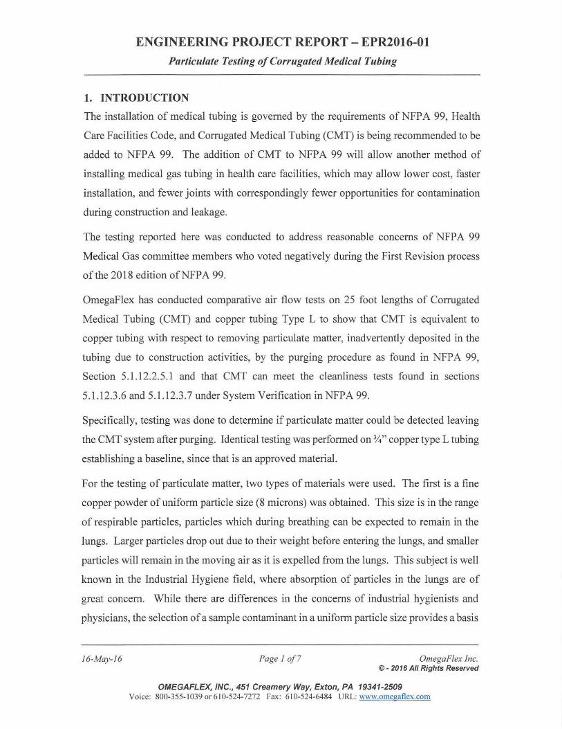
ENGINEERING PROJECT REPORT- EPR2016-0l
Particulate Testing of Corrugated Medical Tubing
1. INTRODUCTION
The installation of medical tubing is governed by the requirements of NFPA 99, Health
Care Facilities Code, and Corrugated Medical Tubing (CMT) is being recommended to be
added to NFP A 99. The addition of CMT to NFP A 99 will allow another method of
installing medical gas tubing in health care facilities, which may allow lower cost, faster
installation, and fewer joints with correspondingly fewer opportunities for contamination
during construction and leakage.
The testing reported here was conducted to address reasonable concerns of NFP A 99
Medical Gas committee members who voted negatively during the First Revision process
of the 2018 edition of NFP A 99.
OmegaFlex has conducted comparative air flow tests on 25 foot lengths of Corrugated
Medical Tubing (CMT) and copper tubing Type L to show that CMT is equivalent to
copper tubing with respect to removing particulate matter, inadvertently deposited in the
tubing due to construction activities, by the purging procedure as found in NFPA 99,
Section 5.1.12.2.5.1 and that CMT can meet the cleanliness tests found in sections
5.1.12.3.6 and 5.1.12.3.7 under System Verification in NFPA 99.
Specifically, testing was done to determine if particulate matter could be detected leaving
the CMT system after purging. Identical testing was performed on%" copper type L tubing
establishing a baseline, since that is an approved material.
For the testing of particulate matter, two types of materials were used. The first is a fine
copper powder of uniform particle size (8 microns) was obtained. This size is in the range
of respirable particles, particles which during breathing can be expected to remain in the
lungs. Larger particles drop out due to their weight before entering the lungs, and smaller
particles will remain in the moving air as it is expelled from the lungs. This subject is well
known in the Industrial Hygiene field, where absorption of particles in the lungs are of
great concern. While there are differences in the concerns of industrial hygienists and
physicians, the selection of a sample contaminant in a uniform particle size provides a basis
16-May-16 Page I of7 OmegaF/ex Inc. © - 2016 All Rights Reserved
OMEGAFLEX, INC., 451 Creamery Way, Exton, PA 19341-2509 Voice: 800-355-1039 or610-524-7272 Fax: 610-524-6484 URL: www.omegaflex.com
ENGINEERING PROJECT REPORT- EPR2016-0l
Particulate Testing of Corrugated Medical Tubing
for comparison that is in the range of sizes that are of concern to the lungs, and is believed
to be repeatable.
The second is particles of ground copper tubing. This simulates cutting and deburring
particles created during the normal installation of copper tubing.
The particulate tests were conducted on CMT and copper type L Tubing systems of 25 ft
lengths (no elbows or bends) to minimize the possibility of particles accumulating in the
tubing at bends and elbows. The CMT was 25 ft continuous length and the copper type L
consisted of coupled lengths of two 1 0 foot lengths and one 5 foot length.
16-May-16 Page 2 of7 OmegaF!ex Inc. © - 2016 All Rights Reserved
OMEGAFLEX, INC., 451 Creamery Way, Exton, PA 19341-2509 Voice: 800-355-1039 or 6 10-524-7272 Fax: 610-524-6484 URL: www.omegatlex.com
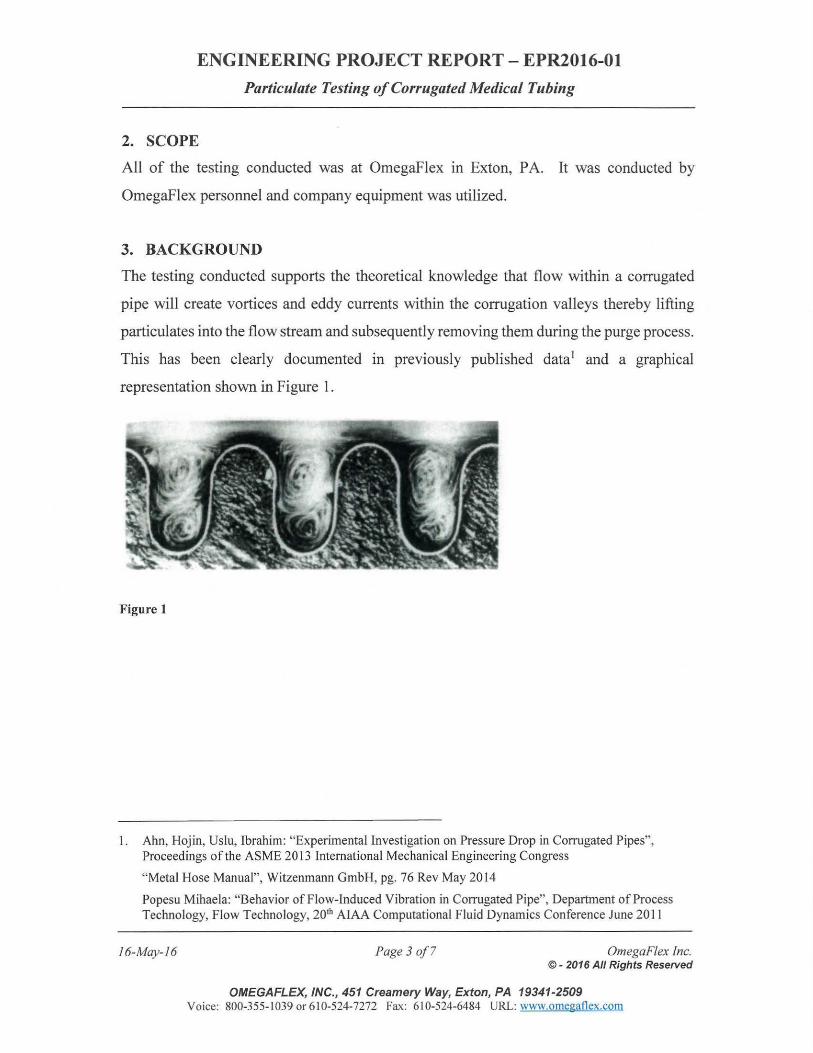
ENGINEERING PROJECT REPORT- EPR2016-0l
Particulate Testing of Corrugated Medical Tubing
2. SCOPE
All of the testing conducted was at Omegaflex in Exton, P A. It was conducted by
Omegaflex personnel and company equipment was utilized.
3. BACKGROUND
The testing conducted supports the theoretical knowledge that flow within a corrugated
pipe will create vortices and eddy currents within the corrugation valleys thereby lifting
particulates into the flow stream and subsequently removing them during the purge process.
This has been clearly documented in previously published data1 and a graphical
representation shown in Figure 1.
Figure 1
I. Ahn, Hojin, Uslu, Ibrahim: "Experimental Investigation on Pressure Drop in Corrugated Pipes", Proceedings ofthe ASME 2013 International Mechanical Engineering Congress
"Metal Hose Manual", Witzenmann GmbH, pg. 76 Rev May 2014
Popesu Mihaela: "Behavior of Flow-Induced Vibration in Corrugated Pipe", Department of Process Technology, Flow Technology, 20th AIAA Computational Fluid Dynamics Conference June 20 II
16-May-16 Page 3 of7 OmegaF/ex Inc. © - 2016 All Rights Reserved
OMEGAFLEX, INC., 451 Creamery Way, Exton, PA 19341-2509 Voice: 800-355-1039 or 6 10-524-7272 Fax: 610-524-6484 URL: www.omegaflex.com
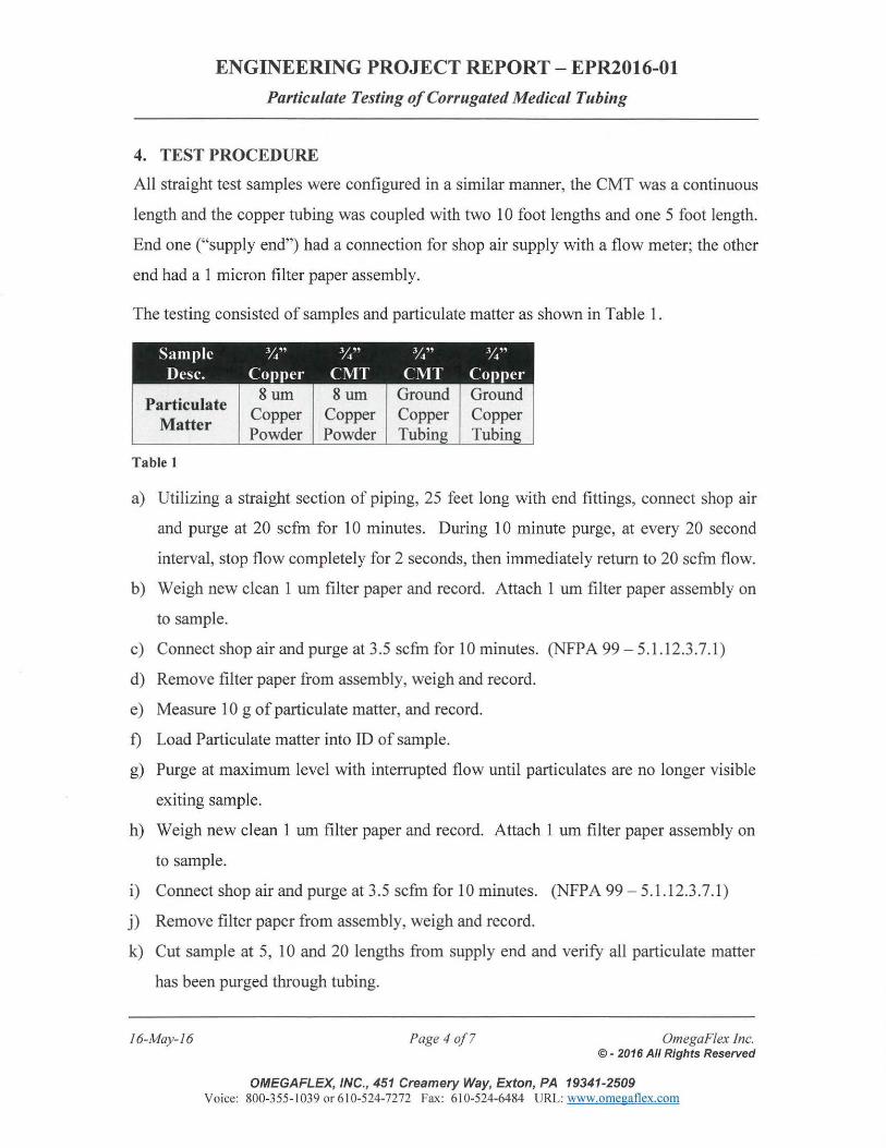
ENGINEERING PROJECT REPORT- EPR2016-0l
Particulate Testing of Corrugated Medical Tubing
4. TEST PROCEDURE
All straight test samples were configured in a similar manner, the CMT was a continuous
length and the copper tubing was coupled with two 10 foot lengths and one 5 foot length.
End one ("supply end") had a connection for shop air supply with a flow meter; the other
end had a 1 micron filter paper assembly.
The testing consisted of samples and particulate matter as shown in Table 1.
Sample Y." Y." Y." Y." Desc. Copper CMT C\1T Copper
Particulate Matter
Table I
8um Copper Powder
8um Copper Powder
Ground Copper Tubing
Ground Copper Tubing
a) Utilizing a straight section of piping, 25 feet long with end fittings, connect shop air
and purge at 20 scfm for 10 minutes. During 10 minute purge, at every 20 second
interval, stop flow completely for 2 seconds, then immediately return to 20 scfm flow.
b) Weigh new clean 1 urn filter paper and record. Attach 1 urn filter paper assembly on
to sample.
c) Connect shop air and purge at 3.5 scfm for 10 minutes. (NFPA 99- 5.1.12.3.7.1)
d) Remove filter paper from assembly, weigh and record.
e) Measure 10 g of particulate matter, and record.
f) Load Particulate matter into ID of sample.
g) Purge at maximum level with interrupted flow until particulates are no longer visible
exiting sample.
h) Weigh new clean 1 urn filter paper and record. Attach 1 urn filter paper assembly on
to sample.
i) Connect shop air and purge at 3.5 scfm for 10 minutes. (NFPA 99 - 5.1. 12.3.7.1)
j) Remove filter paper from assembly, weigh and record.
k) Cut sample at 5, 10 and 20 lengths from supply end and verify all particulate matter
has been purged through tubing.
16-May-16 Page 4 of7 OmegaF/ex Inc. © - 2016 All Rights Reserved
OMEGAFLEX, INC., 451 Creamery Way, Exton, PA 19341-2509 Voice: 800-355-1039 or6 10-524-7272 Fax: 610-524-6484 URL: www.omegatlex.com
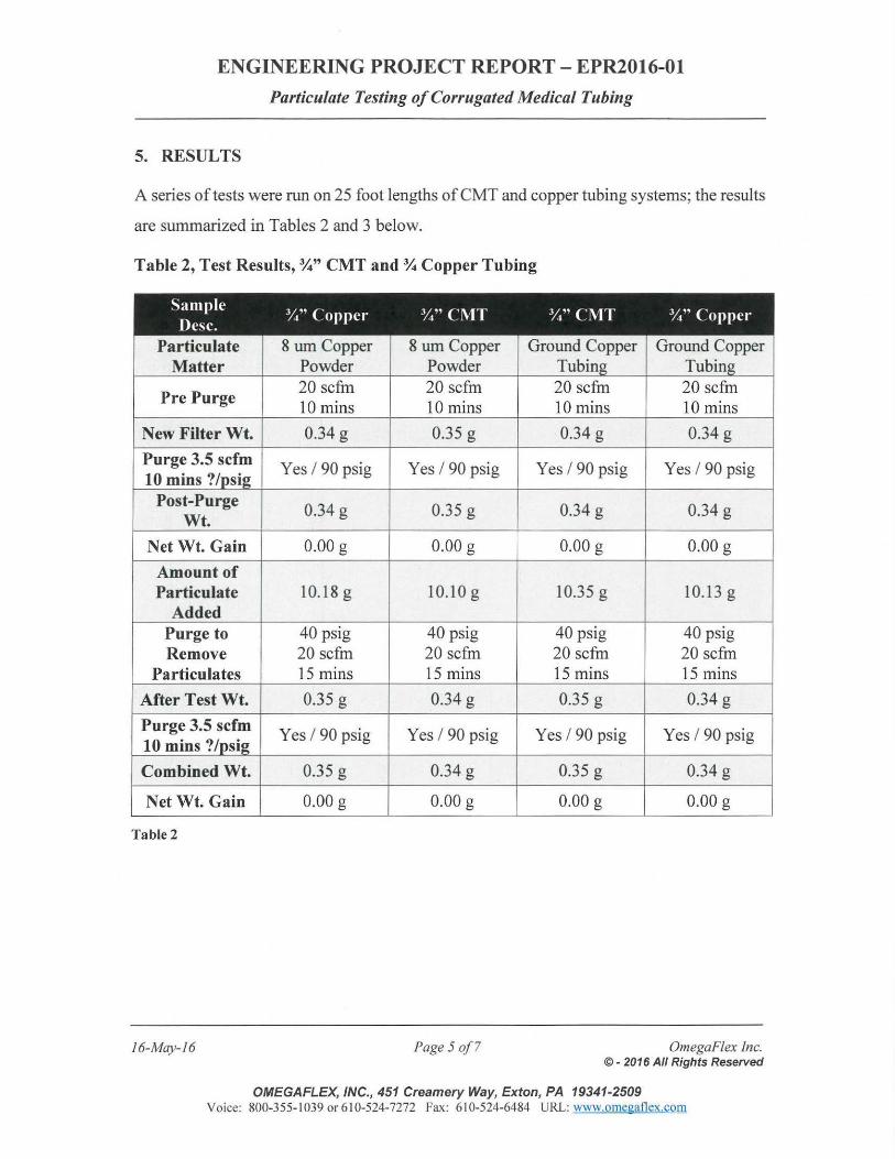
ENGINEERING PROJECT REPORT- EPR2016-0l
Particulate Testing of Corrugated Medical Tubing
5. RESULTS
A series of tests were run on 25 foot lengths of CMT and copper tubing systems; the results
are summarized in Tables 2 and 3 below.
Table 2, Test Results,%" CMT and% Copper Tubing
Particulate Matter
Pre Purge
New Filter Wt.
Purge 3.5 scfm 10 mins?
Post-Purge Wt.
Net Wt. Gain
Amount of Particulate
Added Purge to Remove
Particulates
After Test Wt.
Purge 3.5 scfm 10 mins?
Combined Wt.
Net Wt. Gain
Table2
16-May-16
8 urn Copper 8 urn Copper Powder Powder 20 scfm 20 scfm 10 mins 10 mins
0.34 g 0.35 g
Yes I 90 psig Yes I 90 psig
0.34 g 0.35 g
0.00 g 0.00 g
10.18 g 10.10 g
40 psig 40 psig 20 scfm 20 scfm 15 mins 15 mins
0.35 g 0.34 g
Yes I 90 psig Yes I 90 psig
0.35 g 0.34 g
0.00 g 0.00 g
Page 5 of7
Ground Copper Ground Copper
20 scfm 20 scfm 10 mins 10 mins
0.34 g 0.34 g
Yes I 90 psig Yes I 90 psig
0.34 g 0.34 g
0.00 g 0.00 g
10.35 g 10.13 g
40 psig 40 psig 20 scfm 20 scfm 15 mins 15 mins
0.35 g 0.34 g
Yes I 90 psig Yes I 90 psig
0.35 g 0.34 g
0.00 g 0.00 g
Omega Flex inc. ©- 2016 All Rights Reserved
OMEGAFLEX, INC., 451 Creamery Way, Exton, PA 19341-2509 Voice: 800-355- 1039 or 610-524-7272 Fax : 6 10-524-6484 URL: www.omegaflex.com
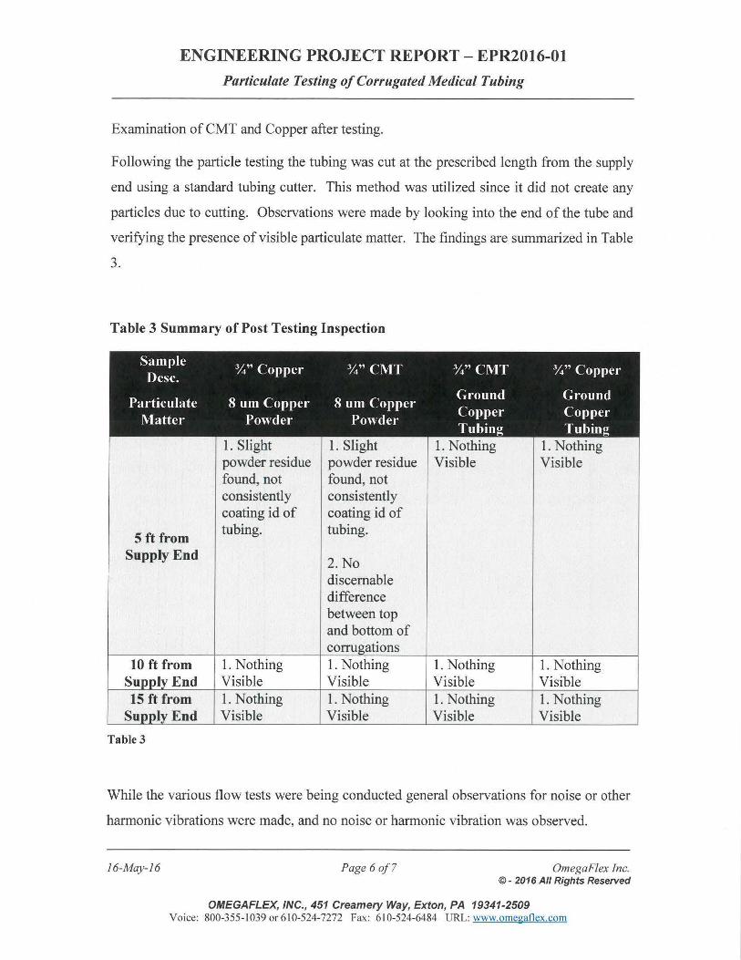
ENGINEERING PROJECT REPORT- EPR2016-0l
Particulate Testing of Corrugated Medical Tubing
Examination of CMT and Copper after testing.
Following the particle testing the tubing was cut at the prescribed length from the supply
end using a standard tubing cutter. This method was utilized since it did not create any
particles due to cutting. Observations were made by looking into the end of the tube and
verifying the presence of visible particulate matter. The findings are summarized in Table
3.
Table 3 Summary of Post Testing Inspection
Sample %"Copper %"CMT %"CMT %"Copper Des c.
Ground Ground Particulate 8 urn Copper 8 urn Copper Copper Copper Matter Powder Powder Tubing Tubing
1. Slight 1. Slight 1. Nothing 1. Nothing powder residue powder residue Visible Visible found, not found, not consistently consistently coating id of coating id of
5 ft from tubing. tubing.
Supply End 2.No discemable difference between top and bottom of
10ft from 1. Nothing 1. Nothing 1. Nothing 1. Nothing End Visible Visible Visible Visible
15ft from 1. Nothing 1. Nothing 1. Nothing 1. Nothing Su End Visible Visible Visible Visible
Table 3
While the various flow tests were being conducted general observations for noise or other
harmonic vibrations were made, and no noise or harmonic vibration was observed.
16-May-16 Page 6 of7 OmegaFlex Inc. © - 2016 All Rights Reserved
OMEGAFLEX, INC., 451 Creamery Way, Exton, PA 19341-2509 Voice: 800-355-1039 or 610-524-7272 Fax: 610-524-6484 URL: www.omegaflex.com
ENGINEERING PROJECT REPORT- EPR2016-0l
Particulate Testing of Corrugated Medical Tubing
6. CONCLUSION
The CMT system performed similarly as the copper system under the same test conditions.
During the post testing inspection of the ID, a light film of the residual copper powder was
found on near the application point on both the Copper tubing and the CMT. It did not
completely cover the ID circumference, it was spotty. Further analysis found no
discemable difference between top and bottom of corrugations on the CMT.
From these tests it can be concluded that a fine, respirable type particles or ground copper
tubing particles introduced into a CMT system will be removed during standard purge
process as does with copper tubing.
16-May-16 Page 7 o.f7 OmegaF/ex Inc. ©- 2016 All Rights Reserved
OMEGAFLEX, INC., 451 Creamery Way, Exton, PA 19341-2509 Voice: 800-355-1039 or 6 10-524-7272 Fax: 6 10-524-6484 URL: www.omegatlex.com
ENGINEERING PROJECT REPORT - EPR2016-01
Particulate Testing of Corrugated Medical Tubing
7. DOCUMENT APPROVALS -Revision A
Written By:
Approved By:
16-May-16
Owen Murphy Junior Project Engineer OmegaFlex, Inc.
Dean W. Rivest, P.E., MSME Vice-President & General Manager OmegaFlex, Inc.
OmegaFlex Inc. ©- 2016 All Rights Reserved
OMEGAFLEX, INC., 451 Creamery Way, Exton, PA 19341-2509 Voice: 800-355-1039 or610-524-7272 Fax: 610-524-6484 URL: www.omegaflex.com
16-May-16
ENGINEERING PROJECT REPORT- EPR2016-0l
Particulate Testing of Corrugated Medical Tubing
APPENDIX
AJ. Equipment List
Appendix Page 1 OmegaFlex Inc. © - 2016 All Rights Reserved
OMEGAFLEX, INC., 451 Creamery Way, Exton, PA 19341-2509 Voice: 800-355- I 039 or 6 I 0-524-7272 Fax: 6 I 0-524-6484 URL: www.omegatlex.com
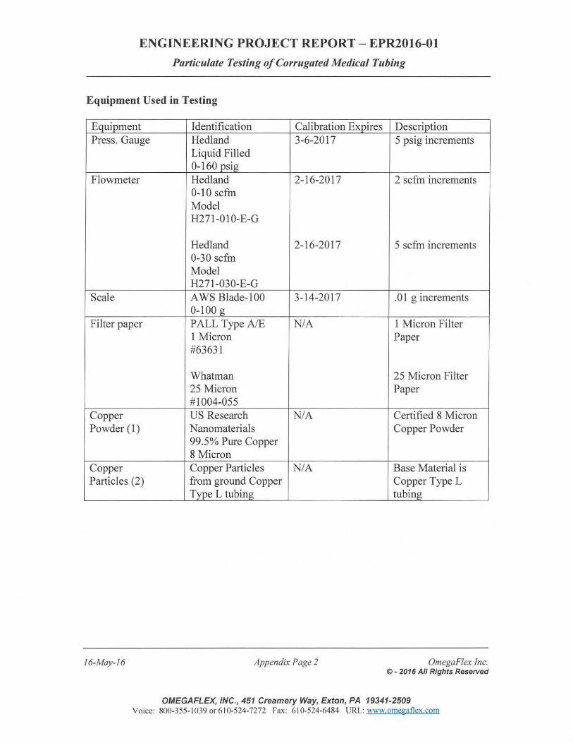
ENGINEERING PROJECT REPORT- EPR2016-0l
Particulate Testing of Corrugated Medical Tubing
Equipment Used in Testing
Equipment Press. Gauge
Flowmeter
Scale
Filter paper
Copper Powder (1)
Copper Particles (2)
16-May-16
Identification Calibration Expires Hedland 3-6-2017 Liquid Filled 0-160 psig Hedland 2-16-2017 0-10 scfm Model H271-010-E-G
Hedland 2-16-2017 0-30 scfm Model H271-030-E-G A WS Blade-1 00 3-14-2017 0-100 g PALL Type AlE N/A 1 Micron #63631
Whatman 25 Micron #1004-055 US Research N/A Nanomaterials 99.5% Pure Copper 8 Micron Copper Particles N/A from ground Copper Type L tubing
Appendix Page 2
Description 5 psig increments
2 scfm increments
5 scfm increments
.01 g increments
1 Micron Filter Paper
25 Micron Filter Paper
Certified 8 Micron Copper Powder
Base Material is Copper Type L tubing
OmegaFiex Inc. ©- 2016 All Rights Reserved
OMEGAFLEX, INC., 451 Creamery Way, Exton, PA 19341-2509 Voice: 800-355-1 039 or 610-524-7272 Fax: 610-524-6484 URL: www.omegaflex.com
16-May-16
ENGINEERING PROJECT REPORT- EPR2016-01
Particulate Testing of Corrugated Medical Tubing
APPENDIX
A.2 Documentation of Testing
Appendix Page 3 OmegaFlex Inc. ©- 2016 All Rights Reserved
OMEGAFLEX, INC., 451 Creamery Way, Exton, PA 19341-2509 Voice: 800-355-1039 or 610-524-7272 Fax: 610-524-6484 URL: www.omegaflex.com
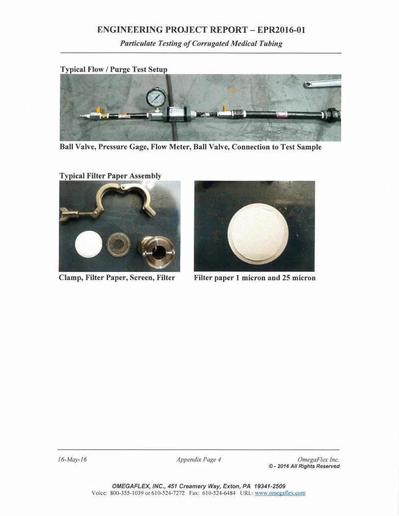
ENGINEERING PROJECT REPORT - EPR2016-0l
Particulate Testing of Corrugated Medical Tubing
Ball Valve, Pressure Gage, Flow Meter, Ball Valve, Connection to Test Sample
Clamp, Filter Paper, Screen, Filter Filter paper 1 micron and 25 micron
16-May-16 Appendix Page 4 OmegaFlex Inc. © - 2016 All Rights Reserved
OMEGAFLEX, INC., 451 Creamery Way, Exton, PA 19341-2509 Voice: 800-355-1 039 or 6 10-524-7272 Fax: 6 10-524-6484 URL: www.omegatlex.com
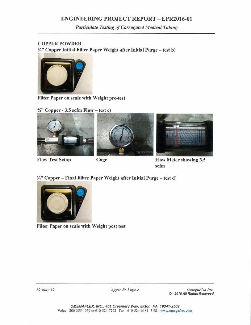
ENGINEERING PROJECT REPORT - EPR2016-0l
Particulate Testing of Corrugated Medical Tubing
COPPER POWDER %" Copper Initial Filter Paper Weight after Initial Purge - test b)
Filter Paper on scale with Weight pre-test
Flow Test Setup Gage Flow Meter showing 3.5 scfm
%"Copper - Final Filter Paper Weight after Initial Purge - test d)
Filter Paper on scale with Weight post test
16-May-16 Appendix Page 5 OmegaF/ex Inc. © - 2016 All Rights Reserved
OMEGAFLEX, INC., 451 Creamery Way, Exton, PA 19341-2509 Voice: 800-355-1 039 or 610-524-7272 Fax: 610-524-6484 URL: www.omegatlex.com
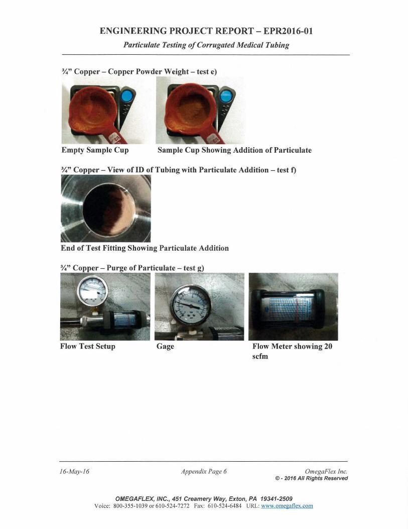
ENGINEERING PROJECT REPORT - EPR2016-0l
Particulate Testing of Corrugated Medical Tubing
%"Copper- Copper Powder Weight- test e)
- · " 4. ./
' . I
Empty Sample Cup Sample Cup Showing Addition of Particulate
End of Test Fitting Showing Particulate Addition
Flow Test Setup
16-May- 16
Gage
Appendix Page 6
Flow Meter showing 20 scfm
OmegaFlex Inc. © - 2016 All Rights Reserved
OMEGAFLEX, INC., 451 Creamery Way, Exton, PA 19341-2509 Voice: 800-355-1039 or 610-524-7272 Fax: 610-524-6484 URL: www.omegaflex.com
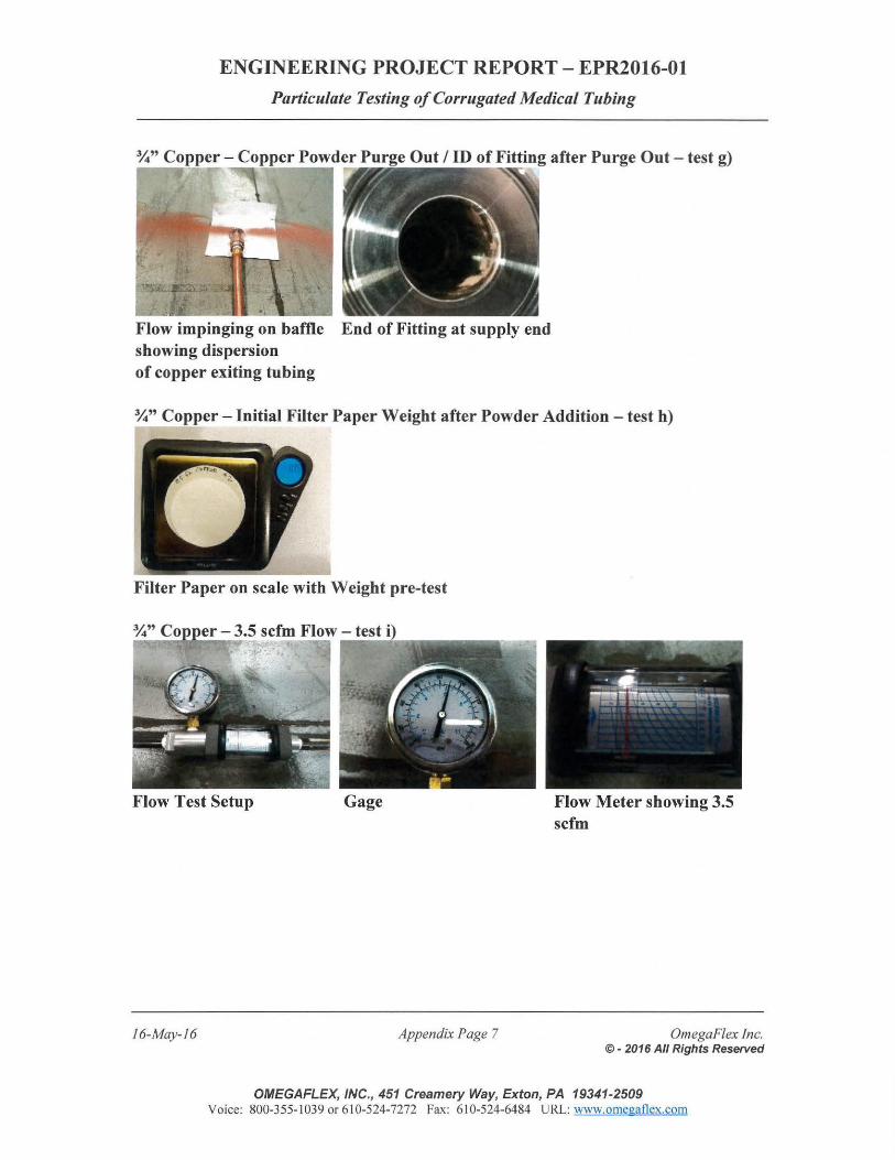
ENGINEERING PROJECT REPORT- EPR2016-0l
Particulate Testing of Corrugated Medical Tubing
Out I ID of Fitting after Purge Out - test g)
Flow impinging on baffle End of Fitting at supply end showing dispersion of copper exiting tubing
%"Copper- Initial Filter Paper Weight after Powder Addition- test h)
Filter Paper on scale with Weight pre-test
Flow Test Setup Gage
16-May-16 Appendix Page 7
Flow Meter showing 3.5 scfm
OmegaF/ex Inc. © - 2016 All Rights Reserved
OMEGAFLEX, INC., 451 Creamery Way, Exton, PA 19341-2509 Voice: 800-355-1 039 or 6 10-524-7272 Fax: 6 10-524-6484 URL: www.omegaflex.com
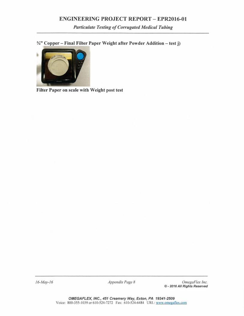
ENGINEERING PROJECT REPORT- EPR2016-0l
Particulate Testing of Corrugated Medical Tubing
%" Copper- Final Filter Paper Weight after Powder Addition- test j)
Filter Paper on scale with Weight post test
16-May-16 Appendix Page 8 OmegaFlex Inc. © - 2016 All Rights Reserved
OMEGAFLEX, INC., 451 Creamery Way, Exton, PA 19341-2509 Voice: 800-355-1 039 or 610-524-7272 Fax: 610-524-6484 URL: www.omegaflex.com
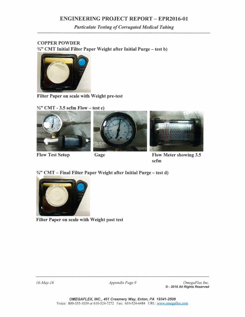
ENGINEERING PROJECT REPORT - EPR2016-0l
Particulate Testing of Corrugated Medical Tubing
COPPER POWDER %" CMT Initial Filter Paper Weight after Initial Purge- test b)
Filter Paper on scale with Weight pre-test
Flow Test Setup Gage Flow Meter showing 3.5 scfm
%" CMT - Final Filter Paper Weight after Initial Purge - test d)
Filter Paper on scale with Weight post test
16-May- 16 Appendix Page 9 OmegaFlex Inc. ©- 2016 All Rights Reserved
OMEGAFLEX, INC., 451 Creamery Way, Exton, PA 19341-2509 Voice: 800-355- 1039 or 61 0-524-7272 Fax: 610-524-6484 URL: www.omegaflex.com
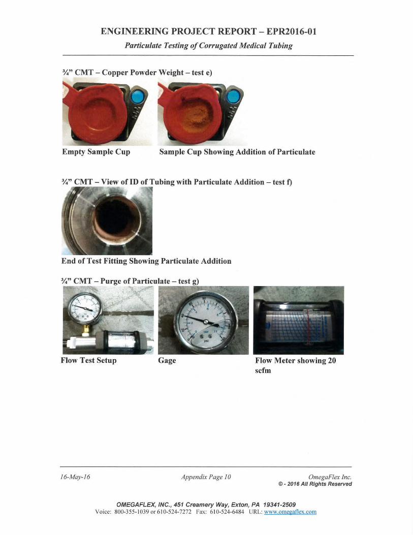
ENGINEERING PROJECT REPORT- EPR2016-0l
Particulate Testing of Corrugated Medical Tubing
%" CMT- Copper Powder Weight - test e)
Empty Sample Cup Sample Cup Showing Addition of Particulate
End of Test Fitting Showing Particulate Addition
Flow Test Setup
16-May-16
Gage
Appendix Page I 0
Flow Meter showing 20 scfm
OmegaF/ex Inc. © - 2016 All Rights Reserved
OMEGAFLEX, INC., 451 Creamery Way, Exton, PA 19341-2509 Voice: 800-355-1 039 or 610-524-7272 Fax: 610-524-6484 URL: www.omegaflex.com
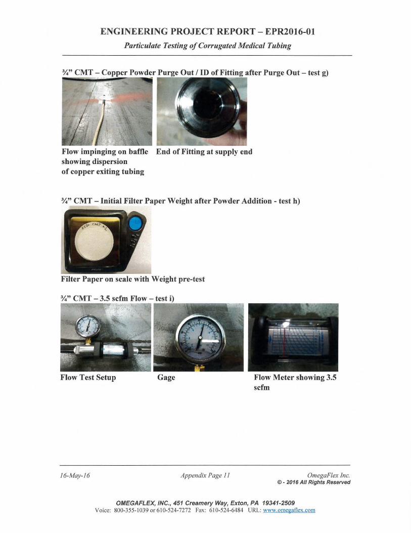
ENGINEERING PROJECT REPORT- EPR2016-01
Particulate Testing of Corrugated Medical Tubing
Flow impinging on baffle End of Fitting at supply end showing dispersion of copper exiting tubing
%" CMT- Initial Filter Paper Weight after Powder Addition- test h)
Filter Paper on scale with Weight pre-test
Flow Test Setup Gage
16-May-16 Appendix Page 11
Flow Meter showing 3.5 scfm
OmegaF/ex Inc. © - 2016 All Rights Reserved
OMEGAFLEX, INC., 451 Creamery Way, Exton, PA 19341-2509 Voice: 800-355- I 039 or 6 I 0-524-7272 Fax: 6 I 0-524-6484 URL: www.omegaflex.com
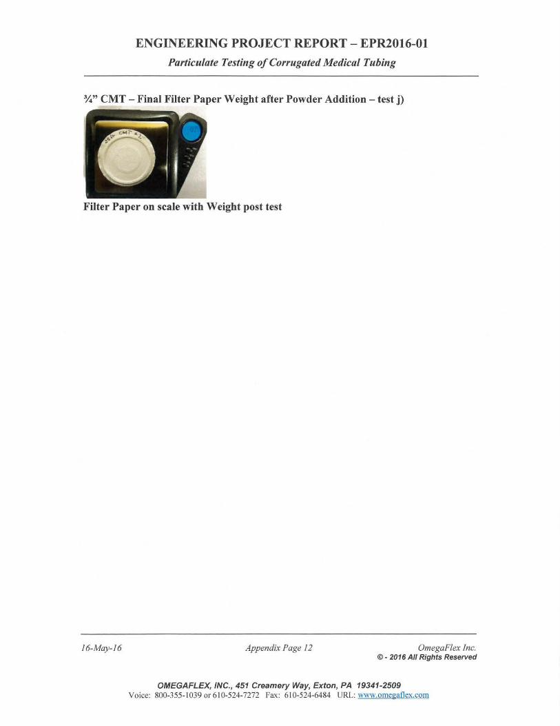
ENGINEERING PROJECT REPORT- EPR2016-01
Particulate Testing of Corrugated Medical Tubing
%" CMT - Final Filter Paper Weight after Powder Addition- test j)
Filter Paper on scale with Weight post test
16-May-16 Appendix Page 12 OmegaFlex Inc. © - 2016 All Rights Reserved
OMEGAFLEX, INC., 451 Creamery Way, Exton, PA 19341-2509 Voice: 800-355-1 039 or 610-524-7272 Fax: 61 0-524-6484 URL: www.omegatlex.com
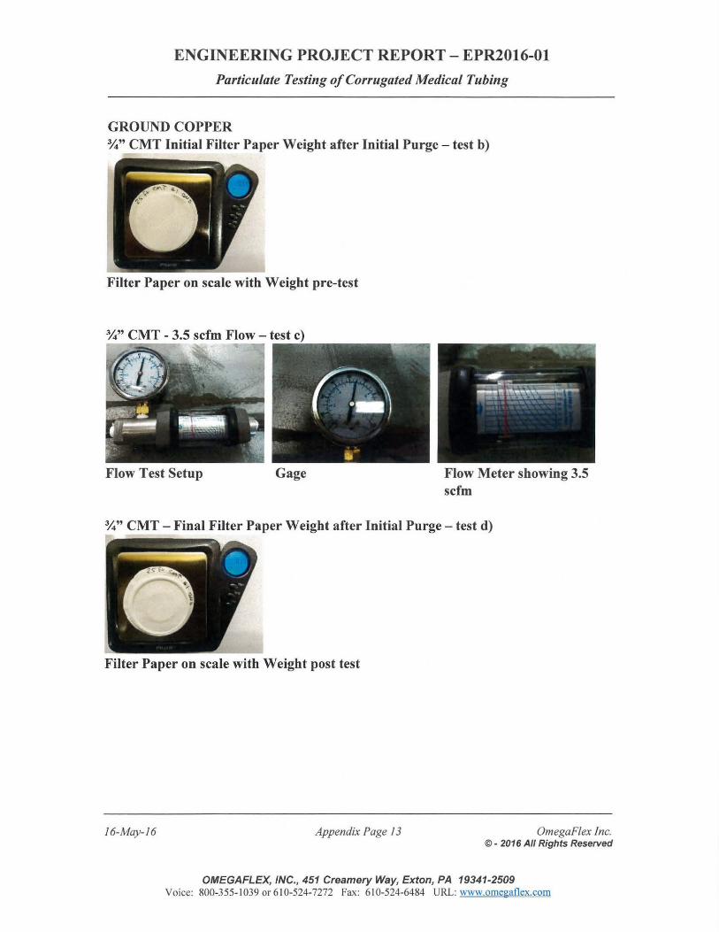
ENGINEERING PROJECT REPORT- EPR2016-0l
Particulate Testing of Corrugated Medical Tubing
GROUND COPPER %" CMT Initial Filter Paper Weight after Initial Purge- test b)
Filter Paper on scale with Weight pre-test
Flow Test Setup Gage Flow Meter showing 3.5 scfm
%" CMT -Final Filter Paper Weight after Initial Purge- test d)
Filter Paper on scale with Weight post test
16-May- 16 Appendix Page 13 OmegaF/ex Inc. © - 2016 All Rights Reserved
OMEGAFLEX, INC., 451 Creamery Way, Exton, PA 19341-2509 Voice: 800-355-1039 or610-524-7272 Fax: 610-524-6484 URL: www.omegatlex.com
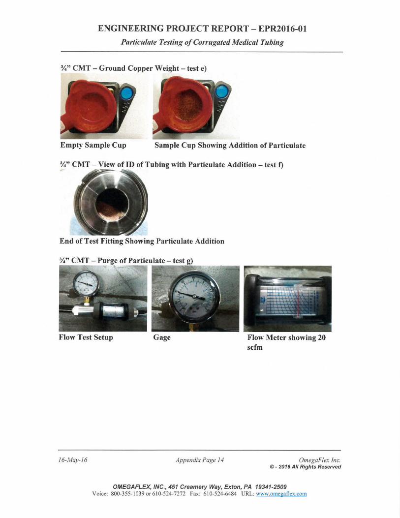
ENGINEERING PROJECT REPORT- EPR2016-01
Particulate Testing of Corrugated Medical Tubing
%" CMT - Ground Copper Weight - test e)
Empty Sample Cup Sample Cup Showing Addition of Particulate
%" CMT - View of ID of Tubing with Particulate Addition - test f)
End of Test Fitting Showing Particulate Addition
Flow Test Setup Gage
16-May-16 Appendix Page 14
Flow Meter showing 20 scfm
Omega Flex Inc. ©- 2016 All Rights Reserved
OMEGAFLEX, INC., 451 Creamery Way, Exton, PA 19341-2509 Voice: 800-355-1039 or 610-524-7272 Fax: 61 0-524-6484 URL: www.omegatlex.com
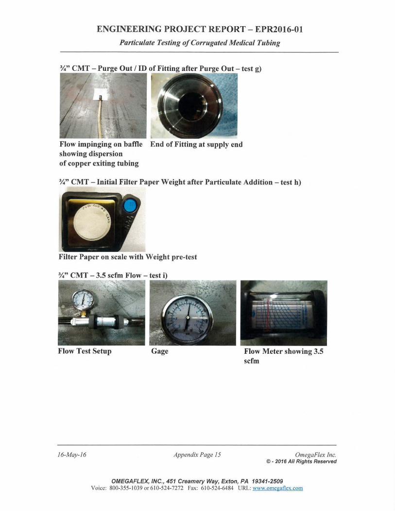
ENGINEERING PROJECT REPORT- EPR2016-01
Particulate Testing of Corrugated Medical Tubing
Flow impinging on baffle End of Fitting at supply end showing dispersion of copper exiting tubing
%" CMT- Initial Filter Paper Weight after Particulate Addition - test h)
-• • •
Filter Paper on scale with Weight pre-test
Flow Test Setup Gage
16-May-16 Appendix Page 15
Flow Meter showing 3.5 scfm
OmegaFlex Inc. © • 2016 All Rights Reserved
OMEGAFLEX, INC., 451 Creamery Way, Exton, PA 19341-2509 Voice: 800-355-1 039 or 61 0-524-7272 Fax: 61 0-524-6484 URL: www.omegaflex.com
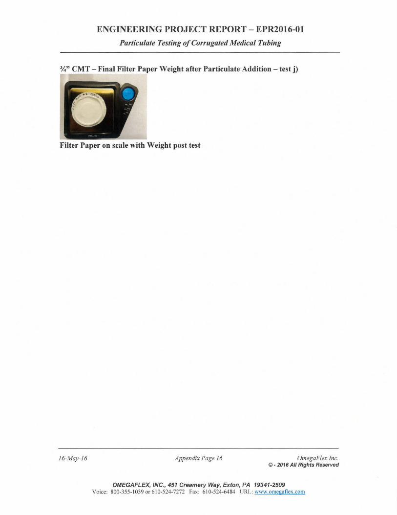
ENGINEERING PROJECT REPORT- EPR2016-01
Particulate Testing of Corrugated Medical Tubing
%" CMT - Final Filter Paper Weight after Particulate Addition - test j)
Filter Paper on scale with Weight post test
16-May-16 Appendix Page 16 OmegaFlex Inc. ©- 2016 All Rights Reserved
OMEGAFLEX, INC., 451 Creamery Way, Exton, PA 19341-2509 Voice: 800-355- 1039 or 610-524-7272 Fax: 61 0-524-6484 URL: www.omegaflex.com
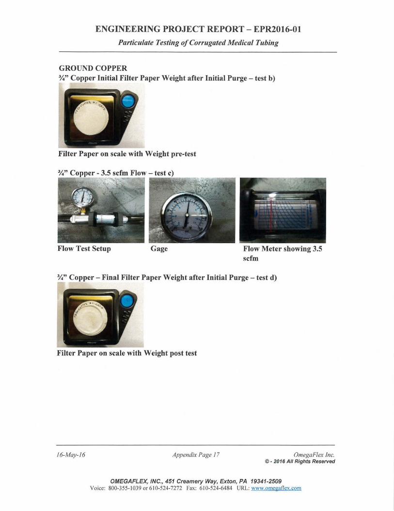
ENGINEERING PROJECT REPORT- EPR2016-0l
Particulate Testing of Corrugated Medical Tubing
GROUND COPPER %"Copper Initial Filter Paper Weight after Initial Purge- test b)
Filter Paper on scale with Weight pre-test
Flow Test Setup Gage Flow Meter showing 3.5 scfm
%" Copper - Final Filter Paper Weight after Initial Purge - test d)
--.• , "
Filter Paper on scale with Weight post test
16-May-16 Appendix Page 17 OmegaFlex Inc. © - 2016 All Rights Reserved
OMEGAFLEX, INC., 451 Creamery Way, Exton, PA 19341-2509 Voice: 800-355-1039 or 610-524-7272 Fax: 610-524-6484 URL: www.omegatlex.com
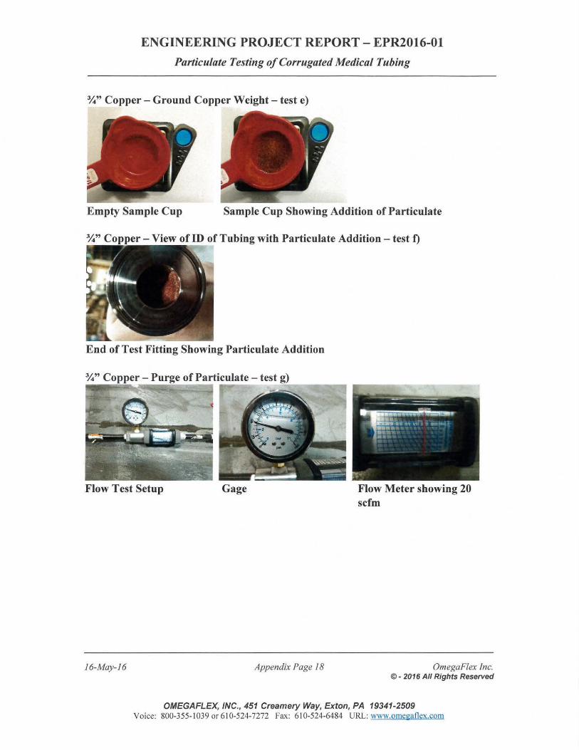
ENGINEERING PROJECT REPORT- EPR2016-0l
Particulate Testing of Corrugated Medical Tubing
%"Copper- Ground Copper Weight- test e)
Empty Sample Cup Sample Cup Showing Addition of Particulate
- View of ID of Tubing with Particulate Addition - test f)
End of Test Fitting Showing Particulate Addition
Flow Test Setup
16-May-16
Gage
Appendix Page 18
Flow Meter showing 20 scfm
OmegaF/ex Inc. © - 2016 All Rights Reserved
OMEGAFLEX, INC., 451 Creamery Way, Exton, PA 19341-2509 Voice: 800-355- 1039 or 610-524-7272 Fax: 610-524-6484 URL: www.omegaflex.com
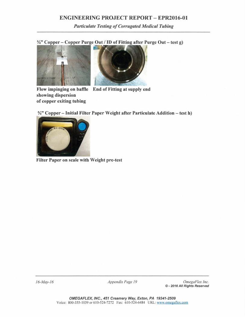
ENGINEERING PROJECT REPORT- EPR2016-01
Particulate Testing of Corrugated Medical Tubing
Flow impinging on baffle End of Fitting at supply end showing dispersion of copper exiting tubing
%"Copper - Initial Filter Paper Weight after Particulate Addition- test h)
Filter Paper on scale with Weight pre-test
16-May-16 Appendix Page 19 OmegaFlex Inc. © - 2016 All Rights Reserved
OMEGAFLEX, INC., 451 Creamery Way, Ex ton, PA 19341-2509 Voice: 800-355- 1039 or 610-524-7272 Fax: 610-524-6484 URL: www.omegaflex.com
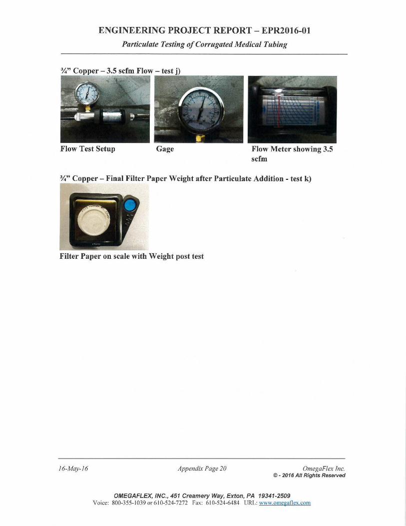
ENGINEERING PROJECT REPORT- EPR2016-0l
Particulate Testing of Corrugated Medical Tubing
Flow Test Setup Gage Flow Meter showing 3.5 scfm
%"Copper - Final Filter Paper Weight after Particulate Addition- test k)
Filter Paper on scale with Weight post test
16-May-16 Appendix Page 20 OmegaFlex Inc. ©- 2016 All Rights Reserved
OMEGAFLEX, INC., 451 Creamery Way, Exton, PA 19341-2509 Voice: 800-355-1039 or 610-524-7272 Fax: 610-524-6484 URL: www.omegaflex.com
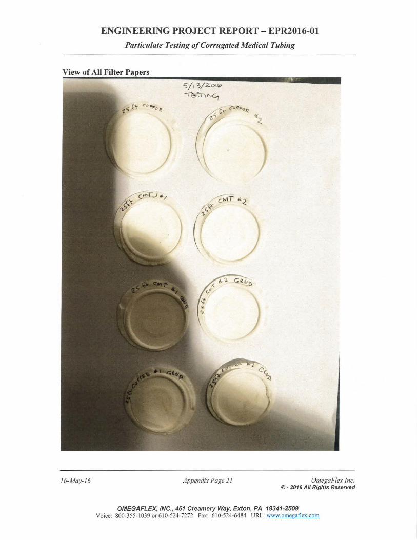
ENGINEERING PROJECT REPORT - EPR2016-01
Particulate Testing of Corrugated Medical Tubing
View of All Filter Papers
16-May-16 Appendix Page 2 1 OmegaF/ex Inc. © - 2016 All Rights Reserved
OMEGAFLEX, INC., 451 Creamery Way, Exton, PA 19341-2509 Voice: 800-355- 1039 or 61 0-524-7272 Fax: 610-524-6484 URL: www.omegaflex.com
16-May-16
ENGINEERING PROJECT REPORT- EPR2016-0l
Particulate Testing of Corrugated Medical Tubing
APPENDIX
A.2 Test Data Sheets
Appendix Page 22 OmegaF/ex Inc. © - 2016 All Rights Reserved
OMEGAFLEX,INC., 451 Creamery Way, Exton, PA 19341-2509 Voice: 800-355-1039 or 610-524-7272 Fax: 610-524-6484 URL: www.omegaflex.com
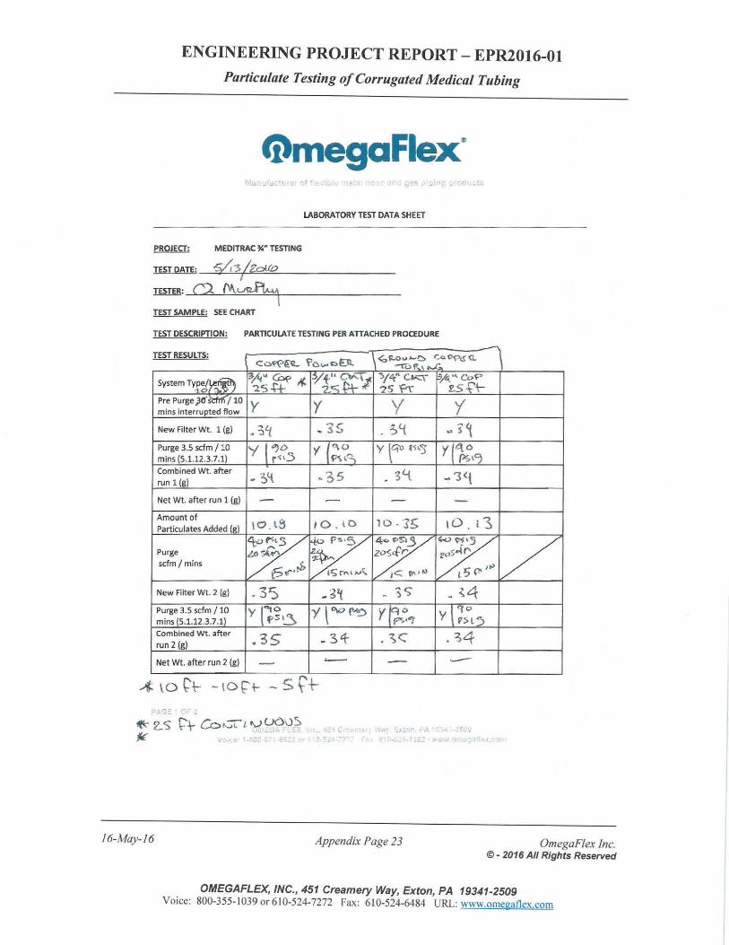
ENGINEERING PROJECT REPORT - EPR2016-01
Particulate Testing of Corrugated Medical Tubing
tnmegaflex' ,,. d .ts
LABORATORY TEST DATA SHEET
MEDITRAC %n TESTING
TEST DATE: -s.A-.s I Zp!.(O I
TESTER: ('9, M_u~ - I TEST SAMPLE: SEE CHART
TEST DESCRIPTION: PARTICULATE TESTING PER A IT ACHED PROCEDURE
TEST RESULTS:
System T~r.~~ Pre Purge )6' S'ctr!1 I 10 mins interrupted flow
New Filter Wt. 1 (g)
Purge 3.5 scfm I 10 mins (5.1.12.3.7.1) Combined Wt. after run 1 (g)
Net Wt. afte r run 1 (g)
Amount of Particulates Added (g)
Purge scfm I mins
New Filter Wt. 2 (g)
Purge 3.5 scfm I 10 mins (5.1.12.3.7.1} Combined Wt. after
run 2 (g)
y y y '( • ?,'f .3S ~q .. s~ y l7<C:5 y (;.~~ y \qo t~\.s y ([;tCJ -~'{ ~ 35 . 3t.t -1<{
- - - -IO . l3 10, tD 10- "3E;
\
<to y VHS
. 35 .34- . ~c Net Wt. after run 2 (g) - -
16-May-16
, I (
•. :J •.
Appendix Page 23 Omega Flex Inc. © • 2016 All Rights Reserved
OMEGAFLEX, INC., 451 Creamery Way, Exton, PA 19341-2509 Voice: 800-355- I 039 or 6 I 0-524-7272 Fax: 610-524-6484 URL: www.omegaflex.com
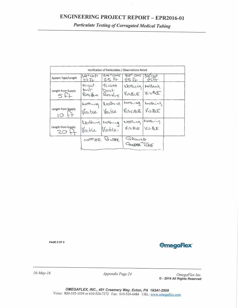
ENGINEERING PROJECT REPORT- EPR2016-01
Particulate Testing of Corrugated Medical Tubing
Verification of Particulates I Observations Noted
System Type/ Length v~<{eo J:> -11+'·~ '>{4"• ~ · Y~_fr_ ?5 'H- 2-S N- '25 +'+-?lLt-t- 1 Lt.&l71> Woi'\Nt.~j ~l:t.W,
Length f rom Supply 'b~ ['2o<..+-V~.st ~L.£ '(L'>t~
5~-t-- ~t~ ~~tJv-e_
~~"~ lJo~~ ~~~ ~o'\:k.,~"-\ Length from Supply VLsJ\.P... '(\,s.s ,<3cd. v .. s\~
LO ~t· \fv'> L bltl.-
lb~~ ~Vv"'j ~~ "-=-~·4
Leng~~Su~~ Vt)t bl.L Vvs1 bU-' (L\i.~lC \Is~ &,L
c..oY"?~ Q. ~ G."=..., r
" J.~\Zibe ----
PAGE20F2
16-May-16 Appendix Page 24 OmegaF!ex inc. © - 2016 All Rights Reserved
OMEGAFLEX, INC., 451 Creamery Way, Exton, PA 19341-2509 Voice: 800-355-1 039 or 6 10-524-7272 Fax: 610-524-6484 URL: www.omegaflex.com
16-May- 16
ENGINEERING PROJECT REPORT- EPR2016-0l
Particulate Testing of Corrugated Medical Tubing
PARTICULATE FLOW TESTING
Product: M ediTrac• %'' Corrugated M etal Tubing (CMT) and %'' Copper Type L Tubing
MediTrac Flow Testing Rev B.docx
Appendix Page 25 OmegaFlex Inc. ©- 2016 All Rights Reserved
OMEGAFLEX, INC., 451 Creamery Way, Exton, PA 19341-2509 Voice: 800-355-1 039 or 610-524-7272 Fax: 610-524-6484 URL: www.omegatlex.com
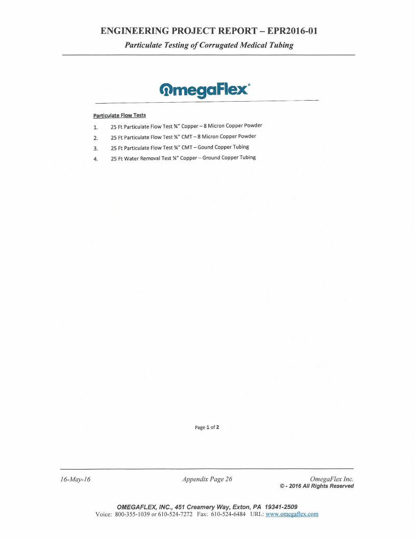
16-May-16
ENGINEERING PROJECT REPORT- EPR2016-0l
Particulate Testing of Corrugated Medical Tubing
@mega Flex* Particulate Flow Tests
1. 25 Ft Particulate Flow Test W' Copper- 8 Micron Copper Powder
2. 25Ft Particulate Flow Test W' CMT - 8 Micron Copper Powder
3. 25 Ft Particulate Flow Test W' CMT- Gound Copper Tubing
4. 25 Ft Water Removal Test :Y." Copper- Ground Copper Tubing
Page 1 of2
Appendix Page 26 OmegaF/ex Inc. © - 2016 All Rights Reserved
OMEGAFLEX, INC., 451 Creamery Way, Exton, PA 19341-2509 Voice: 800-355-1039 or 610-524-7272 Fax: 610-524-6484 URL: www.omegatlex.com
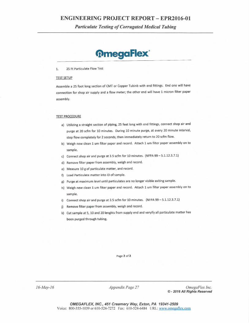
16-May-16
ENGINEERING PROJECT REPORT- EPR2016-01
Particulate Testing of Corrugated Medical Tubing
@mega Flex" 1. 25 Ft Particulate Flow Test
TEST SETUP
Assemble a 2S foot long section of CMT or Copper Tubinb with end fittings. End one will have
connection for shop air supply and a flow meter; the other end will have 1 micron filter paper
assembly.
TEST PROCEDURE
a) Utilizing a straight section of piping, 25 feet long with end fittings, connect shop air and
purge at 20 scfm for 10 minutes. During 10 minute purge, at every 20 minute interval,
stop flow completely for 2 seconds, then immediately return to 20 scfm flow.
b) Weigh new clean 1 urn filter paper and record. Attach 1 urn filter paper assembly on to
sample.
c) Connect shop air and purge at 3.5 scfm for 10 minutes. (NFPA 99- 5.1.12.3. 7.1)
d) Remove filter paperfrom assembly, weigh and record.
e) Measure 10 g of particulate matter, and record.
f) load Particulate matter into ID of sample.
g) Purge at maximum level until particulates are no longer visible exiting sample.
h) Weigh new clean 1 urn filter paper and record. Attach 1 urn filter paper assembly on to
sample.
i) Connect shop air and purge at 3.5 scfm for 10 minutes. (NFPA 99- 5.1.12.3.7.1}
j) Remove filter paper from assembly, weigh and record .
k) Cut sample at 5, 10 and 20 lenghts from supply end and veryify all particulate matter has
been purged through tubing.
Page 2 of 2
Appendix Page 27 OmegaFlex Inc. © - 2016 All Rights Reserved
OMEGAFLEX, INC., 451 Creamery Way, Exton, PA 19341-2509 Voice: 800-355-1039 or 610-524-7272 Fax: 610-524-6484 URL: www.omegaflex.com
16-May-16
ENGINEERING PROJECT REPORT- EPR2016-0l
Particulate Testing of Corrugated Medical Tubing
APPENDIX
A.3 Copper Powder Certificate
Appendix Page 28 OmegaF!ex inc. © - 2016 All Rights Reserved
OMEGAFLEX, INC., 451 Creamery Way, Exton, PA 19341-2509 Voice: 800-355- 1039 or 610-524-7272 Fax: 61 0-524-6484 URL: www.omegaflex.com
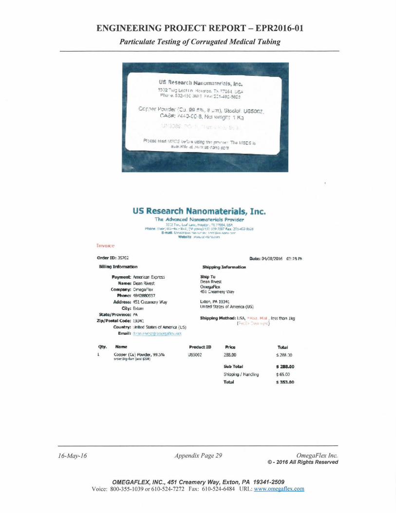
16-May-16
ENGINEERING PROJECT REPORT - EPR2016-0l
Particulate Testing of Corrugated Medical Tubing
U5 qf'S.~rc ll N;,uomari"'N'I~. Inc. ·~·)2-.,; ~=I I n •t : e,.,·,n. ~~ ~;~~ ~ gt-u ~. !3'2··1,( ~,;.; -~rt· :.:1-a.p:_.se:~
C.c:p:.r 1-'cr,-.-:ter ·~J ~ := ~ .. l!' - ·11), :;t-.;c;Qt tJ8SOC; CAOIII: I,;.!. J-!C· e. P..J~I 11/P.I~:Jr~ i f<,~
Fit:'~ f!ad t\1~[:._:: !.:4'':.. W UEl~ rtt· f'lf"'\• IIC' i"},. t.•._sc ~ I:, a • .,. ,,u. 411. .•~ 'I :n; r ,:,~: e~ -n
us Research Nanomaterials, Inc. Tile Acll.onced Nanomatel"ic!ls PI"''Mder
1;:z T·ll'. !..~ LM,., -~~ , "'- ''Q!ol. US" ,.,.,Dnf: .. .,.; .. ., , ,.,..... , - • ,.1. ~"tt,.-.. .. ,) .. i ) ~;:.ar •u ::51 ..... -::.t·l!tJI
E-m•l. S-~·,.,~••.r, '"•lT 1.r m· ll"fT:C. F. n."lro ·n..-w.Hit• ~tW.. U>I'\1 '"~IJ.U:nt
Ol"de' ID: 35702
Billing ldomwdon
Pa)'lllellll: .r\rnerolr Exj)rcs:;
~-~ ~ao Rivest CMIJ)III'f: ~aFlex
PhOIICl '18'12:88(1917
Addtes.5; i51 Qe..ruy WoJy
Cily: E~Lur1
SltiCeJ Pro\1111(8; PA Zip/ PMtal ~: Ul_,..l
Coullhy: ,Jnled Slllte5 cf Amel'lcll (US)
ElTiilil: -,n r • '""'
Qt¥. NllrM
Cooper (C.U) 1'0\V!Ier, 'fl. ~'lW ..--or.Jiq-ium (ood ~~)
5hi~ Infar1nalja.
Ship TD !lean Rr.est On~ 4S 1 CJQmerv \'lay
lxtO"', PA 193'\l Un'lrd ~!M or Amfrial. (us:.
Shipping Mediad: l..S.\, (
ProductiD l!'rici:
USS002 lBS.OO
!iiOrjjf<>QI
S!lill!ling I Handi~Y,~
TDbl
Appendix Page 29
Tot.JI
$ 2Rfi ~()
• 218.00
$65.00
$353.00
OmegaFlex Inc. © - 2016 All Rights Reserved
OMEGAFLEX, INC., 451 Creamery Way, Exton, PA 19341-2509 Voice: 800-355-1039 or 610-524-7272 Fax: 610-524-6484 URL: www.omegatlex.com
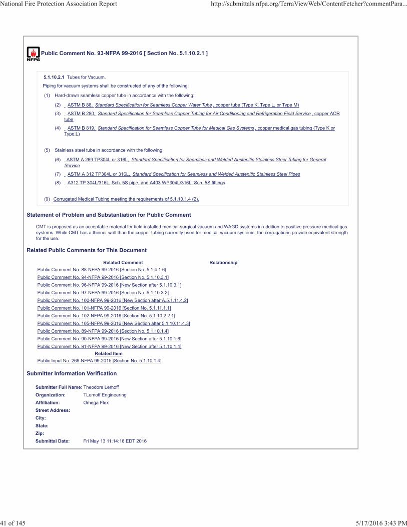
Public Comment No. 93-NFPA 99-2016 [ Section No. 5.1.10.2.1 ]
5.1.10.2.1 Tubes for Vacuum.
Piping for vacuum systems shall be constructed of any of the following:
(1) Hard-drawn seamless copper tube in accordance with the following:
(2) ASTM B 88, Standard Specification for Seamless Copper Water Tube , copper tube (Type K, Type L, or Type M)
(3) ASTM B 280, Standard Specification for Seamless Copper Tubing for Air Conditioning and Refrigeration Field Service , copper ACRtube
(4) ASTM B 819, Standard Specification for Seamless Copper Tube for Medical Gas Systems , copper medical gas tubing (Type K orType L)
(5) Stainless steel tube in accordance with the following:
(6) ASTM A 269 TP304L or 316L, Standard Specification for Seamless and Welded Austenitic Stainless Steel Tubing for GeneralService
(7) ASTM A 312 TP304L or 316L, Standard Specification for Seamless and Welded Austenitic Stainless Steel Pipes
(8) A312 TP 304L/316L, Sch. 5S pipe, and A403 WP304L/316L, Sch. 5S fittings
(9) Corrugated Medical Tubing meeting the requirements of 5.1.10.1.4 (2).
Statement of Problem and Substantiation for Public Comment
CMT is proposed as an acceptable material for field-installed medical-surgical vacuum and WAGD systems in addition to positive pressure medical gas systems. While CMT has a thinner wall than the copper tubing currently used for medical vacuum systems, the corrugations provide equivalent strength for the use.
Related Public Comments for This Document
Related Comment RelationshipPublic Comment No. 88-NFPA 99-2016 [Section No. 5.1.4.1.6]Public Comment No. 94-NFPA 99-2016 [Section No. 5.1.10.3.1]Public Comment No. 96-NFPA 99-2016 [New Section after 5.1.10.3.1]Public Comment No. 97-NFPA 99-2016 [Section No. 5.1.10.3.2]Public Comment No. 100-NFPA 99-2016 [New Section after A.5.1.11.4.2]Public Comment No. 101-NFPA 99-2016 [Section No. 5.1.11.1.1]Public Comment No. 102-NFPA 99-2016 [Section No. 5.1.10.2.2.1]Public Comment No. 105-NFPA 99-2016 [New Section after 5.1.10.11.4.3]Public Comment No. 89-NFPA 99-2016 [Section No. 5.1.10.1.4]Public Comment No. 90-NFPA 99-2016 [New Section after 5.1.10.1.6]Public Comment No. 91-NFPA 99-2016 [New Section after 5.1.10.1.4]
Related ItemPublic Input No. 269-NFPA 99-2015 [Section No. 5.1.10.1.4]
Submitter Information Verification
Submitter Full Name: Theodore LemoffOrganization: TLemoff EngineeringAffilliation: Omega FlexStreet Address:City:State:Zip:Submittal Date: Fri May 13 11:14:16 EDT 2016
National Fire Protection Association Report http://submittals.nfpa.org/TerraViewWeb/ContentFetcher?commentPara...
41 of 145 5/17/2016 3:43 PM
Public Comment No. 102-NFPA 99-2016 [ Section No. 5.1.10.2.2.1 ]
5.1.10.2.2.1
If copper or CMT vacuum tubing is installed along with any medical gas tubing, the vacuum tubing shall, prior to installation, be prominentlylabeled or otherwise identified to preclude using materials or installation procedures in the medical gas system that are not suitable for oxygenservice.
Statement of Problem and Substantiation for Public Comment
This revision will provide the same installation requirements for corrugated metal tubing, which is made from bronze, as for copper tubing.
Related Public Comments for This Document
Related Comment RelationshipPublic Comment No. 88-NFPA 99-2016 [Section No. 5.1.4.1.6]Public Comment No. 94-NFPA 99-2016 [Section No. 5.1.10.3.1]Public Comment No. 96-NFPA 99-2016 [New Section after 5.1.10.3.1]Public Comment No. 97-NFPA 99-2016 [Section No. 5.1.10.3.2]Public Comment No. 100-NFPA 99-2016 [New Section after A.5.1.11.4.2]Public Comment No. 101-NFPA 99-2016 [Section No. 5.1.11.1.1]Public Comment No. 105-NFPA 99-2016 [New Section after 5.1.10.11.4.3]Public Comment No. 89-NFPA 99-2016 [Section No. 5.1.10.1.4]Public Comment No. 90-NFPA 99-2016 [New Section after 5.1.10.1.6]Public Comment No. 91-NFPA 99-2016 [New Section after 5.1.10.1.4]Public Comment No. 93-NFPA 99-2016 [Section No. 5.1.10.2.1]
Related ItemPublic Input No. 269-NFPA 99-2015 [Section No. 5.1.10.1.4]
Submitter Information Verification
Submitter Full Name: Theodore LemoffOrganization: TLemoff EngineeringAffilliation: Omega FlexStreet Address:City:State:Zip:Submittal Date: Sun May 15 09:44:01 EDT 2016
National Fire Protection Association Report http://submittals.nfpa.org/TerraViewWeb/ContentFetcher?commentPara...
42 of 145 5/17/2016 3:43 PM

Public Comment No. 96-NFPA 99-2016 [ New Section after 5.1.10.3.1 ]
TITLE OF NEW CONTENT
5.1.10.3.2 Positive pressure patient gas systems, medical support gas systems, vacuum systems, and WAGD systems constructed of CMTshall have turns, offseted, and other changes I direction made by bending the tubing up to the minimum bend radius, or by fittings in accordancewith 5.1.10.3.1.
Statement of Problem and Substantiation for Public Comment
This new paragraph recognizes CMT is an inherently flexible tube product which can be safely bent up to the minimum bend radius with no reduction in cross sectional area or damage to the tubing. The minimum bend radius is verified for each tube size as part of the listing process.
Related Public Comments for This Document
Related Comment RelationshipPublic Comment No. 88-NFPA 99-2016 [Section No. 5.1.4.1.6]Public Comment No. 97-NFPA 99-2016 [Section No. 5.1.10.3.2]Public Comment No. 100-NFPA 99-2016 [New Section after A.5.1.11.4.2]Public Comment No. 101-NFPA 99-2016 [Section No. 5.1.11.1.1]Public Comment No. 105-NFPA 99-2016 [New Section after 5.1.10.11.4.3]Public Comment No. 89-NFPA 99-2016 [Section No. 5.1.10.1.4]Public Comment No. 90-NFPA 99-2016 [New Section after 5.1.10.1.6]Public Comment No. 91-NFPA 99-2016 [New Section after 5.1.10.1.4]Public Comment No. 93-NFPA 99-2016 [Section No. 5.1.10.2.1]Public Comment No. 94-NFPA 99-2016 [Section No. 5.1.10.3.1]Public Comment No. 102-NFPA 99-2016 [Section No. 5.1.10.2.2.1]
Related ItemPublic Input No. 272-NFPA 99-2015 [New Section after 5.1.10.3.1]
Submitter Information Verification
Submitter Full Name: Theodore LemoffOrganization: TLemoff EngineeringAffilliation: Omega FlexStreet Address:City:State:Zip:Submittal Date: Fri May 13 11:25:00 EDT 2016
National Fire Protection Association Report http://submittals.nfpa.org/TerraViewWeb/ContentFetcher?commentPara...
43 of 145 5/17/2016 3:43 PM
Public Comment No. 94-NFPA 99-2016 [ Section No. 5.1.10.3.1 ]
5.1.10.3.1*
Positive pressure patient gas systems, medical support gas systems, vacuum systems, and WAGD systems constructed of rigid tubing shallhave all turns, offsets, and other changes in direction made using fittings or techniques appropriate to any of the following acceptable joiningmethods:
(1) Brazing, as described in 5.1.10.4
(2) Welding, as described in 5.1.10.5
(3) Memory metal fittings, as described in 5.1.10.6
(4) Axially swaged, elastic preload fittings, as described in 5.1.10.7
(5) Threaded, as described under 5.1.10.8
Statement of Problem and Substantiation for Public Comment
This change recognizes CMT is an inherently flexible tube product which can be safely bent up to the minimum bend radius with no reduction in cross sectional area or damage to the tubing. The minimum bend radius is verified for each tube size as part of the listing process.
Related Public Comments for This Document
Related Comment RelationshipPublic Comment No. 96-NFPA 99-2016 [New Section after 5.1.10.3.1]Public Comment No. 97-NFPA 99-2016 [Section No. 5.1.10.3.2]Public Comment No. 100-NFPA 99-2016 [New Section after A.5.1.11.4.2]Public Comment No. 101-NFPA 99-2016 [Section No. 5.1.11.1.1]Public Comment No. 105-NFPA 99-2016 [New Section after 5.1.10.11.4.3]Public Comment No. 88-NFPA 99-2016 [Section No. 5.1.4.1.6]Public Comment No. 89-NFPA 99-2016 [Section No. 5.1.10.1.4]Public Comment No. 90-NFPA 99-2016 [New Section after 5.1.10.1.6]Public Comment No. 91-NFPA 99-2016 [New Section after 5.1.10.1.4]Public Comment No. 93-NFPA 99-2016 [Section No. 5.1.10.2.1]Public Comment No. 102-NFPA 99-2016 [Section No. 5.1.10.2.2.1]
Related ItemPublic Input No. 272-NFPA 99-2015 [New Section after 5.1.10.3.1]
Submitter Information Verification
Submitter Full Name: Theodore LemoffOrganization: TLemoff EngineeringAffilliation: Omega FlexStreet Address:City:State:Zip:Submittal Date: Fri May 13 11:20:45 EDT 2016
National Fire Protection Association Report http://submittals.nfpa.org/TerraViewWeb/ContentFetcher?commentPara...
44 of 145 5/17/2016 3:43 PM
Public Comment No. 97-NFPA 99-2016 [ Section No. 5.1.10.3.2 ]
5.1.10.3.2
Vacuum systems and WAGD systems fabricated from copper tubing shall be permitted to have branch connections made using mechanicallyformed, drilled, and extruded tee-branch connections that are formed in accordance with the tool manufacturer's instructions. Such branchconnections shall be joined by brazing, as described in 5.1.10.4.
Statement of Problem and Substantiation for Public Comment
Paragraph 5.1.10.3.3 is revised to limit mechanically formed, drilled, and extruded tee-branch connections to copper tubing. These methods are not appropriate for corrugated metal tubing.
Related Public Comments for This Document
Related Comment RelationshipPublic Comment No. 88-NFPA 99-2016 [Section No. 5.1.4.1.6]Public Comment No. 100-NFPA 99-2016 [New Section after A.5.1.11.4.2]Public Comment No. 105-NFPA 99-2016 [New Section after 5.1.10.11.4.3]Public Comment No. 89-NFPA 99-2016 [Section No. 5.1.10.1.4]Public Comment No. 90-NFPA 99-2016 [New Section after 5.1.10.1.6]Public Comment No. 91-NFPA 99-2016 [New Section after 5.1.10.1.4]Public Comment No. 93-NFPA 99-2016 [Section No. 5.1.10.2.1]Public Comment No. 94-NFPA 99-2016 [Section No. 5.1.10.3.1]Public Comment No. 96-NFPA 99-2016 [New Section after 5.1.10.3.1]Public Comment No. 101-NFPA 99-2016 [Section No. 5.1.11.1.1]Public Comment No. 102-NFPA 99-2016 [Section No. 5.1.10.2.2.1]
Related ItemPublic Input No. 272-NFPA 99-2015 [New Section after 5.1.10.3.1]
Submitter Information Verification
Submitter Full Name: Theodore LemoffOrganization: TLemoff EngineeringAffilliation: Omega FlexStreet Address:City:State:Zip:Submittal Date: Fri May 13 11:31:18 EDT 2016
National Fire Protection Association Report http://submittals.nfpa.org/TerraViewWeb/ContentFetcher?commentPara...
45 of 145 5/17/2016 3:43 PM
Public Comment No. 45-NFPA 99-2016 [ New Section after 5.1.10.10 ]
(4) Removable and nonremovable push-fet fittings and crimping fittings that employ a quick assembly connector.
Statement of Problem and Substantiation for Public Comment
This would not allow the use of propress fittings for joints
Related ItemPublic Input No. 99-NFPA 99-2015 [Section No. 5.1.7.7]
Submitter Information Verification
Submitter Full Name: Patrick SondsOrganization: Lexington Medical CenterStreet Address:City:State:Zip:Submittal Date: Thu Mar 24 20:51:24 EDT 2016
National Fire Protection Association Report http://submittals.nfpa.org/TerraViewWeb/ContentFetcher?commentPara...
46 of 145 5/17/2016 3:43 PM
Public Comment No. 105-NFPA 99-2016 [ New Section after 5.1.10.11.4.3 ]
TITLE OF NEW CONTENT5.1.10.11.4.4 Supports for CMT shall be in accordance with the CMT manufacturer's installation instructions.
Statement of Problem and Substantiation for Public Comment
A new paragraph is added to cover supports for CMT. CMT is a listed product, and the listing process will verify the appropriate supports and they will be included in the CMT manufacturer's installation instructions.
Related Public Comments for This Document
Related Comment RelationshipPublic Comment No. 88-NFPA 99-2016 [Section No. 5.1.4.1.6]Public Comment No. 101-NFPA 99-2016 [Section No. 5.1.11.1.1]Public Comment No. 100-NFPA 99-2016 [New Section after A.5.1.11.4.2]Public Comment No. 89-NFPA 99-2016 [Section No. 5.1.10.1.4]Public Comment No. 90-NFPA 99-2016 [New Section after 5.1.10.1.6]Public Comment No. 91-NFPA 99-2016 [New Section after 5.1.10.1.4]Public Comment No. 93-NFPA 99-2016 [Section No. 5.1.10.2.1]Public Comment No. 94-NFPA 99-2016 [Section No. 5.1.10.3.1]Public Comment No. 96-NFPA 99-2016 [New Section after 5.1.10.3.1]Public Comment No. 97-NFPA 99-2016 [Section No. 5.1.10.3.2]Public Comment No. 101-NFPA 99-2016 [Section No. 5.1.11.1.1]Public Comment No. 102-NFPA 99-2016 [Section No. 5.1.10.2.2.1]
Related ItemPublic Input No. 269-NFPA 99-2015 [Section No. 5.1.10.1.4]
Submitter Information Verification
Submitter Full Name: Theodore LemoffOrganization: TLemoff EngineeringAffilliation: Omega FlexStreet Address:City:State:Zip:Submittal Date: Mon May 16 10:58:52 EDT 2016
National Fire Protection Association Report http://submittals.nfpa.org/TerraViewWeb/ContentFetcher?commentPara...
47 of 145 5/17/2016 3:43 PM
Public Comment No. 101-NFPA 99-2016 [ Section No. 5.1.11.1.1 ]
5.1.11.1.1
Piping shall be labeled by stenciling, printing, or adhesive markers that identify the patient medical gas, the support gas, or the vacuum systemand include the following:
(1) Name of the gas or vacuum system or the chemical symbol per Table 5.1.11
(2) Gas or vacuum system color code per Table 5.1.11
(3) Where positive pressure gas piping systems operate at pressures other than the standard gauge pressure in Table 5.1.11, the operatingpressure in addition to the name of the gas
Statement of Problem and Substantiation for Public Comment
An identical change was submitted as a proposal to allow printing the required information on the medical gas in the piping system. The committee rejected the proposal stating, “This section is meant to be a field-applied labeling rather than anything that comes from the manufacturer”. While this meaning may be clear to the committee, a reading of the requirement does not make it clear to others that printing by the tube manufacturer does not comply with the requirement.
All NFPA codes and standards are encouraged to be written in with performance based requirements. This comment supports that goal. The requirement ensures that all tubing is labeled. It is not important if the information is added in the field, or provided with the tubing, just that it is there.
Related Public Comments for This Document
Related Comment RelationshipPublic Comment No. 88-NFPA 99-2016 [Section No. 5.1.4.1.6]Public Comment No. 89-NFPA 99-2016 [Section No. 5.1.10.1.4]Public Comment No. 91-NFPA 99-2016 [New Section after 5.1.10.1.4]Public Comment No. 97-NFPA 99-2016 [Section No. 5.1.10.3.2]Public Comment No. 100-NFPA 99-2016 [New Section after A.5.1.11.4.2]Public Comment No. 105-NFPA 99-2016 [New Section after 5.1.10.11.4.3]Public Comment No. 90-NFPA 99-2016 [New Section after 5.1.10.1.6]Public Comment No. 93-NFPA 99-2016 [Section No. 5.1.10.2.1]Public Comment No. 94-NFPA 99-2016 [Section No. 5.1.10.3.1]Public Comment No. 96-NFPA 99-2016 [New Section after 5.1.10.3.1]Public Comment No. 102-NFPA 99-2016 [Section No. 5.1.10.2.2.1]Public Comment No. 105-NFPA 99-2016 [New Section after 5.1.10.11.4.3]
Related ItemPublic Input No. 275-NFPA 99-2015 [Section No. 5.1.11.1.1]
Submitter Information Verification
Submitter Full Name: Theodore LemoffOrganization: TLemoff EngineeringAffilliation: Omega FlexStreet Address:City:State:Zip:Submittal Date: Sun May 15 09:36:58 EDT 2016
National Fire Protection Association Report http://submittals.nfpa.org/TerraViewWeb/ContentFetcher?commentPara...
48 of 145 5/17/2016 3:43 PM
Public Comment No. 64-NFPA 99-2016 [ Section No. 5.1.12.4.14.4 ]
5.1.12.4.14.4 Oxygen Central Supply System Using Concentrators.
The oxygen central supply system using concentrators shall be tested according to the following:
(1) The oxygen central supply system shall be tested for purity of the oxygen.
(2) Tests of the alarms after calibration and setup per the manufacturer's instructions shall be conducted as well as tests of the operationalcontrols.
(3) Each concentrator supply system shall be operated with the supply system's isolating valve closed and the unit venting at a flow of 25percent or more of nameplate capacity for an elapsed time of at least 12 hours prior to the tests in 5.1.12.4.14.4(4) .
(4) The oxygen quality from each concentrator supply system shall be validated as follows:
(a) The operation of all control sensors/switches and the oxygen monitor shall be checked for proper operation and function.
(b) The quality of the oxygen shall be confirmed to meet the USP monograph appropriate for the technology in use for Oxygen 93% .
(c) The accuracy of the oxygen monitor shall be validated against oxygen of known concentration, and the monitor calibrated calibratedin accordance with the USPC .
(5) The central supply system shall be tested for correct operation of the cascade (i.e., primary — secondary — reserve). It shall be permittedto test source rotation for systems so constructed.
(6) The operation of all alarms (see 5.1.9.2.4(12) and 5.1.9.2.4(14) ) shall be tested,
(7) The accuracy of the central system oxygen monitor shall be validated against oxygen of known concentration, and the monitorcalibrated calibrated in accordance with the manufacturer's specifications .
(8) Tests in 5.1.12.4.14.4(3)to 5.1.12.4.14.4(5) shall be performed when any concentrator supply system has been opened to atmosphere(e.g., during service or replacement).
Statement of Problem and Substantiation for Public Comment
The type of technology is not important; the drug product needs to meet the requirements in the USPC.
Related ItemFirst Revision No. 661-NFPA 99-2015 [New Section after 5.1.12.3.14.3]
Submitter Information Verification
Submitter Full Name: Karen KoenigOrganization: CGAStreet Address:City:State:Zip:Submittal Date: Mon Apr 11 09:15:54 EDT 2016
National Fire Protection Association Report http://submittals.nfpa.org/TerraViewWeb/ContentFetcher?commentPara...
49 of 145 5/17/2016 3:43 PM
Public Comment No. 78-NFPA 99-2016 [ Section No. 5.1.13.3.1 ]
5.1.13.3.1
Support gases shall be permitted to be supplied from the same sources as patient care gases. Where this is done, they shall be treated as thepatient care gas and not as a support gas (see 5.1.1 through 5.1.12 and 5.1.14 ) .
Statement of Problem and Substantiation for Public Comment
Medical gases are prohibited from being used for support purposes.
Related ItemPublic Input No. 451-NFPA 99-2015 [New Section after 5.1.13.4]
Submitter Information Verification
Submitter Full Name: Corky BishopOrganization: Airgas USA LLCStreet Address:City:State:Zip:Submittal Date: Thu Apr 28 16:17:18 EDT 2016
National Fire Protection Association Report http://submittals.nfpa.org/TerraViewWeb/ContentFetcher?commentPara...
50 of 145 5/17/2016 3:43 PM
Public Comment No. 65-NFPA 99-2016 [ Section No. 5.1.14.5.10 ]
5.1.14.5.10
Where oxygen central supply systems using concentrators are used, and one or more of the three sources is a cylinder header the facility shallestablish procedures to ensure the facility is always provided with an average day's supply of oxygen 93% in reserve, as follows:
(1) The facility shall establish a minimum cylinder pressure that will permit an average day's supply. That value will be included as part of thestandard operating procedure for the oxygen 93% supply system,
(2) The cylinders shall be inspected daily and any loss of pressure noted.
(3) When the cylinders are found to have lost pressure, due to use or leakage and thus are below the pre-established pressure, the cylindersshall be exchanged.
Statement of Problem and Substantiation for Public Comment
The correct product name is 93% oxygen.
Related ItemFirst Revision No. 672-NFPA 99-2015 [New Section after 5.1.14.4.9]
Submitter Information Verification
Submitter Full Name: Karen KoenigOrganization: CGAStreet Address:City:State:Zip:Submittal Date: Mon Apr 11 09:36:07 EDT 2016
National Fire Protection Association Report http://submittals.nfpa.org/TerraViewWeb/ContentFetcher?commentPara...
51 of 145 5/17/2016 3:43 PM
Public Comment No. 66-NFPA 99-2016 [ Section No. 5.2.3.6 ]
5.2.3.6
Oxygen supply systems using concentrators shall be permitted to consist of two sources, one of which shall be a cylinder header with sufficientOxygen 93% cylinder connections for capacity for an average day's supply.
Statement of Problem and Substantiation for Public Comment
The system needs to have adequate capacity not cylinder connections.
Related ItemFirst Revision No. 673-NFPA 99-2015 [New Section after 5.2.3.5]
Submitter Information Verification
Submitter Full Name: Karen KoenigOrganization: CGAStreet Address:City:State:Zip:Submittal Date: Mon Apr 11 09:40:56 EDT 2016
National Fire Protection Association Report http://submittals.nfpa.org/TerraViewWeb/ContentFetcher?commentPara...
52 of 145 5/17/2016 3:43 PM
Public Comment No. 8-NFPA 99-2016 [ Section No. 5.3 ]
5.3* Category 3 Piped Gas and Vacuum Systems.
5.3.1* Applicability.
These requirements shall apply to health care facilities that qualify to install Category 3 systems as defined in Chapter 4.
5.3.1.1
The following sections of this chapter shall apply to the operation, management, and maintenance of the medical gas and vacuum systems inboth new and existing Category 3 health care facilities:
(1) 5.3.1.2(1)
(2) 5.3.1.6
(3) 5.3.2
(4) 5.3.4.1(4)
(5) 5.3.3.3.2
(6) 5.3.3.3.3
(7) 5.3.3.3.4
(8) 5.3.3.3.5
(9) 5.3.3.3.6
(10) 5.3.3.3.7
(11) 5.3.3.4(4)
(12) 5.3.14
5.3.1.2
Category 3 piped gas and vacuum systems shall be permitted when all of the following criteria are met:
(1)
(2) The loss of the piped gas and vacuum systems is not likely to cause injury to patients, staff, or visitors, but can cause discomfort.
(3) The facility piped gas and vacuum systems are intended for Category 3 or Category 4 patient care rooms per 3.3.132.3 and 3.3.132.4.
5.3.1.3
Where the term medical gas occurs, the provisions shall apply to all piped systems for oxygen, nitrous oxide, medical air, carbon dioxide,helium, air, and mixtures thereof. Wherever the name of a specific gas service occurs, the provision shall apply only to that gas.
5.3.1.4
Where the term medical support gas occurs, the provisions shall apply to all piped systems for nitrogen and dental air. Wherever the name of aspecific gas service occurs, the provision shall apply only to that gas.
5.3.1.5
Wherever the term vacuum occurs, the provisions shall apply to all piped systems for medical–surgical vacuum, waste anesthetic gas disposal(WAGD), and dental vacuum. Wherever the name of a specific vacuum service occurs, the provision shall apply only to that vacuum service.
5.3.1.6
An existing system that is not in strict compliance with the requirements of this code shall be permitted to continue in use as long as theauthority having jurisdiction has determined that such use does not constitute a distinct hazard to life.
5.3.2 Nature of Hazards of Gas and Vacuum Systems.
Potential fire and explosion hazards associated with Category 3 gas and dental vacuum systems shall be considered in the design, installation,testing, operation, and maintenance of the systems.
5.3.3 Sources.
Category 3 systems shall comply with 5.2.3, except as included in 5.3.3.1 through 5.3.3.11.
5.3.3.1 Central Supply System Identification and Labeling.
Category 3 systems shall comply with 5.2.3.1.
5.3.3.2 Central Supply Operations.
Category 3 systems shall comply with 5.2.3.2.
5.3.3.3 Central Supply System Locations.
Category 3 systems shall comply with 5.2.3.3.
5.3.3.3.1
Ventilation for motor-driven equipment, including dental air sources and dental vacuum sources, shall comply with 5.2.3.3.
5.3.3.3.2
Enclosures shall serve no purpose other than to contain the medical gas source equipment, except that nitrogen source equipment and dentalair cylinders in 5.3.3.6.1 shall be permitted in the enclosure.
* Only moderate sedation; minimal sedation, as defined in 3.3.63.3 and 3.3.63.4; or no sedation is performed. Deep sedation and generalanesthesia shall not be permitted.
National Fire Protection Association Report http://submittals.nfpa.org/TerraViewWeb/ContentFetcher?commentPara...
53 of 145 5/17/2016 3:43 PM
5.3.3.3.3
Dental air compressors, dental vacuum pumps, and other equipment shall not be located in enclosures for medical gas cylinders.
5.3.3.3.4
Dental air compressors shall be installed in a designated mechanical equipment area, heated and ventilated in accordance with 5.2.3.3, andhave required utilities (e.g., electrical power, drains, lighting).
5.3.3.3.5
Where nitrogen or dental air in cylinders is used, the cylinders shall be permitted to be located in a dental air compressor equipment room.
5.3.3.3.6
Nitrogen and dental air cylinders shall be permitted to be located in enclosures for medical gases.
5.3.3.3.7
Cylinders in service and in storage shall be individually secured and located to prevent falling or being knocked over.
5.3.3.4 Central Supply Systems.
Category 3 systems, including dental air sources and dental vacuum sources shall comply with 5.2.3.4 except as follows:
(1) The central supply system’s final line regulators shall be permitted to be simplex.
(2) For a single treatment facility, the central supply system shall contain a minimum of two equal headers, of one or more cylinders, with eachheader containing a minimum of an average day’s supply.
(3) Where the central supply system is remote from the building being served, the manifold in this category shall include an automatic meansof alternating the primary and secondary headers.
(4) Where the central supply system is not remote, the manifold in this category shall include a manual or automatic means of alternating theprimary and secondary headers.
(5) Where the central supply system serves multiple treatment facilities, the manifold in this category shall include an automatic means ofalternating the primary and secondary headers.
(6) For dental applications, flexible connectors of other than all-metal construction that connect manifolds to the gas distribution piping shallnot exceed 1.52 m (5 ft) in length and shall not penetrate walls, floors, ceilings, or partitions.
(7) Pressure relief valve discharge that will not create an oxygen deficient atmosphere hazard shall be permitted to exhaust inside themanifold room.
5.3.3.5 Category 3 Medical Air Supply Systems.
Category 3 medical air supply systems shall comply with 5.2.3.5.
5.3.3.6* Dental Air Supply Systems.
Dental air supply systems shall comply with 5.3.3.6.1 or 5.3.3.6.2.
5.3.3.6.1 Dental Air Compressor Supply Systems.
5.3.3.6.1.1 General.
Category 3 dental air compressor supply systems shall include the following:
(1) Disconnect switch(es)
(2) Motor starting device(s)
(3) Motor overload protection device(s)
(4) One or more compressors
(5) For single, duplex, or multiple compressor systems, means for activation/deactivation of each individual compressor
(6) When multiple compressors are used, manual or automatic means to alternate individual compressors
(7) When multiple compressors are used, manual or automatic means to activate the additional unit(s) should the in-service unit(s) beincapable of maintaining adequate pressure
(8) Intake filter–muffler(s) of the dry type
(9) Receiver(s) with a manual or automatic drain
(10) Shutoff valves
(11) Compressor discharge check valve(s) (for multiple compressors)
(12) Air dryer(s) that maintains a minimum of 40 percent relative humidity at operating pressure and temperature
(13) In-line final particulate/coalescing filters rated at 0.01 μ, with filter status indicator to ensure the delivery of dental air with a maximumallowable 0.05 ppm liquid oil
(14) Pressure regulator(s)
(15) Pressure relief valve
(16) Pressure indicator
(17) Moisture indicator
5.3.3.6.1.2 Receivers.
Receivers shall have the following:
(1) The capacity to prevent short cycling of the compressor(s)
(2) Compliance with Section VIII, “Unfired Pressure Vessels,” of the ASME Boiler and Pressure Vessel Code
National Fire Protection Association Report http://submittals.nfpa.org/TerraViewWeb/ContentFetcher?commentPara...
54 of 145 5/17/2016 3:43 PM
5.3.3.6.1.3* Moisture Indicator.
Moisture indicators shall have the following:
(1) A location in the active airstream prior to, or after, the receiver and upstream of any system pressure regulators
(2) The ability to indicate (e.g., by color change, digital readout, or other method understood by the user) when the relative humidity of thedental air exceeds 40 percent at line pressure and temperature
5.3.3.6.1.4 Pressure Relief Valve Discharge.
Pressure relief valves for dental air systems having less than 84,950 L (3000 ft3) at STP shall be permitted to discharge locally indoors in a safemanner that will not restrict the flow.
5.3.3.6.1.5* Source of Dental Air Compressor Intake.
Dental air sources for a compressor(s) shall meet the following requirements:
(1) If the intake is located inside the building, it shall be located within a space where no chemical-based materials are stored or used.
(2) If the intake is located inside the building, it shall be located in a space that is not used for patient medical treatment.
(3) If the intake is located inside the building, it shall not be taken from a room or space in which there is an open or semi-open discharge froma Category 3 vacuum system.
(4) If the intake is located outside the building, it shall be drawn from locations where no contamination from vacuum exhaust discharges orparticulate matter is anticipated.
5.3.3.6.2 Dental Air Cylinder Supply Systems.
5.3.3.6.2.1 Quality of Dental Air Cylinder.
Dental air cylinders shall meet or exceed the quality grade requirements of industrial air.
5.3.3.6.2.2
Dental air cylinders shall be permitted to be installed in enclosures for Category 3 medical gases or in a mechanical room.
5.3.3.6.2.3
Dental air cylinder source equipment shall include the following:
(1) One or more cylinders of dental air, each providing at least an average day’s supply
(2) A manifold if primary and secondary cylinders are provided
(3) A line pressure regulating valve
(4) A check valve downstream from the pressure regulating valve
(5) A pressure relief valve set at 50 percent above the normal line pressure and located downstream from the check valve
5.3.3.6.2.4
Mechanical means shall be provided to ensure that the dental air cylinder gas source equipment is connected to the correct gas distributionpiping system.
5.3.3.6.2.5
Threaded connections to manifolds shall comply with the mandatory requirements of CGA V-5, Diameter-Index Safety System(Noninterchangeable Low Pressure Connections for Medical Gas Applications).
5.3.3.6.2.6
Flexible connectors shall have a gauge pressure rating not less than 6895 kPa (1000 psi).
5.3.3.6.2.7
Flexible connectors of other than all-metal construction that connect manifolds to the gas distribution piping shall not exceed 1.52 m (5 ft) inlength and shall not penetrate walls, floors, ceilings, or partitions.
5.3.3.6.2.8
Pressure relief valves for dental air cylinder systems having less than 84,950 L (3000 ft3) at STP shall be permitted to discharge locally indoorsin a safe manner that will not restrict the flow.
5.3.3.7 Instrument Air Supply Systems.
A Category 3 instrument air supply system, if used, shall comply with 5.2.3.9, except that instrument air supply system compressors, dryers,aftercoolers, filters, and regulators shall be permitted to be simplex.
5.3.3.8* Nitrogen Supply System.
Nitrogen source equipment shall be permitted to be installed in enclosures for Category 3 medical gases or in a mechanical room.
5.3.3.8.1
Nitrogen source equipment shall include the following:
(1) One or more cylinders of nitrogen NF, each providing at least an average day’s supply
(2) A manifold, if primary and secondary cylinders are provided
(3) A line pressure regulating valve
(4) A check valve downstream from the pressure regulating valve
(5) A pressure relief valve set at 50 percent above the normal line pressure and located downstream from the check valve
(6) A pressure relief valve discharge piped to outdoors at a point that will not create a probable hazard and that is turned down to prevent theentry of rain or snow
National Fire Protection Association Report http://submittals.nfpa.org/TerraViewWeb/ContentFetcher?commentPara...
55 of 145 5/17/2016 3:43 PM
5.3.3.8.2
Flexible connectors of other than all-metal construction that connect manifolds to the gas distribution piping shall not exceed 1.52 m (5 ft) inlength and shall not penetrate walls, floors, ceilings, or partitions.
5.3.3.9 Medical–Surgical Vacuum.
Category 3 medical–surgical vacuum systems, if used, shall comply with 5.2.3.5.
5.3.3.10 Dental Vacuum Supply Systems.
5.3.3.10.1 Category 3 Dental Vacuum Supply Systems.
5.3.3.10.1.1
Category 3 vacuum sources shall include the following:
(1) A vacuum pump(s) suited for wet or dry service as intended in the system design
(2) If intended for wet service, properly vented liquid/air separator
5.3.3.10.1.2
Category 3 vacuum source equipment shall be obtained from, and be installed under the supervision of, the manufacturer(s) or supplier(s) whois familiar with its installation, operation, and use.
National Fire Protection Association Report http://submittals.nfpa.org/TerraViewWeb/ContentFetcher?commentPara...
56 of 145 5/17/2016 3:43 PM
5.3.3.10.1.3* Drainage from Vacuum Equipment.
Drainage from vacuum equipment shall include the following:
(1) Liquids drained from a Category 3 vacuum source shall discharge indirectly to a sanitary drainage system through an approved air gap toa trapped and vented drain.
(2) The clear air gap between a vacuum drain outlet or indirect drain pipe, and the flood category rim of an indirect waste receptor or otherpoint of disposal, shall be not less than twice the diameter of the effective opening of the drain served, but not less than 25.4 mm (1 in.),unless the local plumbing code requires a larger air gap.
(3) Where the drainage is from a waste holding tank on the suction side of the vacuum source, the following requirements shall be met:
(a) A check valve shall be installed in the drain line from the holding tank between the tank and any vent lines.
(b) The trap in the building drainage system shall be the deep-seal type that is conventionally vented within the plumbing system.
(c) An additional vent shall be installed between the holding tank drain check valve and the drain trap, on the inlet side of the trap, toclose and seal the check valve while the holding tank is operating under vacuum and collecting waste.
(d) The additional vent described in 5.3.3.10.1.3(3)(c) shall be permitted to be connected to the plumbing system vents, unless a drainpump system with a positive pressure discharge is installed, in which case 5.3.3.10.1.3(4) shall apply.
(e) Both of the vents in 5.3.3.10.1.3(3)(c) and 5.3.3.10.1.3(3)(d) shall extend vertically to not less than 152 mm (6 in.) above the top ofthe holding tank before turning horizontal.
(f) Outdoor vents shall be protected against the entry of insects, vermin, debris, and precipitation.
(g) The trap and drain branch shall be not less than two pipe sizes larger than the waste pipe from the separator, but not less than DN50(NPS 2).
(h) The trap seal shall be not less than 100 mm (4 in.) deep.
(i) The vent for the vacuum check valve shall be not less than the size of the check valve.
(j) The vent for the trap shall be not less than one-half the size of the trap and drain branch.
(4)
(5) Where the drainage is at a positive pressure from an air/waste separator on the discharge side of the vacuum source, the followingrequirements shall be met:
(a) Where there is a positive pressure discharge from a vacuum pump, it shall be required to drain through an air/waste separator.
(b) Discharge shall be either of the following:
i. Direct into a trap in the building drainage system that is the deep-seal type and is conventionally vented within the plumbingsystem
ii. Indirect to the plumbing system through an air gap equal to the diameter of the discharge pipe, but not less than 25.4 mm (1 in.)above the rim
(c) The trap vent shall extend vertically to not less than 152 mm (6 in.) above the top of the separator before turning horizontal.
(d) Outdoor vents shall be protected against the entry of insects, vermin, debris, and precipitation.
(e) The trap and drain branch shall be two pipe sizes larger than the waste pipe from the separator, but not less than DN40 (NPS 11�2).
(f) The air/waste separator vent shall be the full size of the separator vent connection.
(g) The separator vent shall be separate from the building vent piping.
(6) The indirect drainage from vacuum equipment shall discharge to the sanitary drainage system through an approved air gap withoutcausing overflow or splatter on building surfaces.
(7) None of the requirements within this chapter for drainage in Category 3 dental vacuum systems shall supersede provisions of the localplumbing code.
* Where the drainage is from a waste holding tank on the suction side of the vacuum source and a positive discharge pump drain system isin place, the following requirements shall be met:
(a) The pump shall drain indirectly to the plumbing system through an air gap equal to the diameter of the discharge pipe but not lessthan 25.4 mm (1 in.) above the rim.
(b) A check valve shall be installed in the drain line from the holding tank to the drain.
(c) The trap in the building drainage system shall be the deep seal type that is conventionally vented within the plumbing system.
(d) The trap and drain branch shall be not less than two pipe sizes larger than the waste pipe from the separator, but not less than DN40(NPS 11�2).
(e) The trap seal shall be at least two times the exhaust back pressure in the separator but not less than 100 mm (4 in.) deep.
National Fire Protection Association Report http://submittals.nfpa.org/TerraViewWeb/ContentFetcher?commentPara...
57 of 145 5/17/2016 3:43 PM
5.3.3.10.1.4 Vacuum Exhaust.
The exhaust from Category 3 vacuum sources shall comply with the following:
(1) It shall be piped to the outside through a separate vent system.
(2) The exhaust point shall be chosen to minimize the hazards of noise.
(3) The exhaust point shall be remote from any door, window, or other opening into the building.
(4) The exhaust point shall be located at a different elevation than air intakes.
(5) The exhaust point shall not be located where affected by prevailing winds, adjacent buildings, topography, or other obstacles to the rapiddispersion of the exhaust gases.
(6) The exhaust point shall be protected against the entry of insects, vermin, debris, and precipitation.
(7) The exhaust piping shall be sized to prevent back pressure greater than the pump manufacturer’s recommendations.
(8)
(9) Where multiple pumps exhaust through a common pipe, piping shall be arranged following the pump manufacturer’s recommendations.
5.3.3.11 Waste Anesthetic Gas Disposal (WAGD).
Category 3 systems shall comply with 5.2.3.8.
5.3.4 Valves.
5.3.4.1 Emergency Shutoff Valves.
Category 3 systems shall comply with 5.2.4, except as follows:
(1)
(2) Where a central Category 3 medical gas supply system supplies two treatment facilities, each facility shall be provided with an emergencyshutoff valve so located in the treatment facility to be accessible from all use-point locations in an emergency.
(3) Emergency shutoff valves shall be labeled to indicate the gas they control and shall shut off only the gas to the treatment facility that theyserve.
(4) A remotely activated shutoff valve at a supply manifold shall not be used for emergency shutoff. For clinical purposes, such a remote valveactuator shall not fail-closed in the event of a loss of electric power. Where remote actuators are the type that fail-open, it shall bemandatory that cylinder shutoff valves be closed whenever the system is not in use.
5.3.5* Station Outlets and Inlets.
Category 3 systems shall comply with 5.2.5.
5.3.6 Manufactured Assemblies.
Category 3 systems shall comply with 5.2.6.
5.3.7 Surface-Mounted Medical Gas Rails.
Category 3 systems shall comply with 5.2.7.
5.3.8 Pressure and Vacuum Indicators.
Category 3 systems shall comply with 5.2.8.
5.3.9 Category 3 Warning Systems.
Category 3 warning systems shall comply with 5.2.9 except as follows:
(1) Warning systems shall be permitted to be a single alarm panel.
(2) The alarm panel shall be located in an area of continuous surveillance while the facility is in operation.
(3) Pressure and vacuum switches/sensors shall be mounted at the source equipment with a pressure indicator at the master alarm panel.
(4) Warning systems for medical gas systems shall provide the following alarms:
(a) Oxygen main line pressure low
(b) Oxygen main line pressure high
(c) Oxygen changeover to secondary bank or about to changeover (if automatic)
(d) Nitrous oxide main line pressure low
(e) Nitrous oxide main line pressure high
(f) Nitrous oxide changeover to secondary bank or about to changeover (if automatic)
(5) Audible and noncancelable alarm visual signals shall indicate if the pressure in the main line increases or decreases 20 percent from thenormal operating pressure.
(6) Visual indications shall remain until the situation that caused the alarm is resolved.
(7) Pressure switches/sensors shall be installed downstream of any emergency shutoff valves and any other shutoff valves in the system andshall cause an alarm for the medical gas if the pressure decreases or increases 20 percent from the normal operating pressure.
(8) A cancelable audible indication of each alarm condition that produces a sound at the alarm panel shall reinitiate the audible signal ifanother alarm condition occurs while the audible signal is silenced.
5.3.10 Distribution.
* Where multiple pumps exhaust through a common pipe, each pump shall be fitted with a check valve or a manual isolation valve or shallbe arranged to allow capping the individual pump exhausts when a pump is removed for service.
* Where a central Category 3 medical gas supply is remote from a single treatment facility, the main supply line shall be provided with anemergency shutoff valve so located in the single treatment facility to be accessible from all use-point locations in an emergency.
National Fire Protection Association Report http://submittals.nfpa.org/TerraViewWeb/ContentFetcher?commentPara...
58 of 145 5/17/2016 3:43 PM
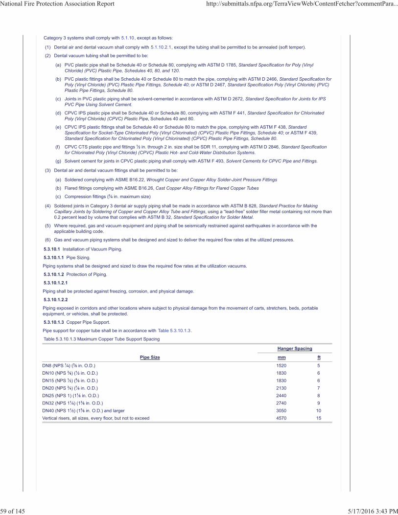
Category 3 systems shall comply with 5.1.10, except as follows:
(1) Dental air and dental vacuum shall comply with 5.1.10.2.1, except the tubing shall be permitted to be annealed (soft temper).
(2) Dental vacuum tubing shall be permitted to be:
(a) PVC plastic pipe shall be Schedule 40 or Schedule 80, complying with ASTM D 1785, Standard Specification for Poly (VinylChloride) (PVC) Plastic Pipe, Schedules 40, 80, and 120.
(b) PVC plastic fittings shall be Schedule 40 or Schedule 80 to match the pipe, complying with ASTM D 2466, Standard Specification forPoly (Vinyl Chloride) (PVC) Plastic Pipe Fittings, Schedule 40; or ASTM D 2467, Standard Specification Poly (Vinyl Chloride) (PVC)Plastic Pipe Fittings, Schedule 80.
(c) Joints in PVC plastic piping shall be solvent-cemented in accordance with ASTM D 2672, Standard Specification for Joints for IPSPVC Pipe Using Solvent Cement.
(d) CPVC IPS plastic pipe shall be Schedule 40 or Schedule 80, complying with ASTM F 441, Standard Specification for ChlorinatedPoly (Vinyl Chloride) (CPVC) Plastic Pipe, Schedules 40 and 80.
(e) CPVC IPS plastic fittings shall be Schedule 40 or Schedule 80 to match the pipe, complying with ASTM F 438, StandardSpecification for Socket-Type Chlorinated Poly (Vinyl Chlorinated) (CPVC) Plastic Pipe Fittings, Schedule 40; or ASTM F 439,Standard Specification for Chlorinated Poly (Vinyl Chlorinated) (CPVC) Plastic Pipe Fittings, Schedule 80.
(f) CPVC CTS plastic pipe and fittings 1�2 in. through 2 in. size shall be SDR 11, complying with ASTM D 2846, Standard Specificationfor Chlorinated Poly (Vinyl Chloride) (CPVC) Plastic Hot- and Cold-Water Distribution Systems.
(g) Solvent cement for joints in CPVC plastic piping shall comply with ASTM F 493, Solvent Cements for CPVC Pipe and Fittings.
(3) Dental air and dental vacuum fittings shall be permitted to be:
(a) Soldered complying with ASME B16.22, Wrought Copper and Copper Alloy Solder-Joint Pressure Fittings
(b) Flared fittings complying with ASME B16.26, Cast Copper Alloy Fittings for Flared Copper Tubes
(c) Compression fittings (3�4 in. maximum size)
(4) Soldered joints in Category 3 dental air supply piping shall be made in accordance with ASTM B 828, Standard Practice for MakingCapillary Joints by Soldering of Copper and Copper Alloy Tube and Fittings, using a “lead-free” solder filler metal containing not more than0.2 percent lead by volume that complies with ASTM B 32, Standard Specification for Solder Metal.
(5) Where required, gas and vacuum equipment and piping shall be seismically restrained against earthquakes in accordance with theapplicable building code.
(6) Gas and vacuum piping systems shall be designed and sized to deliver the required flow rates at the utilized pressures.
5.3.10.1 Installation of Vacuum Piping.
5.3.10.1.1 Pipe Sizing.
Piping systems shall be designed and sized to draw the required flow rates at the utilization vacuums.
5.3.10.1.2 Protection of Piping.
5.3.10.1.2.1
Piping shall be protected against freezing, corrosion, and physical damage.
5.3.10.1.2.2
Piping exposed in corridors and other locations where subject to physical damage from the movement of carts, stretchers, beds, portableequipment, or vehicles, shall be protected.
5.3.10.1.3 Copper Pipe Support.
Pipe support for copper tube shall be in accordance with Table 5.3.10.1.3.
Table 5.3.10.1.3 Maximum Copper Tube Support Spacing
Hanger Spacing
Pipe Size mm ft
DN8 (NPS 1�4) (3�8 in. O.D.) 1520 5DN10 (NPS 3�8) (1�2 in. O.D.) 1830 6DN15 (NPS 1�2) (5�8 in. O.D.) 1830 6DN20 (NPS 3�4) (7�8 in. O.D.) 2130 7DN25 (NPS 1) (11�8 in. O.D.) 2440 8DN32 (NPS 11�4) (13�8 in. O.D.) 2740 9DN40 (NPS 11�2) (15�8 in. O.D.) and larger 3050 10Vertical risers, all sizes, every floor, but not to exceed 4570 15
National Fire Protection Association Report http://submittals.nfpa.org/TerraViewWeb/ContentFetcher?commentPara...
59 of 145 5/17/2016 3:43 PM
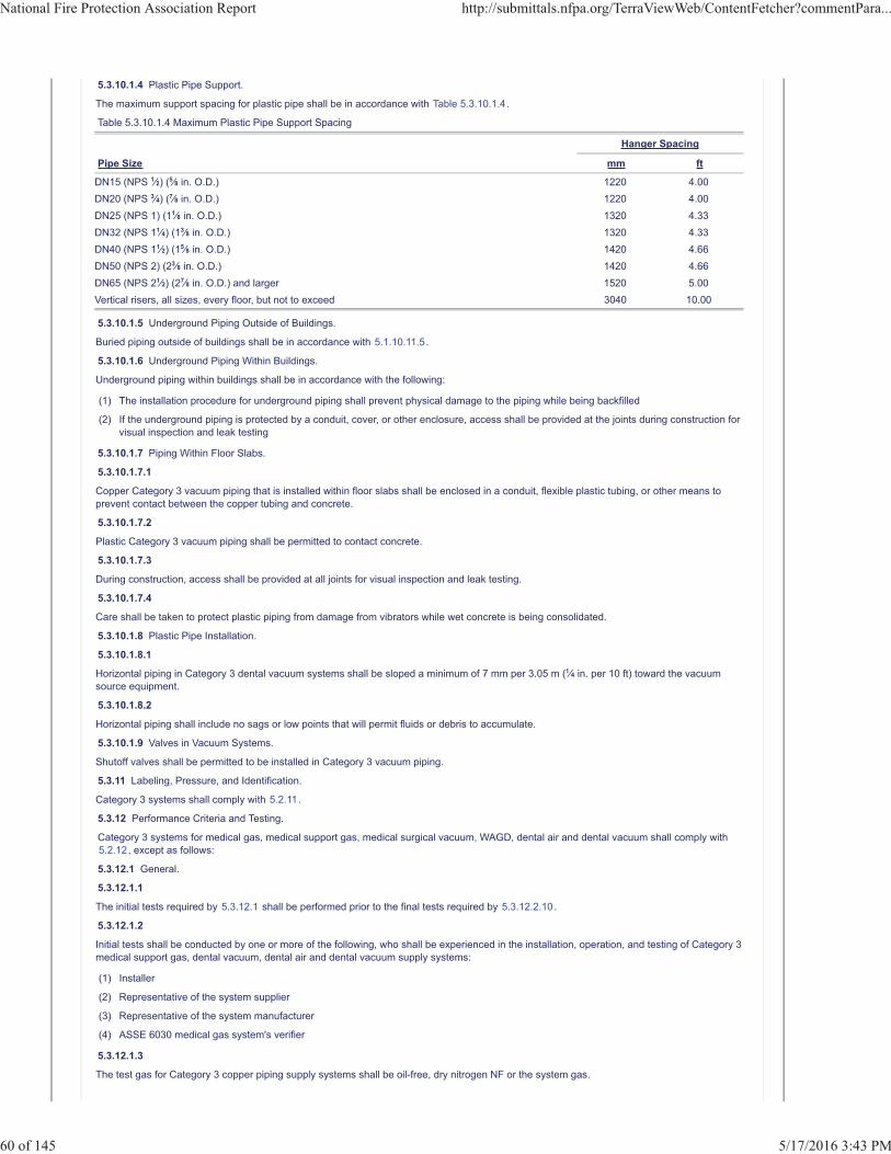
5.3.10.1.4 Plastic Pipe Support.
The maximum support spacing for plastic pipe shall be in accordance with Table 5.3.10.1.4.
Table 5.3.10.1.4 Maximum Plastic Pipe Support Spacing
Hanger Spacing
Pipe Size mm ft
DN15 (NPS 1�2) (5�8 in. O.D.) 1220 4.00DN20 (NPS 3�4) (7�8 in. O.D.) 1220 4.00DN25 (NPS 1) (11�8 in. O.D.) 1320 4.33DN32 (NPS 11�4) (13�8 in. O.D.) 1320 4.33DN40 (NPS 11�2) (15�8 in. O.D.) 1420 4.66DN50 (NPS 2) (23�8 in. O.D.) 1420 4.66DN65 (NPS 21�2) (27�8 in. O.D.) and larger 1520 5.00Vertical risers, all sizes, every floor, but not to exceed 3040 10.00
5.3.10.1.5 Underground Piping Outside of Buildings.
Buried piping outside of buildings shall be in accordance with 5.1.10.11.5.
5.3.10.1.6 Underground Piping Within Buildings.
Underground piping within buildings shall be in accordance with the following:
(1) The installation procedure for underground piping shall prevent physical damage to the piping while being backfilled
(2) If the underground piping is protected by a conduit, cover, or other enclosure, access shall be provided at the joints during construction forvisual inspection and leak testing
5.3.10.1.7 Piping Within Floor Slabs.
5.3.10.1.7.1
Copper Category 3 vacuum piping that is installed within floor slabs shall be enclosed in a conduit, flexible plastic tubing, or other means toprevent contact between the copper tubing and concrete.
5.3.10.1.7.2
Plastic Category 3 vacuum piping shall be permitted to contact concrete.
5.3.10.1.7.3
During construction, access shall be provided at all joints for visual inspection and leak testing.
5.3.10.1.7.4
Care shall be taken to protect plastic piping from damage from vibrators while wet concrete is being consolidated.
5.3.10.1.8 Plastic Pipe Installation.
5.3.10.1.8.1
Horizontal piping in Category 3 dental vacuum systems shall be sloped a minimum of 7 mm per 3.05 m (1�4 in. per 10 ft) toward the vacuumsource equipment.
5.3.10.1.8.2
Horizontal piping shall include no sags or low points that will permit fluids or debris to accumulate.
5.3.10.1.9 Valves in Vacuum Systems.
Shutoff valves shall be permitted to be installed in Category 3 vacuum piping.
5.3.11 Labeling, Pressure, and Identification.
Category 3 systems shall comply with 5.2.11.
5.3.12 Performance Criteria and Testing.
Category 3 systems for medical gas, medical support gas, medical surgical vacuum, WAGD, dental air and dental vacuum shall comply with5.2.12, except as follows:
5.3.12.1 General.
5.3.12.1.1
The initial tests required by 5.3.12.1 shall be performed prior to the final tests required by 5.3.12.2.10.
5.3.12.1.2
Initial tests shall be conducted by one or more of the following, who shall be experienced in the installation, operation, and testing of Category 3medical support gas, dental vacuum, dental air and dental vacuum supply systems:
(1) Installer
(2) Representative of the system supplier
(3) Representative of the system manufacturer
(4) ASSE 6030 medical gas system's verifier
5.3.12.1.3
The test gas for Category 3 copper piping supply systems shall be oil-free, dry nitrogen NF or the system gas.
National Fire Protection Association Report http://submittals.nfpa.org/TerraViewWeb/ContentFetcher?commentPara...
60 of 145 5/17/2016 3:43 PM
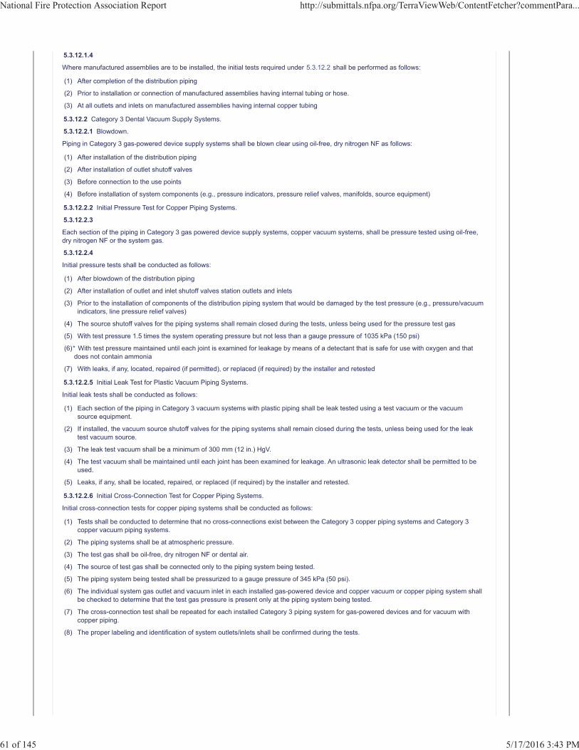
5.3.12.1.4
Where manufactured assemblies are to be installed, the initial tests required under 5.3.12.2 shall be performed as follows:
(1) After completion of the distribution piping
(2) Prior to installation or connection of manufactured assemblies having internal tubing or hose.
(3) At all outlets and inlets on manufactured assemblies having internal copper tubing
5.3.12.2 Category 3 Dental Vacuum Supply Systems.
5.3.12.2.1 Blowdown.
Piping in Category 3 gas-powered device supply systems shall be blown clear using oil-free, dry nitrogen NF as follows:
(1) After installation of the distribution piping
(2) After installation of outlet shutoff valves
(3) Before connection to the use points
(4) Before installation of system components (e.g., pressure indicators, pressure relief valves, manifolds, source equipment)
5.3.12.2.2 Initial Pressure Test for Copper Piping Systems.
5.3.12.2.3
Each section of the piping in Category 3 gas powered device supply systems, copper vacuum systems, shall be pressure tested using oil-free,dry nitrogen NF or the system gas.
5.3.12.2.4
Initial pressure tests shall be conducted as follows:
(1) After blowdown of the distribution piping
(2) After installation of outlet and inlet shutoff valves station outlets and inlets
(3) Prior to the installation of components of the distribution piping system that would be damaged by the test pressure (e.g., pressure/vacuumindicators, line pressure relief valves)
(4) The source shutoff valves for the piping systems shall remain closed during the tests, unless being used for the pressure test gas
(5) With test pressure 1.5 times the system operating pressure but not less than a gauge pressure of 1035 kPa (150 psi)
(6)
(7) With leaks, if any, located, repaired (if permitted), or replaced (if required) by the installer and retested
5.3.12.2.5 Initial Leak Test for Plastic Vacuum Piping Systems.
Initial leak tests shall be conducted as follows:
(1) Each section of the piping in Category 3 vacuum systems with plastic piping shall be leak tested using a test vacuum or the vacuumsource equipment.
(2) If installed, the vacuum source shutoff valves for the piping systems shall remain closed during the tests, unless being used for the leaktest vacuum source.
(3) The leak test vacuum shall be a minimum of 300 mm (12 in.) HgV.
(4) The test vacuum shall be maintained until each joint has been examined for leakage. An ultrasonic leak detector shall be permitted to beused.
(5) Leaks, if any, shall be located, repaired, or replaced (if required) by the installer and retested.
5.3.12.2.6 Initial Cross-Connection Test for Copper Piping Systems.
Initial cross-connection tests for copper piping systems shall be conducted as follows:
(1) Tests shall be conducted to determine that no cross-connections exist between the Category 3 copper piping systems and Category 3copper vacuum piping systems.
(2) The piping systems shall be at atmospheric pressure.
(3) The test gas shall be oil-free, dry nitrogen NF or dental air.
(4) The source of test gas shall be connected only to the piping system being tested.
(5) The piping system being tested shall be pressurized to a gauge pressure of 345 kPa (50 psi).
(6) The individual system gas outlet and vacuum inlet in each installed gas-powered device and copper vacuum or copper piping system shallbe checked to determine that the test gas pressure is present only at the piping system being tested.
(7) The cross-connection test shall be repeated for each installed Category 3 piping system for gas-powered devices and for vacuum withcopper piping.
(8) The proper labeling and identification of system outlets/inlets shall be confirmed during the tests.
* With test pressure maintained until each joint is examined for leakage by means of a detectant that is safe for use with oxygen and thatdoes not contain ammonia
National Fire Protection Association Report http://submittals.nfpa.org/TerraViewWeb/ContentFetcher?commentPara...
61 of 145 5/17/2016 3:43 PM
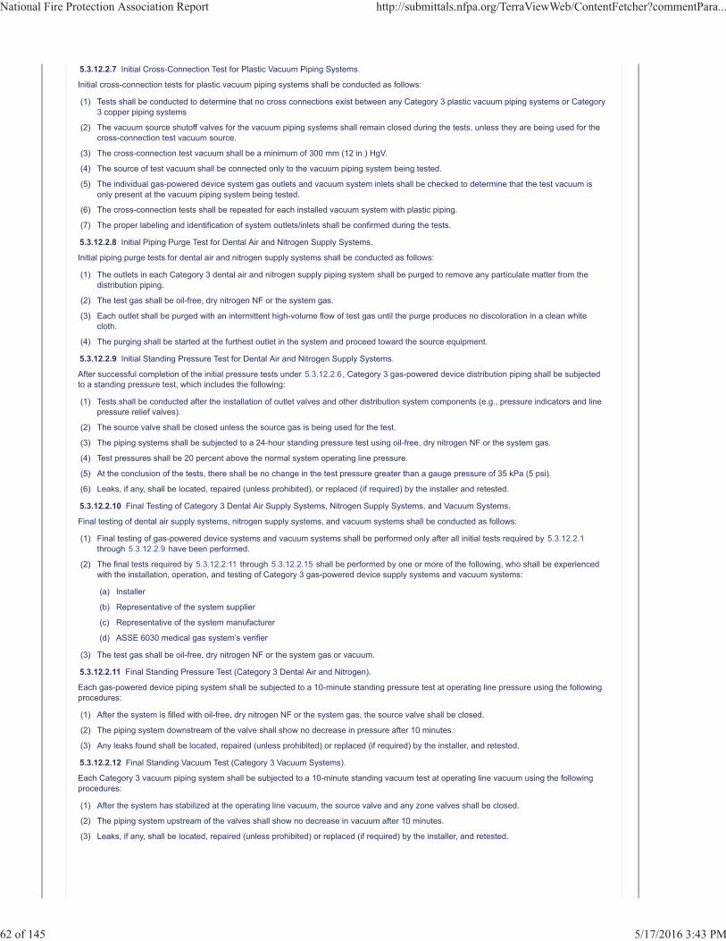
5.3.12.2.7 Initial Cross-Connection Test for Plastic Vacuum Piping Systems.
Initial cross-connection tests for plastic vacuum piping systems shall be conducted as follows:
(1) Tests shall be conducted to determine that no cross connections exist between any Category 3 plastic vacuum piping systems or Category3 copper piping systems
(2) The vacuum source shutoff valves for the vacuum piping systems shall remain closed during the tests, unless they are being used for thecross-connection test vacuum source.
(3) The cross-connection test vacuum shall be a minimum of 300 mm (12 in.) HgV.
(4) The source of test vacuum shall be connected only to the vacuum piping system being tested.
(5) The individual gas-powered device system gas outlets and vacuum system inlets shall be checked to determine that the test vacuum isonly present at the vacuum piping system being tested.
(6) The cross-connection tests shall be repeated for each installed vacuum system with plastic piping.
(7) The proper labeling and identification of system outlets/inlets shall be confirmed during the tests.
5.3.12.2.8 Initial Piping Purge Test for Dental Air and Nitrogen Supply Systems.
Initial piping purge tests for dental air and nitrogen supply systems shall be conducted as follows:
(1) The outlets in each Category 3 dental air and nitrogen supply piping system shall be purged to remove any particulate matter from thedistribution piping.
(2) The test gas shall be oil-free, dry nitrogen NF or the system gas.
(3) Each outlet shall be purged with an intermittent high-volume flow of test gas until the purge produces no discoloration in a clean whitecloth.
(4) The purging shall be started at the furthest outlet in the system and proceed toward the source equipment.
5.3.12.2.9 Initial Standing Pressure Test for Dental Air and Nitrogen Supply Systems.
After successful completion of the initial pressure tests under 5.3.12.2.6, Category 3 gas-powered device distribution piping shall be subjectedto a standing pressure test, which includes the following:
(1) Tests shall be conducted after the installation of outlet valves and other distribution system components (e.g., pressure indicators and linepressure relief valves).
(2) The source valve shall be closed unless the source gas is being used for the test.
(3) The piping systems shall be subjected to a 24-hour standing pressure test using oil-free, dry nitrogen NF or the system gas.
(4) Test pressures shall be 20 percent above the normal system operating line pressure.
(5) At the conclusion of the tests, there shall be no change in the test pressure greater than a gauge pressure of 35 kPa (5 psi).
(6) Leaks, if any, shall be located, repaired (unless prohibited), or replaced (if required) by the installer and retested.
5.3.12.2.10 Final Testing of Category 3 Dental Air Supply Systems, Nitrogen Supply Systems, and Vacuum Systems.
Final testing of dental air supply systems, nitrogen supply systems, and vacuum systems shall be conducted as follows:
(1) Final testing of gas-powered device systems and vacuum systems shall be performed only after all initial tests required by 5.3.12.2.1through 5.3.12.2.9 have been performed.
(2) The final tests required by 5.3.12.2.11 through 5.3.12.2.15 shall be performed by one or more of the following, who shall be experiencedwith the installation, operation, and testing of Category 3 gas-powered device supply systems and vacuum systems:
(a) Installer
(b) Representative of the system supplier
(c) Representative of the system manufacturer
(d) ASSE 6030 medical gas system’s verifier
(3) The test gas shall be oil-free, dry nitrogen NF or the system gas or vacuum.
5.3.12.2.11 Final Standing Pressure Test (Category 3 Dental Air and Nitrogen).
Each gas-powered device piping system shall be subjected to a 10-minute standing pressure test at operating line pressure using the followingprocedures:
(1) After the system is filled with oil-free, dry nitrogen NF or the system gas, the source valve shall be closed.
(2) The piping system downstream of the valve shall show no decrease in pressure after 10 minutes.
(3) Any leaks found shall be located, repaired (unless prohibited) or replaced (if required) by the installer, and retested.
5.3.12.2.12 Final Standing Vacuum Test (Category 3 Vacuum Systems).
Each Category 3 vacuum piping system shall be subjected to a 10-minute standing vacuum test at operating line vacuum using the followingprocedures:
(1) After the system has stabilized at the operating line vacuum, the source valve and any zone valves shall be closed.
(2) The piping system upstream of the valves shall show no decrease in vacuum after 10 minutes.
(3) Leaks, if any, shall be located, repaired (unless prohibited) or replaced (if required) by the installer, and retested.
National Fire Protection Association Report http://submittals.nfpa.org/TerraViewWeb/ContentFetcher?commentPara...
62 of 145 5/17/2016 3:43 PM
5.3.12.2.13 Final Cross-Connection Test (Category 3 Gas-Powered Devices and Vacuum and Scavenging Systems).
After closing of walls and completion of the requirements of 5.3.12.2, it shall be determined that no cross-connections exist between the pipingsystems for Category 3 gas-powered devices and vacuum and scavenging systems using the following method:
(1) Test each piping system independently, starting with the vacuum systems first, and check that the test vacuum is present only at inlets ofthe system being tested.
(2) Reduce all piping systems to atmospheric pressure.
(3) Operate the Category 3 vacuum or scavenging system being tested at the normal system vacuum, using the source equipment.
(4) Test each gas outlet and vacuum inlet using appropriate adapters to verify that vacuum is present only at the vacuum inlets in the systembeing tested, and not at any gas outlets or inlets.
(5) Shut down the vacuum source equipment and slowly break the vacuum in the vacuum piping system, increasing its pressure toatmospheric.
(6) Test each Category 3 vacuum system until all are determined to be free of cross-connections.
(7) Using oil-free, dry nitrogen NF or the system gas, pressurize the gas piping system to a gauge pressure of 345 kPa (50 psi).
(8) Test each gas-powered device gas outlet using appropriate adapters to verify that the test gas pressure is present only at the outlets in thegas-powered device system being tested.
(9) After it has been determined that a gas-powered device piping system is free of cross-connections, disconnect the source of test gas andreduce the piping to atmospheric pressure.
(10) Proceed to test each gas-powered device piping system until all are determined to be free of cross-connections.
5.3.12.2.14 Final Piping Purge Test (Category 3 Gas-Powered Devices).
To remove any traces of particulate matter deposited in the pipelines as a result of construction, a heavy, intermittent purging of eachgas-powered device pipeline shall be done.
(1) The appropriate adapter shall be obtained from the facility or manufacturer, and high purge rates shall be put on each outlet.
(2) After the purge is started, it shall be rapidly interrupted several times until the purge produces no discoloration in a white cloth loosely heldover the adapter during the purge.
(3) To avoid possible damage to the outlet and its components, the test shall not be conducted using any implement other than the correctadapter.
5.3.12.2.15 Final Tie-In Test (Category 3 Dental Air, Nitrogen, and Vacuum Systems).
(1) Prior to the connection of any new piping in extensions or additions to an existing piping system, the final tests in 5.3.12.2 shall besuccessfully performed on the new work.
(2) Each joint in the final connection between the new work and the existing system shall be leak-tested, with the gas of system designation orvacuum at the normal operating pressure or vacuum, by means of a leak detectant that is safe for use with oxygen and does not containammonia.
(3) For gas piping, immediately after a final connection is made and leak-tested, the specific altered zone and components in the immediatezone or area that is downstream from the point or area of intrusion shall be purged per 5.3.12.2.14.
5.3.12.2.16 Source Equipment Testing (Category 3 Dental Air, Nitrogen, and Vacuum Systems).
Source equipment testing shall be conducted as follows:
(1) Source equipment checks shall be performed following the installation of the interconnecting pipelines, accessories, and sourceequipment.
(2) Where the source equipment and system gas or vacuum is used for testing of the distribution piping, the source equipment shall bechecked out and placed in operation prior to testing the distribution piping.
(3) The source equipment shall be checked out and placed in operation according to the manufacturer’s instructions.
5.3.13 Reserved.
5.3.14 Operation and Management of Category 3 Systems.
Category 3 systems shall comply with 5.2.14.
Additional Proposed Changes
File Name Description ApprovedCCN_6.pdf 99_CC Note 6
Statement of Problem and Substantiation for Public Comment
NOTE: This Public Comment appeared as CC Note No. ___ in the First Draft Report on First Revision No. ___, and is also related to Public Input No. ____, Committee Input No.
The technical committee is directed to FCR-4 to see the new Chapter 15 for dental gas and vacuum systems. This was added by the CC to facilitate public review and is based on the work of a task group of PIP. The following items need to be addressed by PIP at the second draft stage:
- Ensure terminology is consistent with other chapters of NFPA 99 where appropriate. (i.e. remove the term “facilities” from risk application)
- Review and revise Chapter 5 as needed based on the new Chapter. (i.e. remove references to dental in 5.3)
- The risk approach of the Chapter should refer to “Categories” as shown in the FCR.
National Fire Protection Association Report http://submittals.nfpa.org/TerraViewWeb/ContentFetcher?commentPara...
63 of 145 5/17/2016 3:43 PM
- Add definitions as needed (i.e. “dental”)
Related ItemFirst Correlating Revision No. 4-NFPA 99-2015 [New Section after 14.3.3.4]
Submitter Information Verification
Submitter Full Name: Tc On Hea-AacOrganization: CC on Health Care FacilitiesStreet Address:City:State:Zip:Submittal Date: Tue Mar 15 12:33:09 EDT 2016
National Fire Protection Association Report http://submittals.nfpa.org/TerraViewWeb/ContentFetcher?commentPara...
64 of 145 5/17/2016 3:43 PM
Public Comment No. 24-NFPA 99-2016 [ Section No. 5.3.14 ]
5.3.14 Operation and Management of Category 3 Systems.
Category 3 systems shall comply with 5.2.14.
Additional Proposed Changes
File Name Description ApprovedCCN_7.pdf 99_CC Note 7
Statement of Problem and Substantiation for Public Comment
This Public Comment appeared as CC Note No. 7 in the First Draft Report.The Correlating Committee directs PIP committee to work with NFPA 45 to include the missing requirements in that document rather than NFPA 99. The specific items should be identified and public input submitted to NFPA 45. The CC has been made aware that NFPA 45 TC is willing to assist in this.
Related ItemCorrelating Committee Note No. 7-NFPA 99-2015 [New Section after 5.3.14]
Submitter Information Verification
Submitter Full Name: Tc On Hea-AacOrganization: CC on Health Care FacilitiesStreet Address:City:State:Zip:Submittal Date: Wed Mar 16 08:24:36 EDT 2016
National Fire Protection Association Report http://submittals.nfpa.org/TerraViewWeb/ContentFetcher?commentPara...
65 of 145 5/17/2016 3:43 PM
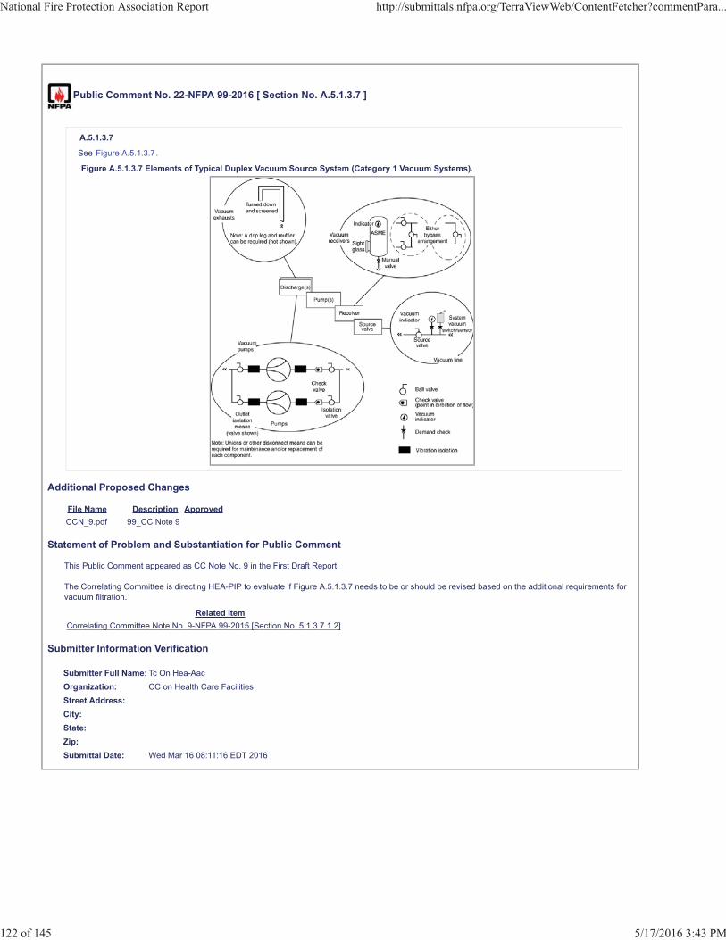
Public Comment No. 22-NFPA 99-2016 [ Section No. A.5.1.3.7 ]
A.5.1.3.7
See Figure A.5.1.3.7.
Figure A.5.1.3.7 Elements of Typical Duplex Vacuum Source System (Category 1 Vacuum Systems).
Additional Proposed Changes
File Name Description ApprovedCCN_9.pdf 99_CC Note 9
Statement of Problem and Substantiation for Public Comment
This Public Comment appeared as CC Note No. 9 in the First Draft Report.
The Correlating Committee is directing HEA-PIP to evaluate if Figure A.5.1.3.7 needs to be or should be revised based on the additional requirements for vacuum filtration.
Related ItemCorrelating Committee Note No. 9-NFPA 99-2015 [Section No. 5.1.3.7.1.2]
Submitter Information Verification
Submitter Full Name: Tc On Hea-AacOrganization: CC on Health Care FacilitiesStreet Address:City:State:Zip:Submittal Date: Wed Mar 16 08:11:16 EDT 2016
National Fire Protection Association Report http://submittals.nfpa.org/TerraViewWeb/ContentFetcher?commentPara...
122 of 145 5/17/2016 3:43 PM
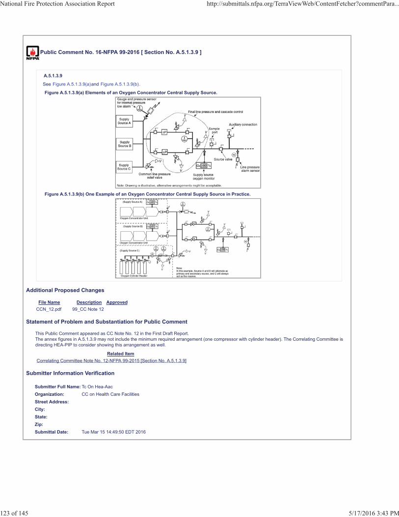
Public Comment No. 16-NFPA 99-2016 [ Section No. A.5.1.3.9 ]
A.5.1.3.9
See Figure A.5.1.3.9(a)and Figure A.5.1.3.9(b).
Figure A.5.1.3.9(a) Elements of an Oxygen Concentrator Central Supply Source.
Figure A.5.1.3.9(b) One Example of an Oxygen Concentrator Central Supply Source in Practice.
Additional Proposed Changes
File Name Description ApprovedCCN_12.pdf 99_CC Note 12
Statement of Problem and Substantiation for Public Comment
This Public Comment appeared as CC Note No. 12 in the First Draft Report.The annex figures in A.5.1.3.9 may not include the minimum required arrangement (one compressor with cylinder header). The Correlating Committee is directing HEA-PIP to consider showing this arrangement as well.
Related ItemCorrelating Committee Note No. 12-NFPA 99-2015 [Section No. A.5.1.3.9]
Submitter Information Verification
Submitter Full Name: Tc On Hea-AacOrganization: CC on Health Care FacilitiesStreet Address:City:State:Zip:Submittal Date: Tue Mar 15 14:49:50 EDT 2016
National Fire Protection Association Report http://submittals.nfpa.org/TerraViewWeb/ContentFetcher?commentPara...
123 of 145 5/17/2016 3:43 PM
Public Comment No. 99-NFPA 99-2016 [ Section No. A.5.1.5 ]
A.5.1.5
Station outlets/inlets should be located at an appropriate height above the floor to prevent physical damage to equipment attached to the outlet.The minimum number of station outlets/inlets for each system that is installed should be provided per the FGI Guidelines for Design andConstruction of Hospitals and Outpatient Facilities or other federal, state, or local codes. One method to use is s tation outlets and inlets listed and labeled in accordance with UL 1331, Station Inlets and Outlets, which are suitable fordistribution of nonflammable medical gas in rigid piping systems operating at standard operating pressures.
Statement of Problem and Substantiation for Public Comment
NFPA 99 does not prevent a listed station outlet/inlet from being used. However, if a listed station outlet/inlet is used, the station outlet/inlet should be listed as suitable for installation in accordance with the installation standard requirements. The purpose of Annex A is to provide explanatory material for informational purpose only. This proposal assists the user of NFPA 99 to identify those listed station outlet/inlets that are considered as suitable for installation in accordance with NFPA 99.
Related ItemPublic Input No. 295-NFPA 99-2015 [Section No. A.5.1.5]
Submitter Information Verification
Submitter Full Name: John TaeckerOrganization: UL LLCStreet Address:City:State:Zip:Submittal Date: Sat May 14 11:06:29 EDT 2016
National Fire Protection Association Report http://submittals.nfpa.org/TerraViewWeb/ContentFetcher?commentPara...
124 of 145 5/17/2016 3:43 PM

Public Comment No. 20-NFPA 99-2016 [ Section No. A.5.1.9.2 ]
National Fire Protection Association Report http://submittals.nfpa.org/TerraViewWeb/ContentFetcher?commentPara...
125 of 145 5/17/2016 3:43 PM

A.5.1.9.2
National Fire Protection Association Report http://submittals.nfpa.org/TerraViewWeb/ContentFetcher?commentPara...
126 of 145 5/17/2016 3:43 PM
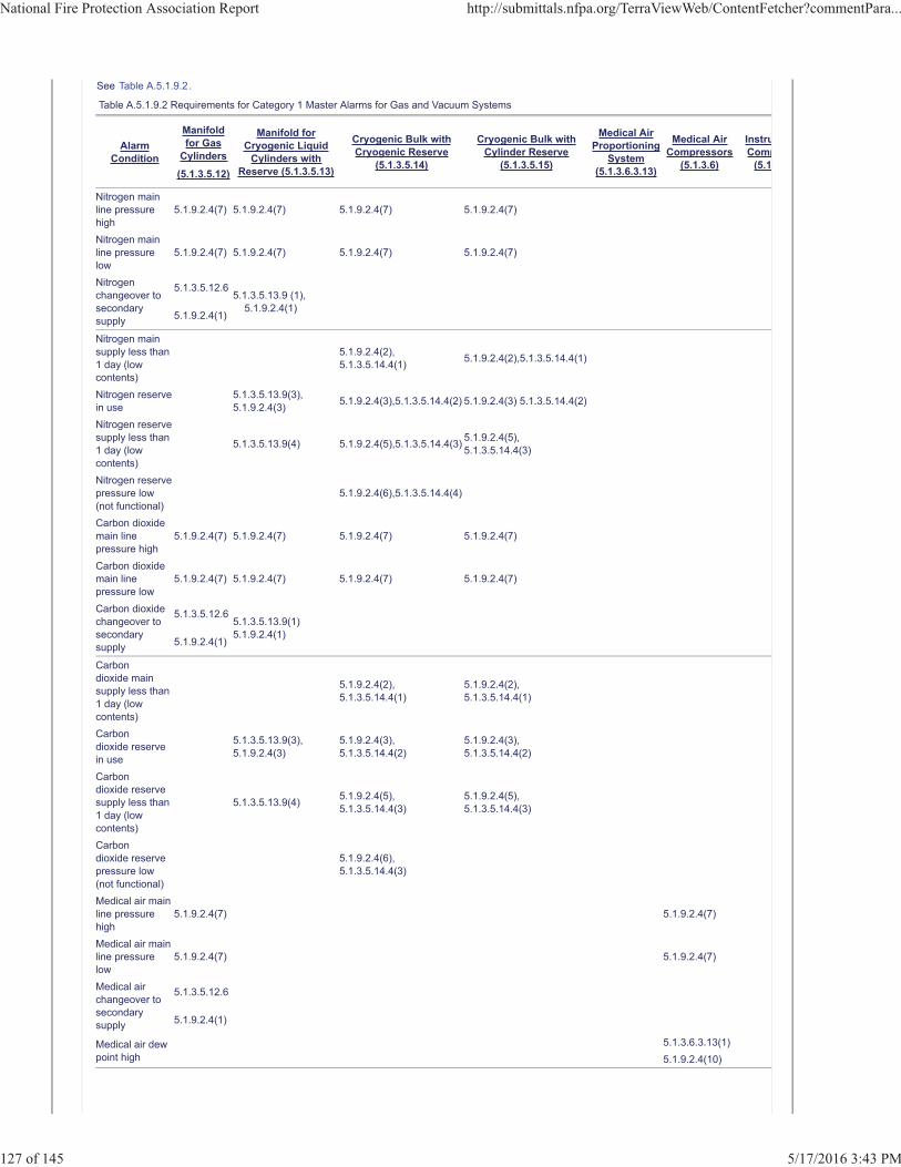
See Table A.5.1.9.2.
Table A.5.1.9.2 Requirements for Category 1 Master Alarms for Gas and Vacuum Systems
AlarmCondition
Manifoldfor Gas
Cylinders
(5.1.3.5.12)
Manifold forCryogenic Liquid
Cylinders withReserve (5.1.3.5.13)
Cryogenic Bulk withCryogenic Reserve
(5.1.3.5.14)
Cryogenic Bulk withCylinder Reserve
(5.1.3.5.15)
Medical AirProportioning
System(5.1.3.6.3.13)
Medical AirCompressors
(5.1.3.6)
InstruComp
(5.1
Nitrogen mainline pressurehigh
5.1.9.2.4(7) 5.1.9.2.4(7) 5.1.9.2.4(7) 5.1.9.2.4(7)
Nitrogen mainline pressurelow
5.1.9.2.4(7) 5.1.9.2.4(7) 5.1.9.2.4(7) 5.1.9.2.4(7)
Nitrogenchangeover tosecondarysupply
5.1.3.5.12.65.1.3.5.13.9 (1), 5.1.9.2.4(1)
5.1.9.2.4(1)
Nitrogen mainsupply less than1 day (lowcontents)
5.1.9.2.4(2), 5.1.3.5.14.4(1) 5.1.9.2.4(2),5.1.3.5.14.4(1)
Nitrogen reservein use
5.1.3.5.13.9(3), 5.1.9.2.4(3) 5.1.9.2.4(3),5.1.3.5.14.4(2) 5.1.9.2.4(3) 5.1.3.5.14.4(2)
Nitrogen reservesupply less than1 day (lowcontents)
5.1.3.5.13.9(4) 5.1.9.2.4(5),5.1.3.5.14.4(3) 5.1.9.2.4(5),5.1.3.5.14.4(3)
Nitrogen reservepressure low(not functional)
5.1.9.2.4(6),5.1.3.5.14.4(4)
Carbon dioxidemain linepressure high
5.1.9.2.4(7) 5.1.9.2.4(7) 5.1.9.2.4(7) 5.1.9.2.4(7)
Carbon dioxidemain linepressure low
5.1.9.2.4(7) 5.1.9.2.4(7) 5.1.9.2.4(7) 5.1.9.2.4(7)
Carbon dioxidechangeover tosecondarysupply
5.1.3.5.12.65.1.3.5.13.9(1) 5.1.9.2.4(1)
5.1.9.2.4(1)
Carbondioxide mainsupply less than1 day (lowcontents)
5.1.9.2.4(2),5.1.3.5.14.4(1)
5.1.9.2.4(2),5.1.3.5.14.4(1)
Carbondioxide reservein use
5.1.3.5.13.9(3), 5.1.9.2.4(3)
5.1.9.2.4(3),5.1.3.5.14.4(2)
5.1.9.2.4(3),5.1.3.5.14.4(2)
Carbondioxide reservesupply less than1 day (lowcontents)
5.1.3.5.13.9(4) 5.1.9.2.4(5),5.1.3.5.14.4(3)
5.1.9.2.4(5),5.1.3.5.14.4(3)
Carbondioxide reservepressure low(not functional)
5.1.9.2.4(6),5.1.3.5.14.4(3)
Medical air mainline pressurehigh
5.1.9.2.4(7) 5.1.9.2.4(7)
Medical air mainline pressurelow
5.1.9.2.4(7) 5.1.9.2.4(7)
Medical airchangeover tosecondarysupply
5.1.3.5.12.6
5.1.9.2.4(1)
Medical air dewpoint high
5.1.3.6.3.13(1)5.1.9.2.4(10)
National Fire Protection Association Report http://submittals.nfpa.org/TerraViewWeb/ContentFetcher?commentPara...
127 of 145 5/17/2016 3:43 PM
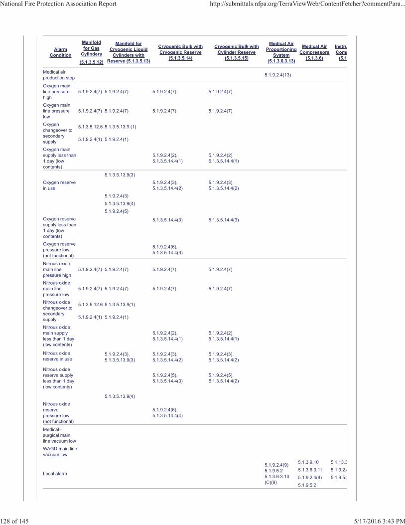
AlarmCondition
Manifoldfor Gas
Cylinders
(5.1.3.5.12)
Manifold forCryogenic Liquid
Cylinders withReserve (5.1.3.5.13)
Cryogenic Bulk withCryogenic Reserve
(5.1.3.5.14)
Cryogenic Bulk withCylinder Reserve
(5.1.3.5.15)
Medical AirProportioning
System(5.1.3.6.3.13)
Medical AirCompressors
(5.1.3.6)
InstruComp
(5.1
Medical airproduction stop 5.1.9.2.4(13)
Oxygen mainline pressurehigh
5.1.9.2.4(7) 5.1.9.2.4(7) 5.1.9.2.4(7) 5.1.9.2.4(7)
Oxygen mainline pressurelow
5.1.9.2.4(7) 5.1.9.2.4(7) 5.1.9.2.4(7) 5.1.9.2.4(7)
Oxygenchangeover tosecondarysupply
5.1.3.5.12.6 5.1.3.5.13.9 (1)
5.1.9.2.4(1) 5.1.9.2.4(1)
Oxygen mainsupply less than1 day (lowcontents)
5.1.9.2.4(2),5.1.3.5.14.4(1)
5.1.9.2.4(2),5.1.3.5.14.4(1)
Oxygen reservein use
5.1.3.5.13.9(3) 5.1.9.2.4(3),5.1.3.5.14.4(2)
5.1.9.2.4(3),5.1.3.5.14.4(2)
5.1.9.2.4(3)5.1.3.5.13.9(4)
5.1.3.5.14.4(3) 5.1.3.5.14.4(3)
5.1.9.2.4(5)Oxygen reservesupply less than1 day (lowcontents)Oxygen reservepressure low(not functional)
5.1.9.2.4(6),5.1.3.5.14.4(3)
Nitrous oxidemain linepressure high
5.1.9.2.4(7) 5.1.9.2.4(7) 5.1.9.2.4(7) 5.1.9.2.4(7)
Nitrous oxidemain linepressure low
5.1.9.2.4(7) 5.1.9.2.4(7) 5.1.9.2.4(7) 5.1.9.2.4(7)
Nitrous oxidechangeover tosecondarysupply
5.1.3.5.12.6 5.1.3.5.13.9(1)
5.1.9.2.4(1) 5.1.9.2.4(1)
Nitrous oxidemain supplyless than 1 day(low contents)
5.1.9.2.4(2),5.1.3.5.14.4(1)
5.1.9.2.4(2),5.1.3.5.14.4(1)
Nitrous oxidereserve in use
5.1.9.2.4(3),5.1.3.5.13.9(3)
5.1.9.2.4(3),5.1.3.5.14.4(2)
5.1.9.2.4(3),5.1.3.5.14.4(2)
Nitrous oxidereserve supplyless than 1 day(low contents)
5.1.9.2.4(5),5.1.3.5.14.4(3)
5.1.9.2.4(5),5.1.3.5.14.4(2)
5.1.3.5.13.9(4)Nitrous oxidereservepressure low(not functional)
5.1.9.2.4(6),5.1.3.5.14.4(4)
Medical–surgical mainline vacuum lowWAGD main linevacuum low
Local alarm
5.1.9.2.4(9)5.1.9.5.25.1.3.6.3.13(C)(9)
5.1.3.9.10 5.1.13.35.1.3.6.3.11 5.1.9.2.45.1.9.2.4(9) 5.1.9.5.25.1.9.5.2
National Fire Protection Association Report http://submittals.nfpa.org/TerraViewWeb/ContentFetcher?commentPara...
128 of 145 5/17/2016 3:43 PM
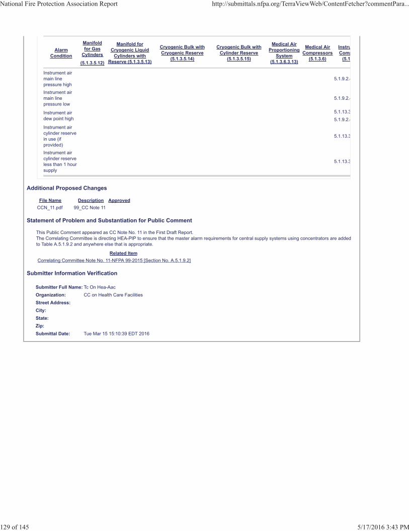
AlarmCondition
Manifoldfor Gas
Cylinders
(5.1.3.5.12)
Manifold forCryogenic Liquid
Cylinders withReserve (5.1.3.5.13)
Cryogenic Bulk withCryogenic Reserve
(5.1.3.5.14)
Cryogenic Bulk withCylinder Reserve
(5.1.3.5.15)
Medical AirProportioning
System(5.1.3.6.3.13)
Medical AirCompressors
(5.1.3.6)
InstruComp
(5.1
Instrument airmain linepressure high
5.1.9.2.4
Instrument airmain linepressure low
5.1.9.2.4
Instrument airdew point high
5.1.13.35.1.9.2.4
Instrument aircylinder reservein use (ifprovided)
5.1.13.3
Instrument aircylinder reserveless than 1 hoursupply
5.1.13.3
Additional Proposed Changes
File Name Description ApprovedCCN_11.pdf 99_CC Note 11
Statement of Problem and Substantiation for Public Comment
This Public Comment appeared as CC Note No. 11 in the First Draft Report.The Correlating Committee is directing HEA-PIP to ensure that the master alarm requirements for central supply systems using concentrators are added to Table A.5.1.9.2 and anywhere else that is appropriate.
Related ItemCorrelating Committee Note No. 11-NFPA 99-2015 [Section No. A.5.1.9.2]
Submitter Information Verification
Submitter Full Name: Tc On Hea-AacOrganization: CC on Health Care FacilitiesStreet Address:City:State:Zip:Submittal Date: Tue Mar 15 15:10:39 EDT 2016
National Fire Protection Association Report http://submittals.nfpa.org/TerraViewWeb/ContentFetcher?commentPara...
129 of 145 5/17/2016 3:43 PM
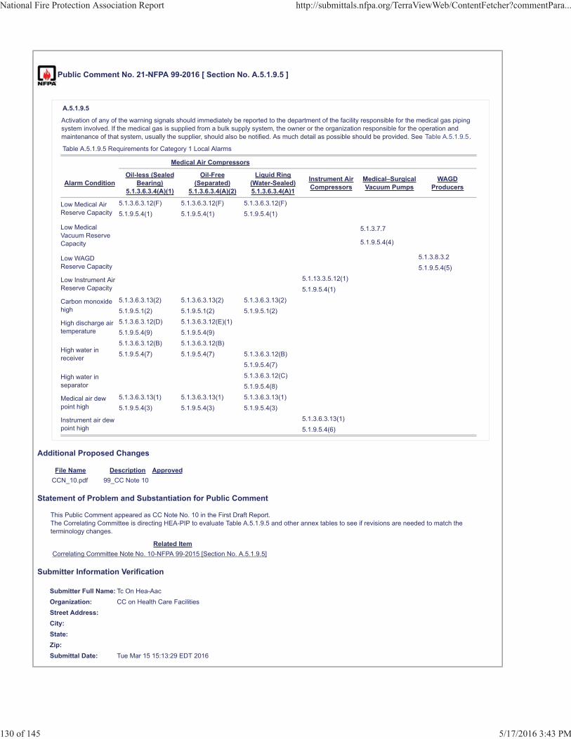
Public Comment No. 21-NFPA 99-2016 [ Section No. A.5.1.9.5 ]
A.5.1.9.5
Activation of any of the warning signals should immediately be reported to the department of the facility responsible for the medical gas pipingsystem involved. If the medical gas is supplied from a bulk supply system, the owner or the organization responsible for the operation andmaintenance of that system, usually the supplier, should also be notified. As much detail as possible should be provided. See Table A.5.1.9.5.
Table A.5.1.9.5 Requirements for Category 1 Local Alarms
Medical Air Compressors
Alarm ConditionOil-less (Sealed
Bearing)5.1.3.6.3.4(A)(1)
Oil-Free(Separated)
5.1.3.6.3.4(A)(2)
Liquid Ring(Water-Sealed)5.1.3.6.3.4(A)1
Instrument AirCompressors
Medical–SurgicalVacuum Pumps
WAGDProducers
Low Medical AirReserve Capacity
5.1.3.6.3.12(F) 5.1.3.6.3.12(F) 5.1.3.6.3.12(F)5.1.9.5.4(1) 5.1.9.5.4(1) 5.1.9.5.4(1)
Low MedicalVacuum ReserveCapacity
5.1.3.7.7
5.1.9.5.4(4)
Low WAGDReserve Capacity
5.1.3.8.3.25.1.9.5.4(5)
Low Instrument AirReserve Capacity
5.1.13.3.5.12(1)5.1.9.5.4(1)
Carbon monoxidehigh
5.1.3.6.3.13(2) 5.1.3.6.3.13(2) 5.1.3.6.3.13(2)5.1.9.5.1(2) 5.1.9.5.1(2) 5.1.9.5.1(2)
High discharge airtemperature
5.1.3.6.3.12(D) 5.1.3.6.3.12(E)(1)5.1.9.5.4(9) 5.1.9.5.4(9)
High water inreceiver
5.1.3.6.3.12(B) 5.1.3.6.3.12(B)5.1.9.5.4(7) 5.1.9.5.4(7) 5.1.3.6.3.12(B)
5.1.9.5.4(7)
High water inseparator
5.1.3.6.3.12(C)5.1.9.5.4(8)
Medical air dewpoint high
5.1.3.6.3.13(1) 5.1.3.6.3.13(1) 5.1.3.6.3.13(1)5.1.9.5.4(3) 5.1.9.5.4(3) 5.1.9.5.4(3)
Instrument air dewpoint high
5.1.3.6.3.13(1)5.1.9.5.4(6)
Additional Proposed Changes
File Name Description ApprovedCCN_10.pdf 99_CC Note 10
Statement of Problem and Substantiation for Public Comment
This Public Comment appeared as CC Note No. 10 in the First Draft Report.The Correlating Committee is directing HEA-PIP to evaluate Table A.5.1.9.5 and other annex tables to see if revisions are needed to match the terminology changes.
Related ItemCorrelating Committee Note No. 10-NFPA 99-2015 [Section No. A.5.1.9.5]
Submitter Information Verification
Submitter Full Name: Tc On Hea-AacOrganization: CC on Health Care FacilitiesStreet Address:City:State:Zip:Submittal Date: Tue Mar 15 15:13:29 EDT 2016
National Fire Protection Association Report http://submittals.nfpa.org/TerraViewWeb/ContentFetcher?commentPara...
130 of 145 5/17/2016 3:43 PM
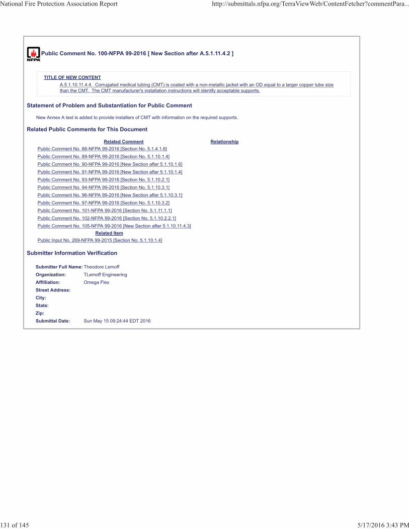
Public Comment No. 100-NFPA 99-2016 [ New Section after A.5.1.11.4.2 ]
TITLE OF NEW CONTENTA.5.1.10.11.4.4. Corrugated medical tubing (CMT) is coated with a non-metallic jacket with an OD equal to a larger copper tube sizethan the CMT. The CMT manufacturer's installation instructions will identify acceptable supports.
Statement of Problem and Substantiation for Public Comment
New Annex A text is added to provide installers of CMT with information on the required supports.
Related Public Comments for This Document
Related Comment RelationshipPublic Comment No. 88-NFPA 99-2016 [Section No. 5.1.4.1.6]Public Comment No. 89-NFPA 99-2016 [Section No. 5.1.10.1.4]Public Comment No. 90-NFPA 99-2016 [New Section after 5.1.10.1.6]Public Comment No. 91-NFPA 99-2016 [New Section after 5.1.10.1.4]Public Comment No. 93-NFPA 99-2016 [Section No. 5.1.10.2.1]Public Comment No. 94-NFPA 99-2016 [Section No. 5.1.10.3.1]Public Comment No. 96-NFPA 99-2016 [New Section after 5.1.10.3.1]Public Comment No. 97-NFPA 99-2016 [Section No. 5.1.10.3.2]Public Comment No. 101-NFPA 99-2016 [Section No. 5.1.11.1.1]Public Comment No. 102-NFPA 99-2016 [Section No. 5.1.10.2.2.1]Public Comment No. 105-NFPA 99-2016 [New Section after 5.1.10.11.4.3]
Related ItemPublic Input No. 269-NFPA 99-2015 [Section No. 5.1.10.1.4]
Submitter Information Verification
Submitter Full Name: Theodore LemoffOrganization: TLemoff EngineeringAffilliation: Omega FlexStreet Address:City:State:Zip:Submittal Date: Sun May 15 09:24:44 EDT 2016
National Fire Protection Association Report http://submittals.nfpa.org/TerraViewWeb/ContentFetcher?commentPara...
131 of 145 5/17/2016 3:43 PM