Embed Size (px)
Citation preview
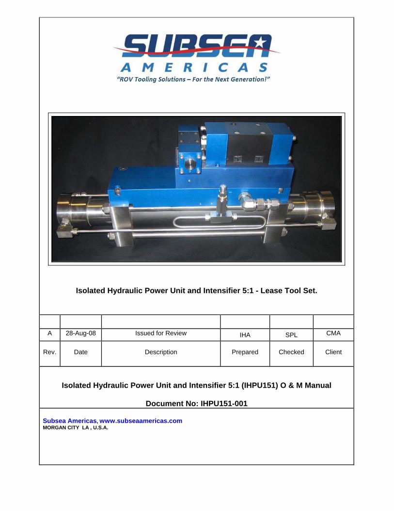
Isolated Hydraulic Power Unit and Intensifier 5:1 - Lease Tool Set.
A 28-Aug-08 Issued for Review IHA SPL CMA
Rev. Date Description Prepared Checked Client
Isolated Hydraulic Power Unit and Intensifier 5:1 (IHPU151) O & M Manual
Document No: IHPU151-001 Subsea Americas, www.subseaamericas.com MORGAN CITY LA , U.S.A.

Subsea Americas Rental IHPU151-001 Rev.A Isolated Hydraulic Power Unit and Intensifier 5:1 (IHPU151) O & M Manual Page No. 2 of 30
CONFIDENTIAL: This document may not be reproduced in any form without the written permission of Sub-Sea Americas
CONTENTS 1.0 INTRODUCTION .................................................................................................. 4
1.1 Description ................................................................................................. 4
1.2 Scope ......................................................................................................... 5
1.3 Definitions ................................................................................................... 6
1.4 Specifications ............................................................................................. 7
1.5 Theory of Operation ................................................................................... 9
2.0 SETUP AND OPERATION INSTRUCTIONS ..................................................... 11
2.1 Mechanical Installation ............................................................................. 11
2.2 Hydraulic Installation ................................................................................ 13
2.3 Hydraulic Setup ........................................................................................ 16
3.0 SYSTEM MAINTENANCE ................................................................................. 19
3.1 Post Dives ................................................................................................ 19
3.2 Post Operations ........................................................................................ 19
3.3 General Maintenance ............................................................................... 19
4.0 TROUBLE SHOOTING ...................................................................................... 25
APPENDIX A - Drawings ............................................................................................. 26
APPENDIX B - Vendors Information ................................ Error! Bookmark not defined.
APPENDIX C - Performance Curves ................................ Error! Bookmark not defined.
Subsea Americas Rental IHPU151-001 Rev.A Isolated Hydraulic Power Unit and Intensifier 5:1 (IHPU151) O & M Manual Page No. 3 of 30
CONFIDENTIAL: This document may not be reproduced in any form without the written permission of Sub-Sea Americas
DISCLAIMER
This technical manual has been drafted by Sub-Sea Tooling (SST) at the request of
Subsea Americas, and in no way, leaves SST liable for the accuracy of the information on
the Isolated Hydraulic Power Unit and Intensifier contained herein. Furthermore, SST
bears no responsibility for the safety and operation of the Isolated Hydraulic Power Unit
and Intensifier.
By delivery of this manual, SST makes no statement of assurance of its completeness or
accuracy with respect to the delivered equipment. SST assumes no responsibility to
modify, update, or change the manual content at any time beyond its initial delivery.
SST herewith provides notice that the Isolated Hydraulic Power Unit and Intensifier
System design is based on assumed conditions. It must however, be understood by
technicians that, responsibility for the safe and successful use of the Isolated Hydraulic
Power Unit and Intensifier System is the responsibility of the technicians. It is further, the
responsibility of the technicians to identify any and all damage or wear to the system and
to take action to return the equipment to serviceable condition prior to continued
operation.
SST disclaims any liability for safety, damage to third party equipment, life of the system
or its components beyond those areas specifically discussed herein.
Subsea Americas Rental IHPU151-001 Rev.A Isolated Hydraulic Power Unit and Intensifier 5:1 (IHPU151) O & M Manual Page No. 4 of 30
CONFIDENTIAL: This document may not be reproduced in any form without the written permission of Sub-Sea Americas
1.0 INTRODUCTION
1.1 Description
This document is a Technical Manual prepared by SST for the Isolated Hydraulic
Supply, HP Directional Control Valve and Reservoir as a complete system to
pump water based fluids such as Castrol Trans Aqua HT and Marston Bentley
HW540.
The heart of the system is the IHPU151. When configured with the correct seal
types, the IHPU151 is capable of pumping;
• ISO Fluids,
• Water,
• Water Glycols,
• Methanol
• and, pulling partial vacuums
This Technical Specification provides the necessary information required by the
prospective user to install and operate the IHPU System on a standard work
class ROV. The ROV will be required to supply at a minimum, hydraulic
capabilities of up to 3000 psi at 12 gpm and two pilot lines from the ROV valve
pack which must be open centre to the HP DCV at 3000 psi.
Subsea Americas Rental IHPU151-001 Rev.A Isolated Hydraulic Power Unit and Intensifier 5:1 (IHPU151) O & M Manual Page No. 5 of 30
CONFIDENTIAL: This document may not be reproduced in any form without the written permission of Sub-Sea Americas
1.2 Scope
The Isolated Hydraulic Supply System has been fabricated for the supply of
aggressive fluids within the Sub Sea Tooling Industry. In its current configuration,
it is designed as a pump for these aggressive fluids. However, it may also be
configured as a vacuum pump to be used within a Variable Buoyancy System.
Subsea Americas Responsibility
Mako shall provide the IHPU System complete with;
• The IHPU151,
• The HP Directional Control Valve (DCV),
• The Reservoir
And the interconnect plumbing between the abovementioned components.
Operator Responsibility
The Operator will supply;
• The hydraulic power and the interconnection to the IHPU,
• The Pilot pressure and the interconnect to the Pilots (must be piloted from
open centre valves) of the HP DCV,
• The Output lines from the HP DCV to the Operator supplied, or third party
equipment.
The Operator shall also be responsible for the most effective way of mounting the
equipment.
Design Life
The design life of the Isolated Hydraulic Supply System is up to a maximum of
five (5) years from the date of commissioning. Components must be removed
from service, five years after that date.

Subsea Americas Rental IHPU151-001 Rev.A Isolated Hydraulic Power Unit and Intensifier 5:1 (IHPU151) O & M Manual Page No. 6 of 30
CONFIDENTIAL: This document may not be reproduced in any form without the written permission of Sub-Sea Americas
1.3 Definitions
DCV Directional Control Valve
gpm gallons per minute
HP High Pressure
IHPU Isolated Hydraulic Power Unit
IHPU151 Isolated Hydraulic Power Unit / Intensifier 5.5:1 Intensification Ratio
ISO International Standards Organisation
JIC Joint Industrial Convention
LP Low Pressure
MSDS Material Safety Data Sheets
NAS8 National Aeronautical Standards cleanliness level 8
P1 Output Pressure Port Number 1
P2 Output Pressure Port Number 2
PPE Personnel Protective Equipment
psi pounds per square inch
Reservoir Isolated Fluid Reservoir
ROV Remotely Operated Vehicle

Subsea Americas Rental IHPU151-001 Rev.A Isolated Hydraulic Power Unit and Intensifier 5:1 (IHPU151) O & M Manual Page No. 7 of 30
CONFIDENTIAL: This document may not be reproduced in any form without the written permission of Sub-Sea Americas
1.4 Specifications
The IHPU System is designed to interface onto a Remotely Operated Vehicle
(ROV) via the ROV hydraulic valve packs or switchable hydraulic supply. The
ROV will also be required to supply two pilot lines from the valve packs to control
the HP Directional Control Valve (DCV). The following specifications are
described such that interface may be achieved.
• IHPU151
Length x Width x Height 26.25” x 6” x 11.5”
Weight (in air) 81 lbs
Weight (in water) Approximately 55 lbs
Intensification Ratio Approx 5.5:1
Primary Fluid ISO 32 or equiv
Secondary Fluid Water/Glycols, ISO Fluids, Water, Methanol
Max Input Pressure 3,000 psi
Max Input Flow 12 gpm
Primary Seals Cast
Primary Cylinder Material Steel
Primary Manifolds T6 6061
Primary Controls Steel
Primary Piston and Rod 316 SS
Max Output Pressure 17,500 psi
Max Output Flow 2.6 gpm
Secondary Seals Turcon-T24 and XV043
Secondary Housing 316 SS
Secondary Piston Drawn Aluminium Bronze
Primary Input Fitting No 6 Swagelok
Primary Output Fitting No 8 Swagelok
Secondary Input Fitting No 6 Swagelok
Secondary Output Fitting No 4 Autoclave ST
Tie Rods 4 x 5/8 x 20 UNF ASTM A311
Tie Rod Torque 70 ft-lbs
Check Valve Cracking Pressure 6 psi each

Subsea Americas Rental IHPU151-001 Rev.A Isolated Hydraulic Power Unit and Intensifier 5:1 (IHPU151) O & M Manual Page No. 8 of 30
CONFIDENTIAL: This document may not be reproduced in any form without the written permission of Sub-Sea Americas
• HP DVC.
Length x Width x Height 5.25” x 7.25” x 3.5”
Weight (in air) 14 lbs
Weight (in water) 12.5 lbs
Fluid Water/Glycols, ISO Fluids, Water
Max Input Pressure 5,000 psi
Max Input Flow 4 gpm
Max Pilot Pressure 3,000 psi
Housing Material 303 SS
Shear material Polished Tool Steel
Seal Type Shear
HP Input Fitting No 4 JIC
HP Output Fittings No 4 Swagelok
Pilot Fittings No 4 Swagelok
Return Fitting No 6 Swagelok
Mounting Pattern 4 x 1/4x20 @ 2.75” x 2.0”
• Reservoir
Length x Diameter 25” x 8.75”
Weight (in air) 16 lbs
Weight (in water) 3.5 lbs
Fluid Water/Glycols, ISO Fluids, Water
Max Volume 4.5 gallons
Output Connection No 8 Swagelok
Fill Connection No 4 JIC
Bladder Material Buna
Bladder Dim 8” OD x 24”
Mounting Fixture 2 x 1.25” Cargo Straps
Subsea Americas Rental IHPU151-001 Rev.A Isolated Hydraulic Power Unit and Intensifier 5:1 (IHPU151) O & M Manual Page No. 9 of 30
CONFIDENTIAL: This document may not be reproduced in any form without the written permission of Sub-Sea Americas
1.5 Theory of Operation
The heart of the IHPU System is the IHPU151. This is a self-reciprocating,
double acting piston pump, powered by the ROV’s ISO hydraulic fluid system.
The IHPU151 is designed to isolate the pumped fluids (from the Reservoir) from
the ROV hydraulic system. Therefore, cross contamination should not occur.
The IHPU is a 5.5:1 (approx) intensifier i.e., it will amplify the input pressure by
approx five times. For an output pressure of 15,000 psi, the input pressure
should be limited to approximately 2750 psi.
The HP side of the IHPU151 has been designed to operate at pressures up to
15,000 psi. However, the limiting factor in the IHPU System will be the HP DCV
which is designed to switch fluid directions at operating pressures up to 5,000
psi.
The suction side of the IHPU151 draws fluid from the 4.5 gallon reservoir via the
½” supply line. This supply line is also Tee-ed into the return side of the DCV.
The HP Directional Control Valve (DCV) is only a means of switching direction of
flow to the third party user without contaminating the ROV ISO supply. The HP
DCV is a 4-way, 3-position Shear Seal type Valve with centre-blocked
configuration, encased in a stainless steel housing. It is capable of operating at
pressures up to 5000 psi. The DCV must be piloted from the ROV valve pack
with open centre solenoid valves. Failure to do so will stop the DCV from
returning to centre position.
The Reservoir is a Buna Elastomer Bladder Reservoir (collapsible bladder type,
not positive pressure), encased in a PVC housing for protection. Fluid from the
4.5 gallon bladder is drawn by the IHPU via the ½” supply line. The bladder is
Subsea Americas Rental IHPU151-001 Rev.A Isolated Hydraulic Power Unit and Intensifier 5:1 (IHPU151) O & M Manual Page No. 10 of 30
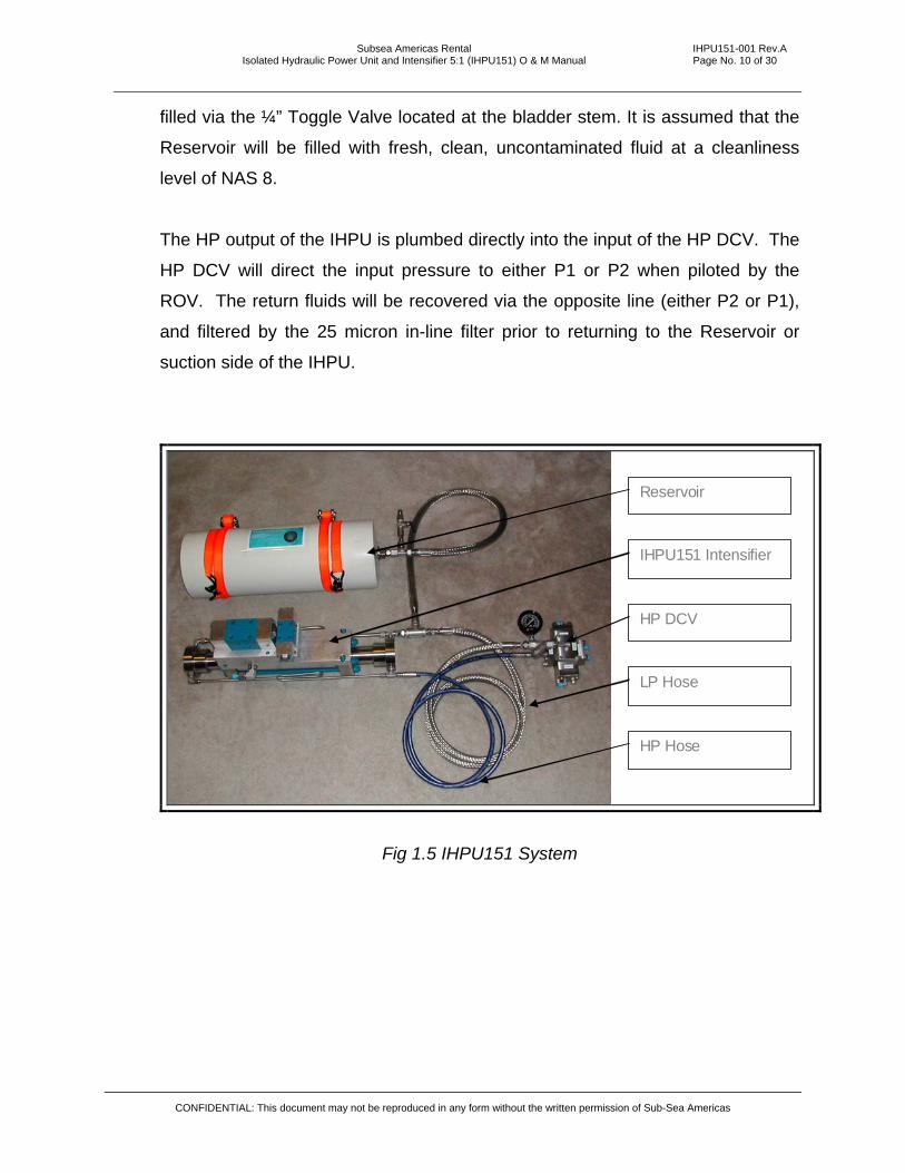
filled via the ¼” Toggle Valve located at the bladder stem. It is assumed that the
Reservoir will be filled with fresh, clean, uncontaminated fluid at a cleanliness
level of NAS 8.
The HP output of the IHPU is plumbed directly into the input of the HP DCV. The
HP DCV will direct the input pressure to either P1 or P2 when piloted by the
ROV. The return fluids will be recovered via the opposite line (either P2 or P1),
and filtered by the 25 micron in-line filter prior to returning to the Reservoir or
suction side of the IHPU.
Reservoir
IHPU151 Intensifier
HP DCV
LP Hose
HP Hose
Fig 1.5 IHPU151 System
CONFIDENTIAL: This document may not be reproduced in any form without the written permission of Sub-Sea Americas

Subsea Americas Rental IHPU151-001 Rev.A Isolated Hydraulic Power Unit and Intensifier 5:1 (IHPU151) O & M Manual Page No. 11 of 30
2.0 SETUP AND OPERATION INSTRUCTIONS
2.1 Mechanical Installation
Mechanical installation will be broken down into three parts.
1. Mounting of the IHPU151,
2. Mounting of the DVC,
3. Mounting of the Reservoir,
Within the confines of the ROV.
2.1.1 The IHPU151. The IHPU151, should be mounted reasonably close
to the front of the ROV and attached via the four 1/4 x 20 UNC
mounting holes at the base of the end caps. Note: the tie rods for
the end caps for the IHPU must not be removed in order to install
mounting brackets. The tie rods must remain torqued to the values
as described in the specification.
4 x ¼” x 20 Mounting Holes
Fig 2.1.1 IHPU151 Mounting Pattern
CONFIDENTIAL: This document may not be reproduced in any form without the written permission of Sub-Sea Americas
Subsea Americas Rental IHPU151-001 Rev.A Isolated Hydraulic Power Unit and Intensifier 5:1 (IHPU151) O & M Manual Page No. 12 of 30
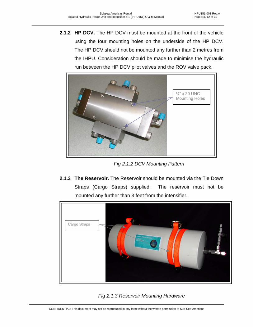
2.1.2 HP DCV. The HP DCV must be mounted at the front of the vehicle
using the four mounting holes on the underside of the HP DCV.
The HP DCV should not be mounted any further than 2 metres from
the IHPU. Consideration should be made to minimise the hydraulic
run between the HP DCV pilot valves and the ROV valve pack.
¼” x 20 UNC Mounting Holes
Fig 2.1.2 DCV Mounting Pattern
2.1.3 The Reservoir. The Reservoir should be mounted via the Tie Down
Straps (Cargo Straps) supplied. The reservoir must not be
mounted any further than 3 feet from the intensifier.
Cargo Straps
Fig 2.1.3 Reservoir Mounting Hardware
CONFIDENTIAL: This document may not be reproduced in any form without the written permission of Sub-Sea Americas

Subsea Americas Rental IHPU151-001 Rev.A Isolated Hydraulic Power Unit and Intensifier 5:1 (IHPU151) O & M Manual Page No. 13 of 30
CONFIDENTIAL: This document may not be reproduced in any form without the written permission of Sub-Sea Americas
2.2 Hydraulic Installation
Once the mechanical installation of the IHPU151, HP DCV and Reservoir is
complete, the hydraulic interconnect hoses may be installed.
• The pressure and return line to the IHPU151 will be operator furnished
and plumbed directly to the IHPU151 from the ROV switchable valve with
variable pressure capability or a proportional valve set. The supply line
should be a 3/8” hydraulic hose while the return line should be ½”
hydraulic hose.
NOTE
The ROV switchable valve with variable pressure capability or a
proportional valve must be able to return to tank in order for the system to
remain compensated during transit to working depth.
2.2.1 IHPU151 HP output; The IHPU151 HP output must use the 15,000
psi rated HP ¼” line supplied. An alternative lower pressure hose
supplied with No 4 JIC fittings has been supplied for 0-3000 psi
operations in conjunction with the DVC (via a T-piece and pressure
gauge at the DCV, if installed).
2.2.2 IHPU151 LP input/suction; The IHPU151 LP input/suction line will
be the 3/8” line supplied. This line must be connected from the No 6
Swagelok fitting at the output of the return filter (at the HP DCV)
directly to the No 6 Swagelok fitting at the input to the IHPU151.
Note this is via a t-piece for the Reservoir connection.

Subsea Americas Rental IHPU151-001 Rev.A Isolated Hydraulic Power Unit and Intensifier 5:1 (IHPU151) O & M Manual Page No. 14 of 30
HP Isolated Fluid Out
Isolated Fluid Input
Return to ROV Tank
Supply from ROV (ISO fluid – Tellus)
Fig 2.2.1 IHPU151
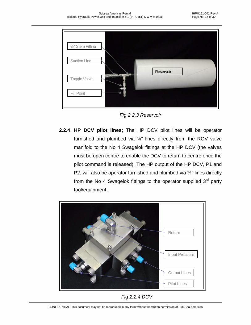
2.2.3 Reservoir LP line; The Reservoir LP line is the ½” line supplied.
This line must be connected directly from the No 8 Swagelok fitting
at the t-piece of the bladder stem, directly to the No 8 Swagelok at
the t-piece of the IHPU151 input/suction side.
CONFIDENTIAL: This document may not be reproduced in any form without the written permission of Sub-Sea Americas
Subsea Americas Rental IHPU151-001 Rev.A Isolated Hydraulic Power Unit and Intensifier 5:1 (IHPU151) O & M Manual Page No. 15 of 30
Reservoir
½” Stem Fittjng
Suction Line
Toggle Valve
Fill Point
Fig 2.2.3 Reservoir
2.2.4 HP DCV pilot lines; The HP DCV pilot lines will be operator
furnished and plumbed via ¼” lines directly from the ROV valve
manifold to the No 4 Swagelok fittings at the HP DCV (the valves
must be open centre to enable the DCV to return to centre once the
pilot command is released). The HP output of the HP DCV, P1 and
P2, will also be operator furnished and plumbed via ¼” lines directly
from the No 4 Swagelok fittings to the operator supplied 3rd party
tool/equipment.
Pilot Lines
Return
Output Lines
Input Pressure
Fig 2.2.4 DCV
CONFIDENTIAL: This document may not be reproduced in any form without the written permission of Sub-Sea Americas

Subsea Americas Rental IHPU151-001 Rev.A Isolated Hydraulic Power Unit and Intensifier 5:1 (IHPU151) O & M Manual Page No. 16 of 30
CONFIDENTIAL: This document may not be reproduced in any form without the written permission of Sub-Sea Americas
NOTE
The ROV directional control valve used to supply the pilots must be
centre return to tank in order for the function to turn off once the
pilot command is removed. This system will not function on a
boosted return system.
2.3 Hydraulic Setup
WARNING This IHPU System is capable of producing pressures up to 17,500 psi.
The operator is responsible for ensuring the safety of all personnel and
equipment associated in the installation, setting-up, testing and
operation of this equipment. Personnel Protective Equipment (PPE)
must be worn by all personnel associated in the installation, setting-up,
testing and operation of this equipment. PPE must include, but not
limited to Safety Glasses, Full heavy material Coveralls, Hard Hat,
Safety Boots and Protective Gloves. It is also the operator’s
responsibility to obtain and read the MSDS sheets associated with the
fluids intended for use with this equipment.
CAUTION
Excessive oil temperature can severely damage system components. Do
not let oil temperature exceed manufacturer’s limits. If overheating occurs,
shut down operation and wait for components to cool before proceeding.
2.3.1 Pilot Tests; Once the mechanical and hydraulic installation is
complete, the pilot lines to the HP DCV will be tested allowing fluid
to flow from the reservoir through either P1 or P2. This is achieved
by pushing on the bladder; increasing the internal pressure enough
to overcome the IHPU151 internal check valve spring pressures of
Subsea Americas Rental IHPU151-001 Rev.A Isolated Hydraulic Power Unit and Intensifier 5:1 (IHPU151) O & M Manual Page No. 17 of 30
CONFIDENTIAL: This document may not be reproduced in any form without the written permission of Sub-Sea Americas
12 psi (6 psi each check valve). Fluid will then flow out from either
P1 or P2 depending on which pilot is selected.
CAUTION
This circuit will not function as designed on a boosted return
hydraulic power supply.
2.3.2 IHPU151 Tests; The input pressure to the primary side of the
IHPU151 must be limited to 1/5th of the required output pressure i.e.
the ROV operator must ensure the correct input pressure is set to
the intensifier. The input flow to the primary side of the IHPU151
must initially be set to zero. Once the IHPU is turned on
hydraulically, the input flow to the primary side may be increased to
a maximum of 12 gpm.
NOTE
The IHPU151 is capable of operating pressures up to 17,500 psi.
Damage to other components may occur if the input pressure is not
verified prior to operation.
CAUTION
When testing the system on deck using a purge cart, pay attention
to the return line. Returning oil through a purge cart directional
control valve could result in return pressures exceeding
manufacturers recommendations with respect to equipment
installed. If in doubt, always connect the return line directly to tank.
Also, be aware that at higher flow rates, the pressure drop across a
directional control valve on the purge cart supply and may result in
a lower delivery pressure than required for normal operation. It
may be necessary to connect directly to the purge cart pump output
to reduce these pressure drop losses.

Subsea Americas Rental IHPU151-001 Rev.A Isolated Hydraulic Power Unit and Intensifier 5:1 (IHPU151) O & M Manual Page No. 18 of 30
CONFIDENTIAL: This document may not be reproduced in any form without the written permission of Sub-Sea Americas
2.3.3 Pressure Monitoring Tests; With the pressure gauge connected
at the input to the HP DCV, monitor the pressure build up prior to
switching the HP DCV. The desired output pressure of the
IHPU151 should be approximately three times the pressure
supplied by the ROV. Once the desired output pressure is
reached, the IHPU151 should stop stroking.
NOTE
The input flow to the intensifier must be limited to a maximum of 12
gpm as the return filter is rated to a maximum of 2 gpm.
CAUTION
Operating IHPU System with contaminated fluids can result in
component damage. Ensure that the reservoir fluid is at a
cleanliness level of NAS 8 before operating the system. If water
contamination occurs, purge the contaminated fluid and replace
with fresh fluid.
2.3.4 Pressure Output at P1 & P2: Switch the output for the HP DCV
from the closed centre position to pressure out at P1. The
IHPU151 should recommence stroking until the desired output
pressure is achieved again. Repeat this for output port P2 on the
HP DCV. Note: Do not allow the reservoir to drain, as the pump
will suck the elastomer into the suction line.
This completes the hydraulic setup procedures for the IHPU151.
Subsea Americas Rental IHPU151-001 Rev.A Isolated Hydraulic Power Unit and Intensifier 5:1 (IHPU151) O & M Manual Page No. 19 of 30
CONFIDENTIAL: This document may not be reproduced in any form without the written permission of Sub-Sea Americas
3.0 SYSTEM MAINTENANCE
System maintenance shall be broken into three sections. Post Dives, Post
Operation and General Maintenance.
3.1 Post Dives
After each dive the IHPU system must be washed down with fresh water. The
mechanical attachment points and hydraulic interconnects should be inspected
for loose fittings and leaks. Should the IHPU not be required for more than 24
hours, the IHPU151 and HP DCV must be flushed internally with an ISO
fluid. Storage of water glycol fluids in the reservoir is not recommended for more
than 24 hours. The Reservoir must be flushed with fresh water and dried prior to
storage.
3.2 Post Operations
Once the hydraulic circuit is no longer required, the circuit must be washed down
with fresh water and internally flushed with an ISO fluid as per section 3.1.
The hydraulic interconnects should be flushed and plugged. Each individual
component should be capped. Also, the reservoir must be flushed with fresh
water similar to Post Dives. The components, removed from the ROV and
placed in the shipping container supplied for long-term storage.
3.3 General Maintenance
Should there be any noticeable deterioration in the IHPU output pressure for the
given input pressure or fluid cross contamination, the IHPU151 HP End Caps
may be removed and the glide rings and HP seals replaced as described below.
Should there be any problems with HP Seal End Check Valves, the Check
Valves should be replaced. Once replaced, the IHPU should be tested on
standard charge cart with ISO fluids. Should there be any problems with the
IHPU151 control circuit, the Manifold Directional Control Valves (DCVs) should
Subsea Americas Rental IHPU151-001 Rev.A Isolated Hydraulic Power Unit and Intensifier 5:1 (IHPU151) O & M Manual Page No. 20 of 30
be replaced. Note: The IHPU151 Manifold DCVs are not field serviceable. They
must be returned to the manufacturer for refurbishment/replacement.
Should there be contamination between the control fluid and ISO fluid via the HP
Directional Control Valve (HP DCV), the HP DCV should be removed and
returned to the manufacturer for overhaul. Note: This item is not a field
serviceable unit.
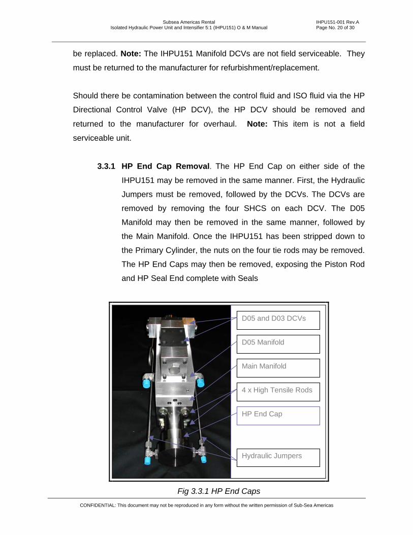
3.3.1 HP End Cap Removal. The HP End Cap on either side of the
IHPU151 may be removed in the same manner. First, the Hydraulic
Jumpers must be removed, followed by the DCVs. The DCVs are
removed by removing the four SHCS on each DCV. The D05
Manifold may then be removed in the same manner, followed by
the Main Manifold. Once the IHPU151 has been stripped down to
the Primary Cylinder, the nuts on the four tie rods may be removed.
The HP End Caps may then be removed, exposing the Piston Rod
and HP Seal End complete with Seals
D05 and D03 DCVs
D05 Manifold
Main Manifold
Hydraulic Jumpers
4 x High Tensile Rods
HP End Cap
Fig 3.3.1 HP End Caps
CONFIDENTIAL: This document may not be reproduced in any form without the written permission of Sub-Sea Americas
Subsea Americas Rental IHPU151-001 Rev.A Isolated Hydraulic Power Unit and Intensifier 5:1 (IHPU151) O & M Manual Page No. 21 of 30
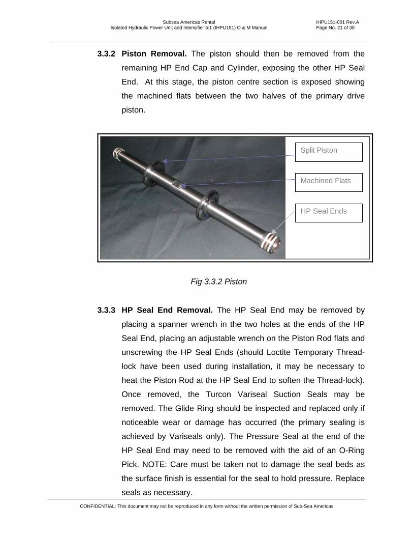
3.3.2 Piston Removal. The piston should then be removed from the
remaining HP End Cap and Cylinder, exposing the other HP Seal
End. At this stage, the piston centre section is exposed showing
the machined flats between the two halves of the primary drive
piston.
Split Piston
Machined Flats
HP Seal Ends
Fig 3.3.2 Piston
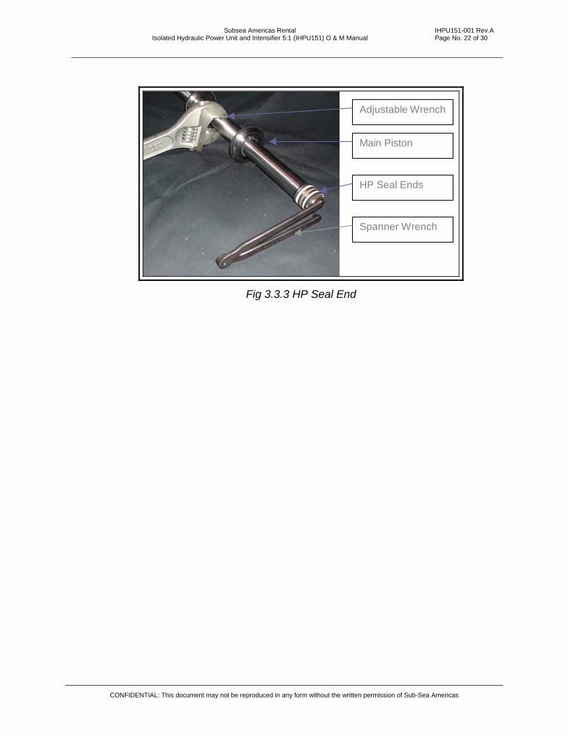
3.3.3 HP Seal End Removal. The HP Seal End may be removed by
placing a spanner wrench in the two holes at the ends of the HP
Seal End, placing an adjustable wrench on the Piston Rod flats and
unscrewing the HP Seal Ends (should Loctite Temporary Thread-
lock have been used during installation, it may be necessary to
heat the Piston Rod at the HP Seal End to soften the Thread-lock).
Once removed, the Turcon Variseal Suction Seals may be
removed. The Glide Ring should be inspected and replaced only if
noticeable wear or damage has occurred (the primary sealing is
achieved by Variseals only). The Pressure Seal at the end of the
HP Seal End may need to be removed with the aid of an O-Ring
Pick. NOTE: Care must be taken not to damage the seal beds as
the surface finish is essential for the seal to hold pressure. Replace
seals as necessary. CONFIDENTIAL: This document may not be reproduced in any form without the written permission of Sub-Sea Americas
Subsea Americas Rental IHPU151-001 Rev.A Isolated Hydraulic Power Unit and Intensifier 5:1 (IHPU151) O & M Manual Page No. 22 of 30
Adjustable Wrench
Main Piston
HP Seal Ends
Spanner Wrench
Fig 3.3.3 HP Seal End
CONFIDENTIAL: This document may not be reproduced in any form without the written permission of Sub-Sea Americas

Subsea Americas Rental IHPU151-001 Rev.A Isolated Hydraulic Power Unit and Intensifier 5:1 (IHPU151) O & M Manual Page No. 23 of 30
3.3.4 Glide Ring Installation. The Glide rings are installed with the O-
Ring first onto the seal bed, followed by the Glide Ring. The Glide
Ring is then installed with the use of the Seal Loading Mandrel. The
Mandrel is placed over the end of the HP Seal End and the Glide
Ring is slid up the Mandrel with the Seal Pusher Tool. NOTE: if the
Glide Ring is too stiff, the Glide Ring may be softened by placing it
in hot water for a few minutes.
HP Seal End
Seal Installation Tool
Glide Ring
Fig 3.3.4 Glide Ring Installation
3.3.5 Glide Ring Re-Sizing. Once the Glide Ring has been installed, the
Glide Ring will need to be re-sized with the Re-Sizing Tool. The
Glide Ring must be coated with a light coating of Oil or Grease and
the Re-Sizing Tool brought over the top of the Glide Ring, forcing
the Glide Ring to compress into its original shape
Re-Sizing Tool
Glide Ring
Fig 3.3.5 Glide Ring Re-Sizing
CONFIDENTIAL: This document may not be reproduced in any form without the written permission of Sub-Sea Americas
Subsea Americas Rental IHPU151-001 Rev.A Isolated Hydraulic Power Unit and Intensifier 5:1 (IHPU151) O & M Manual Page No. 24 of 30
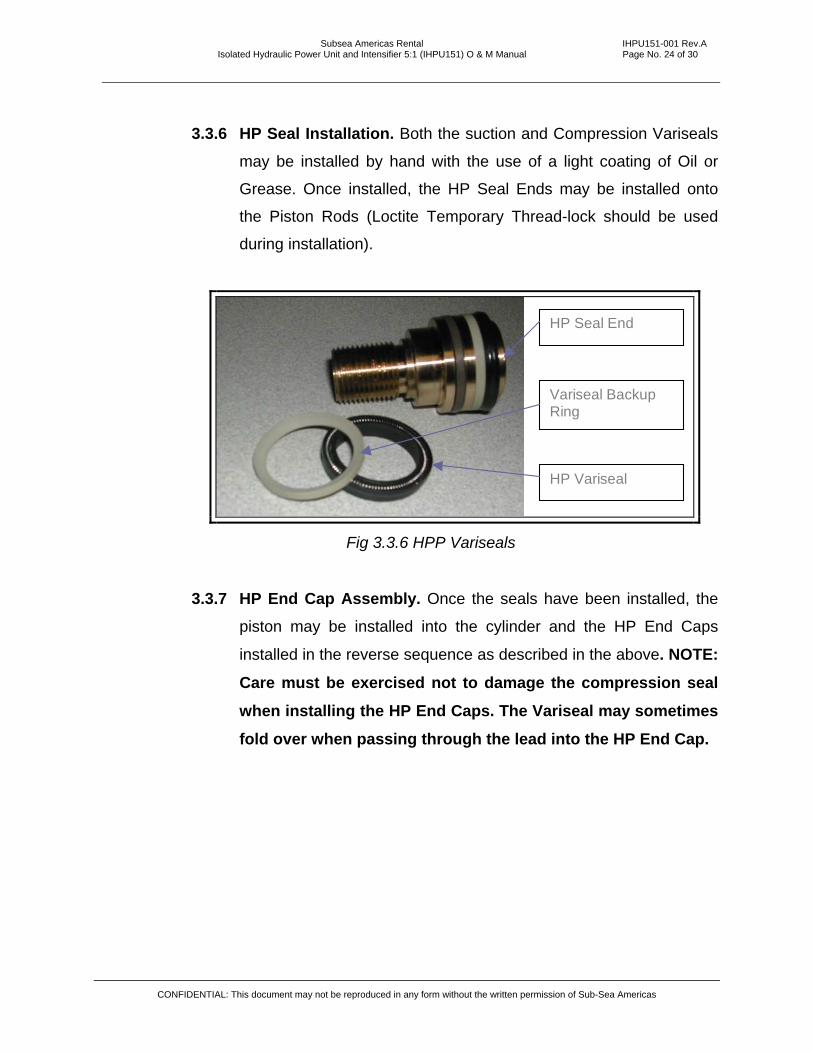
3.3.6 HP Seal Installation. Both the suction and Compression Variseals
may be installed by hand with the use of a light coating of Oil or
Grease. Once installed, the HP Seal Ends may be installed onto
the Piston Rods (Loctite Temporary Thread-lock should be used
during installation).
HP Seal End
HP Variseal
Variseal Backup Ring
Fig 3.3.6 HPP Variseals
3.3.7 HP End Cap Assembly. Once the seals have been installed, the
piston may be installed into the cylinder and the HP End Caps
installed in the reverse sequence as described in the above. NOTE:
Care must be exercised not to damage the compression seal
when installing the HP End Caps. The Variseal may sometimes
fold over when passing through the lead into the HP End Cap.
CONFIDENTIAL: This document may not be reproduced in any form without the written permission of Sub-Sea Americas
Subsea Americas Rental IHPU151-001 Rev.A Isolated Hydraulic Power Unit and Intensifier 5:1 (IHPU151) O & M Manual Page No. 25 of 30
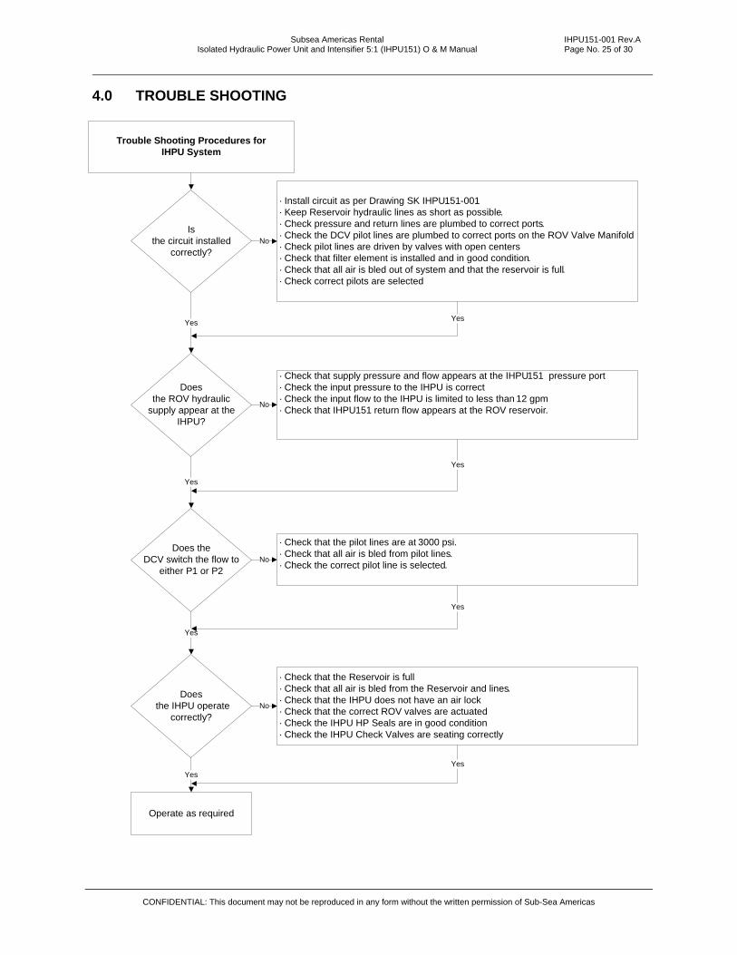
4.0 TROUBLE SHOOTING
Trouble Shooting Procedures for IHPU System
Is the circuit installed
correctly?
· Install circuit as per Drawing SK IHPU151-001· Keep Reservoir hydraulic lines as short as possible.· Check pressure and return lines are plumbed to correct ports.· Check the DCV pilot lines are plumbed to correct ports on the ROV Valve Manifold· Check pilot lines are driven by valves with open centers · Check that filter element is installed and in good condition.· Check that all air is bled out of system and that the reservoir is full.· Check correct pilots are selected
Does the ROV hydraulic
supply appear at the IHPU?
· Check that supply pressure and flow appears at the IHPU151 pressure port· Check the input pressure to the IHPU is correct· Check the input flow to the IHPU is limited to less than 12 gpm· Check that IHPU151 return flow appears at the ROV reservoir.
Does the DCV switch the flow to
either P1 or P2
· Check that the pilot lines are at 3000 psi.· Check that all air is bled from pilot lines.· Check the correct pilot line is selected.
Does the IHPU operate
correctly?
· Check that the Reservoir is full· Check that all air is bled from the Reservoir and lines.· Check that the IHPU does not have an air lock· Check that the correct ROV valves are actuated· Check the IHPU HP Seals are in good condition· Check the IHPU Check Valves are seating correctly
Operate as required
No
Yes
No
Yes
No
Yes
No
Yes
Yes
Yes
Yes
Yes
CONFIDENTIAL: This document may not be reproduced in any form without the written permission of Sub-Sea Americas

Subsea Americas Rental IHPU151-001 Rev.A Isolated Hydraulic Power Unit and Intensifier 5:1 (IHPU151) O & M Manual Page No. 26 of 30
CONFIDENTIAL: This document may not be reproduced in any form without the written permission of Sub-Sea Americas
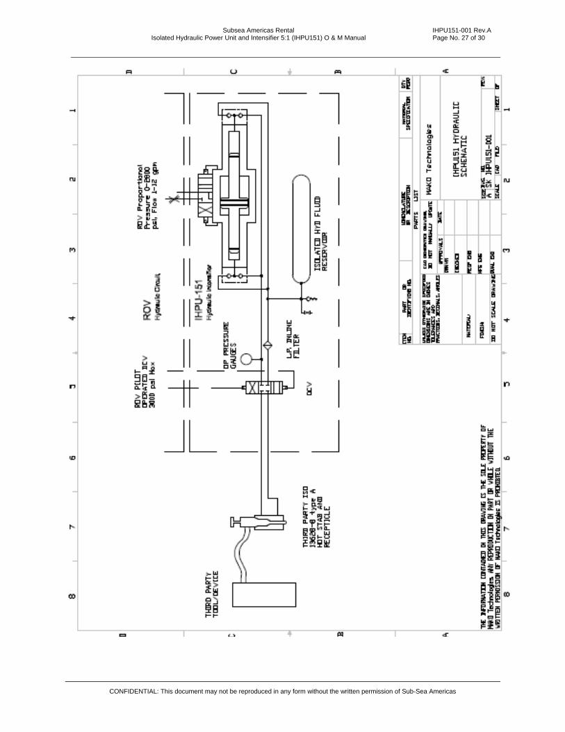
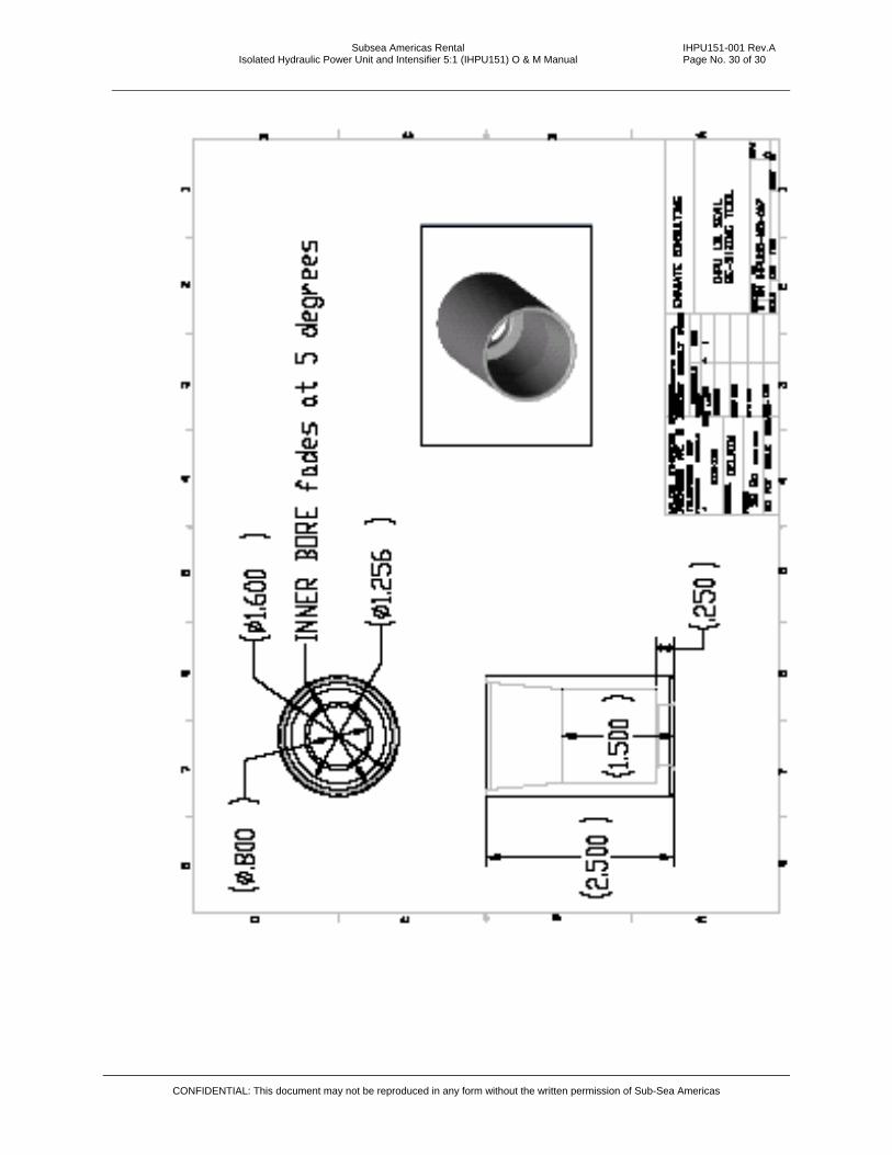
APPENDIX A - Drawings
SK IHPU151-001 IHPU HYDRAULIC SCHEMATIC
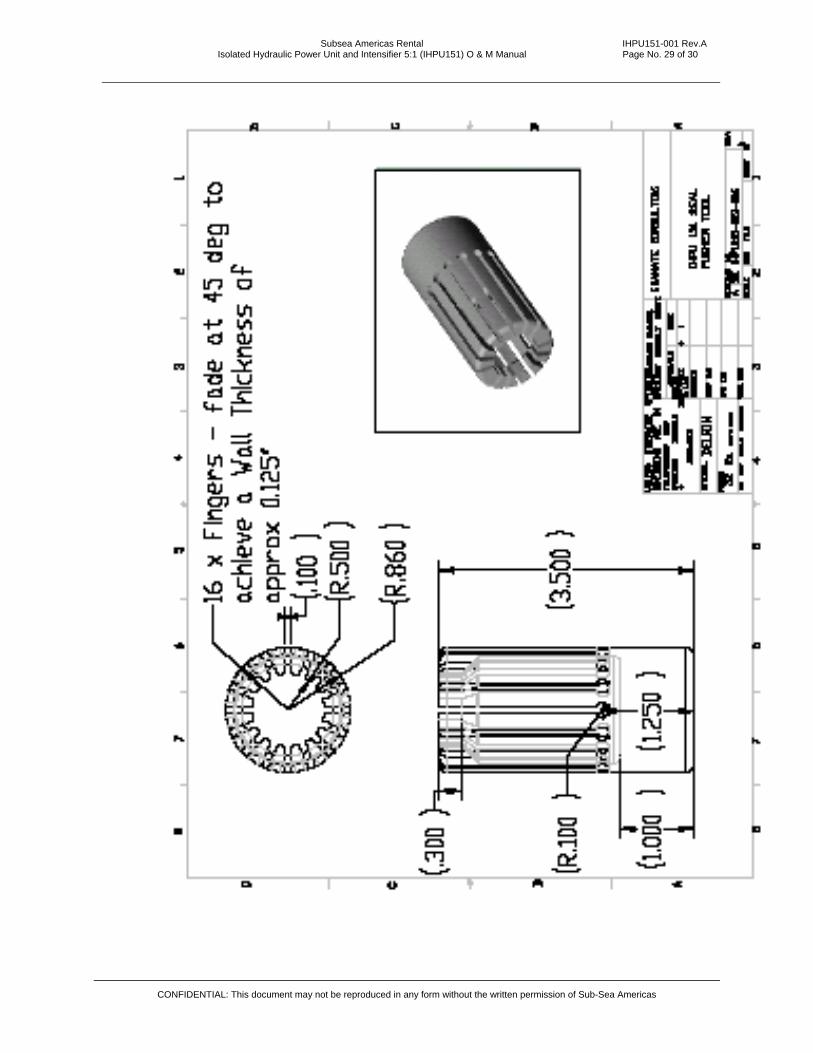
SK IHPU151-003-005 IHPU151 SEAL LOADING MANDREL
SK IHPU151-003-006 IHPU151 SEAL PUSHER TOOL
SK IHPU151-003-007 IHPU151 SEAL RE-SIZING TOOL
Subsea Americas Rental IHPU151-001 Rev.A Isolated Hydraulic Power Unit and Intensifier 5:1 (IHPU151) O & M Manual Page No. 27 of 30
CONFIDENTIAL: This document may not be reproduced in any form without the written permission of Sub-Sea Americas

Subsea Americas Rental IHPU151-001 Rev.A Isolated Hydraulic Power Unit and Intensifier 5:1 (IHPU151) O & M Manual Page No. 28 of 30
CONFIDENTIAL: This document may not be reproduced in any form without the written permission of Sub-Sea Americas
Subsea Americas Rental IHPU151-001 Rev.A Isolated Hydraulic Power Unit and Intensifier 5:1 (IHPU151) O & M Manual Page No. 29 of 30
CONFIDENTIAL: This document may not be reproduced in any form without the written permission of Sub-Sea Americas
Subsea Americas Rental IHPU151-001 Rev.A Isolated Hydraulic Power Unit and Intensifier 5:1 (IHPU151) O & M Manual Page No. 30 of 30
CONFIDENTIAL: This document may not be reproduced in any form without the written permission of Sub-Sea Americas