Embed Size (px)
Citation preview
Increase your fluid power
High pressure intensifierHydraulic cylinders
2
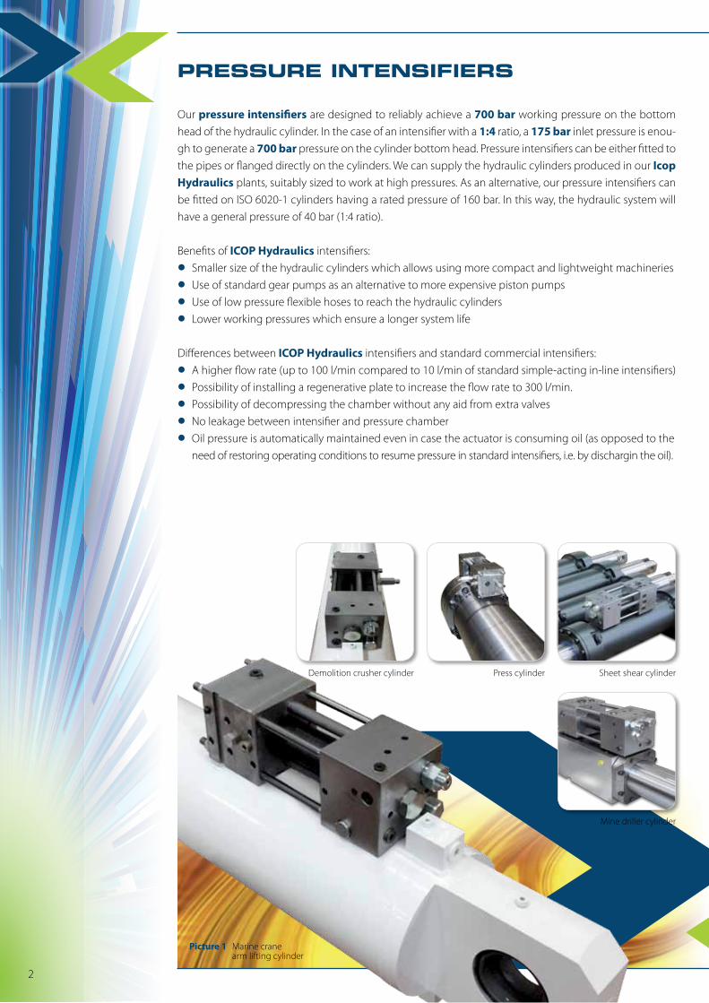
Demolition crusher cylinder Sheet shear cylinder
Mine driller cylinder
Press cylinder
Our pressure intensifiers are designed to reliably achieve a 700 bar working pressure on the bottom head of the hydraulic cylinder. In the case of an intensifier with a 1:4 ratio, a 175 bar inlet pressure is enou-gh to generate a 700 bar pressure on the cylinder bottom head. Pressure intensifiers can be either fitted to the pipes or flanged directly on the cylinders. We can supply the hydraulic cylinders produced in our Icop Hydraulics plants, suitably sized to work at high pressures. As an alternative, our pressure intensifiers can be fitted on ISO 6020-1 cylinders having a rated pressure of 160 bar. In this way, the hydraulic system will have a general pressure of 40 bar (1:4 ratio).
Benefits of ICOP Hydraulics intensifiers:
• Smaller size of the hydraulic cylinders which allows using more compact and lightweight machineries
• Use of standard gear pumps as an alternative to more expensive piston pumps
• Use of low pressure flexible hoses to reach the hydraulic cylinders
• Lower working pressures which ensure a longer system life
Differences between ICOP Hydraulics intensifiers and standard commercial intensifiers:
• A higher flow rate (up to 100 l/min compared to 10 l/min of standard simple-acting in-line intensifiers)
• Possibility of installing a regenerative plate to increase the flow rate to 300 l/min.
• Possibility of decompressing the chamber without any aid from extra valves
• No leakage between intensifier and pressure chamber
• Oil pressure is automatically maintained even in case the actuator is consuming oil (as opposed to the need of restoring operating conditions to resume pressure in standard intensifiers, i.e. by dischargin the oil).
Picture 1 Marine crane arm lifting cylinder
PRESSURE INTENSIFIERS
Increase your fluid power
FIELDS OF APPLICATION
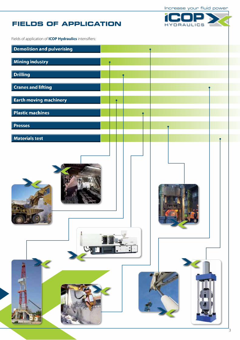
Fields of application of ICOP Hydraulics intensifiers:
Demolition and pulverising
Mining industry
Drilling
Cranes and lifting
Earth moving machinery
Plastic machines
Presses
Materials test
3
PRESSURE INTENSIFIERS
GENERAL CHARACTERISTICS
APPLICATION
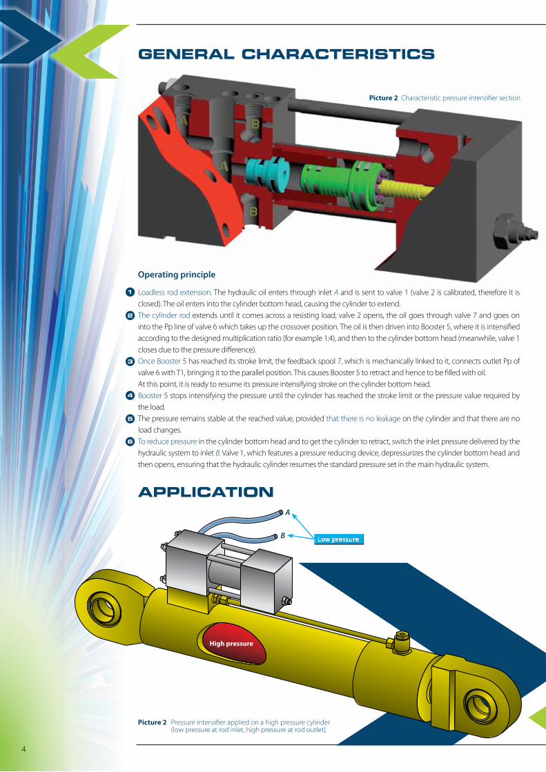
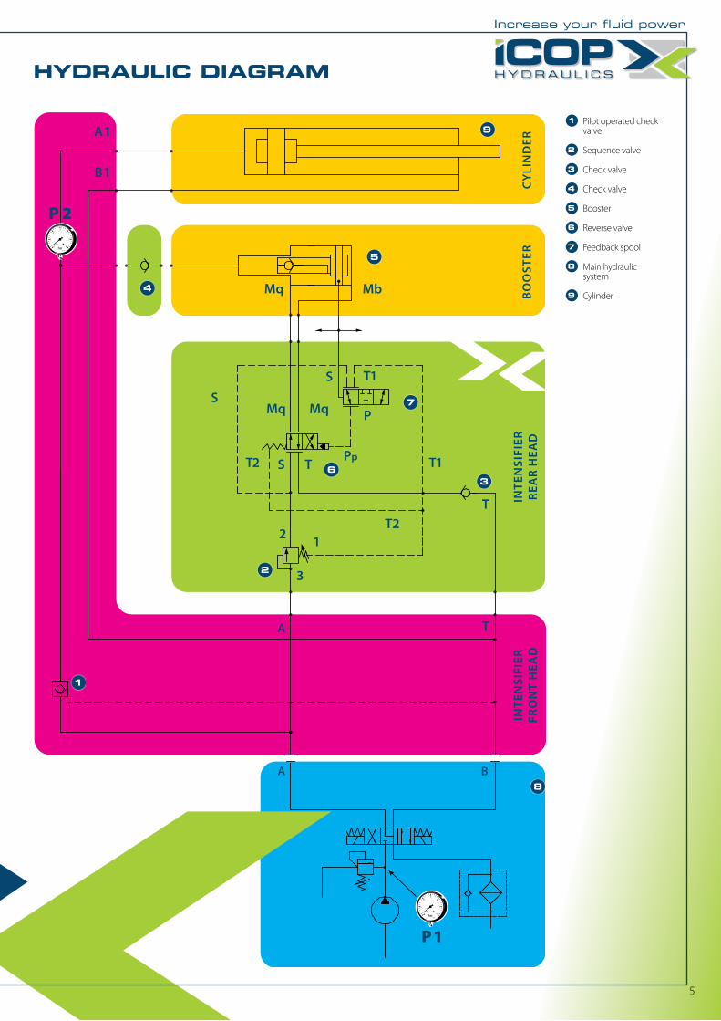
Loadless rod extension. The hydraulic oil enters through inlet A and is sent to valve 1 (valve 2 is calibrated, therefore it is closed). The oil enters into the cylinder bottom head, causing the cylinder to extend.The cylinder rod extends until it comes across a resisting load; valve 2 opens, the oil goes through valve 7 and goes on into the Pp line of valve 6 which takes up the crossover position. The oil is then driven into Booster 5, where it is intensified according to the designed multiplication ratio (for example 1:4), and then to the cylinder bottom head (meanwhile, valve 1 closes due to the pressure difference).Once Booster 5 has reached its stroke limit, the feedback spool 7, which is mechanically linked to it, connects outlet Pp of valve 6 with T1, bringing it to the parallel position. This causes Booster 5 to retract and hence to be filled with oil.At this point, it is ready to resume its pressure intensifying stroke on the cylinder bottom head.Booster 5 stops intensifying the pressure until the cylinder has reached the stroke limit or the pressure value required by the load.The pressure remains stable at the reached value, provided that there is no leakage on the cylinder and that there are no load changes.To reduce pressure in the cylinder bottom head and to get the cylinder to retract, switch the inlet pressure delivered by the hydraulic system to inlet B. Valve 1, which features a pressure reducing device, depressurizes the cylinder bottom head and then opens, ensuring that the hydraulic cylinder resumes the standard pressure set in the main hydraulic system.
2
1
3
4
5
6
Low pressure
4
Picture 2 Pressure intensifier applied on a high pressure cylinder (low pressure at rod inlet, high pressure at rod outlet).
Picture 2 Characteristic pressure intensifier section
High pressure
Operating principle
B
A
CY
LIN
DER
BO
OST
ER
P 1
P 2
T
TA
A B
S
S T
S
B1
A1
Mb
Mq Mq
Mq
T2
T1T2
T1
2 1
P
Pp
3
INTE
NSI
FIER
FRO
NT
HEA
DIN
TEN
SIFI
ERR
EAR
HEA
D
Increase your fluid power
HYDRAULIC DIAGRAMGENERAL CHARACTERISTICS
APPLICATION
1 Pilot operated check valve
2 Sequence valve
3 Check valve
4 Check valve
5 Booster
6 Reverse valve
7 Feedback spool
8 Main hydraulic system
9 Cylinder
2
1
9
3
4
5
7
8
6
5
6
CHARACTERISTIC CURVES
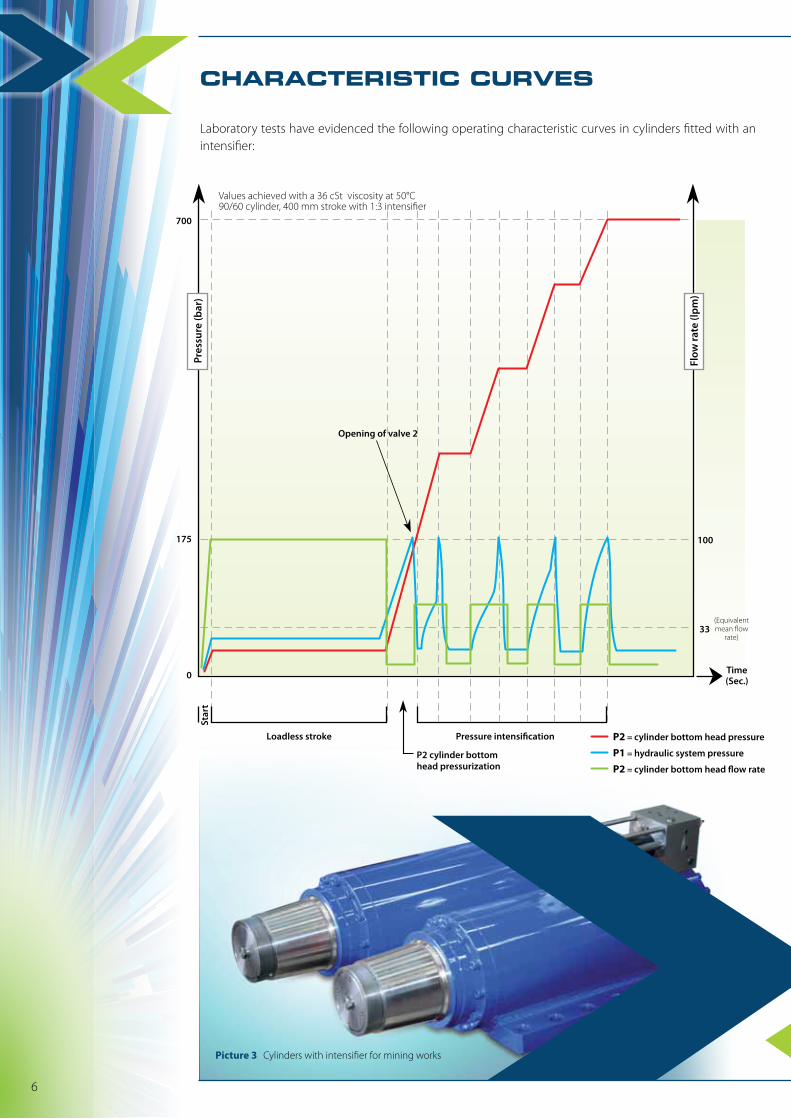
Laboratory tests have evidenced the following operating characteristic curves in cylinders fitted with an intensifier:
700
100
(Equivalentmean �ow
rate)
Loadless stroke Pressure intensi�cation
Opening of valve 2
P2 cylinder bottomhead pressurization
Star
t
33
Time(Sec.)
175
0
P2 = cylinder bottom head pressure
P1 = hydraulic system pressure
P2 = cylinder bottom head �ow rate
Pres
sure
(bar
)
Flow
rate
(lpm
)
Values achieved with a 36 cSt viscosity at 50°C90/60 cylinder, 400 mm stroke with 1:3 intensifier
Picture 3 Cylinders with intensifier for mining works
bar 700
°C -20 / +80
l/min 100
cSt 10 ÷ 400
cSt 25
°C -20 / +70
Degree of fluid contamination ISO 4406:1999 Standard class 20/18/15
kg 35
Maximum operating pressure
Fluid temperature range
Maximum flow rate
Fluid viscosity range
Recommended viscosity
Ambient temperature range
Masse
Increase your fluid power
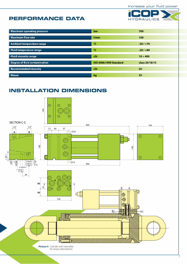
PERFORMANCE DATA
INSTALLATION DIMENSIONS
SECTION C-C
A B
1/2”460
140
394
140
140
29,5
14 H
8
130
CB
A
C60
40
Ø26H8Ø33
Ø18Ø21,5
27,5+/- 0,05
2.9+0-0,100
30
4
1/2”12 49 57
D19
D13
34
140
7
Picture 4 Cylinder with intensifier for shears (demolition)
8
DEMOLITION, PULVERISING
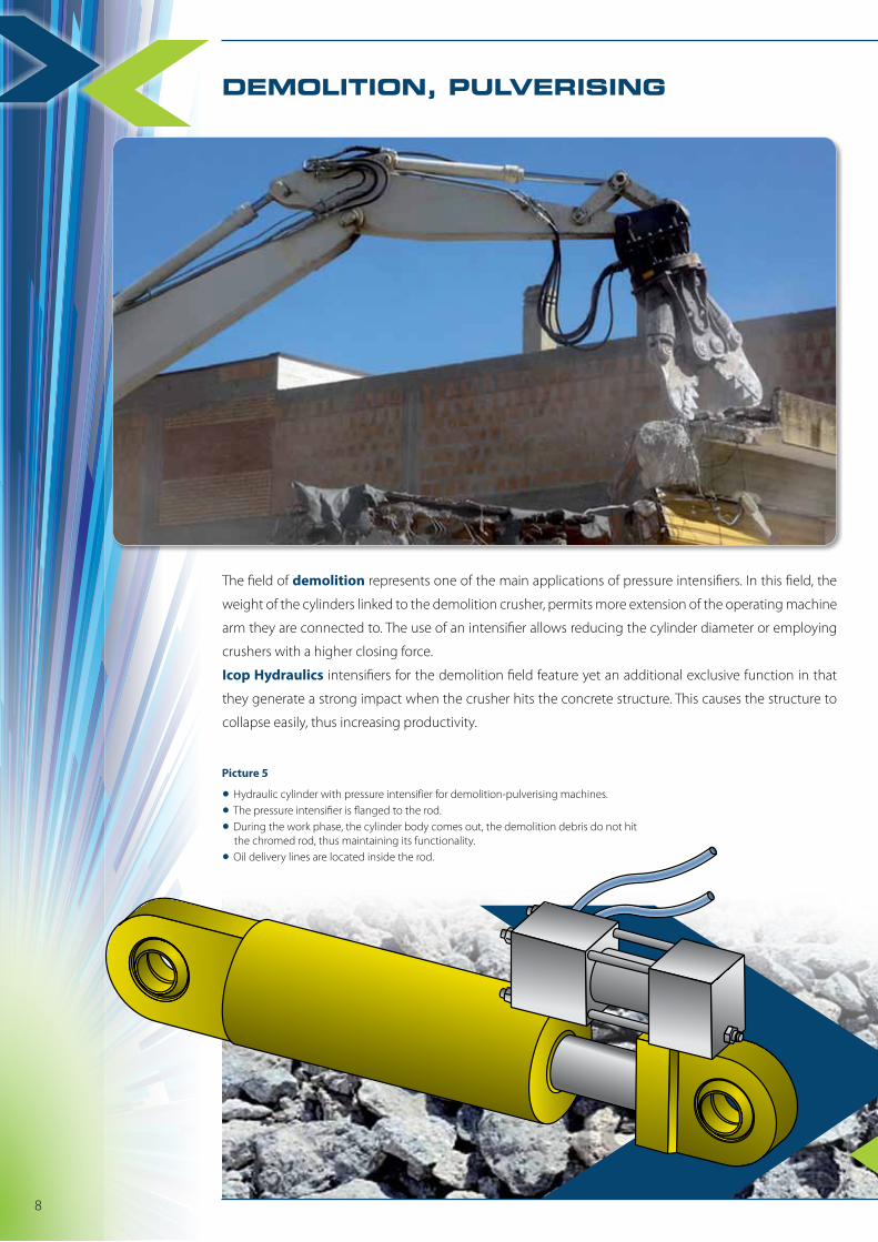
The field of demolition represents one of the main applications of pressure intensifiers. In this field, the
weight of the cylinders linked to the demolition crusher, permits more extension of the operating machine
arm they are connected to. The use of an intensifier allows reducing the cylinder diameter or employing
crushers with a higher closing force.
Icop Hydraulics intensifiers for the demolition field feature yet an additional exclusive function in that
they generate a strong impact when the crusher hits the concrete structure. This causes the structure to
collapse easily, thus increasing productivity.
• Hydraulic cylinder with pressure intensifier for demolition-pulverising machines.
• The pressure intensifier is flanged to the rod.
• During the work phase, the cylinder body comes out, the demolition debris do not hit the chromed rod, thus maintaining its functionality.
• Oil delivery lines are located inside the rod.
Picture 5
Increase your fluid power
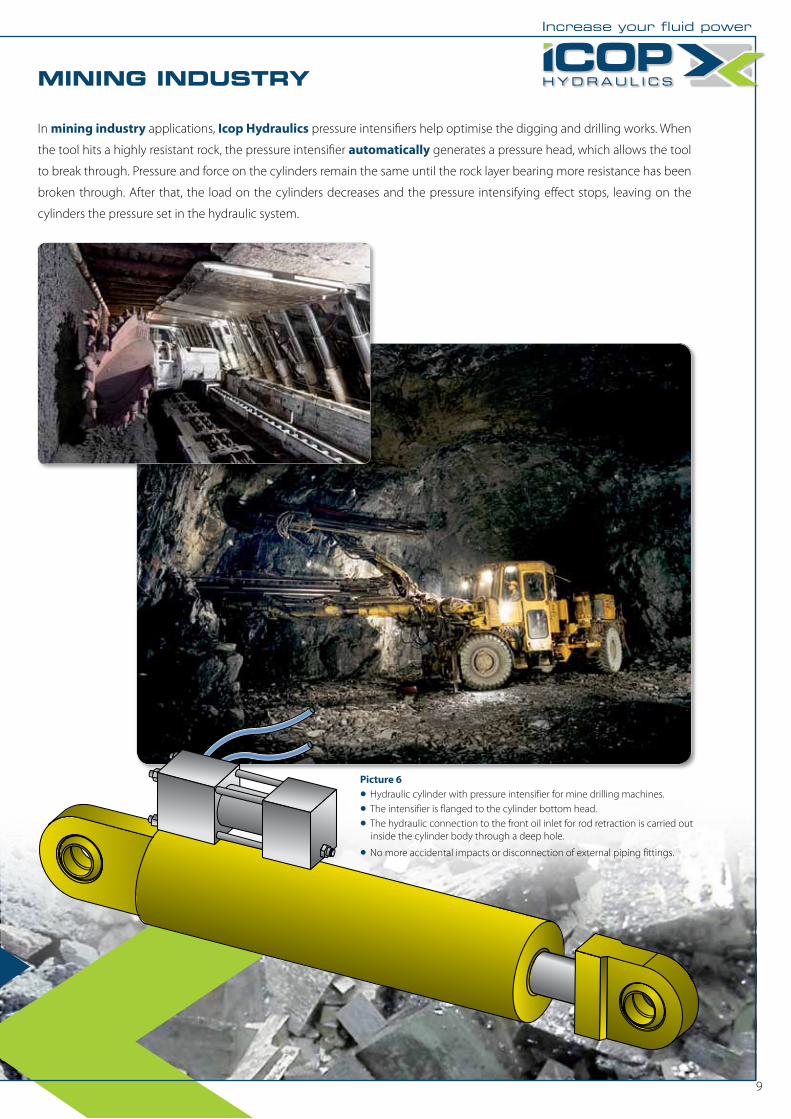
In mining industry applications, Icop Hydraulics pressure intensifiers help optimise the digging and drilling works. When
the tool hits a highly resistant rock, the pressure intensifier automatically generates a pressure head, which allows the tool
to break through. Pressure and force on the cylinders remain the same until the rock layer bearing more resistance has been
broken through. After that, the load on the cylinders decreases and the pressure intensifying effect stops, leaving on the
cylinders the pressure set in the hydraulic system.
MINING INDUSTRY
9
DEMOLITION, PULVERISING
Picture 6
• Hydraulic cylinder with pressure intensifier for mine drilling machines.
• The intensifier is flanged to the cylinder bottom head.
• The hydraulic connection to the front oil inlet for rod retraction is carried out inside the cylinder body through a deep hole.
• No more accidental impacts or disconnection of external piping fittings.
10
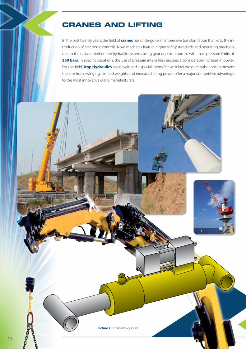
CRANES AND LIFTING
In the past twenty years, the field of cranes has undergone an impressive transformation thanks to the in-
troduction of electronic controls. Now, machines feature higher safety standards and operating precision,
due to the tests carried on the hydraulic systems using gear or piston pumps with max. pressure limits of
350 bars. In specific situations, the use of pressure intensifiers ensures a considerable increase in power.
For this field, Icop Hydraulics has developed a special intensifier with low pressure pulsations to prevent
the arm from swinging. Limited weights and increased lifting power offer a major competitive advantage
to the most innovative crane manufacturers.
Picture 7 Lifting arm cylinder
Increase your fluid power
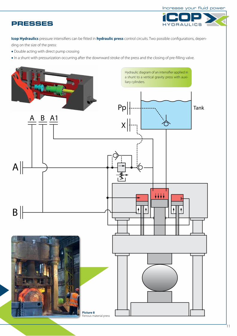
PRESSES
Icop Hydraulics pressure intensifiers can be fitted in hydraulic press control circuits. Two possible configurations, depen-
ding on the size of the press:
• Double acting with direct pump crossing
• In a shunt with pressurization occurring after the downward stroke of the press and the closing of pre-filling valve.
A
A B A1Pp Tank
X
B
11
Picture 8Ferrous material press
Hydraulic diagram of an intensifier applied in a shunt to a vertical gravity press with auxi-liary cylinders.
12
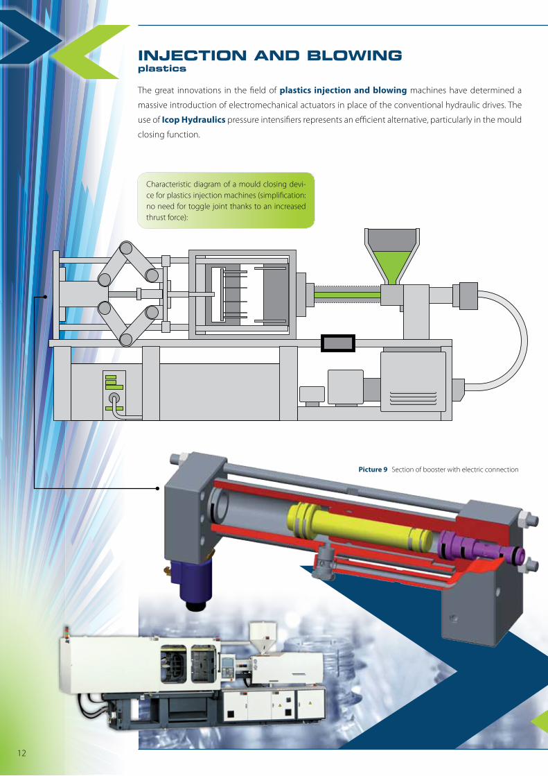
The great innovations in the field of plastics injection and blowing machines have determined a
massive introduction of electromechanical actuators in place of the conventional hydraulic drives. The
use of Icop Hydraulics pressure intensifiers represents an efficient alternative, particularly in the mould
closing function.
INJECTION AND BLOWINGplastics
Picture 9 Section of booster with electric connection
Characteristic diagram of a mould closing devi-ce for plastics injection machines (simplification: no need for toggle joint thanks to an increased thrust force):
Increase your fluid power
1 1
B1 B1
A1 A17 7
6 6
2 2
3
5
8 8
AB AB
Diagram 1 Diagram 2
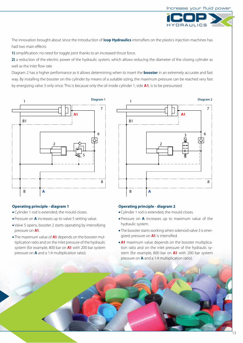
Operating principle - diagram 1
• Cylinder 1 rod is extended, the mould closes.
• Pressure on A increases up to valve 5 setting value.
• Valve 5 opens, booster 2 starts operating by intensifying pressure on A1.
• The maximum value of A1 depends on the booster mul-tiplication ratio and on the inlet pressure of the hydraulic system (for example, 800 bar on A1 with 200 bar system pressure on A and a 1:4 multiplication ratio).
Operating principle - diagram 2
• Cylinder 1 rod is extended, the mould closes.
• Pressure on A increases up to maximum value of the hydraulic system.
• The booster starts working when solenoid valve 3 is ener-gized; pressure on A1 is intensified.
• A1 maximum value depends on the booster multiplica-tion ratio and on the inlet pressure of the hydraulic sy-stem (for example, 800 bar on A1 with 200 bar system pressure on A and a 1:4 multiplication ratio).
The innovation brought about since the introduction of Icop Hydraulics intensifiers on the plastics injection machines has
had two main effects:
1) simplification: no need for toggle joint thanks to an increased thrust force.
2) a reduction of the electric power of the hydraulic system, which allows reducing the diameter of the closing cylinder as
well as the inlet flow rate
Diagram 2 has a higher performance as it allows determining when to insert the booster in an extremely accurate and fast
way. By installing the booster on the cylinder by means of a suitable sizing, the maximum pressure can be reached very fast
by energizing valve 3 only once. This is because only the oil inside cylinder 1, side A1, is to be pressurized.
13