Embed Size (px)
Citation preview

1
OPERAOPERAOPERAOPERAOPERATTTTTORS’ORS’ORS’ORS’ORS’ GUIDE GUIDE GUIDE GUIDE GUIDE
Intensifier Manual 05-09
WARNINGWARNINGWARNINGWARNINGWARNING All information found in this guide must be read and understood before operation or testing of this tool.
Failure to read and understand these warnings andsafe handling instructions could result in severepersonal injury and or death.
REL-10-I-SAREL-10-I-SA/D
SINGLE & DOUBLE ACTINGHYDRAULIC 10,000 PSI
INTENSIFIER / VALVE
The NEW REL-10-I-SA/D single& double acting control systemsprovides a unique solution to yourhigh pressure tooling requirements.
REL-10-I10,000 PSI INTENSIFIER
This system combines thepower of a high pressureintensifier with the simplicityof a fixed position threeway control valve.
This revolutionary intensifier will increase linepressure to a maximum of 10,000 psi and is fullycompat ib le w i th a l l h igh pressure hydrau l icequipment. (i.e. Crimping, Cutting & Spearing Tools)
RELIABLE EQUIPMENT & SERVICE CO., INC.92 Steamwhistle Drive • Ivyland, PA 18974 • USA
Phone: 215-357-3500 • Fax: 215-357-9193
MODEL: REL-10-I & REL-10-I-SASOURCE PRESSURE: 2,000 PSIINTENSIFIED PRESSURE: 10,000 PSISERIAL NO.: ____________YEAR: ___________
NONONONONOTICETICETICETICETICESizes, weights and tool specifications listed in thismanual are subject to change without notice.Please consult factory for information and updates.

2
TABLE OF CONTENTSRegistration .................................. 2Tool Quick Reference .............. 3-4General Safety Issues ............. 5-7SPECIFICATIONSGeneral ......................................... 7Pre-Operation .............................. 8Hydraulic Fluids .......................... 8Connections and Hoses ............. 9Operation (Single Acting) ......... 10Operation (Double Acting) ....... 11MAINTENANCEGeneral ....................................... 12Troubleshooting........................ 13Before Disassembly ................. 14
REGISTRATIONUPON RECEIPT OF THIS TOOL, COMPLETE THE REGISTRATION BELOW.
COMPANY ____________________________________________________
ADDRESS ____________________________________________________
_____________________________________________________________
PHONE _______________________ FAX___________________________
SERIAL NUMBER ______________________________________________
DATE OF PURCHASE___________________________________________
DEALER NAME ________________________________________________
Reservoir Clean & Fill ............... 14Major Components (Fig. 1 & 2) 15-16External Assembly (Fig. 3) ............ 17Motor Assembly (Figure 4) .......... 18Pump Block Assy (Figure 5) ...19-20Drive Gear Assy (Figure 6) ............ 21REL-DIR-VALVE.......................... 22Valve Assembly (Figure 7) .......23-24Maintenance Record................. 25Phone, Fax & Address .............. 24
This symbol indicates itemsof extreme importance. Safetyof user and others may be injeopardy if these instructionsare not read and understood.
DISTRIBDISTRIBDISTRIBDISTRIBDISTRIBUTED BYUTED BYUTED BYUTED BYUTED BY

3
TABLE OF CONTENTSRegistration & Distributor Information ..................................................... 2Table of Contents............................................................................................ 3Tool Quick Reference (REL-10-I) ................................................................ 4Tool Quick Reference (REL-10-I-SA) .......................................................... 5Tool Quick Reference (REL-10-I-SAD) ................................................... 6-7General Safety Issues ............................................................................. 8-10Pre-Operation ................................................................................................11Hydraulic Fluids ............................................................................................11Connections and Hoses (ALL MODELS) .............................................. 12Operation (REL-10-I-SA) ............................................................................. 13Operation (REL-10-I-SAD Single Acting) ............................................... 14Operation (REL-10-I-SAD Double Acting) ............................................. 15MAINTENANCEGeneral ........................................................................................................... 16Before Disassembly .................................................................................... 17REL-10-I Drawings & Parts Lists (Fig. 1 & 2) .............................................. 18-19REL-10-I Drawing & Parts List (Fig. 3) ............................................................... 20PVA-00L3 Control Valve Drawing & Parts List (Figure 4) ........................ 21Maintenance Record ................................................................................... 22Manufacturer Contact Information (Phone, Fax & Address) ........... 22
THIS SYMBOL INDICATES ITEMS OF EXTREME IMPORTANCE.Safety of user and others may be in jeopardy if these instructions arenot read and understood.
Operation/Safety methods may vary in accordance with the workingguidelines established by each utility or contractor
For your own safety, ensure that you fully comply with all safe operationguidelines required by your employer.WARNING

4
SPECIFICATIONSHYDRAULIC SYSTEM ..................Open or Closed CenterMOTOR.......................................................... Gear DrivenOPERATING PRESSURE ........................ 1,400-2,000 psiFLOW RANGE ....................................................4-7 gpmOPTIMUM OPERATING PRESSURE .. 1,800 psi @ 6 gpmOUTPUT - FAST ADVANCE MODE ..............305 in. 3/minOUTPUT - HIGH PRESSURE MODE.............. 30 in. 3/minRELIEF VALVE SETTING .................... 4,000 - 10,000 psiHIGH PRESSURE PORT ............................... 3/8 in. NPTINLET PORT .................................................. 3/8 in. NPTRETURN PORT ............................................. 3/8 in. NPT
SPECIAL FEATURESHIGH PRESSURE COUPLER............................. IncludedADJUSTABLE MOUNTING BRACKETS.............. IncludedUL-BCA - MOUNTING BUCKET ......................... Optional
REL-10-IINTENSIFIER
10,000 PSI
A SMALL A SMALL A SMALL A SMALL A SMALL TTTTTOOL FOR OOL FOR OOL FOR OOL FOR OOL FOR A BIG JOB!A BIG JOB!A BIG JOB!A BIG JOB!A BIG JOB!This revolutionary intensifier will increaseline pressure to a maximum of 10,000 psiand is fully compatible with all highpressure hydraulic equipment. (i.e.Crimping, Cutting & Spearing Tools)In comparison to the Stage Pump's 75 to185 moving parts, Reliable's Intensifierwith only 12 moving parts will provideconsistent, smooth operation andsimplicity of service, which was neverbefore available in it's costly andcomplex counterpart.
92 Steamwhist le Drive • Ivyland, PA 18974Phone: 800-966-3530 • Fax: 215-357-9193Visit us on the web at www.Reliable-Equip.com
SPECIAL FEATURES1. H/P Quick-Disconnects2. Folding Handle with 90O Stop3. Adjustable Mounting Brackets
Height 4.50 in.Length 5.25 in.Width 4.25 in.Weight 9.75 lb.
REL - 4 - I Increase to 4,000 psiREL - 6 - I Increase to 6,000 psiREL-10 - I Increase to 10,000 psi

5
SPECIFICATIONSHYDRAULIC SYSTEM ................. Open or Closed CenterMOTOR ......................................................... Gear DrivenOPERATING PRESSURE ........................1,400-2,000 psiFLOW RANGE.................................................... 4-7 gpmOPTIMUM OPERATING PRESSURE ... 1,800 psi @ 6 gpmOUTPUT - FAST ADVANCE MODE ............. 305 in. 3/minOUTPUT - HIGH PRESSURE MODE ............. 30 in. 3/minRELIEF VALVE SETTING ................... 4,000 - 10,000 psiHIGH PRESSURE PORT ............................... 3/8 in. NPTINLET PORT .................................................. 3/8 in. NPTRETURN PORT .............................................. 3/8 in. NPT
SPECIAL FEATURESHIGH PRESSURE COUPLER ............................. IncludedADJUSTABLE MOUNTING BRACKETS .............. IncludedUL-BCA - MOUNTING BUCKET......................... Optional
REL-10-I-SASINGLE ACTING 10,000 PSI
INTENSIFIER/VALVE
The REL-10-I-SA provides quick advanceand retract for high pressure (10,000 psi) singleacting spring return tools, without the need foradditional H/P hoses, couplers or an in-linecontrol valve.This system combines the power of a highpressure intensifier with the simplicity of a fixedposition three way control valve.The REL-10-I intensifier will increase linepressure to a maximum of 10,000 psi and isfully compatible with all high pressure hydraulicequipment.The PVA-00L3 single-acting control valve,provides 3-way control (Advance, Neutral,Retract) direct from the high pressure source.Together this intensifier/valve package allowsreturn oil to bypass the intensifier and returndirectly to the tank (return) line, increasing toolspeed and performance.
SPECIFICATIONS - HYD. POWER SOURCE200 PSI back pressure is the maximum agreed standard for the Hydraulic Tool ManufacturersAssociation (HTMA).
1. Maximum fluid temperature must not exceed 140OF (60OC) at the maximum expected ambienttemperature. A sufficient oil cooling capacity is needed to limit the fluid temperature.
2. Maximum flow must not exceed 8 GPM. Install a flow meter in the return line to test the rate of flowin the system before working the tool.
3. Pressure relief valve must not exceed 2,200 PSI. The pressure relief valve must be located in thesupply circuit between the pump and the intensifier to limit excessive pressure to the tool.
Any hydraulic power source used with this unit must meet the requirements above.
REL-10-IINTENSIFIER
PVA-00L33-WAY VALVE

6
TYPICAL DOUBLE ACTING SET-UP
(4-WAY VALVE REQUIRED)(SHOWN BELOW)
PVA 1122CONTROL VALVE W/ 3VE3 HOSES
3VE310,000 PSI HOSE SET
3VE310,000 PSI HOSE
The REL-10-I-S/DA is the perfect 10,000 psipower source, providing all the benefits of a doubleacting tool system, while complementing existingsingle acting tool inventories.Power, function, and simplicity have beencombined into this unique all in one hydraulicpower system.This system combines the power of a highpressure intensifier with the simplicity of a fixedposition three way control valve.When using the single acting connection:REL-10-I-SA/D provides quick advance andretract for high pressure (10,000 psi) single actingspring return tools, without the need for additionalH/P hoses, couplers or an in-line control valve.When using the double acting connection:REL-10-I-SA/D provides quick advance andretract for high pressure (10,000 psi) double actingtools, combined with the versatility and efficiencyof a four way control valve.
REL-10-I-S/DATYPICAL SINGLE ACTING SET-UP
(SHOWN ON THE RIGHT)
REL-10-I-S/DA
REL-10-I-S/DA
REL-60SAS/A CRIMPING HEAD
REL-60DAD/A CRIMPING HEAD
SPECIFICATIONSHYDRAULIC SYSTEM ..................Open or Closed CenterMOTOR.......................................................... Gear DrivenOPERATING PRESSURE ........................ 1,400-2,000 psiFLOW RANGE ....................................................4-7 gpmOPTIMUM OPERATING PRESSURE .. 1,800 psi @ 6 gpmOUTPUT - FAST ADVANCE MODE ..............305 in. 3/minOUTPUT - HIGH PRESSURE MODE.............. 30 in. 3/minRELIEF VALVE SETTING .................... 4,000 - 10,000 psiS/A HIGH PRESSURE PORT ........................ 3/8 in. NPTD/A HIGH PRESSURE PORT ........................ 1/4 in. NPTLOW PRESSURE INLET PORT..................... 3/8 in. NPTLOW PRESSURE RETURN PORT ................ 3/8 in. NPT
SPECIAL FEATURESHIGH PRESSURE COUPLERS .......................... IncludedADJUSTABLE MOUNTING BRACKETS.............. IncludedUL-BCA - MOUNTING BUCKET ......................... Optional
RELIABLE EQUIPMENT COMBINES FORCE & FUNCTION

7
SPECIFICATIONS - HYD. POWER SOURCE200 PSI back pressure is the maximum agreed standard for the Hydraulic Tool ManufacturersAssociation (HTMA).
1. Maximum fluid temperature must not exceed 140OF (60OC) at the maximum expected ambienttemperature. A sufficient oil cooling capacity is needed to limit the fluid temperature.
2. Maximum flow must not exceed 8 GPM. Install a flow meter in the return line to test the rate offlow in the system before working the tool.
3. Pressure relief valve must not exceed 2,200 PSI. The pressure relief valve must be located inthe supply circuit between the pump and the intensifier to limit excessive pressure to the tool.
Any hydraulic power source used with this unit must meet the requirements above.
ADJUSTABLEMOUNTING BASE
DOUBLE ACTINGHIGH PRESSURE CONNECTIONS
1/4” N.P.T.RETURN PORT
FOR DOUBLE ACTINGTOOL CONNECTION
LOW PRESSURE PORTS(TO POWER SUPPLY)
PVA-00L3SINGLE-ACTING CONTROL VALVE
REL-10-IINTENSIFIER
REL-10-I-S/DASINGLE / DOUBLE ACTING
HIGH PRESSURE CONTROL SYSTEM(4-WAY CONTROL VALVE REQUIRED
FOR D/A OPERATION)
3/8” N.P.T.SINGLE ACTINGHIGH PRESSURE
CONNECTION
1/4” N.P.T.PRESSURE PORT
FOR DOUBLE ACTINGTOOL CONNECTION
The REL-10-I intensifier will increaseline pressure to a maximum of 10,000 psiand is fully compatible with all highpressure hydraulic equipment.
The PVA-00L3 single-acting controlvalve, provides 3-way control (Advance,Neutral, and Retract) direct from the highpressure source.Together this intensifier/valve packageallows return oil to bypass the intensifierand return directly to the tank (return) line,increasing tool speed and performance.
TANK3/8” M.N.P.T.
PRESSURE3/8” F.N.P.T.

8
WARNING
BEFORE USING THIS TOOL, READ THE WARNINGSand the recommended practices described in this manual.Failure by the operator to read and fully understand thesewarnings will leave this person unqualified to use and operatethis tool. Property damage, severe personal injury, and/ordeath could result by not following these warnings.
EyeProtection
These warnings will appear in appropriate locations when they are pertinent to theparticular subject being shown. Read each one carefully and follow them strictly.
WARNINGAlways wear eye protection to avoidinjury from flying debris or hydraulicoil leaks. Failure to do so can resultin serious personal injury.
Hard Hat
WARNINGAlways wear a hard hat to avoid injuryfrom falling debris. Failure to do socan result in serious personal injury.
HearingProtection
WARNINGAlways wear hearing protection, toavoid hearing loss due to long termexposure to high noise levels.
FootProtection
Always wear foot protection.Failure to do so can result in seriouspersonal injury.
WARNING
WARNING
ProtectiveGloves
Always wear protective glovesFailure to do so can result in seriouspersonal injury.
WARNINGHydraulic oil may cause irritation.Use care to prevent contact with skin.In case of accidental contact, washaffected area immediately
SkinIrritation

9
WARNING
SafetyDO NOT attempt to make any changes to any of the componentparts or accessories when connected to the power source.
DO NOT adjust, inspect, or clean tool while the tool is connectedto the power source. The tool could accidentally start upand cause serious injury.
DO NOT lock the tool in the On Position. In an emergency,serious damage or injury could occur during the timerequired to stop the tool.
Safe Operation & CareUSE THIS TOOL FOR ITS INTENDED PURPOSE ONLYAny other use can result in injury or property damage.INSPECT TOOL BEFORE USE. Replace any worn, damagedor missing parts. A damaged or improperly assembled toolmay malfunction, injuring operator and/or nearby personnel.INSPECT HYDRAULIC HOSES AND COUPLINGS before each use.Repair or replace if any cracking, leakage, wear or damageis is found. Worn or damaged hoses may fail resulting inpersonal injury or property damage.CLEAR WORK AREA of all bystanders and unnecessarypersonnel before operating this tool.KEEP ALL PARTS OF THE BODY AWAY FROM MOVING PARTS.
Failure to observe this warning could result in serious injury.
WARNING
Oil Injection InjuryHydraulic oil or fluid under the skin is a serious injury. Oilunder pressure can penetrate the skin and may causedismemberment or loss of life. Seek medical assistanceimmediately if such an injury should occur.Always wear safety gloves, eye protection and all requiredsafety equipment when operating or handling this tool.DO NOT use fingers or hands to attempt to locate a leak.DO NOT handle hoses or couplers while system is pressurized.NEVER open or service the system before depressurizing.
WARNING

10
Safe HandlingHYDRAULIC FLUID MAY CAUSE SKIN IRRITATION.Prevent hydraulic fluid from making contact with skin.IN THE EVENT OF SKIN CONTACT immediately wash thoroughly.Failure to observe this warning could result in injury.CAUTION
Electrical Shock HazardUse only certified nonconductive hoses and fittings. Alwayswear and use the necessary clothing, equipment and safetypractices to protect against electrical shock. Failure to followthese rules can result in serious personal injury or death.WARNING
CAUTION
General SafetyEnsure that all fellow employees and bystanders are clear andprotected from possible injury caused by this tool or the operationsbeing performed. Persons in close proximity could be injuredand property damaged if the tool were to malfunction.This tool should always be used within the limits and purposesstated by the product manufacturer. Abuse or usage beyond themanufacturers’ intended purposes could cause damage to thetool and severe injury to the operator.
Burn HazardDo Not connect or disconnect tool, hoses or fittings whilepower source is running or while hydraulic fluid is hot.Hot hydraulic fluid may cause serious burns.Failure to observe this warning could result in serious injury.WARNING
CAUTION
The information in this manual is intended to guide the user inthe use and application of this tool. It is not intended as asubstitute for proper training and experience in safe workpractices for this type of equipment.Consult your supervisor or safety personnel if you have anyquestions regarding the safe operation of this tool.

11
PRE-OPERATION OF TOOL
Before attempting to run or use the REL-10-I, REL-10-I-SA or connected tools, checkall connections, including hoses, and couplings. (See WARNINGS on pages 4-7)Wear all safety items required, and make sure that the working area is clear ofobstructions and non-essential personnel.
DO NOT connect hoses or fittings to pump before reading all ofthe instructions in this section.Ensure power source is OFF, hydraulic flow is turned OFF.Failure to comply with this warning can result in severe injury or death.WARNING
HYDRAULIC FLUIDSAll hydraulic f luids that meet these l isted specif ications or the l isted HTMAspecifications may be used for this tool.S. U. S.@ 100O F (38O C) ........................................................................... 140 TO 225@ 210O F (99O C) ......................................................................... 40 minimumFLASH POINT......................................................... 340O F min. (170O C min.)POUR POINT .. ..................................................... -30O F min. (-34O C min.)
HOSES AND FITTINGSThere exists the potential for shock in using anything otherthan certified nonconductive hoses and hydraulic oil withdielectric properties, when using system components nearenergized electrical lines. Failure to recognize these conditionscould cause electrocution.
Hoses and fittings used with this tool must comply with S.A.E. J1273 which coversrecommended practice for selection, installation, and maintenance of hose and hoseassemblies. The correct hoses and fittings are available from your supplier.WARNING: Failure to comply with these warnings could result in severe bodily injury.
WARNING
If you have any questions regarding the information found in this manual pleasecontact the supervising authority, or RELIABLE EQUIPMENT before continuing.Phone: 215-357-3500 Toll Free: 800-966-3530 Fax: 215-357-9193
NOTICE

12
UNIT/HOSE CONNECTIONSUNIT/HOSE CONNECTIONSUNIT/HOSE CONNECTIONSUNIT/HOSE CONNECTIONSUNIT/HOSE CONNECTIONSALWAYS TURN OFF hydraulic source and move valve handle toRETRACT before connecting or disconnecting any components.ALWAYS DEPRESSURIZE hydraulic system, before slowlyconnecting/disconnecting this unit or any of the systems components.ALWAYS TIGHTEN couplings completely. Loose or improperlytightened couplings will not allow fluid to pass through thehose creating a blockage in the supply or return line.ALWAYS INSPECT HOSES AND CONNECTORS before connectionto tool. Replace or repair if any leakage is evident. Leakage is a signof deterioration in component parts. Worn or leaking parts must berepaired or replaced. Tool damage or severe injury could result.
WARNING
HOSE INSTALLATION1. ENSURE POWER SOURCE IS OFF AND OIL HAS COOLED,2. ENSURE HYDRAULIC FLOW IS TURNED OFF.3. ALWAYS ENSURE CONNECTORS ARE CLEAN.4. CONNECT HOSES TO HYDRAULIC SUPPLY.5. ENSURE THAT THE VALVE IS IN THE RETRACT POSITION.6. CONNECT THE REL-10-I-SA INTENSIFIER.7. ENSURE THAT THE VALVE IS IN THE RETRACT POSITION.8. CONNECT THE HOSE TO THE PRESSURE PORT ON THEREL-10-I-SA, THEN CONNECT TO THE PORT ON THE TOOL.
CAUTION
DISCONNECTING HOSESTurn OFF hydraulic source, ensure valve handle is in theRETRACT position and oil has cooled before disconnectingthe hydraulic source, tool, or hoses.Disconnect hose from the REL-10-I-SA, before disconnecting the tool.Disconnect the pressure hose from the pressure “P” port on thehydraulic source, then disconnect the hose from the pressure porton the REL-10-I-SA.Disconnect the return hose from the return “T” port on the REL-10-I-SA,then disconnect the hose from the return (tank) port on the source.Install dust caps on all connectors to prevent dirt and contaminentsfrom entering the hydraulic system.
CAUTION
WARNING: Failure to comply with these warnings may result in severe bodily injury.

13
USE ALL APPROPRIATE AND APPLICABLE PERSONALSAFETY PROCEDURES AND EQUIPMENT AS REQUIREDBY THE OPERATING COMPANY.Inspect, set-up and connect the tool as described on theprevious pages.WARNING: DO NOT connect or disconnect the tool,hoses, or fittings while the tool is running, hot, or underpressure. Serious injury or burns could result.Replace all parts that show signs of wear or damage.A damaged or improperly assembled tool may injureoperator and/or nearby personnel.Set up desired operation. (ie. crimp, cut, or spearing).Review and understand all operation and safety guidelinesrelating to the operation to be performed.Ensure that valve is in the RETRACT position before initiatinghydraulic power souce.Activate the REL-10-I-SA by moving valve handle to theADVANCE position. The tool operation will begin immediately.
NOTE: Moving the valve handle to the HOLD (center) positionwill stop the tool action allowing for confirmation andrepositioning as needed.When relief valve popping occurs desired pressure hasbeen achieved and operation should be complete.Repeat as necessary.NOTE: Holding valve handle in the ADVANCE positionafter relief valve has popped will cause unnecessarywear on relief valve and pump assembly.Move valve to RETRACT and allow tool cutting blades,crimping jaws or ram to return fully.Valve should be in the RETRACT position when not in use.
REL-10-I-SA OPERAREL-10-I-SA OPERAREL-10-I-SA OPERAREL-10-I-SA OPERAREL-10-I-SA OPERATIONTIONTIONTIONTION
LOW PRESSURE PORTS(TO POWER SUPPLY)
HIGH PRESSURESINGLE ACTING PORT
VALVE HANDLE
REL-10-IINTENSIFIER
PVA-00L33-WAY VALVE
REL-10-I-SAINTENSIFIER/VALVE
Move valve handle todesired action ADV
(advance) or RET (retract)return to HOLD upon
completion of operation
PVA-00L33-WAY VALVE
NOTICEIf you have any questions regarding the information found in this manual pleasecontact the supervising autority, or RELIABLE EQUIPMENT before continuing.
Phone: 215-357-3500 Toll Free: 800-966-3530 Fax: 215-357-9193

14
USE ALL APPROPRIATE AND APPLICABLE PERSONALSAFETY PROCEDURES AND EQUIPMENT AS REQUIREDBY THE OPERATING COMPANY.Inspect, set-up and connect the tool as described on theprevious pages.WARNING: DO NOT connect or disconnect the tool,hoses, or fittings while the tool is running, hot, or under pressure.Serious injury or burns could result.Replace all parts that show signs of wear or damage.A damaged or improperly assembled tool may injureoperator and/or nearby personnel.Set up desired operation. (ie. crimp, cut, or spearing).Review and understand all operation and safety guidelinesrelating to the operation to be performed.Ensure that valve is in the RETRACT position before initiatinghydraulic power souce.Activate the REL-10-I-SA by moving valve handle to the LEFTADVANCE position. The tool operation will begin immediately.
NOTE: Moving the valve handle to the HOLD (center) positionwill stop the tool action allowing for confirmation andrepositioning as needed.When relief valve popping occurs desired pressure hasbeen achieved and operation should be complete.Repeat as necessary.NOTE: Holding valve handle in the ADVANCE positionafter relief valve has popped will cause unnecessarywear on relief valve and pump assembly.Move valve to RIGHT/RETRACT and allow tool cuttingblades, crimping jaws or ram to return fully.Valve should be in the RETRACT position when not in use.
REL-10-I-SAD REL-10-I-SAD REL-10-I-SAD REL-10-I-SAD REL-10-I-SAD S/A OPERAS/A OPERAS/A OPERAS/A OPERAS/A OPERATIONTIONTIONTIONTION
NOTICE
LOW PRESSURE PORTS(TO POWER SUPPLY)
H/P SINGLE ACTINGPRESSURE PORT
VALVE HANDLE
REL-10-IINTENSIFIER
PVA-00L33-WAY VALVE
PVA-00L33-WAY VALVE
H/P DOUBLE ACTINGPRESSURE PORT
DOUBLE ACTINGRETURN PORT
Move valve handleto desired action
LEFT/ADV (advance)or RIGHT/RET (retract) return
upon completionof operation.
If you have any questions regarding the information found in this manual pleasecontact the supervising autority, or RELIABLE EQUIPMENT before continuing.
Phone: 215-357-3500 Toll Free: 800-966-3530 Fax: 215-357-9193

15
USE ALL APPROPRIATE AND APPLICABLE PERSONALSAFETY PROCEDURES AND EQUIPMENT AS REQUIREDBY THE OPERATING COMPANY.Inspect, set-up and connect the tool as described on theprevious pages. NOTE: AN IN LINE FOUR WAY CONTROLVALVE IS REQUIRED FOR DOUBLE ACTING OPERATION.WARNING: DO NOT connect or disconnect the tool, hoses,or fittings while the tool is running, hot, or under pressure.Tool damage, serious injury or burns may result.Replace all parts that show signs of wear or damage.A damaged or improperly assembled tool may injure operator and/or nearby personnel.Set up desired operation. (ie. crimp, cut, or spearing).Review and understand all operation and safety guidelines relatingto the operation to be performed.Ensure that valve is in the RETRACT position before initiatinghydraulic power souce.Activate the REL-10-I-SA/D by moving valve handle to theLEFT/ADVANCE position.Operate in-line control valve to activate double acting tool and begincutting or crimping procedure.When relief valve popping occurs desired pressure has beenachieved and operation should be complete.NOTE: Holding control valve in the ADVANCE position after reliefvalve has popped will cause unnecessary wear on relief valveand pump assembly.Use the in-line control valve to open or retract tool jaw/blades.Repeat as necessary.Move valve handle to RIGHT/RETRACT to stop pressure.Valve should be in RIGHT/RETRACT position when not in use.WARNING: ALWAYS ensure valve handle is in the retractposition and hydraulic source is turned off before youconnect or disconnect the tool, hoses, or fittings while thetool is running, hot, or under pressure.Serious property damage, injury, or burns may result.
REL-10-I-SAD REL-10-I-SAD REL-10-I-SAD REL-10-I-SAD REL-10-I-SAD D/A OPERAD/A OPERAD/A OPERAD/A OPERAD/A OPERATIONTIONTIONTIONTION
LOW PRESSURE PORTS(TO POWER SUPPLY)
H/P SINGLE ACTINGPRESSURE PORT
VALVE HANDLE
REL-10-IINTENSIFIER
PVA-00L33-WAY VALVE
Move valve handleto desired action
LEFT/ADV (advance)or RIGHT/RET (retract) return
upon completionof operation.
PVA-00L33-WAY VALVE
H/P DOUBLE ACTINGPRESSURE PORT
DOUBLE ACTINGRETURN PORT
LEFT RIGHT
NOTICEIf you have any questions regarding the information found in this manual pleasecontact the supervising autority, or RELIABLE EQUIPMENT before continuing.
Phone: 215-357-3500 Toll Free: 800-966-3530 Fax: 215-357-9193

16
BEFORE USING THIS PRODUCTREAD THE SAFETY WARNINGSand recommended practices described inthe manual. Failure by the operator to readand fully understand the warnings willleave this person unqualified to use andoperate the tool.
Failure to observe all warnings and instructions could resultin property damage, severe personal injury, and/or death.
ELECTROCUTIONHAZARD
The user should be properlytrained in the correct proceduresrequired for work on or aroundelectrical lines.
REL-SM
WARNING
IMPORIMPORIMPORIMPORIMPORTTTTTANTANTANTANTANT::::: The greatest cause of hydraulic pump/valve failure is dirt.Prevent the introduction of foreign matter into the unit via hydraulic fluid,dirty connections or accumulation of sediment.
SCHEDULED MAINTENANCEThe life, reliability, and safety of the tool is dependent on proper maintenance.
DAILY MAINTENANCE
Clean all surfaces including, hand control, fittings, hoses and housing.
Inspect tool for wear and damage. Worn or damaged parts can cause malfunction.
Inspect for cracked hoses and leaking fittings.
Check fluid level of the power source reservoir frequently.
All the above items must be replaced with new parts if signs of wear are evident.
FLUID CONTAMINATION: Cover the ends of fittings with a dust cap when disconnected.This will help keep the fluid from contamination.
MONTHLY MAINTENANCE: Inspect per Appendix A, SAE Standard J1273, 5/86 forhose or fitting damage such as wear, cracks or leakage; replace the necessary parts.
NOTE: Keep Label Set clean and legible. Replace decals when necessary.

17
Before disassembly, disconnect hoses as described in this manual.Any residual pressure within the unit can and will spray athigh velocity, injuring the person doing the disassembly. Hot orpressurized hydraulic fluid will cause serious injury or death.Complete disassembly is not recommended. Return the unitto an authorized dealer for total disassembly and/or repair.WARNING
READ BEFORE DISASSEMBLY
WARNING
SafetyDO NOT attempt to make any changes to any of the componentparts or accessories when connected to the power source.DO NOT adjust, inspect, or clean tool while the tool is connectedto the power source. The tool could accidentally start upand cause serious injury.
Complete disassembly is not recommended.
Return the unit to an authorized dealer for total disassembly and/or repair.
All maintenance or disassembly should take place on a flat, clean work surfacecovered with towels or wipers so as to have a clean space for the disassembled parts.
Inspect each part during disassembly for wear, scratches, and cuts. Discard theworn or damaged parts and replace with new parts.
Use only factory specified parts when repairing and/or replacing.
Severe damage to the tool can occur with non-specified parts.
O-rings are sensitive to sharp edges. Inspect closely for cuts or damage. A smallcut will cause a leak. When assembling or disassembling O-rings, use hydraulic fluidas a lubricant to help disassembly or installation.
The unique plumbing required to integrate the REL-10-I with the PVA-00L3 3-way valve iscustom fitted for each unit, and cannot be purchased for non-factory repairs at this time.If any unit requires repair or replacement of these parts, please return to RELIABLEfor factory authorized service.
If you have any questions regarding the information found in this manual pleasecontact the supervising authority or RELIABLE EQUIPMENT before continuing.
Phone: 215-357-3500 Toll Free: 800-966-3530 Fax: 215-357-9193
18
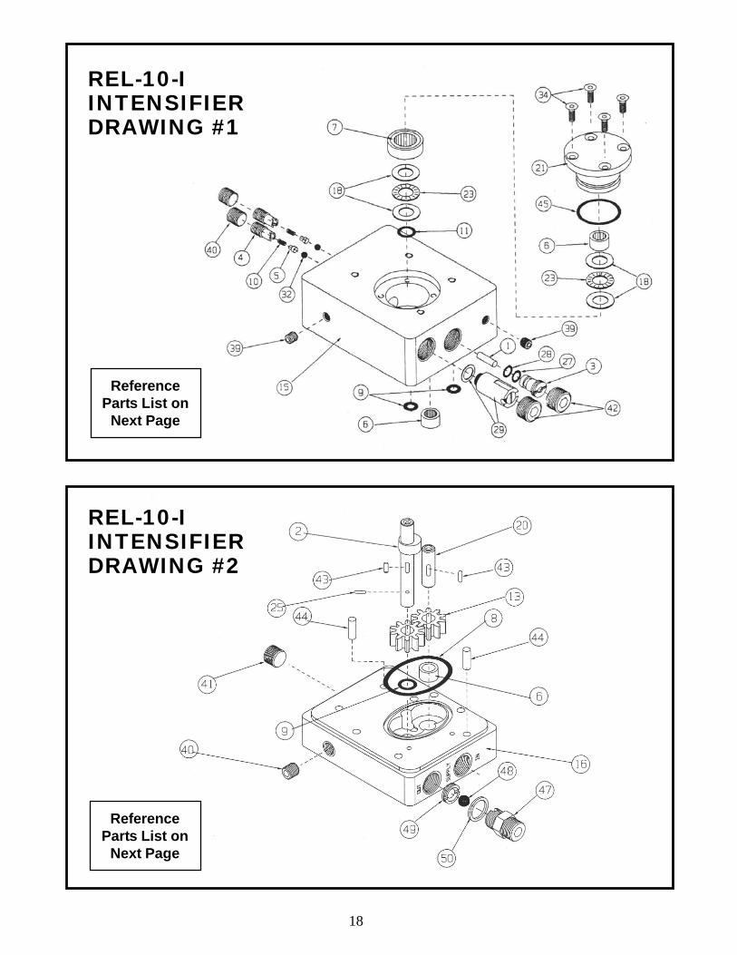
REL-10-IINTENSIFIERDRAWING #1
REL-10-IINTENSIFIERDRAWING #2
ReferenceParts List on
Next Page
ReferenceParts List on
Next Page

19
REF. PART QTY. DESCRIPTION
* 1 12728 1 PISTON * 3 12732 1 BUSHING (PRESSURE)
4 12733 2 CHECK VALVE BODY5 12734 2 PINTLE6 12736 6 SHAFT BEARING7 12737 1 CAM BEARING ASSEMBLY
** 9 12739 3 O-RING HOLE SEAL10 12740 2 SPRING (PINTLE)
** 11 12742 2 O-RING SHAFT SEAL15 12766 1 PRESSURE BLOCK18 12769 4 THRUST WASHER21 12772 1 INSERT REAR23 12774 2 BEARING (THRUST)
** 27 12778 1 BACK-UP RING** 28 12779 1 O-RING BUSHING
29 12780 1 VALVE ASSEMBLY32 12783 2 BALL (3/16“)34 12786 4 SCREW39 12791 5 1/16 NPT PLUG40 12792 1 1/4 NPT PLUG42 12794 1 1/2 NPT PLUG
** 45 12741 1 O-RING REAR SEAL
REF. PART QTY. DESCRIPTION
2 12731 1 CAM SHAFT ASSEMBLY6 12736 6 SHAFT BEARING
** 8 12738 2 O-RING FACE SEAL** 9 12739 3 O-RING HOLE SEAL
13 12745 2 PUMP GEAR16 12767 1 PUMP BLOCK20 12771 1 SHAFT (IDLER, PUMP)25 12776 2 PIN (DRIVE)40 12792 3 1/4 NPT PLUG43 12795 2 PINS (DRIVE)44 12796 4 DOWELS47 12735 1 REV. CHECK ADAPTER48 12744 1 3/8 BALL49 12743 1 BALL SEAT
** 50 12748 1 O-RING
* TO BE SOLD AS A MATCH SET** SUPPLIED IN SEAL KIT K3195 SAPRTLST 12/20/96
DRAWING #1 PARTS LIST
DRAWING #2 PARTS LIST

20
REL-10-IINTENSIFIERDRAWING #3
REF. PART QTY. DESCRIPTION
6 12736 6 SHAFT BEARING** 8 12738 2 O-RING FACE SEAL
14 12746 2 RETURN GEAR (please advise serial # when ordering)17 12768 1 PUMP GEAR (RETURN BLOCK)22 12773 1 SHAFT (IDLER, RETURN)30 12781 2 MOUNT36 12788 4 SCREW (SCFH)37 12789 6 SREW (SHCS)38 12790 6 LOCKWASHER43 12795 4 PINS (DRIVE)44 12796 4 DOWELS
** SUPPLIED IN SEAL KIT K3195 SAPRTLST 12/20/96
DRAWING #3 PARTS LIST
ReferenceParts List
Below
If you have any questions regarding the information found in this manual pleasecontact the supervising autority, or RELIABLE EQUIPMENT before continuing.Phone: 215-357-3500 Toll Free: 800-966-3530 Fax: 215-357-9193

21
PVA-00L33-WAY VALVEDRAWING #4
REF. PART QTY. DESCRIPTION
1 35001 1 VALVE BODY2 35002 1 CAP3 35003 1 ROTOR4 35004 1 THRUST BEARING5 35005 1 THRUST WASHER
* 6 35006 1 O-RING (CAP)7 35007 1 BALL, 1/4 DIA.8 35008 1 SPRING9 35009 1 ROLL PIN
10 35010 1 SHAFT* 11 35011 1 GREASE SEAL
12 35012 1 SPIROL PIN13 35013 4 GROMMET
* 14 35014 4 O-RING* 15 35015 4 BACK UP RING
16 35016 4 CUST. WAVE SPRING17 35017 1 END BLOCK18 35018 1 STUD19 35019 1 PLASTIC BALL20 35020 1 SCREW (BHSC)21 35021 4 SCREW (SHCS)22 35022 2 PLUG (NOT SHOWN)
* 23 35022 1 SHAFT SEAL
* SUPPLIED IN SEAL KIT PART #R35100
DRAWING #4 PARTS LIST
The unique plumbing requiredto integrate the REL-10-I withthe PVA-00L3 3-way valve iscustom fitted for each unit,and cannot be purchased fornon-factory repairs at this time.If any unit requires repair orreplacement of these parts,please return to RELIABLE forfactory authorized service.
Consult your RELIABLErepresentative for more
information about our completeline of hydraulic tools.
NOTICE

22
92 Steamwhistle Drive Ivyland, PA 18974Phone: 800-966-3530 Fax: 215-357-9193Visit us on the web at www.Reliable-Equip.com
If you have any questions regarding the informationfound in this manual please contact RELIABLE EQUIPMENT at
the address, phone or fax numbers shown below.
Date Parts or Service Required
MAINTENANCE RECORDS