Embed Size (px)
Citation preview
Manufacturing hydraulic solutions for a global market...
Manufacturing hydraulic solutions for a global market...
PT99

No task tootough for
Power Teamto tame.
No task tootough for
Power Teamto tame.
Building a 1,100 foot tower; lifting a 1.4 million pound bridge;
moving live rocket motors; raising a 37,000 ton warship
in drydock.
These are but a few of the thousands of tasks
tamed by Power Team power.
Whatever the industry:bridge construction
and maintenance; manufacturing;
general construction; utilities; mining
and quarrying; transportation; marine; test/quality assurance;
the solution to your problem is very possibly
within the pages of this catalog.

Hydraulic CylindersPgs. 4-27
Hydraulic PumpsPgs. 28-65
105-106
Hydraulic ValvesPgs. 66-79
Hydraulic AccessoriesPgs. 80-90
Lifting and JackingPgs. 91-106
Hydraulic ToolsPgs. 107-120
Shop EquipmentPgs. 121-135
Pulling SystemsPgs. 136-170
Mechanical ToolsPgs. 171-174
1
Hydraulic CylindersChoosing a cylinder .............................4-7“C” single-acting, spring return ...........8-9“C” cylinder accessories ..................10-11Threaded “C” cylinders..........................12“RLS” low profile .................................13“RSS” Shorty cylinders ........................14Cribbing blocks/swivel caps ..................15“RH” /”RHA” Center-Hole.................16-17“RT” Center-Hole Twin...........................18Center-Hole cyl. accessories..................19“RP” pull cylinders ................................19“RD” double-acting ..........................20-21“R” double-acting..................................22“R” load return ......................................23“R” locking collar ..................................24“RA” aluminum .....................................25“C” and “RA” locking collar...................26
Hydraulic PumpsChoosing a pump.............................28-31Hydraulic intensifier...............................33P12-P460D hand..............................34-35PA9 air/hyd. ....................................36-37PA6 air/hyd. ....................................38-39PA4/PA50/PA60/PA64 air/hyd. .......40-41PA17/PA46/PA55 air/hyd. ................42-43PE10/PR10 “Quarter Horse” ............44-45PE17/PE84 electric/hyd. ..................46-47PE46 electric/hyd. ...........................48-49PE18 electric/hyd. ...........................50-51PE30 electric/hyd. ...........................52-53PE55/PED electric/hyd. ...................54-55“Assemble to Order” pumps ............56-59PE21/PQ electric/hyd. .....................60-61PE200/PE400 electric/hyd. ..............62-63Gas engine pumps ...........................64-65Pre-stressing/post tensioning ......105-106
Hydraulic ValvesChoosing a valve ..............................66-68Pump mounted ................................69-74Pre-stressing/post tensioning ...............75Remote mounted .............................76-77In-line...............................................78-79
Hydraulic AccessoriesSubplates...............................................81Pressure switch.....................................81Manifolds...............................................82Digital pressure gauges.........................83Photo tachometer ..................................83Gauges ..................................................84Hoses ....................................................85Couplers ................................................86Cart, hydraulic pump.............................86Fittings...................................................87Oil ..........................................................88Remote pump controls..........................89Seal kits, cylinder ..................................90Reservoirs, hyd. pump ..........................90
Lifting and Jacking Cylinder and pump sets.........................92Maintenance sets...................................93Bottle jacks............................................94Toe jacks................................................95Telescoping jacks ..................................96Mini jack................................................96High tonnage portable jacks.............97-99Inflatable jacks .............................100-101Pre-stressing/post tensioning ......102-106
Hydraulic ToolsRebar benders..............................107-110Spreaders ............................................111Nut splitters.........................................112“C” Clamps..........................................113Pipe flange spreaders ..........................113Hydraulic punches .......................114-117Hydraulic testers ..........................118-120
Shop EquipmentMaintenance presses ...................121-131Press accessories................................132Mobile floor cranes ......................133-134Load positioning slings .......................135
Pulling SystemsIntroduction and safety ................136-139Hydra Grip-O-Matic® pullers .......140-141Super Grip-O-Matic®...................142-143Grip-O-Matic® .............................144-147Push-Pullers® .............................148-151Pulling attachments .....................152-153Slide hammer pullers ...................154-155Puller adapters .............................157-158Puller sets ............................156, 159-165High tonnage pullers ....................166-168Protective blankets ..............................169Railroad bearing pullers ......................170Maintenance security chests ...............170
Mechanical ToolsBushing/seal driver sets ......................171Wrenches and pry bars .......................172Retaining ring pliers ............................173Thread chaser, pick-up tool .................174
See alphabetical and numerical indexes(pages 175-178) for complete
product listing.
NOTE: All weights listed in this catalog indicate product weights. For shippingweights, see Power Team price list or consult factory.
¨
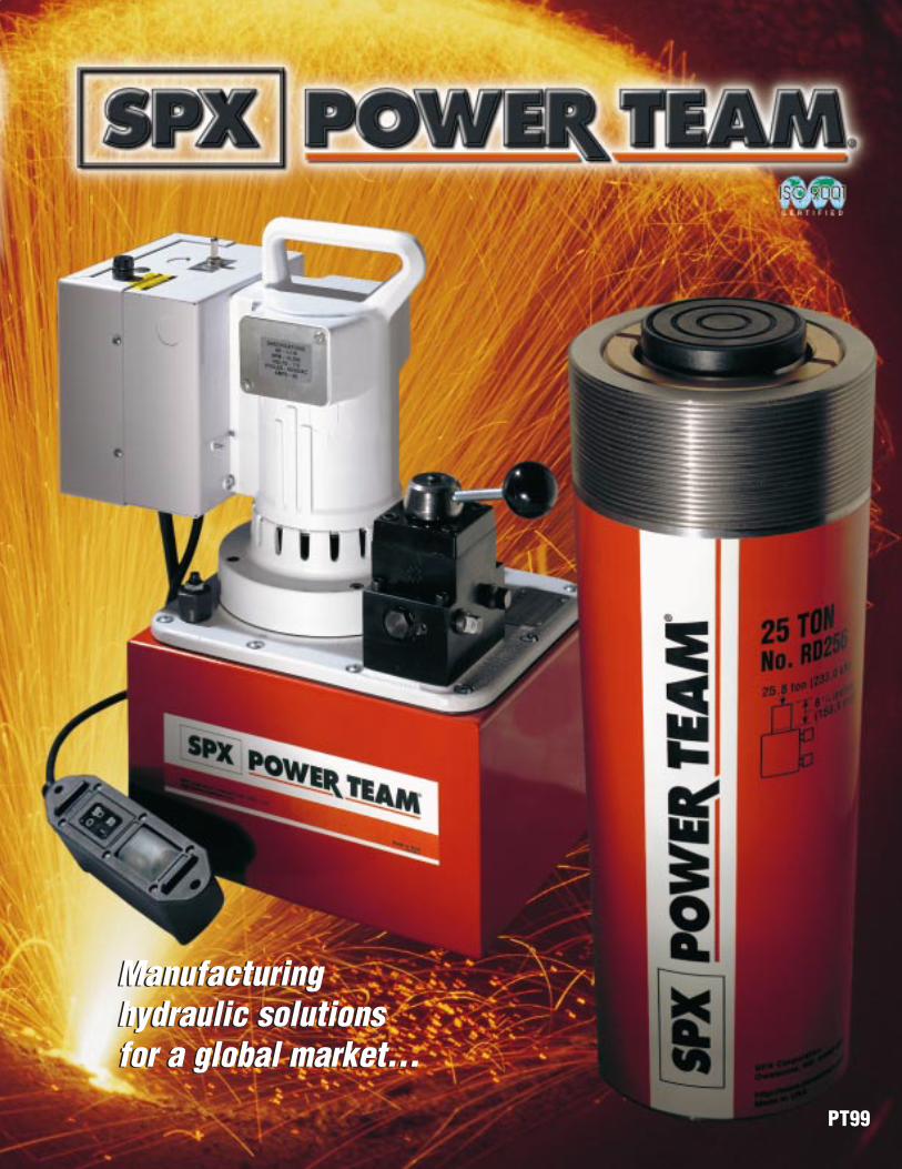
Why insist on Power TeamA heritage of creative problem solvingPower Team’s roots go back nearly 75 years. The founder of
its predecessor companycreated the gear and bearing puller line thatwas copied worldwidewhen patents expired. Inthe 1950’s, the companyentered the field of high-pressure fluid power, andtoday supplies world classmanufacturers with Power Team designedhydraulic components topower their own productsin diverse industries. Butthe Power Team focusisn’t on the past, but onthe future. We hopeyou’ll share it with us asa valued customer.
Commitment to qualityPower Team’s commitment to quality is evident in everything we do, from raw material receipt to the way we support our customers after they purchase our products. Power Team is registered for the coveted ISO 9001 international quality standard.ISO 9001 is the most stringent of the quality standards developedby the ISO Technical Committee, and requires compliance withstandards for management, administration, product development,and manufacturing.
Registration verifies that Power Team hasadopted and maintains documentationfor processes ranging from suppliers to customers, inspection, handling andtraining. ISO 9001 also requires periodicinternal and external audits to ensure thatall aspects of work affecting quality control are monitored.This always has beenand will continue to be,our philosophy. That’sour guarantee to you.
NEW!NEW!60 ton, 4.00” stroke aluminum double-acting cylinderSee page 17
NEW!NEW!“Economy” toe jacksSee page 95
NEW!NEW!55 and 150 ton double-acting cylinders with 18.13” strokeSee page 21
NEW!NEW!Telescoping bottle jacksSee page 96
NEW!NEW!Hydra Grip-O-Matic®gear and bearing pullersSee pages 140-141
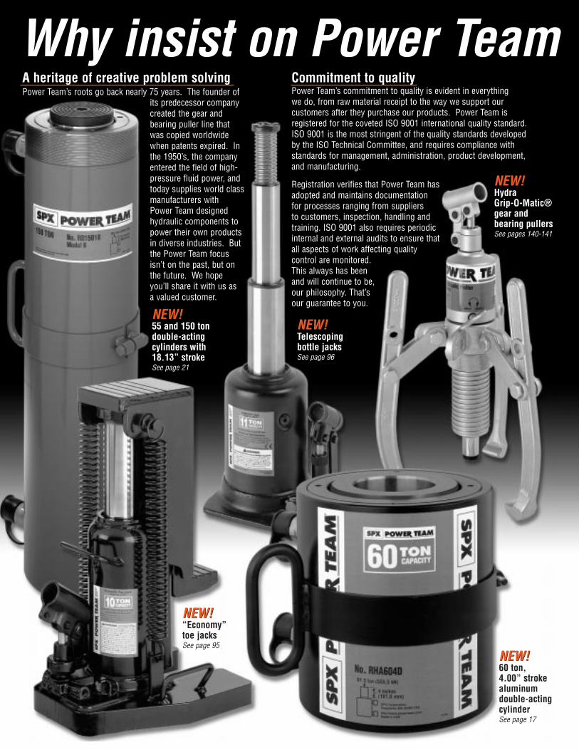
products...Power Team products comply to exacting standardsOur hydraulic cylinders fully comply with the criteria set forth in the American Society of MechanicalEngineers standard ASME B30.1, and our heavy duty pressure gauges comply with ASME B40.1,Grade B. Hydraulic hoses meet the criteria of the Material Handling Institute’s specification IJ100.
Power Team supplies a Letter of Incorporation or a Declaration of Conformity and CE marking for all productsthat conform with European community directives. Where specified, electric pump assemblies meet the design, assembly and testrequirements of the Canadian Standards Association. And, where specified, electric pump assemblies meet the design, assemblyand test requirements of NEMA 12, a National Electrical Manufacturer’s Association standard relating to electrical componentsused to resist moisture and dust.
Product innovationThe list of products which were introduced to industry by Power Team is a lengthy one. Lightweight aluminumhydraulic cylinders, battery-operatedportable hydraulic pumping units, Roll-Bed® hydraulic presses, railroadaxle journal bearing replacers andhydraulic system testers are but afew examples of ongoingPower Team innovation.
Your problem solverOur highly trained staff of application specialists can analyze your specific hydraulicpower requirement. Using our unique PowerBase IIsoftware, they can produce a detailed circuit diagram customized to your needs. Many of PowerTeam’s authorized distributors now have PowerBasecapabilities, and can provide you with the sameinformation, plus first hand consultation.
As near as your phoneA worldwide network of AuthorizedPower Team distributors assureslocal availability of our products. To ensure that parts and service areavailable locally for the user ofPower Team products, we maintaina global network of AuthorizedService Centers. Power Team’songoing training programs keepthese key people up to date on ourlatest developments.
NEW!NEW!5 ton Mini JackSee page 96
NEW!NEW!PA9 Seriesair/hydraulic pumpsSee pages 36-37
NEW!NEW!Post tension/stressingjacks and pumpsSee pages 102-106
NEW!NEW!Hydraulic rebar bendersSee pages 107-110
4®
Cylin
ders
Power Team ToBuild Your Own
Tame Tough Tasks
If you’ve used Power Teamhydraulics before, and know thecomponents you need, you maywish to simply consult index atrear of catalog to locate thepage containing specificationsand ordering information. If not,we think you’ll find the followingstep-by-step information helpful.
Considerations:
What push or pull tonnageis required per cylinder in yourapplication?
What is the push or pullstroke length required?
Does the cylinder need topush or pull? Or both? (Single-acting cylinders extend the pistonunder hydraulic pressure; double-acting cylinders extend and retractthe piston under pressure).
Does the applicationrequire multiple cylinders?
Is the application stationaryor must the components be lightin weight for easy portability?
Do you need to extend arod or cable through the centerof the cylinder for the application,as in a tensioning operation?
Does the applicationrequire that the cylinder fit withinlimited-clearance work areas?
Does the applicationrequire that the cylinder be“dead-ended” at the end of itswork stroke?
Will the cylinder need towithstand off-center loads?Cylinders with swivel caps areavailable.
Does the applicationrequire that the lifted load besupported for extended periods?Locking Collar cylinders areideal for such jobs, as arecribbing blocks.
Is corrosion resistancerequired? Our unique PowerTech surface treatment is stan-dard on many Power Teamcylinders, and optional on anyof our cylinders which featuresteel construction.
Will the application involvehigh cycles (over 2,500 in thecylinder’s lifetime)? Our “RD”,“RH”, “RP” and “C” seriescylinders are ideal choices.See pgs. 5-6 for capabilities ofeach cylinder type.
12
11
10
9
8
7
6
5
4
3
2
1
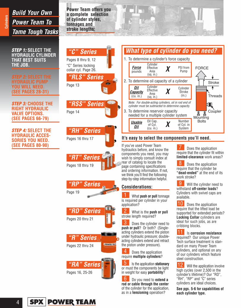
What type of cylinder do you need?1. To determine a cylinder’s force capacity
2. To determine oil capacity of a cylinder
Note: For double-acting cylinders, oil in rod end of cylinder must be subtracted to determine capacity.
3. To determine reservoir capacityneeded for a multiple cylinder system
STEP 1: SELECT THEHYDRAULIC CYLINDERTHAT BEST SUITS THE JOB.
STEP 2: SELECT THEHYDRAULIC PUMP YOU WILL NEED. (SEE PAGES 28-31)
STEP 3: CHOOSE THERIGHT HYDRAULICVALVE OPTIONS. (SEE PAGES 66-79)
STEP 4: SELECT THEHYDRAULIC ACCES-SORIES YOU NEED.(SEE PAGES 80-90)
Forcepounds
CylinderEffective
Area(sq. in.)
X PSI fromPump
UsableOil
Oil Cap. of Cyl.
(cu. in.)X
Number of Cyl. inSystem
OilCapacity(cu. in.)
CylinderEffective
Area(sq. in.)
XCylinderStroke(in.)
Power Team offers youa complete selection of cylinder styles, tonnages and stroke lengths:
“C” SeriesPages 8 thru 9, 12“C” Series lockingcollar cyl. Page 26.
“RLS” SeriesPage 13
“RSS” SeriesPage 14
“RH” SeriesPages 16 thru 17
“RT” SeriesPages 18 thru 19
“RP” SeriesPage 19
“RD” SeriesPages 20 thru 21
“R” SeriesPages 22 thru 24
“RA” SeriesPages 16, 25-26
It’s easy to select the components you’ll need.
5®
Cylinders
Right CylinderChoosing The
For YOUR Task
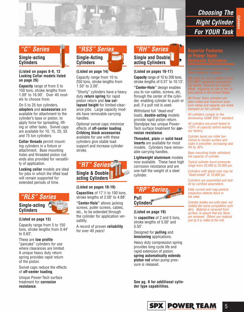
“C” SeriesSingle-acting Cylinders
(Listed on pages 8-9, 12Locking Collar models listedon page 26)Capacity range of from 5 to150 tons, stroke lengths from1.00" to 16.00". Over 40 mod-els to choose from. On 5 to 25 ton cylinders,adapters and accessories areavailable for attachment to thecylinder’s base or piston, toapply force for spreading, lift-ing or other tasks. Swivel capsare available for 10, 15, 25, 55and 75 ton cylindersCollar threads permit mount-ing cylinders in a fixture orattachment. Base mountingholes and threaded piston rodends also provided for versatili-ty of application.Locking collar models are idealfor jobs in which the lifted loadwill remain supported forextended periods of time.
“RLS” SeriesSingle-acting Cylinders
(Listed on page 13)Capacity range from 5 to 150tons, stroke lengths from 0.44"to 0.63".These are low profile“pancake” cylinders for usewhere clearances are limited.A unique heavy duty returnspring provides rapid return of the piston.Swivel caps reduce the effectsof off-center loading.Unique Power-Tech surfacetreatment for corrosion resistance.
“RSS” SeriesSingle-Acting Cylinders
(Listed on page 14)Capacity range from 10 to 250 tons, stroke lengths from1.50" to 3.00".“Shorty” cylinders have a heavyduty return spring for rapidpiston return and low col-lapsed height for limited-clear-ance jobs. Large capacity mod-els have removable carryinghandles.Optional swivel caps minimizeeffects of off-center loading.Cribbing block accessoriesavailable for use with thesecylinders give stable load support and increase cylinderstroke.
“RT” Series Single & Double-acting Cylinders
(Listed on pages 18-19)Capacities of 17 1⁄2 to 100 tons,stroke lengths of 2.00" to 4.88".“Center-Hole” allows jackingscrews, puller screws, cables,etc., to be extended throughthe cylinder for application ver-satility.A record of proven reliabilityfor over 40 years!
“RH” SeriesSingle and Double-acting Cylinders
(Listed on pages 16-17)Capacity range of 10 to 200 tons,stroke lengths of 0.31" to 10.13".“Center-Hole” design enablesyou to run cables, screws, etc,through the center of the cylin-der, enabling cylinder to push orpull, if a pull rod is used. Withstand full “dead-end”loads, double-acting modelsprovide rapid piston return.Standpipe has unique Power-Tech surface treatment for cor-rosion resistance.Threaded, plain or solid headinserts are available for mostmodels. Cylinders have remov-able carrying handles.Lightweight aluminum modelsnow available. These have highcorrosion resistance and areone half the weight of a steelcylinder.
“RP” SeriesPull Cylinders
(Listed on page 19)In capacities of 2 and 5 tons,stroke lengths of 5.00" and5.50".Designed for pulling and tensioning applications.Heavy duty compression springprovides long cycle life andrapid extension of piston;spring automatically extendspiston rod when pump pres-sure is released.
See pg. 6 for additional cylin-der type capabilities.
Superior Features of Power TeamHydraulic Cylinders:
Good reasons to specify PowerTeam hydraulic cylinders:
We build our own cylinders in ourISO 9001 registered manufactur-ing facility, honored by IndustryWeek magazine as one of the 10best plants in the United States.
All Power Team cylinders aredate-coded and maximum pres-sure rating and capacity are metalstamped on the cylinder.
All cylinders comply to thedemanding ASME B30.1 standard.
All cylinders are proof tested to125% of capacity before leavingour factory.
Cylinder bores are roller bur-nished to harden surface andmake it smoother, increasing seallife by 30%.
Base mounting holes withstandfull capacity of cylinder.
Typical cylinder burst pressuresrange from 25,000 to 35,000 psi.
Cylinders with gland nuts may be“dead-ended” at 10,000 psi.
Cylinders are assembled and test-ed by certified assemblers.
Eddy current and mag particleinspection detects flaws in the steel.
Cylinder bodies are solid steel, notwelded like some competitive cylin-ders. Material is removed fromsurface, to assure that any flawsare removed. Others use materialjust as it is rolled at the mill.
Right CylinderChoosing The
For YOUR Task
6®
Cylin
ders
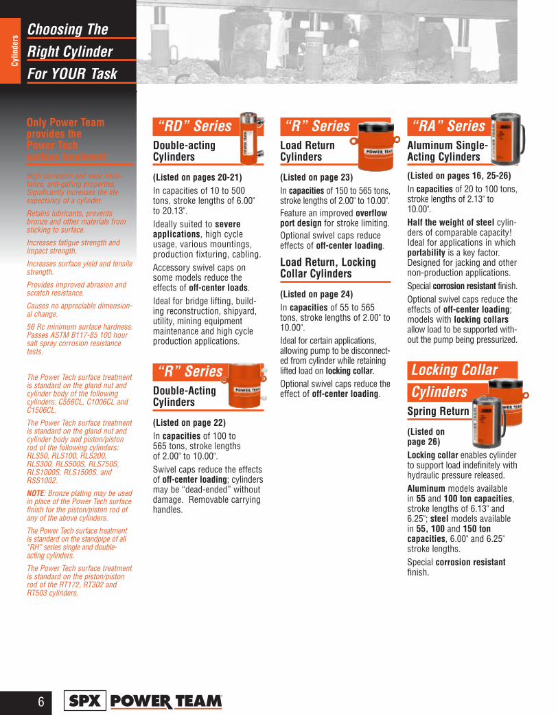
“RD” SeriesDouble-acting Cylinders
(Listed on pages 20-21) In capacities of 10 to 500tons, stroke lengths of 6.00" to 20.13". Ideally suited to severe applications, high cycleusage, various mountings,production fixturing, cabling.Accessory swivel caps onsome models reduce theeffects of off-center loads.Ideal for bridge lifting, build-ing reconstruction, shipyard,utility, mining equipmentmaintenance and high cycleproduction applications.
“R” Series Double-Acting Cylinders
(Listed on page 22)In capacities of 100 to 565 tons, stroke lengths of 2.00" to 10.00".Swivel caps reduce the effectsof off-center loading; cylindersmay be “dead-ended” withoutdamage. Removable carryinghandles.
“R” Series Load Return Cylinders
(Listed on page 23)In capacities of 150 to 565 tons,stroke lengths of 2.00" to 10.00".Feature an improved overflowport design for stroke limiting.Optional swivel caps reduceeffects of off-center loading.
Load Return, LockingCollar Cylinders
(Listed on page 24)In capacities of 55 to 565tons, stroke lengths of 2.00" to10.00". Ideal for certain applications,allowing pump to be disconnect-ed from cylinder while retaininglifted load on locking collar.Optional swivel caps reduce theeffect of off-center loading.
“RA” Series Aluminum Single-Acting Cylinders
(Listed on pages 16, 25-26)In capacities of 20 to 100 tons,stroke lengths of 2.13" to10.00". Half the weight of steel cylin-ders of comparable capacity!Ideal for applications in whichportability is a key factor.Designed for jacking and othernon-production applications.Special corrosion resistant finish.Optional swivel caps reduce theeffects of off-center loading;models with locking collarsallow load to be supported with-out the pump being pressurized.Locking Collar Locking CollarCylinders
Spring Return
(Listed on page 26)Locking collar enables cylinderto support load indefinitely withhydraulic pressure released.Aluminum models available in 55 and 100 ton capacities,stroke lengths of 6.13" and6.25"; steel models availablein 55, 100 and 150 toncapacities, 6.00" and 6.25"stroke lengths.Special corrosion resistantfinish.
Only Power Team provides the Power Tech surface treatment:
High corrosion and wear resis-tance, anti-galling properties.Significantly increases the lifeexpectancy of a cylinder.
Retains lubricants, preventsbronze and other materials fromsticking to surface.
Increases fatigue strength andimpact strength.
Increases surface yield and tensilestrength.
Provides improved abrasion andscratch resistance.
Causes no appreciable dimension-al change.
56 Rc minimum surface hardness.Passes ASTM B117-85 100 hoursalt spray corrosion resistancetests.
The Power Tech surface treatmentis standard on the gland nut andcylinder body of the followingcylinders: C556CL, C1006CL andC1506CL.
The Power Tech surface treatmentis standard on the gland nut andcylinder body and piston/pistonrod of the following cylinders:RLS50, RLS100, RLS200,RLS300, RLS500S, RLS750S,RLS1000S, RLS1500S, andRSS1002.
NOTE: Bronze plating may be usedin place of the Power Tech surfacefinish for the piston/piston rod ofany of the above cylinders.
The Power Tech surface treatmentis standard on the standpipe of all“RH” series single and double-acting cylinders.
The Power Tech surface treatmentis standard on the piston/pistonrod of the RT172, RT302 andRT503 cylinders.
SelectionCylinder
Chart
7®
Cylinders
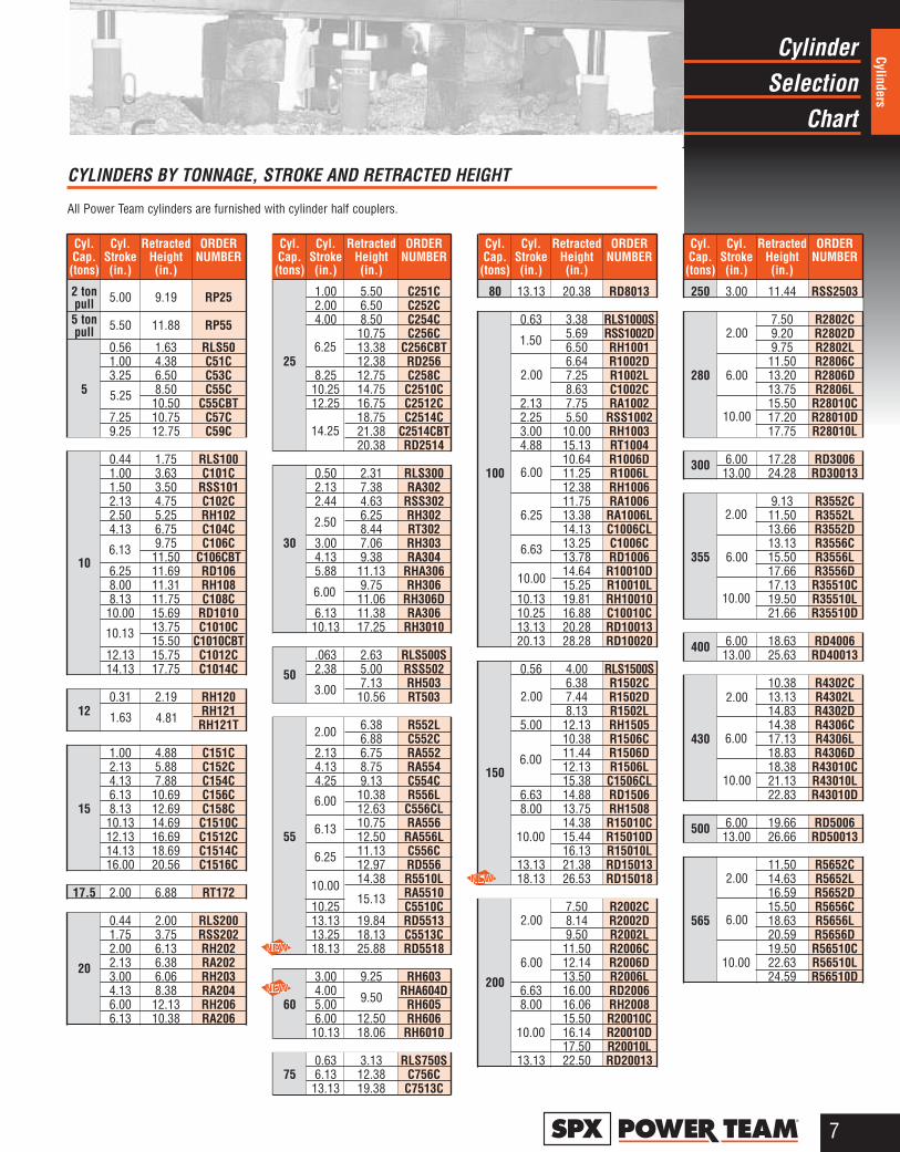
CYLINDERS BY TONNAGE, STROKE AND RETRACTED HEIGHT
All Power Team cylinders are furnished with cylinder half couplers.
Cyl. Cyl. Retracted ORDERCap. Stroke Height NUMBER(tons) (in.) (in.)
2 ton 5.00 9.19 RP25pull5 ton 5.50 11.88 RP55pull
0.56 1.63 RLS501.00 4.38 C51C3.25 6.50 C53C
5 8.50 C55C10.50 C55CBT
7.25 10.75 C57C9.25 12.75 C59C
0.44 1.75 RLS1001.00 3.63 C101C1.50 3.50 RSS1012.13 4.75 C102C2.50 5.25 RH1024.13 6.75 C104C
9.75 C106C
10 11.50 C106CBT6.25 11.69 RD1068.00 11.31 RH1088.13 11.75 C108C10.00 15.69 RD1010
13.75 C1010C15.50 C1010CBT
12.13 15.75 C1012C14.13 17.75 C1014C
0.31 2.19 RH12012 RH121
RH121T
1.00 4.88 C151C2.13 5.88 C152C4.13 7.88 C154C6.13 10.69 C156C
15 8.13 12.69 C158C10.13 14.69 C1510C12.13 16.69 C1512C14.13 18.69 C1514C16.00 20.56 C1516C
17.5 2.00 6.88 RT172
0.44 2.00 RLS2001.75 3.75 RSS2022.00 6.13 RH202
20 2.13 6.38 RA2023.00 6.06 RH2034.13 8.38 RA2046.00 12.13 RH2066.13 10.38 RA206
Cyl. Cyl. Retracted ORDERCap. Stroke Height NUMBER(tons) (in.) (in.)
1.00 5.50 C251C2.00 6.50 C252C4.00 8.50 C254C
10.75 C256C13.38 C256CBT
25 12.38 RD2568.25 12.75 C258C10.25 14.75 C2510C12.25 16.75 C2512C
18.75 C2514C21.38 C2514CBT20.38 RD2514
0.50 2.31 RLS3002.13 7.38 RA3022.44 4.63 RSS302
6.25 RH3028.44 RT302
30 3.00 7.06 RH3034.13 9.38 RA3045.88 11.13 RHA306
9.75 RH30611.06 RH306D
6.13 11.38 RA30610.13 17.25 RH3010
.063 2.63 RLS500S
50 2.38 5.00 RSS5027.13 RH503
10.56 RT503
6.38 R552L6.88 C552C
2.13 6.75 RA5524.13 8.75 RA5544.25 9.13 C554C
10.38 R556L12.63 C556CL10.75 RA556
55 12.50 RA556L11.13 C556C12.97 RD55614.38 R5510L
RA551010.25 C5510C13.13 19.84 RD551313.25 18.13 C5513C18.13 25.88 RD5518
3.00 9.25 RH6034.00 RHA604D
60 5.00 RH6056.00 12.50 RH60610.13 18.06 RH6010
0.63 3.13 RLS750S75 6.13 12.38 C756C
13.13 19.38 C7513C
Cyl. Cyl. Retracted ORDERCap. Stroke Height NUMBER(tons) (in.) (in.)
80 13.13 20.38 RD8013
0.63 3.38 RLS1000S5.69 RSS1002D6.50 RH10016.64 R1002D7.25 R1002L8.63 C1002C
2.13 7.75 RA10022.25 5.50 RSS10023.00 10.00 RH10034.88 15.13 RT1004
10.64 R1006D100 11.25 R1006L
12.38 RH100611.75 RA100613.38 RA1006L14.13 C1006CL13.25 C1006C13.78 RD100614.64 R10010D15.25 R10010L
10.13 19.81 RH1001010.25 16.88 C10010C13.13 20.28 RD1001320.13 28.28 RD10020
0.56 4.00 RLS1500S6.38 R1502C7.44 R1502D8.13 R1502L
5.00 12.13 RH150510.38 R1506C11.44 R1506D
150 12.13 R1506L15.38 C1506CL
6.63 14.88 RD15068.00 13.75 RH1508
14.38 R15010C15.44 R15010D16.13 R15010L
13.13 21.38 RD1501318.13 26.53 RD15018
7.50 R2002C8.14 R2002D9.50 R2002L11.50 R2006C12.14 R2006D
200 13.50 R2006L6.63 16.00 RD20068.00 16.06 RH2008
15.50 R20010C16.14 R20010D17.50 R20010L
13.13 22.50 RD20013
Cyl. Cyl. Retracted ORDERCap. Stroke Height NUMBER(tons) (in.) (in.)
250 3.00 11.44 RSS2503
7.50 R2802C9.20 R2802D9.75 R2802L11.50 R2806C
280 13.20 R2806D13.75 R2806L15.50 R28010C17.20 R28010D17.75 R28010L
300 6.00 17.28 RD300613.00 24.28 RD30013
9.13 R3552C11.50 R3552L13.66 R3552D13.13 R3556C
355 15.50 R3556L17.66 R3556D17.13 R35510C19.50 R35510L21.66 R35510D
400 6.00 18.63 RD400613.00 25.63 RD40013
10.38 R4302C13.13 R4302L14.83 R4302D14.38 R4306C
430 17.13 R4306L18.83 R4306D18.38 R43010C21.13 R43010L22.83 R43010D
500 6.00 19.66 RD500613.00 26.66 RD50013
11.50 R5652C14.63 R5652L16.59 R5652D15.50 R5656C
565 18.63 R5656L20.59 R5656D19.50 R56510C22.63 R56510L24.59 R56510D
6.13
10.13
1.63
6.25
14.25
2.50
6.00
3.00
2.00
6.00
6.13
6.25
10.00
1.50
2.00
6.00
6.25
6.63
10.00
5.25
2.00
6.00
10.00
2.00
6.00
10.00
2.00
6.00
10.00
2.00
6.00
10.00
2.00
6.00
10.00
2.00
6.00
10.00
4.81
15.13
9.50
HydraulicSingle-Acting
Cylinders
8®
Cylin
ders
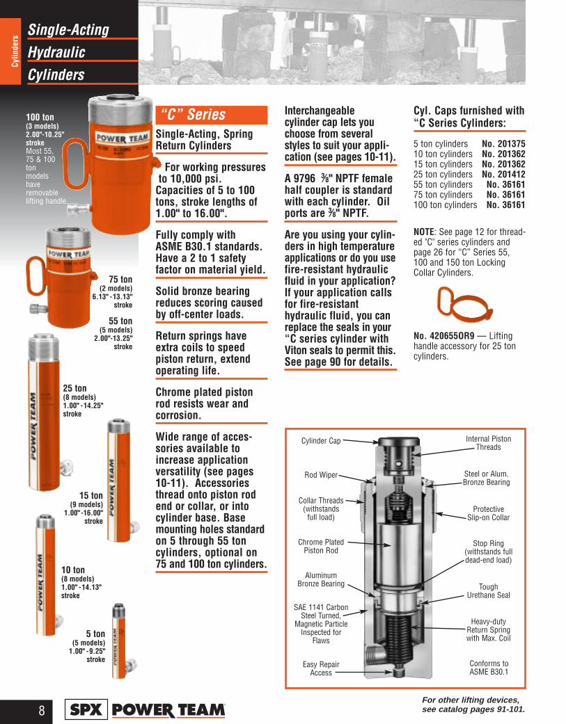
“C” Series Single-Acting, SpringReturn Cylinders
For working pressures to 10,000 psi.
Capacities of 5 to 100tons, stroke lengths of1.00" to 16.00".
Fully comply with ASME B30.1 standards.Have a 2 to 1 safety factor on material yield.
Solid bronze bearingreduces scoring causedby off-center loads.
Return springs haveextra coils to speed piston return, extendoperating life.
Chrome plated pistonrod resists wear andcorrosion.
Wide range of acces-sories available toincrease applicationversatility (see pages10-11). Accessoriesthread onto piston rodend or collar, or intocylinder base. Basemounting holes standardon 5 through 55 toncylinders, optional on75 and 100 ton cylinders.
Interchangeable cylinder cap lets youchoose from severalstyles to suit your appli-cation (see pages 10-11).
A 9796 3⁄8" NPTF femalehalf coupler is standardwith each cylinder. Oilports are 3⁄8" NPTF.
Are you using your cylin-ders in high temperatureapplications or do you usefire-resistant hydraulicfluid in your application?If your application callsfor fire-resistanthydraulic fluid, you canreplace the seals in your“C series cylinder withViton seals to permit this. See page 90 for details.
Cyl. Caps furnished with “C Series Cylinders:
5 ton cylinders No. 20137510 ton cylinders No. 20136215 ton cylinders No. 20136225 ton cylinders No. 20141255 ton cylinders No. 3616175 ton cylinders No. 36161100 ton cylinders No. 36161
NOTE: See page 12 for thread-ed "C" series cylinders andpage 26 for “C” Series 55,100 and 150 ton LockingCollar Cylinders.
No. 420655OR9 — Lifting handle accessory for 25 toncylinders.
Cylinder Cap
Collar Threads(withstands
full load)Protective
Slip-on Collar
Chrome PlatedPiston Rod
Stop Ring (withstands fulldead-end load)
AluminumBronze Bearing Tough
Urethane Seal
SAE 1141 CarbonSteel Turned,
Magnetic ParticleInspected for
Flaws
Heavy-dutyReturn Springwith Max. Coil
Easy RepairAccess
Conforms toASME B30.1
Rod Wiper
Internal PistonThreads
Steel or Alum.Bronze Bearing
100 ton(3 models)2.00"-10.25" strokeMost 55,75 & 100ton models have removable lifting handle.
75 ton(2 models)
6.13" - 13.13" stroke
55 ton(5 models)
2.00"-13.25" stroke
25 ton(8 models)1.00" - 14.25" stroke
15 ton(9 models)
1.00" - 16.00" stroke
10 ton(8 models)1.00" - 14.13" stroke
5 ton(5 models)
1.00" - 9.25" stroke
For other lifting devices, see catalog pages 91-101.
HydraulicSingle-Acting
Cylinders
9®
Cylinders
C
A
B
HJK
E
F
Base MountingHoles
D
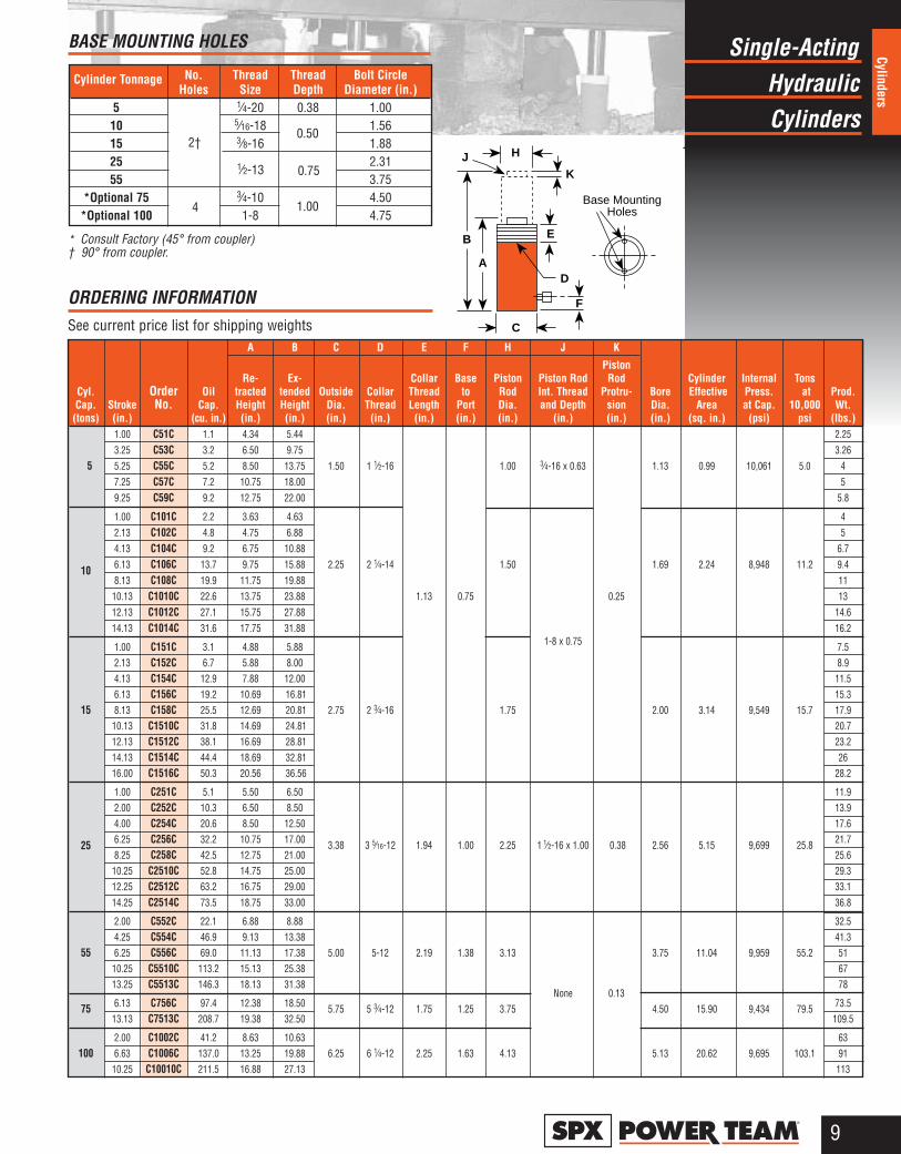
BASE MOUNTING HOLES
* Consult Factory (45° from coupler)† 90° from coupler.
ORDERING INFORMATION See current price list for shipping weights
A B C D E F H J K
Piston Re- Ex- Collar Base Piston Piston Rod Rod Cylinder Internal Tons
Cyl. Order Oil tracted tended Outside Collar Thread to Rod Int. Thread Protru- Bore Effective Press. at Prod.Cap. Stroke No. Cap. Height Height Dia. Thread Length Port Dia. and Depth sion Dia. Area at Cap. 10,000 Wt.(tons) (in.) (cu. in.) (in.) (in.) (in.) (in.) (in.) (in.) (in.) (in.) (in.) (in.) (sq. in.) (psi) psi (lbs.)
1.00 C51C 1.1 4.34 5.44 2.253.25 C53C 3.2 6.50 9.75 3.26
5 5.25 C55C 5.2 8.50 13.75 1.50 1 1⁄2-16 1.00 3⁄4-16 x 0.63 1.13 0.99 10,061 5.0 47.25 C57C 7.2 10.75 18.00 59.25 C59C 9.2 12.75 22.00 5.8
1.00 C101C 2.2 3.63 4.63 42.13 C102C 4.8 4.75 6.88 54.13 C104C 9.2 6.75 10.88 6.7
10 6.13 C106C 13.7 9.75 15.88 2.25 2 1⁄4-14 1.50 1.69 2.24 8,948 11.2 9.48.13 C108C 19.9 11.75 19.88 1110.13 C1010C 22.6 13.75 23.88 1.13 0.75 0.25 1312.13 C1012C 27.1 15.75 27.88 14.614.13 C1014C 31.6 17.75 31.88 16.2
1.00 C151C 3.1 4.88 5.88 1-8 x 0.75 7.52.13 C152C 6.7 5.88 8.00 8.94.13 C154C 12.9 7.88 12.00 11.56.13 C156C 19.2 10.69 16.81 15.3
15 8.13 C158C 25.5 12.69 20.81 2.75 2 3⁄4-16 1.75 2.00 3.14 9,549 15.7 17.910.13 C1510C 31.8 14.69 24.81 20.712.13 C1512C 38.1 16.69 28.81 23.214.13 C1514C 44.4 18.69 32.81 2616.00 C1516C 50.3 20.56 36.56 28.2
1.00 C251C 5.1 5.50 6.50 11.92.00 C252C 10.3 6.50 8.50 13.94.00 C254C 20.6 8.50 12.50 17.6
25 6.25 C256C 32.2 10.75 17.00 3.38 3 5⁄16-12 1.94 1.00 2.25 1 1⁄2-16 x 1.00 0.38 2.56 5.15 9,699 25.8 21.78.25 C258C 42.5 12.75 21.00 25.610.25 C2510C 52.8 14.75 25.00 29.312.25 C2512C 63.2 16.75 29.00 33.114.25 C2514C 73.5 18.75 33.00 36.8
2.00 C552C 22.1 6.88 8.88 32.54.25 C554C 46.9 9.13 13.38 41.3
55 6.25 C556C 69.0 11.13 17.38 5.00 5-12 2.19 1.38 3.13 3.75 11.04 9,959 55.2 5110.25 C5510C 113.2 15.13 25.38 6713.25 C5513C 146.3 18.13 31.38
None 0.1378
75 6.13 C756C 97.4 12.38 18.50 5.75 5 3⁄4-12 1.75 1.25 3.75 4.50 15.90 9,434 79.5 73.513.13 C7513C 208.7 19.38 32.50 109.5
2.00 C1002C 41.2 8.63 10.63 63100 6.63 C1006C 137.0 13.25 19.88 6.25 6 1⁄4-12 2.25 1.63 4.13 5.13 20.62 9,695 103.1 91
10.25 C10010C 211.5 16.88 27.13 113
Cylinder Tonnage No. Thread Thread Bolt CircleHoles Size Depth Diameter (in.)
5 1⁄4-20 0.38 1.0010 5⁄16-18 1.5615 3⁄8-16 1.8825 2.3155 3.75
*Optional 75 3⁄4-10 4.50*Optional 100 1-8 4.75
2†
4
1⁄2-13
0.50
0.75
1.00
CylinderHydraulic
Accessories
10®
Cylin
ders
Cylinder Mounting Accessories for “C” Series CylindersExtension Rod
ThreadedConnector
Threaded Adapter
Plain Adapter
Cylinder BaseAttachment
90° "V" Base
CylinderMounting Plate
Cylinder Flat Base
Smooth Saddle
Serrated Saddle
Plunger Base
Body Clevis
Piston Clevis
Swivel Cap
1
67
7
a
b a
b8
8
9
11 10
Support Base
12
13
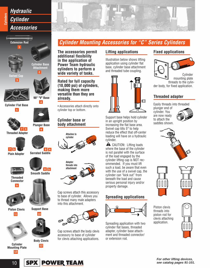
The accessories permitadditional flexibility in the application ofPower Team hydrauliccylinders to perform awide variety of tasks.
Rated for full capacity(10,000 psi) of cylinders,making them more versatile than they arealready.
• Accessories attach directly ontocylinder top or bottom.
Cylinder base or body attachment
Cap screws attach this accessoryto base of cylinder. Allows youto thread many male adaptersinto this attachment.
Cap screws attach the body clevisaccessory to base of cylinderfor clevis attaching applications.
Lifting applications
Illustration below shows liftingapplication using cylinder flatbase, cylinder base attachmentand threaded tube coupling.
Support base helps hold cylinderin an upright position byincreasing the flat base area.Swivel cap tilts 5° to helpreduce the effect that off-centerloading will have on a hydrauliccylinder.
CAUTION: Lifting loadswhere the base of the cylinderis not parallel with the surfaceof the load engaged by thecylinder lifting cap is NOT rec-ommended. If you must liftsuch a load, be aware that evenwith the use of a swivel cap, thecylinder can “kick out” frombeneath the load and causeserious personal injury and/orproperty damage.
Spreading applications
Spreading application with twocylinder flat bases, threadedadapter, cylinder base attach-ment and threaded connector/or extension rod.
Fixed applications
Cylindermounting plate
threads to the cylin-der body, for fixed application.
Threaded adapter
Easily threads into threadedplunger end ofcylinder. Youare now readyto attach thesaddles shown.
Piston clevisthreads into piston rod forclevis attachingapplication.
Attaches tocylinder
Adapterthreads intoattachment
For other lifting devices, see catalog pages 91-101.
2
3
4
5
CylinderHydraulic
Accessories
11®
Cylinders
1
1110
13
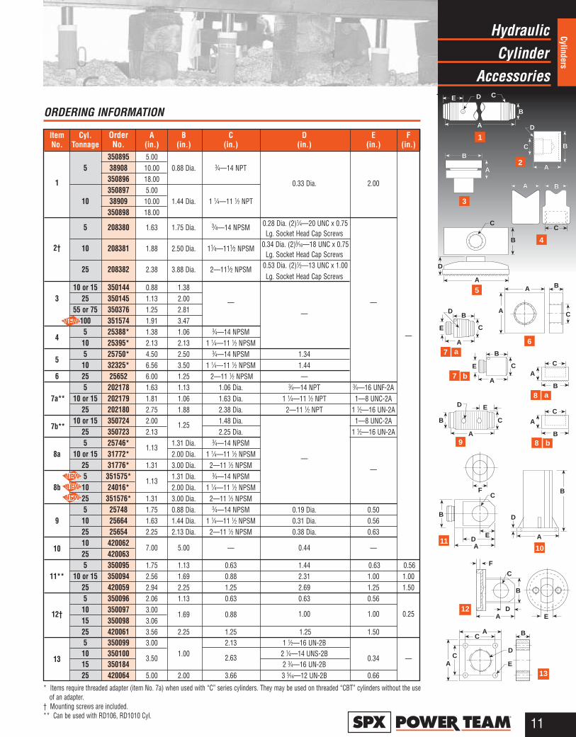
Item Cyl. Order A B C D E FNo. Tonnage No. (in.) (in.) (in.) (in.) (in.) (in.)
350895 5.005 38908 10.00 0.88 Dia. 3⁄4—14 NPT
1 350896 18.00 0.33 Dia. 2.00350897 5.00
10 38909 10.00 1.44 Dia. 1 1⁄4—11 1⁄2 NPT350898 18.00
5 208380 1.63 1.75 Dia. 3⁄4—14 NPSM 0.28 Dia. (2)1⁄4—20 UNC x 0.75Lg. Socket Head Cap Screws
2† 10 208381 1.88 2.50 Dia. 11⁄4—111⁄2 NPSM 0.34 Dia. (2)5⁄16—18 UNC x 0.75Lg. Socket Head Cap Screws
25 208382 2.38 3.88 Dia. 2—111⁄2 NPSM 0.53 Dia. (2)1⁄2—13 UNC x 1.00Lg. Socket Head Cap Screws
10 or 15 350144 0.88 1.383 25 350145 1.13 2.00 — —
55 or 75 350376 1.25 2.81 —100 351574 1.91 3.47
45 25388* 1.38 1.06 3⁄4—14 NPSM —10 25395* 2.13 2.13 1 1⁄4—11 1⁄2 NPSM
55 25750* 4.50 2.50 3⁄4—14 NPSM 1.3410 32325* 6.56 3.50 1 1⁄4—11 1⁄2 NPSM 1.44
6 25 25652 6.00 1.25 2—11 1⁄2 NPSM —5 202178 1.63 1.13 1.06 Dia. 3⁄4—14 NPT 3⁄4—16 UNF-2A
7a** 10 or 15 202179 1.81 1.06 1.63 Dia. 1 1⁄4—11 1⁄2 NPT 1—8 UNC-2A25 202180 2.75 1.88 2.38 Dia. 2—11 1⁄2 NPT 1 1⁄2—16 UN-2A
7b**10 or 15 350724 2.00 1.25 1.48 Dia. 1—8 UNC-2A
25 350723 2.13 2.25 Dia. 1 1⁄2—16 UN-2A5 25746*
1.131.31 Dia. 3⁄4—14 NPSM
8a 10 or 15 31772* 2.00 Dia. 1 1⁄4—11 1⁄2 NPSM —25 31776* 1.31 3.00 Dia. 2—11 1⁄2 NPSM —5 351575*
1.131.31 Dia. 3⁄4—14 NPSM
8b 10 24016* 2.00 Dia. 1 1⁄4—11 1⁄2 NPSM25 351576* 1.31 3.00 Dia. 2—11 1⁄2 NPSM5 25748 1.75 0.88 Dia. 3⁄4—14 NPSM 0.19 Dia. 0.50
9 10 25664 1.63 1.44 Dia. 1 1⁄4—11 1⁄2 NPSM 0.31 Dia. 0.5625 25654 2.25 2.13 Dia. 2—11 1⁄2 NPSM 0.38 Dia. 0.63
1010 420062
7.00 5.00 — 0.44 —25 4200635 350095 1.75 1.13 0.63 1.44 0.63 0.56
11** 10 or 15 350094 2.56 1.69 0.88 2.31 1.00 1.0025 420059 2.94 2.25 1.25 2.69 1.25 1.505 350096 2.06 1.13 0.63 0.63 0.56
12† 10 350097 3.001.69 0.88 1.00 1.00 0.25
15 350098 3.0625 420061 3.56 2.25 1.25 1.25 1.505 350099 3.00 2.13 1 1⁄2—16 UN-2B
1310 350100
3.501.00 2.63 2 1⁄4—14 UNS-2B
0.34 —15 350184 2 3⁄4—16 UN-2B25 420064 5.00 2.00 3.66 3 5⁄16—12 UN-2B 0.66
ORDERING INFORMATION
* Items require threaded adapter (item No. 7a) when used with “C” series cylinders. They may be used on threaded “CBT” cylinders without the use of an adapter.
† Mounting screws are included.** Can be used with RD106, RD1010 Cyl.
AC
D
EC
A
B
B
E
A
D
C
B
E
A
C
B
D E
C
A
B
A
C
A E
B
D
C
F
A
A B
C
A
B
D
B
A
D
C
A
C
F
A
C
ED
B
B
C
B
A A
C
D
B
A
E
B
D C
A B
B
A A
C
D
B
A
E
B
D C
A B
2
3
4
5
6
8
89
7
7 b
a
b
a
12
HydraulicSingle-Acting
Cylinders
12®
Cylin
ders
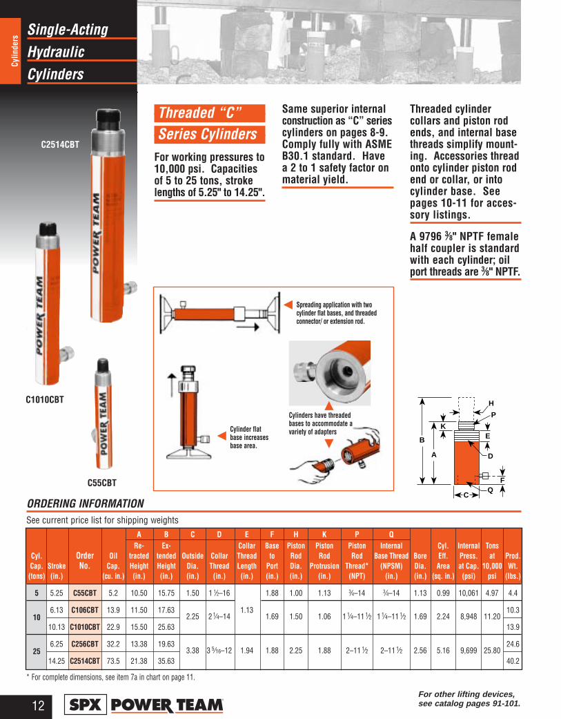
Threaded “C” Series Cylinders
For working pressures to10,000 psi. Capacitiesof 5 to 25 tons, strokelengths of 5.25" to 14.25".
Same superior internalconstruction as “C” seriescylinders on pages 8-9.Comply fully with ASMEB30.1 standard. Havea 2 to 1 safety factor onmaterial yield.
Threaded cylinder collars and piston rodends, and internal basethreads simplify mount-ing. Accessories threadonto cylinder piston rodend or collar, or intocylinder base. Seepages 10-11 for acces-sory listings.
A 9796 3⁄8" NPTF femalehalf coupler is standardwith each cylinder; oilport threads are 3⁄8" NPTF.
Spreading application with twocylinder flat bases, and threadedconnector/ or extension rod.
Cylinder flatbase increases base area.
C1010CBT
C55CBT
C2514CBT
Cylinders have threadedbases to accommodate avariety of adapters
* For complete dimensions, see item 7a in chart on page 11.
A B C D E F H K P QRe- Ex- Collar Base Piston Piston Piston Internal Cyl. Internal Tons
Cyl. Order Oil tracted tended Outside Collar Thread to Rod Rod Rod Base Thread Bore Eff. Press. at Prod.Cap. Stroke No. Cap. Height Height Dia. Thread Length Port Dia. Protrusion Thread* (NPSM) Dia. Area at Cap. 10,000 Wt.(tons) (in.) (cu. in.) (in.) (in.) (in.) (in.) (in.) (in.) (in.) (in.) (NPT) (in.) (in.) (sq. in.) (psi) psi (lbs.)
5 5.25 C55CBT 5.2 10.50 15.75 1.50 1 1⁄2–16 1.88 1.00 1.13 3⁄4–14 3⁄4–14 1.13 0.99 10,061 4.97 4.4
106.13 C106CBT 13.9 11.50 17.63
2.25 2 1⁄4–141.13
1.69 1.50 1.06 1 1⁄4–11 1⁄2 1 1⁄4–11 1⁄2 1.69 2.24 8,948 11.2010.3
10.13 C1010CBT 22.9 15.50 25.63 13.9
256.25 C256CBT 32.2 13.38 19.63
3.38 3 5⁄16–12 1.94 1.88 2.25 1.88 2–11 1⁄2 2–11 1⁄2 2.56 5.16 9,699 25.8024.6
14.25 C2514CBT 73.5 21.38 35.63 40.2
ORDERING INFORMATION See current price list for shipping weights
For other lifting devices, see catalog pages 91-101.
C
A
B
H
P
D
K
QF
E
HydraulicSingle-Acting
Cylinders
13®
Cylinders
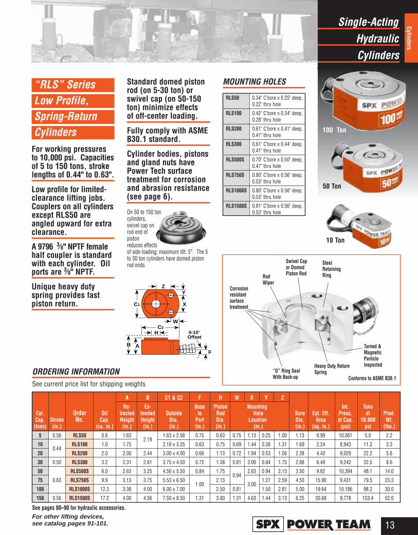
Swivel Capor DomedPiston Rod
SteelRetainingRing
“O” Ring SealWith Back-up
Heavy Duty ReturnSpring
Turned &MagneticParticleInspected
Conforms to ASME B30.1
RodWiper
Corrosionresistantsurfacetreatment
ORDERING INFORMATION See current price list for shipping weights
RLS50 0.34" C’bore x 0.25" deep, 0.22" thru hole
RLS100 0.42" C’bore x 0.34" deep,0.28" thru hole
RLS200 0.61" C’bore x 0.41" deep,0.41" thru hole
RLS300 0.61" C’bore x 0.44" deep,0.41" thru hole
RLS500S 0.70" C’bore x 0.50" deep, 0.47" thru hole
RLS750S 0.80" C’bore x 0.56" deep,0.53" thru hole
RLS1000S 0.80" C’bore x 0.56" deep,0.53" thru hole
RLS1500S 0.81" C’bore x 0.56" deep,0.53" thru hole
MOUNTING HOLES
10 Ton
50 Ton
100 Ton
See pages 80–90 for hydraulic accessories.
A B C1 & C2 F H W X Y Z
Re- Ex- Base Piston Mounting Int. TonsCyl. Order Oil tracted tended Outside to Rod Hole Bore Cyl. Eff. Press. at Prod.Cap. Stroke No. Cap. Height Height Dia. Port Dia. Location Dia. Area at Cap. 10,000 Wt.(tons) (in.) (cu. in.) (in.) (in.) (in.) (in.) (in.) (in.) (in.) (sq. in.) (psi) psi (lbs.)
5 0.56 RLS50 0.6 1.632.19
1.63 x 2.56 0.75 0.63 0.75 1.13 0.25 1.00 1.13 0.99 10,061 5.0 2.2
100.44
RLS100 1.0 1.75 2.19 x 3.25 0.63 0.75 0.69 1.44 0.38 1.31 1.69 2.24 8,943 11.2 3.3
20 RLS200 2.0 2.00 2.44 3.00 x 4.00 0.66 1.13 0.72 1.94 0.53 1.56 2.38 4.43 9,029 22.2 5.6
30 0.50 RLS300 3.2 2.31 2.81 3.75 x 4.50 0.72 1.38 0.81 2.06 0.84 1.75 2.88 6.49 9,242 32.5 8.6
50 RLS500S 6.0 2.63 3.25 4.50 x 5.50 0.84 1.750.94
2.63 0.94 2.13 3.50 9.62 10,394 48.1 14.0
75 0.63 RLS750S 9.9 3.13 3.75 5.53 x 6.501.00
2.133.00
1.27 2.59 4.50 15.90 9,431 79.5 23.3
100 RLS1000S 12.3 3.38 4.00 6.00 x 7.00 2.50 0.81 1.50 2.81 5.00 19.64 10,186 98.2 30.0
150 0.56 RLS1500S 17.2 4.00 4.56 7.50 x 8.50 1.31 3.00 1.31 4.63 1.44 3.13 6.25 30.68 9,778 153.4 52.0
“RLS” Series Low Profile, Spring-Return Cylinders
For working pressuresto 10,000 psi. Capacitiesof 5 to 150 tons, strokelengths of 0.44" to 0.63".
Low profile for limited-clearance lifting jobs.Couplers on all cylindersexcept RLS50 areangled upward for extraclearance.
A 9796 3⁄8" NPTF femalehalf coupler is standardwith each cylinder. Oilports are 3⁄8" NPTF.
Unique heavy dutyspring provides fastpiston return.
Standard domed pistonrod (on 5-30 ton) orswivel cap (on 50-150ton) minimize effects of off-center loading.
Fully comply with ASMEB30.1 standard.
Cylinder bodies, pistonsand gland nuts havePower Tech surfacetreatment for corrosionand abrasion resistance(see page 6).
On 50 to 150 toncylinders,swivel cap onrod end ofpistonreduces effectsof side loading; maximum tilt: 5°. The 5to 30 ton cylinders have domed pistonrod ends.
AB
HC2
0-10°Offset
F
W
X
Y
C1
Z
For other lifting devices, see catalog pages 91-101.

Hydraulic“Shorty”
Cylinders
14®
Cylin
ders
“Shorty” Spring Return Cylinders
For working pressuresto 10,000 psi. Capacitiesof 10 to 250 tons, strokelengths of 1.50" to 3.00".
Heavy duty return springon all models exceptRSS1002D (which isdouble-acting) providesfast piston return; lowcollapsed height of thisseries is ideal for jobshaving limited clear-ance. Coupler on 10thru 50 ton models isangled upward 5° foradded clearance.
Grooved piston topkeeps load from sliding.
Fully comply with ASMEB30.1 standard.
Bronze plated piston rodsand gland nuts resistscoring and corrosion.Cylinders can be “dead-ended” at full capacity.
Optional swivel caps(see page 15) reducethe effects of off-centerloading. Cribbing blockaccessories also avail-able (see page 15) togive stable load supportand increase cylinderstroke.
Removable carryinghandles on 100 and 250 ton models.
Selected “RSS” series cylinders have theexclusive Power Techsurface treatment, providing corrosion andabrasion resistance.See page 6 for details.
10 and 20 Ton
30 and 50 Ton
100 Ton
F
5 ̊
C
A
B
H
A B C F HBase Piston Cylinder Internal Tons
Cylinder Order Oil Retracted Extended Outside to Rod Bore Effective Press. at Prod.Capacity Stroke No. Cap. Height Height Dia. Port Dia. Dia. Area at Cap. 10,000 Wt.(Tons) (in.) (cu. in.) (in.) (in.) (in.) (in.) (in.) (in.) (sq. in.) (psi) psi (lbs.)Push Push Return Push Push Push10 1.50 RSS101 3.4 3.50 5.00 2.75 1.50 1.69 2.24 8,943 11.2 6.020 1.75 RSS202 7.7 3.75 5.50 3.56 0.63 2.16 2.38 4.43 9,029 22.1 9.930 2.44 RSS302 15.8 – 4.63 7.06 4.00 2.50 2.88 6.49 9,243 32.5 14.750 2.38 RSS502 22.8 5.00 7.38 4.88 0.75 3.13 3.50 9.62 10,393 48.1 23.2
1002.25 RSS1002 44.2 5.50 7.75 6.63 0.94 4.38
5.00 19.63 10,186 98.247.3
1.50 RSS1002D 29.4 12.9 5.69 7.19 6.88 0.94* 3.75 54.6250 3.00 RSS2503 150.6 – 11.44 14.44 9.88 1.81 5.50 8.00 50.22 9,956 251.1 220.0
*Cylinder top to port is 1.56"See pages 80–90 for hydraulic accessories.
ORDERING INFORMATION See current price list for shipping weights
250 Ton
Maximum coilspring for fastcylinder return
GroovedPiston Rod
Coated SteelRetaining Nut
Heavy DutyReturn Spring
Bronze PlatedPiston Rod
Easy RepairAccess
Turned &Magnetic ParticleInspected
Selected "RSS" SeriesCylinders have corrosionresistant surface treatmenton body.
Oil Port angled 5°on all but RSS1002,RSS1002D, RSS2503
For other lifting devices, see catalog pages 91-101.
100 Ton Double-Acting

CylinderHydraulic
Accessories
15®
Cylinders
ORDERING INFORMATION
1. ExtendCylinderLoad
2. InsertLowerRing,Retract Cyl.
Each cribbing block set includes rings, padsand insertion handle. (See table below.)
3. InsertPad
4. Lift Loadby addingRingsand Pads
LOAD
LOAD
LOAD
LOAD
30 TonShorty
Cylinder.(Cylinder not
included in set)
Use with Order A B C Wt.Cyl. No. No. (in.) (in.) (in.) lbs.RSS101 350320 1.00 1.44 1.44 .5RSS202 350321 1.38 2.13 1.3RSS302 350322 2.50 2.13 1.6RSS502 350331 1.44 3.25 2.7
RSS1002 350332 1.81 4.38 3.38 6.6
For Use with ➠ 30 ton Cylinder No. RSS302 50 ton Cylinder No. RSS502 100 ton Cylinder No. RSS1002Order Number ➠ 30 ton Set No. CB30 50 ton Set No. CB50 100 ton Set No. CB100
Lower Ring Upper Ring Stacking Pad Lower Ring Upper Ring Stacking Pad Lower Ring Upper Ring Stacking PadNo. Included in Set 1 2 3 1 2 3 1 3 4
Outside Diameter (in.) 4.50 4.50 2.75 5.50 5.50 3.38 7.39 7.39 4.75Inside Diameter (in.) 2.81 2.81 – 3.45 3.45 – 4.81 4.81 –
Height, each (in.) 2.28 1.80 1.78 2.22 1.72 1.69 2.13 1.75 1.72Total Stacked Height 5.44 5.19 6.88of Rings in Set (in.)Weight of Set (lbs.) 20 28 64
Each set includes one Insertion Handle No. 45589 - 0.50" Hex. X 18.00" Long, 4.00" Bend
C
A
BCribbing blocks areshown here in use witha 30 ton RSS302“Shorty” cylinder.
Mounting screws included
CAUTION: Lifting loads wherethe base of the cylinder is not parallelwith the surface of the load engagedby the cylinder lifting cap is NOTrecommended. If you must liftsuch a load, be aware that evenwith the use of a swivel cap, thecylinder can “kick out” from beneaththe load and cause serious personalinjury and/or property damage.
Cribbing Block Sets
Convert Power Team“Shorty” cylinders tomechanical cribbingdevices; more stablethan timber or otherawkward, makeshiftmethods. Ideal for lift-ing applications suchas structure moving.Reduce cribbing timedramatically.
In effect, increases thestroke of the cylinder;stacking pads act ascylinder extensions:
1. Extend cylinder and insertlower supporting ring.
2. Retract cylinder, insert astacking pad.
3. Extend cylinder again;pad increases cylinderstroke.
4. Repeat process until allrings and pads are used.
Insertion handle is usedfor inserting rings andpads.
Sets available for 30,50 and 100 ton capacitycylinder modelsRSS302, RSS502 andRSS1002.
Swivel caps for RSS Series PowerTeam hydraulic cylinders
Designed to tilt a maximum of 5°. Helpreduce the effects ofoff-center loading.
Radial grooves in top ofswivel cap lessen ten-dency of an off-centerload to slip; notchacross face of each caphelps keep loads havinga protruding or roundshape centered.NOTE: Swivel caps cannot beused with cribbing blocks.
Lower Ring
Insertion HandleNo. 45589
Upper Ring
Stacking Pad
HydraulicSingle-Acting
Cylinders
16®
Cylin
ders
*These cylinders supplied with carrying handles. ** RH120 and RH121T do not have an internal threaded insert, but do have a 3⁄4-16 internalthread. The RH120 inlet port is 1⁄4" NPTF.
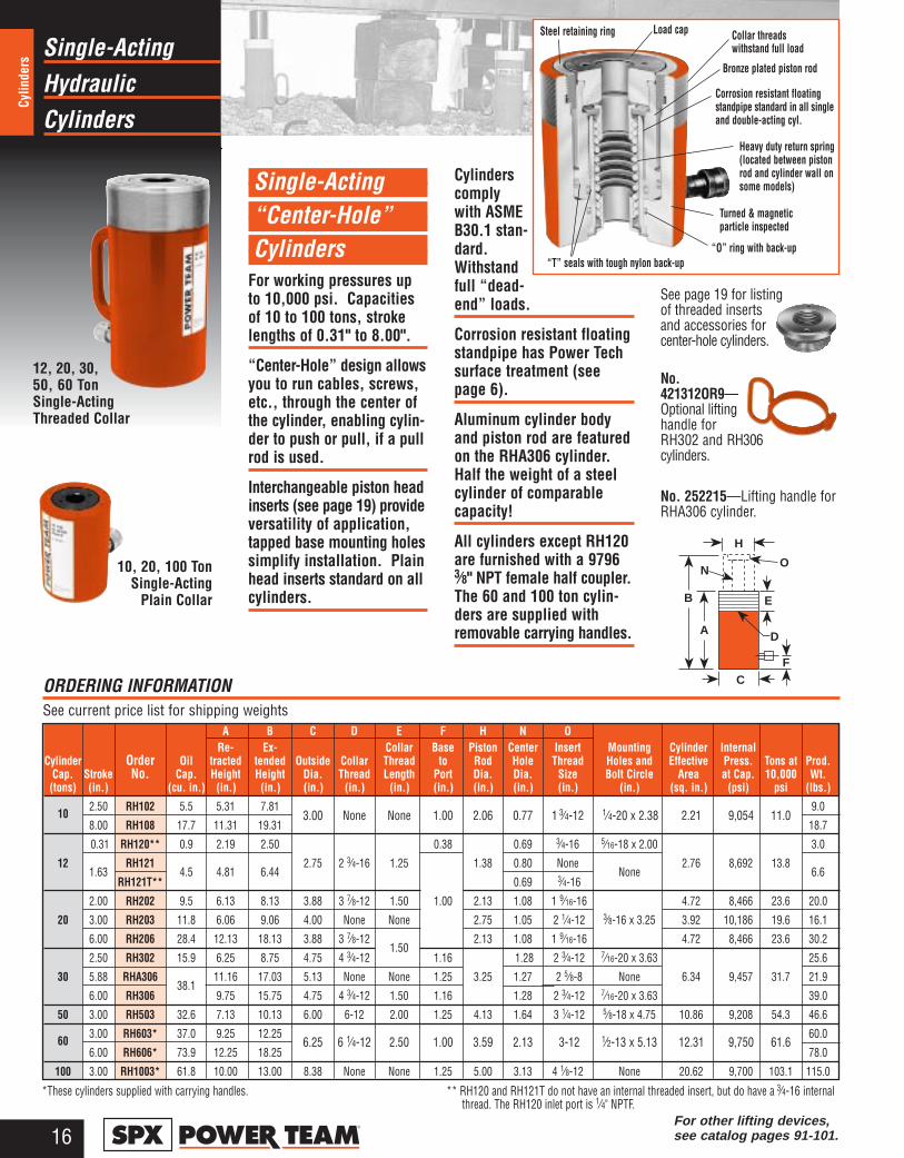
10, 20, 100 TonSingle-Acting
Plain Collar
12, 20, 30,50, 60 TonSingle-ActingThreaded Collar
Single-Acting “Center-Hole” Cylinders
For working pressures upto 10,000 psi. Capacitiesof 10 to 100 tons, strokelengths of 0.31" to 8.00".
“Center-Hole” design allowsyou to run cables, screws,etc., through the center ofthe cylinder, enabling cylin-der to push or pull, if a pullrod is used.
Interchangeable piston headinserts (see page 19) provideversatility of application,tapped base mounting holessimplify installation. Plainhead inserts standard on allcylinders.
Cylinderscomplywith ASMEB30.1 stan-dard.Withstandfull “dead-end” loads.
Corrosion resistant floatingstandpipe has Power Techsurface treatment (seepage 6).
Aluminum cylinder bodyand piston rod are featuredon the RHA306 cylinder.Half the weight of a steelcylinder of comparablecapacity!
All cylinders except RH120are furnished with a 97963⁄8" NPT female half coupler.The 60 and 100 ton cylin-ders are supplied withremovable carrying handles.
See page 19 for listingof threaded insertsand accessories for center-hole cylinders.
No.421312OR9—Optional liftinghandle forRH302 and RH306cylinders.
No. 252215—Lifting handle forRHA306 cylinder.
A
B
H
NO
CF
E
D
Steel retaining ring Load cap Collar threadswithstand full load
Bronze plated piston rod
Corrosion resistant floatingstandpipe standard in all singleand double-acting cyl.
“T” seals with tough nylon back-up“O” ring with back-up
Heavy duty return spring(located between pistonrod and cylinder wall onsome models)
Turned & magneticparticle inspected
For other lifting devices, see catalog pages 91-101.
ORDERING INFORMATION See current price list for shipping weights
A B C D E F H N ORe- Ex- Collar Base Piston Center Insert Mounting Cylinder Internal
Cylinder Order Oil tracted tended Outside Collar Thread to Rod Hole Thread Holes and Effective Press. Tons at Prod.Cap. Stroke No. Cap. Height Height Dia. Thread Length Port Dia. Dia. Size Bolt Circle Area at Cap. 10,000 Wt.(tons) (in.) (cu. in.) (in.) (in.) (in.) (in.) (in.) (in.) (in.) (in.) (in.) (in.) (sq. in.) (psi) psi (lbs.)
102.50 RH102 5.5 5.31 7.81
3.00 None None 1.00 2.06 0.77 1 3⁄4-12 1⁄4-20 x 2.38 2.21 9,054 11.09.0
8.00 RH108 17.7 11.31 19.31 18.7
0.31 RH120** 0.9 2.19 2.50 0.38 0.69 3⁄4-16 5⁄16-18 x 2.00 3.0
121.63
RH1214.5 4.81 6.44
2.75 2 3⁄4-16 1.25 1.38 0.80 NoneNone
2.76 8,692 13.86.6
RH121T** 0.69 3⁄4-16
2.00 RH202 9.5 6.13 8.13 3.88 3 7⁄8-12 1.50 1.00 2.13 1.08 1 9⁄16-16 4.72 8,466 23.6 20.0
20 3.00 RH203 11.8 6.06 9.06 4.00 None None 2.75 1.05 2 1⁄4-12 3⁄8-16 x 3.25 3.92 10,186 19.6 16.1
6.00 RH206 28.4 12.13 18.13 3.88 3 7⁄8-121.50
2.13 1.08 1 9⁄16-16 4.72 8,466 23.6 30.2
2.50 RH302 15.9 6.25 8.75 4.75 4 3⁄4-12 1.16 1.28 2 3⁄4-12 7⁄16-20 x 3.63 25.6
30 5.88 RHA30638.1
11.16 17.03 5.13 None None 1.25 3.25 1.27 2 5⁄8-8 None 6.34 9,457 31.7 21.9
6.00 RH306 9.75 15.75 4.75 4 3⁄4-12 1.50 1.16 1.28 2 3⁄4-12 7⁄16-20 x 3.63 39.0
50 3.00 RH503 32.6 7.13 10.13 6.00 6-12 2.00 1.25 4.13 1.64 3 1⁄4-12 5⁄8-18 x 4.75 10.86 9,208 54.3 46.6
603.00 RH603* 37.0 9.25 12.25
6.25 6 1⁄4-12 2.50 1.00 3.59 2.13 3-12 1⁄2-13 x 5.13 12.31 9,750 61.660.0
6.00 RH606* 73.9 12.25 18.25 78.0
100 3.00 RH1003* 61.8 10.00 13.00 8.38 None None 1.25 5.00 3.13 4 1⁄8-12 None 20.62 9,700 103.1 115.0
HydraulicDouble-Acting
Cylinders
17®
Cylinders
* These cylinders supplied with carrying handles. † Measured with 0.75" high serrated insert installed.
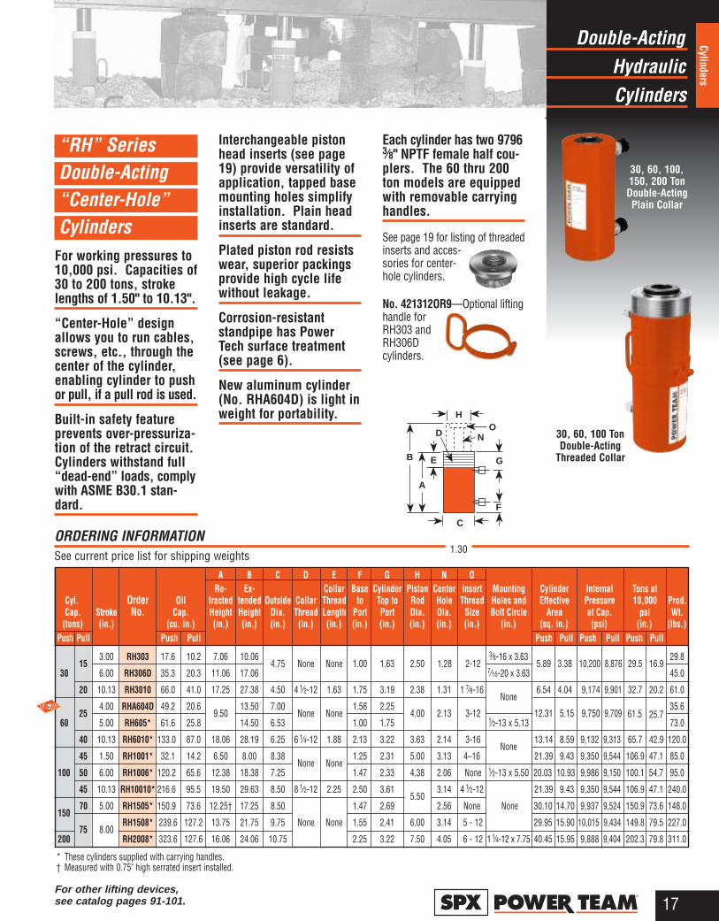
30, 60, 100,150, 200 TonDouble-ActingPlain Collar
30, 60, 100 TonDouble-Acting
Threaded Collar
ORDERING INFORMATION See current price list for shipping weights
A B C D E F G H N ORe- Ex- Collar Base Cylinder Piston Center Insert Mounting Cylinder Internal Tons at
Cyl. Order Oil tracted tended Outside Collar Thread to Top to Rod Hole Thread Holes and Effective Pressure 10,000 Prod.Cap. Stroke No. Cap. Height Height Dia. Thread Length Port Port Dia. Dia. Size Bolt Circle Area at Cap. psi Wt.
(tons) (in.) (cu. in.) (in.) (in.) (in.) (in.) (in.) (in.) (in.) (in.) (in.) (in.) (in.) (sq. in.) (psi) (in.) (lbs.)Push Pull Push Pull Push Pull Push Pull Push Pull
153.00 RH303 17.6 10.2 7.06 10.06
4.75 None None 1.00 1.63 2.50 2-123⁄8-16 x 3.63
5.89 3.38 10,200 8,876 29.5 16.929.8
30 6.00 RH306D 35.3 20.3 11.06 17.06 7⁄16-20 x 3.63 45.0
20 10.13 RH3010 66.0 41.0 17.25 27.38 4.50 4 1⁄2-12 1.63 1.75 3.19 2.38 1.31 1 7⁄8-16None
6.54 4.04 9,174 9,901 32.7 20.2 61.0
254.00 RHA604D 49.2 20.6
9.5013.50 7.00
None None1.56 2.25
4.00 2.13 3-12 12.31 5.15 9,750 9,70935.6
60 5.00 RH605* 61.6 25.8 14.50 6.53 1.00 1.75 1⁄2-13 x 5.13 73.0
40 10.13 RH6010* 133.0x 87.0x 18.06 28.19 6.25 6 1⁄4-12 1.88 2.13 3.22 3.63 2.14 3-16None
13.14 8.59 9,132 9,313 65.7 42.9 120.0
45 1.50 RH1001* 32.1 14.2 6.50 8.00 8.38None None
1.25 2.31 5.00 3.13 4–16 21.39 9.43 9,350 9,544 106.9 47.1 85.0
100 50 6.00 RH1006* 120.2x 65.6x 12.38 18.38 7.25 1.47 2.33 4.38 2.06 None 1⁄2-13 x 5.50 20.03 10.93 9,986 9,150 100.1 54.7 95.0
45 10.13 RH10010* 216.6x 95.5x 19.50 29.63 8.50 8 1⁄2-12 2.25 2.50 3.615.50
3.14 4 1⁄2-12 21.39 9.43 9,350 9,544 106.9 47.1 240.0
15070 5.00 RH1505* 150.9x 73.6x 12.25† 17.25 8.50 1.47 2.69 2.56 None None 30.10 14.70 9,937 9,524 150.9 73.6 148.0
75 8.00RH1508* 239.6 127.2 13.75 21.75 9.75 None None 1.55 2.41 6.00 3.14 5 - 12 29.95 15.90 10,015 9,434 149.8 79.5 227.0
200 RH2008* 323.6 127.6 16.06 24.06 10.75 2.25 3.22 7.50 4.05 6 - 12 1 1⁄4-12 x 7.75 40.45 15.95 9,888 9,404 202.3 79.8 311.0
“RH” Series Double-Acting “Center-Hole” Cylinders
For working pressures to10,000 psi. Capacities of30 to 200 tons, strokelengths of 1.50" to 10.13".
“Center-Hole” designallows you to run cables,screws, etc., through thecenter of the cylinder,enabling cylinder to pushor pull, if a pull rod is used.
Built-in safety featureprevents over-pressuriza-tion of the retract circuit.Cylinders withstand full“dead-end” loads, complywith ASME B30.1 stan-dard.
Interchangeable pistonhead inserts (see page19) provide versatility ofapplication, tapped basemounting holes simplifyinstallation. Plain headinserts are standard.
Plated piston rod resistswear, superior packingsprovide high cycle lifewithout leakage.
Corrosion-resistantstandpipe has PowerTech surface treatment(see page 6).
New aluminum cylinder(No. RHA604D) is light inweight for portability.
Each cylinder has two 97963⁄8" NPTF female half cou-plers. The 60 thru 200ton models are equippedwith removable carryinghandles.
See page 19 for listing of threadedinserts and acces-sories for center-hole cylinders.
No. 421312OR9—Optional liftinghandle forRH303 andRH306Dcylinders.
EB
H
NO
F
G
D
A
C
For other lifting devices, see catalog pages 91-101.
1.30
61.5 25.7
1.28
Hydraulic“Center-Hole”
Cylinders
18®
Cylin
ders
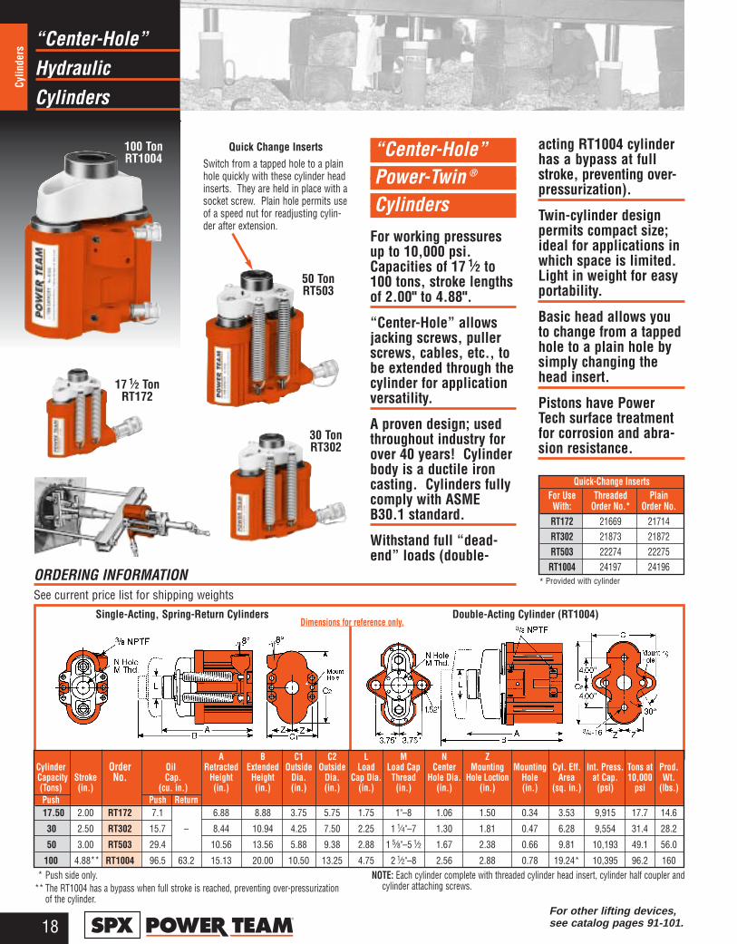
Quick Change InsertsSwitch from a tapped hole to a plainhole quickly with these cylinder headinserts. They are held in place with asocket screw. Plain hole permits useof a speed nut for readjusting cylin-der after extension.
“Center-Hole” Power-Twin ®
CylindersFor working pressuresup to 10,000 psi.Capacities of 17 1⁄2 to100 tons, stroke lengthsof 2.00" to 4.88".
“Center-Hole” allowsjacking screws, pullerscrews, cables, etc., tobe extended through thecylinder for applicationversatility.
A proven design; usedthroughout industry forover 40 years! Cylinderbody is a ductile ironcasting. Cylinders fullycomply with ASMEB30.1 standard.
Withstand full “dead-end” loads (double-
acting RT1004 cylinderhas a bypass at fullstroke, preventing over-pressurization).
Twin-cylinder designpermits compact size;ideal for applications inwhich space is limited.Light in weight for easyportability.
Basic head allows youto change from a tappedhole to a plain hole bysimply changing thehead insert.
Pistons have PowerTech surface treatmentfor corrosion and abra-sion resistance.
Single-Acting, Spring-Return Cylinders Double-Acting Cylinder (RT1004)Dimensions for reference only.
* Provided with cylinderORDERING INFORMATION See current price list for shipping weights
100 Ton RT1004
17 1⁄2 Ton RT172
30 Ton RT302
Quick-Change InsertsFor Use Threaded PlainWith: Order No.* Order No.RT172 21669 21714RT302 21873 21872RT503 22274 22275RT1004 24197 24196
A B C1 C2 L M N ZCylinder Order Oil Retracted Extended Outside Outside Load Load Cap Center Mounting Mounting Cyl. Eff. Int. Press. Tons at Prod.Capacity Stroke No. Cap. Height Height Dia. Dia. Cap Dia. Thread Hole Dia. Hole Loction Hole Area at Cap. 10,000 Wt.(Tons) (in.) (cu. in.) (in.) (in.) (in.) (in.) (in.) (in.) (in.) (in.) (in.) (sq. in.) (psi) psi (lbs.)Push Push Return17.50 2.00 RT172 7.1 6.88 8.88 3.75 5.75 1.75 1"–8 1.06 1.50 0.34 3.53 9,915 17.7 14.6
30 2.50 RT302 15.7 – 8.44 10.94 4.25 7.50 2.25 1 1⁄4"–7 1.30 1.81 0.47 6.28 9,554 31.4 28.2
50 3.00 RT503 29.4 10.56 13.56 5.88 9.38 2.88 1 5⁄8"–5 1⁄2 1.67 2.38 0.66 9.81 10,193 49.1 56.0
100 4.88** RT1004 96.5 63.2 15.13 20.00 10.50 13.25 4.75 2 1⁄2"–8 2.56 2.88 0.78 19.24* 10,395 96.2 160* Push side only.
** The RT1004 has a bypass when full stroke is reached, preventing over-pressurizationof the cylinder.
NOTE: Each cylinder complete with threaded cylinder head insert, cylinder half coupler andcylinder attaching screws.
50 Ton RT503
For other lifting devices, see catalog pages 91-101.

Cylinders AndHydraulic
Accessories
19®
Cylinders
A B C D E G H K P QRe- Ex- Collar Cylinder Piston Piston Piston Cyl. Internal Tons
Cyl. Order Oil tracted tended Outside Collar Thread Top to Rod Rod Rod Base Bore Eff. Pressure at Prod.Cap. Stroke No. Cap. Height Height Dia. Thread Length Port Dia. Protrusion Thread Thread Dia. Area at. Cap. 10,000 Wt.
(Tons) (in.) (cu. in.) (in.) (in.) (in.) (in.) (in.) (in.) (in.) (in.) (NPTF) (NPTF) (in.) (sq. in.) (psi) psi (lbs.)Pull Pull Pull Pull
2 5.00 RP25 2.8 9.56 14.56 1.75 1 1⁄2-161.00 1.69
0.75 1.00 3⁄4-14 3⁄4-14 1.13 0.55 7,250 2.75 4.0
5 5.50 RP55 6.2 11.88 17.38 2.25 2 1⁄4-14 1.19 1.38 1 1⁄4-11 1⁄2 1 1⁄4-11 1⁄2 1.69 1.13 8,850 5.65 11.0
ORDERING INFORMATION See current price list for shipping weights
ACCESSORY SETS
Use with Order A B C D ECyl No. No. (in.) (in.) (in.) (in.) (in.)RP25 421057* 5.13 4.31 1.31 2.00 0.75RP55 421056** 6.00 5.00 1.50 2.50 0.88
* For base mounting, extension rod 351106 is required.** For base mounting, extension rod 351075 is required.
C
AK
QG
D
PH
B
E
Threaded Plain Solid**
RP25
❶
❷
❸
❹
➎
➏
➐
➑
OR↔
See accessory set chartbelow.
“Center-Hole” Cylinder Accessories
Cylinder head insertsand attachments for RHand RT series center-hole cylinders.
Provides added versa-tility of application.
“RP” Series Pull Cylinders
For working pressures to10,000 psi. Capacitiesof 2 and 5 tons, strokelengths of 5.00" and 5.50".
Designed for pulling andtensioning applications.
Heavy duty compressionspring provides longcycle life and rapid exten-sion of piston; springautomatically extendspiston rod when pumppressure is released.
A
C
D
E bolt size
B
Clevis
Head Inserts For RH Series Cylinders
To use with RT172, RH203 RT302, RH302 RT503, RH503, RH603 RT1004Cyl. No ➠ RH303, RH306 RH605, RH606
No. Order Set No. ➠ RHA20 RHA30 RHA50 RHA100Speed Crank 24814 27198 29595 303785
Speed 302482 302483 33439 34136Nut 1"–8 thd. 11⁄4"–7 thd. 15⁄8"–5 1⁄2 thd. 21⁄2"–8 thd.
Adjusting 32118 34758 32698 32699Screw 1"–8 thd. 20.00" lg. 11⁄4"–7 thd. 24.00" lg. 15⁄8"–5 1⁄2 thd. 30.00" lg. 21⁄2"–8 thd. 34.25" lg.
Threaded Order threaded insert for RH series cylinders with the accessory set. (See table to right).Insert Threaded insert supplied with RT series cylinders
Pushing 201923 34510 34755 –Adapter 1"–8 thd. 0.50" dia. shank 11⁄4"–7 thd. 0.75" dia. shank 15⁄8"–5 1⁄2 thd. 1.00" dia. shankPushing 201454 34511 34756 –Adapter 1"–8 thd. 0.75" dia. shank 11⁄4"–7 thd. 1.00" dia. shank 15⁄8"–5 1⁄2 thd. 1.25" dia. shank
Jack 24813 25931 32701 32702Screw 1"–8 thd. 7.00" lg. 11⁄4"–7 thd. 9.00" lg. 15⁄8"–5 1⁄2 thd. 11.00" lg. 21⁄2"–8 thd. 16.00" lg.Screw 28228 28229 28230 –Cap 1"–8 thd. 1.50" dia. 11⁄4"–7 thd. 1.75" dia. 15⁄8"–5 1⁄2 thd. 2.25" dia.
❶❷
❸
❹
➎
➏
➐
➑* Comes standard with cylinder.
** Provided with and only available forRH1006 and RH1505 cylinders.
For Use Threaded Inside Dia. ofWith: Order No. Plain Insert*
(in.)
RH102, RH108 286320.773⁄4"–16
RH203 28612 1.051"–8
RH302, RH306 38904 1.301 1⁄4"–7
RH303 28644 1.281 1⁄4"–7
RH503 38855 1.67 1 5⁄8"–5 1⁄2RH603, RH605 34251 2.13 RH606 1 5⁄8"–5 1⁄2
RH1006– 2.06
RH1505
For other lifting devices, see catalog pages 91-101.
HydraulicDouble-Acting
Cylinders
20®
Cylin
ders
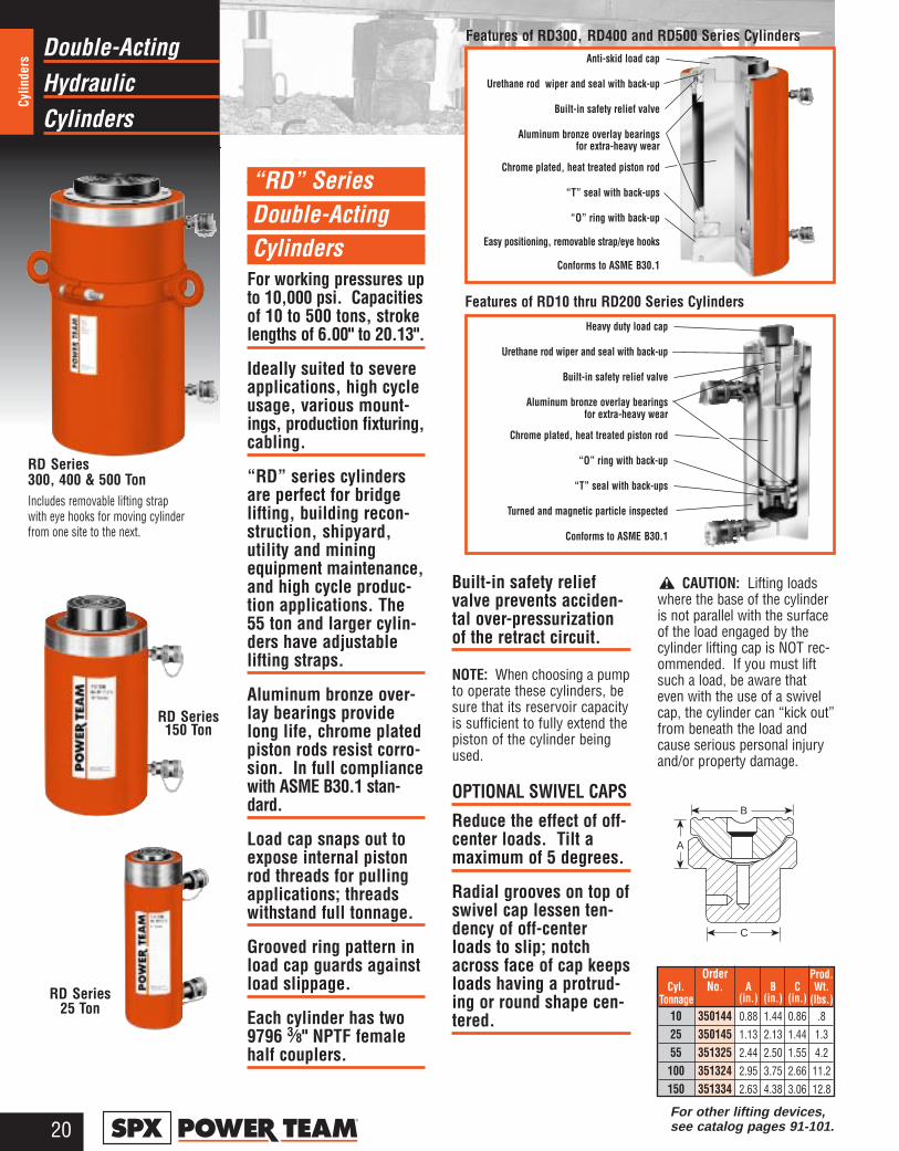
“RD” Series Double-Acting Cylinders
For working pressures upto 10,000 psi. Capacitiesof 10 to 500 tons, strokelengths of 6.00" to 20.13".
Ideally suited to severeapplications, high cycleusage, various mount-ings, production fixturing,cabling.
“RD” series cylindersare perfect for bridgelifting, building recon-struction, shipyard,utility and miningequipment maintenance,and high cycle produc-tion applications. The55 ton and larger cylin-ders have adjustablelifting straps.
Aluminum bronze over-lay bearings providelong life, chrome platedpiston rods resist corro-sion. In full compliancewith ASME B30.1 stan-dard.
Load cap snaps out toexpose internal pistonrod threads for pullingapplications; threadswithstand full tonnage.
Grooved ring pattern inload cap guards againstload slippage.
Each cylinder has two9796 3⁄8" NPTF femalehalf couplers.
Built-in safety reliefvalve prevents acciden-tal over-pressurizationof the retract circuit.
NOTE: When choosing a pumpto operate these cylinders, besure that its reservoir capacityis sufficient to fully extend thepiston of the cylinder beingused.
OPTIONAL SWIVEL CAPS
Reduce the effect of off-center loads. Tilt amaximum of 5 degrees.
Radial grooves on top ofswivel cap lessen ten-dency of off-centerloads to slip; notchacross face of cap keepsloads having a protrud-ing or round shape cen-tered.
RD Series25 Ton
RD Series300, 400 & 500 TonIncludes removable lifting strapwith eye hooks for moving cylinderfrom one site to the next.
Order Prod.Cyl. No. A B C Wt.
Tonnage (in.) (in.) (in.) (lbs.)10 350144 0.88 1.44 0.86 .8
25 350145 1.13 2.13 1.44 1.355 351325 2.44 2.50 1.55 4.2
100 351324 2.95 3.75 2.66 11.2
150 351334 2.63 4.38 3.06 12.8
C
A
B
Features of RD300, RD400 and RD500 Series Cylinders
Features of RD10 thru RD200 Series Cylinders
RD Series150 Ton
Anti-skid load cap
Urethane rod wiper and seal with back-up
Built-in safety relief valve
Aluminum bronze overlay bearings for extra-heavy wear
Chrome plated, heat treated piston rod
“T” seal with back-ups
“O” ring with back-up
Easy positioning, removable strap/eye hooks
Conforms to ASME B30.1
Heavy duty load cap
Urethane rod wiper and seal with back-up
Built-in safety relief valve
Aluminum bronze overlay bearings for extra-heavy wear
Chrome plated, heat treated piston rod
“O” ring with back-up
“T” seal with back-ups
Turned and magnetic particle inspected
Conforms to ASME B30.1
CAUTION: Lifting loadswhere the base of the cylinderis not parallel with the surfaceof the load engaged by thecylinder lifting cap is NOT rec-ommended. If you must liftsuch a load, be aware thateven with the use of a swivelcap, the cylinder can “kick out”from beneath the load andcause serious personal injuryand/or property damage.
For other lifting devices, see catalog pages 91-101.
HydraulicDouble-Acting
Cylinders
21®
Cylinders
C
A
B
HJK
E
F
G
D
3/8 NPTF
Note: Threads on cyl. collarsare std. on RD series cylinders.
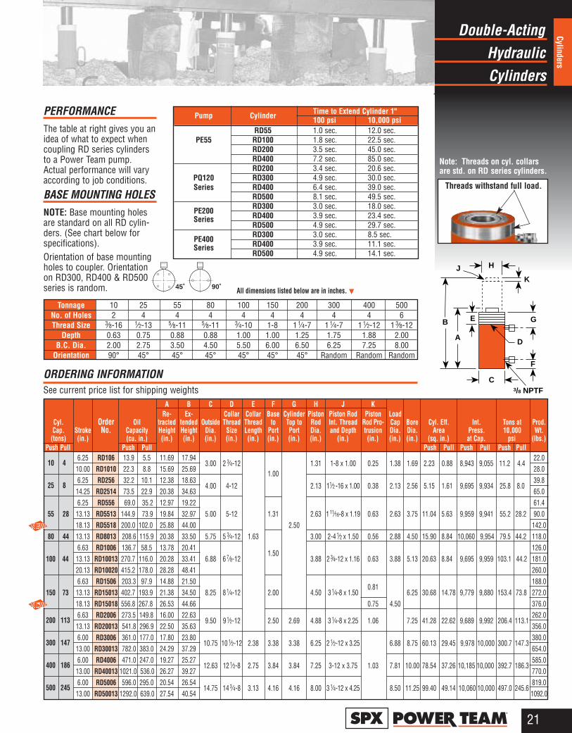
PERFORMANCEThe table at right gives you anidea of what to expect whencoupling RD series cylindersto a Power Team pump.Actual performance will varyaccording to job conditions.
BASE MOUNTING HOLESNOTE: Base mounting holesare standard on all RD cylin-ders. (See chart below forspecifications).Orientation of base mountingholes to coupler. Orientationon RD300, RD400 & RD500series is random.
Threads withstand full load.
All dimensions listed below are in inches. ▼
ORDERING INFORMATION See current price list for shipping weights
A B C D E F G H J KRe- Ex- Collar Collar Base Cylinder Piston Piston Rod Piston Load
Cyl. Order Oil tracted tended Outside Thread Thread to Top to Rod Int. Thread Rod Pro- Cap Bore Cyl. Eff. Int. Tons at Prod.Cap. Stroke No. Capacity Height Height Dia. Size Length Port Port Dia. and Depth trusion Dia. Dia. Area Press. 10,000 Wt.(tons) (in.) (cu. in.) (in.) (in.) (in.) (in.) (in.) (in.) (in.) (in.) (in.) (in.) (in.) (in.) (sq. in.) at Cap. psi (lbs.)
Push Pull Push Pull Push Pull Push Pullx Push Pull
10 46.25 RD106 13.9 5.5 11.69 17.94
3.00 2 3⁄4-12 1.31 1-8 x 1.00 0.25 1.38 1.69 2.23 0.88– 8,943 9,055 11.2 4.422.0
10.00 RD1010 22.3 8.8 15.69 25.691.00
28.0
25 86.25 RD256 32.2 10.1 12.38 18.63
4.00 4-12 2.13 11⁄2 -16 x 1.00 0.38 2.13 2.56 5.15 1.61– 9,695 9,934 25.8 8.039.8
14.25 RD2514 73.5 22.9 20.38 34.63 65.06.25 RD556 69.0 35.2 12.97 19.22 61.4
55 28 13.13 RD5513 144.9 73.9 19.84 32.97 5.00 5-12 1.31 2.63 1 11⁄16-8 x 1.19 0.63 2.63 3.75 11.04 5.63– 9,959 9,941 55.2 28.2 90.018.13 RD5518 200.0 102.0 25.88 44.00 2.50 142.0
80 44 13.13 RD8013 208.6 115.9 20.38 33.50 5.75 5 3⁄4-12 1.63 3.00 2-4 1⁄2 x 1.50 0.56 2.88 4.50 15.90 8.84– 10,060 9,954i 79.5 44.2 118.06.63 RD1006 136.7 58.5 13.78 20.41
1.50126.0
100 44 13.13 RD10013 270.7 116.0 20.28 33.41 6.88 6 7⁄8-12 3.88 2 3⁄4-12 x 1.16 0.63 3.88 5.13 20.63 8.84– 9,695 9,959 103.1 44.2 181.020.13 RD10020 415.2 178.0 28.28 48.41 260.06.63 RD1506 203.3 97.9 14.88 21.50
0.81188.0
150 73 13.13 RD15013 402.7 193.9 21.38 34.50 8.25 8 1⁄4-12 2.00 4.50 3 1⁄4-8 x 1.50 6.25 30.68 14.78 9,779 9,880 153.4 73.8 272.018.13 RD15018 556.8 267.8 26.53 44.66 0.75 4.50 376.0
200 1136.63 RD2006 273.5 149.8 16.00 22.63
9.50 9 1⁄2-12 2.50 2.69 4.88 3 1⁄4-8 x 2.25 1.06 7.25 41.28 22.62 9,689 9,992 206.4 113.1262.0
13.13 RD20013 541.8 296.9 22.50 35.63 356.0
300 1476.00 RD3006 361.0 177.0 17.80 23.80
10.75 10 1⁄2-12 2.38 3.38 3.38 6.25 2 1⁄2-12 x 3.25 6.88 8.75 60.13 29.45 9,978 10,000 300.7 147.3380.0
13.00 RD30013 782.0 383.0 24.29 37.29 654.0
400 1866.00 RD4006 471.0 247.0 19.27 25.27
12.63 12 1⁄2-8 2.75 3.84 3.84 7.25 3-12 x 3.75 1.03 7.81 10.00 78.54 37.26 10,185 10,000i
392.7 186.3585.0
13.00 RD40013 1021.0 536.0 26.27 39.27 770.0
500 2456.00 RD5006 596.0 295.0 20.54 26.54
14.75 14 3⁄4-8 3.13 4.16 4.16 8.00 3 1⁄4-12 x 4.25 8.50 11.25 99.40 49.14 10,060 10,000 497.0 245.6819.0
13.00 RD50013 1292.0 639.0 27.54 40.54 1092.0
90˚45˚
Tonnage 10 25 55 80 100 150 200 300 400 500No. of Holes 2 4 4 4 4 4 4 4 4 6Thread Size 3⁄8-16 1⁄2-13 5⁄8-11 5⁄8-11 3⁄4-10 1-8 1 1⁄4-7 1 1⁄4-7 1 1⁄2-12 1 3⁄8-12
Depth 0.63 0.75 0.88 0.88 1.00 1.00 1.25 1.75 1.88 2.00B.C. Dia. 2.00 2.75 3.50 4.50 5.50 6.00 6.50 6.25 7.25 8.00
Orientation 90° 45° 45° 45° 45° 45° 45° Random Random Random
Pump Cylinder Time to Extend Cylinder 1"100 psi 10,000 psi
RD55 1.0 sec. 12.0 sec.PE55 RD100 1.8 sec. 22.5 sec.
RD200 3.5 sec. 45.0 sec.RD400 7.2 sec. 85.0 sec.RD200 3.4 sec. 20.6 sec.
PQ120 RD300 4.9 sec. 30.0 sec.Series RD400 6.4 sec. 39.0 sec.
RD500 8.1 sec. 49.5 sec.
PE200 RD300 3.0 sec. 18.0 sec.
Series RD400 3.9 sec. 23.4 sec.RD500 4.9 sec. 29.7 sec.
PE400 RD300 3.0 sec. 8.5 sec.
Series RD400 3.9 sec. 11.1 sec.RD500 4.9 sec. 14.1 sec.

HydraulicDouble-Acting
Cylinders
22®
Cylin
ders
“R” Series Double-Acting Cylinders
For working pressuresup to 10,000 psi.Capacities of 100 to 565 tons, stroke lengthsof 2.00" to 10.00".
Swivel caps reduce the effects of off-centerloading; have 5° maxi-mum tilt. Radialgrooves on swivel capcan reduce load slip-page. Cylinders may be“dead-ended” withoutdamage.
Hard chrome plated,heat treated piston rodprovides reduced wearon both piston andgland nut.
Built-in safety reliefvalve prevents acciden-tal over-pressurizationof the retract circuit.
Each cylinder has two9796 3⁄8" NPTF femalehalf couplers.
In full compliance withASME B30.1 standard.
R1502D
R56510D
B
HK
FC
G
A
ORDERING INFORMATION See current price list for shipping weights
A B C F G H KRe- Ex- Base Cylinder Piston Piston Cylinder
Cyl. Order Oil tracted tended Outside to Top to Rod Rod Bore Effective Internal Tons at Prod.Cap. Stroke No. Capacity Height Height Dia. Port Port Dia. Protrusion Dia. Area Press. 10,000 Wt.(tons) (in.) (cu. in.) (in.) (in.) (in.) (in.) (in.) (in.) (in.) (in.) (sq. in.) at Cap. psi (lbs.)
Push Return Push Push Push2.00 R1002D 41.2 19.2 6.64 8.64 54.0
100 6.00 R1006D 123.6 57.6 10.64 16.64 6.50 1.00 2.20 3.75 0.28 5.13 20.60 9,695 103.0 81.010.00 R10010D 206.0 96.0 14.64 24.64 108.02.00 R1502D 61.4 29.6 7.44 9.44 95.0
150 6.00 R1506D 184.2 88.8 11.44 17.44 8.06 1.25 2.25 4.50 0.30 6.25 30.70 9,778 153.4 136.010.00 R15010D 307.0 148.0 15.44 25.44 177.02.00 R2002D 82.6 39.2 8.14 10.14 136.0
200 6.00 R2006D 247.8 117.6 12.14 18.14 9.25 1.63 2.31 5.25 0.34 7.25 41.30 9,690 206.4 187.010.00 R20010D 413.0 196.0 16.14 26.14 239.02.00 R2802D 113.4 47.2 9.20 11.20 219.0
280 6.00 R2806D 340.2 141.6 13.20 19.20 10.88 1.88 2.58 6.50 0.41 8.50 56.70 9,870 283.7 297.010.00 R28010D 567.0 236.0 17.20 27.20 376.02.00 R3552D 141.8 47.4 11.41 13.41 324.0
355 6.00 R3556D 425.4 142.2 15.41 21.41 11.75 2.13 2.75 7.75 0.44 9.50 70.90 10,017 354.4 421.010.00 R35510D 709.0 237.0 19.41 29.41 517.02.00 R4302D 173.2 59.6 12.33 14.33 439.0
430 6.00 R4306D 519.6 178.8 16.33 22.33 13.00 2.50 2.95 8.50 0.47 10.50 86.60 9,932 433.0 558.010.00 R43010D 866.0 298.0 20.33 30.33 673.02.00 R5652D 226.2 76.8 13.59 15.59 619.0
565 6.00 R5656D 678.6 230.4 17.59 23.59 14.88 2.75 3.20 9.75 0.55 12.00 113.10 9,991 565.5 772.010.00 R56510D 1131.0 384.0 21.59 31.59 926.0
HydraulicSingle-Acting
Cylinders
23®
Cylinders
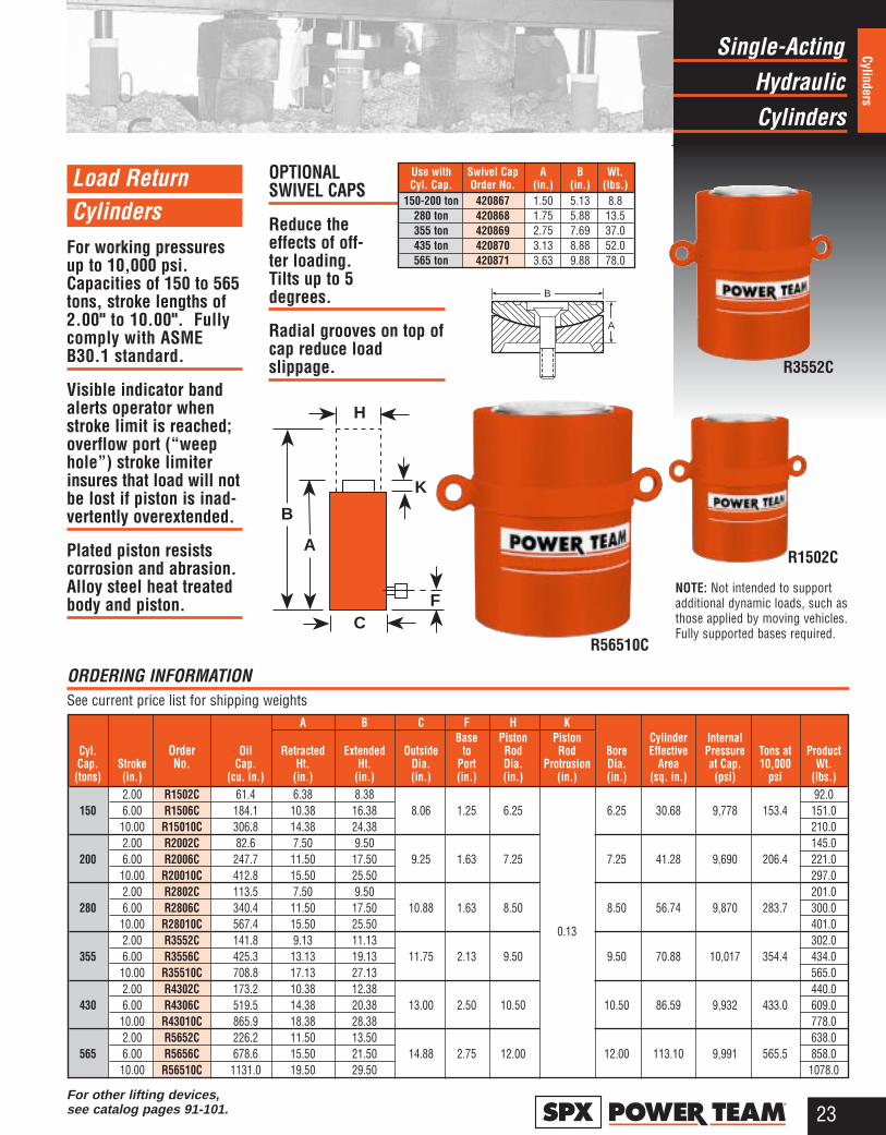
Load Return Cylinders
For working pressuresup to 10,000 psi.Capacities of 150 to 565tons, stroke lengths of2.00" to 10.00". Fullycomply with ASMEB30.1 standard.
Visible indicator bandalerts operator whenstroke limit is reached;overflow port (“weephole”) stroke limiter insures that load will notbe lost if piston is inad-vertently overextended.
Plated piston resistscorrosion and abrasion.Alloy steel heat treatedbody and piston.
OPTIONALSWIVEL CAPS
Reduce theeffects of off- cen-ter loading. Tilts up to 5degrees.
Radial grooves on top ofcap reduce load slippage.
ORDERING INFORMATION See current price list for shipping weights
A B C F H KBase Piston Piston Cylinder Internal
Cyl. Order Oil Retracted Extended Outside to Rod Rod Bore Effective Pressure Tons at ProductCap. Stroke No. Cap. Ht. Ht. Dia. Port Dia. Protrusion Dia. Area at Cap. 10,000 Wt.(tons) (in.) (cu. in.) (in.) (in.) (in.) (in.) (in.) (in.) (in.) (sq. in.) (psi) psi (lbs.)
2.00 R1502C 61.4 6.38 8.38 92.0150 6.00 R1506C 184.1 10.38 16.38 8.06 1.25 6.25 6.25 30.68 9,778 153.4 151.0
10.00 R15010C 306.8 14.38 24.38 210.02.00 R2002C 82.6 7.50 9.50 145.0
200 6.00 R2006C 247.7 11.50 17.50 9.25 1.63 7.25 7.25 41.28 9,690 206.4 221.010.00 R20010C 412.8 15.50 25.50 297.02.00 R2802C 113.5 7.50 9.50 201.0
280 6.00 R2806C 340.4 11.50 17.50 10.88 1.63 8.50 8.50 56.74 9,870 283.7 300.010.00 R28010C 567.4 15.50 25.50 0.13 401.02.00 R3552C 141.8 9.13 11.13 302.0
355 6.00 R3556C 425.3 13.13 19.13 11.75 2.13 9.50 9.50 70.88 10,017 354.4 434.010.00 R35510C 708.8 17.13 27.13 565.02.00 R4302C 173.2 10.38 12.38 440.0
430 6.00 R4306C 519.5 14.38 20.38 13.00 2.50 10.50 10.50 86.59 9,932 433.0 609.010.00 R43010C 865.9 18.38 28.38 778.02.00 R5652C 226.2 11.50 13.50 638.0
565 6.00 R5656C 678.6 15.50 21.50 14.88 2.75 12.00 12.00 113.10 9,991 565.5 858.010.00 R56510C 1131.0 19.50 29.50 1078.0
B
A
C
A
B
H
K
F
Use with Swivel Cap A B Wt.Cyl. Cap. Order No. (in.) (in.) (lbs.)
150-200 ton 420867 1.50 5.13 8.8280 ton 420868 1.75 5.88 13.5355 ton 420869 2.75 7.69 37.0435 ton 420870 3.13 8.88 52.0565 ton 420871 3.63 9.88 78.0
For other lifting devices, see catalog pages 91-101.
NOTE: Not intended to supportadditional dynamic loads, such asthose applied by moving vehicles.Fully supported bases required.
R1502C
R3552C
R56510C

HydraulicSingle-Acting
Cylinders
24®
Cylin
ders
Load Return, Locking Collar Cylinders
For working pressures to10,000 psi. Capacitiesof 55 to 565 tons, strokelengths of 2.00" to 10.00".
Locking collar providespositive mechanical lockto support lifted load forextended periods oftime with hydraulicpressure released.
Visible indicator bandalerts operator whenstroke limit is reached;overflow port (“weep
hole”) stroke limiterinsures that load will notbe lost if piston is inad-vertently overextended.
Bronze plated pistonresists corrosion andabrasion. Cylindersfully comply with ASMEB30.1 standard.
OPTIONAL SWIVEL CAPS Reduce the effect of off-center loads. Tilt amaximum of 5 degrees.
Radial grooves on topof swivel cap lessentendency of off-centerloads to slip.
Locking collar feature permits non-hydraulic support of load
R56510L B
A
NOTE: Supported loads not toexceed the rated capacity of thecylinders. Not intended to supportadditional dynamic loads, such asthose applied by moving vehicles.Fully supported bases required.
Use with Swivel Cap A B Wt.Cyl. Cap. Order No. (in.) (in.) (lbs.)
55-100 ton 420866 1.00 2.81 1.8150-200 ton 420867 1.50 5.13 8.8
280 ton 420868 1.75 5.88 13.5355 ton 420869 2.75 7.69 37.0435 ton 420870 3.13 8.88 52.0565 ton 420871 3.63 9.88 78.0
ORDERING INFORMATION See current price list for shipping weights
C
A
B
H
K
F
T
A B C F H K TBase Piston Piston Cylinder Internal
Cyl. Order Oil Retracted Extended Outside to Rod Rod Nut Bore Effective Pressure Tons at ProductCap. Stroke No. Cap. Ht. Ht. Dia. Port Dia. Protrusion Thickness Dia. Area at Cap. 10,000 Wt.(tons) (in.) (cu. in.) (in.) (in.) (in.) (in.) (in.) (in.) (in.) (in.) (sq. in.) (psi) psi (lbs.)
2.00 R552L 22.10 6.38 8.38 33.755 6.00 R556L 66.30 10.38 16.38 4.94 3.75 1.44 3.75 11.04 9,964 55.2 58.0
10.00 R5510L 110.40 14.38 24.38 1.00 80.02.00 R1002L 41.30 7.25 9.25 66.0
100 6.00 R1006L 123.80 11.25 17.25 6.50 5.13 5.13 20.63 9,695 103.0 103.010.00 R10010L 206.30 15.25 25.25 1.75 142.02.00 R1502L 61.40 8.13 10.13 117.0
150 6.00 R1506L 184.10 12.13 18.13 8.06 1.25 6.25 6.25 30.68 9,778 153.4 177.010.00 R15010L 306.80 16.13 26.13 235.02.00 R2002L 82.60 9.50 11.50 183.0
200 6.00 R2006L 247.70 13.50 19.50 9.25 7.25 2.00 7.25 41.28 9,690 206.4 259.010.00 R20010L 412.80 17.50 27.50 1.63 0.13 335.02.00 R2802L 113.50 9.75 11.75 261.0
280 6.00 R2806L 340.40 13.75 19.75 10.88 8.50 2.25 8.50 56.74 9,870 283.7 359.010.00 R28010L 567.40 17.75 27.75 459.02.00 R3552L 141.80 11.50 13.50 381.0
355 6.00 R3556L 425.30 15.50 21.50 11.75 2.13 9.50 2.38 9.50 70.88 10,017 354.4 512.010.00 R35510L 708.80 19.50 29.50 643.02.00 R4302L 173.20 13.13 15.13 556.0
430 6.00 R4306L 519.50 17.13 23.13 13.00 2.50 10.50 2.75 10.50 86.59 9,932 433.0 725.010.00 R43010L 865.90 21.13 31.13 894.02.00 R5652L 226.20 14.63 16.63 811.0
565 6.00 R5656L 678.60 18.63 24.63 14.88 2.75 12.00 3.13 12.00 113.10 9,991 565.5 1031.010.00 R56510L 1131.0 22.63 32.63 1251.0
For other lifting devices, see catalog pages 91-101.
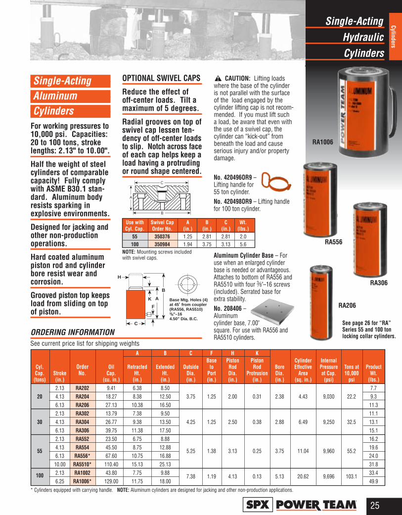
Single-Acting Aluminum Cylinders
For working pressures to10,000 psi. Capacities:20 to 100 tons, strokelengths: 2.13" to 10.00".
Half the weight of steelcylinders of comparablecapacity! Fully complywith ASME B30.1 stan-dard. Aluminum bodyresists sparking inexplosive environments.
Designed for jacking andother non-productionoperations.
Hard coated aluminumpiston rod and cylinderbore resist wear andcorrosion.
Grooved piston top keepsload from sliding on topof piston.
OPTIONAL SWIVEL CAPS
Reduce the effect of off-center loads. Tilt amaximum of 5 degrees.
Radial grooves on top ofswivel cap lessen ten-dency of off-center loadsto slip. Notch across faceof each cap helps keep aload having a protrudingor round shape centered.
CAUTION: Lifting loadswhere the base of the cylinderis not parallel with the surfaceof the load engaged by thecylinder lifting cap is not recom-mended. If you must lift sucha load, be aware that even withthe use of a swivel cap, thecylinder can “kick-out” frombeneath the load and causeserious injury and/or propertydamage.
HydraulicSingle-Acting
Cylinders
25®
Cylinders
ORDERING INFORMATION See current price list for shipping weights
RA206
RA306
RA556
RA1006
No. 420496OR9 –Lifting handle for 55 ton cylinder.No. 420498OR9 – Lifting handlefor 100 ton cylinder.
Aluminum Cylinder Base – Foruse when an enlarged cylinderbase is needed or advantageous.Attaches to bottom of RA556 andRA5510 with four 3⁄8"–16 screws(included). Serrated base forextra stability.No. 208406 –Aluminumcylinder base, 7.00"square. For use with RA556 andRA5510 cylinders.
See page 26 for “RA”Series 55 and 100 tonlocking collar cylinders.
A B C F H KBase Piston Piston Cylinder Internal
Cyl. Order Oil Retracted Extended Outside to Rod Rod Bore Effective Pressure Tons at ProductCap. Stroke No. Cap. Ht. Ht. Dia. Port Dia. Protrusion Dia. Area at Cap. 10,000 Wt.(tons) (in.) (cu. in.) (in.) (in.) (in.) (in.) (in.) (in.) (in.) (sq. in.) (psi) psi (lbs.)
2.13 RA202 9.41 6.38 8.50 7.720 4.13 RA204 18.27 8.38 12.50 3.75 1.25 2.00 0.31 2.38 4.43 9,030 22.2 9.3
6.13 RA206 27.13 10.38 16.50 11.32.13 RA302 13.79 7.38 9.50 11.1
30 4.13 RA304 26.77 9.38 13.50 4.25 1.25 2.50 0.38 2.88 6.49 9,250 32.5 13.16.13 RA306 39.75 11.38 17.50 15.12.13 RA552 23.50 6.75 8.88 16.2
554.13 RA554 45.50 8.75 12.88
5.25 1.38 3.13 0.25 3.75 11.04 9,960 55.219.6
6.13 RA556* 67.60 10.75 16.88 24.010.00 RA5510* 110.40 15.13 25.13 31.8
100 2.13 RA1002 43.80 7.75 9.887.38 1.19 4.13 0.13 5.13 20.62 9,696 103.1
33.46.25 RA1006* 129.00 11.75 18.00 49.9
AK
B
H
Base Mtg. Holes (4)at 45˚ from coupler(RA556, RA5510)3/8"–164.50" Dia. B.C.
C
F
NOTE: Mounting screws includedwith swivel caps.
Use with Swivel Cap A B C Wt.Cyl. Cap. Order No. (in.) (in.) (in.) (lbs.)
55 350376 1.25 2.81 2.81 2.0100 350984 1.94 3.75 3.13 5.6
A
C
B
* Cylinders equipped with carrying handle. NOTE: Aluminum cylinders are designed for jacking and other non-production applications.
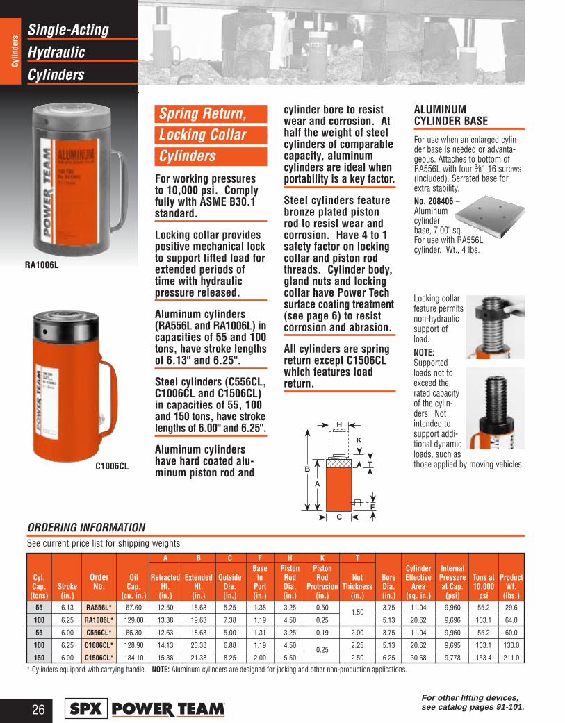
HydraulicSingle-Acting
Cylinders
26®
Cylin
ders
Spring Return, Locking Collar Cylinders
For working pressuresto 10,000 psi. Complyfully with ASME B30.1standard.
Locking collar providespositive mechanical lockto support lifted load forextended periods oftime with hydraulicpressure released.
Aluminum cylinders(RA556L and RA1006L) incapacities of 55 and 100tons, have stroke lengthsof 6.13" and 6.25".
Steel cylinders (C556CL,C1006CL and C1506CL)in capacities of 55, 100and 150 tons, have strokelengths of 6.00" and 6.25".
Aluminum cylindershave hard coated alu-minum piston rod and
cylinder bore to resistwear and corrosion. Athalf the weight of steelcylinders of comparablecapacity, aluminumcylinders are ideal whenportability is a key factor.
Steel cylinders featurebronze plated pistonrod to resist wear andcorrosion. Have 4 to 1safety factor on lockingcollar and piston rodthreads. Cylinder body,gland nuts and lockingcollar have Power Techsurface coating treatment(see page 6) to resistcorrosion and abrasion.
All cylinders are springreturn except C1506CLwhich features loadreturn.
RA1006L
C1006CL
C
A
B
H
K
T
F
ALUMINUM CYLINDER BASE
For use when an enlarged cylin-der base is needed or advanta-geous. Attaches to bottom ofRA556L with four 3⁄8"–16 screws(included). Serrated base forextra stability.No. 208406 –Aluminumcylinderbase, 7.00" sq.For use with RA556Lcylinder. Wt., 4 lbs.
ORDERING INFORMATION See current price list for shipping weights
Locking collarfeature permitsnon-hydraulicsupport ofload.NOTE:Supportedloads not toexceed therated capacityof the cylin-ders. Notintended tosupport addi-tional dynamicloads, such asthose applied by moving vehicles.
A B C F H K TBase Piston Piston Cylinder Internal
Cyl. Order Oil Retracted Extended Outside to Rod Rod Nut Bore Effective Pressure Tons at ProductCap. Stroke No. Cap. Ht. Ht. Dia. Port Dia. Protrusion Thickness Dia. Area at Cap. 10,000 Wt.(tons) (in.) (cu. in.) (in.) (in.) (in.) (in.) (in.) (in.) (in.) (in.) (sq. in.) (psi) psi (lbs.)
55 6.13 RA556L* 67.60 12.50 18.63 5.25 1.38 3.25 0.501.50
3.75 11.04 9,960 55.2 29.6
100 6.25 RA1006L* 129.00 13.38 19.63 7.38 1.19 4.50 0.25 5.13 20.62 9,696 103.1 64.0
55 6.00 C556CL* 66.30 12.63 18.63 5.00 1.31 3.25 0.19 2.00 3.75 11.04 9,960 55.2 60.0
100 6.25 C1006CL* 128.90 14.13 20.38 6.88 1.19 4.500.25
2.25 5.13 20.62 9,695 103.1 130.0
150 6.00 C1506CL* 184.10 15.38 21.38 8.25 2.00 5.50 2.50 6.25 30.68 9,778 153.4 211.0
For other lifting devices, see catalog pages 91-101.
* Cylinders equipped with carrying handle. NOTE: Aluminum cylinders are designed for jacking and other non-production applications.
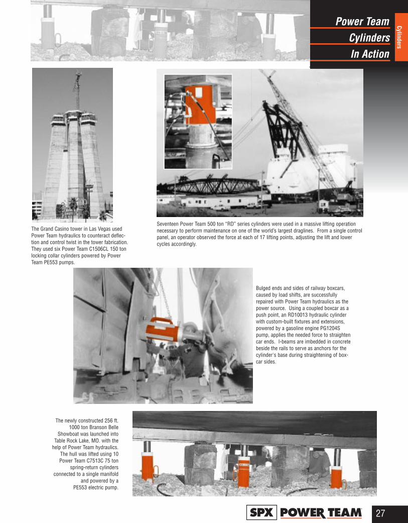
CylindersPower Team
In Action
27®
Cylinders
Seventeen Power Team 500 ton “RD” series cylinders were used in a massive lifting operationnecessary to perform maintenance on one of the world’s largest draglines. From a single controlpanel, an operator observed the force at each of 17 lifting points, adjusting the lift and lowercycles accordingly.
The Grand Casino tower in Las Vegas usedPower Team hydraulics to counteract deflec-tion and control twist in the tower fabrication.They used six Power Team C1506CL 150 tonlocking collar cylinders powered by PowerTeam PE553 pumps.
The newly constructed 256 ft.1000 ton Branson Belle
Showboat was launched intoTable Rock Lake, MO. with the
help of Power Team hydraulics.The hull was lifted using 10Power Team C7513C 75 ton
spring-return cylindersconnected to a single manifold
and powered by aPE553 electric pump.
Bulged ends and sides of railway boxcars,caused by load shifts, are successfullyrepaired with Power Team hydraulics as thepower source. Using a coupled boxcar as apush point, an RD10013 hydraulic cylinderwith custom-built fixtures and extensions,powered by a gasoline engine PG1204Spump, applies the needed force to straightencar ends. I-beams are imbedded in concretebeside the rails to serve as anchors for thecylinder's base during straightening of box-car sides.
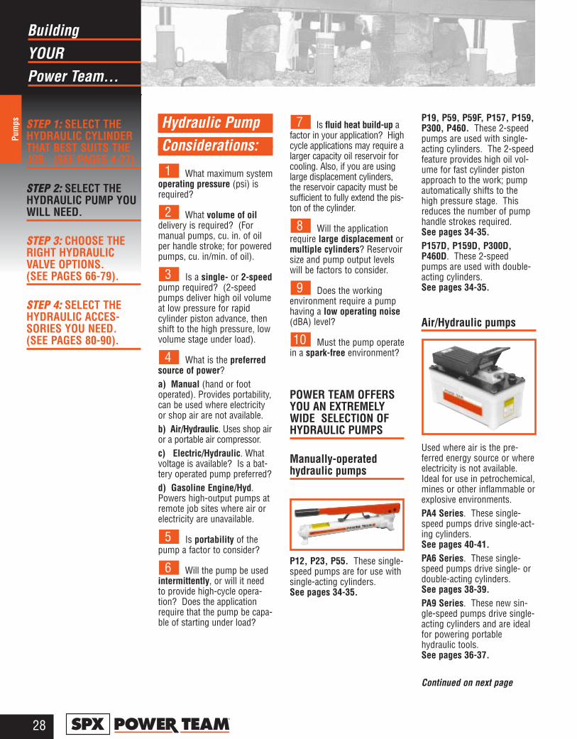
YOURBuilding
Power Team...
Pum
ps
28®
STEP 1: SELECT THEHYDRAULIC CYLINDERTHAT BEST SUITS THEJOB. (SEE PAGES 4-27).
STEP 2: SELECT THEHYDRAULIC PUMP YOUWILL NEED.
STEP 3: CHOOSE THERIGHT HYDRAULICVALVE OPTIONS. (SEE PAGES 66-79).
STEP 4: SELECT THEHYDRAULIC ACCES-SORIES YOU NEED.(SEE PAGES 80-90).
Hydraulic Pump Considerations:
What maximum systemoperating pressure (psi) isrequired?
What volume of oildelivery is required? (Formanual pumps, cu. in. of oilper handle stroke; for poweredpumps, cu. in/min. of oil).
Is a single- or 2-speedpump required? (2-speedpumps deliver high oil volumeat low pressure for rapidcylinder piston advance, thenshift to the high pressure, lowvolume stage under load).
What is the preferredsource of power?a) Manual (hand or footoperated). Provides portability,can be used where electricityor shop air are not available.b) Air/Hydraulic. Uses shop airor a portable air compressor. c) Electric/Hydraulic. Whatvoltage is available? Is a bat-tery operated pump preferred?d) Gasoline Engine/Hyd.Powers high-output pumps atremote job sites where air orelectricity are unavailable.
Is portability of thepump a factor to consider?
Will the pump be usedintermittently, or will it needto provide high-cycle opera-tion? Does the applicationrequire that the pump be capa-ble of starting under load?
Is fluid heat build-up afactor in your application? Highcycle applications may require alarger capacity oil reservoir forcooling. Also, if you are usinglarge displacement cylinders,the reservoir capacity must besufficient to fully extend the pis-ton of the cylinder.
Will the applicationrequire large displacement ormultiple cylinders? Reservoirsize and pump output levelswill be factors to consider.
Does the working environment require a pumphaving a low operating noise(dBA) level?
Must the pump operatein a spark-free environment?
POWER TEAM OFFERSYOU AN EXTREMELYWIDE SELECTION OFHYDRAULIC PUMPS
Manually-operatedhydraulic pumps
P12, P23, P55. These single-speed pumps are for use withsingle-acting cylinders. See pages 34-35.
P19, P59, P59F, P157, P159,P300, P460. These 2-speedpumps are used with single-acting cylinders. The 2-speedfeature provides high oil vol-ume for fast cylinder pistonapproach to the work; pumpautomatically shifts to thehigh pressure stage. Thisreduces the number of pumphandle strokes required. See pages 34-35.P157D, P159D, P300D,P460D. These 2-speedpumps are used with double-acting cylinders. See pages 34-35.
Air/Hydraulic pumps
Used where air is the pre-ferred energy source or whereelectricity is not available.Ideal for use in petrochemical,mines or other inflammable orexplosive environments.PA4 Series. These single-speed pumps drive single-act-ing cylinders. See pages 40-41.PA6 Series. These single-speed pumps drive single- ordouble-acting cylinders. See pages 38-39.PA9 Series. These new sin-gle-speed pumps drive single-acting cylinders and are idealfor powering portablehydraulic tools. See pages 36-37.
Continued on next page
10
9
8
7
6
5
4
3
2
1

Right PumpChoosing The
For YOUR Task
Pumps
29®
PA50 Series. These single-speed pumps drive single- ordouble-acting low pressure(3,200 psi) cylinders. See pages 40-41.PA60. This 2-speed pump isequipped with a manifold tooperate multiple cylinders,and provides a 2-gallon reser-voir capacity. See pages 40-41.PA64. Similar to PA60, this 2-speed pump drives single- ordouble-acting cylinders. See pages 40-41.PA172 and PA174. These“economy” 2-speed pumpsdrive single- or double-actingcylinders, depending on themodel chosen. Provide a lowweight to output ratio. See pages 42-43.PA462 and PA464 Series.These 2-speed pumps drivesingle or double-acting cylin-ders, depending on the modelselected. They offer highspeed cylinder pistonadvance. See pages 42-43.PA554. This 2-speed pumpdrives single- or double-actingcylinders, delivering a highvolume of oil. See pages 42-43.
Electric/HydraulicPumps
All of the following pumps are2-speed models, and can beused to drive single- or dou-ble-acting cylinders.“Quarter Horse” Series. Astheir name implies, thesepumps feature a 1⁄4 hp electricmotor. A battery-poweredversion is available. Having alow noise level and weighingjust 20 lbs., they are ideal forpowering portable hydraulicspreaders, nut splitters, pipeflange spreaders and othertools. See pages 44-45.PE17 and PE84 Series. CSArated for intermittent duty,these feature a 1⁄2 hp, singlephase induction motor with alow noise level (67-81 dBA).Smaller generators and lowamperage circuits can be usedas a power source. See pages 46-47.
PE46 Series. Powered by a11⁄2 hp, single phase inductionmotor, operate at a moderatenoise level of 77-81 dBA.CSA rated for intermittentduty. See pages 48-49.PE18 Series. CSA rated forintermittent duty, these featurea 1⁄2 hp, single phase universalmotor with a noise level of 85-90 dBA. Provide high perfor-mance at a low price. Haslow amperage draw. See pages 50-51. PE30 Series. Equipped with a1 hp, single phase permanentmagnet motor, have a noiselevel of only 82-87 dBA. CSArated for intermittent duty, andrequire a relatively low volt-age; ideal for use in generalconstruction applications. Rollcage/handle protects themotor and controls. See pages 52-53.PE55 and PED25 Series. Thefamous Vanguard® pumpshave been continually upgrad-ed for 40 years; some of theoriginals are still in service!Equipped with a 11⁄8 hp, singlephase universal motor, have ahigh noise level (90-95 dBA).Offer the best weight to per-formance ratio of any PowerTeam electric/hydraulic pump.CSA rated for intermittentduty. The PED25 versions are“dual flow” pumps whichdeliver the same low and highpressures to both valves, andhave a noise level of 80-85dBA. They have a 11⁄2 hpinduction motor. See pages 54-55.
Continued on page 30...
PE60 Series. The Vanguard®
Supreme® pumps providetrouble-free service in themost severe working environ-ments. Powered by a 11⁄8 hp,single phase motor, has amoderate noise level of 80-85dBA. Start well under loadeven at the reduced voltagesencountered on constructionsites. High-output pumps,ideal for use with post-ten-sioning/pre-stressing jacksand other high-pressurehydraulic tools. See pages 105-106.
One of two Power TeamElectric/Hydraulic Pumps (fore-ground) that powered 16 100-toncylinders to support tunnel boringmachine in transport.
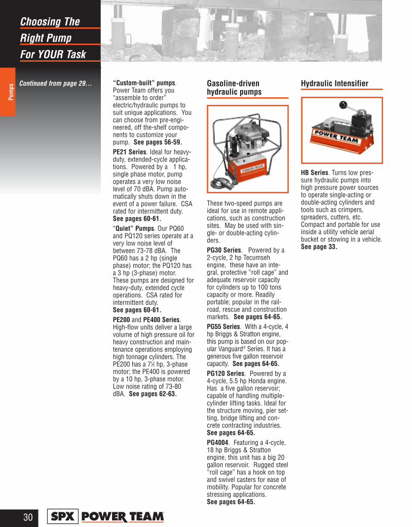
Right PumpChoosing The
For YOUR Task
Pum
ps
30®
“Custom-built” pumps.Power Team offers you“assemble to order”electric/hydraulic pumps tosuit unique applications. Youcan choose from pre-engi-neered, off the-shelf compo-nents to customize yourpump. See pages 56-59.PE21 Series. Ideal for heavy-duty, extended-cycle applica-tions. Powered by a 1 hp,single phase motor, pumpoperates a very low noiselevel of 70 dBA. Pump auto-matically shuts down in theevent of a power failure. CSArated for intermittent duty.See pages 60-61.“Quiet” Pumps. Our PQ60and PQ120 series operate at avery low noise level ofbetween 73-78 dBA. ThePQ60 has a 2 hp (singlephase) motor; the PQ120 hasa 3 hp (3-phase) motor.These pumps are designed forheavy-duty, extended cycleoperations. CSA rated forintermittent duty. See pages 60-61.PE200 and PE400 Series.High-flow units deliver a largevolume of high pressure oil forheavy construction and main-tenance operations employinghigh tonnage cylinders. ThePE200 has a 71⁄2 hp, 3-phasemotor; the PE400 is poweredby a 10 hp, 3-phase motor.Low noise rating of 73-80dBA. See pages 62-63.
Gasoline-drivenhydraulic pumps
These two-speed pumps areideal for use in remote appli-cations, such as constructionsites. May be used with sin-gle- or double-acting cylin-ders.PG30 Series. Powered by a2-cycle, 2 hp Tecumsehengine, these have an inte-gral, protective “roll cage” andadequate reservoir capacityfor cylinders up to 100 tonscapacity or more. Readilyportable; popular in the rail-road, rescue and constructionmarkets. See pages 64-65.PG55 Series. With a 4-cycle, 4hp Briggs & Stratton engine,this pump is based on our pop-ular Vanguard® Series. It has agenerous five gallon reservoircapacity. See pages 64-65.PG120 Series. Powered by a4-cycle, 5.5 hp Honda engine.Has a five gallon reservoir;capable of handling multiple-cylinder lifting tasks. Ideal forthe structure moving, pier set-ting, bridge lifting and con-crete contracting industries.See pages 64-65.PG4004. Featuring a 4-cycle,18 hp Briggs & Strattonengine, this unit has a big 20gallon reservoir. Rugged steel“roll cage” has a hook on topand swivel casters for ease ofmobility. Popular for concretestressing applications. See pages 64-65.
Hydraulic Intensifier
HB Series. Turns low pres-sure hydraulic pumps intohigh pressure power sourcesto operate single-acting ordouble-acting cylinders andtools such as crimpers,spreaders, cutters, etc.Compact and portable for useinside a utility vehicle aerialbucket or stowing in a vehicle.See page 33.
Continued from page 29...
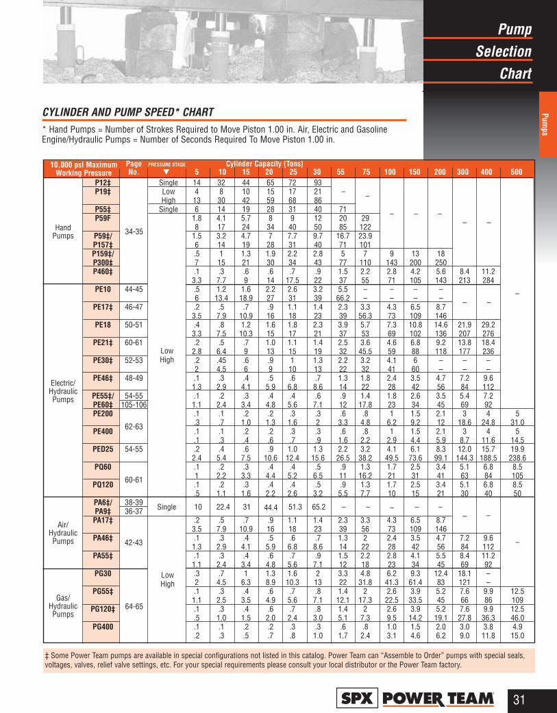
31®
SelectionPump
Chart
Pumps
CYLINDER AND PUMP SPEED* CHART* Hand Pumps = Number of Strokes Required to Move Piston 1.00 in. Air, Electric and GasolineEngine/Hydraulic Pumps = Number of Seconds Required To Move Piston 1.00 in.
‡ Some Power Team pumps are available in special configurations not listed in this catalog. Power Team can “Assemble to Order” pumps with special seals,voltages, valves, relief valve settings, etc. For your special requirements please consult your local distributor or the Power Team factory.
10,000 psi MaximumWorking Pressure
Gas/HydraulicPumps
Air/HydraulicPumps
Electric/HydraulicPumps
HandPumps
LowHigh
– –
– – –
– –
– –
–
Single 10 22.4 31 44.4 51.3 65.2 – – – – –– –
–
LowHigh
34-35
64-65
42-43
60-61
62-63
Page PRESSURE STAGE Cylinder Capacity (Tons) No. ▼ 5 10 15 20 25 30 55 75 100 150 200 300 400 500
P12‡ Single 14 32 44 65 72 93P19‡ Low 4 8 10 15 17 21
High 13 30 42 59 68 86P55‡ Single 6 14 19 28 31 40 71P59F 1.8 4.1 5.7 8 9 12 20 29
8 17 24 34 40 50 85 122P59‡/ 1.5 3.2 4.7 7 7.7 9.7 16.7 23.9P157‡ 6 14 19 28 31 40 71 101P159‡/ .5 1 1.3 1.9 2.2 2.8 5 7 9 13 18P300‡ 7 15 21 30 34 43 77 110 143 200 250P460‡ .1 .3 .6 .6 .7 .9 1.5 2.2 2.8 4.2 5.6 8.4 11.2
3.3 7.7 9 14 17.5 22 37 55 71 105 143 213 284PE10 44-45 .5 1.2 1.6 2.2 2.6 3.2 5.5 – – – –
6 13.4 18.9 27 31 39 66.2 – – – –PE17‡ 46-47 .2 .5 .7 .9 1.1 1.4 2.3 3.3 4.3 6.5 8.7
3.5 7.9 10.9 16 18 23 39 56.3 73 109 146PE18 50-51 .4 .8 1.2 1.6 1.8 2.3 3.9 5.7 7.3 10.8 14.6 21.9 29.2
3.3 7.5 10.3 15 17 21 37 53 69 102 136 207 276PE21‡ 60-61 .2 .5 .7 1.0 1.1 1.4 2.5 3.6 4.6 6.8 9.2 13.8 18.4
2.8 6.4 9 13 15 19 32 45.5 59 88 118 177 236PE30‡ 52-53 .2 .45 .6 .9 1 1.3 2.2 3.2 4.1 6 – – –
2 4.5 6 9 10 13 22 32 41 60 – – –PE46‡ 48-49 .1 .3 .4 .5 .6 .7 1.3 1.8 2.4 3.5 4.7 7.2 9.6
1.3 2.9 4.1 5.9 6.8 8.6 14 22 28 42 56 84 112PE55‡/ 54-55 .1 .2 .3 .4 .4 .6 .9 1.4 1.8 2.6 3.5 5.4 7.2PE60‡ 105-106 1.1 2.4 3.4 4.8 5.6 7.1 12 17.8 23 34 45 69 92PE200 .1 .1 .2 .2 .3 .3 .6 .8 1 1.5 2.1 3 4 5
.3 .7 1.0 1.3 1.6 2 3.3 4.8 6.2 9.2 12 18.6 24.8 31.0PE400 .1 .1 .2 .2 .3 .3 .6 .8 1 1.5 2.1 3 4 5
.1 .3 .4 .6 .7 .9 1.6 2.2 2.9 4.4 5.9 8.7 11.6 14.5PED25 54-55 .2 .4 .6 .9 1.0 1.3 2.2 3.2 4.1 6.1 8.3 12.0 15.7 19.9
2.4 5.4 7.5 10.6 12.4 15.6 26.5 38.2 49.5 73.6 99.1 144.3 188.5 238.6PQ60 .1 .2 .3 .4 .4 .5 .9 1.3 1.7 2.5 3.4 5.1 6.8 8.5
1 2.2 3.3 4.4 5.2 6.5 11 16.2 21 31 41 63 84 105PQ120 .1 .2 .3 .4 .4 .5 .9 1.3 1.7 2.5 3.4 5.1 6.8 8.5
.5 1.1 1.6 2.2 2.6 3.2 5.5 7.7 10 15 21 30 40 50PA6‡/ 38-39PA9‡ 36-37PA17‡ .2 .5 .7 .9 1.1 1.4 2.3 3.3 4.3 6.5 8.7
3.5 7.9 10.9 16 18 23 39 56 73 109 146PA46‡ .1 .3 .4 .5 .6 .7 1.3 2 2.4 3.5 4.7 7.2 9.6
1.3 2.9 4.1 5.9 6.8 8.6 14 22 28 42 56 84 112PA55‡ .1 .3 .4 .6 .7 .9 1.5 2.2 2.8 4.1 5.5 8.4 11.2
1.1 2.4 3.4 4.8 5.6 7.1 12 18 23 34 45 69 92PG30 .3 .7 1 1.3 1.6 2 3.3 4.8 6.2 9.3 12.4 18.1 –
2 4.5 6.3 8.9 10.3 13 22 31.8 41.3 61.4 83 121 –PG55‡ .1 .3 .4 .6 .7 .8 1.4 2 2.6 3.9 5.2 7.6 9.9 12.5
1.1 2.5 3.5 4.9 5.6 7.1 12.1 17.3 22.5 33.5 45 66 86 109PG120‡ .1 .3 .4 .6 .7 .8 1.4 2 2.6 3.9 5.2 7.6 9.9 12.5
.5 1.0 1.5 2.0 2.4 3.0 5.1 7.3 9.5 14.2 19.1 27.8 36.3 46.0PG400 .1 .1 .2 .2 .3 .3 .6 .8 1.0 1.5 2.0 3.0 3.8 4.9
.2 .3 .5 .7 .8 1.0 1.7 2.4 3.1 4.6 6.2 9.0 11.8 15.0
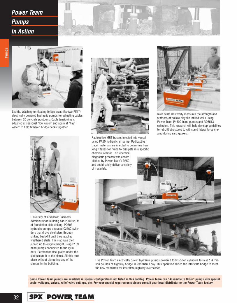
PumpsPower Team
In Action
Pum
ps
32®
Radioactive MRT tracers injected into vesselusing PA50 hydraulic air pump. Radioactivetracer materials are injected to determine howlong it takes for fluids to dissipate in a specificchemical reactor. This chemicaldiagnostic process was accom-plished by Power Team’s PA50and could safely deliver a varietyof materials.
Iowa State University measures the strength andstiffness of hollow clay tile infilled walls usingPower Team P460D hand pumps and RD5513cylinders. This research will help develop guidelinesto retrofit structures to withstand lateral force cre-ated during earthquakes.
Seattle, Washington floating bridge uses fifty-two PE174electrically powered hydraulic pumps for adjusting cablesbetween 20 concrete pontoons. Cable tensioning isadjusted at seasonal “low water” and again at “highwater” to hold tethered bridge decks together.
Five Power Team electrically driven hydraulic pumps powered forty 55 ton cylinders to raise 1.4 mil-lion pounds of highway bridge in less than a day. This operation raised the interstate bridge to meetthe new standards for interstate highway overpasses.
University of Arkansas’ BusinessAdministration building had 2000 sq. ft.of foundation slab sinking. PQ603hydraulic pumps operated C256C cylin-ders that drove steel piers throughsinking back-fill until they reachedweathered shale. The slab was thenjacked up to original height using P159hand pumps connected to the cylin-ders. Permanent steel plates under theslab secure it to the plates. All this tookplace without disrupting any of theclasses in the building.
Some Power Team pumps are available in special configurations not listed in this catalog. Power Team can “Assemble to Order” pumps with specialseals, voltages, valves, relief valve settings, etc. For your special requirements please consult your local distributor or the Power Team factory.
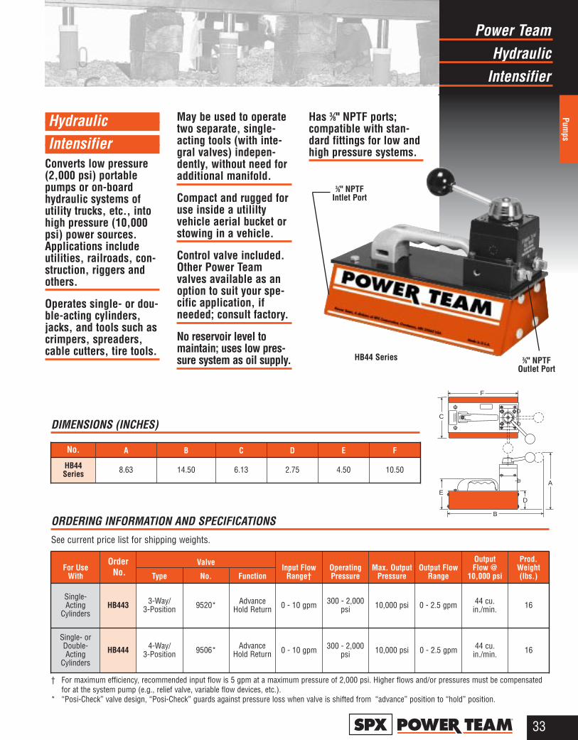
HydraulicPower Team
Intensifier
Pumps
33®
Hydraulic Intensifier
Converts low pressure(2,000 psi) portablepumps or on-boardhydraulic systems ofutility trucks, etc., intohigh pressure (10,000psi) power sources.Applications includeutilities, railroads, con-struction, riggers andothers.
Operates single- or dou-ble-acting cylinders,jacks, and tools such ascrimpers, spreaders,cable cutters, tire tools.
May be used to operatetwo separate, single-acting tools (with inte-gral valves) indepen-dently, without need foradditional manifold.
Compact and rugged foruse inside a utililtyvehicle aerial bucket orstowing in a vehicle.
Control valve included.Other Power Teamvalves available as anoption to suit your spe-cific application, ifneeded; consult factory.
No reservoir level tomaintain; uses low pres-sure system as oil supply.
Has 3⁄8" NPTF ports;compatible with stan-dard fittings for low andhigh pressure systems.
WA
RN
ING
A
B
C
DE
F
3⁄8" NPTF Outlet Port
HB44 Series
3⁄8" NPTF Intlet Port
ORDERING INFORMATION AND SPECIFICATIONSSee current price list for shipping weights.
For UseWith
OrderNo.
ValveInput Flow
Range†OperatingPressure
Max. OutputPressure
Output FlowRange
Output Flow @
10,000 psi
Prod.Weight(lbs.)
Single- Acting
CylindersHB443 3-Way/
3-Position
0 - 10 gpm 300 - 2,000psi 10,000 psi 0 - 2.5 gpm 44 cu.
in./min. 16
Single- orDouble-Acting
Cylinders
HB444 4-Way/3-Position
DIMENSIONS (INCHES)
No. A B C D E F
HB44Series 8.63 14.50 6.13 2.75 4.50 10.50
† For maximum efficiency, recommended input flow is 5 gpm at a maximum pressure of 2,000 psi. Higher flows and/or pressures must be compensatedfor at the system pump (e.g., relief valve, variable flow devices, etc.).
* “Posi-Check” valve design, “Posi-Check” guards against pressure loss when valve is shifted from “advance” position to “hold” position.
Type
9520*
9506*
No.
Advance Hold Return
Function
Advance Hold Return
0 - 10 gpm 300 - 2,000psi 10,000 psi 0 - 2.5 gpm 44 cu.
in./min. 16

HydraulicPower Team
Hand Pumps
Pum
ps
34®
Hydraulic Hand Pumps
10,000 psi capacity.
Choice of single- or 2-speed versions to powersingle- or double-actingcylinders.
Up to 21⁄2 gal. reservoircapacity. Internal reliefvalve.
All pumps except P460Series can be operatedhorizontally or verticallywith pump in the head-down position.
For operatingsingle-acting cylinders:
Single-speed pumps
No. P12—Has finger tip con-trol valve. Non-vented reser-voir. Max. handle effort: 75 lbs.No. P55—Has finger tip con-trol valve. All metal construc-tion, carrying handle andlarge oil fill port. Non-ventedreservoir. Max. handle effort:145 lbs.No. P23—Compact size witha 3,000 psi relief valve setting.Max. handle effort: 70 lbs.
Two-speed pumps
No. P19—All-metal light-weight and compact pumphas maximum handle effort of99 lbs.No. P59—All metal construc-tion, carrying handle and largeoil fill port. Non-vented reser-voir. Max. handle effort: 145lbs.
No. P59F—Foot-operatedpump with foot- or hand-operated press-to-releasevalve. Aluminum body andlever; steel non-vented reser-voir. Max. handle effort: 145lbs.Nos. P157 and P159—Allmetal construction, carryinghandle and large oil fill port.Non-vented reservoir. Max.handle effort: 140 lbs.No. P300—Same as P159except has large 11⁄2 gal.reservior with sight gauge.No. P460—All metal con-struction, carrying handle andlarge 21⁄2 gal. reservoir. Max.handle effort: 90 lbs.
For operating double-acting cylinders:
Nos. P157D and P159D—Same features as P157 andP159, except have 4-way, tan-dem center valves. Max. han-dle effort: 140 lbs.No. P300D—Same as P159Dexcept has 11⁄2 gal. reservoirwith sight gauge. No. P460D—Same as P460,but has a 4-way valve.
U.S. PatentNo.3,822,966
P12Single-Speed
P59Two-Speed
P300Two-Speed
P460Two-Speed
P59FTwo-Speed
P157/P159Two-Speed
P157D/P159DTwo-Speed
P19Two-Speed
P23Single-Speed
3,000 psi
P55Single-Speed
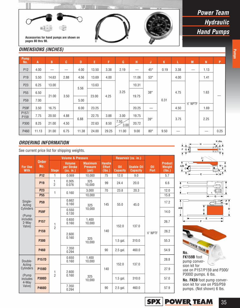
35®
HydraulicPower Team
Hand Pumps
Pumps
E M
DNA/BC
J
GF
H
G L
K dia.
+
K
G
PM
D
EF
H
A/BC
No.FK159B footpump conver-sion kit foruse on P157/P159 and P300/P300D pumps. 6 lbs.No. FK59 foot pump conver-sion kit for use on P55/P59pumps. (Not shown) 6 lbs.
Accessories for hand pumps are shown onpages 80 thru 90.
7.50 3.00
21.00 3.50
5.56
6.88
23.00 4.253.25
19.75
39°
38°
0.31
4.75
3.75
3⁄8" NPTF
1.63
2.25
—
Single-Acting
Cylinders
(Pumpincludes 2-WayValve)
Double-Acting
Cylinders
(Pumpincludes 4-WayValve)
For Use With
Order No.
Volume & Pressure
Stage
Volume per Stroke(cu. in.)
Maximum Pressure
(psi)
Handle Effort(lbs.)
Reservoir (cu. in.)
Oil Capacity
Usable OilCapacity
ProductWeight(lbs.)
Oil Port
2.6000.160
P12 1 0.069
0.160
0.6620.160
0.5500.130
0.6500.160
2.6000.160
7.3500.294
0.6500.160
7.3500.294
10,000
3,00010,000
32510,000
1,40010,000
32510,000
1,40010,000
32510,000
75
70
145
140
90
140
90
12.0 9.0
20.3
45.0
137.0
310.0
460.0
137.0
310.0
460.0
5.7
12.015.8
17.2
14.0
26.7
55.3
54.9
28.8
27.9
57.0
57.9
23.8
55.0
152.0
1.5 gal.
2.5 gal.
152.0
1.5 gal.
2.5 gal.
1
12
P23P55
P59
0.3050.076
32510,000 20.0 6.624.4991
2P19
P59F
P157
P159
P300
P460
P157D
P159D
P300D
P460D
3⁄8" NPTF
DIMENSIONS (INCHES)
ORDERING INFORMATION See current price list for shipping weights.
12
P157/P159
PumpNo. A B C D E F G H J K L M N P
P12 4.00 — — 4.00 13.50 3.38 2.19 — 45° 0.19 3.38 — 1.13
P19 5.50 14.63 2.88 4.56 13.69 4.00 11.06 53° 4.00 1.41
P23 6.25 13.00 13.63 10.31
P55 6.50
P59 7.00 5.00
P59F 3.50 16.75 6.00 23.25 20.25 — 4.50 1.69
7.75 20.50 4.88 22.75 3.88 3.00 19.75
P300 8.25 21.00 4.50 22.63 8.50 20.72
P460 11.13 31.00 6.75 11.38 24.00 29.25 11.00 9.00 80° 9.50 — — 0.25
26.2
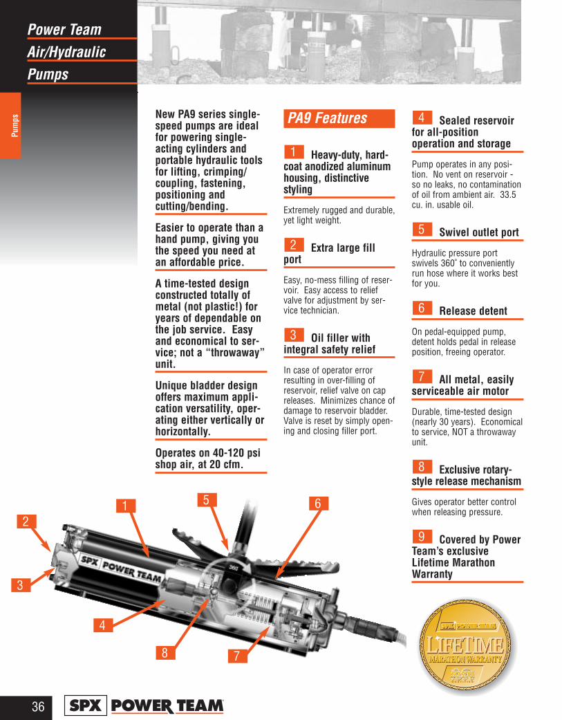
Air/HydraulicPower Team
Pumps
Pum
ps
36®
New PA9 series single-speed pumps are idealfor powering single-acting cylinders andportable hydraulic toolsfor lifting, crimping/coupling, fastening,positioning andcutting/bending.
Easier to operate than ahand pump, giving youthe speed you need atan affordable price.
A time-tested designconstructed totally ofmetal (not plastic!) foryears of dependable onthe job service. Easyand economical to ser-vice; not a “throwaway”unit.
Unique bladder designoffers maximum appli-cation versatility, oper-ating either vertically orhorizontally.
Operates on 40-120 psishop air, at 20 cfm.
PA9 Features
Heavy-duty, hard-coat anodized aluminumhousing, distinctivestyling
Extremely rugged and durable,yet light weight.
Extra large fillport
Easy, no-mess filling of reser-voir. Easy access to reliefvalve for adjustment by ser-vice technician.
Oil filler withintegral safety relief
In case of operator errorresulting in over-filling ofreservoir, relief valve on capreleases. Minimizes chance ofdamage to reservoir bladder.Valve is reset by simply open-ing and closing filler port.
Sealed reservoirfor all-position operation and storage
Pump operates in any posi-tion. No vent on reservoir -so no leaks, no contaminationof oil from ambient air. 33.5cu. in. usable oil.
Swivel outlet port
Hydraulic pressure portswivels 360˚ to convenientlyrun hose where it works bestfor you.
Release detent
On pedal-equipped pump,detent holds pedal in releaseposition, freeing operator.
All metal, easilyserviceable air motor
Durable, time-tested design(nearly 30 years). Economicalto service, NOT a throwawayunit.
Exclusive rotary-style release mechanism
Gives operator better controlwhen releasing pressure.
Covered by PowerTeam’s exclusiveLifetime MarathonWarranty
9
8
7
6
5
4
3
2
1
3
21 5 6
78
4
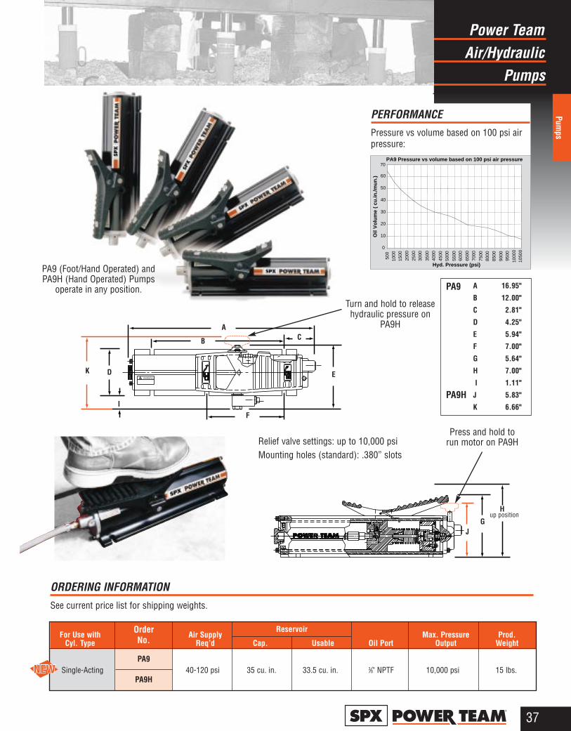
Air/HydraulicPower Team
Pumps
Pumps
37®
WARNING
A
B C
E
F
DK
PA9 Pressure vs volume based on 100 psi air pressure
0
10
20
30
40
50
60
70
500
1000
1500
2000
2500
3000
3500
4000
4500
5000
5500
6000
6500
7000
7500
8000
8500
9000
9500
1000
010
500
Hyd. Pressure (psi)
Oil
Vo
lum
e (
cu.in
./mu
n.)
PA9
PA9H
A 16.95"
B 12.00"
C 2.81"
D 4.25"
E 5.94"
F 7.00"
G 5.64"
H 7.00"
I 1.11"
J 5.83"
K 6.66"
PERFORMANCEPressure vs volume based on 100 psi airpressure:
I
Hup position
GJ
Relief valve settings: up to 10,000 psiMounting holes (standard): .380” slots
PA9 (Foot/Hand Operated) andPA9H (Hand Operated) Pumps
operate in any position.
For Use with Air Supply Max. Pressure Prod. Cyl. Type Req’d Cap. Usable Oil Port Output Weight
ORDERING INFORMATIONSee current price list for shipping weights.
PA9Single-Acting
OrderNo.
Reservoir
PA9H40-120 psi 35 cu. in. 33.5 cu. in. 3⁄8" NPTF 10,000 psi 15 lbs.
Turn and hold to releasehydraulic pressure on
PA9H
Press and hold to run motor on PA9H

Air/HydraulicPower Team
Pumps
Pum
ps
38®
Single-speed pumpsdrive single-acting ordouble-acting cylinders,are compact, light-weight and portable.For operating pressuresto 10,000 psi.
A quarter century recordof proven reliablity. TheOEM power unit ofchoice for major manu-facturers of auto bodyand frame straightenersand other equipment.
Operate at 40-100 psishop air pressure at thepump.
Internal relief valvesprotect circuit compo-nents, air inlet filterprotects motor.
All metal air motor, duc-tile iron pump.
Permanently ventedreservoir cap.
For operating single-acting cylinders:
No. PA6—Highly efficientpower unit has 98 cu. in. oil(usable), high density polyeth-ylene reservoir . No. PA6M—Same as PA6,except has metal reservoir.No. PA6M-1—Same as PA6,except has 1 gallon metalreservoir.No. PA6-2—Same as PA6except has 2 gallon, high den-sity polyethylene reservoir.No. PA6M-2—Same as PA6except has 21⁄2 gallon metalreservoir.No. PA6A—Same as PA6 withan externally adjustable reliefvalve.No. PA6AM—Same as PA6Aexcept has metal reservoir.
For operating single- ordouble-acting cylinders:
No. PA6D—Has 9504 3-way/4way valve, 98 cu. in. oil(usable), high density polyeth-ylene reservoir.No. PA6DM—Same as PA6Dexcept has metal reservoir.No. PA6DM-1—Same asPA6D except has 1 gallonmetal reservoir.No. PA6D2—Same as PA6Dexcept has 2 gallon, high den-sity polyethylene reservoir.No. PA6DM-2—Same asPA6D, except has 21⁄2 gallonmetal reservoir.
Metal reservoir conversion kits
Metal reservoirs are availableto convert these pumps fromhigh density polyethylene tometal reservoirs.No. 213896 – Metal reservoir,(for PA6, PA6A, PA6D) 105cu. in. capacity. Includes gas-ket and fasteners. Wt., 3 lbs.No 213895 – Steel reservoir, (for PA6-2 and PA6D2); 21⁄2gallon capacity. Includes gas-ket and fasteners. Wt., 9 lbs.
9531 filter/regulator/lubricator, air
Recommended for use with single-speed air/hydraulicpumps found on this page.
See pages 80 thru 90 for hydraulicaccessories.
PA6DM-1
dBA 85 at 10,000 psi for all PA6 series pumps.PA6D2
PA6DM-2PA6-2
PA6M-2
PA6, PA6A,PA6M, PA6AM
PA6DPA6DM
PA6M-1
U.S. Patent No.: 4,352,644 and 3,788,781
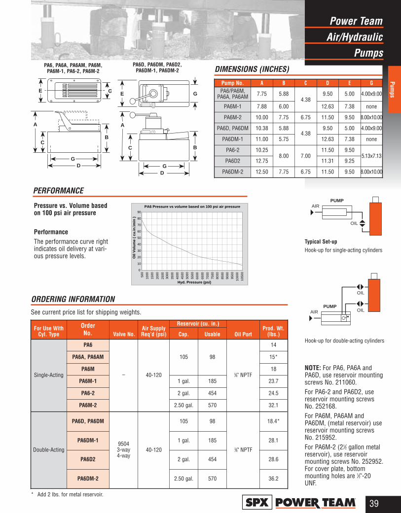
Air/HydraulicPower Team
Pumps
Pumps
39®
NOTE: For PA6, PA6A andPA6D, use reservoir mountingscrews No. 211060.For PA6-2 and PA6D2, use reservoir mounting screws No. 252168.For PA6M, PA6AM andPA6DM, (metal reservoir) usereservoir mounting screwsNo. 215952.For PA6M-2 (21⁄2 gallon metalreservoir), use reservoirmounting screws No. 252952.For cover plate, bottommounting holes are 1⁄2"-20UNF.
PERFORMANCE
Pressure vs. Volume basedon 100 psi air pressure
PerformanceThe performance curve rightindicates oil delivery at vari-ous pressure levels.
A
C
GD
B
GE
GD
B
A
C
E G
Typical Set-upHook-up for single-acting cylinders
PA6, PA6A, PA6AM, PA6M,PA6M-1, PA6-2, PA6M-2
PA6D, PA6DM, PA6D2, PA6DM-1, PA6DM-2
Hook-up for double-acting cylinders
OrderNo. Valve No. Oil Port
Double-Acting
Reservoir (cu. in.)For Use With
Cyl. TypeAir SupplyReq’d (psi) Cap. Usable
Prod. Wt. (lbs.)
Single-Acting
PA6
– 40-120
105 98
3⁄8" NPTF
14
PA6A, PA6AM 15*
PA6M 18
PA6M-2 2.50 gal. 570 32.1
PA6D, PA6DM 105 98 18.4*
PA6D2 28.6
* Add 2 lbs. for metal reservoir.
ORDERING INFORMATION See current price list for shipping weights.
2 gal. 454
PA6M-1 23.71 gal. 185
PA6DM-1 1 gal. 185 28.1
PA6-2 24.52 gal. 454
2.50 gal. 570PA6DM-2 36.2
DIMENSIONS (INCHES)
Pump No. A B C D E GPA6/PA6M,
PA6A, PA6AM 7.75 5.884.38
9.50 5.00 4.00x9.00
PA6M-1 7.88 6.00 12.63 7.38 none
PA6M-2 10.00 7.75 6.75 11.50 9.50 8.00x10.00
PA6D, PA6DM 10.38 5.884.38
9.50 5.00 4.00x9.00
PA6DM-1 11.00 5.75 12.63 7.38 none
PA6-2 10.258.00 7.00
11.50 9.505.13x7.13
PA6D2 12.75 11.31 9.25
PA6DM-2 12.50 7.75 6.75 11.50 9.50 8.00x10.00
95043-way4-way
40-120 3⁄8" NPTF
PA6 Pressure vs volume based on 100 psi air pressure
0
10
20
30
40
50
60
70
80
90
Hyd. Pressure (psi)
Oil
Vo
lum
e (
cu.in
.\min
)
500
1000
1500
2000
2500
3000
3500
4000
4500
5000
5500
6000
6500
7000
7500
8000
8500
9000
9500
1000
0
1050
0
AIRPUMP
OIL
AIRPUMP
OIL
OIL
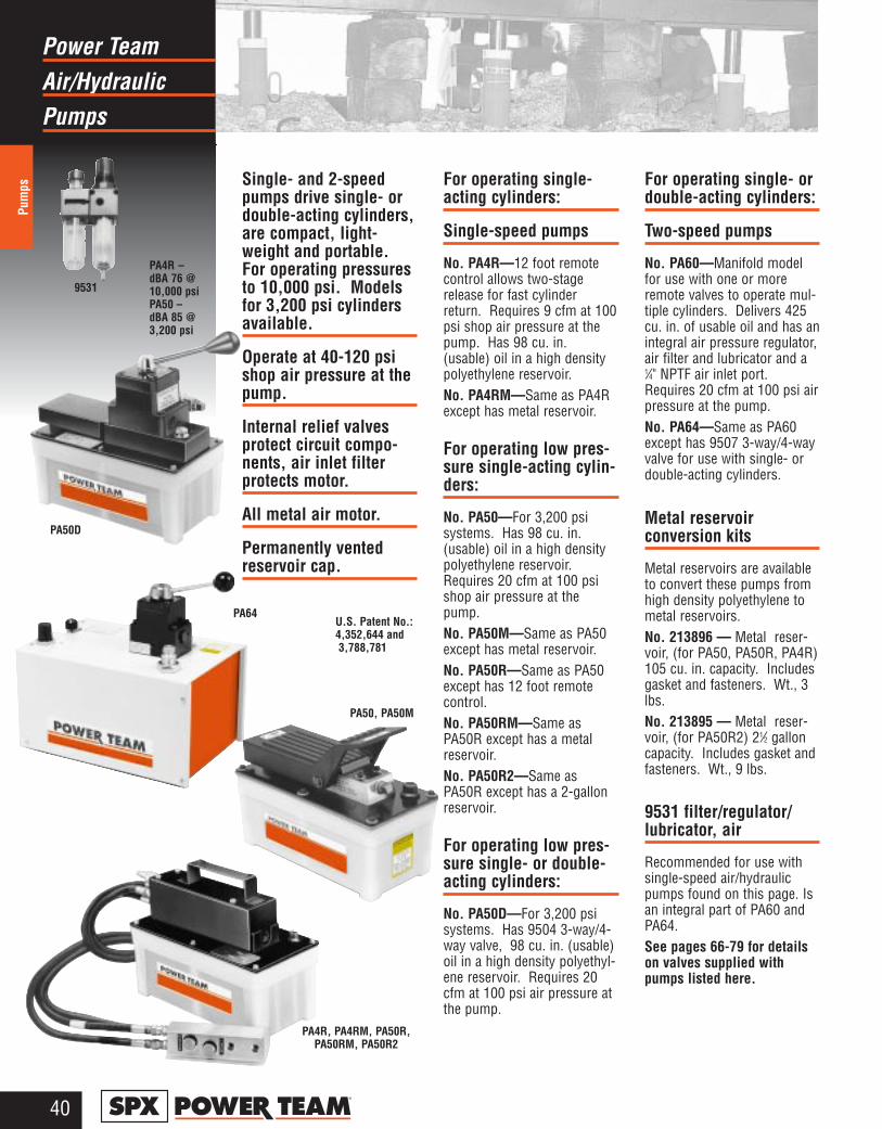
Air/HydraulicPower Team
Pumps
Pum
ps
40®
Single- and 2-speedpumps drive single- ordouble-acting cylinders,are compact, light-weight and portable.For operating pressuresto 10,000 psi. Modelsfor 3,200 psi cylindersavailable.
Operate at 40-120 psishop air pressure at thepump.
Internal relief valvesprotect circuit compo-nents, air inlet filterprotects motor.
All metal air motor.
Permanently ventedreservoir cap.
For operating single-acting cylinders:
Single-speed pumps
No. PA4R—12 foot remotecontrol allows two-stagerelease for fast cylinderreturn. Requires 9 cfm at 100psi shop air pressure at thepump. Has 98 cu. in.(usable) oil in a high densitypolyethylene reservoir.No. PA4RM—Same as PA4Rexcept has metal reservoir.
For operating low pres-sure single-acting cylin-ders:
No. PA50—For 3,200 psisystems. Has 98 cu. in.(usable) oil in a high densitypolyethylene reservoir.Requires 20 cfm at 100 psishop air pressure at thepump.No. PA50M—Same as PA50except has metal reservoir.No. PA50R—Same as PA50except has 12 foot remotecontrol.No. PA50RM—Same asPA50R except has a metalreservoir.No. PA50R2—Same asPA50R except has a 2-gallonreservoir.
For operating low pres-sure single- or double-acting cylinders:
No. PA50D—For 3,200 psisystems. Has 9504 3-way/4-way valve, 98 cu. in. (usable)oil in a high density polyethyl-ene reservoir. Requires 20cfm at 100 psi air pressure atthe pump.
For operating single- ordouble-acting cylinders:
Two-speed pumps
No. PA60—Manifold modelfor use with one or moreremote valves to operate mul-tiple cylinders. Delivers 425cu. in. of usable oil and has anintegral air pressure regulator,air filter and lubricator and a1⁄4" NPTF air inlet port.Requires 20 cfm at 100 psi airpressure at the pump.No. PA64—Same as PA60except has 9507 3-way/4-wayvalve for use with single- ordouble-acting cylinders.
Metal reservoir conversion kits
Metal reservoirs are availableto convert these pumps fromhigh density polyethylene tometal reservoirs.No. 213896 — Metal reser-voir, (for PA50, PA50R, PA4R)105 cu. in. capacity. Includesgasket and fasteners. Wt., 3lbs.No. 213895 — Metal reser-voir, (for PA50R2) 21⁄2 galloncapacity. Includes gasket andfasteners. Wt., 9 lbs.
9531 filter/regulator/lubricator, air
Recommended for use with single-speed air/hydraulicpumps found on this page. Isan integral part of PA60 andPA64.See pages 66-79 for detailson valves supplied withpumps listed here.
U.S. Patent No.: 4,352,644 and 3,788,781
PA4R, PA4RM, PA50R,PA50RM, PA50R2
PA50, PA50M
PA50D
PA64
9531
PA4R – dBA 76 @10,000 psiPA50 – dBA 85 @3,200 psi
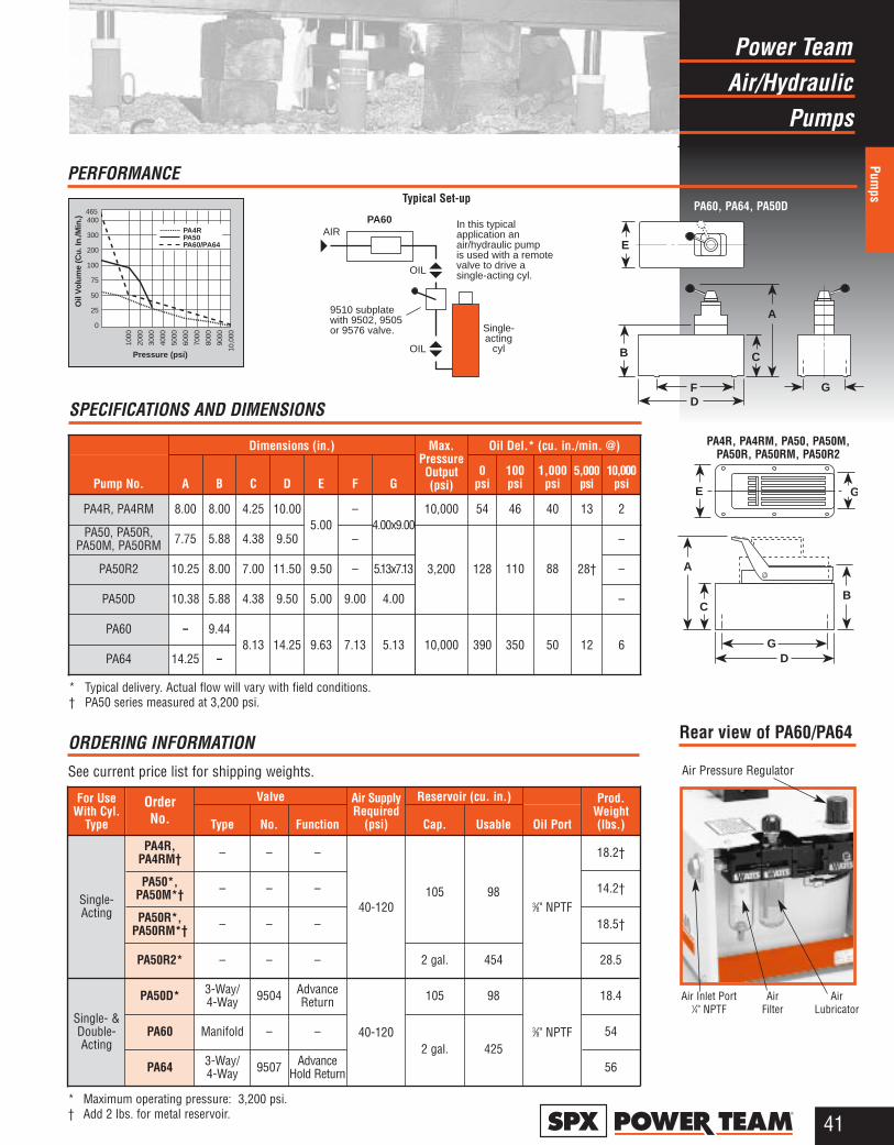
Air/HydraulicPower Team
Pumps
Pumps
41®
PERFORMANCE
Oil
Vo
lum
e (C
u. I
n./M
in.)
Pressure (psi)
1000
2000
3000
4000
5000
6000
7000
8000
9000
10,0
00PA4RPA50PA60/PA64
465400
300
200
100
75
50
25
0A
C
F
B
D
E
G
AIRPA60
OIL
OIL
Single-acting
cyl
9510 subplatewith 9502, 9505or 9576 valve.
In this typicalapplication anair/hydraulic pumpis used with a remotevalve to drive asingle-acting cyl.
GD
B
A
C
E G
PA4R, PA4RM, PA50, PA50M,PA50R, PA50RM, PA50R2
PA60, PA64, PA50DTypical Set-up
AirLubricator
AirFilter
Air Inlet Port1⁄4" NPTF
Air Pressure Regulator
Rear view of PA60/PA64
Single-Acting
OrderNo.
Prod.Weight(lbs.)
Air SupplyRequired
(psi)
ORDERING INFORMATION See current price list for shipping weights.
* Maximum operating pressure: 3,200 psi.† Add 2 lbs. for metal reservoir.
Valve Reservoir (cu. in.)For UseWith Cyl.
Type Type No. Function Cap. Usable
PA4R,PA4RM† – – –
40-120105 98
PA50*,PA50M*† – – –
PA50R*,PA50RM*† – – –
PA50R2* – – – 2 gal. 454
Single- &Double-Acting
PA60 Manifold – –2 gal. 425
PA64 3-Way/4-Way 9507 Advance
Hold Return
Oil Port
3⁄8" NPTF
18.2†
14.2†
18.5†
28.5
54
56
PA50D* 3-Way/4-Way 9504 Advance
Return 105 98 18.4
SPECIFICATIONS AND DIMENSIONS
Dimensions (in.) Oil Del.* (cu. in./min. @)
PA4R, PA4RM 8.00 8.00 4.25 10.005.00
–4.00x9.00
10,000 54 46 40 13 2
PA50, PA50R,PA50M, PA50RM 7.75 5.88 4.38 9.50 – –
PA60 – 9.448.13 14.25 9.63 7.13 5.13 10,000 390 350 50 12 6
PA64 14.25 –
Pump No. A B C D E F G
Max.PressureOutput(psi)
0 psi
100psi
1,000psi
10,000psi
PA50R2 10.25 8.00 7.00 11.50 9.50 – 5.13x7.13 –
* Typical delivery. Actual flow will vary with field conditions.† PA50 series measured at 3,200 psi.
PA50D 10.38 5.88 4.38 9.50 5.00 9.00 4.00 –
110 88 28†1283,200
3⁄8" NPTF40-120
5,000psi
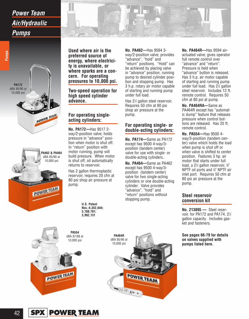
Air/HydraulicPower Team
Pumps
Pum
ps
42®
Used where air is thepreferred source ofenergy, where electrici-ty is unavailable, orwhere sparks are a con-cern. For operatingpressures to 10,000 psi.
Two-speed operation forhigh speed cylinderadvance.
For operating single-acting cylinders:
No. PA172—Has 9517 2-way/2-position valve; holdspressure in “advance” posi-tion when motor is shut off.In “return” position withmotor running, pump willbuild pressure. When motoris shut off, oil automaticallyreturns to reservoir.Has 2 gallon thermoplasticreservoir, requires 20 cfm at80 psi shop air pressure atpump.
No. PA462—Has 9584 3-way/2-position valve; provides“advance”, “hold” and“return” positions. “Hold” canbe achieved by placing valvein “advance” position, runningpump to desired cylinder posi-tion and stopping pump. Has3 h.p. rotary air motor capableof starting and running pumpunder full load.Has 21⁄2 gallon steel reservoir.Requires 50 cfm at 80 psishop air pressure at thepump.
For operating single- ordouble-acting cylinders:
No. PA174—Same as PA172except has 9500 4-way/3-position (tandem center)valve for use with single- ordouble-acting cylinders..No. PA464—Same as PA462except has 9500 4-way/3-position (tandem center)valve for two single-actingcylinders or one double-actingcylinder. Valve provides“advance”, “hold” and“return” positions withoutstopping pump.
No. PA464R—Has 9594 air-actuated valve; gives operatorfull remote control over“advance” and “return”.Pressure is held when“advance” button is released.Has 3 h.p. air motor capableof starting and running pumpunder full load. Has 21⁄2 gallonsteel reservoir. Includes 12 ft.remote control. Requires 50cfm at 80 psi at pump.No. PA464RA—Same asPA464R except has “automat-ic dump” feature that releasespressure when control but-tons are released. Has 25 ft.remote control.No. PA554—Has 9500 4-way/3-position (tandem cen-ter) valve which holds the loadwhen pump is shut off orwhen valve is shifted to centerposition. Features 3 hp. airmotor that starts under fullload, a 21⁄2 gallon reservoir, 3⁄8"NPTF oil ports and 3⁄8" NPTF airinlet port. Requires 50 cfm at80 psi air pressure at thepump.
Steel reservoir conversion kit
No. 213895 — � Steel reser-voir, for PA172 and PA174, 21⁄2gallon capacity. Includes gas-ket and fasteners.
See pages 66-79 for detailson valves supplied withpumps listed here.
PA172dBA 85/90 at10,000 psi
U.S. PatentNos.:4,352,644;3,788,781;3,992,131
PA464RdBA 85/90 at10,000 psi
PA554dBA 87/88 at 10,000 psi
PA462 & PA464dBA 85/90 at10,000 psi
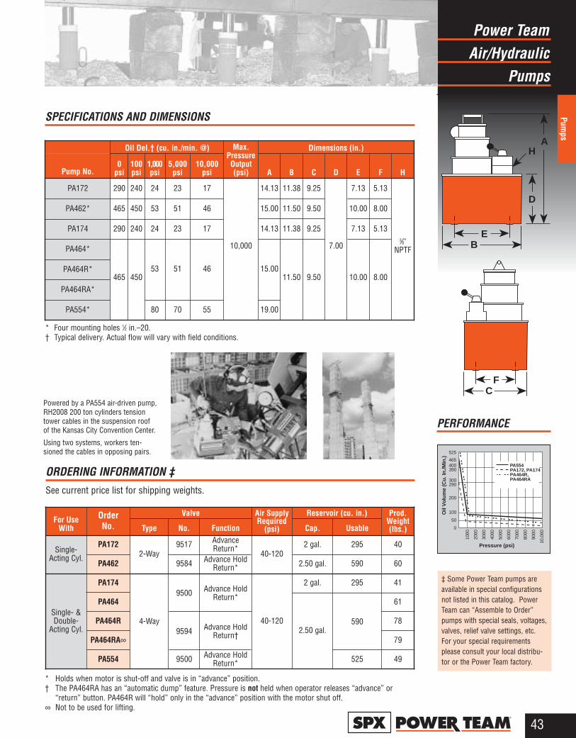
Air/HydraulicPower Team
Pumps
Pumps
43®
PERFORMANCE
525
Oil
Vo
lum
e (C
u. I
n./M
in.)
Pressure (psi)
1000
2000
3000
4000
5000
6000
7000
8000
9000
10,0
00
PA554PA172, PA174PA464R,PA464RA
465400390
300290
200
100
50
0
D
A
EB
H
FC
OrderNo.
ORDERING INFORMATION ‡ See current price list for shipping weights.
Valve Air SupplyRequired
(psi)
Reservoir (cu. in.) Prod.Weight(lbs.)
For UseWith Type No. Function Cap. Usable
Single-Acting Cyl.
PA1722-Way
9517 AdvanceReturn*
40-1202 gal. 295 40
Single- &Double-
Acting Cyl.
PA174
4-Way
9500 Advance HoldReturn*
2 gal. 295 41
PA462 9584 Advance HoldReturn* 2.50 gal. 590 60
PA464
2.50 gal.590
61
PA464R9594 Advance Hold
Return†
40-120 78
PA464RA∞ 79
PA554 9500 Advance HoldReturn* 525 49
* Holds when motor is shut-off and valve is in “advance” position.† The PA464RA has an “automatic dump” feature. Pressure is not held when operator releases “advance” or
“return” button. PA464R will “hold” only in the “advance” position with the motor shut off.∞ Not to be used for lifting.
Dimensions (in.)
PA462*
Oil Del.† (cu. in./min. @)
15.00 11.50 9.50
PA172 14.13 11.38 9.25
7.00
7.13 5.13
3⁄8"NPTF10,000
290 240 24 23 17
PA174 14.13 11.38 9.25 7.13 5.13290 240 24 23 17
PA464*
15.0011.50 9.50 10.00 8.00465 450
53 51 46PA464R*
Pump No. A B C D E F H
Max.PressureOutput(psi)
0psi
100psi
1,000psi
5,000psi
10,000psi
10.00 8.00465 450 53 51 46
PA554* 19.0080 70 55
PA464RA*
* Four mounting holes 1⁄2 in.–20.† Typical delivery. Actual flow will vary with field conditions.
SPECIFICATIONS AND DIMENSIONS
‡ Some Power Team pumps areavailable in special configurationsnot listed in this catalog. PowerTeam can “Assemble to Order”pumps with special seals, voltages,valves, relief valve settings, etc.For your special requirementsplease consult your local distribu-tor or the Power Team factory.
Powered by a PA554 air-driven pump,RH2008 200 ton cylinders tensiontower cables in the suspension roofof the Kansas City Convention Center.
Using two systems, workers ten-sioned the cables in opposing pairs.

Quarter HorsePower Team
Electric Pumps
Pum
ps
44®
The Quarter Horse® is aperfect portable powersource for hydrauliccylinders, spreaders,punches, nut splitters,pipe flange spreadersand other tools. Weighsjust 20 lbs.
Powered by a 1⁄4 h.p.,6,000 rpm, permanentmagnet motor that startseasily under load, evenwith reduced voltageconditions.
For operating pressuresto 10,000 psi. Pumpsfor 3,000 psi and 5,000psi operating pressuresalso available: consultfactory.
Battery-operated modelshave 8 foot power cordwith alligator clips toconnect to any 12 voltbattery. Optionalrechargeable batterypack with shoulder strapfor maximum portabilityalso available. Pumptypically delivers 15minutes of continuousoperation at 10,000 psion a single batterycharge, or 20 minutes ofcontinuous operation at5,000 psi.
Bladder type reservoir(60 cu. in. usable)enables pump to beoperated in any position.
For operating single-acting cylinders:
No. PE102—Has 2-way valve.“Advance” position holdspressure with motor shut off;“return” position advancescylinder with motor running,automatically returns cylinderwith motor shut off.No. PE102A—Has manifold.Cylinder advances with motorrunning and automaticallyreturns with motor shut off.
For operating double-acting cylinders:
No. PR104—Has 4-way valveand 8 foot alligator clip cord;for 12 volt DC use only.Provides cylinder “advance”,“hold” and “return” positions.See “Ordering Information”on opposite page for listingof all Quarter Horse® pumpversions available.
Example of QuarterHorse® work capability:
Using a fully charged batterypack with a PR102 pump anda Power Team HP35 hydraulicpunch, eighty 0.75" dia. holescan be punched in 0.38" mildsteel plate in less than onehour!
PE10 Series Quarter Horse®
PE102
PE102A
PR104
LR19814
• The optional, externally-adjustablepressure regulator can be easilyinstalled on all pumps
• Two speed high performance in acompact package
• Light in weight (Only 20 lbs.with oil)
• Low noise level (68-74 dbaat 3 ft.)
• Optional 24 volt hand and footswitches available for all AC pow-ered pump models
• Bladder-type oil reservoir allowspump to operate in any position.
• High-impact housing with flame-retardant construction. Has basemounting holes for fixed installa-tion if desired.

* “Advance” position holds pressure with motor shut off. “Return” position advances cylinder with motor running and returns cylinder with motor shut off.
Note: Amp draw at 10,000 psi; 6 amp at 115 volt, 3 amp at 230 volt, and 25 amp at 12 volt.
Quarter HorsePower Team
Electric Pumps
Pumps
45®
RC12V – Replacement 4 ft.battery cord only. Wt., .5 lbs.
Battery Charger Only – Willrecharge RB12V battery in11⁄2 hr. See below for part nos.BC12 – Battery charger forU.S.A. Wt., 6.6 lbs.BC12EUR – Battery chargerfor Europe. Wt., 6.6 lbs.BC12AUS – Battery chargerfor Australia. Wt., 6.6 lbs.9560 – Pressure regulator.Adjustable from 1,000 to10,000 psi.All mount-ing hard-wareincluded.Wt., 3 lbs.25017 – Remote hand controlwith 10 ft. cord. Wt., 0.8 lb.
ACCESSORIES
RB12V
RC12V
BP12VQ – Optional 12 voltbattery pack. Includes sealedlead acid battery, 115V charg-er, 4 ft. cord, carrying caseand shoulder strap. Wt., 17.7lbs.
251660 – Foot switch with 10ft. cord. Single pole, doublethrow, 15 amp @ 125-250VAC. Wt., 1 lb.
BP12INT – Battery with cordand carrying case. Wt., 11.1lbs.RB12V – Replacement batteryonly. Wt., 10.4 lbs.
250
200
150
100
50
0
Oil
Vol
ume
(Cu.
In./M
in.)
Pressure (psi)
100
500
1000
2000
3000
4000
5000
7000
10,0
00
PE10, PR10Series
PERFORMANCE
The Quarter Horse pump has a maxi-mum operating pressure of 10,000psi, which handles a wide variety ofhand held hydraulic tools.
Battery-operated
modelsallow for a
greaterdegree ofportability
and versatili-ty in remotelocations or
on smalljobs wheresetup canslow you
down.
PE104
PE102-220
PR102
For Use Order Valve Control Reservoir With No. Type No. Function Switch Motor Cap.
Single-Acting
Cylinders
AdvanceReturn (Auto.)*
AdvanceReturn
AdvanceReturn(Auto.)*
AdvanceReturn
AdvanceReturn(Auto.)*
AdvanceReturn
AdvanceHold Return
2–Way/Auto.Dump
Auto.Dump
PE102
PE102A
PE102A-220
PR102A
1⁄4 hp, 110/115V50/60 Hz,
Single Phase
(60 cu. in.usable)
(60 cu. in.usable)
1⁄4 hp, 220/230V50/60 Hz,
Single Phase
1⁄4 hp, 12V
PE104-220
PR104
1⁄4 hp, 110/115V50/60 Hz, Single Phase
1⁄4 hp, 12V
Double-Acting
Cylinders
2–Way/Auto.Dump
Auto.Dump
2–Way/Auto.Dump
Auto.Dump
4–Way
RockerType off,Momen-tary on
RockerType off,Momen-tary on
9561
9562
9561
9562
9561
9562
95631⁄4 hp, 220/230V
50/60 Hz, Single Phase
ORDERING INFORMATION See current price list for shipping weights.
Oil Delivery(cu. in./min.)
Pump No.
Max.PressureOutput
dBa atidle and10,000
psi0-400
psi10,000
psiOverall
Dimensions
Prod.Weightwith Oil(lbs.)
PE10 SeriesPR10 Series
10,000psi 68–74* 120 10 13.00"Lx7.75"W
x8.00"H 20
SPECIFICATIONS AND DIMENSIONS
NOTE: PR10 rechargeable model is equipped with 8 ft. cord with alligatorclip. Order optional battery pack No. BP12VQ or use with any 12volt battery.
* Measured at 3 ft. distance, all sides.NOTE: High pressure flow on 5,000 psi unit is 20 cu. in./min. Flow on
3,000 psi unit is 30 cu. in./min. Consult factory for further infor-mation.
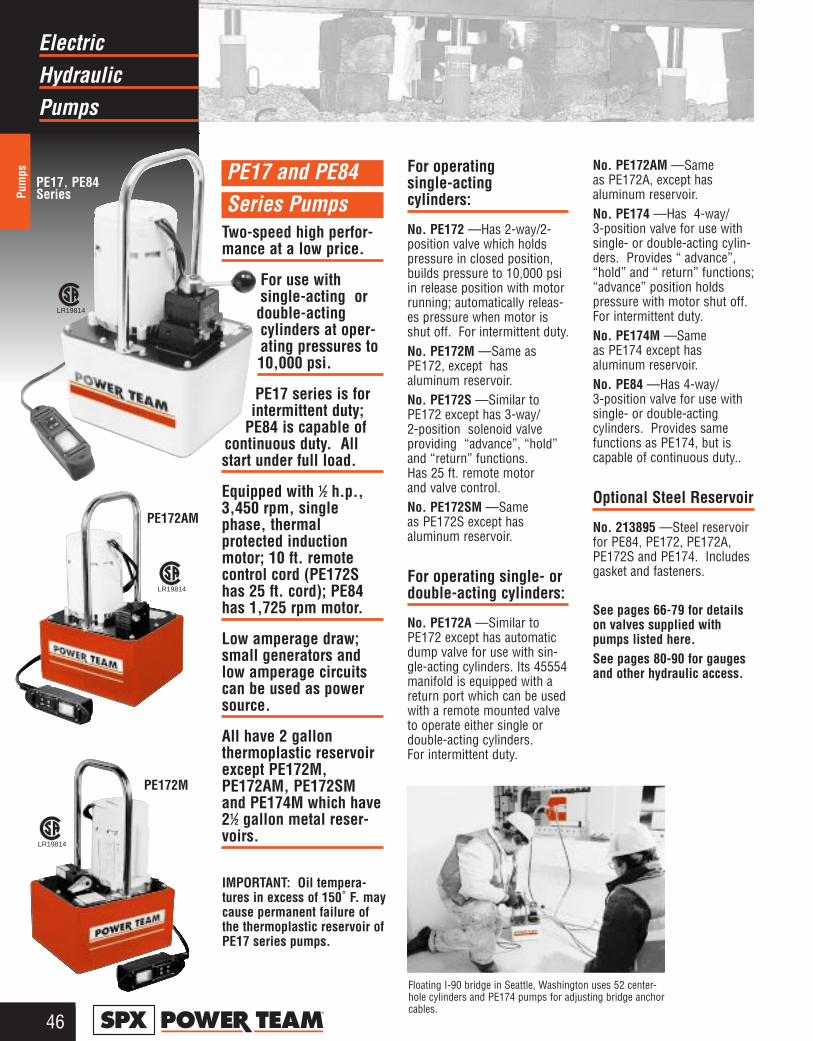
HydraulicElectric
Pumps
Pum
ps
46®
PE172AM
PE172M
PE17 and PE84Series Pumps
Two-speed high perfor-mance at a low price.
For use with single-acting or
double-actingcylinders at oper-ating pressures to10,000 psi.
PE17 series is forintermittent duty;
PE84 is capable of continuous duty. Allstart under full load.
Equipped with 1⁄2 h.p.,3,450 rpm, singlephase, thermal protected inductionmotor; 10 ft. remotecontrol cord (PE172Shas 25 ft. cord); PE84has 1,725 rpm motor.
Low amperage draw;small generators andlow amperage circuitscan be used as powersource.
All have 2 gallon thermoplastic reservoirexcept PE172M,PE172AM, PE172SMand PE174M which have21⁄2 gallon metal reser-voirs.
For operating single-acting cylinders:
No. PE172 —Has 2-way/2-position valve which holdspressure in closed position,builds pressure to 10,000 psiin release position with motorrunning; automatically releas-es pressure when motor isshut off. For intermittent duty. No. PE172M —Same asPE172, except has aluminum reservoir.No. PE172S —Similar toPE172 except has 3-way/ 2-position solenoid valve providing “advance”, “hold”and “return” functions. Has 25 ft. remote motorand valve control.No. PE172SM —Same as PE172S except has aluminum reservoir.
For operating single- ordouble-acting cylinders:
No. PE172A —Similar toPE172 except has automaticdump valve for use with sin-gle-acting cylinders. Its 45554manifold is equipped with areturn port which can be usedwith a remote mounted valveto operate either single ordouble-acting cylinders. For intermittent duty.
No. PE172AM —Same as PE172A, except hasaluminum reservoir.No. PE174 —Has 4-way/ 3-position valve for use withsingle- or double-acting cylin-ders. Provides “ advance”,“hold” and “ return” functions;“advance” position holds pressure with motor shut off.For intermittent duty.No. PE174M —Same as PE174 except has aluminum reservoir.No. PE84 —Has 4-way/3-position valve for use withsingle- or double-acting cylinders. Provides samefunctions as PE174, but iscapable of continuous duty..
Optional Steel Reservoir
No. 213895 —Steel reservoirfor PE84, PE172, PE172A,PE172S and PE174. Includesgasket and fasteners.
See pages 66-79 for detailson valves supplied withpumps listed here.See pages 80-90 for gaugesand other hydraulic access.
LR19814
LR19814
LR19814
PE17, PE84Series
Floating I-90 bridge in Seattle, Washington uses 52 center-hole cylinders and PE174 pumps for adjusting bridge anchorcables.
IMPORTANT: Oil tempera-tures in excess of 150˚ F. maycause permanent failure ofthe thermoplastic reservoir ofPE17 series pumps.

47®
HydraulicElectric
Pumps
Pumps
A
B
E
DC F
G
PE84PE17 Series
500
400
300
200
100
0
Oil
Vo
lum
e (C
u. I
n./M
in.)
Pressure (psi)
100
500
1000
2000
3000
4000
5000
7000
10,0
00
‡ Some Power Team pumps areavailable in special configurationsnot listed in this catalog. PowerTeam can “Assemble to Order”pumps with special seals, voltages,valves, relief valve settings, etc.For your special requirementsplease consult your local distribu-tor or the Power Team factory.
PERFORMANCE
ValveType No. Function
Reservoir(Usable)Cap.Motor
Control Switch ††
For UseWith
OrderNo.
Oil Del. (cu. in./min. @)†
* Measured at 3 ft. distance, all sides. † Typical delivery. Actual flow will vary with field conditions.
* Available with 220 V., 50 Hz motor (to order, place suffix “50-220” behind pump order number). ** Usable oil is calculated with the oil fill at the recommended level of 1.50” below reservoir cover plate.*** “Advance” position holds pressure with motor shut off.† “Advance” position holds pressure with motor shut off. “Return” position advances cylinder with motor
running and returns cylinder with motor shut off.†† Control switch on PE17 series wired with line voltage.∞ Not to be used for lifting.NOTE: The remote motor control switch on 220V., 50 cycle PE17 series pumps is 24 volt.
SPECIFICATIONS AND DIMENSIONS
ORDERING INFORMATION ‡See current price list for shipping weights.
Single-Acting
Cyl.
PE172A∞ Auto/DumpManifold Advance Return
Remote Motor Control (10 ft.) on/off
1⁄2 hp 110/115 V*50/60 Hz, Single Phase
2 gal. ** 295 cu. in.
PE172AM∞ 2.50 gal. ** 375 cu. in.
PE1722-Way
Advance Return(Auto†)
2 gal. ** 295 cu. in.
PE172M 2.50 gal. ** 375 cu. in.
PE172S3-Way Advance Hold
ReturnRemote Motor &
Valve (10 ft.)1⁄2 hp 110/115 VAC
50/60 Hz, Single Phase2 gal.** 295 cu. in.
PE172SM 2.50 gal.** 375 cu. in.
Double-or MultiSingle-Acting
Cyl.
PE84
4-Way Advance HoldReturn***
Remote Motor Control (10 ft.) on/off
1⁄2 hp 115 V* 60 Hz, Single Phase2 gal.** 295 cu. in.
PE174 1⁄2 hp 110/115 V*50/60 Hz, Single PhasePE174M 2.50 gal.** 375 cu. in.
45554
9517
9579
9500
Max. dBA at Amp Draw Dimensions (in.) Prod. Wt.Press. Idle and 115 V - at 0 100 5,000 10,000 With Oil
Pump No. Output rpm 10,000 psi 10,000 psi psi psi psi psi A B C D E F G (lbs.)PE17 18.50 7.00 11.38 7.13 14.88 9.25 5.13 45Series
PE17M 10,000 3,45067/81* 10
290 190 20 1618.13 6.63 11.50 N/A 14.50 9.50 N/A 53Series psi
PE84 1,750 145 120 12 8 18.50 7.00 11.38 7.13 15.38 9.25 5.13 47

HydraulicElectric
Pumps
Pum
ps
48®
Two-speed high perfor-mance in a lightweight,compact package.
For use with single- ordouble-acting cylindersat operating pressuresto 10,000 psi.
Equipped with a 11⁄2 hp,3,450 rpm single phase,60 Hz thermal protectedinduction motor thatstarts under full load.Noise level of 77-81dBA.
CSA rated for intermit-tent duty.
All equipped with a 10foot remote controlexcept PE462S whichhas a 25 foot remotecontrol.
For operating single-acting cylinders:
No. PE462—Has 9584 3-way/2-position valve providing“advance” and “return” func-tions.No. PE462S—Similar toPE462 but has solenoid oper-ated 9579 3-way/2-positionvalve that controls “advance”and “return” functions.Equipped with a 24 volt, 25foot remote motor and valvecontrol.No. PE462A—Has 9610 3-way/2-position, pilot-operated“dump” valve. When pump isstarted, pilot oil automaticallycloses valve and oil is directedto cylinder. When pump isstopped, valve automaticallyopens and oil returns to reser-voir.
For operating single- ordouble-acting cylinders:
No. PE464—Has 9500 4-way/3-position valve providing“advance”, “hold” and“return” functions on double-acting or multiple single-act-ing cylinders.No. PE464S—Has a solenoidoperated 9592 3/4way/2-posi-tion valve which controls the“advance” and “return” func-tions.
See pages 66-79 for detailson valves supplied withpumps listed here.
PE464
LR19814
PE462A
LR19814
PE462S
U.S. Patent No. 3,053,186
LR19814
Super-conducting electromagnets ofthe type used in levitating trains andin high-power scientific apparatusmust be cooled to -452˚ F. in order towork. When turned off, they must bewarmed to room temperature.
The firm that manufactures stripheaters which warm the magnetstests them on a custom-built fixtureunder operating level mechanicalstress for insulation integrity. A fail-ure in the heater's insulation couldshort the magnets.
The successful test fixture uses aPower Team RLS1500S 150 tonhydraulic cylinder powered by aPE464S pump. A timing circuit helpsautomate the tests. Under 10,000psi mechanical pressure, the strip issubjected to 2,000 volts. Heatersthat fail are rejected.
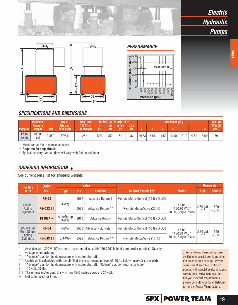
HydraulicElectric
Pumps
Pumps
49®
‡ Some Power Team pumps areavailable in special configurationsnot listed in this catalog. PowerTeam can “Assemble to Order”pumps with special seals, voltages,valves, relief valve settings, etc.For your special requirementsplease consult your local distribu-tor or the Power Team factory.
A
B
GF
DC
E
500
400
300
200
100
0
Oil
Vo
lum
e (C
u. I
n./M
in.)
Pressure (psi)
100
500
1000
2000
3000
4000
5000
7000
10,0
00
PE46 Series
PERFORMANCE
MotorControl Switch †††For Use
WithOrderNo.
* Available with 220 V., 50 Hz motor (to order, place suffix “50-220” behind pump order number). Specifyvoltage when ordering.
** “Advance” position holds pressure with motor shut off.*** Usable oil is calculated with the oil fill at the recommended level of .50 in. below reservoir cover plate.† “Advance” position holds pressure with motor shut off. “Return” position returns cylinder.†† 115 volt, 60 Hz.††† The remote motor control switch on PE46 series pumps is 24 volt.∞ Not to be used for lifting.
ORDERING INFORMATION ‡See current price list for shipping weights.
Valve Reservoir
Type No. Cap. Usable
Single-Acting
Cylinders
PE462
3-Way
9584 Remote Motor Control (10 ft.) On/Off
11⁄2 hp 115/230 VAC*
60 Hz, Single Phase
2.50 gal.***
590 cu. in.PE462S †† 9579 Remote Motor/Valve (25 ft.)
PE462A ∞ Auto/Dump 3-Way 9610 Remote Motor Control (10 ft.) On/Off
Double- orMulti Single-
ActingCylinders
PE464 4-Way 9500 Remote Motor Control (10 ft.) On/Off 11⁄2 hp 115/230 VAC*
60 Hz, Single Phase
2.50 gal.***
590 cu. in.
PE464S †† 3/4-Way 9592 Remote Motor/Valve (10 ft.)
Function
Advance Return †
Advance Return **
Advance Return
Advance Hold Return †
Advance Return **
Oil Del. (cu. in./min. @)†
SPECIFICATIONS AND DIMENSIONS
* Measured at 3 ft. distance, all sides. ** Requires 20 amp circuit.† Typical delivery. Actual flow will vary with field conditions.
Maximum dBA at Amp Draw Dimensions (in.) Prod. Wt.Pressure Idle and 115 V - at 0 100 5,000 10,000 With Oil
Pump No. Output rpm 10,000 psi 10,000 psi psi psi psi psi A B C D E F G (lbs.)PE46 10,000 3,450 77/81* 25** 500 450 51 46 19.63 6.81 11.50 10.00 18.13 9.50 8.00 79Series psi
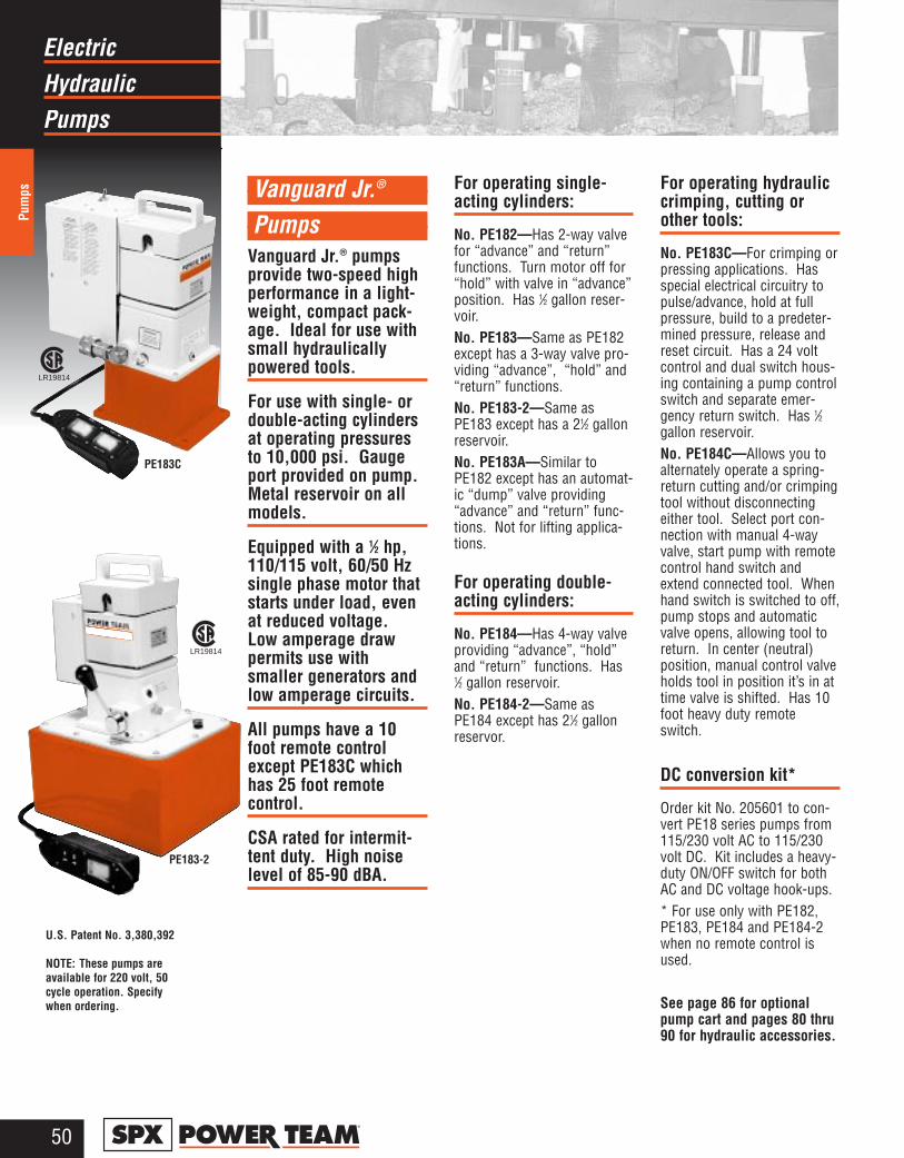
HydraulicElectric
Pumps
Pum
ps
50®
Vanguard Jr.®
Pumps Vanguard Jr.® pumpsprovide two-speed highperformance in a light-weight, compact pack-age. Ideal for use withsmall hydraulicallypowered tools.
For use with single- ordouble-acting cylindersat operating pressuresto 10,000 psi. Gaugeport provided on pump.Metal reservoir on allmodels.
Equipped with a 1⁄2 hp,110/115 volt, 60/50 Hzsingle phase motor thatstarts under load, evenat reduced voltage.Low amperage drawpermits use withsmaller generators andlow amperage circuits.
All pumps have a 10foot remote controlexcept PE183C whichhas 25 foot remotecontrol.
CSA rated for intermit-tent duty. High noiselevel of 85-90 dBA.
For operating single-acting cylinders:
No. PE182—Has 2-way valvefor “advance” and “return”functions. Turn motor off for“hold” with valve in “advance”position. Has 1⁄2 gallon reser-voir.No. PE183—Same as PE182except has a 3-way valve pro-viding “advance”, “hold” and“return” functions.No. PE183-2—Same asPE183 except has a 21⁄2 gallonreservoir.No. PE183A—Similar toPE182 except has an automat-ic “dump” valve providing“advance” and “return” func-tions. Not for lifting applica-tions.
For operating double-acting cylinders:
No. PE184—Has 4-way valveproviding “advance”, “hold”and “return” functions. Has1⁄2 gallon reservoir.No. PE184-2—Same asPE184 except has 21⁄2 gallonreservor.
For operating hydrauliccrimping, cutting orother tools:
No. PE183C—For crimping orpressing applications. Hasspecial electrical circuitry topulse/advance, hold at fullpressure, build to a predeter-mined pressure, release andreset circuit. Has a 24 voltcontrol and dual switch hous-ing containing a pump controlswitch and separate emer-gency return switch. Has 1⁄2gallon reservoir.No. PE184C—Allows you toalternately operate a spring-return cutting and/or crimpingtool without disconnectingeither tool. Select port con-nection with manual 4-wayvalve, start pump with remotecontrol hand switch andextend connected tool. Whenhand switch is switched to off,pump stops and automaticvalve opens, allowing tool toreturn. In center (neutral)position, manual control valveholds tool in position it’s in attime valve is shifted. Has 10foot heavy duty remoteswitch.
DC conversion kit*
Order kit No. 205601 to con-vert PE18 series pumps from115/230 volt AC to 115/230volt DC. Kit includes a heavy-duty ON/OFF switch for bothAC and DC voltage hook-ups.* For use only with PE182,PE183, PE184 and PE184-2when no remote control isused.
See page 86 for optionalpump cart and pages 80 thru90 for hydraulic accessories.
LR19814
LR19814
U.S. Patent No. 3,380,392
NOTE: These pumps areavailable for 220 volt, 50cycle operation. Specifywhen ordering.
PE183C
PE183-2
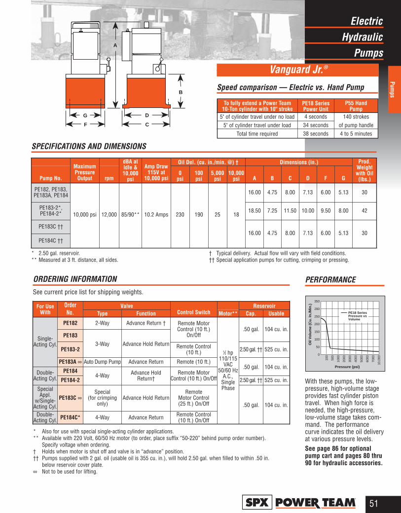
HydraulicElectric
Pumps
Pumps
51®
G
F
D
C
B
A
PE18 SeriesPressure vsVolume
350
290
250
200
150
100
50
0
Oil
Vo
lum
e (C
u. I
n./M
in.)
Pressure (psi)
100
500
1000
2000
3000
4000
5000
6000
7000
10,0
00With these pumps, the low-pressure, high-volume stageprovides fast cylinder pistontravel. When high force isneeded, the high-pressure,low-volume stage takes com-mand. The performancecurve indicates the oil deliveryat various pressure levels.See page 86 for optionalpump cart and pages 80 thru90 for hydraulic accessories.
PERFORMANCE
OrderNo.
ORDERING INFORMATIONSee current price list for shipping weights.
* Also for use with special single-acting cylinder applications.** Available with 220 Volt, 60/50 Hz motor (to order, place suffix “50-220” behind pump order number).
Specify voltage when ordering.† Holds when motor is shut off and valve is in “advance” position.†† Pumps supplied with 2 gal. oil (usable oil is 355 cu. in.), will hold 2.50 gal. when filled to within .50 in.
below reservoir cover plate.∞ Not to be used for lifting.
Valve ReservoirFor UseWith Type Function Control Switch Motor** Cap. Usable
Single-Acting Cyl.
PE182 2-Way Advance Return † Remote MotorControl (10 ft.)
On/Off
1⁄2 hp110/115
VAC50/60 Hz
A.C.,SinglePhase
.50 gal. 104 cu. in.PE183
3-Way Advance Hold ReturnPE183-2 Remote Control
(10 ft.) 2.50 gal. †† 525 cu. in.
PE183A ∞ Auto Dump Pump Advance Return Remote (10 ft.).50 gal. 104 cu. in.
Double-Acting Cyl.
PE1844-Way Remote Motor
Control (10 ft.) On/OffPE184-2 2.50 gal. †† 525 cu. in.
SpecialAppl.
w/Single-Acting Cyl.
PE183C ∞Special
(for crimping only)
Advance Hold ReturnRemote
Motor Control (25 ft.) On/Off .50 gal. 104 cu. in.
Double-Acting Cyl. PE184C* 4-Way Advance Return Remote Control
(10 ft.) On/Off
SPECIFICATIONS AND DIMENSIONS
* 2.50 gal. reservoir. ** Measured at 3 ft. distance, all sides.
† Typical delivery. Actual flow will vary with field conditions. †† Special application pumps for cutting, crimping or pressing.
Oil Del. (cu. in./min. @) † Dimensions (in.)
Pump No.
Maximum PressureOutput rpm
dBA at Idle & 10,000
psi
Amp Draw115V at
10,000 psi0
psi100psi
5,000psi
10,000psi A B C D F G
Prod.Weightwith Oil (lbs.)
PE182, PE183,PE183A, PE184
10,000 psi 12,000 85/90** 10.2 Amps 230 190 25 18
16.00 4.75 8.00 7.13 6.00 5.13 30
PE183-2*,PE184-2* 18.50 7.25 11.50 10.00 9.50 8.00 42
PE183C ††16.00 4.75 8.00 7.13 6.00 5.13 30
PE184C ††
P55 HandPump
PE18 SeriesPower Unit
To fully extend a Power Team10-Ton cylinder with 10" stroke
Speed comparison — Electric vs. Hand Pump
Vanguard Jr.®
140 strokesof pump handle4 to 5 minutes
4 seconds34 seconds38 seconds
5" of cylinder travel under no load5" of cylinder travel under load
Total time required
Advance HoldReturn†
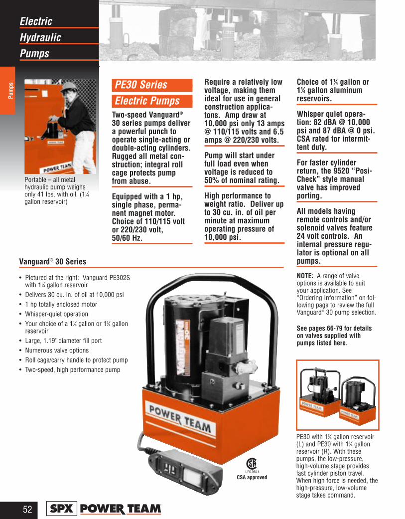
HydraulicElectric
Pumps
Pum
ps
52®
PE30 SeriesElectric Pumps
Two-speed Vanguard®
30 series pumps delivera powerful punch tooperate single-acting ordouble-acting cylinders.Rugged all metal con-struction; integral rollcage protects pumpfrom abuse.
Equipped with a 1 hp,single phase, perma-nent magnet motor.Choice of 110/115 voltor 220/230 volt, 50/60 Hz.
Require a relatively lowvoltage, making themideal for use in generalconstruction applica-tons. Amp draw at10,000 psi only 13 amps@ 110/115 volts and 6.5amps @ 220/230 volts.
Pump will start underfull load even whenvoltage is reduced to50% of nominal rating.
High performance toweight ratio. Deliver upto 30 cu. in. of oil perminute at maximumoperating pressure of10,000 psi.
Choice of 11⁄4 gallon or13⁄4 gallon aluminumreservoirs.
Whisper quiet opera-tion: 82 dBA @ 10,000psi and 87 dBA @ 0 psi.CSA rated for intermit-tent duty.
For faster cylinderreturn, the 9520 “Posi-Check” style manualvalve has improvedporting.
All models havingremote controls and/orsolenoid valves feature24 volt controls. Aninternal pressure regu-lator is optional on allpumps.
NOTE: A range of valveoptions is available to suityour application. See“Ordering Information” on fol-lowing page to review the fullVanguard® 30 pump selection.
See pages 66-79 for detailson valves supplied withpumps listed here.
PE30 with 13⁄4 gallon reservoir(L) and PE30 with 11⁄4 gallonreservoir (R). With thesepumps, the low-pressure,high-volume stage providesfast cylinder piston travel.When high force is needed, thehigh-pressure, low-volumestage takes command.
Portable – all metalhydraulic pump weighsonly 41 lbs. with oil. (11⁄4gallon reservoir)
Vanguard® 30 Series
CSA approvedLR19814
• Pictured at the right: Vanguard PE302Swith 11⁄4 gallon reservoir
• Delivers 30 cu. in. of oil at 10,000 psi• 1 hp totally enclosed motor• Whisper-quiet operation• Your choice of a 11⁄4 gallon or 13⁄4 gallon
reservoir• Large, 1.19" diameter fill port• Numerous valve options• Roll cage/carry handle to protect pump• Two-speed, high performance pump

HydraulicElectric
Pumps
Pumps
53®
Vanguard® 30 Series
H
W L
The performance curve aboveindicates the oil delivery atvarious pressure levels.
PERFORMANCE
PE30 Series
400350300250200150100500
Oil
Vol
ume
(Cu.
In./M
in.)
Pressure (psi)
500
1000
2000
3000
4000
5000
6000
7000
8000
10,0
00
Control SwitchOrderNo.
Maximum dBA at Amp Draw Oil Del. (cu. in./min. @) Prod. Wt.Pressure Idle & 115V at 100 500 1,000 5,000 10,000 Overall With Oil
Pump No. Output 10,000 psi 10,000 psi psi psi psi psi psi Dimensions (lbs.)PE30 Series 10.00"L x 9.00"W x 16.00"H 41w/1.25 gal. res.PE30 Series 10,000 psi 87/82 13 300 200 44 38 30
13.50"L x 9.50"W x 16.50"H 49w/1.75 gal. res.
ORDERING INFORMATIONSee current price list for shipping weights.
* “Posi-Check” valve design, “Posi-Check” guards against pressure losswhen valve is shifted from “advance” to “hold” position.
** Shipped with 1 gal. of oil (231 cu. in., 210 usable).*** Shipped with 2 gal. of oil.
∞ Not to be used for lifting.† 115 volt, 60 Hz.†† For 220/230 volt, 50/60 Hz. add suffix “- 220” (example PE302-220).
Valve ReservoirFor UseWith Type Function
Motor (4,000 rpm) †† Cap. Usable
Single-Acting
Cylinders
PE302A ∞ Auto Dump Automatic Pilot Oper. Remote MotorControl (10 ft.)
1 hp 110/115 VAC
50/60 Hz, Single Phase
1.25 gal. ** 280 cu. in.
PE302 3-Way, 2 Pos. Advance ReturnOn/Off/Pulse Switch
PE303 3-Way, 3 Pos. Advance Hold Return
PE302R3-Way, 2 Pos. Advance Return
Remote MotorControl (10 ft.)
PE302S † Remote Motor &Valve (10 ft.)
PE303R 3-Way, 3 Pos. Advance Hold ReturnRemote MotorControl (10 ft.)PE302A-2 ∞ Auto Dump Automatic Pilot Oper.
1.75 gal. *** 380 cu. in.
PE302-2 3-Way, 2 Pos. Advance ReturnOn/Off/Pulse Switch
PE303-2 3-Way, 3 Pos. Advance Hold Return
PE302R-23-Way, 2 Pos. Advance Return
Remote MotorControl (10 ft.)
PE302S-2 † Remote Motor &Valve (10 ft.)
PE303R-2 3-Way, 3 Pos. Advance Hold Return Remote MotorControl (10 ft.)
Double-Acting
Cylinders
PE304
Advance Hold Return
On/Off/Pulse Switch
1 hp 110/115 VAC
50/60 Hz, Single Phase
1.25 gal. ** 280 cu. in.PE304R Remote Motor
Control (10 ft.)
PE304-2 On/Off/Pulse Switch1.75 gal. *** 380 cu. in.
PE304R-2 Remote MotorControl (10 ft.)
No.
9610
9584
9520 *
9584
9579 (115V solenoid)
9520 *
9610
9584
9520 *
9584
9579 (115V solenoid)
9520 *
9506 *
SPECIFICATIONS AND DIMENSIONS
4-Way, 3 Pos.Tandem Ctr.
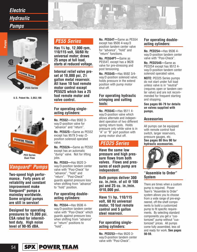
HydraulicElectric
Pumps
Pum
ps
54®
PE55 SeriesHas 11⁄8 hp, 12,000 rpm,110/115 volt, 50/60 Hzuniversal motor; draws25 amps at full load,starts at reduced voltage.
Internal relief valve pre-set at 10,000 psi, 21⁄2gallon metal reservoir.All have 10 foot remotemotor control exceptPE552S which has a 25foot remote motor andvalve control.
For operating single-acting cylinders:
No. PE552—Has 9582 3-way/2-position valve for“advance” and “return”.No. PE552S—Same as PE552except has 9579 3-way /2-position solenoid operatedvalve.No. PE552A—Same as PE552except has an automatic“dump” valve. Not for liftingjobs.No. PE553—Has 9520 3-way/3-position tandem centervalve with “Posi-Check” for“advance”, “hold” and“return”. “Posi-Check”guards against pressure losswhen shifting from “advance”to “hold” position.
For operating double-acting cylinders:
No. PE554—Has 9506 4-way/3-position tandem centervalve with “Posi-Check” whichguards against pressure losswhen shifting from “advance”or “return” positions to“hold”.
No. PE554T—Same as PE554except has 9500 4-way/3position tandem center valvefor “advance”, “hold” and“return” functions.No. PE554PT—Same asPE554T, except has a 9628valve for pre-stressing andpost tensioning.No. PE554S—Has 9592 3/4-way/2-position solenoid valve;holds pressure in the extendposition with pump motorshut off.
For operating hydrauliccrimping and cuttingtools:
No. PE554C—Has 9511 4-way/3-position valve whichallows alternate and indepen-dent operation of two differentspring return tools. Holdspressure only while valve is in“A” or “B” port position withpump motor shut off.
PED25 Series Have the same lowpressure and high pres-sure flows from bothvalves. Flows and pres-sures of each pump areindependent.
Both pumps deliver 300cu. in./min. of oil @ 100psi and 25 cu. in./min.@10,000 psi.
Have 11⁄2 hp, 110/115volt, 60 Hz universalmotor, 10 foot remotecontrol and 5 gallonsteel reservoir.
For operating single-acting cylinders:
No. PED253—Has 9520 3-way/3-position tandem centervalve with “Posi-Check”.
For operating double-acting cylinders:
No. PED254—Has 9506 4-way/3-position tandem centervalve with “Posi-Check”. No. PED254S—Same asPED254 except has 9512 4-way/3-position tandem centersolenoid operated valve.NOTE: PED25 Series pumpsdo not start under full loadunless valve is in “neutral”(requires open or tandem cen-ter valve) and are not recom-mended for frequent startingand stopping.See pages 66-79 for detailson valves supplied withpumps.
Accessories
All pumps can be equippedwith remote control footswitch, larger reservoirs,pressure gauges, etc. See pages 80 thru 90 forhydraulic accessories.
“Assemble to Order”System
There are times when a custompump is required. PowerTeam’s “Assemble to Order”system allows you to choosefrom a wide range of pre-engi-neered, off-the-shelf compo-nents to build a customizedpump to fit specific require-ments. By selecting standardcomponents you get a “cus-tomized” pump without “cus-tomized” prices. All pumpscome fully assembled, less oiland ready for work. See pages56-59.
Two-speed high perfor-mance. Forty years ofreliability and constantimprovement makeVanguard® pumps amainstay worldwide.Some original pumpsare still in service!
Designed for operatingpressures to 10,000 psi.CSA rated for intermit-tent duty. High noiselevel of 90-95 dBA.
Vanguard® Pumps
PE55 Series
PED SeriesDual Flow
U.S. Patent No. 3,053,186
LR19814
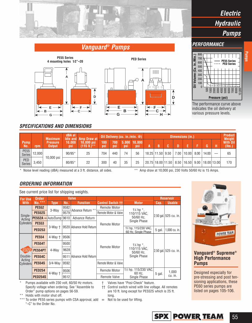
PE554PT
HydraulicElectric
Pumps
Pumps
55®
PERFORMANCE
PE55 SeriesPED Series
800700600500400300200100
0Oil V
olum
e (C
u. In
./Min
.)
Pressure (psi)
500
1000
2000
3000
4000
5000
6000
7000
8000
10,00
0
The performance curve aboveindicates the oil delivery atvarious pressure levels.
Vanguard® Pumps
A
D
FC
EB
G GB
E FC
H
A
D
PE55 Series4 mounting holes 1⁄2”–20
PED Series
OrderNo.***
* Pumps available with 230 volt, 60/50 Hz motors.Specify voltage when ordering. See “Assemble toOrder” pump options on pages 56-59.
** Holds with motor shut off.*** To order PE55 series pumps with CSA approval, add
“–C” to the Order No.
† Valves have “Posi-Check” feature. †† Control switch wired with line voltage. All remotes
are 10 ft. long except for PE552S which is 25 ft.long.
∞ Not to be used for lifting.
ORDERING INFORMATION See current price list for shipping weights.
Valve ReservoirFor UseWith Type No. Function Control Switch †† Motor Cap. Usable
Single-Acting
Cylinders
PE5523-Way
9582Advance Return **
Remote Motor11⁄8 hp *,
110/115 VAC, 50/60 Hz,
Single Phase2.50 gal. 525 cu. in.
PE552S 9579 Remote Motor & ValvePE552A ∞ Auto/Dump 9610 Advance Return
Remote MotorPE5533-Way † 9520 Advance Hold Return
PED253 11⁄2 hp, 115/230 VAC, 60 Hz, Single Phase 5 gal. 1,000 cu. in.
Double-Acting
Cylinders
PE554 4-Way † 9506
Advance Hold Return
Remote Motor 11⁄8 hp *, 110/115 VAC,
50/60 Hz, Single Phase
2.50 gal. 525 cu. in.
PE554T
4-Way
9500
PE554C 9511
PE554S 3/4-Way 9592 Remote Motor & Valve
PED2544-Way †
9506 Remote Motor 11⁄2 hp, 115/230 VAC,60 Hz,
Single Phase5 gal. 1,000
cu. in.PED254S 9512 Remote Valve
dBA at Product Maximum Idle and Amp Draw at Weight
Pump Pressure 10,000 10,000 psi 100 700 5,000 10,000 With OilNo. rpm Output psi (115 V.)** psi psi psi psi A B C D E F G H (lbs.)
PE55 Series 12,000
10,000 psi90/95* 25 704 440 74 56 18.25 11.50 9.50 7.00 10.00 8.00 14.00 — 65
PEDSeries 3,450 80/85* 22 300 40 35 25 20.75 18.00 11.50 8.50 16.50 9.00 18.00 13.00 170
* Noise level reading (dBA) measured at a 3 ft. distance, all sides. ** Amp draw at 10,000 psi, 230 Volts 50/60 Hz is 15 Amps.
SPECIFICATIONS AND DIMENSIONS
Dimensions (in.)Oil Delivery (cu. in./min. @)
Vanguard® Supreme®
High PerformancePumps
Designed especially forpre-stressing and post ten-sioning applications, thesePE60 series pumps arelisted on pages 105-106.
9628
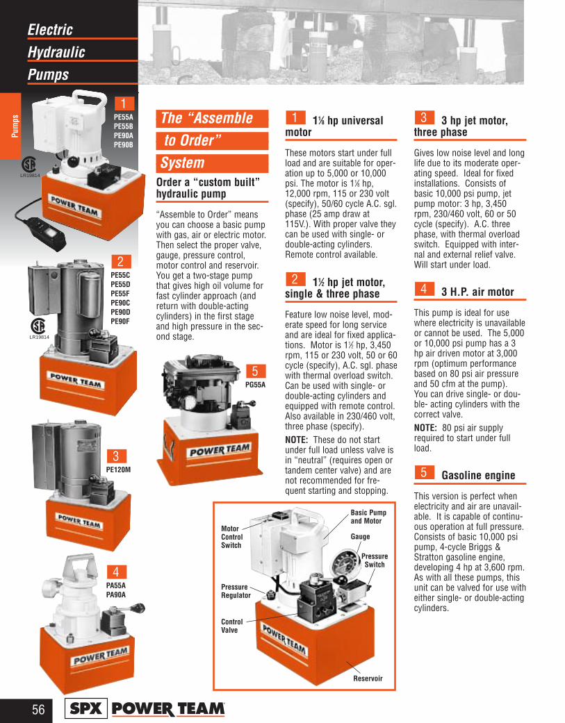
HydraulicElectric
Pumps
Pum
ps
56®
The “Assembleto Order”
SystemOrder a “custom built”hydraulic pump
“Assemble to Order” meansyou can choose a basic pumpwith gas, air or electric motor.Then select the proper valve,gauge, pressure control,motor control and reservoir.You get a two-stage pumpthat gives high oil volume forfast cylinder approach (andreturn with double-actingcylinders) in the first stageand high pressure in the sec-ond stage.
11⁄8 hp universalmotor
These motors start under fullload and are suitable for oper-ation up to 5,000 or 10,000psi. The motor is 11⁄8 hp,12,000 rpm, 115 or 230 volt(specify), 50/60 cycle A.C. sgl.phase (25 amp draw at115V.). With proper valve theycan be used with single- ordouble-acting cylinders.Remote control available.
11⁄2 hp jet motor, single & three phase
Feature low noise level, mod-erate speed for long serviceand are ideal for fixed applica-tions. Motor is 11⁄2 hp, 3,450rpm, 115 or 230 volt, 50 or 60cycle (specify), A.C. sgl. phasewith thermal overload switch.Can be used with single- ordouble-acting cylinders andequipped with remote control.Also available in 230/460 volt,three phase (specify). NOTE: These do not startunder full load unless valve isin “neutral” (requires open ortandem center valve) and arenot recommended for fre-quent starting and stopping.
3 hp jet motor, three phase
Gives low noise level and longlife due to its moderate oper-ating speed. Ideal for fixedinstallations. Consists ofbasic 10,000 psi pump, jetpump motor: 3 hp, 3,450rpm, 230/460 volt, 60 or 50cycle (specify). A.C. threephase, with thermal overloadswitch. Equipped with inter-nal and external relief valve.Will start under load.
3 H.P. air motor
This pump is ideal for usewhere electricity is unavailableor cannot be used. The 5,000or 10,000 psi pump has a 3hp air driven motor at 3,000rpm (optimum performancebased on 80 psi air pressureand 50 cfm at the pump).You can drive single- or dou-ble- acting cylinders with thecorrect valve. NOTE: 80 psi air supplyrequired to start under fullload.
Gasoline engine
This version is perfect whenelectricity and air are unavail-able. It is capable of continu-ous operation at full pressure.Consists of basic 10,000 psipump, 4-cycle Briggs &Stratton gasoline engine,developing 4 hp at 3,600 rpm.As with all these pumps, thisunit can be valved for use witheither single- or double-actingcylinders.
5
4
3
2
1PE55APE55BPE90APE90B
1
PE55CPE55DPE55FPE90CPE90DPE90F
2
PE120M
3
PA55APA90A
4
PG55A
5
MotorControlSwitch
PressureRegulator
Basic Pumpand Motor
Gauge
PressureSwitch
ControlValve
Reservoir
LR19814
LR19814
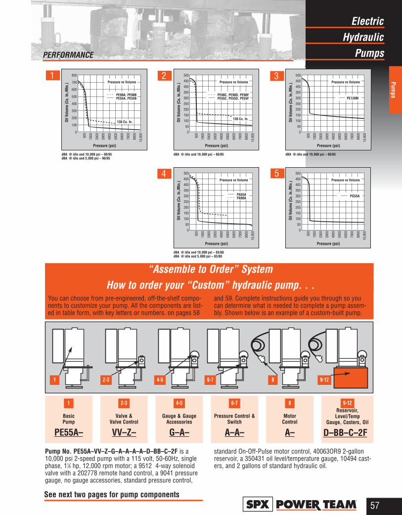
HydraulicElectric
Pumps
Pumps
57®
“Assemble to Order” SystemHow to order your “Custom” hydraulic pump. . .
You can choose from pre-engineered, off-the-shelf compo-nents to customize your pump. All the components are list-ed in table form, with key letters or numbers. on pages 58
and 59. Complete instructions guide you through so youcan determine what is needed to complete a pump assem-bly. Shown below is an example of a custom-built pump.
9-126-74-52-31
1
8
Basic Pump
PE55A–
Valve &Valve Control
VV–Z–
Gauge & GaugeAccessories
G–A–
Pressure Control &Switch
A–A–
Motor Control
A–
Reservoir,Level/Temp
Gauge, Casters, Oil
D–BB–C–2F
9-126-74-52-31 8
Pump No. PE55A–VV–Z–G–A–A–A–A–D–BB–C–2F is a10,000 psi 2-speed pump with a 115 volt, 50-60Hz, singlephase, 11⁄8 hp, 12,000 rpm motor; a 9512 4-way solenoidvalve with a 202778 remote hand control, a 9041 pressuregauge, no gauge accessories, standard pressure control,
standard On-Off-Pulse motor control, 40063OR9 2-gallonreservoir, a 350431 oil level/temperature gauge, 10494 cast-ers, and 2 gallons of standard hydraulic oil.
PE120M
Pressure vs Volume
500
450
400
350
300
250
200
150
100
50
0
Oil V
olum
e (C
u. In
./Min
.)
Pressure (psi)
500
1000
2000
3000
4000
5000
6000
7000
8000
10,0
00
dBA @ idle and 10,000 psi – 80/85
PE90C, PE90D, PE90FPE55C, PE55D, PE55F
Pressure vs Volume
130 Cu. In.
500
450
400
350
300
250
200
150
100
50
0
Oil V
olum
e (C
u. In
./Min
.)
Pressure (psi)
500
1000
2000
3000
4000
5000
6000
7000
8000
10,0
00
dBA @ idle and 10,000 psi – 80/85
PE90A, PE90BPE55A, PE55B
Pressure vs Volume
130 Cu. In.
800
700
600
500
400
300
200
100
0
Oil V
olum
e (C
u. In
./Min
.)
Pressure (psi)
500
1000
2000
3000
4000
5000
6000
7000
8000
10,0
00
dBA @ idle and 10,000 psi – 90/95dBA @ idle and 5,000 psi – 90/95
Pressure vs Volume
PA55APA90A
500
450
400
350
300
250
200
150
100
50
0
Oil V
olum
e (C
u. In
./Min
.)
Pressure (psi)
500
1000
2000
3000
4000
5000
6000
7000
8000
10,0
00dBA @ idle and 10,000 psi – 83/88dBA @ idle and 5,000 psi – 83/88
Pressure vs Volume
PG55A
500
450
400
350
300
250
200
150
100
50
0
Oil V
olum
e (C
u. In
./Min
.)
Pressure (psi)
500
1000
2000
3000
4000
5000
6000
7000
8000
10,0
00
1
PERFORMANCE
2 3
4 5
See next two pages for pump components
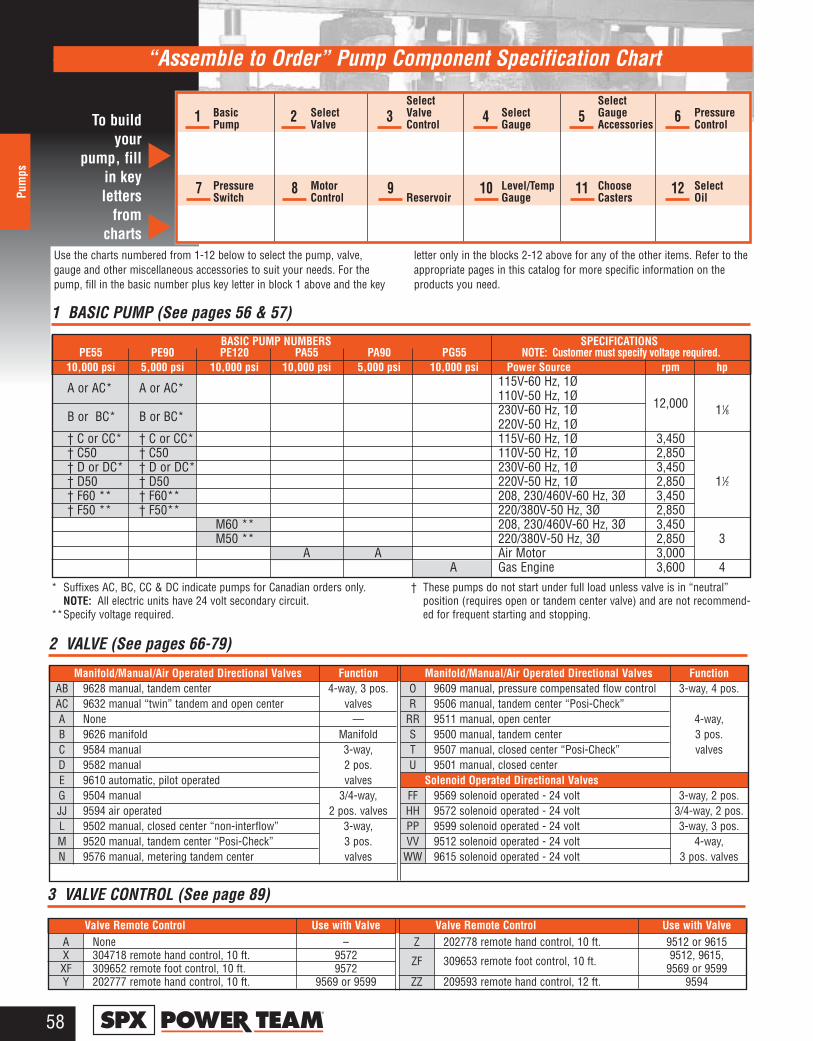
58®
Pum
ps
“Assemble to Order” Pump Component Specification Chart
3 VALVE CONTROL (See page 89)
Valve Remote Control Use with ValveA None –X 304718 remote hand control, 10 ft. 9572XF 309652 remote foot control, 10 ft. 9572Y 202777 remote hand control, 10 ft. 9569 or 9599
Valve Remote Control Use with ValveZ 202778 remote hand control, 10 ft. 9512 or 9615
ZF 309653 remote foot control, 10 ft. 9512, 9615,9569 or 9599
ZZ 209593 remote hand control, 12 ft. 9594
2 VALVE (See pages 66-79)
Manifold/Manual/Air Operated Directional Valves FunctionAB 9628 manual, tandem center 4-way, 3 pos. AC 9632 manual “twin” tandem and open center valvesA None —B 9626 manifold ManifoldC 9584 manual 3-way,D 9582 manual 2 pos.E 9610 automatic, pilot operated valvesG 9504 manual 3/4-way,JJ 9594 air operated 2 pos. valvesL 9502 manual, closed center “non-interflow” 3-way,M 9520 manual, tandem center “Posi-Check” 3 pos.N 9576 manual, metering tandem center valves
Manifold/Manual/Air Operated Directional Valves FunctionO 9609 manual, pressure compensated flow control 3-way, 4 pos.R 9506 manual, tandem center “Posi-Check”
RR 9511 manual, open center 4-way,S 9500 manual, tandem center 3 pos.T 9507 manual, closed center “Posi-Check” valvesU 9501 manual, closed center
Solenoid Operated Directional ValvesFF 9569 solenoid operated - 24 volt 3-way, 2 pos.HH 9572 solenoid operated - 24 volt 3/4-way, 2 pos.PP 9599 solenoid operated - 24 volt 3-way, 3 pos.VV 9512 solenoid operated - 24 volt 4-way,
WW 9615 solenoid operated - 24 volt 3 pos. valves
BASIC PUMP NUMBERS SPECIFICATIONSPE55 PE90 PE120 PA55 PA90 PG55 NOTE: Customer must specify voltage required.
10,000 psi 5,000 psi 10,000 psi 10,000 psi 5,000 psi 10,000 psi Power Source rpm hp
A or AC* A or AC* 115V-60 Hz, 1Ø110V-50 Hz, 1Ø
B or BC* B or BC* 230V-60 Hz, 1Ø 12,000 11⁄8220V-50 Hz, 1Ø
† C or CC* † C or CC* 115V-60 Hz, 1Ø 3,450† C50 † C50 110V-50 Hz, 1Ø 2,850† D or DC* † D or DC* 230V-60 Hz, 1Ø 3,450† D50 † D50 220V-50 Hz, 1Ø 2,850 11⁄2† F60 ** † F60** 208, 230/460V-60 Hz, 3Ø 3,450† F50 ** † F50** 220/380V-50 Hz, 3Ø 2,850
M60 ** 208, 230/460V-60 Hz, 3Ø 3,450M50 ** 220/380V-50 Hz, 3Ø 2,850 3
A A Air Motor 3,000A Gas Engine 3,600 4
1 BASIC PUMP (See pages 56 & 57)
* Suffixes AC, BC, CC & DC indicate pumps for Canadian orders only.NOTE: All electric units have 24 volt secondary circuit.
**Specify voltage required.
† These pumps do not start under full load unless valve is in “neutral”position (requires open or tandem center valve) and are not recommend-ed for frequent starting and stopping.
To buildyour
pump, fillin key letters
fromcharts
Use the charts numbered from 1-12 below to select the pump, valve,gauge and other miscellaneous accessories to suit your needs. For thepump, fill in the basic number plus key letter in block 1 above and the key
letter only in the blocks 2-12 above for any of the other items. Refer to theappropriate pages in this catalog for more specific information on theproducts you need.
▲▲
1 2 3 4 5 6
7 8 9 10 11 12
Select SelectBasic Select Valve Select Gauge PressurePump Valve Control Gauge Accessories Control
Pressure Motor Level/Temp Choose SelectSwitch Control Reservoir Gauge Casters Oil
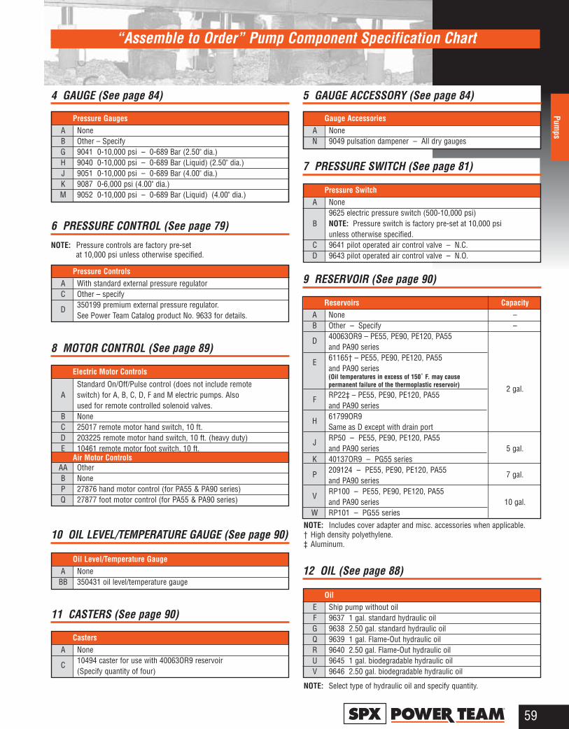
59®
Pumps
“Assemble to Order” Pump Component Specification Chart
NOTE: Includes cover adapter and misc. accessories when applicable.† High density polyethylene.‡ Aluminum.
NOTE: Select type of hydraulic oil and specify quantity.
4 GAUGE (See page 84)
Pressure GaugesA NoneB Other – SpecifyG 9041 0-10,000 psi – 0-689 Bar (2.50" dia.)H 9040 0-10,000 psi – 0-689 Bar (Liquid) (2.50" dia.)J 9051 0-10,000 psi – 0-689 Bar (4.00" dia.)K 9087 0-6,000 psi (4.00" dia.)M 9052 0-10,000 psi – 0-689 Bar (Liquid) (4.00" dia.)
6 PRESSURE CONTROL (See page 79)
NOTE: Pressure controls are factory pre-set at 10,000 psi unless otherwise specified.
Pressure ControlsA With standard external pressure regulatorC Other – specify
D 350199 premium external pressure regulator. See Power Team Catalog product No. 9633 for details.
5 GAUGE ACCESSORY (See page 84)
Gauge AccessoriesA NoneN 9049 pulsation dampener – All dry gauges
7 PRESSURE SWITCH (See page 81)
Pressure SwitchA None
9625 electric pressure switch (500-10,000 psi)B NOTE: Pressure switch is factory pre-set at 10,000 psi
unless otherwise specified.C 9641 pilot operated air control valve – N.C.D 9643 pilot operated air control valve – N.O.
10 OIL LEVEL/TEMPERATURE GAUGE (See page 90)
Oil Level/Temperature GaugeA None
BB 350431 oil level/temperature gauge
11 CASTERS (See page 90)
CastersA None
C 10494 caster for use with 40063OR9 reservoir (Specify quantity of four)
9 RESERVOIR (See page 90)
Reservoirs CapacityA None –B Other – Specify –
D 40063OR9 – PE55, PE90, PE120, PA55 and PA90 series
E 61165† – PE55, PE90, PE120, PA55 and PA90 series (Oil temperatures in excess of 150˚ F. may cause permanent failure of the thermoplastic reservoir) 2 gal.
F RP22‡ – PE55, PE90, PE120, PA55 and PA90 series
H 61799OR9 Same as D except with drain port
J RP50 – PE55, PE90, PE120, PA55 and PA90 series 5 gal.
K 40137OR9 – PG55 series
P 209124 – PE55, PE90, PE120, PA55 7 gal.and PA90 series
V RP100 – PE55, PE90, PE120, PA55 and PA90 series 10 gal.
W RP101 – PG55 series
12 OIL (See page 88)
OilE Ship pump without oilF 9637 1 gal. standard hydraulic oilG 9638 2.50 gal. standard hydraulic oilQ 9639 1 gal. Flame-Out hydraulic oilR 9640 2.50 gal. Flame-Out hydraulic oilU 9645 1 gal. biodegradable hydraulic oilV 9646 2.50 gal. biodegradable hydraulic oil
8 MOTOR CONTROL (See page 89)
Electric Motor Controls
Standard On/Off/Pulse control (does not include remote A switch) for A, B, C, D, F and M electric pumps. Also
used for remote controlled solenoid valves.B NoneC 25017 remote motor hand switch, 10 ft.D 203225 remote motor hand switch, 10 ft. (heavy duty)E 10461 remote motor foot switch, 10 ft.
Air Motor ControlsAA OtherB NoneP 27876 hand motor control (for PA55 & PA90 series)Q 27877 foot motor control (for PA55 & PA90 series)
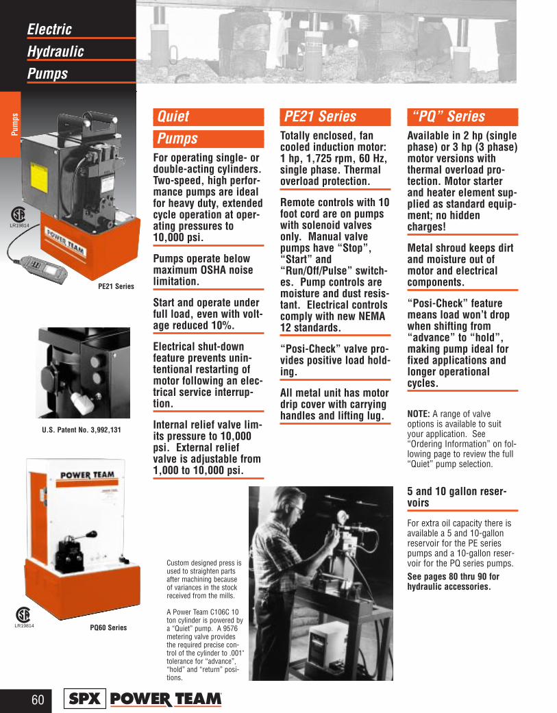
HydraulicElectric
Pumps
Pum
ps
60®
QuietPumps
For operating single- ordouble-acting cylinders.Two-speed, high perfor-mance pumps are idealfor heavy duty, extendedcycle operation at oper-ating pressures to10,000 psi.
Pumps operate belowmaximum OSHA noiselimitation.
Start and operate underfull load, even with volt-age reduced 10%.
Electrical shut-downfeature prevents unin-tentional restarting ofmotor following an elec-trical service interrup-tion.
Internal relief valve lim-its pressure to 10,000psi. External reliefvalve is adjustable from1,000 to 10,000 psi.
PE21 SeriesTotally enclosed, fancooled induction motor:1 hp, 1,725 rpm, 60 Hz,single phase. Thermaloverload protection.
Remote controls with 10foot cord are on pumpswith solenoid valvesonly. Manual valvepumps have “Stop”,“Start” and“Run/Off/Pulse” switch-es. Pump controls aremoisture and dust resis-tant. Electrical controlscomply with new NEMA12 standards.
“Posi-Check” valve pro-vides positive load hold-ing.
All metal unit has motordrip cover with carryinghandles and lifting lug.
“PQ” SeriesAvailable in 2 hp (singlephase) or 3 hp (3 phase)motor versions withthermal overload pro-tection. Motor starterand heater element sup-plied as standard equip-ment; no hiddencharges!
Metal shroud keeps dirtand moisture out ofmotor and electricalcomponents.
“Posi-Check” featuremeans load won’t dropwhen shifting from“advance” to “hold”,making pump ideal forfixed applications andlonger operationalcycles.
NOTE: A range of valveoptions is available to suityour application. See“Ordering Information” on fol-lowing page to review the full“Quiet” pump selection.
5 and 10 gallon reser-voirs
For extra oil capacity there isavailable a 5 and 10-gallonreservoir for the PE seriespumps and a 10-gallon reser-voir for the PQ series pumps.See pages 80 thru 90 forhydraulic accessories.
LR19814
LR19814
PE21 Series
PQ60 Series
U.S. Patent No. 3,992,131
Custom designed press isused to straighten partsafter machining becauseof variances in the stockreceived from the mills.
A Power Team C106C 10ton cylinder is powered bya “Quiet” pump. A 9576metering valve providesthe required precise con-trol of the cylinder to .001"tolerance for “advance”,“hold” and “return” posi-tions.
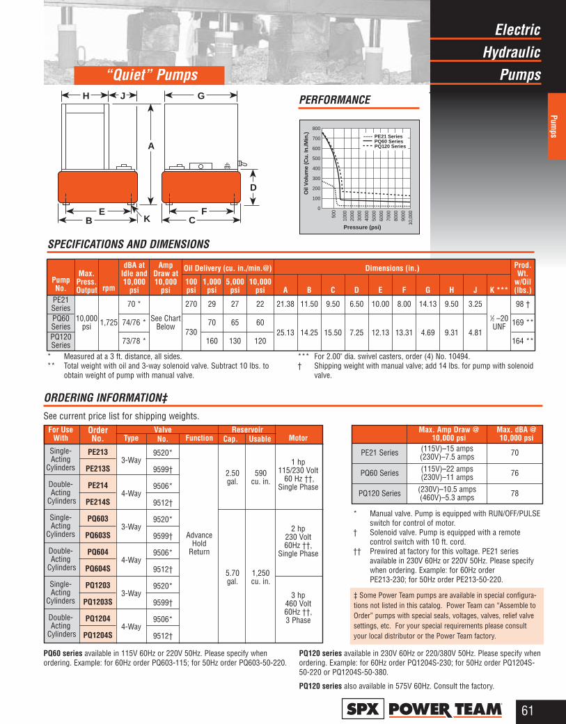
HydraulicElectric
Pumps
Pumps
61®
EB
H J
A
G
FC
D
K
“Quiet” Pumps
PE21 SeriesPQ60 SeriesPQ120 Series
800
700
600
500
400
300
200
100
0
Oil
Vo
lum
e (C
u. I
n./M
in.)
Pressure (psi)
1000
2000
3000
4000
5000
6000
7000
8000
9000
10,0
00500
PERFORMANCE
rpm
Max. Amp Draw @ Max. dBA @10,000 psi 10,000 psi
PE21 Series
PQ60 Series
PQ120 Series
ReservoirCap. Usable
2.50 590gal. cu. in.
5.70 1,250gal. cu. in.
Type
3-Way
4-Way
3-Way
4-Way
3-Way
4-Way
OrderNo.
PE213
PE213S
PE214
PE214S
PQ603
PQ603S
PQ604
PQ604S
PQ1203
PQ1203S
PQ1204
PQ1204S
For UseWith
Single- Acting
Cylinders
Double-Acting
Cylinders
Single-Acting
Cylinders
Double-Acting
Cylinders
Single-Acting
Cylinders
Double-Acting
Cylinders
Function
AdvanceHold
Return
* Manual valve. Pump is equipped with RUN/OFF/PULSEswitch for control of motor.
† Solenoid valve. Pump is equipped with a remote control switch with 10 ft. cord.
†† Prewired at factory for this voltage. PE21 series available in 230V 60Hz or 220V 50Hz. Please specifywhen ordering. Example: for 60Hz order PE213-230; for 50Hz order PE213-50-220.
(115V)–15 amps(230V)–7.5 amps(115V)–22 amps(230V)–11 amps
(230V)–10.5 amps(460V)–5.3 amps
Motor
1 hp115/230 Volt
60 Hz ††,Single Phase
2 hp230 Volt60Hz ††,
Single Phase
3 hp460 Volt60Hz ††,3 Phase
ORDERING INFORMATION‡See current price list for shipping weights.
ValveNo.
9520*
9599†
9506*
9512†
9520*
9599†
9506*
9512†
9520*
9599†
9506*
9512†
PQ60 series available in 115V 60Hz or 220V 50Hz. Please specify whenordering. Example: for 60Hz order PQ603-115; for 50Hz order PQ603-50-220.
PQ120 series available in 230V 60Hz or 220/380V 50Hz. Please specify whenordering. Example: for 60Hz order PQ1204S-230; for 50Hz order PQ1204S-50-220 or PQ1204S-50-380.
PQ120 series also available in 575V 60Hz. Consult the factory.
* Measured at a 3 ft. distance, all sides.** Total weight with oil and 3-way solenoid valve. Subtract 10 lbs. to
obtain weight of pump with manual valve.
*** For 2.00" dia. swivel casters, order (4) No. 10494.† Shipping weight with manual valve; add 14 lbs. for pump with solenoid
valve.
SPECIFICATIONS AND DIMENSIONS
PumpNo.
Max.Press.Output
dBA atIdle and10,000
psi
AmpDraw at10,000
psi
Oil Delivery (cu. in./min.@) Dimensions (in.) Prod.Wt.
w/Oil(lbs.)
100psi
1,000psi
5,000psi
10,000psi A B C D E F G H J K ***
PE21Series
10,000psi 1,725
70 *
See ChartBelow
270 29 27 22 21.38 11.50 9.50 6.50 10.00 8.00 14.13 9.50 3.251⁄2 –20UNF
98 †
PQ60Series 74/76 *
73070 65 60
25.13 14.25 15.50 7.25 12.13 13.31 4.69 9.31 4.81169 **
PQ120Series 73/78 * 160 130 120 164 **
70
76
78
‡ Some Power Team pumps are available in special configura-tions not listed in this catalog. Power Team can “Assemble toOrder” pumps with special seals, voltages, valves, relief valvesettings, etc. For your special requirements please consultyour local distributor or the Power Team factory.
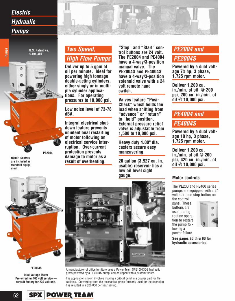
HydraulicElectric
Pumps
Pum
ps
62®
Two Speed,High Flow Pumps
Deliver up to 5 gpm ofoil per minute. Ideal forpowering high tonnagedouble-acting cylinders,either singly or in multi-ple cylinder applica-tions. For operatingpressures to 10,000 psi.
Low noise level of 73-78dBA.
Integral electrical shut-down feature preventsunintentional restartingof motor following anelectrical service inter-ruption. Over-currentprotection preventsdamage to motor as aresult of overheating.
“Stop” and “Start” con-trol buttons are 24 volt.The PE2004 and PE4004have a 4-way/3-positionmanual valve. ThePE2004S and PE4004Shave a 4-way/3-positionsolenoid valve with a 24volt remote handswitch.
Valves feature “Posi-Check” which holds theload when shifting from“advance” or “return”to “hold” position.External pressure reliefvalve is adjustable from1,500 to 10,000 psi.
Heavy duty 4.00" dia.casters assure easymaneuvering.
20 gallon (3,927 cu. in.usable) reservoir has alow oil level sightgauge.
PE2004 and PE2004S
Powered by a dual volt-age 71⁄2 hp, 3 phase,1,725 rpm motor.
Deliver 1,200 cu.in./min. of oil @ 200psi, 200 cu. in./min. ofoil @ 10,000 psi.
PE4004 and PE4004S
Powered by a dual volt-age 10 hp, 3 phase,1,725 rpm motor.
Deliver 1,200 cu.in./min. of oil @ 200psi, 420 cu. in./min. ofoil @ 10,000 psi.
Motor controls
The PE200 and PE400 seriespumps are equipped with a 24volt start and stop button onthe controlpanel. Thesebuttons areused duringroutine opera-tion to restartthe pump fol-lowing apower failure.See pages 80 thru 90 forhydraulic accessories.
PE2004
PE2004S
Dual Voltage MotorPre-wired for 460 volt service —consult factory for 230 volt unit.
NOTE: Casters are included asstandard equip-ment.
U.S. Patent No.4,105,369
A manufacturer of office furniture uses a Power Team SPE10013DS hydraulicpress powered by a PE4004S pump, and equipped with a custom fixture.
The application shown involves making a critical bend in a drawer part for filecabinets. Converting from the mechanical press formerly used for the operationhas resulted in a $20,000 per year saving.
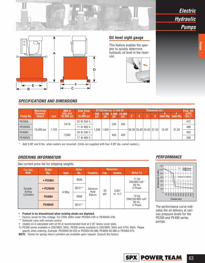
HydraulicElectric
Pumps
Pumps
63®
EB
FC
D
A
Oil level sight gauge
This feature enables the oper-ator to quickly determinehydraulic oil level in the reser-voir.
PE200 SeriesPE400 Series
Pressure vs Volume
1400
1200
1000
800
600
400
200
0
Oil V
olum
e (C
u. In
./Min
.)
Pressure (psi)
400
800
1200
1600
2000
3000
4000
5000
6000
7000
8000
10,0
00
PERFORMANCE
The performance curve indi-cates the oil delivery at vari-ous pressure levels for thePE200 and PE400 seriespumps.
ReservoirCap. Usable
20 3,927gal. cu. in.†
Type
4-Way
Order No.
• PE2004
• PE2004S
PE4004
PE4004S
For UseWith
Double-Acting
Cylinders
Motor ††
71⁄2 hp230/460 volt*
60 Hz,3 Phase
10 hp208/230/460 volt*
60 Hz,3 Phase
Function
AdvanceHold
Return
• Product to be discontinued when existing stocks are depleted.* Factory wired for this voltage. For 230V, 60Hz order PE2004-230 or PE4004S-230.** Solenoid valve with remote control.† Usable oil is calculated with oil fill at recommended level at 2.25" below cover plate.†† PE200 series available in 220/380V, 50Hz. PE400 series available in 220/380V, 50Hz and 575V, 60Hz. Please
specify when ordering. Example: PE2004S-50-220 or PE2004-50-380; PE4004-50-380 or PE4004-575.NOTE: Valves for spring return cylinders are available upon request. Consult the factory.
ORDERING INFORMATIONSee current price list for shipping weights.
ValveNo.
9506
9512**
9506
9512**
Maximum dBA at Amp Draw Prod. Wt.Pressure Idle and at 200 1,200 5,000 10,000 E F w/Oil
Pump No. Output rpm 10,000 psi 10,000 psi psi psi psi psi A* B C D Caster Mtg. Caster Mtg. (lbs.)*
PE2004 22 @ 230 V. 472
PE2004S74/79
11 @ 460 V.230 200
486
PE400410,000 psi 1,725
34 @ 230 V.1,200 1,050 36.38 25.00 24.00 21.25 15.50 21.50
492
PE4004S73/80
17 @ 460 V.450 420
506
Oil Delivery (cu. in./min.@) Dimensions (in.)
* Add 5.00" and 8 lbs. when casters are mounted. (Units are supplied with four 4.00" dia. swivel casters.)
SPECIFICATIONS AND DIMENSIONS
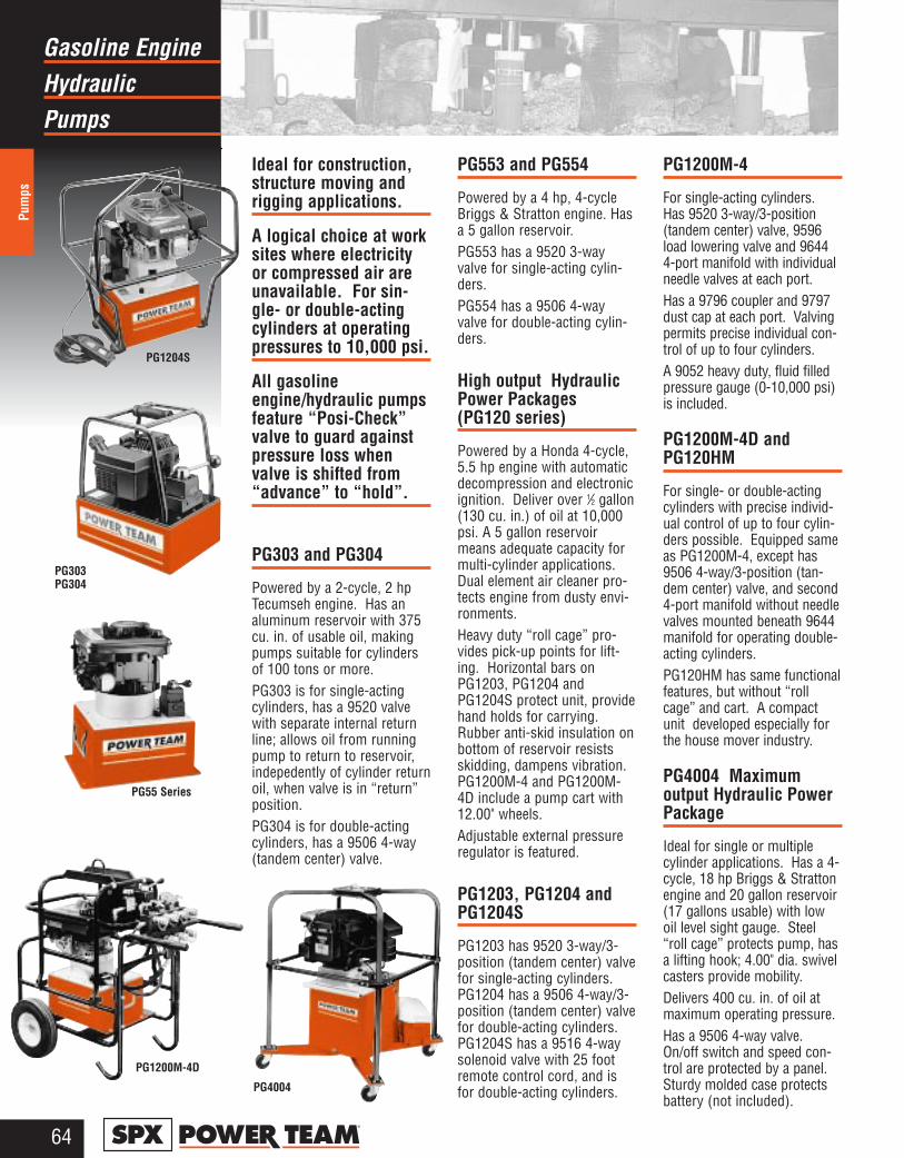
HydraulicGasoline Engine
Pumps
Pum
ps
64®
Ideal for construction,structure moving andrigging applications.
A logical choice at worksites where electricityor compressed air areunavailable. For sin-gle- or double-actingcylinders at operatingpressures to 10,000 psi.
All gasolineengine/hydraulic pumpsfeature “Posi-Check”valve to guard againstpressure loss whenvalve is shifted from“advance” to “hold”.
PG303 and PG304
Powered by a 2-cycle, 2 hpTecumseh engine. Has analuminum reservoir with 375cu. in. of usable oil, makingpumps suitable for cylindersof 100 tons or more.PG303 is for single-actingcylinders, has a 9520 valvewith separate internal returnline; allows oil from runningpump to return to reservoir,indepedently of cylinder returnoil, when valve is in “return”position.PG304 is for double-actingcylinders, has a 9506 4-way(tandem center) valve.
PG553 and PG554
Powered by a 4 hp, 4-cycleBriggs & Stratton engine. Hasa 5 gallon reservoir.PG553 has a 9520 3-wayvalve for single-acting cylin-ders.PG554 has a 9506 4-wayvalve for double-acting cylin-ders.
High output HydraulicPower Packages (PG120 series)
Powered by a Honda 4-cycle,5.5 hp engine with automaticdecompression and electronicignition. Deliver over 1⁄2 gallon(130 cu. in.) of oil at 10,000psi. A 5 gallon reservoirmeans adequate capacity formulti-cylinder applications.Dual element air cleaner pro-tects engine from dusty envi-ronments. Heavy duty “roll cage” pro-vides pick-up points for lift-ing. Horizontal bars onPG1203, PG1204 andPG1204S protect unit, providehand holds for carrying.Rubber anti-skid insulation onbottom of reservoir resistsskidding, dampens vibration.PG1200M-4 and PG1200M-4D include a pump cart with12.00" wheels.Adjustable external pressureregulator is featured.
PG1203, PG1204 andPG1204S
PG1203 has 9520 3-way/3-position (tandem center) valvefor single-acting cylinders.PG1204 has a 9506 4-way/3-position (tandem center) valvefor double-acting cylinders.PG1204S has a 9516 4-waysolenoid valve with 25 footremote control cord, and isfor double-acting cylinders.
PG1200M-4
For single-acting cylinders.Has 9520 3-way/3-position(tandem center) valve, 9596load lowering valve and 96444-port manifold with individualneedle valves at each port.Has a 9796 coupler and 9797dust cap at each port. Valvingpermits precise individual con-trol of up to four cylinders.A 9052 heavy duty, fluid filledpressure gauge (0-10,000 psi)is included.
PG1200M-4D andPG120HM
For single- or double-actingcylinders with precise individ-ual control of up to four cylin-ders possible. Equipped sameas PG1200M-4, except has9506 4-way/3-position (tan-dem center) valve, and second4-port manifold without needlevalves mounted beneath 9644manifold for operating double-acting cylinders.PG120HM has same functionalfeatures, but without “rollcage” and cart. A compactunit developed especially forthe house mover industry.
PG4004 Maximum output Hydraulic PowerPackage
Ideal for single or multiplecylinder applications. Has a 4-cycle, 18 hp Briggs & Strattonengine and 20 gallon reservoir(17 gallons usable) with lowoil level sight gauge. Steel“roll cage” protects pump, hasa lifting hook; 4.00" dia. swivelcasters provide mobility.Delivers 400 cu. in. of oil atmaximum operating pressure.Has a 9506 4-way valve.On/off switch and speed con-trol are protected by a panel.Sturdy molded case protectsbattery (not included).
PG303 PG304
PG55 Series
PG1204S
PG4004
PG1200M-4D
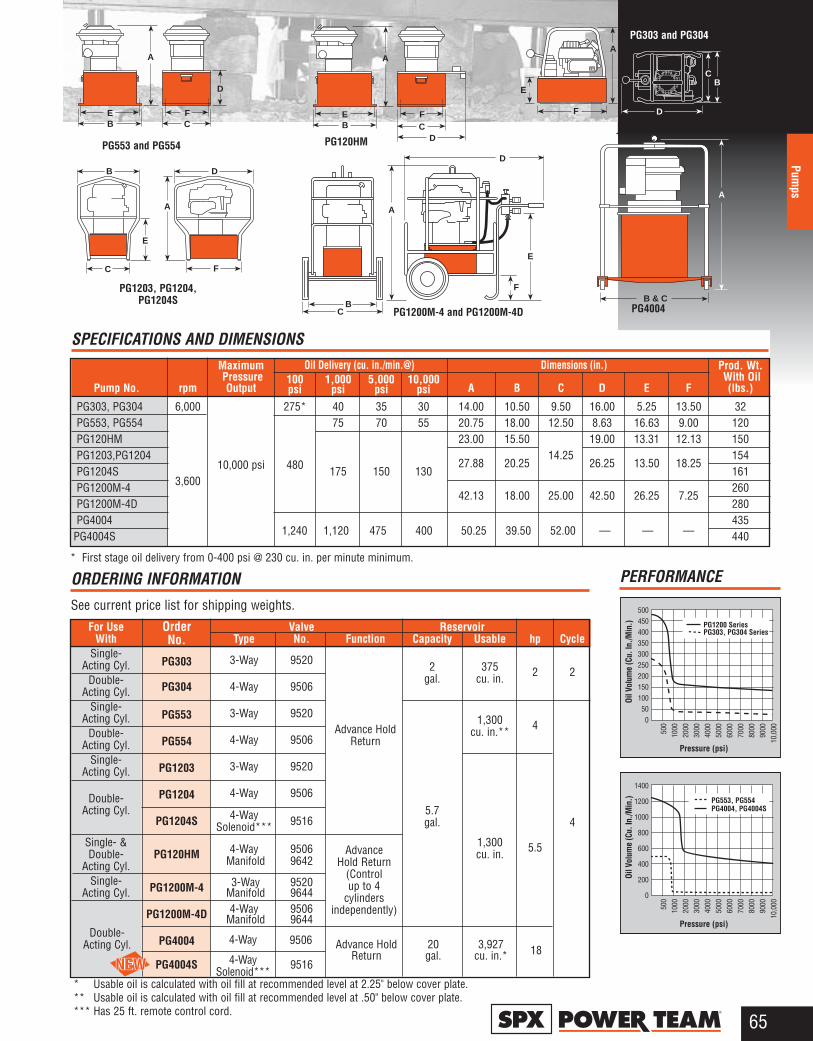
65®
Pumps
PG553, PG554PG4004, PG4004S
PG1200 SeriesPG303, PG304 Series
500450400350300250200150100500
Oil V
olum
e (C
u. In
./Min
.)
Pressure (psi)
500
1000
2000
3000
4000
5000
6000
7000
8000
9000
10,0
00
1400
1200
1000
800
600
400
200
0
Oil V
olum
e (C
u. In
./Min
.)
Pressure (psi)
500
1000
2000
3000
4000
5000
6000
7000
8000
9000
10,0
00
PERFORMANCE
PG303 and PG304
PG120HMPG553 and PG554
PG1203, PG1204,PG1204S
PG1200M-4 and PG1200M-4D PG4004
A
BC
D
E
F
C
E
B D
A
F
EB
FC
A
D
E
A
D
CB
F
B & C
A
EB
FC
A
D
* Usable oil is calculated with oil fill at recommended level at 2.25" below cover plate.** Usable oil is calculated with oil fill at recommended level at .50" below cover plate.*** Has 25 ft. remote control cord.
ORDERING INFORMATIONSee current price list for shipping weights.
For Use Valve ReservoirWith Type No. Function Capacity Usable hp Cycle
Single- 3-Way 9520 2 375Acting Cyl.gal. cu. in. 2
Double- 4-Way 95062
Acting Cyl.Single- 3-Way 9520 1,300Acting Cyl.
cu. in.** 4Double- 4-Way 9506
Advance HoldActing Cyl. Return
Single- 3-Way 9520Acting Cyl.
4-Way 9506Double-Acting Cyl. 4-Way 9516
5.7Solenoid*** gal. 4
Single- & 4-Way 9506 1,300Double- Manifold 9642 cu. in. 5.5
Acting Cyl.Single- 3-Way 9520
Acting Cyl. Manifold 9644 4-Way 9506
Manifold 9644
PG4004S 9516
Advance Hold Return
(Controlup to 4
cylindersindependently)
* First stage oil delivery from 0-400 psi @ 230 cu. in. per minute minimum.
SPECIFICATIONS AND DIMENSIONSOil Delivery (cu. in./min.@) Dimensions (in.)
Order No.
PG303
PG304
PG553
PG554
PG1203
PG1204
PG1204S
PG120HM
PG1200M-4
PG1200M-4D
PG4004
Maximum Prod. Wt.Pressure 100 1,000 5,000 10,000 With Oil
Pump No. rpm Output psi psi psi psi A B C D E F (lbs.)
PG303, PG304 6,000 275* 40 35 30 14.00 10.50 9.50 16.00 5.25 13.50 32PG553, PG554 75 70 55 20.75 18.00 12.50 8.63 16.63 9.00 120PG120HM 23.00 15.50 19.00 13.31 12.13 150PG1203,PG1204
27.88 20.2514.25
26.25 13.50 18.25154
PG1204S 10,000 psi 480 175 150 130 161PG1200M-4 3,600
42.13 18.00 25.00 42.50 26.25 7.25260
PG1200M-4D 280PG4004 435
PG4004S 4401,240 1,120 475 400 50.25 39.50 52.00 — — —
Advance Hold 20 3,927Return gal. cu. in.* 18
4-WaySolenoid***
Double-Acting Cyl. 95064-Way
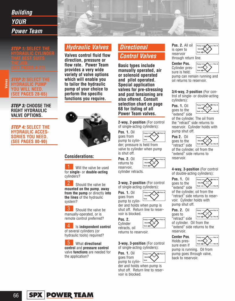
YOURBuilding
Power Team
66®
Valv
es
STEP 1: SELECT THEHYDRAULIC CYLINDERTHAT BEST SUITS THE JOB.(SEE PAGES 4-27)
STEP 2: SELECT THEHYDRAULIC PUMP YOU WILL NEED. (SEE PAGES 28-65)
STEP 3: CHOOSE THERIGHT HYDRAULICVALVE OPTIONS.
STEP 4: SELECT THEHYDRAULIC ACCES-SORIES YOU NEED.(SEE PAGES 80-90)
Hydraulic ValvesValves control fluid flowdirection, pressure orflow rate. Power Teamprovides a very widevariety of valve optionswhich will enable you to tailor the hydraulicpump of your choice toperform the specificfunctions you require.
Considerations:
Will the valve be usedfor single- or double-actingcylinders?
Should the valve bemounted on the pump, awayfrom the pump or directly intothe lines of the hydraulic system?
Should the valve bemanually-operated, or isremote control preferred?
Is independent controlof several cylinders (orhydraulic tools) required?
What directional control and pressure controlvalve functions are needed forthe application?
Directional Control Valves
Basic types includemanually operated, airor solenoid operatedand pilot operated.Special applicationvalves for pre-stressingand post tensioning arealso offered. Consultselection chart on page68 for listing of allPower Team valves.
2-way, 2-position (For controlof single-acting cylinders):Pos. 1. Oilgoes frompump to cylin-der; pressure is held fromvalve to cylinder when pumpis shut off.Pos. 2. Oilreturns toreservoir,cylinder retracts.
3-way, 2-position (For controlof single-acting cylinders):Pos. 1. Oilgoes frompump to cylin-der and holds when pump isshut off. Return line to reser-voir is blocked.Pos. 2.Cylinderretracts, oilreturns to reservoir.
3-way, 3-position (For controlof single-acting cylinders):Pos. 1. Oilgoes frompump to cylin-der and holds when pump isshut off. Return line to reser-voir is blocked.
Pos. 2. All oilis open toreservoirthrough return line.Center Pos.Cylinder pres-sure is held;pump can remain running andoil returns to reservoir.
3/4-way, 2-position (For con-trol of single- or double-actingcylinders):Pos. 1. Oilgoes to the“extend” sideof the cylinder. The oil fromthe “retract” side returns toreservoir. Cylinder holds withpump shut off.Pos 2. Oilgoes to the“retract” sideof the cylinder, oil from the“extend” side returns toreservoir.
4-way, 3-position (For controlof double-acting cylinders):Pos. 1. Oilgoes to the“extend” sideof the cylinder, oil from the“retract” side returns to reser-voir. Cylinder holds withpump shut off. Pos. 2. Oilgoes to“retract” sideof cylinder. Oil from the“extend” side returns to thereservoir.Center Pos.Holds pres-sure even ifpump is running. Oil frompump goes through valve,back to reservoir.
5
4
3
2
1
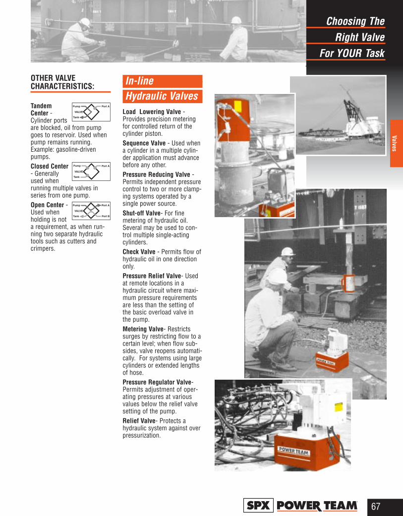
Right ValveChoosing The
For YOUR Task
67®
Valves
OTHER VALVE CHARACTERISTICS:
TandemCenter -Cylinder portsare blocked, oil from pumpgoes to reservoir. Used whenpump remains running.Example: gasoline-drivenpumps.Closed Center- Generallyused whenrunning multiple valves inseries from one pump.Open Center -Used whenholding is nota requirement, as when run-ning two separate hydraulictools such as cutters andcrimpers.
In-line Hydraulic Valves
Load Lowering Valve -Provides precision meteringfor controlled return of thecylinder piston.Sequence Valve - Used whena cylinder in a multiple cylin-der application must advancebefore any other.Pressure Reducing Valve -Permits independent pressurecontrol to two or more clamp-ing systems operated by asingle power source.Shut-off Valve- For finemetering of hydraulic oil.Several may be used to con-trol multiple single-actingcylinders.Check Valve - Permits flow ofhydraulic oil in one directiononly.Pressure Relief Valve- Usedat remote locations in ahydraulic circuit where maxi-mum pressure requirementsare less than the setting ofthe basic overload valve inthe pump.Metering Valve- Restrictssurges by restricting flow to acertain level; when flow sub-sides, valve reopens automati-cally. For systems using largecylinders or extended lengthsof hose.Pressure Regulator Valve-Permits adjustment of oper-ating pressures at variousvalues below the relief valvesetting of the pump.Relief Valve- Protects ahydraulic system against overpressurization.
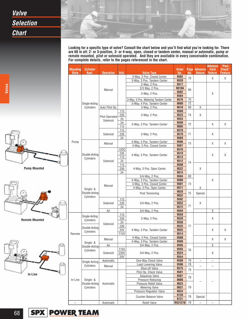
SelectionValve
Chart
68®
Valv
es
Looking for a specific type of valve? Consult the chart below and you’ll find what you’re looking for. Thereare 60 in all: 2- or 3-position, 3- or 4-way, open, closed or tandem center, manual or automatic, pump orremote mounted, pilot or solenoid operated. And they are available in every conceivable combination.For complete details, refer to the pages referenced in the chart.
Advance “Posi-Mounting Cylinder Order Page Advance Hold Check”
Style Appl. Operation Volt. Valve Type No. No. Return Return Feature3-Way, 3 Pos. Closed Center X X3-Way, 3 Pos. Tandem Center
2-Way, 2 Pos.
Manual 2/3 Way, 2 Pos.
3-Way, 2 Pos. X
3-Way, 3 Pos. Metering Tandem CenterSingle-Acting 3-Way, 4 Pos. Tandem Center
Cylinders Auto Pilot Op. 3-Way, 2 Pos. X115
Pilot Operated 230 3-Way, 2 Pos. X
Solenoid 2424 3-Way, 3 Pos. Tandem Center X X115115
Solenoid 230 3-Way, 2 Pos. X24
Pump Manual 4-Way, 3 Pos. Tandem Center X X4-Way, 3 Pos. Closed Center
12DC
Double-Acting 230 4-Way, 3 Pos. Tandem Center X XCylinders 115
Solenoid 24115230 4-Way, 3 Pos. Open Center X24
3/4-Way, 2 Pos.4-Way, 3 Pos. Tandem Center X
Manual 4-Way, 3 Pos. Closed Center
Single- & 4-Way, 3 Pos. Open Center X
Double-Acting Post Tensioning SpecialCylinders
115Solenoid 230 3/4-Way, 2 Pos. X
24Air 3/4-Way, 2 Pos. X
Single-Acting 115
Cylinders 230 3-Way, 2 Pos. X
Solenoid 24
Double-Acting 230
Cylinders 24V 4-Way, 3 Pos. Tandem Center X XRemote 115V
Manual 4-Way, 3 Pos. Closed Center X XSingle- & 4-Way, 3 Pos. Tandem Center
Double-Acting Air 3/4-Way, 2 Pos. X
Cylinders 115VSolenoid 230V 3/4-Way, 2 Pos. X
24V
Single-Acting Automatic One-Way Check Valve – –
Cylinders Manual Load Lowering Valve – –Shut-off Valve
Pilot Op. Check ValveSequence Valve
In-Line Single- & Pressure Reducing – –Double-Acting Automatic Pressure Relief Valve
Cylinders Metering ValvePressure Regulator Valve
Counter Balance Valve Special
– Automatic Relief Valve – –
Pump Mounted
Remote Mounted
In-Line
9502 7095209517
9610A 69958295849576 709609 729610 6995899523 7495539599 72960595799570 7195699506 7395079516951995139512 749590952296159504 6995009501 7395119628 759632959295529572 71
95949559952695569525 77955595149508950995959593 76952495549580 799596 789575 7995819597 78960896239631 7996339720 789721
RV21278 79
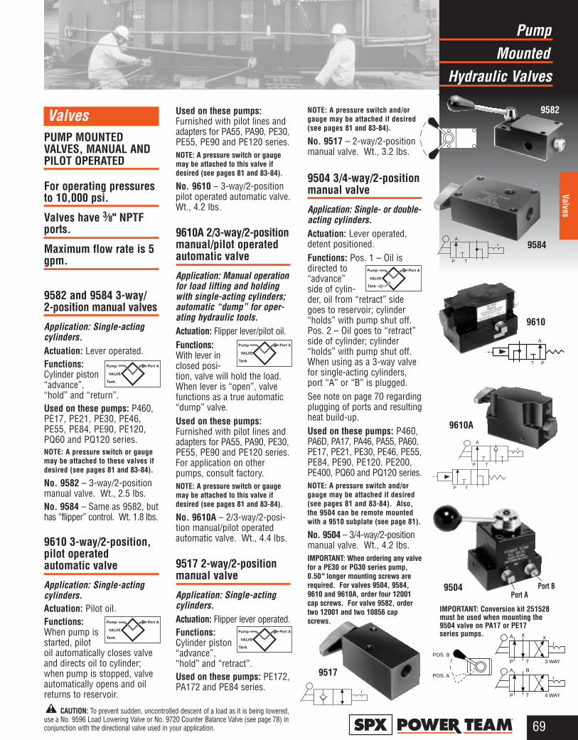
MountedPump
Hydraulic Valves
69®
Valves
ValvesPUMP MOUNTEDVALVES, MANUAL ANDPILOT OPERATED
For operating pressuresto 10,000 psi.
Valves have 3⁄8" NPTFports.
Maximum flow rate is 5gpm.
9582 and 9584 3-way/2-position manual valves
Application: Single-actingcylinders.Actuation: Lever operated.Functions:Cylinder piston“advance”,“hold” and “return”.Used on these pumps: P460,PE17, PE21, PE30, PE46,PE55, PE84, PE90, PE120,PQ60 and PQ120 series.NOTE: A pressure switch or gaugemay be attached to these valves ifdesired (see pages 81 and 83-84).
No. 9582 – 3-way/2-positionmanual valve. Wt., 2.5 lbs.No. 9584 – Same as 9582, buthas “flipper” control. Wt. 1.8 lbs.
9610 3-way/2-position,pilot operated automatic valve
Application: Single-actingcylinders.Actuation: Pilot oil.Functions:When pump isstarted, pilotoil automatically closes valveand directs oil to cylinder;when pump is stopped, valveautomatically opens and oilreturns to reservoir.
Used on these pumps:Furnished with pilot lines andadapters for PA55, PA90, PE30,PE55, PE90 and PE120 series.NOTE: A pressure switch or gaugemay be attached to this valve ifdesired (see pages 81 and 83-84).
No. 9610 – 3-way/2-positionpilot operated automatic valve.Wt., 4.2 lbs.
9610A 2/3-way/2-positionmanual/pilot operatedautomatic valve
Application: Manual operationfor load lifting and holdingwith single-acting cylinders;automatic “dump” for oper-ating hydraulic tools.Actuation: Flipper lever/pilot oil.Functions:With lever inclosed posi-tion, valve will hold the load.When lever is “open”, valvefunctions as a true automatic“dump” valve. Used on these pumps:Furnished with pilot lines andadapters for PA55, PA90, PE30,PE55, PE90 and PE120 series.For application on otherpumps, consult factory.NOTE: A pressure switch or gaugemay be attached to this valve ifdesired (see pages 81 and 83-84).
No. 9610A – 2/3-way/2-posi-tion manual/pilot operatedautomatic valve. Wt., 4.4 lbs.
9517 2-way/2-positionmanual valve
Application: Single-actingcylinders.Actuation: Flipper lever operated.Functions:Cylinder piston“advance”,“hold” and “retract”.Used on these pumps: PE172,PA172 and PE84 series.
NOTE: A pressure switch and/orgauge may be attached if desired(see pages 81 and 83-84).
No. 9517 – 2-way/2-positionmanual valve. Wt., 3.2 lbs.
9504 3/4-way/2-positionmanual valve
Application: Single- or double-acting cylinders.Actuation: Lever operated,detent positioned.Functions: Pos. 1 – Oil isdirected to“advance”side of cylin-der, oil from “retract” sidegoes to reservoir; cylinder“holds” with pump shut off.Pos. 2 – Oil goes to “retract”side of cylinder; cylinder“holds” with pump shut off.When using as a 3-way valvefor single-acting cylinders,port “A” or “B” is plugged. See note on page 70 regardingplugging of ports and resultingheat build-up.Used on these pumps: P460,PA6D, PA17, PA46, PA55, PA60,PE17, PE21, PE30, PE46, PE55,PE84, PE90, PE120, PE200,PE400, PQ60 and PQ120 series. NOTE: A pressure switch and/orgauge may be attached if desired(see pages 81 and 83-84). Also,the 9504 can be remote mountedwith a 9510 subplate (see page 81).
No. 9504 – 3/4-way/2-positionmanual valve. Wt., 4.2 lbs.IMPORTANT: When ordering any valvefor a PE30 or PG30 series pump,0.50" longer mounting screws arerequired. For valves 9504, 9584,9610 and 9610A, order four 12001cap screws. For valve 9582, ordertwo 12001 and two 10856 capscrews.
9584
9610
9610A
9517
9504Port A
Port B
P T
A
P T
P T
A
A
T P
9582
POS. B
POS. A
A X
P T 3 WAY
X
A B
P T 4 WAY
CAUTION: To prevent sudden, uncontrolled descent of a load as it is being lowered,use a No. 9596 Load Lowering Valve or No. 9720 Counter Balance Valve (see page 78) inconjunction with the directional valve used in your application.
IMPORTANT: Conversion kit 251528must be used when mounting the9504 valve on PA17 or PE17 series pumps.
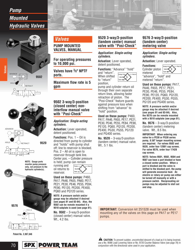
MountedPump
Hydraulic Valves
70®
Valv
es
ValvesPUMP MOUNTEDVALVES, MANUAL
For operating pressuresto 10,000 psi.
Valves have 3⁄8" NPTFports.
Maximum flow rate is 5gpm
9502 3-way/3-position(closed center) non-interflow manual valvewith “Posi-Check”
Application: Single-actingcylinders.Actuation: Lever operated,detent positioned.Functions: Pos. 1 – Oil isdirected from pump to cylinderand “holds” with pump shutoff; line to reservoir is blocked.Pos. 2 – All oil is open toreservoir through tank line.Center pos. – Cylinder pressureis held; pump can remainrunning andoil returns toreservoir.Used on these pumps: P460,PA17, PA46, PA55, PA60, PE17,PE21, PE30, PE46, PE55, PE84,PE90, PE120, PE200, PE400,PQ60 and PQ120 series.NOTE: A pressure switch and/orgauge may be attached if desired(see pages 81 and 83-84). Also, the9502 can be remote mounted if a9510 subplate is used (see page 81).
No. 9502 – 3-way/3-position(closed center) manual valve.Wt., 4.2 lbs.
9520 3-way/3-position(tandem center) manualvalve with “Posi-Check”
Application: Single-actingcylinders.Actuation: Lever operated,detent positioned.Functions: “Advance” “hold”and “return”.When shiftedto “return”position,pump and cylinder return oilthrough their own separatereturn lines, allowing fasterretraction of piston. The“Posi-Check” feature guardsagainst pressure loss whenshifting from “advance” to“hold” position.Used on these pumps: P460,PA17, PA46, PA55, PE17, PE21,PE30, PE46, PE55, PE84, PE90,PE120, PQ60, PQ120, PE200,PE400, PG30, PG55, PG120and PG400 series.No. 9520 – 3-way/3-position(tandem center) manual valve.Wt., 5.1 lbs.
9576 3-way/3-position(tandem center) metering valve
Application: Single-actingcylinders.Actuation: Lever operated.Functions:Cylinder pistonmetered“advance”, “hold” andmetered “return”.Used on these pumps: PA17,PA46, PA55, PE17, PE21,PE30, PE46, PE55, PE84,PE90, PE120, PQ60, PQ120,PE200, PE400, PG30, PG55,PG120 and PG400 series.NOTE: A pressure switch and/orgauge may be attached if desired(see pages 81 and 83-84). Also,the 9576 can be remote mountedwith a 9510 subplate (see page 81).
No. 9576 – 3-way/3-position(tandem center) meteringvalve. Wt., 8.5 lbs.IMPORTANT: When ordering anyvalve for a PE30 or PG30 seriespump, 0.50" longer mounting screwsare required. For valves 9502 and9520, order four 12001 cap screws.For valve 9576, order four 17428cap screws.
NOTE: Valves 9501, 9502, 9504 and9507 can have a port blocked or havea closed center position. When aport is blocked and the valve isshifted to the blocked port, the pumpwill generate excessive heat. Anelectric or rotary air pump can eitherbe turned off manually or with apressure switch. Reciprocating airpumps may be adjusted to stall outand stop.
9520
Patent No. 3,967,646
NOTE: Gauge ports monitor pump pressureonly, not pressure to thehydraulic cylinder(s).
ADVANCE
HOLD
RETRACT
P T
A
P T
A
ADVANCE
HOLD RETRACT
POS. A
POS. B
POS. C
P T
A
9502
9576
CAUTION: To prevent sudden, uncontrolled descent of a load as it is being lowered,use a No. 9596 Load Lowering Valve or No. 9720 Counter Balance Valve (see page 78) inconjunction with the directional valve used in your application.
IMPORTANT: Conversion kit 251528 must be used whenmounting any of the valves on this page on PA17 or PE17pumps.
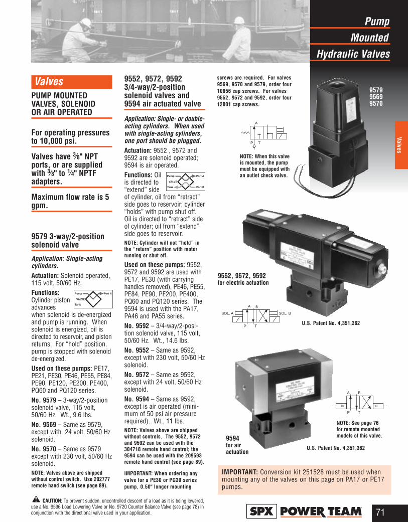
MountedPump
Hydraulic Valves
71®
Valves
ValvesPUMP MOUNTEDVALVES, SOLENOID OR AIR OPERATED
For operating pressuresto 10,000 psi.
Valves have 3⁄8" NPTports, or are suppliedwith 3⁄8" to 1⁄4" NPTFadapters.
Maximum flow rate is 5gpm.
9579 3-way/2-positionsolenoid valve
Application: Single-actingcylinders. Actuation: Solenoid operated,115 volt, 50/60 Hz.Functions:Cylinder pistonadvanceswhen solenoid is de-energizedand pump is running. Whensolenoid is energized, oil isdirected to reservoir, and pistonreturns. For “hold” position,pump is stopped with solenoidde-energized.Used on these pumps: PE17,PE21, PE30, PE46, PE55, PE84,PE90, PE120, PE200, PE400,PQ60 and PQ120 series.No. 9579 – 3-way/2-positionsolenoid valve, 115 volt,50/60 Hz. Wt., 9.6 lbs.No. 9569 – Same as 9579,except with 24 volt, 50/60 Hzsolenoid.No. 9570 – Same as 9579except with 230 volt, 50/60 Hzsolenoid.NOTE: Valves above are shippedwithout control switch. Use 202777remote hand switch (see page 89).
9552, 9572, 9592 3/4-way/2-position solenoid valves and9594 air actuated valve
Application: Single- or double-acting cylinders. When usedwith single-acting cylinders,one port should be plugged. Actuation: 9552 , 9572 and9592 are solenoid operated;9594 is air operated.Functions: Oilis directed to“extend” sideof cylinder, oil from “retract”side goes to reservoir; cylinder“holds” with pump shut off.Oil is directed to “retract” sideof cylinder; oil from “extend”side goes to reservoir.NOTE: Cylinder will not “hold” inthe “return” position with motorrunning or shut off.
Used on these pumps: 9552,9572 and 9592 are used withPE17, PE30 (with carryinghandles removed), PE46, PE55,PE84, PE90, PE200, PE400,PQ60 and PQ120 series. The9594 is used with the PA17,PA46 and PA55 series.No. 9592 – 3/4-way/2-posi-tion solenoid valve, 115 volt,50/60 Hz. Wt., 14.6 lbs.No. 9552 – Same as 9592,except with 230 volt, 50/60 Hzsolenoid.No. 9572 – Same as 9592,except with 24 volt, 50/60 Hzsolenoid.No. 9594 – Same as 9592,except is air operated (mini-mum of 50 psi air pressurerequired). Wt., 11 lbs.NOTE: Valves above are shippedwithout controls. The 9552, 9572and 9592 can be used with the304718 remote hand control; the9594 can be used with the 209593remote hand control (see page 89).
IMPORTANT: When ordering anyvalve for a PE30 or PG30 seriespump, 0.50" longer mounting
screws are required. For valves9569, 9570 and 9579, order four10856 cap screws. For valves9552, 9572 and 9592, order four12001 cap screws.
957995699570
NOTE: When this valveis mounted, the pumpmust be equipped withan outlet check valve.
NOTE: See page 76for remote mountedmodels of this valve.
9552, 9572, 9592for electric actuation
9594for airactuation
U.S. Patent No. 4,351,362
U.S. Patent No. 4,351,362
P T
A
P T
A
SOL. BSOL. A
B
P T
A B
CAUTION: To prevent sudden, uncontrolled descent of a load as it is being lowered,use a No. 9596 Load Lowering Valve or No. 9720 Counter Balance Valve (see page 78) inconjunction with the directional valve used in your application.
IMPORTANT: Conversion kit 251528 must be used whenmounting any of the valves on this page on PA17 or PE17pumps.
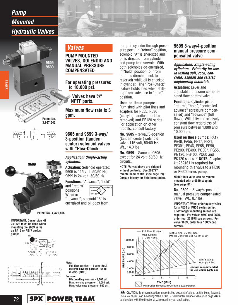
MountedPump
Hydraulic Valves
72®
Valv
es
ValvesPUMP MOUNTEDVALVES, SOLENOID ANDMANUAL PRESSURECOMPENSATED
For operating pressuresto 10,000 psi.
Valves have 3⁄8"NPTF ports.
Maximum flow rate is 5gpm.
9605 and 9599 3-way/3-position (tandem center) solenoid valveswith “Posi-Check”
Application: Single-actingcylinders. Actuation: Solenoid operated:9605 is 115 volt, 50/60 Hz;9599 is 24 volt, 50/60 Hz. Functions: “Advance”, “hold”and “return”positions.When in“advance”, solenoid “B” isenergized and oil goes from
pump to cylinder through pres-sure port. In “return” position,solenoid “A” is energized andoil is directed from cylinderand pump to reservoir. Withboth solenoids de-energized,in “hold” position, oil frompump is directed back toreservoir while oil is checkedin cylinder. The “Posi-Check”feature holds load when shift-ing from “advance to “hold”position.Used on these pumps:Furnished with pilot lines andadapters for PE55, PE30 (carrying handles must beremoved) and PE120 series.For application on other models, consult factory.No. 9605 – 3-way/3-position(tandem center) solenoidvalve, 115 volt, 50/60 Hz.Wt., 14.0 lbs.No. 9599 – Same as 9605except for 24 volt, 50/60 Hzcircuits.NOTE: Valves above are shippedwithout controls. Use 202777remote hand control (see page 89).Consult factory for field installation.
9609 3-way/4-positionmanual pressure com-pensated valve
Application: Single-actingcylinders. Primarily for usein testing soil, rock, con-crete, asphalt and relatedengineering materials.Actuation: Lever andadjustable, pressure compen-sated flow control valve.Functions: Cylinder piston“return”, “hold”, “controlledadvance” (pressure compen-sated) and “advance” (fullflow). Will deliver a relativelyconstant flow regardless ofpressure between 1,000 and10,000 psi.Used on these pumps: PA17,PA46, PA55, PE17, PE21,PE30*, PE46, PE55, PE90,PE200, PE400, PG30*, PG55,PG120, PG400, PQ60 andPQ120 series. * NOTE: Adapterkit 252161 is required formounting this valve to a PE30or PG30 series pump.NOTE: This valve can be remotemounted with a 9510 subplate (see page 81).
No. 9609 – 3-way/4-positionmanual pressure compensatedvalve. Wt., 8.7 lbs.IMPORTANT: When ordering any valvefor a PE30 or PG30 series pump,0.50" longer mounting screws arerequired. For valves 9599 and 9605,order four 251078 cap screws. Forvalve 9609, order four 10855 capscrews.
96059599
Patent No.3,967,646
P T
A
1 2 3 4 5 6 7
10,000
8,000
6,000
4,000
2,0001,000
0
Full Flow PositionMax. Setting:770 psi / Sec.
Test Setting: 35 psi / Sec.(Meets Concrete Std. ASTM C-39)
Min. Setting:6.24 psi / Sec.
Metered and Pressure Compensated PositionTIME (MIN.)
PR
ES
SU
RE
(psi
)
Unit not recommendedfor use under 1,000 psi
Flow:Full flow position — 5 gpm (Ref.)Metered advance position - 65 cu. in./min. (Max.)
Pressure:Min. working pressure - 1,000 psi.Max. working pressure - 10,000 psi.Max. valve case pressure - 500 psi.
CON. ADV.ADV. HOLD RET.
A
P T
RET.
HOLD
CONTR.ADV.
1
2 3
4
6 5
FULLADV.
Patent No. 4,471,805
9609
CAUTION: To prevent sudden, uncontrolled descent of a load as it is being lowered,use a No. 9596 Load Lowering Valve or No. 9720 Counter Balance Valve (see page 78) inconjunction with the directional valve used in your application.
IMPORTANT: Conversion kit251528 must be used whenmounting the 9609 valve on PA17 or PE17 seriespumps.
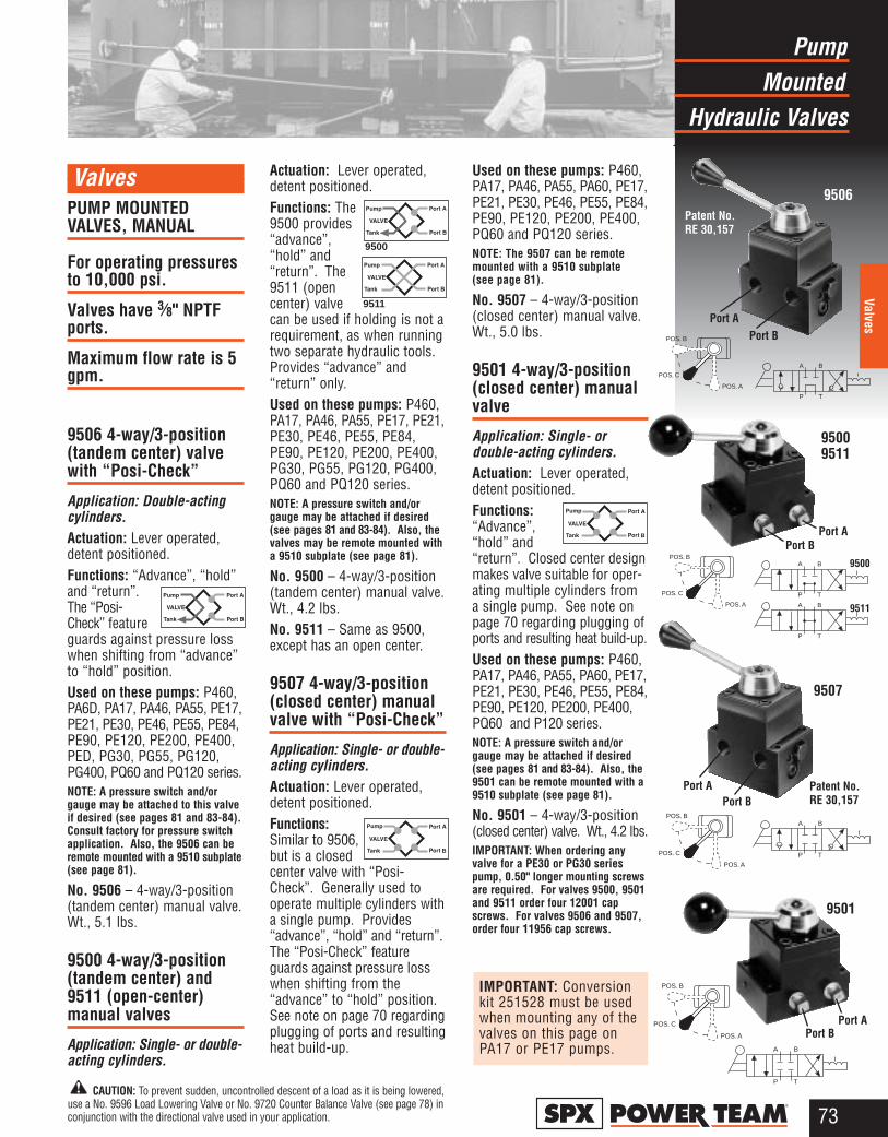
MountedPump
Hydraulic Valves
73®
Valves
ValvesPUMP MOUNTEDVALVES, MANUAL
For operating pressuresto 10,000 psi.
Valves have 3⁄8" NPTFports.
Maximum flow rate is 5gpm.
9506 4-way/3-position(tandem center) valvewith “Posi-Check”
Application: Double-actingcylinders.Actuation: Lever operated,detent positioned.Functions: “Advance”, “hold”and “return”.The “Posi-Check” featureguards against pressure losswhen shifting from “advance”to “hold” position.Used on these pumps: P460,PA6D, PA17, PA46, PA55, PE17,PE21, PE30, PE46, PE55, PE84,PE90, PE120, PE200, PE400,PED, PG30, PG55, PG120,PG400, PQ60 and PQ120 series.NOTE: A pressure switch and/orgauge may be attached to this valveif desired (see pages 81 and 83-84).Consult factory for pressure switchapplication. Also, the 9506 can beremote mounted with a 9510 subplate(see page 81).
No. 9506 – 4-way/3-position(tandem center) manual valve.Wt., 5.1 lbs.
9500 4-way/3-position(tandem center) and9511 (open-center)manual valves
Application: Single- or double-acting cylinders.
Actuation: Lever operated,detent positioned.Functions: The9500 provides“advance”,“hold” and“return”. The9511 (opencenter) valvecan be used if holding is not arequirement, as when runningtwo separate hydraulic tools.Provides “advance” and“return” only.Used on these pumps: P460,PA17, PA46, PA55, PE17, PE21,PE30, PE46, PE55, PE84,PE90, PE120, PE200, PE400,PG30, PG55, PG120, PG400,PQ60 and PQ120 series.NOTE: A pressure switch and/orgauge may be attached if desired(see pages 81 and 83-84). Also, thevalves may be remote mounted witha 9510 subplate (see page 81).
No. 9500 – 4-way/3-position(tandem center) manual valve.Wt., 4.2 lbs.No. 9511 – Same as 9500,except has an open center.
9507 4-way/3-position(closed center) manualvalve with “Posi-Check”
Application: Single- or double-acting cylinders.Actuation: Lever operated,detent positioned.Functions:Similar to 9506,but is a closedcenter valve with “Posi-Check”. Generally used tooperate multiple cylinders witha single pump. Provides“advance”, “hold” and “return”.The “Posi-Check” featureguards against pressure losswhen shifting from the“advance” to “hold” position.See note on page 70 regardingplugging of ports and resultingheat build-up.
Used on these pumps: P460,PA17, PA46, PA55, PA60, PE17,PE21, PE30, PE46, PE55, PE84,PE90, PE120, PE200, PE400,PQ60 and PQ120 series.NOTE: The 9507 can be remotemounted with a 9510 subplate (see page 81).
No. 9507 – 4-way/3-position(closed center) manual valve.Wt., 5.0 lbs.
9501 4-way/3-position(closed center) manualvalve
Application: Single- or double-acting cylinders.Actuation: Lever operated,detent positioned.Functions:“Advance”,“hold” and“return”. Closed center designmakes valve suitable for oper-ating multiple cylinders from a single pump. See note onpage 70 regarding plugging ofports and resulting heat build-up. Used on these pumps: P460,PA17, PA46, PA55, PA60, PE17,PE21, PE30, PE46, PE55, PE84,PE90, PE120, PE200, PE400,PQ60 and P120 series.NOTE: A pressure switch and/orgauge may be attached if desired(see pages 81 and 83-84). Also, the9501 can be remote mounted with a9510 subplate (see page 81).
No. 9501 – 4-way/3-position(closed center) valve. Wt., 4.2 lbs.IMPORTANT: When ordering anyvalve for a PE30 or PG30 seriespump, 0.50" longer mounting screwsare required. For valves 9500, 9501and 9511 order four 12001 capscrews. For valves 9506 and 9507,order four 11956 cap screws.
9506
9507
Patent No.RE 30,157
95009511
9501
9511
9500
Port APort B
P T
A B
P T
A B
POS. B
POS. C
POS. A
POS. B
POS. C
POS. A
P T
A B
Port APort B
Port BPort A
Port BPort A
P T
A B
POS. B
POS. C
POS. A
Patent No.RE 30,157
CAUTION: To prevent sudden, uncontrolled descent of a load as it is being lowered,use a No. 9596 Load Lowering Valve or No. 9720 Counter Balance Valve (see page 78) inconjunction with the directional valve used in your application.
9500
B
B
9511
P T
A B
POS. B
POS. C
POS. A
IMPORTANT: Conversionkit 251528 must be usedwhen mounting any of thevalves on this page onPA17 or PE17 pumps.

MountedPump
Hydraulic Valves
74®
Valv
es
ValvesPUMP MOUNTEDVALVES, SOLENOIDOPERATED
For operating pressuresto 10,000 psi.
Valves have 3⁄8" NPTFports.
Maximum flow rate is 5gpm.
9513 4-way/3-position(tandem center) pilotoperated solenoid valve
Application: Double-actingcylinders.Actuation: Solenoid operated,115 volt, 50/60 Hz.Functions:“Advance”,“hold” and“return”. The “Posi-Check” feature holds the load whenshifting from the “advance” tothe “hold” position.Used on these pumps: PE17,PE21, PE30 (with carryinghandles removed), PE46, PE55,PE84, PE90, PE120, PE200,PE400, PQ60 and PQ120 series. NOTE: A gauge may be attached ifdesired (see pages 83-84).
No. 9513 – 4-way/3-position(tandem center) solenoidvalve, 115 volt, 50/60 Hz.Wt., 18.1 lbs.No. 9512 – Same as 9513except for 24 volt, 50/60 Hzcircuits.
No. 9516 – Same as 9513except for 12 volt DC. Suitablefor use on the PG1204S andPG400 series pumps only.No. 9519 – Same as 9513except for 230 volt, 50/60 Hzcircuits. Consult factory forfield installation.NOTE: Valves above are shippedwithout control switch. Use 202778remote hand switch (see page 89).
IMPORTANT: Conversion kit 251528must be used when mounting 9513,9512, 9516 or 9519 valves on PE17series pumps.
9590 4-way/3-position(open center) solenoidvalve
Application: Double-actingcylinders.Actuation: Solenoid operated,115 volt, 50/60 Hz.Functions:“Advance”,open center and“return” positions. Cylinderports and pump port are opento reservoir in “neutral”.Used on these pumps:Furnished with pilot lines andadapters for PE30 (with carry-ing handles removed), PE55,PE90 and PE120 series. Forother pump models, consultfactory.NOTE: A pressure switch and/orgauge may be attached if desired(see pages 81 and 83-84).
No. 9590 – 4-way/3-position(open center) solenoid valve,115 volt, 50/60 Hz. Wt., 15.5 lbs.No. 9522 – Same as 9590except for 230 volt, 50/60 Hz.No. 9615 – Same as 9590except for 24 volt, 50/60 Hz.NOTE: Valves above are shippedwithout control switch. Use 202778remote hand switch (see page 89).
9589 3-way/2-position(pilot operated) solenoid valve
Application: Single-actingcylinders.Actuation: Solenoid operated,115 volt, 50/60 Hz.Function:“Advance” and “return”.Used on these pumps:Furnished with pilot lines and adapters for PE30 (withcarrying handles removed),PE55, PE90 and PE120series. For other pump models, consult factory.NOTE: A pressure switch and/orgauge may be attached if desired(see pages 81 and 83-84).
No. 9589 – 3-way/2-position(pilot operated) solenoidvalve, 115 volt, 50/60 Hz.Wt., 8.2 lbs.No. 9523 – Same as 9589except for 230 volt, 50/60 Hz.No. 9553 – Same as 9589except for 24 volt, 50/60 Hz.NOTE: Valves above are shippedwithout control switch. Use 202777remote hand switch (see page 89).
IMPORTANT: When ordering anyvalve for a PE30 or PG30 seriespump, 0.50" longer mounting screwsare required. For valves 9513 and9519, order four 11956 cap screws.For valves 9523, 9553 and 9589,order four 10855 cap screws. Forvalves 9522, 9590 and 9615, orderfour 10854 cap screws.
9513951295169519
952295909615
952395539589
Patent No.4,083,381
Port A
Port B
P T
A B
P T
A B
P T
A
SOLHYD
Port A
Port B
CAUTION: To prevent sudden, uncontrolled descent of a load as it is being lowered,use a No. 9596 Load Lowering Valve or No. 9720 Counter Balance Valve (see page 78) inconjunction with the directional valve used in your application.
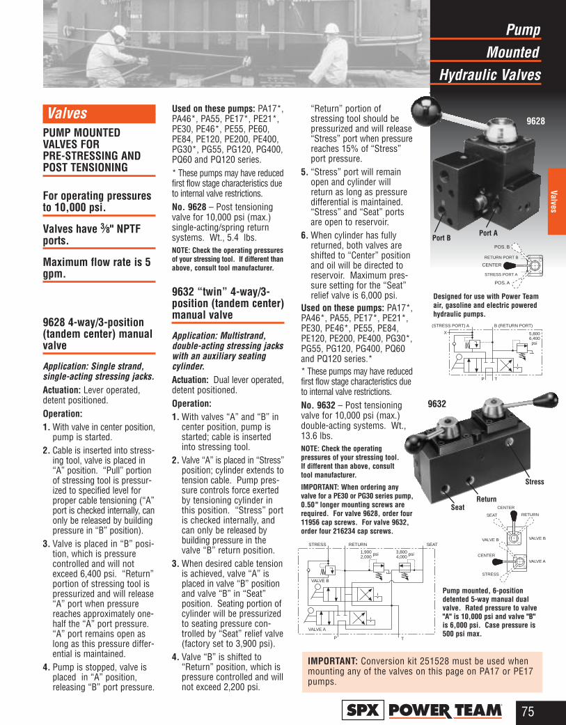
MountedPump
Hydraulic Valves
75®
Valves
Valves PUMP MOUNTEDVALVES FOR PRE-STRESSING ANDPOST TENSIONING
For operating pressuresto 10,000 psi.
Valves have 3⁄8" NPTFports.
Maximum flow rate is 5gpm.
9628 4-way/3-position(tandem center) manualvalve
Application: Single strand,single-acting stressing jacks.Actuation: Lever operated,detent positioned.Operation:1. With valve in center position,
pump is started.2. Cable is inserted into stress-
ing tool, valve is placed in“A” position. “Pull” portionof stressing tool is pressur-ized to specified level forproper cable tensioning (“A”port is checked internally, canonly be released by buildingpressure in “B” position).
3. Valve is placed in “B” posi-tion, which is pressure controlled and will notexceed 6,400 psi. “Return”portion of stressing tool ispressurized and will release“A” port when pressurereaches approximately one-half the “A” port pressure.“A” port remains open aslong as this pressure differ-ential is maintained.
4. Pump is stopped, valve isplaced in “A” position,releasing “B” port pressure.
Used on these pumps: PA17*,PA46*, PA55, PE17*, PE21*,PE30, PE46*, PE55, PE60,PE84, PE120, PE200, PE400,PG30*, PG55, PG120, PG400,PQ60 and PQ120 series.* These pumps may have reducedfirst flow stage characteristics dueto internal valve restrictions.No. 9628 – Post tensioningvalve for 10,000 psi (max.)single-acting/spring returnsystems. Wt., 5.4 lbs.NOTE: Check the operating pressuresof your stressing tool. If different thanabove, consult tool manufacturer.
9632 “twin” 4-way/3-position (tandem center)manual valve
Application: Multistrand,double-acting stressing jackswith an auxiliary seatingcylinder.Actuation: Dual lever operated,detent positioned.Operation:1. With valves “A” and “B” in
center position, pump isstarted; cable is insertedinto stressing tool.
2. Valve “A” is placed in “Stress”position; cylinder extends totension cable. Pump pres-sure controls force exertedby tensioning cylinder inthis position. “Stress” portis checked internally, andcan only be released bybuilding pressure in thevalve “B” return position.
3. When desired cable tensionis achieved, valve “A” isplaced in valve “B” positionand valve “B” in “Seat”position. Seating portion ofcylinder will be pressurizedto seating pressure con-trolled by “Seat” relief valve(factory set to 3,900 psi).
4. Valve “B” is shifted to“Return” position, which ispressure controlled and willnot exceed 2,200 psi.
“Return” portion of stressing tool should bepressurized and will release“Stress” port when pressurereaches 15% of “Stress”port pressure.
5. “Stress” port will remainopen and cylinder willreturn as long as pressuredifferential is maintained.“Stress” and “Seat” portsare open to reservoir.
6. When cylinder has fullyreturned, both valves areshifted to “Center” positionand oil will be directed toreservoir. Maximum pres-sure setting for the “Seat”relief valve is 6,000 psi.
Used on these pumps: PA17*,PA46*, PA55, PE17*, PE21*,PE30, PE46*, PE55, PE84,PE120, PE200, PE400, PG30*,PG55, PG120, PG400, PQ60and PQ120 series.** These pumps may have reducedfirst flow stage characteristics dueto internal valve restrictions.No. 9632 – Post tensioningvalve for 10,000 psi (max.)double-acting systems. Wt.,13.6 lbs.NOTE: Check the operating pressures of your stressing tool.If different than above, consult tool manufacturer.
IMPORTANT: When ordering anyvalve for a PE30 or PG30 series pump,0.50 " longer mounting screws arerequired. For valve 9628, order four11956 cap screws. For valve 9632,order four 216234 cap screws.
9628
Stress
Pump mounted, 6-positiondetented 5-way manual dualvalve. Rated pressure to valve"A" is 10,000 psi and valve "B"is 6,000 psi. Case pressure is500 psi max.
Designed for use with Power Teamair, gasoline and electric poweredhydraulic pumps.
Port APort B
ReturnSeat
POS. B
CENTER
POS. A
RETURN PORT B
STRESS PORT A
P T
(STRESS PORT) A B (RETURN PORT)
X 5,8006,400 psi
P T
1,9002,000
psi 3,8004,000
psi
STRESS RETURN SEAT
VALVE B
VALVE A
SEAT
CENTER
RETURN
VALVE B
VALVE A
STRESS
VALVE B
CENTER
9632
IMPORTANT: Conversion kit 251528 must be used whenmounting any of the valves on this page on PA17 or PE17pumps.
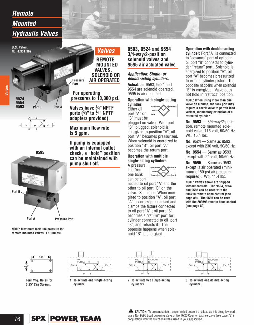
MountedRemote
Hydraulic Valves
76®
Valv
es
ValvesREMOTEMOUNTED
VALVES,SOLENOID OR
AIR OPERATED
For operating pressures to 10,000 psi.
Valves have 1⁄4" NPTFports (3⁄8" to 1⁄4" NPTFadapters provided).
Maximum flow rate is 5 gpm.
If pump is equippedwith an internal outletcheck, a “hold” positioncan be maintained withpump shut off.
9593, 9524 and 95543/4-way/2-position solenoid valves and9595 air actuated valve
Application: Single- or double-acting cylinders.Actuation: 9593, 9524 and9554 are solenoid operated,9595 is air operated.Operation with single-actingcylinder:Either oilport “A” or“B” must beplugged on valve. With port“B” plugged, solenoid isenergized to position “A”; oilport “A” becomes pressurized.When solenoid is energized toposition “B”, oil port “A”becomes the return port.Operation with multiple single-acting cylinders: A pressureline fromone bankcan be con-nected to oil port “A” and theother to oil port “B” on thevalve. Sequence: When ener-gized to position “A”, oil port“A” becomes pressurized andclamps the fixture connectedto oil port “A” ; oil port “B”becomes a “return” port forcylinder connected to oil port“B”, and retracts it. Theopposite happens when sole-noid “B” is energized.
Operation with double-actingcylinder: Port “A” is connectedto “advance” port of cylinder,oil port “B” connects to cylin-der “return” port. Solenoid isenergized to position “A”, oilport “A” becomes pressurizedto extend cylinder piston. Theopposite happens when solenoid“B” is energized. Valve doesnot hold in “retract” position.NOTE: When using more than onevalve on a pump, the tank port mayrequire a check valve to permit inad-vertent, momentary extension of aretracted cylinder.
No. 9593 — 3/4-way/2-posi-tion, remote mounted sole-noid valve, 115 volt, 50/60 Hz.Wt., 15.4 lbs.No. 9524 — Same as 9593except with 230 volt, 50/60 Hz.No. 9554 — Same as 9593except with 24 volt, 50/60 Hz.No. 9595 — Same as 9593except is air operated (mini-mum of 50 psi air pressurerequired). Wt., 11.4 lbs. NOTE: Valves above are shippedwithout controls. The 9524, 9554and 9593 can be used with the304718 remote hand control (seepage 89). The 9595 can be usedwith the 209593 remote hand control(see page 89).
P T
A B
NOTE: Maximum tank line pressure forremote mounted valves is 1,000 psi.
U.S. Patent No. 4,351,362
952495549593
3. To actuate one double-actingcylinder.
Port APort B
Pressure Port
P T
OILPORT A
SOL. A SOL. B
OIL PORTB
P T
OILPORT A
SOL. A SOL. B
OIL PORTB
P T
XOILPORT A
SOL. A
X
SOL. B
2. To actuate two single-actingcylinders.
3.13
2.00
1. To actuate one single-actingcylinder.
Pressure PortPort A
Port B
9595
Four Mtg. Holes for 0.25" Cap Screws.
CAUTION: To prevent sudden, uncontrolled descent of a load as it is being lowered,use a No. 9596 Load Lowering Valve or No. 9720 Counter Balance Valve (see page 78) inconjunction with the directional valve used in your application.
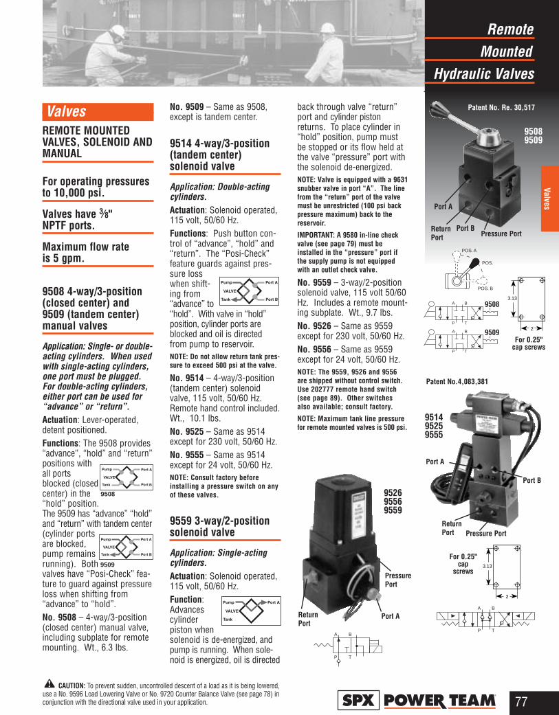
MountedRemote
Hydraulic Valves
77®
Valves
ValvesREMOTE MOUNTEDVALVES, SOLENOID ANDMANUAL
For operating pressuresto 10,000 psi.
Valves have 3⁄8" NPTF ports.
Maximum flow rate is 5 gpm.
9508 4-way/3-position(closed center) and9509 (tandem center)manual valves
Application: Single- or double-acting cylinders. When usedwith single-acting cylinders,one port must be plugged.For double-acting cylinders,either port can be used for“advance” or “return”.Actuation: Lever-operated,detent positioned.Functions: The 9508 provides“advance”, “hold” and “return”positions withall portsblocked (closedcenter) in the“hold” position.The 9509 has “advance” “hold”and “return” with tandem center(cylinder portsare blocked,pump remainsrunning). Bothvalves have “Posi-Check” fea-ture to guard against pressureloss when shifting from“advance” to “hold”.No. 9508 – 4-way/3-position(closed center) manual valve,including subplate for remotemounting. Wt., 6.3 lbs.
No. 9509 – Same as 9508,except is tandem center.
9514 4-way/3-position(tandem center) solenoid valve
Application: Double-actingcylinders.Actuation: Solenoid operated,115 volt, 50/60 Hz.Functions: Push button con-trol of “advance”, “hold” and“return”. The “Posi-Check”feature guards against pres-sure losswhen shift-ing from“advance” to“hold”. With valve in “hold”position, cylinder ports areblocked and oil is directedfrom pump to reservoir. NOTE: Do not allow return tank pres-sure to exceed 500 psi at the valve.
No. 9514 – 4-way/3-position(tandem center) solenoidvalve, 115 volt, 50/60 Hz.Remote hand control included.Wt., 10.1 lbs.No. 9525 – Same as 9514except for 230 volt, 50/60 Hz.No. 9555 – Same as 9514except for 24 volt, 50/60 Hz.NOTE: Consult factory beforeinstalling a pressure switch on anyof these valves.
9559 3-way/2-positionsolenoid valve
Application: Single-actingcylinders.Actuation: Solenoid operated,115 volt, 50/60 Hz.Function:Advancescylinder piston whensolenoid is de-energized, andpump is running. When sole-noid is energized, oil is directed
back through valve “return”port and cylinder pistonreturns. To place cylinder in“hold” position, pump mustbe stopped or its flow held atthe valve “pressure” port withthe solenoid de-energized. NOTE: Valve is equipped with a 9631snubber valve in port “A”. The linefrom the “return” port of the valvemust be unrestricted (100 psi backpressure maximum) back to thereservoir.
IMPORTANT: A 9580 in-line checkvalve (see page 79) must beinstalled in the “pressure” port ifthe supply pump is not equippedwith an outlet check valve.
No. 9559 – 3-way/2-positionsolenoid valve, 115 volt 50/60Hz. Includes a remote mount-ing subplate. Wt., 9.7 lbs.No. 9526 – Same as 9559except for 230 volt, 50/60 Hz.No. 9556 – Same as 9559except for 24 volt, 50/60 Hz.NOTE: The 9559, 9526 and 9556are shipped without control switch.Use 202777 remote hand switch(see page 89). Other switches also available; consult factory.
NOTE: Maximum tank line pressurefor remote mounted valves is 500 psi.
951495259555
952695569559
Patent No. Re. 30,517
Port A
Port B
Pressure Port
PressurePort
ReturnPort
ReturnPort
Port A
Port B
For 0.25" cap screws
For 0.25" cap
screws
9509
POS. B
POS.
POS. A
P T
A B
P T
A B
P T
A B
P T
A B
3.13
2
3.13
2
Port A
Pressure PortReturnPort
95089509
9508
Patent No.4,083,381
CAUTION: To prevent sudden, uncontrolled descent of a load as it is being lowered,use a No. 9596 Load Lowering Valve or No. 9720 Counter Balance Valve (see page 78) inconjunction with the directional valve used in your application.
B
9508
9509

Hydraulic In-Line
Valves
78®
Valv
es
In-Line ValvesFor operating pressuresto 10,000 psi.
Maximum flow rate is 5gpm.
9596 load lowering valve
Application: Precisionmetering for controlled cylinder piston return.Operation: Permits free flowwhen extending cylinder, built-in pressure relief and “Posi-Check” locks and holds loadin raised position until opera-tor opens valve. May be pre-set to provide consistentmetered return, or operatormay select rate of return witheach actuation. Has 3⁄8" NPTFports.NOTE: Pressure relief valve settingis 12,000 psi. Operating pressure is10,000 psi and max. flow rate is 5gpm.
No. 9596 – Load loweringvalve. Wt., 2.1 lbs.
9597 sequence valve
Application: Used when onecylinder in a multi-cylinderapplication must advancebefore any other.Operation: Pump is connectedto port “P” and separate cylin-ders to ports “A” and “B”.When pressure is applied toport “P”, cylinder “A” advances.Cylinder “B” will not advanceuntil a predetermined pressure
setting is reached in cylinder“A”. Pressure setting isadjustable from 500 to 5,000psi with adjustment screw;factory preset at 1,000 psi.Has 3⁄8" NPTF ports.No. 9597 – Pressure controlsequencing valve. Wt., 5.6 lbs.
9608 pressure reducingvalve
Application: Provides com-plete, independent pressurecontrol to two or moreclamping systems operatedby a single power source.Operation: Can be used toprovide different pressures invarious stages of a single system. Virtually zero leakageacross valve means each sys-tem can be operated by a singlecontinuous pressure source.Adjustable from 1,000 to 5,000psi at outlet port “B” (sec-ondary). Has 1⁄4" NPTF ports.No. 9608 – Pressure reducingvalve. Wt., 5.8 lbs.
9720 counter balancevalve
Application: Double-actingcylinders. Provides positiveholding and controlled,“chatter-free” lowering of a load. Operation: Load is raised atflow rate of pump, and heldwhen pump is shut off. Whenthe pump is shifted to “retract”,the counter balance valve willcontinue to hold the load untilsystem pressure exceedspressure caused by load. Theload can then be loweredsmoothly to the flow rate of thepump. The counter balancevalve is designed to operatewith pumps having a highpressure flow rate of up to120 cu. in./min. and cylinderratios of 3 to 1.
CAUTION: This patentedcounter balance valve has apilot pressure as high as 3,000psi. Because this pressure isapplied to the rod end of thecylinder while it is already underload, the system should notbe sized for loads greater than80% of cylinder rated capacity.No. 9720 – Counter balancevalve, including two male andtwo female half couplers, twohydraulic hoses, fittings anddust caps. Wt., 10 lbs.No. 9721 – Same as 9720,but does not include couplers,hoses, fittings and dust caps.Wt., 9.2 lbs.
9596
9608
9597
Port APrimary
3⁄8" NPTFPort P
Pressure3⁄8" NPTF
Port BSecondary3⁄8" NPTF Adjusting
Screw
To Atmosphere
SequenceValve
OptionalCircuit forDouble-ActingRams
Cyl. No. 2Secondary
Circuit
Cyl. No. 1PrimaryCircuit
Port A Port B
No. 9502Valve
No. 9597Sequence
Valve
No. 9508Remote Valve
Port isplugged
Load Lowering Valve No. 9596
Return
SecondaryCylinder
PrimaryCylinder
AdjustingScrew
PILOT
TO PUMPRETRACT
TO PUMPADVANCE
TO CYL.RETRACTPORT
TO CYL.BASEPORT
No. 9626Manifold
Pressure
Patent No. 5,676,169
9720
CAUTION: To prevent sudden, uncontrolled descent of a load as it is being lowered,use a No. 9596 Load Lowering Valve or No. 9720 Counter Balance Valve in conjunctionwith the directional valve used in your application.
ReducedPressureControl
Port A Port B
Port T
OverPressureControl

Hydraulic In-Line
Valves
79®
Valves
In-Line ValvesFor operating pressuresto 10,000 psi.
Maximum flow rate is 5gpm (No. 9633 has flowrange of 17 cu. in./min.to 6 gpm).
9575 shut-off valve
Application: This needlevalve permits fine meteringof hydraulic oil.Operation: Can be used forcontrolling multiple single-acting cylinders.No. 9575 – Shut off valve with3⁄8" NPTF ports. Wt., 1.4 lbs.
9580 check valve
Application: Permits flow ofhydraulic oil in one directiononly.Operation: Installs right inhydraulic line.No. 9580 – Check valve with3⁄8" NPTF male ends. Wt., .4 lb.
9581 pilot operatedcheck valve
Application: For use withopen or tandem centervalves. Permits free flow offluid in one direction.Operation: Flow is blocked inopposite direction until pilotoil pressure is applied. Thisprevents the loss of pressureif the valve is inadvertentlyshifted or the pump line isbroken. Minimum crackingpressure is 60 psi. Requiredpilot pressure is approximate-ly 16% of checked systempressure.No. 9581 – Pilot operatedcheck valve with 3⁄8" NPTFports. Wt., 3.8 lbs.
9623 “in-line” pressurerelief valve
Application: Single- or double-acting cylinders. For remotelocations in a hydraulic circuitwhere maximum pressurerequirements are less thanbasic overload valve settingin pump.Operation: Adjustable from1,000 to 10,000 psi. Valve isspring-loaded and direct-acting.No. 9623 – Pressure relief valvewith 3⁄8" NPTF ports. Wt., 2 lbs.
9631 metering valve
Application: For systems usinglarge cylinders or extendedlengths of hydraulic hose.Operation: Controls surges byrestricting flow if it exceeds 7gpm. When flow subsides,valve reopens automatically.Has 3⁄8" NPTF male end tothread into return port of system control valve, and a3⁄8" NPTF female end, permit-ting return hose to be directlyconnected. No. 9631 – Metering valve.Wt., .2 lb.
9633 “in-line” pressureregulator valve
Application: Single- or double-acting cylinders. Permitsadjusting operating pressuresat various values below reliefvalve setting of pump.Operation: Regulator valve iseasily adjusted to maintainpressures between 300 and10,000 psi. Maintains a givenpressure setting within 3% overrepeated cycles. Flow rangeis 17 cu. in./minute to 6 gpm.No. 9633 – In-line pressureregulator valve with two 3⁄8"NPTF inlet ports and one 1⁄8"NPTF tank port. Includes 3 footdrain line kit. Wt., 1.9 lbs.
RV21278 series reliefvalves
Application: Provide an eco-nomical means of protectingan hydraulic circuit againstover pressurization. Operation: These factory preset valves are designed formaximum flow rate of 5 gpm.Furnished with 1⁄8" NPT maleport. All valves weigh .2 lb.NOTE: Care should be exercised toprotect workers from hot, pressurizedhydraulic oil. Install these valvesonly in an enclosed or shielded area.
Valve Pressure Part No. Setting (psi)RV21278 10,100 / 10,700
RV21278-6 600 /640RV21278-10 900 / 1,000RV21278-15 1,500 / 1,700RV21278-20 1,900 / 2,200RV21278-28 2,700 / 3,000RV21278-30 3,000 / 3,400RV21278-32 3,100 / 3,300RV21278-35 3,500 / 3,800RV21278-40 4,100 / 4,500RV21278-43 4,400 / 4,800RV21278-48 4,900 / 5,300RV21278-50 5,100 / 5,700RV21278-52 5,300 / 5,900RV21278-55 5,600 / 6,200RV21278-57 5,800 / 6,400RV21278-60 6,100 / 6,700RV21278-65 6,600 / 7,200RV21278-70 7,100 / 7,700RV21278-75 7,600 / 8,200RV21278-80 8,100 / 8,700RV21278-83 8,400 / 9,000RV21278-86 8,700 / 9,300RV21278-88 8,900 / 9,600RV21278-90 9,100 / 9,700
9581
9631
9623
RV21278 Series
1⁄8 NPT
9580
Simplyturn the han-
dle clockwiseto increase the
pressure setting,counter-clockwise
to reduce pressure.
Note: 3' Drain Line Kit is included.
9575
Double-actingCylinder
No. 9623PressureRelief Valve
Tee
Gauge
No. 9506Valve
Adj. Screw
Double-acting Cylinder
No. 9500Valve
No. 9625 Pressure Switch
No. 9581 Pilot Op. Check Valve
Preset — Non-Serviceable
9633
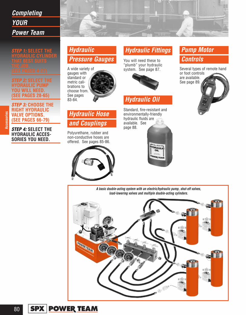
YOURCompleting
Power Team
80®
Acce
ssor
ies
STEP 1: SELECT THEHYDRAULIC CYLINDERTHAT BEST SUITS THE JOB.(SEE PAGES 4-27)
STEP 2: SELECT THEHYDRAULIC PUMP YOU WILL NEED. (SEE PAGES 28-65)
STEP 3: CHOOSE THERIGHT HYDRAULICVALVE OPTIONS. (SEE PAGES 66-79)
STEP 4: SELECT THEHYDRAULIC ACCES-SORIES YOU NEED.
Hydraulic Pressure Gauges
A wide variety ofgauges withstandard ormetric cali-brations tochoose from.See pages 83-84.
Hydraulic Hose and Couplings
Polyurethane, rubber andnon-conductive hoses areoffered. See pages 85-86.
Hydraulic FittingsYou will need these to“plumb” your hydraulic system. See page 87.
Hydraulic Oil Standard, fire-resistant andenvironmentally-friendlyhydraulic fluids areavailable. Seepage 88.
Pump Motor Controls
Several types of remote handor foot controlsare available.See page 89.
A basic double-acting system with an electric/hydraulic pump, shut-off valves, load-lowering valves and multiple double-acting cylinders.
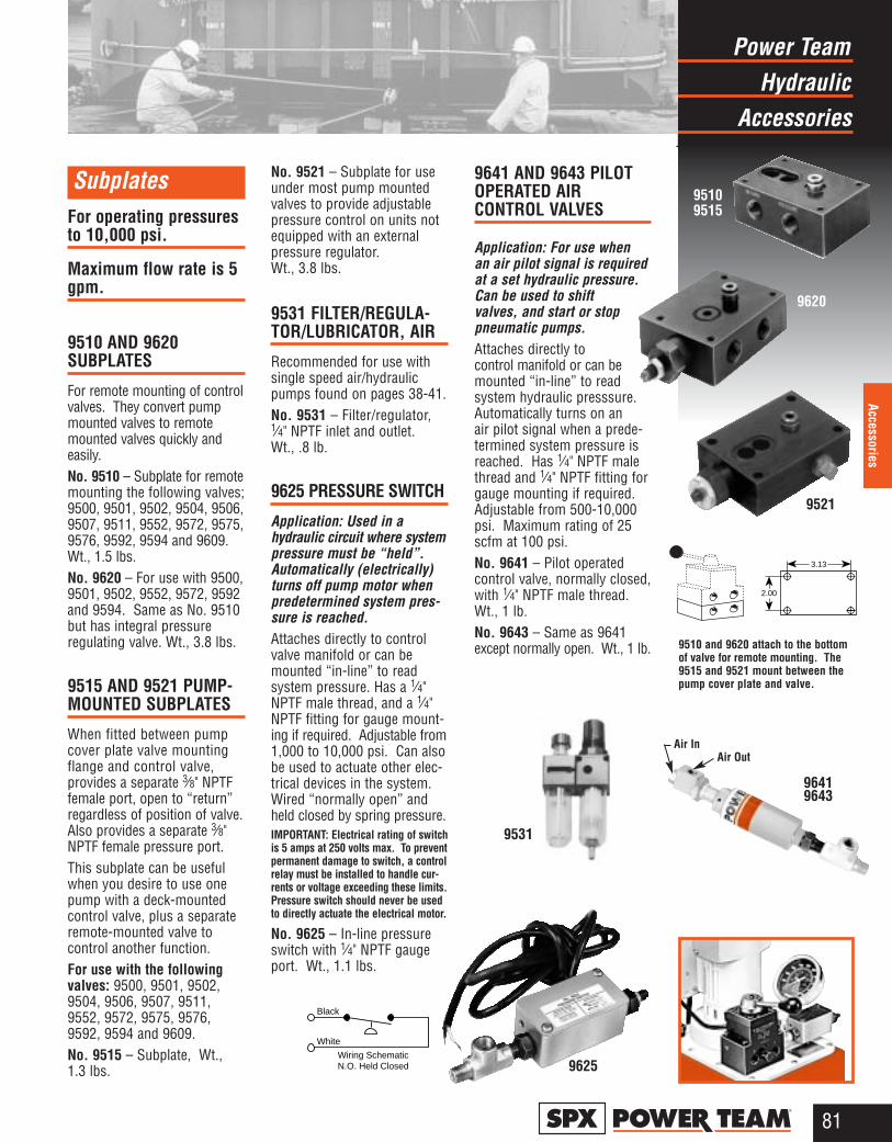
HydraulicPower Team
Accessories
81®
Accessories
SubplatesFor operating pressuresto 10,000 psi.
Maximum flow rate is 5gpm.
9510 AND 9620 SUBPLATES
For remote mounting of controlvalves. They convert pumpmounted valves to remotemounted valves quickly andeasily.No. 9510 – Subplate for remotemounting the following valves;9500, 9501, 9502, 9504, 9506,9507, 9511, 9552, 9572, 9575,9576, 9592, 9594 and 9609.Wt., 1.5 lbs.No. 9620 – For use with 9500,9501, 9502, 9552, 9572, 9592and 9594. Same as No. 9510but has integral pressure regulating valve. Wt., 3.8 lbs.
9515 AND 9521 PUMP-MOUNTED SUBPLATES
When fitted between pumpcover plate valve mountingflange and control valve, provides a separate 3⁄8" NPTFfemale port, open to “return”regardless of position of valve.Also provides a separate 3⁄8"NPTF female pressure port. This subplate can be usefulwhen you desire to use onepump with a deck-mountedcontrol valve, plus a separateremote-mounted valve to control another function.For use with the followingvalves: 9500, 9501, 9502,9504, 9506, 9507, 9511,9552, 9572, 9575, 9576,9592, 9594 and 9609.No. 9515 – Subplate, Wt.,1.3 lbs.
No. 9521 – Subplate for useunder most pump mountedvalves to provide adjustablepressure control on units notequipped with an externalpressure regulator. Wt., 3.8 lbs.
9531 FILTER/REGULA-TOR/LUBRICATOR, AIR
Recommended for use withsingle speed air/hydraulicpumps found on pages 38-41.No. 9531 – Filter/regulator,1⁄4" NPTF inlet and outlet. Wt., .8 lb.
9625 PRESSURE SWITCH
Application: Used in ahydraulic circuit where systempressure must be “held”.Automatically (electrically)turns off pump motor whenpredetermined system pres-sure is reached.Attaches directly to controlvalve manifold or can bemounted “in-line” to read system pressure. Has a 1⁄4"NPTF male thread, and a 1⁄4"NPTF fitting for gauge mount-ing if required. Adjustable from1,000 to 10,000 psi. Can alsobe used to actuate other elec-trical devices in the system.Wired “normally open” andheld closed by spring pressure.IMPORTANT: Electrical rating of switchis 5 amps at 250 volts max. To preventpermanent damage to switch, a controlrelay must be installed to handle cur-rents or voltage exceeding these limits.Pressure switch should never be usedto directly actuate the electrical motor.
No. 9625 – In-line pressureswitch with 1⁄4" NPTF gaugeport. Wt., 1.1 lbs.
9641 AND 9643 PILOTOPERATED AIR CONTROL VALVES
Application: For use when an air pilot signal is requiredat a set hydraulic pressure.Can be used to shiftvalves, and start or stoppneumatic pumps.Attaches directly to control manifold or can bemounted “in-line” to readsystem hydraulic presssure.Automatically turns on an air pilot signal when a prede-termined system pressure isreached. Has 1⁄4" NPTF malethread and 1⁄4" NPTF fitting forgauge mounting if required.Adjustable from 500-10,000psi. Maximum rating of 25scfm at 100 psi.No. 9641 – Pilot operatedcontrol valve, normally closed,with 1⁄4" NPTF male thread.Wt., 1 lb.No. 9643 – Same as 9641except normally open. Wt., 1 lb.
9625
96419643
Air InAir Out
95109515
9531
9521
9620
9510 and 9620 attach to the bottomof valve for remote mounting. The9515 and 9521 mount between thepump cover plate and valve.
3.13
2.00
Black
Wiring SchematicN.O. Held Closed
White
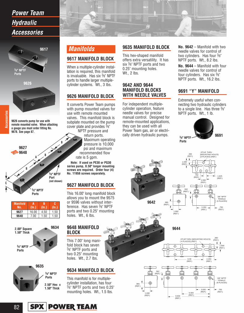
HydraulicPower Team
Accessories
82®
Acce
ssor
ies
Manifolds9617 MANIFOLD BLOCK
When a multiple-cylinder instal-lation is required, this manifoldis invaluable. Has six 3⁄8" NPTFports to handle larger multiple-cylinder systems. Wt., 3 lbs.
9626 MANIFOLD BLOCK
It converts Power Team pumpswith pump mounted valves foruse with remote mountedvalves. This manifold block issubplate mounted on the pumpcover plate and provides 3⁄8"
NPTF pressure andreturn ports.Maximum operatingpressure is 10,000psi and maximum
recommended flowrate is 5 gpm.
Note: If used on PE30 or PG30series pump, 0.50" longer mountingscrews are required. Order four (4)No. 11956 screws separately.
9627 MANIFOLD BLOCK
This 16.00" long manifold blockallows you to mount the 9575or 9596 valves without inter-ference. Has seven 3⁄8" NPTFports and two 0.25" mountingholes. Wt., 6 lbs.
9648 MANIFOLDBLOCK
This 7.00" long mani-fold block has seven3⁄8" NPTF ports andtwo 0.25" mountingholes. Wt., 2.7 lbs.
9634 MANIFOLD BLOCK
This manifold is for multiple-cylinder installation, has four3⁄8" NPTF ports and two 0.25"mounting holes. Wt., 1.5 lbs.
9635 MANIFOLD BLOCK
This hex-shaped manifoldoffers extra versatility. It hassix 3⁄8" NPTF ports and two0.25" mounting holes. Wt., 2 lbs.
9642 AND 9644 MANIFOLD BLOCKSWITH NEEDLE VALVES
For independent multiple-cylinder operation, featureneedle valves for precise manual control. Designed forremote-mounted applications,they can be used with allPower Team gas, air or electri-cally driven hydraulic pumps.
No. 9642 – Manifold with twoneedle valves for control oftwo cylinders. Has four 3⁄8"NPTF ports. Wt., 8.2 lbs.No. 9644 – Manifold with fourneedle valves for control offour cylinders. Has six 3⁄8"NPTF ports. Wt., 16.2 lbs.
9691 “Y” MANIFOLD
Extremely useful when con-necting two hydraulic cylindersto a single line. Has three 3⁄8"NPTF ports. Wt., 1 lb.
9644
2.50" Hex x1.50" Thick
96913⁄8" NPTFPorts
3⁄8" NPTFPorts
9627 9648
.965 (REF.)
1.000 (REF.)
.562(REF.)
.750(REF.)
3.250(REF.)
1.625(REF.)
.360(REF.)
1.000 (REF.)
.750(REF.)
1.500(REF.)
.375 Ø THRU (MOUNTING HOLES)(3 PLACES) (REF.)
3/8" NPTFFEMALE
(4 PLACES)
.965 (REF.)
1.000 (REF.)
.562(REF.)
.750(REF.)
3.000(REF.)
6.000 (REF.)9.000
(REF.)
3/8" NPTFFEMALE
(6 PLACES)
2.250 (REF.)
.360(REF.)
1.000(REF.)
.375 Ø THRU (MOUNTING HOLES)( 4 PLACES) (REF.)
6.00 (REF.)
B
A
C
B
B
9617
3⁄8" NPTFPorts
96342.00" Square1.50" Thick
3⁄8" NPTFPorts
9635
9626 converts pump for use withremote mounted valve. When attachinga gauge you must order fitting No.9678. See page 87.
9626
9642
3⁄8" NPTFPorts
3⁄8" NPTFPort(not shown)
Manifold A B CNo. (In.) (In.) (In.)
9627 16.00 4.50 1.509648 7.00 1.50 1.50
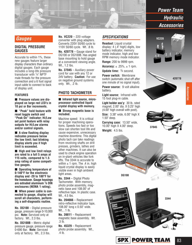
HydraulicPower Team
Accessories
83®
Accessories
GaugesDIGITAL PRESSUREGAUGES
Accurate to within 1%, thesenew gauges feature larger display characters than ordinarydigital gauges. Each gaugeincludes a long-life pressuretransducer with 1⁄4" NPTFmale threads for the pressureconnection and a 6 foot signalinput cable to connect to backof display unit.
FEATURES■ Pressure values are dis-played on large red LED’s in10 psi or Bar increments.■ “Peak” hold feature withreset toggle switch and“Peak On” indicator; Hi/Lowset point feature with relayoutputs for Hi/Low alarmsand/or control signals.■ A slow flashing displayindicates pressure below the low limit; fast blinkingdisplay alerts you if highlimit is exceeded.■ High and low limit relaysare rated to a full 5 amps at115 volts, compared to 1.5amp rating of some competi-tive gauges.■ Operating temperature of0-140°F for the electronicdisplay and -20 to 180°F forthe transducer. Gauge housingsare extruded aluminum 1⁄8 DINenclosures (NEMA 1 rating).■ When power cable is con-nected to gauge, display willscroll all characters, perform-ing a self-diagnostic routine.
No. DG100 – Digital pressuregauge, pressure range 0-10,000psi. Note: Serviced only atfactory. Wt., 2.3 lbs.No. DG100B – Metric digitalpressure gauge, pressure range0-690 Bar. Note: Servicedonly at factory. Wt., 2.3 lbs.
No. VC220 – 220 voltageconverter with plug adapters.Converts 220V 50/60 cycle to110V 50/60 cycle. Wt. .8 lb. No. 420778 – Gauge stand forDG100 or DG100B. Has angledbase mounting to hold gaugeat a convenient viewing angle.Wt., 1.2 lbs. No. 37045 – Auxiliary powercord for use with any 12 or24V battery. Caution: For useon negative ground systemsonly. Wt., .2 lb.
PHOTO TACHOMETER
■ Infrared light source, micro-processor controlled liquidcrystal display with memory. ■ Strong magnetic base isincluded.Machine speed: It is criticalfor proper machining opera-tions. Speeds too fast or tooslow can shorten tool life andcause expensive, unnecessarymachine downtime. This digitalphoto tach can take readingsfrom revolving shafts on drillpresses, grinders, lathes andother machines. It can also beused to check engine operationon in-plant vehicles like forklifts. The 3344 is accurate towithin ± 1 rpm. The .4 in. highliquid crystal display is easilyvisible even in high ambientlight areas.No. 3344 – Digital PhotoTachometer. With memory,photo probe assembly, mag-netic base and 108.00" ofreflective tape. In plastic case.Wt., 4.5 lbs.No. 204666 – Replacementretro-reflective indicator tape,108.00" long x 0.50" wide.Wt., .1 lb.No. 39811 – Replacementmagnetic base assembly. Wt..3 lb.No. 45329 – Replacementphoto probe assembly. Wt.,.4 lb.
SPECIFICATIONS
Readout: Liquid crystal display: 4 (.4" high) digits, lowbattery indicator, memorymode indicator, high and lowRPM memory mode indicator.Range: 200 to 9999 rpm.Accuracy: ± .25%, ± 1 rpm.Update time: 3⁄4 second.Power switch: Membraneswitch (automatic shut-off afterone minute of no signal input).Power source: 9 volt alkalinebattery.Light source: Infrared with15 foot plug-in cable.Light holder ass’y: 30 lb. ratedmagnet; 2.00" dia. X 0.25" high(4.00" high overall with post).Size: 3.38" wide, 6.00" high X1.50" deep.Carrying case: 13.50" wide,10.00" high X 4.00" deep.Weight: 4.5 lbs.
DG100
420778
VC220
37045
3344
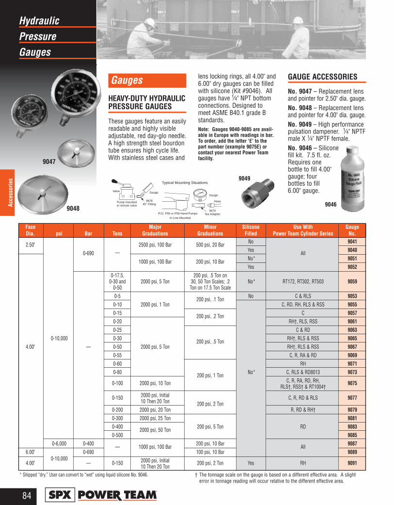
PressureHydraulic
Gauges
84®
Acce
ssor
ies
Gauges
HEAVY-DUTY HYDRAULIC PRESSURE GAUGES
These gauges feature an easilyreadable and highly visibleadjustable, red day-glo needle.A high strength steel bourdontube ensures high cycle life.With stainless steel cases and
lens locking rings, all 4.00" and6.00" dry gauges can be filledwith silicone (Kit #9046). Allgauges have 1⁄4" NPT bottomconnections. Designed tomeet ASME B40.1 grade Bstandards.Note: Gauges 9040-9085 are avail-able in Europe with readings in bar.To order, add the letter ‘E’ to thepart number (example 9075E) orcontact your nearest Power Teamfacility.
GAUGE ACCESSORIES
No. 9047 – Replacement lensand pointer for 2.50" dia. gauge.No. 9048 – Replacement lensand pointer for 4.00" dia. gauge.No. 9049 – High performancepulsation dampener. 1⁄4" NPTFmale X 1⁄4" NPTF female.No. 9046 – Siliconefill kit. 7.5 fl. oz.Requires one bottle to fill 4.00"gauge; four bottles to fill 6.00" gauge.
9048
9047
9046
Valve
Pump mounted or remote valve
Gauge
967845° Fitting
Gauge
Hose
9670Tee Adapter
Typical Mounting Situations
P12, P55 or P59 Hand Pumps
In Line Mounted
* Shipped “dry.” User can convert to “wet” using liquid silicone No. 9046. † The tonnage scale on the gauge is based on a different effective area. A slight error in tonnage reading will occur relative to the different effective area.
Face Major Minor Silicone Use With GaugeDia. psi Bar Tons Graduations Graduations Filled Power Team Cylinder Series No.
2.50" 2500 psi, 100 Bar 500 psi, 20 Bar No 9041
0-690 — Yes All 9040
1000 psi, 100 Bar 200 psi, 10 Bar No* 9051Yes 9052
0-17.5, 200 psi, .5 Ton on0-30 and 2000 psi, 5 Ton 30, 50 Ton Scales; .2 No* RT172, RT302, RT503 9059
0-50 Ton on 17.5 Ton Scale0-5 200 psi, .1 Ton No C & RLS 90530-10 2000 psi, 1 Ton C, RD, RH, RLS & RSS 90550-15 200 psi, .2 Ton C 90570-20 RH†, RLS, RSS 90610-25 C & RD 9063
0-10,000 0-30 200 psi, .5 Ton RH†, RLS & RSS 90654.00" — 0-50 2000 psi, 5 Ton RH†, RLS & RSS 9067
0-55 C, R, RA & RD 90690-60 RH 90710-80 200 psi, 1 Ton No* C, RLS & RD8013 9073
0-100 2000 psi, 10 Ton C, R, RA, RD, RH, 9075RLS†, RSS† & RT1004†
0-150 2000 psi, Initial C, R, RD & RLS 907710 Then 20 Ton 200 psi, 2 Ton
0-200 2000 psi, 20 Ton R, RD & RH† 90790-300 2000 psi, 25 Ton 90810-400 2000 psi, 50 Ton 200 psi, 5 Ton RD 90830-500 9085
0-6,000 0-400 — 1000 psi, 100 Bar 200 psi, 10 Bar All 90876.00" 0-690 100 psi, 10 Bar 9089
4.00" 0-10,000
— 0-150 2000 psi, Initial 200 psi, 2 Ton Yes RH 909110 Then 20 Ton
9049
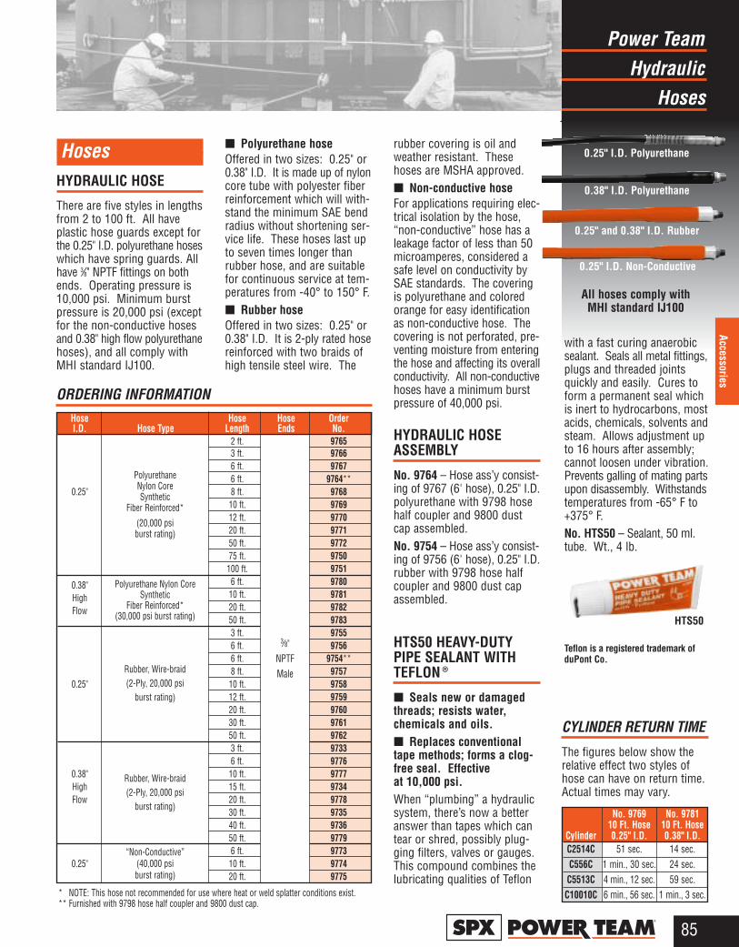
HydraulicPower Team
Hoses
85®
Accessories
HosesHYDRAULIC HOSE
There are five styles in lengthsfrom 2 to 100 ft. All haveplastic hose guards except forthe 0.25" I.D. polyurethane hoseswhich have spring guards. Allhave 3⁄8" NPTF fittings on bothends. Operating pressure is10,000 psi. Minimum burstpressure is 20,000 psi (exceptfor the non-conductive hosesand 0.38" high flow polyurethanehoses), and all comply withMHI standard IJ100.
■ Polyurethane hoseOffered in two sizes: 0.25" or0.38" I.D. It is made up of nyloncore tube with polyester fiberreinforcement which will with-stand the minimum SAE bendradius without shortening ser-vice life. These hoses last upto seven times longer thanrubber hose, and are suitablefor continuous service at tem-peratures from -40° to 150° F.■ Rubber hoseOffered in two sizes: 0.25" or0.38" I.D. It is 2-ply rated hosereinforced with two braids ofhigh tensile steel wire. The
rubber covering is oil andweather resistant. Thesehoses are MSHA approved.■ Non-conductive hoseFor applications requiring elec-trical isolation by the hose,“non-conductive” hose has aleakage factor of less than 50microamperes, considered asafe level on conductivity bySAE standards. The coveringis polyurethane and coloredorange for easy identificationas non-conductive hose. Thecovering is not perforated, pre-venting moisture from enteringthe hose and affecting its overallconductivity. All non-conductivehoses have a minimum burstpressure of 40,000 psi.
HYDRAULIC HOSEASSEMBLY
No. 9764 – Hose ass’y consist-ing of 9767 (6' hose), 0.25" I.D.polyurethane with 9798 hosehalf coupler and 9800 dustcap assembled.No. 9754 – Hose ass’y consist-ing of 9756 (6' hose), 0.25" I.D.rubber with 9798 hose halfcoupler and 9800 dust capassembled.
HTS50 HEAVY-DUTYPIPE SEALANT WITHTEFLON ®
■ Seals new or damagedthreads; resists water, chemicals and oils.■ Replaces conventionaltape methods; forms a clog-free seal. Effective at 10,000 psi.When “plumbing” a hydraulicsystem, there’s now a betteranswer than tapes which cantear or shred, possibly plug-ging filters, valves or gauges.This compound combines thelubricating qualities of Teflon
CYLINDER RETURN TIME
The figures below show therelative effect two styles ofhose can have on return time.Actual times may vary.
No. 9769 No. 978110 Ft. Hose 10 Ft. Hose
Cylinder 0.25" I.D. 0.38" I.D.C2514C 51 sec. 14 sec.C556C 1 min., 30 sec. 24 sec.
C5513C 4 min., 12 sec. 59 sec.C10010C 6 min., 56 sec. 1 min., 3 sec.* NOTE: This hose not recommended for use where heat or weld splatter conditions exist.
** Furnished with 9798 hose half coupler and 9800 dust cap.
Hose Hose Hose OrderI.D. Hose Type Length Ends No.
2 ft. 97653 ft. 97666 ft. 97676 ft. 9764**
0.25" 8 ft. 976810 ft. 976912 ft. 977020 ft. 977150 ft. 977275 ft. 9750100 ft. 9751
0.38" 6 ft. 9780
High 10 ft. 9781
Flow 20 ft. 978250 ft. 97833 ft. 97556 ft. 97566 ft. 9754**8 ft. 9757
0.25" 10 ft. 975812 ft. 975920 ft. 976030 ft. 976150 ft. 97623 ft. 97336 ft. 9776
0.38" 10 ft. 9777High 15 ft. 9734Flow 20 ft. 9778
30 ft. 973540 ft. 973650 ft. 97796 ft. 9773
0.25" 10 ft. 977420 ft. 9775
3⁄8"
NPTFMale
ORDERING INFORMATION
PolyurethaneNylon Core Synthetic
Fiber Reinforced*
(20,000 psi burst rating)
Polyurethane Nylon CoreSynthetic
Fiber Reinforced* (30,000 psi burst rating)
Rubber, Wire-braid(2-Ply, 20,000 psi
burst rating)
Rubber, Wire-braid(2-Ply, 20,000 psi
burst rating)
“Non-Conductive”(40,000 psi burst rating)
0.25" I.D. Polyurethane
0.38" I.D. Polyurethane
0.25" and 0.38" I.D. Rubber
0.25" I.D. Non-Conductive
All hoses comply with MHI standard IJ100
with a fast curing anaerobicsealant. Seals all metal fittings,plugs and threaded jointsquickly and easily. Cures toform a permanent seal whichis inert to hydrocarbons, mostacids, chemicals, solvents andsteam. Allows adjustment upto 16 hours after assembly;cannot loosen under vibration.Prevents galling of mating partsupon disassembly. Withstandstemperatures from -65° F to+375° F.No. HTS50 – Sealant, 50 ml.tube. Wt., 4 lb.
Teflon is a registered trademark ofduPont Co.
HTS50
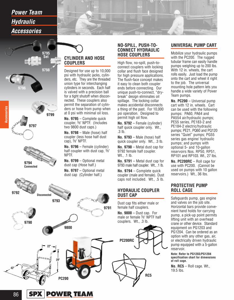
HydraulicPower Team
Accessories
86®
Acce
ssor
ies
CYLINDER AND HOSECOUPLERS
Designed for use up to 10,000psi with hydraulic jacks, cylin-ders, etc. They are the threadedunion type for interchangingcylinders in seconds. Each halfis valved with a precision ballfor a tight shutoff when discon-nected. These couplers alsopermit the separation of cylin-ders or hose from pump whenat 0 psi with minimal oil loss.No. 9795 – Complete quickcoupler, 3⁄8" NPTF. (Includestwo 9800 dust caps.)No. 9798 – Male (hose) halfcoupler (less hose half dustcap), 3⁄8" NPTF.No. 9796 – Female (cylinder)half coupler with dust cap, 3⁄8"NPTF.No. 9799 – Optional metaldust cap (Hose half.)No. 9797 – Optional metaldust cap (Cylinder half.)
NO-SPILL, PUSH-TO-CONNECT HYDRAULICHOSE COUPLERS
High flow, no-spill, push-to-connect couplers with lockingcollar and flush face designedfor high pressure applications.The flush-face concept makesit easy to clean both couplerends before connecting. Ourunique push-to-connect, “dry-break” design eliminates oilspillage. The locking collarmakes accidental disconnectsa thing of the past. For 10,000psi operation. Designed topermit high oil flow.No. 9792 – Female (cylinder)half quick coupler only. Wt.,.3 lb.No. 9793 – Male (hose) halfquick coupler only. Wt., .3 lb.No. 9790 – Metal dust cap for9792 female half coupler.Wt., .1 lb.No. 9791 – Metal dust cap for9793 male half coupler. Wt., .1 lb.No. 9794 – Complete quickcoupler (male and female). Dustcaps not included. Wt., .5 lb.
HYDRAULIC COUPLERDUST CAP
Dust cap fits either male orfemale half couplers.No. 9800 – Dust cap. Formale or female 3⁄8" NPTF halfcouplers. Wt., .3 lb.
UNIVERSAL PUMP CART
Mobilize your hydraulic pumpswith the PC200. The ruggedtubular frame can easily handlepumps weighing up to 200 lbs.With 12 in. wheels, the cartrolls easily. Just load the pumponto the cart and wheel it rightto the job. The universalmounting hole pattern lets youhandle a wide variety of PowerTeam pumps.No. PC200 – Universal pumpcart with 12 in. wheels. Cartcan be used with the followingpumps: PA60, PA64 andPA554 air/hydraulic pumps;PE55 series, PE183-2 andPE184-2 electric/hydraulicpumps; PE21, PQ60 and PQ120series “Quiet” pumps; PG55series gas engine/ hydraulicpumps; and pumps withoptional 5- and 10-gallonreservoirs Nos. RP50, RP51,RP101 and RP103. Wt., 27 lbs.No. PC200RC – Roll cage foruse with PC200. (Cannot beused on pumps with 10 gallonreservoirs.) Wt., 36 lbs.
PROTECTIVE PUMPROLL CAGE
Safeguards pump, gas engineand valves on the job site.Horizontal bars provide conve-nient hand holds for carryingpump, a pick-up point permitslifting unit with an overheadcrane or other device. Standardequipment on PG1203 andPG1204. Can be ordered as anoption with any other gas, air,or electrically driven hydraulicpump equipped with a 5-gallonreservoir.Note: Refer to PG1203/PG1204specification chart for dimensionsof roll cage.
No. RC5 – Roll cage. Wt.,19.5 lbs.
9796
9800
9799
Disconnected
9793
RC5
9797
9790
9791
9792
9794Connected
PC200
22"
29"
43"
9795Set
9798
PC200RC
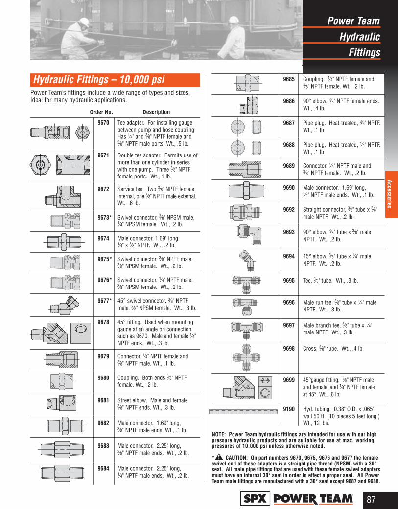
HydraulicPower Team
Fittings
87®
Accessories
9670 Tee adapter. For installing gaugebetween pump and hose coupling.Has 1⁄4" and 3⁄8" NPTF female and3⁄8" NPTF male ports. Wt., .5 lb.
9671 Double tee adapter. Permits use ofmore than one cylinder in serieswith one pump. Three 3⁄8" NPTFfemale ports. Wt., 1 lb.
9672 Service tee. Two 3⁄8" NPTF femaleinternal, one 3⁄8" NPTF male external.Wt., .6 lb.
9673* Swivel connector, 3⁄8" NPSM male,1⁄4" NPSM female. Wt., .2 lb.
9674 Male connector, 1.69" long, 1⁄4" x 3⁄8" NPTF. Wt., .2 lb.
9675* Swivel connector. 3⁄8" NPTF male,3⁄8" NPSM female. Wt., .2 lb.
9676* Swivel connector. 1⁄4" NPTF male,3⁄8" NPSM female. Wt., .2 lb.
9677* 45° swivel connector. 3⁄8" NPTFmale, 3⁄8" NPSM female. Wt., .3 lb.
9678 45° fitting. Used when mountinggauge at an angle on connectionsuch as 9670. Male and female 1⁄4"NPTF ends. Wt., .3 lb.
9679 Connector. 1⁄4" NPTF female and3⁄8" NPTF male. Wt., .1 lb.
9680 Coupling. Both ends 3⁄8" NPTFfemale. Wt., .2 lb.
9681 Street elbow. Male and female 3⁄8" NPTF ends. Wt., .3 lb.
9682 Male connector. 1.69" long, 3⁄8" NPTF male ends. Wt., .1 lb.
9683 Male connector. 2.25" long, 3⁄8" NPTF male ends. Wt., .2 lb.
9684 Male connector. 2.25" long, 1⁄4" NPTF male ends. Wt., .2 lb.
9685 Coupling. 1⁄4" NPTF female and3⁄8" NPTF female. Wt., .2 lb.
9686 90° elbow. 3⁄8" NPTF female ends.Wt., .4 lb.
9687 Pipe plug. Heat-treated, 3⁄8" NPTF.Wt., .1 lb.
9688 Pipe plug. Heat-treated, 1⁄4" NPTF.Wt., .1 lb.
9689 Connector. 1⁄4" NPTF male and 3⁄8" NPTF female. Wt., .2 lb.
9690 Male connector. 1.69" long, 1⁄4" NPTF male ends. Wt., .1 lb.
9692 Straight connector, 3⁄8" tube x 3⁄8"male NPTF. Wt., .2 lb.
9693 90° elbow, 3⁄8" tube x 3⁄8" maleNPTF. Wt., .2 lb.
9694 45° elbow, 3⁄8" tube x 1⁄4" maleNPTF. Wt., .2 lb.
9695 Tee, 3⁄8" tube. Wt., .3 lb.
9696 Male run tee, 3⁄8" tube x 1⁄4" maleNPTF. Wt., .3 lb.
9697 Male branch tee, 3⁄8" tube x 1⁄4"male NPTF. Wt., .3 lb.
9698 Cross, 3⁄8" tube. Wt., .4 lb.
9699 45°gauge fitting. 3⁄8" NPTF maleand female, and 1⁄4" NPTF female at 45°. Wt., .6 lb.
9190 Hyd. tubing. 0.38" O.D. x .065"wall 50 ft. (10 pieces 5 feet long.)Wt., 12 lbs.
NOTE: Power Team hydraulic fittings are intended for use with our highpressure hydraulic products and are suitable for use at max. workingpressures of 10,000 psi unless otherwise noted.
* CAUTION: On part numbers 9673, 9675, 9676 and 9677 the femaleswivel end of these adapters is a straight pipe thread (NPSM) with a 30°seat. All male pipe fittings that are used with these female swivel adaptersmust have an internal 30° seat in order to effect a proper seal. All PowerTeam male fittings are manufactured with a 30° seat except 9687 and 9688.
Hydraulic Fittings – 10,000 psiPower Team’s fittings include a wide range of types and sizes.Ideal for many hydraulic applications.
Order No. Description
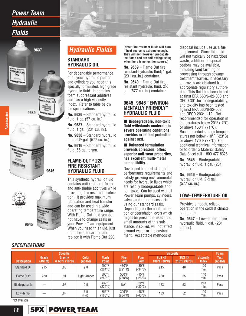
HydraulicPower Team
Fluids
88®
Acce
ssor
ies
Hydraulic FluidsSTANDARD HYDRAULIC OIL
For dependable performanceof all your hydraulic pumpsand cylinders you need thisspecially formulated, high gradehydraulic fluid. It containsfoam suppressant additivesand has a high viscosityindex. Refer to table belowfor specifications.No. 9636 – Standard hydraulicfluid, 1 qt. (57 cu. in.).No. 9637 – Standard hydraulicfluid, 1 gal. (231 cu. in.).No. 9638 – Standard hydraulicfluid, 21⁄2 gal. (577 cu. in.).No. 9616 – Standard hydraulicfluid, 55 gal. drum.
FLAME-OUT ® 220 FIRE RESISTANTHYDRAULIC FLUID
This synthetic hydraulic fluidcontains anti-rust, anti-foamand anti-sludge additives whileproviding fire resistant protec-tion. It provides maximumlubrication and heat transferand can be used in a wideoperating temperature range.With Flame-Out fluid you donot have to change seals inyour Power Team equipment.When you need this fluid, justdrain the standard oil andreplace it with Flame-Out 220.
(Note: Fire resistant fluids will burnif heat source is extreme enough.They will not, however, propagatethe flame and are self-extinguishingwhen there is no ignition source.)
No. 9639 – Flame-Out fireresistant hydraulic fluid, 1 gal.(231 cu. in.) container.No. 9640 – Flame-Out fireresistant hydraulic fluid, 21⁄2gal. (577 cu. in.) container.
9645, 9646 “ENVIRON-MENTALLY FRIENDLY”HYDRAULIC FLUID
■ Biodegradable, non-toxicfluid withstands moderate tosevere operating conditions;provides excellent protectionagainst rust.■ Balanced formulation prevents corrosion, offerssuperior anti-wear properties,has excellent multi-metalcompatibility.Developed to meet stringentperformance requirements andsatisfy growing environmentalneeds for hydraulic fluids whichare readily biodegradable andnon-toxic. Can be used with allPower Team pumps, cylinders,valves and other accessoriesusing our standard seals.Depending on the contamina-tion or degradation levels whichmight be present in used fluid,small amounts of this sub-stance, if spilled, will not affectground water or the environ-ment. Acceptable methods of
disposal include use as a fuelsupplement. Since this fluidwill not typically be hazardouswaste, additional disposaloptions may be available,including land farming or processing through sewagetreatment facilities, if necessaryapprovals are obtained fromappropriate regulatory authori-ties. This fluid has been testedagainst EPA 560/6-82-003 andOECD 301 for biodegradability,and toxicity has been testedagainst EPA 560/6-82-002 and OECD 203: 1-12. Notrecommended for operation intemperatures below 20°F (-7°C)or above 160°F (71°C).Recommended storage temper-atures not below -10°F (-23°C)or above 170°F (77°C). Foradditional technical informationor to order a Material SafetyData Sheet call 1-800-477-8326.No. 9645 – Biodegradablehydraulic fluid, 1 gal. (231 cu. in.).No. 9646 – Biodegradablehydraulic fluid, 21⁄2 gal. (577 cu. in.).
LOW–TEMPERATURE OIL
Provides smooth, reliableoperation in the coldest climateconditions.No. 9647 – Low–temperaturehydraulic fluid, 1 gal. (231cu. in.).
9637
9639
9646
9645
EN
VIR
ON
MEN T PROTE
CT
ING
PR ODUCT
Specific Viscosity FoamGrade Gravity Color Flash Fire Pour SUS @ SUS @ Viscosity Test
Description (ASTM) @ 60°F (16°C) (ASTM) Point Point Point 100°F (38°C) 210°F (99°C) Index (ASTM)
Standard Oil 215 .88 2.0 400°F 430°F -30°F 215 48 100 Pass(204°C) (221°C) (-34°C) min.
Flame Out® 220 .91 Light Amber 500°F 550°F -15°F 220 55 140 Pass(260°C) (288°C) (-26°C) min.
Biodegradable — .92 2.0 432°F NA* -22°F 183 53 213 Pass(224°C) (-30°C) min.
Low-Temp. — .87 6.5 356°F 399°F -48°F 183 52 190 Pass(Red) (180°C) (204°C) (-45°C) min.
SPECIFICATIONS
*Not available
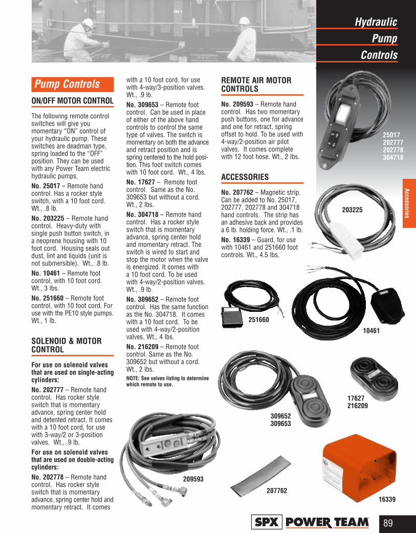
PumpHydraulic
Controls
89®
Accessories
Pump ControlsON/OFF MOTOR CONTROL
The following remote controlswitches will give youmomentary “ON” control ofyour hydraulic pump. Theseswitches are deadman type,spring loaded to the “OFF”position. They can be usedwith any Power Team electrichydraulic pumps.No. 25017 – Remote handcontrol. Has a rocker styleswitch, with a 10 foot cord.Wt., .8 lb.No. 203225 – Remote handcontrol. Heavy-duty with single push button switch, ina neoprene housing with 10foot cord. Housing seals outdust, lint and liquids (unit isnot submersible). Wt., .8 lb.No. 10461 – Remote footcontrol, with 10 foot cord.Wt., 3 lbs.No. 251660 – Remote footcontrol, with 10 foot cord. Foruse with the PE10 style pumps.Wt., 1 lb.
SOLENOID & MOTORCONTROL
For use on solenoid valvesthat are used on single-actingcylinders:No. 202777 – Remote handcontrol. Has rocker styleswitch that is momentaryadvance, spring center holdand detented retract. It comeswith a 10 foot cord, for usewith 3-way/2 or 3-positionvalves. Wt., .9 lb.For use on solenoid valvesthat are used on double-actingcylinders:No. 202778 – Remote handcontrol. Has rocker styleswitch that is momentaryadvance, spring center hold andmomentary retract. It comes
with a 10 foot cord, for usewith 4-way/3-position valves.Wt., .9 lb.No. 309653 – Remote footcontrol. Can be used in placeof either of the above handcontrols to control the sametype of valves. The switch ismomentary on both the advanceand retract position and isspring centered to the hold posi-tion. This foot switch comeswith 10 foot cord. Wt., 4 lbs.No. 17627 – Remote footcontrol. Same as the No.309653 but without a cord.Wt., 2 lbs.No. 304718 – Remote handcontrol. Has a rocker styleswitch that is momentaryadvance, spring center holdand momentary retract. Theswitch is wired to start andstop the motor when the valveis energized. It comes with a 10 foot cord. To be usedwith 4-way/2-position valves.Wt., .9 lb.No. 309652 – Remote footcontrol. Has the same functionas the No. 304718. It comeswith a 10 foot cord. To beused with 4-way/2-positionvalves. Wt., 4 lbs.No. 216209 – Remote footcontrol. Same as the No.309652 but without a cord.Wt., 2 lbs.NOTE: See valves listing to determinewhich remote to use.
REMOTE AIR MOTORCONTROLS
No. 209593 – Remote handcontrol. Has two momentarypush buttons, one for advanceand one for retract, spring offset to hold. To be used with4-way/2-position air pilotvalves. It comes completewith 12 foot hose. Wt., 2 lbs.
ACCESSORIES
No. 207762 – Magnetic strip.Can be added to No. 25017,202777, 202778 and 304718hand controls. The strip hasan adhesive back and providesa 6 lb. holding force. Wt., .1 lb.No. 16339 – Guard, for usewith 10461 and 251660 footcontrols. Wt., 4.5 lbs.
25017202777202778304718
209593
17627216209
16339207762
203225
10461
309652309653
251660
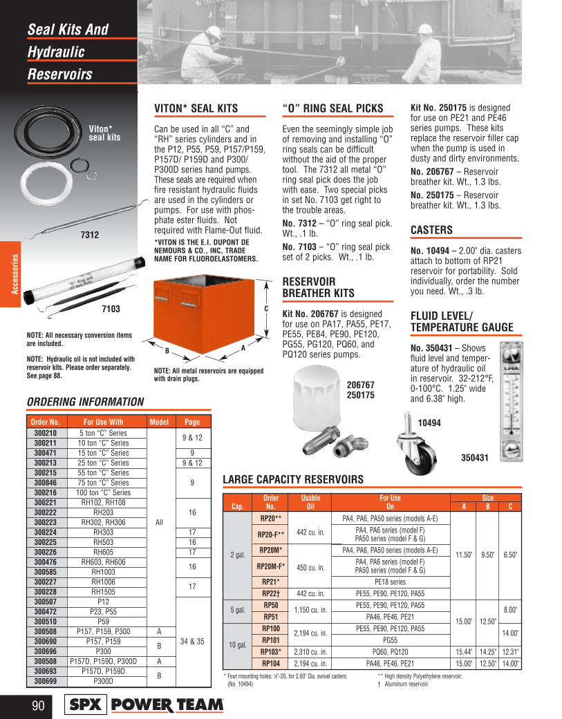
HydraulicSeal Kits And
Reservoirs
90®
Acce
ssor
ies
Order Usable For Use Size Cap. No. Oil On A B C
RP20** PA4, PA6, PA50 series (models A-E)
RP20-F** 442 cu. in. PA4, PA6 series (model F) PA50 series (model F & G)
2 gal. RP20M* PA4, PA6, PA50 series (models A-E) 11.50" 9.50" 6.50"RP20M-F* PA4, PA6 series (model F)
450 cu. in. PA50 series (model F & G)RP21* PE18 seriesRP22† 442 cu. in. PE55, PE90, PE120, PA55
5 gal. RP50 1,150 cu. in. PE55, PE90, PE120, PA55 8.00"RP51 PA46, PE46, PE21 15.00" 12.50"RP100 2,194 cu. in. PE55, PE90, PE120, PA55 14.00"
10 gal. RP101 PG55RP103* 2,310 cu. in. PQ60, PQ120 15.44" 14.25" 12.31"RP104 2,194 cu. in. PA46, PE46, PE21 15.00" 12.50" 14.00"
VITON* SEAL KITS
Can be used in all “C” and“RH” series cylinders and inthe P12, P55, P59, P157/P159,P157D/ P159D and P300/P300D series hand pumps.These seals are required whenfire resistant hydraulic fluidsare used in the cylinders orpumps. For use with phos-phate ester fluids. Notrequired with Flame-Out fluid.*VITON IS THE E.I. DUPONT DENEMOURS & CO., INC, TRADE NAME FOR FLUOROELASTOMERS.
“O” RING SEAL PICKS
Even the seemingly simple jobof removing and installing “O”ring seals can be difficultwithout the aid of the propertool. The 7312 all metal “O”ring seal pick does the jobwith ease. Two special picksin set No. 7103 get right tothe trouble areas.No. 7312 – “O” ring seal pick.Wt., .1 lb.No. 7103 – “O” ring seal pickset of 2 picks. Wt., .1 lb.
RESERVOIR BREATHER KITS
Kit No. 206767 is designedfor use on PA17, PA55, PE17,PE55, PE84, PE90, PE120,PG55, PG120, PQ60, andPQ120 series pumps.
Kit No. 250175 is designedfor use on PE21 and PE46series pumps. These kitsreplace the reservoir filler capwhen the pump is used industy and dirty environments.No. 206767 – Reservoirbreather kit. Wt., 1.3 lbs.No. 250175 – Reservoirbreather kit. Wt., 1.3 lbs.
CASTERS
No. 10494 – 2.00" dia. castersattach to bottom of RP21reservoir for portability. Soldindividually, order the numberyou need. Wt., .3 lb.
FLUID LEVEL/TEMPERATURE GAUGE
No. 350431 – Showsfluid level and temper-ature of hydraulic oilin reservoir. 32-212°F,0-100°C. 1.25" wideand 6.38" high.
A
C
B
7312
7103
350431
NOTE: All necessary conversion itemsare included.
NOTE: Hydraulic oil is not included withreservoir kits. Please order separately.See page 88.
Viton*seal kits
* Four mounting holes: 1⁄2"-20, for 2.00" Dia. swivel casters (No. 10494)
** High density Polyethylene reservoir.† Aluminum reservoir.
LARGE CAPACITY RESERVOIRS
ORDERING INFORMATION
10494
206767250175
Order No. For Use With Model Page300210 5 ton “C” Series 9 & 12300211 10 ton “C” Series300471 15 ton “C” Series 9300213 25 ton “C” Series 9 & 12300215 55 ton “C” Series300846 75 ton “C” Series 9300216 100 ton “C” Series300221 RH102, RH108300222 RH203 16300223 RH302, RH306 All300224 RH303 17300225 RH503 16300226 RH605 17300476 RH603, RH606 16300585 RH1003300227 RH1006 17300228 RH1505300507 P12300472 P23, P55300510 P59300508 P157, P159, P300 A300690 P157, P159 B 34 & 35300696 P300300508 P157D, P159D, P300D A300693 P157D, P159D B300699 P300D
NOTE: All metal reservoirs are equippedwith drain plugs.
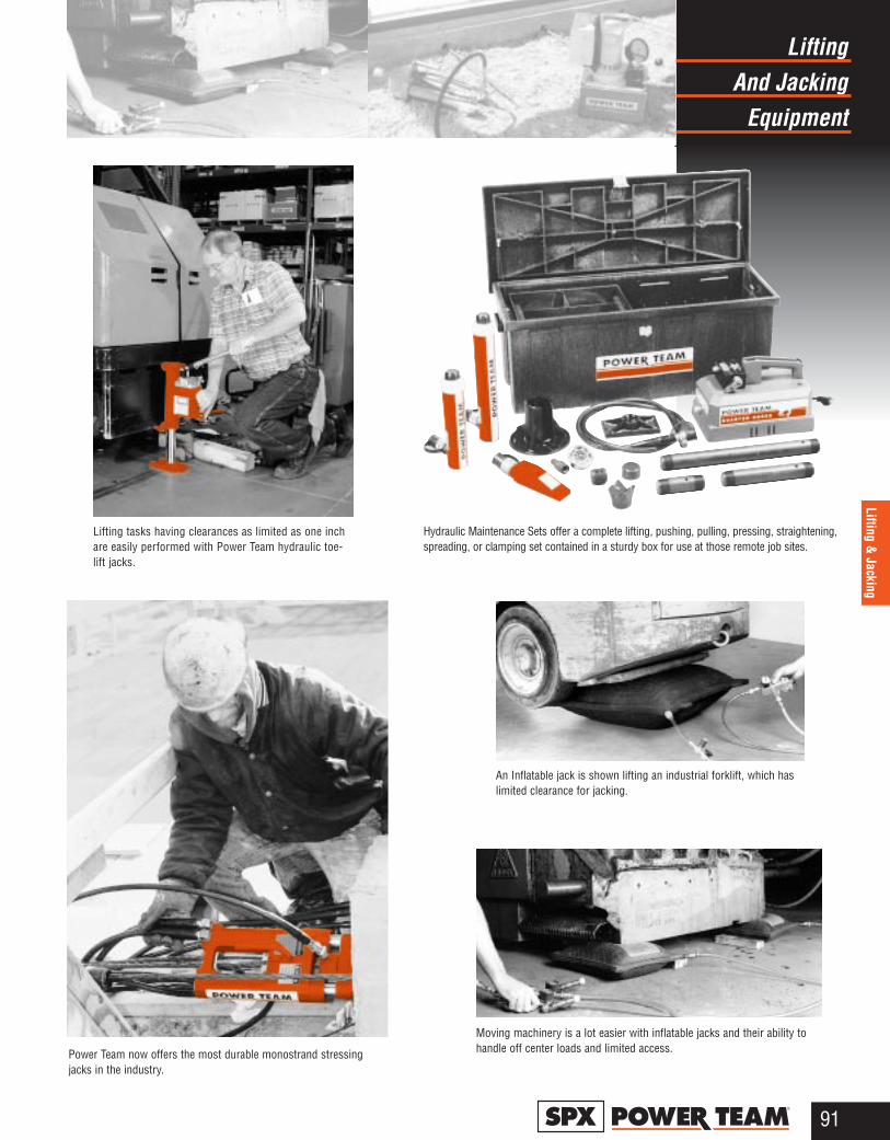
And JackingLifting
Equipment
91®
Lifting & Jacking
An Inflatable jack is shown lifting an industrial forklift, which haslimited clearance for jacking.
Hydraulic Maintenance Sets offer a complete lifting, pushing, pulling, pressing, straightening,spreading, or clamping set contained in a sturdy box for use at those remote job sites.
Moving machinery is a lot easier with inflatable jacks and their ability tohandle off center loads and limited access.
Lifting tasks having clearances as limited as one inchare easily performed with Power Team hydraulic toe-lift jacks.
Power Team now offers the most durable monostrand stressingjacks in the industry.
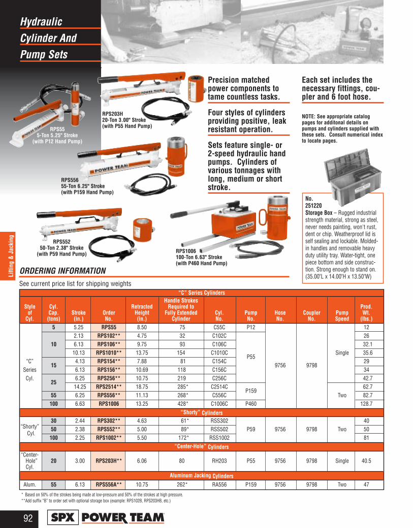
Cylinder AndHydraulic
Pump Sets
92®
Lifti
ng &
Jac
king
Precision matchedpower components totame countless tasks.
Four styles of cylindersproviding positive, leakresistant operation.
Sets feature single- or2-speed hydraulic handpumps. Cylinders ofvarious tonnages withlong, medium or shortstroke.
Each set includes thenecessary fittings, cou-pler and 6 foot hose.
NOTE: See appropriate catalogpages for additonal details onpumps and cylinders supplied withthese sets. Consult numerical indexto locate pages.
No.251220Storage Box – Rugged industrialstrength material, strong as steel,never needs painting, won't rust,dent or chip. Weatherproof lid isself sealing and lockable. Molded-in handles and removable heavyduty utility tray. Water-tight, onepiece bottom and side construc-tion. Strong enough to stand on. (35.00"L x 14.00"H x 13.50"W)
RPS1006100-Ton 6.63" Stroke(with P460 Hand Pump)
RPS203H20-Ton 3.00" Stroke(with P55 Hand Pump)RPS55
5-Ton 5.25" Stroke(with P12 Hand Pump)
RPS55655-Ton 6.25" Stroke(with P159 Hand Pump)
“C” Series CylindersHandle Strokes
Style Cyl. Retracted Required to Prod.of Cap. Stroke Order Height Fully Extended Cyl. Pump Hose Coupler Pump Wt.
Cyl. (tons) (in.) No. (in.) Cylinder No. No. No. No. Speed (lbs.)5 5.25 RPS55 8.50 75 C55C P12 12
2.13 RPS102** 4.75 32 C102C 2610 6.13 RPS106** 9.75 93 C106C 32.1
10.13 RPS1010** 13.75 154 C1010CP55
Single 35.6“C”
154.13 RPS154** 7.88 81 C154C
9756 979829
Series 6.13 RPS156** 10.69 118 C156C 34Cyl.
256.25 RPS256** 10.75 219 C256C 42.7
14.25 RPS2514** 18.75 285* C2514CP159
62.755 6.25 RPS556** 11.13 268* C556C Two 82.7
100 6.63 RPS1006 13.25 428* C1006C P460 128.7“Shorty” Cylinders
“Shorty”30 2.44 RPS302** 4.63 61* RSS302 40
Cyl.50 2.38 RPS552** 5.00 89* RSS502 P59 9756 9798 Two 50
100 2.25 RPS1002** 5.50 172* RSS1002 81“Center-Hole” Cylinders
“Center-Hole” 20 3.00 RPS203H** 6.06 80 RH203 P55 9756 9798 Single 40.5Cyl.
Aluminum Jacking CylindersAlum. 55 6.13 RPS556A** 10.75 262* RA556 P159 9756 9798 Two 47
* Based on 50% of the strokes being made at low-pressure and 50% of the strokes at high pressure.**Add suffix “B” to order set with optional storage box (example: RPS102B, RPS203HB, etc.)
ORDERING INFORMATIONSee current price list for shipping weights
RPS55250-Ton 2.38" Stroke
(with P59 Hand Pump)
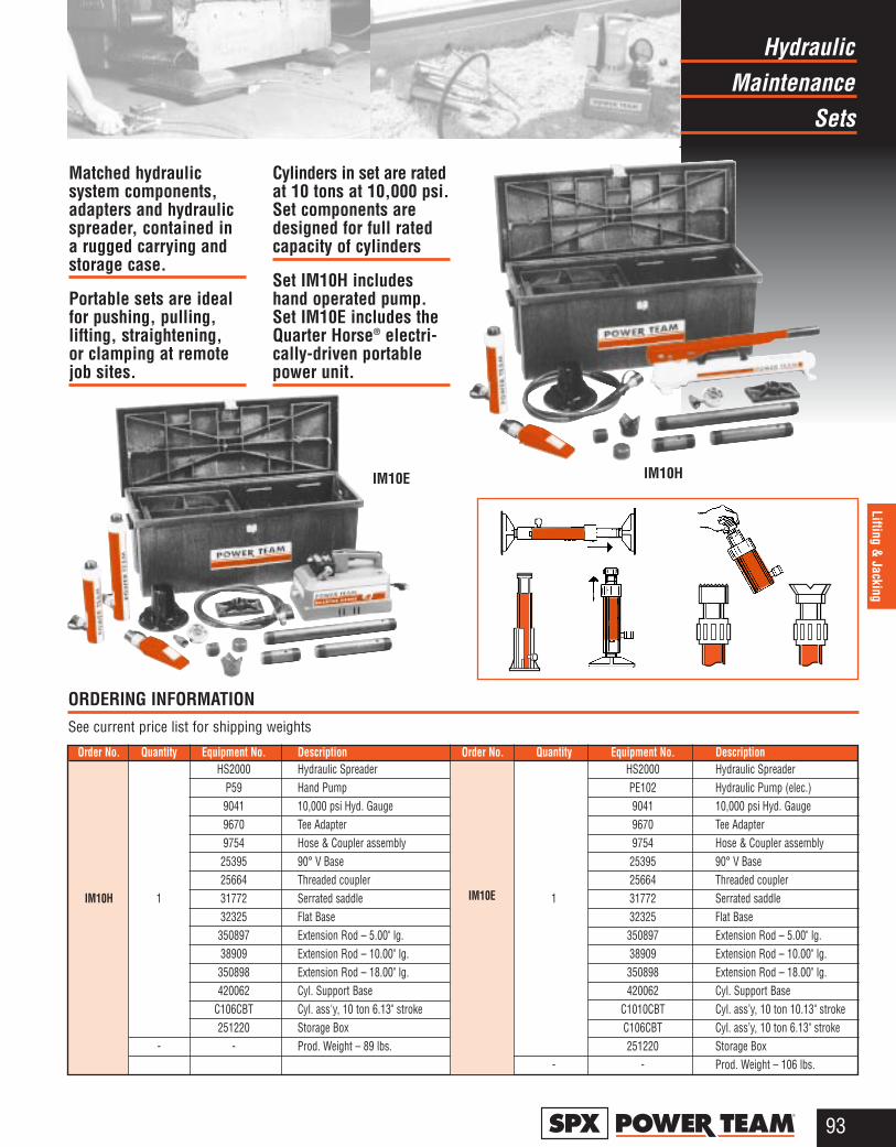
MaintenanceHydraulic
Sets
93®
Lifting & Jacking
Matched hydraulic system components,adapters and hydraulicspreader, contained ina rugged carrying andstorage case.
Portable sets are idealfor pushing, pulling,lifting, straightening, or clamping at remotejob sites.
Cylinders in set are ratedat 10 tons at 10,000 psi.Set components aredesigned for full ratedcapacity of cylinders
Set IM10H includeshand operated pump.Set IM10E includes theQuarter Horse® electri-cally-driven portablepower unit.
ORDERING INFORMATION See current price list for shipping weights
Order No. Quantity Equipment No. Description Order No. Quantity Equipment No. DescriptionHS2000 Hydraulic Spreader HS2000 Hydraulic Spreader
P59 Hand Pump PE102 Hydraulic Pump (elec.)9041 10,000 psi Hyd. Gauge 9041 10,000 psi Hyd. Gauge9670 Tee Adapter 9670 Tee Adapter9754 Hose & Coupler assembly 9754 Hose & Coupler assembly25395 90° V Base 25395 90° V Base25664 Threaded coupler 25664 Threaded coupler
IM10H 1 31772 Serrated saddle 1 31772 Serrated saddle32325 Flat Base 32325 Flat Base350897 Extension Rod – 5.00" lg. 350897 Extension Rod – 5.00" lg.38909 Extension Rod – 10.00" lg. 38909 Extension Rod – 10.00" lg.350898 Extension Rod – 18.00" lg. 350898 Extension Rod – 18.00" lg.420062 Cyl. Support Base 420062 Cyl. Support Base
C106CBT Cyl. ass'y, 10 ton 6.13" stroke C1010CBT Cyl. ass’y, 10 ton 10.13" stroke251220 Storage Box C106CBT Cyl. ass’y, 10 ton 6.13" stroke
- - Prod. Weight – 89 lbs. 251220 Storage Box- - Prod. Weight – 106 lbs.
IM10E
IM10HIM10E
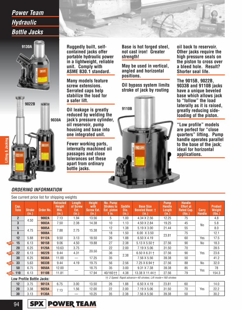
HydraulicPower Team
Bottle Jacks
94®
Lifti
ng &
Jac
king
Ruggedly built, self-contained jacks offerportable hydraulic powerin a lightweight, reliableunit. Comply withASME B30.1 standard.
Many models featurescrew extensions.Serrated caps help stabilize the load for a safer lift.
Oil leakage is greatlyreduced by welding thejack’s pressure cylinder,oil reservoir, pumphousing and base intoone integrated unit.
Fewer working parts,internally machined oilpassages and close tolerances set theseapart from ordinary bottle jacks.
Base is hot forged steel,not cast iron! Greaterstrength!
May be used in vertical,angled and horizontalpositions.
Oil bypass system limitsstroke of jack by routing
oil back to reservoir.Other jacks require thehigh pressure seals onthe piston to cross overa bleed hole. Result?Shorter seal life.
The 9015B, 9022B,9033B and 9110B jackshave a unique beveledbase which allows jackto “follow” the load laterally as it is raised,greatly reducing side-loading of the piston.
“Low profile” modelsare perfect for “closequarters” lifting. Pumphandle operates parallelto the base of the jack;ideal for horizontalapplications.
Retracted Length Height No. Pump Pump HandleCap. Height of Screw with Strokes to Saddle Base Size Handle Effort at ProductTons Stroke Order No. Min. Ext. Screw Ext. Ext. piston Dia. Beveled Base: † Length Rated Cap. Carry Weight
(in.) (in.) (in.) (in.) 1 in. (in.) (in.) (in.) (lbs.) Handle (lbs.)2
4.509002A 7.13 1.94 13.56 5 1.00 4.34 X 2.56 12.25 75 4.8
3 9003A 7.50 2.38 14.38 10 1.13 4.50 X 2.84 19.25 45 No 5.85
4.759005A
7.88 2.75 15.3812 1.38 5.19 X 3.00 21.44 55 8.0
8 9008A 18 1.50 6.00 X 3.5023.81
75 12.112 5.88 9112A 9.50 3.13 18.50 26 1.88 6.50 X 4.19 60 Yes 17.515 6.13 9015B 9.06 4.50 19.88 27 2.38 5.13 X 5.50 † 27.56 90 No 18.320 6.25 9120A 10.63 3.75
20.5022 2.00 7.19 X 5.06 31.50 70 28.5
22 6.13 9022B 9.44 4.31 362.38
6.50 X 6.31 † 27.56 90 Yes 23.630 6.25 9030A 11.00 — 17.25 35 7.56 X 5.56 39.38 50 41.233 5.63 9033B 9.44 4.19 19.75 56 2.56 7.25 X 6.94 † 27.56 88 No 32.050 6.75 9050A 12.00
— 18.75 35 3.00 9.31 X 7.38 39.38 85
Yes78
110 6.13 9110B 11.81 17.94 40/160†† 4.38 13.38 X 11.44 † 27.56 79 154.3
12 3.75 9012A 6.75 3.00 13.50 26 1.88 6.50 X 4.19 23.81 60 14.020 3.38 9020A 7.13 1.56 12.00 22 2.00 7.19 X 5.06 31.50 70 Yes 22.230 3.13 9130A — 10.25 35 2.38 7.56 X 5.56 39.38 50 30.2
Low Profile Bottle Jacks: †† 2 Speed: Rapid advance ≈40 strokes; Lift mode ≈160 strokes
ORDERING INFORMATION See current price list for shipping weights
9130A
9022B
9030A
9110B
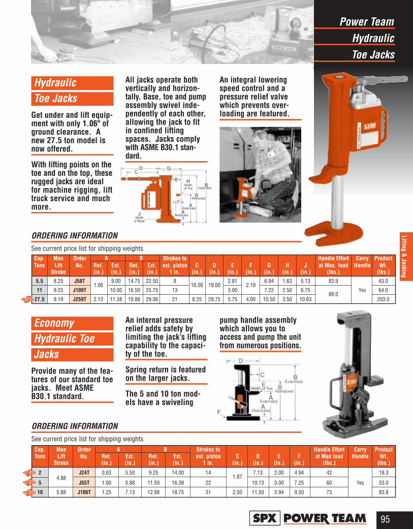
HydraulicPower Team
Toe Jacks
95®
Lifting & Jacking
Hydraulic Toe Jacks
Get under and lift equip-ment with only 1.06" ofground clearance. Anew 27.5 ton model isnow offered.
With lifting points on thetoe and on the top, theserugged jacks are idealfor machine rigging, lifttruck service and muchmore.
All jacks operate bothvertically and horizon-tally. Base, toe and pumpassembly swivel inde-pendently of each other,allowing the jack to fitin confined liftingspaces. Jacks complywith ASME B30.1 stan-dard.
An integral loweringspeed control and apressure relief valvewhich prevents over-loading are featured.
Economy Hydraulic Toe Jacks
Provide many of the fea-tures of our standard toejacks. Meet ASMEB30.1 standard.
An internal pressurerelief adds safety bylimiting the jack’s liftingcapability to the capaci-ty of the toe.
Spring return is featuredon the larger jacks.
The 5 and 10 ton mod-els have a swiveling
pump handle assemblywhich allows you toaccess and pump the unitfrom numerous positions.
ORDERING INFORMATION See current price list for shipping weights
ORDERING INFORMATION See current price list for shipping weights
Cap. Max Order A B Strokes to Handle Effort Carry ProductTons Lift No. Ret. Ext. Ret. Ext. ext. piston C D E F G H J at Max. load Handle Wt.
Stroke (in.) (in.) (in.) (in.) 1 in. (in.) (in.) (in.) (in.) (in.) (in.) (in.) (lbs.) (lbs.)
5.5 8.25 J58T1.06
9.00 14.75 22.50 816.00 19.00
2.812.19
6.94 1.63 5.13 83.9 43.0
11 9.25 J109T 10.00 16.50 25.75 13 3.00 7.22 2.50 6.7588.0
Yes 64.0
27.5 9.19 J259T 2.13 11.38 19.88 29.06 21 8.25 29.75 5.75 4.00 10.50 3.50 10.63 203.0
Cap. Max Order A B Strokes to Handle Effort Carry ProductTons Lift No. Ret. Ext. Ret. Ext. ext. piston C D E F at Max load Handle Wt.
Stroke (in.) (in.) (in.) (in.) 1 in. (in.) (in.) (in.) (in.) (lbs.) (lbs.)
24.88
J24T 0.63 5.50 9.25 14.00 141.87
7.13 2.00 4.94 42 18.3
5 J55T 1.00 5.88 11.50 16.38 22 10.13 3.00 7.25 60 Yes 53.0
10 5.88 J106T 1.25 7.13 12.88 18.75 31 2.50 11.50 3.94 9.50 73 83.8

Telescoping JacksHydraulic
And Mini Jack
96®
Lifti
ng &
Jac
king
9105A
Hydraulic Telescoping Jacks
The quality and relia-bility of our standardbottle jacks, but with a super long stroke.Eliminates the need tolift-crib-lift, etc. Thissaves job time and effort.Usually, you only haveto place the jack onceto complete the lift.
The 9015X offers verylow clearance capability,making it the ideal choicefor forklift maintenanceor machine lifting.
The 9006X, 9011X and9013X all feature aunique beveled basewhich allows the jackto “follow” the load laterally as it is raised,greatly reducing side-loading of the piston.
Jacks comply with theASME B30.1 standard.
Hydraulic Mini Jack
Here’s 5 tons of power inthe palm of your hand!Use it vertically or hori-zontally as a jack orspreader to apply forcewith just over 2.50" ofclearance needed. Thislittle task tamer weighsonly 4.2 lbs.
Use it to turn yourmechanical gear pullerof five tons or largerinto an hydraulic puller.
Handle operation isespecially convenientfor horizontal position-ing, though you can usethe jack at any angle.
Complies with ASMEB30.1 standard.
9013X9011X
Retracted Length Height No. Pump Pump HandleCap. Height of Screw with Strokes to Saddle Base Size Handle Effort at Carry ProductTons Stroke Order No. Min. Ext. Screw Ext. Ext. piston Dia. Beveled Base: † Length Rated Cap. Handle Weight
(in.) (in.) (in.) (in.) 1 in. (in.) (in.) (in.) (lbs.) (lbs.)6 12.00 9006X 8.50 –– 20.50 14 1.75 4.75 X 5.25 † 79
No14.0
11 10.30 9011X 7.88 2.69 20.88 25 1.63 6.31 X 6.50 † 27.56 88 19.513 10.00 9013X 9.06 3.31 22.38 35 1.88 6.94 X 7.31 † 79
Yes25.0
15 7.13 9015X 6.69 2.75 16.56 32 2.06 5.63 X 7.63 23.63 95 26.5
Retracted No. Pump Pump HandleCap. Height Max Strokes to Saddle Base Handle Effort at Carry ProductTons Stroke Order No. Min. Height Ext. piston Dia. Size Length Rated Cap. Handle Weight
(in.) (in.) (in.) 1 in. (in.) (in.) (in.) (lbs.) (lbs.)
5 0.81 9105A 2.56 3.38 4 1.13 2.94 Dia. 9.44 16.75 No 4.2
ORDERING INFORMATIONSee current price list for shipping weights
ORDERING INFORMATION See current price list for shipping weights
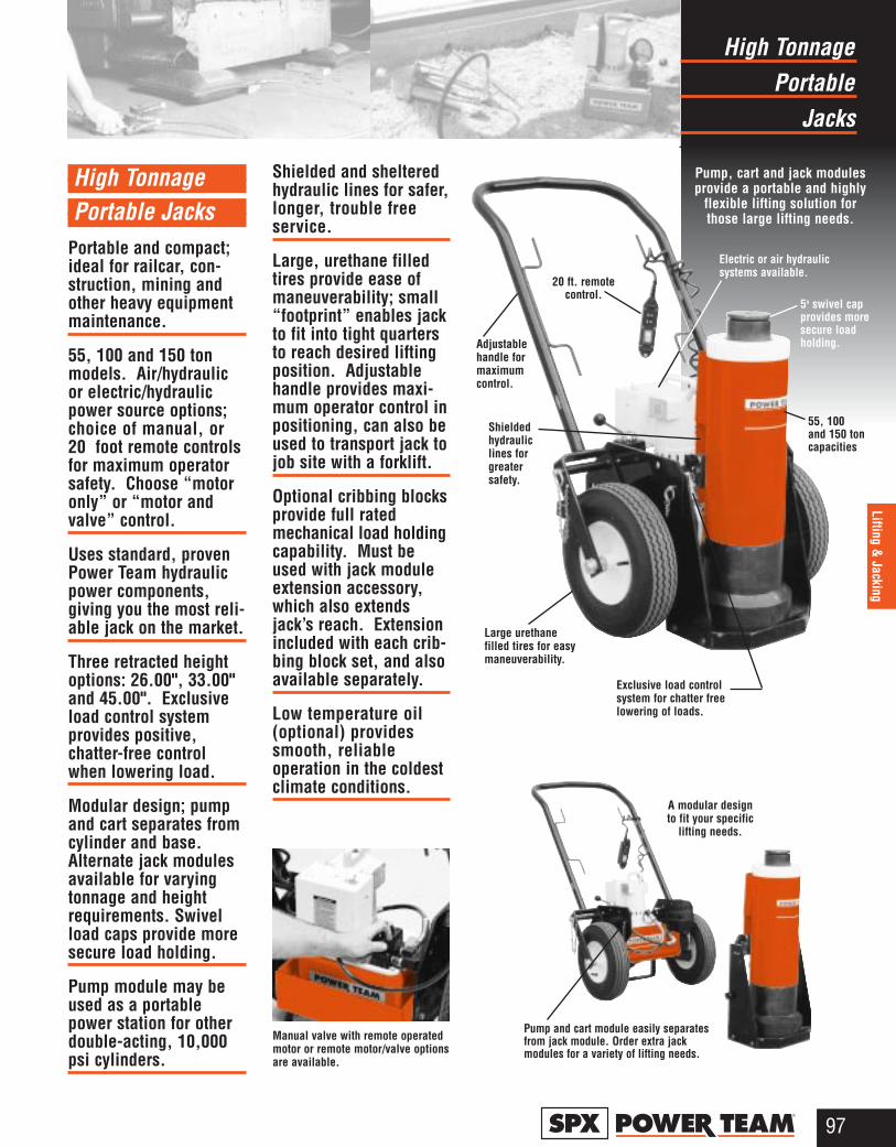
PortableHigh Tonnage
Jacks
97®
Lifting & Jacking
High Tonnage Portable Jacks
Portable and compact;ideal for railcar, con-struction, mining andother heavy equipmentmaintenance.
55, 100 and 150 tonmodels. Air/hydraulicor electric/hydraulicpower source options;choice of manual, or20 foot remote controlsfor maximum operatorsafety. Choose “motoronly” or “motor andvalve” control.
Uses standard, provenPower Team hydraulicpower components, giving you the most reli-able jack on the market.
Three retracted heightoptions: 26.00", 33.00"and 45.00". Exclusiveload control system provides positive, chatter-free controlwhen lowering load.
Modular design; pumpand cart separates fromcylinder and base.Alternate jack modulesavailable for varyingtonnage and heightrequirements. Swivelload caps provide moresecure load holding.
Pump module may beused as a portablepower station for otherdouble-acting, 10,000psi cylinders.
Shielded and shelteredhydraulic lines for safer,longer, trouble freeservice.
Large, urethane filledtires provide ease ofmaneuverability; small“footprint” enables jackto fit into tight quartersto reach desired liftingposition. Adjustablehandle provides maxi-mum operator control inpositioning, can also beused to transport jack tojob site with a forklift.
Optional cribbing blocksprovide full ratedmechanical load holdingcapability. Must beused with jack moduleextension accessory,which also extendsjack’s reach. Extensionincluded with each crib-bing block set, and alsoavailable separately.
Low temperature oil(optional) providessmooth, reliable operation in the coldestclimate conditions.
A modular designto fit your specific
lifting needs.
Manual valve with remote operatedmotor or remote motor/valve optionsare available.
Pump and cart module easily separatesfrom jack module. Order extra jackmodules for a variety of lifting needs.
Exclusive load controlsystem for chatter freelowering of loads.
Electric or air hydraulicsystems available.
Shieldedhydraulic lines for greatersafety.
Adjustablehandle for maximumcontrol.
20 ft. remotecontrol.
5o swivel capprovides moresecure loadholding.
Pump, cart and jack modulesprovide a portable and highly
flexible lifting solution forthose large lifting needs.
55, 100 and 150 toncapacities
Large urethanefilled tires for easymaneuverability.
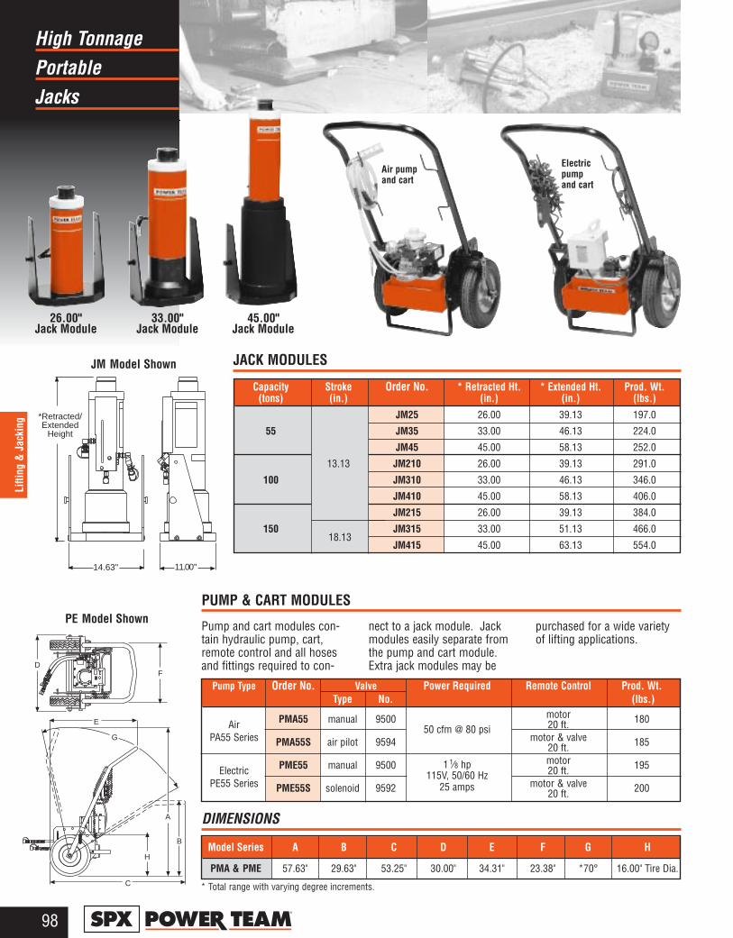
PortableHigh Tonnage
Jacks
98®
Lifti
ng &
Jac
king
Air pumpand cart
26.00" Jack Module
33.00"Jack Module
45.00"Jack Module
Electricpumpand cart
A
ON
OFF
OFF
REMOTE
9
796
1000
0 P
SI M
AX
MA
DE
IN U
SA
FD
E
G
B
H
C
11.00"
9796
10000 PSI MAXMADE IN USA
14.63"
*Retracted/Extended
Height
JM Model Shown
PE Model ShownPUMP & CART MODULES
JACK MODULES
Pump and cart modules con-tain hydraulic pump, cart,remote control and all hosesand fittings required to con-
nect to a jack module. Jackmodules easily separate fromthe pump and cart module.Extra jack modules may be
purchased for a wide varietyof lifting applications.
Model Series A B C D E F G H
PMA & PME 57.63" 29.63" 53.25" 30.00" 34.31" 23.38" *70° 16.00" Tire Dia.
Pump Type Order No. Valve Power Required Remote Control Prod. Wt.Type No. (lbs.)
PMA55 manual 9500 motor 180Air 50 cfm @ 80 psi 20 ft.PA55 Series PMA55S air pilot 9594 motor & valve 18520 ft.
PME55 manual 9500 1 1⁄8 hp motor 195Electric 115V, 50/60 Hz 20 ft.PE55 Series PME55S solenoid 9592 25 amps motor & valve 20020 ft.
Capacity Stroke Order No. * Retracted Ht. * Extended Ht. Prod. Wt.(tons) (in.) (in.) (in.) (lbs.)
JM25 26.00 39.13 197.0
55 JM35 33.00 46.13 224.0
JM45 45.00 58.13 252.0
13.13 JM210 26.00 39.13 291.0
100 JM310 33.00 46.13 346.0
JM410 45.00 58.13 406.0
JM215 26.00 39.13 384.0
150 JM315 33.00 51.13 466.0
JM415 45.00 63.13 554.0
* Total range with varying degree increments.
DIMENSIONS
18.13

PortableHigh Tonnage
Jacks
99®
Lifting & Jacking
F GEDC
BA
H
AB
C
■ Increases jack's reach.■ Swivel cap (5° max.) provides
more secure load holding.
■ Convert jackmodule intostable mechani-cal cribbingdevice.
■ Increaseretracted heightup to 20.50inches.
Jack Module ExtensionCribbing Block Set
For heavy-duty lifting in railroad,construction, mining and industrialapplications.
Capacity Order No. A B C D E F G H Prod. Wt.(tons) (in.) (in.) (in.) (in.) (in.) (in.) (in.) (in.) (lbs.)
55 421365 8.81 6.81 5.00 2.63 1 11⁄16–8UN 2.50 2.63 3.63 21.0
100 421366 9.00 7.00 6.88 3.88 2 3⁄4–12UN 3.75 3.88 3.75 40.0
150 421367 8.63 6.63 8.00 4.50 3 1⁄4–8UNC 4.38 4.50 3.50 50.0
55 Ton 100 Ton 150 TonOrder No. CBS55 CBS100 CBS150No. in Set 1 4 1 4 1 4
A 1.50" 3.00" 1.50" 3.00" 1.50" 3.00"
B 1.75" 3.25" 1.75" 3.25" 1.75" 3.25"
C 5.50" 5.50" 7.38" 7.38" 8.75" 8.75"
Jack Module Ext. 6.81" 7.00" 6.63"
Total Stack Ht. 20.31" 20.50" 20.13"
Product Wt. (lbs.) 36.0 68.0 85.0
Capacity Stroke Ret. Ht. Jack▼ ORDER NUMBER ▼
(tons) (in.) (in.) Module26.00 JM25 JAM5526 JAR5526 JEM5526 JER5526
55 33.00 JM35 JAM5533 JAR5533 JEM5533 JER5533
13.13
45.00 JM45 JAM5545 JAR5545 JEM5545 JER554526.00 JM210 JAM10026 JAR10026 JEM10026 JER10026
100 33.00 JM310 JAM10033 JAR10033 JEM10033 JER1003345.00 JM410 JAM10045 JAR10045 JEM10045 JER1004526.00 JM215 JAM15026 JAR15026 JEM15026 JER15026
15018.13
33.00 JM315 JAM15033 JAR15033 JEM15033 JER1503345.00 JM415 JAM15045 JAR15045 JEM15045 JER15045
JACK MODULE EXTENSIONS
HIGH TONNAGE PORTABLE JACKS
CRIBBING BLOCK SETS - Includes One Jack Module Extension
ORDER
NUMBER
▲▲
Pump and Cart ModuleAir/Hydraulic Pump Electric Pump
Manual Air Pilot Manual Solenoid50CFM @ 80 psi 115 V. 50/60Hz.
PMA55 PMA55S PME55 PME55S
Valve TypePower RequirementsPump and Cart #
Select a jack module and pump and specifyby order number as shown in “Order Number”chart. Complete jack assemblies can also bepurchased by ordering a jack module andpump and cart module separately.
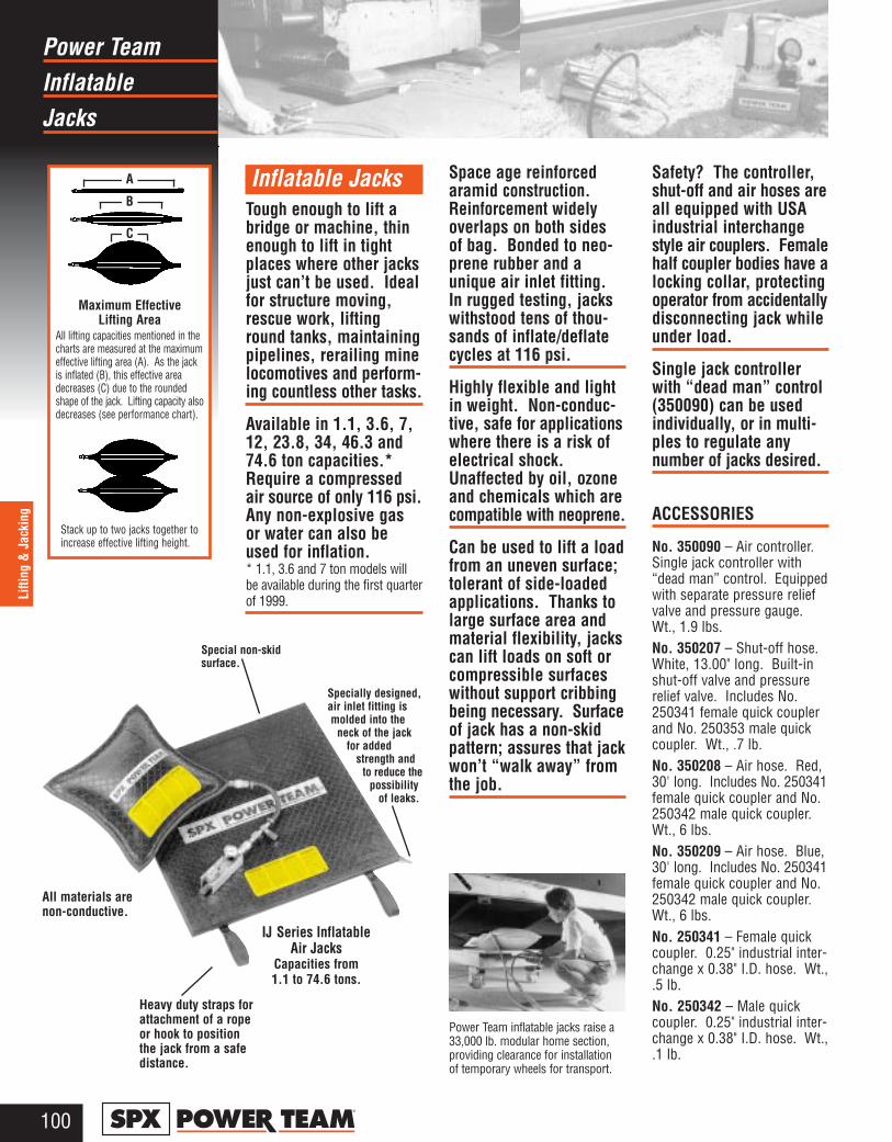
InflatablePower Team
Jacks
100®
Lifti
ng &
Jac
king
Inflatable JacksTough enough to lift abridge or machine, thinenough to lift in tightplaces where other jacksjust can’t be used. Idealfor structure moving,rescue work, liftinground tanks, maintainingpipelines, rerailing minelocomotives and perform-ing countless other tasks.
Available in 1.1, 3.6, 7,12, 23.8, 34, 46.3 and74.6 ton capacities.*Require a compressedair source of only 116 psi.Any non-explosive gasor water can also beused for inflation.* 1.1, 3.6 and 7 ton models willbe available during the first quarterof 1999.
Space age reinforcedaramid construction.Reinforcement widelyoverlaps on both sides of bag. Bonded to neo-prene rubber and aunique air inlet fitting.In rugged testing, jackswithstood tens of thou-sands of inflate/deflatecycles at 116 psi.
Highly flexible and lightin weight. Non-conduc-tive, safe for applicationswhere there is a risk ofelectrical shock.Unaffected by oil, ozoneand chemicals which arecompatible with neoprene.
Can be used to lift a loadfrom an uneven surface;tolerant of side-loadedapplications. Thanks tolarge surface area andmaterial flexibility, jackscan lift loads on soft orcompressible surfaceswithout support cribbingbeing necessary. Surfaceof jack has a non-skidpattern; assures that jackwon’t “walk away” fromthe job.
Safety? The controller,shut-off and air hoses areall equipped with USAindustrial interchangestyle air couplers. Femalehalf coupler bodies have alocking collar, protectingoperator from accidentallydisconnecting jack whileunder load.
Single jack controllerwith “dead man” control(350090) can be usedindividually, or in multi-ples to regulate anynumber of jacks desired.
ACCESSORIES
No. 350090 – Air controller.Single jack controller with“dead man” control. Equippedwith separate pressure reliefvalve and pressure gauge.Wt., 1.9 lbs.No. 350207 – Shut-off hose.White, 13.00" long. Built-inshut-off valve and pressurerelief valve. Includes No.250341 female quick couplerand No. 250353 male quickcoupler. Wt., .7 lb.No. 350208 – Air hose. Red,30' long. Includes No. 250341female quick coupler and No.250342 male quick coupler.Wt., 6 lbs.No. 350209 – Air hose. Blue,30' long. Includes No. 250341female quick coupler and No.250342 male quick coupler.Wt., 6 lbs.No. 250341 – Female quickcoupler. 0.25" industrial inter-change x 0.38" I.D. hose. Wt.,.5 lb.No. 250342 – Male quickcoupler. 0.25" industrial inter-change x 0.38" I.D. hose. Wt.,.1 lb.
A
B
C
Maximum Effective Lifting Area
All lifting capacities mentioned in thecharts are measured at the maximumeffective lifting area (A). As the jackis inflated (B), this effective areadecreases (C) due to the roundedshape of the jack. Lifting capacity alsodecreases (see performance chart).
Stack up to two jacks together toincrease effective lifting height.
Power Team inflatable jacks raise a33,000 lb. modular home section,providing clearance for installationof temporary wheels for transport.
All materials arenon-conductive.
Heavy duty straps forattachment of a ropeor hook to positionthe jack from a safedistance.
IJ Series InflatableAir Jacks
Capacities from 1.1 to 74.6 tons.
Special non-skid surface.
Specially designed,air inlet fitting is molded into the
neck of the jack for added
strength and to reduce the
possibility of leaks.
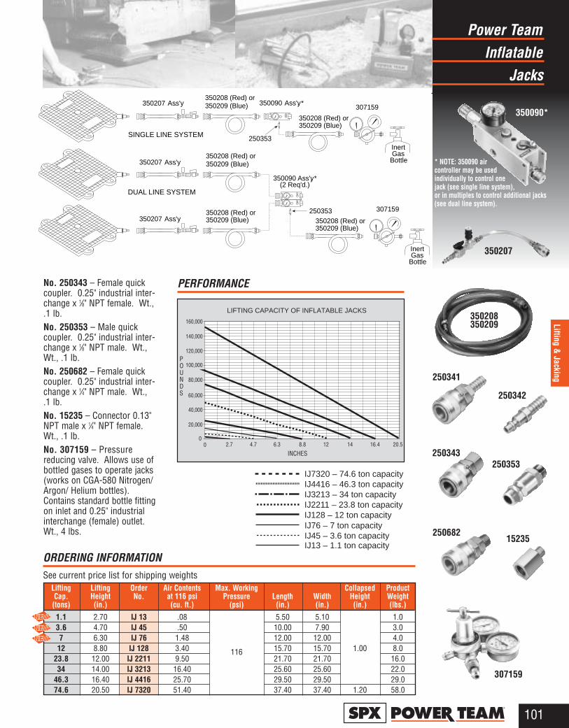
InflatablePower Team
Jacks
101®
Lifting & Jacking
No. 250343 – Female quickcoupler. 0.25" industrial inter-change x 1⁄8" NPT female. Wt.,.1 lb.No. 250353 – Male quickcoupler. 0.25" industrial inter-change x 1⁄8" NPT male. Wt.,Wt., .1 lb.No. 250682 – Female quickcoupler. 0.25" industrial inter-change x 1⁄4" NPT male. Wt.,.1 lb.No. 15235 – Connector 0.13"NPT male x 1⁄4" NPT female.Wt., .1 lb.No. 307159 – Pressurereducing valve. Allows use ofbottled gases to operate jacks(works on CGA-580 Nitrogen/Argon/ Helium bottles).Contains standard bottle fittingon inlet and 0.25" industrialinterchange (female) outlet.Wt., 4 lbs.
350207 Ass'y.350208 (Red) or350209 (Blue) 350090 Ass'y. *
250353
350208 (Red) or350209 (Blue)
307159
InertGas
Bottle350207 Ass'y.
350207 Ass'y.
350208 (Red) or350209 (Blue)
350208 (Red) or350209 (Blue)
350090 Ass'y. *(2 Req'd.)
350208 (Red) or350209 (Blue)
307159
SINGLE LINE SYSTEM
DUAL LINE SYSTEM
250353
InertGas
Bottle
IJ7320 – 74.6 ton capacityIJ4416 – 46.3 ton capacityIJ3213 – 34 ton capacityIJ2211 – 23.8 ton capacityIJ128 – 12 ton capacityIJ76 – 7 ton capacityIJ45 – 3.6 ton capacityIJ13 – 1.1 ton capacity
LIFTING CAPACITY OF INFLATABLE JACKS
INCHES
POUNDS
2.7 4.7 12 14 16.4 20.56.3 8.800
20,000
40,000
140,000
160,000
120,000
60,000
100,000
80,000
350090*
307159
350208350209
350207
250341
250353
250342
250343
25068215235
Lifting Lifting Order Air Contents Max. Working Collapsed ProductCap. Height No. at 116 psi Pressure Length Width Height Weight(tons) (in.) (cu. ft.) (psi) (in.) (in.) (in.) (lbs.)
1.1 2.70 IJ 13 .08 5.50 5.10 1.03.6 4.70 IJ 45 .50 10.00 7.90 3.07 6.30 IJ 76 1.48 12.00 12.00 4.012 8.80 IJ 128 3.40 116 15.70 15.70 1.00 8.0
23.8 12.00 IJ 2211 9.50 21.70 21.70 16.034 14.00 IJ 3213 16.40 25.60 25.60 22.0
46.3 16.40 IJ 4416 25.70 29.50 29.50 29.074.6 20.50 IJ 7320 51.40 37.40 37.40 1.20 58.0
ORDERING INFORMATION See current price list for shipping weights
* NOTE: 350090 aircontroller may be usedindividually to control onejack (see single line system),or in multiples to control additional jacks(see dual line system).
PERFORMANCE
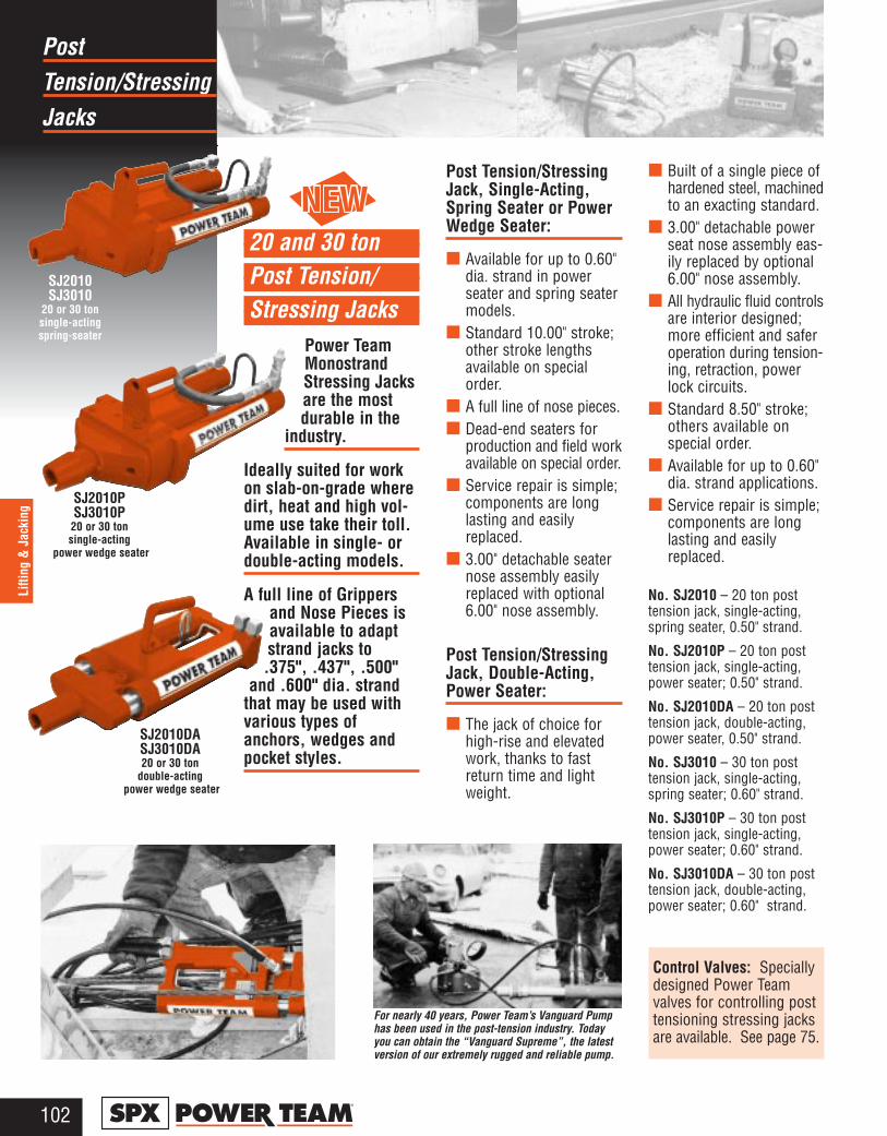
Tension/StressingPost
Jacks
102®
Lifti
ng &
Jac
king
20 and 30 ton Post Tension/ Stressing Jacks
Power TeamMonostrandStressing Jacksare the mostdurable in the
industry.
Ideally suited for workon slab-on-grade wheredirt, heat and high vol-ume use take their toll.Available in single- ordouble-acting models.
A full line of Grippersand Nose Pieces isavailable to adaptstrand jacks to.375", .437", .500"
and .600" dia. strandthat may be used withvarious types ofanchors, wedges andpocket styles.
Post Tension/StressingJack, Single-Acting,Spring Seater or PowerWedge Seater:
■ Available for up to 0.60"dia. strand in powerseater and spring seatermodels.
■ Standard 10.00" stroke;other stroke lengthsavailable on specialorder.
■ A full line of nose pieces.■ Dead-end seaters for
production and field workavailable on special order.
■ Service repair is simple;components are longlasting and easilyreplaced.
■ 3.00" detachable seaternose assembly easilyreplaced with optional6.00" nose assembly.
Post Tension/StressingJack, Double-Acting,Power Seater:
■ The jack of choice forhigh-rise and elevatedwork, thanks to fastreturn time and lightweight.
■ Built of a single piece ofhardened steel, machinedto an exacting standard.
■ 3.00" detachable powerseat nose assembly eas-ily replaced by optional6.00" nose assembly.
■ All hydraulic fluid controlsare interior designed;more efficient and saferoperation during tension-ing, retraction, powerlock circuits.
■ Standard 8.50" stroke;others available on special order.
■ Available for up to 0.60"dia. strand applications.
■ Service repair is simple;components are longlasting and easilyreplaced.
No. SJ2010 – 20 ton posttension jack, single-acting,spring seater, 0.50" strand.
No. SJ2010P – 20 ton posttension jack, single-acting,power seater; 0.50" strand.
No. SJ2010DA – 20 ton posttension jack, double-acting,power seater, 0.50" strand.
No. SJ3010 – 30 ton posttension jack, single-acting,spring seater; 0.60" strand.
No. SJ3010P – 30 ton posttension jack, single-acting,power seater; 0.60" strand.
No. SJ3010DA – 30 ton posttension jack, double-acting,power seater; 0.60" strand.
SJ2010PSJ3010P20 or 30 ton single-acting
power wedge seater
SJ2010SJ3010
20 or 30 ton single-acting spring-seater
SJ2010DASJ3010DA20 or 30 ton
double-actingpower wedge seater
For nearly 40 years, Power Team’s Vanguard Pump has been used in the post-tension industry. Todayyou can obtain the “Vanguard Supreme”, the latestversion of our extremely rugged and reliable pump.
Control Valves: Speciallydesigned Power Teamvalves for controlling posttensioning stressing jacksare available. See page 75.

Tension/StressingPost
Jacks
103®
Lifting & Jacking
Pick the system that’s right for you
Basic Stressing Diagram
Detachable Nose Piece
No.9758 hoseconnects
directly to jack, 3⁄8" NPTF Jack Grippers
on undersideof jack
PE604T VanguardSupreme Pump
IntegralPressureGauge
Pressure
4-way 3-position (tandem center)Manual Valve
No. 9500
Set
SJ2010P/SJ3010P Jacksingle-acting, power wedge seater
Detachable Nose Piece
PocketFormer
removed
Strand
Stressing Jack sets easily on top of strand
Wedge
Anchor
PlasticSheathing overgreased strand
Cut-awayview
ConcreteSlab
No.9758 hoseconnects
directly to jack, 3⁄8" NPTF
Jack Gripperson underside
of jack
PE604PTVanguardSupreme
Pump IntegralPressureGauge
Pressure
Special 4-way 3-posit.Manual Valve No. 9628
Set
Detachable Nose Piece
No.9758 hosesconnect
directly to jack, 3⁄8" NPTF
Jack Gripperson underside
of jack
No. 9763 hoseconnect directly
to 1⁄4" NPTF
No. 9763hose connects
directly to 1⁄4" NPTF
PE604PT VanguardSupreme Pump
IntegralPressureGauge
Special 4-way 3-position Manual Valve No. 9628
Return
PressureSJ2010DA
SJ3010DA Jackdouble-acting,
power wedge seater
Post Tension/StressingSystem available fromPower Team
A combination of our lightweightPE60 Vanguard Supremehydraulic pump, and the heavyduty Post Tensioning/StressingJack gives you ease of use, durability and portability in yourpost tensioning/stressing operations. Contact your Power TeamDistributor for more details about a system that can save you money.
The SJ2010 or SJ3010 jacksmake slab-on-grade stressingsimple, safe and quick
SJ2010/SJ3010 Jacksingle-acting, spring seater

Tension/StressingPost
Jacks
104®
Lifti
ng &
Jac
king
WA
RN
ING
WA
RN
ING
DA
NG
ER
Recommended Cyl. Internal Tons atCyl. Pump for this Strand Seater Oil Effective Pressure 10,000Cap. Stroke Order No. Stressing Jack Diameter Type Capacity Area at Cap. psi A B C Weight(tons) (in.) (in.) (cu. in.) (sq. in.) (psi) (in.) (in.) (in.) (lbs.)
20SJ2010 PE604T
.375-.50Spring
45.2 4.5 8,948 22.4 21.00 9.00 6.50 55.0
10.00SJ2010P PE604PT Power
30SJ3010 PE604T
.375-.60Spring
63.6 6.3 9,549 31.4 22.00 10.20 7.00 76.0SJ3010P
208.50
SJ2010DA PE604PT .375-.50 Power 53.0 5.3 7,575 26.418.50
7.506.50
42.0
30 SJ3010DA .375-.60 67.6 7.9 7,554 39.7 8.50 52.0
Used with 3.00" 3.00" 6.00" 6.00" .38" .44" .50" .60" GripperStressing Nose Wedge Nose Wedge Diameter Diameter Diameter Diameter Replacement Retainer Plate
Jack Piece Seater Piece Seater Gripper Set Gripper Set Gripper Set Gripper Set Gripper Handle (2 used)
SJ2010252564 252562 252759 252763 252568 252761 252567 252570 252565
SJ2010P NA
SJ2010DA 252543 252542 252760 252764 252650 252762 252555 252556 252544
SJ3010252564 252562 252759 252763 252568 252761 252567 252569 252570 252565
SJ3010P
SJ3010DA 253363 253361 253364 253362 253390 NA 253391 253365 252556 252544
No. 9758 Hose - 10 ft. rubber, wire-braid (2-ply, 20,000 psi burst rating) 3⁄8" NPTF male hose ends
No. 9763 Hose - 10 ft. rubber, wire-braid (2-ply, 20,000 psi burst rating) 0.38" x 1⁄4" NPTF male hose ends
ORDERING INFORMATION See current price list for shipping weights
ACCESSORIES AND HOSES ORDERING INFORMATION
20 or 30 ton Post Tension/Stressing Jacks
C
A
B
Orange tinted blocks indicate parts originally supplied with tool.
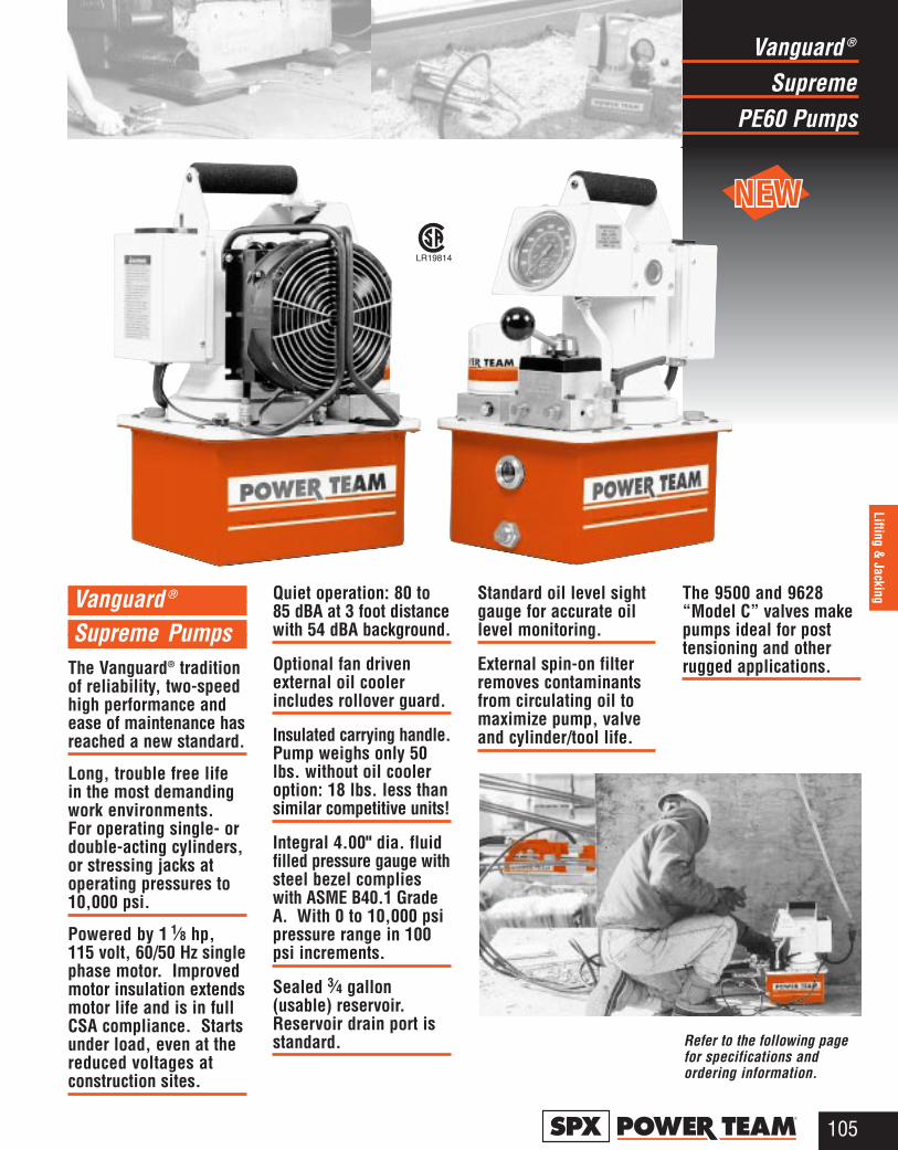
Vanguard ®
Supreme PumpsThe Vanguard® traditionof reliability, two-speedhigh performance andease of maintenance hasreached a new standard.
Long, trouble free lifein the most demandingwork environments. For operating single- ordouble-acting cylinders,or stressing jacks atoperating pressures to10,000 psi.
Powered by 1 1⁄8 hp,115 volt, 60/50 Hz singlephase motor. Improvedmotor insulation extendsmotor life and is in fullCSA compliance. Startsunder load, even at thereduced voltages atconstruction sites.
Quiet operation: 80 to85 dBA at 3 foot distancewith 54 dBA background.
Optional fan drivenexternal oil coolerincludes rollover guard.
Insulated carrying handle.Pump weighs only 50lbs. without oil cooleroption: 18 lbs. less thansimilar competitive units!
Integral 4.00" dia. fluidfilled pressure gauge withsteel bezel complieswith ASME B40.1 GradeA. With 0 to 10,000 psipressure range in 100psi increments.
Sealed 3⁄4 gallon(usable) reservoir.Reservoir drain port isstandard.
Standard oil level sightgauge for accurate oillevel monitoring.
External spin-on filterremoves contaminantsfrom circulating oil tomaximize pump, valveand cylinder/tool life.
The 9500 and 9628“Model C” valves makepumps ideal for posttensioning and otherrugged applications.
SupremeVanguard ®
PE60 Pumps
105®
Lifting & Jacking
Refer to the following pagefor specifications andordering information.
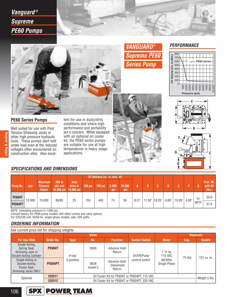
SupremeVanguard ®
PE60 Pumps
106®
Lifti
ng &
Jac
king
A
F
G
B
E
C
D
VANGUARD®
Supreme PE60 Series Pump
PE60 Series Pumps
Well suited for use with PostTension Stressing Jacks orother high pressure hydraulictools. These pumps start wellunder load even at the reducedvoltages often encountered onconstruction sites. Also excel-
lent for use in dusty/dirtyconditions and where highperformance and portabilityare a concern. When equippedwith an optional oil coolerkit, the PE60 series pumpsare suitable for use at hightemperatures in heavy usageapplications.
PE60 Series
800700600500400300200100
0Oil
Volu
me
(Cu.
In./M
in.)
Pressure (psi)
500
1000
2000
3000
4000
5000
6000
7000
8000
10,0
00
Oil Delivery (cu. in./min. @)
Maximum dBA at Amp Prod. Wt.Pump No. rpm Pressure idle and draw at 100 psi 700 psi 5,000 10,000 A B C D E F G with Oil
Output 10,000 psi 10,000 psi psi psi (lbs.)
PE604T12,000 10,000 80/85 25 704 440 74 56 9.31" 11.50" 18.25" 6.00" 15.00" 4.00"
3⁄8" 50.0
PE604PT NPTF 51.0
Valve ReservoirFor Use With Order No. Type No. Function Control Switch Motor Cap. UsableSingle-Acting,Spring Seat, PE604T 9500 Advance Hold
Stressing Jack or Return 1 1⁄8 hpDouble-Acting Cylinder 4-way On/Off/Pulse 115 VAC .75 Gal. 157 cu. in.
Single-Acting or 3-position Advance Hold control switch 60/50HzDouble-Acting, PE604PT 9628 � Sequenced Single Phase
Power Seat, model C ReturnStressing Jacks ONLY
Optional 252511 Oil Cooler Kit for PE604T or PE604PT, 115 VAC Weight 5 lbs.252512 Oil Cooler Kit for PE604T or PE604PT, 220 VAC
ORDERING INFORMATIONSee current price list for shipping weights
PERFORMANCE
NOTE: Unloading pressure is 1,000 psi.Consult factory for PE60 pump models with other control and valve options.For 220/230 volt, 50/60 Hz, single-phase models, add -220 suffix
SPECIFICATIONS AND DIMENSIONS
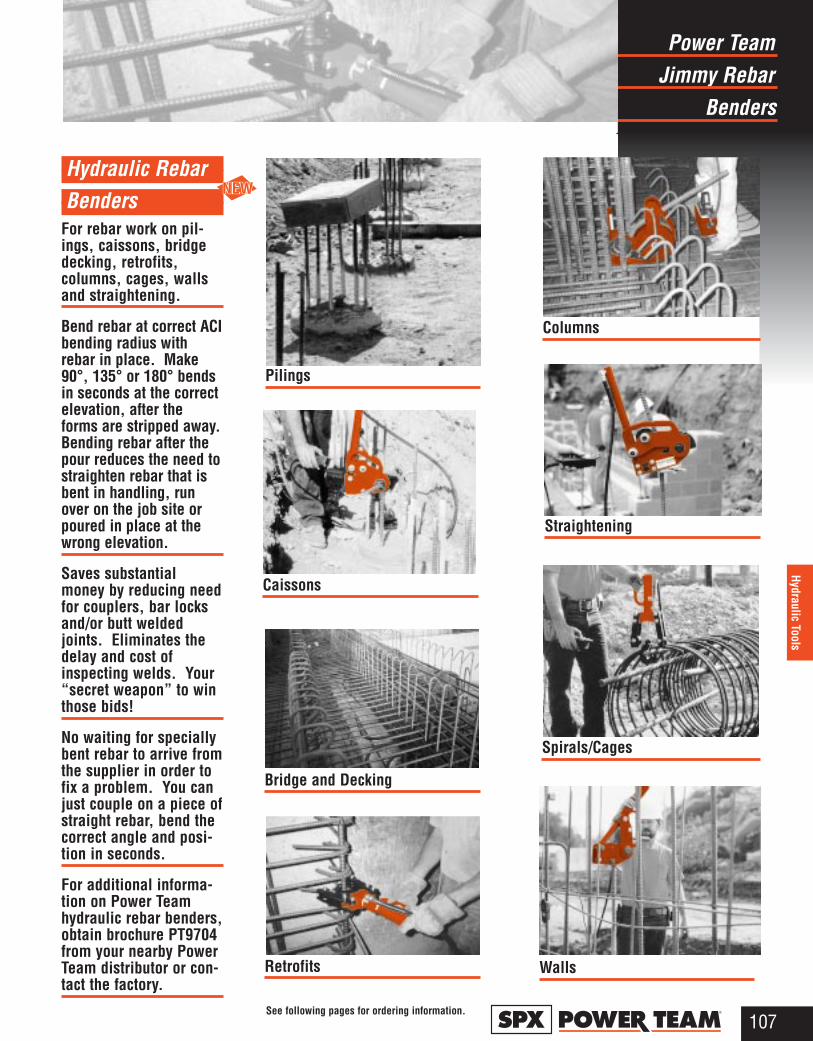
Jimmy RebarPower Team
Benders
107®
Hydraulic Tools
Hydraulic Rebar Benders
For rebar work on pil-ings, caissons, bridgedecking, retrofits,columns, cages, wallsand straightening.
Bend rebar at correct ACIbending radius withrebar in place. Make90°, 135° or 180° bendsin seconds at the correctelevation, after theforms are stripped away.Bending rebar after thepour reduces the need tostraighten rebar that isbent in handling, runover on the job site orpoured in place at thewrong elevation.
Saves substantialmoney by reducing needfor couplers, bar locksand/or butt weldedjoints. Eliminates thedelay and cost ofinspecting welds. Your“secret weapon” to winthose bids!
No waiting for speciallybent rebar to arrive fromthe supplier in order tofix a problem. You canjust couple on a piece ofstraight rebar, bend thecorrect angle and posi-tion in seconds.
For additional informa-tion on Power Teamhydraulic rebar benders,obtain brochure PT9704from your nearby PowerTeam distributor or con-tact the factory.
Pilings
Caissons
Bridge and Decking
Retrofits Walls
Spirals/Cages
Straightening
Columns
See following pages for ordering information.
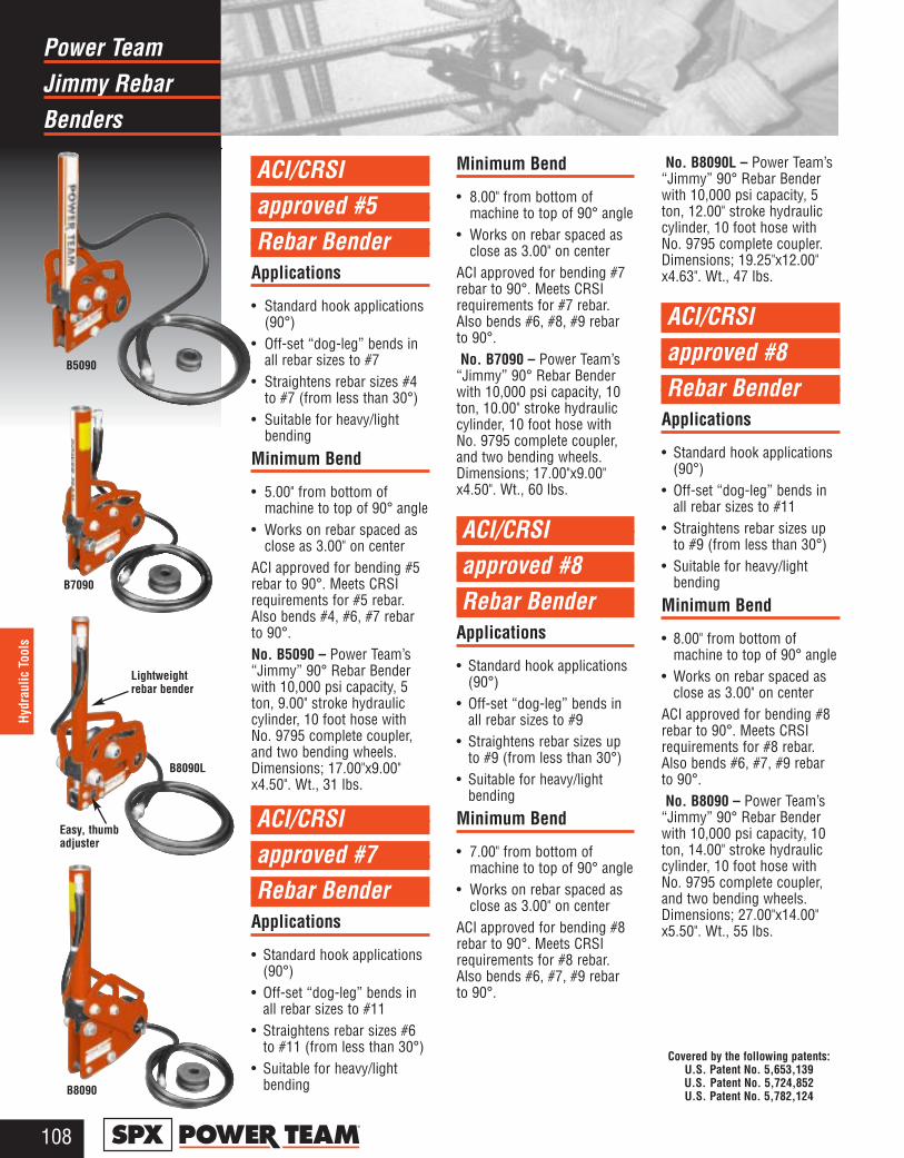
Jimmy RebarPower Team
Benders
108®
Hydr
aulic
Too
ls
B5090
B7090
B8090L
B8090
ACI/CRSI approved #5 Rebar Bender
Applications
• Standard hook applications(90°)
• Off-set “dog-leg” bends inall rebar sizes to #7
• Straightens rebar sizes #4to #7 (from less than 30°)
• Suitable for heavy/lightbending
Minimum Bend
• 5.00" from bottom ofmachine to top of 90° angle
• Works on rebar spaced asclose as 3.00" on center
ACI approved for bending #5rebar to 90°. Meets CRSIrequirements for #5 rebar.Also bends #4, #6, #7 rebarto 90°.No. B5090 – Power Team’s“Jimmy” 90° Rebar Benderwith 10,000 psi capacity, 5ton, 9.00" stroke hydrauliccylinder, 10 foot hose withNo. 9795 complete coupler,and two bending wheels.Dimensions; 17.00"x9.00"x4.50". Wt., 31 lbs.
ACI/CRSI approved #7 Rebar Bender
Applications
• Standard hook applications(90°)
• Off-set “dog-leg” bends inall rebar sizes to #11
• Straightens rebar sizes #6to #11 (from less than 30°)
• Suitable for heavy/lightbending
Minimum Bend
• 8.00" from bottom ofmachine to top of 90° angle
• Works on rebar spaced asclose as 3.00" on center
ACI approved for bending #7rebar to 90°. Meets CRSIrequirements for #7 rebar.Also bends #6, #8, #9 rebarto 90°.No. B7090 – Power Team’s
“Jimmy” 90° Rebar Benderwith 10,000 psi capacity, 10ton, 10.00" stroke hydrauliccylinder, 10 foot hose withNo. 9795 complete coupler,and two bending wheels.Dimensions; 17.00"x9.00"x4.50". Wt., 60 lbs.
ACI/CRSIapproved #8 Rebar Bender
Applications
• Standard hook applications(90°)
• Off-set “dog-leg” bends inall rebar sizes to #9
• Straightens rebar sizes upto #9 (from less than 30°)
• Suitable for heavy/lightbending
Minimum Bend
• 7.00" from bottom ofmachine to top of 90° angle
• Works on rebar spaced asclose as 3.00" on center
ACI approved for bending #8rebar to 90°. Meets CRSIrequirements for #8 rebar.Also bends #6, #7, #9 rebarto 90°.
No. B8090L – Power Team’s“Jimmy” 90° Rebar Benderwith 10,000 psi capacity, 5ton, 12.00" stroke hydrauliccylinder, 10 foot hose withNo. 9795 complete coupler.Dimensions; 19.25"x12.00"x4.63". Wt., 47 lbs.
ACI/CRSIapproved #8 Rebar Bender
Applications
• Standard hook applications(90°)
• Off-set “dog-leg” bends inall rebar sizes to #11
• Straightens rebar sizes upto #9 (from less than 30°)
• Suitable for heavy/lightbending
Minimum Bend
• 8.00" from bottom ofmachine to top of 90° angle
• Works on rebar spaced asclose as 3.00" on center
ACI approved for bending #8rebar to 90°. Meets CRSIrequirements for #8 rebar.Also bends #6, #7, #9 rebarto 90°.No. B8090 – Power Team’s
“Jimmy” 90° Rebar Benderwith 10,000 psi capacity, 10ton, 14.00" stroke hydrauliccylinder, 10 foot hose withNo. 9795 complete coupler,and two bending wheels.Dimensions; 27.00"x14.00"x5.50". Wt., 55 lbs.
Easy, thumbadjuster
Lightweightrebar bender
Covered by the following patents:U.S. Patent No. 5,653,139U.S. Patent No. 5,724,852U.S. Patent No. 5,782,124
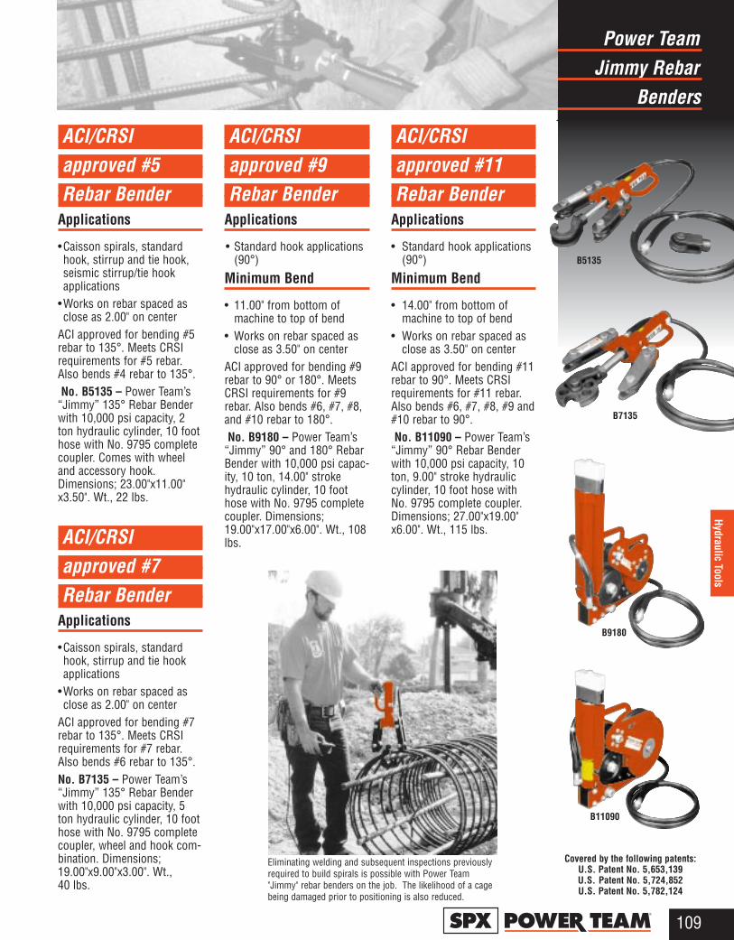
Jimmy RebarPower Team
Benders
109®
Hydraulic Tools
ACI/CRSI approved #5 Rebar Bender
Applications
•Caisson spirals, standardhook, stirrup and tie hook, seismic stirrup/tie hookapplications
•Works on rebar spaced asclose as 2.00" on center
ACI approved for bending #5rebar to 135°. Meets CRSIrequirements for #5 rebar.Also bends #4 rebar to 135°.No. B5135 – Power Team’s
“Jimmy” 135° Rebar Benderwith 10,000 psi capacity, 2ton hydraulic cylinder, 10 foothose with No. 9795 completecoupler. Comes with wheeland accessory hook.Dimensions; 23.00"x11.00"x3.50". Wt., 22 lbs.
ACI/CRSIapproved #7Rebar Bender
Applications
•Caisson spirals, standardhook, stirrup and tie hookapplications
•Works on rebar spaced asclose as 2.00" on center
ACI approved for bending #7rebar to 135°. Meets CRSIrequirements for #7 rebar.Also bends #6 rebar to 135°.No. B7135 – Power Team’s“Jimmy” 135° Rebar Benderwith 10,000 psi capacity, 5ton hydraulic cylinder, 10 foothose with No. 9795 completecoupler, wheel and hook com-bination. Dimensions;19.00"x9.00"x3.00". Wt.,40 lbs.
ACI/CRSI approved #9Rebar Bender
Applications
• Standard hook applications(90°)
Minimum Bend
• 11.00" from bottom ofmachine to top of bend
• Works on rebar spaced asclose as 3.50" on center
ACI approved for bending #9rebar to 90° or 180°. MeetsCRSI requirements for #9rebar. Also bends #6, #7, #8,and #10 rebar to 180°.No. B9180 – Power Team’s
“Jimmy” 90° and 180° RebarBender with 10,000 psi capac-ity, 10 ton, 14.00" strokehydraulic cylinder, 10 foothose with No. 9795 completecoupler. Dimensions;19.00"x17.00"x6.00". Wt., 108lbs.
ACI/CRSIapproved #11Rebar Bender
Applications
• Standard hook applications(90°)
Minimum Bend
• 14.00" from bottom ofmachine to top of bend
• Works on rebar spaced asclose as 3.50" on center
ACI approved for bending #11rebar to 90°. Meets CRSIrequirements for #11 rebar.Also bends #6, #7, #8, #9 and#10 rebar to 90°.No. B11090 – Power Team’s
“Jimmy” 90° Rebar Benderwith 10,000 psi capacity, 10ton, 9.00" stroke hydrauliccylinder, 10 foot hose withNo. 9795 complete coupler.Dimensions; 27.00"x19.00"x6.00". Wt., 115 lbs.
B5135
B7135
B9180
B11090
Eliminating welding and subsequent inspections previouslyrequired to build spirals is possible with Power Team"Jimmy" rebar benders on the job. The likelihood of a cagebeing damaged prior to positioning is also reduced.
Covered by the following patents:U.S. Patent No. 5,653,139U.S. Patent No. 5,724,852U.S. Patent No. 5,782,124
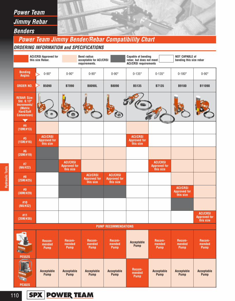
Jimmy RebarPower Team
Benders
110®
Hydr
aulic
Too
ls
Power Team Jimmy Bender/Rebar Compatibility ChartORDERING INFORMATION and SPECIFICATIONS
Bending Angles 0-90° 0-90° 0-90° 0-90° 0-135° 0-135° 0-180° 0-90°
ORDER NO. B5090 B7090 B8090L B8090 B5135 B7135 B9180 B11090
REBAR Size:Std. 0.13"
Increments/(Metric
Hard/SoftConversion)
#4(10M/#13)
#5(15M/#16)
ACI/CRSIApproved for
this size
ACI/CRSIApproved for
this size
#6(20M/#19)
#7(NA/#22)
ACI/CRSIApproved for
this size
ACI/CRSIApproved for
this size
#8(25M/#25)
ACI/CRSIApproved for
this size
ACI/CRSIApproved for
this size
#9(30M/#29)
ACI/CRSIApproved for
this size
#10(NA/#32)
#11(35M/#36)
ACI/CRSIApproved for
this size
PUMP RECOMMENDATIONS
PE552S
Recom-mendedPump
Recom-mendedPump
Recom-mendedPump
Recom-mendedPump
AcceptablePump
Recom-mendedPump
Recom-mendedPump
Recom-mendedPump
PE302S
AcceptablePump
AcceptablePump
AcceptablePump
AcceptablePump
Recom-mendedPump
AcceptablePump
AcceptablePump
AcceptablePump
ACI/CRSI Approved forthis size Rebar.
Bend radius acceptable for ACI/CRSIrequirements.
Capable of bendingrebar, but does not meetACI/CRSI requirements
NOT CAPABLE of bending this size rebar
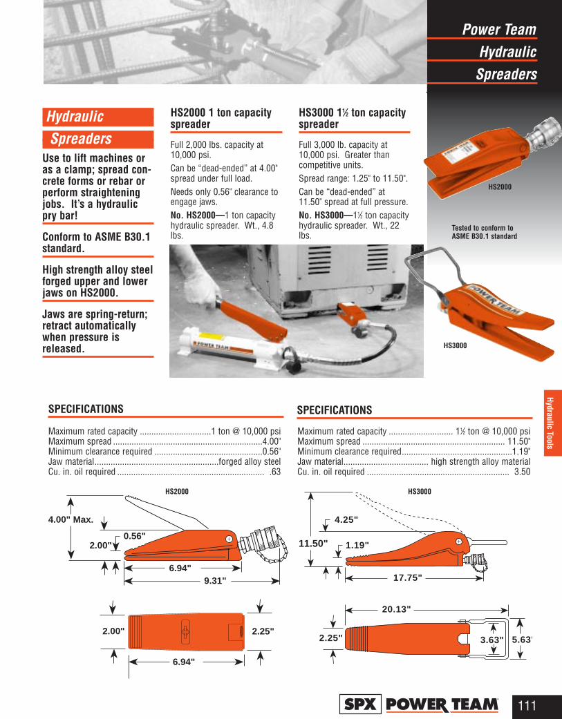
HydraulicSpreaders
Use to lift machines oras a clamp; spread con-crete forms or rebar orperform straighteningjobs. It’s a hydraulicpry bar!
Conform to ASME B30.1standard.
High strength alloy steelforged upper and lowerjaws on HS2000.
Jaws are spring-return;retract automaticallywhen pressure isreleased.
HS2000 1 ton capacityspreader
Full 2,000 lbs. capacity at10,000 psi.Can be “dead-ended” at 4.00"spread under full load.Needs only 0.56" clearance toengage jaws.No. HS2000—1 ton capacityhydraulic spreader. Wt., 4.8lbs.
HS3000 11⁄2 ton capacityspreader
Full 3,000 lb. capacity at10,000 psi. Greater thancompetitive units.Spread range: 1.25" to 11.50".Can be “dead-ended” at11.50" spread at full pressure.No. HS3000—11⁄2 ton capacityhydraulic spreader. Wt., 22lbs.
6.94" 9.31"
2.00"
4.00" Max.
0.56"
6.94"
2.25"2.00"
11.50"
20.13"
2.25" 3.63" 5.63"
17.75"
1.19"
4.25"
HydraulicPower Team
Spreaders
111®
Hydraulic Tools
HS3000
Tested to conform toASME B30.1 standard
HS2000
Maximum rated capacity ...............................1 ton @ 10,000 psiMaximum spread .................................................................4.00"Minimum clearance required ...............................................0.56"Jaw material......................................................forged alloy steelCu. in. oil required ................................................................ .63
SPECIFICATIONS
HS2000
SPECIFICATIONS
Maximum rated capacity ............................ 11⁄2 ton @ 10,000 psiMaximum spread .............................................................. 11.50"Minimum clearance required................................................1.19"Jaw material..................................... high strength alloy materialCu. in. oil required .............................................................. 3.50
HS3000

NutHydraulic
Splitters
112®
Hydr
aulic
Too
ls
HNS225
Align mark on cutter blade with scale.
HNS150
Hydraulic Nut Splitters
Hydraulic nut splitter, 15 ton capacity
Now you can simply “dial-in”the size of the nut you want tosplit, without the worry ofdamaging the bolt. Just alignthe mark on the cutter bladewith the scale on the frame ofthe splitter. The speciallydesigned “tool” steel cutterblade penetrates the nut tothe precise point where itcracks. And because the cut-ter blade is preset, it mechani-cally stops short of the boltthreads. The nut splitter fea-tures a dramatically improvedcutter blade with an 800%greater resistance to chippingand breaking over previousmodels. The new designallows you to rotate the blade180° within the frame. Thisallows you to use both sidesof the cutter blade, and infact, doubles the life of thecutter blade. The HNS150features a rugged one-piece
cutting frame coupled to aheavy-duty swivelinghydraulic cylinder. With itscompact size, you can use itin confined areas where it willdeliver up to 15 tons of force,enough to split the toughest“fused” or rusted-on grade 2Hnuts used on up to 0.75" dia.bolts (1.13" hex size). Thesofter SAE grade 2 nuts up to1.00" bolt size (1.50" hex size)are easily cut.No. HNS150 – 15 tonhydraulic nut splitter. Comeswith a No. 9796 half coupler.Wt., 8.1 lbs.No. 308840 – Replacement cutter blade for HNS150 (notcovered by warranty). Wt., .7lb.
Pump recommendationsfor HNS225
For field or irregular use, werecommend the use of theP19 hydraulic hand pump(pages 34-35). For repetitiveapplications, the PA6air/hydraulic pump (pages 38-39) or the PE172electric/hydraulic pump(pages 46-47) are suggested.
Hydraulic nut splitter, 25 ton capacity
For use on 1.13" to 2.25" hexnuts, this splitter has thepower to crack the toughestbig nuts. The speciallydesigned heat-treated blade ispushed into the nut, crackingit and expanding it. A secondcut opposite from the firstmay be used to separate thenut into halves for easyremoval. When job is com-pleted, the blade returns tothe starting position.No. HNS225 – 360° swivelbody, 25 ton capacity nutsplitter with blade. Comeswith a C252C hydraulic cylin-der. For use on 1.13" to 2.25"hex nuts. Length: 14.50".Wt., 29 lbs.No. 308022 – Replacementcutter blade (not covered bywarranty). Wt., 1 lb.
2 or A 5 or B 8 or C 2H(5) (9) (10) (12)
Nut Grade-English ➡(Nut Class-Metric) ➡Nut Splitter Cap. ➡ 15 ton 25 ton 15 ton 25 ton 15 ton 25 ton 15 ton 25 ton Hex Size, Max. 1.50 2.25 1.50 2.25 1.31 2.06 1.13 1.69
(36) (55) (36) (55) (33) (46) (29) (36)Bolt Size, Max. 1.00 1.50 1.00 1.50 0.88 1.38 0.75 1.13
(24) (36) (24) (36) (22) (30) (19) (29)Nut Thickness, 1.00 1.50 0.86 1.28 0.88 1.17 0.75 0.97
Max. (32) (33.9) (20.8) (30.2) (26) (25) (19) (20.9)Hex Size, Min. 0.50 1.13 0.50 1.13 0.50 1.13 0.50 1.13
(13) (29) (13) (29) (13) (29) (13) (29)
SPECIFICATIONSHNS150, 15 ton and HNS225, 25 ton at 10,000 psi (max.)
DIMENSIONS
Order Head No. A B C D E F Thickness
HNS150 2.88" 3.38" 7.88" 2.75" 10.38" 2.06" 1.00"HNS225 4.25" 6.00" 14.38" 3.88" N/A 3.25" 1.50"
A
BC
E
FD
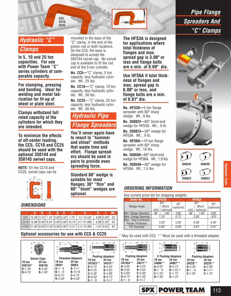
Spreaders AndPipe Flange
“C” Clamps
113®
Hydraulic Tools
Hydraulic “C” Clamps
In 5, 10 and 25 toncapacities. For usewith Power Team “C”series cylinders of com-parable capacity.
For clamping, pressingand bending. Ideal forwelding and metal fab-rication for fit-up ofsheet or plate steel.
Clamps withstand fullrated capacity of thecylinders for which theyare intended.
To minimize the effectsof off-center loading,the CC5, CC10 and CC25should be used with theoptional 350144 and350145 swivel caps.
NOTE: On the CC10 andCC25, swivel caps can be
mounted in the base of the“C” clamp, in the end of thepiston rod or both locations.On the CC5, the base isdesigned to accept the350144 swivel cap. No swivelcap is available to fit the rodend of the 5-ton cylinder. No. CC5—“C” clamp, 5 toncapacity, less hydraulic cylin-der. Wt., 25 lbs.No. CC10—“C” clamp, 10 toncapacity, less hydraulic cylin-der. Wt., 50 lbs.No. CC25—“C” clamp, 25 toncapacity, less hydraulic cylin-der. Wt., 65 lbs.
Hydraulic Pipe Flange Spreaders
You’ll never again haveto resort to “hammerand chisel” methodsthat waste time andeffort. Flange spread-ers should be used inpairs to provide evenspreading force.
Standard 60° wedge issuitable for mostflanges; 30° “thin” and60° “blunt” wedges areoptional.
The HFS3A is designedfor applications wheretotal thickness offlanges and max.spread gap is 3.00" orless and flange boltsare a min. of 0.69" dia.
Use HFS6A if total thick-ness of flanges andmax. spread gap is6.00" or less, andflange bolts are a min.of 0.81" dia.
No. HFS3A—5 ton flangespreader with 60° sharpwedge. Wt., 9 lbs.No. 350822—60° blunt-endwedge for HFS3A. Wt., .9 lb.No. 350823—30° wedge forHFS3A. Wt., .9 lb.No. HFS6A—10 ton flangespreader with 60° sharpwedge. Wt., 18 lbs.No. 350550—60° blunt-endwedge for HFS6A. Wt., 1.9 lbs.No. 350549—30° wedge forHFS6A. Wt., 1.5 lbs.
CC5,CC10,CC25
350549 350550
350823 350822
HFS3A
Optional accessories for use with CC5 & CC25 * May be used with CC5 ** Must be used with a threaded adapter.
Threaded Adapters10 ton 25 ton38597 38953A–1 - 8 A–11⁄4-7B–1 - 8 B–11⁄2-16C–0.75" C–2.75"D–2.00" D–4.38"
Swivel Caps10 ton 25 ton350144* 350145A–1.38" A–2.00"B–0.75" B–1.00"
Pushing Adapters10 ton 25 ton201923** 34510**A–3.13" A–3.25"B–2.25" B–2.63"C–5.38" C–5.88"D–0.50" D–0.75"E–1 - 8 E–11⁄4-7
Pushing Adapters10 ton 25 ton201454** 34511**A–3.06" A–3.25"B–2.63" B–2.63"C–5.69" C–5.88"D–0.75" D–1.00"E–1 - 8 E–11⁄4-7
V Pushing Adapters10 ton 25 ton34806** 34807**A–2.63" A–3.13"B–1 - 8 B–1.25-7C–1.50" C–1.75"D–1.00" D–1.25"
Pushing Adapters10 ton 25 ton28228** 28229**A–2.38" A–2.88"B–1 - 8 B–11⁄4-7 C–1.50" C–1.75"
E
BA
C
DB
AC
D
A BE
BA
C
D B
A
DC BC
A
Order No. HFS3A HFS6A60° 30° 60° 30°
Wedge Angle (Blunt (optional) (Blunt (optional)(std) optional) (std) optional)
Min. Flange Opening .06" 1.00" 0.06" .06" 1.50" 0.06"Max. Flange Opening 1.25" 0.72" 2.00" .970"Max. Total Combined
Flange Thickness 3.50" 3.50" 6.56" 6.56"Pin Diameter 0.69" 0.69" 0.81" 0.81"
ORDERING INFORMATIONSee current price list for shipping weights.
A B C
D
E
FG
H
I
A B C D E F G H I Wt.CC5 12.38" 3.75" 7 .31" 2.00" 2.50" 7.75" 11⁄2"-16 UN 0.88" 3.00" 25
CC10 15.88" 6.00" 9.44" 2.00" 3.00" 10.75" 21⁄4"-14 UNS 0.88" 3.50" 50CC25 21.00" 6.00" 12.50" 3.00" 4.00" 12.31" 3 5⁄16"-12 UNS 1.44" 4.63" 65
DIMENSIONS
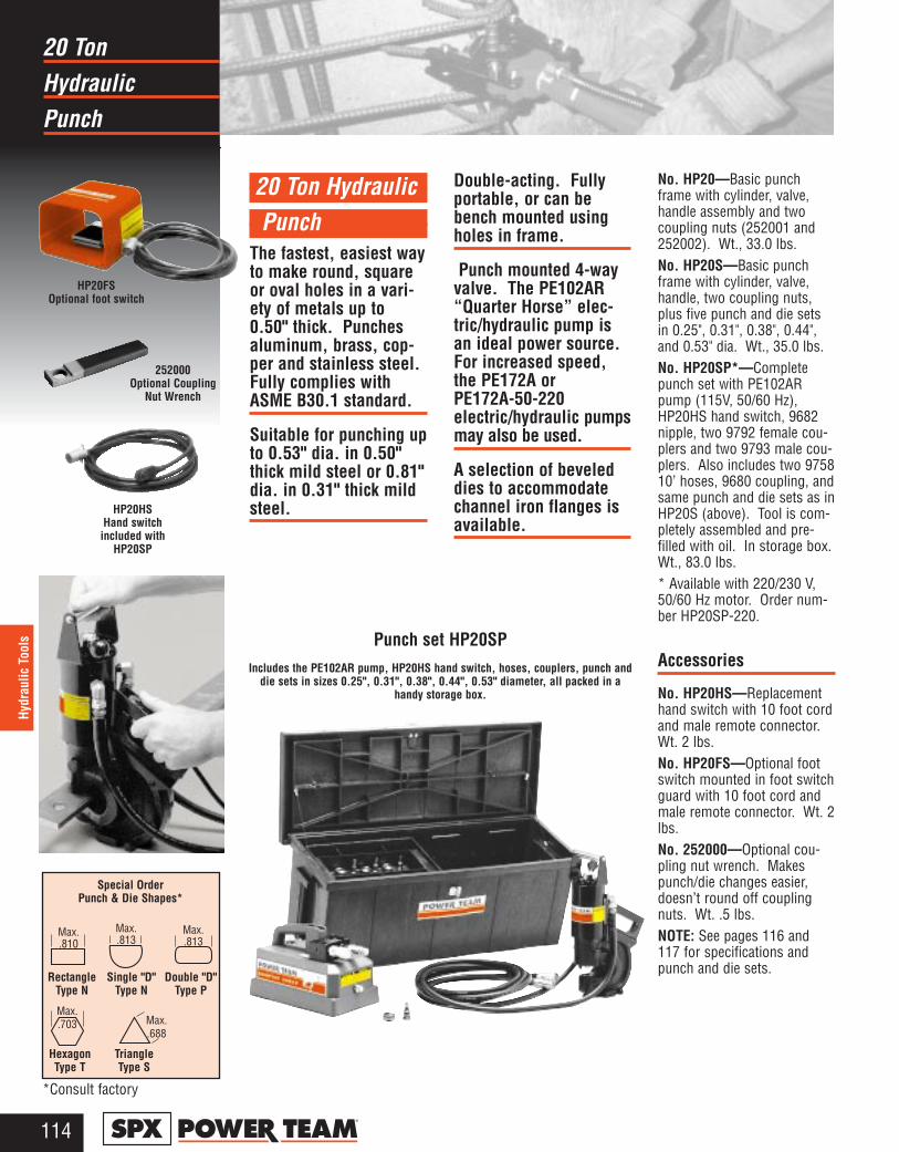
Hydraulic20 Ton
Punch
114®
Hydr
aulic
Too
ls
20 Ton HydraulicPunch
The fastest, easiest wayto make round, squareor oval holes in a vari-ety of metals up to0.50" thick. Punchesaluminum, brass, cop-per and stainless steel.Fully complies withASME B30.1 standard.
Suitable for punching upto 0.53" dia. in 0.50"thick mild steel or 0.81"dia. in 0.31" thick mildsteel.
Double-acting. Fullyportable, or can bebench mounted usingholes in frame.
Punch mounted 4-wayvalve. The PE102AR“Quarter Horse” elec-tric/hydraulic pump isan ideal power source.For increased speed,the PE172A orPE172A-50-220electric/hydraulic pumpsmay also be used.
A selection of beveleddies to accommodatechannel iron flanges isavailable.
No. HP20—Basic punchframe with cylinder, valve,handle assembly and twocoupling nuts (252001 and252002). Wt., 33.0 lbs.No. HP20S—Basic punchframe with cylinder, valve,handle, two coupling nuts,plus five punch and die setsin 0.25", 0.31", 0.38", 0.44",and 0.53" dia. Wt., 35.0 lbs.No. HP20SP*—Completepunch set with PE102ARpump (115V, 50/60 Hz),HP20HS hand switch, 9682nipple, two 9792 female cou-plers and two 9793 male cou-plers. Also includes two 975810’ hoses, 9680 coupling, andsame punch and die sets as inHP20S (above). Tool is com-pletely assembled and pre-filled with oil. In storage box.Wt., 83.0 lbs.* Available with 220/230 V,50/60 Hz motor. Order num-ber HP20SP-220.
Accessories
No. HP20HS—Replacementhand switch with 10 foot cordand male remote connector.Wt. 2 lbs.No. HP20FS—Optional footswitch mounted in foot switchguard with 10 foot cord andmale remote connector. Wt. 2lbs.No. 252000—Optional cou-pling nut wrench. Makespunch/die changes easier,doesn’t round off couplingnuts. Wt. .5 lbs.NOTE: See pages 116 and117 for specifications andpunch and die sets.
Punch set HP20SPIncludes the PE102AR pump, HP20HS hand switch, hoses, couplers, punch and
die sets in sizes 0.25", 0.31", 0.38", 0.44", 0.53" diameter, all packed in ahandy storage box.
HP20FS Optional foot switch
HP20HS Hand switch
included withHP20SP
252000Optional Coupling
Nut Wrench
Special Order Punch & Die Shapes*
Max..810
Max..813
Max..813
Max..703 Max.
.688
RectangleType N
Single "D"Type N
Double "D"Type P
HexagonType T
TriangleType S
*Consult factory

Hydraulic35 Ton
Punch
115®
Hydraulic Tools
35 Ton HydraulicPunch
Punches a smooth, pre-cise hole in seconds;much faster thandrilling. Can handlemild steel up to 0.50"thick.
Fully portable for con-struction, maintenanceand service applica-tions, or can be mount-ed on a workbench forproduction jobs. Hascarrying handle for pre-cise locating.
Rugged, forged steel“C” frame for greatstrength and durability.
Dual action, springloaded stripper holdsmaterial during punch-ing operation, stripsmaterial from punch onreturn. Scribe lines onstripper aid in locatingthe punch.
The PE172electric/hydraulic pumpis an ideal powersource.
No. HP35—Hydraulic punchonly. Includes metal carryingcase and die change tools.Wt., 42.5 lbs.No. HP35S—Hydraulic punchwith punches and dies.Includes HP35 punch, metalcarrying case and 250459punch and die set. Wt., 44lbs.No. HP35P—Hydraulic punchset with hydraulics. Samecontents as HP35SP, but doesnot include punch and die set.NOTE: Available in 220 volt, 50Hz. To order, add suffix “-220”to Order No. Wt., 86.3 lbs.No. HP35SP—Hydraulicpunch set with hydraulics.Includes HP35 hydraulicpunch, PE172 electric/hydraulic pump, 9756 hose,9798 hose half coupler,250459 punch and die set,metal carrying case. NOTE:Available in 220 volt. Toorder, add suffix “-220” toOrder No. Wt., 87.8 lbs. No. 250459—Punch and dieset for round holes. Consistof one each: PD437 0.44"punch/die, PD562 0.56"punch/die, PD688 0.69"punch/die, PD812 0.81"punch/die. Each punch/diesize is also available separate-ly. Wt., 1.5 lbs.Special punches - Square,oval, metric and specialpunch/die setsare also avail-able. Consultfactory foradditionalinformation.NOTE: See pages 116 and117 for specifications andpunch and die sets.
No. HP35SP
Hydraulic punching makes holes in a variety of materials much fasterthan drilling. Ideal for use in construction, maintenance or serviceapplications.
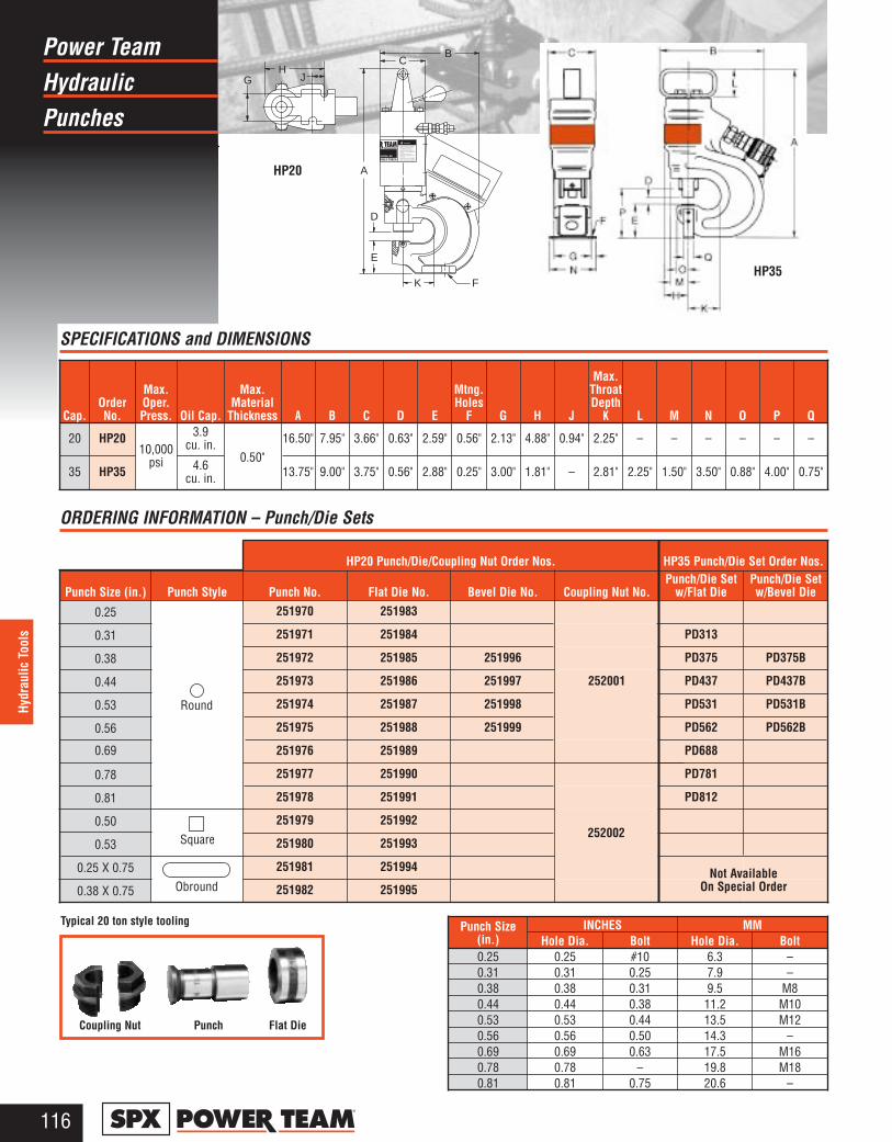
HydraulicPower Team
Punches
116®
Hydr
aulic
Too
ls
SPECIFICATIONS and DIMENSIONS
ORDERING INFORMATION – Punch/Die Sets
Cap.OrderNo.
Max.Oper.Press. Oil Cap.
Max.Material
Thickness A B C D E
Mtng.Holes
F G H J
Max.ThroatDepth
K L M N O P Q
20 HP2010,000
psi
3.9cu. in.
0.50"16.50" 7.95" 3.66" 0.63" 2.59" 0.56" 2.13" 4.88" 0.94" 2.25" – – – – – –
35 HP35 4.6cu. in. 13.75" 9.00" 3.75" 0.56" 2.88" 0.25" 3.00" 1.81" – 2.81" 2.25" 1.50" 3.50" 0.88" 4.00" 0.75"
HP20 Punch/Die/Coupling Nut Order Nos. HP35 Punch/Die Set Order Nos.
Punch Size (in.) Punch Style Punch No. Flat Die No. Bevel Die No. Coupling Nut No.Punch/Die Set
w/Flat Die
0.25 251970 251983
0.31 251971 251984 PD313
0.38 251972 251985 251996 PD375
0.44 251973 251986 251997 252001 PD437
0.53 251974 251987 251998 PD531
0.56 251975 251988 251999 PD562
0.69 251976 251989 PD688
0.78 251977 251990 PD781
0.81 251978 251991 PD812
0.50 251979 251992
0.53 251980 251993
0.25 X 0.75 251981 251994
0.38 X 0.75 251982 251995
Typical 20 ton style tooling
Coupling Nut Punch Flat Die
Punch/Die Setw/Bevel Die
PD375B
PD437B
PD531B
PD562B
Punch Size(in.)
INCHES MMHole Dia. Bolt Hole Dia. Bolt
0.25 0.25 #10 6.3 – 0.31 0.31 0.25 7.9 –0.38 0.38 0.31 9.5 M80.44 0.44 0.38 11.2 M100.53 0.53 0.44 13.5 M120.56 0.56 0.50 14.3 –0.69 0.69 0.63 17.5 M160.78 0.78 – 19.8 M180.81 0.81 0.75 20.6 –
WARNING
READ, UNDERSTAND AND FOLLOW THEOPERATING INSTRUCTIONS BEFORE USINGTHIS TOOL.ALWAYS WEAR SAFETY GLASSES.NEVER EXCEED THE MAXIMUM CAPACITYOF THIS TOOL.
WARNINGS MAY RESULT IN PERSONALINJURY OR PROPERTY DAMAGE.
HARDENED METAL MAY FLY APART WHEN
FAILURE TO OBSERVE THE FOLLOWING
SEVERED. TAKE THE NECESSARY PRECAU-TIONS BY USING A PROTECTIVE BLANKET.
!
K
E
D
F
A
CB
HJG
HP20
HP35
Round
Square
ObroundNot Available
On Special Order
252002
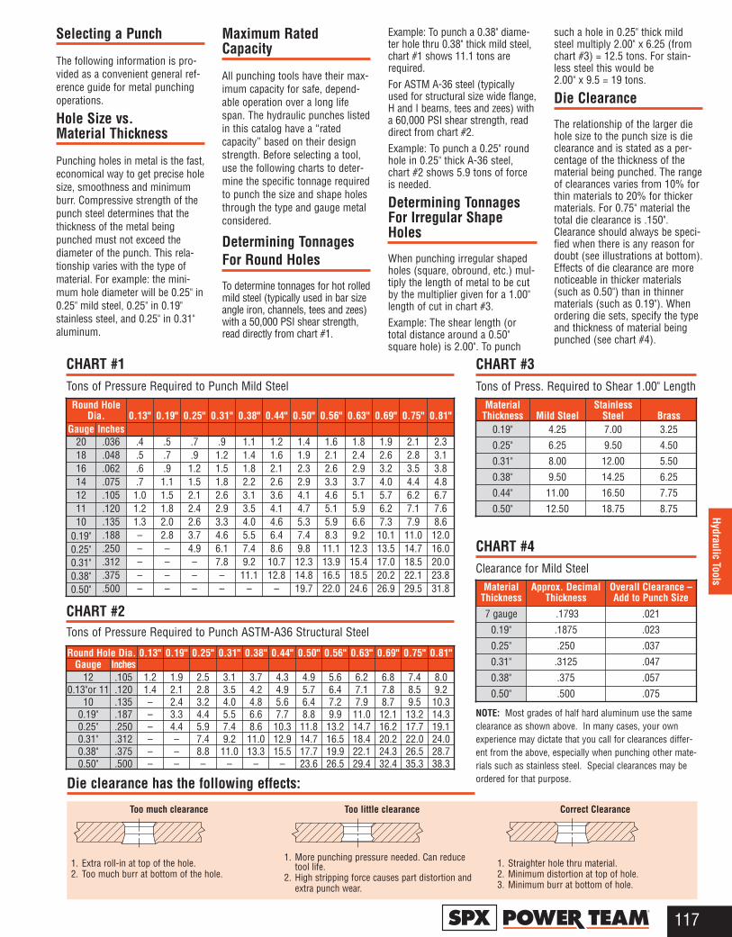
117®
Hydraulic Tools
Too much clearance
1. Extra roll-in at top of the hole.2. Too much burr at bottom of the hole.
Too little clearance
1. More punching pressure needed. Can reducetool life.
2. High stripping force causes part distortion andextra punch wear.
Correct Clearance
1. Straighter hole thru material.2. Minimum distortion at top of hole.3. Minimum burr at bottom of hole.
Die clearance has the following effects:
Round HoleDia. 0.13" 0.19" 0.25" 0.31" 0.38" 0.44" 0.50" 0.56" 0.63" 0.69" 0.75" 0.81"
Gauge Inches20 .036 .4 .5 .7 .9 1.1 1.2 1.4 1.6 1.8 1.9 2.1 2.318 .048 .5 .7 .9 1.2 1.4 1.6 1.9 2.1 2.4 2.6 2.8 3.116 .062 .6 .9 1.2 1.5 1.8 2.1 2.3 2.6 2.9 3.2 3.5 3.814 .075 .7 1.1 1.5 1.8 2.2 2.6 2.9 3.3 3.7 4.0 4.4 4.812 .105 1.0 1.5 2.1 2.6 3.1 3.6 4.1 4.6 5.1 5.7 6.2 6.711 .120 1.2 1.8 2.4 2.9 3.5 4.1 4.7 5.1 5.9 6.2 7.1 7.610 .135 1.3 2.0 2.6 3.3 4.0 4.6 5.3 5.9 6.6 7.3 7.9 8.6
0.19" .188 – 2.8 3.7 4.6 5.5 6.4 7.4 8.3 9.2 10.1 11.0 12.00.25" .250 – – 4.9 6.1 7.4 8.6 9.8 11.1 12.3 13.5 14.7 16.00.31" .312 – – – 7.8 9.2 10.7 12.3 13.9 15.4 17.0 18.5 20.00.38" .375 – – – – 11.1 12.8 14.8 16.5 18.5 20.2 22.1 23.80.50" .500 – – – – – – 19.7 22.0 24.6 26.9 29.5 31.8
CHART #1Tons of Pressure Required to Punch Mild Steel
CHART #3Tons of Press. Required to Shear 1.00" Length
CHART #4Clearance for Mild Steel
CHART #2Tons of Pressure Required to Punch ASTM-A36 Structural Steel
Round Hole Dia. 0.13" 0.19" 0.25" 0.31" 0.38" 0.44" 0.50" 0.56" 0.63" 0.69" 0.75" 0.81"Gauge Inches
12 .105 1.2 1.9 2.5 3.1 3.7 4.3 4.9 5.6 6.2 6.8 7.4 8.00.13"or 11 .120 1.4 2.1 2.8 3.5 4.2 4.9 5.7 6.4 7.1 7.8 8.5 9.2
10 .135 – 2.4 3.2 4.0 4.8 5.6 6.4 7.2 7.9 8.7 9.5 10.30.19" .187 – 3.3 4.4 5.5 6.6 7.7 8.8 9.9 11.0 12.1 13.2 14.30.25" .250 – 4.4 5.9 7.4 8.6 10.3 11.8 13.2 14.7 16.2 17.7 19.10.31" .312 – – 7.4 9.2 11.0 12.9 14.7 16.5 18.4 20.2 22.0 24.00.38" .375 – – 8.8 11.0 13.3 15.5 17.7 19.9 22.1 24.3 26.5 28.70.50" .500 – – – – – – 23.6 26.5 29.4 32.4 35.3 38.3
MaterialThickness Mild Steel
StainlessSteel Brass
0.19" 4.25 7.00 3.25
0.25" 6.25 9.50 4.50
0.31" 8.00 12.00 5.50
0.38" 9.50 14.25 6.25
0.44" 11.00 16.50 7.75
0.50" 12.50 18.75 8.75
MaterialThickness
Approx. DecimalThickness
Overall Clearance –Add to Punch Size
7 gauge .1793 .021
0.19" .1875 .023
0.25" .250 .037
0.31" .3125 .047
0.38" .375 .057
0.50" .500 .075
NOTE: Most grades of half hard aluminum use the sameclearance as shown above. In many cases, your ownexperience may dictate that you call for clearances differ-ent from the above, especially when punching other mate-rials such as stainless steel. Special clearances may beordered for that purpose.
Selecting a Punch
The following information is pro-vided as a convenient general ref-erence guide for metal punchingoperations.
Hole Size vs. Material Thickness
Punching holes in metal is the fast,economical way to get precise holesize, smoothness and minimumburr. Compressive strength of thepunch steel determines that thethickness of the metal beingpunched must not exceed thediameter of the punch. This rela-tionship varies with the type ofmaterial. For example: the mini-mum hole diameter will be 0.25" in0.25" mild steel, 0.25" in 0.19"stainless steel, and 0.25" in 0.31"aluminum.
Maximum RatedCapacity
All punching tools have their max-imum capacity for safe, depend-able operation over a long lifespan. The hydraulic punches listedin this catalog have a “ratedcapacity” based on their designstrength. Before selecting a tool,use the following charts to deter-mine the specific tonnage requiredto punch the size and shape holesthrough the type and gauge metalconsidered.
Determining TonnagesFor Round Holes
To determine tonnages for hot rolledmild steel (typically used in bar sizeangle iron, channels, tees and zees)with a 50,000 PSI shear strength,read directly from chart #1.
Example: To punch a 0.38" diame-ter hole thru 0.38" thick mild steel,chart #1 shows 11.1 tons arerequired.For ASTM A-36 steel (typicallyused for structural size wide flange,H and I beams, tees and zees) witha 60,000 PSI shear strength, readdirect from chart #2.Example: To punch a 0.25" roundhole in 0.25" thick A-36 steel,chart #2 shows 5.9 tons of forceis needed.
Determining TonnagesFor Irregular ShapeHoles
When punching irregular shapedholes (square, obround, etc.) mul-tiply the length of metal to be cutby the multiplier given for a 1.00"length of cut in chart #3.Example: The shear length (ortotal distance around a 0.50"square hole) is 2.00". To punch
such a hole in 0.25" thick mildsteel multiply 2.00" x 6.25 (fromchart #3) = 12.5 tons. For stain-less steel this would be2.00" x 9.5 = 19 tons.
Die Clearance
The relationship of the larger diehole size to the punch size is dieclearance and is stated as a per-centage of the thickness of thematerial being punched. The rangeof clearances varies from 10% forthin materials to 20% for thickermaterials. For 0.75" material thetotal die clearance is .150".Clearance should always be speci-fied when there is any reason fordoubt (see illustrations at bottom).Effects of die clearance are morenoticeable in thicker materials(such as 0.50") than in thinnermaterials (such as 0.19"). Whenordering die sets, specify the typeand thickness of material beingpunched (see chart #4).
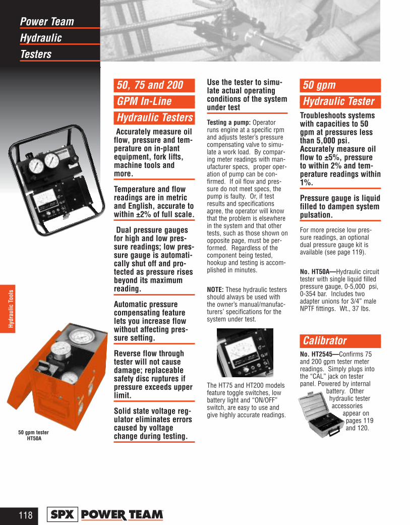
HydraulicPower Team
Testers
118®
Hydr
aulic
Too
ls
50, 75 and 200GPM In-Line Hydraulic TestersAccurately measure oil
flow, pressure and tem-perature on in-plantequipment, fork lifts,machine tools andmore.
Temperature and flowreadings are in metricand English, accurate towithin ±2% of full scale.
Dual pressure gaugesfor high and low pres-sure readings; low pres-sure gauge is automati-cally shut off and pro-tected as pressure risesbeyond its maximumreading.
Automatic pressurecompensating featurelets you increase flowwithout affecting pres-sure setting.
Reverse flow throughtester will not causedamage; replaceablesafety disc ruptures ifpressure exceeds upperlimit.
Solid state voltage reg-ulator eliminates errorscaused by voltagechange during testing.
Use the tester to simu-late actual operatingconditions of the systemunder test
Testing a pump: Operatorruns engine at a specific rpmand adjusts tester’s pressurecompensating valve to simu-late a work load. By compar-ing meter readings with man-ufacturer specs, proper oper-ation of pump can be con-firmed. If oil flow and pres-sure do not meet specs, thepump is faulty. Or, if testresults and specificationsagree, the operator will knowthat the problem is elsewherein the system and that othertests, such as those shown onopposite page, must be per-formed. Regardless of thecomponent being tested,hookup and testing is accom-plished in minutes.
NOTE: These hydraulic testersshould always be used withthe owner’s manual/manufac-turers’ specifications for thesystem under test.
The HT75 and HT200 modelsfeature toggle switches, lowbattery light and “ON/OFF”switch, are easy to use andgive highly accurate readings.
50 gpm Hydraulic Tester
Troubleshoots systemswith capacities to 50gpm at pressures lessthan 5,000 psi.Accurately measure oilflow to ±5%, pressureto within 2% and tem-perature readings within1%.
Pressure gauge is liquidfilled to dampen systempulsation.
For more precise low pres-sure readings, an optionaldual pressure gauge kit isavailable (see page 119).
No. HT50A—Hydraulic circuittester with single liquid filledpressure gauge, 0-5,000 psi,0-354 bar. Includes twoadapter unions for 3/4” maleNPTF fittings. Wt., 37 lbs.
CalibratorNo. HT2545—Confirms 75and 200 gpm tester meterreadings. Simply plugs intothe “CAL” jack on testerpanel. Powered by internal
battery. Otherhydraulic testeraccessories
appear onpages 119and 120.
50 gpm testerHT50A
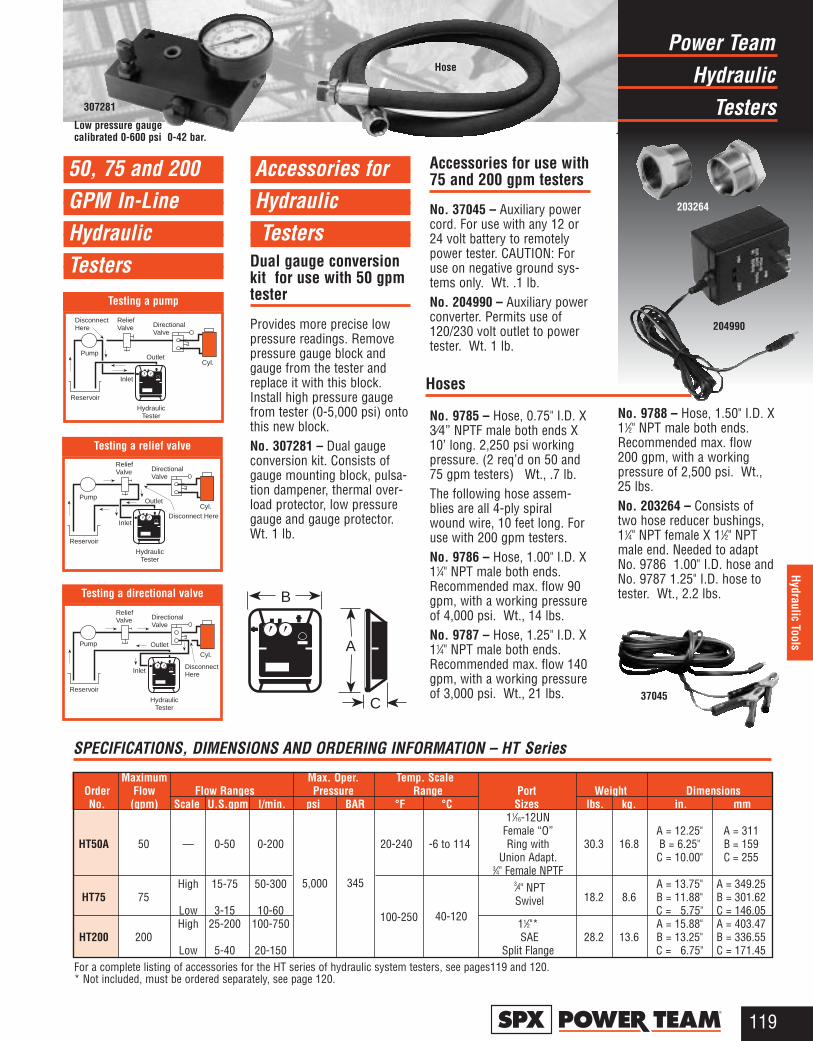
HydraulicPower Team
Testers
119®
Hydraulic Tools
Testing a pump
50, 75 and 200GPM In-LineHydraulic Testers
For a complete listing of accessories for the HT series of hydraulic system testers, see pages119 and 120. * Not included, must be ordered separately, see page 120.
Maximum Max. Oper. Temp. ScaleOrder Flow Flow Ranges Pressure Range Port Weight DimensionsNo. (gpm) Scale U.S.gpm l/min. psi BAR °F °C Sizes lbs. kg. in. mm
11⁄16-12UNFemale “O” A = 12.25" A = 311
HT50A 50 — 0-50 0-200 20-240 -6 to 114 Ring with 30.3 16.8 B = 6.25" B = 159Union Adapt. C = 10.00" C = 255
3⁄4" Female NPTFHigh 15-75 50-300 3⁄4" NPT A = 13.75" A = 349.25
HT75 75 Swivel 18.2 8.6 B = 11.88" B = 301.62Low 3-15 10-60 C = 5.75" C = 146.05High 25-200 100-750 11⁄2"* A = 15.88" A = 403.47
HT200 200 SAE 28.2 13.6 B = 13.25" B = 336.55Low 5-40 20-150 Split Flange C = 6.75" C = 171.45
SPECIFICATIONS, DIMENSIONS AND ORDERING INFORMATION – HT Series
DisconnectHere
ReliefValve Directional
Valve
Outlet
Inlet
Reservoir
Cyl.
HydraulicTester
Pump
Disconnect Here
ReliefValve Directional
Valve
Outlet
Inlet
Reservoir
Cyl.Pump
HydraulicTester
DisconnectHere
ReliefValve Directional
Valve
Outlet
Inlet
Reservoir
Cyl.
Pump
HydraulicTester
Testing a directional valve
Testing a relief valve
B
A
C
Accessories for HydraulicTesters
Dual gauge conversionkit for use with 50 gpmtester
Provides more precise lowpressure readings. Removepressure gauge block andgauge from the tester andreplace it with this block.Install high pressure gaugefrom tester (0-5,000 psi) ontothis new block.No. 307281 – Dual gaugeconversion kit. Consists ofgauge mounting block, pulsa-tion dampener, thermal over-load protector, low pressuregauge and gauge protector.Wt. 1 lb.
Accessories for use with75 and 200 gpm testers
No. 37045 – Auxiliary powercord. For use with any 12 or24 volt battery to remotelypower tester. CAUTION: Foruse on negative ground sys-tems only. Wt. .1 lb.No. 204990 – Auxiliary powerconverter. Permits use of120/230 volt outlet to powertester. Wt. 1 lb.
No. 9785 – Hose, 0.75" I.D. X3⁄4” NPTF male both ends X10’ long. 2,250 psi workingpressure. (2 req’d on 50 and75 gpm testers) Wt., .7 lb.The following hose assem-blies are all 4-ply spiralwound wire, 10 feet long. Foruse with 200 gpm testers.No. 9786 – Hose, 1.00" I.D. X11⁄4" NPT male both ends.Recommended max. flow 90gpm, with a working pressureof 4,000 psi. Wt., 14 lbs.No. 9787 – Hose, 1.25" I.D. X11⁄4" NPT male both ends.Recommended max. flow 140gpm, with a working pressureof 3,000 psi. Wt., 21 lbs.
No. 9788 – Hose, 1.50" I.D. X11⁄2" NPT male both ends.Recommended max. flow200 gpm, with a workingpressure of 2,500 psi. Wt.,25 lbs.No. 203264 – Consists oftwo hose reducer bushings,11⁄4" NPT female X 11⁄2" NPTmale end. Needed to adaptNo. 9786 1.00" I.D. hose andNo. 9787 1.25" I.D. hose totester. Wt., 2.2 lbs.
Hoses
Low pressure gaugecalibrated 0-600 psi 0-42 bar.
203264
204990
307281
Hose
37045
5,000 345
100-250 40-120
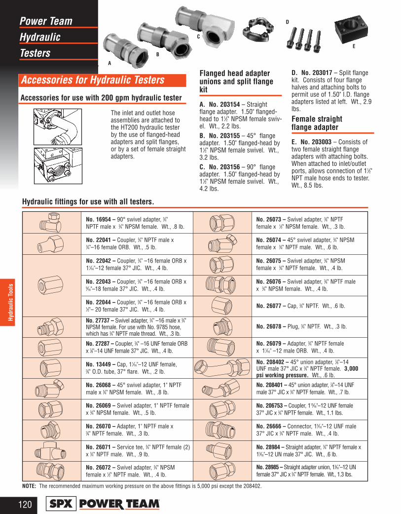
HydraulicPower Team
Testers
120®
Hydr
aulic
Too
ls
NOTE: The recommended maximum working pressure on the above fittings is 5,000 psi except the 208402.
No. 16954 – 90° swivel adapter, 3⁄4" NPTF male x 3⁄4" NPSM female. Wt., .8 lb.
No. 22041 – Coupler, 3⁄4" NPTF male x 3⁄4"–16 female ORB. Wt., .5 lb.
No. 22042 – Coupler, 3⁄4" –16 female ORB x11⁄16"–12 female 37° JIC. Wt., .4 lb.
No. 22043 – Coupler, 3⁄4" –16 female ORB x9⁄16"–18 female 37° JIC. Wt., .4 lb.
No. 22044 – Coupler, 3⁄4" –16 female ORB x1⁄2"– 20 female 37° JIC. Wt., .4 lb.
No. 27737 – Swivel adapter, 3⁄4" –16 male x 3⁄4"NPSM female. For use with No. 9785 hose,which has 3⁄4" NPTF male thread. Wt., .3 lb.
No. 27287 – Coupler, 3⁄4" –16 UNF female ORBx 7⁄8"–14 UNF female 37° JIC. Wt., .4 lb.
No. 13449 – Cap, 11⁄16"–12 UNF female, 3⁄4" O.D. tube, 37° flare. Wt., .2 lb.
No. 26068 – 45° swivel adapter, 1" NPTFmale x 3⁄4" NPSM female. Wt., .8 lb.
No. 26069 – Swivel adapter, 1" NPTF femalex 3⁄4" NPSM female. Wt., .5 lb.
No. 26070 – Adapter, 1" NPTF male x 3⁄4" NPTF female. Wt., .3 lb.
No. 26071 – Service tee, 3⁄4" NPTF female (2)x 3⁄4" NPTF male. Wt., .9 lb.
No. 26072 – Swivel adapter, 3⁄4" NPSMfemale x 1⁄2" NPTF male. Wt., .4 lb.
No. 26073 – Swivel adapter, 3⁄4" NPTFfemale x 1⁄2" NPSM female. Wt., .3 lb.
No. 26074 – 45° swivel adapter, 3⁄4" NPSMfemale x 3⁄4" NPTF male. Wt., .6 lb.
No. 26075 – Swivel adapter, 3⁄4" NPSMfemale x 3⁄4" NPTF female. Wt., .4 lb.
No. 26076 – Swivel adapter, 3⁄4" NPTF malex 3⁄4" NPSM female. Wt., .4 lb.
No. 26077 – Cap, 3⁄4" NPTF. Wt., .6 lb.
No. 26078 – Plug, 3⁄4" NPTF. Wt., .3 lb.
No. 26079 – Adapter, 3⁄4" NPTF female x 11⁄16" –12 male ORB. Wt., .4 lb.
No. 208402 – 45° union adapter, 7⁄8"–14UNF male 37° JIC x 3⁄4" NPTF female. 3,000psi working pressure. Wt., .6 lb.
No. 208401 – 45° union adapter, 7⁄8"–14 UNFmale 37° JIC x 3⁄4" NPTF female. Wt., .7 lb.
No. 206753 – Coupler, 115⁄16"–12 UNF female37° JIC x 3⁄4" NPTF female. Wt., 1.1 lbs.
No. 26666 – Connector, 15⁄16"–12 UNF male37° JIC x 3⁄4" NPTF male. Wt., .4 lb.
No. 28984 – Straight adapter, 3⁄4" NPTF female x13⁄16"–12 UN male 37° JIC. Wt., .6 lb.
No. 28985 – Straight adapter union, 13⁄16"–12 UNfemale 37° JIC x 3⁄4" NPTF female. Wt., 1.3 lbs.
Accessories for Hydraulic Testers
The inlet and outlet hoseassemblies are attached tothe HT200 hydraulic testerby the use of flanged-headadapters and split flanges,or by a set of female straightadapters.
Accessories for use with 200 gpm hydraulic tester
Flanged head adapterunions and split flangekit
A. No. 203154 – Straightflange adapter. 1.50" flanged-head to 11⁄2" NPSM female swiv-el. Wt., 2.2 lbs.B. No. 203155 – 45° flangeadapter. 1.50" flanged-head by11⁄2" NPSM female swivel. Wt.,3.2 lbs.C. No. 203156 – 90° flangeadapter. 1.50" flanged-head by11⁄2" NPSM female swivel. Wt.,4.2 lbs.
D. No. 203017 – Split flangekit. Consists of four flangehalves and attaching bolts topermit use of 1.50" I.D. flangeadapters listed at left. Wt., 2.9lbs.
Female straight flange adapter
E. No. 203003 – Consists oftwo female straight flangeadapters with attaching bolts.When attached to inlet/outletports, allows connection of 11⁄2"NPT male hose ends to tester.Wt., 8.5 lbs.
A
B
C
D
E
Hydraulic fittings for use with all testers.

MaintenancePower Team
Presses
121®
Shop Equipment
2 TO 1 SAFETY FACTORon hydraulic cylinders and theymeet ASME B30.1 standards.Cylinders are easily removedfor other applications. Single-or double-acting cylinders areavailable; built-in relief valve on double-acting cylinders.
FULL RATED CAPACITYacross width of upper frame,even with workhead moved toone side. (Heavy-duty pressesonly.)
LARGER WORK AREA thanmost competitors’ models.
ALIGNMENT LEVER forsimple pin replacement afterraising or lowering the bed.
CLOSE MANUFACTURINGTOLERANCE allows even loaddistribution over four alloy steelpins; not two, like some competi-tors. (Heavy-duty presses only.)
OPEN THROAT® FEATUREon 25 ton press provides addi-tional work area by mountingcylinder on outside for C-frameadvantage.
FRAMES CAN BE USEDHORIZONTALLY for pressingjobs on extra-long shafts (seephoto above).
ELECTRIC, AIR OR HANDHYDRAULIC PUMPS are avail-able. All are standard PowerTeam pumps.
CSA approved electric pumpsare standard on all presses.
Externally adjustable reliefvalve for precise operator controlof working pressure is standardon all electric pumps exceptPE10 and PE17 series.
24 volt hand switch for remotecontrol on pumps equipped withsolenoid valves.
ONE-MAN OPERATION for bed adjustment. Winch unitquickly raises or lowers bed todesired height. Self-lockingwinch mechanism prevents bedfrom dropping when handle isreleased.
0.38" I.D. HOSE on springreturn cylinders on heavy-dutypresses provides up to six timesfaster cylinder return than stan-dard 0.25" I.D. hose.
FAST CYLINDERAPPROACH to work providedby 2-speed hand, air or electricpumps.
RUGGED UPRIGHTS, 50percent stronger than channeliron. Four post design meansopen side for easy loading oflong material.
NOTE: Certain features do notapply to Power Team 10 ton,Roll-Bed, or economy presses.
12
11
10
9
8
7
6
5
4
3
2
1
1
2
3
4
5
6
8
9
10
11
12
NOTE: Certain press applications may require guarding.Because of the multitude of possible press uses, it isimpossible to design a guard that will meet every customerneed. The end user must provide his own guarding wherethe situations dictate.
Horizontal pressing capabilities7
IMPORTANT SAFETY INFORMATION:
Power Team has protective blankets available which may affordprotection from injury to users and others should part breakageoccur. Power Team recommends the use of these blankets for allpushing, pulling, pressing, and lifting applications. See page 169for additional information.
OpenThroat®
Powerful Power Team Shop Maintenance Presses
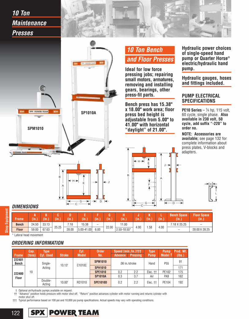
Maintenance10 Ton
Presses
122®
Shop
Equ
ipm
ent DIMENSIONS
10 Ton Bench and Floor Presses
Ideal for low forcepressing jobs; repairingsmall motors, armatures,removing and installinggears, bearings, otherpress-fit parts.
Bench press has 15.38"x 18.00" work area; floorpress bed height isadjustable from 5.00" to41.00" with horizontal“daylight” of 21.00".
Hydraulic power choicesof single-speed handpump or Quarter Horse®
electric/hydraulic handpump.
Hydraulic gauges, hosesand fittings included.
PUMP ELECTRICALSPECIFICATIONS
PE10 Series – 1⁄4 hp, 115 volt,60 cycle, single phase. Alsoavailable in 230 volt, 50cycle, add suffix “-220” toorder no.NOTE: Accessories areavailable; see page 132 forcomplete information aboutpress plates, V-blocks andadapters.
† Optional air/hydraulic pumps available on request.†† “Advance” position holds pressure with motor shut off. “Return” position advances cylinder with motor running and returns cylinder with
motor shut off.††† Typical performance based on 100 psi and 10,000 psi pump specifications. Actual speeds may vary with operating conditions.
Cap. Type Cyl. Order Type Pump Prod. Wt. Frame (tons) Cyl. Used Stroke Model No. Advance Pressing Pump Model † (lbs.)222481 SPM1010 91Bench Single- 10.13" C1010C .06 in./stroke Hand P55
Acting SPH1010 171
222480 10 SPE1010 0.2 2.2 Elec. †† PE102 175
Floor SP1010A 0.3 3.7 Air PA9 162Double- 10.00" RD1010 SPE1010D 0.2 2.2 Elec. †† PE104 192Acting
* Lateral head movement
GC
B
AE
D
JHA
HE
F
GC
D
J
B
Speed (min./in.)†††
ORDERING INFORMATION
A B C D E F G H J K L Bench Space Floor Space Frame (in.) (in.) (in.) (in.) (in.) (in.) (in.) (in.) (in.) (in.) (in.) (in.) (in.)
Bench 24.50 33.1325.25
7.18 15.38 –22.00
11.004.00 1.58 4.00
7.18 X 25.25 –
Floor 59.00 67.63 28.00 5.00-41.00 6.00 2.50-18.50* – 28.00 X 28.25
SPM1010
SP1010A
L
K

Maintenance25 Ton “C” Frame
Presses
123®
Shop Equipment
25 Ton “C” FrameMaintenance Press
Can be bench mountedor mounted on optionalpedestal base.
Bench mounted versionrequires less than 1.5sq. ft. of space; onoptional pedestal, only4 sq. ft. of floor spaceis needed.
“Open Throat” designmakes loading andunloading of work easy.
Cylinder head adjusts tothree convenient workingpositions, providing upto 20.25" of “daylight.”
Hydraulic cylinderdelivers a 6.25" stroke,is driven by a P59 handpump.
PEDESTAL BASE NO.60846
This optional pedestal pro-vides a stable base for yourSPM256C. It takes up onlyabout 4 sq. ft. of space andincludes a bracket for mount-ing the pump on the side ofpedestal press. It must beordered separately. Wt., 76lbs.
NOTE: Accessories areavailable; see page 132 forcomplete information aboutpress plates, V-blocks andadapters.
BenchMounted
PedestalMounted
Lower Bolster
A
F
8.50"
C
N
B
H
GG
InternalThread
L
J
K M
6.25" CylinderStroke
5.50"
D
Dia.Holes
E
0.56"
R
P
Cap. Type Cyl. Order Type Pump Prod.Wt.(tons) Cyl. Used Stroke Model No. Advance Pressing Pump Model (lbs.)
25 Single- 6.25" C256C SPM256C* .129 0.03 Hand P59 240Acting in./stroke in./stroke
A B C D E F G H(Cyl. Retracted)(in.) (in.) (in.) (in.) (in.) (in.) (in.) (in.)
77.63 24.50 24.00 41.63 36.00 6.00 5.00 10.25, 15.25, 20.25
DIMENSIONS
* SPM256C does not include No. 60846 pedestal base.** Typical performance based on pump specifications. Actual speeds may vary with operating conditions.
Speed**
ORDERING INFORMATION
J K L M N P R Floor Space(in.) (in.) (in.) (in.) (in.) (in.) (in.) (in.)6.50 12.50 11⁄2 –16 8.00 43.00 2.00 7.00 24.00 X 24.50
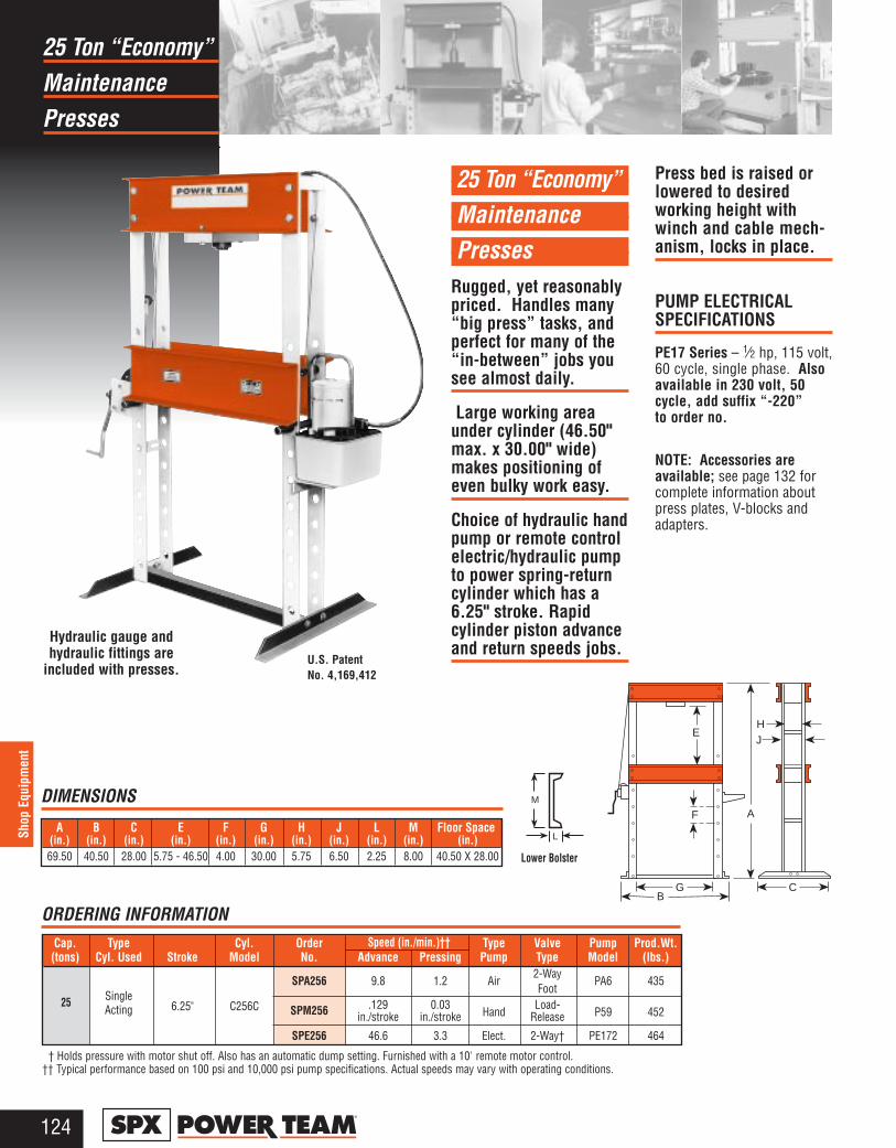
Maintenance25 Ton “Economy”
Presses
124®
Shop
Equ
ipm
ent
25 Ton “Economy” Maintenance Presses
Rugged, yet reasonablypriced. Handles many“big press” tasks, andperfect for many of the“in-between” jobs yousee almost daily.
Large working areaunder cylinder (46.50"max. x 30.00" wide)makes positioning ofeven bulky work easy.
Choice of hydraulic handpump or remote controlelectric/hydraulic pumpto power spring-returncylinder which has a6.25" stroke. Rapidcylinder piston advanceand return speeds jobs.
Press bed is raised orlowered to desiredworking height withwinch and cable mech-anism, locks in place.
PUMP ELECTRICAL SPECIFICATIONS
PE17 Series – 1⁄2 hp, 115 volt,60 cycle, single phase. Alsoavailable in 230 volt, 50cycle, add suffix “-220” to order no.
NOTE: Accessories areavailable; see page 132 forcomplete information aboutpress plates, V-blocks andadapters.
A B C E F G H J L M Floor Space(in.) (in.) (in.) (in.) (in.) (in.) (in.) (in.) (in.) (in.) (in.)69.50 40.50 28.00 5.75 - 46.50 4.00 30.00 5.75 6.50 2.25 8.00 40.50 X 28.00
DIMENSIONS
† Holds pressure with motor shut off. Also has an automatic dump setting. Furnished with a 10' remote motor control.†† Typical performance based on 100 psi and 10,000 psi pump specifications. Actual speeds may vary with operating conditions.
ORDERING INFORMATION
U.S. PatentNo. 4,169,412
Hydraulic gauge andhydraulic fittings are
included with presses.
A
E
F
GB
C
HJ
Cap. Type Cyl. Order Type Valve Pump Prod.Wt.(tons) Cyl. Used Stroke Model No. Advance Pressing Pump Type Model (lbs.)
SPA256 9.8 1.2 Air2-Way
PA6 435FootSingle
6.25" C256C SPM256 .129 0.03Hand
Load-P59 452Acting in./stroke in./stroke Release
SPE256 46.6 3.3 Elect. 2-Way† PE172 464
Speed (in./min.)††
25
M
L
Lower Bolster
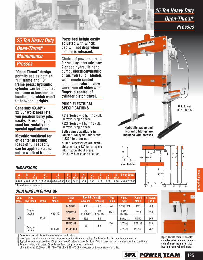
Hydraulic gauge andhydraulic fittings are
included with presses.
Open-Throat®
25 Ton Heavy Duty
Presses
125®
Shop Equipment
25 Ton Heavy Duty Open-Throat®
Maintenance Presses
“Open Throat” designpermits use as both an“H” frame and “C”frame press; hydrauliccylinder can be mountedon frame extensions tohandle jobs which won’tfit between uprights.
Generous 43.38" x32.00" work area letsyou position bulky jobseasily. Press may beused horizontally forspecial applications.
Movable workhead foroff-center pressing;loads of full capacitycan be applied acrossentire width of frame.
Press bed height easilyadjusted with winch;bed will not drop whenhandle is released.
Choice of power sourcesfor rapid cylinder advance:2-speed hydraulic handpump, electric/hydraulicor air/hydraulic. Modelswith remote controlenable operator to viewwork from all sides withfingertip control ofcylinder piston travel.
PUMP ELECTRICAL SPECIFICATIONS
PE17 Series – 1⁄2 hp, 115 volt,60 cycle, single phase.PE21 Series – 1 hp, 115 volt,60 cycle, single phase.Both pumps available in 230 volt, 50 cycle, add suffix“-220” to order no.NOTE: Accessories are avail-able; see page 132 for completeinformation about pressplates, V-blocks and adapters.
A B C D* E F G H J K L M Floor Space(in.) (in.) (in.) (in.) (in.) (in.) (in.) (in.) (in.) (in.) (in.) (in.) (in.)68.00 43.00 28.00 3.00 - 29.00 6.88 - 43.38 4.50 32.00 5.50 6.50 7.00 2.50 8.00 43.00 X 28.00
Cap. Type Cyl. Order Type Valve Pump‡ Prod.Wt.(tons) Cyl. Used Stroke Model No. Advance Pressing Pump Type Model (lbs.)
SPA2514 9.8 1.2 Air 2-Way Foot PA6 683
Single-C2514C SPM2514 .49 .03 Hand Load- P159 693Acting in./stroke in./stroke Release
14.25" SPE2514 46.6 3.3 2-Way†† PE172 665
SPE2514S52 4.0
Elec. 3-Way† PE213S 759Double- RD2514 SPE2514DS 4-Way† PE214S 787Acting
† Solenoid valve with 24 volt remote control hand switch.†† Holds pressure with motor shut off. Also has an automatic dump setting. Furnished with a 10' remote motor control.
††† Typical performance based on 100 psi and 10,000 psi pump specifications. Actual speeds may vary under operating conditions.‡ Pump standard with press. Other Power Team pumps can be substituted.
dBA at idle and 10,000 psi: PE172–67/81 dBA; PE21–70 dBA measured at 3 foot distance, all sides.
Speed (in./min.)†††
25
DIMENSIONS
ORDERING INFORMATION
* Lateral head movement
U.S. Patent No. 4,169,412
Open Throat feature enablescylinder to be mounted on out-side of press frame for fastbearing removal and more.
A
E
F
G
B C
HJ
D
K
M
L
Lower Bolster
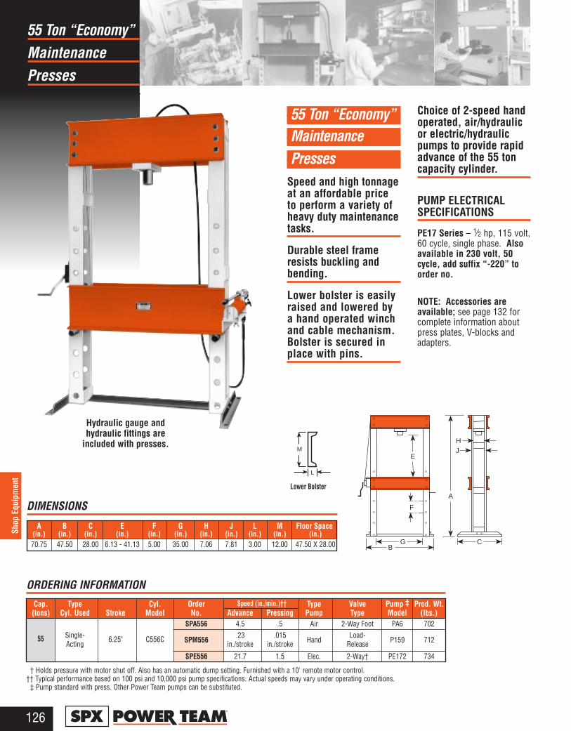
Maintenance55 Ton “Economy”
Presses
126®
Shop
Equ
ipm
ent
55 Ton “Economy”Maintenance Presses
Speed and high tonnageat an affordable priceto perform a variety ofheavy duty maintenancetasks.
Durable steel frameresists buckling andbending.
Lower bolster is easilyraised and lowered bya hand operated winchand cable mechanism.Bolster is secured inplace with pins.
Choice of 2-speed handoperated, air/hydraulicor electric/hydraulicpumps to provide rapidadvance of the 55 toncapacity cylinder.
PUMP ELECTRICAL SPECIFICATIONS
PE17 Series – 1⁄2 hp, 115 volt,60 cycle, single phase. Alsoavailable in 230 volt, 50cycle, add suffix “-220” toorder no.
NOTE: Accessories areavailable; see page 132 forcomplete information aboutpress plates, V-blocks andadapters.
Cap. Type Cyl. Order Type Valve Pump ‡ Prod. Wt.(tons) Cyl. Used Stroke Model No. Advance Pressing Pump Type Model (lbs.)
SPA556 4.5 .5 Air 2-Way Foot PA6 702Single- 6.25" C556C SPM556
.23 .015Hand
Load-P159 712Acting in./stroke in./stroke Release
SPE556 21.7 1.5 Elec. 2-Way† PE172 734
† Holds pressure with motor shut off. Also has an automatic dump setting. Furnished with a 10' remote motor control.†† Typical performance based on 100 psi and 10,000 psi pump specifications. Actual speeds may vary under operating conditions.
‡ Pump standard with press. Other Power Team pumps can be substituted.
Speed (in./min.)††
55
ORDERING INFORMATION
A
E
F
GB
C
HJ
Hydraulic gauge andhydraulic fittings are
included with presses. M
L
Lower Bolster
A B C E F G H J L M Floor Space(in.) (in.) (in.) (in.) (in.) (in.) (in.) (in.) (in.) (in.) (in.)70.75 47.50 28.00 6.13 - 41.13 5.00 35.00 7.06 7.81 3.00 12.00 47.50 X 28.00
DIMENSIONS

Maintenance55 Ton Heavy Duty
Presses
127®
Shop Equipment
55 Ton Heavy DutyMaintenance Presses
Movable workhead forfull off-center pressingat full rated capacityacross width of upperframe without bucklingor bending.
Maximum “daylight” is42.00" x 36.00", makingpositioning of even bulkywork pieces easy.
Height of press bed iseasily adjusted withwinch; friction brakeprevents bed from drop-ping and handle fromspinning upon release.
55 ton cylinder haschrome plated pistonrod and wiper seals tokeep out corrosion andcontamination in a shopenvironment.
Presses with single-actingcylinder offer choice of2-speed hand operated orelectric/hydraulic pump.Models with double-acting cylinder have anelectric/hydraulic pump.Press model equippedwith remote controlenables operator toview work from all sideswith fingertip control ofcylinder piston travel.
Press can be used hori-zontally for specialapplications with user-supplied support legs.
PUMP ELECTRICAL SPECIFICATIONS
PE17 Series – 1⁄2 hp, 115 volt,60 cycle, single phase. Alsoavailable in 230 volt, 50 cycle.PE21 Series – 1 hp, 115 volt,60 cycle, single phase. Alsoavailable in 230 volt, 50 cycle.PQ60 Series – 2 hp, 230 volt,60 cycle, single phase. Alsoavailable in 230 volt, 50 cycle.
To order presseswith 230 volt, 50 cycle pumps,add suffix “-220”to order no.NOTE:Accessories areavailable; seepage 132 forcomplete infor-mation aboutpress plates, V-blocks andadapters.
* Frame is shipped assembled. † Solenoid valve with 24 volt remote control hand switch.
†† Holds pressure with motor shut off. Also has an automatic dump setting. Furnished with a 10' remote motor control.††† Typical performance based on 100 psi and 10,000 psi pump specifications. Actual speeds may vary with operating conditions.
‡ Pump standard with press. Other Power Team pumps can be substituted. dBA at idle and 10,000 psi: PE172—67/81; PE21 Series—70; PQ60—74/76; measured at 3 foot distance, all sides.
Speed (in./min.)†††
ORDERING INFORMATION
Hydraulic gauge andhydraulic fittings are
included with presses.
Cap.* Type Cyl. Order Type Valve Pump‡ Prod. Wt.(tons) Cyl. Used Stroke Model No. Advance Pressing Pump Type Model (lbs.)
SPM5513 .665 .026 Hand 2-Way P460 960Single- in./stroke in./strokeActing 13.25" C5513C
SPE5513 21.7 1.5 2-Way†† PE172 980SPE5513S 24.4 1.9 Elec. 3-Way† PE213S 1,056
Double- SPE5513D 21.7 1.5 4-Way PE174 993Acting 13.13" RD5513
SPE5513DS 66.1 5.4 4-Way† PQ604S 1,114
A
E
F
G
BC
HJ
D M
L
Lower Bolster
SF50
A B C D* E F G H J L M Floor Space(in.) (in.) (in.) (in.) (in.) (in.) (in.) (in.) (in.) (in.) (in.) (in.)72.00 48.50 36.00 3.25 - 32.75 6.00 - 42.00 6.00 36.00 6.75 8.00 3.00 12.00 48.50 X 36.00
DIMENSIONS
* Lateral head movement
No. SF50 – Straighteningfixtures for use with 55-tonshop or 80-ton Roll-Bed®
presses (2 ea.). Wt., 104 lbs.Not part of press assembly– order separately.
55
U.S. Patent No. 4,169,412
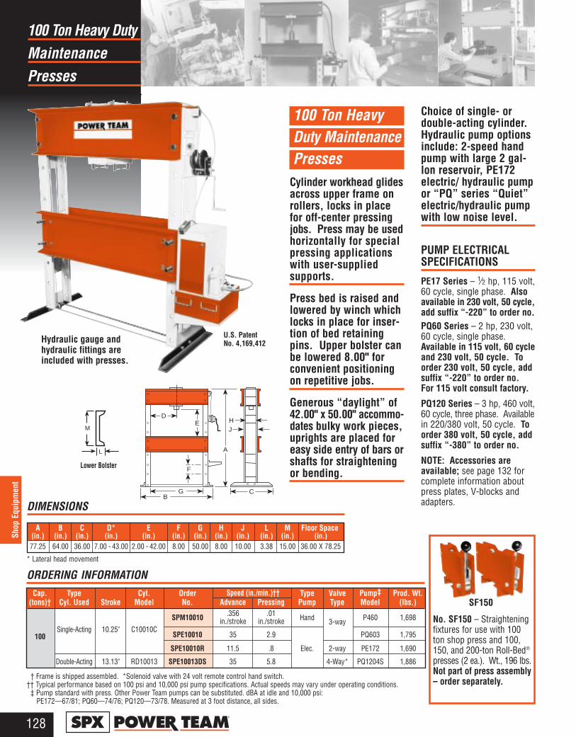
100 Ton Heavy Duty Maintenance Presses
Cylinder workhead glidesacross upper frame onrollers, locks in placefor off-center pressingjobs. Press may be usedhorizontally for specialpressing applicationswith user-supplied supports.
Press bed is raised andlowered by winch whichlocks in place for inser-tion of bed retainingpins. Upper bolster canbe lowered 8.00" forconvenient positioningon repetitive jobs.
Generous “daylight” of42.00" x 50.00" accommo-dates bulky work pieces,uprights are placed foreasy side entry of bars orshafts for straighteningor bending.
Choice of single- ordouble-acting cylinder.Hydraulic pump optionsinclude: 2-speed handpump with large 2 gal-lon reservoir, PE172electric/ hydraulic pumpor “PQ” series “Quiet”electric/hydraulic pumpwith low noise level.
PUMP ELECTRICAL SPECIFICATIONS
PE17 Series – 1⁄2 hp, 115 volt,60 cycle, single phase. Alsoavailable in 230 volt, 50 cycle,add suffix “-220” to order no. PQ60 Series – 2 hp, 230 volt,60 cycle, single phase.Available in 115 volt, 60 cycleand 230 volt, 50 cycle. Toorder 230 volt, 50 cycle, addsuffix “-220” to order no.For 115 volt consult factory.
PQ120 Series – 3 hp, 460 volt,60 cycle, three phase. Availablein 220/380 volt, 50 cycle. Toorder 380 volt, 50 cycle, addsuffix “-380” to order no.
NOTE: Accessories areavailable; see page 132 forcomplete information aboutpress plates, V-blocks andadapters.
Maintenance100 Ton Heavy Duty
Presses
128®
Shop
Equ
ipm
ent
Cap. Type Cyl. Order Type Valve Pump‡ Prod. Wt.(tons)† Cyl. Used Stroke Model No. Advance Pressing Pump Type Model (lbs.)
SPM10010 .356 .01 Hand P460 1,698
Single-Acting 10.25" C10010Cin./stroke in./stroke 3-way
100 SPE10010 35 2.9 PQ603 1,795
SPE10010R 11.5 .8 Elec. 2-way PE172 1,690
Double-Acting 13.13" RD10013 SPE10013DS 35 5.8 4-Way* PQ1204S 1,886
† Frame is shipped assembled. *Solenoid valve with 24 volt remote control hand switch.†† Typical performance based on 100 psi and 10,000 psi pump specifications. Actual speeds may vary under operating conditions.
‡ Pump standard with press. Other Power Team pumps can be substituted. dBA at idle and 10,000 psi:PE172—67/81; PQ60—74/76; PQ120—73/78. Measured at 3 foot distance, all sides.
Speed (in./min.)††
ORDERING INFORMATION
Hydraulic gauge andhydraulic fittings areincluded with presses.
A
E
GB
C
HJ
D
F
SF150
M
L
Lower Bolster
DIMENSIONS
* Lateral head movement
A B C D* E F G H J L M Floor Space(in.) (in.) (in.) (in.) (in.) (in.) (in.) (in.) (in.) (in.) (in.) (in.)77.25 64.00 36.00 7.00 - 43.00 2.00 - 42.00 8.00 50.00 8.00 10.00 3.38 15.00 36.00 X 78.25
No. SF150 – Straighteningfixtures for use with 100ton shop press and 100,150, and 200-ton Roll-Bed®
presses (2 ea.). Wt., 196 lbs.Not part of press assembly– order separately.
U.S. PatentNo. 4,169,412

150 and 200 Ton Heavy Duty Maintenance Presses
Standing 71⁄2 feet tall,these giants handle thereally big jobs. May beused horizontally forspecial pressing applica-tions with user-suppliedsupports.
Workhead has widehorizontal travel; ruggedpress frame withstandsload of rated capacityacross full width of frame.
Winch mechanism pro-vides easy positioning ofpress bed, locks in placefor insertion of retainingpins. Upper bolster canbe lowered 11.00" forconvenient positioningon repetitive jobs.
Uprights are placed foreasy side entry of bars
or shafts for straighten-ing or bending.
Fast cylinder approachis provided by PQ1204S“Quiet” electric/hydraulicpump. Has remotecontrol hand switch,enabling operator toview work from all sideswith fingertip control ofcylinder piston travel.
PUMP ELECTRICAL SPECIFICATIONS
PQ120 Series – 3 hp, 460volt, 60 cycle, three phase.Also available in 220/380 volt,50 cycle, add suffix “-380” toorder no.NOTE: To order press with230 volt, 60 cycle, singlephase pump, order press lessPQ1204S. Order pump No.PQ604S separately.NOTE: Accessories areavailable; see page 132 forcomplete information aboutpress plates, V-blocks andadapters.
Heavy Duty150 And 200 Ton
Presses
129®
Shop Equipment
U.S. PatentNo. 4,169,412
Hydraulic gauge andhydraulic fittings areincluded with presses.
ORDERING INFORMATION
Cap. Type Cyl. Order Type Valve Pump Prod. Wt.(tons)† Cyl. Used Stroke Model No. Advance Pressing Pump Type Model*** (lbs.)
150 Double-13.13"
RD15013 SPE15013DS 24 3.9Electric* 4-way** PQ1204S
3,015200 Acting RD20013 SPE20013DS 18 2.9 3,276
† Frame is shipped assembled.†† Typical performance based on 100 psi and 10,000 psi pump specifications. Actual speeds may vary under operating conditions.
* Pre-wired at factory for 460V.** Solenoid valve with 24 volt remote control hand switch.
*** Pump standard with press. Other Power Team pumps can be substituted. dBA at idle and 10,000 psi: 73/78, measured at 3 foot distance, all sides.
Speed (in./min.)††
A
E
GB
C
HJ
D
F
M
L
Lower BolsterDIMENSIONS
* Lateral head movement
A B C D* E F G H J L M Floor Space(in.) (in.) (in.) (in.) (in.) (in.) (in.) (in.) (in.) (in.) (in.) (in.)90.00 71.00 44.00 11.00 - 39.00 9.00 - 43.75 11.00 50.00 12.50 15.00 4.13 18.00 44.00 X 71.00
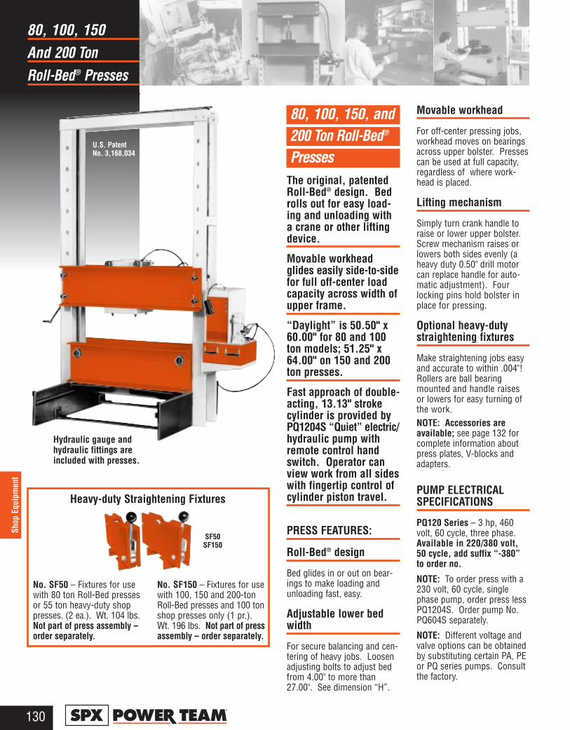
And 200 Ton80, 100, 150
Roll-Bed® Presses
130®
Shop
Equ
ipm
ent
80, 100, 150, and200 Ton Roll-Bed®
PressesThe original, patentedRoll-Bed® design. Bedrolls out for easy load-ing and unloading witha crane or other liftingdevice.
Movable workheadglides easily side-to-sidefor full off-center loadcapacity across width ofupper frame.
“Daylight” is 50.50" x60.00" for 80 and 100ton models; 51.25" x64.00" on 150 and 200ton presses.
Fast approach of double-acting, 13.13" strokecylinder is provided byPQ1204S “Quiet” electric/hydraulic pump withremote control handswitch. Operator canview work from all sideswith fingertip control ofcylinder piston travel.
PRESS FEATURES:
Roll-Bed® design
Bed glides in or out on bear-ings to make loading andunloading fast, easy.
Adjustable lower bedwidth
For secure balancing and cen-tering of heavy jobs. Loosenadjusting bolts to adjust bedfrom 4.00" to more than27.00". See dimension “H”.
Movable workhead
For off-center pressing jobs,workhead moves on bearingsacross upper bolster. Pressescan be used at full capacity,regardless of where work-head is placed.
Lifting mechanism
Simply turn crank handle toraise or lower upper bolster.Screw mechanism raises orlowers both sides evenly (aheavy duty 0.50" drill motorcan replace handle for auto-matic adjustment). Fourlocking pins hold bolster inplace for pressing.
Optional heavy-duty straightening fixtures
Make straightening jobs easyand accurate to within .004"!Rollers are ball bearingmounted and handle raisesor lowers for easy turning ofthe work. NOTE: Accessories areavailable; see page 132 forcomplete information aboutpress plates, V-blocks andadapters.
PUMP ELECTRICALSPECIFICATIONS
PQ120 Series – 3 hp, 460volt, 60 cycle, three phase.Available in 220/380 volt,50 cycle, add suffix “-380”to order no.
NOTE: To order press with a230 volt, 60 cycle, singlephase pump, order press lessPQ1204S. Order pump No.PQ604S separately.
NOTE: Different voltage andvalve options can be obtainedby substituting certain PA, PEor PQ series pumps. Consultthe factory.
U.S. Patent No. 3,168,034
Hydraulic gauge andhydraulic fittings areincluded with presses.
No. SF50 – Fixtures for usewith 80 ton Roll-Bed pressesor 55 ton heavy-duty shoppresses. (2 ea.). Wt. 104 lbs.Not part of press assembly –order separately.
No. SF150 – Fixtures for usewith 100, 150 and 200-tonRoll-Bed presses and 100 tonshop presses only (1 pr.).Wt. 196 lbs. Not part of pressassembly – order separately.
SF50SF150
Heavy-duty Straightening Fixtures
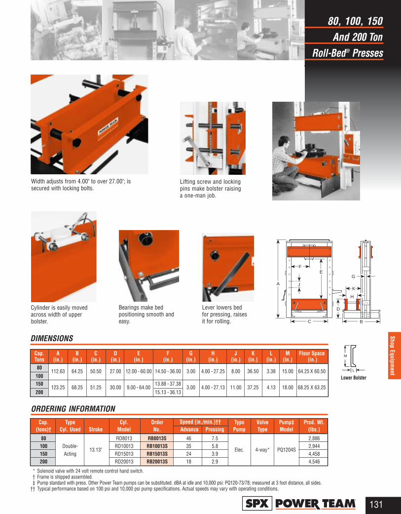
And 200 Ton80, 100, 150
Roll-Bed® Presses
131®
Shop Equipment
Cap. Type Cyl. Order Type Valve Pump‡ Prod. Wt.(tons)† Cyl. Used Stroke Model No. Advance Pressing Pump Type Model (lbs.)
80 RD8013 RB8013S 46 7.5 2,886100 Double-
13.13"RD10013 RB10013S 35 5.8
Elec. 4-way* PQ1204S2,944
150 Acting RD15013 RB15013S 24 3.9 4,458200 RD20013 RB20013S 18 2.9 4,546
* Solenoid valve with 24 volt remote control hand switch.† Frame is shipped assembled. ‡ Pump standard with press. Other Power Team pumps can be substituted. dBA at idle and 10,000 psi: PQ120-73/78; measured at 3 foot distance, all sides.
†† Typical performance based on 100 psi and 10,000 psi pump specifications. Actual speeds may vary with operating conditions.
Speed (in./min.)††
DIMENSIONS
ORDERING INFORMATION
Cap. A B C D E F G H J K L M Floor Space Tons (in.) (in.) (in.) (in.) (in.) (in.) (in.) (in.) (in.) (in.) (in.) (in.) (in.)80
112.63 64.25 50.50 27.00 12.00 - 60.00 14.50 - 36.00 3.00 4.00 - 27.25 8.00 36.50 3.38 15.00 64.25 X 60.50100150
123.25 68.25 51.25 30.00 9.00 - 64.0013.88 - 37.38
3.00 4.00 - 27.13 11.00 37.25 4.13 18.00 68.25 X 63.25200 15.13 - 36.13
Width adjusts from 4.00" to over 27.00"; issecured with locking bolts.
Bearings make bedpositioning smooth andeasy.
Cylinder is easily movedacross width of upperbolster.
Lever lowers bedfor pressing, raisesit for rolling.
Lifting screw and lockingpins make bolster raisinga one-man job.
A
E
C B
G
F
J
D
H
K
M
L
Lower Bolster

Hydraulic PressPower Team
Accessories
132®
Shop
Equ
ipm
ent
Part No. Tire Size I.D. Plate O.D.TPP1 4.00" 3.88"TPP2 5.00" 4.88"TPP3 6.00", 6.25" 5.88"TPP4 6.50" 6.38"TPP5 8.00" 7.88"TPP6 10.00" 9.88"TPP7 10.50" 10.38"TPP8 11.25" 11.13"TPP9 12.00", 12.13" 11.88"TPP10 14.00" 13.88"TPP11 15.00" 14.88"TPP12 16.00" 15.88"TPP13 17.75" 17.63"
TPS6 Spacer/Pushing Adapter 3.75" X 6.00"
TBP1622 Bed Plate 16.00" X 22.00" X 2.00"
THREADED ADAPTER DIMENSIONS (in.)Adapter
No. A B C D38597 1- 8 1- 8 0.75 1.3138953 11⁄4 - 7 11⁄2 - 16 2.75 4.3837368 15⁄8 - 51⁄2 — 1.69 2.5043562 21⁄4 - 12 2.25 3.0038954 1 5⁄8 - 51⁄2 1 11⁄16 - 8 3.25 4.1943563 21⁄4 - 12 23⁄4 - 12 2.25 3.1946070 2 - 41⁄2
SOLID RUBBER TIREREMOVING/INSTALLINGSET FOR 55- THRU 200-TON SHOP PRESSES
Now an easy way to presssolid rubber tires. The TPP200uses plates instead of combina-tion rings to press a rim froman old tire into a new one.Plates are stacked so none ismore than 2 in. smaller thanthe one under it to keep theplates from bending. They can
be used on any Power Teampress with 55 ton capacity ormore. NOTE: Many tiresrequire 100 tons of force ormore, depending on tire sizeand condition. These plateswithstand max. force of 150tons.No. TPP200 — Tire pressplate set. Includes 13 pressplates, spacer pushing adapterand press bed plate. For useon solid rubber tires from4.00" to 17.75" I.D.
Set No. TPP200
Press Accessories
Pressing rim into new tire onPower Team Press.
TPS63.75" X 6.00"
TPP1 – TPP133.88" – 17.63" X 0.75"
CAUTION: Pushingadapters are designed foruse with specific shaftsizes, and depending onthe condition of the shaftends, the adapter maynot withstand the fullpress tonnage. Alwaysuse a protective blanketor other suitable guardwhen pressing.
B
C D
E
F
G
A
DC
B
RamStackedPlates
OldTire
NewTire
Press Plate
Press Bed
V-BLOCKS (in.)Part Width Length Thick AngleNo. A B C D
1890 2.00 9.00 1.251891 2.50 11.50 1.751892 3.50 14.00 2.00 1200
1893 5.00 1.50207395 5.75 23.00 2.50
Cylinder
"A"
"B""C"
Angle"D"
A
A B C D E F GV-Throat Threaded Adapter
Use With Press Pushing Pushing V-Pushing Single- Double- PushingPress: Order No. Plate V-Blocks Adapter Adapter Adapter Acting Cyls. Acting Cyls. Adapter
Included in Set10 Ton SPA10 1888 1890 (Pr.) 201923 201454 34806 38597 38597 –
0.50" dia. shank 0.75" dia. shank 1" – 8 1" – 8Included in Set
25 Ton SPA25 1889 1891 (Pr.) 34510 34511 34807 38953 38953 –0.75" dia. shank 1.00" dia. shank 1 1⁄4" – 7 1 1⁄4" – 7
Not Included34755 34756 Order Separately
55 Ton SPA55 – 1892 (Pr.) 1.00" dia. shank 1.50" dia. shank 34808 37368 38954 –
1 5⁄8" – 5 1⁄2" 1 5⁄8" – 5 1⁄2"Not Included
Order Separately80/100 SPA100 – 1893**(Pr.) – – 36469 43562 43563 21332
Ton 2 1⁄4" – 12 2 1⁄4" – 1246070***2 1⁄4" – 12
150/200SPA200 – 207395 (Pr.) –
4445844457
None*–Ton 2.25" dia. shank – –
* Pushing adapters thread directly into RD15013 and RD20013 cylinders.** V-blocks, No. 1893, are recommended for use with 80-ton Roll-Bed press. Not recommended for use with 100 ton Roll Bed.
***For 80-ton Roll-Bed press.NOTE: Individual press accessories may be ordered separately.
ORDERING INFORMATION
TBP162216.00" X 22.00" X 2.00"
ACCESSORIES
Press Accessory KitMake your Power Team presseven more versatile with oneof these accessory sets.These sets will eliminatemakeshift set-ups. Many ofthese items can be used withpullers you already have.

FloorMobile
Cranes
133®
Shop Equipment
Mobile Floor Cranes, 6,000 lb.Capacity
Working capacities of4,000, 5,000 and 6,000lbs. Boom swings a full3 feet in 4,000 lb. posi-tion; 26.00" in 6,000 lb.position.
For stability, legs extendto nearly 130.00" withmaximum spread of59.75". Steering dollyprovides mobility, actsas a floor lock by liftingrear wheel off the floor.
FC6000 has 2-speed handpump which fully extendsboom with 120 strokesunder no load; with 480strokes under load.
FC6000E has electric/hydraulic pump whichfully extends boom in16.2 seconds under noload; in 4.6 minutesunder load.
HYDRAULIC PUMP
Electric/hydraulicpump withremote motorcontrol forlifting andlowering.The 61399also has a
manual load lowering valvefor precise operator control.
HAND PUMP
2-speed hand pump 64663 forfast boom travel and preciseoperator controlled descent.
ORDERING INFORMATION
No. FC6000 – 6,000 lb.capacity mobile floor cranewith retractable legs. Comesequipped with a 2-speed handpump (64663). Wt., 1,300 lbs.No. FC6000E – 6,000 lb.capacity mobile floor cranewith retractable legs. Comesequipped with a 115V, 50/60HZ electric/hydraulic pump(61399) with remote motorcontrol and a manual loadlowering valve. Wt., 1,300 lbs.For 220 volt version, part No.FC6000E-220.
Ext. Center Ret.Boom Capacity (lbs.) 4,000 5,000 6,000A Max. Boom Hgt. 161.88" 150.69" 139.50"
B Min. Boom Hgt. 6.00" 17.38" 28.75"C Overall Hgt. (Boom horiz.) 87.00" 87.00" 87.00"
D Overall Length* 129.13" 113.88" 98.25"E Inside Leg Length 91.69" 76.13" 43.25"
F Eff. Boom Horiz. Reach 94.25" 78.75" 63.25"
G Outside Leg Width** 59.75" 57.75" 55.75"H Boom Swing 36.00" 31.00" 26.00"
J Inside Leg Width 35.75"K Leg Height 9.06"
M Wheel dia. 8.00"Dolly Wheel Dia. 5.00"
* Legs in storage position: 80.88" ** Legs in storage position: 53.50"
DIMENSIONS (in.)
Optional load positioning sling
See page 135
6,000 lb.Capacity
FC6000E
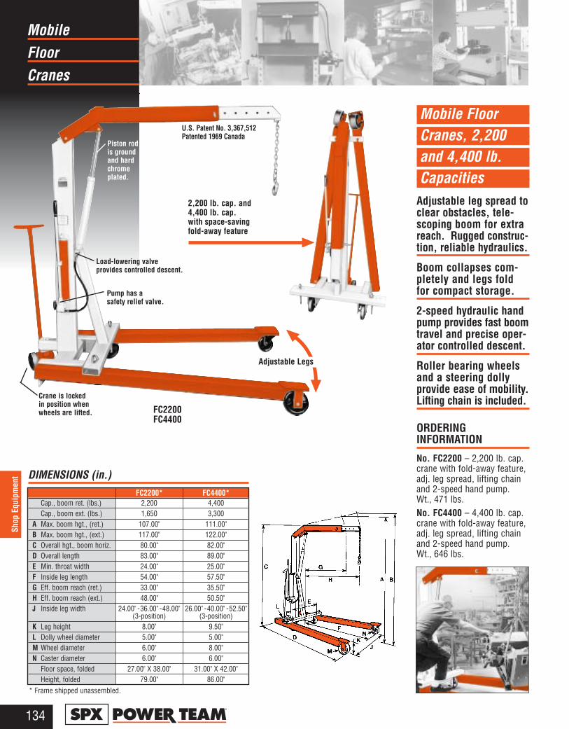
Mobile Floor Cranes, 2,200 and 4,400 lb. Capacities
Adjustable leg spread toclear obstacles, tele-scoping boom for extrareach. Rugged construc-tion, reliable hydraulics.
Boom collapses com-pletely and legs foldfor compact storage.
2-speed hydraulic handpump provides fast boomtravel and precise oper-ator controlled descent.
Roller bearing wheelsand a steering dollyprovide ease of mobility.Lifting chain is included.
ORDERING INFORMATION
No. FC2200 – 2,200 lb. cap.crane with fold-away feature,adj. leg spread, lifting chainand 2-speed hand pump.Wt., 471 lbs.No. FC4400 – 4,400 lb. cap.crane with fold-away feature,adj. leg spread, lifting chainand 2-speed hand pump.Wt., 646 lbs.
FloorMobile
Cranes
134®
Shop
Equ
ipm
ent
Load-lowering valve provides controlled descent.
Pump has a safety relief valve.
Crane is lockedin position whenwheels are lifted.
U.S. Patent No. 3,367,512Patented 1969 Canada
2,200 lb. cap. and4,400 lb. cap. with space-savingfold-away feature
FC2200FC4400
Adjustable Legs
Piston rodis ground and hardchromeplated.
FC2200* FC4400*Cap., boom ret. (lbs.) 2,200 4,400Cap., boom ext. (lbs.) 1,650 3,300
A Max. boom hgt., (ret.) 107.00" 111.00"B Max. boom hgt., (ext.) 117.00" 122.00"C Overall hgt., boom horiz. 80.00" 82.00"D Overall length 83.00" 89.00"E Min. throat width 24.00" 25.00"F Inside leg length 54.00" 57.50"G Eff. boom reach (ret.) 33.00" 35.50"H Eff. boom reach (ext.) 48.00" 50.50"J Inside leg width 24.00" - 36.00" - 48.00" 26.00" - 40.00" - 52.50"
(3-position) (3-position)K Leg height 8.00" 9.50"L Dolly wheel diameter 5.00" 5.00"M Wheel diameter 6.00" 8.00"N Caster diameter 6.00" 6.00"
Floor space, folded 27.00" X 38.00" 31.00" X 42.00"Height, folded 79.00" 86.00"
DIMENSIONS (in.)
* Frame shipped unassembled.
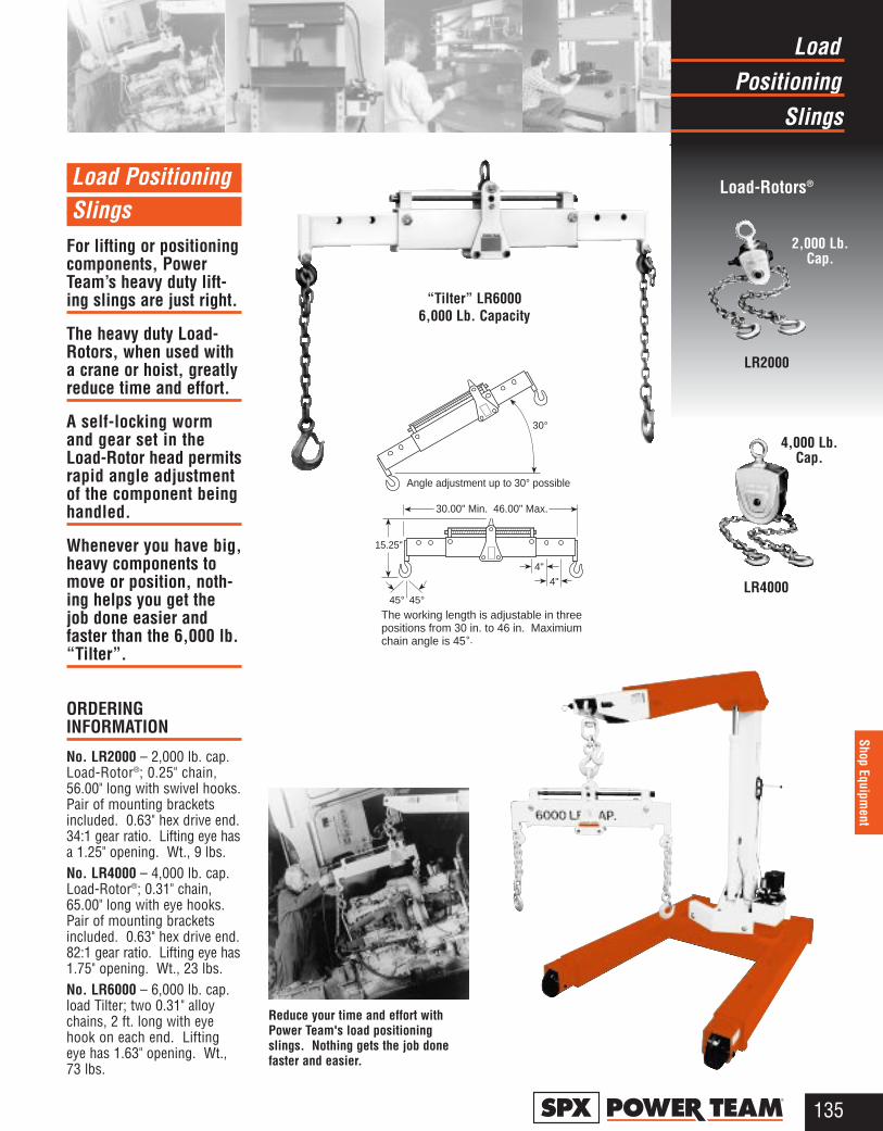
Load Positioning Slings
For lifting or positioningcomponents, PowerTeam’s heavy duty lift-ing slings are just right.
The heavy duty Load-Rotors, when used witha crane or hoist, greatlyreduce time and effort.
A self-locking wormand gear set in theLoad-Rotor head permitsrapid angle adjustmentof the component beinghandled.
Whenever you have big,heavy components tomove or position, noth-ing helps you get thejob done easier andfaster than the 6,000 lb.“Tilter”.
ORDERING INFORMATION
No. LR2000 – 2,000 lb. cap.Load-Rotor®; 0.25" chain,56.00" long with swivel hooks.Pair of mounting bracketsincluded. 0.63" hex drive end.34:1 gear ratio. Lifting eye hasa 1.25" opening. Wt., 9 lbs.No. LR4000 – 4,000 lb. cap.Load-Rotor®; 0.31" chain,65.00" long with eye hooks.Pair of mounting bracketsincluded. 0.63" hex drive end.82:1 gear ratio. Lifting eye has1.75" opening. Wt., 23 lbs.No. LR6000 – 6,000 lb. cap.load Tilter; two 0.31" alloychains, 2 ft. long with eyehook on each end. Liftingeye has 1.63" opening. Wt.,73 lbs.
PositioningLoad
Slings
135®
Shop Equipment
Load-Rotors®
2,000 Lb.Cap.
LR2000
LR4000
4,000 Lb.Cap.
Reduce your time and effort withPower Team's load positioningslings. Nothing gets the job donefaster and easier.
“Tilter” LR6000 6,000 Lb. Capacity
Angle adjustment up to 30° possible
30°
15.25"
30.00" Min. 46.00" Max.
45° 45°
4"
4"
The working length is adjustable in threepositions from 30 in. to 46 in. Maximiumchain angle is 45°.
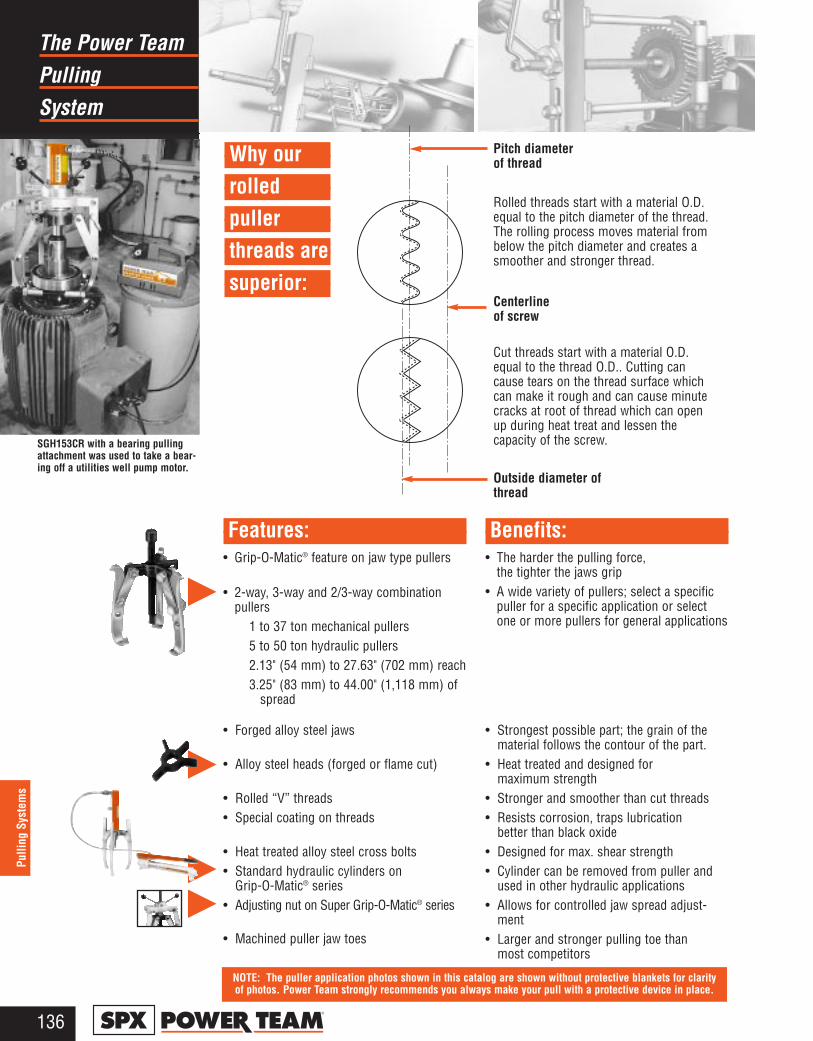
Why ourrolledpuller threads aresuperior:
PullingThe Power Team
System
136®
Pulli
ng S
yste
ms
SGH153CR with a bearing pullingattachment was used to take a bear-ing off a utilities well pump motor.
Rolled threads start with a material O.D.equal to the pitch diameter of the thread.The rolling process moves material frombelow the pitch diameter and creates asmoother and stronger thread.
Cut threads start with a material O.D.equal to the thread O.D.. Cutting cancause tears on the thread surface whichcan make it rough and can cause minutecracks at root of thread which can openup during heat treat and lessen thecapacity of the screw.
Pitch diameterof thread
Centerlineof screw
Outside diameter ofthread
• Grip-O-Matic® feature on jaw type pullers
• 2-way, 3-way and 2/3-way combinationpullers
1 to 37 ton mechanical pullers5 to 50 ton hydraulic pullers2.13" (54 mm) to 27.63" (702 mm) reach3.25" (83 mm) to 44.00" (1,118 mm) of
spread
• The harder the pulling force, the tighter the jaws grip
• A wide variety of pullers; select a specificpuller for a specific application or selectone or more pullers for general applications
• Forged alloy steel jaws
• Alloy steel heads (forged or flame cut)
• Rolled “V” threads• Special coating on threads
• Heat treated alloy steel cross bolts• Standard hydraulic cylinders on
Grip-O-Matic® series• Adjusting nut on Super Grip-O-Matic® series
• Machined puller jaw toes
• Strongest possible part; the grain of the material follows the contour of the part.
• Heat treated and designed for maximum strength
• Stronger and smoother than cut threads• Resists corrosion, traps lubrication
better than black oxide • Designed for max. shear strength• Cylinder can be removed from puller and
used in other hydraulic applications• Allows for controlled jaw spread adjust-
ment• Larger and stronger pulling toe than
most competitors
Features: Benefits:
NOTE: The puller application photos shown in this catalog are shown without protective blankets for clarity of photos. Power Team strongly recommends you always make your pull with a protective device in place.
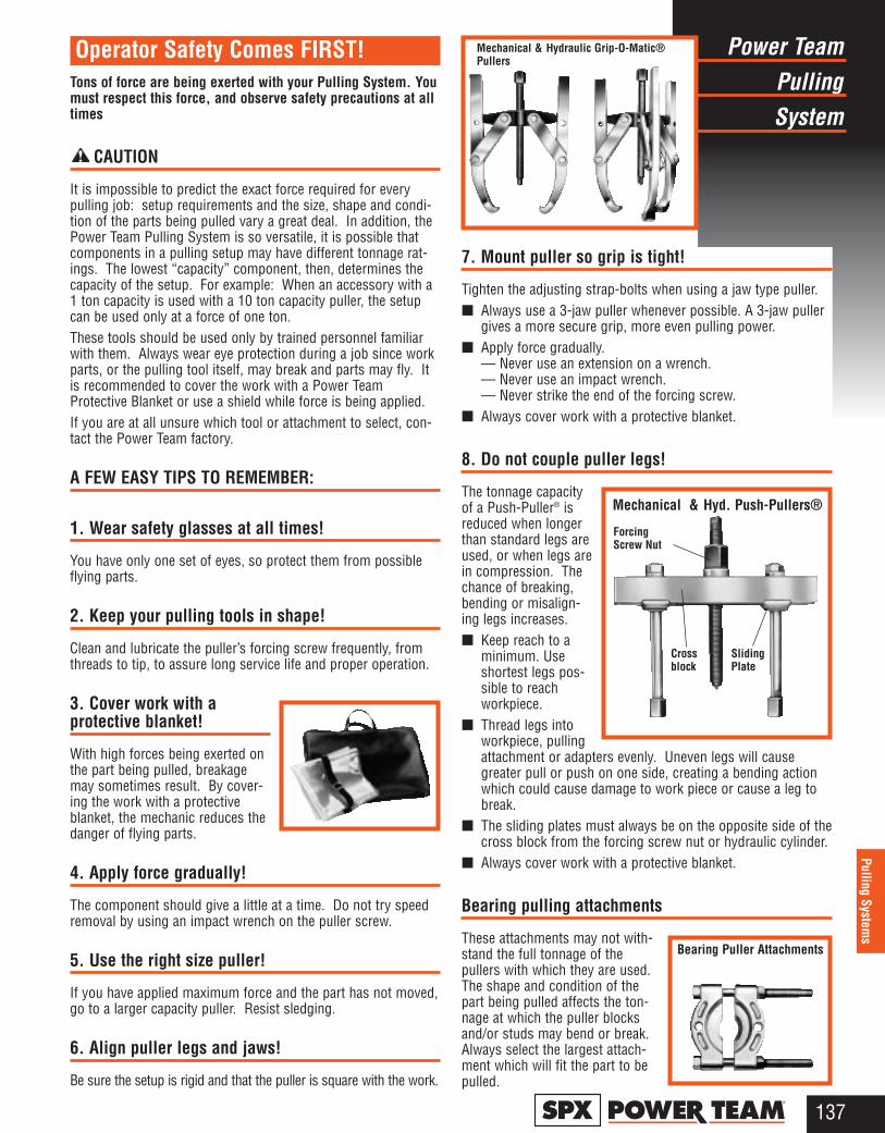
PullingPower Team
System
137®
Pulling Systems
Tons of force are being exerted with your Pulling System. Youmust respect this force, and observe safety precautions at alltimes
CAUTION
It is impossible to predict the exact force required for everypulling job: setup requirements and the size, shape and condi-tion of the parts being pulled vary a great deal. In addition, thePower Team Pulling System is so versatile, it is possible thatcomponents in a pulling setup may have different tonnage rat-ings. The lowest “capacity” component, then, determines thecapacity of the setup. For example: When an accessory with a1 ton capacity is used with a 10 ton capacity puller, the setupcan be used only at a force of one ton.These tools should be used only by trained personnel familiarwith them. Always wear eye protection during a job since workparts, or the pulling tool itself, may break and parts may fly. Itis recommended to cover the work with a Power TeamProtective Blanket or use a shield while force is being applied.If you are at all unsure which tool or attachment to select, con-tact the Power Team factory.
A FEW EASY TIPS TO REMEMBER:
1. Wear safety glasses at all times!
You have only one set of eyes, so protect them from possibleflying parts.
2. Keep your pulling tools in shape!
Clean and lubricate the puller’s forcing screw frequently, fromthreads to tip, to assure long service life and proper operation.
3. Cover work with a protective blanket!
With high forces being exerted onthe part being pulled, breakagemay sometimes result. By cover-ing the work with a protectiveblanket, the mechanic reduces thedanger of flying parts.
4. Apply force gradually!
The component should give a little at a time. Do not try speedremoval by using an impact wrench on the puller screw.
5. Use the right size puller!
If you have applied maximum force and the part has not moved,go to a larger capacity puller. Resist sledging.
6. Align puller legs and jaws!
Be sure the setup is rigid and that the puller is square with the work.
7. Mount puller so grip is tight!
Tighten the adjusting strap-bolts when using a jaw type puller.■ Always use a 3-jaw puller whenever possible. A 3-jaw puller
gives a more secure grip, more even pulling power.■ Apply force gradually.
— Never use an extension on a wrench. — Never use an impact wrench. — Never strike the end of the forcing screw.
■ Always cover work with a protective blanket.
8. Do not couple puller legs!
The tonnage capacityof a Push-Puller® isreduced when longerthan standard legs areused, or when legs arein compression. Thechance of breaking,bending or misalign-ing legs increases.■ Keep reach to a
minimum. Useshortest legs pos-sible to reachworkpiece.
■ Thread legs intoworkpiece, pullingattachment or adapters evenly. Uneven legs will causegreater pull or push on one side, creating a bending actionwhich could cause damage to work piece or cause a leg tobreak.
■ The sliding plates must always be on the opposite side of thecross block from the forcing screw nut or hydraulic cylinder.
■ Always cover work with a protective blanket.
Bearing pulling attachments
These attachments may not with-stand the full tonnage of thepullers with which they are used.The shape and condition of thepart being pulled affects the ton-nage at which the puller blocksand/or studs may bend or break.Always select the largest attach-ment which will fit the part to bepulled.
Operator Safety Comes FIRST! Mechanical & Hydraulic Grip-O-Matic®Pullers
Mechanical & Hyd. Push-Pullers®
Bearing Puller Attachments
SlidingPlate
Crossblock
ForcingScrew Nut
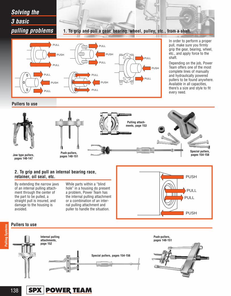
3 basic Solving the
pulling problems
138®
Pulli
ng S
yste
ms
PULL
PUSH
PULL
PULL
PUSH
PULL
PUSH
PULL
PULL
PUSH
PULL
PULL
PUSH
PULL
PULL
PULL
PUSH
PUSH
PULL
1. To grip and pull a gear, bearing, wheel, pulley, etc., from a shaft.
In order to perform a properpull, make sure you firmlygrip the gear, bearing, wheel,etc., and apply force to theshaft.Depending on the job, PowerTeam offers one of the mostcomplete lines of manuallyand hydraulically poweredpullers to be found anywhere.Available in all capacities,there’s a size and style to fitevery need.
Pullers to use
By extending the narrow jawsof an internal pulling attach-ment through the center ofthe part to be pulled, astraight pull is insured, anddamage to the housing isavoided.
While parts within a “blindhole” in a housing do presenta problem, Power Team hasthe internal pulling attachmentor a combination of an inter-nal pulling attachment andpuller to handle the situation.
Pullers to use
2. To grip and pull an internal bearing race,retainer, oil seal, etc.
Internal pullingattachments, page 152
Push-pullers,pages 148-151
Jaw type pullers,pages 140-147
Push-pullers,pages 148-151
Pulling attach-ments, page 153
Special pullers, pages 154-158
Special pullers, pages 154-156
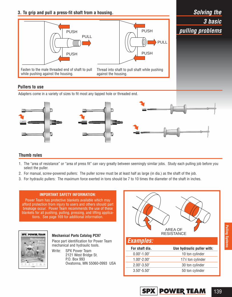
3 basicSolving the
pulling problems
139®
Pulling Systems
3. To grip and pull a press-fit shaft from a housing.
Fasten to the male threaded end of shaft to pullwhile pushing against the housing.
Pullers to useAdapters come in a variety of sizes to fit most any tapped hole or threaded end.
IMPORTANT SAFETY INFORMATION:Power Team has protective blankets available which may
afford protection from injury to users and others should partbreakage occur. Power Team recommends the use of these
blankets for all pushing, pulling, pressing, and lifting applica-tions. See page 169 for additional information.
Thumb rules
1. The “area of resistance” or “area of press fit” can vary greatly between seemingly similar jobs. Study each pulling job before youselect the puller.
2. For manual, screw-powered pullers: The puller screw must be at least half as large (in dia.) as the shaft of the job.3. For hydraulic pullers: The maximum force exerted in tons should be 7 to 10 times the diameter of the shaft in inches.
Thread into shaft to pull shaft while pushingagainst the housing.
Mechanical Parts Catalog PC97Piece part identification for Power Team mechanical and hydraulic tools.Write: SPX Power Team
2121 West Bridge St.P.O. Box 993Owatonna, MN 55060-0993 USA
PULLPUSH
PUSH
PULL
PUSH
PUSH
AREA OFRESISTANCE
Examples:For shaft dia. Use hydraulic puller with:
0.00"-1.00" 10 ton cylinder 1.00"-2.00" 171⁄2 ton cylinder 2.00"-3.50" 30 ton cylinder 3.50"-5.50" 50 ton cylinder
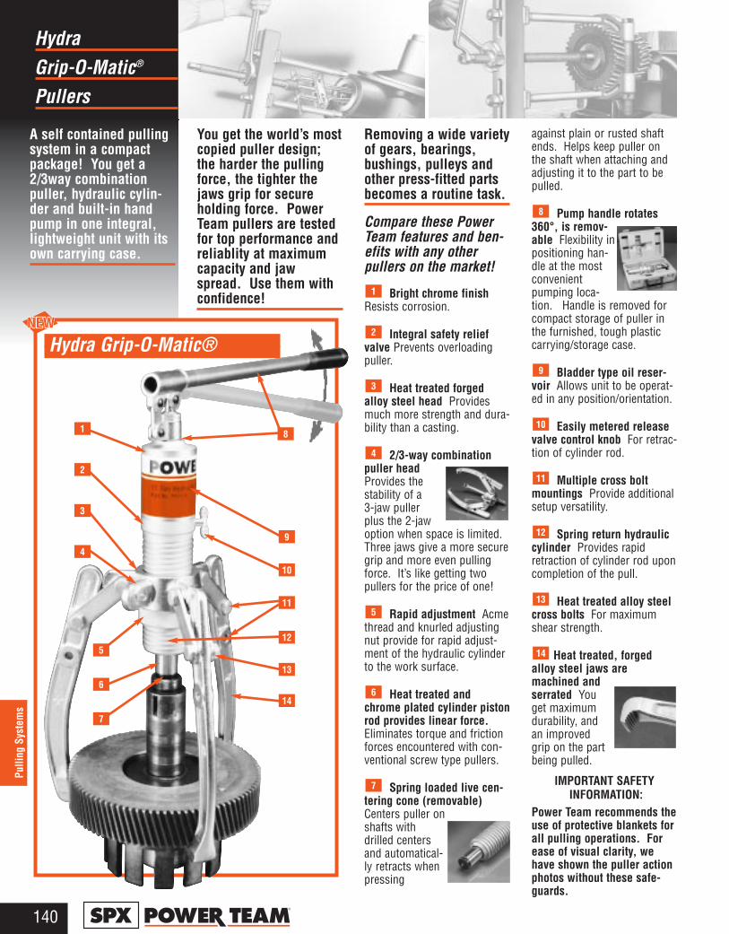
Grip-O-Matic®
Hydra
Pullers
140®
Pulli
ng S
yste
ms
1
2
3
4
5
6
7
Hydra Grip-O-Matic®
8
9
10
11
12
13
14
A self contained pullingsystem in a compactpackage! You get a2/3way combinationpuller, hydraulic cylin-der and built-in handpump in one integral,lightweight unit with itsown carrying case.
You get the world’s mostcopied puller design;the harder the pullingforce, the tighter thejaws grip for secureholding force. PowerTeam pullers are testedfor top performance andreliablity at maximumcapacity and jawspread. Use them withconfidence!
Removing a wide varietyof gears, bearings,bushings, pulleys andother press-fitted partsbecomes a routine task.
Compare these PowerTeam features and ben-efits with any otherpullers on the market!
Bright chrome finishResists corrosion.
Integral safety reliefvalve Prevents overloadingpuller.
Heat treated forgedalloy steel head Providesmuch more strength and dura-bility than a casting.
2/3-way combinationpuller headProvides thestability of a3-jaw pullerplus the 2-jawoption when space is limited.Three jaws give a more securegrip and more even pullingforce. It’s like getting twopullers for the price of one!
Rapid adjustment Acmethread and knurled adjustingnut provide for rapid adjust-ment of the hydraulic cylinderto the work surface.
Heat treated andchrome plated cylinder pistonrod provides linear force.Eliminates torque and frictionforces encountered with con-ventional screw type pullers.
Spring loaded live cen-tering cone (removable)Centers puller onshafts withdrilled centersand automatical-ly retracts whenpressing
against plain or rusted shaftends. Helps keep puller onthe shaft when attaching andadjusting it to the part to bepulled.
Pump handle rotates360°, is remov-able Flexibility inpositioning han-dle at the mostconvenientpumping loca-tion. Handle is removed forcompact storage of puller inthe furnished, tough plasticcarrying/storage case.
Bladder type oil reser-voir Allows unit to be operat-ed in any position/orientation.
Easily metered releasevalve control knob For retrac-tion of cylinder rod.
Multiple cross boltmountings Provide additionalsetup versatility.
Spring return hydrauliccylinder Provides rapidretraction of cylinder rod uponcompletion of the pull.
Heat treated alloy steelcross bolts For maximumshear strength.
Heat treated, forgedalloy steel jaws aremachined andserrated Youget maximumdurability, andan improvedgrip on the partbeing pulled.
IMPORTANT SAFETY INFORMATION:
Power Team recommends theuse of protective blankets forall pulling operations. Forease of visual clarity, wehave shown the puller actionphotos without these safe-guards.
14
13
12
11
10
9
8
7
6
5
4
3
2
1

Grip-O-Matic®
Hydra
Pullers
141®
Pulling Systems
Cyl. Cap.
Puller accessory converts PH113C intoa Hydraulic Straightening Tool
A perfect portable tool for straightening shafts,bars, etc. Simply remove pump and cylinder frompuller head and insert into the HST11 straighteningtool accessory (see photo). Widely used in steelmills, wire roll companies, wire extruding firms, thetextile industry and anywhere portable straightening capability isneeded. Contoured heat treated shaft adapter included.
The new No. HST11S set includes straightening tool, pump andcylinder assembly and shaft adapter.
No. HST11S*
*Includes pump andcylinder assembly.
Shaftadapterincluded
No. HST11Use with pump
and cylinderassembly from
PH113C(not included)
PATENT Nos. : USA No. 5,233,740; Canada No. 2052729; Germany No. G9114718.2; Korea No. 79208607 andNo. 95-16522; Taiwan No. 40137 and No. 60151; P.R.C. No. ZL 93211036.3; Japan No. 3-106430; other patents pending.* Use with pump and cylinder assembly from PH113C (Not Included)
ORDERING INFORMATION
See current price list for shipping weights.
Spread
Stroke
No.HST11/HST11S
PHSeries
Reach
E
F/G
D
E
F Dia. Adj.
Thd.
Reac
h
Stro
ke
Reach
Spread
Spread
GDia.
OrderNo. Reach Spread Stroke
6 tons PH63C 6.00" 7.88"
3.13"
0.56"
—
0.44"
A
Puller Jaw Tip
21 lbs.
32 lbs.
0.38"
0.25"
B
Max.2.38"
8 tons PH83C 7.50" 9.81"
Min.1.56"
11 tons PH113C 9.00" 11.00"
2.56"
1.13"
1.00"
0.88"
C
——
2.00"
1.25"
D
——
3.25"
E
2.38"
1.97"
1.66"
F
1.13"
3.34"
0.88"
G
17.6 lbs.
14.5 lbs.
10.8 lbs.
PullerWeight
20.6 lbs.
18.6 lbs.
13.7 lbs.
PullerWeight
(w/case)
11 tonsHST11*
HST11S5.91"
3.50" to16.13"
A
C
B
Cyl. Cap.
OrderNo. Reach Spread
8 tons1188 12.50"
11.00"
11 tons 12.50
Optional Long Jaws (Set of 3, not shown)for PH83C or PH113C
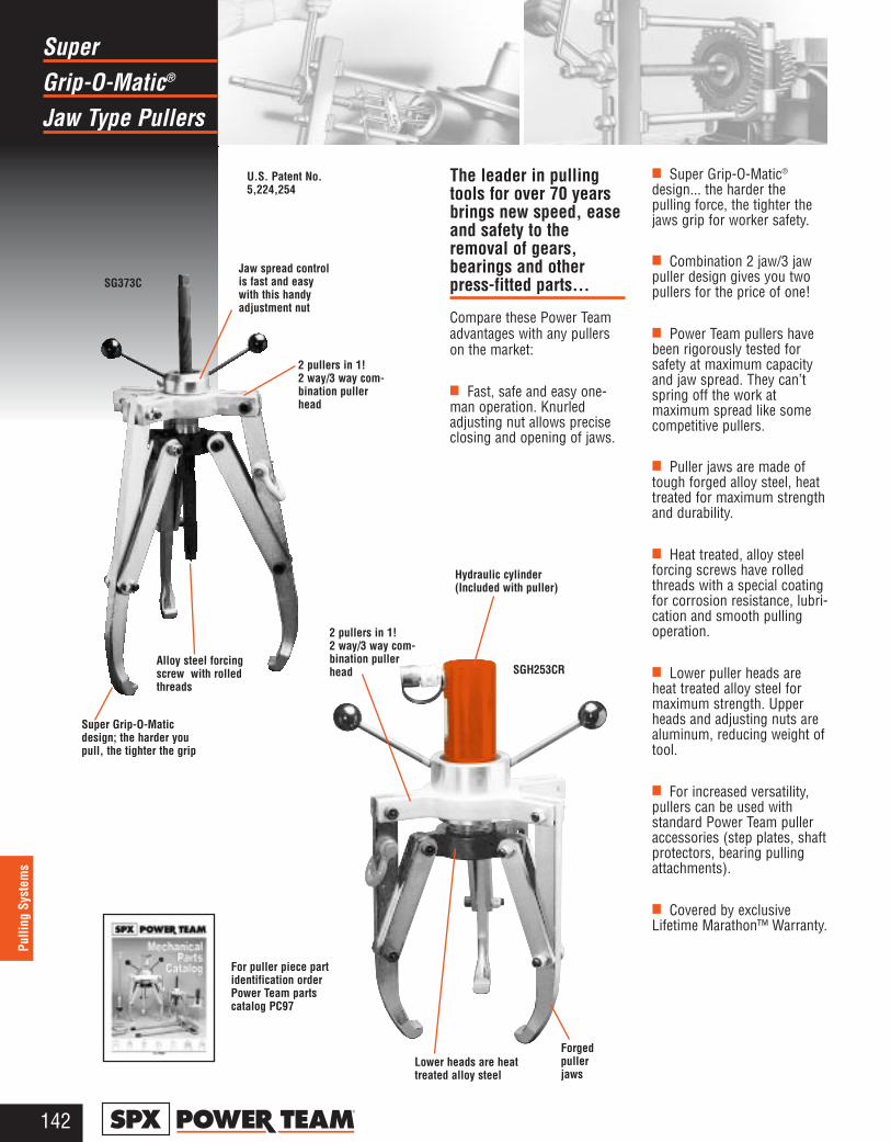
Grip-O-Matic®
Super
Jaw Type Pullers
142®
Pulli
ng S
yste
ms
The leader in pullingtools for over 70 yearsbrings new speed, easeand safety to theremoval of gears,bearings and otherpress-fitted parts...
Compare these Power Teamadvantages with any pullerson the market:
■ Fast, safe and easy one-man operation. Knurledadjusting nut allows preciseclosing and opening of jaws.
■ Super Grip-O-Matic®
design... the harder thepulling force, the tighter thejaws grip for worker safety.
■ Combination 2 jaw/3 jawpuller design gives you twopullers for the price of one!
■ Power Team pullers havebeen rigorously tested forsafety at maximum capacityand jaw spread. They can’tspring off the work atmaximum spread like somecompetitive pullers.
■ Puller jaws are made oftough forged alloy steel, heattreated for maximum strengthand durability.
■ Heat treated, alloy steelforcing screws have rolledthreads with a special coatingfor corrosion resistance, lubri-cation and smooth pullingoperation.
■ Lower puller heads areheat treated alloy steel formaximum strength. Upperheads and adjusting nuts arealuminum, reducing weight oftool.
■ For increased versatility,pullers can be used withstandard Power Team pulleraccessories (step plates, shaftprotectors, bearing pullingattachments).
■ Covered by exclusiveLifetime Marathon™ Warranty.
Jaw spread controlis fast and easywith this handyadjustment nut
2 pullers in 1! 2 way/3 way com-bination pullerhead
Forgedpullerjaws
Hydraulic cylinder(Included with puller)
Lower heads are heattreated alloy steel
U.S. Patent No.5,224,254
For puller piece part identification order Power Team partscatalog PC97
SG373C
SGH253CR
Super Grip-O-Maticdesign; the harder youpull, the tighter the grip
Alloy steel forcingscrew with rolledthreads
2 pullers in 1! 2 way/3 way com-bination pullerhead
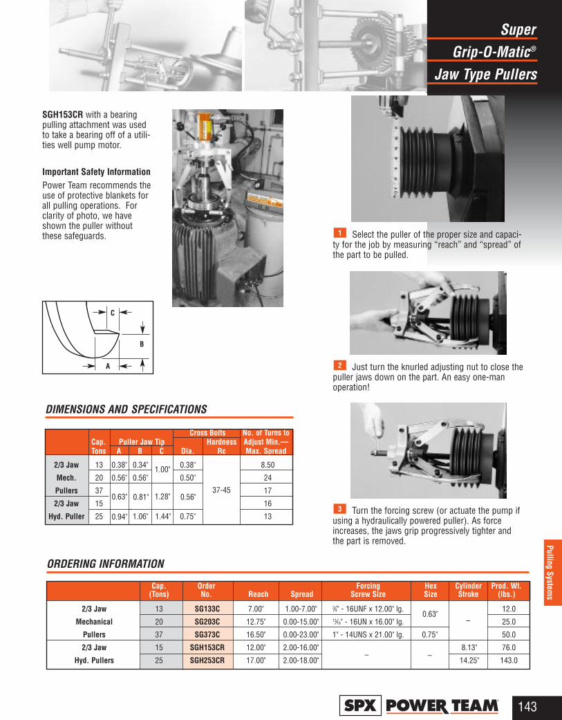
Grip-O-Matic®
Super
Jaw Type Pullers
143®
Pulling Systems
ORDERING INFORMATION
Cap. Order Forcing Hex Cylinder Prod. Wt.(Tons) No. Reach Spread Screw Size Size Stroke (lbs.)
2/3 Jaw 13 SG133C 7.00" 1.00-7.00" 3⁄4" - 16UNF x 12.00" lg. 12.0
Mechanical 20 SG203C 12.75" 0.00-15.00" 13⁄16" - 16UN x 16.00" lg. 25.0
Pullers 37 SG373C 16.50" 0.00-23.00" 1" - 14UNS x 21.00" lg. 0.75" 50.0
2/3 Jaw 15 SGH153CR 12.00" 2.00-16.00" 8.13" 76.0
Hyd. Pullers 25 SGH253CR 17.00" 2.00-18.00" 14.25" 143.0
DIMENSIONS AND SPECIFICATIONS
C
A
B
SGH153CR with a bearingpulling attachment was usedto take a bearing off of a utili-ties well pump motor.
Important Safety InformationPower Team recommends theuse of protective blankets forall pulling operations. Forclarity of photo, we haveshown the puller withoutthese safeguards.
Just turn the knurled adjusting nut to close thepuller jaws down on the part. An easy one-manoperation!
2
Turn the forcing screw (or actuate the pump ifusing a hydraulically powered puller). As forceincreases, the jaws grip progressively tighter andthe part is removed.
3
Select the puller of the proper size and capaci-ty for the job by measuring “reach” and “spread” ofthe part to be pulled.
1
Cross Bolts No. of Turns toCap. Puller Jaw Tip Hardness Adjust Min.—Tons A B C Dia. Rc Max. Spread
2/3 Jaw 13 0.38" 0.34" 0.38" 8.50
Mech. 20 0.56" 0.56" 0.50" 24
Pullers 37 17
2/3 Jaw 15 16
Hyd. Puller 25 1.06" 1.44" 0.75" 130.94"
37-450.81" 1.28" 0.56"
1.00"
0.63"
0.63"–
––
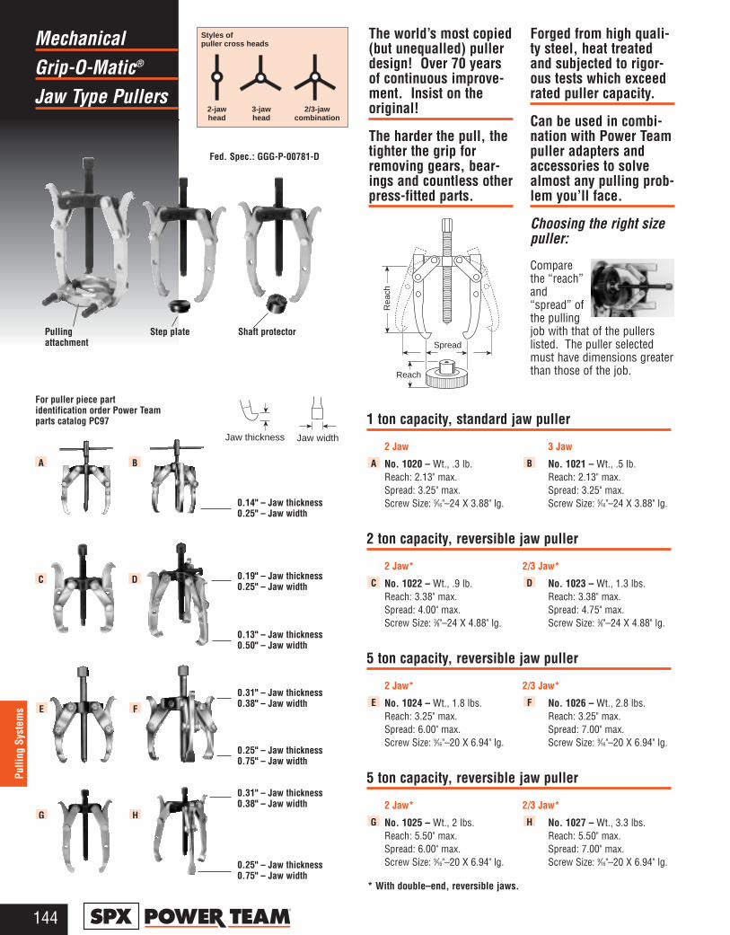
Grip-O-Matic®
Mechanical
Jaw Type Pullers
144®
Pulli
ng S
yste
ms
1 ton capacity, standard jaw puller
2 Jaw 3 Jaw
No. 1020 – Wt., .3 lb. No. 1021 – Wt., .5 lb.Reach: 2.13" max. Reach: 2.13" max. Spread: 3.25" max. Spread: 3.25" max. Screw Size: 5⁄16"–24 X 3.88" lg. Screw Size: 5⁄16"–24 X 3.88" lg.
2 ton capacity, reversible jaw puller
2 Jaw* 2/3 Jaw*
No. 1022 – Wt., .9 lb. No. 1023 – Wt., 1.3 lbs. Reach: 3.38" max. Reach: 3.38" max. Spread: 4.00" max. Spread: 4.75" max. Screw Size: 3⁄8"–24 X 4.88" lg. Screw Size: 3⁄8"–24 X 4.88" lg.
5 ton capacity, reversible jaw puller
2 Jaw* 2/3 Jaw*
No. 1024 – Wt., 1.8 lbs. No. 1026 – Wt., 2.8 lbs. Reach: 3.25" max. Reach: 3.25" max. Spread: 6.00" max. Spread: 7.00" max. Screw Size: 9⁄16"–20 X 6.94" lg. Screw Size: 9⁄16"–20 X 6.94" lg.
5 ton capacity, reversible jaw puller
2 Jaw* 2/3 Jaw*
No. 1025 – Wt., 2 lbs. No. 1027 – Wt., 3.3 lbs. Reach: 5.50" max. Reach: 5.50" max. Spread: 6.00" max. Spread: 7.00" max. Screw Size: 9⁄16"–20 X 6.94" lg. Screw Size: 9⁄16"–20 X 6.94" lg.
HG
FE
DC
BA
Fed. Spec.: GGG-P-00781-D
0.14" – Jaw thickness0.25" – Jaw width
0.25" – Jaw thickness0.75" – Jaw width
0.31" – Jaw thickness0.38" – Jaw width
0.25" – Jaw thickness0.75" – Jaw width
0.31" – Jaw thickness0.38" – Jaw width
0.13" – Jaw thickness0.50" – Jaw width
0.19" – Jaw thickness0.25" – Jaw width
Pulling attachment
Step plate Shaft protector
* With double–end, reversible jaws.
The world’s most copied(but unequalled) pullerdesign! Over 70 yearsof continuous improve-ment. Insist on theoriginal!
The harder the pull, thetighter the grip forremoving gears, bear-ings and countless otherpress-fitted parts.
Forged from high quali-ty steel, heat treatedand subjected to rigor-ous tests which exceedrated puller capacity.
Can be used in combi-nation with Power Teampuller adapters andaccessories to solvealmost any pulling prob-lem you’ll face.
Choosing the right sizepuller:
Comparethe “reach”and“spread” ofthe pullingjob with that of the pullerslisted. The puller selectedmust have dimensions greaterthan those of the job.
Jaw width
Rea
ch
Spread
Reach
Styles ofpuller cross heads
2-jawhead
3-jawhead
2/3-jawcombination
For puller piece part identification order Power Teamparts catalog PC97
BA
DC
FE
HG
Jaw thickness

Grip-O-Matic®
Mechanical
Jaw Type Pullers
145®
Pulling Systems
7 ton capacity, reversible jaw puller
2 Jaw* 2/3 Jaw*
No. 1035 – Wt., 4.5 lbs. No. 1037 – Wt., 6.3 lbs. Reach: 5.00" max. Reach: 5.00" max. Spread: 9.00" max. Spread: 10.50" max. Screw Size: 11⁄16"–18 X 9.00" lg. Screw Size: 11⁄16"–18 X 9.00" lg.
7 ton capacity, long jaw puller
2 Jaw 2/3 Jaw
No. 1036 – Wt., 5 lbs. No. 1038 – Wt., 7.3 lbs. Reach: 8.75" max. Reach: 8.75" max.Spread: 9.50" max. Spread: 11.00" max.Screw Size: 11⁄16"–18 X 9.00" lg. Screw Size: 11⁄16"–18 X 9.00" lg.
13 ton capacity, standard and long jaw pullers
Std. 2 Jaw Long 2 Jaw
No. 1039 – Wt., 10.5 lbs. No. 1040 – Wt., 13 lbs.Reach: 11.00" max. Reach: 15.25" max.Spread: 12.50" max. Spread: 15.50" max.Screw Size: 13⁄16"–16 X 12.00" lg. Screw Size: 13⁄16"–16 X 12.00" lg.
Std. 2/3 Jaw Long 2/3 Jaw
No. 1041 – Wt., 14.8 lbs. No. 1042 – Wt., 18.3 lbs.Reach: 11.00" max. Reach: 15.25" max.Spread: 14.00" max. Spread: 17.00" max.Screw Size: 13⁄16"–16 X 12.00" lg. Screw Size: 13⁄16"–16 X 12.00" lg.
171⁄2 ton capacity, standard and long jaw pullers
Std. 2 Jaw Long 2 Jaw
No. 1043 – Wt., 23 lbs. No. 1044 – Wt., 26 lbs.Reach: 14.50" max. Reach: 18.75" max.Spread: 14.00" max. Spread: 16.00" max.Screw Size: 1"–14 X 13.50" lg. Screw Size: 1"–14 X 13.50" lg.
Std. 3 Jaw Long 3 Jaw
No. 1045 – Wt., 33 lbs. No. 1046 – Wt., 37 lbs.Reach: 14.50" max. Reach: 18.75" max.Spread: 14.00" max. Spread: 16.00" max.Screw Size: 1"–14 X 13.50" lg. Screw Size: 1"–14 X 13.50" lg.
25 ton capacity, standard and long jaw pullers
Std. 2 Jaw Long 2 Jaw
No. 1047 – Wt., 37.5 lbs. No. 1048 – Wt., 42.8 lbs.Reach: 15.50" max. Reach: 22.25" max.Spread: 16.00" max. Spread: 20.00" max.Screw Size:11⁄4"–12 X 16.63" lg. Screw Size: 11⁄4"–12 X 16.63" lg.
Std. 3 Jaw Long 3 Jaw
No. 1049 – Wt., 54 lbs. No. 1050 – Wt., 60 lbs. Reach: 15.50" max. Reach: 22.25" max. Spread: 16.00" max. Spread: 20.00" max. Screw Size: 11⁄4"–12 X 16.63" lg. Screw Size: 11⁄4"–12 X 16.63" lg.
SS
RR
PP
OO
NN
ML
KJ
* With double–end, reversible jaws.
0.34" – Jaw thickness1.00" – Jaw width
0.56" – Jaw thickness1.00" – Jaw width
1.06" – Jaw thickness1.50" – Jaw width
0.81" – Jaw thickness1.28" – Jaw width
0.34" – Jaw thickness1.00" – Jaw width
0.31" – Jaw thickness1.00" – Jaw width
For puller piece part identification order Power Team parts catalog PC97
Jaw width
Jaw thickness
KJ
ML
ON
QP
SR
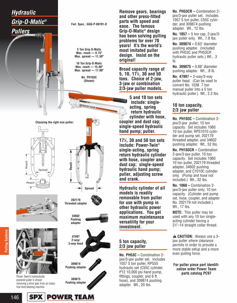
Grip-O-Matic®
Hydraulic
Pullers
146®
Pulli
ng S
yste
ms
Remove gears, bearingsand other press-fittedparts with speed andease. The famousGrip-O-Matic® designhas been solving pullingproblems for over 70years! It’s the world’smost imitated pullerdesign. Insist on theoriginal!
Broad capacity range of5, 10, 171⁄2, 30 and 50tons. Choice of 2-jaw,3-jaw or combination2/3-jaw puller models.
5 and 10 ton sets include: single-
acting, spring return hydraulic
cylinder with hose,coupler and dust cap;single-speed hydraulichand pump; puller.
171⁄2, 30 and 50 ton setsinclude: Power-Twin®
single-acting, springreturn hydraulic cylinderwith hose, coupler anddust cap; single-speedhydraulic hand pump;puller, adjusting screwand crank.
Hydraulic cylinder of allmodels is readilyremovable from pullerfor use with pump inother hydraulic powerapplications. You getmaximum maintenanceversatility for yourinvestment.
5 ton capacity, 2/3 jaw puller
No. PH53C – Combination 2-jaw/3-jaw puller set. Includes1057 5 ton puller, RPS55hydraulic set (C55C cylinder,P12 10,000 psi hand pump,fittings, coupler, and 6 ft.hose), and 309874 pushingadapter. Wt., 20 lbs.
No. PH53CR – Combination 2-jaw/3-jaw puller set. Includes1057 5 ton puller, C55C cylin-der, and 309874 pushingadapter. Wt., 12 lbs.No. 1057 – 5 ton cap. 2-jaw/3-jaw puller only. Wt., 7.8 lbs.No. 309874 – 0.63" diameterpushing adapter. (Includedwith PH53C and PH53CRhydraulic puller sets.) Wt., .3lb.No. 309875 – 0.88" diameterpushing adapter. Wt., .8 lb.No. 47997 – 2-way/3-waypuller head. (Can be used toconvert No. 1038 7 tonmanual puller into a 5 tonhydraulic puller.) Wt., 2.3 lbs.
10 ton capacity, 2/3 jaw puller
No. PH103C – Combination 2-jaw/3-jaw puller; 10 toncapacity. Set includes 106010 ton puller, RPS1010 cylin-der and pump set, 202179threaded adapter, and 34602pushing adapter. Wt., 52 lbs.No. PH103CR – Combination2-jaw/3-jaw puller, 10 toncapacity. Set includes 106010 ton puller, 202179 threadedadapter, 34602 pushingadapter, and C1010C cylinderonly. (Pump and hose notincluded.) Wt., 32 lbs.No. 1060 – Combination 2-jaw/3-jaw puller only; 10 toncapacity. (Cylinder and pumpset, hose, coupler, and adapterNo. 202179 not included.) Wt., 17 lbs.NOTE: This puller may beused with any 10 ton single-acting cylinder having a21⁄4"–14 straight collar thread.
CAUTION: Always use a 3-jaw puller where clearancepermits in order to provide amore stable setup and a moreeven pulling force.
For puller piece part identifi-cation order Power Team
parts catalog PC97
Fed. Spec.: GGG-P-00781-D
202179Threaded adapter
34602Pushingadapter
47997 2-way/
3-way head
309874Pushing adapter
309875Pushing adapter
Power Team’s hydraulically powered puller is shown removing a drive gear from an indus-trial shot-blasting machine.
Choosing the right size puller:
Rea
ch
Spread
Reach
Spread
Reac
h
5 Ton Grip-O-MaticMax. reach — 8.75"
Max. spread — 11.50"
10 Ton Grip-O-MaticMax. reach — 15.00" Max. spread — 17.00"
No. PH103C (Shown)
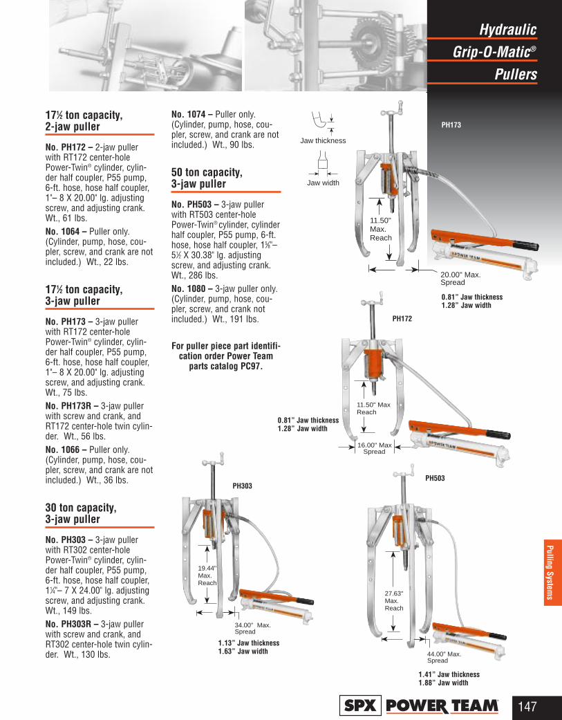
Grip-O-Matic®
Hydraulic
Pullers
147®
Pulling Systems
171⁄2 ton capacity,2-jaw puller
No. PH172 – 2-jaw pullerwith RT172 center-holePower-Twin® cylinder, cylin-der half coupler, P55 pump,6-ft. hose, hose half coupler,1"– 8 X 20.00" lg. adjustingscrew, and adjusting crank.Wt., 61 lbs.No. 1064 – Puller only.(Cylinder, pump, hose, cou-pler, screw, and crank are notincluded.) Wt., 22 lbs.
171⁄2 ton capacity,3-jaw puller
No. PH173 – 3-jaw pullerwith RT172 center-holePower-Twin® cylinder, cylin-der half coupler, P55 pump,6-ft. hose, hose half coupler,1"– 8 X 20.00" lg. adjustingscrew, and adjusting crank.Wt., 75 lbs.No. PH173R – 3-jaw pullerwith screw and crank, andRT172 center-hole twin cylin-der. Wt., 56 lbs.No. 1066 – Puller only.(Cylinder, pump, hose, cou-pler, screw, and crank are notincluded.) Wt., 36 lbs.
30 ton capacity,3-jaw puller
No. PH303 – 3-jaw pullerwith RT302 center-holePower-Twin® cylinder, cylin-der half coupler, P55 pump,6-ft. hose, hose half coupler,11⁄4"– 7 X 24.00" lg. adjustingscrew, and adjusting crank.Wt., 149 lbs.No. PH303R – 3-jaw pullerwith screw and crank, andRT302 center-hole twin cylin-der. Wt., 130 lbs.
No. 1074 – Puller only.(Cylinder, pump, hose, cou-pler, screw, and crank are notincluded.) Wt., 90 lbs.
50 ton capacity,3-jaw puller
No. PH503 – 3-jaw pullerwith RT503 center-holePower-Twin® cylinder, cylinderhalf coupler, P55 pump, 6-ft.hose, hose half coupler, 15⁄8"–51⁄2 X 30.38" lg. adjustingscrew, and adjusting crank.Wt., 286 lbs.No. 1080 – 3-jaw puller only.(Cylinder, pump, hose, cou-pler, screw, and crank notincluded.) Wt., 191 lbs.
For puller piece part identifi-cation order Power Team
parts catalog PC97.
PH172
PH303PH503
Jaw width
Jaw thickness
11.50" Max Reach
16.00" MaxSpread
27.63" Max.Reach
44.00" Max.Spread
19.44" Max.Reach
34.00" Max.Spread
11.50" Max.Reach
20.00" Max.Spread
1.41” Jaw thickness1.88” Jaw width
1.13” Jaw thickness1.63” Jaw width
0.81” Jaw thickness1.28” Jaw width
PH173
0.81” Jaw thickness1.28” Jaw width
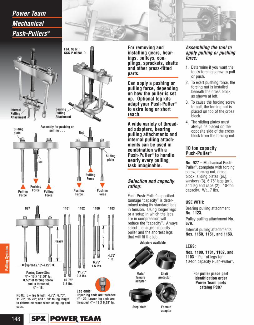
MechanicalPower Team
Push-Pullers®
148®
Pulli
ng S
yste
ms
For removing andinstalling gears, bear-ings, pulleys, cou-plings, sprockets, shaftsand other press-fittedparts.
Can apply a pushing orpulling force, dependingon how the puller is setup. Optional leg kitsadapt your Push-Puller®
to extra long or shortreach.
A wide variety of thread-ed adapters, bearingpulling attachments andinternal pulling attach-ments can be used incombination with aPush-Puller® to handlenearly every pullingtask imaginable.
Selection and capacityrating:
Each Push-Puller’s specifiedtonnage “capacity” is deter-mined using its standard legsin tension. Using longer legsor a setup in which the legsare in compression willreduce the “capacity”. Alwaysselect the largest capacitypuller and the shortest legsthat will fit the job.
Assembling the tool toapply pulling or pushingforce:
1. Determine if you want thetool’s forcing screw to pullor push.
2. To exert pushing force, theforcing nut is installedbeneath the cross block,as shown at left.
3. To cause the forcing screwto pull, the forcing nut isplaced on top of the crossblock.
4. The sliding plates mustalways be placed on theopposite side of the crossblock from the forcing nut.
10 ton capacityPush-Puller®
No. 927 – Mechanical Push-Puller®, complete with forcingscrew, forcing nut, crossblock, sliding plates (pr.),washers (3), 6.75" legs (pr.),and leg end caps (2). 10-toncapacity. Wt., 7 lbs.
USE WITH:Bearing pulling attachmentNo. 1123. Pulley pulling attachment No.679. Internal pulling attachmentsNos. 1150, 1151, and 1153.
LEGS:Nos. 1100, 1101, 1102, and1103 – Pair of legs for 10-ton capacity Push-Puller®.
For puller piece partidentification order Power Team parts
catalog PC97
Fed. Spec.:GGG-P-00781-D
Adapters available
Male/femaleadapter
Shaftprotector
Step plate Femaleadapter
927 1101 1102 1100 1103
15.75"3.3 lbs.
11.75"2.3 lbs.
6.75"1.5 lbs.
4.75"1 lb.
Spread 2.13"–7.25"
Forcing Screw Size: 3⁄4" – 16 X 12.00" lg.
0.50" of forcing screwend is threaded
5⁄8" – 18.Leg endsUpper leg ends are threaded1⁄2" – 20. Lower leg ends arethreaded 5⁄8" – 18 X 0.63" lg.
NOTE: L = leg length: 4.75", 6.75",11.75", 15.75"; add 1.50" to leg lengthto determine reach when using leg endcaps.
Slidingplate
Nut
Nut
Slidingplate
▲PullingForce
▲PullingForce
▼Pushing
Force
Assembly for pushing orpulling . . .
▲PullingForce
▼Pushing
Force
▼Pushing
Force
ReachL
BearingPullingAttachment
Internal PullingAttachment
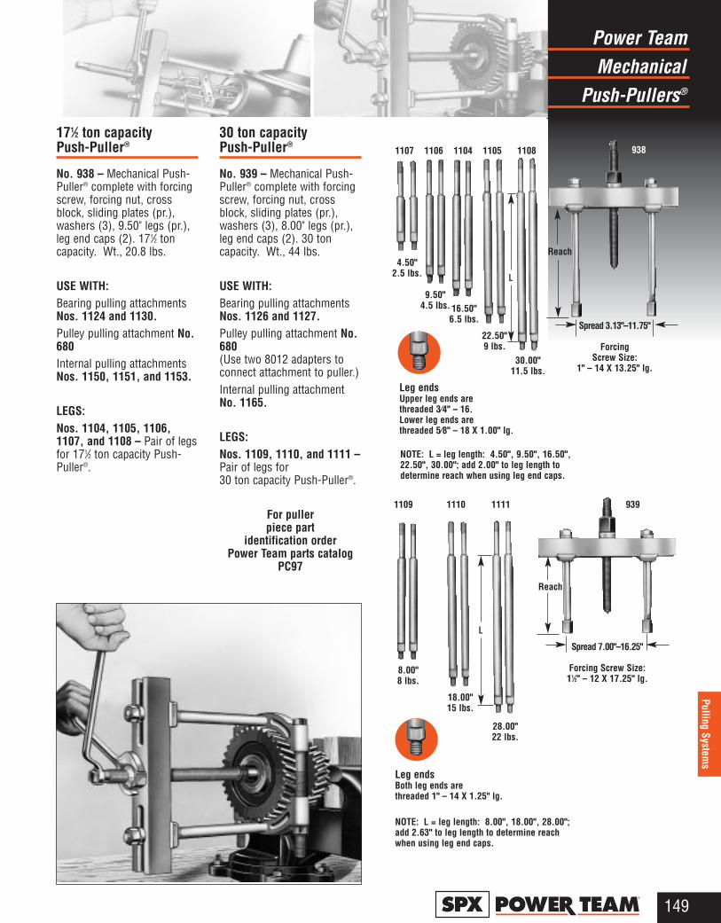
MechanicalPower Team
Push-Pullers®
149®
Pulling Systems
171⁄2 ton capacityPush-Puller®
No. 938 – Mechanical Push-Puller® complete with forcingscrew, forcing nut, crossblock, sliding plates (pr.),washers (3), 9.50" legs (pr.),leg end caps (2). 171⁄2 toncapacity. Wt., 20.8 lbs.
USE WITH:Bearing pulling attachmentsNos. 1124 and 1130. Pulley pulling attachment No.680 Internal pulling attachmentsNos. 1150, 1151, and 1153.
LEGS:Nos. 1104, 1105, 1106,1107, and 1108 – Pair of legsfor 171⁄2 ton capacity Push-Puller®.
30 ton capacityPush-Puller®
No. 939 – Mechanical Push-Puller® complete with forcingscrew, forcing nut, crossblock, sliding plates (pr.),washers (3), 8.00" legs (pr.),leg end caps (2). 30 toncapacity. Wt., 44 lbs.
USE WITH:Bearing pulling attachmentsNos. 1126 and 1127.Pulley pulling attachment No.680(Use two 8012 adapters toconnect attachment to puller.)Internal pulling attachmentNo. 1165.
LEGS:Nos. 1109, 1110, and 1111 –Pair of legs for 30 ton capacity Push-Puller®.
For puller piece part
identification order Power Team parts catalog
PC97
4.50" 2.5 lbs.
Spread 3.13"–11.75"
Forcing Screw Size:
1" – 14 X 13.25" lg.
Leg endsUpper leg ends are threaded 3⁄4" – 16. Lower leg ends are threaded 5⁄8" – 18 X 1.00" lg.
NOTE: L = leg length: 4.50", 9.50", 16.50",22.50", 30.00"; add 2.00" to leg length todetermine reach when using leg end caps.
1107 1106 1104 1105 1108
9.50" 4.5 lbs. 16.50"
6.5 lbs.
22.50"9 lbs.
30.00" 11.5 lbs.
8.00" 8 lbs.
Leg endsBoth leg ends are threaded 1" – 14 X 1.25" lg.
18.00" 15 lbs.
28.00" 22 lbs.
NOTE: L = leg length: 8.00", 18.00", 28.00";add 2.63" to leg length to determine reachwhen using leg end caps.
938
Reach
Spread 7.00"–16.25"
Forcing Screw Size: 11⁄2" – 12 X 17.25" lg.
Reach
1109 1110 1111 939
L
L
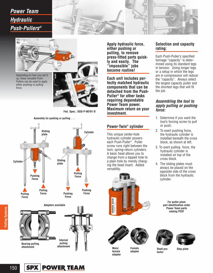
HydraulicPower Team
Push-Pullers®
150®
Pulli
ng S
yste
ms
Apply hydraulic force,either pushing orpulling, to removepress-fitted parts quick-ly and easily. The“impossible” jobsbecome routine!
Each unit includes per-fectly matched hydrauliccomponents that can bedetached from the Push-Puller® for other tasksrequiring dependablePower Team power.Maximum return on yourinvestment.
Power-Twin® cylinder
This unique center-holehydraulic cylinder powerseach Push-Puller®. Pullerscrew runs right between thetwin, spring-return cylinders.A basic head allows you tochange from a tapped hole toa plain hole by merely chang-ing the head insert. Addedversatility.
Selection and capacityrating:
Each Push-Puller’s specifiedtonnage “capacity” is deter-mined using its standard legsin tension. Using longer legsor a setup in which the legsare in compression will reducethe “capacity”. Always selectthe largest capacity puller andthe shortest legs that will fitthe job.
Assembling the tool toapply pulling or pushingforce:
1. Determine if you want thetool’s forcing screw to pullor push.
2. To exert pushing force,the hydraulic cylinder isinstalled beneath the crossblock, as shown at left.
3. To exert pulling force, thehydraulic cylinder isinstalled on top of thecross block.
4. The sliding plates mustalways be placed on theopposite side of the crossblock from the hydrauliccylinder.
Fed. Spec.: GGG-P-00781-D
Adapters available
Bearing pullingattachment
Depending on how you set itup, these versatile Push-Pullers can be used to applyeither pushing or pullingforce.
For puller piece part identification order
Power Team parts catalog PC97
Slidingplate
Cylinder Slidingplate
Cylinder
▲PullingForce
▲PullingForce
▲PullingForce
▼Pushing
Force
▼Pushing
Force
▼Pushing
Force
Assembly for pushing or pulling . . .
Male/femaleadapter
Shaft pro-tector
Step plateFemaleadapter
Internalpulling
attachment
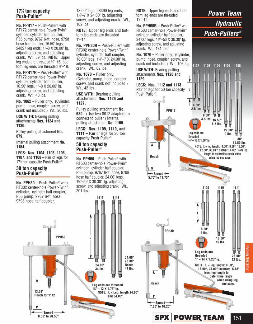
171⁄2 ton capacityPush-Puller®
No. PPH17 – Push-Puller® withRT172 center-hole Power-Twin®
cylinder, cylinder half coupler,P55 pump, 9767 6-ft. hose, 9798hose half coupler, 16.50" legs,24827 leg ends, 1"–8 X 20.00" lg.adjusting screw, and adjustingcrank. Wt., 59 lbs. NOTE: Upperleg ends are threaded 3⁄4"–16, bot-tom leg ends are threaded 5⁄8"–18.No. PPH17R – Push-Puller® withRT172 center-hole Power-Twin®
cylinder, cylinder half coupler,16.50" legs, 1"–8 X 20.00" lg.adjusting screw, and adjustingcrank. Wt., 40 lbs. No. 1062 – Puller only. (Cylinder,pump, hose, coupler, screw, andcrank not included.) Wt., 20 lbs.USE WITH: Bearing pullingattachments Nos. 1124 and1130. Pulley pulling attachment No.679. Internal pulling attachment No.1154.LEGS: Nos. 1104, 1105, 1106,1107, and 1108 – Pair of legs for171⁄2 ton capacity Push-Puller®.
30 ton capacityPush-Puller®
No. PPH30 – Push-Puller® withRT302 center-hole Power-Twin®
cylinder, cylinder half coupler,P55 pump, 9767 6-ft. hose,9798 hose half coupler,
18.00" legs, 28390 leg ends,11⁄4"–7 X 24.00" lg. adjustingscrew, and adjusting crank. Wt.,102 lbs.NOTE: Upper leg ends and bot-tom leg ends are threaded1"–14.No. PPH30R – Push-Puller® withRT302 center-hole Power-Twin®
cylinder, cylinder half coupler,18.00" legs, 11⁄4"–7 X 24.00" lg.adjusting screw, and adjustingcrank. Wt., 82 lbs.No. 1070 – Puller only.(Cylinder, pump, hose, coupler,screw, and crank not included.)Wt., 42 lbs.USE WITH: Bearing pullingattachments Nos. 1126 and1127.Pulley pulling attachment No.680. (Use two 8012 adapters toconnect to puller.) Internalpulling attachment No. 1166.LEGS: Nos. 1109, 1110, and1111 – Pair of legs for 30 toncapacity Push-Puller®.
50 ton capacityPush-Puller®
No. PPH50 – Push-Puller® withRT503 center-hole Power-Twin®
cylinder, cylinder half coupler,P55 pump, 9767 6-ft. hose, 9798hose half coupler, 24.00" legs,15⁄8"–51⁄2 X 30.38" lg. adjustingscrew, and adjusting crank. Wt.,201 lbs.
NOTE: Upper leg ends and bot-tom leg ends are threaded11⁄4"–12.No. PPH50R – Push-Puller® withRT503 center-hole Power-Twin®
cylinder, cylinder half coupler,24.00" legs, 15⁄8"–51⁄2 X 30.38" lg.adjusting screw, and adjustingcrank. Wt., 181 lbs.No. 1076 – Puller only. (Cylinder,pump, hose, coupler, screw, andcrank not included.) Wt., 106 lbs.USE WITH: Bearing pullingattachments Nos. 1128 and1129. LEGS: Nos. 1112 and 1113 –Pair of legs for 50 ton capacityPush-Puller®.
HydraulicPower Team
Push-Pullers®
151®
Pulling Systems
1107 1106 1104 1105 1108
PPH17
Reach
Spread5.75" to 11.75"
4.50"2.5 lbs.
Leg ends are threaded 5⁄8" – 18 X 1.00" lg.
L
NOTE: L = leg length: 4.50", 9.50", 16.50", 22.50", 30.00 "; subtract 4.88" from leg
length to determine reach when using leg end caps.
9.50"4.5 lbs.
22.50"9 lbs.
30"11.50 lbs.
16.50"6.5 lbs.
L
Leg ends arethreaded 1" – 14 X 1.25" lg.
8.00"8 lbs.
18.00"15 lbs.
28.00"22 lbs.
1109 1110 1111
1112 1113
PPH50
24.00"34 lbs.
Spread8.50" to 20.50"
Leg ends are threaded11⁄4" – 12 X 1.75" lg.
NOTE: L = Leg: length 24.00" and 34.00".
L
34.00"23.38"Reach47 lbs.
13.38"Reach for 1112
PPH30
Spread7.00" to 16.25"
Reach
NOTE: L = leg length: 8.00", 18.00", 28.00"; subtract 5.88"
from leg length to determine reach
when using leg end caps.
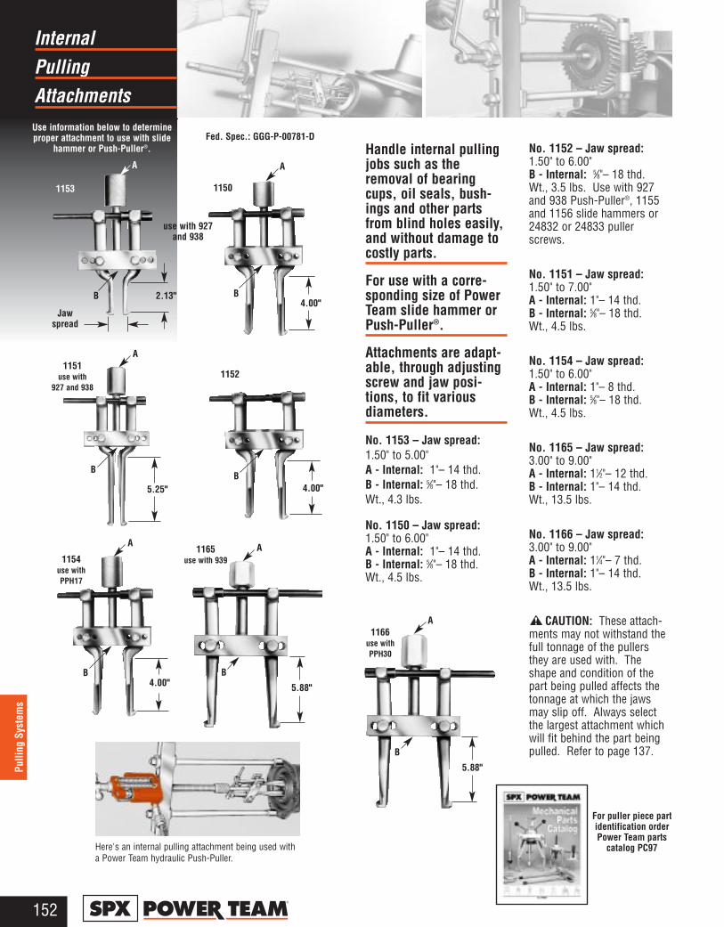
PullingInternal
Attachments
152®
Pulli
ng S
yste
ms
Handle internal pullingjobs such as theremoval of bearingcups, oil seals, bush-ings and other partsfrom blind holes easily,and without damage tocostly parts.
For use with a corre-sponding size of PowerTeam slide hammer orPush-Puller®.
Attachments are adapt-able, through adjustingscrew and jaw posi-tions, to fit variousdiameters.
No. 1153 – Jaw spread:1.50" to 5.00" A - Internal: 1"– 14 thd. B - Internal: 5⁄8"– 18 thd. Wt., 4.3 lbs.
No. 1150 – Jaw spread:1.50" to 6.00" A - Internal: 1"– 14 thd. B - Internal: 5⁄8"– 18 thd. Wt., 4.5 lbs.
No. 1152 – Jaw spread:1.50" to 6.00" B - Internal: 5⁄8"– 18 thd. Wt., 3.5 lbs. Use with 927and 938 Push-Puller®, 1155and 1156 slide hammers or24832 or 24833 pullerscrews.
No. 1151 – Jaw spread:1.50" to 7.00" A - Internal: 1"– 14 thd. B - Internal: 5⁄8"– 18 thd. Wt., 4.5 lbs.
No. 1154 – Jaw spread:1.50" to 6.00" A - Internal: 1"– 8 thd. B - Internal: 5⁄8"– 18 thd. Wt., 4.5 lbs.
No. 1165 – Jaw spread:3.00" to 9.00"A - Internal: 11⁄2"– 12 thd. B - Internal: 1"– 14 thd. Wt., 13.5 lbs.
No. 1166 – Jaw spread:3.00" to 9.00"A - Internal: 11⁄4"– 7 thd. B - Internal: 1"– 14 thd. Wt., 13.5 lbs.
CAUTION: These attach-ments may not withstand thefull tonnage of the pullersthey are used with. Theshape and condition of thepart being pulled affects thetonnage at which the jawsmay slip off. Always selectthe largest attachment whichwill fit behind the part beingpulled. Refer to page 137.
Fed. Spec.: GGG-P-00781-DUse information below to determineproper attachment to use with slide
hammer or Push-Puller®.
11521151
use with 927 and 938
1154 use withPPH17
1166use withPPH30
Here's an internal pulling attachment being used witha Power Team hydraulic Push-Puller.
For puller piece part identification order Power Team parts
catalog PC97
1165 use with 939
5.25"
B
A
4.00"B
A
5.88"
B
A
5.88"
B
A
4.00"B
1153 1150
use with 927and 938
2.13"B
A
Jawspread
4.00"B
A
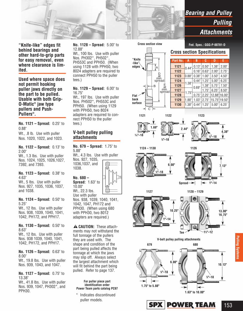
PullingBearing and Pulley
Attachments
153®
Pulling Systems
“Knife-like” edges fitbehind bearings andother hard-to-grip partsfor easy removal, evenwhere clearance is lim-ited.
Used where space doesnot permit hookingpuller jaws directly onthe part to be pulled.Usable with both Grip-O-Matic® jaw typepullers and Push-Pullers®.
No. 1121 – Spread: 0.25" to0.88"Wt., .8 lb. Use with pullerNos. 1020, 1022, and 1023.
No. 1122 – Spread: 0.13" to2.00"Wt., 1.3 lbs. Use with pullerNos. 1024, 1025, 1026,1027,7392, and 7393.
No. 1123 – Spread: 0.38" to4.63"Wt., 5 lbs. Use with pullerNos. 927, 1035, 1036, 1037,and 1038.
No. 1124 – Spread: 0.50" to5.25"Wt., 12 lbs. Use with pullerNos. 938, 1039, 1040, 1041,1042, PH172, and PPH17.
No. 1130 – Spread: 0.50" to8.63"Wt., 12 lbs. Use with pullerNos. 938 1039, 1040, 1041,1042, PH172, and PPH17.
No. 1126 – Spread: 0.63" to8.00"Wt., 19.8 lbs. Use with pullerNos. 939, 1043, and 1047.
No. 1127 – Spread: 0.75" to13.38"Wt., 41.8 lbs. Use with pullerNos. 939, 1047, PH302*, andPPH30.
No. 1128 – Spread: 5.00" to12.88"Wt., 100 lbs. Use with pullerNos. PH302*, PH502*,PH553C and PPH50. (Whenusing 1128 with PPH50, two8024 adapters are required toconnect PPH50 to the pullertees.)
No. 1129 – Spread: 6.00" to16.75"Wt., 197 lbs. Use with pullerNos. PH502*, PH553C andPPH50. (When using 1129with PPH50, two 8024adapters are required to con-nect PPH50 to the pullertees.)
V-belt pulley pullingattachments
No. 679 – Spread: 1.75" to5.88"Wt., 4.3 lbs. Use with pullerNos. 927, 1035,1036,1037, and1038.
No. 680 –Spread: 1.63" to10.00"Wt., 22.3 lbs.Use with pullerNos. 938, 1039, 1040, 1041,1042, 1047, PH172 andPPH30. (When using 680with PPH30, two 8012adapters are required.)
CAUTION: These attach-ments may not withstand thefull tonnage of the pullersthey are used with. Theshape and condition of thepart being pulled affects thetonnage at which the jawsmay slip off. Always selectthe largest attachment whichwill fit behind the part beingpulled. Refer to page 137.
For puller piece part identification order
Power Team parts catalog PC97
1121
1.69"
5⁄16"–18
1122 1123
11261124 – 1130
1127 1128 – 1129
679 680
V-belt pulley pulling attachments
Fed. Spec.: GGG-P-00781-D
Flatbacksurface
“Knife-like”edges
Cross section view
Cross section Specifications
Part No. A B C D E
1121 0.13" 0.50" 1.38" 2.00"1122 0.16" 0.63" 2.00" 2.75"1123 0.88" 0.38" 1.00" 3.50" 4.50"1124 0.44" 1.25" 5.00" 6.25"1126 1.38" 5.75" 7.50"1127 1.75" 6.25" 8.50"1128 0.75" 2.25" 12.88" 16.00"1129 1.88" 1.03" 2.75" 15.75" 19.50"1130 1.38" 0.44" 1.25" 5.00" 6.25"
B
A
Dat
min.spread
Eat
min.spread
C
2.44"
3⁄8"–18
4.38"5⁄8"–18
6.00"
5⁄8"–18
10.25"
1"–14
6.00"
5⁄8"–18
1.75" to 5.88"
10.13"
5⁄8"–18
1.63" to 10.00"
13.00"16.75"
13⁄4"–12Tee
7.13"
1"–14Spread
0.44"
1.38"
1.75"0.69"
* Indicates discontinued puller models.
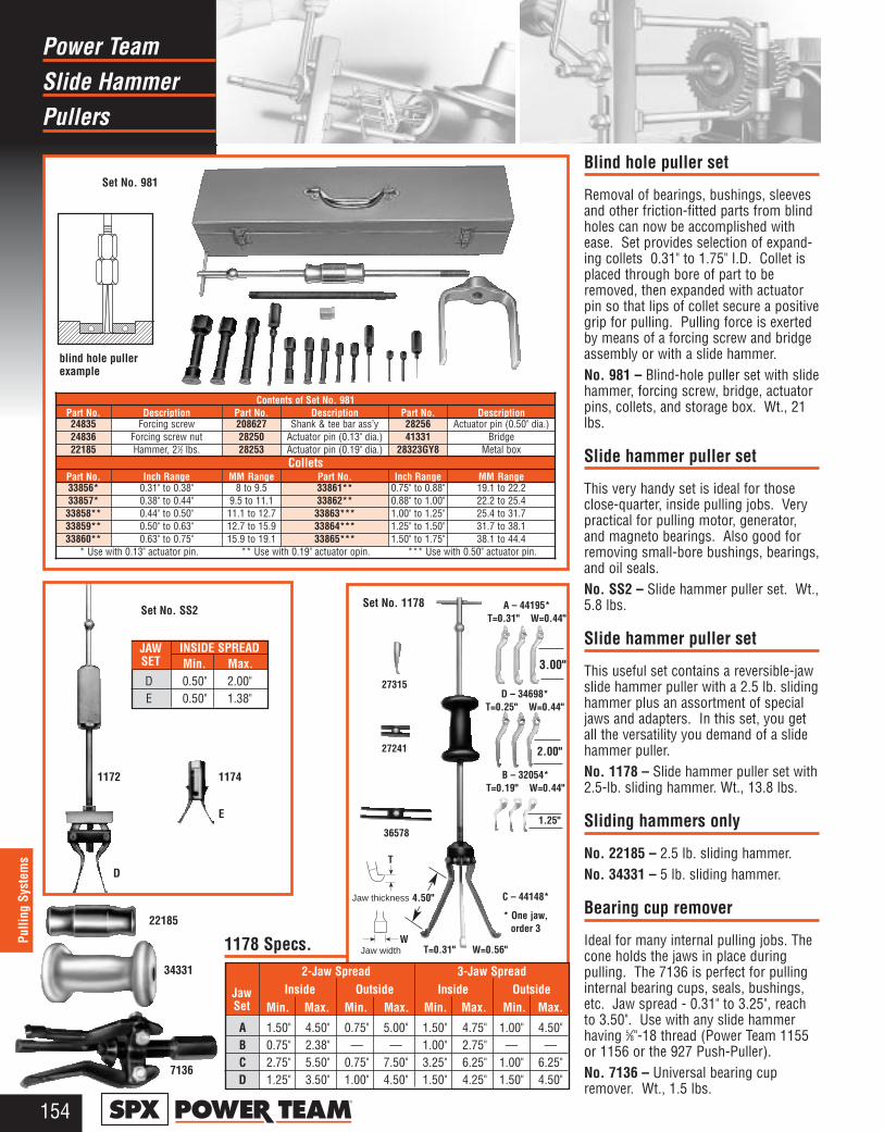
Slide HammerPower Team
Pullers
154®
Pulli
ng S
yste
ms
INSIDE SPREADMin. Max.
D 0.50" 2.00" E 0.50" 1.38"
Blind hole puller set
Removal of bearings, bushings, sleevesand other friction-fitted parts from blindholes can now be accomplished withease. Set provides selection of expand-ing collets 0.31" to 1.75" I.D. Collet isplaced through bore of part to beremoved, then expanded with actuatorpin so that lips of collet secure a positivegrip for pulling. Pulling force is exertedby means of a forcing screw and bridgeassembly or with a slide hammer.No. 981 – Blind-hole puller set with slidehammer, forcing screw, bridge, actuatorpins, collets, and storage box. Wt., 21lbs.
Slide hammer puller set
This very handy set is ideal for thoseclose-quarter, inside pulling jobs. Verypractical for pulling motor, generator,and magneto bearings. Also good forremoving small-bore bushings, bearings,and oil seals.No. SS2 – Slide hammer puller set. Wt.,5.8 lbs.
Slide hammer puller set
This useful set contains a reversible-jawslide hammer puller with a 2.5 lb. slidinghammer plus an assortment of specialjaws and adapters. In this set, you getall the versatility you demand of a slidehammer puller.No. 1178 – Slide hammer puller set with2.5-lb. sliding hammer. Wt., 13.8 lbs.
Sliding hammers only
No. 22185 – 2.5 lb. sliding hammer.No. 34331 – 5 lb. sliding hammer.
Bearing cup remover
Ideal for many internal pulling jobs. Thecone holds the jaws in place duringpulling. The 7136 is perfect for pullinginternal bearing cups, seals, bushings,etc. Jaw spread - 0.31" to 3.25", reachto 3.50". Use with any slide hammerhaving 5⁄8"-18 thread (Power Team 1155or 1156 or the 927 Push-Puller). No. 7136 – Universal bearing cupremover. Wt., 1.5 lbs.
JAWSET
C – 44148*
* One jaw, order 3
36578
T
W
27241
27315
Set No. 1178
1172 1174
E
D
22185
Set No. SS2
34331 2-Jaw Spread 3-Jaw SpreadInside Outside Inside Outside
Min. Max. Min. Max. Min. Max. Min. Max.
A 1.50" 4.50" 0.75" 5.00" 1.50" 4.75" 1.00" 4.50"B 0.75" 2.38" — — 1.00" 2.75" — — C 2.75" 5.50" 0.75" 7.50" 3.25" 6.25" 1.00" 6.25"D 1.25" 3.50" 1.00" 4.50" 1.50" 4.25" 1.50" 4.50"
JawSet
1178 Specs.
7136
Jaw width
Jaw thickness 4.50"
B – 32054*T=0.19" W=0.44"
A – 44195*T=0.31" W=0.44"
D – 34698*T=0.25" W=0.44"
1.25"
T=0.31" W=0.56"
2.00"
3.00"
Set No. 981
Contents of Set No. 981Part No. Description Part No. Description Part No. Description24835 Forcing screw 208627 Shank & tee bar ass’y 28256 Actuator pin (0.50" dia.)24836 Forcing screw nut 28250 Actuator pin (0.13" dia.) 41331 Bridge22185 Hammer, 21⁄2 lbs. 28253 Actuator pin (0.19" dia.) 28323GY8 Metal box
ColletsPart No. Inch Range MM Range Part No. Inch Range MM Range33856* 0.31" to 0.38" 8 to 9.5 33861** 0.75" to 0.88" 19.1 to 22.233857* 0.38" to 0.44" 9.5 to 11.1 33862** 0.88" to 1.00" 22.2 to 25.433858** 0.44" to 0.50" 11.1 to 12.7 33863*** 1.00" to 1.25" 25.4 to 31.733859** 0.50" to 0.63" 12.7 to 15.9 33864*** 1.25" to 1.50" 31.7 to 38.133860** 0.63" to 0.75" 15.9 to 19.1 33865*** 1.50" to 1.75" 38.1 to 44.4
* Use with 0.13" actuator pin. ** Use with 0.19" actuator opin. *** Use with 0.50" actuator pin.
blind hole pullerexample
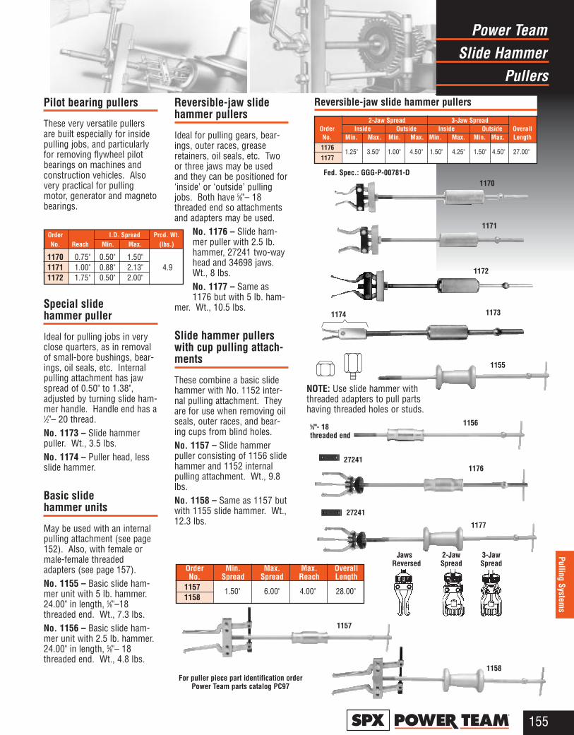
Pilot bearing pullers
These very versatile pullersare built especially for insidepulling jobs, and particularlyfor removing flywheel pilotbearings on machines andconstruction vehicles. Alsovery practical for pullingmotor, generator and magnetobearings.
Special slidehammer puller
Ideal for pulling jobs in veryclose quarters, as in removalof small-bore bushings, bear-ings, oil seals, etc. Internalpulling attachment has jawspread of 0.50" to 1.38",adjusted by turning slide ham-mer handle. Handle end has a1⁄2"– 20 thread. No. 1173 – Slide hammerpuller. Wt., 3.5 lbs.No. 1174 – Puller head, lessslide hammer.
Basic slidehammer units
May be used with an internalpulling attachment (see page152). Also, with female ormale-female threadedadapters (see page 157).No. 1155 – Basic slide ham-mer unit with 5 lb. hammer.24.00" in length, 5⁄8"–18threaded end. Wt., 7.3 lbs.No. 1156 – Basic slide ham-mer unit with 2.5 lb. hammer.24.00" in length, 5⁄8"– 18threaded end. Wt., 4.8 lbs.
Reversible-jaw slidehammer pullers
Ideal for pulling gears, bear-ings, outer races, greaseretainers, oil seals, etc. Twoor three jaws may be usedand they can be positioned for‘inside’ or ‘outside’ pullingjobs. Both have 5⁄8"– 18threaded end so attachmentsand adapters may be used.
No. 1176 – Slide ham-mer puller with 2.5 lb.hammer, 27241 two-wayhead and 34698 jaws.Wt., 8 lbs.No. 1177 – Same as1176 but with 5 lb. ham-
mer. Wt., 10.5 lbs.
Slide hammer pullerswith cup pulling attach-ments
These combine a basic slidehammer with No. 1152 inter-nal pulling attachment. Theyare for use when removing oilseals, outer races, and bear-ing cups from blind holes.No. 1157 – Slide hammerpuller consisting of 1156 slidehammer and 1152 internalpulling attachment. Wt., 9.8lbs.No. 1158 – Same as 1157 butwith 1155 slide hammer. Wt.,12.3 lbs.
Slide HammerPower Team
Pullers
155®
Pulling Systems
Order Min. Max. Max. OverallNo. Spread Spread Reach Length
11571158
2-Jaw Spread 3-Jaw SpreadOrder Inside Outside Inside Outside OverallNo. Min. Max. Min. Max. Min. Max. Min. Max. Length
1176
1177
1172
1156
1176
NOTE: Use slide hammer withthreaded adapters to pull partshaving threaded holes or studs.
5⁄8"- 18 threaded end
27241
27241
1157
1158
1173
1155
1174
For puller piece part identification order Power Team parts catalog PC97
1177
Jaws 2-Jaw 3-JawReversed Spread Spread
1.25" 3.50" 1.00" 4.50" 1.50" 4.25" 1.50" 4.50" 27.00"
Reversible-jaw slide hammer pullers
Order I.D. Spread Prod. Wt. No. Reach Min. Max. (lbs.)
1170 0.75" 0.50" 1.50" 1171 1.00" 0.88" 2.13" 4.9 1172 1.75" 0.50" 2.00"
1.50" 6.00" 4.00" 28.00"
1170Fed. Spec.: GGG-P-00781-D
1171
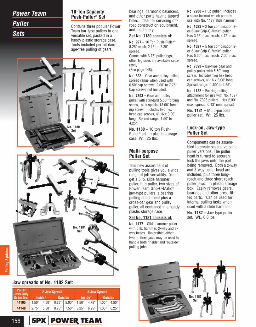
PullerPower Team
Sets
156®
Pulli
ng S
yste
ms
10-Ton CapacityPush-Puller® Set
Contains three popular PowerTeam bar-type pullers in oneversatile set, packed in ahandy plastic storage case.Tools included permit dam-age-free pulling of gears,
bearings, harmonic balancers,and other parts having tappedholes. Ideal for servicing off-road construction equipment,and machinery.Set No. 1180 consists of:No. 927 – 10 Ton Push-Puller®;8.25" reach, 2.13" to 7.25"spread. Comes with 6.75" puller legs,other leg sizes are available sepa-rately (See page 148).
No. 522 – Gear and pulley puller;spread range when used with0.50" cap screws: 2.00" to 7.75".Cap screws not included.
No. 7393 – Gear and pulleypuller with standard 5.50" forcingscrew, plus special 13.00" forc-ing screw. Includes two hexhead cap screws, 3⁄8"-16 x 3.00"long. Spread range: 1.50" to4.25".
No. 1180 – 10 ton Push-Puller® set, in plastic storagecase. Wt., 25 lbs.
Multi-purposePuller Set
This new assortment ofpulling tools gives you a widerange of job versatility. Youget a 5 lb. slide hammerpuller, hub puller, two sizes ofPower Team Grip-O-Matic®
jaw-type pullers, a bearingpulling attachment plus across-bar gear and pulleypuller, all contained in a handyplastic storage case.Set No. 1181 consists of:No. 1177 – Slide hammer pullerwith 5 lb. hammer, 2-way and 3-way heads. Reversible: eithertwo or three jaws may be used tohandle both "inside" and "outside"pulling jobs.
No. 7208 – Hub puller. Includesa spare locknut which permitsuse with No. 1177 slide hammer.
No. 1023 – 2 ton combination 2-or 3-jaw Grip-O-Matic® puller.Has 3.38" max. reach, 4.75" max.spread.
No. 1027 – 5 ton combination 2-or 3-jaw Grip-O-Matic® puller.Has 5.50" max. reach, 7.00" max.spread.
No. 7393 – Bar-type gear andpulley puller with 5.50" longscrew. Includes two hex headcap screws, 3⁄8"-16 x 3.00" long.Spread range: 1.50" to 4.25".
No. 1122 – Bearing pullingattachment for use with No. 1027and No. 7393 pullers. Has 2.00"max. spread, 0.13" min. spread.
No. 1181 – Multi-purposepuller set. Wt., 25 lbs.
Lock-on, Jaw-typePuller Set
Components can be assem-bled to create several versatilepuller versions. The pullerhead is turned to securelylock the jaws onto the partbeing removed. Both a 2-wayand 3-way puller head areincluded, plus three long-reach and three short-reachpuller jaws. In plastic storagebox. Easily removes gears,bearings and other press-fit-ted parts. *Can be used forinternal pulling tasks whenused with a slide hammer.No. 1182 – Jaw-type pullerset. Wt., 6.8 lbs
2-Jaw Spread 3-Jaw SpreadPullerJaws onlyOrder No. Inside* Outside Inside* Outside
44195 1.50” 4.50” 0.75” 5.00” 1.50” 4.75” 1.00” 4.50”
44148 2.75” 5.50” 0.75” 7.50” 3.25” 6.25” 1.00” 6.25”
No. 1180Set
No. 1181Set
No. 1182Set
Jaw spreads of No. 1182 Set:
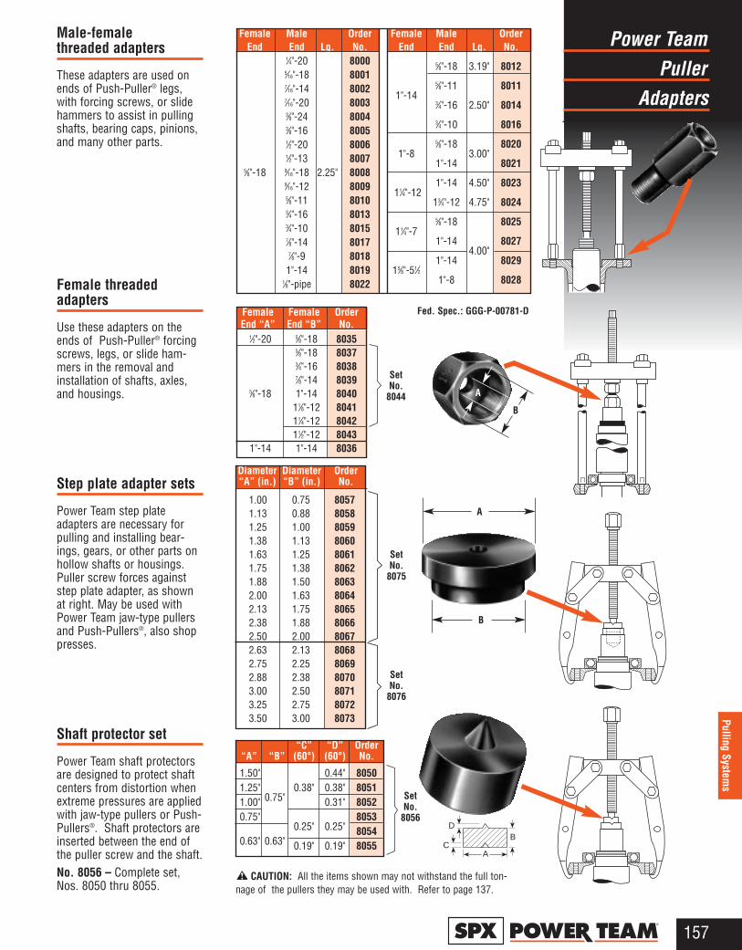
Puller Power Team
Adapters
157®
Pulling Systems
Female Male OrderEnd End Lg. No.
1⁄4"-20 80005⁄16"-18 80017⁄16"-14 80027⁄16"-20 80033⁄8"-24 80043⁄8"-16 80051⁄2"-20 80061⁄2"-13 8007
5⁄8"-18 9⁄16"-18 2.25" 80089⁄16"-12 80095⁄8"-11 80103⁄4"-16 80133⁄4"-10 80157⁄8"-14 80177⁄8"-9 80181"-14 8019
1⁄8"-pipe 8022
Female Male OrderEnd End Lg. No.
5⁄8"-18 3.19" 8012
1"-145⁄8"-11 80113⁄4"-16 2.50" 80143⁄4"-10 8016
1"-85⁄8"-18
3.00"8020
1"-14 8021
11⁄4"-121"-14 4.50" 8023
13⁄4"-12 4.75" 8024
11⁄4"-75⁄8"-18 8025
1"-144.00"
8027
15⁄8"-51⁄21"-14 8029
1"-8 8028
“C” “D” Order“A” “B” (60°) (60°) No.
1.50" 0.44" 80501.25"
0.75"0.38" 0.38" 8051
1.00" 0.31" 80520.75"
0.25" 0.25"8053
0.63" 0.63"8054
0.19" 0.19" 8055
Diameter Diameter Order“A” (in.) “B” (in.) No.
1.00 0.75 80571.13 0.88 80581.25 1.00 80591.38 1.13 80601.63 1.25 80611.75 1.38 80621.88 1.50 80632.00 1.63 80642.13 1.75 80652.38 1.88 80662.50 2.00 80672.63 2.13 80682.75 2.25 80692.88 2.38 80703.00 2.50 80713.25 2.75 80723.50 3.00 8073
Set No.
8044
Set No.
8075
Set No.
8076
CAUTION: All the items shown may not withstand the full ton-nage of the pullers they may be used with. Refer to page 137.
Fed. Spec.: GGG-P-00781-D
AC
DB
Female Female OrderEnd “A” End “B” No.
1⁄2"-20 5⁄8"-18 80355⁄8"-18 80373⁄4"-16 80387⁄8"-14 8039
5⁄8"-18 1"-14 804011⁄8"-12 804111⁄4"-12 804211⁄2"-12 8043
1"-14 1"-14 8036
A
A
B
B
Male-female threaded adapters
These adapters are used onends of Push-Puller® legs,with forcing screws, or slidehammers to assist in pullingshafts, bearing caps, pinions,and many other parts.
Female threadedadapters
Use these adapters on theends of Push-Puller® forcingscrews, legs, or slide ham-mers in the removal andinstallation of shafts, axles,and housings.
Step plate adapter sets
Power Team step plateadapters are necessary forpulling and installing bear-ings, gears, or other parts onhollow shafts or housings.Puller screw forces againststep plate adapter, as shownat right. May be used withPower Team jaw-type pullersand Push-Pullers®, also shoppresses.
Shaft protector set
Power Team shaft protectorsare designed to protect shaftcenters from distortion whenextreme pressures are appliedwith jaw-type pullers or Push-Pullers®. Shaft protectors areinserted between the end ofthe puller screw and the shaft.No. 8056 – Complete set,Nos. 8050 thru 8055.
SetNo.
8056

Pullers AndSpecial Purpose
Metric Adapters
158®
Pulli
ng S
yste
ms
Gear and pulley pullers
Ideal for pulling many smallparts having tapped holes.The Nos. 7392 and 7393 maybe used with the No. 1122pulling attachment to removebearings, etc. Pullers includetwo hex head cap screws, 3⁄8"– 16 NC x 3.00" long. Spread:1.50"–4.25". Width of pullerblock is 4.88". Cap screws arenot included with the No. 522,but any cap screws up to0.50" diameter may be used.No. 522 spread, when usedwith 0.50" dia. cap screws, is2.00"–7.75". Width of the No.522 puller block is 8.25" .No. 7392 – Puller with 13.00"long screw. Wt., 2 lbs.No. 7393 – Puller with 5.50"long screw. Wt., 1.5 lbs.No. 522 – Puller with 11.63"long screw. Wt., 4.3 lbs.
Flange type puller
Slotted holes in puller bodypermit cap screws to be posi-tioned to handle bolt-circlediameters from 1.50" to 4.63". No. 518 – Flange type puller.Includes 3 cap screws, 3⁄8" –24 NF X 3.00" lg. and 3 capscrews 3⁄8" – 16 NC X 3.00" lg.Wt., 3.4 lbs.
PA7 4-in-1 puller set
You can quickly assemble a 2-or 3-jaw puller with standardor long reach jaws. No. PA7 — Four-In-One pullerset, 7 ton cap. Standard jawmax. reach: 5.00"/ max.spread: 10.50". Long jaw max.reach: 8.75"/max. spread:11.00". Wt., 10.8 lbs.
Metric adapters
Four separate metric kitsavailable with a variety ofsizes for your Push- Puller®
legs or forcing screws! Eachpackaged in a convenientplastic organizer case.Adapters also available sepa-rately.
Metric Puller Adapter Sets
Storage/organizer case is included with each set.One adapter per size included in kit.
Adapters one each in kits 8110, 8120, 8130, 8140 are also available individually.
PA7
For puller piece part identification order Power Team parts catalog PC97
No. 8110 – Male Metric Adapter Kit. Wt., 3 lbs.
Female Male OrderEnd End Lgth. No.
M6X1.0 8111M8X1.0 8112M8X1.25 8113
5⁄8"-18 M10X1.25 2.25" 8114M10X1.50 8115M12X1.25 8116M12X1.75 8117
No. 8120 – Male Metric Adapter Kit. Wt., 3 lbs.
Female Male OrderEnd End Lgth. No.
M14X1.52.25"
8121M14X2.0 8122
5⁄8"-18 M16X1.5 8123M16X2.0 2.75" 8124M20X1.5 8125M20X2.5 8126
No. 8140 — Male Metric Adapter Kit. Wt., 5.3 lbs.
Female Male OrderEnd End Lgth. No.
M16X1.5 8141M16X2.0 8142M18X1.5 8143
1"-14 M20X1.5 3.00" 8144M20X2.5 8145M22X1.5 8146M24X2.0 8147M24X3.0 8148
No. 8130 – Female Metric Adapter Kit. Wt., 2.8 lbs.
Std. MetricFemale Female Order
End End Lgth. No.M6X1.0 8131M8X1.25 8132M10X1.5 8133
5⁄8"-18 M12X1.75 1.63" 8134M14X2.0 8135M16X2.0 8136M20X2.5 8137
518
Forcing Screw 5⁄8"–18 x 5.00" Long
7393
Forcing Screw5⁄8"–18 x
5.50" Long
7392
Forcing Screw5⁄8"–18 x
13.00" Long
522
ForcingScrew
3⁄4"–16 x11.63"Long
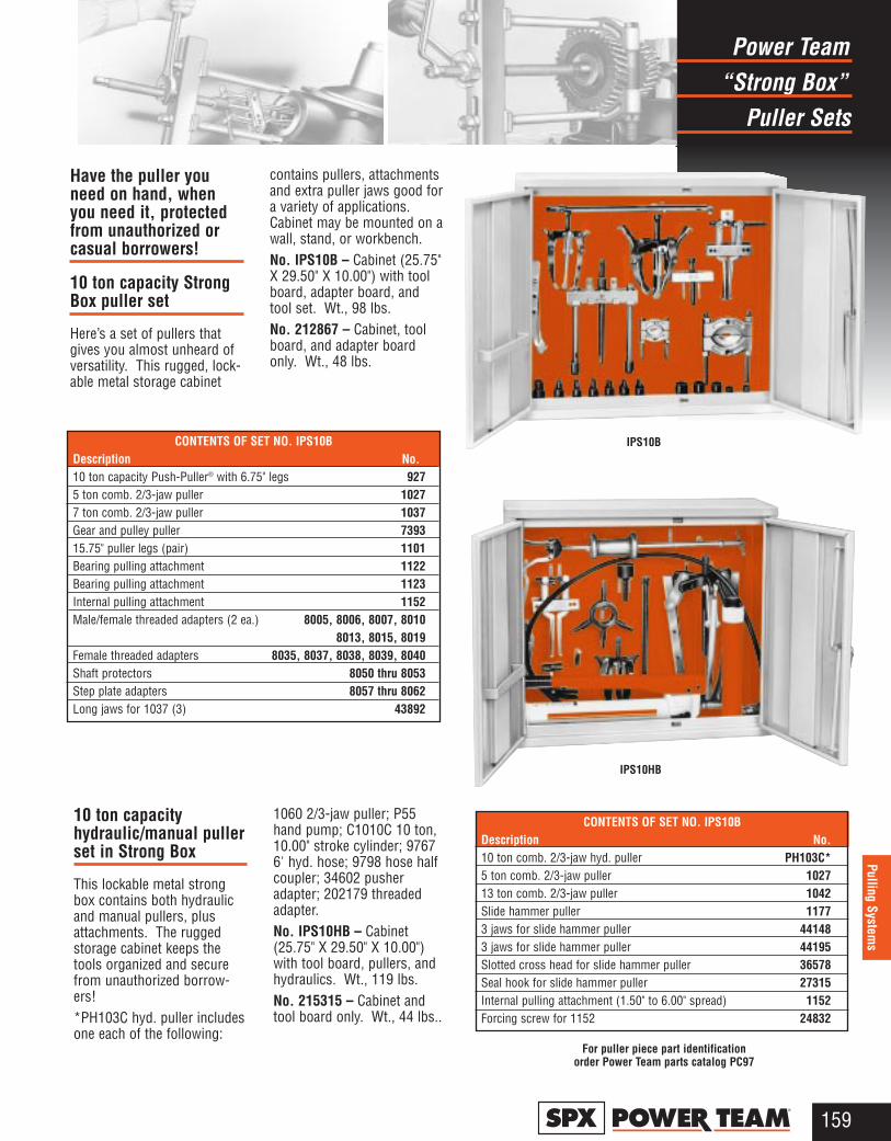
“Strong Box”Power Team
Puller Sets
159®
Pulling Systems
CONTENTS OF SET NO. IPS10BDescription No.10 ton comb. 2/3-jaw hyd. puller PH103C*5 ton comb. 2/3-jaw puller 102713 ton comb. 2/3-jaw puller 1042Slide hammer puller 11773 jaws for slide hammer puller 441483 jaws for slide hammer puller 44195Slotted cross head for slide hammer puller 36578Seal hook for slide hammer puller 27315Internal pulling attachment (1.50" to 6.00" spread) 1152Forcing screw for 1152 24832
CONTENTS OF SET NO. IPS10BDescription No.10 ton capacity Push-Puller® with 6.75" legs 9275 ton comb. 2/3-jaw puller 10277 ton comb. 2/3-jaw puller 1037Gear and pulley puller 739315.75" puller legs (pair) 1101Bearing pulling attachment 1122Bearing pulling attachment 1123Internal pulling attachment 1152Male/female threaded adapters (2 ea.) 8005, 8006, 8007, 8010
8013, 8015, 8019Female threaded adapters 8035, 8037, 8038, 8039, 8040Shaft protectors 8050 thru 8053Step plate adapters 8057 thru 8062Long jaws for 1037 (3) 43892
IPS10HB
For puller piece part identification order Power Team parts catalog PC97
IPS10B
Have the puller youneed on hand, whenyou need it, protectedfrom unauthorized orcasual borrowers!
10 ton capacity StrongBox puller set
Here’s a set of pullers thatgives you almost unheard ofversatility. This rugged, lock-able metal storage cabinet
contains pullers, attachmentsand extra puller jaws good fora variety of applications.Cabinet may be mounted on awall, stand, or workbench.No. IPS10B – Cabinet (25.75"X 29.50" X 10.00") with toolboard, adapter board, andtool set. Wt., 98 lbs.No. 212867 – Cabinet, toolboard, and adapter boardonly. Wt., 48 lbs.
10 ton capacityhydraulic/manual pullerset in Strong Box
This lockable metal strongbox contains both hydraulicand manual pullers, plusattachments. The ruggedstorage cabinet keeps thetools organized and securefrom unauthorized borrow-ers!*PH103C hyd. puller includesone each of the following:
1060 2/3-jaw puller; P55hand pump; C1010C 10 ton,10.00" stroke cylinder; 97676' hyd. hose; 9798 hose halfcoupler; 34602 pusheradapter; 202179 threadedadapter.No. IPS10HB – Cabinet(25.75" X 29.50" X 10.00")with tool board, pullers, andhydraulics. Wt., 119 lbs.No. 215315 – Cabinet andtool board only. Wt., 44 lbs..
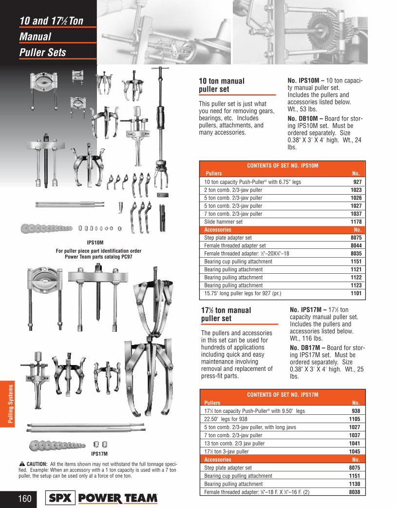
Manual10 and 171⁄2 Ton
Puller Sets
160®
Pulli
ng S
yste
ms
IPS10M
For puller piece part identification order Power Team parts catalog PC97
CONTENTS OF SET NO. IPS10MPullers No.
10 ton capacity Push-Puller® with 6.75” legs 9272 ton comb. 2/3-jaw puller 10235 ton comb. 2/3-jaw puller 10265 ton comb. 2/3-jaw puller 10277 ton comb. 2/3-jaw puller 1037Slide hammer set 1178Accessories No.Step plate adapter set 8075Female threaded adapter set 8044Female threaded adapter: 1⁄2"–20X5⁄8"–18 8035Bearing cup pulling attachment 1151Bearing pulling attachment 1121Bearing pulling attachment 1122Bearing pulling attachment 112315.75" long puller legs for 927 (pr.) 1101
CAUTION: All the items shown may not withstand the full tonnage speci-fied. Example: When an accessory with a 1 ton capacity is used with a 7 tonpuller, the setup can be used only at a force of one ton.
10 ton manualpuller set
This puller set is just whatyou need for removing gears,bearings, etc. Includespullers, attachments, andmany accessories.
No. IPS10M – 10 ton capaci-ty manual puller set.Includes the pullers andaccessories listed below.Wt., 53 lbs. No. DB10M – Board for stor-ing IPS10M set. Must beordered separately. Size0.38" X 3' X 4' high. Wt., 24lbs.
IPS17M
CONTENTS OF SET NO. IPS17MPullers No.171⁄2 ton capacity Push-Puller® with 9.50" legs 93822.50" legs for 938 11055 ton comb. 2/3-jaw puller, with long jaws 10277 ton comb. 2/3-jaw puller 103713 ton comb. 2/3 jaw puller 1041171⁄2 ton 3-jaw puller 1045Accessories No.Step plate adapter set 8075Bearing cup pulling attachment 1151Bearing pulling attachment 1130 Female threaded adapter: 5⁄8"–18 F. X 3⁄4"–16 F. (2) 8038
171⁄2 ton manualpuller set
The pullers and accessoriesin this set can be used forhundreds of applicationsincluding quick and easymaintenance involvingremoval and replacement ofpress-fit parts.
No. IPS17M – 171⁄2 toncapacity manual puller set.Includes the pullers andaccessories listed below.Wt., 116 lbs.No. DB17M – Board for stor-ing IPS17M set. Must beordered separately. Size0.38" X 3' X 4' high. Wt., 25lbs.
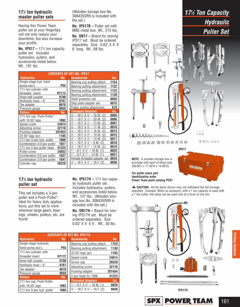
Hydraulic171⁄2 Ton Capacity
Puller Set
161®
Pulling Systems
171⁄2 ton hydraulicpuller set
This set includes a 3-jawpuller and a Push-Puller®.Ideal for heavy duty applica-tions; put this set to workwherever large gears, bear-ings, wheels, pulleys, etc. arefound.
No. IPS17H – 171⁄2 ton capac-ity hydraulic puller set.Includes hydraulics, pullers,and accessories listed below.Wt., 137 lbs. (Wooden stor-age box No. 308435OR9 isincluded with the set.)No. DB17H – Board for stor-ing IPS17H set. Must beordered separately. Size0.63" X 4' X 4'. Wt., 30 lbs.
IPS17
IPS17H
NOTE: A wooden storage box is provided with each of these sets.(36.00"L x 17.50"H x 14.00"D)
For puller piece part identification order Power Team parts catalog PC97
CAUTION: All the items shown may not withstand the full tonnagespecified. Example: When an accessory with a 1 ton capacity is used witha 7 ton puller, the setup can be used only at a force of one ton.
Hydraulics No.Single-stage hyd. hand pump ass’y. P55171⁄2 ton cylinder with threaded insert RT172Hose half coupler 9798Hydraulic hose – 6' 9767Tee adapter 9670Pressure gauge 9059Pullers No.171⁄2 ton cap. Push-Puller®
with 16.50" legs 1062Speed crank 24814Adjusting screw 32118Pushing adapter 20192322.50" legs (pr) 1105171⁄2 ton 3-jaw hyd. puller 1066Combination 2/3-jaw puller 1027171⁄2 ton 2-jaw puller head 41224Puller screw 24832Combination 2/3-jaw puller 1037Combination 2/3-jaw puller 1041Cylinder cap 28228
Accessories No.Bearing cup pulling attach. 1154Bearing pulling attachment 1122Bearing pulling attachment 1123Bearing pulling attachment 1130Shaft protector set 8056Step plate adapter set 8075Pulley pulling attachment 679Threaded Adapters No.5⁄8" – 18 F. X 3⁄8" – 16 M. (2) 80055⁄8" – 18 F. X 1⁄2" – 20 M. (2) 80065⁄8" – 18 F. X 1⁄2" – 13 M. (2) 80075⁄8" – 18 F. X 5⁄8" – 11 M. (2) 80105⁄8" – 18 F. X 3⁄4" – 16 M. (2) 80135⁄8" – 18 F. X 3⁄4" – 10 M. (2) 80155⁄8" – 18 F. X 7⁄8" – 14 M. (2) 80175⁄8" – 18 F. X 7⁄8" – 9 M. (2) 80185⁄8" – 18 F. X 1" – 14 M. (2) 80191" – 8 F. X 5⁄8" – 18 M. (1) 80201" – 8 F. X 1" – 14 M. (1) 8021Female threaded adapter set 80445⁄8" – 18 F. X 3⁄4" – 16 F. (2) 8038
CONTENTS OF SET NO. IPS17
Hydraulics No.Single-stage hydraulic hand pump ass’y. P55171⁄2 ton cylinder with threaded insert RT172Hose half coupler 9798Hydraulic hose – 6' 9767Tee adapter 9670Pressure gauge 9059Pullers No.171⁄2 ton cap. Push-Puller with 16.50" legs 1062171⁄2 ton 3-jaw hyd. puller 1066
Accessories No.Bearing cup pulling attach. 1154Bearing pulling attachment 113022.50" legs (pr) 1105Speed crank 24814Screw cap 28228Adjusting screw 32118Pushing adapter 2014542-jaw head for 1066 41224Threaded Adapters No.1" – 8 F. X 5⁄8" – 18 M. (1) 80205⁄8" – 18 F. X 3⁄4" – 16 F. (2) 8038
CONTENTS OF SET NO. IPS17H
171⁄2 ton hydraulicmaster puller sets
Having this Power Teampuller set at your fingertipswill not only reduce yourdowntime, but also increaseyour profits.No. IPS17 – 171⁄2 ton capacitypuller set. Includeshydraulics, pullers, andaccessories listed below.Wt., 191 lbs.
(Wooden storage box No.308435OR9 is included withthe set.)No. IPS17B – Puller set withMB5 metal box. Wt., 213 lbs.No. DB17 – Board for storingIPS17 set. Must be orderedseparately. Size: 0.63" X 4' X6' long. Wt., 68 lbs.
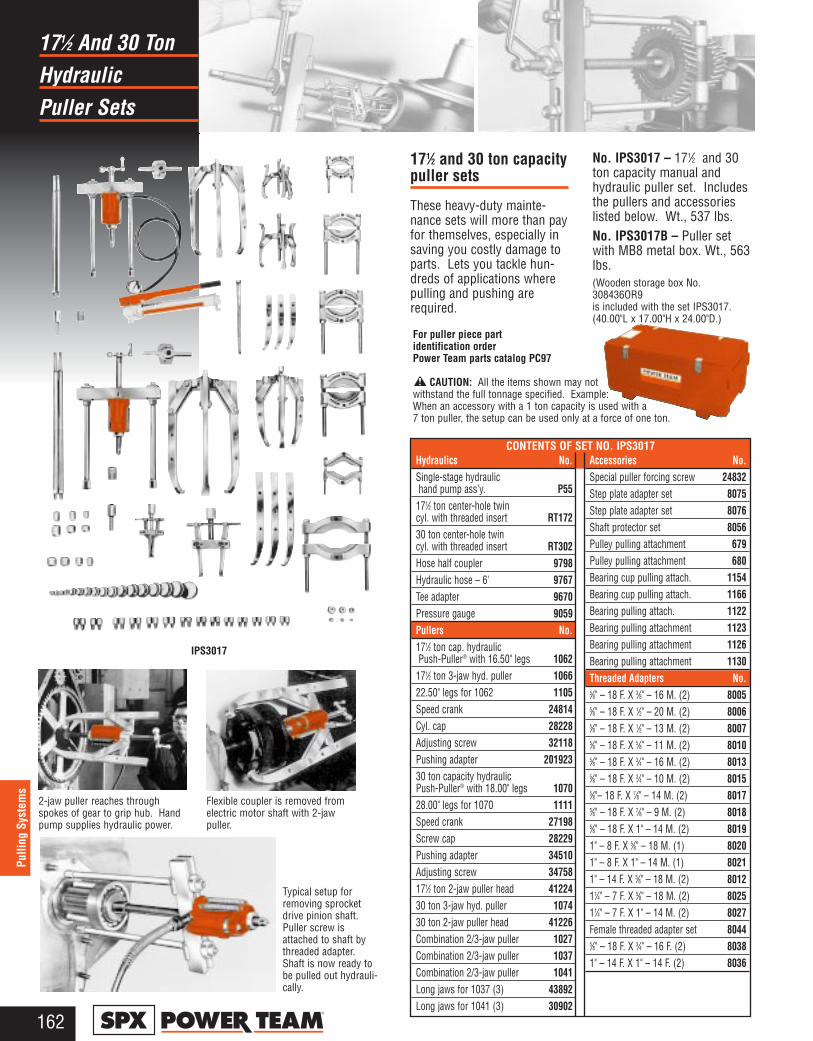
Hydraulic171⁄2 And 30 Ton
Puller Sets
162®
Pulli
ng S
yste
ms
171⁄2 and 30 ton capacitypuller sets
These heavy-duty mainte-nance sets will more than payfor themselves, especially insaving you costly damage toparts. Lets you tackle hun-dreds of applications wherepulling and pushing arerequired.
No. IPS3017 – 171⁄2 and 30ton capacity manual andhydraulic puller set. Includesthe pullers and accessorieslisted below. Wt., 537 lbs.No. IPS3017B – Puller setwith MB8 metal box. Wt., 563lbs.(Wooden storage box No.308436OR9 is included with the set IPS3017. (40.00"L x 17.00"H x 24.00"D.)
2-jaw puller reaches throughspokes of gear to grip hub. Handpump supplies hydraulic power.
Flexible coupler is removed fromelectric motor shaft with 2-jawpuller.
Typical setup forremoving sprocketdrive pinion shaft.Puller screw isattached to shaft bythreaded adapter.Shaft is now ready tobe pulled out hydrauli-cally.
IPS3017
Hydraulics No.Single-stage hydraulichand pump ass’y. P55
171⁄2 ton center-hole twin cyl. with threaded insert RT17230 ton center-hole twincyl. with threaded insert RT302Hose half coupler 9798Hydraulic hose – 6' 9767Tee adapter 9670Pressure gauge 9059Pullers No.171⁄2 ton cap. hydraulicPush-Puller® with 16.50" legs 1062
171⁄2 ton 3-jaw hyd. puller 106622.50" legs for 1062 1105Speed crank 24814Cyl. cap 28228Adjusting screw 32118Pushing adapter 20192330 ton capacity hydraulicPush-Puller® with 18.00" legs 107028.00" legs for 1070 1111Speed crank 27198Screw cap 28229Pushing adapter 34510Adjusting screw 34758171⁄2 ton 2-jaw puller head 4122430 ton 3-jaw hyd. puller 107430 ton 2-jaw puller head 41226Combination 2/3-jaw puller 1027Combination 2/3-jaw puller 1037Combination 2/3-jaw puller 1041Long jaws for 1037 (3) 43892Long jaws for 1041 (3) 30902
Accessories No.Special puller forcing screw 24832Step plate adapter set 8075Step plate adapter set 8076Shaft protector set 8056Pulley pulling attachment 679Pulley pulling attachment 680Bearing cup pulling attach. 1154Bearing cup pulling attach. 1166Bearing pulling attach. 1122 Bearing pulling attachment 1123 Bearing pulling attachment 1126 Bearing pulling attachment 1130Threaded Adapters No.5⁄8" – 18 F. X 3⁄8" – 16 M. (2) 80055⁄8" – 18 F. X 1⁄2" – 20 M. (2) 80065⁄8" – 18 F. X 1⁄2" – 13 M. (2) 80075⁄8" – 18 F. X 5⁄8" – 11 M. (2) 80105⁄8" – 18 F. X 3⁄4" – 16 M. (2) 80135⁄8" – 18 F. X 3⁄4" – 10 M. (2) 80155⁄8"– 18 F. X 7⁄8" – 14 M. (2) 8017 5⁄8" – 18 F. X 7⁄8" – 9 M. (2) 80185⁄8" – 18 F. X 1" – 14 M. (2) 80191" – 8 F. X 5⁄8" – 18 M. (1) 80201" – 8 F. X 1" – 14 M. (1) 80211" – 14 F. X 5⁄8" – 18 M. (2) 801211⁄4" – 7 F. X 5⁄8" – 18 M. (2) 802511⁄4" – 7 F. X 1" – 14 M. (2) 8027Female threaded adapter set 80445⁄8" – 18 F. X 3⁄4" – 16 F. (2) 80381" – 14 F. X 1" – 14 F. (2) 8036
CONTENTS OF SET NO. IPS3017
For puller piece part identification order Power Team parts catalog PC97
CAUTION: All the items shown may not withstand the full tonnage specified. Example: When an accessory with a 1 ton capacity is used with a7 ton puller, the setup can be used only at a force of one ton.
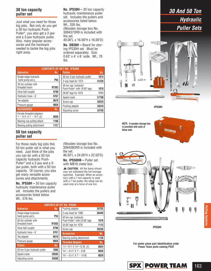
Hydraulic30 And 50 Ton
Puller Sets
163®
Pulling Systems
IPS30H
30 ton capacitypuller set
Just what you need for thosebig jobs. Not only do you geta 30 ton hydraulic Push-Puller®, you also get a 2-jawand a 3-jaw hydraulic puller.Also, many popular acces-sories and the hardwareneeded to tackle the big jobsright away.
No. IPS30H – 30 ton capacityhydraulic maintenance pullerset. Includes the pullers andaccessories listed below.Wt., 330 lbs. (Wooden storage box No.308437OR9 is included withthe set. 40.00"L x 16.00"H x 16.00"D)No. DB30H – Board for stor-ing IPS30H set. Must beordered separately. Size:0.63" x 4' x 6' wide. Wt., 78lbs.
50 ton capacitypuller set
For those really big jobs this50 ton puller set is what youneed. Just think of the jobsyou can do with a 50 toncapacity hydraulic Push-Puller® and a 2-jaw and a 3-jaw puller, both with a 50 toncapacity. Of course, you alsoget many versatile acces-sories and attachments.No. IPS50H – 50 ton capacityhydraulic maintenance pullerset. Includes the pullers andaccessories listed below.Wt., 576 lbs.
(Wooden storage box No.308438OR9 is included withthe set.46.50"L x 24.00"H x 22.50"D)No. IPS50HB – Puller setwith MB16 metal box.
CAUTION: All the items shownmay not withstand the full tonnagespecified. Example: When an acces-sory with a 1 ton capacity is usedwith a 7 ton puller, the setup can beused only at a force of one ton.
NOTE: A wooden storage boxis provided with each ofthese sets.
IPS50H
For puller piece part identification order Power Team parts catalog PC97
Hydraulics No.Single-stage hydraulichand pump ass’y. P55
30 ton cylinder with threaded insert RT302Hose half coupler 9798Hydraulic hose – 6' 9767Tee adapter 9670Pressure gauge 9059ACCESSORIES No.Female threaded adapters 1" – 14 F. X 1" – 14 F. (2) 8036Bearing cup pulling attach. 1166Bearing pulling attachment 1127
Pullers No.30 ton 3-jaw hydraulic puller 10742-way head for 1074 4122630 ton cap. hydraulic Push-Puller® with 18.00" legs 107028.00" legs for 1070 1111Speed crank 27198Screw cap 28229Pushing adapter 34510Adjusting screw 34758
CONTENTS OF SET NO. IPS30H
Hydraulics No.Single-stage hydraulichand pump ass’y. P5550 ton cylinder with threaded insert RT503Hose half coupler 9798Hydraulic hose – 6' 9767Tee adapter 9670Pressure gauge 9059Pullers No.50 ton 3-jaw hydraulic puller 1080Speed crank 29595Adjusting screw 32698
Pushing adapter 347552-way head for 1080 5044950 ton cap. hydraulic Push-Puller® with 24.00" legs 107634.00" legs for 1076 1113Screw cap 28230Accessories No.Bearing pulling attachment 1128Threaded Adapters No.11⁄4"–12 F. X 13⁄4"–12 M. (2) 802415⁄8" – 51⁄2 F. X 1" – 8 M. 8028 15⁄8" – 51⁄2 F. X 1" – 14 M. 8029
CONTENTS OF SET NO. IPS50H
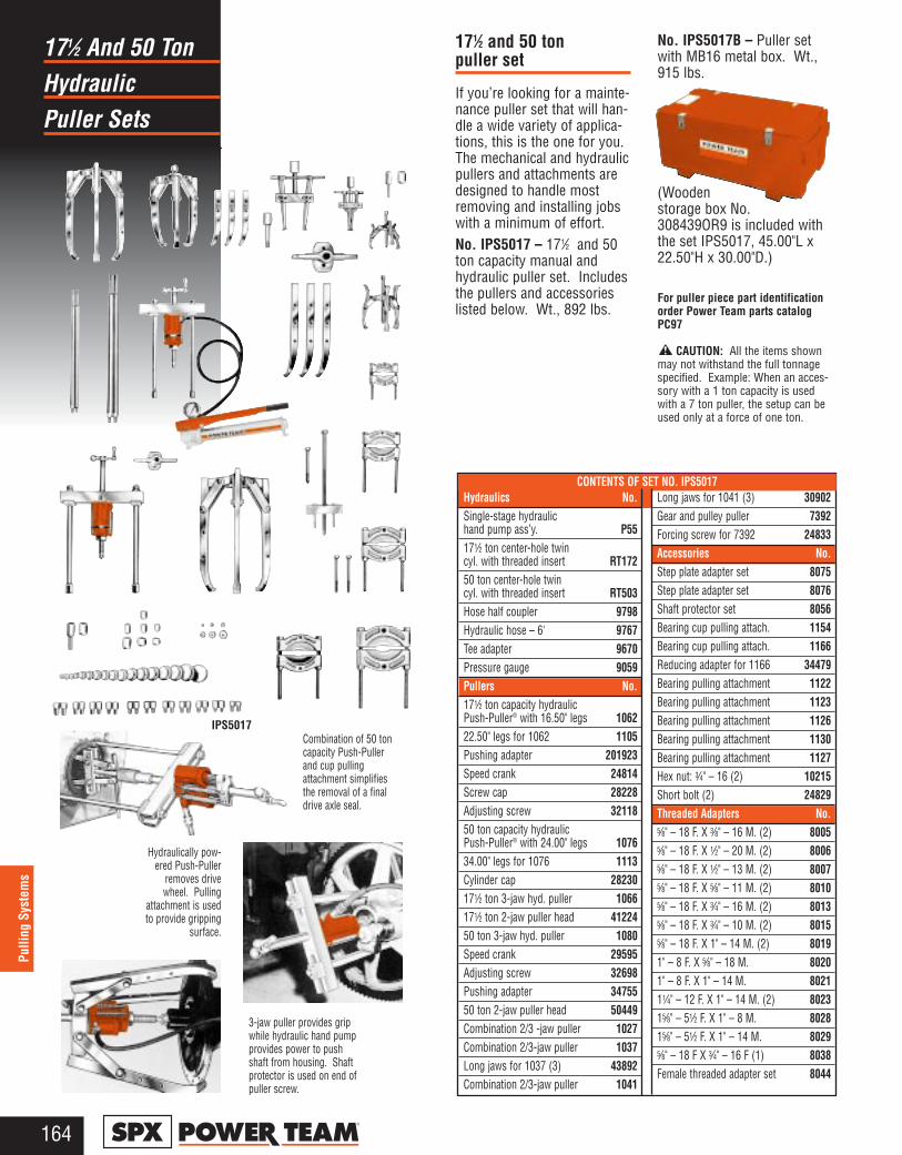
Hydraulics No.Single-stage hydraulichand pump ass’y. P55171⁄2 ton center-hole twin cyl. with threaded insert RT17250 ton center-hole twin cyl. with threaded insert RT503Hose half coupler 9798Hydraulic hose – 6' 9767Tee adapter 9670Pressure gauge 9059Pullers No.171⁄2 ton capacity hydraulic Push-Puller® with 16.50" legs 106222.50" legs for 1062 1105Pushing adapter 201923Speed crank 24814Screw cap 28228Adjusting screw 3211850 ton capacity hydraulic Push-Puller® with 24.00" legs 107634.00" legs for 1076 1113Cylinder cap 28230171⁄2 ton 3-jaw hyd. puller 1066171⁄2 ton 2-jaw puller head 41224 50 ton 3-jaw hyd. puller 1080Speed crank 29595Adjusting screw 32698Pushing adapter 3475550 ton 2-jaw puller head 50449Combination 2/3 -jaw puller 1027Combination 2/3-jaw puller 1037Long jaws for 1037 (3) 43892Combination 2/3-jaw puller 1041
Long jaws for 1041 (3) 30902Gear and pulley puller 7392Forcing screw for 7392 24833Accessories No.Step plate adapter set 8075Step plate adapter set 8076Shaft protector set 8056Bearing cup pulling attach. 1154Bearing cup pulling attach. 1166Reducing adapter for 1166 34479Bearing pulling attachment 1122 Bearing pulling attachment 1123 Bearing pulling attachment 1126 Bearing pulling attachment 1130Bearing pulling attachment 1127Hex nut: 3⁄4" – 16 (2) 10215 Short bolt (2) 24829Threaded Adapters No.5⁄8" – 18 F. X 3⁄8" – 16 M. (2) 80055⁄8" – 18 F. X 1⁄2" – 20 M. (2) 80065⁄8" – 18 F. X 1⁄2" – 13 M. (2) 80075⁄8" – 18 F. X 5⁄8" – 11 M. (2) 80105⁄8" – 18 F. X 3⁄4" – 16 M. (2) 80135⁄8" – 18 F. X 3⁄4" – 10 M. (2) 80155⁄8" – 18 F. X 1" – 14 M. (2) 80191" – 8 F. X 5⁄8" – 18 M. 80201" – 8 F. X 1" – 14 M. 802111⁄4" – 12 F. X 1" – 14 M. (2) 802315⁄8" – 51⁄2 F. X 1" – 8 M. 802815⁄8" – 51⁄2 F. X 1" – 14 M. 80295⁄8" – 18 F X 3⁄4" – 16 F (1) 8038Female threaded adapter set 8044
Hydraulic171⁄2 And 50 Ton
Puller Sets
164®
Pulli
ng S
yste
ms
171⁄2 and 50 tonpuller set
If you’re looking for a mainte-nance puller set that will han-dle a wide variety of applica-tions, this is the one for you.The mechanical and hydraulicpullers and attachments aredesigned to handle mostremoving and installing jobswith a minimum of effort.No. IPS5017 – 171⁄2 and 50ton capacity manual andhydraulic puller set. Includesthe pullers and accessorieslisted below. Wt., 892 lbs.
No. IPS5017B – Puller setwith MB16 metal box. Wt.,915 lbs.
(Woodenstorage box No.308439OR9 is included withthe set IPS5017, 45.00"L x22.50"H x 30.00"D.)
For puller piece part identification order Power Team parts catalogPC97
CAUTION: All the items shownmay not withstand the full tonnagespecified. Example: When an acces-sory with a 1 ton capacity is usedwith a 7 ton puller, the setup can beused only at a force of one ton.
IPS5017
Hydraulically pow-ered Push-Puller
removes drivewheel. Pulling
attachment is usedto provide gripping
surface.
Combination of 50 toncapacity Push-Pullerand cup pullingattachment simplifiesthe removal of a finaldrive axle seal.
3-jaw puller provides gripwhile hydraulic hand pumpprovides power to pushshaft from housing. Shaftprotector is used on end ofpuller screw.
CONTENTS OF SET NO. IPS5017
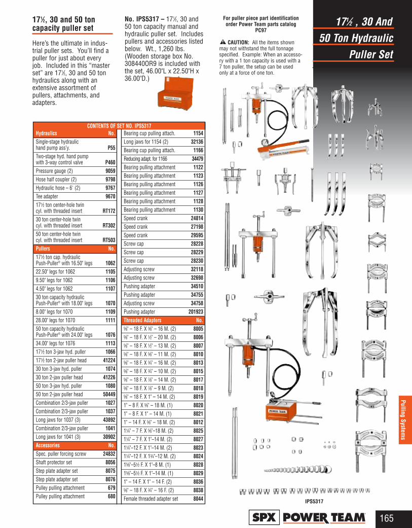
50 Ton Hydraulic171⁄2 , 30 And
Puller Set
165®
Pulling Systems
171⁄2, 30 and 50 toncapacity puller set
Here’s the ultimate in indus-trial puller sets. You’ll find apuller for just about everyjob. Included in this “masterset” are 171⁄2, 30 and 50 tonhydraulics along with anextensive assortment ofpullers, attachments, andadapters.
No. IPS5317 – 171⁄2, 30 and50 ton capacity manual andhydraulic puller set. Includespullers and accessories listedbelow. Wt., 1,260 lbs.(Wooden storage box No.308440OR9 is included withthe set, 46.00"L x 22.50"H x36.00"D.)
IPS5317
Hydraulics No.Single-stage hydraulic hand pump ass’y. P55Two-stage hyd. hand pumpwith 3-way control valve P460Pressure gauge (2) 9059Hose half coupler (2) 9798Hydraulic hose – 6' (2) 9767Tee adapter 9670171⁄2 ton center-hole twin cyl. with threaded insert RT17230 ton center-hole twin cyl. with threaded insert RT30250 ton center-hole twin cyl. with threaded insert RT503Pullers No.171⁄2 ton cap. hydraulic Push-Puller® with 16.50" legs 106222.50" legs for 1062 11059.50" legs for 1062 11064.50" legs for 1062 110730 ton capacity hydraulic Push-Puller® with 18.00" legs 10708.00" legs for 1070 110928.00" legs for 1070 111150 ton capacity hydraulicPush-Puller® with 24.00" legs 107634.00" legs for 1076 1113171⁄2 ton 3-jaw hyd. puller 1066171⁄2 ton 2-jaw puller head 4122430 ton 3-jaw hyd. puller 107430 ton 2-jaw puller head 4122650 ton 3-jaw hyd. puller 108050 ton 2-jaw puller head 50449Combination 2/3-jaw puller 1027Combination 2/3-jaw puller 1037Long jaws for 1037 (3) 43892Combination 2/3-jaw puller 1041Long jaws for 1041 (3) 30902Accessories No.Spec. puller forcing screw 24832Shaft protector set 8056Step plate adapter set 8075Step plate adapter set 8076Pulley pulling attachment 679Pulley pulling attachment 680
Bearing cup pulling attach. 1154Long jaws for 1154 (2) 32136Bearing cup pulling attach. 1166 Reducing adapt. for 1166 34479Bearing pulling attachment 1122 Bearing pulling attachment 1123 Bearing pulling attachment 1126 Bearing pulling attachment 1127Bearing pulling attachment 1128Bearing pulling attachment 1130Speed crank 24814Speed crank 27198Speed crank 29595Screw cap 28228Screw cap 28229Screw cap 28230Adjusting screw 32118Adjusting screw 32698Pushing adapter 34510Pushing adapter 34755Adjusting screw 34758Pushing adapter 201923Threaded Adapters No.5⁄8" – 18 F. X 3⁄8" – 16 M. (2) 80055⁄8" – 18 F. X 1⁄2" – 20 M. (2) 80065⁄8" – 18 F. X 1⁄2" – 13 M. (2) 80075⁄8" – 18 F. X 5⁄8" – 11 M. (2) 80105⁄8" – 18 F. X 3⁄4" – 16 M. (2) 80135⁄8" – 18 F. X 3⁄4" – 10 M. (2) 80155⁄8" – 18 F. X 7⁄8" – 14 M. (2) 80175⁄8" – 18 F. X 7⁄8" – 9 M. (2) 80185⁄8" – 18 F. X 1" – 14 M. (2) 80191" – 8 F. X 5⁄8" – 18 M. (1) 80201" – 8 F. X 1" – 14 M. (1) 80211" – 14 F. X 5⁄8" – 18 M. (2) 801211⁄4" – 7 F. X 5⁄8"–18 M. (2) 802511⁄4" – 7 F. X 1"–14 M. (2) 802711⁄4"–12 F. X 1"–14 M. (2) 802311⁄4"–12 F. X 13⁄4"–12 M. (2) 802415⁄8"–51⁄2 F. X 1"–8 M. (1) 802815⁄8"–51⁄2 F. X 1"–14 M. (1) 80291" – 14 F. X 1" – 14 F. (2) 80365⁄8" – 18 F. X 3⁄4" – 16 F. (2) 8038Female threaded adapter set 8044
CONTENTS OF SET NO. IPS5317
For puller piece part identification order Power Team parts catalog
PC97
CAUTION: All the items shownmay not withstand the full tonnagespecified. Example: When an accesso-ry with a 1 ton capacity is used with a7 ton puller, the setup can be usedonly at a force of one ton.
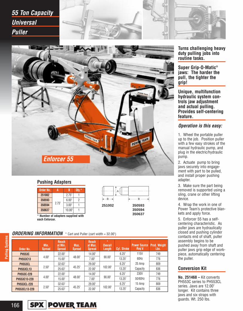
Universal55 Ton Capacity
Puller
166®
Pulli
ng S
yste
ms
Min.Spread
4.00"
2.50"
4.00"
2.50"
Reach at Min.Spread22.00"15.00"32.63"25.63"22.00"15.00"32.63"25.63"
Max.Spread
48.00"
45.25"
48.00"
45.25"
Reachat Max.Spread14.00"7.00"29.00"22.00"14.00"7.00"29.00"22.00"
*OverallLength
90.00"
102.00"
90.00"
102.00"
Cyl. Stroke6.25"13.25"6.25"13.25"6.25"13.25"6.25"13.25"
Power Source Req’d115V60Hz
25 AmpCapacity
230V50/60Hz15 AmpCapacity
Order No.PH553C
PH553C13PH553CL
PH553CL13PH553C-220
PH553C13-220PH553CL-220
PH553CL13-220
Order No. A B Qty.*251002 2.75" 1350593
2.75"6.00" 2
350594 3.00" 1350637 10.00" 1
Pushing Adapters
ORDERING INFORMATION * Cart and Puller (cart width = 32.00")
* Number of adapters supplied witheach Enforcer.
BB
A
251002 350593350594350637
Turns challenging heavyduty pulling jobs intoroutine tasks.
Super Grip-O-Matic®
jaws: The harder thepull, the tighter thegrip!
Unique, multifunctionhydraulic system con-trols jaw adjustmentand actual pulling.Provides self-centeringfeature.
Operation is this easy:
1. Wheel the portable pullerup to the job. Position pullerwith a few easy strokes of themanual hydraulic pump, andplug in the electric/hydraulicpump.2. Actuate pump to bringjaws securely into engage-ment with part to be pulled,and install proper pushingadapter.3. Make sure the part beingremoved is supported using asling, crane or other liftingdevice.4. Wrap the work in one ofPower Team’s protective blan-kets and apply force.5. Enforcer 55 has a self-centering characteristic. Aspuller jaws are hydraulicallyclosed and pushing cylindercontacts end of shaft, pullerassembly begins to bepushed away from shaft andpuller jaws grip edge of work-piece, automatically centeringthe puller.
Conversion Kit
No. 251468 – Kit convertsPH553C series to PH553CLseries. Jaws are 12.00"longer. Kit contains threejaws and six straps withguards. Wt. 250 lbs.
Enforcer 55
2.75"
Prod. WeightLbs.749776809836749776809836
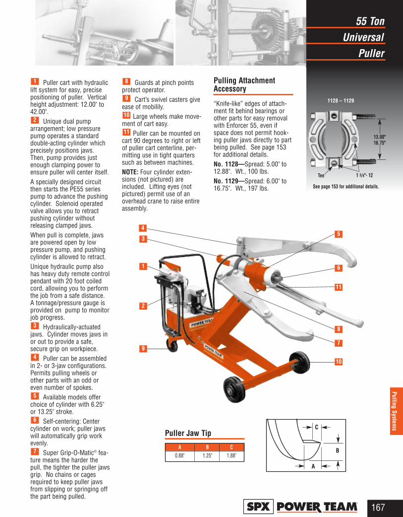
Universal55 Ton
Puller
167®
Pulling Systems
Puller cart with hydrauliclift system for easy, precisepositioning of puller. Verticalheight adjustment: 12.00" to42.00".
Unique dual pumparrangement; low pressurepump operates a standarddouble-acting cylinder whichprecisely positions jaws.Then, pump provides justenough clamping power toensure puller will center itself. A specially designed circuitthen starts the PE55 seriespump to advance the pushingcylinder. Solenoid operatedvalve allows you to retractpushing cylinder withoutreleasing clamped jaws.When pull is complete, jawsare powered open by lowpressure pump, and pushingcylinder is allowed to retract.Unique hydraulic pump alsohas heavy duty remote controlpendant with 20 foot coiledcord, allowing you to performthe job from a safe distance.A tonnage/pressure gauge isprovided on pump to monitorjob progress.
Hydraulically-actuatedjaws. Cylinder moves jaws inor out to provide a safe,secure grip on workpiece.
Puller can be assembledin 2- or 3-jaw configurations.Permits pulling wheels orother parts with an odd oreven number of spokes.
Available models offerchoice of cylinder with 6.25"or 13.25" stroke.
Self-centering: Centercylinder on work; puller jawswill automatically grip workevenly.
Super Grip-O-Matic® fea-ture means the harder thepull, the tighter the puller jawsgrip. No chains or cagesrequired to keep puller jawsfrom slipping or springing offthe part being pulled.
Guards at pinch pointsprotect operator.
Cart’s swivel casters giveease of mobilily.
Large wheels make move-ment of cart easy.
Puller can be mounted oncart 90 degrees to right or leftof puller cart centerline, per-mitting use in tight quarterssuch as between machines.NOTE: Four cylinder exten-sions (not pictured) areincluded. Lifting eyes (notpictured) permit use of anoverhead crane to raise entireassembly.
Pulling AttachmentAccessory
“Knife-like” edges of attach-ment fit behind bearings orother parts for easy removalwith Enforcer 55, even ifspace does not permit hook-ing puller jaws directly to partbeing pulled. See page 153for additional details.No. 1128—Spread: 5.00" to12.88". Wt., 100 lbs.No. 1129—Spread: 6.00" to16.75". Wt., 197 lbs.
11
10
9
8
7
6
5
4
3
2
1
1128 – 1129
1 3/4"- 12
13.00" 16.75"
Tee
See page 153 for additional details.
9
2
1
3
45
6
11
8
7
10
A B C0.88" 1.25" 1.88"
Puller Jaw TipC
A
B
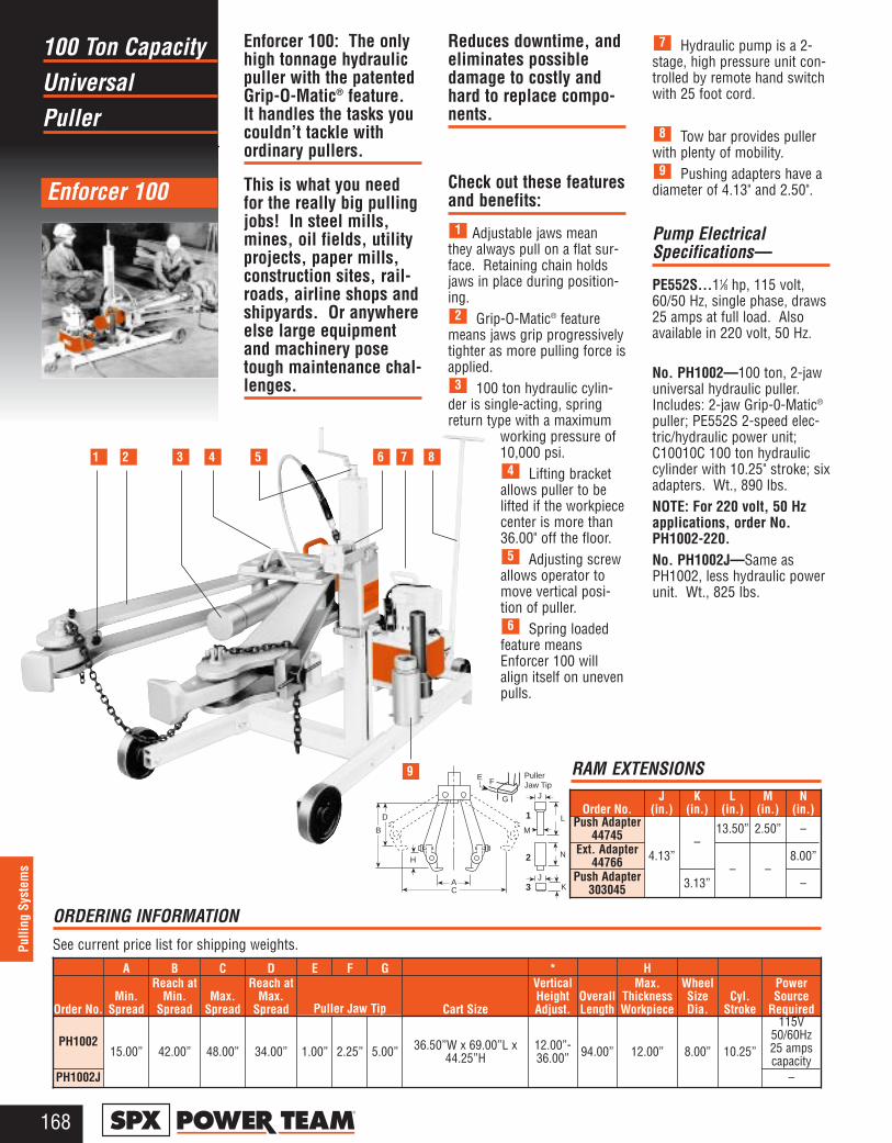
Universal100 Ton Capacity
Puller
168®
Pulli
ng S
yste
ms
M
1
2
3AC
H
D
B
KJ
L
N
J
PullerJaw TipF
G
E
1 2 3 4 5 6 7 8
9
Order No.J
(in.)K
(in.)L
(in.)M
(in.)N
(in.)Push Adapter
44745 –13.50” 2.50” –
Ext. Adapter44766 4.13”
– –8.00”
Push Adapter303045 3.13” –
Enforcer 100
RAM EXTENSIONS
ORDERING INFORMATIONSee current price list for shipping weights.
A B C D E F G * H
Order No.Min.
Spread
Reach atMin.
SpreadMax.
Spread
Reach atMax.
Spread Puller Jaw Tip Cart Size
VerticalHeightAdjust.
OverallLength
Max.ThicknessWorkpiece
WheelSizeDia.
Cyl.Stroke
PowerSource
Required
PH100215.00” 42.00” 48.00” 34.00” 1.00” 2.25” 5.00” 36.50”W x 69.00”L x
44.25”H12.00”-36.00” 94.00” 12.00” 8.00” 10.25”
115V50/60Hz25 ampscapacity
PH1002J –
Enforcer 100: The onlyhigh tonnage hydraulicpuller with the patentedGrip-O-Matic® feature.It handles the tasks youcouldn’t tackle withordinary pullers.
This is what you needfor the really big pullingjobs! In steel mills,mines, oil fields, utilityprojects, paper mills,construction sites, rail-roads, airline shops andshipyards. Or anywhereelse large equipmentand machinery posetough maintenance chal-lenges.
Reduces downtime, andeliminates possibledamage to costly andhard to replace compo-nents.
Check out these featuresand benefits:
Adjustable jaws meanthey always pull on a flat sur-face. Retaining chain holdsjaws in place during position-ing.
Grip-O-Matic® featuremeans jaws grip progressivelytighter as more pulling force isapplied.
100 ton hydraulic cylin-der is single-acting, springreturn type with a maximum
working pressure of 10,000 psi.
Lifting bracketallows puller to belifted if the workpiececenter is more than36.00" off the floor.
Adjusting screwallows operator tomove vertical posi-tion of puller.
Spring loadedfeature meansEnforcer 100 willalign itself on unevenpulls.
Hydraulic pump is a 2-stage, high pressure unit con-trolled by remote hand switchwith 25 foot cord.
Tow bar provides pullerwith plenty of mobility.
Pushing adapters have adiameter of 4.13" and 2.50".
Pump ElectricalSpecifications—
PE552S...11⁄8 hp, 115 volt,60/50 Hz, single phase, draws25 amps at full load. Alsoavailable in 220 volt, 50 Hz.
No. PH1002—100 ton, 2-jawuniversal hydraulic puller.Includes: 2-jaw Grip-0-Matic®
puller; PE552S 2-speed elec-tric/hydraulic power unit;C10010C 100 ton hydrauliccylinder with 10.25" stroke; sixadapters. Wt., 890 lbs.NOTE: For 220 volt, 50 Hzapplications, order No.PH1002-220.No. PH1002J—Same asPH1002, less hydraulic powerunit. Wt., 825 lbs.
9
8
7
6
5
4
3
2
1
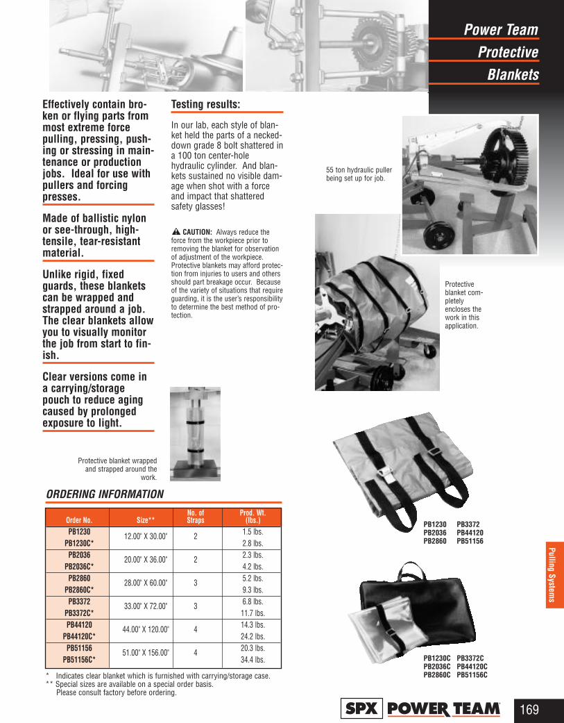
Effectively contain bro-ken or flying parts frommost extreme forcepulling, pressing, push-ing or stressing in main-tenance or productionjobs. Ideal for use withpullers and forcingpresses.
Made of ballistic nylonor see-through, high-tensile, tear-resistantmaterial.
Unlike rigid, fixedguards, these blanketscan be wrapped andstrapped around a job.The clear blankets allowyou to visually monitorthe job from start to fin-ish.
Clear versions come ina carrying/storagepouch to reduce agingcaused by prolongedexposure to light.
Testing results:
In our lab, each style of blan-ket held the parts of a necked-down grade 8 bolt shattered ina 100 ton center-holehydraulic cylinder. And blan-kets sustained no visible dam-age when shot with a forceand impact that shatteredsafety glasses!
CAUTION: Always reduce theforce from the workpiece prior toremoving the blanket for observationof adjustment of the workpiece.Protective blankets may afford protec-tion from injuries to users and othersshould part breakage occur. Becauseof the variety of situations that requireguarding, it is the user’s responsibilityto determine the best method of pro-tection.
ProtectivePower Team
Blankets
169®
Pulling Systems
Protective blanket wrappedand strapped around the
work.
PB1230 PB3372PB2036 PB44120PB2860 PB51156
PB1230C PB3372CPB2036C PB44120CPB2860C PB51156C
55 ton hydraulic pullerbeing set up for job.
Protectiveblanket com-pletelyencloses thework in thisapplication.
ORDERING INFORMATIONNo. of Prod. Wt.
Order No. Size** Straps (lbs.)PB1230 12.00" X 30.00" 2 1.5 lbs.
PB1230C* 2.8 lbs.PB2036 20.00" X 36.00" 2 2.3 lbs.
PB2036C* 4.2 lbs.PB2860 28.00" X 60.00" 3 5.2 lbs.
PB2860C* 9.3 lbs.PB3372 33.00" X 72.00" 3 6.8 lbs.
PB3372C* 11.7 lbs.PB44120 44.00" X 120.00" 4 14.3 lbs.
PB44120C* 24.2 lbs.PB51156 51.00" X 156.00" 4 20.3 lbs.
PB51156C* 34.4 lbs.
* Indicates clear blanket which is furnished with carrying/storage case.** Special sizes are available on a special order basis.
Please consult factory before ordering.
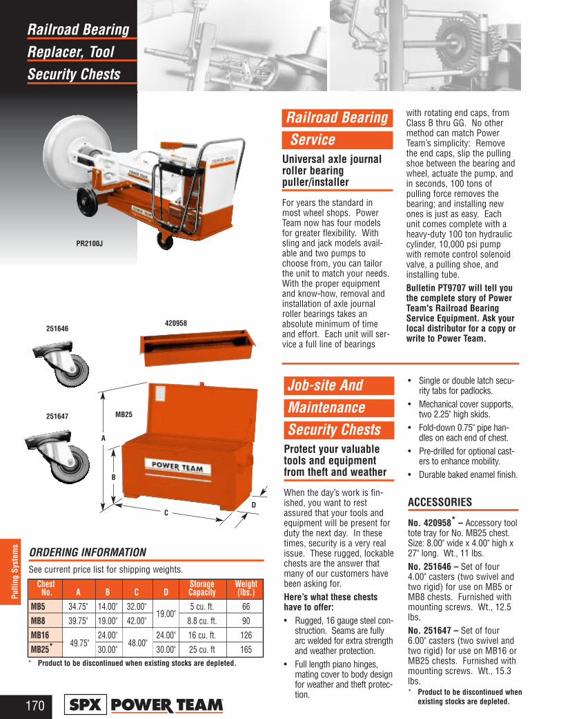
Replacer, ToolRailroad Bearing
Security Chests
170®
Pulli
ng S
yste
ms
Railroad BearingService
Universal axle journalroller bearingpuller/installer
For years the standard inmost wheel shops. PowerTeam now has four modelsfor greater flexibility. Withsling and jack models avail-able and two pumps tochoose from, you can tailorthe unit to match your needs.With the proper equipmentand know-how, removal andinstallation of axle journalroller bearings takes anabsolute minimum of timeand effort. Each unit will ser-vice a full line of bearings
with rotating end caps, fromClass B thru GG. No othermethod can match PowerTeam’s simplicity: Removethe end caps, slip the pullingshoe between the bearing andwheel, actuate the pump, andin seconds, 100 tons ofpulling force removes thebearing; and installing newones is just as easy. Eachunit comes complete with aheavy-duty 100 ton hydrauliccylinder, 10,000 psi pumpwith remote control solenoidvalve, a pulling shoe, andinstalling tube.Bulletin PT9707 will tell youthe complete story of PowerTeam's Railroad BearingService Equipment. Ask yourlocal distributor for a copy orwrite to Power Team.
Job-site And MaintenanceSecurity Chests
Protect your valuabletools and equipmentfrom theft and weather
When the day’s work is fin-ished, you want to restassured that your tools andequipment will be present forduty the next day. In thesetimes, security is a very realissue. These rugged, lockablechests are the answer thatmany of our customers havebeen asking for.Here’s what these chestshave to offer:• Rugged, 16 gauge steel con-
struction. Seams are fullyarc welded for extra strengthand weather protection.
• Full length piano hinges,mating cover to body designfor weather and theft protec-tion.
• Single or double latch secu-rity tabs for padlocks.
• Mechanical cover supports,two 2.25" high skids.
• Fold-down 0.75" pipe han-dles on each end of chest.
• Pre-drilled for optional cast-ers to enhance mobility.
• Durable baked enamel finish.
ACCESSORIES
No. 420958* – Accessory tooltote tray for No. MB25 chest.Size: 8.00" wide x 4.00" high x27" long. Wt., 11 lbs.No. 251646 – Set of four4.00" casters (two swivel andtwo rigid) for use on MB5 orMB8 chests. Furnished withmounting screws. Wt., 12.5lbs.No. 251647 – Set of four6.00" casters (two swivel andtwo rigid) for use on MB16 orMB25 chests. Furnished withmounting screws. Wt., 15.3lbs.
Chest Storage WeightNo. A B C D Capacity (lbs.)
MB5 34.75" 14.00" 32.00" 19.00" 5 cu. ft. 66
MB8 39.75" 19.00" 42.00" 8.8 cu. ft. 90
MB16 49.75" 24.00" 48.00" 24.00" 16 cu. ft. 126
MB25* 30.00" 30.00" 25 cu. ft 165
PR2100J
MB25
420958251646
251647
A
B
CD
ORDERING INFORMATIONSee current price list for shipping weights.
49.75" 48.00"
19.00"
* Product to be discontinued when existing stocks are depleted.
* Product to be discontinued whenexisting stocks are depleted.
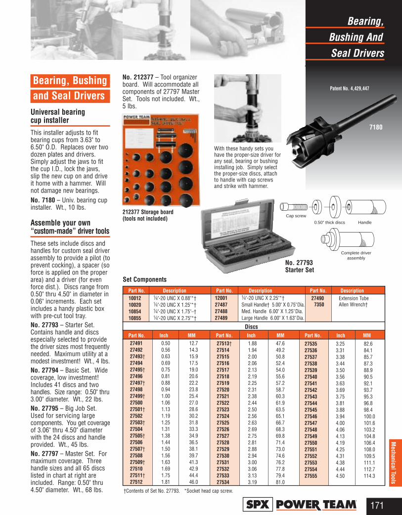
Bushing AndBearing,
Seal Drivers
171®
Mechanical Tools
Bearing, Bushingand Seal Drivers
Universal bearing cup installerThis installer adjusts to fitbearing cups from 3.63" to6.50" O.D. Replaces over twodozen plates and drivers.Simply adjust the jaws to fitthe cup I.D., lock the jaws,slip the new cup on and driveit home with a hammer. Willnot damage new bearings.No. 7180 – Univ. bearing cupinstaller. Wt., 10 lbs.
Assemble your own “custom-made” driver toolsThese sets include discs andhandles for custom seal driverassembly to provide a pilot (toprevent cocking), a spacer (soforce is applied on the properarea) and a driver (for evenforce dist.). Discs range from0.50" thru 4.50" in diameter in0.06" increments. Each setincludes a handy plastic boxwith pre-cut tool tray.No. 27793 – Starter Set.Contains handle and discsespecially selected to providethe driver sizes most frequentlyneeded. Maximum utility at amodest investment! Wt., 4 lbs.No. 27794 – Basic Set. Widecoverage, low investment!Includes 41 discs and twohandles. Size range: 0.50" thru3.00" diameter. Wt., 22 lbs.No. 27795 – Big Job Set.Used for servicing largecomponents. You get coverageof 3.06" thru 4.50" diameterwith the 24 discs and handleprovided. Wt., 45 lbs.No. 27797 – Master Set. Formaximum coverage. Threehandle sizes and all 65 discslisted in chart at right areincluded. Range: 0.50" thru4.50" diameter. Wt., 68 lbs.
No. 212377 – Tool organizerboard. Will accommodate allcomponents of 27797 MasterSet. Tools not included. Wt.,5 lbs.
†Contents of Set No. 27793. *Socket head cap screw.
27513† 1.88 47.627514 1.94 49.227515 2.00 50.827516 2.06 52.427517 2.13 54.027518 2.19 55.627519 2.25 57.227520 2.31 58.727521 2.38 60.327522 2.44 61.927523 2.50 63.527524 2.56 65.127525 2.63 66.727526 2.69 68.327527 2.75 69.827528 2.81 71.427529 2.88 73.027530 2.94 74.627531 3.00 76.227532 3.06 77.827533 3.13 79.427534 3.19 81.0
Part No. Inch MM Part No. Inch MM
10012 1⁄4"-20 UNC X 0.88"*†10020 1⁄4"-20 UNC X 1.25"*†10854 1⁄4"-20 UNC X 1.75"–†10855 1⁄4"-20 UNC X 2.75"*†
Part No. Description Part No. Description Part No. Description
Discs
Set Components
With these handy sets youhave the proper-size driver forany seal, bearing or bushinginstalling job. Simply selectthe proper-size discs, attachto handle with cap screwsand strike with hammer.
212377 Storage board (tools not included)
Part No. Inch MM Part No. Inch MM Part No. Inch MM27491 0.50 12.727492 0.56 14.327493† 0.63 15.927494 0.69 17.527495† 0.75 19.027496 0.81 20.627497† 0.88 22.227498 0.94 23.827499† 1.00 25.427500 1.06 27.027501† 1.13 28.627502 1.19 30.227503† 1.25 31.827504 1.31 33.327505† 1.38 34.927506 1.44 36.527507† 1.50 38.127508 1.56 39.727509† 1.63 41.327510 1.69 42.927511† 1.75 44.427512 1.81 46.0
27535 3.25 82.627536 3.31 84.127537 3.38 85.727538 3.44 87.327539 3.50 88.927540 3.56 90.527541 3.63 92.127542 3.69 93.727543 3.75 95.327544 3.81 96.827545 3.88 98.427546 3.94 100.027547 4.00 101.627548 4.06 103.227549 4.13 104.827550 4.19 106.427551 4.25 108.027552 4.31 109.527553 4.38 111.127554 4.44 112.727555 4.50 114.3
Patent No. 4,429,447
Cap screw
0.50" thick discs Handle
Complete driverassembly
12001 1⁄4"-20 UNC X 2.25"*†27487 Small Handle† 5.00" X 0.75"Dia.27488 Med. Handle 6.00" X 1.25"Dia.27489 Large Handle 6.00" X 1.63"Dia.
27490 Extension Tube7350 Allen Wrench†
No. 27793 Starter Set
7180
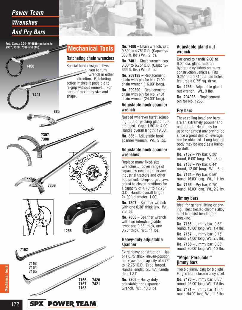
WrenchesPower Team
And Pry Bars
172®
Mec
hani
cal T
ools
Fed. Spec.: GGG- W-665b (pertains to7307, 7308, 7309 and 885). Mechanical Tools
Ratcheting chain wrenchesSpecial head design allows
you to turnwrench in either
direction. Ratchetingaction makes it possible tore-grip without removal. Forparts of most any size andshape.
No. 7400 – Chain wrench, cap.0.50" to 4.75" O.D. (Capacity=333 ft. lbs.) Wt., 2 lbs.No. 7401 – Chain wrench, cap.3.00" to 6.75" O.D. (Capacity=666 ft. lbs.) Wt., 5 lbs.No. 209199 – Replacementchain with pin for No. 7400chain wrench (16.00" long).No. 209200 – Replacementchain with pin for No. 7401chain wrench (24.00" long).
Adjustable hook spannerwrenchNeeded wherever turret adjust-ing nuts or packing gland nutsare used. Cap.: 1.50" to 4.00".Handle overall length: 19.00". No. 885 – Adjustable hookspanner wrench. Wt., 3 lbs.
Adjustable hook spannerwrenchesReplace many fixed-sizewrenches… cover range ofcapacities needed to serviceindustrial tractors and otherequipment. Drop-forged jawsadjust to eleven positions fora capacity of 4.75" to 12.75"O.D. Handle overall length:24.00"; diameter: 1.00".No. 7307 – Spanner wrenchwith one 0.38" thick jaw. Wt.,7.3 lbs.No. 7308 – Spanner wrenchwith two interchangeablejaws: one 0.38" thick, one0.75" thick. Wt., 11 lbs.
Heavy-duty adjustablespannerExtra heavy construction. Hasone 0.75" thick, eleven-positionhook-jaw for a capacity of 4.75"to 12.75" O.D. Drop-forged.Handle length: 25.75"; handledia.: 1.31"No. 7309 – Heavy dutyadjustable hook spannerwrench. Wt., 13.3 lbs.
Adjustable gland nutwrenchDesigned to handle 2.00" to6.00" dia. gland nuts onhydraulic cylinders on manyconstruction vehicles. Fits0.25" and 0.31" dia. pin holes;features a 0.75" sq. drive.No. 1266 – Adjustable glandnut wrench. Wt., 3 lbs.No. 204928 – Replacementpin for No. 1266.
Pry barsThese rolling head pry barsare an extremely popular anduseful tool. Head may beused for almost any prying jobsince a great deal of leveragecan be obtained. Long taperedbody may be used as a lining-up drift.No. 7162 – Pry bar; 0.38"round, 6.00" long. Wt., .3 lb.No. 7163 – Pry bar; 0.44"round, 12.00" long. Wt., .6 lb.No. 7164 – Pry bar; 0.56"round, 16.00" long. Wt., 1.1 lbs.No. 7165 – Pry bar; 0.75"round, 18.00" long. Wt., 2.2 lbs.
Jimmy barsIdeal for general lifting or pry-ing. Heat treated chrome alloysteel to resist bending orbreaking.No. 7166 – Jimmy bar; 0.63"round, 18.00" long. Wt., 1.4 lbs.No. 7167 – Jimmy bar; 0.75"round, 24.00" long. Wt., 2.5 lbs.No. 7168 – Jimmy bar; 0.88"round, 30.00" long. Wt., 4.3 lbs.
“Major Persuader”jimmy barsTwo big jimmy bars for big jobs.Forged from chrome alloy steel.No. 7420 – Jimmy bar; 0.88"round, 46.00" long. Wt., 7.5 lbs.No. 7421 – Jimmy bar; 1.00"round, 54.00" long. Wt., 11.3 lbs.
7400
7401
885
7309
73077308
716671677168
74207421
7162
716371647165
1266

RingRetaining
Pliers
173®
Mechanical Tools
714Fed. Spec.:GGG-P-480
Fed. Spec.: GGG-P-480-E
7313
7123K
External Internal ConvertibleNos. 0100 No. 7300
03000500
Nos.112013201340
1125*1345*1131**1329**1349**
Nos. 0200 No. 730104000600
* 45° Angled Tips ** 90° Angled Tips
Horseshoe lock ring plierFor removing horseshoe lockrings used on hydraulic brakes,differentials, etc. Plier is 8.00"long; max. spread: 0.94"No. 714 – Horseshoe lockring plier. Wt., .4 lb.No. 7313 – External snap ringplier easily removes snap ringsused to retain bearings onshafts. Max. spread = 1.44".
Retaining ring plier kitsChoose from four sets; internalring, external ring and convert-ible pliers for either internal orexternal rings.No. 7053K – Replaceable tippliers kit. This versatile kitcontains (1) internal and (1)external pliers with (8) tipsets. Two sets each: .038"dia. 90° bend, .047" dia.straight, .047" dia. 90° bend,.070" dia. straight.Recommended for 0.25"–2.00"rings. Packaged in plasticstorage case. Wt., .8 lb.No. 15702 – Replaceable tipkit (only) for No. 7053K.No. 7123K – Convertible pliers
kit. Contains No. 1120 (.038"dia./straight tip) and No. 1340(.070" dia/straight tip). Eachpliers “converts” to handleboth internal and externalrings. Packaged in a reusableplastic storage case. Wt., .8 lb.No. 7125K – Convertible plierskit. Contains No. 1125 (.038"dia./45° bent tip) and No. 1345(.070" dia/45° bent tip). Eachpliers “converts” to handleboth internal and externalrings. Packaged in a reusableplastic storage case. Wt., .8 lb.No. 7406K – Professional pli-ers kit. Contains (6) retainingconvertible pliers to handleboth internal and external ringsfrom 0.25"–2.00". Includesstraight and 90° off-set plierswith .038", .047", and .070" tip diameters. Includes Nos.1120, 1131, 1320, 1329,1340 and 1349. Packaged inan impact resistant storagecase. Wt., 2 lbs.
Replacement tips for7300 and 7301 pliers:No. 209201 – Replacementtips (pr.) for the 7300 and7301 pliers. Wt., .1 lb.
Retaining Ring Pliers Selection Guide
7053Kinternal & externalplier, 4 sizes of tips.
7406K
* Capacities are shown for basic style rings.
Tip Tip Size For Int'l Rings* For External Rings*Plier No. Bend Dia. (in.) Bore Dia. (in.) Shaft Dia. (in.)
0100 .038 .375 – 1.023 –0200 – .250 – .8750300 .070 1.062 – 1.750 –0400 Str. – .938 – 1.4380500 .090 1.812 – 3.500 –0600 .115 – 1.500 – 3.5007300 .120 3.062 – 6.000 –7301 – 3.543 – 6.500
Convertible Pliers1120 Str.1125 45° .038 .375 – .562 .250 – .6721131 90°1320 Str. .047 .625 – 1.023 .687 – .8751329 90°1340 Str.1345 45° .070 1.062 – 1.750 .938 – 1.4381349 90°
Always wear Safety Goggles when using Pliers

MechanicalPower Team
Tools
174®
Mec
hani
cal T
ools
LIFETIME MARATHON™ WARRANTYEFFECTIVE 4-1-84
All Power Team products and partswith the exception noted below, arewarranted against defects in mate-rials and workmanship for the lifeof the product or part. (The life ofthe product or part is defined asthat point in time when it no longerfunctions due to normal wear.) Thiswarranty does not cover any productor part that has been worn out,abused, heated, ground or otherwisealtered, used for a purpose otherthan that for which it was intended,or used in a manner inconsistentwith any instructions regarding itsuse. Chains, batteries, electricmotors, gas engines, knives andcutter blades which are sold with
Power Team products are not cov-ered by this warranty. All electricmotors and gas engines are separate-ly warranted by their manufacturerunder the conditions stated in theirseparate warranty.
Power Team’s electronic productsare warranted against defects inmaterial and workmanship for one year.To qualify for warranty consideration,return the Power Team product,freight prepaid, to a Power Teamauthorized repair center or to thePower Team factory. If any productor part manufactured by Power Teamis found to be defective by PowerTeam, in its sole judgement, PowerTeam will, at its option, either repairor replace such defective product orpart and return it via best groundtransportation, freight prepaid. THISREMEDY SHALL BE THE EXCLUSIVEREMEDY AVAILABLE FOR ANYDEFECTS IN THE PRODUCTS ORPARTS MANUFACTURED ANDSOLD BY POWER TEAM OR FORDAMAGES RESULTING FROM ANY
OTHER CAUSE WHATSOEVER,INCLUDING WITHOUT LIMITATION,POWER TEAM’S NEGLIGENCE.POWER TEAM SHALL NOT, IN ANYEVENT, BE LIABLE TO ANY BUYERFOR CONSEQUENTIAL OR INCI-DENTAL DAMAGES OF ANY KIND,WHETHER FOR DEFECTIVE ORNON-CONFORMING GOODS, NEGLIGENCE, ON THE BASIS OFSTRICT LIABILITY, OR FOR ANYOTHER REASON.Power Team’s warranty is expresslylimited to persons who purchasePower Team’s products or parts forthe resale or use in the ordinarycourse of the buyer’s business. THIS WARRANTY IS EXCLUSIVE,AND POWER TEAM MAKES NOOTHER WARRANTY OF ANY KINDWHATSOEVER, EXPRESSED ORIMPLIED, WITH RESPECT TO THEPRODUCTS MANUFACTURED ANDSOLD BY IT, WHETHER AS TOMERCHANTABILITY, FITNESS FORA PARTICULAR PURPOSE, OR ANYOTHER MATTER. No agent,employee or representative of
Power Team has any authority tobind Power Team to any affirma-tion, representation, or warrantyconcerning Power Team productsor parts, except as stated herein.The purpose of this exclusive remedy shall be to provide thebuyer with repair or replacement ofproducts or parts manufactured byPower Team found to be defectivein materials or workmanship ornegligently manufactured. Thisexclusive remedy shall not bedeemed to have failed of itsessential purpose so long as PowerTeam is willing and able to replacesaid defective products or parts inthe prescribed manner.
Warranty effective 4-1-84Copies of this warranty are available from the factory
upon request.
Service AvailabilityA world-wide network ofAuthorized Service Centersassures prompt, local partsand serviceaccess to theowner ofPower Teamproducts.
Distributor NetworkPower Team considers theindustrial distributor as thevital link in factory-to-customercommunications and productavailability. As a marketing-oriented manufacturer, PowerTeam is constantly seekingout industry's needs forwork-saving new products
and regards the industrialdistributor as an importantmember of Power Team. Ourtrained force of factory repre-sentatives is at the disposalof distributor and customeralike.
Universal outside threadchaserRestore damaged threads onshafts, housings, cages, etc.,for re-assembly of matchingparts. Eliminates need forthread-cutting equipment.Will not harm threads. V-padsand dies can be replaced.Cap. 1.25" to 5.00" O.D.No. 7402 – Thread chaser,complete (with 6 dies: threadsper inch – 4, 5, 6, 7, 71⁄2, 8,9, 10, 11, 111⁄2, 12, 14, 16,18, 20 and 24). Wt., 4.5 lbs.
No. 202817 – Metric threadchaser dies (3 dies: mm perthread: 1, 1.25, 1.5, 1.75, 2,2.5, 3, 3.5, and 4). Wt., .2 lb.
Magnetic pick-up toolHas permanent magnetic headfor retrieving parts from other-wise inaccessible places.No. 7395 – Pick-up tool withpocket clip. 6.00" lg. Wt., .1 lb.
7402
7395
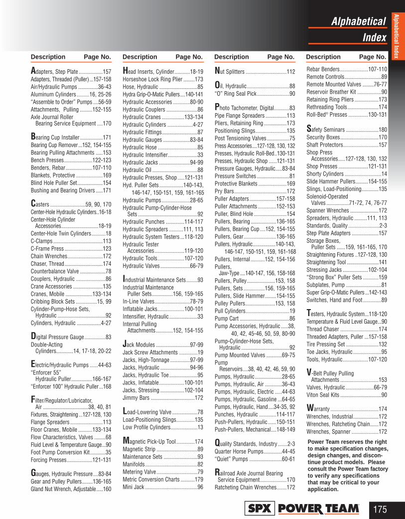
IndexAlphabetical
175®
Description Page No. Description Page No. Description Page No. Description Page No.
Alphabetical Index
Adapters, Step Plate .................157Adapters, Threaded (Puller)...157-158Air/Hydraulic Pumps ..............36-43Aluminum Cylinders .........16, 25-26“Assemble to Order” Pumps ....56-59Attachments, Pulling .........152-155Axle Journal Roller
Bearing Service Equipment ....170
Bearing Cup Installer ................171Bearing Cup Remover...152, 154-155Bearing Pulling Attachments .....153Bench Presses....................122-123Benders, Rebar...................107-110Blankets, Protective ...................169Blind Hole Puller Set..................154Bushing and Bearing Drivers .....171
Casters .........................59, 90, 170Center-Hole Hydraulic Cylinders..16-18Center-Hole Cylinder
Accessories............................18-19Center-Hole Twin Cylinders..........18C-Clamps ...................................113C-Frame Press ...........................123Chain Wrenches.........................172Chaser, Thread...........................174Counterbalance Valve ..................78Couplers, Hydraulic .....................86Crane Accessories .....................135Cranes, Mobile ...................133-134Cribbing Block Sets ...............15, 99Cylinder-Pump-Hose Sets,
Hydraulic ..................................92Cylinders, Hydraulic .................4-27
Digital Pressure Gauge...............83Double-Acting
Cylinders............14, 17-18, 20-22
Electric/Hydraulic Pumps ......44-63“Enforcer 55”
Hydraulic Puller...............166-167“Enforcer 100” Hydraulic Puller...168
Filter/Regulator/Lubricator, Air ................................38, 40, 81
Fixtures, Straightening...127-128, 130Flange Spreaders .......................113Floor Cranes, Mobile ..........133-134Flow Characteristics, Valves ........68Fluid Level & Temperature Gauge...90Foot Pump Conversion Kit...........35Forcing Presses..................121-131
Gauges, Hydraulic Pressure....83-84Gear and Pulley Pullers........136-165Gland Nut Wrench, Adjustable.....160
Head Inserts, Cylinder...........18-19Horseshoe Lock Ring Plier ........173Hose, Hydraulic ...........................85Hydra Grip-O-Matic Pullers....140-141Hydraulic Accessories ............80-90Hydraulic Couplers ......................86Hydraulic Cranes ................133-134Hydraulic Cylinders ..................4-27Hydraulic Fittings.........................87Hydraulic Gauges ...................83-84Hydraulic Hose ............................85Hydraulic Intensifier.....................33Hydraulic Jacks ......................94-99Hydraulic Oil ................................88Hydraulic Presses, Shop.....121-131Hyd. Puller Sets.................140-143,
146-147, 150-151, 159, 161-165Hydraulic Pumps....................28-65Hydraulic Pump-Cylinder-Hose
Sets ..........................................92Hydraulic Punches .............114-117Hydraulic Spreaders ..........111, 113Hydraulic System Testers ...118-120Hydraulic Tester
Accessories.....................119-120Hydraulic Tools...................107-120Hydraulic Valves.....................66-79
Industrial Maintenance Sets........93Industrial Maintenance
Puller Sets...............156, 159-165In-Line Valves.........................78-79Inflatable Jacks...................100-101Intensifier, Hydraulic ....................33Internal Pulling
Attachments............152, 154-155
Jack Modules ........................97-99Jack Screw Attachments .............19Jacks, High-Tonnage ..............97-99Jacks, Hydraulic .....................94-96Jacks, Hydraulic Toe....................95Jacks, Inflatable..................100-101Jacks, Stressing .................102-104Jimmy Bars ...............................172
Load-Lowering Valve ..................78Load-Positioning Slings.............135Low Profile Cylinders...................13
Magnetic Pick-Up Tool .............174Magnetic Strip .............................89Maintenance Sets ........................93Manifolds.....................................82Metering Valve.............................79Metric Conversion Charts ..........179Mini Jack .....................................96
Nut Splitters .............................112
Oil, Hydraulic..............................88“O” Ring Seal Pick.......................90
Photo Tachometer, Digital...........83Pipe Flange Spreaders ...............113Pliers, Retaining Ring ................173Positioning Slings......................135Post Tensioning Valves................75Press Accessories....127-128, 130, 132Presses, Hydraulic Roll-Bed..130-131Presses, Hydraulic Shop ......121-131Pressure Gauges, Hydraulic.....83-84Pressure Switches .......................81Protective Blankets ....................169Pry Bars.....................................172Puller Adapters...................157-158Puller Attachments .............152-153Puller, Blind Hole .......................154Pullers, Bearing ..................136-165Pullers, Bearing Cup ....152, 154-155Pullers, Gear.......................136-165Pullers, Hydraulic.................140-143,
146-147, 150-151, 159, 161-168Pullers, Internal ..........152, 154-156Pullers,
Jaw-Type ....140-147, 156, 158-168Pullers, Pulley....................153, 158Pullers, Sets ...............156, 159-165Pullers, Slide Hammer........154-155Pulley Pullers.....................153, 158Pull Cylinders...............................19Pump Cart ...................................86Pump Accessories, Hydraulic .....38,
40, 42, 45-46, 50, 59, 80-90Pump-Cylinder-Hose Sets,
Hydraulic ..................................92Pump Mounted Valves ...........69-75Pump
Reservoirs....38, 40, 42, 46, 59, 90Pumps, Hydraulic ...................28-65Pumps, Hydraulic, Air ............36-43Pumps, Hydraulic, Electric .....44-63Pumps, Hydraulic, Gasoline ...64-65Pumps, Hydraulic, Hand....34-35, 92Punches, Hydraulic ............114-117Push-Pullers, Hydraulic......150-151Push-Pullers, Mechanical....148-149
Quality Standards, Industry .......2-3Quarter Horse Pumps.............44-45“Quiet” Pumps .......................60-61
Railroad Axle Journal Bearing Service Equipment...................170
Ratcheting Chain Wrenches.......172
Rebar Benders....................107-110Remote Controls..........................89Remote Mounted Valves ........76-77Reservoir Breather Kit .................90Retaining Ring Pliers .................173Rethreading Tools......................174Roll-Bed® Presses ..............130-131
Safety Seminars .......................180Security Boxes...........................170Shaft Protectors.........................157Shop Press
Accessories.....127-128, 130, 132Shop Presses .....................121-131Shorty Cylinders ..........................14Slide Hammer Pullers.........154-155Slings, Load-Positioning............135Solenoid-Operated
Valves ................71-72, 74, 76-77Spanner Wrenches ....................172Spreaders, Hydraulic .........111, 113Standards, Quality ......................2-3Step Plate Adapters ...................157Storage Boxes,
Puller Sets ......159, 161-165, 170Straightening Fixtures ..127-128, 130Straightening Tool ........................141Stressing Jacks ..................102-104“Strong Box” Puller Sets ...........159Subplates, Pump .........................81Super Grip-O-Matic Pullers ...142-143Switches, Hand and Foot .............89
Testers, Hydraulic System...118-120Temperature & Fluid Level Gauge...90Thread Chaser ...........................174Threaded Adapters, Puller ...157-158Tire Pressing Set .......................132Toe Jacks, Hydraulic ....................95Tools, Hydraulic..................107-120
V-Belt Pulley Pulling Attachments ...........................153
Valves, Hydraulic ....................66-79Viton Seal Kits .............................90
Warranty ..................................174Wrenches, Industrial..................172Wrenches, Ratcheting Chain......172Wrenches, Spanner ...................172
Power Team reserves the rightto make specification changes,design changes, and discon-tinue product models. Pleaseconsult the Power Team factoryto verify any specificationsthat may be critical to yourapplication.

176®
IndexNumerical
Tool No. Page No. Tool No. Page No. Tool No. Page No. Tool No. Page No.Num
eric
al In
dex
B5090........................108, 110B5135.........................109-110B7090........................108, 110B7135.........................109-110B8090........................108, 110B8090L......................108, 110B9180.........................109-110B11090 .......................109-110BC12 ..................................45BC12AUS ...........................45BC12EUR ..........................45BP12INT .............................45BP12VQ ..............................45
C51C.................................8, 9C53C.................................8, 9C55C.................................8, 9C55CBT ..............................12C57C.................................8, 9C59C.................................8, 9C101C...............................8, 9C102C...............................8, 9C104C...............................8, 9C106C...............................8, 9C106CBT ............................12C108C...............................8, 9C151C...............................8, 9C152C...............................8, 9C154C...............................8, 9C156C...............................8, 9C158C...............................8, 9C251C...............................8, 9C252C...............................8, 9C254C...............................8, 9C256C...............................8, 9C256CBT ............................12C258C...............................8, 9C552C...............................8, 9C554C...............................8, 9C556C...............................8, 9C556CL...............................26C756C...............................8, 9C1002C.............................8, 9C1006C.............................8, 9C1006CL.............................26C1010C.............................8, 9C1010CBT ..........................12C1012C.............................8, 9C1014C.............................8, 9C1510C.............................8, 9C1512C.............................8, 9C1514C.............................8, 9C1516C.............................8, 9C2510C.............................8, 9C2512C.............................8, 9C2514C.............................8, 9C2514CBT ..........................12C5510C.............................8, 9C5513C.............................8, 9C7513C.............................8, 9C10010C...........................8, 9C1506CL.............................26CB30 - CB100 .....................15CBS55 - CBS150 ................99CC5 ...................................113CC10 .................................113CC25 .................................113DB10M ..............................160
DB17 .................................161DB17H ..............................161DB17M ..............................160DB30H ..............................163DG100, DG100B.................83
FC2200 .............................134FC4400 .............................134FC6000, FC6000E ............133FK59 ...................................35FK159B ...............................35
HFS3A...............................113HFS6A...............................113HB443, HB444 ....................33HNS150.............................112HNS225.............................112HP20..........................114, 116HP20FS, HP20HS.............114HP20S .......................114, 116HP20SP.....................114, 116HP35, HP35P ............115, 116HP35S, HP35SP .......115, 116HS2000..............................111HS3000..............................111HST11 ...............................141HST11S.............................141HT50A ........................118-119HT75...........................118-119HT200.........................118-119HT2545..............................118HTS50.................................85
IM10E, IM10H.....................93IJ13 ............................100-101IJ45 ............................100-101IJ76 ............................100-101IJ128 ..........................100-101IJ2211 ........................100-101IJ3213 ........................100-101IJ4416 ........................100-101IJ7320 ........................100-101IPS10B, IPS10HB.............159IPS10M .............................160IPS17, IPS17B ..................161IPS17H..............................161IPS17M .............................160IPS30H..............................163IPS3017, IPS3017B..........162IPS50H..............................163IPS5017, IPS5017B..........164IPS5317 ............................165
J24T ....................................95J55T ....................................95J58T ....................................95J106T ..................................95J109T ..................................95J259T ..................................95JAM5526 - JAM15045.........99JAR5526 - JAR15045..........99JEM5526 - JEM15045.........99JER5526 - JER15045..........99JM25 - JM415 ................98-99
LR2000 .............................135LR4000 .............................135LR6000 .............................135
MB5...................................170MB8...................................170MB16.................................170MB25.................................170
P12 ................................34-35P19 ................................34-35P23 ................................34-35P55 ................................34-35P59, P59F......................34-35P157, P157D .................34-35P159, P159D .................34-35P300, P300D .................34-35P460, P460D .................34-35PA4R, PA4RM................40-41PA6, PA6A .....................38-39PA6AM, PA6M-1 ............38-39PA6-2 .............................38-39PA6D, PA6DM................38-39PA6DM-1, PA6DM-2 ......38-39PA6D2............................38-39PA6M .............................38-39PA6M-1 ..........................38-39PA6M-2 ..........................38-39PA7....................................158PA9, PA9H .....................36-37PA50, PA50D .................40-41PA50M, PA50R ..............40-41PA50R2, PA50RM..........40-41PA55A............................56-58PA60 ..............................40-41PA64 ..............................40-41PA90A............................56-58PA172 ............................42-43PA174 ............................42-43PA462 ............................42-43PA464 ............................42-43PA464R..........................42-43PA464RA .......................42-43PA554 ............................42-43PB1230 - PB51156C .........169PC200 .................................86PC200RC............................86PD313 - PD812..................116PE55A,B,C,D,F ............56-58PE84 ..............................46-47PE90A,B,C,D,F ............56-58PE102, PE102A.............44-45PE102AR...........................114PE102-220.....................44-45PE102A-220 ..................44-45PE104 ............................44-45PE104-220.....................44-45PE120M .........................56-58PE172, PE172A.............46-47PE172AM.......................46-47PE172M .........................46-47PE172S..........................46-47PE172SM.......................46-47PE174, PE174M ............46-47PE182 ............................50-51PE183, PE183-2 ............50-51PE183A, PE183C ..........50-51PE184 ............................50-51PE184-2.........................50-51PE184C .........................50-51PE213, PE213S.............60-61
PE214, PE214S.............60-61PE302, PE302-2 ............52-53PE302A..........................52-53PE302A-2 ......................52-53PE302R .........................52-53PE302R-2 ......................52-53PE302S..........................52-53PE302S-2 ......................52-53PE303 ............................52-53PE303-2.........................52-53PE303R .........................52-53PE303R-2 ......................52-53PE304 ............................52-53PE304-2.........................52-53PE304R .........................52-53PE304R-2 ......................52-53PE462, PE462A.............48-49PE462S..........................48-49PE464, PE464S.............48-49PE552, PE552A.............54-55PE552S..........................54-55PE553 ............................54-55PE554 ............................54-55PE554C .........................54-55PE554PT .......................54-55PE554S, PE554T...........54-55PE604T, PE604PT.....105-106PE2004 ..........................62-63PE2004S........................62-63PE4004 ..........................62-63PE4004S........................62-63PED253 .........................54-55PED254 .........................54-55PED254S .......................54-55PG55A ...........................56-58PG120HM ......................64-65PG303............................64-65PG304............................64-65PG553............................64-65PG554............................64-65PG1200M-4 ...................64-65PG1200M-4D.................64-65PG1203..........................64-65PG1204..........................64-65PG1204S .......................64-65PG4004..........................64-65PG4004S .......................64-65PH53C ..............................146PH53CR............................146PH63C .......................140-141PH83C .......................140-141PH103C ............................146PH103CR..........................146PH113C......................140-141PH172 ...............................147PH173 ...............................147PH173R ............................147PH303, PH303R ...............147PH503 ...............................147PH553C .....................166-167PH553C-220 ..............166-167PH553C13 .................166-167PH553C13-220 ..........166-167PH553CL ...................166-167PH553CL-220 ............166-167PH553CL13 ...............166-167PH553CL13-220 ........166-167PH1002 .............................168
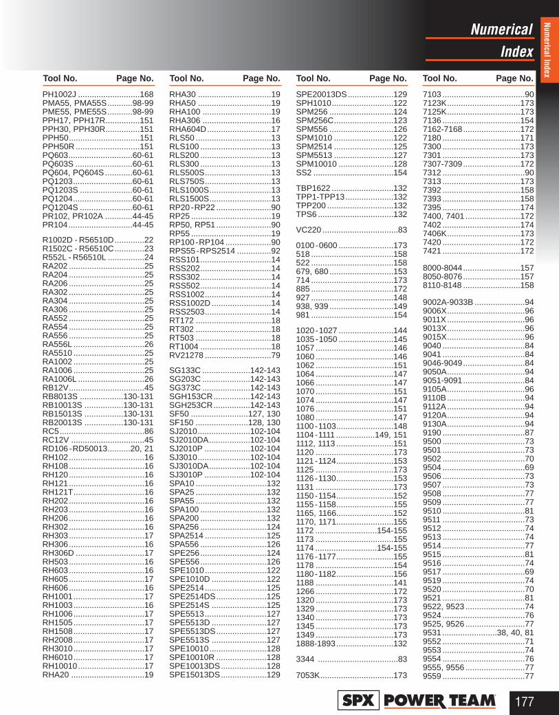
IndexNumerical
177®
Tool No. Page No. Tool No. Page No. Tool No. Page No. Tool No. Page No.
Numerical Index
PH1002J ...........................168PMA55, PMA55S...........98-99PME55, PME55S...........98-99PPH17, PPH17R...............151PPH30, PPH30R...............151PPH50...............................151PPH50R ............................151PQ603............................60-61PQ603S .........................60-61PQ604, PQ604S............60-61PQ1203..........................60-61PQ1203S .......................60-61PQ1204..........................60-61PQ1204S .......................60-61PR102, PR102A ............44-45PR104............................44-45
R1002D - R56510D.............22R1502C - R56510C.............23R552L - R56510L ................24RA202 .................................25RA204 .................................25RA206 .................................25RA302 .................................25RA304 .................................25RA306 .................................25RA552 .................................25RA554 .................................25RA556 .................................25RA556L ...............................26RA5510 ...............................25RA1002 ...............................25RA1006 ...............................25RA1006L .............................26RB12V.................................45RB8013S ...................130-131RB10013S .................130-131RB15013S .................130-131RB20013S .................130-131RC5.....................................86RC12V ................................45RD106 - RD50013..........20, 21RH102.................................16RH108.................................16RH120.................................16RH121.................................16RH121T...............................16RH202.................................16RH203.................................16RH206.................................16RH302.................................16RH303.................................17RH306.................................16RH306D ..............................17RH503.................................16RH603.................................16RH605.................................17RH606.................................16RH1001...............................17RH1003...............................16RH1006...............................17RH1505...............................17RH1508...............................17RH2008...............................17RH3010...............................17RH6010...............................17RH10010.............................17RHA20 ................................19
RHA30 ................................19RHA50 ................................19RHA100 ..............................19RHA306 ..............................16RHA604D............................17RLS50 .................................13RLS100 ...............................13RLS200 ...............................13RLS300 ...............................13RLS500S.............................13RLS750S.............................13RLS1000S...........................13RLS1500S...........................13RP20 - RP22 ........................90RP25 ...................................19RP50, RP51 ........................90RP55 ...................................19RP100 - RP104 ....................90RPS55 - RPS2514 ...............92RSS101...............................14RSS202...............................14RSS302...............................14RSS502...............................14RSS1002.............................14RSS1002D ..........................14RSS2503.............................14RT172 .................................18RT302 .................................18RT503 .................................18RT1004 ...............................18RV21278 .............................79
SG133C .....................142-143SG203C .....................142-143SG373C .....................142-143SGH153CR................142-143SGH253CR................142-143SF50 .........................127, 130SF150 .......................128, 130SJ2010.......................102-104SJ2010DA..................102-104SJ2010P ....................102-104SJ3010.......................102-104SJ3010DA..................102-104SJ3010P ....................102-104SPA10 ...............................132SPA25 ...............................132SPA55 ...............................132SPA100 .............................132SPA200 .............................132SPA256 .............................124SPA2514 ...........................125SPA556 .............................126SPE256.............................124SPE556.............................126SPE1010...........................122SPE1010D ........................122SPE2514...........................125SPE2514DS......................125SPE2514S ........................125SPE5513...........................127SPE5513D ........................127SPE5513DS......................127SPE5513S ........................127SPE10010.........................128SPE10010R ......................128SPE10013DS....................128SPE15013DS....................129
SPE20013DS....................129SPH1010...........................122SPM256 ............................124SPM256C..........................123SPM556 ............................126SPM1010 ..........................122SPM2514 ..........................125SPM5513 ..........................127SPM10010 ........................128SS2 ...................................154
TBP1622 ...........................132TPP1-TPP13.....................132TPP200 .............................132TPS6 .................................132
VC220 .................................83
0100 - 0600 ........................173518 ....................................158522 ....................................158679, 680 ............................153714 ....................................173885 ....................................172927 ....................................148938, 939 ............................149981 ....................................154
1020 - 1027 ........................1441035 - 1050 ........................1451057 ..................................1461060 ..................................1461062 ..................................1511064 ..................................1471066 ..................................1471070 ..................................1511074 ..................................1471076 ..................................1511080 ..................................1471100 - 1103.........................1481104 - 1111 .................149, 1511112, 1113 .........................1511120 ..................................1731121 - 1124.........................1531125 ..................................1731126 - 1130.........................1531131 ..................................1731150 - 1154.........................1521155 - 1158.........................1551165, 1166.........................1521170, 1171.........................1551172 ...........................154-1551173 ..................................1551174 ...........................154-1551176 - 1177.........................1551178 ..................................1541180 - 1182.........................1561188 ..................................1411266 ..................................1721320 ..................................1731329 ..................................1731340 ..................................1731345 ..................................1731349 ..................................1731888-1893.........................132
3344 ...................................83
7053K................................173
7103 ....................................907123K................................1737125K................................1737136 ..................................1547162-7168.........................1727180 ..................................1717300 ..................................1737301 ..................................1737307-7309.........................1727312 ....................................907313 ..................................1737392 ..................................1587393 ..................................1587395 ..................................1747400, 7401 ........................1727402 ..................................1747406K................................1737420 ..................................1727421 ..................................172
8000-8044.........................1578050-8076.........................1578110-8148 .........................158
9002A-9033B ......................949006X..................................969011X..................................969013X..................................969015X..................................969040 ....................................849041 ....................................849046-9049...........................849050A..................................949051-9091...........................849105A..................................969110B..................................949112A..................................949120A..................................949130A..................................949190 ....................................879500 ....................................739501 ....................................739502 ....................................709504 ....................................699506 ....................................739507 ....................................739508 ....................................779509 ....................................779510 ....................................819511 ....................................739512 ....................................749513 ....................................749514 ....................................779515 ....................................819516 ....................................749517 ....................................699519 ....................................749520 ....................................709521 ....................................819522, 9523 ..........................749524 ....................................769525, 9526 ..........................779531........................38, 40, 819552 ....................................719553 ....................................749554 ....................................769555, 9556 ..........................779559 ....................................77
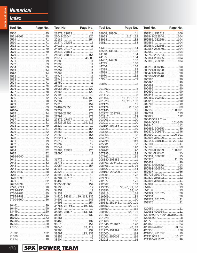
178®
IndexNumerical
Tool No. Page No. Tool No. Page No. Tool No. Page No. Tool No. Page No.Num
eric
al In
dex
9560 ....................................459561-9563...........................459569 ....................................719570 ....................................719572 ....................................719575 ....................................799576 ....................................709579 ....................................719580 ....................................799581 ....................................799582 ....................................699584 ....................................699589 ....................................749590 ....................................749592 ....................................719593 ....................................769594 ....................................719595 ....................................769596 ....................................789597 ....................................789599 ....................................729605 ....................................729608 ....................................789609 ....................................729610 ....................................699610A..................................699615 ....................................749616 ....................................889617 ....................................829620 ....................................819623 ....................................799625 ....................................819626 ....................................829627 ....................................829628 ....................................759631 ....................................799632 ....................................759633 ....................................799634 ....................................829635 ....................................829636-9640...........................889641 ....................................819642 ....................................829643 ....................................819644 ....................................829645-9647...........................889648 ....................................829670-9690...........................879691 ....................................829692-9699...........................879720, 9721 ..........................789733-9736...........................859750-9783...........................859785-9788 .........................1199790-9800...........................86
10461 ..................................8910494 ..................................9013449 ................................12015235.........................100-10115702 ................................17316339 ..................................8916954 ................................12017627 ..................................89
21332 ................................13221669 ..................................1821714 ..................................18
21872, 21873 ......................1822041-22044.....................12022185 ................................15422274, 22275 ......................1824016 ..................................1124196, 24197 ......................1824813, 24814 ......................1924835, 24836 ....................15425017 ............................45, 8925388 ..................................1125395 ..................................1125652 ..................................1125654 ..................................1125664 ..................................1125746 ..................................1125748 ..................................1125750 ..................................1125931 ..................................1926068-26079.....................12026666 ................................12027198 ..................................1927241.........................154-15527287 ................................12027315 ................................15427487-27555.....................17127737 ................................12027793-27795.....................17127797 ................................17127876, 27877 ......................5928228-28229 ...............19, 11328230 ..................................1928250 ................................15428253 ................................15428256 ................................15428323GY8.........................15428612 ..................................1928632 ..................................1928644 ..................................1928984, 28985 ....................12029595 ..................................19
31772 ..................................1131776 ..................................1132054 ................................15432118 ..................................1932325 ..................................1132698, 32699 ......................1932701, 32702 ......................1933439 ..................................1933856-33865.....................15434136 ..................................1934251 ..................................1934331 ................................15434510, 34511........19, 113, 13234602 ................................14634698 ................................15434755, 34756..............19, 13234758 ..................................1934806, 34807 ............113, 13234808 ................................13236161 ....................................836469 ................................13236578 ................................15437045 ..........................83, 11937368 ................................13238597 ........................113, 13238855 ..................................1938904 ..................................19
38908, 38909 ......................1138953 ........................113, 13238954 ................................13239811 ..................................83
41331 ................................15443562, 43563 ....................13244148 ................................15444195 ................................15444457, 44458 ....................13244745 ................................16844766 ................................16845329 ..................................8345589 ..................................1546070 ................................13247997 ................................146
60846 ................................123
201362 ..................................8201375 ..................................8201412 ..................................8201454 ................19, 113, 132201923 ................19, 113, 132202178 ................................11202179 ........................11, 146202180 ................................11202777, 202778 ..................89202817 ..............................174203003 ..............................120203017 ..............................120203154-203156.................120203225 ................................89203264 ..............................119204666 ................................83204928 ..............................172204990 ..............................119205601 ................................50206753 ..............................120206767 ................................90207395 ..............................132207762 ................................89208380-208382 ...................11208401, 208402 ................120208406 ..........................25, 26208627 ..............................154209199, 209200 ................172209201 ..............................173209593 ................................89212377 ..............................171212867 ..............................159213895..............38, 40, 42, 46213896 ..........................38, 40215315 ..............................159216209 ................................89250175 ................................90250341-250343..........100-101250353.......................100-101250459 ..............................115250682.......................100-101251002 ..............................166251220 ................................92251468 ..............................166251646, 251647 ................170251660 ..........................45, 89251970-251999 .................116252000 ..............................114252001-252002 .................116252215 ................................16
252511, 252512 ................106252542-252544.................104252555, 252556 ................104252562 ..............................104252564, 252565 ................104252567-252570.................104252650 ..............................104252759-252764.................104253361-253365.................104253390, 253391 ................104
300210-300216...................90300221-300228...................90300471-300476...................90300507-300510...................90300585 ................................90300690 ................................90300693 ................................90300696 ................................90300699 ................................90300846 ................................90302482, 302483 ..................19303045 ..............................168303785 ................................19304718 ................................89307159.......................100-101307281 ..............................119308022 ..............................112308435OR9 Thru308440OR9 ...............161-165308840 ..............................112309652, 309653 ..................89309874, 309875 ................146350090.......................100-101350094-350100 ...................11350144, 350145 ....11, 20, 113350184 ................................11350199 ................................59350207-350209..........100-101350320-350322...................15350331, 350332 ..................15350376 ..........................11, 25350431 ................................90350549-350550 .................113350593-350594.................166350637 ..............................166350723-350724 ...................11350822-350823 .................113350895-350898 ...................11350984 ................................25351075 ................................19351106 ................................19351324, 351325 ..................20351334 ................................20351574, 351575 ..................11351576 ................................11
420059 ................................11420061-420064 ...................11420496OR9-420498OR9 ....25420655OR9...........................8420778 ................................83420866 ................................24420867-420871.............23, 24420958 ..............................170421056, 421057 ..................19421312OR9 ...................16-17421365-421367...................99
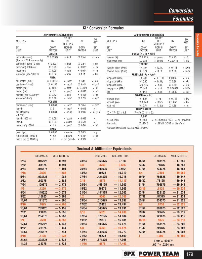
FormulasConversion
179®
Conversion Formulas
APPROXIMATE CONVERSIONTO GET
MULTIPLY BY OR BYTO
MULTIPLY GET
SI* CONV NON-SI CONV SI* UNIT FACTOR UNIT FACTOR UNIT
LENGTHmillimeter (mm) X 0.03937 = inch X 25.4 = mm (1 inch = 25.4 mm exactly)centimeter (cm) 10 mm X 0.3937 = inch X 2.54 = cmmeter (m) 1000 mm X 3.28 = foot X 0.305 = mmeter (m) X 1.09 = yard X 0.914 = mkilometer (km) 1000 m X 0.62 = mile X 1.61 = km
AREAmillimeter2 (mm2 ) X 0.00155 = inch2 X 645 = mm2
centimeter2 (cm2) X 0.155 = inch2 X 6.45 = cm2
meter2 (m2) X 10.8 = foot2 X 0.0929 = m2
meter2 (m2) X 1.2 = yard2 X 0.836 = m2
hectare (ha) 10,000 m2 X 2.47 = acre X 0.405 = hakilometer2 (km2) X 0.39 = mile2 X 2.59 = km2
VOLUMEcentimeter3 (cm3) X 0.061 = inch3 X 16.4 = cm3
liter (l) X 61 = inch3 X 0.016 = lmilliliter (ml ) X 0.034 = oz-liq X 29.6 = ml (1 ml= 1 cm3)liter (l) 1000 ml X 1.06 = quart X 0.946 = lliter (l) X 0.26 = gallon X 3.79 = lmeter3 (m3) 1000 l X 1.3 = yard3 X 0.76 = m3
MASSgram (g) X 0.035 = ounce X 28.3 = gkilogram (kg) 1000 g X 2.2 = pound X 0.454 = kgmetric ton (t) 1000 kg X 1.1 = ton (short) X 0.907 = t
APPROXIMATE CONVERSIONTO GET
MULTIPLY BY OR BYTO
MULTIPLY GET
SI* CONV NON-SI CONV SI* UNIT FACTOR UNIT FACTOR UNIT
FORCE (N = kg • m/s2)newton (N) X 0.225 = pound X 4.45 = Nkilonewton (kN) X 225 = pound X 0.00445 = kN
TORQUEnewton meter (N•m) X 8.9 = lb. in. X 0.113 = N•mnewton meter (N•m) X 0.74 = lb. ft. X 1.36 = N•m
PRESSURE (Pa = N/m2)kilopascal (kPa) X 4.0 = in. H2O X 0.249 = kPakilopascal (kPa) X 0.30 = in. Hg X 3.38 = kPakilopascal (kPa) X 0.145 = p.s.i. X 6.89 = kPamegapascal (MPa) X 145 = p.s.i. X 0.00689 = MPaBar X 14.5 = p.s.i. X .0689 = Bar
POWER (w = J/s)kilowatt (kw) X 1.34 = hp X 0.746 = kwkilowatt (kw) X 0.948 = Btu/s X 1.055 = kwwatt (w) X 0.74 = ft. lb/s X 1.36 = w
TEMPERATURE°C = (°F - 32) ÷ 1.8 °F = (°C X 1.8) + 32
FLOWcu. cm./min. X .061 = cu. in/min.X 16.4 = cu. cm./min.liters/min. X .2642 = GPMX 3.785 = liters/min.
* System International (Modern Metric System)
SI* Conversion Formulas
DECIMALS MILLIMETERS
1/64 .015625 — 0.3971/32 .03125 — 0.7943/64 .046875 — 1.1911/16 .0625 — 1.5885/64 .078125 — 1.9843/32 .09375 — 2.3817/64 .109375 — 2.7781/8 .1250 — 3.1759/64 .140625 — 3.5725/32 .15625 — 3.96911/64 .171875 — 4.3663/16 .1875 — 4.76313/64 .203125 — 5.1597/32 .21875 — 5.55615/64 .234375 — 5.9531/4 .2500 — 6.35017/64 .265625 — 6.7479/32 .28125 — 7.14419/64 .296875 — 7.5415/16 .3125 — 7.93821/64 .328125 — 8.33411/32 .34375 — 8.731
DECIMALS MILLIMETERS
23/64 .359375 — 9.1283/8 .3750 — 9.52525/64 .390625 — 9.92213/32 .40625 — 10.31927/64 .421875 — 10.7167/16 .4375 — 11.11329/64 .453125 — 11.50915/32 .46875 — 11.90631/64 .484375 — 12.3031/2 .5000 — 12.70033/64 .515625 — 13.09717/32 .53125 — 13.49435/64 .546875 — 13.8919/16 .5625 — 14.28837/64 .578125 — 14.68419/32 .59375 — 15.08139/64 .609375 — 15.4785/8 .6250 — 15.87541/64 .640625 — 16.27221/32 .65625 — 16.66943/64 .671875 — 17.06611/16 .6875 — 17.463
DECIMALS MILLIMETERS
45/64 .703125 — 17.85923/32 .71875 — 18.25647/64 .734375 — 18.6533/4 .7500 — 19.05049/64 .765625 — 19.44725/32 .78125 — 19.84451/64 .796875 — 20.24113/16 .8125 — 20.63853/64 .828125 — 21.03427/32 .84375 — 21.43155/64 .859375 — 21.8287/8 .8750 — 22.22557/64 .890625 — 22.62229/32 .90625 — 23.01959/64 .921875 — 23.41615/16 .9375 — 23.81361/64 .953125 — 24.20931/32 .96875 — 24.60663/64 .984375 — 25.0031 1.000 — 25.400
1 mm = .03937".001" = .0254 mm
Decimal & Millimeter Equivalents

180®
Safety Power Team
Safe
ty S
emin
ars
Your creative application of Power Team products can win a cash award.
If you've come up with a creative new application of Power Team hydraulics tosolve a unique problem, we'd like to hear about it! In fact, you could even wina $100 cash award for your entry! Just send a snapshot of the application anda brief write-up describing the problem and your solution using Power Teamhydraulics. Each entry will be acknowledged and Power Team will be the soleauthority in determining prize winners.
Ask for the Power Team Idea Book No. PTIB95See creative ideas for uses ofPower Team hydraulics.
Send your entry to:SPX Power Team 2121 West Bridge St.P.O. Box 993Owatonna, MN 55060-0993 USA
A safety seminar program as powerful as our products.
Worker safety is smart business. As a responsiblemanager, you care about thewelfare of your employees.As a business person, youknow that accidents canpump up your workman’scompensation costs andinsurance rates and hurt the bottom line, as well asemployee productivity andmorale.
We offer 2 free, effectivein-plant safety programs:
1. “A Common SenseApproach to Lifting”Content: Basic hydraulicprinciples; proper selection,use and maintenance ofhydraulic power compo-nents including cylinders,pumps, hoses and acces-sories. “Do’s and don’ts.”
2. “Pullers – GeneralSafety Tips”Content: Presents the threebasic pulling problems andtheir safe solution usingjaw-type pullers, Push-pullers, hydraulically powered pullers, specialtypullers and puller acces-sories. Use of protectiveblankets. “Do’s and don’ts.”
Seminars
For full information on our free safety seminar programs, call your nearest Power Team distributor or Power Team Customer Service (1-800-541-1418).
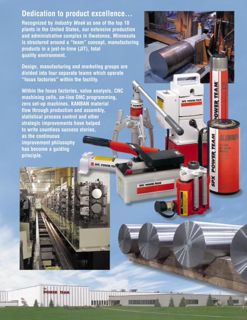
Dedication to product excellence...Recognized by Industry Week as one of the top 10plants in the United States, our extensive productionand administrative complex in Owatonna, Minnesota is structured around a “team” concept, manufacturingproducts in a just-in-time (JIT), total quality environment.
Design, manufacturing and marketing groups aredivided into four separate teams which operate “focus factories” within the facility.
Within the focus factories, value analysis, CNCmachining cells, on-line DNC programming, zero set-up machines, KANBAN material flow through production and assembly, statistical process control and otherstrategic improvements have helped to write countless success stories, as the continuous improvement philosophyhas become a guiding principle.

UNITED STATESSPX Corporation2121 West Bridge StreetPO Box 993Owatonna, MN 55060-0993Telephone: 1-507-455-7100Cust. Service/Order EntryTel: 1-800-541-1418FAX: 1-800-288-7031E-mail: [email protected] ServicesTel: 1-800-477-8326FAX: 1-800-765-8326 or
1-507-455-7160International Sales:Tel: 1-507-455-7150FAX: 1-507-455-7122
AUSTRALIA7 Expo CourtMount Waverley Victoria 3149AustraliaTel: 61 (3) 95628800FAX: 61 (3) 95628080E-mail: [email protected]
BRAZILAv. N Sra. do Sabar�, 4901S�o Paulo, SP 04447-021BrasilTel: 55 (11) 246-4177FAX: 55 (11) 246-2793
EUROPEKlarenanstelerweg 5 D6468 EP KerkradeNetherlandsTel: 31 (45) 5678877FAX: 31 (45) 5678878E-mail: [email protected]
FAR EAST36 Joo Koon CircleSingapore 629061SingaporeTel: (65) 862 2522FAX: (65) 862 4633E-mail: [email protected]
JAPAN5-53 Minowacho2 Chome, Kohoku-ku, Yokohama, Kanagawa 223-0051JapanTel: 81 (45) 562-7700FAX: 81 (45) 562-7800
KOREAAnyang P.O. Box 50Kyounggi-DoSouth Korea 430-600Tel: 82-343-391-0209FAX: 82-343-396-5373E-mail: [email protected]
UNITED KINGDOMUnit 1A Park Road Industrial EstateConsettCounty Durham DH8 5PUUnited KingdomTel: 44 1207 507077FAX: 44 1207 506938E-mail: [email protected]
INTERNEThttp://www.powerteam.com
© Copyright 1999 SPX Power Team, Owatonna, MN 55060 Printed in USA 1/99
PT99