Embed Size (px)
Citation preview

Generating StationProtection
GET-6497A


INTRODUCTION - Tripping modes
- Generator back up protection
- Protection for accidentally energizing agenerator on turning gear
This guide is concerned primarily with shortcircuit protection and protection for abnormaloperating conditions for generating stations. Itspecifies the minimum recommended protectionfor steam turbine generators, for hydro generators,and for gas turbine generators. Additional desiredprotection should be provided if it is economicallyjustified. Unless otherwise stated, these recom-mendations apply to either attended or unattendedstations having generators rated as follows:
- Protection during start-up or shutdown
- Current transformers
- Potential transformers
- Sub-synchronous resonance
l 1000 kva and higher, any voltage
l 5 kv and higher, any kva
l 2.2 kv and higher, and 501 kva and higher
The guide contains the following sections:
Recommended Generating Station Protection- presents recommended and optional protec-tion for specific generator applications andarrangements.
- Unit generator-transformer installation- Generators bussed at generator voltage
Excitation System Protection - presents rec-ommended and optional protection for avail-able excitation systems.
- Alterrex
- Generrex
Considerations Involving Individual Forms ofRelaying - considers special problem areas,setting information and application rules notprovided elsewhere, or any other special con-siderations pertinent to a particular type ofrelay or protection.
- Stator short-circuit protection
- Loss-of-excitation protection
- Reverse power (anti-motoring) protection
- Unbalanced current (single phasing) protec-tion
Other Protective Considerations - considerssupplementary protection and other forms ofprotection not covered earlier.
1.
2.
3.
4.
5.
6
7
8.
9.
10.
11
REFERENCES
Protection for Accidentally Energizing a Gen-erator While on Turning Gear, J. Berdy, 1977.
Out of Step Protection for Generators, J.Berdy, 1976.
Protection of Synchronous Generators DuringUnbalanced System Conditions, J. Berdy, P. G.Brown, 1975.
Protective Relaying for Pumped Storage HydroUnits, IEEE PSRC Report, PAS, May/June1975.
Loss of Excitation Protection for Modern Syn-chronous Generators, J. Berdy, IEEE Trans-actions, PAS, Sept./Oct. 1975.
Protection of Steam Turbine GeneratorsDuring Abnormal Frequency Conditions, J.Berdy, P. G. Brown, L. E. Goff, 1974.
Protection of Large Steam Turbine GeneratorsDuring Abnormal Conditions, J. Berdy, M.Crenshaw, M. Temoshok, CIGRE, 1972.
Protection of Large Tandem Generators, J.Berdy, 1972.
Potential Transformer Applications on UnitConnected Generators, I E E E Committee Re-port, PAS, Jan./Feb. 1972.
Electrical Design Considerations in PumpedStorage Hydro Plants, P. G. Brown, G. W.Otte, IEEE Transactions, Vol. S82, 1963.
Recent Practices and Trends in ProtectiveRelaying, IEEE Committee Report, PAS, Feb.1960.
3

12. The Art and Science of Protective Relaying, C. 15. IEEE Recommended Practice for ProtectionR. Mason. and Coordination of Industrial and Commercial
Power Systems, I EE E Standard 242-l 975.13. Operation of Apparatus Protective Relaying at
Reduced Frequencies, AIEE-Committee Re- 16. Transmission Line Reclosing - Turbine Gener-port, PAS Feb. 1959. ator Duties and Stability Considerations, P. G.
Brown, R. Quay, Texas A&M Relay Confer-14. Design and Test of the Navajo Plant Subsyn- ence, April 1976.
chronous Resonance Protection Filters, C.E.J.Bowler, C. H. Holley, T. M. Morong, J. B. Tice,CIGRE Paper 31-06, 1976.

GENERATING-STATION PROTECTION
UNIT GENERATOR-TRANSFORMER to limit the current for a single line-to-ground faultINSTALLATION at the terminals of the generator to 10 primary
amperes or less. Figure 1 shows graphically theFigure 1 shows a typical unit generator-transfor- various available forms of protection, while relay
mer installation with high impedance grounding recommendations are given in Table 1 where devicethrough a distribution transformer. In this arrange- numbers correspond to the encircled numbers inment, the grounding impedance is usually selected Fig. 1.
Tran
Diff
StatorOverheat ing
V o l t s / H z
O v e r
V o l t
A u xPt
151 INs u
Sta.ServiceTran
TranDiff
Sta. AuxB a c k - U p
Ct"
t
Feeders
8 7o-s u
Tran.D i f f
Sta.A u x
Back-Up
Figure 1. Unit generator transformer arrangement.
6

TABLE 1
-___. __
Device
21
21x3240
464951
51 /GN
51 /TN
51TN/SS
51v
5959V/HZ6061
6364F64G71
Quantityand Type
3-CEB5lB (a) (w)1-CEBl3C (a) (w)1-SAM141 -GGP53C (b)1-CEH51A (c)1 -CEH52A (c)1 -SGC12A (d)1-IRT51A (e)3-IAC53A (g)
or 3-l FC53A1-IAC53A (g) (y)
or 1-IFC53A1-IAC53A (g) (w)
or 1 -I FC53A1-IAC53A (g)
or 1-IFC53A (g)3-IJCV51A (h) (w)
or 3-IGCV51A (h) (w)1-IAV71B (i)2-STV11A (j)1-CFVB11B (k)3-IAC53B (Q)
or 3-IFC53B (a)l-Type 900-1A (m)1-PJG12 (n)1 -IAV51 K1 -Gas Detector (0)
*(BFI) = Breaker failure initiate (k)
(a)
(b)
(c)
(d)
(e)
(f)
(g)
(h)
Function, RelayControl led or
Breakers Tripped Device
21x 78
86G 8194G 1 86B94G 1 86G
94G 1Alarm (f)
86G
86T/SU87B
86G87G87T
86G 87T/SS
86G 87T/SU
86G
94G 194G 1Alarm
86G, 87X
87X94G 19462151
151TN
86G86G
86G, 87XAlarm
151 TN/SU
AUX CTAUX PT
Quantityand Type
1 -GSY51 A (p)and 1-CEX57E (p)
1-SFF21A (q)1-HEA611 -HEA61
1 -H EA613-PVD11 C
or 3-PVD21 (r)3-CFD22 (s)3-BDD 15B (t)
or 3-STD15C (t)3-STD 15C
or 3-STD 15C3-BDD1 5B
or 3-STD 15C1-HGA14A
1 or 2-HFA53K2 or 2-HFA53K
3-IAC53A (g)o r 3-IFC53A
1 -IAC53A (g)o r 1-IFC53A
1-IAC53A (g)o r 1-IFC53A (g)
3-JARO (u)3-JE27 (v)
Function, RelayControlled or
Breakers Tripped
94G2
94G2D,E,F,G
A,C,D,H, shutdown(BFI)*
B,E86B
86G, 87X86G
86G
86T/SU
CO2 (z)A,C,H (x) (BFI)*
A (BFI)*86T/SU
86T/SU
86T/SU
(Q)
1;’(o)
(P)
(q)
Used to open trip circuits of devices 21, 32, 40, 51V, 78. Canalso be used to remove regulator from service.For multi-circuit hydro generators.Type 900-1A fault pressure relay.The PJG12 can be set with zero or 2 seconds time delay. Ingeneral, it is recommended that time delay be used with thisprotection.Gas Detector Relay. Only applicable on conservator or atmo-seal type of transformers.Optional. Used when during loss of synchronism, the electricalcenter is in either the step up transformer or in the generator.Underfrequency protection for the turbine. One or morerelays may be required to provide protection. See reference 6.The PVD21 is faster version of the PVD1 1.For generators smaller than 2000 kVA, the IJD52 may be sub-stituted. The IJD52 is also used on class 1 E standby generators.If HV bus arrangement is such that two HV breakers are In-volved, use 3-BDD16B or 3STD16C.Use with 87T.Use with 21 and 51V.For two step tripping with external fault backup relays, devices51TN, 51V or 21X would first trip breaker A and then after ashort time delay, control device 86G. This would require anadditional RPM1 IA or SAM11A timer to be controlled by51TN and 51V.A generator may have a main field breaker (C) or an exciterfield breaker (H) or a generator may have both. If both fieldbreakers are used, both should be tripped by 94G1 and 86G.51GN is backup for stator ground faults. Two possible loca-tions for this protection are shown.Used only on enclosed air cooled machines.
7

GENERATORS BUSSED ATGENERATOR VOLTAGE
Figure 2 shows a typical installation where gen- than rated full load current. Figure 2 shows graph-erators are bussed at generator voltage. In this ically the available forms of protection, and relayarrangement, the generator is generally low resist- recommendations are given in Table 2, where theante grounded. The grounding resistance is usually device numbers correspond to the encircled num-selected to limit the generator’s contribution to a bers in Fig. 2.single line-to-ground fault at its terminals to less
8

Step-UpTrans.
Grounding
Bus Diff
HU PhaseLU LineRelays
StatorOver-
Heating
-4tPT
GroundingImpedance
VoltBal
Loss of 7*Sync 0”n
Loss ofExc.
LVPhase
Back- Jp
n46 CurrUnbal
59UHZ
Volts/Hz
51T -ss
LA"Y
StaServiceTrans
JO8 7 G e nG N G N D
Y
Figure 2. Generators bussed at generator voltage.
TransDiff
9

TABLE 2
Device
21
2 1 x3240
464950/5 1 SS
51GN
51 N/GT
51T
51TN
51TN/SS
5 1 V
5959VHZ6061
63
Quantityand Type
3CEB51 B (a)1-CEB13C (a)1-SAM11A1 -GGP53C (b)1 -CEH51 A (c)1 -CEH52A (c)1 SGC12A (d)1-IRT51A (e)3-IAC53B (g)
or 3-IFC53B (g)1-IAC53A (g) (w)
or 1-IFC53A (g)1-IAC53A (g)
or 1-IFC53A (g)3-IAC53A (g)
or 3-IFC53A (g)1-IAC53A (g)
or 1-IFC53A (g)1-IAC53A (g)
o r 1-IFC53A (g)3-IJCV51A (h) (w)
or 3-IGCV51A (h) (w)1 -IAV71 B (i)2-STV11A (j)1 -CFVB11B (k)3-IAC53B ((i)
or 3-IFC53B ((0I-Type 900-IA (m)
*(BFI) B r e a k e r Failure lnitiate
(a)
(b)
(c)
(f)
(9)
(h)
Function, RelayControlled or
Breakers Tripped
2 1 X
B94G194G1
94G1Alarm (f)
E
86G
86T
86T
86T
86T/SS
86G
94G 194G 1Alarm86G, 87X
86T
Device
64F7178
8186B186B286G
86T86T/SS87Bl
87B2
87G87GN
87T
87TN
87T/SS
87X94G 19 4 G 2AUX PTGS
(k)
(o)
(P)
(q)
II!
(t)
(U)
iii,
Quantityand Type
1 -PJG 12 (n)1-Gas Detector (o)1-GSY51A (p)
and 1-CEX57E (p)1-SFF21A (q)1 -HEA611-HEA611 -HEA61
1 -HEA611 -HEA613-PVD11C
o r 3-PVD21 (r)3-PVD1 1C
or 3-PVD21 (r)3-CFD22 (s)1-ICC52A (t)
o r 1-IFC53A ( t )3-BDD15B (u)
o r 3STD15C ( u )1-ICC52A1-IFC53A3-BDD15B
or 3-STD 15C1-HGA14A
1 o r 2-HFA53K1 o r 2-HFA53K
3-JE27 (v)Ground Sensor (z)
Function, RelayControlled or
Breakers Tripped___-___-
86GAlarm9 4 G 2
9 4 G 2B,C,D,E. (BFI)*
G,H,KD, L,F, shutdown
(BFI)*A,BE,G86B 1
86B2
86G, 87X86G, 87X
86T
86T
86T/SS
CO2 (y)D,F,L (x) (BFI)*
A, (BFI)*
86T/SS

EXCITATION SYSTEM PROTECTION
ALTERRAEX EXCITATION SYSTEM cialized protective functions are incorporated asrequired for protection of the specific excitation
Figure 3 shows the ALTERREX excitation sys- system components unique to this particular de-tern as used on large steam turbine generators. It sign. Figure 3 shows schematically the variousshould be noted that a number of generator pro- forms of protection, while the device designationstect ive funct ions are incorporated as standard are given in Table 3.features of the excitation equipment. Many spe-
Ext. ExciterField AlternatorBrk’r > n
Exc.Di f f
Exc. -Field
Ground
ExciterVoltageUnbalance
6 4 FieldOF Ground
=_
DiodeBridge Main Main
Field Generator
FieldOvervoltage PT
I ) ( )
059EV/Hz
GeneratorI * Volts/Hertz
Voltage *11 Regulators
* A
De-Exe
Figure 3. Alterrex excitation system protective equipment.
11

TABLE 3ALTERREX EXCITATION SYSTEM
DeviceFunction
59F
50E/76E
59EV / H Z
60E
64E
64F
87E
83R
DeviceDescription
Field Overvoltage
Exciter Field Over-current Instantaneous/Inverse Time
Generator Volts PerHertz
Exciter VoltageBalance
Exciter Field Ground
Generator FieldGround
Exciter Differential
Regulator TrippingRelay
DeviceIdentifi-cation
JA114*
*
MA336*
MA305**
YA122*
YA122*
3-CFD2 2 ” ”
AC toDC
Function,Relay
Controlledor
BreakersTripped
8 6 G t
83Rt
94G-1 t
8 6 G t
Alarm
8 6 G t
86G-t
ControlMode
Notes:
* This equipment supplied as an integral part of excitation equip-ment.
** These protective functions are optional. The 60E provides morec o m p l e t e protection than 87E which covers only the exciteral ternator .
i All excitation systems will be equipped with two independent ,redundant shutdown methods:
l
Main field breaker or equivalent. (41 F)
Exciter field breaker or equivalent. (41 E)
l D e - e x c i t a t i o n thru cont ro l ac t ion of vo l tage regula tors .(DE-EXC)
12

GENERREX EXCITATION SYSTEM
Figure 4 shows the GENERREX excitation sys- required for protection of the specific excitationtern as used on large steam turbine generators. It system components un ique to th i s pa r t i cu la rshould be noted that a number of generator pro- design. Figure 4 shows schematically the varioustect ive funct ions are incorporated as standard forms of protection, while the device designationsfeatures of the excitation equipment. Many spe- are given in Table 4.cialized protective functions are incorporated as
Generator
Stator Wdg.
“ C ” I, P”CT
Loss ofCoolantFlow
m"P" Bar
F ”r
,1
Field Wdg.
Field“z O v e r Exc.
Field 6 4Voltage Gnd.
GND FIzVoltage
Regulators
PT’S
\
0--j-g--Field Brk’r.
De-ExeVolt GeneratorBal Volts/Hertz
Figure 4. Generrex excitation system protective equipment.
13

-_-
DeviceFunction
59F
59EV / H Z
60E
60R
64E
64F
74
80
TABLE 4GENERREX EXCITATION SYSTEM
DeviceDescription
__-_____
Field Overvoltage
Generator Volts PerHertz
Exciter VoltageUnbalance
Voltage Balance
Exciter WindingGround
Generator FieldGround
Rectifier Over Tem-perature
Generator/ExciterWinding Loss ofCoolant Flow
-
DeviceIdentifi-cation
**
*
*
I A V51K**
YA1 22”
I-I
II
t
/
I
Function,Relay
Controlledor
BreakersTripped
86G t
94G-1 t
86G t
Alarm
86G t
86G t
Alarm
TurbineRunbackThen 86Gt
Notes :
* This equipment supplled a s a n i n t e g r a l p a r t o f t h e excitationequipment as printed circuit boa rds .
** T h e s e r e l a y s s u p p l i e d a s s t a n d a r d f e a t u r e o f t h e e x c i t a t i o nsystern.
t All excitation systems wiII be supplied with two independent, redundant shu tdown me thods :
l Main field breaker or equivalent. (41 F)
l Exc i te r shor t ing b reaker . (52E)
l De-excitation t h r u c o n t r o l action o f v o l t a g e r e g u l a t o r s .(DE-EXC)
14

INDIVIDUAL FORMS OF RELAYING
The primary purpose of this section is to presentspecial considerations involving individual forms ofrelaying. Items under this heading are intended toindicate special problem areas, application rulesnot provided elsewhere, changes in applicationrules, or any other special considerations pertinentto a particular type of relay or protection.
STATOR SHORT-CIRCUIT PROTECTION
Differential Protection (Type CFD22B)
The only problem which may require consider-ation with this type of protection is the possibilityof high voltages in the CT circuits during internalfaults, and therefore the need for Thyrite limitersacross each phase of the CT secondaries. It shou Idbe noted that this problem is of primary concernwhen a group of generators are bussed at generatorvoltage and there are no external impedances tolimit the current flow into a fault within a differ-ential zone. This is not generally a problem withthe unit generator-transformer arrangement sincetransformer impedance will limit fault current.
Current transformer secondary voltages are afunction of secondary fault current, impedance ofthe differential operate circuit, and CT tap beingused. Since a rigorous calculation of this voltageis complex, two simple rules have been evolved todetermine the need for Thyrite limiters. Theserules are:
l When the full CT winding is being used, limitersare not required when the secondary currentsare below 84 amperes.
l When a lower tap is used on the CT, limitersare not required when the current is less than84 x (active turns/total turns)2.
It should be noted that when an IJD differentialrelay is used, the limiting current is 50 amperes.
Ground Fault Protection (Type IAV51K)
There are seve ral pointsinterest w ith this p rotection.
which might be of
l The recommended setting for this relay is 5.4volts pickup, No. 10 time dial. With this setting,
about 96 percent of the generatorbe protected for grou nd faults.
winding will
l When grounded wye-grounded wye PTS are usedon the generator terminals, the IAV51K will notalways coordinate with the PT fuses for groundfaults on the PT secondaries. Since the IAV pro-vides better thermal protection than the fuses,some utilities accept this shortcoming and con-tinue to use the recommended settings. The No.10 time-dial setting provides maximum obtain-able coordination with the low side PT fuses.
Where this situation is not acceptable, utilitieswill unground the PT secondary neutral andground any one of the secondary phase wires.With this approach, a ground fault on one of theother phase wires would create a phase-to-phasefault which would be cleared by the fuses andwhich would not affect the IAV51K.
l A problem not often recognized by users is thepossibility of incorrect operation of the IAV forground faults on the high-voltage side of the unittransformer. When a high-tension ground faultoccurs, a voltage may appear at the generatorneutral due to the capacitance coupling betweentransformer windings. The magnitude of thisvoltage, on the distribution transformer second-ary basis, can be as high as 20 volts which is wellabove the sensitive pick-up setting (5.4 volts) ofthe IAV. The No. 10 time dial setting generallyused provides more than enough time to rideover the clearing of system ground faults andthereby prevents undesired IAV operation.
l Where PT secondary neutrals are not groundedand coordination with PT fuses is not a consid-eration, some utilities will want to use a lowertime dial setting. If this is the case, the time dialsetting should be based on the voltage magni-tude which can appear across the IAV duringhigh-side ground faults, and the time it takes toclear such faults. If this voltage is not known orcannot be calculated, a reasonable assumptionwould be that this voltage will be about fourtimes pickup (4 x 5.4 volts). With this multipleof pick-up, select a time dial setting whichwould provide enough time with margin to rideover clearing of high-side faults.
15

LOSS OF EXCITATION PROTECTION
Two types of relays are available for this protec-tion. These are:
0
0
CEHS1. This relay has a single mho functionwhich operates with no external time delay.
CEH52. This relay has two independent mhofunctions and a built in timer which operates inconjunction with one of the mho units.
The CEH51 would be used on small, less impor-tant machines on a power system. Its setting wouldbe as shown in Fig. 5. This setting will detect a lossof excitation from full load down to no load.Normally, no external time delay would be usedwith this relay. If it is possible, however, for stableswings to enter the relay characteristic (see refer-ence 5), an external time delay of up to 0.5 setsmay be added to prevent incorrect tripping.
The CEH52 would be used on the importantsystem generators where optimum protection andsecurity are essential. The settings for this relay areshown in Fig. 6. The unit set with 1.0 per unit im-pedance on machine base, provides loss of excita-tion protection from full load down to about 30percent load. Since a loss of excitation in thisloading range has the greatest adverse effects onthe generator and system, this unit should be per-mitted to trip in high-speed.
The second unit, with a diameter setting equalto synchronous reactance Xd, would detect a lossof excitation from full load down to no load. Sinceit is possible this unit may operate on stableswings, however, a time delay of up to 0.5 setsmay be used to prevent incorrect tripping.
REVERSE POWER (ANTIPROTECTION
Reverse power or ant
-MOTORING)
-motoring protection isrecommended for all steam turbine generators.
The relay recommended for this function is theGGP53C. This relay has a current pickup level of10 milliamperes and should be applicable in mostcases. The user, however, should obtain the ex-pected no load motoring losses from the steamturbine generator manufacturer to ascertain thatthere will be sufficient pickup margin.
Figure 5. Application of the CEH51.
+x I
Diameter = X
Figure 6. Application of the CEH52.
It is recommended that a 30-second time delaybe used with this relay to prevent operation duringpower swings caused by system disturbances.
It should be noted, this relay has a holding coilwhich, if not properly adjusted, may cause unde-sired relay operation. The purpose of this holdingcoil is to hold the directional unit contacts closed
16

when the relay is operating near pickup in a loca-tion where there is vibration. This holding coil canbe adjusted to prevent incorrect operations, or ifvibration at the relay location is not severe, theholding coil can be shorted out and eliminated.
UNBALANCED CURRENT (SINGLEPHASING) PROTECTION
The relay recommended for this function for alltypes and sizes of generators is the SGC1 2, staticnegative sequence time overcurrent relay. Thecharacteristics of this relay are:
l Tripping Unit
- A negative sequence current pick-up range9 to 20 per cent of generator rated current.
of
- A time-current characteristic which exactlymatches the generator I22t capability curve.
The relay I22t characteristic is adjustable over
a range of 2-40.
- A reset characteristic which approximatesgenerator rotor cooling rates.
- An optional direct reading meter, calibratedin per cent negative sequence current.
l Alarm Unit
- Negative sequence current pick-up range: 3 to20 percent of generator rated current.
- A three (3) second time delay.
With this sensitivity, the SGC12 is not onlycapable of providing protection for uncleared un-balanced system faults but it can also provide pro-tection for open conductor faults and/or singlephasing of generators.
Of particular concern is the need for open con-ductor and single phasing protection for gener-ators. There have been a number of recent caseswhere generator-transformer units were operatedwith one or two phases open for prolonged periodsof time. In most instances, these open phase condi-tions were caused by the failure of one pole of ahigh-voltage circuit breaker to close or to openwhen the generator-transformer unit was con-nected to or disconnected from the system. Open-
phase conditions have also been caused by brokentine conductors or the misoperation of one pole ofa line circuit breaker.
With one or two phases open on the high voltagesystem, the negative sequence current levels in agenerator will be a function of generator and sys-tem impedances, generator or line loading, andsystem configuration. While specific values ofgenerator negative sequence currents will vary fromsystem to system, these negative sequence currentlevels can vary over a range from .05 per unit up to0.6 per unit of generator rated current. The SGC12relay, with its sensitive pickup range, can be set toeither alarm or to trip for these low levels of nega-tive sequence currents.
It should be noted that the electromechanicalnegative sequence relay, type INC, with an I2tripping level of 0.63 per unit, will not detect anopen conductor or single phasing condition in mostinstances.
OTHER PROTECTIVE CONSIDERATIONS
This section considers supplementary protectionand other forms of protection not covered earlier.In addition, it considers equipment and devicesused with protective relaying in the generator zone.
TRIPPING MODES
Figures 1 and 2 show three methods of trippingwith the electrical protection in the generatorzone: tripping hand-reset lockout relay 86G;tripping self reset auxiliary relays 94G1 and 94G2.
Tripping via the lockout relay 86G trips themain and field breakers, the turbine, and the boiler.This mode is used where generator and/or trans-former faults are involved and for backup oper-ations.
Relay 94G1 initiates tripping of the main gen-erator breaker(s) and the field breaker(s). Thismode is used where it may be possible to quicklycorrect the abnormality and therefore would per-mit reconnecting the machine to the system in ashort period of time.
In both of the above instances, it will be neces-sary to transfer the station auxiliaries to the stand-by source.
17

Relay 94G2 only initiates tripping of the maingenerator breaker(s). This mode is used where,during some system disturbances, it is desirable tokeep the station auxiliaries connected to the gen-erator. For example, during a loss of synchronismor a disturbance which produces low frequencytripping, the standby source may be out of phasewith the generator or non-existent. This trippingmode would permit reconnecting the machine tothe system with a minimum of delay.
These are the only tripping modes for electricalprotection discussed in this guide.
For other turbine protective functions, a so-called sequential tripping mode is used. In thismode, the turbine valves are tripped first, then aux-iliary contacts on these valves are used to initiatetripping of the main and field breakers. With thisapproach, backup protection for possible failuresin the valve auxiliary contacts, the control cir-cuitry, and/or the breakers is provided by thereverse power relay. To provide this backup func-tion, the reverse power relay (32) must be con-nected to initiate tripping of the main and fieldbreakers through 94G1 as shown in Figures 1 and2.
Another tripping mode used is a simultaneoustrip. In this approach, the protective relays used totrip the turbine valves would also initiate a simul-taneous trip of the generator main and fieldbreakers. In some instances, a time delay is used inthe breaker tripping chain. If such time delay isused, the effect of this time delay on the generatorand/or system should be determined.
GENERATOR BACK-UP PROTECTION
Phase Fault Backup
Backup protection against relay failure is notnormally applied to unit generator transformers.Their operation is closely supervised, and theprotection listed under 2A1 provides enough over-lap and duplication of the various protective func-tions to make separate backup relaying consideredto be unnecessary. It should be noted that the sys-tem phase fault backup relays, type CEB or IJCV,provide some measure of backup protection forboth the generator and the main transformer.
Ground Fault Backup
Generator ground backup protection may beprovided in several ways.
1.
2.
3.
One approach is to use a simple time overcurrentrelay 51GN connected to CTS in either the neu-tral of the primary winding of the distributiontransformer or in the distribution transformersecondary as shown in Fig. 1. With eithermethod, the CT ratio and relay pickup settingare selected with the intent of providing thesame degree of protection as with the overvolt-age relay IAV51K. In general, it is difficult toachieve this sensitivity, since the relay must beset so that it will not pick up on the zero se-quence harmonic currents and the normal 60 Hzunbalance currents that flow in the neutral. Thetime setting for this relay must be coordinatedwith the IAV51K and the potential transformerfuses.
Another approach is to use potential transform-ers connected grounded wye-broken delta at themachine terminals with an IAV51K connectedacross the broken delta. This method providesthe same degree of protection as with the over-voltage relay across the generator neutral re-sistor. It should be noted that this approach actsas a high impedance grounding bank and there-fore its effect on generator grounding and faultcurrent levels should be determined.
Some utilities use a voltmeter connected acrossthe grounding resistor to check the integrity ofthe grounding system and the availability of theground protection. Under normal conditions,zero sequence harmonic voltages (mostly 3rdharmonic) will be present across the resistor.The absence of these harmonic voltages wouldbe an indication of possible problems with thegrounding system and/or relays.
Breaker Failure Relaying
It is recommended that breaker failure relayingbe incorporated as an integral part of the overallprotection for all types of generators.
Protection for failure of the H.V. main generatorbreaker(s) can be accomplished through the use ofelectromechanical or static current detectors andtimers as in the breaker failure schemes for line
18

Bus(S)
Bus(N)
Trip Trip Bkr. #I
Device Type Function*50BF CHC Fault Detector*62BF SAM11 Timer
62X NGA1 5A Bkr FailureInitiate E/MLine Relays
86BF HEA61 Lockout Relay86G HEA61 Gen. Zone Prot.
Lockout Relay
86SB HEA61 Bus (S) Lockout Relay
94G1,94G2 HGA14 or Gen. Zone Prot.HFA53 Trip Relays
BFI Bkr FailureInitiate StaticLine Relays
“As an alternate use SBC21 static breaker failure relay.
Figure 7.
protection. A simplified breaker failure arrange-ment is shown in Figure 7. Since two main break-ers are involved, there is a current detector andtimer associated with each breaker.
Operation of the scheme is simple and straight-forward, Like all such schemes, when the primaryand backup protection detect an internal fault,they will attempt to trip the necessary breakersand at the same t ime start the breaker fa i luretimers. If a breaker does not clear the fauIt in aspecified time, the timer wilt trip other breakers
necessary to clear the fault. In this case, if breakerNo. 3 fails, bus (S) must be tripped; if breakerNo. 2 fails, breaker No. 1 and the remote end ofline (A) must be tripped. Since the remote relayson line (A) will not be able to detect a low levelfault in the generator-transformer zone, some formof transferred tripping will have to be used.
The only thing unusual about the arrangementin Figure 7 is the use of breaker auxiliary “a” con-tacts in the circuit. These breaker auxiliary con-tacts are necessary for controlling the backup timer
19

in case the current level is below pickup of thefault detector relays (50B R/2, 50B F/3) as could bepossible for a low-level transformer fault, a motor-ing condition, or low level unbalanced currents. Ifindependent pole control is used, breaker “a” con-tacts from each pole (three required) would haveto be placed in parallel with the current detector50BF contacts for each breaker. It shouId be notedauxiliary switches on circuit breakers are not other-wise used in breaker failure relaying because (1)the auxiliary switch or mechanism may have beenthe cause of the breaker failing to clear the fault or(2) the breaker may have opened mechanicallywithout clearing the fault. In this case, the breaker“a” switches must be trusted for low-level faults.
It should be emphasized that the intent of thesimplified scheme shown in Fig. 7 is to illustrateonly the general approach used for achieving breakerfailure backup. The user should design and imple-ment the scheme to obtain the required level ofreliability. For example, Figures 1, 2, and 7 showa single lockout relay 86G. It would be desirableto split the generator zone protection into groupsand have each group operate a separate lockoutrelay. For instance, separate the primary and back-up relays and have each operate a separate lockoutrelay. In this way, a single lockout relay failurewill not eliminate all protection.
Another factor to consider is the operating pro-cedure when a machine is shut down for mainte-nance. When a ring bus, or a breaker and a half, ora double breaker-double bus arrangement is usedon the high side, it is common practice for someutilities to isolate the unit generator and close thehigh-voltage breakers to close the ring or tie thetwo busses together. Under these conditions, itwill be necessary to isolate the lockout and triprelay contacts to prevent unnecessary breakerfa i lure backup operat ion dur ing relay test ing.Some utilities use knife switches for this function.Whatever approach is used, the protection providedfor accidentally energizing a generator on turninggear should never be removed from service whenthe machine is shut down for maintenance.
GENERATOR ENERGIZED ACCIDENTALLYON TURNING GEAR
When a generator is energized three phase whileon turning gear, it will behave and accelerate as aninduction motor. The equivalent machine imped-
ance during the high slip interval can be repre-sented by negative sequence reactance (X2) inseries with negative sequence resistance (R2).(Note: Negative sequence reactance of a steam tur-b ine generator equals subtransient reactanceX”dv.) The machine terminal voltage and currentduring this interval will be a function of generator,transformer and system impedances. If the gen-erator- t ransformer is connected to an inf in i tesystem the machine currents will be high (severalper unit) and conversely if the unit is connectedto a weak system, the machine current could below (1-2 p.u.).
During the period the machine is accelerating,high currents will be induced in the rotor and thetime to damage may be on the order of a fewseconds. To prevent damage to the rotor, stator,bearings, etc., it is desirable that high-speed pro-tection be provided for this contingency.
There are several relays used in the generatorzone that may detect or can be set to detect thiscondition. These are:
l Loss of excitation relay, CEH.
l Reverse power relay, GGP, ICW.
l System backup relays CEB, IJCV.
CEH Relay
W ith normal set t ings, subtransient reactance(X”dv) may be just inside at the top of the relaycharacteristic (see reference 1). Depending on theoffset used and the relay and impedance toler-ances, CEH operation may be marginal in someinstances. Therefore, each application should bechecked. In any event, it is not recommended thatthe offset be reduced to obtain more margin sincethe CEH may then operate incorrectly on stableswings.
It should be noted, the CEH is usually taken outof service by breaker “a” switches when the ma-chine is shut down. When the breaker is closed, theI, IIa switch may fail to close and place the relayback in service and therefore there may be a ques-tion as to the dependability of the CEH for thisprotection.
20

Reverse Power Relays (GGP, ICW)
The power into the machine during this contin-gency can be approximated by using machine cur-rent and the negative sequence resistance R2. Itwould appear, the resulting power levels will be inthe pickup range (3 percent or higher of machinerating) of the GGP and the ICW. If the terminalvoltage is low during this contingency, however,the GGP may not produce an output.
The GGP relay has an ac voltage timer (IAV)whose pickup level is about 48 percent of ratedvolts. If the terminal voltage is below this level, asit may well be, the relay will never time out.
Both types of relays involve time delay andtherefore are less desirable.
System Backup Relays (CEB13C, IJCV)
In many instances, the CEB relay can be ad-justed to provide protection. The relay would haveto be connected at the machine terminals and thereverse offset adjusted to encompass subtransientreactance. In general, a 4 ohm offset would berequired. This relay has time delay associated withit which would be undesirable in this instance.
The IJCV should be able to detect this condi-tion with normal settings. Its pickup, however,should be checked with the expected terminalconditions. This relay has an advantage in that itcan operate as a simple overcurrent relay in casethe potential supply is disconnected when themachine is down for maintenance. Again, the timedelay associated with this relay would be undesir-able.
It should be noted that if the potential supply isdisconnected during maintenance, the GGP, theICW, and the CEH will become inoperative. TheCEB, with its offset setting, will have a voltage pro-portional to current which may produce sufficienttorque to cause relay operation.
Speed Relay
Gas turbines have an auxiliary relay in theSpeedtronic Governor which will continuallyattempt to trip the unit during underspeed condi-tions.
Supplementary Protection
While there are several generator zone relayswhich may provide protection for this contingency,the performance of this protection may be marg-inal and requires close checking. Therefore, thepreferred approach is to provide supplementaryprotection designed for this specific purpose.
Figure 8 shows a protective scheme which hasbeen suggested for this contingency. This approachuses a frequency relay-current relay combinationwhich would only be in service when the machineis shut down.
The current relay could be a sensitively setinstantaneous relay of the type CHC12. It shouldhave a continuous rating which would permit it tobe picked up continuously when the machine ison-line and carrying full load. The pickup settingof this relay should be 50 percent or less of theminimum generator current seen during thiscontingency.
The frequency relay would be an IJF51C2A,with a pickup setting range of 48-55 Hz. This relaywould be set well below any emergency operatingfrequency.
The voltage balance relay CFVB prevents incor-rect operations for an IJF loss of potential undernormal operating conditions.
When the generator is shut down and the fre-quency drops below the IJF setting, the IJF resetsand energizes auxiliary relay 83 which in turn armsthe current relay circuit. If the generator is acci-dentally energized, the time delay dropout of 83permits 50 to pick up and trip the unit in highspeed.
Whichever scheme is used to provide protectionfor accidentally energizing a generator on turninggear, the protection should be connected to tripthe main breaker, initiate breaker failure backup,and be so implemented that it is never taken out ofservice when the machine is shut down for main-tenance.
START-UP OR SHUTDOWN PROTECTION
During start-up or shutdown of a generator, theunit may be operated at reduced and/or decreasing
21

+DC
50 --50BF -60 -81 -
83 -
86 -
Instantaneous Overcurrent Relay, Type CHC12Breaker Failure Current DetectorVoltage Balance Relay, Type CFVBFrequency Relay, Type IJF51C2A
(Depending on the aux. relay used (83), it maybe necessary to bypass seal-in circuit. TheHGA17A specified for 83 will not pick up thisseal-in).
Auxiliary Relay Time Drop Out, HGAl7A, (15cycle drop out time.)Lock Out Relay - HEA
Figure 8. Supplementary protectiongizing a generator on turning gear.
fo r accidentally ener-
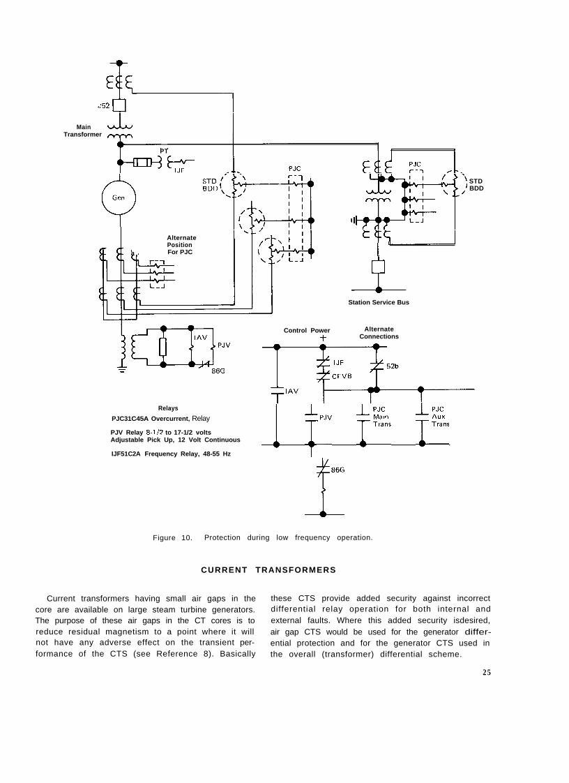
frequency with field applied for a period of time.When operating frequency decreases below rated,the sensitivity of most generator zone protectiverelays will be adversely affected. The sensitivity ofa few relays will only be slightly reduced whileother relays will not provide adequate protectionor become inoperative. Reference 13 and Fig. 9show the effects of frequency on the pickup ofrelays which may be used in the generator zone. Itshould be noted that the transformer differentialrelay (BDD and STD) and generator ground relay(IAV51 K) both being tuned relays, lose sensitivityrather rapidly below 60 Hz. The generator differ-ential CFD is less affected by frequency butbecomes insensitive below 30 Hz. Induction-disk,current-type relays could provide adequate protec-tion down to 20 Hz, while plunger-type relays arenot adversely affected by off-frequency operation.
In general, current transformer performance willnot be a problem at reduced frequency (Reference13). While CT voltage output decreases with fre-quency, the reactive component of most relay bur-dens also decreases with frequency. Therefore, thereduction in CT capability is compensated for bya reduction in relay burden.
Supplementary protection for a unit generatortransformer during the start-up or shutdownperiod can be provided through the use of plunger-type relays as shown in Figure 10. Supplementaryground fault protection can be provided by usinga PJV voltage relay connected in parallel with theIAV51 K.
Supplementary phase fault protection can beprovided by using PJC overcurrent relays in eitherone of two methods:
1. Placing PJC relays in series with the operate cir-cuits of the transformer differential relay.
2. Place PJC relays in the CT phase leads whichconnect to the generator backup relays ormetering.
Method (I), the preferred approach, is capableof providing sensitive supplementary protection.The PJC relay would be set above the differencecurrent that will flow in the differential circuitduring normal 60 Hz operation. This is to preventoperating the PJC relay continuously energized.In general, the difference current will be small andit will be possible in most instances to set the PJCat its minimum 2 amp pickup.
One factor which must be considered whenusing this method is the effect of the PJC burdenon the 60 Hz operation of the transformer differ-ential relay. The PJC current coil will be in the dif-ferential circuit at all times and will present addi-tional burden to the CTS. The effect of added bur-den on the low voltage CTS will generally benegligible but it may be necessary to check theratio error of the high voltage CTS.
When method (2) is used, the PJC would have tobe set above maximum full load current so that therelay would not be picked up continuously whenthe machine is on line. This setting would not pro-vide sensitive protection during start-up or shut-down. If a pickup setting below full load current
22

is used, the PJC coil would have to be short cir-cuited before the machine is connected to the sys-tem since plunger relays cannot be operated pickedup continuously.In general, short circuiting cur-rent coils is not considered a desirable practice.Method (2) has an advantage in that it may also beused to provide protection for accidentally ener-gizing a generator on turning gear. In this instance,it could be used in place of the CHC as discussedearlier.
When a generator is bussed at low vottage (seeFig. 2), supplemental ground protection could beprovided by using a sensitive PJC current relay in
series with the time overcurrent relay normallyused for protection. Supplemental phase faultprotection could be provided by method (2). Inthis case, it would be necessary to short circuitboth the phase and ground PJC current coils whenthe machine is connected to the system if bothrelays could be picked up continuously.
The supplementary protection for both typesof generator arrangements is usually inactivatedwhen the units are connected to the system. Thiscan be accomplished by opening the trip circuitswith a breaker“b” switch or with an underfre-quency relay as shown in Fig. 10.
23

8 r....
7
6 .
5
4
(A) PJC1
/-
1 1..... \l.... \.. \.. (D)
. I. ‘lAV51K. I.. I
1(C) l . \
CFD l ,
i(E)
IBDD
. ETD, \. \ t.
. s \.. \. \
. . \. .
/
/’ _0’r/-m- I
-.
(F) PJV0
0 10 20 30
(A)) _ - - _
(B)
(C) . . . . . . . .
(D) - - -
(E) - - - -
(F) Jc--)cI
40
Frequency In Hz
50 60 70 80
Plunger Type Current Relay
Induction Overcurrent Relay
Generator Differential Relay
Generator Ground Relay
Harmonic, Restraint Transformer Differential Relay
Plunger Type Voltage Relay
Figure 9. Relay pick-up vs. frequency.
24
MainTransformer
PT
Gen0Position
a For PJC I ’
Alternate
Station Service Bus
Control Power AlternateConnections
Relays
PJC31C45A Overcurrent, Relay
PJV Relay 8-1/2 to 17-1/2 voltsAdjustable Pick Up, 12 Volt Continuous
IJF51C2A Frequency Relay, 48-55 Hz
1 TpJV ;e, tkks
Figure 10. Protection during low frequency operation.
CURRENT TRANSFORMERS
STDBDD
Current transformers having small air gaps in the these CTS provide added security against incorrectcore are available on large steam turbine generators. differential relay operation for both internal andThe purpose of these air gaps in the CT cores is to external faults. Where this added security isdesired,reduce residual magnetism to a point where it will air gap CTS would be used for the generator differ-not have any adverse effect on the transient per- ential protection and for the generator CTS used informance of the CTS (see Reference 8). Basically the overall (transformer) differential scheme.
25

In addition, LSTG CTs rated 15,000 primaryamperes and higher are provided with shield wind-ings. The purpose of these windings is to shield thecore from extraneous flux fields (proximity effects)which might cause localized saturation in the coreand thereby cause excessive CT error during a faultcondition.
POTENTIAL TRANSFORMERS
For many years, it has been and still is recom-mended that line-to-line rated PTs connected line-to-ground be used on high resistance groundedgenerators. This practice minimizes the possibilityof ferro-non-linear resonance when the generatorand transformer are connected as a unit.
It should be noted it is possible to have a PTferro-resonance problem with the unit generator-transformer arrangement if the generator is dis-connected and the PTs are left connected tothe delta winding of the GSU transformer, whichis then used to serve station auxiliary load. Withthe PTs connected to an ungrounded system, thepossibility of ferro-non-linear resonance is almosta certainty. To suppress ferro-resonance for thisoperating condition, resistance loading should beapplied across each phase of the secondary wind-ing. Resistance loading equal to PT thermal ratingmay be required.
If the detection of ground faults is desired dur-
ing this mode of operatioin one of two methods:
n, this can be accomp ished
1. Connect an overvoltage-undervoltage relay, TypeIAV53M, across one phase of the secondarywinding.
2. Connect a secondary winding in broken deltaand use an IAV51 K across the broken delta.
With both methods, it will be necessary to checkthe effects of the loading resistance on the relayvoltages during a ground fault.
To avoid coordination problems, it may benecessary to remove this supplementary protectionwhen the unit is operated in normal mode. In addi-tion, the resistance loading applied to suppressferro-resonance should be removed when thegenerator is reconnected.
SUB-SYNCHRONOUS RESONANCE
When a generator is connected to a system thathas series capacitor compensation, it is possible todevelop sub-synchronous frequency oscillationsand shaft torques which can be damaging to thegenerator. Therefore, when a generator will beoperating on a series-compensated system, it isrecommended that a protective system be providedto control the sub-synchronous resonance duty onthe generator. This complex subject and the pro-tection recommendations are discussed in Refer-ence 14.
26