Embed Size (px)
Citation preview
International Research Journal of Engineering and Technology (IRJET) e-ISSN: 2395-0056
Volume: 02 Issue: 05 | Aug-2015 www.irjet.net p-ISSN: 2395-0072
© 2015, IRJET ISO 9001:2008 Certified Journal Page 646
Effect of Slope Stability on Stabilized Soil
due to Earthquake Loads using GeoStudio
Amritha R 1, K V Manjunath 2and Dr R Prabhakara3
1. Graduate student, 2.Associate Professor, and 3. Professor & Head of Department,
Department of Civil Engineering, M.S.Ramaiah Institute of Technology, Bangalore, Karnataka, India
---------------------------------------------------------------------***---------------------------------------------------------------------Abstract – Black cotton soil found in many central
parts of India and Karnataka poses several serious
problems for civil engineers in the buildings, roads,
slopes, retaining structures, etc. This paper evaluates
the possible use of Granulated Blast Furnace Slag (GBS)
to stabilize Black Cotton Soil (BCS). The soil sample
collected from Kadur, Chikmanglur District of
Karnataka was classified as highly compressible
clay(CH) as per Indian Standard Classification System
(ISCS). In this investigation, the response of slopes made
of GBS stabilized BCS under dynamic loading was
studied using finite element method. The slope was
assumed to be constructed with BCS stabilized with
(GBS) along with small amounts of lime viz, 1, 2 and 4
% and for a slope of 15m height. These soil mass along
with the slope was subjected to an amplitude of 0.1g
which was equivalent to highest earthquake in the
region as per past earthquake records. The stability of
slope was analysed and factor of safety was
determined. Factor of safety obtained for unstabilized
soil slope is compared with stabilized soil slope. It was
observed that the stabilized soil performs better under
seismic condition when compared to unstabilized soil
slope.
Key Words: Slope stability, Black cotton Soil, GBS, Factor
of Safety, Dynamic Analysis.
1.INTRODUCTION
In India, expansive soils are usually called Black Cotton
soil (BCS). These soils show high strength under dry
condition (in summer), but undergoes rapid reduction in
strength when it is saturated (during monsoon). The
properties of BCS can be enhanced by blending it with
industrial wastes like Fly Ash, GBS, GGBS, Rice Husk Ash,
etc. GBS, which is a slag material of sand-sized particles, is
one such material which is used to enhance the strength of
BCS. It is not only useful in enhancing the strength of the
soil, but is also a very useful way of disposing industrial
waste and makes the stabilization process more eco-
friendly.
Slopes are one of the main Civil Engineering components
in embankments and earth dams. Stability of these man-
made slopes is of great importance. The stability or
potential to withstand the movement of soil is mainly
measured by its shear strength. There are many causes for
the failure of slopes. Earthquake is one of these main
causes.
Earthquake is one of the most devastating forms of natural
disaster. It causes a lot of damage to life and property. It is
a result of sudden release of energy from earth’s crust
which creates seismic waves. Liquefaction is also one of
the effects of earthquake where in the soil loses its
strength and transforms from solid to liquid state. This
effect leads to sinking of soil and collapse of structures.
Inertia forces which are induced in the slope due to
earthquake results in the displacement of the soil. When
this displacement exceeds certain limit the slope is said to
have failed, because the factor of safety drops below unity
during earthquake. In order to mitigate this failure, it is
tried to stabilize the BCS using GBS and lime so that it may
be used in constructing the slopes which would be more
strong.
2. MATERIALS AND METHOD
2.1 Location of Material.
The BC soil sample used for this study was collected from
Kadur, Chikmaglur District of Karnataka at a depth of 1m
below ground level. The GBS sample used for this study
was procured from Jindal Steel Plant, Bellary in Karnataka.
2.2 Testing method
Properties of BCS and GBS were determined as per Indian
Standard code and are tabulated in Table 1. The soil
International Research Journal of Engineering and Technology (IRJET) e-ISSN: 2395-0056
Volume: 02 Issue: 05 | Aug-2015 www.irjet.net p-ISSN: 2395-0072
© 2015, IRJET ISO 9001:2008 Certified Journal Page 647
obtained from the site was carefully pulverized with
rammer to break lumps. It was then oven dried and mixed
in different proportions with GBS and lime. The different
proportions tested for are tabulated in Table 2. Laboratory
tests were performed on these proportions to determine
their strength parameters.
Table 1: Properties of soil and GBS
Properties BCS GBS
Liquid limit (%) 61 NA
Plastic limit (%) 23.2 NA
Shrinkage limit (%) 14.43 NA-
Specific gravity 2.668 2.525
Maximum Dry Density
(kN/m3)
15.4
13.6
Optimum Moisture Content
(%) 21.5 15.2
CBR value (soaked) (%) 0.11 NA
CBR value (unsoaked) (%) 1.58 NA
28th day UCC strength (kPa) 122 NA
Indian Standard Soil
Classification CH ML
Cohesion (kPa) 90 0
Angle of internal friction () 26 36
Table 2: Combinations of additives with soil
Sl.
No. BCS (%) GBS(%) LIME(%)
1 100 10 0
2 100 10 1
3 100 10 2
4 100 10 4
3. RESULTS AND DISCUSSION
3.1 Compaction properties
Compaction properties for the blended mixes were
determined as per mini compaction test proposed by
Sreedharan and Sivapullaiah (2005). The MDD decreased
on addition of GBS and lime whereas OMC increased for
the same. As lime needs water for chemical reactions and
becomes stronger, the OMC increased because the
presence of optimum content of water for lime provides
more strength.
3.2 Shear strength
Direct shear tests were conducted as per IS 2720 (Part
13) – 1986. These experiments were used to determine
the shear strength of the soil in terms of C and Phi.(Vide
table 3) Samples of various mixes were prepared with
maximum dry density in the laboratory and tested.
Table 3: Direct shear test results
PROPORTIONS DENSITY
in
(kN/m3)
C
in
(kPa)
Phi
in
(degrees)
100 % BCS 15.08 90 25.5
BCS + 10% GBS 14.27 82 28.5
BCS + 1% LIME + 10%
GBS
14.27 76 31
BCS + 2% LIME + 10%
GBS
14.27 70 35
BCS + 4% LIME + 10%
GBS
14.27 63 40.5
4. ANALYSIS OF SLOPE STABILITY
Geo Studio includes elementary features of SLOPE/W,
SEEP/W, SIGMA/W, QUAKE/W, TEMP/W, CTRAN/W,
AIR/W, and VADOSE/W for solving slope stablity and
other related geotechnical analysis. In the present study
two features were primarily used to study the stability,
namely, SLOPE/W which gives the stability of the slope
and QUAKE/W which performs earthquake analysis of the
soil
International Research Journal of Engineering and Technology (IRJET) e-ISSN: 2395-0056
Volume: 02 Issue: 05 | Aug-2015 www.irjet.net p-ISSN: 2395-0072
© 2015, IRJET ISO 9001:2008 Certified Journal Page 648
5. RESULTS AND DISCUSSION
The static and dynamic factors of safety have been given in
Tables 4 to 8. For a slope of 1:1, from Table 4, it was
observed that addition of 10% GBS reduced the dynamic
factor of safety but the addition of 1% Lime increased the
factor of safety and on further addition of lime, the factor
of safety reduced compared to 1% but was found to be
higher than plain BCS. From this, it was understood that
the addition of 10%GBS and 1% lime gives us the highest
dynamic factor of safety. It was also seen that 10 % GBS
and 1 % lime was found to give the highest dynamic factor
of safety only for slope angles of 1:1 and 1:0.9. From Table
6, Table 7 and Table 8, the results show that the factor of
safety increased on addition of lime and it is seen that the
highest factor of safety is obtained for 10% GBS and 4%
lime.
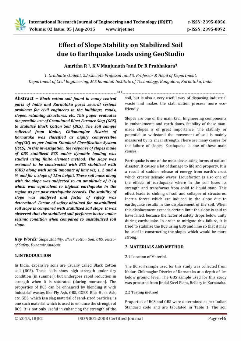
After finalizing the geometry and obtaining material
properties, the slope was modelled in Geostudio SLOPE/W
by keeping the height constant at 15m and the slope
angles were varied using slope angles 45, 48, 51, 55
and 61. Fig 1, shows the analytical model for 45. The
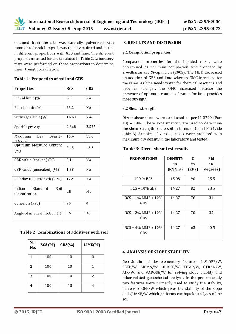
other slope angles were also modelled similarly. SLOPE/W
gives us the static factor of safety of the slope as shown in
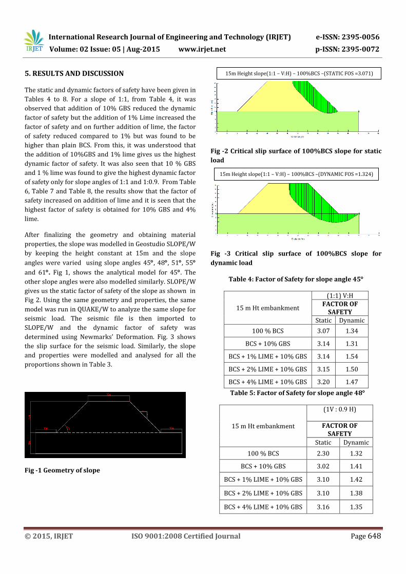
Fig 2. Using the same geometry and properties, the same
model was run in QUAKE/W to analyze the same slope for
seismic load. The seismic file is then imported to
SLOPE/W and the dynamic factor of safety was
determined using Newmarks’ Deformation. Fig. 3 shows
the slip surface for the seismic load. Similarly, the slope
and properties were modelled and analysed for all the
proportions shown in Table 3.
Fig -1 Geometry of slope
Fig -2 Critical slip surface of 100%BCS slope for static
load
Fig -3 Critical slip surface of 100%BCS slope for
dynamic load
Table 4: Factor of Safety for slope angle 45
15 m Ht embankment
(1:1) V:H FACTOR OF
SAFETY Static Dynamic
100 % BCS 3.07 1.34
BCS + 10% GBS 3.14 1.31
BCS + 1% LIME + 10% GBS 3.14 1.54
BCS + 2% LIME + 10% GBS 3.15 1.50
BCS + 4% LIME + 10% GBS 3.20 1.47
Table 5: Factor of Safety for slope angle 48
15 m Ht embankment
(1V : 0.9 H)
FACTOR OF SAFETY
Static Dynamic
100 % BCS 2.30 1.32
BCS + 10% GBS 3.02 1.41
BCS + 1% LIME + 10% GBS 3.10 1.42
BCS + 2% LIME + 10% GBS 3.10 1.38
BCS + 4% LIME + 10% GBS 3.16 1.35
15m Height slope(1:1 – V:H) – 100%BCS –(STATIC FOS =3.071)
15m Height slope(1:1 – V:H) – 100%BCS –(DYNAMIC FOS =1.324)
International Research Journal of Engineering and Technology (IRJET) e-ISSN: 2395-0056
Volume: 02 Issue: 05 | Aug-2015 www.irjet.net p-ISSN: 2395-0072
© 2015, IRJET ISO 9001:2008 Certified Journal Page 649
Table 6: Factor of Safety for slope angle 51
5 m Ht embankment
(1 V : 0.8 H)
FACTOR OF SAFETY
Static Dynamic
100 % BCS 2.99 1.36
BCS + 10% GBS 2.96 1.33
BCS + 1% LIME + 10% GBS 2.87 1.45
BCS + 2% LIME + 10% GBS 2.93 1.41
BCS + 4% LIME + 10% GBS 2.88 1.52
Table 7: Factor of Safety for 55
15 m Ht embankment
(1 V : 0.7 H)
FACTOR OF SAFETY
Static Dynamic
100 % BCS 2.88 1.51
BCS + 10% GBS 2.88 1.46
BCS + 1% LIME + 10% GBS 2.83 1.48
BCS + 2% LIME + 10% GBS 2.83 1.44
BCS + 4% LIME + 10% GBS 2.80 1.74
Table 8: Factor of Safety for slope angle 61
15 m Ht embankment
(1V: 0.5H)
FACTOR OF SAFETY
Static Dynamic
100 % BCS 2.75 1.77
BCS + 10% GBS 2.84 1.76
BCS + 1% LIME + 10% GBS 2.81 1.69
BCS + 2% LIME + 10% GBS 2.77 1.69
BCS + 4% LIME + 10% GBS 2.76 1.89
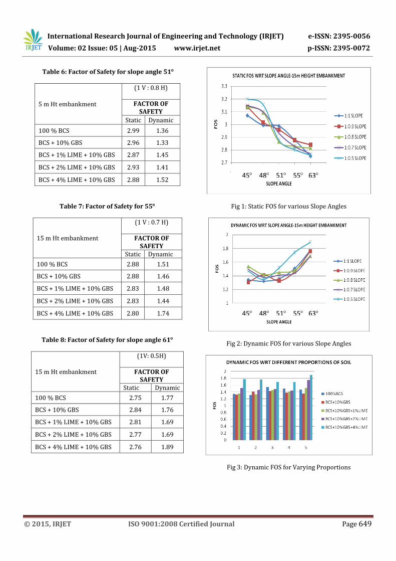
Fig 1: Static FOS for various Slope Angles
Fig 2: Dynamic FOS for various Slope Angles
Fig 3: Dynamic FOS for Varying Proportions
45 48 51 55 63
45 48 51 55 63
International Research Journal of Engineering and Technology (IRJET) e-ISSN: 2395-0056
Volume: 02 Issue: 05 | Aug-2015 www.irjet.net p-ISSN: 2395-0072
© 2015, IRJET ISO 9001:2008 Certified Journal Page 650
6. CONCLUSIONS
The following conclusions was drawn from the results of
the slope stability analyses.
The static factor of safety increases as the
percentage of lime increases, it was seen that for a
slope of 1:1, the static factor safety increased by
2.18% when compared to BCS, on addition of 10%
GBS.
On further addition of 1% lime and 10% GBS, the
static factor of safety was 2.32% higher than that
for BCS.
While for 2% and 4% lime, there was an increase
of 2.57% and 4.23% compared to BCS
respectively.
The dynamic factor of safety for stabilized soil is
higher when lime and GBS were added.
It was observed for a slope of 1:1, the dynamic
factor of safety for 10% GBS decreased by 2.67%
when compared to 100% BCS, while 1% lime
+10% BCS gave an increase of FOS by 14.68%
when compared to 100% BCS.
Also the FOS for 2% lime and 4% lime was found
to be higher by 11.55% and 9.46% respectively
when compared to 100%BCS.
An optimum percentage of lime is obtained as the
slop angle is varied, for slope of 1:1 and 1:0.9, the
optimum percentage of lime was 1% + 10% GBS.
While for the other slopes, the optimum
percentage lime was found to be 4% lime.
Also it was observed that the dynamic factor of
safety increased as the slope angle increased. This
was because as the slope increased, the mass of
the soil in the slope reduced hence there was an
increase of factor of safety.
REFERENCES
1. G Sridevi and A Sreerama Rao(2011),
Utilization Of GBS In Road Sub-Base,
Proceedings of Indian Geotechnical Conference,
December 15-17,2011, Kochi (Paper No. H-
076)
2. Laxmikant Yadu, and R K Tripathi (2013),
“Stabilization Of Soft Soil With Granulated Blast
Furnace Slag And Flyash” ,International Journal
of Research in Engineering and Technology.
ISSN:2319-1163.
3. Huy Thanh Pham , Htet Zaw Oo, Cheng Jing,(
2013 ) “Stability Of Slope And Seepage Analysis In
Earth Dam Using Numerical Finite Element
Model”, Study of Civil Enginreering and
Architecture (SCEA) Volume 2 Issue 4, December
2013.
4. Stability Modelling With SLOPE/W 2007
Version, An Engineering Methodology, Third
Edition, March 2008, GEO-SLOPE International Ltd.
5. Dynamic Modelling With QUAKE/W 2007
Version, An Engineering Methodology, Third
Editioni, March 2008, GEO-SLOPE International
Ltd.
6. Indian Standard Codes IS:2720
BIOGRAPHIES
Name : Amritha R Designation : Graduate student Qualification : B.E.(Civil), M.Tech(Structural Engg) Research Area : Soil Stabilization using GBS
Name : K.V.Manjunath Designation : Associate Professor Qualification : B.E.(Civil), M.Tech(GeotechnicalEngg),(PhD) Research Area : Soil Stabilization using GGBS
Name : Dr R Prabhakara
Designation : Professor & Head
Qualification : M.Tech (Construction
Technology), PhD (Civil Engg)
Research Area : Materials and Structures