Embed Size (px)
Citation preview

DUAL FEED RF GUN DESIGN FOR LCLS
Liling XIAO, Zenghai LI
Advanced Computations Department
Stanford Linear Accelerator Center
Nov.3 2004, SLAC-LCLS Injector RF System Internal Review

L. Xiao and Z. Li LCLS Injector RF System Review
2
Outline
1. Introduction
2. Design via Simulation
3. Pulsed Heating
4. Quadruple mode
5. Dual Feed Gun Parameters
6. Summary
L. Xiao and Z. Li LCLS Injector RF System Review
3
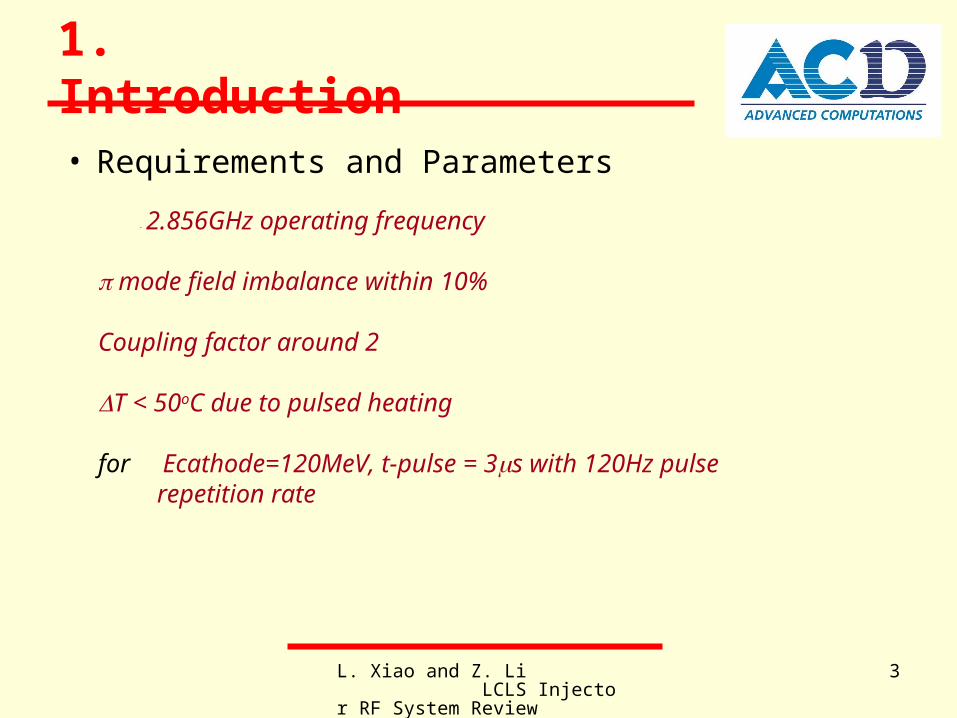
1. Introduction
• Requirements and Parameters
- 2.856GHz operating frequency mode field imbalance within 10% Coupling factor around 2 T < 50oC due to pulsed heating
for Ecathode=120MeV, t-pulse = 3s with 120Hz pulse repetition rate

L. Xiao and Z. Li LCLS Injector RF System Review
4
D.T.Palmer, et al., “Microwave Measurements of the BNL/SLAC/UCLA 1.6 cell Photocathode RF Gun “
SLAC-PUB-95-6799
• Previous Study
R.Boyce, et al., “Design Considerations for the LCLS RF Gun”,
LCLS TN 04-4, April 2004
J.Hodgson
L. Xiao and Z. Li LCLS Injector RF System Review
5
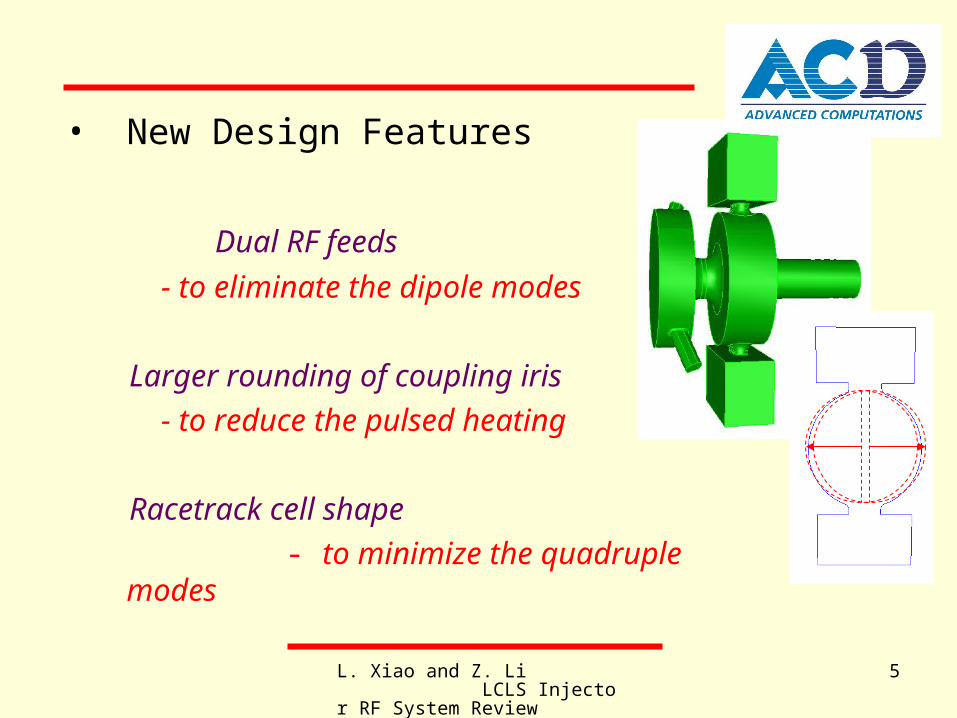
• New Design Features
Dual RF feeds
- to eliminate the dipole modes
Larger rounding of coupling iris
- to reduce the pulsed heating
Racetrack cell shape
- to minimize the quadruple modes

L. Xiao and Z. Li LCLS Injector RF System Review
6
A A
BB
Results: f=2.8625GHz, β=2.28 (E0:E1=1:0.908), T=150oC for the single feed gun dimensions. (comparing the data on Slide 15)
Laser Port
RF Coupling Aperture
2. Design via SimulationOriginal Design
L. Xiao and Z. Li LCLS Injector RF System Review
7
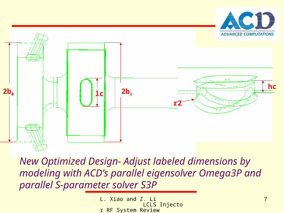
2b0 2b1lchc
r2
New Optimized Design- Adjust labeled dimensions by modeling with ACD’s parallel eigensolver Omega3P and parallel S-parameter solver S3P
L. Xiao and Z. Li LCLS Injector RF System Review
8
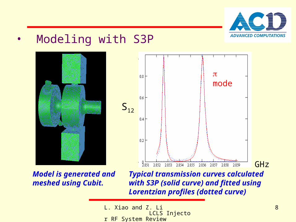
S12
GHz
mode
Model is generated and meshed using Cubit.
Typical transmission curves calculated with S3P (solid curve) and fitted using Lorentzian profiles (dotted curve)
• Modeling with S3P
L. Xiao and Z. Li LCLS Injector RF System Review
9
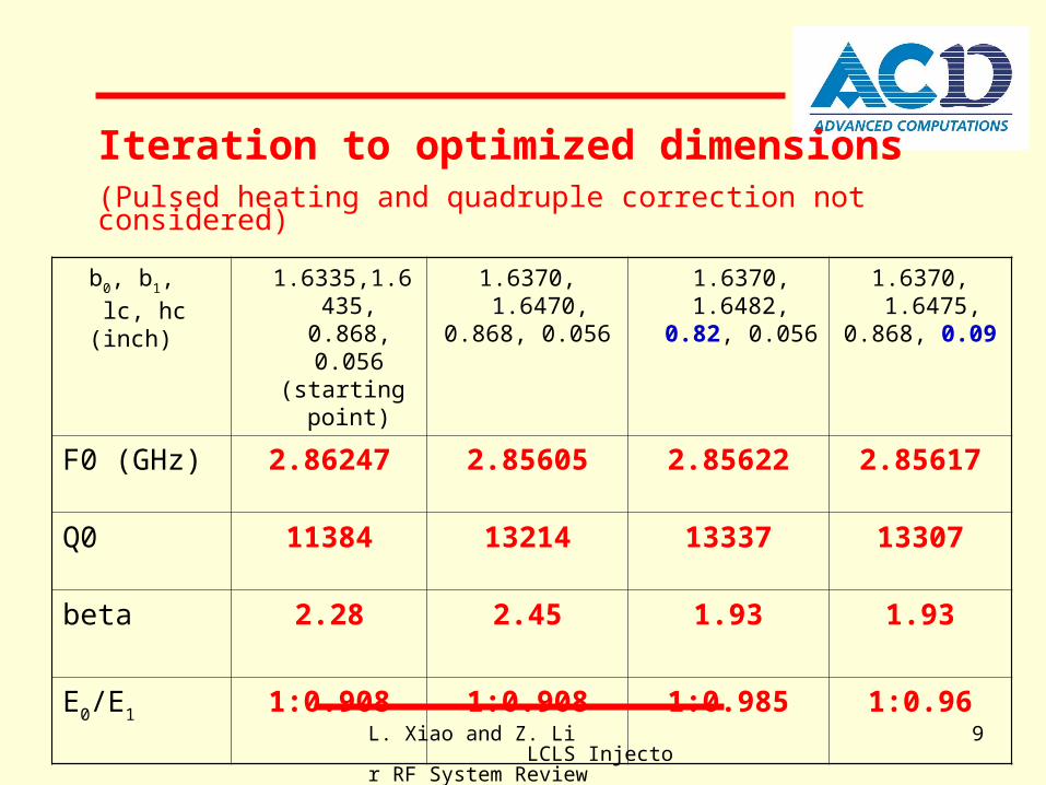
b0, b1,
lc, hc(inch)
1.6335,1.6435, 0.868, 0.056
(starting point)
1.6370, 1.6470, 0.868, 0.056
1.6370, 1.6482, 0.82, 0.056
1.6370, 1.6475, 0.868, 0.09
F0 (GHz) 2.86247 2.85605 2.85622 2.85617
Q0 11384 13214 13337 13307
beta 2.28 2.45 1.93 1.93
E0/E1 1:0.908 1:0.908 1:0.985 1:0.96
Iteration to optimized dimensions(Pulsed heating and quadruple correction not considered)
L. Xiao and Z. Li LCLS Injector RF System Review
10
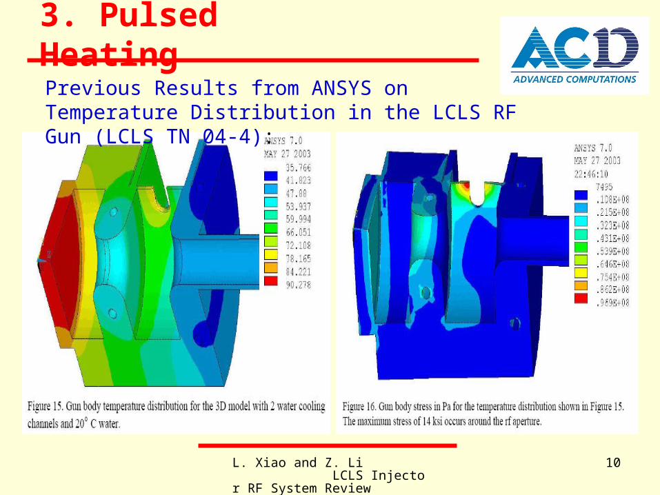
3. Pulsed Heating
Previous Results from ANSYS on Temperature Distribution in the LCLS RF Gun (LCLS TN 04-4):
L. Xiao and Z. Li LCLS Injector RF System Review
11
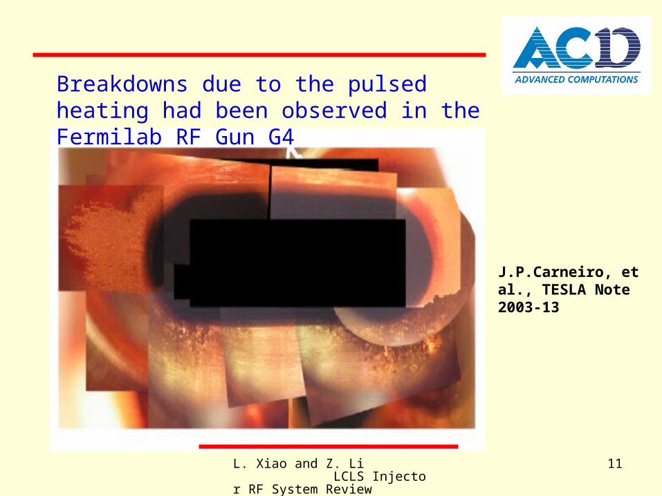
Breakdowns due to the pulsed heating had been observed in the Fermilab RF Gun G4
J.P.Carneiro, et al., TESLA Note 2003-13
L. Xiao and Z. Li LCLS Injector RF System Review
12
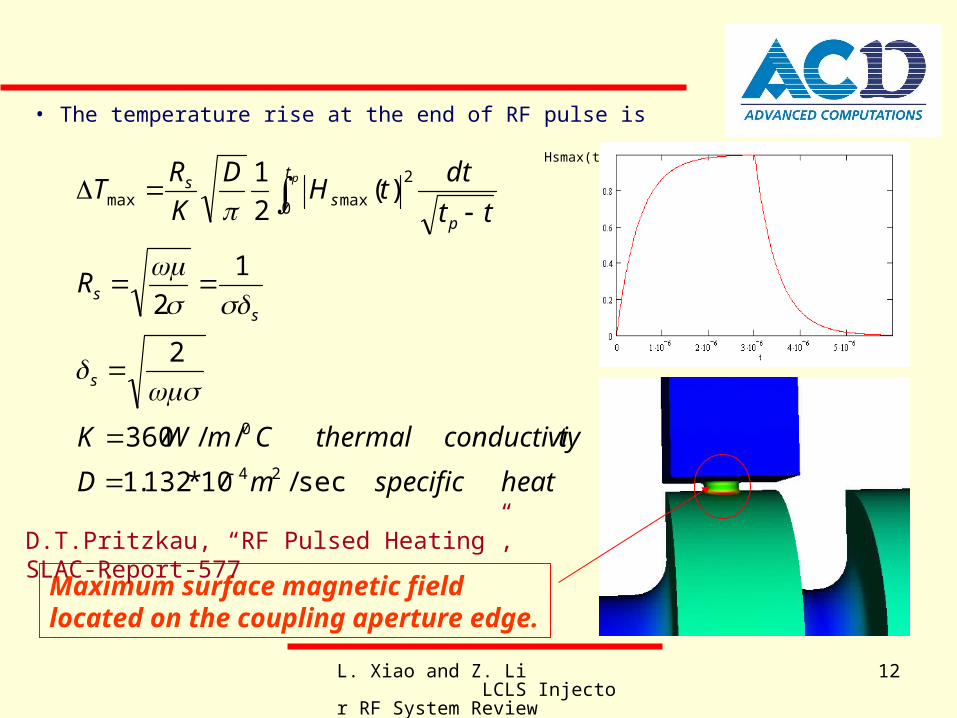
• The temperature rise at the end of RF pulse is
heatspecificmD
tyconductivithermalCmWK
R
tt
dttH
D
K
RT
s
ss
t
p
ss p
sec/10*132.1
//360
2
1
2
)(2
1
24
0
0
2
maxmax
Hsmax(t)
Maximum surface magnetic field located on the coupling aperture edge.
D.T.Pritzkau, “RF Pulsed Heating”, SLAC-Report-577
L. Xiao and Z. Li LCLS Injector RF System Review
13
40
60
80
100
120
140
160
0 0.05 0.1 0.15 0.2 0.25r2 (inch)
dT d
egre
e C
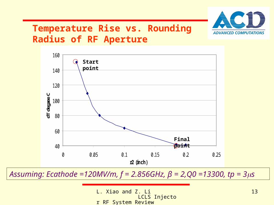
Temperature Rise vs. Rounding Radius of RF Aperture
Assuming: Ecathode =120MV/m, f = 2.856GHz, β = 2,Q0 =13300, tp = 3s
Start point
Final point
L. Xiao and Z. Li LCLS Injector RF System Review
14
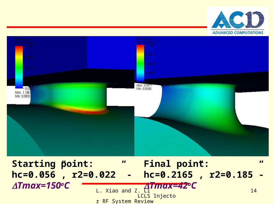
Starting point: hc=0.056”, r2=0.022” - Tmax=150oC
Final point: hc=0.2165”, r2=0.185”- Tmax=42oC
L. Xiao and Z. Li LCLS Injector RF System Review
15
hc=0.2165 inch
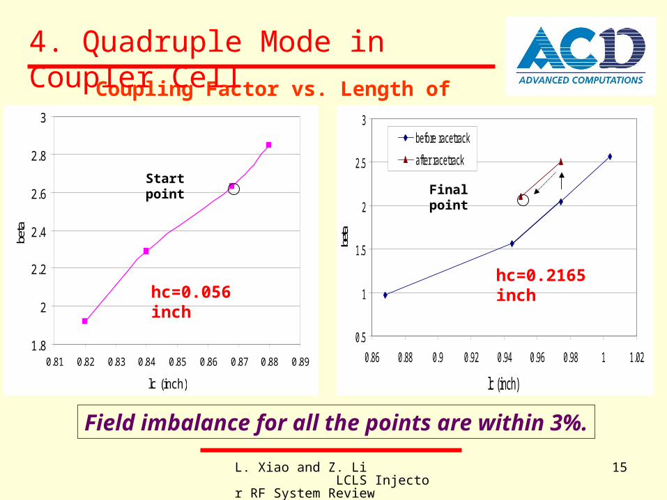
Coupling Factor vs. Length of Aperture
1.8
2
2.2
2.4
2.6
2.8
3
0.81 0.82 0.83 0.84 0.85 0.86 0.87 0.88 0.89
lc (inch)
beta
hc=0.056 inch
0.5
1
1.5
2
2.5
3
0.86 0.88 0.9 0.92 0.94 0.96 0.98 1 1.02
lc (inch)
beta
before racetrack
after racetrack
Field imbalance for all the points are within 3%.
Final pointStart point
hc=0.2165 inch
4. Quadruple Mode in Coupler Cell

L. Xiao and Z. Li LCLS Injector RF System Review
16
βr/
mm
Quadruple Moment in Cylindrical Cavity
-0.008
-0.006
-0.004
-0.002
0.000
0.002
0.004
0.006
0.008
-180 -120 -60 0 60 120 180
rf phase (degree)
cylindrical (lc=0.9744")
cylindrical (lc=0.868")
4th order finite element basis functions in Omega3P have to be used to compute the quadruple fields accurately in the models. And the fields from Omega3P are being used
in PARMELA emittance calculations.

L. Xiao and Z. Li LCLS Injector RF System Review
17
βr/
mm
b1 b1d
-0.008
-0.006
-0.004
-0.002
0.000
0.002
0.004
0.006
0.008
-180 -120 -60 0 60 120 180
rf phase
cylindrical cavity
racetrack cavity withd=0.124"racetrack cavity withd=0.14"racetrack cavity withd=0.134"
Quadruple Moment in Racetrack Cavity

L. Xiao and Z. Li LCLS Injector RF System Review
18
Effect of Laser Ports
1: max T=36oC
βr/
mm
2: Quadruple moment due to the laser ports is about 5% of that in the cylindrical cavity. -0.008
-0.006
-0.004
-0.002
0.000
0.002
0.004
0.006
0.008
-180 -120 -60 0 60 120 180
rf phase
cylindrical coupler cell
half cell with laser port
L. Xiao and Z. Li LCLS Injector RF System Review
19
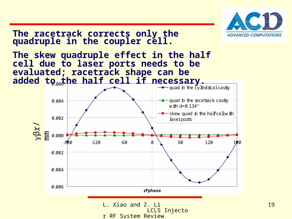
βr/
mm
-0.006
-0.004
-0.002
0.000
0.002
0.004
0.006
-180 -120 -60 0 60 120 180
rf phase
quad in the cylindrical cavity
quad in the racetrack cavitywith d=0.134"
skew quad in the half cell withlaser ports
The racetrack corrects only the quadruple in the coupler cell.
The skew quadruple effect in the half cell due to laser ports needs to be evaluated; racetrack shape can be added to the half cell if necessary.
βr/
mm

L. Xiao and Z. Li LCLS Injector RF System Review
20
5. Dual Feed “Corrected” RF Gun
b1 b1
d

L. Xiao and Z. Li LCLS Injector RF System Review
21
Parameter Value
Race track arc radius b1 1.5999 inch (original:1.6435”)
Race track arc separation d 0.134 inch (original: 0)
Race track cell length l1 1.28 inch
Half cell radius b0 1.6361 inch (original:1.6335”, not consider the laser ports)
Half cell length l0 0.896 inch
RF coupling hole size (slot length) lc 0.95 inch (original:0.868”)
RF coupling hole radius of curvature rc 0.1875 inch
RF coupling hole size (slot width) 2rc 0.375 inch
RF coupling hole thickness hc 0.2165 inch (original: 0.056”)
RF coupling hole rounding radius r1 on up side 0.022 inch
RF coupling hole rounding radius r2 on down side 0.185 inch (original: 0.022”)
Cell iris radius a 0.492 inch
Disk thickness t 0.868 inch
Disk rounding radius r 0.375 inch
Laser port hole size (slot length) ll 0.433 inch
Laser port hole radius of curvature rl 0.125 inch
Laser port hole size (slot width) 2rl 0.250 inch
Laser port hole rounding radius r3 0.030 inch
Laser port offset the cathode plate 0.531 inch
Laser port angle 18 degree
Waveguide 2.840 inch*1.340inch
RF-GUN Final Dimensions

L. Xiao and Z. Li LCLS Injector RF System Review
22
“Corrected” RF GUN Parameters:
RF Parameters
F0 (GHz) 2.856022
Q0 13325
β 2.07
Mode Sep. f (MHz) 3.4
T max (oC) 44
E0:E1 1:0.962
L. Xiao and Z. Li LCLS Injector RF System Review
23
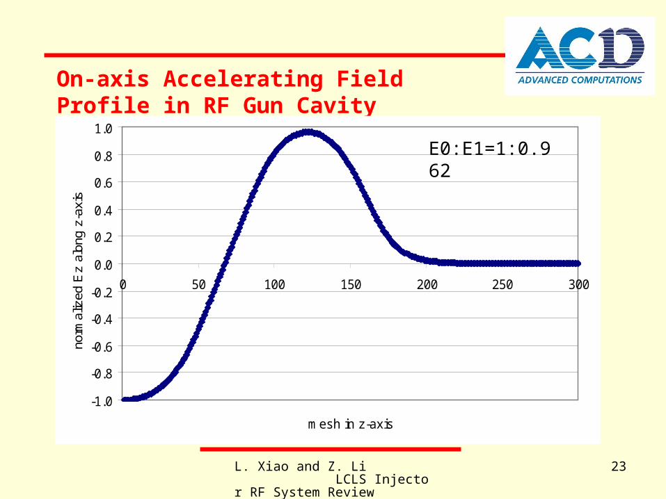
On-axis Accelerating Field Profile in RF Gun Cavity
-1.0
-0.8
-0.6
-0.4
-0.2
0.0
0.2
0.4
0.6
0.8
1.0
0 50 100 150 200 250 300
mesh in z-axis
norm
aliz
ed E
z al
ong
z-ax
is
E0:E1=1:0.962
L. Xiao and Z. Li LCLS Injector RF System Review
24
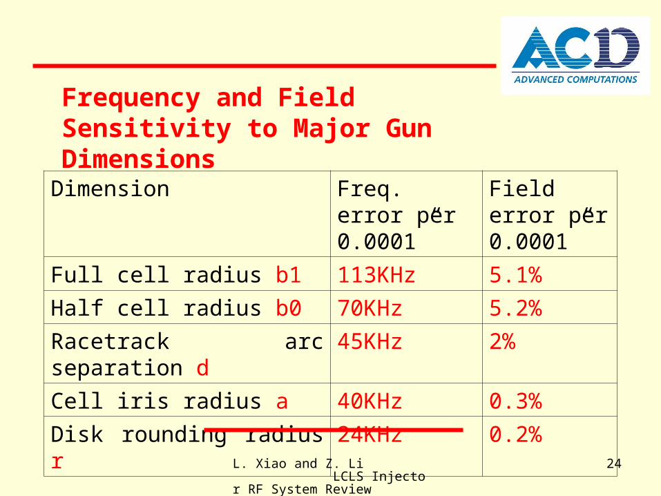
Dimension Freq. error per 0.0001”
Field error per 0.0001”
Full cell radius b1 113KHz 5.1%
Half cell radius b0 70KHz 5.2%
Racetrack arc separation d 45KHz 2%
Cell iris radius a 40KHz 0.3%
Disk rounding radius r 24KHz 0.2%
Frequency and Field Sensitivity to Major Gun Dimensions
L. Xiao and Z. Li LCLS Injector RF System Review
25
The original RF gun design has been optimized to:
- eliminate the dipole modes
- reduce pulsed heating
- minimize the quadruple moment
A “corrected” design has been generated using SLAC’s parallel codes Omega3P & S3P with 4th order elements
The steady-state thermal properties needs to be studied again for the new dual feed gun design.
6. Summary