Embed Size (px)
Citation preview
Control relay suitablefor safety circuitseasySafetyES4P…
Moeller addresses worldwide:www.moeller.net/address
E-Mail: [email protected]: www.moeller.net
Issued by: Moeller GmbHHein-Moeller-Str. 7–11D-53115 Bonn
© 2008 by Moeller GmbHSubject to alterationAWB2528-1599en IP/IP/Eb 09/08Printed in the Federal Republic of Germany (09/08)Article No.: xxxxxx
4 *patpks#nycmyn*
Eaton's electrical business is a global leader in electrical control, power distribution, uninterruptible power supply and industrial automation products and services. Eaton's global electrical brands, including Cutler-Hammer®, MGE Office Protection Systems™, Powerware®, Holec®, MEM®, Santak and Moeller, provide customer-driven PowerChain Management® solutions to serve the power system needs of the industrial, institutional, government, utility, commercial, residential, IT, mission critical and OEM markets worldwide.www.eaton.com
easyS
afet
y ES
AP…
User Manual
09/08 AWB2528-1599en
A
Rückenbreite 30 – 60 mm (1 Blatt = 0,106 mm für Digitaldruck)(1 Blatt = 0,080 mm für Offsetdruck bei 80 g/m2)
All brand and product names are trademarks or registered trademarks of the owner concerned.
1st published 2008, edition date 02/082nd edition 09/2008
See revision protocol in the “About this manual“ chapter
Author: Arno DielmannEditor: Thomas KrachtTranslator: globaldocs GmbH
All rights reserved, including those of the translation.
No part of this manual may be reproduced in any form (printed, photocopy, microfilm or any other process) or processed, duplicated or distributed by means of electronic systems without written permission of Moeller GmbH, Bonn.
Subject to alteration without notice.
Rückenbreite (1 Blatt = 0,106 mm für Digitaldruck)(1 Blatt = 0,080 mm für Offsetdruck bei 80 g/m2)

Moe
llerG
mbH
Safe
ty in
stru
ctio
nsDanger! Dangerous electrical voltage!
Before commencing the installation
• Disconnect the power supply of the device.
• Ensure that devices cannot be accidentally restarted.
• Verify isolation from the supply.
• Earth and short circuit.
• Cover or enclose neighbouring units that are live.
• Follow the engineering instructions (AWA) of the device concerned.
• Only suitably qualified personnel in accordance with EN 50110-1/-2 (VDE 0105 Part 100) may work on this device/system.
• Before installation and before touching the device ensure that you are free of electrostatic charge.
• The functional earth (FE) must be connected to the protective earth (PE) or to the potential equalisation. The system installer is responsible for implementing this connection.
• Connecting cables and signal lines should be installed so that inductive or capacitive interference does not impair the automation functions.
• Install automation devices and related operating elements in such a way that they are well protected against unintentional operation.
• Suitable safety hardware and software measures should be implemented for the I/O interface so that a line or wire breakage on the signal side does not result in undefined states in the automation devices.
• Ensure a reliable electrical isolation of the low voltage for the 24 volt supply. Only use power supply units complying with IEC 60364-4-41 (VDE 0100 Part 410) or HD 384.4.41 S2.
• Deviations of the mains voltage from the rated value must not exceed the tolerance limits given in the specifications, otherwise this may cause malfunction and dangerous operation.
• Emergency stop devices complying with IEC/EN 60204-1 must be effective in all operating modes of the automation devices. Unlatching the emergency-stop devices must not cause restart.
• Devices that are designed for mounting in housings or control cabinets must only be operated and controlled after they have been installed with the housing closed. Desktop or portable units must only be operated and controlled in enclosed housings.
I
II
• Measures should be taken to ensure the proper restart of programs interrupted after a voltage dip or failure. This should not cause dangerous operating states even for a short time. If necessary, emergency-stop devices should be implemented.
• Wherever faults in the automation system may cause damage to persons or property, external measures must be implemented to ensure a safe operating state in the event of a fault or malfunction (for example, by means of separate limit switches, mechanical interlocks etc.).
09/08 AWB2528-1599en
Contents
About this manual 9List of revisions 9Intended users 10Exclusion of liability 10Device designation 13Reading conventions 14
1 easySafety 15Proper use 15Overview of functions 16Device overview 19– easySafety-Basic device 19– LED display 20– Key to part numbers easySafety 21easySafety operation 22– Keyboard 22– Selecting menus and entering values 22– Status display for the easySafety basic unit 23– Status display for the local expansion 25– Status display additional information 27– Menu structure 28– Choosing the main and system menu 29– Main menu 30– System menu 31– Selecting or toggling between menu items 35– Cursor display 35– Setting values 35
2 Installation 37Mounting 38– Mounting on top-hat rail 39– Screw mounting 40Connecting the expansion device 41Terminals 42– Tools 42– Cable cross-sections 42
1
Contents
2
09/08 AWB2528-1599en
Connecting the power supply 42– Cable protection 42– DC-Basic device 43– DC expansion device EASY…-DC-.E 43Connecting the inputs 44– Connecting easy DC digital inputs 45Connecting outputs 47– Connecting the safety outputs (QS/QR) 47– Connecting relay outputs 49– Connecting transistor outputs 51– Connecting test signal outputs 53Connecting network easyNet 55– Connection assignment of the RJ45 socket on
the device 55– Prefabricated network connection cables 56– User-assembled network connection cables 57– Bus termination resistor 58– Plugging and unplugging network cables 59– easyNet-topologies 60– Cable length with cross-sections 62Connecting the serial multi-function interface 64– Connection to a PC 65– Connecting for point-to-point communication 66– Inserting the memory card 68Expanding inputs/outputs 69– Local standard expansion device 71– Remote standard expansion 72
3 Commissioning 73Switching on 73Setting the menu language 74easySafetyoperating modes 75– RUN and STOP and BUSY 75The first circuit diagram 77– Starting point: the status display 79– Switching to the standard circuit diagram 80– Creating a standard circuit diagram for lamp
controls 82– Switching to the safety circuit diagram 88
Contents09/08 AWB2528-1599en
– Creating a safety circuit diagram for an emergency-stop circuit 90
– Testing the safety circuit diagram 99– Testing the standard circuit diagram 100– Deleting the standard circuit diagram 103– Deleting the safety circuit diagram 103
4 Wiring with easySafety 105easySafety operation 105– Buttons for editing circuit diagrams and
function blocks 105– Operation 106Circuit diagram elements 107– Configuration 107– Function blocks 109– Relays 109– Contacts 110– Coils 110– Markers 111Circuit diagram display 116Transfer from and to the memory card 118– Information on the memory card 118– Transfer from/to a device without display 119– Loading and saving with a memory card 120– Deleting a circuit diagram on the card 124– Transferring the language from and to the
memory card 124Loading and saving with easySoft-Safety 125Working with contacts and relays 127– Entering and changing contacts and coils 128– Creating or changing connections 133– Adding or deleting rungs 135– Saving circuit diagrams 135– Aborting circuit diagram entry 136– Searching for contacts and coils 136– Got to a rung 137– Deleting rungs 137– Switching with the cursor buttons 138– Checking the circuit diagram 139– Coil functions 141
3
Contents
4
09/08 AWB2528-1599en
– Jumps 146– Test outputs, test signals 149Working with function blocks 151– Adding function blocks to the circuit diagram
for the first time 153– Setting function block parameters 154– Changing function block parameters 162– Deleting function blocks 166– Checking function blocks 167
5 Standard function blocks 169A, analog value comparator/threshold value switch 170AR, arithmetic function block 177BC, data block comparator 182BT, data block transfer 192BV, Boolean operation 206C, counter relay 211CP, comparator 219D, text display 222DB, data block 229DG, diagnostics 233GT, get value from the NET 238HW, seven-day time switch 242HY, year time switch 250JC, conditional jump 257LB, jump label 261MR, master reset 262MX, data multiplexer 265NC, numerical converter 271OT, operating hours counter 278PT - Put value to the NET 282SC, set date/time 287SR, shift register 289T, timing relay 304TB, table function 319Example with timing relay and counter function block 326
Contents09/08 AWB2528-1599en
6 Safety function blocks 331Rules in the safety circuit diagram 331Common features 335– Error contact ER 335– Enable parameter, EN enable coil 336– Operating mode parameter, RE reset coil 336– Parameter SUT (Startup test) 337– QV actual value output 338– DG diagnostics output 338– Application examples 338EM, feedback circuitmonitoring 339EN, enable switch 350ES, Emergency-stop 361FS, safety foot switch 372LC, light curtain 384LM, light curtain muting 398OM, Maximum speed monitoring 424OS, operating mode selector switch 439SE, Start element 448SG, safety gate (optionally with guard locking) 455TH, two-hand button 471TS, Safety timing relay 484ZM, zero (standstill) monitoring 499
7 easyNet network 511Introduction to the easyNet network 511– Transfer behaviour of the NET stations 515– Functions of the NET stations 516– Function terminal mode 517– Transfer of the standart- and safety circuit
diagram via the NET 519Commissioning NET stations 520– "Commissioning NET stations" quick guide 522– Parameterising and configuring NET stations 523– Creating the station list 525– Configure NET 526– Changing the NET configuration 530– Tip: Carry out a NET configuration through
NET station 1 after every change to the NET. 531
5
Contents
6
09/08 AWB2528-1599en
– Checking the functionality of the NET 533– Displaying the status display of other stations 536– Wiring NET operands in the standard circuit
diagram 537Description of the NET-PARAMETERs 549Replacing a NET station 555Power supply failure on station with NET-ID 1 556
8 easySafety Settings 559Password protection 559– General information 559– Access levels 561– Entering passwords 562– Activating the password 566– Unlocking easySafety 567– Changing passwords 569– Delete password 569– Master password no longer known 571Sealing the safety configuration 572Enabling overwriting from the card 573Changing the menu language 575Setting date and time 576Changing between winter/summer time (DST) 577– Setting DST parameters 578Activating/deactivating DEBOUNCE 581– Activating DEBOUNCE 581– Deactivating DEBOUNCE 582Activating and deactivating the P buttons 582– Activating the P buttons 583– Deactivating the P buttons 583Startup behaviour 584– Setting the startup behaviour 584– Behaviour when the circuit diagram is
deleted 586– Behaviour during upload/download to card or
PC 586– Possible faults 586Setting contrast and backlight 587Retention 589– Requirements 590
Contents09/08 AWB2528-1599en
– Setting retentive behaviour 590– Deleting areas 591– Deleting retentive actual values of markers
and function blocks 591– Transferring retentive behaviour 592
9 easySafety internal 593easySafety circuit diagram 593– How the easySafety device evaluates the
safety and standard circuit diagram as well as the function blocks 594
– What you must consider when creating the circuit diagram 597
Time behaviour of the inputs and outputs 599– Input delay (debounce) 600Reaction time of an easySafety device 603Diagnostics 606– Diagnostics using the ID diagnostics contact 606– Diagnostics using the DG diagnostics
function block 607– Diagnostics using the ER contact 613– Diagnostics of faults inside and outside the
device 614Expanding an easySafety device 617– How is an expansion device detected? 618– Transfer behaviour 618– Monitoring the functionality of the expansion
device 619– Checking the transistor output for short-circuit/
overload 620Displaying device information 621Device version 622
Appendix 623List of function blocks 623– Function block coils 625– Function block contacts 627– Function block inputs (constants, operands) 628– Function block output (operands) 629
7
Contents
8
09/08 AWB2528-1599en
– Other operands 629Contacts and coils used in the circuit diagram 630Memory requirement 642Technical data 644– General 644– Voltage supply:DC 652– Network easyNet 653– Digital inputs 24 V DC 654– Test signal outputs 655– Relay outputs 656– Transistor outputs 658Dimensions 660
Index 661
09/08 AWB2528-1599en
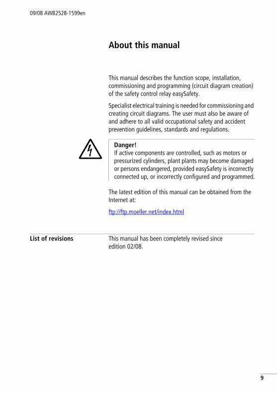
About this manual
This manual describes the function scope, installation, commissioning and programming (circuit diagram creation) of the safety control relay easySafety.
Specialist electrical training is needed for commissioning and creating circuit diagrams. The user must also be aware of and adhere to all valid occupational safety and accident prevention guidelines, standards and regulations.
The latest edition of this manual can be obtained from the Internet at:
ftp://ftp.moeller.net/index.html
List of revisions This manual has been completely revised since edition 02/08.
j Danger! If active components are controlled, such as motors or pressurized cylinders, plant plants may become damaged or persons endangered, provided easySafety is incorrectly connected up, or incorrectly configured and programmed.
9
About this manual
10
09/08 AWB2528-1599en
Intended users This manual is written particularly for planners, developers and operators of applications in electrical engineering, control system construction and machine building who wish to use the safety relays (easySafety devices) for the safe operation of a machine.
A easySafety device must only be installed and connected up by trained electricians or other persons who are familiar with the installation of electrical equipment.
Exclusion of liability We have provided all the information in this manual to the best of our knowledge and belief and in accordance with the latest state of the art. However, this does not exclude the possibility of inaccuracies so that we cannot accept any liability for the accuracy and completeness of the information. In particular, this information does not guarantee any particular properties.
The devices described must only be installed and operated in accordance with the content of this manual and the AWA installation instructions provided with the device. Installation, commissioning, operation, maintenance and refitting of the devices must only be carried out by qualified persons. The devices must only be used in the areas recommended and only in conjunction with third-party devices and components that have been approved by us. Only use is technically faultless condition is permitted. Faultfree and safe operation of the system requires proper transport, storage, installation as well as careful operation and maintenance. If the following safety instructions are not observed, particularly with regard to commissioning and maintenance of the devices by insufficiently qualified
j Danger! It is assumed that operators have specialist electrical knowledge for configuration, creating circuit diagrams and start-up. Plant sections and persons are at risk if a easySafety device is incorrectly connected or configured and active components such as motors or pressure cylinders are controlled.
Exclusion of liability09/08 AWB2528-1599en
personnel and/or in the event of improper use of the devices, any hazards caused by the devices cannot be excluded. We cannot accept any liability for any resulting injury or damage.
For example programming/configurations with easySafety the following also applies:
easySoft-Safety is a computer program for the generating and testing as well as the documentation and administration of configurations for easySafety devices. In order to demonstrate the generating of a configuration, Moeller provides prospective customers with sample programming and sample configurations for easySafety devices.
The use of such sample programs and of easySoft-Safety are subject to the following safety instructions and operating guidelines:
1. The configuration examples provided here have been created by Moeller to the best of its knowledge and belief and to the current technological standards. The possibility of errors in the configuration can not, however, be excluded and the provided configuration examples do not cover all function blocks and applications available for the easySafety devices. If you encounter any malfunction, error and/or any other problem when using the configuration samples, please contact your Moeller contact person.
2. The configuration, the preparation of a circuit diagram and the initial start-up of easySafety devices require safety know how and electro technical know how. If an easySafety-device is improperly connected or wrongly configured and active components such as motors and remote cylinders are being actuated, plant components and humans are endangered.
3. When using the provided sample programs and generating a configuration with easySoft-Safety, the user has the sole responsibility to observe the following:
• All relevant regulations regarding the preparation of a circuit diagram for easySafety-devices according to the updated user manuals AWA and AWB of ES4P by Moeller,
11

About this manual
12
09/08 AWB2528-1599en
• All relevant regulations, directives, rules and standards of occupational safety and accident prevention regarding the intended preparation of circuit diagrams, initial start-up and the operation of easySafety-devices, particularly those issued by Employers’ Liability Insurance Associations (Berufsgenossenschaft),
• Acknowledged rule of technology and state of science. • All other general due diligence regarding the prevention of
damages to life and physical condition of persons as well as material damage.
4. Moeller assumes no liability for any damage caused by the application of the provided sample programs contrary to the preceding safety instructions and operating guidelines according to the preceding numbers 1 to 3.
Device designation09/08 AWB2528-1599en
Device designation The manual applies to the easySafety safety control relays which are part of the easy device family. The following terms are used for the device types if the description applies to all these types:
• easySafety for– ES4P-...-..,
• easy600 for– EASY618-.C-RE– EASY620-DC-TE
• easy800 for– EASY819-..,– EASY820-..,– EASY821-..,– EASY822-..
13
About this manual
14
09/08 AWB2528-1599en
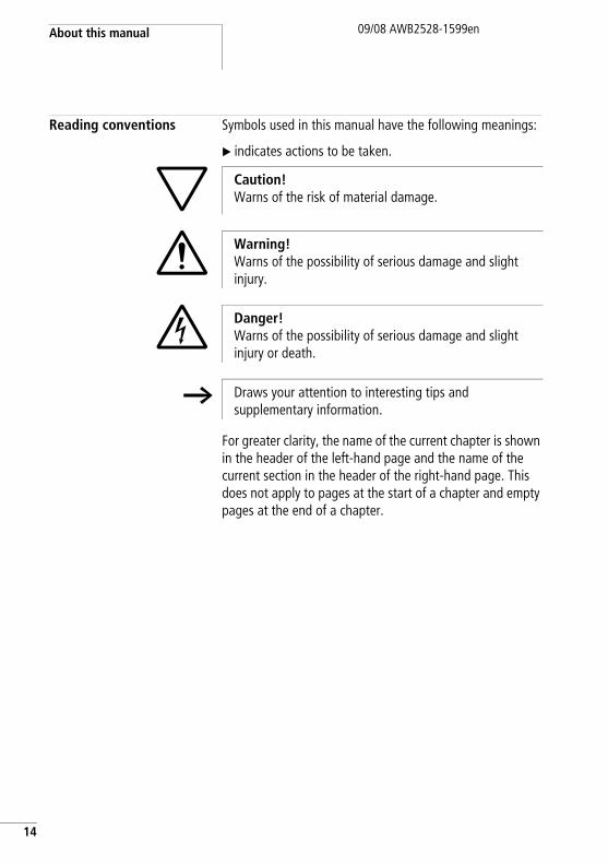
Reading conventions Symbols used in this manual have the following meanings:
X indicates actions to be taken.
For greater clarity, the name of the current chapter is shown in the header of the left-hand page and the name of the current section in the header of the right-hand page. This does not apply to pages at the start of a chapter and empty pages at the end of a chapter.
h Caution!Warns of the risk of material damage.
i Warning! Warns of the possibility of serious damage and slight injury.
j Danger! Warns of the possibility of serious damage and slight injury or death.
h Draws your attention to interesting tips and supplementary information.
09/08 AWB2528-1599en
1 easySafety
Proper use The configurable safety control relay enables you to implement a large number safety-related tasks for system and machine building. The easySafety device is a safety element that monitors signal transmitters used as part of the guards on machines for the prevention of hazards to persons or equipment.
easySafety device is designed to be installed in an enclosure, switch cabinet or distribution board.
Power supply and signal terminals must be protected against accidental contact and covered.
The easySafety device may only be operated if it has been correctly fitted and connected by qualified electrical specialists. The installation must comply with regulations for electromagnetic compatibility (EMC).
j Danger!The power up of the easySafety device must not cause any hazards arising from activated devices, such as unexpected motor startups or power ups.
15
easySafety
16
09/08 AWB2528-1599en
Overview of functions The easySafety device is an electronic and configurable safety and control relay.Unlike conventional safety relays, these functions are not permanently set but can be configured as required. A safety control relay can therefore be used for a wide range of safety and standard functions in machine and plant construction.
The device is equipped with:
• Safety inputs and outputs.• Test signal outputs.• Safety function blocks.• Logic functions.• Time functions.• Integrated display and operating elements.
A safety control relay enables you to implement a wide range of safety and control functions for plant and machine building applications. The wide variety of safety function blocks enables you to protect the hazardous area and prevent the occurrence any hazardous situations quickly and easily, depending on the safety category required. The configurable safety function blocks allow you to adapt your project to the safety category required.
The device uses its safety circuit diagram to monitor signal transmitters that are used as part of safety systems on machines for preventing hazards to persons or equipment, provided that it is installed, connected and correctly configured correctly and in accordance with the relevant regulations.
j Danger! The safety function is implemented by switching off the device outputs. In the safety state, the semiconductor outputs are 0 and the relay outputs are open. With a 2-channel architecture (category 3/4) use two device outputs or the redundant relay output for the disconnection.
Overview of functions09/08 AWB2528-1599en
The easySafety processes standard control tasks with its standard circuit diagram.
The integrated easyNet network makes it possible to connect up to eight Net stations to a PLC. All easySafety devices, devices of type easy800/MFD-Titan and PLCs of type XC200-/EC4-200 can be NET stations.
Each easyNet station can process its own safety circuit diagram and if required also a standard circuit diagram. This allows the design of systems using high-speed controllers with decentralised intelligence.
The safety and standard circuit diagrams are created in ladder logic. The circuit diagram can be entered either on the device, using the operating buttons or on the PC using the configuration software easySoft-Safety.
For example, you can:
• Connect n/o and n/c contacts in series and in parallel• Connect output relays and markers.• Define outputs as coils, impulse relays, rising or falling
edge-triggered relays or as latching relays.• Configure ready-to-use and tested safety function blocks
for your safety application.
h The data from the safety circuit diagram is also available for processing in the standard circuit diagram in order to ensure optimum utilisation of the device.
However, in order not to impair the safety-related functions, non-safety data from the standard circuit diagram is prevented from being used in the safety circuit diagram.
j Danger!easyNet is a network designed for non-safety applications. Data transferred via this network must not be used for safety-relevant applications.
17
easySafety
18
09/08 AWB2528-1599en
The safety circuit diagram provides you with safety circuit diagrams such as emergency-stop functions, two-hand control buttons or safety timing relays. The function blocks in the standard circuit diagram provide you with several functions such as arithmetic functions, value comparison functions or up/down counting. All function blocks provided are listed in alphabetical order in the Appendix on Page 623. The cross-references provide links to detailed descriptions of these function blocks.
If you prefer to wire up the easySafety from a PC, then use the CL-SOFT configuration software.
A wide range of programming functions allow you, for example, to simulate the power flow in the safety and standard circuit diagram (offline test). You can also monitor the power flow and view the operand states (online test) after the safety and standard circuit diagram is transferred to the safety control relay.
You can protect your safety application as well as your know-how by entering a master, safety and/or standardpassword.
With the configuration software you can also print out your circuit diagram in different formats (e.g. DIN or ANSI or easy) and thus produce comprehensive documentation.
Device overview09/08 AWB2528-1599en
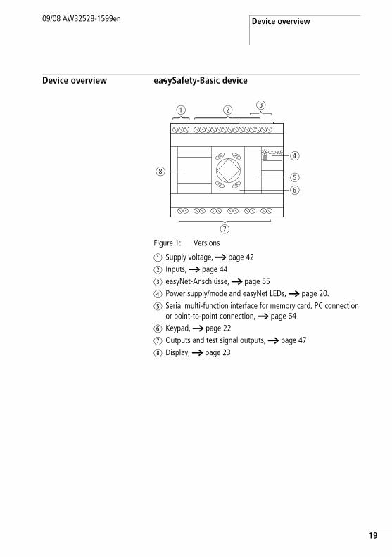
Device overview easySafety-Basic device
Figure 1: Versions
a Supply voltage, a page 42b Inputs, a page 44c easyNet-Anschlüsse, a page 55d Power supply/mode and easyNet LEDs, a page 20.e Serial multi-function interface for memory card, PC connection
or point-to-point connection, a page 64f Keypad, a page 22g Outputs and test signal outputs, a page 47h Display, a page 23
a bc
d
e
f
h
g
19
easySafety
20
09/08 AWB2528-1599en
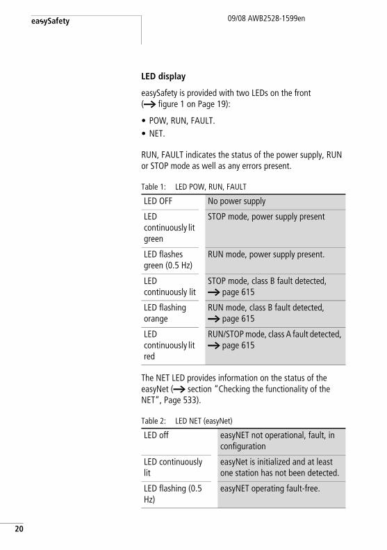
LED display
easySafety is provided with two LEDs on the front (a figure 1 on Page 19):
• POW, RUN, FAULT.• NET.
RUN, FAULT indicates the status of the power supply, RUN or STOP mode as well as any errors present.
Table 1: LED POW, RUN, FAULT
The NET LED provides information on the status of the easyNet (a section “Checking the functionality of the NET”, Page 533).
Table 2: LED NET (easyNet)
LED OFF No power supply
LED continuously lit green
STOP mode, power supply present
LED flashes green (0.5 Hz)
RUN mode, power supply present.
LED continuously lit
STOP mode, class B fault detected, a page 615
LED flashing orange
RUN mode, class B fault detected, a page 615
LED continuously lit red
RUN/STOP mode, class A fault detected, a page 615
LED off easyNET not operational, fault, in configuration
LED continuously lit
easyNet is initialized and at least one station has not been detected.
LED flashing (0.5 Hz)
easyNET operating fault-free.
Device overview09/08 AWB2528-1599en
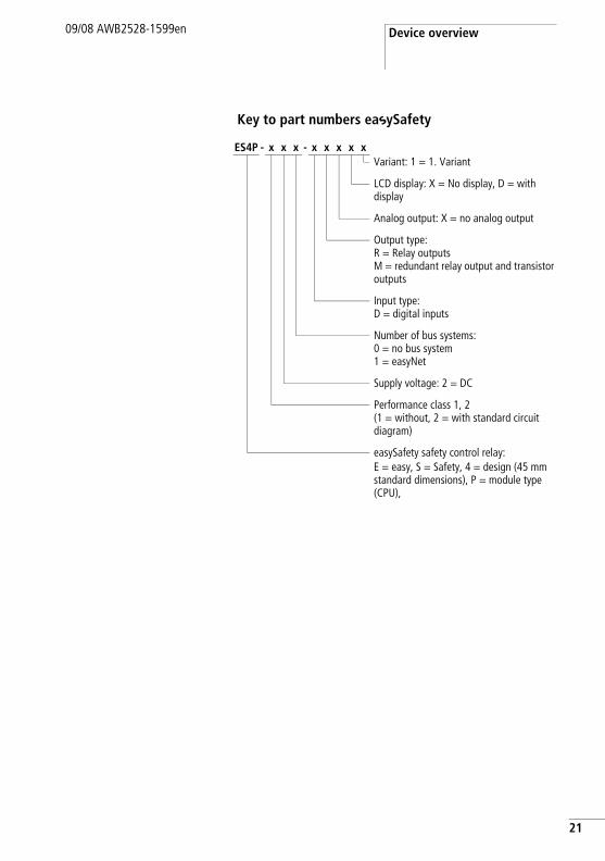
Key to part numbers easySafety
ES4P - x x x - x x x x xVariant: 1 = 1. Variant
LCD display: X = No display, D = with display
Analog output: X = no analog output
Output type:R = Relay outputsM = redundant relay output and transistor outputs
Input type: D = digital inputs
Number of bus systems:0 = no bus system1 = easyNet
Supply voltage: 2 = DC
Performance class 1, 2 (1 = without, 2 = with standard circuit diagram)
easySafety safety control relay: E = easy, S = Safety, 4 = design (45 mm standard dimensions), P = module type (CPU),
21
easySafety
22
09/08 AWB2528-1599en
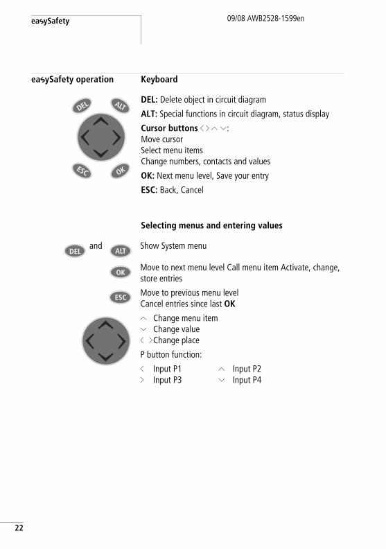
easySafety operation Keyboard
Selecting menus and entering values
DEL: Delete object in circuit diagram
ALT: Special functions in circuit diagram, status display
Cursor buttons ú í Í Ú:Move cursor Select menu itemsChange numbers, contacts and values
OK: Next menu level, Save your entry
ESC: Back, Cancel
ALT
ESC
DEL
OK
and Show System menu
Move to next menu level Call menu item Activate, change, store entries
Move to previous menu levelCancel entries since last OK
Í Úú í
Change menu itemChange valueChange place
P button function:
úí
Input P1Input P3
ÍÚ
Input P2Input P4
DEL ALT
OK
ESC
easySafety operation09/08 AWB2528-1599en
Status display for the easySafety basic unit
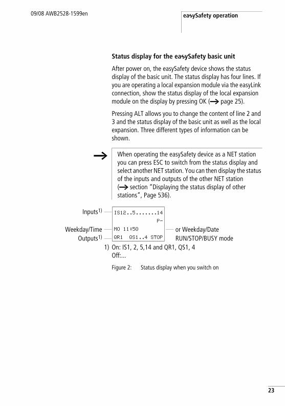
After power on, the easySafety device shows the status display of the basic unit. The status display has four lines. If you are operating a local expansion module via the easyLink connection, show the status display of the local expansion module on the display by pressing OK (a page 25).
Pressing ALT allows you to change the content of line 2 and 3 and the status display of the basic unit as well as the local expansion. Three different types of information can be shown.
Figure 2: Status display when you switch on
h When operating the easySafety device as a NET station you can press ESC to switch from the status display and select another NET station. You can then display the status of the inputs and outputs of the other NET station (a section “Displaying the status display of other stations”, Page 536).
Inputs1)
Weekday/Time or Weekday/DateOutputs1) RUN/STOP/BUSY mode
1) On: IS1, 2, 5,14 and QR1, QS1, 4Off:...
IS12..5.......14
P-
MO 11:50
QR1 QS1..4 STOP
23
easySafety
24
09/08 AWB2528-1599en
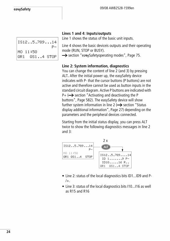
Lines 1 and 4: Inputs/outputsLine 1 shows the status of the basic unit inputs.
Line 4 shows the basic deviceís outputs and their operating mode (RUN, STOP or BUSY).a section “easySafetyoperating modes”, Page 75.
Line 2: System information, diagnosticsYou can change the content of line 2 (and 3) by pressing ALT. After the initial power up, the easySafety device indicates with P- that the cursor buttons (P buttons) are not active and therefore cannot be used as button inputs in the standard circuit diagram. Active P buttons are indicated with P+ (a section “Activating and deactivating the P buttons”, Page 582). The easySafety device will show further system information in line 2 (a section “Status display additional information”, Page 27) depending on the parameters and the peripheral devices connected.
Starting from the initial status display, you can press ALT twice to show the following diagnostics messages in line 2 and 3:
• Line 2: status of the local diagnostics bits ID1...ID9 and P-/+.
• Line 3: status of the local diagnostics bits I10...I16 as well as R15 and R16
IS12..5.789...14
P-
MO 11:50
QR1 QS1..4 STOP
IS12..5.789...14
P-
MO 11:50
QR1 QS1..4 STOPIS12..5.789....14
ID 1.......9 P-
ID10.....16 R..
QR1 QS1..4 STOP
ALT
2 x
easySafety operation09/08 AWB2528-1599en
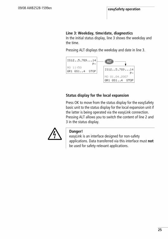
Line 3: Weekday, time/date, diagnosticsIn the initial status display, line 3 shows the weekday and the time.
Pressing ALT displays the weekday and date in line 3.
Status display for the local expansion
Press OK to move from the status display for the easySafety basic unit to the status display for the local expansion unit if the latter is being operated via the easyLink connection. Pressing ALT allows you to switch the content of line 2 and 3 in the status display.
IS12..5.789...14
P-
MO 11:50
QR1 QS1..4 STOPIS12..5.789...14
P-
MO 01.04.2007
QR1 QS1..4 STOP
ALT
j Danger!easyLink is an interface designed for non-safety applications. Data transferred via this interface must not be used for safety-relevant applications.
25
easySafety
26
09/08 AWB2528-1599en
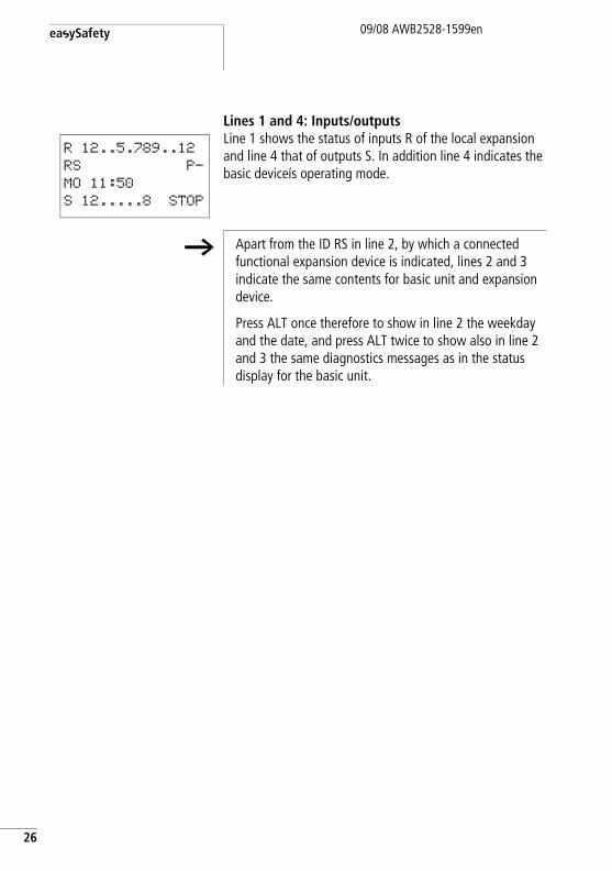
Lines 1 and 4: Inputs/outputsLine 1 shows the status of inputs R of the local expansion and line 4 that of outputs S. In addition line 4 indicates the basic deviceís operating mode.
R 12..5.789..12
RS P-
MO 11:50
S 12.....8 STOP
h Apart from the ID RS in line 2, by which a connected functional expansion device is indicated, lines 2 and 3 indicate the same contents for basic unit and expansion device.
Press ALT once therefore to show in line 2 the weekday and the date, and press ALT twice to show also in line 2 and 3 the same diagnostics messages as in the status display for the basic unit.
easySafety operation09/08 AWB2528-1599en
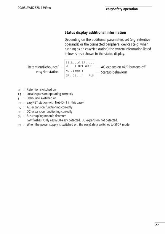
Status display additional information
Depending on the additional parameters set (e.g. retentive operands) or the connected peripheral devices (e.g. when running as an easyNet station) the system information listed below is also shown in the status display.
Retention/Debounce/easyNet station
AC expansion ok/P buttons offStartup behaviour
RE : Retention switched onRS : Local expansion operating correctlyI : Debounce switched onNT1 : easyNET station with Net-ID (1 in this case)AC : AC expansion functioning correctlyDC : DC expansion functioning correctlyGW : Bus coupling module detected
GW flashes: Only easy200-easy detected. I/O expansion not detected.ST : When the power supply is switched on, the easySafety switches to STOP mode
IS12...6.89.....
RE I NT1 AC P-
MO 11:50 T
QR1 QS1..4 RUN
27
easySafety
28
09/08 AWB2528-1599en
Menu structure
The easySafety device has two different menu structures, the main menu and the system menu.
The main menu provides the most frequently required functions during operation.
The system menu is used for entering global device parameters, and can be accessed without entering a password. The menus are marked by preceding letters to distinguish between safety and standard parameters:
• S stands for safety functions,• STD stands for standard functions.
easySafety operation09/08 AWB2528-1599en
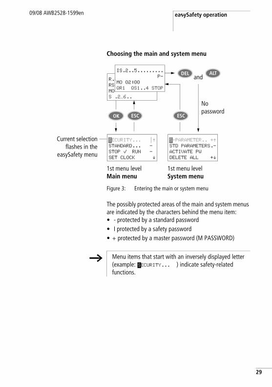
Choosing the main and system menu
Figure 3: Entering the main or system menu
The possibly protected areas of the main and system menus are indicated by the characters behind the menu item: • - protected by a standard password• I protected by a safety password• + protected by a master password (M PASSWORD)
ALTR.2
RS
MO
S .2…6..
IS.2..5.........
P-
MO 02:00
QR1 QS1..4 STOP
DELand
No password
ESCESCOK
Current selectionflashes in the
easySafety menu
1st menu levelMain menu
1st menu levelSystem menu
SECURITY... nÆSTANDARD... -
STOP å RUN -
SET CLOCK æ
S-PARAMETER.. +ÆSTD PARAMETERS.-
ACTIVATE PW
DELETE ALL +æ
h Menu items that start with an inversely displayed letter (example: ) indicate safety-related functions.
SECURITY...
29
easySafety
30
09/08 AWB2528-1599en
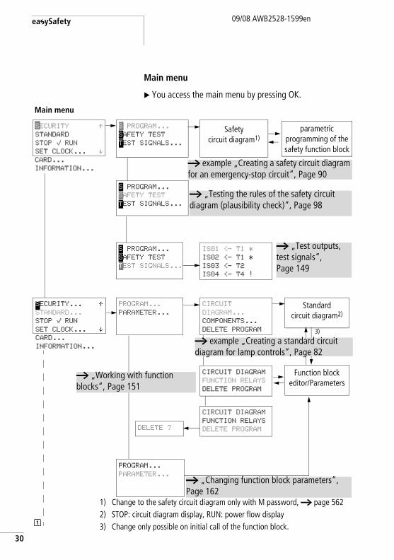
Main menu
X You access the main menu by pressing OK.
S PROGRAM...
SAFETY TEST
TEST SIGNALS...
SECURITY ÆSTANDARD
STOP å RUN
SET CLOCK... æCARD...
INFORMATION...
S PROGRAM...
SAFETY TEST
TEST SIGNALS...
Safetycircuit diagram1)
parametric programming of the safety function block
IS01 <- T1 *
IS02 <- T1 *
IS03 <- T2
IS04 <- T4 !
a „Test outputs, test signals“, Page 149
a example „Creating a safety circuit diagram for an emergency-stop circuit“, Page 90
Main menu
a „Testing the rules of the safety circuit diagram (plausibility check)“, Page 98
S PROGRAM...
SAFETY TEST
TEST SIGNALS...
SECURITY... ÆSTANDARD...
STOP å RUN
SET CLOCK... æCARD...
INFORMATION...
PROGRAM...
PARAMETER...
CIRCUIT DIAGRAM
FUNCTION RELAYS
DELETE PROGRAM
Function block editor/Parameters
CIRCUIT
DIAGRAM...
COMPONENTS...
DELETE PROGRAM
Standardcircuit diagram2)
CIRCUIT DIAGRAM
FUNCTION RELAYS
DELETE PROGRAMDELETE ?
PROGRAM...
PARAMETER...
1) Change to the safety circuit diagram only with M password, a page 5622) STOP: circuit diagram display, RUN: power flow display3) Change only possible on initial call of the function block.
3)
1
a „Changing function block parameters“, Page 162
a example „Creating a standard circuit diagram for lamp controls“, Page 82
a „Working with function blocks“, Page 151
easySafety operation09/08 AWB2528-1599en
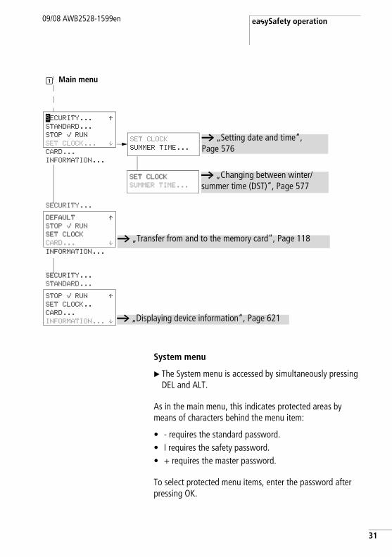
System menu
X The System menu is accessed by simultaneously pressing DEL and ALT.
As in the main menu, this indicates protected areas by means of characters behind the menu item:
• - requires the standard password.• I requires the safety password.• + requires the master password.
To select protected menu items, enter the password after pressing OK.
SET CLOCK
SUMMER TIME...
SET CLOCK
SUMMER TIME...
a „Setting date and time“, Page 576
a „Changing between winter/summer time (DST)“, Page 577
a „Displaying device information“, Page 621
SECURITY... ÆSTANDARD...
STOP å RUN
SET CLOCK... æCARD...
INFORMATION...
DEFAULT ÆSTOP å RUN
SET CLOCK
CARD... æ
SECURITY...
INFORMATION...
STOP å RUN ÆSET CLOCK..
CARD...
INFORMATION... æ
SECURITY...
STANDARD...
a „Transfer from and to the memory card“, Page 118
Main menu1
31
easySafety
32
09/08 AWB2528-1599en
1
SEAL-SAFETY TRNSF.FROM CARDå
System menu
PROTECTION...
SYSTEM...
M PASSWORD...
S PASSWORD...
M PASSWORD...
S PASSWORD...
PROTECTION...
SYSTEM...
SEAL SAFETY IS
NOT REVERSIBLE!
OK->ACTIVATE
ESC->CANCEL
SEAL-SAFETY TRNSF.FROM CARDå
S-PARAMETER... ÆSTD PARAMETERS
ACTIVATE PW
DELETE ALL æSAFETY-ID:
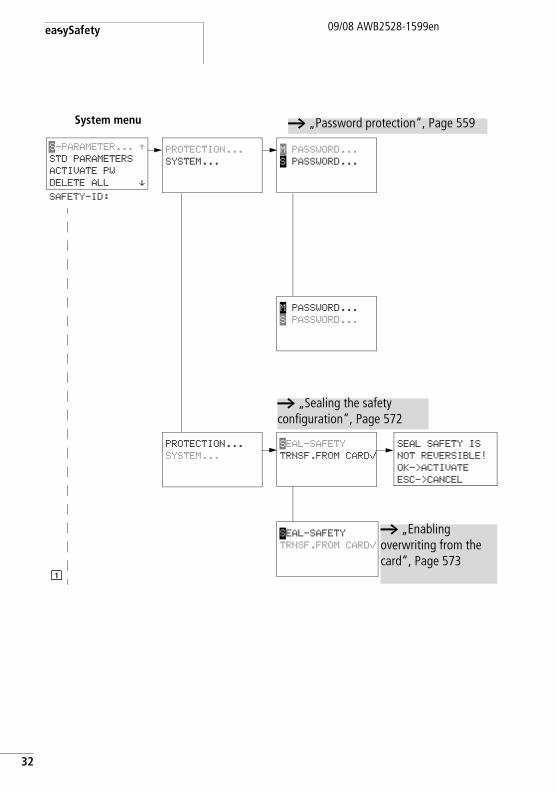
a „Password protection“, Page 559
a „Sealing the safety configuration“, Page 572
a „Enabling overwriting from the card“, Page 573
easySafety operation09/08 AWB2528-1599en
1 2
System menu
PROTECTION...
SYSTEM...
MENU LANGUAGE
CONFIGURATOR...
STD PASSWORD...
RANGE…
STD PASSWORD...
RANGE…
PROTECTION...
SYSTEM...
MENU LANGUAGE
CONFIGURATOR...
P BUTTONS åÆRUN MODE åDEBOUNCE...
DISPLAY... æRETENTION...
S-PARAMETER... ÆSTD PARAMETERS
ACTIVATE PW
DELETE ALL æSAFETY-ID: -
P BUTTONS åÆRUN MODE åDEBOUNCE...
DISPLAY... æRETENTION...
P BUTTONS
RUN MODE ÆDEBOUNCE...
DISPLAY...
RETENTION... æ
PROTECTION...
SYSTEM...
MENU LANGUAGE
CONFIGURATOR...
ENGLISH ÆDEUTSCH
ITALIANO å
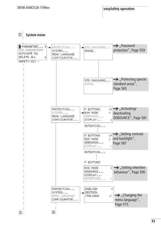
a „Protecting special standard areas“, Page 565
a „Activating/deactivating DEBOUNCE“, Page 581
a „Changing the menu language“, Page 575
1
a „Setting retentive behaviour“, Page 590
a „Setting contrast and backlight“, Page 587
a „Password protection“, Page 559
33
easySafety
34
09/08 AWB2528-1599en
System menu
PROTECTION...
SYSTEM...
MENU LANGUAGE
CONFIGURATOR...
NET...
LINK...
NET PARAMETER..
STATIONS...
CONFIGURE
Display NET only in STOP mode
NET PARAMETER..
STATIONS...
CONFIGURE
NET PARAMETER..
STATIONS...
CONFIGURE
The further menus depend on the connected expansiondevice.
NET...
LINK...
S-PARAMETER... ÆSTD PARAMETERS
ACTIVATE PW
DELETE ALL æSAFETY-ID: -
S-PARAMETER... ÆSTD PARAMETERS
ACTIVATE PW
DELETE ALL æSAFETY-ID: -
S-PARAMETER... ÆSTD PARAMETERS
ACTIVATE PW
DELETE ALL æSAFETY-ID: -
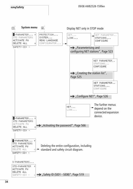
Deleting the entire configuration, including standard and safety circuit diagram.
a „Creating the station list“, Page 525
a „Configure NET“, Page 526
a „Parameterising and configuring NET stations“, Page 523
STD-PARAMETER ÆACTIVATE PW
DELETE ALL
SAFETY-ID: - æ
S-PARAMETERS...
1 2
a „Activating the password“, Page 566
a „Safety ID (SID1 - SID8)“, Page 519
easySafety operation09/08 AWB2528-1599en
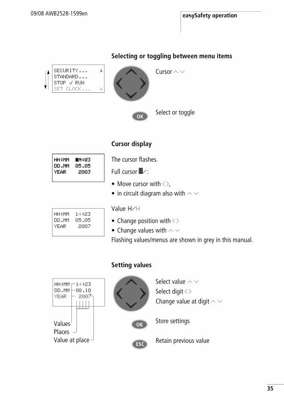
Selecting or toggling between menu items
Cursor display
Setting values
Cursor Í Ú
Select or toggle
SECURITY... æSTANDARD...
STOP å RUN
SET CLOCK... æ
OK
The cursor flashes.
Full cursor Ê/:
• Move cursor with ú í,• in circuit diagram also with Í Ú
Value H/H
• Change position with ú í• Change values with Í ÚFlashing values/menus are shown in grey in this manual.
HH:MM â4:23DD.MM 05.05
YEAR 2003
HH:MM â4:23DD.MM 05.05
YEAR 2007
HH:MM 14:23
DD.MM 05.05
YEAR 2007
Select value Í ÚSelect digit ú íChange value at digit Í Ú
Store settings
Retain previous value
ValuesPlaces Value at place
HH:MM 14:23
DD.MM 08.10
YEAR 2007
OK
ESC
35

36
09/08 AWB2528-1599en

09/08 AWB2528-1599en
2 Installation
easySafety devices must only be installed and wired up by qualified electricians or other persons familiar with the installation of electrical equipment.
The devices are easySafetyinstalled in the following order:
• Mounting• Wiring up the inputs.• Wiring up the outputs.• Wiring easyNet network (optional).• Connecting serial multi-function interface (optional).• Connecting the power supply.
j Danger of electric shock!Never carry out electrical work on the device while the power supply is switched on.
Always follow the safety rules:
• Switch off and isolate.• Verify isolation from the supply.• Secure against reclosing.• Short-circuit and ground.• Cover adjacent live parts.
37
Installation
38
09/08 AWB2528-1599en
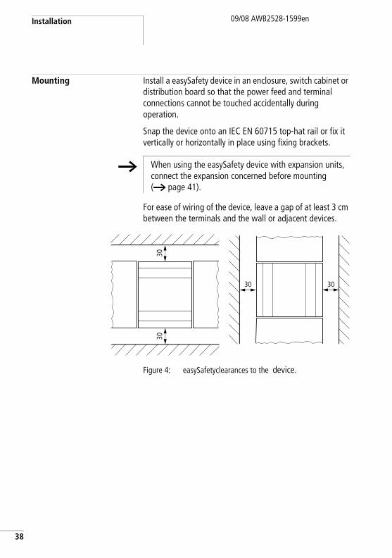
Mounting Install a easySafety device in an enclosure, switch cabinet or distribution board so that the power feed and terminal connections cannot be touched accidentally during operation.
Snap the device onto an IEC EN 60715 top-hat rail or fix it vertically or horizontally in place using fixing brackets.
For ease of wiring of the device, leave a gap of at least 3 cm between the terminals and the wall or adjacent devices.
Figure 4: easySafetyclearances to the device.
h When using the easySafety device with expansion units, connect the expansion concerned before mounting (a page 41).
3030
3030
Mounting09/08 AWB2528-1599en
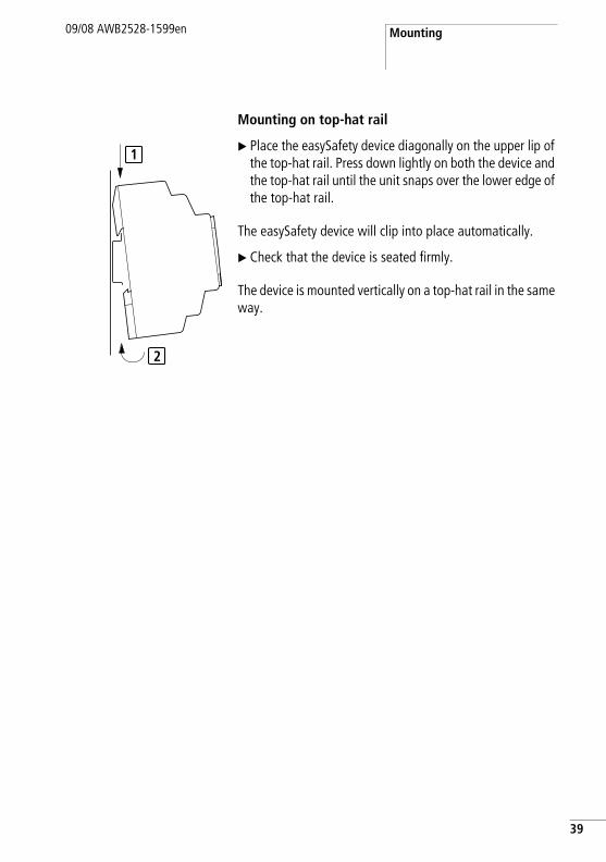
Mounting on top-hat rail
X Place the easySafety device diagonally on the upper lip of the top-hat rail. Press down lightly on both the device and the top-hat rail until the unit snaps over the lower edge of the top-hat rail.
The easySafety device will clip into place automatically.
X Check that the device is seated firmly.
The device is mounted vertically on a top-hat rail in the same way.
1
2
39
Installation
40
09/08 AWB2528-1599en
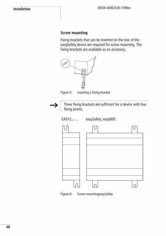
Screw mounting
Fixing brackets that can be inserted on the rear of the easySafety device are required for screw mounting. The fixing brackets are available as an accessory.
Figure 5: Inserting a fixing bracket
Figure 6: Screw mountingeasySafety
CLICK !
h Three fixing brackets are sufficient for a device with four fixing points.
EASY2..-… easySafety, easy600
Connecting the expansion device
09/08 AWB2528-1599en
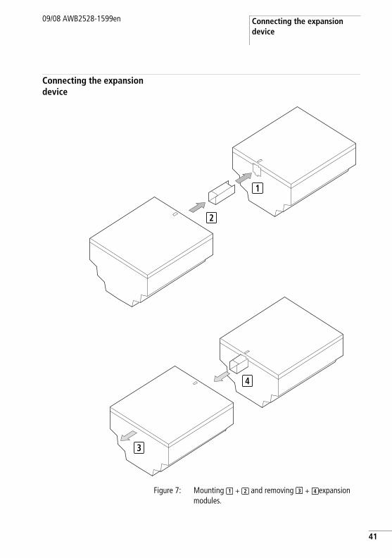
Connecting the expansion device
Figure 7: Mounting + and removing + expansion modules.
1
3
4
2
1 2 3 4
41
Installation
42
09/08 AWB2528-1599en
Terminals Tools
Slot-head screwdriver, width 3.5 mm, tightening torque 0.6 Nm.
Cable cross-sections
• Solid: 0.2 to 4 mm2 (AWG 22 -12).• Flexible with ferrule: 0.2 to 2.5 mm2
(AWG 22 -12).
Connecting the power supply
Cable protection
Connect cable protection (F1) of at least 1 A (T) and no more than 4 A (T) to the easySafety device and to the standard expansion device.
h Caution!The first time it is switched on, the easySafety power supply behaves capacitively, and the inrush current that flows is higher than the nominal input current.
The switching device and the power supply device for switching on the power supply must be designed for this, i.e. no Reed relay contacts, no proximity switches.
When designing the DC power supply unit, bear the inrush current in mind and use time-lag fuses.
h The connection data required for the device types is provided in chapter “Technical data”, page 644.
The devices run a system test for three seconds after the power supply has been switched on. After this time the device switches to RUN or STOP mode depending on the default setting.
Connecting the power supply09/08 AWB2528-1599en
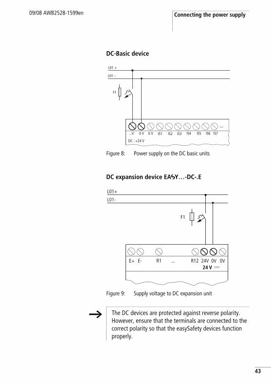
DC-Basic device
Figure 8: Power supply on the DC basic units
DC expansion device EASY…-DC-.E
Figure 9: Supply voltage to DC expansion unit
...V 0 V0 V
L01 –
F1
L01 +
DC : +24 V
IS1 IS3IS2 IS4 IS6IS5 IS7
...
0V0V24V
L01-
F1
L01+
24 VE+ E- R1 ... R12
h The DC devices are protected against reverse polarity. However, ensure that the terminals are connected to the correct polarity so that the easySafety devices function properly.
43
Installation
44
09/08 AWB2528-1599en
Connecting the inputs The easySafety device is provided only with safety outputs. For safety applications, the IS safety inputs must be read in the safety circuit diagram, processed and output exclusively with the QR output (redundant relay output) or one of the QS outputs (safety transistor/relay outputs).
The inputs of the easySafety devices switch electronically. Once you have connected a contact via an input terminal, you can reuse it as a switching contact in the safety and standard circuit diagram as often as you like.
When using special function blocks, certain inputs are permanently assigned to these function blocks and cannot be used for any other purpose. The relevant function block description describes which inputs are affected.
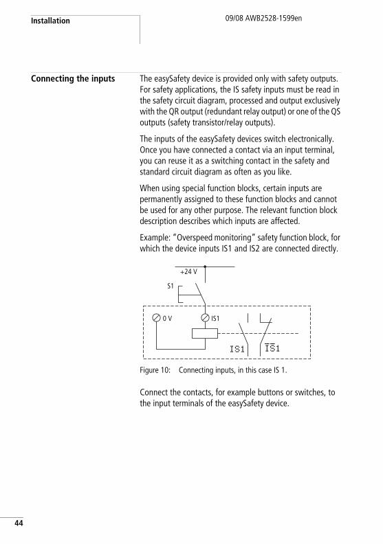
Example: “Overspeed monitoring” safety function block, for which the device inputs IS1 and IS2 are connected directly.
Figure 10: Connecting inputs, in this case IS 1.
Connect the contacts, for example buttons or switches, to the input terminals of the easySafety device.
+24 V
S1
0 V IS1
IS1 IS1
Connecting the inputs09/08 AWB2528-1599en
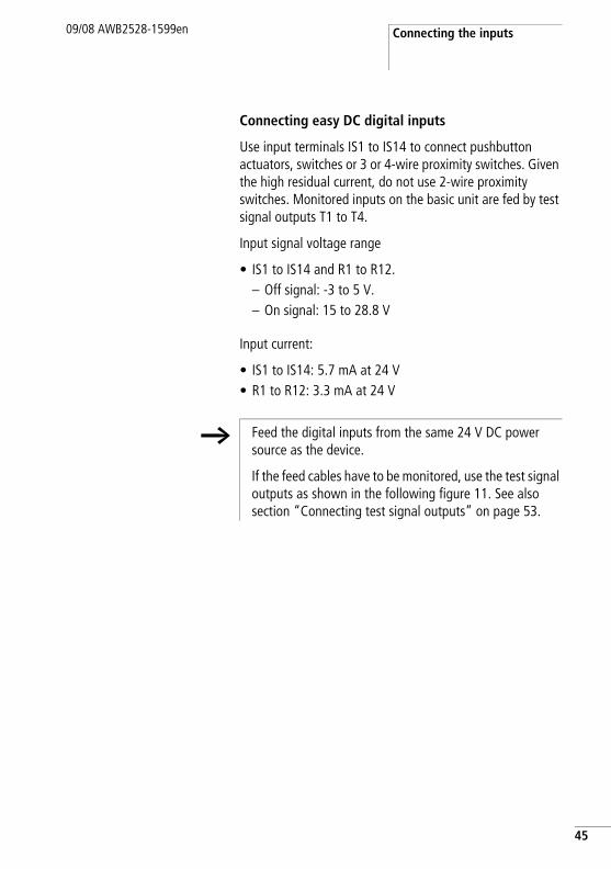
Connecting easy DC digital inputs
Use input terminals IS1 to IS14 to connect pushbutton actuators, switches or 3 or 4-wire proximity switches. Given the high residual current, do not use 2-wire proximity switches. Monitored inputs on the basic unit are fed by test signal outputs T1 to T4.
Input signal voltage range
• IS1 to IS14 and R1 to R12.– Off signal: -3 to 5 V.– On signal: 15 to 28.8 V
Input current:
• IS1 to IS14: 5.7 mA at 24 V• R1 to R12: 3.3 mA at 24 V
h Feed the digital inputs from the same 24 V DC power source as the device.
If the feed cables have to be monitored, use the test signal outputs as shown in the following figure 11. See also section “Connecting test signal outputs” on page 53.
45
Installation
46
09/08 AWB2528-1599en
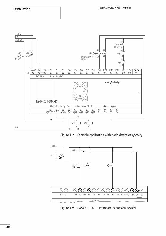
Figure 11: Example application with basic device easySafety
Figure 12: EASY6…-DC-.E (standard expansion device)
0 V
+24 V10 V+24 V
-F26 A
gL/gG
12
0V+24V QS1 QS2 QS3 QS4 T1 T2 T3 T4
Output 1x Relay / 6A 4x Test Signal
ES4P-221-DMXD14x Transistor / 0,5A
DC 24 V Input 14 x DC
NET
ALT
OK
-K3
DEL
ESC
IS1 IS2 IS3 IS4 IS5 IS6 IS7 IS8 IS9 IS10 IS11 IS12 IS13 IS14
1QR1
2
+24V 0V 0V
P1
P2
P3
P4
21
-F1S 1A
-Q1
1A2A
-Q2
1A2A
-S1
1222
1121
-Q2
1222
-Q1
1222
3141
-S6
ea ySafety
EMERGENCY-STOP
Reset
L01 +
L01 –
R10R9R8R7R6R5R4R3R2R1E+ E– R11 R12 0V0V+24V
24 V H
F1
Connecting outputs09/08 AWB2528-1599en
Connecting outputs The easySafety device has safety outputs (QR/QS) and test outputs with test signals (T1-T4) exclusively. Test signals are used to detect cross circuits (a section “Test outputs, test signals” on page 149).
Connecting the safety outputs (QS/QR)
A value that is read at the safety input and processed in the safety circuit diagram can be output safely via the output QR (redundant relay output) or one of the outputs QS (safety transistor/relay outputs).
The safety outputs (QR/QS) can also be used in the standard circuit diagram providing the following is observed.
The QS./QR. outputs function inside as isolated contacts.
h Connect the test signal outputs T1 to T4 with the inputs in order to be able to detectperipheral faults such as cross-circuits between the signal cables. They are not intended for operating loads.
h A safety output (QR/QS) can either be used in the safety circuit diagram or as a non-safety output in the standard circuit diagram. A double use of this output type causes an error signal with the circuit diagram safety test as it would contravene rule number 9 (a section “Testing the rules of the safety circuit diagram (plausibility check)” on page 98).
j Danger!Device outputs QR and QS that are set by the standard circuit diagram are not safety outputs and must only be used for standard tasks. Make sure that these outputs do not trigger any safety-related actions on the machine or plant.
47
Installation
48
09/08 AWB2528-1599en
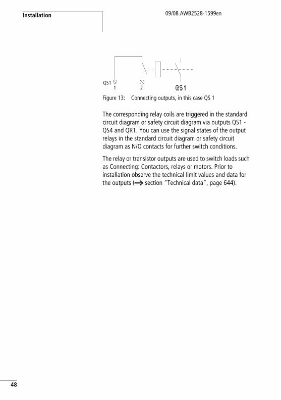
Figure 13: Connecting outputs, in this case QS 1
The corresponding relay coils are triggered in the standard circuit diagram or safety circuit diagram via outputs QS1 - QS4 and QR1. You can use the signal states of the output relays in the standard circuit diagram or safety circuit diagram as N/O contacts for further switch conditions.
The relay or transistor outputs are used to switch loads such as Connecting: Contactors, relays or motors. Prior to installation observe the technical limit values and data for the outputs (a section “Technical data”, page 644).
QS11 2 QS1
Connecting outputs09/08 AWB2528-1599en
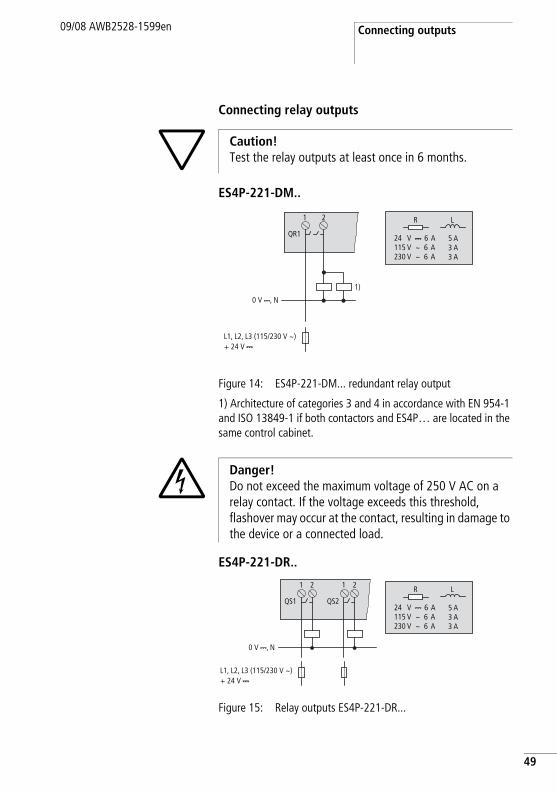
Connecting relay outputs
ES4P-221-DM..
Figure 14: ES4P-221-DM... redundant relay output
1) Architecture of categories 3 and 4 in accordance with EN 954-1 and ISO 13849-1 if both contactors and ES4P… are located in the same control cabinet.
ES4P-221-DR..
Figure 15: Relay outputs ES4P-221-DR...
h Caution!Test the relay outputs at least once in 6 months.
+ 24 V H
0 V H, N
L1, L2, L3 (115/230 V h)
1 2
QR1
1)
R L
24 V H 6 A115 V h 6 A230 V h 6 A
5 A3 A3 A
j Danger!Do not exceed the maximum voltage of 250 V AC on a relay contact. If the voltage exceeds this threshold, flashover may occur at the contact, resulting in damage to the device or a connected load.
+ 24 V H
0 V H, N
L1, L2, L3 (115/230 V h)
1 2
QS1
1 2
QS2
R L
24 V H 6 A115 V h 6 A230 V h 6 A
5 A3 A3 A
49
Installation
50
09/08 AWB2528-1599en
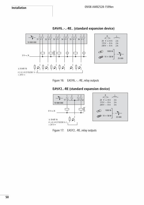
EASY6..-..-RE.. (standard expansion device)
Figure 16: EASY6..-..-RE..relay outputs
EASY2..-RE (standard expansion device)
Figure 17: EASY2..-RE..relay outputs
0 V H, N
F 8 A/B 16
L1, L2, L3 (115/230 V h) + 24 V H
25 000
R L
24 V H 8 A115 V h 8 A230 V h 8 A
2 A2 A2 A
1000 W
10 x 58 W
1 2 2 2 2 2 21 1 1 1 1
10 000 000
S6S5S4S3S2S1
+ 24 V H
0 V H, N
F 8 A/B 16L1, L2, L3 (115/230 Vh)
1 2 21
10 000 000S2S1
25 000
R L
24 V H 8 A115 V h 8 A230 V h 8 A
3 A3 A3 A
1000 W
10 x 58 W
Connecting outputs09/08 AWB2528-1599en
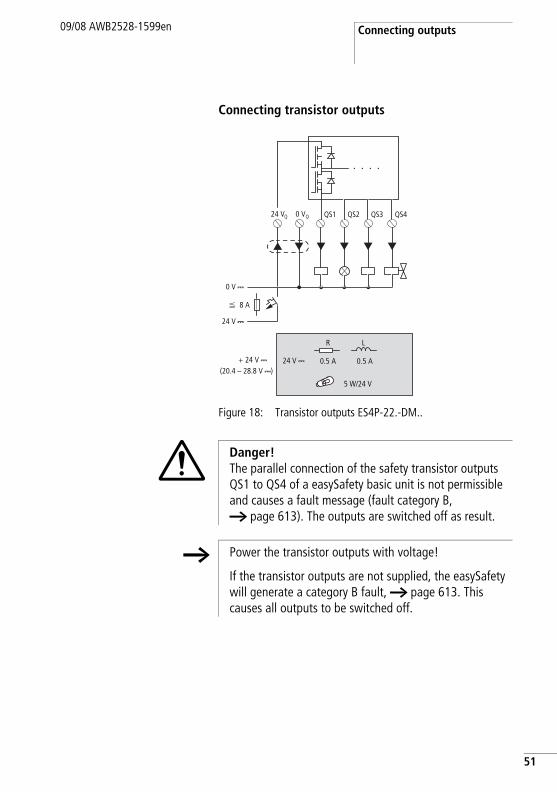
Connecting transistor outputs
Figure 18: Transistor outputs ES4P-22.-DM..
0 V QS1 QS2 QS3 QS4Q24 VQ
F 8 A
0 V H
24 V H
(20.4 – 28.8 V H)+ 24 V H
R L
5 W/24 V
0.5 A24 V H 0.5 A
i Danger!The parallel connection of the safety transistor outputs QS1 to QS4 of a easySafety basic unit is not permissible and causes a fault message (fault category B, a page 613). The outputs are switched off as result.
h Power the transistor outputs with voltage!
If the transistor outputs are not supplied, the easySafety will generate a category B fault, a page 613. This causes all outputs to be switched off.
51
Installation
52
09/08 AWB2528-1599en
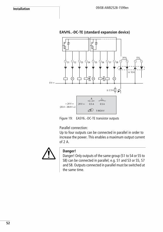
EASY6..-DC-TE (standard expansion device)
Figure 19: EASY6..-DC-TE transistor outputs
Parallel connection:Up to four outputs can be connected in parallel in order to increase the power. This enables a maximum output current of 2 A.
0 V H
S1 S2 S3 S4 S5 S6 S7 S8
0 VQ24 VQ
f 2.5 A
F 10 A
(20.4 – 28.8 V H)+ 24 V H
R L
5 W/24 V
0.5 A24 V H 0.5 A
i Danger!Danger! Only outputs of the same group (S1 to S4 or S5 to S8) can be connected in parallel; e.g. S1 and S3 or S5, S7 and S8. Outputs connected in parallel must be switched at the same time.
Connecting outputs09/08 AWB2528-1599en
Behaviour in the event of a short-circuit/overloadIn the event of a short-circuit or overload on a transistor output of a easySafety basic device, all outputs are disconnected. Once you have rectified the fault or malfunction, you can reset the easySafety device by switching the power supply off and on again.
If the short circuit or overload occurs on a non-safety expansion device, only this output switches off. The output will switch back on up to the maximum temperature after a cooling time that depends on the ambient temperature and the current level. If the fault condition persists, the output will keep switching off and on until the fault is corrected or until the power supply is switched off (a section “Diagnostics”, page 606).
Connecting test signal outputs
The easySafety devices are provided with 4 test signal outputs (T1 to T4). These outputs (T1 to T4) generate periodic test signals that are looped back to an IS... input and evaluated inside the device. In this way, it is possible to detect external faults (e.g. cross-circuits).
A test signal T… can be applied to several IS… inputs if cross-circuits between the supply cables used can be excluded.
i Danger!Use the test signal outputs exclusively for activating the inputs. The activation of loads is not permissible.
j Danger!Danger!Ensure that the multiple use of test signal outputs does not cause hazardous faults, for example, because a cross-circuit cannot be detected.
53
Installation
54
09/08 AWB2528-1599en
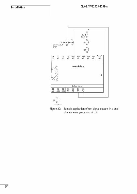
Figure 20: Sample application of test signal outputs in a dual-channel emergency stop circuit
QS2 QS3 QS4 T1 T2 T3 T4
4x Test Signal
NET
ALT
OK
IS6 IS7 IS8 IS9 IS10 IS11 IS12 IS13 IS14
P2
P3
P4
-Q2
1A2A
-S1
1222
1121
-Q2
1222
-Q1
1222
3141
-S2
ea ySafety
EMERGENCY-STOP
Reset
Connecting network easyNet09/08 AWB2528-1599en
Connecting network easyNet
easyNet is a network for non-safety applications to which a maximum of 8 nodes can be connected. Any device with a network connection can be an easyNet node. Further information on configuring and commissioning the easyNet is provided in chapter “easyNet network”, page 511. Specifications for the easyNet are provided in the Technical Data, page 653.
Connection assignment of the RJ45 socket on the device
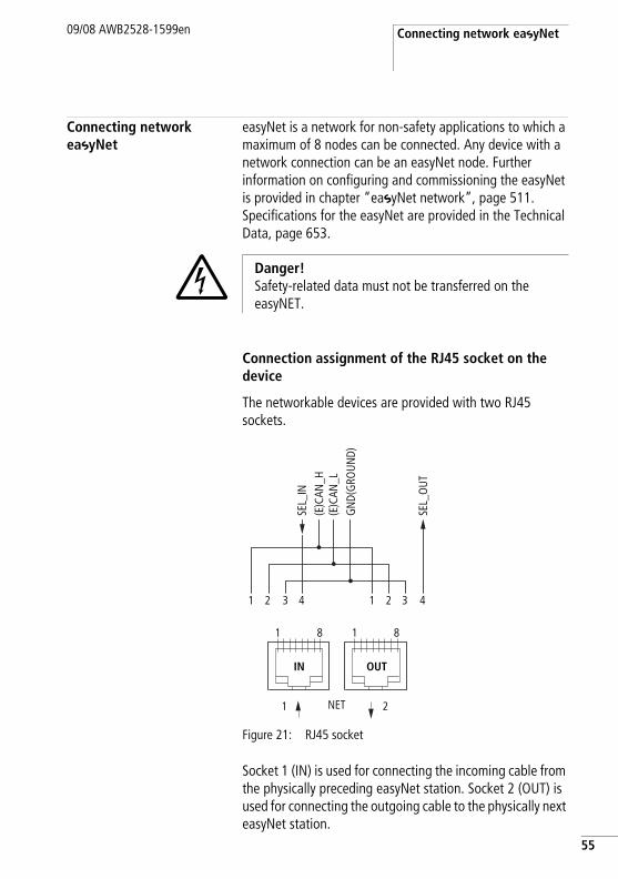
The networkable devices are provided with two RJ45 sockets.
Figure 21: RJ45 socket
Socket 1 (IN) is used for connecting the incoming cable from the physically preceding easyNet station. Socket 2 (OUT) is used for connecting the outgoing cable to the physically next easyNet station.
j Danger!Safety-related data must not be transferred on the easyNET.
1
SEL_
IN
GN
D(G
ROUN
D)
(E)C
AN_L
(E)C
AN_H
SEL_
OUT
2 3 41 2 3 4
1
1
8 1 8
2NET
IN OUT
55
Installation
56
09/08 AWB2528-1599en
The physically first and last stations in the easyNet network must each be terminated with a bus termination resistor. Because the physically first easyNet station has no predecessor, the bus termination resistor is connected to socket 1 here. Accordingly, the bus termination resistor is connected to socket 2 of the last easyNet station.
Prefabricated network connection cables
The following network connection cables are available for simple installation:
Table 3: Prefabricated cables, RJ45 plug on both ends
Cable length Type designation
cm
30 EASY-NT-30
80 EASY-NT-80
150 EASY-NT-150
Connecting network easyNet09/08 AWB2528-1599en
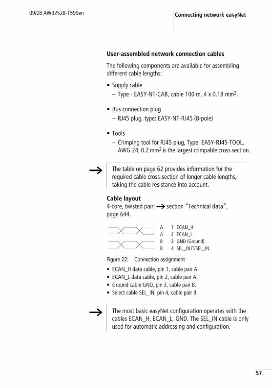
User-assembled network connection cables
The following components are available for assembling different cable lengths:
• Supply cable– Type - EASY-NT-CAB, cable 100 m, 4 x 0.18 mm2.
• Bus connection plug– RJ45 plug, type: EASY-NT-RJ45 (8-pole)
• Tools– Crimping tool for RJ45 plug, Type: EASY-RJ45-TOOL.
AWG 24, 0.2 mm2 is the largest crimpable cross section.
Cable layout4-core, twisted pair; a section “Technical data”, page 644.
Figure 22: Connection assignment
• ECAN_H data cable, pin 1, cable pair A.• ECAN_L data cable, pin 2, cable pair A.• Ground cable GND, pin 3, cable pair B.• Select cable SEL_IN, pin 4, cable pair B.
h The table on page 62 provides information for the required cable cross-section of longer cable lengths, taking the cable resistance into account.
A 1 ECAN_HA 2 ECAN_LB 3 GND (Ground)B 4 SEL_OUT/SEL_IN
h The most basic easyNet configuration operates with the cables ECAN_H, ECAN_L, GND. The SEL_IN cable is only used for automatic addressing and configuration.
57
Installation
58
09/08 AWB2528-1599en
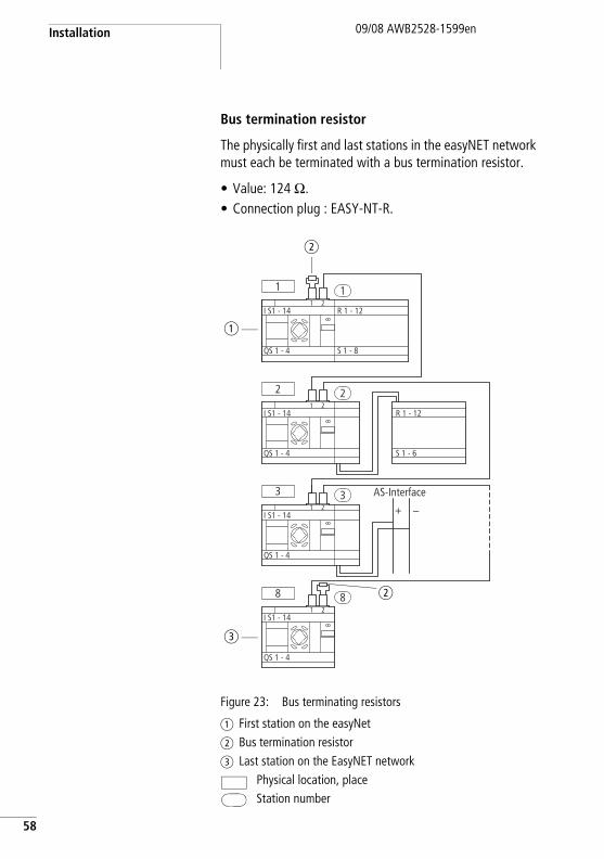
Bus termination resistor
The physically first and last stations in the easyNET network must each be terminated with a bus termination resistor.
• Value: 124 O.• Connection plug : EASY-NT-R.
Figure 23: Bus terminating resistors
a First station on the easyNetb Bus termination resistorc Last station on the EasyNET network
Physical location, placeStation number
1 1
2 2
I S1 - 141 2
1 2
1 2
1 2
QS 1 - 4
I S1 - 14
QS 1 - 4
3 3 AS-Interface
+ –I S1 - 14
QS 1 - 4
8 8
I S1 - 14
QS 1 - 4
R 1 - 12
S 1 - 6
R 1 - 12
S 1 - 8
a
b
c
b
Connecting network easyNet09/08 AWB2528-1599en
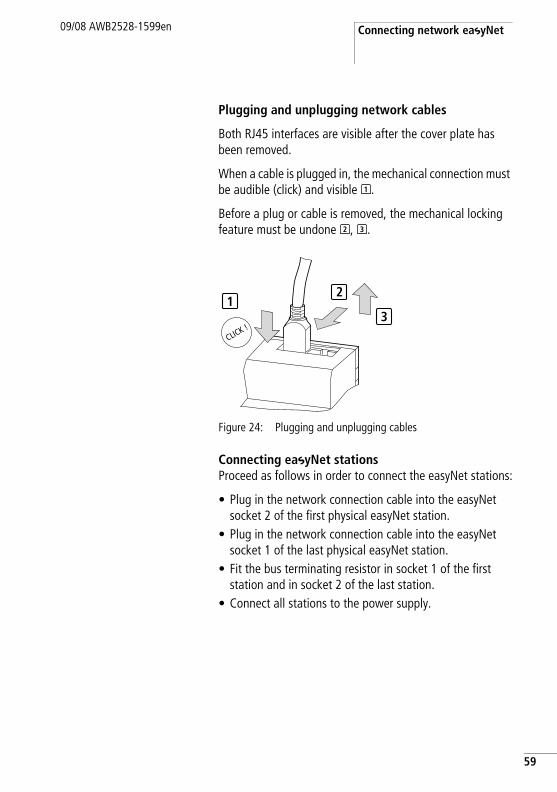
Plugging and unplugging network cables
Both RJ45 interfaces are visible after the cover plate has been removed.
When a cable is plugged in, the mechanical connection must be audible (click) and visible .
Before a plug or cable is removed, the mechanical locking feature must be undone , .
Figure 24: Plugging and unplugging cables
Connecting easyNet stationsProceed as follows in order to connect the easyNet stations:
• Plug in the network connection cable into the easyNet socket 2 of the first physical easyNet station.
• Plug in the network connection cable into the easyNet socket 1 of the last physical easyNet station.
• Fit the bus terminating resistor in socket 1 of the first station and in socket 2 of the last station.
• Connect all stations to the power supply.
1
2 3
12
3
59
Installation
60
09/08 AWB2528-1599en
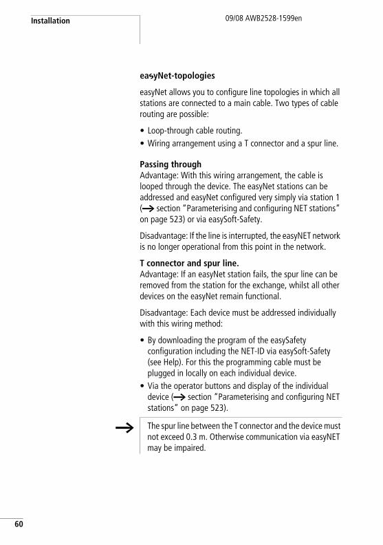
easyNet-topologies
easyNet allows you to configure line topologies in which all stations are connected to a main cable. Two types of cable routing are possible:
• Loop-through cable routing.• Wiring arrangement using a T connector and a spur line.
Passing throughAdvantage: With this wiring arrangement, the cable is looped through the device. The easyNet stations can be addressed and easyNet configured very simply via station 1 (a section “Parameterising and configuring NET stations” on page 523) or via easySoft-Safety.
Disadvantage: If the line is interrupted, the easyNET network is no longer operational from this point in the network.
T connector and spur line.Advantage: If an easyNet station fails, the spur line can be removed from the station for the exchange, whilst all other devices on the easyNet remain functional.
Disadvantage: Each device must be addressed individually with this wiring method:
• By downloading the program of the easySafety configuration including the NET-ID via easySoft-Safety (see Help). For this the programming cable must be plugged in locally on each individual device.
• Via the operator buttons and display of the individual device (a section “Parameterising and configuring NET stations” on page 523).
h The spur line between the T connector and the device must not exceed 0.3 m. Otherwise communication via easyNET may be impaired.
Connecting network easyNet09/08 AWB2528-1599en
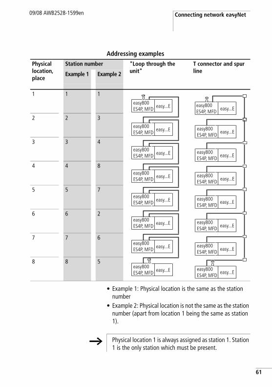
Addressing examples
• Example 1: Physical location is the same as the station number
• Example 2: Physical location is not the same as the station number (apart from location 1 being the same as station 1).
Physical location, place
Station number "Loop through the unit"
T connector and spur lineExample 1 Example 2
1 1 1
2 2 3
3 3 4
4 4 8
5 5 7
6 6 2
7 7 6
8 8 5
easy800ES4P, MFD
easy800ES4P, MFD
easy800ES4P, MFD
easy800ES4P, MFD
easy800ES4P, MFD
easy800ES4P, MFD
easy800ES4P, MFD
easy800ES4P, MFD
easy...E
easy...E
easy...E
easy...E
easy...E
easy...E
easy...E
easy...E
easy800ES4P, MFD
easy800ES4P, MFD
easy800ES4P, MFD
easy800ES4P, MFD
easy800ES4P, MFD
easy800ES4P, MFD
easy800ES4P, MFD
easy800ES4P, MFD
easy...E
easy...E
easy...E
easy...E
easy...E
easy...E
easy...E
easy...E
h Physical location 1 is always assigned as station 1. Station 1 is the only station which must be present.
61
Installation
62
09/08 AWB2528-1599en
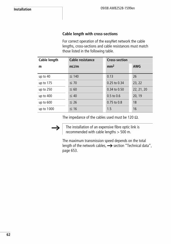
Cable length with cross-sections
For correct operation of the easyNet network the cable lengths, cross-sections and cable resistances must match those listed in the following table.
The impedance of the cables used must be 120 O.
The maximum transmission speed depends on the total length of the network cables, a section “Technical data”, page 653.
Cable length Cable resistance Cross-section
m mO/m mm2 AWG
up to 40 F 140 0.13 26
up to 175 F 70 0.25 to 0.34 23, 22
up to 250 F 60 0.34 to 0.50 22, 21, 20
up to 400 F 40 0.5 to 0.6 20, 19
up to 600 F 26 0.75 to 0.8 18
up to 1000 F 16 1.5 16
h The installation of an expensive fibre optic link is recommended with cable lengths > 500 m.
Connecting network easyNet09/08 AWB2528-1599en
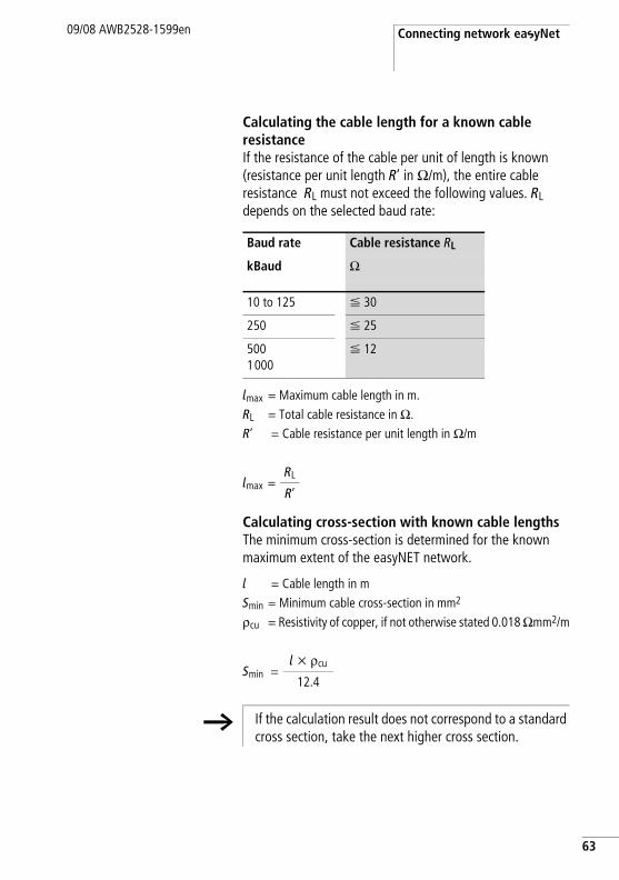
Calculating the cable length for a known cable resistanceIf the resistance of the cable per unit of length is known (resistance per unit length R’ in O/m), the entire cable resistance RL must not exceed the following values. RL depends on the selected baud rate:
lmax = Maximum cable length in m.RL = Total cable resistance in O.R’ = Cable resistance per unit length in O/m
Calculating cross-section with known cable lengthsThe minimum cross-section is determined for the known maximum extent of the easyNET network.
l = Cable length in mSmin = Minimum cable cross-section in mm2
rcu = Resistivity of copper, if not otherwise stated 0.018 Omm2/m
Baud rate Cable resistance RL
kBaud O
10 to 125 F 30
250 F 25
5001000
F 12
lmax =RL
R’
Smin =l x rcu
12.4
h If the calculation result does not correspond to a standard cross section, take the next higher cross section.
63
Installation
64
09/08 AWB2528-1599en
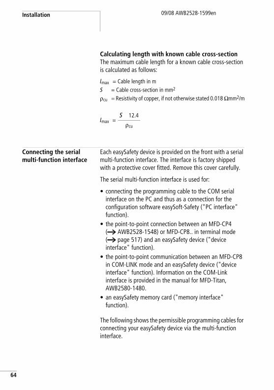
Calculating length with known cable cross-sectionThe maximum cable length for a known cable cross-section is calculated as follows:
lmax = Cable length in mS = Cable cross-section in mm2
rcu = Resistivity of copper, if not otherwise stated 0.018 Omm2/m
Connecting the serial multi-function interface
Each easySafety device is provided on the front with a serial multi-function interface. The interface is factory shipped with a protective cover fitted. Remove this cover carefully.
The serial multi-function interface is used for:
• connecting the programming cable to the COM serial interface on the PC and thus as a connection for the configuration software easySoft-Safety ("PC interface" function).
• the point-to-point connection between an MFD-CP4 (a AWB2528-1548) or MFD-CP8.. in terminal mode (a page 517) and an easySafety device ("device interface" function).
• the point-to-point communication between an MFD-CP8 in COM-LINK mode and an easySafety device ("device interface" function). Information on the COM-Link interface is provided in the manual for MFD-Titan, AWB2580-1480.
• an easySafety memory card ("memory interface" function).
The following shows the permissible programming cables for connecting your easySafety device via the multi-function interface.
lmax =S 12.4
rcu
Connecting the serial multi-function interface
09/08 AWB2528-1599en
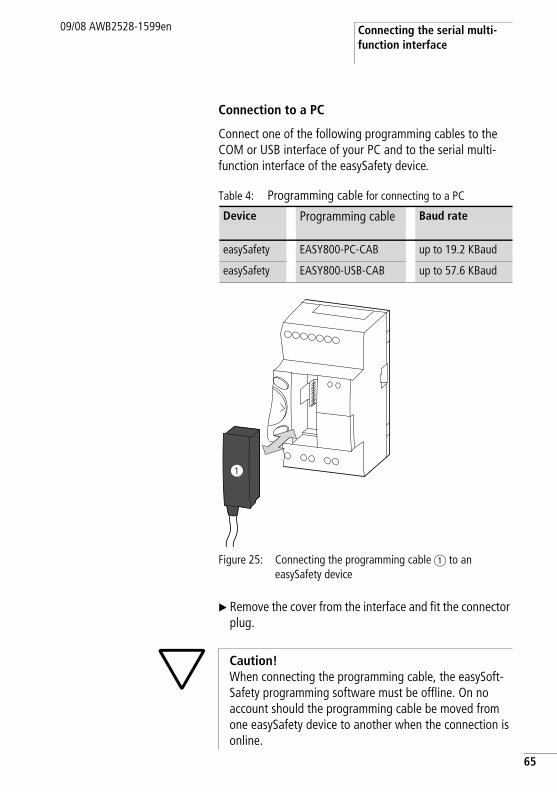
Connection to a PC
Connect one of the following programming cables to the COM or USB interface of your PC and to the serial multi-function interface of the easySafety device.
Table 4: Programming cable for connecting to a PC
Figure 25: Connecting the programming cable a to an easySafety device
X Remove the cover from the interface and fit the connector plug.
Device Programming cable Baud rate
easySafety EASY800-PC-CAB up to 19.2 KBaud
easySafety EASY800-USB-CAB up to 57.6 KBaud
h Caution!When connecting the programming cable, the easySoft-Safety programming software must be offline. On no account should the programming cable be moved from one easySafety device to another when the connection is online.
65
Installation
66
09/08 AWB2528-1599en
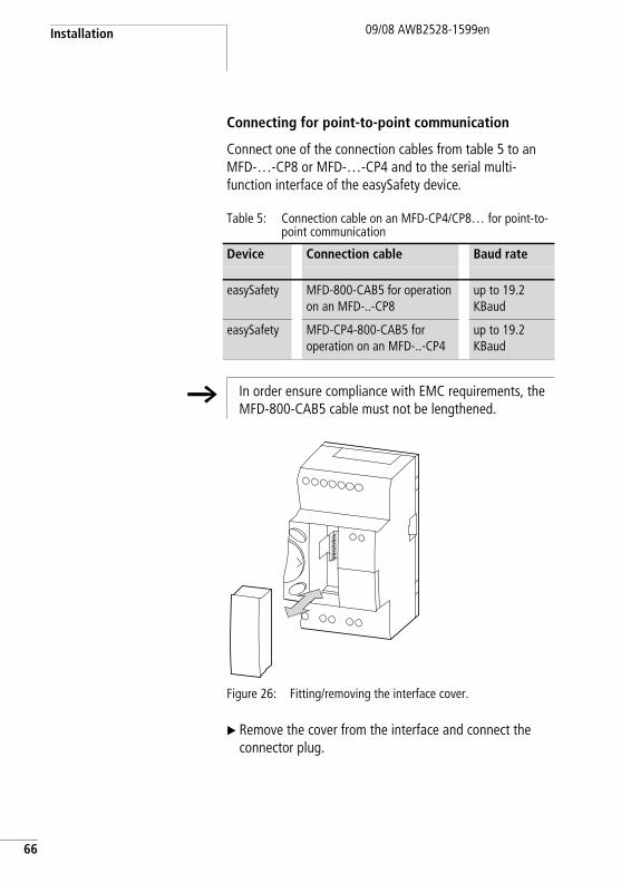
Connecting for point-to-point communication
Connect one of the connection cables from table 5 to an MFD-…-CP8 or MFD-…-CP4 and to the serial multi-function interface of the easySafety device.
Table 5: Connection cable on an MFD-CP4/CP8… for point-to-point communication
Figure 26: Fitting/removing the interface cover.
X Remove the cover from the interface and connect the connector plug.
Device Connection cable Baud rate
easySafety MFD-800-CAB5 for operation on an MFD-..-CP8
up to 19.2 KBaud
easySafety MFD-CP4-800-CAB5 for operation on an MFD-..-CP4
up to 19.2 KBaud
h In order ensure compliance with EMC requirements, the MFD-800-CAB5 cable must not be lengthened.
Connecting the serial multi-function interface
09/08 AWB2528-1599en
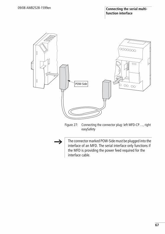
Figure 27: Connecting the connector plug: left MFD-CP…, right easySafety
POW-Side
h The connector marked POW-Side must be plugged into the interface of an MFD. The serial interface only functions if the MFD is providing the power feed required for the interface cable.
67
Installation
68
09/08 AWB2528-1599en
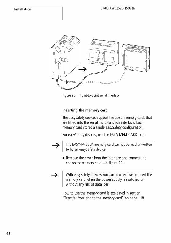
Figure 28: Point-to-point serial interface
Inserting the memory card
The easySafety devices support the use of memory cards that are fitted into the serial multi-function interface. Each memory card stores a single easySafety configuration.
For easySafety devices, use the ES4A-MEM-CARD1 card.
X Remove the cover from the interface and connect the connector memory card a figure 29.
How to use the memory card is explained in section “Transfer from and to the memory card” on page 118.
POW-Side
h The EASY-M-256K memory card cannot be read or written to by an easySafety device.
h With easySafety devices you can also remove or insert the memory card when the power supply is switched on without any risk of data loss.
Expanding inputs/outputs09/08 AWB2528-1599en
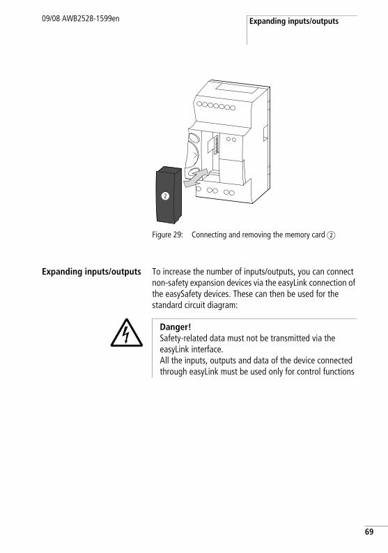
Figure 29: Connecting and removing the memory card b
Expanding inputs/outputs To increase the number of inputs/outputs, you can connect non-safety expansion devices via the easyLink connection of the easySafety devices. These can then be used for the standard circuit diagram:
j Danger!Safety-related data must not be transmitted via the easyLink interface.All the inputs, outputs and data of the device connected through easyLink must be used only for control functions
69
Installation
70
09/08 AWB2528-1599en
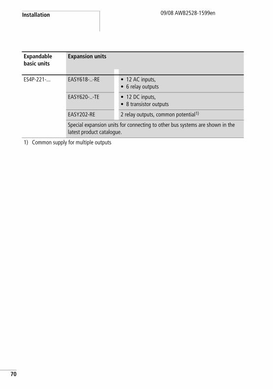
Expandable basic units
Expansion units
ES4P-221-... EASY618-..-RE • 12 AC inputs,• 6 relay outputs
EASY620-..-TE • 12 DC inputs,• 8 transistor outputs
EASY202-RE 2 relay outputs, common potential1)
Special expansion units for connecting to other bus systems are shown in the latest product catalogue.
1) Common supply for multiple outputs
Expanding inputs/outputs09/08 AWB2528-1599en
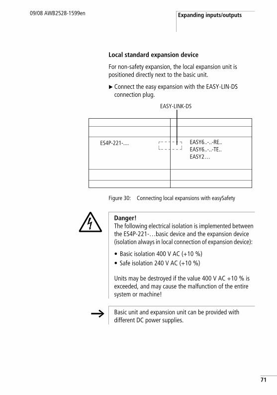
Local standard expansion device
For non-safety expansion, the local expansion unit is positioned directly next to the basic unit.
X Connect the easy expansion with the EASY-LIN-DS connection plug.
Figure 30: Connecting local expansions with easySafety
EASY-LINK-DS
EASY6..-..-RE..EASY6..-..-TE..EASY2…
ES4P-221-....
j Danger! The following electrical isolation is implemented between the ES4P-221-…basic device and the expansion device (isolation always in local connection of expansion device):
• Basic isolation 400 V AC (+10 %)• Safe isolation 240 V AC (+10 %)
Units may be destroyed if the value 400 V AC +10 % is exceeded, and may cause the malfunction of the entire system or machine!
h Basic unit and expansion unit can be provided with different DC power supplies.
71
Installation
72
09/08 AWB2528-1599en
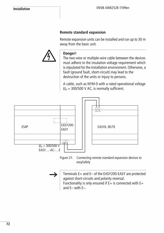
Remote standard expansion
Remote expansion units can be installed and run up to 30 m away from the basic unit.
Figure 31: Connecting remote standard expansion devices to easySafety
j Danger!The two-wire or multiple-wire cable between the devices must adhere to the insulation voltage requirement which is stipulated for the installation environment. Otherwise, a fault (ground fault, short-circuit) may lead to the destruction of the units or injury to persons.
A cable, such as NYM-0 with a rated operational voltage Ue = 300/500 V AC, is normally sufficient.
E+ E–
E+ E–
ES4P EASY6..RE/TEEASY200-EASY
Ue = 300/500 VEASY…-AC-…E
h Terminals E+ and E– of the EASY200-EASY are protected against short-circuits and polarity reversal. Functionality is only ensured if E+ is connected with E+ and E– with E–.
09/08 AWB2528-1599en
3 Commissioning
Switching on Before startup check whether the power supply, inputs, outputs, the serial interface and the easy-NET connection easyLink are properly connected:
• easySafety basic device and 24 VDC expansion unit:– Terminal +24 V: Voltage +24 V – Terminal 0 V: Voltage 0 V. – Terminals IS1 to IS14, R1 to R12 (expansion device):
actuation via +24°V.– Terminals QR1, QS1-QS4, T1 to T4.– Terminals S1-S8 (expansion unit).
• 230 VAC version of local or remote standard expansion:– Terminal L: Phase conductor L– Terminal N: Neutral conductor N– Terminals R1 to R12: Actuation via phase conductor L– Terminals S1-S6.
j Danger!If you have already integrated devices into a system, secure any parts of the system connected to the working area to prevent access and ensure that no-one can be injured if, for example, motors start up unexpectedly.
73
Commissioning
74
09/08 AWB2528-1599en
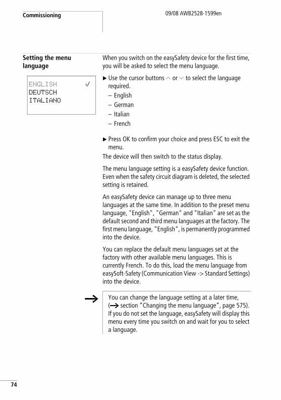
Setting the menu language
When you switch on the easySafety device for the first time, you will be asked to select the menu language.
X Use the cursor buttons Í or Ú to select the language required.– English– German– Italian– French
X Press OK to confirm your choice and press ESC to exit the menu.
The device will then switch to the status display.
The menu language setting is a easySafety device function. Even when the safety circuit diagram is deleted, the selected setting is retained.
An easySafety device can manage up to three menu languages at the same time. In addition to the preset menu language, "English", "German" and "Italian" are set as the default second and third menu languages at the factory. The first menu language, "English", is permanently programmed into the device.
You can replace the default menu languages set at the factory with other available menu languages. This is currently French. To do this, load the menu language from easySoft-Safety (Communication View -> Standard Settings) into the device.
ENGLISH åDEUTSCH
ITALIANO
h You can change the language setting at a later time, (a section “Changing the menu language”, page 575). If you do not set the language, easySafety will display this menu every time you switch on and wait for you to select a language.
easySafetyoperating modes09/08 AWB2528-1599en
easySafetyoperating modes
RUN and STOP and BUSY
easySafety has the three operating modes RUN, STOP and BUSY. The device switches operating mode BUSY only temporarily when:
• a configuration transfer with easySoft-Safety is being performed;
• you start the configuration.
In the RUN operating mode, the safety circuit diagram, as well as the possibly wired standard circuit diagram, are executed continuously until you select STOP, the internal device safety monitoring mechanism detects an error or the supply voltage is turned off.
The safety circuit diagram and the parameters are retained in the event of a power failure. All you will have to do is reset the real-time clock after the back-up time has elapsed. In RUN mode:
• the process image of the inputs are read.• the safety and standard circuit diagram are processed.• the process image of the outputs is transferred to the
physical outputs.
In STOP mode neither the safety nor the standard circuit diagram are run. Only in this mode is circuit diagram entry, modification of the system parameters or configuration of the easyNet possible. It is also possible to store the safety and standard circuit diagram on the external memory card or load them from the external memory card. In this mode, a circuit diagram can also be transferred from and to easySoft-Safety.
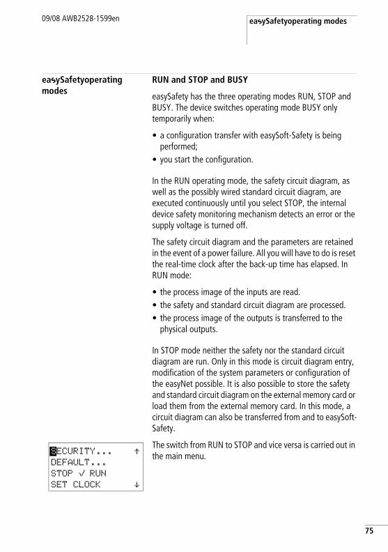
The switch from RUN to STOP and vice versa is carried out in the main menu.SECURITY... Æ
DEFAULT...
STOP å RUN
SET CLOCK æ
75
Commissioning
76
09/08 AWB2528-1599en
If the easySafety devices without a display do not contain an safety circuit diagram, but this is stored on the memory card, this is loaded automatically after startup. The device will then process the circuit diagram in RUN mode.
j Danger!In RUN mode an easySafety device will immediately run the saved safety and standard circuit diagram in the unit when the power supply is switched on.
The outputs are activated according to the switch logic of the circuit diagram.
Configure your machine/plant so that the automatic starting of the easySafety device never causes unintentional starting of the machine/plant concerned.
Create your safety circuit diagram so that after the power supply is switched on, there is always a defined safety startup behaviour. Information on startup behaviour is provided on page 584.
The device does not start with RUN mode if you deactivate RUN MODE (exception: devices without display).
easySafety devices without display and operator buttons have a different startup behaviour. The RUN MODE and CARD START functions are activated automatically in this case, since no device operations for manual starting are possible.
The first circuit diagram09/08 AWB2528-1599en
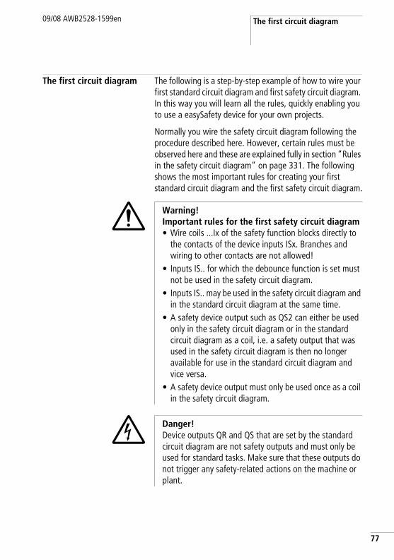
The first circuit diagram The following is a step-by-step example of how to wire your first standard circuit diagram and first safety circuit diagram. In this way you will learn all the rules, quickly enabling you to use a easySafety device for your own projects.
Normally you wire the safety circuit diagram following the procedure described here. However, certain rules must be observed here and these are explained fully in section “Rules in the safety circuit diagram” on page 331. The following shows the most important rules for creating your first standard circuit diagram and the first safety circuit diagram.
i Warning!Important rules for the first safety circuit diagram• Wire coils ...Ix of the safety function blocks directly to
the contacts of the device inputs ISx. Branches and wiring to other contacts are not allowed!
• Inputs IS.. for which the debounce function is set must not be used in the safety circuit diagram.
• Inputs IS.. may be used in the safety circuit diagram and in the standard circuit diagram at the same time.
• A safety device output such as QS2 can either be used only in the safety circuit diagram or in the standard circuit diagram as a coil, i.e. a safety output that was used in the safety circuit diagram is then no longer available for use in the standard circuit diagram and vice versa.
• A safety device output must only be used once as a coil in the safety circuit diagram.
j Danger!Device outputs QR and QS that are set by the standard circuit diagram are not safety outputs and must only be used for standard tasks. Make sure that these outputs do not trigger any safety-related actions on the machine or plant.
77
Commissioning
78
09/08 AWB2528-1599en
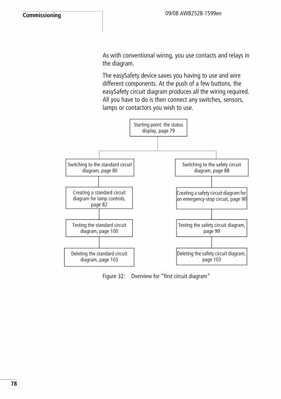
As with conventional wiring, you use contacts and relays in the diagram.
The easySafety device saves you having to use and wire different components. At the push of a few buttons, the easySafety circuit diagram produces all the wiring required. All you have to do is then connect any switches, sensors, lamps or contactors you wish to use.
Figure 32: Overview for “first circuit diagram”
Switching to the standard circuit diagram, page 80
Creating a standard circuit diagram for lamp controls,
page 82
Starting point: the status display, page 79
Testing the standard circuit diagram, page 100
Switching to the safety circuit diagram, page 88
Testing the safety circuit diagram, page 99
Deleting the standard circuit diagram, page 103
Creating a safety circuit diagram for an emergency-stop circuit, page 90
Deleting the safety circuit diagram, page 103
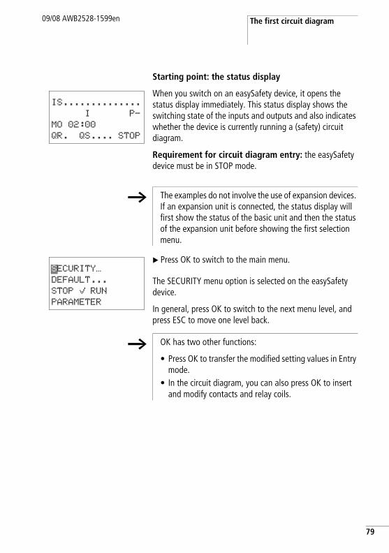
The first circuit diagram09/08 AWB2528-1599en
Starting point: the status display
When you switch on an easySafety device, it opens the status display immediately. This status display shows the switching state of the inputs and outputs and also indicates whether the device is currently running a (safety) circuit diagram.
Requirement for circuit diagram entry: the easySafety device must be in STOP mode.
X Press OK to switch to the main menu.
The SECURITY menu option is selected on the easySafety device.
In general, press OK to switch to the next menu level, and press ESC to move one level back.
IS..............
I P-
MO 02:00
QR. QS.... STOP
h The examples do not involve the use of expansion devices. If an expansion unit is connected, the status display will first show the status of the basic unit and then the status of the expansion unit before showing the first selection menu.
SECURITY…
DEFAULT...
STOP å RUN
PARAMETER
h OK has two other functions:
• Press OK to transfer the modified setting values in Entry mode.
• In the circuit diagram, you can also press OK to insert and modify contacts and relay coils.
79
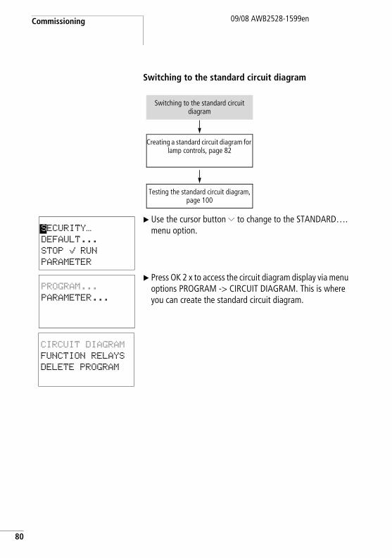
Commissioning
80
09/08 AWB2528-1599en
Switching to the standard circuit diagram
X Use the cursor button Ú to change to the STANDARD…. menu option.
X Press OK 2 x to access the circuit diagram display via menu options PROGRAM -> CIRCUIT DIAGRAM. This is where you can create the standard circuit diagram.
Switching to the standard circuit diagram
Creating a standard circuit diagram for lamp controls, page 82
Testing the standard circuit diagram, page 100
SECURITY…
DEFAULT...
STOP å RUN
PARAMETER
PROGRAM...
PARAMETER...
CIRCUIT DIAGRAM
FUNCTION RELAYS
DELETE PROGRAM
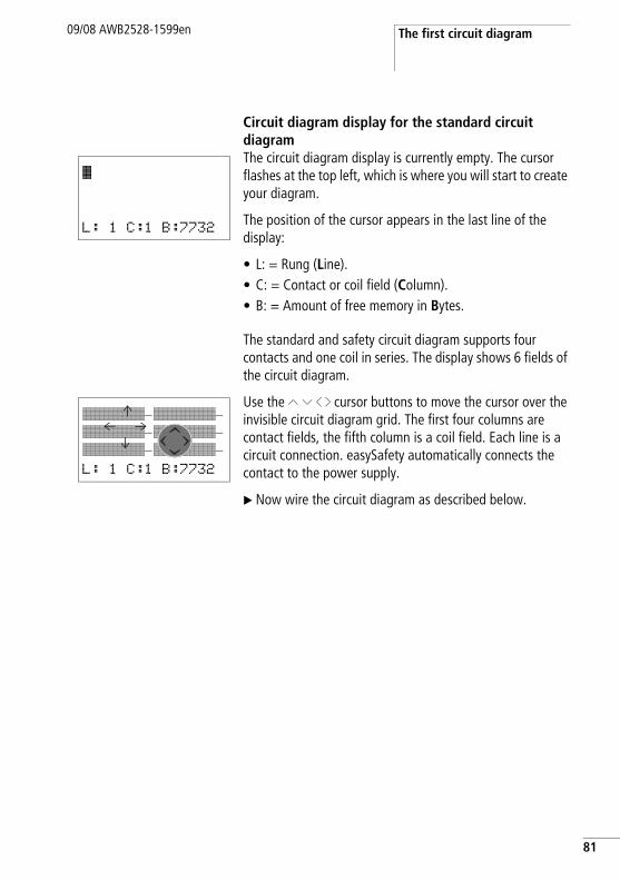
The first circuit diagram09/08 AWB2528-1599en
Circuit diagram display for the standard circuit diagramThe circuit diagram display is currently empty. The cursor flashes at the top left, which is where you will start to create your diagram.
The position of the cursor appears in the last line of the display:
• L: = Rung (Line).• C: = Contact or coil field (Column).• B: = Amount of free memory in Bytes.
The standard and safety circuit diagram supports four contacts and one coil in series. The display shows 6 fields of the circuit diagram.
Use the Í Ú ú í cursor buttons to move the cursor over the invisible circuit diagram grid. The first four columns are contact fields, the fifth column is a coil field. Each line is a circuit connection. easySafety automatically connects the contact to the power supply.
X Now wire the circuit diagram as described below.
Ê
L: 1 C:1 B:7732
ÊÊÊÊÊÊÊ-ÊÊÊÊÊÊÊ-ÊÊÊÊÊÊÊ-ÊÊÊÊÊÊÊ-ÊÊÊÊÊÊÊ-ÊÊÊÊÊÊÊ-L: 1 C:1 B:7732
Ml
Lm
81
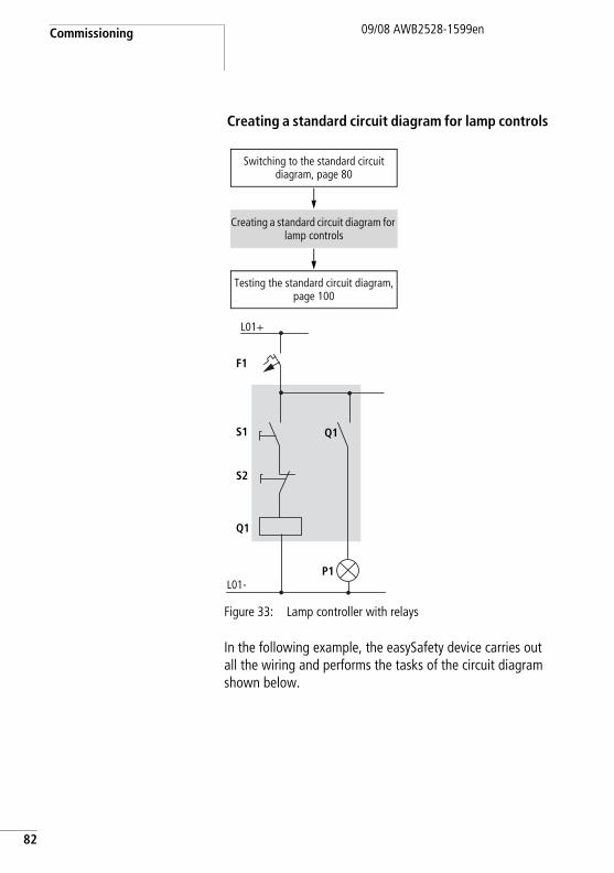
Commissioning
82
09/08 AWB2528-1599en
Creating a standard circuit diagram for lamp controls
Figure 33: Lamp controller with relays
In the following example, the easySafety device carries out all the wiring and performs the tasks of the circuit diagram shown below.
Switching to the standard circuit diagram, page 80
Creating a standard circuit diagram for lamp controls
Testing the standard circuit diagram, page 100
P1L01-
S1
S2
L01+
F1
Q1
Q1
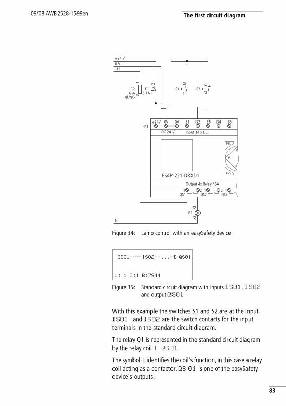
The first circuit diagram09/08 AWB2528-1599en
Figure 34: Lamp control with an easySafety device
Figure 35: Standard circuit diagram with inputs IS01, IS02 and output QS01
With this example the switches S1 and S2 are at the input. IS01 and IS02 are the switch contacts for the input terminals in the standard circuit diagram.
The relay Q1 is represented in the standard circuit diagram by the relay coil Ä QS01.
The symbol Ä identifies the coil's function, in this case a relay coil acting as a contactor. QS 01 is one of the easySafety device's outputs.
N
1L10 V+24 V
-F26 A
gL/gG
12
Output 4x Relay / 6A
DEL
-K1
ES4P-221-DRXD1
DC 24 V Input 14 x DC
ESC
IS1 IS2 IS3 IS4 IS5
1QS1
2 1QS2
2 1QS3
+24V 0V 0V
P1
P
P
21
-F1S 1A
-S1
3141
1X2X
-P1
-S2
1222
IS01----IS02--...-Ä QS01
L: 1 C:1 B:7944
83
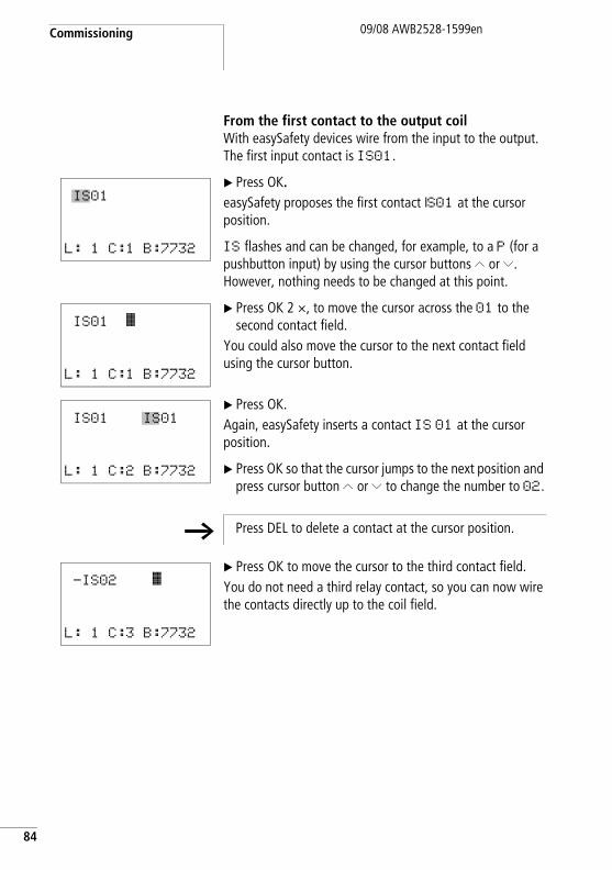
Commissioning
84
09/08 AWB2528-1599en
From the first contact to the output coilWith easySafety devices wire from the input to the output. The first input contact is IS01.
X Press OK.easySafety proposes the first contact IS01 at the cursor position.
IS flashes and can be changed, for example, to a P (for a pushbutton input) by using the cursor buttons Í or Ú. However, nothing needs to be changed at this point.
X Press OK 2 ×, to move the cursor across the 01 to the second contact field.
You could also move the cursor to the next contact field using the cursor button.
X Press OK.Again, easySafety inserts a contact IS 01 at the cursor position.
X Press OK so that the cursor jumps to the next position and press cursor button Í or Ú to change the number to 02.
X Press OK to move the cursor to the third contact field.You do not need a third relay contact, so you can now wire the contacts directly up to the coil field.
IS01
L: 1 C:1 B:7732
IS01 Ê
L: 1 C:1 B:7732
IS01 IS01
L: 1 C:2 B:7732
h Press DEL to delete a contact at the cursor position.
-IS02 Ê
L: 1 C:3 B:7732
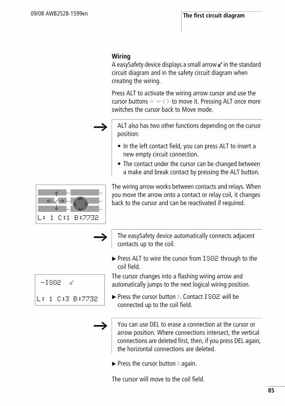
The first circuit diagram09/08 AWB2528-1599en
WiringA easySafety device displays a small arrow l in the standard circuit diagram and in the safety circuit diagram when creating the wiring.
Press ALT to activate the wiring arrow cursor and use the cursor buttons Í Ú ú í to move it. Pressing ALT once more switches the cursor back to Move mode.
The wiring arrow works between contacts and relays. When you move the arrow onto a contact or relay coil, it changes back to the cursor and can be reactivated if required.
X Press ALT to wire the cursor from IS02 through to the coil field.
The cursor changes into a flashing wiring arrow and automatically jumps to the next logical wiring position.
X Press the cursor button í. Contact IS02 will be connected up to the coil field.
X Press the cursor button í again.
The cursor will move to the coil field.
h ALT also has two other functions depending on the cursor position:
• In the left contact field, you can press ALT to insert a new empty circuit connection.
• The contact under the cursor can be changed between a make and break contact by pressing the ALT button.
ÊÊÊÊÊÊÊ-ÊÊÊÊÊÊÊ-ÊÊÊÊlÊÊ-ÊÊÊÊÊÊÊ-ÊÊÊÊÊÊÊ-ÊÊÊÊÊÊÊ-L: 1 C:1 B:7732
Ml
Lm
h The easySafety device automatically connects adjacent contacts up to the coil.
-IS02 l
L: 1 C:3 B:7732
h You can use DEL to erase a connection at the cursor or arrow position. Where connections intersect, the vertical connections are deleted first, then, if you press DEL again, the horizontal connections are deleted.
85
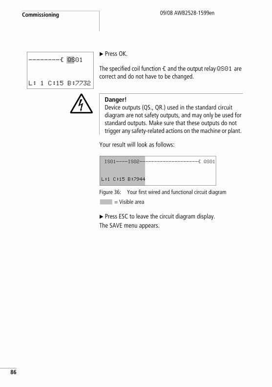
Commissioning
86
09/08 AWB2528-1599en
X Press OK.
The specified coil function Ä and the output relay QS01 are correct and do not have to be changed.
Your result will look as follows:
Figure 36: Your first wired and functional circuit diagram
= Visible area
X Press ESC to leave the circuit diagram display. The SAVE menu appears.
--------Ä QS01
L: 1 C:15 B:7732
j Danger!Device outputs (QS., QR.) used in the standard circuit diagram are not safety outputs, and may only be used for standard outputs. Make sure that these outputs do not trigger any safety-related actions on the machine or plant.
IS01----IS02--------------------Ä QS01
L:1 C:15 B:7944
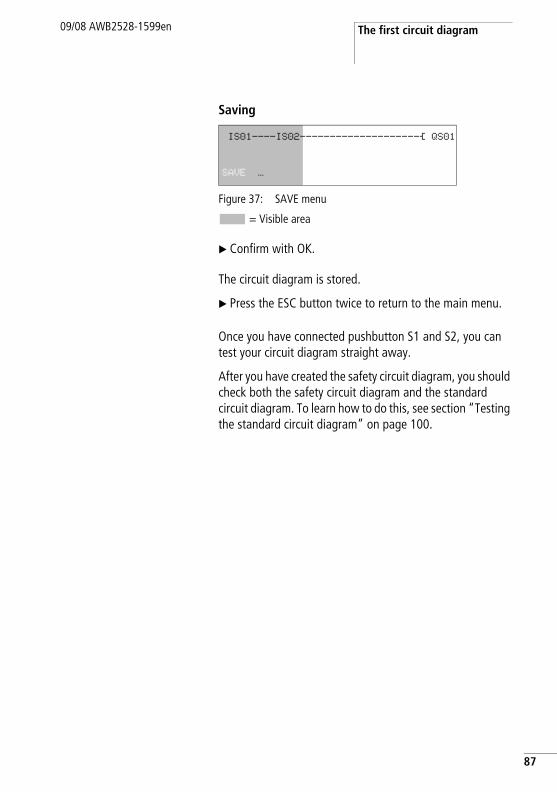
The first circuit diagram09/08 AWB2528-1599en
Saving
Figure 37: SAVE menu
= Visible area
X Confirm with OK.
The circuit diagram is stored.
X Press the ESC button twice to return to the main menu.
Once you have connected pushbutton S1 and S2, you can test your circuit diagram straight away.
After you have created the safety circuit diagram, you should check both the safety circuit diagram and the standard circuit diagram. To learn how to do this, see section “Testing the standard circuit diagram” on page 100.
IS01----IS02--------------------Ä QS01
SAVE …
87
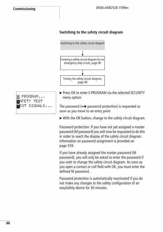
Commissioning
88
09/08 AWB2528-1599en
Switching to the safety circuit diagram
X Press OK to enter S PROGRAM via the selected SECURITY menu option.
The password (a password protection) is requested as soon as you move to an entry point
X With the OK button, change to the safety circuit diagram.
Password protection: If you have not yet assigned a master password (M password) you will now be requested to do this in order to reach the display of the safety circuit diagram. Information on password assignment is provided on page 559.
If you have already assigned the master password (M password), you will only be asked to enter the password if you wish to change the safety circuit diagram. As soon as you open a contact or coil field with OK, you must enter the defined M password.
Password protection is automatically reactivated if you do not make any changes to the safety configuration of an easySafety device for 30 minutes.
Switching to the safety circuit diagram
Creating a safety circuit diagram for an emergency-stop circuit, page 90
Testing the safety circuit diagram, page 99
S PROGRAM...
SAFETY TEST
TEST SIGNALS...
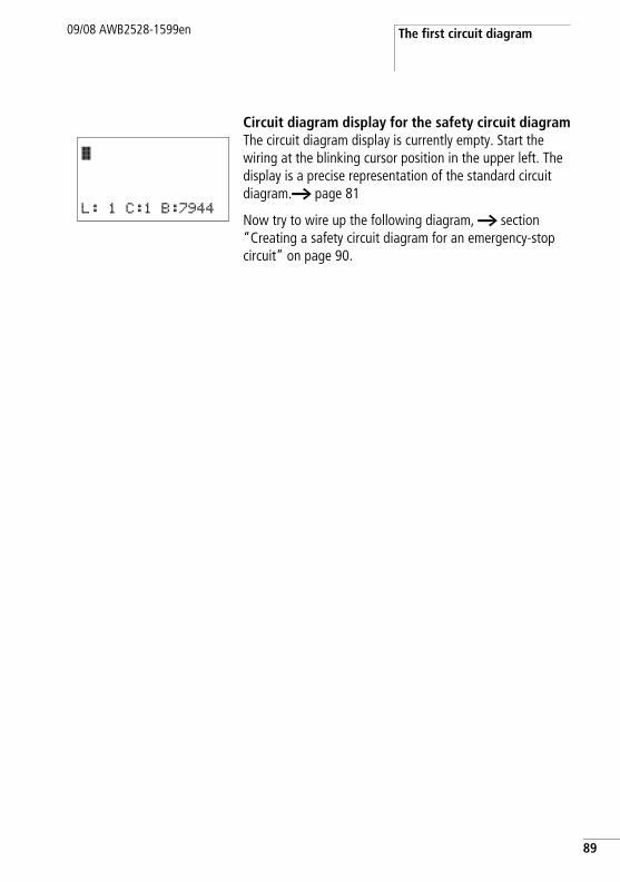
The first circuit diagram09/08 AWB2528-1599en
Circuit diagram display for the safety circuit diagramThe circuit diagram display is currently empty. Start the wiring at the blinking cursor position in the upper left. The display is a precise representation of the standard circuit diagram.a page 81
Now try to wire up the following diagram, a section “Creating a safety circuit diagram for an emergency-stop circuit” on page 90.
Ê
L: 1 C:1 B:7944
89
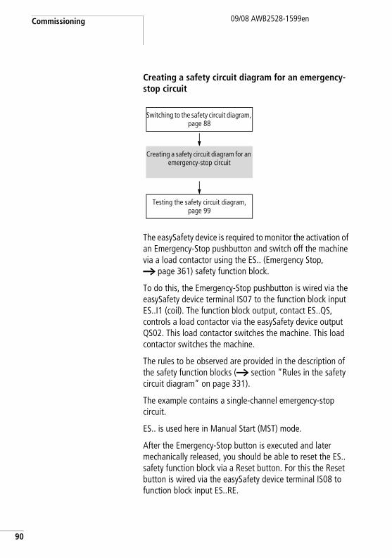
Commissioning
90
09/08 AWB2528-1599en
Creating a safety circuit diagram for an emergency-stop circuit
The easySafety device is required to monitor the activation of an Emergency-Stop pushbutton and switch off the machine via a load contactor using the ES.. (Emergency Stop, a page 361) safety function block.
To do this, the Emergency-Stop pushbutton is wired via the easySafety device terminal IS07 to the function block input ES..I1 (coil). The function block output, contact ES..QS, controls a load contactor via the easySafety device output QS02. This load contactor switches the machine. This load contactor switches the machine.
The rules to be observed are provided in the description of the safety function blocks (a section “Rules in the safety circuit diagram” on page 331).
The example contains a single-channel emergency-stop circuit.
ES.. is used here in Manual Start (MST) mode.
After the Emergency-Stop button is executed and later mechanically released, you should be able to reset the ES.. safety function block via a Reset button. For this the Reset button is wired via the easySafety device terminal IS08 to function block input ES..RE.
Switching to the safety circuit diagram, page 88
Creating a safety circuit diagram for an emergency-stop circuit
Testing the safety circuit diagram, page 99
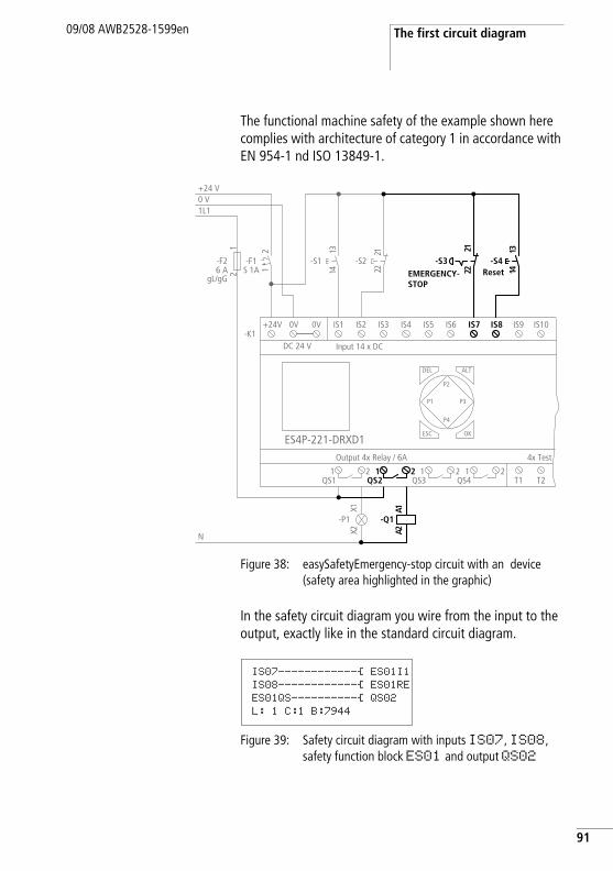
The first circuit diagram09/08 AWB2528-1599en
The functional machine safety of the example shown here complies with architecture of category 1 in accordance with EN 954-1 nd ISO 13849-1.
Figure 38: easySafetyEmergency-stop circuit with an device (safety area highlighted in the graphic)
In the safety circuit diagram you wire from the input to the output, exactly like in the standard circuit diagram.
Figure 39: Safety circuit diagram with inputs IS07, IS08, safety function block ES01 and output QS02
12
N
1L10 V+24 V
-F26 A
gL/gG
Output 4x Relay / 6A
-K1
ES4P-221-DRXD1
DC 24 V Input 14 x DC
IS1 IS2 IS3 IS4
1QS1
+24V 0V 0V
21
-F1S 1A
-S1
3141
1X2X
-P1
-S2
1222
T1 T2
4x Test
DEL
OK
ALT
ESC
IS5 IS6 IS9 IS10
2
P1
P2
P3
P4
2 1QS4
1QS3
2
IS7 IS8
1222
-S3
3141
-S4
-Q1
1A2A
1QS2
2
EMERGENCY-STOP
Reset
IS07------------Ä ES01I1IS08------------Ä ES01REES01QS----------Ä QS02 L: 1 C:1 B:7944
91
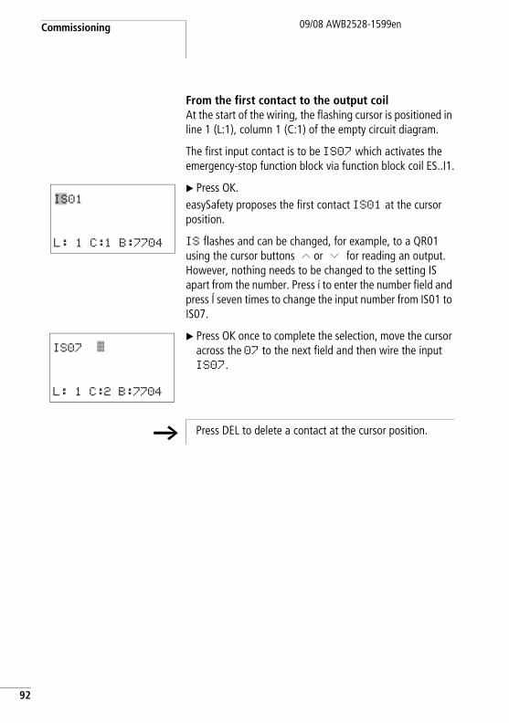
Commissioning
92
09/08 AWB2528-1599en
From the first contact to the output coilAt the start of the wiring, the flashing cursor is positioned in line 1 (L:1), column 1 (C:1) of the empty circuit diagram.
The first input contact is to be IS07 which activates the emergency-stop function block via function block coil ES..I1.
X Press OK.easySafety proposes the first contact IS01 at the cursor position.
IS flashes and can be changed, for example, to a QR01 using the cursor buttons Í or Ú for reading an output. However, nothing needs to be changed to the setting IS apart from the number. Press í to enter the number field and press Í seven times to change the input number from IS01 to IS07.
X Press OK once to complete the selection, move the cursor across the 07 to the next field and then wire the input IS07.
IS01
L: 1 C:1 B:7704
IS07 Ê
L: 1 C:2 B:7704
h Press DEL to delete a contact at the cursor position.
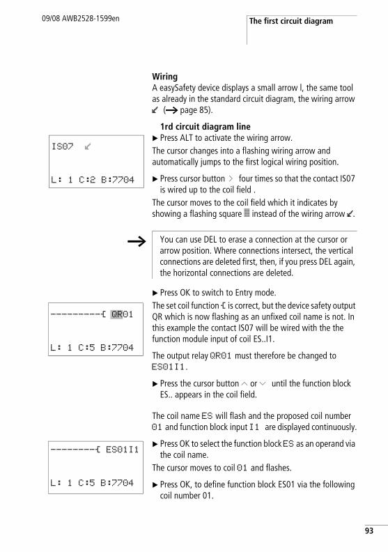
The first circuit diagram09/08 AWB2528-1599en
WiringA easySafety device displays a small arrow l, the same tool as already in the standard circuit diagram, the wiring arrow l (a page 85).
1rd circuit diagram lineX Press ALT to activate the wiring arrow.The cursor changes into a flashing wiring arrow and automatically jumps to the first logical wiring position.
X Press cursor button í four times so that the contact IS07 is wired up to the coil field .
The cursor moves to the coil field which it indicates by showing a flashing square Ê instead of the wiring arrow l.
X Press OK to switch to Entry mode.The set coil function Ä is correct, but the device safety output QR which is now flashing as an unfixed coil name is not. In this example the contact IS07 will be wired with the the function module input of coil ES..I1.
The output relay QR01 must therefore be changed to ES01I1.
X Press the cursor button Í or Ú until the function block ES.. appears in the coil field.
The coil name ES will flash and the proposed coil number 01 and function block input I1 are displayed continuously.
X Press OK to select the function block ES as an operand via the coil name.
The cursor moves to coil 01 and flashes.
X Press OK, to define function block ES01 via the following coil number 01.
IS07 l
L: 1 C:2 B:7704
h You can use DEL to erase a connection at the cursor or arrow position. Where connections intersect, the vertical connections are deleted first, then, if you press DEL again, the horizontal connections are deleted.
---------Ä QR01
L: 1 C:5 B:7704
--------Ä ES01I1
L: 1 C:5 B:7704
93
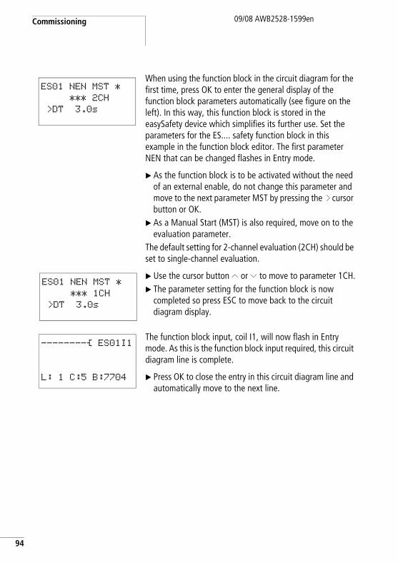
Commissioning
94
09/08 AWB2528-1599en
When using the function block in the circuit diagram for the first time, press OK to enter the general display of the function block parameters automatically (see figure on the left). In this way, this function block is stored in the easySafety device which simplifies its further use. Set the parameters for the ES.... safety function block in this example in the function block editor. The first parameter NEN that can be changed flashes in Entry mode.
X As the function block is to be activated without the need of an external enable, do not change this parameter and move to the next parameter MST by pressing the í cursor button or OK.
X As a Manual Start (MST) is also required, move on to the evaluation parameter.
The default setting for 2-channel evaluation (2CH) should be set to single-channel evaluation.
X Use the cursor button Í or Ú to move to parameter 1CH.X The parameter setting for the function block is now
completed so press ESC to move back to the circuit diagram display.
The function block input, coil I1, will now flash in Entry mode. As this is the function block input required, this circuit diagram line is complete.
X Press OK to close the entry in this circuit diagram line and automatically move to the next line.
ES01 NEN MST *
*** 2CH
>DT 3.0s
ES01 NEN MST *
*** 1CH
>DT 3.0s
--------Ä ES01I1
L: 1 C:5 B:7704
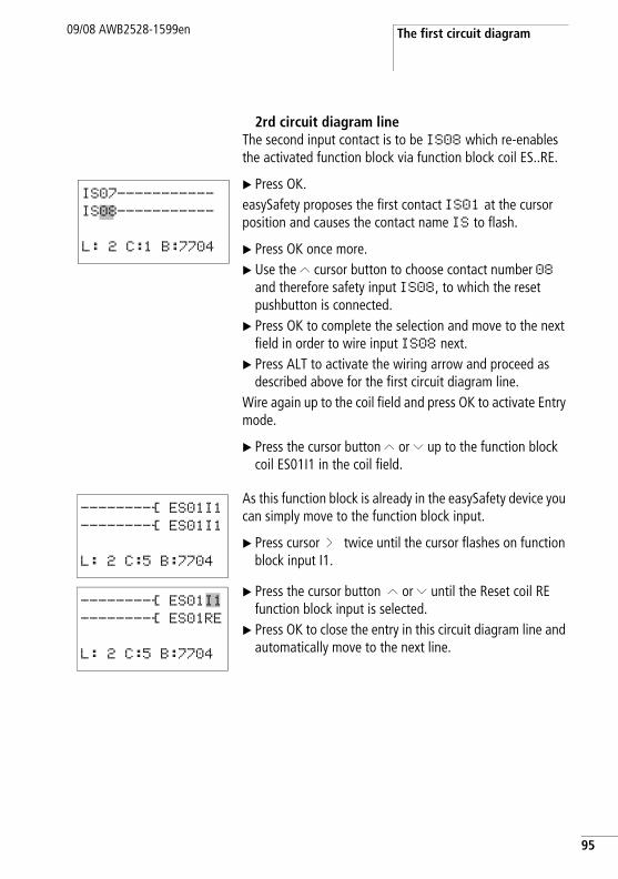
The first circuit diagram09/08 AWB2528-1599en
2rd circuit diagram lineThe second input contact is to be IS08 which re-enables the activated function block via function block coil ES..RE.
X Press OK.easySafety proposes the first contact IS01 at the cursor position and causes the contact name IS to flash.
X Press OK once more.X Use the Í cursor button to choose contact number 08
and therefore safety input IS08, to which the reset pushbutton is connected.
X Press OK to complete the selection and move to the next field in order to wire input IS08 next.
X Press ALT to activate the wiring arrow and proceed as described above for the first circuit diagram line.
Wire again up to the coil field and press OK to activate Entry mode.
X Press the cursor button Í or Ú up to the function block coil ES01I1 in the coil field.
As this function block is already in the easySafety device you can simply move to the function block input.
X Press cursor í twice until the cursor flashes on function block input I1.
X Press the cursor button Í or Ú until the Reset coil RE function block input is selected.
X Press OK to close the entry in this circuit diagram line and automatically move to the next line.
IS07-----------
IS08-----------
L: 2 C:1 B:7704
--------Ä ES01I1--------Ä ES01I1
L: 2 C:5 B:7704
--------Ä ES01I1--------Ä ES01RE
L: 2 C:5 B:7704
95
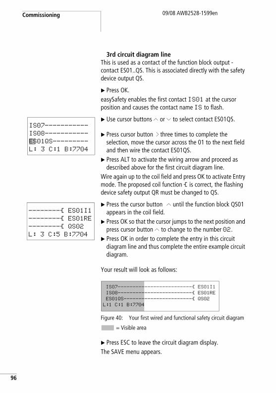
Commissioning
96
09/08 AWB2528-1599en
3rd circuit diagram lineThis is used as a contact of the function block output - contact ES01..QS. This is associated directly with the safety device output QS.
X Press OK.easySafety enables the first contact IS01 at the cursor position and causes the contact name IS to flash.
X Use cursor buttons Í or Ú to select contact ES01QS.
X Press cursor button í three times to complete the selection, move the cursor across the 01 to the next field and then wire the contact ES01QS.
X Press ALT to activate the wiring arrow and proceed as described above for the first circuit diagram line.
Wire again up to the coil field and press OK to activate Entry mode. The proposed coil function Ä is correct, the flashing device safety output QR must be changed to QS.
X Press the cursor button Í until the function block QS01 appears in the coil field.
X Press OK so that the cursor jumps to the next position and press cursor button Í to change to the number 02.
X Press OK in order to complete the entry in this circuit diagram line and thus complete the entire example circuit diagram.
Your result will look as follows:
Figure 40: Your first wired and functional safety circuit diagram
= Visible area
X Press ESC to leave the circuit diagram display. The SAVE menu appears.
IS07-----------
IS08-----------
ES01QS---------
L: 3 C:1 B:7704
--------Ä ES01I1--------Ä ES01RE--------Ä QS02L: 3 C:5 B:7704
IS07-------------------------Ä ES01I1IS08-------------------------Ä ES01REES01QS-----------------------Ä QS02L:1 C:1 B:7704
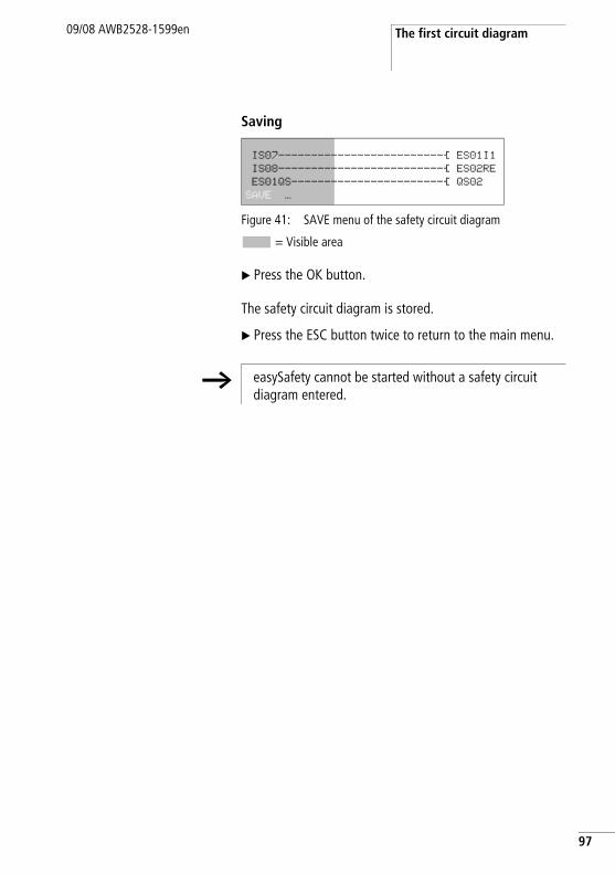
The first circuit diagram09/08 AWB2528-1599en
Saving
Figure 41: SAVE menu of the safety circuit diagram
= Visible area
X Press the OK button.
The safety circuit diagram is stored.
X Press the ESC button twice to return to the main menu.
IS07-------------------------Ä ES01I1IS08-------------------------Ä ES02REES01QS-----------------------Ä QS02SAVE …
h easySafety cannot be started without a safety circuit diagram entered.
97
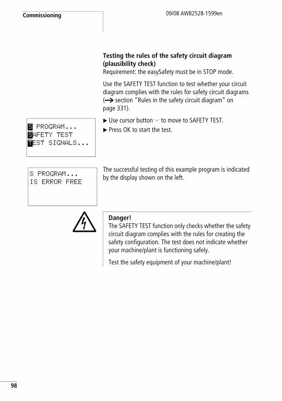
Commissioning
98
09/08 AWB2528-1599en
Testing the rules of the safety circuit diagram(plausibility check)Requirement: the easySafety must be in STOP mode.
Use the SAFETY TEST function to test whether your circuit diagram complies with the rules for safety circuit diagrams (a section “Rules in the safety circuit diagram” on page 331).
X Use cursor button Ú to move to SAFETY TEST.X Press OK to start the test.
The successful testing of this example program is indicated by the display shown on the left.
S PROGRAM...
SAFETY TEST
TEST SIGNALS...
S PROGRAM...
IS ERROR FREE
j Danger!The SAFETY TEST function only checks whether the safety circuit diagram complies with the rules for creating the safety configuration. The test does not indicate whether your machine/plant is functioning safely.
Test the safety equipment of your machine/plant!
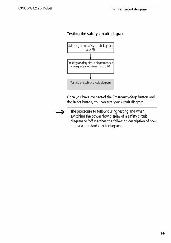
The first circuit diagram09/08 AWB2528-1599en
Testing the safety circuit diagram
Once you have connected the Emergency-Stop button and the Reset button, you can test your circuit diagram.
Switching to the safety circuit diagram, page 88
Creating a safety circuit diagram for an emergency-stop circuit, page 90
Testing the safety circuit diagram
h The procedure to follow during testing and when switching the power flow display of a safety circuit diagram on/off matches the following description of how to test a standard circuit diagram.
99
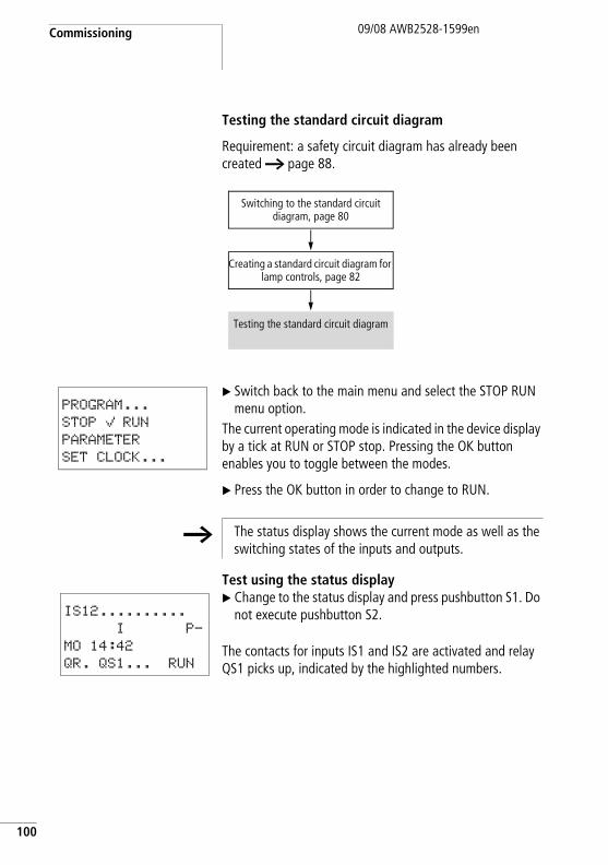
Commissioning
100
09/08 AWB2528-1599en
Testing the standard circuit diagram
Requirement: a safety circuit diagram has already been created a page 88.
X Switch back to the main menu and select the STOP RUN menu option.
The current operating mode is indicated in the device display by a tick at RUN or STOP stop. Pressing the OK button enables you to toggle between the modes.
X Press the OK button in order to change to RUN.
Test using the status displayX Change to the status display and press pushbutton S1. Do
not execute pushbutton S2.
The contacts for inputs IS1 and IS2 are activated and relay QS1 picks up, indicated by the highlighted numbers.
Switching to the standard circuit diagram, page 80
Creating a standard circuit diagram for lamp controls, page 82
Testing the standard circuit diagram
PROGRAM...
STOP å RUN
PARAMETER
SET CLOCK...
h The status display shows the current mode as well as the switching states of the inputs and outputs.
IS12..........
I P-
MO 14:42
QR. QS1... RUN
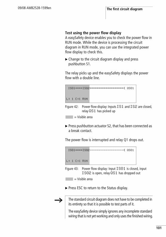
The first circuit diagram09/08 AWB2528-1599en
Test using the power flow displayA easySafety device enables you to check the power flow in RUN mode. While the device is processing the circuit diagram in RUN mode, you can use the integrated power flow display to check this.
X Change to the circuit diagram display and press pushbutton S1.
The relay picks up and the easySafety displays the power flow with a double line.
Figure 42: Power flow display: Inputs IS1 and IS2 are closed, relay QS1 has picked up
= Visible area
X Press pushbutton actuator S2, that has been connected as a break contact.
The power flow is interrupted and relay Q1 drops out.
Figure 43: Power flow display: Input IS01 is closed, input IS02 is open, relay QS1 has dropped out
= Visible area
X Press ESC to return to the Status display.
IS01====IS02===================Ä QS01
L: 1 C:1 RUN
IS01====IS02-------------------Ä QS01
L: 1 C:1 RUN
h The standard circuit diagram does not have to be completed in its entirety so that it is possible to test parts of it.
The easySafety device simply ignores any incomplete standard wiring that is not yet working and only uses the finished wiring.
101
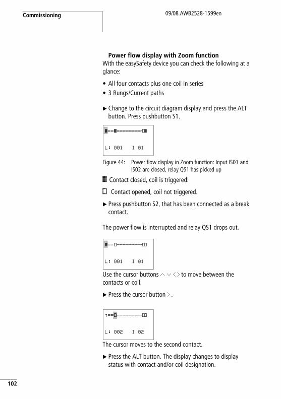
Commissioning
102
09/08 AWB2528-1599en
Power flow display with Zoom functionWith the easySafety device you can check the following at a glance:
• All four contacts plus one coil in series• 3 Rungs/Current paths
X Change to the circuit diagram display and press the ALT button. Press pushbutton S1.
Figure 44: Power flow display in Zoom function: Input IS01 and IS02 are closed, relay QS1 has picked up
â Contact closed, coil is triggered:
# Contact opened, coil not triggered.
X Press pushbutton S2, that has been connected as a break contact.
The power flow is interrupted and relay QS1 drops out.
Use the cursor buttons Í Ú ú í to move between the contacts or coil.
X Press the cursor button í .
The cursor moves to the second contact.
X Press the ALT button. The display changes to display status with contact and/or coil designation.
â==â========Äâ
L: 001 I 01
â==#--------Ä#
L: 001 I 01
Æ==#--------Ä#
L: 002 I 02
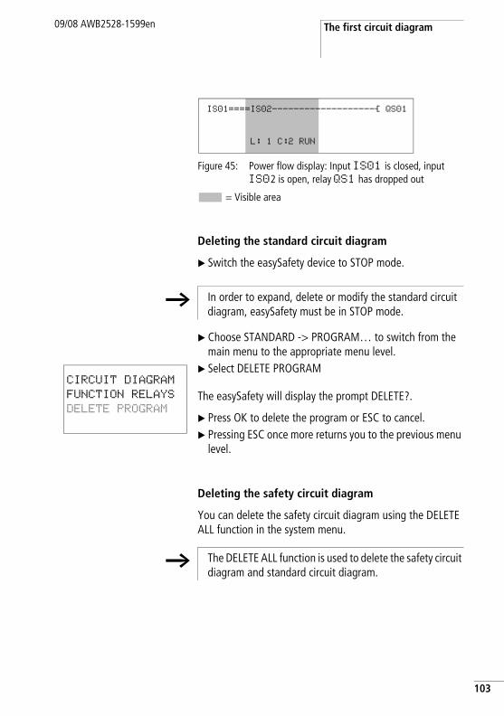
The first circuit diagram09/08 AWB2528-1599en
Figure 45: Power flow display: Input IS01 is closed, input IS02 is open, relay QS1 has dropped out
= Visible area
Deleting the standard circuit diagram
X Switch the easySafety device to STOP mode.
X Choose STANDARD -> PROGRAM… to switch from the main menu to the appropriate menu level.
X Select DELETE PROGRAM
The easySafety will display the prompt DELETE?.
X Press OK to delete the program or ESC to cancel.X Pressing ESC once more returns you to the previous menu
level.
Deleting the safety circuit diagram
You can delete the safety circuit diagram using the DELETE ALL function in the system menu.
IS01====IS02-------------------Ä QS01
L: 1 C:2 RUN
h In order to expand, delete or modify the standard circuit diagram, easySafety must be in STOP mode.
CIRCUIT DIAGRAM
FUNCTION RELAYS
DELETE PROGRAM
h The DELETE ALL function is used to delete the safety circuit diagram and standard circuit diagram.
103

104
09/08 AWB2528-1599en
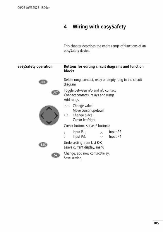
09/08 AWB2528-1599en
4 Wiring with easySafety
This chapter describes the entire range of functions of an easySafety device.
easySafety operation Buttons for editing circuit diagrams and function blocks
Delete rung, contact, relay or empty rung in the circuit diagram
Toggle between n/o and n/c contactConnect contacts, relays and rungsAdd rungs
ÍÚ
ú í
Change valueMove cursor up/downChange placeCursor left/right
Cursor buttons set as P buttons:
úí
Input P1,Input P3,
ÍÚ
Input P2Input P4
Undo setting from last OK Leave current display, menu
Change, add new contact/relay, Save setting
DEL
ALT
ESC
OK
105
Wiring with easySafety
106
09/08 AWB2528-1599en
Operation
The cursor buttons in the easySafety circuit diagram have three functions:
• Moving.• Input.• Connecting.
The current mode is indicated by the appearance of the flashing cursor.
In Move mode, use ÍÚ ú í to position the cursor on the circuit diagram in order to select a rung, a contact or a relay coil.
Press OK to switch to Entry mode so that you can enter or change a value at the cursor position. Press ESC in Entry mode to restore easySafety to the last changes of an entry.
Press ALT to switch to Connect mode for wiring contacts and relays. Press ALT again to return to Move.
Press ESC to exit the circuit diagram and parameter display.
â
IS01
l
h The easySafety device performs a large part of this cursor change automatically. For example it switches the cursor to Move mode when it is no longer possible to make an entry or connection at the selected cursor position.
Circuit diagram elements09/08 AWB2528-1599en
Circuit diagram elements Configuration
A configuration is a series of commands that the easySafety device processes cyclically in RUN mode. A easySafety configuration consists of the necessary settings for the device, easyNet, password, system settings, at least a circuit diagram and function blocks.
A circuit diagram is the part of the configuration in which the contacts are connected together. In RUN mode, a coil is switched on or off depending on the power flow and coil function set.
The configuration of easySafety consists of:
• Safety circuit diagram containing the safety function for implementing safety-related tasks.
• Standard circuit diagram for implementing the general, non-safety tasks of the control relay.
Safety-relevant tasksThe term “safety circuit diagram” is given to the fail-safe part of the easySafety configuration. The safety circuit diagram consists of contacts and coils of the safety basic devices which are wired together. Contacts can, for example, be the inputs of the easySafety device or outputs of safety function blocks. Coils can, for example, be outputs of the basic unit or inputs of safety function blocks. Special measures are implemented to ensure that the safety function blocks operate error-free. The function blocks continuously read the current state of the connected safety transmitters and process this information. On the basis of the result, the safety circuit diagram removes or issues the enable via one of the device safety outputs (QS.., QR..) for a particular function.
107
Wiring with easySafety
108
09/08 AWB2528-1599en
Non-safety-relevant tasksCertain inputs/outputs of safety function blocks can be connected in the safety circuit diagram or also in the standard circuit diagram. The device safety inputs can also be read and processed in the standard circuit diagram. The result is output via safety outputs which however, CANNOT be used in the safety circuit diagram.
An internal management function prevents the accidental double use of these outputs (QS.., QR..).
The safety circuit diagram cannot access the data of the standard circuit diagram in order to prevent the processing of non-safety data in the safety circuit diagram.
Conversely, the standard circuit diagram only has indirect access to the safety circuit diagram. In the standard circuit diagram you can therefore:
• use diagnostic function blocks to evaluate signals of the non-safety diagnostic outputs of the safety function blocks, a page 233.
• evaluate the error contact ER of a safety function block for signalling a general fault, a page 335.
• activate or deactivate safety function blocks as required, a page 336.
The relationship between the safety and standard circuit diagram must observe the rules specified for the creation of safety circuit diagrams (a page 331). Check that these rules are observed by choosing the SAFETY TEST menu option.
j Danger!Device outputs (QS., QR.) that are used in the standard circuit diagram are not safety outputs and must only be used for standard tasks. Make sure that these outputs do not trigger any safety-related actions on the machine or plant.
Circuit diagram elements09/08 AWB2528-1599en
The easySafety control relay can be connected locally or via easyNet with a non-safety I/O expansion device. These non-safety I/Os are only read, processed and written by the standard circuit diagram.
Further information on expansion options is provided in chapter “Expanding an easySafety device” from page 617 as well as in chapter “Introduction to the easyNet network”, on page 511.
Function blocks
Function blocks are program blocks with special functions. Examples: emergency-stop relays, timing relays, time switches. Function blocks are provided with or without contacts and coils. How a safety or standard function block is added to the safety or standard circuit diagram and parameterised is described in „Working with function blocks“ on page 151.
In RUN mode the function blocks are processed according to the circuit diagram and the results are updated accordingly.
Examples: Timing relay = Function block with contacts and coilsTime switch = Function block with contacts
Relays
Relays are switching devices that are emulated in easySafety device electronically, which activate their contacts according to the assigned function. A relay consists of at least one coil and contact.
h A easySafety device is primarily a configurable safety relay, and this is why the safety circuit diagram is obligatory. Without it, the device could not fulfill any safety function and therefore any configuration without a safety circuit diagram is rejected as invalid.
109
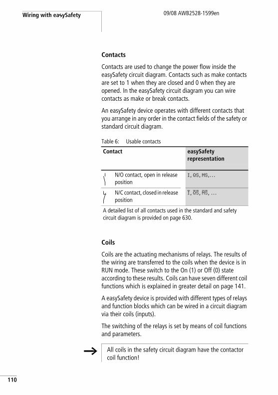
Wiring with easySafety
110
09/08 AWB2528-1599en
Contacts
Contacts are used to change the power flow inside the easySafety circuit diagram. Contacts such as make contacts are set to 1 when they are closed and 0 when they are opened. In the easySafety circuit diagram you can wire contacts as make or break contacts.
An easySafety device operates with different contacts that you arrange in any order in the contact fields of the safety or standard circuit diagram.
Table 6: Usable contacts
Coils
Coils are the actuating mechanisms of relays. The results of the wiring are transferred to the coils when the device is in RUN mode. These switch to the On (1) or Off (0) state according to these results. Coils can have seven different coil functions which is explained in greater detail on page 141.
A easySafety device is provided with different types of relays and function blocks which can be wired in a circuit diagram via their coils (inputs).
The switching of the relays is set by means of coil functions and parameters.
Contact easySafety representation
N/O contact, open in release position
I, QS, MS,…
N/C contact, closed in release position
I, QS, MS, …
A detailed list of all contacts used in the standard and safety circuit diagram is provided on page 630.
h All coils in the safety circuit diagram have the contactor coil function!
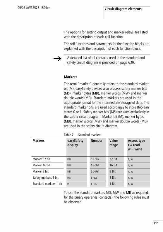
Circuit diagram elements09/08 AWB2528-1599en
The options for setting output and marker relays are listed with the description of each coil function.
The coil functions and parameters for the function blocks are explained with the description of each function block.
Markers
The term “marker” generally refers to the standard marker bit (M). easySafety devices also process safety marker bits (MS), marker bytes (MB), marker words (MW) and marker double words (MD). Standard markers are used in the appropriate format for the intermediate storage of data. The standard marker bits are used accordingly to store Boolean states 0 or 1. Safety marker bits (MS) are used exclusively in the safety circuit diagram. Marker bit (M), marker bytes (MB), marker words (MW) and marker double words (MD) are used in the safety circuit diagram.
Table 7: Standard markers
To use the standard markers MD, MW and MB as required for the binary operands (contacts), the following rules must be observed:
h A detailed list of all contacts used in the standard and safety circuit diagram is provided on page 630.
Markers easySafety display
Number Value range
Access typer = readw = write
Marker 32 bit MD 01-96 32 Bit r, w
Marker 16 bit MW 01-96 16 Bit r, w
Marker 8 bit MB 01-96 8 Bit r, w
Safety markers 1 bit MS 1-32 1 Bit r, w
Standard markers 1 bit M 1-96 1 Bit r, w
111
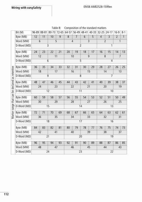
Wiring with easySafety
112
09/08 AWB2528-1599en
Table 8: Composition of the standard markers
Mar
ker r
ange
that
can
be
decl
ared
as
rete
ntiv
e
Bit (M) 96-89 88-81 80-73 72-65 64-57 56-49 48-41 40-33 32-25 24-17 16-9 8-1Byte (MB) 12 11 10 9 8 7 6 5 4 3 2 1Word (MW) 6 5 4 3 2 1D-Word (MD) 3 2 1
Byte (MB) 24 23 22 21 20 19 18 17 16 15 14 13Word (MW) 12 11 10 9 8 7D-Word (MD) 6 5 4
Byte (MB) 36 35 34 33 32 31 30 29 28 27 26 25Word (MW) 18 17 16 15 14 13D-Word (MD) 9 8 7
Byte (MB) 48 47 46 45 44 43 42 41 40 39 38 37Word (MW) 24 23 22 21 20 19D-Word (MD) 12 11 10
Byte (MB) 60 59 58 57 56 55 54 53 52 51 50 49Word (MW) 30 29 28 27 26 25D-Word (MD) 15 14 13
Byte (MB) 72 71 70 69 68 67 66 65 64 63 62 61Word (MW) 36 35 34 33 32 31D-Word (MD) 18 17 16
Byte (MB) 84 83 82 81 80 79 78 77 76 75 74 73Word (MW) 42 41 40 39 38 37D-Word (MD) 21 20 19
Byte (MB) 96 95 94 93 92 91 90 89 88 87 86 85Word (MW) 48 47 46 45 44 43D-Word (MD) 24 23 22
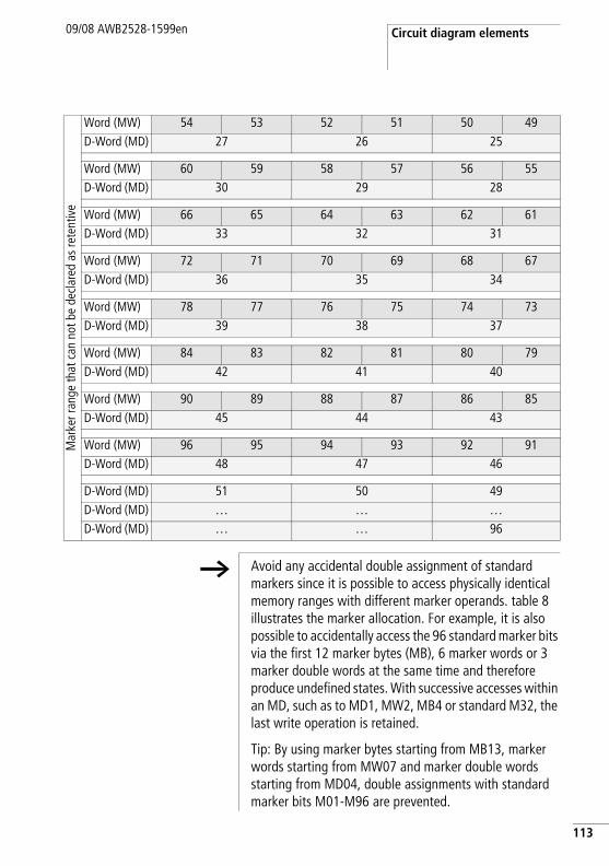
Circuit diagram elements09/08 AWB2528-1599en
Mar
ker r
ange
that
can
not
be
decl
ared
as
rete
ntiv
e
Word (MW) 54 53 52 51 50 49D-Word (MD) 27 26 25
Word (MW) 60 59 58 57 56 55D-Word (MD) 30 29 28
Word (MW) 66 65 64 63 62 61D-Word (MD) 33 32 31
Word (MW) 72 71 70 69 68 67D-Word (MD) 36 35 34
Word (MW) 78 77 76 75 74 73D-Word (MD) 39 38 37
Word (MW) 84 83 82 81 80 79D-Word (MD) 42 41 40
Word (MW) 90 89 88 87 86 85D-Word (MD) 45 44 43
Word (MW) 96 95 94 93 92 91D-Word (MD) 48 47 46
D-Word (MD) 51 50 49D-Word (MD) … … …D-Word (MD) … … 96
h Avoid any accidental double assignment of standard markers since it is possible to access physically identical memory ranges with different marker operands. table 8 illustrates the marker allocation. For example, it is also possible to accidentally access the 96 standard marker bits via the first 12 marker bytes (MB), 6 marker words or 3 marker double words at the same time and therefore produce undefined states. With successive accesses within an MD, such as to MD1, MW2, MB4 or standard M32, the last write operation is retained.
Tip: By using marker bytes starting from MB13, marker words starting from MW07 and marker double words starting from MD04, double assignments with standard marker bits M01-M96 are prevented.
113
Wiring with easySafety
114
09/08 AWB2528-1599en
Retentive standard markersYou can declare a freely definable contiguous range of marker bytes within the range MB01-MB96 as retentive. The table 8 shows how together with these marker bytes MB01-MB96, also marker words MW01-48 and marker double words MD01-24 can be declared as retentive.
The remaining marker words MW49-96 and marker double words MD25-96 cannot be declared as retentive!
The conditions by which the retentive data of a device is deleted are described in a section “Retention” on page 589).
Circuit diagram elements09/08 AWB2528-1599en
Number formatsThe easySafety device processes calculations with a signed 31-bit value.
The value range is: –2147483648 to +2147483647
With a 31-bit value, the 32nd value is the sign bit.
Bit 32 = status 0 -> positive number.
Example:00000000000000000000010000010010bin = 412hex = 1042dec
Bit 32 = status 1 -> negative number.
Example: 11111111111111111101110010101110bin = FFFFDCAEhex = –2147474606dec
h The values of the data types marker byte (MB) and marker word (MB) are processed as unsigned. This must be remembered particularly if you wish to transfer the output of a standard function block which can take on negative values to the input of a standard function block and wish to buffer the value in the marker range.
If a used variable can take on negative values and you wish to store this in the marker range, you must assign a marker double word for it.
115
Wiring with easySafety
116
09/08 AWB2528-1599en
Circuit diagram display You wire contacts and coils of relays in the easySafety circuit diagram from left to right, from the contact to the coil. The standard circuit diagram is entered in an invisible wiring grid with contact fields, coil fields and rungs, and wired together with connections. easySafety enables you to create a safety circuit diagram for the functions as a configurable safety relay safety relay that is kept separate from the standard circuit diagram that is also provided for general control tasks. The safety circuit diagram is organised with contact fields, coil fields and rungs in the same way as the standard circuit diagram.
• Insert contacts in the four contact fields. The first contact field on the left is automatically connected to the voltage.
• In the coil field the relay coil to be controlled is entered with the coil identifier and coil function. The coil identifier consists of the coil name, coil number and, in the case of function blocks, with the function identifier. The coil function defines the operation of the coil.
• Each line in the circuit diagram represents a rung. In a configuration of the easySafety device, up to 256 rungs can be wired. These can be divided up between the safety and standard circuit diagram as required. The editor counts the rungs used and shows the number of rungs available in the status line.
h There are 253 rungs available in the standard circuit diagram, and another 253 in the safety circuit diagram, for wiring contacts and coils. The device reserves three rungs per circuit diagram for internal management purposes.
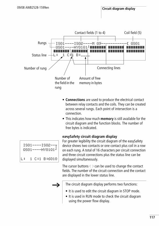
Circuit diagram display09/08 AWB2528-1599en
• Connections are used to produce the electrical contact between relay contacts and the coils. They can be created across several rungs. Each point of intersection is a connection.
• This indicates how much memory is still available for the circuit diagram and the function blocks. The number of free bytes is indicated.
easySafety circuit diagram displayFor greater legibility the circuit diagram of the easySafety device shows two contacts or one contact plus coil in a row on each rung. A total of 16 characters per circuit connection and three circuit connections plus the status line can be displayed simultaneously.
The cursor buttons ú í can be used to change the contact fields. The number of the circuit connection and the contact are displayed in the lower status line.
IS01----IS02----M 09-----------Ä QS01QS01----HY01Q1kâââââââ âââââââ ââââââââ
âââââââ âââââââ âââââââ âââââââ ââââââââL: 1 C:1 B:____
Contact fields (1 to 4) Coil field (5)
Connecting lines
Rungs
Status line
Number of rung
Number of the field in the rung
Amount of free memory in bytes
IS01----IS02--uQS01----HY01Q1k
L: 1 C:1 B:6010
h The circuit diagram display performs two functions:
• It is used to edit the circuit diagram in STOP mode.• It is used in RUN mode to check the circuit diagram
using the power flow display.
117

Wiring with easySafety
118
09/08 AWB2528-1599en
Transfer from and to the memory card
Configurations are transferred via the serial multi-function interface. There are two possibilities:
• From or to a easySafety memory card, a page 120.• Via the programming cable from or to the COM serial PC
interface and thus from or to the configuration software easySoft-Safety, a page 125 or in the Online Help.
How to remove the cover of the serial multi-function interface, connect a programming cable and fit a memory card is described in section “Connecting the serial multi-function interface” on page 64.
Information on the memory card
The 256 KB memory card easySafety ES4A-MEM-CARD1 is available as an accessory for devices. This memory card can neither be read nor written by an easy800 or an MFD-Titan.
A configuration with all the necessary parameters can be loaded from the memory card into the easySafety device or written from the device to the card.
Each memory card stores a single easySafety configuration and two memory languages.
All information on the memory card is retained when the card is in a de-energized state, so that you can use the card for archiving, transporting and copying configurations.
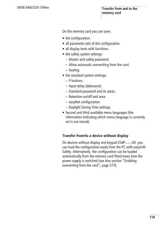
Transfer from and to the memory card
09/08 AWB2528-1599en
On the memory card you can save:
• the configuration.• all parameter sets of the configuration.• all display texts with functions.• the safety system settings:
– Master and safety password.– Allow automatic overwriting from the card.– Sealing.
• the standard system settings:– P buttons.– Input delay (debounce).– Standard password and its areas.– Retention on/off and area.– easyNet configuration.– Daylight Saving Time settings.
• Second and third available menu languages (the information indicating which menu language is currently set is not stored).
Transfer from/to a device without display
On devices without display and keypad ES4P-...-..XX. you can load the configuration easily from the PC with easySoft-Safety. Alternatively the configuration can be loaded automatically from the memory card fitted every time the power supply is switched (see also section “Enabling overwriting from the card”, page 573).
119
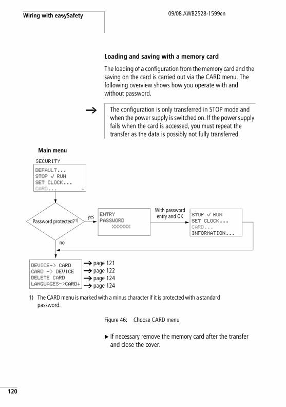
Wiring with easySafety
120
09/08 AWB2528-1599en
Loading and saving with a memory card
The loading of a configuration from the memory card and the saving on the card is carried out via the CARD menu. The following overview shows how you operate with and without password.
Figure 46: Choose CARD menu
X If necessary remove the memory card after the transfer and close the cover.
h The configuration is only transferred in STOP mode and when the power supply is switched on. If the power supply fails when the card is accessed, you must repeat the transfer as the data is possibly not fully transferred.
yesPassword protected?1)
DEFAULT...
STOP å RUN
SET CLOCK...
CARD... æ
SSECURITY
ENTRY
PASSWORD
XXXXXX
STOP å RUN
SET CLOCK...
CARD...
INFORMATION...
no
SMain menu
DEVICE-> CARD
CARD -> DEVICE
DELETE CARD
LANGUAGES->CARDæ
a page 121a page 122a page 124a page 124
1) The CARD menu is marked with a minus character if it is protected with a standard password.
With password entry and OK
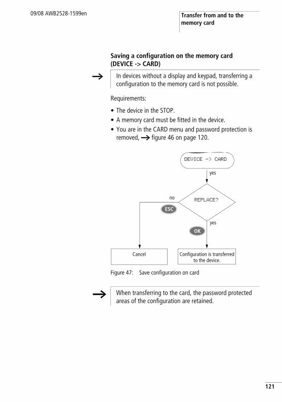
Transfer from and to the memory card
09/08 AWB2528-1599en
Saving a configuration on the memory card (DEVICE -> CARD)
Requirements:
• The device in the STOP.• A memory card must be fitted in the device.• You are in the CARD menu and password protection is
removed, a figure 46 on page 120.
Figure 47: Save configuration on card
h In devices without a display and keypad, transferring a configuration to the memory card is not possible.
DEVICE -> CARD
REPLACE?no
Cancel Configuration is transferred to the device.
yes
yes
OK
ESC
h When transferring to the card, the password protected areas of the configuration are retained.
121
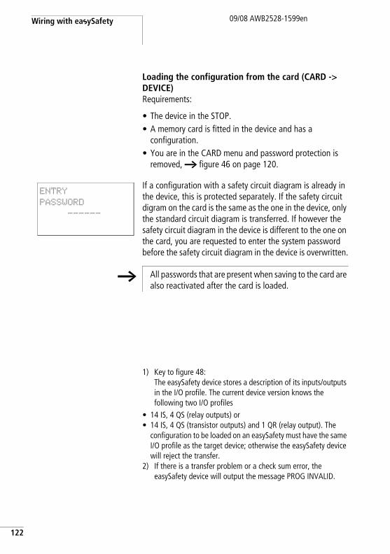
Wiring with easySafety
122
09/08 AWB2528-1599en
Loading the configuration from the card (CARD -> DEVICE)Requirements:
• The device in the STOP.• A memory card is fitted in the device and has a
configuration.• You are in the CARD menu and password protection is
removed, a figure 46 on page 120.
If a configuration with a safety circuit diagram is already in the device, this is protected separately. If the safety circuit digram on the card is the same as the one in the device, only the standard circuit diagram is transferred. If however the safety circuit diagram in the device is different to the one on the card, you are requested to enter the system password before the safety circuit diagram in the device is overwritten.
1) Key to figure 48:The easySafety device stores a description of its inputs/outputs in the I/O profile. The current device version knows the following two I/O profiles
• 14 IS, 4 QS (relay outputs) or• 14 IS, 4 QS (transistor outputs) and 1 QR (relay output). The
configuration to be loaded on an easySafety must have the same I/O profile as the target device; otherwise the easySafety device will reject the transfer.
2) If there is a transfer problem or a check sum error, the easySafety device will output the message PROG INVALID.
ENTRY
PASSWORD
------
h All passwords that are present when saving to the card are also reactivated after the card is loaded.
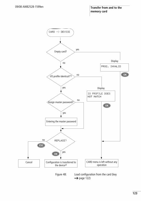
Transfer from and to the memory card
09/08 AWB2528-1599en
Figure 48: Load configuration from the card (key a page 122)
noI/O profile identical?1)
CARD -> DEVICE
no
Cancel
Entering the master password
yes
yes
Assign master password?
REPLACE?
Configuration is transferred to the device2)
CARD menu is left without any operation
no
IO PROFILE DOES
NOT MATCH
ESC
OKyes
Display
OK
yesEmpty card?
noPROG. INVALID
Display
OK
123
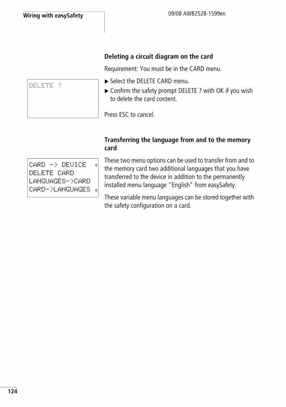
Wiring with easySafety
124
09/08 AWB2528-1599en
Deleting a circuit diagram on the card
Requirement: You must be in the CARD menu.
X Select the DELETE CARD menu.X Confirm the safety prompt DELETE ? with OK if you wish
to delete the card content.
Press ESC to cancel.
Transferring the language from and to the memory card
These two menu options can be used to transfer from and to the memory card two additional languages that you have transferred to the device in addition to the permanently installed menu language "English" from easySafety.
These variable menu languages can be stored together with the safety configuration on a card.
DELETE ?
CARD -> DEVICE Æ DELETE CARD
LANGUAGES->CARD
CARD->LANGUAGES æ
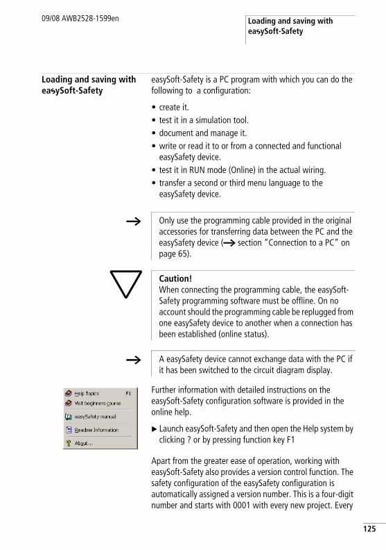
Loading and saving with easySoft-Safety
09/08 AWB2528-1599en
Loading and saving with easySoft-Safety
easySoft-Safety is a PC program with which you can do the following to a configuration:
• create it. • test it in a simulation tool. • document and manage it.• write or read it to or from a connected and functional
easySafety device. • test it in RUN mode (Online) in the actual wiring.• transfer a second or third menu language to the
easySafety device.
Further information with detailed instructions on the easySoft-Safety configuration software is provided in the online help.
X Launch easySoft-Safety and then open the Help system by clicking ? or by pressing function key F1
Apart from the greater ease of operation, working with easySoft-Safety also provides a version control function. The safety configuration of the easySafety configuration is automatically assigned a version number. This is a four-digit number and starts with 0001 with every new project. Every
h Only use the programming cable provided in the original accessories for transferring data between the PC and the easySafety device (a section “Connection to a PC” on page 65).
h Caution!When connecting the programming cable, the easySoft-Safety programming software must be offline. On no account should the programming cable be replugged from one easySafety device to another when a connection has been established (online status).
h A easySafety device cannot exchange data with the PC if it has been switched to the circuit diagram display.
125
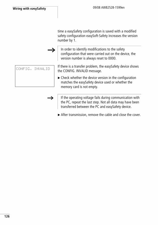
Wiring with easySafety
126
09/08 AWB2528-1599en
time a easySafety configuration is saved with a modified safety configuration easySoft-Safety increases the version number by 1.
If there is a transfer problem, the easySafety device shows the CONFIG. INVALID message.
X Check whether the device version in the configuration matches the easySafety device used or whether the memory card is not empty.
X After transmission, remove the cable and close the cover.
h In order to identify modifications to the safety configuration that were carried out on the device, the version number is always reset to 0000.
CONFIG. INVALID
h If the operating voltage fails during communication with the PC, repeat the last step. Not all data may have been transferred between the PC and easySafety device.
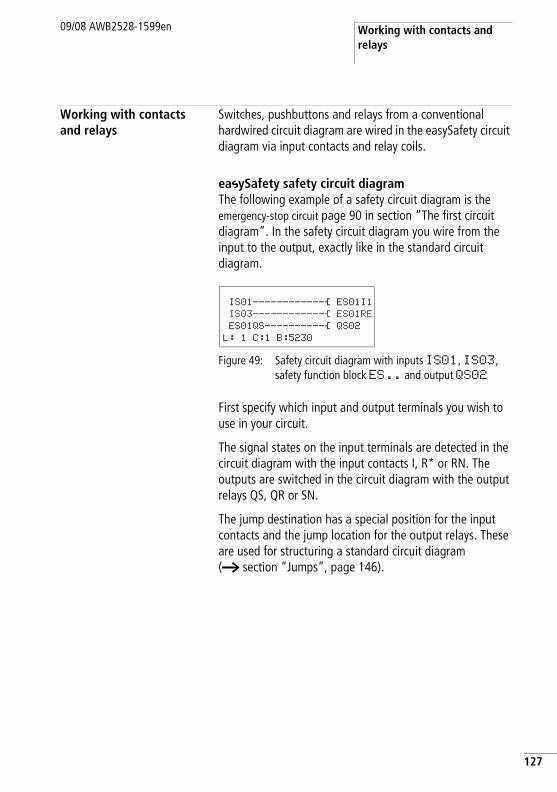
Working with contacts and relays
09/08 AWB2528-1599en
Working with contacts and relays
Switches, pushbuttons and relays from a conventional hardwired circuit diagram are wired in the easySafety circuit diagram via input contacts and relay coils.
easySafety safety circuit diagramThe following example of a safety circuit diagram is the emergency-stop circuit page 90 in section “The first circuit diagram”. In the safety circuit diagram you wire from the input to the output, exactly like in the standard circuit diagram.
Figure 49: Safety circuit diagram with inputs IS01, IS03, safety function block ES.. and output QS02
First specify which input and output terminals you wish to use in your circuit.
The signal states on the input terminals are detected in the circuit diagram with the input contacts I, R* or RN. The outputs are switched in the circuit diagram with the output relays QS, QR or SN.
The jump destination has a special position for the input contacts and the jump location for the output relays. These are used for structuring a standard circuit diagram (a section “Jumps”, page 146).
IS01------------Ä ES01I1IS03------------Ä ES01REES01QS----------Ä QS02L: 1 C:1 B:5230
127
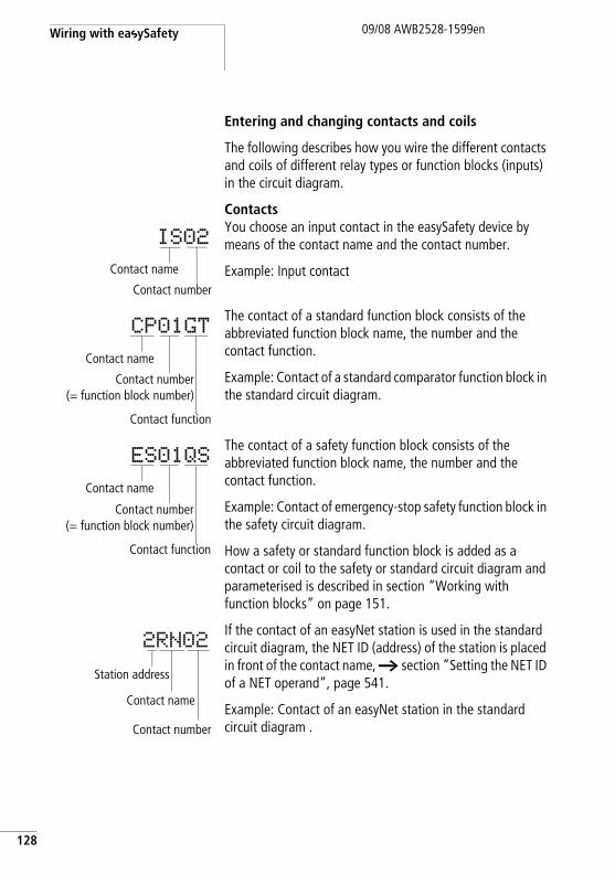
Wiring with easySafety
128
09/08 AWB2528-1599en
Entering and changing contacts and coils
The following describes how you wire the different contacts and coils of different relay types or function blocks (inputs) in the circuit diagram.
ContactsYou choose an input contact in the easySafety device by means of the contact name and the contact number.
Example: Input contact
The contact of a standard function block consists of the abbreviated function block name, the number and the contact function.
Example: Contact of a standard comparator function block in the standard circuit diagram.
The contact of a safety function block consists of the abbreviated function block name, the number and the contact function.
Example: Contact of emergency-stop safety function block in the safety circuit diagram.
How a safety or standard function block is added as a contact or coil to the safety or standard circuit diagram and parameterised is described in section “Working with function blocks” on page 151.
If the contact of an easyNet station is used in the standard circuit diagram, the NET ID (address) of the station is placed in front of the contact name, a section “Setting the NET ID of a NET operand”, page 541.
Example: Contact of an easyNet station in the standard circuit diagram .
IS02
Contact name
Contact number
CP01GT
Contact name
Contact number(= function block number)
Contact function
ES01QS
Contact name
Contact number(= function block number)
Contact function
2RN02
Station address
Contact name
Contact number
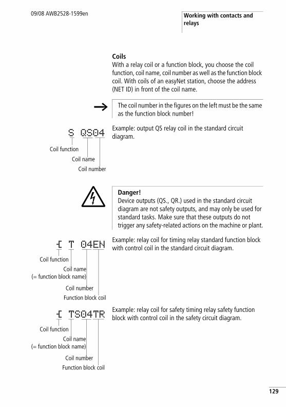
Working with contacts and relays
09/08 AWB2528-1599en
CoilsWith a relay coil or a function block, you choose the coil function, coil name, coil number as well as the function block coil. With coils of an easyNet station, choose the address (NET ID) in front of the coil name.
Example: output QS relay coil in the standard circuit diagram.
Example: relay coil for timing relay standard function block with control coil in the standard circuit diagram.
Example: relay coil for safety timing relay safety function block with control coil in the safety circuit diagram.
h The coil number in the figures on the left must be the same as the function block number!
S QS04
Coil function
Coil name
Coil number
j Danger! Device outputs (QS., QR.) used in the standard circuit diagram are not safety outputs, and may only be used for standard tasks. Make sure that these outputs do not trigger any safety-related actions on the machine or plant.
Ä T 04ENCoil function
Coil name(= function block name)
Coil number
Function block coil
Ä TS04TRCoil function
Coil name(= function block name)
Coil number
Function block coil
129
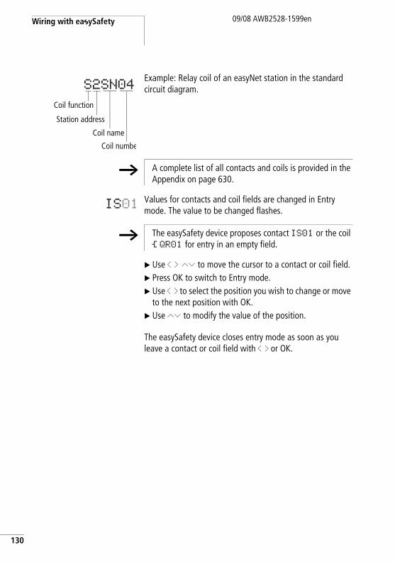
Wiring with easySafety
130
09/08 AWB2528-1599en
Example: Relay coil of an easyNet station in the standard circuit diagram.
Values for contacts and coil fields are changed in Entry mode. The value to be changed flashes.
X Use ú í ÍÚ to move the cursor to a contact or coil field.X Press OK to switch to Entry mode.X Use ú í to select the position you wish to change or move
to the next position with OK.X Use ÍÚ to modify the value of the position.
The easySafety device closes entry mode as soon as you leave a contact or coil field with ú í or OK.
S2SN04
Coil function
Station address
Coil numbe
Coil name
h A complete list of all contacts and coils is provided in the Appendix on page 630.
IS01
h The easySafety device proposes contact IS01 or the coil Ä QR01 for entry in an empty field.
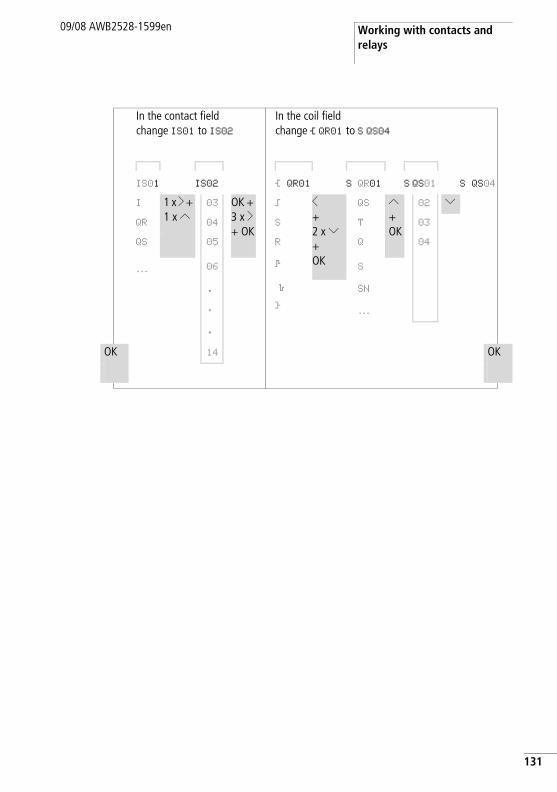
Working with contacts and relays
09/08 AWB2528-1599en
In the contact field change IS01 to IS02
In the coil field change Ä QR01 to S QS04
IS01 IS02 Ä QR01 S QR01 S QS01 S QS04
I 1 x í + 1 x Í
03 OK + 3 x í+ OK
ä ú+ 2 x Ú+OK
QS Í+OK
02 ÚQR 04 S T 03
QS 05 R Q 04
… 06 È S
. è SN
. Å …
.
OK 14 OK
131
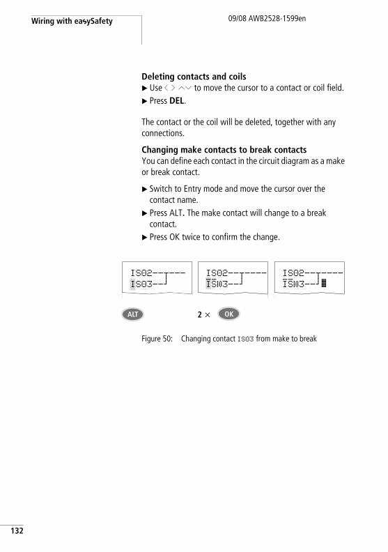
Wiring with easySafety
132
09/08 AWB2528-1599en
Deleting contacts and coilsX Use ú í ÍÚ to move the cursor to a contact or coil field.X Press DEL.
The contact or the coil will be deleted, together with any connections.
Changing make contacts to break contactsYou can define each contact in the circuit diagram as a make or break contact.
X Switch to Entry mode and move the cursor over the contact name.
X Press ALT. The make contact will change to a break contact.
X Press OK twice to confirm the change.
Figure 50: Changing contact IS03 from make to break
IS02--u---IS03--k
IS02--u----IS03--k
IS02--u----IS03--kê
ALT OK2 x
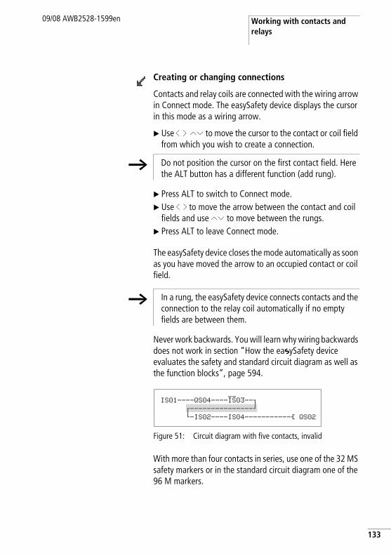
Working with contacts and relays
09/08 AWB2528-1599en
Creating or changing connections
Contacts and relay coils are connected with the wiring arrow in Connect mode. The easySafety device displays the cursor in this mode as a wiring arrow.
X Use ú í ÍÚ to move the cursor to the contact or coil field from which you wish to create a connection.
X Press ALT to switch to Connect mode.X Use ú í to move the arrow between the contact and coil
fields and use ÍÚ to move between the rungs.X Press ALT to leave Connect mode.
The easySafety device closes the mode automatically as soon as you have moved the arrow to an occupied contact or coil field.
Never work backwards. You will learn why wiring backwards does not work in section “How the easySafety device evaluates the safety and standard circuit diagram as well as the function blocks”, page 594.
Figure 51: Circuit diagram with five contacts, invalid
With more than four contacts in series, use one of the 32 MS safety markers or in the standard circuit diagram one of the 96 M markers.
l
h Do not position the cursor on the first contact field. Here the ALT button has a different function (add rung).
h In a rung, the easySafety device connects contacts and the connection to the relay coil automatically if no empty fields are between them.
IS01----QS04----IS03--oz---------------kh-IS02----IS04-----------Ä QS02
133
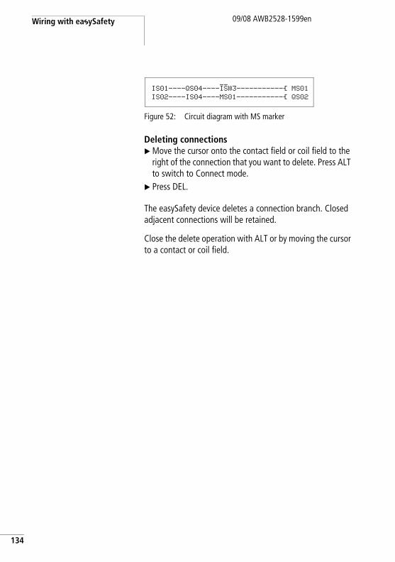
Wiring with easySafety
134
09/08 AWB2528-1599en
Figure 52: Circuit diagram with MS marker
Deleting connectionsX Move the cursor onto the contact field or coil field to the
right of the connection that you want to delete. Press ALT to switch to Connect mode.
X Press DEL.
The easySafety device deletes a connection branch. Closed adjacent connections will be retained.
Close the delete operation with ALT or by moving the cursor to a contact or coil field.
IS01----QS04----IS03-----------Ä MS01IS02----IS04----MS01-----------Ä QS02
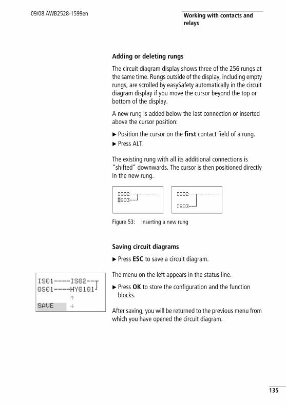
Working with contacts and relays
09/08 AWB2528-1599en
Adding or deleting rungs
The circuit diagram display shows three of the 256 rungs at the same time. Rungs outside of the display, including empty rungs, are scrolled by easySafety automatically in the circuit diagram display if you move the cursor beyond the top or bottom of the display.
A new rung is added below the last connection or inserted above the cursor position:
X Position the cursor on the first contact field of a rung.X Press ALT.
The existing rung with all its additional connections is “shifted” downwards. The cursor is then positioned directly in the new rung.
Figure 53: Inserting a new rung
Saving circuit diagrams
X Press ESC to save a circuit diagram.
The menu on the left appears in the status line.
X Press OK to store the configuration and the function blocks.
After saving, you will be returned to the previous menu from which you have opened the circuit diagram.
IS02--u------IS03--k
IS02--u------- n
IS03--k
IS01----IS02--uQS01----HY01Q1k
ÆSAVE æ
135
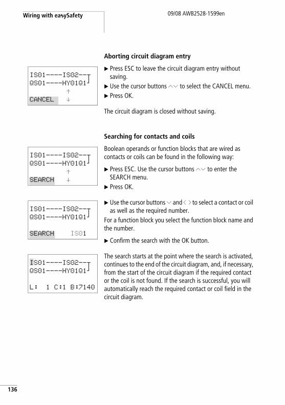
Wiring with easySafety
136
09/08 AWB2528-1599en
Aborting circuit diagram entry
X Press ESC to leave the circuit diagram entry without saving.
X Use the cursor buttons ÍÚ to select the CANCEL menu.X Press OK.
The circuit diagram is closed without saving.
Searching for contacts and coils
Boolean operands or function blocks that are wired as contacts or coils can be found in the following way:
X Press ESC. Use the cursor buttons ÍÚ to enter the SEARCH menu.
X Press OK.
X Use the cursor buttons Ú and ú í to select a contact or coil as well as the required number.
For a function block you select the function block name and the number.
X Confirm the search with the OK button.
The search starts at the point where the search is activated, continues to the end of the circuit diagram, and, if necessary, from the start of the circuit diagram if the required contact or the coil is not found. If the search is successful, you will automatically reach the required contact or coil field in the circuit diagram.
IS01----IS02--uQS01----HY01Q1k
ÆCANCEL æ
IS01----IS02--uQS01----HY01Q1k
ÆSEARCH æ
IS01----IS02--uQS01----HY01Q1k
SEARCH IS01
IS01----IS02--uQS01----HY01Q1k
L: 1 C:1 B:7140
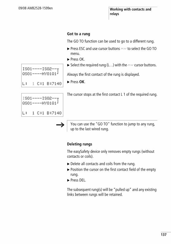
Working with contacts and relays
09/08 AWB2528-1599en
Got to a rung
The GO TO function can be used to go to a different rung.
X Press ESC and use cursor buttons ÍÚ to select the GO TO menu.
X Press OK.X Select the required rung (L…) with the ÍÚ cursor buttons.
Always the first contact of the rung is displayed.
X Press OK.
The cursor stops at the first contact L 1 of the required rung.
Deleting rungs
The easySafety device only removes empty rungs (without contacts or coils).
X Delete all contacts and coils from the rung.X Position the cursor on the first contact field of the empty
rung.X Press DEL.
The subsequent rung(s) will be “pulled up” and any existing links between rungs will be retained.
IS01----IS02--uQS01----HY01Q1k
L: 1 C:1 B:7140
IS01----IS02--uQS01----HY01Q1k
L: 1 C:1 B:7140
h You can use the "GO TO" function to jump to any rung, up to the last wired rung.
137
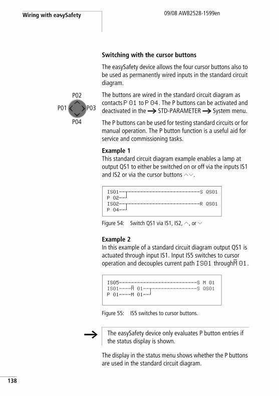
Wiring with easySafety
138
09/08 AWB2528-1599en
Switching with the cursor buttons
The easySafety device allows the four cursor buttons also to be used as permanently wired inputs in the standard circuit diagram.
The buttons are wired in the standard circuit diagram as contacts P 01 to P 04. The P buttons can be activated and deactivated in the h STD-PARAMETER h System menu.
The P buttons can be used for testing standard circuits or for manual operation. The P button function is a useful aid for service and commissioning tasks.
Example 1This standard circuit diagram example enables a lamp at output QS1 to either be switched on or off via the inputs IS1 and IS2 or via the cursor buttons ÍÚ.
Figure 54: Switch QS1 via IS1, IS2, Í, or Ú
Example 2In this example of a standard circuit diagram output QS1 is actuated through input IS1. Input IS5 switches to cursor operation and decouples current path IS01 throughM 01.
Figure 55: IS5 switches to cursor buttons.
The display in the status menu shows whether the P buttons are used in the standard circuit diagram.
P01
P02
P03
P04
IS01--u------------------------S QS01P 02--kIS02--u------------------------R QS01P 04--k
IS05--------------------------S M 01
IS01----M 01--u---------------S QS01P 01----M 01--k
h The easySafety device only evaluates P button entries if the status display is shown.
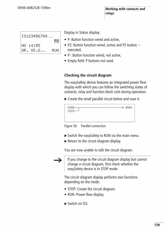
Working with contacts and relays
09/08 AWB2528-1599en
Display in Status display:
• P: Button function wired and active,• P2: Button function wired, active and P2 button Í
executed,• P-: Button function wired, not active,• Empty field: P buttons not used.
Checking the circuit diagram
The easySafety device features an integrated power flow display with which you can follow the switching states of contacts, relay and function block coils during operation.
X Create the small parallel circuit below and save it.
Figure 56: Parallel connection
X Switch the easySafety to RUN via the main menu.X Return to the circuit diagram display.
You are now unable to edit the circuit diagram.
The circuit diagram display performs two functions depending on the mode:
• STOP: Create the circuit diagram.• RUN: Power flow display.
X Switch on IS3.
IS123456789….. P2
MO 14:55
QR. QS.2.. RUN
IS02--u------------------------S QS01IS03--k
h If you change to the circuit diagram display but cannot change a circuit diagram, first check whether the easySafety device is in STOP mode.
139
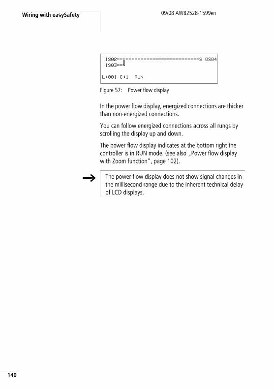
Wiring with easySafety
140
09/08 AWB2528-1599en
Figure 57: Power flow display
In the power flow display, energized connections are thicker than non-energized connections.
You can follow energized connections across all rungs by scrolling the display up and down.
The power flow display indicates at the bottom right the controller is in RUN mode. (see also „Power flow display with Zoom function“, page 102).
.
IS02==š=========================S QS04IS03==–
L:001 C:1 RUN
h The power flow display does not show signal changes in the millisecond range due to the inherent technical delay of LCD displays.
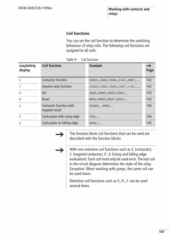
Working with contacts and relays
09/08 AWB2528-1599en
Coil functions
You can set the coil function to determine the switching behaviour of relay coils. The following coil functions are assigned to all coils:
Table 9: Coil function
easySafety display
Coil function Example a Page
Ä Contactor function ÄQS01,ÄD02,ÄS04,Ä:01,ÄM07,.. 142
ä Impulse relay function äQS03,äM04,äD08,äS07,ä:01,.. 142
S Set SQ08,SM02,SD03,SS04.. 143
R Reset RQ04,RM05,RD07,RS03.. 143
Å Contactor function with negated result
ÅQS04, ÅM96.. 144
È Cycle pulse with rising edge ÈM01.. 144
è Cycle pulse on falling edge èM42.. 145
h The function block coil functions that can be used are described with the function blocks.
h With non-retentive coil functions such as Ä (contactor), Å (negated contactor), È, è (rising and falling edge evaluation): Each coil must only be used once. The last coil in the circuit diagram determines the state of the relay. Exception: When working with jumps, the same coil can be used twice.
Retentive coil functions such as S, R, ä can be used several times.
141
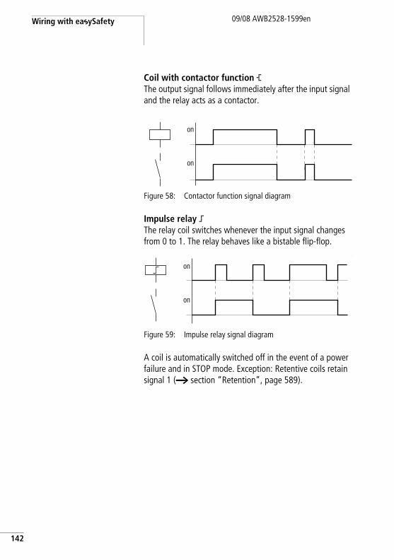
Wiring with easySafety
142
09/08 AWB2528-1599en
Coil with contactor function ÄThe output signal follows immediately after the input signal and the relay acts as a contactor.
Figure 58: Contactor function signal diagram
Impulse relay äThe relay coil switches whenever the input signal changes from 0 to 1. The relay behaves like a bistable flip-flop.
:
Figure 59: Impulse relay signal diagram
A coil is automatically switched off in the event of a power failure and in STOP mode. Exception: Retentive coils retain signal 1 (a section “Retention”, page 589).
on
on
on
on
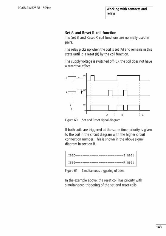
Working with contacts and relays
09/08 AWB2528-1599en
Set S and Reset R coil functionThe Set S and Reset R coil functions are normally used in pairs.
The relay picks up when the coil is set (A) and remains in this state until it is reset (B) by the coil function.
The supply voltage is switched off (C), the coil does not have a retentive effect.
Figure 60: Set and Reset signal diagram
If both coils are triggered at the same time, priority is given to the coil in the circuit diagram with the higher circuit connection number. This is shown in the above signal diagram in section B.
Figure 61: Simultaneous triggering of QS01
In the example above, the reset coil has priority with simultaneous triggering of the set and reset coils.
on
on
S
R
on
A B C
IS05---------------------------S QS01
IS10---------------------------R QS01
143
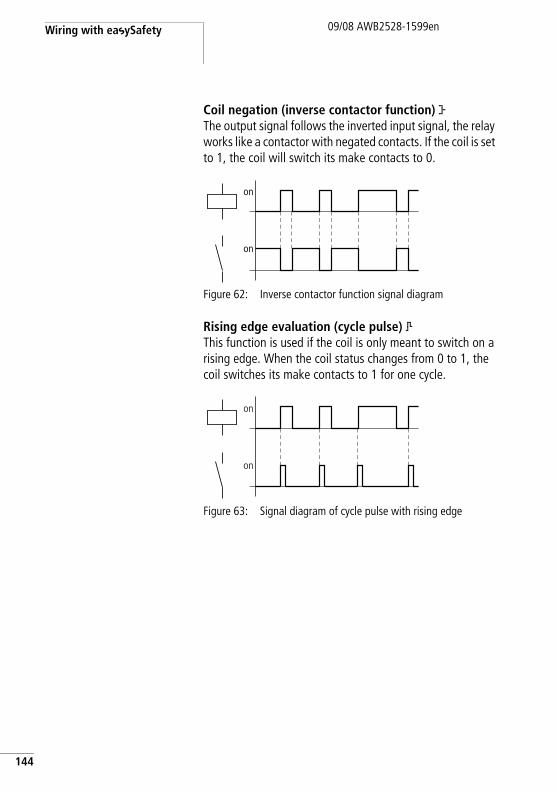
Wiring with easySafety
144
09/08 AWB2528-1599en
Coil negation (inverse contactor function) ÅThe output signal follows the inverted input signal, the relay works like a contactor with negated contacts. If the coil is set to 1, the coil will switch its make contacts to 0.
Figure 62: Inverse contactor function signal diagram
Rising edge evaluation (cycle pulse) ÈThis function is used if the coil is only meant to switch on a rising edge. When the coil status changes from 0 to 1, the coil switches its make contacts to 1 for one cycle.
Figure 63: Signal diagram of cycle pulse with rising edge
on
on
on
on
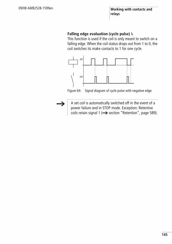
Working with contacts and relays
09/08 AWB2528-1599en
Falling edge evaluation (cycle pulse) èThis function is used if the coil is only meant to switch on a falling edge. When the coil status drops out from 1 to 0, the coil switches its make contacts to 1 for one cycle.
Figure 64: Signal diagram of cycle pulse with negative edge
on
on
h A set coil is automatically switched off in the event of a power failure and in STOP mode. Exception: Retentive coils retain signal 1 (a section “Retention”, page 589).
145
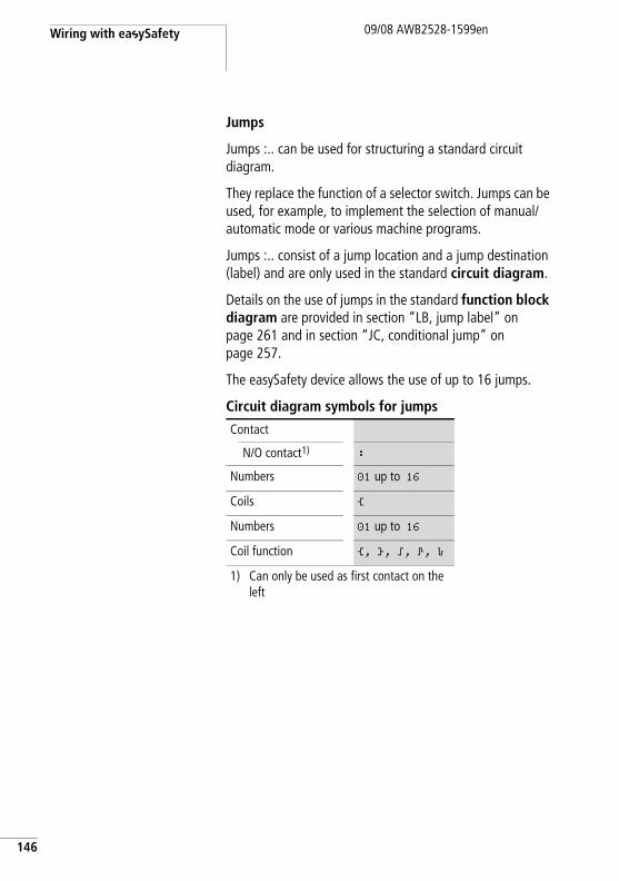
Wiring with easySafety
146
09/08 AWB2528-1599en
Jumps
Jumps :.. can be used for structuring a standard circuit diagram.
They replace the function of a selector switch. Jumps can be used, for example, to implement the selection of manual/automatic mode or various machine programs.
Jumps :.. consist of a jump location and a jump destination (label) and are only used in the standard circuit diagram.
Details on the use of jumps in the standard function block diagram are provided in section “LB, jump label” on page 261 and in section “JC, conditional jump” on page 257.
The easySafety device allows the use of up to 16 jumps.
Circuit diagram symbols for jumps
Contact
N/O contact1) :
Numbers 01 up to 16
Coils Ä
Numbers 01 up to 16
Coil function Ä, Å, ä, È, è
1) Can only be used as first contact on the left
Working with contacts and relays
09/08 AWB2528-1599en
FunctionIf the jump coil is triggered, the rungs after the jump coil are no longer processed. The states of the coils before the jump will be retained, unless they are overwritten in rungs that were not missed by the jump. Jumps are always made forwards, i.e. the jump ends on the first contact with the same number as that of the coil.
• Coil = jump on 1 state• Contact only at the first leftmost contact = Jump label
The jump contact location is always 1.
Power flow displayJumped sections are indicated by the coils in the power flow display.
All coils after the jump coil are shown with the symbol of the jump coil.
h Backward jumps cannot be executed due to the way in which easySafety works. If the jump label does not come after the jump coil, the jump will be made to the end of the circuit diagram. The last rung is also skipped.
The same jump coil and contact can be used several times as long as they are used in pairs, i.e.:Coil Ä:1/skipped area/contact:1, Coil Ä:1/skipped area/contact:1etc.
h Caution! If rungs are skipped, the states of the coils are retained. The time of started timing relays continues to run.
147
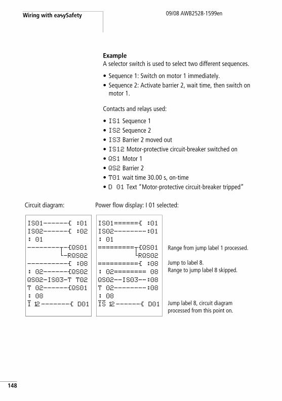
Wiring with easySafety
148
09/08 AWB2528-1599en
ExampleA selector switch is used to select two different sequences.
• Sequence 1: Switch on motor 1 immediately.• Sequence 2: Activate barrier 2, wait time, then switch on
motor 1.
Contacts and relays used:
• IS1 Sequence 1• IS2 Sequence 2• IS3 Barrier 2 moved out• IS12 Motor-protective circuit-breaker switched on• QS1 Motor 1• QS2 Barrier 2• T01 wait time 30.00 s, on-time• D 01 Text “Motor-protective circuit-breaker tripped”
Circuit diagram: Power flow display: I 01 selected:
Range from jump label 1 processed.
Jump to label 8.Range to jump label 8 skipped.
Jump label 8, circuit diagram processed from this point on.
IS01------Ä :01
IS02------Ä :02
: 01
--------u-ÄQS01 h-RQS02
----------Ä :08
: 02------ÄQS02QS02-IS03-T T02
T 02------ÄQS01: 08
I 12-------Ä D01
IS01======Ä :01
IS02--------:01
: 01
=========uÄQS01hRQS02
==========Ä :08
: 02======== 08
QS02--IS03--:08
T 02--------:08
: 08
IS 12------Ä D01
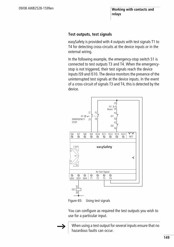
Working with contacts and relays
09/08 AWB2528-1599en
Test outputs, test signals
easySafety is provided with 4 outputs with test signals T1 to T4 for detecting cross-circuits at the device inputs or in the external wiring.
In the following example, the emergency-stop switch S1 is connected to test outputs T3 and T4. When the emergency-stop is not triggered, their test signals reach the device inputs IS9 and IS10. The device monitors the presence of the uninterrupted test signals at the device inputs. In the event of a cross-circuit of signals T3 and T4, this is detected by the device.
Figure 65: Using test signals
You can configure as required the test outputs you wish to use for a particular input.
QS2 QS3 QS4 T1 T2 T3 T4
4x Test Signal
NET
ALT
OK
IS6 IS7 IS8 IS9 IS10 IS11 IS12 IS13 IS14
P2
P3
P4
-Q2
1A2A
-S1
1222
1121
-Q2
1222
-Q112
2231
4 1
-S2
ea ySafety
EMERGENCY-STOP
Reset
h When using a test output for several inputs ensure that no hazardous faults can occur.
149
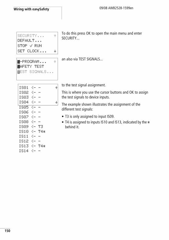
Wiring with easySafety
150
09/08 AWB2528-1599en
To do this press OK to open the main menu and enter SECURITY...
an also via TEST SIGNALS...
to the test signal assignment.
This is where you use the cursor buttons and OK to assign the test signals to device inputs.
The example shown illustrates the assignment of the different test signals:
• T3 is only assigned to input IS09.• T4 is assigned to inputs IS10 and IS13, indicated by the *
behind it.
SECURITY... ÆDEFAULT...
STOP å RUN
SET CLOCK... æ
S-PROGRAM... ÆSAFETY TEST
TEST SIGNALS...
IS05 <- -
IS06 <- -
IS07 <- -
IS08 <- -
IS09 <- T3
IS10 <- T4*
IS11 <- -
IS12 <- -
IS13 <- T4*
IS14 <- -
IS01 <- - ÆIS02 <- -
IS03 <- -
IS04 <- - æ
Working with function blocks09/08 AWB2528-1599en
Working with function blocks
This chapter describes further on how to add and parameterise function blocks in the circuit diagram. A detailed description of all available function blocks is provided in the sections „Standard function blocks“ on page 169 and „Safety function blocks“ on page 331. The function blocks are presented there in alphabetical order. This section, however, describes some general notes on working with function blocks.
Function blocks allow you to emulate different devices in your circuit diagram from conventional safety, open-loop and closed-loop control technology. Function blocks for easySafety devices are divided into:
• safety function blocks for implementing safety functions.• standard function blocks for normal open-loop and
closed-loop control tasks.
The following applies to function blocks:
h Current actual values are deleted when you switch off the power supply or switch easySafety to STOP mode. Exception: retentive data keeps its state (a section “Retention”, page 589).
The most recent actual values are transferred to the operands every cycle. The data function block is an exception.
h If you do not wish to enable others to modify the standard function blocks, set the enable character from “+” to “–” when entering the circuit diagram and entering the parameters, and protect it with a standard password. The parameters of the safety function blocks are automatically protected by the master password.
151
Wiring with easySafety
152
09/08 AWB2528-1599en
h As every standard function block in the function block list takes up memory, even if it is no longer being used and has been deleted in the standard circuit diagram, you should clear it occasionally.
Check the standard function block diagram for any function blocks that are no longer required and delete them, a section “Deleting function blocks”, page 166.
h Caution!RUN mode: easySafety processes the function blocks after the circuit diagram has been run through. This takes the last status of the coils into account.
h The function blocks are designed so that an output value of a function block can be assigned directly with an input of another function block. The 32-bit data format is used automatically. This also enables the transfer of negative values.
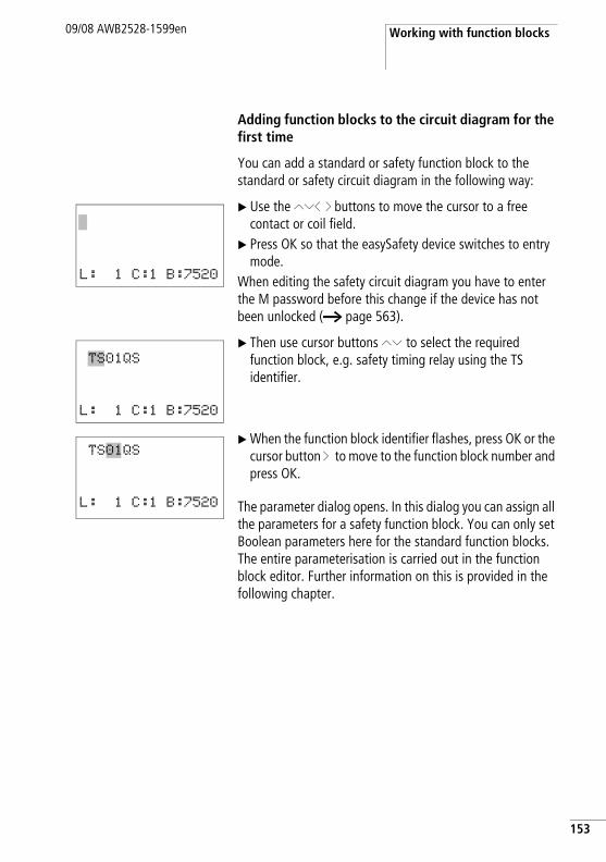
Working with function blocks09/08 AWB2528-1599en
Adding function blocks to the circuit diagram for the first time
You can add a standard or safety function block to the standard or safety circuit diagram in the following way:
X Use the ÍÚú í buttons to move the cursor to a free contact or coil field.
X Press OK so that the easySafety device switches to entry mode.
When editing the safety circuit diagram you have to enter the M password before this change if the device has not been unlocked (a page 563).
X Then use cursor buttons ÍÚ to select the required function block, e.g. safety timing relay using the TS identifier.
X When the function block identifier flashes, press OK or the cursor button í to move to the function block number and press OK.
The parameter dialog opens. In this dialog you can assign all the parameters for a safety function block. You can only set Boolean parameters here for the standard function blocks. The entire parameterisation is carried out in the function block editor. Further information on this is provided in the following chapter.
L: 1 C:1 B:7520
TS01QS
L: 1 C:1 B:7520
TS01QS
L: 1 C:1 B:7520
153
Wiring with easySafety
154
09/08 AWB2528-1599en
Setting function block parameters
Safety function blocks with which you can implement your safety functions are always part of the safety circuit diagram. Unlike standard function blocks, the parameters are set from the safety circuit diagram instead of in a special function block editor.
Standard function blocks are simply called in the standard circuit diagram and also enter the basic parameters there. You assign actual value and setpoint parameters for the function block inputs and outputs via the FUNCTION RELAYS menu. You can of course also set the basic parameters in the function block editor and then add the standard function block in the standard circuit diagram as a contact or coil.
The edited standard function blocks are always part of the standard circuit diagram.
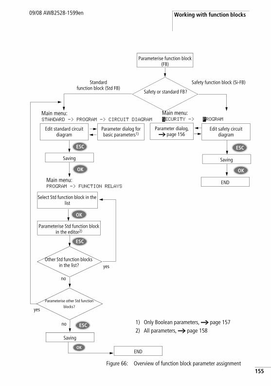
Working with function blocks09/08 AWB2528-1599en
Figure 66: Overview of function block parameter assignment
Safety or standard FB?
Safety function block (Si-FB)
Edit safety circuit diagram
Parameter dialog, a page 156
Standardfunction block (Std FB)
Edit standard circuit diagram
Parameter dialog for basic parameters1)
Main menu:STANDARD -> PROGRAM -> CIRCUIT DIAGRAM
Saving
Select Std function block in the list
Parameterise Std function block in the editor2)
Parameterise other Std function blocks?
Saving
yes
Saving
ESC
OK
no ESC
ESC
Parameterise function block (FB)
ESC
OK
Other Std function blocks in the list? yes
no
1) Only Boolean parameters, a page 1572) All parameters, a page 158
Main menu:PROGRAM -> FUNCTION RELAYS
OK
OK
END
END
Main menu:SECURITY -> S PROGRAM
155
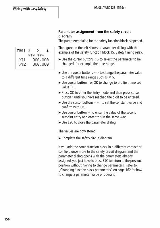
Wiring with easySafety
156
09/08 AWB2528-1599en
Parameter assignment from the safety circuit diagramThe parameter dialog for the safety function block is opened.
The figure on the left shows a parameter dialog with the example of the safety function block TS, Safety timing relay.
X Use the cursor buttons ú í to select the parameter to be changed, for example the time range.
X Use the cursor buttons ÍÚ to change the parameter value to a different time range such as M:S.
X Use cursor button í or OK to change to the first time set value T1.
X Press OK to enter the Entry mode and then press cursor button í until you have reached the digit to be entered.
X Use the cursor buttons ÍÚ to set the constant value and confirm with OK.
X Use cursor button Ú to enter the value of the second setpoint entry and enter this in the same way.
X Use ESC to close the parameter dialog.
The values are now stored.
X Complete the safety circuit diagram.
If you add the same function block in a different contact or coil field once more to the safety circuit diagram and the parameter dialog opens with the parameters already assigned, you just have to press ESC to return to the previous position without having to change parameters. Refer to „Changing function block parameters“ on page 162 for how to change a parameter value or operand.
TS01 S X *
*** ***
>T1 000.000
>T2 000.000
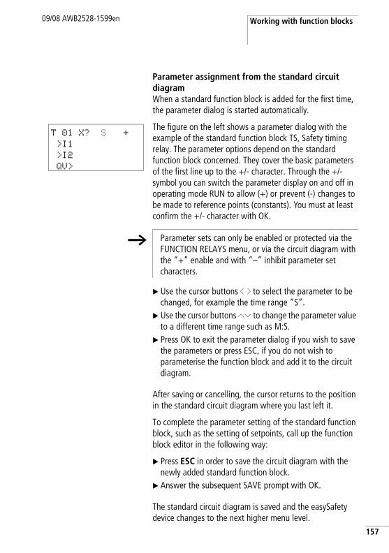
Working with function blocks09/08 AWB2528-1599en
Parameter assignment from the standard circuit diagramWhen a standard function block is added for the first time, the parameter dialog is started automatically.
The figure on the left shows a parameter dialog with the example of the standard function block TS, Safety timing relay. The parameter options depend on the standard function block concerned. They cover the basic parameters of the first line up to the +/- character. Through the +/- symbol you can switch the parameter display on and off in operating mode RUN to allow (+) or prevent (-) changes to be made to reference points (constants). You must at least confirm the +/- character with OK.
X Use the cursor buttons ú í to select the parameter to be changed, for example the time range “S”.
X Use the cursor buttons ÍÚ to change the parameter value to a different time range such as M:S.
X Press OK to exit the parameter dialog if you wish to save the parameters or press ESC, if you do not wish to parameterise the function block and add it to the circuit diagram.
After saving or cancelling, the cursor returns to the position in the standard circuit diagram where you last left it.
To complete the parameter setting of the standard function block, such as the setting of setpoints, call up the function block editor in the following way:
X Press ESC in order to save the circuit diagram with the newly added standard function block.
X Answer the subsequent SAVE prompt with OK.
The standard circuit diagram is saved and the easySafety device changes to the next higher menu level.
T 01 X? S +
>I1
>I2
QV>
h Parameter sets can only be enabled or protected via the FUNCTION RELAYS menu, or via the circuit diagram with the “+” enable and with “–” inhibit parameter set characters.
157
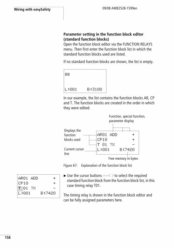
Wiring with easySafety
158
09/08 AWB2528-1599en
Parameter setting in the function block editor (standard function blocks)Open the function block editor via the FUNCTION RELAYS menu. Then first enter the function block list in which the standard function blocks used are listed.
If no standard function blocks are shown, the list is empty.
In our example, the list contains the function blocks AR, CP and T. The function blocks are created in the order in which they were edited.
Figure 67: Explanation of the function block list
X Use the cursor buttons ÍÚú í to select the required standard function block from the function block list, in this case timing relay T01.
The timing relay is shown in the function block editor and can be fully assigned parameters here.
ââ
L:001 B:3100
Displays the function blocks used
Function, special function, parameter display
Free memory in bytes
Current cursor line
AR01 ADD +
CP10 +
T 01 ?X -
L:001 B:7420
AR01 ADD +
CP10 +
T 01 ?X -
L:001 B:7420
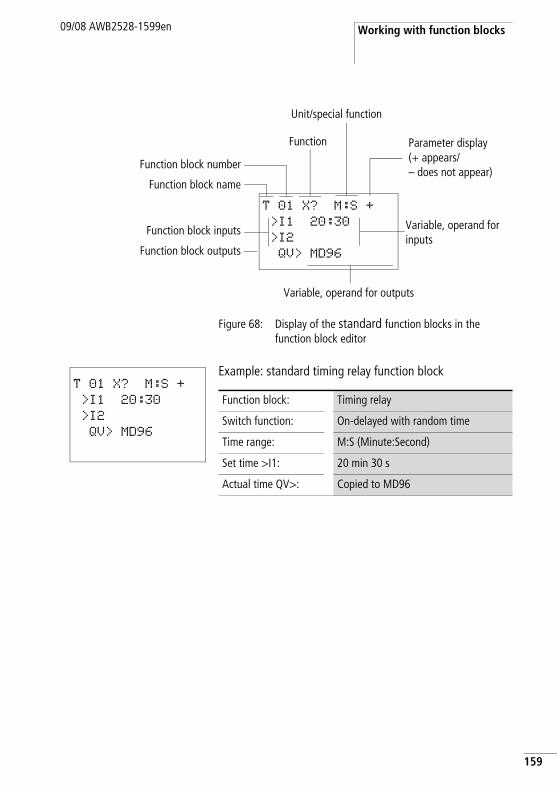
Working with function blocks09/08 AWB2528-1599en
Figure 68: Display of the standard function blocks in the function block editor
Example: standard timing relay function block
Parameter display(+ appears/– does not appear)
Unit/special function
Function block number
Function block name
Function block inputs
Function block outputs
Variable, operand for outputs
Variable, operand for inputs
Function
T 01 X? M:S +
>I1 20:30
>I2
QV> MD96
T 01 X? M:S +
>I1 20:30
>I2
QV> MD96
Function block: Timing relay
Switch function: On-delayed with random time
Time range: M:S (Minute:Second)
Set time >I1: 20 min 30 s
Actual time QV>: Copied to MD96
159
Wiring with easySafety
160
09/08 AWB2528-1599en
Assigning operands at the input of a standard function block
The following operands can be assigned to the input of a standard function block:
• Constants, e.g.: 42,• Markers such as MD, MW, MB,• All output variables of the function blocks …QV>
h Caution! When assigning the parameters of a standard function block input, ensure that these cannot be triggered with impermissible values during operation. There is a danger of this if you assign a variable that can assume negative values to a standard function block input that can only accept positive values.
If, for example, the standard function block T timing relay is triggered with a negative time set value, it will no longer switch in the expected way.
You should therefore take care to exclude such situations, as the easySafety device cannot foresee these when the parameters are assigned.
If, for example, you have assigned the QV output of the AR arithmetic function at input I1 of the T standard function block, you should add the CP comparator in between in order to detect and indicate the occurrence a negative value.
In most applications, a thorough simulation is enough to prevent any impermissible values at the function block input.
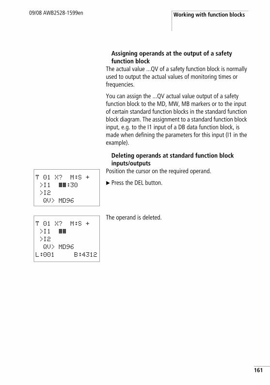
Working with function blocks09/08 AWB2528-1599en
Assigning operands at the output of a safety function block
The actual value ...QV of a safety function block is normally used to output the actual values of monitoring times or frequencies.
You can assign the ...QV actual value output of a safety function block to the MD, MW, MB markers or to the input of certain standard function blocks in the standard function block diagram. The assignment to a standard function block input, e.g. to the I1 input of a DB data function block, is made when defining the parameters for this input (I1 in the example).
Deleting operands at standard function block inputs/outputs
Position the cursor on the required operand.
X Press the DEL button.
The operand is deleted.
T 01 X? M:S +
>I1 ââ:30>I2
QV> MD96
T 01 X? M:S +
>I1 ââ>I2
QV> MD96
L:001 B:4312
161
Wiring with easySafety
162
09/08 AWB2528-1599en
Changing function block parameters
A easySafety device allows you to change the parameters of standard function blocks, such as the setpoints of timing or counter relays without calling up the circuit diagram. To change these parameters, the easySafety device must be in RUN mode.
With safety function blocks, parameters can only be changed via the safety circuit diagram and only then if the easySafety device is in STOP mode. The procedures for changing parameters of a safety or standard function block are different:
Changing safety function block parametersRequirement: The easySafety device must be in STOP mode!
Proceed as follows to call the parameter dialog again for changes:
X Select the safety function block in the safety circuit diagram.
X Press OK to enter Entry mode.X Move to the function block number and press OK.The parameter dialog opens.
X Press OK or cursor button í to move to the parameter to be changed.
X Change the parameters required, e.g. the time range M:S (Minute:Second) to S (Second) and exit the parameter dialog with ESC.
The easySafety device returns to the safety circuit diagram.
Working with function blocks09/08 AWB2528-1599en
Changing standard function block parametersParameters of the standard function blocks that you use in the standard circuit diagram can be changed with the following accesses:
• Access 1 - FUNCTION RELAYS, STOP modeAll parameters can be set or deleted via STANDARD -> PROGRAM -> FUNCTION RELAYS and the function block editor.
• Access 2- FUNCTION RELAYS menu, RUN modeYou access the function block editor via STANDARD -> PROGRAM... -> FUNCTION RELAYS. Here you can change set values (constants). This access is blocked on a password-protected program.
• Access 3- PARAMETERS menu option, RUN modeChoose STANDARD -> PARAMETERS to change the set values (constants). These modification options are also provided if you have saved the program and therefore password protected the function block editor. With the standard function blocks uses you can use the +/- character to set which function blocks allow the changing of their parameters.
Access 1 - FUNCTION RELAYS, STOP modeThis access method is basically no different to the initial parameter assignment of a standard function block (a section “Parameter assignment from the standard circuit diagram”, page 157).
Access 2 - FUNCTION RELAYS, RUN modeRequirements for the parameter setting via STANDARD ->FUNCTION RELAYS:
• The standard function block is used in the standard circuit diagram or function block.
• Access to the parameter set is enabled, indicated by the +/- character at the top right of the display.
Proceed as follows to call the parameter dialog again for changes:
X Press OK to switch to the main menu.
163
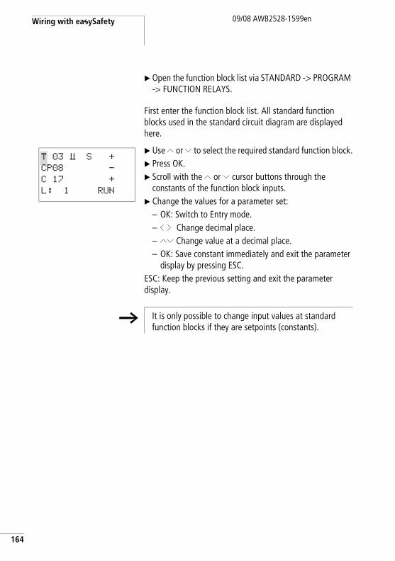
Wiring with easySafety
164
09/08 AWB2528-1599en
X Open the function block list via STANDARD -> PROGRAM -> FUNCTION RELAYS.
First enter the function block list. All standard function blocks used in the standard circuit diagram are displayed here.
X Use Í or Ú to select the required standard function block.X Press OK.X Scroll with the Í or Ú cursor buttons through the
constants of the function block inputs.X Change the values for a parameter set:
– OK: Switch to Entry mode.– ú í Change decimal place.– ÍÚ Change value at a decimal place.– OK: Save constant immediately and exit the parameter
display by pressing ESC.ESC: Keep the previous setting and exit the parameter display.
T 03 Ü S +CP08 -
C 17 +
L: 1 RUN
h It is only possible to change input values at standard function blocks if they are setpoints (constants).
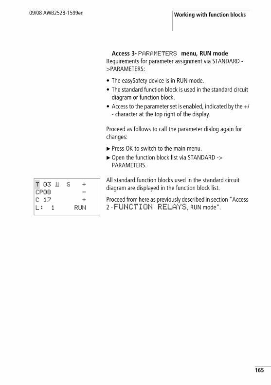
Working with function blocks09/08 AWB2528-1599en
Access 3- PARAMETERS menu, RUN modeRequirements for parameter assignment via STANDARD ->PARAMETERS:
• The easySafety device is in RUN mode.• The standard function block is used in the standard circuit
diagram or function block.• Access to the parameter set is enabled, indicated by the +/
- character at the top right of the display.
Proceed as follows to call the parameter dialog again for changes:
X Press OK to switch to the main menu.X Open the function block list via STANDARD ->
PARAMETERS.
All standard function blocks used in the standard circuit diagram are displayed in the function block list.
Proceed from here as previously described in section “Access 2 - FUNCTION RELAYS, RUN mode”.
T 03 Ü S +CP08 -
C 17 +
L: 1 RUN
165
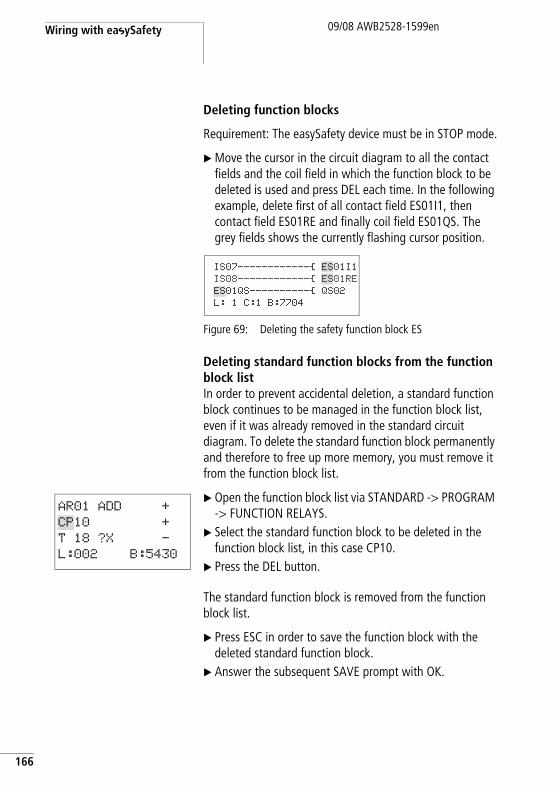
Wiring with easySafety
166
09/08 AWB2528-1599en
Deleting function blocks
Requirement: The easySafety device must be in STOP mode.
X Move the cursor in the circuit diagram to all the contact fields and the coil field in which the function block to be deleted is used and press DEL each time. In the following example, delete first of all contact field ES01I1, then contact field ES01RE and finally coil field ES01QS. The grey fields shows the currently flashing cursor position.
Figure 69: Deleting the safety function block ES
Deleting standard function blocks from the function block listIn order to prevent accidental deletion, a standard function block continues to be managed in the function block list, even if it was already removed in the standard circuit diagram. To delete the standard function block permanently and therefore to free up more memory, you must remove it from the function block list.
X Open the function block list via STANDARD -> PROGRAM -> FUNCTION RELAYS.
X Select the standard function block to be deleted in the function block list, in this case CP10.
X Press the DEL button.
The standard function block is removed from the function block list.
X Press ESC in order to save the function block with the deleted standard function block.
X Answer the subsequent SAVE prompt with OK.
IS07------------Ä ES01I1IS08------------Ä ES01REES01QS----------Ä QS02 L: 1 C:1 B:7704
AR01 ADD +
CP10 +
T 18 ?X -
L:002 B:5430
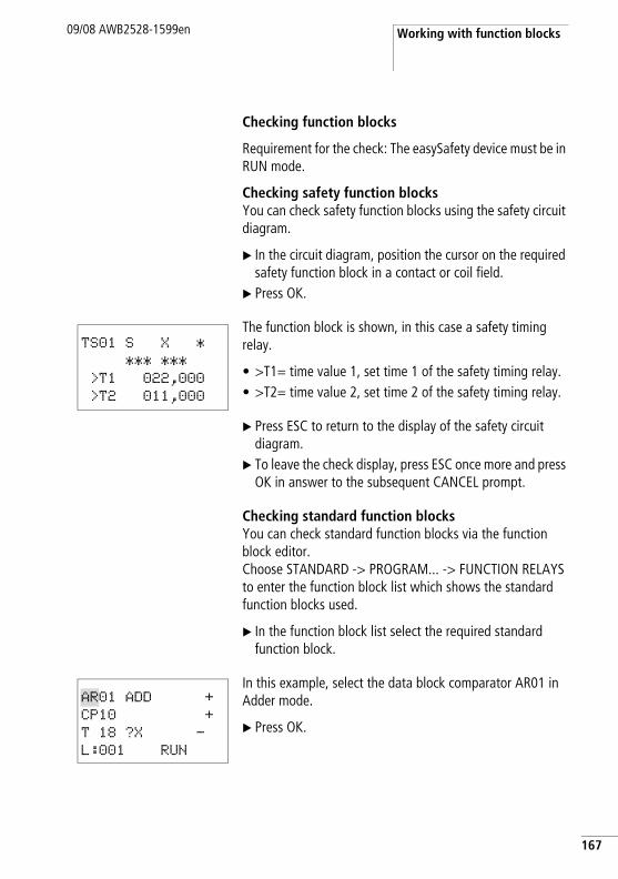
Working with function blocks09/08 AWB2528-1599en
Checking function blocks
Requirement for the check: The easySafety device must be in RUN mode.
Checking safety function blocksYou can check safety function blocks using the safety circuit diagram.
X In the circuit diagram, position the cursor on the required safety function block in a contact or coil field.
X Press OK.
The function block is shown, in this case a safety timing relay.
• >T1= time value 1, set time 1 of the safety timing relay.• >T2= time value 2, set time 2 of the safety timing relay.
X Press ESC to return to the display of the safety circuit diagram.
X To leave the check display, press ESC once more and press OK in answer to the subsequent CANCEL prompt.
Checking standard function blocksYou can check standard function blocks via the function block editor. Choose STANDARD -> PROGRAM... -> FUNCTION RELAYS to enter the function block list which shows the standard function blocks used.
X In the function block list select the required standard function block.
In this example, select the data block comparator AR01 in Adder mode.
X Press OK.
TS01 S X *
*** ***
>T1 022,000
>T2 011,000
AR01 ADD +
CP10 +
T 18 ?X -
L:001 RUN
167
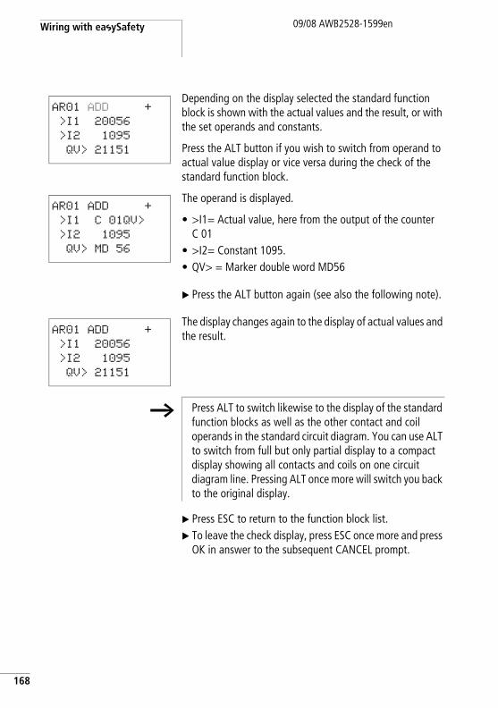
Wiring with easySafety
168
09/08 AWB2528-1599en
Depending on the display selected the standard function block is shown with the actual values and the result, or with the set operands and constants.
Press the ALT button if you wish to switch from operand to actual value display or vice versa during the check of the standard function block.
The operand is displayed.
• >I1= Actual value, here from the output of the counter C 01
• >I2= Constant 1095.• QV> = Marker double word MD56
X Press the ALT button again (see also the following note).
The display changes again to the display of actual values and the result.
X Press ESC to return to the function block list.X To leave the check display, press ESC once more and press
OK in answer to the subsequent CANCEL prompt.
AR01 ADD +
>I1 20056
>I2 1095
QV> 21151
AR01 ADD +
>I1 C 01QV>
>I2 1095
QV> MD 56
AR01 ADD +
>I1 20056
>I2 1095
QV> 21151
h Press ALT to switch likewise to the display of the standard function blocks as well as the other contact and coil operands in the standard circuit diagram. You can use ALT to switch from full but only partial display to a compact display showing all contacts and coils on one circuit diagram line. Pressing ALT once more will switch you back to the original display.
09/08 AWB2528-1599en
5 Standard function blocks
Standard function blocks are used to implement NON-safety-related tasks in the controller. They are therefore only used in the standard circuit diagram.
j Danger! Device outputs QR and QS that are set by the standard circuit diagram are not safety outputs and must only be used for standard tasks. Ensure that these outputs do not trigger safety-related functions on the machine or plant.
169
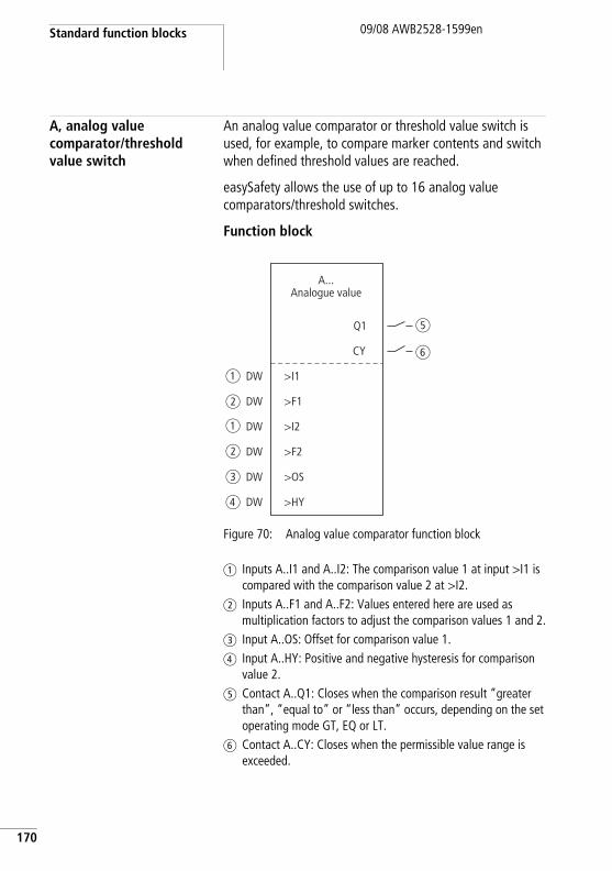
Standard function blocks
170
09/08 AWB2528-1599en
A, analog value comparator/threshold value switch
An analog value comparator or threshold value switch is used, for example, to compare marker contents and switch when defined threshold values are reached.
easySafety allows the use of up to 16 analog value comparators/threshold switches.
Function block
Figure 70: Analog value comparator function block
a Inputs A..I1 and A..I2: The comparison value 1 at input >I1 is compared with the comparison value 2 at >I2.
b Inputs A..F1 and A..F2: Values entered here are used as multiplication factors to adjust the comparison values 1 and 2.
c Input A..OS: Offset for comparison value 1.d Input A..HY: Positive and negative hysteresis for comparison
value 2.e Contact A..Q1: Closes when the comparison result “greater
than”, “equal to” or “less than” occurs, depending on the set operating mode GT, EQ or LT.
f Contact A..CY: Closes when the permissible value range is exceeded.
A...Analogue value
a
b
a
b
c
d
e
f
Q1
>I1
>F1
>I2
>F2
>OS
>HY
CY
DW
DW
DW
DW
DW
DW
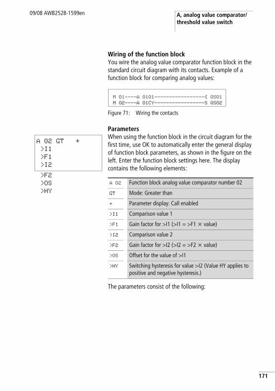
A, analog value comparator/threshold value switch
09/08 AWB2528-1599en
Wiring of the function blockYou wire the analog value comparator function block in the standard circuit diagram with its contacts. Example of a function block for comparing analog values:
Figure 71: Wiring the contacts
ParametersWhen using the function block in the circuit diagram for the first time, use OK to automatically enter the general display of function block parameters, as shown in the figure on the left. Enter the function block settings here. The display contains the following elements:
The parameters consist of the following:
M 01----A 01Q1-----------------Ä QS01 M 02----A 01CY-----------------S QS02
A 02 GT +
>I1
>F1
>I2
>F2
>OS
>HY
A 02 Function block analog value comparator number 02
GT Mode: Greater than
+ Parameter display: Call enabled
>I1 Comparison value 1
>F1 Gain factor for >I1 (>I1 = >F1 x value)
>I2 Comparison value 2
>F2 Gain factor for >I2 (>I2 = >F2 x value)
>OS Offset for the value of >I1
>HY Switching hysteresis for value >I2 (Value HY applies to positive and negative hysteresis.)
171
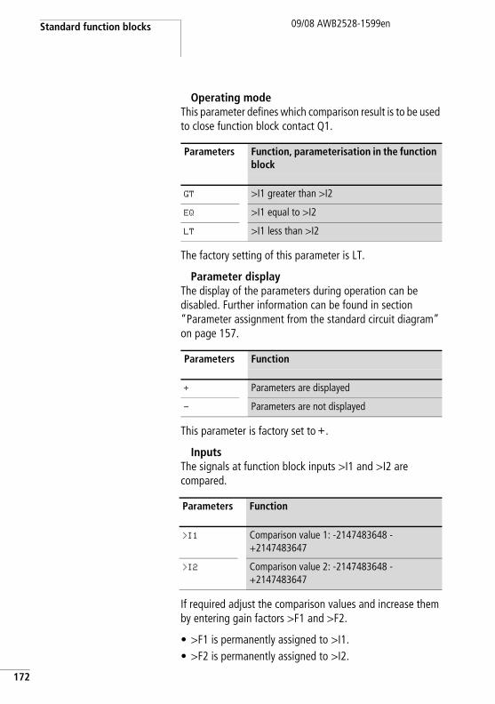
Standard function blocks
172
09/08 AWB2528-1599en
Operating modeThis parameter defines which comparison result is to be used to close function block contact Q1.
The factory setting of this parameter is LT.
Parameter displayThe display of the parameters during operation can be disabled. Further information can be found in section “Parameter assignment from the standard circuit diagram” on page 157.
This parameter is factory set to +.
InputsThe signals at function block inputs >I1 and >I2 are compared.
If required adjust the comparison values and increase them by entering gain factors >F1 and >F2.
• >F1 is permanently assigned to >I1.• >F2 is permanently assigned to >I2.
Parameters Function, parameterisation in the function block
GT >I1 greater than >I2
EQ >I1 equal to >I2
LT >I1 less than >I2
Parameters Function
+ Parameters are displayed
- Parameters are not displayed
Parameters Function
>I1 Comparison value 1: -2147483648 - +2147483647
>I2 Comparison value 2: -2147483648 - +2147483647
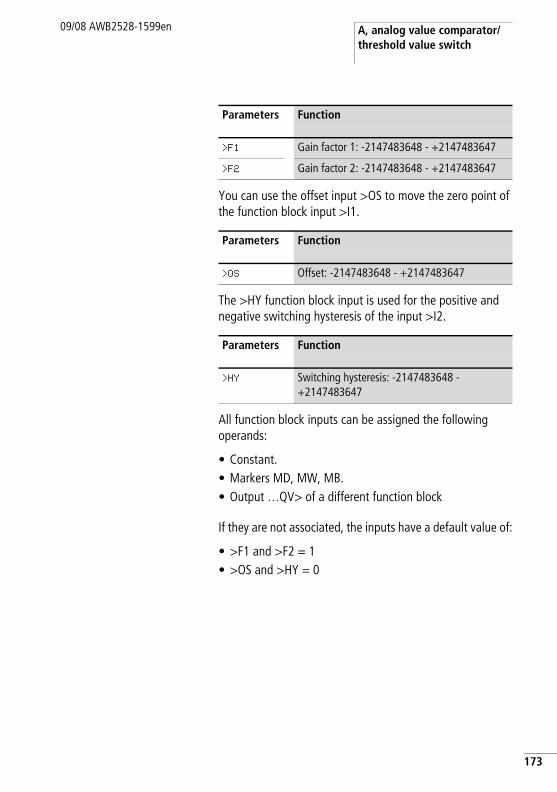
A, analog value comparator/threshold value switch
09/08 AWB2528-1599en
You can use the offset input >OS to move the zero point of the function block input >I1.
The >HY function block input is used for the positive and negative switching hysteresis of the input >I2.
All function block inputs can be assigned the following operands:
• Constant.• Markers MD, MW, MB.• Output …QV> of a different function block
If they are not associated, the inputs have a default value of:
• >F1 and >F2 = 1• >OS and >HY = 0
Parameters Function
>F1 Gain factor 1: -2147483648 - +2147483647
>F2 Gain factor 2: -2147483648 - +2147483647
Parameters Function
>OS Offset: -2147483648 - +2147483647
Parameters Function
>HY Switching hysteresis: -2147483648 - +2147483647
173
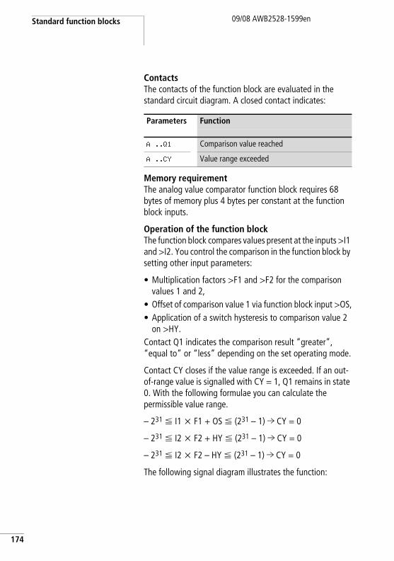
Standard function blocks
174
09/08 AWB2528-1599en
ContactsThe contacts of the function block are evaluated in the standard circuit diagram. A closed contact indicates:
Memory requirementThe analog value comparator function block requires 68 bytes of memory plus 4 bytes per constant at the function block inputs.
Operation of the function blockThe function block compares values present at the inputs >I1 and >I2. You control the comparison in the function block by setting other input parameters:
• Multiplication factors >F1 and >F2 for the comparison values 1 and 2,
• Offset of comparison value 1 via function block input >OS,• Application of a switch hysteresis to comparison value 2
on >HY.Contact Q1 indicates the comparison result “greater”, “equal to” or “less” depending on the set operating mode.
Contact CY closes if the value range is exceeded. If an out-of-range value is signalled with CY = 1, Q1 remains in state 0. With the following formulae you can calculate the permissible value range.
– 231 F I1 x F1 + OS F (231 – 1) l CY = 0
– 231 F I2 x F2 + HY F (231 – 1) l CY = 0
– 231 F I2 x F2 – HY F (231 – 1) l CY = 0
The following signal diagram illustrates the function:
Parameters Function
A ..Q1 Comparison value reached
A ..CY Value range exceeded
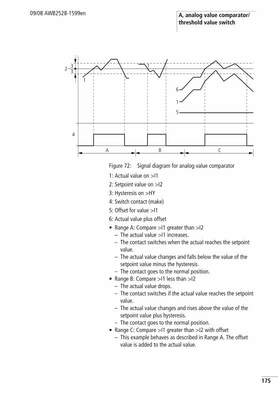
A, analog value comparator/threshold value switch
09/08 AWB2528-1599en
Figure 72: Signal diagram for analog value comparator
1: Actual value on >I12: Setpoint value on >I23: Hysteresis on >HY4: Switch contact (make)5: Offset for value >I16: Actual value plus offset• Range A: Compare >I1 greater than >I2
– The actual value >I1 increases.– The contact switches when the actual reaches the setpoint
value.– The actual value changes and falls below the value of the
setpoint value minus the hysteresis.– The contact goes to the normal position.
• Range B: Compare >I1 less than >I2 – The actual value drops.– The contact switches if the actual value reaches the setpoint
value.– The actual value changes and rises above the value of the
setpoint value plus hysteresis.– The contact goes to the normal position.
• Range C: Compare >I1 greater than >I2 with offset– This example behaves as described in Range A. The offset
value is added to the actual value.
1
32
4
A B C
3 1
6
1
5
175

Standard function blocks
176
09/08 AWB2528-1599en
• Comparison >I1 equals >I2The contact switches on:– If I1 is equal to I2, i.e. the actual value is equal to the setpoint
value.– If I1 is equal to I2, i.e. the actual value is equal to the setpoint
value.The contact switches off:– If the hysteresis limit is exceeded with the actual value rising.– If the hysteresis limit is undershot with the actual value
decreasing.
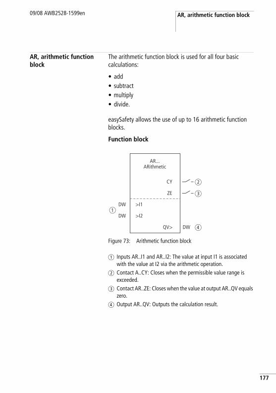
AR, arithmetic function block09/08 AWB2528-1599en
AR, arithmetic function block
The arithmetic function block is used for all four basic calculations:
• add• subtract• multiply• divide.
easySafety allows the use of up to 16 arithmetic function blocks.
Function block
Figure 73: Arithmetic function block
a Inputs AR..I1 and AR..I2: The value at input I1 is associated with the value at I2 via the arithmetic operation.
b Contact A..CY: Closes when the permissible value range is exceeded.
c Contact AR..ZE: Closes when the value at output AR..QV equals zero.
d Output AR..QV: Outputs the calculation result.
AR...ARithmetic
QV>
CY
ZE
>I1
>I2DW
DW
DW
a
b
c
d
177
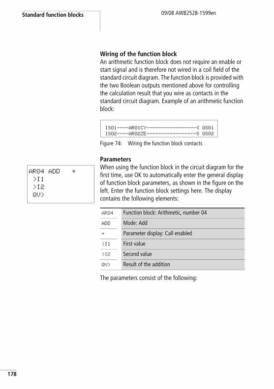
Standard function blocks
178
09/08 AWB2528-1599en
Wiring of the function blockAn arithmetic function block does not require an enable or start signal and is therefore not wired in a coil field of the standard circuit diagram. The function block is provided with the two Boolean outputs mentioned above for controlling the calculation result that you wire as contacts in the standard circuit diagram. Example of an arithmetic function block:
Figure 74: Wiring the function block contacts
ParametersWhen using the function block in the circuit diagram for the first time, use OK to automatically enter the general display of function block parameters, as shown in the figure on the left. Enter the function block settings here. The display contains the following elements:
The parameters consist of the following:
IS01----AR01CY-----------------Ä QS01 IS02----AR02ZE-----------------S QS02
AR04 ADD +
>I1
>I2
QV>
AR04 Function block: Arithmetic, number 04
ADD Mode: Add
+ Parameter display: Call enabled
>I1 First value
>I2 Second value
QV> Result of the addition
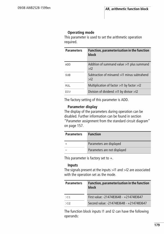
AR, arithmetic function block09/08 AWB2528-1599en
Operating modeThis parameter is used to set the arithmetic operation required.
The factory setting of this parameter is ADD.
Parameter displayThe display of the parameters during operation can be disabled. Further information can be found in section “Parameter assignment from the standard circuit diagram” on page 157.
This parameter is factory set to +.
InputsThe signals present at the inputs >I1 and >I2 are associated with the operation set as the mode.
The function block inputs I1 and I2 can have the following operands:
Parameters Function, parameterisation in the function block
ADD Addition of summand value >I1 plus summand >I2
SUB Subtraction of minuend >I1 minus subtrahend >I2
MUL Multiplication of factor >I1 by factor >I2
DIV Division of dividend >I1 by divisor >I2
Parameters Function
+ Parameters are displayed
- Parameters are not displayed
Parameters Function, parameterisation in the function block
>I1 First value: -2147483648 - +2147483647
>I2 Second value: -2147483648 - +2147483647
179
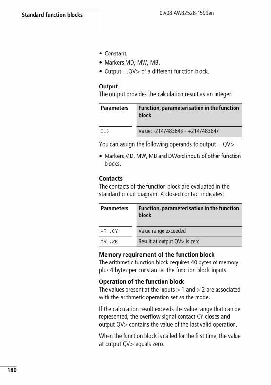
Standard function blocks
180
09/08 AWB2528-1599en
• Constant.• Markers MD, MW, MB.• Output …QV> of a different function block.
OutputThe output provides the calculation result as an integer.
You can assign the following operands to output …QV>:
• Markers MD, MW, MB and DWord inputs of other function blocks.
ContactsThe contacts of the function block are evaluated in the standard circuit diagram. A closed contact indicates:
Memory requirement of the function blockThe arithmetic function block requires 40 bytes of memory plus 4 bytes per constant at the function block inputs.
Operation of the function blockThe values present at the inputs >I1 and >I2 are associated with the arithmetic operation set as the mode.
If the calculation result exceeds the value range that can be represented, the overflow signal contact CY closes and output QV> contains the value of the last valid operation.
When the function block is called for the first time, the value at output QV> equals zero.
Parameters Function, parameterisation in the function block
QV> Value: -2147483648 - +2147483647
Parameters Function, parameterisation in the function block
AR..CY Value range exceeded
AR..ZE Result at output QV> is zero
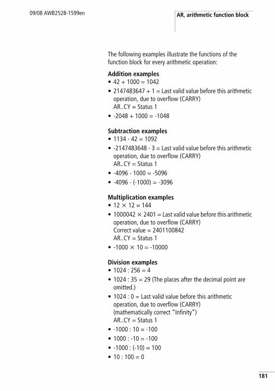
AR, arithmetic function block09/08 AWB2528-1599en
The following examples illustrate the functions of the function block for every arithmetic operation:
Addition examples• 42 + 1000 = 1042• 2147483647 + 1 = Last valid value before this arithmetic
operation, due to overflow (CARRY)AR..CY = Status 1
• -2048 + 1000 = -1048
Subtraction examples• 1134 - 42 = 1092• -2147483648 - 3 = Last valid value before this arithmetic
operation, due to overflow (CARRY)AR..CY = Status 1
• -4096 - 1000 = -5096• -4096 - (-1000) = -3096
Multiplication examples• 12 x 12 = 144• 1000042 x 2401 = Last valid value before this arithmetic
operation, due to overflow (CARRY)Correct value = 2401100842AR..CY = Status 1
• -1000 x 10 = -10000
Division examples• 1024 : 256 = 4• 1024 : 35 = 29 (The places after the decimal point are
omitted.)• 1024 : 0 = Last valid value before this arithmetic
operation, due to overflow (CARRY)(mathematically correct “Infinity”)AR..CY = Status 1
• -1000 : 10 = -100• 1000 : -10 = -100• -1000 : (-10) = 100• 10 : 100 = 0
181
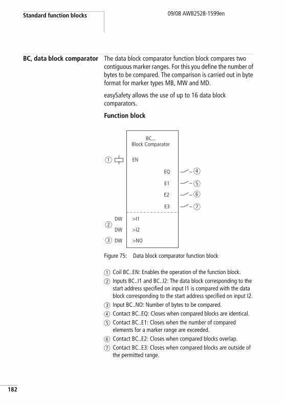
Standard function blocks
182
09/08 AWB2528-1599en
BC, data block comparator The data block comparator function block compares two contiguous marker ranges. For this you define the number of bytes to be compared. The comparison is carried out in byte format for marker types MB, MW and MD.
easySafety allows the use of up to 16 data block comparators.
Function block
Figure 75: Data block comparator function block
a Coil BC..EN: Enables the operation of the function block.b Inputs BC..I1 and BC..I2: The data block corresponding to the
start address specified on input I1 is compared with the data block corresponding to the start address specified on input I2.
c Input BC..NO: Number of bytes to be compared.d Contact BC..EQ: Closes when compared blocks are identical.e Contact BC..E1: Closes when the number of compared
elements for a marker range are exceeded.f Contact BC..E2: Closes when compared blocks overlap.g Contact BC..E3: Closes when compared blocks are outside of
the permitted range.
EN
DW
E2
E3
BC...Block Comparator
a
f
g
EQ
E1
d
e
>I1
DWb
>I2
DWc >NO
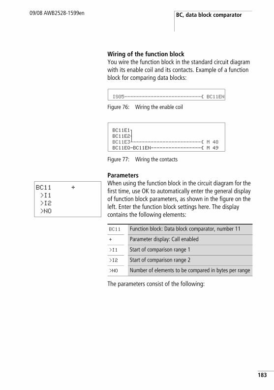
BC, data block comparator09/08 AWB2528-1599en
Wiring of the function blockYou wire the function block in the standard circuit diagram with its enable coil and its contacts. Example of a function block for comparing data blocks:
Figure 76: Wiring the enable coil
Figure 77: Wiring the contacts
ParametersWhen using the function block in the circuit diagram for the first time, use OK to automatically enter the general display of function block parameters, as shown in the figure on the left. Enter the function block settings here. The display contains the following elements:
The parameters consist of the following:
IS05--------------------------Ä BC11EN
BC11E1o BC11E2s BC11E3j-----------------------Ä M 48 BC11EQ-BC11EN-----------------Ä M 49
BC11 +
>I1
>I2
>NO
BC11 Function block: Data block comparator, number 11
+ Parameter display: Call enabled
>I1 Start of comparison range 1
>I2 Start of comparison range 2
>NO Number of elements to be compared in bytes per range
183
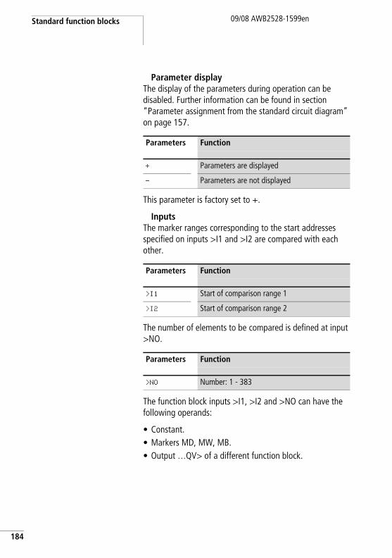
Standard function blocks
184
09/08 AWB2528-1599en
Parameter displayThe display of the parameters during operation can be disabled. Further information can be found in section “Parameter assignment from the standard circuit diagram” on page 157.
This parameter is factory set to +.
InputsThe marker ranges corresponding to the start addresses specified on inputs >I1 and >I2 are compared with each other.
The number of elements to be compared is defined at input >NO.
The function block inputs >I1, >I2 and >NO can have the following operands:
• Constant.• Markers MD, MW, MB.• Output …QV> of a different function block.
Parameters Function
+ Parameters are displayed
- Parameters are not displayed
Parameters Function
>I1 Start of comparison range 1
>I2 Start of comparison range 2
Parameters Function
>NO Number: 1 - 383
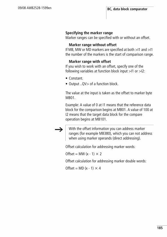
BC, data block comparator09/08 AWB2528-1599en
Specifying the marker rangeMarker ranges can be specified with or without an offset.
Marker range without offsetIf MB, MW or MD markers are specified at both >I1 and >I1 the number of the markers is the start of comparison range.
Marker range with offsetIf you wish to work with an offset, specify one of the following variables at function block input >I1 or >I2:
• Constant.• Output ..QV> of a function block.
The value at the input is taken as the offset to marker byte MB01.
Example: A value of 0 at I1 means that the reference data block for the comparison begins at MB01. A value of 100 at I2 means that the target data block for the compare operation begins at MB101.
Offset calculation for addressing marker words:
Offset = MW (x - 1) x 2
Offset calculation for addressing marker double words:
Offset = MD (x - 1) x 4
h With the offset information you can address marker ranges (for example MB380), which you can not address when using marker operands (direct addressing).
185
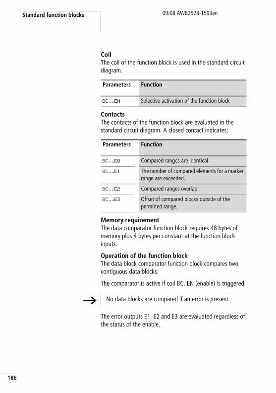
Standard function blocks
186
09/08 AWB2528-1599en
CoilThe coil of the function block is used in the standard circuit diagram.
ContactsThe contacts of the function block are evaluated in the standard circuit diagram. A closed contact indicates:
Memory requirementThe data comparator function block requires 48 bytes of memory plus 4 bytes per constant at the function block inputs.
Operation of the function blockThe data block comparator function block compares two contiguous data blocks.
The comparator is active if coil BC..EN (enable) is triggered.
The error outputs E1, E2 and E3 are evaluated regardless of the status of the enable.
Parameters Function
BC..EN Selective activation of the function block
Parameters Function
BC..EQ Compared ranges are identical
BC..E1 The number of compared elements for a marker range are exceeded.
BC..E2 Compared ranges overlap
BC..E3 Offset of compared blocks outside of the permitted range.
h No data blocks are compared if an error is present.
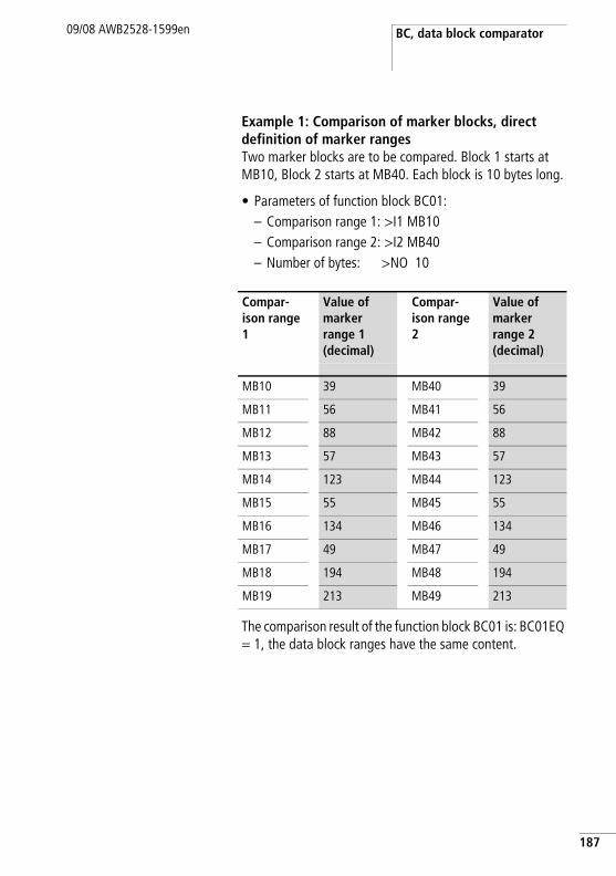
BC, data block comparator09/08 AWB2528-1599en
Example 1: Comparison of marker blocks, direct definition of marker rangesTwo marker blocks are to be compared. Block 1 starts at MB10, Block 2 starts at MB40. Each block is 10 bytes long.
• Parameters of function block BC01:– Comparison range 1: >I1 MB10– Comparison range 2: >I2 MB40– Number of bytes: >NO 10
The comparison result of the function block BC01 is: BC01EQ = 1, the data block ranges have the same content.
Compar-ison range 1
Value of marker range 1 (decimal)
Compar-ison range 2
Value of marker range 2 (decimal)
MB10 39 MB40 39
MB11 56 MB41 56
MB12 88 MB42 88
MB13 57 MB43 57
MB14 123 MB44 123
MB15 55 MB45 55
MB16 134 MB46 134
MB17 49 MB47 49
MB18 194 MB48 194
MB19 213 MB49 213
187
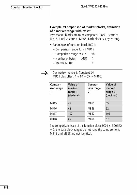
Standard function blocks
188
09/08 AWB2528-1599en
Example 2:Comparison of marker blocks, definition of a marker range with offsetTwo marker blocks are to be compared. Block 1 starts at MB15, Block 2 starts at MB65. Each block is 4 bytes long.
• Parameters of function block BC01:– Comparison range 1: >I1 MB15– Comparison range 2: >I2 64– Number of bytes: >NO 4– Marker MB01: 1
The comparison result of the function block BC01 is: BC01EQ = 0, the data block ranges do not have the same content. MB18 and MB68 are not identical.
h Comparison range 2: Constant 64:MB01 plus offset: 1 + 64 = 65 r MB65.
Compar-ison range 1
Value of marker range 1 (decimal)
Compar-ison range 2
Value of marker range 2 (decimal)
MB15 45 MB65 45
MB16 62 MB66 62
MB17 102 MB67 102
MB18 65 MB68 57
BC, data block comparator09/08 AWB2528-1599en
Example 3: Comparison of marker blocks, definition of a marker range in a different format.Two marker blocks are to be compared. Block 1 starts at MB60, Block 2 starts at MD80. Each block is 6 bytes long.
• Parameters of function block BC01:– Comparison range 1: >I1 MB60– Comparison range 2: >I2 MD80– Number of bytes: >NO 6
The data block ranges do not have the same content. BC01EQ = 0, MB65 and MD81 (Byte 2) are not identical.
h The comparison is in byte format. MD80 has 4 bytes. Therefore the first two bytes of MD81 are also compared.
Compar-ison range 1
Value of marker range 1 (decimal/binary)
Compar-ison range 2
Value of marker range 2 (decimal/binary)
MB60 45/00101101
MD80 (Byte 1, LSB)
1097219629/01000001011001100011111000101101
MB61 62/00111110
MD80 (Byte 2)
1097219629/01000001011001100011111000101101
MB62 102/01100110
MD80 (Byte 3)
1097219629/01000001011001100011111000101101
MB63 65/01000001
MD80 (Byte 4, MSB)
1097219629/01000001011001100011111000101101
MB64 173/10101101
MD81 (Byte 1, LSB)
15277/0011101110101101
MB65 59/00111011
MD81 (Byte 2)
15277/0000100010101101
189
Standard function blocks
190
09/08 AWB2528-1599en
Example 4:Comparison of marker blocks, range violation error.Two marker blocks are to be compared. Block 1 starts at MD60, Block 2 starts at MD90. Each block is 30 bytes long.
• Parameters of function block BC01:– Comparison range 1: >I1 MD60– Comparison range 2: >I2 MD90– Number of bytes: >NO 30
The error message “Number of comparison elements exceeds one of the comparison ranges” is output.
BC01E1 is 1.
Example 5: Comparison of marker blocks, range overlap error.Two marker blocks are to be compared. Block 1 starts at MW60, Block 2 starts at MW64. Each block is 12 bytes.
• Parameters of function block BC01:– Comparison range 1: >I1 MW60– Comparison range 2: >I2 MW64– Number of bytes: >NO 12
The error message “Comparison ranges overlap” is output.
BC01E2 is 1.
h The comparison is in byte format. MD90 to MD96 is 28 bytes. The number of bytes is 30 bytes.
h The comparison is in byte format. MW60 to MW64 is 8 bytes. The number of bytes is 12 bytes.

BC, data block comparator09/08 AWB2528-1599en
Example 6: Comparison of marker blocks, invalid offset error.Two marker blocks are to be compared. Block 1 starts at MW40, block 2 at MW54. The block length is determined by the value of counter C 01QV.
• Parameters of function block BC01:– Comparison range 1: >I1 MW40– Comparison range 2: >I2 MW54– Number of bytes: >NO C 01QV
The error message "The specified offset of the comparison ranges is outside of the permissible range" is output.
BC01E3 is 1.
h The value of C 01QV is 1024. This value is too big. The value at >NO can be between 1 and +383.
191
Standard function blocks
192
09/08 AWB2528-1599en
BT, data block transfer The function block is used to transfer values from one marker range to another (copy data). The marker ranges can be overwritten with a particular value (data initialisation). The following marker types can be transferred and overwritten:
• MB.• MW.• MD.
easySafety allows the use of up to 16 data block transfer function blocks.
Function block
Figure 78: Data block transfer function block
a Coil BT..T_: Trigger coil, function block transfers on rising edge.b Inputs: BT..I1: Start of the source range or initialisation marker
(MB,MW,MD). BT..I2: Start of destination range.c Input BT..NO: Number of bytes to be transferred.d Contact BT..E1: Closes when source or destination range is
exceeded.e Contact BT..E2: Closes when source and destination range
overlap.f Contact BT..E3: Closes when the offset is invalid.
BT...Block Transmitter
a
b
c
e
d
f
E1
E2
>I1
>I2
E3
T_
>NODW
DW
DW
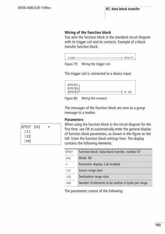
BT, data block transfer09/08 AWB2528-1599en
Wiring of the function blockYou wire the function block in the standard circuit diagram with its trigger coil and its contacts. Example of a block transfer function block:
Figure 79: Wiring the trigger coil
The trigger coil is connected to a device input.
Figure 80: Wiring the contacts
The messages of the function block are sent as a group message to a marker.
ParametersWhen using the function block in the circuit diagram for the first time, use OK to automatically enter the general display of function block parameters, as shown in the figure on the left. Enter the function block settings here. The display contains the following elements:
The parameters consist of the following:
IS05--------------------------Ä BT07T_
BT07E1o BT07E2s BT07E3j-----------------------Ä M 42
BT07 INI +
>I1
>I2
>NO
BT07 Function block: Data block transfer, number 07
INI Mode: INI
+ Parameter display: Call enabled
>I1 Source range start
>I2 Destination range start
>NO Number of elements to be written in bytes per range
193
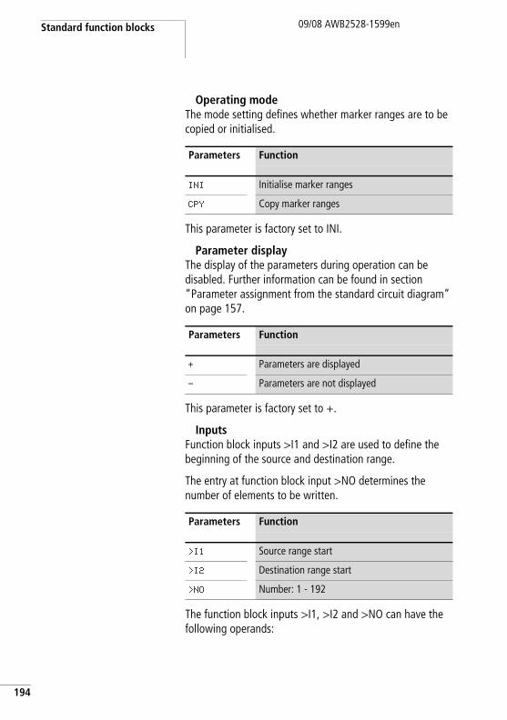
Standard function blocks
194
09/08 AWB2528-1599en
Operating modeThe mode setting defines whether marker ranges are to be copied or initialised.
This parameter is factory set to INI.
Parameter displayThe display of the parameters during operation can be disabled. Further information can be found in section “Parameter assignment from the standard circuit diagram” on page 157.
This parameter is factory set to +.
InputsFunction block inputs >I1 and >I2 are used to define the beginning of the source and destination range.
The entry at function block input >NO determines the number of elements to be written.
The function block inputs >I1, >I2 and >NO can have the following operands:
Parameters Function
INI Initialise marker ranges
CPY Copy marker ranges
Parameters Function
+ Parameters are displayed
- Parameters are not displayed
Parameters Function
>I1 Source range start
>I2 Destination range start
>NO Number: 1 - 192
BT, data block transfer09/08 AWB2528-1599en
• Constant.• Markers MD, MW, MB.• Output …QV> of a different function block.
Specifying the marker rangeMarker ranges can be specified with or without an offset.
Marker range without offsetIf MB, MW or MD markers are specified at both >I1 and >I2 the number of the markers is the start of comparison range.
Marker range with offsetIf you wish to work with an offset, specify one of the following variables at function block input >I1 or >I2.
• Constant.• Output ..QV of a function block.
The value at the input is taken as the offset to marker byte MB01.
Offset calculation for addressing marker words:
Offset = MW (x - 1) x 2
Offset calculation for addressing marker double words:
Offset = MD (x - 1) x 4.
CoilThe coil of the function block is used in the standard circuit diagram to transfer the input value.
h With the offset information you can address marker ranges (for example MB380), which you can not address when using marker operands (direct addressing).
Parameters Function
BT..T_ Triggering the transfer on a rising edge
195
Standard function blocks
196
09/08 AWB2528-1599en
ContactsThe contacts of the function block are evaluated in the standard circuit diagram. A closed contact indicates:
Memory requirementThe transfer data block function block requires 48 bytes of memory plus 4 bytes per constant at the function block inputs.
Operation of the function blockThe transfer data block function block has two operating modes.
INI mode, initialise marker rangesThere is one source range and one destination range. The source range is specified at >I1. The length of the source range is one byte. The destination range is specified at >I2. The length of the destination range is specified by the number of bytes at the >NO input.
The content of the source range is transferred to the marker bytes in the destination range.
The function block carries out a transfer on a rising edge at coil T_ (Trigger).
The error contacts E1, E2 and E3 are evaluated regardless of the status of the trigger.
Parameters Function
BT..E1 Exceeding the source or destination range
BT..E2 Overlapping of source and destination range
BT..E3 Invalid offset
h No data blocks are initialised or copied if an error occurs.

BT, data block transfer09/08 AWB2528-1599en
Example 1: Initialising marker blocks, direct definition marker ranges
The value of marker byte 10 is to be transferred to marker bytes 20 to 29.
• Parameters of function block BT01:– Source range: >I1 MB10– Destination range: >I2 MB20– Number of bytes: >NO 10
After a rising edge from 0 to 1 at coil BT01T_ the value 123 is present in the marker bytes MB20 to MB29.
Source-range
Value of source marker range (decimal)
Destina-tion range
Value of destination marker range (decimal)
MB10 123 MB20 123
MB21 123
MB22 123
MB23 123
MB24 123
MB25 123
MB26 123
MB27 123
MB28 123
MB29 123
197
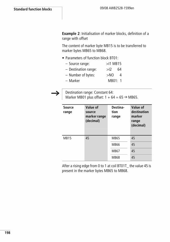
Standard function blocks
198
09/08 AWB2528-1599en
Example 2: Initialisation of marker blocks, definition of a range with offset
The content of marker byte MB15 is to be transferred to marker bytes MB65 to MB68.
• Parameters of function block BT01:– Source range: >I1 MB15– Destination range: >I2 64– Number of bytes: >NO 4– Marker MB01: 1
After a rising edge from 0 to 1 at coil BT01T_ the value 45 is present in the marker bytes MB65 to MB68.
h Destination range: Constant 64:Marker MB01 plus offset: 1 + 64 = 65 r MB65.
Source range
Value of source marker range (decimal)
Destina-tion range
Value of destination marker range (decimal)
MB15 45 MB65 45
MB66 45
MB67 45
MB68 45
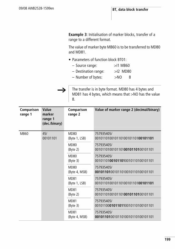
BT, data block transfer09/08 AWB2528-1599en
Example 3: Initialisation of marker blocks, transfer of a range to a different format.
The value of marker byte MB60 is to be transferred to MD80 and MD81.
• Parameters of function block BT01:– Source range: >I1 MB60– Destination range: >I2 MD80– Number of bytes: >NO 8
h The transfer is in byte format. MD80 has 4 bytes and MD81 has 4 bytes, which means that >NO has the value 8.
Comparison range 1
Value marker range 1 (dec./binary)
Comparison range 2
Value of marker range 2 (decimal/binary)
MB60 45/00101101
MD80 (Byte 1, LSB)
757935405/ 00101101001011010010110100101101
MD80 (Byte 2)
757935405/ 00101101001011010010110100101101
MD80 (Byte 3)
757935405/ 00101101001011010010110100101101
MD80 (Byte 4, MSB)
757935405/ 00101101001011010010110100101101
MD81 (Byte 1, LSB)
757935405/ 00101101001011010010110100101101
MD81 (Byte 2)
757935405/ 00101101001011010010110100101101
MD81 (Byte 3)
757935405/ 00101100010110110010110100101101
MD81 (Byte 4, MSB)
757935405/ 00101101001011010010110100101101
199
Standard function blocks
200
09/08 AWB2528-1599en
After a rising edge from 0 to 1 at coil BT01T_ the value 757935405 is present in the marker double words MD80 and MD81.
Example 4: Transfer of marker byte, destination range violation error.
The value of marker byte MB96 is to be transferred to MD93, MD94, MD95 and MD96. The length is 16 bytes.
• Parameters of function block BT01:– Source range: >I1 MD96– Destination range: >I2 MD93– Number of bytes: >NO 18
The error message “Number of elements exceeds the destination range” is output.
BT01E1 is 1.
Example 5: Transfer of marker bytes, invalid offset error.
The value of marker byte MB40 is to be transferred to MW54 and subsequent marker words. The block length is specified by the value of the counter C 01QV.
• Parameters of function block BT01:– Source range: >I1 MB40
Destination range: >I2 MW54Number of bytes: >NO C 01QV
The message "The specified offset of the destination range is outside of the permissible range" is output.
BT01E3 is 1.
h The transfer is in byte format. MD93 to MD96 is 16 bytes. 18 bytes were incorrectly defined as length.
h The value of C 01QV is 788. This value is too big. The value at >NO can be between 1 and +192.
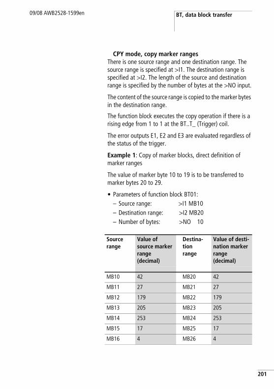
BT, data block transfer09/08 AWB2528-1599en
CPY mode, copy marker rangesThere is one source range and one destination range. The source range is specified at >I1. The destination range is specified at >I2. The length of the source and destination range is specified by the number of bytes at the >NO input.
The content of the source range is copied to the marker bytes in the destination range.
The function block executes the copy operation if there is a rising edge from 1 to 1 at the BT..T_ (Trigger) coil.
The error outputs E1, E2 and E3 are evaluated regardless of the status of the trigger.
Example 1: Copy of marker blocks, direct definition of marker ranges
The value of marker byte 10 to 19 is to be transferred to marker bytes 20 to 29.
• Parameters of function block BT01:– Source range: >I1 MB10– Destination range: >I2 MB20– Number of bytes: >NO 10
Source range
Value of source marker range (decimal)
Destina-tion range
Value of desti-nation marker range (decimal)
MB10 42 MB20 42
MB11 27 MB21 27
MB12 179 MB22 179
MB13 205 MB23 205
MB14 253 MB24 253
MB15 17 MB25 17
MB16 4 MB26 4
201
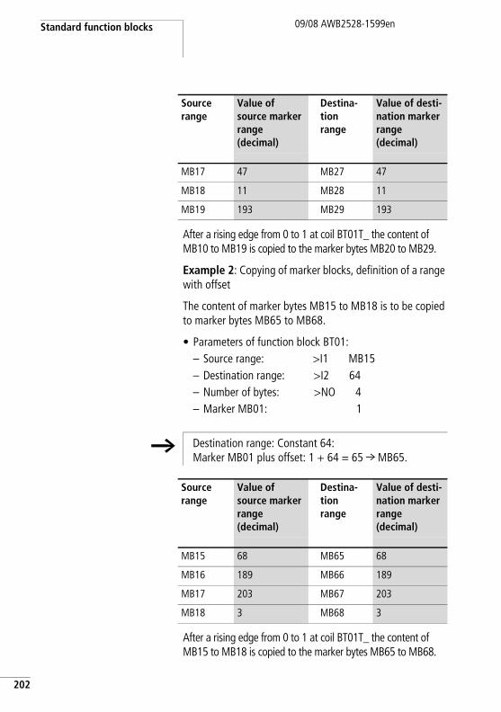
Standard function blocks
202
09/08 AWB2528-1599en
After a rising edge from 0 to 1 at coil BT01T_ the content of MB10 to MB19 is copied to the marker bytes MB20 to MB29.
Example 2: Copying of marker blocks, definition of a range with offset
The content of marker bytes MB15 to MB18 is to be copied to marker bytes MB65 to MB68.
• Parameters of function block BT01:– Source range: >I1 MB15– Destination range: >I2 64– Number of bytes: >NO 4– Marker MB01: 1
After a rising edge from 0 to 1 at coil BT01T_ the content of MB15 to MB18 is copied to the marker bytes MB65 to MB68.
MB17 47 MB27 47
MB18 11 MB28 11
MB19 193 MB29 193
Source range
Value of source marker range (decimal)
Destina-tion range
Value of desti-nation marker range (decimal)
h Destination range: Constant 64:Marker MB01 plus offset: 1 + 64 = 65 r MB65.
Source range
Value of source marker range (decimal)
Destina-tion range
Value of desti-nation marker range (decimal)
MB15 68 MB65 68
MB16 189 MB66 189
MB17 203 MB67 203
MB18 3 MB68 3
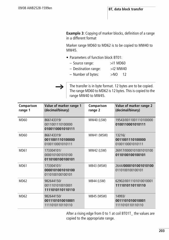
BT, data block transfer09/08 AWB2528-1599en
Example 3: Copying of marker blocks, definition of a range in a different format
Marker range MD60 to MD62 is to be copied to MW40 to MW45.
• Parameters of function block BT01:– Source range: >I1 MD60– Destination range: >I2 MW40– Number of bytes: >NO 12
After a rising edge from 0 to 1 at coil BT01T_ the values are copied to the appropriate range.
h The transfer is in byte format. 12 bytes are to be copied. The range MD60 to MD62 is 12 bytes. This is copied to the range MW40 to MW45.
Comparison range 1
Value of marker range 1 (decimal/binary)
Comparison range 2
Value of marker range 2 (decimal/binary)
MD60 866143319/ 00110011101000000100110001010111
MW40 (LSW) 19543/00110011101000000100110001010111
MD60 866143319/ 00110011101000000100110001010111
MW41 (MSW) 13216/00110011101000000100110001010111
MD61 173304101/00001010010101000110100100100101
MW42 (LSW) 26917/00001010010101000110100100100101
MD61 173304101/00001010010101000110100100100101
MB43 (MSW) 2644/00001010010101000110100100100101
MD62 982644150/ 00111010100100011111010110110110
MB44 (LSW) 62902/00111010100100011111010110110110
MD62 982644150/00111010100100011111010110110110
MB45 (MSW) 14993/00111010100100011111010110110110
203
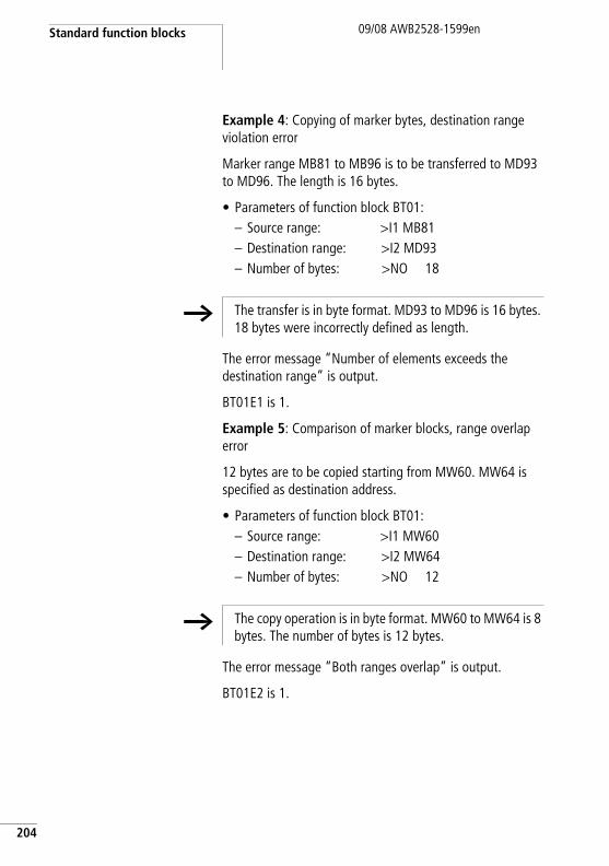
Standard function blocks
204
09/08 AWB2528-1599en
Example 4: Copying of marker bytes, destination range violation error
Marker range MB81 to MB96 is to be transferred to MD93 to MD96. The length is 16 bytes.
• Parameters of function block BT01:– Source range: >I1 MB81– Destination range: >I2 MD93– Number of bytes: >NO 18
The error message “Number of elements exceeds the destination range” is output.
BT01E1 is 1.
Example 5: Comparison of marker blocks, range overlap error
12 bytes are to be copied starting from MW60. MW64 is specified as destination address.
• Parameters of function block BT01:– Source range: >I1 MW60– Destination range: >I2 MW64– Number of bytes: >NO 12
The error message “Both ranges overlap” is output.
BT01E2 is 1.
h The transfer is in byte format. MD93 to MD96 is 16 bytes. 18 bytes were incorrectly defined as length.
h The copy operation is in byte format. MW60 to MW64 is 8 bytes. The number of bytes is 12 bytes.
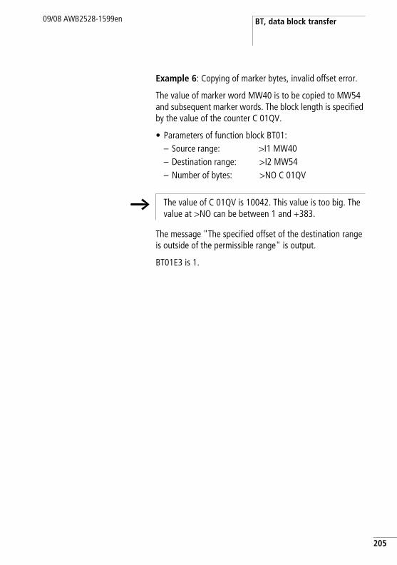
BT, data block transfer09/08 AWB2528-1599en
Example 6: Copying of marker bytes, invalid offset error.
The value of marker word MW40 is to be copied to MW54 and subsequent marker words. The block length is specified by the value of the counter C 01QV.
• Parameters of function block BT01:– Source range: >I1 MW40– Destination range: >I2 MW54– Number of bytes: >NO C 01QV
The message "The specified offset of the destination range is outside of the permissible range" is output.
BT01E3 is 1.
h The value of C 01QV is 10042. This value is too big. The value at >NO can be between 1 and +383.
205
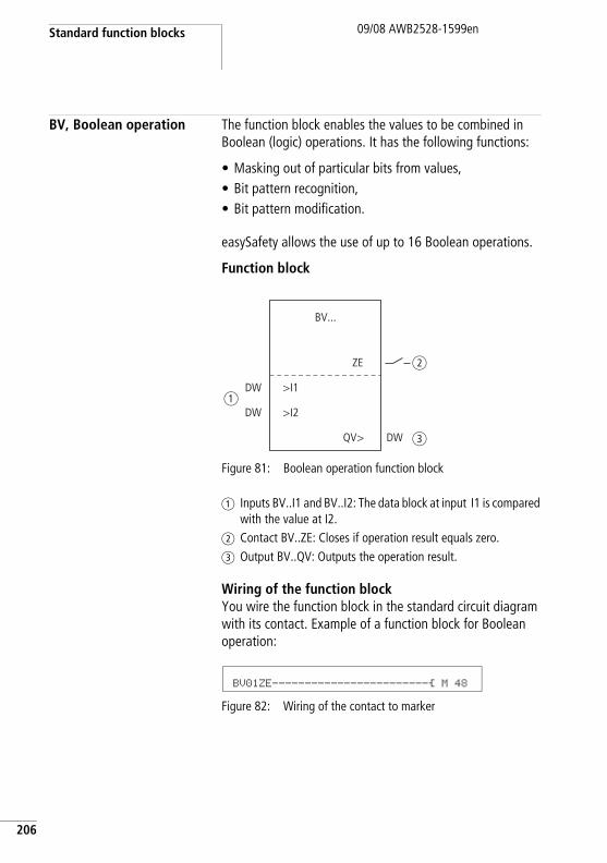
Standard function blocks
206
09/08 AWB2528-1599en
BV, Boolean operation The function block enables the values to be combined in Boolean (logic) operations. It has the following functions:
• Masking out of particular bits from values,• Bit pattern recognition,• Bit pattern modification.
easySafety allows the use of up to 16 Boolean operations.
Function block
Figure 81: Boolean operation function block
a Inputs BV..I1 and BV..I2: The data block at input I1 is compared with the value at I2.
b Contact BV..ZE: Closes if operation result equals zero.c Output BV..QV: Outputs the operation result.
Wiring of the function blockYou wire the function block in the standard circuit diagram with its contact. Example of a function block for Boolean operation:
Figure 82: Wiring of the contact to marker
BV...
>I1
>I2
QV>
ZE
DW
DW
DW
a
b
c
BV01ZE------------------------Ä M 48
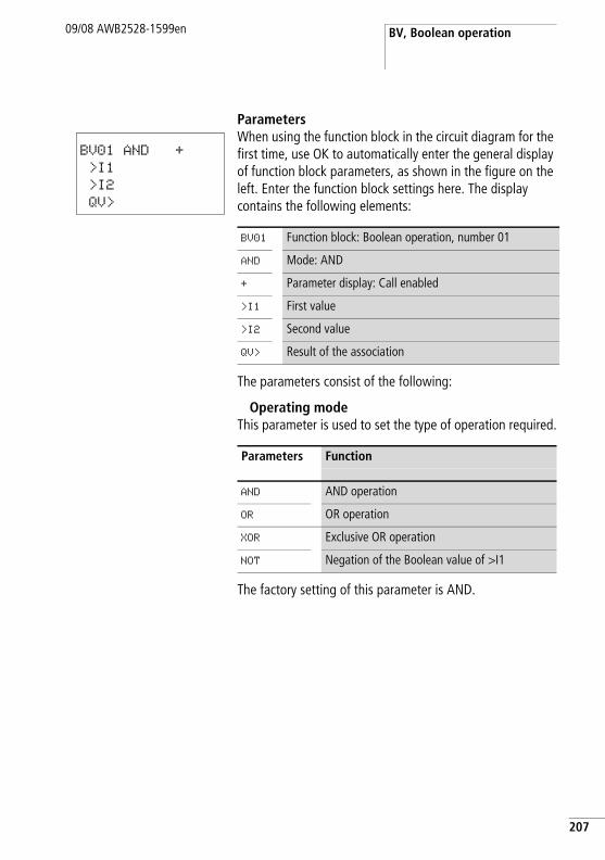
BV, Boolean operation09/08 AWB2528-1599en
ParametersWhen using the function block in the circuit diagram for the first time, use OK to automatically enter the general display of function block parameters, as shown in the figure on the left. Enter the function block settings here. The display contains the following elements:
The parameters consist of the following:
Operating modeThis parameter is used to set the type of operation required.
The factory setting of this parameter is AND.
BV01 AND +
>I1
>I2
QV>
BV01 Function block: Boolean operation, number 01
AND Mode: AND
+ Parameter display: Call enabled
>I1 First value
>I2 Second value
QV> Result of the association
Parameters Function
AND AND operation
OR OR operation
XOR Exclusive OR operation
NOT Negation of the Boolean value of >I1
207
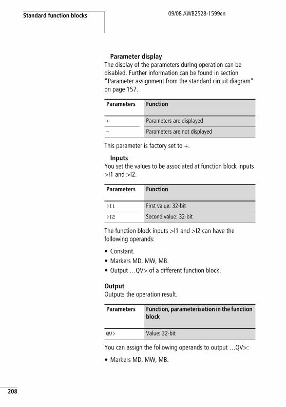
Standard function blocks
208
09/08 AWB2528-1599en
Parameter displayThe display of the parameters during operation can be disabled. Further information can be found in section “Parameter assignment from the standard circuit diagram” on page 157.
This parameter is factory set to +.
InputsYou set the values to be associated at function block inputs >I1 and >I2.
The function block inputs >I1 and >I2 can have the following operands:
• Constant.• Markers MD, MW, MB.• Output …QV> of a different function block.
OutputOutputs the operation result.
You can assign the following operands to output …QV>:
• Markers MD, MW, MB.
Parameters Function
+ Parameters are displayed
- Parameters are not displayed
Parameters Function
>I1 First value: 32-bit
>I2 Second value: 32-bit
Parameters Function, parameterisation in the function block
QV> Value: 32-bit
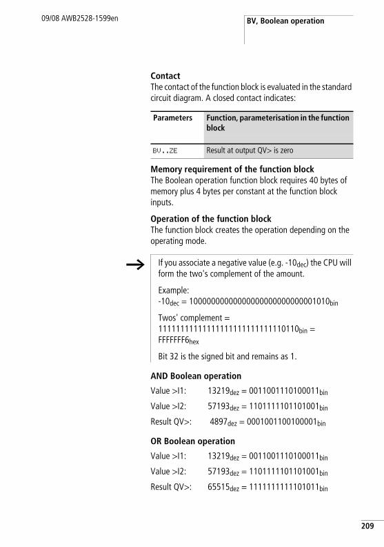
BV, Boolean operation09/08 AWB2528-1599en
ContactThe contact of the function block is evaluated in the standard circuit diagram. A closed contact indicates:
Memory requirement of the function blockThe Boolean operation function block requires 40 bytes of memory plus 4 bytes per constant at the function block inputs.
Operation of the function blockThe function block creates the operation depending on the operating mode.
AND Boolean operation
OR Boolean operation
Parameters Function, parameterisation in the function block
BV..ZE Result at output QV> is zero
h If you associate a negative value (e.g. -10dec) the CPU will form the two's complement of the amount.
Example:-10dec = 10000000000000000000000000001010bin
Twos' complement = 11111111111111111111111111110110bin =FFFFFFF6hex
Bit 32 is the signed bit and remains as 1.
Value >I1: 13219dez = 0011001110100011bin
Value >I2: 57193dez = 1101111101101001bin
Result QV>: 4897dez = 0001001100100001bin
Value >I1: 13219dez = 0011001110100011bin
Value >I2: 57193dez = 1101111101101001bin
Result QV>: 65515dez = 1111111111101011bin
209
Standard function blocks
210
09/08 AWB2528-1599en
XOR Boolean operation
NOT Boolean operation
The NOT sequence operates according to the following rules:
>I1, positive valueSubtract value of >I1 and 1:–|>I1| – 1 = >I2
>I1, negative valueSubtract value of >I1 and 1:–|>I1| – 1 = >I2
Value >I1: 13219dez = 0011001110100011bin
Value >I2: 57193dez = 1101111101101001bin
Result QV>: 60618dez = 1110110011001010bin
Value >I1: 13219dez = 00000000000000000011001110100011bin
Value >I2: deleted
Result QV>: -13220dez = 11111111111111111100110001011100bin
C, counter relay09/08 AWB2528-1599en
C, counter relay The counter relay (function relay) counts pulses that are received at counter input C_. The count direction can be set.
You can set a lower and higher limit setpoint as comparison values for the counter relay function block, as well as a start value.
easySafety allows the use of up to 16 counter relays.
h Counting is carried out cyclically. The time of a pulse must therefore be greater than twice the cycle time.
h Square wave count pulses are required to ensure a 1:1 mark to space ratio.
The relay counts only in RUN mode.
h page 326 on Example with timing relay and counter function block provides information on the timing relay and counter function block.
211
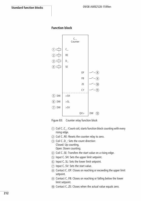
Standard function blocks
212
09/08 AWB2528-1599en
Function block
Figure 83: Counter relay function block
a Coil C..C_: Count coil, starts function block counting with every rising edge.
b Coil C..RE: Resets the counter relay to zero.c Coil C..D_: Sets the count direction:
Closed: Up counting,Open: Down counting.
d Coil C..SE: Transfers the start value on a rising edge.e Input C..SH: Sets the upper limit setpoint.f Input C..SL: Sets the lower limit setpoint.g Input C..SV: Sets the start value.h Contact C..OF: Closes on reaching or exceeding the upper limit
setpoint.i Contact C..FB: Closes on reaching or falling below the lower
limit setpoint.j Contact C..ZE: Closes when the actual value equals zero.
C_
RE
D_
ZE
CY
C...Counter
a
b
c
e
f
g
d
h
i
j
k
l
SE
OF
FB
QV>
>SV
>SL
>SH
DW
DW
DW
DW
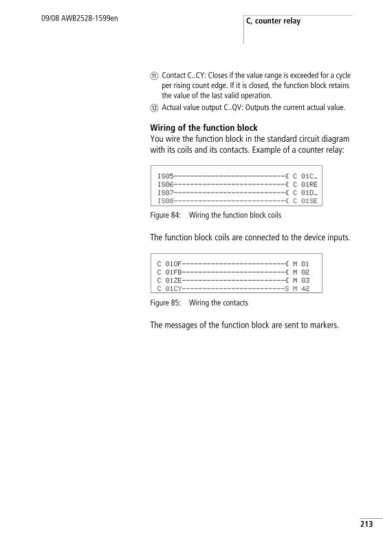
C, counter relay09/08 AWB2528-1599en
k Contact C..CY: Closes if the value range is exceeded for a cycle per rising count edge. If it is closed, the function block retains the value of the last valid operation.
l Actual value output C..QV: Outputs the current actual value.
Wiring of the function blockYou wire the function block in the standard circuit diagram with its coils and its contacts. Example of a counter relay:
Figure 84: Wiring the function block coils
The function block coils are connected to the device inputs.
Figure 85: Wiring the contacts
The messages of the function block are sent to markers.
IS05---------------------------Ä C 01C_ IS06---------------------------Ä C 01RE IS07---------------------------Ä C 01D_ IS08---------------------------Ä C 01SE
C 01OF-------------------------Ä M 01 C 01FB-------------------------Ä M 02 C 01ZE-------------------------Ä M 03 C 01CY-------------------------S M 42
213
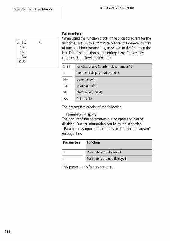
Standard function blocks
214
09/08 AWB2528-1599en
ParametersWhen using the function block in the circuit diagram for the first time, use OK to automatically enter the general display of function block parameters, as shown in the figure on the left. Enter the function block settings here. The display contains the following elements:
The parameters consist of the following:
Parameter displayThe display of the parameters during operation can be disabled. Further information can be found in section “Parameter assignment from the standard circuit diagram” on page 157.
This parameter is factory set to +.
C 16 +
>SH
>SL
>SV
QV>
C 16 Function block: Counter relay, number 16
+ Parameter display: Call enabled
>SH Upper setpoint
>SL Lower setpoint
>SV Start value (Preset)
QV> Actual value
Parameters Function
+ Parameters are displayed
- Parameters are not displayed
C, counter relay09/08 AWB2528-1599en
InputsThe upper and lower limit setpoints are set at function block inputs >SH and >SL respectively.
The start value is used to cause the function block to count from a specified offset value.
The function block inputs >SH, >SL and >SV can have the following operands:
• Constant.• Markers MD, MW, MB.• Output …QV> of a different function block.
OutputActual value output C..QV supplies the current actual value as an integer.
You can assign the following operands to output …QV>:
• Markers MD, MW, MB.
Parameters Function
>SH Upper setpoint: -2147483648 - +2147483647
>SL Lower setpoint: -2147483648 - +2147483647
>SV Start value: -2147483648 - +2147483647
Parameters Function
>QV Actual value: -2147483648 - +2147483647
215
Standard function blocks
216
09/08 AWB2528-1599en
CoilsThe coils of the function block are used in the standard circuit diagram.
ContactsThe contacts of the function block are evaluated in the standard circuit diagram. A closed contact indicates:
Memory requirementThe counter relay function block requires 52 bytes of memory plus 4 bytes per constant at the function block inputs.
RetentionCounter relays can be operated with retentive actual values. The number of retentive counter relays can be selected in the SYSTEM r RETENTION menu. The retentive actual value requires 4 bytes of memory.
If a counter relay is retentive, the actual value is retained when the operating mode changes from RUN to STOP as well as when the power supply is switched off. When is started in RUN mode, the counter relay continues with the retentively stored actual value. If easySafety is started in RUN mode, the timing relay operates with the retentively saved actual value.
Parameters Function
C ..C_ Count coil, starts counting with rising edges
C ..RE Reset of the counter relay to zero
C ..D_ Count direction setting
C ..SE Transfer of the start value on a rising edge.
Parameters Function
C ..OF Reaching or exceeding the upper limit setpoint
C ..FB Reaching or falling below the lower limit setpoint
C ..ZE Actual value equals zero
C ..CY Value range exceeded
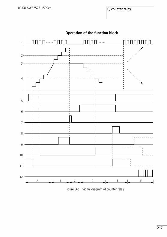
C, counter relay09/08 AWB2528-1599en
Operation of the function block
Figure 86: Signal diagram of counter relay
1
2
......... .........
3
4
6
7
8
9
10
11
12A B C D E F
5
217
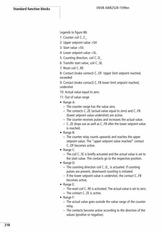
Standard function blocks
218
09/08 AWB2528-1599en
Legends to figure 86:1: Counter coil C..C_2: Upper setpoint value >SH3: Start value >SV.4: Lower setpoint value >SL.5: Counting direction, coil C..D_6: Transfer start value, coil C..SE.7: Reset coil C..RE8: Contact (make contact) C..OF: Upper limit setpoint reached, exceeded9: Contact (make contact) C..FB lower limit setpoint reached, undershot10: Actual value equal to zero.11: Out of value range• Range A:
– The counter range has the value zero.– The contacts C..ZE (actual value equal to zero) and C..FB
(lower setpoint value undershot) are active.– The counter receives pulses and increases the actual value.– C..ZE drops out as well as C..FB after the lower setpoint value
is reached.• Range B:
– The counter relay counts upwards and reaches the upper setpoint value. The “upper setpoint value reached” contact C..OF becomes active.
• Range C:– The coil C..SE is briefly actuated and the actual value is set to
the start value. The contacts go to the respective position.• Range D:
– The counting direction coil C..D_ is actuated. If counting pulses are present, downward counting is initiated.
– If the lower setpoint value is undershot, the contact C..FB becomes active.
• Range E:– The reset coil C..RE is activated. The actual value is set to zero.– The contact C..ZE is active.
• Range F:– The actual value goes outside the value range of the counter
relay.– The contacts become active according to the direction of the
values (positive or negative).
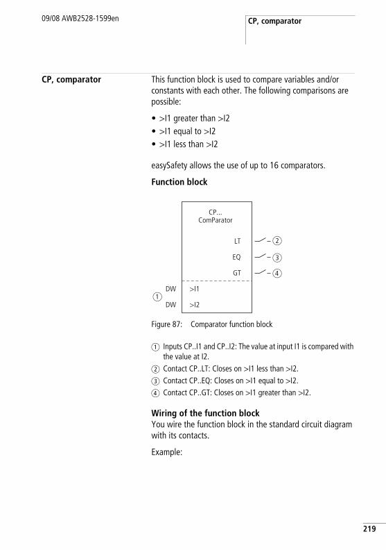
CP, comparator09/08 AWB2528-1599en
CP, comparator This function block is used to compare variables and/or constants with each other. The following comparisons are possible:
• >I1 greater than >I2• >I1 equal to >I2• >I1 less than >I2
easySafety allows the use of up to 16 comparators.
Function block
Figure 87: Comparator function block
a Inputs CP..I1 and CP..I2: The value at input I1 is compared with the value at I2.
b Contact CP..LT: Closes on >I1 less than >I2.c Contact CP..EQ: Closes on >I1 equal to >I2.d Contact CP..GT: Closes on >I1 greater than >I2.
Wiring of the function blockYou wire the function block in the standard circuit diagram with its contacts.
Example:
GT
CP...ComParator
LT
EQ
>I2
>I1
DW
DWa
b
c
d
219
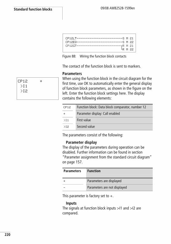
Standard function blocks
220
09/08 AWB2528-1599en
Figure 88: Wiring the function block contacts
The contact of the function block is sent to markers.
ParametersWhen using the function block in the circuit diagram for the first time, use OK to automatically enter the general display of function block parameters, as shown in the figure on the left. Enter the function block settings here. The display contains the following elements:
The parameters consist of the following:
Parameter displayThe display of the parameters during operation can be disabled. Further information can be found in section “Parameter assignment from the standard circuit diagram” on page 157.
This parameter is factory set to +.
InputsThe signals at function block inputs >I1 and >I2 are compared.
CP12LT-------------------------S M 21
CP12EQ-------------------------S M 22
CP12GT------------------------uR M 21hR M 22
CP12 +
>I1
>I2
CP12 Function block: Data block comparator, number 12
+ Parameter display: Call enabled
>I1 First value
>I2 Second value
Parameters Function
+ Parameters are displayed
- Parameters are not displayed
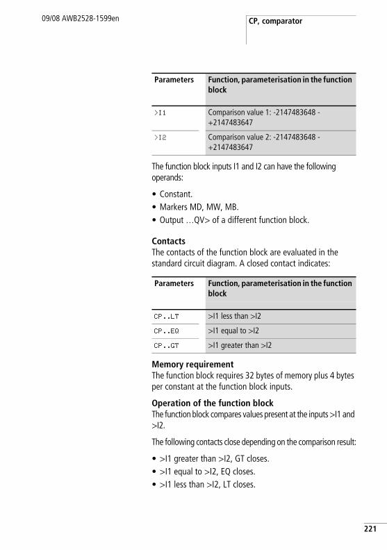
CP, comparator09/08 AWB2528-1599en
The function block inputs I1 and I2 can have the following operands:
• Constant.• Markers MD, MW, MB.• Output …QV> of a different function block.
ContactsThe contacts of the function block are evaluated in the standard circuit diagram. A closed contact indicates:
Memory requirementThe function block requires 32 bytes of memory plus 4 bytes per constant at the function block inputs.
Operation of the function blockThe function block compares values present at the inputs >I1 and >I2.
The following contacts close depending on the comparison result:
• >I1 greater than >I2, GT closes.• >I1 equal to >I2, EQ closes.• >I1 less than >I2, LT closes.
Parameters Function, parameterisation in the function block
>I1 Comparison value 1: -2147483648 - +2147483647
>I2 Comparison value 2: -2147483648 - +2147483647
Parameters Function, parameterisation in the function block
CP..LT >I1 less than >I2
CP..EQ >I1 equal to >I2
CP..GT >I1 greater than >I2
221
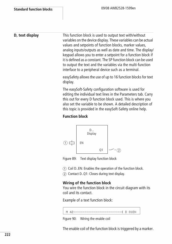
Standard function blocks
222
09/08 AWB2528-1599en
D, text display This function block is used to output text with/without variables on the device display. These variables can be actual values and setpoints of function blocks, marker values, analog inputs/outputs as well as date and time. The display/keypad allows you to enter a setpoint for a function block if it is defined as a constant. The SP function block can be used to output the text and the variables via the multi-function interface to a peripheral device such as a terminal.
easySafety allows the use of up to 16 function blocks for text display.
The easySoft-Safety configuration software is used for editing the individual text lines in the Parameters tab. Carry this out for every D function block used. This is where you also set the variable to be shown. A detailed description of this topic is provided in the easySoft-Safety online help.
Function block
Figure 89: Text display function block
a Coil D..EN: Enables the operation of the function block.b Contact D..Q1: Closes during text display.
Wiring of the function blockYou wire the function block in the circuit diagram with its coil and its contact.
Example of a text function block:
Figure 90: Wiring the enable coil
The enable coil of the function block is triggered by a marker.
EN
Q1
D...Display
a
b
M 42--------------------------Ä D 01EN
D, text display09/08 AWB2528-1599en
Figure 91: Wiring of the function block contact
Figure 92: Wiring the enable coil with Set/Reset
ParametersWhen using the function block in the circuit diagram for the first time, use OK to automatically enter the general display of function block parameters, as shown in the figure on the left. Enter the function block settings here. The display contains the following elements:
Parameter displayThe display of the parameters during operation can be disabled. Further information can be found in section “Parameter assignment from the standard circuit diagram” on page 157.
This parameter is factory set to +.
D 01Q1-------------------------Ä M 02
M 05-------------------------S D 01EN
M 06-------------------------R D 01EN
D 16 +
D16 Function block: Text output, number 16
+ Parameter display: Call enabled
Parameters Function
+ Parameters are displayed
- Parameters are not displayed
223
Standard function blocks
224
09/08 AWB2528-1599en
CoilThe coils of the function block are used in the standard circuit diagram.
ContactThe contact of the function block is evaluated in the standard circuit diagram. It closes when the function block is active.
Memory requirementThe text display function block requires 160 bytes of memory irrespective of the size of the text.
DisplayUp to 16 characters per line and up to 4 lines can be displayed.
Displaying a variableThe function block enables the display of:
• Actual values/setpoints of all function blocks except for HW and HY.
• Markers (MB, MW and MD).• Date and time.
The variables and setpoints can be inserted at any desired position in the single-line text. The variables can be 4, 5, 7 and 11 places long. Incorrect entries can cause characters to be overwritten or hidden.
The following formats for timing relay, time and date are supported.
Parameters Function
D ..EN Selective activation of the function block
Parameters Function
D ..Q1 Display of text
CONTROL
SWITCHING
COMMUNICATION
SIMPLY EASY
D, text display09/08 AWB2528-1599en
Entering setpoints via keypad/displayThe function block setpoints shown on the display and which can be defined as constants can be edited. The possibility of editing must be activated in the programming software. The values can be 4, 5, 7 and 11 places long. Incorrect entries can cause characters to be overwritten or hidden.
FunctionThe text is output if you activate the EN coil. For this the status display must be active before the text display is called.
If the coil (EN) is returned to 0, the control relay display reactivates the status display after 4 s.
The additional Central Europe and Cyrillic fonts can also be used for the text display and combined with the display attributes Flashing and Inverse. These options can be set for individual lines, and the attributes can be used in any combination.
Different behaviour of the function blocks D01 and D02 to D16
D01 outputs an alarm text: If D01 is activated, the text assigned to it will be displayed until:
• The coil D01 is reset to 0.• STOP mode is selected.• The easySafety device is switched off.• The OK or DEL + ALT buttons are used to switch to a
menu.
Variable Format
Timing relays s s s . s s s
min min : s s
h h : min min
Time h h : min min
Date DD.MM : YYYY
225
Standard function blocks
226
09/08 AWB2528-1599en
D 02 to D 16: If several texts are present and are triggered, each text is automatically displayed in turn every 4 s. This process will be repeated until:
• No other text display function block is set to 1.• STOP mode is selected.• The easySafety device is switched off.• The OK or DEL + ALT buttons are used to switch to a
menu.• The text for D01 is displayed.
The function of the text display function is fully simulated by the Simulation tool.
Displayable character setYou can enter characters from the character maps “Western European”, “Central European” and “Cyrillic”.
Example characters from the character map “Western European”:
A B C D E F G H I J K L M N O P Q R S T U V W X Y Z
a b c d e f g h i j k l m n o p q r s t u v w x y z
0 1 2 3 4 5 6 7 8 9
Examples of special characters:
° ! " # $ % & ' () * + , - . / : ; < = > ? [\] ^ _ ` { | } ~ . and space.
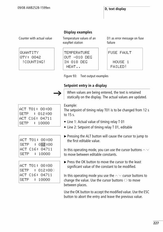
D, text display09/08 AWB2528-1599en
Display examples
Figure 93: Text output examples
Setpoint entry in a display
Example:The setpoint of timing relay T01 is to be changed from 12 s to 15 s.
• Line 1: Actual value of timing relay T 01• Line 2: Setpoint of timing relay T 01, editable
X Pressing the ALT button will cause the cursor to jump to the first editable value.
In this operating mode, you can use the cursor buttons Í Ú to move between editable constants.
X Press the OK button to move the cursor to the least significant value of the constant to be modified.
In this operating mode you use the Í Ú cursor buttons to change the value. Use the cursor buttons ú í to move between places.
Use the OK button to accept the modified value. Use the ESC button to abort the entry and leave the previous value.
Counter with actual value Temperature values of an easyNet station
D1 as error message on fuse failure
QUANTITY
QTY: 0042
!COUNTING!
TEMPERATURE
OUT -010 DEG
IN 018 DEG
HEAT..
FUSE FAULT
HOUSE 1
FAILED!
h When values are being entered, the text is retained statically on the display. The actual values are updated.
ACT T01: 00:00
SETP : 012:00
ACT C16: 04711
SETP : 10000
ACT T01: 00:00
SETP : 012:00
ACT C16: 04711
SETP : 10000
ACT T01: 00:00
SETP : 012:000
ACT C16: 04711
SETP : 10000
227
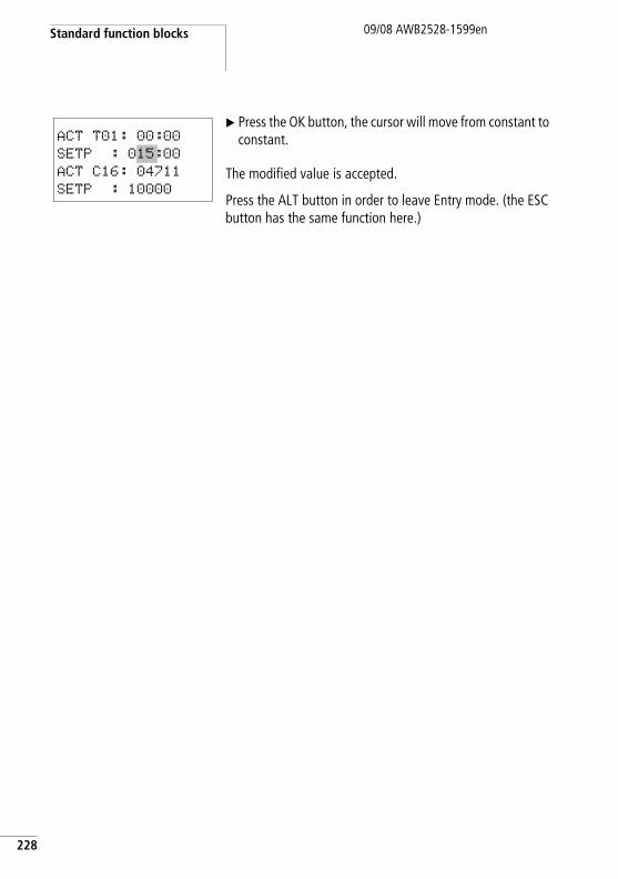
Standard function blocks
228
09/08 AWB2528-1599en
X Press the OK button, the cursor will move from constant to constant.
The modified value is accepted.
Press the ALT button in order to leave Entry mode. (the ESC button has the same function here.)
ACT T01: 00:00
SETP : 015:00
ACT C16: 04711
SETP : 10000
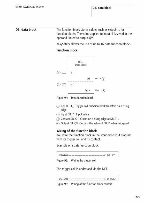
DB, data block09/08 AWB2528-1599en
DB, data block The function block stores values such as setpoints for function blocks. The value applied to input I1 is saved in the operand linked to output QV.
easySafety allows the use of up to 16 data function blocks.
Function block
Figure 94: Data function block
a Coil DB..T_: Trigger coil, function block transfers on a rising edge.
b Input DB..I1: Input value.c Contact DB..Q1: Closes on a rising edge at DB..T_.d Output DB..QV: Outputs the value of DB..I1 when triggered.
Wiring of the function blockYou wire the function block in the standard circuit diagram with its trigger coil and its contact.
Example of a data function block:
Figure 95: Wiring the trigger coil
The trigger coil is addressed via the NET.
Figure 96: Wiring of the function block contact
T_
DB...Data Block
a
b
c
d
Q1
QV>
>I1DW
DW
GT01Q1-----------------------Ä DB16T
DB16Q1-----------------------Ä D 02EN
229
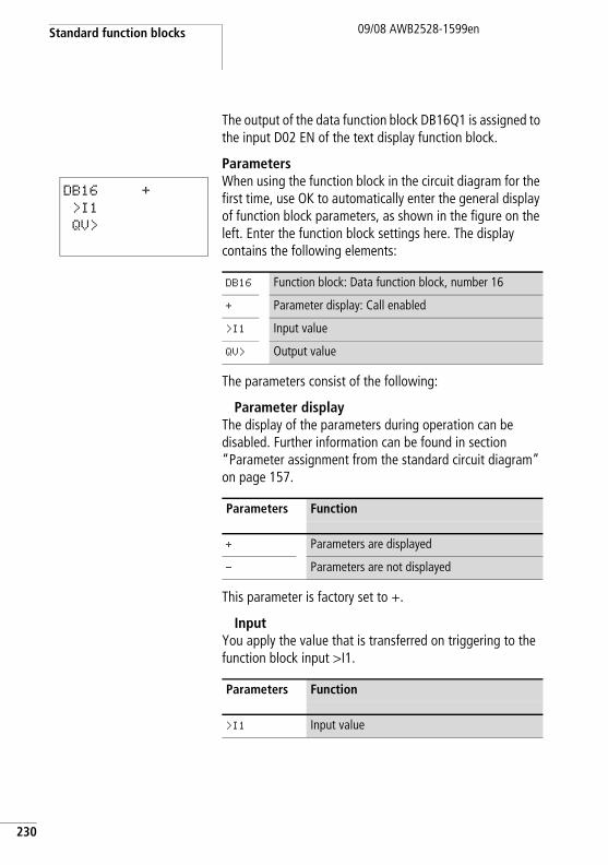
Standard function blocks
230
09/08 AWB2528-1599en
The output of the data function block DB16Q1 is assigned to the input D02 EN of the text display function block.
ParametersWhen using the function block in the circuit diagram for the first time, use OK to automatically enter the general display of function block parameters, as shown in the figure on the left. Enter the function block settings here. The display contains the following elements:
The parameters consist of the following:
Parameter displayThe display of the parameters during operation can be disabled. Further information can be found in section “Parameter assignment from the standard circuit diagram” on page 157.
This parameter is factory set to +.
InputYou apply the value that is transferred on triggering to the function block input >I1.
DB16 +
>I1
QV>
DB16 Function block: Data function block, number 16
+ Parameter display: Call enabled
>I1 Input value
QV> Output value
Parameters Function
+ Parameters are displayed
- Parameters are not displayed
Parameters Function
>I1 Input value
DB, data block09/08 AWB2528-1599en
The function block input >I1 can be assigned the following operands:
• Constant.• Markers MD, MW, MB.• Output …QV> of a different function block.
OutputThe output provides the input value when triggered as an integer.
You can assign the following operands to output …QV>:
• Markers MD, MW, MB.
CoilThe coil of the function block is used in the standard circuit diagram to transfer the value at input >I1 to the function block and supply it on its output.
ContactThe contact of the function block is evaluated in the standard circuit diagram. A closed contact indicates that the transferred value is output on the output.
Parameters Function, parameterisation in the function block
QV> Output value: -2147483648 - +2147483647
Parameters Function
DB..T_ Transfer the value to >I1
Parameters Function
DB..Q1 Transfer of the value from >I1 to QV>
231
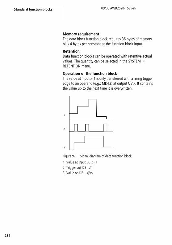
Standard function blocks
232
09/08 AWB2528-1599en
Memory requirementThe data block function block requires 36 bytes of memory plus 4 bytes per constant at the function block input.
RetentionData function blocks can be operated with retentive actual values. The quantity can be selected in the SYSTEM r RETENTION menu.
Operation of the function blockThe value at input >I1 is only transferred with a rising trigger edge to an operand (e.g.: MD42) at output QV>. It contains the value up to the next time it is overwritten.
Figure 97: Signal diagram of data function block
1: Value at input DB..>I12: Trigger coil DB…T_3: Value on DB…QV>
2
3
1
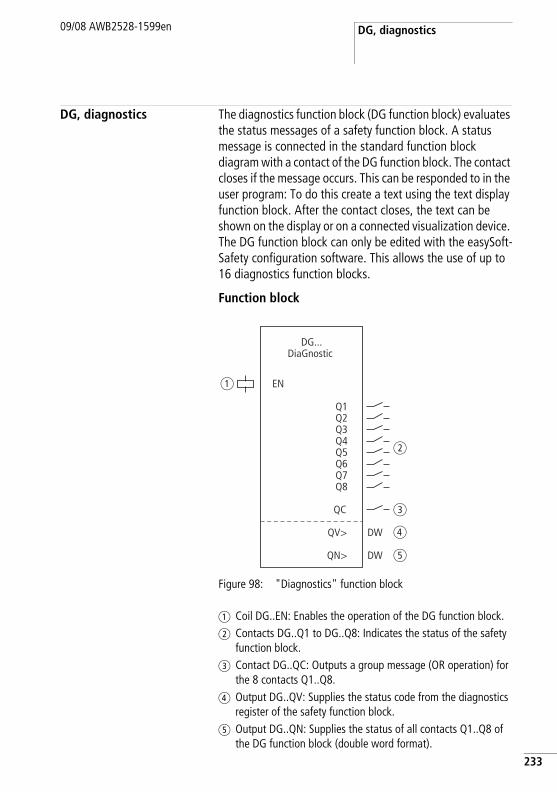
DG, diagnostics09/08 AWB2528-1599en
DG, diagnostics The diagnostics function block (DG function block) evaluates the status messages of a safety function block. A status message is connected in the standard function block diagram with a contact of the DG function block. The contact closes if the message occurs. This can be responded to in the user program: To do this create a text using the text display function block. After the contact closes, the text can be shown on the display or on a connected visualization device. The DG function block can only be edited with the easySoft-Safety configuration software. This allows the use of up to 16 diagnostics function blocks.
Function block
Figure 98: "Diagnostics" function block
a Coil DG..EN: Enables the operation of the DG function block.b Contacts DG..Q1 to DG..Q8: Indicates the status of the safety
function block.c Contact DG..QC: Outputs a group message (OR operation) for
the 8 contacts Q1..Q8.d Output DG..QV: Supplies the status code from the diagnostics
register of the safety function block.e Output DG..QN: Supplies the status of all contacts Q1..Q8 of
the DG function block (double word format).
DG...DiaGnostic
a
b
c
d
e
EN
Q1Q2Q3Q4Q5Q6Q7Q8
QC
QN>
QV>
DW
DW
233
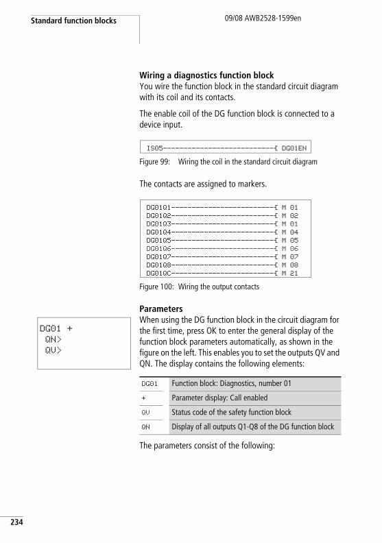
Standard function blocks
234
09/08 AWB2528-1599en
Wiring a diagnostics function blockYou wire the function block in the standard circuit diagram with its coil and its contacts.
The enable coil of the DG function block is connected to a device input.
Figure 99: Wiring the coil in the standard circuit diagram
The contacts are assigned to markers.
Figure 100: Wiring the output contacts
ParametersWhen using the DG function block in the circuit diagram for the first time, press OK to enter the general display of the function block parameters automatically, as shown in the figure on the left. This enables you to set the outputs QV and QN. The display contains the following elements:
The parameters consist of the following:
IS05---------------------------Ä DG01EN
DG01Q1-------------------------Ä M 01 DG01Q2-------------------------Ä M 02 DG01Q3-------------------------Ä M 01 DG01Q4-------------------------Ä M 04 DG01Q5-------------------------Ä M 05 DG01Q6-------------------------Ä M 06 DG01Q7-------------------------Ä M 07 DG01Q8-------------------------Ä M 08 DG01QC-------------------------Ä M 21
DG01 +
QN>
QV>
DG01 Function block: Diagnostics, number 01
+ Parameter display: Call enabled
QV Status code of the safety function block
QN Display of all outputs Q1-Q8 of the DG function block
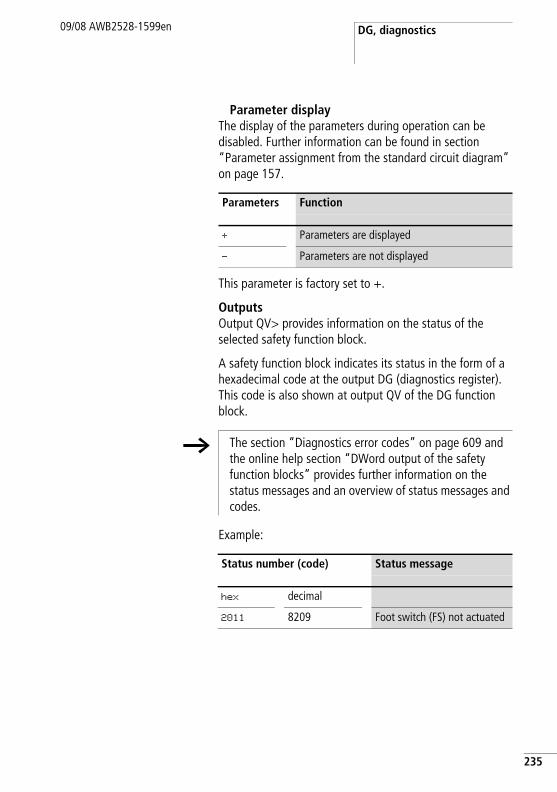
DG, diagnostics09/08 AWB2528-1599en
Parameter displayThe display of the parameters during operation can be disabled. Further information can be found in section “Parameter assignment from the standard circuit diagram” on page 157.
This parameter is factory set to +.
OutputsOutput QV> provides information on the status of the selected safety function block.
A safety function block indicates its status in the form of a hexadecimal code at the output DG (diagnostics register). This code is also shown at output QV of the DG function block.
Example:
Parameters Function
+ Parameters are displayed
- Parameters are not displayed
h The section “Diagnostics error codes” on page 609 and the online help section “DWord output of the safety function blocks” provides further information on the status messages and an overview of status messages and codes.
Status number (code) Status message
hex decimal
2011 8209 Foot switch (FS) not actuated
235
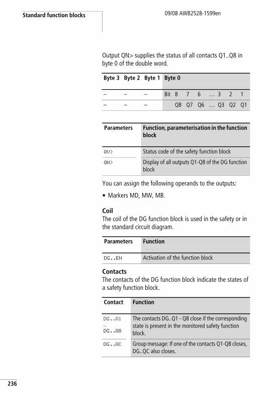
Standard function blocks
236
09/08 AWB2528-1599en
Output QN> supplies the status of all contacts Q1..Q8 in byte 0 of the double word.
You can assign the following operands to the outputs:
• Markers MD, MW, MB.
CoilThe coil of the DG function block is used in the safety or in the standard circuit diagram.
ContactsThe contacts of the DG function block indicate the states of a safety function block.
Byte 3 Byte 2 Byte 1 Byte 0
– – – Bit 8 7 6 … 3 2 1
– – – Q8 Q7 Q6 … Q3 Q2 Q1
Parameters Function, parameterisation in the function block
QV> Status code of the safety function block
QN> Display of all outputs Q1-Q8 of the DG function block
Parameters Function
DG..EN Activation of the function block
Contact Function
DG..Q1
…
DG..Q8
The contacts DG..Q1 - Q8 close if the corresponding state is present in the monitored safety function block.
DG..QC Group message: If one of the contacts Q1-Q8 closes, DG..QC also closes.
DG, diagnostics09/08 AWB2528-1599en
Memory requirementThe DG function block requires 104 bytes of memory plus 4 bytes per constant at the function block inputs.
Operation of the function blockA DG function block is assigned to a safety function block. The safety function block indicates its status at its DG output (diagnostics register). This status, such as “Foot switch not actuated” with the FS safety function block, can be assigned to a contact of the DG function block in the standard function block diagram. If the status occurs at the safety function block, the assigned contact will close on the DG function block. The 8 contacts of a DG function block allow 8 states to be associated with the contacts. If a safety function block has more than 8 states, a second DG function block can process the additional status messages.
The DG function block is assigned to the corresponding safety function block in the standard function block diagram. After you have dragged the DG function block into this diagram, right-clicking the function block with the mouse will call up its Parameters tab. First associate the safety function block with the DG function block. To do this enter the number of the DG function block and enter in the Safety function block field the type of safety function block you have entered in the safety circuit diagram. The Safety function block states field shows 8 outputs of the DG function block with a status menu from which you can select the required status message.
If the safety function block takes on one of these states, the DG..Q signal contact assigned to it will close. The contacts of the function block are associated in the standard circuit diagram.
237
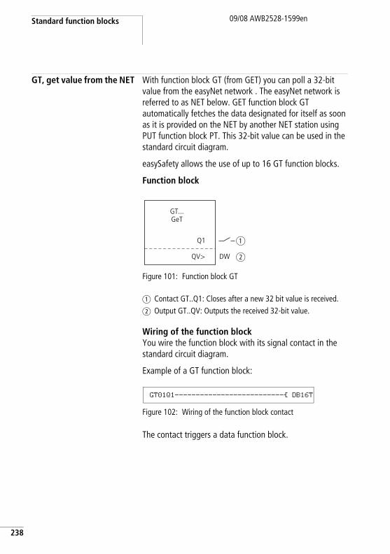
Standard function blocks
238
09/08 AWB2528-1599en
GT, get value from the NET With function block GT (from GET) you can poll a 32-bit value from the easyNet network . The easyNet network is referred to as NET below. GET function block GT automatically fetches the data designated for itself as soon as it is provided on the NET by another NET station using PUT function block PT. This 32-bit value can be used in the standard circuit diagram.
easySafety allows the use of up to 16 GT function blocks.
Function block
Figure 101: Function block GT
a Contact GT..Q1: Closes after a new 32 bit value is received.b Output GT..QV: Outputs the received 32-bit value.
Wiring of the function blockYou wire the function block with its signal contact in the standard circuit diagram.
Example of a GT function block:
Figure 102: Wiring of the function block contact
The contact triggers a data function block.
GT...GeT
a
bQV>
Q1
DW
GT01Q1--------------------------Ä DB16T
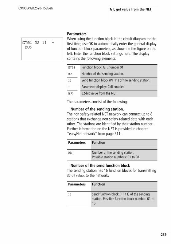
GT, get value from the NET09/08 AWB2528-1599en
ParametersWhen using the function block in the circuit diagram for the first time, use OK to automatically enter the general display of function block parameters, as shown in the figure on the left. Enter the function block settings here. The display contains the following elements:
The parameters consist of the following:
Number of the sending station.The non safety-related NET network can connect up to 8 stations that exchange non safety-related data with each other. The stations are identified by their station number. Further information on the NET is provided in chapter “easyNet network” from page 511.
Number of the send function blockThe sending station has 16 function blocks for transmitting 32-bit values to the network.
GT01 02 11 +
QV>
GT01 Function block: GT, number 01
02 Number of the sending station.
11 Send function block (PT 11) of the sending station.
+ Parameter display: Call enabled
QV> 32-bit value from the NET
Parameters Function
02 Number of the sending station.Possible station numbers: 01 to 08
Parameters Function
11 Send function block (PT 11) of the sending station. Possible function block number: 01 to 16
239
Standard function blocks
240
09/08 AWB2528-1599en
Parameter displayThe display of the parameters during operation can be disabled. Further information can be found in section “Parameter assignment from the standard circuit diagram” on page 157.
This parameter is factory set to +.
OutputThe output provides the value fetched from the network for one operating cycle.
You can assign the following operands to output …QV>:
• Markers MD, MW, MB.
ContactThe contact of the function block is evaluated in the standard circuit diagram. A closed contact indicates that new data have been received through the NET and are available at function block output QV.
Memory requirementThe GT function block requires 28 bytes of memory.
GT diagnosticsThe GT function block only functions if the easyNet network is running properly (a section “Checking the functionality of the NET”, page 533).
Parameters Function
+ Parameters are displayed
- Parameters are not displayed
Parameters Function, parameterisation in the function block
QV> Value: -2147483648 - +2147483647
Parameters Function
GT..Q1 Fetched value present at QV>
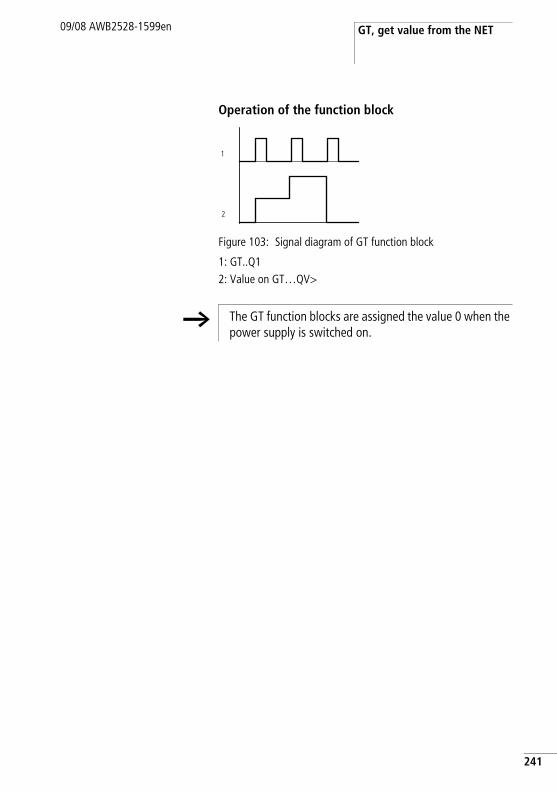
GT, get value from the NET09/08 AWB2528-1599en
Operation of the function block
Figure 103: Signal diagram of GT function block
1: GT..Q12: Value on GT…QV>
1
2
h The GT function blocks are assigned the value 0 when the power supply is switched on.
241
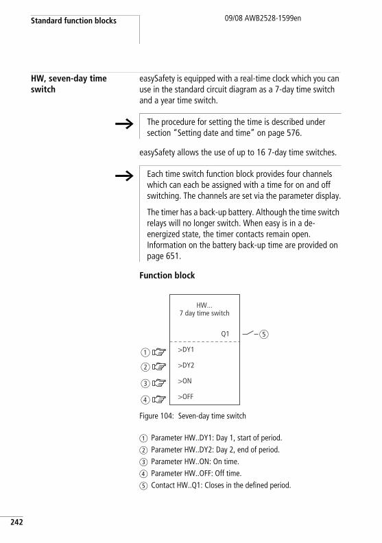
Standard function blocks
242
09/08 AWB2528-1599en
HW, seven-day time switch
easySafety is equipped with a real-time clock which you can use in the standard circuit diagram as a 7-day time switch and a year time switch.
easySafety allows the use of up to 16 7-day time switches.
Function block
Figure 104: Seven-day time switch
a Parameter HW..DY1: Day 1, start of period.b Parameter HW..DY2: Day 2, end of period.c Parameter HW..ON: On time.d Parameter HW..OFF: Off time.e Contact HW..Q1: Closes in the defined period.
h The procedure for setting the time is described under section “Setting date and time” on page 576.
h Each time switch function block provides four channels which can each be assigned with a time for on and off switching. The channels are set via the parameter display.
The timer has a back-up battery. Although the time switch relays will no longer switch. When easy is in a de-energized state, the timer contacts remain open. Information on the battery back-up time are provided on page 651.
>DY1
Q1
HW...7 day time switch
>DY2
>ON
>OFF
b
a
c
d
e
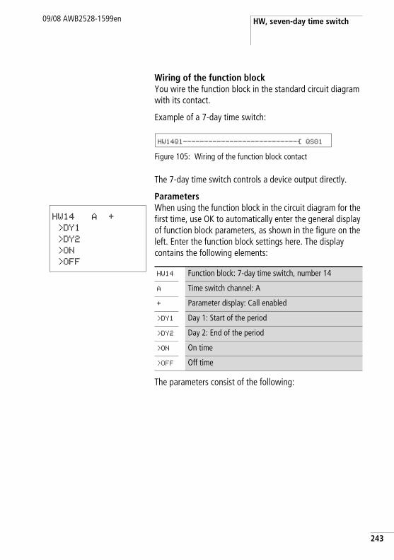
HW, seven-day time switch09/08 AWB2528-1599en
Wiring of the function blockYou wire the function block in the standard circuit diagram with its contact.
Example of a 7-day time switch:
Figure 105: Wiring of the function block contact
The 7-day time switch controls a device output directly.
ParametersWhen using the function block in the circuit diagram for the first time, use OK to automatically enter the general display of function block parameters, as shown in the figure on the left. Enter the function block settings here. The display contains the following elements:
The parameters consist of the following:
HW14Q1---------------------------Ä QS01
HW14 A +
>DY1
>DY2
>ON
>OFF
HW14 Function block: 7-day time switch, number 14
A Time switch channel: A
+ Parameter display: Call enabled
>DY1 Day 1: Start of the period
>DY2 Day 2: End of the period
>ON On time
>OFF Off time
243
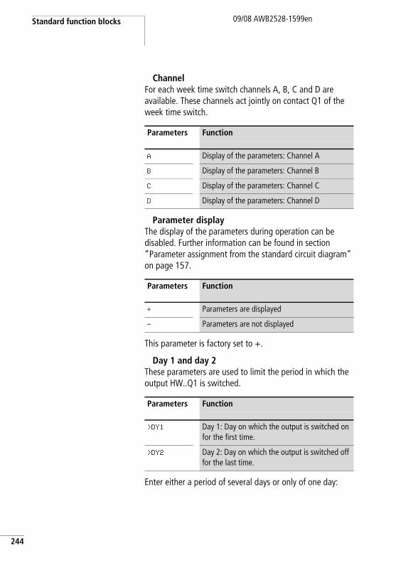
Standard function blocks
244
09/08 AWB2528-1599en
ChannelFor each week time switch channels A, B, C and D are available. These channels act jointly on contact Q1 of the week time switch.
Parameter displayThe display of the parameters during operation can be disabled. Further information can be found in section “Parameter assignment from the standard circuit diagram” on page 157.
This parameter is factory set to +.
Day 1 and day 2These parameters are used to limit the period in which the output HW..Q1 is switched.
Enter either a period of several days or only of one day:
Parameters Function
A Display of the parameters: Channel A
B Display of the parameters: Channel B
C Display of the parameters: Channel C
D Display of the parameters: Channel D
Parameters Function
+ Parameters are displayed
- Parameters are not displayed
Parameters Function
>DY1 Day 1: Day on which the output is switched on for the first time.
>DY2 Day 2: Day on which the output is switched off for the last time.
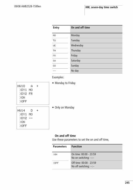
HW, seven-day time switch09/08 AWB2528-1599en
Examples:
• Monday to Friday
• Only on Monday
On and off timeUse these parameters to set the on and off time,
Entry On and off time
MO Monday
TU Tuesday
WE Wednesday
TH Thursday
FR Friday
SA Saturday
SO Sunday
-- No day
HW10 A +
>DY1 MO
>DY2 FR
>ON
>OFF
HW14 D +
>DY1 MO
>DY2 --
>ON
>OFF
Parameters Function
>ON On time: 00:00 - 23:59No on switching: --:--
>OFF Off time: 00:00 - 23:59No off switching: --:--
245
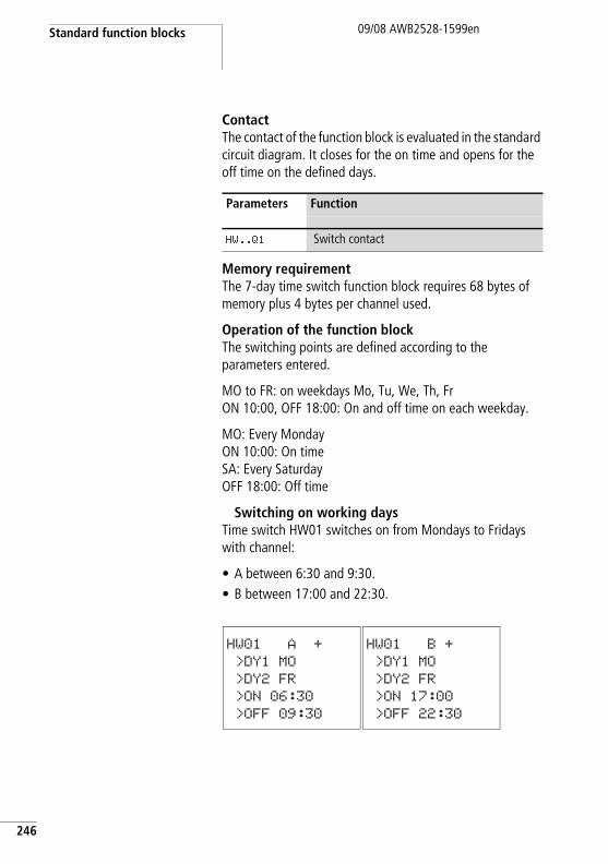
Standard function blocks
246
09/08 AWB2528-1599en
ContactThe contact of the function block is evaluated in the standard circuit diagram. It closes for the on time and opens for the off time on the defined days.
Memory requirementThe 7-day time switch function block requires 68 bytes of memory plus 4 bytes per channel used.
Operation of the function blockThe switching points are defined according to the parameters entered.
MO to FR: on weekdays Mo, Tu, We, Th, FrON 10:00, OFF 18:00: On and off time on each weekday.
MO: Every MondayON 10:00: On timeSA: Every SaturdayOFF 18:00: Off time
Switching on working daysTime switch HW01 switches on from Mondays to Fridays with channel:
• A between 6:30 and 9:30.• B between 17:00 and 22:30.
Parameters Function
HW..Q1 Switch contact
HW01 B +
>DY1 MO
>DY2 FR
>ON 17:00
>OFF 22:30
HW01 A +
>DY1 MO
>DY2 FR
>ON 06:30
>OFF 09:30
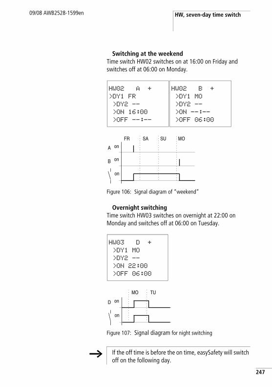
HW, seven-day time switch09/08 AWB2528-1599en
Switching at the weekendTime switch HW02 switches on at 16:00 on Friday and switches off at 06:00 on Monday.
Figure 106: Signal diagram of “weekend”
Overnight switchingTime switch HW03 switches on overnight at 22:00 on Monday and switches off at 06:00 on Tuesday.
Figure 107: Signal diagram for night switching
HW02 A +
>DY1 FR
>DY2 --
>ON 16:00
>OFF --:--
HW02 B +
>DY1 MO
>DY2 --
>ON --:--
>OFF 06:00
HW03 D +
>DY1 MO
>DY2 --
>ON 22:00
>OFF 06:00
h If the off time is before the on time, easySafety will switch off on the following day.
247
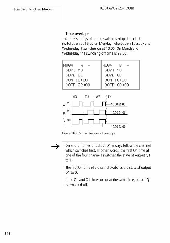
Standard function blocks
248
09/08 AWB2528-1599en
Time overlapsThe time settings of a time switch overlap. The clock switches on at 16:00 on Monday, whereas on Tuesday and Wednesday it switches on at 10:00. On Monday to Wednesday the switching-off time is 22:00.
Figure 108: Signal diagram of overlaps
HW04 A +
>DY1 MO
>DY2 WE
>ON 16:00
>OFF 22:00
HW04 B +
>DY1 TU
>DY2 WE
>ON 10:00
>OFF 00:00
h On and off times of output Q1 always follow the channel which switches first. In other words, the first On time at one of the four channels switches the state at output Q1 to 1.
The first Off time of a channel switches the state at output Q1 to 0.
If the On and Off times occur at the same time, output Q1 is switched off.
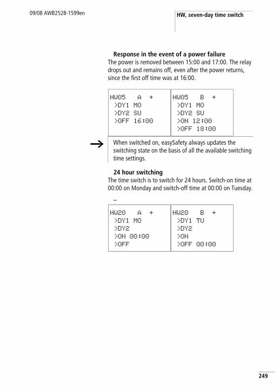
HW, seven-day time switch09/08 AWB2528-1599en
Response in the event of a power failureThe power is removed between 15:00 and 17:00. The relay drops out and remains off, even after the power returns, since the first off time was at 16:00.
24 hour switchingThe time switch is to switch for 24 hours. Switch-on time at 00:00 on Monday and switch-off time at 00:00 on Tuesday.
–
HW05 A +
>DY1 MO
>DY2 SU
>OFF 16:00
HW05 B +
>DY1 MO
>DY2 SU
>ON 12:00
>OFF 18:00
h When switched on, easySafety always updates the switching state on the basis of all the available switching time settings.
HW20 A +
>DY1 MO
>DY2
>ON 00:00
>OFF
HW20 B +
>DY1 TU
>DY2
>ON
>OFF 00:00
249
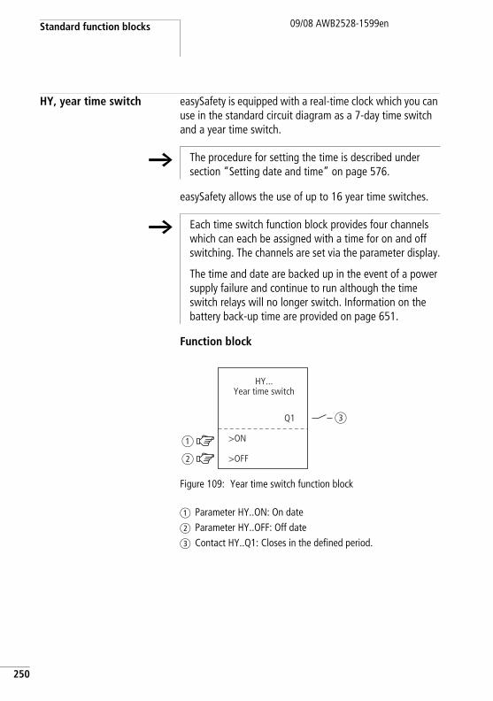
Standard function blocks
250
09/08 AWB2528-1599en
HY, year time switch easySafety is equipped with a real-time clock which you can use in the standard circuit diagram as a 7-day time switch and a year time switch.
easySafety allows the use of up to 16 year time switches.
Function block
Figure 109: Year time switch function block
a Parameter HY..ON: On dateb Parameter HY..OFF: Off datec Contact HY..Q1: Closes in the defined period.
h The procedure for setting the time is described under section “Setting date and time” on page 576.
h Each time switch function block provides four channels which can each be assigned with a time for on and off switching. The channels are set via the parameter display.
The time and date are backed up in the event of a power supply failure and continue to run although the time switch relays will no longer switch. Information on the battery back-up time are provided on page 651.
>ON
Q1
HY...Year time switch
b
a
c
>OFF
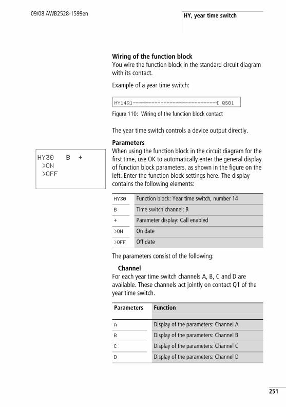
HY, year time switch09/08 AWB2528-1599en
Wiring of the function blockYou wire the function block in the standard circuit diagram with its contact.
Example of a year time switch:
Figure 110: Wiring of the function block contact
The year time switch controls a device output directly.
ParametersWhen using the function block in the circuit diagram for the first time, use OK to automatically enter the general display of function block parameters, as shown in the figure on the left. Enter the function block settings here. The display contains the following elements:
The parameters consist of the following:
ChannelFor each year time switch channels A, B, C and D are available. These channels act jointly on contact Q1 of the year time switch.
HY14Q1---------------------------Ä QS01
HY30 B +
>ON
>OFF
HY30 Function block: Year time switch, number 14
B Time switch channel: B
+ Parameter display: Call enabled
>ON On date
>OFF Off date
Parameters Function
A Display of the parameters: Channel A
B Display of the parameters: Channel B
C Display of the parameters: Channel C
D Display of the parameters: Channel D
251
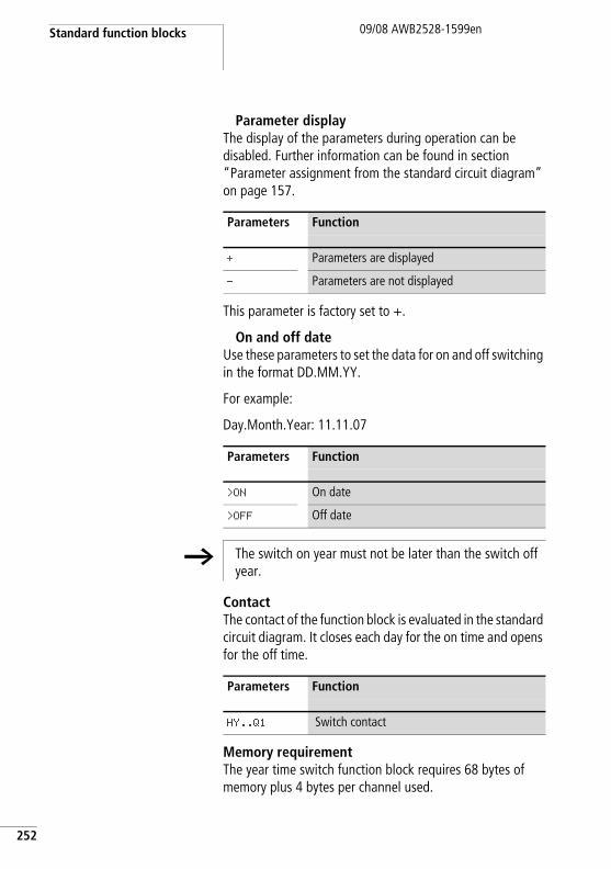
Standard function blocks
252
09/08 AWB2528-1599en
Parameter displayThe display of the parameters during operation can be disabled. Further information can be found in section “Parameter assignment from the standard circuit diagram” on page 157.
This parameter is factory set to +.
On and off dateUse these parameters to set the data for on and off switching in the format DD.MM.YY.
For example:
Day.Month.Year: 11.11.07
ContactThe contact of the function block is evaluated in the standard circuit diagram. It closes each day for the on time and opens for the off time.
Memory requirementThe year time switch function block requires 68 bytes of memory plus 4 bytes per channel used.
Parameters Function
+ Parameters are displayed
- Parameters are not displayed
Parameters Function
>ON On date
>OFF Off date
h The switch on year must not be later than the switch off year.
Parameters Function
HY..Q1 Switch contact
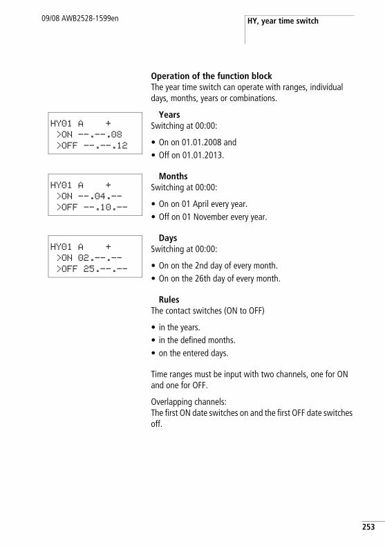
HY, year time switch09/08 AWB2528-1599en
Operation of the function blockThe year time switch can operate with ranges, individual days, months, years or combinations.
YearsSwitching at 00:00:
• On on 01.01.2008 and• Off on 01.01.2013.
MonthsSwitching at 00:00:
• On on 01 April every year.• Off on 01 November every year.
DaysSwitching at 00:00:
• On on the 2nd day of every month.• On on the 26th day of every month.
RulesThe contact switches (ON to OFF)
• in the years.• in the defined months.• on the entered days.
Time ranges must be input with two channels, one for ON and one for OFF.
Overlapping channels:The first ON date switches on and the first OFF date switches off.
HY01 A +
>ON --.--.08
>OFF --.--.12
HY01 A +
>ON --.04.--
>OFF --.10.--
HY01 A +
>ON 02.--.--
>OFF 25.--.--
253
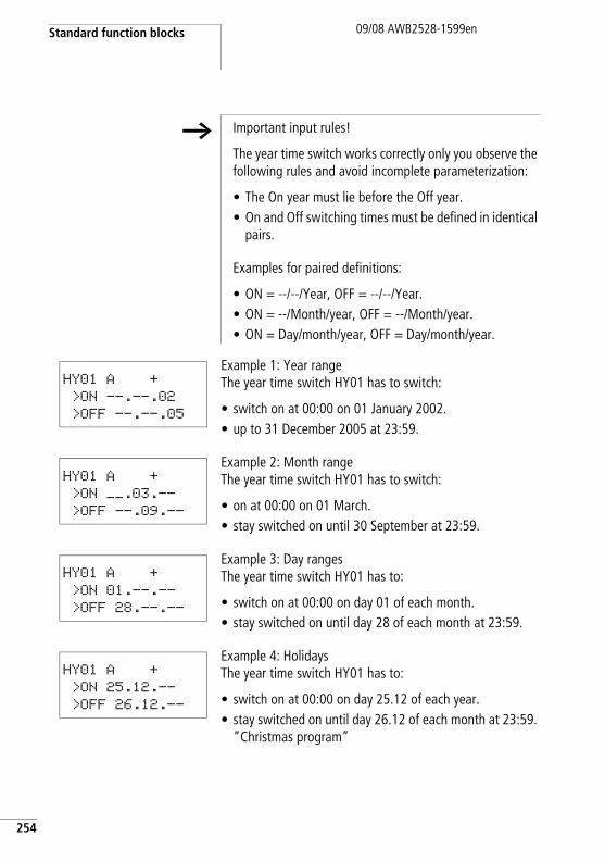
Standard function blocks
254
09/08 AWB2528-1599en
Example 1: Year rangeThe year time switch HY01 has to switch:
• switch on at 00:00 on 01 January 2002.• up to 31 December 2005 at 23:59.
Example 2: Month rangeThe year time switch HY01 has to switch:
• on at 00:00 on 01 March.• stay switched on until 30 September at 23:59.
Example 3: Day rangesThe year time switch HY01 has to:
• switch on at 00:00 on day 01 of each month.• stay switched on until day 28 of each month at 23:59.
Example 4: HolidaysThe year time switch HY01 has to:
• switch on at 00:00 on day 25.12 of each year.• stay switched on until day 26.12 of each month at 23:59.
“Christmas program”
h Important input rules!
The year time switch works correctly only you observe the following rules and avoid incomplete parameterization:
• The On year must lie before the Off year.• On and Off switching times must be defined in identical
pairs.
Examples for paired definitions:
• ON = --/--/Year, OFF = --/--/Year. • ON = --/Month/year, OFF = --/Month/year.• ON = Day/month/year, OFF = Day/month/year.
HY01 A +
>ON --.--.02
>OFF --.--.05
HY01 A +
>ON __.03.-- >OFF --.09.--
HY01 A +
>ON 01.--.--
>OFF 28.--.--
HY01 A +
>ON 25.12.--
>OFF 26.12.--
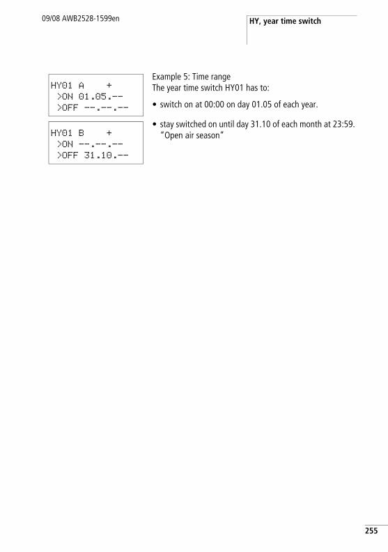
HY, year time switch09/08 AWB2528-1599en
Example 5: Time rangeThe year time switch HY01 has to:
• switch on at 00:00 on day 01.05 of each year.
• stay switched on until day 31.10 of each month at 23:59. “Open air season”
HY01 A +
>ON 01.05.--
>OFF --.--.--
HY01 B +
>ON --.--.--
>OFF 31.10.--
255
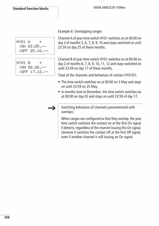
Standard function blocks
256
09/08 AWB2528-1599en
Example 6: Overlapping ranges
Channel A of year time switch HY01 switches on at 00:00 on day 3 of months 5, 6, 7, 8, 9, 10 and stays switched on until 23.59 on day 25 of these months.
Channel B of year time switch HY01 switches on at 00:00 on day 2 of months 6, 7, 8, 9, 10, 11, 12 and stays switched on until 23:59 on day 17 of these months.
Total of the channels and behaviour of contact HY01Q1:
• The time switch switches on at 00:00 on 3 May and stays on until 23:59 on 25 May.
• In months June to December, the time switch switches on at 00:00 on day 02 and stays on until 23:59 of day 17.
HY01 A +
>ON 03.05.--
>OFF 25.10.--
HY01 B +
>ON 02.06.--
>OFF 17.12.--
h Switching behaviour of channels parameterized with overlaps:
When ranges are configured so that they overlap, the year time switch switches the contact on at the first On signal it detects, regardless of the channel issuing this On signal. Likewise it switches the contact off at the first Off signal, even if another channel is still issuing an On signal.
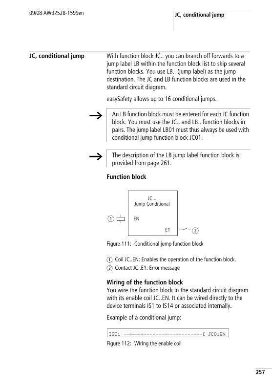
JC, conditional jump09/08 AWB2528-1599en
JC, conditional jump With function block JC.. you can branch off forwards to a jump label LB within the function block list to skip several function blocks. You use LB.. (jump label) as the jump destination. The JC and LB function blocks are used in the standard circuit diagram.
easySafety allows up to 16 conditional jumps.
Function block
Figure 111: Conditional jump function block
a Coil JC..EN: Enables the operation of the function block.b Contact JC..E1: Error message
Wiring of the function blockYou wire the function block in the standard circuit diagram with its enable coil JC..EN. It can be wired directly to the device terminals IS1 to IS14 or associated internally.
Example of a conditional jump:
Figure 112: Wiring the enable coil
h An LB function block must be entered for each JC function block. You must use the JC.. and LB.. function blocks in pairs. The jump label LB01 must thus always be used with conditional jump function block JC01.
h The description of the LB jump label function block is provided from page 261.
EN
E1
JC...Jump Conditional
a
b
IS01 ---------------------------Ä JC01EN
257
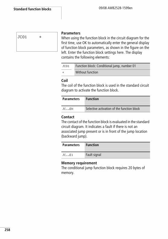
Standard function blocks
258
09/08 AWB2528-1599en
ParametersWhen using the function block in the circuit diagram for the first time, use OK to automatically enter the general display of function block parameters, as shown in the figure on the left. Enter the function block settings here. The display contains the following elements:
CoilThe coil of the function block is used in the standard circuit diagram to activate the function block.
ContactThe contact of the function block is evaluated in the standard circuit diagram. It indicates a fault if there is not an associated jump present or is in front of the jump location (backward jump).
Memory requirementThe conditional jump function block requires 20 bytes of memory.
JC01 +
JC01 Function block: Conditional jump, number 01
+ Without function
Parameters Function
JC..EN Selective activation of the function block
Parameters Function
JC..E1 Fault signal
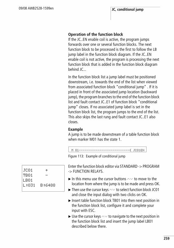
JC, conditional jump09/08 AWB2528-1599en
Operation of the function blockIf the JC..EN enable coil is active, the program jumps forwards over one or several function blocks. The next function block to be processed is the first to follow the LB jump label in the function block diagram. If the JC..EN enable coil is not active, the program is processing the next function block that is added in the function block diagram behind JC...
In the function block list a jump label must be positioned downstream, i.e. towards the end of the list when viewed from associated function block “conditional jump” . If it is placed in front of the associated jump location (backward jump), the program branches to the end of the function block list and fault contact JC..E1 of function block “conditional jump” closes. If no associated jump label is set in the function block list, the program jumps to the end of the list. This also skips the last rung and fault contact JC..E1 also closes.
Example A jump is to be made downstream of a table function block when marker M01 has the state 1.
Figure 113: Example of conditional jump
Enter the function block editor via STANDARD -> PROGRAM -> FUNCTION RELAYS.
X In this menu use the cursor buttons ÍÚ to move to the location from where the jump is to be made and press OK.
X Then use the cursor keys ÍÚ to select function block JC01 and close the input dialog with two clicks on OK.
X Insert table function block TB01 into then next position in the function block list, configure it and complete your input with ESC.
X Use the cursor keys ÍÚ to navigate to the next position in the function block list and insert the jump label LB01 described below there.
M 01---------------------------Ä JC01EN
JC01 +
TB01 -
LB01
L:031 B:6488
259
Standard function blocks
260
09/08 AWB2528-1599en
During processing the program branches off to jump label LB01 as long as JC01EN remains in state 1.
h For subsequently inserting function block JC.. in the function block list to skip other, existing function blocks, the use of the easySoft Safety configuration software is recommended. This software allows function blocks to be moved into any position.
LB, jump label09/08 AWB2528-1599en
LB, jump label Within the function block list jump label LB.. is the jump target for a conditional jump with function block JC.. . In the standard circuit diagram function blocks JC and LB are always used in pairs.
easySafety allows the use of up to 16 jump labels.
Function blockBecause function block LB.. acts only as a jump target, it does not have to be linked in the circuit diagram and does not have to be parameterized. It has neither coils nor contacts and is simply placed at the required position in the function block list.
In the function block list a jump label must be positioned downstream, i.e. towards the end of the list when viewed from associated function block “conditional jump”. If it is placed in front of the associated jump location (backward jump), the program branches to the end of the function block list and fault contact JC..E1 of function block “conditional jump” closes. If no associated jump label is set in the function block list, the program jumps to the end of the list and fault contact JC..E1 also closes.
Enter the function block editor from the main menu via STANDARD -> PROGRAM -> FUNCTION RELAYS.
X In this menu use the cursor buttons ÍÚ to move to the location to which the jump is to be made and press OK.
X Then use the cursor keys ÍÚ to select function block LB.. and close the input dialog with two clicks on OK.
The description of the JC function block, conditional jump, is provided from a chapter “JC, conditional jump” on page 257. This also contains an example.
h For each function block LB.. a corresponding function block JC.. (conditional jump) must exist as jumping-off point. Conditional jump JC01, for example, is always associated with jump label LB01.
261
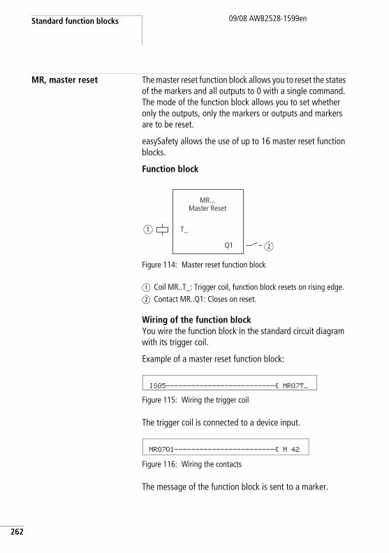
Standard function blocks
262
09/08 AWB2528-1599en
MR, master reset The master reset function block allows you to reset the states of the markers and all outputs to 0 with a single command. The mode of the function block allows you to set whether only the outputs, only the markers or outputs and markers are to be reset.
easySafety allows the use of up to 16 master reset function blocks.
Function block
Figure 114: Master reset function block
a Coil MR..T_: Trigger coil, function block resets on rising edge.b Contact MR..Q1: Closes on reset.
Wiring of the function blockYou wire the function block in the standard circuit diagram with its trigger coil.
Example of a master reset function block:
Figure 115: Wiring the trigger coil
The trigger coil is connected to a device input.
Figure 116: Wiring the contacts
The message of the function block is sent to a marker.
T_
Q1
MR...Master Reset
a
b
IS05--------------------------Ä MR07T_
MR07Q1------------------------Ä M 42
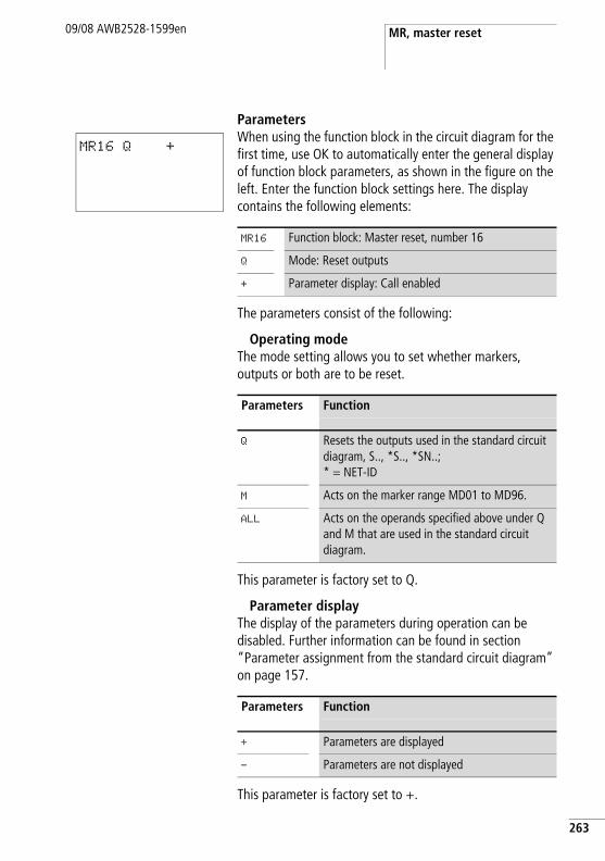
MR, master reset09/08 AWB2528-1599en
ParametersWhen using the function block in the circuit diagram for the first time, use OK to automatically enter the general display of function block parameters, as shown in the figure on the left. Enter the function block settings here. The display contains the following elements:
The parameters consist of the following:
Operating modeThe mode setting allows you to set whether markers, outputs or both are to be reset.
This parameter is factory set to Q.
Parameter displayThe display of the parameters during operation can be disabled. Further information can be found in section “Parameter assignment from the standard circuit diagram” on page 157.
This parameter is factory set to +.
MR16 Q +
MR16 Function block: Master reset, number 16
Q Mode: Reset outputs
+ Parameter display: Call enabled
Parameters Function
Q Resets the outputs used in the standard circuit diagram, S.., *S.., *SN..;* = NET-ID
M Acts on the marker range MD01 to MD96.
ALL Acts on the operands specified above under Q and M that are used in the standard circuit diagram.
Parameters Function
+ Parameters are displayed
- Parameters are not displayed
263
Standard function blocks
264
09/08 AWB2528-1599en
CoilThe coil of the function block is used in the standard circuit diagram.
ContactThe contact of the function block is evaluated in the standard circuit diagram. A closed contact indicates:
Memory requirementThe master reset function block requires 20 bytes of memory.
Operation of the function blockAll outputs or the markers are set to 0 in accordance with the operating mode when a rising edge is detected on the trigger coil.
The contact MR1..Q1 assumes the state of its own trigger coil and confirms the reset operation.
Parameters Function
MR..T_ Triggering the function on a rising edge
Parameters Function
MR..Q1 Reset
h Carry out the master reset function block so that all data ranges are cleared reliably. Otherwise subsequent function blocks may overwrite the data ranges.
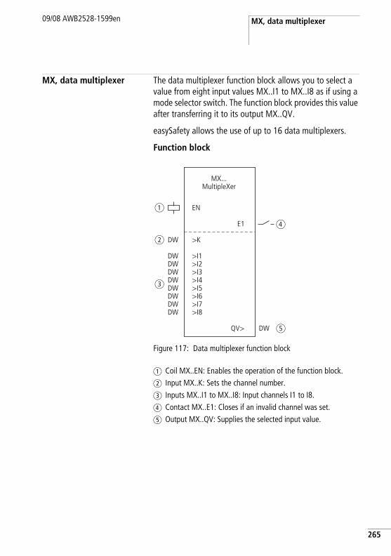
MX, data multiplexer09/08 AWB2528-1599en
MX, data multiplexer The data multiplexer function block allows you to select a value from eight input values MX..I1 to MX..I8 as if using a mode selector switch. The function block provides this value after transferring it to its output MX..QV.
easySafety allows the use of up to 16 data multiplexers.
Function block
Figure 117: Data multiplexer function block
a Coil MX..EN: Enables the operation of the function block.b Input MX..K: Sets the channel number.c Inputs MX..I1 to MX..I8: Input channels I1 to I8.d Contact MX..E1: Closes if an invalid channel was set.e Output MX..QV: Supplies the selected input value.
EN
>K
E1
QV>
MX...MultipleXer
>I1>I2>I3>I4>I5>I6>I7>I8DW
DWDWDWDWDWDWDW
DW
DW
a
b
c
e
d
265
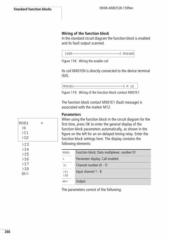
Standard function blocks
266
09/08 AWB2528-1599en
Wiring of the function blockIn the standard circuit diagram the function block is enabled and its fault output scanned.
Figure 118: Wiring the enable coil
Its coil MX01EN is directly connected to the device terminal IS05.
L
Figure 119: Wiring of the function block contact MX01E1
The function block contact MX01E1 (fault message) is associated with the marker M12.
ParametersWhen using the function block in the circuit diagram for the first time, press OK to enter the general display of the function block parameters automatically, as shown in the figure on the left for an on-delayed timing relay. Enter the function block settings here. The display contains the following elements:
The parameters consist of the following:
IS05--------------------------Ä MX01EN
MX01E1---------------------------Ä M 12
MX01 +
>K
>I1
>I2
>I3
>I4
>I5
>I6
>I7
>I8
QV>
MX01 Function block; Data multiplexer, number 01
+ Parameter display: Call enabled
>K Channel number (0 - 7)
>I1
>I8
Input channel 1 - 8
QV> Output
MX, data multiplexer09/08 AWB2528-1599en
Parameter displayThe display of the parameters during operation can be disabled. Further information can be found in section “Parameter assignment from the standard circuit diagram” on page 157.
This parameter is factory set to +.
InputsFunction block input >K is used to define the input channel to be supplied at function block output QV>.
Assign the values to function block inputs >I1 to >I8 that you wish to output on function block output QV>.
The function block inputs >K and >I1 and >I8 can have the following operands:
• Constant.• Markers MD, MW, MB.• Output …QV> of a different function block.
Parameters Function
+ Parameters are displayed
- Parameters are not displayed
Parameters Function
>K Channel number (0 - 7)
>I1…>I8 Input value 1-8: - 2147483648 - +2147483647
267
Standard function blocks
268
09/08 AWB2528-1599en
OutputThe output QV> supplies the value present at the selected input channel.
The function block output MX..QV can have the following operands:
• Markers MD, MW, MB.
CoilThe coil MX..EN is used to activate the function block in the standard circuit diagram.
ContactThe contact of the function block is evaluated in the standard circuit diagram. A closed contact indicates:
Memory requirementThe data multiplexer function block requires 96 bytes of memory plus 4 bytes per constant at the function block inputs.
Parameters Function, parameterisation in the function block
QV> Output value: - 2147483648 - +2147483647
Coil Function
MX..EN Activation of the function block
Parameters Function
MX..E1 Fault, e.g. invalid parameter
MX, data multiplexer09/08 AWB2528-1599en
Operation of the function blockThe multiplexer is active if the enable coil MX..EN has been triggered.
You use the channel number input MX..K to set which input is to be switched through to the output. The channel number input switches the input values in their order, i.e.:
• Channel number 0 supplies the input MX..I1 to MX..QV.• Channel number 7 supplies the input MX..I8 to MX..QV.
The fault contact MX..E1 closes if an invalid parameter is present at the channel number input MX..K.
Example A drive is required to run at a fixed speed and at three dependent speeds.
It receives the setting from a multiplexer function block.
MB08 defines the channel number that is to be passed onto the output. The fixed speed is set as a constant at input MX01I1, the subsequent inputs are assigned the variable values from markers MB01 to B03. The setpoints at output MX01QV of the function block are output at MB04.
The function block is first of all activated in the standard circuit diagram by marker M33. The following diagram shows the association.
L
Figure 120:Circuit diagram for enabling the data multiplexer function block
M 33---------------------------Ä MX01EN
269
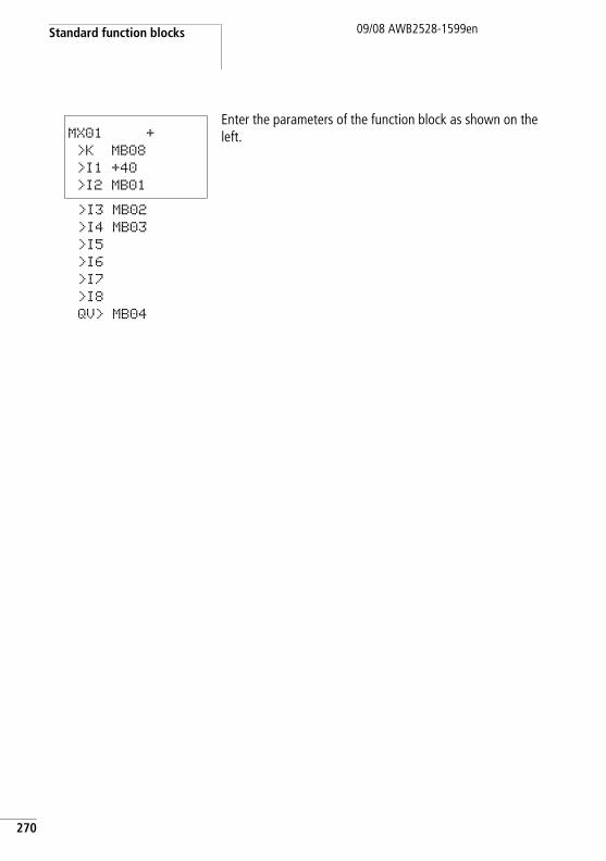
Standard function blocks
270
09/08 AWB2528-1599en
Enter the parameters of the function block as shown on the left.MX01 +
>K MB08
>I1 +40
>I2 MB01
>I3 MB02
>I4 MB03
>I5
>I6
>I7
>I8
QV> MB04
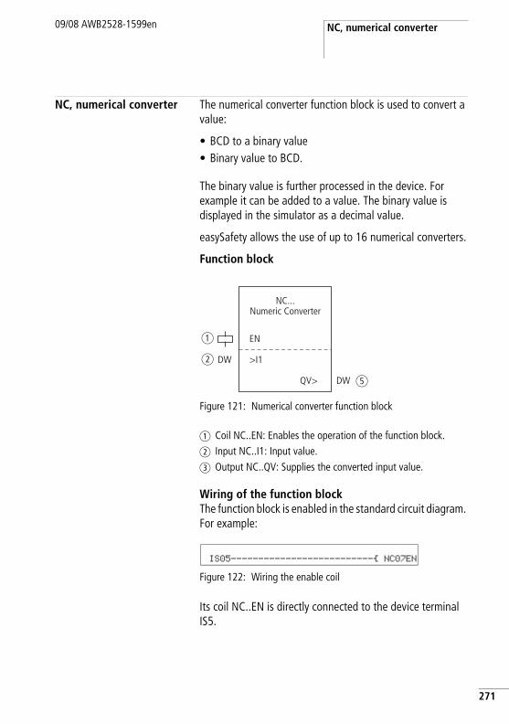
NC, numerical converter09/08 AWB2528-1599en
NC, numerical converter The numerical converter function block is used to convert a value:
• BCD to a binary value• Binary value to BCD.
The binary value is further processed in the device. For example it can be added to a value. The binary value is displayed in the simulator as a decimal value.
easySafety allows the use of up to 16 numerical converters.
Function block
Figure 121: Numerical converter function block
a Coil NC..EN: Enables the operation of the function block.b Input NC..I1: Input value.c Output NC..QV: Supplies the converted input value.
Wiring of the function blockThe function block is enabled in the standard circuit diagram. For example:
Figure 122: Wiring the enable coil
Its coil NC..EN is directly connected to the device terminal IS5.
EN
NC...Numeric Converter
>I1
QV>
DW
DW
a
b
e
IS05--------------------------Ä NC07EN
271
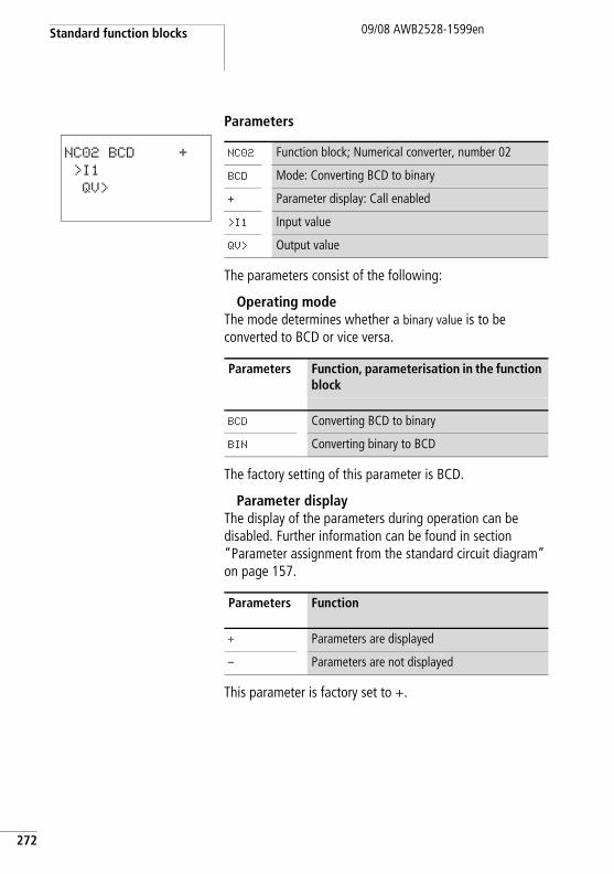
Standard function blocks
272
09/08 AWB2528-1599en
Parameters
The parameters consist of the following:
Operating modeThe mode determines whether a binary value is to be converted to BCD or vice versa.
The factory setting of this parameter is BCD.
Parameter displayThe display of the parameters during operation can be disabled. Further information can be found in section “Parameter assignment from the standard circuit diagram” on page 157.
This parameter is factory set to +.
NC02 BCD +
>I1
QV>
NC02 Function block; Numerical converter, number 02
BCD Mode: Converting BCD to binary
+ Parameter display: Call enabled
>I1 Input value
QV> Output value
Parameters Function, parameterisation in the function block
BCD Converting BCD to binary
BIN Converting binary to BCD
Parameters Function
+ Parameters are displayed
- Parameters are not displayed
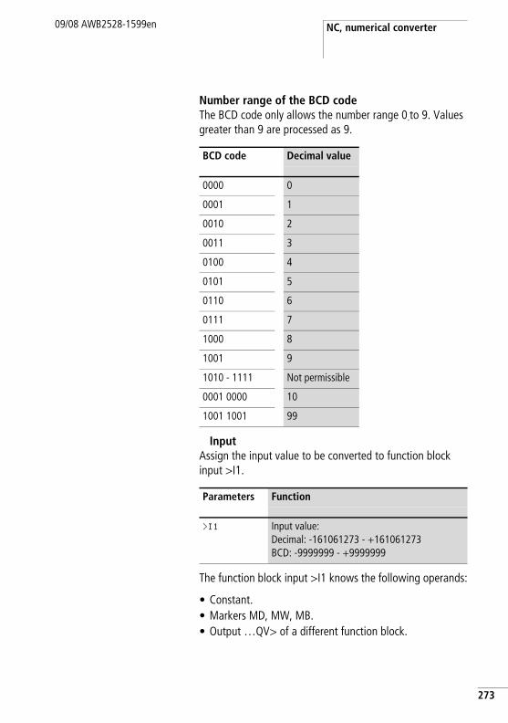
NC, numerical converter09/08 AWB2528-1599en
Number range of the BCD codeThe BCD code only allows the number range 0.to 9. Values greater than 9 are processed as 9.
InputAssign the input value to be converted to function block input >I1.
The function block input >I1 knows the following operands:
• Constant.• Markers MD, MW, MB.• Output …QV> of a different function block.
BCD code Decimal value
0000 0
0001 1
0010 2
0011 3
0100 4
0101 5
0110 6
0111 7
1000 8
1001 9
1010 - 1111 Not permissible
0001 0000 10
1001 1001 99
Parameters Function
>I1 Input value:Decimal: -161061273 - +161061273BCD: -9999999 - +9999999
273
Standard function blocks
274
09/08 AWB2528-1599en
OutputOutput QV> supplies the converted value.
The function block register output NC..QV can have the following operands:
• Markers MD, MW, MB.
CoilThe coil NC..EN is used to activate the function block in the standard circuit diagram. If coil NC..EN is not active, the entire function block is deactivated and reset. The output value is set to zero.
Memory requirementThe numerical converter function block requires 32 bytes of memory plus 4 bytes per constant at the function block input.
Operation of the function blockBCD mode
The BCD value present at input I1 is converted to a binary value and supplied on the output QV>. The binary value is displayed as a decimal value.
Example 1:Input value >I1: +9decBinary value: 1001Decimal value QV>: + 9
Parameters Function, parameterisation in the function block
QV> Output value:Decimal: -161061273 - +161061273BCD: -9999999 - +9999999
Coil Function
NC..EN Selective activation of the function block
NC, numerical converter09/08 AWB2528-1599en
Example 2:Input value >I1: +14decBinary value: 1110Decimal value QV>: + 9
Example 3:Input value >I1: 19decBinary value: 00010011Decimal value QV>: 13
Example 4:Input value >I1: 161061273decBinary value: 1001100110011001100110011001Decimal value QV>: 9999999
Example 5:Input value >I1: -61673decBinary value: 10000000000000001111000011101001Decimal value QV>: -9099
Example 6:Input value >I1: 2147483647decBinary value: 01111111111111111111111111111111Decimal value QV>: 9999999
h Bit 32 is the sign bit. Bit 32 = 1 r Sign = Minus.
h Values greater than 161061273 are output as 9999999. Values less than –161061273 are output as –9999999. The working range of the function block has been exceeded.
275
Standard function blocks
276
09/08 AWB2528-1599en
BIN modeThe binary value present at input >I1 is converted to a BCD value and supplied at the output QV>. The binary value is displayed as a decimal value.
Example 1:Input value >I1: +7decBCD binary value: 0111Hexadecimal value: 0111Decimal value QV>: + 7
Example 2:Input value >I1: +11decBCD binary value: 00010001Hexadecimal value: 00010001Decimal value QV>: +17 (1 + 16)
Hexadecimal value:Bit 0 has the value 1. Bit 4 has the value 16 Total: Bit 0 plus bit 4 = 17
Example 3:Input value >I1: 19decBCD binary value: 00011001Hexadecimal value: 00011001Decimal value QV>: 25 (1 + 8 + 16)
Example 4:Input value >I1: 9999999decBCD binary value: 1001100110011001100110011001Hexadecimal value: 1001100110011001100110011001Decimal value QV>: + 161061273
NC, numerical converter09/08 AWB2528-1599en
Example 5:Input value >I1: -61673decBCD binary value: 10000000000001100001011001110011Hexadecimal value: 10000000000001100001011001110011Decimal value QV>: + -398963
Example 6:Input value >I1: 2147483647decBCD binary value: 01111111111111111111111111111111Hexadecimal value: 01111111111111111111111111111111Decimal value QV>: + 161061273
h Bit 32 is the sign bit. Bit 32 = 1 r Sign = Minus.
h Values greater than 9999999 are output as 161061273. Values less than –9999999 are output as –161061273. The working range of the function block has been exceeded.
277
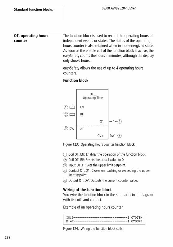
Standard function blocks
278
09/08 AWB2528-1599en
OT, operating hours counter
The function block is used to record the operating hours of independent events or states. The status of the operating hours counter is also retained when in a de-energized state. As soon as the enable coil of the function block is active, the easySafety counts the hours in minutes, although the display only shows hours.
easySafety allows the use of up to 4 operating hours counters.
Function block
Figure 123: Operating hours counter function block
a Coil OT..EN: Enables the operation of the function block.b Coil OT..RE: Resets the actual value to 0.c Input OT..I1: Sets the upper limit setpoint.d Contact OT..Q1: Closes on reaching or exceeding the upper
limit setpoint.e Output OT..QV: Outputs the current counter value.
Wiring of the function blockYou wire the function block in the standard circuit diagram with its coils and contact.
Example of an operating hours counter:
Figure 124: Wiring the function block coils
EN
OT...Operating Time
a
b
c
d
e
RE
Q1
>I1
QV>
DW
DW
IS10-----------------------------Ä OT03EN M 42-----------------------------Ä OT03RE
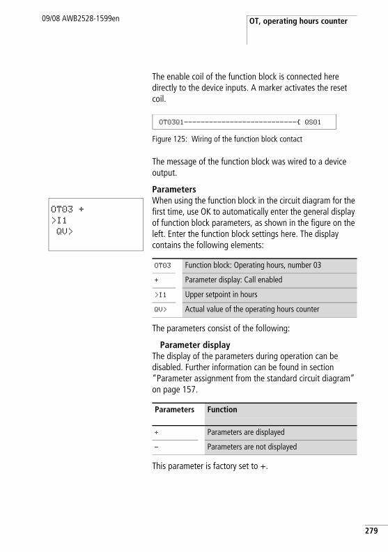
OT, operating hours counter09/08 AWB2528-1599en
The enable coil of the function block is connected here directly to the device inputs. A marker activates the reset coil.
Figure 125: Wiring of the function block contact
The message of the function block was wired to a device output.
ParametersWhen using the function block in the circuit diagram for the first time, use OK to automatically enter the general display of function block parameters, as shown in the figure on the left. Enter the function block settings here. The display contains the following elements:
The parameters consist of the following:
Parameter displayThe display of the parameters during operation can be disabled. Further information can be found in section “Parameter assignment from the standard circuit diagram” on page 157.
This parameter is factory set to +.
OT03Q1---------------------------Ä QS01
OT03 +
>I1
QV>
OT03 Function block: Operating hours, number 03
+ Parameter display: Call enabled
>I1 Upper setpoint in hours
QV> Actual value of the operating hours counter
Parameters Function
+ Parameters are displayed
- Parameters are not displayed
279
Standard function blocks
280
09/08 AWB2528-1599en
InputThe >I1 block input is used to specify the upper setpoint value in hours. When it is reached, the block contact sends a signal.
The function block input >I1 can be assigned the following operands:
• Constant.• Markers MD, MW, MB.• Output …QV> of a different function block.
OutputThe output QV> supplies the counted operating hours as an integer value in hours.
You can assign the following operands to output …QV>:
• Markers MD, MW, MB
CoilsThe enable coil starts the function block.
The reset coil resets the operating hours counter to zero.
Parameters Function
>I1 Upper setpoint: 0 hours - > 100 years
Parameters Function
QV> Operating hours: 0 hours - > 100 years
Parameters Function
OT..EN Selective activation of the function block
OT..RE Reset the counter to zero
OT, operating hours counter09/08 AWB2528-1599en
ContactThe contact of the function block is evaluated in the standard circuit diagram. A closed contact indicates:
Memory requirementThe operating hours counter function block requires 36 bytes of memory plus 4 bytes per constant at the function block input.
Operation of the function blockIf the enable coil OT…EN is triggered to the 1 state, the counter adds the value 1 to its actual value every minute (basic clock rate: 1 minute).
If the actual value on QV> reaches the setpoint value of >I1, the contact OT…Q1 switches for as long as the actual value is greater than or equal to the setpoint value.
The actual value is retained in the unit until the reset coil OT…RE is actuated. The actual value is then set to zero.
AccuracyThe operating hours counter is accurate to the nearest minute. If the enable coil signal is terminated within a minute, the value for seconds is lost.
The value range of the operating hours counter is between 0 hours and 100 years.
Parameters Function
OT..Q1 Reaching or exceeding the upper limit setpoint
h The following operations do not clear the actual value of the operating hours counter: Operating mode change RUN, STOP, power ON, OFF, Delete program, Change program, Load new program.
281
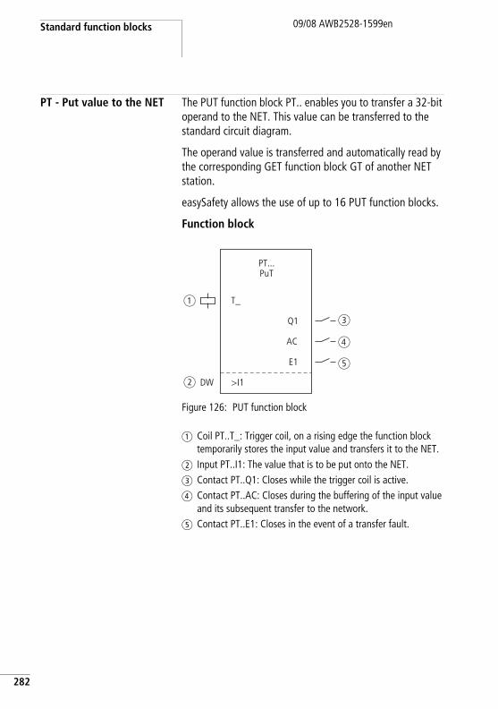
Standard function blocks
282
09/08 AWB2528-1599en
PT - Put value to the NET The PUT function block PT.. enables you to transfer a 32-bit operand to the NET. This value can be transferred to the standard circuit diagram.
The operand value is transferred and automatically read by the corresponding GET function block GT of another NET station.
easySafety allows the use of up to 16 PUT function blocks.
Function block
Figure 126: PUT function block
a Coil PT..T_: Trigger coil, on a rising edge the function block temporarily stores the input value and transfers it to the NET.
b Input PT..I1: The value that is to be put onto the NET.c Contact PT..Q1: Closes while the trigger coil is active.d Contact PT..AC: Closes during the buffering of the input value
and its subsequent transfer to the network.e Contact PT..E1: Closes in the event of a transfer fault.
T_
PT...PuT
a
b
c
d
e
Q1
>I1
AC
E1
DW
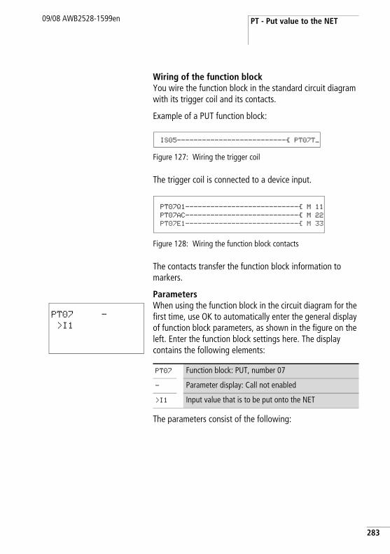
PT - Put value to the NET09/08 AWB2528-1599en
Wiring of the function blockYou wire the function block in the standard circuit diagram with its trigger coil and its contacts.
Example of a PUT function block:
Figure 127: Wiring the trigger coil
The trigger coil is connected to a device input.
Figure 128: Wiring the function block contacts
The contacts transfer the function block information to markers.
ParametersWhen using the function block in the circuit diagram for the first time, use OK to automatically enter the general display of function block parameters, as shown in the figure on the left. Enter the function block settings here. The display contains the following elements:
The parameters consist of the following:
IS05--------------------------Ä PT07T_
PT07Q1---------------------------Ä M 11 PT07AC---------------------------Ä M 22 PT07E1---------------------------Ä M 33
PT07 -
>I1
PT07 Function block: PUT, number 07
- Parameter display: Call not enabled
>I1 Input value that is to be put onto the NET
283
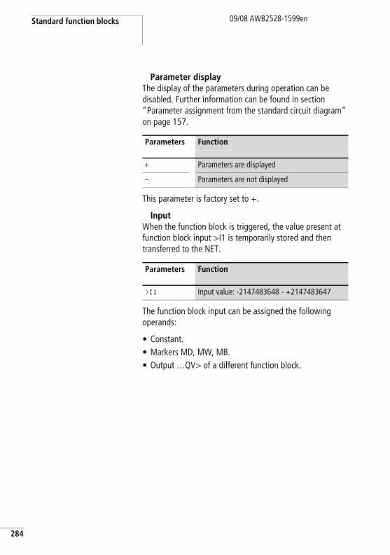
Standard function blocks
284
09/08 AWB2528-1599en
Parameter displayThe display of the parameters during operation can be disabled. Further information can be found in section “Parameter assignment from the standard circuit diagram” on page 157.
This parameter is factory set to +.
InputWhen the function block is triggered, the value present at function block input >I1 is temporarily stored and then transferred to the NET.
The function block input can be assigned the following operands:
• Constant.• Markers MD, MW, MB.• Output …QV> of a different function block.
Parameters Function
+ Parameters are displayed
- Parameters are not displayed
Parameters Function
>I1 Input value: -2147483648 - +2147483647
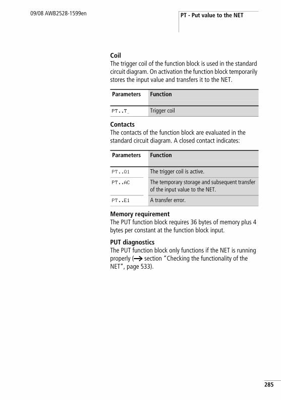
PT - Put value to the NET09/08 AWB2528-1599en
CoilThe trigger coil of the function block is used in the standard circuit diagram. On activation the function block temporarily stores the input value and transfers it to the NET.
ContactsThe contacts of the function block are evaluated in the standard circuit diagram. A closed contact indicates:
Memory requirementThe PUT function block requires 36 bytes of memory plus 4 bytes per constant at the function block input.
PUT diagnosticsThe PUT function block only functions if the NET is running properly (a section “Checking the functionality of the NET”, page 533).
Parameters Function
PT..T_ Trigger coil
Parameters Function
PT..Q1 The trigger coil is active.
PT..AC The temporary storage and subsequent transfer of the input value to the NET.
PT..E1 A transfer error.
285
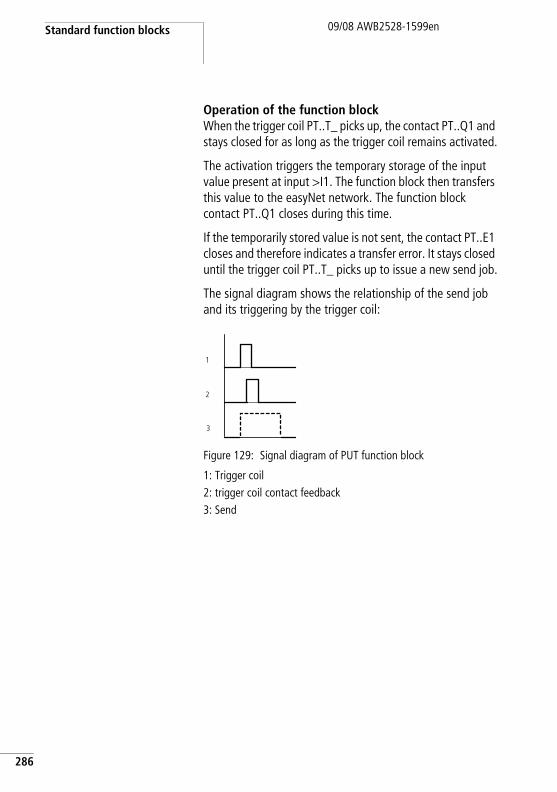
Standard function blocks
286
09/08 AWB2528-1599en
Operation of the function blockWhen the trigger coil PT..T_ picks up, the contact PT..Q1 and stays closed for as long as the trigger coil remains activated.
The activation triggers the temporary storage of the input value present at input >I1. The function block then transfers this value to the easyNet network. The function block contact PT..Q1 closes during this time.
If the temporarily stored value is not sent, the contact PT..E1 closes and therefore indicates a transfer error. It stays closed until the trigger coil PT..T_ picks up to issue a new send job.
The signal diagram shows the relationship of the send job and its triggering by the trigger coil:
Figure 129: Signal diagram of PUT function block
1: Trigger coil2: trigger coil contact feedback3: Send
1
2
3
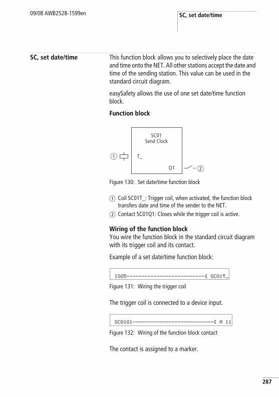
SC, set date/time09/08 AWB2528-1599en
SC, set date/time This function block allows you to selectively place the date and time onto the NET. All other stations accept the date and time of the sending station. This value can be used in the standard circuit diagram.
easySafety allows the use of one set date/time function block.
Function block
Figure 130: Set date/time function block
a Coil SC01T_: Trigger coil, when activated, the function block transfers date and time of the sender to the NET.
b Contact SC01Q1: Closes while the trigger coil is active.
Wiring of the function blockYou wire the function block in the standard circuit diagram with its trigger coil and its contact.
Example of a set date/time function block:
Figure 131: Wiring the trigger coil
The trigger coil is connected to a device input.
Figure 132: Wiring of the function block contact
The contact is assigned to a marker.
T_
SC01Send Clock
Q1
a
b
IS05--------------------------Ä SC01T_
SC01Q1---------------------------Ä M 11
287
Standard function blocks
288
09/08 AWB2528-1599en
ParametersThis function block is a triggerable system service. It therefore does not have any parameters.
CoilThe trigger coil of the function block is used in the standard circuit diagram.
ContactThe contact of the function block is evaluated in the standard circuit diagram. A closed contact indicates:
Memory requirementThe SC function block requires 20 bytes of memory.
SC diagnosticsThe SC function block only functions if the NET is running properly (a section “Checking the functionality of the NET”, page 533).
Operation of the function blockIf the trigger coil of the function block is activated, the current date, the day of the week and time from the sending station is automatically put onto the NET. The sending stations executes this operation as soon as a new minute starts on the device real-time clock. The other stations accept this value.
Example: The trigger pulse is actuated at 03:32:21 (hh:mm:ss). The other stations are synchronised at 03:33:00. This time is accessed by all other stations. This process can be repeated as often as desired.
Accuracy of time synchronisationThe maximum time deviation between the functional stations is 5 s.
Parameters Function
SC01T_ Trigger coil
Parameters Function
SC01Q1 while the trigger coil is active.
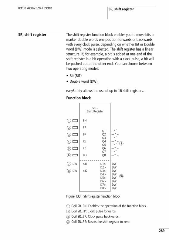
SR, shift register09/08 AWB2528-1599en
SR, shift register The shift register function block enables you to move bits or marker double words one position forwards or backwards with every clock pulse, depending on whether Bit or Double word (DW) mode is selected. The shift register has a linear structure. If, for example, a bit is added at one end of the shift register in a bit operation with a clock pulse, a bit will be pushed out at the other end. You can choose between two operating modes:
• Bit (BIT).• Double word (DW).
easySafety allows the use of up to 16 shift registers.
Function block
Figure 133: Shift register function block
a Coil SR..EN: Enables the operation of the function block.b Coil SR..FP: Clock pulse forwards.c Coil SR..BP: Clock pulse backwards.d Coil SR..RE: Resets the shift register to zero.
SR...Shift Register
EN
RE
BP
FPQ1Q2Q3Q4Q5Q6Q7Q8
D1>D2>D3>D4>D5>D6>D7>D8>
>I1
>I2
FD
BD
DW
DW
DWDWDWDWDWDWDWDW
a
b
c
d
e
f
g
h
i
j
289
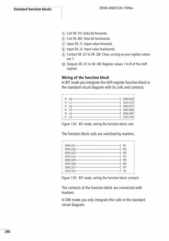
Standard function blocks
290
09/08 AWB2528-1599en
e Coil SR..FD: Data bit forwards.f Coil SR..BD: Data bit backwards.g Input SR..I1: Input value forwards.h Input SR..I2: Input value backwards.i Contact SR..Q1 to SR..Q8: Close, as long as your register values
are 1.j Outputs SR..D1 to SR..D8: Register values 1 to 8 of the shift
register.
Wiring of the function blockIn BIT mode you integrate the shift register function block in the standard circuit diagram with its coils and contacts:
Figure 134: BIT mode, wiring the function block coils
The function block coils are switched by markers.
Figure 135: BIT mode, wiring the function block contacts
The contacts of the function block are connected with markers.
In DW mode you only integrate the coils in the standard circuit diagram:
M 10--------------------------Ä SR01EN M 11--------------------------Ä SR01FD M 12--------------------------Ä SR01FP M 13--------------------------Ä SR01BD M 14--------------------------Ä SR01BP M 15--------------------------Ä SR01RE
SR01Q1------------------------Ä M1 SR01Q2------------------------Ä M2 SR01Q3------------------------Ä M3 SR01Q4------------------------Ä M4 SR01Q5------------------------Ä M5 SR01Q6------------------------Ä M6 SR01Q7------------------------Ä M7 SR01Q8------------------------Ä M8
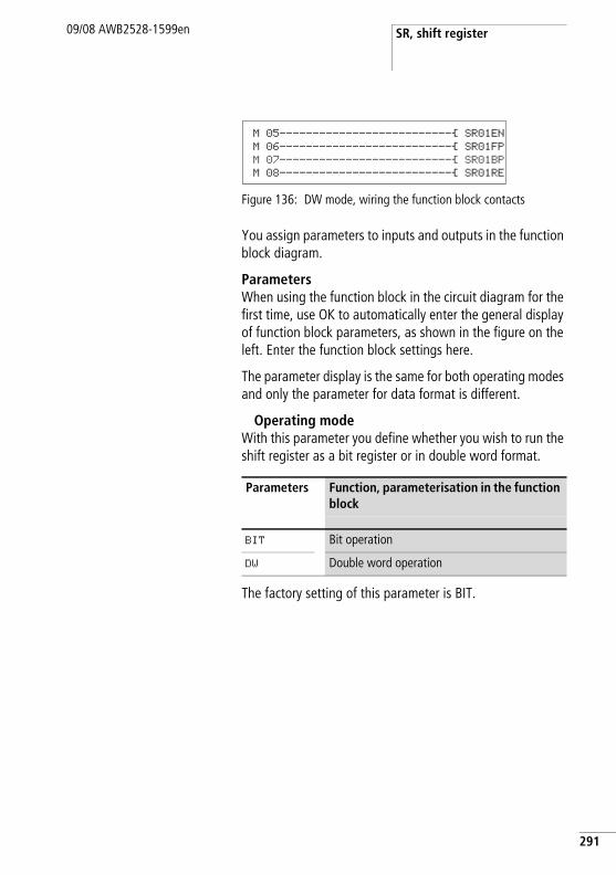
SR, shift register09/08 AWB2528-1599en
Figure 136: DW mode, wiring the function block contacts
You assign parameters to inputs and outputs in the function block diagram.
ParametersWhen using the function block in the circuit diagram for the first time, use OK to automatically enter the general display of function block parameters, as shown in the figure on the left. Enter the function block settings here.
The parameter display is the same for both operating modes and only the parameter for data format is different.
Operating modeWith this parameter you define whether you wish to run the shift register as a bit register or in double word format.
The factory setting of this parameter is BIT.
Parameters Function, parameterisation in the function block
BIT Bit operation
DW Double word operation
M 05--------------------------Ä SR01EN M 06--------------------------Ä SR01FP M 07--------------------------Ä SR01BP M 08--------------------------Ä SR01RE
291
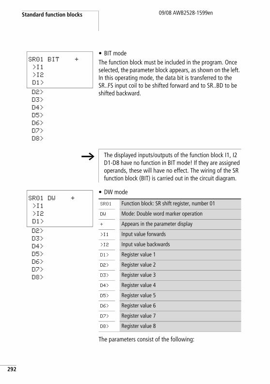
Standard function blocks
292
09/08 AWB2528-1599en
• BIT modeThe function block must be included in the program. Once selected, the parameter block appears, as shown on the left. In this operating mode, the data bit is transferred to the SR..FS input coil to be shifted forward and to SR..BD to be shifted backward.
• DW mode
The parameters consist of the following:
SR01 BIT +
>I1
>I2
D1>
D2>
D3>
D4>
D5>
D6>
D7>
D8>
h The displayed inputs/outputs of the function block I1, I2 D1-D8 have no function in BIT mode! If they are assigned operands, these will have no effect. The wiring of the SR function block (BIT) is carried out in the circuit diagram.
SR01 DW +
>I1
>I2
D1>
D2>
D3>
D4>
D5>
D6>
D7>
D8>
SR01 Function block: SR shift register, number 01
DW Mode: Double word marker operation
+ Appears in the parameter display
>I1 Input value forwards
>I2 Input value backwards
D1> Register value 1
D2> Register value 2
D3> Register value 3
D4> Register value 4
D5> Register value 5
D6> Register value 6
D7> Register value 7
D8> Register value 8
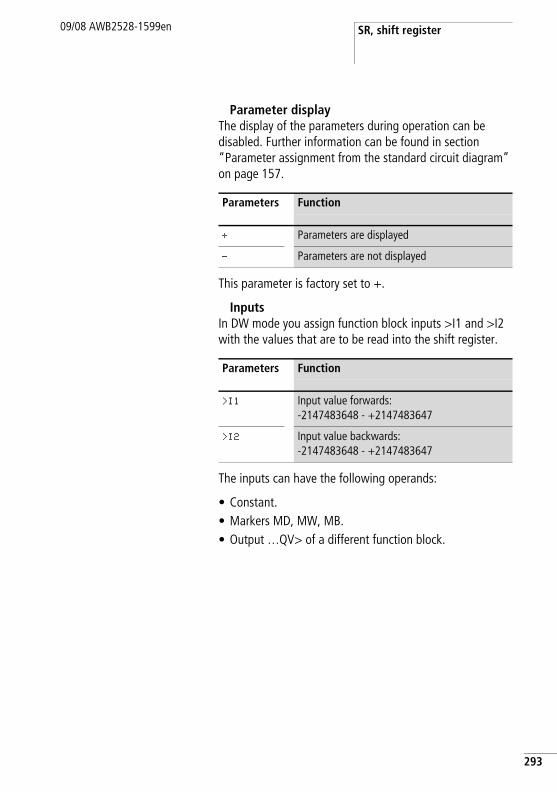
SR, shift register09/08 AWB2528-1599en
Parameter displayThe display of the parameters during operation can be disabled. Further information can be found in section “Parameter assignment from the standard circuit diagram” on page 157.
This parameter is factory set to +.
InputsIn DW mode you assign function block inputs >I1 and >I2 with the values that are to be read into the shift register.
The inputs can have the following operands:
• Constant.• Markers MD, MW, MB.• Output …QV> of a different function block.
Parameters Function
+ Parameters are displayed
- Parameters are not displayed
Parameters Function
>I1 Input value forwards:-2147483648 - +2147483647
>I2 Input value backwards:-2147483648 - +2147483647
293
Standard function blocks
294
09/08 AWB2528-1599en
OutputsLikewise, only in DW mode do the function block outputs D1> to D8> output register values 1 to 8.
The outputs can have the following operands:
• Markers MD, MW, MB.
CoilsThe coil SR..EN is used to activate the function block in the standard circuit diagram.
The forwards pulse input coil SR..FP triggers the following function when it is activated, depending on the mode:
The remaining content of the register is then moved forwards.
Parameters Function
D1>…D8> Register values 1 - 8:-2147483648 - +2147483647
Coil Function
SR..EN Selective activation of the function block
Coil Function
SR..FP BIT mode: Transfer of the data bit at input coil SR..FD to the register SR..Q1.DW mode: Transfer of the value SR..I1 to the register SR..D1.
SR, shift register09/08 AWB2528-1599en
The backwards pulse input coil SR..BP triggers the following function when it is activated, depending on the mode:
The remaining content of the register is then moved backwards.
The reset coil SR..RE causes the following in both directions:
ContactsFor the standard circuit diagram the function block in BIT mode has 8 contacts SR..Q1 to SR..Q8. A closed contact indicates:
Memory requirementThe SR function block requires 96 bytes of memory plus 4 bytes per constant at the function block input.
Coil Function
SR..BP BIT mode: Transfer of the data bit at input coil SR..BD to the register SR..Q8.DW mode: Transfer of the value SR..I2 to the register SR..D8.
Coil Function
SR..RE Reset of the register
Coil Function
SR..Q1 - SR..Q8
Output of the bit register fields 1 - 8
295
Standard function blocks
296
09/08 AWB2528-1599en
Operation of the function block
The shift register has a linear structure. This means that a clock pulse initiates the following actions:
• A new value/data bit is transferred to the register and the other data is moved one place further in the register.
• The value/data bit at the other end of the register is pushed out.
• Both shift directions, forwards and backwards, are possible.
The function block has two operating modes for different data formats:
• BIT for a bit data format• DW for a double word data format.
In BIT mode, the function block uses
• Input coils: SR..FD and SR..BD.• Register field contacts: SR..Q1 to SR..Q8.
In DW mode the function block processes inputs and outputs in double word format:
• Inputs SR..I1 and SR..I2• Outputs: SR..D1 to SR..D8.
SR..FD and SR..I1 are for data that the function block transfers to register Q1 or D1 in a forwards direction when SR..FP is activated.
The following two figures illustrate the process for forward shift operations in BIT and DW modes.
h The shift register function block must be enabled so that it can work, i.e. the coil SR..EN must be active. If this is not active, the entire function block is deactivated.
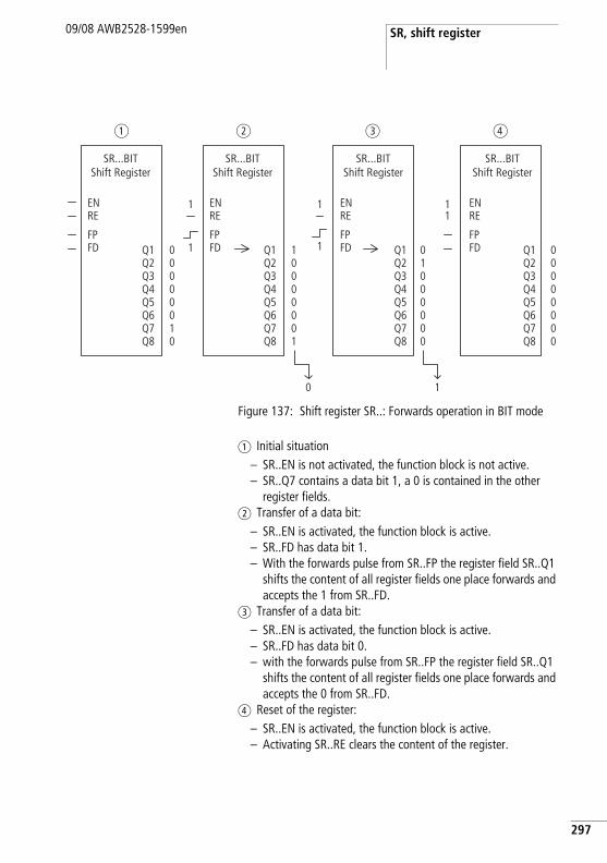
SR, shift register09/08 AWB2528-1599en
Figure 137: Shift register SR..: Forwards operation in BIT mode
a Initial situation– SR..EN is not activated, the function block is not active.– SR..Q7 contains a data bit 1, a 0 is contained in the other
register fields.b Transfer of a data bit:
– SR..EN is activated, the function block is active.– SR..FD has data bit 1.– With the forwards pulse from SR..FP the register field SR..Q1
shifts the content of all register fields one place forwards and accepts the 1 from SR..FD.
c Transfer of a data bit:– SR..EN is activated, the function block is active.– SR..FD has data bit 0.– with the forwards pulse from SR..FP the register field SR..Q1
shifts the content of all register fields one place forwards and accepts the 0 from SR..FD.
d Reset of the register:– SR..EN is activated, the function block is active.– Activating SR..RE clears the content of the register.
1
Q1Q2Q3Q4Q5Q6Q7Q8
Q1Q2Q3Q4Q5Q6Q7Q8
Q1Q2Q3Q4Q5Q6Q7Q8
00000000
01000000
10000001
00000010
a b c d
SR...BITShift Register
EN
SR...BITShift Register
ENRE
FPFD
RE
FPFD Q1
Q2Q3Q4Q5Q6Q7Q8
SR...BITShift Register
ENRE
FPFD
SR...BITShift Register
ENRE
FPFD1
1
1
1 11
0
297
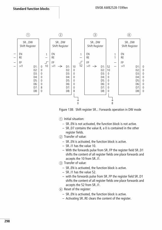
Standard function blocks
298
09/08 AWB2528-1599en
Figure 138: Shift register SR..: Forwards operation in DW mode
a Initial situation:– SR..EN is not activated, the function block is not active.– SR..D7 contains the value 8, a 0 is contained in the other
register fields.b Transfer of value:
– SR..EN is activated, the function block is active.– SR..I1 has the value 10.– With the forwards pulse from SR..FP the register field SR..D1
shifts the content of all register fields one place forwards and accepts the 10 from SR..I1.
c Transfer of value:– SR..EN is activated, the function block is active.– SR..I1 has the value 52.– with the forwards pulse from SR..FP the register field SR..D1
shifts the content of all register fields one place forwards and accepts the 52 from SR..I1.
d Reset of the register:– SR..EN is activated, the function block is active.– Activating SR..RE clears the content of the register.
D1:D2:D3:D4:D5:D6:D7:D8:
8
00000000
5210000000
100000008
00000080
a b c d
SR...DWShift Register
EN
SR...DWShift Register
ENRE
FP>I1
RE
FP>I1
SR...DWShift Register
ENRE
FP>I1
SR...DWShift Register
ENRE
FP>I110
1
52
1 11
0
D1:D2:D3:D4:D5:D6:D7:D8:
D1:D2:D3:D4:D5:D6:D7:D8:
D1:D2:D3:D4:D5:D6:D7:D8:
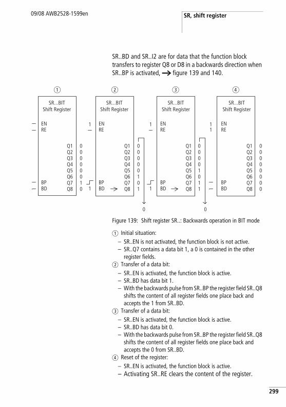
SR, shift register09/08 AWB2528-1599en
SR..BD and SR..I2 are for data that the function block transfers to register Q8 or D8 in a backwards direction when SR..BP is activated, a figure 139 and 140.
Figure 139: Shift register SR..: Backwards operation in BIT mode
a Initial situation:– SR..EN is not activated, the function block is not active.– SR..Q7 contains a data bit 1, a 0 is contained in the other
register fields.b Transfer of a data bit:
– SR..EN is activated, the function block is active.– SR..BD has data bit 1.– With the backwards pulse from SR..BP the register field SR..Q8
shifts the content of all register fields one place back and accepts the 1 from SR..BD.
c Transfer of a data bit:– SR..EN is activated, the function block is active.– SR..BD has data bit 0.– With the backwards pulse from SR..BP the register field SR..Q8
shifts the content of all register fields one place back and accepts the 0 from SR..BD.
d Reset of the register:– SR..EN is activated, the function block is active.– Activating SR..RE clears the content of the register.
Q1Q2Q3Q4Q5Q6Q7Q8
Q1Q2Q3Q4Q5Q6Q7Q8
Q1Q2Q3Q4Q5Q6Q7Q8
00000000
00001011
00000101
00000010
a b c d
SR...BITShift Register
EN
SR...BITShift Register
ENRE
BPBD
RE
BPBD
Q1Q2Q3Q4Q5Q6Q7Q8
SR...BITShift Register
ENRE
BPBD
SR...BITShift Register
ENRE
BPBD1
1
1
1 11
0 0
299
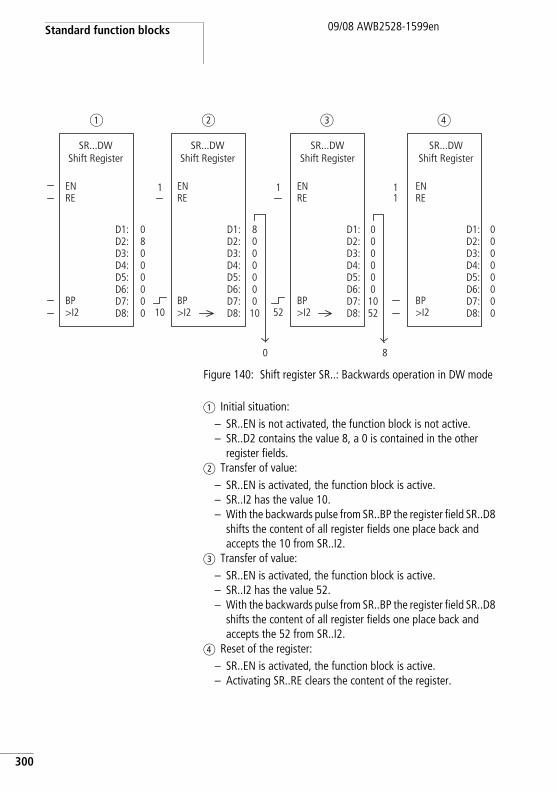
Standard function blocks
300
09/08 AWB2528-1599en
Figure 140: Shift register SR..: Backwards operation in DW mode
a Initial situation:– SR..EN is not activated, the function block is not active.– SR..D2 contains the value 8, a 0 is contained in the other
register fields.b Transfer of value:
– SR..EN is activated, the function block is active.– SR..I2 has the value 10.– With the backwards pulse from SR..BP the register field SR..D8
shifts the content of all register fields one place back and accepts the 10 from SR..I2.
c Transfer of value:– SR..EN is activated, the function block is active.– SR..I2 has the value 52.– With the backwards pulse from SR..BP the register field SR..D8
shifts the content of all register fields one place back and accepts the 52 from SR..I2.
d Reset of the register:– SR..EN is activated, the function block is active.– Activating SR..RE clears the content of the register.
00000000
D1:D2:D3:D4:D5:D6:D7:D8:
000000
1052
D1:D2:D3:D4:D5:D6:D7:D8:
8000000
10
D1:D2:D3:D4:D5:D6:D7:D8:
08000000
a b c d
SR...DWShift Register
EN
SR...DWShift Register
ENRE
BP>I2
RE
BP>I2
D1:D2:D3:D4:D5:D6:D7:D8:
SR...DWShift Register
ENRE
BP>I2
SR...DWShift Register
ENRE
BP>I210
1
52
1 11
0 8
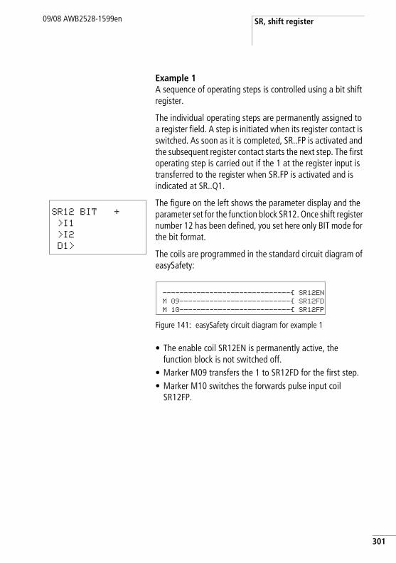
SR, shift register09/08 AWB2528-1599en
Example 1A sequence of operating steps is controlled using a bit shift register.
The individual operating steps are permanently assigned to a register field. A step is initiated when its register contact is switched. As soon as it is completed, SR..FP is activated and the subsequent register contact starts the next step. The first operating step is carried out if the 1 at the register input is transferred to the register when SR.FP is activated and is indicated at SR..Q1.
The figure on the left shows the parameter display and the parameter set for the function block SR12. Once shift register number 12 has been defined, you set here only BIT mode for the bit format.
The coils are programmed in the standard circuit diagram of easySafety:
Figure 141: easySafety circuit diagram for example 1
• The enable coil SR12EN is permanently active, the function block is not switched off.
• Marker M09 transfers the 1 to SR12FD for the first step.• Marker M10 switches the forwards pulse input coil
SR12FP.
SR12 BIT +
>I1
>I2
D1>
------------------------------Ä SR12EN M 09--------------------------Ä SR12FD M 10--------------------------Ä SR12FP
301
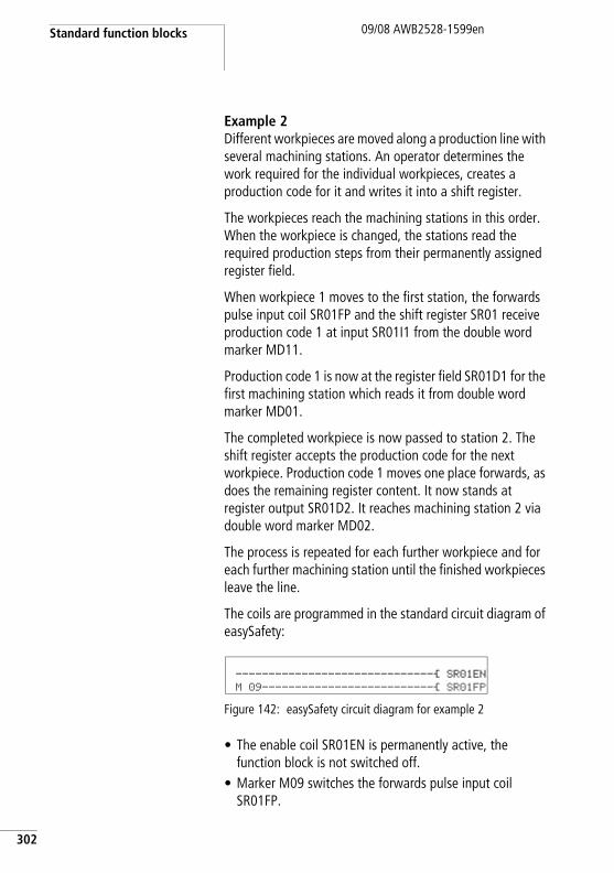
Standard function blocks
302
09/08 AWB2528-1599en
Example 2Different workpieces are moved along a production line with several machining stations. An operator determines the work required for the individual workpieces, creates a production code for it and writes it into a shift register.
The workpieces reach the machining stations in this order. When the workpiece is changed, the stations read the required production steps from their permanently assigned register field.
When workpiece 1 moves to the first station, the forwards pulse input coil SR01FP and the shift register SR01 receive production code 1 at input SR01I1 from the double word marker MD11.
Production code 1 is now at the register field SR01D1 for the first machining station which reads it from double word marker MD01.
The completed workpiece is now passed to station 2. The shift register accepts the production code for the next workpiece. Production code 1 moves one place forwards, as does the remaining register content. It now stands at register output SR01D2. It reaches machining station 2 via double word marker MD02.
The process is repeated for each further workpiece and for each further machining station until the finished workpieces leave the line.
The coils are programmed in the standard circuit diagram of easySafety:
Figure 142: easySafety circuit diagram for example 2
• The enable coil SR01EN is permanently active, the function block is not switched off.
• Marker M09 switches the forwards pulse input coil SR01FP.
------------------------------Ä SR01EN M 09--------------------------Ä SR01FP
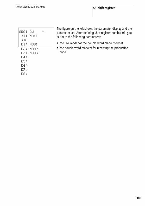
SR, shift register09/08 AWB2528-1599en
The figure on the left shows the parameter display and the parameter set. After defining shift register number 01, you set here the following parameters:
• the DW mode for the double word marker format.• the double word markers for receiving the production
code.
SR01 DW +
>I1 MD11
>I2
D1> MD01
D2> MD02
D3> MD03
D4>
D5>
D6>
D7>
D8>
303
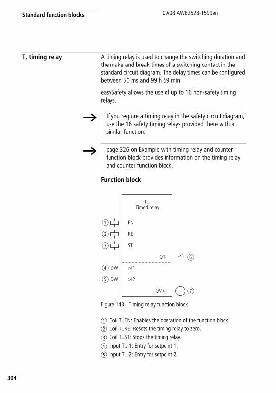
Standard function blocks
304
09/08 AWB2528-1599en
T, timing relay A timing relay is used to change the switching duration and the make and break times of a switching contact in the standard circuit diagram. The delay times can be configured between 50 ms and 99 h 59 min.
easySafety allows the use of up to 16 non-safety timing relays.
Function block
Figure 143: Timing relay function block
a Coil T..EN: Enables the operation of the function block.b Coil T..RE: Resets the timing relay to zero.c Coil T..ST: Stops the timing relay.d Input T..I1: Entry for setpoint 1.e Input T..I2: Entry for setpoint 2.
h If you require a timing relay in the safety circuit diagram, use the 16 safety timing relays provided there with a similar function.
h page 326 on Example with timing relay and counter function block provides information on the timing relay and counter function block.
EN
RE
ST
>I1
Q1
QV>
T...Timed relay
>I2DW
DW
a
b
c
d
e
f
g
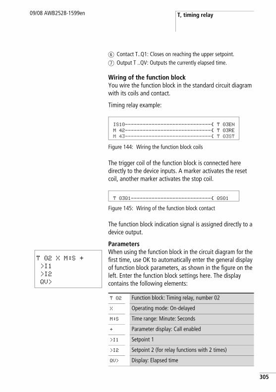
T, timing relay09/08 AWB2528-1599en
f Contact T..Q1: Closes on reaching the upper setpoint.g Output T ..QV: Outputs the currently elapsed time.
Wiring of the function blockYou wire the function block in the standard circuit diagram with its coils and contact.
Timing relay example:
Figure 144: Wiring the function block coils
The trigger coil of the function block is connected here directly to the device inputs. A marker activates the reset coil, another marker activates the stop coil.
Figure 145: Wiring of the function block contact
The function block indication signal is assigned directly to a device output.
ParametersWhen using the function block in the circuit diagram for the first time, use OK to automatically enter the general display of function block parameters, as shown in the figure on the left. Enter the function block settings here. The display contains the following elements:
IS10-----------------------------Ä T 03EN M 42-----------------------------Ä T 03RE M 43-----------------------------Ä T 03ST
T 03Q1---------------------------Ä QS01
T 02 X M:S +
>I1
>I2
QV>
T 02 Function block: Timing relay, number 02
X Operating mode: On-delayed
M:S Time range: Minute: Seconds
+ Parameter display: Call enabled
>I1 Setpoint 1
>I2 Setpoint 2 (for relay functions with 2 times)
QV> Display: Elapsed time
305
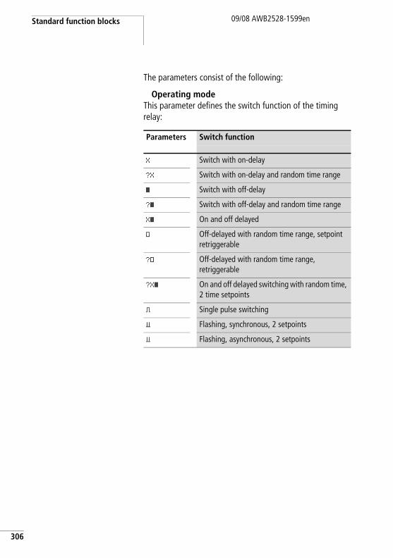
Standard function blocks
306
09/08 AWB2528-1599en
The parameters consist of the following:
Operating modeThis parameter defines the switch function of the timing relay:
Parameters Switch function
X Switch with on-delay
?X Switch with on-delay and random time range
â Switch with off-delay
?â Switch with off-delay and random time range
Xâ On and off delayed
# Off-delayed with random time range, setpoint retriggerable
?# Off-delayed with random time range, retriggerable
?Xâ On and off delayed switching with random time, 2 time setpoints
ü Single pulse switching
Ü Flashing, synchronous, 2 setpoints
Ü Flashing, asynchronous, 2 setpoints
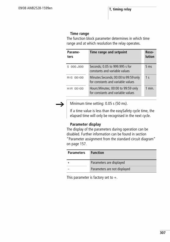
T, timing relay09/08 AWB2528-1599en
Time rangeThe function block parameter determines in which time range and at which resolution the relay operates.
Parameter displayThe display of the parameters during operation can be disabled. Further information can be found in section “Parameter assignment from the standard circuit diagram” on page 157.
This parameter is factory set to +.
Parame-ters
Time range and setpoint Reso-lution
S 000.000 Seconds; 0.05 to 999.995 s for constants and variable values
5 ms
M:S 00:00 Minutes:Seconds; 00:00 to 99:59 only for constants and variable values
1 s
H:M 00:00 Hours:Minutes; 00:00 to 99:59 only for constants and variable values
1 min.
h Minimum time setting: 0.05 s (50 ms).
If a time value is less than the easySafety cycle time, the elapsed time will only be recognised in the next cycle.
Parameters Function
+ Parameters are displayed
- Parameters are not displayed
307
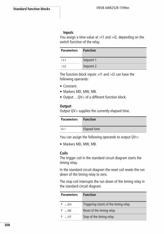
Standard function blocks
308
09/08 AWB2528-1599en
InputsYou assign a time value at >I1 and >I2, depending on the switch function of the relay.
The function block inputs >I1 and >I2 can have the following operands:
• Constant.• Markers MD, MW, MB.• Output …QV> of a different function block.
OutputOutput QV> supplies the currently elapsed time.
You can assign the following operands to output QV>:
• Markers MD, MW, MB.
CoilsThe trigger coil in the standard circuit diagram starts the timing relay.
In the standard circuit diagram the reset coil resets the run down of the timing relay to zero.
The stop coil interrupts the run down of the timing relay in the standard circuit diagram.
Parameters Function
>I1 Setpoint 1
>I2 Setpoint 2
Parameters Function
QV> Elapsed time
Parameters Function
T ..EN Triggering (start) of the timing relay
T ..RE Reset of the timing relay
T ..ST Stop of the timing relay
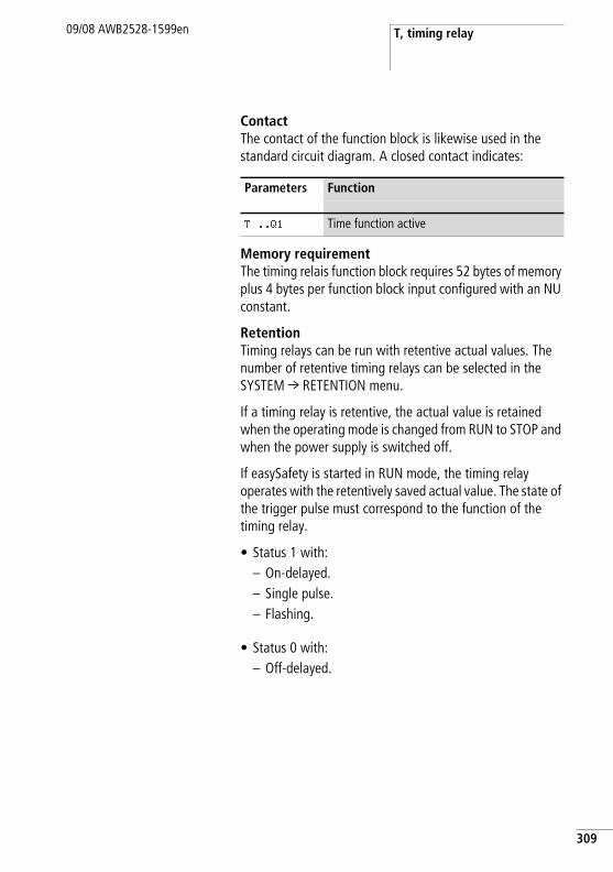
T, timing relay09/08 AWB2528-1599en
ContactThe contact of the function block is likewise used in the standard circuit diagram. A closed contact indicates:
Memory requirementThe timing relais function block requires 52 bytes of memory plus 4 bytes per function block input configured with an NU constant.
RetentionTiming relays can be run with retentive actual values. The number of retentive timing relays can be selected in the SYSTEM r RETENTION menu.
If a timing relay is retentive, the actual value is retained when the operating mode is changed from RUN to STOP and when the power supply is switched off.
If easySafety is started in RUN mode, the timing relay operates with the retentively saved actual value. The state of the trigger pulse must correspond to the function of the timing relay.
• Status 1 with:– On-delayed.– Single pulse.– Flashing.
• Status 0 with:– Off-delayed.
Parameters Function
T ..Q1 Time function active
309
Standard function blocks
310
09/08 AWB2528-1599en
Operation of the function blockThe relay is started via the trigger coil T…EN and can be selectively reset via the reset coil T…RE. The third coil T..ST terminates the run down of the actual time.
Variable time valuesIf you associate the function block inputs T ..I1 and T ..I2 with operands, you can use variable setpoints. The setpoints are transferred as follows, depending on the time range selected:
• S, value in milliseconds. The last digit is rounded up or down to 0 or 5, maximum value = 999995 ms.
• M:S, value in seconds, maximum value = 5999 s.• H:M, value in minutes, maximum value = 5999 min.
• Examples of time range S:– Operand value 9504 -> Time value is 9.505 s.– Operand value 45507 -> Time value is 45.51 s.
• Examples of time range M:S:– Operand value 5999 -> Time value is 99 h, 59 min.
• Example of time range H:M:– Operand value 5999 -> Time value is 99 h, 59 min.
Different methods are used depending on the operating modes of the function block:
h The delay times are the same as described for the constants.
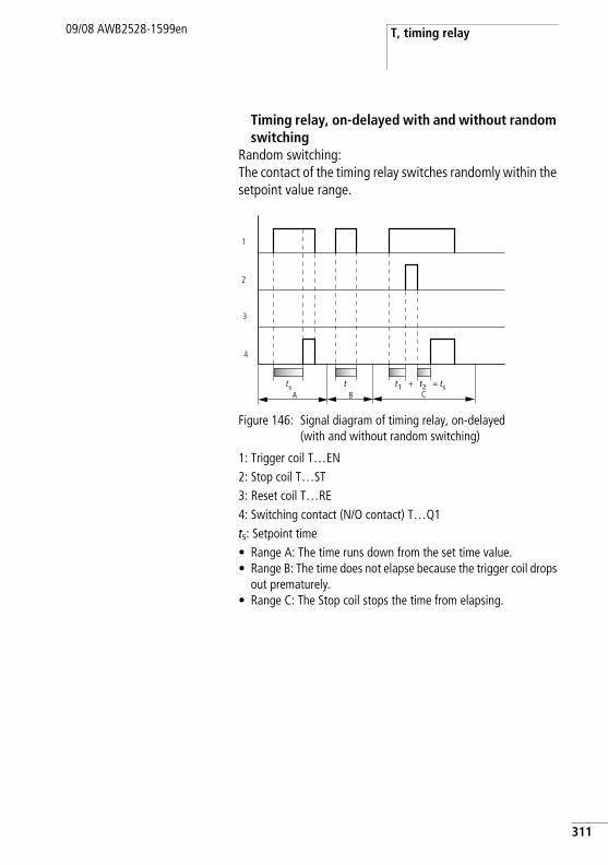
T, timing relay09/08 AWB2528-1599en
Timing relay, on-delayed with and without random switching
Random switching:The contact of the timing relay switches randomly within the setpoint value range.
Figure 146: Signal diagram of timing relay, on-delayed (with and without random switching)
1: Trigger coil T…EN2: Stop coil T…ST3: Reset coil T…RE4: Switching contact (N/O contact) T…Q1ts: Setpoint time• Range A: The time runs down from the set time value.• Range B: The time does not elapse because the trigger coil drops
out prematurely.• Range C: The Stop coil stops the time from elapsing.
t1 + t2 = tst
A Bts
1
2
4
3
C
311
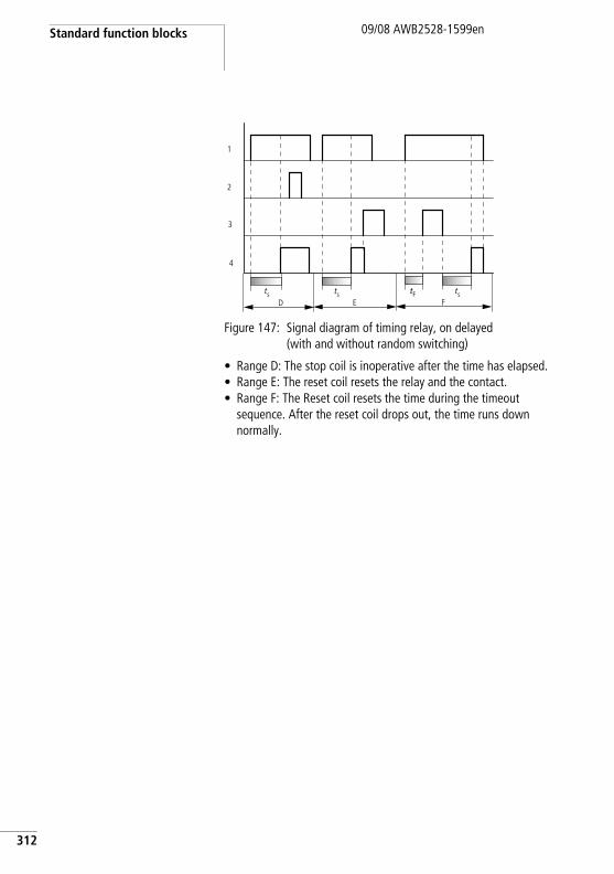
Standard function blocks
312
09/08 AWB2528-1599en
Figure 147: Signal diagram of timing relay, on delayed (with and without random switching)
• Range D: The stop coil is inoperative after the time has elapsed.• Range E: The reset coil resets the relay and the contact.• Range F: The Reset coil resets the time during the timeout
sequence. After the reset coil drops out, the time runs down normally.
tFD E
ts
1
2
4
3
tsF
ts
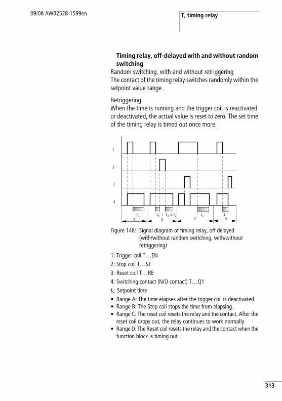
T, timing relay09/08 AWB2528-1599en
Timing relay, off-delayed with and without random switching
Random switching, with and without retriggeringThe contact of the timing relay switches randomly within the setpoint value range.
RetriggeringWhen the time is running and the trigger coil is reactivated or deactivated, the actual value is reset to zero. The set time of the timing relay is timed out once more.
Figure 148: Signal diagram of timing relay, off delayed (with/without random switching, with/without retriggering)
1: Trigger coil T…EN2: Stop coil T…ST3: Reset coil T…RE4: Switching contact (N/O contact) T…Q1ts: Setpoint time• Range A: The time elapses after the trigger coil is deactivated.• Range B: The Stop coil stops the time from elapsing.• Range C: The reset coil resets the relay and the contact. After the
reset coil drops out, the relay continues to work normally.• Range D: The Reset coil resets the relay and the contact when the
function block is timing out.
A Bt1 + t2 = tsts
C
1
2
4
3
tsDt
313
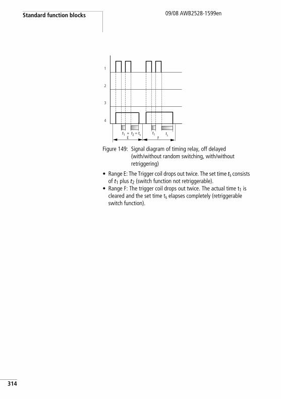
Standard function blocks
314
09/08 AWB2528-1599en
Figure 149: Signal diagram of timing relay, off delayed (with/without random switching, with/without retriggering)
• Range E: The Trigger coil drops out twice. The set time ts consists of t1 plus t2 (switch function not retriggerable).
• Range F: The trigger coil drops out twice. The actual time t1 is cleared and the set time ts elapses completely (retriggerable switch function).
Et1 + t2 = ts
1
2
4
3
tsF
t1
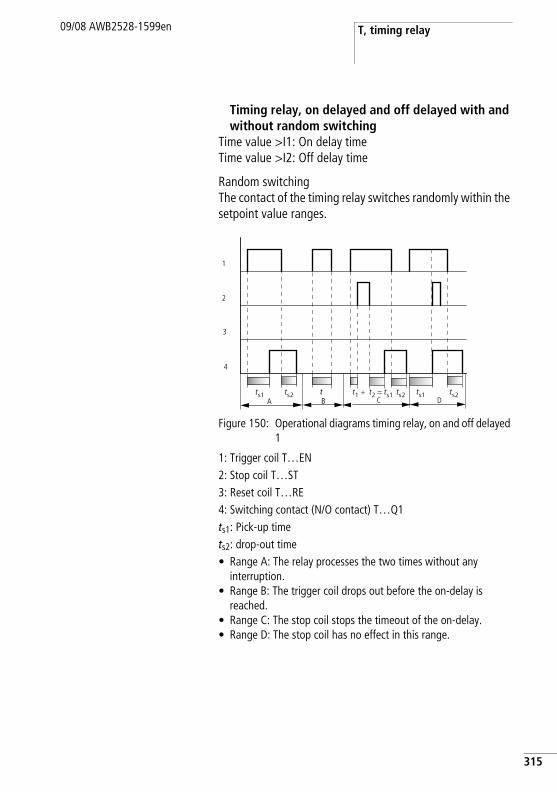
T, timing relay09/08 AWB2528-1599en
Timing relay, on delayed and off delayed with and without random switching
Time value >I1: On delay timeTime value >I2: Off delay time
Random switchingThe contact of the timing relay switches randomly within the setpoint value ranges.
Figure 150: Operational diagrams timing relay, on and off delayed 1
1: Trigger coil T…EN2: Stop coil T…ST3: Reset coil T…RE4: Switching contact (N/O contact) T…Q1ts1: Pick-up timets2: drop-out time• Range A: The relay processes the two times without any
interruption.• Range B: The trigger coil drops out before the on-delay is
reached.• Range C: The stop coil stops the timeout of the on-delay.• Range D: The stop coil has no effect in this range.
A B C
1
2
4
3
Dtts1 ts2 ts2 ts1 ts2t1 + t2 = ts1
315
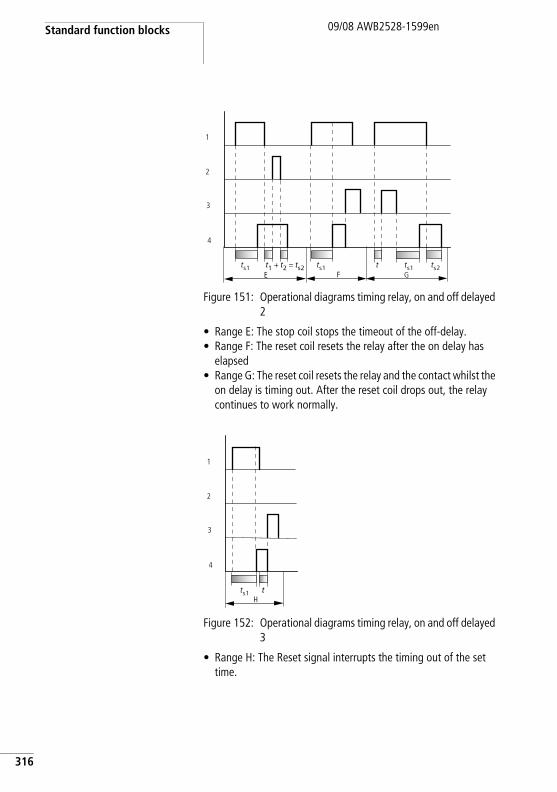
Standard function blocks
316
09/08 AWB2528-1599en
Figure 151: Operational diagrams timing relay, on and off delayed 2
• Range E: The stop coil stops the timeout of the off-delay.• Range F: The reset coil resets the relay after the on delay has
elapsed• Range G: The reset coil resets the relay and the contact whilst the
on delay is timing out. After the reset coil drops out, the relay continues to work normally.
Figure 152: Operational diagrams timing relay, on and off delayed 3
• Range H: The Reset signal interrupts the timing out of the set time.
E Ft1 + t2 = ts2
G
1
2
4
3
tts1 ts1 ts1 ts2
Ht
1
2
4
3
ts1
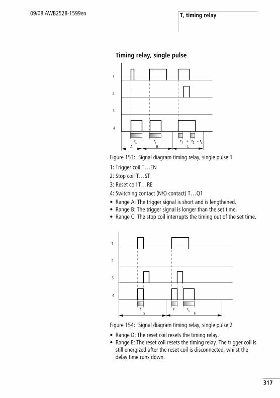
T, timing relay09/08 AWB2528-1599en
Timing relay, single pulse
Figure 153: Signal diagram timing relay, single pulse 1
1: Trigger coil T…EN2: Stop coil T…ST3: Reset coil T…RE4: Switching contact (N/O contact) T…Q1• Range A: The trigger signal is short and is lengthened.• Range B: The trigger signal is longer than the set time.• Range C: The stop coil interrupts the timing out of the set time.
Figure 154: Signal diagram timing relay, single pulse 2
• Range D: The reset coil resets the timing relay.• Range E: The reset coil resets the timing relay. The trigger coil is
still energized after the reset coil is disconnected, whilst the delay time runs down.
A B
t1 + t2 = tsts tsC
1
2
4
3
t
D Et ts
1
2
4
3
317
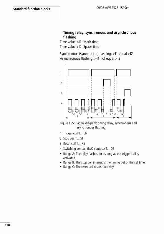
Standard function blocks
318
09/08 AWB2528-1599en
Timing relay, synchronous and asynchronous flashing
Time value >I1: Mark time Time value >I2: Space time
Synchronous (symmetrical) flashing: >I1 equal >I2Asynchronous flashing: >I1 not equal >I2
Figure 155: Signal diagram: timing relay, synchronous and asynchronous flashing
1: Trigger coil T…EN2: Stop coil T…ST3: Reset coil T…RE4: Switching contact (N/O contact) T…Q1• Range A: The relay flashes for as long as the trigger coil is
activated.• Range B: The stop coil interrupts the timing out of the set time.• Range C: The reset coil resets the relay.
t1 + t2 = ts2ts1 ts1 ts1
ts2 ts2ts1 ts1
ts2ts2A B
1
2
4
3
t ts1ts2
C
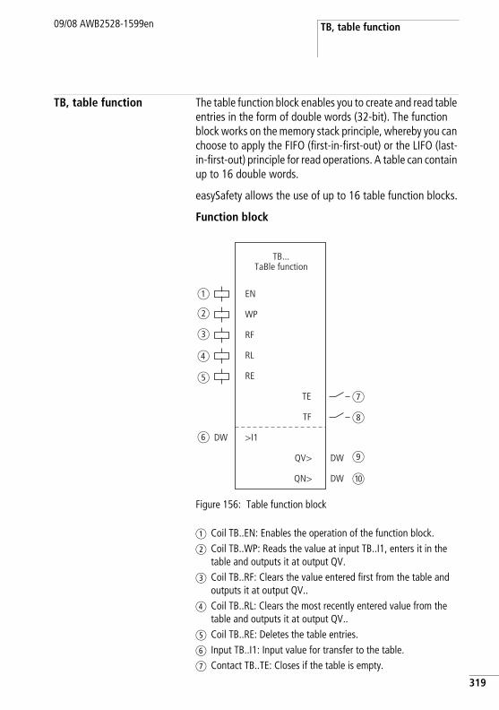
TB, table function09/08 AWB2528-1599en
TB, table function The table function block enables you to create and read table entries in the form of double words (32-bit). The function block works on the memory stack principle, whereby you can choose to apply the FIFO (first-in-first-out) or the LIFO (last-in-first-out) principle for read operations. A table can contain up to 16 double words.
easySafety allows the use of up to 16 table function blocks.
Function block
Figure 156: Table function block
a Coil TB..EN: Enables the operation of the function block.b Coil TB..WP: Reads the value at input TB..I1, enters it in the
table and outputs it at output QV.c Coil TB..RF: Clears the value entered first from the table and
outputs it at output QV..d Coil TB..RL: Clears the most recently entered value from the
table and outputs it at output QV..e Coil TB..RE: Deletes the table entries.f Input TB..I1: Input value for transfer to the table.g Contact TB..TE: Closes if the table is empty.
EN
TB...TaBle function
a
b
c
d
e
f
g
h
i
j
RE
TE
>I1
QV>
WP
RF
RL
TF
QN>
DW
DW
DW
319
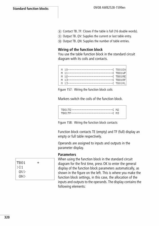
Standard function blocks
320
09/08 AWB2528-1599en
h Contact TB..TF: Closes if the table is full (16 double words).i Output TB..QV: Supplies the current or last table entry.j Output TB..QN: Supplies the number of table entries.
Wiring of the function blockYou use the table function block in the standard circuit diagram with its coils and contacts.
Figure 157: Wiring the function block coils
Markers switch the coils of the function block.
Figure 158: Wiring the function block contacts
Function block contacts TE (empty) and TF (full) display an empty or full table respectively.
Operands are assigned to inputs and outputs in the parameter display.
ParametersWhen using the function block in the standard circuit diagram for the first time, press OK to enter the general display of the function block parameters automatically, as shown in the figure on the left. This is where you make the function block settings, in this case, the allocation of the inputs and outputs to the operands. The display contains the following elements:
M 10--------------------------Ä TB01EN M 11--------------------------Ä TB01WP M 12--------------------------Ä TB01RE M 13--------------------------Ä TB01RF M 13--------------------------Ä TB01RL
TB01TE------------------------Ä M2 TB01TF------------------------Ä M3
TB01 +
>I1
QV>
QN>
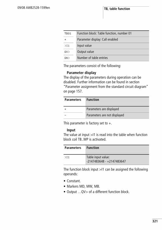
TB, table function09/08 AWB2528-1599en
The parameters consist of the following:
Parameter displayThe display of the parameters during operation can be disabled. Further information can be found in section “Parameter assignment from the standard circuit diagram” on page 157.
This parameter is factory set to +.
InputThe value at input >I1 is read into the table when function block coil TB..WP is activated.
The function block input >I1 can be assigned the following operands:
• Constant.• Markers MD, MW, MB.• Output …QV> of a different function block.
TB01 Function block: Table function, number 01
+ Parameter display: Call enabled
>I1 Input value
QV> Output value
QN> Number of table entries
Parameters Function
+ Parameters are displayed
- Parameters are not displayed
Parameters Function
>I1 Table input value:-2147483648 - +2147483647
321
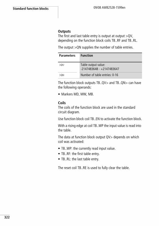
Standard function blocks
322
09/08 AWB2528-1599en
OutputsThe first and last table entry is output at output >QV, depending on the function block coils TB..RF and TB..RL.
The output >QN supplies the number of table entries.
The function block outputs TB..QV> and TB..QN> can have the following operands:
• Markers MD, MW, MB.
CoilsThe coils of the function block are used in the standard circuit diagram.
Use function block coil TB..EN to activate the function block.
With a rising edge at coil TB..WP the input value is read into the table.
The data at function block output QV> depends on which coil was activated:
• TB..WP: the currently read input value.• TB..RF: the first table entry.• TB..RL: the last table entry.
The reset coil TB..RE is used to fully clear the table.
Parameters Function
>QV Table output value:-2147483648 - +2147483647
>QN Number of table entries: 0-16
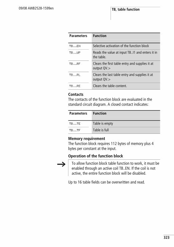
TB, table function09/08 AWB2528-1599en
ContactsThe contacts of the function block are evaluated in the standard circuit diagram. A closed contact indicates:
Memory requirementThe function block requires 112 bytes of memory plus 4 bytes per constant at the input.
Operation of the function block
Up to 16 table fields can be overwritten and read.
Parameters Function
TB..EN Selective activation of the function block
TB..WP Reads the value at input TB..I1 and enters it in the table.
TB..RF Clears the first table entry and supplies it at output QV.>
TB..RL Clears the last table entry and supplies it at output QV.>
TB..RE Clears the table content.
Parameters Function
TB..TE Table is empty
TB..TF Table is full
h To allow function block table function to work, it must be enabled through an active coil TB..EN. If the coil is not active, the entire function block will be disabled.
323
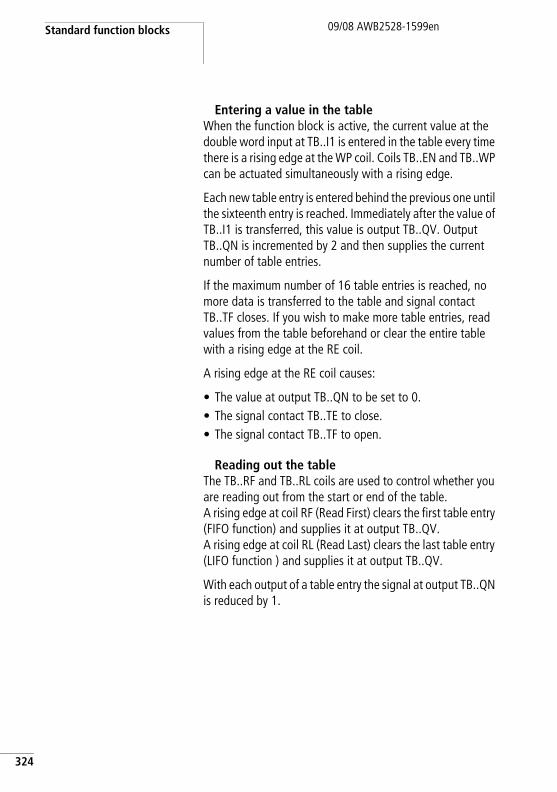
Standard function blocks
324
09/08 AWB2528-1599en
Entering a value in the tableWhen the function block is active, the current value at the double word input at TB..I1 is entered in the table every time there is a rising edge at the WP coil. Coils TB..EN and TB..WP can be actuated simultaneously with a rising edge.
Each new table entry is entered behind the previous one until the sixteenth entry is reached. Immediately after the value of TB..I1 is transferred, this value is output TB..QV. Output TB..QN is incremented by 2 and then supplies the current number of table entries.
If the maximum number of 16 table entries is reached, no more data is transferred to the table and signal contact TB..TF closes. If you wish to make more table entries, read values from the table beforehand or clear the entire table with a rising edge at the RE coil.
A rising edge at the RE coil causes:
• The value at output TB..QN to be set to 0.• The signal contact TB..TE to close.• The signal contact TB..TF to open.
Reading out the tableThe TB..RF and TB..RL coils are used to control whether you are reading out from the start or end of the table. A rising edge at coil RF (Read First) clears the first table entry (FIFO function) and supplies it at output TB..QV. A rising edge at coil RL (Read Last) clears the last table entry (LIFO function ) and supplies it at output TB..QV.
With each output of a table entry the signal at output TB..QN is reduced by 1.
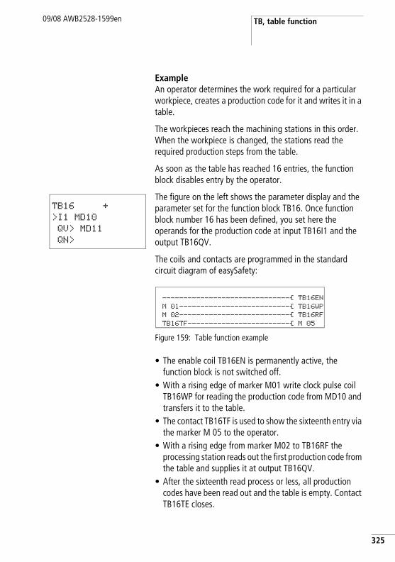
TB, table function09/08 AWB2528-1599en
ExampleAn operator determines the work required for a particular workpiece, creates a production code for it and writes it in a table.
The workpieces reach the machining stations in this order. When the workpiece is changed, the stations read the required production steps from the table.
As soon as the table has reached 16 entries, the function block disables entry by the operator.
The figure on the left shows the parameter display and the parameter set for the function block TB16. Once function block number 16 has been defined, you set here the operands for the production code at input TB16I1 and the output TB16QV.
The coils and contacts are programmed in the standard circuit diagram of easySafety:
Figure 159: Table function example
• The enable coil TB16EN is permanently active, the function block is not switched off.
• With a rising edge of marker M01 write clock pulse coil TB16WP for reading the production code from MD10 and transfers it to the table.
• The contact TB16TF is used to show the sixteenth entry via the marker M 05 to the operator.
• With a rising edge from marker M02 to TB16RF the processing station reads out the first production code from the table and supplies it at output TB16QV.
• After the sixteenth read process or less, all production codes have been read out and the table is empty. Contact TB16TE closes.
TB16 +
>I1 MD10
QV> MD11
QN>
------------------------------Ä TB16EN M 01--------------------------Ä TB16WP M 02--------------------------Ä TB16RF TB16TF------------------------Ä M 05
325
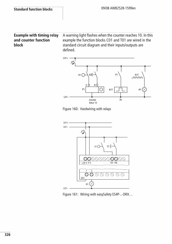
Standard function blocks
326
09/08 AWB2528-1599en
Example with timing relay and counter function block
A warning light flashes when the counter reaches 10. In this example the function blocks C01 and T01 are wired in the standard circuit diagram and their inputs/outputs are defined.
Figure 160: Hardwiring with relays
Figure 161: Wiring with easySafety ES4P-..-DRX…
L01–
P1
P1
K1T
K1T
C R
H1
S1 S2
L01+
2sCounterValue 10
1 2
H1
L01–
S2
L01+
L01–
+24 V 0 V IS5 IS6
S1
QS1
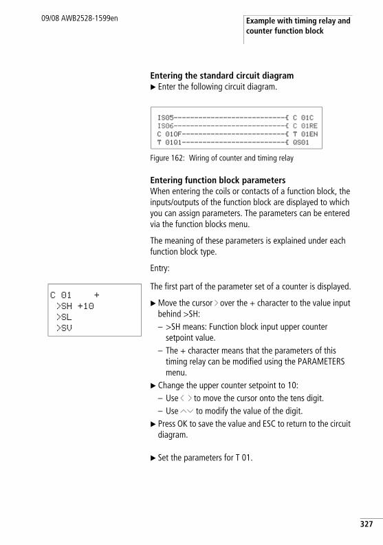
Example with timing relay and counter function block
09/08 AWB2528-1599en
Entering the standard circuit diagramX Enter the following circuit diagram.
Figure 162: Wiring of counter and timing relay
Entering function block parametersWhen entering the coils or contacts of a function block, the inputs/outputs of the function block are displayed to which you can assign parameters. The parameters can be entered via the function blocks menu.
The meaning of these parameters is explained under each function block type.
Entry:
The first part of the parameter set of a counter is displayed.
X Move the cursor í over the + character to the value input behind >SH:– >SH means: Function block input upper counter
setpoint value.– The + character means that the parameters of this
timing relay can be modified using the PARAMETERS menu.
X Change the upper counter setpoint to 10:– Use ú í to move the cursor onto the tens digit.– Use ÍÚ to modify the value of the digit.
X Press OK to save the value and ESC to return to the circuit diagram.
X Set the parameters for T 01.
IS05---------------------------Ä C 01C IS06---------------------------Ä C 01RE C 01OF-------------------------Ä T 01EN T 01Q1-------------------------Ä QS01
C 01 +
>SH +10
>SL
>SV
327
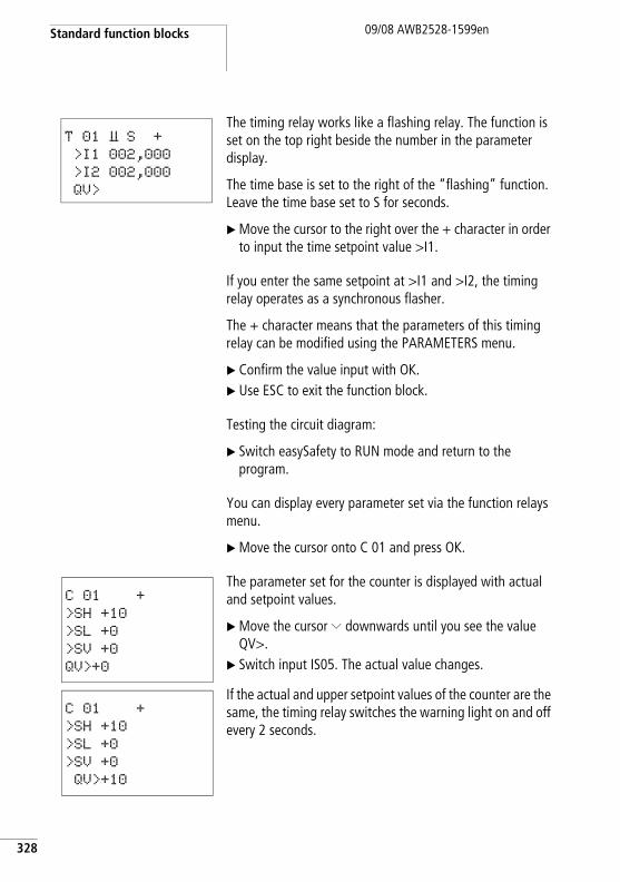
Standard function blocks
328
09/08 AWB2528-1599en
The timing relay works like a flashing relay. The function is set on the top right beside the number in the parameter display.
The time base is set to the right of the “flashing” function. Leave the time base set to S for seconds.
X Move the cursor to the right over the + character in order to input the time setpoint value >I1.
If you enter the same setpoint at >I1 and >I2, the timing relay operates as a synchronous flasher.
The + character means that the parameters of this timing relay can be modified using the PARAMETERS menu.
X Confirm the value input with OK.X Use ESC to exit the function block.
Testing the circuit diagram:
X Switch easySafety to RUN mode and return to the program.
You can display every parameter set via the function relays menu.
X Move the cursor onto C 01 and press OK.
The parameter set for the counter is displayed with actual and setpoint values.
X Move the cursor Ú downwards until you see the value QV>.
X Switch input IS05. The actual value changes.
If the actual and upper setpoint values of the counter are the same, the timing relay switches the warning light on and off every 2 seconds.
T 01 Ü S + >I1 002,000
>I2 002,000
QV>
C 01 +
>SH +10
>SL +0
>SV +0
QV>+0
C 01 +
>SH +10
>SL +0
>SV +0
QV>+10
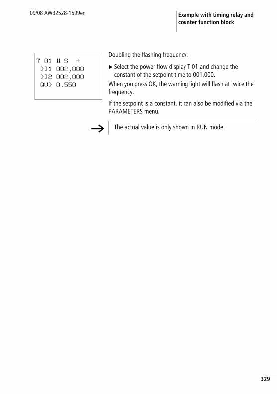
Example with timing relay and counter function block
09/08 AWB2528-1599en
Doubling the flashing frequency:
X Select the power flow display T 01 and change the constant of the setpoint time to 001,000.
When you press OK, the warning light will flash at twice the frequency.
If the setpoint is a constant, it can also be modified via the PARAMETERS menu.
T 01 Ü S + >I1 002,000
>I2 002,000
QV> 0.550
h The actual value is only shown in RUN mode.
329

330
09/08 AWB2528-1599en
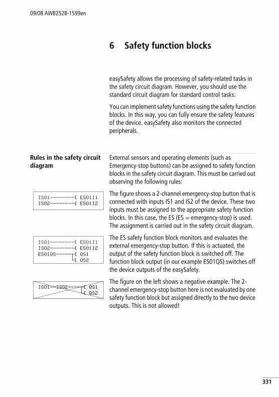
09/08 AWB2528-1599en
6 Safety function blocks
easySafety allows the processing of safety-related tasks in the safety circuit diagram. However, you should use the standard circuit diagram for standard control tasks.
You can implement safety functions using the safety function blocks. In this way, you can fully ensure the safety features of the device. easySafety also monitors the connected peripherals.
Rules in the safety circuit diagram
External sensors and operating elements (such as Emergency-stop buttons) can be assigned to safety function blocks in the safety circuit diagram. This must be carried out observing the following rules:
The figure shows a 2-channel emergency-stop button that is connected with inputs IS1 and IS2 of the device. These two inputs must be assigned to the appropriate safety function blocks. In this case, the ES (ES = emergency-stop) is used. The assignment is carried out in the safety circuit diagram.
The ES safety function block monitors and evaluates the external emergency-stop button. If this is actuated, the output of the safety function block is switched off. The function block output (in our example ES01QS) switches off the device outputs of the easySafety.
The figure on the left shows a negative example. The 2-channel emergency-stop button here is not evaluated by one safety function block but assigned directly to the two device outputs. This is not allowed!
IS01--------Ä ES01I1IS02--------Ä ES01I2
IS01--------Ä ES01I1IS02--------Ä ES01I2ES01QS-----uÄ QS1
hÄ QS2
IS01--IS02----uÄ QS1hÄ QS2
331
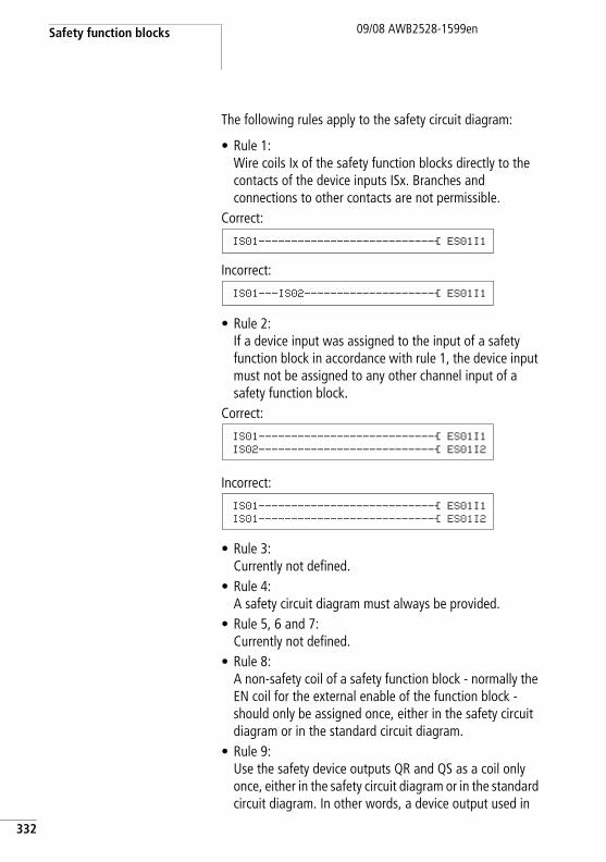
Safety function blocks
332
09/08 AWB2528-1599en
The following rules apply to the safety circuit diagram:
• Rule 1:Wire coils Ix of the safety function blocks directly to the contacts of the device inputs ISx. Branches and connections to other contacts are not permissible.
Correct:
Incorrect:
• Rule 2:If a device input was assigned to the input of a safety function block in accordance with rule 1, the device input must not be assigned to any other channel input of a safety function block.
Correct:
Incorrect:
• Rule 3:Currently not defined.
• Rule 4:A safety circuit diagram must always be provided.
• Rule 5, 6 and 7:Currently not defined.
• Rule 8:A non-safety coil of a safety function block - normally the EN coil for the external enable of the function block - should only be assigned once, either in the safety circuit diagram or in the standard circuit diagram.
• Rule 9:Use the safety device outputs QR and QS as a coil only once, either in the safety circuit diagram or in the standard circuit diagram. In other words, a device output used in
IS01---------------------------Ä ES01I1
IS01---IS02--------------------Ä ES01I1
IS01---------------------------Ä ES01I1IS02---------------------------Ä ES01I2
IS01---------------------------Ä ES01I1IS01---------------------------Ä ES01I2
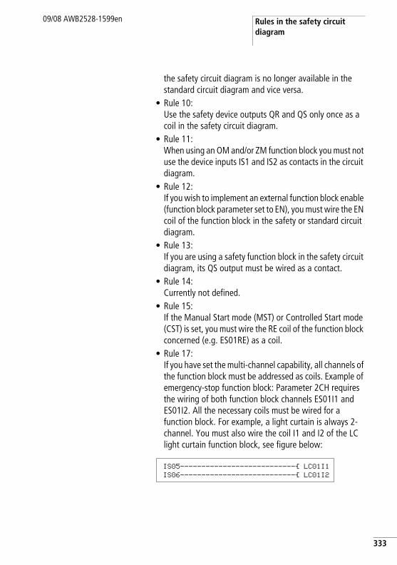
Rules in the safety circuit diagram
09/08 AWB2528-1599en
the safety circuit diagram is no longer available in the standard circuit diagram and vice versa.
• Rule 10:Use the safety device outputs QR and QS only once as a coil in the safety circuit diagram.
• Rule 11:When using an OM and/or ZM function block you must not use the device inputs IS1 and IS2 as contacts in the circuit diagram.
• Rule 12:If you wish to implement an external function block enable (function block parameter set to EN), you must wire the EN coil of the function block in the safety or standard circuit diagram.
• Rule 13:If you are using a safety function block in the safety circuit diagram, its QS output must be wired as a contact.
• Rule 14:Currently not defined.
• Rule 15:If the Manual Start mode (MST) or Controlled Start mode (CST) is set, you must wire the RE coil of the function block concerned (e.g. ES01RE) as a coil.
• Rule 17:If you have set the multi-channel capability, all channels of the function block must be addressed as coils. Example of emergency-stop function block: Parameter 2CH requires the wiring of both function block channels ES01I1 and ES01I2. All the necessary coils must be wired for a function block. For example, a light curtain is always 2-channel. You must also wire the coil I1 and I2 of the LC light curtain function block, see figure below:
IS05---------------------------Ä LC01I1IS06---------------------------Ä LC01I2
333
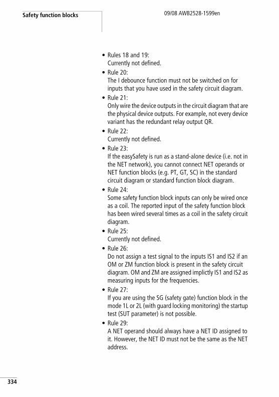
Safety function blocks
334
09/08 AWB2528-1599en
• Rules 18 and 19:Currently not defined.
• Rule 20:The I debounce function must not be switched on for inputs that you have used in the safety circuit diagram.
• Rule 21:Only wire the device outputs in the circuit diagram that are the physical device outputs. For example, not every device variant has the redundant relay output QR.
• Rule 22:Currently not defined.
• Rule 23:If the easySafety is run as a stand-alone device (i.e. not in the NET network), you cannot connect NET operands or NET function blocks (e.g. PT, GT, SC) in the standard circuit diagram or standard function block diagram.
• Rule 24:Some safety function block inputs can only be wired once as a coil. The reported input of the safety function block has been wired several times as a coil in the safety circuit diagram.
• Rule 25:Currently not defined.
• Rule 26:Do not assign a test signal to the inputs IS1 and IS2 if an OM or ZM function block is present in the safety circuit diagram. OM and ZM are assigned implictly IS1 and IS2 as measuring inputs for the frequencies.
• Rule 27:If you are using the SG (safety gate) function block in the mode 1L or 2L (with guard locking monitoring) the startup test (SUT parameter) is not possible.
• Rule 29:A NET operand should always have a NET ID assigned to it. However, the NET ID must not be the same as the NET address.
Common features09/08 AWB2528-1599en
Both the easySafety device as well as the easySoft-Safety software help you to observe these rules by means of a plausibility check.
Further details are provided in the description of the individual function blocks.
Common features The following features described are the same for all safety function blocks. They are therefore summarised here and are not mentioned in the individual descriptions.
Error contact ER
As soon as a safety function block finds impermissible states or timeouts of monitored times at its coils, the ER error contact closes to indicate a general error. This signal is available both in the standard as well as safety circuit diagram.
Further information on the cause of the error is provided at the DG function block output. This can be indicated in the status display or in the simulation function of easySoft-Safety. Furthermore, it is possible to evaluate the individual states of the safety function blocks and further process them by using the DG diagnostics function block in the standard circuit diagram a page 233.
335
Safety function blocks
336
09/08 AWB2528-1599en
Enable parameter, EN enable coil
(external enable, factory setting: NEN)
If the enable parameter is set to EN, the enable coil of the function block is used so that the function block can be activated and deactivated externally. If this coil is not active, the function block remains deactivated and its enable contact QS stays switched off, irrespective of whether the safety conditions are fulfilled or not.
If required the function block can also work if the EN enable coil is not used. For this the enable parameter must be set to NEN (factory setting).
If an enable is required (Parameter: EN), the EN coil (e.g. ES01EN) is either addressed from the safety circuit diagram or from the standard circuit diagram.
Operating mode parameter, RE reset coil
(factory setting: MST)
This parameter is used to set the startup behaviour of the safety function block. The manual restart function prevents uncontrolled starting after the power supply is switched on and after the protected area is given clearance.
• AST (Automatic start)The enable contact closes as soon as the input circuit or circuits are closed, i.e the protected area is given clearance. If the RE reset coil is wired and the Automatic Start mode (AST) is set, the following warning will appear: “The reset is switched although the Automatic Start mode is selected”.
h Ensure that the AST parameter setting causes the unexpected startup of the machine or an uncontrolled change in the speed of the machine. This must be excluded by the design of a safe control system!
Common features09/08 AWB2528-1599en
• MST (manual start, factory setting)
The rising edge of the Reset button at the RE reset coil causes the enable contact to close.
• CST (Controlled start)
The falling edge of the Reset button at the RE reset coil causes the enable contact to close.
If the Manual Start (MST) or Controlled Start (CST) operating mode is set, but the RE Reset coil is not wired, the following message will appear because rule 15 is being broken: “MST or CST operating mode is selected for the function block, but the Reset is not connected”.
Parameter SUT (Startup test)
(Factory setting: No startup test)
A startup test means that the enable contact is not closed as soon as the operating voltage is applied and the protected area is clear. The protected area must be interrupted expressly once beforehand. The same applies to safety gate monitoring. In this case you first have to open the safety gate and then close it again before the enable signal appears at
h The precondition for this is that the safety peripherals indicate a clear protected area.
h The precondition for this is that the safety peripherals indicate a clear protected area.
h In the MST and CST operating modes, and after an error has been detected, operation can be enabled again with the safety function block's RE Reset coil. The precondition for this is that the safety peripherals indicate a clear protected area.
When using it in such a way, make sure that the reset pushbutton is placed in a position from which the operator can see the entire protected area.
337
Safety function blocks
338
09/08 AWB2528-1599en
the function block output. Remember to actuate the Reset button when using MST or CST mode in order to obtain the required function block enable.
QV actual value output
The QV actual value output normally outputs the actual values of monitoring times or frequencies. You can assign the MD, MW, MB markers to it in the standard circuit diagram, e.g. with the DB block.
DG diagnostics output
You use the DG diagnostics function block in the standard circuit diagram in order to evaluate the error code at the DG diagnostics output. Its 8 output contacts provide you with an accurate overview of the cause of function block error. You can forward this information or initiate a suitable routine.a section “Diagnostics using the DG diagnostics function block” ,page 607.
Application examples
The application examples in the descriptions of the individual safety function blocks only refer to the direct connection of the function blocks. Due to the range of different applications complete solutions cannot be illustrated at this point.
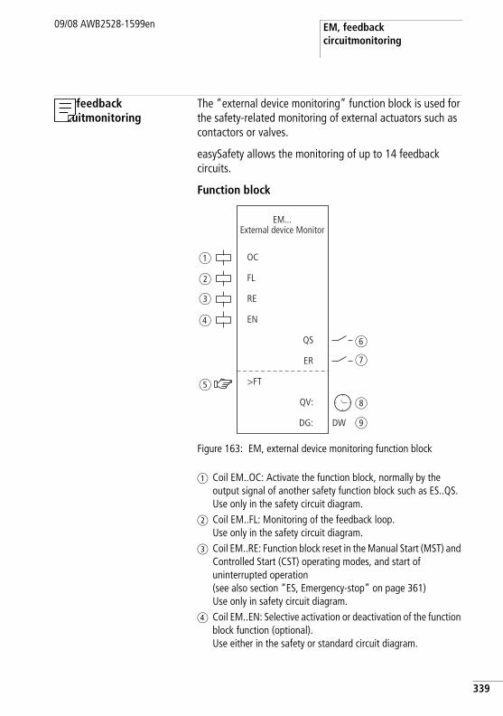
EM, feedback circuitmonitoring
09/08 AWB2528-1599en
EM, feedback circuitmonitoring
The “external device monitoring” function block is used for the safety-related monitoring of external actuators such as contactors or valves.
easySafety allows the monitoring of up to 14 feedback circuits.
Function block
Figure 163: EM, external device monitoring function block
a Coil EM..OC: Activate the function block, normally by the output signal of another safety function block such as ES..QS. Use only in the safety circuit diagram.
b Coil EM..FL: Monitoring of the feedback loop. Use only in the safety circuit diagram.
c Coil EM..RE: Function block reset in the Manual Start (MST) and Controlled Start (CST) operating modes, and start of uninterrupted operation (see also section “ES, Emergency-stop” on page 361)Use only in safety circuit diagram.
d Coil EM..EN: Selective activation or deactivation of the function block function (optional). Use either in the safety or standard circuit diagram.
OC
FL
RE
EN
>FT
QS
ER
DG:
QV:
EM...External device Monitor
a
b
c
d
e
f
g
h
iDW
339
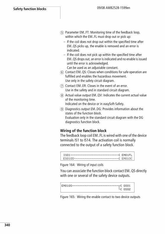
Safety function blocks
340
09/08 AWB2528-1599en
e Parameter EM..FT: Monitoring time of the feedback loop, within which the EM..FL must drop out or pick up:
– If the coil does not drop out within the specified time after EM..QS picks up, the enable is removed and an error is indicated.
– If the coil does not pick up within the specified time after EM..QS drops out, an error is indicated and no enable is issued until the error is acknowledged. Can be used as an adjustable constant.
f Contact EM..QS: Closes when conditions for safe operation are fulfilled and enables the hazardous movement. Use only in the safety circuit diagram.
g Contact EM..ER: Closes in the event of an error. Use in the safety and in standard circuit diagram.
h Actual value output EM..QV: Indicates the current actual value of the monitoring time. Indicated on the device or in easySoft-Safety.
i Diagnostics output EM..DG: Provides information about the states of the function block. Evaluation only in the standard circuit diagram with the DG diagnostics function block.
Wiring of the function blockThe feedback loop coil EM..FL is wired with one of the device terminals IS1 to IS14. The activation coil is normally connected to the output of a safety function block.
Figure 164: Wiring of input coils
You can associate the function block contact EM..QS directly with one or several of the safety device outputs.
Figure 165: Wiring the enable contact to two device outputs
IS01---------------------------Ä EM01FL
ES01QS-------------------------Ä EM01OC
EM01QS--------------------------uÄ QS01
hÄ QS02
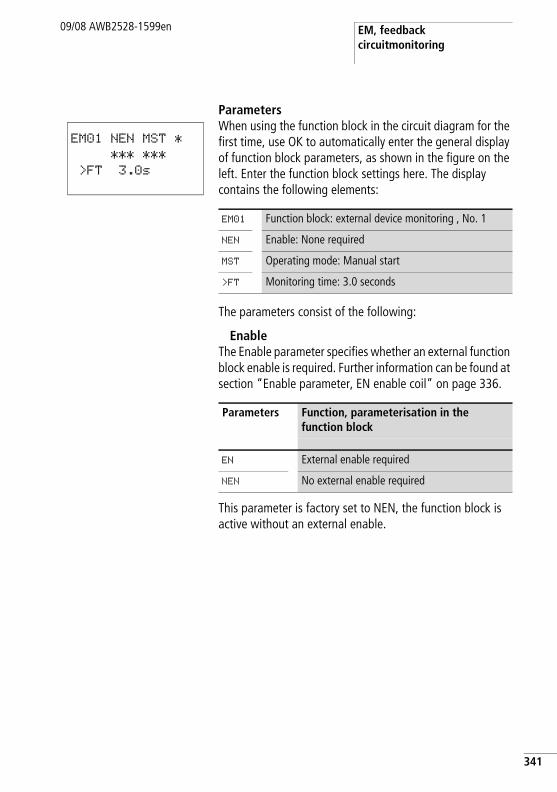
EM, feedback circuitmonitoring
09/08 AWB2528-1599en
ParametersWhen using the function block in the circuit diagram for the first time, use OK to automatically enter the general display of function block parameters, as shown in the figure on the left. Enter the function block settings here. The display contains the following elements:
The parameters consist of the following:
EnableThe Enable parameter specifies whether an external function block enable is required. Further information can be found at section “Enable parameter, EN enable coil” on page 336.
This parameter is factory set to NEN, the function block is active without an external enable.
EM01 NEN MST *
*** ***
>FT 3.0s
EM01 Function block: external device monitoring , No. 1
NEN Enable: None required
MST Operating mode: Manual start
>FT Monitoring time: 3.0 seconds
Parameters Function, parameterisation in the function block
EN External enable required
NEN No external enable required
341
Safety function blocks
342
09/08 AWB2528-1599en
ModeAfter easySafety has determined the conditions for safe operation, there are different kinds of restarts possible. They are described in greater detail as operating modes in section “Operating mode parameter, RE reset coil” on page 336.
The factory setting of this parameter is MST, Manual Start.
Monitoring timeAfter the EM..OC picks up, the function block monitors whether the feedback signal via coil EM..FL is generated within the specified monitoring time.
This parameter is factory set to 3.0 s.
OutputsActual value output QV: Indicates the current actual value of the monitoring time.
Diagnostics output DG: Provides information the states of the function block. It is evaluated in the standard circuit diagram e. g. with the diagnostics function block.
Parameters Function, parameterisation in the function block
MST Manual start
CST Controlled start
AST Automatic start, no manual restart
Parameters Function, parameterisation in the function block
>FT 0.1 - 3.0 s; adjustable in increments of g0.1 s
Parameters Function, parameterisation in the function block
QV: Monitoring time actual value: Time
DG: Diagnostics: double worda table 10
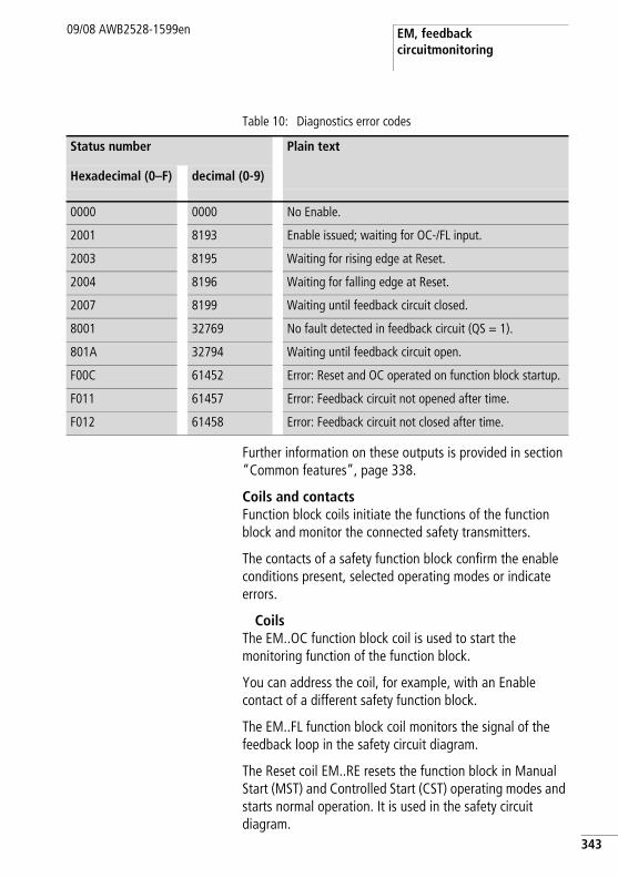
EM, feedback circuitmonitoring
09/08 AWB2528-1599en
Table 10: Diagnostics error codes
Further information on these outputs is provided in section “Common features”, page 338.
Coils and contactsFunction block coils initiate the functions of the function block and monitor the connected safety transmitters.
The contacts of a safety function block confirm the enable conditions present, selected operating modes or indicate errors.
CoilsThe EM..OC function block coil is used to start the monitoring function of the function block.
You can address the coil, for example, with an Enable contact of a different safety function block.
The EM..FL function block coil monitors the signal of the feedback loop in the safety circuit diagram.
The Reset coil EM..RE resets the function block in Manual Start (MST) and Controlled Start (CST) operating modes and starts normal operation. It is used in the safety circuit diagram.
Status number Plain text
Hexadecimal (0–F) decimal (0-9)
0000 0000 No Enable.
2001 8193 Enable issued; waiting for OC-/FL input.
2003 8195 Waiting for rising edge at Reset.
2004 8196 Waiting for falling edge at Reset.
2007 8199 Waiting until feedback circuit closed.
8001 32769 No fault detected in feedback circuit (QS = 1).
801A 32794 Waiting until feedback circuit open.
F00C 61452 Error: Reset and OC operated on function block startup.
F011 61457 Error: Feedback circuit not opened after time.
F012 61458 Error: Feedback circuit not closed after time.
343
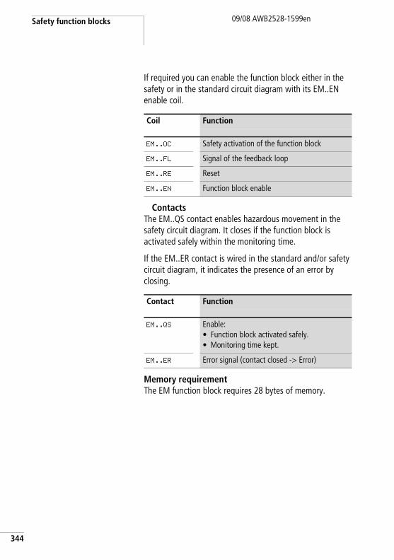
Safety function blocks
344
09/08 AWB2528-1599en
If required you can enable the function block either in the safety or in the standard circuit diagram with its EM..EN enable coil.
ContactsThe EM..QS contact enables hazardous movement in the safety circuit diagram. It closes if the function block is activated safely within the monitoring time.
If the EM..ER contact is wired in the standard and/or safety circuit diagram, it indicates the presence of an error by closing.
Memory requirementThe EM function block requires 28 bytes of memory.
Coil Function
EM..OC Safety activation of the function block
EM..FL Signal of the feedback loop
EM..RE Reset
EM..EN Function block enable
Contact Function
EM..QS Enable:• Function block activated safely.• Monitoring time kept.
EM..ER Error signal (contact closed -> Error)
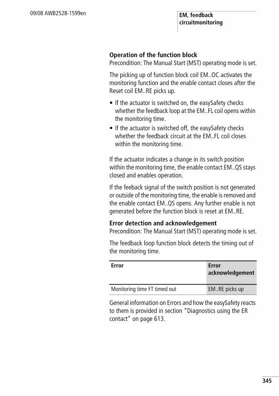
EM, feedback circuitmonitoring
09/08 AWB2528-1599en
Operation of the function blockPrecondition: The Manual Start (MST) operating mode is set.
The picking up of function block coil EM..OC activates the monitoring function and the enable contact closes after the Reset coil EM..RE picks up.
• If the actuator is switched on, the easySafety checks whether the feedback loop at the EM..FL coil opens within the monitoring time.
• If the actuator is switched off, the easySafety checks whether the feedback circuit at the EM..FL coil closes within the monitoring time.
If the actuator indicates a change in its switch position within the monitoring time, the enable contact EM..QS stays closed and enables operation.
If the feeback signal of the switch position is not generated or outside of the monitoring time, the enable is removed and the enable contact EM..QS opens. Any further enable is not generated before the function block is reset at EM..RE.
Error detection and acknowledgementPrecondition: The Manual Start (MST) operating mode is set.
The feedback loop function block detects the timing out of the monitoring time.
General information on Errors and how the easySafety reacts to them is provided in section “Diagnostics using the ER contact” on page 613.
Error Error acknowledgement
Monitoring time FT timed out EM..RE picks up
345
Safety function blocks
346
09/08 AWB2528-1599en
Example 1 - Architecture of Category 4 according to EN 954-1 and ISO 13849-1Monitoring of the switch position change of two contactors with cross-circuit monitoring of the external wiring. The safety output of an ES01QS emergency-stop function block switches the EM01 OC coil and activates the function block. The enable must be removed if the feedback signal for the contactor switch position is delayed. The monitoring time is set to 2.5 seconds.
This looks as follows in the electrical circuit diagram:
h Note that the emergency-stop function block is in AST (Automatic Start) mode. Manual enabling is only possible via the Reset coil of the EM function block. If the safety application does not have an EM function block, the emergency-stop function block should be set to MST or CST mode in order to prevent unwanted enabling after the emergency-stop actuator is released.
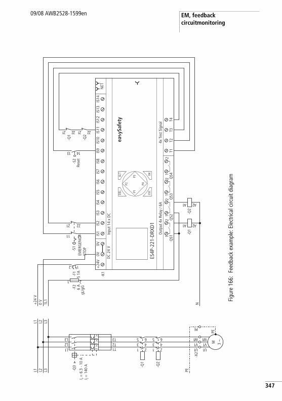
EM, feedback circuitmonitoring
09/08 AWB2528-1599en
Figu
re 1
66:
Feed
back
exa
mpl
e: E
lect
rical
circ
uit d
iagr
am
ea y
Safe
ty
PEL3L2L1
1U
-X2
-Q2
1 23 45 6
-Q1
1 23 45 6
1L2L3L
1T2T3TI >
I >I >
-Q3
M 3 h
1U1V1 W
PE
1V1 W
EP
L3L2L1
N1L1
0 V
+24
V
-F2
6 A
gL/g
G
1 2
T1T2
T3T4
4x T
est S
igna
lO
utpu
t 4x
Rela
y / 6
A
DEL
-K1
OK
ALT
ES4P
-221
-DRX
D1
DC
24 V
NET
Inpu
t 14
x D
C
ESC
IS1
IS2
IS3
IS4
IS5
IS6
IS7
IS8
IS9
IS10
IS11
IS12
IS13
IS14
1Q
S12
1Q
S22
1Q
S32
1Q
S42
+24
V0V
0V
P1
P2
P3
P4
2 1
-F1
S 1A
-Q1
1A 2A
-Q2
1A 2A
31 41
-S2
-Q2
12 22
-Q1
12 22
I r = 6
.3 -
10 A
I i = 1
40 A
-S1
12 22
11 21
Rese
tEM
ERG
ENCY
-ST
OP
347
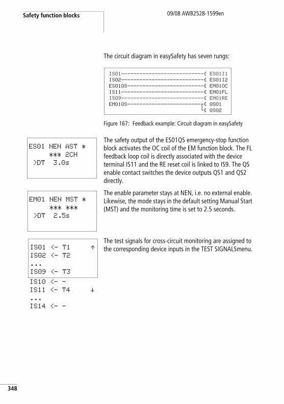
Safety function blocks
348
09/08 AWB2528-1599en
The circuit diagram in easySafety has seven rungs:
Figure 167: Feedback example: Circuit diagram in easySafety
The safety output of the ES01QS emergency-stop function block activates the OC coil of the EM function block. The FL feedback loop coil is directly associated with the device terminal IS11 and the RE reset coil is linked to IS9. The QS enable contact switches the device outputs QS1 and QS2 directly.
The enable parameter stays at NEN, i.e. no external enable. Likewise, the mode stays in the default setting Manual Start (MST) and the monitoring time is set to 2.5 seconds.
The test signals for cross-circuit monitoring are assigned to the corresponding device inputs in the TEST SIGNALSmenu.
IS01---------------------------Ä ES01I1
IS02---------------------------Ä ES01I2
ES01QS-------------------------Ä EM01OC
IS11---------------------------Ä EM01FL
IS09---------------------------Ä EM01RE
EM01QS------------------------uÄ QS01
hÄ QS02
ES01 NEN AST *
*** 2CH
>DT 3.0s
EM01 NEN MST *
*** ***
>DT 2.5s
IS01 <- T1 ÆIS02 <- T2
...
IS09 <- T3
IS10 <- -
IS11 <- T4 æ...
IS14 <- -
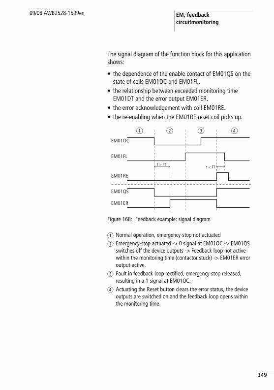
EM, feedback circuitmonitoring
09/08 AWB2528-1599en
The signal diagram of the function block for this application shows:
• the dependence of the enable contact of EM01QS on the state of coils EM01OC and EM01FL.
• the relationship between exceeded monitoring time EM01DT and the error output EM01ER.
• the error acknowledgement with coil EM01RE.• the re-enabling when the EM01RE reset coil picks up.
Figure 168: Feedback example: signal diagram
a Normal operation, emergency-stop not actuatedb Emergency-stop actuated -> 0 signal at EM01OC -> EM01QS
switches off the device outputs -> Feedback loop not active within the monitoring time (contactor stuck) -> EM01ER error output active.
c Fault in feedback loop rectified, emergency-stop released, resulting in a 1 signal at EM01OC.
d Actuating the Reset button clears the error status, the device outputs are switched on and the feedback loop opens within the monitoring time.
EM01OC
EM01FL
EM01QS
EM01ER
EM01RE
t > FTt < FT
a b c d
349
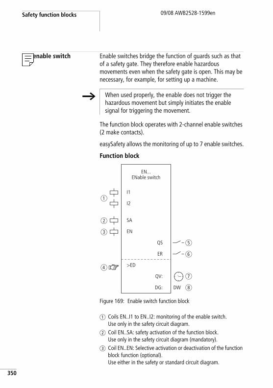
Safety function blocks
350
09/08 AWB2528-1599en
EN, enable switch Enable switches bridge the function of guards such as that of a safety gate. They therefore enable hazardous movements even when the safety gate is open. This may be necessary, for example, for setting up a machine.
The function block operates with 2-channel enable switches (2 make contacts).
easySafety allows the monitoring of up to 7 enable switches.
Function block
Figure 169: Enable switch function block
a Coils EN..I1 to EN..I2: monitoring of the enable switch. Use only in the safety circuit diagram.
b Coil EN..SA: safety activation of the function block.Use only in the safety circuit diagram (mandatory).
c Coil EN..EN: Selective activation or deactivation of the function block function (optional). Use either in the safety or standard circuit diagram.
h When used properly, the enable does not trigger the hazardous movement but simply initiates the enable signal for triggering the movement.
I1
I2
SA
EN
>ED
QS
ER
DG:
QV:
EN...ENable switch
a
b
c
d
e
f
g
hDW
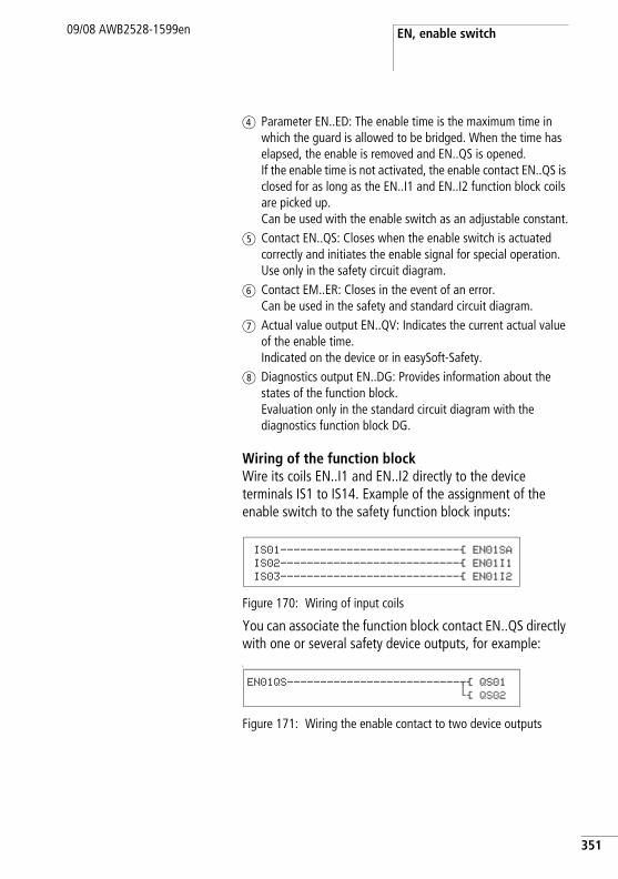
EN, enable switch09/08 AWB2528-1599en
d Parameter EN..ED: The enable time is the maximum time in which the guard is allowed to be bridged. When the time has elapsed, the enable is removed and EN..QS is opened. If the enable time is not activated, the enable contact EN..QS is closed for as long as the EN..I1 and EN..I2 function block coils are picked up. Can be used with the enable switch as an adjustable constant.
e Contact EN..QS: Closes when the enable switch is actuated correctly and initiates the enable signal for special operation. Use only in the safety circuit diagram.
f Contact EM..ER: Closes in the event of an error. Can be used in the safety and standard circuit diagram.
g Actual value output EN..QV: Indicates the current actual value of the enable time. Indicated on the device or in easySoft-Safety.
h Diagnostics output EN..DG: Provides information about the states of the function block. Evaluation only in the standard circuit diagram with the diagnostics function block DG.
Wiring of the function blockWire its coils EN..I1 and EN..I2 directly to the device terminals IS1 to IS14. Example of the assignment of the enable switch to the safety function block inputs:
Figure 170: Wiring of input coils
You can associate the function block contact EN..QS directly with one or several safety device outputs, for example:L
Figure 171: Wiring the enable contact to two device outputs
IS01---------------------------Ä EN01SA
IS02---------------------------Ä EN01I1
IS03---------------------------Ä EN01I2
EN01QS--------------------------uÄ QS01
hÄ QS02
351
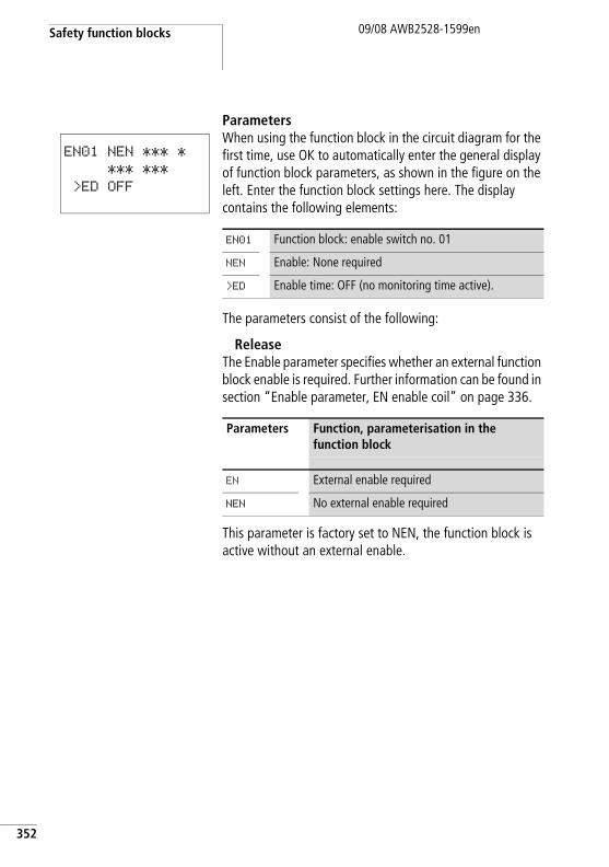
Safety function blocks
352
09/08 AWB2528-1599en
ParametersWhen using the function block in the circuit diagram for the first time, use OK to automatically enter the general display of function block parameters, as shown in the figure on the left. Enter the function block settings here. The display contains the following elements:
The parameters consist of the following:
ReleaseThe Enable parameter specifies whether an external function block enable is required. Further information can be found in section “Enable parameter, EN enable coil” on page 336.
This parameter is factory set to NEN, the function block is active without an external enable.
EN01 NEN *** *
*** ***
>ED OFF
EN01 Function block: enable switch no. 01
NEN Enable: None required
>ED Enable time: OFF (no monitoring time active).
Parameters Function, parameterisation in the function block
EN External enable required
NEN No external enable required
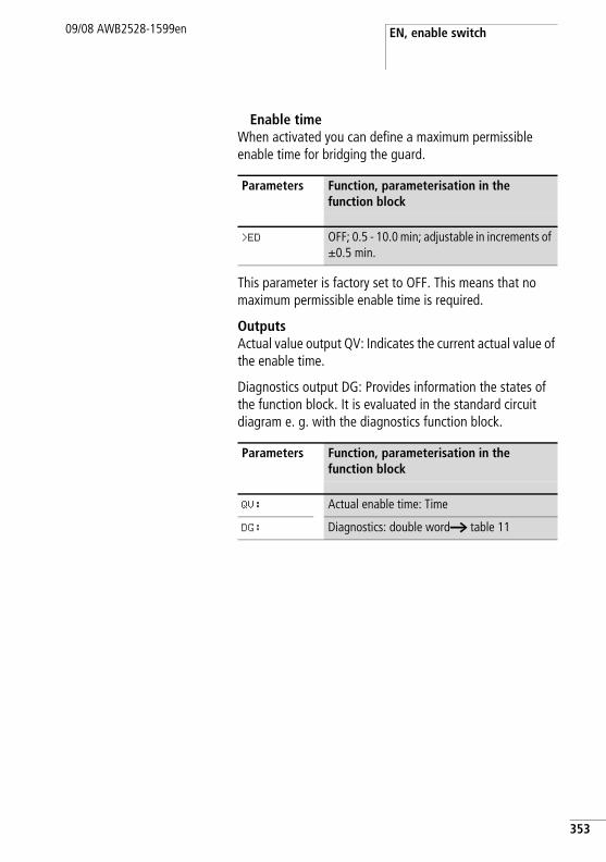
EN, enable switch09/08 AWB2528-1599en
Enable timeWhen activated you can define a maximum permissible enable time for bridging the guard.
This parameter is factory set to OFF. This means that no maximum permissible enable time is required.
OutputsActual value output QV: Indicates the current actual value of the enable time.
Diagnostics output DG: Provides information the states of the function block. It is evaluated in the standard circuit diagram e. g. with the diagnostics function block.
Parameters Function, parameterisation in the function block
>ED OFF; 0.5 - 10.0 min; adjustable in increments of g0.5 min.
Parameters Function, parameterisation in the function block
QV: Actual enable time: Time
DG: Diagnostics: double worda table 11
353
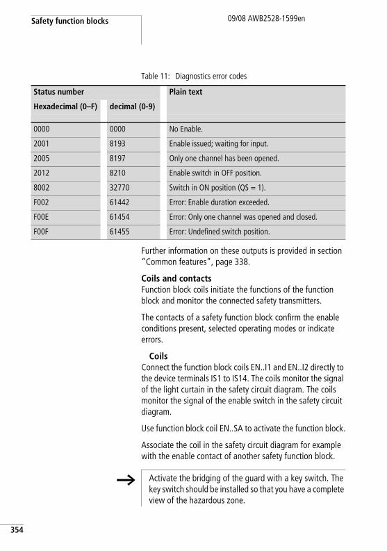
Safety function blocks
354
09/08 AWB2528-1599en
Table 11: Diagnostics error codes
Further information on these outputs is provided in section “Common features”, page 338.
Coils and contactsFunction block coils initiate the functions of the function block and monitor the connected safety transmitters.
The contacts of a safety function block confirm the enable conditions present, selected operating modes or indicate errors.
CoilsConnect the function block coils EN..I1 and EN..I2 directly to the device terminals IS1 to IS14. The coils monitor the signal of the light curtain in the safety circuit diagram. The coils monitor the signal of the enable switch in the safety circuit diagram.
Use function block coil EN..SA to activate the function block.
Associate the coil in the safety circuit diagram for example with the enable contact of another safety function block.
Status number Plain text
Hexadecimal (0–F) decimal (0-9)
0000 0000 No Enable.
2001 8193 Enable issued; waiting for input.
2005 8197 Only one channel has been opened.
2012 8210 Enable switch in OFF position.
8002 32770 Switch in ON position (QS = 1).
F002 61442 Error: Enable duration exceeded.
F00E 61454 Error: Only one channel was opened and closed.
F00F 61455 Error: Undefined switch position.
h Activate the bridging of the guard with a key switch. The key switch should be installed so that you have a complete view of the hazardous zone.
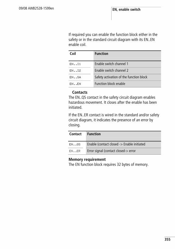
EN, enable switch09/08 AWB2528-1599en
If required you can enable the function block either in the safety or in the standard circuit diagram with its EN..EN enable coil.
ContactsThe EN..QS contact in the safety circuit diagram enables hazardous movement. It closes after the enable has been initiated.
If the EN..ER contact is wired in the standard and/or safety circuit diagram, it indicates the presence of an error by closing.
Memory requirementThe EN function block requires 32 bytes of memory.
Coil Function
EN..I1 Enable switch channel 1
EN..I2 Enable switch channel 2
EN..SA Safety activation of the function block
EN..EN Function block enable
Contact Function
EN..QS Enable (contact closed -> Enable initiated
EN..ER Error signal (contact closed-> error
355
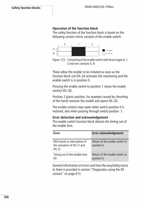
Safety function blocks
356
09/08 AWB2528-1599en
Operation of the function blockThe safety function of the function block is based on the following contact mirror variants of the enable switch:
Figure 172: Contacting of the enable switch with three stages 0, 1, 2 and two contacts A, B
These allow the enable to be initiated as soon as the function block coil EN..SA activates the monitoring and the enable switch is in position 0.
Pressing the enable switch to position 1 closes the enable contact EN..QS.
Position 2 (panic position, for example caused by clenching of the hand) removes the enable and opens EN..QS.
The enable contact stays open when switch position 0 is restored, also when passing through switch position 1.
Error detection and acknowledgementThe enable switch function block detects the timing out of the enable time.
General information on Errors and how the easySafety reacts to them is provided in section “Diagnostics using the ER contact” on page 613.
Error Error acknowledgement
Wire break or interruption of the activation of EN..I1 and EN..I2.
Return of the enable switch to position 0.
Timing out of the enable time ED.
Return of the enable switch to position 0.
A
B
0 1 2
EN, enable switch09/08 AWB2528-1599en
ExampleMonitoring of an enable switch with cross-circuit monitoring of the external wiring. Activation coil EN01SA is triggered by a key switch. The enable switch must only be active at reduced speed. This condition is scanned with the OM (maximum speed monitoring) function block. The wiring of the OM function block is described in section “OM, Maximum speed monitoring” on page 424.
Moving the switch from position 0 to 1 triggers the enable. The enable contact EN01QS of the function block closes and the signal is assigned to the safety marker MS05 for further processing.
The enable is removed if the switch is held down in position 2 or released and is thus returned to position 0. When returning to switch position 0 from switch position 2, there is no enable when passing through position 1.
The guard can only be bridged for up to 3 minutes.
357
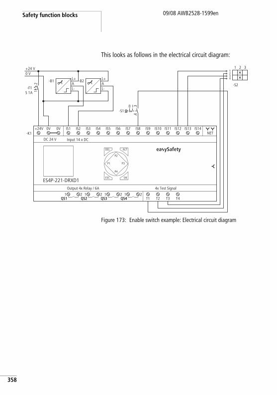
Safety function blocks
358
09/08 AWB2528-1599en
This looks as follows in the electrical circuit diagram:
Figure 173: Enable switch example: Electrical circuit diagram
0 V+24 V
T1 T2 T3 T4
4x Test SignalOutput 4x Relay / 6A
DEL
-K1
OK
ALT
ES4P-221-DRXD1
DC 24 V
NET
Input 14 x DC
ESC
IS1 IS2 IS3 IS4 IS5 IS6 IS7 IS8 IS9 IS10 IS11 IS12 IS13 IS14
1QS1
2QS1
1QS2
2QS2
1QS3
2QS3
1QS4
2QS4
+24V 0V 0V
P1
P2
P3
P4
21
-F1S 1A
L+AL-
-B1L+AL-
-B2
I-S1
0 3.4.
21
43
2
-S2
31
ea ySafety
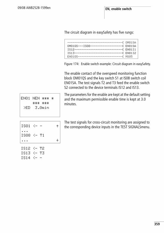
EN, enable switch09/08 AWB2528-1599en
The circuit diagram in easySafety has five rungs:
Figure 174: Enable switch example: Circuit diagram in easySafety.
The enable contact of the overspeed monitoring function block OM01QS and the key switch S1 at IS08 switch coil EN01SA. The test signals T2 and T3 feed the enable switch S2 connected to the device terminals IS12 and IS13.
The parameters for the enable are kept at the default setting and the maximum permissible enable time is kept at 3.0 minutes.
The test signals for cross-circuit monitoring are assigned to the corresponding device inputs in the TEST SIGNALSmenu.
-------------------------------Ä OM01SAOM01QS---IS08------------------Ä EN01SAIS12---------------------------Ä EN01I1IS13---------------------------Ä EN01I2EN01QS-------------------------Ä MS05
EN01 NEN *** *
*** ***
>ED 3.0min
IS01 <- - Æ...
IS08 <- T1
... æIS12 <- T2
IS13 <- T3
IS14 <- -
359
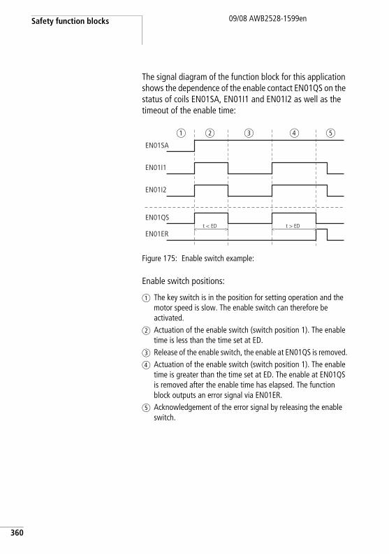
Safety function blocks
360
09/08 AWB2528-1599en
The signal diagram of the function block for this application shows the dependence of the enable contact EN01QS on the status of coils EN01SA, EN01I1 and EN01I2 as well as the timeout of the enable time:
Figure 175: Enable switch example:
Enable switch positions:
a The key switch is in the position for setting operation and the motor speed is slow. The enable switch can therefore be activated.
b Actuation of the enable switch (switch position 1). The enable time is less than the time set at ED.
c Release of the enable switch, the enable at EN01QS is removed.d Actuation of the enable switch (switch position 1). The enable
time is greater than the time set at ED. The enable at EN01QS is removed after the enable time has elapsed. The function block outputs an error signal via EN01ER.
e Acknowledgement of the error signal by releasing the enable switch.
EN01I1
EN01I2
EN01QS
EN01ER
EN01SA
t < ED t > ED
a b c ed
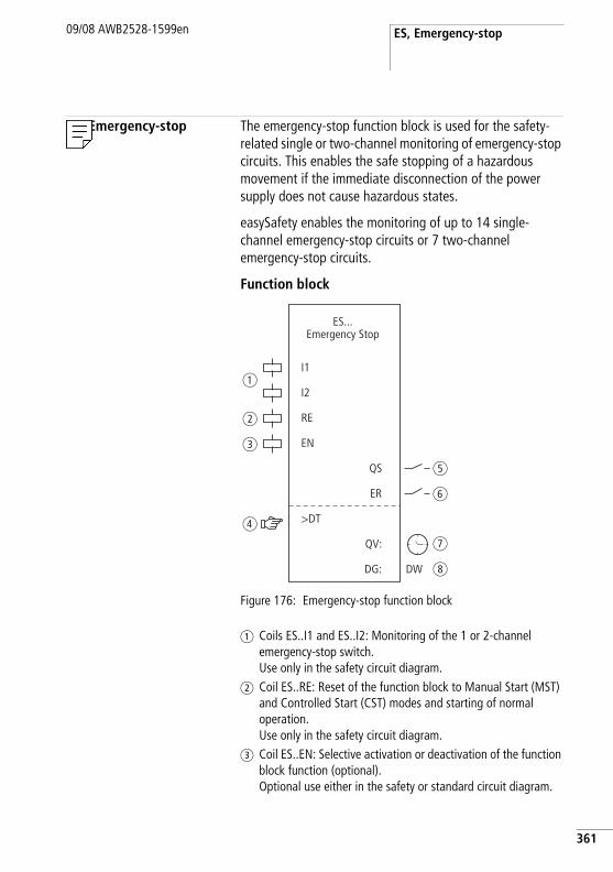
ES, Emergency-stop09/08 AWB2528-1599en
ES, Emergency-stop The emergency-stop function block is used for the safety-related single or two-channel monitoring of emergency-stop circuits. This enables the safe stopping of a hazardous movement if the immediate disconnection of the power supply does not cause hazardous states.
easySafety enables the monitoring of up to 14 single-channel emergency-stop circuits or 7 two-channel emergency-stop circuits.
Function block
Figure 176: Emergency-stop function block
a Coils ES..I1 and ES..I2: Monitoring of the 1 or 2-channel emergency-stop switch. Use only in the safety circuit diagram.
b Coil ES..RE: Reset of the function block to Manual Start (MST) and Controlled Start (CST) modes and starting of normal operation. Use only in the safety circuit diagram.
c Coil ES..EN: Selective activation or deactivation of the function block function (optional). Optional use either in the safety or standard circuit diagram.
I1
I2
RE
EN
>DT
ER
DG:
QV:
ES...Emergency Stop
QS
DW
a
b
c
d
e
f
g
h
361
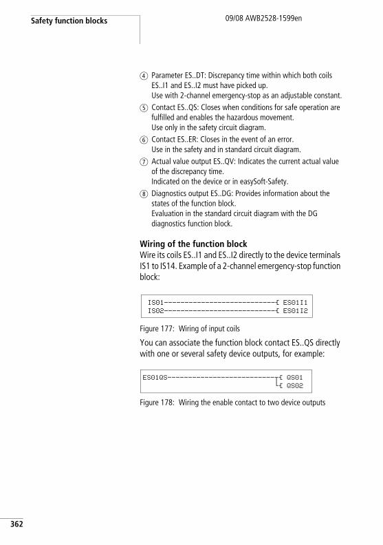
Safety function blocks
362
09/08 AWB2528-1599en
d Parameter ES..DT: Discrepancy time within which both coils ES..I1 and ES..I2 must have picked up. Use with 2-channel emergency-stop as an adjustable constant.
e Contact ES..QS: Closes when conditions for safe operation are fulfilled and enables the hazardous movement. Use only in the safety circuit diagram.
f Contact ES..ER: Closes in the event of an error. Use in the safety and in standard circuit diagram.
g Actual value output ES..QV: Indicates the current actual value of the discrepancy time. Indicated on the device or in easySoft-Safety.
h Diagnostics output ES..DG: Provides information about the states of the function block. Evaluation in the standard circuit diagram with the DG diagnostics function block.
Wiring of the function blockWire its coils ES..I1 and ES..I2 directly to the device terminals IS1 to IS14. Example of a 2-channel emergency-stop function block:
Figure 177: Wiring of input coils
You can associate the function block contact ES..QS directly with one or several safety device outputs, for example:
Figure 178: Wiring the enable contact to two device outputs
IS01---------------------------Ä ES01I1
IS02---------------------------Ä ES01I2
ES01QS--------------------------uÄ QS01
hÄ QS02
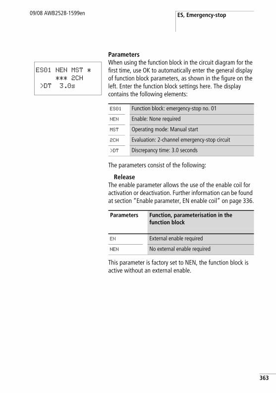
ES, Emergency-stop09/08 AWB2528-1599en
ParametersWhen using the function block in the circuit diagram for the first time, use OK to automatically enter the general display of function block parameters, as shown in the figure on the left. Enter the function block settings here. The display contains the following elements:
The parameters consist of the following:
ReleaseThe enable parameter allows the use of the enable coil for activation or deactivation. Further information can be found at section “Enable parameter, EN enable coil” on page 336.
This parameter is factory set to NEN, the function block is active without an external enable.
ES01 NEN MST *
*** 2CH
>DT 3.0s
ES01 Function block: emergency-stop no. 01
NEN Enable: None required
MST Operating mode: Manual start
2CH Evaluation: 2-channel emergency-stop circuit
>DT Discrepancy time: 3.0 seconds
Parameters Function, parameterisation in the function block
EN External enable required
NEN No external enable required
363
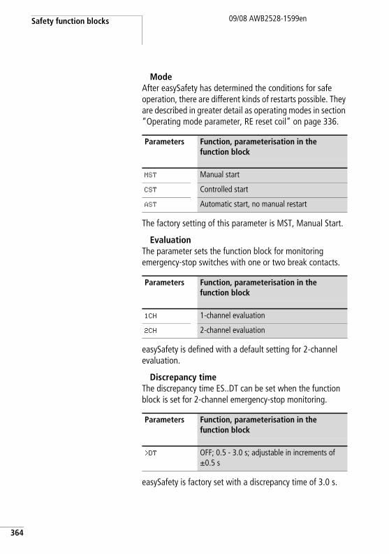
Safety function blocks
364
09/08 AWB2528-1599en
ModeAfter easySafety has determined the conditions for safe operation, there are different kinds of restarts possible. They are described in greater detail as operating modes in section “Operating mode parameter, RE reset coil” on page 336.
The factory setting of this parameter is MST, Manual Start.
EvaluationThe parameter sets the function block for monitoring emergency-stop switches with one or two break contacts.
easySafety is defined with a default setting for 2-channel evaluation.
Discrepancy timeThe discrepancy time ES..DT can be set when the function block is set for 2-channel emergency-stop monitoring.
easySafety is factory set with a discrepancy time of 3.0 s.
Parameters Function, parameterisation in the function block
MST Manual start
CST Controlled start
AST Automatic start, no manual restart
Parameters Function, parameterisation in the function block
1CH 1-channel evaluation
2CH 2-channel evaluation
Parameters Function, parameterisation in the function block
>DT OFF; 0.5 - 3.0 s; adjustable in increments of g0.5 s
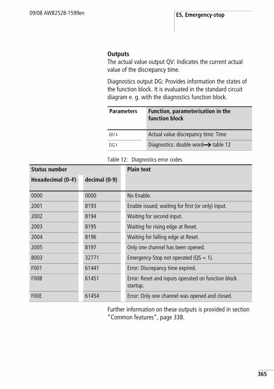
ES, Emergency-stop09/08 AWB2528-1599en
OutputsThe actual value output QV: Indicates the current actual value of the discrepancy time.
Diagnostics output DG: Provides information the states of the function block. It is evaluated in the standard circuit diagram e. g. with the diagnostics function block.
Table 12: Diagnostics error codes
Further information on these outputs is provided in section “Common features”, page 338.
Parameters Function, parameterisation in the function block
QV: Actual value discrepancy time: Time
DG: Diagnostics: double worda table 12
Status number Plain text
Hexadecimal (0–F) decimal (0-9)
0000 0000 No Enable.
2001 8193 Enable issued; waiting for first (or only) input.
2002 8194 Waiting for second input.
2003 8195 Waiting for rising edge at Reset.
2004 8196 Waiting for falling edge at Reset.
2005 8197 Only one channel has been opened.
8003 32771 Emergency-Stop not operated (QS = 1).
F001 61441 Error: Discrepancy time expired.
F00B 61451 Error: Reset and inputs operated on function block startup.
F00E 61454 Error: Only one channel was opened and closed.
365
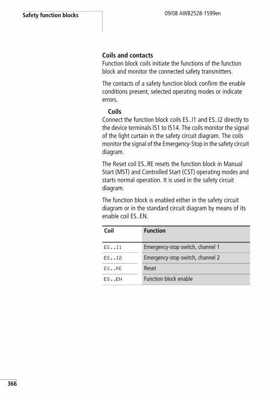
Safety function blocks
366
09/08 AWB2528-1599en
Coils and contactsFunction block coils initiate the functions of the function block and monitor the connected safety transmitters.
The contacts of a safety function block confirm the enable conditions present, selected operating modes or indicate errors.
CoilsConnect the function block coils ES..I1 and ES..I2 directly to the device terminals IS1 to IS14. The coils monitor the signal of the light curtain in the safety circuit diagram. The coils monitor the signal of the Emergency-Stop in the safety circuit diagram.
The Reset coil ES..RE resets the function block in Manual Start (MST) and Controlled Start (CST) operating modes and starts normal operation. It is used in the safety circuit diagram.
The function block is enabled either in the safety circuit diagram or in the standard circuit diagram by means of its enable coil ES..EN.
Coil Function
ES..I1 Emergency-stop switch, channel 1
ES..I2 Emergency-stop switch, channel 2
ES..RE Reset
ES..EN Function block enable
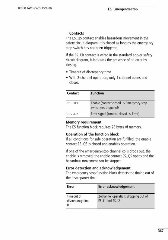
ES, Emergency-stop09/08 AWB2528-1599en
ContactsThe ES..QS contact enables hazardous movement in the safety circuit diagram. It is closed as long as the emergency-stop switch has not been triggered.
If the ES..ER contact is wired in the standard and/or safety circuit diagram, it indicates the presence of an error by closing.
• Timeout of discrepancy time• With 2-channel operation, only 1 channel opens and
closes.
Memory requirementThe ES function block requires 28 bytes of memory.
Operation of the function blockIf all conditions for safe operation are fulfilled, the enable contact ES..QS is closed and enables operation.
If one of the emergency-stop channel coils drops out, the enable is removed, the enable contact ES..QS opens and the hazardous movement can be stopped.
Error detection and acknowledgementThe emergency-stop function block detects the timing out of the discrepancy time.
Contact Function
ES..QS Enable (contact closed -> Emergency-stop switch not triggered)
ES..ER Error signal (contact closed -> Error)
Error Error acknowledgement
Timeout of discrepancy time DT
2-channel operation: dropping out of ES..I1 and ES..I2
367
Safety function blocks
368
09/08 AWB2528-1599en
Example 1 - Architecture of Category 4 according to EN 954-1 and ISO 13849-1Monitoring of a 2-channel emergency-stop switch and cross-circuit monitoring of its external wiring. The actuation of the pushbutton triggers the emergency-stop function. Releasing the Reset button after the removal of the hazard initiates the re-enabling in a controlled manner. The discrepancy time is set for 0.5 seconds.
The break contacts of the emergency-stop switch S1 are connected to the device terminals IS9 and IS10 and are provided with the test signals T3 and T4. The safety device outputs QS1 and QS3 switch the contactors Q1 and Q2 directly. The enable is initiated by the function block after the emergency-stop switch has been released and the Reset button has been actuated.
This looks as follows in the electrical circuit diagram:
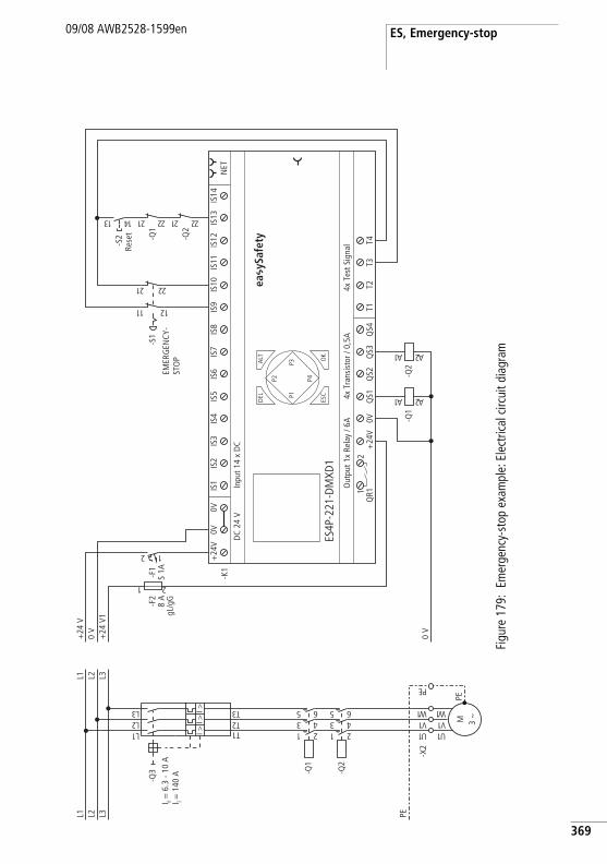
ES, Emergency-stop09/08 AWB2528-1599en
Figu
re 1
79:
Emer
genc
y-st
op e
xam
ple:
Ele
ctric
al c
ircui
t dia
gram
PEL3L2L1
1U
-X2
-Q2
1 23 45 6
-Q1
1 23 45 6
1L2L3L
1T2T3TI >
I >I >
-Q3
M 3 h
1U1V1 W
PE
1V1 W
EP
L3L2L1
0 V
+24
V1
0 V
+24
V
-F2
8 A
gL/g
G
1 2
0V+
24V
QS1
QS2
QS3
QS4
T1T2
T3T4
Out
put 1
x Re
lay
/ 6A
4x T
est S
igna
l
ES4P
-221
-DM
XD1
4x T
rans
isto
r / 0
,5A
DC
24 V
Inpu
t 14
x D
C
NET
ALT OK
-K1
DEL
ESC
IS1
IS2
IS3
IS4
IS5
IS6
IS7
IS8
IS9
IS10
IS11
IS12
IS13
IS14
1Q
R12
+24
V0V
0V
P1
P2
P3
P42 1
-F1
S 1A
-Q1
1A 2A
-Q2
1A 2A
-S1
12 22
11 21
-Q2
12 22
-Q1
12 2231 41
-S2
I r = 6
.3 -
10 A
I i = 1
40 A
ea y
Safe
ty
EMER
GEN
CY-
STO
P
Rese
t
369
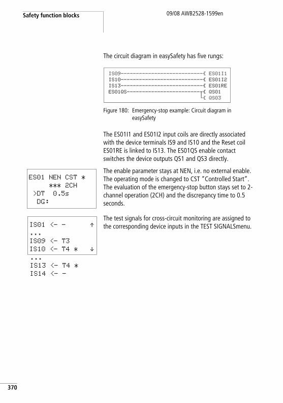
Safety function blocks
370
09/08 AWB2528-1599en
The circuit diagram in easySafety has five rungs:
Figure 180: Emergency-stop example: Circuit diagram in easySafety
The ES01I1 and ES01I2 input coils are directly associated with the device terminals IS9 and IS10 and the Reset coil ES01RE is linked to IS13. The ES01QS enable contact switches the device outputs QS1 and QS3 directly.
The enable parameter stays at NEN, i.e. no external enable. The operating mode is changed to CST “Controlled Start”. The evaluation of the emergency-stop button stays set to 2-channel operation (2CH) and the discrepancy time to 0.5 seconds.
The test signals for cross-circuit monitoring are assigned to the corresponding device inputs in the TEST SIGNALSmenu.
IS09---------------------------Ä ES01I1IS10---------------------------Ä ES01I2IS13---------------------------Ä ES01REES01QS------------------------uÄ QS01
hÄ QS03
ES01 NEN CST *
*** 2CH
>DT 0.5s
DG:
IS01 <- - Æ...
IS09 <- T3
IS10 <- T4 * æ...
IS13 <- T4 *
IS14 <- -
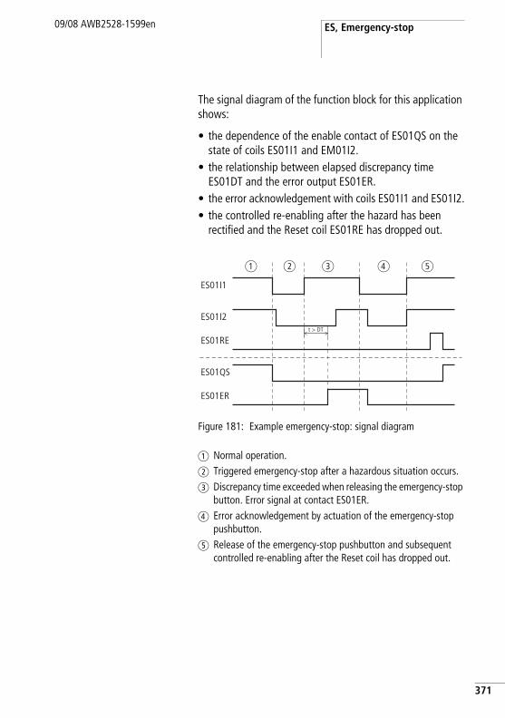
ES, Emergency-stop09/08 AWB2528-1599en
The signal diagram of the function block for this application shows:
• the dependence of the enable contact of ES01QS on the state of coils ES01I1 and EM01I2.
• the relationship between elapsed discrepancy time ES01DT and the error output ES01ER.
• the error acknowledgement with coils ES01I1 and ES01I2.• the controlled re-enabling after the hazard has been
rectified and the Reset coil ES01RE has dropped out.
Figure 181: Example emergency-stop: signal diagram
a Normal operation.b Triggered emergency-stop after a hazardous situation occurs.c Discrepancy time exceeded when releasing the emergency-stop
button. Error signal at contact ES01ER.d Error acknowledgement by actuation of the emergency-stop
pushbutton.e Release of the emergency-stop pushbutton and subsequent
controlled re-enabling after the Reset coil has dropped out.
ES01I1
ES01I2
ES01QS
ES01ER
t > DT
ES01RE
a b c ed
371
Safety function blocks
372
09/08 AWB2528-1599en
FS, safety foot switch Safety foot switches bridge the function of guards such as that of a safety gate. They therefore enable hazardous movements even when the safety gate is open. This may be necessary, for example, for setting up a machine.
The make contact closes when the foot pedal is actuated up to the pressure point. If in the event of a hazard the pedal is actuated beyond the pressure point, the positively driven break contact is opened and mechanically interlocked. An additional pushbutton is implemented for the release. The safety foot switch does not then move over the switch on point when it is reset.
The function block operates with 2-channel or 4-channel safety foot switches. easySafety allows the monitoring of up to 7 safety foot switches.
h When used properly, the enable does not trigger the hazardous movement but simply initiates the enable signal for triggering the movement.
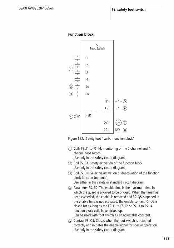
FS, safety foot switch09/08 AWB2528-1599en
Function block
Figure 182: Safety foot "switch function block"
a Coils FS..I1 to FS..I4: monitoring of the 2-channel and 4-channel foot switch.Use only in the safety circuit diagram.
b Coil FS..SA: safety activation of the function block. Use only in the safety circuit diagram.
c Coil FS..EN: Selective activation or deactivation of the function block function (optional). Use either in the safety or standard circuit diagram.
d Parameter FS..ED: The enable time is the maximum time in which the guard is allowed to be bridged. When the time has been exceeded, the enable is removed and FS..QS is opened. If the enable time is not activated, the enable contact FS..QS is closed for as long as the FS..I1 to FS..I2 or FS..I1 to FS..I4 function block coils have picked up. Can be used with foot switch as an adjustable constant.
e Contact FS..QS: Closes when the foot switch is actuated correctly and initiates the enable signal for special operation. Use only in the safety circuit diagram.
I1
I2
SA
EN
>ED
QS
ER
DG:
QV:
FS...Foot Switch
a
b
c
d
e
f
g
h
I3
I4
DW
373
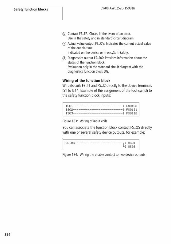
Safety function blocks
374
09/08 AWB2528-1599en
f Contact FS..ER: Closes in the event of an error. Use in the safety and in standard circuit diagram.
g Actual value output FS..QV: Indicates the current actual value of the enable time. Indicated on the device or in easySoft-Safety.
h Diagnostics output FS..DG: Provides information about the states of the function block. Evaluation only in the standard circuit diagram with the diagnostics function block DG.
Wiring of the function blockWire its coils FS..I1 and FS..I2 directly to the device terminals IS1 to IS14. Example of the assignment of the foot switch to the safety function block inputs:
Figure 183: Wiring of input coils
You can associate the function block contact FS..QS directly with one or several safety device outputs, for example:L
Figure 184: Wiring the enable contact to two device outputs
IS01---------------------------Ä EN01SA
IS02---------------------------Ä FS01I1
IS03---------------------------Ä FS01I2
FS01QS--------------------------uÄ QS01
hÄ QS02
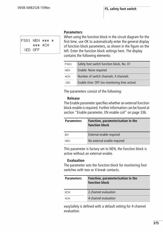
FS, safety foot switch09/08 AWB2528-1599en
ParametersWhen using the function block in the circuit diagram for the first time, use OK to automatically enter the general display of function block parameters, as shown in the figure on the left. Enter the function block settings here. The display contains the following elements:
The parameters consist of the following:
ReleaseThe Enable parameter specifies whether an external function block enable is required. Further information can be found at section “Enable parameter, EN enable coil” on page 336.
This parameter is factory set to NEN, the function block is active without an external enable.
EvaluationThe parameter sets the function block for monitoring foot switches with two or 4 break contacts.
easySafety is defined with a default setting for 4-channel evaluation.
FS01 NEN *** *
*** 4CH
>ED OFF
FS01 Safety foot switch function block, No. 01
NEN Enable: None required
4CH Number of switch channels: 4 channels
>ED Enable time: OFF (no monitoring time active).
Parameters Function, parameterisation in the function block
EN External enable required
NEN No external enable required
Parameters Function, parameterisation in the function block
2CH 2-channel evaluation
4CH 4-channel evaluation
375
Safety function blocks
376
09/08 AWB2528-1599en
Enable timeWhen activated you can define a maximum permissible enable time for bridging the guard.
This parameter is factory set to OFF. This means that no maximum permissible enable time is required.
OutputsActual value output QV: Indicates the current actual value of the enable time.
Diagnostics output DG: Provides information the states of the function block. It is evaluated in the standard circuit diagram e.g. with the diagnostics function block.
Parameters Function, parameterisation in the function block
>ED OFF; 0.5 - 10.0 min; adjustable in increments of g0.5 min.
Parameters Function, parameterisation in the function block
QV: Actual enable time: Time
DG: Diagnostics: double word a table 13
FS, safety foot switch09/08 AWB2528-1599en
Table 13: Diagnostics error codes
Further information on these outputs is provided in section “Common features”, page 338.
Coils and contactsFunction block coils initiate the functions of the function block and monitor the connected safety transmitters.
The contacts of a safety function block confirm the enable conditions present, selected operating modes or indicate errors.
CoilsConnect the function block coils FS..I1 and FS..I4 directly to the device terminals IS1 to IS14. The coils monitor the signal of the foot switch in the safety circuit diagram.
Use function block coil FS..SA to activate the function block.
Associate the coil only in the safety circuit diagram for example with the enable contact of another safety function block.
Status number Plain text
Hexadecimal (0–F) decimal (0-9)
0000 0000 No Enable.
2001 8193 Enable issued; waiting for first (or only) input.
2011 8209 Foot switch not operated (position 0).
2013 8211 Foot switch in panic position (position 2).
2014 8212 Undefined foot switch position
8004 32772 Foot switch operated (position 1).
F002 61442 Error: Enable duration exceeded.
F00F 61455 Error: Foot switch 1/2 position is not permissible after enable.
F010 61456 Error: Position 1 not permissible after panic position.
h Activate the bridging of the guard with a key switch. The key switch should be installed so that you have a complete view of the hazardous zone.
377
Safety function blocks
378
09/08 AWB2528-1599en
If required you can enable the function block either in the safety or in the standard circuit diagram with its FS..EN enable coil.
ContactsThe FS..QS contact enables hazardous movement in the safety circuit diagram. It closes after the enable has been initiated.
If the FS..ER contact is wired in the standard and/or safety circuit diagram, it indicates the presence of an error by closing.
Memory requirementThe FS function block requires 32 bytes of memory.
Coil Function
FS..I1 Foot switch channel 1
FS..I2 Foot switch channel 2
FS..I3 Foot switch channel 3
FS..I4 Foot switch channel 4
FS..SA Safety activation of the function block
FS..EN Function block enable
Contact Function
FS..QS Enable (contact closed -> Foot switch initiates enable
FS..ER Error signal (contact closed -> Error)
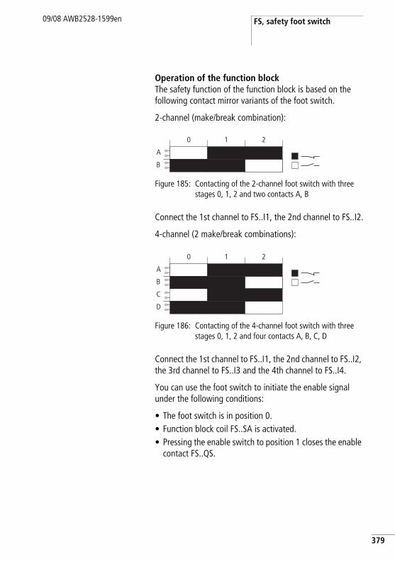
FS, safety foot switch09/08 AWB2528-1599en
Operation of the function blockThe safety function of the function block is based on the following contact mirror variants of the foot switch.
2-channel (make/break combination):
Figure 185: Contacting of the 2-channel foot switch with three stages 0, 1, 2 and two contacts A, B
Connect the 1st channel to FS..I1, the 2nd channel to FS..I2.
4-channel (2 make/break combinations):
Figure 186: Contacting of the 4-channel foot switch with three stages 0, 1, 2 and four contacts A, B, C, D
Connect the 1st channel to FS..I1, the 2nd channel to FS..I2, the 3rd channel to FS..I3 and the 4th channel to FS..I4.
You can use the foot switch to initiate the enable signal under the following conditions:
• The foot switch is in position 0. • Function block coil FS..SA is activated.• Pressing the enable switch to position 1 closes the enable
contact FS..QS.
A
B
0 1 2
A
B
0 1 2
C
D
379
Safety function blocks
380
09/08 AWB2528-1599en
Position 2 (panic position, for example if you fully press the foot switch) removes the enable and opens FS..QS.
With both switch types (2 or 4-channel) the enable contact stays open when switch position 0 is resumed, also when passing through switch position 1.
Error detection and acknowledgementThe safety foot switch detects the timing out of the enable time.
General information on Errors and how the easySafety reacts to them is provided in section “Diagnostics using the ER contact” on page 613.
Error Error acknowledgement
Wire break or interruption of the activation of FS..I1 and FS..I4.
Return of the foot switch to position 0.
Timing out of the enable time ED.
Return of the foot switch to position 0.
FS, safety foot switch09/08 AWB2528-1599en
ExampleMonitoring of a 2-channel foot switch with cross-circuit monitoring of the external wiring. Activation coil FS01SA is triggered by a key switch.
This condition is scanned with the OM (maximum speed monitoring) function block. The wiring of the OM function block is described in section “OM, Maximum speed monitoring” on page 424.
Moving the switch from position 0 to 1 triggers the enable. The enable contact FS01QS of the function block closes and the signal is assigned to the safety marker MS05 for further processing.
The enable is removed if you continue to hold down the switch in position 2 or take your foot off the switch to thus return it to position 0. When returning to switch position 2 from switch position 0, there is no enable when passing through position 1.
The guard can only be bridged for up to 3 minutes.
The electrical circuit is as follows:
h The foot switch must only be active at reduced speed.
381
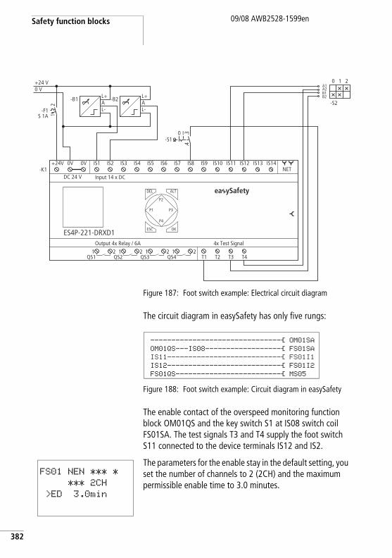
Safety function blocks
382
09/08 AWB2528-1599en
Figure 187: Foot switch example: Electrical circuit diagram
The circuit diagram in easySafety has only five rungs:
Figure 188: Foot switch example: Circuit diagram in easySafety
The enable contact of the overspeed monitoring function block OM01QS and the key switch S1 at IS08 switch coil FS01SA. The test signals T3 and T4 supply the foot switch S11 connected to the device terminals IS12 and IS2.
The parameters for the enable stay in the default setting, you set the number of channels to 2 (2CH) and the maximum permissible enable time to 3.0 minutes.
0 V+24 V
T1 T2 T3 T4
4x Test SignalOutput 4x Relay / 6A
DEL
-K1
OK
ALT
ES4P-221-DRXD1
DC 24 VNET
Input 14 x DC
ESC
IS1 IS2 IS3 IS4 IS5 IS6 IS7 IS8 IS9 IS10 IS11 IS12 IS13 IS14
1QS1
2 1QS2
2 1QS3
2 1QS4
2
+24V 0V 0V
P1
P2
P3
P4
21
-F1S 1A
L+AL-
-B1 L+AL-
-B2
I-S1
0 3.4.
A2A1
B2B1
1
-S2
0 2
ea ySafety
-------------------------------Ä OM01SAOM01QS---IS08------------------Ä FS01SAIS11---------------------------Ä FS01I1IS12---------------------------Ä FS01I2FS01QS-------------------------Ä MS05
FS01 NEN *** *
*** 2CH
>ED 3.0min
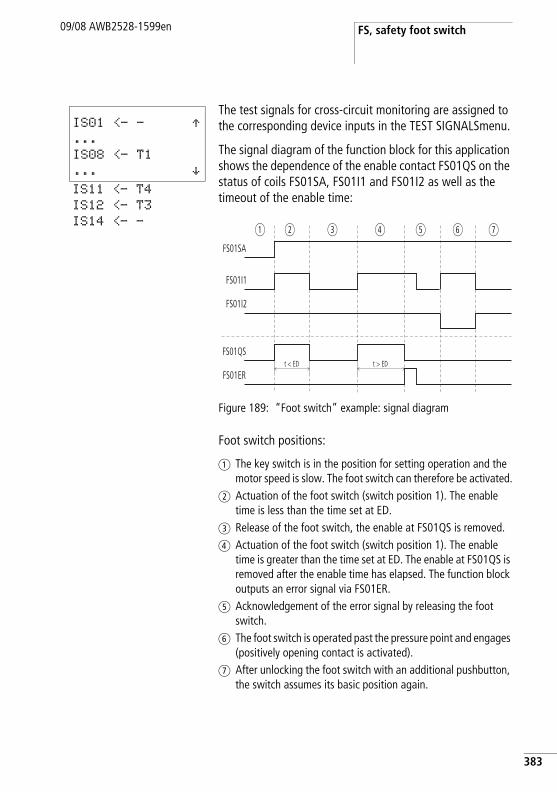
FS, safety foot switch09/08 AWB2528-1599en
The test signals for cross-circuit monitoring are assigned to the corresponding device inputs in the TEST SIGNALSmenu.
The signal diagram of the function block for this application shows the dependence of the enable contact FS01QS on the status of coils FS01SA, FS01I1 and FS01I2 as well as the timeout of the enable time:
Figure 189: “Foot switch” example: signal diagram
Foot switch positions:
a The key switch is in the position for setting operation and the motor speed is slow. The foot switch can therefore be activated.
b Actuation of the foot switch (switch position 1). The enable time is less than the time set at ED.
c Release of the foot switch, the enable at FS01QS is removed.d Actuation of the foot switch (switch position 1). The enable
time is greater than the time set at ED. The enable at FS01QS is removed after the enable time has elapsed. The function block outputs an error signal via FS01ER.
e Acknowledgement of the error signal by releasing the foot switch.
f The foot switch is operated past the pressure point and engages (positively opening contact is activated).
g After unlocking the foot switch with an additional pushbutton, the switch assumes its basic position again.
IS01 <- - Æ...
IS08 <- T1
... æIS11 <- T4
IS12 <- T3
IS14 <- -
FS01I1
FS01I2
FS01QS
FS01ER
FS01SA
t < ED t > ED
a b c ed gf
383
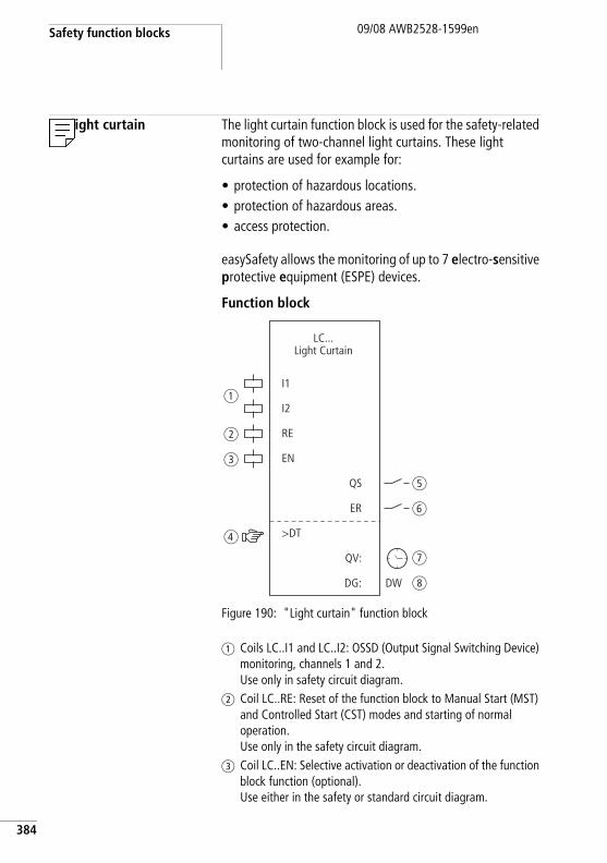
Safety function blocks
384
09/08 AWB2528-1599en
LC, light curtain The light curtain function block is used for the safety-related monitoring of two-channel light curtains. These light curtains are used for example for:
• protection of hazardous locations.• protection of hazardous areas.• access protection.
easySafety allows the monitoring of up to 7 electro-sensitive protective equipment (ESPE) devices.
Function block
Figure 190: "Light curtain" function block
a Coils LC..I1 and LC..I2: OSSD (Output Signal Switching Device) monitoring, channels 1 and 2.Use only in safety circuit diagram.
b Coil LC..RE: Reset of the function block to Manual Start (MST) and Controlled Start (CST) modes and starting of normal operation. Use only in the safety circuit diagram.
c Coil LC..EN: Selective activation or deactivation of the function block function (optional). Use either in the safety or standard circuit diagram.
I1
I2
RE
EN
>DT
QS
ER
DG:
QV:
LC...Light Curtain
DW
a
b
c
d
e
f
g
h
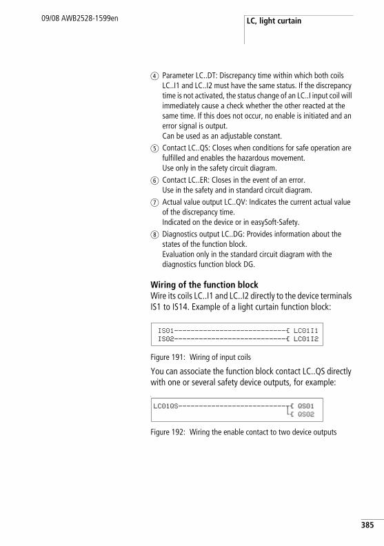
LC, light curtain09/08 AWB2528-1599en
d Parameter LC..DT: Discrepancy time within which both coils LC..I1 and LC..I2 must have the same status. If the discrepancy time is not activated, the status change of an LC..I input coil will immediately cause a check whether the other reacted at the same time. If this does not occur, no enable is initiated and an error signal is output. Can be used as an adjustable constant.
e Contact LC..QS: Closes when conditions for safe operation are fulfilled and enables the hazardous movement. Use only in the safety circuit diagram.
f Contact LC..ER: Closes in the event of an error. Use in the safety and in standard circuit diagram.
g Actual value output LC..QV: Indicates the current actual value of the discrepancy time. Indicated on the device or in easySoft-Safety.
h Diagnostics output LC..DG: Provides information about the states of the function block. Evaluation only in the standard circuit diagram with the diagnostics function block DG.
Wiring of the function blockWire its coils LC..I1 and LC..I2 directly to the device terminals IS1 to IS14. Example of a light curtain function block:
Figure 191: Wiring of input coils
You can associate the function block contact LC..QS directly with one or several safety device outputs, for example:L
Figure 192: Wiring the enable contact to two device outputs
IS01---------------------------Ä LC01I1
IS02---------------------------Ä LC01I2
LC01QS--------------------------uÄ QS01
hÄ QS02
385
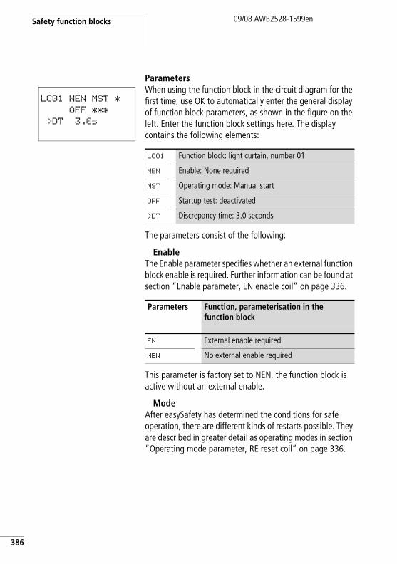
Safety function blocks
386
09/08 AWB2528-1599en
ParametersWhen using the function block in the circuit diagram for the first time, use OK to automatically enter the general display of function block parameters, as shown in the figure on the left. Enter the function block settings here. The display contains the following elements:
The parameters consist of the following:
EnableThe Enable parameter specifies whether an external function block enable is required. Further information can be found at section “Enable parameter, EN enable coil” on page 336.
This parameter is factory set to NEN, the function block is active without an external enable.
ModeAfter easySafety has determined the conditions for safe operation, there are different kinds of restarts possible. They are described in greater detail as operating modes in section “Operating mode parameter, RE reset coil” on page 336.
LC01 NEN MST *
OFF ***
>DT 3.0s
LC01 Function block: light curtain, number 01
NEN Enable: None required
MST Operating mode: Manual start
OFF Startup test: deactivated
>DT Discrepancy time: 3.0 seconds
Parameters Function, parameterisation in the function block
EN External enable required
NEN No external enable required
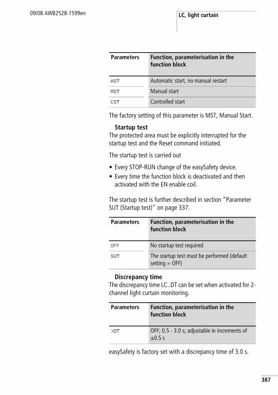
LC, light curtain09/08 AWB2528-1599en
The factory setting of this parameter is MST, Manual Start.
Startup testThe protected area must be explicitly interrupted for the startup test and the Reset command initiated.
The startup test is carried out
• Every STOP-RUN change of the easySafety device.• Every time the function block is deactivated and then
activated with the EN enable coil.
The startup test is further described in section “Parameter SUT (Startup test)” on page 337.
Discrepancy timeThe discrepancy time LC..DT can be set when activated for 2-channel light curtain monitoring.
easySafety is factory set with a discrepancy time of 3.0 s.
Parameters Function, parameterisation in the function block
AST Automatic start, no manual restart
MST Manual start
CST Controlled start
Parameters Function, parameterisation in the function block
OFF No startup test required
SUT The startup test must be performed (default setting = OFF)
Parameters Function, parameterisation in the function block
>DT OFF; 0.5 - 3.0 s; adjustable in increments of g0.5 s
387
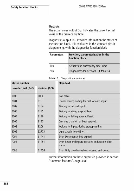
Safety function blocks
388
09/08 AWB2528-1599en
OutputsThe actual value output QV: Indicates the current actual value of the discrepancy time.
Diagnostics output DG: Provides information the states of the function block. It is evaluated in the standard circuit diagram e. g. with the diagnostics function block.
Table 14: Diagnostics error codes
Further information on these outputs is provided in section “Common features”, page 338.
Parameters Function, parameterisation in the function block
QV: Actual value discrepancy time: Time
DG: Diagnostics: double word a table 14
Status number Plain text
Hexadecimal (0–F) decimal (0-9)
0000 0000 No Enable.
2001 8193 Enable issued; waiting for first (or only) input.
2002 8194 Waiting for second input.
2003 8195 Waiting for rising edge at Reset.
2004 8196 Waiting for falling edge at Reset.
2005 8197 Only one channel has been opened.
200E 8206 Waiting for inputs during startup testing.
8005 32773 Light curtain free (QS = 1).
F001 61441 Error: Discrepancy time expired.
F00B 61451 Error: Reset and inputs operated on function block startup.
F00E 61454 Error: Only one channel was opened and closed.
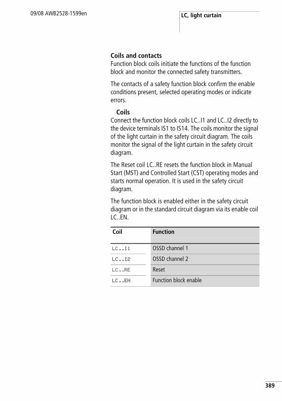
LC, light curtain09/08 AWB2528-1599en
Coils and contactsFunction block coils initiate the functions of the function block and monitor the connected safety transmitters.
The contacts of a safety function block confirm the enable conditions present, selected operating modes or indicate errors.
CoilsConnect the function block coils LC..I1 and LC..I2 directly to the device terminals IS1 to IS14. The coils monitor the signal of the light curtain in the safety circuit diagram. The coils monitor the signal of the light curtain in the safety circuit diagram.
The Reset coil LC..RE resets the function block in Manual Start (MST) and Controlled Start (CST) operating modes and starts normal operation. It is used in the safety circuit diagram.
The function block is enabled either in the safety circuit diagram or in the standard circuit diagram via its enable coil LC..EN.
Coil Function
LC..I1 OSSD channel 1
LC..I2 OSSD channel 2
LC..RE Reset
LC..EN Function block enable
389
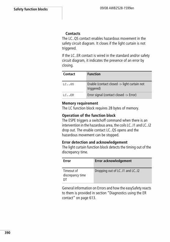
Safety function blocks
390
09/08 AWB2528-1599en
ContactsThe LC..QS contact enables hazardous movement in the safety circuit diagram. It closes if the light curtain is not triggered.
If the LC..ER contact is wired in the standard and/or safety circuit diagram, it indicates the presence of an error by closing.
Memory requirementThe LC function block requires 28 bytes of memory.
Operation of the function blockThe ESPE triggers a switchoff command when there is an intervention in the hazardous area, the coils LC..I1 and LC..I2 drop out. The enable contact LC..QS opens and the hazardous movement can be stopped.
Error detection and acknowledgementThe light curtain function block detects the timing out of the discrepancy time.
General information on Errors and how the easySafety reacts to them is provided in section “Diagnostics using the ER contact” on page 613.
Contact Function
LC..QS Enable (contact closed -> light curtain not triggered)
LC..ER Error signal (contact closed -> Error)
Error Error acknowledgement
Timeout of discrepancy time DT
Dropping out of LC..I1 and LC..I2
LC, light curtain09/08 AWB2528-1599en
Example 1 - Architecture of Category 2 according to EN 954-1 and ISO 13849-1Access control of an area with a 2-channel light curtain. Interruption of the light beam removes the enable, the re-enabling is automatic and without a manual startup after the protected area is vacated. The monitoring of the discrepancy time is set to 1 second and a startup test is to be carried out after every RUN/STOP change of the device.
The enable contacts of the light curtain are connected to IS2 and IS3, the safety relay output QS1 switches contactor Q1 directly.
This looks as follows in the electrical circuit diagram:
h Using suitable measures, ensure that any hazard is excluded after automatic re-enabling.
391
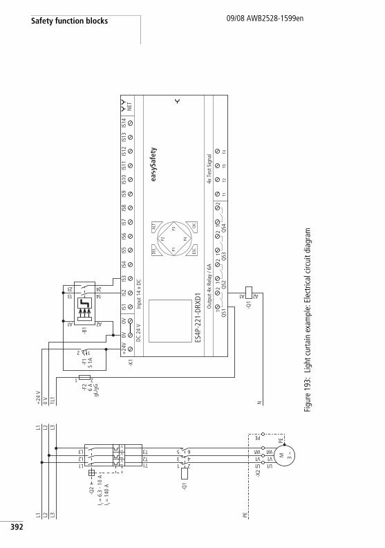
Safety function blocks
392
09/08 AWB2528-1599en
Figu
re 1
93:
Ligh
t cur
tain
exa
mpl
e: E
lect
rical
circ
uit d
iagr
am
PEL3L2L1
1U
-X2
-Q1
1 23 45 6
1L2L3L
1T2T3TI >
I >I >
-Q2
M 3 h
1U1V1 W
PE
1V1 W
EP
L3L2L1
N1L1
0 V
+24
V
-F2
6 A
gL/g
G
1 2
T1T2
T3T4
4x T
est S
igna
lO
utpu
t 4x
Rela
y / 6
A
DEL
-K1
OK
ALT
ES4P
-221
-DRX
D1
DC
24 V
NET
Inpu
t 14
x D
C
ESC
IS1
IS2
IS3
IS4
IS5
IS6
IS7
IS8
IS9
IS10
IS11
IS12
IS13
IS14
1Q
S12
1Q
S22
1Q
S32
1Q
S42
+24
V0V
0V
P1
P2
P3
P4
2 1
-F1
S 1A
2A1A
-B1
31 4132 42
-Q1
1A 2A
ea y
Safe
ty
I r = 6
.3 -
10 A
I i = 1
40 A
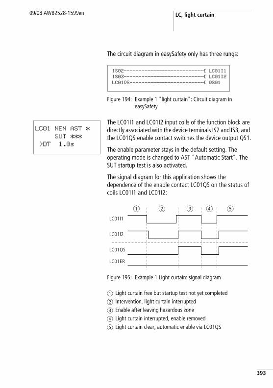
LC, light curtain09/08 AWB2528-1599en
The circuit diagram in easySafety only has three rungs:
Figure 194: Example 1 "light curtain": Circuit diagram in easySafety
The LC01I1 and LC01I2 input coils of the function block are directly associated with the device terminals IS2 and IS3, and the LC01QS enable contact switches the device output QS1.
The enable parameter stays in the default setting. The operating mode is changed to AST “Automatic Start”. The SUT startup test is also activated.
The signal diagram for this application shows the dependence of the enable contact LC01QS on the status of coils LC01I1 and LC01I2:
Figure 195: Example 1 Light curtain: signal diagram
a Light curtain free but startup test not yet completedb Intervention, light curtain interruptedc Enable after leaving hazardous zoned Light curtain interrupted, enable removede Light curtain clear, automatic enable via LC01QS
IS02---------------------------Ä LC01I1IS03---------------------------Ä LC01I2LC01QS-------------------------Ä QS01
LC01 NEN AST *
SUT ***
>DT 1.0s
LC01I1
LC01QS
LC01ER
LC01I2
a b c d e
393
Safety function blocks
394
09/08 AWB2528-1599en
Example 2 - Architecture of Category 4 according to EN 954-1 and ISO 13849-1Monitoring of a 2-channel light curtain and cross-circuit monitoring of its external wiring. The interruption of the light curtain triggers the protective function. After the area monitored by the light curtain is vacated, the controlled re-enabling is completed by actuating the Reset key switch. The discrepancy time is set to 0.5 seconds.
The make contacts of the light curtain -B1 are connected to the device terminals IS2 and IS3 and are supplied with test signals T3 and T4. Test signal T2 supplies the Reset button -S1 connected to IS6. The safety device outputs QS2 and QS4 switch the contactors Q1 and Q2 directly.
This looks as follows in the electrical circuit diagram:
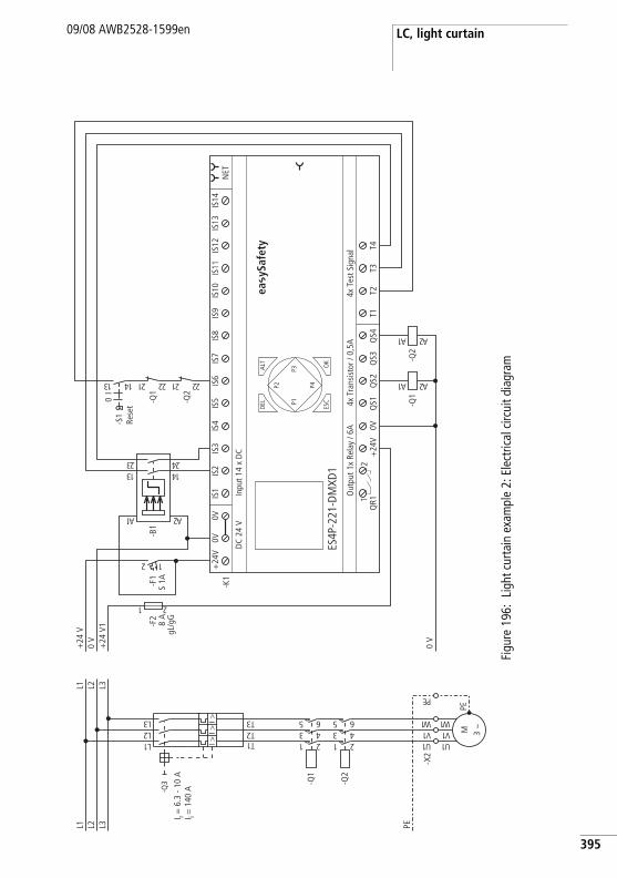
LC, light curtain09/08 AWB2528-1599en
Figu
re 1
96:
Ligh
t cur
tain
exa
mpl
e 2:
Ele
ctric
al c
ircui
t dia
gram
PEL3L2L1
1U
-X2
-Q2
1 23 45 6
-Q1
1 23 45 6
1L2L3L
1T2T3TI >
I >I >
-Q3
M 3 h
1U1V1 W
PE
1V1 W
EP
L3L2L1
0 V
+24
V1
0 V
+24
V
-F2
8 A
gL/g
G
1 2
0V+
24V
QS1
QS2
QS3
QS4
T1T2
T3T4
Out
put 1
x Re
lay
/ 6A
4x T
est S
igna
l
ES4P
-221
-DM
XD1
4x T
rans
isto
r / 0
,5A
DC
24 V
Inpu
t 14
x D
C
NET
ALT OK
-K1
DEL
ESC
IS1
IS2
IS3
IS4
IS5
IS6
IS7
IS8
IS9
IS10
IS11
IS12
IS13
IS14
1Q
R12
+24
V0V
0V
P1
P2
P3
P42 1
-F1
S 1A
2A1A
-B1
31 4132 42
-Q1
1A 2A
-Q2
12 22
-Q1
12 22
I0
-S1
31 41
-Q2
1A 2A
I r = 6
.3 -
10 A
I i = 1
40 A
ea y
Safe
ty
Rese
t
395
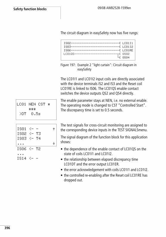
Safety function blocks
396
09/08 AWB2528-1599en
The circuit diagram in easySafety now has five rungs:
Figure 197: Example 2 "light curtain": Circuit diagram in easySafety
The LC01I1 and LC01I2 input coils are directly associated with the device terminals IS2 and IS3 and the Reset coil LC01RE is linked to IS06. The LC01QS enable contact switches the device outputs QS2 and QS4 directly.
The enable parameter stays at NEN, i.e. no external enable. The operating mode is changed to CST “Controlled Start”. The discrepancy time is set to 0.5 seconds.
The test signals for cross-circuit monitoring are assigned to the corresponding device inputs in the TEST SIGNALSmenu.
The signal diagram of the function block for this application shows:
• the dependence of the enable contact of LC01QS on the state of coils LC01I1 and LC01I2.
• the relationship between elapsed discrepancy time LC01DT and the error output LC01ER.
• the error acknowledgement with coils LC01I1 and LC01I2.• the controlled re-enabling after the Reset coil LC01RE has
dropped out.
IS02---------------------------Ä LC01I1IS03---------------------------Ä LC01I2IS06---------------------------Ä LC01RELC01QS------------------------uÄ QS02
hÄ QS04
LC01 NEN CST *
***
>DT 0.5s
IS01 <- - ÆIS02 <- T3
IS03 <- T4
... æIS06 <- T2
...
IS14 <- -
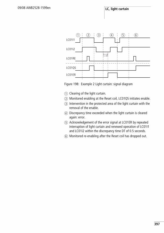
LC, light curtain09/08 AWB2528-1599en
Figure 198: Example 2 Light curtain: signal diagram
a Clearing of the light curtain.b Monitored enabling at the Reset coil, LC01QS initiates enable.c Intervention in the protected area of the light curtain with the
removal of the enable.d Discrepancy time exceeded when the light curtain is cleared
again: error.e Acknowledgement of the error signal at LC01ER by repeated
interruption of light curtain and renewed operation of LC01I1 and LC01I2 within the discrepancy time DT of 0.5 seconds.
f Monitored re-enabling after the Reset coil has dropped out.
LC01I1
LC01I2
LC01QS
LC01ER
LC01REt > DT
a b c d e f
397
Safety function blocks
398
09/08 AWB2528-1599en
LM, light curtain muting Muting is the process-related temporary suspension of a guard. This function is required if material has to be moved through the protected area of the guard without stopping the operating sequence.
The muting state must be removed immediately after the material has passed through and the guard must be restored to function. The muting system must therefore be able to distinguish between objects and persons.
The Light curtain muting function block (LM) enables you to implement muting functions on your light curtain.
easySafety enables you to monitor up to 2 light curtains with muting sensors arranged in parallel and in series.
h The muting state must be removed immediately after the material has passed through and the guard must be restored to function. The muting system must therefore be able to distinguish between objects and persons.
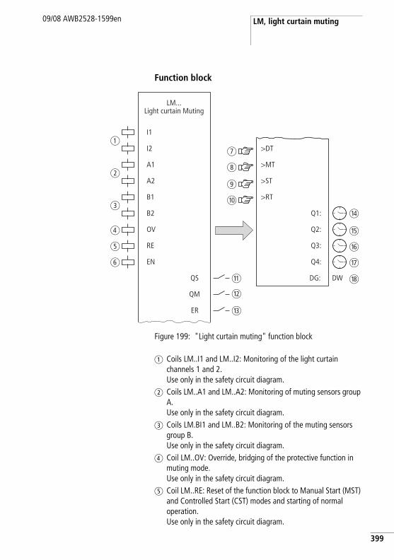
LM, light curtain muting09/08 AWB2528-1599en
Function block
Figure 199: "Light curtain muting" function block
a Coils LM..I1 and LM..I2: Monitoring of the light curtain channels 1 and 2.Use only in the safety circuit diagram.
b Coils LM..A1 and LM..A2: Monitoring of muting sensors group A.Use only in the safety circuit diagram.
c Coils LM.BI1 and LM..B2: Monitoring of the muting sensors group B.Use only in the safety circuit diagram.
d Coil LM..OV: Override, bridging of the protective function in muting mode. Use only in the safety circuit diagram.
e Coil LM..RE: Reset of the function block to Manual Start (MST) and Controlled Start (CST) modes and starting of normal operation. Use only in the safety circuit diagram.
I1
I2
RE
EN
>DT
QS
QM
DG:
Q1:
LM...Light curtain Muting
A1
A2
B1
B2
OV
>MT
>ST
>RT
ER
Q2:
Q3:
Q4:
DW
a
b
c
d
e
f
k
l
m
j
i
h
g
n
o
p
q
r
399
Safety function blocks
400
09/08 AWB2528-1599en
f Coil LM..EN: Selective activation or deactivation of the function block function (optional). Use either in the safety or standard circuit diagram.
g Parameter LM..DT: Discrepancy time within which both coils LM..I1 and LM..I2 must have picked up (logic 1). Can be used as an adjustable constant.
h Parameter LM..MT: Muting time, the maximum bridging time between entering and vacating the hazardous zone. Can be used as an adjustable constant.
i Parameter LM..ST: Synchronisation time within which the muting coils within a group must reach the same state in order to allow or end the bridging of the safety function in a controlled manner. Can be used as an adjustable constant.
j Parameter LM..RT: Duration of override release time, within which the protection function can be bridged during muting in the event of a fault. Can be used as an adjustable constant.
k Contact LM..QS: Closes when conditions for safe operation are fulfilled and enables the hazardous movement. Use only in the safety circuit diagram.
l Contact LM..QM: Closes during muting. Use only in the safety circuit diagram.
m Contact LM..ER: Closes in the event of an error. Use in the safety and in standard circuit diagram.
n Actual value output LM..Q1: Indicates the current actual value of the discrepancy time. Indicated on the device or in easySoft-Safety.
o Actual value output LM..Q2: Indicates the current actual value of the muting time. Indicated on the device or in easySoft-Safety.
p Actual value output LM..Q3: Indicates the current actual value of the synchronisation time. Indicated on the device or in easySoft-Safety.
q Actual value output LM..Q4: Indicates the current actual value of the override release time. Indicated on the device or in easySoft-Safety.
r Diagnostics output LM..DG: Provides information about the states of the function block. Evaluation only in the standard circuit diagram with the diagnostics function block DG.
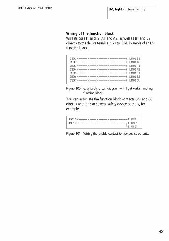
LM, light curtain muting09/08 AWB2528-1599en
Wiring of the function blockWire its coils I1 and I2, A1 and A2, as well as B1 and B2 directly to the device terminals IS1 to IS14. Example of an LM function block:
Figure 200: easySafety circuit diagram with light curtain muting function block.
You can associate the function block contacts QM and QS directly with one or several safety device outputs, for example:L
Figure 201: Wiring the enable contact to two device outputs.
IS01---------------------------Ä LM01I1IS02---------------------------Ä LM01I2IS03---------------------------Ä LM01A1IS04---------------------------Ä LM01A2IS05---------------------------Ä LM01B1IS06---------------------------Ä LM01B2IS07---------------------------Ä LM01OV
LM01QM---------------------------Ä QS1
LM01QS--------------------------uÄ QS2
hÄ QS3
401
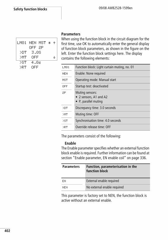
Safety function blocks
402
09/08 AWB2528-1599en
ParametersWhen using the function block in the circuit diagram for the first time, use OK to automatically enter the general display of function block parameters, as shown in the figure on the left. Enter the function block settings here. The display contains the following elements:
The parameters consist of the following:
EnableThe Enable parameter specifies whether an external function block enable is required. Further information can be found at section “Enable parameter, EN enable coil” on page 336.
This parameter is factory set to NEN, the function block is active without an external enable.
LM01 NEN MST * ÆOFF 2P
>DT 3.0S
>MT OFF æ>ST 4.0s
>RT OFF LM01 Function block: Light curtain muting, no. 01
NEN Enable: None required
MST Operating mode: Manual start
OFF Startup test: deactivated
2P Muting sensors:• 2 sensors, A1 and A2• P, parallel muting
>DT Discrepancy time: 3.0 seconds
>MT Muting time: OFF
>ST Synchronisation time: 4.0 seconds
>RT Override release time: OFF
Parameters Function, parameterisation in the function block
EN External enable required
NEN No external enable required
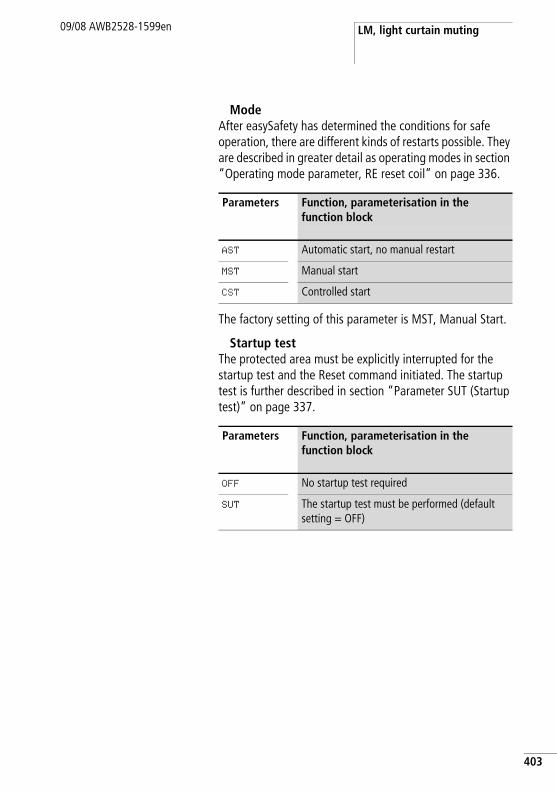
LM, light curtain muting09/08 AWB2528-1599en
ModeAfter easySafety has determined the conditions for safe operation, there are different kinds of restarts possible. They are described in greater detail as operating modes in section “Operating mode parameter, RE reset coil” on page 336.
The factory setting of this parameter is MST, Manual Start.
Startup testThe protected area must be explicitly interrupted for the startup test and the Reset command initiated. The startup test is further described in section “Parameter SUT (Startup test)” on page 337.
Parameters Function, parameterisation in the function block
AST Automatic start, no manual restart
MST Manual start
CST Controlled start
Parameters Function, parameterisation in the function block
OFF No startup test required
SUT The startup test must be performed (default setting = OFF)
403
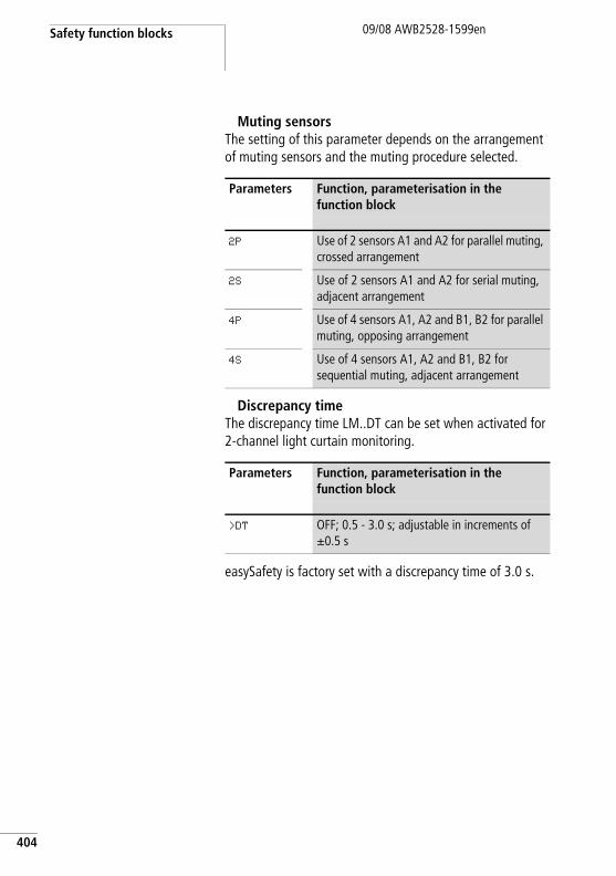
Safety function blocks
404
09/08 AWB2528-1599en
Muting sensorsThe setting of this parameter depends on the arrangement of muting sensors and the muting procedure selected.
Discrepancy timeThe discrepancy time LM..DT can be set when activated for 2-channel light curtain monitoring.
easySafety is factory set with a discrepancy time of 3.0 s.
Parameters Function, parameterisation in the function block
2P Use of 2 sensors A1 and A2 for parallel muting, crossed arrangement
2S Use of 2 sensors A1 and A2 for serial muting, adjacent arrangement
4P Use of 4 sensors A1, A2 and B1, B2 for parallel muting, opposing arrangement
4S Use of 4 sensors A1, A2 and B1, B2 for sequential muting, adjacent arrangement
Parameters Function, parameterisation in the function block
>DT OFF; 0.5 - 3.0 s; adjustable in increments of g0.5 s
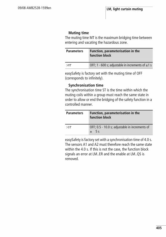
LM, light curtain muting09/08 AWB2528-1599en
Muting timeThe muting time MT is the maximum bridging time between entering and vacating the hazardous zone.
easySafety is factory set with the muting time of OFF (corresponds to infinitely).
Synchronisation timeThe synchronisation time ST is the time within which the muting coils within a group must reach the same state in order to allow or end the bridging of the safety function in a controlled manner.
easySafety is factory set with a synchronisation time of 4.0 s. The sensors A1 and A2 must therefore reach the same state within the 4.0 s. If this is not the case, the function block signals an error at LM..ER and the enable at LM..QS is removed.
Parameters Function, parameterisation in the function block
>MT OFF; 1 - 600 s; adjustable in increments of g1 s
Parameters Function, parameterisation in the function block
>ST OFF; 0.5 - 10.0 s; adjustable in increments of g 5 s
405
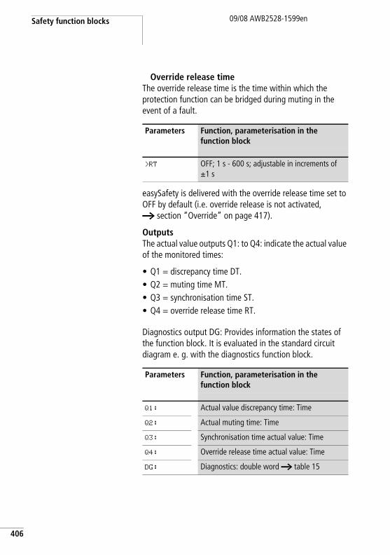
Safety function blocks
406
09/08 AWB2528-1599en
Override release timeThe override release time is the time within which the protection function can be bridged during muting in the event of a fault.
easySafety is delivered with the override release time set to OFF by default (i.e. override release is not activated, a section “Override” on page 417).
OutputsThe actual value outputs Q1: to Q4: indicate the actual value of the monitored times:
• Q1 = discrepancy time DT.• Q2 = muting time MT.• Q3 = synchronisation time ST.• Q4 = override release time RT.
Diagnostics output DG: Provides information the states of the function block. It is evaluated in the standard circuit diagram e. g. with the diagnostics function block.
Parameters Function, parameterisation in the function block
>RT OFF; 1 s - 600 s; adjustable in increments of g1 s
Parameters Function, parameterisation in the function block
Q1: Actual value discrepancy time: Time
Q2: Actual muting time: Time
Q3: Synchronisation time actual value: Time
Q4: Override release time actual value: Time
DG: Diagnostics: double word a table 15
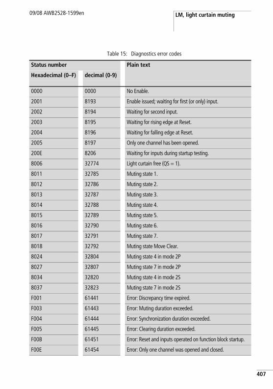
LM, light curtain muting09/08 AWB2528-1599en
Table 15: Diagnostics error codes
Status number Plain text
Hexadecimal (0–F) decimal (0-9)
0000 0000 No Enable.
2001 8193 Enable issued; waiting for first (or only) input.
2002 8194 Waiting for second input.
2003 8195 Waiting for rising edge at Reset.
2004 8196 Waiting for falling edge at Reset.
2005 8197 Only one channel has been opened.
200E 8206 Waiting for inputs during startup testing.
8006 32774 Light curtain free (QS = 1).
8011 32785 Muting state 1.
8012 32786 Muting state 2.
8013 32787 Muting state 3.
8014 32788 Muting state 4.
8015 32789 Muting state 5.
8016 32790 Muting state 6.
8017 32791 Muting state 7.
8018 32792 Muting state Move Clear.
8024 32804 Muting state 4 in mode 2P
8027 32807 Muting state 7 in mode 2P
8034 32820 Muting state 4 in mode 2S
8037 32823 Muting state 7 in mode 2S
F001 61441 Error: Discrepancy time expired.
F003 61443 Error: Muting duration exceeded.
F004 61444 Error: Synchronization duration exceeded.
F005 61445 Error: Clearing duration exceeded.
F00B 61451 Error: Reset and inputs operated on function block startup.
F00E 61454 Error: Only one channel was opened and closed.
407
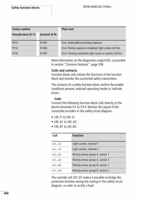
Safety function blocks
408
09/08 AWB2528-1599en
More information on the diagnostics output DG: is provided in section “Common features”, page 338.
Coils and contactsFunction block coils initiate the functions of the function block and monitor the connected safety transmitters.
The contacts of a safety function block confirm the enable conditions present, selected operating modes or indicate errors.
CoilsConnect the following function block coils directly to the device terminals IS1 to IS14. Monitor the signal of the connected encoders in the safety circuit diagram.
• LM..I1 to LM..I2.• LM..A1 to LM..A2.• LM..B1 to LM..B2.
The override coil LM..OV makes it possible to bridge the protective function during the muting in the safety circuit diagram, in order to rectify a fault.
F019 61465 Error: Implausible processing sequence.
F01A 61466 Error: Muting sequence completed, light curtain not free.
F01B 61467 Error: Clearing completed; light curtain or sensors not free.
Status number Plain text
Hexadecimal (0–F) decimal (0-9)
Coil Function
LM..I1 Light curtain, channel 1
LM..I2 Light curtain, channel 2
LM..A1 Muting sensor group A, sensor 1
LM..A2 Muting sensor group A, sensor 2
LM..B1 Muting sensor group B, sensor 1
LM..B2 Muting sensor group B, sensor 2
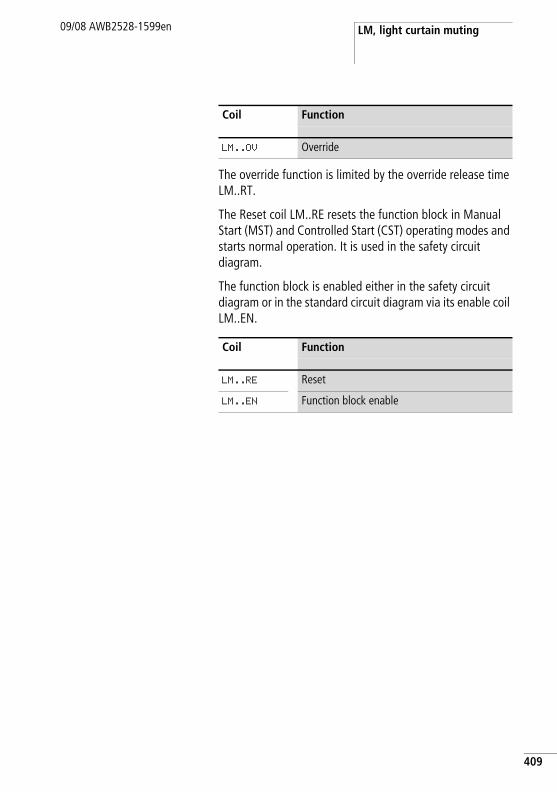
LM, light curtain muting09/08 AWB2528-1599en
The override function is limited by the override release time LM..RT.
The Reset coil LM..RE resets the function block in Manual Start (MST) and Controlled Start (CST) operating modes and starts normal operation. It is used in the safety circuit diagram.
The function block is enabled either in the safety circuit diagram or in the standard circuit diagram via its enable coil LM..EN.
Coil Function
LM..OV Override
Coil Function
LM..RE Reset
LM..EN Function block enable
409
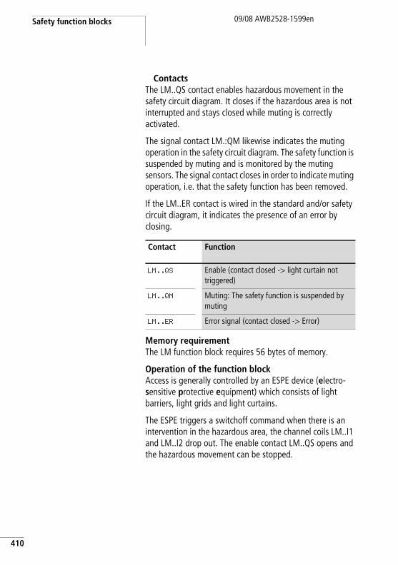
Safety function blocks
410
09/08 AWB2528-1599en
ContactsThe LM..QS contact enables hazardous movement in the safety circuit diagram. It closes if the hazardous area is not interrupted and stays closed while muting is correctly activated.
The signal contact LM.:QM likewise indicates the muting operation in the safety circuit diagram. The safety function is suspended by muting and is monitored by the muting sensors. The signal contact closes in order to indicate muting operation, i.e. that the safety function has been removed.
If the LM..ER contact is wired in the standard and/or safety circuit diagram, it indicates the presence of an error by closing.
Memory requirementThe LM function block requires 56 bytes of memory.
Operation of the function blockAccess is generally controlled by an ESPE device (electro-sensitive protective equipment) which consists of light barriers, light grids and light curtains.
The ESPE triggers a switchoff command when there is an intervention in the hazardous area, the channel coils LM..I1 and LM..I2 drop out. The enable contact LM..QS opens and the hazardous movement can be stopped.
Contact Function
LM..QS Enable (contact closed -> light curtain not triggered)
LM..QM Muting: The safety function is suspended by muting
LM..ER Error signal (contact closed -> Error)
LM, light curtain muting09/08 AWB2528-1599en
MutingUnlike the LC light curtain function block, this function block also has the muting function. The muting function makes it possible to automatically bridge the safety function of the EPSE for a specific time. This enables goods to be transported through the hazardous area of the guard without stopping the cyclical operation.
Two muting sensors fitted in front of the protected area of the EPSE initiate the bridging:
• They detect entry into the protected area.• You start the monitoring of the maximum permissible
muting time while the muting contact QM of the function block indicates the activated muting function.
Optical pushbutton actuators or inductive proximity sensors are used as muting sensors.
If the sensors determine that the transported material has not yet left the muting area (muting area including light curtain) after the maximum permissible muting time MT has elapsed, the LM..QS enable contact opens and the LM..ER error contact closes.
Various sensor arrangements can be used. Parallel and sequential muting are possible.
j Danger!Ensure suitable measures for preventing danger to persons or objects during muting.
j Danger!The bridging must also be removed automatically after the material has passed through and the guard must be restored to function.
h The illustrations below of light curtain muting the basic sensor arrangements. For the exact arrangement of the sensors for each application, dee the (preliminary) standard IEC/TS 62046 02/2008.
411
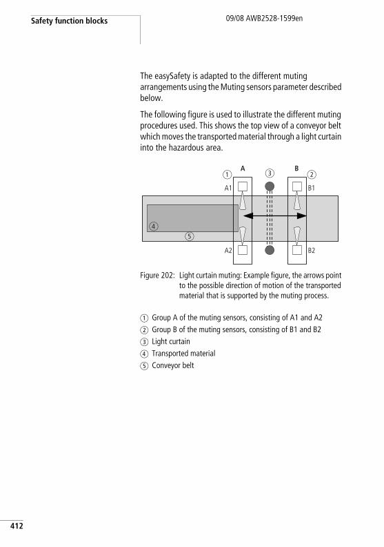
Safety function blocks
412
09/08 AWB2528-1599en
The easySafety is adapted to the different muting arrangements using the Muting sensors parameter described below.
The following figure is used to illustrate the different muting procedures used. This shows the top view of a conveyor belt which moves the transported material through a light curtain into the hazardous area.
Figure 202: Light curtain muting: Example figure, the arrows point to the possible direction of motion of the transported material that is supported by the muting process.
a Group A of the muting sensors, consisting of A1 and A2b Group B of the muting sensors, consisting of B1 and B2c Light curtaind Transported materiale Conveyor belt
a bc
ed
A B
A1
A2
B1
B2
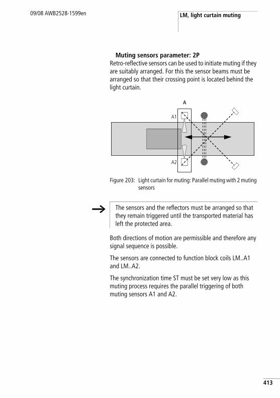
LM, light curtain muting09/08 AWB2528-1599en
Muting sensors parameter: 2PRetro-reflective sensors can be used to initiate muting if they are suitably arranged. For this the sensor beams must be arranged so that their crossing point is located behind the light curtain.
Figure 203: Light curtain for muting: Parallel muting with 2 muting sensors
Both directions of motion are permissible and therefore any signal sequence is possible.
The sensors are connected to function block coils LM..A1 and LM..A2.
The synchronization time ST must be set very low as this muting process requires the parallel triggering of both muting sensors A1 and A2.
A
A1
A2
h The sensors and the reflectors must be arranged so that they remain triggered until the transported material has left the protected area.
413
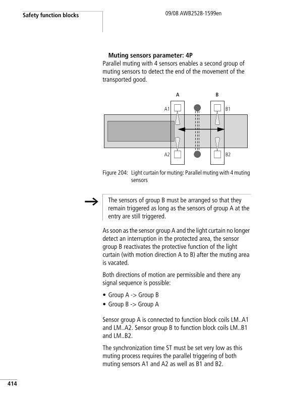
Safety function blocks
414
09/08 AWB2528-1599en
Muting sensors parameter: 4PParallel muting with 4 sensors enables a second group of muting sensors to detect the end of the movement of the transported good.
Figure 204: Light curtain for muting: Parallel muting with 4 muting sensors
As soon as the sensor group A and the light curtain no longer detect an interruption in the protected area, the sensor group B reactivates the protective function of the light curtain (with motion direction A to B) after the muting area is vacated.
Both directions of motion are permissible and there any signal sequence is possible:
• Group A -> Group B• Group B -> Group A
Sensor group A is connected to function block coils LM..A1 and LM..A2. Sensor group B to function block coils LM..B1 and LM..B2.
The synchronization time ST must be set very low as this muting process requires the parallel triggering of both muting sensors A1 and A2 as well as B1 and B2.
A B
A1
A2
B1
B2
h The sensors of group B must be arranged so that they remain triggered as long as the sensors of group A at the entry are still triggered.
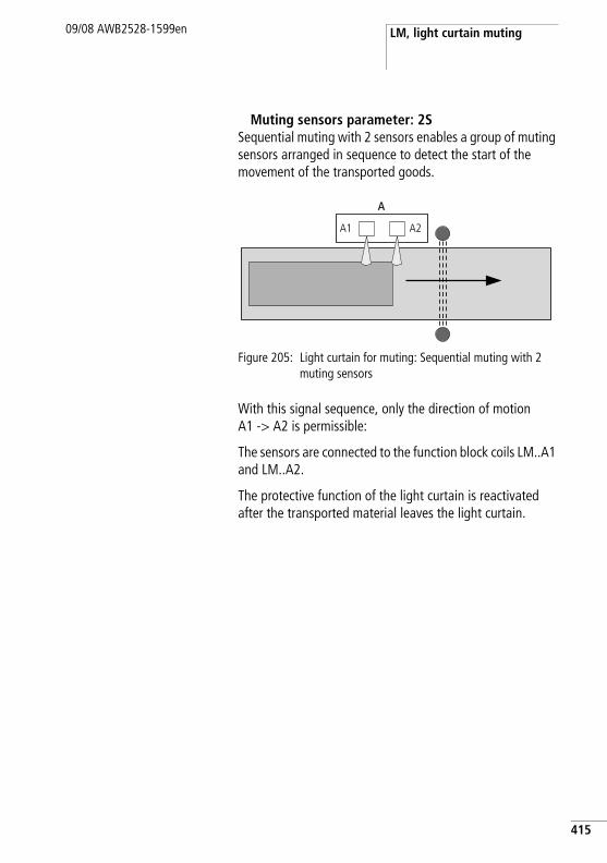
LM, light curtain muting09/08 AWB2528-1599en
Muting sensors parameter: 2SSequential muting with 2 sensors enables a group of muting sensors arranged in sequence to detect the start of the movement of the transported goods.
Figure 205: Light curtain for muting: Sequential muting with 2 muting sensors
With this signal sequence, only the direction of motion A1 -> A2 is permissible:
The sensors are connected to the function block coils LM..A1 and LM..A2.
The protective function of the light curtain is reactivated after the transported material leaves the light curtain.
A
A1 A2
415
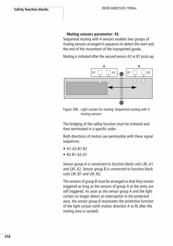
Safety function blocks
416
09/08 AWB2528-1599en
Muting sensors parameter: 4SSequential muting with 4 sensors enables two groups of muting sensors arranged in sequence to detect the start and the end of the movement of the transported goods.
Muting is initiated after the second sensor A2 or B1 picks up.
Figure 206: Light curtain for muting: Sequential muting with 4 muting sensors
The bridging of the safety function must be initiated and then terminated in a specific order.
Both directions of motion are permissible with these signal sequences:
• A1-A2-B1-B2• B2-B1-A2-A1
Sensor group A is connected to function block coils LM..A1 and LM..A2. Sensor group B is connected to function block coils LM..B1 and LM..B2.
The sensors of group B must be arranged so that they remain triggered as long as the sensors of group A at the entry are still triggered. As soon as the sensor group A and the light curtain no longer detect an interruption in the protected area, the sensor group B reactivates the protective function of the light curtain (with motion direction A to B) after the muting area is vacated.
A
A1 A2
B
B1 B2
LM, light curtain muting09/08 AWB2528-1599en
OverrideThe override function enables you to bridge the muting sequence and thus clear, for example, the jammed transported material. Override is only possible if the function block LM has detected an error in the muting sequence. In order to activate override, you must set a maximum override release time RT. When the coil LM..OV picks up, the muting sequence is bridged and the enable is initiated at function block output LM..QS. The override is terminated after the override release time RT has elapsed or the coil LM..OV is opened. The override function is also terminated if the muting system detects the default state. This is the case when no muting sensors have been triggered and the light curtain is clear.
If the function block has the Manual Start (MST) or Controlled Start (CST) operating mode, the LM..RE reset input must be activated in order to reset the function block and start uninterrupted operation.
h Install the override pushbutton in a location with a clear view of the hazardous zone.
The override function must only be executed by authorised personnel and should only be activated using something like a key switch.
417
Safety function blocks
418
09/08 AWB2528-1599en
Error detection and acknowledgementThe light curtain muting function block detects the timing out of the following times:
• Discrepancy time DT.• Synchronisation time ST.• Muting time MT.• Override release time RT.
The function block also monitors the order of the muting sequence for sequential muting.
General information on Errors and how the easySafety reacts to them is provided in section “Diagnostics using the ER contact” on page 613.
Example 1 - Architecture of Category 4 according to EN 954-1 and ISO 13849-1Access control of an area with a 2-channel light curtain. The protective function is bridged automatically by 2 muting sensors arranged in parallel and reactivated when the transported material has passed through.
An override button enables the conveyed material to be moved out of the hazardous area during muting in the event of damage.
Error Error acknowledgement
Timeout of discrepancy time DT
Dropping out of LM..I1 and LM..I2
Timeout of the synchronisation time ST.
Dropping out of LM..A1 and LM..A2 as well as LM..B1 and LM..B2
Timeout of the muting time MT
Dropping out of LM..I1 and LM..I2,LM..A1 and LM..A2 as well as LM..B1 and LM..B2
Timeout of the override release time RT
Dropping out of LM..I1 and LM..I2,LM..A1 and LM..A2 as well as LM..B1 and LM..B2
Muting sequence Dropping out of LM..OV or picking up of LM..RE
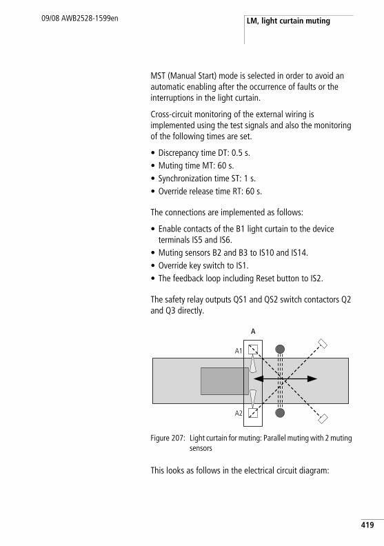
LM, light curtain muting09/08 AWB2528-1599en
MST (Manual Start) mode is selected in order to avoid an automatic enabling after the occurrence of faults or the interruptions in the light curtain.
Cross-circuit monitoring of the external wiring is implemented using the test signals and also the monitoring of the following times are set.
• Discrepancy time DT: 0.5 s.• Muting time MT: 60 s.• Synchronization time ST: 1 s.• Override release time RT: 60 s.
The connections are implemented as follows:
• Enable contacts of the B1 light curtain to the device terminals IS5 and IS6.
• Muting sensors B2 and B3 to IS10 and IS14. • Override key switch to IS1.• The feedback loop including Reset button to IS2.
The safety relay outputs QS1 and QS2 switch contactors Q2 and Q3 directly.
Figure 207: Light curtain for muting: Parallel muting with 2 muting sensors
This looks as follows in the electrical circuit diagram:
A
A1
A2
419
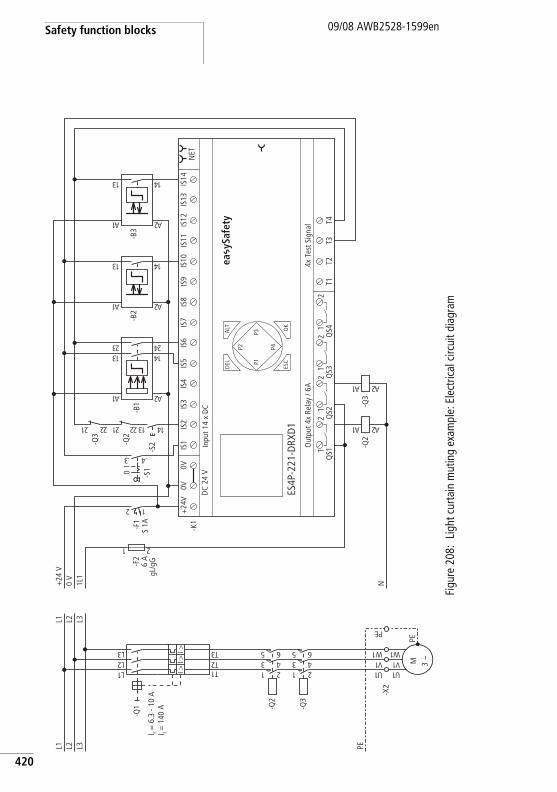
Safety function blocks
420
09/08 AWB2528-1599en
Figu
re 2
08:
Ligh
t cur
tain
mut
ing
exam
ple:
Ele
ctric
al c
ircui
t dia
gram
PEL3L2L1
1U
-X2
-Q3
1 23 45 6
-Q2
1 23 45 6
1L2L3L
1T2T3TI >
I >I >
-Q1
M 3 h
1U1V1 W
PE
1V1 W
EP
L3L2L1
N1L1
0 V
+24
V
T1T2
T3T4
4x T
est S
igna
lO
utpu
t 4x
Rela
y / 6
A
DEL
-K1
OK
ALT
ES4P
-221
-DRX
D1
DC 2
4 V
NET
Inpu
t 14
x DC
ESC
IS1
IS2
IS3
IS4
IS5
IS6
IS7
IS8
IS9
IS10
IS11
IS12
IS13
IS14
1Q
S12
1Q
S22
1Q
S32
1Q
S42
+24
V0V
0V
P1
P2
P3
P42 1
-F1
S 1A
I
-S10
3. 4.
-Q2
1A 2A
-S2
31 41
-Q2
12 22
-Q3
12 22
2A1A
-B1
31 4132 42
-Q3
1A 2A
2A1A
-B2
31 41
2A1A
-B3
31 41
ea y
Safe
ty
I r = 6
.3 -
10 A
I i = 1
40 A
-F2
6 A
gL/g
G
1 2
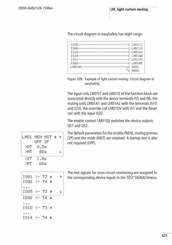
LM, light curtain muting09/08 AWB2528-1599en
The circuit diagram in easySafety has eight rungs:
Figure 209: Example of light curtain muting: Circuit diagram in easySafety.
The input coils LM01I1 and LM01I2 of the function block are associated directly with the device terminals IS5 and IS6, the muting coils LM01A1 and LM01A2 with the terminals IS10 and IS14, the override coil LM01OV with IS1 and the Reset coil with the input IS02.
The enable contact LM01QS switches the device outputs QS1 and QS2.
The default parameters for the enable (NEN), muting process (2P) and the mode (MST) are retained. A startup test is also not required (OFF).
The test signals for cross-circuit monitoring are assigned to the corresponding device inputs in the TEST SIGNALSmenu.
IS05---------------------------Ä LM01I1IS06---------------------------Ä LM01I2IS10---------------------------Ä LM01A1IS14---------------------------Ä LM01A2IS01---------------------------Ä LM01OVIS02---------------------------Ä LM01RELM01QS------------------------uÄ QS01
hÄ QS02
LM01 NEN MST * ÆOFF 2P
>DT 0.5s
>MT 60s æ>ST 1.0s
>RT 60s
IS01 <- T3 * ÆIS02 <- T4 *
...
IS05 <- T3 * æIS06 <- T4 *
...
IS10 <- T3 *
...
IS14 <- T4 *
421
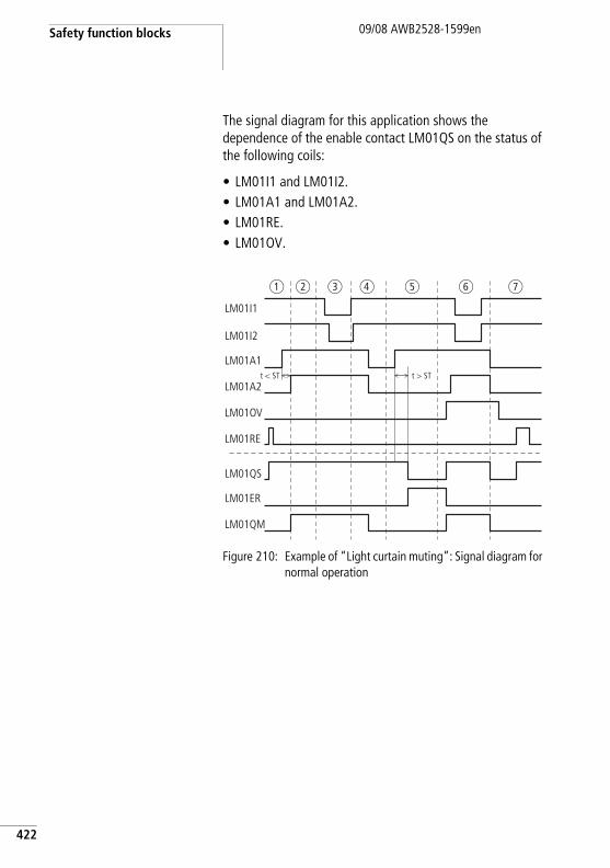
Safety function blocks
422
09/08 AWB2528-1599en
The signal diagram for this application shows the dependence of the enable contact LM01QS on the status of the following coils:
• LM01I1 and LM01I2.• LM01A1 and LM01A2.• LM01RE.• LM01OV.
Figure 210: Example of “Light curtain muting”: Signal diagram for normal operation
t > STt < ST
LM01I1
LM01I2
LM01A1
LM01A2
LM01OV
LM01RE
LM01QS
LM01ER
LM01QM
a b c d e f g
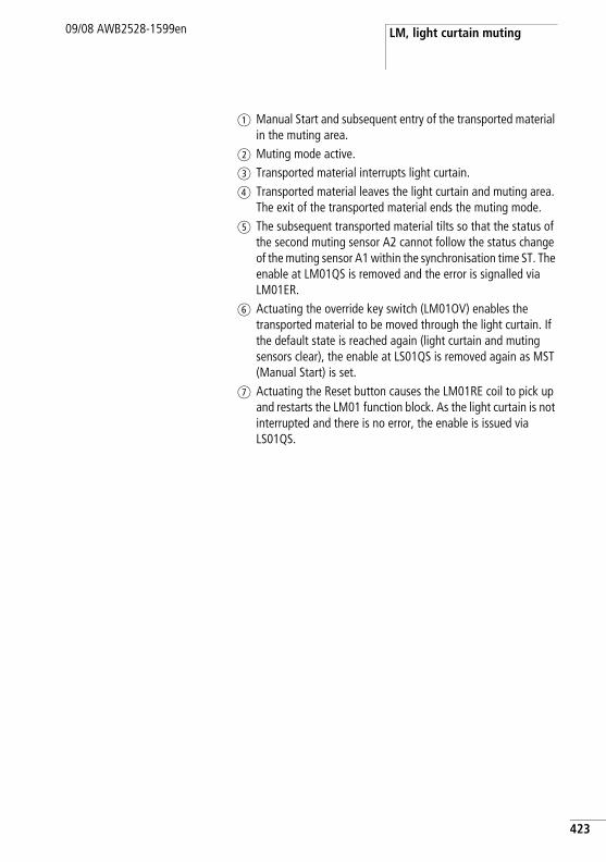
LM, light curtain muting09/08 AWB2528-1599en
a Manual Start and subsequent entry of the transported material in the muting area.
b Muting mode active.c Transported material interrupts light curtain.d Transported material leaves the light curtain and muting area.
The exit of the transported material ends the muting mode.e The subsequent transported material tilts so that the status of
the second muting sensor A2 cannot follow the status change of the muting sensor A1 within the synchronisation time ST. The enable at LM01QS is removed and the error is signalled via LM01ER.
f Actuating the override key switch (LM01OV) enables the transported material to be moved through the light curtain. If the default state is reached again (light curtain and muting sensors clear), the enable at LS01QS is removed again as MST (Manual Start) is set.
g Actuating the Reset button causes the LM01RE coil to pick up and restarts the LM01 function block. As the light curtain is not interrupted and there is no error, the enable is issued via LS01QS.
423
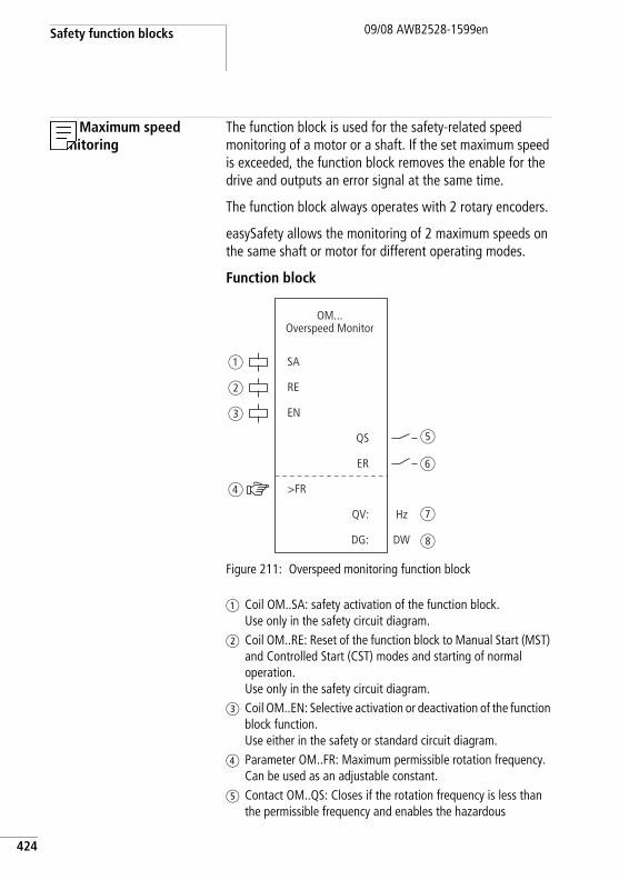
Safety function blocks
424
09/08 AWB2528-1599en
OM, Maximum speed monitoring
The function block is used for the safety-related speed monitoring of a motor or a shaft. If the set maximum speed is exceeded, the function block removes the enable for the drive and outputs an error signal at the same time.
The function block always operates with 2 rotary encoders.
easySafety allows the monitoring of 2 maximum speeds on the same shaft or motor for different operating modes.
Function block
Figure 211: Overspeed monitoring function block
a Coil OM..SA: safety activation of the function block. Use only in the safety circuit diagram.
b Coil OM..RE: Reset of the function block to Manual Start (MST) and Controlled Start (CST) modes and starting of normal operation. Use only in the safety circuit diagram.
c Coil OM..EN: Selective activation or deactivation of the function block function. Use either in the safety or standard circuit diagram.
d Parameter OM..FR: Maximum permissible rotation frequency. Can be used as an adjustable constant.
e Contact OM..QS: Closes if the rotation frequency is less than the permissible frequency and enables the hazardous
SA
RE
EN
>FR
QS
ER
DG:
QV:
OM...Overspeed Monitor
a
b
c
d
e
f
g
hDW
Hz
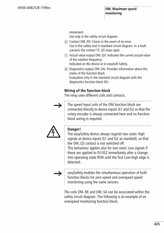
OM, Maximum speed monitoring
09/08 AWB2528-1599en
movement. Use only in the safety circuit diagram.
f Contact OM..ER: Closes in the event of an error. Use in the safety and in standard circuit diagram. In a fault scenario the contact TS..QS stays open.
g Actual value output OM..QV: Indicates the current actual value of the rotation frequency. Indicated on the device or in easySoft-Safety.
h Diagnostics output OM..DG: Provides information about the states of the function block. Evaluation only in the standard circuit diagram with the diagnostics function block DG.
Wiring of the function blockThe relay uses different coils and contacts.
The coils OM..RE and OM..SA can be associated within the safety circuit diagram. The following is an example of an overspeed monitoring function block.
h The speed input coils of the OM function block are connected directly to device inputs IS1 and IS2 so that the rotary encoder is always connected here and no function block wiring is required.
j Danger!The easySafety device always regards two static High signals at device inputs IS1 and IS2 as standstill, so that the OM..QS contact is not switched off. This behaviour applies also for two static Low signals if these are applied to IS1/IS2 immediately after a change into operating state RUN until the first Low-High edge is detected.
h easySafety enables the simultaneous operation of both function blocks for zero speed and overspeed speed monitoring using the same sensors.
425
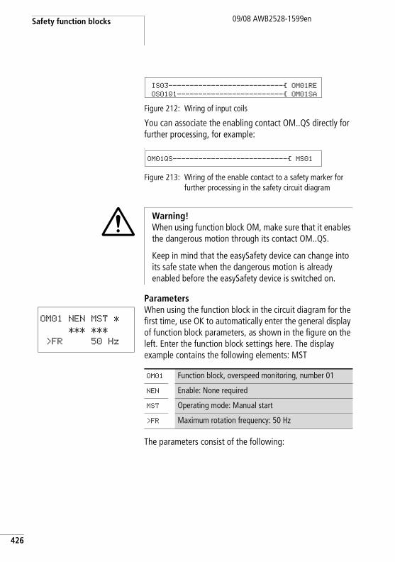
Safety function blocks
426
09/08 AWB2528-1599en
Figure 212: Wiring of input coils
You can associate the enabling contact OM..QS directly for further processing, for example:L
Figure 213: Wiring of the enable contact to a safety marker for further processing in the safety circuit diagram
ParametersWhen using the function block in the circuit diagram for the first time, use OK to automatically enter the general display of function block parameters, as shown in the figure on the left. Enter the function block settings here. The display example contains the following elements: MST
The parameters consist of the following:
IS03---------------------------Ä OM01RE
OS01Q1-------------------------Ä OM01SA
OM01QS---------------------------Ä MS01
i Warning!When using function block OM, make sure that it enables the dangerous motion through its contact OM..QS.
Keep in mind that the easySafety device can change into its safe state when the dangerous motion is already enabled before the easySafety device is switched on.
OM01 NEN MST *
*** ***
>FR 50 Hz
OM01 Function block, overspeed monitoring, number 01
NEN Enable: None required
MST Operating mode: Manual start
>FR Maximum rotation frequency: 50 Hz
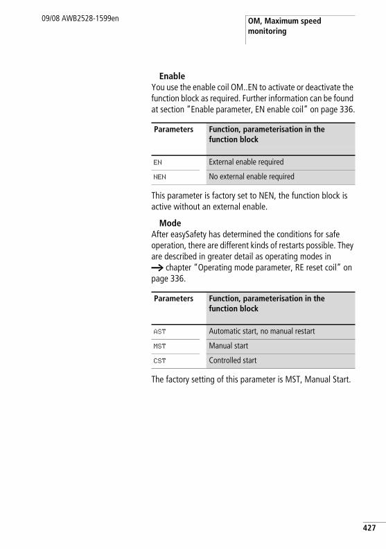
OM, Maximum speed monitoring
09/08 AWB2528-1599en
EnableYou use the enable coil OM..EN to activate or deactivate the function block as required. Further information can be found at section “Enable parameter, EN enable coil” on page 336.
This parameter is factory set to NEN, the function block is active without an external enable.
ModeAfter easySafety has determined the conditions for safe operation, there are different kinds of restarts possible. They are described in greater detail as operating modes in a chapter “Operating mode parameter, RE reset coil” on page 336.
The factory setting of this parameter is MST, Manual Start.
Parameters Function, parameterisation in the function block
EN External enable required
NEN No external enable required
Parameters Function, parameterisation in the function block
AST Automatic start, no manual restart
MST Manual start
CST Controlled start
427
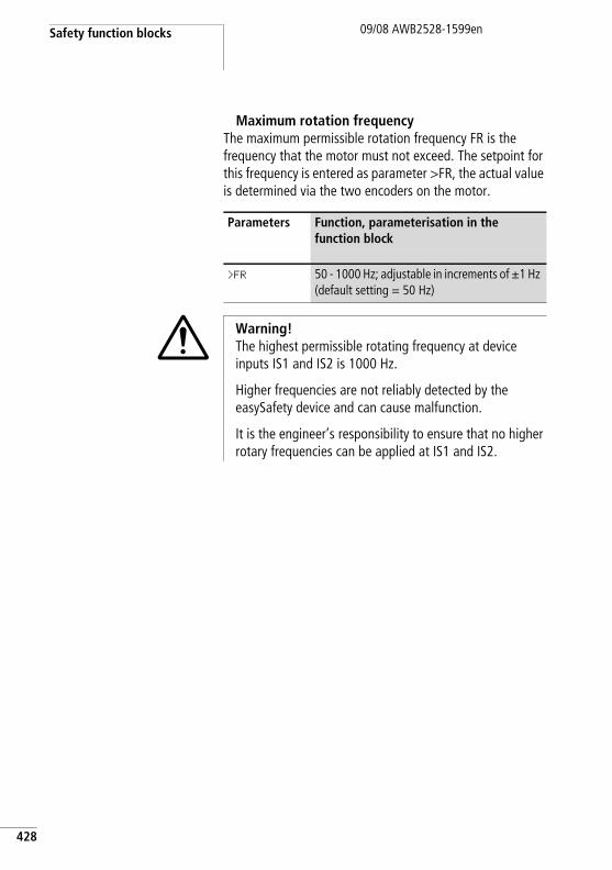
Safety function blocks
428
09/08 AWB2528-1599en
Maximum rotation frequencyThe maximum permissible rotation frequency FR is the frequency that the motor must not exceed. The setpoint for this frequency is entered as parameter >FR, the actual value is determined via the two encoders on the motor.
Parameters Function, parameterisation in the function block
>FR 50 - 1000 Hz; adjustable in increments of g1 Hz (default setting = 50 Hz)
i Warning!The highest permissible rotating frequency at device inputs IS1 and IS2 is 1000 Hz.
Higher frequencies are not reliably detected by the easySafety device and can cause malfunction.
It is the engineer’s responsibility to ensure that no higher rotary frequencies can be applied at IS1 and IS2.
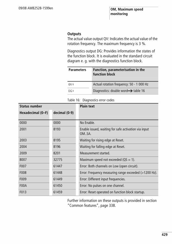
OM, Maximum speed monitoring
09/08 AWB2528-1599en
OutputsThe actual value output QV: Indicates the actual value of the rotation frequency. The maximum frequency is 3 %.
Diagnostics output DG: Provides information the states of the function block. It is evaluated in the standard circuit diagram e. g. with the diagnostics function block.
Table 16: Diagnostics error codes
Further information on these outputs is provided in section “Common features”, page 338.
Parameters Function, parameterisation in the function block
QV: Actual rotation frequency: 50 - 1 000 Hz
DG: Diagnostics: double worda table 16
Status number Plain text
Hexadecimal (0–F) decimal (0-9)
0000 0000 No Enable.
2001 8193 Enable issued, waiting for safe activation via input OM..SA.
2003 8195 Waiting for rising edge at Reset.
2004 8196 Waiting for falling edge at Reset.
2009 8201 Measurement started.
8007 32775 Maximum speed not exceeded (QS = 1).
F007 61447 Error: Both channels on Low (open circuit).
F008 61448 Error: Frequency measuring range exceeded (>1200 Hz).
F009 61449 Error: Different input frequencies.
F00A 61450 Error: No pulses on one channel.
F013 61459 Error: Reset operated on function block startup.
429
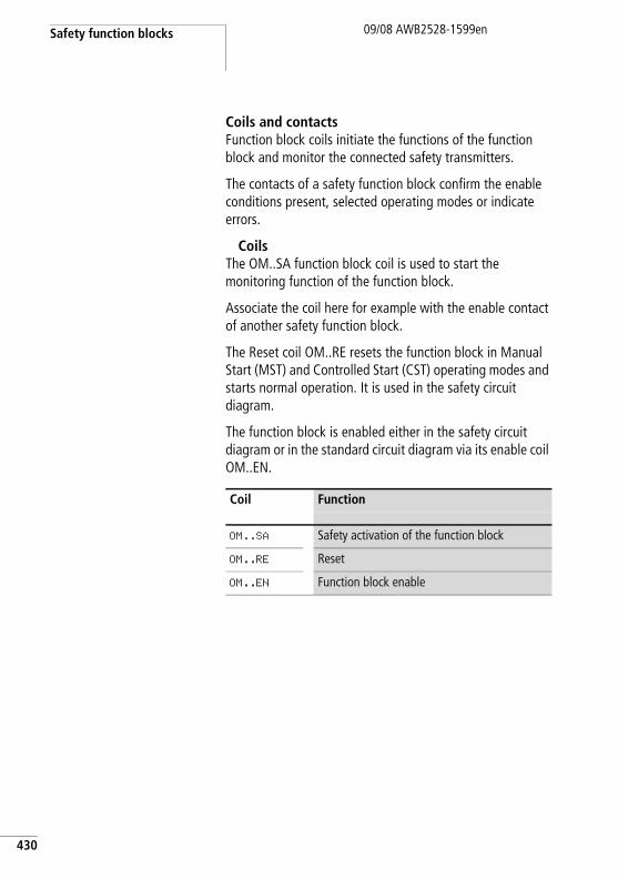
Safety function blocks
430
09/08 AWB2528-1599en
Coils and contactsFunction block coils initiate the functions of the function block and monitor the connected safety transmitters.
The contacts of a safety function block confirm the enable conditions present, selected operating modes or indicate errors.
CoilsThe OM..SA function block coil is used to start the monitoring function of the function block.
Associate the coil here for example with the enable contact of another safety function block.
The Reset coil OM..RE resets the function block in Manual Start (MST) and Controlled Start (CST) operating modes and starts normal operation. It is used in the safety circuit diagram.
The function block is enabled either in the safety circuit diagram or in the standard circuit diagram via its enable coil OM..EN.
Coil Function
OM..SA Safety activation of the function block
OM..RE Reset
OM..EN Function block enable
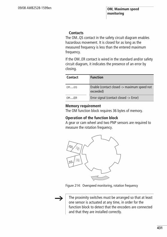
OM, Maximum speed monitoring
09/08 AWB2528-1599en
ContactsThe OM..QS contact in the safety circuit diagram enables hazardous movement. It is closed for as long as the measured frequency is less than the entered maximum frequency.
If the OM..ER contact is wired in the standard and/or safety circuit diagram, it indicates the presence of an error by closing.
Memory requirementThe OM function block requires 36 bytes of memory.
Operation of the function blockA gear or cam wheel and two PNP sensors are required to measure the rotation frequency.
Figure 214: Overspeed monitoring, rotation frequency
Contact Function
OM..QS Enable (contact closed -> maximum speed not exceeded)
OM..ER Error signal (contact closed -> Error)
h The proximity switches must be arranged so that at least one sensor is actuated at any time, in order for the function block to detect that the encoders are connected and that they are installed correctly.
431
Safety function blocks
432
09/08 AWB2528-1599en
• A wire break is indicated and the enable is removed if both sensors have not switched.
• If both function block coils receive a synchronous signal, a fault is indicated and the enable may possibly be removed.
• After each change of easySafety into operating state RUN the two sensors can issue the same level without a fault message being generated. In operating mode AST contact OM..QS is closed at that time.Only when the first edge is detected at one of the two inputs IS1/IS2 does the function block signal a fault if both sensors output the same level. Contact OM..QS then opens.
The speed is determined by the frequency measured. The frequency depends on the number of pulses per rotation:
With a gear wheel on a shaft with 6 cams and a maximum speed of 800 rpm, the maximum rotation frequency FR is calculated using the formula:
f [Hz] = C * n[rpm] / 60
80 Hz = 6 * 800 [rpm] / 60
If the set frequency is exceeded, the enable for the drive is removed. The enable is issued again in the following cases:
• After the reset coil OM..RE has picked up at zero speed.• In AST - automatic restart without manual restart - if the
actual rotation speed is below the set rotation speed by at least 5 %.
j Danger!In order to avoid unexpected restarts, use Manual Start (MST) or Controlled Start (CST) mode.
OM, Maximum speed monitoring
09/08 AWB2528-1599en
Error detection and acknowledgementThe function block detects when the maximum permissible rotation frequency is exceeded, as well as the failure of the sensors at device terminals IS1 and IS2.
General information on Errors and how the easySafety reacts to them is provided in section “Diagnostics using the ER contact” on page 613.
h The maximum permissible rotation frequency on device inputs IS1 and IS2 is 1000 Hz.
Error Error acknowledgement
Maximum permissible rotation frequency exceeded
Drop out of coil OM..SA for activation of the safety function block
Failure of sensors Drop out of coil OM..SA for activation of the safety function block
433
Safety function blocks
434
09/08 AWB2528-1599en
Example 1 - Architecture of Category 2 according to EN 954-1 and ISO 13849-1The speed of a shaft is required to not exceed 400 rpm. Two inductive proximity switches in conjunction with a cam disk with 10 cams on the shaft record the speed.
The function block is required to remove the enable for driving the shaft as soon as the maximum speed is exceeded. The drive must stand still before the function block allows a re-enabling via OM01RE. This is implemented using the ZM zero monitoring function block. The wiring of the ZM function block is not explained further in this example. Further information can be found in section “ZM, zero (standstill) monitoring”, page 499.
The connections are implemented as follows in this example:
• The feedback loop including Reset button to IS9.• Both sensors to IS1 and IS2.• Enabling contact OM..QS switches device output QS1.• The coil SA is always active for the safe activation in this
example.The rotation frequency to be set on easySafety: 10 x 400 rpm / 60 = 66 Hz.
This looks as follows in the electrical circuit diagram:
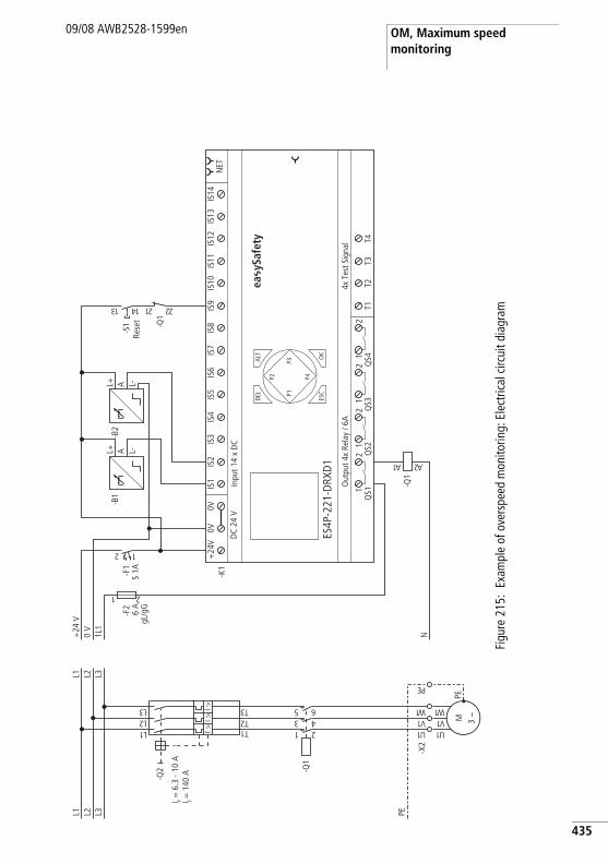
OM, Maximum speed monitoring
09/08 AWB2528-1599en
Figu
re 2
15:
Exam
ple
of o
vers
peed
mon
itorin
g: E
lect
rical
circ
uit d
iagr
am
PEL3L2L1
1U
-X2
-Q1
1 23 45 6
1L2L3L
1T2T3TI >
I >I >
-Q2
M 3 h
1U1V1 W
PE
1V1 W
EP
L3L2L1
N1L1
0 V
+24
V
-F2
6 A
gL/g
G
1 2
T1T2
T3T4
4x T
est S
igna
lO
utpu
t 4x
Rela
y / 6
A
DEL
-K1
OK
ALT
ES4P
-221
-DRX
D1
DC
24 V
NET
Inpu
t 14
x D
C
ESC
IS1
IS2
IS3
IS4
IS5
IS6
IS7
IS8
IS9
IS10
IS11
IS12
IS13
IS14
1Q
S12
1Q
S22
1Q
S32
1Q
S42
+24
V0V
0V
P1
P2
P3
P42 1
-F1
S 1A
L+ A L-
-B1
-Q1
1A 2A
L+ A L-
-B2
-Q1
12 2231 41
-S1
ea y
Safe
ty
I r = 6
.3 -
10 A
I i = 1
40 A
Rese
t
435
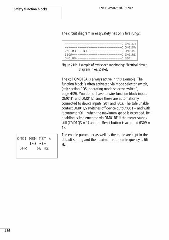
Safety function blocks
436
09/08 AWB2528-1599en
The circuit diagram in easySafety has only five rungs:
Figure 216: Example of overspeed monitoring: Electrical circuit diagram in easySafety
The coil OM01SA is always active in this example. The function block is often activated via mode selector switch, (a section “OS, operating mode selector switch”, page 439). You do not have to wire function block inputs OM01I1 and OM01I2, since these are automatically connected to device inputs IS01 and IS02. The safe Enable contact OM01QS switches off device output QS1 – and with it contactor Q1 – when the maximum speed is exceeded. Re-enabling is implemented via OM01RE if the motor stands still (ZM01QS = 1) and the Reset button is actuated (IS09 = 1).
The enable parameter as well as the mode are kept in the default setting and the maximum rotation frequency is 66 Hz.
-------------------------------Ä ZM01SA-------------------------------Ä OM01SAZM01QS---IS09------------------Ä OM01REIS09---------------------------Ä ZM01REOM01QS-------------------------Ä QS01
OM01 NEN MST *
*** ***
>FR 66 Hz
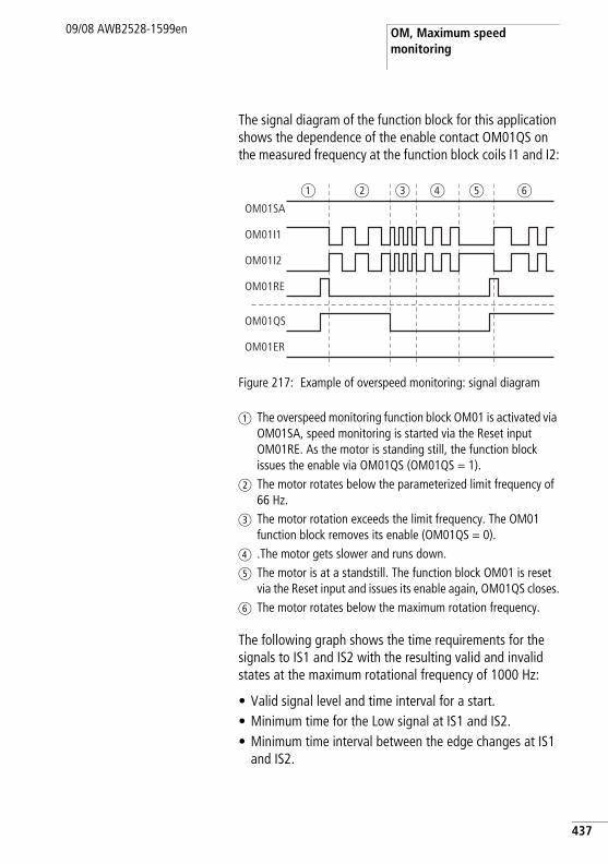
OM, Maximum speed monitoring
09/08 AWB2528-1599en
The signal diagram of the function block for this application shows the dependence of the enable contact OM01QS on the measured frequency at the function block coils I1 and I2:
Figure 217: Example of overspeed monitoring: signal diagram
a The overspeed monitoring function block OM01 is activated via OM01SA, speed monitoring is started via the Reset input OM01RE. As the motor is standing still, the function block issues the enable via OM01QS (OM01QS = 1).
b The motor rotates below the parameterized limit frequency of 66 Hz.
c The motor rotation exceeds the limit frequency. The OM01 function block removes its enable (OM01QS = 0).
d .The motor gets slower and runs down.e The motor is at a standstill. The function block OM01 is reset
via the Reset input and issues its enable again, OM01QS closes.f The motor rotates below the maximum rotation frequency.
The following graph shows the time requirements for the signals to IS1 and IS2 with the resulting valid and invalid states at the maximum rotational frequency of 1000 Hz:
• Valid signal level and time interval for a start.• Minimum time for the Low signal at IS1 and IS2. • Minimum time interval between the edge changes at IS1
and IS2.
OM01SA
OM01QS
OM01ER
OM01RE
OM01I1
OM01I2
a b c d e f
437
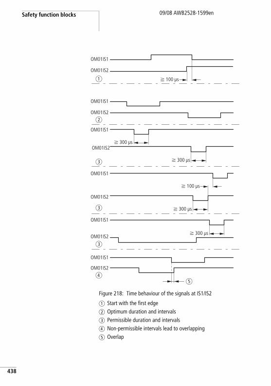
Safety function blocks
438
09/08 AWB2528-1599en
Figure 218: Time behaviour of the signals at IS1/IS2
a Start with the first edgeb Optimum duration and intervalsc Permissible duration and intervalsd Non-permissible intervals lead to overlappinge Overlap
f 300 µs
f 300 µs
OM01IS2
OM01IS1
OM01IS2
OM01IS1
OM01IS2
OM01IS1
OM01IS2
OM01IS1
OM01IS2
OM01IS1
d
c
c
c
b
OM01IS2
OM01IS1
a
e
f 300 µs
f 300 µs
f 100 µs
f 100 µs
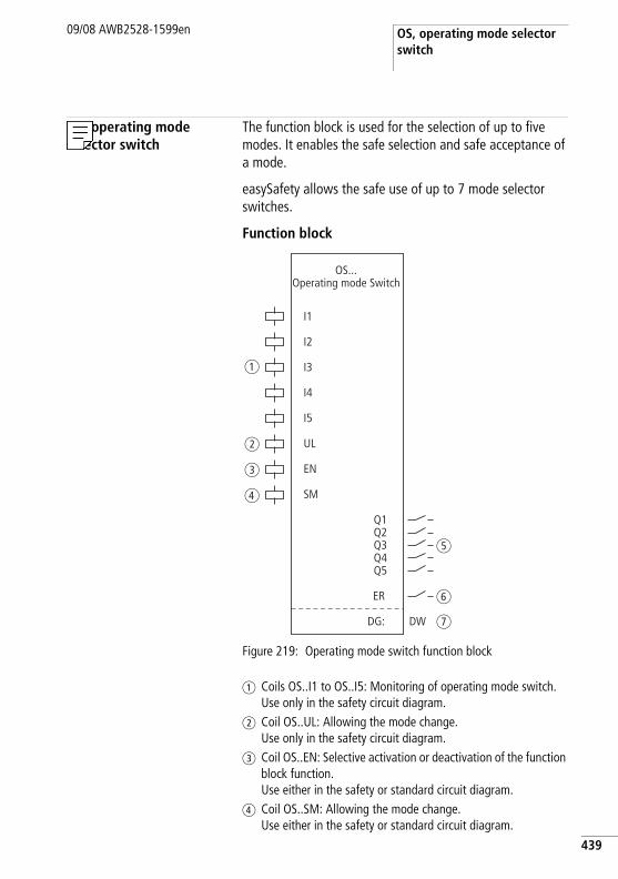
OS, operating mode selector switch
09/08 AWB2528-1599en
OS, operating mode selector switch
The function block is used for the selection of up to five modes. It enables the safe selection and safe acceptance of a mode.
easySafety allows the safe use of up to 7 mode selector switches.
Function block
Figure 219: Operating mode switch function block
a Coils OS..I1 to OS..I5: Monitoring of operating mode switch. Use only in the safety circuit diagram.
b Coil OS..UL: Allowing the mode change. Use only in the safety circuit diagram.
c Coil OS..EN: Selective activation or deactivation of the function block function. Use either in the safety or standard circuit diagram.
d Coil OS..SM: Allowing the mode change. Use either in the safety or standard circuit diagram.
I1
I2
UL
EN
SM
Q1
OS...Operating mode Switch
I3
I4
I5
ER
Q2Q3Q4Q5
DG: DW
a
b
c
d
e
f
g
439
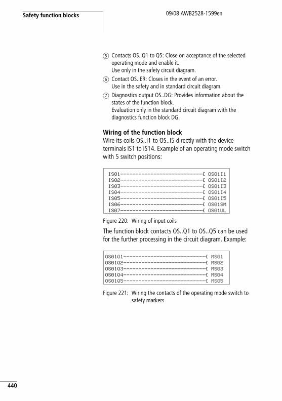
Safety function blocks
440
09/08 AWB2528-1599en
e Contacts OS..Q1 to Q5: Close on acceptance of the selected operating mode and enable it. Use only in the safety circuit diagram.
f Contact OS..ER: Closes in the event of an error. Use in the safety and in standard circuit diagram.
g Diagnostics output OS..DG: Provides information about the states of the function block. Evaluation only in the standard circuit diagram with the diagnostics function block DG.
Wiring of the function blockWire its coils OS..I1 to OS..I5 directly with the device terminals IS1 to IS14. Example of an operating mode switch with 5 switch positions:
Figure 220: Wiring of input coils
The function block contacts OS..Q1 to OS..Q5 can be used for the further processing in the circuit diagram. Example:L
Figure 221: Wiring the contacts of the operating mode switch to safety markers
IS01---------------------------Ä OS01I1
IS02---------------------------Ä OS01I2
IS03---------------------------Ä OS01I3
IS04---------------------------Ä OS01I4
IS05---------------------------Ä OS01I5
IS06---------------------------Ä OS01SM
IS07---------------------------Ä OS01UL
OS01Q1---------------------------Ä MS01
OS01Q2---------------------------Ä MS02
OS01Q3---------------------------Ä MS03
OS01Q4---------------------------Ä MS04
OS01Q5---------------------------Ä MS05
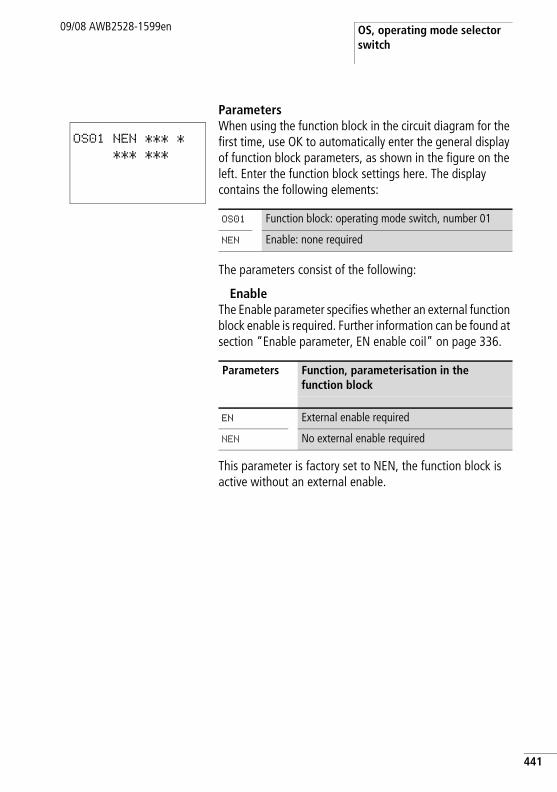
OS, operating mode selector switch
09/08 AWB2528-1599en
ParametersWhen using the function block in the circuit diagram for the first time, use OK to automatically enter the general display of function block parameters, as shown in the figure on the left. Enter the function block settings here. The display contains the following elements:
The parameters consist of the following:
EnableThe Enable parameter specifies whether an external function block enable is required. Further information can be found at section “Enable parameter, EN enable coil” on page 336.
This parameter is factory set to NEN, the function block is active without an external enable.
OS01 NEN *** *
*** ***
OS01 Function block: operating mode switch, number 01
NEN Enable: none required
Parameters Function, parameterisation in the function block
EN External enable required
NEN No external enable required
441
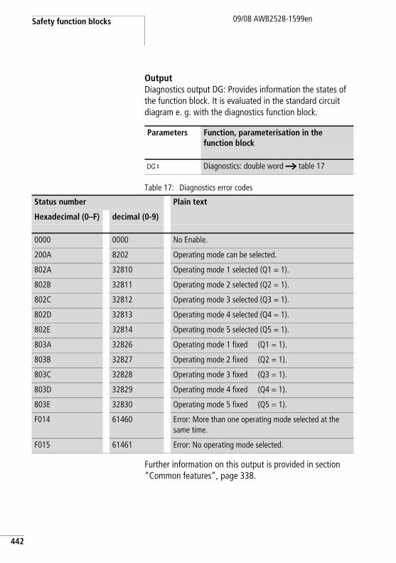
Safety function blocks
442
09/08 AWB2528-1599en
OutputDiagnostics output DG: Provides information the states of the function block. It is evaluated in the standard circuit diagram e. g. with the diagnostics function block.
Table 17: Diagnostics error codes
Further information on this output is provided in section “Common features”, page 338.
Parameters Function, parameterisation in the function block
DG: Diagnostics: double word a table 17
Status number Plain text
Hexadecimal (0–F) decimal (0-9)
0000 0000 No Enable.
200A 8202 Operating mode can be selected.
802A 32810 Operating mode 1 selected (Q1 = 1).
802B 32811 Operating mode 2 selected (Q2 = 1).
802C 32812 Operating mode 3 selected (Q3 = 1).
802D 32813 Operating mode 4 selected (Q4 = 1).
802E 32814 Operating mode 5 selected (Q5 = 1).
803A 32826 Operating mode 1 fixed (Q1 = 1).
803B 32827 Operating mode 2 fixed (Q2 = 1).
803C 32828 Operating mode 3 fixed (Q3 = 1).
803D 32829 Operating mode 4 fixed (Q4 = 1).
803E 32830 Operating mode 5 fixed (Q5 = 1).
F014 61460 Error: More than one operating mode selected at the same time.
F015 61461 Error: No operating mode selected.
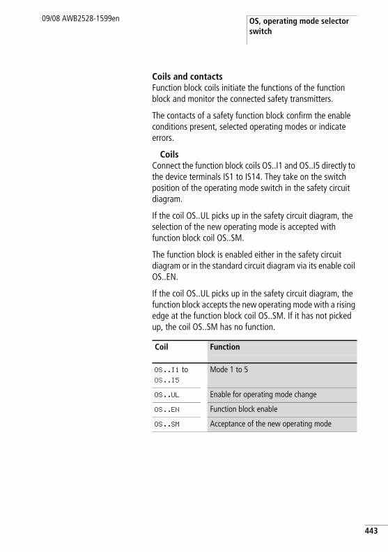
OS, operating mode selector switch
09/08 AWB2528-1599en
Coils and contactsFunction block coils initiate the functions of the function block and monitor the connected safety transmitters.
The contacts of a safety function block confirm the enable conditions present, selected operating modes or indicate errors.
CoilsConnect the function block coils OS..I1 and OS..I5 directly to the device terminals IS1 to IS14. They take on the switch position of the operating mode switch in the safety circuit diagram.
If the coil OS..UL picks up in the safety circuit diagram, the selection of the new operating mode is accepted with function block coil OS..SM.
The function block is enabled either in the safety circuit diagram or in the standard circuit diagram via its enable coil OS..EN.
If the coil OS..UL picks up in the safety circuit diagram, the function block accepts the new operating mode with a rising edge at the function block coil OS..SM. If it has not picked up, the coil OS..SM has no function.
Coil Function
OS..I1 to OS..I5
Mode 1 to 5
OS..UL Enable for operating mode change
OS..EN Function block enable
OS..SM Acceptance of the new operating mode
443
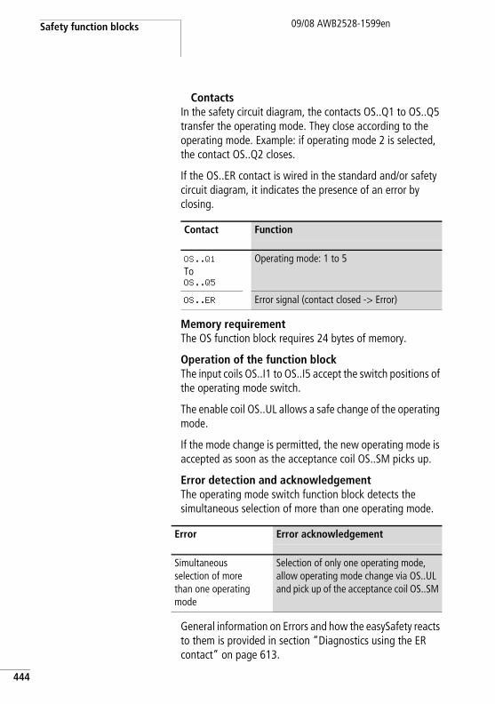
Safety function blocks
444
09/08 AWB2528-1599en
ContactsIn the safety circuit diagram, the contacts OS..Q1 to OS..Q5 transfer the operating mode. They close according to the operating mode. Example: if operating mode 2 is selected, the contact OS..Q2 closes.
If the OS..ER contact is wired in the standard and/or safety circuit diagram, it indicates the presence of an error by closing.
Memory requirementThe OS function block requires 24 bytes of memory.
Operation of the function blockThe input coils OS..I1 to OS..I5 accept the switch positions of the operating mode switch.
The enable coil OS..UL allows a safe change of the operating mode.
If the mode change is permitted, the new operating mode is accepted as soon as the acceptance coil OS..SM picks up.
Error detection and acknowledgementThe operating mode switch function block detects the simultaneous selection of more than one operating mode.
General information on Errors and how the easySafety reacts to them is provided in section “Diagnostics using the ER contact” on page 613.
Contact Function
OS..Q1
ToOS..Q5
Operating mode: 1 to 5
OS..ER Error signal (contact closed -> Error)
Error Error acknowledgement
Simultaneous selection of more than one operating mode
Selection of only one operating mode, allow operating mode change via OS..UL and pick up of the acceptance coil OS..SM
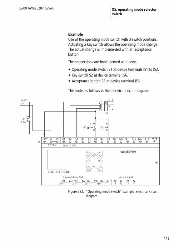
OS, operating mode selector switch
09/08 AWB2528-1599en
ExampleUse of the operating mode switch with 3 switch positions. Actuating a key switch allows the operating mode change. The actual change is implemented with an acceptance button.
The connections are implemented as follows:
• Operating mode switch S1 at device terminals IS1 to IS3.• Key switch S2 at device terminal IS6. • Acceptance button S3 at device terminal IS8.
This looks as follows in the electrical circuit diagram:
Figure 222: "Operating mode switch" example: electrical circuit diagram
0 V+24 V
21
-F1S 1A
T1 T2 T3 T4
4x Test SignalOutput 4x Relay / 6A
DEL
-K1
OK
ALT
ES4P-221-DRXD1
DC 24 V
NET
Input 14 x DC
ESC
IS1 IS2 IS3 IS4 IS5 IS6 IS7 IS8 IS9 IS10 IS11 IS12 IS13 IS14
1QS1
2 1QS2
2 1QS3
2 1QS4
2
+24V 0V 0V
P1
P2
P3
P4
I0-S2
3141
123456
-S1
1 2 3
3141
-S3
ea ySafety
445
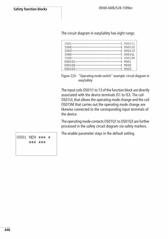
Safety function blocks
446
09/08 AWB2528-1599en
The circuit diagram in easySafety has eight rungs:
Figure 223: "Operating mode switch" example: circuit diagram in easySafety
The input coils OS01I1 to 13 of the function block are directly associated with the device terminals IS1 to IS3. The coil OS01UL that allows the operating mode change and the coil OS01SM that carries out the operating mode change are likewise connected to the corresponding input terminals of the device.
The operating mode contacts OS01Q1 to OS01Q3 are further processed in the safety circuit diagram via safety markers.
The enable parameter stays in the default setting.
IS01---------------------------Ä OS01I1IS02---------------------------Ä OS01I2IS03---------------------------Ä OS01I3IS06---------------------------Ä OS01ULIS08---------------------------Ä OS01SMOS01Q1-------------------------Ä MS01OS01Q2-------------------------Ä MS02OS01Q3-------------------------Ä MS03
OS01 NEN *** *
*** ***
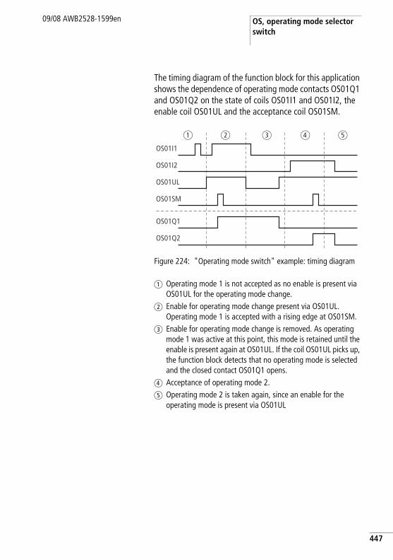
OS, operating mode selector switch
09/08 AWB2528-1599en
The timing diagram of the function block for this application shows the dependence of operating mode contacts OS01Q1 and OS01Q2 on the state of coils OS01I1 and OS01I2, the enable coil OS01UL and the acceptance coil OS01SM.
Figure 224: "Operating mode switch" example: timing diagram
a Operating mode 1 is not accepted as no enable is present via OS01UL for the operating mode change.
b Enable for operating mode change present via OS01UL. Operating mode 1 is accepted with a rising edge at OS01SM.
c Enable for operating mode change is removed. As operating mode 1 was active at this point, this mode is retained until the enable is present again at OS01UL. If the coil OS01UL picks up, the function block detects that no operating mode is selected and the closed contact OS01Q1 opens.
d Acceptance of operating mode 2.e Operating mode 2 is taken again, since an enable for the
operating mode is present via OS01UL
OS01Q1
OS01Q2
OS01I1
OS01I2
OS01UL
OS01SM
a b c d e
447
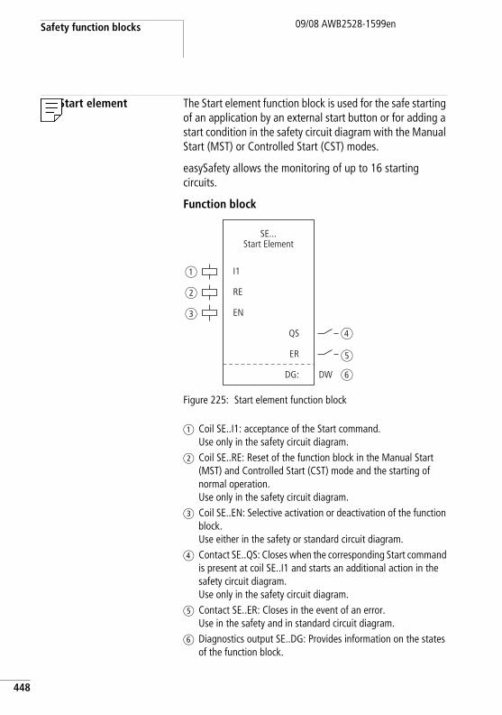
Safety function blocks
448
09/08 AWB2528-1599en
SE, Start element The Start element function block is used for the safe starting of an application by an external start button or for adding a start condition in the safety circuit diagram with the Manual Start (MST) or Controlled Start (CST) modes.
easySafety allows the monitoring of up to 16 starting circuits.
Function block
Figure 225: Start element function block
a Coil SE..I1: acceptance of the Start command. Use only in the safety circuit diagram.
b Coil SE..RE: Reset of the function block in the Manual Start (MST) and Controlled Start (CST) mode and the starting of normal operation. Use only in the safety circuit diagram.
c Coil SE..EN: Selective activation or deactivation of the function block. Use either in the safety or standard circuit diagram.
d Contact SE..QS: Closes when the corresponding Start command is present at coil SE..I1 and starts an additional action in the safety circuit diagram.Use only in the safety circuit diagram.
e Contact SE..ER: Closes in the event of an error. Use in the safety and in standard circuit diagram.
f Diagnostics output SE..DG: Provides information on the states of the function block.
I1
RE
EN
QS
ER
DG:
SE...Start Element
DW
a
b
c
d
e
f
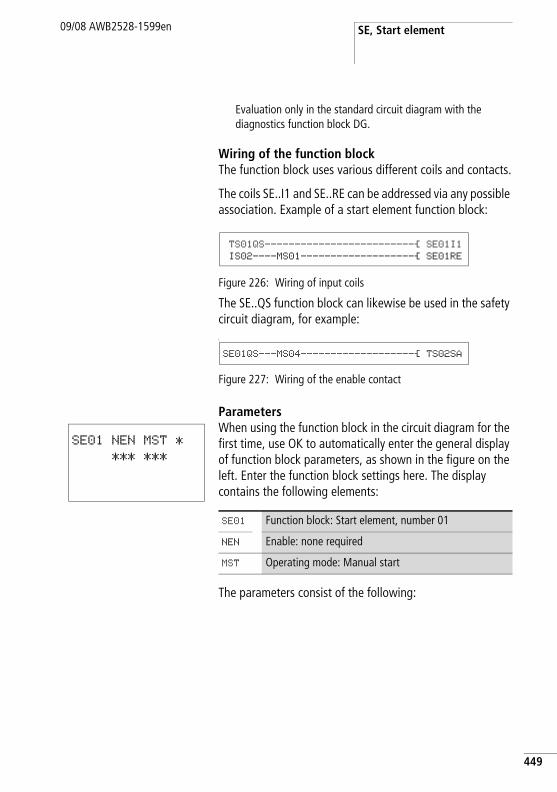
SE, Start element09/08 AWB2528-1599en
Evaluation only in the standard circuit diagram with the diagnostics function block DG.
Wiring of the function blockThe function block uses various different coils and contacts.
The coils SE..I1 and SE..RE can be addressed via any possible association. Example of a start element function block:
Figure 226: Wiring of input coils
The SE..QS function block can likewise be used in the safety circuit diagram, for example:L
Figure 227: Wiring of the enable contact
ParametersWhen using the function block in the circuit diagram for the first time, use OK to automatically enter the general display of function block parameters, as shown in the figure on the left. Enter the function block settings here. The display contains the following elements:
The parameters consist of the following:
TS01QS-------------------------Ä SE01I1
IS02----MS01-------------------Ä SE01RE
SE01QS---MS04-------------------Ä TS02SA
SE01 NEN MST *
*** ***
SE01 Function block: Start element, number 01
NEN Enable: none required
MST Operating mode: Manual start
449
Safety function blocks
450
09/08 AWB2528-1599en
EnableThe Enable parameter specifies whether an external function block enable is required. Further information can be found at section “Enable parameter, EN enable coil” on page 336.
This parameter is factory set to NEN, the function block is active without an external enable.
Mode parameterAfter easySafety has determined the conditions for safe operation, there are different kinds of restarts possible. They are described in greater detail as operating modes in chapter “Operating mode parameter, RE reset coil” on page 336.
This parameter is factory set to MST, manual start.
OutputDiagnostics output DG: Provides information the states of the function block. It is evaluated in the standard circuit diagram e. g. with the diagnostics function block.
Parameters Function, parameterisation in the function block
EN External enable required
NEN No external enable required
Parameters Function, parameterisation in the function block
MST Manual start
CST Controlled start
Parameters Function, parameterisation in the function block
DG: Diagnostics: double word a table 18
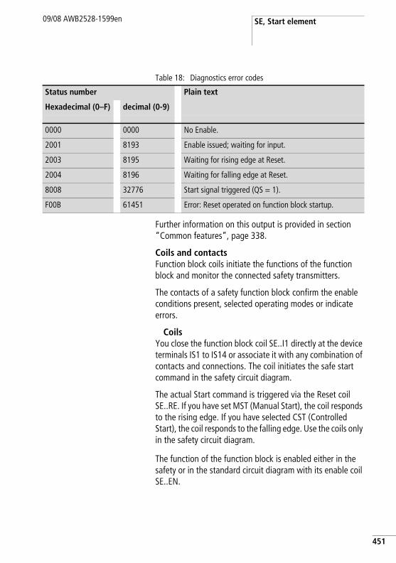
SE, Start element09/08 AWB2528-1599en
Table 18: Diagnostics error codes
Further information on this output is provided in section “Common features”, page 338.
Coils and contactsFunction block coils initiate the functions of the function block and monitor the connected safety transmitters.
The contacts of a safety function block confirm the enable conditions present, selected operating modes or indicate errors.
CoilsYou close the function block coil SE..I1 directly at the device terminals IS1 to IS14 or associate it with any combination of contacts and connections. The coil initiates the safe start command in the safety circuit diagram.
The actual Start command is triggered via the Reset coil SE..RE. If you have set MST (Manual Start), the coil responds to the rising edge. If you have selected CST (Controlled Start), the coil responds to the falling edge. Use the coils only in the safety circuit diagram.
The function of the function block is enabled either in the safety or in the standard circuit diagram with its enable coil SE..EN.
Status number Plain text
Hexadecimal (0–F) decimal (0-9)
0000 0000 No Enable.
2001 8193 Enable issued; waiting for input.
2003 8195 Waiting for rising edge at Reset.
2004 8196 Waiting for falling edge at Reset.
8008 32776 Start signal triggered (QS = 1).
F00B 61451 Error: Reset operated on function block startup.
451
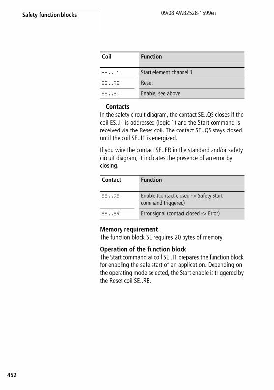
Safety function blocks
452
09/08 AWB2528-1599en
ContactsIn the safety circuit diagram, the contact SE..QS closes if the coil ES..I1 is addressed (logic 1) and the Start command is received via the Reset coil. The contact SE..QS stays closed until the coil SE..I1 is energized.
If you wire the contact SE..ER in the standard and/or safety circuit diagram, it indicates the presence of an error by closing.
Memory requirementThe function block SE requires 20 bytes of memory.
Operation of the function blockThe Start command at coil SE..I1 prepares the function block for enabling the safe start of an application. Depending on the operating mode selected, the Start enable is triggered by the Reset coil SE..RE.
Coil Function
SE..I1 Start element channel 1
SE..RE Reset
SE..EN Enable, see above
Contact Function
SE..QS Enable (contact closed -> Safety Start command triggered)
SE..ER Error signal (contact closed -> Error)
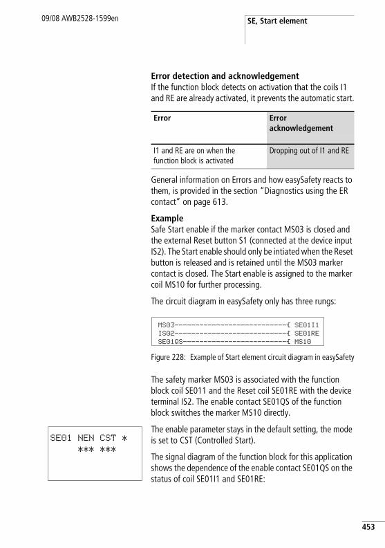
SE, Start element09/08 AWB2528-1599en
Error detection and acknowledgementIf the function block detects on activation that the coils I1 and RE are already activated, it prevents the automatic start.
General information on Errors and how easySafety reacts to them, is provided in the section “Diagnostics using the ER contact” on page 613.
ExampleSafe Start enable if the marker contact MS03 is closed and the external Reset button S1 (connected at the device input IS2). The Start enable should only be intiated when the Reset button is released and is retained until the MS03 marker contact is closed. The Start enable is assigned to the marker coil MS10 for further processing.
The circuit diagram in easySafety only has three rungs:
Figure 228: Example of Start element circuit diagram in easySafety
The safety marker MS03 is associated with the function block coil SE011 and the Reset coil SE01RE with the device terminal IS2. The enable contact SE01QS of the function block switches the marker MS10 directly.
The enable parameter stays in the default setting, the mode is set to CST (Controlled Start).
The signal diagram of the function block for this application shows the dependence of the enable contact SE01QS on the status of coil SE01I1 and SE01RE:
Error Error acknowledgement
I1 and RE are on when the function block is activated
Dropping out of I1 and RE
MS03---------------------------Ä SE01I1IS02---------------------------Ä SE01RESE01QS-------------------------Ä MS10
SE01 NEN CST *
*** ***
453
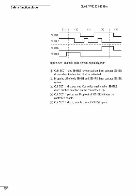
Safety function blocks
454
09/08 AWB2528-1599en
Figure 229: Example Start element signal diagram
a Coils SE01I1 and SE01RE have picked up. Error contact SE01ER closes when the function block is activated.
b Dropping off of coils SE01I1 and SE01RE. Error contact SE01ER opens.
c Coil SE01I1 dropped out. Controlled enable when SE01RE drops out has no effect on the contact SE01QS.
d Coil SE01I1 picked up. Drop out of SE01ER initiates the controlled enable.
e Coil SE01I1 drops, enable contact SE01QS opens.
SE01I1
SE01QS
SE01ER
SE01RE
a b c d e
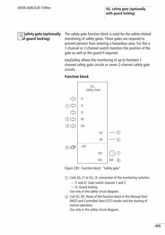
SG, safety gate (optionally with guard locking)
09/08 AWB2528-1599en
SG, safety gate (optionally with guard locking)
The safety gate function block is used for the safety-related monitoring of safety gates. These gates are required to prevent persons from entering a hazardous area. For this a 1-channel or 2-channel switch monitors the position of the gate as well as the guard if required.
easySafety allows the monitoring of up to fourteen 1-channel safety gate circuits or seven 2-channel safety gate circuits.
Function block
Figure 230: Function block: "Safety gate"
a Coils SG..I1 to SG..I3: connection of the monitoring switches:– I1 and I2: Gate switch channel 1 and 2– I3: Guard locking
Use only in the safety circuit diagram.b Coil SG..RE: Reset of the function block in the Manual Start
(MST) and Controlled Start (CST) modes and the starting of normal operation. Use only in the safety circuit diagram.
I1
I2
RE
EN
>DT
QS
ER
DG:
QV:
SG...Safety Gate
a
b
c
d
e
f
g
h
I3
DW
455
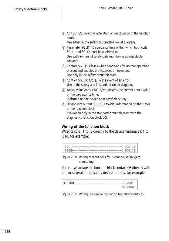
Safety function blocks
456
09/08 AWB2528-1599en
c Coil SG..EN: Selective activation or deactivation of the function block. Use either in the safety or standard circuit diagram.
d Parameter SG..DT: Discrepancy time within which both coils SG..I1 and SG..I2 must have picked up. Use with 2-channel safety gate monitoring as adjustable constant
e Contact SG..QS: Closes when conditions for normal operation present and enables the hazardous movement. Use only in the safety circuit diagram.
f Contact SG..ER: Closes in the event of an error. Use in the safety and in standard circuit diagram.
g Actual value output DG..QV: Indicates the current actual value of the discrepancy time. Indicated on the device or in easySoft-Safety.
h Diagnostics output SG..DG: Provides information on the states of the function block. Evaluation only in the standard circuit diagram with the diagnostics function block DG.
Wiring of the function blockWire its coils I1 to I3 directly to the device terminals IS1 to IS14, for example:
Figure 231: Wiring of input coils for 2-channel safety gate monitoring
You can associate the function block contact QS directly with one or several of the safety device outputs, for example:
L
Figure 232: Wiring the enable contact to two device outputs
IS01---------------------------Ä SG01I1
IS02---------------------------Ä SG01I2
SG01QS--------------------------uÄ QS01
hÄ QS02
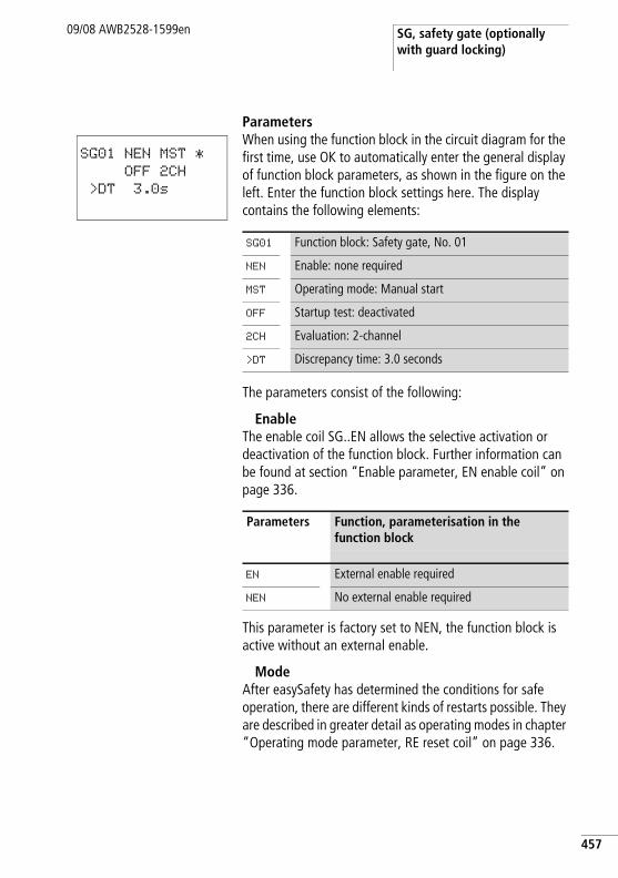
SG, safety gate (optionally with guard locking)
09/08 AWB2528-1599en
ParametersWhen using the function block in the circuit diagram for the first time, use OK to automatically enter the general display of function block parameters, as shown in the figure on the left. Enter the function block settings here. The display contains the following elements:
The parameters consist of the following:
EnableThe enable coil SG..EN allows the selective activation or deactivation of the function block. Further information can be found at section “Enable parameter, EN enable coil” on page 336.
This parameter is factory set to NEN, the function block is active without an external enable.
ModeAfter easySafety has determined the conditions for safe operation, there are different kinds of restarts possible. They are described in greater detail as operating modes in chapter “Operating mode parameter, RE reset coil” on page 336.
SG01 NEN MST *
OFF 2CH
>DT 3.0s
SG01 Function block: Safety gate, No. 01
NEN Enable: none required
MST Operating mode: Manual start
OFF Startup test: deactivated
2CH Evaluation: 2-channel
>DT Discrepancy time: 3.0 seconds
Parameters Function, parameterisation in the function block
EN External enable required
NEN No external enable required
457
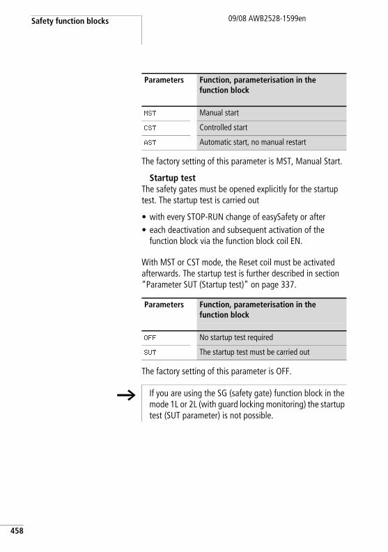
Safety function blocks
458
09/08 AWB2528-1599en
The factory setting of this parameter is MST, Manual Start.
Startup testThe safety gates must be opened explicitly for the startup test. The startup test is carried out
• with every STOP-RUN change of easySafety or after• each deactivation and subsequent activation of the
function block via the function block coil EN.
With MST or CST mode, the Reset coil must be activated afterwards. The startup test is further described in section “Parameter SUT (Startup test)” on page 337.
The factory setting of this parameter is OFF.
Parameters Function, parameterisation in the function block
MST Manual start
CST Controlled start
AST Automatic start, no manual restart
Parameters Function, parameterisation in the function block
OFF No startup test required
SUT The startup test must be carried out
h If you are using the SG (safety gate) function block in the mode 1L or 2L (with guard locking monitoring) the startup test (SUT parameter) is not possible.
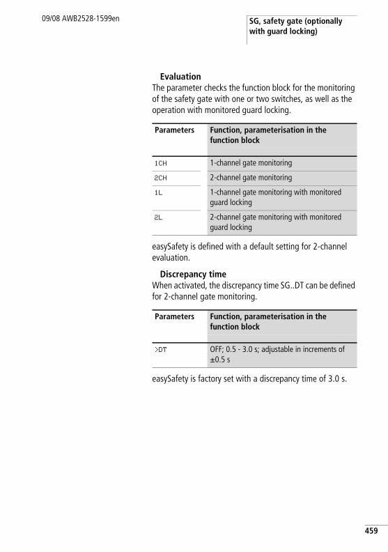
SG, safety gate (optionally with guard locking)
09/08 AWB2528-1599en
EvaluationThe parameter checks the function block for the monitoring of the safety gate with one or two switches, as well as the operation with monitored guard locking.
easySafety is defined with a default setting for 2-channel evaluation.
Discrepancy timeWhen activated, the discrepancy time SG..DT can be defined for 2-channel gate monitoring.
easySafety is factory set with a discrepancy time of 3.0 s.
Parameters Function, parameterisation in the function block
1CH 1-channel gate monitoring
2CH 2-channel gate monitoring
1L 1-channel gate monitoring with monitored guard locking
2L 2-channel gate monitoring with monitored guard locking
Parameters Function, parameterisation in the function block
>DT OFF; 0.5 - 3.0 s; adjustable in increments of g0.5 s
459
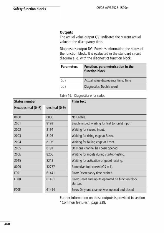
Safety function blocks
460
09/08 AWB2528-1599en
OutputsThe actual value output QV: Indicates the current actual value of the discrepancy time.
Diagnostics output DG: Provides information the states of the function block. It is evaluated in the standard circuit diagram e. g. with the diagnostics function block.
Table 19: Diagnostics error codes
Further information on these outputs is provided in section “Common features”, page 338.
Parameters Function, parameterisation in the function block
QV: Actual value discrepancy time: Time
DG: Diagnostics: Double word
Status number Plain text
Hexadecimal (0–F) decimal (0-9)
0000 0000 No Enable.
2001 8193 Enable issued; waiting for first (or only) input.
2002 8194 Waiting for second input.
2003 8195 Waiting for rising edge at Reset.
2004 8196 Waiting for falling edge at Reset.
2005 8197 Only one channel has been opened.
200E 8206 Waiting for inputs during startup testing.
2015 8213 Waiting for activation of guard locking.
8009 32777 Protective door closed (QS = 1).
F001 61441 Error: Discrepancy time expired.
F00B 61451 Error: Reset and inputs operated on function block startup.
F00E 61454 Error: Only one channel was opened and closed.
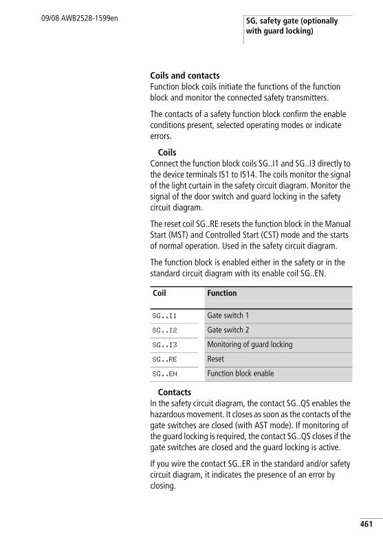
SG, safety gate (optionally with guard locking)
09/08 AWB2528-1599en
Coils and contactsFunction block coils initiate the functions of the function block and monitor the connected safety transmitters.
The contacts of a safety function block confirm the enable conditions present, selected operating modes or indicate errors.
CoilsConnect the function block coils SG..I1 and SG..I3 directly to the device terminals IS1 to IS14. The coils monitor the signal of the light curtain in the safety circuit diagram. Monitor the signal of the door switch and guard locking in the safety circuit diagram.
The reset coil SG..RE resets the function block in the Manual Start (MST) and Controlled Start (CST) mode and the starts of normal operation. Used in the safety circuit diagram.
The function block is enabled either in the safety or in the standard circuit diagram with its enable coil SG..EN.
ContactsIn the safety circuit diagram, the contact SG..QS enables the hazardous movement. It closes as soon as the contacts of the gate switches are closed (with AST mode). If monitoring of the guard locking is required, the contact SG..QS closes if the gate switches are closed and the guard locking is active.
If you wire the contact SG..ER in the standard and/or safety circuit diagram, it indicates the presence of an error by closing.
Coil Function
SG..I1 Gate switch 1
SG..I2 Gate switch 2
SG..I3 Monitoring of guard locking
SG..RE Reset
SG..EN Function block enable
461
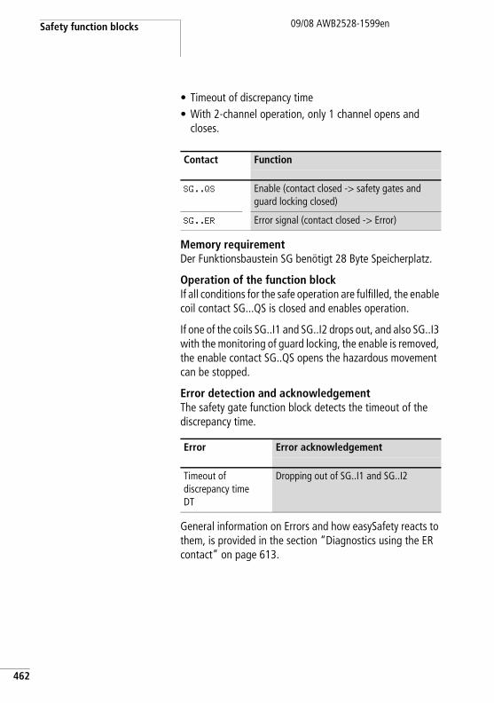
Safety function blocks
462
09/08 AWB2528-1599en
• Timeout of discrepancy time• With 2-channel operation, only 1 channel opens and
closes.
Memory requirementDer Funktionsbaustein SG benötigt 28 Byte Speicherplatz.
Operation of the function blockIf all conditions for the safe operation are fulfilled, the enable coil contact SG...QS is closed and enables operation.
If one of the coils SG..I1 and SG..I2 drops out, and also SG..I3 with the monitoring of guard locking, the enable is removed, the enable contact SG..QS opens the hazardous movement can be stopped.
Error detection and acknowledgementThe safety gate function block detects the timeout of the discrepancy time.
General information on Errors and how easySafety reacts to them, is provided in the section “Diagnostics using the ER contact” on page 613.
Contact Function
SG..QS Enable (contact closed -> safety gates and guard locking closed)
SG..ER Error signal (contact closed -> Error)
Error Error acknowledgement
Timeout of discrepancy time DT
Dropping out of SG..I1 and SG..I2
SG, safety gate (optionally with guard locking)
09/08 AWB2528-1599en
Example 1 - Architecture of Category 4 according to EN 954-1 and ISO 13849-12-channel monitoring of a safety gate with cross-circuit monitoring of its external wiring. When the safety gate opens, the motor stops and the hazardous movement comes to a standstill. Pressing the Reset button after the safety gate closes initiates the re-enabling and the motor is started. The discrepancy time is set to 0.5 seconds.
The safety gate is monitored with two position switches B1 and B2. Both position switches are supplied with the test signals T3 and T4. They are connected to the device inputs IS13 and IS14. The safety device outputs QS1 and QS2 switch directly the contactors Q1 and Q2. The function block initiates the enable after the safety gate is closed and after the pressing and subsequent release of the Reset button that is connected to IS9.
This looks as follows in the electrical circuit diagram:
463
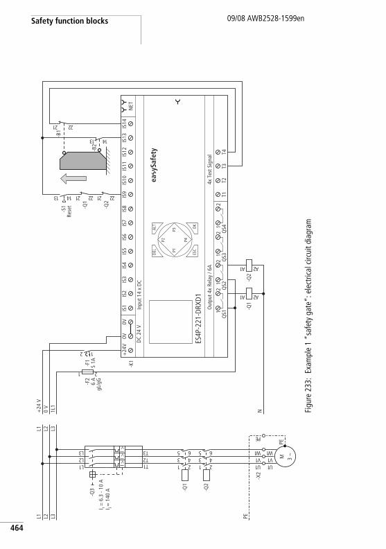
Safety function blocks
464
09/08 AWB2528-1599en
Figu
re 2
33:
Exam
ple
1 “s
afet
y ga
te”:
ele
ctric
al c
ircui
t dia
gram
I r = 6
.3 -
10 A
I i = 1
40 A
ea y
Safe
ty
PEL3L2L1
1U
-X2
-Q2
1 23 45 6
-Q1
1 23 45 6
1L2L3L
1T2T3TI >
I >I >
-Q3
M 3 h
1U1V1 W
PE
1V1 W
EP
L3L2L1
N1L1
0 V
+24
V
-F2
6 A
gL/g
G
1 2
T1T2
T3T4
4x T
est S
igna
lO
utpu
t 4x
Rela
y / 6
A
DEL
-K1
OK
ALT
ES4P
-221
-DRX
D1
DC
24 V
NET
Inpu
t 14
x D
C
ESC
IS1
IS2
IS3
IS4
IS5
IS6
IS7
IS8
IS9
IS10
IS11
IS12
IS13
IS14
1Q
S12
1Q
S22
1Q
S32
1Q
S42
+24
V0V
0V
P1
P2
P3
P4
2 1
-F1
S 1A
-Q1
1A 2A-Q
2
1A 2A
-Q2
12 22
-Q1
12 2231 41
-S1
-B2
31 41-B1
12 22
Rese
t
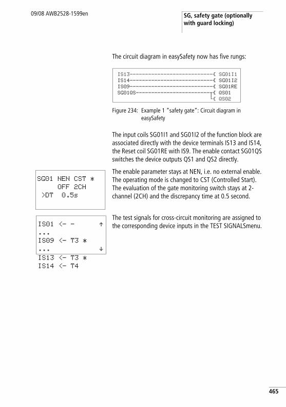
SG, safety gate (optionally with guard locking)
09/08 AWB2528-1599en
The circuit diagram in easySafety now has five rungs:
Figure 234: Example 1 “safety gate”: Circuit diagram in easySafety
The input coils SG01I1 and SG01I2 of the function block are associated directly with the device terminals IS13 and IS14, the Reset coil SG01RE with IS9. The enable contact SG01QS switches the device outputs QS1 and QS2 directly.
The enable parameter stays at NEN, i.e. no external enable. The operating mode is changed to CST (Controlled Start). The evaluation of the gate monitoring switch stays at 2-channel (2CH) and the discrepancy time at 0.5 second.
The test signals for cross-circuit monitoring are assigned to the corresponding device inputs in the TEST SIGNALSmenu.
IS13---------------------------Ä SG01I1
IS14---------------------------Ä SG01I2
IS09---------------------------Ä SG01RE
SG01QS------------------------uÄ QS01
hÄ QS02
SG01 NEN CST *
OFF 2CH
>DT 0.5s
IS01 <- - Æ...
IS09 <- T3 *
... æIS13 <- T3 *
IS14 <- T4
465
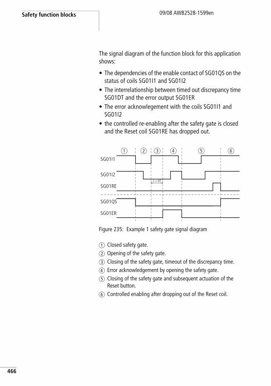
Safety function blocks
466
09/08 AWB2528-1599en
The signal diagram of the function block for this application shows:
• The dependencies of the enable contact of SG01QS on the status of coils SG01I1 and SG01I2
• The interrelationship between timed out discrepancy time SG01DT and the error output SG01ER
• The error acknowlegement with the coils SG01I1 and SG01I2
• the controlled re-enabling after the safety gate is closed and the Reset coil SG01RE has dropped out.
Figure 235: Example 1 safety gate signal diagram
a Closed safety gate.b Opening of the safety gate.c Closing of the safety gate, timeout of the discrepancy time.d Error acknowledgement by opening the safety gate.e Closing of the safety gate and subsequent actuation of the
Reset button.f Controlled enabling after dropping out of the Reset coil.
SG01I1
SG01I2
SG01QS
SG01ER
t > DT
SG01RE
a b c d e f
SG, safety gate (optionally with guard locking)
09/08 AWB2528-1599en
Example 2 - Architecture of Category 4 according to EN 954-1 and ISO 13849-12-channel monitoring of a safety gate with guard locking and cross-circuit monitoring of its external wiring. The actuation of the release button opens the guard, the safety gate is enabled and removes the enable from the hazardous movement. Pressing the Reset button after the safety gate closes initiates the re-enabling. The discrepancy time is set to 0.5 seconds.
The safety gate is monitored with a safety position switch B1 with a tumbler and another position switch B2. Both limit switches and the feedback of the tumbler are fed with test signals T1 to T3 and are connected to device inputs IS2, IS5 and IS6. Safety device outputs QS1 and QS2 switch contactors Q1 and Q2 directly. The function block issues the enable after the safety gate is closed and the reset pushbutton that is connected to IS9 is activated.
This looks as follows in the electrical circuit diagram:
467
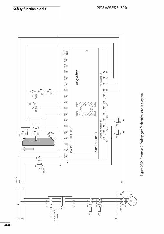
Safety function blocks
468
09/08 AWB2528-1599en
Figu
re 2
36:
Exam
ple
2 “s
afet
y ga
te”:
ele
ctric
al c
ircui
t dia
gram
Ir =
6.3
- 10
AI i
= 1
40 A
ea y
Safe
ty
PEL3L2L1
1U
-X2
-Q2
1 23 45 6
-Q1
1 23 45 6
1L2L3L
1T2T3TI >
I >I >
-Q3
M 3 h
1U1V1 W
PE
1V1 W
EP
L3L2L1
N1L1
0 V
+24
V
-F2
6 A
gL/g
G
1 2
T1T2
T3T4
4x T
est S
igna
lO
utpu
t 4x
Rela
y / 6
A
DEL
-K1
OK
ALT
ES4P
-221
-DRX
D1
DC
24 V
NET
Inpu
t 14
x D
C
ESC
IS1
IS2
IS3
IS4
IS5
IS6
IS7
IS8
IS9
IS10
IS11
IS12
IS13
IS14
1Q
S12
1Q
S22
1Q
S32
1Q
S42
+24
V0V
0V
P1
P2
P3
P4
2 1
-F1
S 1A
-Q1
1A 2A
-B2
31 41
-B1
11 21 12 22
1A 2A -Q2
1A 2A
31 41
-S2
-Q2
12 22
-Q1
12 22
-S1
31 41
Rese
tun
lock
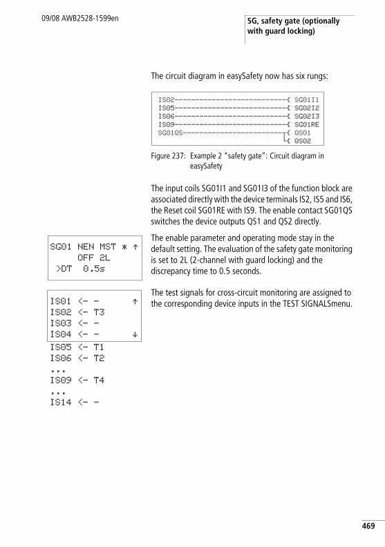
SG, safety gate (optionally with guard locking)
09/08 AWB2528-1599en
The circuit diagram in easySafety now has six rungs:
Figure 237: Example 2 “safety gate”: Circuit diagram in easySafety
The input coils SG01I1 and SG01I3 of the function block are associated directly with the device terminals IS2, IS5 and IS6, the Reset coil SG01RE with IS9. The enable contact SG01QS switches the device outputs QS1 and QS2 directly.
The enable parameter and operating mode stay in the default setting. The evaluation of the safety gate monitoring is set to 2L (2-channel with guard locking) and the discrepancy time to 0.5 seconds.
The test signals for cross-circuit monitoring are assigned to the corresponding device inputs in the TEST SIGNALSmenu.
IS02---------------------------Ä SG01I1
IS05---------------------------Ä SG02I2
IS06---------------------------Ä SG02I3
IS09---------------------------Ä SG01RE
SG01QS------------------------uÄ QS01
hÄ QS02
SG01 NEN MST * ÆOFF 2L
>DT 0.5s
IS01 <- - ÆIS02 <- T3
IS03 <- -
IS04 <- - æIS05 <- T1
IS06 <- T2
...
IS09 <- T4
...
IS14 <- -
469
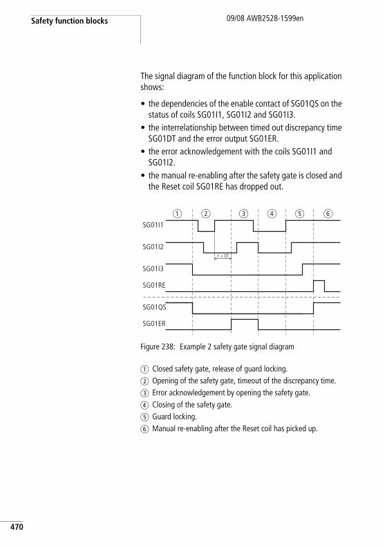
Safety function blocks
470
09/08 AWB2528-1599en
The signal diagram of the function block for this application shows:
• the dependencies of the enable contact of SG01QS on the status of coils SG01I1, SG01I2 and SG01I3.
• the interrelationship between timed out discrepancy time SG01DT and the error output SG01ER.
• the error acknowledgement with the coils SG01I1 and SG01I2.
• the manual re-enabling after the safety gate is closed and the Reset coil SG01RE has dropped out.
Figure 238: Example 2 safety gate signal diagram
a Closed safety gate, release of guard locking.b Opening of the safety gate, timeout of the discrepancy time.c Error acknowledgement by opening the safety gate.d Closing of the safety gate.e Guard locking.f Manual re-enabling after the Reset coil has picked up.
SG01I1
SG01I2
SG01QS
SG01ER
t > DT
SG01RE
SG01I3
a b c d e f
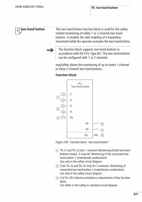
TH, two-hand button09/08 AWB2528-1599en
TH, two-hand button The two hand button function block is used for the safety-related monitoring of safety 1 or 2-channel two hand buttons. It enables the safe enabling of a hazardous movement while the operator actuates the two hand button.
easySafety allows the monitoring of up to seven 1-channel or three 2-channel two hand buttons.
Function block
Figure 239: Function block "two hand button"
a TH..I1 and TH..I2 coils: 1-channel: Monitoring of both two hand buttons (make). 2-channel: Monitoring of the connected two hand button 1 (make/break combination). Use only in the safety circuit diagram.
b Coils TH..I3 and TH..I4: Only for 2-channels: Monitoring of connected two hand button 2 (make/break combination).Use only in the safety circuit diagram.
c Coil TH..EN: Selective activation or deactivation of the function block. Use either in the safety or standard circuit diagram.
h The function block supports two hand buttons in accordance with EN 574, Type IIIC. The two hand buttons can be configured with 1 or 2 channels.
I1
EN
QS
ER
DG:
TH...Two Hand button
a
b
c
d
e
f
I2
I3
I4
DW
471
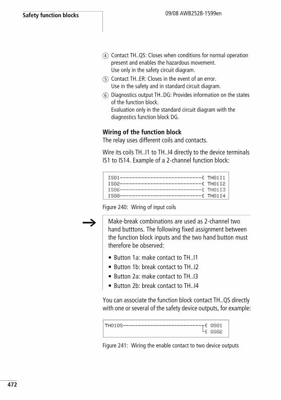
Safety function blocks
472
09/08 AWB2528-1599en
d Contact TH..QS: Closes when conditions for normal operation present and enables the hazardous movement. Use only in the safety circuit diagram.
e Contact TH..ER: Closes in the event of an error. Use in the safety and in standard circuit diagram.
f Diagnostics output TH..DG: Provides information on the states of the function block. Evaluation only in the standard circuit diagram with the diagnostics function block DG.
Wiring of the function blockThe relay uses different coils and contacts.
Wire its coils TH..I1 to TH..I4 directly to the device terminals IS1 to IS14. Example of a 2-channel function block:
Figure 240: Wiring of input coils
You can associate the function block contact TH..QS directly with one or several of the safety device outputs, for example:L
Figure 241: Wiring the enable contact to two device outputs
IS01---------------------------Ä TH01I1
IS02---------------------------Ä TH01I2
IS06---------------------------Ä TH01I3
IS08---------------------------Ä TH01I4
h Make-break combinations are used as 2-channel two hand butttons. The following fixed assignment between the function block inputs and the two hand button must therefore be observed:
• Button 1a: make contact to TH..I1• Button 1b: break contact to TH..I2• Button 2a: make contact to TH..I3• Button 2b: break contact to TH..I4
TH01QS--------------------------uÄ QS01
hÄ QS02
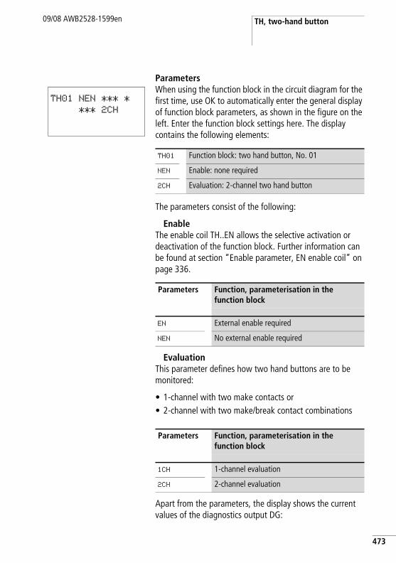
TH, two-hand button09/08 AWB2528-1599en
ParametersWhen using the function block in the circuit diagram for the first time, use OK to automatically enter the general display of function block parameters, as shown in the figure on the left. Enter the function block settings here. The display contains the following elements:
The parameters consist of the following:
EnableThe enable coil TH..EN allows the selective activation or deactivation of the function block. Further information can be found at section “Enable parameter, EN enable coil” on page 336.
EvaluationThis parameter defines how two hand buttons are to be monitored:
• 1-channel with two make contacts or• 2-channel with two make/break contact combinations
Apart from the parameters, the display shows the current values of the diagnostics output DG:
TH01 NEN *** *
*** 2CH
TH01 Function block: two hand button, No. 01
NEN Enable: none required
2CH Evaluation: 2-channel two hand button
Parameters Function, parameterisation in the function block
EN External enable required
NEN No external enable required
Parameters Function, parameterisation in the function block
1CH 1-channel evaluation
2CH 2-channel evaluation
473
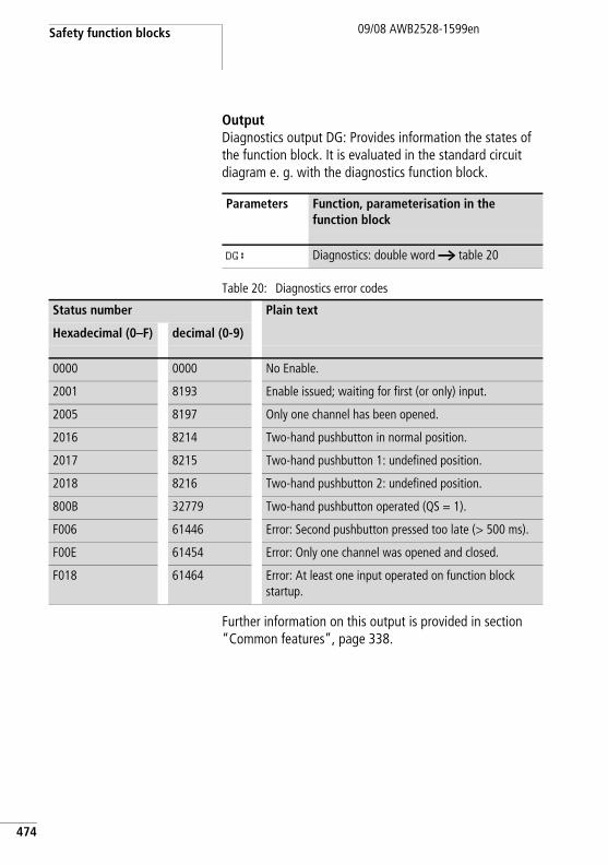
Safety function blocks
474
09/08 AWB2528-1599en
OutputDiagnostics output DG: Provides information the states of the function block. It is evaluated in the standard circuit diagram e. g. with the diagnostics function block.
Table 20: Diagnostics error codes
Further information on this output is provided in section “Common features”, page 338.
Parameters Function, parameterisation in the function block
DG: Diagnostics: double word a table 20
Status number Plain text
Hexadecimal (0–F) decimal (0-9)
0000 0000 No Enable.
2001 8193 Enable issued; waiting for first (or only) input.
2005 8197 Only one channel has been opened.
2016 8214 Two-hand pushbutton in normal position.
2017 8215 Two-hand pushbutton 1: undefined position.
2018 8216 Two-hand pushbutton 2: undefined position.
800B 32779 Two-hand pushbutton operated (QS = 1).
F006 61446 Error: Second pushbutton pressed too late (> 500 ms).
F00E 61454 Error: Only one channel was opened and closed.
F018 61464 Error: At least one input operated on function block startup.
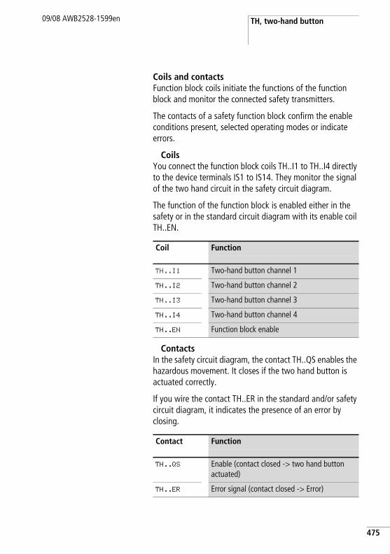
TH, two-hand button09/08 AWB2528-1599en
Coils and contactsFunction block coils initiate the functions of the function block and monitor the connected safety transmitters.
The contacts of a safety function block confirm the enable conditions present, selected operating modes or indicate errors.
CoilsYou connect the function block coils TH..I1 to TH..I4 directly to the device terminals IS1 to IS14. They monitor the signal of the two hand circuit in the safety circuit diagram.
The function of the function block is enabled either in the safety or in the standard circuit diagram with its enable coil TH..EN.
ContactsIn the safety circuit diagram, the contact TH..QS enables the hazardous movement. It closes if the two hand button is actuated correctly.
If you wire the contact TH..ER in the standard and/or safety circuit diagram, it indicates the presence of an error by closing.
Coil Function
TH..I1 Two-hand button channel 1
TH..I2 Two-hand button channel 2
TH..I3 Two-hand button channel 3
TH..I4 Two-hand button channel 4
TH..EN Function block enable
Contact Function
TH..QS Enable (contact closed -> two hand button actuated)
TH..ER Error signal (contact closed -> Error)
475
Safety function blocks
476
09/08 AWB2528-1599en
Memory requirementThe function block TH requires 24 bytes of memory.
Operation of the function blockIf you actuate the two hand button, the function block coils will switch as follows:
• 1-channel operation:– the coils TH..I1 and TH..I2 pick up.
• 2-channel operation:– the coils TH..I1 and TH..I3 pick up.– the coils TH..I2 and TH..I4 drop out.
If this occurs within a fixed time of 500 ms, the enable contact TH..QS closes and enables operation.
If one of coils picks up or drops out, the enable is removed, the enable contact TH..QS opens and the hazardous movement is stopped.
Error detection and acknowledgementThe function block detects the non-synchronous switching of the two hand buttons. Both switches must achieve the same switch state within a fixed time of 500 ms.
General information on Errors and how easySafety reacts to them, is provided in the section “Diagnostics using the ER contact” on page 613.
Error Error acknowledgement
Timeout of the 500 ms
• 1-channel operation:– Dropping out of TH..I1 and TH..I2• 2-channel operation:– Dropping out of TH..I1 and TH..I3– Picking up of TH..I2 and TH..I4
TH, two-hand button09/08 AWB2528-1599en
Example 1 - Architecture of Category 2 according to EN 954-1 and ISO 13849-1Monitoring of a 1-channel two hand button with cross-circuit monitoring between the connected make contacts. Actuation of the button triggers the enable.
The two hand button S1 is connected to the device terminals IS10 and IS11, the safety transistor output QS1 switches the contactor Q1 directly.
This looks as follows in the electrical circuit diagram:
477
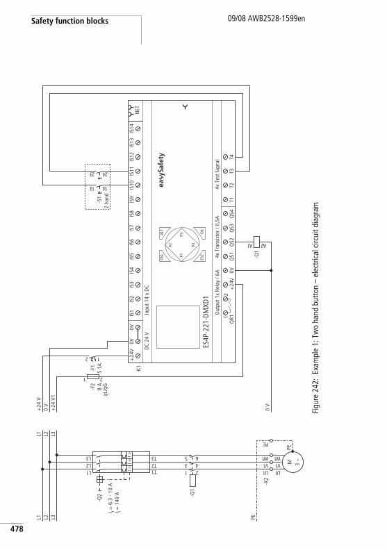
Safety function blocks
478
09/08 AWB2528-1599en
Figu
re 2
42:
Exam
ple
1: T
wo
hand
but
ton
– el
ectri
cal c
ircui
t dia
gram
PEL3L2L1
1U
-X2
-Q1
1 23 45 6
1L2L3L
1T2T3TI >
I >I >
-Q2
M 3 h
1U1V1 W
PE
1V1 W
EP
L3L2L1
0 V
+24
V1
0 V
+24
V
-F2
8 A
gL/g
G
1 2
0V+
24V
QS1
QS2
QS3
QS4
T1T2
T3T4
Out
put 1
x Re
lay
/ 6A
4x T
est S
igna
l
ES4P
-221
-DM
XD1
4x T
rans
isto
r / 0
,5A
DC
24 V
Inpu
t 14
x D
C
NET
ALT OK
-K1
DEL
ESC
IS1
IS2
IS3
IS4
IS5
IS6
IS7
IS8
IS9
IS10
IS11
IS12
IS13
IS14
1Q
R12
+24
V0V
0V
P1
P2
P3
P42 1
-F1
S 1A
-Q1
1A 2A
-S1
31 41
32 42
ea y
Safe
ty
I r = 6
.3 -
10 A
I i = 1
40 A
2 ha
nd
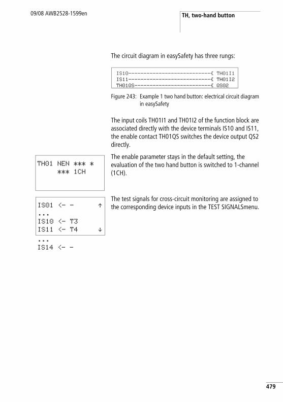
TH, two-hand button09/08 AWB2528-1599en
The circuit diagram in easySafety has three rungs:
Figure 243: Example 1 two hand button: electrical circuit diagram in easySafety
The input coils TH01I1 and TH01I2 of the function block are associated directly with the device terminals IS10 and IS11, the enable contact TH01QS switches the device output QS2 directly.
The enable parameter stays in the default setting, the evaluation of the two hand button is switched to 1-channel (1CH).
The test signals for cross-circuit monitoring are assigned to the corresponding device inputs in the TEST SIGNALSmenu.
IS10---------------------------Ä TH01I1IS11---------------------------Ä TH01I2TH01QS-------------------------Ä QS02
TH01 NEN *** *
*** 1CH
IS01 <- - Æ...
IS10 <- T3
IS11 <- T4 æ...
IS14 <- -
479
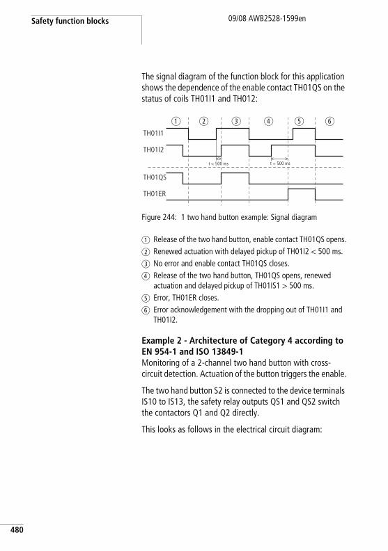
Safety function blocks
480
09/08 AWB2528-1599en
The signal diagram of the function block for this application shows the dependence of the enable contact TH01QS on the status of coils TH01I1 and TH012:
Figure 244: 1 two hand button example: Signal diagram
a Release of the two hand button, enable contact TH01QS opens.b Renewed actuation with delayed pickup of TH01I2 < 500 ms.c No error and enable contact TH01QS closes.d Release of the two hand button, TH01QS opens, renewed
actuation and delayed pickup of TH01IS1 > 500 ms.e Error, TH01ER closes.f Error acknowledgement with the dropping out of TH01I1 and
TH01I2.
Example 2 - Architecture of Category 4 according to EN 954-1 and ISO 13849-1Monitoring of a 2-channel two hand button with cross-circuit detection. Actuation of the button triggers the enable.
The two hand button S2 is connected to the device terminals IS10 to IS13, the safety relay outputs QS1 and QS2 switch the contactors Q1 and Q2 directly.
This looks as follows in the electrical circuit diagram:
TH01I1
TH01QS
TH01ER
TH01I2
t < 500 ms t = 500 ms
a b c d e f
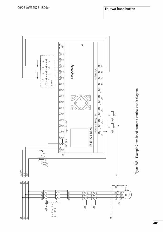
TH, two-hand button09/08 AWB2528-1599en
Figu
re 2
45:
Exam
ple
2 tw
o ha
nd b
utto
n: e
lect
rical
circ
uit d
iagr
am
PEL3L2L1
1U
-X2
-Q2
1 23 45 6
-Q1
1 23 45 6
1L2L3L
1T2T3TI >
I >I >
-Q3
I r = 6
.3 -
10 A
I i = 1
40 A
M 3 h
1U1V1 W
PE
1V1 W
EP
L3L2L1
N1L1
0 V
+24
V
-F2
6 A
gL/g
G
1 2
T1T2
T3T4
4x T
est S
igna
lO
utpu
t 4x
Rela
y / 6
A
DEL
-K1
OK
ALT
ES4P
-221
-DRX
D1
DC
24 V
NET
Inpu
t 14
x D
C
ESC
IS1
IS2
IS3
IS4
IS5
IS6
IS7
IS8
IS9
IS10
IS11
IS12
IS13
IS14
1Q
S12
1Q
S22
1Q
S32
1Q
S42
+24
V0V
0V
P1
P2
P3
P4
2 1
-F1
S 1A
-Q1
1A 2A
-Q2
1A 2A
-S2
31 41
12 22
33 43
14 24
ea y
Safe
ty
2 ha
nd
481
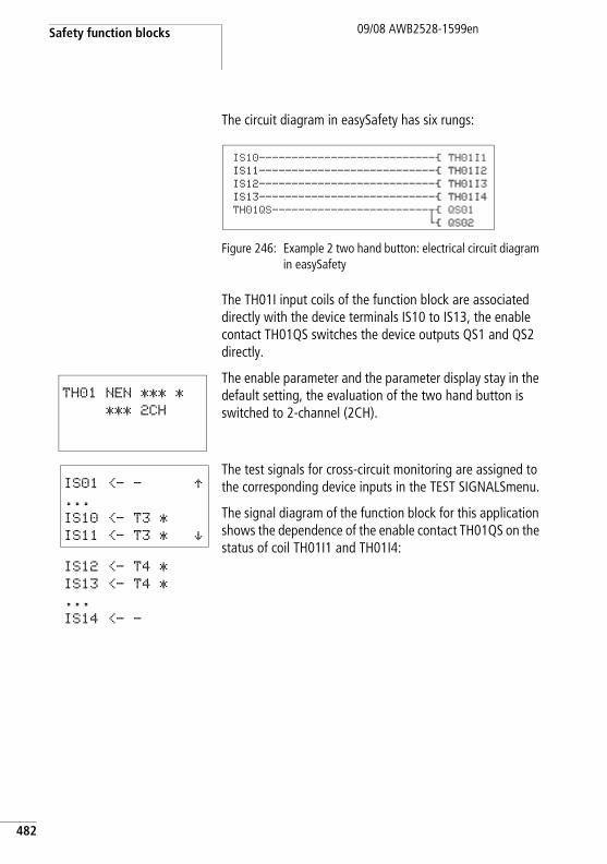
Safety function blocks
482
09/08 AWB2528-1599en
The circuit diagram in easySafety has six rungs:
Figure 246: Example 2 two hand button: electrical circuit diagram in easySafety
The TH01I input coils of the function block are associated directly with the device terminals IS10 to IS13, the enable contact TH01QS switches the device outputs QS1 and QS2 directly.
The enable parameter and the parameter display stay in the default setting, the evaluation of the two hand button is switched to 2-channel (2CH).
The test signals for cross-circuit monitoring are assigned to the corresponding device inputs in the TEST SIGNALSmenu.
The signal diagram of the function block for this application shows the dependence of the enable contact TH01QS on the status of coil TH01I1 and TH01I4:
IS10---------------------------Ä TH01I1IS11---------------------------Ä TH01I2IS12---------------------------Ä TH01I3IS13---------------------------Ä TH01I4TH01QS------------------------uÄ QS01
hÄ QS02
TH01 NEN *** *
*** 2CH
IS01 <- - Æ...
IS10 <- T3 *
IS11 <- T3 * æIS12 <- T4 *
IS13 <- T4 *
...
IS14 <- -
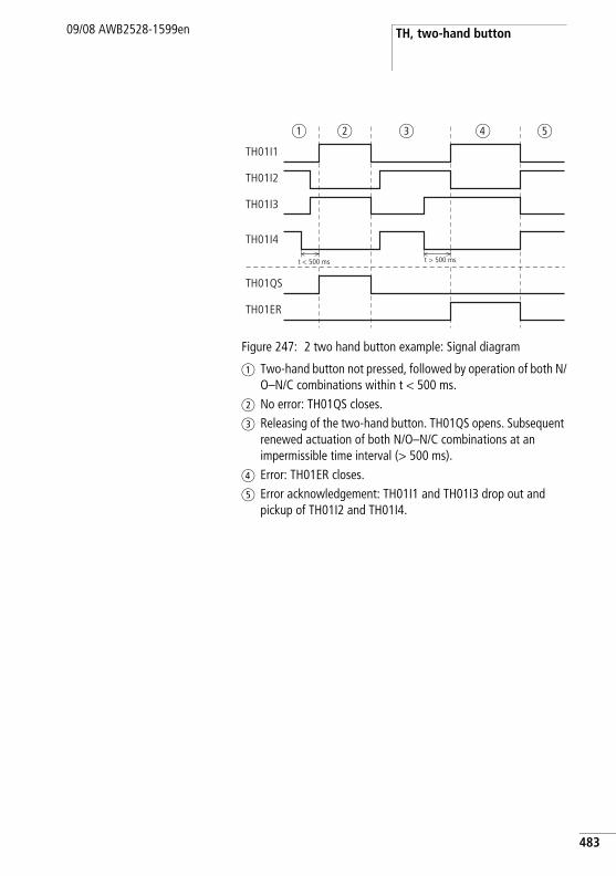
TH, two-hand button09/08 AWB2528-1599en
Figure 247: 2 two hand button example: Signal diagram
a Two-hand button not pressed, followed by operation of both N/O–N/C combinations within t < 500 ms.
b No error: TH01QS closes.c Releasing of the two-hand button. TH01QS opens. Subsequent
renewed actuation of both N/O–N/C combinations at an impermissible time interval (> 500 ms).
d Error: TH01ER closes.e Error acknowledgement: TH01I1 and TH01I3 drop out and
pickup of TH01I2 and TH01I4.
TH01I1
TH01I2
TH01QS
TH01ER
TH01I3
TH01I4
t < 500 ms t > 500 ms
a b c d e
483
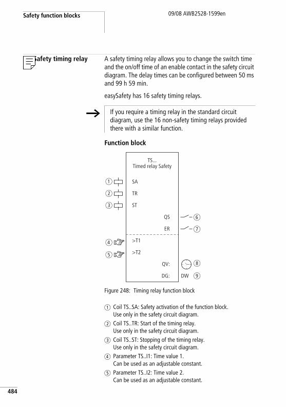
Safety function blocks
484
09/08 AWB2528-1599en
TS, Safety timing relay A safety timing relay allows you to change the switch time and the on/off time of an enable contact in the safety circuit diagram. The delay times can be configured between 50 ms and 99 h 59 min.
easySafety has 16 safety timing relays.
Function block
Figure 248: Timing relay function block
a Coil TS..SA: Safety activation of the function block. Use only in the safety circuit diagram.
b Coil TS..TR: Start of the timing relay. Use only in the safety circuit diagram.
c Coil TS..ST: Stopping of the timing relay. Use only in the safety circuit diagram.
d Parameter TS..I1: Time value 1.Can be used as an adjustable constant.
e Parameter TS..I2: Time value 2.Can be used as an adjustable constant.
h If you require a timing relay in the standard circuit diagram, use the 16 non-safety timing relays provided there with a similar function.
SA
TR
ST
>T1
QS
ER
DG:
QV:
TS...Timed relay Safety
>T2
DW
a
b
c
d
e
f
g
h
i
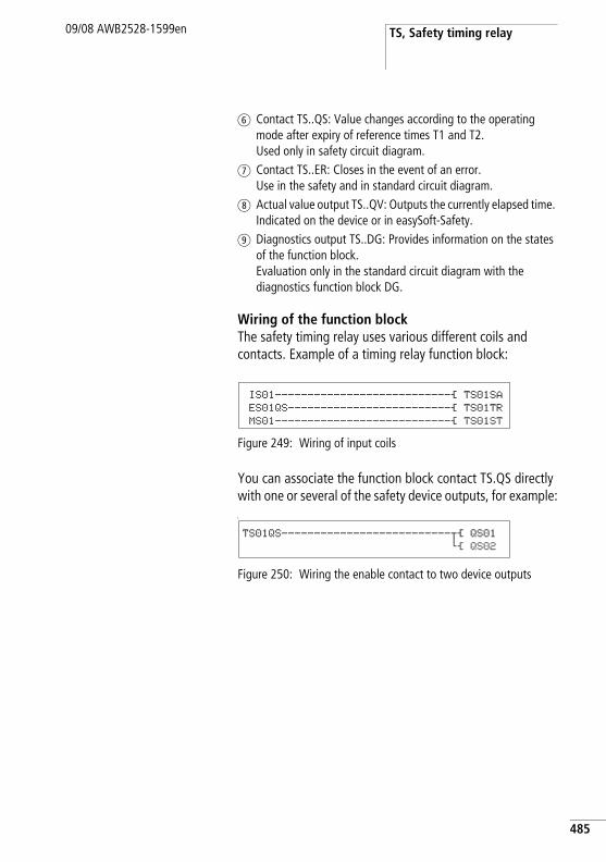
TS, Safety timing relay09/08 AWB2528-1599en
f Contact TS..QS: Value changes according to the operating mode after expiry of reference times T1 and T2.Used only in safety circuit diagram.
g Contact TS..ER: Closes in the event of an error. Use in the safety and in standard circuit diagram.
h Actual value output TS..QV: Outputs the currently elapsed time. Indicated on the device or in easySoft-Safety.
i Diagnostics output TS..DG: Provides information on the states of the function block. Evaluation only in the standard circuit diagram with the diagnostics function block DG.
Wiring of the function blockThe safety timing relay uses various different coils and contacts. Example of a timing relay function block:
Figure 249: Wiring of input coils
You can associate the function block contact TS.QS directly with one or several of the safety device outputs, for example:L
Figure 250: Wiring the enable contact to two device outputs
IS01---------------------------Ä TS01SAES01QS-------------------------Ä TS01TRMS01---------------------------Ä TS01ST
TS01QS--------------------------uÄ QS01
hÄ QS02
485
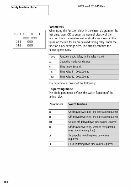
Safety function blocks
486
09/08 AWB2528-1599en
ParametersWhen using the function block in the circuit diagram for the first time, press OK to enter the general display of the function block parameters automatically, as shown in the figure on the left for an on-delayed timing relay. Enter the function block settings here. The display contains the following elements:
Zeitwert
The parameters consist of the following:
Operating modeThe Mode parameter defines the switch function of the timing relay.
TS01 S X *
*** ***
>T1 000
>T2 000
TS01 Function block: Safety timing relay No. 01
X Operating mode: On-delayed
S Time range: Seconds
>T1 Time value T1: 000s.000ms
>T2 Time value T2: 000s.000ms
Parameters Switch function
X On-delayed switching (one time value required)
â Off-delayed switching (one time value required)
Xâ On and off-delayed (two time values required)
# Off delayed switching, setpoint retriggerable (one time value required)
ü Single pulse switching (one time value required)
Ü Flash switching (two time values required)
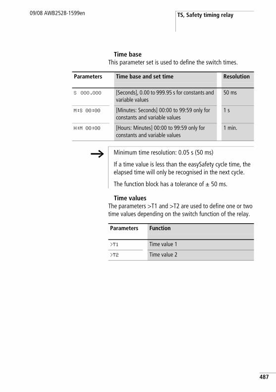
TS, Safety timing relay09/08 AWB2528-1599en
Time baseThis parameter set is used to define the switch times.
Time valuesThe parameters >T1 and >T2 are used to define one or two time values depending on the switch function of the relay.
Parameters Time base and set time Resolution
S 000.000 [Seconds], 0.00 to 999.95 s for constants and variable values
50 ms
M:S 00:00 [Minutes: Seconds] 00:00 to 99:59 only for constants and variable values
1 s
H:M 00:00 [Hours: Minutes] 00:00 to 99:59 only for constants and variable values
1 min.
h Minimum time resolution: 0.05 s (50 ms)
If a time value is less than the easySafety cycle time, the elapsed time will only be recognised in the next cycle.
The function block has a tolerance of g 50 ms.
Parameters Function
>T1 Time value 1
>T2 Time value 2
487
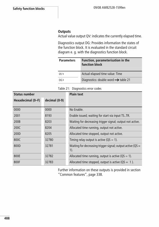
Safety function blocks
488
09/08 AWB2528-1599en
OutputsActual value output QV: indicates the currently elapsed time.
Diagnostics output DG: Provides information the states of the function block. It is evaluated in the standard circuit diagram e. g. with the diagnostics function block.
Table 21: Diagnostics error codes
Further information on these outputs is provided in section “Common features”, page 338.
Parameters Function, parameterisation in the function block
QV: Actual elapsed time value: Time
DG: Diagnostics: double word a table 21
Status number Plain text
Hexadecimal (0–F) decimal (0-9)
0000 0000 No Enable.
2001 8193 Enable issued; waiting for start via input TS..TR.
200B 8203 Waiting for decreasing trigger signal; output not active.
200C 8204 Allocated time running, output not active.
200D 8205 Allocated time stopped, output not active.
800C 32780 Timing relay output is active (QS = 1).
800D 32781 Waiting for decreasing trigger signal; output active (QS = 1).
800E 32782 Allocated time running, output is active (QS = 1).
800F 32783 Allocated time stopped, output is active (QS = 1 ).
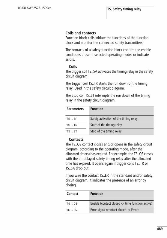
TS, Safety timing relay09/08 AWB2528-1599en
Coils and contactsFunction block coils initiate the functions of the function block and monitor the connected safety transmitters.
The contacts of a safety function block confirm the enable conditions present, selected operating modes or indicate errors.
CoilsThe trigger coil TS..SA activates the timing relay in the safety circuit diagram.
The trigger coil TS..TR starts the run down of the timing relay. Used in the safety circuit diagram.
The Stop coil TS..ST interrupts the run down of the timing relay in the safety circuit diagram.
ContactsThe TS..QS contact closes and/or opens in the safety circuit diagram, according to the operating mode, after the allocated time(s) has expired. For example, the TS..QS closes with the on-delayed safety timing relay after the allocated time has expired. It opens again if trigger coils TS..TR or TS..SA drop out.
If you wire the contact TS..ER in the standard and/or safety circuit diagram, it indicates the presence of an error by closing.
Parameters Function
TS..SA Safety activation of the timing relay
TS..TR Start of the timing relay
TS..ST Stop of the timing relay
Contact Function
TS..QS Enable (contact closed -> time function active)
TS..ER Error signal (contact closed -> Error)
489
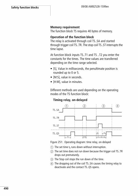
Safety function blocks
490
09/08 AWB2528-1599en
Memory requirementThe function block TS requires 40 bytes of memory.
Operation of the function blockThe relay is activated through coil TS..SA and started through trigger coil TS..TR. The stop coil TS..ST interrupts the time lapse.
At function block inputs TS..T1 and TS ..T2 you enter the constants for the times. The time values are transferred depending on the time range selected.
• [S], Value in milliseconds, the penultimate position is rounded up to 0 or 5.
• [M:S], value in seconds.• [H:M], value in minutes.
Different methods are used depending on the operating modes of the TS function block:
Timing relay, on-delayed
Figure 251: Operating diagram: time relay, on-delayed
a The set time ts runs down without interruption.b The set time does not run down because the trigger coil TS..TR
drops out prematurely.c The Stop coil stops the run down of the time.d The dropping out of the coil TS..SA causes the timing relay to
deactivate and the contact TS..QS opens.
TS..SA
TS..TR
TS..QS
TS..ST
t1 + t2 = ts
t2t1
ts t<ts
a b c d
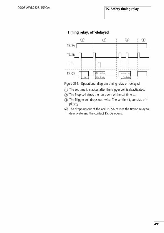
TS, Safety timing relay09/08 AWB2528-1599en
Timing relay, off-delayed
Figure 252: Operational diagram timing relay off-delayed
a The set time ts elapses after the trigger coil is deactivated.b The Stop coil stops the run down of the set time ts.c The Trigger coil drops out twice. The set time ts consists of t1
plus t2
d The dropping out of the coil TS..SA causes the timing relay to deactivate and the contact TS..QS opens.
t1
TS..SA
TS..TR
TS..QS
TS..ST
t1+t2=tsts t1 + t2 = ts
t1 t2t2
a b c d
491
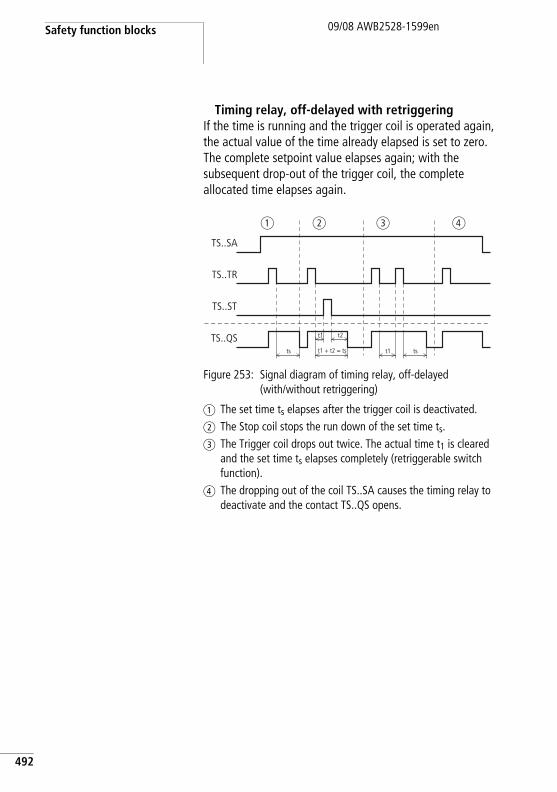
Safety function blocks
492
09/08 AWB2528-1599en
Timing relay, off-delayed with retriggeringIf the time is running and the trigger coil is operated again, the actual value of the time already elapsed is set to zero. The complete setpoint value elapses again; with the subsequent drop-out of the trigger coil, the complete allocated time elapses again.
Figure 253: Signal diagram of timing relay, off-delayed(with/without retriggering)
a The set time ts elapses after the trigger coil is deactivated.b The Stop coil stops the run down of the set time ts.c The Trigger coil drops out twice. The actual time t1 is cleared
and the set time ts elapses completely (retriggerable switch function).
d The dropping out of the coil TS..SA causes the timing relay to deactivate and the contact TS..QS opens.
t1
TS..SA
TS..TR
TS..QS
TS..ST
t1ts t1 + t2 = ts
t2
ts
a b c d
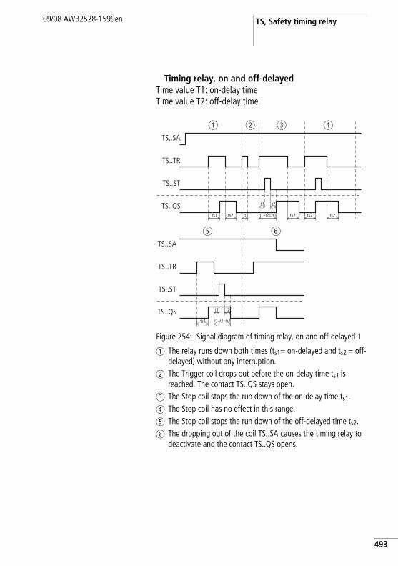
TS, Safety timing relay09/08 AWB2528-1599en
Timing relay, on and off-delayed Time value T1: on-delay timeTime value T2: off-delay time
Figure 254: Signal diagram of timing relay, on and off-delayed 1
a The relay runs down both times (ts1= on-delayed and ts2 = off-delayed) without any interruption.
b The Trigger coil drops out before the on-delay time ts1 is reached. The contact TS..QS stays open.
c The Stop coil stops the run down of the on-delay time ts1.d The Stop coil has no effect in this range.e The Stop coil stops the run down of the off-delayed time ts2.f The dropping out of the coil TS..SA causes the timing relay to
deactivate and the contact TS..QS opens.
TS..SA
TS..TR
TS..QS
TS..ST
ts1 ts2 t t1+t2=ts1 ts2 ts2ts2
t1 t2
a b c d
TS..SA
TS..TR
TS..QS
TS..ST
ts1 t1+t2=ts2
t2t1
e f
493
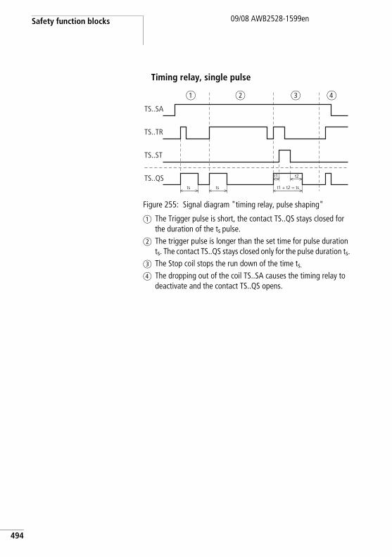
Safety function blocks
494
09/08 AWB2528-1599en
Timing relay, single pulse
Figure 255: Signal diagram "timing relay, pulse shaping"
a The Trigger pulse is short, the contact TS..QS stays closed for the duration of the ts pulse.
b The trigger pulse is longer than the set time for pulse duration ts. The contact TS..QS stays closed only for the pulse duration ts.
c The Stop coil stops the run down of the time ts.d The dropping out of the coil TS..SA causes the timing relay to
deactivate and the contact TS..QS opens.
TS..SA
TS..TR
TS..QS
TS..ST
t1 + t2 = ts
t2t1
ts ts
a b dc
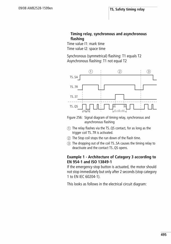
TS, Safety timing relay09/08 AWB2528-1599en
Timing relay, synchronous and asynchronous flashing
Time value I1: mark time Time value I2: space time
Synchronous (symmetrical) flashing: T1 equals T2Asynchronous flashing: T1 not equal T2
Figure 256: Signal diagram of timing relay, synchronous and asynchronous flashing
a The relay flashes via the TS..QS contact, for as long as the trigger coil TS..TR is activated.
b The Stop coil stops the run down of the flash time.c The dropping out of the coil TS..SA causes the timing relay to
deactivate and the contact TS..QS opens.
Example 1 - Architecture of Category 3 according to EN 954-1 and ISO 13849-1If the emergency-stop button is actuated, the motor should not stop immediately but only after 2 seconds (stop category 1 to EN IEC 60204-1).
This looks as follows in the electrical circuit diagram:
TS..SA
TS..TR
TS..QS
TS..ST
ts1 ts2
t1 t2
t1 + t2 = ts1
a b c
495
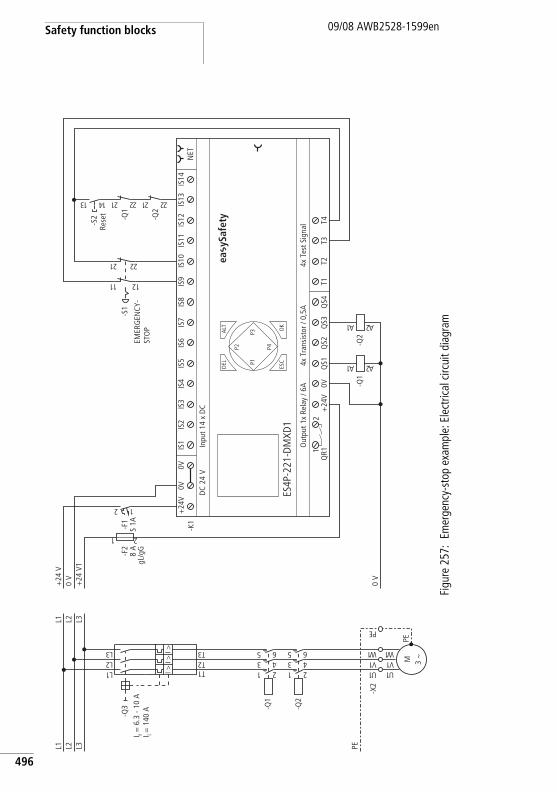
Safety function blocks
496
09/08 AWB2528-1599en
Figu
re 2
57:
Emer
genc
y-st
op e
xam
ple:
Ele
ctric
al c
ircui
t dia
gram
PEL3L2L1
1U
-X2
-Q2
1 23 45 6
-Q1
1 23 45 6
1L2L3L
1T2T3TI >
I >I >
-Q3
M 3 h
1U1V1 W
PE
1V1 W
EP
L3L2L1
0 V
+24
V1
0 V
+24
V
-F2
8 A
gL/g
G
1 2
0V+
24V
QS1
QS2
QS3
QS4
T1T2
T3T4
Out
put 1
x Re
lay
/ 6A
4x T
est S
igna
l
ES4P
-221
-DM
XD1
4x T
rans
isto
r / 0
,5A
DC
24 V
Inpu
t 14
x D
C
NET
ALT OK
-K1
DEL
ESC
IS1
IS2
IS3
IS4
IS5
IS6
IS7
IS8
IS9
IS10
IS11
IS12
IS13
IS14
1Q
R12
+24
V0V
0V
P1
P2
P3
P4
2 1
-F1
S 1A
-Q1
1A 2A
-Q2
1A 2A
-S1
12 22
11 21
-Q2
12 22
-Q1
12 2231 41
-S2
I r = 6
.3 -
10 A
I i = 1
40 A
ea y
Safe
ty
EMER
GEN
CY-
STO
P
Rese
t
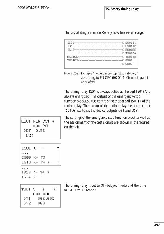
TS, Safety timing relay09/08 AWB2528-1599en
The circuit diagram in easySafety now has seven rungs:
Figure 258: Example 1, emergency-stop, stop category 1 according to EN OEC 60204-1: Circuit diagram in easySafety
The timing relay TS01 is always active as the coil TS01SA is always energized. The output of the emergency-stop function block ES01QS controls the trigger coil TS01TR of the timing relay. The output of the timing relay, i.e. the contact TS01QS, switches the device outputs QS1 and QS3.
The settings of the emergency-stop function block as well as the assignment of the test signals are shown in the figures on the left.
The timing relay is set to Off-delayed mode and the time value T1 to 2 seconds.
IS09---------------------------Ä ES01I1IS10---------------------------Ä ES01I2IS13---------------------------Ä ES01RE-------------------------------Ä TS01SAES01QS-------------------------Ä TS01TRTS01QS------------------------uÄ QS01
hÄ QS03
ES01 NEN CST *
*** 2CH
>DT 0.5S
DG:
IS01 <- - Æ...
IS09 <- T3
IS10 <- T4 * æ...
IS13 <- T4 *
IS14 <- -
TS01 S â *
*** ***
>T1 002.000
>T2 000
497
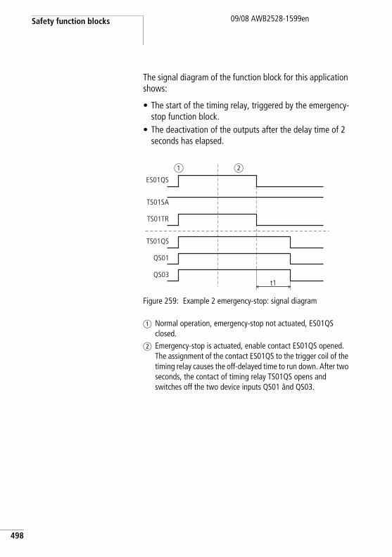
Safety function blocks
498
09/08 AWB2528-1599en
The signal diagram of the function block for this application shows:
• The start of the timing relay, triggered by the emergency-stop function block.
• The deactivation of the outputs after the delay time of 2 seconds has elapsed.
Figure 259: Example 2 emergency-stop: signal diagram
a Normal operation, emergency-stop not actuated, ES01QS closed.
b Emergency-stop is actuated, enable contact ES01QS opened. The assignment of the contact ES01QS to the trigger coil of the timing relay causes the off-delayed time to run down. After two seconds, the contact of timing relay TS01QS opens and switches off the two device inputs QS01 ând QS03.
ES01QS
TS01SA
TS01QS
QS01
TS01TR
QS03t1
a b
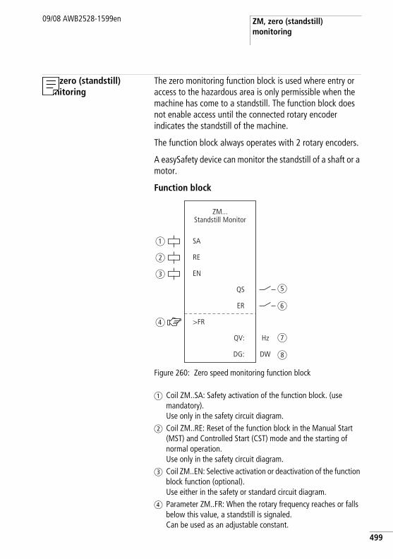
ZM, zero (standstill) monitoring
09/08 AWB2528-1599en
ZM, zero (standstill) monitoring
The zero monitoring function block is used where entry or access to the hazardous area is only permissible when the machine has come to a standstill. The function block does not enable access until the connected rotary encoder indicates the standstill of the machine.
The function block always operates with 2 rotary encoders.
A easySafety device can monitor the standstill of a shaft or a motor.
Function block
Figure 260: Zero speed monitoring function block
a Coil ZM..SA: Safety activation of the function block. (use mandatory). Use only in the safety circuit diagram.
b Coil ZM..RE: Reset of the function block in the Manual Start (MST) and Controlled Start (CST) mode and the starting of normal operation. Use only in the safety circuit diagram.
c Coil ZM..EN: Selective activation or deactivation of the function block function (optional). Use either in the safety or standard circuit diagram.
d Parameter ZM..FR: When the rotary frequency reaches or falls below this value, a standstill is signaled.Can be used as an adjustable constant.
SA
RE
EN
>FR
QS
ER
DG:
QV:
ZM...Standstill Monitor
DW
Hz
a
b
c
d
e
f
g
h
499
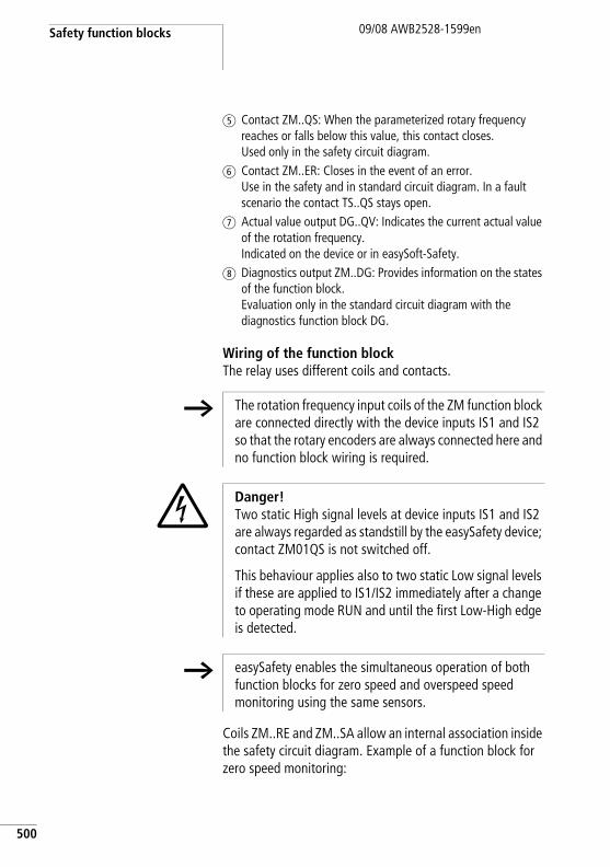
Safety function blocks
500
09/08 AWB2528-1599en
e Contact ZM..QS: When the parameterized rotary frequency reaches or falls below this value, this contact closes.Used only in the safety circuit diagram.
f Contact ZM..ER: Closes in the event of an error. Use in the safety and in standard circuit diagram. In a fault scenario the contact TS..QS stays open.
g Actual value output DG..QV: Indicates the current actual value of the rotation frequency. Indicated on the device or in easySoft-Safety.
h Diagnostics output ZM..DG: Provides information on the states of the function block. Evaluation only in the standard circuit diagram with the diagnostics function block DG.
Wiring of the function blockThe relay uses different coils and contacts.
Coils ZM..RE and ZM..SA allow an internal association inside the safety circuit diagram. Example of a function block for zero speed monitoring:
h The rotation frequency input coils of the ZM function block are connected directly with the device inputs IS1 and IS2 so that the rotary encoders are always connected here and no function block wiring is required.
j Danger!Two static High signal levels at device inputs IS1 and IS2 are always regarded as standstill by the easySafety device; contact ZM01QS is not switched off.
This behaviour applies also to two static Low signal levels if these are applied to IS1/IS2 immediately after a change to operating mode RUN and until the first Low-High edge is detected.
h easySafety enables the simultaneous operation of both function blocks for zero speed and overspeed speed monitoring using the same sensors.
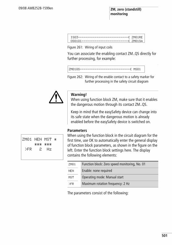
ZM, zero (standstill) monitoring
09/08 AWB2528-1599en
Figure 261: Wiring of input coils
You can associate the enabling contact ZM..QS directly for further processing, for example:
L
Figure 262: Wiring of the enable contact to a safety marker for further processing in the safety circuit diagram
ParametersWhen using the function block in the circuit diagram for the first time, use OK to automatically enter the general display of function block parameters, as shown in the figure on the left. Enter the function block settings here. The display contains the following elements:
The parameters consist of the following:
IS03---------------------------Ä ZM01RE
OS01Q1-------------------------Ä ZM01SA
ZM01QS---------------------------Ä MS01
i Warning!When using function block ZM, make sure that it enables the dangerous motion through its contact ZM..QS.
Keep in mind that the easySafety device can change into its safe state when the dangerous motion is already enabled before the easySafety device is switched on.
ZM01 NEN MST *
*** ***
>FR 2 Hz
ZM01 Function block: Zero speed monitoring, No. 01
NEN Enable: none required
MST Operating mode: Manual start
>FR Maximum rotation frequency: 2 Hz
501
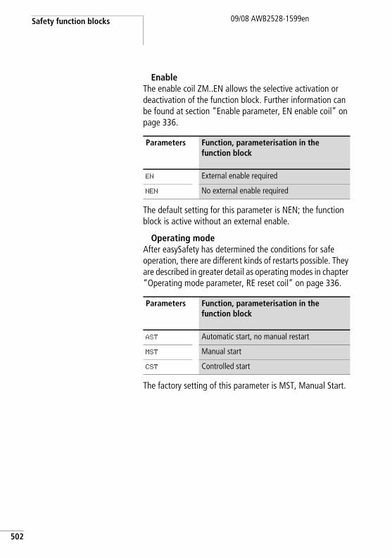
Safety function blocks
502
09/08 AWB2528-1599en
EnableThe enable coil ZM..EN allows the selective activation or deactivation of the function block. Further information can be found at section “Enable parameter, EN enable coil” on page 336.
The default setting for this parameter is NEN; the function block is active without an external enable.
Operating modeAfter easySafety has determined the conditions for safe operation, there are different kinds of restarts possible. They are described in greater detail as operating modes in chapter “Operating mode parameter, RE reset coil” on page 336.
The factory setting of this parameter is MST, Manual Start.
Parameters Function, parameterisation in the function block
EN External enable required
NEN No external enable required
Parameters Function, parameterisation in the function block
AST Automatic start, no manual restart
MST Manual start
CST Controlled start
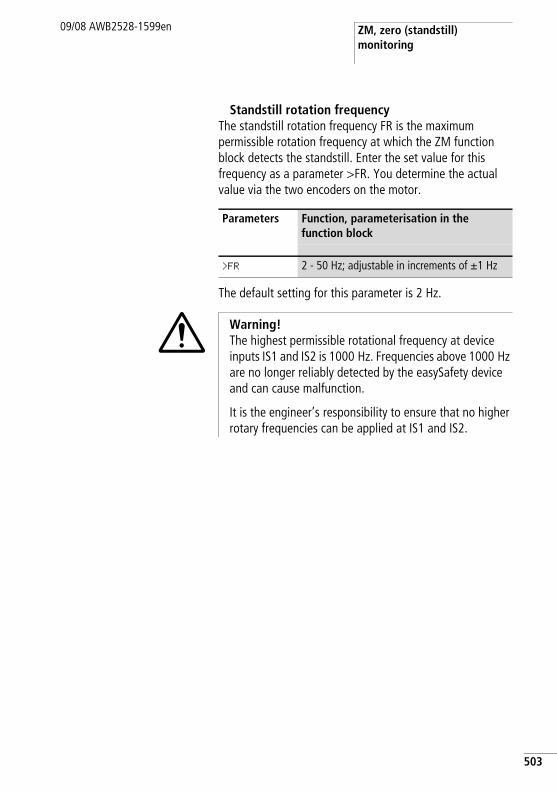
ZM, zero (standstill) monitoring
09/08 AWB2528-1599en
Standstill rotation frequencyThe standstill rotation frequency FR is the maximum permissible rotation frequency at which the ZM function block detects the standstill. Enter the set value for this frequency as a parameter >FR. You determine the actual value via the two encoders on the motor.
The default setting for this parameter is 2 Hz.
Parameters Function, parameterisation in the function block
>FR 2 - 50 Hz; adjustable in increments of g1 Hz
i Warning! The highest permissible rotational frequency at device inputs IS1 and IS2 is 1000 Hz. Frequencies above 1000 Hz are no longer reliably detected by the easySafety device and can cause malfunction.
It is the engineer’s responsibility to ensure that no higher rotary frequencies can be applied at IS1 and IS2.
503
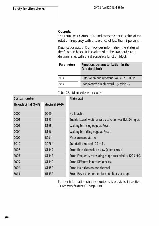
Safety function blocks
504
09/08 AWB2528-1599en
OutputsThe actual value output QV: Indicates the actual value of the rotation frequency with a tolerance of less than 3 percent..
Diagnostics output DG: Provides information the states of the function block. It is evaluated in the standard circuit diagram e. g. with the diagnostics function block.
Table 22: Diagnostics error codes
Further information on these outputs is provided in section “Common features”, page 338.
Parameters Function, parameterisation in the function block
QV: Rotation frequency actual value: 2 - 50 Hz
DG: Diagnostics: double word a table 22
Status number Plain text
Hexadecimal (0–F) decimal (0-9)
0000 0000 No Enable.
2001 8193 Enable issued, wait for safe activation via ZM..SA input.
2003 8195 Waiting for rising edge at Reset.
2004 8196 Waiting for falling edge at Reset.
2009 8201 Measurement started.
8010 32784 Standstill detected (QS = 1).
F007 61447 Error: Both channels on Low (open circuit).
F008 61448 Error: Frequency measuring range exceeded (>1200 Hz).
F009 61449 Error: Different input frequencies.
F00A 61450 Error: No pulses on one channel.
F013 61459 Error: Reset operated on function block startup.
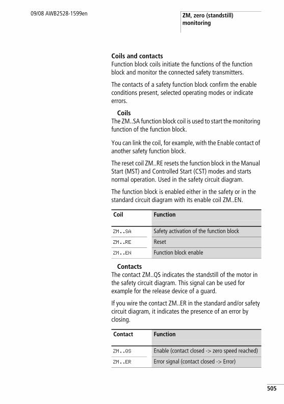
ZM, zero (standstill) monitoring
09/08 AWB2528-1599en
Coils and contactsFunction block coils initiate the functions of the function block and monitor the connected safety transmitters.
The contacts of a safety function block confirm the enable conditions present, selected operating modes or indicate errors.
CoilsThe ZM..SA function block coil is used to start the monitoring function of the function block.
You can link the coil, for example, with the Enable contact of another safety function block.
The reset coil ZM..RE resets the function block in the Manual Start (MST) and Controlled Start (CST) modes and starts normal operation. Used in the safety circuit diagram.
The function block is enabled either in the safety or in the standard circuit diagram with its enable coil ZM..EN.
ContactsThe contact ZM..QS indicates the standstill of the motor in the safety circuit diagram. This signal can be used for example for the release device of a guard.
If you wire the contact ZM..ER in the standard and/or safety circuit diagram, it indicates the presence of an error by closing.
Coil Function
ZM..SA Safety activation of the function block
ZM..RE Reset
ZM..EN Function block enable
Contact Function
ZM..QS Enable (contact closed -> zero speed reached)
ZM..ER Error signal (contact closed -> Error)
505
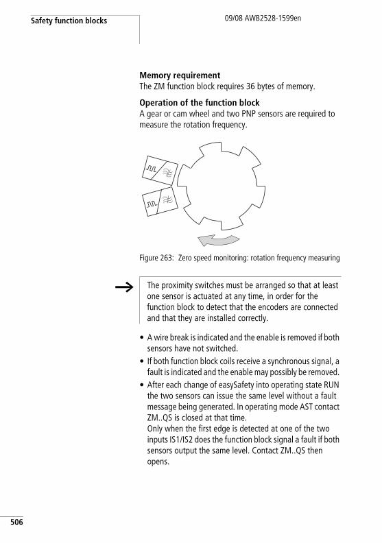
Safety function blocks
506
09/08 AWB2528-1599en
Memory requirementThe ZM function block requires 36 bytes of memory.
Operation of the function blockA gear or cam wheel and two PNP sensors are required to measure the rotation frequency.
Figure 263: Zero speed monitoring: rotation frequency measuring
• A wire break is indicated and the enable is removed if both sensors have not switched.
• If both function block coils receive a synchronous signal, a fault is indicated and the enable may possibly be removed.
• After each change of easySafety into operating state RUN the two sensors can issue the same level without a fault message being generated. In operating mode AST contact ZM..QS is closed at that time. Only when the first edge is detected at one of the two inputs IS1/IS2 does the function block signal a fault if both sensors output the same level. Contact ZM..QS then opens.
h The proximity switches must be arranged so that at least one sensor is actuated at any time, in order for the function block to detect that the encoders are connected and that they are installed correctly.
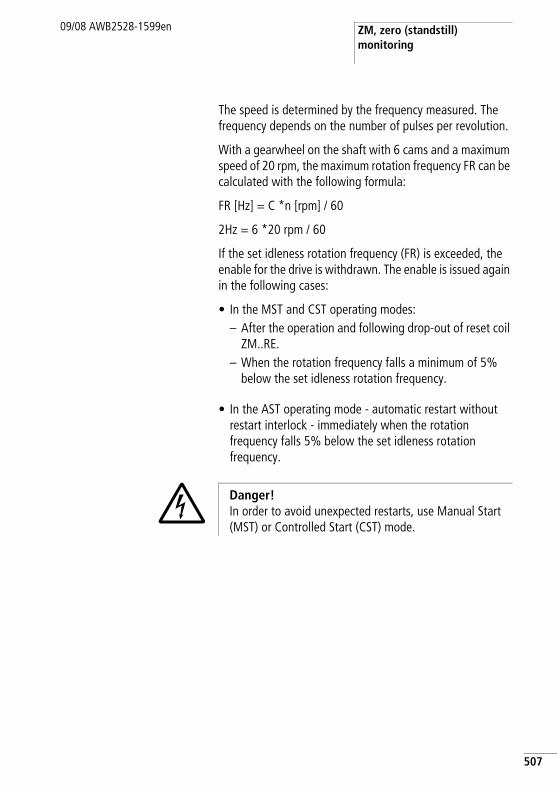
ZM, zero (standstill) monitoring
09/08 AWB2528-1599en
The speed is determined by the frequency measured. The frequency depends on the number of pulses per revolution.
With a gearwheel on the shaft with 6 cams and a maximum speed of 20 rpm, the maximum rotation frequency FR can be calculated with the following formula:
FR [Hz] = C *n [rpm] / 60
2Hz = 6 *20 rpm / 60
If the set idleness rotation frequency (FR) is exceeded, the enable for the drive is withdrawn. The enable is issued again in the following cases:
• In the MST and CST operating modes:– After the operation and following drop-out of reset coil
ZM..RE.– When the rotation frequency falls a minimum of 5%
below the set idleness rotation frequency.
• In the AST operating mode - automatic restart without restart interlock - immediately when the rotation frequency falls 5% below the set idleness rotation frequency.
j Danger!In order to avoid unexpected restarts, use Manual Start (MST) or Controlled Start (CST) mode.
507
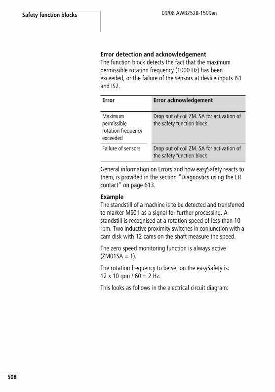
Safety function blocks
508
09/08 AWB2528-1599en
Error detection and acknowledgementThe function block detects the fact that the maximum permissible rotation frequency (1000 Hz) has been exceeded, or the failure of the sensors at device inputs IS1 and IS2.
General information on Errors and how easySafety reacts to them, is provided in the section “Diagnostics using the ER contact” on page 613.
ExampleThe standstill of a machine is to be detected and transferred to marker MS01 as a signal for further processing. A standstill is recognised at a rotation speed of less than 10 rpm. Two inductive proximity switches in conjunction with a cam disk with 12 cams on the shaft measure the speed.
The zero speed monitoring function is always active (ZM01SA = 1).
The rotation frequency to be set on the easySafety is:12 x 10 rpm / 60 = 2 Hz.
This looks as follows in the electrical circuit diagram:
Error Error acknowledgement
Maximum permissible rotation frequency exceeded
Drop out of coil ZM..SA for activation of the safety function block
Failure of sensors Drop out of coil ZM..SA for activation of the safety function block
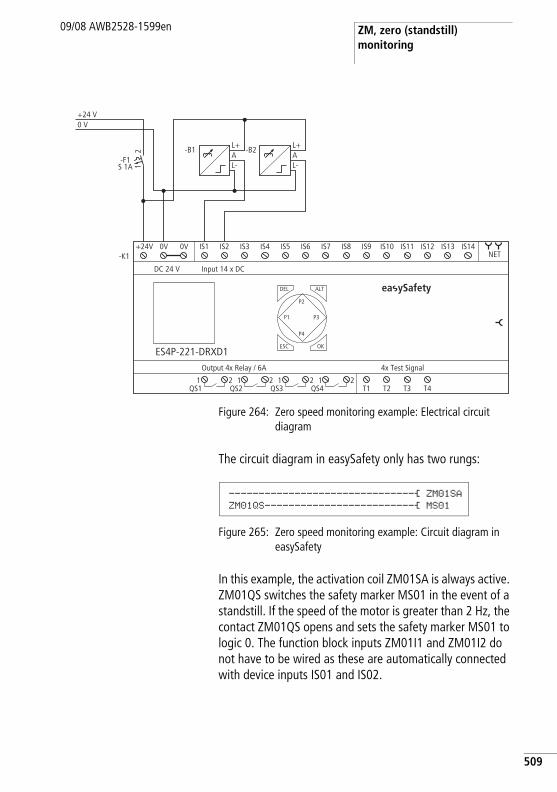
ZM, zero (standstill) monitoring
09/08 AWB2528-1599en
Figure 264: Zero speed monitoring example: Electrical circuit diagram
The circuit diagram in easySafety only has two rungs:
Figure 265: Zero speed monitoring example: Circuit diagram in easySafety
In this example, the activation coil ZM01SA is always active. ZM01QS switches the safety marker MS01 in the event of a standstill. If the speed of the motor is greater than 2 Hz, the contact ZM01QS opens and sets the safety marker MS01 to logic 0. The function block inputs ZM01I1 and ZM01I2 do not have to be wired as these are automatically connected with device inputs IS01 and IS02.
0 V+24 V
T1 T2 T3 T4
4x Test SignalOutput 4x Relay / 6A
DEL
-K1
OK
ALT
ES4P-221-DRXD1
DC 24 V
NET
Input 14 x DC
ESC
IS1 IS2 IS3 IS4 IS5 IS6 IS7 IS8 IS9 IS10 IS11 IS12 IS13 IS14
1QS1
2 1QS2
2 1QS3
2 1QS4
2
+24V 0V 0V
P1
P2
P3
P4
21
-F1S 1A
L+AL-
-B1L+AL-
-B2
ea ySafety
-------------------------------Ä ZM01SAZM01QS-------------------------Ä MS01
509
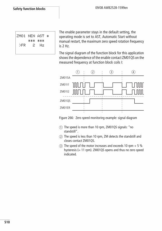
Safety function blocks
510
09/08 AWB2528-1599en
The enable parameter stays in the default setting, the operating mode is set to AST, Automatic Start without manual restart, the maximum zero speed rotation frequency is 2 Hz.
The signal diagram of the function block for this application shows the dependence of the enable contact ZM01QS on the measured frequency at function block coils I:
Figure 266: Zero speed monitoring example: signal diagram
a The speed is more than 10 rpm, ZM01QS signals: “no standstill”.
b The speed is less than 10 rpm, ZM detects the standstill and closes contact ZM01QS.
c The speed of the motor increases and exceeds 10 rpm + 5 % hysteresis (= 11 rpm). ZM01QS opens and thus no zero speed indicated.
ZM01 NEN AST *
*** ***
>FR 2 Hz
ZM01SA
ZM01QS
ZM01ER
ZM01I2
ZM01I1
a b c d
09/08 AWB2528-1599en
7 easyNet network
Introduction to the easyNet network
The easyNet network, termed the NET in the following document, is based on the CAN (Controller Area Network) serial bus system. CAN complies with the ISO 11898 standard.
The NET is designed for a maximum of 8 stations. It enables the exchange of process and system data as well as the transfer of the safety circuit diagram from and to the NET stations.
NET stations on the non-safety network can include all easySafety devices (safety control relays). Mixed operation of other NET stations such as easy800/MFD-Titan and easySafety NET stations can be implemented in an overall NET topology.
j Danger!easyNet is a network designed for non-safety applications. Data transferred via this network must not be used for safety-relevant applications.
h Distribute tasks amongst several devices which can exchange data with each other via the NET: easySafety devices for safety-related switching and MFD-Titan devices for display and operating tasks.
511
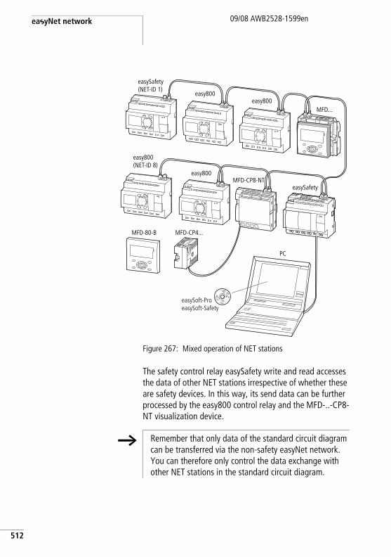
easyNet network
512
09/08 AWB2528-1599en
Figure 267: Mixed operation of NET stations
The safety control relay easySafety write and read accesses the data of other NET stations irrespective of whether these are safety devices. In this way, its send data can be further processed by the easy800 control relay and the MFD-..-CP8-NT visualization device.
easy800easy800
MFD-80-B MFD-CP4...
MFD-CP8-NTeasySafety
MFD...
easy800(NET-ID 8)
easy800
easySafety(NET-ID 1)
PC
easySoft-ProeasySoft-Safety
h Remember that only data of the standard circuit diagram can be transferred via the non-safety easyNet network. You can therefore only control the data exchange with other NET stations in the standard circuit diagram.
Introduction to the easyNet network
09/08 AWB2528-1599en
The physically first NET station that is located at the beginning of the network manages the network and therefore the configuration, commissioning and diagnostics of the NET. This station with NET ID 1 is given the most extensive write/read access within the network.
In this way, the commissioning of NET stations is very simple. Apart from the installation with prefabricated cables, this only requires the following for the standard loop through topology:
• Definition of the first NET station by assigning NET ID 1 and the possible necessary modification of the baud rate in the NET PARAMETERS menu.
• Creation of the station list with automatic assignment of the NET IDs for the connected devices in the STATION menu.
• Configuration via the CONFIGURATION menu.
Further information on the configuration of the NET can be found on page 526.
Commissioning is even simpler with easySoft-Safety and easySoft-Pro. From easySoft-Pro version V6.30 Pro you can create NET configurations that contain easySafety devices from the ES4P device family in addition to previously established devices. This easySoft-Pro software covers all easySafety device versions under the heading ES4P device.
Further information on this is provided in the Online Help of easySoft-Pro.
h The complete configuration of the ES4P device can only be carried out with easySoft-Safety. However, easySoft-Pro allows you to transfer NET settings for commissioning such as "NET-ID", the baud rate and "Bus-Delay" to the easySafety device. This may be necessary in order to also address the other devices and test their functions.
513
easyNet network
514
09/08 AWB2528-1599en
If you wish to configure a mixed operation of easySafety devices and previous NET stations, such as easy800, in certain circumstances the easySoft-Safety configuration software is sufficient. This is the case if the previous NET stations are only operated in REMOTE IO mode without a circuit diagram. Only if a circuit diagram is required for these conventional NET stations is the use of easySoft-Pro recommended. The parallel use of easySoft-Pro and easySoft-Safety is possible without any restrictions.
The NET network allows the following operations:
• Processing of additional inputs and outputs in the standard circuit diagram.
• Implementation of faster and more effective controls using distributed circuit diagrams.
• Date and time synchronisation of the NET stations.• Read the inputs and outputs of all other NET stations in
the standard circuit diagram.• Read the inputs and outputs of previous NET stations that
do not execute their own circuit diagrams, and write to their outputs, in the standard circuit diagram.
• Send 32-bit values to other stations using PUT function blocks in the standard circuit diagram and receive data from them using GET function blocks.
• Loading safety configurations from and to every station (a section “Transfer of the standart- and safety circuit diagram via the NET”, page 519).
• Control the STOP/RUN operating mode of NET stations 2 to 8 based on the operating mode of station 1 (master). In order to do this, the REMOTE RUN option must be activated in NET stations 2 to 8.
j Danger!Ensure that the automatic starting of easySafety will not cause the unwanted starting of machines and plants.
Introduction to the easyNet network
09/08 AWB2528-1599en
Transfer behaviour of the NET stations
Prior to every circuit diagram cycle the network data is written from the NET receive buffer to the operand image of the standard circuit diagram . The standard circuit diagram processes the next cycle with this data. At the end of the circuit diagram cycle the refreshed network data from the operand image is written to the NET send buffer and then transferred.
Reading and sending the data via the NETThe communication process of a NET station reads every message on the NET and checks whether any messages are meant for its own address (NET ID). If yes, they are transferred to a receive memory.
If the content of the send memory changes, a message is sent provided that no other message is being transferred on the NET at this time. The NET ensures that each station can send its messages. This means that each station must maintain a delay time between the sending of messages.
The pause time increases the higher the number of stations and the lower baud rate setting.
The number of NET stations present is recognised by every station by means of a “sign of life” signal.
h The following applies to a fast message transfer:
• Set the fastest possible baud rate to suit the network length and cable cross-section.
• Fewer messages means faster messages.• Avoid transferring (download/upload) a circuit diagram
while the NET stations are in RUN mode.
515
easyNet network
516
09/08 AWB2528-1599en
Functions of the NET stations
There are various different NET station types that differ according to their type of programming and scope of functions, and some of which do not execute their own program.
Net stations with or without program• NET stations with their own program.
– Possible NET IDs: 1-8– Possible devices: All
• NET stations without their own program, as input/output devices in REMOTE IO mode. In this type of application, NET station 1 must always have a program.– Possible NET IDs: 2-8– Possible devices: MFD-Titan and easy800
Types of programming• NET stations of easy (programming in the form of a
standard circuit diagram):– easy800 control relay– Operating and visualization devices (MFD-CP8-...-NT)– Safety control relay (ES4-…)
• NET stations for IEC programming (programming in accordance with IEC 61131-3 standard):– XC200 controllers– EC4-200 controllers (see AWB2724-1584GB)
h easySafety devices cannot be run in REMOTE IO mode as a NET station. These always require a safety circuit diagram.
Introduction to the easyNet network
09/08 AWB2528-1599en
Function terminal mode
Terminal mode allows you to use the operating buttons of an MFD-CP8-...-NT, which is run as a NET station to create or modify the standard circuit diagram (the program) of another NET station.
On the other hand, this type of access is possible for a local connection of the MFD-CP8-... via the multi-function interface in terminal mode.
You can use the MFD-CP8-...-NT to establish in succession a connection to a NET stations.
Simultaneous operation of several logical terminal connections between two NET stations is possible apart from the easySafety devices.
h Terminal mode access to easySafety devices via the NET is not permissible and therefore disabled.
h Do not allow terminal mode access to a NET station from two sides at the same time as this will cause a fault on the NET. This also applies to simultaneous access to a device via the NET and via easySoft-Pro or an MFD-CP8-...-NT in terminal mode.
517
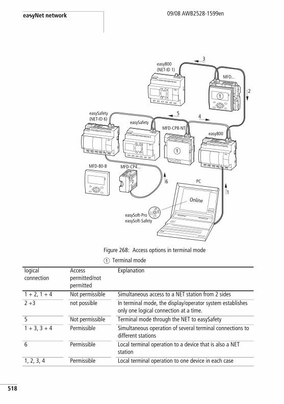
easyNet network
518
09/08 AWB2528-1599en
Figure 268: Access options in terminal mode
a Terminal mode
MFD-80-B MFD-CP4...
Online
MFD-CP8-NTeasySafety
easySafety(NET-ID 6)
MFD...
easy800
easy800(NET-ID 1)
PC
easySoft-ProeasySoft-Safety
a
a
6
5 4
1
2
3
logical connection
Access permitted/not permitted
Explanation
1 + 2, 1 + 4 Not permissible Simultaneous access to a NET station from 2 sides2 +3 not possible In terminal mode, the display/operator system establishes
only one logical connection at a time.5 Not permissible Terminal mode through the NET to easySafety1 + 3, 3 + 4 Permissible Simultaneous operation of several terminal connections to
different stations6 Permissible Local terminal operation to a device that is also a NET
station1, 2, 3, 4 Permissible Local terminal operation to one device in each case
Introduction to the easyNet network
09/08 AWB2528-1599en
Transfer of the standart- and safety circuit diagram via the NET
From easySoft-Safety, the safety configuration can be transferred (PC => Device/Device => PC), compared (PC = Device ?) and deleted via the NET.
With this configuration you access via the NET the target device via the NET station that is connected to the PC with a programming cable. The NET provides this routing function automatically under the following conditions.
• The NET must be configured correctly and be in operation.• The easySafety must have been assigned a safety ID (SID).
Safety ID (SID1 - SID8)You can also transfer the safety circuit diagram from easySoft-Safety to the target device via the NET.
To do this, you must assign a safety ID to the target device.
This safety ID identifies it uniquely and reliably as the receiver of the safety configuration. For the transfer, the values of the safety ID on the safety control relay and in the easySoft-Safety project must coincide.
The safety ID is permanently assigned to the safety control relay and is also retained if, for example, the device is given another position or NET ID in the NET.
The safety ID is a property of the device and does not have to be the same as the NET ID (although this recommended). It is not password protected and is not part of the configuration. You assign the safety ID in the following way:
h A safety configuration consists of the safety circuit diagram, a possible standard circuit diagram (incl. the function block diagram in each case) and the safety settings.
519
easyNet network
520
09/08 AWB2528-1599en
• Via keypad and display directly on the device. In this case move to the system menu and select here the SAFETY ID menu.
• Via MFD-CP4…/CP8… in TERMINAL MODE if this is directly connected to the safety control relay.
• Via easySoft-Safety if the safety control relay to be parameterised is directly connected to the PC via a programming cable and the Local setting is selected in the Communication View.
Commissioning NET stations
Requirements for commissioning the NET:
• All stations must be properly connected to the NET (a section “Connecting network easyNet”, page 55), the bus terminating resistors on the physically first and last NET stations must be fitted and the power supply must be connected to all NET stations. The POW LED of all NET stations must be lit or flashing.
• As the first NET station, use a device with a display.• The device to be parameterised must be in STOP mode.
The POW LED of this NET station must be permanently lit.When commissioning for the first time, the NET LED is “Off”.
h Your NET can only be configured by the station with NET-ID 1 if it has been set up according to the "loop-through" (a page 61) topology. In order to simplify the process, you should define all parameters through this NET station with NET-ID 1.
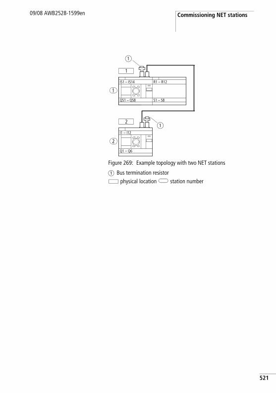
Commissioning NET stations09/08 AWB2528-1599en
Figure 269: Example topology with two NET stations
a Bus termination resistor physical location station number
1
1
IS1 – IS14
QS1 – QS8
2
2
I1 – I12
Q1 – Q6
R1 – R12
S1 – S8
a
a
521
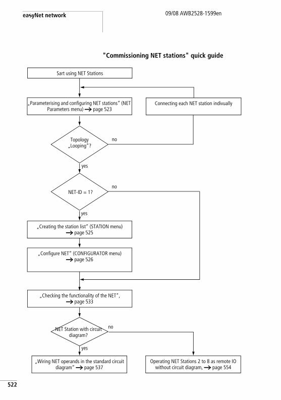
easyNet network
522
09/08 AWB2528-1599en
"Commissioning NET stations" quick guide
„Creating the station list“ (STATION menu)a page 525
no
Connecting each NET station indivually
no
yes
yes
Topology „Looping“?
NET-ID = 1?
NET Station with circuit diagram?
„Checking the functionality of the NET“, a page 533
yes
no
„Parameterising and configuring NET stations“ (NET Parameters menu) a page 523
Sart using NET Stations
„Configure NET“ (CONFIGURATOR menu)a page 526
„Wiring NET operands in the standard circuit diagram“ a page 537
Operating NET Stations 2 to 8 as remote IO without circuit diagram, a page 554
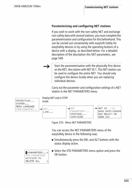
Commissioning NET stations09/08 AWB2528-1599en
Parameterising and configuring NET stations
If you wish to work with the non-safety NET and exchange non-safety data with several stations, you must complete the parameterisation and configuration for this beforehand. This can be carried out conveniently with easySoft-Safety for easySafety devices or by using the operating buttons of a device with a display, as described below. For a detailed description of the description this NET-parameters, see page 549.
Carry out the parameter and configuration settings of a NET station in the NET PARAMETERS menu:
Figure 270: Menu NET PARAMETERS
You can access the NET PARAMETERS menu of the easySafety device in the following way:
X Simultaneously press the DEL and ALT buttons with the status display active.
X Select the STD PARAMETERS menu option and press the OK button.
h Start the parameterisation with the physically first device on the NET, the station with NET ID 1. This NET station can be used to configure the entire NET. You should only configure the device locally when you are replacing individual devices.
NET ID : 01
BAUD RATE:1000KB
BUS DELAY: 00
SEND IO:
PROTECTION...
SYSTEM...
MENU LANGUAGE
CONFIGURATOR... NET...
LINK...
Display NET only in STOP mode.
NET
PARAMETERS...
STATIONS...
CONFIGURE
S-PARAMETERS...ÆSTD PARAMETERS
ACTIVATE PW
DELETE ALL æ
523
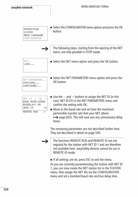
easyNet network
524
09/08 AWB2528-1599en
X Select the CONFIGURATOR menu option and press the OK button.
X Select the NET menu option and press the OK button.
X Select the NET PARAMETERS menu option and press the OK button.
X Use the Í and Ú buttons to assign the NET ID (in this case: NET ID 01) in the NET PARAMETERS menu and confirm the setting with OK.
X Move to the baud rate and set here the maximum permissible transfer rate that your NET allows (a page 653). This will save you any unnecessary delay times:
The remaining parameters are not described further here. They are described in detail on page 549.
X If all settings are ok, press ESC to exit the menu.As you are currently parameterising the station with NET ID 1, you can now create the NET station list in the STATION menu, then assign the NET IDs via the CONFIGURATION menu and set a standard baud rate and bus delay time.
PROTECTION
SYSTEM
MENU LANGUAGE
CONFIGURATOR
h The following steps, starting from the opening of the NET menu, are only possible in STOP mode.
NET..
LINK...
NET PARAMETER..
STATIONS...
CONFIGURE...
NET ID : 01 ÆBAUD RATE:125KB
BUSDELAY: 00
SEND IO åæREMOTE RUN å
h The functions REMOTE RUN and REMOTE IO are not required for the station with NET ID 1 and are therefore not available here. easySafety devices cannot be run in REMOTE IO mode.
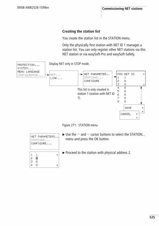
Commissioning NET stations09/08 AWB2528-1599en
Creating the station list
You create the station list in the STATION menu.
Only the physically first station with NET ID 1 manages a station list. You can only register other NET stations via this NET station or via easySoft-Pro and easySoft-Safety.
Figure 271: STATION menu
X Use the Í and Ú cursor buttons to select the STATION... menu and press the OK button.
X Proceed to the station with physical address 2.
NET PARAMETER..
STATIONS...
CONFIGURE
This list is only created in station 1 (station with NET ID 1).
SAVE Ææ
CANCEL Ææ
POS NET ID Æ1 1
2 0
3 0 æ4 0
5 0
6 0
7 0
8 0
PROTECTION...
SYSTEM...
MENU LANGUAGE
CONFIGURATOR... NET...
LINK...
Display NET only in STOP mode.
NET PARAMETERS..
STATIONS...
CONFIGURE...
1 1 Æ2 0
3 0
4 0 æ
525
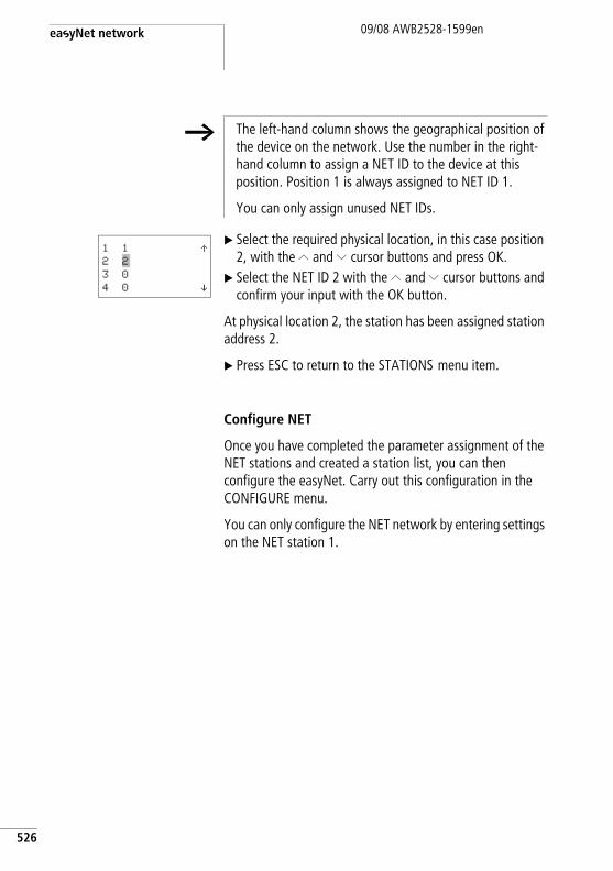
easyNet network
526
09/08 AWB2528-1599en
X Select the required physical location, in this case position 2, with the Í and Ú cursor buttons and press OK.
X Select the NET ID 2 with the Í and Ú cursor buttons and confirm your input with the OK button.
At physical location 2, the station has been assigned station address 2.
X Press ESC to return to the STATIONS menu item.
Configure NET
Once you have completed the parameter assignment of the NET stations and created a station list, you can then configure the easyNet. Carry out this configuration in the CONFIGURE menu.
You can only configure the NET network by entering settings on the NET station 1.
h The left-hand column shows the geographical position of the device on the network. Use the number in the right-hand column to assign a NET ID to the device at this position. Position 1 is always assigned to NET ID 1.
You can only assign unused NET IDs.
1 1 Æ2 2
3 0
4 0 æ
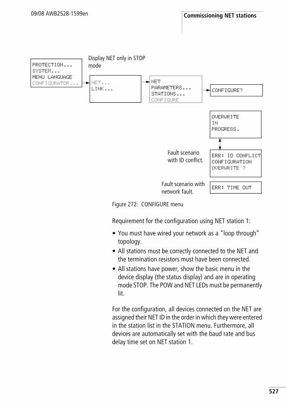
Commissioning NET stations09/08 AWB2528-1599en
Figure 272: CONFIGURE menu
Requirement for the configuration using NET station 1:
• You must have wired your network as a “loop through” topology.
• All stations must be correctly connected to the NET and the termination resistors must have been connected.
• All stations have power, show the basic menu in the device display (the status display) and are in operating mode STOP. The POW and NET LEDs must be permanently lit.
For the configuration, all devices connected on the NET are assigned their NET ID in the order in which they were entered in the station list in the STATION menu. Furthermore, all devices are automatically set with the baud rate and bus delay time set on NET station 1.
PROTECTION...
SYSTEM...
MENU LANGUAGE
CONFIGURATOR... NET...
LINK...
Display NET only in STOP mode
NET
PARAMETERS...
STATIONS...
CONFIGURE
CONFIGURE?
OVERWRITE
IN
PROGRESS.
Fault scenario with ID conflict.
Fault scenario with network fault.
ERR: ID CONFLICT
CONFIGURATION
OVERWRITE ?
ERR: TIME OUT
527
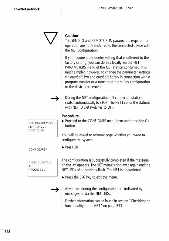
easyNet network
528
09/08 AWB2528-1599en
ProcedureX Proceed to the CONFIGURE menu item and press the OK
button.
You will be asked to acknowledge whether you want to configure the system.
X Press OK.
The configuration is successfully completed if the message on the left appears. The NET menu is displayed again and the NET LEDs of all stations flash. The NET is operational.
X Press the ESC key to exit the menu.
h Caution! The SEND IO and REMOTE RUN parameters required for operation are not transferred to the connected device with the NET configuration.
If you require a parameter setting that is different to the factory setting, you can do this locally via the NET PARAMETERS menu of the NET station concerned. It is much simpler, however, to change the parameter settings via easySoft-Pro and easySoft-Safety in connection with a program transfer or a transfer of the safety configuration to the device concerned.
h During the NET configuration, all connected stations switch automatically to STOP. The NET LED for the stations with NET ID 2-8 switches to OFF.
NET_PARAMETERS..STATION...
CONFIGURE
CONFIGURE?
CONFIGURATION
IN
PROGRESS.
h Any errors during the configuration are indicated by messages or via the NET LEDs.
Further information can be found in section “Checking the functionality of the NET” on page 533.
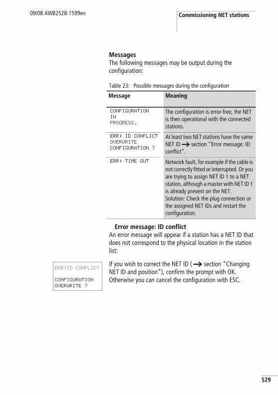
Commissioning NET stations09/08 AWB2528-1599en
MessagesThe following messages may be output during the configuration:
Table 23: Possible messages during the configuration
Error message: ID conflictAn error message will appear if a station has a NET ID that does not correspond to the physical location in the station list:
If you wish to correct the NET ID ( a section “Changing NET ID and position”), confirm the prompt with OK. Otherwise you can cancel the configuration with ESC.
Message Meaning
CONFIGURATION
IN
PROGRESS.
The configuration is error-free, the NET is then operational with the connected stations.
ERR: ID CONFLICT
OVERWRITE
CONFIGURATION ?
At least two NET stations have the same NET ID a section “Error message: ID conflict”.
ERR: TIME OUT Network fault, for example if the cable is not correctly fitted or interrupted. Or you are trying to assign NET ID 1 to a NET station, although a master with NET ID 1 is already present on the NET. Solution: Check the plug connection or the assigned NET IDs and restart the configuration.
ERR:ID CONFLICT
CONFIGURATION
OVERWRITE ?
529
easyNet network
530
09/08 AWB2528-1599en
Changing the NET configuration
The configuration of the NET network can be modified at any time at NET station 1, physical location 1.
Changing NET PARAMETERSX The NET parameters are modified as described on
page 523.
Changing NET ID and positionX Go to the physical location which is to be modified
(a section “Creating the station list” on page 525).X Press the OK button.
X Select the required NET ID with the Í and Ú cursor buttons and confirm your input with the OK button.
X Configure NET stations again using the CONFIGURATION menu, a page 528.
h Existing NET IDs can only be modified to free, non-assigned NET IDs. If all eight numbers are assigned, all NET IDs which are to be modified must be set to zero. After that all NET IDs can be reassigned.
For greater simplicity, the device sets all NET IDs to zero that have a physical location behind the first assigned zero.
Commissioning NET stations09/08 AWB2528-1599en
h Caution! Operating the NET with two masters (two stations with NET-ID 1) is not allowed, and leads to malfunctions on the NET.
Possible effects of this type of incorrect configuration with two masters competing against each other, and in which one is operated in the STOP operating mode and the other in the RUN operating mode, are as follows:
NET stations with NET-ID 2 - 8 that should follow the operating mode changes of the NET station with NET-ID 1 automatically during operation (REMOTE RUN parameter definition) keep toggling constantly between the STOP and RUN operating modes.
When integrating a master that is already configured into an existing NET, please make sure that there is no other station with NET-ID 1 on the NET.
Also, when performing the configuration from easySoft-Pro or easySoft-Safety and a local connection to a station, please make sure you do not assign NET-ID 1 to this station if there is a master on the NET already.
Tip: Carry out a NET configuration through NET station 1 after every change to the NET.
531
easyNet network
532
09/08 AWB2528-1599en
Deleting the safety configuration of a NET stationSelecting DELETE ALL on a configured NET station will also delete its NET ID.
The device concerned is no longer a NET station, indicated by its switched off LED. The NET LED of all other configured NET stations in operation indicates the NET fault with a permanent light.
Solution for the accidental deletion of the NET configuration
• With “loop-through” topologyYou must create a new NET configuration via the NET station 1 (a page 523).
• With “T-piece and spur line” topology.Locally reassign a NET ID to the device concerned.
h Caution!If you delete the standard and safety configuration in NET station 1, the NET configuration managed by this station will also be deleted.
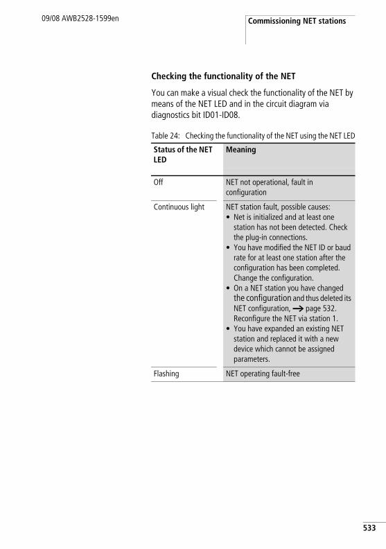
Commissioning NET stations09/08 AWB2528-1599en
Checking the functionality of the NET
You can make a visual check the functionality of the NET by means of the NET LED and in the circuit diagram via diagnostics bit ID01-ID08.
Table 24: Checking the functionality of the NET using the NET LED
Status of the NET LED
Meaning
Off NET not operational, fault in configuration
Continuous light NET station fault, possible causes: • Net is initialized and at least one
station has not been detected. Check the plug-in connections.
• You have modified the NET ID or baud rate for at least one station after the configuration has been completed. Change the configuration.
• On a NET station you have changed the configuration and thus deleted its NET configuration, a page 532. Reconfigure the NET via station 1.
• You have expanded an existing NET station and replaced it with a new device which cannot be assigned parameters.
Flashing NET operating fault-free
533
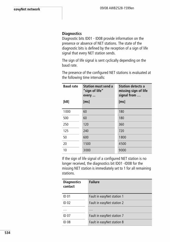
easyNet network
534
09/08 AWB2528-1599en
DiagnosticsDiagnostic bits ID01 - ID08 provide information on the presence or absence of NET stations. The state of the diagnostic bits is defined by the reception of a sign of life signal that every NET station sends.
The sign of life signal is sent cyclically depending on the baud rate.
The presence of the configured NET stations is evaluated at the following time intervalls:
If the sign of life signal of a configured NET station is no longer received, the diagnostics bit ID01 -ID08 for the missing NET station is immediately set to 1 for all remaining stations.
Baud rate Station must send a “sign of life” every ...
Station detects a missing sign of life signal from …
[kB] [ms] [ms]
1000 60 180
500 60 180
250 120 360
125 240 720
50 600 1800
20 1500 4500
10 3000 9000
Diagnostics contact
Failure
ID 01 Fault in easyNet station 1
ID 02 Fault in easyNet station 2
… …
ID 07 Fault in easyNet station 7
ID 08 Fault in easyNet station 8
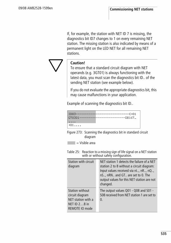
Commissioning NET stations09/08 AWB2528-1599en
If, for example, the station with NET ID 7 is missing, the diagnostics bit ID7 changes to 1 on every remaining NET station. The missing station is also indicated by means of a permanent light on the LED NET for all remaining NET stations.
Example of scanning the diagnostics bit ID..
Figure 273: Scanning the diagnostics bit in standard circuit diagram
= Visible area
Table 25: Reaction to a missing sign of life signal on a NET station with or without safety configuration.
h Caution! To ensure that a standard circuit diagram with NET operands (e.g. 3GT01) is always functioning with the latest data, you must scan the diagnostics bit ID.. of the sending NET station (see example below).
If you do not evaluate the appropriate diagnostics bit, this may cause malfunctions in your application.
Station with circuit diagram
NET station 1 detects the failure of a NET station 2 to 8 without a circuit diagram:Input values received via nI.., nR.., nQ.., nS.., nRN.. and GT.. are set to 0. The output values for this NET station are not changed.
Station without circuit diagramNET station with a NET ID 2…8 in REMOTE IO mode
The output values Q01 - Q08 and S01 - S08 received from NET station 1 are set to 0.
ID03-----------------------------Ä:01GT03Q1-------------------------DB16T_
....
:01....
535
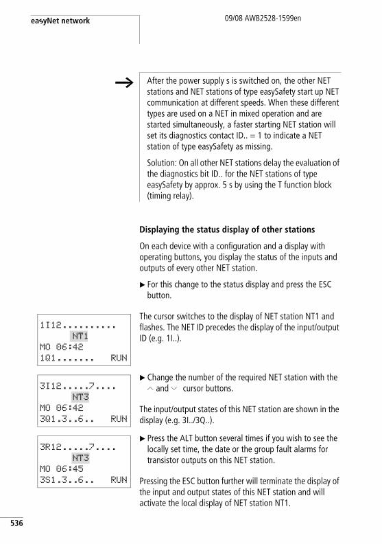
easyNet network
536
09/08 AWB2528-1599en
Displaying the status display of other stations
On each device with a configuration and a display with operating buttons, you display the status of the inputs and outputs of every other NET station.
X For this change to the status display and press the ESC button.
The cursor switches to the display of NET station NT1 and flashes. The NET ID precedes the display of the input/output ID (e.g. 1I..).
X Change the number of the required NET station with the Í and Ú cursor buttons.
The input/output states of this NET station are shown in the display (e.g. 3I../3Q..).
X Press the ALT button several times if you wish to see the locally set time, the date or the group fault alarms for transistor outputs on this NET station.
Pressing the ESC button further will terminate the display of the input and output states of this NET station and will activate the local display of NET station NT1.
h After the power supply s is switched on, the other NET stations and NET stations of type easySafety start up NET communication at different speeds. When these different types are used on a NET in mixed operation and are started simultaneously, a faster starting NET station will set its diagnostics contact ID.. = 1 to indicate a NET station of type easySafety as missing.
Solution: On all other NET stations delay the evaluation of the diagnostics bit ID.. for the NET stations of type easySafety by approx. 5 s by using the T function block (timing relay).
1I12..........
NT1
MO 06:42
1Q1....... RUN
3I12.....7....
NT3
MO 06:42
3Q1.3..6.. RUN
3R12.....7....
NT3
MO 06:45
3S1.3..6.. RUN
Commissioning NET stations09/08 AWB2528-1599en
Example: You are viewing the display of NET station NT3, and NT3 is flashing in the display. The inputs and outputs 3I.., 3R.., 3Q.. and 3S.. cannot be displayed.
After you have switched to the local display by pressing ESC, the NT3 display is no longer flashing and the states of the local inputs and outputs are displayed.
Wiring NET operands in the standard circuit diagram
The NET operands that can be used depend on the operation of the devices on the NET and the following types of application:
h The NET station that shows the status on its display, cannot read out its own data from the NET (see the following example).
h You use the NET operands only in the standard circuit diagram.
Operating devices on the NET Usable NET operands of data type…
Bit 32 Bit
REMOTE IO mode; only NET station 1 processes a circuit diagram.
nI.., nR.., nQ.., nS... –
All NET stations each process a circuit diagram.
nI.., nR.., nQ.., nS.., nRN.., nSN...
nPT.. and nGT...
Mixed operation of NET stations with and without a circuit diagram.
nI.., nR.., nQ.., nS.., nRN.., nSN...
nPT.. and nGT...
537
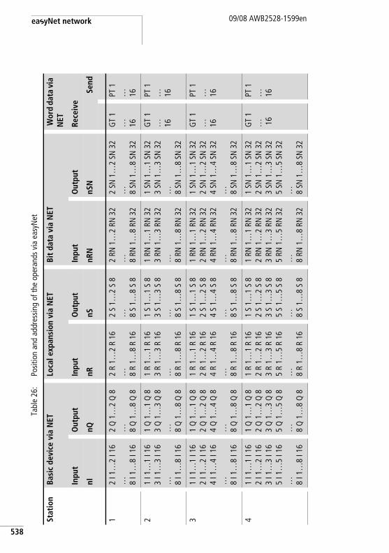
easyNet network
538
09/08 AWB2528-1599en
Tabl
e 26
:Po
sitio
n an
d ad
dres
sing
of th
e op
eran
ds v
ia e
asyN
et
Stat
ion
Basi
c de
vice
via
NET
Loca
l exp
ansi
on v
ia N
ETBi
t da
ta v
ia N
ET W
ord
data
via
N
ET
Inpu
tO
utpu
tIn
put
Out
put
Inpu
tO
utpu
tRe
ceiv
e
nInQ
nRnS
nRN
nSN
Send
12
I 1…
2 I 1
6… 8
I 1…
8 I 1
6
2 Q
1…
2 Q
8… 8
Q 1
…8
Q 8
2 R
1…2
R 16
… 8 R
1…8
R 16
2 S
1…2
S 8
… 8 S
1…8
S 8
2 RN
1…
2 RN
32
… 8 RN
1…
8 RN
32
2 SN
1…
2 SN
32
… 8 SN
1…
8 SN
32
GT
1… 16
PT 1
… 16
21
I 1…
1 I 1
63
I 1…
3 I 1
6… 8
I 1…
8 I 1
6
1 Q
1…
1 Q
83
Q 1
…3
Q 8
… 8 Q
1…
8 Q
8
1 R
1…1
R 16
3 R
1…3
R 16
… 8 R
1…8
R 16
1 S
1…1
S 8
3 S
1…3
S 8
… 8 S
1…8
S 8
1 RN
1…
1 RN
32
3 RN
1…
3 RN
32
… 8 RN
1…
8 RN
32
1 SN
1…
1 SN
32
3 SN
1…
3 SN
32
… 8 SN
1…
8 SN
32
GT
1… 16
PT 1
… 16
31
I 1…
1 I 1
62
I 1…
2 I 1
64
I 1…
4 I 1
6… 8
I 1…
8 I 1
6
1 Q
1…
1 Q
82
Q 1
…2
Q 8
4 Q
1…
4 Q
8… 8
Q 1
…8
Q 8
1 R
1…1
R 16
2 R
1…2
R 16
4 R
1…4
R 16
… 8 R
1…8
R 16
1 S
1…1
S 8
2 S
1…2
S 8
4 S
1…4
S 8
… 8 S
1…8
S 8
1 RN
1…
1 RN
32
2 RN
1…
2 RN
32
4 RN
1…
4 RN
32
… 8 RN
1…
8 RN
32
1 SN
1…
1 SN
32
2 SN
1…
2 SN
32
4 SN
1…
4 SN
32
… 8 SN
1…
8 SN
32
GT
1… 16
PT 1
… 16
41
I 1…
1 I 1
62
I 1…
2 I 1
63
I 1…
3 I 1
65
I 1…
5 I 1
6… 8
I 1…
8 I 1
6
1 Q
1…
1 Q
82
Q 1
…2
Q 8
3 Q
1…
3 Q
85
Q 1
…5
Q 8
… 8 Q
1…
8 Q
8
1 R
1…1
R 16
2 R
1…2
R 16
3 R
1…3
R 16
5 R
1…5
R 16
… 8 R
1…8
R 16
1 S
1…1
S 8
2 S
1…2
S 8
3 S
1…3
S 8
5 S
1…5
S 8
… 8 S
1…8
S 8
1 RN
1…
1 RN
32
2 RN
1…
2 RN
32
3 RN
1…
3 RN
32
5 RN
1…
5 RN
32
… 8 RN
1…
8 RN
32
1 SN
1…
1 SN
32
2 SN
1…
2 SN
32
3 SN
1…
3 SN
32
5 SN
1…
5 SN
32
… 8 SN
1…
8 SN
32
GT
1… 1
6
PT 1
… 16
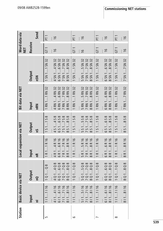
Commissioning NET stations09/08 AWB2528-1599en
51
I 1…
1 I 1
6… 4
I 1…
4 I 1
66
I 1…
6 I 1
67
I 1…
7 I 1
68
I 1…
8 I 1
6
1 Q
1…
Q 8
… 4 Q
1…
4 Q
86
Q 1
…6
Q 8
7 Q
1…
7 Q
88
Q 1
…8
Q 8
1 R
1…1
R 16
… 4 R
1…4
R 16
6 R
1…6
R 16
7 R
1…7
R 16
8 R
1…8
R 16
1 S
1…1
S 8
… 4 S
1…4
S 8
6 S
1…6
S 8
7 S
1…7
S 8
8 S
1…8
S 8
1 RN
1…
1 RN
32
… 4 RN
1…
4 RN
32
6 RN
1…
6 RN
32
7 RN
1…
7 RN
32
8 RN
1…
8 RN
32
1 SN
1…
1 SN
32
… 4 SN
1…
4 SN
32
6 SN
1…
6 SN
32
7 SN
1…
7 SN
32
8 SN
1…
8 SN
32
GT
1… 1
6
PT 1
… 16
61
I 1…
1 I 1
6… 5
I 1…
5 I 1
67
I 1…
7 I 1
68
I 1…
8 I 1
6
1 Q
1…
1 Q
8… 5
Q 1
…5
Q 8
7 Q
1…
7 Q
88
Q 1
…8
Q 8
1 R
1…1
R 16
… 5 R
1…5
R 16
7 R
1…7
R 16
8 R
1…8
R 16
1 S
1…1
S 8
… 5 S
1…5
S 8
7 S
1…7
S 8
8 S
1…8
S 8
1 RN
1…
1 RN
32
… 5 RN
1…
5 RN
32
7 RN
1…
7 RN
32
8 RN
1…
8 RN
32
1 SN
1…
1 SN
32
… 5 SN
1…
5 SN
32
7 SN
1…
7 SN
32
8 SN
1…
8 SN
32
GT
1… 16
PT 1
… 16
71
I 1…
1 I 1
6… 6
I 1…
6 I 1
68
I 1…
8 I 1
6
1 Q
1…
1 Q
8… 6
Q 1
…6
Q 8
8 Q
1…
8 Q
8
1 R
1…1
R 16
… 6 R
1…6
R 16
8 R
1…8
R 16
1 S
1…1
S 8
… 6 S
1…6
S 8
8 S
1…8
S 8
1 RN
1…
1 RN
32
… 6 RN
1…
6 RN
32
8 RN
1…
8 RN
32
1 SN
1…
1 SN
32
… 6 SN
1…
6 SN
32
8 SN
1…
8 SN
32
GT
1… 1
6
PT 1
… 16
81
I 1…
1 I 1
6… 8
I 1…
8 I 1
6
1 Q
1…
1 Q
8… 8
Q 1
…8
Q 8
1 R
1…1
R 16
… 8 R
1…8
R 16
1 S
1…1
S 8
… 8 S
1…8
S 8
1 RN
1…
1 RN
32
… 7 RN
1…
7 RN
32
1 SN
1…
1 SN
32
… 7 SN
1…
7 SN
32
GT
1… 1
6
PT 1
… 16
Stat
ion
Basi
c de
vice
via
NET
Loca
l exp
ansi
on v
ia N
ETBi
t da
ta v
ia N
ET W
ord
data
via
N
ET
Inpu
tO
utpu
tIn
put
Out
put
Inpu
tO
utpu
tRe
ceiv
e
nInQ
nRnS
nRN
nSN
Send
539
easyNet network
540
09/08 AWB2528-1599en
NET operands nI.., nR.., nQ.. and nS..The following NET operands can be written to and/or read.
Reading of nI.., nR.., nQ.. and nS..n = NET ID of the station with NET operands that are read or written.
Each NET station with a standard circuit diagram can read the signal states at the input and output terminals of each other NET station via these operands wired as contacts. This is possible regardless of whether a circuit diagram is being processed or not on the NET station to be read.
Use these nI.., nR.., nQ.. and nS.. NET operands to read the signal states of NET stations (NET-ID 2 - 8).
h The operands *RN.. and *SN.. are always NET operands and must only be used with the preceding NET ID as nRN.. and nSN... The NET operands are only available in the standard circuit diagram. Placing a NET ID in front of the operand is explained on page 541. Without a preceding NET ID, the circuit diagram test SAFETY TEST will report that Rule 29 has been broken (a section “Rules in the safety circuit diagram”, page 334).
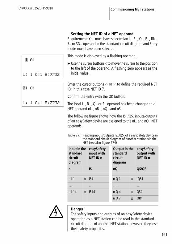
Commissioning NET stations09/08 AWB2528-1599en
Setting the NET ID of a NET operandRequirement: You must have selected an I.., R.., Q.., R.., RN.. S.. or SN.. operand in the standard circuit diagram and Entry mode must have been selected.
This mode is displayed by a flashing operand.
X Use the cursor buttons ú to move the cursor to the position to the left of the operand. A flashing zero appears as the initial value.
Enter the cursor buttons Í or Ú to define the required NET ID; in this case NET ID 7.
Confirm the entry with the OK button.
The local I.., R.., Q.. or S.. operand has been changed to a NET operand nI.., nR.., nQ.. and nS...
The following figure shows how the IS../QS. inputs/outputs of an easySafety device are assigned to the nI.. and nQ.. NET operands.
Table 27: Reading inputs/outputs IS../QS. of a easySafety device in the standard circuit diagram of another station via the NET (see also figure 274)
I 01
L: 1 C:1 B:7732
7I 01
L: 1 C:1 B:7732
Input in the standard circuit diagram
easySafety input with NET ID n
Output in the standard circuit diagram
easySafety output with NET ID n
nI IS nQ QS/QR
n I 1 q IS1 n Q 1 q QS1
… … … …
n I 14 q IS14 n Q 4 q QS4
n Q 7 q QR1
j Danger! The safety inputs and outputs of an easySafety device operating as a NET station can be read in the standard circuit diagram of another NET station, however, they lose their safety properties.
541
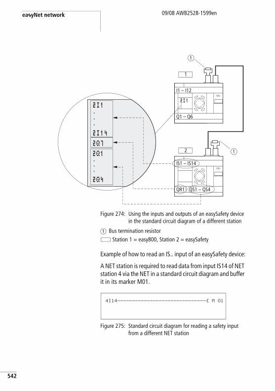
easyNet network
542
09/08 AWB2528-1599en
Figure 274: Using the inputs and outputs of an easySafety device in the standard circuit diagram of a different station
a Bus termination resistor Station 1 = easy800, Station 2 = easySafety
Example of how to read an IS.. input of an easySafety device:
A NET station is required to read data from input IS14 of NET station 4 via the NET in a standard circuit diagram and buffer it in its marker M01.
Figure 275: Standard circuit diagram for reading a safety input from a different NET station
1
I1 – I12
Q1 – Q6
2
IS1 – IS14
QR1 QS1 – QS4
a
a
2I1...2I142Q72Q1...2Q4
2I1...
4I14------------------------------Ä M 01
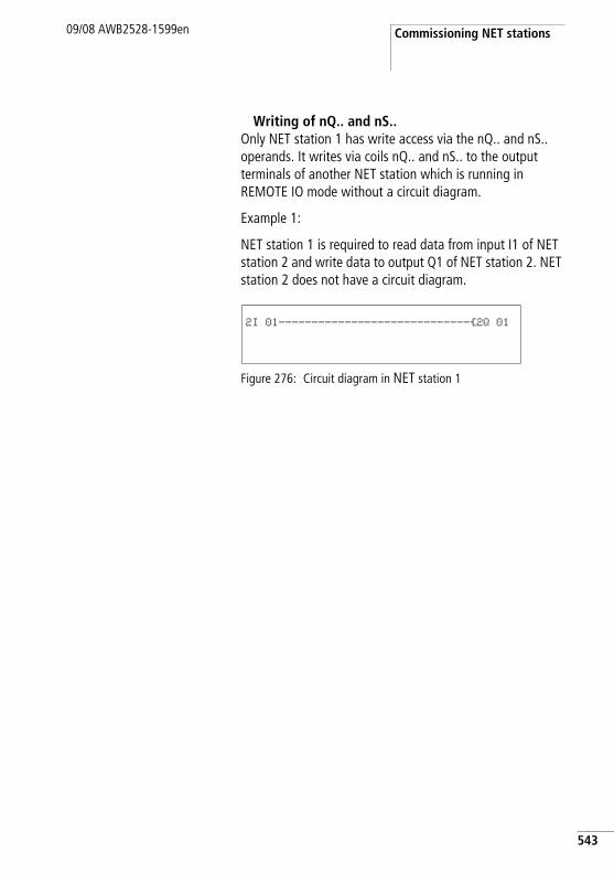
Commissioning NET stations09/08 AWB2528-1599en
Writing of nQ.. and nS..Only NET station 1 has write access via the nQ.. and nS.. operands. It writes via coils nQ.. and nS.. to the output terminals of another NET station which is running in REMOTE IO mode without a circuit diagram.
Example 1:
NET station 1 is required to read data from input I1 of NET station 2 and write data to output Q1 of NET station 2. NET station 2 does not have a circuit diagram.
Figure 276: Circuit diagram in NET station 1
2I 01-----------------------------Ä2Q 01
543
easyNet network
544
09/08 AWB2528-1599en
NET operands nRN.. (input) and nSN.. (output)To use these NET operands, the sending and receiving station must each have a circuit diagram.
The NET stations for bit exchange must always use the RN and SN in pairs (a figure 277 and 278).
Writing via SNThe NET operand SN (Send NET) is used for sending bit data from one NET station to another. To do this you select the SN operand in a coil field.
Reading using RNThe RN (Receive NET) NET operand is used to receive the bit data that another NET station has sent. To do this you select the RN operand in a contact field.
SN-RN combinationAs the RN and SN must always be used in pairs, the following rule applies:
• on the sending station and receiving station use the same operand number for each SN/RN pair to be formed.
• in the circuit diagram of the sending station you set for the SN operand (coil) the station number (NET ID) of the receiving station.
• in the circuit diagram of the receiving station you set for the RN operand (contact) the station number (NET ID) of the sending station.
h The operands *RN.. and *SN.. are always NET operands and must only be used with the preceding NET ID as nRN.. and nSN... The NET operands are only available in the standard circuit diagram. Placing a NET ID in front of the operand is explained on page 541. Without a preceding NET ID, the circuit diagram test SAFETY TEST will report that Rule 29 has been broken (a section “Rules in the safety circuit diagram”, page 334).
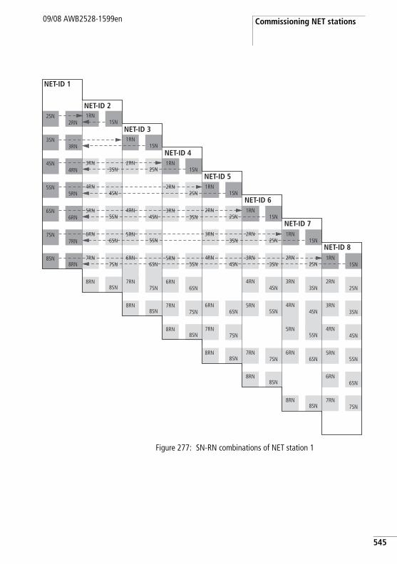
Commissioning NET stations09/08 AWB2528-1599en
Figure 277: SN-RN combinations of NET station 1
NET-ID 1
NET-ID 2
NET-ID 3
NET-ID 4
NET-ID 5
NET-ID 6
NET-ID 7
NET-ID 8
1SN
2SN
4SN
6SN
7SN
8SN
1RN
2RN
3SN3RN
4RN
6RN
7RN
8RN
1SN
2SN
5SN
6SN
7SN
8SN
1RN
2RN
3SN3RN
5RN
6RN
7RN
8RN
1SN
2SN
4SN
5SN
6SN
7SN
8SN
1RN
2RN
4RN
5RN
6RN
7RN
8RN
1SN
4SN
5SN
6SN
7SN
8SN
1RN
3SN3RN
4RN
5RN
6RN
7RN
8RN
2RN
4RN
5RN
6RN
7RN
8RN
2SN
3RN3SN
4SN
5SN
6SN
7SN
8SN
1SN
2SN
4SN
5SN
7SN
8SN
1RN
2RN
3SN3RN
4RN
5RN
7RN
8RN
1SN
2SN
4SN
5SN
6SN
8SN
1RN
2RN
3SN3RN
4RN
5RN
6RN
8RN
1SN
2SN
4SN
5SN
6SN
7SN
1RN
2RN
3SN3RN
4RN
5RN
6RN
7RN
545
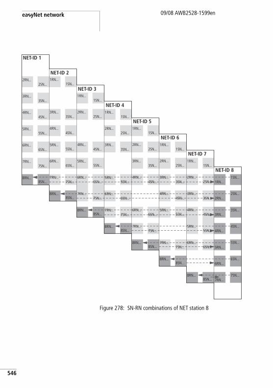
easyNet network
546
09/08 AWB2528-1599en
Figure 278: SN-RN combinations of NET station 8
NET-ID 1
NET-ID 2
NET-ID 3
NET-ID 4
NET-ID 5
NET-ID 6
NET-ID 7
NET-ID 8
1SN...
2SN...
4SN...
6SN...
7SN...
8SN...
1RN...
2RN...
3SN...3RN...
4RN...
6RN...
7RN...
8RN...
1SN...
2SN...
5SN...
6SN...
7SN...
8SN...
1RN...
2RN...
3SN...3RN...
5RN...
6RN...
7RN...
8RN...
1SN...
2SN...
4SN...
5SN...
6SN...
7SN...
8SN...
1RN...
2RN...
4RN...
5RN...
6RN...
7RN...
8RN...
1SN...
4SN...
5SN...
6SN...
7SN...
8SN...
1RN...
3SN...3RN...
4RN...
5RN...
6RN...
7RN...
8RN...
2SN...
4SN...
5SN...
6SN...
7SN...
8SN...
2RN...
3SN...3RN...
4RN...
5RN...
6RN...
7RN...
8RN...
1SN...
2SN...
4SN...
5SN...
7SN...
8SN...
1RN...
2RN...
3SN...3RN...
4RN...
5RN...
7RN...
8RN...
1SN...
2SN...
4SN...
5SN...
6SN...
8SN...
1RN...
2RN...
3SN...3RN...
4RN...
5RN...
6RN...
8RN...
1SN...
2SN...
4SN...
5SN...
6SN...
7SN...
1RN...
2RN...
3SN...3RN...
4RN...
5RN...
6RN...
7RN...
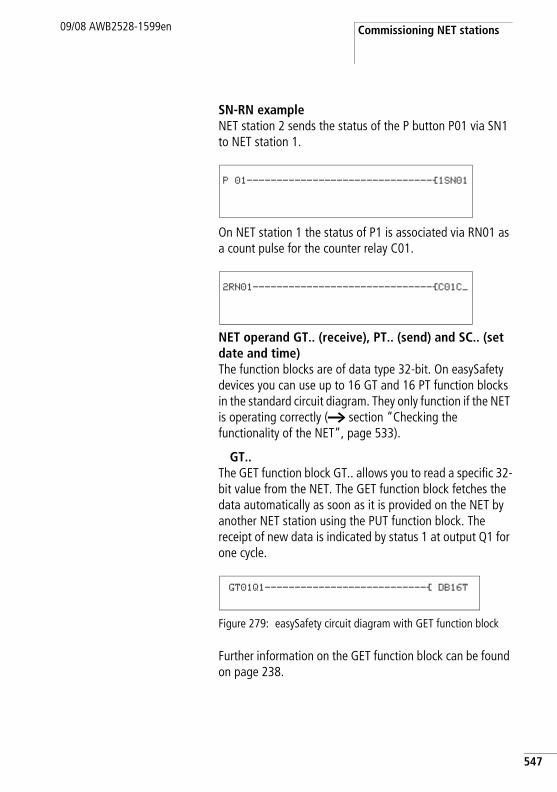
Commissioning NET stations09/08 AWB2528-1599en
SN-RN exampleNET station 2 sends the status of the P button P01 via SN1 to NET station 1.
On NET station 1 the status of P1 is associated via RN01 as a count pulse for the counter relay C01.
NET operand GT.. (receive), PT.. (send) and SC.. (set date and time)The function blocks are of data type 32-bit. On easySafety devices you can use up to 16 GT and 16 PT function blocks in the standard circuit diagram. They only function if the NET is operating correctly (a section “Checking the functionality of the NET”, page 533).
GT..The GET function block GT.. allows you to read a specific 32-bit value from the NET. The GET function block fetches the data automatically as soon as it is provided on the NET by another NET station using the PUT function block. The receipt of new data is indicated by status 1 at output Q1 for one cycle.
Figure 279: easySafety circuit diagram with GET function block
Further information on the GET function block can be found on page 238.
P 01-------------------------------Ä1SN01
2RN01------------------------------ÄC01C_
GT01Q1---------------------------Ä DB16T
547
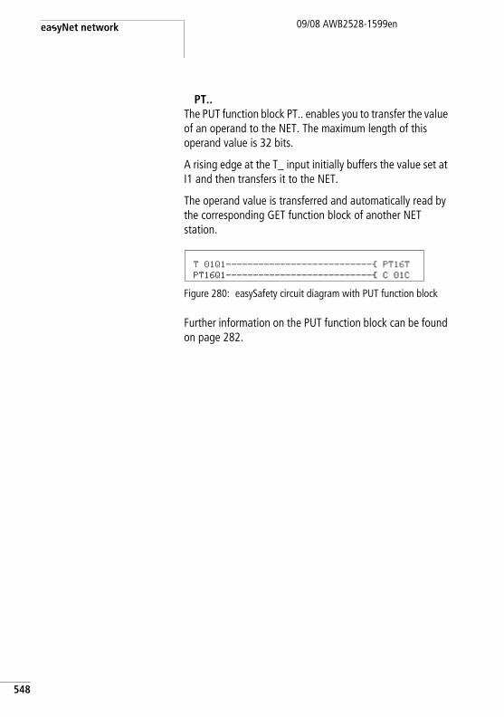
easyNet network
548
09/08 AWB2528-1599en
PT..The PUT function block PT.. enables you to transfer the value of an operand to the NET. The maximum length of this operand value is 32 bits.
A rising edge at the T_ input initially buffers the value set at I1 and then transfers it to the NET.
The operand value is transferred and automatically read by the corresponding GET function block of another NET station.
Figure 280: easySafety circuit diagram with PUT function block
Further information on the PUT function block can be found on page 282.
T 01Q1---------------------------Ä PT16TPT16Q1---------------------------Ä C 01C
Description of the NET-PARAMETERs
09/08 AWB2528-1599en
Description of the NET-PARAMETERs
The NET parameters described below can be found in the NET PARAMETERS menu:
X Simultaneously press the DEL and ALT buttons with the status display active. Then choose STD PARAMETERS -> CONFIGURATOR -> NET -> NET PARAMETERS and press the OK button.
NET ID (Station number)Factory setting NET ID = 00.
Selectable NET IDs 1 - 8.
The NET ID of a device is used to give it a unique identification on the NET. A NET ID can therefore only be assigned once within a network.
The factory setting NET ID 00 prevents the possibility of double addressing when an existing NET station (NET ID 1- 8) has to be replaced.
BAUD RATEData transfer rate of the NET
Factory set baud rate = 125 KB.
The devices allow a NET transfer speed of 10 - 1000 Kbaud, selectable in defined steps. Possible baud rates are: 10, 20, 50, 125, 250, 500 and 1000 KB
X Use Í and Ú to select a baud rate of 10 - 1000 KB and confirm your selection with OK.
The maximum transmission speed depends on the total length of the network cables (a Technical data, section “Network easyNet” on page 653).
h All NET stations must have an identical transfer speed set. This is achieved automatically if you carry out the NET configuration via NET station 1 (a page 523).
549
easyNet network
550
09/08 AWB2528-1599en
BUS DELAY(Bus delay time)
Factory setting: Bus delay time = 0 (recommended setting that you should only change for the reasons stated below).
Use BUS DELAY to change a multiplier that increases the bus delay time [tp] between the transmission cycles of user data in the NET.
• A value 1 means that the bus delay time is doubled.• A value 15 means that the bus delay time is increased
tenfold.
X If necessary, use Í and Ú to set a multiplier of 1 - 15 and confirm your selection with OK.
tpnew = tp x (1 + n)tpnew = new bus delay timetp = bus delay time determined by the networkn = Value at BUS DELAY
h The reaction speed of devices connected via the NET depends essentially on the baud rate, the delay time and the volume of transferred data.
Therefore always set the maximum transfer speed. The factory set baud rate depends on the total length of the network cables of 125 m.
A maximum baud rate is therefore very important if an MFD-Titan is required to work on the NET since additional NET transfer time is needed.
h All NET stations must have an identical bus delay time set. This is achieved automatically if you carry out the NET configuration via NET station 1 (a section “Configure NET” on page 526).
Description of the NET-PARAMETERs
09/08 AWB2528-1599en
In normal operation, the NET stations organise their data exchange independently. The NET stations also determine the minimum delay time required so that all messages can be sent.
Even if a maximum baud rate is set, it may be necessary to increase the bus delay time for the following reasons:
• In addition to the user data, additional data is transferred to the PC, i.e. to easySoft-Pro in online status or to an MFD-Titan in terminal mode.
• The transfer rate is low.
By increasing the bus delay time you increase the time window for online services such as the power flow display, status display of actual values of function block operands and the forcing of markers.
An increase of the bus delay time is only really necessary in the following conditions:
• You use an MFD-Titan in terminal mode via the NET and see the message “Connection establishment in progress...” In this case the bus delay time must be increased permanently.
• You wish to use the online services of the easySoft-Safety configuration software via the NET. In Communication View, however, you will receive the error message “Device not responding”. This fault message appears if you wish to establish an online connection or are already online. In this case, a temporary increase of the bus delay time is useful. It should be reduced after commissioning.
Remember also that the easySoft-Safety configuration software displays status changes more quickly on the device if you select the maximum PC baud rate.
551
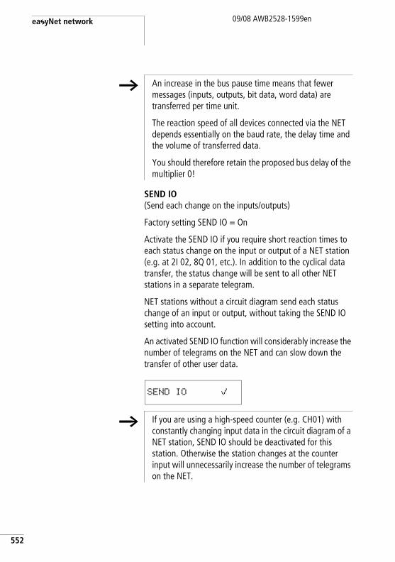
easyNet network
552
09/08 AWB2528-1599en
SEND IO(Send each change on the inputs/outputs)
Factory setting SEND IO = On
Activate the SEND IO if you require short reaction times to each status change on the input or output of a NET station (e.g. at 2I 02, 8Q 01, etc.). In addition to the cyclical data transfer, the status change will be sent to all other NET stations in a separate telegram.
NET stations without a circuit diagram send each status change of an input or output, without taking the SEND IO setting into account.
An activated SEND IO function will considerably increase the number of telegrams on the NET and can slow down the transfer of other user data.
h An increase in the bus pause time means that fewer messages (inputs, outputs, bit data, word data) are transferred per time unit.
The reaction speed of all devices connected via the NET depends essentially on the baud rate, the delay time and the volume of transferred data.
You should therefore retain the proposed bus delay of the multiplier 0!
SEND IO å
h If you are using a high-speed counter (e.g. CH01) with constantly changing input data in the circuit diagram of a NET station, SEND IO should be deactivated for this station. Otherwise the station changes at the counter input will unnecessarily increase the number of telegrams on the NET.
Description of the NET-PARAMETERs
09/08 AWB2528-1599en
REMOTE RUN(operating mode change according to the operating mode of the NET station with NET ID 1)
Factory setting REMOTE RUN = On
REMOTE RUN must be activated on NET stations with NET ID 2 - 8 which are required to automatically follow the operating mode change of the NET station with NET ID 1.
h If you are currently setting the station with NET ID 1, the REMOTE RUN function is therefore not required and is not available here.
j Danger! Ensure that the automatic starting of easySafety will not cause the unwanted starting of machines and plants.
h NET stations with a circuit diagram and a display only follow the operating mode change if the status display or a text is showing in the display on the device.
553
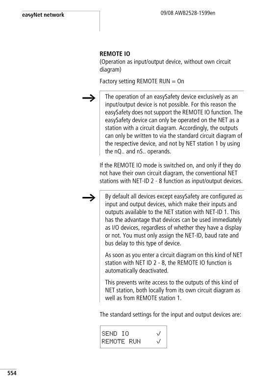
easyNet network
554
09/08 AWB2528-1599en
REMOTE IO(Operation as input/output device, without own circuit diagram)
Factory setting REMOTE RUN = On
If the REMOTE IO mode is switched on, and only if they do not have their own circuit diagram, the conventional NET stations with NET-ID 2 - 8 function as input/output devices.
The standard settings for the input and output devices are:
h The operation of an easySafety device exclusively as an input/output device is not possible. For this reason the easySafety does not support the REMOTE IO function. The easySafety device can only be operated on the NET as a station with a circuit diagram. Accordingly, the outputs can only be written to via the standard circuit diagram of the respective device, and not by NET station 1 by using the nQ.. and nS.. operands.
h By default all devices except easySafety are configured as input and output devices, which make their inputs and outputs available to the NET station with NET-ID 1. This has the advantage that devices can be used immediately as I/O devices, regardless of whether they have a display or not. You must only assign the NET-ID, baud rate and bus delay to this type of device.
As soon as you enter a circuit diagram on this kind of NET station with NET ID 2 - 8, the REMOTE IO function is automatically deactivated.
This prevents write access to the outputs of this kind of NET station, both locally from its own circuit diagram as well as from REMOTE station 1.
SEND IO åREMOTE RUN å
Replacing a NET station09/08 AWB2528-1599en
Replacing a NET station If you wish to replace a NET station NT2 - NT8 in a running plant, you should take preparatory measures in order to ensure fault-free commissioning of this NET station.
ExampleIn a network run with a baud rate of 250 KB, the NET station NT7 is to be replaced.
If you are using a easySafety device as replacement that is still in its default state and does not have a NET-ID, this device is not automatically integrated in the network. Even connected to the power supply and the NET, the LED NET remains off. In this case a configuration can not be written to it with the configuration software easySoft-Safety (Communications view -> Device list field, NT7).
The following procedure ensures fault-free commissioning of the replacement device.
X Connect the easySafety replacement device to the power supply and connect it at the same position to the NET as the device to be replaced.
X Switch the device display of all NET stations to Status display.
X Start the automatic configuration of the NET. The procedure is described in section “Configure NET” on page 526. However, you can also do this via the configuration software. As an alternative to the automatic configuration, you can also switch the power supply of the configured NET stations off and on.
All NET stations in the NET configuration will temporarily switch to STOP.
555
easyNet network
556
09/08 AWB2528-1599en
Power supply failure on station with NET-ID 1
If the power supply of station NET-ID 1 fails during operation, the other NET stations can no longer be notified of the associated operating mode change. This also applies if the standard and safety circuit diagram stop due to a class A fault (see Behaviour of easySafety after a fault, a page 615).
NET stations with NET-ID 2 - 8 on which REMOTE RUN is activated therefore stay in RUN mode until the missing sign of life is detected. The time until the missing sign of life is detected depends on the baud rate and is from 180 - 9000 ms (a section “Diagnostics” , page 534). Up to this time, a NET station 2 - 8 operates with the data previously received via the NET.
The further behaviour of the NET stations 2 - 8 depends on whether REMOTE IO is also activated as well as REMOTE RUN:
• NET station 2 - 8 with activated REMOTE RUNThis type of NET station sets the data received via the NET to zero. It retains its operating state and sets the diagnostics bit ID1 to 1 (see following safety measure).
• NET stations 2 - 8 with activated REMOTE RUN and REMOTE IO that function as input/output devices, i.e. without their own circuit diagram
This type of NET station sets the data received via the NET to zero. It switches to the STOP mode if the device display is showing the Status menu. The device follows NET station 1 when it switches to RUN mode.
h The easySafety device can only be operated on the NET as a station with a circuit diagram.
Power supply failure on station with NET-ID 1
09/08 AWB2528-1599en
Safety measure: On every NET station with a program, monitor the diagnostics bits ID.. in order to detect a missing NET station as quickly as possible (a section “Diagnostics” , page 534).
557

558
09/08 AWB2528-1599en
09/08 AWB2528-1599en
8 easySafety Settings
All easySafety settings can only be carried out on models provided with buttons and LCD display.
Alternatively use the easySoft-Safety configuration software to complete all the settings via the software.
Password protection General information
Only authorised persons are permitted to access the configuration of a safety control relay. The configuration consists of the safety circuit diagram as well as the necessary device settings, which have an effect on machine safety.
The access authorisation is protected by password entries. Passwords are part of each configuration, both in the easySoft-Safety configuration software as well as in the device.
The passwords are required when making entries via the operating buttons of the device in the same way as when using the easySoft-Safety configuration software, for (offline) editing and for simulating a configuration or downloading one to the device.
A device can only be accessed without password entry if it is a new easySafety control relay or a device that has been restored to its factory settings.
h The passwords that are currently assigned in the configuration software are required for offline editing.
For online access or operating the device directly, the device is the controlling system. In other words, as soon as access to a protected menu is required, the passwords of the device carrying out the examination must be available.
559
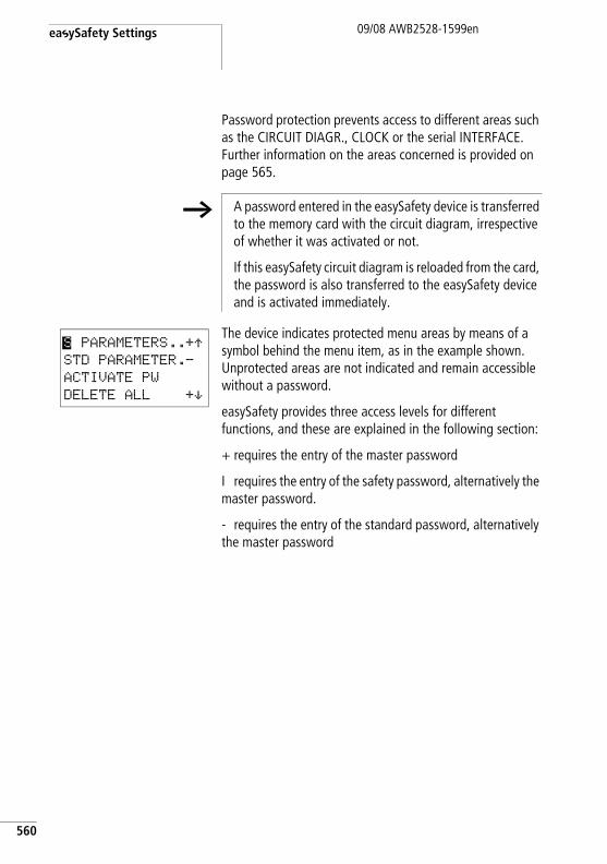
easySafety Settings
560
09/08 AWB2528-1599en
Password protection prevents access to different areas such as the CIRCUIT DIAGR., CLOCK or the serial INTERFACE. Further information on the areas concerned is provided on page 565.
The device indicates protected menu areas by means of a symbol behind the menu item, as in the example shown. Unprotected areas are not indicated and remain accessible without a password.
easySafety provides three access levels for different functions, and these are explained in the following section:
+ requires the entry of the master password
I requires the entry of the safety password, alternatively the master password.
- requires the entry of the standard password, alternatively the master password
h A password entered in the easySafety device is transferred to the memory card with the circuit diagram, irrespective of whether it was activated or not.
If this easySafety circuit diagram is reloaded from the card, the password is also transferred to the easySafety device and is activated immediately.
S PARAMETERS..+ÆSTD PARAMETER.-
ACTIVATE PW
DELETE ALL +æ
Password protection09/08 AWB2528-1599en
Access levels
Master password ( + )The obligatory master password has the highest level and allows access to all functions. The editing of the safety circuit diagram in particular is only possible if the master password has been entered. Each easySafety device must have a master password. For this reason, you are requested to assign a master password when entering the safety circuit diagram for the first time. The easySoft-Safety configuration software works in the same way. For this the master password must be assigned in all cases when adding a device in Project View.
Safety password ( | )The safety password protects the viewing of the safety configuration. You can assign the password if required, for example, if you wish to protect your know-how. The safety password is also advisable if there is a danger of third-parties examining the safety configuration in order to bypass or manipulate it. Without the safety password, the safety configuration can be viewed at any time but not modified. The master password is always required in order to edit it.
If the safety password is assigned and if this is active, the printing or display of the safety configuration in the circuit diagram, communication and simulation views of easySoft-Safety is only possible of the safety or master password has been entered. The safety password does not allow the modification of the safety configuration.
561
easySafety Settings
562
09/08 AWB2528-1599en
Standard password ( - )The standard password protects the viewing of the safety configuration. You can assign the password if required, for example, if you wish to protect your know-how. Without the standard password, the standard circuit diagram can be viewed or modified at any time.
If you have assigned the standard password, activated it and selected the CIRCUIT DIAGR. area (a page 565), the printing or editing of the standard configuration is only possible if the standard or master password has been entered. This applies to the display of the standard configuration in the circuit diagram, communication or simulation view of easySoft-Safety. Remember that you can protect certain areas of the standard configuration with the standard password. The standard password does not allow the modification of the safety configuration.
Entering passwords
You set up a password using the system menu, irrespective of whether the device is in RUN or STOP mode.
The password can consist of any number between 0 and 9. A value between 000001 and 999999 can be entered as a password.
h Assign different master, safety and standard passwords. Repeat entries will cause the error message PASSWORD ALREADY ASSIGNED!
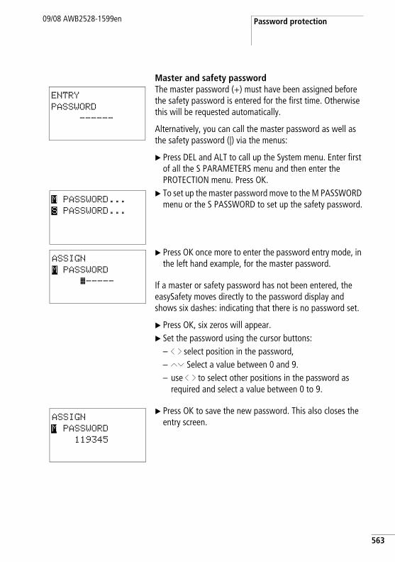
Password protection09/08 AWB2528-1599en
Master and safety passwordThe master password (+) must have been assigned before the safety password is entered for the first time. Otherwise this will be requested automatically.
Alternatively, you can call the master password as well as the safety password (|) via the menus:
X Press DEL and ALT to call up the System menu. Enter first of all the S PARAMETERS menu and then enter the PROTECTION menu. Press OK.
X To set up the master password move to the M PASSWORD menu or the S PASSWORD to set up the safety password.
X Press OK once more to enter the password entry mode, in the left hand example, for the master password.
If a master or safety password has not been entered, the easySafety moves directly to the password display and shows six dashes: indicating that there is no password set.
X Press OK, six zeros will appear.X Set the password using the cursor buttons:
– ú í select position in the password,– ÍÚ Select a value between 0 and 9.– use ú í to select other positions in the password as
required and select a value between 0 to 9.
X Press OK to save the new password. This also closes the entry screen.
ENTRY
PASSWORD
------
M PASSWORD...
S PASSWORD...
ASSIGN
M PASSWORD
â-----
ASSIGN
M PASSWORD
119345
563
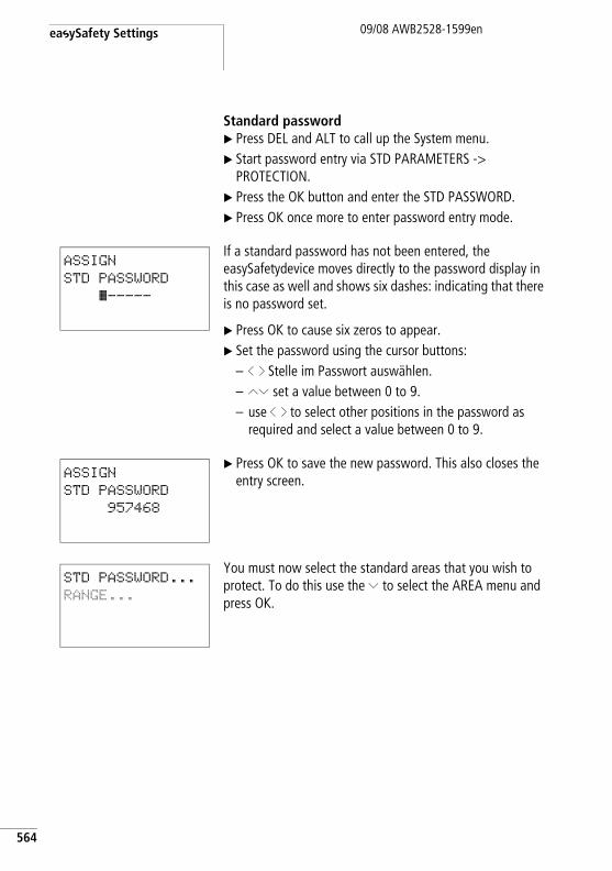
easySafety Settings
564
09/08 AWB2528-1599en
Standard passwordX Press DEL and ALT to call up the System menu.X Start password entry via STD PARAMETERS ->
PROTECTION.X Press the OK button and enter the STD PASSWORD.X Press OK once more to enter password entry mode.
If a standard password has not been entered, the easySafetydevice moves directly to the password display in this case as well and shows six dashes: indicating that there is no password set.
X Press OK to cause six zeros to appear.X Set the password using the cursor buttons:
– ú í Stelle im Passwort auswählen.– ÍÚ set a value between 0 to 9.– use ú í to select other positions in the password as
required and select a value between 0 to 9.
X Press OK to save the new password. This also closes the entry screen.
You must now select the standard areas that you wish to protect. To do this use the Ú to select the AREA menu and press OK.
ASSIGN
STD PASSWORD
â-----
ASSIGN
STD PASSWORD
957468
STD PASSWORD...
RANGE...
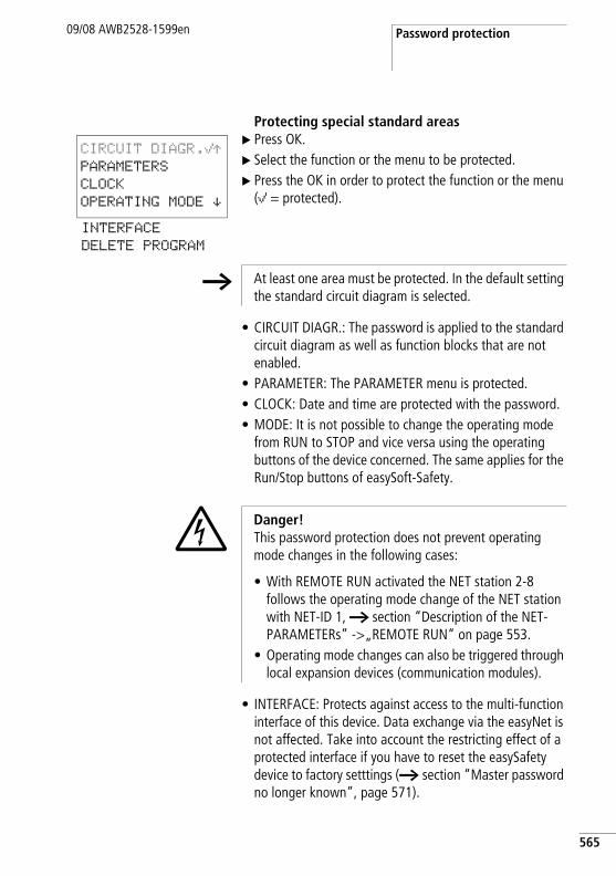
Password protection09/08 AWB2528-1599en
Protecting special standard areasX Press OK. X Select the function or the menu to be protected.X Press the OK in order to protect the function or the menu
(å = protected).
• CIRCUIT DIAGR.: The password is applied to the standard circuit diagram as well as function blocks that are not enabled.
• PARAMETER: The PARAMETER menu is protected.• CLOCK: Date and time are protected with the password.• MODE: It is not possible to change the operating mode
from RUN to STOP and vice versa using the operating buttons of the device concerned. The same applies for the Run/Stop buttons of easySoft-Safety.
• INTERFACE: Protects against access to the multi-function interface of this device. Data exchange via the easyNet is not affected. Take into account the restricting effect of a protected interface if you have to reset the easySafety device to factory setttings (a section “Master password no longer known”, page 571).
CIRCUIT DIAGR.åÆPARAMETERS
CLOCK
OPERATING MODE æINTERFACE
DELETE PROGRAM
h At least one area must be protected. In the default setting the standard circuit diagram is selected.
j Danger! This password protection does not prevent operating mode changes in the following cases:
• With REMOTE RUN activated the NET station 2-8 follows the operating mode change of the NET station with NET-ID 1, a section “Description of the NET-PARAMETERs” ->„REMOTE RUN“ on page 553.
• Operating mode changes can also be triggered through local expansion devices (communication modules).
565
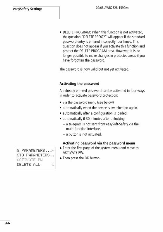
easySafety Settings
566
09/08 AWB2528-1599en
• DELETE PROGRAM: When this function is not activated, the question “DELETE PROG?” will appear if the standard password entry is entered incorrectly four times. This question does not appear if you activate this function and protect the DELETE PROGRAM area. However, it is no longer possible to make changes in protected areas if you have forgotten the password.
The password is now valid but not yet activated.
Activating the password
An already entered password can be activated in four ways in order to activate password protection:
• via the password menu (see below)• automatically when the device is switched on again.• automatically after a configuration is loaded.• automatically if 30 minutes after unlocking
– a telegram is not sent from easySoft-Safety via the multi-function interface.
– a button is not actuated.
Activating password via the password menuX Enter the first page of the system menu and move to
ACTIVATE PW.X Then press the OK button.
S PARAMETERS...ÆSTD PARAMETERS..
ACTIVATE PW
DELETE ALL æ
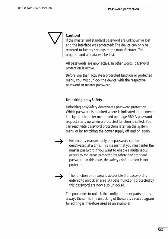
Password protection09/08 AWB2528-1599en
All passwords are now active. In other words, password protection is active.
Before you then activate a protected function or protected menu, you must unlock the device with the respective password or master password.
Unlocking easySafety
Unlocking easySafety deactivates password protection. Which password is required where is indicated in the menu line by the character mentioned on .page 560 A password request starts up when a protected function is called. You can reactivate password protection later via the system menu or by switching the power supply off and on again.
The procedure to unlock the configuration or parts of it is always the same. The unlocking of the safety circuit diagram for editing is therefore used as an example:
h Caution! If the master and standard password are unknown or lost and the interface was protected: The device can only be restored to factory settings at the manufacturer. The program and all data will be lost.
h For security reasons, only one password can be deactivated at a time. This means that you must enter the master password if you want to enable simultaneous access to the areas protected by safety and standard password. In this case, the safety configuration is not protected!
h The function of an area is accessible if a password is entered to unlock an area. All other functions protected by this password are now also unlocked.
567
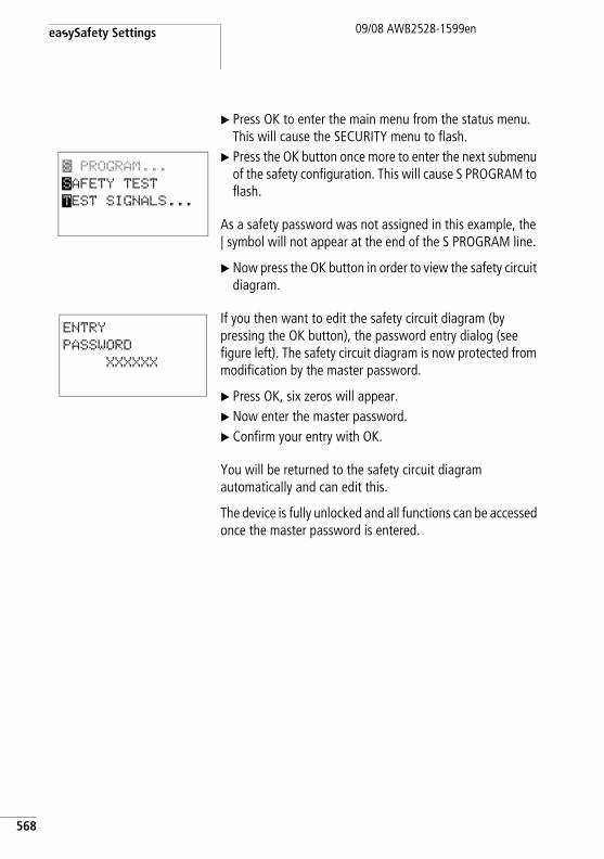
easySafety Settings
568
09/08 AWB2528-1599en
X Press OK to enter the main menu from the status menu. This will cause the SECURITY menu to flash.
X Press the OK button once more to enter the next submenu of the safety configuration. This will cause S PROGRAM to flash.
As a safety password was not assigned in this example, the | symbol will not appear at the end of the S PROGRAM line.
X Now press the OK button in order to view the safety circuit diagram.
If you then want to edit the safety circuit diagram (by pressing the OK button), the password entry dialog (see figure left). The safety circuit diagram is now protected from modification by the master password.
X Press OK, six zeros will appear.X Now enter the master password.X Confirm your entry with OK.
You will be returned to the safety circuit diagram automatically and can edit this.
The device is fully unlocked and all functions can be accessed once the master password is entered.
S PROGRAM...
SAFETY TEST
TEST SIGNALS...
ENTRY
PASSWORD
XXXXXX
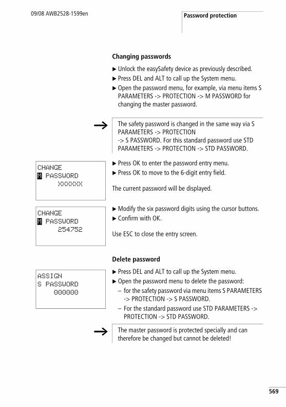
Password protection09/08 AWB2528-1599en
Changing passwords
X Unlock the easySafety device as previously described.X Press DEL and ALT to call up the System menu.X Open the password menu, for example, via menu items S
PARAMETERS -> PROTECTION -> M PASSWORD for changing the master password.
X Press OK to enter the password entry menu.X Press OK to move to the 6-digit entry field.
The current password will be displayed.
X Modify the six password digits using the cursor buttons.X Confirm with OK.
Use ESC to close the entry screen.
Delete password
X Press DEL and ALT to call up the System menu.X Open the password menu to delete the password:
– for the safety password via menu items S PARAMETERS -> PROTECTION -> S PASSWORD.
– For the standard password use STD PARAMETERS -> PROTECTION -> STD PASSWORD.
h The safety password is changed in the same way via S PARAMETERS -> PROTECTION -> S PASSWORD. For this standard password use STD PARAMETERS -> PROTECTION -> STD PASSWORD.
CHANGE
M PASSWORD
XXXXXX
CHANGE
M PASSWORD
254752
ASSIGN
S PASSWORD
000000
h The master password is protected specially and can therefore be changed but cannot be deleted!
569
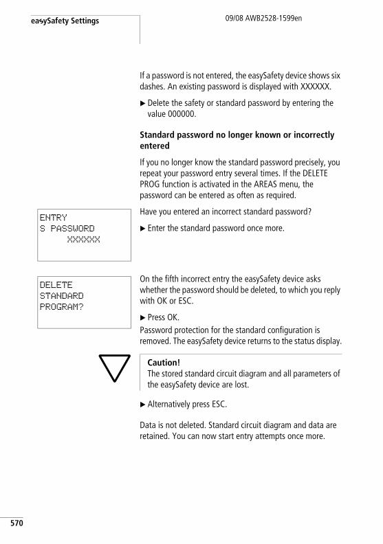
easySafety Settings
570
09/08 AWB2528-1599en
If a password is not entered, the easySafety device shows six dashes. An existing password is displayed with XXXXXX.
X Delete the safety or standard password by entering the value 000000.
Standard password no longer known or incorrectly entered
If you no longer know the standard password precisely, you repeat your password entry several times. If the DELETE PROG function is activated in the AREAS menu, the password can be entered as often as required.
Have you entered an incorrect standard password?
X Enter the standard password once more.
On the fifth incorrect entry the easySafety device asks whether the password should be deleted, to which you reply with OK or ESC.
X Press OK.Password protection for the standard configuration is removed. The easySafety device returns to the status display.
X Alternatively press ESC.
Data is not deleted. Standard circuit diagram and data are retained. You can now start entry attempts once more.
ENTRY
S PASSWORD
XXXXXX
DELETE
STANDARD
PROGRAM?
h Caution! The stored standard circuit diagram and all parameters of the easySafety device are lost.
Password protection09/08 AWB2528-1599en
Master password no longer known
If the master password is no longer available, you must restore the device to its factory settings. This can be done in two ways:
• via the PC with easySoft-Safety, irrespective of RUN or STOP.
• by the manufacturer.
Reset with easySoft-SafetyRequirement: You have opened the communication view and established the connection to the device (online).
X Select Communication -> Factory Reset. X Enter the factory password CLEAR DEVICE.
The configuration is completely deleted.
Reset by the manufacturerYour local Moeller branch will be glad to offer you further help with the repair.
h Caution! Both reset procedures remove all circuit diagrams, parameters and passwords.
h When the multi-function interface is protected, you cannot restore the device factory settings via easySoft-Safety. You must first open the protected interface using the master or standard password.
571
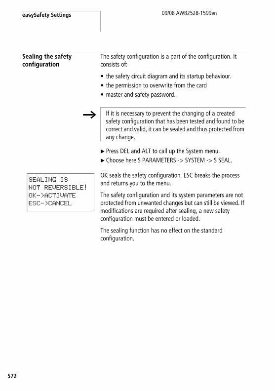
easySafety Settings
572
09/08 AWB2528-1599en
Sealing the safety configuration
The safety configuration is a part of the configuration. It consists of:
• the safety circuit diagram and its startup behaviour.• the permission to overwrite from the card• master and safety password.
X Press DEL and ALT to call up the System menu.X Choose here S PARAMETERS -> SYSTEM -> S SEAL.
OK seals the safety configuration, ESC breaks the process and returns you to the menu.
The safety configuration and its system parameters are not protected from unwanted changes but can still be viewed. If modifications are required after sealing, a new safety configuration must be entered or loaded.
The sealing function has no effect on the standard configuration.
h If it is necessary to prevent the changing of a created safety configuration that has been tested and found to be correct and valid, it can be sealed and thus protected from any change.
SEALING IS
NOT REVERSIBLE!
OK->ACTIVATE
ESC->CANCEL
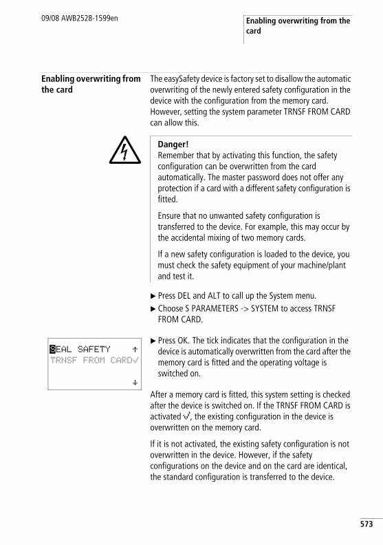
Enabling overwriting from the card
09/08 AWB2528-1599en
Enabling overwriting from the card
The easySafety device is factory set to disallow the automatic overwriting of the newly entered safety configuration in the device with the configuration from the memory card. However, setting the system parameter TRNSF FROM CARD can allow this.
X Press DEL and ALT to call up the System menu.X Choose S PARAMETERS -> SYSTEM to access TRNSF
FROM CARD.
X Press OK. The tick indicates that the configuration in the device is automatically overwritten from the card after the memory card is fitted and the operating voltage is switched on.
After a memory card is fitted, this system setting is checked after the device is switched on. If the TRNSF FROM CARD is activated å, the existing configuration in the device is overwritten on the memory card.
If it is not activated, the existing safety configuration is not overwritten in the device. However, if the safety configurations on the device and on the card are identical, the standard configuration is transferred to the device.
j Danger! Remember that by activating this function, the safety configuration can be overwritten from the card automatically. The master password does not offer any protection if a card with a different safety configuration is fitted.
Ensure that no unwanted safety configuration is transferred to the device. For example, this may occur by the accidental mixing of two memory cards.
If a new safety configuration is loaded to the device, you must check the safety equipment of your machine/plant and test it.
SEAL SAFETY ÆTRNSF FROM CARDå
æ
573
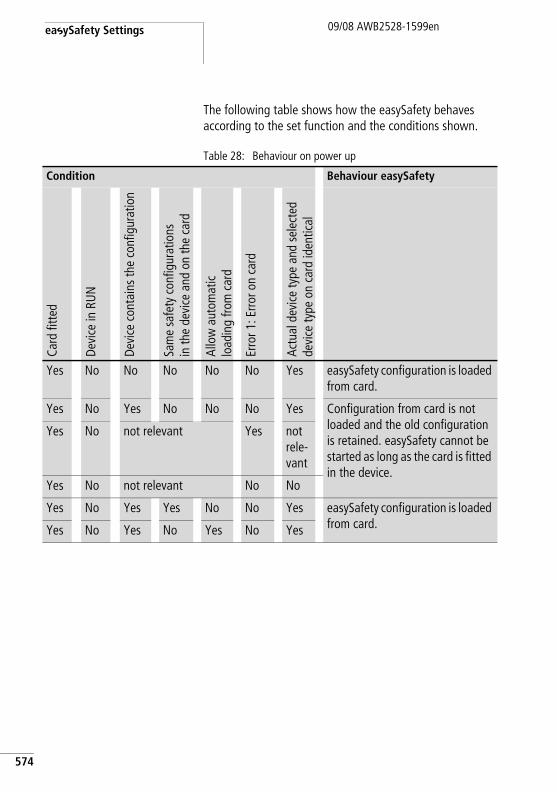
easySafety Settings
574
09/08 AWB2528-1599en
The following table shows how the easySafety behaves according to the set function and the conditions shown.
Table 28: Behaviour on power up
Condition Behaviour easySafety
Card
fitte
d
Devi
ce in
RUN
Devi
ce c
onta
ins
the
conf
igur
atio
n
Sam
e sa
fety
con
figur
atio
ns
in th
e de
vice
and
on
the
card
Allo
w a
utom
atic
load
ing
from
car
d
Erro
r 1: E
rror o
n ca
rd
Actu
al d
evic
e ty
pe a
nd s
elec
ted
devi
ce ty
pe o
n ca
rd id
entic
al
Yes No No No No No Yes easySafety configuration is loaded from card.
Yes No Yes No No No Yes Configuration from card is not loaded and the old configuration is retained. easySafety cannot be started as long as the card is fitted in the device.
Yes No not relevant Yes not rele-vant
Yes No not relevant No No
Yes No Yes Yes No No Yes easySafety configuration is loaded from card.Yes No Yes No Yes No Yes
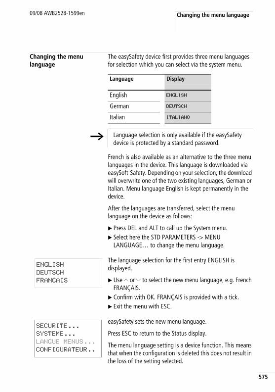
Changing the menu language09/08 AWB2528-1599en
Changing the menu language
The easySafety device first provides three menu languages for selection which you can select via the system menu.
French is also available as an alternative to the three menu languages in the device. This language is downloaded via easySoft-Safety. Depending on your selection, the download will overwrite one of the two existing languages, German or Italian. Menu language English is kept permanently in the device.
After the languages are transferred, select the menu language on the device as follows:
X Press DEL and ALT to call up the System menu.X Select here the STD PARAMETERS -> MENU
LANGUAGE… to change the menu language.
The language selection for the first entry ENGLISH is displayed.
X Use Í or Ú to select the new menu language, e.g. French FRANÇAIS.
X Confirm with OK. FRANÇAIS is provided with a tick.X Exit the menu with ESC.
easySafety sets the new menu language.
Press ESC to return to the Status display.
The menu language setting is a device function. This means that when the configuration is deleted this does not result in the loss of the setting selected.
Language Display
English ENGLISH
German DEUTSCH
Italian ITALIANO
h Language selection is only available if the easySafety device is protected by a standard password.
ENGLISH
DEUTSCH
FRANCAIS
SECURITE...
SYSTEME...
LANGUE MENUS...
CONFIGURATEUR..
575
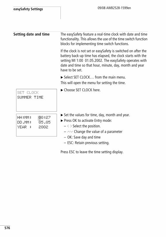
easySafety Settings
576
09/08 AWB2528-1599en
Setting date and time The easySafety feature a real-time clock with date and time functionality. This allows the use of the time switch function blocks for implementing time switch functions.
If the clock is not set or easySafety is switched on after the battery back-up time has elapsed, the clock starts with the setting MI 1:00 01.05.2002. The easySafety operates with date and time so that hour, minute, day, month and year have to be set.
X Select SET CLOCK… from the main menu.This will open the menu for setting the time.
X Choose SET CLOCK here.
X Set the values for time, day, month and year.X Press OK to activate Entry mode:
– ú í Select the position.– ÍÚ Change the value of a parameter– OK: Save day and time– ESC: Retain previous setting.
Press ESC to leave the time setting display.
SET CLOCK
SUMMER TIME
HH:MM: 00:27
DD.MM: 05.05
YEAR : 2002
Changing between winter/summer time (DST)
09/08 AWB2528-1599en
Changing between winter/summer time (DST)
The easySafety models are fitted with a real-time clock. These devices can be automatically switched between summer and winter time.
The following options are available for setting DST parameters:
• NONE: No DST setting.• MANUAL: User-defined daylight saving time setting.• EU: Date for European Union; Start: Last Sunday in March;
End: Last Sunday in October.• GB: Date for United Kingdom (the rules of the European
Union now apply to GB); Start: Last Sunday in March; End: Last Sunday in October.
• US: Date for the United States of America (from March 2007 the modified rule “New Northern America DST”); Start: second Sunday in March; End: first Sunday in November.
• RULE: User-defined dates and changeover times as well as time difference selectable between 0 and 3 hrs; can be set in stages of 0.5 hrs.
h The DST setting you have made is always associated with of the configuration. If you are commissioning easySafety-controlled plants worldwide, it may be necessary to also set and store this configuration with the regional time settings.
For these kinds of easySafety devices for worldwide use, use the “Rule” option for a DST setting.
577
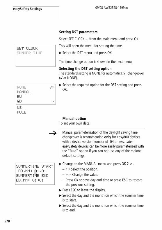
easySafety Settings
578
09/08 AWB2528-1599en
Setting DST parameters
Select SET CLOCK… from the main menu and press OK.
This will open the menu for setting the time.
X Select the DST menu and press OK.
The time change option is shown in the next menu.
Selecting the DST setting optionThe standard setting is NONE for automatic DST changeover (å at NONE).
X Select the required option for the DST setting and press OK.
Manual optionTo set your own date.
X Change to the MANUAL menu and press OK 2 x.– ú í Select the position.– ÍÚ Change the value.– Press OK to save day and time or press ESC to restore
the previous setting.X Press ESC to leave the display.X Select the day and the month on which the summer time
is to start.X Select the day and the month on which the summer time
is to end.
SET CLOCK
SUMMER TIME
US
RULE
NONE åÆMANUAL
EU
GB æ
h Manual parameterization of the daylight saving time changeover is recommended only for easy800 devices with a device version number of 04 or less. Later easySafety devices can be more easily parameterized with the “Rule” option if you can not use any of the regional default settings.
SUMMERTIME START
DD.MM: 01.01
SUMMERTIME END
DD.MM: 01:01
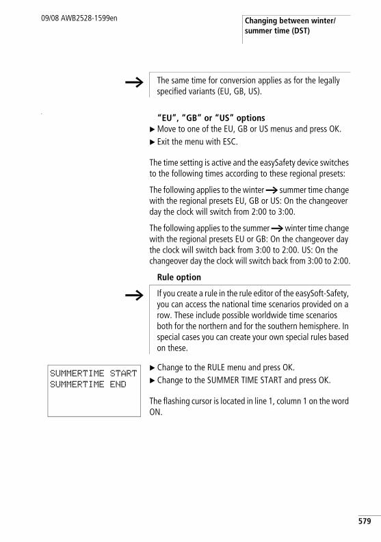
Changing between winter/summer time (DST)
09/08 AWB2528-1599en
a
“EU”, “GB” or “US” optionsX Move to one of the EU, GB or US menus and press OK.X Exit the menu with ESC.
The time setting is active and the easySafety device switches to the following times according to these regional presets:
The following applies to the winter h summer time change with the regional presets EU, GB or US: On the changeover day the clock will switch from 2:00 to 3:00.
The following applies to the summer h winter time change with the regional presets EU or GB: On the changeover day the clock will switch back from 3:00 to 2:00. US: On the changeover day the clock will switch back from 3:00 to 2:00.
Rule option
X Change to the RULE menu and press OK.X Change to the SUMMER TIME START and press OK.
The flashing cursor is located in line 1, column 1 on the word ON.
h The same time for conversion applies as for the legally specified variants (EU, GB, US).
h If you create a rule in the rule editor of the easySoft-Safety, you can access the national time scenarios provided on a row. These include possible worldwide time scenarios both for the northern and for the southern hemisphere. In special cases you can create your own special rules based on these.
SUMMERTIME START
SUMMERTIME END
579
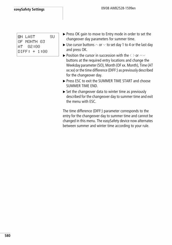
easySafety Settings
580
09/08 AWB2528-1599en
X Press OK gain to move to Entry mode in order to set the changeover day parameters for summer time.
X Use cursor buttons Í or Ú to set day 1 to 4 or the last day and press OK.
X Position the cursor in succession with the ú í or ÍÚ buttons at the required entry locations and change the Weekday parameter (SO), Month (OF xx. Month), Time (AT xx:xx) or the time difference (DIFF:) as previously described for the changeover day.
X Press ESC to exit the SUMMER TIME START and choose SUMMER TIME END.
X Set the changeover data to winter time as previously described for the changeover day to summer time and exit the menu with ESC.
The time difference (DIFF:) parameter corresponds to the entry for the changeover day to summer time and cannot be changed in this menu. The easySafety device now alternates between summer and winter time according to your rule.
ON LAST SU
OF MONTH 03
AT 02:00
DIFF: + 1:00
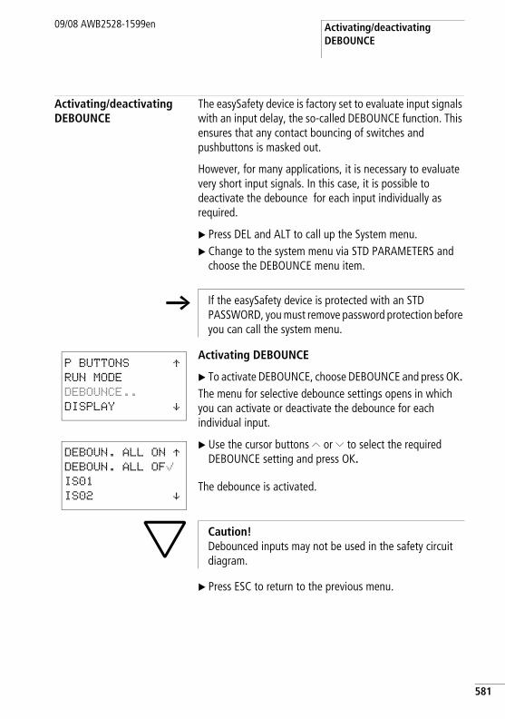
Activating/deactivating DEBOUNCE
09/08 AWB2528-1599en
Activating/deactivating DEBOUNCE
The easySafety device is factory set to evaluate input signals with an input delay, the so-called DEBOUNCE function. This ensures that any contact bouncing of switches and pushbuttons is masked out.
However, for many applications, it is necessary to evaluate very short input signals. In this case, it is possible to deactivate the debounce for each input individually as required.
X Press DEL and ALT to call up the System menu.X Change to the system menu via STD PARAMETERS and
choose the DEBOUNCE menu item.
Activating DEBOUNCE
X To activate DEBOUNCE, choose DEBOUNCE and press OK. The menu for selective debounce settings opens in which you can activate or deactivate the debounce for each individual input.
X Use the cursor buttons Í or Ú to select the required DEBOUNCE setting and press OK.
The debounce is activated.
X Press ESC to return to the previous menu.
h If the easySafety device is protected with an STD PASSWORD, you must remove password protection before you can call the system menu.
P BUTTONS ÆRUN MODE
DEBOUNCE..
DISPLAY æ
DEBOUN. ALL ON ÆDEBOUN. ALL OFåIS01
IS02 æ
h Caution! Debounced inputs may not be used in the safety circuit diagram.
581
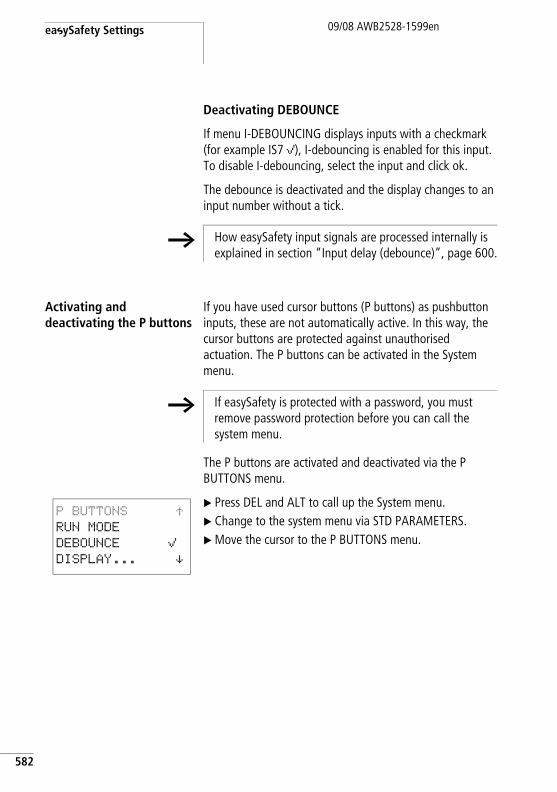
easySafety Settings
582
09/08 AWB2528-1599en
Deactivating DEBOUNCE
If menu I-DEBOUNCING displays inputs with a checkmark (for example IS7 å), I-debouncing is enabled for this input. To disable I-debouncing, select the input and click ok.
The debounce is deactivated and the display changes to an input number without a tick.
Activating and deactivating the P buttons
If you have used cursor buttons (P buttons) as pushbutton inputs, these are not automatically active. In this way, the cursor buttons are protected against unauthorised actuation. The P buttons can be activated in the System menu.
The P buttons are activated and deactivated via the P BUTTONS menu.
X Press DEL and ALT to call up the System menu.X Change to the system menu via STD PARAMETERS.X Move the cursor to the P BUTTONS menu.
h How easySafety input signals are processed internally is explained in section “Input delay (debounce)”, page 600.
h If easySafety is protected with a password, you must remove password protection before you can call the system menu.
P BUTTONS ÆRUN MODE
DEBOUNCE å DISPLAY... æ
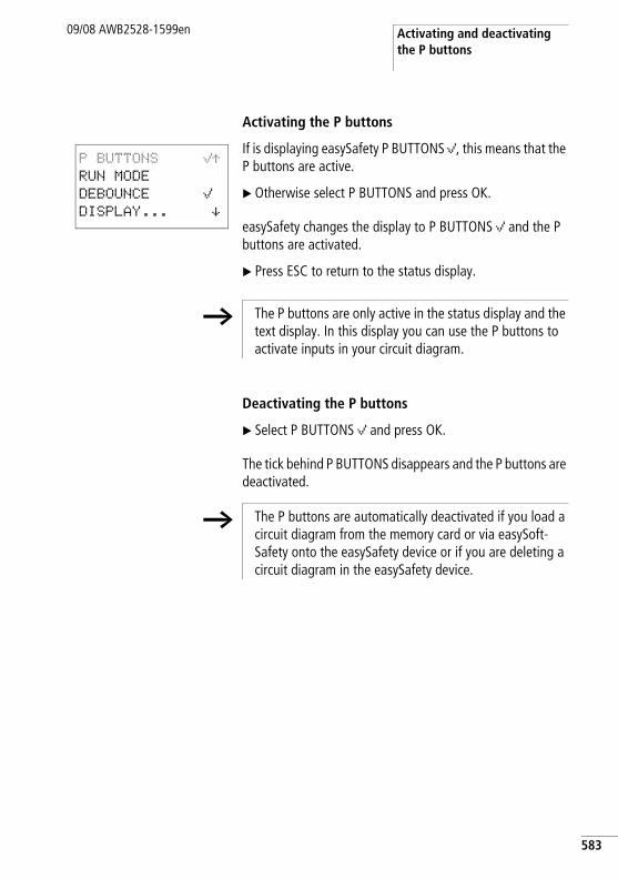
Activating and deactivating the P buttons
09/08 AWB2528-1599en
Activating the P buttons
If is displaying easySafety P BUTTONS å, this means that the P buttons are active.
X Otherwise select P BUTTONS and press OK.
easySafety changes the display to P BUTTONS å and the P buttons are activated.
X Press ESC to return to the status display.
Deactivating the P buttons
X Select P BUTTONS å and press OK.
The tick behind P BUTTONS disappears and the P buttons are deactivated.
P BUTTONS åÆRUN MODE
DEBOUNCE å DISPLAY... æ
h The P buttons are only active in the status display and the text display. In this display you can use the P buttons to activate inputs in your circuit diagram.
h The P buttons are automatically deactivated if you load a circuit diagram from the memory card or via easySoft-Safety onto the easySafety device or if you are deleting a circuit diagram in the easySafety device.
583
easySafety Settings
584
09/08 AWB2528-1599en
Startup behaviour The startup behaviour is an important aid during the commissioning phase. The configuration contained in the easySafety is not fully wired and parameterised. Or the plant/machine is in a state that easySafety cannot control. If easySafety is then switched on, it should not be possible to activate the outputs.
Setting the startup behaviour
Requirement: easySafety must contain a valid configuration.
X Change to the system menu via -> STD PARAMETERS -> SYSTEM.
Set whether easySafety should start in RUN or STOP mode when the power supply is switched on.
h To change to RUN mode without using the configuration software the startup behaviour RUN START must be enabled for easySafety devices without display.
h If easySafety is password protected, easySafety the system menu area cannot be accessed until has been unlocked (a section “Unlocking easySafety”, from page 567).
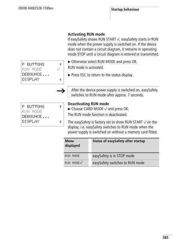
Startup behaviour09/08 AWB2528-1599en
Activating RUN modeIf easySafety shows RUN START å, easySafety starts in RUN mode when the power supply is switched on. If the device does not contain a circuit diagram, it remains in operating mode STOP until a circuit diagram is entered or transmitted.
X Otherwise select RUN MODE and press OK.RUN mode is activated.
X Press ESC to return to the status display.
Deactivating RUN modeX Choose CARD MODE å and press OK.The RUN mode function is deactivated.
The easySafety is factory set to show RUN START å on the display; i.e. easySafety switches to RUN mode when the power supply is switched on without a memory card fitted.
P BUTTONS ÆRUN MODE åDEBOUNCE...
DISPLAY æ
h After the device power supply is switched on, easySafety switches to RUN mode after approx. 7 seconds.
P BUTTONS ÆRUN MODE
DEBOUNCE...
DISPLAY æ
Menu displayed
Status of easySafety after startup
RUN MODE easySafety is in STOP mode
RUN MODEå easySafety switches to RUN mode
585
easySafety Settings
586
09/08 AWB2528-1599en
Behaviour when the circuit diagram is deleted
The setting for the startup behaviour is an easySafety device function. When the circuit diagram is deleted this does not result in the loss of the setting selected.
Behaviour during upload/download to card or PC
The setting is retained if a valid circuit diagram is transferred from easySafety to a memory card or PC. This also applies in the opposite direction, i.e. from the memory card or PC to the easySafety.
Possible faults
easySafetywill not start in RUN mode:
• A program is not available in easySafety.• You have put easySafety in STOP mode (RUN MODE
menu).
h The easySafety devices without a display can only be started in RUN mode.
Setting contrast and backlight09/08 AWB2528-1599en
Setting contrast and backlight
The background illumination of the LCD display can be switched off. The display contrast can be set to one of five stages. The display is not required during operation. The backlight only needs to be active during maintenance operations or when texts have to be displayed.
If the backlight is switched off, it will switch back on when a button is pressed. The backlight switches off automatically 60 s after a button was last pressed.
The contrast and backlight settings are device settings.
X Switch to the system menu.
X In the system menu choose SYSTEM -> STD PARAMETERS -> System-> DISPLAY and press OK.
The menus for setting the contrast and backlight are displayed.
X Press the OK button and change the contrast setting.
X Use the cursor buttons Í and Ú to set a contrast between –2 and +2 and press OK to confirm the setting.
The contrast setting is valid until it is changed again.
h If easySafety is password protected, the system menu cannot be accessed until easySafety has been unlocked (a section “Unlocking easySafety”, from page 567).
CONTRAST: 0
LIGHTING å
CONTRAST: +1
LIGHTING å
587
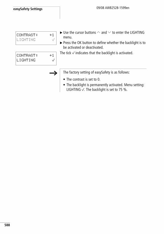
easySafety Settings
588
09/08 AWB2528-1599en
X Use the cursor buttons Í and Ú to enter the LIGHTING menu.
X Press the OK button to define whether the backlight is to be activated or deactivated.
The tick å indicates that the backlight is activated.
CONTRAST: +1
LIGHTING å
CONTRAST: +1
LIGHTING å
h The factory setting of easySafety is as follows:
• The contrast is set to 0.• The backlight is permanently activated. Menu setting:
LIGHTING å. The backlight is set to 75 %.
Retention09/08 AWB2528-1599en
Retention Plant and machine controls require the possibility to retentively set operating states or actual values, i.e. the values should be retained safely even after the power supply of a machine or plant has been switched off and should be left unchanged until the actual value is overwritten.
The following operands and function blocks of the standard circuit diagram can be set retentively:
• Markers.• Counter function blocks.• Data function block.• Timing relays.
Operating hours countereasySafety features 4 retentive operating hours counters. They are always retentive and can only be selectively deleted with a reset command.
Data volume, retentive dataThe maximum memory range for retentive data is 200 bytes (operating hours counters are not included).
MarkersA user-definable and contiguous marker byte range can be declared as retentive.
CountersAll C.. function blocks can be operated with retentive actual values.
Data function blocksA user-definable consistent function block DB range can be operated with retentive actual values.
Timing relaysA user-definable and contiguous range for timing relays T can be run with retentive actual values.
589
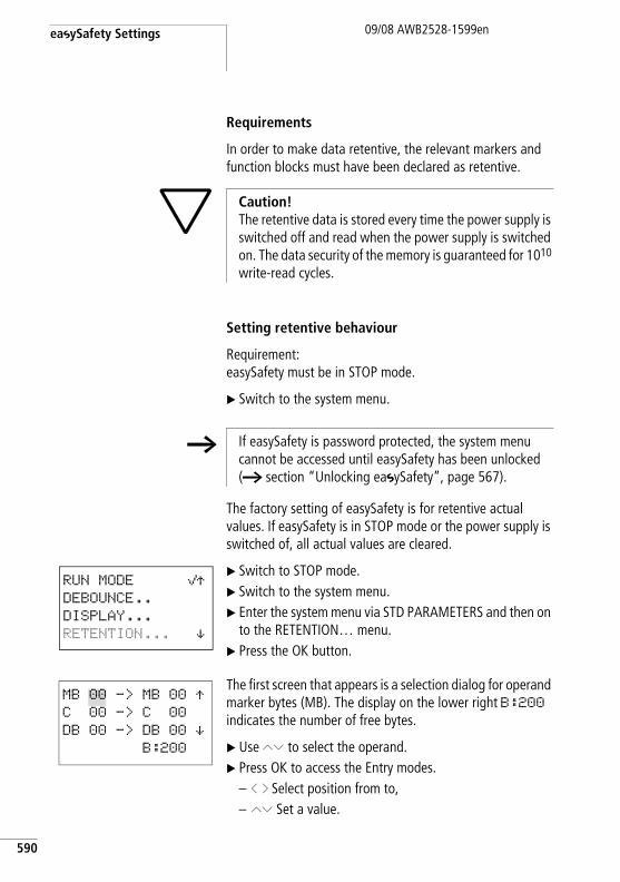
easySafety Settings
590
09/08 AWB2528-1599en
Requirements
In order to make data retentive, the relevant markers and function blocks must have been declared as retentive.
Setting retentive behaviour
Requirement:easySafety must be in STOP mode.
X Switch to the system menu.
The factory setting of easySafety is for retentive actual values. If easySafety is in STOP mode or the power supply is switched of, all actual values are cleared.
X Switch to STOP mode.X Switch to the system menu.X Enter the system menu via STD PARAMETERS and then on
to the RETENTION… menu.X Press the OK button.
The first screen that appears is a selection dialog for operand marker bytes (MB). The display on the lower right B:200 indicates the number of free bytes.
X Use ÍÚ to select the operand. X Press OK to access the Entry modes.
– ú í Select position from to,– ÍÚ Set a value.
h Caution! The retentive data is stored every time the power supply is switched off and read when the power supply is switched on. The data security of the memory is guaranteed for 1010
write-read cycles.
h If easySafety is password protected, the system menu cannot be accessed until easySafety has been unlocked (a section “Unlocking easySafety”, page 567).
RUN MODE åÆDEBOUNCE..
DISPLAY...
RETENTION... æ
MB 00 -> MB 00 ÆC 00 -> C 00
DB 00 -> DB 00 æB:200
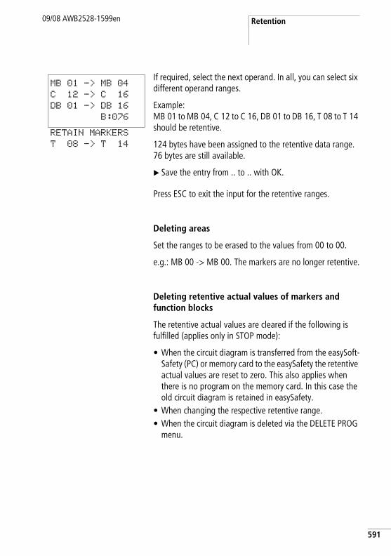
Retention09/08 AWB2528-1599en
If required, select the next operand. In all, you can select six different operand ranges.
Example: MB 01 to MB 04, C 12 to C 16, DB 01 to DB 16, T 08 to T 14 should be retentive.
124 bytes have been assigned to the retentive data range. 76 bytes are still available.
X Save the entry from .. to .. with OK.
Press ESC to exit the input for the retentive ranges.
Deleting areas
Set the ranges to be erased to the values from 00 to 00.
e.g.: MB 00 -> MB 00. The markers are no longer retentive.
Deleting retentive actual values of markers and function blocks
The retentive actual values are cleared if the following is fulfilled (applies only in STOP mode):
• When the circuit diagram is transferred from the easySoft-Safety (PC) or memory card to the easySafety the retentive actual values are reset to zero. This also applies when there is no program on the memory card. In this case the old circuit diagram is retained in easySafety.
• When changing the respective retentive range.• When the circuit diagram is deleted via the DELETE PROG
menu.
MB 01 -> MB 04
C 12 -> C 16
DB 01 -> DB 16
B:076
RETAIN MARKERS
T 08 -> T 14
591
easySafety Settings
592
09/08 AWB2528-1599en
Transferring retentive behaviour
The retentive behaviour setting is a standard circuit diagram. In other words, the setting of the Retention menu is included in any transfer on the memory card or when uploading/downloading to/from the PC.
Changing the mode or the standard circuit diagramThe retentive data is normally stored with its actual values when the operating mode or the easySafety standard circuit diagram is changed. The actual values of no longer used relays are not retained.
Changing the operating modeIf you change from RUN to STOP and then back to RUN, the actual values of the retentive data will be retained.
Changing the easySafety standard circuit diagramThe actual values are retained if the easySafety circuit diagram is changed.
Changing the startup behaviour in the SYSTEM menuThe retentive values in easySafety are retained irrespective of the setting.
Modification of the retentive rangeIf the set retentive ranges are reduced, only the actual values saved in the range will remain.
If the retentive range is extended, the older data is retained. The new data is written with the current actual values in RUN mode.
09/08 AWB2528-1599en
9 easySafety internal
easySafety circuit diagram In conventional control systems, a relay or contactor control processes all the rungs in parallel. The speed with which a contactor switches is thus dependent on the components used, and ranges from 15 to 40 ms for relay pick-up and drop-out.
With easySafety the circuit diagram is processed with a microprocessor that simulates the contacts and relays of the circuit concerned and thus processes all switching operations considerably faster. Safety and standard circuit diagrams are processed in succession from the beginning to the end. In this time, the easySafety device first runs through the six segments of the safety circuit diagram and then the six segments of the standard circuit diagram.
If the operands of the inputs and outputs are addressed in the easySafety configuration, the signal states of the digital inputs/outputs are not scanned but a memory range in the device system memory is accessed. This memory range is called the process image. The process image is divided into two sections: the process image for the inputs and the process image for the outputs.
593
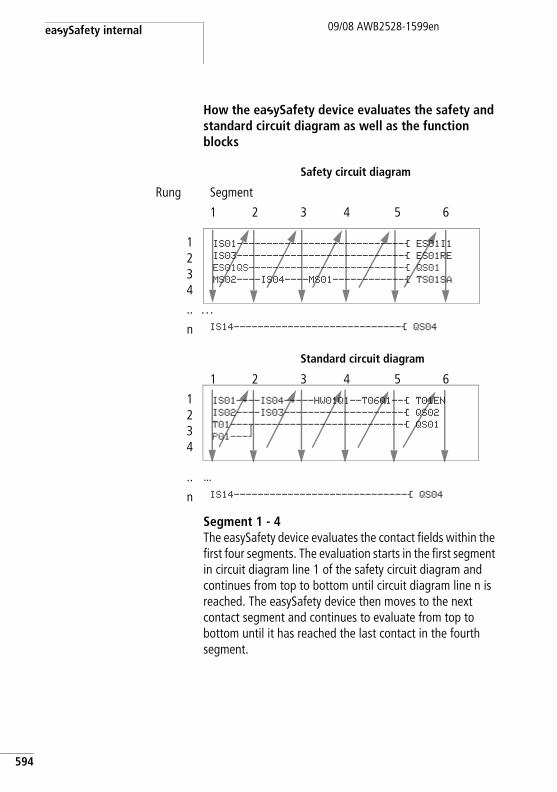
easySafety internal
594
09/08 AWB2528-1599en
How the easySafety device evaluates the safety and standard circuit diagram as well as the function blocks
Segment 1 - 4The easySafety device evaluates the contact fields within the first four segments. The evaluation starts in the first segment in circuit diagram line 1 of the safety circuit diagram and continues from top to bottom until circuit diagram line n is reached. The easySafety device then moves to the next contact segment and continues to evaluate from top to bottom until it has reached the last contact in the fourth segment.
Safety circuit diagram
Rung Segment
1 2 3 4 5 6
1234.. …
n IS14----------------------------Ä QS04
Standard circuit diagram
1 2 3 4 5 6
1234
.. …
n IS14-----------------------------Ä QS04
IS01----------------------------Ä ES01I1IS03----------------------------Ä ES01REES01QS--------------------------Ä QS01MS02----IS04----MS01------------Ä TS01SA
IS01----IS04-----HW01Q1--T06Q1--Ä T01ENIS02----IS03--------------------Ä QS02T01---u-------------------------Ä QS01P01---k
easySafety circuit diagram09/08 AWB2528-1599en
Segment 5In the fifth segment the easySafety device assigns all coils in one pass, from the safety circuit diagram line 1 - n, with the new switch states from the process image of the outputs.
Segment 6The safety function blocks present are evaluated in the sixth segment which is outside of the circuit diagram.
If a standard circuit diagram was created, the easySafety device then passes through the six segments of this circuit diagram in the same order. The sixth segment the function blocks present in the function block list are then reevaluated.
The easySafety device uses this sixth segment in order to:
• process the existing function blocks. The easySafety device processes the safety function blocks in the order in which they were transferred to the safety circuit diagram, i.e. irrespective of their position in the circuit diagram. The output data of a function block is immediately up-to-date after it has been processed. The output data (32-bit) of a safety function block is processed in the standard circuit diagram. In this way you can represent the actual value output TS..QV of a safety timing relay function block on the device display using the D text display function block. The standard function blocks are processed by the easySafety device in the order of the function block list (a FUNCTION BLOCKS menu).
h To change the order in which the standard function blocks are processed, for example, so that the output value of one function block can be used at the input of another standard function block, you can rearrange the function block with the easySoft-Safety programming software.
595
easySafety internal
596
09/08 AWB2528-1599en
• to contact the “outside world” Output relays QS 1 to QS 4 or QR are switched and inputs IS 1 to IS 14 are re-read. For the expansion modules the S... output relays are switched and the R... inputs are read accordingly.
• to exchange easyNet data if this easySafety device receives new read data or provides new send data (a section “easyNet network” on page 593).
• to copy all new switching states to the process image.
The easySafety device uses a fixed process image that lasts for the duration of a cycle. This ensures that each rung is evaluated with the same switching states for one cycle, even if the input signals at IS1 to IS14, for example, change their status several times within a cycle.
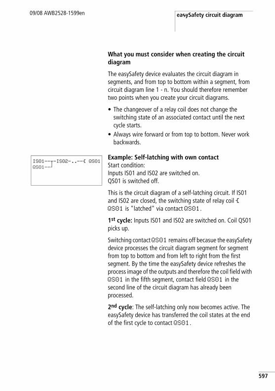
easySafety circuit diagram09/08 AWB2528-1599en
What you must consider when creating the circuit diagram
The easySafety device evaluates the circuit diagram in segments, and from top to bottom within a segment, from circuit diagram line 1 - n. You should therefore remember two points when you create your circuit diagrams.
• The changeover of a relay coil does not change the switching state of an associated contact until the next cycle starts.
• Always wire forward or from top to bottom. Never work backwards.
Example: Self-latching with own contactStart condition:Inputs IS01 and IS02 are switched on. QS01 is switched off.
This is the circuit diagram of a self-latching circuit. If IS01 and IS02 are closed, the switching state of relay coil Ä QS01 is "latched" via contact QS01.
1st cycle: Inputs IS01 and IS02 are switched on. Coil QS01 picks up.
Switching contact QS01 remains off becasue the easySafety device processes the circuit diagram segment for segment from top to bottom and from left to right from the first segment. By the time the easySafety device refreshes the process image of the outputs and therefore the coil field with QS01 in the fifth segment, contact field QS01 in the second line of the circuit diagram has already been processed.
2nd cycle: The self-latching only now becomes active. The easySafety device has transferred the coil states at the end of the first cycle to contact QS01.
IS01--u-IS02-..--Ä QS01QS01--k
597
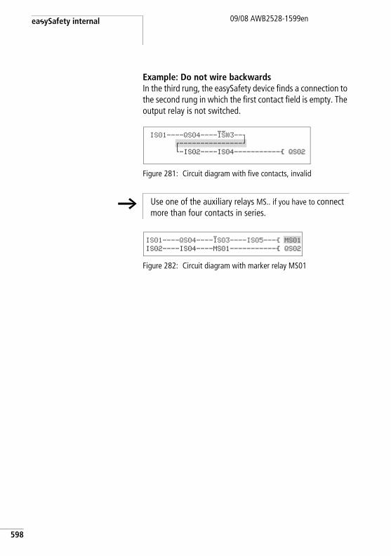
easySafety internal
598
09/08 AWB2528-1599en
Example: Do not wire backwardsIn the third rung, the easySafety device finds a connection to the second rung in which the first contact field is empty. The output relay is not switched.
Figure 281: Circuit diagram with five contacts, invalid
Figure 282: Circuit diagram with marker relay MS01
IS01----QS04----IS03--oz---------------kh-IS02----IS04-----------Ä QS02
h Use one of the auxiliary relays MS.. if you have to connect more than four contacts in series.
IS01----QS04----IS03----IS05---Ä MS01IS02----IS04----MS01-----------Ä QS02
Time behaviour of the inputs and outputs
09/08 AWB2528-1599en
Time behaviour of the inputs and outputs
The reaction time, which is measured from the reading in of a digital input signal to the setting of the associated output, is determined by the timing characteristics of the device inputs and outputs as well as the size and design of the circuit diagram. How to estimate the reaction time is explained in section “Reaction time of an easySafety device”, page 603.
Filtering input signals < 1 msIntelligent sensors (e.g. light curtains) can switch off their output signal for test purposes momentarily. Thus, an easySafety device filters out changes to input signals that are shorter than 1 ms.
Time behaviour of easySafety transistor outputsA easySafety device switches the output signal at its transistor outputs momentarily for testing, i.e. from 1 to 0. The maximum off time is approx. 0.8 ms.
h Take this off time into account when selecting the actuator that the easySafety device is to control.
599
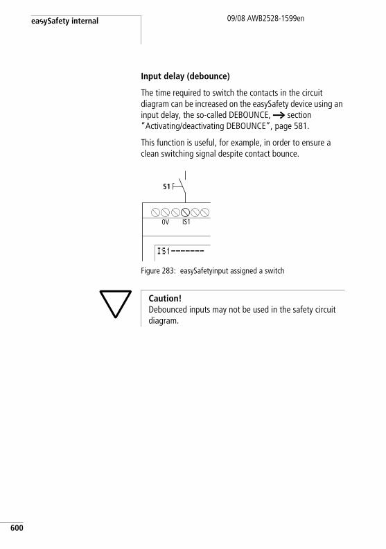
easySafety internal
600
09/08 AWB2528-1599en
Input delay (debounce)
The time required to switch the contacts in the circuit diagram can be increased on the easySafety device using an input delay, the so-called DEBOUNCE, a section “Activating/deactivating DEBOUNCE”, page 581.
This function is useful, for example, in order to ensure a clean switching signal despite contact bounce.
Figure 283: easySafetyinput assigned a switch
S1
0V IS1
IS1-------
h Caution! Debounced inputs may not be used in the safety circuit diagram.
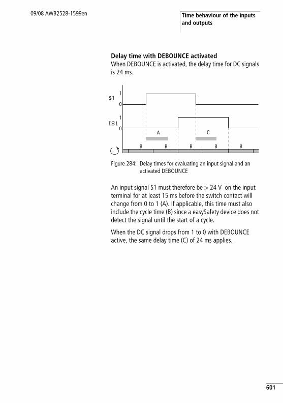
Time behaviour of the inputs and outputs
09/08 AWB2528-1599en
Delay time with DEBOUNCE activatedWhen DEBOUNCE is activated, the delay time for DC signals is 24 ms.
Figure 284: Delay times for evaluating an input signal and an activated DEBOUNCE
An input signal S1 must therefore be > 24 V on the input terminal for at least 15 ms before the switch contact will change from 0 to 1 (A). If applicable, this time must also include the cycle time (B) since a easySafety device does not detect the signal until the start of a cycle.
When the DC signal drops from 1 to 0 with DEBOUNCE active, the same delay time (C) of 24 ms applies.
A C
1
0
1
0
S1
B BB B B
IS1
601
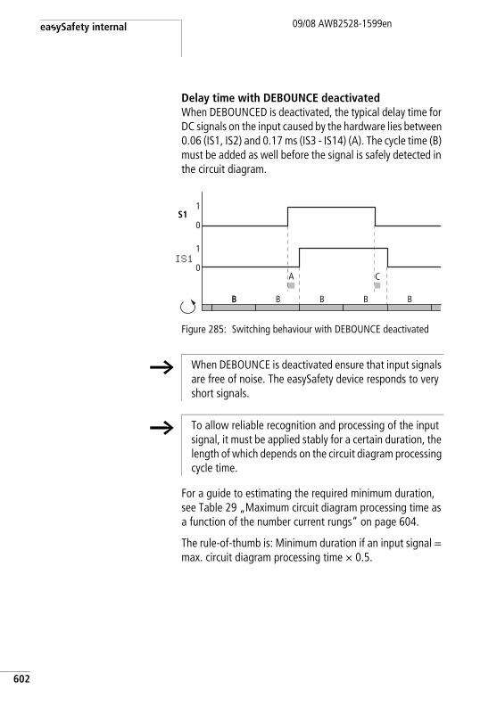
easySafety internal
602
09/08 AWB2528-1599en
Delay time with DEBOUNCE deactivatedWhen DEBOUNCED is deactivated, the typical delay time for DC signals on the input caused by the hardware lies between 0.06 (IS1, IS2) and 0.17 ms (IS3 - IS14) (A). The cycle time (B) must be added as well before the signal is safely detected in the circuit diagram.
Figure 285: Switching behaviour with DEBOUNCE deactivated
For a guide to estimating the required minimum duration, see Table 29 „Maximum circuit diagram processing time as a function of the number current rungs“ on page 604.
The rule-of-thumb is: Minimum duration if an input signal = max. circuit diagram processing time × 0.5.
1
0
1
0
S1
BB BB B B
A C
IS1
h When DEBOUNCE is deactivated ensure that input signals are free of noise. The easySafety device responds to very short signals.
h To allow reliable recognition and processing of the input signal, it must be applied stably for a certain duration, the length of which depends on the circuit diagram processing cycle time.
Reaction time of an easySafety device
09/08 AWB2528-1599en
Reaction time of an easySafety device
The easySafetyreaction time of the device is often required to calculate the time of your safety application. For example, you need this if you have to calculate the distance between a separating or non-separating guard and the hazardous area of a machine (see also EN 294/ISO 13852 and EN 811/ISO 13853).
The reaction time is calculated from the maximum circuit diagram processing time and the output delay. If, however, the maximum circuit diagram processing time is shorter than the error detection time of the easySafety device, which is 150 ms, the reaction time is calculated only from the error detection time and the output delay.
The output delay is:
• For transistor output (QS): 1 ms• For relay output (QR): 50 ms (worst case scenario)
The circuit diagram processing times stated in Table 29 are worst case values. For example, two cycles are taken into account for the processing times to ensure that the actual input image is processed in the circuit diagram. These times may be actually be shorter, however they are never longer.
Only determine the reaction time for calculating your application in the following manner:
X Determine the number of the last processed rung in your safety circuit diagram and in your standard circuit diagram respectively, and add both values together. The empty rungs located in front of the last processed rung, which you can use as comment aids, for example, are also added to the calculation.
X Refer to Table 29 for the maximum circuit diagram processing time.
If the calculated circuit diagram processing time is shorter than the detection time of the easySafety device (150 ms), the following applies in regard to the reaction time:
603
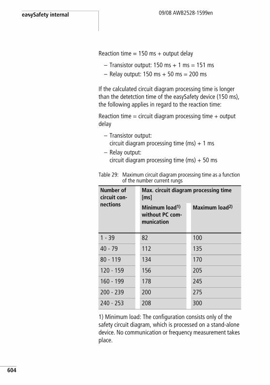
easySafety internal
604
09/08 AWB2528-1599en
Reaction time = 150 ms + output delay
– Transistor output: 150 ms + 1 ms = 151 ms– Relay output: 150 ms + 50 ms = 200 ms
If the calculated circuit diagram processing time is longer than the detetction time of the easySafety device (150 ms), the following applies in regard to the reaction time:
Reaction time = circuit diagram processing time + output delay
– Transistor output: circuit diagram processing time (ms) + 1 ms
– Relay output: circuit diagram processing time (ms) + 50 ms
Table 29: Maximum circuit diagram processing time as a function of the number current rungs
1) Minimum load: The configuration consists only of the safety circuit diagram, which is processed on a stand-alone device. No communication or frequency measurement takes place.
Number of circuit con-nections
Max. circuit diagram processing time [ms]
Minimum load1)
without PC com-munication
Maximum load2)
1 - 39 82 100
40 - 79 112 135
80 - 119 134 170
120 - 159 156 205
160 - 199 178 245
200 - 239 200 275
240 - 253 208 300
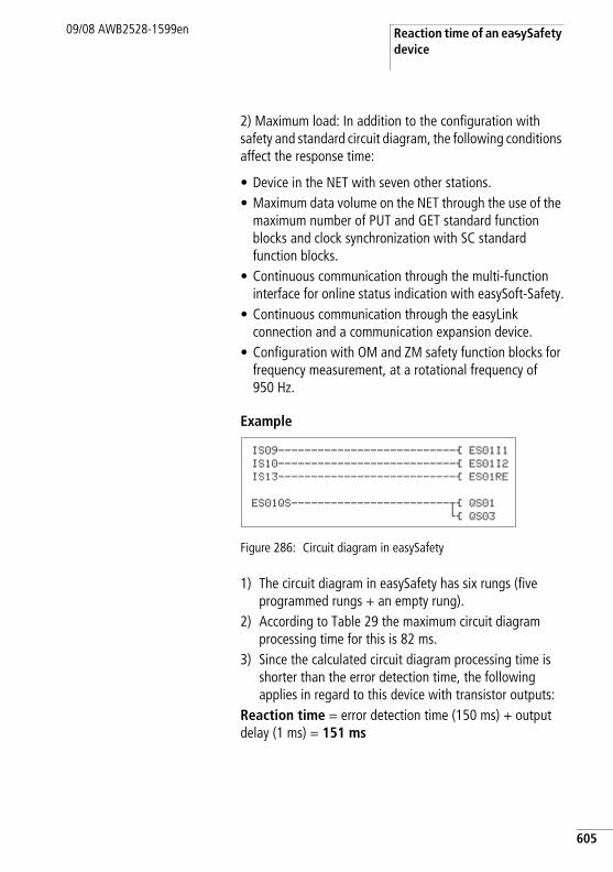
Reaction time of an easySafety device
09/08 AWB2528-1599en
2) Maximum load: In addition to the configuration with safety and standard circuit diagram, the following conditions affect the response time:
• Device in the NET with seven other stations.• Maximum data volume on the NET through the use of the
maximum number of PUT and GET standard function blocks and clock synchronization with SC standard function blocks.
• Continuous communication through the multi-function interface for online status indication with easySoft-Safety.
• Continuous communication through the easyLink connection and a communication expansion device.
• Configuration with OM and ZM safety function blocks for frequency measurement, at a rotational frequency of 950 Hz.
Example
Figure 286: Circuit diagram in easySafety
1) The circuit diagram in easySafety has six rungs (five programmed rungs + an empty rung).
2) According to Table 29 the maximum circuit diagram processing time for this is 82 ms.
3) Since the calculated circuit diagram processing time is shorter than the error detection time, the following applies in regard to this device with transistor outputs:
Reaction time = error detection time (150 ms) + output delay (1 ms) = 151 ms
IS09---------------------------Ä ES01I1IS10---------------------------Ä ES01I2IS13---------------------------Ä ES01RE
ES01QS------------------------uÄ QS01hÄ QS03
605
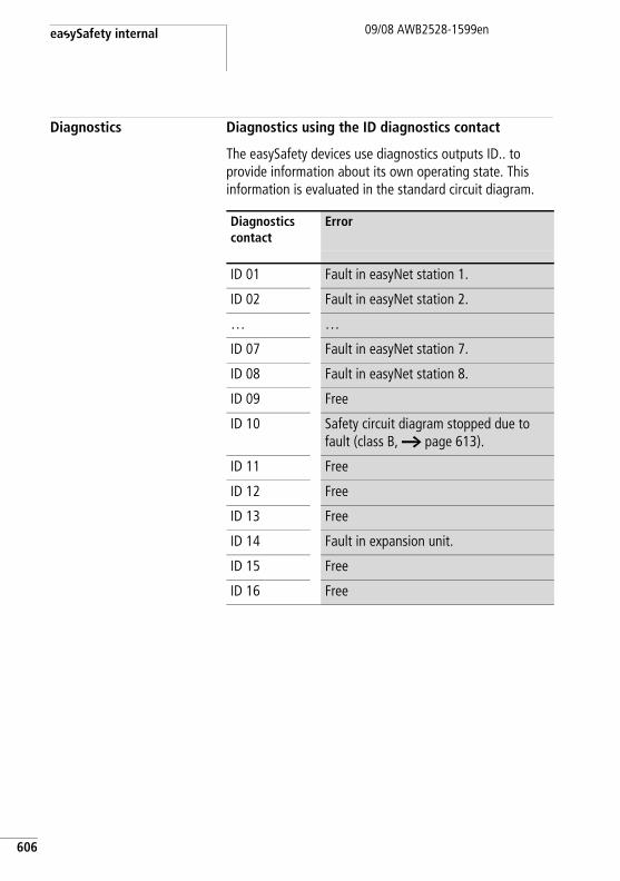
easySafety internal
606
09/08 AWB2528-1599en
Diagnostics Diagnostics using the ID diagnostics contact
The easySafety devices use diagnostics outputs ID.. to provide information about its own operating state. This information is evaluated in the standard circuit diagram.
Diagnostics contact
Error
ID 01 Fault in easyNet station 1.
ID 02 Fault in easyNet station 2.
… …
ID 07 Fault in easyNet station 7.
ID 08 Fault in easyNet station 8.
ID 09 Free
ID 10 Safety circuit diagram stopped due to fault (class B, a page 613).
ID 11 Free
ID 12 Free
ID 13 Free
ID 14 Fault in expansion unit.
ID 15 Free
ID 16 Free
Diagnostics09/08 AWB2528-1599en
Diagnostics using the DG diagnostics function block
A DG diagnostics function block is used to evaluate the status/fault messages of an assigned safety function block and can initiate up to eight appropriate message texts (a chapter “Standard function blocks”, „DG, diagnostics“, page 233). For the meaning of the fault messages see Table 30 on page 609.
The diagnostics and safety function block can only be assigned with the easySoft-Safety configuration software in its standard circuit diagram or function block diagram. Here you also assign in a list a special status/fault message of the selected safety function block to each output Q1-Q8 of the DG function block.
Example using the safety function block ES, EMERGENCY-STOP:
• Assign the safety function block ES01 to the standard function block DG01.
• Assgin the safety function block status “Wait for rising edge at Reset? (see figure) of the function block ES01 to the DG01Q1 output.
607
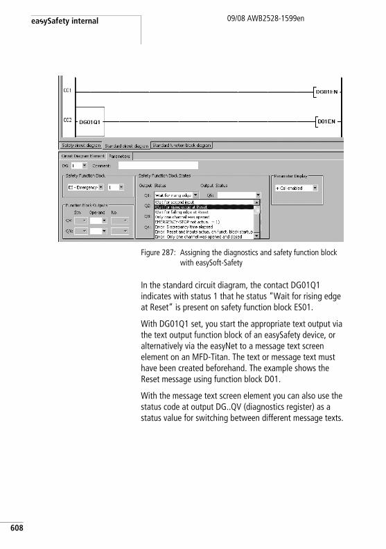
easySafety internal
608
09/08 AWB2528-1599en
Figure 287: Assigning the diagnostics and safety function block with easySoft-Safety
In the standard circuit diagram, the contact DG01Q1 indicates with status 1 that he status “Wait for rising edge at Reset” is present on safety function block ES01.
With DG01Q1 set, you start the appropriate text output via the text output function block of an easySafety device, or alternatively via the easyNet to a message text screen element on an MFD-Titan. The text or message text must have been created beforehand. The example shows the Reset message using function block D01.
With the message text screen element you can also use the status code at output DG..QV (diagnostics register) as a status value for switching between different message texts.
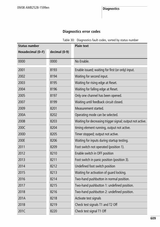
Diagnostics09/08 AWB2528-1599en
Diagnostics error codes
Table 30: Diagnostics fault codes, sorted by status number
Status number Plain text
Hexadecimal (0–F) decimal (0-9)
0000 0000 No Enable.
2001 8193 Enable issued; waiting for first (or only) input.
2002 8194 Waiting for second input.
2003 8195 Waiting for rising edge at Reset.
2004 8196 Waiting for falling edge at Reset.
2005 8197 Only one channel has been opened.
2007 8199 Waiting until feedback circuit closed.
2009 8201 Measurement started.
200A 8202 Operating mode can be selected.
200B 8203 Waiting for decreasing trigger signal; output not active.
200C 8204 timing element running, output not active.
200D 8205 Timer stopped; output not active.
200E 8206 Waiting for inputs during startup testing.
2011 8209 Foot switch not operated (position 1).
2012 8210 Enable switch in OFF position
2013 8211 Foot switch in panic position (position 3).
2014 8212 Undefined foot switch position
2015 8213 Waiting for activation of guard locking.
2016 8214 Two-hand pushbutton in normal position.
2017 8215 Two-hand pushbutton 1: undefined position.
2018 8216 Two-hand pushbutton 2: undefined position.
201A 8218 Activate test signals
201B 8219 Check test signals T1 and T2 Off
201C 8220 Check test signal T1 Off
609
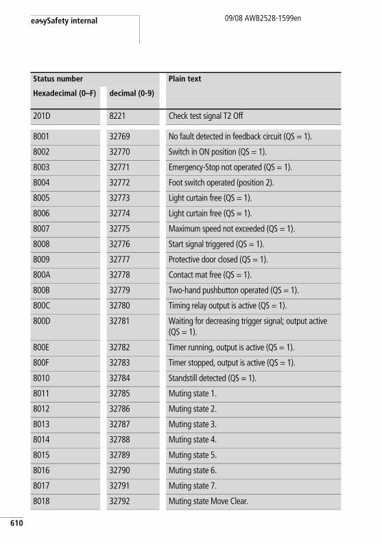
easySafety internal
610
09/08 AWB2528-1599en
201D 8221 Check test signal T2 Off
8001 32769 No fault detected in feedback circuit (QS = 1).
8002 32770 Switch in ON position (QS = 1).
8003 32771 Emergency-Stop not operated (QS = 1).
8004 32772 Foot switch operated (position 2).
8005 32773 Light curtain free (QS = 1).
8006 32774 Light curtain free (QS = 1).
8007 32775 Maximum speed not exceeded (QS = 1).
8008 32776 Start signal triggered (QS = 1).
8009 32777 Protective door closed (QS = 1).
800A 32778 Contact mat free (QS = 1).
800B 32779 Two-hand pushbutton operated (QS = 1).
800C 32780 Timing relay output is active (QS = 1).
800D 32781 Waiting for decreasing trigger signal; output active (QS = 1).
800E 32782 Timer running, output is active (QS = 1).
800F 32783 Timer stopped, output is active (QS = 1).
8010 32784 Standstill detected (QS = 1).
8011 32785 Muting state 1.
8012 32786 Muting state 2.
8013 32787 Muting state 3.
8014 32788 Muting state 4.
8015 32789 Muting state 5.
8016 32790 Muting state 6.
8017 32791 Muting state 7.
8018 32792 Muting state Move Clear.
Status number Plain text
Hexadecimal (0–F) decimal (0-9)
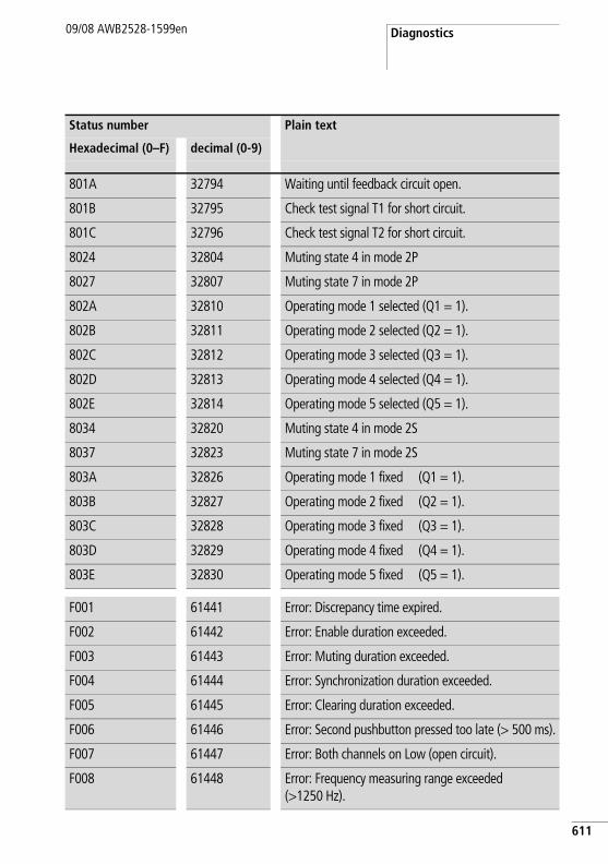
Diagnostics09/08 AWB2528-1599en
801A 32794 Waiting until feedback circuit open.
801B 32795 Check test signal T1 for short circuit.
801C 32796 Check test signal T2 for short circuit.
8024 32804 Muting state 4 in mode 2P
8027 32807 Muting state 7 in mode 2P
802A 32810 Operating mode 1 selected (Q1 = 1).
802B 32811 Operating mode 2 selected (Q2 = 1).
802C 32812 Operating mode 3 selected (Q3 = 1).
802D 32813 Operating mode 4 selected (Q4 = 1).
802E 32814 Operating mode 5 selected (Q5 = 1).
8034 32820 Muting state 4 in mode 2S
8037 32823 Muting state 7 in mode 2S
803A 32826 Operating mode 1 fixed (Q1 = 1).
803B 32827 Operating mode 2 fixed (Q2 = 1).
803C 32828 Operating mode 3 fixed (Q3 = 1).
803D 32829 Operating mode 4 fixed (Q4 = 1).
803E 32830 Operating mode 5 fixed (Q5 = 1).
F001 61441 Error: Discrepancy time expired.
F002 61442 Error: Enable duration exceeded.
F003 61443 Error: Muting duration exceeded.
F004 61444 Error: Synchronization duration exceeded.
F005 61445 Error: Clearing duration exceeded.
F006 61446 Error: Second pushbutton pressed too late (> 500 ms).
F007 61447 Error: Both channels on Low (open circuit).
F008 61448 Error: Frequency measuring range exceeded (>1250 Hz).
Status number Plain text
Hexadecimal (0–F) decimal (0-9)
611
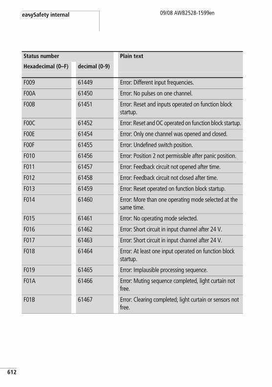
easySafety internal
612
09/08 AWB2528-1599en
F009 61449 Error: Different input frequencies.
F00A 61450 Error: No pulses on one channel.
F00B 61451 Error: Reset and inputs operated on function block startup.
F00C 61452 Error: Reset and OC operated on function block startup.
F00E 61454 Error: Only one channel was opened and closed.
F00F 61455 Error: Undefined switch position.
F010 61456 Error: Position 2 not permissible after panic position.
F011 61457 Error: Feedback circuit not opened after time.
F012 61458 Error: Feedback circuit not closed after time.
F013 61459 Error: Reset operated on function block startup.
F014 61460 Error: More than one operating mode selected at the same time.
F015 61461 Error: No operating mode selected.
F016 61462 Error: Short circuit in input channel after 24 V.
F017 61463 Error: Short circuit in input channel after 24 V.
F018 61464 Error: At least one input operated on function block startup.
F019 61465 Error: Implausible processing sequence.
F01A 61466 Error: Muting sequence completed, light curtain not free.
F01B 61467 Error: Clearing completed; light curtain or sensors not free.
Status number Plain text
Hexadecimal (0–F) decimal (0-9)
Diagnostics09/08 AWB2528-1599en
Diagnostics using the ER contact
The safety function blocks detect sequence faults such as when the monitored times are not observed. If this type of error is detected, the QS enable contact opens immediately. The fault code is sent to the diagnostics output DG> which can in turn be processed with the DG standard function block, a section “Diagnostics using the DG diagnostics function block”, page 607. The error contact ER of the safety function block concerned is closed until the fault is acknowledged by a correct signal sequence at its input coils.
The type of error that causes the error status of the safety function block, and the coils for resetting it again are stated in the description of the individual function blocks, a chapter “Safety function blocks” on page 331.
613
easySafety internal
614
09/08 AWB2528-1599en
Diagnostics of faults inside and outside the device
The easySafety safety control relay monitors itself and also the external wiring.
easySafety is able to detect faults during operation and trigger an appropriate response. easySafety distinguishes between three error classes:
• Class CIf an error does not impair the safety behaviour of easySafety, the device remains in the RUN operating mode. The error is signaled via a diagnostics contact.Error example: Error in easyLink protocol or in easyNet.
• Class BIf an error does impair the behaviour of easySafety, but the execution of the device's internal safety test routines is unaffected by this, a safety circuit diagram STOP occurs. The standard circuit diagram continues to be executed. All device outputs are switched off.Error example: There is an error present in the device's external wiring, e.g. a short circuit due to faulty insulation in the input circuit.
• Class AIf an error impairs the safety behaviour inside the easySafety, both circuit diagrams are switched to STOP (class A); for example: error in the device. All device outputs are switched off.
The following table provides an overview of the behaviour of the easySafety when an error occurs.
h Use the test signal outputs T1 - T4 for optimum monitoring of the external wiring, a chapter “Connecting test signal outputs”, page 53.
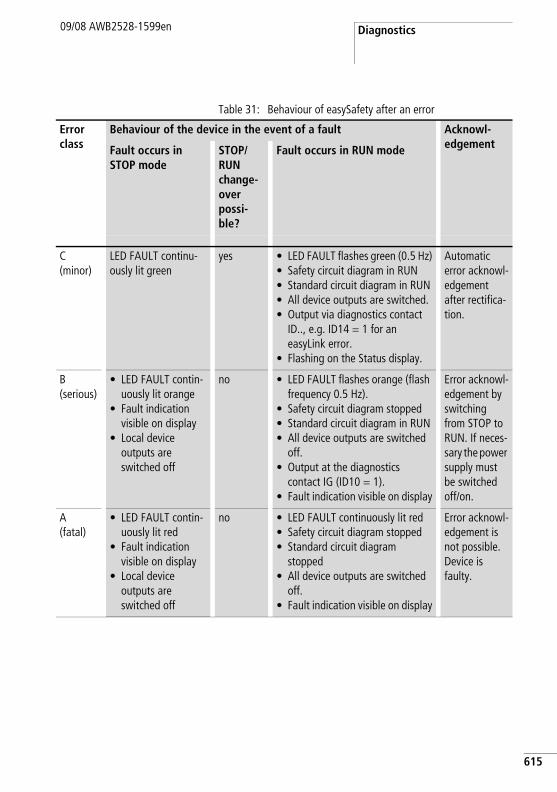
Diagnostics09/08 AWB2528-1599en
Table 31: Behaviour of easySafety after an error
Error class
Behaviour of the device in the event of a fault Acknowl-edgementFault occurs in
STOP modeSTOP/RUN change-over possi-ble?
Fault occurs in RUN mode
C(minor)
LED FAULT continu-ously lit green
yes • LED FAULT flashes green (0.5 Hz)• Safety circuit diagram in RUN• Standard circuit diagram in RUN• All device outputs are switched.• Output via diagnostics contact
ID.., e.g. ID14 = 1 for an easyLink error.
• Flashing on the Status display.
Automatic error acknowl-edgement after rectifica-tion.
B(serious)
• LED FAULT contin-uously lit orange
• Fault indication visible on display
• Local device outputs are switched off
no • LED FAULT flashes orange (flash frequency 0.5 Hz).
• Safety circuit diagram stopped• Standard circuit diagram in RUN• All device outputs are switched
off.• Output at the diagnostics
contact IG (ID10 = 1).• Fault indication visible on display
Error acknowl-edgement by switching from STOP to RUN. If neces-sary the power supply must be switched off/on.
A(fatal)
• LED FAULT contin-uously lit red
• Fault indication visible on display
• Local device outputs are switched off
no • LED FAULT continuously lit red• Safety circuit diagram stopped• Standard circuit diagram
stopped• All device outputs are switched
off.• Fault indication visible on display
Error acknowl-edgement is not possible. Device is faulty.
615
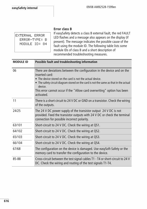
easySafety internal
616
09/08 AWB2528-1599en
Error class BIf easySafety detects a class B external fault, the red FAULT LED flashes and a message also appears on the display (if present). The message indicates the possible cause of the fault using the module ID. The following table lists some module IDs of class B and a short description of recommended troubleshooting measures.
EXTERNAL ERROR
ERROR-TYPE: B
MODULE ID: 84
MODULE ID Possible fault and troubleshooting information
06 There are deviations between the configuration in the device and on the inserted card:• The device stored on the card is not the actual device.• The safety circuit diagram stored on the card is not the same as that in the actual
device.This error cannot occur if the "Allow card overwriting" option has been activated.
11 There is a short circuit to 24 V DC or GND on a transistor. Check the wiring of the outputs.
24/25 The 24 V DC power supply of the transistor output 24 V DC is not provided. Feed the transistor outputs with 24 V DC or check the terminal connection for possible incorrect polarity.
63/101 Short-circuit to 24 V DC. Check the wiring at QS1.
64/102 Short-circuit to 24 V DC. Check the wiring at QS2.
65/103 Short-circuit to 24 V DC. Check the wiring at QS3.
66/104 Short-circuit to 24 V DC. Check the wiring at QS4.
67/68 The configuration on the device is damaged. Use easySoft-Safety or the memory card to transfer the configuration to the device.
85-88 Cross-circuit between the test signal cables T1 - T4 or short-circuit to 24 V DC. Check the wiring and routing of the test signals T1-T4.
Expanding an easySafety device
09/08 AWB2528-1599en
Expanding an easySafety device
You can expand an easySafety device using the non-safety easyLink network:
• Locally with the non-safety expansion modules EASY618-..-RE, EASY620-DC-TE, EASY202-RE.
• Remotely via the non-safety coupling module EASY200-EASY and one of the above mentioned easy600 expansions connected to it.
You can also continue to use easy network modules, such as:
• EASY204-DP for PROFIBUS-DP.• EASY221-CO for CANopen-Bus.• EASY205-ASI for the Actuator-Sensor-Interface bus.• EASY222-DN for DeviceNet.
Install the units and connect the inputs and outputs as described (a section “Connecting the expansion device”, page 41).
The expansion device inputs are processed in the standard circuit diagram of a easySafety device as contacts in the same way as the inputs of the basic unit. The input contacts are assigned the operand identifiers R1 to R12.
R15 and R16 are group fault alarms for the expansion devices with transistor outputs (a section “Monitoring the functionality of the expansion device”, page 619).
The outputs of the expansion devices are processed as relay coils or contacts like the outputs in the basic unit. The output relays are S1 to S8.
j Danger!easyLink is a non-safety interface. Safety-related data must not be transferred via this interface.
h EASY618-..-RE provides the outputs S1 to S6. The other outputs S7, S8 can be used internally.
617
easySafety internal
618
09/08 AWB2528-1599en
The operation on the non-safety easyNet is described in a chapter “Introduction to the easyNet network”, starting on page 511.
How is an expansion device detected?
If at least one R contact or contact/coil S is used in the circuit diagram, the basic unit assumes that an expansion unit is connected.
Transfer behaviour
The input and output data of the expansion units is transferred serially in both directions.
Reaction times of the inputs/outputs of the expansion devicesThe debounce setting has no effect on the expansion unit.
Transfer times for input and output signals:
• Local expansion– Time for inputs R1 to R12: 30 ms + 1 cycle.– Time for outputs S1 to S6 (S8): 15 ms + 1 cycle.
• Remote expansion– Time for inputs R1 to R12: 80 ms + 1 cycle.– Time for outputs S1 to S6 (S8): 40 ms + 1 cycle.
For an approximate cycle time, you can use the circuit diagram processing time divided in half, a table 29 on page 604.
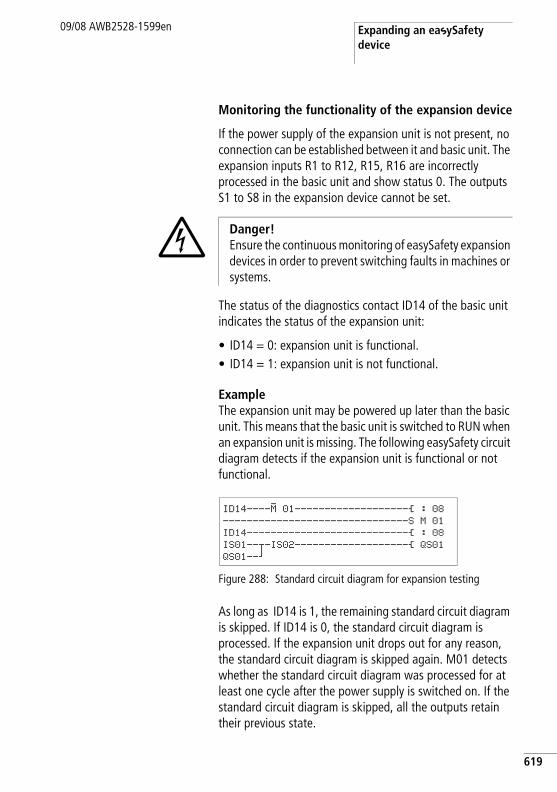
Expanding an easySafety device
09/08 AWB2528-1599en
Monitoring the functionality of the expansion device
If the power supply of the expansion unit is not present, no connection can be established between it and basic unit. The expansion inputs R1 to R12, R15, R16 are incorrectly processed in the basic unit and show status 0. The outputs S1 to S8 in the expansion device cannot be set.
The status of the diagnostics contact ID14 of the basic unit indicates the status of the expansion unit:
• ID14 = 0: expansion unit is functional.• ID14 = 1: expansion unit is not functional.
ExampleThe expansion unit may be powered up later than the basic unit. This means that the basic unit is switched to RUN when an expansion unit is missing. The following easySafety circuit diagram detects if the expansion unit is functional or not functional.
Figure 288: Standard circuit diagram for expansion testing
As long as ID14 is 1, the remaining standard circuit diagram is skipped. If ID14 is 0, the standard circuit diagram is processed. If the expansion unit drops out for any reason, the standard circuit diagram is skipped again. M01 detects whether the standard circuit diagram was processed for at least one cycle after the power supply is switched on. If the standard circuit diagram is skipped, all the outputs retain their previous state.
j Danger! Ensure the continuous monitoring of easySafety expansion devices in order to prevent switching faults in machines or systems.
ID14----M 01-------------------Ä : 08-------------------------------S M 01
ID14---------------------------Ä : 08IS01--u-IS02-------------------Ä QS01
QS01--k
619
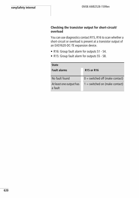
easySafety internal
620
09/08 AWB2528-1599en
Checking the transistor output for short-circuit/overload
You can use diagnostics contact R15, R16 to scan whether a short-circuit or overload is present at a transistor output of an EASY620-DC-TE expansion device.
• R16: Group fault alarm for outputs S1 - S4.• R15: Group fault alarm for outputs S5 - S8.
State
Fault alarms R15 or R16
No fault found 0 = switched off (make contact)
At least one output has a fault
1 = switched on (make contact)
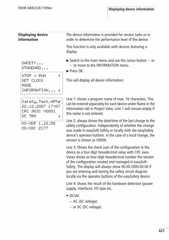
Displaying device information09/08 AWB2528-1599en
Displaying device information
The device information is provided for service tasks or in order to determine the performance level of the device.
This function is only available with devices featuring a display.
X Switch to the main menu and use the cursor button Í or Ú to move to the INFORMATION menu.
X Press OK.
This will display all device information:
Line 1: shows a program name of max. 16 characters. This can be entered separately for each device under Name in the Information tab in Project View. Line 1 will remain empty if this name is not entered.
Line 2: always shows the date/time of the last change to the safety configuration. Independently of whether the change was made in easySoft-Safety or locally with the easySafety device's operator buttons. In the case of a local change, the version is shown as V0000.
Line 3: Shows the check sum of the configuration in the device as a four digit hexadecimal value with CRC xxxx. Vxxxx shows as four-digit hexadecimal number the version of the configuration created and managed in easySoft-Safety. The display will always show 00.00.2000.00.00 if you are entering and storing the safety circuit diagram locally via the operator buttons of the easySafety device.
Line 4: shows the result of the hardware detection (power supply, interfaces, I/O type etc.
• DC/AC– AC (AC voltage) – or DC (DC voltage).
STOP å RUN ÆSET CLOCK
MODE
INFORMATION... æ
SAFETY...
STANDARD...
Safety_Test_APPl22.12.2007 17:07
CRC 9031 V0001
DC TRN æOS-VER 1.10.58
OS-CRC 2177
621
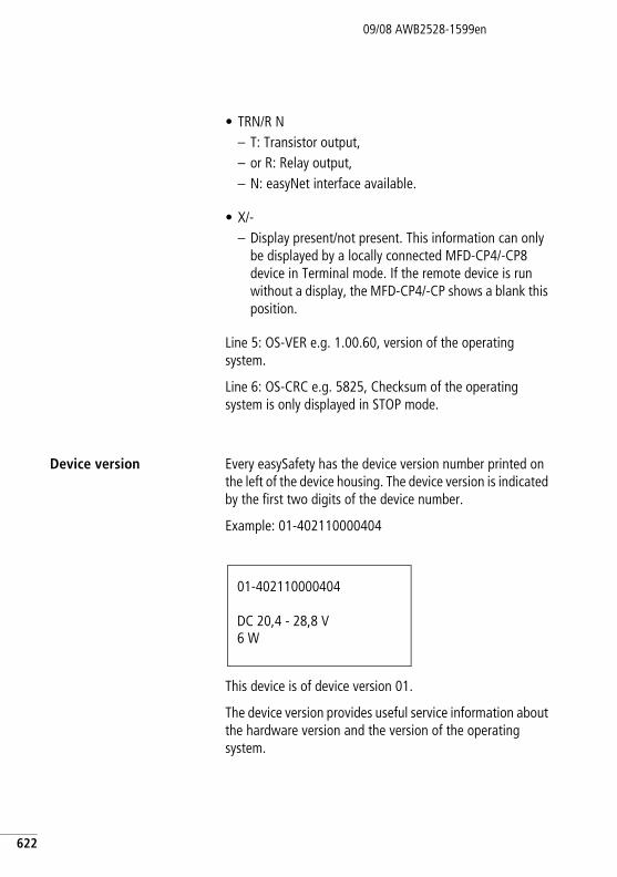
622
09/08 AWB2528-1599en
• TRN/R N– T: Transistor output,– or R: Relay output,– N: easyNet interface available.
• X/-– Display present/not present. This information can only
be displayed by a locally connected MFD-CP4/-CP8 device in Terminal mode. If the remote device is run without a display, the MFD-CP4/-CP shows a blank this position.
Line 5: OS-VER e.g. 1.00.60, version of the operating system.
Line 6: OS-CRC e.g. 5825, Checksum of the operating system is only displayed in STOP mode.
Device version Every easySafety has the device version number printed on the left of the device housing. The device version is indicated by the first two digits of the device number.
Example: 01-402110000404
This device is of device version 01.
The device version provides useful service information about the hardware version and the version of the operating system.
01-402110000404
DC 20,4 - 28,8 V6 W
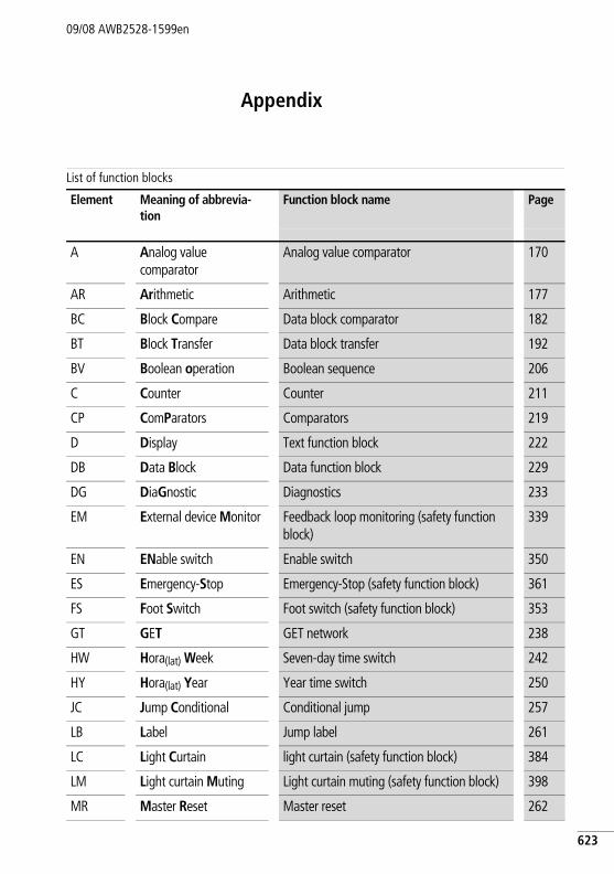
09/08 AWB2528-1599en
Appendix
List of function blocks
Element Meaning of abbrevia-tion
Function block name Page
A Analog value comparator
Analog value comparator 170
AR Arithmetic Arithmetic 177
BC Block Compare Data block comparator 182
BT Block Transfer Data block transfer 192
BV Boolean operation Boolean sequence 206
C Counter Counter 211
CP ComParators Comparators 219
D Display Text function block 222
DB Data Block Data function block 229
DG DiaGnostic Diagnostics 233
EM External device Monitor Feedback loop monitoring (safety function block)
339
EN ENable switch Enable switch 350
ES Emergency-Stop Emergency-Stop (safety function block) 361
FS Foot Switch Foot switch (safety function block) 353
GT GET GET network 238
HW Hora(lat) Week Seven-day time switch 242
HY Hora(lat) Year Year time switch 250
JC Jump Conditional Conditional jump 257
LB Label Jump label 261
LC Light Curtain light curtain (safety function block) 384
LM Light curtain Muting Light curtain muting (safety function block) 398
MR Master Reset Master reset 262
623
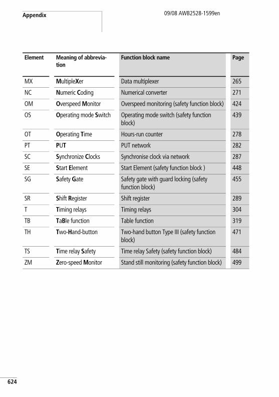
Appendix
624
09/08 AWB2528-1599en
MX MultipleXer Data multiplexer 265
NC Numeric Coding Numerical converter 271
OM Overspeed Monitor Overspeed monitoring (safety function block) 424
OS Operating mode Switch Operating mode switch (safety function block)
439
OT Operating Time Hours-run counter 278
PT PUT PUT network 282
SC Synchronize Clocks Synchronise clock via network 287
SE Start Element Start Element (safety function block ) 448
SG Safety Gate Safety gate with guard locking (safety function block)
455
SR Shift Register Shift register 289
T Timing relays Timing relays 304
TB TaBle function Table function 319
TH Two-Hand-button Two-hand button Type III (safety function block)
471
TS Time relay Safety Time relay Safety (safety function block) 484
ZM Zero-speed Monitor Stand still monitoring (safety function block) 499
Element Meaning of abbrevia-tion
Function block name Page
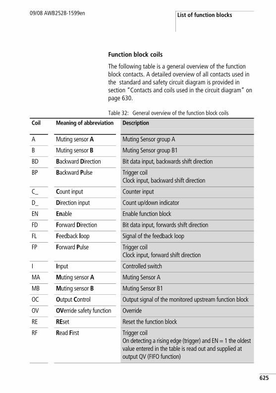
List of function blocks09/08 AWB2528-1599en
Function block coils
The following table is a general overview of the function block contacts. A detailed overview of all contacts used in the standard and safety circuit diagram is provided in section “Contacts and coils used in the circuit diagram” on page 630.
Table 32: General overview of the function block coils
Coil Meaning of abbreviation Description
A Muting sensor A Muting Sensor group A
B Muting sensor B Muting Sensor group B1
BD Backward Direction Bit data input, backwards shift direction
BP Backward Pulse Trigger coilClock input, backward shift direction
C_ Count input Counter input
D_ Direction input Count up/down indicator
EN Enable Enable function block
FD Forward Direction Bit data input, forwards shift direction
FL Feedback loop Signal of the feedback loop
FP Forward Pulse Trigger coilClock input, forward shift direction
I Input Controlled switch
MA Muting sensor A Muting Sensor A
MB Muting sensor B Muting Sensor B1
OC Output Control Output signal of the monitored upstream function block
OV OVerride safety function Override
RE REset Reset the function block
RF Read First Trigger coilOn detecting a rising edge (trigger) and EN = 1 the oldest value entered in the table is read out and supplied at output QV (FIFO function)
625
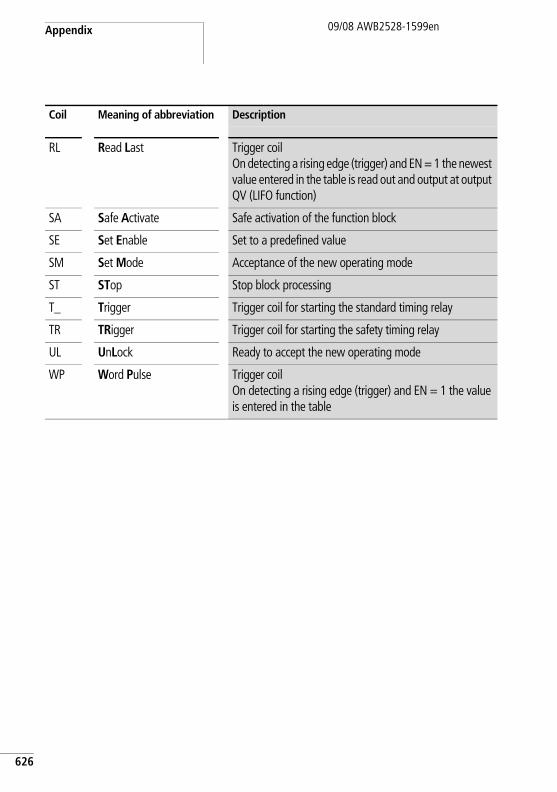
Appendix
626
09/08 AWB2528-1599en
RL Read Last Trigger coilOn detecting a rising edge (trigger) and EN = 1 the newest value entered in the table is read out and output at output QV (LIFO function)
SA Safe Activate Safe activation of the function block
SE Set Enable Set to a predefined value
SM Set Mode Acceptance of the new operating mode
ST STop Stop block processing
T_ Trigger Trigger coil for starting the standard timing relay
TR TRigger Trigger coil for starting the safety timing relay
UL UnLock Ready to accept the new operating mode
WP Word Pulse Trigger coilOn detecting a rising edge (trigger) and EN = 1 the value is entered in the table
Coil Meaning of abbreviation Description
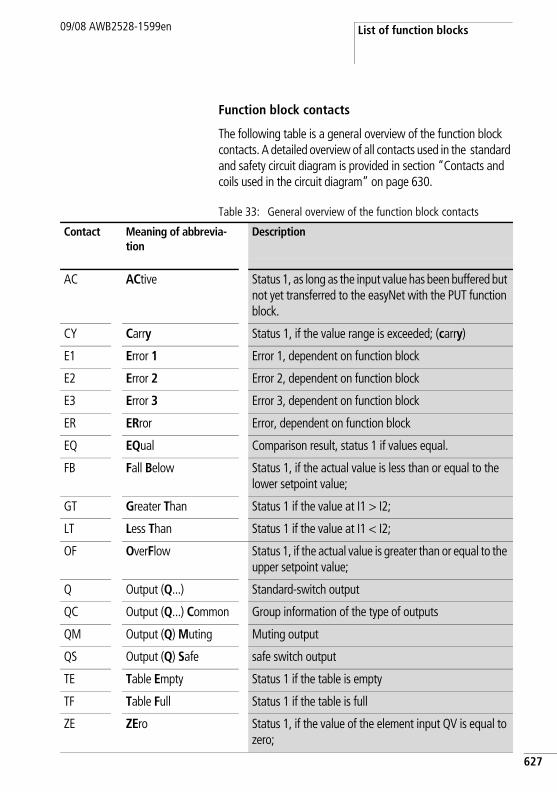
List of function blocks09/08 AWB2528-1599en
Function block contacts
The following table is a general overview of the function block contacts. A detailed overview of all contacts used in the standard and safety circuit diagram is provided in section “Contacts and coils used in the circuit diagram” on page 630.
Table 33: General overview of the function block contacts
Contact Meaning of abbrevia-tion
Description
AC ACtive Status 1, as long as the input value has been buffered but not yet transferred to the easyNet with the PUT function block.
CY Carry Status 1, if the value range is exceeded; (carry)
E1 Error 1 Error 1, dependent on function block
E2 Error 2 Error 2, dependent on function block
E3 Error 3 Error 3, dependent on function block
ER ERror Error, dependent on function block
EQ EQual Comparison result, status 1 if values equal.
FB Fall Below Status 1, if the actual value is less than or equal to the lower setpoint value;
GT Greater Than Status 1 if the value at I1 > I2;
LT Less Than Status 1 if the value at I1 < I2;
OF OverFlow Status 1, if the actual value is greater than or equal to the upper setpoint value;
Q Output (Q...) Standard-switch output
QC Output (Q...) Common Group information of the type of outputs
QM Output (Q) Muting Muting output
QS Output (Q) Safe safe switch output
TE Table Empty Status 1 if the table is empty
TF Table Full Status 1 if the table is full
ZE ZEro Status 1, if the value of the element input QV is equal to zero;
627
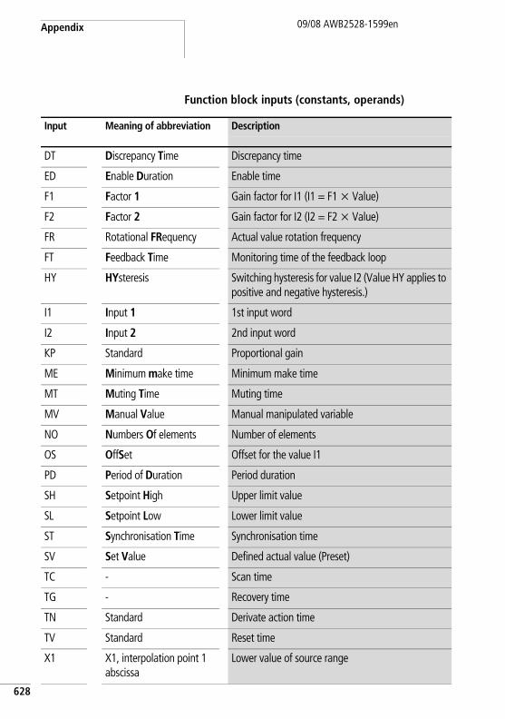
Appendix
628
09/08 AWB2528-1599en
Function block inputs (constants, operands)
Input Meaning of abbreviation Description
DT Discrepancy Time Discrepancy time
ED Enable Duration Enable time
F1 Factor 1 Gain factor for I1 (I1 = F1 x Value)
F2 Factor 2 Gain factor for I2 (I2 = F2 x Value)
FR Rotational FRequency Actual value rotation frequency
FT Feedback Time Monitoring time of the feedback loop
HY HYsteresis Switching hysteresis for value I2 (Value HY applies to positive and negative hysteresis.)
I1 Input 1 1st input word
I2 Input 2 2nd input word
KP Standard Proportional gain
ME Minimum make time Minimum make time
MT Muting Time Muting time
MV Manual Value Manual manipulated variable
NO Numbers Of elements Number of elements
OS OffSet Offset for the value I1
PD Period of Duration Period duration
SH Setpoint High Upper limit value
SL Setpoint Low Lower limit value
ST Synchronisation Time Synchronisation time
SV Set Value Defined actual value (Preset)
TC - Scan time
TG - Recovery time
TN Standard Derivate action time
TV Standard Reset time
X1 X1, interpolation point 1 abscissa
Lower value of source range
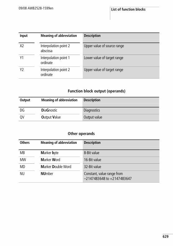
List of function blocks09/08 AWB2528-1599en
Function block output (operands)
Other operands
X2 Interpolation point 2 abscissa
Upper value of source range
Y1 Interpolation point 1 ordinate
Lower value of target range
Y2 Interpolation point 2 ordinate
Upper value of target range
Input Meaning of abbreviation Description
Output Meaning of abbreviation Description
DG DiaGnostic Diagnostics
QV Output Value Output value
Others Meaning of abbreviation Description
MB Marker byte 8-Bit value
MW Marker Word 16-Bit value
MD Marker Double Word 32-Bit value
NU NUmber Constant, value range from –2147483648 to +2147483647
629
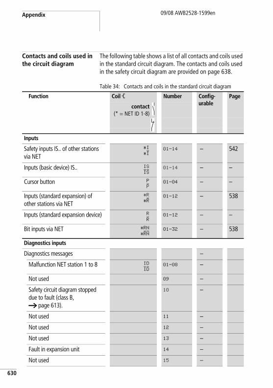
Appendix
630
09/08 AWB2528-1599en
Contacts and coils used in the circuit diagram
The following table shows a list of all contacts and coils used in the standard circuit diagram. The contacts and coils used in the safety circuit diagram are provided on page 638.
Table 34: Contacts and coils in the standard circuit diagram
Function Coil Ä Number Config-urable
Page
contact(* = NET ID 1-8)
Inputs
Safety inputs IS.. of other stations via NET
*I
*I01–14 – 542
Inputs (basic device) IS.. IS
IS01–14 – –
Cursor button P
P01–04 – –
Inputs (standard expansion) of other stations via NET
*R
*R01–12 – 538
Inputs (standard expansion device) R
R01–12 – –
Bit inputs via NET *RN
*RN01–32 – 538
Diagnostics inputs
Diagnostics messages –
Malfunction NET station 1 to 8 ID
ID01–08 –
Not used 09 –
Safety circuit diagram stopped due to fault (class B, a page 613).
10 –
Not used 11 –
Not used 12 –
Not used 13 –
Fault in expansion unit 14 –
Not used 15 –
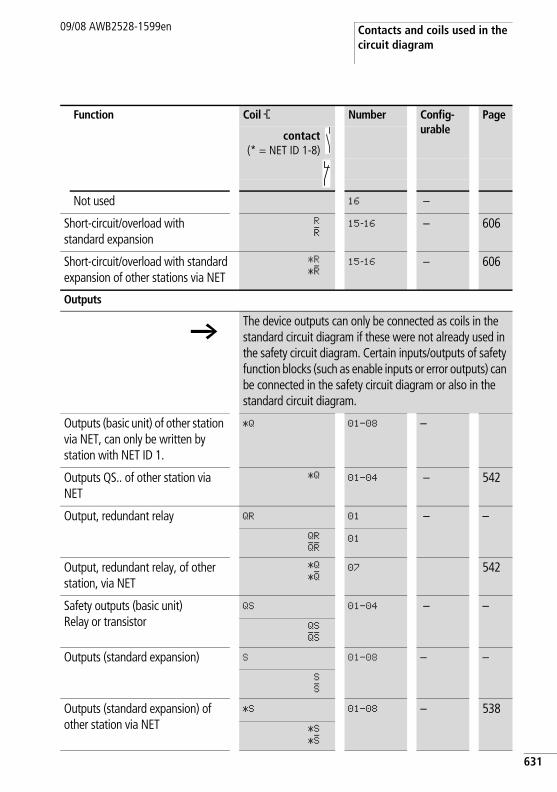
Contacts and coils used in the circuit diagram
09/08 AWB2528-1599en
Not used 16 –
Short-circuit/overload with standard expansion
R
R15-16 – 606
Short-circuit/overload with standard expansion of other stations via NET
*R
*R15-16 – 606
Outputs
hThe device outputs can only be connected as coils in the standard circuit diagram if these were not already used in the safety circuit diagram. Certain inputs/outputs of safety function blocks (such as enable inputs or error outputs) can be connected in the safety circuit diagram or also in the standard circuit diagram.
Outputs (basic unit) of other station via NET, can only be written by station with NET ID 1.
*Q 01–08 –
Outputs QS.. of other station via NET
*Q 01–04 – 542
Output, redundant relay QR 01 – –QR
QR01
Output, redundant relay, of other station, via NET
*Q
*Q07 542
Safety outputs (basic unit)Relay or transistor
QS 01–04 – –QS
QSOutputs (standard expansion) S 01–08 – –
S
SOutputs (standard expansion) of other station via NET
*S 01–08 – 538*S
*S
Function Coil Ä Number Config-urable
Page
contact(* = NET ID 1-8)
631
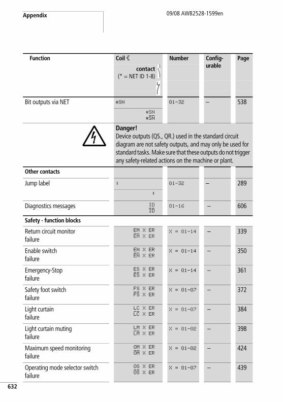
Appendix
632
09/08 AWB2528-1599en
Bit outputs via NET *SN 01–32 – 538*SN
*SN
jDanger! Device outputs (QS., QR.) used in the standard circuit diagram are not safety outputs, and may only be used for standard tasks. Make sure that these outputs do not trigger any safety-related actions on the machine or plant.
Other contacts
Jump label : 01–32 – 289:
Diagnostics messages ID
ID01–16 – 606
Safety - function blocks
Return circuit monitorfailure
EM X ER
EM X ERX = 01–14 – 339
Enable switchfailure
EN X ER
EN X ERX = 01–14 – 350
Emergency-Stopfailure
ES X ER
ES X ERX = 01–14 – 361
Safety foot switchfailure
FS X ER
FS X ERX = 01–07 – 372
Light curtainfailure
LC X ER
LC X ERX = 01–07 – 384
Light curtain mutingfailure
LM X ER
LM X ERX = 01–02 – 398
Maximum speed monitoringfailure
OM X ER
OM X ERX = 01–02 – 424
Operating mode selector switchfailure
OS X ER
OS X ERX = 01–07 – 439
Function Coil Ä Number Config-urable
Page
contact(* = NET ID 1-8)
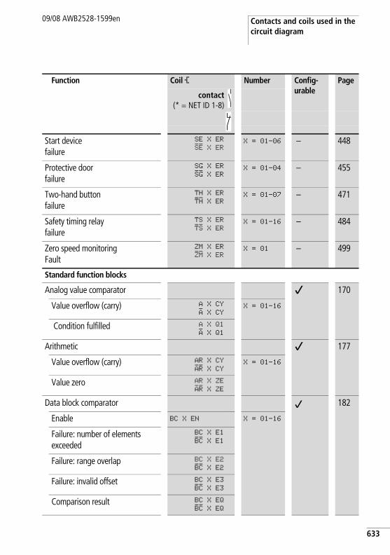
Contacts and coils used in the circuit diagram
09/08 AWB2528-1599en
Start devicefailure
SE X ER
SE X ERX = 01–06 – 448
Protective doorfailure
SG X ER
SG X ERX = 01–04 – 455
Two-hand buttonfailure
TH X ER
TH X ERX = 01–07 – 471
Safety timing relayfailure
TS X ER
TS X ERX = 01–16 – 484
Zero speed monitoringFault
ZM X ER
ZM X ERX = 01 – 499
Standard function blocks
Analog value comparator j 170
Value overflow (carry) A X CY
A X CYX = 01–16
Condition fulfilled A X Q1
A X Q1Arithmetic j 177
Value overflow (carry) AR X CY
AR X CYX = 01–16
Value zero AR X ZE
AR X ZEData block comparator j 182
Enable BC X EN X = 01–16
Failure: number of elements exceeded
BC X E1
BC X E1
Failure: range overlap BC X E2
BC X E2Failure: invalid offset BC X E3
BC X E3Comparison result BC X EQ
BC X EQ
Function Coil Ä Number Config-urable
Page
contact(* = NET ID 1-8)
633
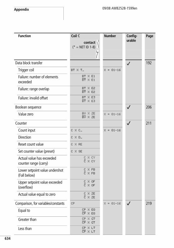
Appendix
634
09/08 AWB2528-1599en
Data block transfer j 192
Trigger coil BT X T_ X = 01–16
Failure: number of elements exceeded
BT X E1
BT X E1
Failure: range overlap BT X E2
BT X E2Failure: invalid offset BT X E3
BT X E3Boolean sequence j 206
Value zero BV X ZE
BV X ZEX = 01–16
Counter j 211
Count input C X C_ X = 01–16
Direction C X D_
Reset count value C X RE
Set counter value (preset) C X SE
Actual value has exceeded counter range (carry)
C X CY
C X CY
Lower setpoint value undershot (Fall below)
C X FB
C X FB
Upper setpoint value exceeded (overflow)
C X OF
C X OF
Actual value equal to zero C X ZE
C X ZEComparison, for variables/constants CP X = 01–16 j 219
Equal to CP X EQ
CP X EQGreater than CP X GT
CP X GTLess than CP X LT
CP X LT
Function Coil Ä Number Config-urable
Page
contact(* = NET ID 1-8)
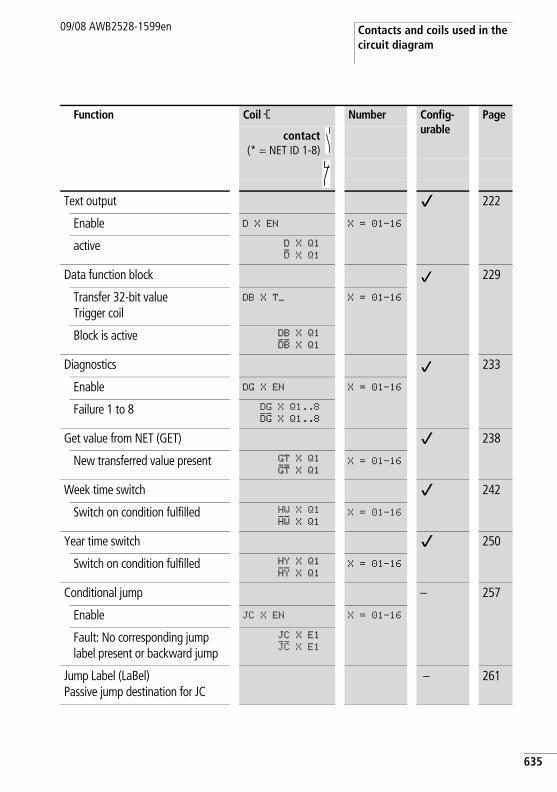
Contacts and coils used in the circuit diagram
09/08 AWB2528-1599en
Text output j 222
Enable D X EN X = 01–16
active D X Q1
D X Q1Data function block j 229
Transfer 32-bit valueTrigger coil
DB X T_ X = 01–16
Block is active DB X Q1
DB X Q1Diagnostics j 233
Enable DG X EN X = 01–16
Failure 1 to 8 DG X Q1..8
DG X Q1..8Get value from NET (GET) j 238
New transferred value present GT X Q1
GT X Q1X = 01–16
Week time switch j 242
Switch on condition fulfilled HW X Q1
HW X Q1X = 01–16
Year time switch j 250
Switch on condition fulfilled HY X Q1
HY X Q1X = 01–16
Conditional jump – 257
Enable JC X EN X = 01–16
Fault: No corresponding jump label present or backward jump
JC X E1
JC X E1
Jump Label (LaBel)Passive jump destination for JC
– 261
Function Coil Ä Number Config-urable
Page
contact(* = NET ID 1-8)
635
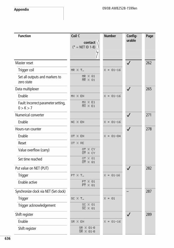
Appendix
636
09/08 AWB2528-1599en
Master reset j 262
Trigger coil MR X T_ X = 01–16
Set all outputs and markers to zero state
MR X Q1
MR X Q1
Data multiplexer j 265
Enable MX X EN X = 01–16
Fault: Incorrect parameter setting, 0 > K > 7
MX X E1
MX X E1
Numerical converter j 271
Enable NC X EN X = 01–16
Hours-run counter j 278
Enable OT X EN X = 01–04
Reset OT X RE
Value overflow (carry) OT X CY
OT X CYSet time reached OT X Q1
OT X Q1Put value on NET (PUT) j 282
Trigger PT X T_ X = 01-16
Enable active PT X Q1
PT X Q1Synchronize clock via NET (Set clock) – 287
Trigger SC X T_ X = 01
Trigger acknowledgement SC X Q1
SC X Q1Shift register j 289
Enable SR X EN X = 01–16
Shift register SR X Q1-8SR X Q1-8
Function Coil Ä Number Config-urable
Page
contact(* = NET ID 1-8)
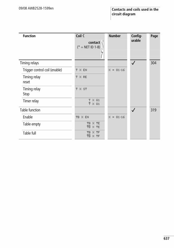
Contacts and coils used in the circuit diagram
09/08 AWB2528-1599en
Timing relays j 304
Trigger control coil (enable) T X EN X = 01-16
Timing relayreset
T X RE
Timing relayStop
T X ST
Timer relay T X Q1
T X Q1Table function j 319
Enable TB X EN X = 01-16
Table empty TB X TE
TB X TETable full TB X TF
TB X TF
Function Coil Ä Number Config-urable
Page
contact(* = NET ID 1-8)
637
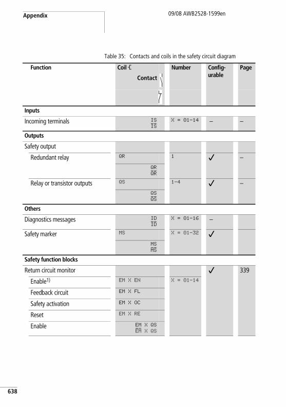
Appendix
638
09/08 AWB2528-1599en
Table 35: Contacts and coils in the safety circuit diagram
Function Coil Ä Number Config-urable
Page
Contact
Inputs
Incoming terminals IS
ISX = 01–14 – –
Outputs
Safety output
Redundant relay QR 1 j –QR
QRRelay or transistor outputs QS 1-4 j –
QS
QSOthers
Diagnostics messages ID
IDX = 01–16 –
Safety marker MS X = 01–32 j
MS
MSSafety function blocks
Return circuit monitor j 339
Enable1) EM X EN X = 01–14
Feedback circuit EM X FL
Safety activation EM X OC
Reset EM X RE
Enable EM X QS
EM X QS
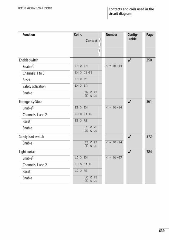
Contacts and coils used in the circuit diagram
09/08 AWB2528-1599en
Enable switch j 350
Enable1) EN X EN X = 01–14
Channels 1 to 3 EN X I1-I3
Reset EN X RE
Safety activation EN X SA
Enable EN X QS
EN X QSEmergency-Stop j 361
Enable1) ES X EN X = 01–14
Channels 1 and 2 ES X I1-I2
Reset ES X RE
Enable ES X QS
ES X QSSafety foot switch j 372
Enable FS X QS
FS X QSX = 01–14
Light curtain j 384
Enable1) LC X EN X = 01–07
Channels 1 and 2 LC X I1-I2
Reset LC X RE
Enable LC X QS
LC X QS
Function Coil Ä Number Config-urable
Page
Contact
639
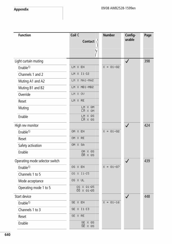
Appendix
640
09/08 AWB2528-1599en
Light curtain muting j 398
Enable1) LM X EN X = 01–02
Channels 1 and 2 LM X I1-I2
Muting A1 and A2 LM X MA1-MA2
Muting B1 and B2 LM X MB1-MB2
Override LM X OV
Reset LM X RE
Muting LM X QM
LM X QMEnable LM X QS
LM X QSHigh rev monitor j 424
Enable1) OM X EN X = 01-02
Reset OM X RE
Safety activation OM X SA
Enable OM X QS
OM X QSOperating mode selector switch j 439
Enable1) OS X EN X = 01-07
Channels 1 to 5 OS X I1-I5
Mode acceptance OS X UL
Operating mode 1 to 5 OS X Q1-Q5OS X Q1-Q5
Start device j 448
Enable1) SE X EN X = 01-16
Channels 1 to 3 SE X I1-I3
Reset SE X RE
Enable SE X QS
SE X QS
Function Coil Ä Number Config-urable
Page
Contact
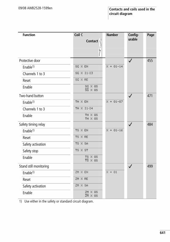
Contacts and coils used in the circuit diagram
09/08 AWB2528-1599en
Protective door j 455
Enable1) SG X EN X = 01-14
Channels 1 to 3 SG X I1-I3
Reset SG X RE
Enable SG X QS
SG X QSTwo-hand button j 471
Enable1) TH X EN X = 01-07
Channels 1 to 3 TH X I1-I4
Enable TH X QS
TH X QS
Safety timing relay j 484
Enable1) TS X EN X = 01-16
Reset TS X RE
Safety activation TS X SA
Safety stop TS X ST
Enable TS X QS
TS X QSStand still monitoring j 499
Enable1) ZM X EN X = 01
Reset ZM X RE
Safety activation ZM X SA
Enable ZM X QS
ZM X QS1) Use either in the safety or standard circuit diagram.
Function Coil Ä Number Config-urable
Page
Contact
641
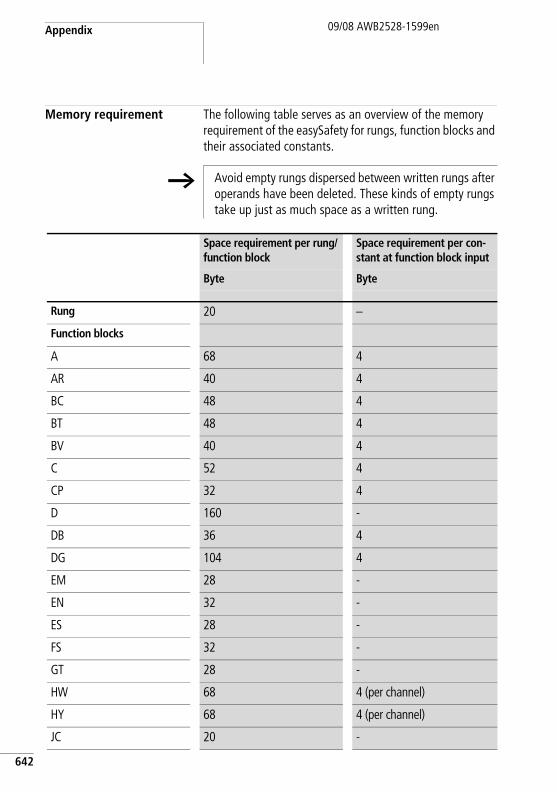
Appendix
642
09/08 AWB2528-1599en
Memory requirement The following table serves as an overview of the memory requirement of the easySafety for rungs, function blocks and their associated constants.
h Avoid empty rungs dispersed between written rungs after operands have been deleted. These kinds of empty rungs take up just as much space as a written rung.
Space requirement per rung/function block
Space requirement per con-stant at function block input
Byte Byte
Rung 20 –
Function blocks
A 68 4
AR 40 4
BC 48 4
BT 48 4
BV 40 4
C 52 4
CP 32 4
D 160 -
DB 36 4
DG 104 4
EM 28 -
EN 32 -
ES 28 -
FS 32 -
GT 28 -
HW 68 4 (per channel)
HY 68 4 (per channel)
JC 20 -
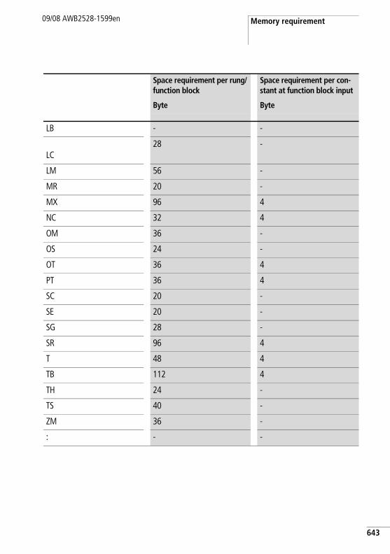
Memory requirement09/08 AWB2528-1599en
LB - -
LC28 -
LM 56 -
MR 20 -
MX 96 4
NC 32 4
OM 36 -
OS 24 -
OT 36 4
PT 36 4
SC 20 -
SE 20 -
SG 28 -
SR 96 4
T 48 4
TB 112 4
TH 24 -
TS 40 -
ZM 36 -
: - -
Space requirement per rung/function block
Space requirement per con-stant at function block input
Byte Byte
643
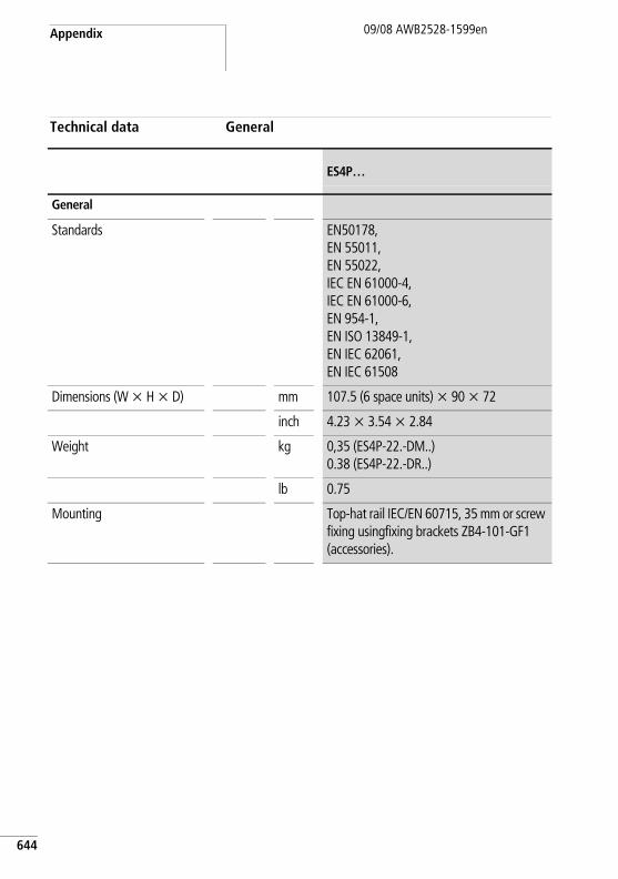
Appendix
644
09/08 AWB2528-1599en
Technical data General
ES4P…
General
Standards EN50178,EN 55011, EN 55022, IEC EN 61000-4,IEC EN 61000-6,EN 954-1,EN ISO 13849-1,EN IEC 62061, EN IEC 61508
Dimensions (W x H x D) mm 107.5 (6 space units) x 90 x 72
inch 4.23 x 3.54 x 2.84
Weight kg 0,35 (ES4P-22.-DM..)0.38 (ES4P-22.-DR..)
lb 0.75
Mounting Top-hat rail IEC/EN 60715, 35 mm or screw fixing usingfixing brackets ZB4-101-GF1 (accessories).
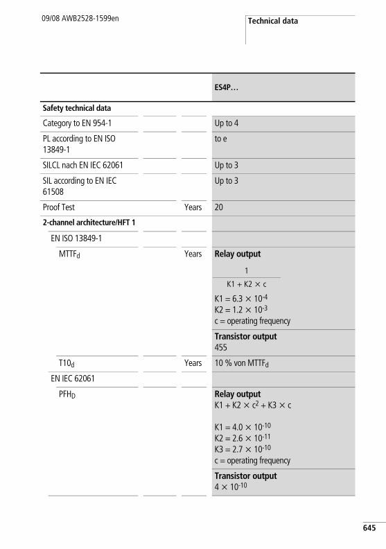
Technical data09/08 AWB2528-1599en
Safety technical data
Category to EN 954-1 Up to 4
PL according to EN ISO 13849-1
to e
SILCL nach EN IEC 62061 Up to 3
SIL according to EN IEC 61508
Up to 3
Proof Test Years 20
2-channel architecture/HFT 1
EN ISO 13849-1
MTTFd Years Relay output
K1 = 6.3 x 10⁻⁴
K2 = 1.2 x 10⁻³
c = operating frequency
Transistor output455
T10d Years 10 % von MTTFd
EN IEC 62061
PFHD Relay output K1 + K2 x c2 + K3 x c
K1 = 4.0 x 10⁻¹⁰
K2 = 2.6 x 10⁻¹¹
K3 = 2.7 x 10⁻¹⁰
c = operating frequency
Transistor output4 x 10-10
ES4P…
1
K1 + K2 x c
645
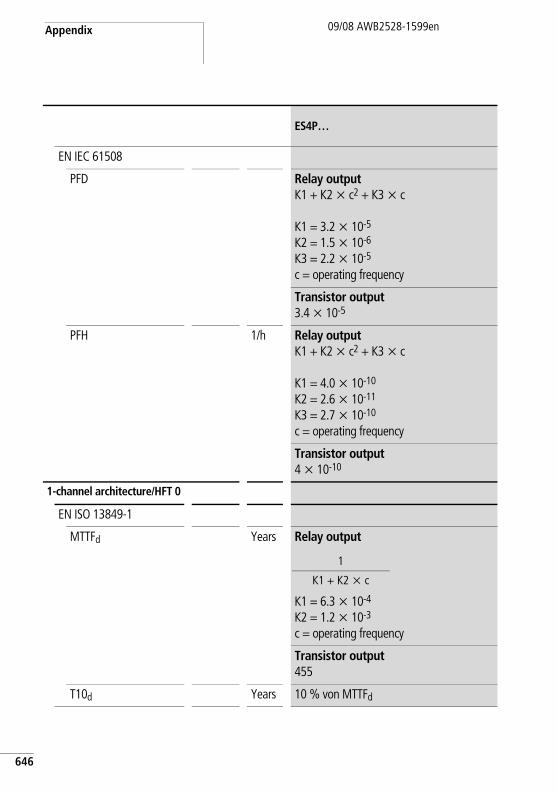
Appendix
646
09/08 AWB2528-1599en
EN IEC 61508
PFD Relay output K1 + K2 x c2 + K3 x c
K1 = 3.2 x 10⁻⁵
K2 = 1.5 x 10⁻⁶
K3 = 2.2 x 10⁻⁵
c = operating frequency
Transistor output 3.4 x 10⁻⁵
PFH 1/h Relay output K1 + K2 x c2 + K3 x c
K1 = 4.0 x 10⁻¹⁰
K2 = 2.6 x 10⁻¹¹
K3 = 2.7 x 10⁻¹⁰ c = operating frequency
Transistor output 4 x 10⁻¹⁰
1-channel architecture/HFT 0
EN ISO 13849-1
MTTFd Years Relay output
K1 = 6.3 x 10⁻⁴
K2 = 1.2 x 10⁻³
c = operating frequency
Transistor output 455
T10d Years 10 % von MTTFd
ES4P…
1
K1 + K2 x c
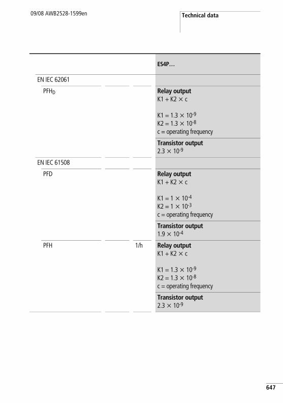
Technical data09/08 AWB2528-1599en
EN IEC 62061
PFHD Relay output K1 + K2 x c
K1 = 1.3 x 10⁻⁹
K2 = 1.3 x 10⁻⁸
c = operating frequency
Transistor output 2.3 x 10⁻⁹
EN IEC 61508
PFD Relay outputK1 + K2 x c
K1 = 1 x 10⁻⁴
K2 = 1 x 10⁻³
c = operating frequency
Transistor output 1.9 x 10⁻⁴
PFH 1/h Relay output K1 + K2 x c
K1 = 1.3 x 10⁻⁹
K2 = 1.3 x 10⁻⁸
c = operating frequency
Transistor output 2.3 x 10⁻⁹
ES4P…
647
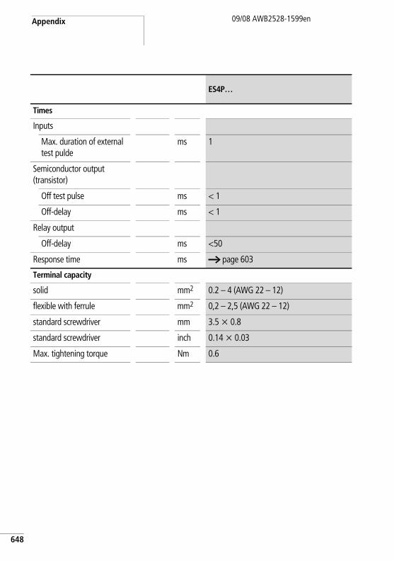
Appendix
648
09/08 AWB2528-1599en
Times
Inputs
Max. duration of external test pulde
ms 1
Semiconductor output (transistor)
Off test pulse ms < 1
Off-delay ms < 1
Relay output
Off-delay ms <50
Response time ms a page 603
Terminal capacity
solid mm2 0.2 – 4 (AWG 22 – 12)
flexible with ferrule mm2 0,2 – 2,5 (AWG 22 – 12)
standard screwdriver mm 3.5 x 0.8
standard screwdriver inch 0.14 x 0.03
Max. tightening torque Nm 0.6
ES4P…
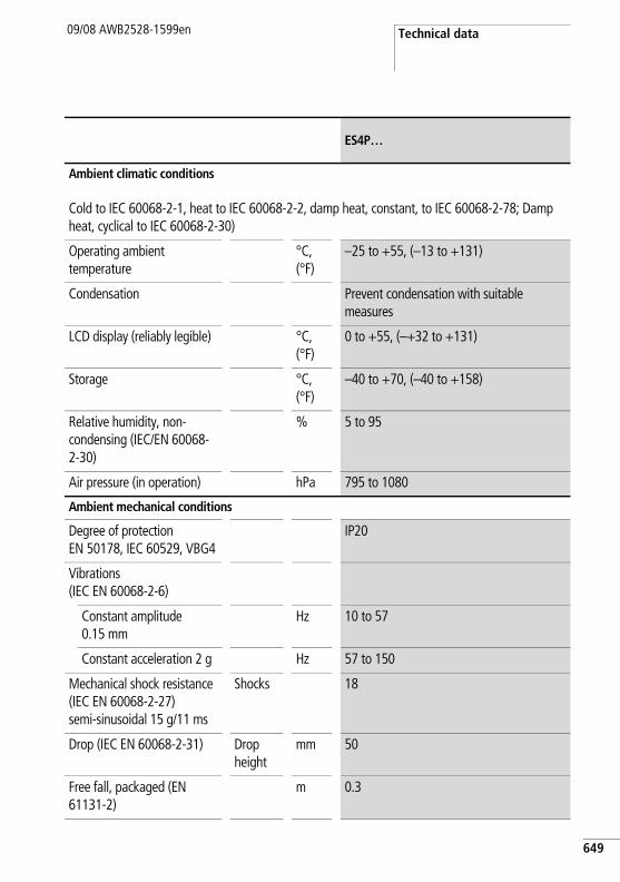
Technical data09/08 AWB2528-1599en
Ambient climatic conditions
Cold to IEC 60068-2-1, heat to IEC 60068-2-2, damp heat, constant, to IEC 60068-2-78; Damp heat, cyclical to IEC 60068-2-30)
Operating ambient temperature
°C, (°F)
–25 to +55, (–13 to +131)
Condensation Prevent condensation with suitable measures
LCD display (reliably legible) °C, (°F)
0 to +55, (–+32 to +131)
Storage °C, (°F)
–40 to +70, (–40 to +158)
Relative humidity, non-condensing (IEC/EN 60068-2-30)
% 5 to 95
Air pressure (in operation) hPa 795 to 1080
Ambient mechanical conditions
Degree of protection EN 50178, IEC 60529, VBG4
IP20
Vibrations (IEC EN 60068-2-6)
Constant amplitude 0.15 mm
Hz 10 to 57
Constant acceleration 2 g Hz 57 to 150
Mechanical shock resistance (IEC EN 60068-2-27) semi-sinusoidal 15 g/11 ms
Shocks 18
Drop (IEC EN 60068-2-31) Drop height
mm 50
Free fall, packaged (EN 61131-2)
m 0.3
ES4P…
649
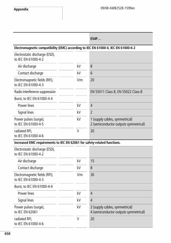
Appendix
650
09/08 AWB2528-1599en
Electromagnetic compatibility (EMC) according to IEC EN 61000-4, IEC EN 61000-6-2
Electrostatic discharge (ESD),to IEC EN 61000-4-2
Air discharge kV 8
Contact discharge kV 6
Electromagnetic fields (RFI), to IEC EN 61000-4-3
V/m 20
Radio interference suppression EN 55011 Class B, EN 55022 Class B
Burst, to IEC EN 61000-4-4
Power lines kV 4
Signal lines kV 2
Power pulses (surge), to IEC EN 61000-4-5
kV 1 (supply cables, symmetrical)2 (semiconductor outputs symmetrical)
radiated RFI,to IEC EN 61000-4-6
V 20
Increased EMC requirements to IEC EN 62061 for safety-related functions.
Electrostatic discharge (ESD),to IEC EN 61000-4-2
Air discharge kV 15
Contact discharge kV 8
Electromagnetic fields (RFI), to IEC EN 61000-4-3
V/m 30
Burst, to IEC EN 61000-4-4
Power lines kV 4
Signal lines kV 4
Power pulses (surge), to IEC EN 62061
kV 2 (supply cables, symmetrical)4 (semiconductor outputs symmetrical)
radiated RFI,to IEC EN 61000-4-6
V 20
ES4P…
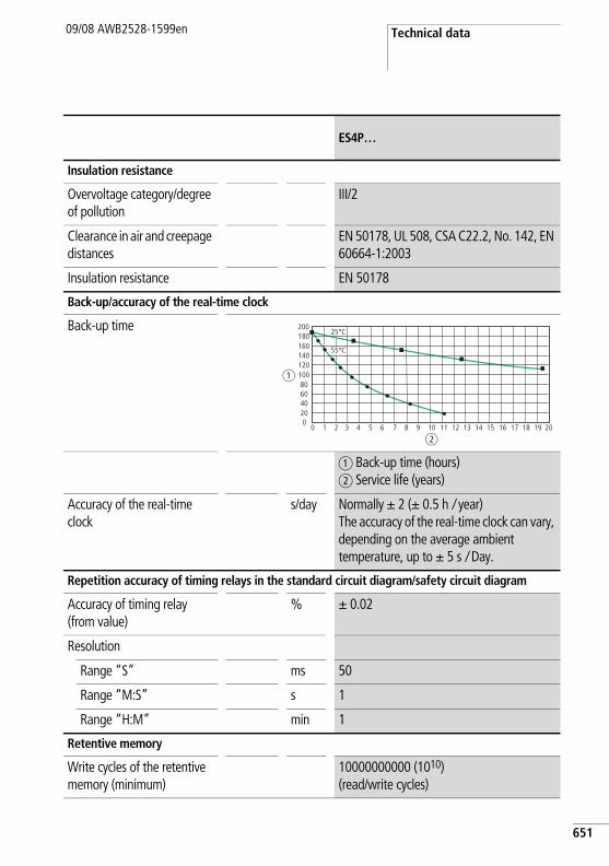
Technical data09/08 AWB2528-1599en
Insulation resistance
Overvoltage category/degree of pollution
III/2
Clearance in air and creepage distances
EN 50178, UL 508, CSA C22.2, No. 142, EN 60664-1:2003
Insulation resistance EN 50178
Back-up/accuracy of the real-time clock
Back-up time
a Back-up time (hours)b Service life (years)
Accuracy of the real-time clock
s/day Normally g 2 (g 0.5 hxyear)The accuracy of the real-time clock can vary, depending on the average ambient temperature, up to g 5 sxDay.
Repetition accuracy of timing relays in the standard circuit diagram/safety circuit diagram
Accuracy of timing relay (from value)
% g 0.02
Resolution
Range “S” ms 50
Range “M:S” s 1
Range “H:M” min 1
Retentive memory
Write cycles of the retentive memory (minimum)
10000000000 (1010) (read/write cycles)
ES4P…
a
b
180200
160140120100806040200
0 2 4 6 8 10 2012 141 3 5 7 9 11 13
55°C
25°C
15 17 1916 18
651
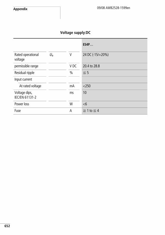
Appendix
652
09/08 AWB2528-1599en
Voltage supply:DC
ES4P…
Rated operational voltage
Ue V 24 DC (-15/+20%)
permissible range V DC 20.4 to 28.8
Residual ripple % F 5
Input current
At rated voltage mA <250
Voltage dips, IEC/EN 61131-2
ms 10
Power loss W <6
Fuse A f 1 to F 4
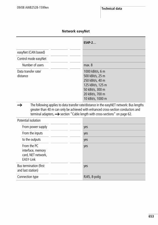
Technical data09/08 AWB2528-1599en
Network easyNet
ES4P-2…
easyNet (CAN based)
Control mode easyNet
Number of users max. 8
Data transfer rate/distance
1000 kBit/s, 6 m500 kBit/s, 25 m250 kBit/s, 40 m125 kBit/s, 125 m50 kBit/s, 300 m20 kBit/s, 700 m10 kBit/s, 1000 m
a The following applies to data transfer rate/distance in the easyNET network: Bus lengths greater than 40 m can only be achieved with enhanced cross-section conductors and terminal adapters, a section “Cable length with cross-sections” on page 62.
Potential isolation
From power supply yes
From the inputs yes
to the outputs yes
From the PC interface, memory card, NET network, EASY-Link
yes
Bus termination (first and last station)
yes
Connection type RJ45, 8-polig
653
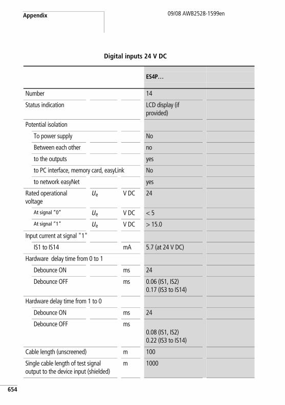
Appendix
654
09/08 AWB2528-1599en
Digital inputs 24 V DC
ES4P…
Number 14
Status indication LCD display (if provided)
Potential isolation
To power supply No
Between each other no
to the outputs yes
to PC interface, memory card, easyLink No
to network easyNet yes
Rated operational voltage
Ue V DC 24
At signal ”0” Ue V DC < 5
At signal ”1” Ue V DC > 15.0
Input current at signal "1"
IS1 to IS14 mA 5.7 (at 24 V DC)
Hardware delay time from 0 to 1
Debounce ON ms 24
Debounce OFF ms 0.06 (IS1, IS2)0.17 (IS3 to IS14)
Hardware delay time from 1 to 0
Debounce ON ms 24
Debounce OFF ms0.08 (IS1, IS2)0.22 (IS3 to IS14)
Cable length (unscreened) m 100
Single cable length of test signal output to the device input (shielded)
m 1000
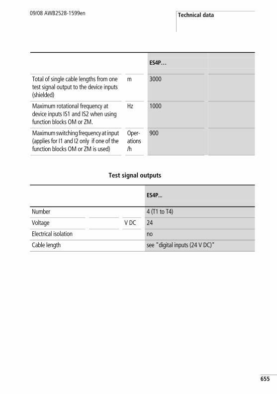
Technical data09/08 AWB2528-1599en
Test signal outputs
Total of single cable lengths from one test signal output to the device inputs (shielded)
m 3000
Maximum rotational frequency at device inputs IS1 and IS2 when using function blocks OM or ZM.
Hz 1000
Maximum switching frequency at input (applies for I1 and I2 only if one of the function blocks OM or ZM is used)
Oper-ations/h
900
ES4P…
ES4P...
Number 4 (T1 to T4)
Voltage V DC 24
Electrical isolation no
Cable length see "digital inputs (24 V DC)"
655
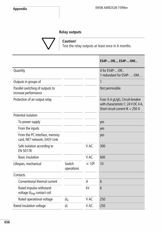
Appendix
656
09/08 AWB2528-1599en
Relay outputs
h Caution! Test the relay outputs at least once in 6 months.
ES4P-...-DR..., ES4P-...-DM...
Quantity 4 for ES4P-...-DR.. 1 redundant for ES4P-…-DM…
Outputs in groups of 1
Parallel switching of outputs to increase performance
Not permissible
Protection of an output relay Fuse: 6 A gL/gG, Circuit-breaker with characteristic C: 24 V DC 4 A, Short-circuit current IK < 250 A
Potential isolation
To power supply yes
From the inputs yes
From the PC interface, memory card, NET network, EASY-Link
yes
Safe isolation according to EN 50178
V AC 300
Basic insulation V AC 600
Lifespan, mechanical Switch operations
x 106 10
Contacts
Conventional thermal current A 6
Rated impulse withstand voltage Uimp contact coil
kV 6
Rated operational voltage Ue V AC 250
Rated insulation voltage Ui V AC 250
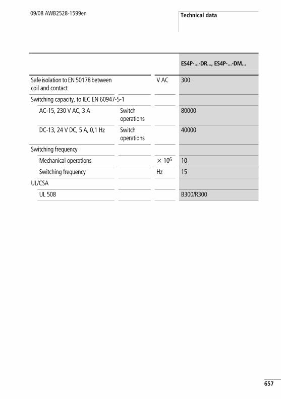
Technical data09/08 AWB2528-1599en
Safe isolation to EN 50178 between coil and contact
V AC 300
Switching capacity, to IEC EN 60947-5-1
AC-15, 230 V AC, 3 A Switch operations
80000
DC-13, 24 V DC, 5 A, 0,1 Hz Switch operations
40000
Switching frequency
Mechanical operations x 106 10
Switching frequency Hz 15
UL/CSA
UL 508 B300/R300
ES4P-...-DR..., ES4P-...-DM...
657
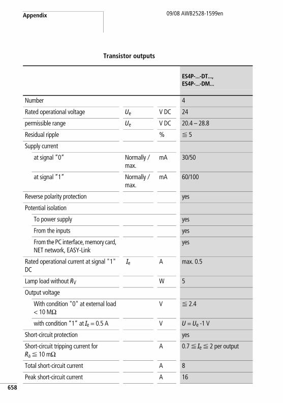
Appendix
658
09/08 AWB2528-1599en
Transistor outputs
ES4P-...-DT..., ES4P-...-DM...
Number 4
Rated operational voltage Ue V DC 24
permissible range Ue V DC 20.4 – 28.8
Residual ripple % F 5
Supply current
at signal ”0” Normallyx
max.mA 30/50
at signal ”1” Normallyx
max.mA 60/100
Reverse polarity protection yes
Potential isolation
To power supply yes
From the inputs yes
From the PC interface, memory card, NET network, EASY-Link
yes
Rated operational current at signal "1" DC
Ie A max. 0.5
Lamp load without RV W 5
Output voltage
With condition "0" at external load < 10 MO
V F 2.4
with condition “1” at Ie = 0.5 A V U = Ue -1 V
Short-circuit protection yes
Short-circuit tripping current for Ra F 10 mO
A 0.7 F Ie F 2 per output
Total short-circuit current A 8
Peak short-circuit current A 16
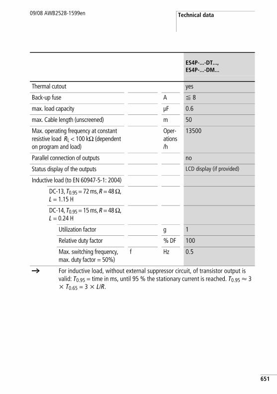
Technical data09/08 AWB2528-1599en
Thermal cutout yes
Back-up fuse A F 8
max. load capacity µF 0.6
max. Cable length (unscreened) m 50
Max. operating frequency at constant resistive load RL < 100 kO (dependent on program and load)
Oper-ations/h
13500
Parallel connection of outputs no
Status display of the outputs LCD display (if provided)
Inductive load (to EN 60947-5-1: 2004)
DC-13, T0.95 = 72 ms, R = 48 O, L = 1.15 H
DC-14, T0.95 = 15 ms, R = 48 O, L = 0.24 H
Utilization factor g 1
Relative duty factor % DF 100
Max. switching frequency, max. duty factor = 50%)
f Hz 0.5
a For inductive load, without external suppressor circuit, of transistor output is valid: T0.95 = time in ms, until 95 % the stationary current is reached. T0.95 Q 3 x T0.65 = 3 x L/R.
ES4P-...-DT..., ES4P-...-DM...
651
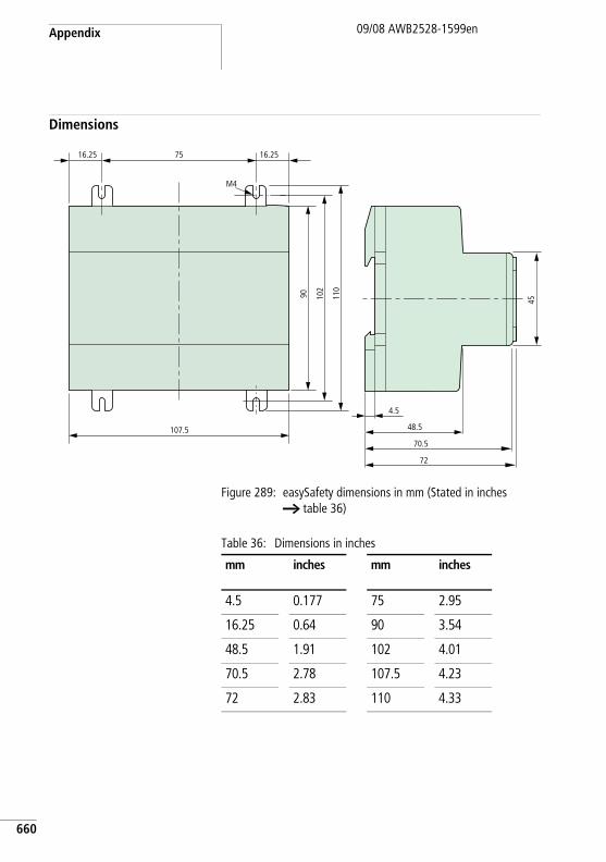
Appendix
660
09/08 AWB2528-1599en
Dimensions
Figure 289: easySafety dimensions in mm (Stated in inches a table 36)
Table 36: Dimensions in inches
90 102
110
M4
107.5
75 16.2516.25
48.5
70.5
72
45
4.5
mm inches mm inches
4.5 0.177 75 2.95
16.25 0.64 90 3.54
48.5 1.91 102 4.01
70.5 2.78 107.5 4.23
72 2.83 110 4.33
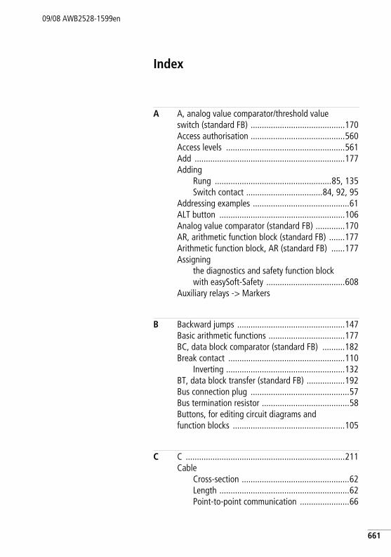
09/08 AWB2528-1599en
Index
A A, analog value comparator/threshold value switch (standard FB) ..........................................170Access authorisation ..........................................560Access levels .....................................................561Add ...................................................................177Adding
Rung ....................................................85, 135Switch contact ..................................84, 92, 95
Addressing examples ...........................................61ALT button ........................................................106Analog value comparator (standard FB) .............170AR, arithmetic function block (standard FB) .......177Arithmetic function block, AR (standard FB) ......177Assigning
the diagnostics and safety function block with easySoft-Safety ...................................608
Auxiliary relays -> Markers
B Backward jumps ................................................147Basic arithmetic functions ..................................177BC, data block comparator (standard FB) ..........182Break contact ....................................................110
Inverting .....................................................132BT, data block transfer (standard FB) .................192Bus connection plug ............................................57Bus termination resistor .......................................58Buttons, for editing circuit diagrams and function blocks ..................................................105
C C .......................................................................211Cable
Cross-section ................................................62Length ..........................................................62Point-to-point communication ......................66
661
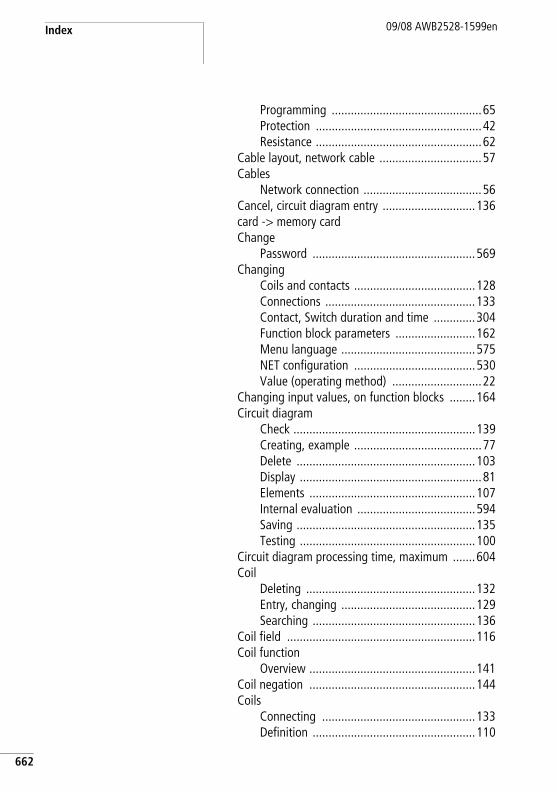
Index 09/08 AWB2528-1599en
662
Programming ...............................................65Protection ....................................................42Resistance ....................................................62
Cable layout, network cable ................................57Cables
Network connection .....................................56Cancel, circuit diagram entry .............................136card -> memory cardChange
Password ...................................................569Changing
Coils and contacts ......................................128Connections ...............................................133Contact, Switch duration and time .............304Function block parameters .........................162Menu language ..........................................575NET configuration ......................................530Value (operating method) ............................22
Changing input values, on function blocks ........164Circuit diagram
Check .........................................................139Creating, example ........................................77Delete ........................................................103Display .........................................................81Elements ....................................................107Internal evaluation .....................................594Saving ........................................................135Testing .......................................................100
Circuit diagram processing time, maximum .......604Coil
Deleting .....................................................132Entry, changing ..........................................129Searching ...................................................136
Coil field ...........................................................116Coil function
Overview ....................................................141Coil negation ....................................................144Coils
Connecting ................................................133Definition ...................................................110
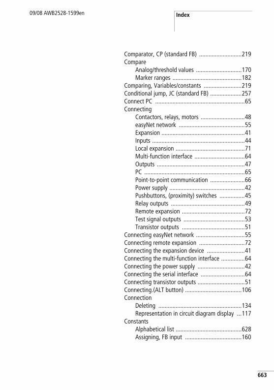
Index09/08 AWB2528-1599en
Comparator, CP (standard FB) ...........................219Compare
Analog/threshold values .............................170Marker ranges ............................................182
Comparing, Variables/constants ........................219Conditional jump, JC (standard FB) ....................257Connect PC .........................................................65Connecting
Contactors, relays, motors ............................48easyNet network ..........................................55Expansion .....................................................41Inputs ...........................................................44Local expansion ............................................71Multi-function interface ................................64Outputs ........................................................47PC ................................................................65Point-to-point communication ......................66Power supply ................................................42Pushbuttons, (proximity) switches ................45Relay outputs ...............................................49Remote expansion ........................................72Test signal outputs .......................................53Transistor outputs ........................................51
Connecting easyNet network ...............................55Connecting remote expansion .............................72Connecting the expansion device ........................41Connecting the multi-function interface ...............64Connecting the power supply ..............................42Connecting the serial interface ............................64Connecting transistor outputs ..............................51Connecting.(ALT button) ....................................106Connection
Deleting .....................................................134Representation in circuit diagram display ...117
ConstantsAlphabetical list ..........................................628Assigning, FB input ....................................160
663
Index 09/08 AWB2528-1599en
664
Contact .............................................................116Bounce .......................................................581Bounce suppression ...................................600Changing, make contact break contact ......132Changing, Switch duration and time ..........304Connecting ................................................133Cursor buttons ...........................................138DefinitionDeleting .....................................................132Entry, changing ..........................................128Searching ...................................................136
Contactor function ............................................142Copying
Data ...........................................................192Marker ranges (CPY) ..................................201
counter relays C (standard FB) ...........................211Counter relays, C (standard FB) .........................211CP, comparator (standard FB) ...........................219Cursor buttons, function ....................................106Cursor display .....................................................35Cycle pulse
Falling edge ...............................................145Rising edge ................................................144
D D, text display (standard FB) .............................222Data block comparator, BC (standard FB) ..........182Data block transfer, BT (standard FB) ................192Data function block, DB (standard FB) ...............229Data multiplexer, MX (standard FB) ...................265Date display ........................................................25Date setting ......................................................576Daylight Saving Time .........................................577Daylight saving time ..........................................577DB, data function block (standard FB) ...............229DEBOUNCE .......................................................600Debounce ..........................................................581Delay times .......................................................601Delete
All ................................................................34Password ...................................................569
Index09/08 AWB2528-1599en
DELETE ALL .........................................................34DELETE FUNCTION ............................................566Deleting
Circuit diagram on card ..............................124Function blocks ..........................................166Operands on FB inputs/outputs ..................161Retentive actual values ...............................591Retentive area ............................................591Rung ..........................................................135
Deleting retentive actual values .........................591Detecting cross-circuits (test signals) .................149Device
Brackets .......................................................40Overview ......................................................19
Device Version ...................................................622DG, Diagnostics (standard FB) ...........................233Diagnostics
-Error codes ................................................609of faults inside and outside the device ........614-Register .....................................................608Status display ...............................................24using the DG diagnostics function block .....607using the ER contact ...................................613using the ID diagnostics contact .................606
Divide ................................................................177
E Electrical isolation, between basic unit and expansion device .................................................71EM, external device monitoring (safety FB) ........339Emergency circuit ................................................91Emergency-stop, ES (safety FB) ..........................361EN, enable switch (safety FB) .............................350Enable switch, EN (safety FB) ............................350ER contact .........................................................613Error
Behaviour of easySafety .............................615Classes .......................................................615Codes .........................................................609
Error -> see also diagnosticsES, Emergency-stop (safety FB) ..........................361
665
Index 09/08 AWB2528-1599en
666
ESC button ........................................................106Evaluating a falling edge ...................................145Evaluating a rising edge ....................................144Evaluating status message, from status FB ........233Expanding inputs/outputs ....................................69Expansion units ...................................................70
F Fault -> DiagnosticsFields ................................................................116FS, safety foot switch (safety FB) .......................372Function block -> Function blocksFunction block editor .................................155, 158Function block list .............................................158
Resorting ...................................................595Function blocks
Adding to the circuit diagram for the first time ....................................................153Alphabetical list .........................................623Assigning operands ............................160, 161Changing parameters .................................162Checking ....................................................167Coils, alphabetical list ................................625Contacts, alphabetical list ..........................627Definition ...................................................109Deleting .....................................................166Editor for parameter setting ...............155, 158General notes ............................................151Inputs, alphabetical listList .............................................................158Memory requirement ..................................642Parameter dialog ........................................155Parameter setting .......................................154
Function overview ...............................................16
G GO TO other rungs ............................................137GT, Get value from network (standard FB) ........238
H HW, 7-day time switch (standard FB) ................242
Index09/08 AWB2528-1599en
HY, year time switch (standard FB) ....................250
I Impulse relay .....................................................142Initialising
Data ...........................................................192Marker ranges ............................................196
Input current .......................................................45Input delay ........................................................600
Setting .......................................................581Inputs
Connecting ...................................................44Expanding ....................................................69Status display ...............................................24
Installation, device ..............................................37INTERFACE ........................................................565Invert
Menu items for safety functions ...................29Inverting
Contact ......................................................132Contactor function .....................................144
J JC, conditional jump (standard FB) ....................257Jump label, LB (standard FB) .............................261Jumps ................................................................146
K Key to part numbers ............................................21Keyboard .............................................................22
L Lamp controller ...................................................82Language selection, menu texts .........................575Latching relay ....................................................143LB, jump label (standard FB) ..............................261LC, Light curtain (safety FB) ...............................384LED display ..........................................................20Light curtain muting, LM (safety FB) ..................398Light curtain, LC (safety FB) ...............................384LM, Light curtain muting (safety FB) ..................398
667
Index 09/08 AWB2528-1599en
668
Local expansionConnecting ..................................................71
M Main menuChange to ....................................................29Overview ......................................................30
Make contact ....................................................110Inverting ....................................................132
Marker rangesCopying .....................................................201Initialising ..................................................196
MarkersAssigning, FB input ....................................160Definition ...................................................111Reset ..........................................................262Retention ...................................................114Value range ...............................................115
Master password ...............................................561Master reset, MR (standard FB) .........................262Maximum load ..................................................605Memory card .....................................................118
Fitting ..........................................................68Memory display, circuit diagram ........................117Memory requirement, for rungs and function blocks ...............................................................642Menu language
Changing ...................................................575Initial switch on ...........................................74
Menu structure ....................................................28Message
PROG INVALID ...................................122, 126Message text .....................................................608Minimum clearances to the device ......................38Minimum load ...................................................604Mode
Entry ..........................................................106Move .........................................................106
Mode change ....................................................100MODULE ID .......................................................616
Index09/08 AWB2528-1599en
MountingTightening ....................................................40Top-hat rail ..................................................39
MR, Master reset (standard FB) .........................262Multiply .............................................................177MX, data multiplexer (standard FB) ...................265
N NC, Numerical converter (standard FB) ..............271Negate, coil .......................................................144Network (easyNet)
Cables ..........................................................59Network connection cable ...................................56Number formats ................................................115Numerical converter, NC (standard FB) ..............271
O OK button .........................................................106OM, Overspeed monitoring (safety FB) ..............424Operands
Assigning ...................................................160Assigning, FB output ..................................161Deleting on FB inputs/outputs ....................161
Operands, alphabetical list ................................628Operating buttons, function ...............................106Operating hours counter, OT (standard FB) ........278Operating mode
RUN, STOP ...................................................75Operating mode change not detected (NET) ......556Operating mode selector switch, OS (safety FB) .439OS, Operating mode selector switch (safety FB) .439OT, Operating hours counter (standard FB) ........278Outputs
Connecting ...................................................47Expanding ....................................................69Reset ..........................................................262Status display ...............................................24
Overload .............................................................53Overspeed monitoring, OM (safety FB) ..............424
669
Index 09/08 AWB2528-1599en
670
P P ButtonsStatus display ...............................................24
P buttons ..........................................................138Activating and deactivating ........................582
Parallel circuit, outputs ........................................52Parameter dialog, for function blocks ................155Parameter setting
Function blocks ..........................................154Parameters
Enabling/disabling access ...........................157Passing through (network topology) ....................60Password
Activation ..................................................566Changing ...................................................569Deleting .....................................................569No longer known .......................................567
Password protection ..........................................559Point-to-point communication .............................66Power failure .......................................................75
Time switch ........................................249, 250Power flow display ............................................101Process image ...................................................593Programming cable .............................................65Protecting areas ................................................565PT, Put value to network (standard FB) .............282
R Range of applications ..........................................15Reaction time ....................................................603Redundant relay output .......................................49Relay
Connecting outputs ......................................49Overview ....................................................630
RelaysCoil function ..............................................141Definition ...................................................109
Reset .................................................................143Device settings via software .......................571Factory settings for the device ....................571Markers and outputs ..................................262
Index09/08 AWB2528-1599en
Retention ..........................................................589Setting .......................................................590Timing relay with retentive actual values ....309
Retentive markers ..............................................114RJ45 socket, connection assignment ....................55Rotation frequency ............................................503Rotation frequency, maximum ...........................428RUN (mode) ........................................................75RUN/STOP changeover ......................................100Rung .................................................................116
Adding new rung ..........................................85Adding/deleting ..........................................135Changing ...................................................137Deleting .....................................................137
S Safety circuit diagramTesting .........................................................99
Safety gate, SG (safety FB) .................................455Safety password ................................................561Safety rules, during installation ............................37Safety timing relay, TS (safety FB) ......................484Saving
Circuit diagram ...........................................135Saving, Values ...................................................229SC, Set time/date (standard FB) .........................287Screw mounting ..................................................40SE, Start element (safety FB) ..............................448Sealing the safety configuration .........................572Sealing, safety configuration .............................572Searching
Contacts and coils ......................................136Self-latching, Circuit example ............................597Set .....................................................................143Setting LCD backlight ........................................587Setting LCD contrast ..........................................587Setting the startup behaviour ............................584Seven day time switch, HW (standard FB) ..........242SG, Safety gate (safety FB) .................................455Shift register, SR (standard FB) ..........................289Short-circuit .........................................................53
671
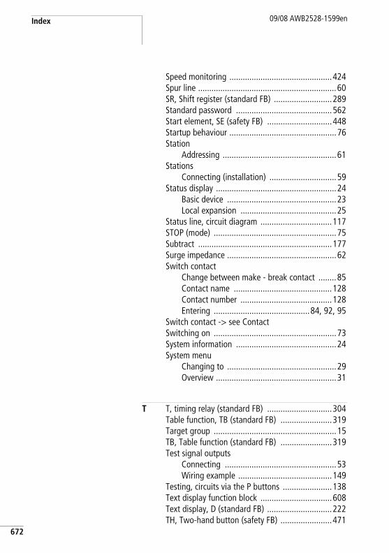
Index 09/08 AWB2528-1599en
672
Speed monitoring ..............................................424Spur line ..............................................................60SR, Shift register (standard FB) ..........................289Standard password ...........................................562Start element, SE (safety FB) .............................448Startup behaviour ................................................76Station
Addressing ...................................................61Stations
Connecting (installation) ..............................59Status display ......................................................24
Basic device .................................................23Local expansion ...........................................25
Status line, circuit diagram ................................117STOP (mode) .......................................................75Subtract ............................................................177Surge impedance .................................................62Switch contact
Change between make - break contact ........85Contact name ............................................128Contact number .........................................128Entering ...........................................84, 92, 95
Switch contact -> see ContactSwitching on .......................................................73System information .............................................24System menu
Changing to .................................................29Overview ......................................................31
T T, timing relay (standard FB) .............................304Table function, TB (standard FB) .......................319Target group .......................................................15TB, Table function (standard FB) .......................319Test signal outputs
Connecting ..................................................53Wiring example ..........................................149
Testing, circuits via the P buttons ......................138Text display function block ................................608Text display, D (standard FB) .............................222TH, Two-hand button (safety FB) .......................471
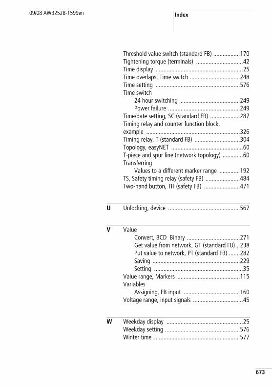
Index09/08 AWB2528-1599en
Threshold value switch (standard FB) .................170Tightening torque (terminals) ..............................42Time display ........................................................25Time overlaps, Time switch ................................248Time setting ......................................................576Time switch
24 hour switching ......................................249Power failure ..............................................249
Time/date setting, SC (standard FB) ...................287Timing relay and counter function block, example ............................................................326Timing relay, T (standard FB) .............................304Topology, easyNET ..............................................60T-piece and spur line (network topology) .............60Transferring
Values to a different marker range .............192TS, Safety timing relay (safety FB) ......................484Two-hand button, TH (safety FB) .......................471
U Unlocking, device ..............................................567
V ValueConvert, BCD Binary ..................................271Get value from network, GT (standard FB) ..238Put value to network, PT (standard FB) .......282Saving ........................................................229Setting .........................................................35
Value range, Markers ........................................115Variables
Assigning, FB input ....................................160Voltage range, input signals ................................45
W Weekday display .................................................25Weekday setting ................................................576Winter time .......................................................577
673
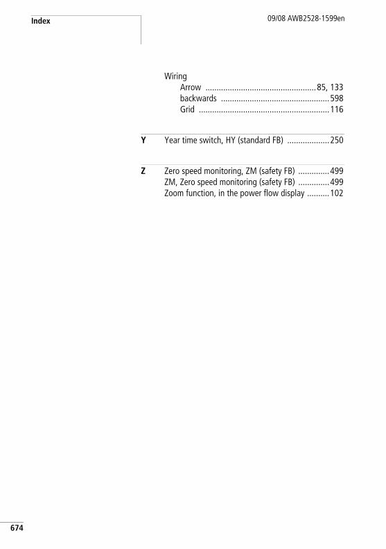
Index 09/08 AWB2528-1599en
674
WiringArrow ..................................................85, 133backwards .................................................598Grid ...........................................................116
Y Year time switch, HY (standard FB) ...................250
Z Zero speed monitoring, ZM (safety FB) ..............499ZM, Zero speed monitoring (safety FB) ..............499Zoom function, in the power flow display ..........102