Embed Size (px)
Citation preview
153
Complementary
technical information Protection of motor circuitsCircuit breaker/contactor coordination
A circuit supplying a motor may include one, two, three or four switchgear or
When a number of devices are used, they must be coordinated to ensure
optimum operation of the motor.
Protection of a motor circuit involves a number of parameters that depend on:
b the application (type of machine driven, operating safety, starting frequency, etc.)
b the level of service continuity imposed by the load or the application
b the applicable standards to ensure protection of life and property.
The necessary electrical functions are of very different natures:
b protection (motor-dedicated for overloads)
b control (generally with high endurance levels)
b isolation.
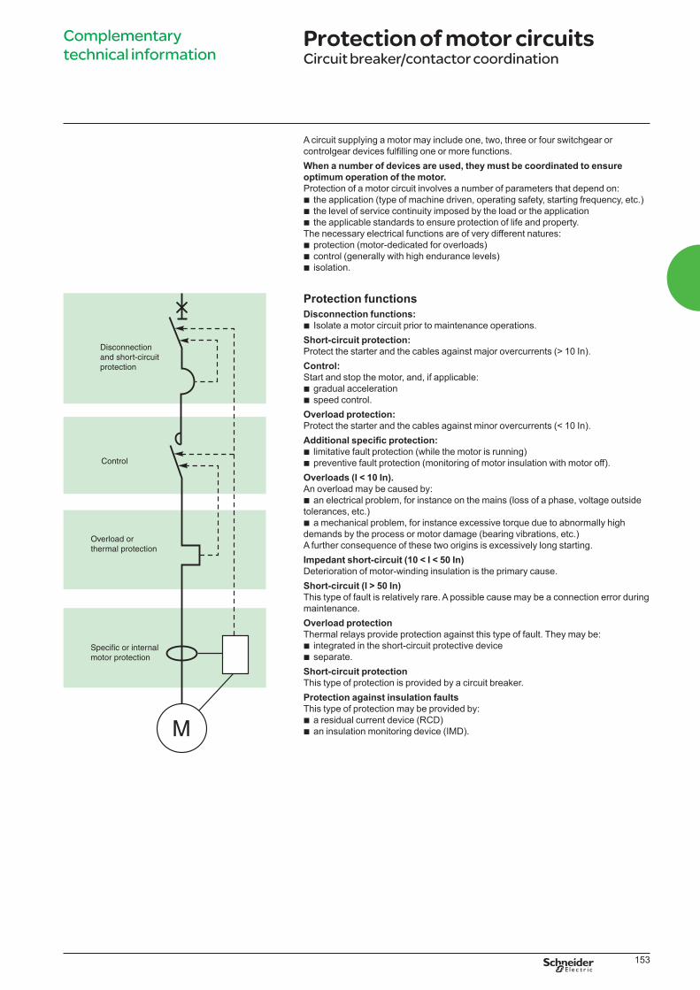
Protection functions
Disconnection functions:
b Isolate a motor circuit prior to maintenance operations.
Short-circuit protection:
Protect the starter and the cables against major overcurrents (> 10 In).
Control:
Start and stop the motor, and, if applicable:
b gradual acceleration
b speed control.
Overload protection:
Protect the starter and the cables against minor overcurrents (< 10 In).
b limitative fault protection (while the motor is running)
b preventive fault protection (monitoring of motor insulation with motor off).
Overloads (I < 10 In).
An overload may be caused by:
b an electrical problem, for instance on the mains (loss of a phase, voltage outside
tolerances, etc.)
b a mechanical problem, for instance excessive torque due to abnormally high
demands by the process or motor damage (bearing vibrations, etc.)
A further consequence of these two origins is excessively long starting.
Impedant short-circuit (10 < I < 50 In)
Deterioration of motor-winding insulation is the primary cause.
Short-circuit (I > 50 In)
This type of fault is relatively rare. A possible cause may be a connection error during
maintenance.
Overload protection
Thermal relays provide protection against this type of fault. They may be:
b integrated in the short-circuit protective device
b separate.
Short-circuit protection
This type of protection is provided by a circuit breaker.
Protection against insulation faults
This type of protection may be provided by:
b a residual current device (RCD)
b an insulation monitoring device (IMD).
LVPED308005EN.indb 153 14/12/2012 08:53:53
154
Complementary
technical information Protection of motor circuitsCircuit breaker/contactor coordination
Applicable standardsA circuit supplying a motor must comply with the general rules set out in IEC
standard 60947-4-1 and in particular with those concerning contactors, motor
starters and their protection as stipulated in IEC 60947-4-1, notably:
b coordination of the components of the motor circuit
b trip class for thermal relays
b contactor utilisation categories
b coordination of insulation.
Coordination of the components of the motor circuit
Two types of coordination
place the switchgear and controlgear in extreme conditions. Depending on the state
coordination:
b type 1:
Deterioration of the contactor and the relay is acceptable under two conditions:
v no danger to operating personnel
v no danger to any components other than the contactor and the relay
b type 2:
Only minor welding of the contactor or starter contacts is permissible and the
contacts must be easily separated.
v following type-2 coordination tests, the switchgear and controlgear functions must
be fully operational.
Which type of coordination is needed?
Selection of a type of coordination depends on the operating conditions
encountered.
The goal is to achieve the best balance between the user’s needs and the cost of the
installation.
b type 1:
vv low cost of switchgear and controlgear
v continuity of service is not imperative or may be ensured by simply replacing the
faulty motor drawer
b type 2:
v continuity of service is imperative
v limited maintenance service
v
LVPED308005EN.indb 154 14/12/2012 08:53:53
155
Complementary
technical information Protection of motor circuitsCircuit breaker/contactor coordination
The different test currents
"Ic", "r" and "Iq" test currents
To qualify for type-2 coordination, the standard requires three fault-current tests to
check that the switchgear and controlgear operates correctly under overload and
short-circuit conditions.
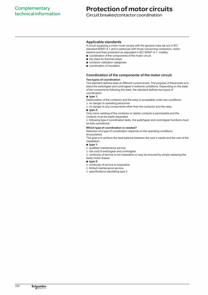
"Ic" current (overload I < 10 In)
The thermal relay provides protection against this type of fault, up to the Ic value (a
IEC standard 60947-4-1 stipulates two tests that must be carried out to guarantee
coordination between the thermal relay and the short-circuit protective device:
b at 0.75 Ic, only the thermal relay reacts
b at 1.25 Ic, the short-circuit protective device reacts.
Following the tests at 0.75 and 1.25 Ic, the trip characteristics of the thermal relay
must be unchanged. Type-2 coordination thus enhances continuity of service. The
contactor may be closed automatically following clearing of the faul.
"r" current
(Impedant short-circuit 10 < I < 50 In)
The primary cause of this type of fault is the deterioration of insulation. IEC standard
to check that the protective device provides protection against impedant short-
circuits.
thermal relay following the test.
The circuit breaker must trip in y 10 ms for a fault current u 15 In.
Operational current Ie (AC3) of the motor (in A) "r" current (kA)
Ie y 16 1
16 < Ie y 63 3
63 < Ie y 125 5
125 < Ie y 315 10
315 < Ie < 630 18
“Iq” current
(short-circuit I > 50 In)
This type of fault is relatively rare. A possible cause may be a connection error during
maintenance.
Short-circuit protection is provided by devices that open quickly.
u 50 kA.
The “Iq” current is used to check the coordination of the switchgear and controlgear
installed on a motor supply circuit.
Following this test under extreme conditions, all the coordinated switchgear
and controlgear must remain operational.
LVPED308005EN.indb 155 14/12/2012 08:53:53
156
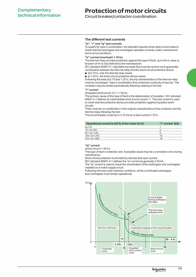
Trip class of a thermal relay.
Complementary
technical information Protection of motor circuitsCircuit breaker/contactor coordination
Trip class of a thermal relayThe four trip class of a thermal relay are 10 A, 10, 20 and 30
(maximum tripping times at 7.2 Ir).
Classes 10 and 10 A are the most commonly used. Classes 20 and 30 are reserved
The diagram and the table opposite can be used to select a thermal relay suited
to the motor starting time.
Class 1.05 Ir 1.2 Ir 1.5 Ir 7.2 Ir
10 A t > 2 h t < 2 h t < 2 min. 2 y t y 10 s
10 t > 2 h t < 2 h t < 4 min. 4 y t y 10 s
20 t > 2 h t < 2 h t < 8 min. 6 y t y 20 s
30 t > 2 h t < 2 h t < 12 min. 9 y t y 30 s
LVPED308005EN.indb 156 14/12/2012 08:53:53
157
Complementary
technical information Protection of motor circuitsCircuit breaker/contactor coordination
The four utilisation categories of contactors (AC1 to AC4)The four utilisation categories of contactors (AC1 to AC4)The utilisation category
determines the operating frequency and endurance of a contactor. The category
depends on the type of load. If the load is a motor; the category also depends on the
Main characteristics of the controlled electrical circuits and applications
Category Type of load Contactor usage Typical applications
AC1 No-inductive (cos 0.8) Energisation Heating, distribution
AC2 Slip-ring motors (cos 0.65) Starting Wire drawing machines
Switching off during running
Regenerative braking
Inching
AC3 Squirrel-cage motors Starting Compressors, lifts, mixing
(cos 0.45 for le y 100A) Switching off during running Pumps, escalators, fans,
(cos 0.35 for le > 100A) Conveyers, air-conditioning
AC4 Squirrel-cage motors Starting Printing machines, wire
(cos 0.45 for le y 100A) Switching off during running
(cos 0.35 for le > 100A) Regenerative braking
Plugging
Inching
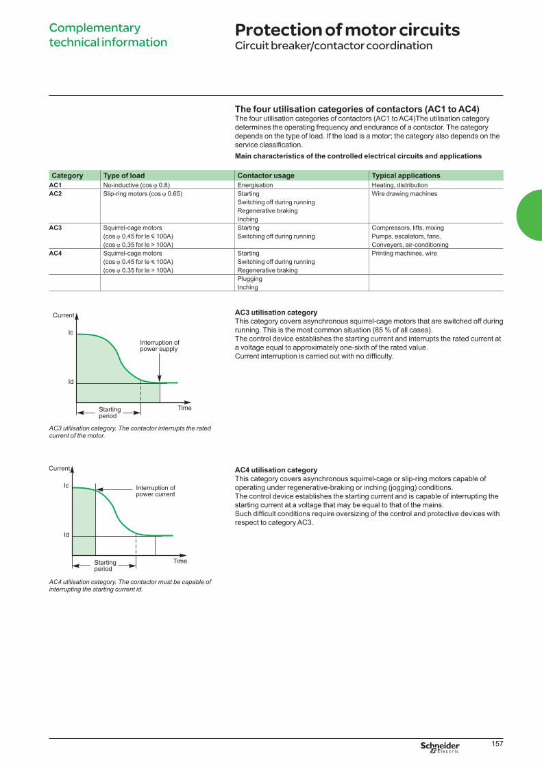
AC3 utilisation category
This category covers asynchronous squirrel-cage motors that are switched off during
running. This is the most common situation (85 % of all cases).
The control device establishes the starting current and interrupts the rated current at
a voltage equal to approximately one-sixth of the rated value.
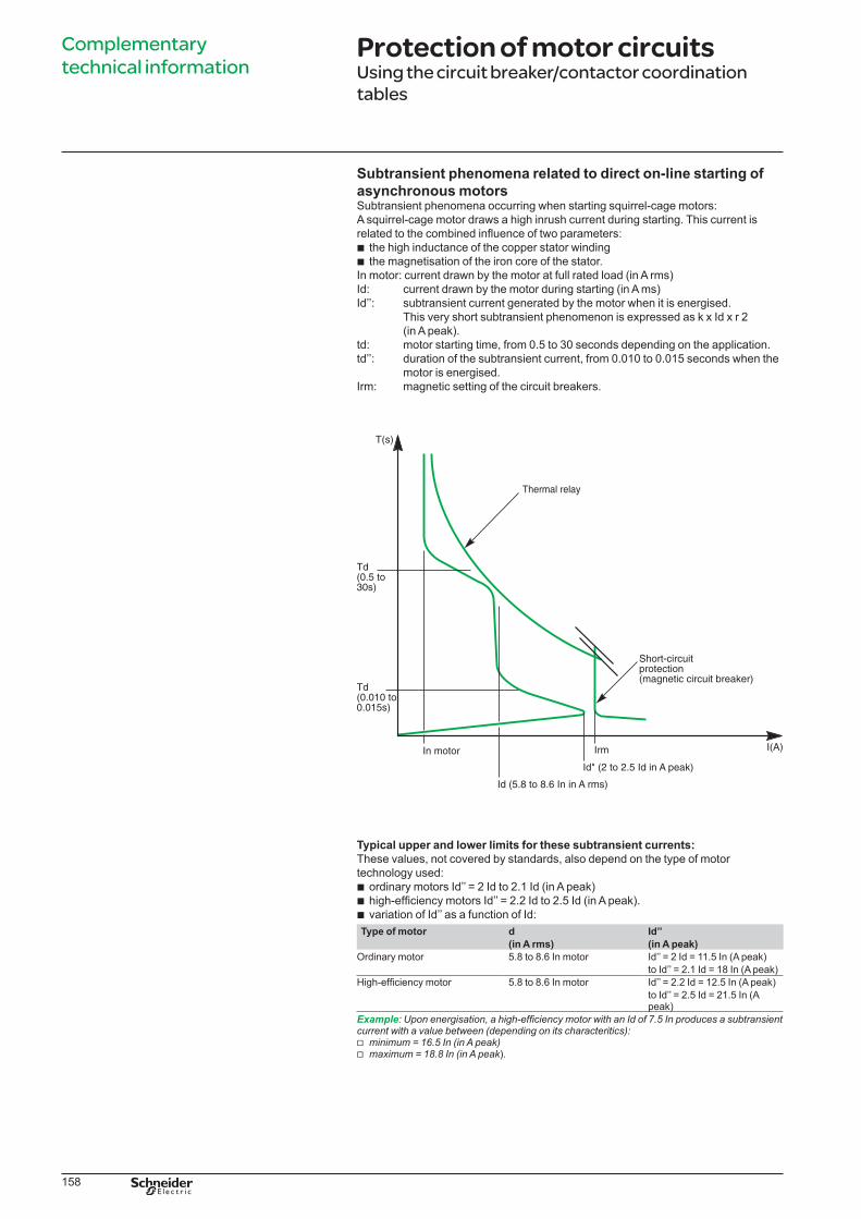
AC4 utilisation category
This category covers asynchronous squirrel-cage or slip-ring motors capable of
operating under regenerative-braking or inching (jogging) conditions.
The control device establishes the starting current and is capable of interrupting the
starting current at a voltage that may be equal to that of the mains.
respect to category AC3.
AC3 utilisation category. The contactor interrupts the rated current of the motor.
AC4 utilisation category. The contactor must be capable of interrupting the starting current id.
LVPED308005EN.indb 157 14/12/2012 08:53:53
158
Complementary
technical information Protection of motor circuitsUsing the circuit breaker/contactor coordination
tables
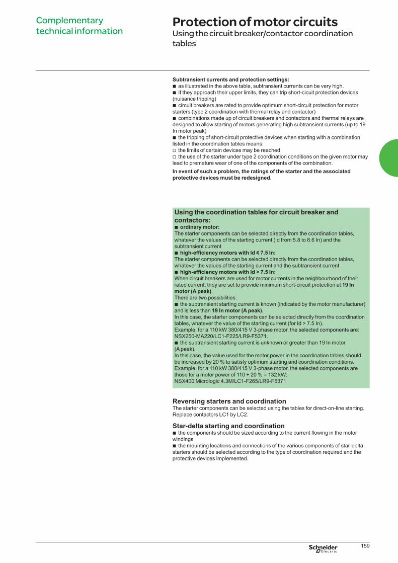
Subtransient phenomena related to direct on-line starting of
asynchronous motorsSubtransient phenomena occurring when starting squirrel-cage motors:
A squirrel-cage motor draws a high inrush current during starting. This current is
b the high inductance of the copper stator winding
b the magnetisation of the iron core of the stator.
In motor: current drawn by the motor at full rated load (in A rms)
Id: current drawn by the motor during starting (in A ms)
Id’’: subtransient current generated by the motor when it is energised.
This very short subtransient phenomenon is expressed as k x Id x r 2
(in A peak).
td: motor starting time, from 0.5 to 30 seconds depending on the application.
td’’: duration of the subtransient current, from 0.010 to 0.015 seconds when the
motor is energised.
Irm: magnetic setting of the circuit breakers.
Typical upper and lower limits for these subtransient currents:
These values, not covered by standards, also depend on the type of motor
technology used:
b ordinary motors Id’’ = 2 Id to 2.1 Id (in A peak)
bb variation of Id’’ as a function of Id:
Type of motor d Id’’
(in A rms) (in A peak)
Ordinary motor 5.8 to 8.6 In motor Id’’ = 2 Id = 11.5 In (A peak)
to Id’’ = 2.1 Id = 18 In (A peak)
5.8 to 8.6 In motor Id’’ = 2.2 Id = 12.5 In (A peak)
to Id’’ = 2.5 Id = 21.5 In (A peak)
Example
v minimum = 16.5 In (in A peak)v maximum = 18.8 In (in A peak).
LVPED308005EN.indb 158 14/12/2012 08:53:53
159
Complementary
technical information Protection of motor circuitsUsing the circuit breaker/contactor coordination
tables
Subtransient currents and protection settings:
b as illustrated in the above table, subtransient currents can be very high.
b If they approach their upper limits, they can trip short-cicuit protection devices
(nuisance tripping)
b circuit breakers are rated to provide optimum short-circuit protection for motor
starters (type 2 coordination with thermal relay and contactor)
b combinations made up of circuit breakers and contactors and thermal relays are
designed to allow starting of motors generating high subtransient currents (up to 19
In motor peak)
b the tripping of short-circuit protective devices when starting with a combination
listed in the coordination tables means:
v the limits of certain devices may be reached
v the use of the starter under type 2 coordination conditions on the given motor may
lead to premature wear of one of the components of the combination.
In event of such a problem, the ratings of the starter and the associated
protective devices must be redesigned.
Using the coordination tables for circuit breaker and
contactors:b ordinary motor:
The starter components can be selected directly from the coordination tables,
whatever the values of the starting current (Id from 5.8 to 8.6 In) and the
subtransient current
b y 7.5 In:
The starter components can be selected directly from the coordination tables,
whatever the values of the starting current and the subtransient current
bWhen circuit breakers are used for motor currents in the neighbourhood of their
rated current, they are set to provide minimum short-circuit protection at 19 In
motor (A peak).
There are two possibilities:
b the subtransient starting current is known (indicated by the motor manufacturer)
and is less than 19 In motor (A peak).
In this case, the starter components can be selected directly from the coordination
tables, whatever the value of the starting current (for Id > 7.5 In).
Example: for a 110 kW 380/415 V 3-phase motor, the selected components are:
NSX250-MA220/LC1-F225/LR9-F5371.
b the subtransient starting current is unknown or greater than 19 In motor
(A peak).
In this case, the value used for the motor power in the coordination tables should
be increased by 20 % to satisfy optimum starting and coordination conditions.
Example: for a 110 kW 380/415 V 3-phase motor, the selected components are
those for a motor power of 110 + 20 % = 132 kW:
NSX400 Micrologic 4.3M/LC1-F265/LR9-F5371
Reversing starters and coordinationThe starter components can be selected using the tables for direct-on-line starting.
Replace contactors LC1 by LC2.
Star-delta starting and coordinationbwindings
b the mounting locations and connections of the various components of star-delta
starters should be selected according to the type of coordination required and the
protective devices implemented.
LVPED308005EN.indb 159 14/12/2012 08:53:54
160
Complementary
technical information Protection of motor circuitsUsing the circuit breaker/contactor coordination
tables
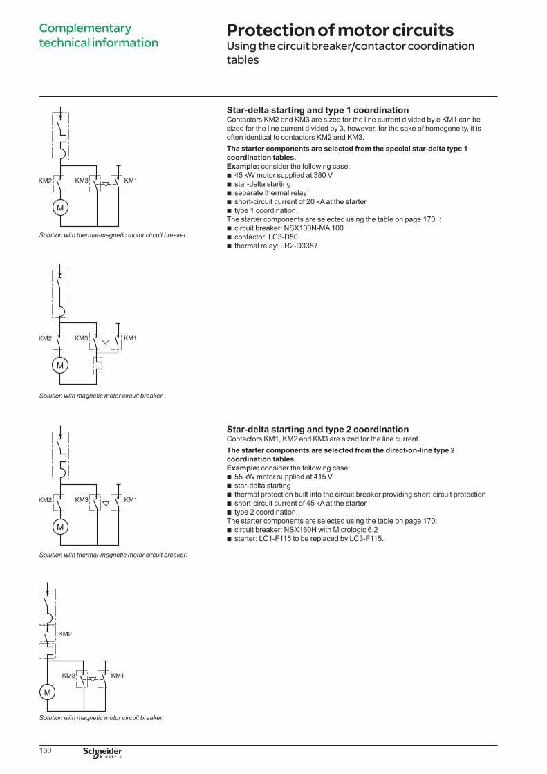
Star-delta starting and type 1 coordinationContactors KM2 and KM3 are sized for the line current divided by e KM1 can be
sized for the line current divided by 3, however, for the sake of homogeneity, it is
often identical to contactors KM2 and KM3.
The starter components are selected from the special star-delta type 1
coordination tables.
Example: consider the following case:
b 45 kW motor supplied at 380 V
b star-delta starting
b separate thermal relay
b short-circuit current of 20 kA at the starter
b type 1 coordination.
The starter components are selected using the table on page 170 :
b circuit breaker: NSX100N-MA 100
b contactor: LC3-D50
b thermal relay: LR2-D3357.
Star-delta starting and type 2 coordinationContactors KM1, KM2 and KM3 are sized for the line current.
The starter components are selected from the direct-on-line type 2
coordination tables.
Example: consider the following case:
b 55 kW motor supplied at 415 V
b star-delta starting
b thermal protection built into the circuit breaker providing short-circuit protection
b short-circuit current of 45 kA at the starter
b type 2 coordination.
The starter components are selected using the table on page 170:
b circuit breaker: NSX160H with Micrologic 6.2
b starter: LC1-F115 to be replaced by LC3-F115.
Solution with thermal-magnetic motor circuit breaker.
Solution with magnetic motor circuit breaker.
Solution with thermal-magnetic motor circuit breaker.
Solution with magnetic motor circuit breaker.
LVPED308005EN.indb 160 14/12/2012 08:53:54
161
Complementary
technical information Protection of motor circuitsCircuit breaker/contactor coordination
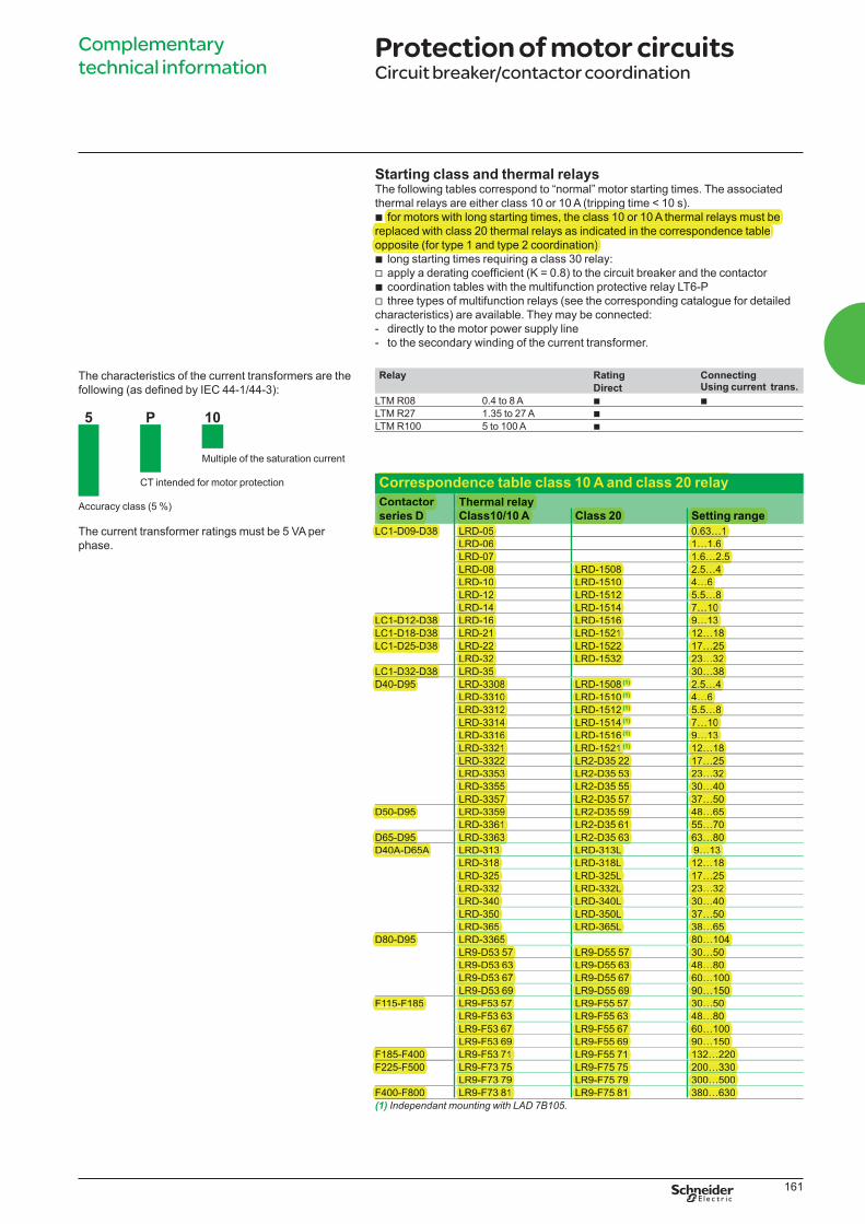
Relay Rating ConnectingUsing current trans. Direct
LTM R08 0.4 to 8 A b b
LTM R27 1.35 to 27 A b
LTM R100 5 to 100 A b
The characteristics of the current transformers are the
5 P 10
Multiple of the saturation current
CT intended for motor protection
Accuracy class (5 %)
The current transformer ratings must be 5 VA per
phase.
Starting class and thermal relaysThe following tables correspond to “normal” motor starting times. The associated
thermal relays are either class 10 or 10 A (tripping time < 10 s).
b for motors with long starting times, the class 10 or 10 A thermal relays must be
replaced with class 20 thermal relays as indicated in the correspondence table
opposite (for type 1 and type 2 coordination)
b long starting times requiring a class 30 relay:
vb coordination tables with the multifunction protective relay LT6-P
v three types of multifunction relays (see the corresponding catalogue for detailed
characteristics) are available. They may be connected:
- directly to the motor power supply line
- to the secondary winding of the current transformer.
Correspondence table class 10 A and class 20 relay
Contactor
series D
Thermal relay
Class10/10 A Class 20 Setting range
LC1-D09-D38 LRD-05 0.63…1
LRD-06 1…1.6
LRD-07 1.6…2.5
LRD-08 LRD-1508 2.5…4
LRD-10 LRD-1510 4…6
LRD-12 LRD-1512 5.5…8
LRD-14 LRD-1514 7…10
LC1-D12-D38 LRD-16 LRD-1516 9…13
LC1-D18-D38 LRD-21 LRD-1521 12…18
LC1-D25-D38 LRD-22 LRD-1522 17…25
LRD-32 LRD-1532 23…32
LC1-D32-D38 LRD-35 30…38
D40-D95 LRD-3308 LRD-1508 (1) 2.5…4
LRD-3310 LRD-1510 (1) 4…6
LRD-3312 LRD-1512 (1) 5.5…8
LRD-3314 LRD-1514 (1) 7…10
LRD-3316 LRD-1516 (1) 9…13
LRD-3321 LRD-1521 (1) 12…18
LRD-3322 LR2-D35 22 17…25
LRD-3353 LR2-D35 53 23…32
LRD-3355 LR2-D35 55 30…40
LRD-3357 LR2-D35 57 37…50
D50-D95 LRD-3359 LR2-D35 59 48…65
LRD-3361 LR2-D35 61 55…70
D65-D95 LRD-3363 LR2-D35 63 63…80
D40A-D65A LRD-313 LRD-313L 9…13
LRD-318 LRD-318L 12…18
LRD-325 LRD-325L 17…25
LRD-332 LRD-332L 23…32
LRD-340 LRD-340L 30…40
LRD-350 LRD-350L 37…50
LRD-365 LRD-365L 38…65
D80-D95 LRD-3365 80…104
LR9-D53 57 LR9-D55 57 30…50
LR9-D53 63 LR9-D55 63 48…80
LR9-D53 67 LR9-D55 67 60…100
LR9-D53 69 LR9-D55 69 90…150
F115-F185 LR9-F53 57 LR9-F55 57 30…50
LR9-F53 63 LR9-F55 63 48…80
LR9-F53 67 LR9-F55 67 60…100
LR9-F53 69 LR9-F55 69 90…150
F185-F400 LR9-F53 71 LR9-F55 71 132…220
F225-F500 LR9-F73 75 LR9-F75 75 200…330
LR9-F73 79 LR9-F75 79 300…500
F400-F800 LR9-F73 81 LR9-F75 81 380…630
(1) Independant mounting with LAD 7B105.
LVPED308005EN.indb 161 14/12/2012 08:53:54
thermal relays are either class 10 or 10 A (tripping time < 10 s).
for motors with long starting times, the class 10 or 10 A thermal relays must be for motors with long starting times, the class 10 or 10 A thermal relays must be
replaced with class 20 thermal relays as indicated in the correspondence table replaced with class 20 thermal relays as indicated in the correspondence table
opposite (for type 1 and type 2 coordination)
Correspondence table class 10 A and class 20 relay
Contactor Thermal relayThermal relay
series D
Thermal relayThermal relay
Class10/10 A Class 20 Setting range
LC1-D09-D38 LRD-05LC1-D09-D38 LRD-05 0.63…1
LRD-06 1…1.6
LRD-07 1.6…2.5
LRD-08 LRD-1508 2.5…4
LRD-10 LRD-1510 4…6
LRD-12 LRD-1512 5.5…8
LRD-14 LRD-1514 7…10
LC1-D12-D38 LRD-16LC1-D12-D38 LRD-16 LRD-1516 9…13
LC1-D18-D38 LRD-21LC1-D18-D38 LRD-21 LRD-1521 12…18
LC1-D25-D38 LRD-22LC1-D25-D38 LRD-22 LRD-1522 17…25
LRD-32 LRD-1532 23…32
LC1-D32-D38 LRD-35LC1-D32-D38 LRD-35 30…38
D40-D95 LRD-3308D40-D95 LRD-3308 LRD-1508 (1) 2.5…4 (1)
LRD-3310 LRD-1510 (1) 4…6 (1)
LRD-3312 LRD-1512 (1) 5.5…8 (1)
LRD-3314 LRD-1514 (1) 7…10 (1)
LRD-3316 LRD-1516 (1) 9…13 (1)
LRD-3321 LRD-1521 (1) 12…18 (1)
LRD-3322 LR2-D35 22 17…25
LRD-3353 LR2-D35 53 23…32
LRD-3355 LR2-D35 55 30…40
LRD-3357 LR2-D35 57 37…50
D50-D95 LRD-3359D50-D95 LRD-3359 LR2-D35 59 48…65
LRD-3361 LR2-D35 61 55…70
D65-D95 LRD-3363D65-D95 LRD-3363 LR2-D35 63 63…80
D40A-D65A LRD-313D40A-D65A LRD-313 LRD-313L 9…13
LRD-318 LRD-318L 12…18
LRD-325 LRD-325L 17…25
LRD-332 LRD-332L 23…32
LRD-340 LRD-340L 30…40
LRD-350 LRD-350L 37…50
LRD-365 LRD-365L 38…65
D80-D95 LRD-3365D80-D95 LRD-3365 80…104
LR9-D53 57 LR9-D55 57 30…50
LR9-D53 63 LR9-D55 63 48…80
LR9-D53 67 LR9-D55 67 60…100
LR9-D53 69 LR9-D55 69 90…150
F115-F185 LR9-F53 57 LR9-F55 57 30…50
LR9-F53 63 LR9-F55 63 48…80
LR9-F53 67 LR9-F55 67 60…100
LR9-F53 69 LR9-F55 69 90…150
F185-F400 LR9-F53 71 LR9-F55 71 132…220
F225-F500 LR9-F73 75 LR9-F75 75 200…330
LR9-F73 79 LR9-F75 79 300…500
F400-F800 LR9-F73 81 LR9-F75 81 380…630

162
Complementary
technical informationType 2 coordination (IEC 60947-4-1) 220/240 V
Circuit breakers, contactors and thermal relays
Performance: Ue = 220/240 VCircuit breakers N H L
NS80-MA - 100 kA -
Starting (1): normal, LRD2 class 10 A, LR9 class 10.
Motors Circuit breakers Contactors (2) Thermal o/l relays
P (kW) I (A) 220 V I (A) 240 V Ie max (A) Type Rating (A) Irm (A) Type Type Irth (A) (1)
0.09 0.7 0.6 1 NS80H-MA 1.5 13.5 LC1 D09 LRD 05 0.63/1
0.12 0.9 0.8 1 NS80H-MA 1.5 13.5 LC1 D09 LRD 05 0.63/1
0.18 1.2 1.1 1.6 NS80H-MA 2.5 22.5 LC1 D09 LRD 06 1/1.6
0.25 1.5 1.4 2.5 NS80H-MA 2.5 32.5 LC1 D09 LRD 07 1.6/2.5
0.37 2 1.8 2.5 NS80H-MA 2.5 32.5 LC1 D09 LRD 07 1.6/2.5
0.55 2.8 2.6 4 NS80H-MA 6.3 57 LC1 D32 LRD 08 2.5/4
0.75 3.5 3.2 4 NS80H-MA 6.3 57 LC1 D32 LRD 08 2.5/4
1.1 5 4.5 6 NS80H-MA 6.3 82 LC1 D32 LRD 10 4/6
1.5 6.5 6 8 NS80H-MA 12.5 113 LC1 D40 LRD 33 12 5.5/8
2.2 9 8 10 NS80H-MA 12.5 138 LC1 D40 LRD 33 14 7/10
3 12 11 12.5 NS80H-MA 12.5 163 LC1 D40 LRD 33 16 9/13
4 15 14 18 NS80H-MA 25 250 LC1 D40 LRD 33 21 12/18
5.5 21 19 25 NS80H-MA 25 325 LC1 D40 LRD 33 22 17/25
6.3 24 22 25 NS80H-MA 25 325 LC1 D40 LRD 33 22 17/25
7.5 28 25 32 NS80H-MA 50 450 LC1 D40 LRD 33 53 23/32
10 36 33 40 NS80H-MA 50 550 LC1 D50 LRD 33 55 30/40
11 39 36 50 NS80H-MA 50 650 LC1 D50 LRD 33 57 37/50
15 52 48 65 NS80H-MA 80 880 LC1 D65 LRD 33 59 48/65
18.5 63 59 65 NS80H-MA 80 880 LC1 D65 LRD 33 59 48/65
22 75 70 80 NS80H-MA 80 1040 LC1 D80 LRD 33 63 63/80
(1) For long starting (class 20), see the correspondence table for thermal relay.(2)
DB
115219.e
ps
LVPED308005EN.indb 162 14/12/2012 08:53:54
163
Complementary
technical informationType 2 coordination (IEC 60947-4-1) 220/240 V
Circuit breakers, contactors and thermal relays
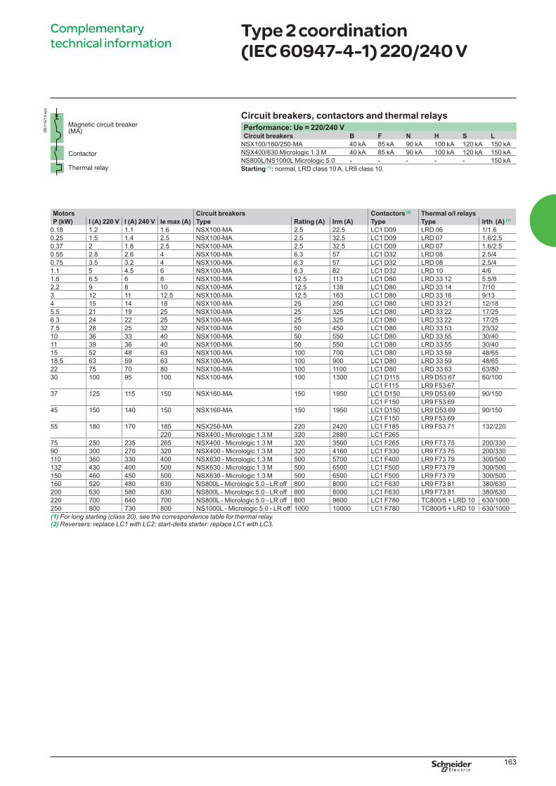
Performance: Ue = 220/240 VCircuit breakers B F N H S L
NSX100/160/250-MA 40 kA 85 kA 90 kA 100 kA 120 kA 150 kA
NSX400/630 Micrologic 1.3 M 40 kA 85 kA 90 kA 100 kA 120 kA 150 kA
NS800L/NS1000L Micrologic 5.0 - - - - - 150 kA
Starting (1): normal, LRD class 10 A, LR9 class 10.
Motors Circuit breakers Contactors (2) Thermal o/l relays
P (kW) I (A) 220 V I (A) 240 V Ie max (A) Type Rating (A) Irm (A) Type Type Irth (A) (1)
0.18 1.2 1.1 1.6 NSX100-MA 2.5 22.5 LC1 D09 LRD 06 1/1.6
0.25 1.5 1.4 2.5 NSX100-MA 2.5 32.5 LC1 D09 LRD 07 1.6/2.5
0.37 2 1.8 2.5 NSX100-MA 2.5 32.5 LC1 D09 LRD 07 1.6/2.5
0.55 2.8 2.6 4 NSX100-MA 6.3 57 LC1 D32 LRD 08 2.5/4
0.75 3.5 3.2 4 NSX100-MA 6.3 57 LC1 D32 LRD 08 2.5/4
1.1 5 4.5 6 NSX100-MA 6.3 82 LC1 D32 LRD 10 4/6
1.5 6.5 6 8 NSX100-MA 12.5 113 LC1 D80 LRD 33 12 5.5/8
2.2 9 8 10 NSX100-MA 12.5 138 LC1 D80 LRD 33 14 7/10
3 12 11 12.5 NSX100-MA 12.5 163 LC1 D80 LRD 33 16 9/13
4 15 14 18 NSX100-MA 25 250 LC1 D80 LRD 33 21 12/18
5.5 21 19 25 NSX100-MA 25 325 LC1 D80 LRD 33 22 17/25
6.3 24 22 25 NSX100-MA 25 325 LC1 D80 LRD 33 22 17/25
7.5 28 25 32 NSX100-MA 50 450 LC1 D80 LRD 33 53 23/32
10 36 33 40 NSX100-MA 50 550 LC1 D80 LRD 33 55 30/40
11 39 36 40 NSX100-MA 50 550 LC1 D80 LRD 33 55 30/40
15 52 48 63 NSX100-MA 100 700 LC1 D80 LRD 33 59 48/65
18.5 63 59 63 NSX100-MA 100 900 LC1 D80 LRD 33 59 48/65
22 75 70 80 NSX100-MA 100 1100 LC1 D80 LRD 33 63 63/80
30 100 95 100 NSX100-MA 100 1300 LC1 D115 LR9 D53 67 60/100
LC1 F115 LR9 F53 67
37 125 115 150 NSX160-MA 150 1950 LC1 D150 LR9 D53 69 90/150
LC1 F150 LR9 F53 69
45 150 140 150 NSX160-MA 150 1950 LC1 D150 LR9 D53 69 90/150
LC1 F150 LR9 F53 69
55 180 170 185 NSX250-MA 220 2420 LC1 F185 LR9 F53 71 132/220
220 NSX400 - Micrologic 1.3 M 320 2880 LC1 F265
75 250 235 265 NSX400 - Micrologic 1.3 M 320 3500 LC1 F265 LR9 F73 75 200/330
90 300 270 320 NSX400 - Micrologic 1.3 M 320 4160 LC1 F330 LR9 F73 75 200/330
110 360 330 400 NSX630 - Micrologic 1.3 M 500 5700 LC1 F400 LR9 F73 79 300/500
132 430 400 500 NSX630 - Micrologic 1.3 M 500 6500 LC1 F500 LR9 F73 79 300/500
150 460 450 500 NSX630 - Micrologic 1.3 M 500 6500 LC1 F500 LR9 F73 79 300/500
160 520 480 630 NS800L - Micrologic 5.0 - LR off 800 8000 LC1 F630 LR9 F73 81 380/630
200 630 580 630 NS800L - Micrologic 5.0 - LR off 800 8000 LC1 F630 LR9 F73 81 380/630
220 700 640 700 NS800L - Micrologic 5.0 - LR off 800 9600 LC1 F780 TC800/5 + LRD 10 630/1000
250 800 730 800 NS1000L - Micrologic 5.0 - LR off 1000 10000 LC1 F780 TC800/5 + LRD 10 630/1000
(1) For long starting (class 20), see the correspondence table for thermal relay.(2)
DB
115219.e
ps
LVPED308005EN.indb 163 14/12/2012 08:53:55
164
Complementary
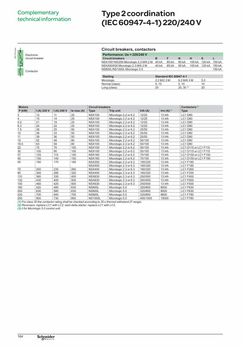
technical informationType 2 coordination (IEC 60947-4-1) 220/240 V
Circuit breakers, contactors
Performance: Ue = 220/240 VCircuit breakers B F N H S L
NSX100/160/250 Micrologic 2.2 M/6.2 M 40 kA 85 kA 90 kA 100 kA 120 kA 150 kA
NSX400/630 Micrologic 2.3 M/6.3 M 40 kA 85 kA 90 kA 100 kA 120 kA 150 kA
NS800L/NS1000L Micrologic 5.0 - - - - - 150 kA
Starting Standard IEC 60947-4-1
Micrologic 2.2 M/2.3 M 6.2 M/6.3 M 5.0
Normal (class) 5, 10 5, 10 10
Long (class) 20 20, 30 (1) 20
Motors Circuit breakers Contactors (2)
P (kW) I (A) 220 V I (A) 240 V Ie max (A) Type Trip unit Irth (A) Irm (A) (3) Type
3 12 11 25 NSX100 Micrologic 2.2 or 6.2 12/25 13 Irth LC1 D80
4 15 14 25 NSX100 Micrologic 2.2 or 6.2 12/25 13 Irth LC1 D80
5.5 21 19 25 NSX100 Micrologic 2.2 or 6.2 12/25 13 Irth LC1 D80
6.3 24 22 25 NSX100 Micrologic 2.2 or 6.2 12/25 13 Irth LC1 D80
7.5 28 25 50 NSX100 Micrologic 2.2 or 6.2 25/50 13 Irth LC1 D80
10 36 33 50 NSX100 Micrologic 2.2 or 6.2 25/50 13 Irth LC1 D80
11 39 36 50 NSX100 Micrologic 2.2 or 6.2 25/50 13 Irth LC1 D80
15 52 48 80 NSX100 Micrologic 2.2 or 6.2 50/100 13 Irth LC1 D80
18.5 63 59 80 NSX100 Micrologic 2.2 or 6.2 50/100 13 Irth LC1 D80
22 75 70 100 NSX100 Micrologic 2.2 or 6.2 50/100 13 Irth LC1 D115 or LC1 F115
30 100 95 100 NSX100 Micrologic 2.2 or 6.2 50/100 13 Irth LC1 D115 or LC1 F115
37 125 115 150 NSX160 Micrologic 2.2 or 6.2 70/150 13 Irth LC1 D150 or LC1 F150
45 150 140 150 NSX160 Micrologic 2.2 or 6.2 70/150 13 Irth LC1 D150 or LC1 F150
55 180 170 185 NSX250 Micrologic 2.2 or 6.2 100/220 13 Irth LC1 F185
NSX400 Micrologic 2.3 or 6.3 160/320 13 Irth LC1 F185
75 250 235 265 NSX400 Micrologic 2.3 or 6.3 160/320 13 Irth LC1 F265
90 300 280 320 NSX400 Micrologic 2.3 or 6.3 160/320 13 Irth LC1 F330
110 360 330 400 NSX630 Micrologic 2.3 or 6.3 250/500 13 Irth LC1 F400
132 430 400 500 NSX630 Micrologic 2.3 or 6.3 250/500 13 Irth LC1 F500
150 460 420 500 NSX630 Micrologic 2.3 or 6.3 250/500 13 Irth LC1 F500
160 520 480 630 NS800L Micrologic 5.0 320/800 8000 LC1 F630
200 630 580 630 NS800L Micrologic 5.0 320/800 8000 LC1 F630
220 700 640 700 NS800L Micrologic 5.0 320/800 9600 LC1 F780
250 800 730 800 NS1000L Micrologic 5.0 400/1000 10000 LC1 F780
(1) For class 30 the contactor rating shall be checked according to 30 s thermal withstand (F range).(2)(3) Ii for Micrologic 5.0 control unit.
DB
115218.e
ps
LVPED308005EN.indb 164 14/12/2012 08:53:55
165
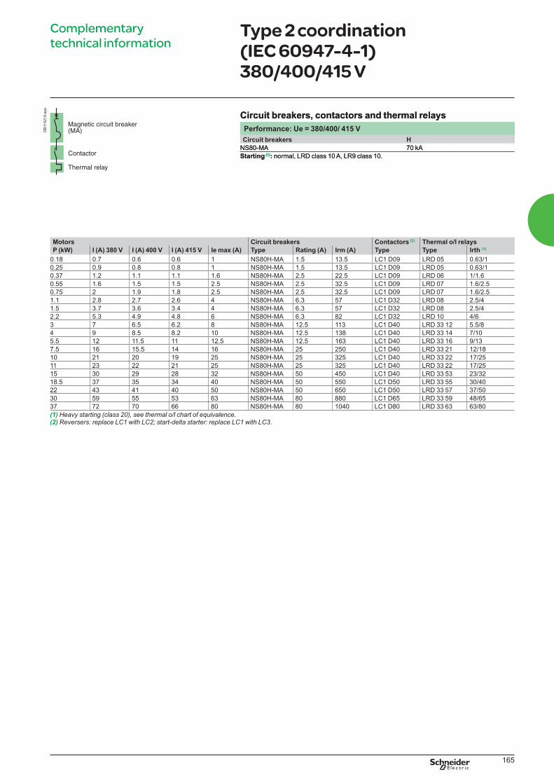
Circuit breakers, contactors and thermal relays
Performance: Ue = 380/400/ 415 V
Circuit breakers H
NS80-MA 70 kA
Starting (1): normal, LRD class 10 A, LR9 class 10.
Complementary
technical informationType 2 coordination (IEC 60947-4-1) 380/400/415 V
Circuit breakers, contactors and thermal relays
Performance: Ue = 380/400/ 415 V
Circuit breakers H
NS80-MA 70 kA
Starting (1): normal, LRD class 10 A, LR9 class 10.
Motors Circuit breakers Contactors (2) Thermal o/l relays
P (kW) I (A) 380 V I (A) 400 V I (A) 415 V Ie max (A) Type Rating (A) Irm (A) Type Type Irth (1)
0.18 0.7 0.6 0.6 1 NS80H-MA 1.5 13.5 LC1 D09 LRD 05 0.63/1
0.25 0.9 0.8 0.8 1 NS80H-MA 1.5 13.5 LC1 D09 LRD 05 0.63/1
0.37 1.2 1.1 1.1 1.6 NS80H-MA 2.5 22.5 LC1 D09 LRD 06 1/1.6
0.55 1.6 1.5 1.5 2.5 NS80H-MA 2.5 32.5 LC1 D09 LRD 07 1.6/2.5
0.75 2 1.9 1.8 2.5 NS80H-MA 2.5 32.5 LC1 D09 LRD 07 1.6/2.5
1.1 2.8 2.7 2.6 4 NS80H-MA 6.3 57 LC1 D32 LRD 08 2.5/4
1.5 3.7 3.6 3.4 4 NS80H-MA 6.3 57 LC1 D32 LRD 08 2.5/4
2.2 5.3 4.9 4.8 6 NS80H-MA 6.3 82 LC1 D32 LRD 10 4/6
3 7 6.5 6.2 8 NS80H-MA 12.5 113 LC1 D40 LRD 33 12 5.5/8
4 9 8.5 8.2 10 NS80H-MA 12.5 138 LC1 D40 LRD 33 14 7/10
5.5 12 11.5 11 12.5 NS80H-MA 12.5 163 LC1 D40 LRD 33 16 9/13
7.5 16 15.5 14 16 NS80H-MA 25 250 LC1 D40 LRD 33 21 12/18
10 21 20 19 25 NS80H-MA 25 325 LC1 D40 LRD 33 22 17/25
11 23 22 21 25 NS80H-MA 25 325 LC1 D40 LRD 33 22 17/25
15 30 29 28 32 NS80H-MA 50 450 LC1 D40 LRD 33 53 23/32
18.5 37 35 34 40 NS80H-MA 50 550 LC1 D50 LRD 33 55 30/40
22 43 41 40 50 NS80H-MA 50 650 LC1 D50 LRD 33 57 37/50
30 59 55 53 63 NS80H-MA 80 880 LC1 D65 LRD 33 59 48/65
37 72 70 66 80 NS80H-MA 80 1040 LC1 D80 LRD 33 63 63/80
(1) Heavy starting (class 20), see thermal o/l chart of equivalence.(2)
DB
115219.e
ps
LVPED308005EN.indb 165 14/12/2012 08:53:55
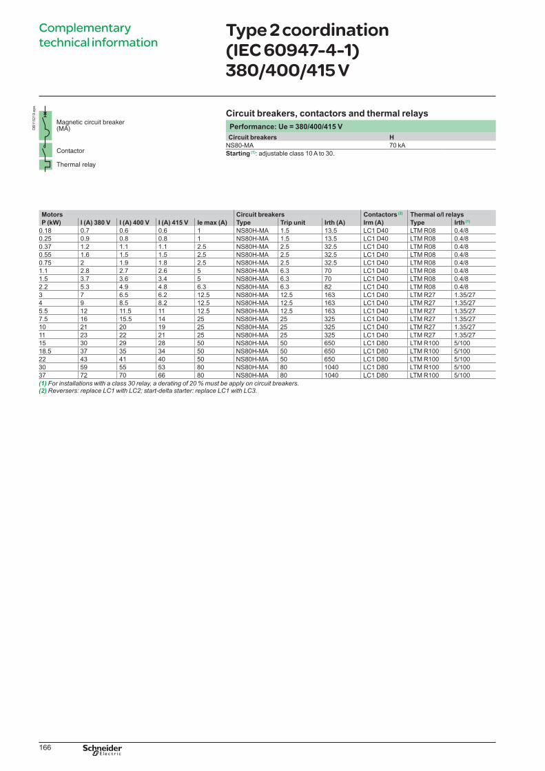
166
Complementary
technical informationType 2 coordination (IEC 60947-4-1) 380/400/415 V
Motors Circuit breakers Contactors (2) Thermal o/l relays
P (kW) I (A) 380 V I (A) 400 V I (A) 415 V Ie max (A) Type Trip unit Irth (A) Irm (A) Type Irth (1)
0.18 0.7 0.6 0.6 1 NS80H-MA 1.5 13.5 LC1 D40 LTM R08 0.4/8
0.25 0.9 0.8 0.8 1 NS80H-MA 1.5 13.5 LC1 D40 LTM R08 0.4/8
0.37 1.2 1.1 1.1 2.5 NS80H-MA 2.5 32.5 LC1 D40 LTM R08 0.4/8
0.55 1.6 1.5 1.5 2.5 NS80H-MA 2.5 32.5 LC1 D40 LTM R08 0.4/8
0.75 2 1.9 1.8 2.5 NS80H-MA 2.5 32.5 LC1 D40 LTM R08 0.4/8
1.1 2.8 2.7 2.6 5 NS80H-MA 6.3 70 LC1 D40 LTM R08 0.4/8
1.5 3.7 3.6 3.4 5 NS80H-MA 6.3 70 LC1 D40 LTM R08 0.4/8
2.2 5.3 4.9 4.8 6.3 NS80H-MA 6.3 82 LC1 D40 LTM R08 0.4/8
3 7 6.5 6.2 12.5 NS80H-MA 12.5 163 LC1 D40 LTM R27 1.35/27
4 9 8.5 8.2 12.5 NS80H-MA 12.5 163 LC1 D40 LTM R27 1.35/27
5.5 12 11.5 11 12.5 NS80H-MA 12.5 163 LC1 D40 LTM R27 1.35/27
7.5 16 15.5 14 25 NS80H-MA 25 325 LC1 D40 LTM R27 1.35/27
10 21 20 19 25 NS80H-MA 25 325 LC1 D40 LTM R27 1.35/27
11 23 22 21 25 NS80H-MA 25 325 LC1 D40 LTM R27 1.35/27
15 30 29 28 50 NS80H-MA 50 650 LC1 D80 LTM R100 5/100
18.5 37 35 34 50 NS80H-MA 50 650 LC1 D80 LTM R100 5/100
22 43 41 40 50 NS80H-MA 50 650 LC1 D80 LTM R100 5/100
30 59 55 53 80 NS80H-MA 80 1040 LC1 D80 LTM R100 5/100
37 72 70 66 80 NS80H-MA 80 1040 LC1 D80 LTM R100 5/100
(1) For installations with a class 30 relay, a derating of 20 % must be apply on circuit breakers.(2)
Circuit breakers, contactors and thermal relays
Performance: Ue = 380/400/415 V
Circuit breakers H
NS80-MA 70 kA
Starting (1): adjustable class 10 A to 30.
DB
115219.e
ps
LVPED308005EN.indb 166 14/12/2012 08:53:56
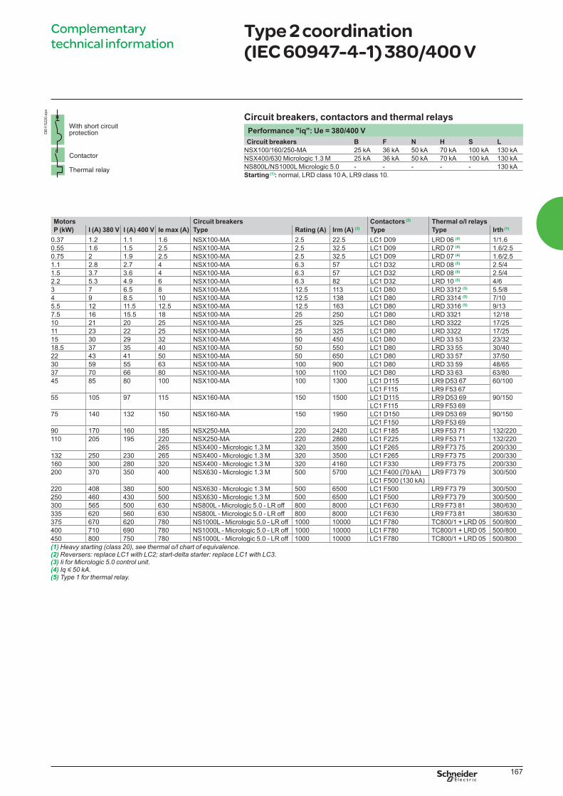
167
Complementary
technical informationType 2 coordination (IEC 60947-4-1) 380/400 V
Circuit breakers, contactors and thermal relays
Performance "iq": Ue = 380/400 V
Circuit breakers B F N H S L
NSX100/160/250-MA 25 kA 36 kA 50 kA 70 kA 100 kA 130 kA
NSX400/630 Micrologic 1.3 M 25 kA 36 kA 50 kA 70 kA 100 kA 130 kA
NS800L/NS1000L Micrologic 5.0 - - - - - 130 kA
Starting (1): normal, LRD class 10 A, LR9 class 10.
Motors Circuit breakers Contactors (2) Thermal o/l relays
P (kW) I (A) 380 V I (A) 400 V Ie max (A) Type Rating (A) Irm (A) (3) Type Type Irth (1)
0.37 1.2 1.1 1.6 NSX100-MA 2.5 22.5 LC1 D09 LRD 06 (4) 1/1.6
0.55 1.6 1.5 2.5 NSX100-MA 2.5 32.5 LC1 D09 LRD 07 (4) 1.6/2.5
0.75 2 1.9 2.5 NSX100-MA 2.5 32.5 LC1 D09 LRD 07 (4) 1.6/2.5
1.1 2.8 2.7 4 NSX100-MA 6.3 57 LC1 D32 LRD 08 (5) 2.5/4
1.5 3.7 3.6 4 NSX100-MA 6.3 57 LC1 D32 LRD 08 (5) 2.5/4
2.2 5.3 4.9 6 NSX100-MA 6.3 82 LC1 D32 LRD 10 (5) 4/6
3 7 6.5 8 NSX100-MA 12.5 113 LC1 D80 LRD 3312 (5) 5.5/8
4 9 8.5 10 NSX100-MA 12.5 138 LC1 D80 LRD 3314 (5) 7/10
5.5 12 11.5 12.5 NSX100-MA 12.5 163 LC1 D80 LRD 3316 (5) 9/13
7.5 16 15.5 18 NSX100-MA 25 250 LC1 D80 LRD 3321 12/18
10 21 20 25 NSX100-MA 25 325 LC1 D80 LRD 3322 17/25
11 23 22 25 NSX100-MA 25 325 LC1 D80 LRD 3322 17/25
15 30 29 32 NSX100-MA 50 450 LC1 D80 LRD 33 53 23/32
18.5 37 35 40 NSX100-MA 50 550 LC1 D80 LRD 33 55 30/40
22 43 41 50 NSX100-MA 50 650 LC1 D80 LRD 33 57 37/50
30 59 55 63 NSX100-MA 100 900 LC1 D80 LRD 33 59 48/65
37 70 66 80 NSX100-MA 100 1100 LC1 D80 LRD 33 63 63/80
45 85 80 100 NSX100-MA 100 1300 LC1 D115 LR9 D53 67 60/100
LC1 F115 LR9 F53 67
55 105 97 115 NSX160-MA 150 1500 LC1 D115 LR9 D53 69 90/150
LC1 F115 LR9 F53 69
75 140 132 150 NSX160-MA 150 1950 LC1 D150 LR9 D53 69 90/150
LC1 F150 LR9 F53 69
90 170 160 185 NSX250-MA 220 2420 LC1 F185 LR9 F53 71 132/220
110 205 195 220 NSX250-MA 220 2860 LC1 F225 LR9 F53 71 132/220
265 NSX400 - Micrologic 1.3 M 320 3500 LC1 F265 LR9 F73 75 200/330
132 250 230 265 NSX400 - Micrologic 1.3 M 320 3500 LC1 F265 LR9 F73 75 200/330
160 300 280 320 NSX400 - Micrologic 1.3 M 320 4160 LC1 F330 LR9 F73 75 200/330
200 370 350 400 NSX630 - Micrologic 1.3 M 500 5700 LC1 F400 (70 kA) LR9 F73 79 300/500
LC1 F500 (130 kA)
220 408 380 500 NSX630 - Micrologic 1.3 M 500 6500 LC1 F500 LR9 F73 79 300/500
250 460 430 500 NSX630 - Micrologic 1.3 M 500 6500 LC1 F500 LR9 F73 79 300/500
300 565 500 630 NS800L - Micrologic 5.0 - LR off 800 8000 LC1 F630 LR9 F73 81 380/630
335 620 560 630 NS800L - Micrologic 5.0 - LR off 800 8000 LC1 F630 LR9 F73 81 380/630
375 670 620 780 NS1000L - Micrologic 5.0 - LR off 1000 10000 LC1 F780 TC800/1 + LRD 05 500/800
400 710 690 780 NS1000L - Micrologic 5.0 - LR off 1000 10000 LC1 F780 TC800/1 + LRD 05 500/800
450 800 750 780 NS1000L - Micrologic 5.0 - LR off 1000 10000 LC1 F780 TC800/1 + LRD 05 500/800
(1) Heavy starting (class 20), see thermal o/l chart of equivalence.(2)(3) Ii for Micrologic 5.0 control unit.(4) Iq y 50 kA.(5) Type 1 for thermal relay.
DB
115220.e
ps
LVPED308005EN.indb 167 14/12/2012 08:53:56

168
Motors Circuit breakers Contactors (2)
P (kW) I (A) 380 V I (A) 400 V Ie max Type Trip unit Irth (A) Irm (A)(3) Type
7.5 16 15.5 25 NSX100 Micrologic 2.2 M or 6.2 M 12/25 13 Irth LC1 D80
10 21 20 25 NSX100 Micrologic 2.2 M or 6.2 M 12/25 13 Irth LC1 D80
11 23 22 25 NSX100 Micrologic 2.2 M or 6.2 M 12/25 13 Irth LC1 D80
15 30 29 50 NSX100 Micrologic 2.2 M or 6.2 M 25/50 13 Irth LC1 D80
18.5 37 35 50 NSX100 Micrologic 2.2 M or 6.2 M 25/50 13 Irth LC1 D80
22 44 41 50 NSX100 Micrologic 2.2 M or 6.2 M 25/50 13 Irth LC1 D80
30 60 55 80 NSX100 Micrologic 2.2 M or 6.2 M 50/100 (80) 13 Irth LC1 D80
37 72 66 80 NSX100 Micrologic 2.2 M or 6.2 M 50/100 (80) 13 Irth LC1 D80
45 85 80 100 NSX100 Micrologic 2.2 M 50/100 13 Irth LC1 D115 or LC1 F115
55 105 97 115 NSX160 Micrologic 2.2 M or 6.2 M 70/150 13 Irth LC1 D115 or LC1 F115
75 138 132 150 NSX160 Micrologic 2.2 M or 6.2 M 70/150 13 Irth LC1 D150 or LC1 F150
90 170 160 185 NSX250 Micrologic 2.2 M or 6.2 M 100/220 13 Irth LC1 F185
110 205 195 220 NSX250 Micrologic 2.2 M or 6.2 M 100/220 13 Irth LC1 F225
265 NSX400 Micrologic 2.3 M or 6.3 M 160/320 13 Irth LC1 F265
132 250 230 265 NSX400 Micrologic 2.3 M or 6.3 M 160/320 13 Irth LC1 F265
160 300 280 320 NSX400 Micrologic 2.3 M or 6.3 M 160/320 13 Irth LC1 F330
200 370 350 400/500 NSX630 Micrologic 2.3 M or 6.3 M 250/500 13 Irth LC1 F400 (70 kA)
LC1 F500 (130 kA)
220 408 380 500 NSX630 Micrologic 2.3 M or 6.3 M 250/500 13 Irth LC1 F500
250 460 430 500 NSX630 Micrologic 2.3 M or 6.3 M 250/500 13 Irth LC1 F500
630 NS800L Micrologic 5.0 320/800 8000 LC1 F630
300 565 500 630 NS800L Micrologic 5.0 320/800 8000 LC1 F630
335 620 560 630 NS800L Micrologic 5.0 320/800 8000 LC1 F630
375 670 620 780 NS1000L Micrologic 5.0 400/1000 10000 LC1 F780
400 710 690 780 NS1000L Micrologic 5.0 400/1000 10000 LC1 F780
450 800 750 780 NS1000L Micrologic 5.0 400/1000 10000 LC1 F780
(1) For class 30 the contactor rating shall be checked according to 30 s thermal withstand (F range).(2)(3) Ii for Micrologic 5.0 control unit.
Complementary
technical informationType 2 coordination (IEC 60947-4-1) 380/400 V
Circuit breakers, contactors
Performance: Ue = 380/400 VCircuit breakers B F N H S L
NSX100/160/250 Micrologic 2.2 M/6.2 M 25 kA 36 kA 50 kA 70 kA 100 kA 130 kA
NSX400/630 Micrologic 2.3 M/6.3 M 25 kA 36 kA 50 kA 70 kA 100 kA 130 kA
NS800L/NS1000L Micrologic 5.0 - - - - - 130 kA
Starting Standard IEC 60947-4-1
Micrologic 2.2 M/2.3 M 6.2 M/6.3 M 5.0
Normal (class) 5, 10 5, 10 10
Long (class) 20 20, 30 (1) 20
DB
115218.e
ps
LVPED308005EN.indb 168 14/12/2012 08:53:56
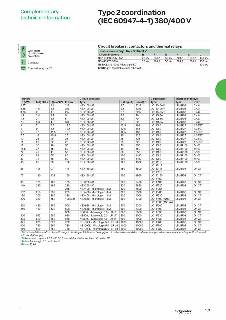
169
Motors Circuit breakers Contactors (2) Thermal o/l relays
P (kW) I (A) 380 V I (A) 400 V Ie max Type Rating (A) Irm (A) (3) Type Type Irth (1)
0.37 1.2 1.1 2.5 NSX100-MA 2.5 32.5 LC1 D40A (4) LTM R08 0.4/8
0.55 1.6 1.5 2.5 NSX100-MA 2.5 32.5 LC1 D40A (4) LTM R08 0.4/8
0.75 2 1.9 2.5 NSX100-MA 2.5 32.5 LC1 D40A (4) LTM R08 0.4/8
1.1 2.8 2.7 5 NSX100-MA 6.3 70 LC1 D65A LTM R08 0.4/8
1.5 3.7 3.6 5 NSX100-MA 6.3 70 LC1 D65A LTM R08 0.4/8
2.2 5.3 4.9 6.3 NSX100-MA 6.3 82 LC1 D65A LTM R08 0.4/8
3 7 6.5 12.5 NSX100-MA 12.5 163 LC1 D80 LTM R27 1.35/27
4 9 8.5 12.5 NSX100-MA 12.5 163 LC1 D80 LTM R27 1.35/27
5.5 12 11.5 12.5 NSX100-MA 12.5 163 LC1 D80 LTM R27 1.35/27
7.5 16 15.5 25 NSX100-MA 25 325 LC1 D80 LTM R27 1.35/27
10 21 20 25 NSX100-MA 25 325 LC1 D80 LTM R27 1.35/27
11 23 22 25 NSX100-MA 25 325 LC1 D80 LTM R27 1.35/27
15 30 29 50 NSX100-MA 50 650 LC1 D80 LTM R100 5/100
18.5 37 35 50 NSX100-MA 50 650 LC1 D80 LTM R100 5/100
22 43 41 50 NSX100-MA 50 650 LC1 D80 LTM R100 5/100
30 59 55 80 NSX100-MA 100 1100 LC1 D80 LTM R100 5/100
37 72 66 80 NSX100-MA 100 1100 LC1 D80 LTM R100 5/100
45 85 80 100 NSX100-MA 100 1300 LC1 D115 LTM R100 5/100
LC1 F115
55 105 97 115 NSX160-MA 150 1500 LC1 D115 LTM R08 On CT
LC1 F115
75 140 132 150 NSX160-MA 150 1950 LC1 D150 LTM R08 On CT
LC1 F150
90 170 160 185 NSX250-MA 220 2420 LC1 F185 LTM R08 On CT
110 210 195 220 NSX250-MA 220 2860 LC1 F225 LTM R08 On CT
265 NSX400 - Micrologic 1.3 M 320 3500 LC1 F265
132 250 230 265 NSX400 - Micrologic 1.3 M 320 3500 LC1 F265 LTM R08 On CT
160 300 280 320 NSX400 - Micrologic 1.3 M 320 4000 LC1 F330 LTM R08 On CT
200 380 350 400/500 NSX630 - Micrologic 1.3 M 500 5700 LC1 F400 (70 kA) LTM R08 On CT
LC1 F500 (130 kA)
220 420 380 500 NSX630 - Micrologic 1.3 M 500 6300 LC1 F500 LTM R08 On CT
250 460 430 500 NSX630 - Micrologic 1.3 M 500 6300 LC1 F500 LTM R08 On CT
630 NS800L - Micrologic 5.0 - LR off 800 8000 LC1 F630 LTM R08 On CT
300 565 500 630 NS800L - Micrologic 5.0 - LR off 800 8000 LC1 F630 LTM R08 On CT
335 620 560 630 NS800L - Micrologic 5.0 - LR off 800 8000 LC1 F630 LTM R08 On CT
375 670 620 780 NS1000L - Micrologic 5.0 - LR off 1000 10000 LC1 F780 LTM R08 On CT
400 710 690 780 NS1000L - Micrologic 5.0 - LR off 1000 10000 LC1 F780 LTM R08 On CT
450 800 750 780 NS1000L - Micrologic 5.0 - LR off 1000 10000 LC1 F780 LTM R08 On CT
(1) For installations with a class 30 relay, a derating of 20 % must be apply on circuit breakers and the contactor rating shall be checked according to 30 s thermal withstand (F range).(2)(3) Ii for Micrologic 5.0 control unit.(4) Iq < 50 kA.
Complementary
technical informationType 2 coordination (IEC 60947-4-1) 380/400 V
Circuit breakers, contactors and thermal relays
Performance "iq": Ue = 380/400 VCircuit breakers B F N H S L
NSX100/160/250-MA 25 kA 36 kA 50 kA 70 kA 100 kA 130 kA
NSX400/630-MA 25 kA 36 kA 50 kA 70 kA 100 kA 130 kA
NS800L/NS1000L Micrologic 5.0 - - - - - 130 kA
Starting (1): adjustable class 10 A to 30.
DB
119497.e
ps
LVPED308005EN.indb 169 14/12/2012 08:53:57
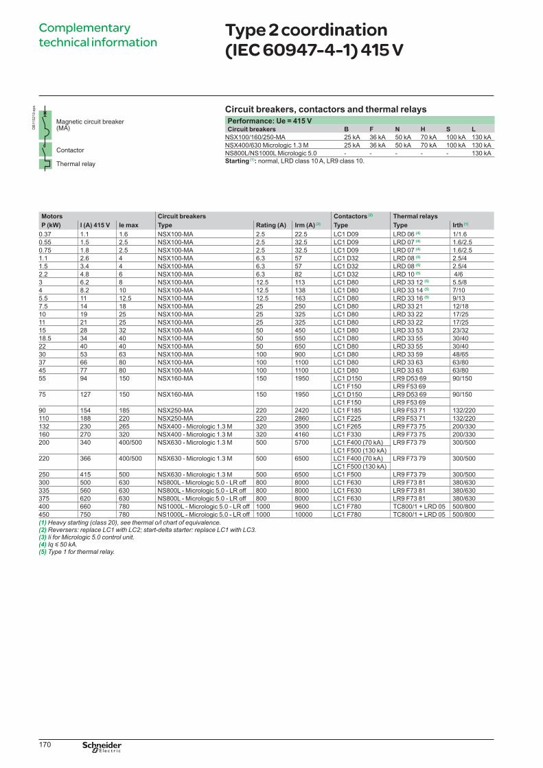
170
Complementary
technical informationType 2 coordination (IEC 60947-4-1) 415 V
Circuit breakers, contactors and thermal relays
Performance: Ue = 415 VCircuit breakers B F N H S L
NSX100/160/250-MA 25 kA 36 kA 50 kA 70 kA 100 kA 130 kA
NSX400/630 Micrologic 1.3 M 25 kA 36 kA 50 kA 70 kA 100 kA 130 kA
NS800L/NS1000L Micrologic 5.0 - - - - - 130 kA
Starting (1): normal, LRD class 10 A, LR9 class 10.
Motors Circuit breakers Contactors (2) Thermal relays
P (kW) I (A) 415 V Ie max Type Rating (A) Irm (A) (3) Type Type Irth (1)
0.37 1.1 1.6 NSX100-MA 2.5 22.5 LC1 D09 LRD 06 (4) 1/1.6
0.55 1.5 2.5 NSX100-MA 2.5 32.5 LC1 D09 LRD 07 (4) 1.6/2.5
0.75 1.8 2.5 NSX100-MA 2.5 32.5 LC1 D09 LRD 07 (4) 1.6/2.5
1.1 2.6 4 NSX100-MA 6.3 57 LC1 D32 LRD 08 (5) 2.5/4
1.5 3.4 4 NSX100-MA 6.3 57 LC1 D32 LRD 08 (5) 2.5/4
2.2 4.8 6 NSX100-MA 6.3 82 LC1 D32 LRD 10 (5) 4/6
3 6.2 8 NSX100-MA 12.5 113 LC1 D80 LRD 33 12 (5) 5.5/8
4 8.2 10 NSX100-MA 12.5 138 LC1 D80 LRD 33 14 (5) 7/10
5.5 11 12.5 NSX100-MA 12.5 163 LC1 D80 LRD 33 16 (5) 9/13
7.5 14 18 NSX100-MA 25 250 LC1 D80 LRD 33 21 12/18
10 19 25 NSX100-MA 25 325 LC1 D80 LRD 33 22 17/25
11 21 25 NSX100-MA 25 325 LC1 D80 LRD 33 22 17/25
15 28 32 NSX100-MA 50 450 LC1 D80 LRD 33 53 23/32
18.5 34 40 NSX100-MA 50 550 LC1 D80 LRD 33 55 30/40
22 40 40 NSX100-MA 50 650 LC1 D80 LRD 33 55 30/40
30 53 63 NSX100-MA 100 900 LC1 D80 LRD 33 59 48/65
37 66 80 NSX100-MA 100 1100 LC1 D80 LRD 33 63 63/80
45 77 80 NSX100-MA 100 1100 LC1 D80 LRD 33 63 63/80
55 94 150 NSX160-MA 150 1950 LC1 D150 LR9 D53 69 90/150
LC1 F150 LR9 F53 69
75 127 150 NSX160-MA 150 1950 LC1 D150 LR9 D53 69 90/150
LC1 F150 LR9 F53 69
90 154 185 NSX250-MA 220 2420 LC1 F185 LR9 F53 71 132/220
110 188 220 NSX250-MA 220 2860 LC1 F225 LR9 F53 71 132/220
132 230 265 NSX400 - Micrologic 1.3 M 320 3500 LC1 F265 LR9 F73 75 200/330
160 270 320 NSX400 - Micrologic 1.3 M 320 4160 LC1 F330 LR9 F73 75 200/330
200 340 400/500 NSX630 - Micrologic 1.3 M 500 5700 LC1 F400 (70 kA) LR9 F73 79 300/500
LC1 F500 (130 kA)
220 366 400/500 NSX630 - Micrologic 1.3 M 500 6500 LC1 F400 (70 kA) LR9 F73 79 300/500
LC1 F500 (130 kA)
250 415 500 NSX630 - Micrologic 1.3 M 500 6500 LC1 F500 LR9 F73 79 300/500
300 500 630 NS800L - Micrologic 5.0 - LR off 800 8000 LC1 F630 LR9 F73 81 380/630
335 560 630 NS800L - Micrologic 5.0 - LR off 800 8000 LC1 F630 LR9 F73 81 380/630
375 620 630 NS800L - Micrologic 5.0 - LR off 800 8000 LC1 F630 LR9 F73 81 380/630
400 660 780 NS1000L - Micrologic 5.0 - LR off 1000 9600 LC1 F780 TC800/1 + LRD 05 500/800
450 750 780 NS1000L - Micrologic 5.0 - LR off 1000 10000 LC1 F780 TC800/1 + LRD 05 500/800
(1) Heavy starting (class 20), see thermal o/l chart of equivalence.(2)(3) Ii for Micrologic 5.0 control unit.(4) Iq y 50 kA.(5) Type 1 for thermal relay.
DB
115219.e
ps
LVPED308005EN.indb 170 14/12/2012 08:53:57
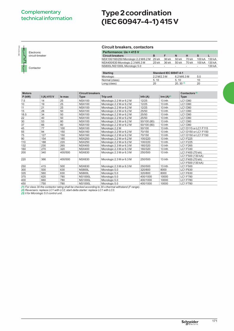
171
Complementary
technical informationType 2 coordination (IEC 60947-4-1) 415 V
Circuit breakers, contactors
Performance: Ue = 415 VCircuit breakers B F N H S L
NSX100/160/250 Micrologic 2.2 M/6.2 M 25 kA 36 kA 50 kA 70 kA 100 kA 130 kA
NSX400/630 Micrologic 2.3 M/6.3 M 25 kA 36 kA 50 kA 70 kA 100 kA 130 kA
NS800L/NS1000L Micrologic 5.0 - - - - - 130 kA
Starting Standard IEC 60947-4-1
Micrologic 2.2 M/2.3 M 6.2 M/6.3 M 5.0
Normal (class) 5, 10 5, 10 10
Long (class) 20 20, 30 (1) 20
Motors Circuit breakers Contactors (2)
P (kW) I (A) 415 V Ie max Type Trip unit Irth (A) Irm (A)(3) Type
7.5 14 25 NSX100 Micrologic 2.2 M or 6.2 M 12/25 13 Irth LC1 D80
10 19 25 NSX100 Micrologic 2.2 M or 6.2 M 12/25 13 Irth LC1 D80
11 21 25 NSX100 Micrologic 2.2 M or 6.2 M 12/25 13 Irth LC1 D80
15 28 50 NSX100 Micrologic 2.2 M or 6.2 M 25/50 13 Irth LC1 D80
18.5 34 50 NSX100 Micrologic 2.2 M or 6.2 M 25/50 13 Irth LC1 D80
22 40 50 NSX100 Micrologic 2.2 M or 6.2 M 25/50 13 Irth LC1 D80
30 53 80 NSX100 Micrologic 2.2 M or 6.2 M 50/100 (80) 13 Irth LC1 D80
37 66 80 NSX100 Micrologic 2.2 M or 6.2 M 50/100 (80) 13 Irth LC1 D80
45 77 100 NSX100 Micrologic 2.2 M 50/100 13 Irth LC1 D115 or LC1 F115
55 94 150 NSX160 Micrologic 2.2 M or 6.2 M 70/150 13 Irth LC1 D150 or LC1 F150
75 127 150 NSX160 Micrologic 2.2 M or 6.2 M 70/150 13 Irth LC1 D150 or LC1 F150
90 154 185 NSX250 Micrologic 2.2 M or 6.2 M 100/220 13 Irth LC1 F225
110 188 220 NSX250 Micrologic 2.2 M or 6.2 M 100/220 13 Irth LC1 F225
132 230 265 NSX400 Micrologic 2.3 M or 6.3 M 160/320 13 Irth LC1 F265
160 270 320 NSX400 Micrologic 2.3 M or 6.3 M 160/320 13 Irth LC1 F330
200 340 400/500 NSX630 Micrologic 2.3 M or 6.3 M 250/500 13 Irth LC1 F400 (70 kA)
LC1 F500 (130 kA)
220 366 400/500 NSX630 Micrologic 2.3 M or 6.3 M 250/500 13 Irth LC1 F400 (70 kA)
LC1 F500 (130 kA)
250 415 500 NSX630 Micrologic 2.3 M or 6.3 M 250/500 13 Irth LC1 F500
300 500 630 NS800L Micrologic 5.0 320/800 8000 LC1 F630
335 560 630 NS800L Micrologic 5.0 320/800 8000 LC1 F630
375 620 780 NS1000L Micrologic 5.0 400/1000 10000 LC1 F780
400 660 780 NS1000L Micrologic 5.0 400/1000 10000 LC1 F780
450 750 780 NS1000L Micrologic 5.0 400/1000 10000 LC1 F780
(1) For class 30 the contactor rating shall be checked according to 30 s thermal withstand (F range).(2)(3) Ii for Micrologic 5.0 control unit.
DB
115218.e
ps
LVPED308005EN.indb 171 14/12/2012 08:53:57
172
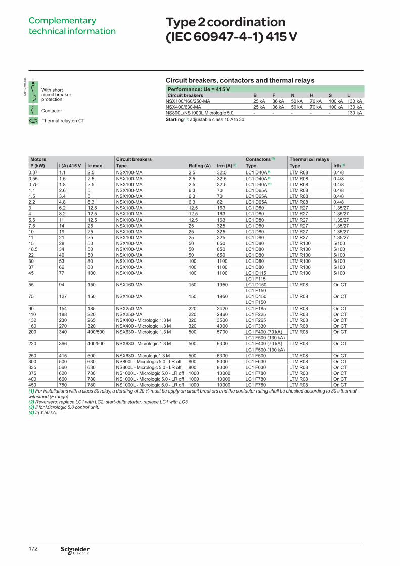
Complementary
technical informationType 2 coordination (IEC 60947-4-1) 415 V
Circuit breakers, contactors and thermal relays
Performance: Ue = 415 VCircuit breakers B F N H S L
NSX100/160/250-MA 25 kA 36 kA 50 kA 70 kA 100 kA 130 kA
NSX400/630-MA 25 kA 36 kA 50 kA 70 kA 100 kA 130 kA
NS800L/NS1000L Micrologic 5.0 - - - - - 130 kA
Starting (1): adjustable class 10 A to 30.
Motors Circuit breakers Contactors (2) Thermal o/l relays
P (kW) I (A) 415 V Ie max Type Rating (A) Irm (A) (3) Type Type Irth (1)
0.37 1.1 2.5 NSX100-MA 2.5 32.5 LC1 D40A (4) LTM R08 0.4/8
0.55 1.5 2.5 NSX100-MA 2.5 32.5 LC1 D40A (4) LTM R08 0.4/8
0.75 1.8 2.5 NSX100-MA 2.5 32.5 LC1 D40A (4) LTM R08 0.4/8
1.1 2.6 5 NSX100-MA 6.3 70 LC1 D65A LTM R08 0.4/8
1.5 3.4 5 NSX100-MA 6.3 70 LC1 D65A LTM R08 0.4/8
2.2 4.8 6.3 NSX100-MA 6.3 82 LC1 D65A LTM R08 0.4/8
3 6.2 12.5 NSX100-MA 12.5 163 LC1 D80 LTM R27 1.35/27
4 8.2 12.5 NSX100-MA 12.5 163 LC1 D80 LTM R27 1.35/27
5.5 11 12.5 NSX100-MA 12.5 163 LC1 D80 LTM R27 1.35/27
7.5 14 25 NSX100-MA 25 325 LC1 D80 LTM R27 1.35/27
10 19 25 NSX100-MA 25 325 LC1 D80 LTM R27 1.35/27
11 21 25 NSX100-MA 25 325 LC1 D80 LTM R27 1.35/27
15 28 50 NSX100-MA 50 650 LC1 D80 LTM R100 5/100
18.5 34 50 NSX100-MA 50 650 LC1 D80 LTM R100 5/100
22 40 50 NSX100-MA 50 650 LC1 D80 LTM R100 5/100
30 53 80 NSX100-MA 100 1100 LC1 D80 LTM R100 5/100
37 66 80 NSX100-MA 100 1100 LC1 D80 LTM R100 5/100
45 77 100 NSX100-MA 100 1100 LC1 D115 LTM R100 5/100
LC1 F115
55 94 150 NSX160-MA 150 1950 LC1 D150 LTM R08 On CT
LC1 F150
75 127 150 NSX160-MA 150 1950 LC1 D150 LTM R08 On CT
LC1 F150
90 154 185 NSX250-MA 220 2420 LC1 F185 LTM R08 On CT
110 188 220 NSX250-MA 220 2860 LC1 F225 LTM R08 On CT
132 230 265 NSX400 - Micrologic 1.3 M 320 3500 LC1 F265 LTM R08 On CT
160 270 320 NSX400 - Micrologic 1.3 M 320 4000 LC1 F330 LTM R08 On CT
200 340 400/500 NSX630 - Micrologic 1.3 M 500 5700 LC1 F400 (70 kA) LTM R08 On CT
LC1 F500 (130 kA)
220 366 400/500 NSX630 - Micrologic 1.3 M 500 6300 LC1 F400 (70 kA) LTM R08 On CT
LC1 F500 (130 kA)
250 415 500 NSX630 - Micrologic1.3 M 500 6300 LC1 F500 LTM R08 On CT
300 500 630 NS800L - Micrologic 5.0 - LR off 800 8000 LC1 F630 LTM R08 On CT
335 560 630 NS800L - Micrologic 5.0 - LR off 800 8000 LC1 F630 LTM R08 On CT
375 620 780 NS1000L - Micrologic 5.0 - LR off 1000 10000 LC1 F780 LTM R08 On CT
400 660 780 NS1000L - Micrologic 5.0 - LR off 1000 10000 LC1 F780 LTM R08 On CT
450 750 780 NS1000L - Micrologic 5.0 - LR off 1000 10000 LC1 F780 LTM R08 On CT
(1) For installations with a class 30 relay, a derating of 20 % must be apply on circuit breakers and the contactor rating shall be checked according to 30 s thermal withstand (F range).(2)(3) Ii for Micrologic 5.0 control unit.(4) Iq y 50 kA.
DB
119497.e
ps
LVPED308005EN.indb 172 14/12/2012 08:53:57
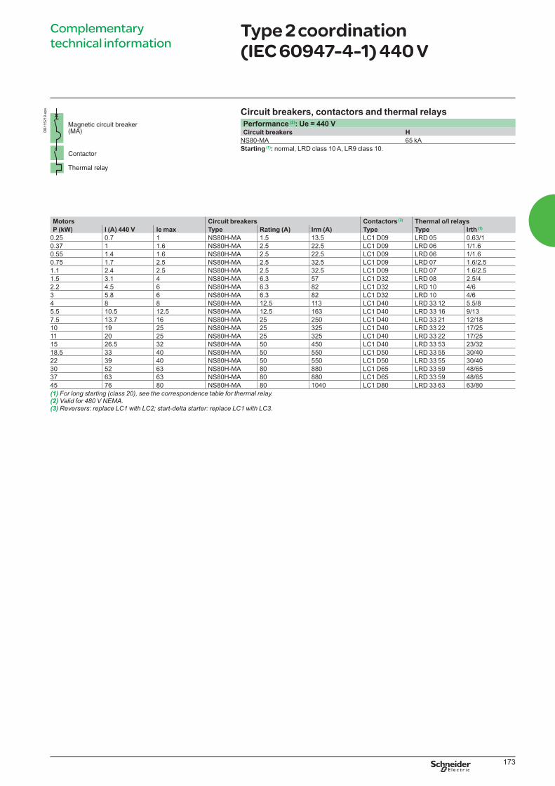
173
Motors Circuit breakers Contactors (3) Thermal o/l relays
P (kW) I (A) 440 V Ie max Type Rating (A) Irm (A) Type Type Irth (1)
0.25 0.7 1 NS80H-MA 1.5 13.5 LC1 D09 LRD 05 0.63/1
0.37 1 1.6 NS80H-MA 2.5 22.5 LC1 D09 LRD 06 1/1.6
0.55 1.4 1.6 NS80H-MA 2.5 22.5 LC1 D09 LRD 06 1/1.6
0.75 1.7 2.5 NS80H-MA 2.5 32.5 LC1 D09 LRD 07 1.6/2.5
1.1 2.4 2.5 NS80H-MA 2.5 32.5 LC1 D09 LRD 07 1.6/2.5
1.5 3.1 4 NS80H-MA 6.3 57 LC1 D32 LRD 08 2.5/4
2.2 4.5 6 NS80H-MA 6.3 82 LC1 D32 LRD 10 4/6
3 5.8 6 NS80H-MA 6.3 82 LC1 D32 LRD 10 4/6
4 8 8 NS80H-MA 12.5 113 LC1 D40 LRD 33 12 5.5/8
5.5 10.5 12.5 NS80H-MA 12.5 163 LC1 D40 LRD 33 16 9/13
7.5 13.7 16 NS80H-MA 25 250 LC1 D40 LRD 33 21 12/18
10 19 25 NS80H-MA 25 325 LC1 D40 LRD 33 22 17/25
11 20 25 NS80H-MA 25 325 LC1 D40 LRD 33 22 17/25
15 26.5 32 NS80H-MA 50 450 LC1 D40 LRD 33 53 23/32
18.5 33 40 NS80H-MA 50 550 LC1 D50 LRD 33 55 30/40
22 39 40 NS80H-MA 50 550 LC1 D50 LRD 33 55 30/40
30 52 63 NS80H-MA 80 880 LC1 D65 LRD 33 59 48/65
37 63 63 NS80H-MA 80 880 LC1 D65 LRD 33 59 48/65
45 76 80 NS80H-MA 80 1040 LC1 D80 LRD 33 63 63/80
(1) For long starting (class 20), see the correspondence table for thermal relay.(2) Valid for 480 V NEMA.(3)
Complementary
technical informationType 2 coordination (IEC 60947-4-1) 440 V
Circuit breakers, contactors and thermal relays
Performance (2): Ue = 440 VCircuit breakers H
NS80-MA 65 kA
Starting (1): normal, LRD class 10 A, LR9 class 10.
DB
115219.e
ps
LVPED308005EN.indb 173 14/12/2012 08:53:58
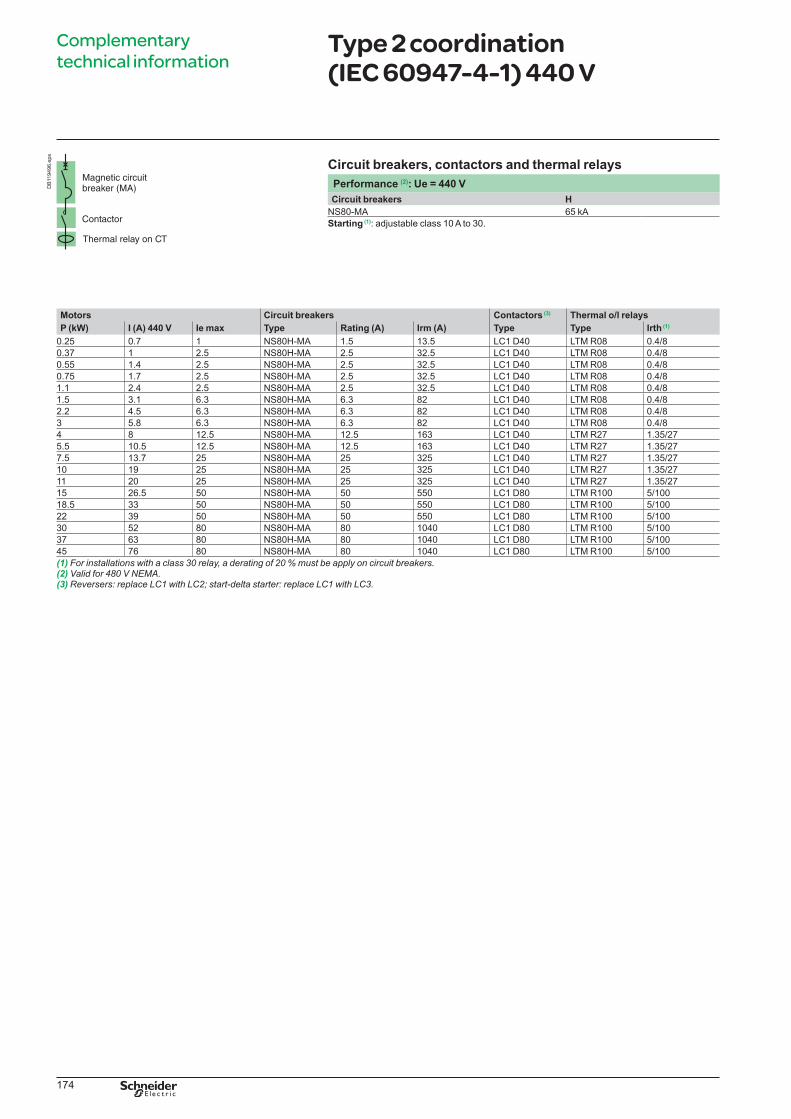
174
Motors Circuit breakers Contactors (3) Thermal o/l relays
P (kW) I (A) 440 V Ie max Type Rating (A) Irm (A) Type Type Irth (1)
0.25 0.7 1 NS80H-MA 1.5 13.5 LC1 D40 LTM R08 0.4/8
0.37 1 2.5 NS80H-MA 2.5 32.5 LC1 D40 LTM R08 0.4/8
0.55 1.4 2.5 NS80H-MA 2.5 32.5 LC1 D40 LTM R08 0.4/8
0.75 1.7 2.5 NS80H-MA 2.5 32.5 LC1 D40 LTM R08 0.4/8
1.1 2.4 2.5 NS80H-MA 2.5 32.5 LC1 D40 LTM R08 0.4/8
1.5 3.1 6.3 NS80H-MA 6.3 82 LC1 D40 LTM R08 0.4/8
2.2 4.5 6.3 NS80H-MA 6.3 82 LC1 D40 LTM R08 0.4/8
3 5.8 6.3 NS80H-MA 6.3 82 LC1 D40 LTM R08 0.4/8
4 8 12.5 NS80H-MA 12.5 163 LC1 D40 LTM R27 1.35/27
5.5 10.5 12.5 NS80H-MA 12.5 163 LC1 D40 LTM R27 1.35/27
7.5 13.7 25 NS80H-MA 25 325 LC1 D40 LTM R27 1.35/27
10 19 25 NS80H-MA 25 325 LC1 D40 LTM R27 1.35/27
11 20 25 NS80H-MA 25 325 LC1 D40 LTM R27 1.35/27
15 26.5 50 NS80H-MA 50 550 LC1 D80 LTM R100 5/100
18.5 33 50 NS80H-MA 50 550 LC1 D80 LTM R100 5/100
22 39 50 NS80H-MA 50 550 LC1 D80 LTM R100 5/100
30 52 80 NS80H-MA 80 1040 LC1 D80 LTM R100 5/100
37 63 80 NS80H-MA 80 1040 LC1 D80 LTM R100 5/100
45 76 80 NS80H-MA 80 1040 LC1 D80 LTM R100 5/100
(1) For installations with a class 30 relay, a derating of 20 % must be apply on circuit breakers.(2) Valid for 480 V NEMA.(3)
Complementary
technical informationType 2 coordination (IEC 60947-4-1) 440 V
Circuit breakers, contactors and thermal relays
Performance (2): Ue = 440 V
Circuit breakers H
NS80-MA 65 kA
Starting (1): adjustable class 10 A to 30.
DB
119496.e
ps
LVPED308005EN.indb 174 14/12/2012 08:53:58
175
Complementary
technical informationType 2 coordination (IEC 60947-4-1) 440 V
Circuit breakers, contactors and thermal relays
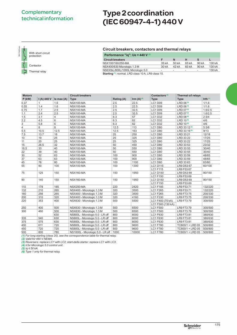
Performance "iq": Ue = 440 V (2)
Circuit breakers F N H S L
NSX100/160/250-MA 35 kA 50 kA 65 kA 90 kA 130 kA
NSX400/630 Micrologic 1.3 M 30 kA 42 kA 65 kA 90 kA 130 kA
NS630bL/800L/1000L Micrologic 5.0 - - - - 130 kA
Starting (1): normal, LRD class 10 A, LR9 class 10.
Motors Circuit breakers Contactors (3) Thermal o/l relays
P (kW) I (A) 440 V Ie max (A) Type Rating (A) Irm (A) (4) Type Type Irth (1)
0.37 1 1.6 NSX100-MA 2.5 22.5 LC1 D09 LRD 06 (5) 1/1.6
0.55 1.4 1.6 NSX100-MA 2.5 22.5 LC1 D09 LRD 06 (5) 1/1.6
0.75 1.7 2.5 NSX100-MA 2.5 32.5 LC1 D09 LRD 07 (5) 1.6/2.5
1.1 2.4 2.5 NSX100-MA 2.5 32.5 LC1 D09 LRD 07 (5) 1.6/2.5
1.5 3.1 4 NSX100-MA 6.3 57 LC1 D32 LRD 08 (6) 2.5/4
2.2 4.5 6 NSX100-MA 6.3 82 LC1 D32 LRD 10 (6) 4/6
3 5.8 6 NSX100-MA 6.3 82 LC1 D32 LRD 10 (6) 4/6
4 8 8 NSX100-MA 12.5 113 LC1 D80 LRD 33 12 (6) 5.5/8
5.5 10.5 12.5 NSX100-MA 12.5 163 LC1 D80 LRD 33 16 (6) 9/13
7.5 13.7 18 NSX100-MA 25 250 LC1 D80 LRD 33 21 12/18
10 19 25 NSX100-MA 25 325 LC1 D80 LRD 33 22 17/25
11 20 25 NSX100-MA 25 325 LC1 D80 LRD 33 22 17/25
15 26.5 32 NSX100-MA 50 450 LC1 D80 LRD 33 53 23/32
18.5 33 40 NSX100-MA 50 550 LC1 D80 LRD 33 55 30/40
22 39 40 NSX100-MA 50 550 LC1 D80 LRD 33 55 30/40
30 52 63 NSX100-MA 100 900 LC1 D80 LRD 33 59 48/65
37 63 63 NSX100-MA 100 900 LC1 D80 LRD 33 59 48/65
45 76 80 NSX100-MA 100 1100 LC1 D80 LRD 33 63 63/80
55 90 100 NSX100-MA 100 1300 LC1 D115 LR9 D53 67 60/100
LC1 F115 LR9 F53 67
75 125 150 NSX160-MA 150 1950 LC1 D150 LR9 D53 69 90/150
LC1 F150 LR9 F53 69
90 140 150 NSX160-MA 150 1950 LC1 D150 LR9 D53 69 90/150
LC1 F150 LR9 F53 69
110 178 185 NSX250-MA 220 2420 LC1 F185 LR9 F53 71 132/220
132 210 265 NSX400 - Micrologic 1.3 M 320 3500 LC1 F265 LR9 F53 71 132/220
160 256 265 NSX400 - Micrologic 1.3 M 320 3500 LC1 F265 LR9 F73 75 200/330
200 310 320 NSX400 - Micrologic 1.3 M 320 4160 LC1 F330 LR9 F73 75 200/330
220 353 400 NSX630 - Micrologic 1.3 M 500 5500 LC1 F400 (70 kA) LR9 F73 79 300/500
LC1 F500 (130 kA)
250 400 500 NSX630 - Micrologic 1.3 M 500 6500 LC1 F500 LR9 F73 79 300/500
300 460 500 NSX630 - Micrologic 1.3 M 500 6500 LC1 F500 LR9 F73 79 300/500
630 NS800L - Micrologic 5.0 - LR off 800 8000 LC1 F630 LR9 F73 81 380/630
335 540 630 NS800L - Micrologic 5.0 - LR off 800 8000 LC1 F630 LR9 F73 81 380/630
375 575 630 NS800L - Micrologic 5.0 - LR off 800 8000 LC1 F630 LR9 F73 81 380/630
400 611 720 NS800L - Micrologic 5.0 - LR off 800 9600 LC1 F780 TC800/1 + LRD 05 500/800
450 720 720 NS800L - Micrologic 5.0 - LR off 800 9600 LC1 F780 TC800/1 + LRD 05 500/800
500 800 780 NS1000L - Micrologic 5.0 - LR off 1000 10000 LC1 F780 TC800/1 + LRD 05 500/800
(1) For long starting (class 20), see the correspondence table for thermal relay.(2) Valid for 480 V NEMA.(3)(4) Ii for Micrologic 5.0 control unit.(5) Iq y 50 kA.(6) Type 1 only for thermal relay.
DB
115220.e
ps
LVPED308005EN.indb 175 14/12/2012 08:53:58
176
Motors Circuit breakers Contactors (3)
P (kW) I (A) 440 V Ie max Type Trip unit Irth (A) Irm (A) (4) Type
7.5 13.7 20 NSX100 Micrologic 2.2 / 6.2 M 12/20 13 Irth LC1 D80
10 19 25 NSX100 Micrologic 2.2 / 6.2 M 15/25 13 Irth LC1 D80
11 20 25 NSX100 Micrologic 2.2 / 6.2 M 15/25 13 Irth LC1 D80
15 26.5 40 NSX100 Micrologic 2.2 / 6.2 M 24/40 13 Irth LC1 D80
18.5 33 40 NSX100 Micrologic 2.2 / 6.2 M 24/40 13 Irth LC1 D80
22 39 40 NSX100 Micrologic 2.2 / 6.2 M 24/40 13 Irth LC1 D80
30 51 80 NSX100 Micrologic 2.2 / 6.2 M 48/80 13 Irth LC1 D80
37 64 80 NSX100 Micrologic 2.2 / 6.2 M 48/80 13 Irth LC1 D80
45 76 80 NSX100 Micrologic 2.2 / 6.2 M 48/80 13 Irth LC1 D80
55 90 100 NSX100 Micrologic 2.2 / 6.2 M 60/100 13 Irth LC1 D115 or LC1 F115
75 125 150 NSX160 Micrologic 2.2 / 6.2 M 90/150 13 Irth LC1 D150 or LC1 F150
90 146 150 NSX160 Micrologic 2.2 / 6.2 M 90/150 13 Irth LC1 D150 or LC1 F150
110 178 185 NSX250 Micrologic 2.2 / 6.2 M 131/220 13 Irth LC1 F185
132 215 265 NSX400 Micrologic 2.3 / 6.3 M 160/320 13 Irth LC1 F265
160 256 265 NSX400 Micrologic 2.3 / 6.3 M 160/320 13 Irth LC1 F265
200 320 320 NSX400 Micrologic 2.3 / 6.3 M 160/320 13 Irth LC1 F330
220 353 400 NSX630 Micrologic 2.3 / 6.3 M 250/500 13 Irth LC1 F400 (70 kA)
LC1 F500 (130 kA)
250 400 400 NSX630 Micrologic 2.3 / 6.3 M 250/500 13 Irth LC1 F500
300 460 500 NSX630 Micrologic 2.3 / 6.3 M 250/500 13 Irth LC1 F500
630 NS800L Micrologic 5.0 320/800 8000 LC1 F630
335 540 630 NS800L Micrologic 5.0 320/800 8000 LC1 F630
375 575 630 NS800L Micrologic 5.0 320/800 8000 LC1 F630
400 611 720 NS800L Micrologic 5.0 320/800 9600 LC1 F780
450 720 720 NS800L Micrologic 5.0 320/800 9600 LC1 F780
500 800 800 NS1000L Micrologic 5.0 400/1000 10000 LC1 F780
(1) Valid for 480 V NEMA.(2) For class 30 the contactor rating shall be checked according to 30 s thermal withstand (F range).(3)(4) Ii for Micrologic 5.0 control unit.
Complementary
technical informationType 2 coordination (IEC 60947-4-1) 440 V
Circuit breakers, contactors
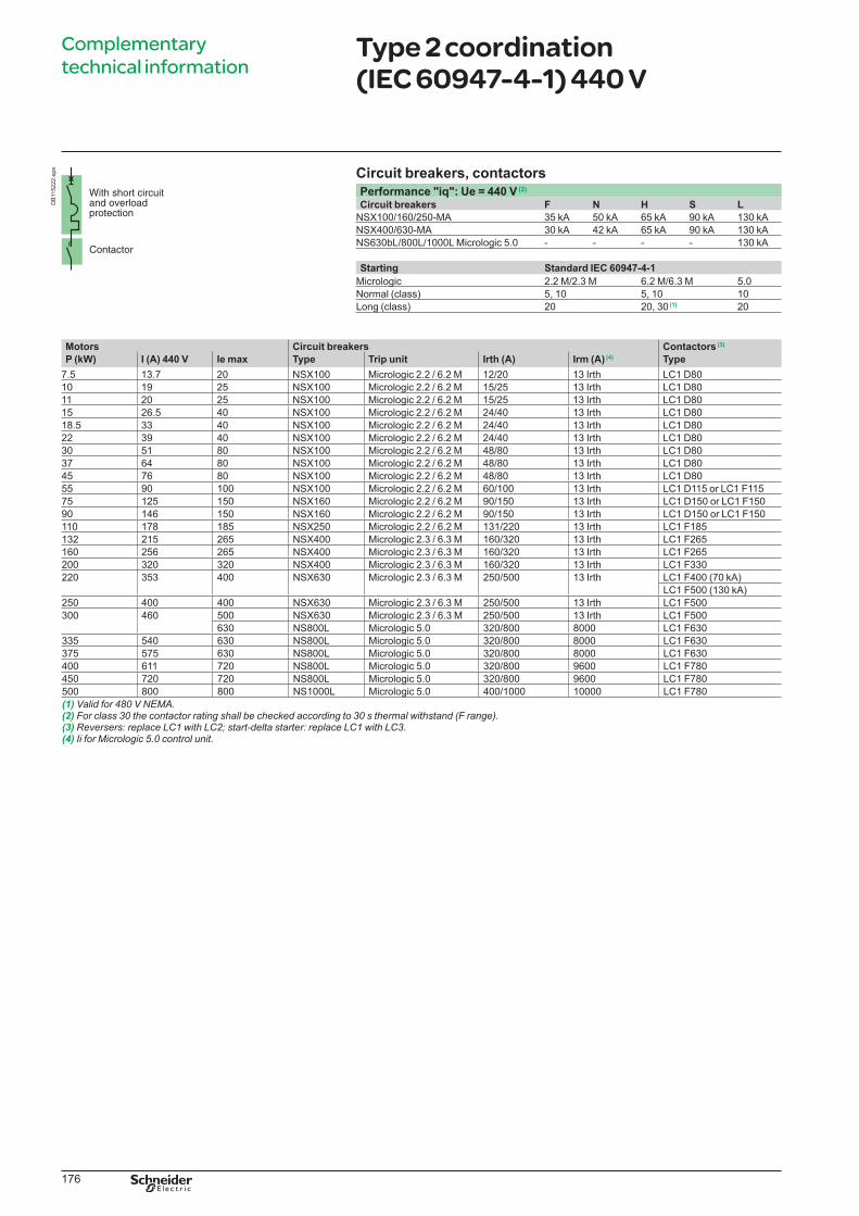
Performance "iq": Ue = 440 V (2)
Circuit breakers F N H S L
NSX100/160/250-MA 35 kA 50 kA 65 kA 90 kA 130 kA
NSX400/630-MA 30 kA 42 kA 65 kA 90 kA 130 kA
NS630bL/800L/1000L Micrologic 5.0 - - - - 130 kA
Starting Standard IEC 60947-4-1
Micrologic 2.2 M/2.3 M 6.2 M/6.3 M 5.0
Normal (class) 5, 10 5, 10 10
Long (class) 20 20, 30 (1) 20
DB
115222.e
ps
LVPED308005EN.indb 176 14/12/2012 08:53:59
177
Complementary
technical informationType 2 coordination (IEC 60947-4-1) 440 V
Circuit breakers, contactors and thermal relays
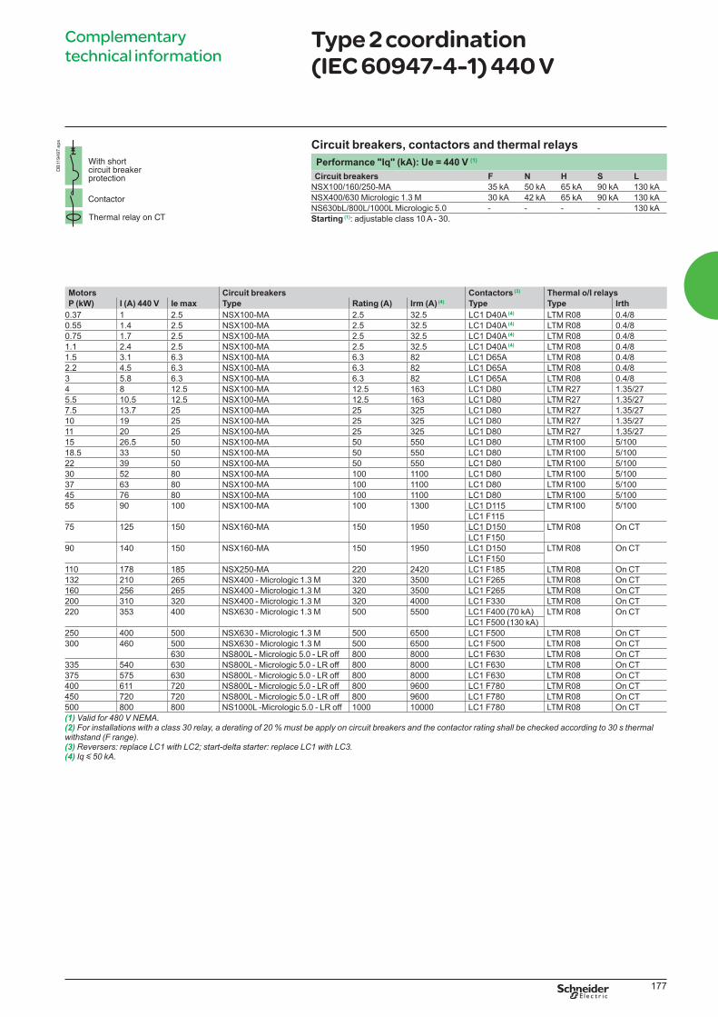
Performance "Iq" (kA): Ue = 440 V (1)
Circuit breakers F N H S L
NSX100/160/250-MA 35 kA 50 kA 65 kA 90 kA 130 kA
NSX400/630 Micrologic 1.3 M 30 kA 42 kA 65 kA 90 kA 130 kA
NS630bL/800L/1000L Micrologic 5.0 - - - - 130 kA
Starting (1): adjustable class 10 A - 30.
Motors Circuit breakers Contactors (3) Thermal o/l relays
P (kW) I (A) 440 V Ie max Type Rating (A) Irm (A) (4) Type Type Irth
0.37 1 2.5 NSX100-MA 2.5 32.5 LC1 D40A (4) LTM R08 0.4/8
0.55 1.4 2.5 NSX100-MA 2.5 32.5 LC1 D40A (4) LTM R08 0.4/8
0.75 1.7 2.5 NSX100-MA 2.5 32.5 LC1 D40A (4) LTM R08 0.4/8
1.1 2.4 2.5 NSX100-MA 2.5 32.5 LC1 D40A (4) LTM R08 0.4/8
1.5 3.1 6.3 NSX100-MA 6.3 82 LC1 D65A LTM R08 0.4/8
2.2 4.5 6.3 NSX100-MA 6.3 82 LC1 D65A LTM R08 0.4/8
3 5.8 6.3 NSX100-MA 6.3 82 LC1 D65A LTM R08 0.4/8
4 8 12.5 NSX100-MA 12.5 163 LC1 D80 LTM R27 1.35/27
5.5 10.5 12.5 NSX100-MA 12.5 163 LC1 D80 LTM R27 1.35/27
7.5 13.7 25 NSX100-MA 25 325 LC1 D80 LTM R27 1.35/27
10 19 25 NSX100-MA 25 325 LC1 D80 LTM R27 1.35/27
11 20 25 NSX100-MA 25 325 LC1 D80 LTM R27 1.35/27
15 26.5 50 NSX100-MA 50 550 LC1 D80 LTM R100 5/100
18.5 33 50 NSX100-MA 50 550 LC1 D80 LTM R100 5/100
22 39 50 NSX100-MA 50 550 LC1 D80 LTM R100 5/100
30 52 80 NSX100-MA 100 1100 LC1 D80 LTM R100 5/100
37 63 80 NSX100-MA 100 1100 LC1 D80 LTM R100 5/100
45 76 80 NSX100-MA 100 1100 LC1 D80 LTM R100 5/100
55 90 100 NSX100-MA 100 1300 LC1 D115 LTM R100 5/100
LC1 F115
75 125 150 NSX160-MA 150 1950 LC1 D150 LTM R08 On CT
LC1 F150
90 140 150 NSX160-MA 150 1950 LC1 D150 LTM R08 On CT
LC1 F150
110 178 185 NSX250-MA 220 2420 LC1 F185 LTM R08 On CT
132 210 265 NSX400 - Micrologic 1.3 M 320 3500 LC1 F265 LTM R08 On CT
160 256 265 NSX400 - Micrologic 1.3 M 320 3500 LC1 F265 LTM R08 On CT
200 310 320 NSX400 - Micrologic 1.3 M 320 4000 LC1 F330 LTM R08 On CT
220 353 400 NSX630 - Micrologic 1.3 M 500 5500 LC1 F400 (70 kA) LTM R08 On CT
LC1 F500 (130 kA)
250 400 500 NSX630 - Micrologic 1.3 M 500 6500 LC1 F500 LTM R08 On CT
300 460 500 NSX630 - Micrologic 1.3 M 500 6500 LC1 F500 LTM R08 On CT
630 NS800L - Micrologic 5.0 - LR off 800 8000 LC1 F630 LTM R08 On CT
335 540 630 NS800L - Micrologic 5.0 - LR off 800 8000 LC1 F630 LTM R08 On CT
375 575 630 NS800L - Micrologic 5.0 - LR off 800 8000 LC1 F630 LTM R08 On CT
400 611 720 NS800L - Micrologic 5.0 - LR off 800 9600 LC1 F780 LTM R08 On CT
450 720 720 NS800L - Micrologic 5.0 - LR off 800 9600 LC1 F780 LTM R08 On CT
500 800 800 NS1000L -Micrologic 5.0 - LR off 1000 10000 LC1 F780 LTM R08 On CT
(1) Valid for 480 V NEMA.(2) For installations with a class 30 relay, a derating of 20 % must be apply on circuit breakers and the contactor rating shall be checked according to 30 s thermal withstand (F range).(3)(4) Iq y 50 kA.
DB
119497.e
ps
LVPED308005EN.indb 177 14/12/2012 08:53:59
178
Complementary
technical informationType 2 coordination (IEC 60947-4-1) 690 V
Circuit breakers, contactors and thermal relays
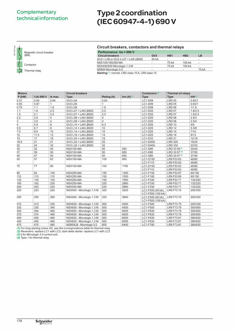
Performance: Ue = 690 VCircuit breakers GV2 HB1 HB2 LB
GV2 < L06 or GV2 u L07 + LA9 LB920 50 kA - - -
NSX100/160/250 MA - 75 kA 100 kA -
NSX400/630 Micrologic 1.3 M - 75 kA 100 kA -
NS800 Micrologic 5.0 - - - 75 kA
Starting (1): normal, LRD class 10 A, LR9 class 10.
Motors Circuit breakers Contactors (2) Thermal o/l relays
P (kW) I (A) 690 V Ie max Type Rating (A) Irm (A) (3) Type Type Irth (1)
0.37 0.64 0.64 GV2 L04 0.63 LC1-D09 LRD 05 0.63/1
0.55 0.87 1 GV2 L05 1 LC1-D09 LRD 05 0.63/1
0.75 1.1 1.6 GV2 L06 1.6 LC1-D09 LRD 06 1/1.6
1.1 1.6 2.5 GV2 L07 + LA9 LB920 2.5 LC1-D25 LRD 07 1.6/2.5
1.5 2.1 2.5 GV2 L07 + LA9 LB920 2.5 LC1-D25 LRD 07 1.6/2.5
2.2 2.8 4 GV2 L08 + LA9 LB920 4 LC1-D25 LRD 08 2.5/4
3 3.8 4 GV2 L08 + LA9 LB920 4 LC1-D25 LRD 08 2.5/4
4 4.9 6 GV2 L10 + LA9 LB920 6.3 LC1-D25 LRD 10 4/6
5.5 6.7 8 GV2 L14 + LA9 LB920 10 LC1-D25 LRD 12 5.5/8
7.5 8.9 10 GV2 L14 + LA9 LB920 10 LC1-D25 LRD 14 7/10
10 11.5 13 GV2 L16 + LA9 LB920 14 LC1-D25 LRD 16 9/13
15 17 18 GV2 L20 + LA9 LB920 18 LC1-D32 LRD 21 12/18
18.5 21 21 GV2 L22 + LA9 LB920 25 LC1-D40A LRD 325 16/24
22 24 32 GV2 L32 + LA9 LB920 32 LC1-D40A LRD 332 23/32
30 32 40 NSX100-MA 50 550 LC1-D80 LRD 33 55 (4) 30/40
37 39 50 NSX100-MA 50 650 LC1-D80 LRD 33 57 (4) 37/50
45 47 50 NSX100-MA 50 650 LC1-D80 LRD 33 57 (4) 37/50
55 57 63 NSX100-MA 100 900 LC1-D150 LR9 F53 63 48/80
LC1-F115 LR9 F53 63 48/80
75 77 80 NSX100-MA 100 1100 LC1-D150 LR9 F53 63 48/80
LC1-F115 LR9 F53 63 48/80
90 93 100 NSX250-MA 150 1350 LC1-F150 LR9 F53 67 60/100
110 113 115 NSX250-MA 150 1500 LC1-F185 LR9 F53 69 90/150
132 134 150 NSX250-MA 150 1950 LC1-F330 LR9 F53 71 132/220
160 162 220 NSX250-MA 220 2860 LC1-F330 LR9 F53 71 132/220
200 203 220 NSX250-MA 220 2860 LC1-F330 LR9 F53 71 132/220
220 223 225 NSX400 - Micrologic 1.3 M 320 3200 LC1-F400 (45 kA) LR9 F73 75 200/330
LC1-F500 (100 kA)
250 250 280 NSX400 - Micrologic 1.3 M 320 3840 LC1-F400 (45 kA) LR9 F73 75 200/330
LC1-F500 (100 kA)
315 313 330 NSX630 - Micrologic 1.3 M 500 4500 LC1-F500 LR9 F73 75 200/330
335 335 340 NSX630 - Micrologic 1.3 M 500 4500 LC1-F500 LR9 F73 79 300/500
355 354 460 NSX630 - Micrologic 1.3 M 500 6000 LC1-F630 LR9 F73 79 300/500
375 374 460 NSX630 - Micrologic 1.3 M 500 6000 LC1-F630 LR9 F73 79 300/500
400 400 460 NSX630 - Micrologic 1.3 M 500 6000 LC1-F630 LR9 F73 81 380/630
450 455 460 NSX630 - Micrologic 1.3 M 500 6000 LC1-F630 LR9 F73 81 380/630
475 475 480 NS800LB - Micrologic 5.0 800 6400 LC1-F780 LR9 F73 81 380/630
(1) For long starting (class 20), see the correspondence table for thermal relay.(2)(3) Ii for Micrologic 5.0 control unit.(4) Type 1 for thermal relay.
DB
115219.e
ps
LVPED308005EN.indb 178 14/12/2012 08:53:59
179
Complementary
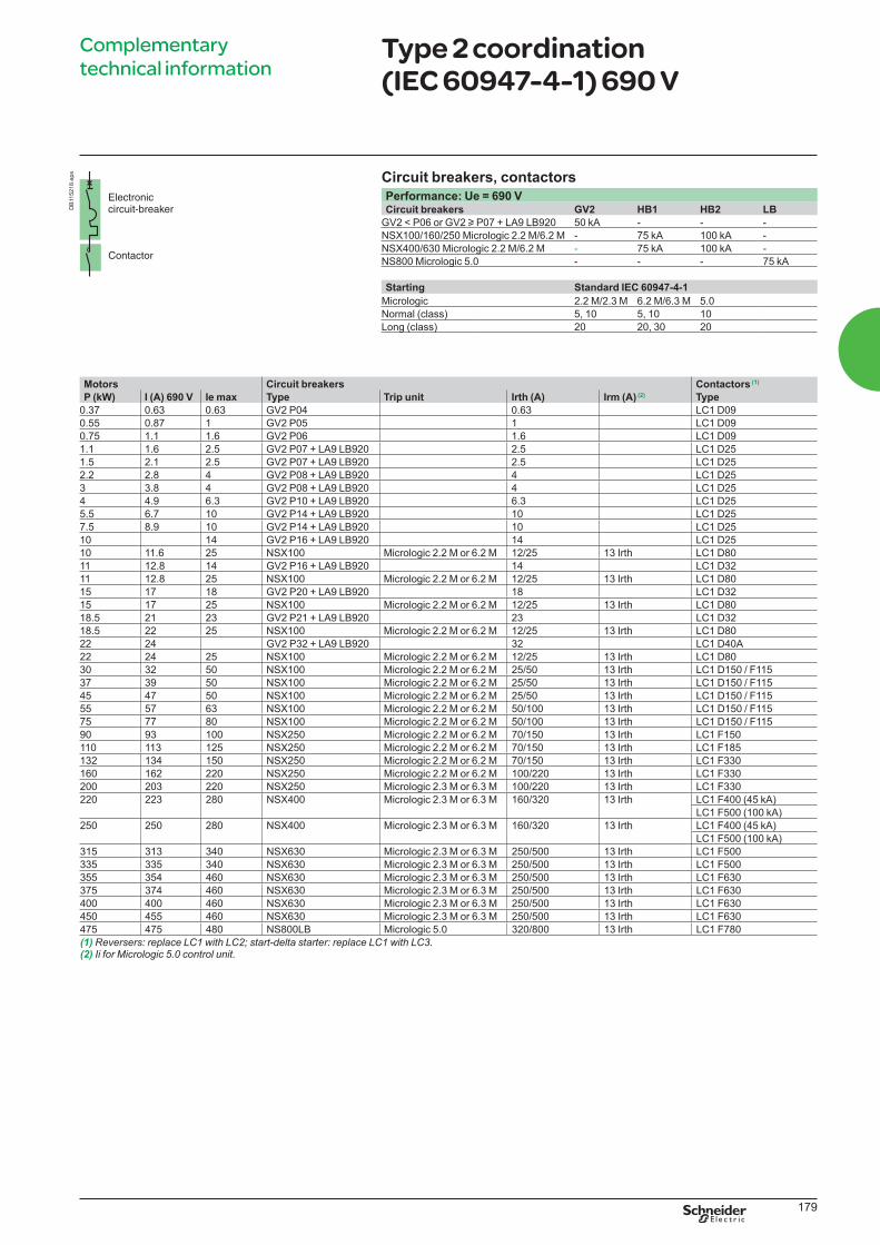
technical informationType 2 coordination (IEC 60947-4-1) 690 V
Circuit breakers, contactors
Performance: Ue = 690 VCircuit breakers GV2 HB1 HB2 LB
GV2 < P06 or GV2 u P07 + LA9 LB920 50 kA - - -
NSX100/160/250 Micrologic 2.2 M/6.2 M - 75 kA 100 kA -
NSX400/630 Micrologic 2.2 M/6.2 M - 75 kA 100 kA -
NS800 Micrologic 5.0 - - - 75 kA
Starting Standard IEC 60947-4-1
Micrologic 2.2 M/2.3 M 6.2 M/6.3 M 5.0
Normal (class) 5, 10 5, 10 10
Long (class) 20 20, 30 20
Motors Circuit breakers Contactors (1)
P (kW) I (A) 690 V Ie max Type Trip unit Irth (A) Irm (A) (2) Type
0.37 0.63 0.63 GV2 P04 0.63 LC1 D09
0.55 0.87 1 GV2 P05 1 LC1 D09
0.75 1.1 1.6 GV2 P06 1.6 LC1 D09
1.1 1.6 2.5 GV2 P07 + LA9 LB920 2.5 LC1 D25
1.5 2.1 2.5 GV2 P07 + LA9 LB920 2.5 LC1 D25
2.2 2.8 4 GV2 P08 + LA9 LB920 4 LC1 D25
3 3.8 4 GV2 P08 + LA9 LB920 4 LC1 D25
4 4.9 6.3 GV2 P10 + LA9 LB920 6.3 LC1 D25
5.5 6.7 10 GV2 P14 + LA9 LB920 10 LC1 D25
7.5 8.9 10 GV2 P14 + LA9 LB920 10 LC1 D25
10 14 GV2 P16 + LA9 LB920 14 LC1 D25
10 11.6 25 NSX100 Micrologic 2.2 M or 6.2 M 12/25 13 Irth LC1 D80
11 12.8 14 GV2 P16 + LA9 LB920 14 LC1 D32
11 12.8 25 NSX100 Micrologic 2.2 M or 6.2 M 12/25 13 Irth LC1 D80
15 17 18 GV2 P20 + LA9 LB920 18 LC1 D32
15 17 25 NSX100 Micrologic 2.2 M or 6.2 M 12/25 13 Irth LC1 D80
18.5 21 23 GV2 P21 + LA9 LB920 23 LC1 D32
18.5 22 25 NSX100 Micrologic 2.2 M or 6.2 M 12/25 13 Irth LC1 D80
22 24 GV2 P32 + LA9 LB920 32 LC1 D40A
22 24 25 NSX100 Micrologic 2.2 M or 6.2 M 12/25 13 Irth LC1 D80
30 32 50 NSX100 Micrologic 2.2 M or 6.2 M 25/50 13 Irth LC1 D150 / F115
37 39 50 NSX100 Micrologic 2.2 M or 6.2 M 25/50 13 Irth LC1 D150 / F115
45 47 50 NSX100 Micrologic 2.2 M or 6.2 M 25/50 13 Irth LC1 D150 / F115
55 57 63 NSX100 Micrologic 2.2 M or 6.2 M 50/100 13 Irth LC1 D150 / F115
75 77 80 NSX100 Micrologic 2.2 M or 6.2 M 50/100 13 Irth LC1 D150 / F115
90 93 100 NSX250 Micrologic 2.2 M or 6.2 M 70/150 13 Irth LC1 F150
110 113 125 NSX250 Micrologic 2.2 M or 6.2 M 70/150 13 Irth LC1 F185
132 134 150 NSX250 Micrologic 2.2 M or 6.2 M 70/150 13 Irth LC1 F330
160 162 220 NSX250 Micrologic 2.2 M or 6.2 M 100/220 13 Irth LC1 F330
200 203 220 NSX250 Micrologic 2.3 M or 6.3 M 100/220 13 Irth LC1 F330
220 223 280 NSX400 Micrologic 2.3 M or 6.3 M 160/320 13 Irth LC1 F400 (45 kA)
LC1 F500 (100 kA)
250 250 280 NSX400 Micrologic 2.3 M or 6.3 M 160/320 13 Irth LC1 F400 (45 kA)
LC1 F500 (100 kA)
315 313 340 NSX630 Micrologic 2.3 M or 6.3 M 250/500 13 Irth LC1 F500
335 335 340 NSX630 Micrologic 2.3 M or 6.3 M 250/500 13 Irth LC1 F500
355 354 460 NSX630 Micrologic 2.3 M or 6.3 M 250/500 13 Irth LC1 F630
375 374 460 NSX630 Micrologic 2.3 M or 6.3 M 250/500 13 Irth LC1 F630
400 400 460 NSX630 Micrologic 2.3 M or 6.3 M 250/500 13 Irth LC1 F630
450 455 460 NSX630 Micrologic 2.3 M or 6.3 M 250/500 13 Irth LC1 F630
475 475 480 NS800LB Micrologic 5.0 320/800 13 Irth LC1 F780
(1)(2) Ii for Micrologic 5.0 control unit.
DB
115218.e
ps
LVPED308005EN.indb 179 14/12/2012 08:53:59
180
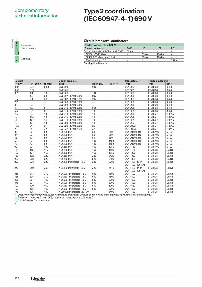
Complementary
technical informationType 2 coordination (IEC 60947-4-1) 690 V
Circuit breakers, contactors
Performance: Ue = 690 VCircuit breakers GV2 HB1 HB2 LB
GV2 < L06 or GV2 u L07 + LA9 LB920 50 kA - - -
NSX100/160/250 MA - 75 kA 100 kA -
NSX400/630 Micrologic 1.3 M - 75 kA 100 kA -
NS800 Micrologic 5.0 - - - 75 kA
Starting (1): adjustable.
DB
115218.e
ps
Motors Circuit breakers Contactors (2) Thermal o/l relays
P (kW) I (A) 690 V Ie max Type Rating (A) Irm (A) (3) Type Type Irth (1)
0.37 0.64 0.64 GV2 L04 0.63 LC1 D09 LTM R08 0.4/8
0.55 0.87 1 GV2 L05 1 LC1 D09 LTM R08 0.4/8
0.75 1.1 1.6 GV2 L06 1.6 LC1 D09 LTM R08 0.4/8
1.1 1.6 2.5 GV2 L07 + LA9 LB920 2.5 LC1 D25 LTM R08 0.4/8
1.5 2.1 2.5 GV2 L07 + LA9 LB920 2.5 LC1 D25 LTM R08 0.4/8
2.2 2.8 4 GV2 L08 + LA9 LB920 4 LC1 D25 LTM R08 0.4/8
3 3.8 4 GV2 L08 + LA9 LB920 4 LC1 D25 LTM R08 0.4/8
4 4.9 6 GV2 L10 + LA9 LB920 6.3 LC1 D25 LTM R08 0.4/8
5.5 6.7 8 GV2 L14 + LA9 LB920 10 LC1 D25 LTM R08 0.4/8
7.5 8.9 10 GV2 L14 + LA9 LB920 10 LC1 D25 LTM R27 1.35/27
10 11.5 13 GV2 L16 + LA9 LB920 14 LC1 D25 LTM R27 1.35/27
11 12.8 14 GV2 L16 + LA9 LB920 14 LC1 D25 LTM R27 1.35/27
15 17 18 GV2 L20 + LA9 LB920 18 LC1 D32 LTM R27 1.35/27
18.5 21 21 GV2 L22 + LA9 LB920 25 LC1 D40A LTM R27 1.35/27
22 24 32 GV2 L32 + LA9 LB920 32 LC1 D40A LTM R27 1.35/27
30 32 50 NSX100-MA 50 650 LC1 D150/F115 LTM R100 5/100
37 39 50 NSX100-MA 50 650 LC1 D150/F115 LTM R100 5/100
45 47 50 NSX100-MA 50 650 LC1 D150/F115 LTM R100 5/100
55 57 63 NSX100-MA 100 1100 LC1 D150/F115 LTM R100 5/100
75 77 80 NSX100-MA 100 1100 LC1 D150/F115 LTM R100 5/100
90 93 100 NSX250-MA 150 1350 LC1 F150 LTM R100 5/100
110 113 115 NSX250-MA 150 1500 LC1 F185 LTM R08 On CT
132 134 150 NSX250-MA 150 1950 LC1 F330 LTM R08 On CT
160 162 220 NSX250-MA 220 2420 LC1 F330 LTM R08 On CT
200 203 220 NSX250-MA 220 2420 LC1 F330 LTM R08 On CT
220 223 225 NSX400-Micrologic 1.3 M 320 3200 LC1 F400 (45 kA) LTM R08 On CT
LC1 F500 (100 kA)
250 250 280 NSX400-Micrologic 1.3 M 320 3840 LC1 F400 (45 kA) LTM R08 On CT
LC1 F500 (100 kA)
315 313 340 NSX630 - Micrologic 1.3 M 500 4500 LC1 F500 LTM R08 On CT
335 335 340 NSX630 - Micrologic 1.3 M 500 4500 LC1 F500 LTM R08 On CT
355 354 460 NSX630 - Micrologic 1.3 M 500 6000 LC1 F630 LTM R08 On CT
375 374 460 NSX630 - Micrologic 1.3 M 500 6000 LC1 F630 LTM R08 On CT
400 400 460 NSX630 - Micrologic 1.3 M 500 6000 LC1 F630 LTM R08 On CT
450 455 460 NSX630 - Micrologic 1.3 M 500 6000 LC1 F630 LTM R08 On CT
475 475 480 NS800LB Micrologic 5 LR Off 6400 LC1 F780 LTM R08 On CT
(1) Observe the recommendations, for installations with a class 30 relay and mounting of the thermal relay on the current transformer.(2)(3) Ii for Micrologic 5.0 control unit.s
LVPED308005EN.indb 180 14/12/2012 08:54:00