Embed Size (px)
Citation preview

Reyrolle
Protection
Devices
Answers for energy
7SG17 Rho 3 Motor Protection Relay

Siemens Protection Devices Limited 2

7SG17 Rho 3 Motor Protection Relay
The 7SG17 Rho 3 is a multi-function numerical Motor Protection relay suitable for all types of a.c. induction motors up to the highest ratings available. Whilst medium voltage 3-phase motors are very reliable and robust, modern designs operate much closer to the limits of thermal margins and to give adequate protection, sophisticated protection relays are required. In addition, increased industrial use of power electronics leads to corruption of power systems and unless specific equipment is installed to eliminate the corruption it can cause considerable rotor overheating. The relay has been designed to protect the motor against these phenomena as well as known abuses such as mechanical overload, stalling, single phasing, terminal box and cabling failures, and too frequent starts. The relay can be set to accurately mimic both the heating and cooling characteristics of the protected motor and consequently ensure that the thermal withstand of the machine is not exceeded, at the same time allowing full use of the motors thermal capability.
• Advanced motor protection - for medium voltage motors
• Easily programmable settings and user interface • Thermal overload and restart inhibit protection • Stall and locked rotor protection • Short circuit and earth fault protection • Phase unbalance protection • Undercurrent detection • Limitation of number of starts • Optional thermistor or resistance temperature
detector (RTD) inputs • Circuit breaker fail • Trip circuit supervision • CT supervision
• Earth fault trip inhibit for contactor control application
• Status inputs with programmable independent pickup and drop off timers.
User Interface
Indication 16 character x 2 line backlit LCD Menu navigation keys LEDs for TRIP, MOTOR STARTING, MOTOR RUNNING, STARTER and PROTECTION HEALTHY status.
Monitoring Functions Description
Monitored quantities can be displayed on the LCD screen or via the communications port. Monitored values include:-
• Primary/secondary currents • Motor full load current • PPS & NPS currents • Thermal equivalent current • Phase difference current • Motor status (Stopped, running) • Time to trip • Time to start • Thermal capacity used • Total starts • Last start time • Last start current • Motor run time • Total run time • Maximum demand/time • Output relay status • Status inputs • Trip circuit healthy/failure • Trip counters • I2 summation • Number of waveform and event records stored Function Overview • Time and Date
Siemens Protection Devices Limited 3
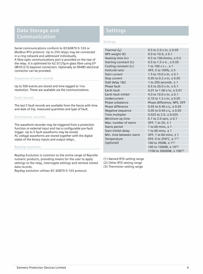
Serial communications conform to IEC60870-5-103 or Modbus RTU protocol. Up to 254 relays may be connected in a ring network and addressed individually. A fibre-optic communications port is provided on the rear of the relay. It is optimised for 62.5/125μm glass fibre using ST® (BFOC/2.5) bayonet connectors. Optionally an RS485 electrical connector can be provided. Sequence of event records Up to 500 events are stored and time tagged to 1ms resolution. These are available via the communications. Fault records The last 5 fault records are available from the fascia with time and date of trip, measured quantities and type of fault. Disturbance recorder The waveform recorder may be triggered from a protection function or external input and has a configurable pre-fault trigger. Up to 5 fault waveforms may be stored. AC voltage waveforms are stored together with the digital states of the binary inputs and output relays.. Reydisp evolution
Reydisp Evolution is common to the entire range of Reyrolle numeric products, providing means for the user to apply settings to the relay, interrogate settings and retrieve stored data records. Reydisp evolution utilises IEC 60870-5-103 protocol.
Data Storage and Communication
Settings
Settings Thermal (lθ) 0.5 to 2.0 x In, Δ 0.05 NPS weight (K) 0.0 to 10.0, Δ 0.1 Heating time (th) 0.5 to 100.0mins, Δ 0.5 Starting constant (ts) 0.5 to 1.5 x th , Δ 0.05 Cooling constant (tc) 1 to 100 x t h , Δ 1 Hot/cold ratio OFF, 5 to 100%, Δ 5 Start current 1.5 to 10.0 x In, Δ 0.1 Stop current 0.05 to 0.2 x In, Δ 0.05 Stall delay 1&2 1 to 250 seconds, Δ 1 Phase fault 0.5 to 20.0 x In, Δ 0.1 Earth fault 0.01 to 1.00 x In, Δ 0.01 Earth fault inhibit 4.0 to 10.0 x In, Δ 0.1 Undercurrent 0.10 to 1.5 x In, Δ 0.05 Phase unbalance Phase difference, NPS, OFF Phase difference 0.05 to 0.40 x lθ, Δ 0.05 Negative sequence 0.05 to 0.40 x lθ, Δ 0.05 Time multiplier 0.025 to 2.0, Δ 0.025 Minimum op time 0.1 to 2.0 secs, Δ 0.1 Max. number of starts OFF, 1 to 20, Δ 1 Starts period 1 to 60 mins, Δ 1 Start inhibit delay 1 to 60 mins, Δ 1 Min. time between starts OFF, 1 to 60 mins, Δ 1
OFF, 0 to 250°C, Δ 1(1) 100 to 350W, Δ 1(2) 100 to 1000W, Δ 10(3)
Temperature (optional)
1100 to 30000W, Δ 100(3) (1) Named RTD setting range (2) Other RTD setting range (3) Thermistor setting range
Siemens Protection Devices Limited 4
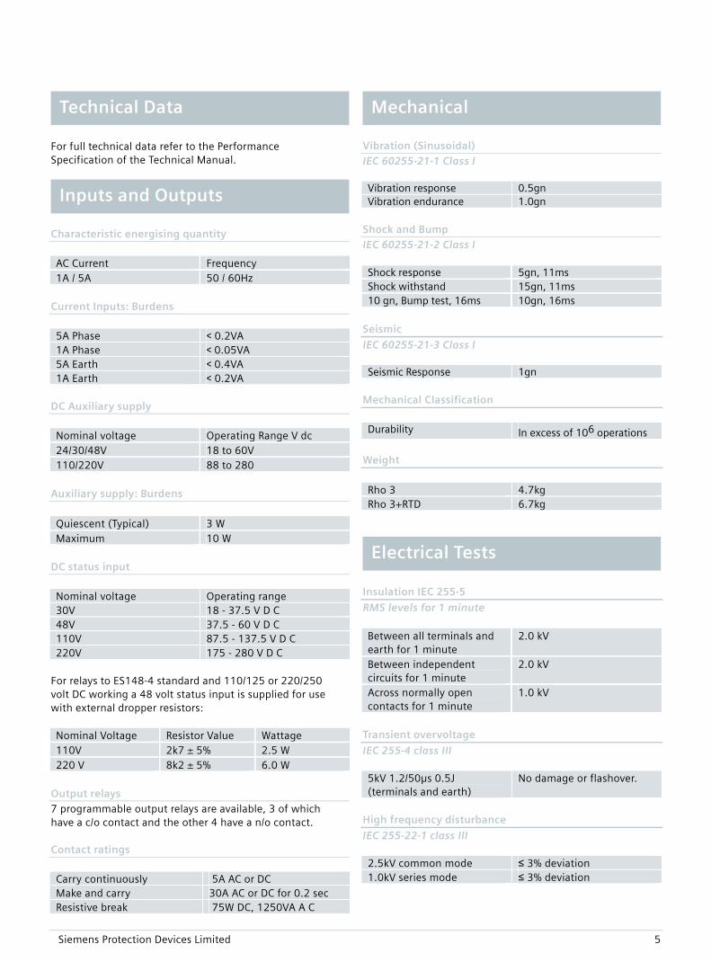
For full technical data refer to the Performance Specification of the Technical Manual.
Characteristic energising quantity AC Current Frequency 1A / 5A 50 / 60Hz
Current Inputs: Burdens 5A Phase < 0.2VA 1A Phase < 0.05VA 5A Earth < 0.4VA 1A Earth < 0.2VA
DC Auxiliary supply Nominal voltage Operating Range V dc 24/30/48V 18 to 60V 110/220V 88 to 280
Auxiliary supply: Burdens Quiescent (Typical) 3 W Maximum 10 W
DC status input
Nominal voltage Operating range 30V 18 - 37.5 V D C 48V 37.5 - 60 V D C 110V 87.5 - 137.5 V D C 220V 175 - 280 V D C
For relays to ES148-4 standard and 110/125 or 220/250 volt DC working a 48 volt status input is supplied for use with external dropper resistors: Nominal Voltage Resistor Value Wattage 110V 2k7 ± 5% 2.5 W 220 V 8k2 ± 5% 6.0 W
Output relays 7 programmable output relays are available, 3 of which have a c/o contact and the other 4 have a n/o contact. Contact ratings
Carry continuously 5A AC or DC Make and carry 30A AC or DC for 0.2 sec Resistive break 75W DC, 1250VA A C
Technical Data Mechanical
Vibration (Sinusoidal)
IEC 60255-21-1 Class I Vibration response 0.5gn Vibration endurance 1.0gn Inputs and Outputs
Shock and Bump IEC 60255-21-2 Class I Shock response 5gn, 11ms Shock withstand 15gn, 11ms 10 gn, Bump test, 16ms 10gn, 16ms
Seismic
IEC 60255-21-3 Class I Seismic Response 1gn
Mechanical Classification
Durability In excess of 106 operations
Weight
Rho 3 4.7kg Rho 3+RTD 6.7kg
Electrical Tests
Insulation IEC 255-5
RMS levels for 1 minute Between all terminals and earth for 1 minute
2.0 kV
Between independent circuits for 1 minute
2.0 kV
Across normally open contacts for 1 minute
1.0 kV
Transient overvoltage
IEC 255-4 class III 5kV 1.2/50µs 0.5J (terminals and earth)
No damage or flashover.
High frequency disturbance
IEC 255-22-1 class III 2.5kV common mode ≤ 3% deviation 1.0kV series mode ≤ 3% deviation
Siemens Protection Devices Limited 5

Siemens Protection Devices Limited 6
Electrostatic Discharge
IEC 255-22-2 class III
Environmental 8kV contact discharge ≤ 5% deviation Temperature
IEC 68-2-1/2 Radio frequency disturbance IEC 255-22-3 Operating range 10°C to +55°C
Storage range 25°C to +70°C 20MHz to 1GHz, 10V/m ≤ 5% deviation
Humidity Fast transient IEC 68-2-3 IEC 255-22-4 class IV Operational test 56 days at 40°C and 93%
RH 4kV 5/50ns 2.5kHz repetitive
≤ 3% deviation

The 7SG17 is supplied in either a size 6 or size 8 case, depending on the binary input, RTD input and output relay requirement.
Fig 1. E6 Case Dimensions
Case Dimensions
Fig 2. E8 Case Dimensions
Siemens Protection Devices Limited 7

Siemens Protection Devices Limited 8
7SG17 - Rho 3
BO 1
BI 1+ve
-ve
5
6
3
4
BI 2-ve
+ve35
36
BI 3-ve
+ve33
34
BO 2 10
9
8
BO 3 18
17
16
BO 411
12
BO 519
20
1A
5A E/F
25
26
27
28
C
B
71A
5A
45
46
47
48
1A
5A
49
50
51
52
A
1A
5A
53
54
55
56
BO 621
22
BO 723
24
BI 4-ve
31
32
BI 5-ve
+ve29
30
BI 6-ve
+ve43
44
BI 7-ve
41
42
BI 8-ve
+ve39
40
BI 9-ve
+ve37
38
Case earth
+ve
-ve
13
14
15
EXPANSION PCB
RTD162
63
61
RTD265
66
64
RTD368
69
67
RTD471
72
70
RTD574
75
73
RTD677
78
76
RTD780
81
79
RTD883
84
82
GND.57
RTD EXPANSION PCB
Earth
Shows contacts internal to relay case assembly.Contacts close when the relay chassis is withdrawn from case
Notes:
BI = Binary InputBO = Binary Output
Fig 3. Connection Diagram for 7SG17 Relay
Connection Diagram
Siemens Protection Devices Limited 9
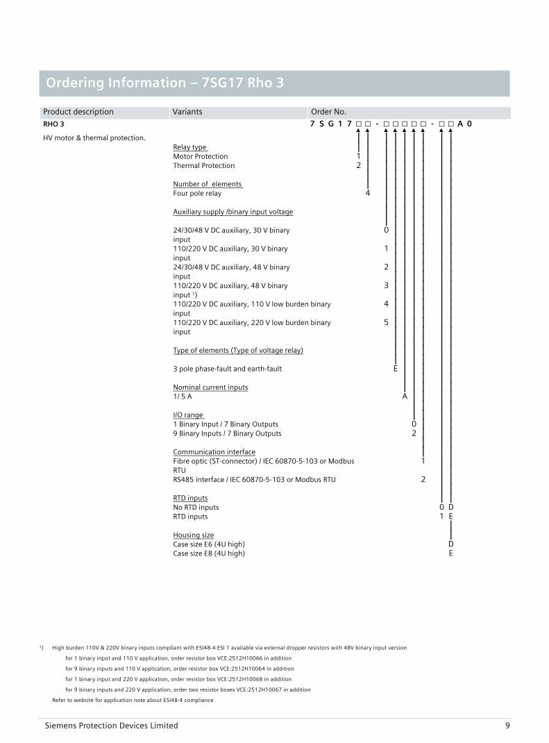
Product description Variants Order No.
RHO 3 7 S G 1 7 □ □ - □ □ □ □ □ - □ □ A 0 ▲ ▲ ▲ ▲ ▲ ▲ ▲ ▲ ▲
HV motor & thermal protection. | | | | | | | | | Relay type | | | | | | | | | Motor Protection 1 | | | | | | | | Thermal Protection 2 | | | | | | | | | | | | | | | | Number of elements | | | | | | | | Four pole relay 4 | | | | | | | | | | | | | | Auxiliary supply /binary input voltage |
|| |
| |
| |
| |
| |
| |
24/30/48 V DC auxiliary, 30 V binary input
0 | |
| |
| |
| |
| |
| |
110/220 V DC auxiliary, 30 V binary input
1 | |
| |
| |
| |
| |
| |
24/30/48 V DC auxiliary, 48 V binary input
2 | |
| |
| |
| |
| |
| |
110/220 V DC auxiliary, 48 V binary input 1)
3 | |
| |
| |
| |
| |
| |
110/220 V DC auxiliary, 110 V low burden binary input
4 | |
| |
| |
| |
| |
| |
110/220 V DC auxiliary, 220 V low burden binary input
5 | |
| |
| |
| |
| |
| |
| | | | | | Type of elements (Type of voltage relay) |
| | |
| |
| |
| |
| |
3 pole phase-fault and earth-fault E | | | | | | | | | | Nominal current inputs | | | | | 1/ 5 A A | | | | | | | | I/O range | | | | 1 Binary Input / 7 Binary Outputs 0 | | | 9 Binary Inputs / 7 Binary Outputs 2 | | | | | | Communication interface | | | Fibre optic (ST-connector) / IEC 60870-5-103 or Modbus
RTU 1 |
| | |
RS485 interface / IEC 60870-5-103 or Modbus RTU 2 | | | | RTD inputs | | No RTD inputs 0 D RTD inputs 1 E | Housing size | Case size E6 (4U high) D Case size E8 (4U high) E
1) High burden 110V & 220V binary inputs compliant with ESI48-4 ESI 1 available via external dropper resistors with 48V binary input version
for 1 binary input and 110 V application, order resistor box VCE:2512H10066 in addition
for 9 binary inputs and 110 V application, order resistor box VCE:2512H10064 in addition
for 1 binary input and 220 V application, order resistor box VCE:2512H10068 in addition
for 9 binary inputs and 220 V application, order two resistor boxes VCE:2512H10067 in addition
Refer to website for application note about ESI48-4 compliance
Ordering Information – 7SG17 Rho 3
Siemens Protection Devices Limited P.O. Box 8 North Farm Road Hebburn Tyne and Wear NE31 1TZ United Kingdom Phone: +44 (0)191 401 7901 Fax: +44 (0)191 401 5575 Web: www.reyrolle-protection.com PTD 24h Customer Support Phone: +49 180 524 7000 Fax: +49 180 524 2471 E-mail: [email protected] Data is subject to change without notification.
Australian Distributor
Relay Monitoring Systems Pty Ltd 6 Anzed Court Mulgrave, Victoria, 3170, Australia Phone: +61 3 8544 1200 Fax: +61 3 8544 1201 Email: [email protected] Web: www.rmspl.com.au