Embed Size (px)
Citation preview
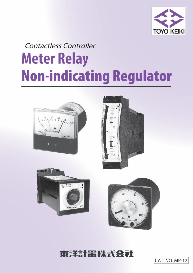
Contactless Controller
Meter Relay Non-indicating Regulator
CAT NO MP-12
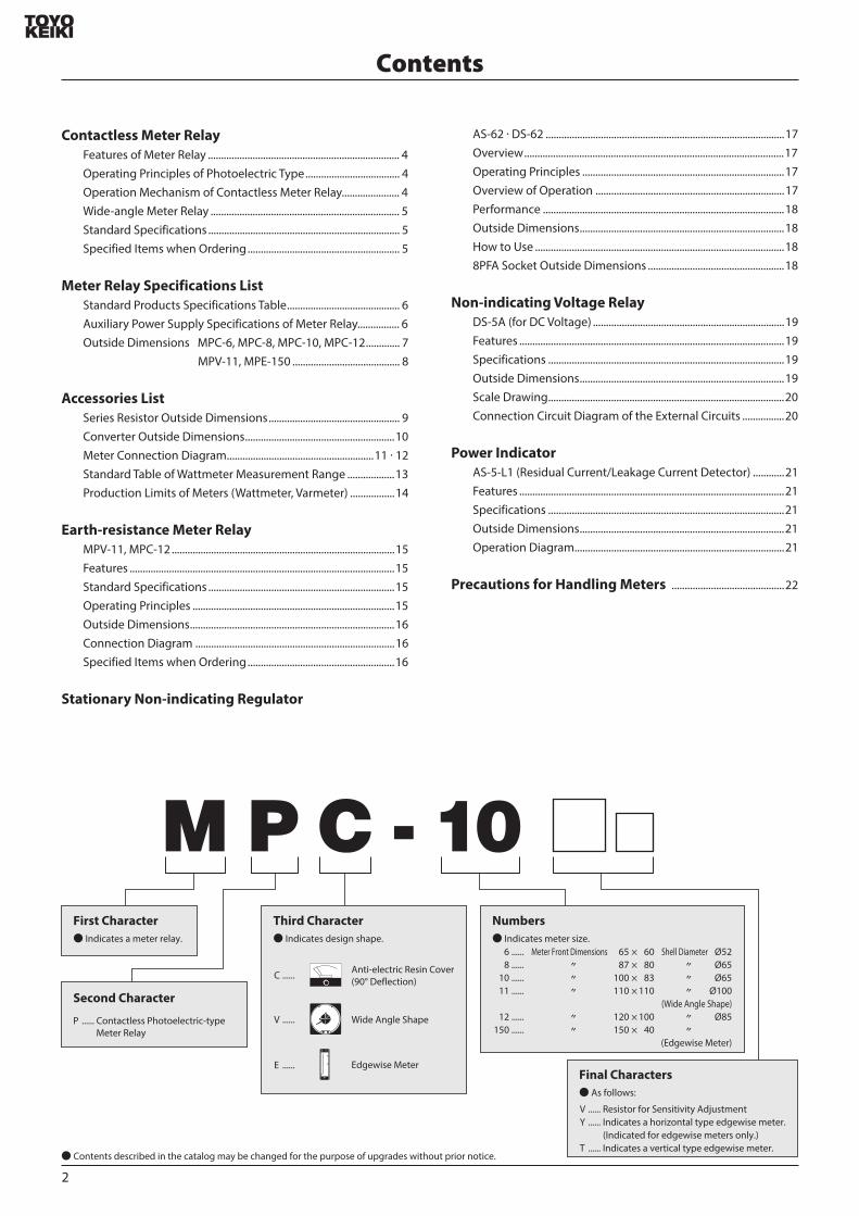
Contents
Contactless Meter Relay Features of Meter Relay 4Operating Principles of Photoelectric Type 4Operation Mechanism of Contactless Meter Relay 4Wide-angle Meter Relay 5Standard Specifications 5Specified Items when Ordering 5
Meter Relay Specifications List Standard Products Specifications Table 6Auxiliary Power Supply Specifications of Meter Relay 6Outside Dimensions MPC-6 MPC-8 MPC-10 MPC-12 7
MPV-11 MPE-150 8
Accessories List Series Resistor Outside Dimensions 9Converter Outside Dimensions10Meter Connection Diagram11 middot 12Standard Table of Wattmeter Measurement Range 13Production Limits of Meters (Wattmeter Varmeter) 14
Earth-resistance Meter Relay MPV-11 MPC-1215Features 15Standard Specifications 15Operating Principles 15Outside Dimensions16Connection Diagram 16Specified Items when Ordering16
Stationary Non-indicating Regulator
AS-62 middot DS-62 17Overview17Operating Principles 17Overview of Operation 17Performance 18Outside Dimensions18How to Use 188PFA Socket Outside Dimensions 18
Non-indicating Voltage Relay DS-5A (for DC Voltage) 19Features 19Specifications 19Outside Dimensions19Scale Drawing20Connection Circuit Diagram of the External Circuits 20
Power Indicator AS-5-L1 (Residual CurrentLeakage Current Detector) 21Features 21Specifications 21Outside Dimensions21Operation Diagram21
Precautions for Handling Meters 22
First Character Indicates a meter relay
2
Second Character
P Contactless Photoelectric-type Meter Relay
Third Character Indicates design shape
C
V
E
Anti-electric Resin Cover (90deg Deflection)
Wide Angle Shape
Edgewise Meter
Numbers Indicates meter size
6 8
10 11
12 150
Oslash52Oslash65Oslash65
Oslash100(Wide Angle Shape)
Oslash85
(Edgewise Meter)
65 times 60 87 times 80 100 times 83 110 times 110
120 times 100 150 times 40
Meter Front Dimensions
Shell Diameter
Final Characters As follows
V Resistor for Sensitivity AdjustmentY Indicates a horizontal type edgewise meter
(Indicated for edgewise meters only)T Indicates a vertical type edgewise meter
Contents described in the catalog may be changed for the purpose of upgrades without prior notice
Meter Relay
Non-indicating Regulator
MPV-11
MPE-150T
AS-62
DS-5A
MPC-6
MPC-8
MPC-10
MPC-12
3
Contactless Meter RelayA precise meter relay that uses the deflection of the pointer to control the external circuits Toyo Keiki manufactures devices with photoelectric-type configurations
Features of Meter Relay These meter relays possess the various features of a contactless
solid state relay
The relay circuits and detection relay are integrated into the main body of the meter This reduces labor potential misconnection and other issues in steps such as connection and installation of the included cells
Highly reliable operation
Reliable operation even during minute meter input
Set point passage-type relay
A light source and a receiver are installed on the upper limit and lower limit pointers respectively The collector current of the photo transistor receiver changes when the foil attached to the movable pointer goes between the light source and the receiver by means of the movable coil input This change in current is converted to a change in voltage which passes through a comparator circuit and a switching circuit to operate the detection relay
1 Passing Signal Retaining TypeWhen the pointer moves past the setting value the passing signal is retained after signal output The signal returns to normal after the pointer moves back to the setting value
2 Passage TypeInstantaneous TypeThe same structure as the stop type below except without the stopper The output signal returns to normal when the pointer reaches around 8 of the scale length past the setting value
3 Stop TypeThe pointer mechanically stops after it passes the H or L setting value and a signal is output The pointer can reach around 8 of the scale length past the setting value
(1) When using a meter relay with L settings (except the wide angle passing signal retaining type) take care not to turn on the power of the meter relay and the meter input at the same time as the L side signal will be generated continuously until the meter pointer passes the set L pointer
(2) Avoid using in areas where the meter will be directly exposed to sunlight in the middle of summer as these are photoelectric-type meter relays
Operating Principles of Photoelectric Type
Metallic Foil
ComparatorCircuit
SwitchingCircuit
VoltageCircuit
Meter Input
Rete
ntio
n Si
deLu
min
esce
ntD
iode
Lum
ines
cent
Dio
de
Phot
oTr
ansi
stor
Phot
oTr
ansi
stor
Phot
oTr
ansi
stor
Phot
oTr
ansi
stor
Lum
ines
cent
Dio
de
Lum
ines
cent
Dio
de
Driv
ing
Side
Driv
ing
Side
Rete
ntio
n Si
de
DetectionRelay
ComparatorCircuit
SwitchingCircuit
DetectionRelay
H Side
L Side
3 4 5
6 7 8
9
10
Photo Transistor
Photo Transistor
Luminescent Diode
Luminescent Diode
Power Supply
1 2
SquareEdgewise Meter RelayPhotoelectric-type Circuit Configuration
Wide-angle Meter RelayPhotoelectric-type Circuit Configuration
Pointer
Metallic Foil
Meter Input
ComparatorCircuit
StorageCircuit
DetectionRelay
DetectionRelay
StorageCircuit
VoltageCircuit
H Side
L Side
PowerSupply
ComparatorCircuit
1 2
6 7 8
3 4 5
9
10
4
Operation Mechanism of Contactless Meter Relay
Precautions for Use
While the standard output signal format of the meter relays is a passing signal retaining type the following three types are used for the MPV-11
Output Signal Format
1 Passing Signal Retaining Type Wide angle shape square shape edgewise shape (MPV type MPC type MPE type)
Wide Angle Shape (MPV type)
Wide Angle Shape (MPV type)
2 Passage TypeInstantaneous Type
3 Stop Type
Compatible Meter Relay Format
L Setting Value H Setting Value
ON- OFF
ON -OFF
H Side Relay Action Between Terminals (3) and (4)
L Side Relay Action Between Terminals (6) and (7)
L Setting Value
Around 8
Around 8
H Setting Value
ON- OFF
ON -OFF
H Side Relay Action Between Terminals (3) and (4)L Side Relay Action Between Terminals (6) and (7)
Wide-angle Meter Relay (Passing Signal Retaining Type)
Standard Specifications
Specified Items when Ordering
While 90deg displacement meter relays have a shielding plate at the 90deg point and can retain the signal by themselves after the pointer passes this wide-angle meter relays are mechanically unable to do this because the displacement angle (240deg) is too large An electronic storage method is used insteadAs a result the following issues occur the first time the auxiliary power supply is turned on Please take this into account when designing circuits
(1) When the Auxiliary Power Supply is Turned On (L Side Only)Load relay operation on the L side should be turned on when the meter pointer is a zero and the auxiliary power supply is turned on but in this case operation does not occur unless the pointer is displaced to around 17mm before the L setting valueHowever this only occurs the first time the pointer passes after turning on the power After this operation is turned off when the L setting value is passed and on after returning to normal and remains on after returning to zeroThis only occurs for the L setting Normal operation occurs from the start for the H setting
(2) When the Auxiliary Power Supply is StoppedIf the indicator input and auxiliary power supply of the meter are applied by different circuits the auxiliary power supply stops when the pointer goes above the H setting value and the H load relay activates If the pointer continues to indicate the same value the H load relay returns (turns off) at the same time as the power supply and usually turns back on when the power is turned on againHowever if the power is off for 40 seconds or longer the storage circuit no longer retains the signal with the result that the previous signal is no longer output when the power is turned on again If the power is off for 40 seconds or longer be sure to return the pointer to the zero position by opening or shorting the meter input circuitNo issue occurs when the power is off for short periods of less than 40 seconds as the storage circuit remains live
Model Name MPC-6 MPC-8 MPC-10 MPC-12 MPE-150 MPV-11
65 times 60 87 times 80 100 times 83 120 times 100 150 times 40 110 times 110
12 ~ 25 12 ~ 25 20 ~ 45 24 ~ 50 35 ~ 75
1A each for H and L AC 100V 1A
1ab each for H and L AC 220V 3A
Approx 48 Approx 68 Approx 80 Approx 100 Approx 100
25 15
25 15 (25) ( ) indicates rectifier type
Approx 170
Approx 260g Approx 380g Approx 400g Approx 680g Approx 560g Approx 14kg
With Terminal Cover With Terminal Cover With Terminal Cover With Terminal Cover With Terminal Cover With Terminal Cover
Wand Type
Wand TypeH RedL Yellow Spearhead Type
H RedL Yellow
Triangular Spearhead Type Triangular Type
Special Anti-electric ResinMethacrylic Resin
and ABS Resin Methacrylic Resin
Between Terminals Phenol ResinBody ABS Resin
ABS Resin and Aluminum Board
Between Terminals Phenol Resin Body ABS Resin
Operating PrinciplesItem
Passage Type
Stop Type
DCAC
Retaining Type
Instantaneous Type
Meter Action
Auxiliary Power Supply
Output Signal
Contact Arrangement and Capacity
Insulation Test
Voltage Test
Characteristics of Meter
Weight
Remarks
Outside (mm)
Scale Length (mm)
Accuracy Class
Pointer
Set Pointer
Scale Plate
Scale Division
Mounting Posture
Cover
Base
Cover Coating Color
Setting
Minimum Set Gap between H and L (Against Scale Length)
Operating Error for Setting Value (Against Scale Length)
Dead Band
Photoelectric Type
White Base
Black or Munsell Notation 75B G415 (Blue-green)
Both H and L can be set as desired throughout the entire scale range
According to Auxiliary Power Supply Specifications of Meter Relay on page 6
1ab each for H and L AC 100V 1A (resistance load)
Between electrical circuit and outer casing of meter 10MΩ or more for 500V mega
Between electrical circuit and outer casing of meter AC 1500V (5060Hz per minute) between contact relay circuit and other electrical circuits AC 500V (5060Hz per minute)
Characteristics of the meter part are based on JIS C standards 1102-1 to 9
5
10
Vertical
Item Entry Guide Specified Items Note
Model Name
Set Method
External Circuit Impedance
Attached Panel
Auxiliary Power Supply Voltage
Other (Accessories etc)
Quantity
Scale
Upper Limit Value Inherent to Meter
Specifications of Meter Interior
Select one of the above model names Example MPC-6 8 10 12
Upper limit (H) lower limit (L) or upper and lower limits (HL) H L H middot L H middot H L middot L
(Indicated only for millivolt meters and μA meters)
Attached Panel Standard Products MPC-6 8 10 20mm MPC-12 32mm (specification required in other cases)
AC or DC voltage value
Indicates whether accessories are required when the rated range is exceeded CT VT series resistor shunt generator none needed etc
Desired delivery time days after order
5
XX items
Enter the value displayed on the scale plate
Not required if this value is the same as that displayed on the scale plate
When there is a particular need to specify the meter sensitivity or internal resistance mA Ω
Ω
AC 110V +5 ndash10 AC 220V etc+5
ndash10
M-4A Model (M-4B Model)
Meter Relay Specifications List[Standard Products Specifications Table]
[Auxiliary Power Supply Specifications of Meter Relay]
[Power Unit]
Maximum Scale Value or Rating Notes
Meter 100mV
Meter 60mV
Meter 150V
110V 1VA
220V 2VA
110V 08VA
5A 08VA
110V 1VA
220V 1VA
5A 05VA
1P varmeter can also be manufactured In ( )
110V Per phase 1VA
220V Per phase 1VA
5A Per phase 05VA
3P varmeter can also be manufactured In ( )
110V Per phase 05VA
5A Per phase 08VA
3P balanced power rate meter can also be manufactured In ( )
Install M-2A near the meter
Over 500V less than 750V (M-2A)
3 voltage division terminals for 750V and higher
(Various types of series resistor depending on voltage)
MPC-6 MPC-8 10 12 MPC-11 MPC-150
Accessories Accessories Accessories Accessories
None
None
M-2A
M-2A
Externally Attached Shunt
None
None
None
M-2A
Externally Attached Shunt
None
None
M-2A
Externally Attached Shunt
None
None
None
M-2A
Externally Attached Shunt
None
M-1
M-2A
None
None
M-1
None
None
M-1
None
None
M-1
M-2A
M-2A
M-2A
None
M-1
None
None
M-1
None
None
M-1
None
FM-3 FM-3 FM-3 FM-3
URG-3 URG-3 URG-3 URG-3
M-2A
Note 1) Specify 1P varmeter 3P varmeter or 3P unbalanced power factor meter (50Hz or 60Hz) 2) See P9 and 10 for outside dimensions of accessories 3) See P11 and 12 for connection diagrams of meter circuits 4) MRS-response can also be manufactured for AC ammeter and AC voltmeter
None None None
ERG-3
(RRG-3)
ERG-3
(RRG-3)
ERG-3
(RRG-3)
ERG-3
(RRG-3)
ERG-3
(RRG-3)
ERG-3
(RRG-3)
ERG-3
(RRG-3)
ERG-3
(RRG-3)
UuRG-3
(URG-3)
UuRG-3
(URG-3)
UuRG-3
(URG-3)
UuRG-3
(URG-3)
M-2A
M-2A and C-3
M-2A and C-3
M-2A and C-3
M-2A and C-3
M-2A and C-3
None
M-2A
C-3
C-3
C-3
C-3
None
None
None
C-3
None
None
None
M-2A
C-3
C-3
C-3
M-2A and C-3
Tachometer
Auxiliary Power Supply VoltageMPC-6
Accessories Power Consumption
P-3(4 terminals)
P-3(4 terminals)
None
15VA
15VA
15VA
None
None
M-4A
M-4B
100mA
80mA
100mA
150mA
MPC-8 10 12
Accessories Power Consumption
None
None
None
15VA
15VA
15VA
None
None
M-4A
M-4B
100mA
80mA
100mA
150mA
MPC-11
Accessories Power Consumption
None
None
None
15VA
15VA
15VA
None
None
M-4A
M-4B
100mA
80mA
100mA
150mA
MPC-150
Accessories Power Consumption
P-3
P-3
None
11VA
11VA
11VA
None
None
M-4A
M-4B
100mA
80mA
100mA
150mA
3P Unbalanced Power Factor Meter Electronic device type
1P Power Factor Meter Electronic device type
3P Wattmeter Electronic device type
1P Wattmeter Electronic device type
Frequency Electronic device type (Dierential Method)
DC Ammeter (Moving-coil type)
100μA
200μA ~ 20mA
Over 20mA up to 1A
Over 1A less than 5A
5A or above
1V-150V
Over 150V up to 300V
Over 300V up to 500V
3V or more up to 300V
Over 300V up to 500V
110V (for VT)
110V 5A
220V 5A
110V 5A
220V 5A
100rpm ~ 5000rpm
45 ~ 55Hz
55 ~ 65Hz
45 ~ 65Hz
110V
220V
LEAD LAG
05 ~ 1 ~ 05
LEAD LAG
05 ~ 1 ~ 05
110V 5A
220V 5A
110V 5A
220V 5A
500μA or more up to 20mA
Over 20mA up to 100mA
Over 100mA up to 5A
Over 5A up to 100A
5A (for CT)
5A (for CT) with extended scale
AC Ammeter (Mean value rectier type)
AC Voltmeter (Mean value rectier type)
DC Voltmeter (Moving-coil type)
AC 100V
200V
24V
DC 12V
24V
25 ~ 70V
71 ~ 150V
Variation of auxiliary power supply is plusmn10 of the values in the table
130
164
7213
751
147 plusmn1
2-Oslash55 Holes
M5 Screw
Values indicated in parentheses ( ) are for the M-4B model
6
OUTPUT
INPUT
Name Plate
10 9
ndash +
MPC-10
MPC-12
Terminal Number Diagram
P-3Auxiliary Power Supply Accessories Terminal Number DiagramNote 1) The terminal number configuration in the diagram
on the right also applies to terminal configurations
for meter relays not specified in the terminal number
diagram
2) As per the diagram for the meter input terminal and
power supply terminal unrelated to polarity in the
diagram for AC
125 68 66
05 10
21
Oslash52
4-M3 Mounting Screws
2
65 plusmn1
24 plusmn05 24 plusmn05
26 plusmn
05
22 plusmn
05
60 plusmn
1
M3 Terminal Screws Terminal Cover
(1)(2)(3)(4)
(9)(10)(6)(7)
26 plusmn
05
22 plusmn
05
24 plusmn05 24 plusmn05
4-Oslash4 Holes
+05
ndash0
Panel Cutout
+05ndash0
Oslash535(+)
Meter Input
(ndash)
(a)H Side L SideLoad
TerminalLoad Terminal(c)
(a)
(c)
(+) Auxiliary Power Supply(ndash)
5840
30
4212
55
OUTPUT
INPUT
NP
50 plusmn05
65
325
M4 Terminal Screws
(+)Meter Input Auxiliary Power
Supply
Load TerminalH Side
Load TerminalL Side
(ndash)
(a)
(b)
(c)
(a)
(b)
(c)
(+)
(ndash)
(1)
(2)
(3)
(4)
(5)
(9)
(10)
(6)
(7)
(8)
(1)
(2)
(3)
(4)
(9)
(10)
(6)
(7)
MPC-6
MPC-8
[Outside Dimensions]
20
12 105100
4-M3 Mounting Screws
05 10
Terminal Cover
Oslash65 2
32 plusmn
05
32 plusmn
05
32 plusmn0532 plusmn05
87 plusmn1
10-M3 Terminal Screws
80 plusmn
1
1
2
3
4
5
9
10
6
7
8
Variable Resistor for Sensitivity Settings
(MPC-8V Model Only)
32 plusmn
05
32 plusmn0532 plusmn05
4-Oslash5 Holes
Oslash67 plusmn1
+05ndash0
Panel Cutout
32 plusmn
05
20
12 105100
4-M3 Mounting Screws
05 10
Terminal Cover
Oslash65 4
32 plusmn
05
32 plusmn
05
32 plusmn05
100 plusmn1
32 plusmn05
1
2
3
4
5
9
10
6
7
8
10-M3 Terminal Screws Variable Resistor for Sensitivity Settings
83 plusmn
1
32 plusmn
05
32 plusmn
05
32 plusmn0532 plusmn05
4-Oslash5 Holes +05ndash0
Oslash67 plusmn1
Panel Cutout
Terminal Cover
20
12 105100
4-M3 Mounting Screws
05
255
10
Oslash64
Oslash85
545
plusmn0
535
plusmn0
5
50 plusmn05
120 plusmn1
50 plusmn05
10-M3 Terminal Screws Variable Resistor for Sensitivity SettingsNote 1
100 plusmn
1
1
2
3
4
5
9
10
6
7
8
35 plusmn
05
45 plusmn
05
50 plusmn05 50 plusmn05
4-Oslash5 Holes
Panel Cutout
Oslash87 plusmn1
+05ndash0
7
MPV-11
MPE-150
Indicates resistance values for resistor for sensitivity adjustment
Note
Auxiliary Power Supply
AC 100 ~ 115V 9 10
9 11
9 (+) 11 (ndash)
AC 200 ~ 230V
DC V
Terminals Used(+) (ndash) (a) (b) (c)
(+)
plusmn
(ndash)
100V
~
115V
200V
~
230V
(a) (b) (c)
AuxiliaryPower Supply
H Side
Terminal Cover
110
plusmn15
110 plusmn15
45plusmn0545plusmn05
1 2 3 4 59 10 11 6 7 8
M3 Terminal Screws
45plusmn0
545
4-Oslash7
Oslash102
45plusmn0545plusmn05
45plusmn0
545
plusmn05
plusmn05
33 or below
8
130
4M-6 Mounting Screws
05
24
145
115
Oslash10
0
Oslash10
2
Black Shading Hood
AuxiliaryPower Supply
L Side
Meter Input
Auxiliary Power Supply
(1) (2) (3) (4) (5)
(10)(9) (11) (6) (7) (8)
Panel Cutout14
6+1
ndash0
(402timesN)+15
N Quantity of Connected Meters
Panel Cutout
Meter Input Terminal ScrewsPolarity unrelated for 1(+) 2(ndash) and AC
(1) (2)
118
165
3612 9
23
150
plusmn1156
115
145
90 25
45 times M4 Screws for Attachment
Terminal Cover
166
Bezel (Escutcheon)
L Setting Knob (Yellow)
H Setting Knob (Red)
H Set Pointer (Red)
L Set Pointer (Yellow)
Pointer
Mechanical Zero-point Adjuster
Terminal Conguration
Load
Rel
ayH
Sid
e
Load
Rel
ayL
Side
Auxil
iary
Powe
r Sup
ply
Note Polarity not displayed for AC power supply
a c b a c b +
(3) (4) (5) (6) (7) (8) (9)(10)40
40 46
Attachment Screw Cap (Nylon 66)
M4 Nut SW8-M3 Terminal Screws
2-M4 Terminal Screws
Dimensions of Meter Body
Bezel Mounting Method
Meter Attachment Method1 Insert meter after panel cutout
2 Secure the attachment bracket to the meter body with the M4 screws
3 Push in the panel face and secure with the 45 M4 setscrews
4 Lock with the M4 nuts
8
9
Series Resistor Outside Dimensions
M-1 ModelWeight Approx 20g
M-2A ModelWeight Approx 100g
448
123
3
70plusmn 05
30
60
80
2-φ45 Holes
2-φ32 Holes
2-M35 ScrewsOne-touch Installation Terminal Cover
(Transparent Polycarbonate Plate)
Name Plate
6
2020
32plusmn
05
10
51
72
Fast-on Tab(187 Series)
M-3 ModelWeight Approx 015kg
M-2B ModelWeight Approx 015kg
M-6 ModelWeight Approx 08kg
M-4A Model (M-4B Model) Weight Approx 03kg
Name Plate
102 plusmn 05
4047
9
5
90
114
E M H
2-φ45 Holes2-φ45 Holes
E M H
銘 板
108 plusmn1
101
121
5543
59
55
Name Plate
H
E
130
164
7213
751(
81)
147 plusmn1
M
2-φ55 Holes
3-M4 Terminal Screws
Dimensions indicated in parentheses ( ) are for the M-4B model
120
135
plusmn1
100 plusmn1
9610
35
160
2-φ55 Holes75R
E
H
GM
Clamped Terminal
2-M4 Screws M5 Terminal Screws
Name Plate
Name Plate
Rating Model Model Rating
500 V
750 V
1000 V
1500 V
2000 V
3000 V
M-1
M-2B
M-3
M-3
M-4A
M-4A
M-6
M-6
M-6
4000 V
5000 V
7500 V
Voltage division (3 terminals) is used for 750V and higher
Series Resistor Models for DC Voltmeter
M-4A Model
M-2B Model
3-M4 Terminal Screws
3-M5 Terminal Screws
C-3 Model Current Transducer
ERG-3 Model URG-3 ModelRRG-3 Model UuRG-3 Model
40 58
30
48
42
12
55
6532
5
M4 Terminal Screws
LINE
METER
NP 40 581624
534
or b
elow
30
1259
4212
55
8098
LINE
METER
50plusmn05
24
65
325
Line Side Terminal ScrewsM4 Terminal Screws
Thickness t
(Note)
50plusmn05
Meter Side
1) 15A or Less 2) 15A and Above Up to 100ASpecications Rated Load 01VA
Primary Current Various types 15A and above up to 100ASecondary Current 10mACircuit Voltage 460VVoltage Test AC2000VWeight Approx 026kgSpecications Rated Load 01VA
Primary Current Various types less than 15ASecondary Current 10mACircuit Voltage 460VVoltage Test AC2000VWeight Approx 02kg
Primary Current Type
15A -75A
15
75A -100A
Conductor Thickness
t (mm)Line Side
Terminal Screws
M6times14
M8times16
Note)
Note)
Converter Outside Dimensions
Converter
Case Material Glass ber-strengthened PC resin Terminal Part Material Glass ber-strengthened PBT resin Cover Material Transparent polycarbonate resin
Din rail mounts can also be manufactured In such cases the model name is RG-3A
[Terminal Arrangement Diagram]
M-2A
FM-3
Series Resistors for AC VoltmeterRectiers for AC Ammeter
(Outside dimensions are the same as the M-3 model on page 9)
10
70plusmn05
30
60
80
2-φ45 Holes
4-M35 ScrewsOne-touch Installation Terminal Cover
(Transparent Polycarbonate Plate)
METER
LINE
LINE電 源METERメータ
For Frequency Meter
LINE
METER
minus +
121plusmn05
72plusmn05
124plusmn
05
96
110plusmn
05
4
7
Terminal CoverM4 Terminal ScrewsHere is an example of a terminal screw position
69
11
Name Plate
2
Meter Connection Diagram
Converter
LINE
METER
①
②
a c b
a c b
AC V
Generator
Generator
Frequency Meter
ConverterVT
LINE
METER
①
②
a c b
a c b
AC V
Frequency Meter (With VT)
a c b
a c b
AC V
Electric Tachometer
M-2A Series Resistor
LINE
METER
+
-
a c b
a c b
AC V
Electric Tachometer (With Series Resistor)
TG
TG
M-2A Series Resistor
LINE
METER
a c b
a c b
AC V
Voltmeter (With Series Resistor)
a c b
a c b
AC V
Voltmeter (Direct Measurement)
a c b
a c b
AC V
Voltmeter (With VT)
M-2A Series Resistor
VT VT
LINE
METER
+
-
+
-
a c b
a c b
AC V
Voltmeter (With VT Series Resistor)
C-3 Current Transducer
LINE
METER
a c b
a c b
AC V
Ammeter (With Current Transducer)
M-2A Rectier Box
LINE
METER
a c b
a c b
AC V
Ammeter (With Rectier Box)
a c b
a c b
AC V
Ammeter (Direct Measurement)
C-3 Current Transducer
CT
LINE
METER
a c b
a c b
AC V
Ammeter (With CT Current Transducer)
Rectier Box
CT
LINE
METER
Current TransducerC-3 M-2A
LINE
METER
a c b
a c b
AC V
Ammeter (With Current Transducer Rectier Box)
+
a c b
a c b
AC V
Ammeter (With Shunt)
a c b
a c b
AC V
H Side Load Relay Contact
L Side LoadRelay Contact
H Side Load Relay Contact
L Side LoadRelay Contact
H Side Load Relay Contact
L Side LoadRelay Contact
H Side Load Relay Contact
L Side LoadRelay Contact
H Side Load Relay Contact
L Side LoadRelay Contact
H Side Load Relay Contact
L Side LoadRelay Contact
H Side Load Relay Contact
L Side LoadRelay Contact
H Side Load Relay Contact
L Side LoadRelay Contact
H Side Load Relay Contact
L Side LoadRelay Contact
H Side Load Relay Contact
L Side LoadRelay Contact
H Side Load Relay Contact
L Side LoadRelay Contact
H Side Load Relay Contact
L Side LoadRelay Contact
H Side Load Relay Contact
L Side LoadRelay Contact
H Side Load Relay Contact
L Side LoadRelay Contact
H Side Load Relay Contact
L Side LoadRelay Contact
H Side Load Relay Contact
L Side LoadRelay Contact
H Side Load Relay Contact
L Side LoadRelay Contact
Power Supply Power Supply Power Supply
Shunt
Load Load Load
Power Supply
Load
Power Supply
Load
Power Supply
Load
Power Supply
Load
Power Supply
Load
Power Supply
Load
Power Supply
Load
Power Supply
Load
Power Supply
Load
Power Supply
Load
Power Supply
Load
Power Supply
Load
Power Supply
Load
Power Supply
Load
Ammeter (Direct Measurement)
Series Resistor
a c b
a c b
AC V
Voltmeter (With Voltage Division Type Series Resistor)
M-2A Shunt Box
LINE
METER
+
-
+
-
a c b
a c b
AC V
Ammeter (With Shunt Box)
H M
E
M-1 M-2A Series Resistor
a c b
a c b
AC V
Voltmeter (With Series Resistor)
a c b
a c b
AC V
Voltmeter (Direct Measurement)
Voltage division type series resistor should be used when the maximum scale value is 750V or higher
Note 1 The terminal diagram below is for MPC-10 and 12 For the terminal arrangements of other models see the outside dimensions page for those models
Note 2 The example auxiliary power supply connection is for AC See the example connection on the next page for DC auxiliary power supplies
Note 3 Accessories (P-3) are required for the MPC-6 even if the auxiliary power supply is AC See the the example connection on the next page for information on connections( )
DC Ammeter and DC Voltmeter (Moving-coil Type)
AC Ammeter or Voltmeter (Rectier Type)
Dierential Analyzer Frequency Meter Electric Tachometer (Rectier)
H Side Load Relay Contact
L Side LoadRelay Contact
H Side Load Relay Contact
L Side LoadRelay Contact
1 2 3 4 5
9 10 6 7 8
1 2 3 4 5
9 10 6 7 8
1 2 3 4 5
9 10 6 7 8
1 2 3 4 5
9 10 6 7 8
1 2 3 4 5
9 10 6 7 8
1 2 3 4 5
9 10 6 7 8
1 2 3 4 5
9 10 6 7 8
1 2 3 4 5
9 10 6 7 8
1 2 3 4 5
9 10 6 7 8
1 2 3 4 5
9 10 6 7 8
1 2 3 4 5
9 10 6 7 8
1 2 3 4 5
9 10 6 7 8
1 2 3 4 5
9 10 6 7 8
1 2 3 4 5
9 10 6 7 8
FM-3
FM-3
1 2 3 4 5
9 10 6 7 8
1 2 3 4 5
9 10 6 7 8
1 2 3 4 5
9 10 6 7 8
1 2 3 4 5
9 10 6 7 8
1 2 3 4 5
9 10 6 7 8
11
P-3
INP
UT
OU
T PU
T
a
c
a
c
Meter InputAC CurrentAC〇〇V
M-4A or M-4B
INP
UT
OU
T PU
T
a
c
b
a c b
a c b
a
c
b
Load TerminalH Side
Load TerminalH Side
Meter Input
Load TerminalL Side
DC CurrentDC〇〇V
Note M-4A (M-4B) not required when the auxiliary power supply is DC24V or DC12V
Note P-3 not required when the auxiliary power supply is AC24V or AC12V
1 2 3 N
DAOLECRUOS CT1CT2
CT3
Auxiliary Power Supply
VT1
VT2
VT3
3P4W Wattmeter Varmeter (With CT)
a c b
a c b
1 2 3 N
DAOLECRUOS CT1CT2
CT3
Auxiliary Power Supply
3P4W Wattmeter Varmeter (With CT VT)
VT1 VT2
a c b
a c b
1 2 3
DAOLECRUOS CT1
CT2
Auxiliary Power Supply
3P Wattmeter Varmeter (With CT VT)
VT1 VT2
a c b
a c b
1 N 2
DAOLECRUOS CT1
CT2
Auxiliary Power Supply
1P3W Wattmeter Varmeter (With CT VT)
VT
a c b
a c b
1 2
SOURCE LOADCT
Auxiliary Power Supply
1P Wattmeter Varmeter (With CT VT)
a c b
a c b
1 2 3
DAOLECRUOS CT1
CT2
Auxiliary Power Supply
3P Wattmeter Varmeter (With CT)
a c b
a c b
1 2
DAOLECRUOS CT
Auxiliary Power Supply
1P Wattmeter Varmeter (With CT)
a c b
a c b
1 N 2
SOURCE LOADCT1
CT2
Auxiliary Power Supply
1P3W Wattmeter Varmeter (With CT)
a c b
a c b
1 2 3 N
SOURCE LOADCT1CT2
CT3
Auxiliary Power Supply
VT
3P4W Power Factor Meter (With CT)
a c b
a c b
1 2 3 N
DAOLECRUOS CT1CT2
CT3
Auxiliary Power Supply
3P4W Power Factor Meter (With CT VT)
VT1 VT2
a c b
a c b
1 2 3
DAOLECRUOS CT1
CT2
Auxiliary Power Supply
3P Unbalanced Power Factor Meter (With CT VT)
VT
5
a c b
a c b
1 2 3
DAOLECRUOS CT
Auxiliary Power Supply
3P Balanced Power Rate Meter (With CT VT)
VT
a c b
a c b
1 2
SOURCE LOADCT
Auxiliary Power Supply
1P Power Factor Meter (With CT VT)
a c b
a c b
1 2 3
DAOLECRUOS CT1
CT2
Auxiliary Power Supply
3P Unbalanced Power Factor Meter (With CT)
a c b
a c b
1 2
DAOLECRUOS CT
Auxiliary Power Supply
1P Power Factor Meter (With CT)
a c b
a c b
1 2 3
SOURCE LOADCT1
Auxiliary Power Supply
3P Balanced Power Rate Meter (With CT)
MPC-6 ModelFor AC Auxiliary Power Supply
MPC-8 MPC-10 MPC-12 ModelFor DC Auxiliary Power Supply
Wattmeter and Varmeter (Electronic Device Type)
Power Factor Meter (Electronic Device Type)
Overall Connection Diagram (Example)
H Side Load Relay Contact
L Side LoadRelay Contact
H Side Load Relay Contact
L Side LoadRelay Contact
H Side Load Relay Contact
L Side LoadRelay Contact
H Side Load Relay Contact
L Side LoadRelay Contact
H Side Load Relay Contact
L Side LoadRelay Contact
H Side Load Relay Contact
L Side LoadRelay Contact
H Side Load Relay Contact
L Side LoadRelay Contact
H Side Load Relay Contact
L Side LoadRelay Contact
H Side Load Relay Contact
L Side LoadRelay Contact
H Side Load Relay Contact
L Side LoadRelay Contact
H Side Load Relay Contact
L Side LoadRelay Contact
H Side Load Relay Contact
L Side LoadRelay Contact
H Side Load Relay Contact
L Side LoadRelay Contact
H Side Load Relay Contact
L Side LoadRelay Contact
H Side Load Relay Contact
L Side LoadRelay Contact
H Side Load Relay Contact
L Side LoadRelay Contact
Load TerminalL Side
1 2 3 4 5
9 10 6 7 8
1 2 3 4 5
9 10 6 7 8
1 2 3 4 5
9 10 6 7 8
1 2 3 4 5
9 10 6 7 8
1 2 3 4 5
9 10 6 7 8
1 2 3 4 5
9 10 6 7 8
1 2 3 4 5
9 10 6 7 8
1 2 3 4 5
9 10 6 7 8
1 2 3 4 5
9 10 6 7 8
1 2 3 4 5
9 10 6 7 8
1 2 3 4 5
9 10 6 7 8
1 2 3 4
9 10 6 7 8
1 2 3 4 5
9 10 6 7 8
1 2 3 4 5
9 10 6 7 8
1 2 3 4 5
9 10 6 7 8
1 2 3 4 5
9 10 6 7 8
1 2 3 4 5
9 10 6 7 8
1 2 3 4
9 10 6 7
910
910
12
Intrinsic Power Value
CT Ratio
5A5A
75A5A
10A5A
15A5A
20A5A
30A5A
40A5A
50A5A
75A5A
100A5A
150A5A
200A5A
300A5A
400A5A
500A5A
750A5A
1000A5A
1500A5A
2000A5A
3000A5A
VT Ratio625Or
667W
Line Voltage
mdash
1 kW
12 kW
2 kW
25 kW
4 kW
5 kW
mdash
10 kW
12 kW
20 kW
25 kW
40 kW
50 kW
mdash
100 kW
120 kW
200 kW
250 kW
400 kW
750 W
12 kW
15 kW
25 kW
3 kW
5 kW
6 kW
75 kW
12 kW
15 kW
25 kW
30 kW
50 kW
60 kW
75 kW
120 kW
150 kW
250 kW
300 kW
500 kW
1 kW
15 kW
2 kW
3 kW
4 kW
6 kW
8 KW
10 kW
15 kW
20 kW
30 kW
40 kW
60 kW
80 kW
100 kW
150 kW
200 kW
300 kW
400 kW
600 kW
12 kW
2 kW
25 kW
4 kW
5 kW
8 kW
10 kW
12 kW
20 kW
25 kW
40 kW
50 kW
80 kW
100 kW
120 kW
200 kW
250 kW
400 kW
500 kW
800 kW
15 kW
25 kW
3 kW
5 kW
6 kW
10 kW
12 kW
15 kW
25 kW
30 kW
50 kW
60 kW
100 kW
120 kW
150 kW
250 kW
300 kW
500 kW
600 kW
1 MW
2 kW
3 kW
4 kW
6 kW
8 KW
12 kW
(16 kW)
20 kW
30 kW
40 kW
60 kW
80 kW
120 kW
(160 kW)
200 kW
300 kW
400 kW
600 kW
800 kW
12 MW
25 kW
4 kW
5 kW
8 kW
10 kW
15 kW
20 kW
25 kW
40 kW
50 kW
80 kW
100 kW
150 kW
200 kW
250 kW
400 kW
500 kW
800 kW
1 MW
15 MW
3 kW
5 kW
6 kW
10 kW
12 kW
20 kW
(24 kW)
30 kW
50 kW
60 kW
100 kW
120 kW
200 kW
(240 kW)
300 kW
500 kW
600 kW
1 MW
12 MW
2 MW
4 kW
6 kW
8 KW
12 kW
(16 kW)
(24 kW)
(32 kW)
40 kW
60 kW
80 kW
120 kW
(160 kW)
(240 kW)
(320 kW)
400 kW
600 kW
800 kW
12 MW
(16 MW)
(24 MW)
20 kW
30 kW
40 kW
60 kW
80 kW
120 kW
(160 kW)
200 kW
300 kW
400 kW
600 kW
800 kW
12 MW
(16 MW)
2 MW
3 MW
4 MW
6 MW
8 MW
12 MW
25 kW
40 kW
50 kW
75 kW
100 kW
150 kW
200 kW
250 kW
400 kW
500 kW
750 kW
1 MW
15 MW
2 MW
25 MW
4 MW
5 MW
75 MW
10 MW
15 MW
30 kW
50 kW
60 kW
100 kW
120 kW
200 kW
(240 kW)
300 kW
500 kW
600 kW
1 MW
12 MW
2 MW
(24 MW)
3 MW
5 MW
6 MW
10 MW
12 MW
20 MW
40 kW
60 kW
80 kW
120 kW
150 kW
(240 kW)
300 kW
400 kW
600 kW
800 kW
12 MW
15 MW
(24 MW)
3 MW
4 MW
6 MW
8 MW
12 MW
15 MW
(24 MW)
50 kW
75 kW
100 kW
150 kW
200 kW
300 kW
400 kW
500 kW
750 kW
1 MW
15 MW
2 MW
3 MW
4 MW
5 MW
75 MW
10 MW
15 MW
20 MW
30 MW
60 kW
100 kW
120 kW
200 kW
(240 kW)
400 kW
(480 kW)
600 kW
1 MW
12 MW
2 MW
(24 MW)
4 MW
(48 MW)
6 MW
10 MW
12 MW
20 MW
(24 MW)
40 MW
MultiplierMeter Types
3P Wattmeters 3P4W Wattmeters 1P3W Wattmeters
1P Wattmeters 3P varmeters and 3P4W varmeters
1P Varmeter
1
12 (1 for varmeters with zero left meters)
14 (12 for zero left meters)
This standards chart is a resource for determining the measurement range values of wattmeters and varmeters so 3P wattmeter CT 〇〇〇A5A standards are indicated
Example VT 3300V110V CT 60A5A 3P Wattmeter
Measurement Range = (667W 833W 1kW or 111kW) x 3300 110 x 60 5 = 240kW 300kW 360kW or 400kW
Note) Numerical values inside parentheses indicate values that deviate from JIS standards but can be manufactured
Standard Table of Wattmeter Measurement Range
[1] For 3P wattmeters 3P4W wattmeters and 1P3W wattmeters the measurement range values are displayed in the voltage ratios (VT ratio dierences) and CT ratio dierences in the table above (There are three types dened for the same VT and CT ratios Choose the appropriate type However an item marked with in the intrinsic power eld needs to be selected for the wide angle meter) Eg) For a VT 3300V110V CT 100A5A 3P wattmeter select the appropriate one from 400kW 500kW or 600kW from the table above
[2] For 1P wattmeters 3P varmeters and 3P4W varmeters the values displayed above are multiplied by 12 and are multiplied by 14 for 1P varmeters
Note 1) For varmeters read kW units as kvarScale is LEAD ~0~LAG kvarExample For a VT 3300V110V CT 100A5A 3P varmeter hellipLEAD2500~LAG250 kvar or LEAD300~0~LAG300 kvar
(500 times 12) (500 times 12) (600 times 12) (600 times 12)
2) For 3P varmeters or 3P4W varmeters with zero left meters follow the values as displayed above and for 1P varmeters with zero left meters the values in the table above are multiplied by 12
[3] If the CT ratio exceeds the range listed above (for example VT 3300V110V CT 5000A5A 3P wattmeter) select a value from the CT 500A5A row (2MW 25MW 3MW) and multiply it by 10
Note) In the situation above scale indicators are 20MW 25MW and 30MW (It is preferable that the highest 3 digits of scales are displayed)
[4] If CT ratios do not correspond with those indicated above (for example CT 60A5A) use the calculation chart below to acquire the measurement range then choose from among them the value with the best ending number
Measurement Range = Intrinsic Power times VT Ratio times CT RatioNote) Select a value indicated below from the intrinsic power value in the above calculation chart However intrinsic power values vary depending on meter type Use the multiplier indicated below to calculate the value
Using the Above Chart
[5] Values of 1 12 15 2 25 3 4 5 6 75 or 8 or integers that are multiples of those 10 values are preferable selections for the upper range scale value (JIS standards)
110V 220V 440V 3300V 6600V
440V110V 3300V110V 6600V110V750Or
833W
125Or
133kW
15Or
167kW
625Or
667W
750Or
833W
1kWOr
111kW
1kWOr
111kW1kW 2kW 1kW 833W 833W667W
625Or
667W
13
MultiplierMeter Types
3P Wattmeters 3P4W Wattmeters 1P3W Wattmeters
1P Wattmeters 3P varmeters and 3P4W varmeters
1P Varmeter
15
110 (15 for varmeters with zero left meters)
120 (110 for zero left meters)
Product Name
1P Wattmeter 1P Varmeter
3P Wattmeter 3P Varmeters 110V 5A220V 5A
110V 5A 300 ~ 625W (var)600 ~ 1250W (var)
500 ~ 1250W (var)1000 ~ 2500W (var)
500 ~ 1250W (var)1000 ~ 2500W (var)
220V 5A
1P3W Wattmeter
3P4W Wattmeter3P4W Varmeter
Rating
110Vradic3V 5A220Vradic3V 5A
Production Range
Example VT 440V110V CT 60A1A 1P Wattmeter
Measurement range = [(625W 667W 750W 833W or 1kW) x 110] x 440 110 x 60 1 = 15kW 16kW 18kW 20kW or 24kW However 15kW or 20kW should be selected
Example VT 6600V110V CT 50A5AWhen measurement range value = 400kW
Note) The meter production range for using a CT of 1A for the secondary current is the value indicated on the left multiplied by 15
[6] Even when using a CT of 1A for the secondary current the measurement range value is as indicated on the left (selection standards chart) Note) If CT ratios do not correspond (for example CT 60A1A) with those indicated to the left (selection standards chart) follow calculation chart [4] below to calculate the measurement range value However intrinsic power values vary depending on meter type Use the multiplier indicated below to calculate
The production range of wattmeters and varmeters can be manufactured according to the indicated range of intrinsic power values in the calculation chart below
Intrinsic Power Value [W]=Measurement Range Value [W]
VT Ratio x CT RatioIntrinsic Power Value W= =667W 400kW
60times10
Production Limits of Meters (Wattmeter Varmeter)
14
15
NoteMeter Relay MPV-11
110times110 120times110
MPC-12
Outside (mm)
Scale Length (mm)
Accuracy Class
Pointer
Set Pointer
Scale Plate
Scale Division
Mounting Posture
Cover
Base
Cover Coating Color
Setting
Operating Error for Setting Value (Against Scale Length)
Dead Band
Output Contact Arrangement and Capacity
Insulation Test
Voltage Test
Characteristics of Meter
Meter Action
Auxiliary Power Supply
Output Signal
Note 1)
Note 2)
Stop Type
Passage Type
A C
Retaining Type
Instantaneous Type
Approx 170
Tapered Type
Triangular with Red H
White Base
Vertical
Methacrylic Resin
15
10
〇
〇
1ab AC220V 3A
Approx 100
Wand Type
Wand Type with Red H
Special Anti-electric Resin
15
10
〇
〇
1ab AC100V 1A
Between Terminals - Phenol Resin Body Cover - ABS resin
N - 15 (black) or 75B G415 (blue-green)
H Setting (Single Side Only)
AC110V AC115V AC220V
Between electrical circuit and outer casing of meter 10MΩ or more for 500V mega
Between electrical circuit and outer casing of meter AC 1500V (5060Hz per minute)Between contact relay circuit and other electrical circuits AC 500V (5060Hz per minute)
Characteristics of the meter part are based on JIS C 1102-1 to 9
plusmn10
plusmn5Intrinsic Error Indicated value
Between 005~1MΩ
Extra Power Unit RG-3 Meter Sensitivity
DC250μA
Earth-resistance Meter Relay MPV-11 MPC-12
This meter relay can measure the earth resistance value of a contactless AC circuit while also detecting abnormal earth resistance values in the same circuit Comprising a contactless meter relay and extra power unit this meter relay can be used for a wide range of purposes such as detecting abnormalities in grounding accidents in settings such as boatsA particularly useful feature is the xed voltage circuit built into the extra power unit which maintains a roughly xed voltage circuit even during uctuations of plusmn10 in the input voltage of AC115V preventing measurement error
[Overview]
[Features]
[Standard Specications]
[Operating Principles]
Earth resistance measurements can be taken continuously while also setting and detecting the desired earth resistance values on the scale of the photoelectric-type detection setting mechanism as well as activating warning equipment using the relay circuit contact
Lines can be measured and detected while live
Note 1) Meter Action Passage Type - The pointer can pass to the end of the scale even if it exceeds the setting value
Note 2) Output Retaining Type - Output is retained even when the pointer passes the setting value The output is discarded when the pointer goes back below the setting valueNote 3) Others a) DC circuit type can also be manufactured if desired
b) See the page about our contactless meter relay for detailsc) In particular a standard meter type can be manufactured if the detection equipment is not requiredd) Also includes a converter Type I S-3 For 3P Type I S-1 For 1P
Apply an AC power supply to the extra power unit to generate DC50V on the output side This DC power supply can be used to combine the unit with a DC ammeter with an MΩ scale making it possible to take measurements and read earth resistance for circuit currents that change depending on the ground statusThe AC side and output side of the extra unit are insulated by a transformer This means that the DC power supply can be considered separate from the lines creating the basic circuit shown on the leftIn the circuit diagram on the left DC50V is being generated by the power unit the power is connected to the meter in a series where Rs = 02 MΩ (scale centering on meter) and a resistance value is being indicatedWhen switch S is turned on the pointer of the meter moves to the maximum indicating 0MΩ in this caseThis means that the maximum current sensitivity value of the inow current is i = =250μA
If a grounding accident occurs and the earth resistance is 02 MΩ (Re = 02 MΩ) the inow current
i1 = = = 125μA and the center scale point of 02 MΩ is indicated
The relationship between the earth resistance value and the current i is as shown below
Lines
Resistance Meter
[Power Unit]
AC 115V
Rs
Re
Re Earth Resistance
S Switch
Rs Standard Resistance
S
e=50v
Circuit Conguration Diagram
02MΩ +02MΩ Rs+Re50V
02MΩ 50V
50V
Measurement point A can be measured from LINE R S or T Auxiliary Power Supply 110V System (9) (10) 220V System (9) (11)
AC100V
AC115V
DC50VB
3
3
2
2
1
1
10 119
4
4 5VT
Zero Ohms Adjustment Volume
R
S
T
LINE LOAD
440V
A
Load Contact
MPV-11
a c d
Power Unit (RG-3)
[Connection Diagram]
[Extra Power Unit]
[How to Use]
[Scale Drawing]
[Outside Dimensions]
MPV-11
MPC-12
RG-3
110plusmn1
5
110plusmn15
45plusmn0545plusmn05
4-φ7
φ102
1 2 3 4 5109 11 6 7 8
M3 Terminal Screws
Terminal Cover
Terminal Cover33 or below
8
130
4M-6 Mounting Screws
05
24
145
115
φ10
0
φ10
2Panel Cutout
Black Shading Hood
45plusmn0545plusmn05
45plusmn0
545
plusmn05
45plusmn0
545
plusmn05
5
35plusmn0
545
plusmn0545
plusmn05
35plusmn0
5
50plusmn05 50plusmn0550plusmn05
120plusmn1
50plusmn05
4-φ5 Holes10-M3Terminal Screws Variable Resistor for Sensitivity SettingsNote 1
20
12 105100
4-M4 Mounting Screws
05
255
10
φ64
Panel Cutout
φ87plusmn1
100plusmn1
φ85
+05minus0
1
2
3
4
5
9
10
6
7
8
121plusmn0572plusmn05
4
769
11
110plusmn
05
96 124plusmn
05
Terminal Cover4-M4 Terminal Screws
ZERO
NPZero OhmsAdjuster
MΩ
MΩ0
1
125infin
234
5
0
1125infin
2345
Resistance value between LINE R S or T and earth is measured between A and BIn the diagram on the left the measurement is taken from
phases S and T but any phase can be usedThe diagram on the left shows an example connection
between MPV and 11 but the same result will be obtained between MPC and 12 (vertical terminal array)The zero ohms adjustment volume is a backup device
embedded in the center of the power unit Insulate auxiliary power supply terminals (9) and (10) before checking the zero ohms adjustment(To stop the output signal of the relay circuit)
[Specied Items when Ordering]
0-5 MΩ (Center Point 02 MΩ) 0-5 MΩ (Center Point 02 MΩ)
Contact Arrangement345
MPVminus11 MPCminus12
Model Name MPV-11 or MPC-12Scale 0-5 MΩ (Center point 02 MΩ)Auxiliary Power Supply AC 110V etcAttached Panel Fe or NFe (Specify MPC-12 model only)Mounting Posture etcCover Coating Color N-15 (black) or 75 BG 415 (blue-green)Other Non-standard specications
Note)
16
Sminus62 minusminusA AC InputD DC InputH H Setting Value L L Setting Value 1 DC Power Supply (DC24V) 2 AC Power Supply AC100110V AC200220VInput
0 60mV1 100mV2 0~1V3 0~5V4 1~5V5 4~20mA6 1A7 5A8 150V9 Others
0 No Delay1 Power Supply Delay2 Signal Delay1 Socket Attachment2 Panel Mounting
( (
DC
AC
VHCOMCL
678
4
5
Power Supply
U6
Input
U1 U2U4 U5
U3
123
U1Input Amplier
U2Rectier Circuit
U3Setting Circuit
U4Comparator Circuit
U5Delay Circuit
U6Power Supply Circuit
VHCOMCL
678
4
5
Power Supply
U5
Input
U1U3 U4
U2
123
U1Input Amplier
U2Setting Circuit
U3Comparator Circuit
U4Delay Circuit
U5Power Supply Circuit
[Operating Principles]
AS-62 (AC Input)
Block Diagram
[Overview of Operation]
DS-62 (DC Input)
Block Diagram
Stationary Non-indicating Regulator AS-62DS-62
This product is a non-indicating adjustment meter with no meter drive unit The AS-62 uses AC input while the DS-62 uses DC input The auxiliary power supply can be used for AC 100110V and AC 200220V This product can also be manufactured with a DC24V power supply The ono status of the relay is shown by a red LED on the front and the setting scale also has an extremely easy-to-see structure Two attachment methods can be used by connector or by panel mounting Panel mounting is done by connecting the lines using the terminal block on the back (M4 screws) Compact design with front panel measuring 625x625
[Overview]
ltSolid State Relaygt
After amplifying the input signal with the input amplier (U1) the entire wave is rectied and attened with the rectier circuit (U2) and then input on the signal side with the comparator circuit (U4)Meanwhile the voltage set by the dial is input on the setting side with the setting circuit (U3) The output from (U4) is a VH or VL value depending on this input This signal is input into a relay drive transistor to turn the relay on and o Here the delay circuit (U5) delays the signal from U4 for around 1 second in the event of a signal delay The circuit constant diers depending on the specications In the event of a power supply delay the relay does not operate for around 7 seconds after the power supply is turned on even when the U4 output voltage is VH This circuit responds to the average input value not DC components
[Overview of Operation]
[Specications]
After amplifying the input signal with the input amplier (U1) the signal is input on the signal side with the comparator circuit (U3) Meanwhile the voltage set by the dial is created by the setting circuit (U2) and input on the setting side of the comparator circuit (U3) The output from (U4) is VH or VL depending on the relationship between the signal and the setting value This signal is input into a relay drive transistor to turn the relay on and o The delay circuit (U5) creates signals for power supply delays (approximately 7 seconds) and signal delays (approximately 1 second) according to the specications
Model Name
17
51 or below24 or below
354
118
or b
elow
81 o
r bel
ow
40plusmn024
78
4
5
8-M35x7 Sems Screws
2-φ45 Holes
4
0
2040
POWER RELAY
SOLIDSTATE CONTROLLER
625
625
10 95126 plusmn7
56
56
8-M4 ScrewsEmbedded in Panel
Attached to Wall
Socket Attachment
Use OMRON 8PFA
40plusmn2
2-φ45 Holesor M4 Tapping
565+
05
-0
565 +05 -0
1
2
3
4 5
6
7
8
Input
ab
cAC100110V
AC200220V
AC Auxiliary Power Supply 1
2
3
4 5
6
7
8
Input
ab
cDC24V
DC Auxiliary Power Supply
+
+
-
Panel Cutout
[Performance]Input Impedance
60mV 100mV1V 5V 1~5V4~20mA5A1A150VThe following standards apply to products with other input specications60mV or More Up to 100mV101mV or More Up to 300VAmmeter Input Resistance value generating a
200mV voltage dropPickup Error plusmn 15Delay
Response Speed
Dead Band
Temperature Coecient
Load Relay Contact Capacity 1 ab AC 250V 3A (resistance load)DC 30V 3A (resistance load)
Power Consumption
Operating Temperature LimitsStorage Temperature RangeMaximum Relative HumidityInput Overload Capacity
60mV 100mV1V5V 1~5V4~20mA1A5A150V
Insulation Test (500V test with mega)Electrical circuit - outer casing input - auxiliary power supply input - relay output20 MΩ or more between each phase
Voltage TestElectrical circuit - outer casing input - auxiliary power supply input - relay output
2000V per minute between each phase
Outer Casing Material Polycarbonate resin phenol resinWeight Approx 400g
10kΩ1MΩ10Ω6mΩ30mΩ1MΩ
10V50V250V100mA10A50A500V
10kΩ1MΩ
Signal DelayPower Supply DelayA S-62D S-62
Approx 1 secondApprox 7 secondsApprox 02 secondsApprox 01 seconds
Around 2
plusmn0510˚C
Approx 3VA (AC power supply) 25W (DC power supply)
0˚C~50˚C-10˚C~60˚C
[How to Use]
Precautions when Handling and Ordering the S-62
[Outside Dimensions and Pin Connection Diagram]
[8PFA Socket Outside Dimensions]
Over 5A Less than 50A
Over 50A Less than 300A
Over 300A Less than 5000A
S-10A Model 60mV
S-8A Model 60mV
S-8 Model 60mV
Over 300V up to 500V
Over 501V up to 750V
Over 751V up to 1500V
Over 1501V up to 30000V
Over 3001V up to 5000V
M - 2 A
M - 2 B
M - 3
M - 4 A
M - 6
This product can be used by panel mounting or socket attachment (specify which when ordering)An attachment bracket and mounting screws are included when panel mount is specied Do not attach with items other than the included screws
1 A frequency range from 40 to 500Hz can be used by the AS-62 Frequencies outside this range are a special specication and prior consultation is needed
2 To control DC currents larger than 5A use a shunt to convert the voltage (to around 60mV) and then receive and control with the 60mV input type DS-62 Model names of shunts are as follows
To control high DC voltages add an external series resistor Model names of series resistors are indicated in the table below
85
100
6080
18
Non-indicating Voltage Relay DS-5A (for DC Voltage)
[Features]
[Specications]
[Outside Dimensions]
[Attachment Diagram]
[Series Resistor Calculation Method for General-Purpose Detector Side and Operation Side]
Driver adjust type enables easy and accurate conguration of voltage settings
Safe operation even for voltages containing ripples 3 dierent attachment methods
Front attachment (attachment to terminal block or rear connection socket on 8P) Rear attachment
[Purposes]Voltage detection in DC power suppliesVoltage detection in rectied power
suppliesAutomatic control
(3) Detection Error
(4) Set Method(5) Contact Capacity(6) Contact Arrangement(7) Relay Contact Output
(1) Detection Method(2) Detected Voltage Rating
Voltage comparison-based voltage detection
Within plusmn15 of upper limit setting maximum voltage value (within plusmn25 for DS-5A-U12)
VR variance by driver adjustmentDC 30V1A (resistance load) AC 100V1AL side 1b H side 1a
Series ResistorModel
Inside Dimensions
Externally connected for operation
Note
DS-5A-24A
DS-5A-48A
DS-5A-100A
DS-5A-U12
DS-5A-U24A
DS-5A-U48A
20~24V
40~48V
80~95V
10~14V
20~28V
40~56V
24~28V
48~56V
105~120V
10~14V
20~28V
40~56V
02
04
11
01
02
05
15
15
50
20
15
15
Setting Range for Detected Voltage
L
Power Consumption (W)
Detection Side Operation Side
Note)
Within plusmn15 of upper limit setting maximum voltage (within plusmn20 for DS-5A-U12)
200mS or less when 97 to 110 of set voltage is applied
20 times per 60 seconds 10 minute stop(When upper limit setting maximum voltage value is 100)
Continuous overvoltage of 120 possible with all models)150 possible for 3 minutes on all models 200 not possible on any models
Insulation Test Between Electrical Circuit and Case DC500V mega 10MΩ or higher
Between Electrical Circuit and Relay Contact DC500V mega 5MΩ or higher
Voltage Test Between Electrical Circuit and Case AC 2000V (5060Hz per minute)
Between Electrical Circuit and Relay Contact AC500V (5060Hz per minute)
ON
ON
OFF
OFF
LH Setting Value
L Side Relay Contact Output
H Side Relay Contact Output
(8) Retained Range
(9) Reaction Time
(10) Operation Frequency(11) Overvoltage Strength
Within 20 P-P-10˚C~50˚C
(12) Detection Input Ripples(13) Operating Temperature Limits
(14) Pin Layout Diagram
L
v v
50plusmn05
60plusmn0
5
44 +0 -05
54+
0 -
05
80 70
35
7652
7
82785
8P Octal Base
[Series Resistor for Operation of the DS-5A-100A R Outside Dimensions]
454
4
64plusmn15
73plusmn15
06
φ 25
43
13plusmn02
φ 15
31
14
Voltage Resistance AC2000VWeight 25g
Attachment Screws
Claw to Prevent Falling O
OMRON8PF Terminal Block Type(see P18)
74
φ30 or higher
2-φ35 Holesor M3 Tapping
Panel Cutout Diagram
If attached directly
123
467
8
H Side Relay Contact Output 1a
L Side RelayContact Output 1b
R
RHRL
Auxiliary Power Supply (-)
L Side Detection Input (-) H Side Detection Input (-)
123
467
8
H Side Relay Contact Output 1a L Side Relay Contact Output 1b
R Auxiliary Power Supply (-)
Detected Voltage Input (-)
COM (+)
[Overview]
Weight 140g
(1) Pin Layout DiagramDS-5A-U (A)
DS-5A-A
R Series Resistor for Operation (Externally Connected)
RL Series Resistor for Operation on L Side (Externally Connected)
RH Series Resistor for Operation on H Side (Externally Connected)
Included only with R DS-5A-100A
See the pin layout diagram on the right for the DS-5A-U model
Both the operation unit and the detection unit are externally attached if the setting range is exceeded
Scale of general purpose model is 0~100
Note 1 Power Consumption (operation at maximum voltage on maximum setting where L = OFF and H = ON)Note 2 DS-5A-U (A) indicates all-purpose model Be sure to connect a series resistor if the values in this table
will be exceeded (Calculation method for series resistors can be found on P20)
This non-indicating voltage relay detects the voltage of DC power supplies It can detect both H and L in detected voltage setting ranges enabling safe operating even with voltages that contain ripples such as those in rectied power supplies
H
5
H
5
COM (+)
19
COM
Input
E
R
Vz
R D
1
7
E R
I Rs
Auxiliary Power Supply VoltageSeries Resistor Externally Connected to Operational Power SupplyCurrentDS-5A-U Equivalent ResistanceDS-5A-U12 Model 0086 kΩDS-5A-U24A Model 04 kΩDS-5A-U48A Model 136 kΩ
22
21 23
20 24V
26
25 27
24 28V
44
42 46
40 48V
52
50 54
48 56V
40 60
20 80
0 100
40 60
20 80
0 100
85 90
80 95V
110 115
105 120V
Auxiliary Power Supply
Detection Input
(-) )-(
(+) )+(
8 72
RR
R DS-5A
DS-5ADS-5A
R Externally Connected Series Resistor
R Externally Connected Series Resistor
Auxiliary Power SupplyDetection Input
(-) )-(
(+) )+(
8 7R (Included Only with 100 Model)DS-5A
a DS-5A-24A48A100A
a DS-5A-24A48A100A
b DS-5A-U24AU48A
b DS-5A-U24AU48A
Auxiliary Power Supply
Detection Input
(-)(-)
(-)
(+) )+(
8 72
RR
R
Auxiliary Power SupplyDetection Input
(-) )-(
(+) )+(
8 7R (Included Only with 100 Model)
1) DS-5A-24A
2) DS-5A-48A
3) DS-5A-100A
4) DS-5A-U24A DS-5A-U48A
DS-5A-U (A)Non-indicating Voltage Relay
(2) Calculation Method for RH or RL Series Resistor for Detection Side (Externally Connected)
(3) Calculation Method for R Series Resistor for Operation Power Supply Side (Externally Connected)
(A) Reference CurrentThe reference current is indicated as a bond
(b) Calculation
(c) Example Calculation
Model Name Reference Current I0 (mA) Vu (V)
DS-5A-U12
DS-5A-U24A
DS-5A-U48A
175
286
333
12
24
48
Model NameSet Voltage Range
(V)Vo (V) Detection Side Multiplier
RH or RL Value
DS-5A-U12
DS-5A-U24A
DS-5A-U48A
NoteModel Name
DS-5A-U12
DS-5A-U24A
DS-5A-U48A
22~26
44~52
92~108
24
48
100
(24-12) [V] 175 [mA]
RH or RL =(Center Point Voltage of Setting (Vo) - Vu)
Reference Current (Io)
I min ≦ I = E-VzR+RD
=686 [kΩ]
(48-24) [V] 286 [mA] =839 [kΩ]
(100-48) [V] 333 [mA] =156 [kΩ]
Caution
Input Voltage (Voltage of Auxiliary Power Supply) Range E [V] and Resistance Value R of Multiplier on Auxiliary Power Supply Side [kΩ]
Emin ≦ E ≦ Emax
80mA ≦ I = ≦ 140mAE-6
R+0086
Emax Maximum voltage of auxiliary power supply Imax Maximum currentEmin Minimum voltage of auxiliary power supply Imin Minimum current
Select R within the range where the above inequality is achievedIf the inequality is not achieved for I rework the equation by methods such as raising the R value or narrowing the voltage range of the power supply
(Note) Settings can be congured in the desired position between 0 and 100 for both H and L
[Scale Drawing]
[Connection Circuit Diagram of the External Circuits]
(1) The detection input and auxiliary power supply input are COM and +
(2) If the detection input and the auxiliary power supply are the same connect the auxiliary power supply terminal (7) and the detection input (8) (8 and 2 for U shape) as shown in the diagram below
(3) If the detection input and the auxiliary power supply are separate connect them as shown in the diagram below
Precautions for External Connections
Do not connect with the polarities of the detection input and auxiliary power supply opposing each other
I
Use the equation below to calculate the current I in the input voltage range then decide on the value for the R series resistor to be connected to the operational power supply
The current I value is for cases in which both the H and L sides are excited by the load relay of the non-indicating voltage relay (L OFF H ON)
≦ I max
25mA ≦ I = ≦ 70mAE-12R+04
15mA ≦ I = ≦ 35mAE-24
R+136
VZ=6VRD=0086kΩ
VZ=12VRD=04kΩ
VZ=24VRD=136kΩ
20
50plusmn05
60plusmn0
5
44 +0 -05
54+
0 -
05
80 70
35
7652
7
82785
8P Octal Base
74
φ30 or higher
2-φ35 Holes (or M3 Tapping)
Panel Cutout Diagram
If attached directly
Note) Can also be attached to the front terminal block (See P19)
40 581624
534
or b
elow
30
1259
4212
55
8098
LINE
METER
24
65
325
Line Side Terminal ScrewsM4 Terminal ScrewsThickness (t)
(Note)
50plusmn05
Meter Side
Name Plate
Rated Load 01VAPrimary Current 25ASecondary Current 10mACircuit Voltage 460VVoltage Test AC2000VWeight Approx 02kg
Note)
123
4567
8
Load RelayContact 1a
Auxiliary Power Supply AC100V
Current TransducerC-3 Model
Power Indicator AS-5-LI (Residual CurrentLeakage Current Detector)
[Overview]
[Features]
[Specications]
[Operation Diagram] [Connection Diagram]
Highly reliable solid-state electronic parts
Lightweight compact type
(Main unit 100g current transducer 200g)
Plugs into 8-pin socket enabling easy security inspections and replacement
[Purposes]
[Outside Dimensions]
[Accessories]
[Example Use]
Detects small amounts of residual power and issues an alert
Detects electric leakage and issues an alert
Detector prevents power from being left switched on
Operating Error
Maximum Circuit Voltage
Maximum Circuit Current
Setting Value
Relay Contact Output
Auxiliary Power Supply Voltage
Accessory
Insulation Resistance(DC500V Mega)
Voltage Resistance(for 1 minute)
Pickup Within setting value plusmn 10Dropout 20 or less of pickup value(dead band is also 20 or less of pickup value)
Contact arrangement 1a
Contact capacity AC100V 03A (resistance load)
AC 100V plusmn 10 5060Hz
C-3 Model Current Transducer
Between electrical circuit and outer casing 10 MΩ or higherBetween electrical circuit and relay contact 10MΩ or higherBetween electrical circuit and outer casing AC2000VBetween electrical circuit and relay contact AC500V
Current Transducer C-3 Model
② ②
⑥
①
① ② ③ ④ ⑤ ⑥
③
④
Load Current
Load Current
Load Relay ON
Load Relay OFF (Maximum 25A)
Dropout Value Pickup Value
I 2 I 1 = 01AC-3 C-3 C-3
Load 1 Load 2 Load 3
AS- 5-LI (1)
AS- 5-LI (2)
AS- 5-LI (3)
L1 L2 L3
Auxiliary Power Supply
Indicator Lamp Buzzer etc
This power indicator contains a highly reliable current relay that can detect low current settings It detects whether there is a 100mA current in circuits with a maximum current of 25A and generates a warning or an indicator drive signal This means that this device can be used together with a current transducer to detect power consumption of 10W in an AC100V circuitIt can be used in centralized monitoring to detect electric leakage and power left on in high-rise buildings dormitories hospitals and hotel rooms reducing the workload for inspections and saving energy in security and safety measures
AC460V
25A
01A (xed)
Specications
21
Precautions for Handling Meters Be sure to note the following when handling as the relay covers of the MPC and MPE-10 model meters are made
from new materials
Maintenance with anti-static nish is not needed at all To clean the surface wipe gently with a light cloth
Avoid direct sunlight and strong UV rays as much as possible (This may cause natural degradation in performance)
Do not apply solder directly to meter terminals
A new type of resin cover with a better anti-electric eect is used
The molded resin contains a special component that causes self-discharge of static electricity
This means that
Special Anti-electric Resin Applied to Cover
Avoid high temperature locations (60˚C or over) because the plastic cover and case of the meter are easily aected by heat
1) The anti-static eect is unaected by the humidity of the operating environment(The charge half-life is less than 1 second even in a relative humidity of around 23)
2) The anti-static eect is semi-permanent in normal indoor operating conditions
3) Maintenance such as application of an anti-static nish is not needed
The cover case may be damaged through contact with chemicals (solvents such as paint thinner benzine alcohol etc)
The previous acrylic resin is used for the MPV and MPE-150 models Use an anti-static nish particularly in poor conditions where static electricity occurs easily such as low humidity [Anti-static nish Anti-static 80S spray (from Tanaka Chemical Laboratory) or Riverson No 30 spray (from Tokyo Yakuhin Kakosei)]
Paint
Thinner
Alcohol
Benzine
Spray
22
Main OceSales Department
Tokyo Oce
Nagoya Oce
Shimoshinjo 3-chome 10-ban 17-go Higashi Yodogawa Ward Osaka City 533-0021TEL 06 (6329) 2441 FAX 06 (6328) 4112
Shin Yoshida Higashi 8-chome47-ban 27-go Kohoku Ward Yokohama City 223-0058TEL 045 (542) 8201~3 FAX 045 (541) 3989
Nagoya SI Bld 6F Nishiki 1-chome 7-ban 32-go Naka Ward Nagoya City 460-0003TEL 052 (219) 7780 FAX 052 (219) 7781
Homepage httpwwwtoyokeikicojp
ISO 9001 Registration No JSAQ 1492
~Promotion of Environmental Issues~
Safety Precautions
D 2008121000
Our company is fully committed to not using hazardous materials in our productsAll of our main products are manufactured without the use of the six hazardous materials prescribed in the RoHS directivesPlease consult us about the compatibility of each productProducts that comply with the RoHS directives are distinguished by a label containing the Ro mark
Only allow this product to be handled by people with sucient knowledge and skill to ensure proper use Carefully review any connection diagrams before soldering
to ensure correctly soldered connections Fully tighten screws Loose screws may cause overheating
or burnoutMount the terminal cover after completing connections Do not use if the specied rating is exceeded Doing so may
lead to malfunction or injury Do not touch live parts of the product Disconnect circuits
during maintenance or inspections
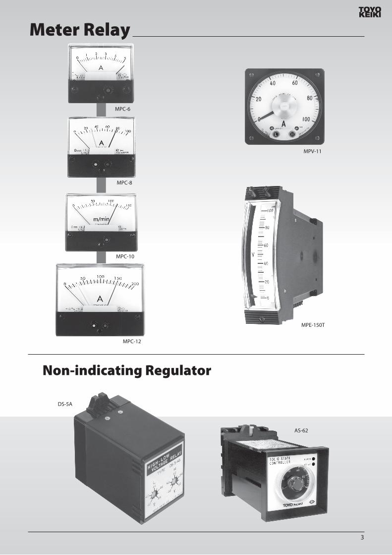
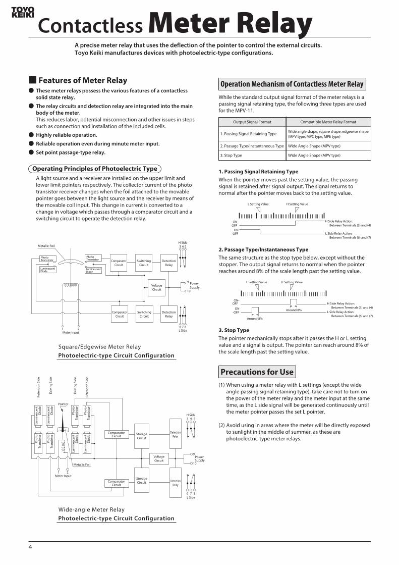
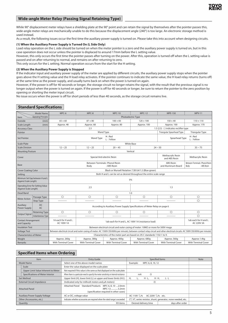
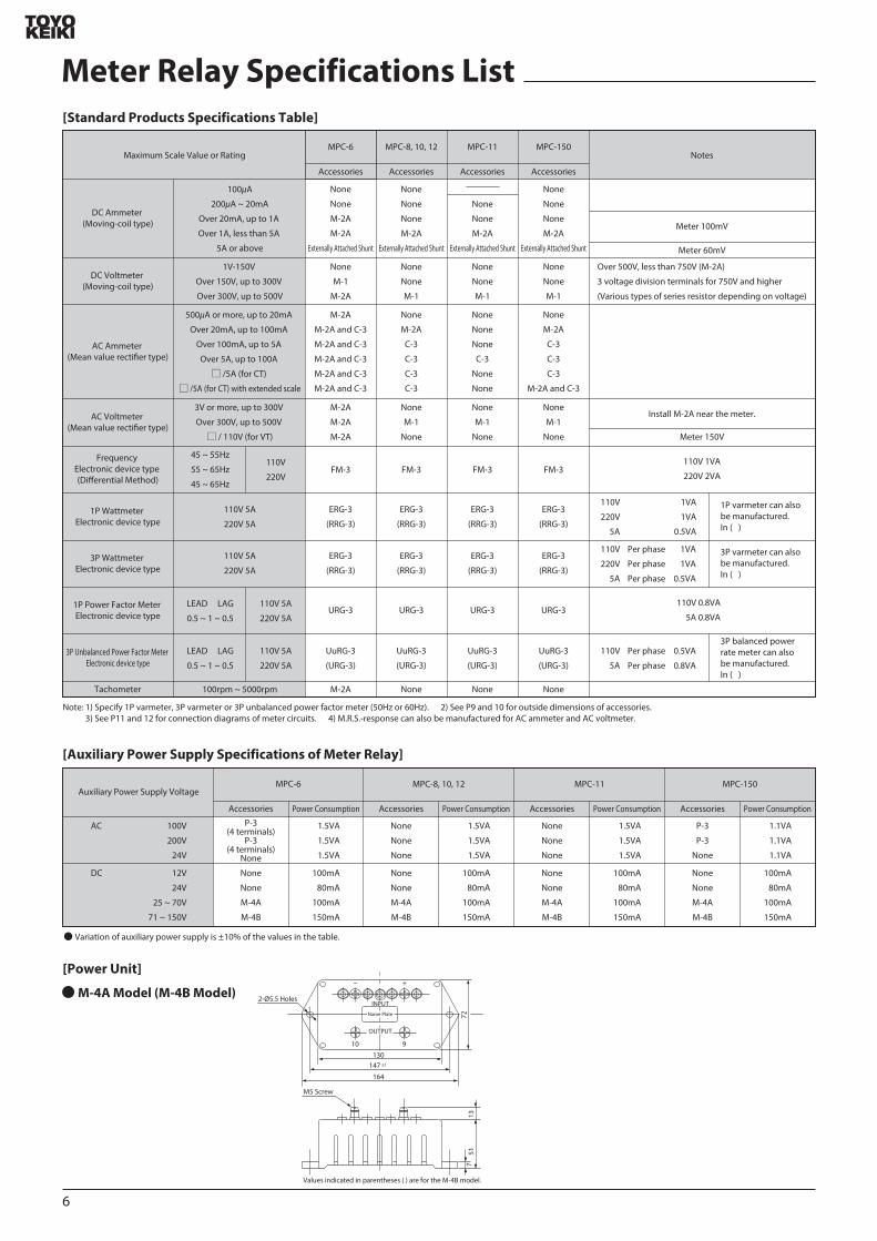
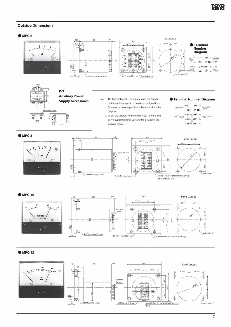
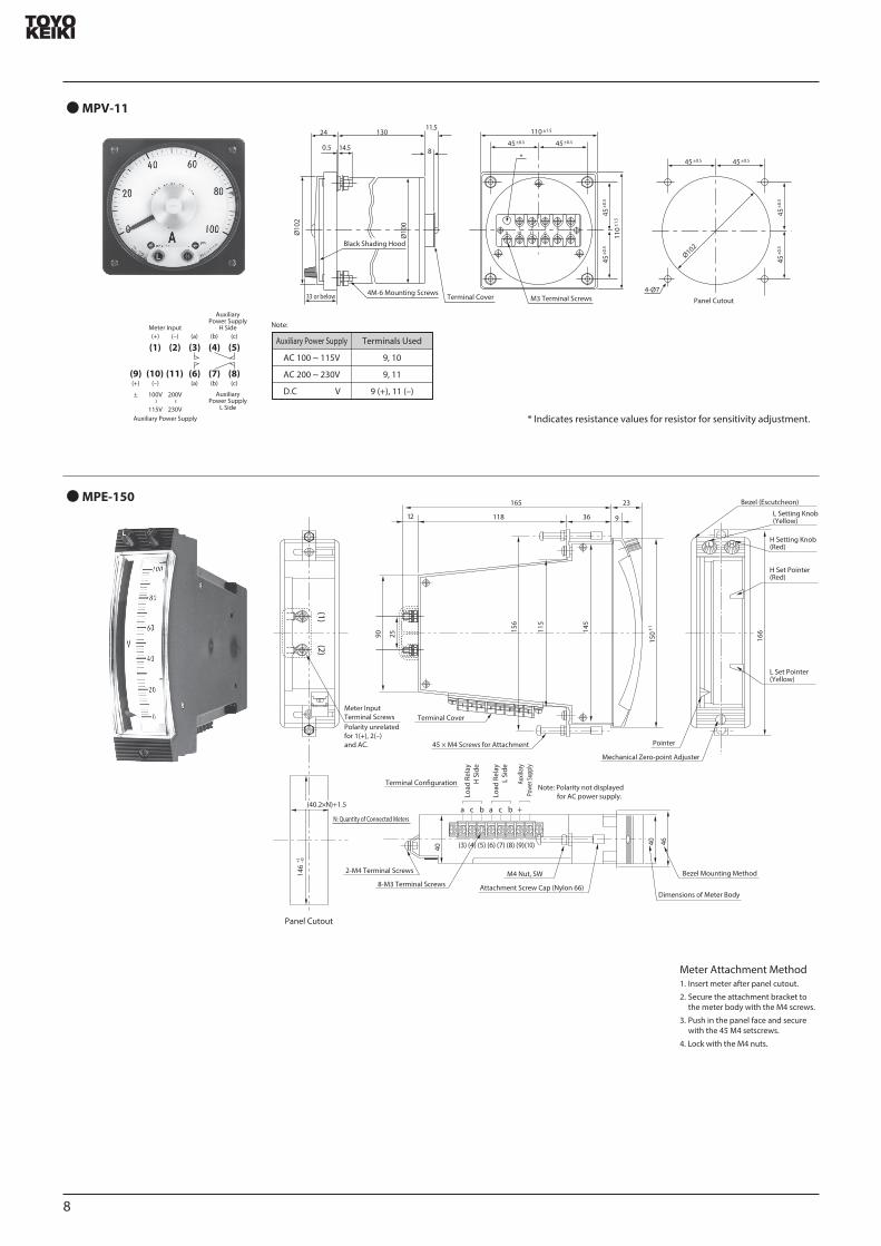
MPV-11
MPE-150
Indicates resistance values for resistor for sensitivity adjustment
Note
Auxiliary Power Supply
AC 100 ~ 115V 9 10
9 11
9 (+) 11 (ndash)
AC 200 ~ 230V
DC V
Terminals Used(+) (ndash) (a) (b) (c)
(+)
plusmn
(ndash)
100V
~
115V
200V
~
230V
(a) (b) (c)
AuxiliaryPower Supply
H Side
Terminal Cover
110
plusmn15
110 plusmn15
45plusmn0545plusmn05
1 2 3 4 59 10 11 6 7 8
M3 Terminal Screws
45plusmn0
545
4-Oslash7
Oslash102
45plusmn0545plusmn05
45plusmn0
545
plusmn05
plusmn05
33 or below
8
130
4M-6 Mounting Screws
05
24
145
115
Oslash10
0
Oslash10
2
Black Shading Hood
AuxiliaryPower Supply
L Side
Meter Input
Auxiliary Power Supply
(1) (2) (3) (4) (5)
(10)(9) (11) (6) (7) (8)
Panel Cutout14
6+1
ndash0
(402timesN)+15
N Quantity of Connected Meters
Panel Cutout
Meter Input Terminal ScrewsPolarity unrelated for 1(+) 2(ndash) and AC
(1) (2)
118
165
3612 9
23
150
plusmn1156
115
145
90 25
45 times M4 Screws for Attachment
Terminal Cover
166
Bezel (Escutcheon)
L Setting Knob (Yellow)
H Setting Knob (Red)
H Set Pointer (Red)
L Set Pointer (Yellow)
Pointer
Mechanical Zero-point Adjuster
Terminal Conguration
Load
Rel
ayH
Sid
e
Load
Rel
ayL
Side
Auxil
iary
Powe
r Sup
ply
Note Polarity not displayed for AC power supply
a c b a c b +
(3) (4) (5) (6) (7) (8) (9)(10)40
40 46
Attachment Screw Cap (Nylon 66)
M4 Nut SW8-M3 Terminal Screws
2-M4 Terminal Screws
Dimensions of Meter Body
Bezel Mounting Method
Meter Attachment Method1 Insert meter after panel cutout
2 Secure the attachment bracket to the meter body with the M4 screws
3 Push in the panel face and secure with the 45 M4 setscrews
4 Lock with the M4 nuts
8
9
Series Resistor Outside Dimensions
M-1 ModelWeight Approx 20g
M-2A ModelWeight Approx 100g
448
123
3
70plusmn 05
30
60
80
2-φ45 Holes
2-φ32 Holes
2-M35 ScrewsOne-touch Installation Terminal Cover
(Transparent Polycarbonate Plate)
Name Plate
6
2020
32plusmn
05
10
51
72
Fast-on Tab(187 Series)
M-3 ModelWeight Approx 015kg
M-2B ModelWeight Approx 015kg
M-6 ModelWeight Approx 08kg
M-4A Model (M-4B Model) Weight Approx 03kg
Name Plate
102 plusmn 05
4047
9
5
90
114
E M H
2-φ45 Holes2-φ45 Holes
E M H
銘 板
108 plusmn1
101
121
5543
59
55
Name Plate
H
E
130
164
7213
751(
81)
147 plusmn1
M
2-φ55 Holes
3-M4 Terminal Screws
Dimensions indicated in parentheses ( ) are for the M-4B model
120
135
plusmn1
100 plusmn1
9610
35
160
2-φ55 Holes75R
E
H
GM
Clamped Terminal
2-M4 Screws M5 Terminal Screws
Name Plate
Name Plate
Rating Model Model Rating
500 V
750 V
1000 V
1500 V
2000 V
3000 V
M-1
M-2B
M-3
M-3
M-4A
M-4A
M-6
M-6
M-6
4000 V
5000 V
7500 V
Voltage division (3 terminals) is used for 750V and higher
Series Resistor Models for DC Voltmeter
M-4A Model
M-2B Model
3-M4 Terminal Screws
3-M5 Terminal Screws
C-3 Model Current Transducer
ERG-3 Model URG-3 ModelRRG-3 Model UuRG-3 Model
40 58
30
48
42
12
55
6532
5
M4 Terminal Screws
LINE
METER
NP 40 581624
534
or b
elow
30
1259
4212
55
8098
LINE
METER
50plusmn05
24
65
325
Line Side Terminal ScrewsM4 Terminal Screws
Thickness t
(Note)
50plusmn05
Meter Side
1) 15A or Less 2) 15A and Above Up to 100ASpecications Rated Load 01VA
Primary Current Various types 15A and above up to 100ASecondary Current 10mACircuit Voltage 460VVoltage Test AC2000VWeight Approx 026kgSpecications Rated Load 01VA
Primary Current Various types less than 15ASecondary Current 10mACircuit Voltage 460VVoltage Test AC2000VWeight Approx 02kg
Primary Current Type
15A -75A
15
75A -100A
Conductor Thickness
t (mm)Line Side
Terminal Screws
M6times14
M8times16
Note)
Note)
Converter Outside Dimensions
Converter
Case Material Glass ber-strengthened PC resin Terminal Part Material Glass ber-strengthened PBT resin Cover Material Transparent polycarbonate resin
Din rail mounts can also be manufactured In such cases the model name is RG-3A
[Terminal Arrangement Diagram]
M-2A
FM-3
Series Resistors for AC VoltmeterRectiers for AC Ammeter
(Outside dimensions are the same as the M-3 model on page 9)
10
70plusmn05
30
60
80
2-φ45 Holes
4-M35 ScrewsOne-touch Installation Terminal Cover
(Transparent Polycarbonate Plate)
METER
LINE
LINE電 源METERメータ
For Frequency Meter
LINE
METER
minus +
121plusmn05
72plusmn05
124plusmn
05
96
110plusmn
05
4
7
Terminal CoverM4 Terminal ScrewsHere is an example of a terminal screw position
69
11
Name Plate
2
Meter Connection Diagram
Converter
LINE
METER
①
②
a c b
a c b
AC V
Generator
Generator
Frequency Meter
ConverterVT
LINE
METER
①
②
a c b
a c b
AC V
Frequency Meter (With VT)
a c b
a c b
AC V
Electric Tachometer
M-2A Series Resistor
LINE
METER
+
-
a c b
a c b
AC V
Electric Tachometer (With Series Resistor)
TG
TG
M-2A Series Resistor
LINE
METER
a c b
a c b
AC V
Voltmeter (With Series Resistor)
a c b
a c b
AC V
Voltmeter (Direct Measurement)
a c b
a c b
AC V
Voltmeter (With VT)
M-2A Series Resistor
VT VT
LINE
METER
+
-
+
-
a c b
a c b
AC V
Voltmeter (With VT Series Resistor)
C-3 Current Transducer
LINE
METER
a c b
a c b
AC V
Ammeter (With Current Transducer)
M-2A Rectier Box
LINE
METER
a c b
a c b
AC V
Ammeter (With Rectier Box)
a c b
a c b
AC V
Ammeter (Direct Measurement)
C-3 Current Transducer
CT
LINE
METER
a c b
a c b
AC V
Ammeter (With CT Current Transducer)
Rectier Box
CT
LINE
METER
Current TransducerC-3 M-2A
LINE
METER
a c b
a c b
AC V
Ammeter (With Current Transducer Rectier Box)
+
a c b
a c b
AC V
Ammeter (With Shunt)
a c b
a c b
AC V
H Side Load Relay Contact
L Side LoadRelay Contact
H Side Load Relay Contact
L Side LoadRelay Contact
H Side Load Relay Contact
L Side LoadRelay Contact
H Side Load Relay Contact
L Side LoadRelay Contact
H Side Load Relay Contact
L Side LoadRelay Contact
H Side Load Relay Contact
L Side LoadRelay Contact
H Side Load Relay Contact
L Side LoadRelay Contact
H Side Load Relay Contact
L Side LoadRelay Contact
H Side Load Relay Contact
L Side LoadRelay Contact
H Side Load Relay Contact
L Side LoadRelay Contact
H Side Load Relay Contact
L Side LoadRelay Contact
H Side Load Relay Contact
L Side LoadRelay Contact
H Side Load Relay Contact
L Side LoadRelay Contact
H Side Load Relay Contact
L Side LoadRelay Contact
H Side Load Relay Contact
L Side LoadRelay Contact
H Side Load Relay Contact
L Side LoadRelay Contact
H Side Load Relay Contact
L Side LoadRelay Contact
Power Supply Power Supply Power Supply
Shunt
Load Load Load
Power Supply
Load
Power Supply
Load
Power Supply
Load
Power Supply
Load
Power Supply
Load
Power Supply
Load
Power Supply
Load
Power Supply
Load
Power Supply
Load
Power Supply
Load
Power Supply
Load
Power Supply
Load
Power Supply
Load
Power Supply
Load
Ammeter (Direct Measurement)
Series Resistor
a c b
a c b
AC V
Voltmeter (With Voltage Division Type Series Resistor)
M-2A Shunt Box
LINE
METER
+
-
+
-
a c b
a c b
AC V
Ammeter (With Shunt Box)
H M
E
M-1 M-2A Series Resistor
a c b
a c b
AC V
Voltmeter (With Series Resistor)
a c b
a c b
AC V
Voltmeter (Direct Measurement)
Voltage division type series resistor should be used when the maximum scale value is 750V or higher
Note 1 The terminal diagram below is for MPC-10 and 12 For the terminal arrangements of other models see the outside dimensions page for those models
Note 2 The example auxiliary power supply connection is for AC See the example connection on the next page for DC auxiliary power supplies
Note 3 Accessories (P-3) are required for the MPC-6 even if the auxiliary power supply is AC See the the example connection on the next page for information on connections( )
DC Ammeter and DC Voltmeter (Moving-coil Type)
AC Ammeter or Voltmeter (Rectier Type)
Dierential Analyzer Frequency Meter Electric Tachometer (Rectier)
H Side Load Relay Contact
L Side LoadRelay Contact
H Side Load Relay Contact
L Side LoadRelay Contact
1 2 3 4 5
9 10 6 7 8
1 2 3 4 5
9 10 6 7 8
1 2 3 4 5
9 10 6 7 8
1 2 3 4 5
9 10 6 7 8
1 2 3 4 5
9 10 6 7 8
1 2 3 4 5
9 10 6 7 8
1 2 3 4 5
9 10 6 7 8
1 2 3 4 5
9 10 6 7 8
1 2 3 4 5
9 10 6 7 8
1 2 3 4 5
9 10 6 7 8
1 2 3 4 5
9 10 6 7 8
1 2 3 4 5
9 10 6 7 8
1 2 3 4 5
9 10 6 7 8
1 2 3 4 5
9 10 6 7 8
FM-3
FM-3
1 2 3 4 5
9 10 6 7 8
1 2 3 4 5
9 10 6 7 8
1 2 3 4 5
9 10 6 7 8
1 2 3 4 5
9 10 6 7 8
1 2 3 4 5
9 10 6 7 8
11
P-3
INP
UT
OU
T PU
T
a
c
a
c
Meter InputAC CurrentAC〇〇V
M-4A or M-4B
INP
UT
OU
T PU
T
a
c
b
a c b
a c b
a
c
b
Load TerminalH Side
Load TerminalH Side
Meter Input
Load TerminalL Side
DC CurrentDC〇〇V
Note M-4A (M-4B) not required when the auxiliary power supply is DC24V or DC12V
Note P-3 not required when the auxiliary power supply is AC24V or AC12V
1 2 3 N
DAOLECRUOS CT1CT2
CT3
Auxiliary Power Supply
VT1
VT2
VT3
3P4W Wattmeter Varmeter (With CT)
a c b
a c b
1 2 3 N
DAOLECRUOS CT1CT2
CT3
Auxiliary Power Supply
3P4W Wattmeter Varmeter (With CT VT)
VT1 VT2
a c b
a c b
1 2 3
DAOLECRUOS CT1
CT2
Auxiliary Power Supply
3P Wattmeter Varmeter (With CT VT)
VT1 VT2
a c b
a c b
1 N 2
DAOLECRUOS CT1
CT2
Auxiliary Power Supply
1P3W Wattmeter Varmeter (With CT VT)
VT
a c b
a c b
1 2
SOURCE LOADCT
Auxiliary Power Supply
1P Wattmeter Varmeter (With CT VT)
a c b
a c b
1 2 3
DAOLECRUOS CT1
CT2
Auxiliary Power Supply
3P Wattmeter Varmeter (With CT)
a c b
a c b
1 2
DAOLECRUOS CT
Auxiliary Power Supply
1P Wattmeter Varmeter (With CT)
a c b
a c b
1 N 2
SOURCE LOADCT1
CT2
Auxiliary Power Supply
1P3W Wattmeter Varmeter (With CT)
a c b
a c b
1 2 3 N
SOURCE LOADCT1CT2
CT3
Auxiliary Power Supply
VT
3P4W Power Factor Meter (With CT)
a c b
a c b
1 2 3 N
DAOLECRUOS CT1CT2
CT3
Auxiliary Power Supply
3P4W Power Factor Meter (With CT VT)
VT1 VT2
a c b
a c b
1 2 3
DAOLECRUOS CT1
CT2
Auxiliary Power Supply
3P Unbalanced Power Factor Meter (With CT VT)
VT
5
a c b
a c b
1 2 3
DAOLECRUOS CT
Auxiliary Power Supply
3P Balanced Power Rate Meter (With CT VT)
VT
a c b
a c b
1 2
SOURCE LOADCT
Auxiliary Power Supply
1P Power Factor Meter (With CT VT)
a c b
a c b
1 2 3
DAOLECRUOS CT1
CT2
Auxiliary Power Supply
3P Unbalanced Power Factor Meter (With CT)
a c b
a c b
1 2
DAOLECRUOS CT
Auxiliary Power Supply
1P Power Factor Meter (With CT)
a c b
a c b
1 2 3
SOURCE LOADCT1
Auxiliary Power Supply
3P Balanced Power Rate Meter (With CT)
MPC-6 ModelFor AC Auxiliary Power Supply
MPC-8 MPC-10 MPC-12 ModelFor DC Auxiliary Power Supply
Wattmeter and Varmeter (Electronic Device Type)
Power Factor Meter (Electronic Device Type)
Overall Connection Diagram (Example)
H Side Load Relay Contact
L Side LoadRelay Contact
H Side Load Relay Contact
L Side LoadRelay Contact
H Side Load Relay Contact
L Side LoadRelay Contact
H Side Load Relay Contact
L Side LoadRelay Contact
H Side Load Relay Contact
L Side LoadRelay Contact
H Side Load Relay Contact
L Side LoadRelay Contact
H Side Load Relay Contact
L Side LoadRelay Contact
H Side Load Relay Contact
L Side LoadRelay Contact
H Side Load Relay Contact
L Side LoadRelay Contact
H Side Load Relay Contact
L Side LoadRelay Contact
H Side Load Relay Contact
L Side LoadRelay Contact
H Side Load Relay Contact
L Side LoadRelay Contact
H Side Load Relay Contact
L Side LoadRelay Contact
H Side Load Relay Contact
L Side LoadRelay Contact
H Side Load Relay Contact
L Side LoadRelay Contact
H Side Load Relay Contact
L Side LoadRelay Contact
Load TerminalL Side
1 2 3 4 5
9 10 6 7 8
1 2 3 4 5
9 10 6 7 8
1 2 3 4 5
9 10 6 7 8
1 2 3 4 5
9 10 6 7 8
1 2 3 4 5
9 10 6 7 8
1 2 3 4 5
9 10 6 7 8
1 2 3 4 5
9 10 6 7 8
1 2 3 4 5
9 10 6 7 8
1 2 3 4 5
9 10 6 7 8
1 2 3 4 5
9 10 6 7 8
1 2 3 4 5
9 10 6 7 8
1 2 3 4
9 10 6 7 8
1 2 3 4 5
9 10 6 7 8
1 2 3 4 5
9 10 6 7 8
1 2 3 4 5
9 10 6 7 8
1 2 3 4 5
9 10 6 7 8
1 2 3 4 5
9 10 6 7 8
1 2 3 4
9 10 6 7
910
910
12
Intrinsic Power Value
CT Ratio
5A5A
75A5A
10A5A
15A5A
20A5A
30A5A
40A5A
50A5A
75A5A
100A5A
150A5A
200A5A
300A5A
400A5A
500A5A
750A5A
1000A5A
1500A5A
2000A5A
3000A5A
VT Ratio625Or
667W
Line Voltage
mdash
1 kW
12 kW
2 kW
25 kW
4 kW
5 kW
mdash
10 kW
12 kW
20 kW
25 kW
40 kW
50 kW
mdash
100 kW
120 kW
200 kW
250 kW
400 kW
750 W
12 kW
15 kW
25 kW
3 kW
5 kW
6 kW
75 kW
12 kW
15 kW
25 kW
30 kW
50 kW
60 kW
75 kW
120 kW
150 kW
250 kW
300 kW
500 kW
1 kW
15 kW
2 kW
3 kW
4 kW
6 kW
8 KW
10 kW
15 kW
20 kW
30 kW
40 kW
60 kW
80 kW
100 kW
150 kW
200 kW
300 kW
400 kW
600 kW
12 kW
2 kW
25 kW
4 kW
5 kW
8 kW
10 kW
12 kW
20 kW
25 kW
40 kW
50 kW
80 kW
100 kW
120 kW
200 kW
250 kW
400 kW
500 kW
800 kW
15 kW
25 kW
3 kW
5 kW
6 kW
10 kW
12 kW
15 kW
25 kW
30 kW
50 kW
60 kW
100 kW
120 kW
150 kW
250 kW
300 kW
500 kW
600 kW
1 MW
2 kW
3 kW
4 kW
6 kW
8 KW
12 kW
(16 kW)
20 kW
30 kW
40 kW
60 kW
80 kW
120 kW
(160 kW)
200 kW
300 kW
400 kW
600 kW
800 kW
12 MW
25 kW
4 kW
5 kW
8 kW
10 kW
15 kW
20 kW
25 kW
40 kW
50 kW
80 kW
100 kW
150 kW
200 kW
250 kW
400 kW
500 kW
800 kW
1 MW
15 MW
3 kW
5 kW
6 kW
10 kW
12 kW
20 kW
(24 kW)
30 kW
50 kW
60 kW
100 kW
120 kW
200 kW
(240 kW)
300 kW
500 kW
600 kW
1 MW
12 MW
2 MW
4 kW
6 kW
8 KW
12 kW
(16 kW)
(24 kW)
(32 kW)
40 kW
60 kW
80 kW
120 kW
(160 kW)
(240 kW)
(320 kW)
400 kW
600 kW
800 kW
12 MW
(16 MW)
(24 MW)
20 kW
30 kW
40 kW
60 kW
80 kW
120 kW
(160 kW)
200 kW
300 kW
400 kW
600 kW
800 kW
12 MW
(16 MW)
2 MW
3 MW
4 MW
6 MW
8 MW
12 MW
25 kW
40 kW
50 kW
75 kW
100 kW
150 kW
200 kW
250 kW
400 kW
500 kW
750 kW
1 MW
15 MW
2 MW
25 MW
4 MW
5 MW
75 MW
10 MW
15 MW
30 kW
50 kW
60 kW
100 kW
120 kW
200 kW
(240 kW)
300 kW
500 kW
600 kW
1 MW
12 MW
2 MW
(24 MW)
3 MW
5 MW
6 MW
10 MW
12 MW
20 MW
40 kW
60 kW
80 kW
120 kW
150 kW
(240 kW)
300 kW
400 kW
600 kW
800 kW
12 MW
15 MW
(24 MW)
3 MW
4 MW
6 MW
8 MW
12 MW
15 MW
(24 MW)
50 kW
75 kW
100 kW
150 kW
200 kW
300 kW
400 kW
500 kW
750 kW
1 MW
15 MW
2 MW
3 MW
4 MW
5 MW
75 MW
10 MW
15 MW
20 MW
30 MW
60 kW
100 kW
120 kW
200 kW
(240 kW)
400 kW
(480 kW)
600 kW
1 MW
12 MW
2 MW
(24 MW)
4 MW
(48 MW)
6 MW
10 MW
12 MW
20 MW
(24 MW)
40 MW
MultiplierMeter Types
3P Wattmeters 3P4W Wattmeters 1P3W Wattmeters
1P Wattmeters 3P varmeters and 3P4W varmeters
1P Varmeter
1
12 (1 for varmeters with zero left meters)
14 (12 for zero left meters)
This standards chart is a resource for determining the measurement range values of wattmeters and varmeters so 3P wattmeter CT 〇〇〇A5A standards are indicated
Example VT 3300V110V CT 60A5A 3P Wattmeter
Measurement Range = (667W 833W 1kW or 111kW) x 3300 110 x 60 5 = 240kW 300kW 360kW or 400kW
Note) Numerical values inside parentheses indicate values that deviate from JIS standards but can be manufactured
Standard Table of Wattmeter Measurement Range
[1] For 3P wattmeters 3P4W wattmeters and 1P3W wattmeters the measurement range values are displayed in the voltage ratios (VT ratio dierences) and CT ratio dierences in the table above (There are three types dened for the same VT and CT ratios Choose the appropriate type However an item marked with in the intrinsic power eld needs to be selected for the wide angle meter) Eg) For a VT 3300V110V CT 100A5A 3P wattmeter select the appropriate one from 400kW 500kW or 600kW from the table above
[2] For 1P wattmeters 3P varmeters and 3P4W varmeters the values displayed above are multiplied by 12 and are multiplied by 14 for 1P varmeters
Note 1) For varmeters read kW units as kvarScale is LEAD ~0~LAG kvarExample For a VT 3300V110V CT 100A5A 3P varmeter hellipLEAD2500~LAG250 kvar or LEAD300~0~LAG300 kvar
(500 times 12) (500 times 12) (600 times 12) (600 times 12)
2) For 3P varmeters or 3P4W varmeters with zero left meters follow the values as displayed above and for 1P varmeters with zero left meters the values in the table above are multiplied by 12
[3] If the CT ratio exceeds the range listed above (for example VT 3300V110V CT 5000A5A 3P wattmeter) select a value from the CT 500A5A row (2MW 25MW 3MW) and multiply it by 10
Note) In the situation above scale indicators are 20MW 25MW and 30MW (It is preferable that the highest 3 digits of scales are displayed)
[4] If CT ratios do not correspond with those indicated above (for example CT 60A5A) use the calculation chart below to acquire the measurement range then choose from among them the value with the best ending number
Measurement Range = Intrinsic Power times VT Ratio times CT RatioNote) Select a value indicated below from the intrinsic power value in the above calculation chart However intrinsic power values vary depending on meter type Use the multiplier indicated below to calculate the value
Using the Above Chart
[5] Values of 1 12 15 2 25 3 4 5 6 75 or 8 or integers that are multiples of those 10 values are preferable selections for the upper range scale value (JIS standards)
110V 220V 440V 3300V 6600V
440V110V 3300V110V 6600V110V750Or
833W
125Or
133kW
15Or
167kW
625Or
667W
750Or
833W
1kWOr
111kW
1kWOr
111kW1kW 2kW 1kW 833W 833W667W
625Or
667W
13
MultiplierMeter Types
3P Wattmeters 3P4W Wattmeters 1P3W Wattmeters
1P Wattmeters 3P varmeters and 3P4W varmeters
1P Varmeter
15
110 (15 for varmeters with zero left meters)
120 (110 for zero left meters)
Product Name
1P Wattmeter 1P Varmeter
3P Wattmeter 3P Varmeters 110V 5A220V 5A
110V 5A 300 ~ 625W (var)600 ~ 1250W (var)
500 ~ 1250W (var)1000 ~ 2500W (var)
500 ~ 1250W (var)1000 ~ 2500W (var)
220V 5A
1P3W Wattmeter
3P4W Wattmeter3P4W Varmeter
Rating
110Vradic3V 5A220Vradic3V 5A
Production Range
Example VT 440V110V CT 60A1A 1P Wattmeter
Measurement range = [(625W 667W 750W 833W or 1kW) x 110] x 440 110 x 60 1 = 15kW 16kW 18kW 20kW or 24kW However 15kW or 20kW should be selected
Example VT 6600V110V CT 50A5AWhen measurement range value = 400kW
Note) The meter production range for using a CT of 1A for the secondary current is the value indicated on the left multiplied by 15
[6] Even when using a CT of 1A for the secondary current the measurement range value is as indicated on the left (selection standards chart) Note) If CT ratios do not correspond (for example CT 60A1A) with those indicated to the left (selection standards chart) follow calculation chart [4] below to calculate the measurement range value However intrinsic power values vary depending on meter type Use the multiplier indicated below to calculate
The production range of wattmeters and varmeters can be manufactured according to the indicated range of intrinsic power values in the calculation chart below
Intrinsic Power Value [W]=Measurement Range Value [W]
VT Ratio x CT RatioIntrinsic Power Value W= =667W 400kW
60times10
Production Limits of Meters (Wattmeter Varmeter)
14
15
NoteMeter Relay MPV-11
110times110 120times110
MPC-12
Outside (mm)
Scale Length (mm)
Accuracy Class
Pointer
Set Pointer
Scale Plate
Scale Division
Mounting Posture
Cover
Base
Cover Coating Color
Setting
Operating Error for Setting Value (Against Scale Length)
Dead Band
Output Contact Arrangement and Capacity
Insulation Test
Voltage Test
Characteristics of Meter
Meter Action
Auxiliary Power Supply
Output Signal
Note 1)
Note 2)
Stop Type
Passage Type
A C
Retaining Type
Instantaneous Type
Approx 170
Tapered Type
Triangular with Red H
White Base
Vertical
Methacrylic Resin
15
10
〇
〇
1ab AC220V 3A
Approx 100
Wand Type
Wand Type with Red H
Special Anti-electric Resin
15
10
〇
〇
1ab AC100V 1A
Between Terminals - Phenol Resin Body Cover - ABS resin
N - 15 (black) or 75B G415 (blue-green)
H Setting (Single Side Only)
AC110V AC115V AC220V
Between electrical circuit and outer casing of meter 10MΩ or more for 500V mega
Between electrical circuit and outer casing of meter AC 1500V (5060Hz per minute)Between contact relay circuit and other electrical circuits AC 500V (5060Hz per minute)
Characteristics of the meter part are based on JIS C 1102-1 to 9
plusmn10
plusmn5Intrinsic Error Indicated value
Between 005~1MΩ
Extra Power Unit RG-3 Meter Sensitivity
DC250μA
Earth-resistance Meter Relay MPV-11 MPC-12
This meter relay can measure the earth resistance value of a contactless AC circuit while also detecting abnormal earth resistance values in the same circuit Comprising a contactless meter relay and extra power unit this meter relay can be used for a wide range of purposes such as detecting abnormalities in grounding accidents in settings such as boatsA particularly useful feature is the xed voltage circuit built into the extra power unit which maintains a roughly xed voltage circuit even during uctuations of plusmn10 in the input voltage of AC115V preventing measurement error
[Overview]
[Features]
[Standard Specications]
[Operating Principles]
Earth resistance measurements can be taken continuously while also setting and detecting the desired earth resistance values on the scale of the photoelectric-type detection setting mechanism as well as activating warning equipment using the relay circuit contact
Lines can be measured and detected while live
Note 1) Meter Action Passage Type - The pointer can pass to the end of the scale even if it exceeds the setting value
Note 2) Output Retaining Type - Output is retained even when the pointer passes the setting value The output is discarded when the pointer goes back below the setting valueNote 3) Others a) DC circuit type can also be manufactured if desired
b) See the page about our contactless meter relay for detailsc) In particular a standard meter type can be manufactured if the detection equipment is not requiredd) Also includes a converter Type I S-3 For 3P Type I S-1 For 1P
Apply an AC power supply to the extra power unit to generate DC50V on the output side This DC power supply can be used to combine the unit with a DC ammeter with an MΩ scale making it possible to take measurements and read earth resistance for circuit currents that change depending on the ground statusThe AC side and output side of the extra unit are insulated by a transformer This means that the DC power supply can be considered separate from the lines creating the basic circuit shown on the leftIn the circuit diagram on the left DC50V is being generated by the power unit the power is connected to the meter in a series where Rs = 02 MΩ (scale centering on meter) and a resistance value is being indicatedWhen switch S is turned on the pointer of the meter moves to the maximum indicating 0MΩ in this caseThis means that the maximum current sensitivity value of the inow current is i = =250μA
If a grounding accident occurs and the earth resistance is 02 MΩ (Re = 02 MΩ) the inow current
i1 = = = 125μA and the center scale point of 02 MΩ is indicated
The relationship between the earth resistance value and the current i is as shown below
Lines
Resistance Meter
[Power Unit]
AC 115V
Rs
Re
Re Earth Resistance
S Switch
Rs Standard Resistance
S
e=50v
Circuit Conguration Diagram
02MΩ +02MΩ Rs+Re50V
02MΩ 50V
50V
Measurement point A can be measured from LINE R S or T Auxiliary Power Supply 110V System (9) (10) 220V System (9) (11)
AC100V
AC115V
DC50VB
3
3
2
2
1
1
10 119
4
4 5VT
Zero Ohms Adjustment Volume
R
S
T
LINE LOAD
440V
A
Load Contact
MPV-11
a c d
Power Unit (RG-3)
[Connection Diagram]
[Extra Power Unit]
[How to Use]
[Scale Drawing]
[Outside Dimensions]
MPV-11
MPC-12
RG-3
110plusmn1
5
110plusmn15
45plusmn0545plusmn05
4-φ7
φ102
1 2 3 4 5109 11 6 7 8
M3 Terminal Screws
Terminal Cover
Terminal Cover33 or below
8
130
4M-6 Mounting Screws
05
24
145
115
φ10
0
φ10
2Panel Cutout
Black Shading Hood
45plusmn0545plusmn05
45plusmn0
545
plusmn05
45plusmn0
545
plusmn05
5
35plusmn0
545
plusmn0545
plusmn05
35plusmn0
5
50plusmn05 50plusmn0550plusmn05
120plusmn1
50plusmn05
4-φ5 Holes10-M3Terminal Screws Variable Resistor for Sensitivity SettingsNote 1
20
12 105100
4-M4 Mounting Screws
05
255
10
φ64
Panel Cutout
φ87plusmn1
100plusmn1
φ85
+05minus0
1
2
3
4
5
9
10
6
7
8
121plusmn0572plusmn05
4
769
11
110plusmn
05
96 124plusmn
05
Terminal Cover4-M4 Terminal Screws
ZERO
NPZero OhmsAdjuster
MΩ
MΩ0
1
125infin
234
5
0
1125infin
2345
Resistance value between LINE R S or T and earth is measured between A and BIn the diagram on the left the measurement is taken from
phases S and T but any phase can be usedThe diagram on the left shows an example connection
between MPV and 11 but the same result will be obtained between MPC and 12 (vertical terminal array)The zero ohms adjustment volume is a backup device
embedded in the center of the power unit Insulate auxiliary power supply terminals (9) and (10) before checking the zero ohms adjustment(To stop the output signal of the relay circuit)
[Specied Items when Ordering]
0-5 MΩ (Center Point 02 MΩ) 0-5 MΩ (Center Point 02 MΩ)
Contact Arrangement345
MPVminus11 MPCminus12
Model Name MPV-11 or MPC-12Scale 0-5 MΩ (Center point 02 MΩ)Auxiliary Power Supply AC 110V etcAttached Panel Fe or NFe (Specify MPC-12 model only)Mounting Posture etcCover Coating Color N-15 (black) or 75 BG 415 (blue-green)Other Non-standard specications
Note)
16
Sminus62 minusminusA AC InputD DC InputH H Setting Value L L Setting Value 1 DC Power Supply (DC24V) 2 AC Power Supply AC100110V AC200220VInput
0 60mV1 100mV2 0~1V3 0~5V4 1~5V5 4~20mA6 1A7 5A8 150V9 Others
0 No Delay1 Power Supply Delay2 Signal Delay1 Socket Attachment2 Panel Mounting
( (
DC
AC
VHCOMCL
678
4
5
Power Supply
U6
Input
U1 U2U4 U5
U3
123
U1Input Amplier
U2Rectier Circuit
U3Setting Circuit
U4Comparator Circuit
U5Delay Circuit
U6Power Supply Circuit
VHCOMCL
678
4
5
Power Supply
U5
Input
U1U3 U4
U2
123
U1Input Amplier
U2Setting Circuit
U3Comparator Circuit
U4Delay Circuit
U5Power Supply Circuit
[Operating Principles]
AS-62 (AC Input)
Block Diagram
[Overview of Operation]
DS-62 (DC Input)
Block Diagram
Stationary Non-indicating Regulator AS-62DS-62
This product is a non-indicating adjustment meter with no meter drive unit The AS-62 uses AC input while the DS-62 uses DC input The auxiliary power supply can be used for AC 100110V and AC 200220V This product can also be manufactured with a DC24V power supply The ono status of the relay is shown by a red LED on the front and the setting scale also has an extremely easy-to-see structure Two attachment methods can be used by connector or by panel mounting Panel mounting is done by connecting the lines using the terminal block on the back (M4 screws) Compact design with front panel measuring 625x625
[Overview]
ltSolid State Relaygt
After amplifying the input signal with the input amplier (U1) the entire wave is rectied and attened with the rectier circuit (U2) and then input on the signal side with the comparator circuit (U4)Meanwhile the voltage set by the dial is input on the setting side with the setting circuit (U3) The output from (U4) is a VH or VL value depending on this input This signal is input into a relay drive transistor to turn the relay on and o Here the delay circuit (U5) delays the signal from U4 for around 1 second in the event of a signal delay The circuit constant diers depending on the specications In the event of a power supply delay the relay does not operate for around 7 seconds after the power supply is turned on even when the U4 output voltage is VH This circuit responds to the average input value not DC components
[Overview of Operation]
[Specications]
After amplifying the input signal with the input amplier (U1) the signal is input on the signal side with the comparator circuit (U3) Meanwhile the voltage set by the dial is created by the setting circuit (U2) and input on the setting side of the comparator circuit (U3) The output from (U4) is VH or VL depending on the relationship between the signal and the setting value This signal is input into a relay drive transistor to turn the relay on and o The delay circuit (U5) creates signals for power supply delays (approximately 7 seconds) and signal delays (approximately 1 second) according to the specications
Model Name
17
51 or below24 or below
354
118
or b
elow
81 o
r bel
ow
40plusmn024
78
4
5
8-M35x7 Sems Screws
2-φ45 Holes
4
0
2040
POWER RELAY
SOLIDSTATE CONTROLLER
625
625
10 95126 plusmn7
56
56
8-M4 ScrewsEmbedded in Panel
Attached to Wall
Socket Attachment
Use OMRON 8PFA
40plusmn2
2-φ45 Holesor M4 Tapping
565+
05
-0
565 +05 -0
1
2
3
4 5
6
7
8
Input
ab
cAC100110V
AC200220V
AC Auxiliary Power Supply 1
2
3
4 5
6
7
8
Input
ab
cDC24V
DC Auxiliary Power Supply
+
+
-
Panel Cutout
[Performance]Input Impedance
60mV 100mV1V 5V 1~5V4~20mA5A1A150VThe following standards apply to products with other input specications60mV or More Up to 100mV101mV or More Up to 300VAmmeter Input Resistance value generating a
200mV voltage dropPickup Error plusmn 15Delay
Response Speed
Dead Band
Temperature Coecient
Load Relay Contact Capacity 1 ab AC 250V 3A (resistance load)DC 30V 3A (resistance load)
Power Consumption
Operating Temperature LimitsStorage Temperature RangeMaximum Relative HumidityInput Overload Capacity
60mV 100mV1V5V 1~5V4~20mA1A5A150V
Insulation Test (500V test with mega)Electrical circuit - outer casing input - auxiliary power supply input - relay output20 MΩ or more between each phase
Voltage TestElectrical circuit - outer casing input - auxiliary power supply input - relay output
2000V per minute between each phase
Outer Casing Material Polycarbonate resin phenol resinWeight Approx 400g
10kΩ1MΩ10Ω6mΩ30mΩ1MΩ
10V50V250V100mA10A50A500V
10kΩ1MΩ
Signal DelayPower Supply DelayA S-62D S-62
Approx 1 secondApprox 7 secondsApprox 02 secondsApprox 01 seconds
Around 2
plusmn0510˚C
Approx 3VA (AC power supply) 25W (DC power supply)
0˚C~50˚C-10˚C~60˚C
[How to Use]
Precautions when Handling and Ordering the S-62
[Outside Dimensions and Pin Connection Diagram]
[8PFA Socket Outside Dimensions]
Over 5A Less than 50A
Over 50A Less than 300A
Over 300A Less than 5000A
S-10A Model 60mV
S-8A Model 60mV
S-8 Model 60mV
Over 300V up to 500V
Over 501V up to 750V
Over 751V up to 1500V
Over 1501V up to 30000V
Over 3001V up to 5000V
M - 2 A
M - 2 B
M - 3
M - 4 A
M - 6
This product can be used by panel mounting or socket attachment (specify which when ordering)An attachment bracket and mounting screws are included when panel mount is specied Do not attach with items other than the included screws
1 A frequency range from 40 to 500Hz can be used by the AS-62 Frequencies outside this range are a special specication and prior consultation is needed
2 To control DC currents larger than 5A use a shunt to convert the voltage (to around 60mV) and then receive and control with the 60mV input type DS-62 Model names of shunts are as follows
To control high DC voltages add an external series resistor Model names of series resistors are indicated in the table below
85
100
6080
18
Non-indicating Voltage Relay DS-5A (for DC Voltage)
[Features]
[Specications]
[Outside Dimensions]
[Attachment Diagram]
[Series Resistor Calculation Method for General-Purpose Detector Side and Operation Side]
Driver adjust type enables easy and accurate conguration of voltage settings
Safe operation even for voltages containing ripples 3 dierent attachment methods
Front attachment (attachment to terminal block or rear connection socket on 8P) Rear attachment
[Purposes]Voltage detection in DC power suppliesVoltage detection in rectied power
suppliesAutomatic control
(3) Detection Error
(4) Set Method(5) Contact Capacity(6) Contact Arrangement(7) Relay Contact Output
(1) Detection Method(2) Detected Voltage Rating
Voltage comparison-based voltage detection
Within plusmn15 of upper limit setting maximum voltage value (within plusmn25 for DS-5A-U12)
VR variance by driver adjustmentDC 30V1A (resistance load) AC 100V1AL side 1b H side 1a
Series ResistorModel
Inside Dimensions
Externally connected for operation
Note
DS-5A-24A
DS-5A-48A
DS-5A-100A
DS-5A-U12
DS-5A-U24A
DS-5A-U48A
20~24V
40~48V
80~95V
10~14V
20~28V
40~56V
24~28V
48~56V
105~120V
10~14V
20~28V
40~56V
02
04
11
01
02
05
15
15
50
20
15
15
Setting Range for Detected Voltage
L
Power Consumption (W)
Detection Side Operation Side
Note)
Within plusmn15 of upper limit setting maximum voltage (within plusmn20 for DS-5A-U12)
200mS or less when 97 to 110 of set voltage is applied
20 times per 60 seconds 10 minute stop(When upper limit setting maximum voltage value is 100)
Continuous overvoltage of 120 possible with all models)150 possible for 3 minutes on all models 200 not possible on any models
Insulation Test Between Electrical Circuit and Case DC500V mega 10MΩ or higher
Between Electrical Circuit and Relay Contact DC500V mega 5MΩ or higher
Voltage Test Between Electrical Circuit and Case AC 2000V (5060Hz per minute)
Between Electrical Circuit and Relay Contact AC500V (5060Hz per minute)
ON
ON
OFF
OFF
LH Setting Value
L Side Relay Contact Output
H Side Relay Contact Output
(8) Retained Range
(9) Reaction Time
(10) Operation Frequency(11) Overvoltage Strength
Within 20 P-P-10˚C~50˚C
(12) Detection Input Ripples(13) Operating Temperature Limits
(14) Pin Layout Diagram
L
v v
50plusmn05
60plusmn0
5
44 +0 -05
54+
0 -
05
80 70
35
7652
7
82785
8P Octal Base
[Series Resistor for Operation of the DS-5A-100A R Outside Dimensions]
454
4
64plusmn15
73plusmn15
06
φ 25
43
13plusmn02
φ 15
31
14
Voltage Resistance AC2000VWeight 25g
Attachment Screws
Claw to Prevent Falling O
OMRON8PF Terminal Block Type(see P18)
74
φ30 or higher
2-φ35 Holesor M3 Tapping
Panel Cutout Diagram
If attached directly
123
467
8
H Side Relay Contact Output 1a
L Side RelayContact Output 1b
R
RHRL
Auxiliary Power Supply (-)
L Side Detection Input (-) H Side Detection Input (-)
123
467
8
H Side Relay Contact Output 1a L Side Relay Contact Output 1b
R Auxiliary Power Supply (-)
Detected Voltage Input (-)
COM (+)
[Overview]
Weight 140g
(1) Pin Layout DiagramDS-5A-U (A)
DS-5A-A
R Series Resistor for Operation (Externally Connected)
RL Series Resistor for Operation on L Side (Externally Connected)
RH Series Resistor for Operation on H Side (Externally Connected)
Included only with R DS-5A-100A
See the pin layout diagram on the right for the DS-5A-U model
Both the operation unit and the detection unit are externally attached if the setting range is exceeded
Scale of general purpose model is 0~100
Note 1 Power Consumption (operation at maximum voltage on maximum setting where L = OFF and H = ON)Note 2 DS-5A-U (A) indicates all-purpose model Be sure to connect a series resistor if the values in this table
will be exceeded (Calculation method for series resistors can be found on P20)
This non-indicating voltage relay detects the voltage of DC power supplies It can detect both H and L in detected voltage setting ranges enabling safe operating even with voltages that contain ripples such as those in rectied power supplies
H
5
H
5
COM (+)
19
COM
Input
E
R
Vz
R D
1
7
E R
I Rs
Auxiliary Power Supply VoltageSeries Resistor Externally Connected to Operational Power SupplyCurrentDS-5A-U Equivalent ResistanceDS-5A-U12 Model 0086 kΩDS-5A-U24A Model 04 kΩDS-5A-U48A Model 136 kΩ
22
21 23
20 24V
26
25 27
24 28V
44
42 46
40 48V
52
50 54
48 56V
40 60
20 80
0 100
40 60
20 80
0 100
85 90
80 95V
110 115
105 120V
Auxiliary Power Supply
Detection Input
(-) )-(
(+) )+(
8 72
RR
R DS-5A
DS-5ADS-5A
R Externally Connected Series Resistor
R Externally Connected Series Resistor
Auxiliary Power SupplyDetection Input
(-) )-(
(+) )+(
8 7R (Included Only with 100 Model)DS-5A
a DS-5A-24A48A100A
a DS-5A-24A48A100A
b DS-5A-U24AU48A
b DS-5A-U24AU48A
Auxiliary Power Supply
Detection Input
(-)(-)
(-)
(+) )+(
8 72
RR
R
Auxiliary Power SupplyDetection Input
(-) )-(
(+) )+(
8 7R (Included Only with 100 Model)
1) DS-5A-24A
2) DS-5A-48A
3) DS-5A-100A
4) DS-5A-U24A DS-5A-U48A
DS-5A-U (A)Non-indicating Voltage Relay
(2) Calculation Method for RH or RL Series Resistor for Detection Side (Externally Connected)
(3) Calculation Method for R Series Resistor for Operation Power Supply Side (Externally Connected)
(A) Reference CurrentThe reference current is indicated as a bond
(b) Calculation
(c) Example Calculation
Model Name Reference Current I0 (mA) Vu (V)
DS-5A-U12
DS-5A-U24A
DS-5A-U48A
175
286
333
12
24
48
Model NameSet Voltage Range
(V)Vo (V) Detection Side Multiplier
RH or RL Value
DS-5A-U12
DS-5A-U24A
DS-5A-U48A
NoteModel Name
DS-5A-U12
DS-5A-U24A
DS-5A-U48A
22~26
44~52
92~108
24
48
100
(24-12) [V] 175 [mA]
RH or RL =(Center Point Voltage of Setting (Vo) - Vu)
Reference Current (Io)
I min ≦ I = E-VzR+RD
=686 [kΩ]
(48-24) [V] 286 [mA] =839 [kΩ]
(100-48) [V] 333 [mA] =156 [kΩ]
Caution
Input Voltage (Voltage of Auxiliary Power Supply) Range E [V] and Resistance Value R of Multiplier on Auxiliary Power Supply Side [kΩ]
Emin ≦ E ≦ Emax
80mA ≦ I = ≦ 140mAE-6
R+0086
Emax Maximum voltage of auxiliary power supply Imax Maximum currentEmin Minimum voltage of auxiliary power supply Imin Minimum current
Select R within the range where the above inequality is achievedIf the inequality is not achieved for I rework the equation by methods such as raising the R value or narrowing the voltage range of the power supply
(Note) Settings can be congured in the desired position between 0 and 100 for both H and L
[Scale Drawing]
[Connection Circuit Diagram of the External Circuits]
(1) The detection input and auxiliary power supply input are COM and +
(2) If the detection input and the auxiliary power supply are the same connect the auxiliary power supply terminal (7) and the detection input (8) (8 and 2 for U shape) as shown in the diagram below
(3) If the detection input and the auxiliary power supply are separate connect them as shown in the diagram below
Precautions for External Connections
Do not connect with the polarities of the detection input and auxiliary power supply opposing each other
I
Use the equation below to calculate the current I in the input voltage range then decide on the value for the R series resistor to be connected to the operational power supply
The current I value is for cases in which both the H and L sides are excited by the load relay of the non-indicating voltage relay (L OFF H ON)
≦ I max
25mA ≦ I = ≦ 70mAE-12R+04
15mA ≦ I = ≦ 35mAE-24
R+136
VZ=6VRD=0086kΩ
VZ=12VRD=04kΩ
VZ=24VRD=136kΩ
20
50plusmn05
60plusmn0
5
44 +0 -05
54+
0 -
05
80 70
35
7652
7
82785
8P Octal Base
74
φ30 or higher
2-φ35 Holes (or M3 Tapping)
Panel Cutout Diagram
If attached directly
Note) Can also be attached to the front terminal block (See P19)
40 581624
534
or b
elow
30
1259
4212
55
8098
LINE
METER
24
65
325
Line Side Terminal ScrewsM4 Terminal ScrewsThickness (t)
(Note)
50plusmn05
Meter Side
Name Plate
Rated Load 01VAPrimary Current 25ASecondary Current 10mACircuit Voltage 460VVoltage Test AC2000VWeight Approx 02kg
Note)
123
4567
8
Load RelayContact 1a
Auxiliary Power Supply AC100V
Current TransducerC-3 Model
Power Indicator AS-5-LI (Residual CurrentLeakage Current Detector)
[Overview]
[Features]
[Specications]
[Operation Diagram] [Connection Diagram]
Highly reliable solid-state electronic parts
Lightweight compact type
(Main unit 100g current transducer 200g)
Plugs into 8-pin socket enabling easy security inspections and replacement
[Purposes]
[Outside Dimensions]
[Accessories]
[Example Use]
Detects small amounts of residual power and issues an alert
Detects electric leakage and issues an alert
Detector prevents power from being left switched on
Operating Error
Maximum Circuit Voltage
Maximum Circuit Current
Setting Value
Relay Contact Output
Auxiliary Power Supply Voltage
Accessory
Insulation Resistance(DC500V Mega)
Voltage Resistance(for 1 minute)
Pickup Within setting value plusmn 10Dropout 20 or less of pickup value(dead band is also 20 or less of pickup value)
Contact arrangement 1a
Contact capacity AC100V 03A (resistance load)
AC 100V plusmn 10 5060Hz
C-3 Model Current Transducer
Between electrical circuit and outer casing 10 MΩ or higherBetween electrical circuit and relay contact 10MΩ or higherBetween electrical circuit and outer casing AC2000VBetween electrical circuit and relay contact AC500V
Current Transducer C-3 Model
② ②
⑥
①
① ② ③ ④ ⑤ ⑥
③
④
Load Current
Load Current
Load Relay ON
Load Relay OFF (Maximum 25A)
Dropout Value Pickup Value
I 2 I 1 = 01AC-3 C-3 C-3
Load 1 Load 2 Load 3
AS- 5-LI (1)
AS- 5-LI (2)
AS- 5-LI (3)
L1 L2 L3
Auxiliary Power Supply
Indicator Lamp Buzzer etc
This power indicator contains a highly reliable current relay that can detect low current settings It detects whether there is a 100mA current in circuits with a maximum current of 25A and generates a warning or an indicator drive signal This means that this device can be used together with a current transducer to detect power consumption of 10W in an AC100V circuitIt can be used in centralized monitoring to detect electric leakage and power left on in high-rise buildings dormitories hospitals and hotel rooms reducing the workload for inspections and saving energy in security and safety measures
AC460V
25A
01A (xed)
Specications
21
Precautions for Handling Meters Be sure to note the following when handling as the relay covers of the MPC and MPE-10 model meters are made
from new materials
Maintenance with anti-static nish is not needed at all To clean the surface wipe gently with a light cloth
Avoid direct sunlight and strong UV rays as much as possible (This may cause natural degradation in performance)
Do not apply solder directly to meter terminals
A new type of resin cover with a better anti-electric eect is used
The molded resin contains a special component that causes self-discharge of static electricity
This means that
Special Anti-electric Resin Applied to Cover
Avoid high temperature locations (60˚C or over) because the plastic cover and case of the meter are easily aected by heat
1) The anti-static eect is unaected by the humidity of the operating environment(The charge half-life is less than 1 second even in a relative humidity of around 23)
2) The anti-static eect is semi-permanent in normal indoor operating conditions
3) Maintenance such as application of an anti-static nish is not needed
The cover case may be damaged through contact with chemicals (solvents such as paint thinner benzine alcohol etc)
The previous acrylic resin is used for the MPV and MPE-150 models Use an anti-static nish particularly in poor conditions where static electricity occurs easily such as low humidity [Anti-static nish Anti-static 80S spray (from Tanaka Chemical Laboratory) or Riverson No 30 spray (from Tokyo Yakuhin Kakosei)]
Paint
Thinner
Alcohol
Benzine
Spray
22
Main OceSales Department
Tokyo Oce
Nagoya Oce
Shimoshinjo 3-chome 10-ban 17-go Higashi Yodogawa Ward Osaka City 533-0021TEL 06 (6329) 2441 FAX 06 (6328) 4112
Shin Yoshida Higashi 8-chome47-ban 27-go Kohoku Ward Yokohama City 223-0058TEL 045 (542) 8201~3 FAX 045 (541) 3989
Nagoya SI Bld 6F Nishiki 1-chome 7-ban 32-go Naka Ward Nagoya City 460-0003TEL 052 (219) 7780 FAX 052 (219) 7781
Homepage httpwwwtoyokeikicojp
ISO 9001 Registration No JSAQ 1492
~Promotion of Environmental Issues~
Safety Precautions
D 2008121000
Our company is fully committed to not using hazardous materials in our productsAll of our main products are manufactured without the use of the six hazardous materials prescribed in the RoHS directivesPlease consult us about the compatibility of each productProducts that comply with the RoHS directives are distinguished by a label containing the Ro mark
Only allow this product to be handled by people with sucient knowledge and skill to ensure proper use Carefully review any connection diagrams before soldering
to ensure correctly soldered connections Fully tighten screws Loose screws may cause overheating
or burnoutMount the terminal cover after completing connections Do not use if the specied rating is exceeded Doing so may
lead to malfunction or injury Do not touch live parts of the product Disconnect circuits
during maintenance or inspections
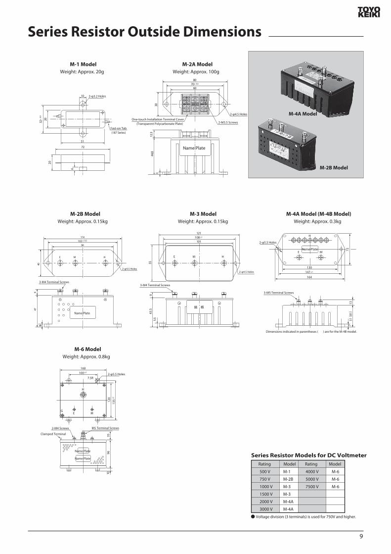
9
Series Resistor Outside Dimensions
M-1 ModelWeight Approx 20g
M-2A ModelWeight Approx 100g
448
123
3
70plusmn 05
30
60
80
2-φ45 Holes
2-φ32 Holes
2-M35 ScrewsOne-touch Installation Terminal Cover
(Transparent Polycarbonate Plate)
Name Plate
6
2020
32plusmn
05
10
51
72
Fast-on Tab(187 Series)
M-3 ModelWeight Approx 015kg
M-2B ModelWeight Approx 015kg
M-6 ModelWeight Approx 08kg
M-4A Model (M-4B Model) Weight Approx 03kg
Name Plate
102 plusmn 05
4047
9
5
90
114
E M H
2-φ45 Holes2-φ45 Holes
E M H
銘 板
108 plusmn1
101
121
5543
59
55
Name Plate
H
E
130
164
7213
751(
81)
147 plusmn1
M
2-φ55 Holes
3-M4 Terminal Screws
Dimensions indicated in parentheses ( ) are for the M-4B model
120
135
plusmn1
100 plusmn1
9610
35
160
2-φ55 Holes75R
E
H
GM
Clamped Terminal
2-M4 Screws M5 Terminal Screws
Name Plate
Name Plate
Rating Model Model Rating
500 V
750 V
1000 V
1500 V
2000 V
3000 V
M-1
M-2B
M-3
M-3
M-4A
M-4A
M-6
M-6
M-6
4000 V
5000 V
7500 V
Voltage division (3 terminals) is used for 750V and higher
Series Resistor Models for DC Voltmeter
M-4A Model
M-2B Model
3-M4 Terminal Screws
3-M5 Terminal Screws
C-3 Model Current Transducer
ERG-3 Model URG-3 ModelRRG-3 Model UuRG-3 Model
40 58
30
48
42
12
55
6532
5
M4 Terminal Screws
LINE
METER
NP 40 581624
534
or b
elow
30
1259
4212
55
8098
LINE
METER
50plusmn05
24
65
325
Line Side Terminal ScrewsM4 Terminal Screws
Thickness t
(Note)
50plusmn05
Meter Side
1) 15A or Less 2) 15A and Above Up to 100ASpecications Rated Load 01VA
Primary Current Various types 15A and above up to 100ASecondary Current 10mACircuit Voltage 460VVoltage Test AC2000VWeight Approx 026kgSpecications Rated Load 01VA
Primary Current Various types less than 15ASecondary Current 10mACircuit Voltage 460VVoltage Test AC2000VWeight Approx 02kg
Primary Current Type
15A -75A
15
75A -100A
Conductor Thickness
t (mm)Line Side
Terminal Screws
M6times14
M8times16
Note)
Note)
Converter Outside Dimensions
Converter
Case Material Glass ber-strengthened PC resin Terminal Part Material Glass ber-strengthened PBT resin Cover Material Transparent polycarbonate resin
Din rail mounts can also be manufactured In such cases the model name is RG-3A
[Terminal Arrangement Diagram]
M-2A
FM-3
Series Resistors for AC VoltmeterRectiers for AC Ammeter
(Outside dimensions are the same as the M-3 model on page 9)
10
70plusmn05
30
60
80
2-φ45 Holes
4-M35 ScrewsOne-touch Installation Terminal Cover
(Transparent Polycarbonate Plate)
METER
LINE
LINE電 源METERメータ
For Frequency Meter
LINE
METER
minus +
121plusmn05
72plusmn05
124plusmn
05
96
110plusmn
05
4
7
Terminal CoverM4 Terminal ScrewsHere is an example of a terminal screw position
69
11
Name Plate
2
Meter Connection Diagram
Converter
LINE
METER
①
②
a c b
a c b
AC V
Generator
Generator
Frequency Meter
ConverterVT
LINE
METER
①
②
a c b
a c b
AC V
Frequency Meter (With VT)
a c b
a c b
AC V
Electric Tachometer
M-2A Series Resistor
LINE
METER
+
-
a c b
a c b
AC V
Electric Tachometer (With Series Resistor)
TG
TG
M-2A Series Resistor
LINE
METER
a c b
a c b
AC V
Voltmeter (With Series Resistor)
a c b
a c b
AC V
Voltmeter (Direct Measurement)
a c b
a c b
AC V
Voltmeter (With VT)
M-2A Series Resistor
VT VT
LINE
METER
+
-
+
-
a c b
a c b
AC V
Voltmeter (With VT Series Resistor)
C-3 Current Transducer
LINE
METER
a c b
a c b
AC V
Ammeter (With Current Transducer)
M-2A Rectier Box
LINE
METER
a c b
a c b
AC V
Ammeter (With Rectier Box)
a c b
a c b
AC V
Ammeter (Direct Measurement)
C-3 Current Transducer
CT
LINE
METER
a c b
a c b
AC V
Ammeter (With CT Current Transducer)
Rectier Box
CT
LINE
METER
Current TransducerC-3 M-2A
LINE
METER
a c b
a c b
AC V
Ammeter (With Current Transducer Rectier Box)
+
a c b
a c b
AC V
Ammeter (With Shunt)
a c b
a c b
AC V
H Side Load Relay Contact
L Side LoadRelay Contact
H Side Load Relay Contact
L Side LoadRelay Contact
H Side Load Relay Contact
L Side LoadRelay Contact
H Side Load Relay Contact
L Side LoadRelay Contact
H Side Load Relay Contact
L Side LoadRelay Contact
H Side Load Relay Contact
L Side LoadRelay Contact
H Side Load Relay Contact
L Side LoadRelay Contact
H Side Load Relay Contact
L Side LoadRelay Contact
H Side Load Relay Contact
L Side LoadRelay Contact
H Side Load Relay Contact
L Side LoadRelay Contact
H Side Load Relay Contact
L Side LoadRelay Contact
H Side Load Relay Contact
L Side LoadRelay Contact
H Side Load Relay Contact
L Side LoadRelay Contact
H Side Load Relay Contact
L Side LoadRelay Contact
H Side Load Relay Contact
L Side LoadRelay Contact
H Side Load Relay Contact
L Side LoadRelay Contact
H Side Load Relay Contact
L Side LoadRelay Contact
Power Supply Power Supply Power Supply
Shunt
Load Load Load
Power Supply
Load
Power Supply
Load
Power Supply
Load
Power Supply
Load
Power Supply
Load
Power Supply
Load
Power Supply
Load
Power Supply
Load
Power Supply
Load
Power Supply
Load
Power Supply
Load
Power Supply
Load
Power Supply
Load
Power Supply
Load
Ammeter (Direct Measurement)
Series Resistor
a c b
a c b
AC V
Voltmeter (With Voltage Division Type Series Resistor)
M-2A Shunt Box
LINE
METER
+
-
+
-
a c b
a c b
AC V
Ammeter (With Shunt Box)
H M
E
M-1 M-2A Series Resistor
a c b
a c b
AC V
Voltmeter (With Series Resistor)
a c b
a c b
AC V
Voltmeter (Direct Measurement)
Voltage division type series resistor should be used when the maximum scale value is 750V or higher
Note 1 The terminal diagram below is for MPC-10 and 12 For the terminal arrangements of other models see the outside dimensions page for those models
Note 2 The example auxiliary power supply connection is for AC See the example connection on the next page for DC auxiliary power supplies
Note 3 Accessories (P-3) are required for the MPC-6 even if the auxiliary power supply is AC See the the example connection on the next page for information on connections( )
DC Ammeter and DC Voltmeter (Moving-coil Type)
AC Ammeter or Voltmeter (Rectier Type)
Dierential Analyzer Frequency Meter Electric Tachometer (Rectier)
H Side Load Relay Contact
L Side LoadRelay Contact
H Side Load Relay Contact
L Side LoadRelay Contact
1 2 3 4 5
9 10 6 7 8
1 2 3 4 5
9 10 6 7 8
1 2 3 4 5
9 10 6 7 8
1 2 3 4 5
9 10 6 7 8
1 2 3 4 5
9 10 6 7 8
1 2 3 4 5
9 10 6 7 8
1 2 3 4 5
9 10 6 7 8
1 2 3 4 5
9 10 6 7 8
1 2 3 4 5
9 10 6 7 8
1 2 3 4 5
9 10 6 7 8
1 2 3 4 5
9 10 6 7 8
1 2 3 4 5
9 10 6 7 8
1 2 3 4 5
9 10 6 7 8
1 2 3 4 5
9 10 6 7 8
FM-3
FM-3
1 2 3 4 5
9 10 6 7 8
1 2 3 4 5
9 10 6 7 8
1 2 3 4 5
9 10 6 7 8
1 2 3 4 5
9 10 6 7 8
1 2 3 4 5
9 10 6 7 8
11
P-3
INP
UT
OU
T PU
T
a
c
a
c
Meter InputAC CurrentAC〇〇V
M-4A or M-4B
INP
UT
OU
T PU
T
a
c
b
a c b
a c b
a
c
b
Load TerminalH Side
Load TerminalH Side
Meter Input
Load TerminalL Side
DC CurrentDC〇〇V
Note M-4A (M-4B) not required when the auxiliary power supply is DC24V or DC12V
Note P-3 not required when the auxiliary power supply is AC24V or AC12V
1 2 3 N
DAOLECRUOS CT1CT2
CT3
Auxiliary Power Supply
VT1
VT2
VT3
3P4W Wattmeter Varmeter (With CT)
a c b
a c b
1 2 3 N
DAOLECRUOS CT1CT2
CT3
Auxiliary Power Supply
3P4W Wattmeter Varmeter (With CT VT)
VT1 VT2
a c b
a c b
1 2 3
DAOLECRUOS CT1
CT2
Auxiliary Power Supply
3P Wattmeter Varmeter (With CT VT)
VT1 VT2
a c b
a c b
1 N 2
DAOLECRUOS CT1
CT2
Auxiliary Power Supply
1P3W Wattmeter Varmeter (With CT VT)
VT
a c b
a c b
1 2
SOURCE LOADCT
Auxiliary Power Supply
1P Wattmeter Varmeter (With CT VT)
a c b
a c b
1 2 3
DAOLECRUOS CT1
CT2
Auxiliary Power Supply
3P Wattmeter Varmeter (With CT)
a c b
a c b
1 2
DAOLECRUOS CT
Auxiliary Power Supply
1P Wattmeter Varmeter (With CT)
a c b
a c b
1 N 2
SOURCE LOADCT1
CT2
Auxiliary Power Supply
1P3W Wattmeter Varmeter (With CT)
a c b
a c b
1 2 3 N
SOURCE LOADCT1CT2
CT3
Auxiliary Power Supply
VT
3P4W Power Factor Meter (With CT)
a c b
a c b
1 2 3 N
DAOLECRUOS CT1CT2
CT3
Auxiliary Power Supply
3P4W Power Factor Meter (With CT VT)
VT1 VT2
a c b
a c b
1 2 3
DAOLECRUOS CT1
CT2
Auxiliary Power Supply
3P Unbalanced Power Factor Meter (With CT VT)
VT
5
a c b
a c b
1 2 3
DAOLECRUOS CT
Auxiliary Power Supply
3P Balanced Power Rate Meter (With CT VT)
VT
a c b
a c b
1 2
SOURCE LOADCT
Auxiliary Power Supply
1P Power Factor Meter (With CT VT)
a c b
a c b
1 2 3
DAOLECRUOS CT1
CT2
Auxiliary Power Supply
3P Unbalanced Power Factor Meter (With CT)
a c b
a c b
1 2
DAOLECRUOS CT
Auxiliary Power Supply
1P Power Factor Meter (With CT)
a c b
a c b
1 2 3
SOURCE LOADCT1
Auxiliary Power Supply
3P Balanced Power Rate Meter (With CT)
MPC-6 ModelFor AC Auxiliary Power Supply
MPC-8 MPC-10 MPC-12 ModelFor DC Auxiliary Power Supply
Wattmeter and Varmeter (Electronic Device Type)
Power Factor Meter (Electronic Device Type)
Overall Connection Diagram (Example)
H Side Load Relay Contact
L Side LoadRelay Contact
H Side Load Relay Contact
L Side LoadRelay Contact
H Side Load Relay Contact
L Side LoadRelay Contact
H Side Load Relay Contact
L Side LoadRelay Contact
H Side Load Relay Contact
L Side LoadRelay Contact
H Side Load Relay Contact
L Side LoadRelay Contact
H Side Load Relay Contact
L Side LoadRelay Contact
H Side Load Relay Contact
L Side LoadRelay Contact
H Side Load Relay Contact
L Side LoadRelay Contact
H Side Load Relay Contact
L Side LoadRelay Contact
H Side Load Relay Contact
L Side LoadRelay Contact
H Side Load Relay Contact
L Side LoadRelay Contact
H Side Load Relay Contact
L Side LoadRelay Contact
H Side Load Relay Contact
L Side LoadRelay Contact
H Side Load Relay Contact
L Side LoadRelay Contact
H Side Load Relay Contact
L Side LoadRelay Contact
Load TerminalL Side
1 2 3 4 5
9 10 6 7 8
1 2 3 4 5
9 10 6 7 8
1 2 3 4 5
9 10 6 7 8
1 2 3 4 5
9 10 6 7 8
1 2 3 4 5
9 10 6 7 8
1 2 3 4 5
9 10 6 7 8
1 2 3 4 5
9 10 6 7 8
1 2 3 4 5
9 10 6 7 8
1 2 3 4 5
9 10 6 7 8
1 2 3 4 5
9 10 6 7 8
1 2 3 4 5
9 10 6 7 8
1 2 3 4
9 10 6 7 8
1 2 3 4 5
9 10 6 7 8
1 2 3 4 5
9 10 6 7 8
1 2 3 4 5
9 10 6 7 8
1 2 3 4 5
9 10 6 7 8
1 2 3 4 5
9 10 6 7 8
1 2 3 4
9 10 6 7
910
910
12
Intrinsic Power Value
CT Ratio
5A5A
75A5A
10A5A
15A5A
20A5A
30A5A
40A5A
50A5A
75A5A
100A5A
150A5A
200A5A
300A5A
400A5A
500A5A
750A5A
1000A5A
1500A5A
2000A5A
3000A5A
VT Ratio625Or
667W
Line Voltage
mdash
1 kW
12 kW
2 kW
25 kW
4 kW
5 kW
mdash
10 kW
12 kW
20 kW
25 kW
40 kW
50 kW
mdash
100 kW
120 kW
200 kW
250 kW
400 kW
750 W
12 kW
15 kW
25 kW
3 kW
5 kW
6 kW
75 kW
12 kW
15 kW
25 kW
30 kW
50 kW
60 kW
75 kW
120 kW
150 kW
250 kW
300 kW
500 kW
1 kW
15 kW
2 kW
3 kW
4 kW
6 kW
8 KW
10 kW
15 kW
20 kW
30 kW
40 kW
60 kW
80 kW
100 kW
150 kW
200 kW
300 kW
400 kW
600 kW
12 kW
2 kW
25 kW
4 kW
5 kW
8 kW
10 kW
12 kW
20 kW
25 kW
40 kW
50 kW
80 kW
100 kW
120 kW
200 kW
250 kW
400 kW
500 kW
800 kW
15 kW
25 kW
3 kW
5 kW
6 kW
10 kW
12 kW
15 kW
25 kW
30 kW
50 kW
60 kW
100 kW
120 kW
150 kW
250 kW
300 kW
500 kW
600 kW
1 MW
2 kW
3 kW
4 kW
6 kW
8 KW
12 kW
(16 kW)
20 kW
30 kW
40 kW
60 kW
80 kW
120 kW
(160 kW)
200 kW
300 kW
400 kW
600 kW
800 kW
12 MW
25 kW
4 kW
5 kW
8 kW
10 kW
15 kW
20 kW
25 kW
40 kW
50 kW
80 kW
100 kW
150 kW
200 kW
250 kW
400 kW
500 kW
800 kW
1 MW
15 MW
3 kW
5 kW
6 kW
10 kW
12 kW
20 kW
(24 kW)
30 kW
50 kW
60 kW
100 kW
120 kW
200 kW
(240 kW)
300 kW
500 kW
600 kW
1 MW
12 MW
2 MW
4 kW
6 kW
8 KW
12 kW
(16 kW)
(24 kW)
(32 kW)
40 kW
60 kW
80 kW
120 kW
(160 kW)
(240 kW)
(320 kW)
400 kW
600 kW
800 kW
12 MW
(16 MW)
(24 MW)
20 kW
30 kW
40 kW
60 kW
80 kW
120 kW
(160 kW)
200 kW
300 kW
400 kW
600 kW
800 kW
12 MW
(16 MW)
2 MW
3 MW
4 MW
6 MW
8 MW
12 MW
25 kW
40 kW
50 kW
75 kW
100 kW
150 kW
200 kW
250 kW
400 kW
500 kW
750 kW
1 MW
15 MW
2 MW
25 MW
4 MW
5 MW
75 MW
10 MW
15 MW
30 kW
50 kW
60 kW
100 kW
120 kW
200 kW
(240 kW)
300 kW
500 kW
600 kW
1 MW
12 MW
2 MW
(24 MW)
3 MW
5 MW
6 MW
10 MW
12 MW
20 MW
40 kW
60 kW
80 kW
120 kW
150 kW
(240 kW)
300 kW
400 kW
600 kW
800 kW
12 MW
15 MW
(24 MW)
3 MW
4 MW
6 MW
8 MW
12 MW
15 MW
(24 MW)
50 kW
75 kW
100 kW
150 kW
200 kW
300 kW
400 kW
500 kW
750 kW
1 MW
15 MW
2 MW
3 MW
4 MW
5 MW
75 MW
10 MW
15 MW
20 MW
30 MW
60 kW
100 kW
120 kW
200 kW
(240 kW)
400 kW
(480 kW)
600 kW
1 MW
12 MW
2 MW
(24 MW)
4 MW
(48 MW)
6 MW
10 MW
12 MW
20 MW
(24 MW)
40 MW
MultiplierMeter Types
3P Wattmeters 3P4W Wattmeters 1P3W Wattmeters
1P Wattmeters 3P varmeters and 3P4W varmeters
1P Varmeter
1
12 (1 for varmeters with zero left meters)
14 (12 for zero left meters)
This standards chart is a resource for determining the measurement range values of wattmeters and varmeters so 3P wattmeter CT 〇〇〇A5A standards are indicated
Example VT 3300V110V CT 60A5A 3P Wattmeter
Measurement Range = (667W 833W 1kW or 111kW) x 3300 110 x 60 5 = 240kW 300kW 360kW or 400kW
Note) Numerical values inside parentheses indicate values that deviate from JIS standards but can be manufactured
Standard Table of Wattmeter Measurement Range
[1] For 3P wattmeters 3P4W wattmeters and 1P3W wattmeters the measurement range values are displayed in the voltage ratios (VT ratio dierences) and CT ratio dierences in the table above (There are three types dened for the same VT and CT ratios Choose the appropriate type However an item marked with in the intrinsic power eld needs to be selected for the wide angle meter) Eg) For a VT 3300V110V CT 100A5A 3P wattmeter select the appropriate one from 400kW 500kW or 600kW from the table above
[2] For 1P wattmeters 3P varmeters and 3P4W varmeters the values displayed above are multiplied by 12 and are multiplied by 14 for 1P varmeters
Note 1) For varmeters read kW units as kvarScale is LEAD ~0~LAG kvarExample For a VT 3300V110V CT 100A5A 3P varmeter hellipLEAD2500~LAG250 kvar or LEAD300~0~LAG300 kvar
(500 times 12) (500 times 12) (600 times 12) (600 times 12)
2) For 3P varmeters or 3P4W varmeters with zero left meters follow the values as displayed above and for 1P varmeters with zero left meters the values in the table above are multiplied by 12
[3] If the CT ratio exceeds the range listed above (for example VT 3300V110V CT 5000A5A 3P wattmeter) select a value from the CT 500A5A row (2MW 25MW 3MW) and multiply it by 10
Note) In the situation above scale indicators are 20MW 25MW and 30MW (It is preferable that the highest 3 digits of scales are displayed)
[4] If CT ratios do not correspond with those indicated above (for example CT 60A5A) use the calculation chart below to acquire the measurement range then choose from among them the value with the best ending number
Measurement Range = Intrinsic Power times VT Ratio times CT RatioNote) Select a value indicated below from the intrinsic power value in the above calculation chart However intrinsic power values vary depending on meter type Use the multiplier indicated below to calculate the value
Using the Above Chart
[5] Values of 1 12 15 2 25 3 4 5 6 75 or 8 or integers that are multiples of those 10 values are preferable selections for the upper range scale value (JIS standards)
110V 220V 440V 3300V 6600V
440V110V 3300V110V 6600V110V750Or
833W
125Or
133kW
15Or
167kW
625Or
667W
750Or
833W
1kWOr
111kW
1kWOr
111kW1kW 2kW 1kW 833W 833W667W
625Or
667W
13
MultiplierMeter Types
3P Wattmeters 3P4W Wattmeters 1P3W Wattmeters
1P Wattmeters 3P varmeters and 3P4W varmeters
1P Varmeter
15
110 (15 for varmeters with zero left meters)
120 (110 for zero left meters)
Product Name
1P Wattmeter 1P Varmeter
3P Wattmeter 3P Varmeters 110V 5A220V 5A
110V 5A 300 ~ 625W (var)600 ~ 1250W (var)
500 ~ 1250W (var)1000 ~ 2500W (var)
500 ~ 1250W (var)1000 ~ 2500W (var)
220V 5A
1P3W Wattmeter
3P4W Wattmeter3P4W Varmeter
Rating
110Vradic3V 5A220Vradic3V 5A
Production Range
Example VT 440V110V CT 60A1A 1P Wattmeter
Measurement range = [(625W 667W 750W 833W or 1kW) x 110] x 440 110 x 60 1 = 15kW 16kW 18kW 20kW or 24kW However 15kW or 20kW should be selected
Example VT 6600V110V CT 50A5AWhen measurement range value = 400kW
Note) The meter production range for using a CT of 1A for the secondary current is the value indicated on the left multiplied by 15
[6] Even when using a CT of 1A for the secondary current the measurement range value is as indicated on the left (selection standards chart) Note) If CT ratios do not correspond (for example CT 60A1A) with those indicated to the left (selection standards chart) follow calculation chart [4] below to calculate the measurement range value However intrinsic power values vary depending on meter type Use the multiplier indicated below to calculate
The production range of wattmeters and varmeters can be manufactured according to the indicated range of intrinsic power values in the calculation chart below
Intrinsic Power Value [W]=Measurement Range Value [W]
VT Ratio x CT RatioIntrinsic Power Value W= =667W 400kW
60times10
Production Limits of Meters (Wattmeter Varmeter)
14
15
NoteMeter Relay MPV-11
110times110 120times110
MPC-12
Outside (mm)
Scale Length (mm)
Accuracy Class
Pointer
Set Pointer
Scale Plate
Scale Division
Mounting Posture
Cover
Base
Cover Coating Color
Setting
Operating Error for Setting Value (Against Scale Length)
Dead Band
Output Contact Arrangement and Capacity
Insulation Test
Voltage Test
Characteristics of Meter
Meter Action
Auxiliary Power Supply
Output Signal
Note 1)
Note 2)
Stop Type
Passage Type
A C
Retaining Type
Instantaneous Type
Approx 170
Tapered Type
Triangular with Red H
White Base
Vertical
Methacrylic Resin
15
10
〇
〇
1ab AC220V 3A
Approx 100
Wand Type
Wand Type with Red H
Special Anti-electric Resin
15
10
〇
〇
1ab AC100V 1A
Between Terminals - Phenol Resin Body Cover - ABS resin
N - 15 (black) or 75B G415 (blue-green)
H Setting (Single Side Only)
AC110V AC115V AC220V
Between electrical circuit and outer casing of meter 10MΩ or more for 500V mega
Between electrical circuit and outer casing of meter AC 1500V (5060Hz per minute)Between contact relay circuit and other electrical circuits AC 500V (5060Hz per minute)
Characteristics of the meter part are based on JIS C 1102-1 to 9
plusmn10
plusmn5Intrinsic Error Indicated value
Between 005~1MΩ
Extra Power Unit RG-3 Meter Sensitivity
DC250μA
Earth-resistance Meter Relay MPV-11 MPC-12
This meter relay can measure the earth resistance value of a contactless AC circuit while also detecting abnormal earth resistance values in the same circuit Comprising a contactless meter relay and extra power unit this meter relay can be used for a wide range of purposes such as detecting abnormalities in grounding accidents in settings such as boatsA particularly useful feature is the xed voltage circuit built into the extra power unit which maintains a roughly xed voltage circuit even during uctuations of plusmn10 in the input voltage of AC115V preventing measurement error
[Overview]
[Features]
[Standard Specications]
[Operating Principles]
Earth resistance measurements can be taken continuously while also setting and detecting the desired earth resistance values on the scale of the photoelectric-type detection setting mechanism as well as activating warning equipment using the relay circuit contact
Lines can be measured and detected while live
Note 1) Meter Action Passage Type - The pointer can pass to the end of the scale even if it exceeds the setting value
Note 2) Output Retaining Type - Output is retained even when the pointer passes the setting value The output is discarded when the pointer goes back below the setting valueNote 3) Others a) DC circuit type can also be manufactured if desired
b) See the page about our contactless meter relay for detailsc) In particular a standard meter type can be manufactured if the detection equipment is not requiredd) Also includes a converter Type I S-3 For 3P Type I S-1 For 1P
Apply an AC power supply to the extra power unit to generate DC50V on the output side This DC power supply can be used to combine the unit with a DC ammeter with an MΩ scale making it possible to take measurements and read earth resistance for circuit currents that change depending on the ground statusThe AC side and output side of the extra unit are insulated by a transformer This means that the DC power supply can be considered separate from the lines creating the basic circuit shown on the leftIn the circuit diagram on the left DC50V is being generated by the power unit the power is connected to the meter in a series where Rs = 02 MΩ (scale centering on meter) and a resistance value is being indicatedWhen switch S is turned on the pointer of the meter moves to the maximum indicating 0MΩ in this caseThis means that the maximum current sensitivity value of the inow current is i = =250μA
If a grounding accident occurs and the earth resistance is 02 MΩ (Re = 02 MΩ) the inow current
i1 = = = 125μA and the center scale point of 02 MΩ is indicated
The relationship between the earth resistance value and the current i is as shown below
Lines
Resistance Meter
[Power Unit]
AC 115V
Rs
Re
Re Earth Resistance
S Switch
Rs Standard Resistance
S
e=50v
Circuit Conguration Diagram
02MΩ +02MΩ Rs+Re50V
02MΩ 50V
50V
Measurement point A can be measured from LINE R S or T Auxiliary Power Supply 110V System (9) (10) 220V System (9) (11)
AC100V
AC115V
DC50VB
3
3
2
2
1
1
10 119
4
4 5VT
Zero Ohms Adjustment Volume
R
S
T
LINE LOAD
440V
A
Load Contact
MPV-11
a c d
Power Unit (RG-3)
[Connection Diagram]
[Extra Power Unit]
[How to Use]
[Scale Drawing]
[Outside Dimensions]
MPV-11
MPC-12
RG-3
110plusmn1
5
110plusmn15
45plusmn0545plusmn05
4-φ7
φ102
1 2 3 4 5109 11 6 7 8
M3 Terminal Screws
Terminal Cover
Terminal Cover33 or below
8
130
4M-6 Mounting Screws
05
24
145
115
φ10
0
φ10
2Panel Cutout
Black Shading Hood
45plusmn0545plusmn05
45plusmn0
545
plusmn05
45plusmn0
545
plusmn05
5
35plusmn0
545
plusmn0545
plusmn05
35plusmn0
5
50plusmn05 50plusmn0550plusmn05
120plusmn1
50plusmn05
4-φ5 Holes10-M3Terminal Screws Variable Resistor for Sensitivity SettingsNote 1
20
12 105100
4-M4 Mounting Screws
05
255
10
φ64
Panel Cutout
φ87plusmn1
100plusmn1
φ85
+05minus0
1
2
3
4
5
9
10
6
7
8
121plusmn0572plusmn05
4
769
11
110plusmn
05
96 124plusmn
05
Terminal Cover4-M4 Terminal Screws
ZERO
NPZero OhmsAdjuster
MΩ
MΩ0
1
125infin
234
5
0
1125infin
2345
Resistance value between LINE R S or T and earth is measured between A and BIn the diagram on the left the measurement is taken from
phases S and T but any phase can be usedThe diagram on the left shows an example connection
between MPV and 11 but the same result will be obtained between MPC and 12 (vertical terminal array)The zero ohms adjustment volume is a backup device
embedded in the center of the power unit Insulate auxiliary power supply terminals (9) and (10) before checking the zero ohms adjustment(To stop the output signal of the relay circuit)
[Specied Items when Ordering]
0-5 MΩ (Center Point 02 MΩ) 0-5 MΩ (Center Point 02 MΩ)
Contact Arrangement345
MPVminus11 MPCminus12
Model Name MPV-11 or MPC-12Scale 0-5 MΩ (Center point 02 MΩ)Auxiliary Power Supply AC 110V etcAttached Panel Fe or NFe (Specify MPC-12 model only)Mounting Posture etcCover Coating Color N-15 (black) or 75 BG 415 (blue-green)Other Non-standard specications
Note)
16
Sminus62 minusminusA AC InputD DC InputH H Setting Value L L Setting Value 1 DC Power Supply (DC24V) 2 AC Power Supply AC100110V AC200220VInput
0 60mV1 100mV2 0~1V3 0~5V4 1~5V5 4~20mA6 1A7 5A8 150V9 Others
0 No Delay1 Power Supply Delay2 Signal Delay1 Socket Attachment2 Panel Mounting
( (
DC
AC
VHCOMCL
678
4
5
Power Supply
U6
Input
U1 U2U4 U5
U3
123
U1Input Amplier
U2Rectier Circuit
U3Setting Circuit
U4Comparator Circuit
U5Delay Circuit
U6Power Supply Circuit
VHCOMCL
678
4
5
Power Supply
U5
Input
U1U3 U4
U2
123
U1Input Amplier
U2Setting Circuit
U3Comparator Circuit
U4Delay Circuit
U5Power Supply Circuit
[Operating Principles]
AS-62 (AC Input)
Block Diagram
[Overview of Operation]
DS-62 (DC Input)
Block Diagram
Stationary Non-indicating Regulator AS-62DS-62
This product is a non-indicating adjustment meter with no meter drive unit The AS-62 uses AC input while the DS-62 uses DC input The auxiliary power supply can be used for AC 100110V and AC 200220V This product can also be manufactured with a DC24V power supply The ono status of the relay is shown by a red LED on the front and the setting scale also has an extremely easy-to-see structure Two attachment methods can be used by connector or by panel mounting Panel mounting is done by connecting the lines using the terminal block on the back (M4 screws) Compact design with front panel measuring 625x625
[Overview]
ltSolid State Relaygt
After amplifying the input signal with the input amplier (U1) the entire wave is rectied and attened with the rectier circuit (U2) and then input on the signal side with the comparator circuit (U4)Meanwhile the voltage set by the dial is input on the setting side with the setting circuit (U3) The output from (U4) is a VH or VL value depending on this input This signal is input into a relay drive transistor to turn the relay on and o Here the delay circuit (U5) delays the signal from U4 for around 1 second in the event of a signal delay The circuit constant diers depending on the specications In the event of a power supply delay the relay does not operate for around 7 seconds after the power supply is turned on even when the U4 output voltage is VH This circuit responds to the average input value not DC components
[Overview of Operation]
[Specications]
After amplifying the input signal with the input amplier (U1) the signal is input on the signal side with the comparator circuit (U3) Meanwhile the voltage set by the dial is created by the setting circuit (U2) and input on the setting side of the comparator circuit (U3) The output from (U4) is VH or VL depending on the relationship between the signal and the setting value This signal is input into a relay drive transistor to turn the relay on and o The delay circuit (U5) creates signals for power supply delays (approximately 7 seconds) and signal delays (approximately 1 second) according to the specications
Model Name
17
51 or below24 or below
354
118
or b
elow
81 o
r bel
ow
40plusmn024
78
4
5
8-M35x7 Sems Screws
2-φ45 Holes
4
0
2040
POWER RELAY
SOLIDSTATE CONTROLLER
625
625
10 95126 plusmn7
56
56
8-M4 ScrewsEmbedded in Panel
Attached to Wall
Socket Attachment
Use OMRON 8PFA
40plusmn2
2-φ45 Holesor M4 Tapping
565+
05
-0
565 +05 -0
1
2
3
4 5
6
7
8
Input
ab
cAC100110V
AC200220V
AC Auxiliary Power Supply 1
2
3
4 5
6
7
8
Input
ab
cDC24V
DC Auxiliary Power Supply
+
+
-
Panel Cutout
[Performance]Input Impedance
60mV 100mV1V 5V 1~5V4~20mA5A1A150VThe following standards apply to products with other input specications60mV or More Up to 100mV101mV or More Up to 300VAmmeter Input Resistance value generating a
200mV voltage dropPickup Error plusmn 15Delay
Response Speed
Dead Band
Temperature Coecient
Load Relay Contact Capacity 1 ab AC 250V 3A (resistance load)DC 30V 3A (resistance load)
Power Consumption
Operating Temperature LimitsStorage Temperature RangeMaximum Relative HumidityInput Overload Capacity
60mV 100mV1V5V 1~5V4~20mA1A5A150V
Insulation Test (500V test with mega)Electrical circuit - outer casing input - auxiliary power supply input - relay output20 MΩ or more between each phase
Voltage TestElectrical circuit - outer casing input - auxiliary power supply input - relay output
2000V per minute between each phase
Outer Casing Material Polycarbonate resin phenol resinWeight Approx 400g
10kΩ1MΩ10Ω6mΩ30mΩ1MΩ
10V50V250V100mA10A50A500V
10kΩ1MΩ
Signal DelayPower Supply DelayA S-62D S-62
Approx 1 secondApprox 7 secondsApprox 02 secondsApprox 01 seconds
Around 2
plusmn0510˚C
Approx 3VA (AC power supply) 25W (DC power supply)
0˚C~50˚C-10˚C~60˚C
[How to Use]
Precautions when Handling and Ordering the S-62
[Outside Dimensions and Pin Connection Diagram]
[8PFA Socket Outside Dimensions]
Over 5A Less than 50A
Over 50A Less than 300A
Over 300A Less than 5000A
S-10A Model 60mV
S-8A Model 60mV
S-8 Model 60mV
Over 300V up to 500V
Over 501V up to 750V
Over 751V up to 1500V
Over 1501V up to 30000V
Over 3001V up to 5000V
M - 2 A
M - 2 B
M - 3
M - 4 A
M - 6
This product can be used by panel mounting or socket attachment (specify which when ordering)An attachment bracket and mounting screws are included when panel mount is specied Do not attach with items other than the included screws
1 A frequency range from 40 to 500Hz can be used by the AS-62 Frequencies outside this range are a special specication and prior consultation is needed
2 To control DC currents larger than 5A use a shunt to convert the voltage (to around 60mV) and then receive and control with the 60mV input type DS-62 Model names of shunts are as follows
To control high DC voltages add an external series resistor Model names of series resistors are indicated in the table below
85
100
6080
18
Non-indicating Voltage Relay DS-5A (for DC Voltage)
[Features]
[Specications]
[Outside Dimensions]
[Attachment Diagram]
[Series Resistor Calculation Method for General-Purpose Detector Side and Operation Side]
Driver adjust type enables easy and accurate conguration of voltage settings
Safe operation even for voltages containing ripples 3 dierent attachment methods
Front attachment (attachment to terminal block or rear connection socket on 8P) Rear attachment
[Purposes]Voltage detection in DC power suppliesVoltage detection in rectied power
suppliesAutomatic control
(3) Detection Error
(4) Set Method(5) Contact Capacity(6) Contact Arrangement(7) Relay Contact Output
(1) Detection Method(2) Detected Voltage Rating
Voltage comparison-based voltage detection
Within plusmn15 of upper limit setting maximum voltage value (within plusmn25 for DS-5A-U12)
VR variance by driver adjustmentDC 30V1A (resistance load) AC 100V1AL side 1b H side 1a
Series ResistorModel
Inside Dimensions
Externally connected for operation
Note
DS-5A-24A
DS-5A-48A
DS-5A-100A
DS-5A-U12
DS-5A-U24A
DS-5A-U48A
20~24V
40~48V
80~95V
10~14V
20~28V
40~56V
24~28V
48~56V
105~120V
10~14V
20~28V
40~56V
02
04
11
01
02
05
15
15
50
20
15
15
Setting Range for Detected Voltage
L
Power Consumption (W)
Detection Side Operation Side
Note)
Within plusmn15 of upper limit setting maximum voltage (within plusmn20 for DS-5A-U12)
200mS or less when 97 to 110 of set voltage is applied
20 times per 60 seconds 10 minute stop(When upper limit setting maximum voltage value is 100)
Continuous overvoltage of 120 possible with all models)150 possible for 3 minutes on all models 200 not possible on any models
Insulation Test Between Electrical Circuit and Case DC500V mega 10MΩ or higher
Between Electrical Circuit and Relay Contact DC500V mega 5MΩ or higher
Voltage Test Between Electrical Circuit and Case AC 2000V (5060Hz per minute)
Between Electrical Circuit and Relay Contact AC500V (5060Hz per minute)
ON
ON
OFF
OFF
LH Setting Value
L Side Relay Contact Output
H Side Relay Contact Output
(8) Retained Range
(9) Reaction Time
(10) Operation Frequency(11) Overvoltage Strength
Within 20 P-P-10˚C~50˚C
(12) Detection Input Ripples(13) Operating Temperature Limits
(14) Pin Layout Diagram
L
v v
50plusmn05
60plusmn0
5
44 +0 -05
54+
0 -
05
80 70
35
7652
7
82785
8P Octal Base
[Series Resistor for Operation of the DS-5A-100A R Outside Dimensions]
454
4
64plusmn15
73plusmn15
06
φ 25
43
13plusmn02
φ 15
31
14
Voltage Resistance AC2000VWeight 25g
Attachment Screws
Claw to Prevent Falling O
OMRON8PF Terminal Block Type(see P18)
74
φ30 or higher
2-φ35 Holesor M3 Tapping
Panel Cutout Diagram
If attached directly
123
467
8
H Side Relay Contact Output 1a
L Side RelayContact Output 1b
R
RHRL
Auxiliary Power Supply (-)
L Side Detection Input (-) H Side Detection Input (-)
123
467
8
H Side Relay Contact Output 1a L Side Relay Contact Output 1b
R Auxiliary Power Supply (-)
Detected Voltage Input (-)
COM (+)
[Overview]
Weight 140g
(1) Pin Layout DiagramDS-5A-U (A)
DS-5A-A
R Series Resistor for Operation (Externally Connected)
RL Series Resistor for Operation on L Side (Externally Connected)
RH Series Resistor for Operation on H Side (Externally Connected)
Included only with R DS-5A-100A
See the pin layout diagram on the right for the DS-5A-U model
Both the operation unit and the detection unit are externally attached if the setting range is exceeded
Scale of general purpose model is 0~100
Note 1 Power Consumption (operation at maximum voltage on maximum setting where L = OFF and H = ON)Note 2 DS-5A-U (A) indicates all-purpose model Be sure to connect a series resistor if the values in this table
will be exceeded (Calculation method for series resistors can be found on P20)
This non-indicating voltage relay detects the voltage of DC power supplies It can detect both H and L in detected voltage setting ranges enabling safe operating even with voltages that contain ripples such as those in rectied power supplies
H
5
H
5
COM (+)
19
COM
Input
E
R
Vz
R D
1
7
E R
I Rs
Auxiliary Power Supply VoltageSeries Resistor Externally Connected to Operational Power SupplyCurrentDS-5A-U Equivalent ResistanceDS-5A-U12 Model 0086 kΩDS-5A-U24A Model 04 kΩDS-5A-U48A Model 136 kΩ
22
21 23
20 24V
26
25 27
24 28V
44
42 46
40 48V
52
50 54
48 56V
40 60
20 80
0 100
40 60
20 80
0 100
85 90
80 95V
110 115
105 120V
Auxiliary Power Supply
Detection Input
(-) )-(
(+) )+(
8 72
RR
R DS-5A
DS-5ADS-5A
R Externally Connected Series Resistor
R Externally Connected Series Resistor
Auxiliary Power SupplyDetection Input
(-) )-(
(+) )+(
8 7R (Included Only with 100 Model)DS-5A
a DS-5A-24A48A100A
a DS-5A-24A48A100A
b DS-5A-U24AU48A
b DS-5A-U24AU48A
Auxiliary Power Supply
Detection Input
(-)(-)
(-)
(+) )+(
8 72
RR
R
Auxiliary Power SupplyDetection Input
(-) )-(
(+) )+(
8 7R (Included Only with 100 Model)
1) DS-5A-24A
2) DS-5A-48A
3) DS-5A-100A
4) DS-5A-U24A DS-5A-U48A
DS-5A-U (A)Non-indicating Voltage Relay
(2) Calculation Method for RH or RL Series Resistor for Detection Side (Externally Connected)
(3) Calculation Method for R Series Resistor for Operation Power Supply Side (Externally Connected)
(A) Reference CurrentThe reference current is indicated as a bond
(b) Calculation
(c) Example Calculation
Model Name Reference Current I0 (mA) Vu (V)
DS-5A-U12
DS-5A-U24A
DS-5A-U48A
175
286
333
12
24
48
Model NameSet Voltage Range
(V)Vo (V) Detection Side Multiplier
RH or RL Value
DS-5A-U12
DS-5A-U24A
DS-5A-U48A
NoteModel Name
DS-5A-U12
DS-5A-U24A
DS-5A-U48A
22~26
44~52
92~108
24
48
100
(24-12) [V] 175 [mA]
RH or RL =(Center Point Voltage of Setting (Vo) - Vu)
Reference Current (Io)
I min ≦ I = E-VzR+RD
=686 [kΩ]
(48-24) [V] 286 [mA] =839 [kΩ]
(100-48) [V] 333 [mA] =156 [kΩ]
Caution
Input Voltage (Voltage of Auxiliary Power Supply) Range E [V] and Resistance Value R of Multiplier on Auxiliary Power Supply Side [kΩ]
Emin ≦ E ≦ Emax
80mA ≦ I = ≦ 140mAE-6
R+0086
Emax Maximum voltage of auxiliary power supply Imax Maximum currentEmin Minimum voltage of auxiliary power supply Imin Minimum current
Select R within the range where the above inequality is achievedIf the inequality is not achieved for I rework the equation by methods such as raising the R value or narrowing the voltage range of the power supply
(Note) Settings can be congured in the desired position between 0 and 100 for both H and L
[Scale Drawing]
[Connection Circuit Diagram of the External Circuits]
(1) The detection input and auxiliary power supply input are COM and +
(2) If the detection input and the auxiliary power supply are the same connect the auxiliary power supply terminal (7) and the detection input (8) (8 and 2 for U shape) as shown in the diagram below
(3) If the detection input and the auxiliary power supply are separate connect them as shown in the diagram below
Precautions for External Connections
Do not connect with the polarities of the detection input and auxiliary power supply opposing each other
I
Use the equation below to calculate the current I in the input voltage range then decide on the value for the R series resistor to be connected to the operational power supply
The current I value is for cases in which both the H and L sides are excited by the load relay of the non-indicating voltage relay (L OFF H ON)
≦ I max
25mA ≦ I = ≦ 70mAE-12R+04
15mA ≦ I = ≦ 35mAE-24
R+136
VZ=6VRD=0086kΩ
VZ=12VRD=04kΩ
VZ=24VRD=136kΩ
20
50plusmn05
60plusmn0
5
44 +0 -05
54+
0 -
05
80 70
35
7652
7
82785
8P Octal Base
74
φ30 or higher
2-φ35 Holes (or M3 Tapping)
Panel Cutout Diagram
If attached directly
Note) Can also be attached to the front terminal block (See P19)
40 581624
534
or b
elow
30
1259
4212
55
8098
LINE
METER
24
65
325
Line Side Terminal ScrewsM4 Terminal ScrewsThickness (t)
(Note)
50plusmn05
Meter Side
Name Plate
Rated Load 01VAPrimary Current 25ASecondary Current 10mACircuit Voltage 460VVoltage Test AC2000VWeight Approx 02kg
Note)
123
4567
8
Load RelayContact 1a
Auxiliary Power Supply AC100V
Current TransducerC-3 Model
Power Indicator AS-5-LI (Residual CurrentLeakage Current Detector)
[Overview]
[Features]
[Specications]
[Operation Diagram] [Connection Diagram]
Highly reliable solid-state electronic parts
Lightweight compact type
(Main unit 100g current transducer 200g)
Plugs into 8-pin socket enabling easy security inspections and replacement
[Purposes]
[Outside Dimensions]
[Accessories]
[Example Use]
Detects small amounts of residual power and issues an alert
Detects electric leakage and issues an alert
Detector prevents power from being left switched on
Operating Error
Maximum Circuit Voltage
Maximum Circuit Current
Setting Value
Relay Contact Output
Auxiliary Power Supply Voltage
Accessory
Insulation Resistance(DC500V Mega)
Voltage Resistance(for 1 minute)
Pickup Within setting value plusmn 10Dropout 20 or less of pickup value(dead band is also 20 or less of pickup value)
Contact arrangement 1a
Contact capacity AC100V 03A (resistance load)
AC 100V plusmn 10 5060Hz
C-3 Model Current Transducer
Between electrical circuit and outer casing 10 MΩ or higherBetween electrical circuit and relay contact 10MΩ or higherBetween electrical circuit and outer casing AC2000VBetween electrical circuit and relay contact AC500V
Current Transducer C-3 Model
② ②
⑥
①
① ② ③ ④ ⑤ ⑥
③
④
Load Current
Load Current
Load Relay ON
Load Relay OFF (Maximum 25A)
Dropout Value Pickup Value
I 2 I 1 = 01AC-3 C-3 C-3
Load 1 Load 2 Load 3
AS- 5-LI (1)
AS- 5-LI (2)
AS- 5-LI (3)
L1 L2 L3
Auxiliary Power Supply
Indicator Lamp Buzzer etc
This power indicator contains a highly reliable current relay that can detect low current settings It detects whether there is a 100mA current in circuits with a maximum current of 25A and generates a warning or an indicator drive signal This means that this device can be used together with a current transducer to detect power consumption of 10W in an AC100V circuitIt can be used in centralized monitoring to detect electric leakage and power left on in high-rise buildings dormitories hospitals and hotel rooms reducing the workload for inspections and saving energy in security and safety measures
AC460V
25A
01A (xed)
Specications
21
Precautions for Handling Meters Be sure to note the following when handling as the relay covers of the MPC and MPE-10 model meters are made
from new materials
Maintenance with anti-static nish is not needed at all To clean the surface wipe gently with a light cloth
Avoid direct sunlight and strong UV rays as much as possible (This may cause natural degradation in performance)
Do not apply solder directly to meter terminals
A new type of resin cover with a better anti-electric eect is used
The molded resin contains a special component that causes self-discharge of static electricity
This means that
Special Anti-electric Resin Applied to Cover
Avoid high temperature locations (60˚C or over) because the plastic cover and case of the meter are easily aected by heat
1) The anti-static eect is unaected by the humidity of the operating environment(The charge half-life is less than 1 second even in a relative humidity of around 23)
2) The anti-static eect is semi-permanent in normal indoor operating conditions
3) Maintenance such as application of an anti-static nish is not needed
The cover case may be damaged through contact with chemicals (solvents such as paint thinner benzine alcohol etc)
The previous acrylic resin is used for the MPV and MPE-150 models Use an anti-static nish particularly in poor conditions where static electricity occurs easily such as low humidity [Anti-static nish Anti-static 80S spray (from Tanaka Chemical Laboratory) or Riverson No 30 spray (from Tokyo Yakuhin Kakosei)]
Paint
Thinner
Alcohol
Benzine
Spray
22
Main OceSales Department
Tokyo Oce
Nagoya Oce
Shimoshinjo 3-chome 10-ban 17-go Higashi Yodogawa Ward Osaka City 533-0021TEL 06 (6329) 2441 FAX 06 (6328) 4112
Shin Yoshida Higashi 8-chome47-ban 27-go Kohoku Ward Yokohama City 223-0058TEL 045 (542) 8201~3 FAX 045 (541) 3989
Nagoya SI Bld 6F Nishiki 1-chome 7-ban 32-go Naka Ward Nagoya City 460-0003TEL 052 (219) 7780 FAX 052 (219) 7781
Homepage httpwwwtoyokeikicojp
ISO 9001 Registration No JSAQ 1492
~Promotion of Environmental Issues~
Safety Precautions
D 2008121000
Our company is fully committed to not using hazardous materials in our productsAll of our main products are manufactured without the use of the six hazardous materials prescribed in the RoHS directivesPlease consult us about the compatibility of each productProducts that comply with the RoHS directives are distinguished by a label containing the Ro mark
Only allow this product to be handled by people with sucient knowledge and skill to ensure proper use Carefully review any connection diagrams before soldering
to ensure correctly soldered connections Fully tighten screws Loose screws may cause overheating
or burnoutMount the terminal cover after completing connections Do not use if the specied rating is exceeded Doing so may
lead to malfunction or injury Do not touch live parts of the product Disconnect circuits
during maintenance or inspections
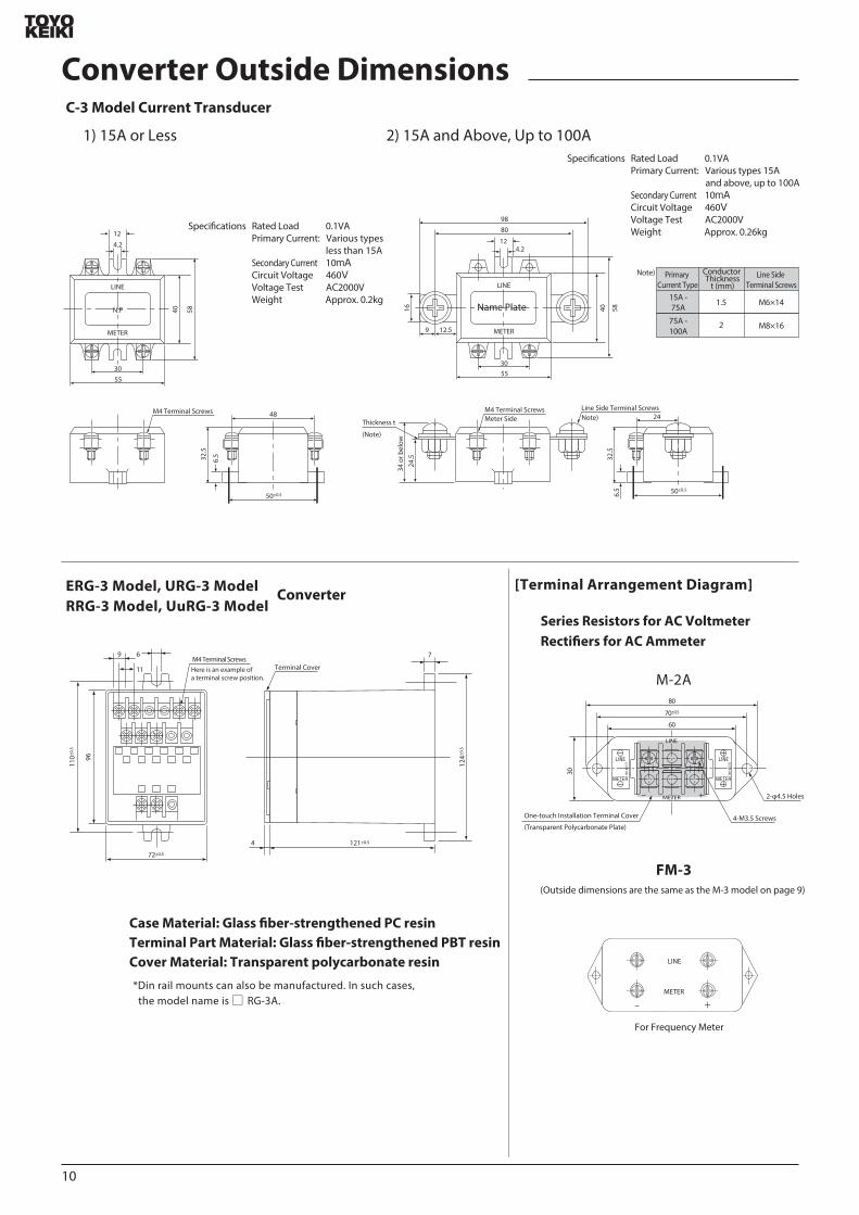
C-3 Model Current Transducer
ERG-3 Model URG-3 ModelRRG-3 Model UuRG-3 Model
40 58
30
48
42
12
55
6532
5
M4 Terminal Screws
LINE
METER
NP 40 581624
534
or b
elow
30
1259
4212
55
8098
LINE
METER
50plusmn05
24
65
325
Line Side Terminal ScrewsM4 Terminal Screws
Thickness t
(Note)
50plusmn05
Meter Side
1) 15A or Less 2) 15A and Above Up to 100ASpecications Rated Load 01VA
Primary Current Various types 15A and above up to 100ASecondary Current 10mACircuit Voltage 460VVoltage Test AC2000VWeight Approx 026kgSpecications Rated Load 01VA
Primary Current Various types less than 15ASecondary Current 10mACircuit Voltage 460VVoltage Test AC2000VWeight Approx 02kg
Primary Current Type
15A -75A
15
75A -100A
Conductor Thickness
t (mm)Line Side
Terminal Screws
M6times14
M8times16
Note)
Note)
Converter Outside Dimensions
Converter
Case Material Glass ber-strengthened PC resin Terminal Part Material Glass ber-strengthened PBT resin Cover Material Transparent polycarbonate resin
Din rail mounts can also be manufactured In such cases the model name is RG-3A
[Terminal Arrangement Diagram]
M-2A
FM-3
Series Resistors for AC VoltmeterRectiers for AC Ammeter
(Outside dimensions are the same as the M-3 model on page 9)
10
70plusmn05
30
60
80
2-φ45 Holes
4-M35 ScrewsOne-touch Installation Terminal Cover
(Transparent Polycarbonate Plate)
METER
LINE
LINE電 源METERメータ
For Frequency Meter
LINE
METER
minus +
121plusmn05
72plusmn05
124plusmn
05
96
110plusmn
05
4
7
Terminal CoverM4 Terminal ScrewsHere is an example of a terminal screw position
69
11
Name Plate
2
Meter Connection Diagram
Converter
LINE
METER
①
②
a c b
a c b
AC V
Generator
Generator
Frequency Meter
ConverterVT
LINE
METER
①
②
a c b
a c b
AC V
Frequency Meter (With VT)
a c b
a c b
AC V
Electric Tachometer
M-2A Series Resistor
LINE
METER
+
-
a c b
a c b
AC V
Electric Tachometer (With Series Resistor)
TG
TG
M-2A Series Resistor
LINE
METER
a c b
a c b
AC V
Voltmeter (With Series Resistor)
a c b
a c b
AC V
Voltmeter (Direct Measurement)
a c b
a c b
AC V
Voltmeter (With VT)
M-2A Series Resistor
VT VT
LINE
METER
+
-
+
-
a c b
a c b
AC V
Voltmeter (With VT Series Resistor)
C-3 Current Transducer
LINE
METER
a c b
a c b
AC V
Ammeter (With Current Transducer)
M-2A Rectier Box
LINE
METER
a c b
a c b
AC V
Ammeter (With Rectier Box)
a c b
a c b
AC V
Ammeter (Direct Measurement)
C-3 Current Transducer
CT
LINE
METER
a c b
a c b
AC V
Ammeter (With CT Current Transducer)
Rectier Box
CT
LINE
METER
Current TransducerC-3 M-2A
LINE
METER
a c b
a c b
AC V
Ammeter (With Current Transducer Rectier Box)
+
a c b
a c b
AC V
Ammeter (With Shunt)
a c b
a c b
AC V
H Side Load Relay Contact
L Side LoadRelay Contact
H Side Load Relay Contact
L Side LoadRelay Contact
H Side Load Relay Contact
L Side LoadRelay Contact
H Side Load Relay Contact
L Side LoadRelay Contact
H Side Load Relay Contact
L Side LoadRelay Contact
H Side Load Relay Contact
L Side LoadRelay Contact
H Side Load Relay Contact
L Side LoadRelay Contact
H Side Load Relay Contact
L Side LoadRelay Contact
H Side Load Relay Contact
L Side LoadRelay Contact
H Side Load Relay Contact
L Side LoadRelay Contact
H Side Load Relay Contact
L Side LoadRelay Contact
H Side Load Relay Contact
L Side LoadRelay Contact
H Side Load Relay Contact
L Side LoadRelay Contact
H Side Load Relay Contact
L Side LoadRelay Contact
H Side Load Relay Contact
L Side LoadRelay Contact
H Side Load Relay Contact
L Side LoadRelay Contact
H Side Load Relay Contact
L Side LoadRelay Contact
Power Supply Power Supply Power Supply
Shunt
Load Load Load
Power Supply
Load
Power Supply
Load
Power Supply
Load
Power Supply
Load
Power Supply
Load
Power Supply
Load
Power Supply
Load
Power Supply
Load
Power Supply
Load
Power Supply
Load
Power Supply
Load
Power Supply
Load
Power Supply
Load
Power Supply
Load
Ammeter (Direct Measurement)
Series Resistor
a c b
a c b
AC V
Voltmeter (With Voltage Division Type Series Resistor)
M-2A Shunt Box
LINE
METER
+
-
+
-
a c b
a c b
AC V
Ammeter (With Shunt Box)
H M
E
M-1 M-2A Series Resistor
a c b
a c b
AC V
Voltmeter (With Series Resistor)
a c b
a c b
AC V
Voltmeter (Direct Measurement)
Voltage division type series resistor should be used when the maximum scale value is 750V or higher
Note 1 The terminal diagram below is for MPC-10 and 12 For the terminal arrangements of other models see the outside dimensions page for those models
Note 2 The example auxiliary power supply connection is for AC See the example connection on the next page for DC auxiliary power supplies
Note 3 Accessories (P-3) are required for the MPC-6 even if the auxiliary power supply is AC See the the example connection on the next page for information on connections( )
DC Ammeter and DC Voltmeter (Moving-coil Type)
AC Ammeter or Voltmeter (Rectier Type)
Dierential Analyzer Frequency Meter Electric Tachometer (Rectier)
H Side Load Relay Contact
L Side LoadRelay Contact
H Side Load Relay Contact
L Side LoadRelay Contact
1 2 3 4 5
9 10 6 7 8
1 2 3 4 5
9 10 6 7 8
1 2 3 4 5
9 10 6 7 8
1 2 3 4 5
9 10 6 7 8
1 2 3 4 5
9 10 6 7 8
1 2 3 4 5
9 10 6 7 8
1 2 3 4 5
9 10 6 7 8
1 2 3 4 5
9 10 6 7 8
1 2 3 4 5
9 10 6 7 8
1 2 3 4 5
9 10 6 7 8
1 2 3 4 5
9 10 6 7 8
1 2 3 4 5
9 10 6 7 8
1 2 3 4 5
9 10 6 7 8
1 2 3 4 5
9 10 6 7 8
FM-3
FM-3
1 2 3 4 5
9 10 6 7 8
1 2 3 4 5
9 10 6 7 8
1 2 3 4 5
9 10 6 7 8
1 2 3 4 5
9 10 6 7 8
1 2 3 4 5
9 10 6 7 8
11
P-3
INP
UT
OU
T PU
T
a
c
a
c
Meter InputAC CurrentAC〇〇V
M-4A or M-4B
INP
UT
OU
T PU
T
a
c
b
a c b
a c b
a
c
b
Load TerminalH Side
Load TerminalH Side
Meter Input
Load TerminalL Side
DC CurrentDC〇〇V
Note M-4A (M-4B) not required when the auxiliary power supply is DC24V or DC12V
Note P-3 not required when the auxiliary power supply is AC24V or AC12V
1 2 3 N
DAOLECRUOS CT1CT2
CT3
Auxiliary Power Supply
VT1
VT2
VT3
3P4W Wattmeter Varmeter (With CT)
a c b
a c b
1 2 3 N
DAOLECRUOS CT1CT2
CT3
Auxiliary Power Supply
3P4W Wattmeter Varmeter (With CT VT)
VT1 VT2
a c b
a c b
1 2 3
DAOLECRUOS CT1
CT2
Auxiliary Power Supply
3P Wattmeter Varmeter (With CT VT)
VT1 VT2
a c b
a c b
1 N 2
DAOLECRUOS CT1
CT2
Auxiliary Power Supply
1P3W Wattmeter Varmeter (With CT VT)
VT
a c b
a c b
1 2
SOURCE LOADCT
Auxiliary Power Supply
1P Wattmeter Varmeter (With CT VT)
a c b
a c b
1 2 3
DAOLECRUOS CT1
CT2
Auxiliary Power Supply
3P Wattmeter Varmeter (With CT)
a c b
a c b
1 2
DAOLECRUOS CT
Auxiliary Power Supply
1P Wattmeter Varmeter (With CT)
a c b
a c b
1 N 2
SOURCE LOADCT1
CT2
Auxiliary Power Supply
1P3W Wattmeter Varmeter (With CT)
a c b
a c b
1 2 3 N
SOURCE LOADCT1CT2
CT3
Auxiliary Power Supply
VT
3P4W Power Factor Meter (With CT)
a c b
a c b
1 2 3 N
DAOLECRUOS CT1CT2
CT3
Auxiliary Power Supply
3P4W Power Factor Meter (With CT VT)
VT1 VT2
a c b
a c b
1 2 3
DAOLECRUOS CT1
CT2
Auxiliary Power Supply
3P Unbalanced Power Factor Meter (With CT VT)
VT
5
a c b
a c b
1 2 3
DAOLECRUOS CT
Auxiliary Power Supply
3P Balanced Power Rate Meter (With CT VT)
VT
a c b
a c b
1 2
SOURCE LOADCT
Auxiliary Power Supply
1P Power Factor Meter (With CT VT)
a c b
a c b
1 2 3
DAOLECRUOS CT1
CT2
Auxiliary Power Supply
3P Unbalanced Power Factor Meter (With CT)
a c b
a c b
1 2
DAOLECRUOS CT
Auxiliary Power Supply
1P Power Factor Meter (With CT)
a c b
a c b
1 2 3
SOURCE LOADCT1
Auxiliary Power Supply
3P Balanced Power Rate Meter (With CT)
MPC-6 ModelFor AC Auxiliary Power Supply
MPC-8 MPC-10 MPC-12 ModelFor DC Auxiliary Power Supply
Wattmeter and Varmeter (Electronic Device Type)
Power Factor Meter (Electronic Device Type)
Overall Connection Diagram (Example)
H Side Load Relay Contact
L Side LoadRelay Contact
H Side Load Relay Contact
L Side LoadRelay Contact
H Side Load Relay Contact
L Side LoadRelay Contact
H Side Load Relay Contact
L Side LoadRelay Contact
H Side Load Relay Contact
L Side LoadRelay Contact
H Side Load Relay Contact
L Side LoadRelay Contact
H Side Load Relay Contact
L Side LoadRelay Contact
H Side Load Relay Contact
L Side LoadRelay Contact
H Side Load Relay Contact
L Side LoadRelay Contact
H Side Load Relay Contact
L Side LoadRelay Contact
H Side Load Relay Contact
L Side LoadRelay Contact
H Side Load Relay Contact
L Side LoadRelay Contact
H Side Load Relay Contact
L Side LoadRelay Contact
H Side Load Relay Contact
L Side LoadRelay Contact
H Side Load Relay Contact
L Side LoadRelay Contact
H Side Load Relay Contact
L Side LoadRelay Contact
Load TerminalL Side
1 2 3 4 5
9 10 6 7 8
1 2 3 4 5
9 10 6 7 8
1 2 3 4 5
9 10 6 7 8
1 2 3 4 5
9 10 6 7 8
1 2 3 4 5
9 10 6 7 8
1 2 3 4 5
9 10 6 7 8
1 2 3 4 5
9 10 6 7 8
1 2 3 4 5
9 10 6 7 8
1 2 3 4 5
9 10 6 7 8
1 2 3 4 5
9 10 6 7 8
1 2 3 4 5
9 10 6 7 8
1 2 3 4
9 10 6 7 8
1 2 3 4 5
9 10 6 7 8
1 2 3 4 5
9 10 6 7 8
1 2 3 4 5
9 10 6 7 8
1 2 3 4 5
9 10 6 7 8
1 2 3 4 5
9 10 6 7 8
1 2 3 4
9 10 6 7
910
910
12
Intrinsic Power Value
CT Ratio
5A5A
75A5A
10A5A
15A5A
20A5A
30A5A
40A5A
50A5A
75A5A
100A5A
150A5A
200A5A
300A5A
400A5A
500A5A
750A5A
1000A5A
1500A5A
2000A5A
3000A5A
VT Ratio625Or
667W
Line Voltage
mdash
1 kW
12 kW
2 kW
25 kW
4 kW
5 kW
mdash
10 kW
12 kW
20 kW
25 kW
40 kW
50 kW
mdash
100 kW
120 kW
200 kW
250 kW
400 kW
750 W
12 kW
15 kW
25 kW
3 kW
5 kW
6 kW
75 kW
12 kW
15 kW
25 kW
30 kW
50 kW
60 kW
75 kW
120 kW
150 kW
250 kW
300 kW
500 kW
1 kW
15 kW
2 kW
3 kW
4 kW
6 kW
8 KW
10 kW
15 kW
20 kW
30 kW
40 kW
60 kW
80 kW
100 kW
150 kW
200 kW
300 kW
400 kW
600 kW
12 kW
2 kW
25 kW
4 kW
5 kW
8 kW
10 kW
12 kW
20 kW
25 kW
40 kW
50 kW
80 kW
100 kW
120 kW
200 kW
250 kW
400 kW
500 kW
800 kW
15 kW
25 kW
3 kW
5 kW
6 kW
10 kW
12 kW
15 kW
25 kW
30 kW
50 kW
60 kW
100 kW
120 kW
150 kW
250 kW
300 kW
500 kW
600 kW
1 MW
2 kW
3 kW
4 kW
6 kW
8 KW
12 kW
(16 kW)
20 kW
30 kW
40 kW
60 kW
80 kW
120 kW
(160 kW)
200 kW
300 kW
400 kW
600 kW
800 kW
12 MW
25 kW
4 kW
5 kW
8 kW
10 kW
15 kW
20 kW
25 kW
40 kW
50 kW
80 kW
100 kW
150 kW
200 kW
250 kW
400 kW
500 kW
800 kW
1 MW
15 MW
3 kW
5 kW
6 kW
10 kW
12 kW
20 kW
(24 kW)
30 kW
50 kW
60 kW
100 kW
120 kW
200 kW
(240 kW)
300 kW
500 kW
600 kW
1 MW
12 MW
2 MW
4 kW
6 kW
8 KW
12 kW
(16 kW)
(24 kW)
(32 kW)
40 kW
60 kW
80 kW
120 kW
(160 kW)
(240 kW)
(320 kW)
400 kW
600 kW
800 kW
12 MW
(16 MW)
(24 MW)
20 kW
30 kW
40 kW
60 kW
80 kW
120 kW
(160 kW)
200 kW
300 kW
400 kW
600 kW
800 kW
12 MW
(16 MW)
2 MW
3 MW
4 MW
6 MW
8 MW
12 MW
25 kW
40 kW
50 kW
75 kW
100 kW
150 kW
200 kW
250 kW
400 kW
500 kW
750 kW
1 MW
15 MW
2 MW
25 MW
4 MW
5 MW
75 MW
10 MW
15 MW
30 kW
50 kW
60 kW
100 kW
120 kW
200 kW
(240 kW)
300 kW
500 kW
600 kW
1 MW
12 MW
2 MW
(24 MW)
3 MW
5 MW
6 MW
10 MW
12 MW
20 MW
40 kW
60 kW
80 kW
120 kW
150 kW
(240 kW)
300 kW
400 kW
600 kW
800 kW
12 MW
15 MW
(24 MW)
3 MW
4 MW
6 MW
8 MW
12 MW
15 MW
(24 MW)
50 kW
75 kW
100 kW
150 kW
200 kW
300 kW
400 kW
500 kW
750 kW
1 MW
15 MW
2 MW
3 MW
4 MW
5 MW
75 MW
10 MW
15 MW
20 MW
30 MW
60 kW
100 kW
120 kW
200 kW
(240 kW)
400 kW
(480 kW)
600 kW
1 MW
12 MW
2 MW
(24 MW)
4 MW
(48 MW)
6 MW
10 MW
12 MW
20 MW
(24 MW)
40 MW
MultiplierMeter Types
3P Wattmeters 3P4W Wattmeters 1P3W Wattmeters
1P Wattmeters 3P varmeters and 3P4W varmeters
1P Varmeter
1
12 (1 for varmeters with zero left meters)
14 (12 for zero left meters)
This standards chart is a resource for determining the measurement range values of wattmeters and varmeters so 3P wattmeter CT 〇〇〇A5A standards are indicated
Example VT 3300V110V CT 60A5A 3P Wattmeter
Measurement Range = (667W 833W 1kW or 111kW) x 3300 110 x 60 5 = 240kW 300kW 360kW or 400kW
Note) Numerical values inside parentheses indicate values that deviate from JIS standards but can be manufactured
Standard Table of Wattmeter Measurement Range
[1] For 3P wattmeters 3P4W wattmeters and 1P3W wattmeters the measurement range values are displayed in the voltage ratios (VT ratio dierences) and CT ratio dierences in the table above (There are three types dened for the same VT and CT ratios Choose the appropriate type However an item marked with in the intrinsic power eld needs to be selected for the wide angle meter) Eg) For a VT 3300V110V CT 100A5A 3P wattmeter select the appropriate one from 400kW 500kW or 600kW from the table above
[2] For 1P wattmeters 3P varmeters and 3P4W varmeters the values displayed above are multiplied by 12 and are multiplied by 14 for 1P varmeters
Note 1) For varmeters read kW units as kvarScale is LEAD ~0~LAG kvarExample For a VT 3300V110V CT 100A5A 3P varmeter hellipLEAD2500~LAG250 kvar or LEAD300~0~LAG300 kvar
(500 times 12) (500 times 12) (600 times 12) (600 times 12)
2) For 3P varmeters or 3P4W varmeters with zero left meters follow the values as displayed above and for 1P varmeters with zero left meters the values in the table above are multiplied by 12
[3] If the CT ratio exceeds the range listed above (for example VT 3300V110V CT 5000A5A 3P wattmeter) select a value from the CT 500A5A row (2MW 25MW 3MW) and multiply it by 10
Note) In the situation above scale indicators are 20MW 25MW and 30MW (It is preferable that the highest 3 digits of scales are displayed)
[4] If CT ratios do not correspond with those indicated above (for example CT 60A5A) use the calculation chart below to acquire the measurement range then choose from among them the value with the best ending number
Measurement Range = Intrinsic Power times VT Ratio times CT RatioNote) Select a value indicated below from the intrinsic power value in the above calculation chart However intrinsic power values vary depending on meter type Use the multiplier indicated below to calculate the value
Using the Above Chart
[5] Values of 1 12 15 2 25 3 4 5 6 75 or 8 or integers that are multiples of those 10 values are preferable selections for the upper range scale value (JIS standards)
110V 220V 440V 3300V 6600V
440V110V 3300V110V 6600V110V750Or
833W
125Or
133kW
15Or
167kW
625Or
667W
750Or
833W
1kWOr
111kW
1kWOr
111kW1kW 2kW 1kW 833W 833W667W
625Or
667W
13
MultiplierMeter Types
3P Wattmeters 3P4W Wattmeters 1P3W Wattmeters
1P Wattmeters 3P varmeters and 3P4W varmeters
1P Varmeter
15
110 (15 for varmeters with zero left meters)
120 (110 for zero left meters)
Product Name
1P Wattmeter 1P Varmeter
3P Wattmeter 3P Varmeters 110V 5A220V 5A
110V 5A 300 ~ 625W (var)600 ~ 1250W (var)
500 ~ 1250W (var)1000 ~ 2500W (var)
500 ~ 1250W (var)1000 ~ 2500W (var)
220V 5A
1P3W Wattmeter
3P4W Wattmeter3P4W Varmeter
Rating
110Vradic3V 5A220Vradic3V 5A
Production Range
Example VT 440V110V CT 60A1A 1P Wattmeter
Measurement range = [(625W 667W 750W 833W or 1kW) x 110] x 440 110 x 60 1 = 15kW 16kW 18kW 20kW or 24kW However 15kW or 20kW should be selected
Example VT 6600V110V CT 50A5AWhen measurement range value = 400kW
Note) The meter production range for using a CT of 1A for the secondary current is the value indicated on the left multiplied by 15
[6] Even when using a CT of 1A for the secondary current the measurement range value is as indicated on the left (selection standards chart) Note) If CT ratios do not correspond (for example CT 60A1A) with those indicated to the left (selection standards chart) follow calculation chart [4] below to calculate the measurement range value However intrinsic power values vary depending on meter type Use the multiplier indicated below to calculate
The production range of wattmeters and varmeters can be manufactured according to the indicated range of intrinsic power values in the calculation chart below
Intrinsic Power Value [W]=Measurement Range Value [W]
VT Ratio x CT RatioIntrinsic Power Value W= =667W 400kW
60times10
Production Limits of Meters (Wattmeter Varmeter)
14
15
NoteMeter Relay MPV-11
110times110 120times110
MPC-12
Outside (mm)
Scale Length (mm)
Accuracy Class
Pointer
Set Pointer
Scale Plate
Scale Division
Mounting Posture
Cover
Base
Cover Coating Color
Setting
Operating Error for Setting Value (Against Scale Length)
Dead Band
Output Contact Arrangement and Capacity
Insulation Test
Voltage Test
Characteristics of Meter
Meter Action
Auxiliary Power Supply
Output Signal
Note 1)
Note 2)
Stop Type
Passage Type
A C
Retaining Type
Instantaneous Type
Approx 170
Tapered Type
Triangular with Red H
White Base
Vertical
Methacrylic Resin
15
10
〇
〇
1ab AC220V 3A
Approx 100
Wand Type
Wand Type with Red H
Special Anti-electric Resin
15
10
〇
〇
1ab AC100V 1A
Between Terminals - Phenol Resin Body Cover - ABS resin
N - 15 (black) or 75B G415 (blue-green)
H Setting (Single Side Only)
AC110V AC115V AC220V
Between electrical circuit and outer casing of meter 10MΩ or more for 500V mega
Between electrical circuit and outer casing of meter AC 1500V (5060Hz per minute)Between contact relay circuit and other electrical circuits AC 500V (5060Hz per minute)
Characteristics of the meter part are based on JIS C 1102-1 to 9
plusmn10
plusmn5Intrinsic Error Indicated value
Between 005~1MΩ
Extra Power Unit RG-3 Meter Sensitivity
DC250μA
Earth-resistance Meter Relay MPV-11 MPC-12
This meter relay can measure the earth resistance value of a contactless AC circuit while also detecting abnormal earth resistance values in the same circuit Comprising a contactless meter relay and extra power unit this meter relay can be used for a wide range of purposes such as detecting abnormalities in grounding accidents in settings such as boatsA particularly useful feature is the xed voltage circuit built into the extra power unit which maintains a roughly xed voltage circuit even during uctuations of plusmn10 in the input voltage of AC115V preventing measurement error
[Overview]
[Features]
[Standard Specications]
[Operating Principles]
Earth resistance measurements can be taken continuously while also setting and detecting the desired earth resistance values on the scale of the photoelectric-type detection setting mechanism as well as activating warning equipment using the relay circuit contact
Lines can be measured and detected while live
Note 1) Meter Action Passage Type - The pointer can pass to the end of the scale even if it exceeds the setting value
Note 2) Output Retaining Type - Output is retained even when the pointer passes the setting value The output is discarded when the pointer goes back below the setting valueNote 3) Others a) DC circuit type can also be manufactured if desired
b) See the page about our contactless meter relay for detailsc) In particular a standard meter type can be manufactured if the detection equipment is not requiredd) Also includes a converter Type I S-3 For 3P Type I S-1 For 1P
Apply an AC power supply to the extra power unit to generate DC50V on the output side This DC power supply can be used to combine the unit with a DC ammeter with an MΩ scale making it possible to take measurements and read earth resistance for circuit currents that change depending on the ground statusThe AC side and output side of the extra unit are insulated by a transformer This means that the DC power supply can be considered separate from the lines creating the basic circuit shown on the leftIn the circuit diagram on the left DC50V is being generated by the power unit the power is connected to the meter in a series where Rs = 02 MΩ (scale centering on meter) and a resistance value is being indicatedWhen switch S is turned on the pointer of the meter moves to the maximum indicating 0MΩ in this caseThis means that the maximum current sensitivity value of the inow current is i = =250μA
If a grounding accident occurs and the earth resistance is 02 MΩ (Re = 02 MΩ) the inow current
i1 = = = 125μA and the center scale point of 02 MΩ is indicated
The relationship between the earth resistance value and the current i is as shown below
Lines
Resistance Meter
[Power Unit]
AC 115V
Rs
Re
Re Earth Resistance
S Switch
Rs Standard Resistance
S
e=50v
Circuit Conguration Diagram
02MΩ +02MΩ Rs+Re50V
02MΩ 50V
50V
Measurement point A can be measured from LINE R S or T Auxiliary Power Supply 110V System (9) (10) 220V System (9) (11)
AC100V
AC115V
DC50VB
3
3
2
2
1
1
10 119
4
4 5VT
Zero Ohms Adjustment Volume
R
S
T
LINE LOAD
440V
A
Load Contact
MPV-11
a c d
Power Unit (RG-3)
[Connection Diagram]
[Extra Power Unit]
[How to Use]
[Scale Drawing]
[Outside Dimensions]
MPV-11
MPC-12
RG-3
110plusmn1
5
110plusmn15
45plusmn0545plusmn05
4-φ7
φ102
1 2 3 4 5109 11 6 7 8
M3 Terminal Screws
Terminal Cover
Terminal Cover33 or below
8
130
4M-6 Mounting Screws
05
24
145
115
φ10
0
φ10
2Panel Cutout
Black Shading Hood
45plusmn0545plusmn05
45plusmn0
545
plusmn05
45plusmn0
545
plusmn05
5
35plusmn0
545
plusmn0545
plusmn05
35plusmn0
5
50plusmn05 50plusmn0550plusmn05
120plusmn1
50plusmn05
4-φ5 Holes10-M3Terminal Screws Variable Resistor for Sensitivity SettingsNote 1
20
12 105100
4-M4 Mounting Screws
05
255
10
φ64
Panel Cutout
φ87plusmn1
100plusmn1
φ85
+05minus0
1
2
3
4
5
9
10
6
7
8
121plusmn0572plusmn05
4
769
11
110plusmn
05
96 124plusmn
05
Terminal Cover4-M4 Terminal Screws
ZERO
NPZero OhmsAdjuster
MΩ
MΩ0
1
125infin
234
5
0
1125infin
2345
Resistance value between LINE R S or T and earth is measured between A and BIn the diagram on the left the measurement is taken from
phases S and T but any phase can be usedThe diagram on the left shows an example connection
between MPV and 11 but the same result will be obtained between MPC and 12 (vertical terminal array)The zero ohms adjustment volume is a backup device
embedded in the center of the power unit Insulate auxiliary power supply terminals (9) and (10) before checking the zero ohms adjustment(To stop the output signal of the relay circuit)
[Specied Items when Ordering]
0-5 MΩ (Center Point 02 MΩ) 0-5 MΩ (Center Point 02 MΩ)
Contact Arrangement345
MPVminus11 MPCminus12
Model Name MPV-11 or MPC-12Scale 0-5 MΩ (Center point 02 MΩ)Auxiliary Power Supply AC 110V etcAttached Panel Fe or NFe (Specify MPC-12 model only)Mounting Posture etcCover Coating Color N-15 (black) or 75 BG 415 (blue-green)Other Non-standard specications
Note)
16
Sminus62 minusminusA AC InputD DC InputH H Setting Value L L Setting Value 1 DC Power Supply (DC24V) 2 AC Power Supply AC100110V AC200220VInput
0 60mV1 100mV2 0~1V3 0~5V4 1~5V5 4~20mA6 1A7 5A8 150V9 Others
0 No Delay1 Power Supply Delay2 Signal Delay1 Socket Attachment2 Panel Mounting
( (
DC
AC
VHCOMCL
678
4
5
Power Supply
U6
Input
U1 U2U4 U5
U3
123
U1Input Amplier
U2Rectier Circuit
U3Setting Circuit
U4Comparator Circuit
U5Delay Circuit
U6Power Supply Circuit
VHCOMCL
678
4
5
Power Supply
U5
Input
U1U3 U4
U2
123
U1Input Amplier
U2Setting Circuit
U3Comparator Circuit
U4Delay Circuit
U5Power Supply Circuit
[Operating Principles]
AS-62 (AC Input)
Block Diagram
[Overview of Operation]
DS-62 (DC Input)
Block Diagram
Stationary Non-indicating Regulator AS-62DS-62
This product is a non-indicating adjustment meter with no meter drive unit The AS-62 uses AC input while the DS-62 uses DC input The auxiliary power supply can be used for AC 100110V and AC 200220V This product can also be manufactured with a DC24V power supply The ono status of the relay is shown by a red LED on the front and the setting scale also has an extremely easy-to-see structure Two attachment methods can be used by connector or by panel mounting Panel mounting is done by connecting the lines using the terminal block on the back (M4 screws) Compact design with front panel measuring 625x625
[Overview]
ltSolid State Relaygt
After amplifying the input signal with the input amplier (U1) the entire wave is rectied and attened with the rectier circuit (U2) and then input on the signal side with the comparator circuit (U4)Meanwhile the voltage set by the dial is input on the setting side with the setting circuit (U3) The output from (U4) is a VH or VL value depending on this input This signal is input into a relay drive transistor to turn the relay on and o Here the delay circuit (U5) delays the signal from U4 for around 1 second in the event of a signal delay The circuit constant diers depending on the specications In the event of a power supply delay the relay does not operate for around 7 seconds after the power supply is turned on even when the U4 output voltage is VH This circuit responds to the average input value not DC components
[Overview of Operation]
[Specications]
After amplifying the input signal with the input amplier (U1) the signal is input on the signal side with the comparator circuit (U3) Meanwhile the voltage set by the dial is created by the setting circuit (U2) and input on the setting side of the comparator circuit (U3) The output from (U4) is VH or VL depending on the relationship between the signal and the setting value This signal is input into a relay drive transistor to turn the relay on and o The delay circuit (U5) creates signals for power supply delays (approximately 7 seconds) and signal delays (approximately 1 second) according to the specications
Model Name
17
51 or below24 or below
354
118
or b
elow
81 o
r bel
ow
40plusmn024
78
4
5
8-M35x7 Sems Screws
2-φ45 Holes
4
0
2040
POWER RELAY
SOLIDSTATE CONTROLLER
625
625
10 95126 plusmn7
56
56
8-M4 ScrewsEmbedded in Panel
Attached to Wall
Socket Attachment
Use OMRON 8PFA
40plusmn2
2-φ45 Holesor M4 Tapping
565+
05
-0
565 +05 -0
1
2
3
4 5
6
7
8
Input
ab
cAC100110V
AC200220V
AC Auxiliary Power Supply 1
2
3
4 5
6
7
8
Input
ab
cDC24V
DC Auxiliary Power Supply
+
+
-
Panel Cutout
[Performance]Input Impedance
60mV 100mV1V 5V 1~5V4~20mA5A1A150VThe following standards apply to products with other input specications60mV or More Up to 100mV101mV or More Up to 300VAmmeter Input Resistance value generating a
200mV voltage dropPickup Error plusmn 15Delay
Response Speed
Dead Band
Temperature Coecient
Load Relay Contact Capacity 1 ab AC 250V 3A (resistance load)DC 30V 3A (resistance load)
Power Consumption
Operating Temperature LimitsStorage Temperature RangeMaximum Relative HumidityInput Overload Capacity
60mV 100mV1V5V 1~5V4~20mA1A5A150V
Insulation Test (500V test with mega)Electrical circuit - outer casing input - auxiliary power supply input - relay output20 MΩ or more between each phase
Voltage TestElectrical circuit - outer casing input - auxiliary power supply input - relay output
2000V per minute between each phase
Outer Casing Material Polycarbonate resin phenol resinWeight Approx 400g
10kΩ1MΩ10Ω6mΩ30mΩ1MΩ
10V50V250V100mA10A50A500V
10kΩ1MΩ
Signal DelayPower Supply DelayA S-62D S-62
Approx 1 secondApprox 7 secondsApprox 02 secondsApprox 01 seconds
Around 2
plusmn0510˚C
Approx 3VA (AC power supply) 25W (DC power supply)
0˚C~50˚C-10˚C~60˚C
[How to Use]
Precautions when Handling and Ordering the S-62
[Outside Dimensions and Pin Connection Diagram]
[8PFA Socket Outside Dimensions]
Over 5A Less than 50A
Over 50A Less than 300A
Over 300A Less than 5000A
S-10A Model 60mV
S-8A Model 60mV
S-8 Model 60mV
Over 300V up to 500V
Over 501V up to 750V
Over 751V up to 1500V
Over 1501V up to 30000V
Over 3001V up to 5000V
M - 2 A
M - 2 B
M - 3
M - 4 A
M - 6
This product can be used by panel mounting or socket attachment (specify which when ordering)An attachment bracket and mounting screws are included when panel mount is specied Do not attach with items other than the included screws
1 A frequency range from 40 to 500Hz can be used by the AS-62 Frequencies outside this range are a special specication and prior consultation is needed
2 To control DC currents larger than 5A use a shunt to convert the voltage (to around 60mV) and then receive and control with the 60mV input type DS-62 Model names of shunts are as follows
To control high DC voltages add an external series resistor Model names of series resistors are indicated in the table below
85
100
6080
18
Non-indicating Voltage Relay DS-5A (for DC Voltage)
[Features]
[Specications]
[Outside Dimensions]
[Attachment Diagram]
[Series Resistor Calculation Method for General-Purpose Detector Side and Operation Side]
Driver adjust type enables easy and accurate conguration of voltage settings
Safe operation even for voltages containing ripples 3 dierent attachment methods
Front attachment (attachment to terminal block or rear connection socket on 8P) Rear attachment
[Purposes]Voltage detection in DC power suppliesVoltage detection in rectied power
suppliesAutomatic control
(3) Detection Error
(4) Set Method(5) Contact Capacity(6) Contact Arrangement(7) Relay Contact Output
(1) Detection Method(2) Detected Voltage Rating
Voltage comparison-based voltage detection
Within plusmn15 of upper limit setting maximum voltage value (within plusmn25 for DS-5A-U12)
VR variance by driver adjustmentDC 30V1A (resistance load) AC 100V1AL side 1b H side 1a
Series ResistorModel
Inside Dimensions
Externally connected for operation
Note
DS-5A-24A
DS-5A-48A
DS-5A-100A
DS-5A-U12
DS-5A-U24A
DS-5A-U48A
20~24V
40~48V
80~95V
10~14V
20~28V
40~56V
24~28V
48~56V
105~120V
10~14V
20~28V
40~56V
02
04
11
01
02
05
15
15
50
20
15
15
Setting Range for Detected Voltage
L
Power Consumption (W)
Detection Side Operation Side
Note)
Within plusmn15 of upper limit setting maximum voltage (within plusmn20 for DS-5A-U12)
200mS or less when 97 to 110 of set voltage is applied
20 times per 60 seconds 10 minute stop(When upper limit setting maximum voltage value is 100)
Continuous overvoltage of 120 possible with all models)150 possible for 3 minutes on all models 200 not possible on any models
Insulation Test Between Electrical Circuit and Case DC500V mega 10MΩ or higher
Between Electrical Circuit and Relay Contact DC500V mega 5MΩ or higher
Voltage Test Between Electrical Circuit and Case AC 2000V (5060Hz per minute)
Between Electrical Circuit and Relay Contact AC500V (5060Hz per minute)
ON
ON
OFF
OFF
LH Setting Value
L Side Relay Contact Output
H Side Relay Contact Output
(8) Retained Range
(9) Reaction Time
(10) Operation Frequency(11) Overvoltage Strength
Within 20 P-P-10˚C~50˚C
(12) Detection Input Ripples(13) Operating Temperature Limits
(14) Pin Layout Diagram
L
v v
50plusmn05
60plusmn0
5
44 +0 -05
54+
0 -
05
80 70
35
7652
7
82785
8P Octal Base
[Series Resistor for Operation of the DS-5A-100A R Outside Dimensions]
454
4
64plusmn15
73plusmn15
06
φ 25
43
13plusmn02
φ 15
31
14
Voltage Resistance AC2000VWeight 25g
Attachment Screws
Claw to Prevent Falling O
OMRON8PF Terminal Block Type(see P18)
74
φ30 or higher
2-φ35 Holesor M3 Tapping
Panel Cutout Diagram
If attached directly
123
467
8
H Side Relay Contact Output 1a
L Side RelayContact Output 1b
R
RHRL
Auxiliary Power Supply (-)
L Side Detection Input (-) H Side Detection Input (-)
123
467
8
H Side Relay Contact Output 1a L Side Relay Contact Output 1b
R Auxiliary Power Supply (-)
Detected Voltage Input (-)
COM (+)
[Overview]
Weight 140g
(1) Pin Layout DiagramDS-5A-U (A)
DS-5A-A
R Series Resistor for Operation (Externally Connected)
RL Series Resistor for Operation on L Side (Externally Connected)
RH Series Resistor for Operation on H Side (Externally Connected)
Included only with R DS-5A-100A
See the pin layout diagram on the right for the DS-5A-U model
Both the operation unit and the detection unit are externally attached if the setting range is exceeded
Scale of general purpose model is 0~100
Note 1 Power Consumption (operation at maximum voltage on maximum setting where L = OFF and H = ON)Note 2 DS-5A-U (A) indicates all-purpose model Be sure to connect a series resistor if the values in this table
will be exceeded (Calculation method for series resistors can be found on P20)
This non-indicating voltage relay detects the voltage of DC power supplies It can detect both H and L in detected voltage setting ranges enabling safe operating even with voltages that contain ripples such as those in rectied power supplies
H
5
H
5
COM (+)
19
COM
Input
E
R
Vz
R D
1
7
E R
I Rs
Auxiliary Power Supply VoltageSeries Resistor Externally Connected to Operational Power SupplyCurrentDS-5A-U Equivalent ResistanceDS-5A-U12 Model 0086 kΩDS-5A-U24A Model 04 kΩDS-5A-U48A Model 136 kΩ
22
21 23
20 24V
26
25 27
24 28V
44
42 46
40 48V
52
50 54
48 56V
40 60
20 80
0 100
40 60
20 80
0 100
85 90
80 95V
110 115
105 120V
Auxiliary Power Supply
Detection Input
(-) )-(
(+) )+(
8 72
RR
R DS-5A
DS-5ADS-5A
R Externally Connected Series Resistor
R Externally Connected Series Resistor
Auxiliary Power SupplyDetection Input
(-) )-(
(+) )+(
8 7R (Included Only with 100 Model)DS-5A
a DS-5A-24A48A100A
a DS-5A-24A48A100A
b DS-5A-U24AU48A
b DS-5A-U24AU48A
Auxiliary Power Supply
Detection Input
(-)(-)
(-)
(+) )+(
8 72
RR
R
Auxiliary Power SupplyDetection Input
(-) )-(
(+) )+(
8 7R (Included Only with 100 Model)
1) DS-5A-24A
2) DS-5A-48A
3) DS-5A-100A
4) DS-5A-U24A DS-5A-U48A
DS-5A-U (A)Non-indicating Voltage Relay
(2) Calculation Method for RH or RL Series Resistor for Detection Side (Externally Connected)
(3) Calculation Method for R Series Resistor for Operation Power Supply Side (Externally Connected)
(A) Reference CurrentThe reference current is indicated as a bond
(b) Calculation
(c) Example Calculation
Model Name Reference Current I0 (mA) Vu (V)
DS-5A-U12
DS-5A-U24A
DS-5A-U48A
175
286
333
12
24
48
Model NameSet Voltage Range
(V)Vo (V) Detection Side Multiplier
RH or RL Value
DS-5A-U12
DS-5A-U24A
DS-5A-U48A
NoteModel Name
DS-5A-U12
DS-5A-U24A
DS-5A-U48A
22~26
44~52
92~108
24
48
100
(24-12) [V] 175 [mA]
RH or RL =(Center Point Voltage of Setting (Vo) - Vu)
Reference Current (Io)
I min ≦ I = E-VzR+RD
=686 [kΩ]
(48-24) [V] 286 [mA] =839 [kΩ]
(100-48) [V] 333 [mA] =156 [kΩ]
Caution
Input Voltage (Voltage of Auxiliary Power Supply) Range E [V] and Resistance Value R of Multiplier on Auxiliary Power Supply Side [kΩ]
Emin ≦ E ≦ Emax
80mA ≦ I = ≦ 140mAE-6
R+0086
Emax Maximum voltage of auxiliary power supply Imax Maximum currentEmin Minimum voltage of auxiliary power supply Imin Minimum current
Select R within the range where the above inequality is achievedIf the inequality is not achieved for I rework the equation by methods such as raising the R value or narrowing the voltage range of the power supply
(Note) Settings can be congured in the desired position between 0 and 100 for both H and L
[Scale Drawing]
[Connection Circuit Diagram of the External Circuits]
(1) The detection input and auxiliary power supply input are COM and +
(2) If the detection input and the auxiliary power supply are the same connect the auxiliary power supply terminal (7) and the detection input (8) (8 and 2 for U shape) as shown in the diagram below
(3) If the detection input and the auxiliary power supply are separate connect them as shown in the diagram below
Precautions for External Connections
Do not connect with the polarities of the detection input and auxiliary power supply opposing each other
I
Use the equation below to calculate the current I in the input voltage range then decide on the value for the R series resistor to be connected to the operational power supply
The current I value is for cases in which both the H and L sides are excited by the load relay of the non-indicating voltage relay (L OFF H ON)
≦ I max
25mA ≦ I = ≦ 70mAE-12R+04
15mA ≦ I = ≦ 35mAE-24
R+136
VZ=6VRD=0086kΩ
VZ=12VRD=04kΩ
VZ=24VRD=136kΩ
20
50plusmn05
60plusmn0
5
44 +0 -05
54+
0 -
05
80 70
35
7652
7
82785
8P Octal Base
74
φ30 or higher
2-φ35 Holes (or M3 Tapping)
Panel Cutout Diagram
If attached directly
Note) Can also be attached to the front terminal block (See P19)
40 581624
534
or b
elow
30
1259
4212
55
8098
LINE
METER
24
65
325
Line Side Terminal ScrewsM4 Terminal ScrewsThickness (t)
(Note)
50plusmn05
Meter Side
Name Plate
Rated Load 01VAPrimary Current 25ASecondary Current 10mACircuit Voltage 460VVoltage Test AC2000VWeight Approx 02kg
Note)
123
4567
8
Load RelayContact 1a
Auxiliary Power Supply AC100V
Current TransducerC-3 Model
Power Indicator AS-5-LI (Residual CurrentLeakage Current Detector)
[Overview]
[Features]
[Specications]
[Operation Diagram] [Connection Diagram]
Highly reliable solid-state electronic parts
Lightweight compact type
(Main unit 100g current transducer 200g)
Plugs into 8-pin socket enabling easy security inspections and replacement
[Purposes]
[Outside Dimensions]
[Accessories]
[Example Use]
Detects small amounts of residual power and issues an alert
Detects electric leakage and issues an alert
Detector prevents power from being left switched on
Operating Error
Maximum Circuit Voltage
Maximum Circuit Current
Setting Value
Relay Contact Output
Auxiliary Power Supply Voltage
Accessory
Insulation Resistance(DC500V Mega)
Voltage Resistance(for 1 minute)
Pickup Within setting value plusmn 10Dropout 20 or less of pickup value(dead band is also 20 or less of pickup value)
Contact arrangement 1a
Contact capacity AC100V 03A (resistance load)
AC 100V plusmn 10 5060Hz
C-3 Model Current Transducer
Between electrical circuit and outer casing 10 MΩ or higherBetween electrical circuit and relay contact 10MΩ or higherBetween electrical circuit and outer casing AC2000VBetween electrical circuit and relay contact AC500V
Current Transducer C-3 Model
② ②
⑥
①
① ② ③ ④ ⑤ ⑥
③
④
Load Current
Load Current
Load Relay ON
Load Relay OFF (Maximum 25A)
Dropout Value Pickup Value
I 2 I 1 = 01AC-3 C-3 C-3
Load 1 Load 2 Load 3
AS- 5-LI (1)
AS- 5-LI (2)
AS- 5-LI (3)
L1 L2 L3
Auxiliary Power Supply
Indicator Lamp Buzzer etc
This power indicator contains a highly reliable current relay that can detect low current settings It detects whether there is a 100mA current in circuits with a maximum current of 25A and generates a warning or an indicator drive signal This means that this device can be used together with a current transducer to detect power consumption of 10W in an AC100V circuitIt can be used in centralized monitoring to detect electric leakage and power left on in high-rise buildings dormitories hospitals and hotel rooms reducing the workload for inspections and saving energy in security and safety measures
AC460V
25A
01A (xed)
Specications
21
Precautions for Handling Meters Be sure to note the following when handling as the relay covers of the MPC and MPE-10 model meters are made
from new materials
Maintenance with anti-static nish is not needed at all To clean the surface wipe gently with a light cloth
Avoid direct sunlight and strong UV rays as much as possible (This may cause natural degradation in performance)
Do not apply solder directly to meter terminals
A new type of resin cover with a better anti-electric eect is used
The molded resin contains a special component that causes self-discharge of static electricity
This means that
Special Anti-electric Resin Applied to Cover
Avoid high temperature locations (60˚C or over) because the plastic cover and case of the meter are easily aected by heat
1) The anti-static eect is unaected by the humidity of the operating environment(The charge half-life is less than 1 second even in a relative humidity of around 23)
2) The anti-static eect is semi-permanent in normal indoor operating conditions
3) Maintenance such as application of an anti-static nish is not needed
The cover case may be damaged through contact with chemicals (solvents such as paint thinner benzine alcohol etc)
The previous acrylic resin is used for the MPV and MPE-150 models Use an anti-static nish particularly in poor conditions where static electricity occurs easily such as low humidity [Anti-static nish Anti-static 80S spray (from Tanaka Chemical Laboratory) or Riverson No 30 spray (from Tokyo Yakuhin Kakosei)]
Paint
Thinner
Alcohol
Benzine
Spray
22
Main OceSales Department
Tokyo Oce
Nagoya Oce
Shimoshinjo 3-chome 10-ban 17-go Higashi Yodogawa Ward Osaka City 533-0021TEL 06 (6329) 2441 FAX 06 (6328) 4112
Shin Yoshida Higashi 8-chome47-ban 27-go Kohoku Ward Yokohama City 223-0058TEL 045 (542) 8201~3 FAX 045 (541) 3989
Nagoya SI Bld 6F Nishiki 1-chome 7-ban 32-go Naka Ward Nagoya City 460-0003TEL 052 (219) 7780 FAX 052 (219) 7781
Homepage httpwwwtoyokeikicojp
ISO 9001 Registration No JSAQ 1492
~Promotion of Environmental Issues~
Safety Precautions
D 2008121000
Our company is fully committed to not using hazardous materials in our productsAll of our main products are manufactured without the use of the six hazardous materials prescribed in the RoHS directivesPlease consult us about the compatibility of each productProducts that comply with the RoHS directives are distinguished by a label containing the Ro mark
Only allow this product to be handled by people with sucient knowledge and skill to ensure proper use Carefully review any connection diagrams before soldering
to ensure correctly soldered connections Fully tighten screws Loose screws may cause overheating
or burnoutMount the terminal cover after completing connections Do not use if the specied rating is exceeded Doing so may
lead to malfunction or injury Do not touch live parts of the product Disconnect circuits
during maintenance or inspections
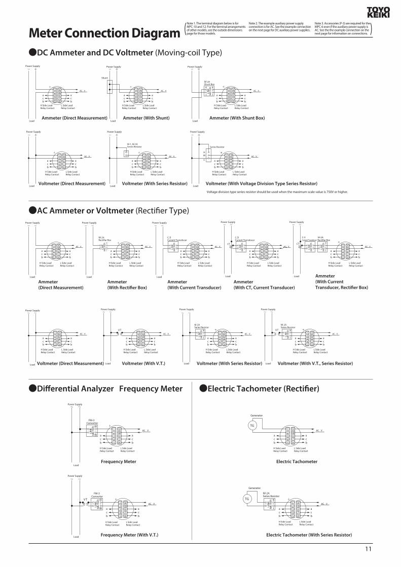
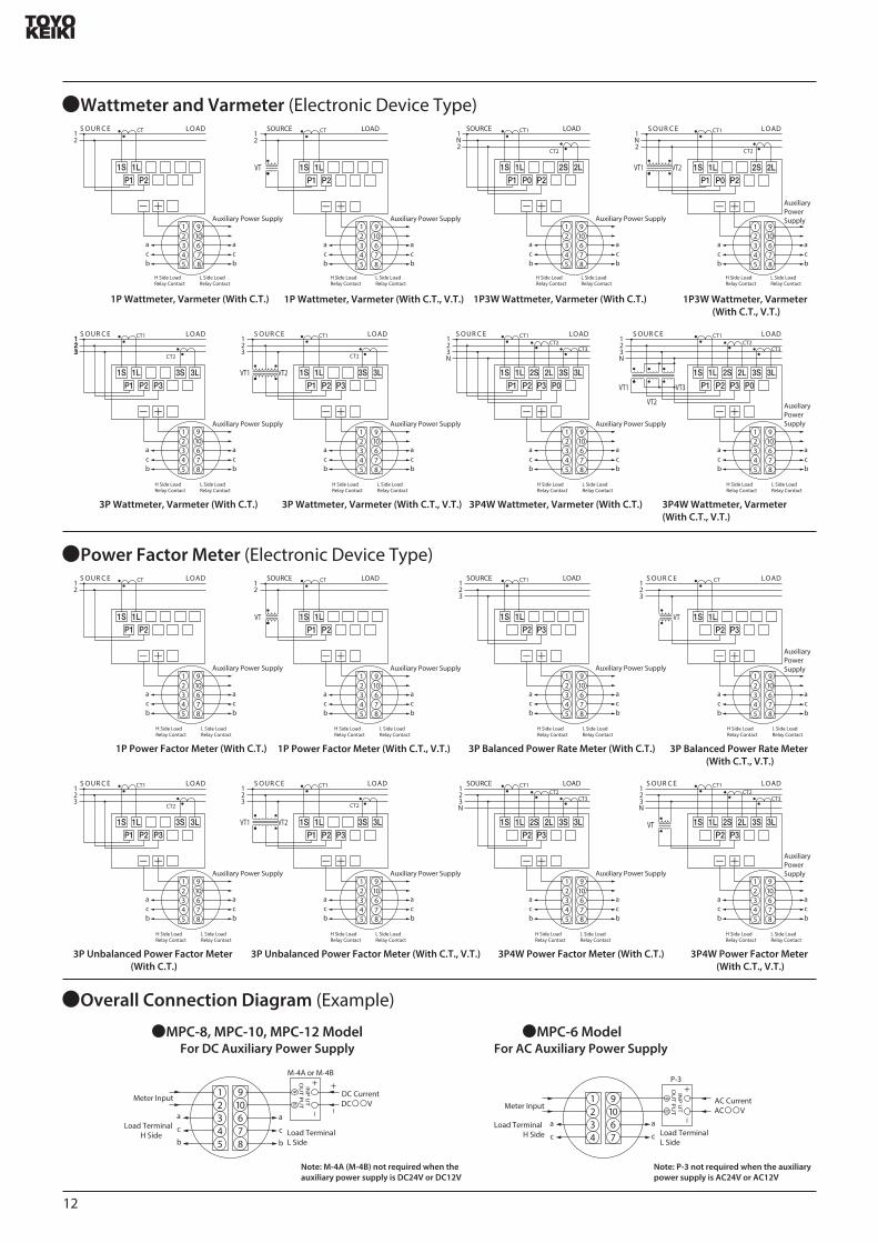
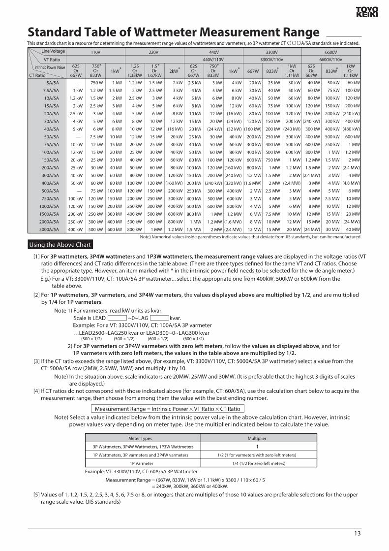
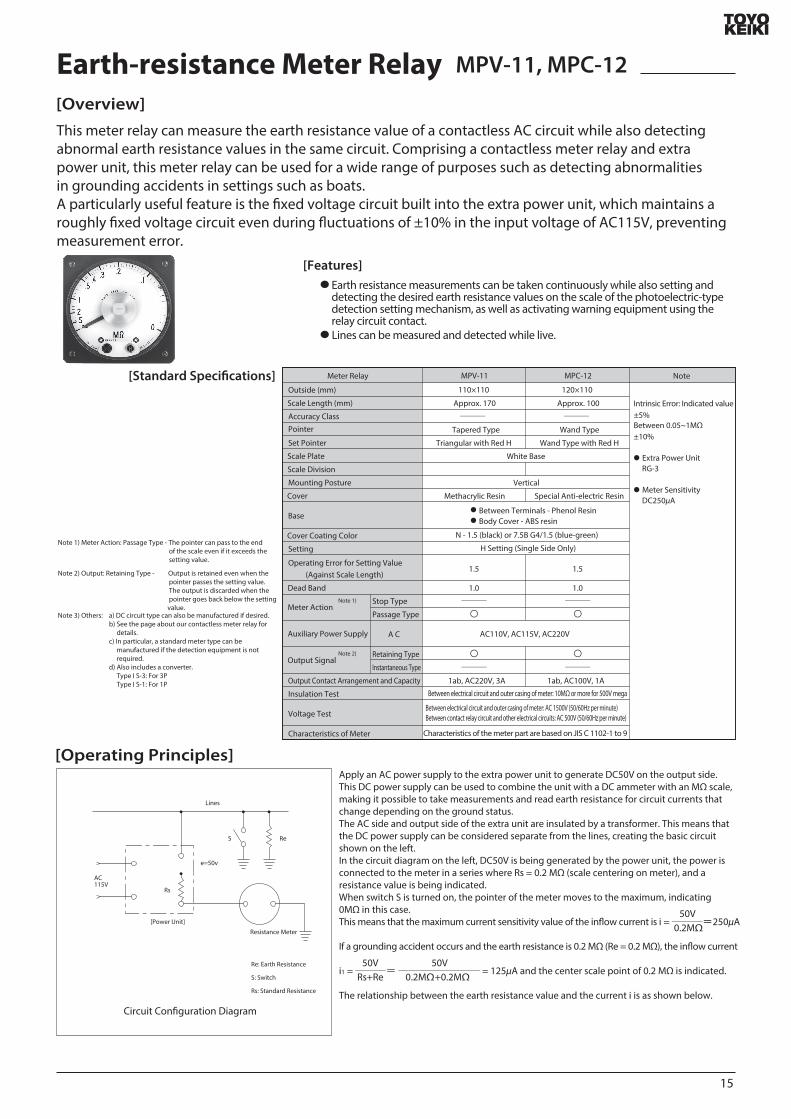
15
NoteMeter Relay MPV-11
110times110 120times110
MPC-12
Outside (mm)
Scale Length (mm)
Accuracy Class
Pointer
Set Pointer
Scale Plate
Scale Division
Mounting Posture
Cover
Base
Cover Coating Color
Setting
Operating Error for Setting Value (Against Scale Length)
Dead Band
Output Contact Arrangement and Capacity
Insulation Test
Voltage Test
Characteristics of Meter
Meter Action
Auxiliary Power Supply
Output Signal
Note 1)
Note 2)
Stop Type
Passage Type
A C
Retaining Type
Instantaneous Type
Approx 170
Tapered Type
Triangular with Red H
White Base
Vertical
Methacrylic Resin
15
10
〇
〇
1ab AC220V 3A
Approx 100
Wand Type
Wand Type with Red H
Special Anti-electric Resin
15
10
〇
〇
1ab AC100V 1A
Between Terminals - Phenol Resin Body Cover - ABS resin
N - 15 (black) or 75B G415 (blue-green)
H Setting (Single Side Only)
AC110V AC115V AC220V
Between electrical circuit and outer casing of meter 10MΩ or more for 500V mega
Between electrical circuit and outer casing of meter AC 1500V (5060Hz per minute)Between contact relay circuit and other electrical circuits AC 500V (5060Hz per minute)
Characteristics of the meter part are based on JIS C 1102-1 to 9
plusmn10
plusmn5Intrinsic Error Indicated value
Between 005~1MΩ
Extra Power Unit RG-3 Meter Sensitivity
DC250μA
Earth-resistance Meter Relay MPV-11 MPC-12
This meter relay can measure the earth resistance value of a contactless AC circuit while also detecting abnormal earth resistance values in the same circuit Comprising a contactless meter relay and extra power unit this meter relay can be used for a wide range of purposes such as detecting abnormalities in grounding accidents in settings such as boatsA particularly useful feature is the xed voltage circuit built into the extra power unit which maintains a roughly xed voltage circuit even during uctuations of plusmn10 in the input voltage of AC115V preventing measurement error
[Overview]
[Features]
[Standard Specications]
[Operating Principles]
Earth resistance measurements can be taken continuously while also setting and detecting the desired earth resistance values on the scale of the photoelectric-type detection setting mechanism as well as activating warning equipment using the relay circuit contact
Lines can be measured and detected while live
Note 1) Meter Action Passage Type - The pointer can pass to the end of the scale even if it exceeds the setting value
Note 2) Output Retaining Type - Output is retained even when the pointer passes the setting value The output is discarded when the pointer goes back below the setting valueNote 3) Others a) DC circuit type can also be manufactured if desired
b) See the page about our contactless meter relay for detailsc) In particular a standard meter type can be manufactured if the detection equipment is not requiredd) Also includes a converter Type I S-3 For 3P Type I S-1 For 1P
Apply an AC power supply to the extra power unit to generate DC50V on the output side This DC power supply can be used to combine the unit with a DC ammeter with an MΩ scale making it possible to take measurements and read earth resistance for circuit currents that change depending on the ground statusThe AC side and output side of the extra unit are insulated by a transformer This means that the DC power supply can be considered separate from the lines creating the basic circuit shown on the leftIn the circuit diagram on the left DC50V is being generated by the power unit the power is connected to the meter in a series where Rs = 02 MΩ (scale centering on meter) and a resistance value is being indicatedWhen switch S is turned on the pointer of the meter moves to the maximum indicating 0MΩ in this caseThis means that the maximum current sensitivity value of the inow current is i = =250μA
If a grounding accident occurs and the earth resistance is 02 MΩ (Re = 02 MΩ) the inow current
i1 = = = 125μA and the center scale point of 02 MΩ is indicated
The relationship between the earth resistance value and the current i is as shown below
Lines
Resistance Meter
[Power Unit]
AC 115V
Rs
Re
Re Earth Resistance
S Switch
Rs Standard Resistance
S
e=50v
Circuit Conguration Diagram
02MΩ +02MΩ Rs+Re50V
02MΩ 50V
50V
Measurement point A can be measured from LINE R S or T Auxiliary Power Supply 110V System (9) (10) 220V System (9) (11)
AC100V
AC115V
DC50VB
3
3
2
2
1
1
10 119
4
4 5VT
Zero Ohms Adjustment Volume
R
S
T
LINE LOAD
440V
A
Load Contact
MPV-11
a c d
Power Unit (RG-3)
[Connection Diagram]
[Extra Power Unit]
[How to Use]
[Scale Drawing]
[Outside Dimensions]
MPV-11
MPC-12
RG-3
110plusmn1
5
110plusmn15
45plusmn0545plusmn05
4-φ7
φ102
1 2 3 4 5109 11 6 7 8
M3 Terminal Screws
Terminal Cover
Terminal Cover33 or below
8
130
4M-6 Mounting Screws
05
24
145
115
φ10
0
φ10
2Panel Cutout
Black Shading Hood
45plusmn0545plusmn05
45plusmn0
545
plusmn05
45plusmn0
545
plusmn05
5
35plusmn0
545
plusmn0545
plusmn05
35plusmn0
5
50plusmn05 50plusmn0550plusmn05
120plusmn1
50plusmn05
4-φ5 Holes10-M3Terminal Screws Variable Resistor for Sensitivity SettingsNote 1
20
12 105100
4-M4 Mounting Screws
05
255
10
φ64
Panel Cutout
φ87plusmn1
100plusmn1
φ85
+05minus0
1
2
3
4
5
9
10
6
7
8
121plusmn0572plusmn05
4
769
11
110plusmn
05
96 124plusmn
05
Terminal Cover4-M4 Terminal Screws
ZERO
NPZero OhmsAdjuster
MΩ
MΩ0
1
125infin
234
5
0
1125infin
2345
Resistance value between LINE R S or T and earth is measured between A and BIn the diagram on the left the measurement is taken from
phases S and T but any phase can be usedThe diagram on the left shows an example connection
between MPV and 11 but the same result will be obtained between MPC and 12 (vertical terminal array)The zero ohms adjustment volume is a backup device
embedded in the center of the power unit Insulate auxiliary power supply terminals (9) and (10) before checking the zero ohms adjustment(To stop the output signal of the relay circuit)
[Specied Items when Ordering]
0-5 MΩ (Center Point 02 MΩ) 0-5 MΩ (Center Point 02 MΩ)
Contact Arrangement345
MPVminus11 MPCminus12
Model Name MPV-11 or MPC-12Scale 0-5 MΩ (Center point 02 MΩ)Auxiliary Power Supply AC 110V etcAttached Panel Fe or NFe (Specify MPC-12 model only)Mounting Posture etcCover Coating Color N-15 (black) or 75 BG 415 (blue-green)Other Non-standard specications
Note)
16
Sminus62 minusminusA AC InputD DC InputH H Setting Value L L Setting Value 1 DC Power Supply (DC24V) 2 AC Power Supply AC100110V AC200220VInput
0 60mV1 100mV2 0~1V3 0~5V4 1~5V5 4~20mA6 1A7 5A8 150V9 Others
0 No Delay1 Power Supply Delay2 Signal Delay1 Socket Attachment2 Panel Mounting
( (
DC
AC
VHCOMCL
678
4
5
Power Supply
U6
Input
U1 U2U4 U5
U3
123
U1Input Amplier
U2Rectier Circuit
U3Setting Circuit
U4Comparator Circuit
U5Delay Circuit
U6Power Supply Circuit
VHCOMCL
678
4
5
Power Supply
U5
Input
U1U3 U4
U2
123
U1Input Amplier
U2Setting Circuit
U3Comparator Circuit
U4Delay Circuit
U5Power Supply Circuit
[Operating Principles]
AS-62 (AC Input)
Block Diagram
[Overview of Operation]
DS-62 (DC Input)
Block Diagram
Stationary Non-indicating Regulator AS-62DS-62
This product is a non-indicating adjustment meter with no meter drive unit The AS-62 uses AC input while the DS-62 uses DC input The auxiliary power supply can be used for AC 100110V and AC 200220V This product can also be manufactured with a DC24V power supply The ono status of the relay is shown by a red LED on the front and the setting scale also has an extremely easy-to-see structure Two attachment methods can be used by connector or by panel mounting Panel mounting is done by connecting the lines using the terminal block on the back (M4 screws) Compact design with front panel measuring 625x625
[Overview]
ltSolid State Relaygt
After amplifying the input signal with the input amplier (U1) the entire wave is rectied and attened with the rectier circuit (U2) and then input on the signal side with the comparator circuit (U4)Meanwhile the voltage set by the dial is input on the setting side with the setting circuit (U3) The output from (U4) is a VH or VL value depending on this input This signal is input into a relay drive transistor to turn the relay on and o Here the delay circuit (U5) delays the signal from U4 for around 1 second in the event of a signal delay The circuit constant diers depending on the specications In the event of a power supply delay the relay does not operate for around 7 seconds after the power supply is turned on even when the U4 output voltage is VH This circuit responds to the average input value not DC components
[Overview of Operation]
[Specications]
After amplifying the input signal with the input amplier (U1) the signal is input on the signal side with the comparator circuit (U3) Meanwhile the voltage set by the dial is created by the setting circuit (U2) and input on the setting side of the comparator circuit (U3) The output from (U4) is VH or VL depending on the relationship between the signal and the setting value This signal is input into a relay drive transistor to turn the relay on and o The delay circuit (U5) creates signals for power supply delays (approximately 7 seconds) and signal delays (approximately 1 second) according to the specications
Model Name
17
51 or below24 or below
354
118
or b
elow
81 o
r bel
ow
40plusmn024
78
4
5
8-M35x7 Sems Screws
2-φ45 Holes
4
0
2040
POWER RELAY
SOLIDSTATE CONTROLLER
625
625
10 95126 plusmn7
56
56
8-M4 ScrewsEmbedded in Panel
Attached to Wall
Socket Attachment
Use OMRON 8PFA
40plusmn2
2-φ45 Holesor M4 Tapping
565+
05
-0
565 +05 -0
1
2
3
4 5
6
7
8
Input
ab
cAC100110V
AC200220V
AC Auxiliary Power Supply 1
2
3
4 5
6
7
8
Input
ab
cDC24V
DC Auxiliary Power Supply
+
+
-
Panel Cutout
[Performance]Input Impedance
60mV 100mV1V 5V 1~5V4~20mA5A1A150VThe following standards apply to products with other input specications60mV or More Up to 100mV101mV or More Up to 300VAmmeter Input Resistance value generating a
200mV voltage dropPickup Error plusmn 15Delay
Response Speed
Dead Band
Temperature Coecient
Load Relay Contact Capacity 1 ab AC 250V 3A (resistance load)DC 30V 3A (resistance load)
Power Consumption
Operating Temperature LimitsStorage Temperature RangeMaximum Relative HumidityInput Overload Capacity
60mV 100mV1V5V 1~5V4~20mA1A5A150V
Insulation Test (500V test with mega)Electrical circuit - outer casing input - auxiliary power supply input - relay output20 MΩ or more between each phase
Voltage TestElectrical circuit - outer casing input - auxiliary power supply input - relay output
2000V per minute between each phase
Outer Casing Material Polycarbonate resin phenol resinWeight Approx 400g
10kΩ1MΩ10Ω6mΩ30mΩ1MΩ
10V50V250V100mA10A50A500V
10kΩ1MΩ
Signal DelayPower Supply DelayA S-62D S-62
Approx 1 secondApprox 7 secondsApprox 02 secondsApprox 01 seconds
Around 2
plusmn0510˚C
Approx 3VA (AC power supply) 25W (DC power supply)
0˚C~50˚C-10˚C~60˚C
[How to Use]
Precautions when Handling and Ordering the S-62
[Outside Dimensions and Pin Connection Diagram]
[8PFA Socket Outside Dimensions]
Over 5A Less than 50A
Over 50A Less than 300A
Over 300A Less than 5000A
S-10A Model 60mV
S-8A Model 60mV
S-8 Model 60mV
Over 300V up to 500V
Over 501V up to 750V
Over 751V up to 1500V
Over 1501V up to 30000V
Over 3001V up to 5000V
M - 2 A
M - 2 B
M - 3
M - 4 A
M - 6
This product can be used by panel mounting or socket attachment (specify which when ordering)An attachment bracket and mounting screws are included when panel mount is specied Do not attach with items other than the included screws
1 A frequency range from 40 to 500Hz can be used by the AS-62 Frequencies outside this range are a special specication and prior consultation is needed
2 To control DC currents larger than 5A use a shunt to convert the voltage (to around 60mV) and then receive and control with the 60mV input type DS-62 Model names of shunts are as follows
To control high DC voltages add an external series resistor Model names of series resistors are indicated in the table below
85
100
6080
18
Non-indicating Voltage Relay DS-5A (for DC Voltage)
[Features]
[Specications]
[Outside Dimensions]
[Attachment Diagram]
[Series Resistor Calculation Method for General-Purpose Detector Side and Operation Side]
Driver adjust type enables easy and accurate conguration of voltage settings
Safe operation even for voltages containing ripples 3 dierent attachment methods
Front attachment (attachment to terminal block or rear connection socket on 8P) Rear attachment
[Purposes]Voltage detection in DC power suppliesVoltage detection in rectied power
suppliesAutomatic control
(3) Detection Error
(4) Set Method(5) Contact Capacity(6) Contact Arrangement(7) Relay Contact Output
(1) Detection Method(2) Detected Voltage Rating
Voltage comparison-based voltage detection
Within plusmn15 of upper limit setting maximum voltage value (within plusmn25 for DS-5A-U12)
VR variance by driver adjustmentDC 30V1A (resistance load) AC 100V1AL side 1b H side 1a
Series ResistorModel
Inside Dimensions
Externally connected for operation
Note
DS-5A-24A
DS-5A-48A
DS-5A-100A
DS-5A-U12
DS-5A-U24A
DS-5A-U48A
20~24V
40~48V
80~95V
10~14V
20~28V
40~56V
24~28V
48~56V
105~120V
10~14V
20~28V
40~56V
02
04
11
01
02
05
15
15
50
20
15
15
Setting Range for Detected Voltage
L
Power Consumption (W)
Detection Side Operation Side
Note)
Within plusmn15 of upper limit setting maximum voltage (within plusmn20 for DS-5A-U12)
200mS or less when 97 to 110 of set voltage is applied
20 times per 60 seconds 10 minute stop(When upper limit setting maximum voltage value is 100)
Continuous overvoltage of 120 possible with all models)150 possible for 3 minutes on all models 200 not possible on any models
Insulation Test Between Electrical Circuit and Case DC500V mega 10MΩ or higher
Between Electrical Circuit and Relay Contact DC500V mega 5MΩ or higher
Voltage Test Between Electrical Circuit and Case AC 2000V (5060Hz per minute)
Between Electrical Circuit and Relay Contact AC500V (5060Hz per minute)
ON
ON
OFF
OFF
LH Setting Value
L Side Relay Contact Output
H Side Relay Contact Output
(8) Retained Range
(9) Reaction Time
(10) Operation Frequency(11) Overvoltage Strength
Within 20 P-P-10˚C~50˚C
(12) Detection Input Ripples(13) Operating Temperature Limits
(14) Pin Layout Diagram
L
v v
50plusmn05
60plusmn0
5
44 +0 -05
54+
0 -
05
80 70
35
7652
7
82785
8P Octal Base
[Series Resistor for Operation of the DS-5A-100A R Outside Dimensions]
454
4
64plusmn15
73plusmn15
06
φ 25
43
13plusmn02
φ 15
31
14
Voltage Resistance AC2000VWeight 25g
Attachment Screws
Claw to Prevent Falling O
OMRON8PF Terminal Block Type(see P18)
74
φ30 or higher
2-φ35 Holesor M3 Tapping
Panel Cutout Diagram
If attached directly
123
467
8
H Side Relay Contact Output 1a
L Side RelayContact Output 1b
R
RHRL
Auxiliary Power Supply (-)
L Side Detection Input (-) H Side Detection Input (-)
123
467
8
H Side Relay Contact Output 1a L Side Relay Contact Output 1b
R Auxiliary Power Supply (-)
Detected Voltage Input (-)
COM (+)
[Overview]
Weight 140g
(1) Pin Layout DiagramDS-5A-U (A)
DS-5A-A
R Series Resistor for Operation (Externally Connected)
RL Series Resistor for Operation on L Side (Externally Connected)
RH Series Resistor for Operation on H Side (Externally Connected)
Included only with R DS-5A-100A
See the pin layout diagram on the right for the DS-5A-U model
Both the operation unit and the detection unit are externally attached if the setting range is exceeded
Scale of general purpose model is 0~100
Note 1 Power Consumption (operation at maximum voltage on maximum setting where L = OFF and H = ON)Note 2 DS-5A-U (A) indicates all-purpose model Be sure to connect a series resistor if the values in this table
will be exceeded (Calculation method for series resistors can be found on P20)
This non-indicating voltage relay detects the voltage of DC power supplies It can detect both H and L in detected voltage setting ranges enabling safe operating even with voltages that contain ripples such as those in rectied power supplies
H
5
H
5
COM (+)
19
COM
Input
E
R
Vz
R D
1
7
E R
I Rs
Auxiliary Power Supply VoltageSeries Resistor Externally Connected to Operational Power SupplyCurrentDS-5A-U Equivalent ResistanceDS-5A-U12 Model 0086 kΩDS-5A-U24A Model 04 kΩDS-5A-U48A Model 136 kΩ
22
21 23
20 24V
26
25 27
24 28V
44
42 46
40 48V
52
50 54
48 56V
40 60
20 80
0 100
40 60
20 80
0 100
85 90
80 95V
110 115
105 120V
Auxiliary Power Supply
Detection Input
(-) )-(
(+) )+(
8 72
RR
R DS-5A
DS-5ADS-5A
R Externally Connected Series Resistor
R Externally Connected Series Resistor
Auxiliary Power SupplyDetection Input
(-) )-(
(+) )+(
8 7R (Included Only with 100 Model)DS-5A
a DS-5A-24A48A100A
a DS-5A-24A48A100A
b DS-5A-U24AU48A
b DS-5A-U24AU48A
Auxiliary Power Supply
Detection Input
(-)(-)
(-)
(+) )+(
8 72
RR
R
Auxiliary Power SupplyDetection Input
(-) )-(
(+) )+(
8 7R (Included Only with 100 Model)
1) DS-5A-24A
2) DS-5A-48A
3) DS-5A-100A
4) DS-5A-U24A DS-5A-U48A
DS-5A-U (A)Non-indicating Voltage Relay
(2) Calculation Method for RH or RL Series Resistor for Detection Side (Externally Connected)
(3) Calculation Method for R Series Resistor for Operation Power Supply Side (Externally Connected)
(A) Reference CurrentThe reference current is indicated as a bond
(b) Calculation
(c) Example Calculation
Model Name Reference Current I0 (mA) Vu (V)
DS-5A-U12
DS-5A-U24A
DS-5A-U48A
175
286
333
12
24
48
Model NameSet Voltage Range
(V)Vo (V) Detection Side Multiplier
RH or RL Value
DS-5A-U12
DS-5A-U24A
DS-5A-U48A
NoteModel Name
DS-5A-U12
DS-5A-U24A
DS-5A-U48A
22~26
44~52
92~108
24
48
100
(24-12) [V] 175 [mA]
RH or RL =(Center Point Voltage of Setting (Vo) - Vu)
Reference Current (Io)
I min ≦ I = E-VzR+RD
=686 [kΩ]
(48-24) [V] 286 [mA] =839 [kΩ]
(100-48) [V] 333 [mA] =156 [kΩ]
Caution
Input Voltage (Voltage of Auxiliary Power Supply) Range E [V] and Resistance Value R of Multiplier on Auxiliary Power Supply Side [kΩ]
Emin ≦ E ≦ Emax
80mA ≦ I = ≦ 140mAE-6
R+0086
Emax Maximum voltage of auxiliary power supply Imax Maximum currentEmin Minimum voltage of auxiliary power supply Imin Minimum current
Select R within the range where the above inequality is achievedIf the inequality is not achieved for I rework the equation by methods such as raising the R value or narrowing the voltage range of the power supply
(Note) Settings can be congured in the desired position between 0 and 100 for both H and L
[Scale Drawing]
[Connection Circuit Diagram of the External Circuits]
(1) The detection input and auxiliary power supply input are COM and +
(2) If the detection input and the auxiliary power supply are the same connect the auxiliary power supply terminal (7) and the detection input (8) (8 and 2 for U shape) as shown in the diagram below
(3) If the detection input and the auxiliary power supply are separate connect them as shown in the diagram below
Precautions for External Connections
Do not connect with the polarities of the detection input and auxiliary power supply opposing each other
I
Use the equation below to calculate the current I in the input voltage range then decide on the value for the R series resistor to be connected to the operational power supply
The current I value is for cases in which both the H and L sides are excited by the load relay of the non-indicating voltage relay (L OFF H ON)
≦ I max
25mA ≦ I = ≦ 70mAE-12R+04
15mA ≦ I = ≦ 35mAE-24
R+136
VZ=6VRD=0086kΩ
VZ=12VRD=04kΩ
VZ=24VRD=136kΩ
20
50plusmn05
60plusmn0
5
44 +0 -05
54+
0 -
05
80 70
35
7652
7
82785
8P Octal Base
74
φ30 or higher
2-φ35 Holes (or M3 Tapping)
Panel Cutout Diagram
If attached directly
Note) Can also be attached to the front terminal block (See P19)
40 581624
534
or b
elow
30
1259
4212
55
8098
LINE
METER
24
65
325
Line Side Terminal ScrewsM4 Terminal ScrewsThickness (t)
(Note)
50plusmn05
Meter Side
Name Plate
Rated Load 01VAPrimary Current 25ASecondary Current 10mACircuit Voltage 460VVoltage Test AC2000VWeight Approx 02kg
Note)
123
4567
8
Load RelayContact 1a
Auxiliary Power Supply AC100V
Current TransducerC-3 Model
Power Indicator AS-5-LI (Residual CurrentLeakage Current Detector)
[Overview]
[Features]
[Specications]
[Operation Diagram] [Connection Diagram]
Highly reliable solid-state electronic parts
Lightweight compact type
(Main unit 100g current transducer 200g)
Plugs into 8-pin socket enabling easy security inspections and replacement
[Purposes]
[Outside Dimensions]
[Accessories]
[Example Use]
Detects small amounts of residual power and issues an alert
Detects electric leakage and issues an alert
Detector prevents power from being left switched on
Operating Error
Maximum Circuit Voltage
Maximum Circuit Current
Setting Value
Relay Contact Output
Auxiliary Power Supply Voltage
Accessory
Insulation Resistance(DC500V Mega)
Voltage Resistance(for 1 minute)
Pickup Within setting value plusmn 10Dropout 20 or less of pickup value(dead band is also 20 or less of pickup value)
Contact arrangement 1a
Contact capacity AC100V 03A (resistance load)
AC 100V plusmn 10 5060Hz
C-3 Model Current Transducer
Between electrical circuit and outer casing 10 MΩ or higherBetween electrical circuit and relay contact 10MΩ or higherBetween electrical circuit and outer casing AC2000VBetween electrical circuit and relay contact AC500V
Current Transducer C-3 Model
② ②
⑥
①
① ② ③ ④ ⑤ ⑥
③
④
Load Current
Load Current
Load Relay ON
Load Relay OFF (Maximum 25A)
Dropout Value Pickup Value
I 2 I 1 = 01AC-3 C-3 C-3
Load 1 Load 2 Load 3
AS- 5-LI (1)
AS- 5-LI (2)
AS- 5-LI (3)
L1 L2 L3
Auxiliary Power Supply
Indicator Lamp Buzzer etc
This power indicator contains a highly reliable current relay that can detect low current settings It detects whether there is a 100mA current in circuits with a maximum current of 25A and generates a warning or an indicator drive signal This means that this device can be used together with a current transducer to detect power consumption of 10W in an AC100V circuitIt can be used in centralized monitoring to detect electric leakage and power left on in high-rise buildings dormitories hospitals and hotel rooms reducing the workload for inspections and saving energy in security and safety measures
AC460V
25A
01A (xed)
Specications
21
Precautions for Handling Meters Be sure to note the following when handling as the relay covers of the MPC and MPE-10 model meters are made
from new materials
Maintenance with anti-static nish is not needed at all To clean the surface wipe gently with a light cloth
Avoid direct sunlight and strong UV rays as much as possible (This may cause natural degradation in performance)
Do not apply solder directly to meter terminals
A new type of resin cover with a better anti-electric eect is used
The molded resin contains a special component that causes self-discharge of static electricity
This means that
Special Anti-electric Resin Applied to Cover
Avoid high temperature locations (60˚C or over) because the plastic cover and case of the meter are easily aected by heat
1) The anti-static eect is unaected by the humidity of the operating environment(The charge half-life is less than 1 second even in a relative humidity of around 23)
2) The anti-static eect is semi-permanent in normal indoor operating conditions
3) Maintenance such as application of an anti-static nish is not needed
The cover case may be damaged through contact with chemicals (solvents such as paint thinner benzine alcohol etc)
The previous acrylic resin is used for the MPV and MPE-150 models Use an anti-static nish particularly in poor conditions where static electricity occurs easily such as low humidity [Anti-static nish Anti-static 80S spray (from Tanaka Chemical Laboratory) or Riverson No 30 spray (from Tokyo Yakuhin Kakosei)]
Paint
Thinner
Alcohol
Benzine
Spray
22
Main OceSales Department
Tokyo Oce
Nagoya Oce
Shimoshinjo 3-chome 10-ban 17-go Higashi Yodogawa Ward Osaka City 533-0021TEL 06 (6329) 2441 FAX 06 (6328) 4112
Shin Yoshida Higashi 8-chome47-ban 27-go Kohoku Ward Yokohama City 223-0058TEL 045 (542) 8201~3 FAX 045 (541) 3989
Nagoya SI Bld 6F Nishiki 1-chome 7-ban 32-go Naka Ward Nagoya City 460-0003TEL 052 (219) 7780 FAX 052 (219) 7781
Homepage httpwwwtoyokeikicojp
ISO 9001 Registration No JSAQ 1492
~Promotion of Environmental Issues~
Safety Precautions
D 2008121000
Our company is fully committed to not using hazardous materials in our productsAll of our main products are manufactured without the use of the six hazardous materials prescribed in the RoHS directivesPlease consult us about the compatibility of each productProducts that comply with the RoHS directives are distinguished by a label containing the Ro mark
Only allow this product to be handled by people with sucient knowledge and skill to ensure proper use Carefully review any connection diagrams before soldering
to ensure correctly soldered connections Fully tighten screws Loose screws may cause overheating
or burnoutMount the terminal cover after completing connections Do not use if the specied rating is exceeded Doing so may
lead to malfunction or injury Do not touch live parts of the product Disconnect circuits
during maintenance or inspections
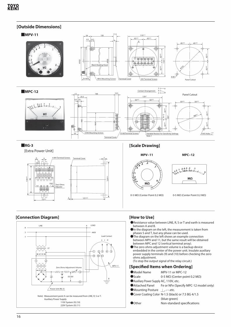
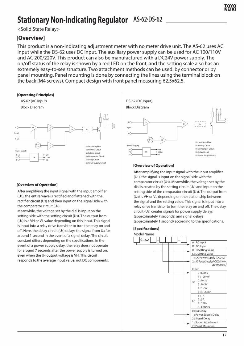
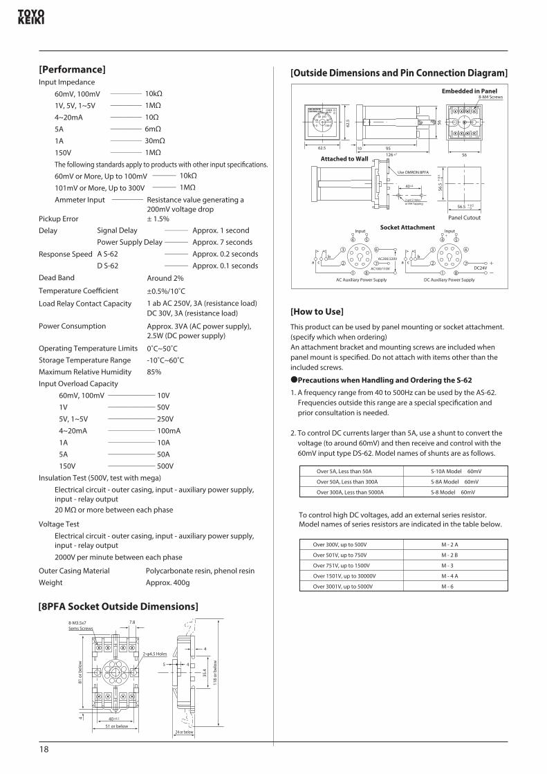
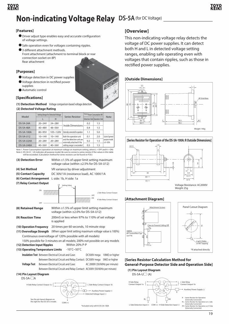
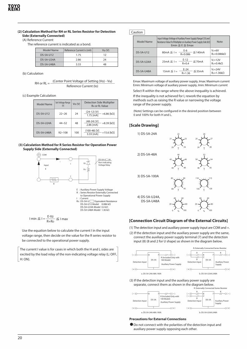
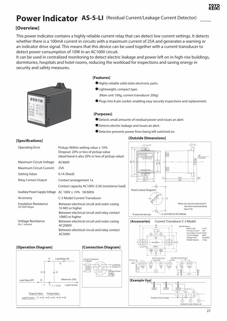
50plusmn05
60plusmn0
5
44 +0 -05
54+
0 -
05
80 70
35
7652
7
82785
8P Octal Base
74
φ30 or higher
2-φ35 Holes (or M3 Tapping)
Panel Cutout Diagram
If attached directly
Note) Can also be attached to the front terminal block (See P19)
40 581624
534
or b
elow
30
1259
4212
55
8098
LINE
METER
24
65
325
Line Side Terminal ScrewsM4 Terminal ScrewsThickness (t)
(Note)
50plusmn05
Meter Side
Name Plate
Rated Load 01VAPrimary Current 25ASecondary Current 10mACircuit Voltage 460VVoltage Test AC2000VWeight Approx 02kg
Note)
123
4567
8
Load RelayContact 1a
Auxiliary Power Supply AC100V
Current TransducerC-3 Model
Power Indicator AS-5-LI (Residual CurrentLeakage Current Detector)
[Overview]
[Features]
[Specications]
[Operation Diagram] [Connection Diagram]
Highly reliable solid-state electronic parts
Lightweight compact type
(Main unit 100g current transducer 200g)
Plugs into 8-pin socket enabling easy security inspections and replacement
[Purposes]
[Outside Dimensions]
[Accessories]
[Example Use]
Detects small amounts of residual power and issues an alert
Detects electric leakage and issues an alert
Detector prevents power from being left switched on
Operating Error
Maximum Circuit Voltage
Maximum Circuit Current
Setting Value
Relay Contact Output
Auxiliary Power Supply Voltage
Accessory
Insulation Resistance(DC500V Mega)
Voltage Resistance(for 1 minute)
Pickup Within setting value plusmn 10Dropout 20 or less of pickup value(dead band is also 20 or less of pickup value)
Contact arrangement 1a
Contact capacity AC100V 03A (resistance load)
AC 100V plusmn 10 5060Hz
C-3 Model Current Transducer
Between electrical circuit and outer casing 10 MΩ or higherBetween electrical circuit and relay contact 10MΩ or higherBetween electrical circuit and outer casing AC2000VBetween electrical circuit and relay contact AC500V
Current Transducer C-3 Model
② ②
⑥
①
① ② ③ ④ ⑤ ⑥
③
④
Load Current
Load Current
Load Relay ON
Load Relay OFF (Maximum 25A)
Dropout Value Pickup Value
I 2 I 1 = 01AC-3 C-3 C-3
Load 1 Load 2 Load 3
AS- 5-LI (1)
AS- 5-LI (2)
AS- 5-LI (3)
L1 L2 L3
Auxiliary Power Supply
Indicator Lamp Buzzer etc
This power indicator contains a highly reliable current relay that can detect low current settings It detects whether there is a 100mA current in circuits with a maximum current of 25A and generates a warning or an indicator drive signal This means that this device can be used together with a current transducer to detect power consumption of 10W in an AC100V circuitIt can be used in centralized monitoring to detect electric leakage and power left on in high-rise buildings dormitories hospitals and hotel rooms reducing the workload for inspections and saving energy in security and safety measures
AC460V
25A
01A (xed)
Specications
21
Precautions for Handling Meters Be sure to note the following when handling as the relay covers of the MPC and MPE-10 model meters are made
from new materials
Maintenance with anti-static nish is not needed at all To clean the surface wipe gently with a light cloth
Avoid direct sunlight and strong UV rays as much as possible (This may cause natural degradation in performance)
Do not apply solder directly to meter terminals
A new type of resin cover with a better anti-electric eect is used
The molded resin contains a special component that causes self-discharge of static electricity
This means that
Special Anti-electric Resin Applied to Cover
Avoid high temperature locations (60˚C or over) because the plastic cover and case of the meter are easily aected by heat
1) The anti-static eect is unaected by the humidity of the operating environment(The charge half-life is less than 1 second even in a relative humidity of around 23)
2) The anti-static eect is semi-permanent in normal indoor operating conditions
3) Maintenance such as application of an anti-static nish is not needed
The cover case may be damaged through contact with chemicals (solvents such as paint thinner benzine alcohol etc)
The previous acrylic resin is used for the MPV and MPE-150 models Use an anti-static nish particularly in poor conditions where static electricity occurs easily such as low humidity [Anti-static nish Anti-static 80S spray (from Tanaka Chemical Laboratory) or Riverson No 30 spray (from Tokyo Yakuhin Kakosei)]
Paint
Thinner
Alcohol
Benzine
Spray
22
Main OceSales Department
Tokyo Oce
Nagoya Oce
Shimoshinjo 3-chome 10-ban 17-go Higashi Yodogawa Ward Osaka City 533-0021TEL 06 (6329) 2441 FAX 06 (6328) 4112
Shin Yoshida Higashi 8-chome47-ban 27-go Kohoku Ward Yokohama City 223-0058TEL 045 (542) 8201~3 FAX 045 (541) 3989
Nagoya SI Bld 6F Nishiki 1-chome 7-ban 32-go Naka Ward Nagoya City 460-0003TEL 052 (219) 7780 FAX 052 (219) 7781
Homepage httpwwwtoyokeikicojp
ISO 9001 Registration No JSAQ 1492
~Promotion of Environmental Issues~
Safety Precautions
D 2008121000
Our company is fully committed to not using hazardous materials in our productsAll of our main products are manufactured without the use of the six hazardous materials prescribed in the RoHS directivesPlease consult us about the compatibility of each productProducts that comply with the RoHS directives are distinguished by a label containing the Ro mark
Only allow this product to be handled by people with sucient knowledge and skill to ensure proper use Carefully review any connection diagrams before soldering
to ensure correctly soldered connections Fully tighten screws Loose screws may cause overheating
or burnoutMount the terminal cover after completing connections Do not use if the specied rating is exceeded Doing so may
lead to malfunction or injury Do not touch live parts of the product Disconnect circuits
during maintenance or inspections
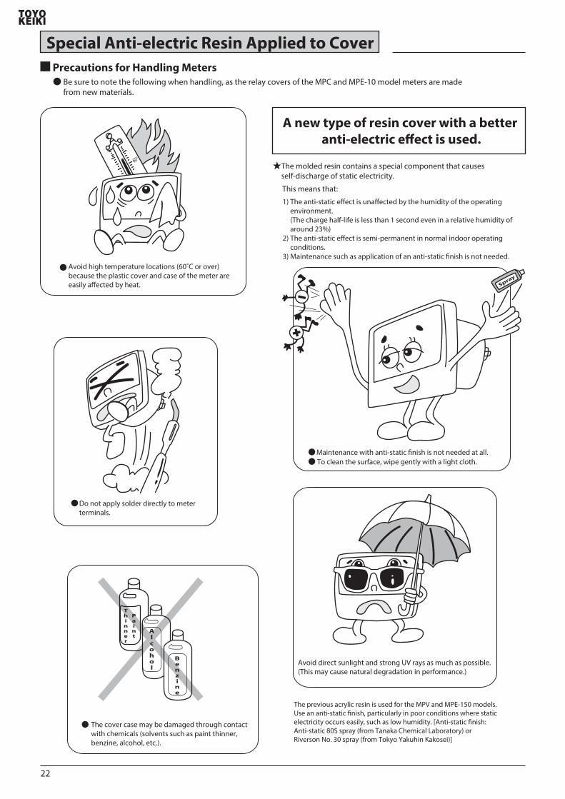