Embed Size (px)
Citation preview

Course Outlines
Calibration and Maintenance of Medical Equipment
Recording devicesStrip chart recorderMagnetic tape recorderDigital recorder
Ultrasound InstrumentX-Ray InstrumentDialysis Machine CT Scan Magnetic Resonance Imaging
Calibration and Electrical Safety of Medical Equipment
Why Test & CalibrationAs components age and equipment undergoes
changes in temperature or humidity or sustainsmechanical stress, performance graduallydegrades. This is called drift.
When this happens your test results become unreliable and both design and performance quality suffer.
While drift cannot be eliminated, it can be detected and either corrected or compensated for through the process of calibration.
Definitions
Calibration: process of comparing an unknown against a reference standard within defined limits, accuracies and Uncertainties
Verification: process of comparing an unknown against a reference standard at usually one data point

Test & Calibration service

What to TEST for?
• Performance Testing
• Safety Testing

When to test equipment
prior to being accepted for use During preventative maintenance.After repairs.
Need for Medical Equipment Testing
• Medical device incidents resulting in patient injury and death• Ensure that the equipment is performing to the expected standards of accuracy, reliability, free of hysteresis and linear (as designed).• Safe and effective devices need to be available forpatient care– Downtime costs money• Regulations, accreditation requirements and standards.

Why do we do electrical safety?
Ensure patient safetyProtect against macroshockProtect against microshock
Test for electrical internal breakdown / damage to power cord, AC mains feed, etc.
Meet codes & standards Association of Medical Instrumentation (AAMI), The International Electrotechnical Commission (IEC), National Federation of Paralegal Associations (NFPA),
etc.Protect against legal liability
In case of a patient incident

Waveform display devices
Permanent magnet moving coil instrumentsلمغناطيسمستديم المتحرك الملف أجهزة
Chart recorder: (Recording Oscillographs) used in a medical instrumentation to make permanent recording of the
waveform.
most common type: permanent magnet moving coil (PMMC).
The PMMC is very similar to the Galvanometer movement. A writing pen replaced the meter point.
Current flowing in the moving coil creates a magnetic field that interact with the magnetic field of the permanent magnet. This will cause deflection of the pen.
The tip of the pen is positioned over a strip of chart paper that is pulled under the pen tip at a constant speed. In this mechanism:
• Y-axis is the deflection to the pen and • X-axis is the time base established by moving the chart paper at a constant speed.
This will produce a chart recording of the waveshape of the applied waveform
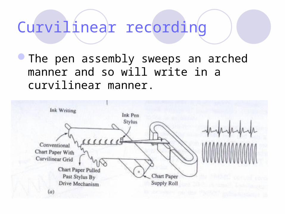
Curvilinear recording
The pen assembly sweeps an arched manner and so will write in a curvilinear manner.
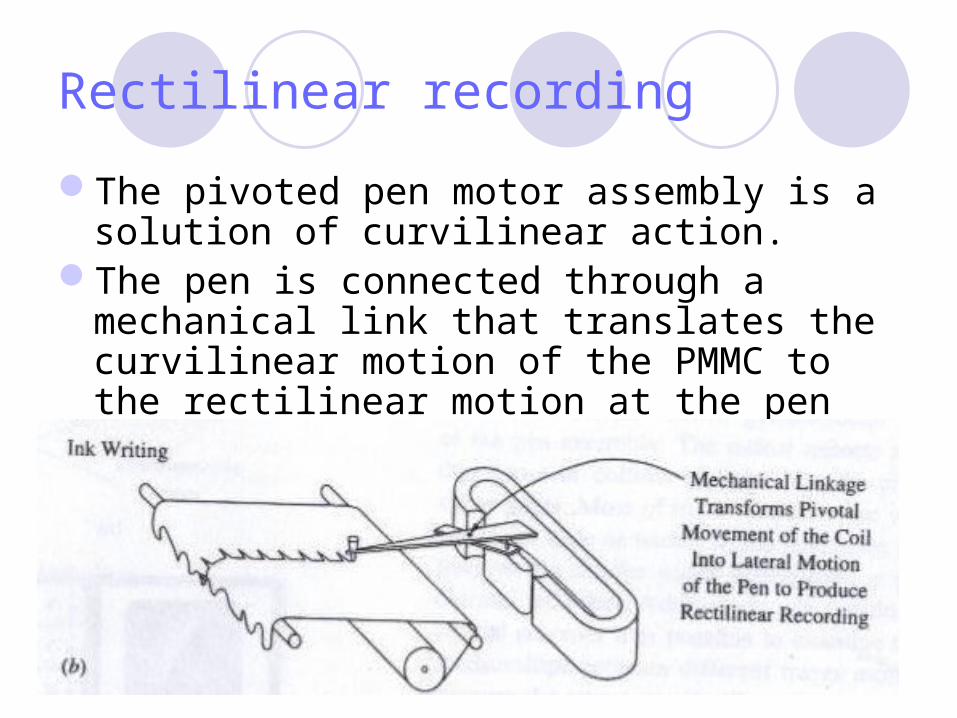
Rectilinear recording
The pivoted pen motor assembly is a solution of curvilinear action.
The pen is connected through a mechanical link that translates the curvilinear motion of the PMMC to the rectilinear motion at the pen tip.
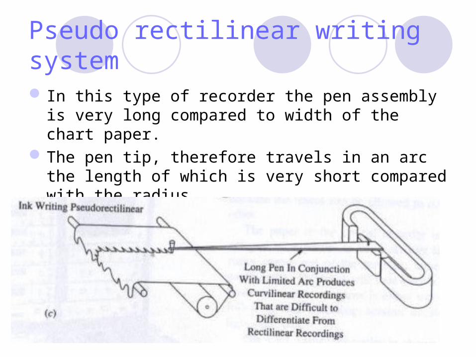
Pseudo rectilinear writing system
In this type of recorder the pen assembly is very long compared to width of the chart paper.
The pen tip, therefore travels in an arc the length of which is very short compared with the radius.
The trace will appear to be nearly linear
Writing Methods Used in Strip Chart Recorders
Thermal, and Direct contact
Both of these types use a special writing stylus (rather than a pen and a knife edge, also called writing edge)
The mark on the paper by the contact of the stylus on the paper along the knife edge,
The stylus tip travels in a curvilinear path, but the resulting trace is rectilinear because the knife edge is straight.
The stylus can write anywhere along its length, so by keeping the knife edge straight under the paper, we obtain the rectilinear recording that shows waveshape as well as amplitude
PMMC writing system
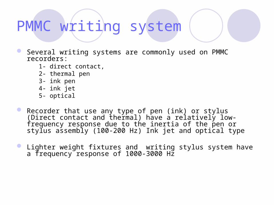
Several writing systems are commonly used on PMMC recorders:1- direct contact,2- thermal pen3- ink pen4- ink jet5- optical
Recorder that use any type of pen (ink) or stylus (Direct contact and thermal) have a relatively low-frequency response due to the inertia of the pen or stylus assembly (100-200 Hz) Ink jet and optical type
Lighter weight fixtures and writing stylus system have a frequency response of 1000-3000 Hz
Direct contact
The direct contact uses a special types of chart paper that is chemically treated to have a carbonized back.
When a pressure applied to that front of the paper a black mark will appear.
Most of these instrument have a frequency response of less than 25 Hz and so are not commonly used in medical instrumentation.

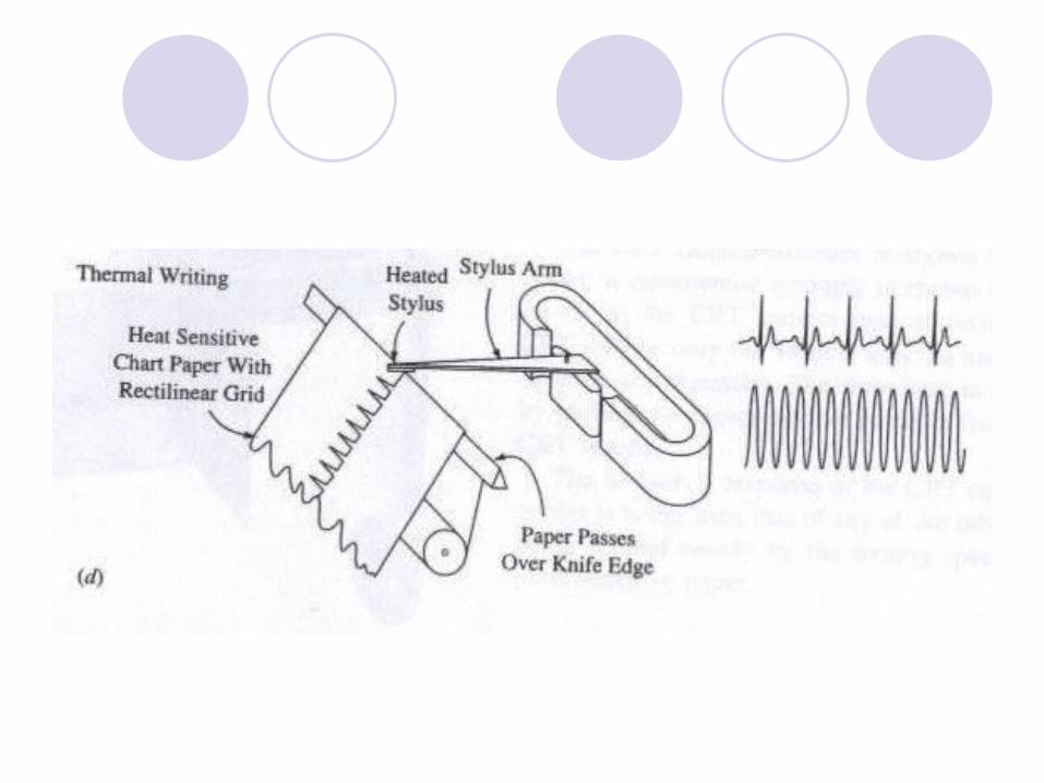
The thermal recorder
The thermal recorder also uses special paper, but in this case it is waxed or treated with paraffin so that it will turn black when treated
The thermal recorder is the most commonly employed in medical instrumentation, especially in cardiovascular instruments such as the ECG and pressure monitors
The Stylus
The stylus in a thermal system is little more than a heated resistance wire connected to a low voltage ac or dc power supply.
Early models formed a U-shaped electrical resistance element
Modern models use a wire inside a cylindrical metal stylus
In both cases a low voltage electrical power supply energizes the element, causing the tip to become heated.
The black mark is made at the points where heated stylus touches the paper
Ink pen writers
use a hollow pen and an ink supply to write on the chart paper.
In some machines the ink pressured by an atomizer-like hand pump EEG system use this type of writing system.
More automatic machines use a thick, viscous ink in a special cartridge that is placed under pressure by a spring-driven piston
In multichannel instruments, the ink may be distributed to all pens from the same cartridge by connecting the line from the cartridge to the input side of a special ink manifold and additional pressure is applied to the ink by the solenoid-operated manifold bladder
Ink jet recorder
Higher-frequency response than are the types mentioned previously.
This type is popular on European instrument
Low-viscosity ink is directed to a nozzle mounted on a PMMC galvanometer in place of the pen assembly.
The ink jet produced by the nozzle is directed at the paper.
When the system is properly adjusted, it will produce a recording that is very linearly rectilinear.
Only a small amount of trace fuzziness due to ink splattering is apparent
للتردادات تستجيب التى االنواعالسابقة االنواع من اكثر المرتفعة
اوروبا فى مشهورة فوهة الى يوجه اللزوجة منخفض حبر
القلم مكان الجلفانومتر فى الى يوجه الفاتحة من المتدفق الحبر
الورقة خط ينتج سوف تماما النظام ضبط عند
االستواء تام الحبر بعثرة نتيجة التشوش بعض ينتج
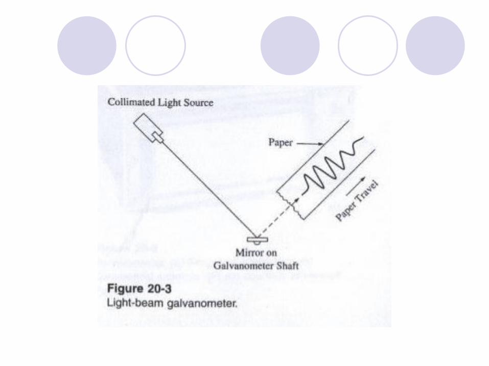
Optical recorder
There are two types of optical recorder:- PMMC type uses small inertia mirror in place
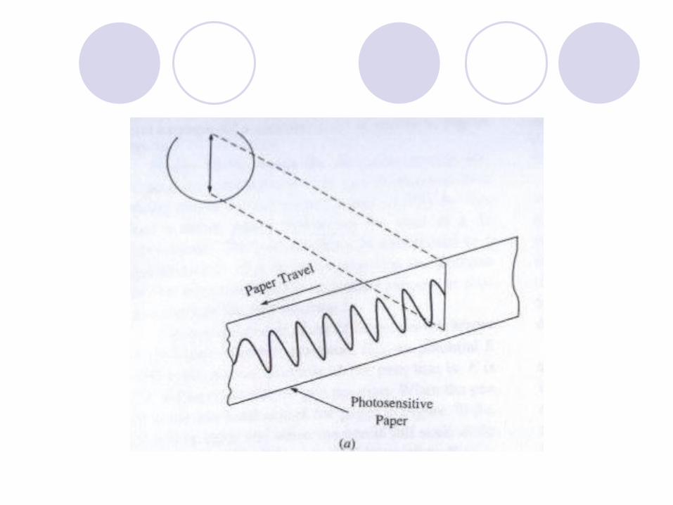
of the pen assembly or stylus. - The other uses a photographic paper that is
pulled across a cathode ray tube and is called a CRT camera recorder.
Most of these recorders use wide paper.On multichannel optical recorder it is possible
to examine the time relationships between different traces more easily because the traces can be allowed to overlap each other.
The paper in the optical recorder is often develop by exposure to an ultraviolet lamp as the paper comes out from the recorder.
Unless the paper is either wet developed following the recording session or stored in a light-light box.
In CRT camera, the CRT sweeps only the vertical axis. The time base is provided by pulling the photosensitive
paper in the front of the CRT screen. The frequency response of the CRT camera recorder is
better than that of any of the other types, being limited mostly by the writing speed of the photosensitive paper.
Servo recorders and recording potentiometers In potentiometeric measurements a three-terminal variable resistor
(potentiometer) is connected to produce an output voltage that is a function of both a reference potential and position of the variable resistor’s wiper arm.
A galvanometer will read zero when the unknown voltage and potentiometer voltage are equal.
Servo recorder
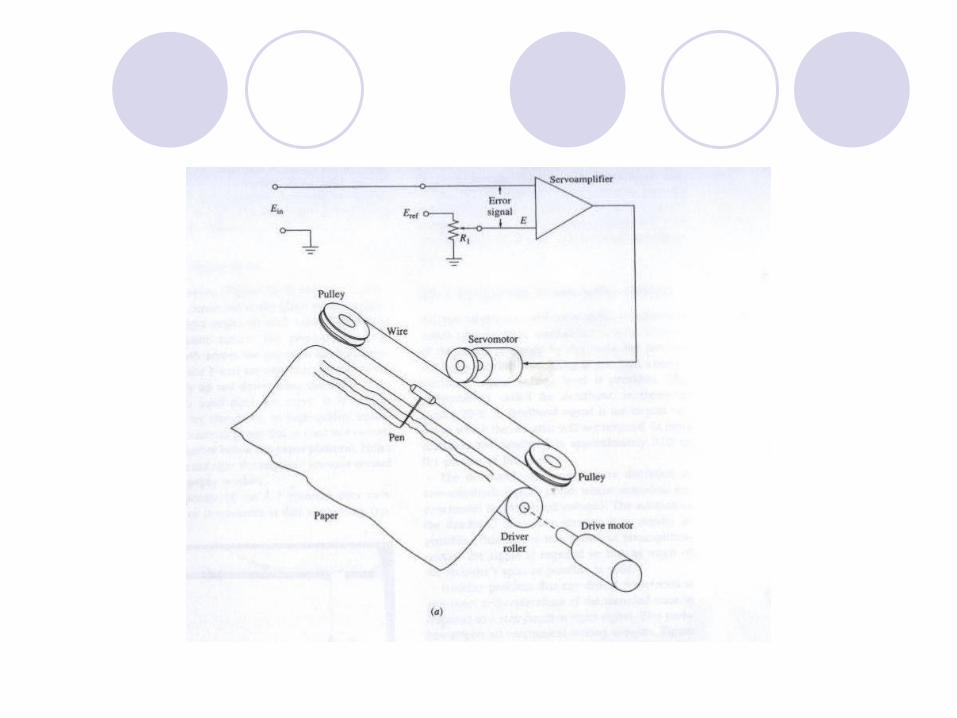
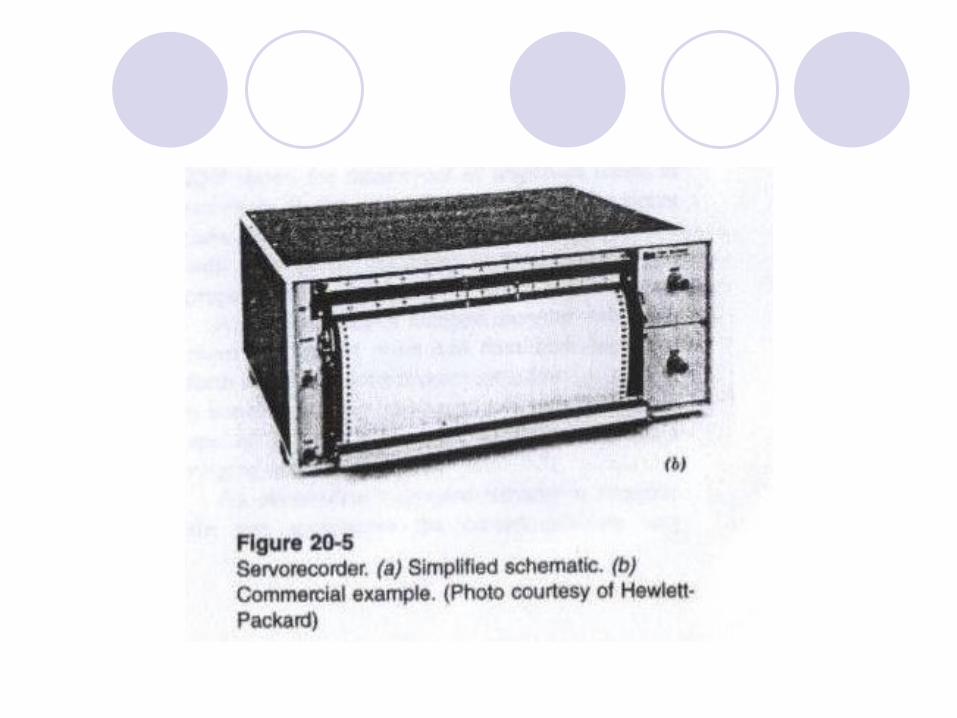
A servo recorder is a self-nulling potentiometer that records the waveshape of the applied signal on graph paper.
The pen attached to a string that is wound around a pair of idler pulleys and drive pulley that is on the shaft of a dc servomotor.
The pen assembly is also linked to a potentiometer (R1) in such a way that the position of the wiper arm on the resistance element is proportional to the pen position.
The potentiometer element is connected across a reference potential Eref, so potential E is the electric analog of pen position.
The pen position is controlled by the dc servomotor, which in turn driven by the output of the servo amplifier.
The amplifier has a differential inputs: Ein (unknown)
is connected to one input, and the position signal E is connected to the other input
The difference signal (Ein – E) represents the error between the actual pen position and the position the pen should be in for the applied voltage.
If the error is zero , meaning that the amplifier output is also zero and the pen is correctly positioned, then the motor remain turned off.
If Ein# E then the amplifier creates an output signal that turns on the motor
The motor drive the pen and potentiometer in such a direction as to cancel the error signal
When the input signal and position signal are equal, then the motor turns on the motor.
A paper drive motor
A paper drive motor forms time base because it pulls the paper underneath the pen at constant rate.
Most high-quality servorecorders use a stepper motor to drive the paper supply.
Such motor will rotate only a few degree every time a pulse applied to its windings
A few models use a continuously running motor that drive the sprocket through a speed-reducing gear box.
The stepper motor system is capable very good accuracy because a crystal oscillator or the ac power mains are used to drive the pulses used to advance the motor.
Digital integrated circuit frequency dividers (counter circuit) can be used to reduce the clock frequency to the frequency required to drive the motor at desired speed.
The reference potentiometer used to measure the pen position may be any of the following devices:
- Slide wire - Rectilinear, or - Rotary.
The slide-wire system is often used because it can be built with less friction and no mechanical linkage.
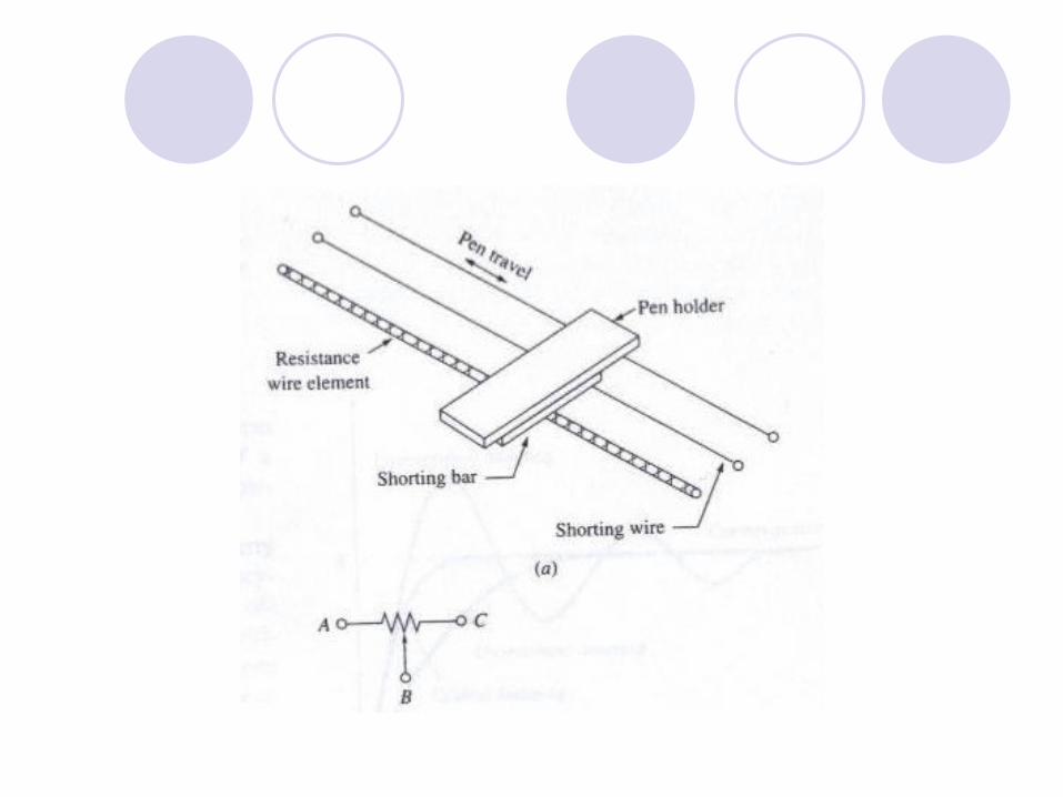
A slide-wire potentiometer
A resistance wire and a shorting wire are stretched taut parallel to each other and the direction of the pen travel.
A shorting bar on the pen assembly serves as a wiper on the resistance element and also connects the shorting wire.
A,B, and C in Figure refer to the potentiometer terminals
the shorting wire serves as terminal B of the potentiometer (the wiper)
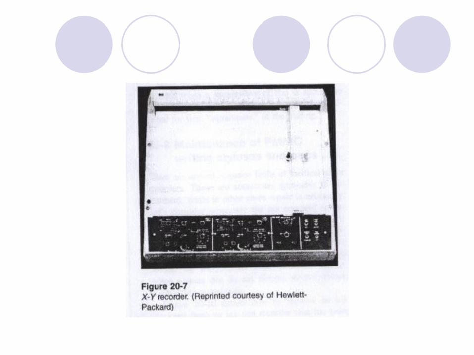
X-Y recorders
The X-Y recorder uses two servo mechanisms connected to the same writing assembly, but at right angles to each other.
The X-axis servomechanism moves the pen-bar assembly back and forth across the paper in the horizontal plane, while the Y-axis servomechanism moves the pen vertically up and down along the bar.
The paper itself does not move. It is held in place either by clamp or, in high-quility instruments by a vacuum pump that is used to evacuate a hollow chamber below the paper platform.
Holes in the platform create the negative pressure needed to keep the paper in place.
One advantage of the X-Y recorder is that almost any type of paper may be used.
Problem of recorder design
1- A dead band signal: largest signal to which the recorder will not respond due to pen assembles mass (inertia). Sufficient preamplification of the signal is required
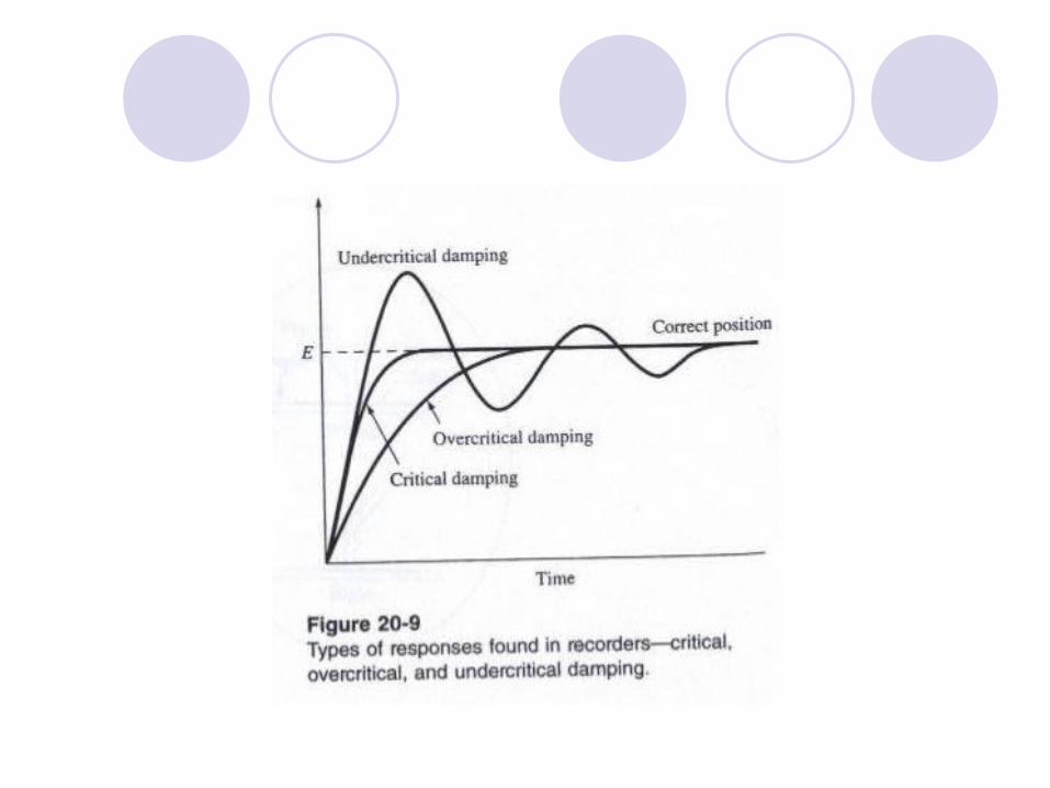
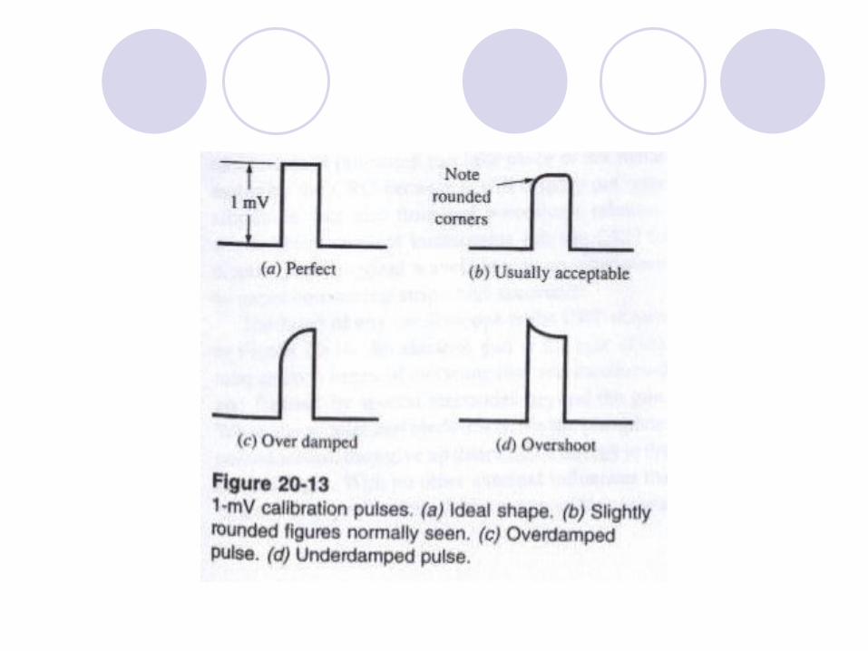
2- Overshooting and undershooting of the recorded trace.
3- undercritically damped reader will overshoot the correct point and then hunt back and forth across the correct point for a few cycle until it hones in and settles properly
4- over critically damped recorder is sluggish the pen approaches the correct position very slowly .
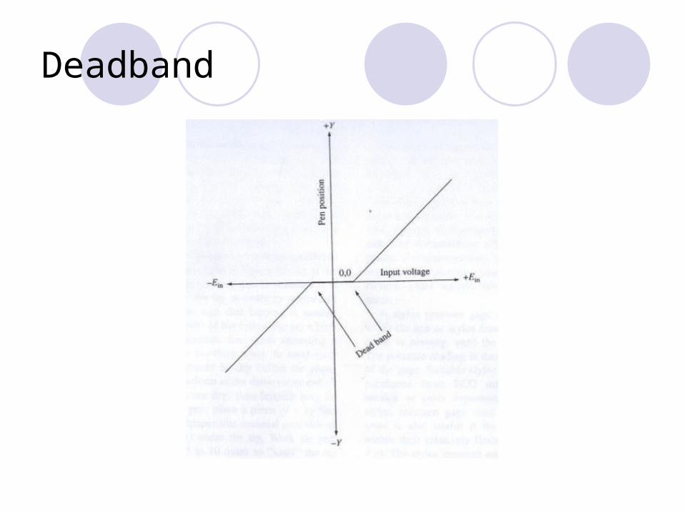
Deadband
Pen assembles are often damaged if they strike the limits-of-travel steps at a high speed.
A pair of Zener diodes connected back to back across the PMMC coil are sometimes used to accomplish the same job.
The Zenner potential of the diodes is selected so that the bodies break over and conduct current only when a voltage greater than the normal full-scale potential is applied to the input of the amplifier
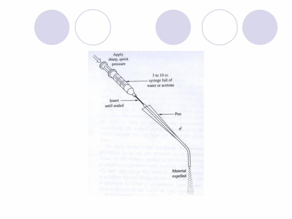
Maintenance of the PMMC writing stylus and pens Figure shows how to remove an ink blockage from an ink pen recorder that has
been allowed to stand too long without being used.
As a general rule, such recorders should be run for about five minutes or so once a week when not in regular service.
Fill a 3- t0 10-cc syringe with water (or acetone for certain type of ink) Insert end into the ink inlet
The pen has to removed from the machine for this operation.
Quickly, and with a single sharp motion, drive the plunger “home” so that a high pressure jet of water or acetone is forced into the pen. The ink clot should be forced out the other end.
Precautions
Always wear protective-goggles and protective clothing.
Make sure that the pen is aimed downward into a sink
As always when dealing with needles, be careful not to stick yourself
The thick high-viscosity ink strains every thing it touches and a nearly impossible to remove.
Ink pen tips are designed to operate parallel to the paper surface
If the pen is worn or when a new pen is installed, it is necessary to lap the tip in order to reestablish the parallelism.
The sign that lapping is needed will be either (or both) of the following: A- a blob f ink when the machine first stats a waveform, or B- a too-thick trace
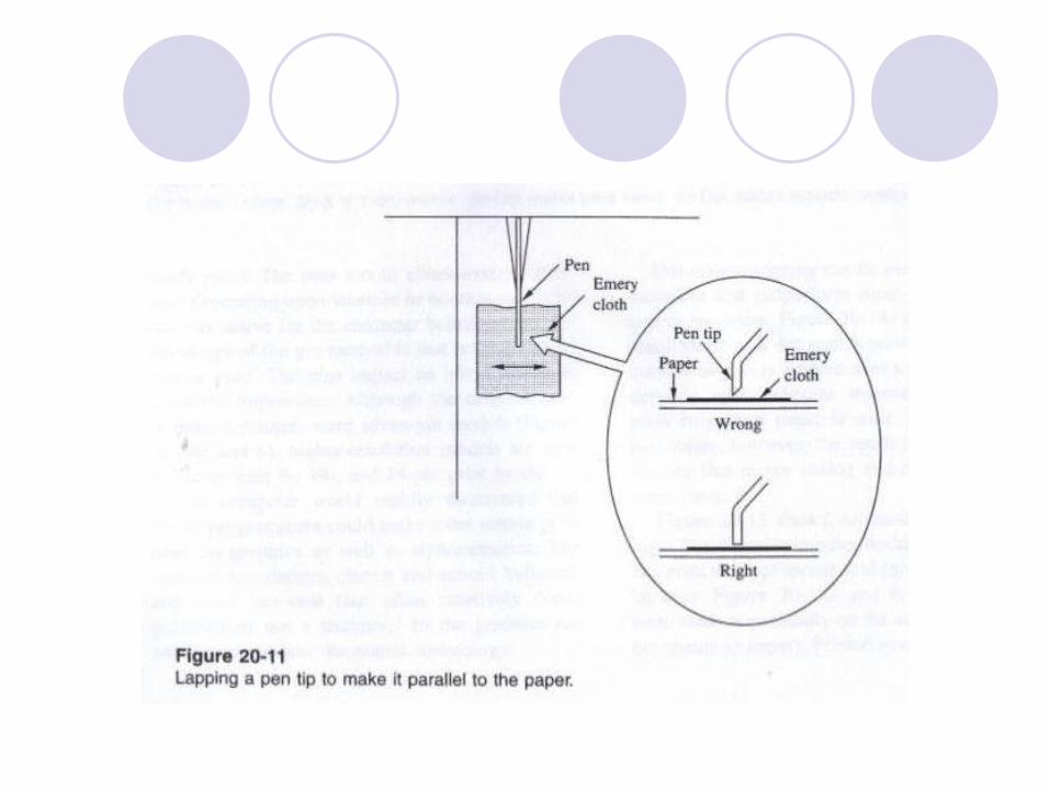
To lap the pen, place a piece of fine Emery cloth (sandpaper) under the tip.
Work the pen tip back and forth 5 to 10 times to sand the tip parallel to the paper
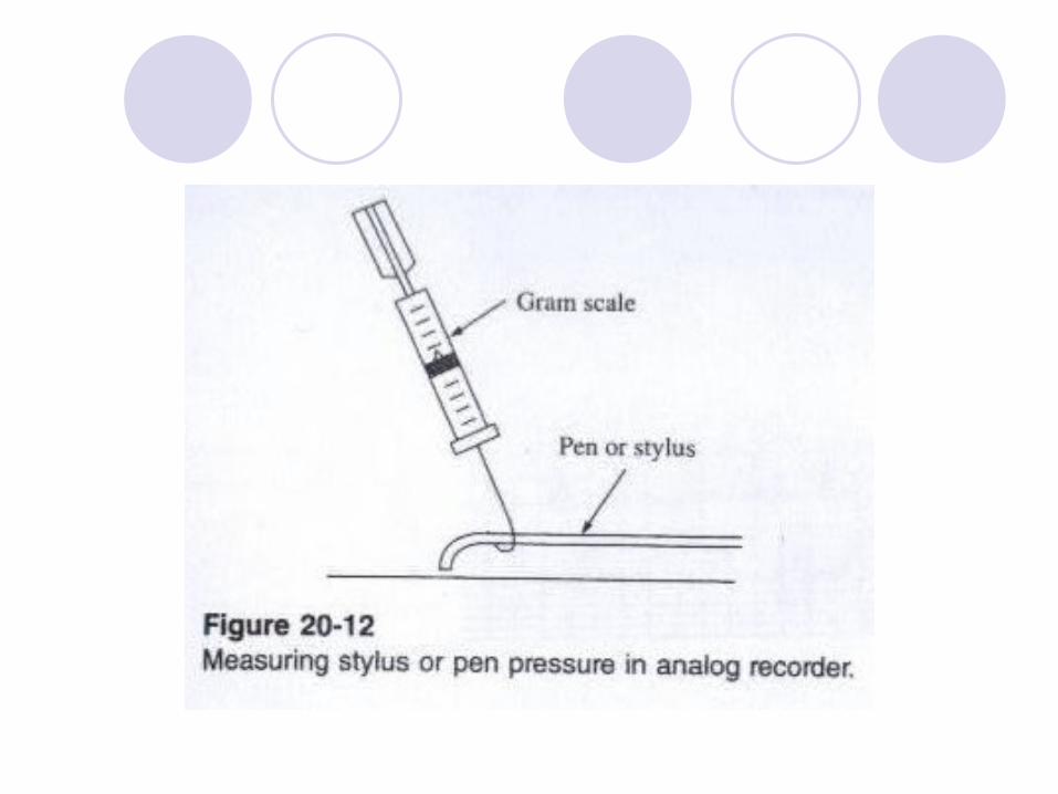
The pressure of the stylus or pen is also important.
If the pressure is not correct, then the waveform may be distorted . In medical equipment it is possible to make a normally healthy lead-1
ECG as though the patient has.
Suitable stylus ECG gages can be purchased from ECG machine manufactures.
The stylus pressure adjustment is made using a screw that is usually located on the rear of the stylus or the assembly that holds it in place.
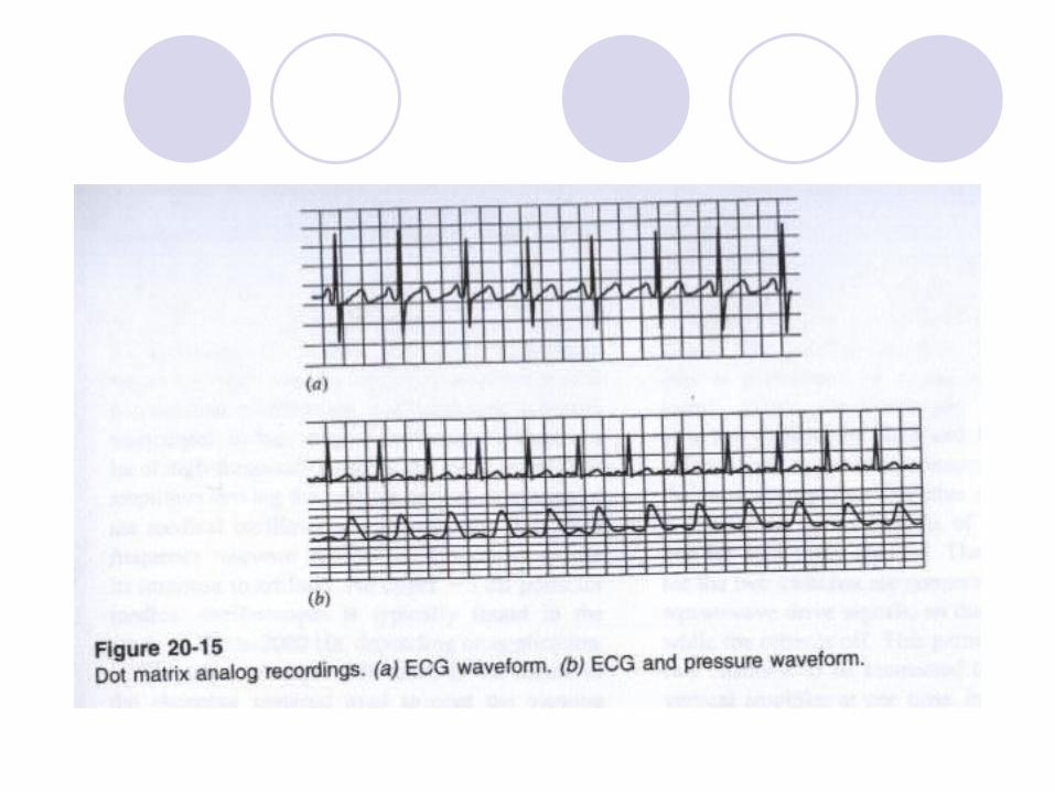
Dot matrix analog recorders
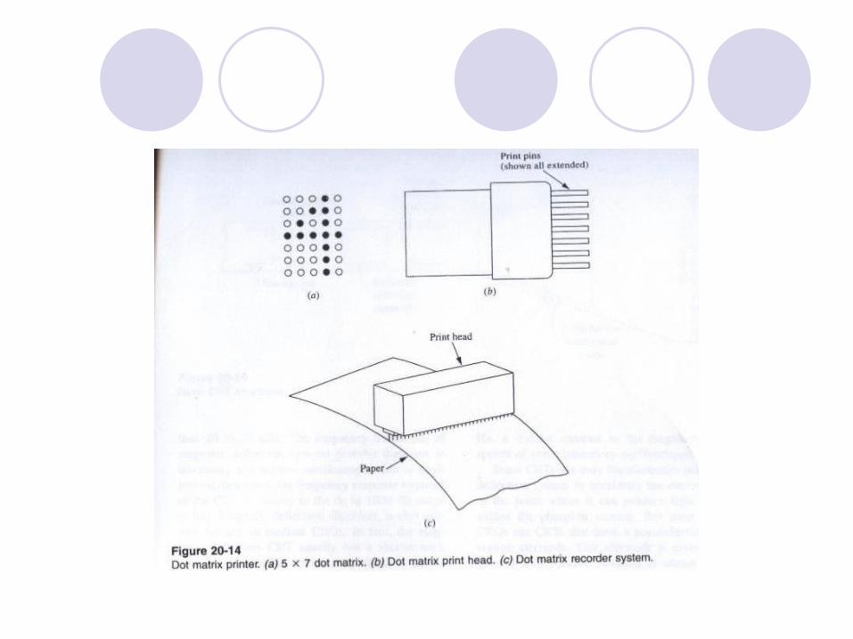
The original dot matrix printers used a 5 X 7 matrix of dots to form alphanumeric data.
The dot matrix machine used a print head to cause the correct dot element
Two different methods:A- Thermal based machine: Some of the earliest machines were thermally based. The dots were thermally connected to heating coils and could be heated
when needed. Special sensitive paper was used to receive the text. This method is no longer widely used.
B- an array of seven print hammers (pins). The pins would either extend or retract depending whether or not that
particular data was active for the character being printed. An advantage of the pin method is that ordinary paper can be used The pen impacted at inked ribbon to leave the impression Higher resolution models are now valuable with 9, 18, 24 pins
Medical Oscilloscopes
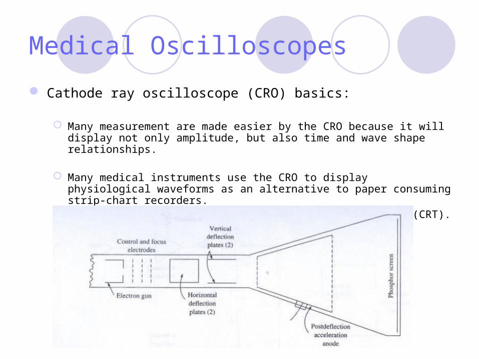
Cathode ray oscilloscope (CRO) basics:
Many measurement are made easier by the CRO because it will display not only amplitude, but also time and wave shape relationships.
Many medical instruments use the CRO to display physiological waveforms as an alternative to paper consuming strip-chart recorders.
The heart of any oscilloscope is the cathode ray tube (CRT).
An electron gun at the rear of the tube emits a beam of electrons that is accelerated and focused by special electrodes beyond the gun
When the accelerated electrodes strike the phosphor coated screen they will gave up their kinetic energy in the form of light.
Without any other external influences the beam will impact exactly in the center of the screen.
Patterns can be drawn on the CRT screen by deflecting the beam up and down and left and right of its normal path.
There are two basic types of CRT deflection system in common use in medical CRO’s:Magnetic deflection, andElectrostatic deflection

Electrostatic deflection CRT’s
The electrostatic form consists of two pair of deflection plates : One for horizontal deflection, and Other for vertical deflection
An electrical potential applied across either set of plates creates an electrostatic field that deflects the electron beam.
The polarity of the potential determines the direction of the deflection, while its magnitude determine the amount of deflection.
Most laboratory and service oscilloscopes use electrostatic deflection CRT’s because they can operate to very high frequencies.
Magnetic deflection CRT’s
In the magnetic deflection system vertical and horizontal electromagnetic coils are positioned around the neck of the CRT, concentric to the electron beam path. Both coils are housed is a single assembly called a deflection yoke.
Current flowing in the deflection coils create magnetic fields that deflect the electron beam.
The frequency limitations of magnetic deflection system prohibit their use in laboratory and service oscilloscopes.
Magnetic deflection is suitable for use in medical CRO’s
Medical Oscilloscopes
Most medical oscilloscopes are of the Y-time type, meaning that the signal, a time varying voltage, is applied to the Y-axis, while a sawtooth time base signal is applied to the X- axis.
This type of sweep allows us to view the waveform of the time domain signals such as the ECG and arterial pressure wave form.
The horizontal sweep speed for the most medical oscilloscopes is 25mm/s or 50 mm/s, with some offering 100 mm/s
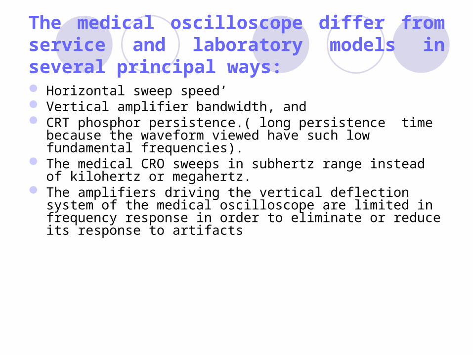
The medical oscilloscope differ from service and laboratory models in several principal ways: Horizontal sweep speed’ Vertical amplifier bandwidth, and CRT phosphor persistence.( long persistence time because the
waveform viewed have such low fundamental frequencies). The medical CRO sweeps in subhertz range instead of kilohertz or
megahertz. The amplifiers driving the vertical deflection system of the medical
oscilloscope are limited in frequency response in order to eliminate or reduce its response to artifacts
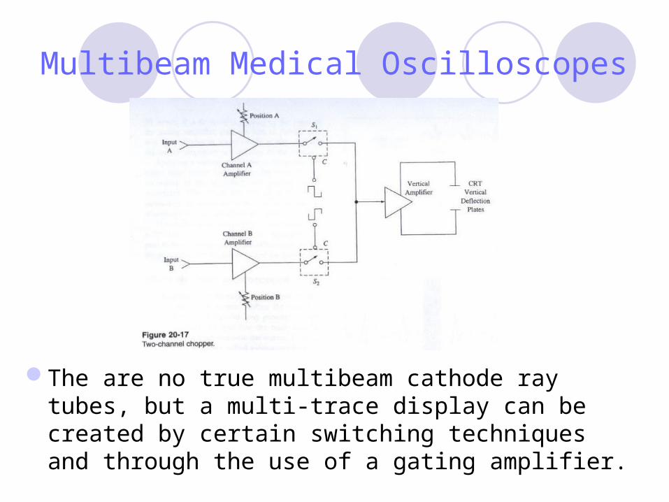
Multibeam Medical Oscilloscopes
The are no true multibeam cathode ray tubes, but a multi-trace display can be created by certain switching techniques and through the use of a gating amplifier.
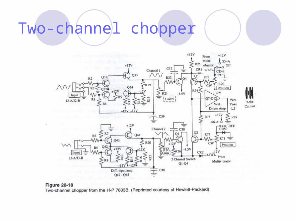
Two-channel chopper
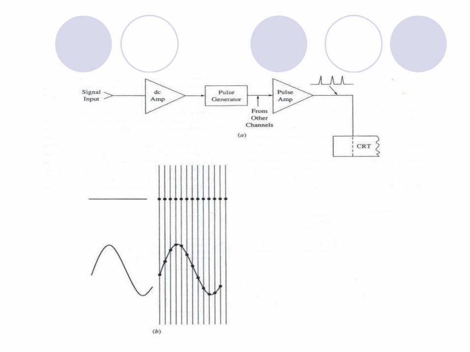
In a gating amplifier system the vertical axis of the CRT is scanned at a fixed rate, usually 1.5-t0 25 kHz range, while, the horizontal axis is swept at 25 mm/s rate.
The electron beam is turned off most of the time. The screen is turned on at specific times by pulses from the gating
amplifier. The pulse repetition rate is controlled by the input voltage
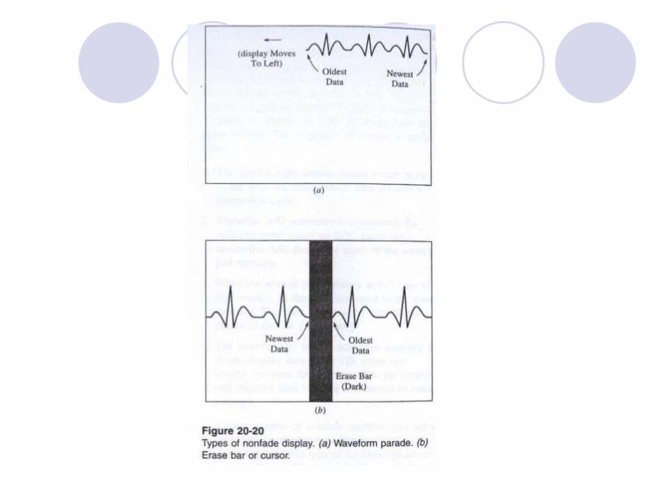

Storage Oscilloscope
The traditional oscilloscope uses a beam of electron to sweep the screen writing the waveform as it is deflected.
The trace vanishes shortly after it is written onto the screen.
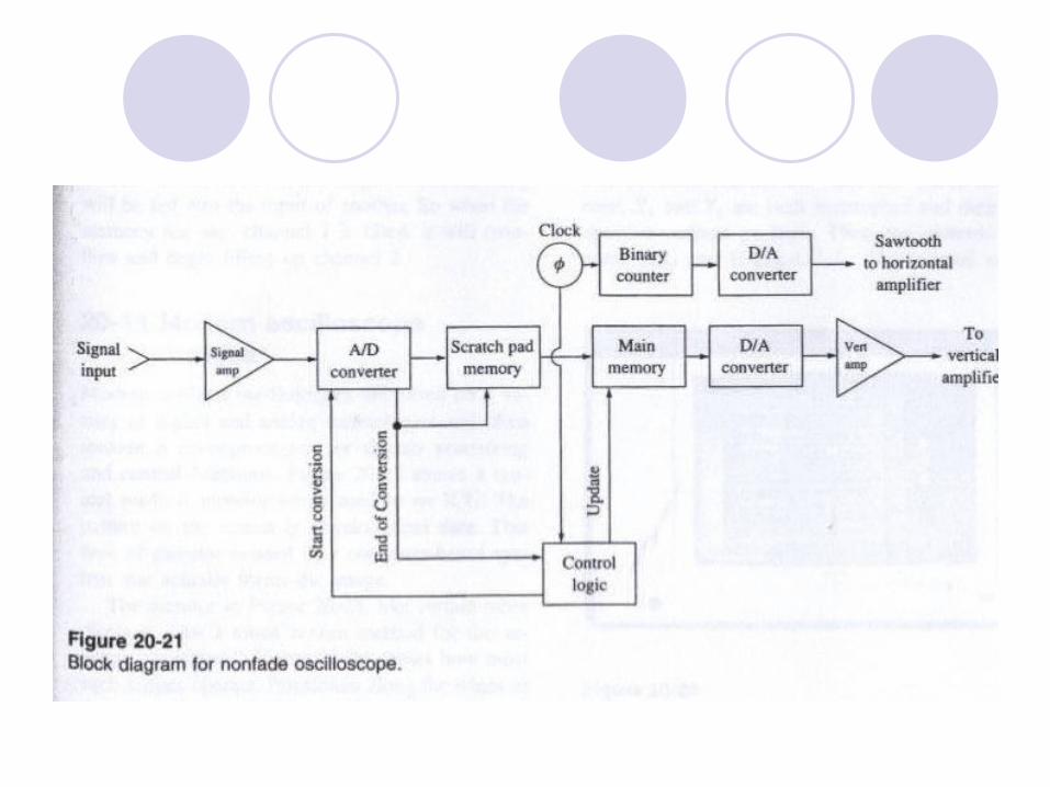
The principal sections of the storage oscilloscope are:1- input amplifier,2- Analog-to-digital converter (A/D),3- scratch pad memory,4- main memory,5- digital to analog converter (D/A),6- output amplifier, 7= control logic section.8- some models include D/A converter to create a horizontal time base
signal that is synchronize with the memory.

Analogue Amplifier
The analogue amplifier serves both - to scale the amplitude of the output signal to the range of the oscilloscope and- to buffer the oscilloscope from the outside world.
This stage tend to be a low gain (less than 10) transistor or IC operational amplifier.
The gain is usually variable, so that the input signal amplitude may be selected properly.
A/D converter
The A/D converter serves to create a digital binary word that is proportional to the applied signal amplitude.
Eight and 10 –bit A/D converters are very common. A/D operation must be synchronize with a series pulses. The control logic section will generate a start pulse to initiate a
conversion and the A/D will generate an end-of-conversion pulse to let the rest of the circuits when it is finished with the conversion cycle.

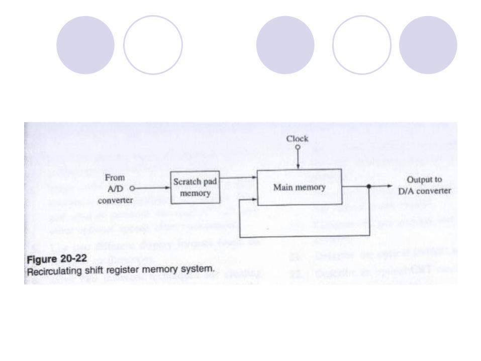
Memory
The scratch pad memory is a shift register that holds one to four of the most recent data produced by the A/D converter.
the main memory contains all the data appearing on the CRT Most medical non fade oscilloscopes use either 256, 512, 1024
eight-bit memory Both scratch and main memory are shift registers.
D/A converter
In some models horizontal sweep is generated by a second D/A converter. A binary counter used to sequentially address memory locations also drive the
horizontal D/A converter. The binary counter is driven by a clock signal, so the output lines increment by one
bit for each clock pulse, The result of this action at the output of the D/A converter is that a few millivolts for
every clock pulse received. When the counter over fellows, its output word goes from full scale( back to zero. The

Modern Oscilloscopes
Modern oscilloscope are based on a variety of digital and analog technologies and often include a microprocessor for signal processing and control functions
Touch screen oscilloscope
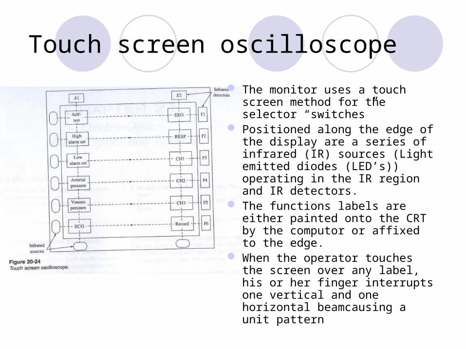
The monitor uses a touch screen method for the selector “switches”
Positioned along the edge of the display are a series of infrared (IR) sources (Light emitted diodes (LED’s)) operating in the IR region and IR detectors.
The functions labels are either painted onto the CRT by the computor or affixed to the edge.
When the operator touches the screen over any label, his or her finger interrupts one vertical and one horizontal beamcausing a unit pattern