Embed Size (px)
Citation preview

IOWA MOLD TOOLING CO., INC.
P.O. Box 189Garner, IA 50438Tel: 641.923.3711
Fax: 641.923.2424www.imt.com
6020 Crane Parts & Specifications
Manual # 99901220
Revised 12-02-2019
Copyright © 2019 Iowa Mold Tooling Co., Inc.All rights reserved
No part of this publication may be reproduced, stored in a retrieval system, or transmitted in any form or by any means, electronic, mechanical, photocopying, recording or otherwise without the prior written permission of Iowa Mold Tooling Co., Inc.
Iowa Mold Tooling Co., Inc. is an Oshkosh Corporation Company
00006020:99901220:REVISIONS LIST
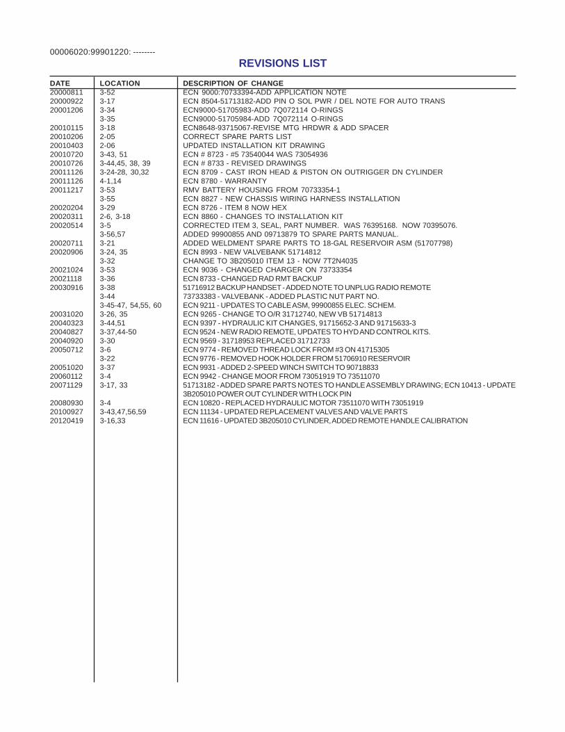
DATE LOCATION DESCRIPTION OF CHANGE20000811 3-52 ECN 9000:70733394-ADD APPLICATION NOTE20000922 3-17 ECN 8504-51713182-ADD PIN O SOL PWR / DEL NOTE FOR AUTO TRANS20001206 3-34 ECN9000-51705983-ADD 7Q072114 O-RINGS
3-35 ECN9000-51705984-ADD 7Q072114 O-RINGS20010115 3-18 ECN8648-93715067-REVISE MTG HRDWR & ADD SPACER20010206 2-05 CORRECT SPARE PARTS LIST20010403 2-06 UPDATED INSTALLATION KIT DRAWING20010720 3-43, 51 ECN # 8723 - #5 73540044 WAS 7305493620010726 3-44,45, 38, 39 ECN # 8733 - REVISED DRAWINGS20011126 3-24-28, 30,32 ECN 8709 - CAST IRON HEAD & PISTON ON OUTRIGGER DN CYLINDER20011126 4-1,14 ECN 8780 - WARRANTY20011217 3-53 RMV BATTERY HOUSING FROM 70733354-1
3-55 ECN 8827 - NEW CHASSIS WIRING HARNESS INSTALLATION20020204 3-29 ECN 8726 - ITEM 8 NOW HEX20020311 2-6, 3-18 ECN 8860 - CHANGES TO INSTALLATION KIT20020514 3-5 CORRECTED ITEM 3, SEAL, PART NUMBER. WAS 76395168. NOW 70395076.
3-56,57 ADDED 99900855 AND 09713879 TO SPARE PARTS MANUAL.20020711 3-21 ADDED WELDMENT SPARE PARTS TO 18-GAL RESERVOIR ASM (51707798)20020906 3-24, 35 ECN 8993 - NEW VALVEBANK 51714812
3-32 CHANGE TO 3B205010 ITEM 13 - NOW 7T2N403520021024 3-53 ECN 9036 - CHANGED CHARGER ON 7373335420021118 3-36 ECN 8733 - CHANGED RAD RMT BACKUP20030916 3-38 51716912 BACKUP HANDSET - ADDED NOTE TO UNPLUG RADIO REMOTE
3-44 73733383 - VALVEBANK - ADDED PLASTIC NUT PART NO.3-45-47, 54,55, 60 ECN 9211 - UPDATES TO CABLE ASM, 99900855 ELEC. SCHEM.
20031020 3-26, 35 ECN 9265 - CHANGE TO O/R 31712740, NEW VB 5171481320040323 3-44,51 ECN 9397 - HYDRAULIC KIT CHANGES, 91715652-3 AND 91715633-320040827 3-37,44-50 ECN 9524 - NEW RADIO REMOTE, UPDATES TO HYD AND CONTROL KITS.20040920 3-30 ECN 9569 - 31718953 REPLACED 3171273320050712 3-6 ECN 9774 - REMOVED THREAD LOCK FROM #3 ON 41715305
3-22 ECN 9776 - REMOVED HOOK HOLDER FROM 51706910 RESERVOIR20051020 3-37 ECN 9931 - ADDED 2-SPEED WINCH SWITCH TO 9071883320060112 3-4 ECN 9942 - CHANGE MOOR FROM 73051919 TO 7351107020071129 3-17, 33 51713182 - ADDED SPARE PARTS NOTES TO HANDLE ASSEMBLY DRAWING; ECN 10413 - UPDATE
3B205010 POWER OUT CYLINDER WITH LOCK PIN20080930 3-4 ECN 10820 - REPLACED HYDRAULIC MOTOR 73511070 WITH 7305191920100927 3-43,47,56,59 ECN 11134 - UPDATED REPLACEMENT VALVES AND VALVE PARTS20120419 3-16,33 ECN 11616 - UPDATED 3B205010 CYLINDER, ADDED REMOTE HANDLE CALIBRATION
--------
00006020:99901220:
INTRODUCTION
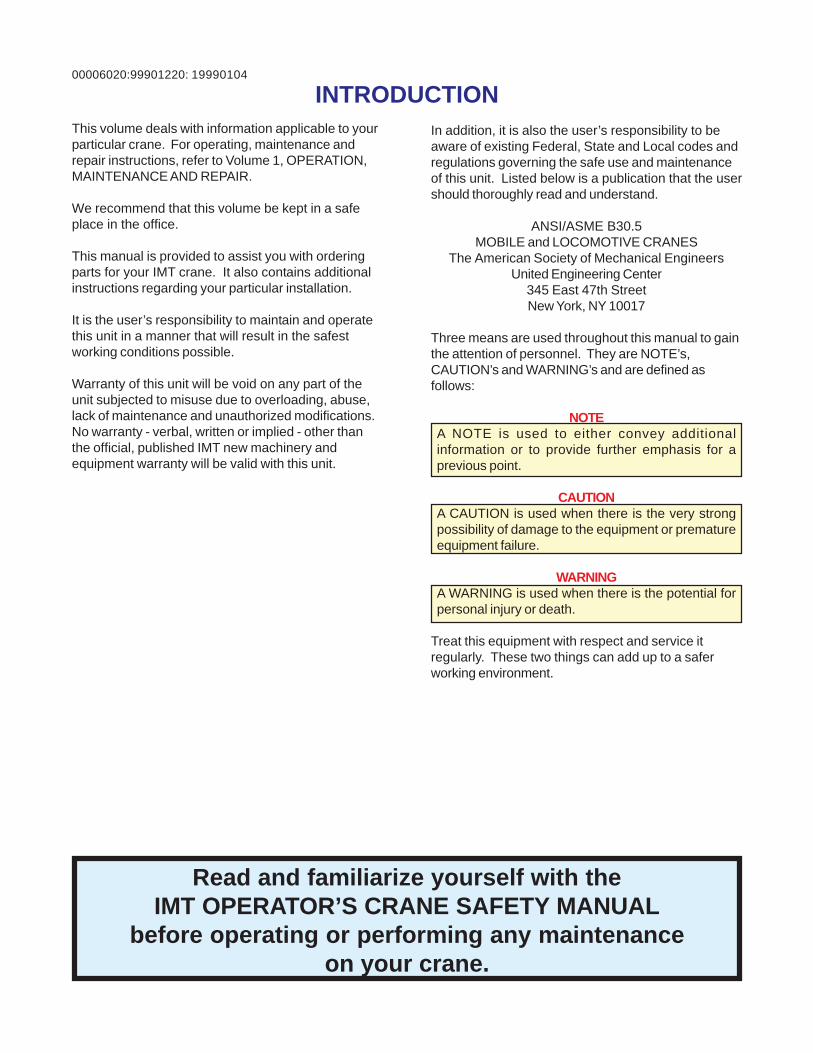
Read and familiarize yourself with theIMT OPERATOR’S CRANE SAFETY MANUAL
before operating or performing any maintenanceon your crane.
19990104
This volume deals with information applicable to yourparticular crane. For operating, maintenance andrepair instructions, refer to Volume 1, OPERATION,MAINTENANCE AND REPAIR.
We recommend that this volume be kept in a safeplace in the office.
This manual is provided to assist you with orderingparts for your IMT crane. It also contains additionalinstructions regarding your particular installation.
It is the user’s responsibility to maintain and operatethis unit in a manner that will result in the safestworking conditions possible.
Warranty of this unit will be void on any part of theunit subjected to misuse due to overloading, abuse,lack of maintenance and unauthorized modifications.No warranty - verbal, written or implied - other thanthe official, published IMT new machinery andequipment warranty will be valid with this unit.
In addition, it is also the user’s responsibility to beaware of existing Federal, State and Local codes andregulations governing the safe use and maintenanceof this unit. Listed below is a publication that the usershould thoroughly read and understand.
ANSI/ASME B30.5MOBILE and LOCOMOTIVE CRANES
The American Society of Mechanical EngineersUnited Engineering Center
345 East 47th StreetNew York, NY 10017
Three means are used throughout this manual to gainthe attention of personnel. They are NOTE’s,CAUTION’s and WARNING’s and are defined asfollows:
NOTEA NOTE is used to either convey additionalinformation or to provide further emphasis for aprevious point.
CAUTIONA CAUTION is used when there is the very strongpossibility of damage to the equipment or prematureequipment failure.
WARNINGA WARNING is used when there is the potential forpersonal injury or death.
Treat this equipment with respect and service itregularly. These two things can add up to a saferworking environment.

00006020:99901220: 20000731NOTES
00006020:99901220: 1-120000404
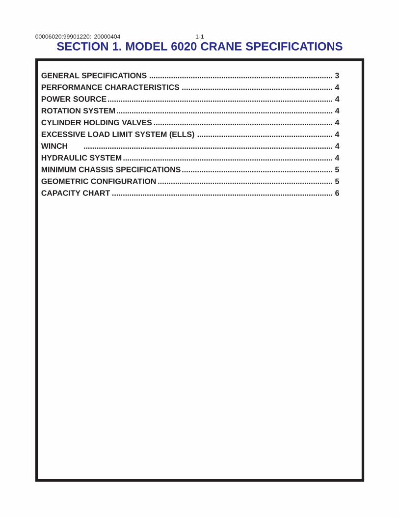
SECTION 1. MODEL 6020 CRANE SPECIFICATIONS
GENERAL SPECIFICATIONS .................................................................................... 3PERFORMANCE CHARACTERISTICS ..................................................................... 4POWER SOURCE....................................................................................................... 4ROTATION SYSTEM................................................................................................... 4CYLINDER HOLDING VALVES .................................................................................. 4EXCESSIVE LOAD LIMIT SYSTEM (ELLS) .............................................................. 4WINCH .................................................................................................................. 4HYDRAULIC SYSTEM ................................................................................................ 4MINIMUM CHASSIS SPECIFICATIONS..................................................................... 5GEOMETRIC CONFIGURATION ................................................................................ 5CAPACITY CHART ..................................................................................................... 6

00006020:99901220: 1-2NOTES
19990104
00006020:99901220: 1-3
IOWA MOLD TOOLING CO., INC.BOX 189, GARNER, IA 50438-0189
TEL: 641-923-3711 FAX: 641-923-2424
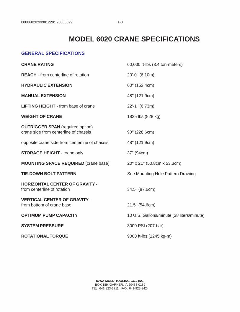
MODEL 6020 CRANE SPECIFICATIONS
20000629
GENERAL SPECIFICATIONS
CRANE RATING 60,000 ft-lbs (8.4 ton-meters)
REACH - from centerline of rotation 20'-0'’ (6.10m)
HYDRAULIC EXTENSION 60'’ (152.4cm)
MANUAL EXTENSION 48'’ (121.9cm)
LIFTING HEIGHT - from base of crane 22'-1'’ (6.73m)
WEIGHT OF CRANE 1825 lbs (828 kg)
OUTRIGGER SPAN (required option)crane side from centerline of chassis 90'’ (228.6cm)
opposite crane side from centerline of chassis 48'’ (121.9cm)
STORAGE HEIGHT - crane only 37” (94cm)
MOUNTING SPACE REQUIRED (crane base) 20'’ x 21'’ (50.8cm x 53.3cm)
TIE-DOWN BOLT PATTERN See Mounting Hole Pattern Drawing
HORIZONTAL CENTER OF GRAVITY -from centerline of rotation 34.5'’ (87.6cm)
VERTICAL CENTER OF GRAVITY -from bottom of crane base 21.5'’ (54.6cm)
OPTIMUM PUMP CAPACITY 10 U.S. Gallons/minute (38 liters/minute)
SYSTEM PRESSURE 3000 PSI (207 bar)
ROTATIONAL TORQUE 9000 ft-lbs (1245 kg-m)
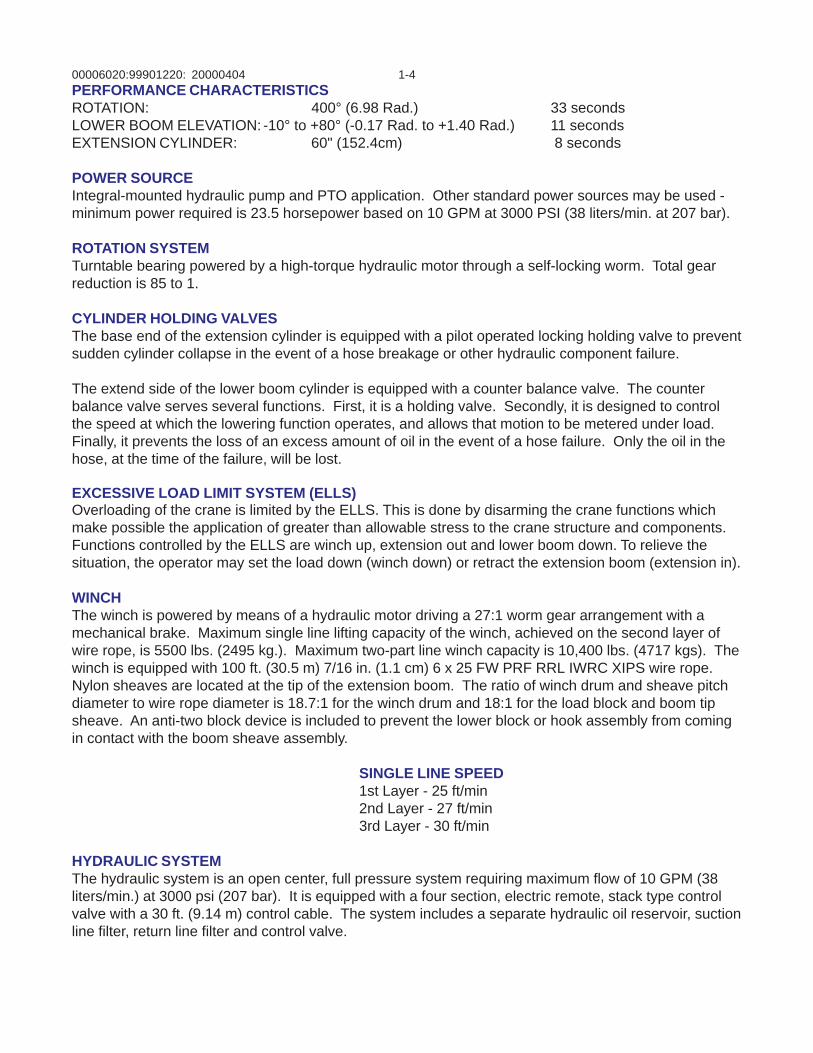
00006020:99901220: 1-420000404PERFORMANCE CHARACTERISTICSROTATION: 400° (6.98 Rad.) 33 secondsLOWER BOOM ELEVATION: -10° to +80° (-0.17 Rad. to +1.40 Rad.) 11 secondsEXTENSION CYLINDER: 60" (152.4cm) 8 seconds
POWER SOURCEIntegral-mounted hydraulic pump and PTO application. Other standard power sources may be used -minimum power required is 23.5 horsepower based on 10 GPM at 3000 PSI (38 liters/min. at 207 bar).
ROTATION SYSTEMTurntable bearing powered by a high-torque hydraulic motor through a self-locking worm. Total gearreduction is 85 to 1.
CYLINDER HOLDING VALVESThe base end of the extension cylinder is equipped with a pilot operated locking holding valve to preventsudden cylinder collapse in the event of a hose breakage or other hydraulic component failure.
The extend side of the lower boom cylinder is equipped with a counter balance valve. The counterbalance valve serves several functions. First, it is a holding valve. Secondly, it is designed to controlthe speed at which the lowering function operates, and allows that motion to be metered under load.Finally, it prevents the loss of an excess amount of oil in the event of a hose failure. Only the oil in thehose, at the time of the failure, will be lost.
EXCESSIVE LOAD LIMIT SYSTEM (ELLS)Overloading of the crane is limited by the ELLS. This is done by disarming the crane functions whichmake possible the application of greater than allowable stress to the crane structure and components.Functions controlled by the ELLS are winch up, extension out and lower boom down. To relieve thesituation, the operator may set the load down (winch down) or retract the extension boom (extension in).
WINCHThe winch is powered by means of a hydraulic motor driving a 27:1 worm gear arrangement with amechanical brake. Maximum single line lifting capacity of the winch, achieved on the second layer ofwire rope, is 5500 lbs. (2495 kg.). Maximum two-part line winch capacity is 10,400 lbs. (4717 kgs). Thewinch is equipped with 100 ft. (30.5 m) 7/16 in. (1.1 cm) 6 x 25 FW PRF RRL IWRC XIPS wire rope.Nylon sheaves are located at the tip of the extension boom. The ratio of winch drum and sheave pitchdiameter to wire rope diameter is 18.7:1 for the winch drum and 18:1 for the load block and boom tipsheave. An anti-two block device is included to prevent the lower block or hook assembly from comingin contact with the boom sheave assembly.
SINGLE LINE SPEED1st Layer - 25 ft/min2nd Layer - 27 ft/min3rd Layer - 30 ft/min
HYDRAULIC SYSTEMThe hydraulic system is an open center, full pressure system requiring maximum flow of 10 GPM (38liters/min.) at 3000 psi (207 bar). It is equipped with a four section, electric remote, stack type controlvalve with a 30 ft. (9.14 m) control cable. The system includes a separate hydraulic oil reservoir, suctionline filter, return line filter and control valve.
00006020:99901220: 1-519990104
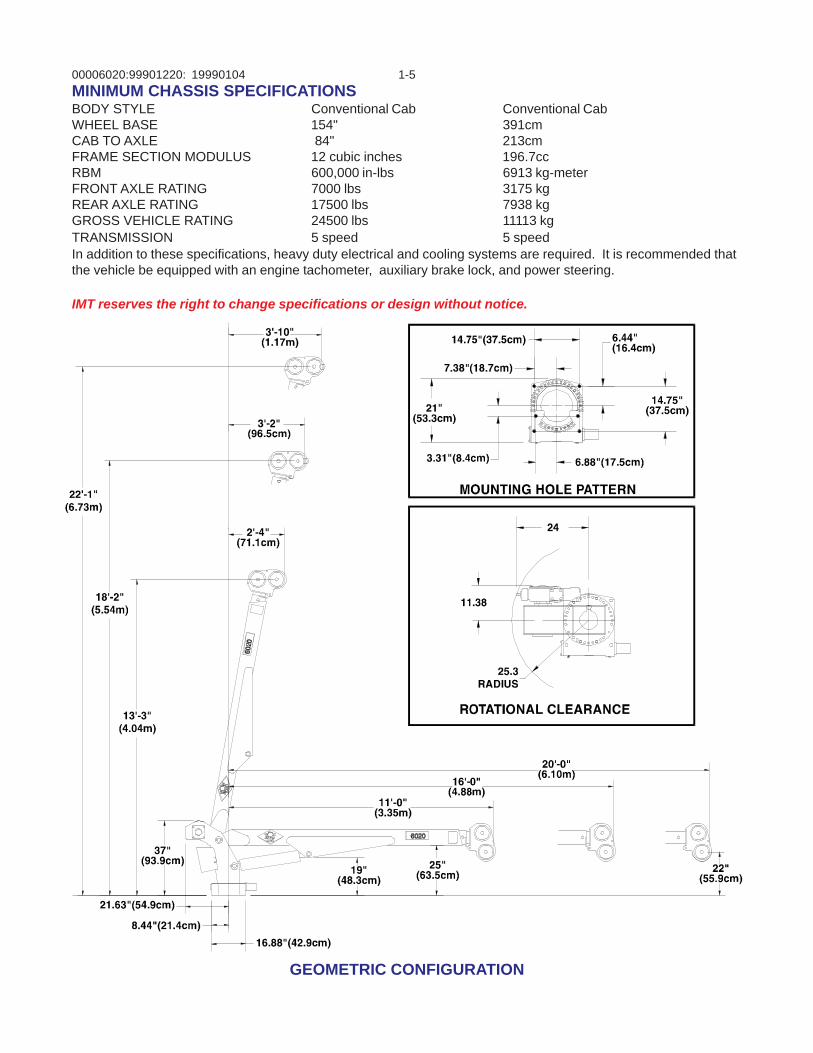
GEOMETRIC CONFIGURATION
MINIMUM CHASSIS SPECIFICATIONSBODY STYLE Conventional Cab Conventional CabWHEEL BASE 154" 391cmCAB TO AXLE 84" 213cmFRAME SECTION MODULUS 12 cubic inches 196.7ccRBM 600,000 in-lbs 6913 kg-meterFRONT AXLE RATING 7000 lbs 3175 kgREAR AXLE RATING 17500 lbs 7938 kgGROSS VEHICLE RATING 24500 lbs 11113 kgTRANSMISSION 5 speed 5 speedIn addition to these specifications, heavy duty electrical and cooling systems are required. It is recommended thatthe vehicle be equipped with an engine tachometer, auxiliary brake lock, and power steering.
IMT reserves the right to change specifications or design without notice.
00006020:99901220: 1-620000629
IOWA MOLD TOOLING CO., INC.BOX 189, GARNER, IA 50438-0189TEL: 641-923-3711 FAX: 641-923-2424
0 3’-0“(91.4cm)
6’-0“(1.83m)
11’-0“(3.35m)
16’-0“(4.88m)
20’-0“(6.10m)
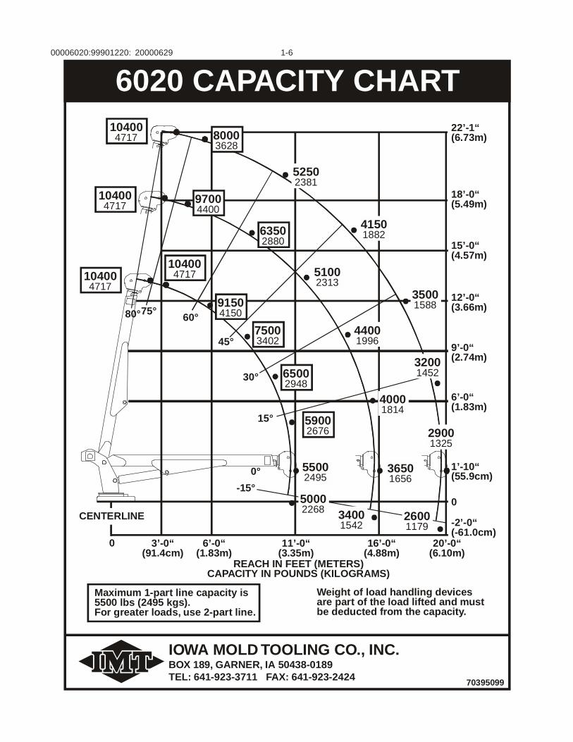
REACH IN FEET (METERS)CAPACITY IN POUNDS (KILOGRAMS)
Weight of load handling devicesare part of the load lifted and mustbe deducted from the capacity.
Maximum 1-part line capacity is5500 lbs (2495 kgs).For greater loads, use 2-part line.
70395099
6020 CAPACITY CHART
0
-2’-0“(-61.0cm)
50002268 3400
154226001179
-15°
CENTERLINE
22’-1“(6.73m)
18’-0“(5.49m)
15’-0“(4.57m)
12’-0“(3.66m)
9’-0“(2.74m)
6’-0“(1.83m)
63502880
52502381
41501882
35001588
44001996
40001814
32001452
51002313
75003402
91504150
65002948
59002676
80003628
97004400
60°
45°
30°
15°
104004717
104004717
104004717
104004717
80°75°
0° 55002495
36501656
1’-10“(55.9cm)
29001325
00006020:99901220: 2-120000404
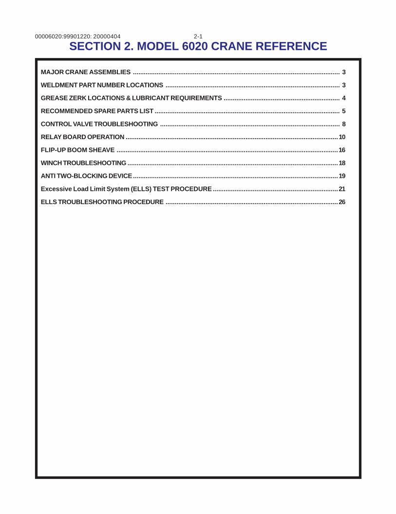
SECTION 2. MODEL 6020 CRANE REFERENCE
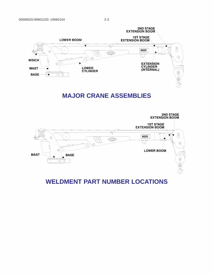
MAJOR CRANE ASSEMBLIES .................................................................................................................. 3
WELDMENT PART NUMBER LOCATIONS ................................................................................................ 3
GREASE ZERK LOCATIONS & LUBRICANT REQUIREMENTS ................................................................ 4
RECOMMENDED SPARE PARTS LIST ...................................................................................................... 5
CONTROL VALVE TROUBLESHOOTING ................................................................................................... 8
RELAY BOARD OPERATION .....................................................................................................................10
FLIP-UP BOOM SHEAVE ..........................................................................................................................16
WINCH TROUBLESHOOTING ....................................................................................................................18
ANTI TWO-BLOCKING DEVICE.................................................................................................................19
Excessive Load Limit System (ELLS) TEST PROCEDURE .....................................................................21
ELLS TROUBLESHOOTING PROCEDURE ...............................................................................................26

00006020:99901220: 2-2NOTES
19990104
00006020:99901220: 2-319990104
MAJOR CRANE ASSEMBLIES
WELDMENT PART NUMBER LOCATIONS
00006020:99901220: 2-4
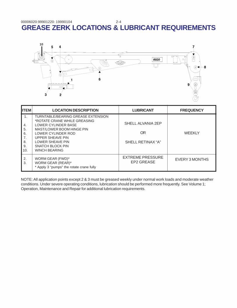
1. TURNTABLE/BEARING GREASE EXTENSION*ROTATE CRANE WHILE GREASING
4. LOWER CYLINDER BASE 5. MAST/LOWER BOOM HINGE PIN 6. LOWER CYLINDER ROD 7. UPPER SHEAVE PIN 8. LOWER SHEAVE PIN 9. SNATCH BLOCK PIN 10. WINCH BEARING
2. WORM GEAR (FWD)* 3. WORM GEAR (REAR)*
* Apply 3 “pumps” the rotate crane fully
ITEM LOCATION DESCRIPTION LUBRICANT FREQUENCY
SHELL ALVANIA 2EP
OR
SHELL RETINAX “A”
WEEKLY
GREASE ZERK LOCATIONS & LUBRICANT REQUIREMENTS
NOTE: All application points except 2 & 3 must be greased weekly under normal work loads and moderate weatherconditions. Under severe operating conditions, lubrication should be performed more frequently. See Volume 1;Operation, Maintenance and Repair for additional lubrication requirements.
19990104
EXTREME PRESSUREEP2 GREASE
EVERY 3 MONTHS
10
00006020:99901220: 2-520010206
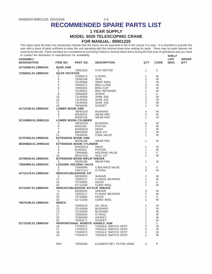
RECOMMENDED SPARE PARTS LIST1 YEAR SUPPLY
MODEL 6020 TELESCOPING CRANEFOR MANUAL: 99901220
This spare parts list does not necessarily indicate that the items can be expected to fail in the course of a year. It is intended to provide theuser with a stock of parts sufficient to keep the unit operating with the minimal down-time waiting for parts. There may be parts failures notcovered by this list. Parts not listed are considered as not being Critical or Normal Wear items during the first year of operations and you needto contact the distributor or manufacturer for availability.
41715069.01.19990104 BASE ASM 2 73051919 HYD MOTOR 1 C
71056551.01.19990104 GEAR ROTATOR 2 70395074 O-RING 1 W 3 76395168 SEAL 2 W 4 70145846 SNAP RING 1 W 5 70055271 BRG-CONE 2 W 6 70055281 BRG-CUP 2 W 7 70145501 BRG RETAINER 1 W 8 70056550 WORM 1 C15 73145506 SHIM .005 2 W16 73145505 SHIM .015 2 W17 73145504 SHIM .030 2 W18 76039295 GASKET 1 W
41712180.01.19990104 LOWER BOOM ASM 5 7BF81520 BUSHING 4 W 6 60030015 WEAR PAD 2 W 7 60030139 WEAR PAD 1 W
3C126990.01.19991216 LOWER BOOM CYLINDER 3 7BF81520 BUSHING 6 W 6 6I503181 PISTON 1 W 7 6H050025 HEAD 1 W 8 9B043920 SEAL KIT 1 W21 73540035 C’BAL VALVE 1 W
41707663.01.19990104 EXTENSION BOOM ASM 5 60030189 WEAR PAD 1 W
3B309820.01.19990104 EXTENSION BOOM CYLINDER 4 6H025015 HEAD 1 W 5 6IX02512 PISTON 1 W 9 73054900 HOLDING VALVE 1 C10 9B101220 SEAL KIT 1 W
41709440.01.19990104 EXTENSION BOOM W/FLIP SHEAVE 5 60030189 WEAR PAD 1 W
73054900.01.19990104 LOCKING HOLDING VALVE 2 73054999 C’BALANCE VALVE 1 C 3 7Q072112 O-RING 3 W
41712179.01.19990104 WINCH/CABLE/HOOK KIT 6 60030255 SHEAVE 3 W12 70055117 FLANGE BEARING 1 W16 70732882 HOOK 1 C42 51713168 CORD REEL 1 W
31712207.01.19990104 WINCH/CABLE/HOOK KIT-FLIP SHEAVE 6 60030255 SHEAVE 3 W12 70055117 FLANGE BEARING 1 W16 70732882 HOOK 1 C42 51713168 CORD REEL 1 W
70570198.01.19990104 WINCH11 76393419 OIL SEAL 1 W12 70143948 BUSHING 1 W13 70143949 BUSHING 1 W17 76393420 O-RING 1 W23 76394300 GASKET 1 W25 76393171 GASKET 1 W
51713182.01.19990104 PROPORTIONAL REMOTE HANDLE ASM 1 C16 77040371 TOGGLE SWITCH SPST 2 W17 77040372 TOGGLE SWITCH SPDT 4 W18 77040373 TOGGLE SWITCH SPST 2 W19 77040374 TOGGLE SWITCH SPDT 1 W
REF 73052006 ELEMENT-RET. FILTER 10MIC 6 P
SHELFLIFE(MO)
ORDERQTYCODEQTYDESCRIPTIONPART NO.ITEM NO.
ASSEMBLYDESIGNATION
00006020:99901220: 2-620020311
INSTALLATION
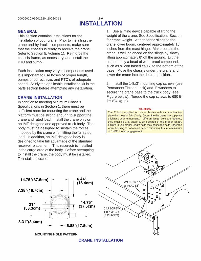
CRANE INSTALLATIONMOUNTING HOLE PATTERN
GENERALThis section contains instructions for theinstallation of your crane. Prior to installing thecrane and hydraulic components, make surethat the chassis is ready to receive the crane(refer to Section 5, Volume 1). Reinforce thechassis frame, as necessary, and install thePTO and pump.
Each installation may vary in components used.It is important to use hoses of proper length,pumps of correct size, and PTO’s of adequatespeed. Study the applicable installation kit in theparts section before attempting any installation.
CRANE INSTALLATIONIn addition to meeting Minimum ChassisSpecifications in Section 1, there must besufficient room for mounting the crane and theplatform must be strong enough to support thecrane and rated load. Install the crane only onan IMT designed and approved truck body. Thebody must be designed to sustain the forcesimposed by the crane when lifting the full ratedload. In addition, an IMT designed body isdesigned to take full advantage of the standardreservoir placement. This reservoir is installedin the cargo area of the body. Before attemptingto install the crane, the body must be installed.To install the crane:
1. Use a lifting device capable of lifting theweight of the crane. See Specifications Sectionfor crane weight. Attach fabric slings to thecrane lower boom, centered approximately 18inches from the mast hinge. Make certain thecrane is well balanced on the slings by slowlylifting approximately 6" off the ground. Lift thecrane, apply a bead of waterproof compound,such as silicon based caulk, to the bottom of thebase. Move the chassis under the crane andlower the crane into the desired position.
2. Install the 1-8x3" mounting cap screws (usePermanent Thread Lock) and 1" washers tosecure the crane base to the truck body (seeFigure below). Torque the cap screws to 680 ft-lbs (94 kg-m).
CAUTIONThe 3” bolts supplied for use on bodies with a crane box topplate thickness of 7/8-1” only. Determine the crane box top platethickness prior to mounting. If different length bolts are required,they must be 1-8, grade 8, zinc coated of the proper length.Failure to use proper length bolts may cause the bolts under theworm housing to bottom out before torqueing. Insure a minimumof 1-1/2” thread engagement.
CAPSCREW1-8 X 3" GR8(6 PLACES)
WASHER 1"(6 PLACES)
00006020:99901220: 2-719990104
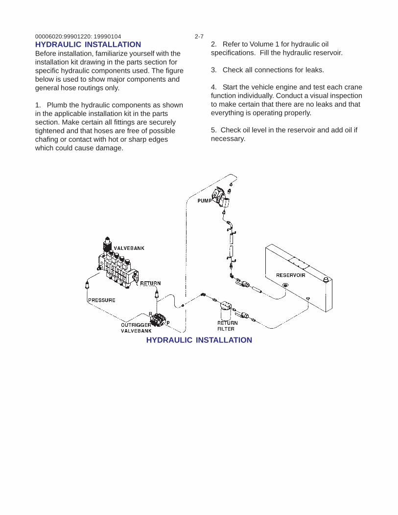
HYDRAULIC INSTALLATION
HYDRAULIC INSTALLATIONBefore installation, familiarize yourself with theinstallation kit drawing in the parts section forspecific hydraulic components used. The figurebelow is used to show major components andgeneral hose routings only.
1. Plumb the hydraulic components as shownin the applicable installation kit in the partssection. Make certain all fittings are securelytightened and that hoses are free of possiblechafing or contact with hot or sharp edgeswhich could cause damage.
2. Refer to Volume 1 for hydraulic oilspecifications. Fill the hydraulic reservoir.
3. Check all connections for leaks.
4. Start the vehicle engine and test each cranefunction individually. Conduct a visual inspectionto make certain that there are no leaks and thateverything is operating properly.
5. Check oil level in the reservoir and add oil ifnecessary.
00006020:99901220: 2-820000720
CONTROL VALVE TROUBLESHOOTINGGENERALThis section describes the operatingcharacteristics of the main control valvebankused on this model of crane. It also providestroubleshooting information which applies to thisvalvebank. See figure on following page forreference.
ELECTRICAL-AMP DRIVER
POWER LEDThe Power LED illuminates red while power isbeing applied to the valve amplifier. If the LED isnot illuminated, no power is being applied to thevalve amplifier.
If the Power LED does not function asdescribed, inspect input wiring and repair orreplace as necessary. When input power isapplied, the LED should illuminate.
PMW% LEDThe PMW% LED indicates the condition of theoutput current flowing to the proportional valve.The LED will change colors from, red to yellowto green. The change of colors indicates thevariance of current flowing to the proportionalvalve. Red indicates minimum current andgreen indicates maximum current. Thisrepresents the flow condition going from lowflow (red) to maximum flow (green), thusvarying the speed of crane functions.
If the LED stays red, as the speed controltrigger is activated, a dead short is present inthe circuit. This could be the result of a wiringproblem, shorted out proportional coil, etc.Inspect the wiring and replace the proportionalcoil, if required.
MIN POTENTIOMETERThe Min adjustment pot will be used to set theminimum amount of movement of an individualfunction at the valvebank when the correspond-ing function switch at the handset is depressed.To adjust, set engine at high speed controlsetting. Depress the “Rotation” function switchat the handset. Adjust the Min pot at the AMPdriver card clockwise until crane begins torotate or counterclockwise until motion begins tostop. No other electrical adjustments are re-quired to properly operate the crane.
HYDRAULICS-VALVEBANK
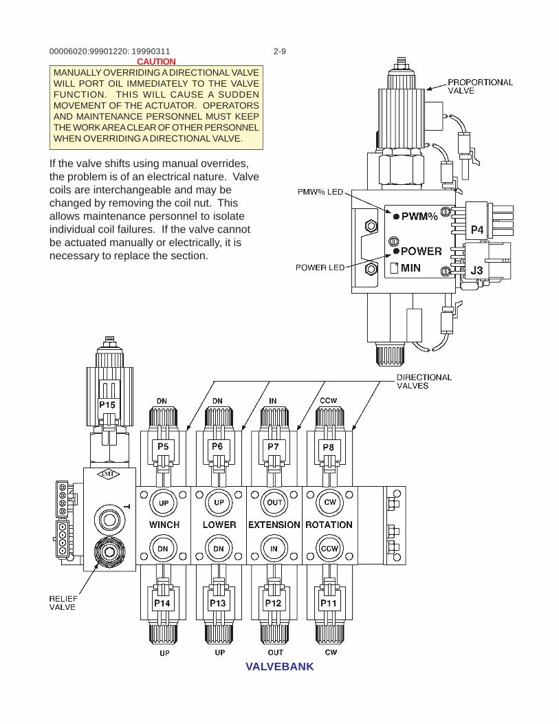
RELIEF VALVEThe relief valve limits the maximum systempressure. Pressure limits the amount of torqueor force an actuator will see. This pressure ispreset to 3000 psi at 10 gpm. If the relief valveshould fail, it would likely stick open. This wouldprevent system pressure from developing andcause a lack of torque/force at the actuator. Therelief valve can be changed easily by screwingit out and replacing with a new one.
PROPORTIONAL VALVEThe proportional valve varies the oil flow to theindividual crane functions. Doing so dictates thespeed of the crane functions. As the electricalcurrent increases to the valve, by using thetrigger on the control handle, more oil is porteddownstream to the crane function. If the valvecoil burns out, the operator would be unable tovary the flow to the crane functions. If the valvespool becomes stuck, the operator would beunable to vary the downstream flow. If speedcontrol is the problem, it is likely an indication ofa proportional valve problem. It is necessary toverify that current is flowing to the coil correctly,and that it is not an electrical problem.
The proportional valve can also be operatedmanually for test purposes. The valve stem canbe screwed in manually to port oil downstream.Doing so will manually position the valve spooland hold it in the manually commanded position.
DIRECTIONAL VALVESThe directional valves (4) control the direction ofthe crane functions. When one of the solenoidsis energized, it shifts the valve spool. Thisallows oil to flow out one of the valve ports. If afunction does not work, a directional valve maybe to blame.
These valves have a standard manual override.You may manually shift the valve by pushing thepin, located in the middle of the solenoid.
00006020:99901220: 2-919990311
VALVEBANK
CAUTIONMANUALLY OVERRIDING A DIRECTIONAL VALVEWILL PORT OIL IMMEDIATELY TO THE VALVEFUNCTION. THIS WILL CAUSE A SUDDENMOVEMENT OF THE ACTUATOR. OPERATORSAND MAINTENANCE PERSONNEL MUST KEEPTHE WORK AREA CLEAR OF OTHER PERSONNELWHEN OVERRIDING A DIRECTIONAL VALVE.
If the valve shifts using manual overrides,the problem is of an electrical nature. Valvecoils are interchangeable and may bechanged by removing the coil nut. Thisallows maintenance personnel to isolateindividual coil failures. If the valve cannotbe actuated manually or electrically, it isnecessary to replace the section.
00006020:99901220: 2-10
RELAY BOARD OPERATION19990104
INTRODUCTIONTo understand how the relay board operates, it isnecessary to understand how the individual relaysfunction.
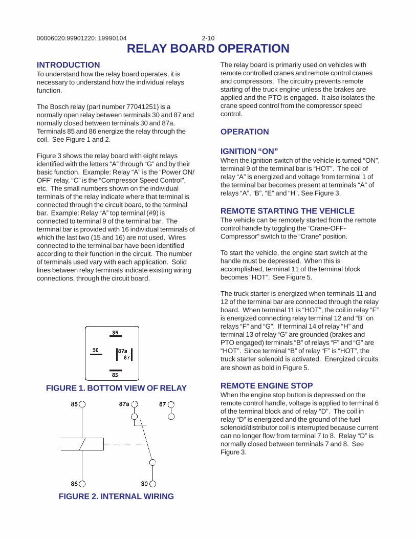
The Bosch relay (part number 77041251) is anormally open relay between terminals 30 and 87 andnormally closed between terminals 30 and 87a.Terminals 85 and 86 energize the relay through thecoil. See Figure 1 and 2.
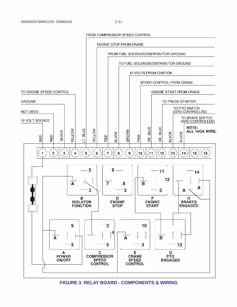
Figure 3 shows the relay board with eight relaysidentified with the letters “A” through “G” and by theirbasic function. Example: Relay “A” is the “Power ON/OFF” relay, “C” is the “Compressor Speed Control”,etc. The small numbers shown on the individualterminals of the relay indicate where that terminal isconnected through the circuit board, to the terminalbar. Example: Relay “A” top terminal (#9) isconnected to terminal 9 of the terminal bar. Theterminal bar is provided with 16 individual terminals ofwhich the last two (15 and 16) are not used. Wiresconnected to the terminal bar have been identifiedaccording to their function in the circuit. The numberof terminals used vary with each application. Solidlines between relay terminals indicate existing wiringconnections, through the circuit board.
The relay board is primarily used on vehicles withremote controlled cranes and remote control cranesand compressors. The circuitry prevents remotestarting of the truck engine unless the brakes areapplied and the PTO is engaged. It also isolates thecrane speed control from the compressor speedcontrol.
OPERATION
IGNITION “ON”When the ignition switch of the vehicle is turned “ON”,terminal 9 of the terminal bar is “HOT”. The coil ofrelay “A” is energized and voltage from terminal 1 ofthe terminal bar becomes present at terminals “A” ofrelays “A”, “B”, “E” and “H”. See Figure 3.
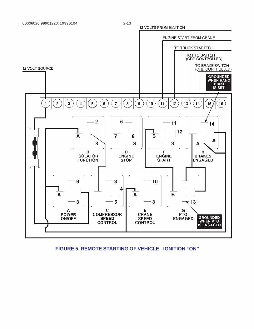
REMOTE STARTING THE VEHICLEThe vehicle can be remotely started from the remotecontrol handle by toggling the “Crane-OFF-Compressor” switch to the “Crane” position.
To start the vehicle, the engine start switch at thehandle must be depressed. When this isaccomplished, terminal 11 of the terminal blockbecomes “HOT”. See Figure 5.
The truck starter is energized when terminals 11 and12 of the terminal bar are connected through the relayboard. When terminal 11 is “HOT”, the coil in relay “F”is energized connecting relay terminal 12 and “B” onrelays “F” and “G”. If terminal 14 of relay “H” andterminal 13 of relay “G” are grounded (brakes andPTO engaged) terminals “B” of relays “F” and “G” are“HOT”. Since terminal “B” of relay “F” is “HOT”, thetruck starter solenoid is activated. Energized circuitsare shown as bold in Figure 5.
REMOTE ENGINE STOPWhen the engine stop button is depressed on theremote control handle, voltage is applied to terminal 6of the terminal block and of relay “D”. The coil inrelay “D” is energized and the ground of the fuelsolenoid/distributor coil is interrupted because currentcan no longer flow from terminal 7 to 8. Relay “D” isnormally closed between terminals 7 and 8. SeeFigure 3.
FIGURE 2. INTERNAL WIRING
FIGURE 1. BOTTOM VIEW OF RELAY
00006020:99901220: 2-11
FIGURE 3. RELAY BOARD - COMPONENTS & WIRING
19990104
00006020:99901220: 2-12
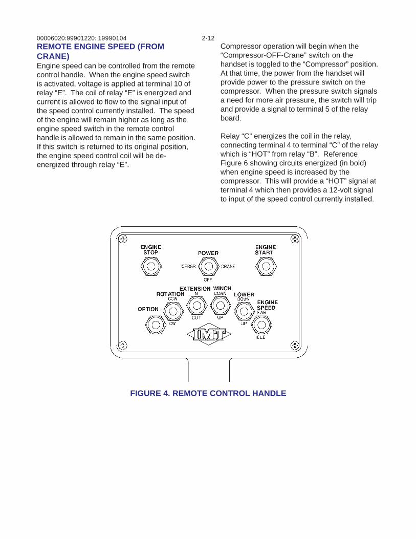
FIGURE 4. REMOTE CONTROL HANDLE
REMOTE ENGINE SPEED (FROMCRANE)Engine speed can be controlled from the remotecontrol handle. When the engine speed switchis activated, voltage is applied at terminal 10 ofrelay “E”. The coil of relay “E” is energized andcurrent is allowed to flow to the signal input ofthe speed control currently installed. The speedof the engine will remain higher as long as theengine speed switch in the remote controlhandle is allowed to remain in the same position.If this switch is returned to its original position,the engine speed control coil will be de-energized through relay “E”.
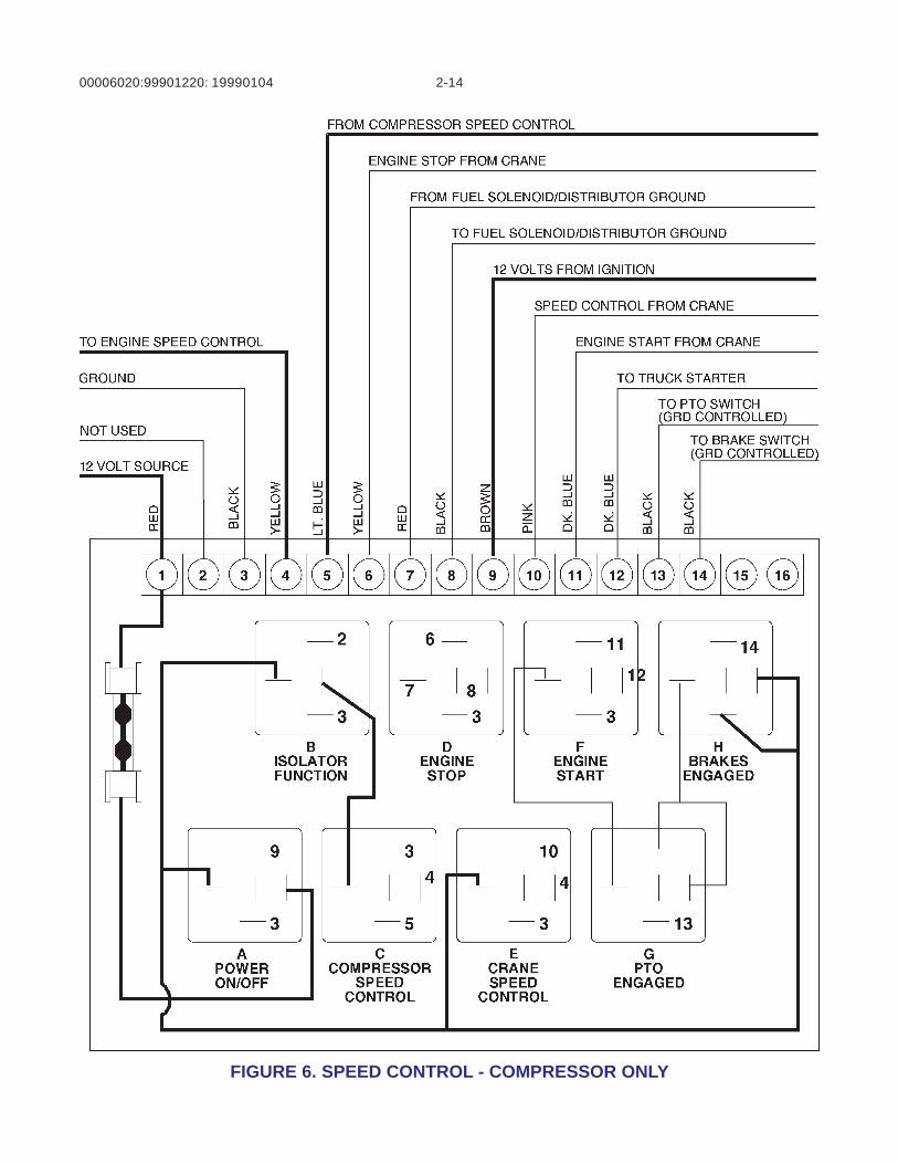
Compressor operation will begin when the“Compressor-OFF-Crane” switch on thehandset is toggled to the “Compressor” position.At that time, the power from the handset willprovide power to the pressure switch on thecompressor. When the pressure switch signalsa need for more air pressure, the switch will tripand provide a signal to terminal 5 of the relayboard.
Relay “C” energizes the coil in the relay,connecting terminal 4 to terminal “C” of the relaywhich is “HOT” from relay “B”. ReferenceFigure 6 showing circuits energized (in bold)when engine speed is increased by thecompressor. This will provide a “HOT” signal atterminal 4 which then provides a 12-volt signalto input of the speed control currently installed.
19990104
00006020:99901220: 2-13
FIGURE 5. REMOTE STARTING OF VEHICLE - IGNITION “ON”
19990104
00006020:99901220: 2-14
FIGURE 6. SPEED CONTROL - COMPRESSOR ONLY
19990104
00006020:99901220: 2-15
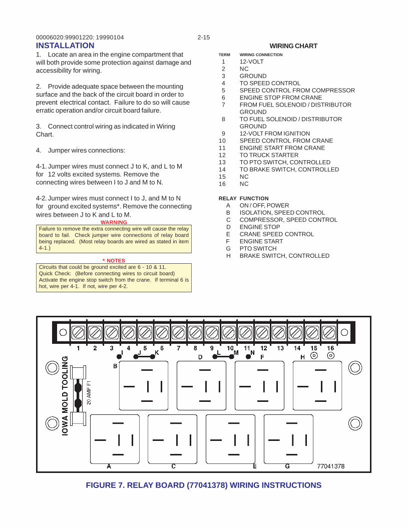
FIGURE 7. RELAY BOARD (77041378) WIRING INSTRUCTIONS
INSTALLATION1. Locate an area in the engine compartment thatwill both provide some protection against damage andaccessibility for wiring.
2. Provide adequate space between the mountingsurface and the back of the circuit board in order toprevent electrical contact. Failure to do so will causeerratic operation and/or circuit board failure.
3. Connect control wiring as indicated in WiringChart.
4. Jumper wires connections:
4-1. Jumper wires must connect J to K, and L to Mfor 12 volts excited systems. Remove theconnecting wires between I to J and M to N.
4-2. Jumper wires must connect I to J, and M to Nfor ground excited systems*. Remove the connectingwires between J to K and L to M.
WARNINGFailure to remove the extra connecting wire will cause the relayboard to fail. Check jumper wire connections of relay boardbeing replaced. (Most relay boards are wired as stated in item4-1.)
* NOTESCircuits that could be ground excited are 6 - 10 & 11.Quick Check: (Before connecting wires to circuit board)Activate the engine stop switch from the crane. If terminal 6 ishot, wire per 4-1. If not, wire per 4-2.
WIRING CHARTTERM WIRING CONNECTION
1 12-VOLT 2 NC 3 GROUND 4 TO SPEED CONTROL 5 SPEED CONTROL FROM COMPRESSOR 6 ENGINE STOP FROM CRANE 7 FROM FUEL SOLENOID / DISTRIBUTOR
GROUND 8 TO FUEL SOLENOID / DISTRIBUTOR
GROUND 9 12-VOLT FROM IGNITION10 SPEED CONTROL FROM CRANE11 ENGINE START FROM CRANE12 TO TRUCK STARTER13 TO PTO SWITCH, CONTROLLED14 TO BRAKE SWITCH, CONTROLLED15 NC16 NC
RELAY FUNCTION A ON / OFF, POWER B ISOLATION, SPEED CONTROL C COMPRESSOR, SPEED CONTROL D ENGINE STOP E CRANE SPEED CONTROL F ENGINE START G PTO SWITCH H BRAKE SWITCH, CONTROLLED
19990104
00006020:99901220: 2-16
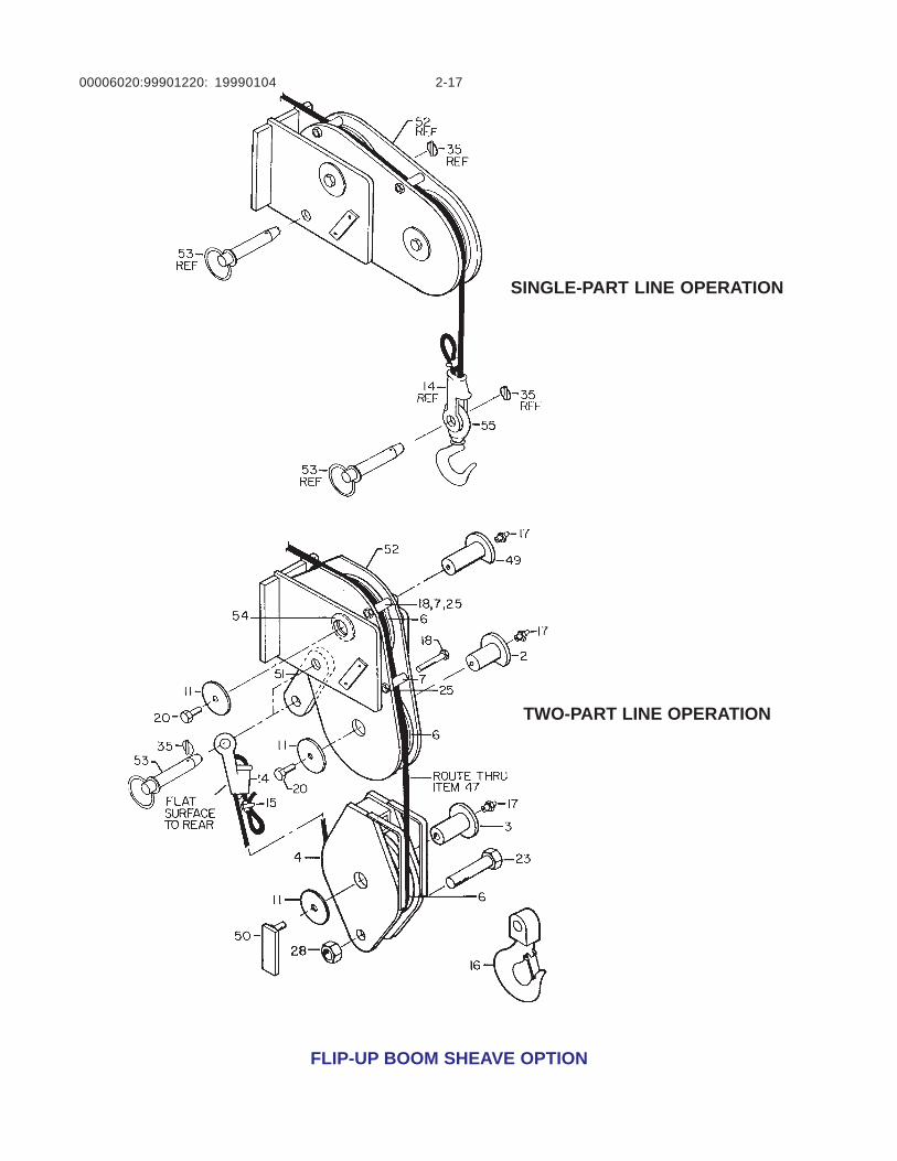
GENERALThis section contains information regarding theoperation of the Flip-up boom sheave which isan available option on the 6020 Crane. Refer tofollowing figure for parts reference.
SINGLE-PART LINE OPERATIONTo position the crane for single-line operation:
1. Disconnect the cable wedge socket (item14) from the boom tip dead end link (item 51) byremoving the other pin and keeper (items 53and 35).
2. Remove the link by removing the other pinand keeper (items 53 and 35)and rotate the flipsheave weldment (item 52) to the horizontalposition and insert one of the retaining pins andkeepers (items 53 and 35) through the lowerhole in the boom tip
.3. Remove the two-part line snatch block (item4) by removing the sheave (item 6) which isheld in place by the pin (item 3), retainer plate(item 11) and wing bolt (item 50).
4. After the cable is freed from the snatchblock, reassemble the sheave and snatchblock. Store the snatch block assembly (items3, 4 and 6) and the dead end link (item 51) in thechassis cab or a body compartment, ifavailable.
5. Locate the 3-ton hook (item 55) which isstored separately on the chassis. Connect thehook to the cable wedge socket using the pinand keeper (items 53 and 35).
The crane should now be in position for single-part line operation. Note that no change inmounting of the anti two-blocking system isrequired.
TWO-PART LINE OPERATIONTo position the crane for two-part line operation:
1. Disconnect the 3-ton hook (item 55) fromthe cable wedge socket (item 14) by removal ofthe pin and keeper (items 53 and 35). Store thehook in the chassis cab or a bodycompartment if available.
2. Locate the two-part line snatch blockassembly (items 3, 4, 6 & 16) and cable deadend link (item 51) which are stored separatelyon the chassis.
3. Remove the pin and keeper (items 53 and35) from the boom tip and rotate the flip sheaveweldment (item 52) to the vertical position.Position the dead end link (item 51) in positionwith the sheave weldment (item 52) and insertthe pin and keeper (items 53 and 35).
4. Disassemble the snatch block assembly(items 3, 4, 6 & 16) and string the cable throughand reassemble the snatch block. Connect thecable wedge socket (item 14)to the dead endlink (item 51) by using the other pin and keeper(items 53 and 35).
The crane should now be in position for two-partline operation. Note that no changes inmounting of the anti two-blocking system isrequired.
FLIP-UP BOOM SHEAVE19990104
00006020:99901220: 2-17
FLIP-UP BOOM SHEAVE OPTION
SINGLE-PART LINE OPERATION
TWO-PART LINE OPERATION
19990104
00006020:99901220: 2-1819990104
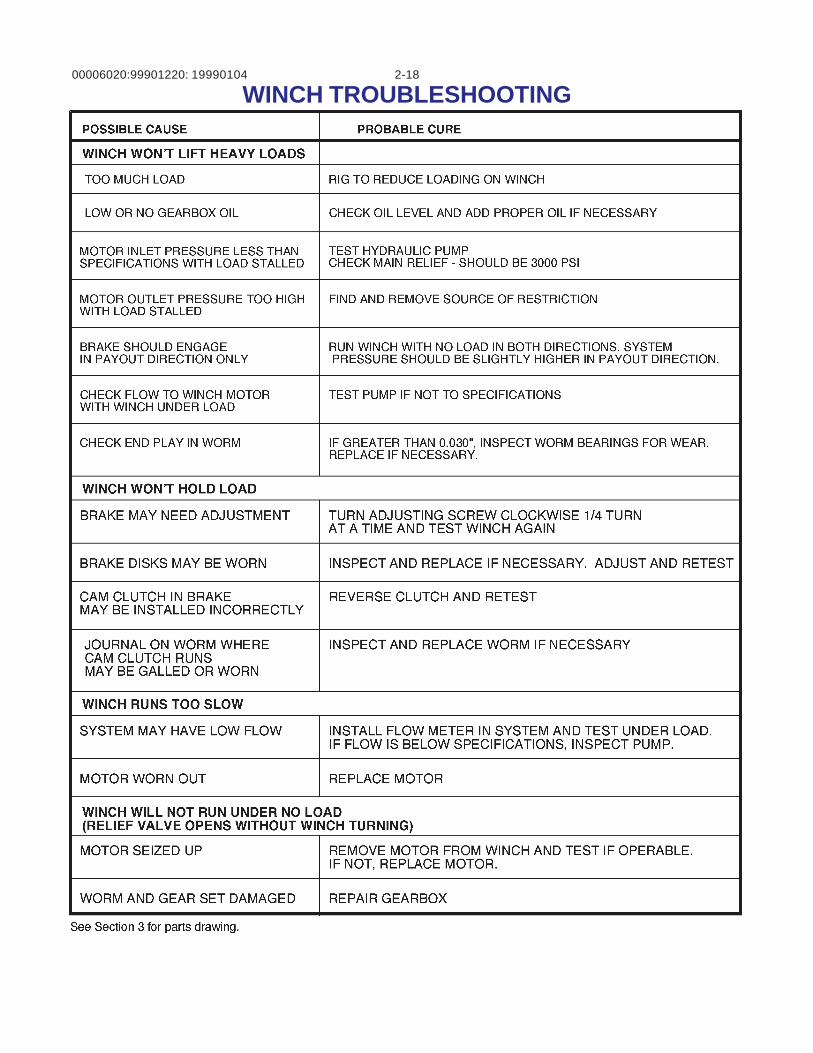
WINCH TROUBLESHOOTING
00006020:99901220: 2-19
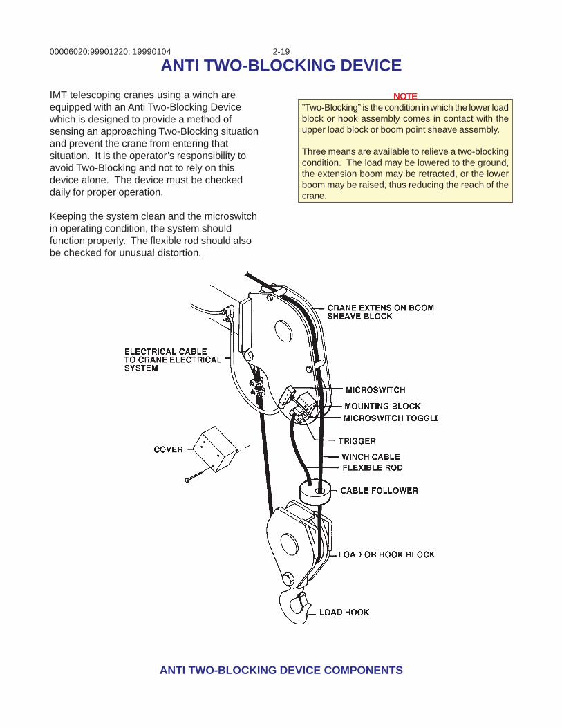
ANTI TWO-BLOCKING DEVICE COMPONENTS
IMT telescoping cranes using a winch areequipped with an Anti Two-Blocking Devicewhich is designed to provide a method ofsensing an approaching Two-Blocking situationand prevent the crane from entering thatsituation. It is the operator’s responsibility toavoid Two-Blocking and not to rely on thisdevice alone. The device must be checkeddaily for proper operation.
Keeping the system clean and the microswitchin operating condition, the system shouldfunction properly. The flexible rod should alsobe checked for unusual distortion.
NOTE”Two-Blocking” is the condition in which the lower loadblock or hook assembly comes in contact with theupper load block or boom point sheave assembly.
Three means are available to relieve a two-blockingcondition. The load may be lowered to the ground,the extension boom may be retracted, or the lowerboom may be raised, thus reducing the reach of thecrane.
ANTI TWO-BLOCKING DEVICE19990104
00006020:99901220: 2-20
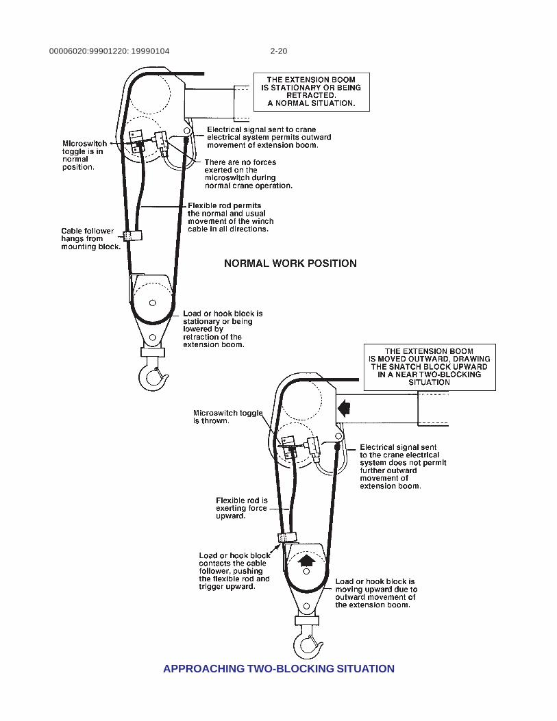
APPROACHING TWO-BLOCKING SITUATION
19990104
00006020:99901220: 2-2120000404
Excessive Load Limit System (ELLS) TEST PROCEDUREThis procedure is to be used for testing the Excessive Load Limit System (ELLS) used on the IMTTelescoping Crane models. Following this test procedure will ensure the system is currently operableand will not allow the crane to be excessively overloaded.
The purpose of the ELLS is to prohibit the excessive overloading of the crane. It does this by disarmingthe functions that make it possible for the operator to apply greater than allowable stress to the cranestructure and components. The functions which are involved in the ELLS may vary for each cranemodel (Refer to TABLE 1 for which functions are shut down by the ELLS on each crane).
The load rating of the crane is determined by the pressure induced in the lower boom cylinder. The ELLSsenses the pressure in the base end of the lower boom cylinder with a normally closed pressure switchlocated on the valve block on the top of the cylinder. When the pressure in the base end of the cylinderexceeds the setting of the pressure switch for that particular crane, the pressure switch opens andbreaks the ground connection for the solenoids that shift the valve spool on the appropriate functions.Once the ground connection is disengaged, the solenoids that shift the valve spools for the appropriatefunctions can not be activated using the remote control handle. Only those functions that will not in-crease the load moment of the crane structure and components will be operable (i.e.- winch down,extension in, lower boom up, rotation). The operator is able to use “WINCH DOWN” to set the weightdown to relieve the crane and “EXTENSION IN” to bring the load in for a shorter load radius. Either ofthese two functions will decrease the load moment of the crane structure and components, thus de-creasing the pressure in the main cylinder.
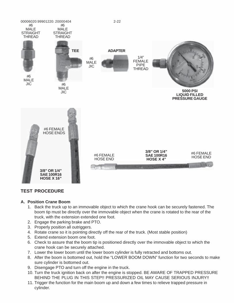
ITEMS REQUIRED TO TEST THE CRANE ELLS (SEE PHOTOS NEXT PAGE)
PRESSURE GAGE ASSEMBLY (GAGE & PIPE-JIC ADAPTER)-5000 PSI LIQUID FILLED PRESSURE GAGE W/ ¼” PIPE THRD QTY 1-1/4 PIPE-#6 JIC ADAPTER (ref) PARKER PART# 0203-4-6 QTY 1
16” HOSE ASSEMBLY (3/8”OR ¼” HOSE W/ #6 FEM. JIC FITTINGS & T-FITTING)-TEE FITTING (ref) PARKER PART# 653T-6-6 QTY 1-#6 FJIC FITTING (ref) PARKER PART# 10643-66 QTY 2-3/8” SAE 100R16 HOSE (ref) PARKER PART# 431-6 QTY 16”
4” HOSE ASSEMBLY (3/8” OR ¼” HOSE W/ #6 FEM. JIC FITTINGS)-#6 FJIC FITTING (ref) PARKER PART# 10643-66 QTY 2-3/8” SAE 100R16 HOSE (ref) PARKER PART# 10643-66 QTY 4”
#6 STR-#6 MALE JIC FITTING (ref) PARKER PART# 0503-6-6 QTY 2
00006020:99901220: 2-2220000404
TEST PROCEDURE
A. Position Crane Boom1. Back the truck up to an immovable object to which the crane hook can be securely fastened. The
boom tip must be directly over the immovable object when the crane is rotated to the rear of thetruck, with the extension extended one foot.
2. Engage the parking brake and PTO.3. Properly position all outriggers.4. Rotate crane so it is pointing directly off the rear of the truck. (Most stable position)5. Extend extension boom one foot.6. Check to assure that the boom tip is positioned directly over the immovable object to which the
crane hook can be securely attached.7. Lower the lower boom until the lower boom cylinder is fully retracted and bottoms out.8. After the boom is bottomed out, hold the “LOWER BOOM DOWN” function for two seconds to make
sure cylinder is bottomed out.9. Disengage PTO and turn off the engine in the truck.10. Turn the truck ignition back on after the engine is stopped. BE AWARE OF TRAPPED PRESSURE
BEHIND THE PLUG IN THIS STEP!! PRESSURIZED OIL MAY CAUSE SERIOUS INJURY!!11. Trigger the function for the main boom up and down a few times to relieve trapped pressure in
cylinder.
#6MALE
JIC
#6MALE
STRAIGHTTHREAD
#6MALE
STRAIGHTTHREAD
#6MALE
JIC
#6MALE
JIC
1/4”FEMALE
PIPETHREAD
5000 PSILIQUID FILLED
PRESSURE GAUGE
3/8” OR 1/4”SAE 100R16HOSE X 4”
3/8” OR 1/4”SAE 100R16HOSE X 16”
#6 FEMALEHOSE END#6 FEMALE
HOSE END
#6 FEMALEHOSE ENDS
TEE ADAPTER
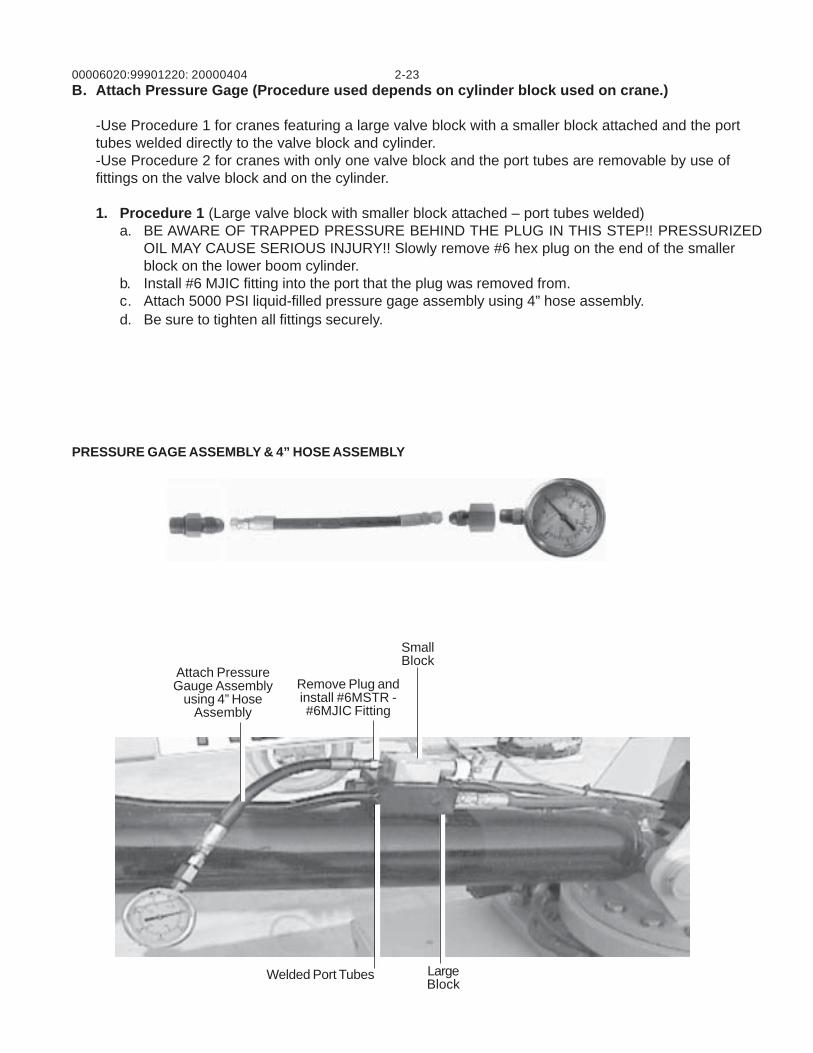
00006020:99901220: 2-2320000404B. Attach Pressure Gage (Procedure used depends on cylinder block used on crane.)
-Use Procedure 1 for cranes featuring a large valve block with a smaller block attached and the porttubes welded directly to the valve block and cylinder.-Use Procedure 2 for cranes with only one valve block and the port tubes are removable by use offittings on the valve block and on the cylinder.
1. Procedure 1 (Large valve block with smaller block attached – port tubes welded)a. BE AWARE OF TRAPPED PRESSURE BEHIND THE PLUG IN THIS STEP!! PRESSURIZED
OIL MAY CAUSE SERIOUS INJURY!! Slowly remove #6 hex plug on the end of the smallerblock on the lower boom cylinder.
b. Install #6 MJIC fitting into the port that the plug was removed from.c. Attach 5000 PSI liquid-filled pressure gage assembly using 4” hose assembly.d. Be sure to tighten all fittings securely.
PRESSURE GAGE ASSEMBLY & 4” HOSE ASSEMBLY
Attach PressureGauge Assembly
using 4” HoseAssembly
Remove Plug andinstall #6MSTR -#6MJIC Fitting
SmallBlock
LargeBlock
Welded Port Tubes
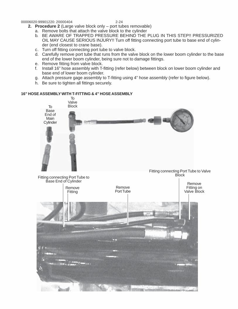
00006020:99901220: 2-24200004042. Procedure 2 (Large valve block only – port tubes removable)
a. Remove bolts that attach the valve block to the cylinderb. BE AWARE OF TRAPPED PRESSURE BEHIND THE PLUG IN THIS STEP!! PRESSURIZED
OIL MAY CAUSE SERIOUS INJURY!! Turn off fitting connecting port tube to base end of cylin-der (end closest to crane base).
c. Turn off fitting connecting port tube to valve block.d. Carefully remove port tube that runs from the valve block on the lower boom cylinder to the base
end of the lower boom cylinder, being sure not to damage fittings.e. Remove fitting from valve block.f. Install 16” hose assembly with T-fitting (refer below) between block on lower boom cylinder and
base end of lower boom cylinder.g. Attach pressure gage assembly to T-fitting using 4” hose assembly (refer to figure below).h. Be sure to tighten all fittings securely.
16” HOSE ASSEMBLY WITH T-FITTING & 4” HOSE ASSEMBLYTo
ValveBlockTo
BaseEnd ofMain
Cylinder
Fitting connecting Port Tube toBase End of Cylinder
RemovePort Tube
Fitting connecting Port Tube to ValveBlock
RemoveFitting on
Valve BlockRemoveFitting
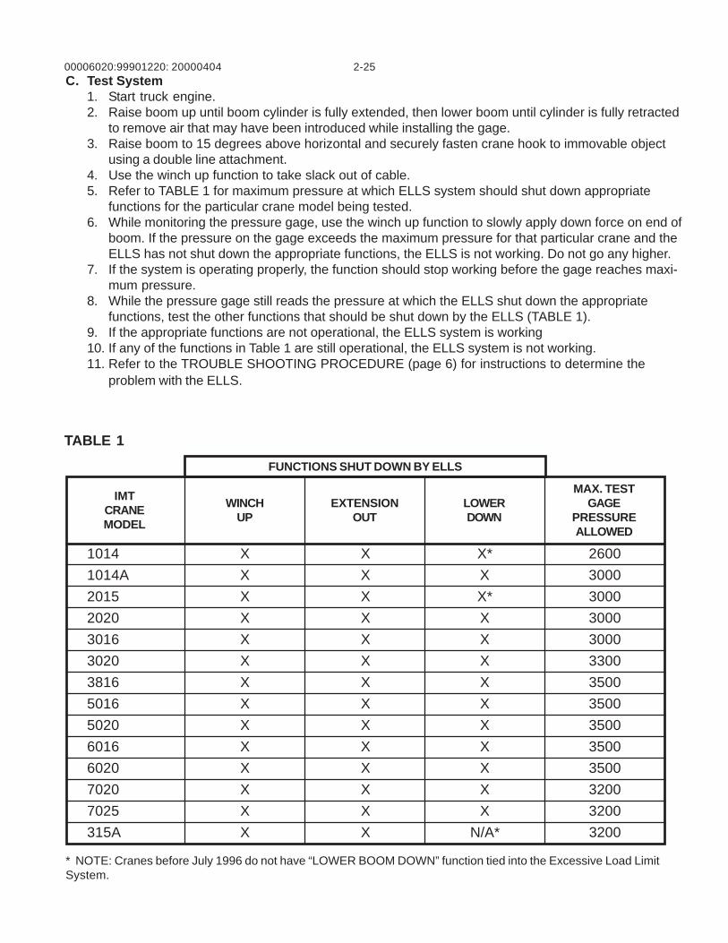
00006020:99901220: 2-2520000404C. Test System
1. Start truck engine.2. Raise boom up until boom cylinder is fully extended, then lower boom until cylinder is fully retracted
to remove air that may have been introduced while installing the gage.3. Raise boom to 15 degrees above horizontal and securely fasten crane hook to immovable object
using a double line attachment.4. Use the winch up function to take slack out of cable.5. Refer to TABLE 1 for maximum pressure at which ELLS system should shut down appropriate
functions for the particular crane model being tested.6. While monitoring the pressure gage, use the winch up function to slowly apply down force on end of
boom. If the pressure on the gage exceeds the maximum pressure for that particular crane and theELLS has not shut down the appropriate functions, the ELLS is not working. Do not go any higher.
7. If the system is operating properly, the function should stop working before the gage reaches maxi-mum pressure.
8. While the pressure gage still reads the pressure at which the ELLS shut down the appropriatefunctions, test the other functions that should be shut down by the ELLS (TABLE 1).
9. If the appropriate functions are not operational, the ELLS system is working10. If any of the functions in Table 1 are still operational, the ELLS system is not working.11. Refer to the TROUBLE SHOOTING PROCEDURE (page 6) for instructions to determine the
problem with the ELLS.
TABLE 1
* NOTE: Cranes before July 1996 do not have “LOWER BOOM DOWN” function tied into the Excessive Load LimitSystem.
FUNCTIONS SHUT DOWN BY ELLS
IMTCRANEMODEL
WINCHUP
EXTENSIONOUT
LOWERDOWN
MAX. TESTGAGE
PRESSUREALLOWED
1014 X X X* 26001014A X X X 30002015 X X X* 30002020 X X X 30003016 X X X 30003020 X X X 33003816 X X X 35005016 X X X 35005020 X X X 35006016 X X X 35006020 X X X 35007020 X X X 32007025 X X X 3200315A X X N/A* 3200
00006020:99901220: 2-2620000404
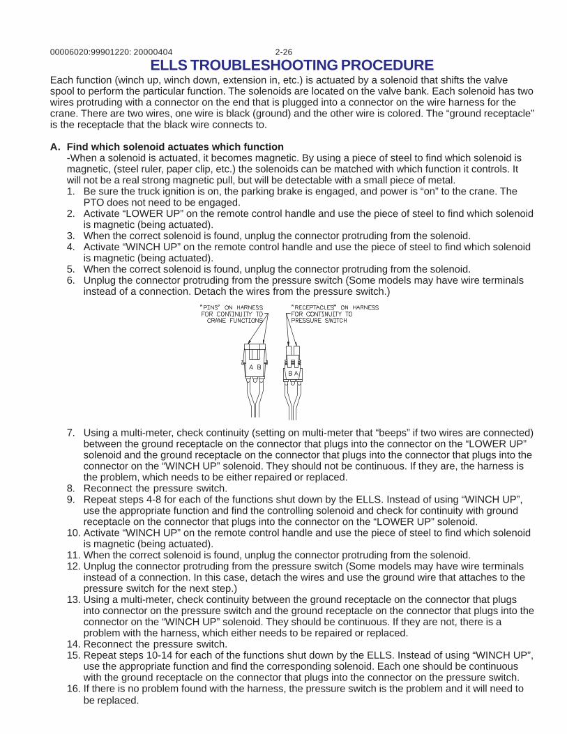
ELLS TROUBLESHOOTING PROCEDUREEach function (winch up, winch down, extension in, etc.) is actuated by a solenoid that shifts the valvespool to perform the particular function. The solenoids are located on the valve bank. Each solenoid has twowires protruding with a connector on the end that is plugged into a connector on the wire harness for thecrane. There are two wires, one wire is black (ground) and the other wire is colored. The “ground receptacle”is the receptacle that the black wire connects to.
A. Find which solenoid actuates which function-When a solenoid is actuated, it becomes magnetic. By using a piece of steel to find which solenoid ismagnetic, (steel ruler, paper clip, etc.) the solenoids can be matched with which function it controls. Itwill not be a real strong magnetic pull, but will be detectable with a small piece of metal.1. Be sure the truck ignition is on, the parking brake is engaged, and power is “on” to the crane. The
PTO does not need to be engaged.2. Activate “LOWER UP” on the remote control handle and use the piece of steel to find which solenoid
is magnetic (being actuated).3. When the correct solenoid is found, unplug the connector protruding from the solenoid.4. Activate “WINCH UP” on the remote control handle and use the piece of steel to find which solenoid
is magnetic (being actuated).5. When the correct solenoid is found, unplug the connector protruding from the solenoid.6. Unplug the connector protruding from the pressure switch (Some models may have wire terminals
instead of a connection. Detach the wires from the pressure switch.)
7. Using a multi-meter, check continuity (setting on multi-meter that “beeps” if two wires are connected)between the ground receptacle on the connector that plugs into the connector on the “LOWER UP”solenoid and the ground receptacle on the connector that plugs into the connector that plugs into theconnector on the “WINCH UP” solenoid. They should not be continuous. If they are, the harness isthe problem, which needs to be either repaired or replaced.
8. Reconnect the pressure switch.9. Repeat steps 4-8 for each of the functions shut down by the ELLS. Instead of using “WINCH UP”,
use the appropriate function and find the controlling solenoid and check for continuity with groundreceptacle on the connector that plugs into the connector on the “LOWER UP” solenoid.
10. Activate “WINCH UP” on the remote control handle and use the piece of steel to find which solenoidis magnetic (being actuated).
11. When the correct solenoid is found, unplug the connector protruding from the solenoid.12. Unplug the connector protruding from the pressure switch (Some models may have wire terminals
instead of a connection. In this case, detach the wires and use the ground wire that attaches to thepressure switch for the next step.)
13. Using a multi-meter, check continuity between the ground receptacle on the connector that plugsinto connector on the pressure switch and the ground receptacle on the connector that plugs into theconnector on the “WINCH UP” solenoid. They should be continuous. If they are not, there is aproblem with the harness, which either needs to be repaired or replaced.
14. Reconnect the pressure switch.15. Repeat steps 10-14 for each of the functions shut down by the ELLS. Instead of using “WINCH UP”,
use the appropriate function and find the corresponding solenoid. Each one should be continuouswith the ground receptacle on the connector that plugs into the connector on the pressure switch.
16. If there is no problem found with the harness, the pressure switch is the problem and it will need tobe replaced.
00006020: 3-199901220:20020905
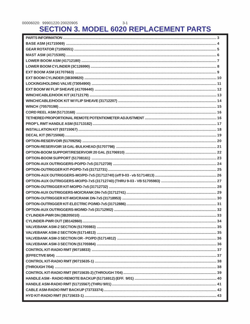
SECTION 3. MODEL 6020 REPLACEMENT PARTSPARTS INFORMATION ...................................................................................................................................................... 3BASE ASM (41715069) ................................................................................................................................................... 4GEAR ROTATOR (71056551) ........................................................................................................................................... 5MAST ASM (41715305) ................................................................................................................................................... 6LOWER BOOM ASM (41712180) .................................................................................................................................... 7LOWER BOOM CYLINDER (3C126990) ........................................................................................................................... 8EXT BOOM ASM (41707663) .......................................................................................................................................... 9EXT BOOM CYLINDER (3B309820) ................................................................................................................................. 10LOCKING/HOLDING VALVE (73054900) .......................................................................................................................... 11EXT BOOM W/ FLIP SHEAVE (41709440) ....................................................................................................................... 12WINCH/CABLE/HOOK KIT (41712179) ............................................................................................................................ 13WINCH/CABLE/HOOK KIT W/ FLIP SHEAVE (31712207) ................................................................................................ 14WINCH (70570198) .......................................................................................................................................................... 15CORD REEL ASM (51713168) ......................................................................................................................................... 16TETHERED PROPORTIONAL REMOTE POTENTIOMETER ADJUSTMENT ...................................................................... 16PROP’L RMT HANDLE ASM (51713182) ......................................................................................................................... 17INSTALLATION KIT (93715067) ....................................................................................................................................... 18DECAL KIT (95715068) .................................................................................................................................................... 19OPTION-RESERVOIR (51709256) ................................................................................................................................... 20OPTION-RESERVOIR 18 GAL-BULKHEAD (51707798) .................................................................................................. 21OPTION-BOOM SUPPORT/RESERVOIR 20 GAL (51706910) ......................................................................................... 22OPTION-BOOM SUPPORT (51708161) .......................................................................................................................... 23OPTION-AUX OUTRIGGERS-PO/PD-7x5 (31712739) ..................................................................................................... 24OPTION-OUTRIGGER KIT-PO/PD-7x5 (31712731) .......................................................................................................... 25OPTION-AUX OUTRIGGERS-MO/PD-7x5 (31712740) (eff 9-03 - vb 51714813) ............................................................ 26OPTION-AUX OUTRIGGERS-MO/PD-7x5 (31712740) (THRU 9-03 - VB 51705983) ...................................................... 27OPTION-OUTRIGGER KIT-MO/PD-7x5 (31712732) ......................................................................................................... 28OPTION-AUX OUTRIGGERS-MO/CRANK DN-7x5 (31712741) ........................................................................................ 29OPTION-OUTRIGGER KIT-MO/CRANK DN-7x5 (31718953) ............................................................................................ 30OPTION-OUTRIGGER KIT-ELECTRIC PO/MD-7x5 (31712886) ........................................................................................ 31OPTION-AUX OUTRIGGERS-MO/MD-7x5 (31712902) .................................................................................................... 32CYLINDER-PWR DN (3B205010) ..................................................................................................................................... 33CYLINDER-PWR OUT (3B142860) ................................................................................................................................... 34VALVEBANK ASM-2 SECTION (51705983) ..................................................................................................................... 35VALVEBANK ASM-2 SECTION (51714813) ..................................................................................................................... 35VALVEBANK ASM-3 SECTION OR - PO/PD (51714812) ................................................................................................. 36VALVEBANK ASM-3 SECTION (51705984) ..................................................................................................................... 36CONTROL KIT-RADIO RMT (90718833) .......................................................................................................................... 37(EFFECTIVE 8/04) ............................................................................................................................................................. 37CONTROL KIT-RADIO RMT (90715635-1) ....................................................................................................................... 38(THROUGH 7/04) .............................................................................................................................................................. 38CONTROL KIT-RADIO RMT (90715635-2) (THROUGH 7/04) ........................................................................................... 39HANDLE ASM - RADIO REMOTE BACKUP (51716912) (EFF. 9/01) ................................................................................ 40HANDLE ASM-RADIO RMT (51715567) (THRU 9/01) ...................................................................................................... 41CABLE ASM-RADIO RMT BACKUP (73733374) .............................................................................................................. 42HYD KIT-RADIO RMT (91715633-1) ................................................................................................................................. 43
00006020: 3-299901220: 20020513
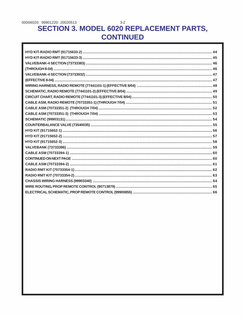
HYD KIT-RADIO RMT (91715633-2) ................................................................................................................................. 44HYD KIT-RADIO RMT (91715633-3) ................................................................................................................................. 45VALVEBANK-4 SECTION (73733383) .............................................................................................................................. 46(THROUGH 8-04) .............................................................................................................................................................. 46VALVEBANK-4 SECTION (73733932) .............................................................................................................................. 47(EFFECTIVE 8-04) ............................................................................................................................................................. 47WIRING HARNESS, RADIO REMOTE (77441101-1) (EFFECTIVE 8/04) ........................................................................... 48SCHEMATIC, RADIO REMOTE (77441101-2) (EFFECTIVE 8/04) ...................................................................................... 49CIRCUIT CHART, RADIO REMOTE (77441101-3) (EFFECTIVE 8/04) ................................................................................ 50CABLE ASM, RADIO REMOTE (70733351-1) (THROUGH 7/04) ...................................................................................... 51CABLE ASM (70733351-2) (THROUGH 7/04) ................................................................................................................. 52CABLE ASM (70733351-3) (THROUGH 7/04) ................................................................................................................. 53SCHEMATIC (99903131) .................................................................................................................................................. 54COUNTERBALANCE VALVE (73540035) ......................................................................................................................... 55HYD KIT (91715652-1) ..................................................................................................................................................... 56HYD KIT (91715652-2) ..................................................................................................................................................... 57HYD KIT (91715652-3) ..................................................................................................................................................... 58VALVEBANK (73733396) ................................................................................................................................................. 59CABLE ASM (70733394-1) .............................................................................................................................................. 60CONTINUED ON NEXT PAGE ............................................................................................................................................ 60CABLE ASM (70733394-2) .............................................................................................................................................. 61RADIO RMT KIT (70733354-1) ......................................................................................................................................... 62RADIO RMT KIT (70733354-2) ......................................................................................................................................... 63CHASSIS WIRING HARNESS (99903340) ....................................................................................................................... 64WIRE ROUTING, PROP REMOTE CONTROL (90713879) ................................................................................................ 65ELECTRICAL SCHEMATIC, PROP REMOTE CONTROL (99900855) ............................................................................... 66
SECTION 3. MODEL 6020 REPLACEMENT PARTS,CONTINUED
00006020: 3-3
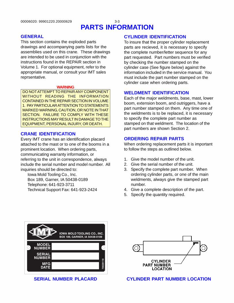
GENERALThis section contains the exploded partsdrawings and accompanying parts lists for theassemblies used on this crane. These drawingsare intended to be used in conjunction with theinstructions found in the REPAIR section inVolume 1. For optional equipment, refer to theappropriate manual, or consult your IMT salesreprsentative.
WARNINGDO NOT ATTEMPT TO REPAIR ANY COMPONENTWITHOUT READING THE INFORMATIONCONTAINED IN THE REPAIR SECTION IN VOLUME1. PAY PARTICULAR ATTENTION TO STATEMENTSMARKED WARNING, CAUTION, OR NOTE IN THATSECTION. FAILURE TO COMPLY WITH THESEINSTRUCTIONS MAY RESULT IN DAMAGE TO THEEQUIPMENT, PERSONAL INJURY, OR DEATH.
CRANE IDENTIFICATIONEvery IMT crane has an identification placardattached to the mast or to one of the booms in aprominent location. When ordering parts,communicating warranty information, orreferring to the unit in correspondence, alwaysinclude the serial number and model number. Allinquiries should be directed to:
Iowa Mold Tooling Co., Inc.Box 189, Garner, IA 50438-0189Telephone: 641-923-3711Technical Support Fax: 641-923-2424
PARTS INFORMATIONCYLINDER IDENTIFICATIONTo insure that the proper cylinder replacementparts are recieved, it is necessary to specifythe complete number/letter sequence for anypart requested. Part numbers must be verifiedby checking the number stamped on thecylinder case (See figure below) against theinformation included in the service manual. Youmust include the part number stamped on thecylinder case when ordering parts.
WELDMENT IDENTIFICATIONEach of the major weldments, base, mast, lowerboom, extension boom, and outriggers, have apart number stamped on them. Any time one ofthe weldments is to be replaced, it is necessaryto specify the complete part number asstamped on that weldment. The location of thepart numbers are shown Section 2.
ORDERING REPAIR PARTSWhen ordering replacement parts it is importantto follow the steps as outlined below.
1. Give the model number of the unit.2. Give the serial number of the unit.3. Specify the complete part number. When
ordering cylinder parts, or one of the mainweldments, always give the stamped partnumber.
4. Give a complete description of the part.5. Specify the quantity required.
SERIAL NUMBER PLACARD CYLINDER PART NUMBER LOCATION
99901220.20000629
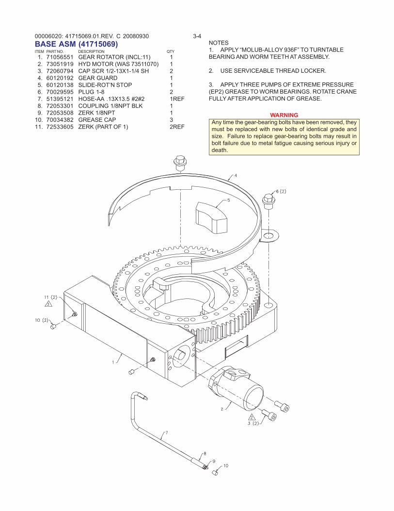
00006020: 3-441715069.01.REV. C 20080930BASE ASM (41715069)ITEM PART NO. DESCRIPTION QTY 1. 71056551 GEAR ROTATOR (INCL:11) 1 2. 73051919 HYD MOTOR (WAS 73511070) 1 3. 72060794 CAP SCR 1/2-13X1-1/4 SH 2 4. 60120192 GEAR GUARD 1 5. 60120138 SLIDE-ROT’N STOP 1 6. 70029595 PLUG 1-8 2 7. 51395121 HOSE-AA .13X13.5 #2#2 1REF 8. 72053301 COUPLING 1/8NPT BLK 1 9. 72053508 ZERK 1/8NPT 110. 70034382 GREASE CAP 311. 72533605 ZERK (PART OF 1) 2REF
WARNINGAny time the gear-bearing bolts have been removed, theymust be replaced with new bolts of identical grade andsize. Failure to replace gear-bearing bolts may result inbolt failure due to metal fatigue causing serious injury ordeath.
NOTES1. APPLY “MOLUB-ALLOY 936F” TO TURNTABLEBEARING AND WORM TEETH AT ASSEMBLY.
2. USE SERVICEABLE THREAD LOCKER.
3. APPLY THREE PUMPS OF EXTREME PRESSURE(EP2) GREASE TO WORM BEARINGS. ROTATE CRANEFULLY AFTER APPLICATION OF GREASE.
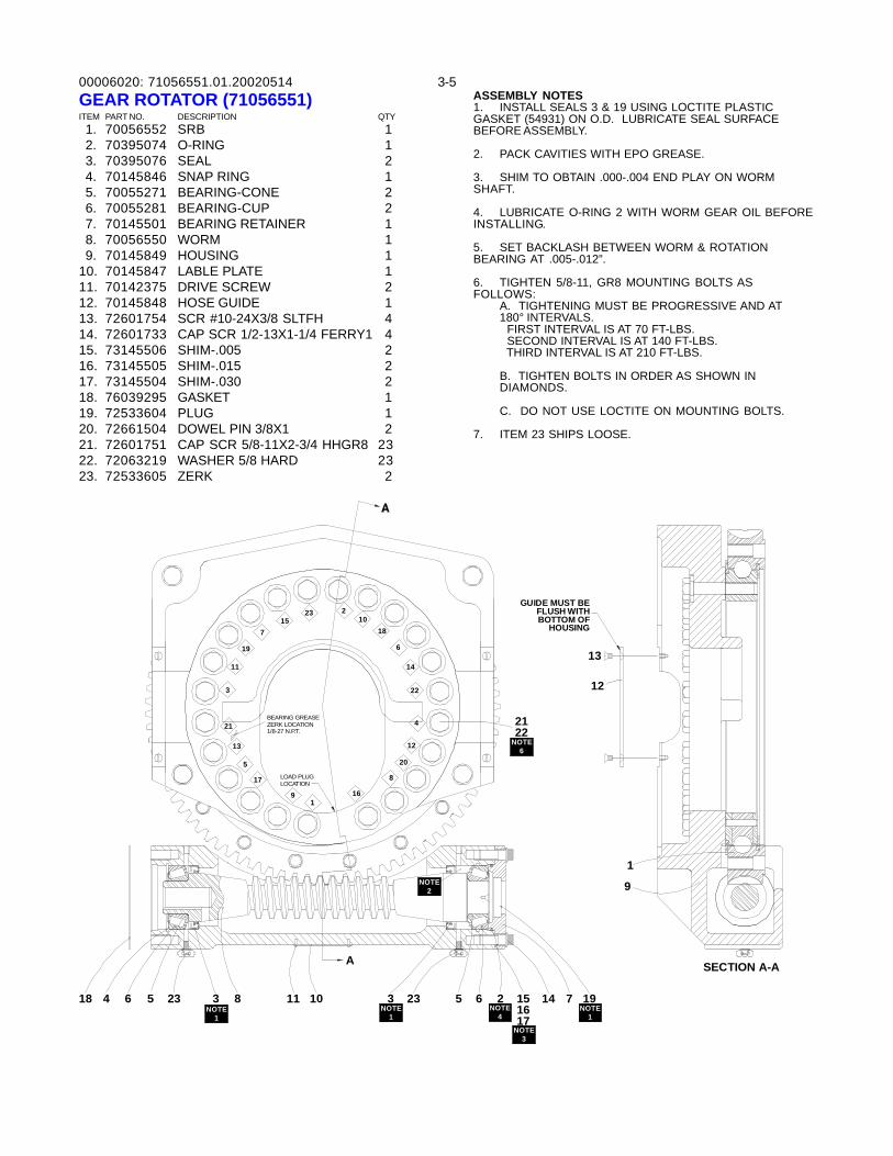
00006020: 3-571056551.01.20020514GEAR ROTATOR (71056551)ITEM PART NO. DESCRIPTION QTY 1. 70056552 SRB 1 2. 70395074 O-RING 1 3. 70395076 SEAL 2 4. 70145846 SNAP RING 1 5. 70055271 BEARING-CONE 2 6. 70055281 BEARING-CUP 2 7. 70145501 BEARING RETAINER 1 8. 70056550 WORM 1 9. 70145849 HOUSING 110. 70145847 LABLE PLATE 111. 70142375 DRIVE SCREW 212. 70145848 HOSE GUIDE 113. 72601754 SCR #10-24X3/8 SLTFH 414. 72601733 CAP SCR 1/2-13X1-1/4 FERRY1 415. 73145506 SHIM-.005 216. 73145505 SHIM-.015 217. 73145504 SHIM-.030 218. 76039295 GASKET 119. 72533604 PLUG 120. 72661504 DOWEL PIN 3/8X1 221. 72601751 CAP SCR 5/8-11X2-3/4 HHGR8 2322. 72063219 WASHER 5/8 HARD 2323. 72533605 ZERK 2
ASSEMBLY NOTES1. INSTALL SEALS 3 & 19 USING LOCTITE PLASTICGASKET (54931) ON O.D. LUBRICATE SEAL SURFACEBEFORE ASSEMBLY.
2. PACK CAVITIES WITH EPO GREASE.
3. SHIM TO OBTAIN .000-.004 END PLAY ON WORMSHAFT.
4. LUBRICATE O-RING 2 WITH WORM GEAR OIL BEFOREINSTALLING.
5. SET BACKLASH BETWEEN WORM & ROTATIONBEARING AT .005-.012”.
6. TIGHTEN 5/8-11, GR8 MOUNTING BOLTS ASFOLLOWS:
A. TIGHTENING MUST BE PROGRESSIVE AND AT180° INTERVALS. FIRST INTERVAL IS AT 70 FT-LBS. SECOND INTERVAL IS AT 140 FT-LBS. THIRD INTERVAL IS AT 210 FT-LBS.
B. TIGHTEN BOLTS IN ORDER AS SHOWN INDIAMONDS.
C. DO NOT USE LOCTITE ON MOUNTING BOLTS.
7. ITEM 23 SHIPS LOOSE.
1
A
2
BEARING GREASEZERK LOCATION1/8-27 N.P.T.
LOAD PLUGLOCATION17
5
9
13
21
19
3
11
715
16
8
20
4
12
23 210
18
6
22
14
9
1
SECTION A-A
12
21226
13
54 618 31
8 511 10 31
2323 6 24
1516173
191
14 7
GUIDE MUST BEFLUSH WITHBOTTOM OF
HOUSING
NOTE1
NOTE1
NOTE4
NOTE3
NOTE1
NOTE2
NOTE6
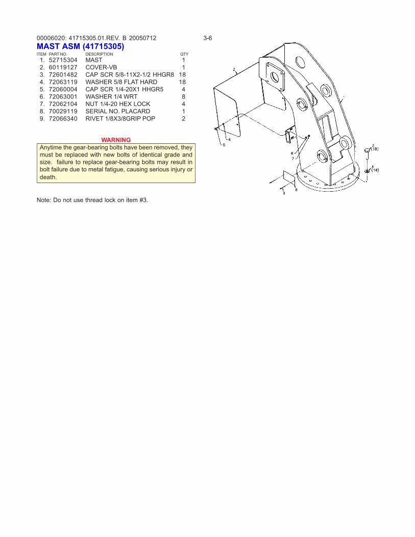
00006020: 3-641715305.01.REV. B 20050712
WARNINGAnytime the gear-bearing bolts have been removed, theymust be replaced with new bolts of identical grade andsize. failure to replace gear-bearing bolts may result inbolt failure due to metal fatigue, causing serious injury ordeath.
MAST ASM (41715305)ITEM PART NO. DESCRIPTION QTY 1. 52715304 MAST 1 2. 60119127 COVER-VB 1 3. 72601482 CAP SCR 5/8-11X2-1/2 HHGR8 18 4. 72063119 WASHER 5/8 FLAT HARD 18 5. 72060004 CAP SCR 1/4-20X1 HHGR5 4 6. 72063001 WASHER 1/4 WRT 8 7. 72062104 NUT 1/4-20 HEX LOCK 4 8. 70029119 SERIAL NO. PLACARD 1 9. 72066340 RIVET 1/8X3/8GRIP POP 2
Note: Do not use thread lock on item #3.
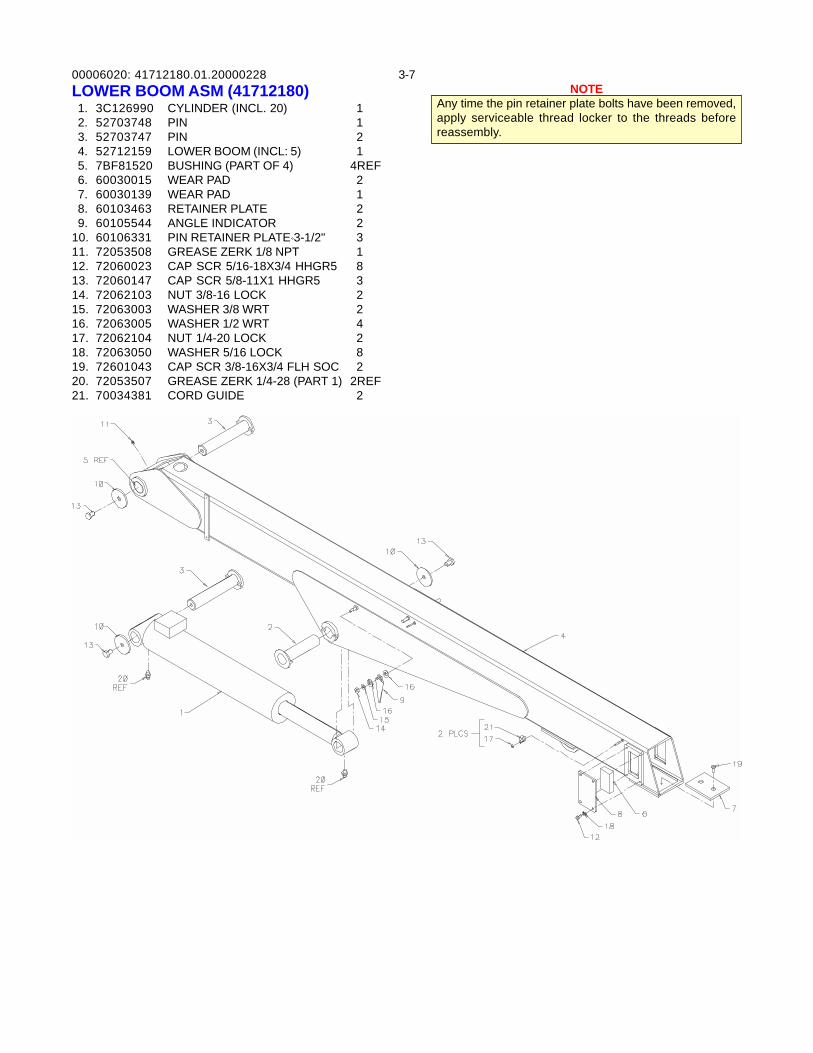
00006020: 3-741712180.01.20000228NOTE
Any time the pin retainer plate bolts have been removed,apply serviceable thread locker to the threads beforereassembly.
LOWER BOOM ASM (41712180) 1. 3C126990 CYLINDER (INCL. 20) 1 2. 52703748 PIN 1 3. 52703747 PIN 2 4. 52712159 LOWER BOOM (INCL: 5) 1 5. 7BF81520 BUSHING (PART OF 4) 4REF 6. 60030015 WEAR PAD 2 7. 60030139 WEAR PAD 1 8. 60103463 RETAINER PLATE 2 9. 60105544 ANGLE INDICATOR 210. 60106331 PIN RETAINER PLATE 3-1/2" 311. 72053508 GREASE ZERK 1/8 NPT 112. 72060023 CAP SCR 5/16-18X3/4 HHGR5 813. 72060147 CAP SCR 5/8-11X1 HHGR5 314. 72062103 NUT 3/8-16 LOCK 215. 72063003 WASHER 3/8 WRT 216. 72063005 WASHER 1/2 WRT 417. 72062104 NUT 1/4-20 LOCK 218. 72063050 WASHER 5/16 LOCK 819. 72601043 CAP SCR 3/8-16X3/4 FLH SOC 220. 72053507 GREASE ZERK 1/4-28 (PART 1) 2REF21. 70034381 CORD GUIDE 2
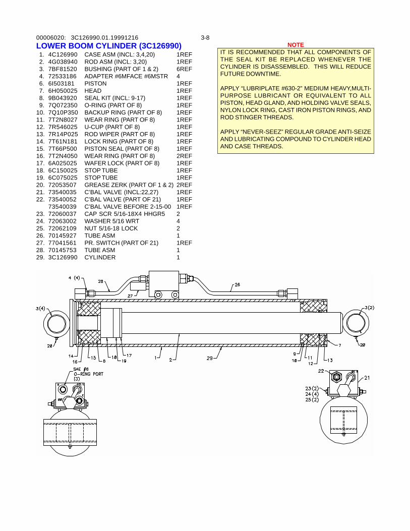
00006020: 3-83C126990.01.19991216NOTE
IT IS RECOMMENDED THAT ALL COMPONENTS OFTHE SEAL KIT BE REPLACED WHENEVER THECYLINDER IS DISASSEMBLED. THIS WILL REDUCEFUTURE DOWNTIME.
APPLY “LUBRIPLATE #630-2” MEDIUM HEAVY,MULTI-PURPOSE LUBRICANT OR EQUIVALENT TO ALLPISTON, HEAD GLAND, AND HOLDING VALVE SEALS,NYLON LOCK RING, CAST IRON PISTON RINGS, ANDROD STINGER THREADS.
APPLY “NEVER-SEEZ” REGULAR GRADE ANTI-SEIZEAND LUBRICATING COMPOUND TO CYLINDER HEADAND CASE THREADS.
LOWER BOOM CYLINDER (3C126990) 1. 4C126990 CASE ASM (INCL: 3,4,20) 1REF 2. 4G038940 ROD ASM (INCL: 3,20) 1REF 3. 7BF81520 BUSHING (PART OF 1 & 2) 6REF 4. 72533186 ADAPTER #6MFACE #6MSTR 4 6. 6I503181 PISTON 1REF 7. 6H050025 HEAD 1REF 8. 9B043920 SEAL KIT (INCL: 9-17) 1REF 9. 7Q072350 O-RING (PART OF 8) 1REF10. 7Q10P350 BACKUP RING (PART OF 8) 1REF11. 7T2N8027 WEAR RING (PART OF 8) 1REF12. 7R546025 U-CUP (PART OF 8) 1REF13. 7R14P025 ROD WIPER (PART OF 8) 1REF14. 7T61N181 LOCK RING (PART OF 8) 1REF15. 7T66P500 PISTON SEAL (PART OF 8) 1REF16. 7T2N4050 WEAR RING (PART OF 8) 2REF17. 6A025025 WAFER LOCK (PART OF 8) 1REF18. 6C150025 STOP TUBE 1REF19. 6C075025 STOP TUBE 1REF20. 72053507 GREASE ZERK (PART OF 1 & 2) 2REF21. 73540035 C’BAL VALVE (INCL:22,27) 1REF22. 73540052 C’BAL VALVE (PART OF 21) 1REF
73540039 C’BAL VALVE BEFORE 2-15-00 1REF23. 72060037 CAP SCR 5/16-18X4 HHGR5 224. 72063002 WASHER 5/16 WRT 425. 72062109 NUT 5/16-18 LOCK 226. 70145927 TUBE ASM 127. 77041561 PR. SWITCH (PART OF 21) 1REF28. 70145753 TUBE ASM 129. 3C126990 CYLINDER 1
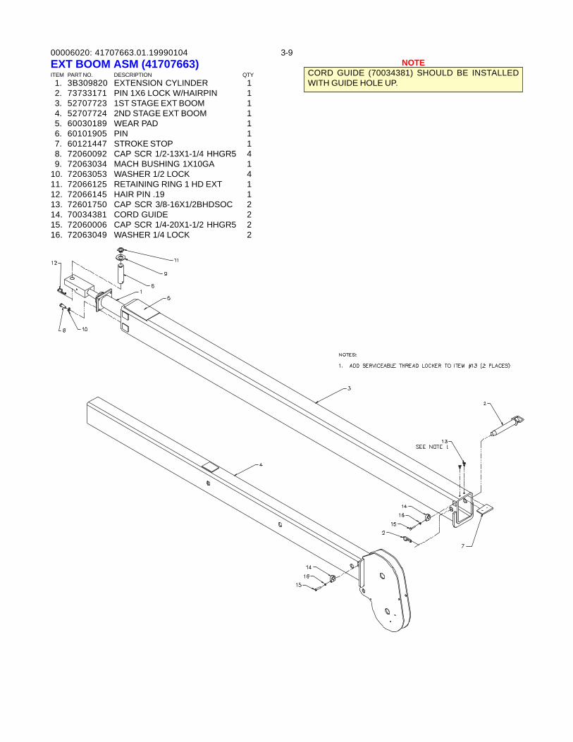
00006020: 3-941707663.01.19990104EXT BOOM ASM (41707663)ITEM PART NO. DESCRIPTION QTY 1. 3B309820 EXTENSION CYLINDER 1 2. 73733171 PIN 1X6 LOCK W/HAIRPIN 1 3. 52707723 1ST STAGE EXT BOOM 1 4. 52707724 2ND STAGE EXT BOOM 1 5. 60030189 WEAR PAD 1 6. 60101905 PIN 1 7. 60121447 STROKE STOP 1 8. 72060092 CAP SCR 1/2-13X1-1/4 HHGR5 4 9. 72063034 MACH BUSHING 1X10GA 110. 72063053 WASHER 1/2 LOCK 411. 72066125 RETAINING RING 1 HD EXT 112. 72066145 HAIR PIN .19 113. 72601750 CAP SCR 3/8-16X1/2BHDSOC 214. 70034381 CORD GUIDE 215. 72060006 CAP SCR 1/4-20X1-1/2 HHGR5 216. 72063049 WASHER 1/4 LOCK 2
NOTECORD GUIDE (70034381) SHOULD BE INSTALLEDWITH GUIDE HOLE UP.
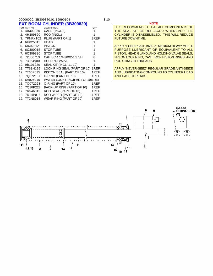
00006020: 3-103B309820.01.19990104EXT BOOM CYLINDER (3B309820)ITEM PART NO. DESCRIPTION QTY 1. 4B309820 CASE (INCL:3) 1 2. 4H309820 ROD (INCL:) 1 3. 7PNPXT02 PLUG (PART OF 1) 3REF 4. 6H025015 HEAD 1 5. 6IX02512 PISTON 1 6. 6C300015 STOP TUBE 1 7. 6C309820 STOP TUBE 1 8. 72060713 CAP SCR 1/4-20X2-1/2 SH 6 9. 73054900 HOLDING VALVE 110. 9B101220 SEAL KIT (INCL: 11-19) 111. 7T61N125 LOCK RING SEAL (PART OF 10) 1REF12. 7T66P025 PISTON SEAL (PART OF 10) 1REF13. 7Q072137 O-RING (PART OF 10) 1REF14. 6A025015 WAFER LOCK RING(PART OF10)1REF15. 7Q072228 O-RING (PART OF 10) 1REF16. 7Q10P228 BACK-UP RING (PART OF 10) 1REF17. 7R546015 ROD SEAL (PART OF 10) 1REF18. 7R14P015 ROD WIPER (PART OF 10) 1REF19. 7T2N8015 WEAR RING (PART OF 10) 1REF
NOTEIT IS RECOMMENDED THAT ALL COMPONENTS OFTHE SEAL KIT BE REPLACED WHENEVER THECYLINDER IS DISASSEMBLED. THIS WILL REDUCEFUTURE DOWNTIME.
APPLY “LUBRIPLATE #630-2” MEDIUM HEAVY,MULTI-PURPOSE LUBRICANT OR EQUIVALENT TO ALLPISTON, HEAD GLAND, AND HOLDING VALVE SEALS,NYLON LOCK RING, CAST IRON PISTON RINGS, ANDROD STINGER THREADS.
APPLY “NEVER-SEEZ” REGULAR GRADE ANTI-SEIZEAND LUBRICATING COMPOUND TO CYLINDER HEADAND CASE THREADS.
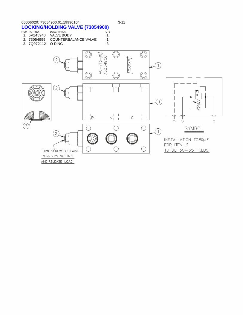
00006020: 3-1173054900.01.19990104LOCKING/HOLDING VALVE (73054900)ITEM PART NO. DESCRIPTION QTY 1. 5V245940 VALVE BODY 1 2. 73054999 COUNTERBALANCE VALVE 1 3. 7Q072112 O-RING 3
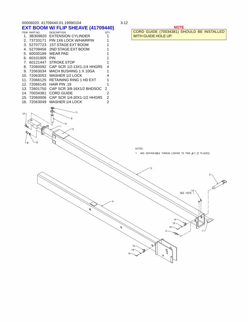
00006020: 3-1241709440.01.19990104EXT BOOM W/ FLIP SHEAVE (41709440)ITEM PART NO. DESCRIPTION QTY 1. 3B309820 EXTENSION CYLINDER 1 2. 73733171 PIN 1X6 LOCK W/HAIRPIN 1 3. 52707723 1ST STAGE EXT BOOM 1 4. 52709456 2ND STAGE EXT BOOM 1 5. 60030189 WEAR PAD 1 6. 60101905 PIN 1 7. 60121447 STROKE STOP 1 8. 72060092 CAP SCR 1/2-13X1-1/4 HHGR5 4 9. 72063034 MACH BUSHING 1 X 10GA 110. 72063053 WASHER 1/2 LOCK 411. 72066125 RETAINING RING 1 HD EXT 112. 72066145 HAIR PIN .19 113. 72601750 CAP SCR 3/8-16X1/2 BHDSOC 214. 70034381 CORD GUIDE 215. 72060006 CAP SCR 1/4-20X1-1/2 HHGR5 216. 72063049 WASHER 1/4 LOCK 2
NOTECORD GUIDE (70034381) SHOULD BE INSTALLEDWITH GUIDE HOLE UP.
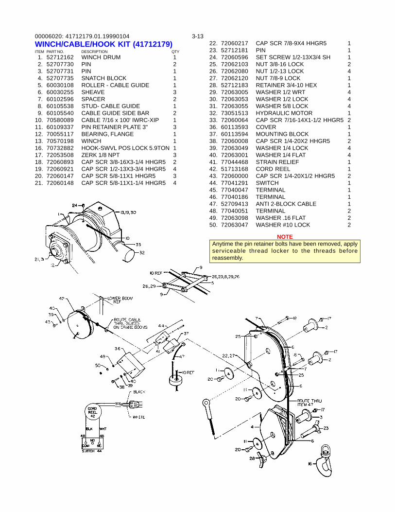
00006020: 3-1341712179.01.19990104
NOTEAnytime the pin retainer bolts have been removed, applyserviceable thread locker to the threads beforereassembly.
WINCH/CABLE/HOOK KIT (41712179)ITEM PART NO. DESCRIPTION QTY 1. 52712162 WINCH DRUM 1 2. 52707730 PIN 2 3. 52707731 PIN 1 4. 52707735 SNATCH BLOCK 1 5. 60030108 ROLLER - CABLE GUIDE 1 6. 60030255 SHEAVE 3 7. 60102596 SPACER 2 8. 60105538 STUD- CABLE GUIDE 1 9. 60105540 CABLE GUIDE SIDE BAR 210. 70580089 CABLE 7/16 x 100' IWRC-XIP 111. 60109337 PIN RETAINER PLATE 3" 312. 70055117 BEARING, FLANGE 113. 70570198 WINCH 116. 70732882 HOOK-SWVL POS LOCK 5.9TON 117. 72053508 ZERK 1/8 NPT 318. 72060893 CAP SCR 3/8-16X3-1/4 HHGR5 219. 72060921 CAP SCR 1/2-13X3-3/4 HHGR5 420. 72060147 CAP SCR 5/8-11X1 HHGR5 321. 72060148 CAP SCR 5/8-11X1-1/4 HHGR5 4
22. 72060217 CAP SCR 7/8-9X4 HHGR5 123. 52712181 PIN 124. 72060596 SET SCREW 1/2-13X3/4 SH 125. 72062103 NUT 3/8-16 LOCK 226. 72062080 NUT 1/2-13 LOCK 427. 72062120 NUT 7/8-9 LOCK 128. 52712183 RETAINER 3/4-10 HEX 129. 72063005 WASHER 1/2 WRT 430. 72063053 WASHER 1/2 LOCK 431. 72063055 WASHER 5/8 LOCK 432. 73051513 HYDRAULIC MOTOR 133. 72060064 CAP SCR 7/16-14X1-1/2 HHGR5 236. 60113593 COVER 137. 60113594 MOUNTING BLOCK 138. 72060008 CAP SCR 1/4-20X2 HHGR5 239. 72063049 WASHER 1/4 LOCK 440. 72063001 WASHER 1/4 FLAT 441. 77044468 STRAIN RELIEF 142. 51713168 CORD REEL 143. 72060000 CAP SCR 1/4-20X1/2 HHGR5 244. 77041291 SWITCH 145. 77040047 TERMINAL 146. 77040186 TERMINAL 147. 52709413 ANTI 2-BLOCK CABLE 148. 77040051 TERMINAL 249. 72063098 WASHER .16 FLAT 250. 72063047 WASHER #10 LOCK 2
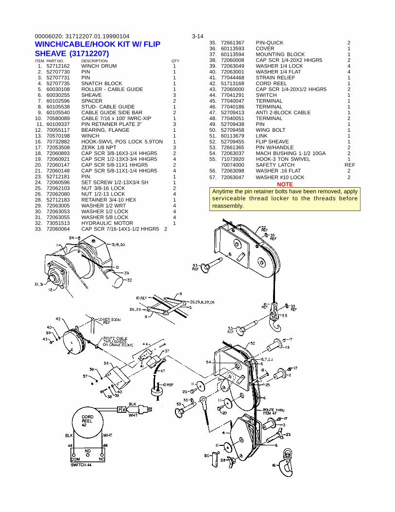
00006020: 3-1431712207.01.19990104
NOTEAnytime the pin retainer bolts have been removed, applyserviceable thread locker to the threads beforereassembly.
WINCH/CABLE/HOOK KIT W/ FLIPSHEAVE (31712207)ITEM PART NO. DESCRIPTION QTY 1. 52712162 WINCH DRUM 1 2. 52707730 PIN 1 3. 52707731 PIN 1 4. 52707735 SNATCH BLOCK 1 5. 60030108 ROLLER - CABLE GUIDE 1 6. 60030255 SHEAVE 3 7. 60102596 SPACER 2 8. 60105538 STUD- CABLE GUIDE 1 9. 60105540 CABLE GUIDE SIDE BAR 210. 70580089 CABLE 7/16 x 100' IWRC-XIP 1 11. 60109337 PIN RETAINER PLATE 3" 312. 70055117 BEARING, FLANGE 113. 70570198 WINCH 116. 70732882 HOOK-SWVL POS LOCK 5.9TON 117. 72053508 ZERK 1/8 NPT 318. 72060893 CAP SCR 3/8-16X3-1/4 HHGR5 219. 72060921 CAP SCR 1/2-13X3-3/4 HHGR5 420. 72060147 CAP SCR 5/8-11X1 HHGR5 221. 72060148 CAP SCR 5/8-11X1-1/4 HHGR5 423. 52712181 PIN 124. 72060596 SET SCREW 1/2-13X3/4 SH 125. 72062103 NUT 3/8-16 LOCK 226. 72062080 NUT 1/2-13 LOCK 428. 52712183 RETAINER 3/4-10 HEX 129. 72063005 WASHER 1/2 WRT 430. 72063053 WASHER 1/2 LOCK 431. 72063055 WASHER 5/8 LOCK 432. 73051513 HYDRAULIC MOTOR 133. 72060064 CAP SCR 7/16-14X1-1/2 HHGR5 2
35. 72661367 PIN-QUICK 236. 60113593 COVER 137. 60113594 MOUNTING BLOCK 138. 72060008 CAP SCR 1/4-20X2 HHGR5 239. 72063049 WASHER 1/4 LOCK 440. 72063001 WASHER 1/4 FLAT 441. 77044468 STRAIN RELIEF 142. 51713168 CORD REEL 143. 72060000 CAP SCR 1/4-20X1/2 HHGR5 244. 77041291 SWITCH 145. 77040047 TERMINAL 146. 77040186 TERMINAL 147. 52709413 ANTI 2-BLOCK CABLE 148. 77040051 TERMINAL 249. 52709438 PIN 150. 52709458 WING BOLT 151. 60113679 LINK 152. 52709455 FLIP SHEAVE 153. 72661365 PIN W/HANDLE 254. 72063037 MACH BUSHING 1-1/2 10GA 255. 71073920 HOOK-3 TON SWIVEL 1
70074000 SAFETY LATCH REF56. 72063098 WASHER .16 FLAT 257. 72063047 WASHER #10 LOCK 2
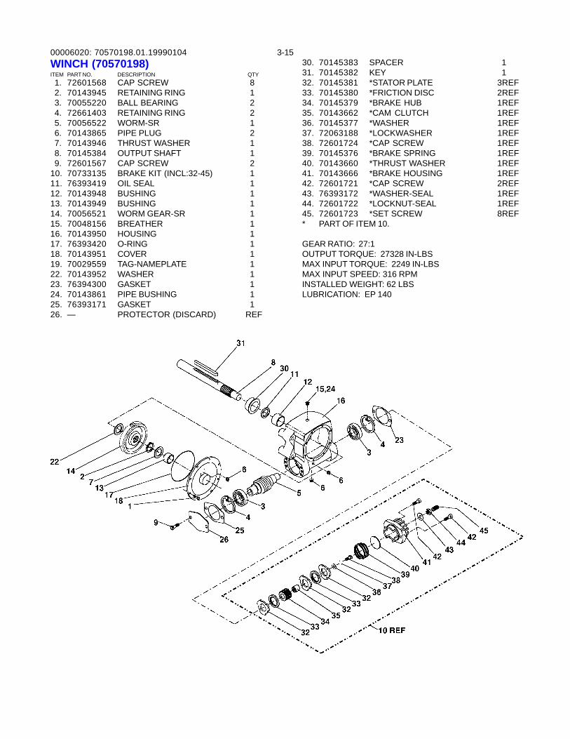
00006020: 3-1570570198.01.19990104WINCH (70570198)ITEM PART NO. DESCRIPTION QTY 1. 72601568 CAP SCREW 8 2. 70143945 RETAINING RING 1 3. 70055220 BALL BEARING 2 4. 72661403 RETAINING RING 2 5. 70056522 WORM-SR 1 6. 70143865 PIPE PLUG 2 7. 70143946 THRUST WASHER 1 8. 70145384 OUTPUT SHAFT 1 9. 72601567 CAP SCREW 210. 70733135 BRAKE KIT (INCL:32-45) 111. 76393419 OIL SEAL 112. 70143948 BUSHING 113. 70143949 BUSHING 114. 70056521 WORM GEAR-SR 115. 70048156 BREATHER 116. 70143950 HOUSING 117. 76393420 O-RING 118. 70143951 COVER 119. 70029559 TAG-NAMEPLATE 122. 70143952 WASHER 123. 76394300 GASKET 124. 70143861 PIPE BUSHING 125. 76393171 GASKET 126. — PROTECTOR (DISCARD) REF
30. 70145383 SPACER 131. 70145382 KEY 132. 70145381 *STATOR PLATE 3REF33. 70145380 *FRICTION DISC 2REF34. 70145379 *BRAKE HUB 1REF35. 70143662 *CAM CLUTCH 1REF36. 70145377 *WASHER 1REF37. 72063188 *LOCKWASHER 1REF38. 72601724 *CAP SCREW 1REF39. 70145376 *BRAKE SPRING 1REF40. 70143660 *THRUST WASHER 1REF41. 70143666 *BRAKE HOUSING 1REF42. 72601721 *CAP SCREW 2REF43. 76393172 *WASHER-SEAL 1REF44. 72601722 *LOCKNUT-SEAL 1REF45. 72601723 *SET SCREW 8REF* PART OF ITEM 10.
GEAR RATIO: 27:1OUTPUT TORQUE: 27328 IN-LBSMAX INPUT TORQUE: 2249 IN-LBSMAX INPUT SPEED: 316 RPMINSTALLED WEIGHT: 62 LBSLUBRICATION: EP 140
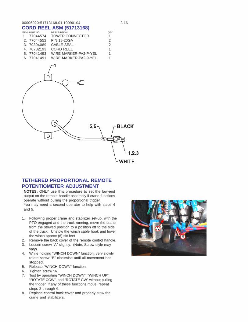
00006020: 3-16CORD REEL ASM (51713168)ITEM PART NO. DESCRIPTION QTY 1. 77044574 TOWER CONNECTOR 1 2. 77044552 PIN 18-20GA 2 3. 70394069 CABLE SEAL 2 4. 70732193 CORD REEL 1 5. 77041493 WIRE MARKER-PA2-P-YEL 1 6. 77041491 WIRE MARKER-PA2-9-YEL 1
51713168.01.19990104
TETHERED PROPORTIONAL REMOTEPOTENTIOMETER ADJUSTMENTNOTES: ONLY use this procedure to set the low-endoutput on the remote handle assembly if crane functionsoperate without pulling the proportional trigger.You may need a second operator to help with steps 4and 5.
1. Following proper crane and stabilizer set-up, with thePTO engaged and the truck running, move the cranefrom the stowed position to a position off to the sideof the truck. Unstow the winch cable hook and lowerthe winch approx (6) six feet.
2. Remove the back cover of the remote control handle.3. Loosen screw “A” slightly. (Note: Screw style may
vary).4. While holding “WINCH DOWN” function, very slowly,
rotate screw “B” clockwise until all movement hasstopped.
5. Release “WINCH DOWN” function.6. Tighten screw “A”7. Test by operating “WINCH DOWN”, “WINCH UP”,
“ROTATE CCW”, and “ROTATE CW” without pullingthe trigger. If any of these functions move, repeatsteps 2 through 6.
8. Replace control back cover and properly stow thecrane and stabilizers.
B
A
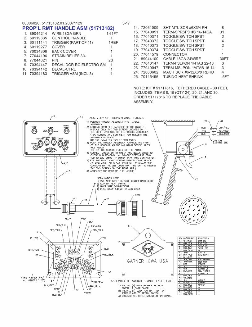
00006020: 3-1751713182.01.20071129PROP’L RMT HANDLE ASM (51713182) 1. 89044214 WIRE 18GA GRN 1.61FT 2. 60119335 CONTROL HANDLE 1 3. 60111141 TRIGGER (PART OF 11) 1REF 4. 60119277 COVER 1 5. 70034306 BACK COVER 1 7. 77044196 STRAIN RELIEF 3/4 1 8. 77044621 PIN 23 9. 70394447 DECAL-DGR RC ELECTRO SM 110. 70394142 DECAL-CTRL 111. 70394183 TRIGGER ASM (INCL:3) 1
14. 72061009 SHT MTL SCR #6X3/4 PH 815. 77040051 TERM-SPRSPD #8 16-14GA 3116. 77040371 TOGGLE SWITCH SPST 217. 77040372 TOGGLE SWITCH SPDT 418. 77040373 TOGGLE SWITCH SPST 219. 77040374 TOGGLE SWITCH SPDT 120. 77044579 CONNECTOR 121. 89044100 CABLE 18GA 24WIRE 30FT22. 77040147 TERM-FSLPON 1/4TAB 22-18 323. 77040047 TERM-MSLPON 1/4TAB 16-14 324. 72060602 MACH SCR #6-32X3/8 RDHD 425. 70145495 TUBING-HEAT SHRINK .5FT
NOTE: KIT # 51717816, TETHERED CABLE - 30 FEET,INCLUDES ITEMS 8, 15 (QTY 24), 20, 21, AND 30.ORDER 51717816 TO REPLACE THE CABLEASSEMBLY.
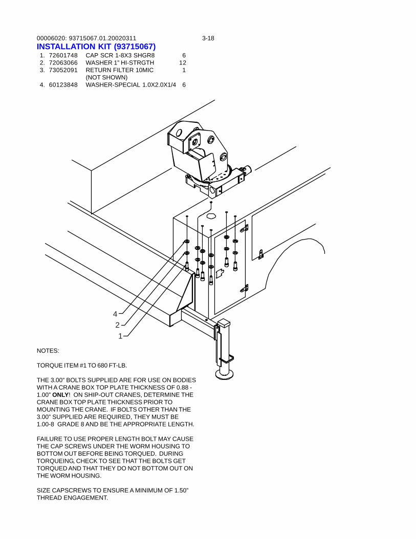
00006020: 3-1893715067.01.20020311INSTALLATION KIT (93715067) 1. 72601748 CAP SCR 1-8X3 SHGR8 6 2. 72063066 WASHER 1” HI-STRGTH 12 3. 73052091 RETURN FILTER 10MIC 1
(NOT SHOWN) 4. 60123848 WASHER-SPECIAL 1.0X2.0X1/4 6
421
NOTES:
TORQUE ITEM #1 TO 680 FT-LB.
THE 3.00” BOLTS SUPPLIED ARE FOR USE ON BODIESWITH A CRANE BOX TOP PLATE THICKNESS OF 0.88 -1.00” ONLY! ON SHIP-OUT CRANES, DETERMINE THECRANE BOX TOP PLATE THICKNESS PRIOR TOMOUNTING THE CRANE. IF BOLTS OTHER THAN THE3.00” SUPPLIED ARE REQUIRED, THEY MUST BE1.00-8 GRADE 8 AND BE THE APPROPRIATE LENGTH.
FAILURE TO USE PROPER LENGTH BOLT MAY CAUSETHE CAP SCREWS UNDER THE WORM HOUSING TOBOTTOM OUT BEFORE BEING TORQUED. DURINGTORQUEING, CHECK TO SEE THAT THE BOLTS GETTORQUED AND THAT THEY DO NOT BOTTOM OUT ONTHE WORM HOUSING.
SIZE CAPSCREWS TO ENSURE A MINIMUM OF 1.50”THREAD ENGAGEMENT.
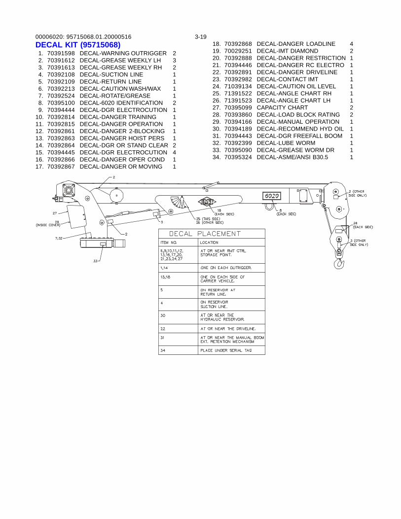
00006020: 3-1995715068.01.20000516DECAL KIT (95715068) 1. 70391598 DECAL-WARNING OUTRIGGER 2 2. 70391612 DECAL-GREASE WEEKLY LH 3 3. 70391613 DECAL-GREASE WEEKLY RH 2 4. 70392108 DECAL-SUCTION LINE 1 5. 70392109 DECAL-RETURN LINE 1 6. 70392213 DECAL-CAUTION WASH/WAX 1 7. 70392524 DECAL-ROTATE/GREASE 1 8. 70395100 DECAL-6020 IDENTIFICATION 2 9. 70394444 DECAL-DGR ELECTROCUTION 110. 70392814 DECAL-DANGER TRAINING 111. 70392815 DECAL-DANGER OPERATION 112. 70392861 DECAL-DANGER 2-BLOCKING 113. 70392863 DECAL-DANGER HOIST PERS 114. 70392864 DECAL-DGR OR STAND CLEAR 215. 70394445 DECAL-DGR ELECTROCUTION 416. 70392866 DECAL-DANGER OPER COND 117. 70392867 DECAL-DANGER OR MOVING 1
18. 70392868 DECAL-DANGER LOADLINE 419. 70029251 DECAL-IMT DIAMOND 220. 70392888 DECAL-DANGER RESTRICTION 121. 70394446 DECAL-DANGER RC ELECTRO 122. 70392891 DECAL-DANGER DRIVELINE 123. 70392982 DECAL-CONTACT IMT 124. 71039134 DECAL-CAUTION OIL LEVEL 125. 71391522 DECAL-ANGLE CHART RH 126. 71391523 DECAL-ANGLE CHART LH 127. 70395099 CAPACITY CHART 228. 70393860 DECAL-LOAD BLOCK RATING 229. 70394166 DECAL-MANUAL OPERATION 130. 70394189 DECAL-RECOMMEND HYD OIL 131. 70394443 DECAL-DGR FREEFALL BOOM 132. 70392399 DECAL-LUBE WORM 133. 70395090 DECAL-GREASE WORM DR 134. 70395324 DECAL-ASME/ANSI B30.5 1
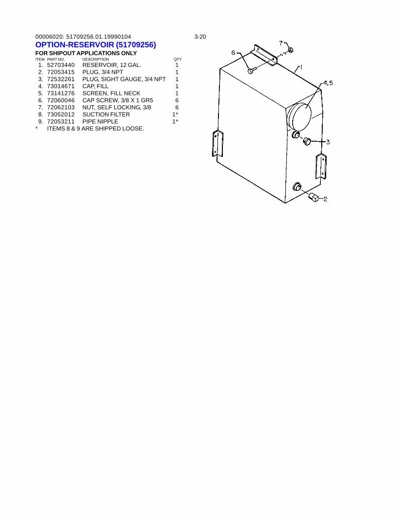
00006020: 3-2051709256.01.19990104OPTION-RESERVOIR (51709256)FOR SHIPOUT APPLICATIONS ONLYITEM PART NO. DESCRIPTION QTY 1. 52703440 RESERVOIR, 12 GAL. 1 2. 72053415 PLUG, 3/4 NPT 1 3. 72532261 PLUG, SIGHT GAUGE, 3/4 NPT 1 4. 73014671 CAP, FILL 1 5. 73141276 SCREEN, FILL NECK 1 6. 72060046 CAP SCREW, 3/8 X 1 GR5 6 7. 72062103 NUT, SELF LOCKING, 3/8 6 8. 73052012 SUCTION FILTER 1* 9. 72053211 PIPE NIPPLE 1** ITEMS 8 & 9 ARE SHIPPED LOOSE.
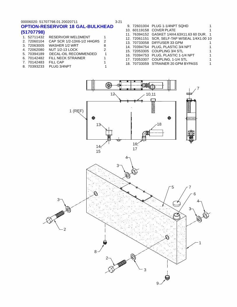
00006020: 3-2151707798.01.20020711OPTION-RESERVOIR 18 GAL-BULKHEAD(51707798) 1. 52711432 RESERVOIR WELDMENT 1 2. 72060104 CAP SCR 1/2-13X6-1/2 HHGR5 2 3. 72063005 WASHER 1/2 WRT 8 4. 72062080 NUT 1/2-13 LOCK 2 5. 70394189 DECAL-OIL RECOMMENDED 1 6. 70142482 FILL NECK STRAINER 1 7. 70142483 FILL CAP 1 8. 70393233 PLUG 3/4NPT 1
710,1112
13
14,15
16,17
18
3
2
82
3
9
3
4
5 7
6
3
4
1
1 (REF)
9. 72601004 PLUG 1-1/4NPT SQHD 110. 60119158 COVER PLATE 111. 76394152 GASKET 1/4X4.63X11.63 60 DUR. 112. 72061151 SCR, SELF-TAP W/SEAL 1/4X1.00 1013. 70733058 DIFFUSER 33 GPM 114. 70394754 PLUG, PLASTIC 3/4 NPT 115. 72053305 COUPLING 3/4 STL 116. 70394753 PLUG, PLASTIC 1-1/4 NPT 117. 72053307 COUPLING, 1-1/4 STL 118. 70733059 STRAINER 20 GPM BYPASS 1
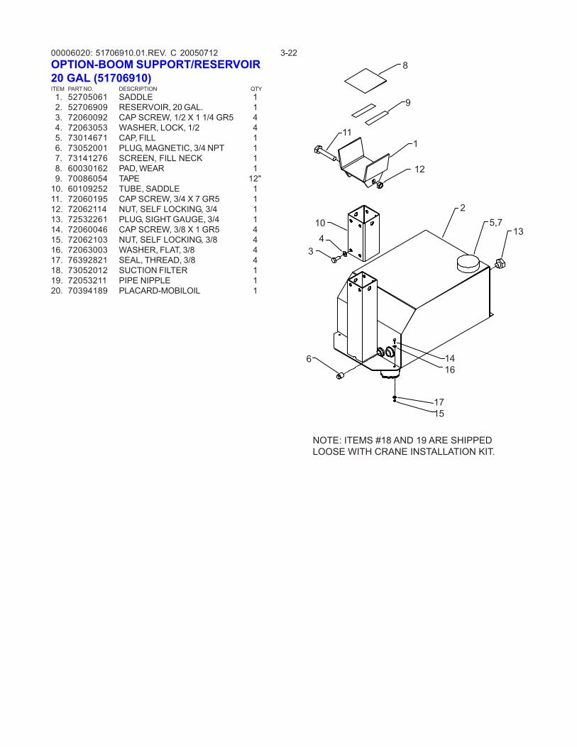
00006020: 3-2251706910.01.REV. C 20050712OPTION-BOOM SUPPORT/RESERVOIR20 GAL (51706910)ITEM PART NO. DESCRIPTION QTY 1. 52705061 SADDLE 1 2. 52706909 RESERVOIR, 20 GAL. 1 3. 72060092 CAP SCREW, 1/2 X 1 1/4 GR5 4 4. 72063053 WASHER, LOCK, 1/2 4 5. 73014671 CAP, FILL 1 6. 73052001 PLUG, MAGNETIC, 3/4 NPT 1 7. 73141276 SCREEN, FILL NECK 1 8. 60030162 PAD, WEAR 1 9. 70086054 TAPE 12"10. 60109252 TUBE, SADDLE 111. 72060195 CAP SCREW, 3/4 X 7 GR5 112. 72062114 NUT, SELF LOCKING, 3/4 113. 72532261 PLUG, SIGHT GAUGE, 3/4 114. 72060046 CAP SCREW, 3/8 X 1 GR5 415. 72062103 NUT, SELF LOCKING, 3/8 416. 72063003 WASHER, FLAT, 3/8 417. 76392821 SEAL, THREAD, 3/8 418. 73052012 SUCTION FILTER 119. 72053211 PIPE NIPPLE 120. 70394189 PLACARD-MOBILOIL 1
135,7
2
1
12
104
3
6 1416
1715
9
11
8
NOTE: ITEMS #18 AND 19 ARE SHIPPEDLOOSE WITH CRANE INSTALLATION KIT.
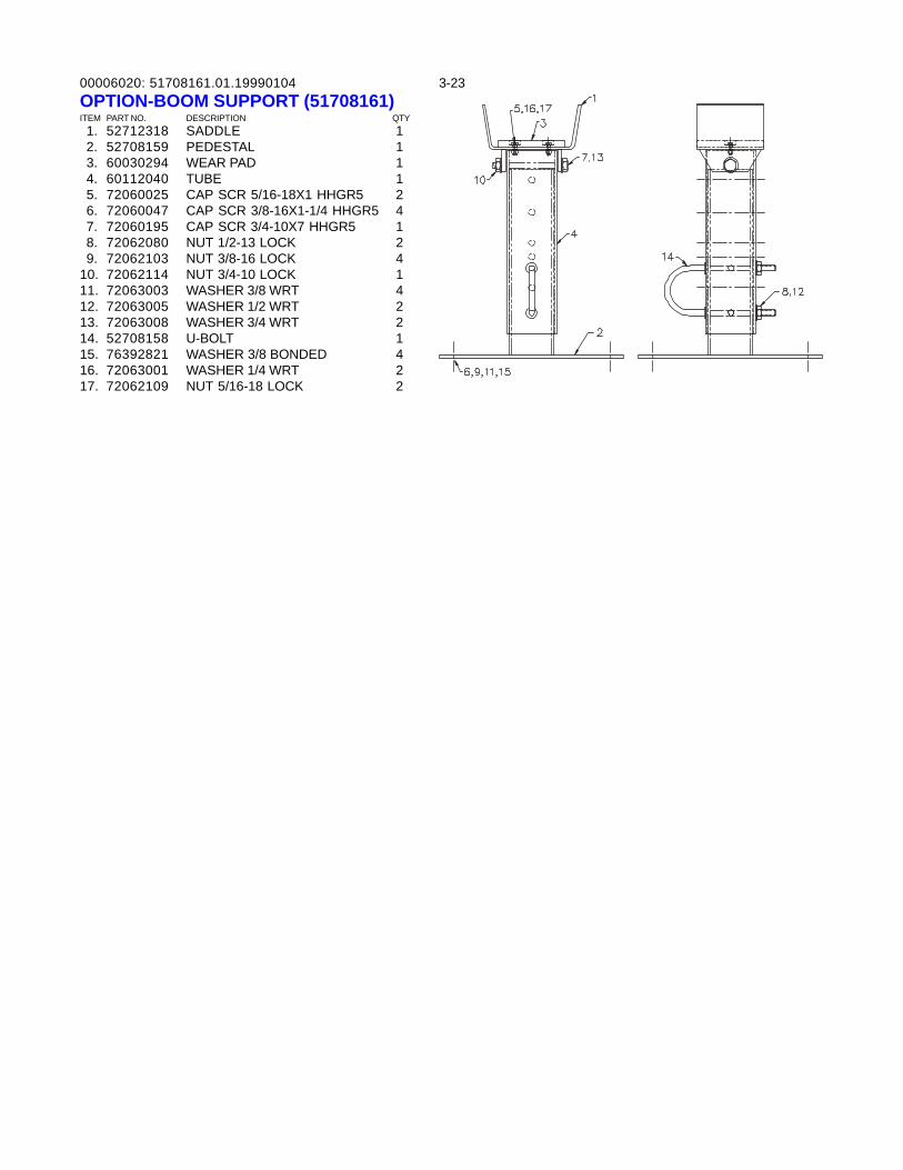
00006020: 3-2351708161.01.19990104OPTION-BOOM SUPPORT (51708161)ITEM PART NO. DESCRIPTION QTY 1. 52712318 SADDLE 1 2. 52708159 PEDESTAL 1 3. 60030294 WEAR PAD 1 4. 60112040 TUBE 1 5. 72060025 CAP SCR 5/16-18X1 HHGR5 2 6. 72060047 CAP SCR 3/8-16X1-1/4 HHGR5 4 7. 72060195 CAP SCR 3/4-10X7 HHGR5 1 8. 72062080 NUT 1/2-13 LOCK 2 9. 72062103 NUT 3/8-16 LOCK 410. 72062114 NUT 3/4-10 LOCK 111. 72063003 WASHER 3/8 WRT 412. 72063005 WASHER 1/2 WRT 213. 72063008 WASHER 3/4 WRT 214. 52708158 U-BOLT 115. 76392821 WASHER 3/8 BONDED 416. 72063001 WASHER 1/4 WRT 217. 72062109 NUT 5/16-18 LOCK 2
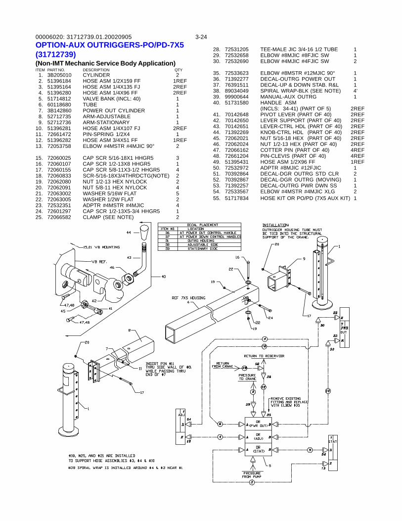
00006020: 3-2431712739.01.20020905OPTION-AUX OUTRIGGERS-PO/PD-7X5(31712739)(Non-IMT Mechanic Service Body Application)ITEM PART NO. DESCRIPTION QTY 1. 3B205010 CYLINDER 2 2. 51396184 HOSE ASM 1/2X159 FF 1REF 3. 51395164 HOSE ASM 1/4X135 FJ 2REF 4. 51396280 HOSE ASM 1/4X96 FF 2REF 5. 51714812 VALVE BANK (INCL: 40) 1 6. 60118680 TUBE 1 7. 3B142860 POWER OUT CYLINDER 1 8. 52712735 ARM-ADJUSTABLE 1 9. 52712736 ARM-STATIONARY 110. 51396281 HOSE ASM 1/4X107 FJ 2REF11. 72661472 PIN-SPRING 1/2X4 112. 51396282 HOSE ASM 3/4X51 FF 1REF13. 72053758 ELBOW #4MSTR #4MJIC 90° 2
15. 72060025 CAP SCR 5/16-18X1 HHGR5 316. 72060107 CAP SCR 1/2-13X8 HHGR5 117. 72060155 CAP SCR 5/8-11X3-1/2 HHGR5 418. 72060833 SCR-5/16-18X3/4THRDCTG(NOTE) 219. 72062080 NUT 1/2-13 HEX NYLOCK 220. 72062091 NUT 5/8-11 HEX NYLOCK 421. 72063002 WASHER 5/16W FLAT 522. 72063005 WASHER 1/2W FLAT 223. 72532351 ADPTR #4MSTR #4MJIC 424. 72601297 CAP SCR 1/2-13X5-3/4 HHGR5 125. 72066582 CLAMP (SEE NOTE) 2
28. 72531205 TEE-MALE JIC 3/4-16 1/2 TUBE 129. 72532658 ELBOW #8MJIC #8FJIC SW 130. 72532690 ELBOW #4MJIC #4FJIC SW 2
35. 72533623 ELBOW #8MSTR #12MJIC 90° 136. 71392277 DECAL-OUTRG POWER OUT 137. 76391511 DECAL-UP & DOWN STAB. R&L 138. 89034049 SPIRAL WRAP-BLK (SEE NOTE) 4’39. 99900644 MANUAL-AUX OUTRG 140. 51731580 HANDLE ASM
(INCLS: 34-41) (PART OF 5) 2REF41. 70142648 PIVOT LEVER (PART OF 40) 2REF42. 70142650 LEVER SUPPORT (PART OF 40) 2REF43. 70142651 LEVER-CTRL HDL (PART OF 40) 2REF44. 71392269 KNOB-CTRL HDL (PART OF 40) 2REF45. 72062021 NUT 5/16-18 HEX (PART OF 40) 2REF46. 72062024 NUT 1/2-13 HEX (PART OF 40) 2REF47. 72066162 COTTER PIN (PART OF 40) 4REF48. 72661204 PIN-CLEVIS (PART OF 40) 4REF49. 51395431 HOSE ASM 1/2X96 FF 1REF50. 72532972 ADPTR #8MJIC #12FJIC 151. 70392864 DECAL-DGR OUTRG STD CLR 252. 70392867 DECAL-DGR OUTRG (MOVING) 153. 71392257 DECAL-OUTRG PWR DWN SS 154. 72533567 ELBOW #4MSTR #4MJIC XLG 255. 51717834 HOSE KIT OR PO/PD (7X5 AUX KIT) 1
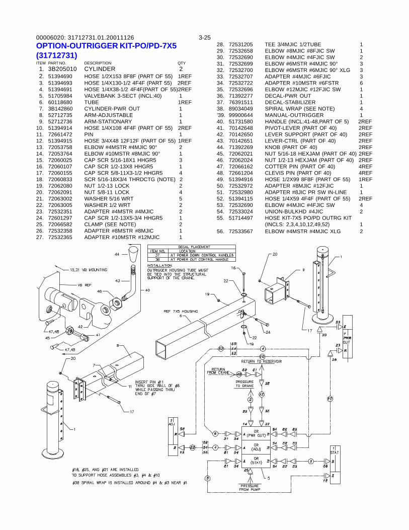
00006020: 3-2531712731.01.20011126OPTION-OUTRIGGER KIT-PO/PD-7X5(31712731)ITEM PART NO. DESCRIPTION QTY 1. 3B205010 CYLINDER 2 2. 51394690 HOSE 1/2X153 8F8F (PART OF 55) 1REF 3. 51394693 HOSE 1/4X130-1/2 4F4F (PART 55) 2REF 4. 51394691 HOSE 1/4X38-1/2 4F4F(PART OF 55)2REF 5. 51705984 VALVEBANK 3-SECT (INCL:40) 1 6. 60118680 TUBE 1REF 7. 3B142860 CYLINDER-PWR OUT 1 8. 52712735 ARM-ADJUSTABLE 1 9. 52712736 ARM-STATIONARY 110. 51394914 HOSE 1/4X108 4F4F (PART OF 55) 2REF11. 72661472 PIN 112. 51394915 HOSE 3/4X48 12F12F (PART OF 55) 1REF13. 72053758 ELBOW #4MSTR #4MJIC 90° 214. 72053764 ELBOW #10MSTR #8MJIC 90° 115. 72060025 CAP SCR 5/16-18X1 HHGR5 316. 72060107 CAP SCR 1/2-13X8 HHGR5 117. 72060155 CAP SCR 5/8-11X3-1/2 HHGR5 418. 72060833 SCR 5/16-18X3/4 THRDCTG (NOTE) 219. 72062080 NUT 1/2-13 LOCK 220. 72062091 NUT 5/8-11 LOCK 421. 72063002 WASHER 5/16 WRT 522. 72063005 WASHER 1/2 WRT 223. 72532351 ADAPTER #4MSTR #4MJIC 224. 72601297 CAP SCR 1/2-13X5-3/4 HHGR5 125. 72066582 CLAMP (SEE NOTE) 226. 72532358 ADAPTER #8MSTR #8MJIC 127. 72532365 ADAPTER #10MSTR #12MJIC 1
28. 72531205 TEE 3/4MJIC 1/2TUBE 129. 72532658 ELBOW #8MJIC #8FJIC SW 130. 72532690 ELBOW #4MJIC #4FJIC SW 231. 72532699 ELBOW #6MSTR #4MJIC 90° 332. 72532700 ELBOW #6MSTR #6MJIC 90° XLG 333. 72532707 ADAPTER #4MJIC #6FJIC 334. 72532722 ADAPTER #10MSTR #6FSTR 635. 72532696 ELBOW #12MJIC #12FJIC SW 136. 71392277 DECAL-PWR OUT 137. 76391511 DECAL-STABILIZER 138. 89034049 SPIRAL WRAP (SEE NOTE) 4’39. 99900644 MANUAL-OUTRIGGER 140. 51731580 HANDLE (INCL:41-48,PART OF 5) 2REF41. 70142648 PIVOT-LEVER (PART OF 40) 2REF42. 70142650 LEVER SUPPORT (PART OF 40) 2REF43. 70142651 LEVER-CTRL (PART OF 40) 2REF44. 71392269 KNOB (PART OF 40) 2REF45. 72062021 NUT 5/16-18 HEXJAM (PART OF 40) 2REF46. 72062024 NUT 1/2-13 HEXJAM (PART OF 40) 2REF47. 72066162 COTTER PIN (PART OF 40) 4REF48. 72661204 CLEVIS PIN (PART OF 40) 4REF49. 51394916 HOSE 1/2X99 8F8F (PART OF 55) 1REF50. 72532972 ADAPTER #8MJIC #12FJIC 151. 72532980 ADAPTER #8JIC PR SW IN-LINE 152. 51394115 HOSE 1/4X59 4F4F (PART OF 55) 2REF53. 72532690 ELBOW #4MJIC #4FJIC SW 454. 72533024 UNION-BULKHD #4JIC 255. 51714497 HOSE KIT-7X5 PO/PD OUTRG KIT
(INCLS: 2,3,4,10,12,49,52) 156. 72533567 ELBOW #4MSTR #4MJIC XLG 2
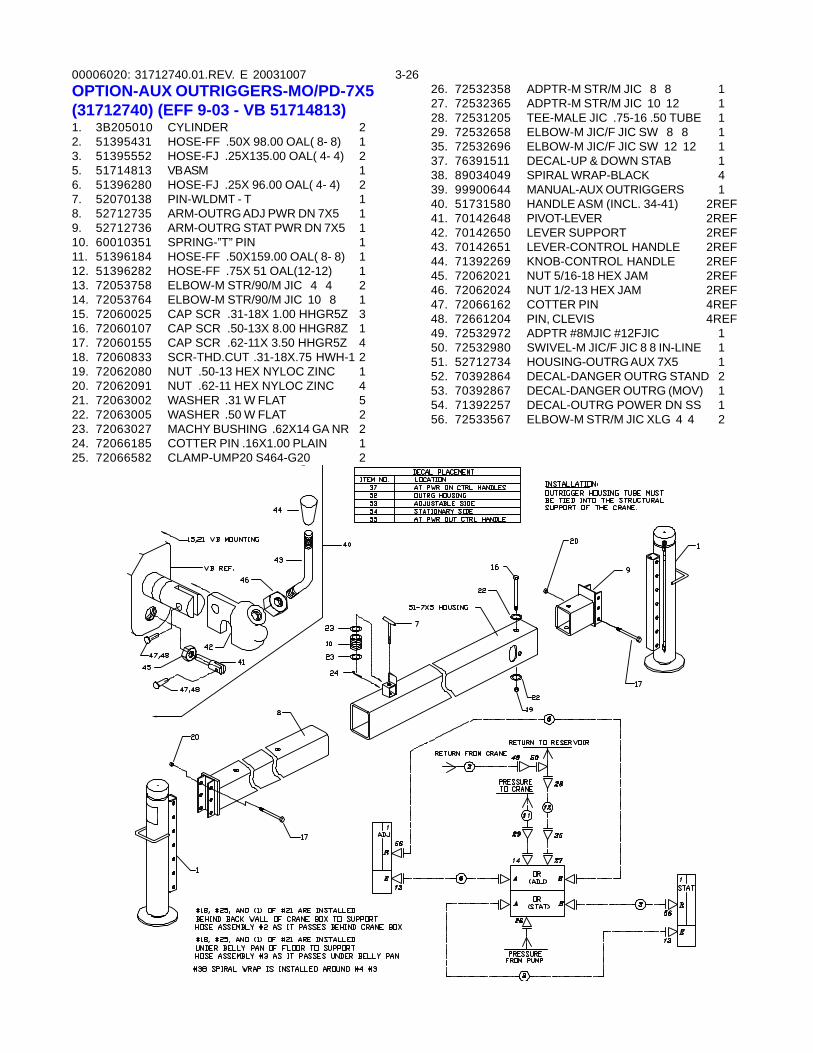
00006020: 3-26OPTION-AUX OUTRIGGERS-MO/PD-7X5(31712740) (EFF 9-03 - VB 51714813)1. 3B205010 CYLINDER 22. 51395431 HOSE-FF .50X 98.00 OAL( 8- 8) 13. 51395552 HOSE-FJ .25X135.00 OAL( 4- 4) 25. 51714813 VB ASM 16. 51396280 HOSE-FJ .25X 96.00 OAL( 4- 4) 27. 52070138 PIN-WLDMT - T 18. 52712735 ARM-OUTRG ADJ PWR DN 7X5 19. 52712736 ARM-OUTRG STAT PWR DN 7X5 110. 60010351 SPRING-”T” PIN 111. 51396184 HOSE-FF .50X159.00 OAL( 8- 8) 112. 51396282 HOSE-FF .75X 51 OAL(12-12) 113. 72053758 ELBOW-M STR/90/M JIC 4 4 214. 72053764 ELBOW-M STR/90/M JIC 10 8 115. 72060025 CAP SCR .31-18X 1.00 HHGR5Z 316. 72060107 CAP SCR .50-13X 8.00 HHGR8Z 117. 72060155 CAP SCR .62-11X 3.50 HHGR5Z 418. 72060833 SCR-THD.CUT .31-18X.75 HWH-1 219. 72062080 NUT .50-13 HEX NYLOC ZINC 120. 72062091 NUT .62-11 HEX NYLOC ZINC 421. 72063002 WASHER .31 W FLAT 522. 72063005 WASHER .50 W FLAT 223. 72063027 MACHY BUSHING .62X14 GA NR 224. 72066185 COTTER PIN .16X1.00 PLAIN 125. 72066582 CLAMP-UMP20 S464-G20 2
26. 72532358 ADPTR-M STR/M JIC 8 8 127. 72532365 ADPTR-M STR/M JIC 10 12 128. 72531205 TEE-MALE JIC .75-16 .50 TUBE 129. 72532658 ELBOW-M JIC/F JIC SW 8 8 135. 72532696 ELBOW-M JIC/F JIC SW 12 12 137. 76391511 DECAL-UP & DOWN STAB 138. 89034049 SPIRAL WRAP-BLACK 439. 99900644 MANUAL-AUX OUTRIGGERS 140. 51731580 HANDLE ASM (INCL. 34-41) 2REF41. 70142648 PIVOT-LEVER 2REF42. 70142650 LEVER SUPPORT 2REF43. 70142651 LEVER-CONTROL HANDLE 2REF44. 71392269 KNOB-CONTROL HANDLE 2REF45. 72062021 NUT 5/16-18 HEX JAM 2REF46. 72062024 NUT 1/2-13 HEX JAM 2REF47. 72066162 COTTER PIN 4REF48. 72661204 PIN, CLEVIS 4REF49. 72532972 ADPTR #8MJIC #12FJIC 150. 72532980 SWIVEL-M JIC/F JIC 8 8 IN-LINE 151. 52712734 HOUSING-OUTRG AUX 7X5 152. 70392864 DECAL-DANGER OUTRG STAND 253. 70392867 DECAL-DANGER OUTRG (MOV) 154. 71392257 DECAL-OUTRG POWER DN SS 156. 72533567 ELBOW-M STR/M JIC XLG 4 4 2
31712740.01.REV. E 20031007
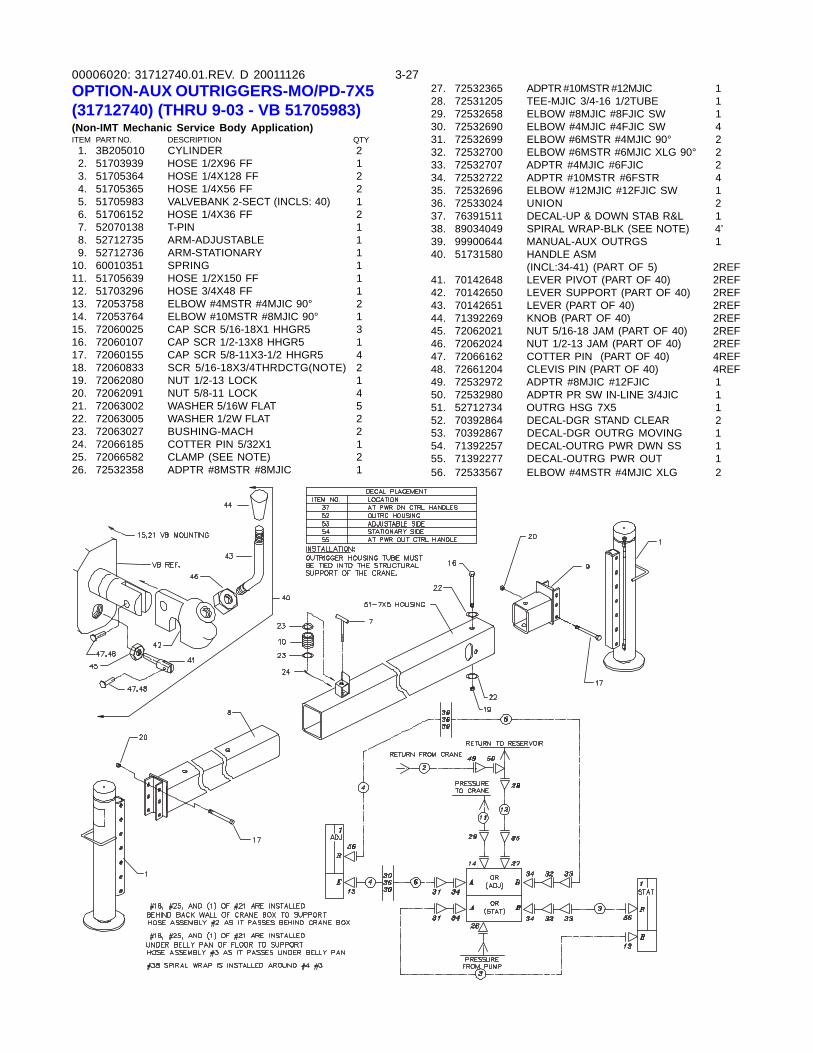
00006020: 3-2731712740.01.REV. D 20011126OPTION-AUX OUTRIGGERS-MO/PD-7X5(31712740) (THRU 9-03 - VB 51705983)(Non-IMT Mechanic Service Body Application)ITEM PART NO. DESCRIPTION QTY 1. 3B205010 CYLINDER 2 2. 51703939 HOSE 1/2X96 FF 1 3. 51705364 HOSE 1/4X128 FF 2 4. 51705365 HOSE 1/4X56 FF 2 5. 51705983 VALVEBANK 2-SECT (INCLS: 40) 1 6. 51706152 HOSE 1/4X36 FF 2 7. 52070138 T-PIN 1 8. 52712735 ARM-ADJUSTABLE 1 9. 52712736 ARM-STATIONARY 110. 60010351 SPRING 111. 51705639 HOSE 1/2X150 FF 112. 51703296 HOSE 3/4X48 FF 113. 72053758 ELBOW #4MSTR #4MJIC 90° 214. 72053764 ELBOW #10MSTR #8MJIC 90° 115. 72060025 CAP SCR 5/16-18X1 HHGR5 316. 72060107 CAP SCR 1/2-13X8 HHGR5 117. 72060155 CAP SCR 5/8-11X3-1/2 HHGR5 418. 72060833 SCR 5/16-18X3/4THRDCTG(NOTE) 219. 72062080 NUT 1/2-13 LOCK 120. 72062091 NUT 5/8-11 LOCK 421. 72063002 WASHER 5/16W FLAT 522. 72063005 WASHER 1/2W FLAT 223. 72063027 BUSHING-MACH 224. 72066185 COTTER PIN 5/32X1 125. 72066582 CLAMP (SEE NOTE) 226. 72532358 ADPTR #8MSTR #8MJIC 1
27. 72532365 ADPTR #10MSTR #12MJIC 128. 72531205 TEE-MJIC 3/4-16 1/2TUBE 129. 72532658 ELBOW #8MJIC #8FJIC SW 130. 72532690 ELBOW #4MJIC #4FJIC SW 431. 72532699 ELBOW #6MSTR #4MJIC 90° 232. 72532700 ELBOW #6MSTR #6MJIC XLG 90° 233. 72532707 ADPTR #4MJIC #6FJIC 234. 72532722 ADPTR #10MSTR #6FSTR 435. 72532696 ELBOW #12MJIC #12FJIC SW 136. 72533024 UNION 237. 76391511 DECAL-UP & DOWN STAB R&L 138. 89034049 SPIRAL WRAP-BLK (SEE NOTE) 4’39. 99900644 MANUAL-AUX OUTRGS 140. 51731580 HANDLE ASM
(INCL:34-41) (PART OF 5) 2REF41. 70142648 LEVER PIVOT (PART OF 40) 2REF42. 70142650 LEVER SUPPORT (PART OF 40) 2REF43. 70142651 LEVER (PART OF 40) 2REF44. 71392269 KNOB (PART OF 40) 2REF45. 72062021 NUT 5/16-18 JAM (PART OF 40) 2REF46. 72062024 NUT 1/2-13 JAM (PART OF 40) 2REF47. 72066162 COTTER PIN (PART OF 40) 4REF48. 72661204 CLEVIS PIN (PART OF 40) 4REF49. 72532972 ADPTR #8MJIC #12FJIC 150. 72532980 ADPTR PR SW IN-LINE 3/4JIC 151. 52712734 OUTRG HSG 7X5 152. 70392864 DECAL-DGR STAND CLEAR 253. 70392867 DECAL-DGR OUTRG MOVING 154. 71392257 DECAL-OUTRG PWR DWN SS 155. 71392277 DECAL-OUTRG PWR OUT 156. 72533567 ELBOW #4MSTR #4MJIC XLG 2
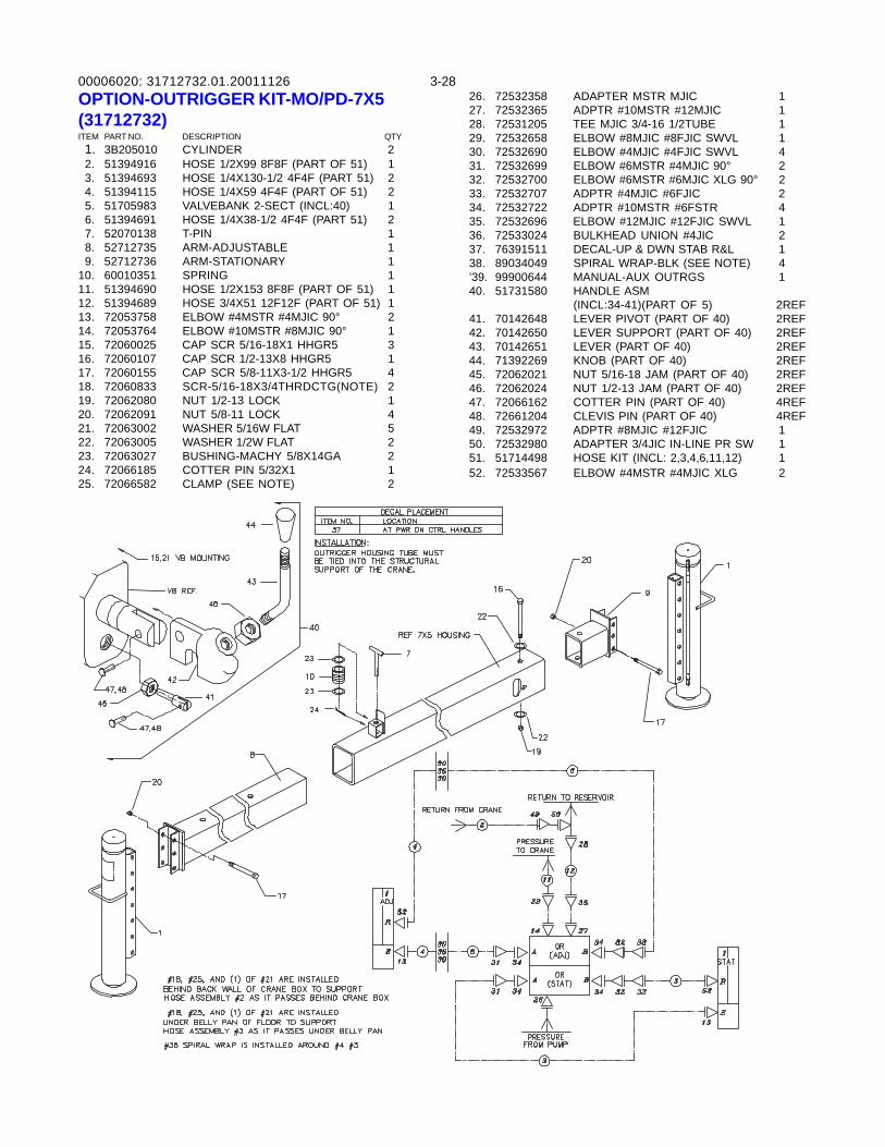
00006020: 3-2831712732.01.20011126OPTION-OUTRIGGER KIT-MO/PD-7X5(31712732)ITEM PART NO. DESCRIPTION QTY 1. 3B205010 CYLINDER 2 2. 51394916 HOSE 1/2X99 8F8F (PART OF 51) 1 3. 51394693 HOSE 1/4X130-1/2 4F4F (PART 51) 2 4. 51394115 HOSE 1/4X59 4F4F (PART OF 51) 2 5. 51705983 VALVEBANK 2-SECT (INCL:40) 1 6. 51394691 HOSE 1/4X38-1/2 4F4F (PART 51) 2 7. 52070138 T-PIN 1 8. 52712735 ARM-ADJUSTABLE 1 9. 52712736 ARM-STATIONARY 110. 60010351 SPRING 111. 51394690 HOSE 1/2X153 8F8F (PART OF 51) 112. 51394689 HOSE 3/4X51 12F12F (PART OF 51) 113. 72053758 ELBOW #4MSTR #4MJIC 90° 214. 72053764 ELBOW #10MSTR #8MJIC 90° 115. 72060025 CAP SCR 5/16-18X1 HHGR5 316. 72060107 CAP SCR 1/2-13X8 HHGR5 117. 72060155 CAP SCR 5/8-11X3-1/2 HHGR5 418. 72060833 SCR-5/16-18X3/4THRDCTG(NOTE) 219. 72062080 NUT 1/2-13 LOCK 120. 72062091 NUT 5/8-11 LOCK 421. 72063002 WASHER 5/16W FLAT 522. 72063005 WASHER 1/2W FLAT 223. 72063027 BUSHING-MACHY 5/8X14GA 224. 72066185 COTTER PIN 5/32X1 125. 72066582 CLAMP (SEE NOTE) 2
26. 72532358 ADAPTER MSTR MJIC 127. 72532365 ADPTR #10MSTR #12MJIC 128. 72531205 TEE MJIC 3/4-16 1/2TUBE 129. 72532658 ELBOW #8MJIC #8FJIC SWVL 130. 72532690 ELBOW #4MJIC #4FJIC SWVL 431. 72532699 ELBOW #6MSTR #4MJIC 90° 232. 72532700 ELBOW #6MSTR #6MJIC XLG 90° 233. 72532707 ADPTR #4MJIC #6FJIC 234. 72532722 ADPTR #10MSTR #6FSTR 435. 72532696 ELBOW #12MJIC #12FJIC SWVL 136. 72533024 BULKHEAD UNION #4JIC 237. 76391511 DECAL-UP & DWN STAB R&L 138. 89034049 SPIRAL WRAP-BLK (SEE NOTE) 4’39. 99900644 MANUAL-AUX OUTRGS 140. 51731580 HANDLE ASM
(INCL:34-41)(PART OF 5) 2REF41. 70142648 LEVER PIVOT (PART OF 40) 2REF42. 70142650 LEVER SUPPORT (PART OF 40) 2REF43. 70142651 LEVER (PART OF 40) 2REF44. 71392269 KNOB (PART OF 40) 2REF45. 72062021 NUT 5/16-18 JAM (PART OF 40) 2REF46. 72062024 NUT 1/2-13 JAM (PART OF 40) 2REF47. 72066162 COTTER PIN (PART OF 40) 4REF48. 72661204 CLEVIS PIN (PART OF 40) 4REF49. 72532972 ADPTR #8MJIC #12FJIC 150. 72532980 ADAPTER 3/4JIC IN-LINE PR SW 151. 51714498 HOSE KIT (INCL: 2,3,4,6,11,12) 152. 72533567 ELBOW #4MSTR #4MJIC XLG 2
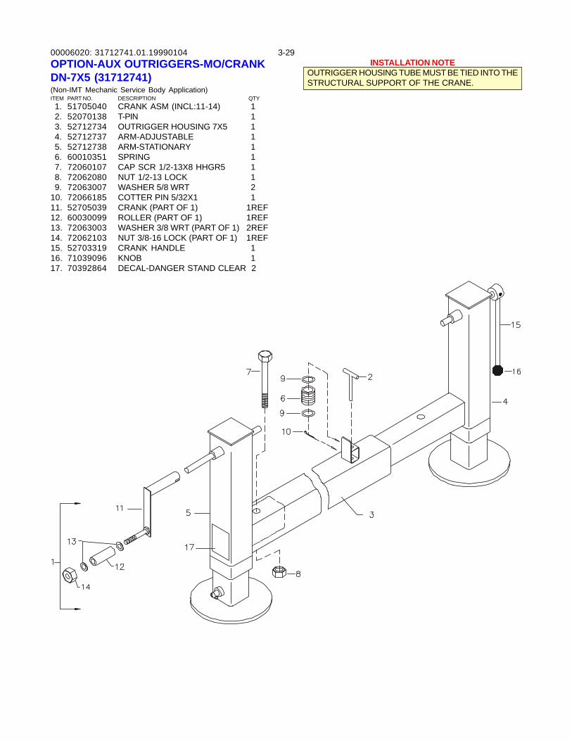
00006020: 3-2931712741.01.19990104OPTION-AUX OUTRIGGERS-MO/CRANKDN-7X5 (31712741)(Non-IMT Mechanic Service Body Application)ITEM PART NO. DESCRIPTION QTY 1. 51705040 CRANK ASM (INCL:11-14) 1 2. 52070138 T-PIN 1 3. 52712734 OUTRIGGER HOUSING 7X5 1 4. 52712737 ARM-ADJUSTABLE 1 5. 52712738 ARM-STATIONARY 1 6. 60010351 SPRING 1 7. 72060107 CAP SCR 1/2-13X8 HHGR5 1 8. 72062080 NUT 1/2-13 LOCK 1 9. 72063007 WASHER 5/8 WRT 210. 72066185 COTTER PIN 5/32X1 111. 52705039 CRANK (PART OF 1) 1REF12. 60030099 ROLLER (PART OF 1) 1REF13. 72063003 WASHER 3/8 WRT (PART OF 1) 2REF14. 72062103 NUT 3/8-16 LOCK (PART OF 1) 1REF15. 52703319 CRANK HANDLE 116. 71039096 KNOB 117. 70392864 DECAL-DANGER STAND CLEAR 2
INSTALLATION NOTEOUTRIGGER HOUSING TUBE MUST BE TIED INTO THESTRUCTURAL SUPPORT OF THE CRANE.
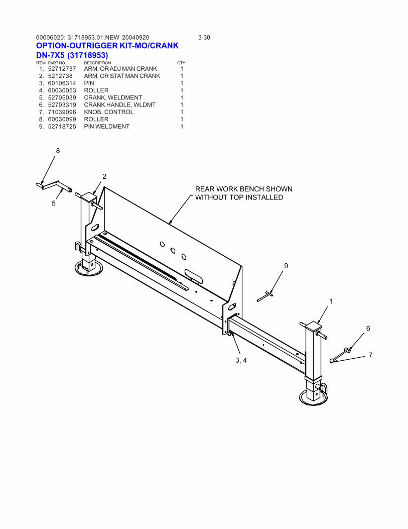
00006020: 3-3031718953.01.NEW 20040920OPTION-OUTRIGGER KIT-MO/CRANKDN-7X5 (31718953)ITEM PART NO. DESCRIPTION QTY 1. 52712737 ARM, OR ADJ MAN CRANK 1 2. 5212738 ARM, OR STAT MAN CRANK 1 3. 60106314 PIN 1 4. 60030053 ROLLER 1 5. 52705039 CRANK, WELDMENT 1 6. 52703319 CRANK HANDLE, WLDMT 1 7. 71039096 KNOB, CONTROL 1 8. 60030099 ROLLER 1 9. 52718725 PIN WELDMENT 1
2
1
3, 4
REAR WORK BENCH SHOWNWITHOUT TOP INSTALLED
6
5
7
8
9
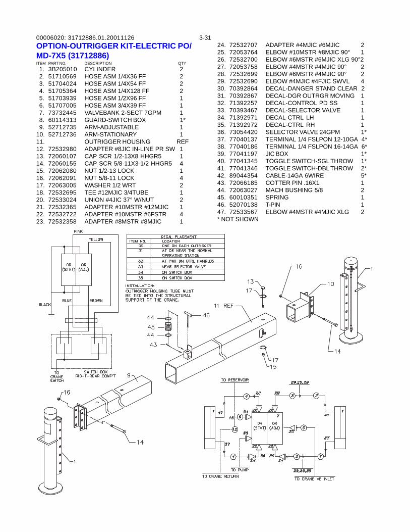
00006020: 3-3131712886.01.20011126OPTION-OUTRIGGER KIT-ELECTRIC PO/MD-7X5 (31712886)ITEM PART NO. DESCRIPTION QTY 1. 3B205010 CYLINDER 2 2. 51710569 HOSE ASM 1/4X36 FF 2 3. 51704024 HOSE ASM 1/4X54 FF 2 4. 51705364 HOSE ASM 1/4X128 FF 2 5. 51703939 HOSE ASM 1/2X96 FF 1 6. 51707005 HOSE ASM 3/4X39 FF 1 7. 73732445 VALVEBANK 2-SECT 7GPM 1 8. 60114313 GUARD-SWITCH BOX 1* 9. 52712735 ARM-ADJUSTABLE 110. 52712736 ARM-STATIONARY 111. OUTRIGGER HOUSING REF12. 72532980 ADAPTER #8JIC IN-LINE PR SW 113. 72060107 CAP SCR 1/2-13X8 HHGR5 114. 72060155 CAP SCR 5/8-11X3-1/2 HHGR5 415. 72062080 NUT 1/2-13 LOCK 116. 72062091 NUT 5/8-11 LOCK 417. 72063005 WASHER 1/2 WRT 218. 72532695 TEE #12MJIC 3/4TUBE 120. 72533024 UNION #4JIC 37° W/NUT 221. 72532365 ADAPTER #10MSTR #12MJIC 122. 72532722 ADAPTER #10MSTR #6FSTR 423. 72532358 ADAPTER #8MSTR #8MJIC 1
24. 72532707 ADAPTER #4MJIC #6MJIC 225. 72053764 ELBOW #10MSTR #8MJIC 90° 126. 72532700 ELBOW #6MSTR #6MJIC XLG 90°227. 72053758 ELBOW #4MSTR #4MJIC 90° 228. 72532699 ELBOW #6MSTR #4MJIC 90° 229. 72532690 ELBOW #4MJIC #4FJIC SWVL 430. 70392864 DECAL-DANGER STAND CLEAR 231. 70392867 DECAL-DGR OUTRGR MOVING 132. 71392257 DECAL-CONTROL PD SS 133. 70393467 DECAL-SELECTOR VALVE 134. 71392971 DECAL-CTRL LH 135. 71392972 DECAL-CTRL RH 136. 73054420 SELECTOR VALVE 24GPM 1*37. 77040137 TERMINAL 1/4 FSLPON 12-10GA 4*38. 77040186 TERMINAL 1/4 FSLPON 16-14GA 6*39. 77041197 JIC BOX 1*40. 77041345 TOGGLE SWITCH-SGL THROW 1*41. 77041346 TOGGLE SWITCH-DBL THROW 2*42. 89044354 CABLE-14GA 6WIRE 5*43. 72066185 COTTER PIN .16X1 144. 72063027 MACH BUSHING 5/8 245. 60010351 SPRING 146. 52070138 T-PIN 147. 72533567 ELBOW #4MSTR #4MJIC XLG 2* NOT SHOWN
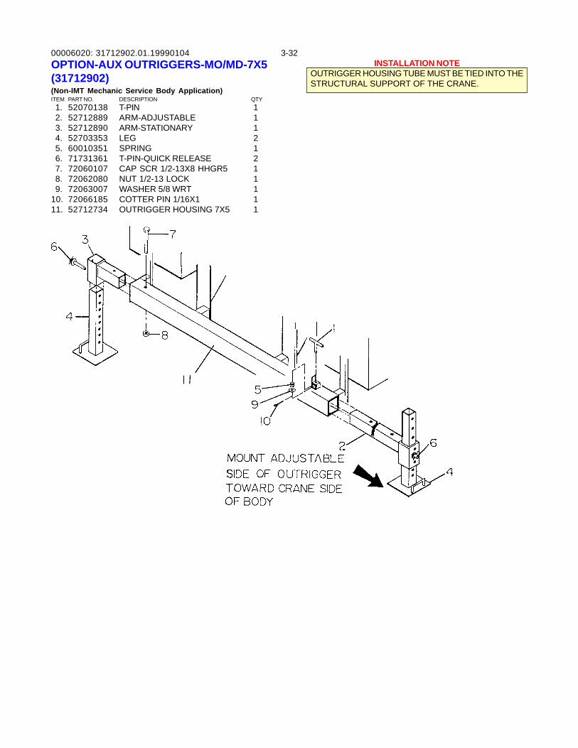
00006020: 3-3231712902.01.19990104OPTION-AUX OUTRIGGERS-MO/MD-7X5(31712902)(Non-IMT Mechanic Service Body Application)ITEM PART NO. DESCRIPTION QTY 1. 52070138 T-PIN 1 2. 52712889 ARM-ADJUSTABLE 1 3. 52712890 ARM-STATIONARY 1 4. 52703353 LEG 2 5. 60010351 SPRING 1 6. 71731361 T-PIN-QUICK RELEASE 2 7. 72060107 CAP SCR 1/2-13X8 HHGR5 1 8. 72062080 NUT 1/2-13 LOCK 1 9. 72063007 WASHER 5/8 WRT 110. 72066185 COTTER PIN 1/16X1 111. 52712734 OUTRIGGER HOUSING 7X5 1
INSTALLATION NOTEOUTRIGGER HOUSING TUBE MUST BE TIED INTO THESTRUCTURAL SUPPORT OF THE CRANE.
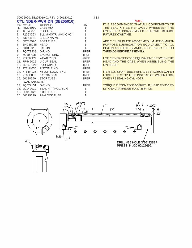
00006020: 3-333B205010.01.REV D 20120419CYLINDER-PWR DN (3B205010)ITEM PART NO. DESCRIPTION QTY 1. 4B205010 CASE ASY 12. 4G048870 ROD ASY 13. 72053763 ELL #8MSTR #8MJIC 90° 14. 73054681 CHECK VALVE 15. 5P288970 PORT TUBE 16 6HD35025 HEAD 17. 6ID35125 PISTON 18. 7Q072338 O-RING 1REF9. 7Q10P338 BACKUP RING 1REF10. 7T2NX427 WEAR RING 2REF11. 7R546025 U-CUP SEAL 1REF12. 7R14P025 ROD WIPER 1REF13. 7T2N4035 PISTON RING 2REF14. 7T61N125 NYLON LOCK RING 1REF15. 7T66P035 PISTON SEAL 1REF16. 60138260 STOP TUBE 1REF
(WAS 6A025025)17. 7Q072151 O-RING 1REF18. 9D142020 SEAL KIT (INCL. 8-17) 119. 6C015025 STOP TUBE 120. 60125699 PIN-LOCK TUBE 1
NOTEIT IS RECOMMENDED THAT ALL COMPONENTS OFTHE SEAL KIT BE REPLACED WHENEVER THECYLINDER IS DISASSEMBLED. THIS WILL REDUCEFUTURE DOWNTIME.
APPLY “LUBRIPLATE #630-2” MEDIUM HEAVY,MULTI-PURPOSE LUBRICANT OR EQUIVALENT TO ALLPISTON AND HEAD GLANDS, LOCK RING AND RODTHREADS BEFORE ASSEMBLY.
USE “NEVER-SEEZ” OR EQUIVALENT BETWEEN THEHEAD AND THE CASE WHEN ASSEMBLING THECYLINDER.
ITEM #16, STOP TUBE, REPLACES 6A025025 WAFERLOCK. USE STOP TUBE INSTEAD OF WAFER LOCKWHEN RESEALING CYLINDER.
TORQUE PISTON TO 500-530 FT-LB, HEAD TO 350 FT-LB, AND CARTRIDGE TO 30-35 FT-LB.
43(2)
5
1517
14
1198
13(2)719
16
12
10(2)612
DRILL #15 HOLE 3/16" DEEPPRESS IN #20 60125699.
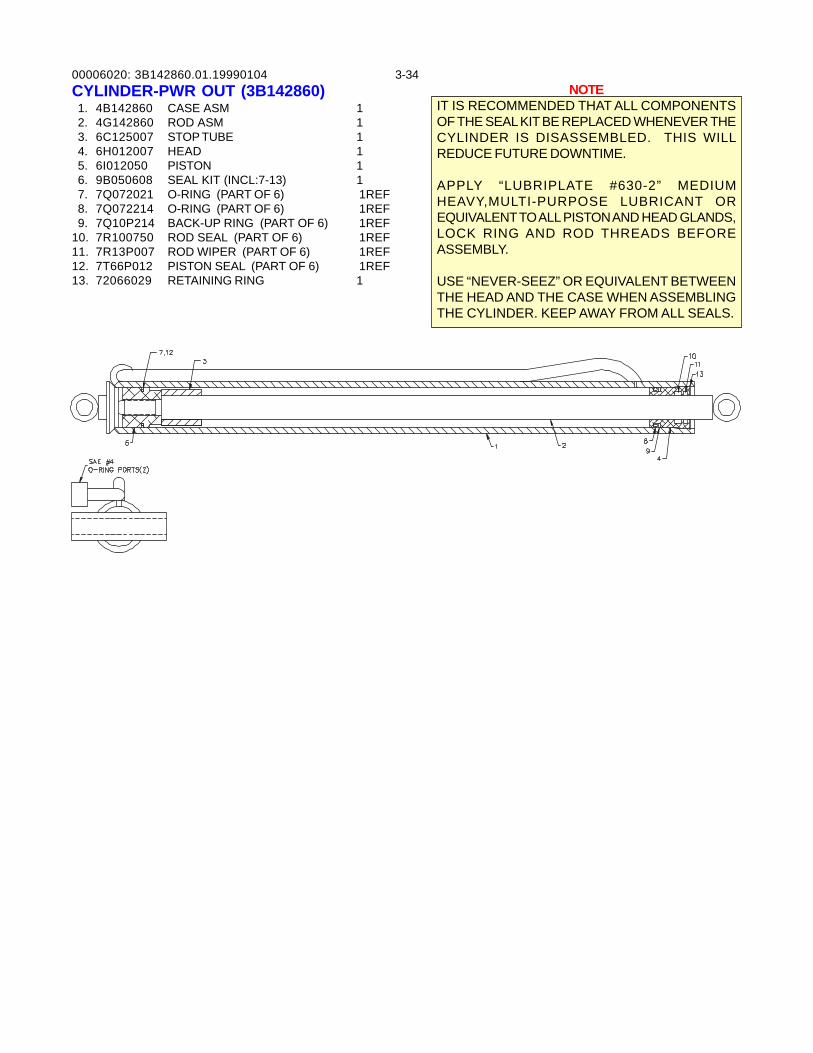
00006020: 3-343B142860.01.19990104CYLINDER-PWR OUT (3B142860) 1. 4B142860 CASE ASM 1 2. 4G142860 ROD ASM 1 3. 6C125007 STOP TUBE 1 4. 6H012007 HEAD 1 5. 6I012050 PISTON 1 6. 9B050608 SEAL KIT (INCL:7-13) 1 7. 7Q072021 O-RING (PART OF 6) 1REF 8. 7Q072214 O-RING (PART OF 6) 1REF 9. 7Q10P214 BACK-UP RING (PART OF 6) 1REF10. 7R100750 ROD SEAL (PART OF 6) 1REF11. 7R13P007 ROD WIPER (PART OF 6) 1REF12. 7T66P012 PISTON SEAL (PART OF 6) 1REF13. 72066029 RETAINING RING 1
NOTEIT IS RECOMMENDED THAT ALL COMPONENTSOF THE SEAL KIT BE REPLACED WHENEVER THECYLINDER IS DISASSEMBLED. THIS WILLREDUCE FUTURE DOWNTIME.
APPLY “LUBRIPLATE #630-2” MEDIUMHEAVY,MULTI-PURPOSE LUBRICANT OREQUIVALENT TO ALL PISTON AND HEAD GLANDS,LOCK RING AND ROD THREADS BEFOREASSEMBLY.
USE “NEVER-SEEZ” OR EQUIVALENT BETWEENTHE HEAD AND THE CASE WHEN ASSEMBLINGTHE CYLINDER. KEEP AWAY FROM ALL SEALS.
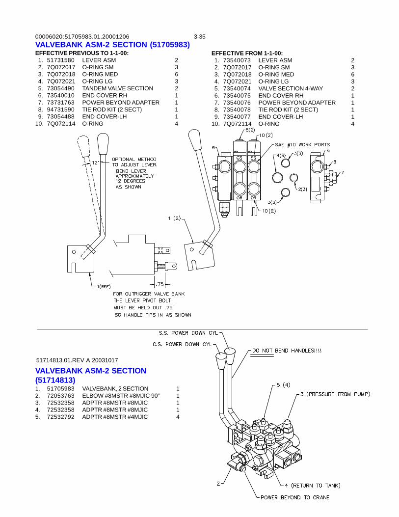
00006020: 3-3551705983.01.20001206VALVEBANK ASM-2 SECTION (51705983)EFFECTIVE PREVIOUS TO 1-1-00: 1. 51731580 LEVER ASM 2 2. 7Q072017 O-RING SM 3 3. 7Q072018 O-RING MED 6 4. 7Q072021 O-RING LG 3 5. 73054490 TANDEM VALVE SECTION 2 6. 73540010 END COVER RH 1 7. 73731763 POWER BEYOND ADAPTER 1 8. 94731590 TIE ROD KIT (2 SECT) 1 9. 73054488 END COVER-LH 110. 7Q072114 O-RING 4
EFFECTIVE FROM 1-1-00: 1. 73540073 LEVER ASM 2 2. 7Q072017 O-RING SM 3 3. 7Q072018 O-RING MED 6 4. 7Q072021 O-RING LG 3 5. 73540074 VALVE SECTION 4-WAY 2 6. 73540075 END COVER RH 1 7. 73540076 POWER BEYOND ADAPTER 1 8. 73540078 TIE ROD KIT (2 SECT) 1 9. 73540077 END COVER-LH 110. 7Q072114 O-RING 4
51714813.01.REV A 20031017
VALVEBANK ASM-2 SECTION(51714813)1. 51705983 VALVEBANK, 2 SECTION 12. 72053763 ELBOW #8MSTR #8MJIC 90° 13. 72532358 ADPTR #8MSTR #8MJIC 14. 72532358 ADPTR #8MSTR #8MJIC 15. 72532792 ADPTR #8MSTR #4MJIC 4
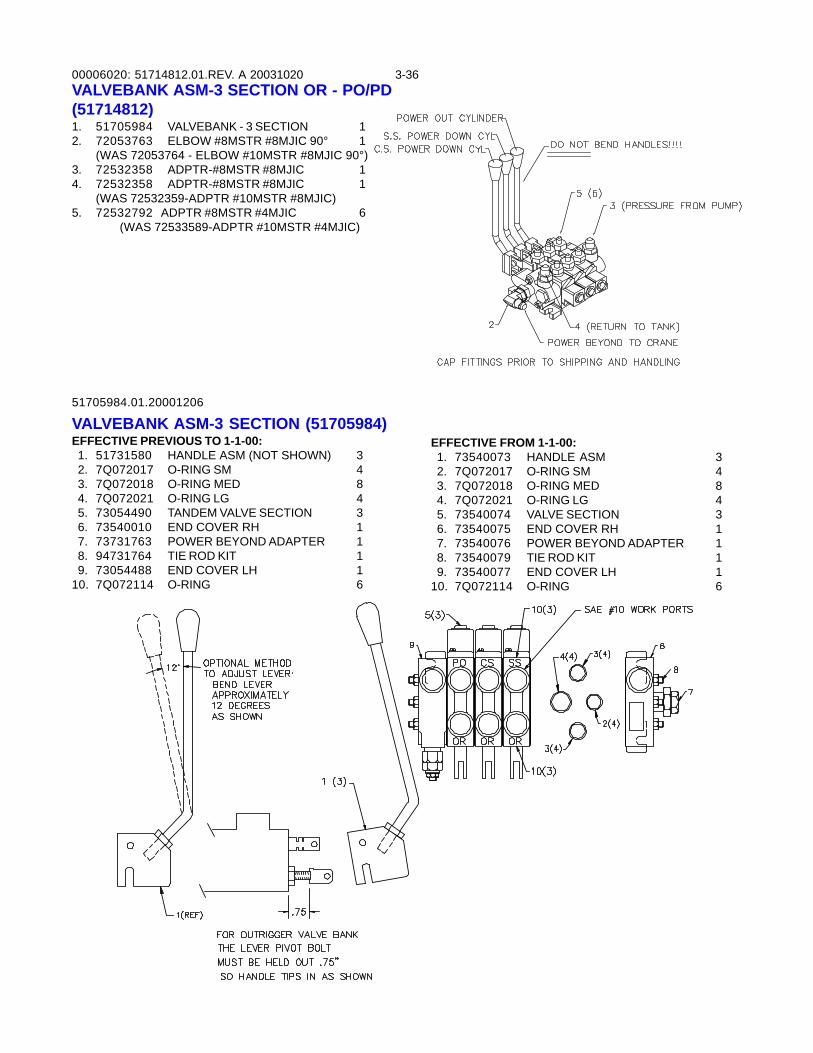
00006020: 3-36
51705984.01.20001206
VALVEBANK ASM-3 SECTION (51705984)EFFECTIVE PREVIOUS TO 1-1-00: 1. 51731580 HANDLE ASM (NOT SHOWN) 3 2. 7Q072017 O-RING SM 4 3. 7Q072018 O-RING MED 8 4. 7Q072021 O-RING LG 4 5. 73054490 TANDEM VALVE SECTION 3 6. 73540010 END COVER RH 1 7. 73731763 POWER BEYOND ADAPTER 1 8. 94731764 TIE ROD KIT 1 9. 73054488 END COVER LH 110. 7Q072114 O-RING 6
EFFECTIVE FROM 1-1-00: 1. 73540073 HANDLE ASM 3 2. 7Q072017 O-RING SM 4 3. 7Q072018 O-RING MED 8 4. 7Q072021 O-RING LG 4 5. 73540074 VALVE SECTION 3 6. 73540075 END COVER RH 1 7. 73540076 POWER BEYOND ADAPTER 1 8. 73540079 TIE ROD KIT 1 9. 73540077 END COVER LH 110. 7Q072114 O-RING 6
51714812.01.REV. A 20031020VALVEBANK ASM-3 SECTION OR - PO/PD(51714812)1. 51705984 VALVEBANK - 3 SECTION 12. 72053763 ELBOW #8MSTR #8MJIC 90° 1
(WAS 72053764 - ELBOW #10MSTR #8MJIC 90°)3. 72532358 ADPTR-#8MSTR #8MJIC 14. 72532358 ADPTR-#8MSTR #8MJIC 1
(WAS 72532359-ADPTR #10MSTR #8MJIC)5. 72532792 ADPTR #8MSTR #4MJIC 6
(WAS 72533589-ADPTR #10MSTR #4MJIC)
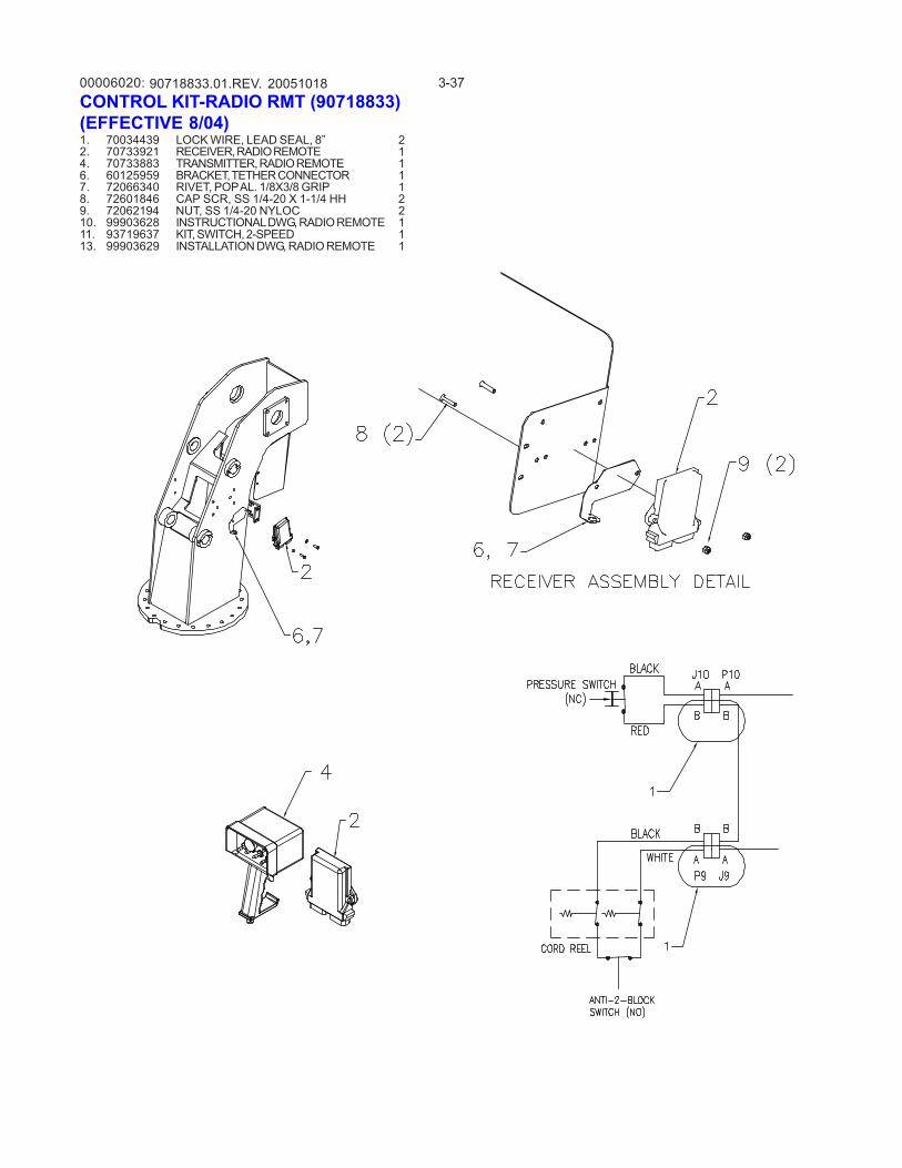
00006020: 3-3790718833.01.REV. 20051018CONTROL KIT-RADIO RMT (90718833)(EFFECTIVE 8/04)1. 70034439 LOCK WIRE, LEAD SEAL, 8” 22. 70733921 RECEIVER, RADIO REMOTE 14. 70733883 TRANSMITTER, RADIO REMOTE 16. 60125959 BRACKET, TETHER CONNECTOR 17. 72066340 RIVET, POP AL. 1/8X3/8 GRIP 18. 72601846 CAP SCR, SS 1/4-20 X 1-1/4 HH 29. 72062194 NUT, SS 1/4-20 NYLOC 210. 99903628 INSTRUCTIONAL DWG, RADIO REMOTE 111. 93719637 KIT, SWITCH, 2-SPEED 113. 99903629 INSTALLATION DWG, RADIO REMOTE 1
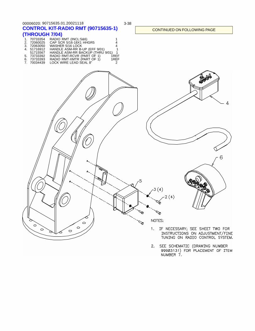
00006020: 3-3890715635.01.20021118CONTROL KIT-RADIO RMT (90715635-1)(THROUGH 7/04) 1. 70733354 RADIO RMT (INCL:5&6) 1 2. 72060025 CAP SCR 5/16-18X1 HHGR5 4 3. 72063050 WASHER 5/16 LOCK 4 4. 51716912 HANDLE ASM-RR B-UP (EFF 9/01) 1
51715567 HANDLE ASM-RR BACKUP (THRU 9/01) 1 5. 73733392 RADIO RMT-RCVR (PART OF 1) 1REF 6. 73733393 RADIO RMT-XMTR (PART OF 1) 1REF 7. 70034439 LOCK WIRE LEAD SEAL 8” 2
CONTINUED ON FOLLOWING PAGE
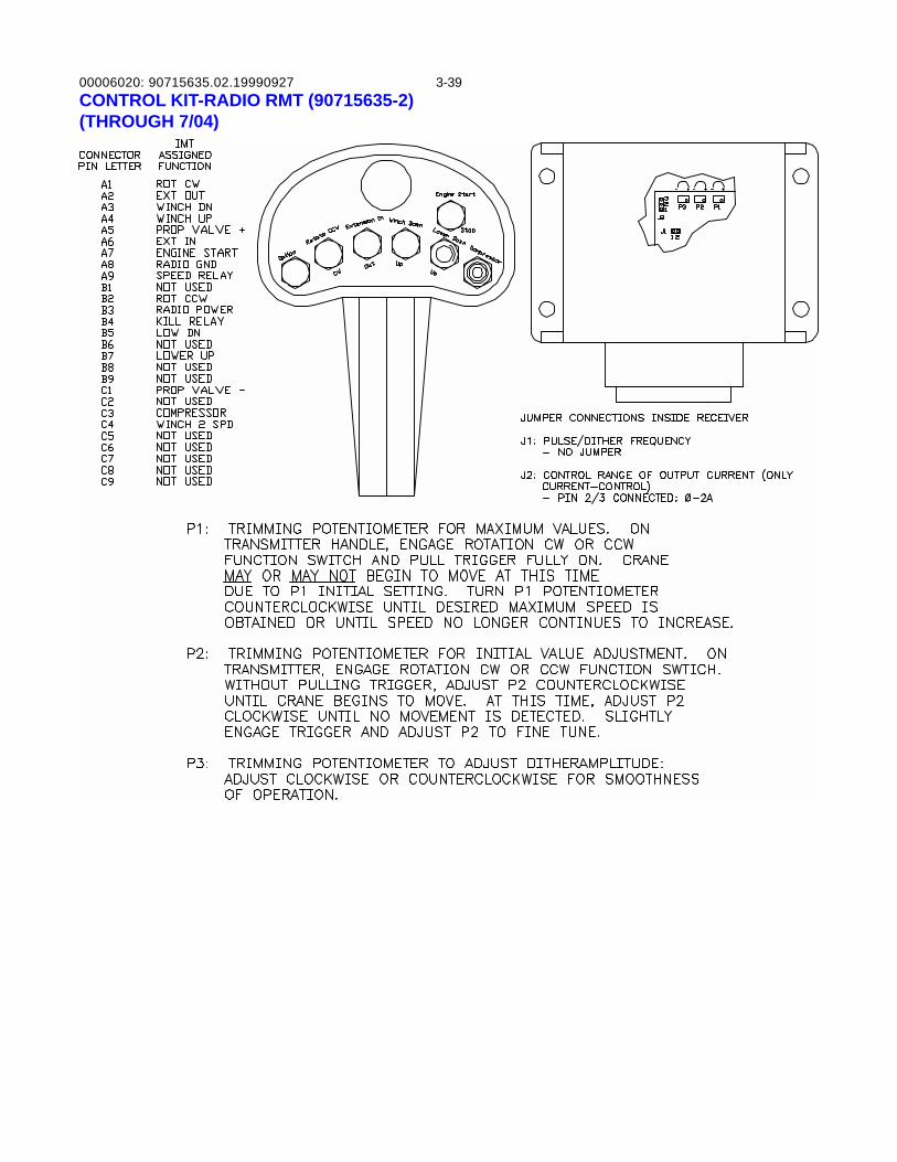
00006020: 3-3990715635.02.19990927CONTROL KIT-RADIO RMT (90715635-2)(THROUGH 7/04)
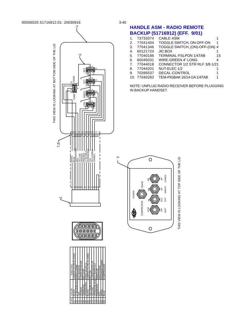
00006020: 3-40HANDLE ASM - RADIO REMOTEBACKUP (51716912) (EFF. 9/01)1. 73733374 CABLE ASM 12. 77041404 TOGGLE SWITCH, ON-OFF-ON 13. 77041346 TOGGLE SWITCH, (ON)-OFF-(ON) 44. 60121724 JIC BOX 15. 77040186 TERMINAL-FSLPON 1/4TAB 156. 60045031 WIRE-GREEN 4” LONG 47. 77044018 CONNECTOR 1/2 STR RLF 3/8-1/218. 77044201 NUT-ELEC 1/2 19. 70395537 DECAL-CONTROL 110. 77040282 TEM-PIGBAK 16/14 GA 1/4TAB 1
NOTE: UNPLUG RADIO RECEIVER BEFORE PLUGGINGIN BACKUP HANDSET.
RO
TE
XT
WIN
CH
LOW
CW
CC
W
OU
T
IN
UP
DN
UP
DN
YE
LLO
WO
RA
NG
EP
INK
/BLK
LT B
LU/B
LKO
RA
NG
E/B
LKTA
NY
ELL
OW
/BLK
TAN
/BLK
RE
D
RO
T
CC
W
CW
EX
T
IN OU
T
WIN
CH
DN UP
LOW
ER
DN UP
CO
MP
RE
SS
OR
CR
AN
E
CR
AN
EC
OM
P
35
5
3
5
53
5
53
555
55
5
THIS
VIE
W IS
LO
OK
ING
AT
BO
TTO
M S
IDE
OF
THE
LID
THIS
VIE
W IS
LO
OK
ING
AT
TOP
SID
E O
F TH
E L
ID
PO
WE
R
OR
AN
GE
/RE
D
WH
ITE
BLU
E
2
55
10 5
CO
LOR
A5
C5
B1
B5
C3
C4
C2
CA
V.
A4
A3
A2
A1
FUN
CTI
ON
WIN
CH
UP
EX
T B
OO
M O
UT
LOW
ER
BO
OM
UP
RO
T C
WJU
MP
ER
TO
PIN
A1
(GN
D)
PR
OP
VA
LVE
(+)
RO
T C
CW
LOW
ER
BO
OM
DN
EX
T B
OO
M IN
WIN
CH
DO
WN
JUM
PE
R T
O P
IN B
1 (G
ND
)LT
.BLU
E/B
LAC
K
TAN
/BLA
CK
YE
LLO
W/B
LAC
K
OR
AN
GE
/BLA
CK
PIN
K/B
LAC
K
YE
LLO
W
BLA
CK
OR
AN
GE
/RE
D
OR
AN
GE
TAN
BLA
CK
MA
IN P
OW
ER
RE
DC
1S
OLE
NO
ID P
OW
ER
WH
ITE
B2
B3
BLU
EC
OM
PR
ES
SO
R
17,
8
64
9
51716912.01: 20030916
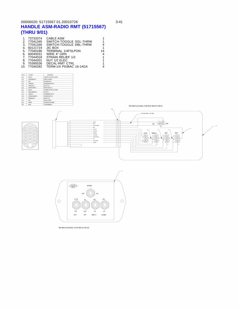
00006020: 3-4151715567.01.20010726HANDLE ASM-RADIO RMT (51715567)(THRU 9/01) 1. 73733374 CABLE ASM 1 2. 77041345 SWITCH-TOGGLE SGL-THRW 1 3. 77041346 SWITCH-TOGGLE DBL-THRW 4 4. 60121724 JIC BOX 1 5. 77040186 TERMINAL 1/4FSLPON 14 6. 60045031 WIRE 4” GRN 4 7. 77044018 STRAIN RELIEF 1/2 1 8. 77044201 NUT 1/2 ELEC 1 9. 70395536 DECAL-RMT CTRL 110. 77040282 TERM-1/4 PIGBAC 16-14GA 4
ROTEXTWINCHLOWCW
CCW
OUT
IN
UP
DN
UP
DN
YELLOW
ORANGE
PINK/BLK
LT BLU/BLK
ORANGE/BLK
TAN
YELLOW/BLK
TAN/BLK
RED
ROT
CCW
CW
EXT
IN
OUT
WINCH
DN
UP
LOWER
DN
UP
OFF ON
OFFON
2
3
5
10
5
5
3
5
5
3
5
5
35
5
1055
105
105
6666
THIS VIEW IS LOOKING AT BOTTOM SIDE OF THE LID
THIS VIEW IS LOOKING AT TOP SIDE OF THE LID
9
1
7,8
4
POWER
ORANGE/RED
WHITE5BLUE
CAP BLUE WIRE - NOT USED
COLOR
A5
C5
B1
B5
C3
C4
C2
CAV.
A4
A3
A2
A1
FUNCTION
WINCH UP
EXT BOOM OUT
LOWER BOOM UP
ROT CW
JUMPER TO PIN A1 (GND)
PROP VALVE (+)
ROT CCW
LOWER BOOM DN
EXT BOOM IN
WINCH DOWN
JUMPER TO PIN B1 (GND)
LT.BLUE/BLACK
TAN/BLACK
YELLOW/BLACK
ORANGE/BLACK
PINK/BLACK
YELLOW
BLACK
ORANGE/RED
ORANGE
TAN
BLACK
MAIN POWERREDC1
SOLENOID POWERWHITEB2
B3 BLUE COMPRESSOR
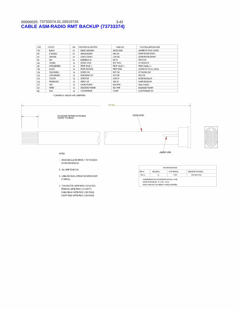
00006020: 3-4273733374.01.20010726CABLE ASM-RADIO RMT BACKUP (73733374)
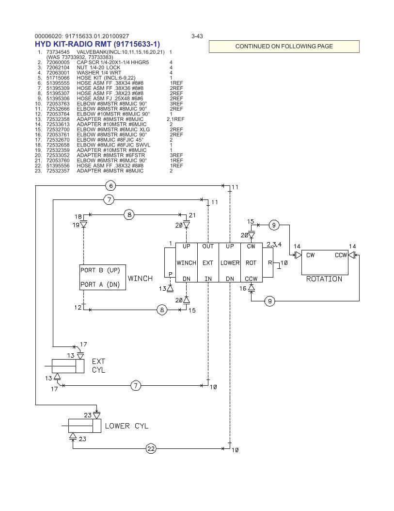
00006020: 3-4391715633.01.20100927HYD KIT-RADIO RMT (91715633-1) 1. 73734545 VALVEBANK(INCL:10,11,15,16,20,21) 1
(WAS 73733932, 73733383) 2. 72060005 CAP SCR 1/4-20X1-1/4 HHGR5 4 3. 72062104 NUT 1/4-20 LOCK 4 4. 72063001 WASHER 1/4 WRT 4 5. 51715066 HOSE KIT (INCL:6-9,22) 1 6. 51395555 HOSE ASM FF .38X34 #8#8 1REF 7. 51395309 HOSE ASM FF .38X36 #8#8 2REF 8. 51395307 HOSE ASM FF .38X23 #6#8 2REF 9. 51395306 HOSE ASM FJ .25X48 #6#6 2REF10. 72053763 ELBOW #8MSTR #8MJIC 90° 3REF11. 72532666 ELBOW #8MSTR #8MJIC 90° 2REF12. 72053764 ELBOW #10MSTR #8MJIC 90° 113. 72532358 ADAPTER #8MSTR #8MJIC 2,1REF14. 72533613 ADAPTER #10MSTR #6MJIC 215. 72532700 ELBOW #6MSTR #6MJIC XLG 2REF16. 72053761 ELBOW #8MSTR #6MJIC 90° 2REF17. 72532670 ELBOW #8MJIC #8FJIC 45° 218. 72532658 ELBOW #8MJIC #8FJIC SWVL 119. 72532359 ADAPTER #10MSTR #8MJIC 120. 72533052 ADAPTER #8MSTR #6FSTR 3REF21. 72053760 ELBOW #6MSTR #6MJIC 90° 1REF22. 51395556 HOSE ASM FF .38X32 #8#8 1REF23. 72532357 ADAPTER #6MSTR #8MJIC 2
CONTINUED ON FOLLOWING PAGE
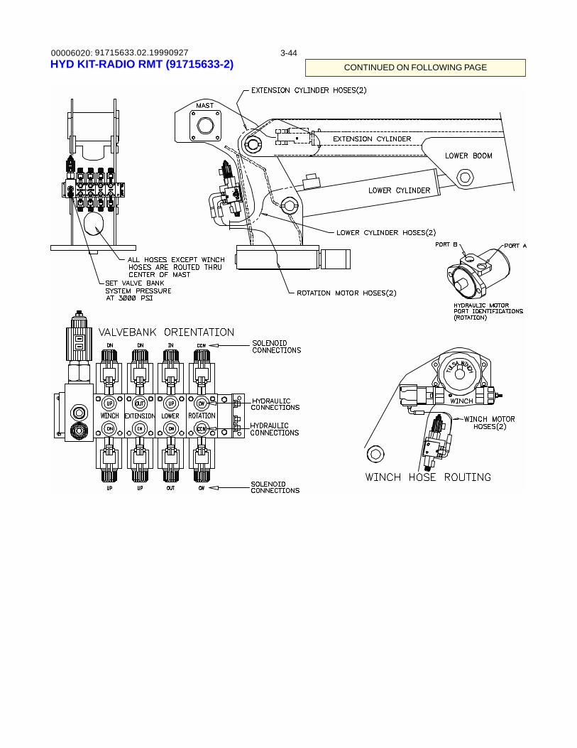
00006020: 3-4491715633.02.19990927HYD KIT-RADIO RMT (91715633-2) CONTINUED ON FOLLOWING PAGE
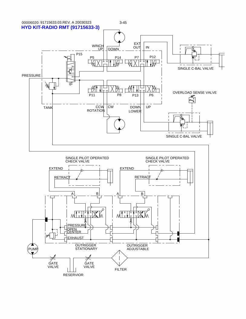
00006020: 3-4591715633.03.REV. A 20030323HYD KIT-RADIO RMT (91715633-3)
SINGLE PILOT OPERATEDCHECK VALVE
A
EXHAUST
PRESSURE
CENTEROPEN
RESERVIOR
GATEVALVE
PUMP
EXTEND
RETRACT
PRESSURE
TANK
FILTERVALVE
STATIONARY
GATE
ADJUSTABLE
CHECK VALVESINGLE PILOT OPERATED
OUTRIGGER
B A B
OUTRIGGER
RETRACT
EXTEND
P14
P8
ROTATION
P11
CCW CW
WINCH
P15P5
UP DOWN
DOWNLOWER
P13
UP
P6
EXT
P7
OUT
P12
IN
SINGLE C-BAL VALVE
SINGLE C-BAL VALVE
OVERLOAD SENSE VALVE
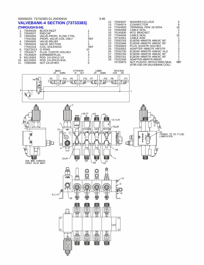
00006020: 3-4673733383.01.20030916VALVEBANK-4 SECTION (73733383)(THROUGH 8-04) 1. 73540028 BLOCK-INLET 1 2. 73540027 END CAP 1 3. 73054934 VALVE-PROPL FLOW CTRL 1
77041556 PROPL VALVE-COIL ONLY REF 4. 73054935 VALVE-RELIEF 1 5. 73540044 VALVE SECTION 4
77041518 COIL-SOLENOID REF 6. 7Q072013 O-RING 10 7. 72533477 PLUG 7/16STR HOLHEX 1 8. 70145829 EXPANDER PLUG 4 9. 60119363 ROD 1/4-20X12-1/2 210. 60119354 ROD 1/4-20X10-9/16 111. 72062000 NUT 1/4-20 HEX 5
12. 72063047 WASHER #10 LOCK 513. 77044574 CONNECTOR 914. 77044550 TERMINAL-FEM 18-20GA 1815. 70394069 CABLE SEAL 216. 70145830 MTG BRACKET 220. 77044594 CABLE SEAL 1621. 70733351 CABLE ASM 122. 72053763 ELBOW #8MSTR #8MJIC 90° 323. 72532666 ELBOW #8MSTR #8MJIC 90° 224. 72533603 PLUG 9/16STR HOLHEX 125. 72533052 ADAPTER #8MSTR #6FSTR 326. 72532700 ELBOW #6MSTR #6MJIC XLG 227. 72053760 ELBOW #6MSTR #6MJIC 90° 128. 72053761 ELBOW #8MSTR #6MJIC 90° 129. 72532356 ADAPTER #8MSTR #8MJIC 1
70733875 NUT, PLASTIC, WITH O-RING SEAL REF(FOR USE ON VALVEBANK COIL)
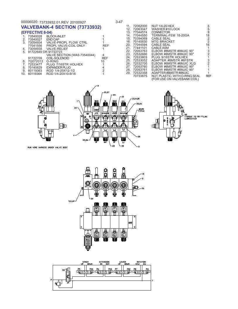
00006020: 3-4773733932.01.REV 20100927VALVEBANK-4 SECTION (73733932)(EFFECTIVE 8-04) 1. 73540028 BLOCK-INLET 1 2. 73540027 END CAP 1 3. 73054934 VALVE-PROPL FLOW CTRL 1
77041556 PROPL VALVE-COIL ONLY REF 4. 73054935 VALVE-RELIEF 1 5. 91722649 OR 91722723
VALVE SECTION (WAS 73540044) 491722709 COIL-SOLENOID REF
6. 7Q072013 O-RING 10 7. 72533477 PLUG 7/16STR HOLHEX 1 8. 70145829 EXPANDER PLUG 4 9. 60119363 ROD 1/4-20X12-1/2 210. 60119364 ROD 1/4-20X10-9/16 1
11. 72062000 NUT 1/4-20 HEX 512. 72063047 WASHER #10 LOCK 513. 77044574 CONNECTOR 914. 77044550 TERMINAL-FEM 18-20GA 1815. 70394069 CABLE SEAL 216. 70145830 MTG BRACKET 220. 77044594 CABLE SEAL 1621. 77441101 CABLE ASM 122. 72053763 ELBOW #8MSTR #8MJIC 90° 323. 72532666 ELBOW #8MSTR #8MJIC 90° 224. 72533603 PLUG 9/16STR HOLHEX 125. 72533052 ADAPTER #8MSTR #6FSTR 326. 72532700 ELBOW #6MSTR #6MJIC XLG 227. 72053760 ELBOW #6MSTR #6MJIC 90° 128. 72053761 ELBOW #8MSTR #6MJIC 90° 129. 72532358 ADAPTER #8MSTR #8MJIC 1
70733875 NUT, PLASTIC, WITH O-RING SEAL REF(FOR USE ON VALVEBANK COIL)
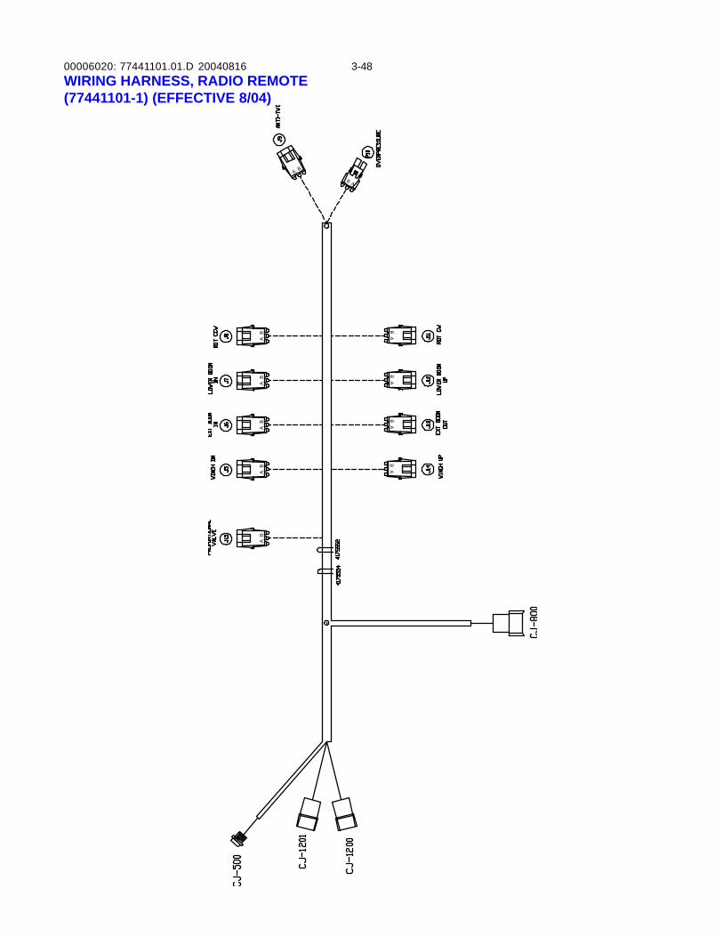
00006020: 3-48WIRING HARNESS, RADIO REMOTE(77441101-1) (EFFECTIVE 8/04)
BA
BA
AB
BA
BA
BA
AB
AB
AB
A B
AB
77441101.01.D 20040816
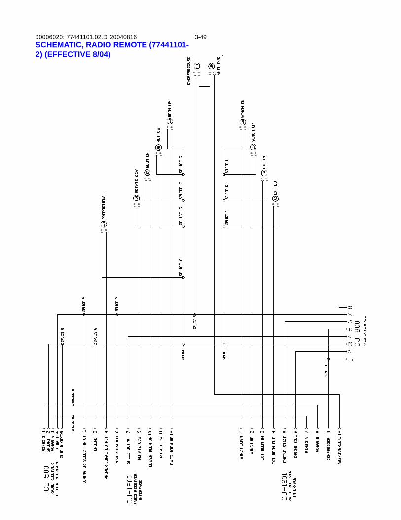
00006020: 3-49
BA B A
AB
B A
B A
B A
A B
A B
A B
A B
BA
SCHEMATIC, RADIO REMOTE (77441101-2) (EFFECTIVE 8/04)
77441101.02.D 20040816
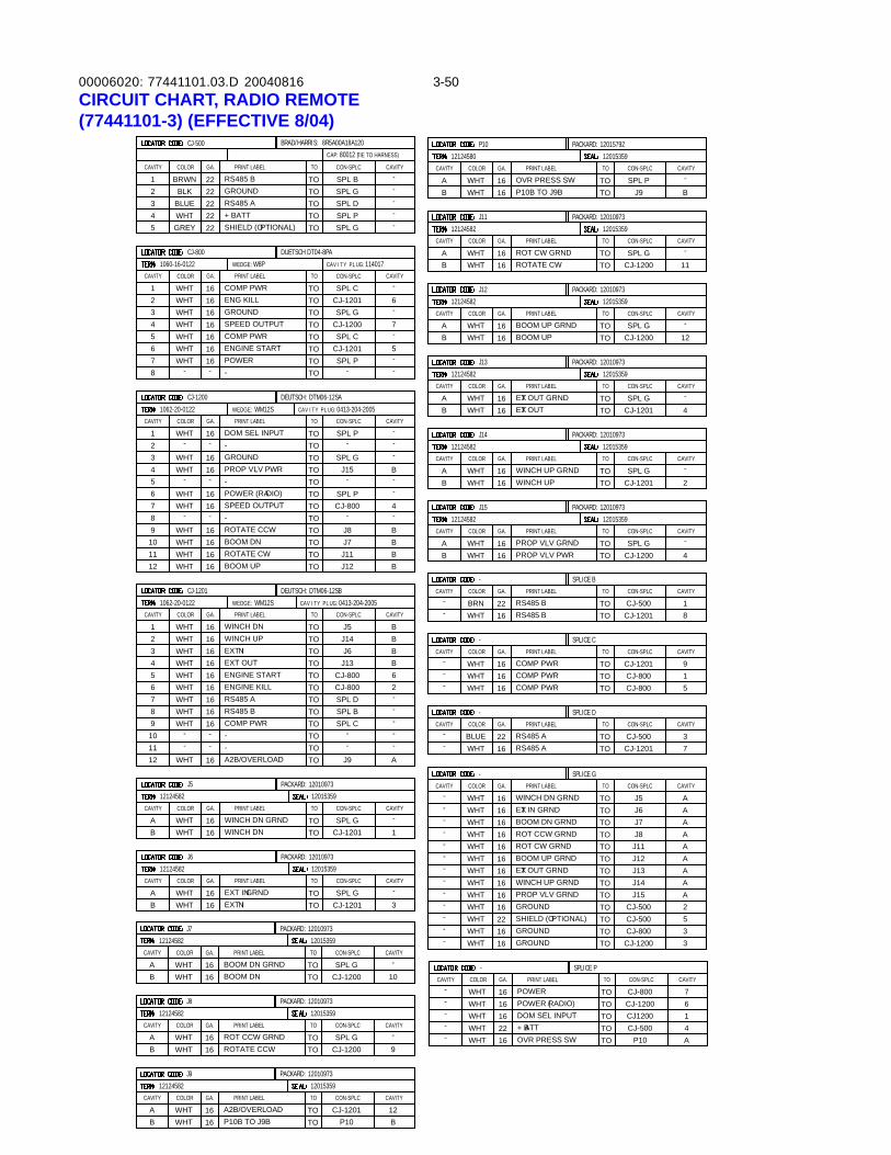
00006020: 3-50CIRCUIT CHART, RADIO REMOTE(77441101-3) (EFFECTIVE 8/04)
77441101.03.D 20040816
PRINT LABEL
WINCH DN GRNDWINCH DN
EXT INEXT IN GRND
PRINT LABEL
POWER
PRINT LABEL
COMP PWR
WEDGE: W8P
COMP PWRSPEED OUTPUTGROUND
ENGINE START
ENG KILL
PRINT LABEL
DOM SEL INPUT-GROUNDPROP VLV PWR-
ROTATE CWBOOM UP
WEDGE: WM12S
POWER (RADIO)SPEED OUTPUT-ROTATE CCW
16WHT1
12124582
J6
CAVITY
BA
COLOR GA.
WHTWHT
1616
--
J5
12124582
AB
CAVITY
8
WHTWHT
COLOR
1616
GA.
-
4
765
32
16WHT
WHTWHTWHT
161616
WHTWHT
1616
163 WHT
CJ-800
1060-16-0122CAVITY COLOR GA.
16WHT1112
10WHTWHT
1616
BOOM DN
6
89
7
45
16WHTWHT
-
WHT
-
16
16
WHT-
16-
CJ-1200
1062-20-0122
12
CAVITY
-WHTCOLOR GA.
16-
-
-SPL CTO
TO CON-SPLC CAVITYGA.CAVITY COLOR PRINT LABEL
J11
CON-SPLC
12015359
PACKARD: 12010973
TO
TOTO
CJ-1201SPL G
CAVITY
3
-
CON-SPLC
-
PACKARD: 12010973
12015359
TOTO
TO
SPL GCJ-1201
TO
CJ-1200TO
TO
TOTO
SPL P
SPL CCJ-1201
TOTO
SPL GCJ-1201
-
CAVITY-
1
AB WHT
WHT
7
-
-
5
-6
12124582CAVITY COLOR
BA WHT
WHT
12015359
PACKARD: 12010973
ROT CW GRNDROTATE CW
1616
TOTO
PRINT LABEL
P10B TO J9B
GA.
OVR PRESS SW1616
TO
TOTO
-
-SPL GCJ-1200 11
--
CAVITY
B
-
CON-SPLC
SPL PJ9
-
--
--
-
12124582
J15
12124582
J14
12124582
J13
12124582
J12
-SPL GTO
P10
CON-SPLC
CAVITY PLUG: 114017
DUETSCH DT04-8PA
TO CAVITY
12124580
J7TOTO
TOJ11J12
SPL PTO
TOTO
TO-
J8
CJ-800
TOTO
J15-
BBB
4-
B
B--
PACKARD: 12015792
12015359
CAVITY
BA
CAVITY
AB
CAVITY
CAVITY
BA
CON-SPLC
CAVITY PLUG: 0413-204-2005
DEUTSCH: DTM06-12SA
TOTO
TO
SPL P-
--
CAVITY
BA
CAVITY
PACKARD: 12010973
SPLICE G
12015359
PRINT LABELCOLOR GA.
PRINT LABEL
PROP VLV GRNDPROP VLV PWR16WHT
WHTCOLOR
16
GA.
CON-SPLCTO CAVITY
CON-SPLC
CJ-1200TOTO
TO
SPL G4
CAVITY-
PACKARD: 12010973
12015359
PACKARD: 12010973
12015359
PRINT LABEL
WINCH UP GRNDWINCH UP
16WHTWHT 16
COLOR GA.
PRINT LABEL
EXT OUT GRNDEXT OUT
GA.COLOR
WHTWHT 16
16
CON-SPLC
SPL GTOTO CJ-1201
TO-
2
CAVITY
CON-SPLCTO
TOTO SPL G
CJ-1201
CAVITY-
4
PACKARD: 12010973
12015359PRINT LABEL
BOOM UP GRNDBOOM UP
WHTWHT
COLOR
1616
GA. CON-SPLC
TOTO
TO
SPL GCJ-1200
CAVITY-
12
CJ-800CJ-1200
CON-SPLCCAVITY
-
---
WHTWHT
1616
COLOR GA.
SPLICE P
POWERPOWER (RADIO)
PRINT LABEL
TOTO
TO
76
CAVITY
A2B/OVERLOAD--COMP PWRRS485 BRS485 AENGINE KILL
EXT OUT
WINCH DN
WEDGE: WM12SPRINT LABEL
2
WHT
WHTWHTWHTWHT
WHT
--
WHT
89
10
1211
54
76
3
WHT
1616
16
--
EXT IN
ENGINE START1616
1616
16
COLOR
WHT
1062-20-0122
CJ-1201
CAVITY
1WHT WINCH UP16
16
GA. CAVITY
TO
TOTOTO
TOTO
TOTO
TOTO
TO
-SPL BSPL C
J9
--
-
A
--
CJ-800J13
SPL DCJ-800
J6
26B
-
B
DEUTSCH: DTM06-12SB
CAVITY PLUG: 0413-204-2005TO
TO
CON-SPLC
J14J5
BB
--
+ BATTDOM SEL INPUT
-- 22WHT
WHT 16CJ-500TO
TO CJ120041
+ BATT
PRINT LABEL
222 BLKBLUEWHT
345 GREY
RS485 A
SHIELD (OPTIONAL)
222222
COLOR
CJ-500
CAVITY
1 BRWNGROUNDRS485 B
GA.
22
CAVITY
-SPL GTOTOTOTO
SPL PSPL D
SPL G
---
BRAD/HARRIS: 8R5A00A18A120
TO
TO
CON-SPLC
SPL B -
TOTO
TO
TO
-CAVITY
--
-WHTWHTCOLOR
WHT
SPLICE CPRINT LABEL
COMP PWRCOMP PWR
COMP PWR1616
GA.
16
CON-SPLC
CJ-1201CJ-800CJ-800
19
5
CAVITY
TO
TOTO
CAVITY
-
--
COLOR
BRNWHT
RS485 BRS485 B
PRINT LABELGA.
2216
SPLICE B
CJ-1201CJ-500CON-SPLC CAVITY
18
TOTO
TO
RS485 A16WHT-
-CAVITY
- BLUECOLOR PRINT LABEL
RS485 A22
GA.
SPLICE D
7CJ-1201CJ-500CON-SPLC
3CAVITY
CAP: 80012 (TIE TO HARNESS)
16WHT OVR PRESS SW TO P10 A
--
EXT OUT GRND TOWHT 1616WHT WINCH UP GRND TO
16
16
16
22
1616
16
1616
1616WHT
WHT
WHTWHT
WHT
WHT
WHTWHT
WHTWHT
WHT
BOOM DN GRND
BOOM UP GRND
PROP VLV GRND
ROT CW GRND
WINCH DN GRND
ROT CCW GRND
EXT IN GRND
GROUND
TOTO
TOTO
TO
TO
TOTO
SHIELD (OPTIONAL)GROUNDGROUND
TOTO
TO
AJ13J14 A
J6J7
J11
J5
J8
J12
J15CJ-500
AA
AA
A
A
2A
CJ-800CJ-1200
CJ-50033
5
BOOM DNBOOM DN GRND
PRINT LABEL
12124582
J7
AB
CAVITY
WHT 16WHT 16
COLOR GA. CON-SPLC
12015359
PACKARD: 12010973
TO SPL GTO CJ-1200
TO-
10
CAVITY
J9
12124582
AB
CAVITY
WHTWHT
COLOR
PACKARD: 12010973
12015359PRINT LABEL
A2B/OVERLOADP10B TO J9B
16
GA.
16TOTO
TO
B
CAVITYCON-SPLC
CJ-1201P10
12
ROT CCW GRNDROTATE CCW
J8
12124582COLORCAVITY
BA WHT
WHT
PRINT LABELGA.
1616
CON-SPLC
SPL GCJ-1200
PACKARD: 12010973
12015359
TO
TO
TO
CAVITY
9
-
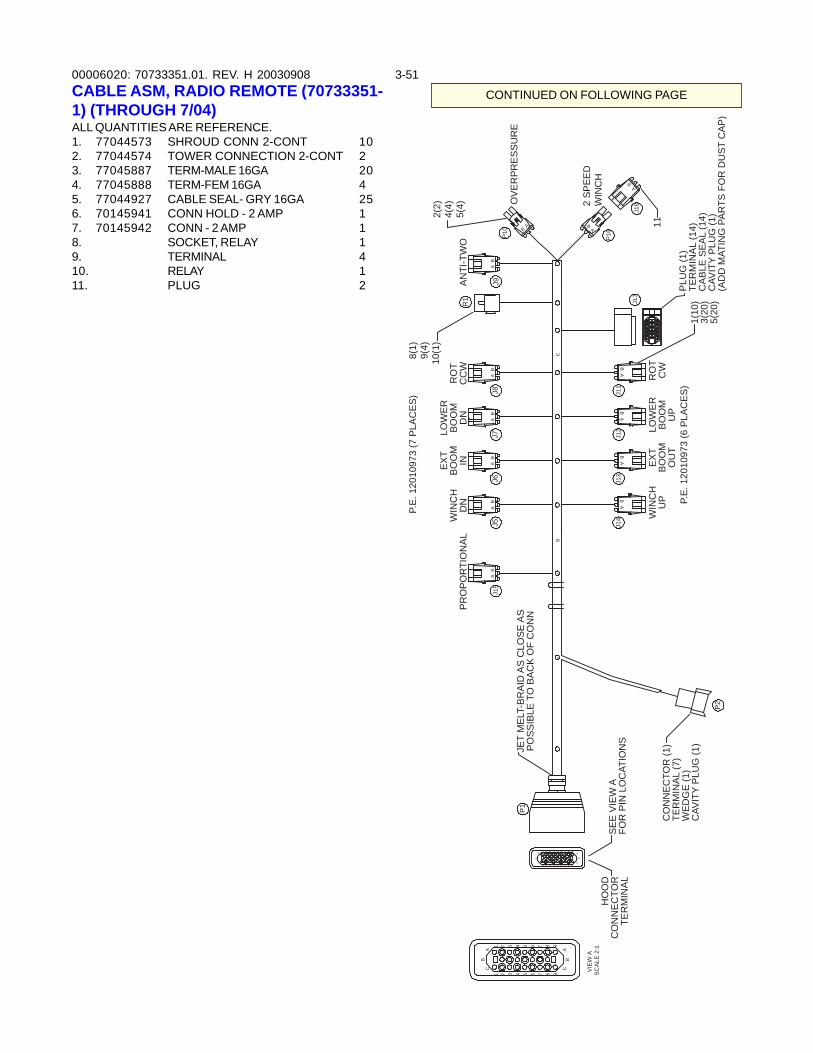
00006020: 3-51
CONTINUED ON FOLLOWING PAGE
70733351.01. REV. H 20030908CABLE ASM, RADIO REMOTE (70733351-1) (THROUGH 7/04)ALL QUANTITIES ARE REFERENCE.1. 77044573 SHROUD CONN 2-CONT 102. 77044574 TOWER CONNECTION 2-CONT 23. 77045887 TERM-MALE 16GA 204. 77045888 TERM-FEM 16GA 45. 77044927 CABLE SEAL- GRY 16GA 256. 70145941 CONN HOLD - 2 AMP 17. 70145942 CONN - 2 AMP 18. SOCKET, RELAY 19. TERMINAL 410. RELAY 111. PLUG 2
P2
P1
B
J13
J14
BA
AB
J12
BA
J11
BA
AB
AB
J5A
J6A
BJ7
BA
J8B
J9A
B
P10 B
A
P16
J15
BA
C
1 2 3 4 5 6 7 8 9
AB
C
7 98654321
AC
B
BC
96 7 8
CB
1 4 52 3
7 86
A
91
A
5432
VIEW
AS
CA
LE 2
:1
R1
J18
BA
11C
ON
NE
CTO
R (1
)TE
RM
INA
L (7
)W
ED
GE
(1)
CAV
ITY
PLU
G (1
)
HO
OD
CO
NN
EC
TOR
TER
MIN
AL
PLU
G (1
)TE
RM
INA
L (1
4)C
AB
LE S
EA
L (1
4)C
AVIT
Y P
LUG
(1)
(AD
D M
ATIN
G P
AR
TS F
OR
DU
ST
CA
P)
2(2)
4(4)
5(4) O
VE
RP
RE
SS
UR
E
AN
TI-T
WO
8(1)
9(4)
10(1
)
P.E
. 120
1097
3 (7
PLA
CE
S)
RO
TC
CW
LOW
ER
BO
OM
DN
EX
TB
OO
MIN
WIN
CH
DN
PR
OP
OR
TIO
NA
L
JET
ME
LT-B
RA
ID A
S C
LOS
E A
SP
OS
SIB
LE T
O B
AC
K O
F C
ON
N
SE
E V
IEW
AFO
R P
IN L
OC
ATIO
NS
P.E
. 120
1097
3 (6
PLA
CE
S)
RO
TC
WLO
WE
RB
OO
MU
P
EX
TB
OO
MO
UT
WIN
CH
UP
1(10
)3(
20)
5(20
)
2 SP
EED
WIN
CH
J17
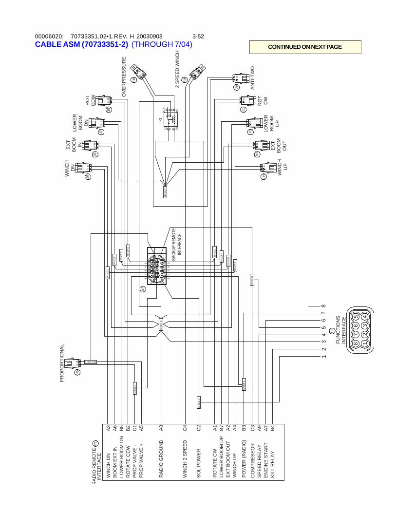
00006020: 3-52CABLE ASM (70733351-2) (THROUGH 7/04)
70733351.02•1.REV. H 20030908
CONTINUED ON NEXT PAGE
P1
P2
A
J14
J13
J12
J11
J5
J6
J7
J8
B
P10
BA
BA
BA
BA
B
SPLI
CE B
SPLIC
E C
B
J9
P16
J15
BA
SPLI
CE D
SPLIC
E F
SPLIC
E E
SPLIC
E G
SPLICE H
SPLIC
E J
SPLI
CE K
SPLI
CE P
SPLI
CE M
SPLI
CE N
SPLIC
E L
J17
54
67
82
31
SPLI
CE R
A
B
C
12
34
5
12
34
5
SPLI
CE Q
863087
8587a
R1
12
345
67
8
B
B
B
B
FUN
CTI
ON
SIN
TER
FAC
E
WIN
CH
DN
��
A3BO
OM
EXT
IN�
�A6
�LOW
ER B
OO
M D
N�
B5�R
OTA
TE C
CW
�B2
PRO
P VA
LVE
-�C
1PR
OP
VALV
E +�
A5
RAD
IO G
RO
UN
D�
A8
WIN
CH
2 S
PEED
�C
4
SOL
POW
ER�
�C
2
RO
TATE
CW
��
A1LO
WER
BO
OM
UP�
B7EX
T BO
OM
OU
T�A2
WIN
CH
UP�
�A4
POW
ER (R
ADIO
)�B3
CO
MPR
ESSO
R�
C3
SPEE
D R
ELAY
�A9
ENG
INE
STAR
T�A7
KILL
REL
AY�
�B4
RAD
IO R
EMO
TEIN
TER
FAC
E
PRO
POR
TIO
NAL
WIN
CH
D
NEX
TBO
OM
INLO
WER
BOO
MD
NR
OT
CC
W OVE
RPR
ESSU
RE
BACK
UP R
EMOT
EIN
TERF
ACE
WIN
CH
U
P
EXT
BOO
MO
UT
LOW
ERBO
OM
UP
RO
TC
W
ANTI
-TW
O
2 SP
EED
WIN
CH
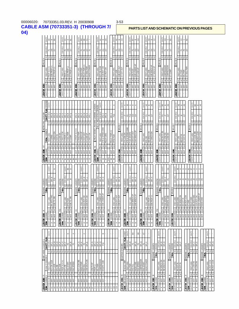
00006020: 3-5370733351.03.REV. H 20030908CABLE ASM (70733351-3) (THROUGH 7/04)
PARTS LIST AND SCHEMATIC ON PREVIOUS PAGES
PR
INT
LAB
EL
J5A
WN
CH
DN
J5B
WN
CH
DN
J6B
EXT
INJ6
A E
XT IN
PR
INT
LAB
EL
J7B
LO
W D
NJ7
A L
OW
DN
PR
INT
LAB
EL
RAD
IO P
OW
ER
PR
INT
LAB
EL
SO
L P
WR
WED
GE
: W8P
CO
MP
RES
SOR
EN
G S
PEED
RAD
IO G
ND
EN
G S
TAR
T
EN
G K
ILL
WIN
SP
D J
16B
PR
OP
(-)S
OL
PW
RC
OM
PR
ESSO
R
PR
INT
LAB
EL
RO
T C
W J
11B
EX
T J1
2BW
IN J
5BW
IN J
14B
PR
OP
VLV
(+)
RO
T C
CW
J8B
RAD
IO P
WR
CO
NN
: 2-1
1031
09-3
LOW
DN
P1
B5
EX
T J7
BE
NG
STA
RT
RAD
IO G
ND
EN
G S
PEED
LOW
P1
B7
EN
G K
ILL
16W
HT
1
1212
4582
J7
A B
CA
VIT
Y
WH
T16
WH
T16
CO
LOR
GA.
1212
4582
J6
CA
VIT
Y
BAC
OLO
RG
A.
WH
TW
HT
1616--
J5
1212
4582
A B
CA
VIT
Y
8
WH
TW
HT
CO
LOR
1616GA.
-
4 76532
16W
HT
WH
TW
HT
WH
T
161616
WH
TW
HT
161616A
3W
HT
16B
7W
HT
--
-C
7
P2
1060
-16-
0122
CA
VIT
Y
C8
C9
CO
LOR
GA.
--
--
--
C4
C6
C5
C2
C3
C1
16W
HT
--
--
--
WH
TW
HT
WH
T16 1616-
-
B4
B6
B5
B2
B3
B1
16W
HT
-W
HT
--16
WH
TW
HT
16 16
-
A6
A8
A9
A7
A4
A5
16W
HT
WH
TW
HT
WH
T16 1616
WH
TW
HT
16 16P1
4-11
0505
1-1
A1
A2
CA
VIT
Y
WH
TW
HT
CO
LOR
GA. 16 16
CA
VIT
Y
CA
VIT
Y
REL
AY S
OCK
ET:
PACK
ARD
120
6568
5, 1
2052
834
REL
AYH
ELLA
874
11 (
SEAL
ED)
CA
VIT
Y
120
1030
0C
AV
ITY
P16
TOP
16A
WN
SPD
16-
WH
T
A8
TOP
1R
ADIO
GN
D16
-W
HT
-S
PL
RTO
TOC
ON
-SPL
CC
AV
ITY
GA.
CA
VIT
YC
OLO
RP
RIN
T LA
BEL
J11
CO
N-S
PLC
CO
N-S
PLC
1201
5359
PACK
ARD
: 12
0109
73
TOS
PL
CTO
SP
L E
TO
1201
5359
PACK
ARD
: 12
0109
73
TO TOTOS
PL
FS
PL
B
- -
CA
VIT
Y
CA
VIT
Y
--
CO
N-S
PLC
-
PACK
ARD
: 12
0109
73
1201
5359
TO TOTO
SP
L B
SP
L D
TO
P1
TO TOTO TOS
PL
K
SP
L Q
P1
TOTOS
PL
BP
1
-
CA
VIT
Y- -
A BW
HT
WH
T
A9 -- A7-B4
1212
4582
CA
VIT
YC
OLO
R
BAW
HT
WH
T
1201
5359
PACK
ARD
: 12
0109
73
J11A
RO
T C
WJ1
1B R
OT
CW
16 16TO TO
PR
INT
LAB
EL
P10
B T
O J
9B
GA.
OP
SI P
10A
16 16
TOTOTO
-
-S
PL
BS
PL
L-
--
CA
VIT
Y
B85
CO
N-S
PLC
R1 J9
- -----
RAD
IO G
ND
J12A
LO
WER
UP
J11A
RO
T C
W
WH
TW
HT
WH
T
161616J9
A A
NTI
-TW
OR
ELA
Y G
ND
J17
GN
DJ8
A R
OT
CC
WJ6
A E
XT IN
J5A
WN
CH
DN
16W
HT
WH
TW
HT
WH
T
161616
WH
TW
HT
1616
TOTOTO
P2
J12
J11
3AA
J8TO TOTOTO
J9R1
J17
TOTOJ6J5
A 87A1 AAA
PR
INT
LAB
EL
J17
WN
CH
DN
J5B
WN
CH
DN
J13A
EX
T O
UT
J14A
WN
CH
UP
-W
HT
WH
T-
16 16
WH
TC
OLO
R
-
WH
TW
HT
CA
VIT
Y---
WIN
J5B
GA. 1616 16
TO TOJ1
7J5
SPLI
CE D TOTOTO TO
P1
CO
N-S
PLC
J13
J14
-
1212
4580
P16
1212
4582
J15
1212
4582
J14
1212
4582
J13
1212
4582
J12
-S
PL
DTO
J9 P10
SP
L N
TO
CO
N-S
PLC
114
017
--
DU
ETSC
H D
T04-
8PA
TO----
P16
TO ----
TO TO TOS
PL
RS
PL
Q
SP
L J
1212
4582
-
CA
VIT
Y
--
1212
4580
A B
CA
VIT
Y
WH
TW
HT
CO
LOR
B -----
- P2
TO TOTO-
SP
L E
TO TOTOS
PL
GS
PL
K
SP
L F
TO TO TOTOS
PL
BP
2
P2
TO TOS
PL
PS
PL
H
- 2 -- -- -6 - 4- - -
PACK
ARD
: 12
0109
73
1201
5359
PACK
ARD
: 12
0157
92
1201
5359
PR
INT
LAB
EL
J9A
AN
TI-T
WO
P10
B T
O J
9B16G
A. 16TO TOTO
B
CA
VIT
YC
ON
-SPL
C
SP
L B
P10
CA
VIT
Y
-
A B
CA
VIT
Y
BAC
AV
ITY
A B
CA
VIT
Y
CA
VIT
Y
BA
CO
N-S
PLC
-
AMP:
HO
OD
: 2-
1102
137-
1
TO TOTO
SP
L L
SP
L M
- -
CA
VIT
Y
BAC
AV
ITY
TOS
PL
FJ1
7 E
XT IN
16A
3W
HT
PACK
ARD
: 12
0109
73
SPLI
CE B
1201
5359
PACK
ARD
: 12
0157
92
1201
5359
PR
INT
LAB
EL
PR
INT
LAB
EL
P16
A W
NSP
DW
INS
PD
J16
B
CO
LOR
GA.
CO
LOR
WH
TW
HT
1616GA.
PR
INT
LAB
EL
J15A
PR
OP
(-)
J15B
PR
OP
(+)
16W
HT
WH
TC
OLO
R
16GA.
CO
N-S
PLC
CO
N-S
PLC
TOTO TO TOP
1S
PL
C
CA
VIT
Y
CA
VIT
Y
C4-
CO
N-S
PLC
SP
L H
TOTOTO
SPL
J-
CA
VIT
Y-
PACK
ARD
: 12
0109
73
1201
5359
PACK
ARD
: 12
0109
73
1201
5359
PR
INT
LAB
EL
J14A
WN
CH
UP
J14B
WN
CH
UP
16W
HT
WH
T16
CO
LOR
GA.
PR
INT
LAB
EL
J13A
EX
T O
UT
J13B
EX
T O
UT
GA.
CO
LOR
WH
TW
HT
1616
CO
N-S
PLC
SP
L C
TO TOS
PL
P
TO- -
CA
VIT
Y
CO
N-S
PLC
TO TOTOS
PL
CS
PL
M
CA
VIT
Y- -
J7A
LO
W D
NA
TB &
OP
RES
GN
D
PR
INT
LAB
EL
OP
SI P
10A
RE
LAY
PW
R (+
)
RE
LAY
GR
DA
TB &
OP
RES
GR
DP
RIN
T LA
BEL
1686
WH
T
-C
OLO
R
WH
TW
HT
WH
T
CA
VIT
Y- -85
GA. 16 1616
1206
6614
CO
LOR
R1
WH
TW
HT
30 87A
87-
CA
VIT
Y
16
--16GA.
TOS
PL
K
TO TO TO
SPLI
CE CTO
CO
N-S
PLC
R1J7P
10
TO TOTOTO
SP
L C
SP
L B
-
CO
N-S
PLC
J17
RO
T C
WJ1
7 LO
W U
PJ1
7 E
XT
OU
TJ1
7 W
NC
H U
PJ1
7 R
AD P
WR
J17
PR
OP
VLV
(+)
J17
CO
MP
J17
SO
L PW
RJ1
7 P
RO
P (-)
J17
RO
T C
CW
J17
LOW
DN
WH
TW
HT
WH
TW
HT
WH
TW
HT
C3
C5
C4
C2
C1
B5
16 1616161616
WH
TW
HT
WH
TW
HT
WH
T
B1
B4
B3
B2
-
A5
A4
16
--16161616
TO TOTOTOTOTO
SP
L M
SP
L L
SP
L N
SP
L P
SP
L K
SP
L H
TO TOTOTOTOTO
SPL
J
SP
L Q
SP
L R
-
SP
L G
SP
L E
PACK
ARD
: 12
0109
73
1201
5359
PR
INT
LAB
EL
J12A
LO
WER
UP
J12B
LO
WER
UP
WH
TW
HT
CO
LOR
1616GA.
CO
N-S
PLC
TOTOTO
SP
L B
SP
L N
CA
VIT
Y- -
120
8967
9
J17
WN
CH
DN
J17
GR
ND
PR
INT
LAB
EL
1212
9409
CO
LOR
J17
WH
TW
HT
CA
VIT
Y
A2
A1
GA. 16 16
MET
RIC
-PAC
: 12
1611
86
TO TOTOC
ON
-SPL
C
SP
L B
SP
L D
P1
TO16
WH
T-
RAD
IO P
WR
B3
A
P1
CO
N-S
PLC
J17
J11
P2
R1
J17
-
A2B
--W
HT
WH
TW
HT
16 1616
CA
VIT
Y
-
-
A3A A
- -
16W
HT
CO
LOR
GA.
WH
TW
HT
1616
RO
T C
W J
11B
J11B
RO
T C
WJ1
7 R
OT
CW
TO TOTO
SPLI
CE L
RAD
IO P
OW
ER
PR
INT
LAB
EL
RE
LAY
PW
R (+
)J1
7 R
AD P
WR
TO TOTOTO
A1 B C57
CA
VIT
Y
86 C1
TOTO TOTOTOTO TOTOTOTO TOTOTOTO TOTOTOTO TOTO
-
P1
CO
N-S
PLC
J17
J15
CO
N-S
PLC
CO
N-S
PLC
P1
J15
J17
P1 J8 J17
CO
N-S
PLC
P1 J6 J17
CO
N-S
PLC
SPLI
CE H
- GA.
CO
LOR
CA
VIT
Y
-
CA
VIT
Y
-
A 30A
- - -
CO
LOR
GA.
WH
T
WH
TW
HT
1616 16
CA
VIT
Y
-
-
- --
- -
16W
HT
WH
TC
OLO
R
WH
T16G
A. 16
TOP
RIN
T LA
BEL
SPLI
CE K
PR
INT
LAB
EL
PR
OP
(-)J1
5A P
RO
P (-
)J1
7 P
RO
P (-)
TOTOTO TO
SPLI
CE J
J17
PR
OP
(+)
PR
OP
VLV
(+)
PR
INT
LAB
EL
J15B
PR
OP
(+)
TOTOTO TO
-
-
CA
VIT
Y
-
- --
-
--
-
16W
HT
WH
T16
CO
LOR
WH
T16G
A.
CA
VIT
Y
-
---
- -
---
-16
WH
TW
HT
WH
T16 16
CO
LOR
GA.
SPLI
CE G
J8B
RO
T C
CW
J17
RO
T C
CW
PR
INT
LAB
EL
RO
T C
CW
J8B
TO TOTO TO
SPLI
CE F
EX
T J7
BJ6
B E
XT IN
J17
EXT
IN
PR
INT
LAB
EL
TO TO TOTO
-
WH
TC
OLO
R
-
WH
TW
HT
WH
TC
OLO
R
WH
TW
HT
CA
VIT
Y
CA
VIT
Y
CA
VIT
Y
AC1
B1
- --
B5
CA
VIT
Y
A5 B
-
CA
VIT
Y- -
GA.
PR
INT
LAB
EL
SO
L P
WR
SO
L P
WR
J17
SO
L PW
R
16 1616
CO
MP
RES
SOR
PR
INT
LAB
EL
CO
MP
RES
SOR
J17
CO
MP
1616GA. 16
SPLI
CE R
WH
TC
OLO
R
-
WH
TW
HT
WH
TC
OLO
R
-
WH
TW
HT
B A5
CA
VIT
Y
B2
- -
CA
VIT
Y-
A6 B A3
CA
VIT
Y
--
CA
VIT
Y-
WIN
J14
BP
RIN
T LA
BEL
J14B
WN
CH
UP
J17
WN
CH
UP
16 1616GA.
SPLI
CE Q
SPLI
CE P
LOW
P1
B7P
RIN
T LA
BEL
J12B
LO
WER
UP
J17
LOW
UP
16 1616GA.
SPLI
CE N
P1 J7 J17
CO
N-S
PLC
CA
VIT
Y
-
-
--
- -
WH
TW
HT
WH
T
16 16 16
CO
LOR
GA.
SPLI
CE E
LOW
DN
P1
B5J7
B L
OW
DN
J17
LOW
DN
PR
INT
LAB
EL
TO TO TOTO
WH
TC
OLO
R
-
WH
TW
HT
BB5
A4
CA
VIT
Y
- --
CA
VIT
Y
EX
T J1
2BP
RIN
T LA
BEL
J13B
EX
T O
UT
J17
EX
T O
UT
16 1616GA.
SPLI
CE M
CO
N-S
PLC
CA
VIT
Y
P1
J17
P2
C2 1 B2
J17
P1
CO
N-S
PLC
P2
B3
CA
VIT
Y
C3 5
J14
J17
P1
CO
N-S
PLC
B C2
CA
VIT
Y
A4
P1
J17
J12
CO
N-S
PLC
B7 B C4
CA
VIT
Y
P1
J17
J13
CO
N-S
PLC
A2 B C3
CA
VIT
Y
J8A
RO
T C
CW
J8B
RO
T C
CW
J8
1212
4582
CO
LOR
CA
VIT
Y
BAW
HT
WH
T
PR
INT
LAB
ELG
A. 1616
CO
N-S
PLC
SP
L B
SP
L G
PACK
ARD
: 12
0109
73
1201
5359
TOTO TO
CA
VIT
Y
--
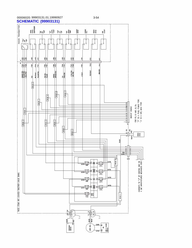
00006020: 3-5499903131.01.19990927SCHEMATIC (99903131)
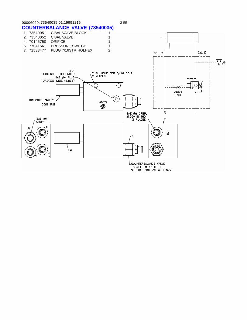
00006020: 3-55COUNTERBALANCE VALVE (73540035) 1. 73540051 C’BAL VALVE BLOCK 1 2. 73540052 C’BAL VALVE 1 4. 70145750 ORIFICE 1 6. 77041561 PRESSURE SWITCH 1 7. 72533477 PLUG 7/16STR HOLHEX 2
73540035.01.19991216
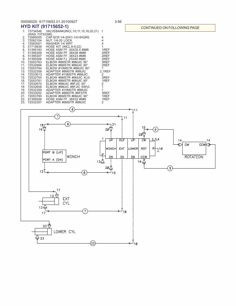
00006020: 3-5691715652.01.20100927HYD KIT (91715652-1) 1. 73734546 VALVEBANK(INCL:10,11,15,16,20,21) 1
(WAS 73733396) 2. 72060005 CAP SCR 1/4-20X1-1/4 HHGR5 4 3. 72062104 NUT 1/4-20 LOCK 4 4. 72063001 WASHER 1/4 WRT 4 5. 51715639 HOSE KIT (INCL:6-9,22) 1 6. 51395183 HOSE ASM FF .50X35.5 #8#8 1REF 7. 51395309 HOSE ASM FF .38X36 #8#8 2REF 8. 51395307 HOSE ASM FF .38X23 #6#8 2REF 9. 51395306 HOSE ASM FJ .25X48 #6#6 2REF10. 72053763 ELBOW #8MSTR #8MJIC 90° 3REF11. 72532666 ELBOW #8MSTR #8MJIC 90° 2REF12. 72053764 ELBOW #10MSTR #8MJIC 90° 113. 72532358 ADAPTER #8MSTR #8MJIC 2,1REF14. 72533613 ADAPTER #10MSTR #6MJIC 215. 72532700 ELBOW #6MSTR #6MJIC XLG 2REF16. 72053761 ELBOW #8MSTR #6MJIC 90° 1REF17. 72532670 ELBOW #8MJIC #8FJIC 45° 218. 72532658 ELBOW #8MJIC #8FJIC SWVL 119. 72532359 ADAPTER #10MSTR #8MJIC 120. 72533052 ADAPTER #8MSTR #6FSTR 3REF21. 72053760 ELBOW #6MSTR #6MJIC 90° 1REF22. 51395556 HOSE ASM FF .38X32 #8#8 1REF23. 72532357 ADAPTER #6MSTR #8MJIC 2
CONTINUED ON FOLLOWING PAGE
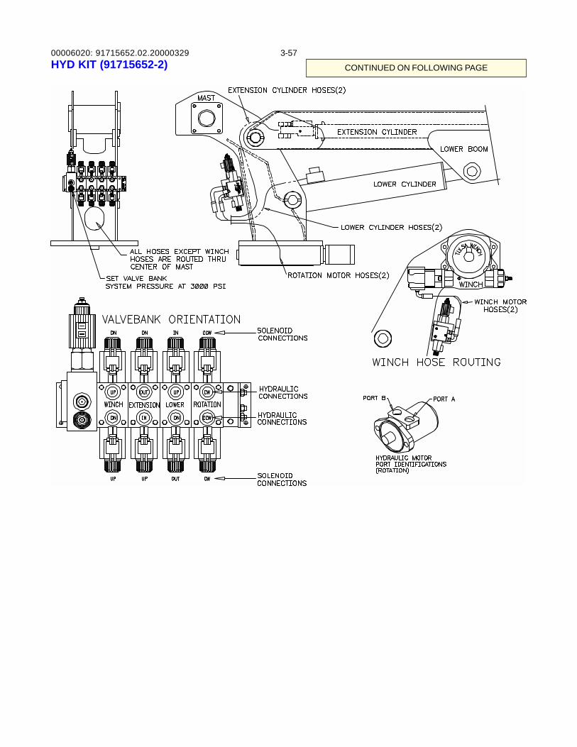
00006020: 3-5791715652.02.20000329HYD KIT (91715652-2) CONTINUED ON FOLLOWING PAGE
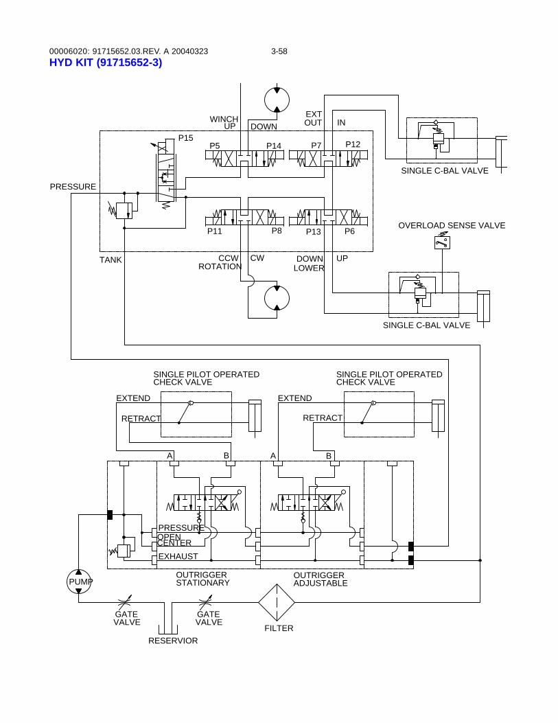
00006020: 3-5891715652.03.REV. A 20040323HYD KIT (91715652-3)
SINGLE PILOT OPERATED
PUMP
PRESSURE
OUTRIGGERADJUSTABLE
OUTRIGGERSTATIONARY
VALVEGATE
VALVEGATE
RESERVIORFILTER
LOWER
EXTEND
RETRACT
OPENCENTER
PRESSURE
EXHAUST
A
EXTEND
B A
TANK
P15
CCWROTATION
P11
P5
UP
P8
CW
P14
DOWNWINCH
SINGLE C-BAL VALVE
B
RETRACT
OVERLOAD SENSE VALVE
INOUT
P6
P12
DOWN
P13
UP
P7
EXT
CHECK VALVE
SINGLE C-BAL VALVE
CHECK VALVESINGLE PILOT OPERATED
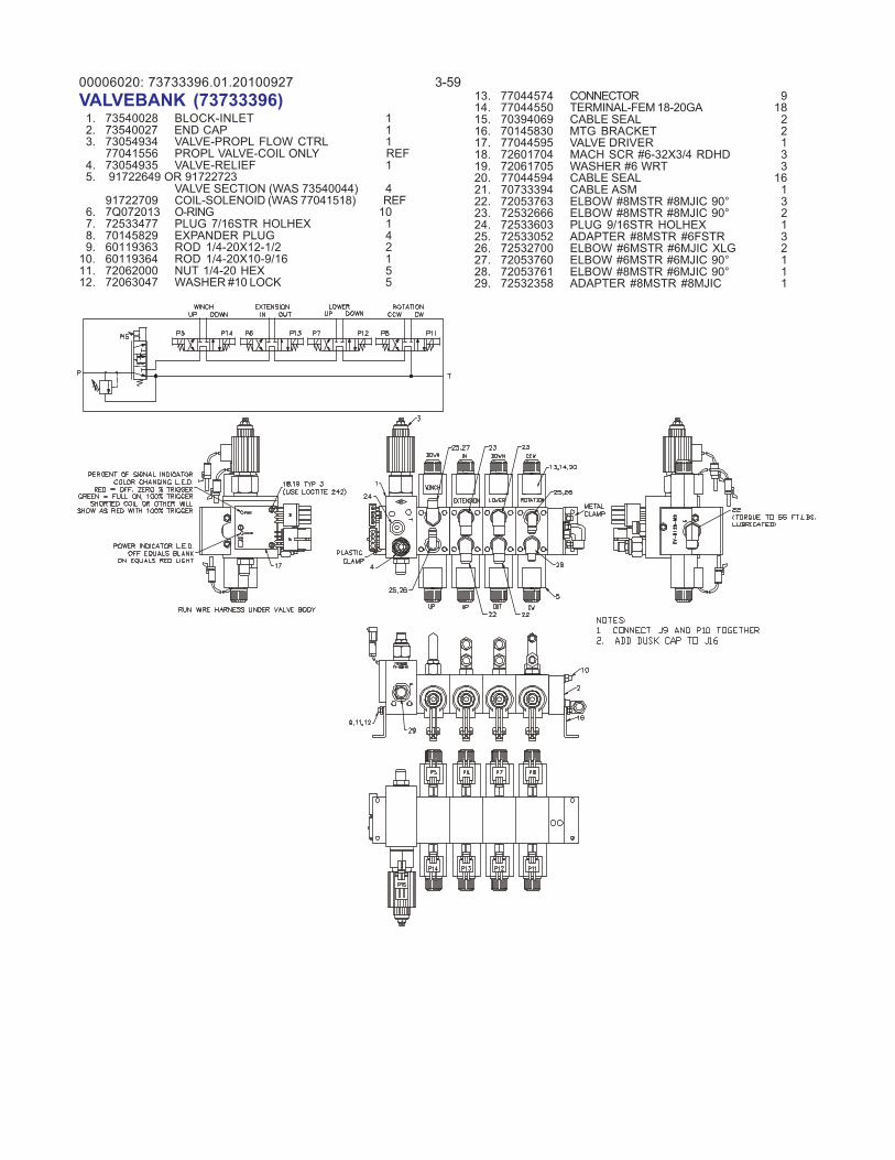
00006020: 3-5973733396.01.20100927VALVEBANK (73733396) 1. 73540028 BLOCK-INLET 1 2. 73540027 END CAP 1 3. 73054934 VALVE-PROPL FLOW CTRL 1
77041556 PROPL VALVE-COIL ONLY REF 4. 73054935 VALVE-RELIEF 1 5. 91722649 OR 91722723
VALVE SECTION (WAS 73540044) 491722709 COIL-SOLENOID (WAS 77041518) REF
6. 7Q072013 O-RING 10 7. 72533477 PLUG 7/16STR HOLHEX 1 8. 70145829 EXPANDER PLUG 4 9. 60119363 ROD 1/4-20X12-1/2 210. 60119364 ROD 1/4-20X10-9/16 111. 72062000 NUT 1/4-20 HEX 512. 72063047 WASHER #10 LOCK 5
13. 77044574 CONNECTOR 914. 77044550 TERMINAL-FEM 18-20GA 1815. 70394069 CABLE SEAL 216. 70145830 MTG BRACKET 217. 77044595 VALVE DRIVER 118. 72601704 MACH SCR #6-32X3/4 RDHD 319. 72061705 WASHER #6 WRT 320. 77044594 CABLE SEAL 1621. 70733394 CABLE ASM 122. 72053763 ELBOW #8MSTR #8MJIC 90° 323. 72532666 ELBOW #8MSTR #8MJIC 90° 224. 72533603 PLUG 9/16STR HOLHEX 125. 72533052 ADAPTER #8MSTR #6FSTR 326. 72532700 ELBOW #6MSTR #6MJIC XLG 227. 72053760 ELBOW #6MSTR #6MJIC 90° 128. 72053761 ELBOW #8MSTR #6MJIC 90° 129. 72532358 ADAPTER #8MSTR #8MJIC 1
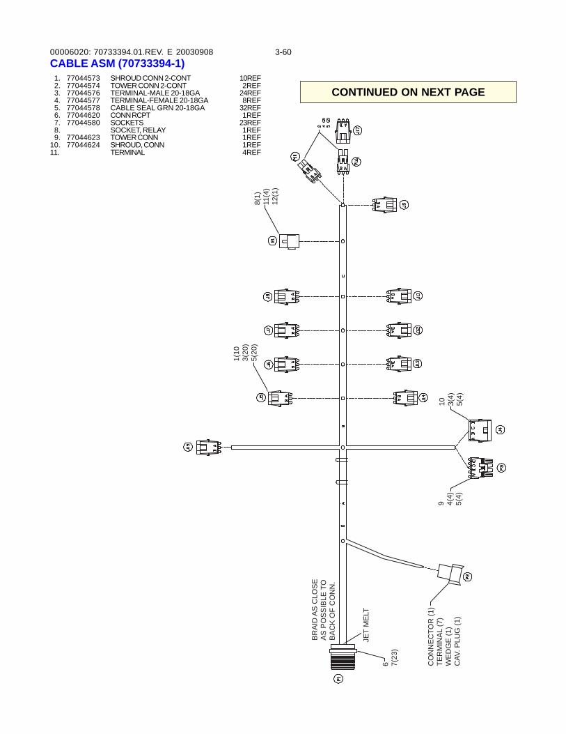
00006020: 3-6070733394.01.REV. E 20030908
1. 77044573 SHROUD CONN 2-CONT 10REF 2. 77044574 TOWER CONN 2-CONT 2REF 3. 77044576 TERMINAL-MALE 20-18GA 24REF 4. 77044577 TERMINAL-FEMALE 20-18GA 8REF 5. 77044578 CABLE SEAL GRN 20-18GA 32REF 6. 77044620 CONN RCPT 1REF 7. 77044580 SOCKETS 23REF 8. SOCKET, RELAY 1REF 9. 77044623 TOWER CONN 1REF10. 77044624 SHROUD, CONN 1REF11. TERMINAL 4REF
CO
NN
EC
TOR
(1)
TER
MIN
AL
(7)
WE
DG
E (1
)C
AV. P
LUG
(1)
BR
AID
AS
CLO
SE
AS
PO
SS
IBLE
TO
BA
CK
OF
CO
NN
.
JET
ME
LT
6 7(23
)
1(10
�3(
20)
5(20
)8(
1)11
(4)
12(1
)
9 4(4)
5(4)
10 3(4)
5(4)
CABLE ASM (70733394-1)
CONTINUED ON NEXT PAGE
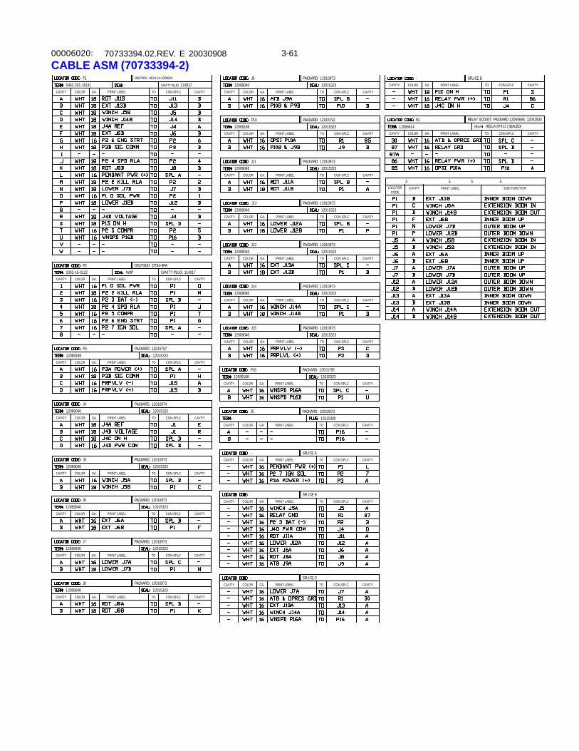
00006020: 3-6170733394.02.REV. E 20030908CABLE ASM (70733394-2)
PRINT LABEL
P1
COLOR
0462-201-16141CAVITY GA. CAVITYCON-SPLCTO
DEUTSCH: HD34-24-23SN059
PRINT LABEL
P2
COLOR
1062-16-0122CAVITY GA. CAVITYCON-SPLC
W8PTO
DEUTSCH: DT04-8PA
CAVITY PLUG: 114017
- CAVITY PLUG: 114017
PRINT LABEL
P3
COLOR
12089188CAVITY GA. CAVITYCON-SPLC
12015323TO
PACKARD: 12015797
PRINT LABEL
J4
COLOR
12089040CAVITY GA. CAVITYCON-SPLC
12015323TO
PACKARD: 12010974
PRINT LABEL
J5
COLOR
12089040CAVITY GA. CAVITYCON-SPLC
12015323TO
PACKARD: 12010973
PRINT LABEL
J9
COLOR
12089040CAVITY GA. CAVITYCON-SPLC
12015323TO
PACKARD: 12010973
PRINT LABEL
P10
COLOR
12089188CAVITY GA. CAVITYCON-SPLC
12015323TO
PACKARD: 12015792
PRINT LABEL
J11
COLOR
12089040CAVITY GA. CAVITYCON-SPLC
12015323TO
PACKARD: 12010973
PRINT LABEL
J12
COLOR
12089040CAVITY GA. CAVITYCON-SPLC
12015323TO
PACKARD: 12010973
PRINT LABEL
J13
COLOR
12089040CAVITY GA. CAVITYCON-SPLC
12015323TO
PACKARD: 12010973
PRINT LABEL
J14
COLOR
12089040CAVITY GA. CAVITYCON-SPLC
12015323TO
PACKARD: 12010973
PRINT LABEL
J15
COLOR
12089040CAVITY GA. CAVITYCON-SPLC
12015323TO
PACKARD: 12010973
PRINT LABEL
P16
COLOR
12089188CAVITY GA. CAVITYCON-SPLC
12015323TO
PACKARD: 12015792
PRINT LABEL
J5
COLOR
-CAVITY GA. CAVITYCON-SPLC
12010300TO
PACKARD: 12010973
PRINT LABEL
-COLORCAVITY GA. CAVITYCON-SPLCTO
SPLICE A
PRINT LABEL
-COLORCAVITY GA. CAVITYCON-SPLCTO
SPLICE B
PRINT LABEL
-COLORCAVITY GA. CAVITYCON-SPLCTO
SPLICE C
PRINT LABEL
-COLORCAVITY GA. CAVITYCON-SPLCTO
SPLICE D
PRINT LABEL
R1
COLOR
12066614CAVITY GA. CAVITYCON-SPLC
RELAY HELLA 87411 (SEALED)
TO
RELAY SOCKET: PACKARD 12065685, 12052834
PRINT LABEL
CAVITYLOCATORCODE
3000 FUNCTION
PRINT LABEL
J6
COLOR
12089040CAVITY GA. CAVITYCON-SPLC
12015323TO
PACKARD: 12010973
PRINT LABEL
J7
COLOR
12089040CAVITY GA. CAVITYCON-SPLC
12015323TO
PACKARD: 12010973
PRINT LABEL
J8
COLOR
12089040CAVITY GA. CAVITYCON-SPLC
12015323TO
PACKARD: 12010973
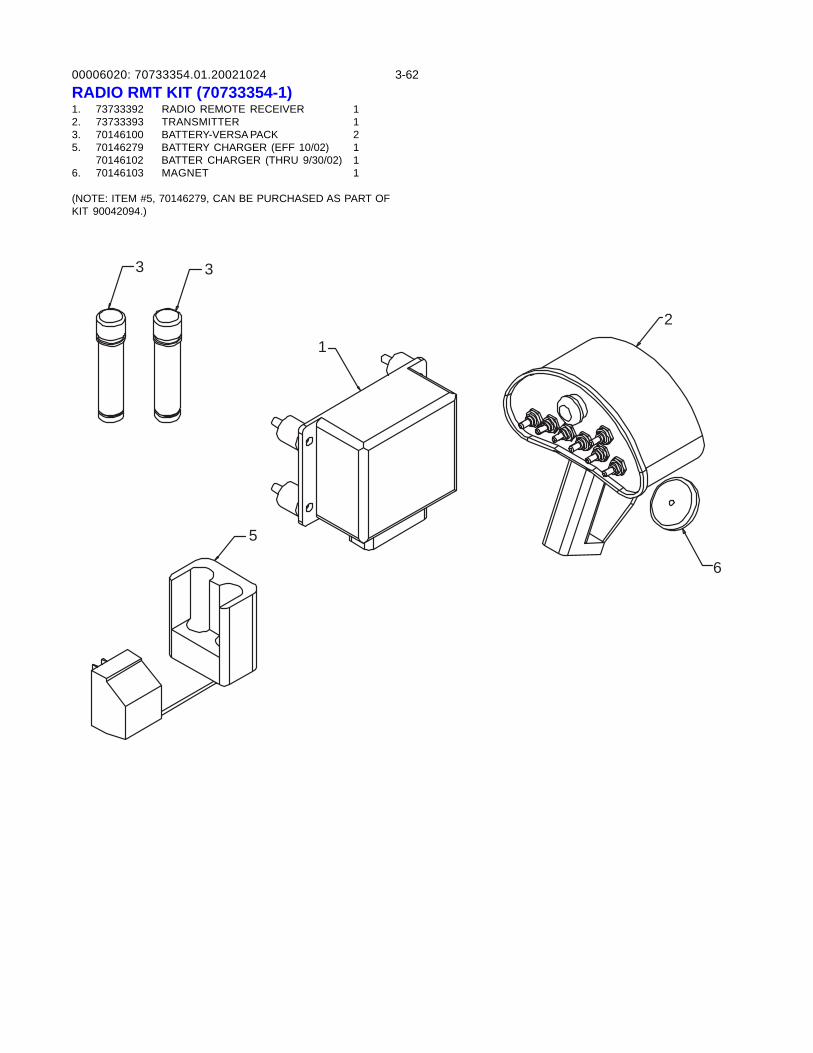
00006020: 3-6270733354.01.20021024RADIO RMT KIT (70733354-1)1. 73733392 RADIO REMOTE RECEIVER 12. 73733393 TRANSMITTER 13. 70146100 BATTERY-VERSA PACK 25. 70146279 BATTERY CHARGER (EFF 10/02) 1
70146102 BATTER CHARGER (THRU 9/30/02) 16. 70146103 MAGNET 1
(NOTE: ITEM #5, 70146279, CAN BE PURCHASED AS PART OFKIT 90042094.)
3 3
5
1
2
6
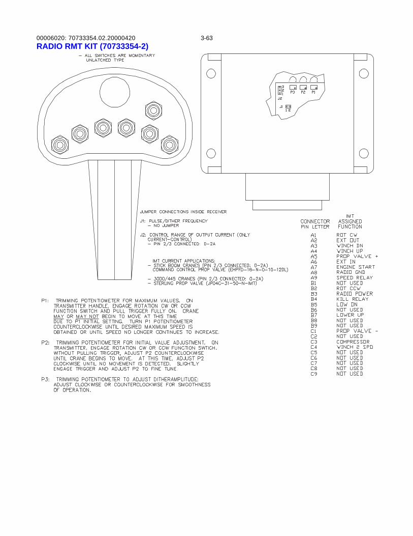
00006020: 3-6370733354.02.20000420RADIO RMT KIT (70733354-2)
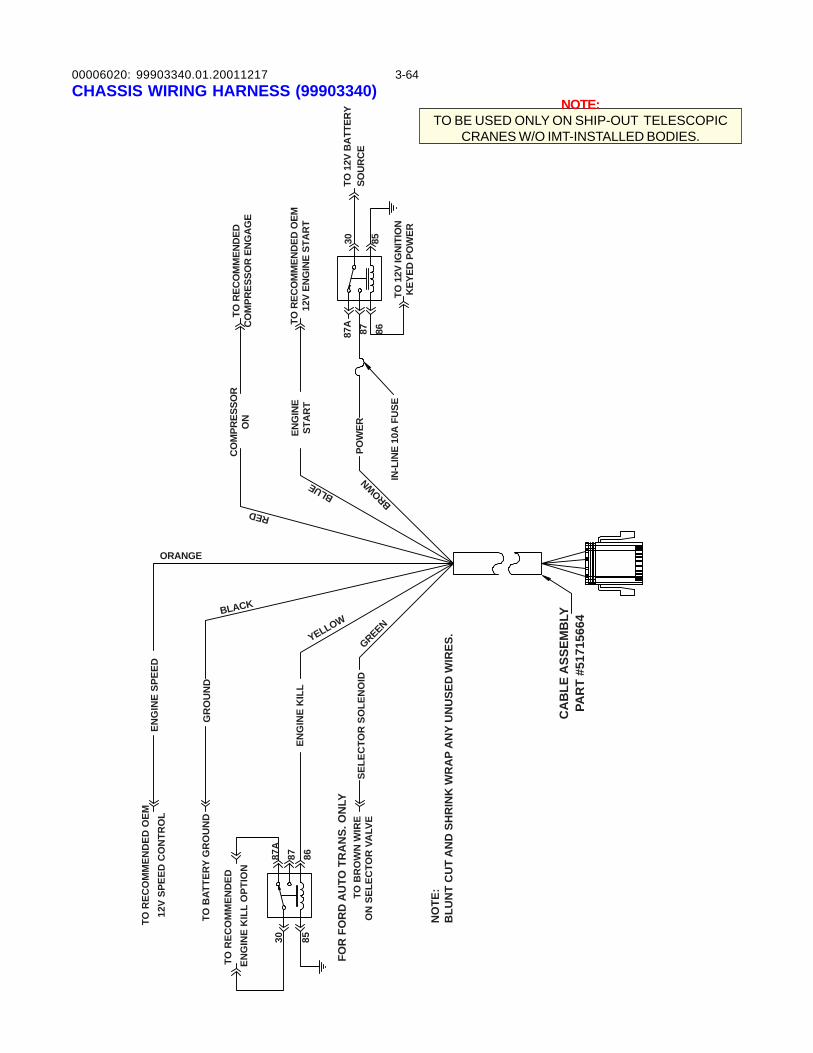
00006020: 3-64CHASSIS WIRING HARNESS (99903340)
NO
TE:
BLU
NT
CU
T A
ND
SH
RIN
K W
RA
P A
NY
UN
USE
D W
IRES
.
FOR
FO
RD
AU
TO T
RA
NS.
ON
LYTO
BR
OW
N W
IRE
ON
SEL
ECTO
R V
ALV
ESE
LEC
TOR
SO
LEN
OID
ENG
INE
KIL
L
30 85
87A
87 86
TO R
ECO
MM
END
ED
ENG
INE
KIL
L O
PTIO
N
TO B
ATTE
RY G
RO
UN
D
TO R
ECO
MM
END
ED O
EM12
V SP
EED
CO
NTR
OL
ENG
INE
SPEE
D
GR
OU
ND
CA
BLE
ASS
EMB
LYPA
RT
#517
1566
4
YELLOW
GREENBLACK
ORANGE
RED
BLUE
BROWN
CO
MPR
ESSO
RO
NTO
REC
OM
MEN
DED
CO
MPR
ESSO
R E
NG
AG
E
ENG
INE
STA
RT
TO R
ECO
MM
END
ED O
EM12
V EN
GIN
E ST
AR
T
POW
ER
IN-L
INE
10A
FU
SETO
12V
IGN
ITIO
NK
EYED
PO
WER
87A
87 86
30 85
TO 1
2V B
ATT
ERY
SOU
RC
E
NOTE:TO BE USED ONLY ON SHIP-OUT TELESCOPIC
CRANES W/O IMT-INSTALLED BODIES.
99903340.01.20011217
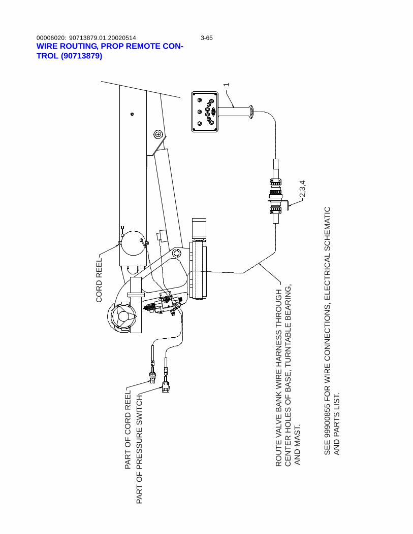
00006020: 3-65
PAR
T O
F C
OR
D R
EE
LPA
RT
OF
PR
ES
SU
RE
SW
ITC
H
CO
RD
RE
EL
RO
UTE
VA
LVE
BA
NK
WIR
E H
AR
NE
SS
TH
RO
UG
HC
EN
TER
HO
LES
OF
BA
SE
, TU
RN
TAB
LE B
EA
RIN
G,
AN
D M
AS
T.
SE
E 9
9900
855
FOR
WIR
E C
ON
NE
CTI
ON
S, E
LEC
TRIC
AL
SC
HE
MAT
ICA
ND
PA
RTS
LIS
T.
2,3,
4
1
WIRE ROUTING, PROP REMOTE CON-TROL (90713879)
90713879.01.20020514
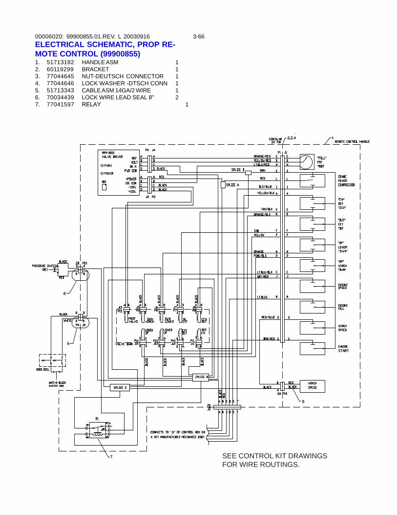
00006020: 3-66ELECTRICAL SCHEMATIC, PROP RE-MOTE CONTROL (99900855)1. 51713182 HANDLE ASM 12. 60119299 BRACKET 13. 77044645 NUT-DEUTSCH CONNECTOR 14. 77044646 LOCK WASHER -DTSCH CONN 15. 51713343 CABLE ASM 14GA/2 WIRE 16. 70034439 LOCK WIRE LEAD SEAL 8” 27. 77041597 RELAY 1
99900855.01.REV. L 20030916
SEE CONTROL KIT DRAWINGSFOR WIRE ROUTINGS.
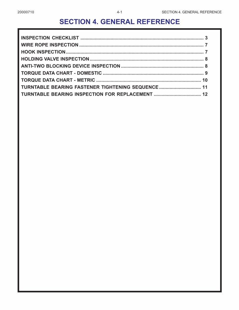
4-1 SECTION 4. GENERAL REFERENCE
INSPECTION CHECKLIST .............................................................................................. 3WIRE ROPE INSPECTION ............................................................................................... 7HOOK INSPECTION ......................................................................................................... 7HOLDING VALVE INSPECTION....................................................................................... 8ANTI-TWO BLOCKING DEVICE INSPECTION ............................................................... 8TORQUE DATA CHART - DOMESTIC ............................................................................. 9TORQUE DATA CHART - METRIC ................................................................................ 10TURNTABLE BEARING FASTENER TIGHTENING SEQUENCE ................................ 11TURNTABLE BEARING INSPECTION FOR REPLACEMENT .................................... 12
SECTION 4. GENERAL REFERENCE20000710

4-2 SECTION 4. GENERAL REFERENCE
NOTES
20000710
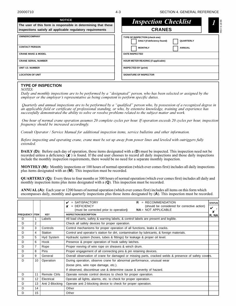
4-3 SECTION 4. GENERAL REFERENCE
������������� ����
OWNER/COMPANY
CONTACT PERSON
CRANE MAKE & MODEL
CRANE SERIAL NUMBER
UNIT I.D. NUMBER
LOCATION OF UNIT
CRANES
TYPE OF INSPECTION (check one)
HOUR METER READING (if applicable)
DATE INSPECTED
INSPECTED BY (print)
SIGNATURE OF INSPECTOR
DAILY (if deficiency found)
MONTHLY
QUARTERLY
ANNUAL
TYPE OF INSPECTION����������� ���� ���� ������ �������������������������������� ����������� ������������� ���������������� ����������������������������������������� ��� ������� ��������� ���������������������!���"
�#!�������� ��� !�� ������ ����������������������������$!����������� ����������������� ����������� %���������� � ������������������������������������� ����� � ���������������&�� � ��' ����������� ��� ���&���� �������!������!������ ���������������������� ��������� �������������������������!�(������������ �����'"
�� ����!����� �������� ��������� ����!����)*���������������������!�"�+��������� ��&������)*�������������!��� ������ ���$!� ������!����� �������������� ��"
,� �!�����������-���� ���.� !����������� �� ������ ���������� ����!�� ��� �������� ������� "
/������ ����� ��� �������� ����� ������ ���!����������!������������������ ���� ��� ���������!���������!��&�� ���"
�������D������������������������� ����� ����� ���������� ���� ����D����� ���������� ������������� ���������� ������������������������������✘ �������������� ����������������� ����������������������� �������� ��������������� ����������� ����� ��������� �������������� ��� ������������������������������� ����� ��������� ����
�� �����M������ ��������� ��������� ��������������������� ����������!������������� ������������������������� ���������� ���������� ���� �����M������������� ������� �����������
���� ������Q���"!���� ���� ���������� �����# ��������������������� ����������!������������� ������������������������ ��������� ����� ���������� ���������� ���� ����Q������������� ������� �����������
��������A���"������������$ ��������������������� ����������!������������� ��������������� ������� �������������������������������� ���������� ����������� ���������� ����� ���������� ������A������������� ������� �����������
�
D 1 Labels All load charts, safety & warning labels, & control labels are present and legible.
D 2 Check all safety devices for proper operation.
D 3 Controls Control mechanisms for proper operation of all functions, leaks & cracks.
D 4 Station Control and operator’s station for dirt, contamination by lubricants, & foreign materials.
D 5 Hyd System Hydraulic system (hoses, tubes & fittings) for leakage & proper oil level.
D 6 Hook Presence & proper operation of hook safety latches.
D 7 Rope Proper reeving of wire rope on sheaves & winch drum.
D 8 Pins Proper engagement of all connecting pins & pin retaining devices.
D 9 General Overall observation of crane for damaged or missing parts, cracked welds & presence of safety covers.
D 10 Operation During operation, observe crane for abnormal performance, unusual wear
(loose pins, wire rope damage, etc.).
If observed, discontinue use & determine cause & severity of hazard.
D 11 Remote Ctrls Operate remote control devices to check for proper operation.
D 12 Electrical Operate all lights, alarms, etc. to check for proper operation.
D 13 Anti 2-Blocking Operate anti 2-blocking device to check for proper operation.
D 14 Other
D 15 Other
STATUS
FREQUENCY
✔ ,✘
R, NAINSPECTION DESCRIPTIONKEYITEM
✔ = SATISFACTORY✘ = DEFICIENCY
(must be corrected prior to operation)
R = RECOMMENDATION(should be considered for corrective action)
NA = NOT APPLICABLE
RE
V: 6
-18-
99NOTICE
The user of this form is responsible in determining that these
inspections satisfy all applicable regulatory requirements
20000710
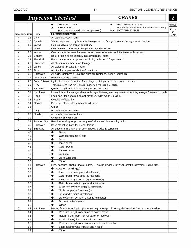
4-4 SECTION 4. GENERAL REFERENCE
M 16 Daily All daily inspection items.
M 17 Cylinders Visual inspection of cylinders for leakage at rod, fittings & welds. Damage to rod & case.M 18 Valves Holding valves for proper operation.
M 19 Valves Control valve for leaks at fittings & between sections.
M 20 Valves Control valve linkages for wear, smoothness of operation & tightness of fasteners.M 21 General Bent, broken or significantly rusted/corroded parts.
M 22 Electrical Electrical systems for presence of dirt, moisture & frayed wires.
M 23 Structure All structural members for damage.M 24 Welds All welds for breaks & cracks.
M 25 Pins All pins for proper installation & condition.
M 26 Hardware All bolts, fasteners & retaining rings for tightness, wear & corrosionM 27 Wear Pads Presence of wear pads.
M 28 Pump & Motor Hydraulic pumps & motors for leakage at fittings, seals & between sections.
M 29 PTO Transmission/PTO for leakage, abnormal vibration & noise.M 30 Hyd Fluid Quality of hydraulic fluid and for presence of water.
M 31 Hyd Lines Hoses & tubes for leakage, abrasion damage, blistering, cracking, deterioration, fitting leakage & secured properly.
M 32 Hook Load hook for abnormal throat distance, twist, wear & cracks.
M 33 Rope Condition of load line.M 34 Manual Presence of operator’s manuals with unit.
M 35 Other
Q 36 Daily All daily inspection items.Q 37 Monthly All monthly inspection items.
Q 38 Condition of wear pads
Q 39 Rotation Sys Rotation bearing for proper torque of all accessible mounting bolts.Q 40 Hardware Base mounting bolts for proper torque.
Q 41 Structure All structural members for deformation, cracks & corrosion.42 ● Base
43 ● Outrigger beams & legs
44 ● Mast45 ● Inner boom
46 ● Outer boom
47 ● Extension(s)48 ● Jib boom
49 ● Jib extension(s)
50 ● OtherQ 51 Hardware Pins, bearings, shafts, gears, rollers, & locking devices for wear, cracks, corrosion & distortion.
52 ● Rotation bearing(s)
53 ● Inner boom pivot pin(s) & retainer(s)54 ● Outer boom pivot pin(s) & retainer(s)
55 ● Inner boom cylinder pin(s) & retainer(s)
56 ● Outer boom cylinder pin(s) & retainer(s)57 ● Extension cylinder pin(s) & retainer(s)
58 ● Jib boom pin(s) & retainer(s)
59 ● Jib cylinder pin(s) & retainer(s)60 ● Jib extension cylinder pin(s) & retainer(s)
61 ● Boom tip attachments
62 ● OtherQ 63 Hyd Lines Hoses, fittings & tubing for proper routing, leakage, blistering, deformation & excessive abrasion.
64 ● Pressure line(s) from pump to control valve
65 ● Return line(s) from control valve to reservoir66 ● Suction line(s) from reservoir to pump
67 ● Pressure line(s) from control valve to each function
68 ● Load holding valve pipe(s) and hose(s)69 ● Other
������������� ���� CRANES �STATUS
FREQUENCY
✔ ,✘
R, NAINSPECTION DESCRIPTIONKEYITEM
✔ = SATISFACTORY✘ = DEFICIENCY
(must be corrected prior to operation)
R = RECOMMENDATION(should be considered for corrective action)
NA = NOT APPLICABLE
20000710
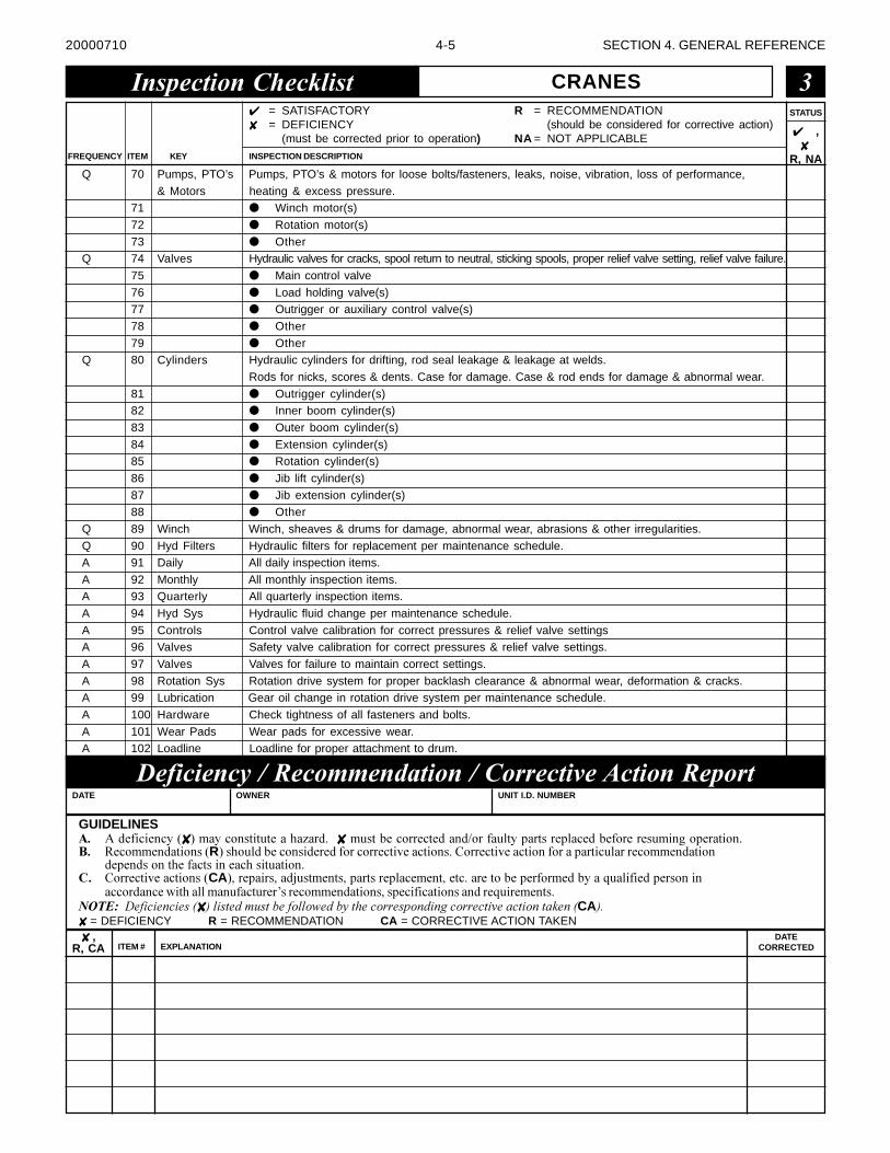
4-5 SECTION 4. GENERAL REFERENCE
STATUS
FREQUENCY
✔ ,✘
R, NAINSPECTION DESCRIPTIONKEYITEM
✔ = SATISFACTORY✘ = DEFICIENCY
(must be corrected prior to operation)
R = RECOMMENDATION(should be considered for corrective action)
NA = NOT APPLICABLE
Q 70 Pumps, PTO’s Pumps, PTO’s & motors for loose bolts/fasteners, leaks, noise, vibration, loss of performance,
& Motors heating & excess pressure.71 ● Winch motor(s)
72 ● Rotation motor(s)
73 ● OtherQ 74 Valves Hydraulic valves for cracks, spool return to neutral, sticking spools, proper relief valve setting, relief valve failure.
75 ● Main control valve
76 ● Load holding valve(s)77 ● Outrigger or auxiliary control valve(s)
78 ● Other
79 ● OtherQ 80 Cylinders Hydraulic cylinders for drifting, rod seal leakage & leakage at welds.
Rods for nicks, scores & dents. Case for damage. Case & rod ends for damage & abnormal wear.
81 ● Outrigger cylinder(s)82 ● Inner boom cylinder(s)
83 ● Outer boom cylinder(s)
84 ● Extension cylinder(s)85 ● Rotation cylinder(s)
86 ● Jib lift cylinder(s)
87 ● Jib extension cylinder(s)88 ● Other
Q 89 Winch Winch, sheaves & drums for damage, abnormal wear, abrasions & other irregularities.
Q 90 Hyd Filters Hydraulic filters for replacement per maintenance schedule.A 91 Daily All daily inspection items.
A 92 Monthly All monthly inspection items.A 93 Quarterly All quarterly inspection items.
A 94 Hyd Sys Hydraulic fluid change per maintenance schedule.
A 95 Controls Control valve calibration for correct pressures & relief valve settingsA 96 Valves Safety valve calibration for correct pressures & relief valve settings.
A 97 Valves Valves for failure to maintain correct settings.
A 98 Rotation Sys Rotation drive system for proper backlash clearance & abnormal wear, deformation & cracks.A 99 Lubrication Gear oil change in rotation drive system per maintenance schedule.
A 100 Hardware Check tightness of all fasteners and bolts.
A 101 Wear Pads Wear pads for excessive wear.A 102 Loadline Loadline for proper attachment to drum.
������������� ���� CRANES �
GUIDELINES�� ������������✘ ��� ������������ �� � �����✘ ������������������ ������� ����� �������� ������������������������ ������� ��������� ������R�������������������������������������� ������������������� ���������� �� ������ ����������� ����
���������������� �������� ������� ������� ����������� �������CA������ ����� ������������� �������� ������������� ��������������������� � � ����������������
����� ����!���� ���� ��� ������"����������� ��������������� ������ ����� ������������������������������✘ ������ ���������������� ����������������� ����������������������������CA�✘ = DEFICIENCY R = RECOMMENDATION CA = CORRECTIVE ACTION TAKEN
�������������������������������������������DATE OWNER UNIT I.D. NUMBER
✘ ,R, CA ITEM # EXPLANATION
DATECORRECTED
20000710

4-6 SECTION 4. GENERAL REFERENCE
������������������������������������������������ �✘ ,
R, CA ITEM # EXPLANATIONDATE
CORRECTED
��� ��������� ��� �� ��� ���������� ������� �� ����������������� �� ��� ����� �������
20000710
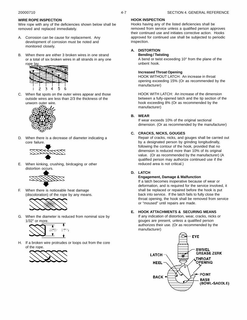
4-7 SECTION 4. GENERAL REFERENCE
WIRE ROPE INSPECTIONWire rope with any of the deficiencies shown below shall beremoved and replaced immediately.
A. Corrosion can be cause for replacement. Anydevelopment of corrosion must be noted andmonitored closely.
B. When there are either 3 broken wires in one strandor a total of six broken wires in all strands in any onerope lay.
C. When flat spots on the outer wires appear and thoseoutside wires are less than 2/3 the thickness of theunworn outer wire.
D. When there is a decrease of diameter indicating acore failure.
E. When kinking, crushing, birdcaging or otherdistortion occurs.
F. When there is noticeable heat damage(discoloration) of the rope by any means.
G. When the diameter is reduced from nominal size by1/32" or more.
H. If a broken wire protrudes or loops out from the coreof the rope.
HOOK INSPECTIONHooks having any of the listed deficiencies shall beremoved from service unless a qualified person approvestheir continued use and initiates corrective action. Hooksapproved for continued use shall be subjected to periodicinspection.
A. DISTORTIONBending / TwistingA bend or twist exceeding 10° from the plane of theunbent hook.
Increased Throat OpeningHOOK WITHOUT LATCH: An increase in throatopening exceeding 15% (Or as recommended by themanufacturer)
HOOK WITH LATCH: An increase of the dimensionbetween a fully-opened latch and the tip section of thehook exceeding 8% (Or as recommended by themanufacturer)
B. WEARIf wear exceeds 10% of the original sectionaldimension. (Or as recommended by the manufacturer)
C. CRACKS, NICKS, GOUGESRepair of cracks, nicks, and gouges shall be carried outby a designated person by grinding longitudinally,following the contour of the hook, provided that nodimension is reduced more than 10% of its originalvalue. (Or as recommended by the manufacturer) (Aqualified person may authorize continued use if thereduced area is not critical.)
D. LATCHEngagement, Damage & MalfunctionIf a latch becomes inoperative because of wear ordeformation, and is required for the service involved, itshall be replaced or repaired before the hook is putback into service. If the latch fails to fully close thethroat opening, the hook shall be removed from serviceor “moused” until repairs are made.
E. HOOK ATTACHMENTS & SECURING MEANSIf any indication of distortion, wear, cracks, nicks orgouges are present, unless a qualified personauthorizes their use. (Or as recommended by themanufacturer)
20000710
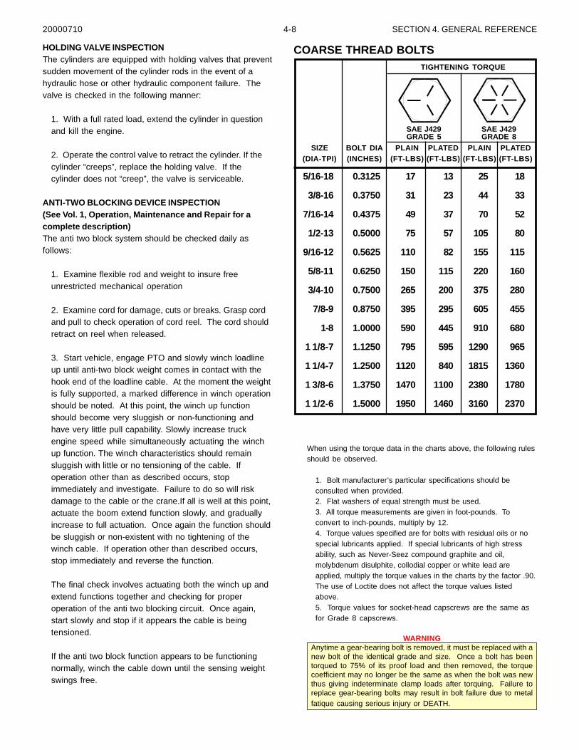
4-8 SECTION 4. GENERAL REFERENCE
HOLDING VALVE INSPECTIONThe cylinders are equipped with holding valves that preventsudden movement of the cylinder rods in the event of ahydraulic hose or other hydraulic component failure. Thevalve is checked in the following manner:
1. With a full rated load, extend the cylinder in questionand kill the engine.
2. Operate the control valve to retract the cylinder. If thecylinder “creeps”, replace the holding valve. If thecylinder does not “creep”, the valve is serviceable.
ANTI-TWO BLOCKING DEVICE INSPECTION(See Vol. 1, Operation, Maintenance and Repair for acomplete description)The anti two block system should be checked daily asfollows:
1. Examine flexible rod and weight to insure freeunrestricted mechanical operation
2. Examine cord for damage, cuts or breaks. Grasp cordand pull to check operation of cord reel. The cord shouldretract on reel when released.
3. Start vehicle, engage PTO and slowly winch loadlineup until anti-two block weight comes in contact with thehook end of the loadline cable. At the moment the weightis fully supported, a marked difference in winch operationshould be noted. At this point, the winch up functionshould become very sluggish or non-functioning andhave very little pull capability. Slowly increase truckengine speed while simultaneously actuating the winchup function. The winch characteristics should remainsluggish with little or no tensioning of the cable. Ifoperation other than as described occurs, stopimmediately and investigate. Failure to do so will riskdamage to the cable or the crane.If all is well at this point,actuate the boom extend function slowly, and graduallyincrease to full actuation. Once again the function shouldbe sluggish or non-existent with no tightening of thewinch cable. If operation other than described occurs,stop immediately and reverse the function.
The final check involves actuating both the winch up andextend functions together and checking for properoperation of the anti two blocking circuit. Once again,start slowly and stop if it appears the cable is beingtensioned.
If the anti two block function appears to be functioningnormally, winch the cable down until the sensing weightswings free.
When using the torque data in the charts above, the following rulesshould be observed.
1. Bolt manufacturer’s particular specifications should beconsulted when provided.2. Flat washers of equal strength must be used.3. All torque measurements are given in foot-pounds. Toconvert to inch-pounds, multiply by 12.4. Torque values specified are for bolts with residual oils or nospecial lubricants applied. If special lubricants of high stressability, such as Never-Seez compound graphite and oil,molybdenum disulphite, collodial copper or white lead areapplied, multiply the torque values in the charts by the factor .90.The use of Loctite does not affect the torque values listedabove.5. Torque values for socket-head capscrews are the same asfor Grade 8 capscrews.
WARNINGAnytime a gear-bearing bolt is removed, it must be replaced with anew bolt of the identical grade and size. Once a bolt has beentorqued to 75% of its proof load and then removed, the torquecoefficient may no longer be the same as when the bolt was newthus giving indeterminate clamp loads after torquing. Failure toreplace gear-bearing bolts may result in bolt failure due to metalfatique causing serious injury or DEATH.
5/16-18 0.3125 17 13 25 18
3/8-16 0.3750 31 23 44 33
7/16-14 0.4375 49 37 70 52
1/2-13 0.5000 75 57 105 80
9/16-12 0.5625 110 82 155 115
5/8-11 0.6250 150 115 220 160
3/4-10 0.7500 265 200 375 280
7/8-9 0.8750 395 295 605 455
1-8 1.0000 590 445 910 680
1 1/8-7 1.1250 795 595 1290 965
1 1/4-7 1.2500 1120 840 1815 1360
1 3/8-6 1.3750 1470 1100 2380 1780
1 1/2-6 1.5000 1950 1460 3160 2370
SIZE BOLT DIA PLAIN PLATED PLAIN PLATED(DIA-TPI) (INCHES) (FT-LBS) (FT-LBS) (FT-LBS) (FT-LBS)
SAE J429GRADE 5
SAE J429GRADE 8
TIGHTENING TORQUE
COARSE THREAD BOLTS
20000710
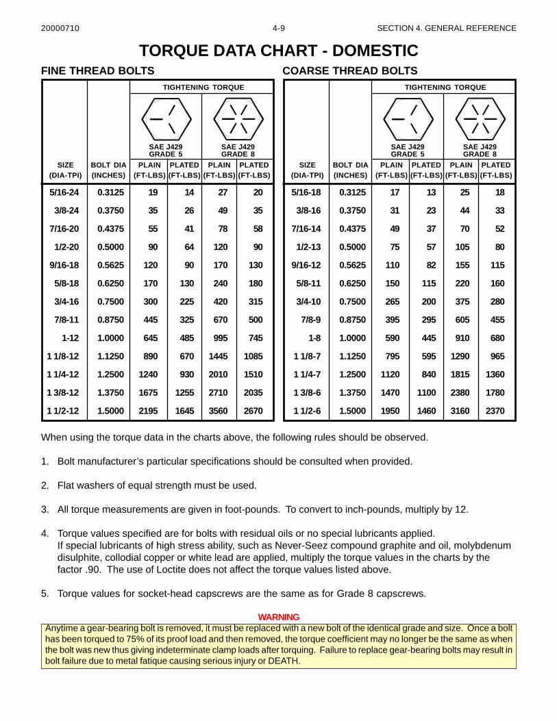
4-9 SECTION 4. GENERAL REFERENCE
When using the torque data in the charts above, the following rules should be observed.
1. Bolt manufacturer’s particular specifications should be consulted when provided.
2. Flat washers of equal strength must be used.
3. All torque measurements are given in foot-pounds. To convert to inch-pounds, multiply by 12.
4. Torque values specified are for bolts with residual oils or no special lubricants applied.If special lubricants of high stress ability, such as Never-Seez compound graphite and oil, molybdenumdisulphite, collodial copper or white lead are applied, multiply the torque values in the charts by thefactor .90. The use of Loctite does not affect the torque values listed above.
5. Torque values for socket-head capscrews are the same as for Grade 8 capscrews.
WARNINGAnytime a gear-bearing bolt is removed, it must be replaced with a new bolt of the identical grade and size. Once a bolthas been torqued to 75% of its proof load and then removed, the torque coefficient may no longer be the same as whenthe bolt was new thus giving indeterminate clamp loads after torquing. Failure to replace gear-bearing bolts may result inbolt failure due to metal fatique causing serious injury or DEATH.
5/16-24 0.3125 19 14 27 20
3/8-24 0.3750 35 26 49 35
7/16-20 0.4375 55 41 78 58
1/2-20 0.5000 90 64 120 90
9/16-18 0.5625 120 90 170 130
5/8-18 0.6250 170 130 240 180
3/4-16 0.7500 300 225 420 315
7/8-11 0.8750 445 325 670 500
1-12 1.0000 645 485 995 745
1 1/8-12 1.1250 890 670 1445 1085
1 1/4-12 1.2500 1240 930 2010 1510
1 3/8-12 1.3750 1675 1255 2710 2035
1 1/2-12 1.5000 2195 1645 3560 2670
SIZE BOLT DIA PLAIN PLATED PLAIN PLATED(DIA-TPI) (INCHES) (FT-LBS) (FT-LBS) (FT-LBS) (FT-LBS)
SAE J429GRADE 5
SAE J429GRADE 8
TIGHTENING TORQUE
5/16-18 0.3125 17 13 25 18
3/8-16 0.3750 31 23 44 33
7/16-14 0.4375 49 37 70 52
1/2-13 0.5000 75 57 105 80
9/16-12 0.5625 110 82 155 115
5/8-11 0.6250 150 115 220 160
3/4-10 0.7500 265 200 375 280
7/8-9 0.8750 395 295 605 455
1-8 1.0000 590 445 910 680
1 1/8-7 1.1250 795 595 1290 965
1 1/4-7 1.2500 1120 840 1815 1360
1 3/8-6 1.3750 1470 1100 2380 1780
1 1/2-6 1.5000 1950 1460 3160 2370
SIZE BOLT DIA PLAIN PLATED PLAIN PLATED(DIA-TPI) (INCHES) (FT-LBS) (FT-LBS) (FT-LBS) (FT-LBS)
SAE J429GRADE 5
SAE J429GRADE 8
TIGHTENING TORQUE
FINE THREAD BOLTS COARSE THREAD BOLTS
TORQUE DATA CHART - DOMESTIC
20000710
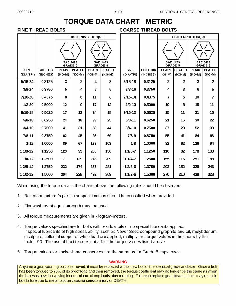
4-10 SECTION 4. GENERAL REFERENCE
When using the torque data in the charts above, the following rules should be observed.
1. Bolt manufacturer’s particular specifications should be consulted when provided.
2. Flat washers of equal strength must be used.
3. All torque measurements are given in kilogram-meters.
4. Torque values specified are for bolts with residual oils or no special lubricants applied.If special lubricants of high stress ability, such as Never-Seez compound graphite and oil, molybdenumdisulphite, collodial copper or white lead are applied, multiply the torque values in the charts by thefactor .90. The use of Loctite does not affect the torque values listed above.
5. Torque values for socket-head capscrews are the same as for Grade 8 capscrews.
WARNINGAnytime a gear-bearing bolt is removed, it must be replaced with a new bolt of the identical grade and size. Once a bolthas been torqued to 75% of its proof load and then removed, the torque coefficient may no longer be the same as whenthe bolt was new thus giving indeterminate clamp loads after torquing. Failure to replace gear-bearing bolts may result inbolt failure due to metal fatique causing serious injury or DEATH.
TORQUE DATA CHART - METRIC
5/16-24 0.3125 3 2 4 3
3/8-24 0.3750 5 4 7 5
7/16-20 0.4375 8 6 11 8
1/2-20 0.5000 12 9 17 12
9/16-18 0.5625 17 12 24 18
5/8-18 0.6250 24 18 33 25
3/4-16 0.7500 41 31 58 44
7/8-11 0.8750 62 45 93 69
1-12 1.0000 89 67 138 103
1 1/8-12 1.1250 123 93 200 150
1 1/4-12 1.2500 171 129 278 209
1 3/8-12 1.3750 232 174 375 281
1 1/2-12 1.5000 304 228 492 369
SIZE BOLT DIA PLAIN PLATED PLAIN PLATED(DIA-TPI) (INCHES) (KG-M) (KG-M) (KG-M) (KG-M)
SAE J429GRADE 5
SAE J429GRADE 8
TIGHTENING TORQUE
5/16-18 0.3125 2 2 3 2
3/8-16 0.3750 4 3 6 5
7/16-14 0.4375 7 5 10 7
1/2-13 0.5000 10 8 15 11
9/16-12 0.5625 15 11 21 16
5/8-11 0.6250 21 16 30 22
3/4-10 0.7500 37 28 52 39
7/8-9 0.8750 55 41 84 63
1-8 1.0000 82 62 126 94
1 1/8-7 1.1250 110 82 178 133
1 1/4-7 1.2500 155 116 251 188
1 3/8-6 1.3750 203 152 329 246
1 1/2-6 1.5000 270 210 438 328
SIZE BOLT DIA PLAIN PLATED PLAIN PLATED(DIA-TPI) (INCHES) (KG-M) (KG-M) (KG-M) (KG-M)
SAE J429GRADE 5
SAE J429GRADE 8
TIGHTENING TORQUE
FINE THREAD BOLTS COARSE THREAD BOLTS
20000710
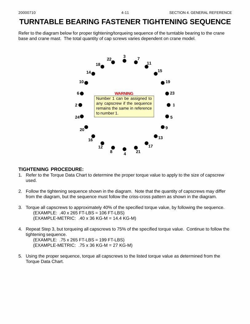
4-11 SECTION 4. GENERAL REFERENCE
TIGHTENING PROCEDURE:1. Refer to the Torque Data Chart to determine the proper torque value to apply to the size of capscrew
used.
2. Follow the tightening sequence shown in the diagram. Note that the quantity of capscrews may differfrom the diagram, but the sequence must follow the criss-cross pattern as shown in the diagram.
3. Torque all capscrews to approximately 40% of the specified torque value, by following the sequence.(EXAMPLE: .40 x 265 FT-LBS = 106 FT-LBS)(EXAMPLE-METRIC: .40 x 36 KG-M = 14.4 KG-M)
4. Repeat Step 3, but torqueing all capscrews to 75% of the specified torque value. Continue to follow thetightening sequence.
(EXAMPLE: .75 x 265 FT-LBS = 199 FT-LBS)(EXAMPLE-METRIC: .75 x 36 KG-M = 27 KG-M)
5. Using the proper sequence, torque all capscrews to the listed torque value as determined from theTorque Data Chart.
TURNTABLE BEARING FASTENER TIGHTENING SEQUENCERefer to the diagram below for proper tightening/torqueing sequence of the turntable bearing to the cranebase and crane mast. The total quantity of cap screws varies dependent on crane model.
WARNINGNumber 1 can be assigned toany capscrew if the sequenceremains the same in referenceto number 1.
3 711
15
19
23
1
5
9
13
172148
12
16
20
24
2
6
10
14
1822
20000710
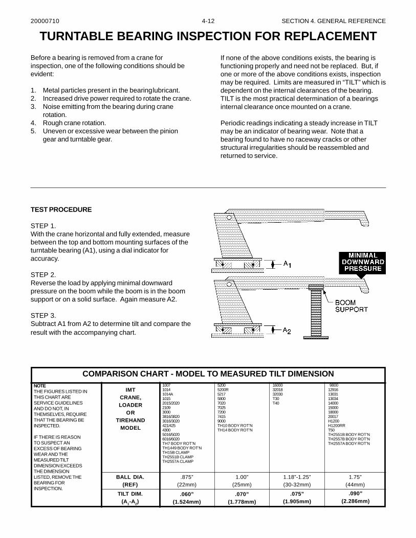
4-12 SECTION 4. GENERAL REFERENCE
Before a bearing is removed from a crane forinspection, one of the following conditions should beevident:
1. Metal particles present in the bearinglubricant.2. Increased drive power required to rotate the crane.3. Noise emitting from the bearing during crane
rotation.4. Rough crane rotation.5. Uneven or excessive wear between the pinion
gear and turntable gear.
TURNTABLE BEARING INSPECTION FOR REPLACEMENT
If none of the above conditions exists, the bearing isfunctioning properly and need not be replaced. But, ifone or more of the above conditions exists, inspectionmay be required. Limits are measured in “TILT” which isdependent on the internal clearances of the bearing.TILT is the most practical determination of a bearingsinternal clearance once mounted on a crane.
Periodic readings indicating a steady increase in TILTmay be an indicator of bearing wear. Note that abearing found to have no raceway cracks or otherstructural irregularities should be reassembled andreturned to service.
TEST PROCEDURE
STEP 1.With the crane horizontal and fully extended, measurebetween the top and bottom mounting surfaces of theturntable bearing (A1), using a dial indicator foraccuracy.
STEP 2.Reverse the load by applying minimal downwardpressure on the boom while the boom is in the boomsupport or on a solid surface. Again measure A2.
STEP 3.Subtract A1 from A2 to determine tilt and compare theresult with the accompanying chart.
NOTETHE FIGURES LISTED INTHIS CHART ARESERVICE GUIDELINESAND DO NOT, INTHEMSELVES, REQUIRETHAT THE BEARING BEINSPECTED.
IF THERE IS REASONTO SUSPECT ANEXCESS OF BEARINGWEAR AND THEMEASURED TILTDIMENSION EXCEEDSTHE DIMENSIONLISTED, REMOVE THEBEARING FORINSPECTION.
IMTCRANE,LOADER
ORTIREHAND
MODEL
BALL DIA.(REF)
TILT DIM.(A1-A2)
.060”(1.524mm)
.070”(1.778mm)
.075”(1.905mm)
.090”(2.286mm)
.875”(22mm)
1.00”(25mm)
1.18”-1.25”(30-32mm)
1.75”(44mm)
100710141014A10152015/2020210930003816/38203016/3020421/42543005016/50206016/6020TH7 BODY ROT’NTH1449 BODY ROT’NTH15B CLAMPTH2551B CLAMPTH2557A CLAMP
52005200R5217580070207025720074159000TH10 BODY ROT’NTH14 BODY ROT’N
160003201832030T30T40
980012916130311303414000150001800020017H1200H1200RRT50TH2551B BODY ROT’NTH2557B BODY ROT’NTH2557A BODY ROT’N
COMPARISON CHART - MODEL TO MEASURED TILT DIMENSION
20000710

4-13 SECTION 4. GENERAL REFERENCE
The information within this manual has been compiled and checked but errors do occur. To provide our customers with amethod of communicating those errors we have provided the Manual Change Request form below. In addition to errorreporting, you are encouraged to suggest changes or additions to the manual which would be of benefit to you. Wecannot guarantee that these additions will be made but we do promise to consider them. When completing the form,please write or print clearly. Submit a copy of the completed form to the address listed below.
MANUAL CHANGE REQUEST
MAIL TO:
IOWA MOLD TOOLING CO., INC.BOX 189
GARNER, IA 50438-0189ATTN: Technical Publications
20000710
DATE PRODUCTMANUAL
MANUALPART NO.
SUBMITTED BY
COMPANY
ADDRESS
CITY, STATE, ZIP
TELEPHONE
ERROR FOUND
LOCATION OF ERROR (page no.):
DESCRIPTION OF ERROR:
ERROR FOUND
DESCRIPTION OF ADDITION:
REASON FOR ADDITION:
4-14 SECTION 4. GENERAL REFERENCE
This parts manual is provided to the user to assist in servicing the equipment. It is the property of Iowa Mold Tooling Co., Inc.and, as such, may not be reproduced either whole or in part, whether by chemical, electrostatic, mechanical or photographicmeans without the expressed written permission of an officer of Iowa Mold Tooling Co., Inc. One manual is provided with eachpiece of new equipment and additional manuals may be obtained at a nominal price. Your distributor may have access to thismanual through the IMT web site at www.IMT.com.
IOWA MOLD TOOLING CO., INC.BOX 189, GARNER, IA 50438-0189
TEL: 641-923-3711
www.imt.com
20000710


![[] HYDRAULIKZYLINDER ISO 6020/2 - Deutsche Messe AGdonar.messe.de/exhibitor/hannovermesse/2017/G262808/iso-6020-2-v4... · TECHNICAL CHARACTERISTICS HYDRAULIKZYLINDER ISO 6020/2 ISO](https://img.pdfslide.us/doc/110x75/5be4ac0809d3f2ad378dc3f9/-hydraulikzylinder-iso-60202-deutsche-messe-technical-characteristics-hydraulikzylinder.jpg)