Embed Size (px)
Citation preview

Manual Part # 99905190
IMT Telescopic Crane Operation & Safety Manual
Revision Date 20140915
IOWA MOLD TOOLING CO., INC.
PO Box 189 Garner, IA 50438
Tel: 641-923-3711 FAX: 641-923-2424 Website: http://www.imt.com
Copyright © 2014 Iowa Mold Tooling Co., Inc. All rights reserved
No part of this publication may be reproduced, stored in a retrieval system, or transmitted in any form or by any means, electronic, mechanical, photocopying, recording or otherwise without the prior written permission of Iowa Mold Tooling Co., Inc.
Iowa Mold Tooling Co., Inc. is an Oshkosh Corporation Company.

i
Contents Revisions ..................................................................................................................................................... iv
Introduction 5
Crane Component Identification ................................................................................................................... 7 Crane Safety.................................................................................................................................................. 8
Operation 11
Initial Operation Requirements ................................................................................................................... 12 Daily Safety Inspections ............................................................................................................................. 12 Preparing the Job Site ................................................................................................................................. 13 Electrical Hazards ....................................................................................................................................... 14 Stabilizers ................................................................................................................................................... 16 Telescopic Crane Controls .......................................................................................................................... 18 Crane Operation Using the Proportional Remote ....................................................................................... 18 Overload Protection System ....................................................................................................................... 21 Receiver Display ......................................................................................................................................... 22 Radio Elimination Cable ............................................................................................................................. 23 Crane Capacity ............................................................................................................................................ 24 Task Performance ....................................................................................................................................... 27 Anti-Two Block System ............................................................................................................................. 28 Auto-Release Hook Storage ........................................................................................................................ 29 Winch .......................................................................................................................................................... 30 Flip Sheave Feature .................................................................................................................................... 31 Double & Single Line ................................................................................................................................. 32 Load Level Indicator ................................................................................................................................... 32 Options ........................................................................................................................................................ 33 Emergency Manual Operation .................................................................................................................... 33 Crane Shut Down ........................................................................................................................................ 34 Troubleshooting .......................................................................................................................................... 35 Operation in Adverse Conditions ................................................................................................................ 36
Cold Weather ................................................................................................................................... 36 Signals ........................................................................................................................................................ 38
Maintenance 41
Maintenance Introduction ........................................................................................................................... 41 Maintenance Schedule ................................................................................................................................ 42 Greasing Instructions .................................................................................................................................. 43
New Crane Rotator Worm Gear Break-In Period ............................................................................ 45

ii Contents
Hydraulic Fluid Level ................................................................................................................................. 45 Crane Hydraulic Oil Specifications ............................................................................................................ 46 Changing Hydraulic Oil & Filter ................................................................................................................ 46 Purging Air from Hydraulic System ........................................................................................................... 47 Hydraulic Pressure Relief ........................................................................................................................... 47 Hydraulic Cylinder Holding Capability ...................................................................................................... 48 Winch Oil Specifications ............................................................................................................................ 48 Wire Rope & Hook Maintenance ............................................................................................................... 49
Wire Rope Inspection ...................................................................................................................... 49 Wire Rope Lubrication .................................................................................................................... 50 Wire Rope Maintenance .................................................................................................................. 50 Wire Rope Inspection & Replacement ............................................................................................ 50 Wire Rope Slings ............................................................................................................................. 51 Wire Rope Lay ................................................................................................................................ 52 Hook Maintenance ........................................................................................................................... 52

Contents iii
Periodic Inspection ..................................................................................................................................... 53 Additional Inspection .................................................................................................................................. 53 Corrosion Control ....................................................................................................................................... 54 Long-Term Storage ..................................................................................................................................... 55
Repair 57
Repair Precautions ...................................................................................................................................... 58 Systematic Repair Procedure ...................................................................................................................... 58 Associating Radio Remote Receiver and Transmitter ................................................................................ 59 Wear Pads ................................................................................................................................................... 60 Cylinder Repair ........................................................................................................................................... 61 Pin Removal & Inspection .......................................................................................................................... 62 Bushings ..................................................................................................................................................... 63 Wire Rope Removal & Replacement .......................................................................................................... 63 Turntable Bearing Inspection ...................................................................................................................... 64 Turntable Bearing Tilt Test ......................................................................................................................... 64 Turntable Bearing Thread Tightening Sequence ........................................................................................ 65 Turntable Bearing Worm End Play & Backlash ......................................................................................... 66
Installation 69
Installation Introduction .............................................................................................................................. 70 Chassis Preparation ..................................................................................................................................... 70 Frame Strength ............................................................................................................................................ 70 PTO & Pump .............................................................................................................................................. 70 Engine Speed Regulation ............................................................................................................................ 71 Crane Installation ........................................................................................................................................ 72
Crane Decals 75
Telescopic Crane Decals ............................................................................................................................. 76 Danger Decals ............................................................................................................................................. 77 Danger Decal Figures ................................................................................................................................. 78 Instructional Decals .................................................................................................................................... 80
Reference 85
Inspection Checklist .................................................................................................................................... 85 Deficiency / Recommendation / Corrective Action Report ........................................................................ 90 Crane Stability Test .................................................................................................................................... 92
Stability Chart .................................................................................................................................. 94 Thread Torque Charts ................................................................................................................................. 95

iv Contents
Revisions
DATE LOCATION DESCRIPTION 20111228 THROUGHOUT ECN 11628 – Updated stabilizer wording, safety decals, added
stabilizer fully deployed instructions. 20131212 PAGE 69 Added NOTE per engineering mark-up. 20140915 Greasing
Instructions ECN 12264 – Molub-Alloy 882 was Molub-Alloy 936
Instructional Decals
ECN 12279 – Removed Mobil Oil from 70394189.

5
Thank you for purchasing an IMT crane! We want you to be able to meet your material handling and lifting needs with this product, and following proper operating procedures is the best way to do this. This manual:
Explains the operation and maintenance of this vehicle and equipment Reviews basic principles of operation Highlights common safety concerns and procedures Gives recommendations for using and maintaining the equipment.
This manual assumes that you:
Have already been fully trained to operate the vehicle and equipment. Have demonstrated the effectiveness of your training and the extent of your knowledge.
BEFORE operating this vehicle and equipment, you, the operator or maintenance person, must read, understand, and follow the instructions found in this operation and maintenance manual and the operation and maintenance manuals from the manufacturers of major components used on this vehicle or equipment. Proper tools and service equipment must be used, taking appropriate precautions as required by accepted safety practices, to prevent personal injury and/or equipment damage. If you are uncertain about the safe operation of any aspect of this vehicle or equipment, stop immediately and seek further training. You are the only person who knows what you don't know. You must speak up about the things you don't know, so you can learn about them before someone is injured or killed because of your lack of knowledge. You are responsible for learning how to operate this vehicle and equipment under all conditions without having to pause to read this manual.
WARNING• Only trained personnel should operate this equipment.• Do not operate or service until you have read and
understood the operation and service manual suppliedwith this equipment.
• Manuals can be obtained from manufacturer’s websiteor by contacting customer service.
• Operating this equipment without knowledge or trainingmay lead to injury or death for you or others.
For more information on crane design and test criteria, refer to ANSI/ASME B30.5, the standard for Mobile and Locomotive Boom Cranes, (You may obtain this publication from ASME at www.asme.org.) Crane operators must also be familiar with OSHA 29 CFR 1926 Subpart CC and CAL-OSHA Title 8, Article 93 (California).
C H A P T E R 1
Introduction

6 IMT Telescopic Crane Operation & Safety Manual Manual #99905190
This volume includes information that is common to all telescopic crane manufactured after June 2011. For specific information, refer to the parts and specifications manual for your crane model. We recommend that this manual and the parts manual are stored with the crane.
MODIFICATIONS
Modifications to your crane must be performed with IMT approved accessories, parts and optional equipment. If in doubt about the safety, compatibility, or appropriateness of any modifications, contact IMT prior to making those modifications. DO NOT alter or modify any safety device! All safety devices must be inspected, tested and maintained in proper working condition.
Note that decals regarding crane safety and operation are considered safety equipment. They must be maintained just as any other safety device. Decals must be kept clean and legible to the operator, operational personnel, and bystanders as specified in the decal section of this manual. DO NOT remove, disable, or disregard any safety device attached to your crane.
WARRANTY
Warranty of this unit will be void on any part of the unit subjected to misuse due to overloading, abuse, lack of maintenance and unauthorized modifications. No warranty - verbal, written or implied - other than the official, published IMT new machinery and equipment warranty will be valid with this unit.
MANUAL STRUCTURE
Throughout this manual, symbols are used to highlight information of particular importance. They are defined as follows:
NOTICE TO THE OWNER / USER
If your equipment is involved in a property damage accident, contact your IMT distributor immediately and provide them with the details of the accident and the serial number of the equipment. If an accident involves personal injury, immediately notify your distributor and the IMT Technical Support department at:
IOWA MOLD TOOLING CO., INC. 500 HWY 18 WEST GARNER, IA 50438
641 - 923 - 3711
CAUTIONA CAUTION is used when there is the
very strong possibility of damage to theequipment or premature equipment
failure.
WARNINGA WARNING is used when there is thepotential for personal injury or death.
DANGERDanger indicates an imminently hazardous
situation which, if not avoided, will resultin death or serious injury. Danger is used
in the most extreme situations.
NOTEA NOTE is used to either convey
additional information or to providefurther emphasis for a previous point.
Chapter 1 Introduction 7
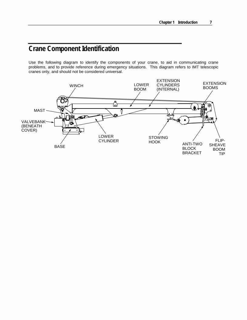
Crane Component Identification Use the following diagram to identify the components of your crane, to aid in communicating crane problems, and to provide reference during emergency situations. This diagram refers to IMT telescopic cranes only, and should not be considered universal.
BASE
VALVEBANK(BENEATHCOVER)
MAST
WINCH
LOWERCYLINDER
LOWERBOOM
EXTENSIONBOOMS
FLIP-SHEAVE
BOOMTIP
ANTI-TWOBLOCKBRACKET
STOWINGHOOK
EXTENSIONCYLINDERS(INTERNAL)
8 IMT Telescopic Crane Operation & Safety Manual Manual #99905190
Crane Safety
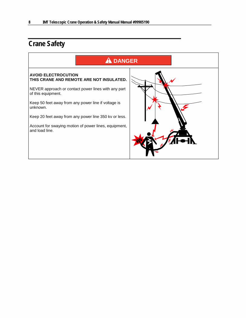
DANGER AVOID ELECTROCUTION THIS CRANE AND REMOTE ARE NOT INSULATED. NEVER approach or contact power lines with any part of this equipment. Keep 50 feet away from any power line if voltage is unknown. Keep 20 feet away from any power line 350 kv or less. Account for swaying motion of power lines, equipment, and load line.
Chapter 1 Introduction 9
WARNING
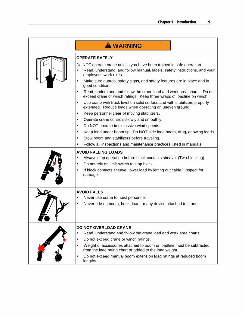
OPERATE SAFELY
Do NOT operate crane unless you have been trained in safe operation. Read, understand, and follow manual, labels, safety instructions, and your
employer's work rules. Make sure guards, safety signs, and safety features are in place and in
good condition. Read, understand and follow the crane load and work area charts. Do not
exceed crane or winch ratings. Keep three wraps of loadline on winch. Use crane with truck level on solid surface and with stabilizers properly
extended. Reduce loads when operating on uneven ground. Keep personnel clear of moving stabilizers. Operate crane controls slowly and smoothly. Do NOT operate in excessive wind speeds. Keep load under boom tip. Do NOT side load boom, drag, or swing loads. Stow boom and stabilizers before traveling. Follow all inspections and maintenance practices listed in manuals.
AVOID FALLING LOADS Always stop operation before block contacts sheave. (Two-blocking) Do not rely on limit switch to stop block. If block contacts sheave, lower load by letting out cable. Inspect for
damage.
AVOID FALLS Never use crane to hoist personnel. Never ride on boom, hook, load, or any device attached to crane.
DO NOT OVERLOAD CRANE Read, understand and follow the crane load and work area charts. Do not exceed crane or winch ratings. Weight of accessories attached to boom or loadline must be subtracted
from the load rating chart or added to the load weight. Do not exceed manual boom extension load ratings at reduced boom
lengths.


11
In This Chapter Initial Operation Requirements ............................................................. 12 Daily Safety Inspections ....................................................................... 12 Preparing the Job Site .......................................................................... 13 Electrical Hazards ................................................................................. 14 Stabilizers ............................................................................................. 16 Telescopic Crane Controls ................................................................... 18 Crane Operation Using the Proportional Remote ................................ 18 Overload Protection System ................................................................. 20 Receiver Display ................................................................................... 21 Radio Elimination Cable ....................................................................... 22 Crane Capacity ..................................................................................... 23 Task Performance ................................................................................ 26 Anti-Two Block System ......................................................................... 27 Auto-Release Hook Storage ................................................................. 28 Winch .................................................................................................... 30 Flip Sheave Feature ............................................................................. 30 Double & Single Line ............................................................................ 31 Load Level Indicator ............................................................................. 33 Options ................................................................................................. 33 Emergency Manual Operation .............................................................. 33 Crane Shut Down ................................................................................. 33 Troubleshooting .................................................................................... 34 Operation in Adverse Conditions .......................................................... 36 Signals .................................................................................................. 38
C H A P T E R 2
Operation
12 IMT Telescopic Crane Operation & Safety Manual Manual #99905190
Initial Operation Requirements To operate a crane, crane operators must conform to qualifications as specified by ANSI B30.5, Chapter 5-3, as well as OSHA 29 CFR 1926 Subpart CC. Prior to beginning work at a job site, the crane operator should understand:
Crane Safety Crane Controls Crane Load Limits Operating Procedures
Certain inherent risks are associated with heavy vehicles due to the nature of their use. Personnel working in the area of these vehicles are subject to certain hazards that cannot be guarded against by mechanical means but only by the exercise of intelligence, care, and common sense. It is therefore essential for the owner of this equipment to have personnel involved in the use and operation of these vehicles who are competent, careful, physically and mentally qualified, and trained in the safe operation of this equipment.
The operator should also have the chance to practice operating the crane prior to using the crane in a job site application. The operator must understand what to do in case of emergency and be prepared to take emergency action at any time. Safe operation is the responsibility of the operator, maintenance and inspection personnel. Safety has been a major consideration in the design and manufacture of this equipment, but only the operator and maintenance personnel can insure a safe work environment.
Daily Safety Inspections Use the following list as a guide when you are inspecting your unit at start-up and during operation, and log your inspection results using the Crane Log (IMT Manual No. 99900686) or the inspection checklist in the reference section of this manual:
1 Vehicle - Check oil level, battery, lights, brakes, and tires for inflation, pressure, cuts, and loose or missing wheel lugs.
2 Safety Accessories - Check for proper function, oil levels, leaks and malfunctions.
3 Anti-Two-Block System - Check daily for performance. See instructions (see "Anti-Two Block System" on page 27) in the Operation section. Inspect sheaves for cracks, grooves, or damage from two-blocking.
4 Hydraulic Oil Reservoir - Check for proper oil level. Check for leaks and blockages.
5 Weldments - Check visually for damage, especially cracks or breaks in welds.
6 Cylinders - Check for leakage and scored rods.
7 Fasteners - Check pins, sheaves, nuts and bolts for breakage, excessive wear and tightness.
8 Hooks - Check for the presence of a safety catch, twists, cracks, or damage.
9 Ropes & Slings - Check for frayed edges, broken strands, kinks, flat spots, and end attachments.
10 Covers & Guards - Check for missing or improperly maintained covers and guards.
11 Remote Control - Check all remote functions for function and corrosion.
Chapter 2 Operation 13
12 Operation Placards and Safety Decals - Check for illegible or missing decals and placards. Refer to the Decal section of this manual for more information on the required decals.
13 Work Area - Check for hazards including powerlines, obstructions, etc.
Replace or repair any items as needed prior to equipment operation.
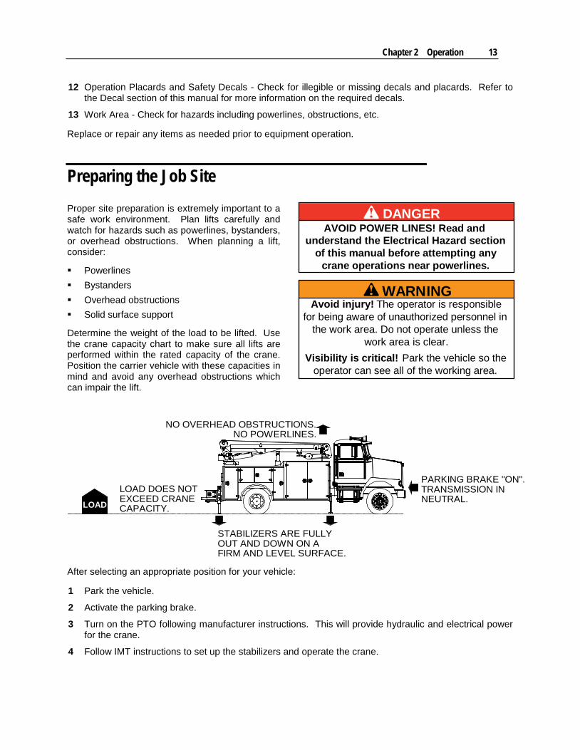
Preparing the Job Site Proper site preparation is extremely important to a safe work environment. Plan lifts carefully and watch for hazards such as powerlines, bystanders, or overhead obstructions. When planning a lift, consider:
Powerlines Bystanders Overhead obstructions Solid surface support
Determine the weight of the load to be lifted. Use the crane capacity chart to make sure all lifts are performed within the rated capacity of the crane. Position the carrier vehicle with these capacities in mind and avoid any overhead obstructions which can impair the lift.
LOAD
LOAD DOES NOTEXCEED CRANECAPACITY.
STABILIZERS ARE FULLYOUT AND DOWN ON AFIRM AND LEVEL SURFACE.
PARKING BRAKE "ON".TRANSMISSION INNEUTRAL.
NO OVERHEAD OBSTRUCTIONS.NO POWERLINES.
After selecting an appropriate position for your vehicle:
1 Park the vehicle.
2 Activate the parking brake.
3 Turn on the PTO following manufacturer instructions. This will provide hydraulic and electrical power for the crane.
4 Follow IMT instructions to set up the stabilizers and operate the crane.
DANGERAVOID POWER LINES! Read and
understand the Electrical Hazard sectionof this manual before attempting any
crane operations near powerlines.
WARNINGAvoid injury! The operator is responsible
for being aware of unauthorized personnel inthe work area. Do not operate unless the
work area is clear.Visibility is critical! Park the vehicle so the
operator can see all of the working area.
14 IMT Telescopic Crane Operation & Safety Manual Manual #99905190
Electrical Hazards
DANGERELECTROCUTION HAZARD
Vehicle is not insulated. Do NOT raise boom into power lines. Look up and use light to search for power lines in the dark. Keep boom and vehicle a minimum of 20 ft. (6.1 m) away from power lines. Do not step off a charged vehicle. If you touch a charged vehicle while standing on the ground, you will die.
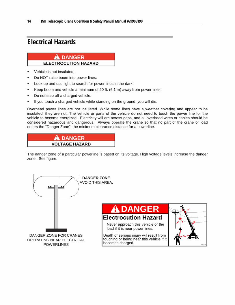
Overhead power lines are not insulated. While some lines have a weather covering and appear to be insulated, they are not. The vehicle or parts of the vehicle do not need to touch the power line for the vehicle to become energized. Electricity will arc across gaps, and all overhead wires or cables should be considered hazardous and dangerous. Always operate the crane so that no part of the crane or load enters the "Danger Zone", the minimum clearance distance for a powerline.
DANGERVOLTAGE HAZARD
The danger zone of a particular powerline is based on its voltage. High voltage levels increase the danger zone. See figure.
DANGER ZONEAVOID THIS AREA.
DANGER ZONE FOR CRANESOPERATING NEAR ELECTRICAL
POWERLINES
70394445
DANGERElectrocution Hazard
Never approach this vehicle or theload if it is near power lines.
Death or serious injury will result fromtouching or being near this vehicle if itbecomes charged.
Chapter 2 Operation 15
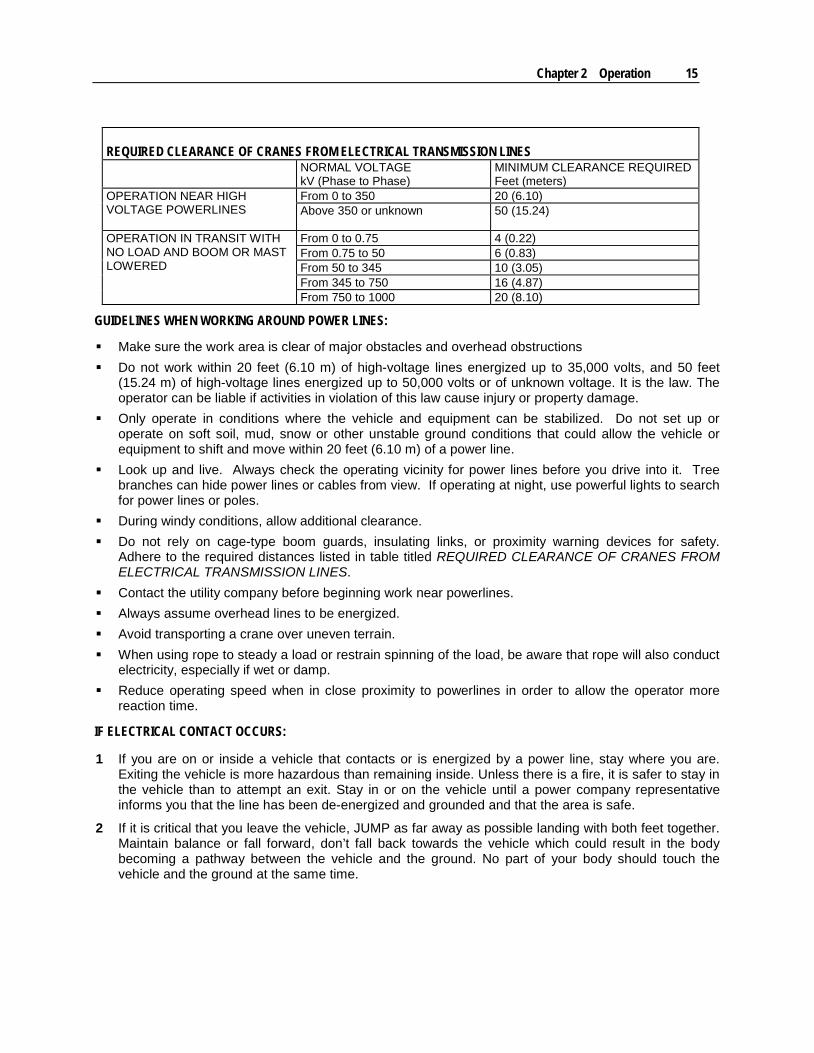
REQUIRED CLEARANCE OF CRANES FROM ELECTRICAL TRANSMISSION LINES NORMAL VOLTAGE
kV (Phase to Phase) MINIMUM CLEARANCE REQUIRED Feet (meters)
OPERATION NEAR HIGH VOLTAGE POWERLINES
From 0 to 350 20 (6.10) Above 350 or unknown 50 (15.24)
OPERATION IN TRANSIT WITH NO LOAD AND BOOM OR MAST LOWERED
From 0 to 0.75 4 (0.22) From 0.75 to 50 6 (0.83) From 50 to 345 10 (3.05) From 345 to 750 16 (4.87) From 750 to 1000 20 (8.10)
GUIDELINES WHEN WORKING AROUND POWER LINES:
Make sure the work area is clear of major obstacles and overhead obstructions Do not work within 20 feet (6.10 m) of high-voltage lines energized up to 35,000 volts, and 50 feet
(15.24 m) of high-voltage lines energized up to 50,000 volts or of unknown voltage. It is the law. The operator can be liable if activities in violation of this law cause injury or property damage.
Only operate in conditions where the vehicle and equipment can be stabilized. Do not set up or operate on soft soil, mud, snow or other unstable ground conditions that could allow the vehicle or equipment to shift and move within 20 feet (6.10 m) of a power line.
Look up and live. Always check the operating vicinity for power lines before you drive into it. Tree branches can hide power lines or cables from view. If operating at night, use powerful lights to search for power lines or poles.
During windy conditions, allow additional clearance. Do not rely on cage-type boom guards, insulating links, or proximity warning devices for safety.
Adhere to the required distances listed in table titled REQUIRED CLEARANCE OF CRANES FROM ELECTRICAL TRANSMISSION LINES.
Contact the utility company before beginning work near powerlines. Always assume overhead lines to be energized. Avoid transporting a crane over uneven terrain. When using rope to steady a load or restrain spinning of the load, be aware that rope will also conduct
electricity, especially if wet or damp. Reduce operating speed when in close proximity to powerlines in order to allow the operator more
reaction time.
IF ELECTRICAL CONTACT OCCURS:
1 If you are on or inside a vehicle that contacts or is energized by a power line, stay where you are. Exiting the vehicle is more hazardous than remaining inside. Unless there is a fire, it is safer to stay in the vehicle than to attempt an exit. Stay in or on the vehicle until a power company representative informs you that the line has been de-energized and grounded and that the area is safe.
2 If it is critical that you leave the vehicle, JUMP as far away as possible landing with both feet together. Maintain balance or fall forward, don’t fall back towards the vehicle which could result in the body becoming a pathway between the vehicle and the ground. No part of your body should touch the vehicle and the ground at the same time.
16 IMT Telescopic Crane Operation & Safety Manual Manual #99905190
3 If you are outside of the vehicle that contacts or is energized by a power line, move away from the vehicle and stay away. Warn others to stay away. You are safe from electrical shock as long as you do not become a pathway for current to flow to the ground. Do not approach the vehicle until a power company representative informs you that the line has been de-energized and grounded and that the area is safe
4 In certain circumstances the ground around a charged vehicle or downed power line may be energized. The ground becomes charged in concentric circles around the vehicle with varying voltage potential. Straddling these bands can result in serious injury or death as the current passes through your body. Stay away from the vehicle or power line, keeping both feet on the ground at the same time. This will prevent you from becoming a conductor between two areas of the ground that are charged differently.
5 If someone is trapped inside a vehicle that has come in contact with a power line, instruct them to stay inside and not to try to exit, unless their life is in eminent danger or a fire is present. Call 911 immediately and instruct the 911 operator to contact the power company. The power company personnel are trained to eliminate the hazard by de-energizing the line.
6 Do not attempt any rescue a person on or inside an energized vehicle, or who is energized themselves. If you touch someone whose body is conducting current, the current will flow through you too. Your muscles will seize up and you will not be able to escape.
ELECTRICAL CONTACT FOLLOW-UP:
1 Inspect and repair any equipment affected by electrical contact.
2 Replace any wire rope which has had high voltage contact.
Stabilizers IMT telescopic cranes are mounted on bodies which include stabilizers to stabilize the vehicle during crane operation.
WARNINGStabilizers can cause serious injury!
Stabilizers help stabilize the crane and carrier vehicle during a lift, but they can be hazardous due to their close proximity to the operator and other personnel. They are the only component of the crane which normally contact the ground. There are various stabilizer designs available, but all require extreme caution in their use. See figures for proper stabilizer operation sequence and warnings.
Stabilizer Operation:
Make sure the job site is properly prepared as described in the section, Preparing the Job Site (on page 13).
Use plates or blocks beneath the stabilizers if they are sinking into the ground. DO NOT use the crane to lift until the stabilizers are properly set up. DO NOT position vehicle near area of uncertain firmness.
1 Prior to setting up the stabilizers, measure the height of the workbench from the ground.
Chapter 2 Operation 17
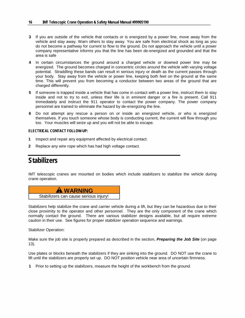
2 Extend the rear stabilizer arms (if applicable) completely. If hydraulic, turn on the engine and engage the PTO. The stabilizer hydraulic valves are located inside the crane control cabinet. If the stabilizers are manual, release the locking pin (inside the cabinet) and extend them until they lock into position. You should be able to see the word "Fully Deployed" on the yellow arrow decal on top of the stabilizer arms when the arms are fully extended.
3 Lower the rear stabilizer legs until full ground contact is achieved with the truck leveled such that the weight on the springs is relieved enough to raise the workbench approximately 1" (2.54 cm). Set up both rear stabilizers prior to setting the front stabilizers.
4 Lower the front stabilizer legs. If the front stabilizer legs do not touch the ground with the rear stabilizers as set in step #3, lower the rear stabilizers until the front stabilizers come in firm contact with the ground, the adjust the rear stabilizers until the truck is level.
5 Use a signal person if the stabilizers are not in view from the control station when extending or lowering the stabilizers.
Avoid stabilizer injuries including:
1 Hitting people while moving out.
2 Crushing people or equipment when contacting the ground.
3 Pinching people when being retracted.
BACK OF TRUCK
BACK OF TRUCK
BACK OF TRUCK
STABILIZERS CAN PINCH, STRIKE,OR CRUSH OBJECTS OR PEOPLE.MAKE SURE THERE ARE NOOBSTRUCTIONS IN OR NEAR THESTABILIZER PATH.
WARNING!
1. EXTEND STABILIZER ARMS TOTHEIR FULL HORIZONTALOPERATING LIMIT.
2. EXTEND STABILIZER LEGSUNTIL FULL CONTACT WITH THEGROUND AND SOLID STABILITYIS ACHIEVED, AND THE VEHICLEIS APPROXIMATELY LEVELED,SIDE-TO-SIDE.
WARNING
70392864
Crush HazardBefore extending stabilizers:
Look around vehicle.Clear area of all people.
Extending stabilizers on peoplemay injure or kill.

18 IMT Telescopic Crane Operation & Safety Manual Manual #99905190
Telescopic Crane Controls Your crane is operated using a fully proportional remote control with a pre-programmed overload protection system. The handheld remote is designed as the primary means for operating the crane. The crane is equipped with a single manual lever (IMT # 70734592) which can be used with the valves to manually stow the crane in case of radio failure.
EngineStart
EngineSpeed
Joystick #1:Boom (up/down)
Rotation (left/right)
JoystickW inchBoom
Crane Operation Using the Proportional Remote Make sure your work site is set up properly prior to lifting or moving a load. Plan your lift carefully. Do not exceed the rated capacity of the crane. Position the vehicle at your work-site and plan your lift per the instructions in Preparing the Job Site (on page 13).
Once your work site is properly set up, use the handheld remote transmitter to operate your crane.
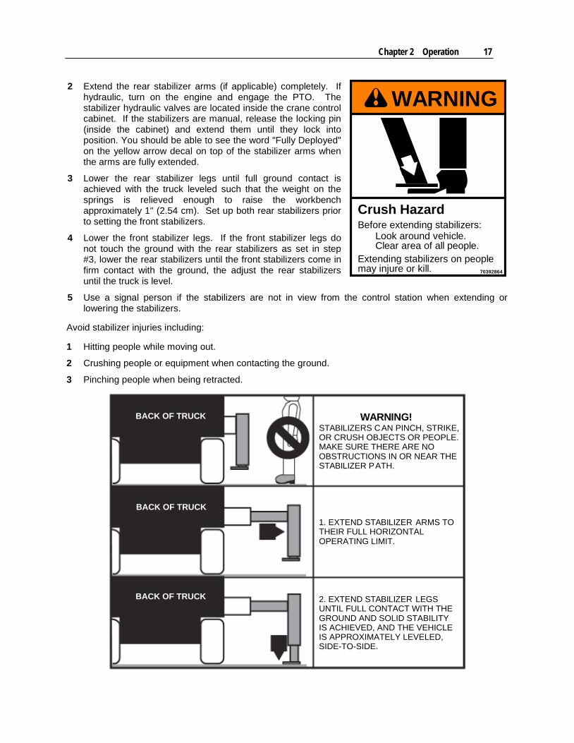
1 Power up your remote control transmitter by turning and pulling out (releasing) the large red E-STOP button, then toggling the Engine Start toggle switch upward for two seconds, then releasing.
Chapter 2 Operation 19
Turn and pullout the red
E-STOPbutton.
Activate theEngine Starttoggle switchto turn ontransmitter.
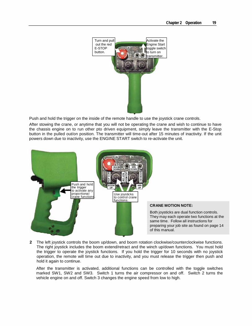
Push and hold the trigger on the inside of the remote handle to use the joystick crane controls. After stowing the crane, or anytime that you will not be operating the crane and wish to continue to have the chassis engine on to run other pto driven equipment, simply leave the transmitter with the E-Stop button in the pulled out/on position. The transmitter will time-out after 15 minutes of inactivity. If the unit powers down due to inactivity, use the ENGINE START switch to re-activate the unit.
WINDOWN
Push and holdthe triggerto activate anyproportionalcrane functions.
BOOMUP
Use joysticksto control cranefunctions.
WINUP
2 The left joystick controls the boom up/down, and boom rotation clockwise/counterclockwise functions. The right joystick includes the boom extend/retract and the winch up/down functions. You must hold the trigger to operate the joystick functions. If you hold the trigger for 10 seconds with no joystick operation, the remote will time out due to inactivity, and you must release the trigger then push and hold it again to continue.
After the transmitter is activated, additional functions can be controlled with the toggle switches marked SW1, SW2 and SW3. Switch 1 turns the air compressor on and off. Switch 2 turns the vehicle engine on and off. Switch 3 changes the engine speed from low to high.
CRANE MOTION NOTE:
Both joysticks are dual function controls.They may each operate two functions at thesame time. Follow all instructions forpreparing your job site as found on page 14of this manual.
20 IMT Telescopic Crane Operation & Safety Manual Manual #99905190
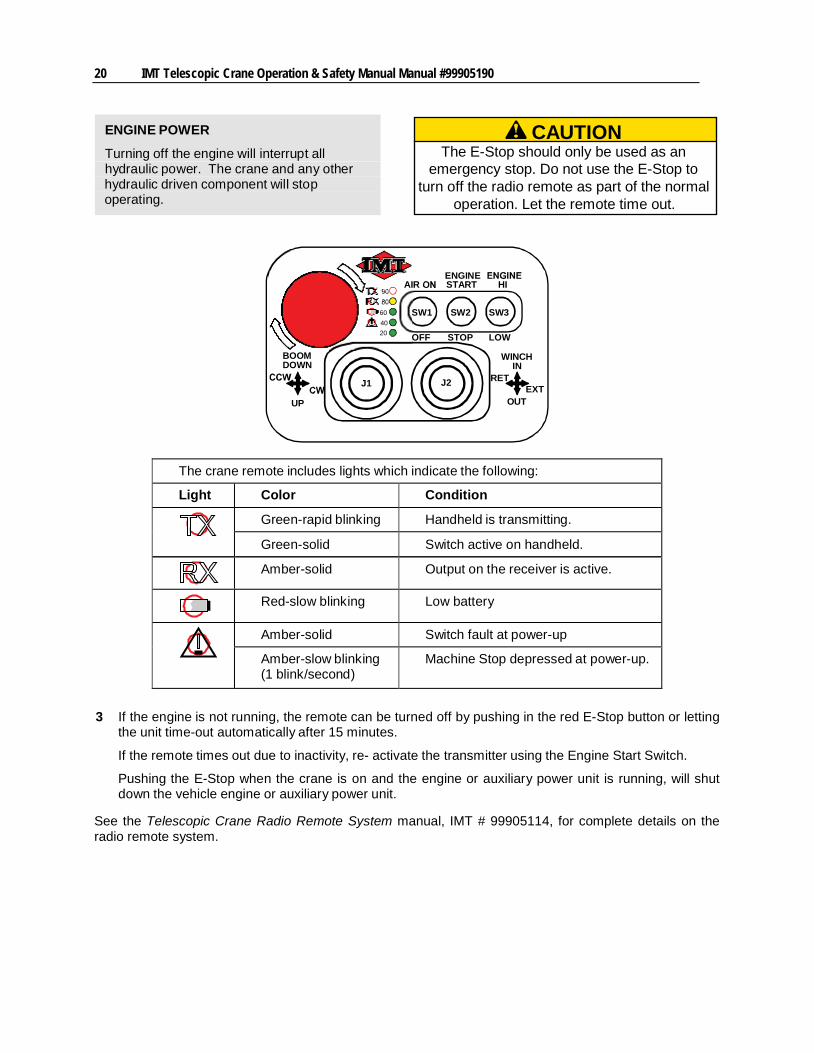
ENGINE POWER
Turning off the engine will interrupt allhydraulic power. The crane and any otherhydraulic driven component will stopoperating.
ENGINEAIR START HI
BOOMDOWN
60 SW1 SW2 SW34020 OFF STOP LOW
WINCHIN
J1 J2 RETEXT
UP OUT
The crane remote includes lights which indicate the following:
Light Color Condition
Green-rapid blinking Handheld is transmitting.
Green-solid Switch active on handheld.
Amber-solid Output on the receiver is active.
Red-slow blinking Low battery
Amber-solid Switch fault at power-up
Amber-slow blinking(1 blink/second)
Machine Stop depressed at power-up.
3 If the engine is not running, the remote can be turned off by pushing in the red E-Stop button or letting the unit time-out automatically after 15 minutes.
If the remote times out due to inactivity, re- activate the transmitter using the Engine Start Switch.
Pushing the E-Stop when the crane is on and the engine or auxiliary power unit is running, will shut down the vehicle engine or auxiliary power unit.
See the Telescopic Crane Radio Remote System manual, IMT # 99905114, for complete details on the radio remote system.
CAUTIONThe E-Stop should only be used as an
emergency stop. Do not use the E-Stop toturn off the radio remote as part of the normal
operation. Let the remote time out.

Chapter 2 Operation 21
Overload Protection System INTRODUCTION
This crane features an overload protection system with a snubbing feature which slows down the rate of crane operation when the crane reaches 90% of the rated load. The lights on the radio remote transmitter indicate the percent of capacity at which the crane is operating. Once the crane reaches a certain capacity level, the light for that level will illuminate. For example, when the crane reaches 20% of capacity, the 20 light will illuminate, and when the crane reaches 60% of capacity, the 60 light will illuminate. To conserve battery power, only the light which shows the actual capacity will light.
OPERATING SPEED AT 90% CAPACITY
Red & steadyat 90% capacity
SNUBBING: When the crane reaches 90 percent of rated load (snubbing), the 90% LED will be red and steady. In this situation, the crane operating speed will be reduced by 50 percent for all joystick functions.
To get back to full speed, reduce the load moment on the crane by:
Raising the boom Retracting the extensions Lowering the winch
When the load moment is below 90 percent, release the joysticks to neutral to regain full speed.
CRANE OVERLOAD (100% CAPACITY)
Red & flashingat 100% capacity
When the crane reaches 100 percent, the 90% LED will flash red. Once the crane reaches 100%, no crane operations will work except those which reduce the load moment of the crane. When in overload, release the joysticks to a neutral position, then reduce the load moment on the crane by:
Raising the boom Retracting the extensions Lowering the winch
The crane will begin to move at a reduced speed once you drop below 100% of the maximum load moment, and at full speed once you drop below 90% of the maximum load moment and have released the joysticks to neutral.
22 IMT Telescopic Crane Operation & Safety Manual Manual #99905190
Receiver Display
RECEIVERWITH LIGHTSAND CODESABOUT CRANEOPERATION
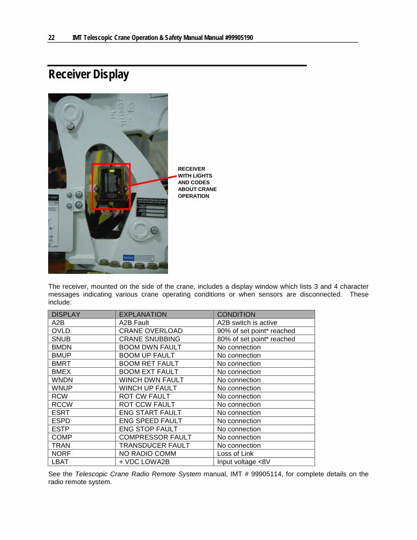
The receiver, mounted on the side of the crane, includes a display window which lists 3 and 4 character messages indicating various crane operating conditions or when sensors are disconnected. These include:
DISPLAY EXPLANATION CONDITION A2B A2B Fault A2B switch is active OVLD CRANE OVERLOAD 90% of set point* reached SNUB CRANE SNUBBING 80% of set point* reached BMDN BOOM DWN FAULT No connection BMUP BOOM UP FAULT No connection BMRT BOOM RET FAULT No connection BMEX BOOM EXT FAULT No connection WNDN WINCH DWN FAULT No connection WNUP WINCH UP FAULT No connection RCW ROT CW FAULT No connection RCCW ROT CCW FAULT No connection ESRT ENG START FAULT No connection ESPD ENG SPEED FAULT No connection ESTP ENG STOP FAULT No connection COMP COMPRESSOR FAULT No connection TRAN TRANSDUCER FAULT No connection NORF NO RADIO COMM Loss of Link LBAT + VDC LOWA2B Input voltage <8V
See the Telescopic Crane Radio Remote System manual, IMT # 99905114, for complete details on the radio remote system.
Chapter 2 Operation 23
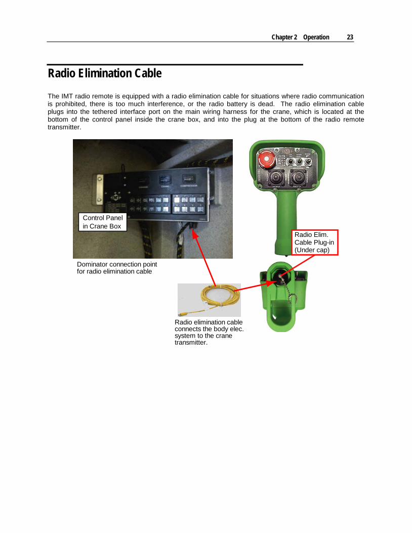
Radio Elimination Cable The IMT radio remote is equipped with a radio elimination cable for situations where radio communication is prohibited, there is too much interference, or the radio battery is dead. The radio elimination cable plugs into the tethered interface port on the main wiring harness for the crane, which is located at the bottom of the control panel inside the crane box, and into the plug at the bottom of the radio remote transmitter.
Dominator connection point
Control Panelin Crane Box
Radio Elim.Cable Plug-in(Under cap)
for radio elimination cable
Radio elimination cableconnects the body elec.system to the cranetransmitter.
24 IMT Telescopic Crane Operation & Safety Manual Manual #99905190
Crane Capacity The IMT crane is designed to lift specific loads. These loads are defined on the capacity placard mounted near the operator’s station and on the crane. Exceeding the limits presented on the capacity placard will create severe safety hazards and will shorten the life of the crane. The operator and other concerned personnel must know the load capacity of the crane and the weight of the load being lifted!
The capacity chart for each model is located in the specific crane technical specifications manual and on placards on the crane and body.
Prior to lifting a load:
1 Determine the weight of the load.
2 Determine the weight of any load handling devices.
3 Add the weight of the load and the weight of the load handling devices. The sum is the total weight of the load being lifted. This weight should not exceed the capacity noted on the chart at the position(s) at which the weight will be lifted.
4 Determine the distance from the centerline of crane rotation to the centerline of the load being lifted.
5 Determine the distance from the centerline of crane rotation to the centerline of the point to which the load should be moved.
6 Verify that the crane is positioned such that the boom will reach both the starting and ending points.
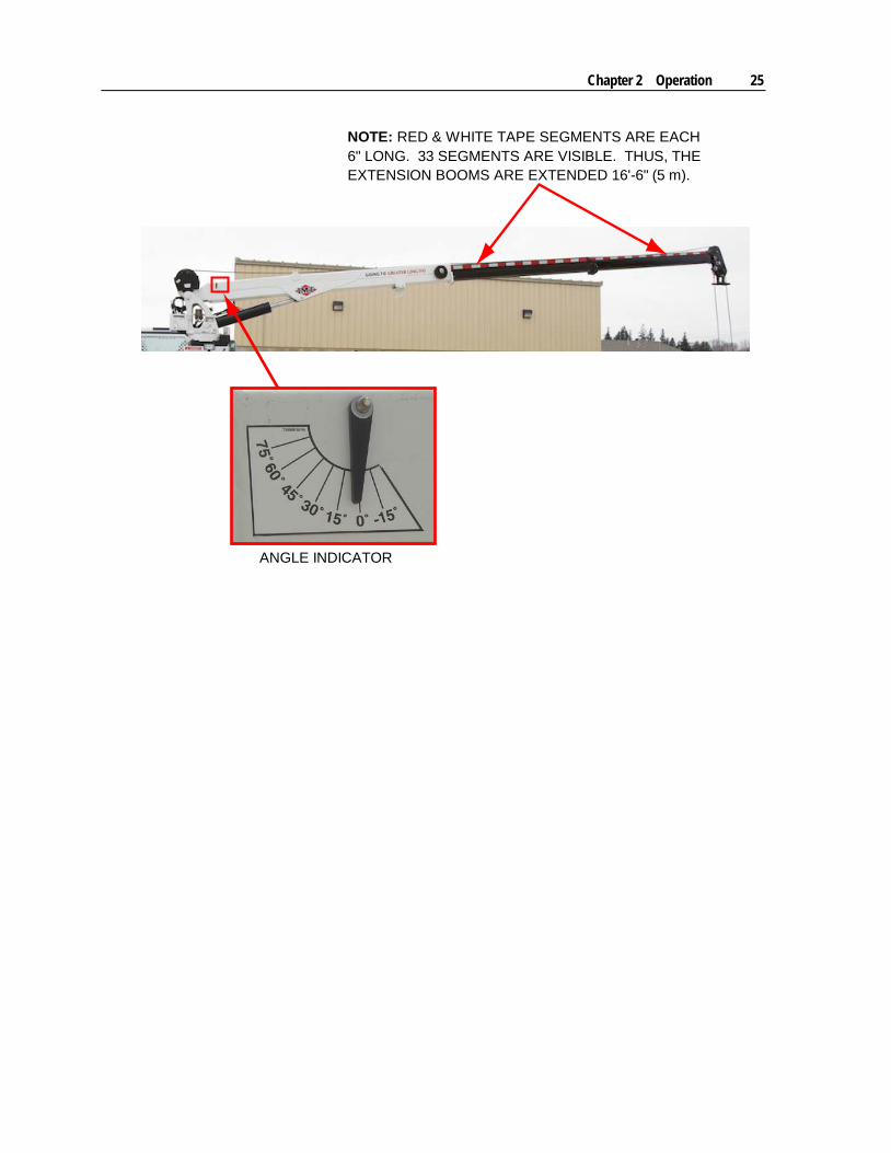
7 Determine the angle at which the crane will be operated (for example, 30° or 45°) by referencing the angle indicator on the lower boom.
8 Locate the load distance and angle on the capacity chart on your equipment (Note - chart below is for reference only) and verify that you can lift the load. (Note - Load value determined in step #3 above.)
9 Use two-part line for any lift which requires two-part line. (Note: The single-part line weight limit is noted in the box on the capacity chart.)
WARNINGNever exceed the crane’s rated load
capacities. Doing so will cause structuraldamage to winches and cables which can
lead to death or serious injury.
NOTECapacity Placards are intentionally locatednear the operator to assure ready referencein determining when a load can or cannot be
handled.Load limit information on the capacity
placards is formulated on 85% of tipping.Tipping refers to the crane actually tippingwith its opposite stabilizer and tires having
broken contact with the surface.
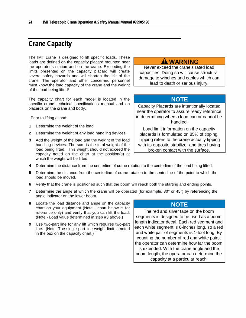
NOTEThe red and silver tape on the boom
segments is designed to be used as a boomlength indicator decal. Each red segment andeach white segment is 6-inches long, so a redand white pair of segments is 1-foot long. Bycounting the number of red and white pairs,
the operator can determine how far the boomis extended. With the crane angle and the
boom length, the operator can determine thecapacity at a particular reach.
Chapter 2 Operation 25
NOTE: RED & WHITE TAPE SEGMENTS ARE EACH6" LONG. 33 SEGMENTS ARE VISIBLE. THUS, THEEXTENSION BOOMS ARE EXTENDED 16'-6" (5 m).
ANGLE INDICATOR
26 IMT Telescopic Crane Operation & Safety Manual Manual #99905190
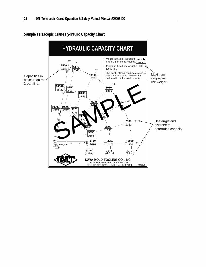
Sample Telescopic Crane Hydraulic Capacity Chart
70399109
IOWA MOLD TOOLING CO., INC.
• Values in the box indicate thexxxx lbxxxx kg
• Maximum 1-part line weight is 5500 lb
TEL: 641-923-3711 FAX: 641-923-2424
13'-0"(4.0 m)
21'-6"(6.6 m)
30'-0"(9.1 m)
75°
60°
45°
30°
15°
0°
85503880
100004535
100004535
61702800
39001770
30301375
26401195
23301060
2030920
89504060
61002765
45802075
40001815
36001635
32501475
57502610
58502655
64002900
74753390
100004535 9025
4095
BOX 189, GARNER, IA 50438-0189
• The weight of load-handling devices ispart of the load lifted and must bededucted from the rated capacity.
use of 2-part line is required.
(2500 kg).
80°
SAMPLEMaximumsingle-partline weight
Capacities inboxes require2-part line.
Use angle anddistance todetermine capacity.
Chapter 2 Operation 27
Task Performance Prior to lifting a load:
1 Verify the load can be lifted and moved using the capacity chart.
2 See Telescopic Crane Capacity (see "Crane Capacity" on page 23)
To operate the crane:
1 Position the crane as close to the job as possible on a firm, dry and level surface. Avoid overhead obstructions on the work side of the unit.
2 Set the auxiliary (parking) brake.
3 Depress the clutch pedal. Shift the transmission into neutral and engage the PTO.
4 Operate the throttle control to achieve the proper engine speed.
5 Before conducting any boom operations, extend both stabilizers and level the crane side to side. Provide blocks if necessary to level the unit on sloping ground or bearing pads if the stabilizers tend to sink into soft terrain or hot asphalt. Some concrete or asphalt surfaces are relatively thin and cannot withstand the stabilizer loading. Concrete can break through and cause instability.
WARNINGAvoid injury or equipment damage! Do NOTattempt to handle a load if the stabilizers areunable to make solid contact with the ground.
Stability over the front (without front stabilizers) can be hampered by raising the vehicle excessively. Use extreme caution when operating in areas around the truck which are not supported by stabilizers because of cushion of tires and springs. When swinging loads from areas supported by stabilizers, use extreme caution because of potential sudden shifting of the support point. Always keep the load as close to the ground as possible.
6 Raise the lower boom.
7 Rotate the boom to the selected location. Release the hook prior to operating the winch or extension boom. Extend the winch cable and lower the hook block so there is sufficient cable to allow for extended boom length before extending any telescoping boom sections. See Auto-Release Hook Storage (on page 28).
DANGERAVOID DEATH OR SERIOUS INJURY!
Don’t swing or drag a load!Check the load safety by first lifting the load
barely off the ground.Keep lifts as close to the ground as possible.
Stop all crane operation at a signal fromanyone.
Stow the crane when not in use.
28 IMT Telescopic Crane Operation & Safety Manual Manual #99905190
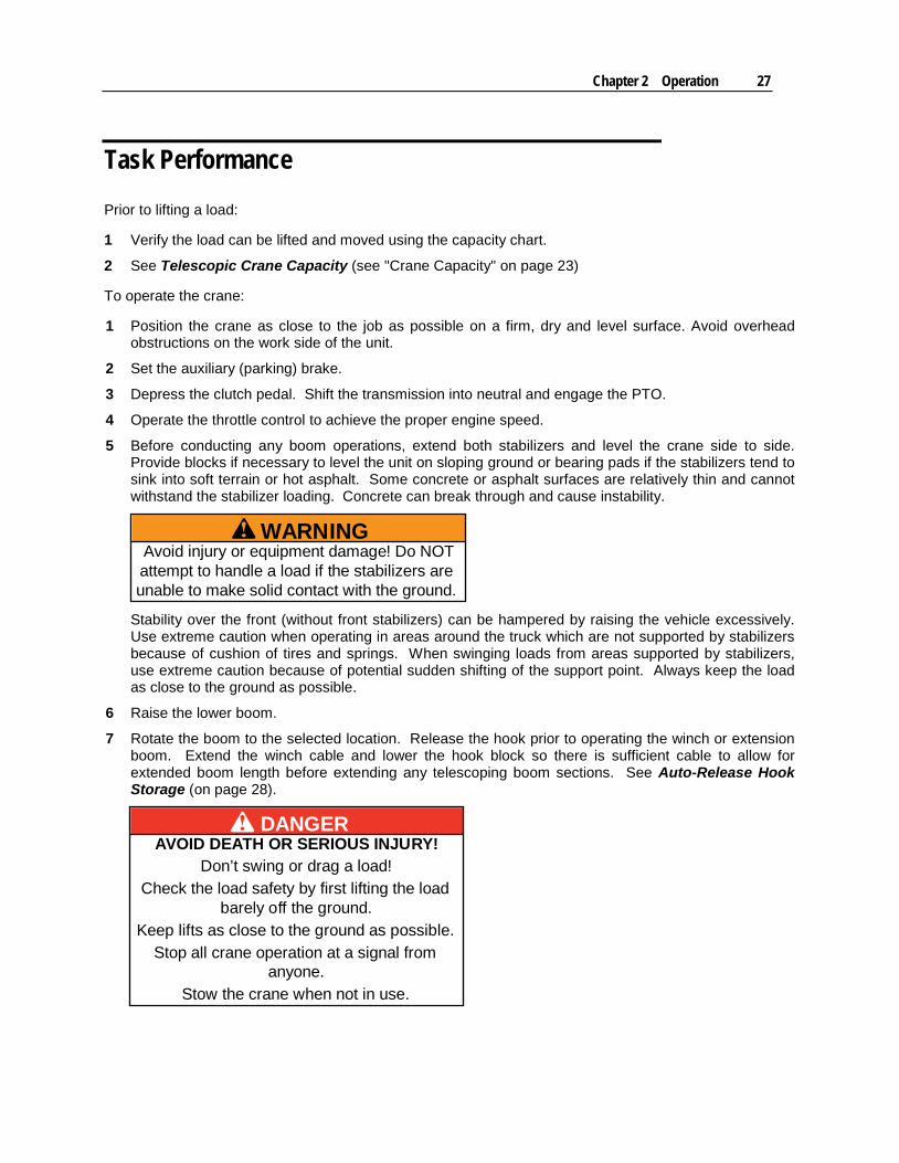
Anti-Two Block System "Two-blocking" is the condition when the lower load block or hook assembly contacts the boom tip sheave assembly. IMT cranes all have anti-two block systems which prevent two-blocking and the subsequent winch cable and sheave damage it can cause.
The anti-two block system on IMT telescopic cranes helps prevent cable damage by sensing the position of the winch cable end attachments and shutting down the functions that cause two-blocking, which are the winch retract function, boom extend function, and lower boom down function. When there is any upward movement of the anti-two-block bracket toward the boom tip, contact to the microswitch will be broken. The lower boom down, extension boom extend, and winch up functions will be shut down until the winch cable is extended and microswitch contact is restored.
Check the anti-two-block system daily using as follows:
1 Examine the weldment to insure free and unrestricted mechanical operation.
2 Examine cord for damage, cuts or breaks. Grasp cord and pull to check operation of cord reel. The cord should retract into the reel when released.
3 With your hand, push the anti-two-block weldment up toward boom tip. You should hear an audible click from the microswitch when the contact is broken.
4 Test the two-block system. Following proper operating procedures,
a) Lift the boom from the saddle.
b) Extend the winch cable to disengage the hook from the stowed position.
c) Retract the winch cable until the snatch block contacts the anti-two-block weldment. When this occurs, all winch motion should stop.
d) Relieve the two-block condition by extending the cable or retracting the extension boom.
e) Test again with the lower boom down function. When the snatch block contacts the anti-two-block weldment, the lower boom down function should stop.
f) Relieve by raising the lower boom.
If the anti-two-block function appears to be functioning normally, winch the cable down until the snatch block swings free.
Cord tocrane elec.system
Microswitch
Spring
Anti-two-blockweldment
Chapter 2 Operation 29
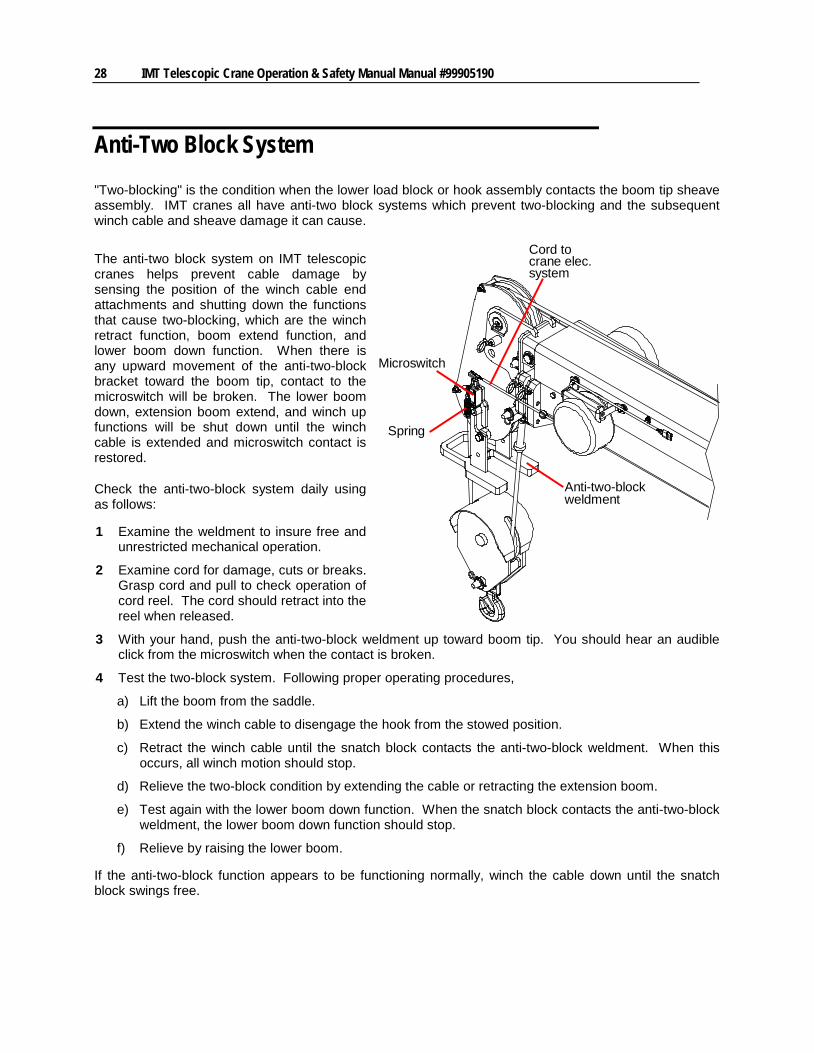
Auto-Release Hook Storage This crane includes a hook storage bracket featuring a gravity hook release which functions once the boom is elevated to an angle above 60 degrees. The bracket has a nub which will prevent the hook from slipping off inadvertently, but when the operator raises the boom past 60 degrees above horizontal and releases some winch cable, the hook can slide off the bracket. Then the operator can further extend the cable to hook on a load.
60 degrees
Hook will slipoff stow bracketwithout manualunlatching
30 IMT Telescopic Crane Operation & Safety Manual Manual #99905190
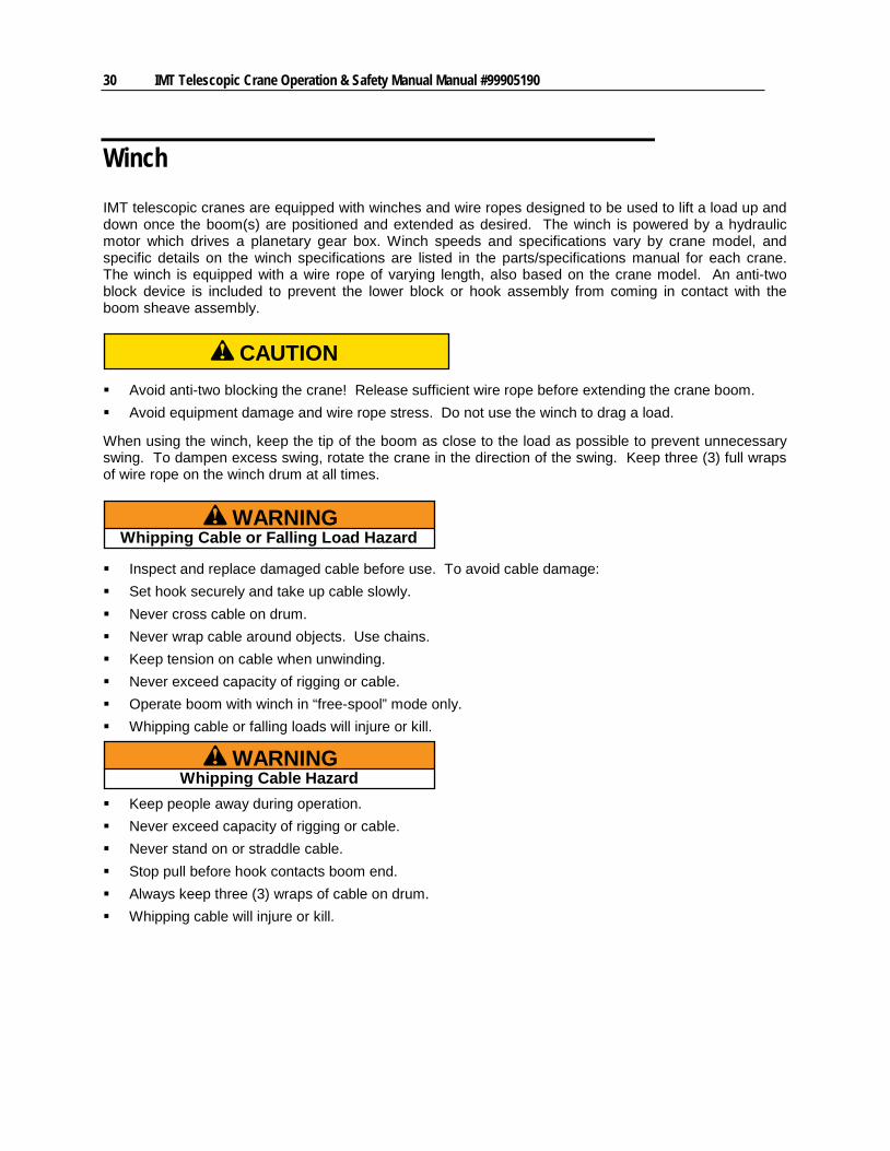
Winch IMT telescopic cranes are equipped with winches and wire ropes designed to be used to lift a load up and down once the boom(s) are positioned and extended as desired. The winch is powered by a hydraulic motor which drives a planetary gear box. Winch speeds and specifications vary by crane model, and specific details on the winch specifications are listed in the parts/specifications manual for each crane. The winch is equipped with a wire rope of varying length, also based on the crane model. An anti-two block device is included to prevent the lower block or hook assembly from coming in contact with the boom sheave assembly.
CAUTION
Avoid anti-two blocking the crane! Release sufficient wire rope before extending the crane boom. Avoid equipment damage and wire rope stress. Do not use the winch to drag a load.
When using the winch, keep the tip of the boom as close to the load as possible to prevent unnecessary swing. To dampen excess swing, rotate the crane in the direction of the swing. Keep three (3) full wraps of wire rope on the winch drum at all times.
WARNINGWhipping Cable or Falling Load Hazard
Inspect and replace damaged cable before use. To avoid cable damage: Set hook securely and take up cable slowly. Never cross cable on drum. Never wrap cable around objects. Use chains. Keep tension on cable when unwinding. Never exceed capacity of rigging or cable. Operate boom with winch in “free-spool” mode only. Whipping cable or falling loads will injure or kill.
WARNINGWhipping Cable Hazard
Keep people away during operation. Never exceed capacity of rigging or cable. Never stand on or straddle cable. Stop pull before hook contacts boom end. Always keep three (3) wraps of cable on drum. Whipping cable will injure or kill.
Chapter 2 Operation 31
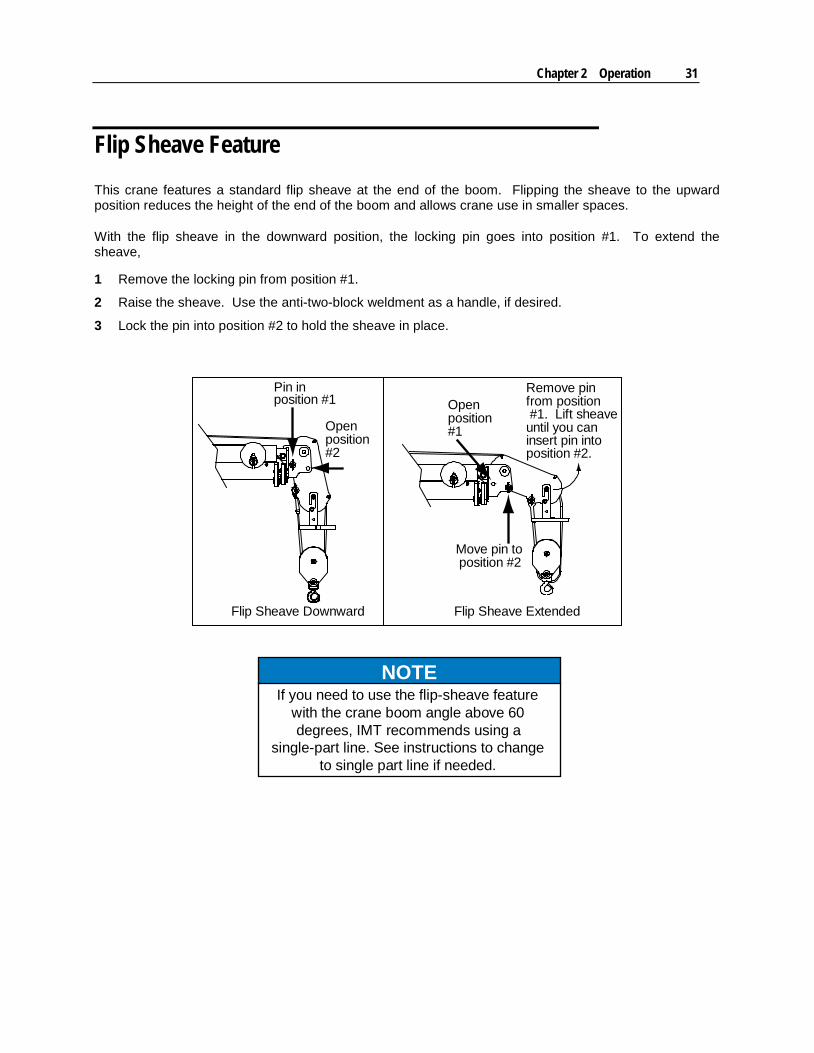
Flip Sheave Feature This crane features a standard flip sheave at the end of the boom. Flipping the sheave to the upward position reduces the height of the end of the boom and allows crane use in smaller spaces.
With the flip sheave in the downward position, the locking pin goes into position #1. To extend the sheave,
1 Remove the locking pin from position #1.
2 Raise the sheave. Use the anti-two-block weldment as a handle, if desired.
3 Lock the pin into position #2 to hold the sheave in place.
Pin inposition #1
Move pin toposition #2
Remove pinfrom position #1. Lift sheaveuntil you caninsert pin into
Flip Sheave Downward Flip Sheave Extended
Openposition
Openposition
#2#1
position #2.
NOTEIf you need to use the flip-sheave feature
with the crane boom angle above 60degrees, IMT recommends using a
single-part line. See instructions to changeto single part line if needed.
32 IMT Telescopic Crane Operation & Safety Manual Manual #99905190
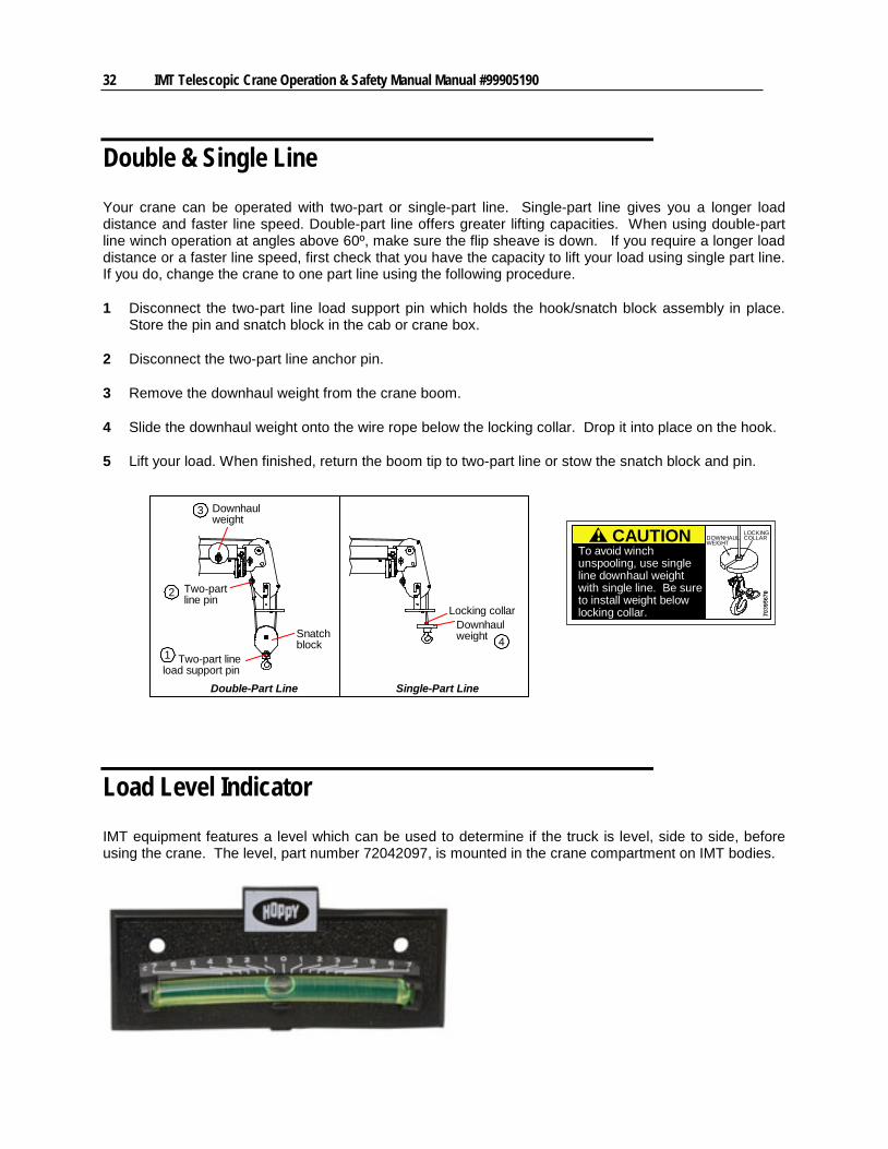
Double & Single Line Your crane can be operated with two-part or single-part line. Single-part line gives you a longer load distance and faster line speed. Double-part line offers greater lifting capacities. When using double-part line winch operation at angles above 60º, make sure the flip sheave is down. If you require a longer load distance or a faster line speed, first check that you have the capacity to lift your load using single part line. If you do, change the crane to one part line using the following procedure.
1 Disconnect the two-part line load support pin which holds the hook/snatch block assembly in place. Store the pin and snatch block in the cab or crane box.
2 Disconnect the two-part line anchor pin.
3 Remove the downhaul weight from the crane boom.
4 Slide the downhaul weight onto the wire rope below the locking collar. Drop it into place on the hook.
5 Lift your load. When finished, return the boom tip to two-part line or stow the snatch block and pin.
Load Level Indicator IMT equipment features a level which can be used to determine if the truck is level, side to side, before using the crane. The level, part number 72042097, is mounted in the crane compartment on IMT bodies.
Snatchblock
Two-partline pin
Downhaulweight
Downhaulweight
Locking collar
Two-part lineload support pin
Double-Part Line Single-Part Line
1
2
3
4
CAUTIONTo avoid winchunspooling, use singleline downhaul weightwith single line. Be sureto install weight belowlocking collar.
LOCKINGCOLLARDOWNHAUL
WEIGHT
Chapter 2 Operation 33
Options The wiring harness on this crane is pre-wired for several options, including:
Boom tip flood light Stow sensor which will indicate when the crane is fully stowed Cable unwind prevention system, which will stop winch function when 2-1/2 wraps of wire rope remain
on the winch spool. This will prevent the cable from completely unwinding and the load falling.
Although these options are not included on every crane, they can be easily added as they are already wired into the main harness.
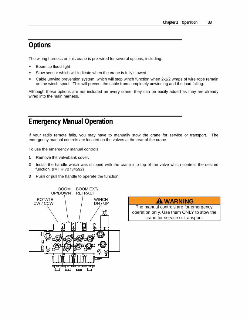
Emergency Manual Operation If your radio remote fails, you may have to manually stow the crane for service or transport. The emergency manual controls are located on the valves at the rear of the crane.
To use the emergency manual controls,
1 Remove the valvebank cover.
2 Install the handle which was shipped with the crane into top of the valve which controls the desired function. (IMT # 70734592)
3 Push or pull the handle to operate the function.
BOOMUP/DOWN
BOOM EXT/RETRACT
WINCHDN / UP
ROTATECW / CCW
WARNINGThe manual controls are for emergency
operation only. Use them ONLY to stow thecrane for service or transport.
34 IMT Telescopic Crane Operation & Safety Manual Manual #99905190
Crane Shut Down 1 Retract the extension booms and winch cable.
2 Secure the hook.
3 Stow the equipment in its travel configuration. Use the boom support located on the bed of the vehicle. Make sure the winch line is slack. After stowing, tighten the winch line just enough to keep the cable from contacting the boom.
CAUTIONExcessive pressure on the boom support may
damage the boom support or the body. 4 When the boom is in the transport position, toggle the lower and extend functions on the handset to
relieve any trapped pressure. This will prevent the boom from bouncing out of the boom support during transit.
5 Stow the stabilizers.
6 Disengage the throttle control.
7 Depress clutch pedal (if applicable) and disengage PTO.
8 Shut off the truck engine using the Engine Stop function on the remote.
9 Secure loose items on truck bed.
10 Release the auxiliary brake.
Watch for highway height and length restrictions, and follow all highway regulations.
Chapter 2 Operation 35
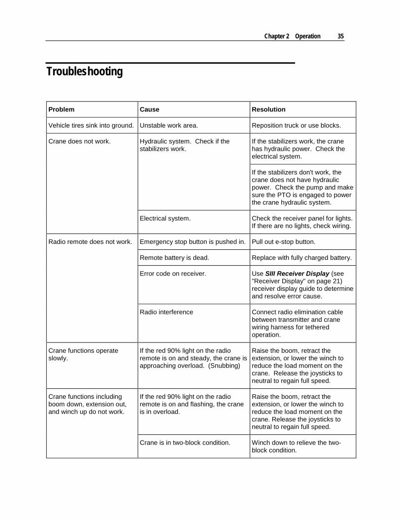
Troubleshooting
Problem Cause Resolution
Vehicle tires sink into ground. Unstable work area. Reposition truck or use blocks.
Crane does not work.
Hydraulic system. Check if the stabilizers work.
If the stabilizers work, the crane has hydraulic power. Check the electrical system.
If the stabilizers don't work, the crane does not have hydraulic power. Check the pump and make sure the PTO is engaged to power the crane hydraulic system.
Electrical system. Check the receiver panel for lights. If there are no lights, check wiring.
Radio remote does not work.
Emergency stop button is pushed in. Pull out e-stop button.
Remote battery is dead. Replace with fully charged battery.
Error code on receiver. Use SIII Receiver Display (see "Receiver Display" on page 21) receiver display guide to determine and resolve error cause.
Radio interference Connect radio elimination cable between transmitter and crane wiring harness for tethered operation.
Crane functions operate slowly.
If the red 90% light on the radio remote is on and steady, the crane is approaching overload. (Snubbing)
Raise the boom, retract the extension, or lower the winch to reduce the load moment on the crane. Release the joysticks to neutral to regain full speed.
Crane functions including boom down, extension out, and winch up do not work.
If the red 90% light on the radio remote is on and flashing, the crane is in overload.
Raise the boom, retract the extension, or lower the winch to reduce the load moment on the crane. Release the joysticks to neutral to regain full speed.
Crane is in two-block condition. Winch down to relieve the two-block condition.
36 IMT Telescopic Crane Operation & Safety Manual Manual #99905190
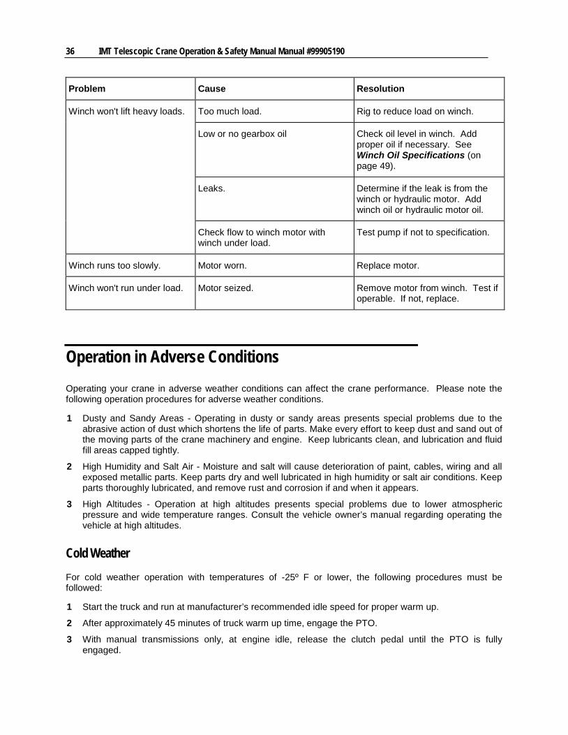
Problem Cause Resolution
Winch won't lift heavy loads.
Too much load. Rig to reduce load on winch.
Low or no gearbox oil Check oil level in winch. Add proper oil if necessary. See Winch Oil Specifications (on page 49).
Leaks. Determine if the leak is from the winch or hydraulic motor. Add winch oil or hydraulic motor oil.
Check flow to winch motor with winch under load.
Test pump if not to specification.
Winch runs too slowly. Motor worn. Replace motor.
Winch won't run under load. Motor seized. Remove motor from winch. Test if operable. If not, replace.
Operation in Adverse Conditions Operating your crane in adverse weather conditions can affect the crane performance. Please note the following operation procedures for adverse weather conditions.
1 Dusty and Sandy Areas - Operating in dusty or sandy areas presents special problems due to the abrasive action of dust which shortens the life of parts. Make every effort to keep dust and sand out of the moving parts of the crane machinery and engine. Keep lubricants clean, and lubrication and fluid fill areas capped tightly.
2 High Humidity and Salt Air - Moisture and salt will cause deterioration of paint, cables, wiring and all exposed metallic parts. Keep parts dry and well lubricated in high humidity or salt air conditions. Keep parts thoroughly lubricated, and remove rust and corrosion if and when it appears.
3 High Altitudes - Operation at high altitudes presents special problems due to lower atmospheric pressure and wide temperature ranges. Consult the vehicle owner’s manual regarding operating the vehicle at high altitudes.
Cold Weather For cold weather operation with temperatures of -25º F or lower, the following procedures must be followed:
1 Start the truck and run at manufacturer’s recommended idle speed for proper warm up.
2 After approximately 45 minutes of truck warm up time, engage the PTO.
3 With manual transmissions only, at engine idle, release the clutch pedal until the PTO is fully engaged.
Chapter 2 Operation 37
4 With the PTO fully engaged and the truck engine running at idle speed, let the hydraulic system oil circulate.
CAUTIONAvoid pump cavitation and potential
permanent damage! During the 45 minutesallowed for warm up, do not race the truckengine and overspeed hydraulic pumps.
If at any time during oil circulation, and especially during the initial warm up time, any hydraulic pump noise such as metal grinding, or a popping noise is heard, shut down the unit immediately. Check that the hydraulic oil line leading to the suction port on the pump is not clogged, or that the hydraulic oil itself has not jelled.
CAUTIONFor crane operation in temperatures below
-25°F, use hydraulic oil conforming toMIL-L-46167.
For winch operation in temperatures below-25°F, change the lubrication oil in the winch
gearbox to oil which conforms toMIL-L-2105C, Grade 75W (GO-75).
After the 45 minute warm up period, begin crane operation as follows:
a) Slowly extend stabilizers approximately 6 inches and retract, extend out again approximately half way and retract, and then extend fully.
b) Deploy the crane raising the lower boom.
c) Rotate the crane slowly, approximately one eighth revolution one way, return to previous position and rotate in opposite direction. Do this several times, then rotate 90º and return.
d) Raise the lower boom, deploy the hook, then begin winch operation by slowly lowering and raising the hook.
e) With sufficient loadline, extend and retract the extension boom. Repeat several times allowing longer operation intervals.
CAUTIONEngage valves slowly during warm-up cycleto prevent sudden hydraulic spikes which will
damage hydraulic components.
NOTEIt is normal for some oil seepage to occur
around piston rod seals during the warm-upoperation. Seepage should cease whenhydraulic system has reached operating
temperature.

38 IMT Telescopic Crane Operation & Safety Manual Manual #99905190
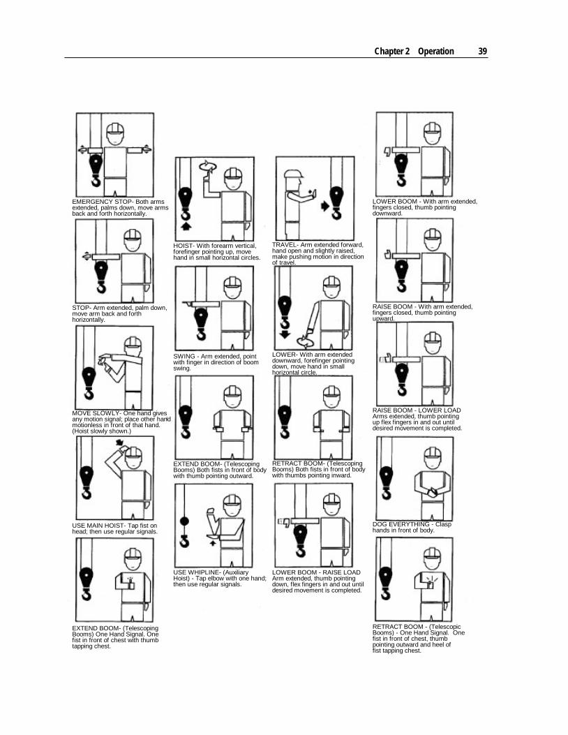
Signals Per OSHA 1926 Subpart CC, signals must be used when the operator's view of the load is obstructed or when the operator or the person handling the load determines signals are necessary. Operator signals may be by hand, voice, audible, or by some other agreed-upon method.
Standard hand signals are in this manual. See the hand signal chart.
Voice or audible signals, whether spoken, radio, telephone, or some other signal method, are acceptable signaling methods, but the signal method must be tested prior to commencing crane operation.
See ANSI B30.5 and OSHA 1926 Subpart CC for more information on signals.
Chapter 2 Operation 39
EMERGENCY STOP- Both armsextended, palms down, move armsback and forth horizontally.
STOP- Arm extended, palm down,move arm back and forthhorizontally.
MOVE SLOWLY- One hand givesany motion signal; place other handmotionless in front of that hand.(Hoist slowly shown.)
USE MAIN HOIST- Tap fist onhead; then use regular signals.
EXTEND BOOM- (TelescopingBooms) One Hand Signal. Onefist in front of chest with thumbtapping chest.
USE WHIPLINE- (AuxiliaryHoist) - Tap elbow with one hand;then use regular signals.
SWING - Arm extended, pointwith finger in direction of boomswing.
EXTEND BOOM- (TelescopingBooms) Both fists in front of bodywith thumb pointing outward.
HOIST- With forearm vertical,forefinger pointing up, movehand in small horizontal circles.
TRAVEL- Arm extended forward,hand open and slightly raised,make pushing motion in directionof travel.
LOWER- With arm extendeddownward, forefinger pointingdown, move hand in smallhorizontal circle.
RETRACT BOOM- (TelescopingBooms) Both fists in front of bodywith thumbs pointing inward.
LOWER BOOM - RAISE LOADArm extended, thumb pointingdown, flex fingers in and out untildesired movement is completed.
RETRACT BOOM - (TelescopicBooms) - One Hand Signal. Onefist in front of chest, thumbpointing outward and heel offist tapping chest.
DOG EVERYTHING - Clasphands in front of body.
RAISE BOOM - LOWER LOADArms extended, thumb pointingup flex fingers in and out untildesired movement is completed.
RAISE BOOM - With arm extended,fingers closed, thumb pointingupward.
LOWER BOOM - With arm extended,fingers closed, thumb pointingdownward.

41
In This Chapter Maintenance Introduction ..................................................................... 41 Maintenance Schedule ......................................................................... 42 Greasing Instructions ............................................................................ 42 Hydraulic Fluid Level ............................................................................ 45 Crane Hydraulic Oil Specifications ....................................................... 45 Changing Hydraulic Oil & Filter ............................................................ 46 Purging Air from Hydraulic System ...................................................... 47 Hydraulic Pressure Relief ..................................................................... 47 Hydraulic Cylinder Holding Capability .................................................. 47 Winch Oil Specifications ....................................................................... 49 Wire Rope & Hook Maintenance .......................................................... 49 Periodic Inspection ............................................................................... 53 Additional Inspection ............................................................................ 53 Corrosion Control ................................................................................. 54 Long-Term Storage .............................................................................. 55
Maintenance Introduction To obtain reliable and satisfactory service, IMT telescopic cranes require a consistent preventative maintenance schedule. Take necessary safety precautions during maintenance procedures to avoid equipment damage and personal injury. Follow the maintenance schedule included with this manual for best results.
1 Maintenance should only be performed by authorized service personnel.
2 Disengage the PTO before any service or repair is performed.
3 DO NOT disconnect any hydraulic components or hoses while there is pressure in those components.
4 Stand clear of high pressure hydraulic fluid leaks. Hot hydraulic fluid will cause serious injury, burns and possibly DEATH.
5 Keep the crane clean and free from built-up grease, oil and dirt to prevent slippery conditions and as an aid in the inspection of the crane.
6 Perform all checks before each period of use.
7 Replace parts with factory approved parts, only.
8 Repair or have repaired any components found to be inadequate, immediately
C H A P T E R 3
Maintenance

42 IMT Telescopic Crane Operation & Safety Manual Manual #99905190
Maintenance Schedule Detailed steps on numerous maintenance procedures are described in the following pages. Use the following chart to help you determine the time schedule of the maintenance requirements.
TIME FRAME MAINTENANCE STEP REFERENCE Weekly Lubricate:
Grease Zerks Hinge Pins Turntable Bearing
Grease:
Worm Gear Teeth
Greasing Instructions
Monthly Complete all required monthly inspections. (See IMT Inspection Checklist in the General Reference section of this manual.)
After the first 50 hours of service
Change hydraulic filter. Dominator manual.
Quarterly
Lubricate worm gear bearings. Complete all required quarterly inspections. (See IMT
Inspection Checklist in the General Reference section of this manual.)
Greasing Instructions
Every 6 months or 800 hours
Purge hydraulic system and replace hydraulic oil and filter. Changing Hydraulic Oil Changing Hydraulic Filter
Every year
Replace winch oil. Complete all required annual inspections. (See IMT
Inspection Checklist in the General Reference section of this manual.)
Winch Oil Specifications (on page 49)
Every 2 years Inspect pins. Pin Removal & Inspection
Chapter 3 Maintenance 43
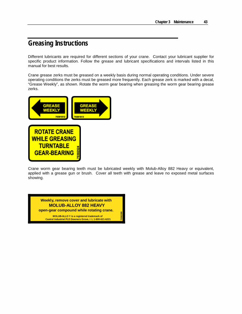
Greasing Instructions Different lubricants are required for different sections of your crane. Contact your lubricant supplier for specific product information. Follow the grease and lubricant specifications and intervals listed in this manual for best results.
Crane grease zerks must be greased on a weekly basis during normal operating conditions. Under severe operating conditions the zerks must be greased more frequently. Each grease zerk is marked with a decal, “Grease Weekly”, as shown. Rotate the worm gear bearing when greasing the worm gear bearing grease zerks.
Crane worm gear bearing teeth must be lubricated weekly with Molub-Alloy 882 Heavy or equivalent, applied with a grease gun or brush. Cover all teeth with grease and leave no exposed metal surfaces showing.
Weekly, remove cover and lubricate withMOLUB-ALLOY 882 HEAVY
open-gear compound while rotating crane.MOLUB-ALLO Y is a registered trademark of
Castrol Industrial PLD Downers Grove, I L 1-800-621-6221 7039
2399
44 IMT Telescopic Crane Operation & Safety Manual Manual #99905190
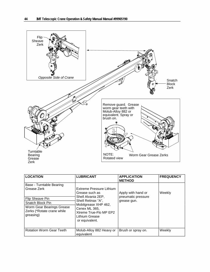
Flip
ZerkSheave
Worm Gear Grease Zerks
Opposite Side of Crane
NOTE:
Remove guard. Greaseworm gear teeth withMolub-Alloy 882 orequivalent. Spray orbrush on.
Rotated view
Turntable
GreaseBearing
Zerk
Snatch
ZerkBlock
LOCATION LUBRICANT APPLICATION METHOD
FREQUENCY
Base - Turntable Bearing Grease Zerk
Extreme Pressure Lithium Grease such as Shell Alvania 2EP, Shell Retinax "A", Mobilgrease XHP 462, Cenex ML 365, Xtreme True-Flo MP EP2 Lithium Grease or equivalent.
Apply with hand or pneumatic pressure grease gun.
Weekly Flip Sheave Pin
Snatch Block Pin Worm Gear Bearings Grease Zerks (*Rotate crane while greasing)
Rotation Worm Gear Teeth Molub-Alloy 882 Heavy or equivalent
Brush or spray on. Weekly
Chapter 3 Maintenance 45
New Crane Rotator Worm Gear Break-In Period Per the Greasing Instructions, the rotator worm gear must be greased weekly with molybdenum disulfide grease. (IMT uses Keystone Moly29 Open Gear Compound when building the crane.)
Brush on the molybdenum disulfide grease liberally on the worm gear teeth before turning the rotator. Cover all teeth with grease and leave no exposed metal surfaces showing. The first rotations of the rotator may be rough and have a scraping sound. This is normal, as the gear and worm are breaking in and will smooth out with continued use. The break-in time varies based on load moment, cycles of use, slope of boom tilt, etc.
IMT recommends running the system 10 to 15 cycles with a light load, 10 to 15 cycles with a medium load, and finally 10 to 15 cycles with a heavy load.
During the break-in period, small shavings of metal may appear in the grease. If this occurs, the grease with shavings should be removed from the gear, and new grease should be applied. This will improve rotation system performance for the life of the system.
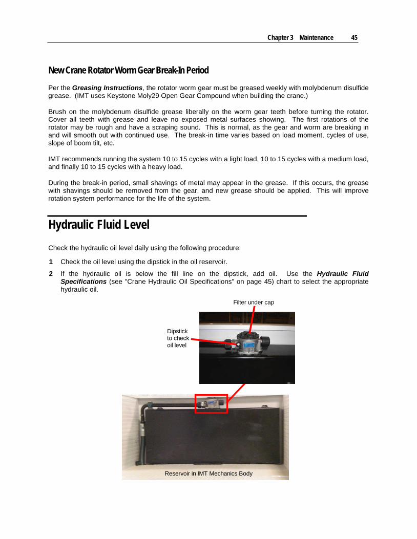
Hydraulic Fluid Level Check the hydraulic oil level daily using the following procedure:
1 Check the oil level using the dipstick in the oil reservoir.
2 If the hydraulic oil is below the fill line on the dipstick, add oil. Use the Hydraulic Fluid Specifications (see "Crane Hydraulic Oil Specifications" on page 45) chart to select the appropriate hydraulic oil.
Filter under cap
Dipstickto checkoil level
Reservoir in IMT Mechanics Body
46 IMT Telescopic Crane Operation & Safety Manual Manual #99905190
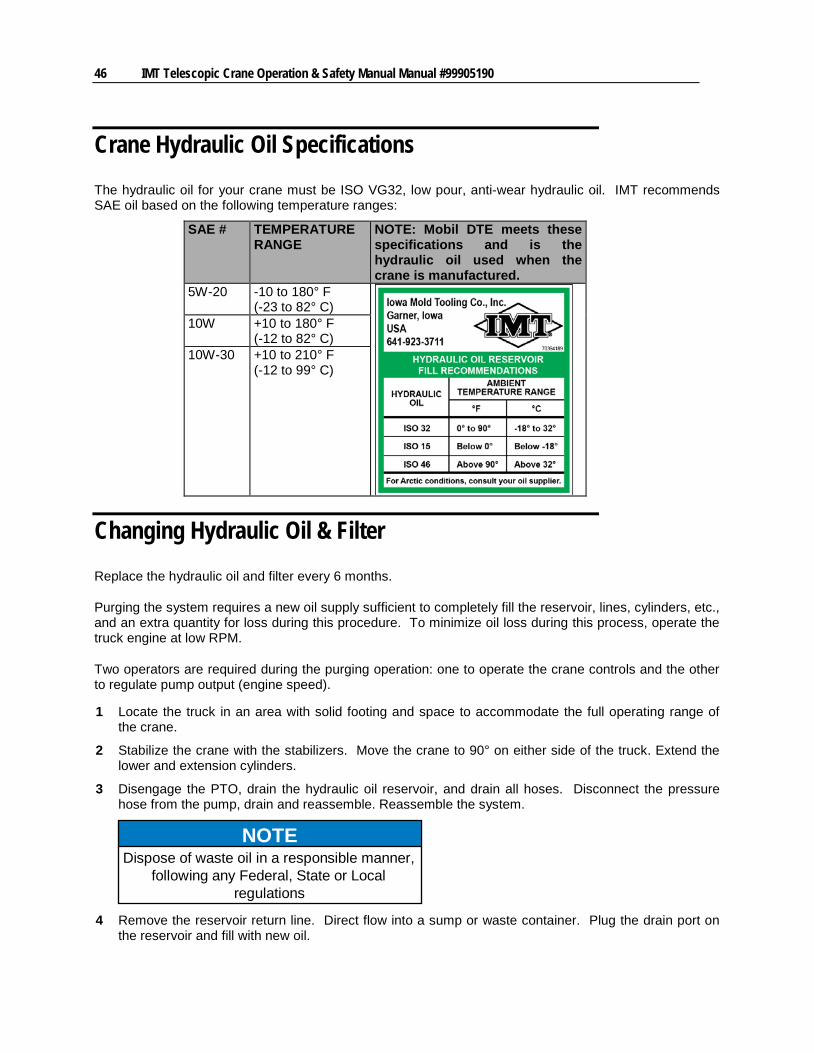
Crane Hydraulic Oil Specifications The hydraulic oil for your crane must be ISO VG32, low pour, anti-wear hydraulic oil. IMT recommends SAE oil based on the following temperature ranges:
SAE # TEMPERATURE RANGE
NOTE: Mobil DTE meets these specifications and is the hydraulic oil used when the crane is manufactured.
5W-20 -10 to 180° F (-23 to 82° C)
10W +10 to 180° F (-12 to 82° C)
10W-30 +10 to 210° F (-12 to 99° C)
Changing Hydraulic Oil & Filter Replace the hydraulic oil and filter every 6 months.
Purging the system requires a new oil supply sufficient to completely fill the reservoir, lines, cylinders, etc., and an extra quantity for loss during this procedure. To minimize oil loss during this process, operate the truck engine at low RPM.
Two operators are required during the purging operation: one to operate the crane controls and the other to regulate pump output (engine speed).
1 Locate the truck in an area with solid footing and space to accommodate the full operating range of the crane.
2 Stabilize the crane with the stabilizers. Move the crane to 90° on either side of the truck. Extend the lower and extension cylinders.
3 Disengage the PTO, drain the hydraulic oil reservoir, and drain all hoses. Disconnect the pressure hose from the pump, drain and reassemble. Reassemble the system.
NOTEDispose of waste oil in a responsible manner,
following any Federal, State or Localregulations
4 Remove the reservoir return line. Direct flow into a sump or waste container. Plug the drain port on the reservoir and fill with new oil.
Chapter 3 Maintenance 47
NOTERead and follow the following instructions
without interruption or stop the engine at theend of each step. If this is not done, excess
oil will be discharged through thedisconnected valve bank return hose.
5 Start the truck engine and engage the PTO. Rotate the crane 90°, retract the extension boom and lower the main boom to the lowest position.
6 Return the crane to its stowed position as marked on the rotation system. Raise the stabilizers. Shut off the engine.
7 All components of the system are now purged. Replace the hydraulic filter (located) under the fill cap in the body.
8 Check hydraulic oil level. Top off if necessary.
Purging Air from Hydraulic System Air trapped in the hydraulic cylinder will cause an erratic “bumpy” motion. To expel the air:
1 Hold the control open for a few seconds after the function has “bottomed out”.
2 Move the function in the opposite direction. Again, hold the control open a few seconds after the function has “bottomed out”.
3 Attempt to operate the crane in the normal manner to determine if the air has been purged.
Hydraulic Pressure Relief
The hydraulic system relief valve is provided to prevent the user from placing too much strain on the hydraulic components. The system relief pressure is preset and sealed at the factory, and it must not be tampered with. If you suspect the system relief pressure of malfunctioning, see your IMT dealer for testing and replacement.
WARNINGSetting the pressure relief higher than the
specification for your model crane is unsafe.DO NOT ATTEMPT. Excessive relief pressurewill damage the equipment and can result in
injury or death. Only an authorized IMTrepresentative may adjust the relief pressureand reseal the relief valve. A broken seal on
the relief valve will void the warranty.

48 IMT Telescopic Crane Operation & Safety Manual Manual #99905190
Hydraulic Cylinder Holding Capability The hydraulic cylinders have holding valves that prevent sudden movement of the cylinder rods in the event of a hydraulic hose or other hydraulic component failure. The valves are non-adjustable and failure is unlikely.
Check the hydraulic cylinder using the following steps:
1 With a full rated load, extend the cylinder in question and kill the engine.
2 Operate the control valve to retract the cylinder. To check the main (lower) cylinder, set the boom horizontally with the maximum load. To check the extension boom cylinder, set the crane at maximum articulation (angle).
If the cylinder “creeps”, replace the holding valve. If the cylinder does not “creep”, the valve is serviceable.
Winch Oil Specifications The use of proper gear oil and regular preventive maintenance will help extend gear train life and reliable winch brake performance.
Oil Change Frequency
Gear oil should be changed after the first 100 hours or 30 days of machine operation, and then every 1000 hours or 12 months, whichever occurs first. Gear oil should also be changed whenever the ambient temperature changes significantly and an oil from a different temperature range would be more appropriate. Check and drain the oil using the fill plug in the winch. The winch should be at least 1/2 full.
Warm-Up Procedure Warming up the winch is recommended at start-up and at ambient temperatures below 40 °F (4 °C). Run the prime mover at its lowest recommended RPM with the hydraulic winch control valve in neutral, allowing sufficient time to warm up the system. Operate the winch at low speeds, forward and reverse, several times to prime all lines with warm hydraulic oil and to circulate gear oil through the planetary gear sets.
Lubricants The following lubricants are recommended based on ambient temperature. Other lubricants may work equally as well. We suggest you work with your lubricant supplier to find an equivalent product if needed. The winch is initially filled with Exxon Spartan EP150 or equivalent.
Winch Fill /Drain Plug
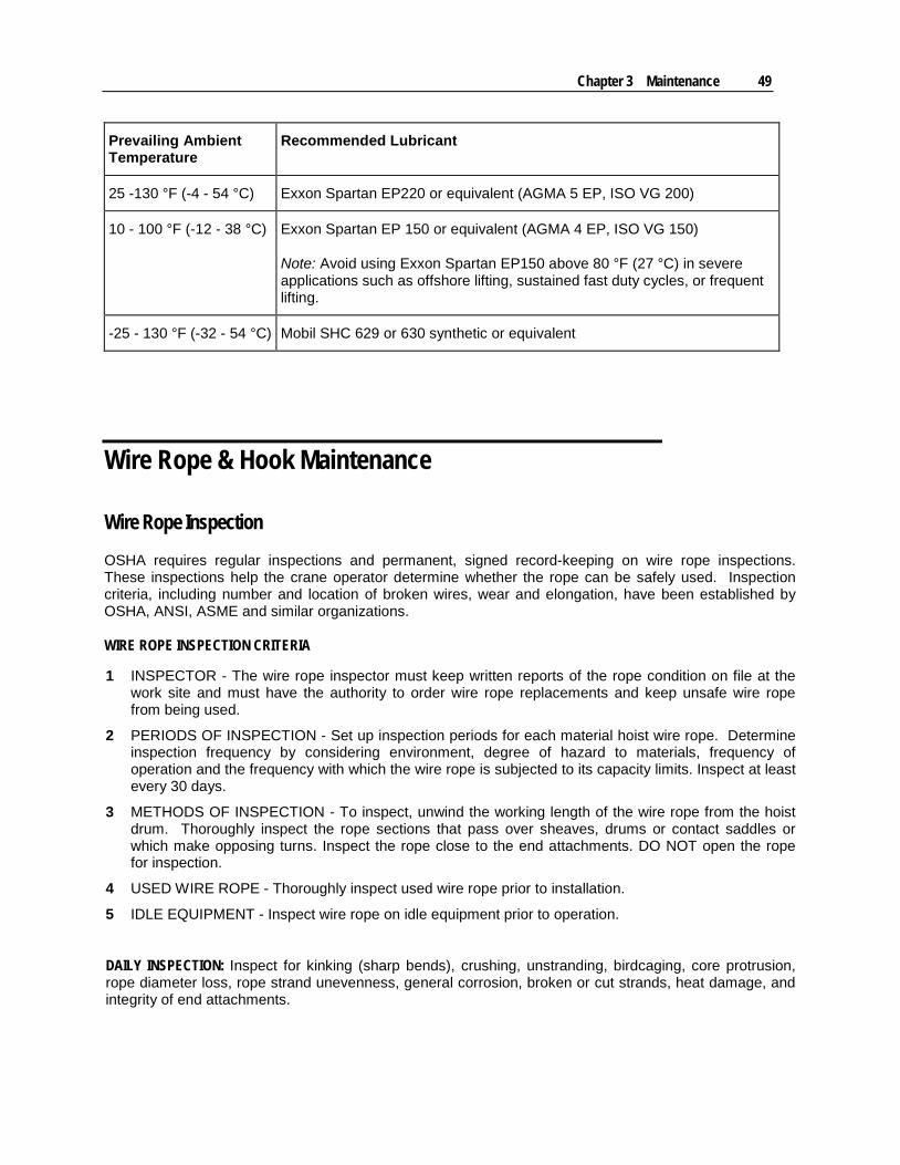
Chapter 3 Maintenance 49
Prevailing Ambient Temperature
Recommended Lubricant
25 -130 °F (-4 - 54 °C) Exxon Spartan EP220 or equivalent (AGMA 5 EP, ISO VG 200)
10 - 100 °F (-12 - 38 °C) Exxon Spartan EP 150 or equivalent (AGMA 4 EP, ISO VG 150)
Note: Avoid using Exxon Spartan EP150 above 80 °F (27 °C) in severe applications such as offshore lifting, sustained fast duty cycles, or frequent lifting.
-25 - 130 °F (-32 - 54 °C) Mobil SHC 629 or 630 synthetic or equivalent
Wire Rope & Hook Maintenance
Wire Rope Inspection OSHA requires regular inspections and permanent, signed record-keeping on wire rope inspections. These inspections help the crane operator determine whether the rope can be safely used. Inspection criteria, including number and location of broken wires, wear and elongation, have been established by OSHA, ANSI, ASME and similar organizations.
WIRE ROPE INSPECTION CRITERIA
1 INSPECTOR - The wire rope inspector must keep written reports of the rope condition on file at the work site and must have the authority to order wire rope replacements and keep unsafe wire rope from being used.
2 PERIODS OF INSPECTION - Set up inspection periods for each material hoist wire rope. Determine inspection frequency by considering environment, degree of hazard to materials, frequency of operation and the frequency with which the wire rope is subjected to its capacity limits. Inspect at least every 30 days.
3 METHODS OF INSPECTION - To inspect, unwind the working length of the wire rope from the hoist drum. Thoroughly inspect the rope sections that pass over sheaves, drums or contact saddles or which make opposing turns. Inspect the rope close to the end attachments. DO NOT open the rope for inspection.
4 USED WIRE ROPE - Thoroughly inspect used wire rope prior to installation.
5 IDLE EQUIPMENT - Inspect wire rope on idle equipment prior to operation.
DAILY INSPECTION: Inspect for kinking (sharp bends), crushing, unstranding, birdcaging, core protrusion, rope diameter loss, rope strand unevenness, general corrosion, broken or cut strands, heat damage, and integrity of end attachments.
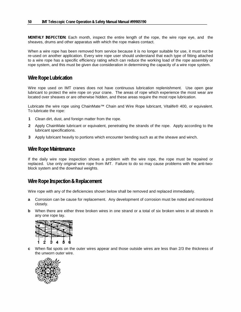
50 IMT Telescopic Crane Operation & Safety Manual Manual #99905190
MONTHLY INSPECTION: Each month, inspect the entire length of the rope, the wire rope eye, and the sheaves, drums and other apparatus with which the rope makes contact.
When a wire rope has been removed from service because it is no longer suitable for use, it must not be re-used on another application. Every wire rope user should understand that each type of fitting attached to a wire rope has a specific efficiency rating which can reduce the working load of the rope assembly or rope system, and this must be given due consideration in determining the capacity of a wire rope system.
Wire Rope Lubrication Wire rope used on IMT cranes does not have continuous lubrication replenishment. Use open gear lubricant to protect the wire rope on your crane. The areas of rope which experience the most wear are located over sheaves or are otherwise hidden, and these areas require the most rope lubrication.
Lubricate the wire rope using ChainMate™ Chain and Wire Rope lubricant, Vitalife® 400, or equivalent. To lubricate the rope:
1 Clean dirt, dust, and foreign matter from the rope.
2 Apply ChainMate lubricant or equivalent, penetrating the strands of the rope. Apply according to the lubricant specifications.
3 Apply lubricant heavily to portions which encounter bending such as at the sheave and winch.
Wire Rope Maintenance If the daily wire rope inspection shows a problem with the wire rope, the rope must be repaired or replaced. Use only original wire rope from IMT. Failure to do so may cause problems with the anti-two-block system and the downhaul weights.
Wire Rope Inspection & Replacement Wire rope with any of the deficiencies shown below shall be removed and replaced immediately.
a Corrosion can be cause for replacement. Any development of corrosion must be noted and monitored closely.
b When there are either three broken wires in one strand or a total of six broken wires in all strands in any one rope lay.
c When flat spots on the outer wires appear and those outside wires are less than 2/3 the thickness of
the unworn outer wire.
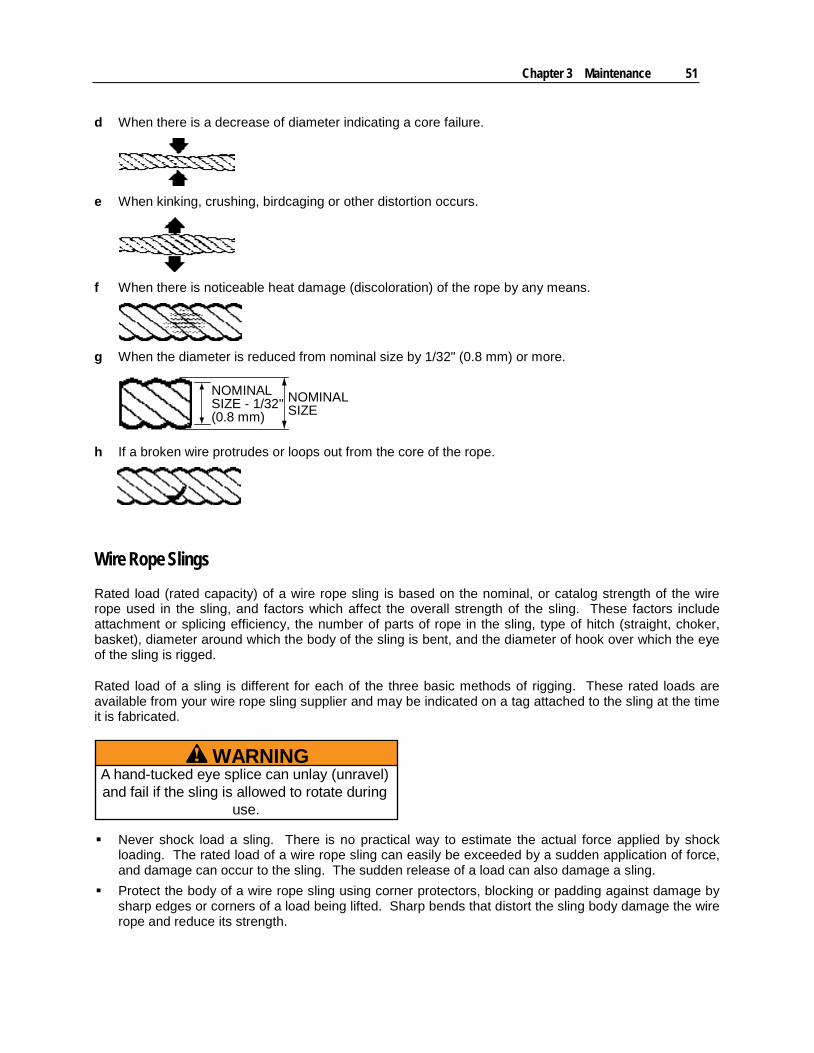
Chapter 3 Maintenance 51
d When there is a decrease of diameter indicating a core failure.
e When kinking, crushing, birdcaging or other distortion occurs.
f When there is noticeable heat damage (discoloration) of the rope by any means.
g When the diameter is reduced from nominal size by 1/32" (0.8 mm) or more.
NOMINALSIZE - 1/32"(0.8 mm)
NOMINALSIZE
h If a broken wire protrudes or loops out from the core of the rope.
Wire Rope Slings Rated load (rated capacity) of a wire rope sling is based on the nominal, or catalog strength of the wire rope used in the sling, and factors which affect the overall strength of the sling. These factors include attachment or splicing efficiency, the number of parts of rope in the sling, type of hitch (straight, choker, basket), diameter around which the body of the sling is bent, and the diameter of hook over which the eye of the sling is rigged.
Rated load of a sling is different for each of the three basic methods of rigging. These rated loads are available from your wire rope sling supplier and may be indicated on a tag attached to the sling at the time it is fabricated.
WARNINGA hand-tucked eye splice can unlay (unravel)and fail if the sling is allowed to rotate during
use.
Never shock load a sling. There is no practical way to estimate the actual force applied by shock loading. The rated load of a wire rope sling can easily be exceeded by a sudden application of force, and damage can occur to the sling. The sudden release of a load can also damage a sling.
Protect the body of a wire rope sling using corner protectors, blocking or padding against damage by sharp edges or corners of a load being lifted. Sharp bends that distort the sling body damage the wire rope and reduce its strength.
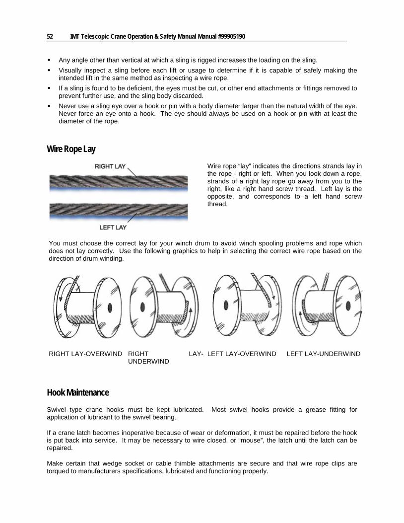
52 IMT Telescopic Crane Operation & Safety Manual Manual #99905190
Any angle other than vertical at which a sling is rigged increases the loading on the sling. Visually inspect a sling before each lift or usage to determine if it is capable of safely making the
intended lift in the same method as inspecting a wire rope. If a sling is found to be deficient, the eyes must be cut, or other end attachments or fittings removed to
prevent further use, and the sling body discarded. Never use a sling eye over a hook or pin with a body diameter larger than the natural width of the eye.
Never force an eye onto a hook. The eye should always be used on a hook or pin with at least the diameter of the rope.
Wire Rope Lay
Wire rope “lay” indicates the directions strands lay in the rope - right or left. When you look down a rope, strands of a right lay rope go away from you to the right, like a right hand screw thread. Left lay is the opposite, and corresponds to a left hand screw thread.
You must choose the correct lay for your winch drum to avoid winch spooling problems and rope which does not lay correctly. Use the following graphics to help in selecting the correct wire rope based on the direction of drum winding.
RIGHT LAY-OVERWIND RIGHT LAY-UNDERWIND
LEFT LAY-OVERWIND LEFT LAY-UNDERWIND
Hook Maintenance Swivel type crane hooks must be kept lubricated. Most swivel hooks provide a grease fitting for application of lubricant to the swivel bearing.
If a crane latch becomes inoperative because of wear or deformation, it must be repaired before the hook is put back into service. It may be necessary to wire closed, or “mouse”, the latch until the latch can be repaired.
Make certain that wedge socket or cable thimble attachments are secure and that wire rope clips are torqued to manufacturers specifications, lubricated and functioning properly.
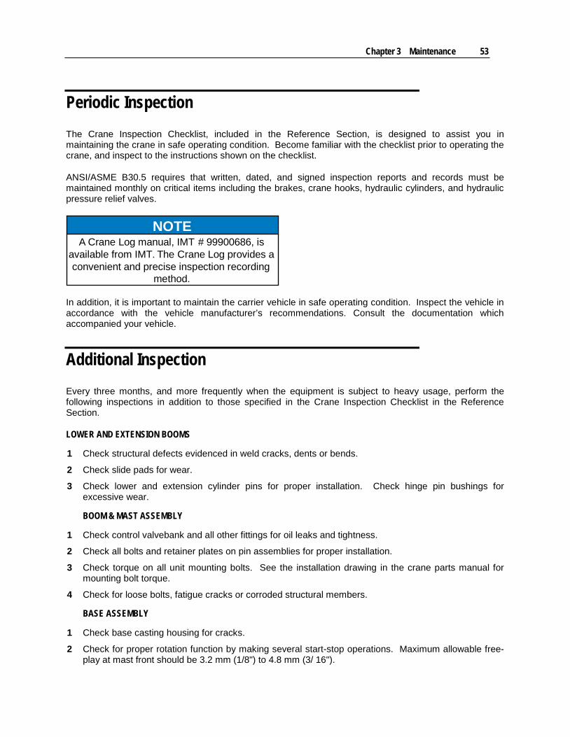
Chapter 3 Maintenance 53
Periodic Inspection The Crane Inspection Checklist, included in the Reference Section, is designed to assist you in maintaining the crane in safe operating condition. Become familiar with the checklist prior to operating the crane, and inspect to the instructions shown on the checklist.
ANSI/ASME B30.5 requires that written, dated, and signed inspection reports and records must be maintained monthly on critical items including the brakes, crane hooks, hydraulic cylinders, and hydraulic pressure relief valves.
NOTEA Crane Log manual, IMT # 99900686, is
available from IMT. The Crane Log provides aconvenient and precise inspection recording
method.
In addition, it is important to maintain the carrier vehicle in safe operating condition. Inspect the vehicle in accordance with the vehicle manufacturer’s recommendations. Consult the documentation which accompanied your vehicle.
Additional Inspection Every three months, and more frequently when the equipment is subject to heavy usage, perform the following inspections in addition to those specified in the Crane Inspection Checklist in the Reference Section.
LOWER AND EXTENSION BOOMS
1 Check structural defects evidenced in weld cracks, dents or bends.
2 Check slide pads for wear.
3 Check lower and extension cylinder pins for proper installation. Check hinge pin bushings for excessive wear.
BOOM & MAST ASSEMBLY
1 Check control valvebank and all other fittings for oil leaks and tightness.
2 Check all bolts and retainer plates on pin assemblies for proper installation.
3 Check torque on all unit mounting bolts. See the installation drawing in the crane parts manual for mounting bolt torque.
4 Check for loose bolts, fatigue cracks or corroded structural members.
BASE ASSEMBLY
1 Check base casting housing for cracks.
2 Check for proper rotation function by making several start-stop operations. Maximum allowable free-play at mast front should be 3.2 mm (1/8") to 4.8 mm (3/ 16").
54 IMT Telescopic Crane Operation & Safety Manual Manual #99905190
3 Check for proper gear mesh in turntable gear-bearing. Check motor and gear-mounting bolts for tightness.
HYDRAULIC SYSTEM
1 CYLINDERS
a) Check rods for damage such as scarring, nicks, dents and rust on out-of-service units.
b) Check for leaks at weld joints and rod seals. Check for drift indicating leakage around piston rings or defective holding valves.
c) Check extension cylinder head and piston positions.
d) Check cylinder case for dents.
2 HYDRAULIC PUMP
a) Check for leaks at shaft seal.
b) Check for drop in operating speed.
c) Check hydraulic oil for excessive heating.
d) Check bolts and fasteners for tightness.
e) Note any unusual vibration or noise.
3 PTO & PUMP
a) Inspect for proper transmission gear to PTO engagement.
b) When supplied, inspect driveline U-joints for securing cap tightness and adequate lubrication.
c) Check mounting bolts on pump and PTO for tightness.
Corrosion Control IMT treats metal to metal surfaces and hardware on new cranes with Cortex VCI-389, a chemical for rust prevention. Surfaces sprayed with Cortex VCI-389 will have a slight yellow or cream color. The discoloration can be removed with a degreaser or citrus cleaner.
Cortex VCI-389 prevents rust for about one year from application. It can be reapplied after crane disassembly or cleaning for continued rust prevention.
In addition, to ensure the life and appearance of the crane, which includes booms, hydraulic hoses, rotation bearings and rotation gearing, the crane must be thoroughly washed and lubricated after performing job functions in harsh environments, such as dirt, sand, salt water spray, etc. If this maintenance step is neglected, you run the risk of shortening the life of the crane through corrosion and abrasion. After a thorough washing, refer to the Lubrication Products & Schedule, for proper maintenance as scheduled.

Chapter 3 Maintenance 55
Long-Term Storage When a crane is put into long term storage, it should be stored within a controlled environment. To prolong the life of hydraulic system seals, o-rings, hoses, filters and pumps, the crane must be operated and maintained on a regular basis. If this maintenance is neglected, hydraulic system components will dry out which will require extensive repair and expense. IMT recommends the crane be operated, with all functions cycled fully as in normal operation, at least every three months. The climate in which the crane is stored may dictate more frequent operation to prevent component deterioration.


57
In This Chapter Repair Precautions ............................................................................... 58 Systematic Repair Procedure ............................................................... 58 Associating Radio Remote Receiver and Transmitter ......................... 59 Wear Pads ............................................................................................ 60 Cylinder Repair ..................................................................................... 61 Pin Removal & Inspection .................................................................... 61 Bushings ............................................................................................... 63 Wire Rope Removal & Replacement .................................................... 63 Turntable Bearing Inspection................................................................ 64 Turntable Bearing Tilt Test ................................................................... 64 Turntable Bearing Thread Tightening Sequence ................................. 65 Turntable Bearing Worm End Play & Backlash .................................... 66
C H A P T E R 4
Repair
58 IMT Telescopic Crane Operation & Safety Manual Manual #99905190
Repair Precautions Maintaining your crane regularly keeps the crane operating safely.
Prior to starting repairs on your crane:
1 Park the crane in an area where other equipment is not operating and where there is no through traffic.
2 Set the carrier vehicle’s parking brake. Use wheel chocks to prevent vehicle movement.
3 Position the crane in its stowed position if possible, or with the boom supported to prevent boom collapse during maintenance.
4 Place all controls in the “OFF” position and disable any means of starting the carrier vehicle or powering the crane.
5 Disconnect the PTO.
6 Secure sheaves and/or load blocks so they will not swing or fall during maintenance.
7 Relieve the hydraulic oil pressure from all circuits before disconnecting any hydraulic fittings or components.
8 Replace any parts with only factory approved replacements.
Prior to putting your crane back into service:
1 Replace all shrouds, guards and safety devices removed during maintenance.
2 Remove all trapped air in the hydraulic system to prevent erratic operation.
3 Clean grease and oil from controls.
4 Make certain all decals are present and legible.
5 DO NOT return to the worksite until all repairs are proven to be in proper working condition.
Systematic Repair Procedure 1 Begin repairs by studying the hydraulic schematics and systematically approaching the problem.
Locate the source of the problem.
List possible causes.
Devise checks.
Conduct checks in a logical order to determine cause.
Consider the remaining service life of components against the cost of parts and labor needed to replace them.
Make the necessary repair(s).
Re-check to be sure nothing has been overlooked.
Functionally test the new part.
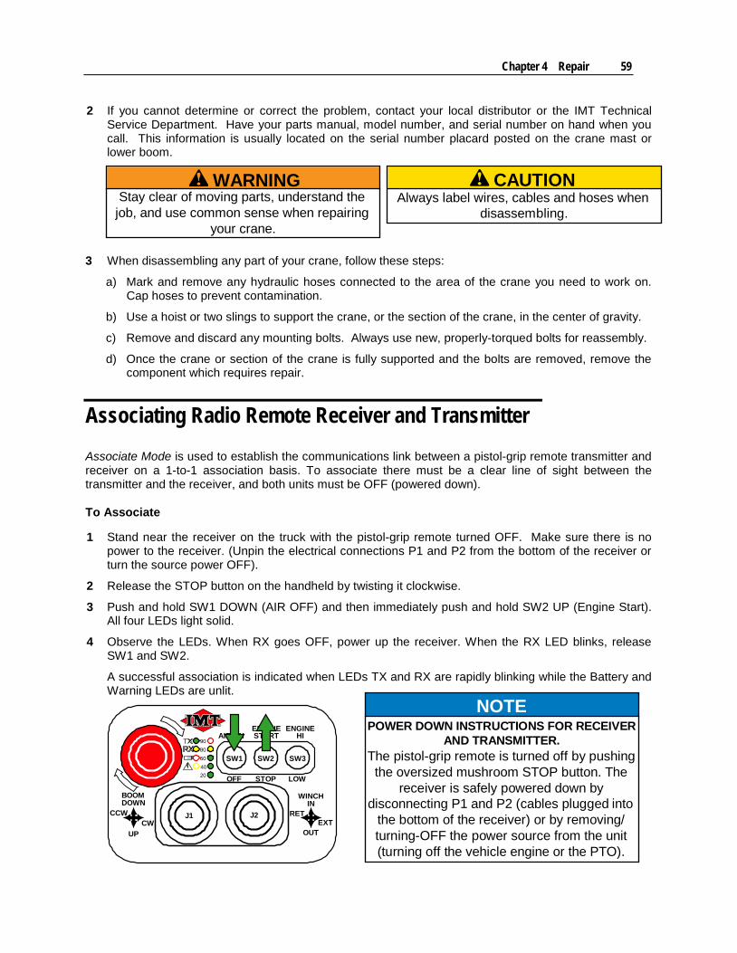
Chapter 4 Repair 59
2 If you cannot determine or correct the problem, contact your local distributor or the IMT Technical Service Department. Have your parts manual, model number, and serial number on hand when you call. This information is usually located on the serial number placard posted on the crane mast or lower boom.
WARNINGStay clear of moving parts, understand thejob, and use common sense when repairing
your crane.
3 When disassembling any part of your crane, follow these steps:
a) Mark and remove any hydraulic hoses connected to the area of the crane you need to work on. Cap hoses to prevent contamination.
b) Use a hoist or two slings to support the crane, or the section of the crane, in the center of gravity.
c) Remove and discard any mounting bolts. Always use new, properly-torqued bolts for reassembly.
d) Once the crane or section of the crane is fully supported and the bolts are removed, remove the component which requires repair.
Associating Radio Remote Receiver and Transmitter Associate Mode is used to establish the communications link between a pistol-grip remote transmitter and receiver on a 1-to-1 association basis. To associate there must be a clear line of sight between the transmitter and the receiver, and both units must be OFF (powered down).
To Associate
1 Stand near the receiver on the truck with the pistol-grip remote turned OFF. Make sure there is no power to the receiver. (Unpin the electrical connections P1 and P2 from the bottom of the receiver or turn the source power OFF).
2 Release the STOP button on the handheld by twisting it clockwise.
3 Push and hold SW1 DOWN (AIR OFF) and then immediately push and hold SW2 UP (Engine Start). All four LEDs light solid.
4 Observe the LEDs. When RX goes OFF, power up the receiver. When the RX LED blinks, release SW1 and SW2.
A successful association is indicated when LEDs TX and RX are rapidly blinking while the Battery and Warning LEDs are unlit.
BOOMDOWN
UP
CCWCW
WINCHIN
OUT
RETEXT
SW1 SW2 SW3
AIR ONENGINESTART
ENGINEHI
OFF STOP LOW
J1 J2
9080604020
NOTEPOWER DOWN INSTRUCTIONS FOR RECEIVER
AND TRANSMITTER.The pistol-grip remote is turned off by pushingthe oversized mushroom STOP button. The
receiver is safely powered down bydisconnecting P1 and P2 (cables plugged into
the bottom of the receiver) or by removing/turning-OFF the power source from the unit(turning off the vehicle engine or the PTO).
CAUTIONAlways label wires, cables and hoses when
disassembling.
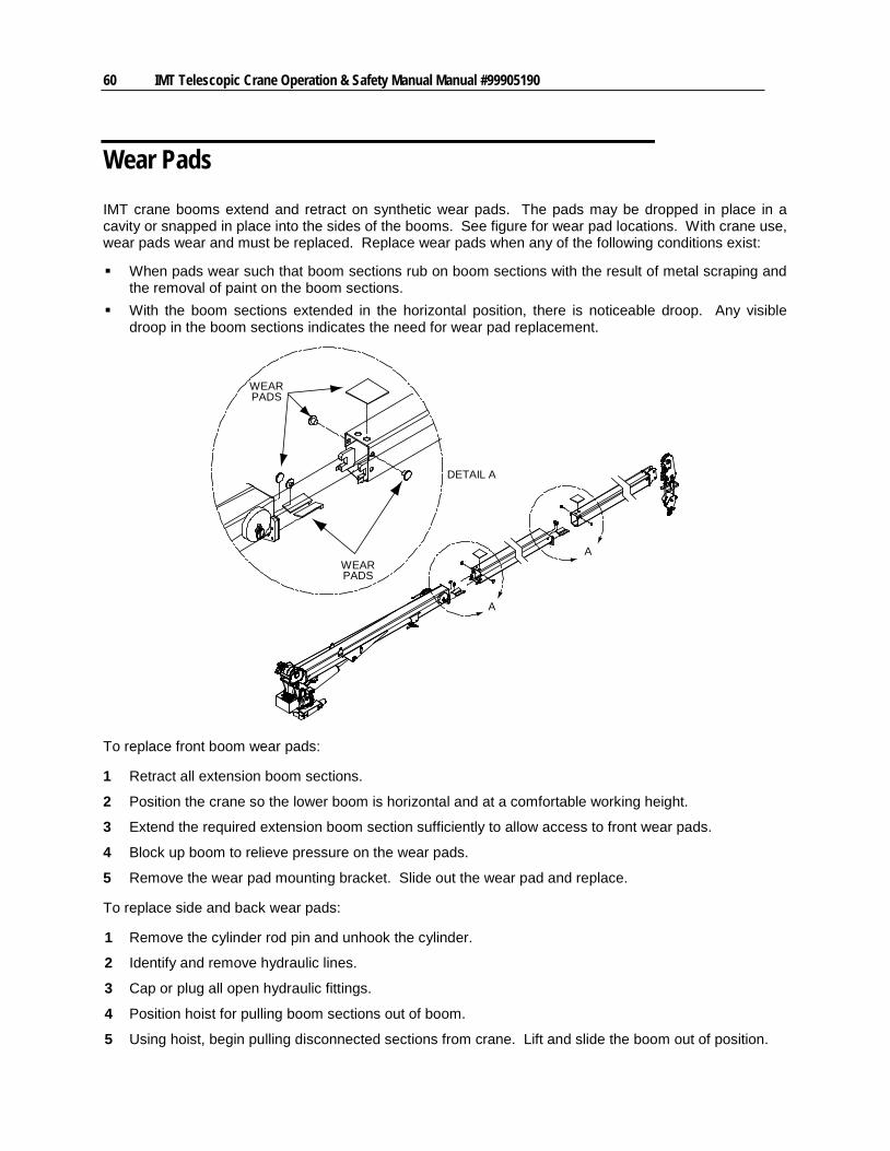
60 IMT Telescopic Crane Operation & Safety Manual Manual #99905190
Wear Pads IMT crane booms extend and retract on synthetic wear pads. The pads may be dropped in place in a cavity or snapped in place into the sides of the booms. See figure for wear pad locations. With crane use, wear pads wear and must be replaced. Replace wear pads when any of the following conditions exist:
When pads wear such that boom sections rub on boom sections with the result of metal scraping and the removal of paint on the boom sections.
With the boom sections extended in the horizontal position, there is noticeable droop. Any visible droop in the boom sections indicates the need for wear pad replacement.
WEARPADS
WEARPADS
A
A
DETAIL A
To replace front boom wear pads:
1 Retract all extension boom sections.
2 Position the crane so the lower boom is horizontal and at a comfortable working height.
3 Extend the required extension boom section sufficiently to allow access to front wear pads.
4 Block up boom to relieve pressure on the wear pads.
5 Remove the wear pad mounting bracket. Slide out the wear pad and replace.
To replace side and back wear pads:
1 Remove the cylinder rod pin and unhook the cylinder.
2 Identify and remove hydraulic lines.
3 Cap or plug all open hydraulic fittings.
4 Position hoist for pulling boom sections out of boom.
5 Using hoist, begin pulling disconnected sections from crane. Lift and slide the boom out of position.

Chapter 4 Repair 61
6 Snap the side wear pads out. Replace.
7 Lift boom end with hoist to relieve pressure on rear wear pad. Remove wear pad. Replace.
8 Reverse steps to re-assemble with new wear pads. Torque according to torque charts in maintenance & inspection section.
9 Start the crane. Slowly cycle the boom in and out with no load to purge air from system.
10 After the air has been purged from the system, check the reservoir oil level. Top off oil level if needed.
Cylinder Repair The cylinders in your IMT telescopic cranes are greaseless.
1 If you need to replace any components on the cylinders, use the cylinder drawings in your parts / specifications manual for parts and placement reference.
2 Torque the rod bearing and any nuts per torques on the cylinder drawings.
3 Apply "Lubriplate" number 630-2 medium-heavy, multipurpose lubricant to all piston, rod bearing, and holding-valve seals.
4 Lock the rod bearing on the cylinder using a self-tapping #8-32 x 0.25" long set screw. Position the screw in a seam between the rod bearing and the case. See cylinder drawings for details.
5 Replace all seals whenever the cylinder is disassembled. See cylinder drawings for seal placement.
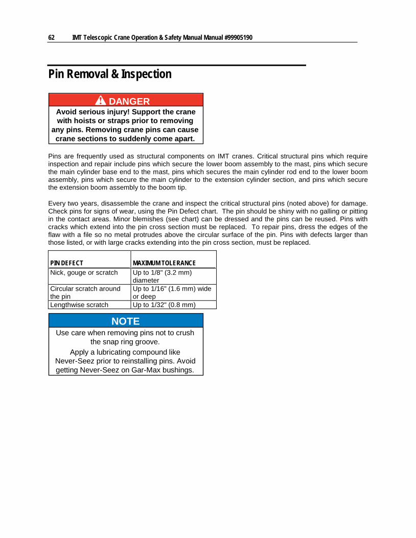
62 IMT Telescopic Crane Operation & Safety Manual Manual #99905190
Pin Removal & Inspection
DANGERAvoid serious injury! Support the cranewith hoists or straps prior to removing
any pins. Removing crane pins can causecrane sections to suddenly come apart.
Pins are frequently used as structural components on IMT cranes. Critical structural pins which require inspection and repair include pins which secure the lower boom assembly to the mast, pins which secure the main cylinder base end to the mast, pins which secures the main cylinder rod end to the lower boom assembly, pins which secure the main cylinder to the extension cylinder section, and pins which secure the extension boom assembly to the boom tip.
Every two years, disassemble the crane and inspect the critical structural pins (noted above) for damage. Check pins for signs of wear, using the Pin Defect chart. The pin should be shiny with no galling or pitting in the contact areas. Minor blemishes (see chart) can be dressed and the pins can be reused. Pins with cracks which extend into the pin cross section must be replaced. To repair pins, dress the edges of the flaw with a file so no metal protrudes above the circular surface of the pin. Pins with defects larger than those listed, or with large cracks extending into the pin cross section, must be replaced.
PIN DEFECT MAXIMUM TOLERANCE Nick, gouge or scratch Up to 1/8" (3.2 mm)
diameter Circular scratch around the pin
Up to 1/16" (1.6 mm) wide or deep
Lengthwise scratch Up to 1/32" (0.8 mm)
NOTEUse care when removing pins not to crush
the snap ring groove.Apply a lubricating compound like
Never-Seez prior to reinstalling pins. Avoidgetting Never-Seez on Gar-Max bushings.
Chapter 4 Repair 63
Bushings Bushings are used to strengthen and support joints and to reduce pin wear. Although bushing failure is highly unlikely, it can happen. Bushing failure is demonstrated by excess movement at crane joints.
Roller bearings are used on some crane sheaves. Bushings, which are bearings without moving parts, are used on the cylinders and booms of some crane models.
To inspect bushings and bearings,
1 Degrease bearing.
2 Inspect the inside coating of the bearing. No tears and breaks in the coating are acceptable.
3 Inspect the metallic body of the bearing. No changes in the bearing dimensions are permitted.
4 Replace the bearing if needed. Otherwise, lightly grease and reassemble.
To replace bearings:
1 Start the bearing in its respective hole by rotating the bearing while applying pressure. Align the grease zerk hole with the bearing hole (if applicable). Once started, drive the bearing to its full counterbored depth by tapping with a rubber mallet. Use a mallet with a head larger than the bearing so the bearing isn’t damaged.
2 If the bearing is loose, tighten the bearing by centerpunching the bore diameter in about 50 places around the 2” deep bored area.
3 After installing bearings, and before assembling the machine, insert the pins through both bearings in each end of the lift cylinders, and through the boom pivot bearings, to ensure alignment and fit are correct. Pins should slide freely through the leading hole and start in the opposite hole. If the pin binds, do not force it. Remove the pin, clean the hole, and reinsert.
Inspect bushings and bearings as needed, and replace any damaged or worn bushings. Lubricate with EP grease upon replacement.
Wire Rope Removal & Replacement The maintenance section of this manual describes inspection criteria for wire rope. If the wire rope is damaged, bent or worn as defined in Wire Rope Inspection & Replacement (on page 50), replace it using the following steps:
1 Run out all wire rope from the winch and stretch it out straight. Disconnect the rope from the cable guide on the side of the lower boom.
2 Remove the clamp which secures the rope to the boom tip. Pull the pin to release the cable.
3 Unhook the wire rope from the winch spool by removing the set screw or cable wedge anchor.
4 Remove the wire rope.
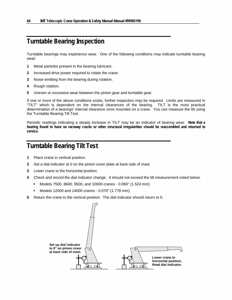
64 IMT Telescopic Crane Operation & Safety Manual Manual #99905190
Turntable Bearing Inspection Turntable bearings may experience wear. One of the following conditions may indicate turntable bearing wear:
1 Metal particles present in the bearing lubricant.
2 Increased drive power required to rotate the crane.
3 Noise emitting from the bearing during rotation.
4 Rough rotation.
5 Uneven or excessive wear between the pinion gear and turntable gear.
If one or more of the above conditions exists, further inspection may be required. Limits are measured in “TILT” which is dependent on the internal clearances of the bearing. TILT is the most practical determination of a bearings' internal clearance once mounted on a crane. You can measure the tilt using the Turntable Bearing Tilt Test.
Periodic readings indicating a steady increase in TILT may be an indicator of bearing wear. Note that a bearing found to have no raceway cracks or other structural irregularities should be reassembled and returned to service.
Turntable Bearing Tilt Test 1 Place crane in vertical position.
2 Set a dial indicator at 0 on the pinion cover plate at back side of mast.
3 Lower crane to the horizontal position.
4 Check and record the dial indicator change. It should not exceed the tilt measurement noted below.
Models 7500, 8600, 9500, and 10000 cranes - 0.060" (1.524 mm)
Models 12000 and 14000 cranes - 0.070" (1.778 mm)
5 Return the crane to the vertical position. The dial indicator should return to 0.
Set up dial indicatorto 0" on pinion coverat back side of mast.
Lower crane tohorizontal position.Read dial indicator.
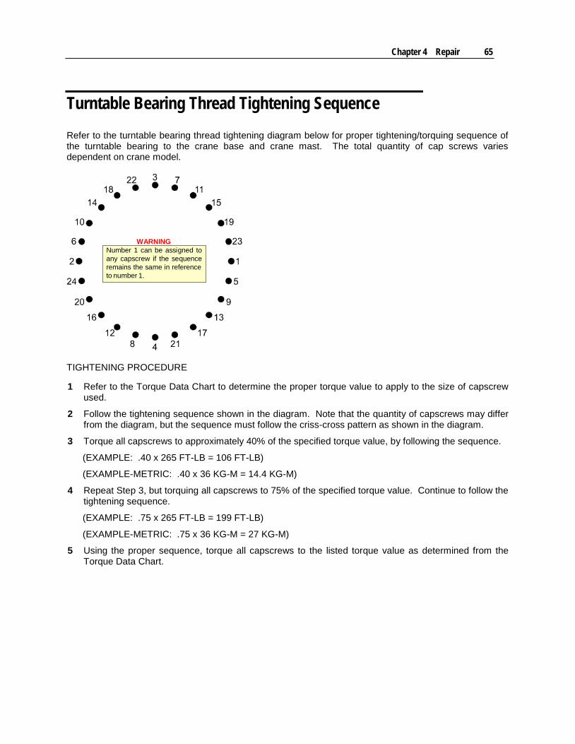
Chapter 4 Repair 65
Turntable Bearing Thread Tightening Sequence Refer to the turntable bearing thread tightening diagram below for proper tightening/torquing sequence of the turntable bearing to the crane base and crane mast. The total quantity of cap screws varies dependent on crane model.
Number 1 can be assigned toany capscrew if the sequenceremains the same in referenceto number 1.
WARNING
TIGHTENING PROCEDURE
1 Refer to the Torque Data Chart to determine the proper torque value to apply to the size of capscrew used.
2 Follow the tightening sequence shown in the diagram. Note that the quantity of capscrews may differ from the diagram, but the sequence must follow the criss-cross pattern as shown in the diagram.
3 Torque all capscrews to approximately 40% of the specified torque value, by following the sequence.
(EXAMPLE: .40 x 265 FT-LB = 106 FT-LB)
(EXAMPLE-METRIC: .40 x 36 KG-M = 14.4 KG-M)
4 Repeat Step 3, but torquing all capscrews to 75% of the specified torque value. Continue to follow the tightening sequence.
(EXAMPLE: .75 x 265 FT-LB = 199 FT-LB)
(EXAMPLE-METRIC: .75 x 36 KG-M = 27 KG-M)
5 Using the proper sequence, torque all capscrews to the listed torque value as determined from the Torque Data Chart.

66 IMT Telescopic Crane Operation & Safety Manual Manual #99905190
Turntable Bearing Worm End Play & Backlash IMT telescopic cranes have an integral base and worm drive rotation system.
Backlash, measured at the highest spot on the turntable bearing, is the shortest distance between non-driving tooth surfaces in mating gears. Measure backlash using a feeler gauge at or near the pitch diameter and tangent to the gear.
To set both Worm End Play and Backlash, you must locate the high tooth on the gear. Usually this spot is marked by the manufacturer with light blue paint. If you cannot find the paint mark, identify the high tooth using a dial indicator with a magnetic base and a round steel pin which is large enough to contact the bearing near the pitch line of the bearing tooth. Set the indicator base on the face of the bearing race that does not have teeth. Place the pin between two of the teeth. Set the indicator probe on the pin and adjust the dial to zero. Rotate the bearing, checking every third tooth until you find the highest indicator reading. Check three teeth in both directions in this area to determine the highest tooth. The amount of run-out varies depending on the diameter of the bearing. Once you find the high tooth, mark it for future reference.
Bearing Tooth Contact Point
Backlash Pitchline
Topland
RootFillet
Pin and Indicator Tip
To set the worm end play:
1 Locate the high tooth on the gear. (The high spot on the bearing is marked by the manufacturer with paint.)
2 Screw a bolt into the threaded hole nearest the high tooth. Screw additional bolts into threaded holes at 90° from the high tooth.
3 Mount a magnetic base with an indicator attached on top of the worm housing and at the opposite end from the motor mount.
4 Adjust the indicator to read from the end of the worm shaft. Set the indicator to “0”.
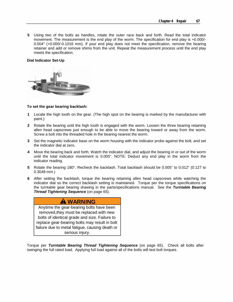
Chapter 4 Repair 67
5 Using two of the bolts as handles, rotate the outer race back and forth. Read the total indicator movement. The measurement is the end play of the worm. The specification for end play is +0.000/-0.004" (+0.000/-0.1016 mm). If your end play does not meet the specification, remove the bearing retainer and add or remove shims from the unit. Repeat the measurement process until the end play meets the specification.
Dial Indicator Set-Up
To set the gear bearing backlash:
1 Locate the high tooth on the gear. (The high spot on the bearing is marked by the manufacturer with paint.)
2 Rotate the bearing until the high tooth is engaged with the worm. Loosen the three bearing retaining allen head capscrews just enough to be able to move the bearing toward or away from the worm. Screw a bolt into the threaded hole in the bearing nearest the worm.
3 Set the magnetic indicator base on the worm housing with the indicator probe against the bolt, and set the indicator dial at zero.
4 Move the bearing back and forth. Watch the indicator dial, and adjust the bearing in or out of the worm until the total indicator movement is 0.005”. NOTE: Deduct any end play in the worm from the indicator reading.
5 Rotate the bearing 180°. Recheck the backlash. Total backlash should be 0.005” to 0.012” (0.127 to 0.3048 mm.)
6 After setting the backlash, torque the bearing retaining allen head capscrews while watching the indicator dial so the correct backlash setting is maintained. Torque per the torque specifications on the turntable gear bearing drawing in the parts/specifications manual. See the Turntable Bearing Thread Tightening Sequence (on page 65).
WARNINGAnytime the gear-bearing bolts have beenremoved,they must be replaced with newbolts of identical grade and size. Failure to
replace gear-bearing bolts may result in boltfailure due to metal fatigue, causing death or
serious injury.
Torque per Turntable Bearing Thread Tightening Sequence (on page 65). Check all bolts after swinging the full rated load. Applying full load against all of the bolts will test bolt torques.


69
In This Chapter Installation Introduction ......................................................................... 70 Chassis Preparation ............................................................................. 70 Frame Strength ..................................................................................... 70 PTO & Pump ........................................................................................ 70 Engine Speed Regulation ..................................................................... 71 Crane Installation .................................................................................. 72
C H A P T E R 5
Installation
70 IMT Telescopic Crane Operation & Safety Manual Manual #99905190
Installation Introduction IMT cranes must be mounted on truck chassis of the appropriate size with the appropriate frame reinforcement, PTO, pump, and hydraulics. Refer to the parts and specifications manual for your crane model for the minimum chassis requirements for your crane.
Chassis Preparation Prior to installing the crane, follow these steps:
1 Inspect the carrier vehicle to be certain it complies with the minimum chassis specifications for your crane model.
2 Clear obstructions from the portion of the chassis frame where the crane body will rest. Check that you have adequate mounting space. Space will be available for gas tanks, etc. after the crane is installed.
3 Install the PTO according to the PTO manufacturer’s instructions.
4 Install the pump. Make sure that the pump rotates in the proper direction and tighten the pump mounting bolts.
5 Connect the pump suction line to the barbed nipple on the bottom side of the reservoir.
6 Connect pump pressure line to pressure port on crane valvebank. (Note: If stabilizers are hydraulic, connect to pressure port on stabilizer valvebank.)
7 Be sure to open ball valve at the reservoir outlet prior to engaging PTO.
8 Spray paint all unpainted surfaces.
Frame Strength Select the proper truck frame to avoid overstressing the truck frame by loads imposed by the crane and its load. You may have the reinforce the frame. The minimum truck frame resistance-to-bending moment (RBM) is listed in the crane minimum chassis specifications in the specifications section of your manual.
PTO & Pump A Power Take Off (PTO) must be properly matched to the vehicle's transmission as well as the requirements of the crane. In order to properly select a PTO, determine:
1 Carrier vehicle transmission make and model
2 Crane and auxiliary equipment power requirements
3 Necessary PTO speed
4 Direction in which PTO must turn
5 PTO torque required

Chapter 5 Installation 71
If possible, use a hydraulic pump mounted directly to the PTO. Follow the PTO manufacturer's instructions to install the PTO and the pump.
DANGER
70392891
Rotating Shaft Hazard
Rotating parts will injure or kill.
Do not work around shafts
Keep body, hands, hair,clothes away.
with engine on.
Engine Speed Regulation The delivery rate of the hydraulic pump determines the operating speed of the crane. In order for the crane to function at speeds stated in the Crane Specifications, the pump must operate at the speed required for the proper delivery rate (required pump speed). To determine the required pump speed, you must know the rated capacity of the pump, the pump speed required for the rated capacity, and the required delivery rate for the proper crane performance.
To determine the engine RPM necessary for required pump speed, the required pump speed is divided by the engine to PTO ratio. (The PTO ratio is generally specified as a percentage of engine speed.)
If you don’t know the engine to PTO ratio, or the pump capacity, contact your dealer or IMT. To find the engine to PTO ratio, you must know the PTO and transmission model numbers as well as the make, model, and year of the truck. To find the proper pump capacity, you must know the pump make and model. Record this information below.
PUMP CAPACITY ENGINE TO PTO RATIO
72 IMT Telescopic Crane Operation & Safety Manual Manual #99905190
Efficient operation of your crane is dependent upon proper pump speed. When operation is too slow, check the pump speed when diagnosing the cause. A tachometer with accurate calibration may be used to check engine speed.
FORMULA TO DETERMINE REQUIRED PUMP SPEED: C = Rated Pump Capacity D = Delivery Rate Required for Proper Pump Performance RPM = Pump Speed Required for Rated Pump Capacity D To calculate: Required Pump Speed = (D / C) x RPM Example: If D = 9 GPM, C = 13 GPM, and RPM = 2000, Required Pump Speed = (9 GPM / 13 GPM) x 2000 = 1385 RPM
FORMULA TO DETERMINE ENGINE RPM: Required Engine RPM = Required Pump Speed / PTO Ratio (%) Example: If Required Pump Speed = 1385 RPM and PTO Ratio = 70%, Required Engine RPM = 1385 RPM / 0.70 = 1980 RPM
Crane Installation Your crane is designed for use with an IMT body installed on a vehicle meeting minimum chassis requirements including a specific body style, wheelbase dimension, cab-to-axle dimension, frame section modulus, RBM*, axle ratings, and gross vehicle ratings. A chart with this information is included in your crane parts / specifications manual.
(*RBM, Resistance-to-Bending-Moment, is a figure of relative strength of a specific frame which is made of a specific grade of steel. RBM is calculated by multiplying the Frame Section Modulus (in cubic inches) by the Frame Yield Strength.)
If the crane is being installed on a body other than an IMT mechanic's body, check with IMT to determine if that body is suitable.
Chapter 5 Installation 73
DANGERDo NOT use this crane on a body not
capable of handling the loads imposed onit. Avoid death or serious injury.
In addition to meeting minimum chassis specifications, make sure there is sufficient room to mount the crane, and that the platform is strong enough to support the crane and rated load. The body must be designed to sustain the forces imposed by the crane when lifting the full rated load.
DANGERInstall the body before installing the
crane. Do not unfold or open the cranebefore installation.
NOTE: Installing an IMT telescopic crane onto an IMT dominator body of a different series may require one of the following:
Use adapter harness 77441564 to install a Series III crane onto a series I or Series II Dominator .
Use adapter harness 77441463 to install a series I or series II crane onto a series III dominator.
Crane Installation Steps:
1 Use a lifting device which can handle the weight of the crane. (See the Specifications section of the crane parts / specifications manual for the crane weight.) Attach fabric slings to the crane lower boom, centered approximately 18" (46 cm) from the mast hinge. Make sure the crane is well balanced by lifting only approximately 6" (15 cm) above the ground. After lifting the crane, apply a bead of waterproof compound, such as silicon-based caulk, to the bottom of the base. Move the chassis under the crane and lower the crane into the desired position.
2 Install the mounting screws and washers to secure the crane base to the truck body. Torque per the installation drawing. Please find the installation drawings in the parts / specifications manual for the specific crane.


75
In This Chapter Telescopic Crane Decals ...................................................................... 76 Danger Decals ...................................................................................... 77 Danger Decal Figures ........................................................................... 77 Instructional Decals .............................................................................. 83
C H A P T E R 6
Crane Decals
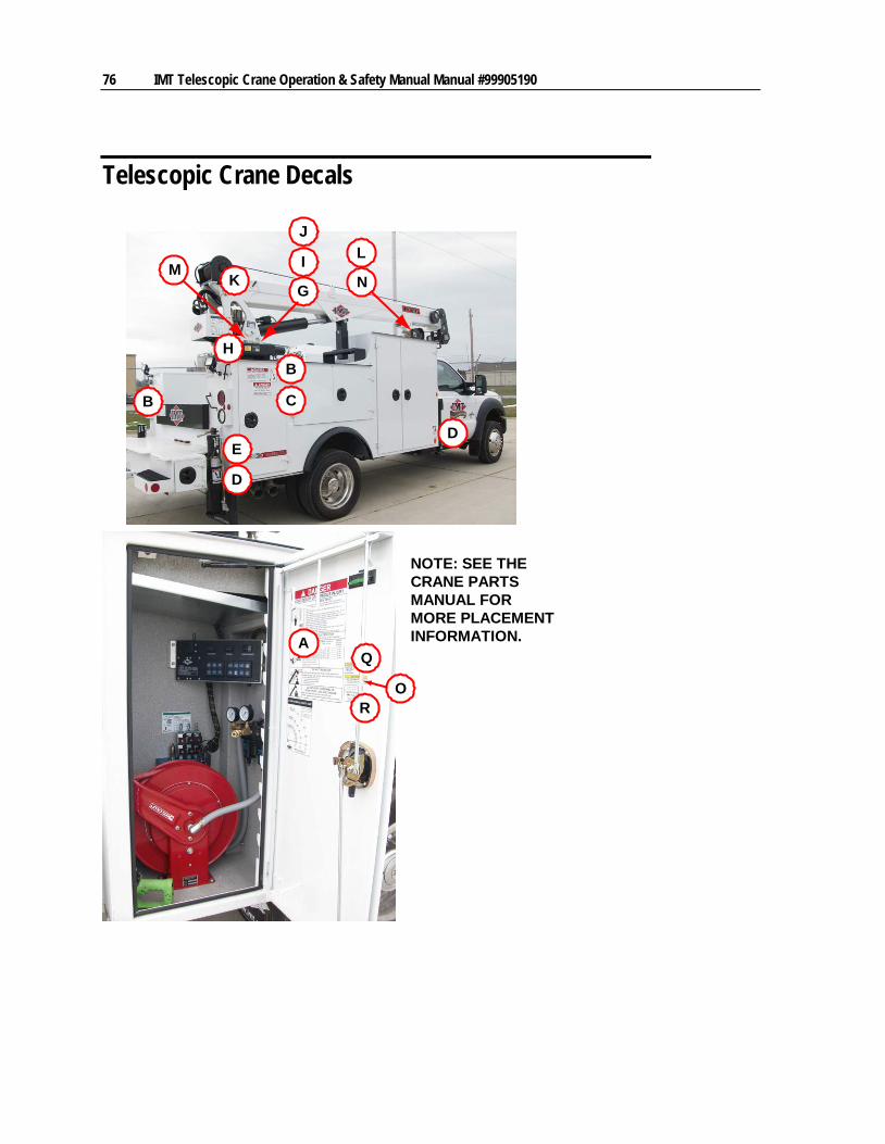
76 IMT Telescopic Crane Operation & Safety Manual Manual #99905190
Telescopic Crane Decals
A
N
B
C
DE
G
H
I
J
B
KML
Q
RO
D
NOTE: SEE THECRANE PARTSMANUAL FORMORE PLACEMENTINFORMATION.
Chapter 6 Crane Decals 77
Danger Decals All operators must familiarize themselves with the “DANGER” decals shown in this section. Your equipment may have additional safety decals that are not described here. Any safety decals affixed to your equipment must be identified, read and understood.
The materials and adhesives used in the production of these decals were designed for maximum durability, adhesion and legibility. Nevertheless, if a decal (including capacity chart) becomes damaged or illegible, replace it at your earliest opportunity. If a crane is repaired or repainted, replace all decals before the crane is put back into service. Individual decals as well as complete decal kits are available from IMT.
The following figures show examples of the safety decals used on IMT cranes, along with an explanation of their purpose, location, and the normal quantity used on each crane.
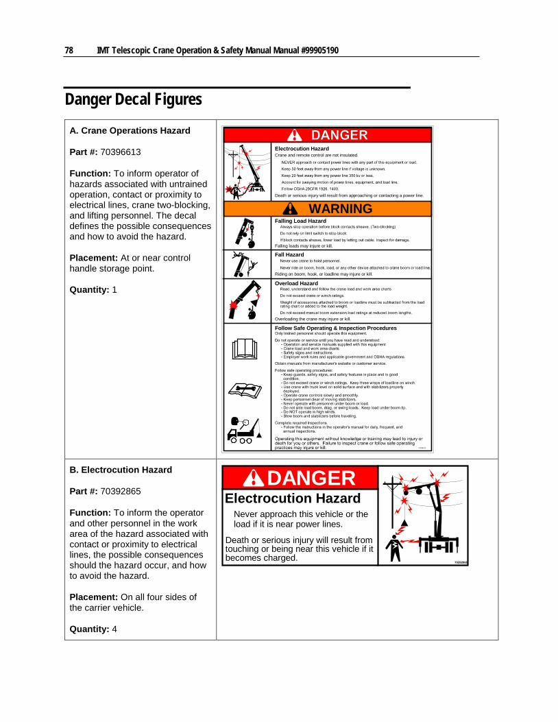
78 IMT Telescopic Crane Operation & Safety Manual Manual #99905190
Danger Decal Figures A. Crane Operations Hazard
Part #: 70396613
Function: To inform operator of hazards associated with untrained operation, contact or proximity to electrical lines, crane two-blocking, and lifting personnel. The decal defines the possible consequences and how to avoid the hazard.
Placement: At or near control handle storage point.
Quantity: 1
Follow Safe Operating & Inspection Procedures
Electrocution HazardCrane and remote control are not insulated.
70396613
Falling Load Hazard
Death or serious injury will result from approaching or contacting a power line.
Falling loads may injure or kill.
Fall Hazard
Riding on boom, hook, or loadline may injure or kill.
Overload Hazard
Overloading the crane may injure or kill.
WARNING
B. Electrocution Hazard
Part #: 70392865
Function: To inform the operator and other personnel in the work area of the hazard associated with contact or proximity to electrical lines, the possible consequences should the hazard occur, and how to avoid the hazard.
Placement: On all four sides of the carrier vehicle.
Quantity: 4
70392865
DANGERElectrocution Hazard
Never approach this vehicle or theload if it is near power lines.
Death or serious injury will result fromtouching or being near this vehicle if itbecomes charged.
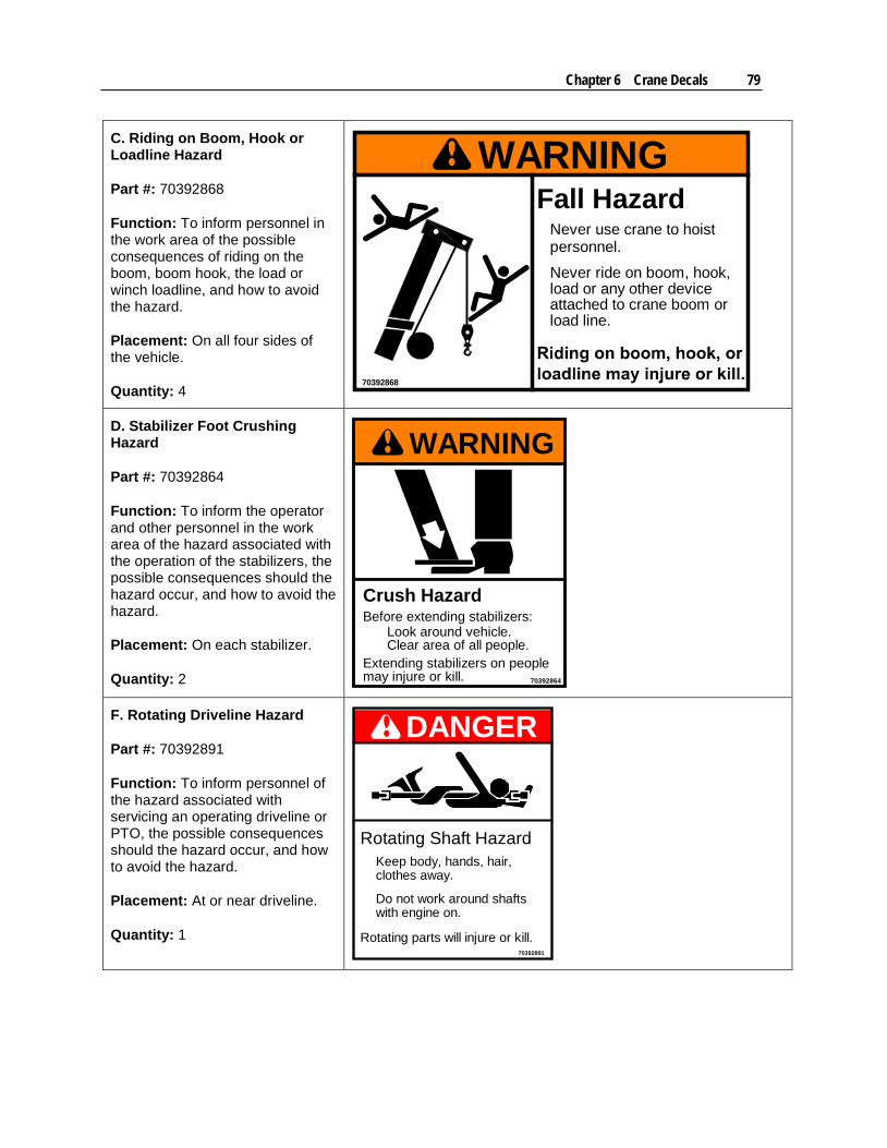
Chapter 6 Crane Decals 79
C. Riding on Boom, Hook or Loadline Hazard
Part #: 70392868
Function: To inform personnel in the work area of the possible consequences of riding on the boom, boom hook, the load or winch loadline, and how to avoid the hazard.
Placement: On all four sides of the vehicle.
Quantity: 4
WARNING
70392868
Fall HazardNever use crane to hoistpersonnel.
Never ride on boom, hook,load or any other deviceattached to crane boom orload line.
D. Stabilizer Foot Crushing Hazard
Part #: 70392864
Function: To inform the operator and other personnel in the work area of the hazard associated with the operation of the stabilizers, the possible consequences should the hazard occur, and how to avoid the hazard.
Placement: On each stabilizer.
Quantity: 2
WARNING
70392864
Crush HazardBefore extending stabilizers:
Look around vehicle.Clear area of all people.
Extending stabilizers on peoplemay injure or kill.
F. Rotating Driveline Hazard
Part #: 70392891
Function: To inform personnel of the hazard associated with servicing an operating driveline or PTO, the possible consequences should the hazard occur, and how to avoid the hazard.
Placement: At or near driveline.
Quantity: 1
DANGER
70392891
Rotating Shaft Hazard
Rotating parts will injure or kill.
Do not work around shafts
Keep body, hands, hair,clothes away.
with engine on.
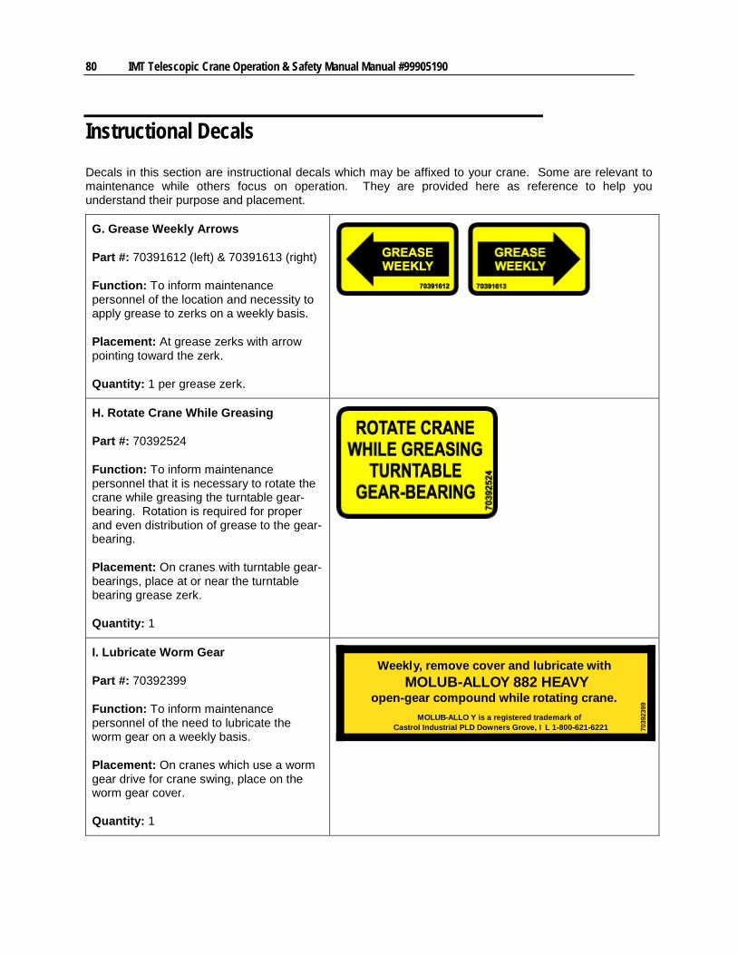
80 IMT Telescopic Crane Operation & Safety Manual Manual #99905190
Instructional Decals Decals in this section are instructional decals which may be affixed to your crane. Some are relevant to maintenance while others focus on operation. They are provided here as reference to help you understand their purpose and placement.
G. Grease Weekly Arrows
Part #: 70391612 (left) & 70391613 (right)
Function: To inform maintenance personnel of the location and necessity to apply grease to zerks on a weekly basis.
Placement: At grease zerks with arrow pointing toward the zerk.
Quantity: 1 per grease zerk.
H. Rotate Crane While Greasing
Part #: 70392524
Function: To inform maintenance personnel that it is necessary to rotate the crane while greasing the turntable gear-bearing. Rotation is required for proper and even distribution of grease to the gear-bearing.
Placement: On cranes with turntable gear-bearings, place at or near the turntable bearing grease zerk.
Quantity: 1
I. Lubricate Worm Gear
Part #: 70392399
Function: To inform maintenance personnel of the need to lubricate the worm gear on a weekly basis.
Placement: On cranes which use a worm gear drive for crane swing, place on the worm gear cover.
Quantity: 1
Weekly, remove cover and lubricate withMOLUB-ALLOY 882 HEAVY
open-gear compound while rotating crane.MOLUB-ALLO Y is a registered trademark of
Castrol Industrial PLD Downers Grove, I L 1-800-621-6221 7039
2399
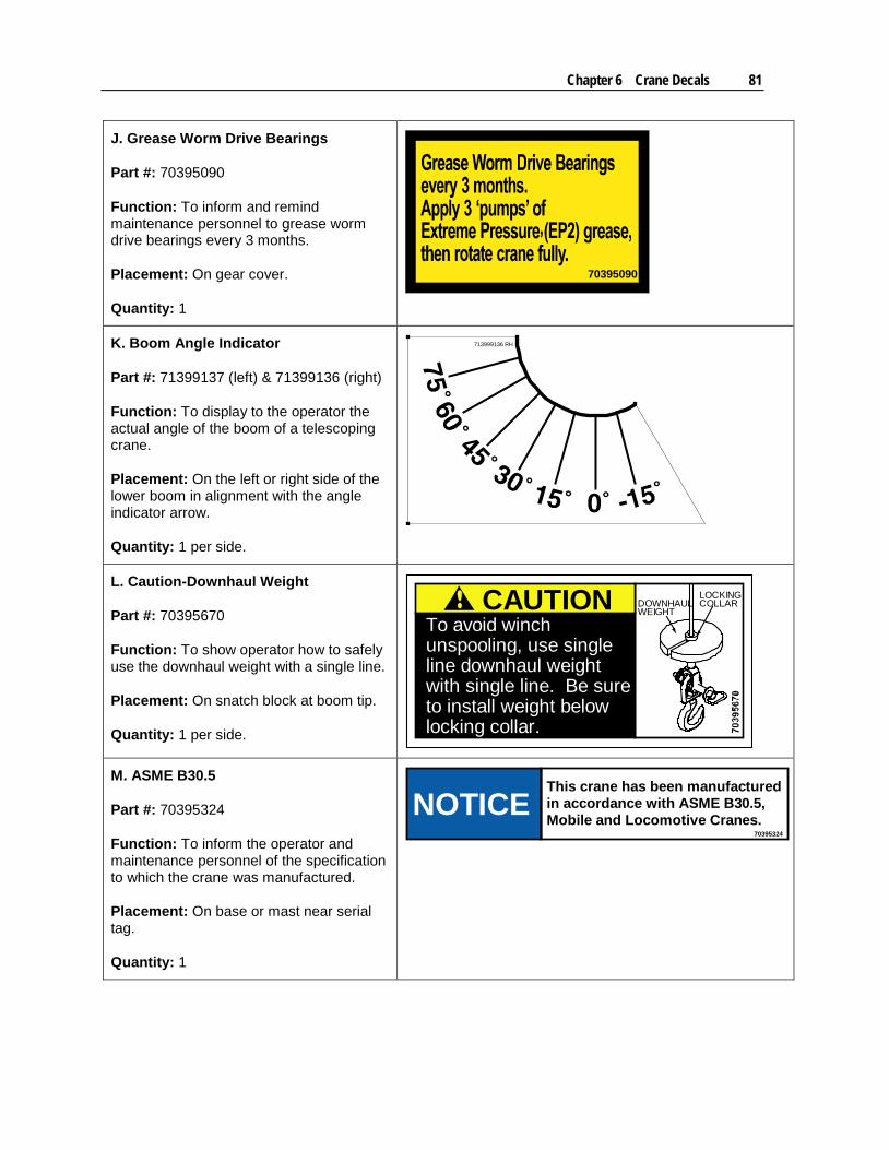
Chapter 6 Crane Decals 81
J. Grease Worm Drive Bearings
Part #: 70395090
Function: To inform and remind maintenance personnel to grease worm drive bearings every 3 months.
Placement: On gear cover.
Quantity: 1
70395090
K. Boom Angle Indicator
Part #: 71399137 (left) & 71399136 (right)
Function: To display to the operator the actual angle of the boom of a telescoping crane.
Placement: On the left or right side of the lower boom in alignment with the angle indicator arrow.
Quantity: 1 per side.
713999136 RH
L. Caution-Downhaul Weight
Part #: 70395670
Function: To show operator how to safely use the downhaul weight with a single line.
Placement: On snatch block at boom tip.
Quantity: 1 per side.
CAUTIONTo avoid winchunspooling, use singleline downhaul weightwith single line. Be sureto install weight belowlocking collar.
LOCKINGCOLLARDOWNHAUL
WEIGHT
M. ASME B30.5
Part #: 70395324
Function: To inform the operator and maintenance personnel of the specification to which the crane was manufactured.
Placement: On base or mast near serial tag.
Quantity: 1
NOTICE70395324
This crane has been manufactured
Mobile and Locomotive Cranes.in accordance with ASME B30.5,
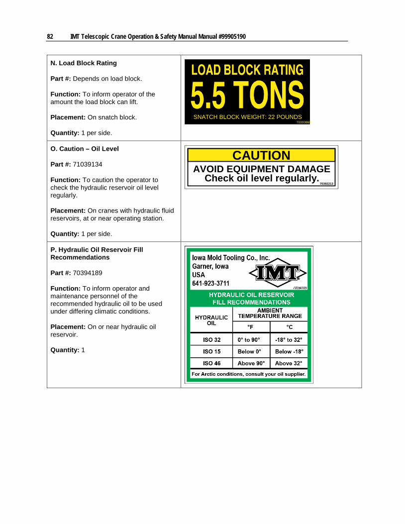
82 IMT Telescopic Crane Operation & Safety Manual Manual #99905190
N. Load Block Rating
Part #: Depends on load block.
Function: To inform operator of the amount the load block can lift.
Placement: On snatch block.
Quantity: 1 per side.
SNATCH BLOCK WEIGHT: 22 POUNDS70393860
O. Caution – Oil Level
Part #: 71039134
Function: To caution the operator to check the hydraulic reservoir oil level regularly.
Placement: On cranes with hydraulic fluid reservoirs, at or near operating station.
Quantity: 1 per side.
CAUTION
70392213
AVOID EQUIPMENT DAMAGECheck oil level regularly.
P. Hydraulic Oil Reservoir Fill Recommendations
Part #: 70394189
Function: To inform operator and maintenance personnel of the recommended hydraulic oil to be used under differing climatic conditions.
Placement: On or near hydraulic oil reservoir.
Quantity: 1
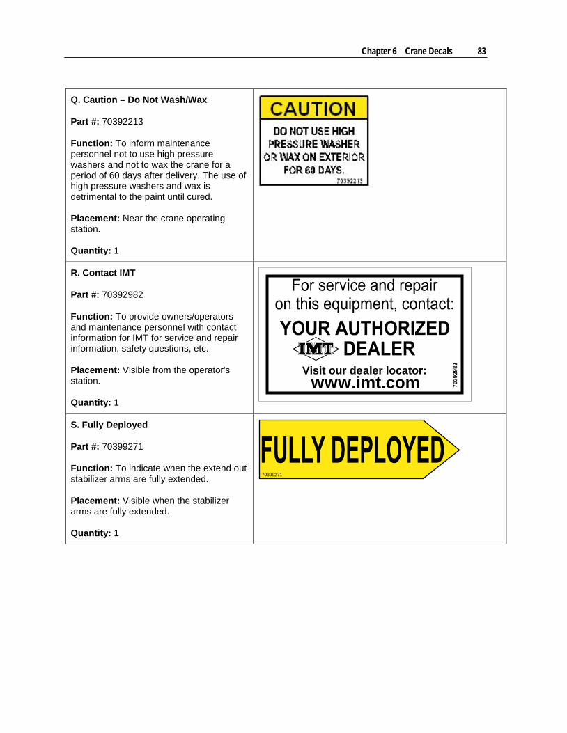
Chapter 6 Crane Decals 83
Q. Caution – Do Not Wash/Wax
Part #: 70392213
Function: To inform maintenance personnel not to use high pressure washers and not to wax the crane for a period of 60 days after delivery. The use of high pressure washers and wax is detrimental to the paint until cured.
Placement: Near the crane operating station.
Quantity: 1
R. Contact IMT
Part #: 70392982
Function: To provide owners/operators and maintenance personnel with contact information for IMT for service and repair information, safety questions, etc.
Placement: Visible from the operator's station.
Quantity: 1
Visit our dealer locator:www.imt.com
S. Fully Deployed
Part #: 70399271
Function: To indicate when the extend out stabilizer arms are fully extended.
Placement: Visible when the stabilizer arms are fully extended.
Quantity: 1
70399271

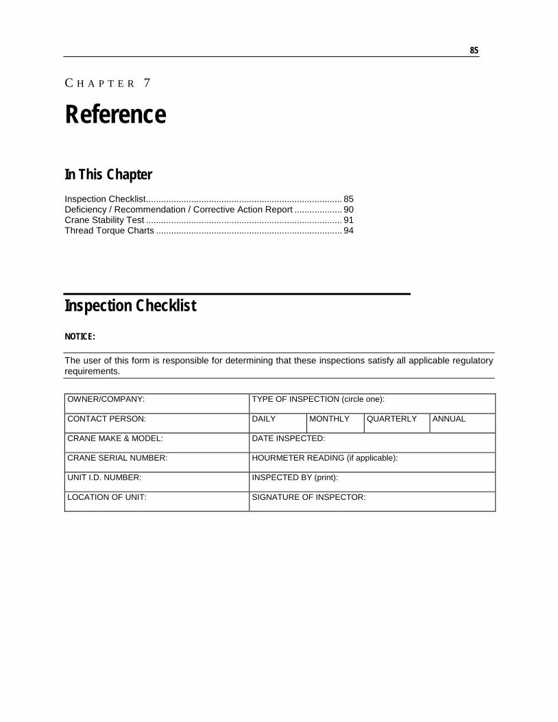
85
In This Chapter Inspection Checklist .............................................................................. 85 Deficiency / Recommendation / Corrective Action Report ................... 90 Crane Stability Test .............................................................................. 91 Thread Torque Charts .......................................................................... 94
Inspection Checklist NOTICE:
The user of this form is responsible for determining that these inspections satisfy all applicable regulatory requirements.
OWNER/COMPANY:
TYPE OF INSPECTION (circle one):
CONTACT PERSON: DAILY MONTHLY QUARTERLY ANNUAL
CRANE MAKE & MODEL: DATE INSPECTED:
CRANE SERIAL NUMBER: HOURMETER READING (if applicable):
UNIT I.D. NUMBER:
INSPECTED BY (print):
LOCATION OF UNIT: SIGNATURE OF INSPECTOR:
C H A P T E R 7
Reference
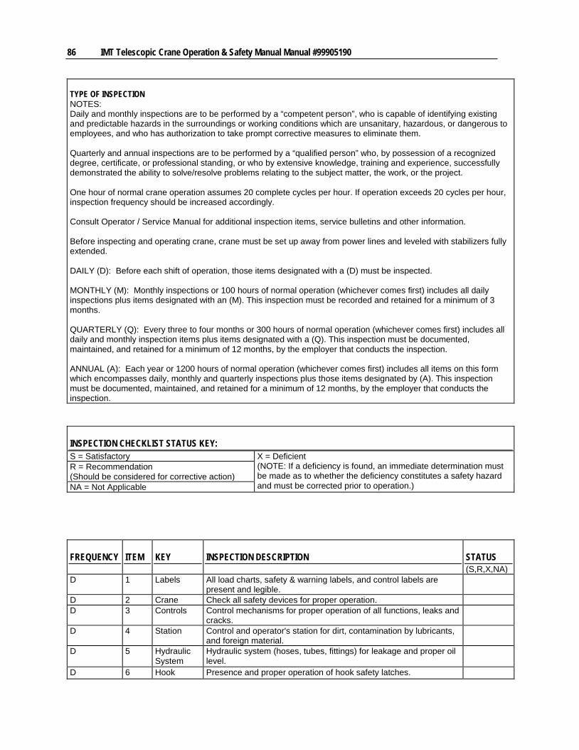
86 IMT Telescopic Crane Operation & Safety Manual Manual #99905190
TYPE OF INSPECTION NOTES: Daily and monthly inspections are to be performed by a “competent person”, who is capable of identifying existing and predictable hazards in the surroundings or working conditions which are unsanitary, hazardous, or dangerous to employees, and who has authorization to take prompt corrective measures to eliminate them. Quarterly and annual inspections are to be performed by a “qualified person” who, by possession of a recognized degree, certificate, or professional standing, or who by extensive knowledge, training and experience, successfully demonstrated the ability to solve/resolve problems relating to the subject matter, the work, or the project. One hour of normal crane operation assumes 20 complete cycles per hour. If operation exceeds 20 cycles per hour, inspection frequency should be increased accordingly. Consult Operator / Service Manual for additional inspection items, service bulletins and other information. Before inspecting and operating crane, crane must be set up away from power lines and leveled with stabilizers fully extended. DAILY (D): Before each shift of operation, those items designated with a (D) must be inspected. MONTHLY (M): Monthly inspections or 100 hours of normal operation (whichever comes first) includes all daily inspections plus items designated with an (M). This inspection must be recorded and retained for a minimum of 3 months. QUARTERLY (Q): Every three to four months or 300 hours of normal operation (whichever comes first) includes all daily and monthly inspection items plus items designated with a (Q). This inspection must be documented, maintained, and retained for a minimum of 12 months, by the employer that conducts the inspection. ANNUAL (A): Each year or 1200 hours of normal operation (whichever comes first) includes all items on this form which encompasses daily, monthly and quarterly inspections plus those items designated by (A). This inspection must be documented, maintained, and retained for a minimum of 12 months, by the employer that conducts the inspection.
INSPECTION CHECKLIST STATUS KEY: S = Satisfactory X = Deficient
(NOTE: If a deficiency is found, an immediate determination must be made as to whether the deficiency constitutes a safety hazard and must be corrected prior to operation.)
R = Recommendation (Should be considered for corrective action) NA = Not Applicable
FREQUENCY ITEM KEY INSPECTION DESCRIPTION STATUS (S,R,X,NA)
D 1 Labels All load charts, safety & warning labels, and control labels are present and legible.
D 2 Crane Check all safety devices for proper operation. D 3 Controls Control mechanisms for proper operation of all functions, leaks and
cracks.
D 4 Station Control and operator's station for dirt, contamination by lubricants, and foreign material.
D 5 Hydraulic System
Hydraulic system (hoses, tubes, fittings) for leakage and proper oil level.
D 6 Hook Presence and proper operation of hook safety latches.
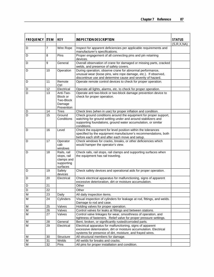
Chapter 7 Reference 87
FREQUENCY ITEM KEY INSPECTION DESCRIPTION STATUS (S,R,X,NA)
D 7 Wire Rope Inspect for apparent deficiencies per applicable requirements and manufacturer’s specifications.
D 8 Pins Proper engagement of all connecting pins and pin retaining devices.
D 9 General Overall observation of crane for damaged or missing parts, cracked welds, and presence of safety covers.
D 10 Operation During operation, observe crane for abnormal performance, unusual wear (loose pins, wire rope damage, etc.). If observed, discontinue use and determine cause and severity of hazard.
D 11 Remote Ctrl
Operate remote control devices to check for proper operation.
D 12 Electrical Operate all lights, alarms, etc. to check for proper operation. D 13 Anti-Two-
Block or Two-Block Damage Prevention
Operate anti two-block or two-block damage prevention device to check for proper operation.
D 14 Tires Check tires (when in use) for proper inflation and condition. D 15 Ground
Conditions Check ground conditions around the equipment for proper support, watching for ground settling under and around stabilizers and supporting foundations, ground water accumulation, or similar conditions.
D 16 Level Check the equipment for level position within the tolerances specified by the equipment manufacturer’s recommendations, both before each shift and after each move and setup.
D 17 Operator cab windows
Check windows for cracks, breaks, or other deficiencies which would hamper the operator's view.
D 18 Rails, rail stops, rail clamps and supporting surfaces
Check rails, rail stops, rail clamps and supporting surfaces when the equipment has rail traveling.
D 19 Safety devices
Check safety devices and operational aids for proper operation.
D 20 Electrical Check electrical apparatus for malfunctioning, signs of apparent excessive deterioration, dirt or moisture accumulation.
D 21 Other D 22 Other M 23 Daily All daily inspection items. M 24 Cylinders Visual inspection of cylinders for leakage at rod, fittings, and welds.
Damage to rod and case.
M 25 Valves Holding valves for proper operation. M 26 Valves Control valves for leaks at fittings and between stations. M 27 Valves Control valve linkages for wear, smoothness of operation, and
tightness of fasteners. Relief valve for proper pressure settings.
M 28 General Bent, broken, or significantly rusted/corroded parts. M 29 Electrical Electrical apparatus for malfunctioning, signs of apparent
excessive deterioration, dirt or moisture accumulation. Electrical systems for presence of dirt, moisture, and frayed wires.
M 30 Structure All structural members for damage. M 31 Welds All welds for breaks and cracks. M 32 Pins All pins for proper installation and condition.

88 IMT Telescopic Crane Operation & Safety Manual Manual #99905190
FREQUENCY ITEM KEY INSPECTION DESCRIPTION STATUS (S,R,X,NA)
M 33 Hardware All bolts, fasteners and retaining rings for tightness, wear and corrosion.
M 34 Wear Pads Presence of wear pads. M 35 Pump &
Motor Hydraulic pumps and motors for leakage at fittings, seals, and between sections. Check tightness of mounting bolts.
M 36 PTO Transmission/PTO for leakage, abnormal vibration & noise, alignment, and mounting bolt torque.
M 37 Hyd Fluid Quality of hydraulic fluid and presence of water. M 38 Hyd Lines Hoses & tubes for leakage, abrasion damage, blistering, cracking,
deterioration, fitting leakage, and secured properly.
M 39 Hook Load hook for abnormal throat distance, twist, wear, and cracks. M 40 Wire Rope Condition of load line. M 41 Manual Presence of operator's manual with unit. M 42 Other M 43 Other Q 44 Daily All daily inspection items. Q 45 Monthly All monthly inspection items. Q 46 Rotation
Sys Rotation bearing for proper torque of all mounting bolts.
Q 47 Hardware Base mounting bolts for proper torque. Q 48 Structure All structural members for deformation, cracks and corrosion. 49 • Base 50 • Stabilizer beams and legs 51 • Mast 52 • Inner Boom 53 • Outer Boom 54 • Extension(s) 55 • Jib boom 56 • Jib extension(s) 57 • Other Q 58 Hardware Pins, bearing, shafts, gears, rollers, and locking devices for wear,
cracks, corrosion and distortion.
59 • Rotation bearing(s) 60 • Inner boom pivot pin(s) and retainer(s) 61 • Outer boom pivot pin(s) and retainer(s) 62 • Inner boom cylinder pin(s) and retainer(s) 63 • Outer boom cylinder pin(s) and retainer(s) 64 • Extension cylinder pin(s) and retainer(s) 65 • Jib boom pin(s) and retainer(s) 66 • Jib cylinder pin(s) and retainer(s) 67 • Jib extension cylinder pin(s) and retainer(s) 68 • Boom tip attachment 69 • Other Q 70 Hyd Lines Hoses, fittings and tubing for proper routing, leakage, blistering,
deformation and excessive abrasion.
71 • Pressure line(s) from pump to control valve 72 • Return line(s) from control valve to reservoir 73 • Suction line(s) from reservoir to pump 74 • Pressure line(s) from control valve to each function 75 • Load holding valve pipe(s) and hose(s) 76 • Other
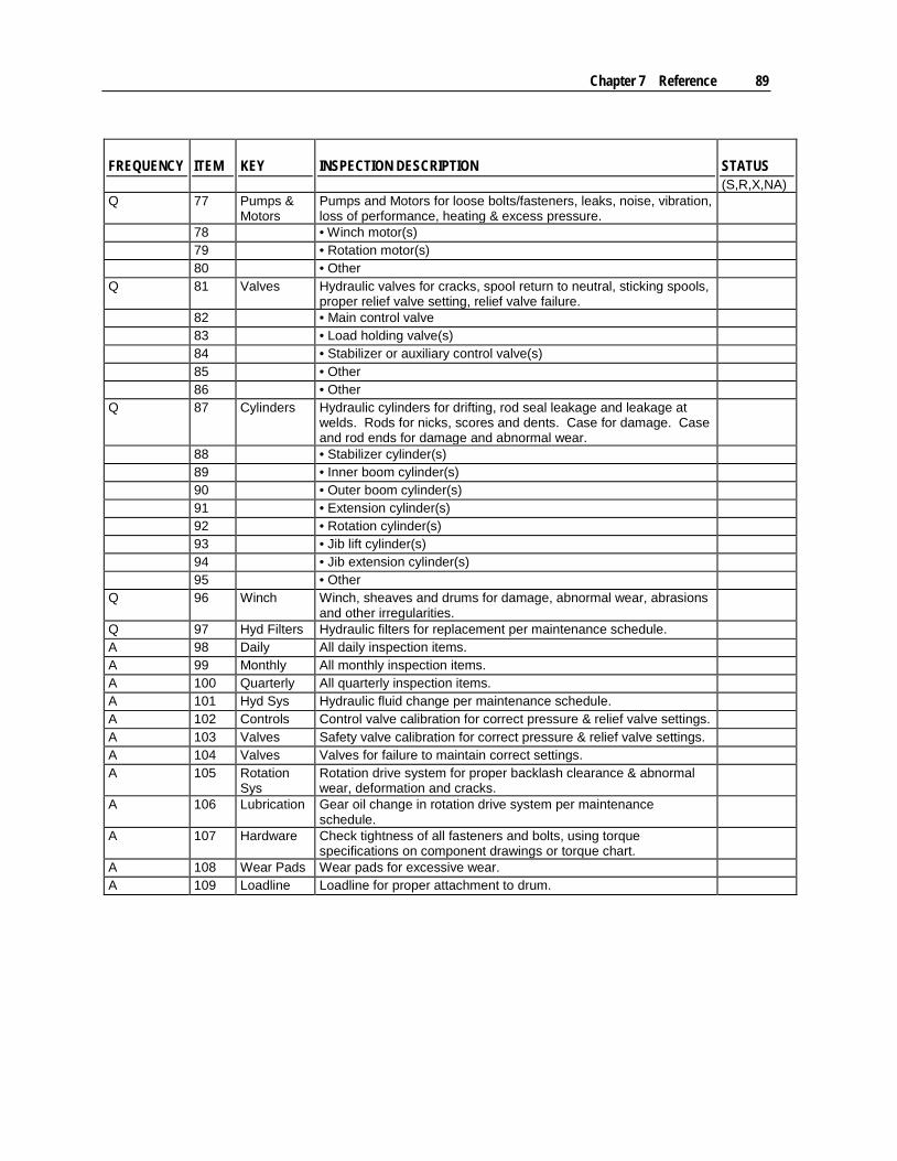
Chapter 7 Reference 89
FREQUENCY ITEM KEY INSPECTION DESCRIPTION STATUS (S,R,X,NA)
Q 77 Pumps & Motors
Pumps and Motors for loose bolts/fasteners, leaks, noise, vibration, loss of performance, heating & excess pressure.
78 • Winch motor(s) 79 • Rotation motor(s) 80 • Other Q 81 Valves Hydraulic valves for cracks, spool return to neutral, sticking spools,
proper relief valve setting, relief valve failure.
82 • Main control valve 83 • Load holding valve(s) 84 • Stabilizer or auxiliary control valve(s) 85 • Other 86 • Other Q 87 Cylinders Hydraulic cylinders for drifting, rod seal leakage and leakage at
welds. Rods for nicks, scores and dents. Case for damage. Case and rod ends for damage and abnormal wear.
88 • Stabilizer cylinder(s) 89 • Inner boom cylinder(s) 90 • Outer boom cylinder(s) 91 • Extension cylinder(s) 92 • Rotation cylinder(s) 93 • Jib lift cylinder(s) 94 • Jib extension cylinder(s) 95 • Other Q 96 Winch Winch, sheaves and drums for damage, abnormal wear, abrasions
and other irregularities.
Q 97 Hyd Filters Hydraulic filters for replacement per maintenance schedule. A 98 Daily All daily inspection items. A 99 Monthly All monthly inspection items. A 100 Quarterly All quarterly inspection items. A 101 Hyd Sys Hydraulic fluid change per maintenance schedule. A 102 Controls Control valve calibration for correct pressure & relief valve settings. A 103 Valves Safety valve calibration for correct pressure & relief valve settings. A 104 Valves Valves for failure to maintain correct settings. A 105 Rotation
Sys Rotation drive system for proper backlash clearance & abnormal wear, deformation and cracks.
A 106 Lubrication Gear oil change in rotation drive system per maintenance schedule.
A 107 Hardware Check tightness of all fasteners and bolts, using torque specifications on component drawings or torque chart.
A 108 Wear Pads Wear pads for excessive wear. A 109 Loadline Loadline for proper attachment to drum.
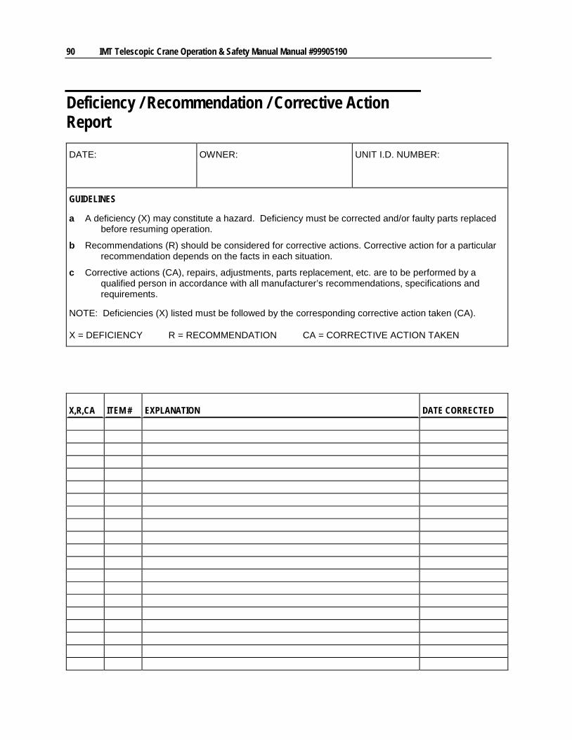
90 IMT Telescopic Crane Operation & Safety Manual Manual #99905190
Deficiency / Recommendation / Corrective Action Report
DATE: OWNER: UNIT I.D. NUMBER:
GUIDELINES
a A deficiency (X) may constitute a hazard. Deficiency must be corrected and/or faulty parts replaced before resuming operation.
b Recommendations (R) should be considered for corrective actions. Corrective action for a particular recommendation depends on the facts in each situation.
c Corrective actions (CA), repairs, adjustments, parts replacement, etc. are to be performed by a qualified person in accordance with all manufacturer’s recommendations, specifications and requirements.
NOTE: Deficiencies (X) listed must be followed by the corresponding corrective action taken (CA).
X = DEFICIENCY R = RECOMMENDATION CA = CORRECTIVE ACTION TAKEN
X,R,CA ITEM # EXPLANATION DATE CORRECTED

Chapter 7 Reference 91
X,R,CA ITEM # EXPLANATION DATE CORRECTED
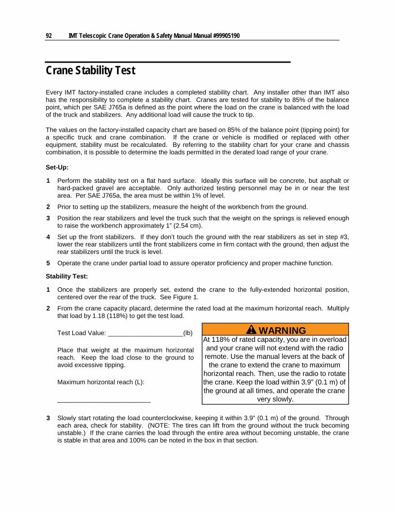
92 IMT Telescopic Crane Operation & Safety Manual Manual #99905190
Crane Stability Test Every IMT factory-installed crane includes a completed stability chart. Any installer other than IMT also has the responsibility to complete a stability chart. Cranes are tested for stability to 85% of the balance point, which per SAE J765a is defined as the point where the load on the crane is balanced with the load of the truck and stabilizers. Any additional load will cause the truck to tip.
The values on the factory-installed capacity chart are based on 85% of the balance point (tipping point) for a specific truck and crane combination. If the crane or vehicle is modified or replaced with other equipment, stability must be recalculated. By referring to the stability chart for your crane and chassis combination, it is possible to determine the loads permitted in the derated load range of your crane.
Set-Up:
1 Perform the stability test on a flat hard surface. Ideally this surface will be concrete, but asphalt or hard-packed gravel are acceptable. Only authorized testing personnel may be in or near the test area. Per SAE J765a, the area must be within 1% of level.
2 Prior to setting up the stabilizers, measure the height of the workbench from the ground.
3 Position the rear stabilizers and level the truck such that the weight on the springs is relieved enough to raise the workbench approximately 1” (2.54 cm).
4 Set up the front stabilizers. If they don’t touch the ground with the rear stabilizers as set in step #3, lower the rear stabilizers until the front stabilizers come in firm contact with the ground, then adjust the rear stabilizers until the truck is level.
5 Operate the crane under partial load to assure operator proficiency and proper machine function.
Stability Test:
1 Once the stabilizers are properly set, extend the crane to the fully-extended horizontal position, centered over the rear of the truck. See Figure 1.
2 From the crane capacity placard, determine the rated load at the maximum horizontal reach. Multiply that load by 1.18 (118%) to get the test load.
Test Load Value: _____________________(lb)
Place that weight at the maximum horizontal reach. Keep the load close to the ground to avoid excessive tipping.
Maximum horizontal reach (L):
__________________________
3 Slowly start rotating the load counterclockwise, keeping it within 3.9” (0.1 m) of the ground. Through each area, check for stability. (NOTE: The tires can lift from the ground without the truck becoming unstable.) If the crane carries the load through the entire area without becoming unstable, the crane is stable in that area and 100% can be noted in the box in that section.
WARNINGAt 118% of rated capacity, you are in overloadand your crane will not extend with the radioremote. Use the manual levers at the back of
the crane to extend the crane to maximumhorizontal reach. Then, use the radio to rotatethe crane. Keep the load within 3.9” (0.1 m) ofthe ground at all times, and operate the crane
very slowly.
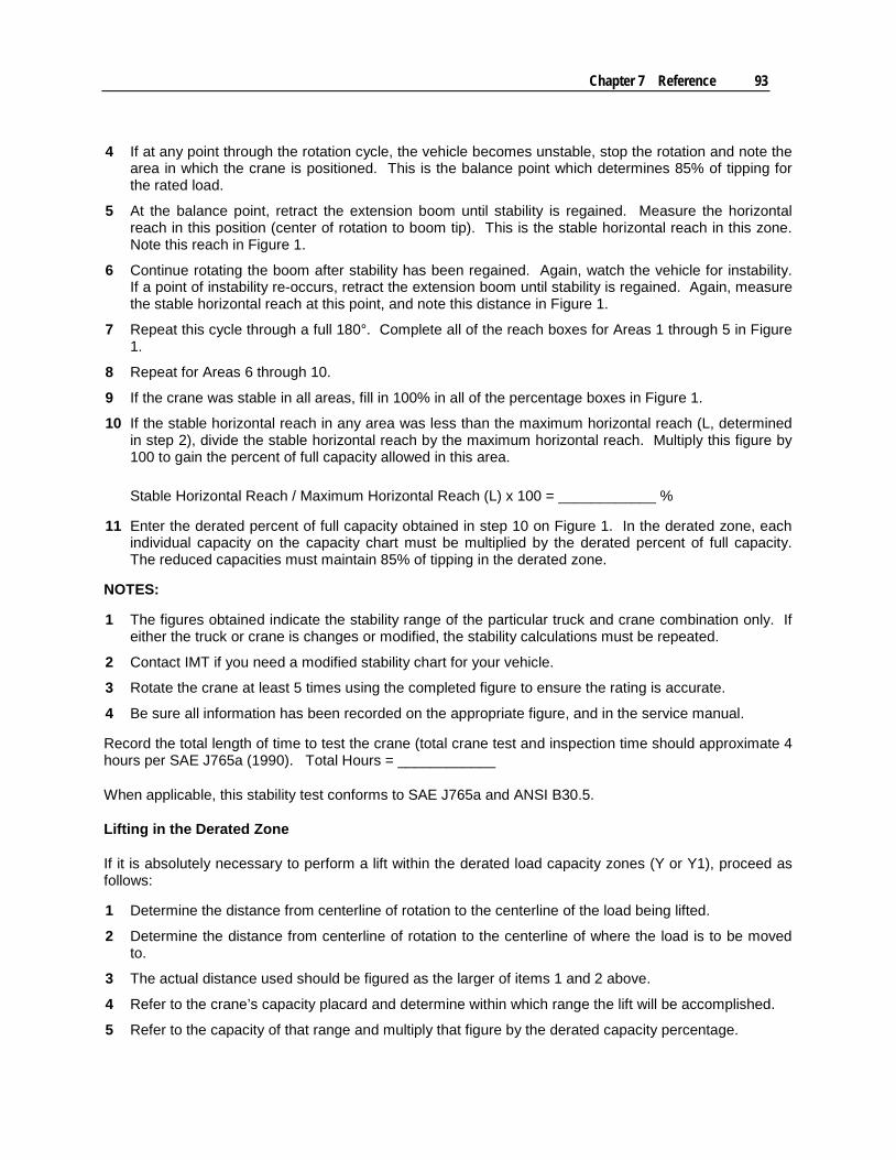
Chapter 7 Reference 93
4 If at any point through the rotation cycle, the vehicle becomes unstable, stop the rotation and note the area in which the crane is positioned. This is the balance point which determines 85% of tipping for the rated load.
5 At the balance point, retract the extension boom until stability is regained. Measure the horizontal reach in this position (center of rotation to boom tip). This is the stable horizontal reach in this zone. Note this reach in Figure 1.
6 Continue rotating the boom after stability has been regained. Again, watch the vehicle for instability. If a point of instability re-occurs, retract the extension boom until stability is regained. Again, measure the stable horizontal reach at this point, and note this distance in Figure 1.
7 Repeat this cycle through a full 180°. Complete all of the reach boxes for Areas 1 through 5 in Figure 1.
8 Repeat for Areas 6 through 10.
9 If the crane was stable in all areas, fill in 100% in all of the percentage boxes in Figure 1.
10 If the stable horizontal reach in any area was less than the maximum horizontal reach (L, determined in step 2), divide the stable horizontal reach by the maximum horizontal reach. Multiply this figure by 100 to gain the percent of full capacity allowed in this area.
Stable Horizontal Reach / Maximum Horizontal Reach (L) x 100 = ____________ %
11 Enter the derated percent of full capacity obtained in step 10 on Figure 1. In the derated zone, each individual capacity on the capacity chart must be multiplied by the derated percent of full capacity. The reduced capacities must maintain 85% of tipping in the derated zone.
NOTES:
1 The figures obtained indicate the stability range of the particular truck and crane combination only. If either the truck or crane is changes or modified, the stability calculations must be repeated.
2 Contact IMT if you need a modified stability chart for your vehicle.
3 Rotate the crane at least 5 times using the completed figure to ensure the rating is accurate.
4 Be sure all information has been recorded on the appropriate figure, and in the service manual.
Record the total length of time to test the crane (total crane test and inspection time should approximate 4 hours per SAE J765a (1990). Total Hours = ____________
When applicable, this stability test conforms to SAE J765a and ANSI B30.5.
Lifting in the Derated Zone
If it is absolutely necessary to perform a lift within the derated load capacity zones (Y or Y1), proceed as follows:
1 Determine the distance from centerline of rotation to the centerline of the load being lifted.
2 Determine the distance from centerline of rotation to the centerline of where the load is to be moved to.
3 The actual distance used should be figured as the larger of items 1 and 2 above.
4 Refer to the crane’s capacity placard and determine within which range the lift will be accomplished.
5 Refer to the capacity of that range and multiply that figure by the derated capacity percentage.
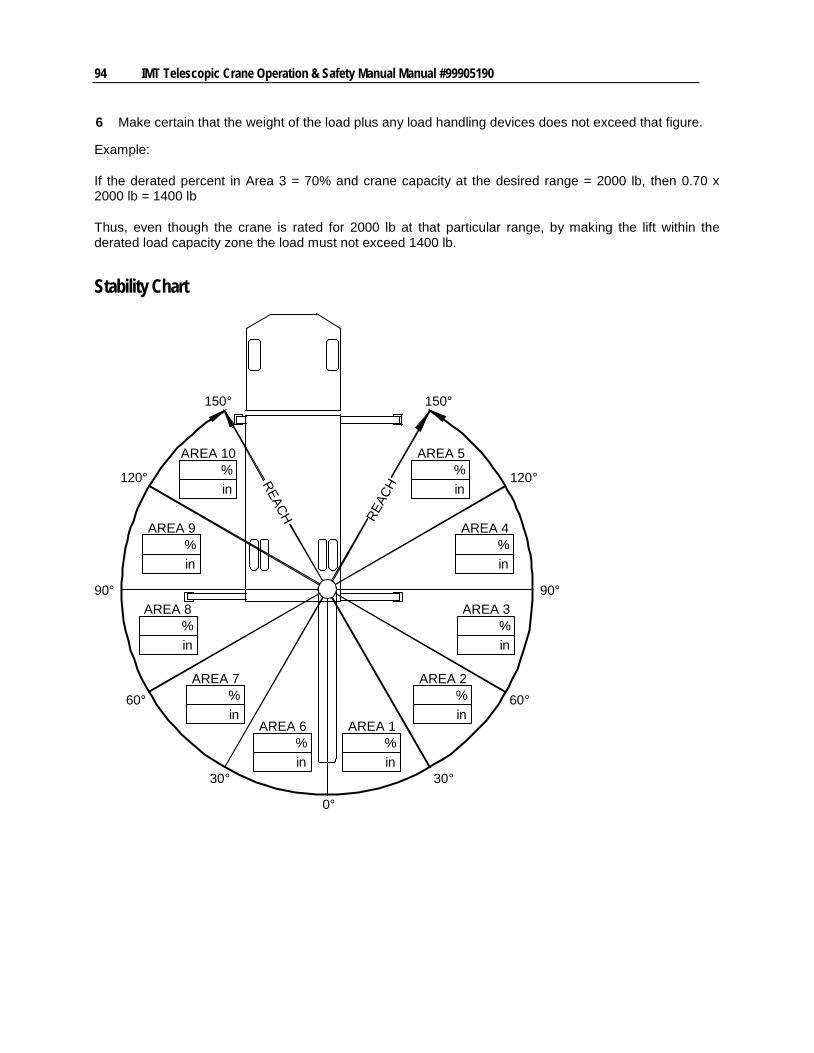
94 IMT Telescopic Crane Operation & Safety Manual Manual #99905190
6 Make certain that the weight of the load plus any load handling devices does not exceed that figure.
Example:
If the derated percent in Area 3 = 70% and crane capacity at the desired range = 2000 lb, then 0.70 x 2000 lb = 1400 lb
Thus, even though the crane is rated for 2000 lb at that particular range, by making the lift within the derated load capacity zone the load must not exceed 1400 lb.
Stability Chart
150°
120°
90°
60°
30°
0°
30°
60°
90°
120°
150°
REAC
HREACH
AREA 10%in
AREA 9%in
AREA 8%in
AREA 7%in
AREA 6%in
AREA 1%in
AREA 2%in
AREA 3%in
AREA 4%in
AREA 5%in
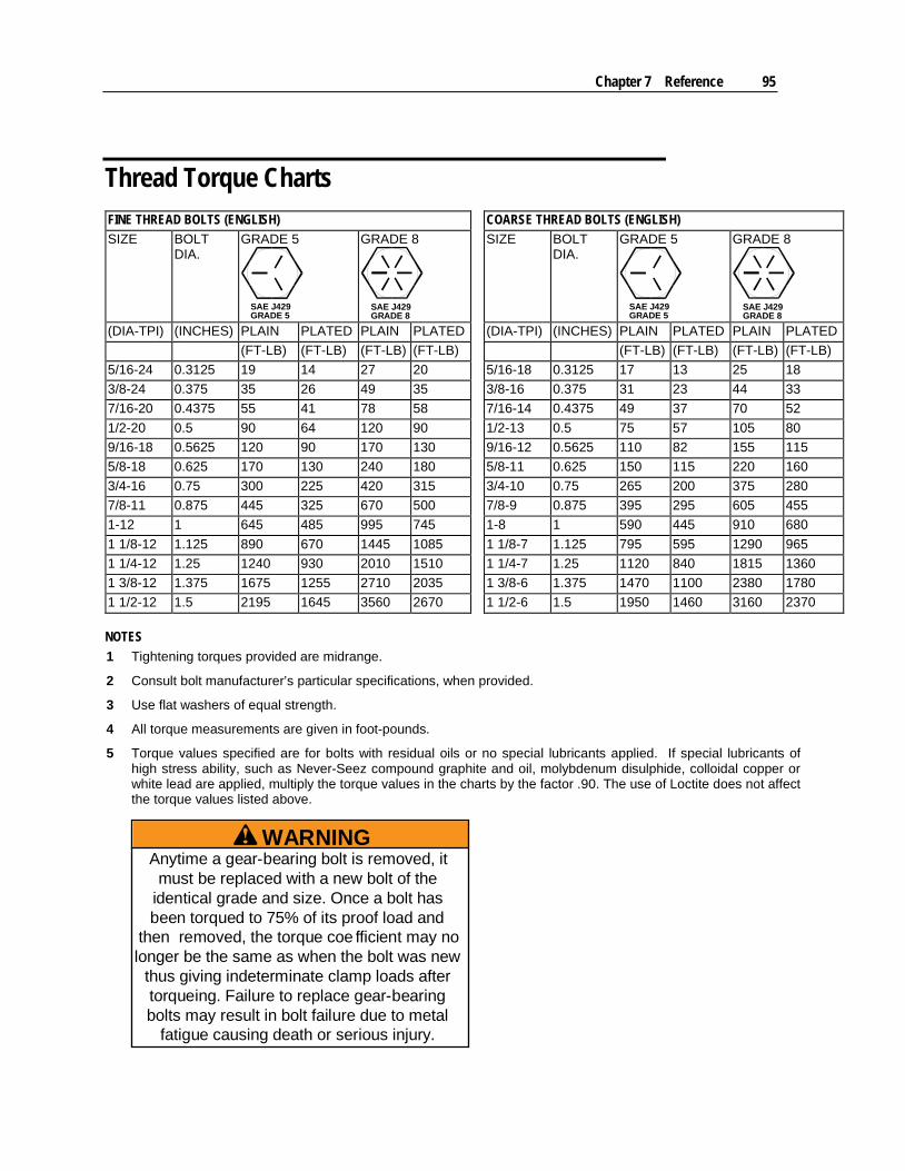
Chapter 7 Reference 95
Thread Torque Charts FINE THREAD BOLTS (ENGLISH) COARSE THREAD BOLTS (ENGLISH) SIZE BOLT
DIA. GRADE 5
SAE J429GRADE 5
GRADE 8
SAE J429GRADE 8
SIZE BOLT DIA.
GRADE 5
SAE J429GRADE 5
GRADE 8
SAE J429GRADE 8
(DIA-TPI) (INCHES) PLAIN PLATED PLAIN PLATED (DIA-TPI) (INCHES) PLAIN PLATED PLAIN PLATED (FT-LB) (FT-LB) (FT-LB) (FT-LB) (FT-LB) (FT-LB) (FT-LB) (FT-LB) 5/16-24 0.3125 19 14 27 20 5/16-18 0.3125 17 13 25 18 3/8-24 0.375 35 26 49 35 3/8-16 0.375 31 23 44 33 7/16-20 0.4375 55 41 78 58 7/16-14 0.4375 49 37 70 52 1/2-20 0.5 90 64 120 90 1/2-13 0.5 75 57 105 80 9/16-18 0.5625 120 90 170 130 9/16-12 0.5625 110 82 155 115 5/8-18 0.625 170 130 240 180 5/8-11 0.625 150 115 220 160 3/4-16 0.75 300 225 420 315 3/4-10 0.75 265 200 375 280 7/8-11 0.875 445 325 670 500 7/8-9 0.875 395 295 605 455 1-12 1 645 485 995 745 1-8 1 590 445 910 680 1 1/8-12 1.125 890 670 1445 1085 1 1/8-7 1.125 795 595 1290 965 1 1/4-12 1.25 1240 930 2010 1510 1 1/4-7 1.25 1120 840 1815 1360 1 3/8-12 1.375 1675 1255 2710 2035 1 3/8-6 1.375 1470 1100 2380 1780 1 1/2-12 1.5 2195 1645 3560 2670 1 1/2-6 1.5 1950 1460 3160 2370 NOTES 1 Tightening torques provided are midrange.
2 Consult bolt manufacturer’s particular specifications, when provided.
3 Use flat washers of equal strength.
4 All torque measurements are given in foot-pounds.
5 Torque values specified are for bolts with residual oils or no special lubricants applied. If special lubricants of high stress ability, such as Never-Seez compound graphite and oil, molybdenum disulphide, colloidal copper or white lead are applied, multiply the torque values in the charts by the factor .90. The use of Loctite does not affect the torque values listed above.
WARNINGAnytime a gear-bearing bolt is removed, it
must be replaced with a new bolt of theidentical grade and size. Once a bolt hasbeen torqued to 75% of its proof load and
then removed, the torque coe fficient may nolonger be the same as when the bolt was new
thus giving indeterminate clamp loads aftertorqueing. Failure to replace gear-bearingbolts may result in bolt failure due to metal
fatigue causing death or serious injury.

96 IMT Telescopic Crane Operation & Safety Manual Manual #99905190
FINE THREAD TORQUE CHART (METRIC)
COARSE THREAD TORQUE CHART (METRIC)
TIGHTENING TORQUE
TIGHTENING TORQUE
SIZE (DIA-TPI)
BOLT DIA. (INCHES) SAE J429
GRADE 5 SAE J429GRADE 8
SIZE (DIA-TPI)
BOLT DIA (INCHES)
SAE J429GRADE 5
SAE J429GRADE 8
PLAIN (KG-M)
PLATED (KG-M)
PLAIN (KG-M)
PLATED (KG-M)
PLAIN (KG-M)
PLATED (KG-M)
PLAIN (KG-M)
PLATED (KG-M)
5/16-24 0.3125 3 2 4 3 5/16-18 0.3125 2 2 3 2 3/8-24 0.375 5 4 7 5 3/8-16 0.375 4 3 6 5 7/16-20 0.4375 8 6 11 8 7/16-14 0.4375 7 5 10 7 1/2-20 0.5 12 9 17 12 1/2-13 0.5 10 8 15 11 9/16-18 0.5625 17 12 24 18 9/16-12 0.5625 15 11 21 16 5/8-18 0.625 24 18 33 25 5/8-11 0.625 21 16 30 22 3/4-16 0.75 41 31 58 44 3/4-10 0.75 37 28 52 39 7/8-11 0.875 62 45 93 69 7/8-9 0.875 55 41 84 63 1-12 1 89 67 138 103 1-8 1 82 62 126 94 1 1/8-12 1.125 123 93 200 150 1 1/8-7 1.125 110 82 178 133 1 1/4-12 1.25 171 129 278 209 1 1/4-7 1.25 155 116 251 188 1 3/8-12 1.375 232 174 375 281 1 3/8-6 1.375 203 152 329 246 1 1/2-12 1.5 304 228 492 369 1 1/2-6 1.5 270 210 438 328 NOTES 1 Tightening torques provided are midrange.
2 Consult bolt manufacturer’s particular specifications, when provided.
3 Use flat washers of equal strength.
4 All torque measurements are given in kilogram-meters.
5 Torque values specified are for bolts with residual oils or no special lubricants applied. If special lubricants of high stress ability, such as Never-Seez compound graphite and oil, molybdenum disulphide, colloidal copper or white lead are applied, multiply the torque values in the charts by the factor .90. The use of Loctite does not affect the torque values listed above.
WARNINGAnytime a gear-bearing bolt is removed, it
must be replaced with a new bolt of theidentical grade and size. Once a bolt hasbeen torqued to 75% of its proof load and
then removed, the torque coe fficient may nolonger be the same as when the bolt was new
thus giving indeterminate clamp loads aftertorqueing. Failure to replace gear-bearingbolts may result in bolt failure due to metal
fatigue causing death or serious injury.