Embed Size (px)
Citation preview
This water heater must be installed and serviced by a qualified person. Please leave this guide with the householder.
Owner’s Guide
and
Installation Instructions
Gas Domestic
Water Heater
641 series
PATENTS This water heater may be protected by one or more patents or registered designs
in the name of Rheem Australia Pty Ltd.
TRADEMARKS ® Registered trademark of Rheem Australia Pty Ltd.
TM Trademark of Rheem Australia Pty Ltd.
Note: Every care has been taken to ensure the accuracy in preparation of this publication. No liability can be accepted for any consequences
which may arise as a result of its application.
Warning: Upon completion of the installation and commissioning of the
water heater, leave this guide with the householder or responsible officer. DO NOT leave this guide inside of the cover of the water heater, as it may interfere with the safe operation of the water heater or ignite when the water heater is turned on.
3
CONTENTS
HOUSEHOLDER – We recommend you read pages 4 to 19.
The other pages are intended for the installer but may be of interest.
About Your Water Heater ............................................................ 4
Regular Care ................................................................................ 9
Water Supplies ........................................................................... 13
Save A Service Call ................................................................... 17
Installation .................................................................................. 20
Connections – Plumbing .......................................................... 28
Commissioning .......................................................................... 32
Lighting The Water Heater ........................................................ 33
Draining The Water Heater ....................................................... 36
Warranty ..................................................................................... 38
4
ABOUT YOUR WATER HEATER
WATER HEATER APPLICATION
This water heater is designed for use in a single family domestic dwelling for the purpose of heating potable water. Its use in an application other than this may shorten its life.
MODEL TYPE
The Vulcan® water heater model you have
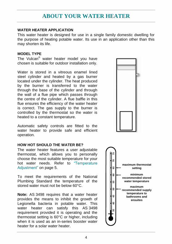
chosen is suitable for outdoor installation only. Water is stored in a vitreous enamel lined steel cylinder and heated by a gas burner located under the cylinder. The heat produced by the burner is transferred to the water through the base of the cylinder and through the wall of a flue pipe which passes through the centre of the cylinder. A flue baffle in this flue ensures the efficiency of the water heater is correct. The gas supply to the burner is controlled by the thermostat so the water is heated to a constant temperature. Automatic safety controls are fitted to the water heater to provide safe and efficient operation.
HOW HOT SHOULD THE WATER BE?
The water heater features a user adjustable thermostat, which allows you to personally choose the most suitable temperature for your hot water needs. Refer to “Temperature Adjustment” on page 5. To meet the requirements of the National Plumbing Standard the temperature of the stored water must not be below 60°C. Note: AS 3498 requires that a water heater provides the means to inhibit the growth of Legionella bacteria in potable water. This water heater can satisfy this AS 3498 requirement provided it is operating and the thermostat setting is 60°C or higher, including when it is used as an in-series booster water heater for a solar water heater.
maximum thermostat
setting
maximum recommended supply
temperature to bathrooms and
ensuites
minimum recommended stored
water temperature
ABOUT YOUR WATER HEATER
5
HOTTER WATER INCREASES THE RISK OF SCALD INJURY
This water heater can deliver water at temperatures which can cause scalding. Check the water temperature before use, such as when entering a shower or filling a bath or basin, to ensure it is suitable for the application and will not cause scald injury. We recommend and it may also be required by regulations that an approved temperature limiting device be fitted into the hot water pipe work to the bathroom and ensuite when this water heater is installed. This will keep the water temperature below 50°C at the bathroom and ensuite. The risk of scald injury will be reduced and still allow hotter water to the kitchen and laundry.
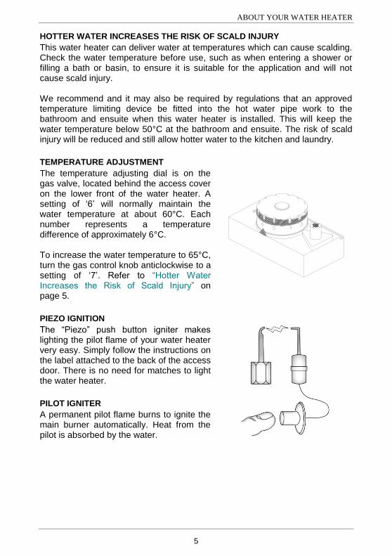
TEMPERATURE ADJUSTMENT
The temperature adjusting dial is on the gas valve, located behind the access cover on the lower front of the water heater. A setting of „6‟ will normally maintain the water temperature at about 60°C. Each number represents a temperature difference of approximately 6°C. To increase the water temperature to 65°C, turn the gas control knob anticlockwise to a setting of „7‟. Refer to “Hotter Water Increases the Risk of Scald Injury” on page 5.
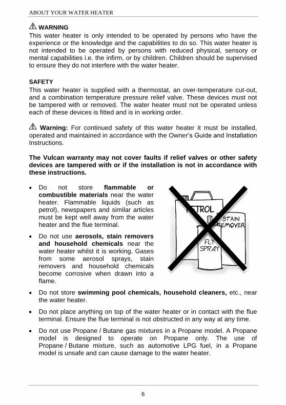
PIEZO IGNITION
The “Piezo” push button igniter makes lighting the pilot flame of your water heater very easy. Simply follow the instructions on the label attached to the back of the access door. There is no need for matches to light the water heater.
PILOT IGNITER
A permanent pilot flame burns to ignite the main burner automatically. Heat from the pilot is absorbed by the water.
ABOUT YOUR WATER HEATER
6
WARNING
This water heater is only intended to be operated by persons who have the experience or the knowledge and the capabilities to do so. This water heater is not intended to be operated by persons with reduced physical, sensory or mental capabilities i.e. the infirm, or by children. Children should be supervised to ensure they do not interfere with the water heater.
SAFETY
This water heater is supplied with a thermostat, an over-temperature cut-out, and a combination temperature pressure relief valve. These devices must not be tampered with or removed. The water heater must not be operated unless each of these devices is fitted and is in working order.
Warning: For continued safety of this water heater it must be installed,
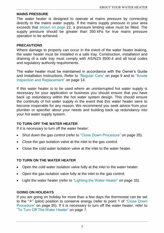
operated and maintained in accordance with the Owner‟s Guide and Installation Instructions. The Vulcan warranty may not cover faults if relief valves or other safety devices are tampered with or if the installation is not in accordance with these instructions. Do not store flammable or
combustible materials near the water heater. Flammable liquids (such as petrol), newspapers and similar articles must be kept well away from the water heater and the flue terminal.
Do not use aerosols, stain removers and household chemicals near the water heater whilst it is working. Gases from some aerosol sprays, stain removers and household chemicals become corrosive when drawn into a flame.
Do not store swimming pool chemicals, household cleaners, etc., near the water heater.
Do not place anything on top of the water heater or in contact with the flue terminal. Ensure the flue terminal is not obstructed in any way at any time.
Do not use Propane / Butane gas mixtures in a Propane model. A Propane model is designed to operate on Propane only. The use of Propane / Butane mixture, such as automotive LPG fuel, in a Propane model is unsafe and can cause damage to the water heater.
ABOUT YOUR WATER HEATER
7
MAINS PRESSURE
The water heater is designed to operate at mains pressure by connecting directly to the mains water supply. If the mains supply pressure in your area exceeds that shown on page 22, a pressure limiting valve must be fitted. The supply pressure should be greater than 350 kPa for true mains pressure operation to be achieved.
PRECAUTIONS
Where damage to property can occur in the event of the water heater leaking, the water heater must be installed in a safe tray. Construction, installation and draining of a safe tray must comply with AS/NZS 3500.4 and all local codes and regulatory authority requirements. The water heater must be maintained in accordance with the Owner‟s Guide and Installation Instructions. Refer to “Regular Care” on page 9 and to “Anode Inspection and Replacement” on page 14. If this water heater is to be used where an uninterrupted hot water supply is necessary for your application or business you should ensure that you have back up redundancy within the hot water system design. This should ensure the continuity of hot water supply in the event that this water heater were to become inoperable for any reason. We recommend you seek advice from your plumber or specifier about your needs and building back up redundancy into your hot water supply system.
TO TURN OFF THE WATER HEATER
If it is necessary to turn off the water heater:
Shut down the gas control (refer to “Close Down Procedure” on page 35).
Close the gas isolation valve at the inlet to the gas control.
Close the cold water isolation valve at the inlet to the water heater.
TO TURN ON THE WATER HEATER
Open the cold water isolation valve fully at the inlet to the water heater.
Open the gas isolation valve fully at the inlet to the gas control.
Light the water heater (refer to “Lighting the Water Heater” on page 33).
GOING ON HOLIDAYS
If you are going on holiday for more than a few days the thermostat can be set to the “” (pilot) position to conserve energy (refer to point 1 of “Close Down Procedure” on page 35). If it is necessary to turn off the water heater, refer to “To Turn Off The Water Heater” on page 7.
ABOUT YOUR WATER HEATER
8
HOW DO I KNOW IF THE WATER HEATER IS INSTALLED CORRECTLY?
Installation requirements are shown on pages 20 to 27. The water heater must be installed:
by a qualified person, and
in accordance with the installation instructions, and
in compliance with Standards AS/NZS 3500.4, AS 5601 or AS/NZS 5601.1, as applicable under local regulations, and all local codes and regulatory authority requirements.
In New Zealand, the installation must also conform with NZS 5261, as applicable under local regulations, and the New Zealand Building Code.
VICTORIAN CUSTOMERS
Notice to Victorian Customers from the Victorian Plumbing Industry Commission. This water heater must be installed by a licensed person as required by the Victorian Building Act 1993. Only a licensed person will give you a Compliance Certificate, showing that the work complies with all the relevant Standards. Only a licensed person will have insurance protecting their workmanship for 6 years. Make sure you use a licensed person to install this water heater and ask for your Compliance Certificate.
DOES THE WATER CHEMISTRY AFFECT THE WATER HEATER?
The water heater is suitable for most public water supplies, however some water chemistries may have detrimental effects on the water heater, its components and fittings. Refer to “Water Supplies” on page 13. If you are in a known harsh water area or you are not sure of your water chemistry, have your water checked against the conditions described on pages 13 to 16.
HOW LONG WILL THE WATER HEATER LAST?
The water heater is supported by a manufacturer‟s warranty (refer to page 38). There are a number of factors that will affect the length of service the water heater will provide. These include but are not limited to the water chemistry, the water pressure, the water temperature (inlet and outlet) and the water usage pattern. Refer to “Precautions” on page 7.
9
REGULAR CARE
ANNUAL SERVICE
For safe and efficient operation, it is recommended an annual service be conducted on the water heater.
Warning: Servicing of a water heater must only be carried out by qualified
personnel. Phone Rheem Service or their nearest Accredited Service Agent. Note: The annual service and routine replacement of any components, if required, are not included in the Vulcan warranty. A charge will be made for this work. Only genuine replacement parts should be used on this water heater. The annual service includes the following actions:
Inspect and flush the temperature pressure relief valve.
Inspect and flush the expansion control valve (if fitted).
Check and if necessary adjust the inlet gas pressure.
Check the piezo igniter, gas control and thermocouple.
Check the operation of and clean the pilot light and main burner.
Visually check the unit for any potential problems.
Inspect all connections.
Check the drain line from the safe tray (if one is installed) is not blocked.
Note: The water heater may need to be drained during this service. After the completion of the service, the water heater will take some time to reheat the water. Hot water may not be available for a while.
REGULAR CARE
10
MAJOR FIVE YEAR SERVICE
It is recommended a major five year service be conducted on the water heater.
Warning: Servicing of a water heater must only be carried out by qualified personnel. Phone Rheem Service or their nearest Accredited Service Agent. Note: The five year service and routine replacement of any components, such as the anode and relief valve(s), are not included in the Vulcan warranty. A charge will be made for this work. Only genuine replacement parts should be used on this water heater. The major service includes the following actions:
Replace the temperature pressure relief valve.
Inspect and flush the expansion control valve (if fitted). If required, replace the valve.
Inspect and if required, replace the anode.
If the anode is not replaced, it should be replaced within three years of this service (refer to “Anode Inspection and Replacement” on page 14).
Check and if necessary adjust the inlet gas pressure.
Check the piezo igniter, gas control and thermocouple.
Check the operation of and clean the pilot light and main burner.
Visually check the unit for any potential problems.
Inspect all connections.
Check the drain line from the safe tray (if one is installed) is not blocked.
Note: The water heater may need to be drained during this service. After the completion of the service, the water heater will take some time to reheat the water. Hot water may not be available for a while.
REGULAR CARE
11
MINOR SIX MONTH MAINTENANCE
It is recommended minor maintenance be performed every six months by the dwelling occupant. The minor maintenance includes:
Operate the easing lever on the temperature pressure relief valve. It is very important you raise and lower the lever gently. Refer to “Temperature Pressure Relief Valve” on page 12.
Warning: Exercise care to avoid any splashing of water, as water
discharged from the drain line will be hot. Stand clear of the drain line‟s point of discharge when operating the valve‟s lever.
Operate the easing lever on the expansion control valve (if fitted). It is very important you raise and lower the lever gently. Refer to “Expansion Control Valve” on page 11.
Check the drain line from the safe tray (if one is installed) is not blocked.
EXPANSION CONTROL VALVE
In many areas, including South Australia, Western Australia and scaling water areas, an expansion control valve is fitted to the cold water line to the water heater. The expansion control valve may discharge a small quantity of water from its drain line during the heating period instead of the temperature pressure relief valve on the water heater. Operate the easing lever on the expansion control valve once every six months. It is very important you raise and lower the lever gently. The expansion control valve should be checked for performance or replaced at intervals not exceeding 5 years, or more frequently in areas where there is a high incidence of water deposits.
REGULAR CARE
12
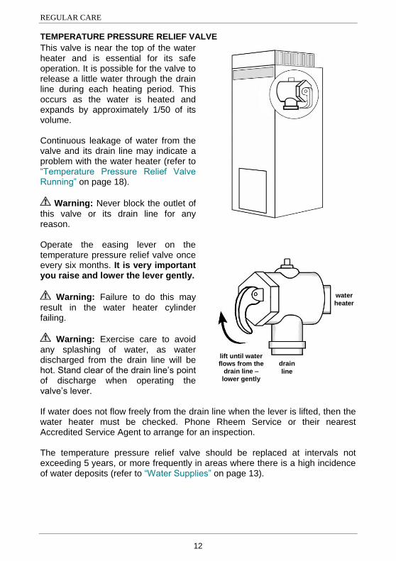
TEMPERATURE PRESSURE RELIEF VALVE
This valve is near the top of the water heater and is essential for its safe operation. It is possible for the valve to release a little water through the drain line during each heating period. This occurs as the water is heated and expands by approximately 1/50 of its volume. Continuous leakage of water from the valve and its drain line may indicate a problem with the water heater (refer to “Temperature Pressure Relief Valve Running” on page 18).
Warning: Never block the outlet of
this valve or its drain line for any reason. Operate the easing lever on the temperature pressure relief valve once every six months. It is very important you raise and lower the lever gently.
Warning: Failure to do this may
result in the water heater cylinder failing.
Warning: Exercise care to avoid any splashing of water, as water discharged from the drain line will be hot. Stand clear of the drain line‟s point of discharge when operating the valve‟s lever. If water does not flow freely from the drain line when the lever is lifted, then the water heater must be checked. Phone Rheem Service or their nearest Accredited Service Agent to arrange for an inspection. The temperature pressure relief valve should be replaced at intervals not exceeding 5 years, or more frequently in areas where there is a high incidence of water deposits (refer to “Water Supplies” on page 13).
water
heater
water
heater
drain
line
lift until water flows from the
drain line – lower gently
13
WATER SUPPLIES
This water heater must be installed in accordance with this advice to be covered by the Vulcan warranty. This water heater is manufactured to suit the water conditions of most public reticulated water supplies. However, there are some known water chemistries which can have detrimental effects on the water heater and its operation and / or life expectancy. If you are unsure of your water chemistry, you may be able to obtain information from your local water supply authority. This water heater should only be connected to a water supply which complies with these guidelines for the Vulcan warranty to apply.
ANODE
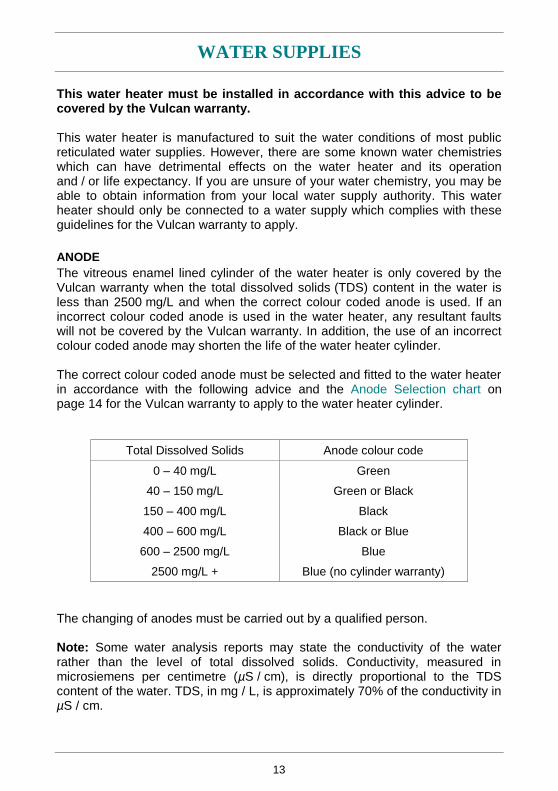
The vitreous enamel lined cylinder of the water heater is only covered by the Vulcan warranty when the total dissolved solids (TDS) content in the water is less than 2500 mg/L and when the correct colour coded anode is used. If an incorrect colour coded anode is used in the water heater, any resultant faults will not be covered by the Vulcan warranty. In addition, the use of an incorrect colour coded anode may shorten the life of the water heater cylinder. The correct colour coded anode must be selected and fitted to the water heater in accordance with the following advice and the Anode Selection chart on page 14 for the Vulcan warranty to apply to the water heater cylinder.
Total Dissolved Solids Anode colour code
0 – 40 mg/L Green
40 – 150 mg/L Green or Black
150 – 400 mg/L Black
400 – 600 mg/L Black or Blue
600 – 2500 mg/L Blue
2500 mg/L + Blue (no cylinder warranty)
The changing of anodes must be carried out by a qualified person. Note: Some water analysis reports may state the conductivity of the water rather than the level of total dissolved solids. Conductivity, measured in microsiemens per centimetre (µS / cm), is directly proportional to the TDS content of the water. TDS, in mg / L, is approximately 70% of the conductivity in µS / cm.
WATER SUPPLIES
14
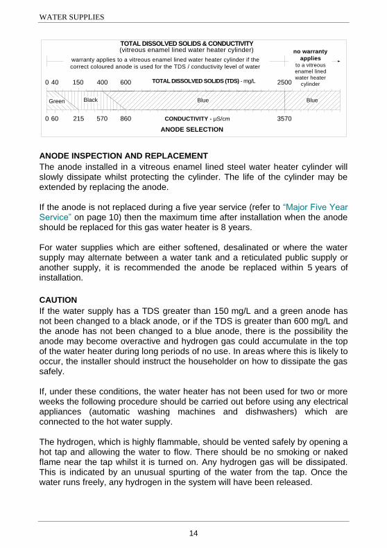
CONDUCTIVITY - µS/cm
TOTAL DISSOLVED SOLIDS & CONDUCTIVITY(vitreous enamel lined water heater cylinder)
40 150 400 600 TOTAL DISSOLVED SOLIDS (TDS) - mg/L
ANODE SELECTION
warranty applies to a vitreous enamel lined water heater cylinder if the
correct coloured anode is used for the TDS / conductivity level of water
2500
3570
no warranty
appliesto a vitreous
enamel lined
water heater
cylinder
BlueBlackGreen
60 215 570 860
0
0
Blue
ANODE INSPECTION AND REPLACEMENT
The anode installed in a vitreous enamel lined steel water heater cylinder will slowly dissipate whilst protecting the cylinder. The life of the cylinder may be extended by replacing the anode. If the anode is not replaced during a five year service (refer to “Major Five Year Service” on page 10) then the maximum time after installation when the anode should be replaced for this gas water heater is 8 years. For water supplies which are either softened, desalinated or where the water supply may alternate between a water tank and a reticulated public supply or another supply, it is recommended the anode be replaced within 5 years of installation.
CAUTION
If the water supply has a TDS greater than 150 mg/L and a green anode has not been changed to a black anode, or if the TDS is greater than 600 mg/L and the anode has not been changed to a blue anode, there is the possibility the anode may become overactive and hydrogen gas could accumulate in the top of the water heater during long periods of no use. In areas where this is likely to occur, the installer should instruct the householder on how to dissipate the gas safely. If, under these conditions, the water heater has not been used for two or more weeks the following procedure should be carried out before using any electrical appliances (automatic washing machines and dishwashers) which are connected to the hot water supply. The hydrogen, which is highly flammable, should be vented safely by opening a hot tap and allowing the water to flow. There should be no smoking or naked flame near the tap whilst it is turned on. Any hydrogen gas will be dissipated. This is indicated by an unusual spurting of the water from the tap. Once the water runs freely, any hydrogen in the system will have been released.
WATER SUPPLIES
15
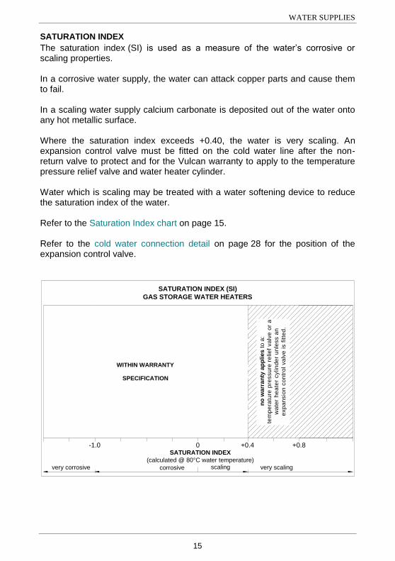
SATURATION INDEX
The saturation index (SI) is used as a measure of the water‟s corrosive or scaling properties. In a corrosive water supply, the water can attack copper parts and cause them to fail. In a scaling water supply calcium carbonate is deposited out of the water onto any hot metallic surface. Where the saturation index exceeds +0.40, the water is very scaling. An expansion control valve must be fitted on the cold water line after the non-return valve to protect and for the Vulcan warranty to apply to the temperature pressure relief valve and water heater cylinder. Water which is scaling may be treated with a water softening device to reduce the saturation index of the water. Refer to the Saturation Index chart on page 15. Refer to the cold water connection detail on page 28 for the position of the expansion control valve.
-1.0
no
wa
rra
nty
ap
plies t
o a
:
tem
pe
ratu
re p
ressu
re r
elie
f va
lve
or
a
wa
ter
he
ate
r cylin
de
r u
nle
ss a
n
exp
an
sio
n c
on
tro
l va
lve
is f
itte
d.
SATURATION INDEX (SI)
GAS STORAGE WATER HEATERS
WITHIN WARRANTY
SPECIFICATION
SATURATION INDEX
(calculated @ 80°C water temperature)
+0.4 +0.80
very corrosive very scalingscalingcorrosive
WATER SUPPLIES
16
CHANGE OF WATER SUPPLY
The changing or alternating from one water supply to another can have a detrimental effect on the operation and / or life expectation of a water heater cylinder and a temperature pressure relief valve. Where there is a changeover from one water supply to another, e.g. a rainwater tank supply, bore water supply, desalinated water supply, public reticulated water supply or water brought in from another supply, then water chemistry information should be sought from the supplier or it should be tested to ensure the water supply meets the requirements given in these guidelines for the Vulcan warranty to apply.
SUMMARY OF WATER CHEMISTRY ADVICE AFFECTING WARRANTY
The water heater and its components are not suitable for certain water chemistries. Those chemistries are listed below. If the water heater is connected at any time to a water supply with the following water chemistry, the Vulcan warranty will not cover any resultant faults on the components listed below:
Water Chemistry Component
Total Dissolved Solids (TDS) > 2500 mg/L water heater cylinder
Total Dissolved Solids (TDS) not suitable for anode type
water heater cylinder
Saturation Index (SI) > +0.4 (if expansion control valve is not fitted)
water heater cylinder temperature pressure relief valve
17
SAVE A SERVICE CALL
Check the items below before making a service call. You will be charged for attending to any condition or fault that is not related to manufacture or failure of a part.
NOT ENOUGH HOT WATER (OR NO HOT WATER)
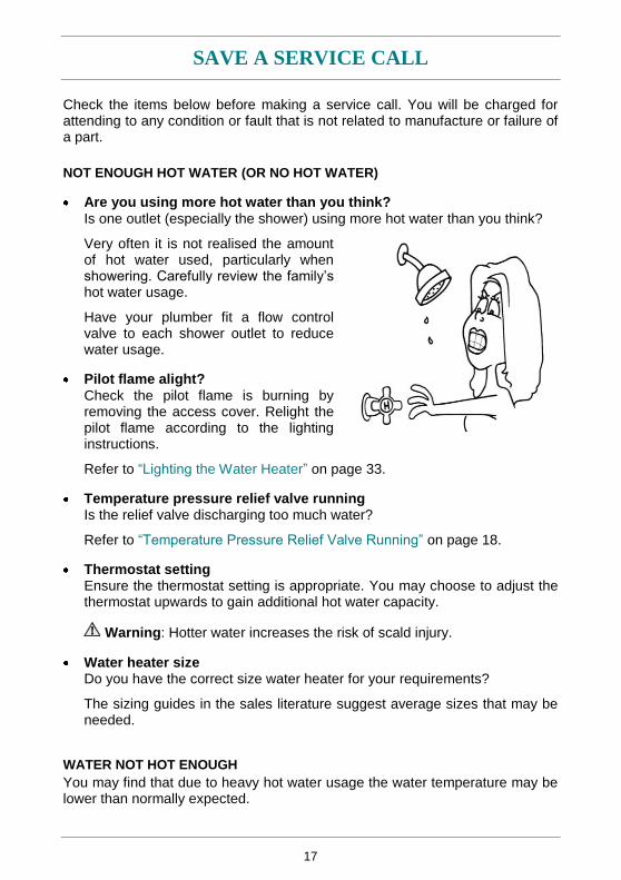
Are you using more hot water than you think?
Is one outlet (especially the shower) using more hot water than you think?
Very often it is not realised the amount of hot water used, particularly when showering. Carefully review the family‟s hot water usage.
Have your plumber fit a flow control valve to each shower outlet to reduce water usage.
Pilot flame alight?
Check the pilot flame is burning by removing the access cover. Relight the pilot flame according to the lighting instructions.
Refer to “Lighting the Water Heater” on page 33.
Temperature pressure relief valve running Is the relief valve discharging too much water?
Refer to “Temperature Pressure Relief Valve Running” on page 18.
Thermostat setting Ensure the thermostat setting is appropriate. You may choose to adjust the thermostat upwards to gain additional hot water capacity.
Warning: Hotter water increases the risk of scald injury.
Water heater size Do you have the correct size water heater for your requirements?
The sizing guides in the sales literature suggest average sizes that may be needed.
WATER NOT HOT ENOUGH
You may find that due to heavy hot water usage the water temperature may be lower than normally expected.
SAVE A SERVICE CALL
18
TEMPERATURE PRESSURE RELIEF VALVE RUNNING
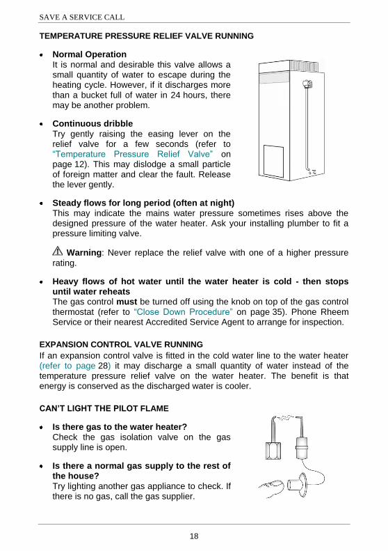
Normal Operation It is normal and desirable this valve allows a small quantity of water to escape during the heating cycle. However, if it discharges more than a bucket full of water in 24 hours, there may be another problem.
Continuous dribble Try gently raising the easing lever on the relief valve for a few seconds (refer to “Temperature Pressure Relief Valve” on page 12). This may dislodge a small particle of foreign matter and clear the fault. Release the lever gently.
Steady flows for long period (often at night) This may indicate the mains water pressure sometimes rises above the designed pressure of the water heater. Ask your installing plumber to fit a pressure limiting valve.
Warning: Never replace the relief valve with one of a higher pressure
rating.
Heavy flows of hot water until the water heater is cold - then stops until water reheats The gas control must be turned off using the knob on top of the gas control thermostat (refer to “Close Down Procedure” on page 35). Phone Rheem Service or their nearest Accredited Service Agent to arrange for inspection.
EXPANSION CONTROL VALVE RUNNING
If an expansion control valve is fitted in the cold water line to the water heater (refer to page 28) it may discharge a small quantity of water instead of the temperature pressure relief valve on the water heater. The benefit is that energy is conserved as the discharged water is cooler.
CAN’T LIGHT THE PILOT FLAME
Is there gas to the water heater? Check the gas isolation valve on the gas supply line is open.
Is there a normal gas supply to the rest of the house? Try lighting another gas appliance to check. If there is no gas, call the gas supplier.
SAVE A SERVICE CALL
19
WATER HEATER APPEARS TO BE LEAKING
When the water heater is first lit, or after a large usage of hot water, condensation may form on the burner of the water heater. This is quite normal, especially in winter months and will dry off as the water is heated.
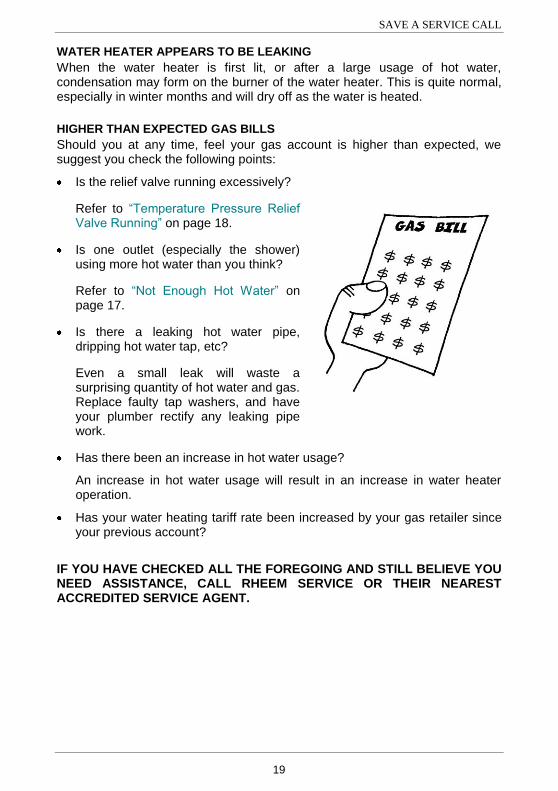
HIGHER THAN EXPECTED GAS BILLS
Should you at any time, feel your gas account is higher than expected, we suggest you check the following points:
Is the relief valve running excessively?
Refer to “Temperature Pressure Relief Valve Running” on page 18.
Is one outlet (especially the shower) using more hot water than you think?
Refer to “Not Enough Hot Water” on page 17.
Is there a leaking hot water pipe, dripping hot water tap, etc?
Even a small leak will waste a surprising quantity of hot water and gas. Replace faulty tap washers, and have your plumber rectify any leaking pipe work.
Has there been an increase in hot water usage?
An increase in hot water usage will result in an increase in water heater operation.
Has your water heating tariff rate been increased by your gas retailer since your previous account?
IF YOU HAVE CHECKED ALL THE FOREGOING AND STILL BELIEVE YOU NEED ASSISTANCE, CALL RHEEM SERVICE OR THEIR NEAREST ACCREDITED SERVICE AGENT.
20
INSTALLATION
THIS WATER HEATER IS FOR OUTDOOR INSTALLATION ONLY. THIS WATER HEATER IS NOT SUITABLE FOR POOL HEATING. Check the water heater is suitable for the gas type available. (refer to the rating label on the water heater)
INSTALLATION STANDARDS
The water heater must be installed:
by a qualified person, and
in accordance with the installation instructions, and
in compliance with Standards AS/NZS 3500.4, AS 5601 or AS/NZS 5601.1, as applicable under local regulations, and all local codes and regulatory authority requirements.
In New Zealand, the installation must also conform with NZS 5261, as applicable under local regulations, and the New Zealand Building Code. All packaging materials must be removed from the water heater prior to its installation. This includes the removal of the cardboard base of the carton from the underside of the water heater.
WATER HEATER APPLICATION
This water heater is designed for use in a single family domestic dwelling for the purpose of heating potable water. Its use in an application other than this may shorten its life. If this water heater is to be used where an uninterrupted hot water supply is necessary for the application or business, then there should be redundancy within the hot water system design. This should ensure the continuity of hot water supply in the event that this water heater was to become inoperable for any reason. We recommend you provide advice to the system owner about their needs and building backup redundancy into the hot water supply system. Note: AS 3498 requires that a water heater provides the means to inhibit the growth of Legionella bacteria in potable water. This water heater can satisfy this AS 3498 requirement provided it is operating and the thermostat setting is 60°C or higher, including when it is used as an in-series booster water heater for a solar water heater.
INSTALLATION
21
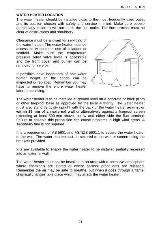
WATER HEATER LOCATION
The water heater should be installed close to the most frequently used outlet and its position chosen with safety and service in mind. Make sure people (particularly children) will not touch the flue outlet. The flue terminal must be clear of obstructions and shrubbery. Clearance must be allowed for servicing of the water heater. The water heater must be accessible without the use of a ladder or scaffold. Make sure the temperature pressure relief valve lever is accessible and the front cover and burner can be removed for service. If possible leave headroom of one water heater height so the anode can be inspected or replaced. Remember you may have to remove the entire water heater later for servicing. The water heater is to be installed at ground level on a concrete or brick plinth or other fireproof base as approved by the local authority. The water heater must also stand vertically upright with the back of the water heater against or within 25 mm of an external wall or alternatively against a fireproof screen extending at least 500 mm above, below and either side the flue terminal. Failure to observe this precaution can cause problems in high wind areas. A secondary flue is not required. It is a requirement of AS 5601 and AS/NZS 5601.1 to secure the water heater to the wall. The water heater must be secured to the wall or screen using the brackets provided. Kits are available to enable the water heater to be installed partially recessed into an external wall. The water heater must not be installed in an area with a corrosive atmosphere where chemicals are stored or where aerosol propellants are released. Remember the air may be safe to breathe, but when it goes through a flame, chemical changes take place which may attack the water heater.
INSTALLATION
22
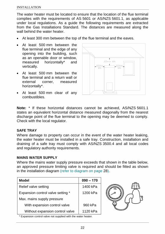
The water heater must be located to ensure that the location of the flue terminal complies with the requirements of AS 5601 or AS/NZS 5601.1, as applicable under local regulations. As a guide the following requirements are extracted from the Gas Installations Standard. The distances are measured along the wall behind the water heater.
At least 300 mm between the top of the flue terminal and the eaves.
At least 500 mm between the flue terminal and the edge of any opening into the building, such as an openable door or window, measured horizontally* and vertically.
At least 500 mm between the flue terminal and a return wall or external corner, measured horizontally*.
At least 500 mm clear of any combustibles.
Note: * If these horizontal distances cannot be achieved, AS/NZS 5601.1 states an equivalent horizontal distance measured diagonally from the nearest discharge point of the flue terminal to the opening may be deemed to comply. Check with the local regulator.
SAFE TRAY
Where damage to property can occur in the event of the water heater leaking, the water heater must be installed in a safe tray. Construction, installation and draining of a safe tray must comply with AS/NZS 3500.4 and all local codes and regulatory authority requirements.
MAINS WATER SUPPLY
Where the mains water supply pressure exceeds that shown in the table below, an approved pressure limiting valve is required and should be fitted as shown in the installation diagram (refer to diagram on page 28).
Model 090 – 170
Relief valve setting 1400 kPa
Expansion control valve setting * 1200 kPa
Max. mains supply pressure
With expansion control valve 960 kPa
Without expansion control valve 1120 kPa
* Expansion control valve not supplied with the water heater.
INSTALLATION
23
TANK WATER SUPPLY
If the water heater is supplied with water from a tank supply and a pressure pump system is not installed, then the bottom of the supply tank must be at least 1 m above the highest point of the hot water plumbing system, including the water heater. Care must be taken to avoid air locks. The cold water line to the water heater should be adequately sized and fitted with a full flow gate valve or ball valve.
HOT WATER DELIVERY
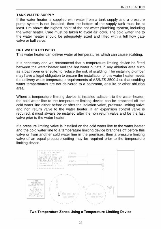
This water heater can deliver water at temperatures which can cause scalding. It is necessary and we recommend that a temperature limiting device be fitted between the water heater and the hot water outlets in any ablution area such as a bathroom or ensuite, to reduce the risk of scalding. The installing plumber may have a legal obligation to ensure the installation of this water heater meets the delivery water temperature requirements of AS/NZS 3500.4 so that scalding water temperatures are not delivered to a bathroom, ensuite or other ablution area. Where a temperature limiting device is installed adjacent to the water heater, the cold water line to the temperature limiting device can be branched off the cold water line either before or after the isolation valve, pressure limiting valve and non return valve to the water heater. If an expansion control valve is required, it must always be installed after the non return valve and be the last valve prior to the water heater. If a pressure limiting valve is installed on the cold water line to the water heater and the cold water line to a temperature limiting device branches off before this valve or from another cold water line in the premises, then a pressure limiting valve of an equal pressure setting may be required prior to the temperature limiting device.
LEGEND
Two Temperature Zones Using a Temperature Limiting Device
INSTALLATION
24
CIRCULATED HOT WATER FLOW AND RETURN SYSTEM
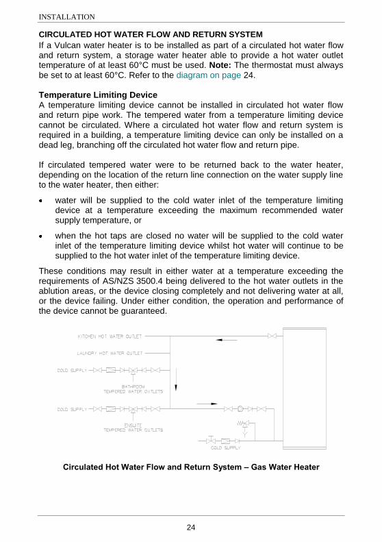
If a Vulcan water heater is to be installed as part of a circulated hot water flow and return system, a storage water heater able to provide a hot water outlet temperature of at least 60°C must be used. Note: The thermostat must always be set to at least 60°C. Refer to the diagram on page 24. Temperature Limiting Device A temperature limiting device cannot be installed in circulated hot water flow and return pipe work. The tempered water from a temperature limiting device cannot be circulated. Where a circulated hot water flow and return system is required in a building, a temperature limiting device can only be installed on a dead leg, branching off the circulated hot water flow and return pipe. If circulated tempered water were to be returned back to the water heater, depending on the location of the return line connection on the water supply line to the water heater, then either:
water will be supplied to the cold water inlet of the temperature limiting device at a temperature exceeding the maximum recommended water supply temperature, or
when the hot taps are closed no water will be supplied to the cold water inlet of the temperature limiting device whilst hot water will continue to be supplied to the hot water inlet of the temperature limiting device.
These conditions may result in either water at a temperature exceeding the requirements of AS/NZS 3500.4 being delivered to the hot water outlets in the ablution areas, or the device closing completely and not delivering water at all, or the device failing. Under either condition, the operation and performance of the device cannot be guaranteed.
LEGEND
Circulated Hot Water Flow and Return System – Gas Water Heater
INSTALLATION
25
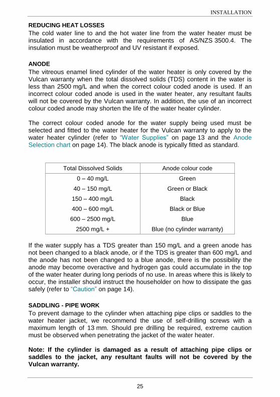
REDUCING HEAT LOSSES
The cold water line to and the hot water line from the water heater must be insulated in accordance with the requirements of AS/NZS 3500.4. The insulation must be weatherproof and UV resistant if exposed.
ANODE
The vitreous enamel lined cylinder of the water heater is only covered by the Vulcan warranty when the total dissolved solids (TDS) content in the water is less than 2500 mg/L and when the correct colour coded anode is used. If an incorrect colour coded anode is used in the water heater, any resultant faults will not be covered by the Vulcan warranty. In addition, the use of an incorrect colour coded anode may shorten the life of the water heater cylinder. The correct colour coded anode for the water supply being used must be selected and fitted to the water heater for the Vulcan warranty to apply to the water heater cylinder (refer to “Water Supplies” on page 13 and the Anode Selection chart on page 14). The black anode is typically fitted as standard.
Total Dissolved Solids Anode colour code
0 – 40 mg/L Green
40 – 150 mg/L Green or Black
150 – 400 mg/L Black
400 – 600 mg/L Black or Blue
600 – 2500 mg/L Blue
2500 mg/L + Blue (no cylinder warranty)
If the water supply has a TDS greater than 150 mg/L and a green anode has not been changed to a black anode, or if the TDS is greater than 600 mg/L and the anode has not been changed to a blue anode, there is the possibility the anode may become overactive and hydrogen gas could accumulate in the top of the water heater during long periods of no use. In areas where this is likely to occur, the installer should instruct the householder on how to dissipate the gas safely (refer to “Caution” on page 14).
SADDLING - PIPE WORK
To prevent damage to the cylinder when attaching pipe clips or saddles to the water heater jacket, we recommend the use of self-drilling screws with a maximum length of 13 mm. Should pre drilling be required, extreme caution must be observed when penetrating the jacket of the water heater. Note: If the cylinder is damaged as a result of attaching pipe clips or saddles to the jacket, any resultant faults will not be covered by the Vulcan warranty.
INSTALLATION
26
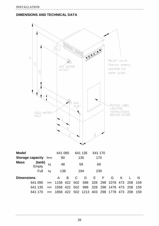
DIMENSIONS AND TECHNICAL DATA
Model 641 090 641 135 641 170
Storage capacity litres 90 135 170
Mass (tank)
Empty kg 48 59 69
Full kg 138 194 239
Dimensions A B C D E F G K L N
641 090 mm 1158 422 502 588 328 298 1078 473 208 159
641 135 mm 1558 422 502 988 328 298 1478 473 208 159
641 170 mm 1858 422 502 1213 403 298 1778 473 208 159
INSTALLATION
27
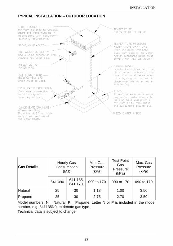
TYPICAL INSTALLATION – OUTDOOR LOCATION
Installation Typical
Gas Domestic Outdoor Water Heater
Gas Details Hourly Gas
Consumption (MJ)
Min. Gas Pressure
(kPa)
Test Point Gas
Pressure (kPa)
Max. Gas Pressure
(kPa)
641 090 641 135 641 170
090 to 170 090 to 170 090 to 170
Natural 25 30 1.13 1.00 3.50
Propane 25 30 2.75 2.70 3.50
Model numbers: N = Natural, P = Propane. Letter N or P is included in the model number, e.g. 641135N0, to denote gas type.
Technical data is subject to change.
28
CONNECTIONS – PLUMBING
All plumbing work must be carried out by a qualified person and in compliance with the Standard AS/NZS 3500.4 and all local codes and regulatory authority requirements. All gas work must be carried out by a qualified person and in compliance with the Standard AS 5601 or AS/NZS 5601.1, as applicable under local regulations, and all local codes and regulatory authority requirements. In New Zealand, the installation must also conform with NZS 5261, as applicable under local regulations.
CONNECTION SIZES
Hot water connection: RP¾/20.
Cold water connection: RP¾/20.
Relief valve connection: RP½/15.
Gas inlet: RP½/15.
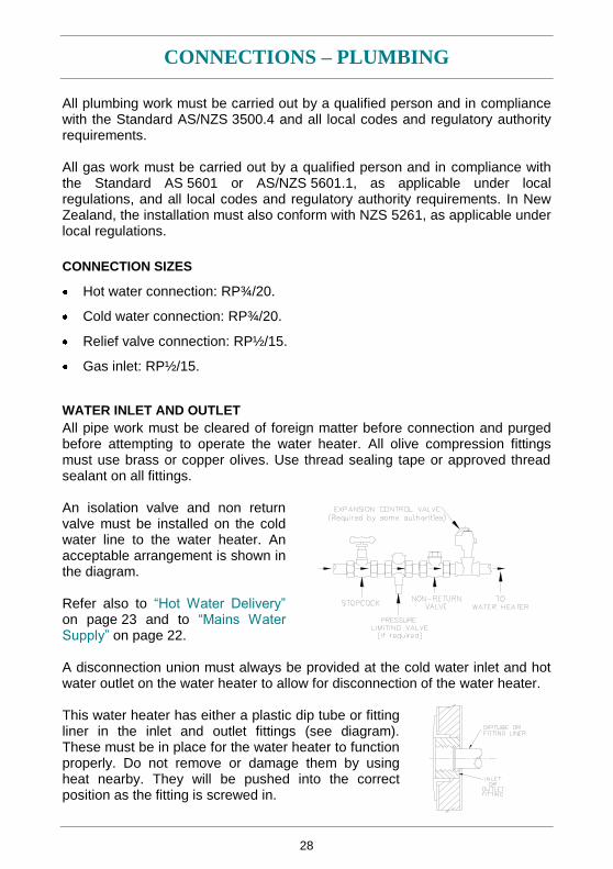
WATER INLET AND OUTLET
All pipe work must be cleared of foreign matter before connection and purged before attempting to operate the water heater. All olive compression fittings must use brass or copper olives. Use thread sealing tape or approved thread sealant on all fittings. An isolation valve and non return valve must be installed on the cold water line to the water heater. An acceptable arrangement is shown in the diagram. Refer also to “Hot Water Delivery” on page 23 and to “Mains Water Supply” on page 22. A disconnection union must always be provided at the cold water inlet and hot water outlet on the water heater to allow for disconnection of the water heater. This water heater has either a plastic dip tube or fitting liner in the inlet and outlet fittings (see diagram). These must be in place for the water heater to function properly. Do not remove or damage them by using heat nearby. They will be pushed into the correct position as the fitting is screwed in.
CONNECTIONS – PLUMBING
29
PIPE SIZES
To achieve true mains pressure operation, the cold water line to the water heater should be the same size or bigger than the hot water line from the water heater. The pipe sizing for hot water supply systems should be carried out by persons competent to do so, choosing the most suitable pipe size for each individual application. Reference to the technical specifications of the water heater and local regulatory authority requirements must be made.
TEMPERATURE PRESSURE RELIEF VALVE
The temperature pressure relief valve is shipped behind the front cover. The temperature pressure relief valve must be fitted before the water heater is operated. Before fitting the relief valve, make sure the probe has not been bent. Seal the thread with Teflon tape - never hemp. Make sure the tape does not hang over the end of the thread. Screw the valve into the correct opening (refer to the installation diagram on page 27) leaving the valve drain pointing downwards. Do not use a wrench on the valve body - use the spanner flats provided. A copper drain line must be fitted to the temperature pressure relief valve (refer to "Relief Valve Drain" on page 30). The valve must be insulated with closed cell polymer insulation or similar (minimum thickness 9 mm) and the insulation installed so as not to impede the operation of the valve. The insulation must be weatherproof and UV resistant if exposed.
EXPANSION CONTROL VALVE
Local regulations may make it mandatory to install an expansion control valve (ECV) in the cold water line to the water heater. In other areas, an ECV is required if the saturation index is greater than +0.4 (refer to “Water Supplies” on page 13). The expansion control valve must always be installed after the non return valve and be the last valve installed prior to the water heater (refer to diagram on page 28). A copper drain line must be fitted to the expansion control valve (refer to "Relief Valve Drain" on page 30). The valve must be insulated with closed cell polymer insulation or similar (minimum thickness 9 mm) and the insulation installed so as not to impede the operation of the valve. The insulation must be weatherproof and UV resistant if exposed.
CONNECTIONS – PLUMBING
30
RELIEF VALVE DRAIN
DN15 (copper drain lines must be fitted to the temperature pressure relief valve and expansion control valve (if one is installed) to carry the discharge clear of the water heater. Connect the drain lines to the valves using disconnection unions. The drain line from the valve to the point of discharge should be as short as possible, have a continuously downward fall all the way from the water heater to the discharge outlet and have no tap, valves or other restrictions in the pipe work. A drain line from a relief valve must comply with the requirements of AS/NZS 3500.4. A drain line must be no longer than 9 metres with no more than three bends greater than 45° before discharging at an outlet or air break. The maximum length of 9 metres for a drain line is reduced by 1 metre for each additional bend required of greater than 45°, up to a maximum of three additional bends. Where the distance to the point of final discharge exceeds this length, the drain line can discharge into a tundish. Subject to local regulatory authority approval, the drain lines from the temperature pressure relief valve and expansion control valve from an individual water heater may be interconnected. The outlet of a drain line must be in such a position that flow out of the pipe can be easily seen, but arranged so discharge will not cause injury, damage or nuisance. The termination point of a drain line must comply with the requirements of AS/NZS 3500.4. Drain lines must not discharge into a safe tray. In locations where water pipes are prone to freezing, drain lines must be insulated, must not exceed 300 mm in length and are to discharge into a tundish through an air gap of between 75 mm and 150 mm. If a drain line discharges into a tundish, the drain line from the tundish must be not less than DN20. The drain line from a tundish must meet the same requirements as for a drain line from a relief valve.
Warning: As the function of the temperature pressure relief valve on this water heater is to discharge high temperature water under certain conditions, it is strongly recommended the pipe work downstream of the relief valve be capable of carrying water exceeding 93°C. Failure to observe this precaution may result in damage to pipe work and property.
CONNECTIONS – PLUMBING
31
GAS INLET
The gas connection is made through the grommet in the left hand side panel to the gas control. The pipe work must be cleared of foreign matter before connection and purged before attempting to light the water heater. An isolation valve and disconnection union must be installed to allow servicing and removal of the water heater.
Note: Refer to the Gas Installations Standard AS 5601 or AS/NZS 5601.1 for
the correct method of sizing the gas supply pipe to the water heater. The pipe size selection must take into account the gas input of this water heater (refer to table on page 27) as well as all of the other gas appliances in the premises.
Warning: Always isolate the water heater before pressure testing the gas supply system. Disconnect the water heater after the isolating cock to prevent the risk of serious damage to the gas control. The Vulcan warranty does not cover damage of any nature resulting from failure to observe this precaution. Refer to rating label for gas types and pressures. Caution: Care is necessary when tightening fittings into the gas valve. The gas valve casting may crack if the fittings are over tightened. Cracked valve castings are not covered under the Vulcan warranty. Damaged valves must be replaced.
32
COMMISSIONING
TO FILL AND TURN ON THE WATER HEATER
The gas pilot or burner must not be lit until the water heater is filled with water.
Open all of the hot water taps in the house (don‟t forget the shower).
Open the cold water isolation valve fully to the water heater.
Air will be forced out of the taps.
Close each tap as water flows freely from it.
Check the pipe work for leaks.
Open the gas isolation valve fully.
Check the gas pipe work for leaks.
Light the water heater (refer to “Lighting the Water Heater” on page 33).
Warning: Upon completion of the installation and commissioning of the water heater, leave this guide with the householder or a responsible officer. DO NOT leave this guide inside of the cover of the water heater, as it may interfere with the safe operation of the water heater or ignite when the water heater is turned on. Explain to the householder or a responsible officer the functions and operation of the water heater.
GAS INLET PRESSURE
IMPORTANT – CHECK the gas supply pressure at the inlet to the water heater with the water heater and all other gas burning appliances in the premises operating (burners alight). The minimum gas supply pressure is:
Natural Gas 1.13 kPa Propane 2.75 kPa If this minimum cannot be achieved, it may indicate the meter or the gas line to the water heater is undersized. It is important to ensure that an adequate gas supply pressure is available to the water heater when other gas burning appliances, on the same gas supply, are operating.
TO TURN OFF THE WATER HEATER
If it is necessary to turn off the water heater on completion of the installation, such as on a building site or where the premises is vacant, then:
Shut down the gas control (refer to “Close Down Procedure” on page 35).
Close the gas isolation valve at the inlet to the gas control.
Close the cold water isolation valve at the inlet to the water heater.
33
LIGHTING THE WATER HEATER
FOR YOUR SAFETY READ BEFORE LIGHTING
Warning: This gas water heater is designed to operate reliably and safely as long as the operating instructions are followed exactly. You must comply with these lighting instructions at every stage. Make sure the water heater is filled with water and the water supply is on, otherwise serious damage to the vitreous enamel cylinder lining and plastic components may occur.
The installer must check all gas connections for leaks, gas supply pressure and test point pressure (refer rating label). Remove the access cover at the front of the water heater to access the gas thermostat. Note: AS 3498 requires that a water heater provides the means to inhibit the growth of Legionella bacteria in potable water. This water heater can satisfy this AS 3498 requirement provided it is operating and the thermostat setting is 60°C or higher, including when it is used as an in-series booster water heater for a solar water heater.
SAFETY INFORMATION
A. This water heater is equipped with an igniter button which lights the pilot. When lighting the pilot follow these instructions exactly.
B. Before lighting ensure there is no smell of gas around or in the vicinity of the water heater and the burner opening. Be sure to smell next to ground level as some gases can settle there.
C. What to do if you smell gas.
Do not try to light the water heater.
If the gas smell is throughout the area, turn the gas control knob clockwise to the “” (off) position and then turn off the isolation valve on the gas line to the water heater. Leave the area and call Rheem Service or a qualified service technician.
D. Use only your hand to turn the gas control knob, never use tools. If the control knob will not turn by hand, don‟t try to repair it, call a qualified service technician. Force or attempted repair may cause a fire or explosion.
E. Do not attempt to operate this water heater if it has been damaged. Call a qualified service technician.
LIGHTING THE WATER HEATER
34
LIGHTING INSTRUCTIONS
Using the gas control light the water heater as follows:
1. Stop, read the safety information on page 33.
2. Remove the access cover.
3. Turn the gas control knob fully clockwise to the “” (off) position.
4. Wait five (5) minutes so any build up of unburnt gas can escape. If you then smell gas, stop and follow “C” in the safety information. If you do not smell gas, proceed to step 4.
5. Turn the knob to the “” (pilot) position.
6. Depress the knob fully (until star disappears below housing) and after 30 seconds, whilst keeping the knob depressed, repeatedly press the igniter button (for up to 40 seconds) until the pilot flame ignites.
Warning: Keep your face clear of the combustion chamber opening
while pressing the igniter.
Note: It is not possible to depress the knob fully if the gas control has activated its safety shut-off feature. In this case, wait 60 seconds for the gas control to reset.
7. Keep the knob depressed for 20 seconds after the pilot flame lights.
8. Release the knob and check the pilot is still alight. The pilot can be checked by looking through the large opening below the gas control.
9. If the pilot has failed to light or has not remained alight, turn the gas control knob to the "” (off) position. Wait five (5) minutes for any unburnt gas to escape and then begin again at step 3.
Warning: Failure to wait five (5) minutes may result in a fire or
explosion.
10. When the pilot flame remains alight with the gas control knob released, turn the knob anticlockwise to the setting of „6‟. This will give a water temperature of about 60°C.
11. Refer to “Temperature Adjustment” on page 5, if further temperature adjustment is required.
12. Replace the access cover.
The main burner will now automatically ignite when heating is required and extinguish when the water has been heated to the set temperature. If the main burner does not light at the selected setting, the water may already be at the selected temperature. Note: Never press the igniter button while the top knob is in a numbered position.
LIGHTING THE WATER HEATER
35
TEST THE WATER HEATER AFTER INSTALLATION
The operation of the water heater must be thoroughly checked by the installer.
The burner flame must light smoothly and quickly from the pilot flame, and must go out quietly and completely.
The main burner flame must be stable, although slight lifting at the front edge of the burner is acceptable when the burner is cold.
The main burner flame should be blue, with a clearly defined inner cone - luminous yellow or "floating" flames are not acceptable, and must be corrected by opening the air shutter (refer to “Air Shutter” on page 35).
Check the test point pressure and compare with the rating label. The pressure regulator is not adjustable and if the test point pressure is not within 5% of the specified value, refer to Rheem Service or their nearest Accredited Service Agent.
If unable to get the water heater working properly, contact Rheem Service or their nearest Accredited Service Agent.
When satisfied everything is working properly instruct the user in the correct method of operation.
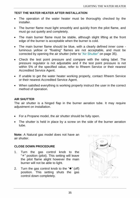
AIR SHUTTER
The air shutter is a hinged flap in the burner aeration tube. It may require adjustment on installation.
For a Propane model, the air shutter should be fully open.
The shutter is held in place by a screw on the side of the burner aeration tube.
Note: A Natural gas model does not have an air shutter.
CLOSE DOWN PROCEDURE
1. Turn the gas control knob to the “” position (pilot). This setting will leave the pilot flame alight however the main burner will not be able to light.
2. Turn the gas control knob to the "" (off) position. This setting shuts the gas control down completely.
36
DRAINING THE WATER HEATER
Warning: Exercise care, as water discharged from the water heater may be of a very high temperature. To drain the water heater:
Turn off the water heater (refer to “To Turn Off The Water Heater” on page 32).
Close all hot water taps.
Operate the relief valve release lever - do not let the lever snap back or you will damage the valve seat. Operating the lever will release the pressure in the water heater.
Undo the union at the cold water inlet to the water heater and attach a hose to the water heater side of the union. Let the other end of the hose go to a drain.
Operate the relief valve again. This will let air into the water heater and allow the water to drain through the hose.

37
This page is intentionally blank.
38
VULCAN GAS MAINS PRESSURE
WATER HEATER WARRANTY – AUSTRALIA ONLY
GAS WATER HEATER 641 SERIES 090, 135, 170 MODELS
1. THE VULCAN WARRANTY – GENERAL
1.1 This warranty is given by Rheem Australia Pty Limited ABN 21 098 823 511 of 1 Alan Street, Rydalmere New South Wales, the manufacturer of Vulcan mains pressure water heaters.
1.2 Rheem offer a trained and qualified national service network who will repair or replace components at the address of the water heater subject to the terms of the Vulcan warranty. Rheem Service, in addition can provide preventative maintenance and advice on the operation of your water heater. The Rheem Service contact number is available 7 days a week on 131031 with Service personnel available to take your call from 8am to 8pm daily (hours subject to change).
1.3 For details about this warranty, you can contact us on 131031 or by email at [email protected] (not for service bookings).
1.4 The terms of this warranty are set out in section 2 and apply to water heaters manufactured after 1st December 2011.
1.5 If a subsequent version of this warranty is published, the terms of that warranty will apply to water heaters manufactured after the date specified in the subsequent version.
2. TERMS OF THE VULCAN WARRANTY AND EXCLUSIONS TO IT
2.1 The decision of whether to repair or replace a faulty component is at Rheem’s sole discretion.
2.2 If you require a call out and we find that the fault is not covered by the Vulcan warranty, you are responsible for our standard call out charge. If you wish to have the relevant component repaired or replaced by Rheem, that service will be at your cost.
2.3 Where a failed component or cylinder is replaced under this warranty, the balance of the original warranty period will remain effective. The replacement does not carry a new Vulcan warranty.
2.4 Where the water heater is installed outside the boundaries of a metropolitan area as defined by Rheem or further than 25 km from either a regional Rheem branch office or an Accredited Rheem Service Agent's office, the cost of transport, insurance and travelling between the nearest branch office or Rheem Accredited Service Agent’s office and the installed site shall be the owner’s responsibility.
2.5 Where the water heater is installed in a position that does not allow safe or ready access, the cost of that access, including the cost of additional materials handling and/or safety equipment, shall be the owner’s responsibility. In other words, the cost of dismantling or removing cupboards, doors or walls and the cost of any special equipment to bring the water heater to floor or ground level or to a serviceable position is not covered by this warranty.
2.6 This warranty only applies to the original and genuine Vulcan water heater in its original installed location and any genuine Vulcan replacement parts.
2.7 The Vulcan warranty does not cover faults that are a result of:
a) Accidental damage to the water heater or any component (for example: (i) Acts of God such as floods, storms, fires, lightning strikes and the like; and (ii) third party acts or omissions).
b) Misuse or abnormal use of the water heater.
VULCAN GAS MAINS PRESSURE
WATER HEATER WARRANTY – AUSTRALIA ONLY
39
c) Installation not in accordance with the Owner’s Guide and Installation Instructions or with relevant statutory and local requirements in the State or Territory in which the water heater is installed.
d) Connection at any time to a water supply that does not comply with the water supply guidelines as outlined in the Owner’s Guide and Installation Instructions.
e) Repairs, attempts to repair or modifications to the water heater by a person other than Rheem Service or a Rheem Accredited Service Agent.
f) Faulty plumbing or faulty gas supply.
g) Failure to maintain the water heater in accordance with the Owner's Guide and Installation Instructions.
h) Transport damage.
i) Fair wear and tear from adverse conditions (for example, corrosion).
j) Cosmetic defects.
2.8 Subject to any statutory provisions to the contrary, this warranty excludes any and all claims for damage to furniture, carpet, walls, foundations or any other consequential loss either directly or indirectly due to leakage from the water heater, or due to leakage from fittings and/ or pipe work of metal, plastic or other materials caused by water temperature, workmanship or other modes of failure.
2.9 If the water heater is not sized to supply the hot water demand in accordance with the guidelines in the Vulcan water heater literature, any resultant fault will not be covered by the Vulcan warranty.
3. WHAT IS COVERED BY THE VULCAN WARRANTY
FOR THE WATER HEATERS DETAILED IN THIS DOCUMENT
3.1 Rheem will repair or replace a faulty component of your water heater if it fails to operate in accordance with its specifications as follows:
What components are covered
The period in which the fault must appear in order to be covered
What coverage you receive
All components Year 1 Repair and/or replacement of the faulty component, free of charge, including labour.
The cylinder (if the water heater is
installed in a single-family domestic dwelling)
Years 2 & 3 Repair and / or replacement of the cylinder, free of charge, including labour.
Years 4 & 5 Replacement cylinder, free of charge. Installation and repair labour costs are the responsibility of the owner.
The cylinder (if the water heater is not installed in a single-family
domestic dwelling)
Years 2 & 3 Replacement cylinder, free of charge. Installation and repair labour costs are the responsibility of the owner.
VULCAN GAS MAINS PRESSURE
WATER HEATER WARRANTY – AUSTRALIA ONLY
Revision Date: 2012 March 122095J
40
GAS WATER HEATER 641 SERIES 090, 135, 170 MODELS
4. ENTITLEMENT TO MAKE A CLAIM UNDER THIS WARRANTY
4.1 To be entitled to make a claim under this warranty you need to:
a) Be the owner of the water heater or have consent of the owner to act on their behalf
b) Contact Rheem Service without undue delay after detection of the defect and, in any event, within the applicable warranty period.
4.2 You are not entitled to make a claim under this warranty if your water heater:
a) Does not have its original serial numbers or rating labels.
b) Is not installed in Australia.
5. HOW TO MAKE A CLAIM UNDER THIS WARRANTY
5.1 If you wish to make a claim under this warranty, you need to:
a) Contact Rheem on 131031 and provide owner’s details, address of the water heater, a contact number and date of installation of the water heater or if that’s unavailable, the date of manufacture and serial number (from the rating label on the water heater)
b) Rheem will arrange for the water heater to be tested and assessed on-site.
c) If Rheem determines that you have a valid warranty claim, Rheem will repair or replace the water heater in accordance with this warranty
5.2 Any expenses incurred in the making of a claim under this warranty will be borne by you.
6. THE AUSTRALIAN CONSUMER LAW
6.1 Our goods come with guarantees that cannot be excluded under the Australian Consumer Law. You are entitled to a replacement or refund for a major failure and for compensation for any other reasonably foreseeable loss or damage. You are also entitled to have the goods repaired or replaced if the goods fail to be of acceptable quality and the failure does not amount to a major failure.
6.2 The Vulcan warranty (set out above) is in addition to any rights and remedies that you may have under the Australian Consumer Law.
RHEEM AUSTRALIA PTY LTD, A.B.N. 21 098 823 511, www.rheem.com.au For Service Telephone 131 031 AUSTRALIA 0800 657 335 NEW ZEALAND


![VULCAN HIGH SPEED DEEP FAT FRYER (ELECTRIC) › vulcan-website...Vulcan catering equipment (ptY)ltD [ 2 ] VULCAN HIGH SPEED DEEP FAT FRYER (ELECTRIC) GENERAL DATA: MANUFACTURER: Vulcan](https://img.pdfslide.us/doc/110x75/60c05ae5c355355f26327394/vulcan-high-speed-deep-fat-fryer-electric-a-vulcan-website-vulcan-catering.jpg)


![VULCAN VIZU HOLDA - Amazon S3...VULCAN CATERING EQUIPMENT (PTY)LTD [ 6 ] VULCAN VIZU HOLDA VULCAN CATERING EQUIPMENT (PTY)LTD VULCAN VIZU HOLDA WIRING DIAGRAM Item No. Stores Ref.No](https://img.pdfslide.us/doc/110x75/60e756b4cf711d2301079486/vulcan-vizu-holda-amazon-s3-vulcan-catering-equipment-ptyltd-6-vulcan.jpg)