Embed Size (px)
Citation preview
ENGLISH
Vulcan SeriesInstallation Manual
www.bandg.com

Preface
DisclaimerAs Navico is continuously improving this product, we retain theright to make changes to the product at any time which may not bereflected in this version of the manual. Please contact your nearestdistributor if you require any further assistance.
It is the owner’s sole responsibility to install and use the equipmentin a manner that will not cause accidents, personal injury orproperty damage. The user of this product is solely responsible forobserving safe boating practices.
NAVICO HOLDING AS AND ITS SUBSIDIARIES, BRANCHES ANDAFFILIATES DISCLAIM ALL LIABILITY FOR ANY USE OF THIS PRODUCTIN A WAY THAT MAY CAUSE ACCIDENTS, DAMAGE OR THAT MAYVIOLATE THE LAW.
Governing Language: This statement, any instruction manuals, userguides and other information relating to the product(Documentation) may be translated to, or has been translated from,another language (Translation). In the event of any conflict betweenany Translation of the Documentation, the English language versionof the Documentation will be the official version of theDocumentation.
This manual represents the product as at the time of printing.Navico Holding AS and its subsidiaries, branches and affiliatesreserve the right to make changes to specifications without notice.
CopyrightCopyright © 2016 Navico Holding AS.
WarrantyThe warranty card is supplied as a separate document.
In case of any queries, refer to the brand website of your unit orsystem: www.bandg.com.
Compliance statementsThis equipment complies with:
• CE under 2014/53/EU Directive
Preface | Vulcan Series Installation Manual 3
• The requirements of level 2 devices of the Radio communications(Electromagnetic Compatibility) standard 2008
• Part 15 of the FCC Rules. Operation is subject to the followingtwo conditions: (1) this device may not cause harmfulinterference, and (2) this device must accept any interferencereceived, including interference that may cause undesiredoperation.
The relevant Declaration of conformity is available in the product'ssection at the following website: www.bandg.com.
Industry CanadaIC RSS-GEN, Sec 7.1.3 Warning Statement- (Required forlicense exempt devices)This device complies with Industry Canada license-exempt RSSstandard(s). Operation is subject to the following two conditions: (1)this device may not cause interference, and (2) this device mustaccept any interference, including interference that may causeundesired operation of the device.
Le présent appareil est conforme aux CNR d’Industrie
Canada applicables aux appareils radio exempts de licence. L’exploitation est autorisée aux deux conditions suivantes: (1)l’appareil ne doit pas produire de brouillage, et (2) l’utilisateur del’appareil doit accepter tout brouillage radioélectrique subi, même sile brouillage est susceptible d’en compromettre le fonctionnement.
WarningThe user is cautioned that any changes or modifications notexpressly approved by the party responsible for compliance couldvoid the user’s authority to operate the equipment.
This equipment generates, uses and can radiate radio frequencyenergy and, if not installed and used in accordance with theinstructions, may cause harmful interference to radiocommunications. However, there is no guarantee that theinterference will not occur in a particular installation. If thisequipment does cause harmful interference to radio or televisionreception, which can be determined by turning the equipment offand on, the user is encouraged to try to correct the interference byone or more of the following measures:
4 Preface | Vulcan Series Installation Manual
• Reorient or relocate the receiving antenna• Increase the separation between the equipment and receiver• Connect the equipment into an outlet on a circuit different from
that of the receiver• Consult the dealer or an experienced technician for help
Internet usageSome features in this product use an internet connection toperform data downloads and uploads. Internet usage via aconnected mobile/cell phone internet connection or a pay-per-MBtype internet connection may require large data usage. Your serviceprovider may charge you based on the amount of data you transfer.If you are unsure, contact your service provider to confirm rates andrestrictions.
Countries of intended use in the EUAT - Austria
BE - Belgium
BG - Bulgaria
CY - Cyprus
CZ - Czech Republic
DK - Denmark
EE - Estonia
FI - Finland
FR - France
DE - Germany
GR - Greece
HU - Hungary
IS - Iceland
IE - Ireland
IT - Italy
LV - Latvia
LI - Liechtenstein
LT - Lithuania
LU - Luxembourg
MT - Malta
Preface | Vulcan Series Installation Manual 5
NL - Netherlands
NO - Norway
PL - Poland
PT - Portugal
RO - Romania
SK - Slovak Republic
SI - Slovenia
ES - Spain
SE - Sweden
CH - Switzerland
TR - Turkey
UK - United Kingdom
TrademarksNavionics® is a registered trademark of Navionics, Inc.
NMEA® and NMEA 2000® are registered trademarks of the NationalMarine Electronics Association.
SiriusXM® is a registered trademark of Sirius XM Radio Inc.
Fishing Hot Spots® is a registered trademark of Fishing Hot Spots Inc.Copyright© 2012 Fishing Hot Spots.
FUSION-Link™ Marine Entertainment Standard™ is a registeredtrademark of FUSION Electronics Ltd.
C-MAP is a trademark of C-MAP.
SD™ and microSD™ are trademarks or registered trademarks ofSD-3C, LLC in the United States, other countries or both.
Wi-Fi® is a registered trademark of the Wi-Fi Alliance®.
Additional mapping data: Copyright© 2012 NSI, Inc.: Copyright©2012 by Richardson’s Maptech.
Bluetooth® is a registered trademark of Bluetooth SIG, Inc.
HDMI® and HDMI™, the HDMI Logo, and High-Definition MultimediaInterface are trademarks or registered trademarks of HDMI LicensingLLC in the United States and other countries.
Navico product referencesThis manual refers to the following Navico products:
6 Preface | Vulcan Series Installation Manual
• Broadband Sounder™ (Broadband Sounder)• DownScan Imaging™ (DownScan)• DownScan Overlay™ (Overlay)• GoFree™ (GoFree)• INSIGHT GENESIS® (Insight Genesis)• SonicHub® (SonicHub)
About this manualThis manual is a reference guide for installing the Vulcan Seriesunits.
Important text that requires special attention from the reader isemphasized as follows:
Ú Note: Used to draw the reader’s attention to a comment orsome important information.
Warning: Used when it is necessary to warnpersonnel that they should proceed carefully toprevent risk of injury and/or damage to equipment/personnel.
Preface | Vulcan Series Installation Manual 7

8 Preface | Vulcan Series Installation Manual
Contents
11 Check the contents11 Vulcan 5 box contents12 Vulcan 7 FS and Vulcan 9 FS box contents
13 Overview13 Front controls14 Rear connections15 Card reader
17 Installation17 Mounting location18 Bracket mounting20 Panel mounting21 Transducer installation
22 Wiring22 Guidelines23 Power Connections24 Power Control connection25 External alarm26 Connecting control devices26 NMEA 2000 backbone28 CZone connection to NMEA 200029 Transducer connection29 Radar connector
31 Software Setup31 First time startup31 Time and Date31 Data source selection33 Device list34 Sonar setup35 StructureScan35 Radar setup40 Autopilot setup52 Fuel setup55 CZone setup57 Wireless setup
Contents | Vulcan Series Installation Manual 9
62 NMEA 2000 setup62 Software updates and data backup
67 Accessories
69 Supported data69 NMEA 2000 compliant PGN List
74 Technical specifications74 Mechanical/Environmental74 Electrical75 Interfaces
76 Dimensional drawings76 Vulcan 5 Dimensional drawings76 Vulcan 7 FS Dimensional drawings77 Vulcan 9 FS Dimensional drawings
10 Contents | Vulcan Series Installation Manual
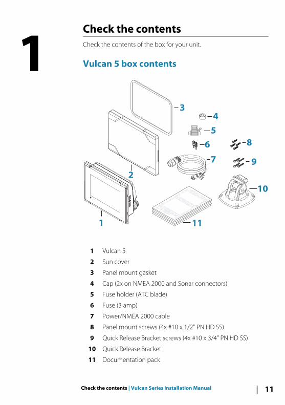
Check the contentsCheck the contents of the box for your unit.
Vulcan 5 box contents
ENGLISH
Installation Manual
bandg.com
ENGLISH
Installation Manual
bandg.com
ENGLISH
Installation Manual
bandg.com
ENGLISH
Installation Manual
bandg.com
1
2
4
5
6
7
10
9
11
8
3
1 Vulcan 5
2 Sun cover
3 Panel mount gasket
4 Cap (2x on NMEA 2000 and Sonar connectors)
5 Fuse holder (ATC blade)
6 Fuse (3 amp)
7 Power/NMEA 2000 cable
8 Panel mount screws (4x #10 x 1/2" PN HD SS)
9 Quick Release Bracket screws (4x #10 x 3/4" PN HD SS)
10 Quick Release Bracket
11 Documentation pack
1
Check the contents | Vulcan Series Installation Manual 11
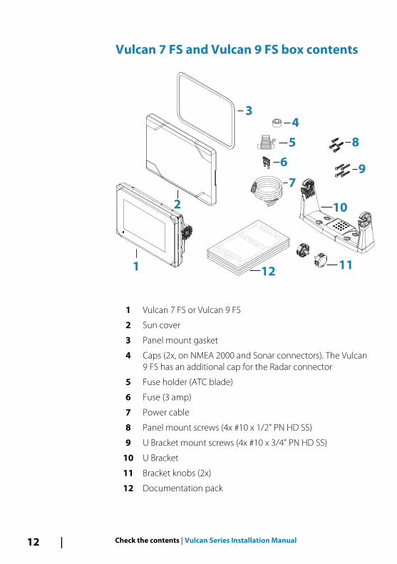
Vulcan 7 FS and Vulcan 9 FS box contents
ENGLISH
Installation Manual
bandg.com
ENGLISH
Installation Manual
bandg.com
ENGLISH
Installation Manual
bandg.com
ENGLISH
Installation Manual
bandg.com
1
2
4
5
6
7
10
9
1211
8
3
1 Vulcan 7 FS or Vulcan 9 FS
2 Sun cover
3 Panel mount gasket
4 Caps (2x, on NMEA 2000 and Sonar connectors). The Vulcan9 FS has an additional cap for the Radar connector
5 Fuse holder (ATC blade)
6 Fuse (3 amp)
7 Power cable
8 Panel mount screws (4x #10 x 1/2" PN HD SS)
9 U Bracket mount screws (4x #10 x 3/4" PN HD SS)
10 U Bracket
11 Bracket knobs (2x)
12 Documentation pack
12 Check the contents | Vulcan Series Installation Manual
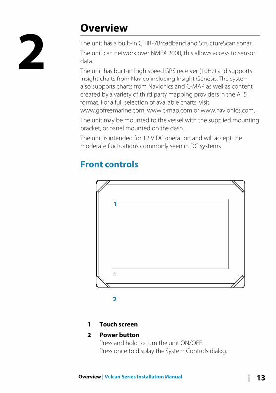
OverviewThe unit has a built-in CHIRP/Broadband and StructureScan sonar.
The unit can network over NMEA 2000, this allows access to sensordata.
The unit has built-in high speed GPS receiver (10Hz) and supportsInsight charts from Navico including Insight Genesis. The systemalso supports charts from Navionics and C-MAP as well as contentcreated by a variety of third party mapping providers in the AT5format. For a full selection of available charts, visitwww.gofreemarine.com, www.c-map.com or www.navionics.com.
The unit may be mounted to the vessel with the supplied mountingbracket, or panel mounted on the dash.
The unit is intended for 12 V DC operation and will accept themoderate fluctuations commonly seen in DC systems.
Front controls
1 Touch screen
2 Power buttonPress and hold to turn the unit ON/OFF.Press once to display the System Controls dialog.
2
Overview | Vulcan Series Installation Manual 13
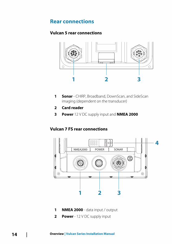
Rear connections
Vulcan 5 rear connections
1 2 3
1 Sonar - CHIRP, Broadband, DownScan, and SideScanimaging (dependent on the transducer)
2 Card reader
3 Power 12 V DC supply input and NMEA 2000
Vulcan 7 FS rear connections
NMEA2000 POWER SONAR
1 2 3
4
1 NMEA 2000 - data input / output
2 Power - 12 V DC supply input
14 Overview | Vulcan Series Installation Manual
3 Sonar - CHIRP, Broadband, DownScan, and SideScanimaging (dependent on the transducer)
4 Card reader
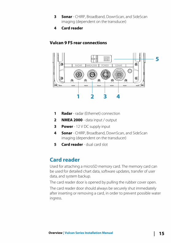
Vulcan 9 FS rear connections
1 2 3 4
5RADAR NMEA2000 POWER SONAR
1 Radar - radar (Ethernet) connection
2 NMEA 2000 - data input / output
3 Power - 12 V DC supply input
4 Sonar - CHIRP, Broadband, DownScan, and SideScanimaging (dependent on the transducer)
5 Card reader - dual card slot
Card readerUsed for attaching a microSD memory card. The memory card canbe used for detailed chart data, software updates, transfer of userdata, and system backup.
The card reader door is opened by pulling the rubber cover open.
The card reader door should always be securely shut immediatelyafter inserting or removing a card, in order to prevent possible wateringress.
Overview | Vulcan Series Installation Manual 15
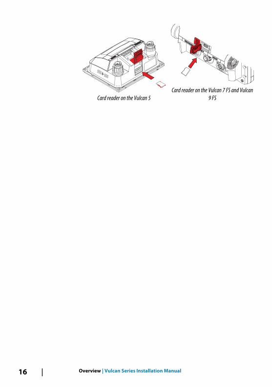
Card reader on the Vulcan 5Card reader on the Vulcan 7 FS and Vulcan
9 FS
16 Overview | Vulcan Series Installation Manual
Installation
Mounting locationChoose the mounting locations carefully before you drill or cut. Theunit should be mounted so that the operator can easily use thecontrols and clearly see the screen.
The unit has a high-contrast screen and is viewable in directsunlight, but for best results install the unit out of direct sunlight.The chosen location should have minimal glare from windows orbright objects.
Ensure that any holes cut are in a safe position and will not weakenthe boat’s structure. If in doubt, consult a qualified boat builder, ormarine electronics installer.
Before cutting a hole in a panel, make sure that there are no hiddenelectrical wires or other parts behind the panel.
Check that it is possible to route cables to the intended mountinglocation.
Consider access to the card reader which is located in the back ofthe unit.
Leave sufficient clearance to connect all relevant cables.
Do not mount any part where it can be used as a hand hold, whereit might be submerged, or where it will interfere with the operation,launching, or retrieving of the boat.
The mounting location may affect the internal GPS receiver. Test theunit in its intended location to ensure satisfactory reception. Anexternal GPS source can be added to overcome poor receptionareas.
For overall width and height requirements, refer to "Dimensionaldrawings" on page 76.
Good ventilation is required. Choose a location that will not exposethe unit to conditions that exceed the specifications - refer to"Technical specifications" on page 74.
3
Installation | Vulcan Series Installation Manual 17
Warning: When installing, ensure appropriate safetyequipment is used. For example, ear muffs, protectiveglasses, gloves and a dust mask. Power tools mayexceed safe noise levels, and can cast off dangerousprojectiles. The dust from many materials commonlyused in boat construction may cause irritation ordamage to eyes, skin, and lungs.
Bracket mounting
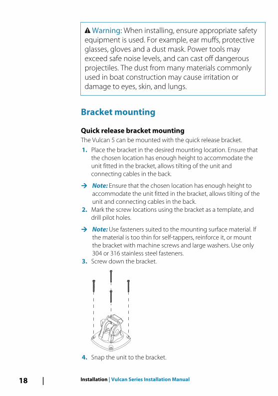
Quick release bracket mountingThe Vulcan 5 can be mounted with the quick release bracket.
1. Place the bracket in the desired mounting location. Ensure thatthe chosen location has enough height to accommodate theunit fitted in the bracket, allows tilting of the unit andconnecting cables in the back.
Ú Note: Ensure that the chosen location has enough height toaccommodate the unit fitted in the bracket, allows tilting of theunit and connecting cables in the back.
2. Mark the screw locations using the bracket as a template, anddrill pilot holes.
Ú Note: Use fasteners suited to the mounting surface material. Ifthe material is too thin for self-tappers, reinforce it, or mountthe bracket with machine screws and large washers. Use only304 or 316 stainless steel fasteners.
3. Screw down the bracket.
4. Snap the unit to the bracket.
18 Installation | Vulcan Series Installation Manual
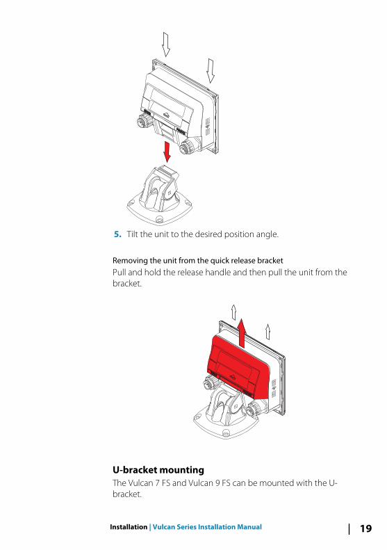
5. Tilt the unit to the desired position angle.
Removing the unit from the quick release bracketPull and hold the release handle and then pull the unit from thebracket.
U-bracket mountingThe Vulcan 7 FS and Vulcan 9 FS can be mounted with the U-bracket.
Installation | Vulcan Series Installation Manual 19
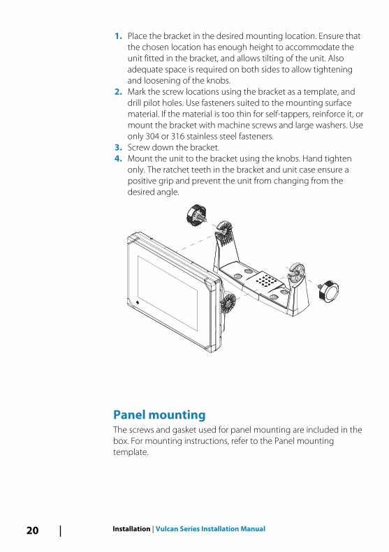
1. Place the bracket in the desired mounting location. Ensure thatthe chosen location has enough height to accommodate theunit fitted in the bracket, and allows tilting of the unit. Alsoadequate space is required on both sides to allow tighteningand loosening of the knobs.
2. Mark the screw locations using the bracket as a template, anddrill pilot holes. Use fasteners suited to the mounting surfacematerial. If the material is too thin for self-tappers, reinforce it, ormount the bracket with machine screws and large washers. Useonly 304 or 316 stainless steel fasteners.
3. Screw down the bracket.4. Mount the unit to the bracket using the knobs. Hand tighten
only. The ratchet teeth in the bracket and unit case ensure apositive grip and prevent the unit from changing from thedesired angle.
Panel mountingThe screws and gasket used for panel mounting are included in thebox. For mounting instructions, refer to the Panel mountingtemplate.
20 Installation | Vulcan Series Installation Manual
Transducer installation For transducer installation information, refer to separate installationinstructions included with the transducer.
Installation | Vulcan Series Installation Manual 21
Wiring
GuidelinesDon't:
• make sharp bends in the cables• run cables in a way that allows water to flow down into the
connectors• run the data cables adjacent to radar, transmitter, or large/high
current carrying cables or high frequency signal cables.• run cables so they interfere with mechanical systems
Do this:
• make drip and service loops• use cable-tie on all cables to keep them secure• solder/crimp and insulate all wiring connections if extending or
shortening the cables. Extending cables should be done withsuitable crimp connectors or solder and heat shrink. Keep joins ashigh as possible to minimize possibility of water immersion.
• leave room adjacent to connectors to ease plugging andunplugging of cables
Warning: Before starting the installation, be sure toturn electrical power off. If power is left on or turned onduring the installation, fire, electrical shock, or otherserious injury may occur. Be sure that the voltage of thepower supply is compatible with the unit.
Warning: The unit has a voltage rating of 12 V DC, itis not suited for use with 24 V DC systems.
Warning: The positive supply wire (red) shouldalways be connected to (+) DC with the supplied fuseor a circuit breaker (closest available to fuse rating).
4
22 Wiring | Vulcan Series Installation Manual
Power Connections
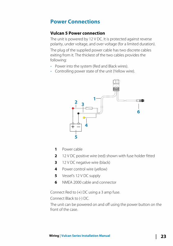
Vulcan 5 Power connectionThe unit is powered by 12 V DC. It is protected against reversepolarity, under voltage, and over voltage (for a limited duration).
The plug of the supplied power cable has two discrete cablesexiting from it. The thickest of the two cables provides thefollowing:
• Power into the system (Red and Black wires).• Controlling power state of the unit (Yellow wire).
1
6
+ _
23
5
4
1 Power cable
2 12 V DC positive wire (red) shown with fuse holder fitted
3 12 V DC negative wire (black)
4 Power control wire (yellow)
5 Vessel’s 12 V DC supply
6 NMEA 2000 cable and connector
Connect Red to (+) DC using a 3 amp fuse.
Connect Black to (-) DC.
The unit can be powered on and off using the power button on thefront of the case.
Wiring | Vulcan Series Installation Manual 23
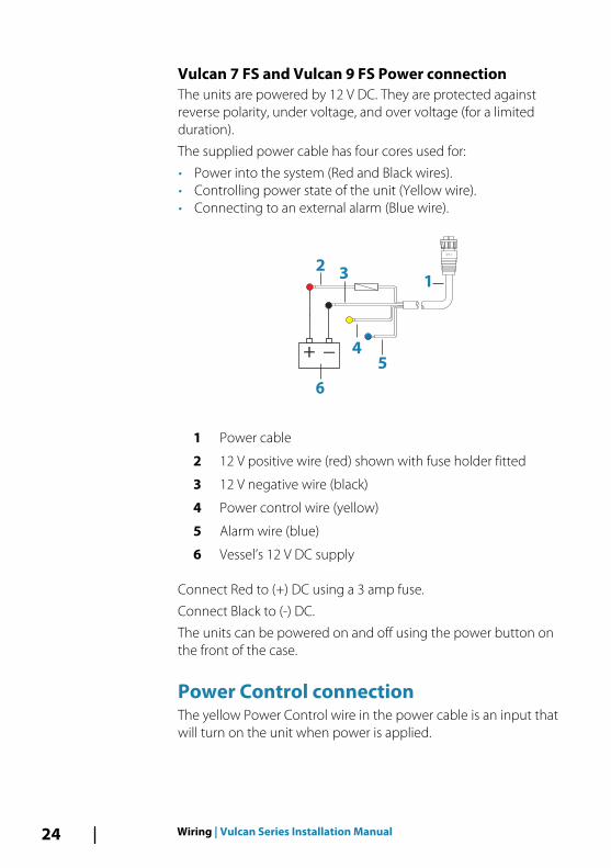
Vulcan 7 FS and Vulcan 9 FS Power connection The units are powered by 12 V DC. They are protected againstreverse polarity, under voltage, and over voltage (for a limitedduration).
The supplied power cable has four cores used for:
• Power into the system (Red and Black wires).• Controlling power state of the unit (Yellow wire).• Connecting to an external alarm (Blue wire).
+ _
1
23
5
6
4
1 Power cable
2 12 V positive wire (red) shown with fuse holder fitted
3 12 V negative wire (black)
4 Power control wire (yellow)
5 Alarm wire (blue)
6 Vessel’s 12 V DC supply
Connect Red to (+) DC using a 3 amp fuse.
Connect Black to (-) DC.
The units can be powered on and off using the power button onthe front of the case.
Power Control connectionThe yellow Power Control wire in the power cable is an input thatwill turn on the unit when power is applied.
24 Wiring | Vulcan Series Installation Manual
Power Control unconnectedDevice will turn on and off when the power button on the front ofthe unit is pressed. Leave the yellow Power Control wiredisconnected and tape or heat-shrink the end to prevent shorting.
Power Control to supply positive (auto on)Device will turn on immediately when power is applied. Commonthe yellow wire with the red wire after the fuse.
Ú Note: The unit cannot be powered down by power button, butcan be put in to standby mode. (The screen backlight turns off.)
Power Control to ignitionDevice will turn on once ignition is turned on to start engines.Connect the yellow wire to the accessories output of the engine keyswitch.
Ú Note: Engine start batteries and house batteries should have acommon ground connection.
External alarmÚ Note: An external alarm cannot be connected to the Vulcan 5.
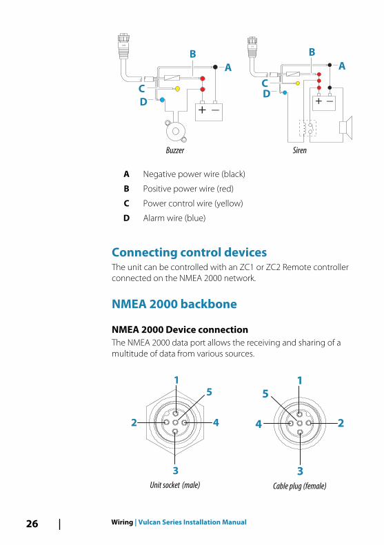
The external alarm can be a small piezo buzzer connected directly,or a horn siren connected through a relay.
Alarms are configured globally in the system. That is, they can beconfigured on any one networked multifunction device orinstrument, and be seen, heard, and acknowledged from all devices.Individual devices can also be configured to not sound their internalbuzzer, but still display the alarm information. For information aboutconfiguring alarms, refer to the Alarms section in the OperatorManual.
For sirens that draw more than 1 Amp, use a relay.
Wiring | Vulcan Series Installation Manual 25
+ _
A
B
D
C
Buzzer
+ _
A
B
D
C
Siren
A Negative power wire (black)
B Positive power wire (red)
C Power control wire (yellow)
D Alarm wire (blue)
Connecting control devicesThe unit can be controlled with an ZC1 or ZC2 Remote controllerconnected on the NMEA 2000 network.
NMEA 2000 backbone
NMEA 2000 Device connectionThe NMEA 2000 data port allows the receiving and sharing of amultitude of data from various sources.
2
1
3
4
5
Unit socket (male)
1
2
5
4
3
Cable plug (female)
26 Wiring | Vulcan Series Installation Manual
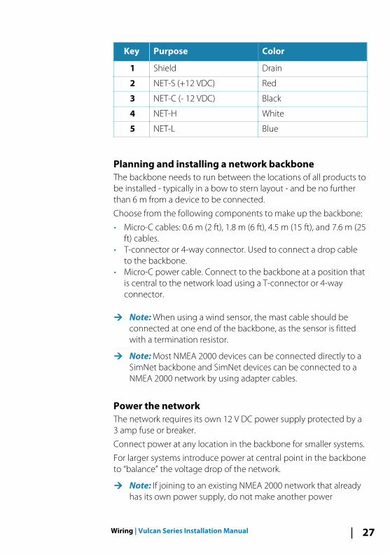
Key Purpose Color
1 Shield Drain
2 NET-S (+12 VDC) Red
3 NET-C (- 12 VDC) Black
4 NET-H White
5 NET-L Blue
Planning and installing a network backboneThe backbone needs to run between the locations of all products tobe installed - typically in a bow to stern layout - and be no furtherthan 6 m from a device to be connected.
Choose from the following components to make up the backbone:
• Micro-C cables: 0.6 m (2 ft), 1.8 m (6 ft), 4.5 m (15 ft), and 7.6 m (25ft) cables.
• T-connector or 4-way connector. Used to connect a drop cableto the backbone.
• Micro-C power cable. Connect to the backbone at a position thatis central to the network load using a T-connector or 4-wayconnector.
Ú Note: When using a wind sensor, the mast cable should beconnected at one end of the backbone, as the sensor is fittedwith a termination resistor.
Ú Note: Most NMEA 2000 devices can be connected directly to aSimNet backbone and SimNet devices can be connected to aNMEA 2000 network by using adapter cables.
Power the networkThe network requires its own 12 V DC power supply protected by a3 amp fuse or breaker.
Connect power at any location in the backbone for smaller systems.
For larger systems introduce power at central point in the backboneto “balance” the voltage drop of the network.
Ú Note: If joining to an existing NMEA 2000 network that alreadyhas its own power supply, do not make another power
Wiring | Vulcan Series Installation Manual 27
connection elsewhere in the network, and ensure the existingnetwork is not powered by 24 V DC.
Ú Note: Do not connect the NMEA 2000 power cable to the sameterminals as the engine start batteries, autopilot computer, bowthruster or other high current devices.
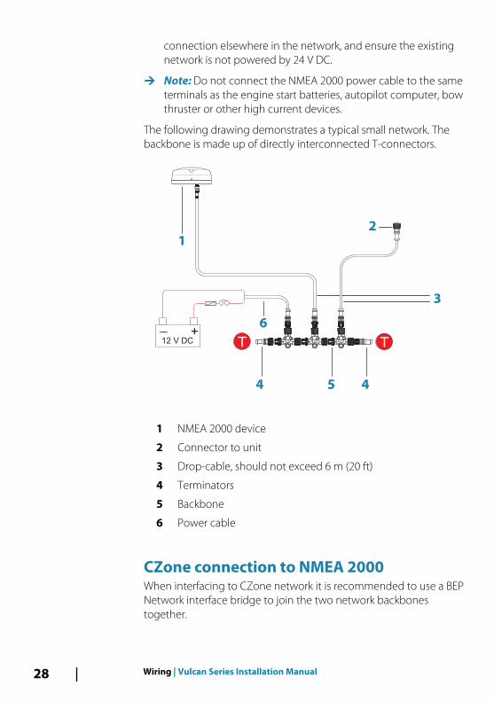
The following drawing demonstrates a typical small network. Thebackbone is made up of directly interconnected T-connectors.
+_12 V DC T
3
44
6
2
1
T
5
1 NMEA 2000 device
2 Connector to unit
3 Drop-cable, should not exceed 6 m (20 ft)
4 Terminators
5 Backbone
6 Power cable
CZone connection to NMEA 2000When interfacing to CZone network it is recommended to use a BEPNetwork interface bridge to join the two network backbonestogether.
28 Wiring | Vulcan Series Installation Manual
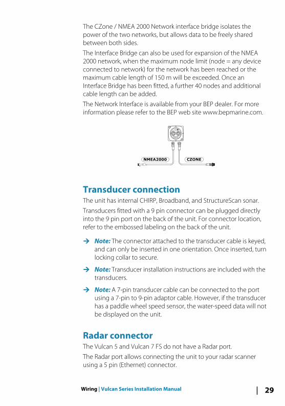
The CZone / NMEA 2000 Network interface bridge isolates thepower of the two networks, but allows data to be freely sharedbetween both sides.
The Interface Bridge can also be used for expansion of the NMEA2000 network, when the maximum node limit (node = any deviceconnected to network) for the network has been reached or themaximum cable length of 150 m will be exceeded. Once anInterface Bridge has been fitted, a further 40 nodes and additionalcable length can be added.
The Network Interface is available from your BEP dealer. For moreinformation please refer to the BEP web site www.bepmarine.com.
NETWORK INTERFACE
Network 1 Network 2
CZONE
NETWORK
CZONENMEA2000
Transducer connectionThe unit has internal CHIRP, Broadband, and StructureScan sonar.
Transducers fitted with a 9 pin connector can be plugged directlyinto the 9 pin port on the back of the unit. For connector location,refer to the embossed labeling on the back of the unit.
Ú Note: The connector attached to the transducer cable is keyed,and can only be inserted in one orientation. Once inserted, turnlocking collar to secure.
Ú Note: Transducer installation instructions are included with thetransducers.
Ú Note: A 7-pin transducer cable can be connected to the portusing a 7-pin to 9-pin adaptor cable. However, if the transducerhas a paddle wheel speed sensor, the water-speed data will notbe displayed on the unit.
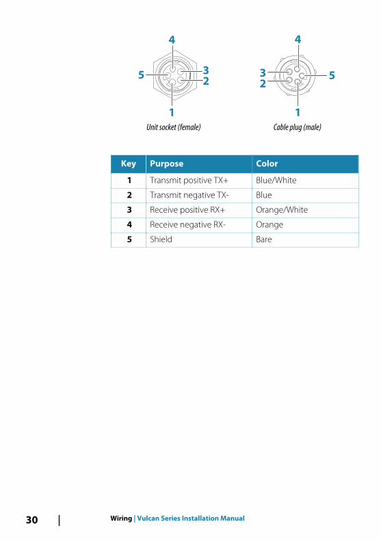
Radar connectorThe Vulcan 5 and Vulcan 7 FS do not have a Radar port.
The Radar port allows connecting the unit to your radar scannerusing a 5 pin (Ethernet) connector.
Wiring | Vulcan Series Installation Manual 29
1
2
3
4
5
Unit socket (female)
2
3
1
4
5
Cable plug (male)
Key Purpose Color
1 Transmit positive TX+ Blue/White
2 Transmit negative TX- Blue
3 Receive positive RX+ Orange/White
4 Receive negative RX- Orange
5 Shield Bare
30 Wiring | Vulcan Series Installation Manual
Software SetupThis unit requires some initial configuration before use, in order toget the most out of the product. The following sections focus onsettings that typically do not require change once configured. Userpreference settings and operation are covered in the OperatorManual. Selecting the Home button opens the Home page, whichhas three distinct areas. The scrollable left column of icons is theTools panel. Select Settings in the Tools panel to open the Settingsdialog to access items that require configuration.
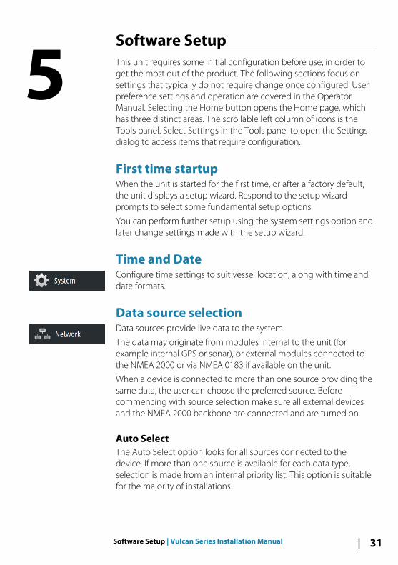
First time startupWhen the unit is started for the first time, or after a factory default,the unit displays a setup wizard. Respond to the setup wizardprompts to select some fundamental setup options.
You can perform further setup using the system settings option andlater change settings made with the setup wizard.
Time and DateConfigure time settings to suit vessel location, along with time anddate formats.
Data source selectionData sources provide live data to the system.
The data may originate from modules internal to the unit (forexample internal GPS or sonar), or external modules connected tothe NMEA 2000 or via NMEA 0183 if available on the unit.
When a device is connected to more than one source providing thesame data, the user can choose the preferred source. Beforecommencing with source selection make sure all external devicesand the NMEA 2000 backbone are connected and are turned on.
Auto SelectThe Auto Select option looks for all sources connected to thedevice. If more than one source is available for each data type,selection is made from an internal priority list. This option is suitablefor the majority of installations.
5
Software Setup | Vulcan Series Installation Manual 31
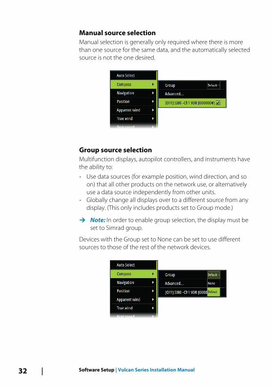
Manual source selectionManual selection is generally only required where there is morethan one source for the same data, and the automatically selectedsource is not the one desired.
Group source selectionMultifunction displays, autopilot controllers, and instruments havethe ability to:
• Use data sources (for example position, wind direction, and soon) that all other products on the network use, or alternativelyuse a data source independently from other units.
• Globally change all displays over to a different source from anydisplay. (This only includes products set to Group mode.)
Ú Note: In order to enable group selection, the display must beset to Simrad group.
Devices with the Group set to None can be set to use differentsources to those of the rest of the network devices.
32 Software Setup | Vulcan Series Installation Manual
Advanced source selectionThis allows the most flexible and precise manual control over whichdevices provide data. Some data sources, such as those for fuellevel, or engine RPM, can only be changed from the Advancedmenu. Occasionally Auto Select may not assign the desired source,which may be corrected using the Advanced Source Selection. Anexample of this is where twin installations with NMEA 2000compliant engines are not programmed with unique instancenumbers. This means that the auto select feature cannot determinewhich engine is fitted on the port and which is fitted on thestarboard side.
Ú Note: The Advanced option is visible in multiple places - thebottom of the Sources list, and under each source category (forexample, Compass). The latter shows a filtered list that onlyrelates to devices that output data relevant to the category.
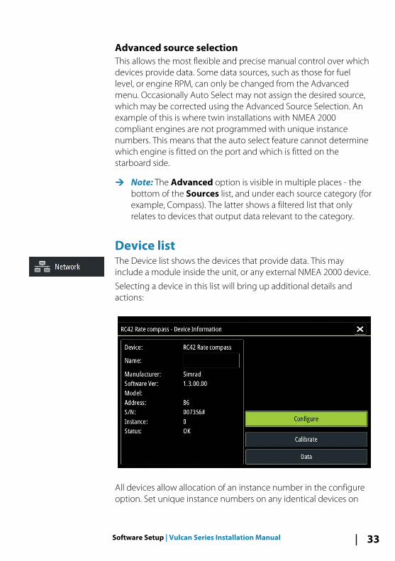
Device list The Device list shows the devices that provide data. This mayinclude a module inside the unit, or any external NMEA 2000 device.
Selecting a device in this list will bring up additional details andactions:
All devices allow allocation of an instance number in the configureoption. Set unique instance numbers on any identical devices on
Software Setup | Vulcan Series Installation Manual 33
the network to allow for the unit to distinguish between them. Thedata option shows all data being output by the device. Somedevices will show additional options specific to the device.
Some devices will show additional option(s) specific to the device -the RC42 illustrated above has a Calibration option, to allow easysetup of this device.
Ú Note: Setting the instance number on a 3rd party product istypically not possible.
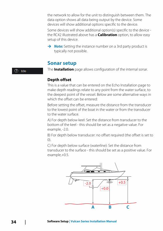
Sonar setupThe Installation page allows configuration of the internal sonar.
Depth offsetThis is a value that can be entered on the Echo Installation page tomake depth readings relate to any point from the water surface, tothe deepest point of the vessel. Below are some alternative ways inwhich the offset can be entered:
Before setting the offset, measure the distance from the transducerto the lowest point of the boat in the water or from the transducerto the water surface.
A) For depth below keel: Set the distance from transducer to thebottom of the keel - this should be set as a negative value. Forexample, -2.0.
B) For depth below transducer: no offset required (the offset is set to0).
C) For depth below surface (waterline): Set the distance fromtransducer to the surface - this should be set as a positive value. Forexample,+0.5.
A B C
+0.5
+0.0
-2.0
34 Software Setup | Vulcan Series Installation Manual
Water temperature calibrationTemperature calibration is used to adjust the water temperaturevalue from the sonar transducer to match the data from anothertemperature sensor. It may be required to correct for localizedinfluences to the measured temperature.
Calibration range: -9.9° - +9.9°. Default is 0°.
Ú Note: Water temperature calibration only appears if thetransducer is temperature capable. Check transducer typeselection if this option should be available.
Transducer typeTransducer type is used for selecting the transducer modelconnected to the sonar module. The transducer selected willdetermine what frequencies the user can select during sonaroperation. In some transducers with built-in temperature sensors,the temperature reading may be inaccurate or not available at all ifthe wrong transducer is selected. Transducer temperature sensorsare one of two impedances - 5k or 10k. Where both options aregiven for the same model transducer, refer to paperwork suppliedwith transducer to determine impedance.
StructureScanThis feature is automatically enabled when a TotalScan transducer isplugged in before the unit has been powered on.
Radar setupÚ Note: The 5" and 7" units do not support radar.
Use the Radar Installation dialog to setup the radar.
Ú Note: The installation can vary depending on the radar. Followthe installation and setup instructions supplied with the radar.
Software Setup | Vulcan Series Installation Manual 35
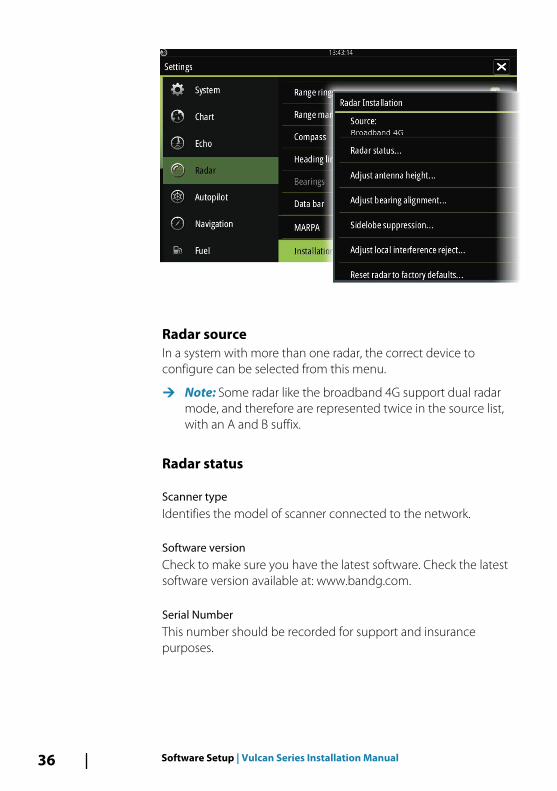
Radar sourceIn a system with more than one radar, the correct device toconfigure can be selected from this menu.
Ú Note: Some radar like the broadband 4G support dual radarmode, and therefore are represented twice in the source list,with an A and B suffix.
Radar status
Scanner typeIdentifies the model of scanner connected to the network.
Software versionCheck to make sure you have the latest software. Check the latestsoftware version available at: www.bandg.com.
Serial NumberThis number should be recorded for support and insurancepurposes.
36 Software Setup | Vulcan Series Installation Manual
MARPA statusThe MARPA status can identify if a heading sensor is on the networkand that the radar is receiving heading information essential forMARPA calculations.
Reset device IDShould a radar be connected to the network that has beenconnected to a dual radar network in the past, it might not bedetected by the system because it might have an invalid Device ID.With the radar connected and powered up, select the Reset DeviceID button to resolve this problem.
Ú Note: This procedure must be performed with only one radaron the network, and only applies where a network combines anolder NSS with other MFDs.
Adjust antenna heightSet the radar scanner height relative to the water surface. The Radaruses this value to calculate the correct STC settings.
Adjust range offset(Pulse Radar only)
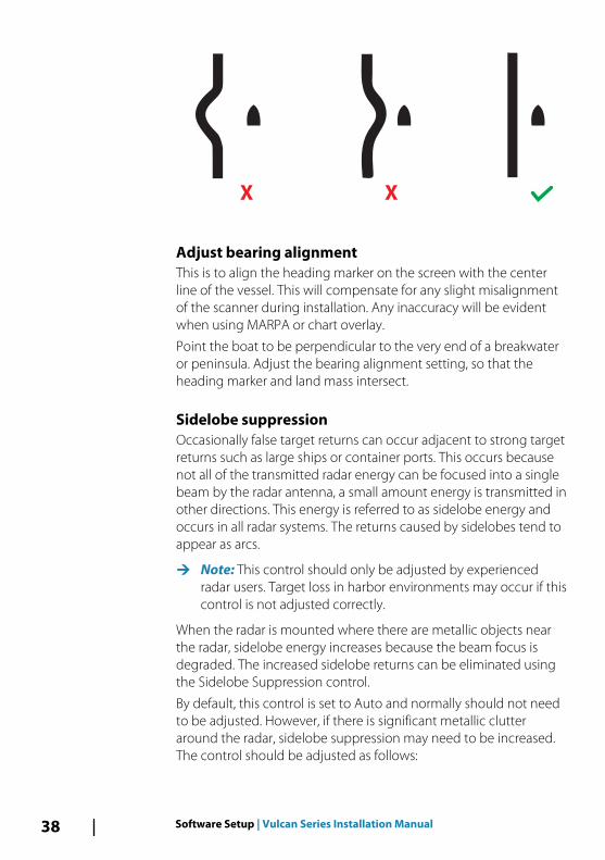
The radar sweep should commence at your vessel (a radar range ofzero). You may need to adjust the radar range offset to achieve this.If this is set incorrectly, a large dark circle in the center of the sweepmight occur. You might notice straight objects such as straight seawalls or piers having curves or an indentation. Objects close to yourvessel may appear “pulled in” or “pushed out".
Adjust the range offset as below when the vessel is about 45 to 90m (50 to 100 yards) from a straight-walled jetty or similar featurethat produces a straight line echo on the display.
• Point the boat towards the jetty• Adjust the gain setting until a reasonably good image of the jetty
echo is displayed
Software Setup | Vulcan Series Installation Manual 37
X X
Adjust bearing alignmentThis is to align the heading marker on the screen with the centerline of the vessel. This will compensate for any slight misalignmentof the scanner during installation. Any inaccuracy will be evidentwhen using MARPA or chart overlay.
Point the boat to be perpendicular to the very end of a breakwateror peninsula. Adjust the bearing alignment setting, so that theheading marker and land mass intersect.
Sidelobe suppressionOccasionally false target returns can occur adjacent to strong targetreturns such as large ships or container ports. This occurs becausenot all of the transmitted radar energy can be focused into a singlebeam by the radar antenna, a small amount energy is transmitted inother directions. This energy is referred to as sidelobe energy andoccurs in all radar systems. The returns caused by sidelobes tend toappear as arcs.
Ú Note: This control should only be adjusted by experiencedradar users. Target loss in harbor environments may occur if thiscontrol is not adjusted correctly.
When the radar is mounted where there are metallic objects nearthe radar, sidelobe energy increases because the beam focus isdegraded. The increased sidelobe returns can be eliminated usingthe Sidelobe Suppression control.
By default, this control is set to Auto and normally should not needto be adjusted. However, if there is significant metallic clutteraround the radar, sidelobe suppression may need to be increased.The control should be adjusted as follows:
38 Software Setup | Vulcan Series Installation Manual

1. Set Radar range to between 1/2 nm to 1 nm and SidelobeSuppression to Auto
2. Take the vessel to a location where sidelobe returns are likely tobe seen. Typically, this would be near a large ship, containerport, or metal bridge.
3. Traverse the area until the strongest sidelobe returns are seen.4. Change Auto sidelobe suppression to OFF then select and
adjust the sidelobe suppression control until the sidelobereturns are just eliminated. You may need to monitor 5-10 radarsweeps to be sure they have been eliminated.
5. Traverse the area again and readjust if sidelobes returns stilloccur.
6. Exit the dialog.
Adjust local interference rejectInterference from some onboard sources can interfere with theBroadband radar. One symptom of this could be a large target onthe screen that remains in the same relative bearing even if thevessel changes direction.
Choose from Local interference rejection LOW, MED or HIGH.Default is LOW.
Restore radar to factory defaultsThis option can be used to revert all user adjustments.
Software Setup | Vulcan Series Installation Manual 39
Autopilot setupÚ Note: For set up and commissioning of NAC-2/NAC-3 autopilot
computers, see the documentation included with the autopilotcomputer.
Verifying the autopilot connectionWhen a compatible autopilot computer is connected to the unit,the system automatically detects the autopilot and an Autopilotmenu icon is included in the Settings menu.
If no Autopilot icon is available in the menu, establish theconnection by running the auto select process.
If the autopilot computer is turned off independently of the unit,the Autopilot menu icon remains available, but only a few of themenu items are available.
Commissioning the autopilot
Ú Note: A dedicated physical STBY key is required forcommissioning. This can be on the autopilot control head, onan autopilot remote controller or a separate standby key.
When the autopilot installation is completed, the commissioningprocedures must be performed. Failure in setting up the autopilotcorrectly may prohibit the autopilot from functioning properly.
The setup of the autopilot computers can be done in full from theunit or from a separate autopilot control head.
The following sections describe how you configure the autopilotfrom the unit. If you connect the unit to an already commissionedautopilot system, you only have to do an automatic source selectionas described above before the autopilot is ready to be used.
40 Software Setup | Vulcan Series Installation Manual
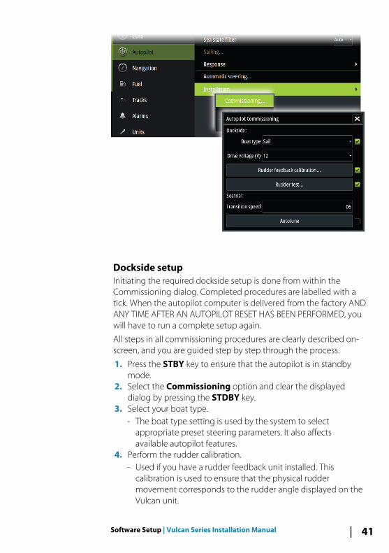
Dockside setupInitiating the required dockside setup is done from within theCommissioning dialog. Completed procedures are labelled with atick. When the autopilot computer is delivered from the factory ANDANY TIME AFTER AN AUTOPILOT RESET HAS BEEN PERFORMED, youwill have to run a complete setup again.
All steps in all commissioning procedures are clearly described on-screen, and you are guided step by step through the process.
1. Press the STBY key to ensure that the autopilot is in standbymode.
2. Select the Commissioning option and clear the displayeddialog by pressing the STDBY key.
3. Select your boat type.- The boat type setting is used by the system to select
appropriate preset steering parameters. It also affectsavailable autopilot features.
4. Perform the rudder calibration.- Used if you have a rudder feedback unit installed. This
calibration is used to ensure that the physical ruddermovement corresponds to the rudder angle displayed on theVulcan unit.
Software Setup | Vulcan Series Installation Manual 41
- The Virtual Feedback option enables your autopilot to steerwithout a conventional rudder feedback unit. This function isdesigned for vessels up to 40 ft powered by outboard or sterndrives only.
- The Virtual Feedback option is only available when there is nofeedback unit connected at first time turn on, or at turn onafter an autopilot reset.
Ú Note: Installing a feedback unit will enhance the performanceof the autopilot and provide an accurate rudder angle indicatoron the autopilot page. Unless impractical or impossible, arudder feedback unit should be installed.
5. Set the drive voltage. Refer to your drive unit documentation forinformation.
6. Run the rudder test as described in the on-screen instructions.
Ú Note: If the boat uses power assisted steering, it is importantthat the engine or electric motor used to enable the powerassist steering is turned on prior to this test.
Warning: Stand CLEAR of the wheel and do notattempt to take manual control of the wheel duringthis test!
Ú Note: When this test is started the autopilot computer issues aseries of PORT and STBD rudder commands and automaticallyverifies correct rudder direction. It detects minimum power todrive the rudder and reduces the rudder speed if it exceeds themaximum preferred speed (8°/sec.) for autopilot operation. Thesystem also detects whether the drive unit is a reversible motoror if a solenoid valve is operated.
Rudder drive setupThe rudder drive setup controls how the autopilot computercontrols the steering system.
42 Software Setup | Vulcan Series Installation Manual
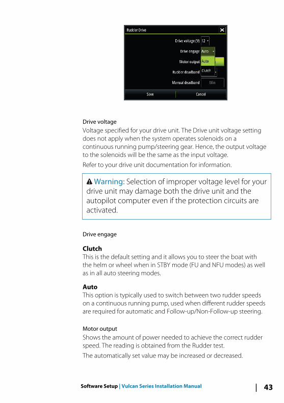
Drive voltageVoltage specified for your drive unit. The Drive unit voltage settingdoes not apply when the system operates solenoids on acontinuous running pump/steering gear. Hence, the output voltageto the solenoids will be the same as the input voltage.
Refer to your drive unit documentation for information.
Warning: Selection of improper voltage level for yourdrive unit may damage both the drive unit and theautopilot computer even if the protection circuits areactivated.
Drive engage
ClutchThis is the default setting and it allows you to steer the boat withthe helm or wheel when in STBY mode (FU and NFU modes) as wellas in all auto steering modes.
AutoThis option is typically used to switch between two rudder speedson a continuous running pump, used when different rudder speedsare required for automatic and Follow-up/Non-Follow-up steering.
Motor outputShows the amount of power needed to achieve the correct rudderspeed. The reading is obtained from the Rudder test.
The automatically set value may be increased or decreased.
Software Setup | Vulcan Series Installation Manual 43
Rudder deadbandThis parameter is used to prevent the rudder from hunting. Thereading is obtained from the Rudder test which optimizes thedeadband to the speed of the boat and the pressure on the rudder.If the auto-setting does not perform properly due to high inertiafrom the wheel or a loose steering gear, it can be adjusted manually.Find the lowest possible value that will prevent the rudder fromcontinuous hunting. A wide deadband causes inaccurate steering.
Ú Note: The rudder deadband setting is not available when theautopilot is configured for Virtual Rudder Feedback.
SeatrialsA seatrial can only be performed if the dockside settings arecompleted and confirmed. The seatrial must always be performed inopen waters at a safe distance from other traffic.
Ú Note: A dedicated physical standby key should be availableduring the seatrial. This can be the standby key on the autopilotcontrol head, on an autopilot remote controller or separatephysical standby key. You can switch the autopilot to standbymode and take manual control of the boat at any time duringthe seatrial by pressing the standby key.
The following seatrial calibration should be done:
• Compass calibration; used to automatically compensate for on-board magnetic interference
• Compass offset adjustment, used to compensate for a fixed offsetin the final heading readout
• Wind vane offset is to compensate for a wind vane that is notmounted facing in exactly the same direction as the bow of thevessel (dead ahead)
• Boat speed calibration• Transition speed setting (the speed at which you want to change
the set of steering parameters).• Automatic tuning of the steering parameters.• Setting the seastate filter• Sailboat Setup menu items.
44 Software Setup | Vulcan Series Installation Manual
Compass calibrationBefore the compass calibration is started, make sure that there isenough open water around the vessel to make a full turn. Thecalibration should be done in calm sea conditions and with minimalwind to obtain good results. Follow the on-screen instruction, anduse about 60-90 seconds to make a full circle. During the calibration,the compass measures the magnitude and direction of the localmagnetic field.
You perform compass calibration from the Device list. Refer to "Devicelist" on page 33
• If the local magnetic field is stronger than the earth’s magneticfield (the local field is reading more than 100 %), the compasscalibration will fail.
• If the local field is reading more than 30 %, you should look forany interfering magnetic objects and remove them, or youshould move the compass to a different location. The (local) fieldangle guides you to the local interfering magnetic object.
Ú Note: Calibration must be made on the compass that is activefor the autopilot. If the compass is not possible to initiatecalibration from the device list on the Vulcan, refer to thecompass’ own instructions regarding calibration.
Ú Note: In certain areas and at high latitudes the local magneticinterference becomes more significant and heading errorsexceeding ±3° may have to be accepted.
Compass mounting offsetAfter compass calibration, the difference (if any) between thecompass lubber line and the boat’s center line should becompensated for.
The compass offset parameter setting is made from the Device list.
1. Find the bearing from the boat position to a visible object. Use achart or a chart plotter.
2. Steer the boat so that the center line of the boat is aligned withthe bearing line pointing towards the object.
3. Select Settings, Network, Device list, and select the compassfrom the list.
4. Select Configure.
Software Setup | Vulcan Series Installation Manual 45
5. Change the offset parameter so that the bearing to the objectand the compass readout becomes equal.
Ú Note: Make sure that both the compass heading and thebearing to the object have the same unit (°M or °T).
Setting the Transition speedThe transition speed is the speed at which the system automaticallychanges between LO and HI steering profiles.
The steering profiles are used to accommodate the boats' tendencyto exhibit different steering characteristics at different speeds. Youmay also have different preferences about the steering performanceof your boat required at low and high speeds.
On power boats it is recommended that you set a value thatrepresents the speed where the hull begins to plane, the speedwhere the boat's steering characteristics change, or at the speedyou want the autopilot to change behavior.
On sailboats the transition speed should be set to around 3-4 knotsto give the best response in a tack.
There is a 2 knots hysteresis to prevent oscillation of HI/LO steeringparameters when the vessel is travelling at the transition speed.
Example
The transition speed is set to 9 knots.
• The system changes from LO profile to HI profile when the speedincreases to 10 knots (= Transition speed plus 1 knot)
• The system changes from HI profile to LO profile when the speeddecreases to 8 knots (= Transition speed minus 1 knot)
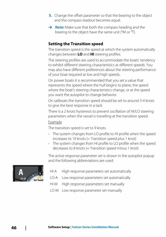
The active response parameter set is shown in the autopilot popupand the following abbreviations are used:
HI-A High response parameters set automatically
LO-A Low response parameters set automatically
HI-M High response parameters set manually
LO-M Low response parameter set manually
46 Software Setup | Vulcan Series Installation Manual
AutotuningThe autotune feature runs the boat through several tests and thenautomatically sets the most important steering parameters.Autotune is not required for the autopilot to function, as it is presetwith steering parameters that should steer most boats in the 30-50foot range. All parameters that are set during autotuning can bemanually adjusted.
Sea state filterThe Sea state filter is used to reduce rudder activity and autopilotsensitivity in rough weather.
OFFSea state filter is disabled. This is default.
AUTOReduces rudder activity and autopilot sensitivity in rough weatherby an adaptive process. The AUTO setting is recommended if youwant to use the seastate filter.
MANUALLinked to the steering response control settings describedpreviously. It may be used to manually find the optimumcombination of course keeping and low rudder activity in rough butsteady sea conditions.
Setting sailing parameters
Ú Note: Sailing parameter settings are only available if the boattype is set to Sail in the Autopilot Commissioning dialog.
Software Setup | Vulcan Series Installation Manual 47
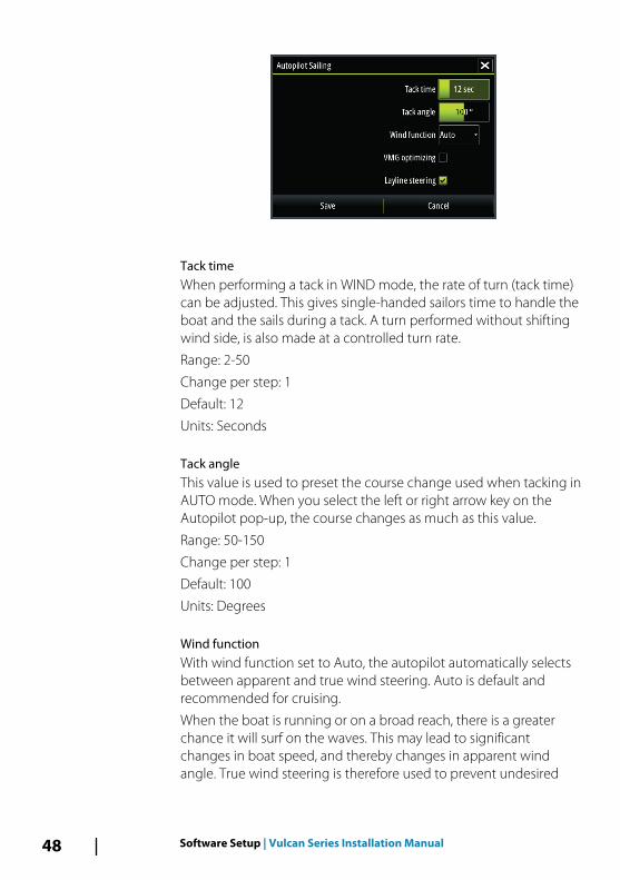
Tack timeWhen performing a tack in WIND mode, the rate of turn (tack time)can be adjusted. This gives single-handed sailors time to handle theboat and the sails during a tack. A turn performed without shiftingwind side, is also made at a controlled turn rate.
Range: 2-50
Change per step: 1
Default: 12
Units: Seconds
Tack angleThis value is used to preset the course change used when tacking inAUTO mode. When you select the left or right arrow key on theAutopilot pop-up, the course changes as much as this value.
Range: 50-150
Change per step: 1
Default: 100
Units: Degrees
Wind functionWith wind function set to Auto, the autopilot automatically selectsbetween apparent and true wind steering. Auto is default andrecommended for cruising.
When the boat is running or on a broad reach, there is a greaterchance it will surf on the waves. This may lead to significantchanges in boat speed, and thereby changes in apparent windangle. True wind steering is therefore used to prevent undesired
48 Software Setup | Vulcan Series Installation Manual
corrections by the autopilot when heading downwind (or close to),while steering to apparent wind is used when beating or reaching.
Apparent wind steering is preferred when you want to maintainmaximum boat speed without continuous trimming of the sails.
VMG optimizingYou can optimize the VMG to wind. When selected, the function willbe active for 5–10 minutes after a new wind angle has been set andonly when beating.
Layline steeringLayline steering is useful when navigating. Cross Track Error (XTE)from the navigator keeps the boat on the track line. If the XTE fromthe navigator exceeds 0.15 nm, the autopilot calculates the laylineand track towards the waypoint.
Manually adjusting steering parametersThe autotune function in the autopilot is so refined that the majorityof boats need no further adjustments of the steering parameters.On some boats however, or in particular sea conditions, fine tuningof the steering parameters may improve the performance of theautopilot.
Transition speedRefer to "Setting the Transition speed" on page 46.
RudderThis parameter determines the ratio between commanded rudderand the heading error. The higher rudder value the more rudder isapplied. If the value is too small it will take a long time tocompensate for a heading error, and the autopilot will fail to keep asteady course. If the value is set too high the overshoot will increaseand the steering will be unstable.
Counter rudderCounter rudder is the amount of counteracting (opposite) rudderapplied to stop the turn at the end of a major course change. Thesettings depend on vessel’s characteristics, loaded/ballastconditions and rate of turn.
Software Setup | Vulcan Series Installation Manual 49
• If the vessel has good dynamic stability, a relatively small valuewill be sufficient
• An unstable vessel will require high value• The greater the vessel’s inertia, the greater value will be required
Increasing counter rudder value may result in some higher rudderactivity also when steering a straight course.
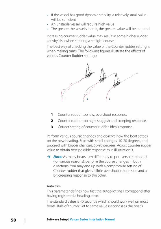
The best way of checking the value of the Counter rudder setting iswhen making turns. The following figures illustrate the effects ofvarious Counter Rudder settings:
1 Counter rudder too low; overshoot response.
2 Counter rudder too high; sluggish and creeping response.
3 Correct setting of counter rudder; ideal response.
Perform various course changes and observe how the boat settleson the new heading. Start with small changes, 10-20 degrees, andproceed with bigger changes, 60-90 degrees. Adjust Counter ruddervalue to obtain best possible response as in illustration 3.
Ú Note: As many boats turn differently to port versus starboard(for various reasons), perform the course changes in bothdirections. You may end up with a compromise setting ofCounter rudder that gives a little overshoot to one side and abit creeping response to the other.
Auto trimThis parameter defines how fast the autopilot shall correspond afterhaving registered a heading error.
The standard value is 40 seconds which should work well on mostboats. Rule of thumb: Set to same value (seconds) as the boat’s
50 Software Setup | Vulcan Series Installation Manual
length in feet. On boats operating on VRF, the value should be setto 20 seconds.
Rate limitSets the maximum allowed rate of turn.
The value should be kept at 6.0°/second unless there is a need formore rapid response in turns.
Minimum rudderThis parameter filters small rudder commands to prevent highrudder activity.
Some boats may have a tendency to not respond to small ruddercommands around the “course keeping” position because of a smallrudder, a rudder deadband, whirls/disturbance of the water-streampassing the rudder, or it is a single nozzle water jet boat.
By increasing the Minimum rudder parameter you may improve thecourse keeping performance on some boats. However, this willincrease the rudder activity.
Minimum wind angle to port and starboardThese parameters should be set identical to the minimum apparentwind angle that will keep the sails from stalling and maintain boatspeed. The parameters vary from boat to boat.
The settings are used for the tack-prevent function. They also applywhen the autopilot is operating in WindNAV mode.
You can select different minimum wind angles for port andstarboard. The difference between port and starboard is taken intoaccount when calculating the Distance To Turn (DTT).
Navigation change limitThis parameter defines the maximum course change that theautopilot is allowed to make when the Vulcan is following a route(NAV steering).
If the required course change to the next waypoint in a route ismore than the set limit, you are prompted and must acknowledgethe course change before the autopilot will turn the vessel.
Software Setup | Vulcan Series Installation Manual 51
ResponseBy default the system switches between HI/LO parameter set basedon speed (motor boats) or speed and wind (sail boats). You canhowever manually select which parameter set that shall be used.
HI or LO must be selected if no speed input is available.
You can manually fine tune each of the two (HI/LO) parameter sets.Level 4 is default with parameter values as set by the autotunefunction. If no autotune is made (not recommended) the level 4values are the factory default values.
A low response level reduces the rudder activity and provides amore “loose” steering.
A high response level increases the rudder activity and provides amore “tight” steering. A too high response level causes the boat tostart lazy-s movements.
Fuel setupThe fuel utility monitors a vessel's fuel consumption. Thisinformation is totaled to indicate trip and seasonal fuel usage, and isused to calculate fuel economy for display on instrument pages andthe data bar.
To use the utility, a Navico Fuel Flow sensor, or a NMEA 2000 engineadaptor cable/gateway with Navico Fuel Data Storage device mustbe fitted to the vessel. Neither the Navico Fuel Flow sensor, nor theSuzuki engine interface require the use of a separate Fuel Storagedevice. Refer to the engine manufacturer or dealer for informationon whether or not your engine provides a data output, and whatadaptor is available to connect to NMEA 2000.
Once the physical connection is made, ensure source selection iscompleted. Multiple engine installations using Fuel Flow sensors, orFuel Data Storage devices, require setup of related engine locationin the Device list. For general source selection information, refer to"Data source selection" on page 31.
Vessel setupThe Vessel setup dialog must be used to select the number ofengines, the number of tanks and vessel’s total fuel capacity acrossall tanks.
52 Software Setup | Vulcan Series Installation Manual
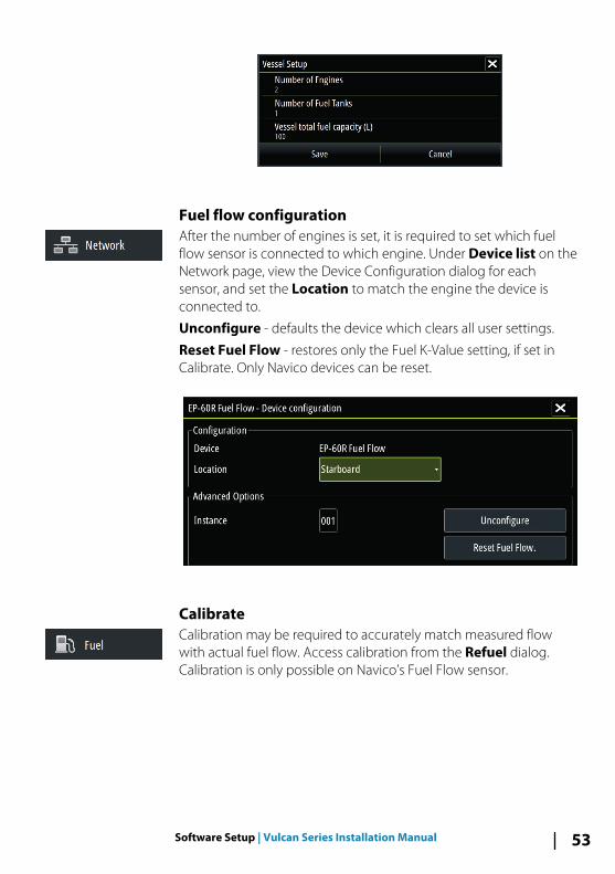
Fuel flow configurationAfter the number of engines is set, it is required to set which fuelflow sensor is connected to which engine. Under Device list on theNetwork page, view the Device Configuration dialog for eachsensor, and set the Location to match the engine the device isconnected to.
Unconfigure - defaults the device which clears all user settings.
Reset Fuel Flow - restores only the Fuel K-Value setting, if set inCalibrate. Only Navico devices can be reset.
CalibrateCalibration may be required to accurately match measured flowwith actual fuel flow. Access calibration from the Refuel dialog.Calibration is only possible on Navico’s Fuel Flow sensor.
Software Setup | Vulcan Series Installation Manual 53
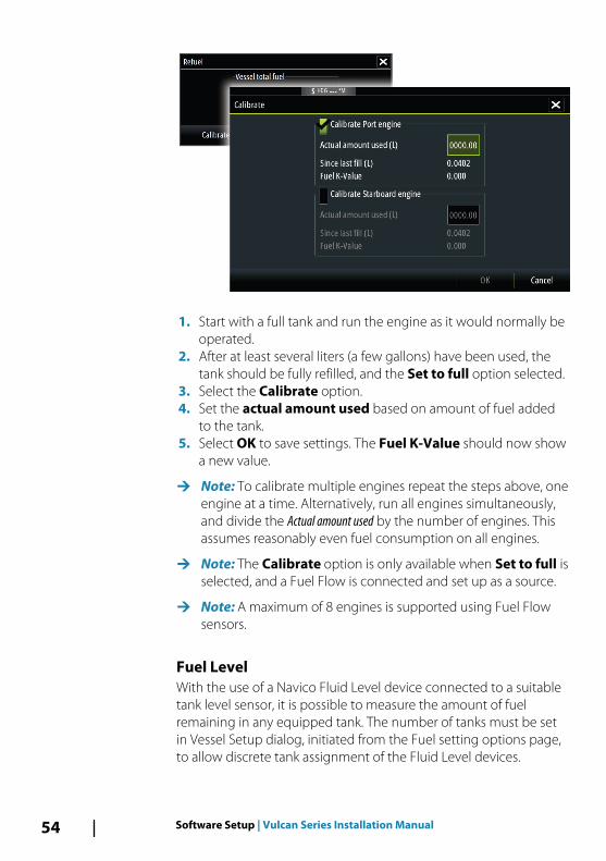
1. Start with a full tank and run the engine as it would normally beoperated.
2. After at least several liters (a few gallons) have been used, thetank should be fully refilled, and the Set to full option selected.
3. Select the Calibrate option.4. Set the actual amount used based on amount of fuel added
to the tank.5. Select OK to save settings. The Fuel K-Value should now show
a new value.
Ú Note: To calibrate multiple engines repeat the steps above, oneengine at a time. Alternatively, run all engines simultaneously,and divide the Actual amount used by the number of engines. Thisassumes reasonably even fuel consumption on all engines.
Ú Note: The Calibrate option is only available when Set to full isselected, and a Fuel Flow is connected and set up as a source.
Ú Note: A maximum of 8 engines is supported using Fuel Flowsensors.
Fuel LevelWith the use of a Navico Fluid Level device connected to a suitabletank level sensor, it is possible to measure the amount of fuelremaining in any equipped tank. The number of tanks must be setin Vessel Setup dialog, initiated from the Fuel setting options page,to allow discrete tank assignment of the Fluid Level devices.
54 Software Setup | Vulcan Series Installation Manual
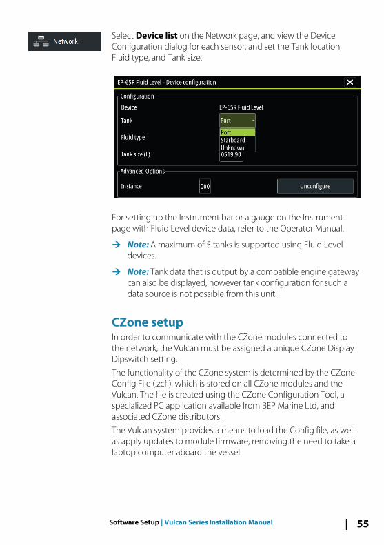
Select Device list on the Network page, and view the DeviceConfiguration dialog for each sensor, and set the Tank location,Fluid type, and Tank size.
For setting up the Instrument bar or a gauge on the Instrumentpage with Fluid Level device data, refer to the Operator Manual.
Ú Note: A maximum of 5 tanks is supported using Fluid Leveldevices.
Ú Note: Tank data that is output by a compatible engine gatewaycan also be displayed, however tank configuration for such adata source is not possible from this unit.
CZone setupIn order to communicate with the CZone modules connected tothe network, the Vulcan must be assigned a unique CZone DisplayDipswitch setting.
The functionality of the CZone system is determined by the CZoneConfig File (.zcf ), which is stored on all CZone modules and theVulcan. The file is created using the CZone Configuration Tool, aspecialized PC application available from BEP Marine Ltd, andassociated CZone distributors.
The Vulcan system provides a means to load the Config file, as wellas apply updates to module firmware, removing the need to take alaptop computer aboard the vessel.
Software Setup | Vulcan Series Installation Manual 55
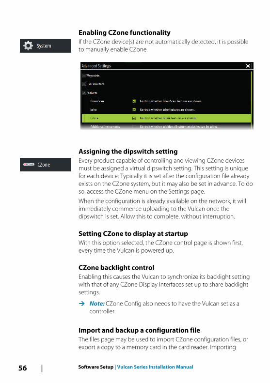
Enabling CZone functionalityIf the CZone device(s) are not automatically detected, it is possibleto manually enable CZone.
Assigning the dipswitch settingEvery product capable of controlling and viewing CZone devicesmust be assigned a virtual dipswitch setting. This setting is uniquefor each device. Typically it is set after the configuration file alreadyexists on the CZone system, but it may also be set in advance. To doso, access the CZone menu on the Settings page.
When the configuration is already available on the network, it willimmediately commence uploading to the Vulcan once thedipswitch is set. Allow this to complete, without interruption.
Setting CZone to display at startupWith this option selected, the CZone control page is shown first,every time the Vulcan is powered up.
CZone backlight controlEnabling this causes the Vulcan to synchronize its backlight settingwith that of any CZone Display Interfaces set up to share backlightsettings.
Ú Note: CZone Config also needs to have the Vulcan set as acontroller.
Import and backup a configuration fileThe files page may be used to import CZone configuration files, orexport a copy to a memory card in the card reader. Importing
56 Software Setup | Vulcan Series Installation Manual
overwrites the existing file on the Vulcan and all connected CZonedevices.
For further information, see "Backing up and Importing user data" on page64.
Upgrading module firmwareThe Files page also allows the loading of NMEA 2000 devicesfirmware upgrades. For example, CZone firmware updates. For moreinformation, refer to "NMEA 2000 device upgrades" on page 65.
Wireless setupThe unit includes built-in wireless functionality that lets you:
• Use a wireless device to remotely view (smartphone and tablet)and control the system (tablet only). Wireless devices use theGoFree app downloaded from their relevant application store.
• Access the GoFree Shop.• Upload your logs to create custom maps at Insight Genesis.• Download software updates• Connect to third party applications
Connecting a tabletInstall the GoFree App on the tablet before following thisprocedure.
Ú Note: To connect a smart device to the unit, the unit's internalwireless must be in 'Access point' mode. To view the internalwireless device network key from the Wireless devices page,the unit's internal wireless must be in 'Access point' mode. Youcan change the unit's internal wireless to 'Access point' modeby selecting the internal wireless in the Wireless devices pageand selecting the Mode option.
1. Navigate to the wireless network connection page on the tablet,and find the unit or GoFree wireless xxxx network. If more thanone is in range, review the Wireless devices page on the unitto confirm which wireless device is connected to the unit.
2. Select the Internal Wireless device on the Wireless devicespage to view its network key.
3. Enter the eight character (or longer) Network Key in the tablet toconnect to the network.
Software Setup | Vulcan Series Installation Manual 57
4. Open the GoFree application - the unit should be automaticallydetected. The name displayed will be either the default, or thatassigned in the Device Name setting. If the unit does notappear, follow the on screen instructions to manually find thedevice.
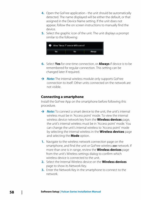
5. Select the graphic icon of the unit. The unit displays a promptsimilar to the following:
6. Select Yes for one-time connection, or Always if device is to beremembered for regular connection. This setting can bechanged later if required.
Ú Note: The internal wireless module only supports GoFreeconnection to itself. Other units connected on the network arenot visible.
Connecting a smartphoneInstall the GoFree App on the smartphone before following thisprocedure.
Ú Note: To connect a smart device to the unit, the unit's internalwireless must be in 'Access point' mode. To view the internalwireless device network key from the Wireless devices page,the unit's internal wireless must be in 'Access point' mode. Youcan change the unit's internal wireless to 'Access point' modeby selecting the internal wireless in the Wireless devices pageand selecting the Mode option.
1. Navigate to the wireless network connection page on thesmartphone, and find the unit or GoFree wireless xxxx network. Ifmore than one is in range, review the Wireless devices pagefrom the unit's Wireless settings dialog to confirm whichwireless device is connected to the unit.
2. Select the Internal Wireless device on the Wireless devicespage to show its Network Key.
3. Enter the Network Key in the smartphone to connect to thenetwork.
58 Software Setup | Vulcan Series Installation Manual
4. Open the GoFree application on the smartphone, the unitshould be automatically detected. The name displayed will beeither the default, or that assigned in the Device Name setting. Ifthe unit does not appear, follow the on screen instructions tomanually find the device.
The MFD's display is shown on the smartphone. To change theMFD's display on the smartphone, use the MFD to change thedisplay on the MFD. The display change on the MFD is reflected onthe smartphone.
Remote controllersWhen a wireless device is connected, it should appear in theRemote controllers list.
Selecting Always allow means the device can automaticallyconnect without needing a password each time. This menu alsoallows disconnection of devices that no longer require access.
Wireless devicesThis dialog shows the internal wireless and any connected WIFI-1devices, as well as their IP and channel number. Selecting theinternal wireless or a WIFI-1 device provides additional detail.
Ú Note: WIFI-1 is possible with the 9" unit only, using the Radar/Ethernet connection on the back of the unit.
To view and change internal wireless detail values (Network name(SSID), Network key, or Channel) the internal wireless must be inAccess Point mode. To select a network (hotspot) to connect to,the internal wireless must be in Client Mode.
ModeDisplays if the internal wireless is set to Access Point mode orClient Mode. Select it to change the wireless between AccessPoint mode and Client Mode.
If the internal wireless is set to Access Point mode, smartphonesand tablets can access the unit to view and control (tablet only) it.Also when set to Access Point mode you can view and change theinternal wireless details. Client Mode allows the unit internetaccess via a wireless hotspot.
Software Setup | Vulcan Series Installation Manual 59
HardwareProvides MAC address details of the wireless.
NetworksOnly visible if the internal wireless is in Client Mode when thedevice is selected. Shows a list of all networks (hotspots) availablefor connection. Select the name of the desired network to enter itsnetwork key and connect to it.
Network Name (SSID) Displays the name of the internal wireless network.
Only visible if the internal wireless is set to Access Point modewhen the device is selected. You can select it and change theinternal wireless network to any name you want for easyidentification.
Network Key Required by the smartphone or tablet to connect to the internalwireless network.
Only visible if the internal wireless is set to Access Point modewhen the device is selected. You can select it and change it toincrease network security. The key must be at least 8 characters.
ChannelOnly visible if the internal wireless is set to Access Point modewhen the device is selected. Select it to change the Channel settingto overcome potential interference to the internal wireless byanother RF device transmitting in the same frequency band.
Restore defaults
AdvancedTools are available within the software to assist in fault-finding andsetting up the wireless network.
60 Software Setup | Vulcan Series Installation Manual
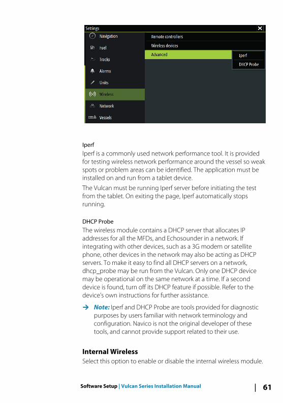
IperfIperf is a commonly used network performance tool. It is providedfor testing wireless network performance around the vessel so weakspots or problem areas can be identified. The application must beinstalled on and run from a tablet device.
The Vulcan must be running Iperf server before initiating the testfrom the tablet. On exiting the page, Iperf automatically stopsrunning.
DHCP ProbeThe wireless module contains a DHCP server that allocates IPaddresses for all the MFDs, and Echosounder in a network. Ifintegrating with other devices, such as a 3G modem or satellitephone, other devices in the network may also be acting as DHCPservers. To make it easy to find all DHCP servers on a network,dhcp_probe may be run from the Vulcan. Only one DHCP devicemay be operational on the same network at a time. If a seconddevice is found, turn off its DHCP feature if possible. Refer to thedevice’s own instructions for further assistance.
Ú Note: Iperf and DHCP Probe are tools provided for diagnosticpurposes by users familiar with network terminology andconfiguration. Navico is not the original developer of thesetools, and cannot provide support related to their use.
Internal WirelessSelect this option to enable or disable the internal wireless module.
Software Setup | Vulcan Series Installation Manual 61
Disabling wireless when not in use reduces the unit’s powerconsumption.
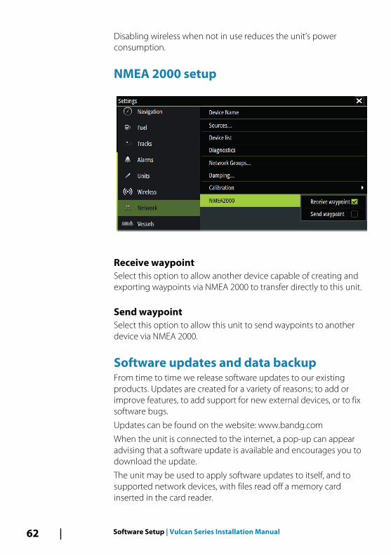
NMEA 2000 setup
Receive waypointSelect this option to allow another device capable of creating andexporting waypoints via NMEA 2000 to transfer directly to this unit.
Send waypointSelect this option to allow this unit to send waypoints to anotherdevice via NMEA 2000.
Software updates and data backupFrom time to time we release software updates to our existingproducts. Updates are created for a variety of reasons; to add orimprove features, to add support for new external devices, or to fixsoftware bugs.
Updates can be found on the website: www.bandg.com
When the unit is connected to the internet, a pop-up can appearadvising that a software update is available and encourages you todownload the update.
The unit may be used to apply software updates to itself, and tosupported network devices, with files read off a memory cardinserted in the card reader.
62 Software Setup | Vulcan Series Installation Manual
Before initiating an update to the unit itself, be sure to back up anypotentially valuable user data.
Network analyzer and service assistantThe system has a built-in service assistant that creates a report ofthe devices installed on the NMEA 2000 network such as thesoftware versions, serial numbers, and information from the settingsfile to assist in technical support enquiries.
To use the analyzer, open the About page of the System settingsdialog and select Support. Two options are displayed:
Ú Note: Remove any mapping cards from your unit and install amemory card with sufficient storage before downloadingsoftware updates or creating and saving reports to the memorycard.
Create reportAnalyzes your network and prompts you for information requiredfor support and creates the report with information automaticallygathered from the network. You can add screenshots and log filesthat will be attached to the report. There is a 20MB limit for thereport attachments. You can save the report to a memory card andemail it to support or upload it directly if you have an internetconnection. If you call technical support first, you can enter anIncident number to assist with tracking.
Check system for updatesAnalyzes your network and checks if updates are available forcompatible devices.
Ú Note: Connect your unit to the internet to check for the latestavailable software versions. The software versions will be up todate as of the last time you updated your unit or connected tothe internet.
Software Setup | Vulcan Series Installation Manual 63
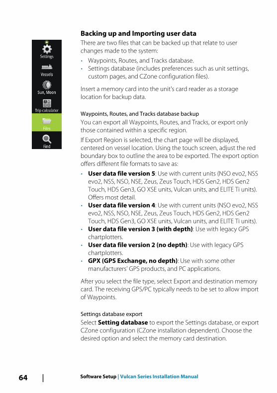
Backing up and Importing user dataThere are two files that can be backed up that relate to userchanges made to the system:
• Waypoints, Routes, and Tracks database.• Settings database (includes preferences such as unit settings,
custom pages, and CZone configuration files).
Insert a memory card into the unit's card reader as a storagelocation for backup data.
Waypoints, Routes, and Tracks database backupYou can export all Waypoints, Routes, and Tracks, or export onlythose contained within a specific region.
If Export Region is selected, the chart page will be displayed,centered on vessel location. Using the touch screen, adjust the redboundary box to outline the area to be exported. The export optionoffers different file formats to save as:
• User data file version 5: Use with current units (NSO evo2, NSSevo2, NSS, NSO, NSE, Zeus, Zeus Touch, HDS Gen2, HDS Gen2Touch, HDS Gen3, GO XSE units, Vulcan units, and ELITE Ti units).Offers most detail.
• User data file version 4: Use with current units (NSO evo2, NSSevo2, NSS, NSO, NSE, Zeus, Zeus Touch, HDS Gen2, HDS Gen2Touch, HDS Gen3, GO XSE units, Vulcan units, and ELITE Ti units).
• User data file version 3 (with depth): Use with legacy GPSchartplotters.
• User data file version 2 (no depth): Use with legacy GPSchartplotters.
• GPX (GPS Exchange, no depth): Use with some othermanufacturers’ GPS products, and PC applications.
After you select the file type, select Export and destination memorycard. The receiving GPS/PC typically needs to be set to allow importof Waypoints.
Settings database exportSelect Setting database to export the Settings database, or exportCZone configuration (CZone installation dependent). Choose thedesired option and select the memory card destination.
64 Software Setup | Vulcan Series Installation Manual
Importing a databaseLater, if the unit has been restored to factory defaults or user data isaccidentally deleted, return to the files page, select the backed upfile, and then Import. View file details for creation date.
Software upgradesThe update file must be loaded to the root directory of the memorycard.
The update may be initiated at boot up: insert the memory card intothe card reader before turning the unit on, boot the unit, and followthe on-screen instructions.
Alternatively, in the Files menu, locate the update file on thememory card inserted in the card reader and select Upgrade,followed by This Display. Accept the prompt to reboot the unit,and wait a few moments as the unit restarts. Do not remove thememory card or repower the unit until the process is completed(this typically takes no more than a couple of minutes).
Software upgrade of remote deviceIt is possible to run an update remotely from one unit and apply itto another, provided they are on the NMEA network. This is onlypossible for units without a card slot.
Remote updating is similar to updating a local unit; select the file onthe memory card and select the Upgrade option, followed byRemote Upgrade. Follow the onscreen options.
NMEA 2000 device upgradesThe update file must be loaded to the root directory of a memorycard inserted in the card reader.
1. Select the Files toolbar option and select the update file underMemory card.
2. Select the Upgrade option presented when the file ishighlighted. A list should appear displaying any compatibledevices the update file applies to. In most cases this will be asingle device.
Ú Note: If no device is shown, check that the device to beupdated has power, and run any outstanding updates for theunit first.
Software Setup | Vulcan Series Installation Manual 65
3. Select the device and initiate the upgrade. Do not interrupt theupgrade process.
66 Software Setup | Vulcan Series Installation Manual
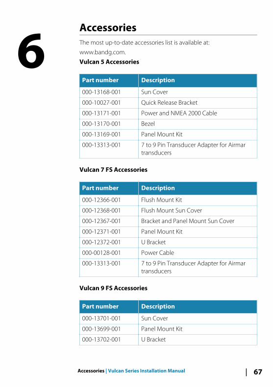
AccessoriesThe most up-to-date accessories list is available at:
www.bandg.com.
Vulcan 5 Accessories
Part number Description
000-13168-001 Sun Cover
000-10027-001 Quick Release Bracket
000-13171-001 Power and NMEA 2000 Cable
000-13170-001 Bezel
000-13169-001 Panel Mount Kit
000-13313-001 7 to 9 Pin Transducer Adapter for Airmartransducers
Vulcan 7 FS Accessories
Part number Description
000-12366-001 Flush Mount Kit
000-12368-001 Flush Mount Sun Cover
000-12367-001 Bracket and Panel Mount Sun Cover
000-12371-001 Panel Mount Kit
000-12372-001 U Bracket
000-00128-001 Power Cable
000-13313-001 7 to 9 Pin Transducer Adapter for Airmartransducers
Vulcan 9 FS Accessories
Part number Description
000-13701-001 Sun Cover
000-13699-001 Panel Mount Kit
000-13702-001 U Bracket
6
Accessories | Vulcan Series Installation Manual 67
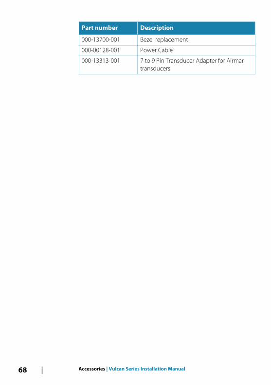
Part number Description
000-13700-001 Bezel replacement
000-00128-001 Power Cable
000-13313-001 7 to 9 Pin Transducer Adapter for Airmartransducers
68 Accessories | Vulcan Series Installation Manual
Supported data
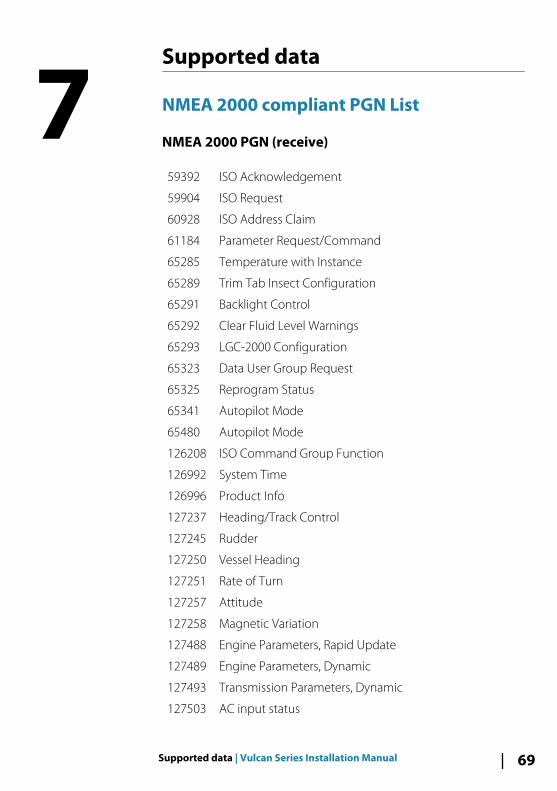
NMEA 2000 compliant PGN List
NMEA 2000 PGN (receive)
59392 ISO Acknowledgement
59904 ISO Request
60928 ISO Address Claim
61184 Parameter Request/Command
65285 Temperature with Instance
65289 Trim Tab Insect Configuration
65291 Backlight Control
65292 Clear Fluid Level Warnings
65293 LGC-2000 Configuration
65323 Data User Group Request
65325 Reprogram Status
65341 Autopilot Mode
65480 Autopilot Mode
126208 ISO Command Group Function
126992 System Time
126996 Product Info
127237 Heading/Track Control
127245 Rudder
127250 Vessel Heading
127251 Rate of Turn
127257 Attitude
127258 Magnetic Variation
127488 Engine Parameters, Rapid Update
127489 Engine Parameters, Dynamic
127493 Transmission Parameters, Dynamic
127503 AC input status
7
Supported data | Vulcan Series Installation Manual 69
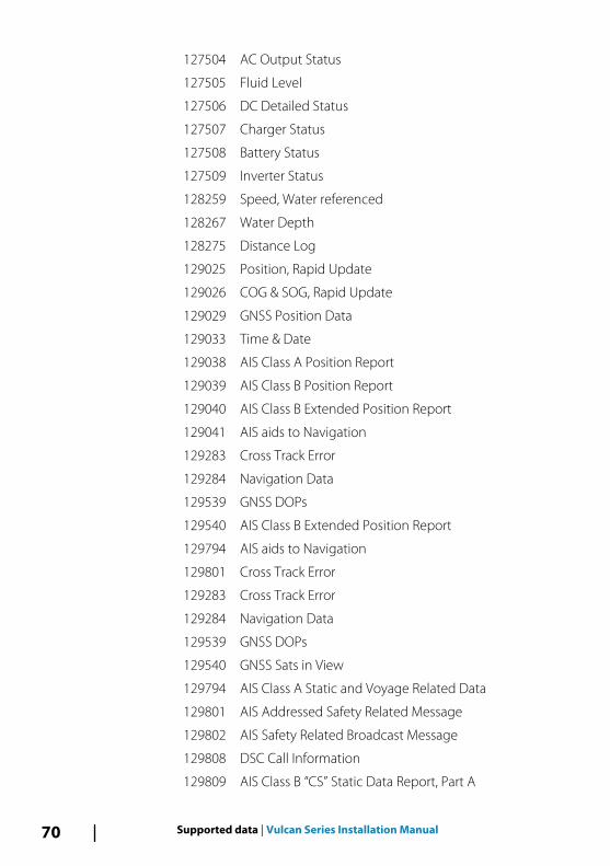
127504 AC Output Status
127505 Fluid Level
127506 DC Detailed Status
127507 Charger Status
127508 Battery Status
127509 Inverter Status
128259 Speed, Water referenced
128267 Water Depth
128275 Distance Log
129025 Position, Rapid Update
129026 COG & SOG, Rapid Update
129029 GNSS Position Data
129033 Time & Date
129038 AIS Class A Position Report
129039 AIS Class B Position Report
129040 AIS Class B Extended Position Report
129041 AIS aids to Navigation
129283 Cross Track Error
129284 Navigation Data
129539 GNSS DOPs
129540 AIS Class B Extended Position Report
129794 AIS aids to Navigation
129801 Cross Track Error
129283 Cross Track Error
129284 Navigation Data
129539 GNSS DOPs
129540 GNSS Sats in View
129794 AIS Class A Static and Voyage Related Data
129801 AIS Addressed Safety Related Message
129802 AIS Safety Related Broadcast Message
129808 DSC Call Information
129809 AIS Class B “CS” Static Data Report, Part A
70 Supported data | Vulcan Series Installation Manual
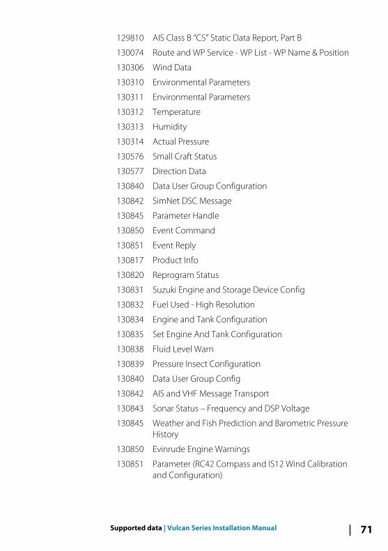
129810 AIS Class B “CS” Static Data Report, Part B
130074 Route and WP Service - WP List - WP Name & Position
130306 Wind Data
130310 Environmental Parameters
130311 Environmental Parameters
130312 Temperature
130313 Humidity
130314 Actual Pressure
130576 Small Craft Status
130577 Direction Data
130840 Data User Group Configuration
130842 SimNet DSC Message
130845 Parameter Handle
130850 Event Command
130851 Event Reply
130817 Product Info
130820 Reprogram Status
130831 Suzuki Engine and Storage Device Config
130832 Fuel Used - High Resolution
130834 Engine and Tank Configuration
130835 Set Engine And Tank Configuration
130838 Fluid Level Warn
130839 Pressure Insect Configuration
130840 Data User Group Config
130842 AIS and VHF Message Transport
130843 Sonar Status – Frequency and DSP Voltage
130845 Weather and Fish Prediction and Barometric PressureHistory
130850 Evinrude Engine Warnings
130851 Parameter (RC42 Compass and IS12 Wind Calibrationand Configuration)
Supported data | Vulcan Series Installation Manual 71
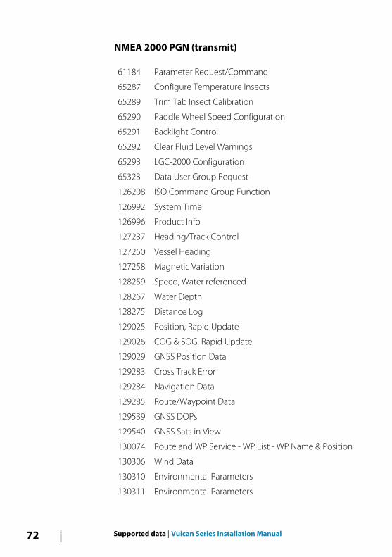
NMEA 2000 PGN (transmit)
61184 Parameter Request/Command
65287 Configure Temperature Insects
65289 Trim Tab Insect Calibration
65290 Paddle Wheel Speed Configuration
65291 Backlight Control
65292 Clear Fluid Level Warnings
65293 LGC-2000 Configuration
65323 Data User Group Request
126208 ISO Command Group Function
126992 System Time
126996 Product Info
127237 Heading/Track Control
127250 Vessel Heading
127258 Magnetic Variation
128259 Speed, Water referenced
128267 Water Depth
128275 Distance Log
129025 Position, Rapid Update
129026 COG & SOG, Rapid Update
129029 GNSS Position Data
129283 Cross Track Error
129284 Navigation Data
129285 Route/Waypoint Data
129539 GNSS DOPs
129540 GNSS Sats in View
130074 Route and WP Service - WP List - WP Name & Position
130306 Wind Data
130310 Environmental Parameters
130311 Environmental Parameters
72 Supported data | Vulcan Series Installation Manual
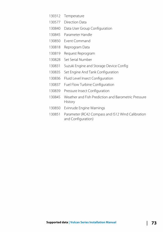
130312 Temperature
130577 Direction Data
130840 Data User Group Configuration
130845 Parameter Handle
130850 Event Command
130818 Reprogram Data
130819 Request Reprogram
130828 Set Serial Number
130831 Suzuki Engine and Storage Device Config
130835 Set Engine And Tank Configuration
130836 Fluid Level Insect Configuration
130837 Fuel Flow Turbine Configuration
130839 Pressure Insect Configuration
130845 Weather and Fish Prediction and Barometric PressureHistory
130850 Evinrude Engine Warnings
130851 Parameter (RC42 Compass and IS12 Wind Calibrationand Configuration)
Supported data | Vulcan Series Installation Manual 73
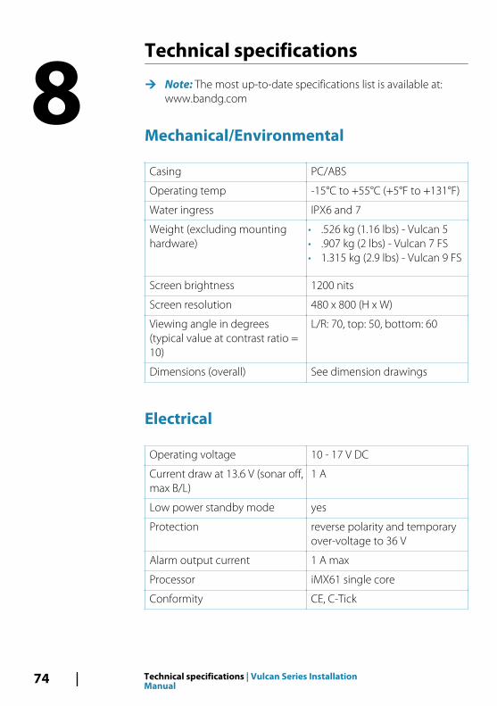
Technical specifications
Ú Note: The most up-to-date specifications list is available at:www.bandg.com
Mechanical/Environmental
Casing PC/ABS
Operating temp -15°C to +55°C (+5°F to +131°F)
Water ingress IPX6 and 7
Weight (excluding mountinghardware)
• .526 kg (1.16 lbs) - Vulcan 5• .907 kg (2 lbs) - Vulcan 7 FS• 1.315 kg (2.9 lbs) - Vulcan 9 FS
Screen brightness 1200 nits
Screen resolution 480 x 800 (H x W)
Viewing angle in degrees(typical value at contrast ratio =10)
L/R: 70, top: 50, bottom: 60
Dimensions (overall) See dimension drawings
Electrical
Operating voltage 10 - 17 V DC
Current draw at 13.6 V (sonar off,max B/L)
1 A
Low power standby mode yes
Protection reverse polarity and temporaryover-voltage to 36 V
Alarm output current 1 A max
Processor iMX61 single core
Conformity CE, C-Tick
8
74 Technical specifications | Vulcan Series InstallationManual
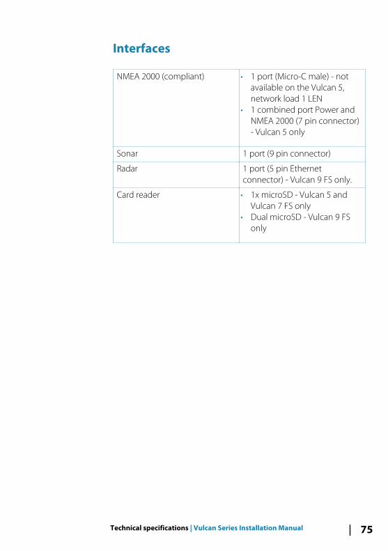
Interfaces
NMEA 2000 (compliant) • 1 port (Micro-C male) - notavailable on the Vulcan 5,network load 1 LEN
• 1 combined port Power andNMEA 2000 (7 pin connector)- Vulcan 5 only
Sonar 1 port (9 pin connector)
Radar 1 port (5 pin Ethernetconnector) - Vulcan 9 FS only.
Card reader • 1x microSD - Vulcan 5 andVulcan 7 FS only
• Dual microSD - Vulcan 9 FSonly
Technical specifications | Vulcan Series Installation Manual 75
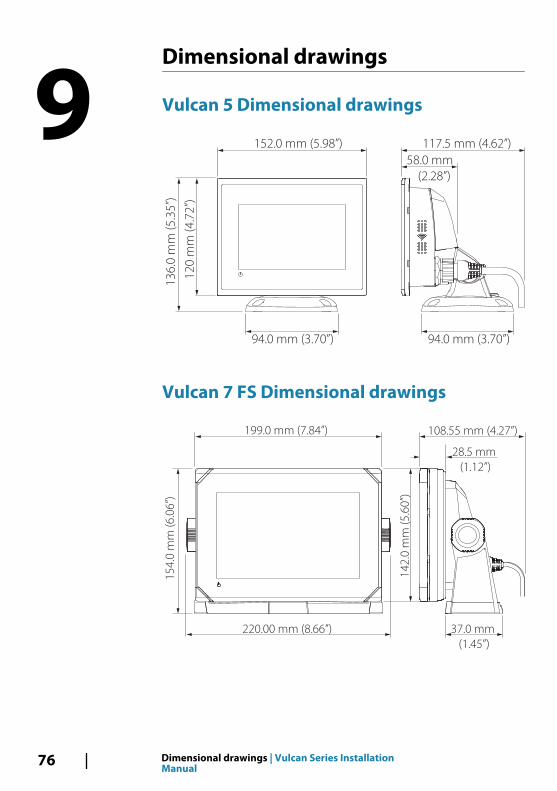
Dimensional drawings
Vulcan 5 Dimensional drawings
152.0 mm (5.98”)
94.0 mm (3.70”)
13
6.0
mm
(5
.35
”)
12
0 m
m (
4.7
2”)
94.0 mm (3.70”)
117.5 mm (4.62”)
58.0 mm
(2.28”)
Vulcan 7 FS Dimensional drawings
199.0 mm (7.84”) 108.55 mm (4.27”)
28.5 mm
(1.12”)
37.0 mm
(1.45”)
220.00 mm (8.66”)
15
4.0
mm
(6
.06
”)
14
2.0
mm
(5
.60
”)
9
76 Dimensional drawings | Vulcan Series InstallationManual
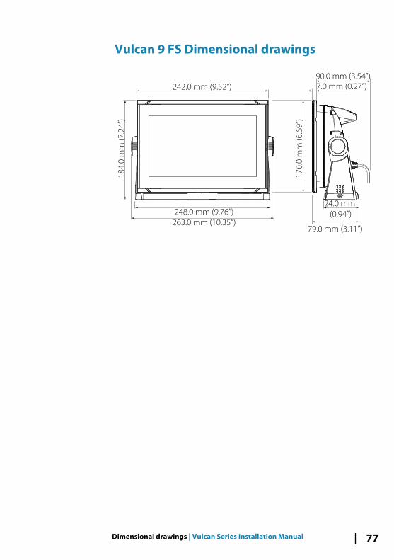
Vulcan 9 FS Dimensional drawings
242.0 mm (9.52”)
248.0 mm (9.76”)
263.0 mm (10.35”)
24.0 mm
(0.94”)
18
4.0
mm
(7
.24
”)
17
0.0
mm
(6
.69
”)
7.0 mm (0.27”)
90.0 mm (3.54”)
79.0 mm (3.11”)
Dimensional drawings | Vulcan Series Installation Manual 77

78 Dimensional drawings | Vulcan Series InstallationManual
IndexA
Advanced SourceSelection 33Auto drive engage
Autopilot setting 43Auto select
sources 31Auto trim
Autopilot 50Autopilot
Auto trim 50Autotuning 47Boat type setting 41Commissioning 40Compass calibration 45Configure 40Counter rudder 49Drive engage 43Drive voltage setting 41, 43HI/LO parameters 52Layline steering 49Manually adjusting steeringparameters 49Minimum rudder 51Minimum wind angle 51Motor output for rudderspeed 43Navigation change limit ona route 51Response 52Rudder calibration setupand test 41Rudder deadbandparameter 44Rudder drive setup 42Rudder parameter 49Sailing parameters 47Sea state filter 47Seatrials 44
Setting the transitionspeed 46Setup 40Tack angle 48Tack time 48Turn Rate limit 51Verify connection 40VMG (to wind)optimizing 49Wind function 48
AutotuningAutopilot 47
B
Back upCZone configurationfile 56User data 64
Backlight controlCZone 56
Boat type settingAutopilot 41
BoatSetup 52
Bracket mounting 19
C
CalibrateCompass for autopilot 45Fuel 53
Card reader 15Channel
GoFree device 60Clutch
Autopilot drive engage 43Commissioning
Autopilot 40Compass
Calibration for autopilot 45
Index | Vulcan Series Installation Manual 79
Configuration fileCZone, Import andbackup 56
ConfigureAutopilot 40
Counter rudderAutopilot 49
Countries of intended use inthe EU 5CZone
Backlight control 56Configuration 55Dipswitch 56Display at startup 56Enabling 56Export CZone config 64Import and backup aconfiguration file 56NMEA 2000 connection 28Setup 55
D
Data backup 62Data source selection 31Database
Backup 64Export settings 64Import 65
Date format 31Depth offset 34Device list 33DHCP
Probe, wireless tool 61Dipswitch
CZone devices settings 56Distance To Turn 51Drive
Autopilot voltagesetting 41
Drive
engage Autopilot 43Voltage, autopilotsetting 43
E
EchosounderDepth offset 34
EnginesSetup 52
ExportRegion 64CZone config 64Database backup 64Database exportsettings 64Waypoints, Routes, andTracks 64
F
FirmwareUpgrade 57
First time startupSetup wizard 31
Flow configurationFuel flow sensor 53
Front controls 13Fuel
Calibrate 53Flow sensorconfiguration 53Level measure 54Setup 52Vessel setup 52
G
GoFreeChannel setting 60DHCP Probe 61Iperf tool 61
80 Index | Vulcan Series Installation Manual
Remote controllers 59Smartphoneconnection 58Tablet connection 57Wireless device setup(phone and tablet) 57
GroupSource selection 32
I
ImportCZone configurationfile 56Database 65User data 64
InstallationMounting 17Transducer 21
Internet usage 5Iperf, wireless tool 61
L
Layline steeringAutopilot setting 49
M
ManualSource selection 32
Minimum rudder 51Minimum wind angle 51Motor output
Autopilot, rudder speed 43Mounting
Bracket 19Location 17Panel 20
N
Navigation change limit
Autopilot setting for aroute 51
NMEA 2000CZone connection 28devices upgrades 65
P
Panel mounting 20Power button 13
Q
Quick release bracketReleasing the unit 19
R
RadarSetup 35
Rate limitTurn 51
Rate of turn (tack time) 48Remote controllers
GoFree, wireless 59Remote device
Software upgrade 65Rudder drive setup
Drive setup, Autopilot 42Rudder
Autopilot 49Calibration, Autopilot 41Counter, for autopilot 49Deadband, Autopilot 44Minimum 51
S
Sailing parametersAutopilot 47
Sea state filterAutopilot 47
Seatrials
Index | Vulcan Series Installation Manual 81
Autopilot 44Setup wizard
First time startup 31Smartphone connection 58Software
Setup 31Software
Updates 62Upgrade 65Upgrade remote device 65
Sonarsetup 34
Source selectionAdvanced 33Auto 31Group 32Manual 32
SteeringAutopilot, turn rate limit 51Autotune 47Layline steering 49Manually adjusting steeringparameters 49Minimum rudder 51Minimum wind angle 51Rudder deadbandparameter 44Rudder drive setup 42Rudder parameter 49Setting the transitionspeed 46Tack angle 48Tack time 48Wind function,Autopilot 48
StructureScan 35
T
Tablet connectionGoFree, wireless 57
Tackangle, autopilot 48Time, autopilot 48
Technical specifications 74Time
Vessel location, format 31Tools
Wireless fault finding 60Transducer type 35Transducer
Installation 21Transition speed
Setting, Autopilot 46Turn Rate limit 51
U
UpgradeSoftware 65
UpgradeModule firmware 57NMEA 2000 devices 65
User databack up 64Importing 64
V
VerifyAutopilot connection 40
VesselSetup 52
VMG optimizingAutopilot 49
W
WarningUser caution 4
Warranty 3Water temperaturecalibration 35
82 Index | Vulcan Series Installation Manual
WindAngle, minimumapparent 51Function, Autopilot 48Mode, rate of turn (tacktime) 48
WirelessDevice setup (phone andtablet) 57Devices details 59DHCP Probe 61Enable or disable theinternal wireless 61Fault finding tools 60Iperf tool 61Remote controllers 59Setup 57Smartphoneconnection 58Tablet connection 57
Index | Vulcan Series Installation Manual 83

*988
-110
99-0
02*
0980