Embed Size (px)
Citation preview
o
o
MIL-B-85B4C12 Auxust 1970BUPERSSD2NGMIL-B-85B4B29 my’ 1963
FIXL3TASY SPECIFICATION
BsASE SYSTFMS, WHEEL, A2RCSAFI!,DESIGN OF
This specification is mandatory for use by all Departments
and Agencies of the Depnrtm.mt of Defense.
1. SCOPE
1.1 _ l%is specification covore the broke system deeign requirements
for aircraft equipped with whee l-type landing gear.
1.2 C laasification. The brake systems shal1 ba either hydraulic or pneumatic;manually operated, power operated , manual-power operated; and shal 1 be of thefolloviqgtypes:
Type I - Hanuol preseura generating: The control unitby manuo1 actuation.
Type 11 - Power pressure generating: The control unitfrem a power generating system.
Type III - 14mual pover pressure generating: Pre.ssurarated in a slave control unit which in turn operates
generates prea.mre
meters pressure
is manua 1ly gene-
the main control
unit which meters fluid from n pre.sauregenerating system.
~pe IV - Pewer-boosred manual preesure generating: The control unitgenerates preesure by manual actuation and, in addition, the manuallygenerated pressure ie boosted by pressure from a por..ergenerating system.
~pe V - Pover brake valve with emergency maeter cylinder: One part ofthe control unit meters pressure from R power generating syetem,and another part of the control unit eervee as a standby manualpressure generating unit when the power system ie inoperative.
PSC 1630
4!!9
Downloaded from http://www.everyspec.com
1.. , . 0 ..,.,.,.11 L,- D -0> ,y+b
2. APPLICASLR DOCUMSNTS
* 2.1 The following documents of the issue in effect on date of invitationfor bids or request for proposal. form a Dart of this specification to theextent specifi~d
SPECIFICATIONS
Military
MIL-T-781MIL-W-5013MIL-w-5424
MIL-H-5440
MIL-P-5518
MIL-v-5525
MIL-C-6026
MIL-P-703&
MIL-S-7742
MIL-C-7979MIL-B-8075
MIL-H-8775
MIL-H-8794MIL-H-8891
MIL-F-9490
MIL-F- 18372
MIL-c-25427
STANDARDS
Military
MIL-STD-203
2
herein:-
Terminal; Wire Rope, Swa8ing
Wheel and Brake Assemblies: AircraftWire Rope, Steel, (Corrosion Resisting) Flexible,
PrefOmed (For Aeronautical Use)Hydraulic Systems, Aircraft, Types I and 11, Design,
Installation, and Data Requirements forPneumatic Systems, Aircraft; Design, Installation, and
Data Requirement forValves, Aircraft Power Brake
Control Unit, Pressure Generating, Manually Operated,Aircraft Hydraulic Brake System
Pulleys, Groove, Antifriction-Bearing, Grease-Lubricated ,
Aircraft
Screw Threads, Standard, Optimum Selected Series: Gene-ral Specification for
Cylinders; Hydraulic Brake, Master, Power AssistedBrake Control Systems, Antiskid, Aircraft wheels: In-
structions for Preparation of Specifications forHydraulic System Components, Aircraft and Missiles,
General Specification forHose, Rubber, Hydraulic, Fuel and Oil ResistantHydraulic Systems, Manned Flight Vehicles, Type III,Design, Installation, and Data Requirements for
Flight Control Systeme - Design, Installation and Teatof, Piloted Aircraft, General Specification forFlight Control Systems, Design, Installation and Test of,Aircraft (General Specification for)Coupling Assembly, Hydraulic, Self-Sealing, Quick Dis-connect
Aircrew Station Controls and Displays for Fixed WingAircraft
●
Downloaded from http://www.everyspec.com
o
*
o*
*
0
MIL-s2’o-250 Aircrew StationControlsAircraft
!4s33540 SafetyWiring and Cotter
Air Force-Naw Aeronautical
AN6204 Valve, Hydraulic Blcedcr
(Copies of specifications, standards, drawings,
UIL-B-8584C
and Oisplays for Rotary Wing
Pinning, Ganernl Praccicef3for
end publicetione required bysuppliers in-conncccion with specific procurement functione ehouId be obtainedfrom che procuring activity or as directed by chc contracting officer).
3. RSQUIREHSNTS
3.1 General requirements. The brake syetems covered by this specificationshe11 be operable under al1 conditione of weather and compatible with the type(temperature range) and class (pressure limits) of hydraulic or pneumatic sys-tems as specified in MIL-H-5440, MIL-P-5518, or HIL-H-BB91, whichever isapplicable.
3.2 Selection of materials. Specificntione and standards for all materials,parte, and Government certiftcntf.onand approval of processes and equipment,which are not specifically deeignaced herein and which ore necessary for theexecution of this specification, ehnll be selected in accordance with proceduresestablishedby the procuringactivity,exceptas providedin the follwingperagraph.
3.2.1 Standardparts. Standardparts (MS or AN) shn11 be used vherever theyare euitable for the purposeand shall bo identifiedon the drawing by theirpart numbers. In the event there ia no euitablecorrespondingetandardpart ineffect on dote of invitationfor bide, commercialporte may be used providedthey conform to al1 requirement of this specificetion and mre than one sourceis available for replacement.
3.3 Design. The deeign and installation of circraft brokfng systems shall bein accordance with the applicable requirements of MIL-H-5440, MIL-P-5518,MIL-H-8775, MIL-H-8891, or MIL-F-18372 and MIL-F-9490 and shell employ to thefulleet possible extent the stnndord components listed therein. TYpO IV brakesystems @hall be used on all carrier-baead oircraft for which the type I systemwwld be inadequate to hold tha aircraft on a 10” alope at maximum design grossweight. A type II brake system IMY be used for carrier-boeed nircroft whichhave an antiskid control Wstem. Where type I or type IV manual eyatems alone. . . .will not meet the 10° slope requirements, a type 11, III, or Vused, but epecial provisions10” slope without the uee of
sho11 be incorpor~ted to hold thenormal pOwer-generatin8 eystems.
sys_temshall beaircroft on theAll detachable
3
Downloaded from http://www.everyspec.com
MIL-B-8584c
I
*
*
*
components and parts shall be safetied in accordance with MS33540 or securedby an approved method that wi 11 prevent loosening.
3.3.1 Wheels and brakes. Wheel and brake aeaemb lies shall conform to therequirements of MIL-W-5013 and the applicable standards.
3.3.2 Normal brake controls. Right and left brakes shall “be separatelyactuated and shall be so designed that they can be applied by toe force on
brake pedals on the rudder controls except for bicycle gear or quadricyclegear, where other suitable brake controle may be used s“bject to approval of
the procuring activity. Pedal location shall conform to the requireme”ta ofMIL-STO-203 or MIL-STO-250, as applicable. The brake pedal linkages shall be sodesigned that a comfortable angle of approximately 90” betw”een the pilot’s footand his lower leg is maintained throughout the full range of movement of the
rudder pedals and seat. Strength sha 11 be provided in the brake pedal and as-sociated linkage to withstand 300 pounds applied at the tip of the pedal with
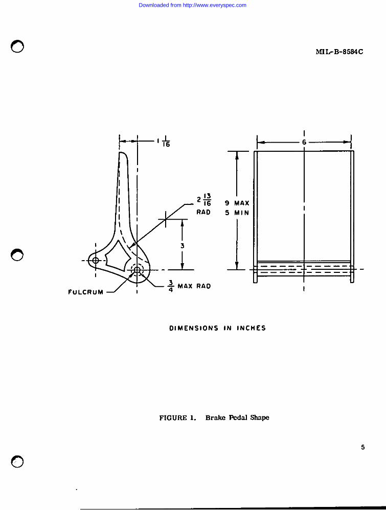
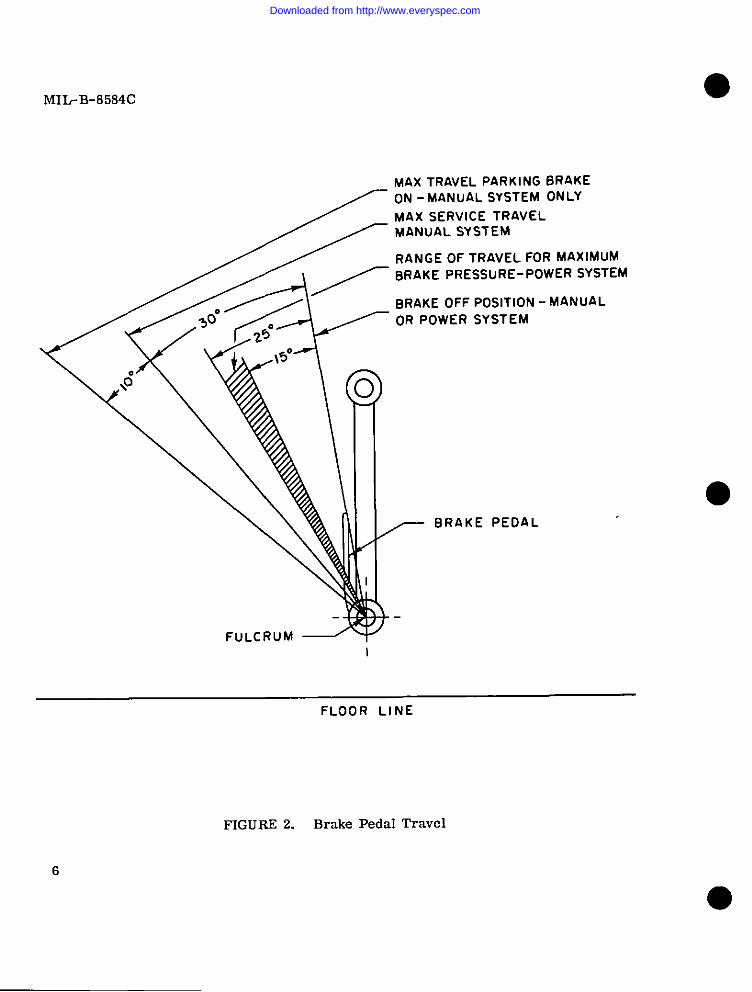
no yielding. The desired shape and travel of the brake pedals and the brakecontrol device shall be as free as possible of friction and lo~t motion (Bee
figures l-and 2) . Means shall be provided to positively return the brake ped-als to the off position when toe force is removed from the pedals. No pumpingsha 11 be allowed 1“ order to meet the deceleration and parking requirements.
3.3.2.1 Manual Iy operated systems, type 1. Manual hydraulic braking controlsystems shall incorporate a brake control unit or units which shall conform to ●MIL-C-6026. The total displacement of the control unit shall be at least 25percent greater than the maximum displacement, including line expansion re-quired to hold the wheels locked against a 33° slope for aircraft at maximumdesign gross weight and a 20° slope for helicopters at design alternate gross
weight. The control unit shall preferably be connected directly to the brakepedal lever. The compressible medium of the temperature compensating devicein the concrol unit shall be designed with a minimum preload of 50 percent anda minimum bottoming load of 125 percent of the parking pressure required to
hold aircraft on an lB” slope at maximum design gross weight and to hold heli-copters on a 10° slope at design alternate gross weight. This device shallhave fluid displacement equivalent to the change in volume of the fluid in thebrake system, neglecting the reservoir, under a temperature change of 44 .4°C
(112”F) . Manual braking control systems shall be such that:
(a) A foot force of between 15 and 20 pounds at the tip of the pedal shall be
required to cause initial movement of the brake pedal.
(b) A foot force of between 75 and 125 pounds at the tip of the pedal shall
develop the torque required on the landplane landing design gross weight orat design alternate gross weight brake stop conditions of the table entitled
4
Downloaded from http://www.everyspec.com
,,.,: r
o
0
FuLCRUM /
I
~fi
r 16
RAD
3
\..\- -l_,
+ M6.X RCtD
MIL-B-8584C
+!
T9 MAX
S MIN
1 j —---- -———.——- —.--— ———
DIMENSIONS IN INCHES
FIGURE 1. Brake PedalShape
5
0
Downloaded from http://www.everyspec.com
MIL-B-8584C
MAX TRAVEL PARKING BRAKEON -MANUAL SYSTEM ONLY
MAX SERVICE TRAVEL/ MANuAL SYSTEM
RANGE OF TRAVEL FOR MAXIMUM
BRAKE PRESSURE- POWER SYSTEM
BRAKE OFF POSITION - MANUALOR POWER SYSTEM
I
FuLCRUM 3
6
BRAKE PEDAL
J
FLOOR LINE
FIGURE 2. Brake Pedal Travel
Downloaded from http://www.everyspec.com
.- 1
0
0
tlIbfI-8584C
“wheel Brake Cnpncity Rcquirementa”of UIL-W-5013. ‘Rv3brake pressure thusobtained shall be connisccnt with the ttverngeof the repeated dynamometertests of the brako in the lmdplnno hnding dcalgn gross wei8ht condition orat deafen alternnte Sross woi8ht.
(c) The trcive1 of tho pednl for full brnko application ahnll ba an indicatedon fi8ure 2. It shall not exceed 30” whilo mcacin8 the requircmmnta of sub-paragraph (b) nbovc.
* (d) In all positions of the brake pedal or ch.?rudder linkage and the seat,ic ahal1 bo possible for tho pilot to apply sufficient stack brake torque tohold the wheels locked tigainata 33” slops for nircrnfc at maximum design grosswei8ht and a 20” S1OPC for hcllcoptera at d@si8n alternnce groan weight. Itshall be possible to meet thin requirement with tho brakes at n temperature of21°C (70”F).
3.3.2.2 Power-opcrntcd syntems, CYPCS 11 and III. Power-operated brake con-trol ayetems shall exhibitno objectionablecimclag between pedal movement andbraka reapon.se. Such systems shnl1 dcvalop “feel” at the pedale, in proportionto the amount of enorgizin8 force npplicd to the brake. Rydrnulic p0UC3rbrakevnlves @hall conform to MIL-V-5525. l’honormal brnkc systam, including nccumu-latore if used, shal 1 be daslgncd to prevant depletion of brake prtissuresupplydue to pi10C operation durin8 normal lnndin8 run or ground hmd ling of the aLr-craft. ConaidorarionahouId bo given co appropriatehydraulic pump operatingapeede.
3.3.2 .2.1 Pow? brakin8 ayatems shall be tmxh chat:
(a) A foot forco of botwcen 15 and 20 pounds at the tip of the pedal shall berequired to cauea initial mntcring throush tho povcr broke valve.
* (b) A fmcforce of betwcah 65 to 85 pounds at chc tip of the pedal shalldevelop the torque required on the landplane landing design Srosa weisht or atdesign alternate 8ross weight brake stop conditions of the table entitled “WheelBrake Capacity Requirements” of WL-W-5013. The brake prcseure thus obtainedshall be consistent with the nverase of the repented dynanwme.cer tests of thebrake Ln the landplane landing design gross weight condition or at desisnalternate 8roas waisht.
* (c) Brnkc pressure sufficient to hold the wheels locked shall be available atthe upper ranges of travel of the brake pedal or rudder linkage and the seat tohold against a 33” S1OPC for aircr4ft at maximum desi8n gross wei8ht and a 20°slope for helicopters at design oltcrnnte cross weight. It shall be possibIeco meet this condition with the brakes at a temperature of 21*C (70”F).
4!3
Downloaded from http://www.everyspec.com
MIL-B-8584C
(d) The travel of the pedals shall be as shown on figure 2. It shall be be-tween 15° and 25° to produce the maximum available brake pressure.
* 3.3.2.3 Controls of carrier-based aircraft, tvpes II. IV, and V systems.On those carrier-based aircraft where power brake systems are required, thebrake control shall conform to MIL-c-7979. as applicable. With the Power sYe-ternoperative, the brakes shall meet the requirement for power-operated systems.With the power system inoperative, the systernshall meet the requirements for
*
*
manually operated systems, except the deceleration capability at 175 poundsmaximum foot force shall be consistent with the aircraft operational require-ments as approved by the procuring activity. For helicopters, 175 poundswximum foot force shall produce a 5 foot per second per second decelerationat basic design gross weight. The braking capability must be adequate for aminimum aircraft braking coefficient of friction of 0.2.
3.3.3 Emergency brake control system. All aircraft using types II and IIIb~ake systems shall be provided with an emergency brake system capable ofdecelerating the aircraft under the conditions specified in 3.3.2 .2.l(b).If an emergency hydraulic system is used, metered differential brake controlshall be provided. The emergency system shall be completely independent ofthe normal system up to the shuttle valve or equivalent unit at the brake.A system wherein a failure of one-half of the normal system still allows thespecified decelerations with differential control is considered equivalentto a separate emergency system. When accumulators or air bottles are usedfor the emergency braking, they shall have s“fficient capacity to provide acleast 10 full brake applications, assuming brakes are adjusted to recommendedclearances, and of which the last shall provide a coefficient of 0.18 minimumbetween tire and runway recommended clearances. The volume of hydraulic fluidrequired should be based on pressures and displacements required to meet thespecified deceleration applications considering three of the applications arewith cold brakes and seven are with hot brakes . If air bottles are used forthe emergency system, the lines between the air bottle control valve and theshuttle valve shall be automatically vented to the atmosphere when not in use.Whenever feasible, emergency brake systems shall function by continued pres-sure on the brake pedal. Emergency systems shall be designed to facilitateoperational checks. The emergency brake system shall be designed to precludeentrapment of the normal system fluid within any of the components whichcould prevent the brake system from going into an emergency mode.
3.3.4 General design requirements
3.3.4.1 Brake t!ystemscm all aircraft shall be provided “ith a parking brakecontrol located a“d actwated in accordance with MIL-STO-203 a“d MIL-STO-250,aS applicable , exc”eptthat the parking lock may be omitted from jet-powered
g
●-1
Downloaded from http://www.everyspec.com
c)
o
0
M23,-B-85s4c
interceptors, jet-powered fightere, and carrier-baeed aircraft. The parkingmechanism nhnl1 provido sufficicnt prcaaure in the brake system to develop atorque to hold on an 18” Blope for nircrafc at maximum design gross weight .mdn 10” Blopc for he licoptcre ticn doaign altcrnnto groan weight. TIIQparkinglock system tihnl1 incI“dc means to compensate for predicted leakage a“d temp.ara-cure vnriatio” .SOthnt at Iaast 75 percent of the parking brake torque definedabove is maintained over n minimum period of 1 hour with enginesoff and a 40”Fdrop fn Cemperacurc. A 40” increneo above the i“icinl parking temperature shallnot result in exceaaivo prcaaurc in the braka system.
3.3.6.2 Op@rntinR media. Brnkes shrillbe designed for une with the operatingmedium mutually determined by the procuring activitiesand the aircroftmanufac-turer for the particu Inr application (hydraulic, pneumatic, ❑echanical).
* 3.3.4.3 Brnko linas. Brake llncs ahal 1 be rout.edco facilitate proper bleed-ing. Traps or bends in hydrnu Iic lines which might C4USC air pockets shall beavoided. S!fmrevcr prnccicablo, the lines shnl 1 hnve a continuous drop from thebrake valve or control unit to the brnkeo, If trnpa or bends cannot be avoided,then n scpnrate AN6204 , or cquivnlcnt, blcodcr valve ehnl1 be installed to ac-complish proper bleeding in occordancc with 1.IIL-H-5440.
3.3.4.4 Provisionsfor removol of brnkas. Brakoe which must be removed beforewheels are removed sho11 braconnected with flcxlbI@ hose conforming to MIL-H-B794,as determined by the brake operating pressura and volumetric expansion r@quire-menca. Self-sen ling couplings conformin8 to ?uL-c-25427 ahn11 be used on allbrakes which must be removed before chc wheel can be reme.d.
3.3.4.5Control cnblen. Brake control cab les aholl conform co HIL-u-5424.
.%aged cerminnls conforming to HIL-T-7B1 ahnl 1 be used on tha ends of brakec.mcrol cnbles. Pullcyn conforming to K!IL-P-7034 shall be ueod wherever brakecontrol cablftB chnngc direccion more than 5“
3.3.4.6 Accessibility. ?mfficicnt clearance or openings shall be providedin order that brake adjustmcnta and bleeding of hydrnulic brakes may be ensilYaccomplished . Reservoirs, brake accuncora, valves, or cy llndera sh411 be
locaced outside the cockpit or cabin enclosure.
3.3.4.7 Plller PIUR. The brake control unit or external rc.servoir,as appli-cable, shall be provided with a readily acceasiblc filler plug. Space and meansshall be provided for easily checking the fluid level in che unit. ‘Ihe thread
shall be selected from M2L-S-7742 with the mnximum pitchpracticable.
9
Downloaded from http://www.everyspec.com
MIL-B-8584c
*
*
*
*
*
*
*
*
*
!
3.3.5 Antiskid control requirements. Unless otherwise specified in the air-craft detail specification, an antiskid system shall be piovided on all aircraft,except helicopters, equipped with type II, III, or V brake systems. Antiskidcontrol devices shall be in accordance with MIL-B-8075.
3.3.5.1 Hydraulic response time. Hydraulic brake systems with an integratedantiskid control syacem sha11 be designed to produce the minimum hydraulic re-sponse time within practical limits for improved antiskid control performance.Minimum response time shall be achieved by minimization of major responsecontributors such aa brake displacement, line expansion, line length, and flowrestrictions.
3.3.6 Brake system flow. It shall be shown by analysis of the hydraulic flawtransferred to and from the brakes during the most adverae conditions, in addi-tion to the nmbrake flow through valvea and modylacora, that adequate capacityis provided to prevent any degradation of the brake system performance.
3.3.7 Brake system maximum pressure. The maximum metered brake pressure maybe any value up to the maximum hydraulic pressure available at the inlet of thepressure ❑etering control unit. The strength of the brake subsystem componentsshall be based on the factors of safety specifled by the procucing activity.
3.3.8 Pressure ❑etering control unit. The ports and internal fluid passagesshall be sized to permit adequate flow to and from the antiskid control valve.Considerations shall include tbe desired initial brake response from the fullyreleased position against residual pressure to the brake applied p~ition inaddition to subsequent cyclic application of pressure by the antiskid controlvalve.
3.3.9 Hydraulic lines
3.3.9.1 m Hydraulic lines for supply and return shall be selected ‘LOprovide minimum pressure drops compatible with flow requirements of the preamremetering control units, antiskid control valves , and brake assemblies under in-stalled environmental co”ditio”s.
3.3.9.2 Flex hoee. The utilization of flex hoses between the control ““it a“dthe wheel shall be held to a minimum to minimize accumulation effect duringpressure changea.
3.3.10 Antiskid control valve.cable to the brake assemblies to
The valves shallimprove hydraulic
be located as clone as practi-coupling.
(
10
Downloaded from http://www.everyspec.com
o*
*
*
*
*
HIL-B-8584C
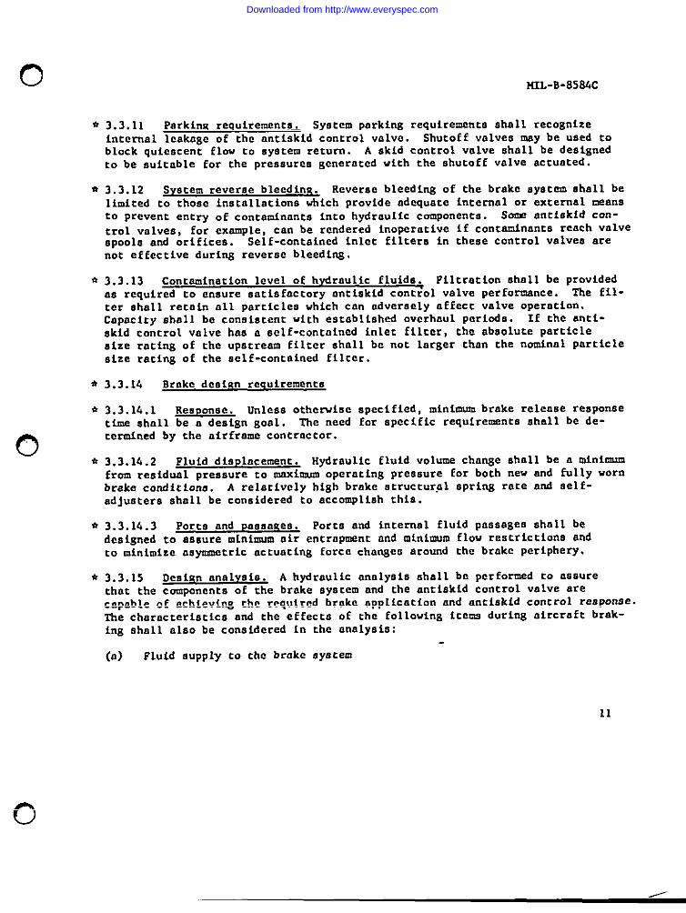
3.3.11 Parkinx requirements. System parking requirementsshall recognizeinternal leakage of the antiskidcontrol valve. Shutoff valves may be used toblock quiescent flow to system return. A skid control valve shall be designedto be suitable for the pressures generated with the shutoff valve actuated.
3.3.12 Svstem reverse bleedin~ Reverse bleeding of the brake system shall belimited to those installationswhich provide adequate internal or external meansto prevent entry of contminante into hydraulic components. Sone antiskid can-
trol valves, for example, can be rendered inoperative if concam.inancareach valve6POO1O and orifices. Self-containedinlet filters in these control valves arenot effectfvo during reverse bleedl~.
3.3.13 Contamination level of hvdraulic fluide. FlltrntLon 8hnll be providedas required co ensure satisfactory anti.skidcontrol valve performance. The fil-ter shall retain all particles which can ndvcraely affect valve operation,Capacity nhnll be consistent with escabllahcd overhaul Periods. If the anti-skid control valve has a eelf-contnined inlet filter, the absolute particlesize ratingof the upstreamfiltershallbe not largerthanthe nominalparticlesize rating of the aclf-containedfilter.
3.3.14 Brnke design reauirementa
3.3.14.1 Response. Unless otherwise spccified, miniuonnbrake release responsetime shall be a design goal. The need for specificrequirements shall be de-termined by the airfrnmc contractor.
3.3.1.4.2 Fluid displncermtt. Hydraulic fluid volume change shall be a mini-from residual pressure to maxicmm operating pressure for both new and fu~ly wornbrake condicfona. A relatively high brake Btructur+l OPriW rate ad self-adjusters shall be considered to accomplish this.
3.3.14.3 Ports and pnsaneee. Porte and internal fluid passages shall bedesigned co assure minimum air entrapment and minimum flow restrictions andto minimize asycnnatricactuating force chrmgcs around the brake periphery.
3.3.15 Deoiun nnalvsin. A hydraulic annlysis shall be performed to assurethat the components of the brake system and the antiskid control valve arecapable Ofachievins the requfred brake application and antiskid control response.The characteristics and the effects of the followingitems during aircraft brak-ing shall also be considered in the analysis:
(a) Fluid supply to che brake system
I
0
Downloaded from http://www.everyspec.com
I
MIL-B-8584C
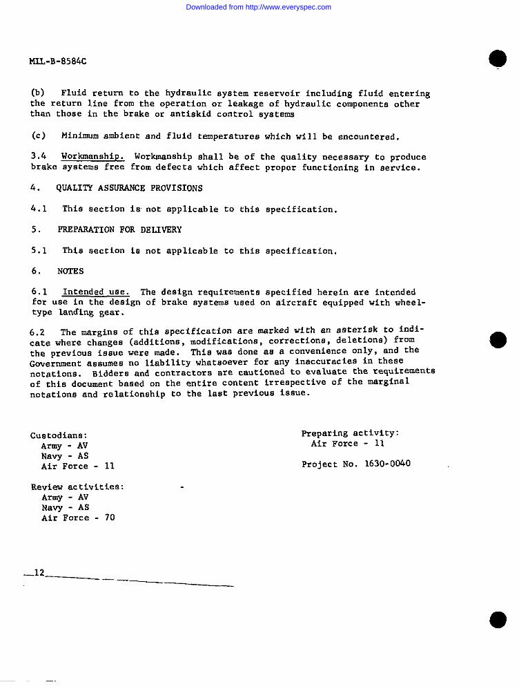
(b) Fluid return to the hydraulic system reservoir including fluid entering
the return line from the operation or leakage of hydraulic components otherthan those in the brake or antiskid control systems
(c) Minimum ambient and fluid temperatures which wi 11 be encountered.
3.4 Workmanship. Workmanship shall be of the quality necessary to producebrake systems free from defects which affect proper functioning in service.
4.
4.1
5.
5.1
6.
6.1
QUALITY ASSUWiNCE PROVISIONS
This eection 16 not applicable to this specification.
PREPARATION FOR DELIVERY
This section is not applicable to this specification.
NWI!ES
Intended uae. The design requirements specified herein are intendedfor use in the design of brake systems used on aircraft equipped with wheel-type lading gear.
..
6.2 The margins of this specification are marked with an asterisk to indi-cete where changes (additions, modifications, corrections, deletions) fromthe previous issue were made. This waa done aa a convenience OnlY, and the
Government assumes no liability whatsoever for any inaccuracies in thesenotations. Bidders and contractors are cautioned to evaluate the requirements
of this document based on the entire content irrespective of tbe marginalnotations and relationship to the last previous issue.
CU8t0di.E!IM: Preparing activity:
Armv - AV Air Force - 11
Na~ - ASAir Force - 11
Review activities:Army - AVNaYY - ASAir Force - 70
Project No. 1630-0040
_12
Downloaded from http://www.everyspec.com
(3
o
0
u, ;iN”;.I4L0 ........ .0!, ,0. 0, , 0., ,4 .“,.. “.. . . “*CO.
AFLC-WPAF124= 67 2M
Downloaded from http://www.everyspec.com