Embed Size (px)
Citation preview
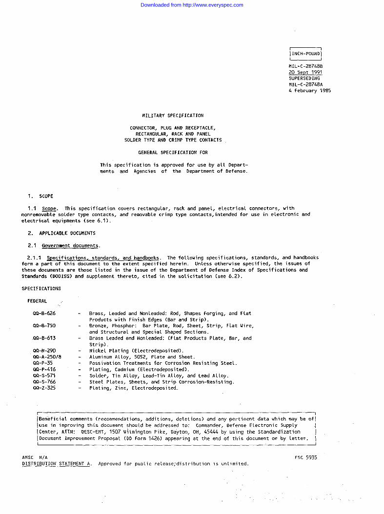
MI L- C-28748B
20 Sept 1991SUPERSEDING
MIL-C-28748A4 February 1985
MILITARY SPECIFICATION
..
CONNECTOR, PLUG AND RECEPTACLE,RECTANGULAR, RACK AND PANEL
SOLDER TYPE AND CRIMP TYPE CONTACTS
GENERAL SPECIFICATION FOR
This specification is approved for use by all Depart-
ments and Agencies of the Department of Defense.
1. SCOPE
1.1 *. This specification covers rectangular, rack and panel, electrical connectors, with
nonremovable solder type contacts, and removable crimp type contacts, intended for use in electronic and
electricalequipments (see 6.1).
2. APPLICABLE DOCUMENTS
2.1 Government documents.
2.1-1 Specifications, standards, and handbooks. The following specifications, standards, and handbooksform a part of this document to the extent specified herein. Unless otherwise specified, the issues of
these documents are those listed in the issue of the Department of Defense Index of Specifications and
Standards (DODISS) and supplement thereto , cited in the solicitation (see 6.2).
SPECIFICATIONS
FEDERAL ..
QQ-B-626
QQ-B-750
.QQ-B-613
QQ-N-290
QQ-A-250/8
QQ-P-35
QQ-P-416
QQ-S-571
WI-S-766QQ-Z-325
I
Brass, Leaded and Nonleaded: Rod, Shapes Forging, and Flat
Products with Finish Edges (Bar and Strip).
Bronze, Phosphor: Bar Plate, Rod, Sheet, Strip, Flat Uire,
and Structural and Special Shaped Sections.
Brass Leaded and Non Leaded: (Flat Products Plate, Bar, and
Strip).
Nickel Plating (E Lectrodeposited).
Aluminum Alloy, 5052, Plate and Sheet.
Passivation Treatments for Corrosion Resisting Steet.
Plating, Cadmium (Elect redeposited).
Solder, Tin Alloy, Lead-Tin Alloy, and Lead Alloy.
Steel Plates, Sheets, and Strip Corrosion-Resisting.
Plating, Zinc, Elect redeposited.
1[Beneficial comments (recommendations, additions, deletions) and any pertinent data which may be oflIuse in improving this document should be addressed to: Commander, Defense Electronic Supply IlCenter, ATTN: CIESC-Et’lT, 1507 i~~~mington Pike, Dayton, OH, 45444 by using the Standardization
[Document Improvement Proposal (DD Form 1426) appearing at the end of this document or by letter. II I
AMSC N/A FSC 5935DISTRIBUTION STATEMENT A. Approved for pub~ic release; distribution is unlimited.
. .. .
Downloaded from http://www.everyspec.com
MI L-c-28748B
MILITARY
MI L-A-8625
MI L-M-14
MI L-P-116
MI L-D-I CIC)O
MI L-u-16878MIL-I-17214
MI L-M-24519
MI L-T-22520
MI L-c-39029
MI L-c-39029/34
MIL-c-39029/35
FIIL-C-39029/36
MI L-C-39029/37
II IL-G-45204
MIL-I-81969/18
MIL-I-81969/20
MI L-C-55330
MIL-P-81728
STANDARDS
MILITARY
MI L-STD-105
MI L-STD-129
MIL-STD-202
MIL-STD-889
MI L-STD-1285
MIL-STD-1344
MI L-s TD-45662
MS3197
MS18194
NS18195
MS18196
MS18197
Anodic Coatings, For Aluminum and ALuminumAlloy.MoldingPlasticsand MoldedPlasticParts,Thermosetting.Preservation,Methodsof.Drawings,Engineeringand AssociatedLists.Wire, Electrical,Insulated,High Temperature.Indi cater, Permeability, Low-Mu (Go-No-Go).
Molding Plastics, Polyester and Potyarylether Thermoplastic.
Tool Crimping, Contact, Electrical Connector.
Contacts, Electrical Connector, Genera~ Specification For.
Contacts, Electrical Connector, Pin, Crimp Removal, (For
MIL-c-28748/3 and MI L-c-28748/13 Connectors).Contacts, Electric Connector, Socket, Crimp Removal, (For
MIL-c-28748/4 and MIL-c-28748/14 Connectors).Contact, Electrical Connector, Pin, Crimp Removal, (MIL-c-
28748/9 Connectors).
Contact, Electrical Connector, Pin, Crimp Removal, (For MI L-
c-28748 Connectors).
Gold Plating, Elect redeposited.
Installing and Removal Tools, Connector Electrical Contact,
Type 1, Class 1.
Installing and Removal Tools, Connector Electrical Contact,
Type 11, Class 1.
Connector Preparation For Delivery of.
Plating Tin Lead (Elect redeposited).
Sampling Procedures and Tables for Inspection by Attributes.
Marking for Shipment and Storage.
Test Method for Electronic and Electrical Component Parts.
Dissimilar Metals.
Marking of Electrical and Electronic Parts.
Test Methods for Electrical Connectors.
Calibration Systems Requirements.
Gage Pin For Socket Contact Engagement Test.
Jackscrew, Electrical Connector, Male and Female, Long,
Turnable.
Jackscrew, Electrical, Connector, Male and Female, Short
Turnable.Jackscrew, Electrical, Connector, Male and Female, Fixed.
Guide Pin, Electrical, Connector, Male and Female.
2.2 Non-Government publications. The following documents form a part of this document to the extent
sDecified herein. Unless otherwise specified, the issues of documents which are DoD adopted are those
l’isted in the issue DoDISS cited in the solicitation. Unless otherwise specified, the issues of documentsnot listed in the DoDISS are the issues of the documents cited in the solicitation (see 6.2).
ANERICAN NATIONAL STANDARDS INSTITUTE (ANSI)
ANSI 646.1-1982 - Surface Texture (Surface Roughness, Uaviness and Lay).
(App~ications for copies should be addressed to the American Nationa~ Standards Institute, Inc., 1430
Broadway, New York, N.Y. 10018-3308).
,-
Downloaded from http://www.everyspec.com
MI L-c-287L8B
ANERICAN SOCIETY FOR TESTING AND MATERIALS (ASTM)
ASTM B 122 Copper-Nickel-Tin Alloy, Copper-Nickel-Zinc Alloy (Nickel
silver), and Copper-Nickel ALLoY Plate, Sheet, Strip, RoLled
Bar.
ASTM B 194 Copper-Beryllium Altoy Plate, Sheet, Strip, and Rolled Bar.
ASTM B 196 Copper-Beryllium Alloy Rod and Bar.ASTM B 197 Copper-Beryllium Alloy Uire.
(Applications for copies should be addressed to the American Society for Testing and Materials, 1916 Race
Street, Philadelphia, PA 19103-1187).
ELECTRONIC INDUSTRIES ASSOCIATION
EIA-364-11 1987 - Test Procedure No. 11, Resistance to Solvents; TestProcedure for Electrical Connectors.
EIA-364-56 1987 - Test Procedure No. 56, Resistance to Soldering Heat; Test
Procedure for Electrical Connectors.
(Applications for copies should be addressed to the Electronic Industries Association, Engineering
Department, 1722 Eye St. N.W. Washington D.C. 20006. )
(Non-Government standards and other publications are normally available from the organizations that
prepare or distribute the documents. These documents also may be available in or through libraries or other
informational services. )
2.3 Order of precedence. In the event of a conflict between the text of this document and the referencescited herein, the text of this document takes precedence. Nothing in this document, however, supersedes
applicable laws and regulations unless a specific exemption has been obtained.
3. REQUIREMENTS
3.1 Specification sheets. The individual item requirements shall be as specified herein and in
accordance with the applicable specification sheet. In the event of conflict between this specification and
the specification sheet, the latter shall govern.
3.2 Qualification. Connectors and removable contacts furnished under this specification shall be
products which are authorized by the qua~ifying activity for listing on the applicable qualified products
list at the time of award of contract (see 4.4 and 6.4).
3.3 Mater iaLs. Materials shall be as specified herein. However, when a definite materia L is notspecified, a material shall be used which will enable the connectors and contacts to meet the performance
requirements of this specification. Acceptance or approval of a constituent material shaLt not be construed
as an assurance of the acceptance of the finished product..,
3.3.1 Nonmagnetic materials. Al[ parts shall be made from materials which are classed as nonmagnetic.
3.3.2 Metals and finishes. AL1 exposed meta L parts, other than electrical contacts, shall be of acorrosion-resistant material or shall be finished to resist corrosion. Noncorrosion-res isting metal partsshall be cadmium p~ated in accordance with type II, class 1 or class 2, of QQ-P-416 or zinc plated in
accordance with type II,class 1 or class 2 of QQ-Z-325, except that a preliminary plating of other meta L is
permissible. Aluminum aLloy parts shatl be anodized in accordance with MI L-A-8625, type I or II. Corrosionresistance stee L parts shall be passivated in accordance with QQ-P-35. Unless otherwise specified (see
3.1), all finishes shall be conductive.
3.3.2.1 Dissimilar metals. When dissimilar metals (as defined in MIL-STD-889) are used in intimate
contact with each other,
dissimilar metals which,
or steel used in contact
protection against electrolysis and corrosion shall be provided. The use of
in contact, tend toward active electrolytic corrosion (particularly brass, copper,
with aluminum and aluminum alloy) is not acceptable.
3
Downloaded from http://www.everyspec.com
MI L-c-28748B
3.3.3 tnsert material. Insert material shatl be a diallyi. phthalate conforming to type SDG-F, GDI-30F,
GII-30F, or SIG-F of MIL-M-14 or polyphenylene su(fide conforming to type GST-40F of MI L-M-24519.
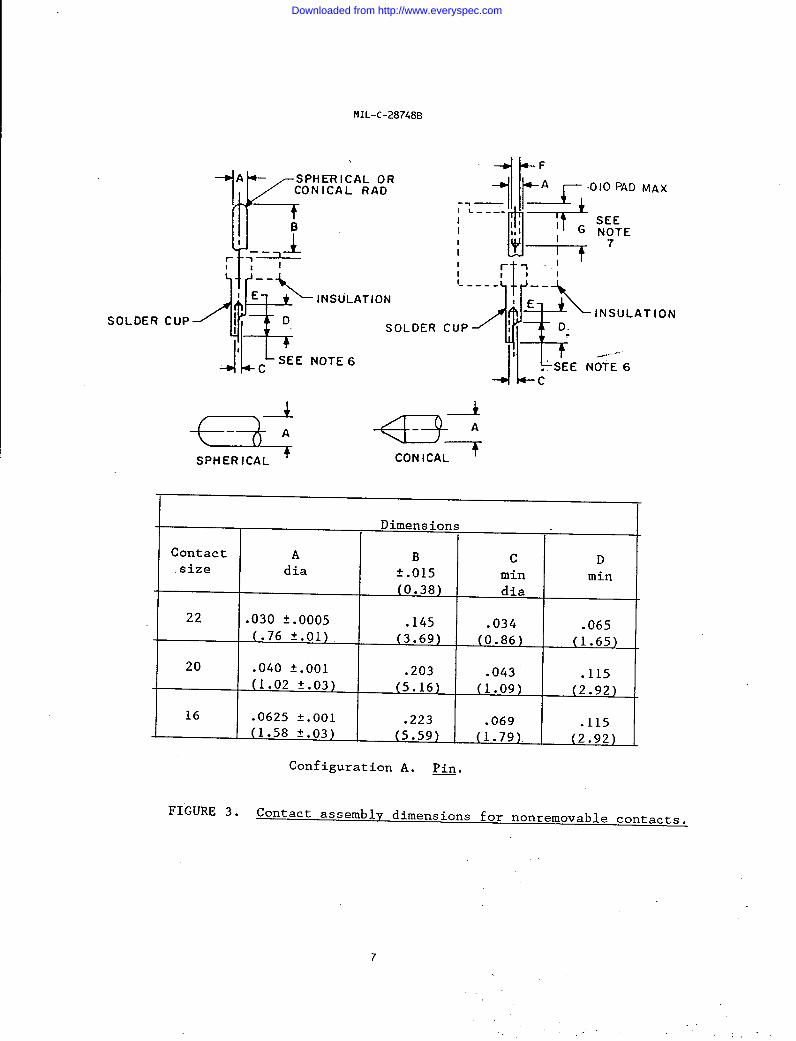
3.3.4 Contacts. Sol_der type contacts shalt conform to figure 3. Materials sha~l be in accordance with
QQ-B-613 or QQ-B-626 or QQ-B-750 or ASTM B 122 (c72500) or ASTM B 194 or ASTM E 196 or ASTM B 197. Crimp
type contacts shall conform to MIL-c-39029.
3.3.4.1 Contact retaininq clip. The contact retaining ctip sha(l be of a material which wil( assure
compliance with the contact retention requirements (see 3.5.4). Plastic contact retaining clips shall not beused.
3.3.4.2 Contact finish (solder type).
3.3.4.2.1 Overatl finish. All parts of the contact sha~l be gold-plated in accordance with MIL-G-45204,
type I, grade C, class 1, over an underplate of nickel in accordance with QQ-N-290, class 2, .000050
(0.00127 mm) to .000150 (0.00381) inches thick.
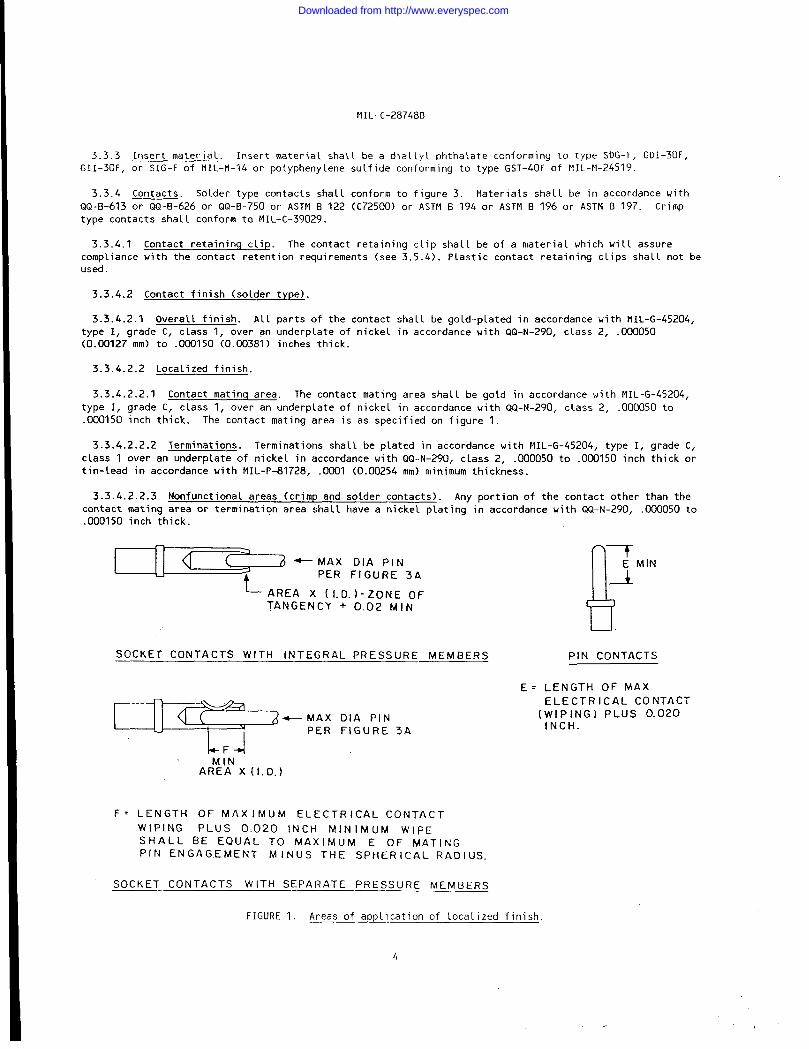
3.3.4.2.2 Localized finish.
3.3.4 .2.2.1 Contact matinq area. The contact mating area shatl be gold in accordance with MIL-G-45204,
type 1, grade C, class 1, over an underp~ate of nickel in accordance with QQ-N-290, class 2, .000050 to
.000150 inch thick. The contact mating area is as specified on figure 1.
3.3.4 .2.2.2 Terminations. Terminations shall be plated in accordance with MIL-G-45204, type I, grade C,
class 1 over an underplate of nickel in accordance with QQ-N-290, class 2, .000050 to .00U150 inch thick or
tin-lead in accordance with MI L-P-81728, .0001 (0.00254 mm) minimum thickness.
3.3.4 .2.2.3 Nonfunctional areas (crimp and solder contacts). Any portion of the contact other than the
contact mating area or termination area shall have a nickel ptating in accordance with QQ-N-290, .000050 to
.000150 inch thick.
=3
[( J -MAX OIA PIN
t-
PER FIGURE 3A
AREA x (t. D. )-ZONE OF
TANGENCY + 0.02 MIN
SOCKET CONTACTS WITH INTEGRAL PRESSURE MEMBERS PIN CONTACTS
E= LENGTH OF MAX
-“::: ‘;;:;3A
ELECTRICAL CONTACT
(wIPING) PLUS 0.020INCH.
~F~MIN
AREA x( I.D.)
F= LENGTH OF MAXIMUM ELECTRICAL CONTACT
WIPING PLUS 0.020 lNCti MINIMUM WIPE
SHALL BE EQUAL TO MAXIMUM E OF MATING
PIN ENGAGEMENT MINUS THE SPHERICAL RADIUS
SOCKET CONTACTS WITH SEPARATE PRESSURE MEhf BERS
FIGURE 1. Areas of app~ication of loca[ized finish.
f+
Downloaded from http://www.everyspec.com

MI L-c-28748B
3.3.5 Protective shells, connector shields and accessories. Unless otherwise specified, protectiveshells, connector shields, and other accessories shall be made of a high grade aluminum alloy conforming to
QQ-A-250/8, Temper H-32 or corrosion-resistant steel conforming to QQ-S-766, series 300 (nonmagnetic), or
other material satisfactory to the Government. There shall be no assembly of protective shells, connector
shields or other accessories made of different materials than specified herein.
3.4 Desiqn and construction. Connectors shall be of the design and construction specified (see 3.1).The removable contact connector is intended to permit individual insertion and removal of the contacts with
the insertion and removal tools specified in 3.4.6. Wire conductors shall be attached to the contacts bycrimping with the crimp tools specified in 3.4.7 for removable contacts and soldered for nonremovable
contacts.
3.4.1 Insert design. Inserts shall be of one-piece construction and shall be such that they willnotcrack, chip, or break in normal service or assembly. Inserts gluedor bonded together shall not be used.The insert dimensions shall be as specified (see 3.1). The insert hole configuration for the removablecontacts sha LL conform to the dimensions shown on figure 2. Removab Le contacts, when assembkd, sha LL berecessed a minimum of 0.010 inch (0.254 mm) be Low the rear face of the insert.
*.494 MINA
Ffl ONT MAT
[06103
MATING FACE
X);?
130124
.0
.0 :~~~ DIAPIN INSERT
*.839 MIN -~
.130
.124‘lA 1 19 DIA. MIN.
I+
t’ T .126‘.122’3’A
+ DIA. 62°58°
SOCKET INSERT
FIGURE 2. Insert hole configuration,
5
:.’
Downloaded from http://www.everyspec.com
MI L-c-28748B
3.4.2 Contacts.
3.4.2.1 Removable contacts. Removable contacts sha(l be qualified to MI L-c-39029. For shipments to the
original equipment manufacturers (OEM), or other suppliers, crimp contact connectors may be supplied without
contacts. (See 3.6 and 6.2).
3.4.2 .1.1 Pin contacts. Pin contacts shall conform to MI L-c-39029/34 and MI L-c-39029/36.
3.4.2 .1.2 Socket contacts. Sockets shall conform to MI L-c-39029/35 and MI L-c-39029/37.
3.4.2 .1.3 Contact retaining c(ip. The contact retaining ctip shatt be furnished as part of the contact,
assembled i n the location shown on MI L-C-39029/34, MI L-c-39029/35, MI L-C-39029/36, and MI L-c-39029/37. The
design of the clip shall be such that the contacts are capable of being inserted and removed by the tools
shown on MIL-I-81969/18 and MIL-I-81969/20.
3.4.2.2 Nonremovable contacts. Nonremovable contact dimensions shall be as
meet the appli cable requirements of this specification.
3.4.2.2.1 Contact pin. The contact pin shall be of the round pin type with
allowing for a flat end not in excess of 0.015 inch (0.381 mm) in diameter for
inch (0.203 mm) for smaller.
shown on figure 3 and shall
a 60-degree included angle,
size 20 or larger and 0.008
3.4.2.2.2 Socket contact. The socket contact shall have a circular cross-section and shal 1 be machined.
The entering end of the socket contact shall be rounded or chamfered to a~ low for directing and centering of
the entering pin. The socket contact shall provide the spring action for maintaining the contact pressure
between the pin and socket. The contact shall be of the closed entry design to exclude the entrance of a
pin 0.005 inch (0.127 mm) Larger than the allowable maximum diameter of the mating pin.
3.4.2 .2.3 Tinninq solder cups. Where pretinned solder cups are requi red, the interior surface of solder
cups shall be completely tinned over 100 percent of the ful~ ci rcte portion and for at least 50 percent of
the remainder of the solder well area with solder conforming to composition $n60 of QQ-s-571 . Only fluxesmeeting CIQ-S-571 sha 11 be used, any excess of which shall be removed. Solder cup terminals sha[ 1 be so
constructed that liquid solder cannot leak through to the front of the socket and prevent insertion of the
pin contact. NO excess solder shall be on the exterior of the solder cup.
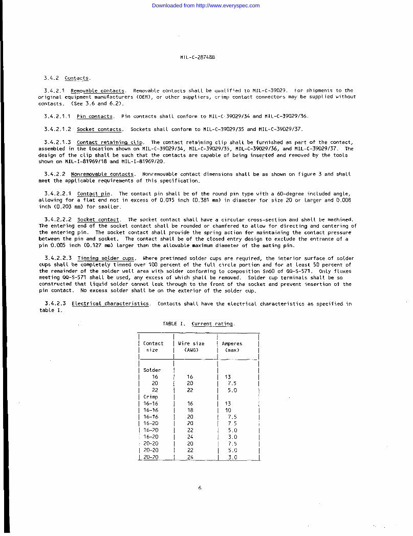
3.4.2.3 Electrical characteristics. Contacts shall have the electrical characteristics as specified in
table I
TABLE 1. Current ratinq
Contact
size
Solder
16
2022
Crimp
16-16
16-16
16-16
16-20
16-20
16-20
20-2020-20
Wire size
(AWG)
16
2022
1618202022242022
20-20 24
6
IAmperes
(max)
I13
7.5 /5.0
13107.57.55.03.07.55.03.0
Downloaded from http://www.everyspec.com
SOLDER CUP
MI L-C-28748B
1~+A SPHERICAL ORCONICAL RAD
!/’l%t—--L
I-11 I I
‘lf’!ig—.
IE %_ INSULATION
~DSOL
1
1
cSEE NOTE 6
,DER C
,.LJ~x””’op’o‘Ax1
p-p-f(1 SE.I ,, I c .,---
I (
-c
II
I
rm-~’I I
I
~ g
----- --
‘E \ INSULATION
UPII 0.
F
I /.” -’
. . SEE NOTE 6
4 h--c
%:
Ae---
A
CONICAL
Dimensions
Contact A B c Dsize dia t.ols min min
(0.38) dia
22 .030 t.000s .145 .034 .065(.76 f.01) (3.69) (0.86) (1.65)
20 .040 tool .203 .043(1.02 t.03)
.115(5.16) (1.09) (2.92)
16 .0625 t.001 .223 .069(1.58 t.03)
.115(5.59) (1.79) (2.92)
Configuration A. ~.
FIGURE 3. Contact assembly dimensions for nonremovable contacts.
7
. .
Downloaded from http://www.everyspec.com
MI L- C-28748B
I
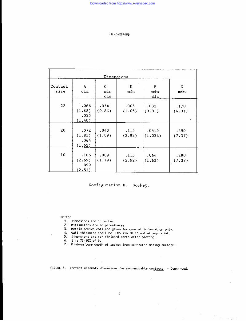
;ontactsize
22
20
16
Dimens ions
A c D’ Fdia min min min
dia dia
.066 .034 .065 .032(1.68) (0.86) (1.65) (0.81)
.055(1.40)
.072 .043 .115 .0415(1.83) (1.09) (2.92) (1.054)
.064(1.62)
.106 .069 .115 .064(2.69) (1.79) (2.92) (1.63)
.099(2.51)
Configuration B. Socket.
G
min
. 170
(4.31)
.290(7.37)
.290
(7.37)
NOTES :
1. Dimensions are in inches.
2. Millimeters are in parentheses.
3. Metric equivalents are given for general information only.
4. Wall thickness shall be .005 min (0.13 mm) at any point.5. Dimensions are for finished parts after plating.
6. E is 75-5(X of D.
7. Minimum bore depth of socket from connector mating surface.
FIGURE 3. Contact assembly dimensions for nonremovable contacts - Continued.
Downloaded from http://www.everyspec.com
MI L-c-28748E
3.4.2.4 Contact identification and arrangement. The contact identification and arrangement sha LL be asspecified (see 3.1). Letters or numerals shall be raised and clearly legible or shall appear in legible
contrasting colors. Letters or numera~s shall be arranged to avoid confusion between contacts. All letters
or numerals shall appear on the front and rear faces of each insert. Lettering of the socket insert shal L
correspond with that of the mating pin insert.
3.4.3 Polarization. Polarization of the plug with its receptacle shaLL be accomplished by mechanical
means such as the shells, protective shell, bosses, guide pins, guide sockets, or jackscreus. Jackscrews,
other than center jackscrew types, shal~ conform to MS18194, MS18195, or MS18196 as applicable. Guide pins
shall conform to MS18197. Where jackscrews and jack sockets are required, they shalt be providedwith asuitablelubricant.
3.4.4 Mating. Unless otherwisespecified(see 3.1), connectorpLugs and receptacles shall be capable of
being mated and unmated by hand without the aid of special tools.
3.4.5 Protective shell. The” protective shell design shall be in accordance with the applicable
standard listed on the supplement to this specification (see 3.1).
mi Litary
3.4.6 Insertion and removal tools. Insertion and removal tools shall be used for easy assembly and
disassembly of pin and socket contact and shall permit connectors to meet the performance requirements of
this specification. Installing tools shall be in accordance with MIL-I-81969/18, and removal tools shall be
in accordance with MIL-I-81969/20.
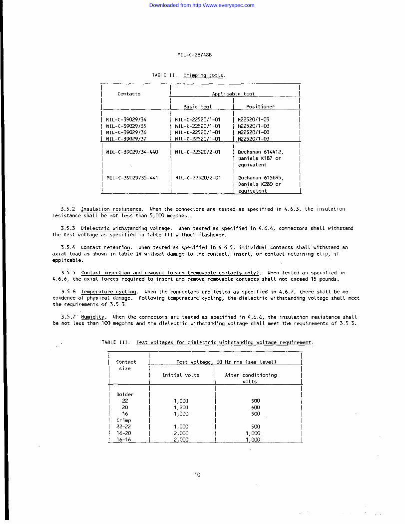
3.4.7 Crimpinq tools. Crimping tools shall conform to the applicable military standard as shown in
table 11.
3.4.8 Operatinq temperature. . The connectors shall be suitablerange of -55°c to +125° C.
3.4.9 Part number chanqes. Changes in the manufacturer’s part
requirements of MIL-D-ICKIO.
for operation throughout a temperature
numbers shall be covered by the drawing
3.4.10 Assembly. For shipments to the OEM or suppliers, connectors may be shipped unassembled. For
shipments directly to the Government , allconnectors shall be assembLedexcept for the removabte contacts.
3.5 Performance. Connectors shall be designed to meet the performance requirements specified herein.
3.5.1
less than
Magnet i c permeabi lity. The relative permeability of the connector assembly or shield shall be
2.0 Mu (see 4.6.2).
9
Downloaded from http://www.everyspec.com
MI L-c-28748B
TABLE II. Crimpinq tools.
I I II Contacts J Applicable too~ I
I
J I Basic tool I Posit ioner I
I MIL-c-39029/34 I MIL-c-22520/l-01 I M22520/1-03
\ MIL-C-39029/35 I MIL-c-22520/l-01 I M22520/1-03
I MIL-C-39029/36 I MIL-c-22520/l-01 I M22520/1-03
MIL-c-39029/37 MI L-c-22520 /l-01 M22520/1-03
I I II MIL-C-39029/34-440 I MIL-c-22520/2-01 [ Buchanan 614412, I
I Daniels K1870r ]
I I I equivalent I
I I I II MIL-c-39029/35-441 I MIL-c-22520/2-01 I 13uchanan 615695, I
I Daniels K2800r I
I I equivalent 1
3.5.2 Insulation resistance. When the connectors are tested as specified in 4.6.3, the insulation
resistance shall be not less than 5,000 megohms.
3.5.3 Dielectric withstanding voltaqe. When tested as specified in 4.6.4, connectors shall withstand
the test voltage as specified in table III without flashover.
3.5.4 Contact retention. When tested as specified in 4.6.5, individual contacts shall withstand an
axial load as shown in table IV without damage to the contact, insert, or contact retaining clip, if
applicable.
3.5.5 Contact insertion and removal forces (removable contacts only). When tested as specified in
4.6.6, the axial forces required to insert and remove removable contacts shall not exceed 15 pounds.
3.5.6 Temperature cycling. When the connectors are tested as specified in 4.6.7, there shall be no
evidence of physical damage. Following temperature cycling, the dielectric withstanding voltage shall meet
the requirements of 3.5.3.
3.5.7 Humidity. When the connectors are tested as specified in 4.6.6, the insulation resistance shatl
be not less than 100 megohms and the dielectric withstanding voltage shall meet the requirements of 3.5.3.
TABLE III. Test vo~taqes for dielectric withstanding voltaqe requirement..
I II Contact J Test voltaqe, 60 Hz rms (sea level)
I size [ IInitial volts I After conditioning
volts
I Solder I i22 1,000 500
/ 20 1,200 6001,000 500
\ Cr~~p I
{ 22-22 I 1,000 500
I 16-20 I 2,000 1,000
J 16-16 2,000 1,000
10
Downloaded from http://www.everyspec.com
MI L-C-28748B
TABLE IV. Contact retention.
I I II Mating [ Pounds I
I end size I
I22
1 20 I ;;16
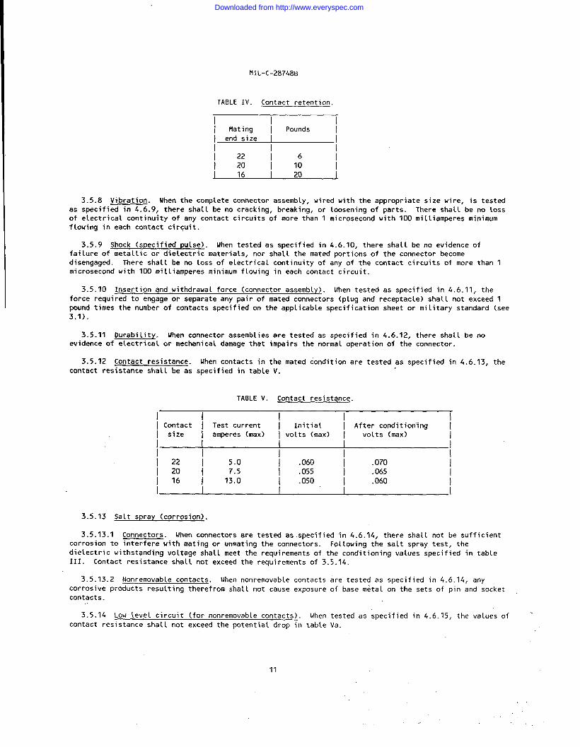
3.5.8 Vibration. When the compkete connector assembly, wired with the appropriate size wire, is tested
as specified in 4.6.9, there shall be no cracking, breaking, or loosening of parts. There shal L be no loss
of electrical continuity of any contact circuits of more than 1 microsecond with 100 milliamperes minimum
flowing in each contact circuit.
3.5.9 Shock (specified pulse). When tested as specified in 4.6.10, there shall be no evidence of
failure of metallic or dielectric materials, nor shatl the mated portions of the connector become
disengaged. There shall be no loss of electrical continuity of any of the contact circuits of more than 1
microsecond with 100 milliamperes minimum flowing in each contact circuit.
3.5.10 Insertion and withdrawal force (connector assembly). When tested as specified in 4.6.11, the
force required to engage or separate any pair of mated connectors (plug and receptacle) shall not exceed ‘1
pound times the number of contactsspecifiedon the applicablespecificationsheet or militarystandard(see3.1).
3.5.11 Durability. When connectorassembliesare testedas specifiedin 4.6.12, there shall be noevidence of electrical or mechanical damage that impairs the norma~ operation of the connector.
3.5.12 Contact resistance. When contacts in the mated condition are tested as specified. in 4.6.13, the
contact resistance shall be as specified in table V.
TABLE V. Contact resistance.
I I I II Contact I Test current I Initial I After conditioning II size I amperes (max) I volts (max) I volts (max)
I
I I I II 22 5.0 I .060 .070
1 20 / 7.5 .055 .065
1161 13.0 I .050 / .060 /
i
3.5.13 Salt spray (corrosion).
3.5.13.1 Connectors. When connectors are tested as specified in 4.6.14, there shall not be sufficientcorrosion to interfere with mating or unmating the connectors. Following the salt spray test, the
dielectric withstanding voltage shall meet the requirements of the conditioning values specified in table
111. Contact resistance shall not exceed the requirements of 3.5.14.
3.5.13.2 Nonremovable contacts. When nonremovable contacts are tested as specified in 4.6.14, any
corrosive products resulting therefrom shal L not cause exposure of base metal on the sets of pin and socket
contacts.
3.5.14 Low tevel circuit (for nonremovable contacts).
contact resistance shall not exceed the potentia L drop in
When tested as specified in 4.6.15, the values of
tabi_e Va.
11
Downloaded from http://www.everyspec.com
I
MI L-c-28748B
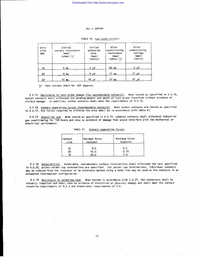
TABLE VA. Low level circuit.
I I I I I I! Wire ! Initial [ Initial \ After i After II size ~ contact resistance ~ potential I conditioning I con;~f;:n9 II AWG (max) drop I resistance I
I (ohms) ~/ I (max) (max) (max) II I (volts) ~ (ohms) II ~ (volts)
II
16 5 mn 5 Jlv 60 mn 6 VV
IJ20i 9mo I 9 llv illmi 11 Uv L
I Ij22i 15 m i 15 ~V i 17mn I 17 JJv 1
~/ Test current shall be .001 amperes.
3.5.15 Resistance to test probe damage (for nonremovable contacts). When tested as specified in 4.6.16,socket contacts shall withstand the bending moment and depth of test probe insertion without evidence of
visible damage. In addition, socket contacts shall meet the requirements of 3.5.16.
3.5.16 Contact separating forces (nonremovable contacts). When socket contacts are tested as specified
in 4.6.17, the forces required to withdraw the pins shal L be in accordance with table VI.
3.5.17 Industrial qas. Uhen tested as specified in 4.6.19, unmated contacts shall withstand industrial
gas conditioning for 100 hours and show no evidence of damage that wou Ld interfere with the mechanical or
electrical performance.
TABLE VI. Contact separating forces.
I I I IIContact Itlaximum force I Minimum force I
I size I (ounces) (ounces) 1I
i z 9.0 0.5
20 16.0 0.75
J 16 20.0 2.0
3.5.18 Solderability. Solderable, nonremovable contact terminations shall withstand the test specified
in 4.6.20, unLess so~der cup terminations are specified. For solder cup terminations, individual contacts
may be removed from the insulator or an alternate method using a hand iron may be used on the contacts in an
assemb(ed (nonremoved) configuration.
3.5.19 Resistance to solderinq heat. Uhen tested in accordance with 4.6.21, the connectors shall be
visual Ly inspected and sha LL show no evidence of distortion or physical damage and shall meet the contact
retention requirements of 3.5.4 and dimensional requirements of 3.4.
12
Downloaded from http://www.everyspec.com

MIL-C-28748B
3.5.20 Resistance to solvents. When tested in accordance with 4.6.22, the connectors shall be visua(ly
inspected and shall show no evidence of cracking, crazing, discoloration, distortion or bleeding out of any
foreign matter from the materiaL. Pitting shal L not be allowed. The marking and color coding shall be
legible.
3.5.21 Contact pin strenqth. Contact pin strength shall be tested in accordance with 4.6.23 with the
forces specified in table VIA. The force shall not produce a permanent set in excess of 0.005 inch (0.13
mm).
TABLE VIA. Contact pin strenqth.
I I II Mating end i Moment i](contact size) I (lb-in.) ~/ I
-
I 16 i 2.00 (8.896N) i
I 20 .53 (2.358 N) I22 I .22 (0.979 N)
~/ Metric equivalents are given for
information only.
3.6 Marking. Connectors and shields shall be marked in accordance with method I of MIL-sTD-1285, and
shall include the military part number (see 3.1), the manufacturer’s name or code symbol, and date code.
For shipments of connectors without contacts to the original equipment manufacturer (OEM) or other
contractors, the complete military part number of the connector with contacts shall be marked on theconnector (see 3.4.2.1 and 6.2).
3.7 $forkmanship. Connectors, contacts, shields, jackscrews , and guide pins shall be processed in such a
manner as to be uniform in quality and shall be free from defects that will affect life, serviceability orappearance. There shall be no evidence of poor molding, fabricating, cracking of insulator after moLding or
improperly assembled contacts, peeling or chipping of the plating or finish, nicks and burrs of metal parts
surfaces, and no post molding warpage of connectors. The contacts shall be free from such burrs or sharp
corners that would damage the plating of mating connectors.
4. QUALITY ASSURANCE PROVISIONS
4.1 Responsibility for inspection. Unless otherwise specified in the contract or purchase order, the
contractor is responsible for the performance of all inspection requirements (examinations and tests) as
specifiedherein. Exceptas otherwisespecified in the contract or purchase order, the contractor may use
his own or any other facilities suitable for the performance of the inspection requirements specified
herein, unless disapproved by the Government. The Government reserves the right to perform any of the
inspections set forth in the specification where such inspections are deemed necessary to assure that
supplies and services conform to prescribed requirements.
4.1.1 Responsibility for compliance. All items shall meet all requirements of sections 3 and 5. The
inspection set forth in this specification shall become a part of the contractor’s overall inspection system
or quality program. The absence of any inspection requirements in the specification shallnotrelievethecontractorof the responsibility of ensuring that all products or supplies submitted to the Government for
acceptance comply with all requirements of the contract. Sampling inspection, as part of manufacturing
operations, is an acceptable practice to ascertain conformance to requirements, however, this does not
authorize submission of known defective material, either indicated or actual, nor does it commit the
Government to accept defective material.
4.1.2 Test equipment and inspection facilities. Test and measuring equipment and inspection facilities
and sufficient accuracy, quality and quantity to permit performance of the required inspection shall be
established and maintained by the contractor. The establishment and’maintenance of a calibration system to
control the accuracy of the measuring and test equipment shall be in accordance with MIL-STD-45662.
,..’
Downloaded from http://www.everyspec.com
MIL-C- 28748B
4.1.3 Assembly distributor. Assembly distributors must be listed on, or approved for
applicable qualified products list. The qualified connector manufacturer shall certify
distributor is approved for the distribution of the manufacturer’s parts. The assembly
listing on, the
that the assembly
distributor sha[l
use only piece parts supplied by the qua~ified connector manufacturer. No testing other than visual
examination is required of certified piece parts obtained from the qualified connector manufacturer, except
when there is cause for rejection. A(l assemblies produced at the assembly distributor’s plant shall be
subjected to examination of product to assure that the assembly process conforms with that established at
the qualified manufacturing plant. Quality control requirements, including Government inspection
surveillance, sha~[ be the same as required for the qualified connector manufacturer.
4.2 Classification of inspections. The inspections requirements specified herein are classified as
follows:
a. Qualification inspection (see 4.4).
b. Quality conformance inspection (see 4.5).
4.3 Inspection conditions and preparation of samples.
4.3.1 Inspection conditions. Unless otherwise specified herein, all inspections shall be performed in
accordance with the test conditions specified in the “GENERAL REQUIREMENTS” of MI L-STD-1344.
4.3.2 Preparation of samples.
4.3.2.1 Contacts. MI L-C-39029/34, MIL-c-39029/35, MIL-c-39029/36, and MIL-c-39029/37 contacts shall be
wired using wire conforming to MIL-w-16878/4 or NIL-w-22759.
4.3.2.2 Shields (if applicable). Shields shall be furnished assembled.
4.4 Qualification inspection. Qualification inspection shall be performed at a laboratory acceptable to
the Government (see 6.4) on sample units produced with equipment and procedures’norma lly used in production.
4.4.1 Sampie size.
4.4.1.1 Connectors. Completely assembled plugs or receptacles,back-up plates,
complete with guide pins, jacks crews,contacts, and shields (if applicable) shall be subjected to qualification inspection as
f ol 10WS :
4.4.1 .1.1 Connectors with nonremovable or removable contacts. The completely assembled plugs andreceptacles (six each for crimp terminations and eight for non-removab Le contacts), with the insertarrangement of the largest size connector in accordance with the applicable military specification sheet,
and two each completely assembled plugs and receptacles for allother connector. .
qualification is desired shal~ be submitted.
4.4.1.2 Nonremovable contacts. Forty
qualification inspection.
4.4.2 Inspection routine. The samp Le
VIII,as applicable, in the order shown.
sets of pin and socket contacts shal 1
shal 1. be subjected to the inspections
.si zes for which
be subjected to
specified in tab Les VII and
14
Downloaded from http://www.everyspec.com
141L-c-28748B
4.4.2.1 Connectors. The six mating connector assemblies (for crimp contact terminations) or eight matingconnector assemb( ies (for nonremovable contacts), shal 1 be divided equally into three groups (for crimp
terminations) or four groups (for nonremovable contacts) of two units each for groups I, II,III,and V(group V is for solder terminations only) tests of table VII. Any two additional mating connectorassemblies shal 1 be designated as group IVsample units of tabte Vll.
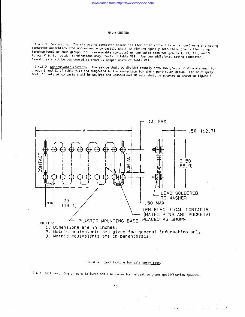
4.4.2.2 Nonremovable contacts. The sample shall be divided equally into two groups of 20 units each forgroups I and 11 of table VIIIand subjected to the inspection for their particular group. For salt spray
test, 10 sets of contacts shall be unwired and unmated and 10 sets shall be mounted as shown on figure 4.
50 MAX
H- ’50 “2-7’
[
.50 MAX
FN Electrical CONTACTS
T3.50(88 .9)
A
/_LEAD SOL!IEREDTO WASHER
NOTES:z’ L (fi~TEo p~Ns AND SOCKETS)
PLASTIC MOUNTING BASE PLACED AS SHOWN
1; Dimensions are in inches.2. Metric equivalents are given for general information only.3. Metric equivalents are in parenthesis.
FIGURE 4. Test fixture for saLt spray test.
4.4.3 Fai~ures. One or more fai lures shall ,be cause for refusa~ to grant qualification approval.
15
Downloaded from http://www.everyspec.com

.
MI L-c-28748B
TABLE VII Qualification inspection - connectors
Number of sample
units
examination ofproduct
‘ermeabi lity
[nsulation
resi stance)ielectric
withstanding
voLtage
:ontact retention
Contact insertion
and remova 1
forcesTemperature
cycling
Dielectric
withstanding
voltage
iumidity
Insulation
resistance
Dielectric
withstanding
voltage
Vibration
Shock (specifiedpulse)
Insertion andwithdrawalforce (connectorassembly)
Durabi lit-yContact resistance
Salt spray
(corrosion)Dielectric
withstanding
voltage
So lderabi 1i ty
Resi stance to
soldering heat
Resistance to
equi rement
paragraph
.1.3.4 .3.6,
nd 3.7
3.5.1
3.5.2
3.5.3
3.5.4
3.5.5
3.5.6
3.5.3
3.5.7
3.5.2
3.5.3
3.5.8
3.5.9
3.5.10
3.5.11
3.5.12
3.5.13.1
3.5.3
3.5.18
3.5.19
Test
method
aragraph
4.6.1
4.6.2
4.6.3
4.6.4
4.6.5
4.6.6
4.6.7
4.6.4
4.6.6
4.6.3
4.6.4
4.6.9
4.6.10
4.6.11
4.6.12
4.6.13
4.6.14
4.6.4
4.6.20
4.6.21
solvents \ 3.5.20
,/ Need not be monitored
I4.6.22
umber of sample
nits to be inspected
Gr
III III 1111
II21212
II1X1XIIII1X1XII[xlIIII/;/x
IIIIIIIIIIII
:!11X1II1X1IIII1X1
i--
Condi t ion
ill,onnectors
Iated or unmated
Mated
Unmated
Unmated
Unmated
Mated
Unmated
Unmated
Unmated
Unmated
Mated
Mated
Iated or unmated
fated or unmated
Mated
Unmated
Mat ed
Unmated
Unmated
Unmated
for electrical continuity during test.&/ Applicable for solder type termination connectors only.
Number
of
ai lures
I
I
-----i
~/ This inspection is to be performed after “solderabilityand “resistance to soldering heat”.
16
Downloaded from http://www.everyspec.com
MIL-c-28748B
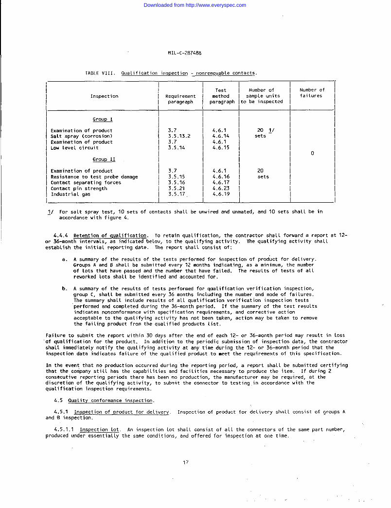
TABLE VIII.Qualification inspection - nonremovable contacts.
I I II Number of I Number of
Inspect ion I Requirement ~ m~t%d I sample units I failuresI paragraph I paragraph Ito be inspected \
Group I
Examination of product I 3.7 I 4.6.1 I 20 IIsalt spray (corrosion) I 3.5.13.2 ~ :::.;4 I sets \Examination of product I 3.7Low Level circuit I 3.5.14 I 4.6:15 ~ I
10GrouP 11 1 I I
I 1 /Examination of product \ 3.7 I 4.6.1 20Resistance to test probe damage I 3.5.15 I 4.6.16 ~ setsContact separating forces I 3.5.16 I 4.6,17 Icontact pin strength / 3.5.21 I 4.6.23 [Industrial. gas \ 3.5.17, I 4.6.19 I
~/ For salt spray test, 10 sets of contacts shall be unwired and unmated, and 10 sets shall be inaccordance with figure 4.
4.4.4 Retention of qualification. To retain qualification, the contractor shall forward a report at 12-or 36-month intervals, as indicated below, to the qualifying activity. The qualifying activity shallestablish the initial reporting date. The report sha L\ consist of:
a. A summary of the results of the tests performed for inspection of product for delivery.Groups A and B shall be submitted every 12 months indicating, as a minimum, the numberof lots that have passed and the number that have failed. The results of tests of all
reworked lots sha Ll be identified and accounted for.
b. A summary of the results of tests performed for qualification verification inspection,group C, shall be submitted every 36 months including the number and mode of failures.,.The summary shalt include results of all qualification verification inspection testsperformed and completed during the 36-month period. If the summary of the test resultsindicates nonconformance with specification requirements, and corrective actionacceptable to the qualifying activity has not been taken , action may be taken to removethe failing product from the qualified products list.
Failure to submit the report within 30 days after the end of each 12- or 36-month period may result in loss
“of qualification for the product. In addition to the periodic submission of inspection data, the contractor
shall immediately notify the qualifying activity at any time during the 12- or 36-month period that theinspection data indicates failure of the qualified product to meet the requirements of this specification.
In the event that no production occurred during the reporting period, a report shall be submitted certifyingthat the company still has the capabilities and facilities necessary to produce the item. If during 2consecutive reporting periods there has been no production, the manufacturer may be required, at thediscretion of the qualifying activity, to submit the connector to testing in accordance with the
qualification inspection requirements.
4.5 Quality conformance inspection.
4.5.1 Inspection of product for delivery. Inspection of product for delivery shall consist of groups Aand B inspection.
4.5.1.1 Inspection lot. An inspection lot shall consist of
produced under essentially the same conditions, and offered for
17
aL1.the connectors of the same part number,
inspection at one time.
Downloaded from http://www.everyspec.com
MI L-c-28748B
4.5.1 .1.1 Sample size, contact measurements. A total of 13 contact positions shall be measured per
sample in each subgroup. For connectors with 13 or less contacts, alL positions shall be measured. This
shallapply to the requirements as specified in 4.6.20, 4.6.4, 4.6.13, and 4.6.15.
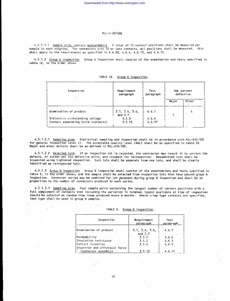
4.5.1.2 Group A inspection. Group A inspection shall consist of the examination and tests specified intable IX, in the order shown.
TABLE IX. Group A inspection.
I I I
Inspect ion I Requirement ~ Test AQL percentI paragraph I paragraph ~ defect ive
I II Major I Minor
II Examination of product I 3.1, 3.4,3.6, ~ 4.6.1 ~
! and 3.714
Ill[ Dielectric withstanding vo~tage I 3.5.3 I 4.6.4 /I Contact separating force (contacts) ] 3.5.16 ] 4.6.17 I I
4.5.1 .2.1 Samplinq plan. Statistical sampling and inspection shall be in accordance with MI L-STD-105for general inspection levelII. The acceptable quality level (AQL) shall be as specified in table IX.Major and minor defects shall be as defined in MI L-STD-105.
4.5.1 .2.2 Rejected lots. If an inspection lot is rejected, the contractor may rework it to correct thedefects, or screen out the defective units, and resubmit for reinspection. Resubmitted lots shall beinspected using tightened inspection. Such lots shal~ be separate from new lots, and shall be clearlyidentified as reinspected lots.
4.5.1.3 Group B inspection. Group B inspection shall consist of the examinations and tests specified intable X, in the order shown, and the sample shall be selected from inspection lots that have passed group Ainspection. Connector series may be combined for lot purposes during group B inspection and shall be inproportion to the number of connectors produced in each series.
4.5.1 .3.1 Sampling p lan. Four sample pairs containing the largest number of contact positions with afull complement of contacts (not including the variation in terminal types) available at time of inspectionshould be selectedthat type shall be
at random from items p~oduced every 6 months. Where” crimp type contacts are specified,used in group b samples.
TABLE X. Group B inspection.
Inspection
Examination of product
Permeabi 1ity
Insulation resistanceContact retention
Insertion and withdrawal force
(connector assembly)
Requirementparaqraph
3.1, 3.4, 3.6,and 3.73.5.13.5.23.5.4
3.5.10
Testparaqraph
4.6.1
4.6.2
4.6.34.6.5
4.6.11
. .
18
Downloaded from http://www.everyspec.com
MI L-c-28748EI
4.5.1 .3.2 Failures. If one or more sample units fail to pass group 8 inspection, the sample shall beconsidered to have failed.
4.5.1 .3.3 Rejected lots. If an inspection Lot is rejected, the contractor may rework it to correct the
defects, or screen out the defective units, and resubmit for reinspection. Resubmitted lots shall beinspected using tightened inspection. Such lots shall be separate from new lots, and shall be clearlyidentified as reinspected lots.
4.5.1 .3.4 Disposition of samp(e units. Sample units which have passed group B inspection may bedelivered on a contract or purchase order if the Lot is accepted.
4.5.2 Periodic inspection. Periodic inspection shall consist of group C inspection. Except where the
results of these inspections show noncompliance with the applicable requirements (see 4.5.2.1.4), deliveryof products which have passed groups A and B inspections shall not be delayed pending the resu Lts of theseperiodic inspections.
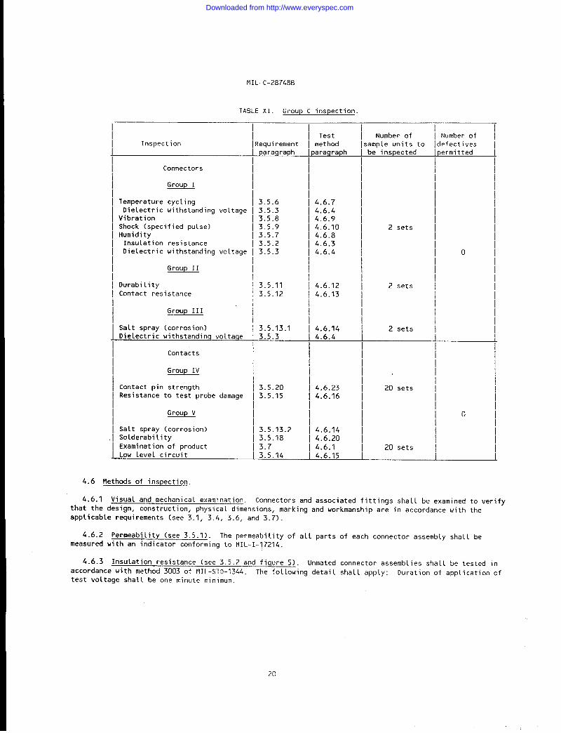
4.5.2.1 Group C inspection. Group C inspection shall consist of the examinations and tests specified intable XI, in the order shown. Group C inspection shall be made on sample units selected from inspectionlots which have passed the groups A and 8 inspection.
4.5.2.1.1 Samplinq plan. Six pairs of sample units of each part nuniber of connectors, and forty sets ofnonremovable pin and socket contacts shall be selected from current production after 200,000 connectors of
each part number have been produced or once every 36 months, whichever occurs first. The six sets ofconnectors shall be divided into three groups and two pairs each shall be subjected to groups I, II, and IIItests of table XI. The 40 sets of nonremovable pin and socket contacts shall be divided into two groups forthe tests of” groups IV and V of table XI.
4.5.2.1.2 Defective. If the number of defective exceed the number allowed in table XI,the sampleshall be considered to have failed.
4.5.2.1.3 Disposition of sample units. Sample units which have been subjected to group C inspectionshall not be delivered on the contract or purchase order.
4.5.2.1.4 Noncompliance. If a sample fails to pass group C inspection, the contractor shall takecorrective action on the materials or processes , or both, as warranted, and on all units of product whichcan be corrected and which were manufactured under essentially the same conditions, with essentially the
same materials,processes, etc. , and which are considered subject to the same failure. Acceptance of theproduct shall be discontinued until corrective action, acceptable to the Government, has been taken. Afterthe corrective action has been taken, group C inspection shall be repeated on additional sample units (allinspection, or the inspection which the original samp Le failed, at the option of the Government). Groups Aand B inspections may be reinstituted; however, final acceptance shall be withheld until the group Creinspection has shown that the corrective action was successful. In the event of failure afterreinspect ion, information concerning the failure and corrective action taken shall be furnished to thecognizant inspection activity and the qualifying activity.
4.5.3 Inspection of packaqinq. Except when commercial packaging is specified, the sampling andinspection of the preservation and interior package marking shall be in accordance with groups A and Bquality conformance inspection requirements of NIL-P-116. The sampling and inspection of the package forshipment and storage shall be in accordance with the quality assurance provisions of the applicablecontainer specification shown in section 5. The inspection of marking for shipment and storage shall be inaccordance with MI L-STD-129. The inspection of commercial packaging shall be as specified in the contact(see 6.2).
19
Downloaded from http://www.everyspec.com
MI L-c- 28748B
TABLE XI. Group C inspection.
Inspection
Connectors
Group I
Temperature cyclingDielectric withstanding voltage
VibrationShock (specified pulse)Humidity
Insulation resistanceDielectric withstanding voltage
Group II
Durabi lityContact resistance
Group 111
Salt spray (corrosion)Dielectric withstanding voltage
Contacts
Group IV
Contact pin strengthResistance to test probe damage
Group V
Salt spray (corrosion)Solderabi lity
Examination of productLow level circuit
!equi rementparagraph
3.5.63.5.33.5.83.5.93.5.73.5.23.5.3
3.5.11
3.5.12
3.5.13.13.5.3
3.5.203.5.15
3.5.13.23.5.18
3.73.5.14
Testmet hod
)araqraph
4.6.74.6.44.6.94.6.104.6.84.6.34.6.4
4.6.124.6.13
4.6.144.6.4
4.6.234.6.16
4.6.144.6.20
4.6.14.6.15
Number ofample units tobe inspected
2 sets
2 sets
2 sets
20 sets
20 sets
Number of
efectives,ermit ted
o
0
i
4.6 Methods of inspection
4.6.1 Visual and mechanical examination. Connectors and associated fittings shal L be examined to verify
that the design, construction,physicat dimensions,markingand workmanshipare in accordance with the
applicable requirements (see 3.1, 3.4, 3.6, and 3.7).
4.6.2 Permeabi lity (see 3.5.1). The permeability of all partsmeasured with an indicator conforming to II IL-I-17214.
4.6.3 Insulation resistance (see 3.5.2 and figure 5). Unmated
accordance with method 3003 of MI L- STD-1344. The fol lowing detai 1
test voltage shall be one minute minimum.
of each connector assemb[y shal 1 be
connector assemblies shall be tested in
shall apply: Duration of application of
20
Downloaded from http://www.everyspec.com

4.6.4tested in
a.
b.
c.
4.6.5
MI L-c-28748B
Dielectric withstanding voltage (see 3.5.3 and fiqure 5). Unmated cbnnector assemblies shall be
accordance with method 3001 of MI L-sTD-1344. The following detai 1s shall apply:
Nature of potential: AC.
Magnitude of test voltage: See table III.
Points of application of test voltage: Between contacts alternately connected and
between contacts and body.
Contact retention (see 3.5.4).
4.6.5.1 Nonremovable contacts. Axial loads shall be applied to individual contacts in unmatedconnectors. The load shall be applied uniformly at a rate of one pound per second in one direction and then
the other direction.
4.6.5.2 Removable contacts. The contact shall be inserted and withdrawn 10 times from the same hole.
The axial loads shall be applied to individual contacts in unmated connectors. The load shal 1 be applied
uniformly (in the normal removal direction) at a rate of one pound per second. The axial Load must bemaintained a minimum of 30 seconds. The maximum axial displacement is .015 inch after seating of the
contact.
4.6.6 Contact insertion and removal forces (see 3.5.5). Contacts shall be inserted and removed from thecorresponding connector inserts nine t i mes by means of tools conforming to MI L-1-81969/18 and
MIL-I-81969/20. The procedures and instrumentation shall be capable of measuring the force applied parallel
to the axis of the contacts. Measurements shall be taken on the first and ninth cycles.
4.6.7 Temperature cycling. Mated connectors shall be tested in accordance with method 1003 ofMIL-STD-1344. The following detai 1s and exception shall apply:
a. Test condition A, except the hightemperature shall be 125°c i 3°C.
b. Measurements after cycling: Following the temperature cycling test, dielectricwithstanding voltage shal 1 be tested as specified in 4.6.4.
4.6.8 Humidity (see 3.5.7 and fiqure 4). Unmated plugs and receptacles shall be tested in accordancewith method 1002, type II, of MIL-STD-1344 except steps 7A and 7B are not requi red. The fol lowing detai 1ssha L1 apply:
a. Initial measurements: No measurements are required after initial conditioning, nor
voltage applied to connectors during exposure.
b. F ina 1 measurement: After completion of step 6 of the fina L cycle, but no sooner than
1-1/2 hours and not later than 3 hours whi le the sample is sti 11 in the chamber,
insulation resistance shall be measured as specified in 4.6.3. Following the insulationresistance test, dielectric withstanding voltage shall be tested as specified in 4.6.4,
except’ the magnitude of test voltage shall be in accordance with table 111 for a period
of 5 minutes, applied between all contacts and the shell.
4.6.9 Vibration (see 3.5.8) . Complete mated connectors shall be tested in accordance with method 2005,
test condition 11 of MIL-STD-1344.
21
Downloaded from http://www.everyspec.com

MI L-c-28748B
+
HORIZONTAL ROWS VERTICAL ROWS
FIGURE 5. Wi rinq diaqram, typical suqqested method for insulation resistance,
dielectric hiqh potential end moisture resistance tests.
VERTICAL ROWSHORIZONTAL ROWS
———— . + =--~B+— I
./i
II
II
I
IIItItI!I1I1IIIII,C,M
II
II
I
II
II
I
1II,IIIII
I
‘c
;L./>
1I!
1
I
I
I
I1I
t,1
III1IIII
:C
,K
1AIII
I
II
1III
;III[i
II1II:C,J
—.’
FIGURE 5a. Wirinq schematic.
22
Downloaded from http://www.everyspec.com
MIL-C-28748B
4.6.10 Shock (specified pulse) (see 3.5 .9). Complete mated connectors shall be tested in accordance
with method 2004 of MI L- STD-1344. The following detai 1s shall apply:
a. Mount i ng method: In accordance with the mounting fixture in method 2005 of
MI L-STD-1344.
b. Test condition 1.
c. Measurements: Contacts shal 1 be monitored for electrical continuity during test and
connectors shall be examined for evidence of fai lure of metallic or dielectric materials
and engagement of the mated portions after test.
4.6.11 Insertion and withdrawal force (connector assembly) (see 3.5.10). Each connector, with full
complement of contacts, sha 11 be mated and unmated. The insertion and withdrawal forces, applied gradually,
shall be measured after three cyc~es.
4.6.12 Durability (see 3.5.11). The complete connector
insertion and withdrawa L at a rate not to exceed 500 cycles
engaging hardware. The insertions and withdrawals shall bethe connectors shalt be subjected in service.
assemblies shall be subjected to 500 cycles of
per hour. Tests shall be conducted using normal
accomplished in a manner similar to that which
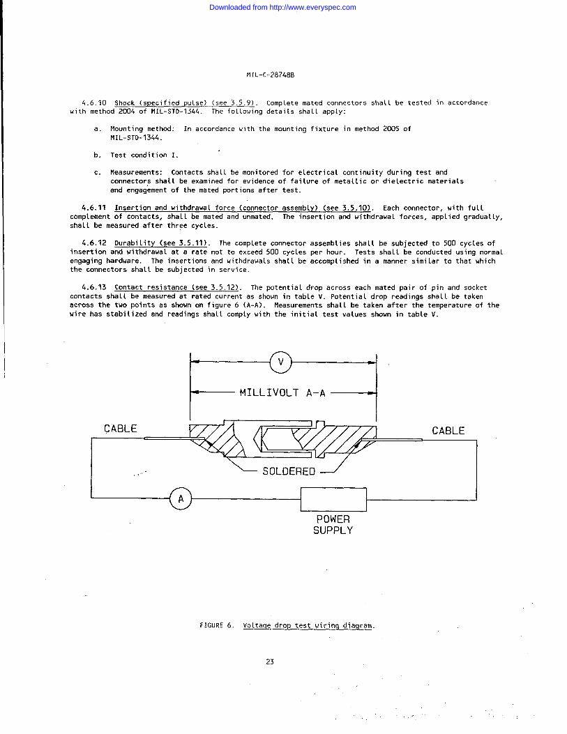
4.6.13 Contact resistance (see 3.5.12). The potential drop across each mated pair of pin and socket
contacts shall be measured at rated current as shown in table V. Potential drop readings shall be taken
across the two points as shown on figure 6 (A-A). Measurements shall be taken after the temperature of the
wire has stabilized and readings shall comply with the initial test values shown in table V.
t-
MILLIVOLT A-A
--iI
ICABLE CABLE
i
...” ‘SOLDERED
IPOWER
SUPPLY
FiGURE 6. Voltaqe drop test wirinq .diaqram.
23
Downloaded from http://www.everyspec.com

NIL-c-28748B
4.6.14 Salt spray (corrosion) (see 3.5.13). The unmated plugs and receptacles, nonremovable contacts
(unwired and unmated), and nonremovable contacts mounted in accordance with figure 4 shall be tested in
accordance with method 1001 of MI L–sTD-1344. The following detai~s shall apply:
a. Test condition B.
b. Measurements after exposure: Immediately after exposure, the exterior surfaces of the
connectors and of the individual sets of pin and socket contacts shall be washed with
tap water and the connectors and the individual sets of pin and socket contacts shall be
dried for 12 hours maximum in a circulating air oven at a temperature of 38°c * 3°C
(lOO° F * S“F). Following the salt spray test, the unmated plugs and receptacles shallbe subjected to the dielectric withstanding voltage test specified in 4.6.4, except the
magnitude of test voltage shall be in accordance with the “after conditioning” values oftable III.
4.6.15 Low level circuit (see 3.5.14). Nonremovable contacts shall be tested in accordance with method
3002 of MIL-sTD-1344.
4.6.16 Resistance to test probe damaqe (nonremovable contacts) (see 3.5.15). Non-removable contacts
shall be tested in accordance with method 2006.1 of MIL-sTD-1344 and with the bending moment of table XII
applied. The contact shall be suitab~y supported to prevent bending, but the support shall not reinforce
the pressure member. The test probe shall consist of a hardened steel pin having a diameter equal to the
nominal dimension of the mating pin contact and a spherical radius tip. The test probe sha~l be free and
unsupported, and the socket contact shal~ be maintained in a horizontal position. For each specified depth,
the contact shall be rotated one comp~ete revolution at a uniform rate.
TABLE XII. Bendinq moment for test probe damaqe test.
I I II Contact I Bend moment \
I size i (inch-pounds) i
1~1/
16 2.0
I 20 0.522 0.125
sions sha 1 be made for4.6.17 Contact separating forces (nonremovable contacts) (see 3.5.16). Prov
mounting socket contacts in a suitable position for applying gradually increasing Loads during withdrawal of
the minimum diameter hardened test pins. The depth of engagement shall be equal to the maximum length of
the pin for the mating connector. Polished test pins conforming to MS3197 of maximum diameter, as shown in
table XIII, shall be inserted into and withdrawn from each socket contact three times prior to measurement.
Following this procedure, polished test pins conforming to MS3197 of minimum diameter, as specified in table
XIII, shall be inserted into each socket contact. Withdrawal forces,
measured.applied gradually, shall then be
24
Downloaded from http://www.everyspec.com

NIL- C-28748Fl
4.6.18 Finish thickness.
4.6.18.1 Overall finish. Plating thickness shall be measured in accordance with MI L-G-45204.Measurements shall be made on the external surfaces of the contact body at the locations shown on figure 7.
SOCKET CON TA”CTS PIN CONTACTS
NOTES:1. Dimensions are in inches.2. Metric equivalents are given for general information only.
FIGURE 7. Platinq thickness measurement - overall finish.
25
.,
Downloaded from http://www.everyspec.com

tlIL-c-28748B
TABLE XIII. Test pins for measurin q contact separating forces.
IMaximum I Minimum I
Contact size diameter I diameter
IJ6 I 0.0635(1.61) I 0.0615(1.56) \
20 [ 0.0410(1.04) I 0.0390(0.99) I
22 I 0.0305(0.77) 0.0295(0.75)
NOTES:
1.
2.
4.6.18.2Measurements
Dimensions are in inches.
Metric equivalents are in parentheses and are for general information only
Localized finish. Finished thickness shall be measured in accordance with MIL-G-45204.
shall be made at point B or C of figure 8 as applicable.
F
r’ 13 +-- hAAx DIA PIN
t-
PER FIG 3A
PAINT (0. D.]
PIN CONTACTS
SOCKET CONTACTS WITH INTEGRAL PRESSURE
~ PRESSURE MEMBER (SPRING)r-
1 2 + MAX DIA PIN
u
IPER FIG 3A
~F-d
POINT C (0.0.)
SOCKET CONTACTS WITH SEPARATE PRESSURE MEMBERS
F= LENGTH OF MAX ELECTRICAL CONTACT
WIPING AREA PLUS .020 INCH MIN.
MAX. WIPE SHALL BE EQUAL TO MAX
E OF MATING PIN ENGAGEMENT
MINUS THE SPHERICAL RADIUS.
FIGURE 8. PLatinq thickness measurement - localized finish.
26
Downloaded from http://www.everyspec.com
MI L-c-28748B
4.6.19 Industrial gas. Unmated contacts sha~ [ be placed on a noncorrosive rack in a closed plastic orglass chamber (volume 2 cubic feet maximum) which contains a 10 percent solution of sulphurated potash NF indisti (ied water. Contacts sha[( not be inunersed in the so~ution but shall be exposed to the sutfide vaporfor 100 hours.
4.6.20 Solderabi 1 ity (see 3.5.18). Solder type contacts shall be tested in accordance with method 208of MI L- STD-202.
4.6.21 Resistance to soldering heat (see 3.5.19). All connectors with solder terminations shal 1 betested in accordance with EIA-364-56. The connectors shal 1 be tested in accordance ui th Drocedure 1. unless
otherwise specified (see 3.1 ).
4.6.22 Resistance to solvents (see 3.5.20). Connectors shall beThe solvents sha[ 1 be class 1. The connectors tested shall be fully
operations.
tested in accordance with EIA-%4-11.assembled by normal assembly
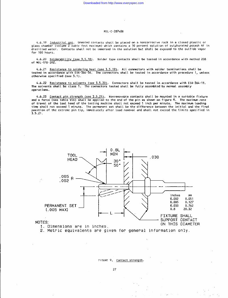
4.6.23 Contact pin strength (see 3.5.21). Nonremovable contacts shal 1 be mounted in a sui table fixtureand a force (see table VIA) sha(l be applied to the end of the pin as shown on figure 9. The maxinnnn rate
of travel of the tool head of the testing machine sha~l not exceed 1 inch per minute. The maximum [oadi ng
time shall not exceed 1 minute. The permanent set sha~ 1 be the difference between the ini t ia~ and the final
position of the extreme pin tip, immediately after load removal and sha[ 1 not exceed the (imits speci f ied in3.5.21.
TOOLHEAD
PERMANENT(.005 MAX)
NOTES:
--i
0.8LMIN
F’—, —
r“”’b~////~.- 1riches
0.002 O.R10.005 0.1270.030 0.762
--ii
0.8 20.32L
FIXTURE SHALL
SET J
1. Dimensions are in inches
~SUPPORT CONTACTON THIS DIAMETER
2. Metric equivalents are given for general information only.
FIGURE 9. Contact strength.
27
Downloaded from http://www.everyspec.com

NIL-c-28748E
5, PACKAGING
5.1 Packaginq requirements. The requirements for packaging shalt be in accordance with MI L-C-55330.
6. NOTES
(This sect ion contains informat ion of a general or explanatory nature that may be helpful, but is notmandatory. )
6.1 Intended use. Connectors and contacts covered by this specification are intended for use in
airborne, ground support, and shipboard electrical and electronic equipment.
6.1.1 Insert material. The connectors covered by this specification are composed of an insert made of a
suitable insulation material into which are fixed either pins or sockets, with which electrical connections
can be made. The specification also covers inserts, so that the units may be purchased separately as
requi red.
6.2 Orderinq data.
6.2.1 Acquisition requirements. Acquisition documents should specify the following:
a. Tit(e, number, and date of this specification.
b. Tit[e, number, and date of the applicable specification sheet and the complete military
part number (see 3.1 ).
c. Level of preservation, packaging, packing and marking required (see section 5).
d. Quantity of units per package, if other than one.
e. Whether contacts are included (see 3.4.2.1 and 3.6)
f. Insert material required (see 3.3.3).
6.3 Definitions. For purposes of this specification, the following definitions shall apply:
6.3.1
6.3.2
“fixed”,
6.3.3
The plug
Connector assembly. A complete connector assemb~y consists of a mated plug and receptac~e.
“’Receptacle. A connector receptac~e is that portion of the connector assemb~y which is norma~ ly
that is rigidly attached to a supporting surface. Itwi11be provided with pin or socket contacts
~. A connector plug is that portion of the connector assembly which is normat Ly “removable”.
wi 11 be provided with pin or socket contacts.
6.4 Qualification. With respect to products requiring qualification, awards wi 11 be made only for
products which are at the time set for opening of bids, qua Lified for inclusion in the applicable qualifiedproducts list whether or not such products have actually been so listed by that date. The attention of the
contractors is called to this requi rement, and manufacturers are urged to arrange to have the products that
they propose to offer to the Federal Government tested for qualification, in order that they may be eligibleto be awarded contracts or purchase orders for the products covered by this specif i cat ion. The activity
responsible for the qualified products Lists is the Space and Naval Warfare Systems Command, Department of
the Navy, Washington, D. C. 20363; however, information pertaining to qua~ification of products may be
obtained from the Defense Electronics Supply Center (DESC-E), Dayton, Ohio 45444. Application forqualification tests willbe made in accordance with “Provisions Governing Qualification” (see 6.4.1).
6.4.1 Copies of “Provisions Governing Qualification” may be obtained upon app Li cat ion to Commanding
Officer, Naval Publications and Forms Center, 5801 Tabor Avenue, Phi lade[phia, PA 19120.
28
Downloaded from http://www.everyspec.com
MI L-C-28748B
6.5 Interchanqeabi lity. All complete connectors, including their complement of pin or socket contacts,having the same part number wi 11 be completely interchangeable wi th each other with respect to instal lat ion
(physical) and performance (function) as specified herei~. Suitable evidence, such as dimensional data, may
be requi red by the Government in order to assure that complete connector assemblies ui 11 be interchangeable
and meet the requirements of this specif i cat ion.
6.5.1 Removable contacts. All pins and sockets will be capab~e of being assembled in the molded inserts
(see 3.1 ) and be completely interchangeable with each other with respect to installat ion (physi cal) and
performance (function) as specified herein. TcxJls wi 11becapableof properly inserting and removing the pin
and socket contacts from the molded inserts. Suitable evidence such as dimensional data, may be required by
the Government in order to assure that pins and sockets wi 11 be interchangeable and meet the requirements of
this specification.
6.5.2 Pluqs and receptacles. Plugs and receptacles of a given size and design manufactured by on”e
source to the requi rements of this specification, wi 11 be capable of mating with associated plugs and
receptacles manufactured to” the requirements of this specification by other sources.
6.6 Subiect key word Listing.
Assembly distributor
Contact pin strength
Diallyl phthalate
Localized finish
Polyphenylene sulfide
Shields and shells
6.7 Chanqes from previous issue. Marginal notations are not used in this revision to identify changeswith respect to the previous issue due to the extensiveness of the changes.
29
..
Downloaded from http://www.everyspec.com
H1L-c-28748B
CONCLUDING MATERIAL
Custodians:
Army - CR
Navy - EC
AirForce - 85
Review activities:
Army - AR, AT, MI
Navy - AS, OS, SHAir Force - 11, 17, 99
DLA - ES
Preparing activity:
Navy - EC
Agent:
DLA - ES
(Project 5935-3771 )
User activities:
Army - AV, MENavy - MC, OS
30
Downloaded from http://www.everyspec.com