Embed Size (px)
Citation preview

Special printSD920-228e-05.02
PiezoelectricSensors
Extending functionalityand simplifyingapplications withmicroelectronics
B. Bill, C. Gossweiler,A. Kirchheim and D. OtterKistler Instrumente AGWinterthur, Schweiz

Piezoelectric Sensors: Extended Functionality and SimplifiedApplications using Microelectronic SystemsDipl.-Phys. B. Bill, Dr.-Ing. C. Gossweiler, Dr.-Ing. A. Kirchheim, Dipl.-Ing. D. Otter
Kistler Instrumente AG, Winterthur (Switzerland)
Paper given at the 9th "Sensor and Measurement Data Recording Symposium",held at the Esslingen Technical Academy during the period 4-6 June 2002.
1. Introduction
The "conventional" piezoelectric measuring chain consists mainly of the sensor, thehighly insulated cable between the sensor and the charge amplifier, the chargeamplifier and a signal processing unit (see Fig. 1). Thanks to rugged sensor design,these measuring chains are capable of providing precise measurements ofprocesses ranging from very slow ("quasi-static") to highly dynamic, even in harshenvironments such as wet conditions and temperatures as low as -196 °C or as highas 600 °C. The charge signal produced by the sensor is converted by the chargeamplifier into a voltage signal proportional to the measurand, which can be amplifiedand filtered. The signal processing unit can be used, for example, to monitor orcontrol processes. The measuring range available in the piezoelectric measuringchain covers several powers of ten, while the ratio of range to response thresholdcan reach 109. This type of measuring chain has proved successful for measuringforce, pressure, strain, torque and acceleration.
Sensor Anschluss-kabel
Ladungs-verstärker
Oszilloskop PC
Fig. 1: Piezoelectric measuring chain for measuring force. The charge signal from the sensor is fed via a highly insulated cable to the charge amplifier, the
output of which is an analog voltage signal proportional to the measurand.
Connectingcable
Chargeamplifier
Oscilloscope
In the case of piezoelectric accelerometers, a measuring chain incorporating anintegral charge/voltage converter (also called an "impedance converter") has beenused successfully for over 30 years. As this is already integrated in the sensor, thereis no need for the highly insulated cable from the sensor to the charge amplifier.Here, the charge amplifier is replaced by a more cost-effective “coupler”, whichserves, on the one hand, to feed the charge/voltage converter integrated in thesensor, and on the other, to decouple the useful signal from the output bias voltage.These voltage-output accelerometers offer the same advantages as thecharge-output measuring chain described above, except that the integral electroniccircuitry limits the maximum temperature to 165 °C and the ratio of range to responsethreshold is smaller.
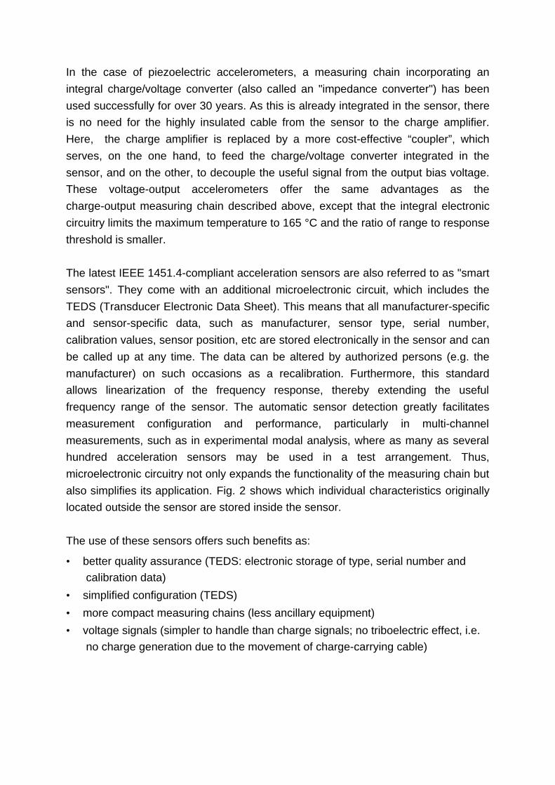
The latest IEEE 1451.4-compliant acceleration sensors are also referred to as "smartsensors". They come with an additional microelectronic circuit, which includes theTEDS (Transducer Electronic Data Sheet). This means that all manufacturer-specificand sensor-specific data, such as manufacturer, sensor type, serial number,calibration values, sensor position, etc are stored electronically in the sensor and canbe called up at any time. The data can be altered by authorized persons (e.g. themanufacturer) on such occasions as a recalibration. Furthermore, this standardallows linearization of the frequency response, thereby extending the usefulfrequency range of the sensor. The automatic sensor detection greatly facilitatesmeasurement configuration and performance, particularly in multi-channelmeasurements, such as in experimental modal analysis, where as many as severalhundred acceleration sensors may be used in a test arrangement. Thus,microelectronic circuitry not only expands the functionality of the measuring chain butalso simplifies its application. Fig. 2 shows which individual characteristics originallylocated outside the sensor are stored inside the sensor.
The use of these sensors offers such benefits as:
• better quality assurance (TEDS: electronic storage of type, serial number andcalibration data)
• simplified configuration (TEDS)
• more compact measuring chains (less ancillary equipment)
• voltage signals (simpler to handle than charge signals; no triboelectric effect, i.e.no charge generation due to the movement of charge-carrying cable)
Sensor
Ladungs-verstärker
Kabel-einfluss
Kalibrierdaten(z. B. Empfindlichkeit)
PositionHerstellerbezeichnung
Typ, Serienummer
Signal-vorverarbeitung
barkeitAbgleich
Fig. 2: Individual characteristics, originally located outside the sensor, are storedinside the sensor
The features already largely implemented in accelerometers are now also beingapplied in other piezoelectric measuring chains for measuring force, strain andpressure. The primary aim here is not to accommodate the electronic circuitry in thesensor under all circumstances but rather to produce a measuring chain that has theadvantages described above as compared with the conventional piezoelectricmeasuring chain. For physical reasons, it is currently not possible to incorporate theelectronic circuitry in a sensor which is exposed to an operating temperature of over165 °C. However, it is possible to construct a chain with a sensor measuring attemperatures above 165 °C by building the associated electronic circuitry, forexample, into the cable connector, which is subject to a lower temperature. Thispaper describes these new measuring chains.
The common feature of the new measuring chains for force and strain describedbelow is the fact that they use the same miniaturized charge amplifier as a modularelement.
2. Measuring Chains for Measurement of Force
In tool monitoring on metal-cutting machine tools, the measurement of the cuttingforces provides accurate information on the condition of the tools used, as well as onthe machining process itself. Reliable process monitoring requires highly accurate
Cableinfluence
Chargeamplifier
Manufacturer'sdesignation, type, serial
number
Signalpreprocessing
Adjustability
Position
Calibration data(e.g. sensitivity)
measurement of the cutting force components. This is ensured by means of a "forcetransmitter", a new sensor with integrated electronic circuitry for measuring up tothree force components.
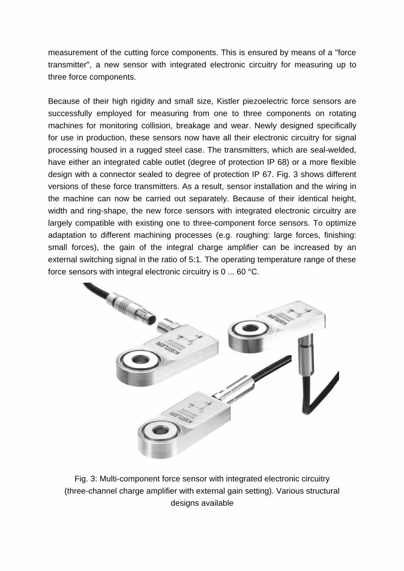
Because of their high rigidity and small size, Kistler piezoelectric force sensors aresuccessfully employed for measuring from one to three components on rotatingmachines for monitoring collision, breakage and wear. Newly designed specificallyfor use in production, these sensors now have all their electronic circuitry for signalprocessing housed in a rugged steel case. The transmitters, which are seal-welded,have either an integrated cable outlet (degree of protection IP 68) or a more flexibledesign with a connector sealed to degree of protection IP 67. Fig. 3 shows differentversions of these force transmitters. As a result, sensor installation and the wiring inthe machine can now be carried out separately. Because of their identical height,width and ring-shape, the new force sensors with integrated electronic circuitry arelargely compatible with existing one to three-component force sensors. To optimizeadaptation to different machining processes (e.g. roughing: large forces, finishing:small forces), the gain of the integral charge amplifier can be increased by anexternal switching signal in the ratio of 5:1. The operating temperature range of theseforce sensors with integral electronic circuitry is 0 ... 60 °C.
Fig. 3: Multi-component force sensor with integrated electronic circuitry(three-channel charge amplifier with external gain setting). Various structural
designs available
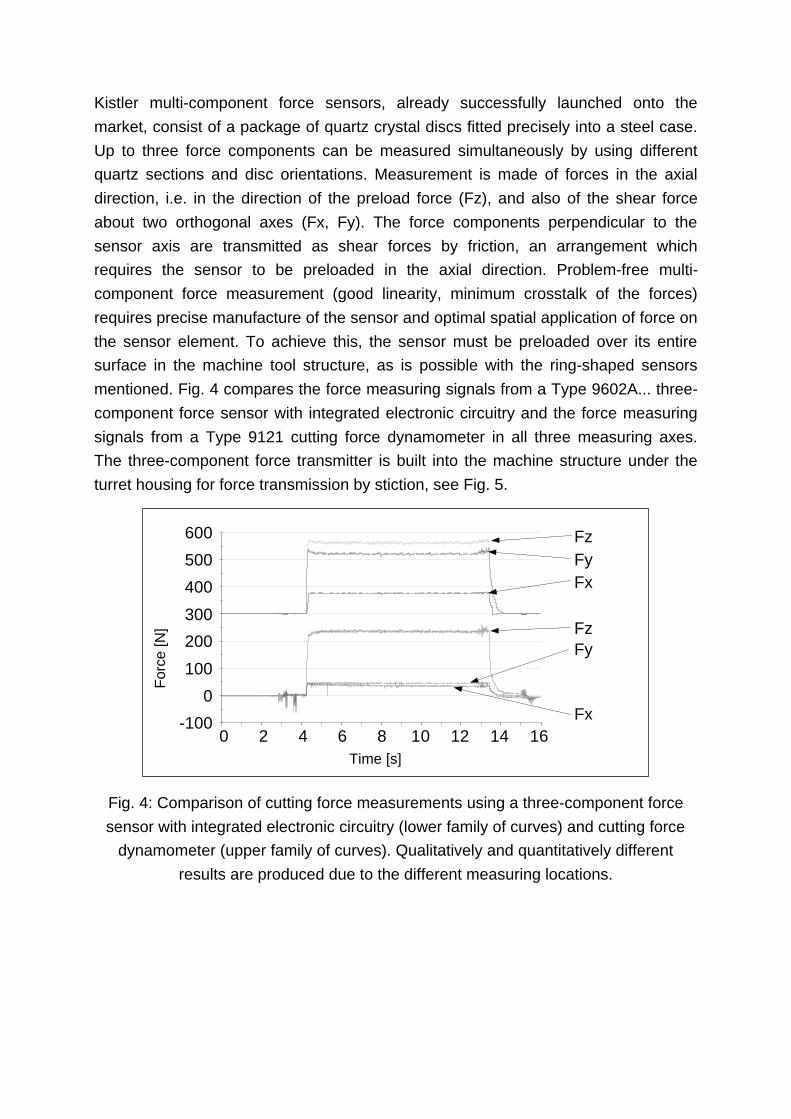
Kistler multi-component force sensors, already successfully launched onto themarket, consist of a package of quartz crystal discs fitted precisely into a steel case.Up to three force components can be measured simultaneously by using differentquartz sections and disc orientations. Measurement is made of forces in the axialdirection, i.e. in the direction of the preload force (Fz), and also of the shear forceabout two orthogonal axes (Fx, Fy). The force components perpendicular to thesensor axis are transmitted as shear forces by friction, an arrangement whichrequires the sensor to be preloaded in the axial direction. Problem-free multi-component force measurement (good linearity, minimum crosstalk of the forces)requires precise manufacture of the sensor and optimal spatial application of force onthe sensor element. To achieve this, the sensor must be preloaded over its entiresurface in the machine tool structure, as is possible with the ring-shaped sensorsmentioned. Fig. 4 compares the force measuring signals from a Type 9602A... three-component force sensor with integrated electronic circuitry and the force measuringsignals from a Type 9121 cutting force dynamometer in all three measuring axes.The three-component force transmitter is built into the machine structure under theturret housing for force transmission by stiction, see Fig. 5.
Zeit [s]
Kra
ft [N
]
0 2 4 6 8 10 12 14 16
Fz
Fx
FyFz
FxFy
-100
0
100
200
300
400
500
600
Fig. 4: Comparison of cutting force measurements using a three-component forcesensor with integrated electronic circuitry (lower family of curves) and cutting force
dynamometer (upper family of curves). Qualitatively and quantitatively differentresults are produced due to the different measuring locations.
Time [s]
For
ce [N
]
Schnittkraft-dynamometer
Kraft-transmitter
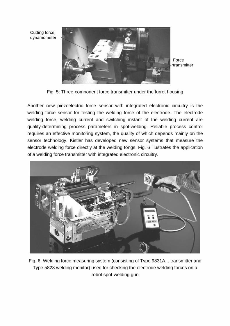
Fig. 5: Three-component force transmitter under the turret housing
Another new piezoelectric force sensor with integrated electronic circuitry is thewelding force sensor for testing the welding force of the electrode. The electrodewelding force, welding current and switching instant of the welding current arequality-determining process parameters in spot-welding. Reliable process controlrequires an effective monitoring system, the quality of which depends mainly on thesensor technology. Kistler has developed new sensor systems that measure theelectrode welding force directly at the welding tongs. Fig. 6 illustrates the applicationof a welding force transmitter with integrated electronic circuitry.
Fig. 6: Welding force measuring system (consisting of Type 9831A... transmitter andType 5823 welding monitor) used for checking the electrode welding forces on a
robot spot-welding gun
Forcetransmitter
Cutting forcedynamometer
These welding force transmitters can be supplied for electrode welding forces of 5 kNand 10 kN. The force sensor used is the same in both cases, the electrical measuringrange of ±5 V being matched to the two force measuring ranges by appropriatefactory adjustment of the modular charge amplifier integrated into the hand grip (seeFig. 6). The operating temperature range of these welding force transmitters is 0 ...60 °C. The welding force transmitter and the welding monitor combine to form amobile measuring system, capable of storing up to 99 evaluations of force/timecurves. The values measured can then be read and/or further processed by acomputer via an RS 232 interface. In addition to the mobile application welding forcetransmitters, there is also a version which is intended for stationary use. In this case,the sensor is installed in a permanent location, such as the electrode dressingstation. The signals can be evaluated with the Kistler Type 5857A... Control MonitorCoMo II or by the machine control system.
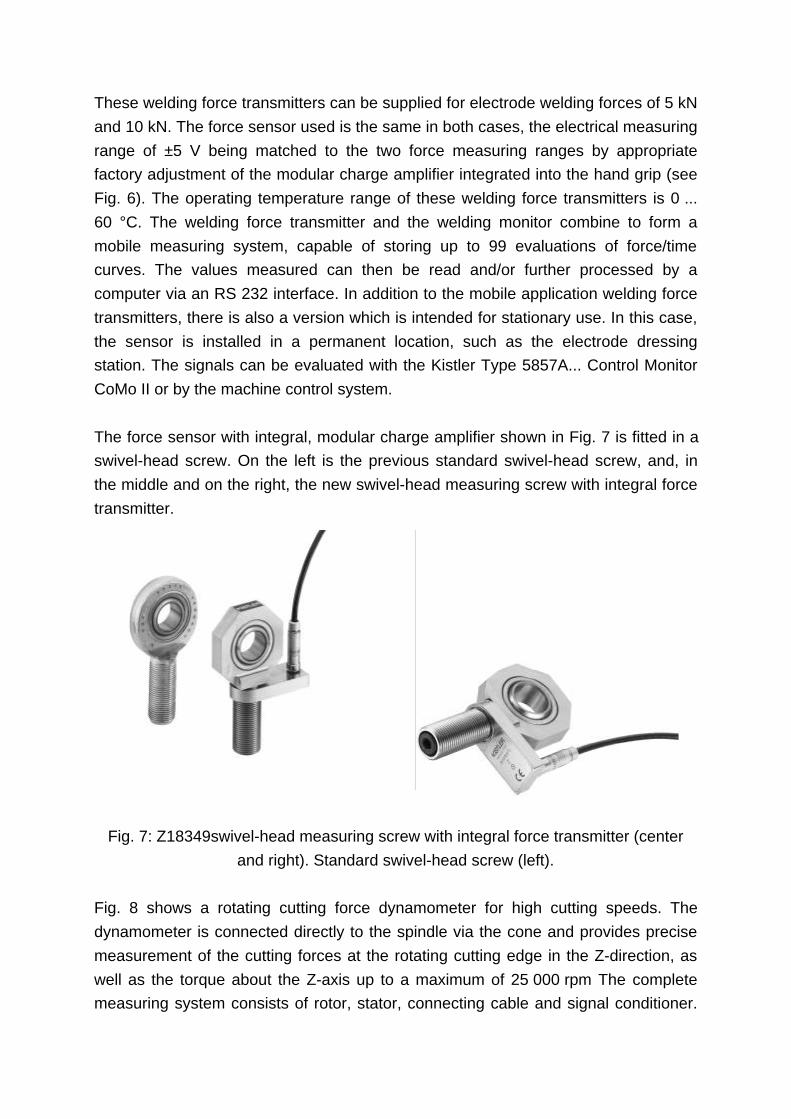
The force sensor with integral, modular charge amplifier shown in Fig. 7 is fitted in aswivel-head screw. On the left is the previous standard swivel-head screw, and, inthe middle and on the right, the new swivel-head measuring screw with integral forcetransmitter.
Fig. 7: Z18349swivel-head measuring screw with integral force transmitter (centerand right). Standard swivel-head screw (left).
Fig. 8 shows a rotating cutting force dynamometer for high cutting speeds. Thedynamometer is connected directly to the spindle via the cone and provides precisemeasurement of the cutting forces at the rotating cutting edge in the Z-direction, aswell as the torque about the Z-axis up to a maximum of 25 000 rpm The completemeasuring system consists of rotor, stator, connecting cable and signal conditioner.

The spindle capacity of the machine tool determines the structure of the rotor,integrated into which are the piezoelectric two-component sensor, two chargeamplifiers and the digital transmission circuitry. An external diameter of only 74 mmhas been achieved by miniaturization. This compact design is very important for highspeed applications because the small external diameter reduces the centrifugalforces acting on the rotating components. Transmission of the measuring signals tothe stator (telemetry head), range switching and active switching of the chargeamplifiers, as well as the power supply, are all controlled by a non-contacting controlsystem. The stationary telemetry head is mounted on the machine tool at a distanceof 1 ...2 mm from the rotor. The downline signal conditioner is responsible for thepower supply, signal transmission and system control. Three measuring ranges canbe selected and measurement can be started either manually or via the serialinterface. The measuring signal is available as an analog voltage signal of ±10 V.The dynamometer is sealed to degree of protection IP 67 and the operatingtemperature range covers 0 ... 60 °C.
Fig. 8: Rotating multi-component dynamometer with integrated electronic circuitryType 9125A... for speeds up to 25 000 rpm.
With this application, complete integration of the electronic circuitry is decisive for thefunctionality of the system. As the tool is fixed directly to the rotating cutting forcedynamometer, the measuring error caused by the moment of inertia can be reducedas compared with conventional cutting force dynamometers.
3. Measuring Chains for Measurement of Strain
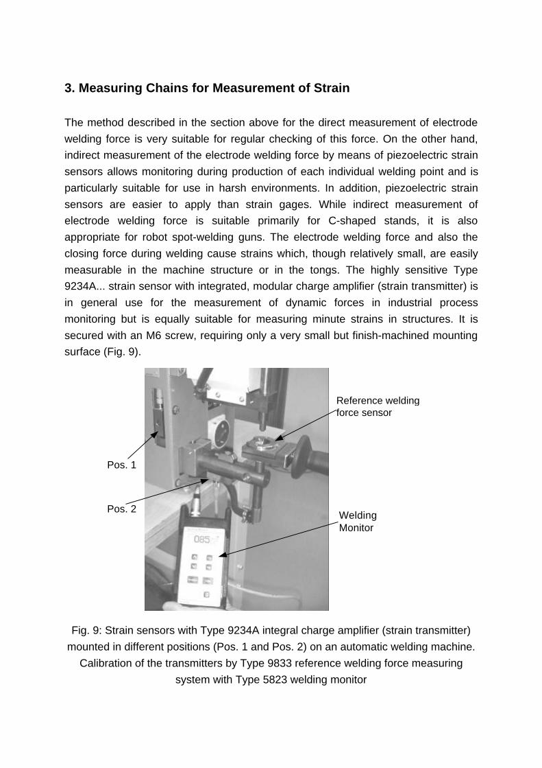
The method described in the section above for the direct measurement of electrodewelding force is very suitable for regular checking of this force. On the other hand,indirect measurement of the electrode welding force by means of piezoelectric strainsensors allows monitoring during production of each individual welding point and isparticularly suitable for use in harsh environments. In addition, piezoelectric strainsensors are easier to apply than strain gages. While indirect measurement ofelectrode welding force is suitable primarily for C-shaped stands, it is alsoappropriate for robot spot-welding guns. The electrode welding force and also theclosing force during welding cause strains which, though relatively small, are easilymeasurable in the machine structure or in the tongs. The highly sensitive Type9234A... strain sensor with integrated, modular charge amplifier (strain transmitter) isin general use for the measurement of dynamic forces in industrial processmonitoring but is equally suitable for measuring minute strains in structures. It issecured with an M6 screw, requiring only a very small but finish-machined mountingsurface (Fig. 9).
Pos. 1
Pos. 2
Referenz-Schweisskraftsensor
WeldingMonitor
Fig. 9: Strain sensors with Type 9234A integral charge amplifier (strain transmitter)mounted in different positions (Pos. 1 and Pos. 2) on an automatic welding machine.
Calibration of the transmitters by Type 9833 reference welding force measuringsystem with Type 5823 welding monitor
Reference weldingforce sensor

The transmitter is located at a position at which the strain correlates well and aslinearly as possible with the electrode welding force. Fig. 9 shows these straintransmitters at two different locations on an automatic welding machine. The straintransmitters can be calibrated to the electrode welding force with a weldingmeasuring system which directly measures the welding electrode force. The straintransmitters supply a voltage signal proportional to the strain at the mounting positionof the transmitters. Fig. 10 shows the calibration curves of the Type 9234A... highlysensitive strain transmitters with integrated electronic circuitry for positions 1 and 2as shown in Fig. 9. They have been plotted together with the Type 9833 weldingforce measuring system.
-3
-2
-1
0
1
2
3
0 0.2 0.4 0.6 0.8 1 1.2 1.4 1.6 1.8-200
0
200
400
600
800
1000
Sch
wei
sskr
afts
enso
r [N
]
Sig
nale
Deh
nung
ssen
sore
n [V
] Pos. 1
Pos. 2
Schweisskraft-Messsystem
Zeit [s]
Fig. 10: Measurement on a spot welding machine. Calibration curves for Type9234A... strain transmitters at Positions 1 and 2, plotted with the Type 9833 welding
force measuring system. Since tensile force operates in the stand at Pos. 1 andpressure operates in the electrode support in Pos. 2, the signals have
correspondingly opposing plus and minus signs
This highly sensitive, acceleration-compensated strain transmitter is sealedaccording to degree of protection IP 65 and has two measuring ranges, which can beselected by remote control. Each sensitivity/measuring range can be selected from amaximum of 100 steps. For each measuring range, the output signal is ±10 V. Fig. 11shows the electrical schematic diagram which shows at once that all components inthe transmitter (charge amplifier, voltage amplifier, adjustment facilities) can beoperated and adjusted via a single multi-core cable.
Time [s]
Welding force measuring system
Sig
nals
from
str
ain
sens
ors
[V]
Wel
ding
forc
e se
nsor
[N]
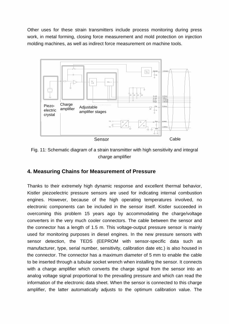
Other uses for these strain transmitters include process monitoring during presswork, in metal forming, closing force measurement and mold protection on injectionmolding machines, as well as indirect force measurement on machine tools.
R_CS
5 (Grey)
R_U/D
10n
V=0,1 .. 1
DC
1 (White)
10n
DC
Range
V=1
2 (Brown)
10n6 (Pink)
+Out
10n
R_INC4 (Yellow)
+Vcc
7 (Blue)
8 (Red)
V=10
100
10n
3 (Green)
DC
DC
1n
Exct.
-Vcc
GND
Operate
Piezo-kristall
Ladungs-verstärker
einstellbareVerstärkerstufen
KabelSensor
Fig. 11: Schematic diagram of a strain transmitter with high sensitivity and integralcharge amplifier
4. Measuring Chains for Measurement of Pressure
Thanks to their extremely high dynamic response and excellent thermal behavior,Kistler piezoelectric pressure sensors are used for indicating internal combustionengines. However, because of the high operating temperatures involved, noelectronic components can be included in the sensor itself. Kistler succeeded inovercoming this problem 15 years ago by accommodating the charge/voltageconverters in the very much cooler connectors. The cable between the sensor andthe connector has a length of 1.5 m. This voltage-output pressure sensor is mainlyused for monitoring purposes in diesel engines. In the new pressure sensors withsensor detection, the TEDS (EEPROM with sensor-specific data such asmanufacturer, type, serial number, sensitivity, calibration date etc.) is also housed inthe connector. The connector has a maximum diameter of 5 mm to enable the cableto be inserted through a tubular socket wrench when installing the sensor. It connectswith a charge amplifier which converts the charge signal from the sensor into ananalog voltage signal proportional to the prevailing pressure and which can read theinformation of the electronic data sheet. When the sensor is connected to this chargeamplifier, the latter automatically adjusts to the optimum calibration value. The
Piezo-electriccrystal
Chargeamplifier Adjustable
amplifier stages
Cable

system components, comprising sensor, cable and connector with integral EEPROM,are inseparably interconnected. Fig. 12 shows the measuring system consisting oftwo engine pressure sensors with integral cable and TEDS connector, as well as theassociated charge amplifier. This amplifier is accommodated as a module in a multi-channel data processing unit, which allows communication with a computer via aninterface, in which the voltage signal proportional to the pressure measured is madeavailable as an analog signal.
Fig. 12: Pressure measuring system with TEDS integral electronic data sheet andType 5064 charge amplifier module. Front sensor: Type 6052A uncooled pressure
sensor with front part ∅5 mm for temperatures up to 350 °C. Rear sensor:Type 7061B water-cooled precision pressure sensor
As with the TEDS acceleration sensors referred to at the beginning, the advantage ofthis type of measuring system with sensor detection consists mainly in the fact thatwhen measuring with many channels, the sensors can be connected to the relevantdata-processing units in any sequence. Thanks to integrated sensor detection, theuser receives correctly assigned amplifier settings and thus calibrated measurandsvia the computer. This results in considerably reduced preparation time formeasurements and prevents any confusion of measuring signals and calibrationdata.
EEPROM (TEDS)-Sensor type-Serial number-Sensitivity-Calibration date
5. Summary
New types of piezoelectric measuring chains with integrated electronic circuitry havebeen introduced for the measurement of force (in one or more directions), strain andpressure. Sensors for force and strain generally come with a modular, integratedcharge amplifier with simple external adjustment and control facilities. These sensorshave an operating temperature range of 0 ... 60 °C.
The new piezoelectric measuring chains for pressure are provided with integratedsensor detection and are IEEE 1451.4-compliant. The EEPROM with the sensor-specific data is at a lower temperature because it is located in a connector at somedistance from the sensor. Thus, the sensor itself (depending on type) can beexposed to an operating temperature of up to 350°C. These sensors require aspecial charge amplifier capable of reading the information from the electronic datasheet. Communication between this special charge amplifier and a computer passesvia a serial interface, an arrangement which ensures that the channel assignmentand the sensitivity selected are correct. As with the already familiar TEDSaccelerometers, authorized persons can alter the information in the electronic datasheet (for example by introducing new calibration data).
The original, "conventional" piezoelectric measuring chain (sensor, highly insulatedcable, external charge amplifier) remains as useful as ever, for example in laboratorymeasurements, and continues to offer maximum flexibility and dynamic response.Nevertheless, attention must be paid to the special characteristics of the piezoelectricmeasuring technique, such as the high insulation resistance needed at the sensoroutput, at the cable and at the charge amplifier input.
The new piezoelectric sensors presented in this paper with their integral and remote-controlled charge amplifier not only offer a degree of flexibility comparable to that ofthe conventional piezoelectric measuring chain but also have the major advantagefor industrial applications that, now, it is only voltage signals which are transmittedand no longer charge signals. As a result, longer and more cost-effective cables canbe used and the influence of the triboelectric effect is eliminated. With the addition ofthe electronic data sheet, each sensor is provided with individual, important data,which allow the recording of clearly assigned and calibrated measurands in a verysimple way, thereby facilitating quality assurance.

Kistler worldwide
Europe
GermanyKistler Instrumente GmbHPO Box 1262DE-73748 OstfildernTel. (+49) 7 11 34 07 0 Fax (+49) 7 11 34 07 [email protected]
FranceKistler SAZA de Courtabœuf 115, avenue du HoggarFR-91953 Les Ulis cédexTel. (+33) 1 69 18 81 81Fax (+33) 1 69 18 81 [email protected]
Asia
China, People's Republic ofKistler China Ltd.Unit D, 24 / F Seabright Plaza9 – 23 Shell StreetNorth Point, Hong KongTel. (+852) 25 91 59 30Fax (+852) 25 91 18 [email protected]
Representative Office BeijingTel. (+86) 10 6202 2163Fax (+86) 10 6202 [email protected]
ItalyKistler Italia s.r.l.Via Paolo Uccello, 4IT-20148 MilanoTel. (+39) 2 481 27 51Fax (+39) 2 481 28 [email protected]
AustriaK-Vertrieb GmbHTechnisches Büro WienLemböckgasse 49fAT-1230 WienTel. (+43) 1 867 48 67 0Fax (+43) 1 867 48 67 [email protected]
Korea, Republic ofKistler Korea Co., Ltd.Suite 1001, Handuk Building649-4, Yeoksam-dongKangnam-ku, Seoul 135 080Tel. (+82) 2 555 6013Fax (+82) 2 555 [email protected]
JapanKistler Japan Co., Ltd.MT Building7-5, Shibadaimon 2-chomeMinato-ku, Tokyo 105Tel. (+81) 3 35 78 02 71Fax (+81) 3 35 78 02 [email protected]
SingaporeKistler Instruments (Pte) Ltd.22A Sixth AvenueSingapore 276 480Tel. (+65) 6469 6773Fax (+65) 6469 [email protected]
UKKistler Instruments Ltd.Alresford House, Mill LaneAlton, Hampshire GU34 2QJ, UKTel. (+44) 1420 54 44 77Fax (+44) 1420 54 44 [email protected]
Switzerland/LiechtensteinKistler Instrumente AG Verkauf SchweizPO Box, Eulachstr. 22CH-8408 WinterthurTel. (+41) 52 224 12 32Fax (+41) 52 224 14 [email protected]
America
USA / CanadaKistler Instrument Corp.75 John Glenn Drive, AmherstNY 14228-2171Tel. (+1) 716 691 5100Fax (+1) 716 691 [email protected]
Other countries
Kistler Instrumente AGExport SalesPO Box, Eulachstr. 22CH-8408 WinterthurTel. (+41) 52 224 11 11Fax (+41) 52 224 15 [email protected]
Headquarters
SwitzerlandKistler Instrumente AGPO Box, CH-8408 WinterthurTel. (+41) 52 224 11 11Fax (+41) 52 224 14 [email protected]
www.kistler.com