Embed Size (px)
DESCRIPTION
manual para probar actuadores automotrices
Citation preview
®
CP9087
TM
PROFESSIONAL
PULSE
9V BATTERY TEST: 1) SET RANGE TO HIGH.
2) SET FUNCTION TO OHMS. 3) D
ISCONNECT ALL LEADS.
O.K. IF TOPMOST TEST LIGHT IS ON. W
EAK IF ANOTHER LIGHT IS ON.
RANGE
FUNCTION
IGNITION MODULE &
ENGINE SENSOR TESTER
TEST
RICH
LEANSelect
LOW,
VOLTS
HIGH
LOW
POWER OFF
VOLTS
OHMS
FREQUENCY
SIGNAL
COMMONTRIGGER
POWER 9V
VehicleService
Info
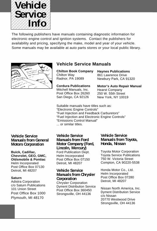
Vehicle ServiceManuals from GeneralMotors Corporation
Buick, Cadillac,Chevrolet, GEO, GMC,Oldsmobile & PontiacHelm IncorporatedPost Office Box 07130Detroit, MI 48207
SaturnAdistra Corporationc/o Saturn Publications101 Union StreetPost Office Box 1000Plymouth, MI 48170
Vehicle ServiceManuals from FordMotor Company (Ford,Lincoln, Mercury)Ford Publication Dept.Helm IncorporatedPost Office Box 07150Detroit, MI 48207
Vehicle ServiceManuals from ChryslerCorporationChrysler CorporationDyment Distribution ServicePost Office Box 360450Strongsville, OH 44136
Vehicle Service Manuals
Haynes Publications861 Lawrence DriveNewbury Park, CA 91320
Motor’s Auto Repair ManualHearst Company250 W. 55th StreetNew York, NY 10019
Suitable manuals have titles such as:“Electronic Engine Controls”“Fuel Injection and Feedback Carburetors”“Fuel Injection and Electronic Engine Controls”“Emissions Control Manual”... or similar titles.
Chilton Book CompanyChilton WayRadnor, PA 19089
Cordura PublicationsMitchell Manuals, Inc.Post Office Box 26260San Diego, CA 92126
The following publishers have manuals containing diagnostic information forelectronic engine control and ignition systems. Contact the publishers foravailability and pricing, specifying the make, model and year of your vehicle.Some manuals may be available at auto parts stores or your local public library.
Vehicle ServiceManuals from Toyota,Honda, Nissan
Toyota Motor CorporationToyota Service Publications750 W. Victoria StreetCompton, CA 90220-5538
Honda Motor Co., Ltd.Helm IncorporatedPost Office Box 07280Detroit, MI 48207
Nissan North America, Inc.Dyment Distribution Servicec/o Nissan20770 Westwood DriveStrongsville, OH 44136
Index
i
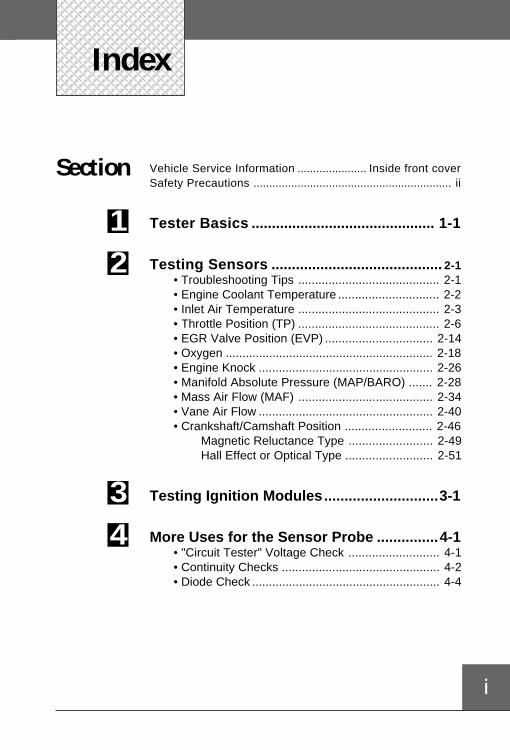
Vehicle Service Information ...................... Inside front coverSafety Precautions ............................................................... ii
Tester Basics ............................................. 1-1
Testing Sensors .......................................... 2-1• Troubleshooting Tips .......................................... 2-1• Engine Coolant Temperature .............................. 2-2• Inlet Air Temperature .......................................... 2-3• Throttle Position (TP) .......................................... 2-6• EGR Valve Position (EVP) ................................ 2-14• Oxygen .............................................................. 2-18• Engine Knock .................................................... 2-26• Manifold Absolute Pressure (MAP/BARO) ....... 2-28• Mass Air Flow (MAF) ........................................ 2-34• Vane Air Flow .................................................... 2-40• Crankshaft/Camshaft Position .......................... 2-46 Magnetic Reluctance Type ......................... 2-49 Hall Effect or Optical Type .......................... 2-51
Testing Ignition Modules............................3-1
More Uses for the Sensor Probe ...............4-1• "Circuit Tester" Voltage Check ........................... 4-1• Continuity Checks ............................................... 4-2• Diode Check ........................................................ 4-4
Section
12
34
6-3ii
General Safety Guidelines to Follow WhenWorking on Vehicles
• Always wear approved eye protection
• Always operate the vehicle in a well-ventilated area. Do not inhale exhaustgases – they are very poisonous!
• Always keep yourself, tools, and test equipment away from all moving or hotengine parts.
• Always make sure the vehicle is in Park (automatic transmission) or Neutral(manual transmission) and that the parking brake is firmly set. Block the drivewheels.
• Never lay tools on vehicle battery. You may short the terminals together,causing harm to yourself, the tools, or the battery.
• Never smoke or have open flames near vehicle. Vapors from fuel or chargingbatteries are highly flammable and explosive.
• Never leave vehicle unattended while running tests.
• Always keep a fire extinguisher suitable for all types of fires handy.
• Always turn ignition key OFF when connecting or disconnecting electricalcomponents, unless otherwise instructed.
• Use shop rags to cover fuel line fittings when connecting or disconnecting fuellines. Avoid contact with fuel. Dispose of all rags properly.
• Clean up all fuel spills immediately.
• Keep away from engine cooling fan. On some vehicles, the fan may start upunexpectedly.
• You must follow vehicle service manual cautions when working around the airbag system. If the cautions are not followed, the air bag may open unexpect-edly, resulting in personal injury. Note that the air bag can still open up severalminutes after the ignition key is turned OFF (or even if the battery is discon-nected) because of a special energy reserve module.
• Always follow vehicle manufacturer’s warnings, cautions, and service procedures.
SafetyFirst
1
1-1
SectionTesterBasics
— Description of Controls and Accessories
— Installing and Checking the 9 Volt BatteryNote: Detailed procedures for testing sensors and ignition modules arelocated in Section 2 (sensors) and Section 3 (ignition modules).
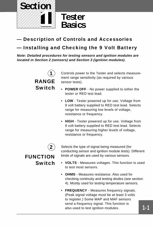
Controls power to the Tester and selects measure-ment range sensitivity (as required by varioussensor tests).
• POWER OFF - No power supplied to either thetester or RED test lead.
• LOW - Tester powered up for use. Voltage from9 volt battery supplied to RED test lead. Selectsrange for measuring low levels of voltage,resistance or frequency.
• HIGH - Tester powered up for use. Voltage from9 volt battery supplied to RED test lead. Selectsrange for measuring higher levels of voltage,resistance or frequency.
Selects the type of signal being measured (forconducting sensor and ignition module tests). Differentkinds of signals are used by various sensors.
• VOLTS - Measures voltages. This function is usedto test most sensors.
• OHMS - Measures resistance. Also used forchecking continuity and testing diodes (see section4). Mostly used for testing temperature sensors.
• FREQUENCY - Measures frequency signals.(Peak signal voltage must be at least 3 voltsto register.) Some MAP and MAF sensorssend a frequency signal. This function isalso used to test ignition modules.
1RANGESwitch
FUNCTIONSwitch
2
Section 1
1-2
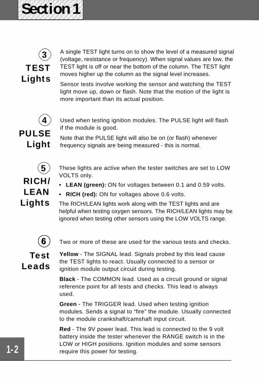
3TEST
Lights
A single TEST light turns on to show the level of a measured signal(voltage, resistance or frequency). When signal values are low, theTEST light is off or near the bottom of the column. The TEST lightmoves higher up the column as the signal level increases.
Sensor tests involve working the sensor and watching the TESTlight move up, down or flash. Note that the motion of the light ismore important than its actual position.
Used when testing ignition modules. The PULSE light will flashif the module is good.
Note that the PULSE light will also be on (or flash) wheneverfrequency signals are being measured - this is normal.
4PULSE
Light
RICH/LEAN
Lights
5 These lights are active when the tester switches are set to LOWVOLTS only.
• LEAN (green): ON for voltages between 0.1 and 0.59 volts.
• RICH (red): ON for voltages above 0.6 volts.
The RICH/LEAN lights work along with the TEST lights and arehelpful when testing oxygen sensors. The RICH/LEAN lights may beignored when testing other sensors using the LOW VOLTS range.
6
TestLeads
Two or more of these are used for the various tests and checks.
Yellow - The SIGNAL lead. Signals probed by this lead causethe TEST lights to react. Usually connected to a sensor orignition module output circuit during testing.
Black - The COMMON lead. Used as a circuit ground or signalreference point for all tests and checks. This lead is alwaysused.
Green - The TRIGGER lead. Used when testing ignitionmodules. Sends a signal to “fire” the module. Usually connectedto the module crankshaft/camshaft input circuit.
Red - The 9V power lead. This lead is connected to the 9 voltbattery inside the tester whenever the RANGE switch is in theLOW or HIGH positions. Ignition modules and some sensorsrequire this power for testing.
6
PULSE
9V BATTERY TEST: 1) SET RANGE TO HIGH. 2) SET FUNCTION TO OHMS. 3) DISCONNECT ALL LEADS.
O.K. IF TOPMOST TEST LIGHT IS ON. WEAK IF ANOTHER LIGHT IS ON.
RANGE
FUNCTION
IGNITION MODULE & ENGINE SENSOR TESTER
IGNITION MODULE & ENGINE SENSOR TESTER
TEST
RICH
LEAN
Select LOW,
VOLTS
HIGH
LOW
POWER OFF
VOLTS
OHMS
FREQUENCY
SIGNAL COMMON TRIGGER POWER 9V
Tester Basics
1-3
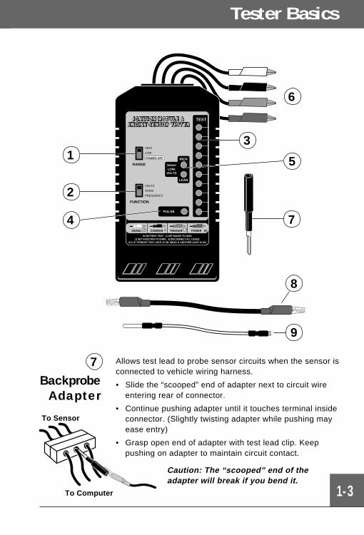
Allows test lead to probe sensor circuits when the sensor isconnected to vehicle wiring harness.
• Slide the “scooped” end of adapter next to circuit wireentering rear of connector.
• Continue pushing adapter until it touches terminal insideconnector. (Slightly twisting adapter while pushing mayease entry)
• Grasp open end of adapter with test lead clip. Keeppushing on adapter to maintain circuit contact.
Caution: The “scooped” end of theadapter will break if you bend it.
7Backprobe
Adapter
2
3
4
1
6
9
8
7
5
To Sensor
To Computer
Section 1 Tester Basics
1-4
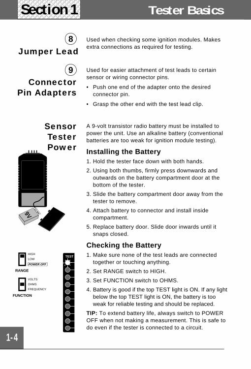
8 Used when checking some ignition modules. Makesextra connections as required for testing.
Jumper Lead
9Connector
Pin Adapters
Used for easier attachment of test leads to certainsensor or wiring connector pins.
• Push one end of the adapter onto the desiredconnector pin.
• Grasp the other end with the test lead clip.
SensorTesterPower
A 9-volt transistor radio battery must be installed topower the unit. Use an alkaline battery (conventionalbatteries are too weak for ignition module testing).
Installing the Battery1. Hold the tester face down with both hands.
2. Using both thumbs, firmly press downwards andoutwards on the battery compartment door at thebottom of the tester.
3. Slide the battery compartment door away from thetester to remove.
4. Attach battery to connector and install insidecompartment.
5. Replace battery door. Slide door inwards until itsnaps closed.
Checking the Battery1. Make sure none of the test leads are connected
together or touching anything.
2. Set RANGE switch to HIGH.
3. Set FUNCTION switch to OHMS.
4. Battery is good if the top TEST light is ON. If any lightbelow the top TEST light is ON, the battery is tooweak for reliable testing and should be replaced.
TIP: To extend battery life, always switch to POWEROFF when not making a measurement. This is safe todo even if the tester is connected to a circuit.
9V
RANGE
HIGH
LOW
POWER OFF
FUNCTION
VOLTS
OHMS
FREQUENCY
TEST
2-1
Section 2Section
2 Testing SensorsTroubleshooting
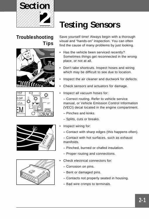
TipsSave yourself time! Always begin with a thoroughvisual and “hands-on” inspection. You can oftenfind the cause of many problems by just looking.
• Has the vehicle been serviced recently?Sometimes things get reconnected in the wrongplace, or not at all.
• Don’t take shortcuts. Inspect hoses and wiringwhich may be difficult to see due to location.
• Inspect the air cleaner and ductwork for defects.
• Check sensors and actuators for damage.
• Inspect all vacuum hoses for:
– Correct routing. Refer to vehicle servicemanual, or Vehicle Emission Control Information(VECI) decal located in the engine compartment.
– Pinches and kinks.
– Splits, cuts or breaks.
• Inspect wiring for:
– Contact with sharp edges (this happens often).
– Contact with hot surfaces, such as exhaustmanifolds.
– Pinched, burned or chafed insulation.
– Proper routing and connections.
• Check electrical connectors for:
– Corrosion on pins.
– Bent or damaged pins.
– Contacts not properly seated in housing.
– Bad wire crimps to terminals.
FRONTOF CAR
U.S.A.
EM
G GAP
YSTCE BOOSTER
HVACCRUISE
BRAKE BOOSTER
TO TRANSMODE
EGRVACREG
EGRVACREG
FUELPRESSREG.
12RAC8
6DLC
24
5AAC28
Section 2
2-2
Engine TEMPERATURE
What toInspect
Sensor operation (see test on page 2-4). Poorconnections at sensor or computer. Faulty sensorwiring (open or short circuits). Heavy deposits onsensor tip which can cause poor response.Leakage into sensor housing. Engine running toohot (problems with antifreeze, thermostat, waterpump, fan, belts, low engine oil).
When to Test • Related trouble codes sent by computer.
• Driveability problems such as hard starting,rough idle, stalling, hesitation, stumble, surging,knocking (pinging), poor fuel economy, or blackexhaust smoke.
Location The sensor is usually threaded into the engineblock, lower intake manifold, or cylinder head toprovide direct contact with coolant.
How is ItUsed?
The computer needs to know engine temperatureso it can modify air/fuel ratios, spark advance, idlespeed, and emission device operation (such as anEGR valve).
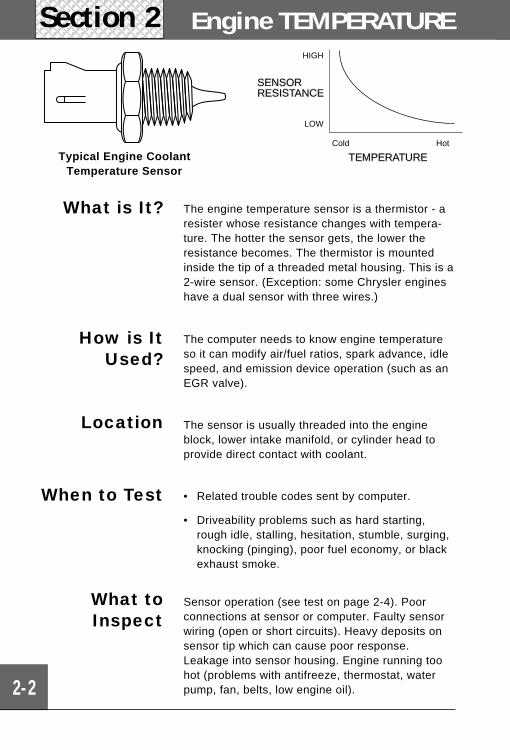
What is It? The engine temperature sensor is a thermistor - aresister whose resistance changes with tempera-ture. The hotter the sensor gets, the lower theresistance becomes. The thermistor is mountedinside the tip of a threaded metal housing. This is a2-wire sensor. (Exception: some Chrysler engineshave a dual sensor with three wires.)
HIGH
SENSORRESISTANCE
LOW
Cold Hot
TEMPERATURETypical Engine CoolantTemperature Sensor
2-3
Air TEMPERATURE
What toInspect
Sensor operation (see test on page 2-4). Poorconnections at sensor or computer. Faulty sensorwiring (open or short circuits). Heavy deposits onsensor tip which can cause poor response.Restricted or blocked air passageways.Engine running too hot (problems withantifreeze, thermostat, water pump, fan, belts,low engine oil).
When to Test • Related trouble codes sent by computer.
• Driveability problems such as hard starting,rough idle, stalling, hesitation, stumble, surging,poor fuel economy, or black exhaust smoke.
Location The sensor is threaded into the intake manifold,throttle body, rear of air cleaner assembly orelsewhere along the path of air entering theengine. Sometimes this sensor is built into a vaneairflow meter or mass airflow sensor assembly.One connector handles both the air flow andtemperature sensor circuits.
How is ItUsed?
The computer needs to know air temperature tocalculate the amount of air entering the engine.Then, the computer can provide the proper air/fuelmixture for the desired operating condition.
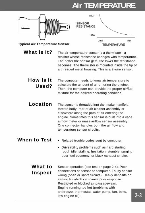
HIGH
SENSORRESISTANCE
LOW
Cold Hot
TEMPERATURE
What is It? The air temperature sensor is a thermistor - aresister whose resistance changes with temperature.The hotter the sensor gets, the lower the resistancebecomes. The thermistor is mounted inside the tip ofa threaded metal housing. This is a 2-wire sensor.
Typical Air Temperature Sensor
Temperature Sensor Test ProcedureUse this procedure for testing all engine coolant or inlet air temperature sensors.
Exceptions:
• Certain Toyota, Nissan and Ford engines using vane airflow sensors have theair temperature sensor built into the vane airflow assembly. Refer to page 2-40for testing.
• GM 1988 2.8L Mass Airflow Sensor (5 pin only) also has a built-in air tempera-ture sensor. Use same test procedure as for vane airflow temperature sensor.Refer to page 2-34 for testing.
Sensor may be tested on or off vehicle.
Warning: On-car testing involves running engine. Observe all safety precautions(see page ii). Work in well ventilated area.
2-4
Testing Sensors
1) Verify ignition key is OFF.
Allow engine to cool to outside temperature before testing.
2) Check Tester battery
Refer to page 1-4. Set RANGE switch to POWER OFFwhen done.
3) Disconnect wiring harness from sensor - Inspect fordamage.
Some vehicles use a metal snap ring to secure wiringharness to sensor. Remove this snap ring before discon-necting wiring harness.
4) Off-Car testing only: Remove sensor.
Be careful of coolant spillage from mounting hole ifremoving engine temperature sensor.
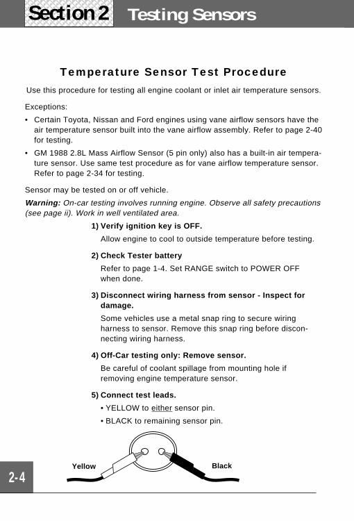
5) Connect test leads.
• YELLOW to either sensor pin.
• BLACK to remaining sensor pin.
Yellow Black
Section 2
2-5
Engine Air TEMPERATURE
6) Verify test clips make good contact and do not touch eachother.
Make sure red and green test clips are not touching anything.
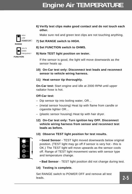
7) Set RANGE switch to HIGH.
8) Set FUNCTION switch to OHMS.
9) Note TEST light position on tester.
If the sensor is good, the light will move downwards as thesensor heats up.
10) On-Car test only: Disconnect test leads and reconnectsensor to vehicle wiring harness.
11) Heat sensor tip thoroughly.
On-Car test: Start engine and idle at 2000 RPM until upperradiator hose is hot.
Off-Car test:
– Dip sensor tip into boiling water, OR...
– (metal sensor housing) Heat tip with flame from candle orcigarette lighter OR...
– (plastic sensor housing) Heat tip with hair dryer.
12) On-Car test only: Turn ignition key OFF. Disconnectvehicle wiring harness from sensor and reconnect testleads as before.
13) Observe TEST light position for test results.
• Good Sensor - TEST light moved downwards below originalposition. (TEST light may go off if sensor is very hot - this isOK.) The TEST light will move upwards as the sensor coolsoff. Range of TEST light movement varies with sensor typeand temperature change.
• Bad Sensor - TEST light position did not change during test.
14) Testing is complete.
Set RANGE switch to POWER OFF and remove all testleads.
RANGE
HIGH
LOW
POWER OFF
FUNCTION
VOLTS
OHMS
FREQUENCY
2-6
Testing SensorsSection 2
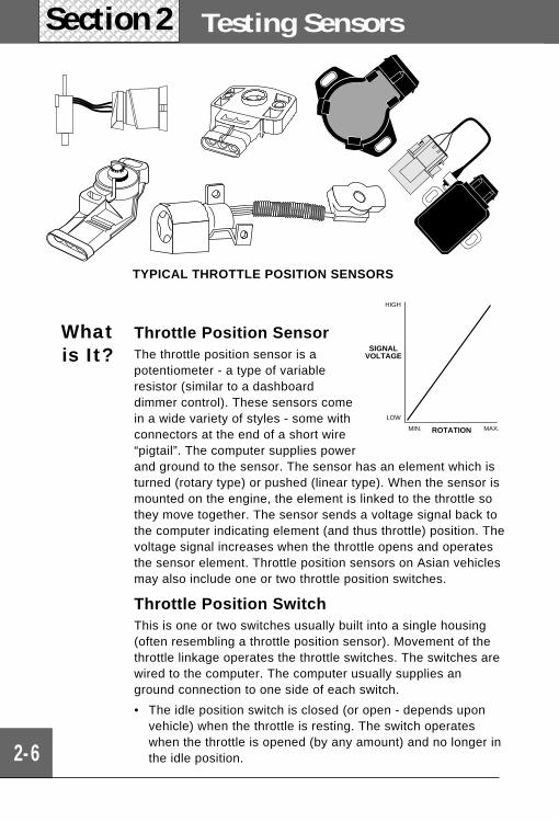
TYPICAL THROTTLE POSITION SENSORS
Throttle Position SensorThe throttle position sensor is apotentiometer - a type of variableresistor (similar to a dashboarddimmer control). These sensors comein a wide variety of styles - some withconnectors at the end of a short wire“pigtail”. The computer supplies powerand ground to the sensor. The sensor has an element which isturned (rotary type) or pushed (linear type). When the sensor ismounted on the engine, the element is linked to the throttle sothey move together. The sensor sends a voltage signal back tothe computer indicating element (and thus throttle) position. Thevoltage signal increases when the throttle opens and operatesthe sensor element. Throttle position sensors on Asian vehiclesmay also include one or two throttle position switches.
Throttle Position SwitchThis is one or two switches usually built into a single housing(often resembling a throttle position sensor). Movement of thethrottle linkage operates the throttle switches. The switches arewired to the computer. The computer usually supplies anground connection to one side of each switch.
• The idle position switch is closed (or open - depends uponvehicle) when the throttle is resting. The switch operateswhen the throttle is opened (by any amount) and no longer inthe idle position.
Whatis It? SIGNAL
VOLTAGE
ROTATION
HIGH
LOW
MAX.MIN.
THROTTLE POSITION Sensor/Switch
2-7
• Sometimes a second switch is used to signal a wideopen throttle condition. This switch is normally open (orclosed - depends upon vehicle) when the throttle is atidle or just partially open. The switch operates when thethrottle is opened beyond a certain point. (The amount ofthrottle opening required to operate the switch varieswith vehicle.)
The computer uses throttle position to determine engineoperating condition: idle (closed throttle), cruise (partthrottle), or hard acceleration (wide open throttle). Thecomputer can then properly control air/fuel mixtures, sparkadvance, idle speed, and lock-up torque converters.
How it isused?
Location Fuel injected engines: Rotary type sensor - usuallymounted to outside of throttle body and linked to throttleshaft.
Computer controlled carburetor engines: Linear (sliding)type - usually mounted inside carburetor (GM) or outsidecarburetor (Ford).
When toTest
• Related trouble codes sent by computer.
• Driveability problems such as hard starting, rough idle,stalling, hesitation, stumble, surging, knocking (pinging),poor fuel economy, backfiring, no torque converter lock-up.
What toInspect
Sensor operation (see test on page 2-10) or switchoperation (see test on page 2-12). Poor connections atsensor or computer. Sensor position adjustment. Faultysensor wiring (open or short circuits). Binding throttle shaftor linkage. If used: “Cruise Control” linkage problems, idlespeed control motor, vacuum hose connected to throttlepositioner, choke, or cam systems affecting throttleposition.
2-8
Testing SensorsSection 2
Some sensors require more than one test.
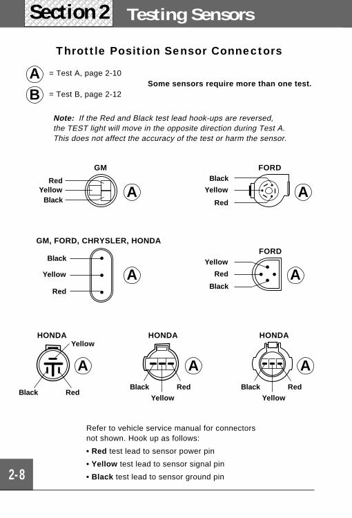
Throttle Position Sensor Connectors
Note: If the Red and Black test lead hook-ups are reversed,the TEST light will move in the opposite direction during Test A.This does not affect the accuracy of the test or harm the sensor.
= Test A, page 2-10
= Test B, page 2-12
AB
Refer to vehicle service manual for connectorsnot shown. Hook up as follows:
• Red test lead to sensor power pin
• Yellow test lead to sensor signal pin
• Black test lead to sensor ground pin
AA A
HONDA
Yellow
RedBlack
HONDA
Yellow
RedBlack
HONDA
RedBlack
Yellow
A
A
A
A
RedYellow
BlackYellow
Red
Black
Yellow
Black
Red
Yellow
Red
Black
GM FORD
FORDGM, FORD, CHRYSLER, HONDA
2-9
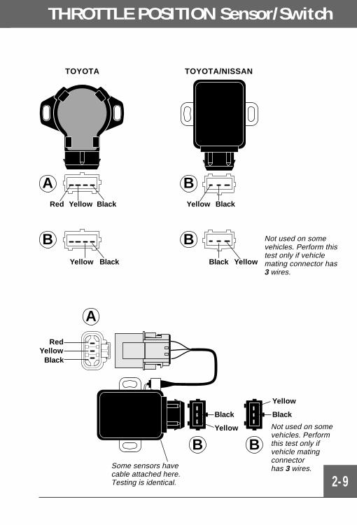
THROTTLE POSITION Sensor/Switch
TOYOTA
B
ABlackYellowRed
BlackYellow
A
B B
Red
BlackYellow
Black
Yellow
Black
Yellow
TOYOTA/NISSAN
B
BYellow Black
Black Y ellow
Not used on somevehicles. Perform thistest only if vehiclemating connector has3 wires.
Some sensors havecable attached here.Testing is identical.
Not used on somevehicles. Performthis test only ifvehicle matingconnectorhas 3 wires.
2-10
Testing SensorsSection 2
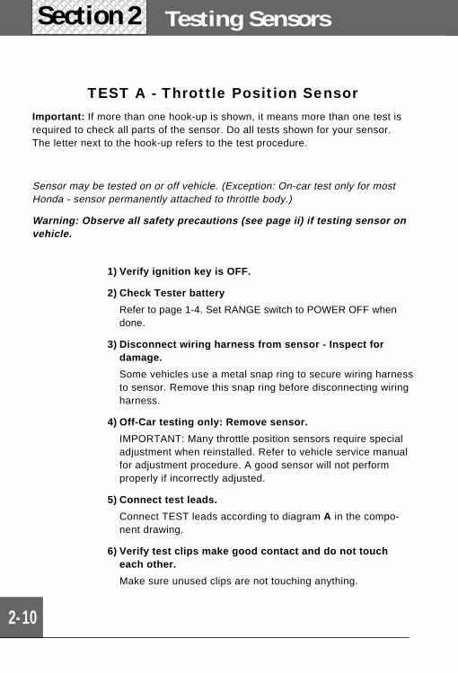
TEST A - Throttle Position SensorImportant: If more than one hook-up is shown, it means more than one test isrequired to check all parts of the sensor. Do all tests shown for your sensor.The letter next to the hook-up refers to the test procedure.
Sensor may be tested on or off vehicle. (Exception: On-car test only for mostHonda - sensor permanently attached to throttle body.)
Warning: Observe all safety precautions (see page ii) if testing sensor onvehicle.
1) Verify ignition key is OFF.
2) Check Tester battery
Refer to page 1-4. Set RANGE switch to POWER OFF whendone.
3) Disconnect wiring harness from sensor - Inspect fordamage.
Some vehicles use a metal snap ring to secure wiring harnessto sensor. Remove this snap ring before disconnecting wiringharness.
4) Off-Car testing only: Remove sensor.
IMPORTANT: Many throttle position sensors require specialadjustment when reinstalled. Refer to vehicle service manualfor adjustment procedure. A good sensor will not performproperly if incorrectly adjusted.
5) Connect test leads.
Connect TEST leads according to diagram A in the compo-nent drawing.
6) Verify test clips make good contact and do not toucheach other.
Make sure unused clips are not touching anything.
2-11
THROTTLE POSITION Sensor/Switch
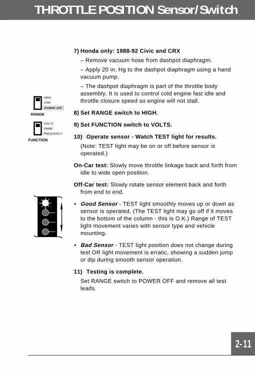
7) Honda only: 1988-92 Civic and CRX
– Remove vacuum hose from dashpot diaphragm.
– Apply 20 in. Hg to the dashpot diaphragm using a handvacuum pump.
– The dashpot diaphragm is part of the throttle bodyassembly. It is used to control cold engine fast idle andthrottle closure speed so engine will not stall.
8) Set RANGE switch to HIGH.
9) Set FUNCTION switch to VOLTS.
10) Operate sensor - Watch TEST light for results.
(Note: TEST light may be on or off before sensor isoperated.)
On-Car test: Slowly move throttle linkage back and forth fromidle to wide open position.
Off-Car test: Slowly rotate sensor element back and forthfrom end to end.
• Good Sensor - TEST light smoothly moves up or down assensor is operated. (The TEST light may go off if it movesto the bottom of the column - this is O.K.) Range of TESTlight movement varies with sensor type and vehiclemounting.
• Bad Sensor - TEST light position does not change duringtest OR light movement is erratic, showing a sudden jumpor dip during smooth sensor operation.
11) Testing is complete.
Set RANGE switch to POWER OFF and remove all testleads.
RANGE
HIGH
LOW
POWER OFF
FUNCTION
VOLTS
OHMS
FREQUENCY
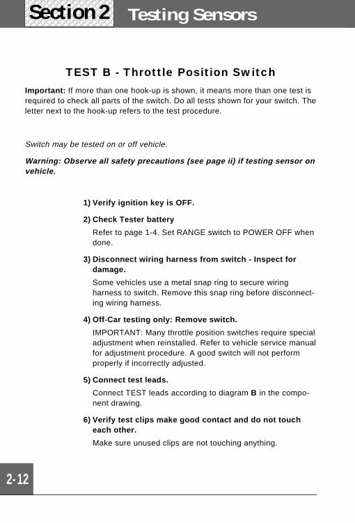
TEST B - Throttle Position SwitchImportant: If more than one hook-up is shown, it means more than one test isrequired to check all parts of the switch. Do all tests shown for your switch. Theletter next to the hook-up refers to the test procedure.
Switch may be tested on or off vehicle.
Warning: Observe all safety precautions (see page ii) if testing sensor onvehicle.
2-12
Testing SensorsSection 2
1) Verify ignition key is OFF.
2) Check Tester battery
Refer to page 1-4. Set RANGE switch to POWER OFF whendone.
3) Disconnect wiring harness from switch - Inspect fordamage.
Some vehicles use a metal snap ring to secure wiringharness to switch. Remove this snap ring before disconnect-ing wiring harness.
4) Off-Car testing only: Remove switch.
IMPORTANT: Many throttle position switches require specialadjustment when reinstalled. Refer to vehicle service manualfor adjustment procedure. A good switch will not performproperly if incorrectly adjusted.
5) Connect test leads.
Connect TEST leads according to diagram B in the compo-nent drawing.
6) Verify test clips make good contact and do not toucheach other.
Make sure unused clips are not touching anything.
FUNCTION
VOLTS
OHMS
FREQUENCY
THROTTLE POSITION Sensor/Switch
2-13
RANGE
HIGH
LOW
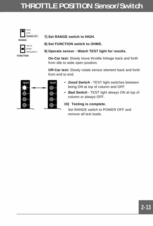
POWER OFF 7) Set RANGE switch to HIGH.
8) Set FUNCTION switch to OHMS.
9) Operate sensor - Watch TEST light for results.
On-Car test: Slowly move throttle linkage back and forthfrom idle to wide open position.
Off-Car test: Slowly rotate sensor element back and forthfrom end to end.
TEST TEST • Good Switch - TEST light switches betweenbeing ON at top of column and OFF
• Bad Switch - TEST light always ON at top ofcolumn or always OFF.
10) Testing is complete.
Set RANGE switch to POWER OFF andremove all test leads.

2-14
Testing SensorsSection 2
Sensor operation (see page 2-15). Poor connec-tions at the sensor or computer. Damaged orsticking EGR valve. Worn or broken vacuumhoses, vacuum connectors. Damaged vacuumreservoir, canister. Problems with control solenoidssupplying operating vacuum to open EGR valve.
What toInspect
When to Test • Related trouble codes sent by computer.
• Driveability problems such as hesitation,stumble, surging, poor fuel economy, erraticacceleration, knocking (pinging), no torqueconverter lock-up.
Location Attached to the top of the EGR valve.
How it isused?
The computer is programmed to provide optimumEGR flow during idle, cruise, and hard accelerationoperating conditions. The computer uses thesensor signal to calculate actual EGR flow. Thenthe computer can modify the EGR valve openingas required.
What is it? This sensor is a potentiometer - a type of variableresistor (similar to a dashboard light dimmercontrol). The computer supplies power and groundto the sensor. the sensor has a shaft which ispushed. When the sensor is mounted on the EGRvalve, the shaft gets pushed as the valve opens.The sensor sends out a voltage signal indicatingthe amount of valve opening (“lift”). The voltagesignal gets larger the more the valve is opened.
SENSOR VOLTAGE
VALVE OPENING
HIGH
LOW
MAX.MIN.
FORDEGR Valve HONDA
EGR Valve
EGR Valve Position/Lift Sensors
2-15
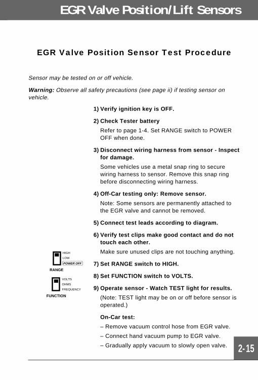
EGR Valve Position Sensor Test Procedure
Sensor may be tested on or off vehicle.
Warning: Observe all safety precautions (see page ii) if testing sensor onvehicle.
1) Verify ignition key is OFF.
2) Check Tester battery
Refer to page 1-4. Set RANGE switch to POWEROFF when done.
3) Disconnect wiring harness from sensor - Inspectfor damage.
Some vehicles use a metal snap ring to securewiring harness to sensor. Remove this snap ringbefore disconnecting wiring harness.
4) Off-Car testing only: Remove sensor.
Note: Some sensors are permanently attached tothe EGR valve and cannot be removed.
5) Connect test leads according to diagram.
6) Verify test clips make good contact and do nottouch each other.
Make sure unused clips are not touching anything.
7) Set RANGE switch to HIGH.
8) Set FUNCTION switch to VOLTS.
9) Operate sensor - Watch TEST light for results.
(Note: TEST light may be on or off before sensor isoperated.)
On-Car test:
– Remove vacuum control hose from EGR valve.
– Connect hand vacuum pump to EGR valve.
– Gradually apply vacuum to slowly open valve.
RANGE
HIGH
LOW
POWER OFF
FUNCTION
VOLTS
OHMS
FREQUENCY
2-16
Testing SensorsSection 2
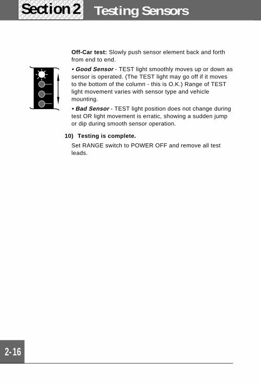
Off-Car test: Slowly push sensor element back and forthfrom end to end.
• Good Sensor - TEST light smoothly moves up or down assensor is operated. (The TEST light may go off if it movesto the bottom of the column - this is O.K.) Range of TESTlight movement varies with sensor type and vehiclemounting.
• Bad Sensor - TEST light position does not change duringtest OR light movement is erratic, showing a sudden jumpor dip during smooth sensor operation.
10) Testing is complete.
Set RANGE switch to POWER OFF and remove all testleads.
EGR Valve Position/Lift Sensors
2-17
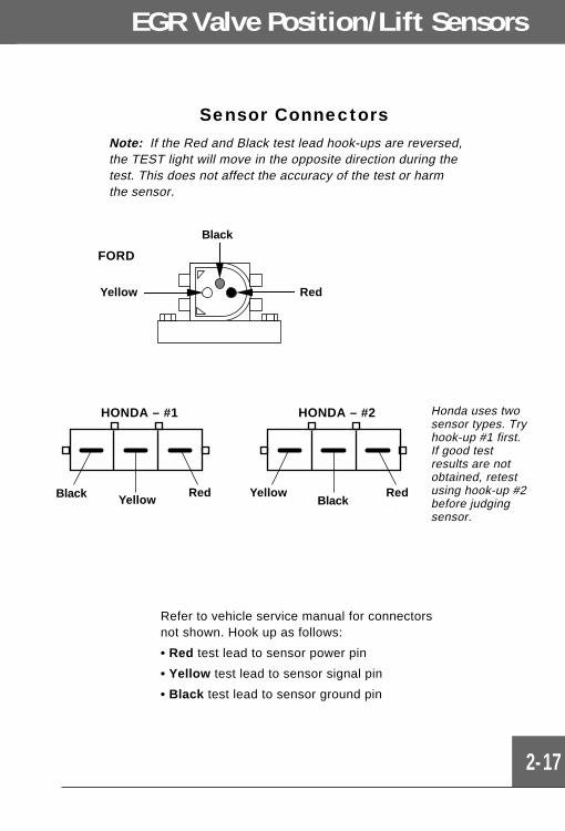
Sensor Connectors
Black
RedYellow
Note: If the Red and Black test lead hook-ups are reversed,the TEST light will move in the opposite direction during thetest. This does not affect the accuracy of the test or harmthe sensor.
FORD
Yellow RedBlack
RedBlack Yellow
HONDA – #2HONDA – #1 Honda uses twosensor types. Tryhook-up #1 first.If good testresults are notobtained, retestusing hook-up #2before judgingsensor.
Refer to vehicle service manual for connectorsnot shown. Hook up as follows:
• Red test lead to sensor power pin
• Yellow test lead to sensor signal pin
• Black test lead to sensor ground pin
2-18
Testing SensorsSection 2
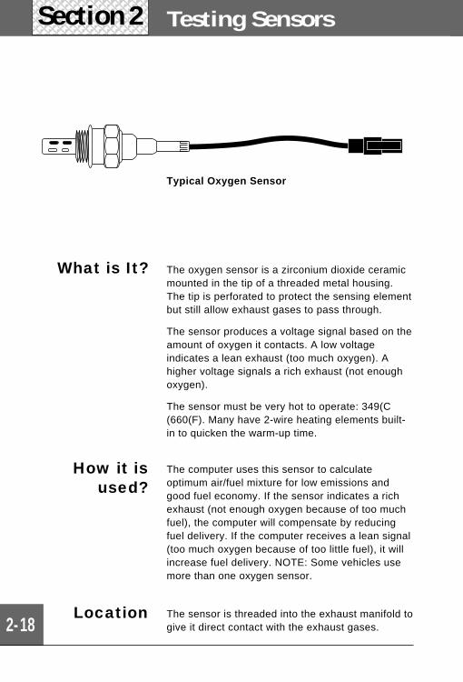
Location The sensor is threaded into the exhaust manifold togive it direct contact with the exhaust gases.
How it isused?
The computer uses this sensor to calculateoptimum air/fuel mixture for low emissions andgood fuel economy. If the sensor indicates a richexhaust (not enough oxygen because of too muchfuel), the computer will compensate by reducingfuel delivery. If the computer receives a lean signal(too much oxygen because of too little fuel), it willincrease fuel delivery. NOTE: Some vehicles usemore than one oxygen sensor.
What is It? The oxygen sensor is a zirconium dioxide ceramicmounted in the tip of a threaded metal housing.The tip is perforated to protect the sensing elementbut still allow exhaust gases to pass through.
The sensor produces a voltage signal based on theamount of oxygen it contacts. A low voltageindicates a lean exhaust (too much oxygen). Ahigher voltage signals a rich exhaust (not enoughoxygen).
The sensor must be very hot to operate: 349(C(660(F). Many have 2-wire heating elements built-in to quicken the warm-up time.
Typical Oxygen Sensor
OXYGEN
2-19
IMPORTANT: Some engines (usually off-road applications)use a titania-type oxygen sensor. This sensorresembles the common zirconium type, but hasan open-ended tip. The titania sensor changesresistance when it operates. This tester isnot designed to test the titania typesensor.
When to Test • Related trouble codes sent by computer.
• Driveability problems such as rough running,hesitation, stumble, poor fuel economy, poorperformance, black exhaust smoke.
Inspection Sensor operation (see page 2-21). Poor connec-tions at the sensor or computer.
This sensor often fails because of contaminationfrom fuel, oil additives, gasket sealer or an overlyrich running engine. Factors which can make a richrunning engine include: ignition system problems(coil, distributor cap, rotor, spark plugs, wires), fuelcontaminated by engine oil, emission devices(carbon canister, EGR valve, PCV valve, airinjection system), manifold leaks, air filter, fuelpressure and engine not at normal operatingtemperature.
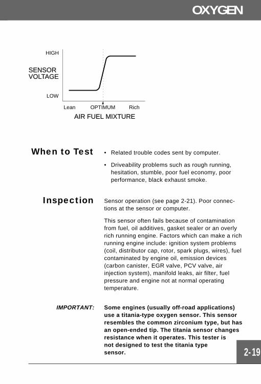
HIGH
SENSORVOLTAGE
LOW
Lean OPTIMUM Rich
AIR FUEL MIXTURE
2-20
Sensor Types
Testing SensorsSection 2
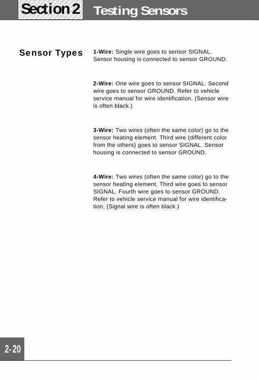
1-Wire: Single wire goes to sensor SIGNAL.Sensor housing is connected to sensor GROUND.
2-Wire: One wire goes to sensor SIGNAL. Secondwire goes to sensor GROUND. Refer to vehicleservice manual for wire identification. (Sensor wireis often black.)
3-Wire: Two wires (often the same color) go to thesensor heating element. Third wire (different colorfrom the others) goes to sensor SIGNAL. Sensorhousing is connected to sensor GROUND.
4-Wire: Two wires (often the same color) go to thesensor heating element. Third wire goes to sensorSIGNAL. Fourth wire goes to sensor GROUND.Refer to vehicle service manual for wire identifica-tion. (Signal wire is often black.)
2-21
OXYGEN
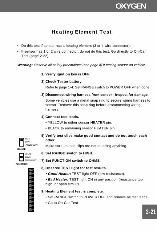
Heating Element Test
• Do this test if sensor has a heating element (3 or 4 wire connector).
• If sensor has 1 or 2 wire connector, do not do this test. Go directly to On-CarTest (page 2-22).
Warning: Observe all safety precautions (see page ii) if testing sensor on vehicle.
1) Verify ignition key is OFF.
2) Check Tester battery
Refer to page 1-4. Set RANGE switch to POWER OFF when done.
3) Disconnect wiring harness from sensor - Inspect for damage.
Some vehicles use a metal snap ring to secure wiring harness tosensor. Remove this snap ring before disconnecting wiringharness.
4) Connect test leads.
• YELLOW to either sensor HEATER pin.
• BLACK to remaining sensor HEATER pin.
5) Verify test clips make good contact and do not touch eachother.
Make sure unused clips are not touching anything.
6) Set RANGE switch to HIGH.
7) Set FUNCTION switch to OHMS.
8) Observe TEST light for test results.
• Good Heater: TEST light OFF (low resistance).
• Bad Heater: TEST light ON in any position (resistance toohigh, or open circuit).
9) Heating Element test is complete.
• Set RANGE switch to POWER OFF and remove all test leads.
• Go to On-Car Test.
RANGE
HIGH
LOW
POWER OFF
FUNCTION
VOLTS
OHMS
FREQUENCY
TEST
2-22
Testing SensorsSection 2
On-Car TestImportant: Reliable testing of the oxygen sensor while on-vehicle is verydifficult because test conditions cannot be well controlled. If the sensorresponds during on-car testing, then it is probably good and no othertesting is necessary. If the sensor does not seem to respond when testedon-car, remove it and perform the off-car test before deciding whether ornot the sensor is bad.
Warning: This test involves running the engine. Observe all safety precautions(see page ii). Work in well-ventilated area.
1) Verify ignition key is OFF.
2) Check Tester battery
Refer to page 1-4. Set RANGE switch to POWER OFFwhen done.
3) Connect test leads.
• YELLOW to sensor SIGNAL circuit.
• BLACK to good vehicle GROUND.
– Keep sensor connected to vehicle wiring and usebackprobe adapter to contact sensor SIGNAL circuit ifpossible.
– If you cannot use backprobe, disconnect sensorconnector and connect YELLOW test lead directly tosensor SIGNAL pin. Note: Most computer systems willstore a trouble code in memory (and turn on the “CheckEngine” light) if engine is run with sensor disconnected.Ignore or erase the code after testing. Refer to VehicleService Manual.
4) Verify test clips make good contact.
Make sure unused clips are not touching anything.
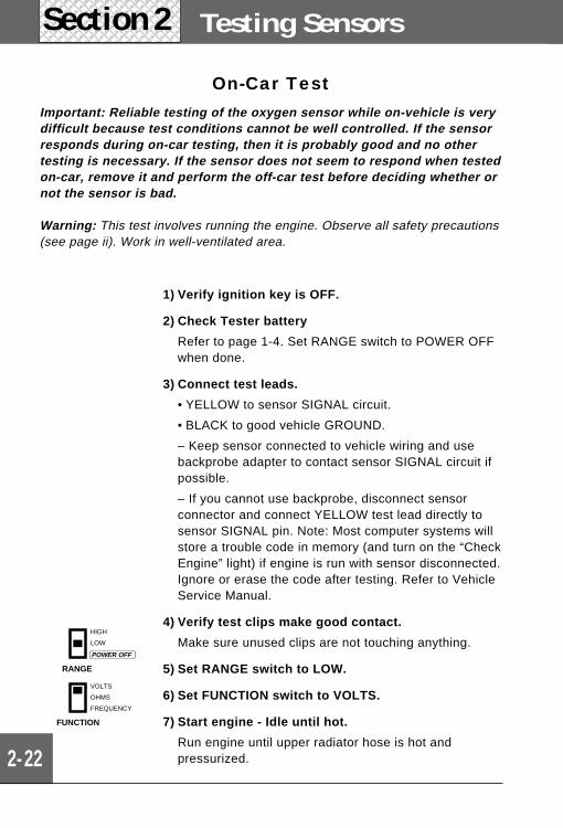
5) Set RANGE switch to LOW.
6) Set FUNCTION switch to VOLTS.
7) Start engine - Idle until hot.
Run engine until upper radiator hose is hot andpressurized.
RANGE
HIGH
LOW
POWER OFF
FUNCTION
VOLTS
OHMS
FREQUENCY
OXYGEN
2-23
8) Observe RICH/LEAN lights during fast idle.
• The TEST light column also indicates sensor voltage,but it is easier to check operation by watching the RICH/LEAN lights.)
• Maintain throttle partially open (2000 RPM idle).
– IF the RICH/LEAN lights flash back and forth every 3seconds or less...
THEN the sensor is good and no further testing isnecessary. Go to step 10.
– IF it takes longer than 3 seconds for the RICH/LEANlights to switch back and forth...
THEN the sensor may be degraded. Go to step 10,then do the Off-Car test on page 2-24
– IF the RICH/LEAN lights do not flash back and forth...
THEN go to step 9.
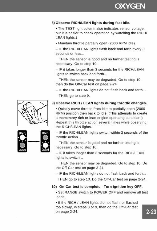
9) Observe RICH / LEAN lights during throttle changes.
• Quickly move throttle from idle to partially open (2000RPM) position then back to idle. (This attempts to createa momentary rich or lean engine operating condition.)Repeat this throttle action several times while observingthe RICH/LEAN lights.
– IF the RICH/LEAN lights switch within 3 seconds of thethrottle action...
THEN the sensor is good and no further testing isnecessary. Go to step 10.
– IF it takes longer than 3 seconds for the RICH/LEANlights to switch...
THEN the sensor may be degraded. Go to step 10. Dothe Off-Car test on page 2-24
– IF the RICH/LEAN lights do not flash back and forth...
THEN go to step 10. Do the Off-Car test on page 2-24.
10) On-Car test is complete - Turn ignition key OFF.
• Set RANGE switch to POWER OFF and remove all testleads.
• If the RICH / LEAN lights did not flash, or flashedtoo slowly, in steps 8 or 9, then do the Off-Car teston page 2-24.
RICH
LEAN
RICH
LEAN
2-24
Testing SensorsSection 2
Off-Car TestWarning: This test involves use of an open flame from a propane torch.Observe all safety precautions for torch operation. Do not use near flammablematerial or gases.
1) Verify ignition key is OFF.
2) Check Tester battery
Refer to page 1-4. Set RANGE switch to POWEROFF when done.
3) Disconnect wiring harness from sensor - Inspectfor damage.
Some vehicles use a metal snap ring to secure wiringharness to sensor. Remove this snap ring beforedisconnecting wiring harness.
4) Remove sensor.
5) Firmly grasp sensor with a pair of locking pliers.
6) Connect test leads
• YELLOW to sensor SIGNAL pin.
• BLACK to sensor GROUND.
7) Verify test clips make good contact and do nottouch each other.
Make sure unused clips are not touching anything.
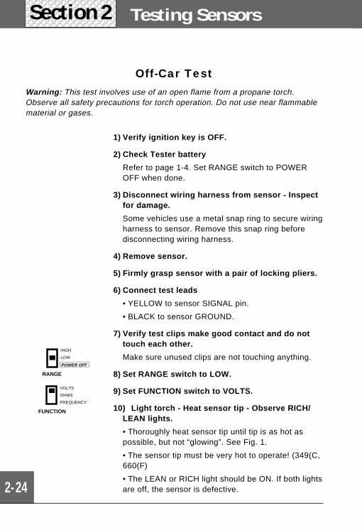
8) Set RANGE switch to LOW.
9) Set FUNCTION switch to VOLTS.
10) Light torch - Heat sensor tip - Observe RICH/LEAN lights.
• Thoroughly heat sensor tip until tip is as hot aspossible, but not “glowing”. See Fig. 1.
• The sensor tip must be very hot to operate! (349(C,660(F)
• The LEAN or RICH light should be ON. If both lightsare off, the sensor is defective.
FUNCTION
VOLTS
OHMS
FREQUENCY
RANGE
HIGH
LOW
POWER OFF
OXYGEN
2-25
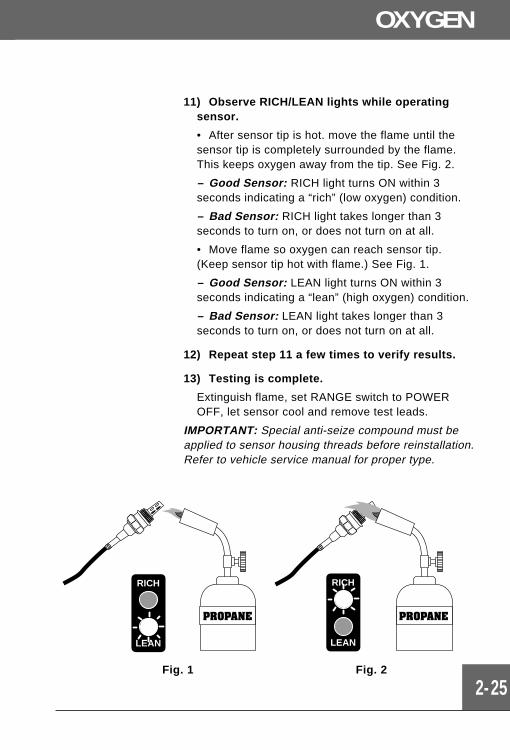
11) Observe RICH/LEAN lights while operatingsensor.
• After sensor tip is hot. move the flame until thesensor tip is completely surrounded by the flame.This keeps oxygen away from the tip. See Fig. 2.
– Good Sensor: RICH light turns ON within 3seconds indicating a “rich” (low oxygen) condition.
– Bad Sensor: RICH light takes longer than 3seconds to turn on, or does not turn on at all.
• Move flame so oxygen can reach sensor tip.(Keep sensor tip hot with flame.) See Fig. 1.
– Good Sensor: LEAN light turns ON within 3seconds indicating a “lean” (high oxygen) condition.
– Bad Sensor: LEAN light takes longer than 3seconds to turn on, or does not turn on at all.
12) Repeat step 11 a few times to verify results.
13) Testing is complete.
Extinguish flame, set RANGE switch to POWEROFF, let sensor cool and remove test leads.
IMPORTANT: Special anti-seize compound must beapplied to sensor housing threads before reinstallation.Refer to vehicle service manual for proper type.
RICH
LEAN
RICH
LEAN
Fig. 1 Fig. 2
2-26
Testing SensorsSection 2
What toInspect
Sensor operation (see test on page 2-27). Poorconnections at sensor or computer. Faulty sensorwiring (open or short circuits). Spark timing. Badfuel quality.
When to Test • Related trouble codes sent by computer.
• Knocking during cruise or hard acceleration (notenough spark retard), hesitation, poor perfor-mance and fuel economy (excess spark retard).
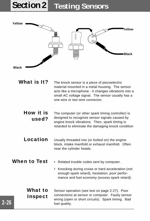
Location Usually threaded into (or bolted on) the engineblock, intake manifold or exhaust manifold. Oftennear the cylinder heads.
How it isused?
The computer (or other spark timing controller) isdesigned to recognize sensor signals caused byengine knock vibrations. Then, spark timing isretarded to eliminate the damaging knock condition
What is It? The knock sensor is a piece of piezoelectricmaterial mounted in a metal housing. The sensoracts like a microphone - it changes vibrations into asmall AC voltage signal. The sensor usually has aone wire or two wire connector.
Yellow
Black
Yellow
Black
RANGE
HIGH
LOW
POWER OFF
Engine KNOCK
2-27
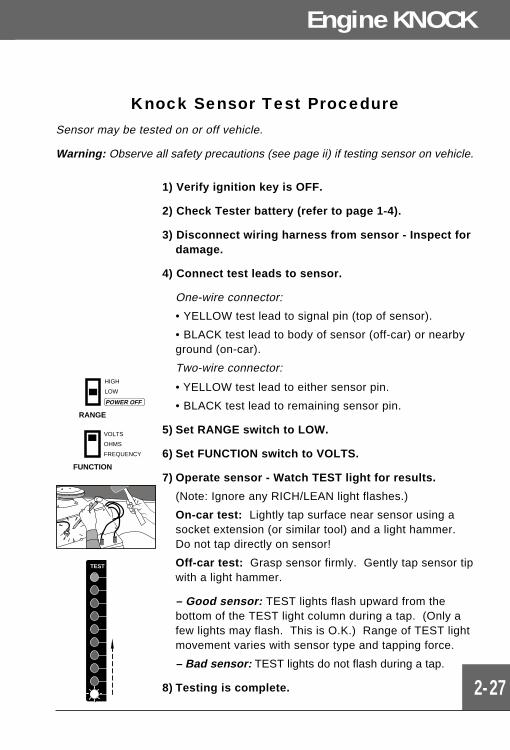
Knock Sensor Test ProcedureSensor may be tested on or off vehicle.
Warning: Observe all safety precautions (see page ii) if testing sensor on vehicle.
1) Verify ignition key is OFF.
2) Check Tester battery (refer to page 1-4).
3) Disconnect wiring harness from sensor - Inspect fordamage.
4) Connect test leads to sensor.
One-wire connector:
• YELLOW test lead to signal pin (top of sensor).
• BLACK test lead to body of sensor (off-car) or nearbyground (on-car).
Two-wire connector:
• YELLOW test lead to either sensor pin.
• BLACK test lead to remaining sensor pin.
5) Set RANGE switch to LOW.
6) Set FUNCTION switch to VOLTS.
7) Operate sensor - Watch TEST light for results.
(Note: Ignore any RICH/LEAN light flashes.)
On-car test: Lightly tap surface near sensor using asocket extension (or similar tool) and a light hammer.Do not tap directly on sensor!
Off-car test: Grasp sensor firmly. Gently tap sensor tipwith a light hammer.
– Good sensor: TEST lights flash upward from thebottom of the TEST light column during a tap. (Only afew lights may flash. This is O.K.) Range of TEST lightmovement varies with sensor type and tapping force.
– Bad sensor: TEST lights do not flash during a tap.
8) Testing is complete.
FUNCTION
VOLTS
OHMS
FREQUENCY
TEST
2-28
Testing SensorsSection 2
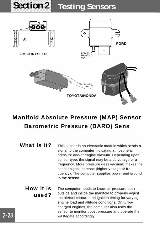
The computer needs to know air pressure bothoutside and inside the manifold to properly adjustthe air/fuel mixture and ignition timing for varyingengine load and altitude conditions. On turbo-charged engines, the computer also uses thesensor to monitor boost pressure and operate thewastegate accordingly.
How it isused?
What is It? This sensor is an electronic module which sends asignal to the computer indicating atmosphericpressure and/or engine vacuum. Depending uponsensor type, the signal may be a dc voltage or afrequency. More pressure (less vacuum) makes thesensor signal increase (higher voltage or fre-quency). The computer supplies power and groundto the sensor.
Manifold Absolute Pressure (MAP) SensorBarometric Pressure (BARO) Sens
TOYOTA/HONDA
GM/CHRYSLER
FORD
Manifold Absolute Pressure MAP/BARO
2-29
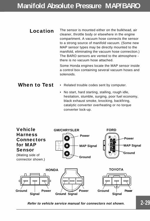
Location The sensor is mounted either on the bulkhead, aircleaner, throttle body or elsewhere in the enginecompartment. A vacuum hose connects the sensorto a strong source of manifold vacuum. (Some newMAP sensor types may be directly mounted to themanifold, eliminating the vacuum hose connection.)The BARO sensors are vented to the atmosphere -there is no vacuum hose attached.
Some Honda engines locate the MAP sensor insidea control box containing several vacuum hoses andsolenoids.
When to Test • Related trouble codes sent by computer.
• No start, hard starting, stalling, rough idle,hesitation, stumble, surging, poor fuel economy,black exhaust smoke, knocking, backfiring,catalytic converter overheating or no torqueconverter lock-up.
SignalPower
SignalGroundPower
SignalGround Power
Ground
TOYOTAHONDA
GM/CHRYSLER
MAP Signal
Power
Ground
MAP Signal
Ground
Power
FORDVehicleHarnessConnectorsfor MAPSensor(Mating side ofconnector shown.)
Refer to vehicle service manual for connectors not shown.
2-30
Testing SensorsSection 2
Manifold Absolute Pressure (MAP) SensorTest Procedure
Testing is done on-vehicle.
Warning: This test involves running the engine. Observe all safetyprecautions (see page ii). Work in well-ventilated area.
1) Verify ignition key is OFF.
2) Check Tester battery
Refer to page 1-4. Set RANGE switch to POWEROFF when done.
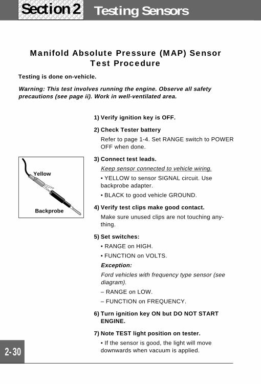
3) Connect test leads.
Keep sensor connected to vehicle wiring.
• YELLOW to sensor SIGNAL circuit. Usebackprobe adapter.
• BLACK to good vehicle GROUND.
4) Verify test clips make good contact.
Make sure unused clips are not touching any-thing.
5) Set switches:
• RANGE on HIGH.
• FUNCTION on VOLTS.
Exception:
Ford vehicles with frequency type sensor (seediagram).
– RANGE on LOW.
– FUNCTION on FREQUENCY.
6) Turn ignition key ON but DO NOT STARTENGINE.
7) Note TEST light position on tester.
• If the sensor is good, the light will movedownwards when vacuum is applied.
Backprobe
Yellow
2-31
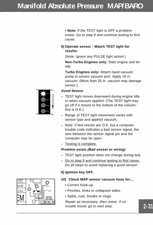
• Note: If the TEST light is OFF a problemexists. Go to step 9 and continue testing to findcause.
8) Operate sensor - Watch TEST light forresults.
(Note: Ignore any PULSE light action.)
Non-Turbo Engines only: Start engine and letidle.
Turbo Engines only: Attach hand vacuumpump to sensor vacuum port. Apply 18 in.vacuum. (More than 25 in. vacuum may damagesensor.)
Good Sensor
– TEST light moves downward during engine idleor when vacuum applied. (The TEST light maygo off if it moves to the bottom of the column -this is O.K.)
– Range of TEST light movement varies withsensor type and applied vacuum.
– Note: if test results are O.K. but a computertrouble code indicates a bad sensor signal, thewire between the sensor signal pin and thecomputer may be open.
– Testing is complete.
Problem exists (Bad sensor or wiring)
– TEST light position does not change during test.
– Go to step 9 and continue testing to find cause.Do all steps to avoid replacing a good sensor!
9) Ignition key OFF.
10) Check MAP sensor vacuum hose for...
• Correct hook-up.
• Pinches, kinks or collapsed sides.
• Splits, cuts, breaks or clogs
Repair as necessary, then retest. If notrouble found, go to next step.
FRONTOF CAR
U.S.A.
EM
G GAP
YSTCE BOOSTER
HVACCRUISE
BRAKE BOOSTER
TO TRANSMODE
EGRVACREG
EGRVACREG
FUELPRESSREG.
12RAC8
Manifold Absolute Pressure MAP/BARO
Testing SensorsSection 2
2-32
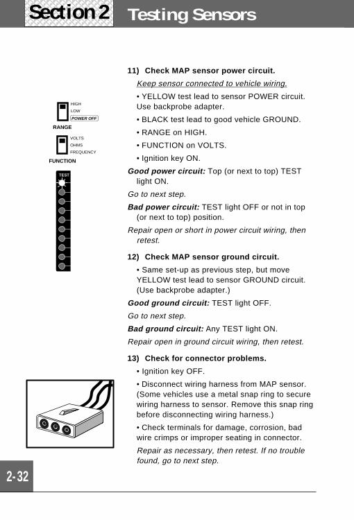
11) Check MAP sensor power circuit.
Keep sensor connected to vehicle wiring.
• YELLOW test lead to sensor POWER circuit.Use backprobe adapter.
• BLACK test lead to good vehicle GROUND.
• RANGE on HIGH.
• FUNCTION on VOLTS.
• Ignition key ON.
Good power circuit: Top (or next to top) TESTlight ON.
Go to next step.
Bad power circuit: TEST light OFF or not in top(or next to top) position.
Repair open or short in power circuit wiring, thenretest.
12) Check MAP sensor ground circuit.
• Same set-up as previous step, but moveYELLOW test lead to sensor GROUND circuit.(Use backprobe adapter.)
Good ground circuit: TEST light OFF.
Go to next step.
Bad ground circuit: Any TEST light ON.
Repair open in ground circuit wiring, then retest.
13) Check for connector problems.
• Ignition key OFF.
• Disconnect wiring harness from MAP sensor.(Some vehicles use a metal snap ring to securewiring harness to sensor. Remove this snap ringbefore disconnecting wiring harness.)
• Check terminals for damage, corrosion, badwire crimps or improper seating in connector.
Repair as necessary, then retest. If no troublefound, go to next step.
RANGE
HIGH
LOW
POWER OFF
FUNCTION
VOLTS
OHMS
FREQUENCY
TEST
2-33
Manifold Absolute Pressure MAP/BARO
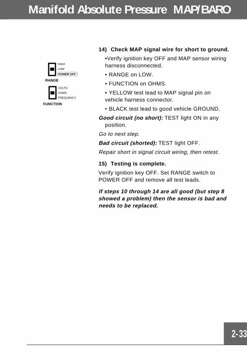
14) Check MAP signal wire for short to ground.
•Verify ignition key OFF and MAP sensor wiringharness disconnected.
• RANGE on LOW.
• FUNCTION on OHMS.
• YELLOW test lead to MAP signal pin onvehicle harness connector.
• BLACK test lead to good vehicle GROUND.
Good circuit (no short): TEST light ON in anyposition.
Go to next step.
Bad circuit (shorted): TEST light OFF.
Repair short in signal circuit wiring, then retest.
15) Testing is complete.
Verify ignition key OFF. Set RANGE switch toPOWER OFF and remove all test leads.
If steps 10 through 14 are all good (but step 8showed a problem) then the sensor is bad andneeds to be replaced.
RANGE
HIGH
LOW
POWER OFF
FUNCTION
VOLTS
OHMS
FREQUENCY
2-34
Testing SensorsSection 2
FLOW
- F
+
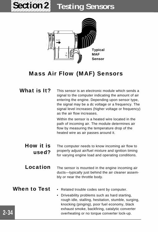
TypicalMAFSensor
• Related trouble codes sent by computer.
• Driveability problems such as hard starting,rough idle, stalling, hesitation, stumble, surging,knocking (pinging), poor fuel economy, blackexhaust smoke, backfiring, catalytic converteroverheating or no torque converter lock-up.
When to Test
Location The sensor is mounted in the engine incoming airducts—typically just behind the air cleaner assem-bly or near the throttle body.
How it isused?
The computer needs to know incoming air flow toproperly adjust air/fuel mixture and ignition timingfor varying engine load and operating conditions.
What is It? This sensor is an electronic module which sends asignal to the computer indicating the amount of airentering the engine. Depending upon sensor type,the signal may be a dc voltage or a frequency. Thesignal level increases (higher voltage or frequency)as the air flow increases.
Within the sensor is a heated wire located in thepath of incoming air. The module determines airflow by measuring the temperature drop of theheated wire as air passes around it.
Mass Air Flow (MAF) Sensors
Mass Air Flow MAF
2-35
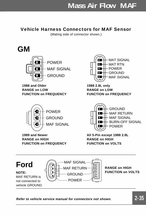
Vehicle Harness Connectors for MAF Sensor(Mating side of connector shown.)
Refer to vehicle service manual for connectors not shown.
MAF SIGNAL
GROUND
POWER
MAF RETURN RANGE on HIGHFUNCTION on VOLTS
POWER
MAF SIGNAL
GROUND
MAT SIGNALMAT RTNPOWERGROUNDMAF SIGNAL
1988 and OlderRANGE on LOWFUNCTION on FREQUENCY
1988 2.8L onlyRANGE on LOWFUNCTION on FREQUENCY
GROUNDMAF RETURN
POWERBURN-OFF SIGNALMAF SIGNAL
POWER
MAF SIGNAL
GROUND
1989 and NewerRANGE on HIGHFUNCTION on FREQUENCY
All 5-Pin except 1988 2.8LRANGE on HIGHFUNCTION on VOLTS
GM
FordNOTE:MAF RETURN isnot connected tovehicle GROUND.
2-36
Testing SensorsSection 2
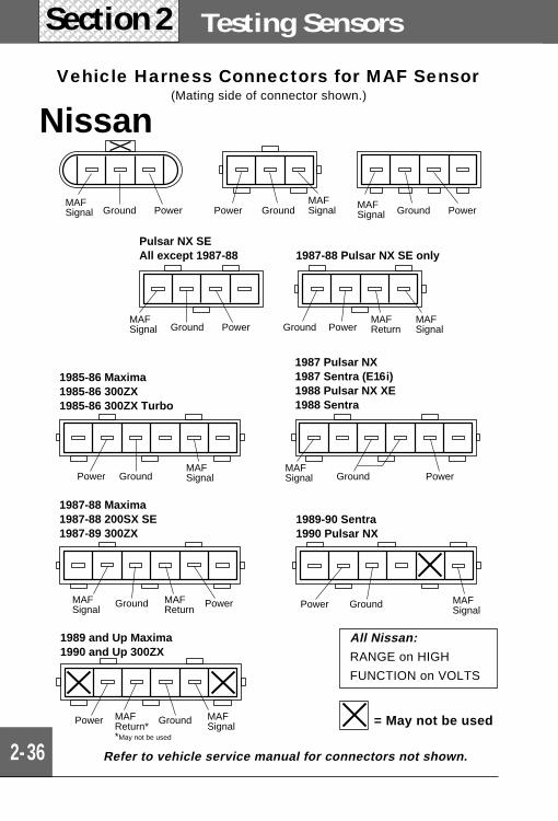
Vehicle Harness Connectors for MAF Sensor(Mating side of connector shown.)
= May not be used
Refer to vehicle service manual for connectors not shown.
1985-86 Maxima 1985-86 300ZX 1985-86 300ZX Turbo
Power GroundMAF Signal
PowerGroundMAF Signal
PowerGroundMAF Signal PowerGround
MAF Return
MAF Signal
PowerGroundMAF SignalPower Ground
MAF Signal
1987-88 Maxima 1987-88 200SX SE 1987-89 300ZX
1987 Pulsar NX 1987 Sentra (E16i) 1988 Pulsar NX XE 1988 Sentra
PowerGroundMAF Signal
PowerGroundMAF Signal
MAF Return
1989-90 Sentra 1990 Pulsar NX
Pulsar NX SE All except 1987-88 1987-88 Pulsar NX SE only
GroundPower MAF Signal
1989 and Up Maxima 1990 and Up 300ZX
Power Ground MAF Signal
MAF Return* *May not be used
Nissan
All Nissan:
RANGE on HIGH
FUNCTION on VOLTS
Mass Air Flow MAF
2-37
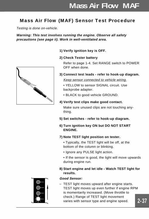
Mass Air Flow (MAF) Sensor Test ProcedureTesting is done on-vehicle.
Warning: This test involves running the engine. Observe all safetyprecautions (see page ii). Work in well-ventilated area.
1) Verify ignition key is OFF.
2) Check Tester battery
Refer to page 1-4. Set RANGE switch to POWEROFF when done.
3) Connect test leads - refer to hook-up diagram.
Keep sensor connected to vehicle wiring.
• YELLOW to sensor SIGNAL circuit. Usebackprobe adapter.
• BLACK to good vehicle GROUND.
4) Verify test clips make good contact.
Make sure unused clips are not touching any-thing.
5) Set switches - refer to hook-up diagram.
6) Turn ignition key ON but DO NOT STARTENGINE.
7) Note TEST light position on tester.
• Typically, the TEST light will be off, at thebottom of the column or blinking.
• Ignore any PULSE light action.
• If the sensor is good, the light will move upwardsduring engine run.
8) Start engine and let idle - Watch TEST light forresults.
Good Sensor:
– TEST light moves upward after engine starts.TEST light moves up even further if engine RPMis momentarily increased. (Move throttle tocheck.) Range of TEST light movementvaries with sensor type and engine speed.
2-38
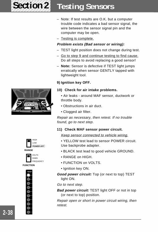
Testing SensorsSection 2– Note: If test results are O.K. but a computer
trouble code indicates a bad sensor signal, thewire between the sensor signal pin and thecomputer may be open.
– Testing is complete.
Problem exists (Bad sensor or wiring):
– TEST light position does not change during test.
– Go to step 9 and continue testing to find cause.Do all steps to avoid replacing a good sensor!
– Note: Sensor is defective if TEST light jumpserratically when sensor GENTLY tapped withlightweight tool.
9) Ignition key OFF.
10) Check for air intake problems.
• Air leaks - around MAF sensor, ductwork orthrottle body.
• Obstructions in air duct.
• Clogged air filter.
Repair as necessary, then retest. If no troublefound, go to next step.
11) Check MAF sensor power circuit.
Keep sensor connected to vehicle wiring.
• YELLOW test lead to sensor POWER circuit.Use backprobe adapter.
• BLACK test lead to good vehicle GROUND.
• RANGE on HIGH.
• FUNCTION on VOLTS.
• Ignition key ON.
Good power circuit: Top (or next to top) TESTlight ON.
Go to next step.
Bad power circuit: TEST light OFF or not in top(or next to top) position.
Repair open or short in power circuit wiring, thenretest.
RANGE
HIGH
LOW
POWER OFF
FUNCTION
VOLTS
OHMS
FREQUENCY
TEST
Mass Air Flow MAF
2-39
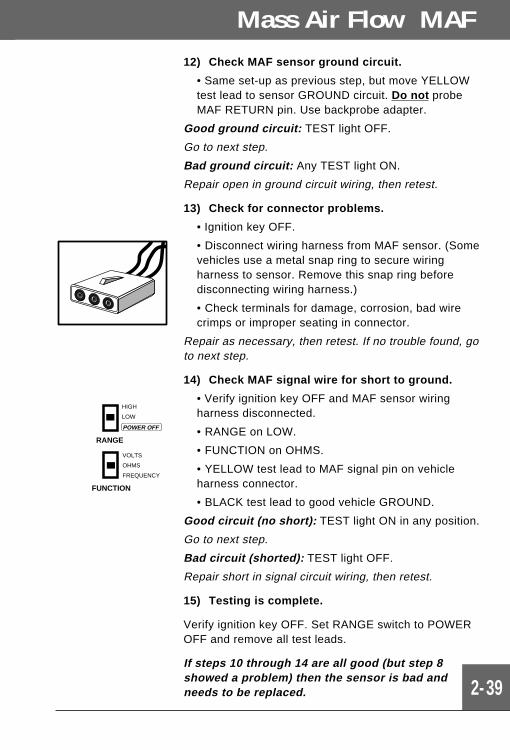
12) Check MAF sensor ground circuit.
• Same set-up as previous step, but move YELLOWtest lead to sensor GROUND circuit. Do not probeMAF RETURN pin. Use backprobe adapter.
Good ground circuit: TEST light OFF.
Go to next step.
Bad ground circuit: Any TEST light ON.
Repair open in ground circuit wiring, then retest.
13) Check for connector problems.
• Ignition key OFF.
• Disconnect wiring harness from MAF sensor. (Somevehicles use a metal snap ring to secure wiringharness to sensor. Remove this snap ring beforedisconnecting wiring harness.)
• Check terminals for damage, corrosion, bad wirecrimps or improper seating in connector.
Repair as necessary, then retest. If no trouble found, goto next step.
14) Check MAF signal wire for short to ground.
• Verify ignition key OFF and MAF sensor wiringharness disconnected.
• RANGE on LOW.
• FUNCTION on OHMS.
• YELLOW test lead to MAF signal pin on vehicleharness connector.
• BLACK test lead to good vehicle GROUND.
Good circuit (no short): TEST light ON in any position.
Go to next step.
Bad circuit (shorted): TEST light OFF.
Repair short in signal circuit wiring, then retest.
15) Testing is complete.
Verify ignition key OFF. Set RANGE switch to POWEROFF and remove all test leads.
If steps 10 through 14 are all good (but step 8showed a problem) then the sensor is bad andneeds to be replaced.
RANGE
HIGH
LOW
POWER OFF
FUNCTION
VOLTS
OHMS
FREQUENCY
2-40
Testing SensorsSection 2
Sensor operation (see tests on pages 2-43 through 2-44).Poor connections at sensor or computer. Faulty sensorwiring (open or short circuits). Airflow obstructions inductwork or clogged air filter. Binding pivot on vane“door”. Air leaks around sensor or throttle body.
What toInspect
When toTest
• Related trouble codes sent by computer.
• Driveability problems such as hard starting, rough idle,stalling, hesitation, stumble, surging, knocking (ping-ing), poor fuel economy, black exhaust smoke, backfir-ing, catalytic converter overheating or no torqueconverter lock-up.
Location The sensor is mounted in the engine incoming air duct -between the air cleaner and the throttle body.
How it isused?
The computer needs to know incoming air flow to properlyadjust air/fuel mixture and ignition timing for varyingengine load and operating conditions.
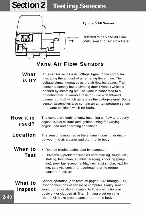
Whatis It?
This sensor sends a dc voltage signal to the computerindicating the amount of air entering the engine. Thevoltage signal increases as the air flow increases. Thesensor assembly has a pivoting door (“vane”) which isopened by incoming air. The vane is connected to apotentiometer (a variable resistor - like a dashboarddimmer control) which generates the voltage signal. Somesensor assemblies also contain an air temperature sensoror a vane position switch (or both).
AIR FLOW
Vane Air Flow Sensors
Typical VAF Sensor
Referred to as Vane Air Flow(VAF) sensor or Air Flow Meter
1 2 3 4 5 6 7
1 2 3 4 5 6 71 2 3 4 5 6 7
1 2 3 4 5 6 7
Vane Air Flow VAF
2-41
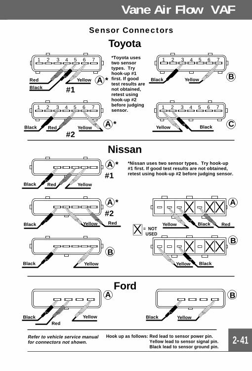
Sensor Connectors
Red Yellow
Black #1
Toyota
A *
A *#2
YellowRedBlack CBlackYellow
BBlack Yellow
*Toyota usestwo sensortypes. Tryhook-up #1first. If goodtest results arenot obtained,retest usinghook-up #2before judgingsensor.
YellowRedBlack
Black
Black
A *#2
A *#1
RedYellow
B
A
B
RedBlackYellow
Yellow Black
Nissan*Nissan uses two sensor types. Try hook-up#1 first. If good test results are not obtained,retest using hook-up #2 before judging sensor.
= NOTUSED
Ford
Hook up as follows: Red lead to sensor power pin.Yellow lead to sensor signal pin.Black lead to sensor ground pin.
Refer to vehicle service manualfor connectors not shown.
Black BlackRed
Yellow
Yellow
Yellow
BA
2-42
Testing SensorsSection 2
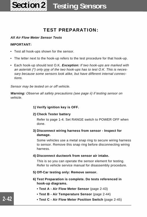
TEST PREPARATION:All Air Flow Meter Sensor Tests
IMPORTANT:
• Test all hook-ups shown for the sensor.
• The letter next to the hook-up refers to the test procedure for that hook-up.
• Each hook-up should test O.K. Exception: If two hook-ups are marked withan asterisk (*) only one of the two hook-ups has to test O.K. This is neces-sary because some sensors look alike, but have different internal connec-tions.
Sensor may be tested on or off vehicle.
Warning: Observe all safety precautions (see page ii) if testing sensor onvehicle.
1) Verify ignition key is OFF.
2) Check Tester battery
Refer to page 1-4. Set RANGE switch to POWER OFF whendone.
3) Disconnect wiring harness from sensor - Inspect fordamage.
Some vehicles use a metal snap ring to secure wiring harnessto sensor. Remove this snap ring before disconnecting wiringharness.
4) Disconnect ductwork from sensor air intake.
This is so you can operate the sensor element for testing.Refer to vehicle service manual for disassembly procedure.
5) Off-Car testing only: Remove sensor.
6) Test Preparation is complete. Do tests referenced inhook-up diagrams.
• Test A - Air Flow Meter Sensor (page 2-43)
• Test B - Air Temperature Sensor (page 2-44)
• Test C - Air Flow Meter Position Switch (page 2-45)
Mass Air Flow MAF
2-43
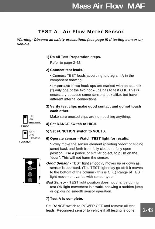
TEST A - Air Flow Meter SensorWarning: Observe all safety precautions (see page ii) if testing sensor onvehicle.
1) Do all Test Preparation steps.
Refer to page 2-42.
2) Connect test leads.
• Connect TEST leads according to diagram A in thecomponent drawing.
• Important: If two hook-ups are marked with an asterisk(*) only one of the two hook-ups has to test O.K. This isnecessary because some sensors look alike, but havedifferent internal connections.
3) Verify test clips make good contact and do not toucheach other.
Make sure unused clips are not touching anything.
4) Set RANGE switch to HIGH.
5) Set FUNCTION switch to VOLTS.
6) Operate sensor - Watch TEST light for results.
Slowly move the sensor element (pivoting “door” or slidingcone) back and forth from fully closed to fully openposition. Use a pencil, or similar object, to push on the“door”. This will not harm the sensor.
Good Sensor - TEST light smoothly moves up or down assensor is operated. (The TEST light may go off if it movesto the bottom of the column - this is O.K.) Range of TESTlight movement varies with sensor type.
Bad Sensor - TEST light position does not change duringtest OR light movement is erratic, showing a sudden jumpor dip during smooth sensor operation.
7) Test A is complete.
Set RANGE switch to POWER OFF and remove all testleads. Reconnect sensor to vehicle if all testing is done.
RANGE
HIGH
LOW
POWER OFF
FUNCTION
VOLTS
OHMS
FREQUENCY
2-44
Testing SensorsSection 2
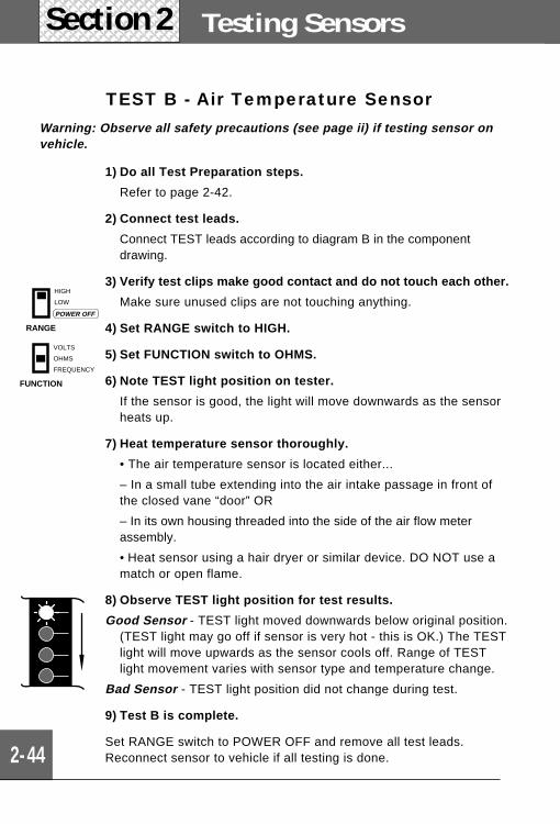
TEST B - Air Temperature SensorWarning: Observe all safety precautions (see page ii) if testing sensor onvehicle.
1) Do all Test Preparation steps.
Refer to page 2-42.
2) Connect test leads.
Connect TEST leads according to diagram B in the componentdrawing.
3) Verify test clips make good contact and do not touch each other.
Make sure unused clips are not touching anything.
4) Set RANGE switch to HIGH.
5) Set FUNCTION switch to OHMS.
6) Note TEST light position on tester.
If the sensor is good, the light will move downwards as the sensorheats up.
7) Heat temperature sensor thoroughly.
• The air temperature sensor is located either...
– In a small tube extending into the air intake passage in front ofthe closed vane “door” OR
– In its own housing threaded into the side of the air flow meterassembly.
• Heat sensor using a hair dryer or similar device. DO NOT use amatch or open flame.
8) Observe TEST light position for test results.
Good Sensor - TEST light moved downwards below original position.(TEST light may go off if sensor is very hot - this is OK.) The TESTlight will move upwards as the sensor cools off. Range of TESTlight movement varies with sensor type and temperature change.
Bad Sensor - TEST light position did not change during test.
9) Test B is complete.
Set RANGE switch to POWER OFF and remove all test leads.Reconnect sensor to vehicle if all testing is done.
RANGE
HIGH
LOW
POWER OFF
FUNCTION
VOLTS
OHMS
FREQUENCY
Mass Air Flow MAF
2-45
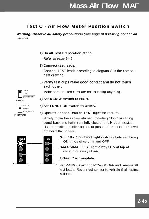
Test C - Air Flow Meter Position SwitchWarning: Observe all safety precautions (see page ii) if testing sensor onvehicle.
1) Do all Test Preparation steps.
Refer to page 2-42.
2) Connect test leads.
Connect TEST leads according to diagram C in the compo-nent drawing.
3) Verify test clips make good contact and do not toucheach other.
Make sure unused clips are not touching anything.
4) Set RANGE switch to HIGH.
5) Set FUNCTION switch to OHMS.
6) Operate sensor - Watch TEST light for results.
Slowly move the sensor element (pivoting “door” or slidingcone) back and forth from fully closed to fully open position.Use a pencil, or similar object, to push on the “door”. This willnot harm the sensor.
RANGE
HIGH
LOW
POWER OFF
FUNCTION
VOLTS
OHMS
FREQUENCY
TEST TEST Good Switch - TEST light switches between beingON at top of column and OFF
Bad Switch - TEST light always ON at top ofcolumn or always OFF.
7) Test C is complete.
Set RANGE switch to POWER OFF and remove alltest leads. Reconnect sensor to vehicle if all testingis done.
2-46
Testing SensorsSection 2
What is Itand
How is ItUsed?
— The computer needs to know rotational speed (orposition) of the engine crankshaft/camshaft for controllingignition and fuel injector systems. If the computer ishandling a Distributorless (or Direct) ignition system orcontrolling the operation of individual fuel injectors, it alsoneeds to know when cylinder #1 is active. The sensors havevarious names such as: Crankshaft Position, Crank Angle,Flywheel, Distributor Pick-Up, Camshaft Position, Cylinder,TDC and RPM.
— Similar sensors are used in anti-lock brake and electroni-cally shifted transmission systems. These sensors havenames such as: Wheel Speed, Vehicle Speed andDriveshaft.
— The sensors come many styles using different connectors.Sometimes an assembly contains more than one sensor.Other versions combine two functions into a single sensor(usually camshaft position and cylinder #1 identification).
— The most common sensor types are Magnetic Reluc-tance and Hall Effect. These are described below along withOptical types which are in limited use.
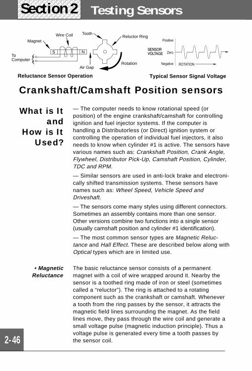
The basic reluctance sensor consists of a permanentmagnet with a coil of wire wrapped around it. Nearby thesensor is a toothed ring made of iron or steel (sometimescalled a “reluctor”). The ring is attached to a rotatingcomponent such as the crankshaft or camshaft. Whenevera tooth from the ring passes by the sensor, it attracts themagnetic field lines surrounding the magnet. As the fieldlines move, they pass through the wire coil and generate asmall voltage pulse (magnetic induction principle). Thus avoltage pulse is generated every time a tooth passes bythe sensor coil.
• MagneticReluctance
Rotation
Reluctor RingToothWire Coil
Magnet
ToComputer
Air Gap
NS
Crankshaft/Camshaft Position sensors
Reluctance Sensor Operation Typical Sensor Signal Voltage
ROTATION
Positive
Negative
ZeroSENSORVOLTAGE
Crankshaft/Camshaft Position
2-47
The optical crank angle sensor consists of a lightsource, a light detector (photo-electric cell) and a rotorplate, which is a slotted disk. Since the distributor shaftand/or camshaft are linked to the rotor plate, theymove together. As the rotor plate rotates, the slits onthe disk interrupt a beam or light sent by the lightsource to the light detector. This interrupting actioncreates two pulse waveforms that are monitored by theengine computer. The engine computer uses thesewaveforms and other engine sensors to optimallycontrol ignition timing.
• Optical
SHUTTER
POWER
GROUND
SIGNAL
MAGNET
HALLSWITCH
HIGH
SIGNAL VOLTAGE
LOW
ROTATION
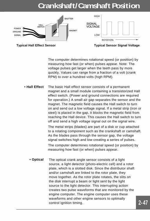
• Hall Effect The basic Hall effect sensor consists of a permanentmagnet and a small module containing a transistorized Halleffect switch. (Power and ground connections are requiredfor operation.) A small air gap separates the sensor and themagnet. The magnetic field causes the Hall switch to turnon and send out a low voltage signal. If a metal strip (iron orsteel) is placed in the gap, it blocks the magnetic field fromreaching the Hall device. This causes the Hall switch to turnoff and send a high voltage signal out on the signal wire.
The metal strips (blades) are part of a disk or cup attachedto a rotating component such as the crankshaft or camshaft.As the blades pass through the sensor gap, the voltagesignal switches high and low creating a series of pulses.
The computer determines rotational speed (or position) bymeasuring how fast (or when) pulses appear.
The computer determines rotational speed (or position) bymeasuring how fast (or when) pulses appear. Note: Thevoltage pulses get larger when the teeth pass by morequickly. Values can range from a fraction of a volt (crankRPM) to over a hundred volts (high RPM).
Typical Hall Effect Sensor Typical Sensor Signal Voltage
2-48
Testing SensorsSection 2
Where isIt?
— Crankshaft Position, Crank Angle, Flywheel, DistributorPick-Up, Camshaft Position, Cylinder, TDC and RPM. Thesensor is usually located inside the distributor (if theengine has one). Vehicles without a distributor have thesensor located in various places around the engine whereit can be mechanically linked to the crankshaft or camshaft.
— Driveshaft: Sensor located in transmission housing ornear driveshaft.
— Wheel Speed, Vehicle Speed: Sensors on individualwheels, drive shaft, or transmission shaft.
All Sensor Types: Sensor operation (see tests on page 2-49 through 2-52). Poor connections at sensor or computer.Faulty sensor wiring (open or short circuits).
– Magnetic Reluctance: Too much gap between sensorcoil and reluctor ring. Cracked, broken, or missing teeth onreluctor ring. Note: Some rings may normally have a gapor irregular tooth space. This gives the computer cylinderidentification information.
– Hall Effect: Foreign objects in gap between Hall sensorand shutter assembly. Cracked, broken, or missing bladeson shutter. Note: Some shutter assemblies may normallyhave irregular blade spacing. This gives the computercylinder identification information.
– Optical: Dirt in the rotor blade slots or light source/detector assembly. Broken or worn teeth on the distributorshaft (if used) or sensor shaft.
What toInspect
• Related trouble codes sent by computer.
• Problems with...
– Ignition: No start, stalling, rough running.
– Electronic Transmission: No torque converter lock-up,faulty shifting or slipping.
– ABS system: Faulty or not working.
When toTest
2-49
Test A - Magnetic Reluctance Type Sensor
Testing is done on-vehicle.
DO NOT test vehicle speed or driveshaft type sensors since they requirevehicle motion.
Warning: Observe all safety precautions (see page ii) when testing sensor onvehicle.
1) Verify ignition key is OFF.
2) Check Tester battery
Refer to page 1-4. Set RANGE switch to POWEROFF when done.
3) Disconnect wiring harness from sensor - Inspectfor damage.
Some vehicles use a metal snap ring to securewiring harness to sensor. Remove this snap ringbefore disconnecting wiring harness.
4) Connect test leads.
Refer to vehicle service manual for sensor pinidentification. Some connectors handle more thanone sensor. Test all sensors.
• YELLOW to one end of sensor coil pin.
• BLACK to other end of sensor coil pin.
5) Verify test clips make good contact and do nottouch each other.
Make sure unused clips are not touching anything.
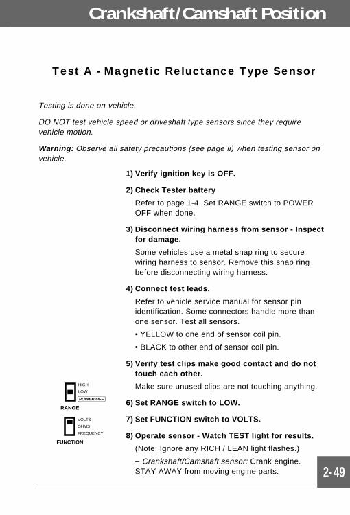
6) Set RANGE switch to LOW.
7) Set FUNCTION switch to VOLTS.
8) Operate sensor - Watch TEST light for results.
(Note: Ignore any RICH / LEAN light flashes.)
– Crankshaft/Camshaft sensor: Crank engine.STAY AWAY from moving engine parts.
RANGE
HIGH
LOW
POWER OFF
FUNCTION
VOLTS
OHMS
FREQUENCY
Crankshaft/Camshaft Position
2-50
Testing SensorsSection 2
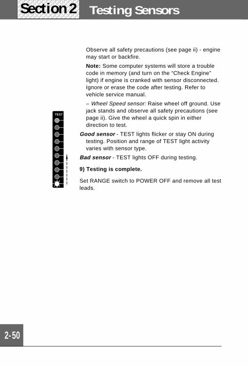
Observe all safety precautions (see page ii) - enginemay start or backfire.
Note: Some computer systems will store a troublecode in memory (and turn on the “Check Engine”light) if engine is cranked with sensor disconnected.Ignore or erase the code after testing. Refer tovehicle service manual.
– Wheel Speed sensor: Raise wheel off ground. Usejack stands and observe all safety precautions (seepage ii). Give the wheel a quick spin in eitherdirection to test.
Good sensor - TEST lights flicker or stay ON duringtesting. Position and range of TEST light activityvaries with sensor type.
Bad sensor - TEST lights OFF during testing.
9) Testing is complete.
Set RANGE switch to POWER OFF and remove all testleads.
TEST
2-51
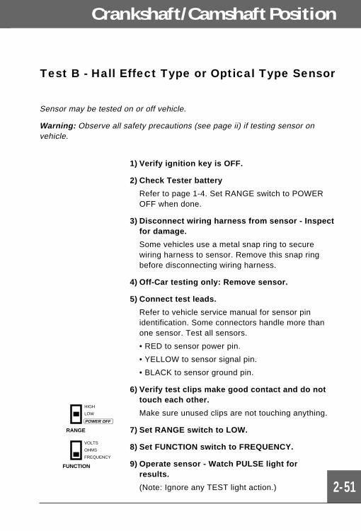
Test B - Hall Effect Type or Optical Type Sensor
Sensor may be tested on or off vehicle.
Warning: Observe all safety precautions (see page ii) if testing sensor onvehicle.
1) Verify ignition key is OFF.
2) Check Tester battery
Refer to page 1-4. Set RANGE switch to POWEROFF when done.
3) Disconnect wiring harness from sensor - Inspectfor damage.
Some vehicles use a metal snap ring to securewiring harness to sensor. Remove this snap ringbefore disconnecting wiring harness.
4) Off-Car testing only: Remove sensor.
5) Connect test leads.
Refer to vehicle service manual for sensor pinidentification. Some connectors handle more thanone sensor. Test all sensors.
• RED to sensor power pin.
• YELLOW to sensor signal pin.
• BLACK to sensor ground pin.
6) Verify test clips make good contact and do nottouch each other.
Make sure unused clips are not touching anything.
7) Set RANGE switch to LOW.
8) Set FUNCTION switch to FREQUENCY.
9) Operate sensor - Watch PULSE light forresults.
(Note: Ignore any TEST light action.)
RANGE
HIGH
LOW
POWER OFF
FUNCTION
VOLTS
OHMS
FREQUENCY
Crankshaft/Camshaft Position
2-52
Testing SensorsSection 2
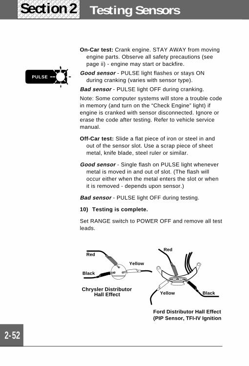
On-Car test: Crank engine. STAY AWAY from movingengine parts. Observe all safety precautions (seepage ii) - engine may start or backfire.
Good sensor - PULSE light flashes or stays ONduring cranking (varies with sensor type).
Bad sensor - PULSE light OFF during cranking.
Note: Some computer systems will store a trouble codein memory (and turn on the “Check Engine” light) ifengine is cranked with sensor disconnected. Ignore orerase the code after testing. Refer to vehicle servicemanual.
Off-Car test: Slide a flat piece of iron or steel in andout of the sensor slot. Use a scrap piece of sheetmetal, knife blade, steel ruler or similar.
Good sensor - Single flash on PULSE light whenevermetal is moved in and out of slot. (The flash willoccur either when the metal enters the slot or whenit is removed - depends upon sensor.)
Bad sensor - PULSE light OFF during testing.
10) Testing is complete.
Set RANGE switch to POWER OFF and remove all testleads.
PULSE
Chrysler DistributorHall Effect
Ford Distributor Hall Effect(PIP Sensor, TFI-IV Ignition
Red
Black
Yellow
Red
Yellow Black
3-1
Section 2
3Section
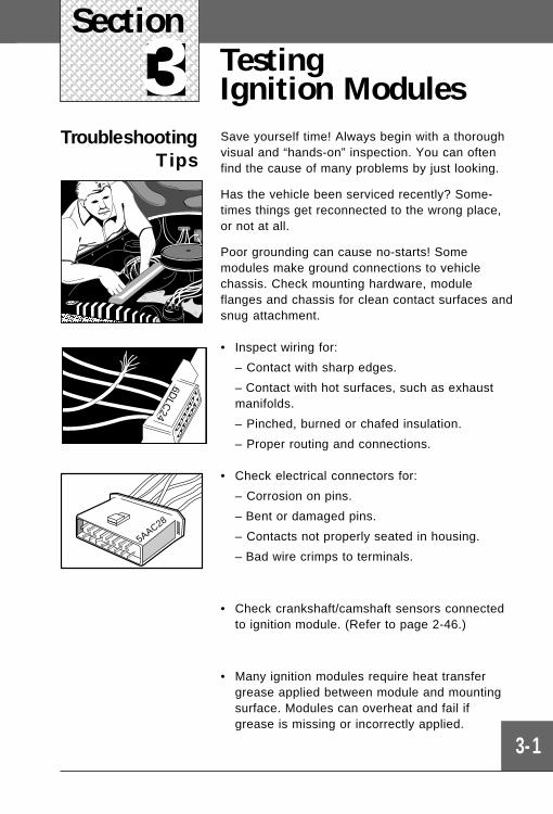
TestingIgnition Modules
TroubleshootingTips
Save yourself time! Always begin with a thoroughvisual and “hands-on” inspection. You can oftenfind the cause of many problems by just looking.
Has the vehicle been serviced recently? Some-times things get reconnected to the wrong place,or not at all.
Poor grounding can cause no-starts! Somemodules make ground connections to vehiclechassis. Check mounting hardware, moduleflanges and chassis for clean contact surfaces andsnug attachment.
• Inspect wiring for:
– Contact with sharp edges.
– Contact with hot surfaces, such as exhaustmanifolds.
– Pinched, burned or chafed insulation.
– Proper routing and connections.
• Check electrical connectors for:
– Corrosion on pins.
– Bent or damaged pins.
– Contacts not properly seated in housing.
– Bad wire crimps to terminals.
• Check crankshaft/camshaft sensors connectedto ignition module. (Refer to page 2-46.)
• Many ignition modules require heat transfergrease applied between module and mountingsurface. Modules can overheat and fail ifgrease is missing or incorrectly applied.
6DLC
24
5AAC28
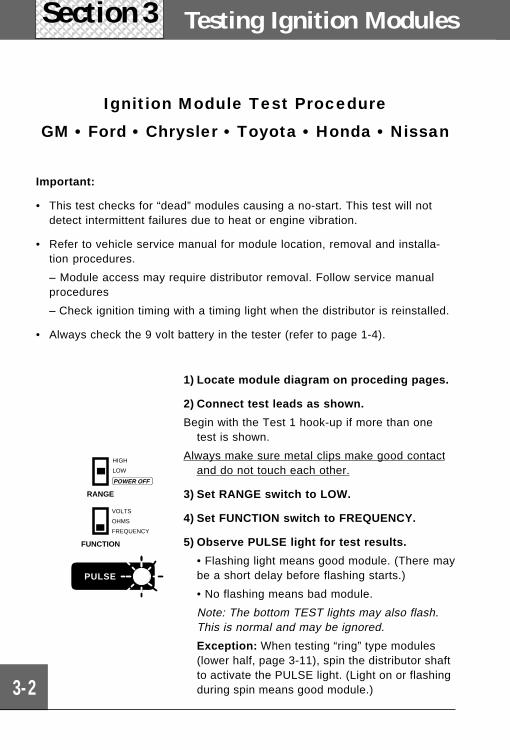
Ignition Module Test Procedure
GM • Ford • Chrysler • Toyota • Honda • Nissan
Important:
• This test checks for “dead” modules causing a no-start. This test will notdetect intermittent failures due to heat or engine vibration.
• Refer to vehicle service manual for module location, removal and installa-tion procedures.
– Module access may require distributor removal. Follow service manualprocedures
– Check ignition timing with a timing light when the distributor is reinstalled.
• Always check the 9 volt battery in the tester (refer to page 1-4).
Testing Ignition Modules
3-2
Section 3
1) Locate module diagram on proceding pages.
2) Connect test leads as shown.
Begin with the Test 1 hook-up if more than onetest is shown.
Always make sure metal clips make good contactand do not touch each other.
3) Set RANGE switch to LOW.
4) Set FUNCTION switch to FREQUENCY.
5) Observe PULSE light for test results.
• Flashing light means good module. (There maybe a short delay before flashing starts.)
• No flashing means bad module.
Note: The bottom TEST lights may also flash.This is normal and may be ignored.
Exception: When testing “ring” type modules(lower half, page 3-11), spin the distributor shaftto activate the PULSE light. (Light on or flashingduring spin means good module.)
RANGE
HIGH
LOW
POWER OFF
FUNCTION
VOLTS
OHMS
FREQUENCY
PULSE
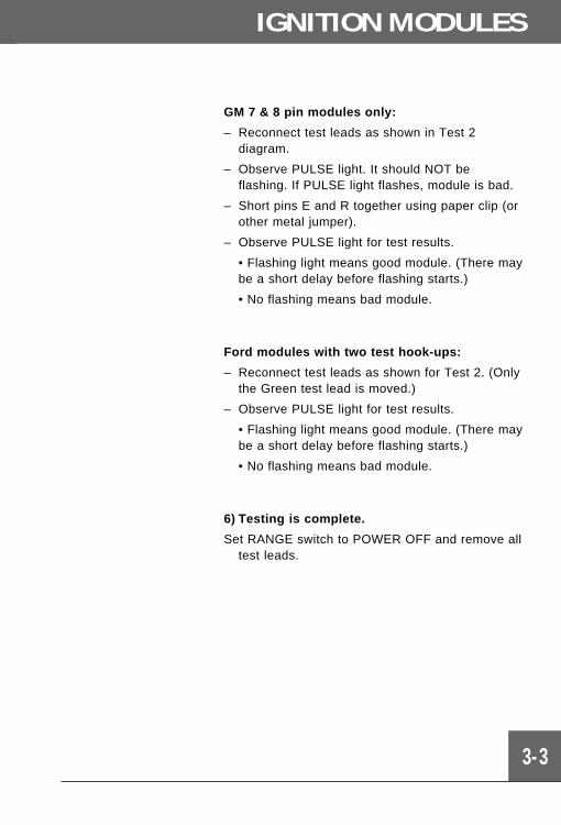
IGNITION MODULES
3-3
GM 7 & 8 pin modules only:
– Reconnect test leads as shown in Test 2diagram.
– Observe PULSE light. It should NOT beflashing. If PULSE light flashes, module is bad.
– Short pins E and R together using paper clip (orother metal jumper).
– Observe PULSE light for test results.
• Flashing light means good module. (There maybe a short delay before flashing starts.)
• No flashing means bad module.
Ford modules with two test hook-ups:
– Reconnect test leads as shown for Test 2. (Onlythe Green test lead is moved.)
– Observe PULSE light for test results.
• Flashing light means good module. (There maybe a short delay before flashing starts.)
• No flashing means bad module.
6) Testing is complete.
Set RANGE switch to POWER OFF and remove alltest leads.
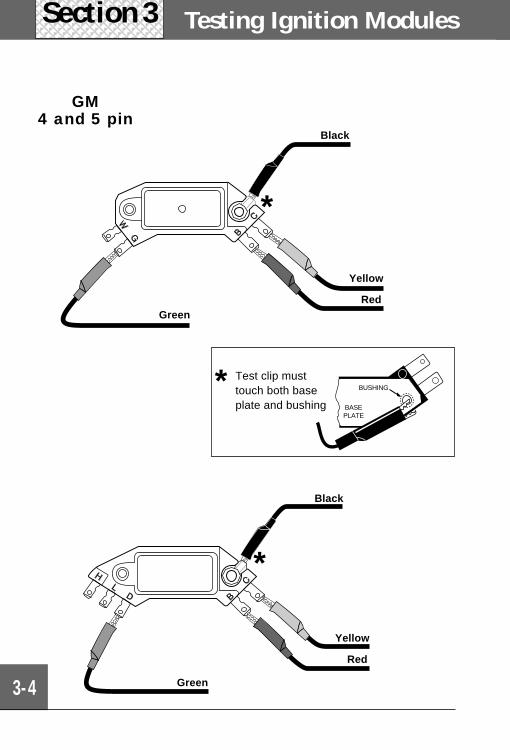
Testing Ignition Modules
3-4
Section 3
GM4 and 5 pin
BASE PLATE
BUSHING* Test clip musttouch both baseplate and bushing
*
*
Yellow
RedGreen
Black
Black
Yellow
Red
Green
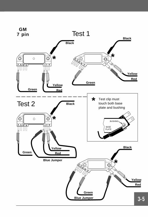
3-5
GM7 pin
*
*
BASE PLATE
BUSHING
Test clip musttouch both baseplate and bushing
*
Black
Yellow
Red
Green
Blue Jumper
Test 2 Black
Yellow
Red
Blue Jumper
* *
Black
Green
Test 1
Yellow
Red
Black
Yellow
RedGreen
Green
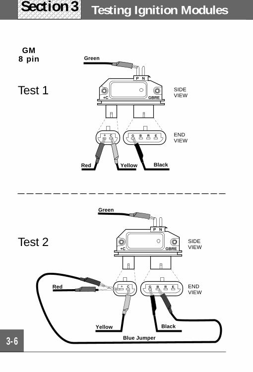
Testing Ignition Modules
3-6
Section 3
GM8 pin
P N
GBRE+C
C G B R E
Test 1
P N
GBRE+C
C G B R E
Test 2
BlackYellowRed
Green
SIDEVIEW
ENDVIEW
Green
SIDEVIEW
ENDVIEW
Yellow
Red
Black
Blue Jumper
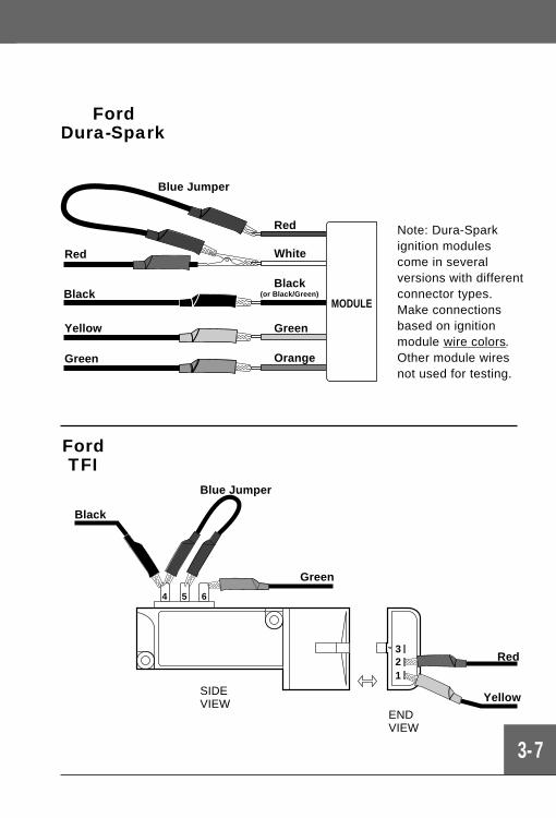
3-7
FordDura-Spark
4 5 6
321
SIDEVIEW
ENDVIEW
Blue Jumper
Green
Red
Yellow
Black
Note: Dura-Sparkignition modulescome in severalversions with differentconnector types.Make connectionsbased on ignitionmodule wire colors.Other module wiresnot used for testing.
FordTFI
Blue Jumper
Black
Yellow
Green
Red
Red
White
Green
Orange
Black(or Black/Green)
MODULE
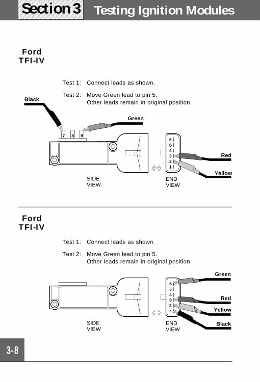
7 8 9654321
Testing Ignition Modules
3-8
Section 3
FordTFI-IV
Test 1: Connect leads as shown.
Test 2: Move Green lead to pin 5.Other leads remain in original position
Yellow
Black
Green
Red
ENDVIEW
SIDEVIEW
Green
ENDVIEW
SIDEVIEW
Red
Yellow
Black
Test 1: Connect leads as shown.
Test 2: Move Green lead to pin 5.Other leads remain in original position
FordTFI-IV
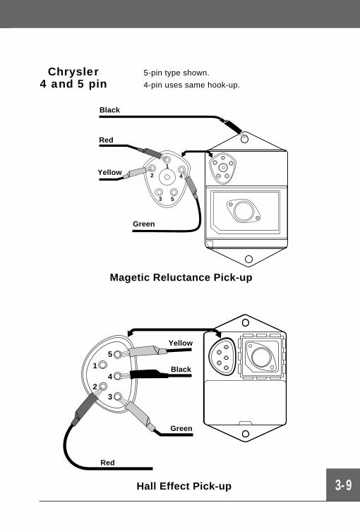
3-9
Chrysler4 and 5 pin
5-pin type shown.
4-pin uses same hook-up.
Magetic Reluctance Pick-up
5
4
32
1
Hall Effect Pick-up
1
2
3 5
4
Red
Black
Red
Yellow
Green
Green
Black
Yellow
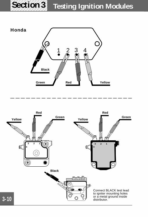
3 2 1
43 2 1
4
Testing Ignition Modules
3-10
Section 3
Red
Black
Yellow
Red
Yellow
1 2 3 4
Honda
Connect BLACK test leadto igniter mounting holesor a metal ground insidedistributor.
Green Red
Black
Yellow
Green Green
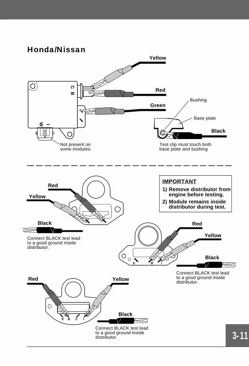
IMPORTANT1) Remove distributor from
engine before testing.2) Module remains inside
distributor during test.
3-11
CB
IW
Connect BLACK test leadto a good ground insidedistributor.
Black
Yellow
Red
E B I
Yellow
Red
Black
Connect BLACK test leadto a good ground insidedistributor.
E B C I
Red Yellow
Black
Connect BLACK test leadto a good ground insidedistributor.
Red
Test clip must touch bothbase plate and bushing
Black
Yellow
Green
Honda/Nissan
Not present onsome modules.
Bushing
Base plate
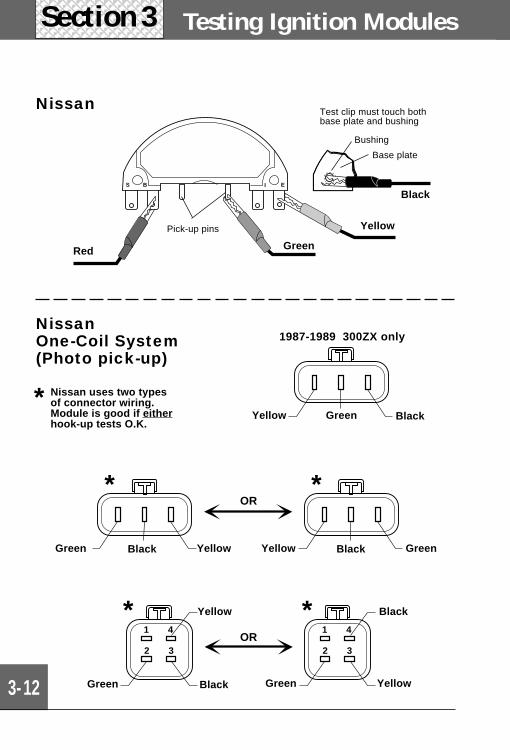
S B I E
Testing Ignition Modules
3-12
Section 3
Nissan
NissanOne-Coil System(Photo pick-up)
Nissan uses two typesof connector wiring.Module is good if eitherhook-up tests O.K.
*
Black
Base plate
Test clip must touch bothbase plate and bushing
Bushing
Yellow
Red
1987-1989 300ZX only
GreenYellow Black
1 4
2 3
1 4
2 3
* *
**
OR
OR
Yellow Black GreenBlackGreen Yellow
BlackGreen
Yellow
Green Yellow
Black
Pick-up pins
Green
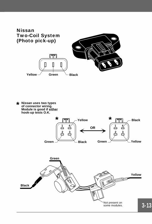
3-13
NissanTwo-Coil System(Photo pick-up)
Not present onsome modules.
GreenYellow Black
1 4
2 3
1 4
2 3
**OR
BlackGreen
Yellow
Green Yellow
Black
Nissan uses two typesof connector wiring.Module is good if eitherhook-up tests O.K.
*
Yellow
Green
Black
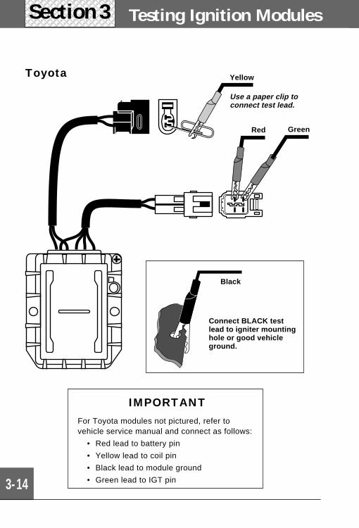
Testing Ignition Modules
3-14
Section 3
Toyota
IMPORTANTFor Toyota modules not pictured, refer tovehicle service manual and connect as follows:
• Red lead to battery pin
• Yellow lead to coil pin
• Black lead to module ground
• Green lead to IGT pin
Red
Yellow
Green
Black
Connect BLACK testlead to igniter mountinghole or good vehicleground.
Use a paper clip toconnect test lead.
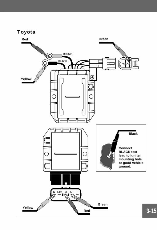
BLACK
C Ext B I, T F
BROWN
3-15
Toyota
Black
Red
Yellow
Green
ConnectBLACK testlead to ignitermounting holeor good vehicleground.
RedYellow
Green
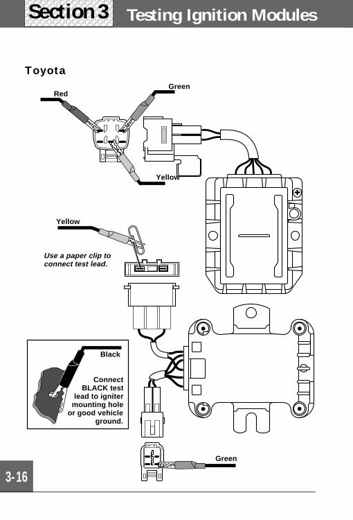
Testing Ignition Modules
3-16
Section 3
ToyotaGreen
Red
Yellow
Use a paper clip toconnect test lead.
Yellow
Green
ConnectBLACK test
lead to ignitermounting hole
or good vehicleground.
Black
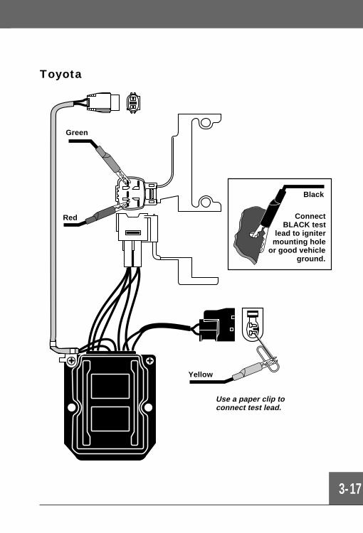
3-17
Toyota
Green
Red ConnectBLACK test
lead to ignitermounting hole
or good vehicleground.
Use a paper clip toconnect test lead.
Yellow
Black
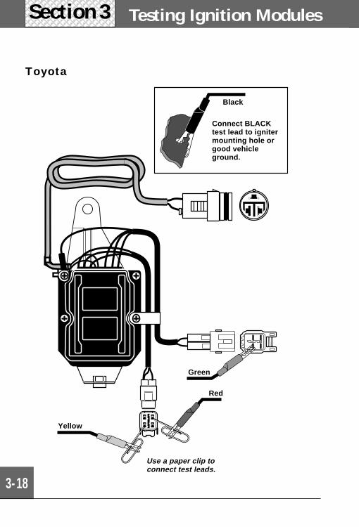
Testing Ignition Modules
3-18
Section 3
Toyota
Black
Green
Red
Yellow
Connect BLACKtest lead to ignitermounting hole orgood vehicleground.
Use a paper clip toconnect test leads.
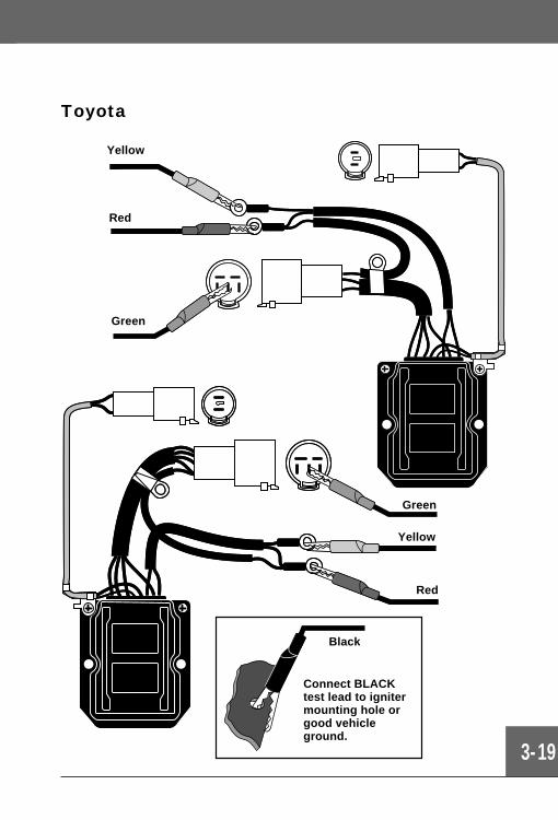
3-19
Toyota
Yellow
Red
Green
Yellow
Red
Green
Connect BLACKtest lead to ignitermounting hole orgood vehicleground.
Black
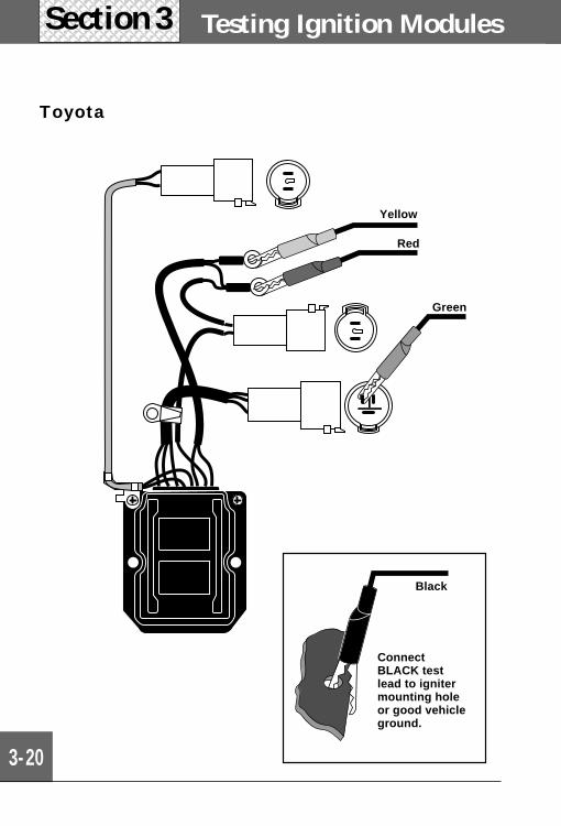
Testing Ignition Modules
3-20
Section 3
Toyota
Yellow
Green
Red
Black
ConnectBLACK testlead to ignitermounting holeor good vehicleground.
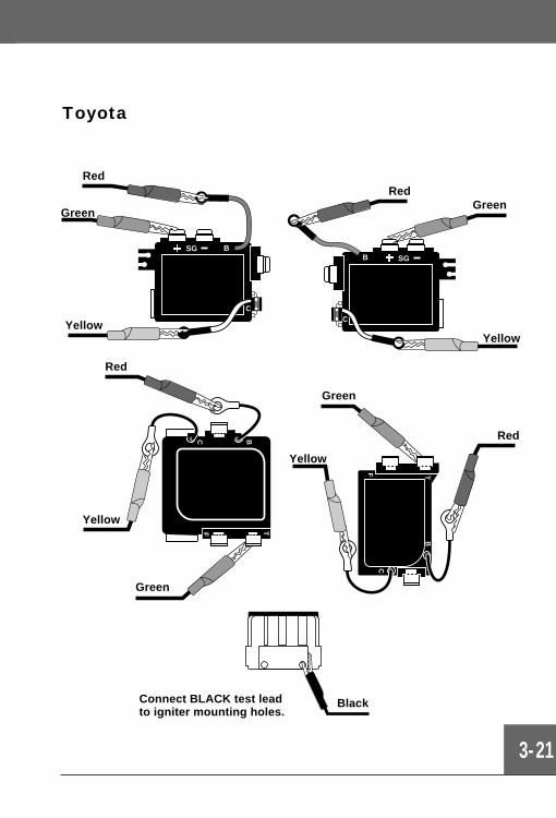
3-21
Toyota
C
+
SGB
C
+
SG B
T
B
C
F
BC
TF
BlackConnect BLACK test leadto igniter mounting holes.
Yellow
Green
Red
Yellow
RedGreen
Red
Yellow
Green
Yellow
Green
Red

3-22
Notes
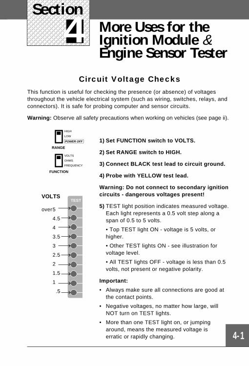
4-1
Section 2
4Section
More Uses for theIgnition Module &Engine Sensor Tester
Circuit Voltage ChecksThis function is useful for checking the presence (or absence) of voltagesthroughout the vehicle electrical system (such as wiring, switches, relays, andconnectors). It is safe for probing computer and sensor circuits.
Warning: Observe all safety precautions when working on vehicles (see page ii).
1) Set FUNCTION switch to VOLTS.
2) Set RANGE switch to HIGH.
3) Connect BLACK test lead to circuit ground.
4) Probe with YELLOW test lead.
Warning: Do not connect to secondary ignitioncircuits - dangerous voltages present!
5) TEST light position indicates measured voltage.Each light represents a 0.5 volt step along aspan of 0.5 to 5 volts.
• Top TEST light ON - voltage is 5 volts, orhigher.
• Other TEST lights ON - see illustration forvoltage level.
• All TEST lights OFF - voltage is less than 0.5volts, not present or negative polarity.
Important:
• Always make sure all connections are good atthe contact points.
• Negative voltages, no matter how large, willNOT turn on TEST lights.
• More than one TEST light on, or jumpingaround, means the measured voltage iserratic or rapidly changing.
RANGE
HIGH
LOW
POWER OFF
FUNCTION
VOLTS
OHMS
FREQUENCY
TESTVOLTS
over5
4.5
4
3.5
3
2.5
2
1.5
1
.5
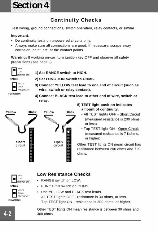
Section 4
4-2
Continuity ChecksTest wiring, ground connections, switch operation, relay contacts, or similar.
Important :• Do continuity tests on unpowered circuits only.• Always make sure all connections are good. If necessary, scrape away
corrosion, paint, etc. at the contact points.
Warning: If working on-car, turn ignition key OFF and observe all safetyprecautions (see page ii).
1) Set RANGE switch to HIGH.
2) Set FUNCTION switch to OHMS.
3) Connect YELLOW test lead to one end of circuit (such aswire, switch or relay contact).
4) Connect BLACK test lead to other end of wire, switch orrelay.
RANGE
HIGH
LOW
POWER OFF
FUNCTION
VOLTS
OHMS
FREQUENCY
5) TEST light position indicatesamount of continuity.• All TEST lights OFF - Short Circuit
(measured resistance is 200 ohms,or less).
• Top TEST light ON - Open Circuit(measured resistance is 7 Kohms,or higher).
Other TEST lights ON mean circuit hasresistance between 200 ohms and 7 Kohms.
Low Resistance Checks• RANGE switch on LOW.
• FUNCTION switch on OHMS.
• Use YELLOW and BLACK test leads.All TEST lights OFF - resistance is 30 ohms, or less.Top TEST light ON - resistance is 300 ohms, or higher.
Other TEST lights ON mean resistance is between 30 ohms and300 ohms.
TEST TEST
Yellow
Shortcircuit
Yellow
Opencircuit
Black Black
FUNCTION
VOLTS
OHMS
FREQUENCY
RANGE
HIGH
LOW
POWER OFF
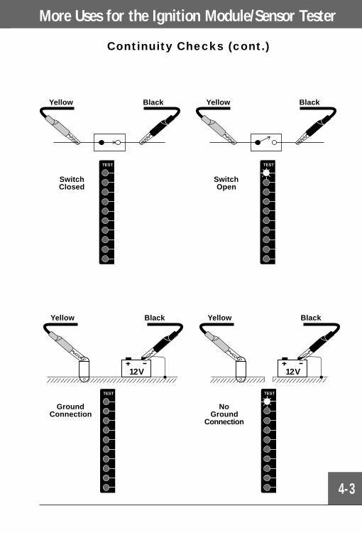
More Uses for the Ignition Module/Sensor Tester
4-3
Continuity Checks (cont.)
12V 12V
TEST TEST
Yellow Black Yellow Black
GroundConnection
NoGround
Connection
TEST TEST
Yellow Black Yellow Black
SwitchClosed
SwitchOpen
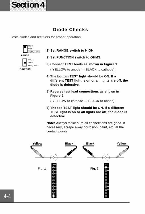
Section 4
4-4
Diode ChecksTests diodes and rectifiers for proper operation.
1) Set RANGE switch to HIGH.
2) Set FUNCTION switch to OHMS.
3) Connect TEST leads as shown in Figure 1.
( YELLOW to anode — BLACK to cathode)
4) The bottom TEST light should be ON. If adifferent TEST light is on or all lights are off, thediode is defective.
5) Reverse test lead connections as shown inFigure 2.
( YELLOW to cathode — BLACK to anode)
6) The top TEST light should be ON. If a differentTEST light is on or all lights are off, the diode isdefective.
Note: Always make sure all connections are good. Ifnecessary, scrape away corrosion, paint, etc. at thecontact points.
FUNCTION
VOLTS
OHMS
FREQUENCY
RANGE
HIGH
LOW
POWER OFF
TESTTEST
Yellow Black
Fig. 2Fig. 1
Black Yellow
Actron ManufacturingCompany9999 Walford AvenueCleveland, Ohio 44102-4621USA
Tel: +1-261-651-9200Fax: +1-216-651-2853
Product Information & Repair
Customer Service Centers
Actron - EuropeCoppen Road, Dagenham,Essex RM8 1NUUNITED KINGDOM
Tel: +44-(0)181-984-8855Fax: +44-(0)181-984-8866
Product Information & Repair
Actron - Europe60 Rte de St Gemme78860 St NOM LA BRETECHEFRANCE
Tel: +33-1-30802205Fax: +33-1 30802182
Product Information Only
FULL ONE (1) YEAR WARRANTYActron Manufacturing Company, 9999 Walford Avenue, Cleveland, Ohio 44102-4621, USA warrants to the user that this unit will be free of defects in materials andworkmanship for a period of one (1) year from the date of original purchase. Any unitthat fails within this period will be repaired without charge when returned to anauthorized factory repair center. Actron requests that a copy of the original, datedsales receipt be returned with the unit to determine if the warranty period is still ineffect. This warranty does not apply to damages caused by accident, alterations orimproper or unreasonable use. Expendable items, such as batteries, fuses, lampbulbs and flash tubes are also excluded from the scope of this warranty. ActronManufacturing Company disclaims any liability for incidental or consequential dam-ages for breach of any written warranty on the unit. Some states do not allow thedisclaimer of liability for incidental or consequential damages, so the above dis-claimer may not apply to you. This warranty gives you specific legal rights and youmay also have rights which vary from state to state.
All information, illustrations and specifications contained in this manual are based onthe latest information available from industry sources at the time of publication. Nowarranty (expressed or implied) can be made for its accuracy or completeness, noris any responsibility assumed by Actron Manufacturing Company or anyone con-nected with it for loss or damages suffered through reliance on any informationcontained in this manual or misuse of the accompanying product. Actron Manufac-turing Company reserves the right to make changes at any time to this manual oraccompanying product without obligation to notify any person or organization of suchchanges.
Warranty(Garantia)

Actron Manufacturing Company 9999 Walford Avenue Cleveland, Ohio 44102-4696 ©1997, Actron Manufacturing Company
Made in the U.S.A. Part No. 2-221301
®