Embed Size (px)
Citation preview
T.B. Skaali, Department of Physics, University of Oslo
FYS 4220 / 9220 – 2011 / #8
Real Time and Embedded Data Systems and Computing
Real-Time / Embedded facilities
T.B. Skaali, Department of Physics, University of Oslo 2FYS 4220 / 9220 - 2011 - Lecture #8
Real-Time / Embedded facilities
• The lecture will discuss the following software and hardware facilities for building Real-time and embedded systems:– Clocks and time
• timer• watchdog• VxWorks timex
– Instrumentation/bus/interconnect systems– I/O
T.B. Skaali, Department of Physics, University of Oslo
CLOCKS
3FYS 4220 / 9220 - 2011 - Lecture #8
T.B. Skaali, Department of Physics, University of Oslo 4FYS 4220 / 9220 - 2011 - Lecture #8
Real-Time clock and time facilities
• Interfacing to the passage of time of ”the real world” is through ”Clocks”– Absolute and relative time– Global time UTC– Delays– Timeouts
• Timing requirements:– Periodic execution of processes– Deadlines
• Timers and watchdogs• Synchronization
T.B. Skaali, Department of Physics, University of Oslo 5FYS 4220 / 9220 - 2011 - Lecture #8
Clocks, POSIX, time.h (1/3)
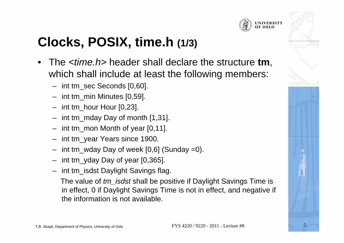
• The <time.h> header shall declare the structure tm, which shall include at least the following members:– int tm_sec Seconds [0,60]. – int tm_min Minutes [0,59]. – int tm_hour Hour [0,23]. – int tm_mday Day of month [1,31]. – int tm_mon Month of year [0,11]. – int tm_year Years since 1900. – int tm_wday Day of week [0,6] (Sunday =0). – int tm_yday Day of year [0,365]. – int tm_isdst Daylight Savings flag.
The value of tm_isdst shall be positive if Daylight Savings Time is in effect, 0 if Daylight Savings Time is not in effect, and negative if the information is not available.
T.B. Skaali, Department of Physics, University of Oslo 6FYS 4220 / 9220 - 2011 - Lecture #8
Clocks, POSIX, time.h (2/3)
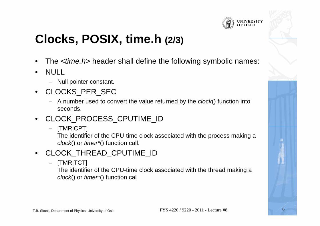
• The <time.h> header shall define the following symbolic names:• NULL
– Null pointer constant.
• CLOCKS_PER_SEC– A number used to convert the value returned by the clock() function into
seconds.
• CLOCK_PROCESS_CPUTIME_ID– [TMR|CPT]
The identifier of the CPU-time clock associated with the process making a clock() or timer*() function call.
• CLOCK_THREAD_CPUTIME_ID– [TMR|TCT]
The identifier of the CPU-time clock associated with the thread making a clock() or timer*() function cal
T.B. Skaali, Department of Physics, University of Oslo 7FYS 4220 / 9220 - 2011 - Lecture #8
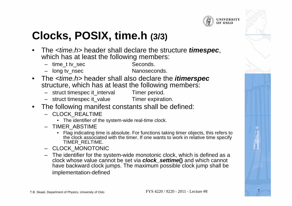
Clocks, POSIX, time.h (3/3)• The <time.h> header shall declare the structure timespec,
which has at least the following members:– time_t tv_sec Seconds. – long tv_nsec Nanoseconds.
• The <time.h> header shall also declare the itimerspecstructure, which has at least the following members:
– struct timespec it_interval Timer period. – struct timespec it_value Timer expiration.
• The following manifest constants shall be defined:– CLOCK_REALTIME
• The identifier of the system-wide real-time clock.– TIMER_ABSTIME
• Flag indicating time is absolute. For functions taking timer objects, this refers to the clock associated with the timer. If one wants to work in relative time specify TIMER_RELTIME.
– CLOCK_MONOTONIC– The identifier for the system-wide monotonic clock, which is defined as a
clock whose value cannot be set via clock_settime() and which cannot have backward clock jumps. The maximum possible clock jump shall be implementation-defined
T.B. Skaali, Department of Physics, University of Oslo
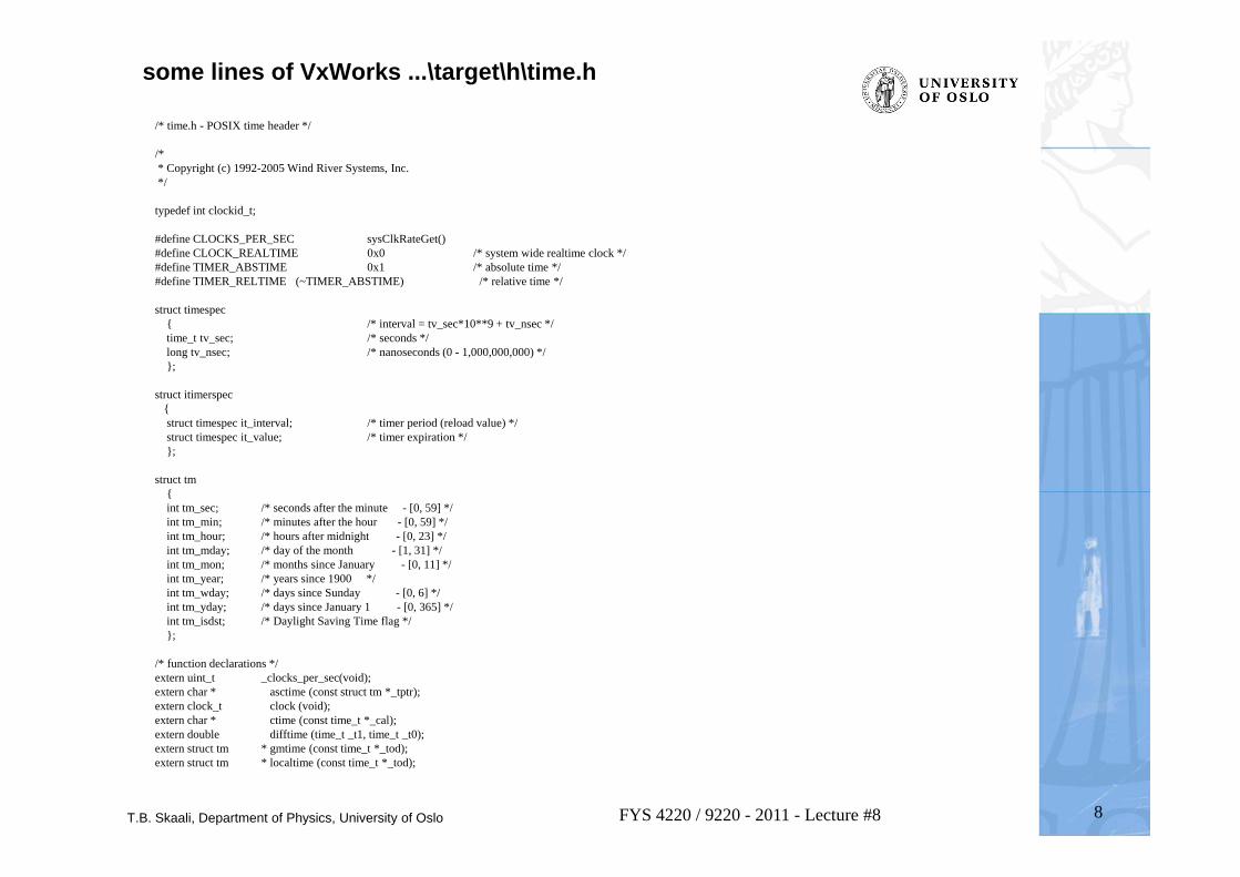
some lines of VxWorks ...\target\h\time.h
8FYS 4220 / 9220 - 2011 - Lecture #8
/* time.h - POSIX time header */
/** Copyright (c) 1992-2005 Wind River Systems, Inc.*/
typedef int clockid_t;
#define CLOCKS_PER_SEC sysClkRateGet()#define CLOCK_REALTIME 0x0 /* system wide realtime clock */#define TIMER_ABSTIME 0x1 /* absolute time */#define TIMER_RELTIME (~TIMER_ABSTIME) /* relative time */
struct timespec{ /* interval = tv_sec*10**9 + tv_nsec */time_t tv_sec; /* seconds */long tv_nsec; /* nanoseconds (0 - 1,000,000,000) */};
struct itimerspec {struct timespec it_interval; /* timer period (reload value) */struct timespec it_value; /* timer expiration */};
struct tm{int tm_sec; /* seconds after the minute - [0, 59] */int tm_min; /* minutes after the hour - [0, 59] */int tm_hour; /* hours after midnight - [0, 23] */int tm_mday; /* day of the month - [1, 31] */int tm_mon; /* months since January - [0, 11] */int tm_year; /* years since 1900 */int tm_wday; /* days since Sunday - [0, 6] */int tm_yday; /* days since January 1 - [0, 365] */int tm_isdst; /* Daylight Saving Time flag */};
/* function declarations */extern uint_t _clocks_per_sec(void);extern char * asctime (const struct tm *_tptr);extern clock_t clock (void);extern char * ctime (const time_t *_cal);extern double difftime (time_t _t1, time_t _t0);extern struct tm * gmtime (const time_t *_tod);extern struct tm * localtime (const time_t *_tod);
T.B. Skaali, Department of Physics, University of Oslo 9FYS 4220 / 9220 - 2011 - Lecture #8
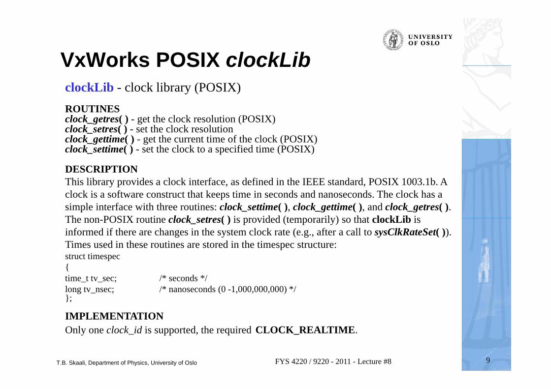
VxWorks POSIX clockLibclockLib - clock library (POSIX) ROUTINESclock_getres( ) - get the clock resolution (POSIX)clock_setres( ) - set the clock resolutionclock_gettime( ) - get the current time of the clock (POSIX)clock_settime( ) - set the clock to a specified time (POSIX)
DESCRIPTIONThis library provides a clock interface, as defined in the IEEE standard, POSIX 1003.1b. A clock is a software construct that keeps time in seconds and nanoseconds. The clock has a simple interface with three routines: clock_settime( ), clock_gettime( ), and clock_getres( ). The non-POSIX routine clock_setres( ) is provided (temporarily) so that clockLib is informed if there are changes in the system clock rate (e.g., after a call to sysClkRateSet( )). Times used in these routines are stored in the timespec structure: struct timespec { time_t tv_sec; /* seconds */ long tv_nsec; /* nanoseconds (0 -1,000,000,000) */ };
IMPLEMENTATION Only one clock_id is supported, the required CLOCK_REALTIME.
T.B. Skaali, Department of Physics, University of Oslo 10FYS 4220 / 9220 - 2011 - Lecture #8
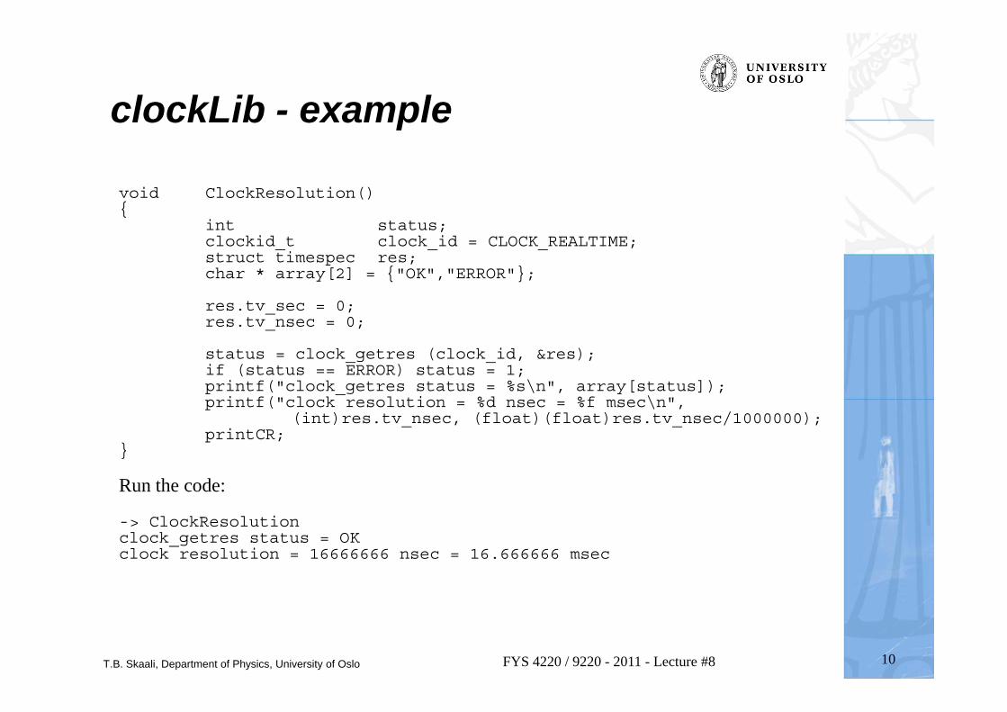
clockLib - example
void ClockResolution(){
int status;clockid_t clock_id = CLOCK_REALTIME;struct timespec res;char * array[2] = {"OK","ERROR"};
res.tv_sec = 0;res.tv_nsec = 0;
status = clock_getres (clock_id, &res);if (status == ERROR) status = 1;printf("clock_getres status = %s\n", array[status]);printf("clock resolution = %d nsec = %f msec\n",
(int)res.tv_nsec, (float)(float)res.tv_nsec/1000000);printCR;
}
Run the code:
-> ClockResolutionclock_getres status = OKclock resolution = 16666666 nsec = 16.666666 msec
T.B. Skaali, Department of Physics, University of Oslo 11FYS 4220 / 9220 - 2011 - Lecture #8
Delays (VxWorks)
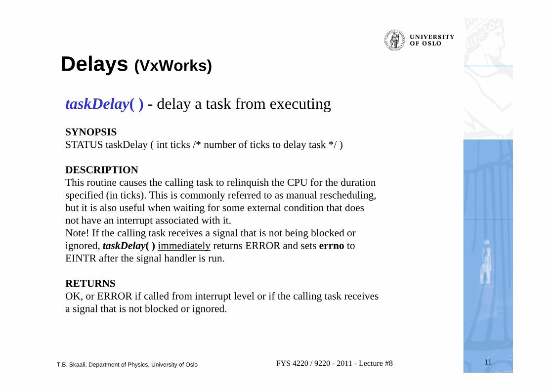
taskDelay( ) - delay a task from executing
SYNOPSISSTATUS taskDelay ( int ticks /* number of ticks to delay task */ )
DESCRIPTIONThis routine causes the calling task to relinquish the CPU for the duration specified (in ticks). This is commonly referred to as manual rescheduling, but it is also useful when waiting for some external condition that does not have an interrupt associated with it. Note! If the calling task receives a signal that is not being blocked or ignored, taskDelay( ) immediately returns ERROR and sets errno to EINTR after the signal handler is run.
RETURNSOK, or ERROR if called from interrupt level or if the calling task receives a signal that is not blocked or ignored.
T.B. Skaali, Department of Physics, University of Oslo 12FYS 4220 / 9220 - 2011 - Lecture #8
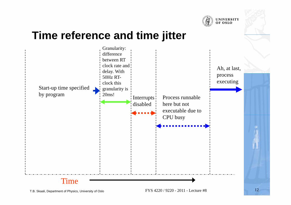
Time reference and time jitter
Start-up time specified by program
Granularity: difference between RT clock rate and delay. With 50Hz RT-clock this granularity is 20ms! Interrupts
disabledProcess runnable here but not executable due to CPU busy
Ah, at last, process executing
Time
T.B. Skaali, Department of Physics, University of Oslo 13FYS 4220 / 9220 - 2011 - Lecture #8
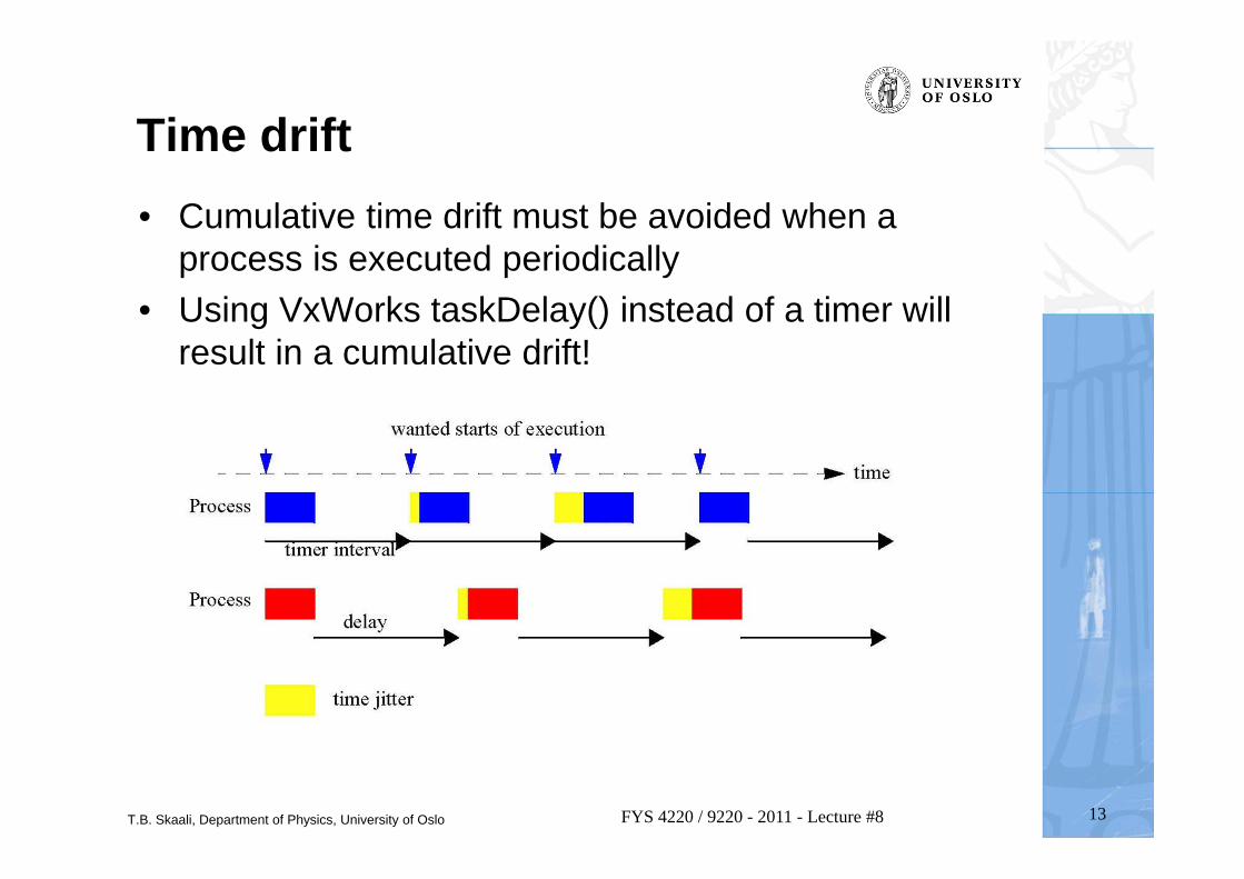
Time drift• Cumulative time drift must be avoided when a
process is executed periodically• Using VxWorks taskDelay() instead of a timer will
result in a cumulative drift!
T.B. Skaali, Department of Physics, University of Oslo 14FYS 4220 / 9220 - 2011 - Lecture #8
POSIX timers (VxWorks)
• The POSIX standard provides for identifying multiple virtual clocks, but only one clock is required--the system-wide real-time clock, identified in the clock and timer routines asCLOCK_REALTIME. VxWorks provides routines to access the system-wide real-time clock; see the reference entry for clockLib. (No virtual clocks are supported in VxWorks.)
• The POSIX timer facility provides routines for tasks to signal themselves at some time in the future. Routines are provided to create, set, connect and delete a timer; see the reference entry for timerLib. When a timer goes off, the default signal (SIGALRM) is sent to the task. sigaction( ) can be used to install a signal handler that executes when the timer expires. Alternatively, timer_connect() can be used.
• An additional POSIX function, nanosleep( ), allows specification of sleep or delay time in units of seconds and nanoseconds
T.B. Skaali, Department of Physics, University of Oslo 15FYS 4220 / 9220 - 2011 - Lecture #8
ROUTINEStimer_cancel ( ) - cancel a timertimer_connect ( ) - connect a user routine to the timer signaltimer_create ( ) - allocate a timer using the specified clock for a timing base (POSIX)timer_delete ( ) - remove a previously created timer (POSIX)timer_gettime ( ) - get the remaining time before expiration and the reload value (POSIX)timer_getoverrun ( ) - return the timer expiration overrun (POSIX)timer_settime ( ) - set the time until the next expiration and arm timer (POSIX)nanosleep ( ) - suspend the current task until the time interval elapses (POSIX)
DESCRIPTIONThis library provides a timer interface, as defined in the IEEE standard, POSIX 1003.1b. Timers are mechanisms by which tasks signal themselves after a designated interval. Timers are built on top of the clock and signal facilities. The clock facility provides an absolute time-base. Standard timer functions simply consist of creation, deletion and setting of a timer. When a timer expires, sigaction ( ) (see sigLib) must be in place in order for the user to handle the event. The "high resolution sleep" facility, nanosleep ( ), allows sub-second sleeping to the resolution of the clock. The clockLib library should be installed and clock_settime ( ) set before the use of any timer routines.
timerLib - timer library (POSIX)
Timer code: see demo program next page
T.B. Skaali, Department of Physics, University of Oslo 16FYS 4220 / 9220 - 2011 - Lecture #8
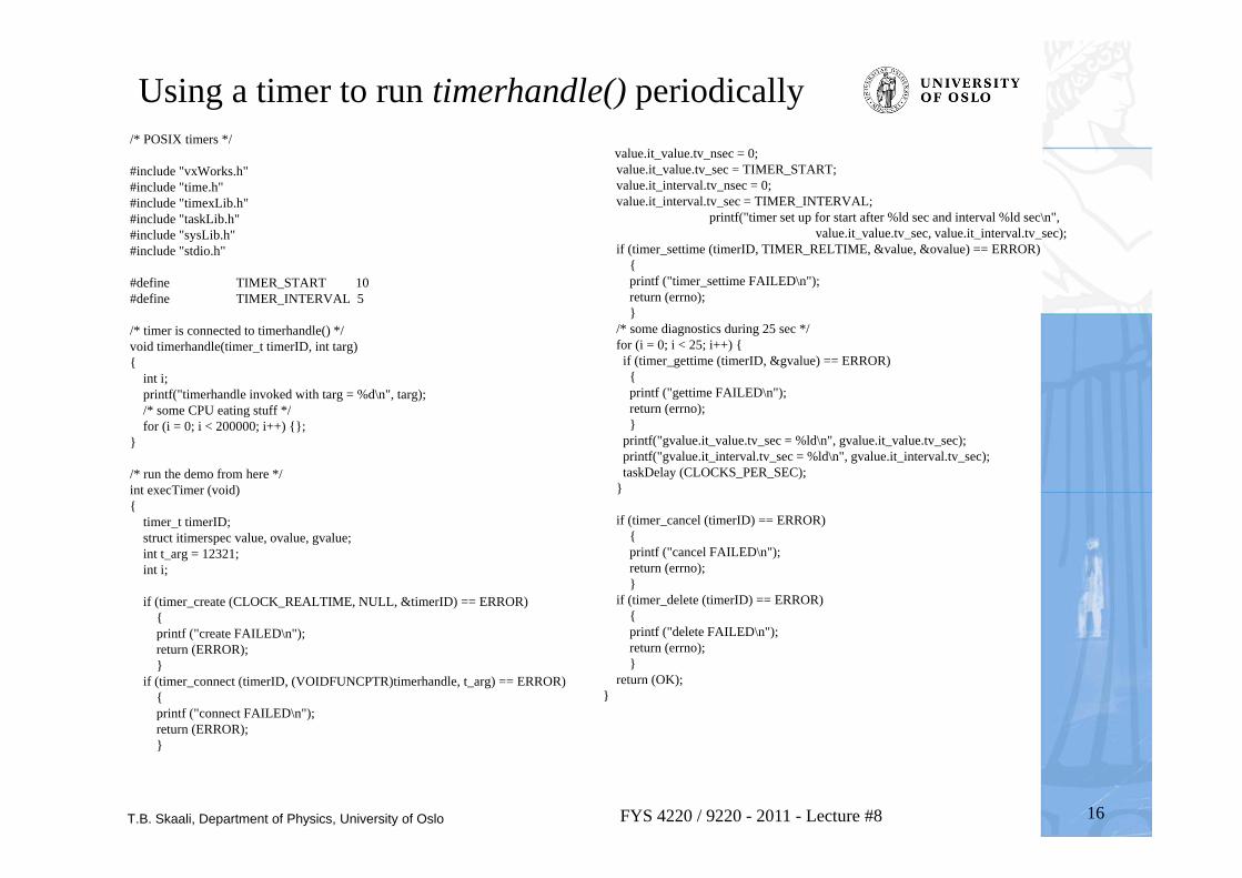
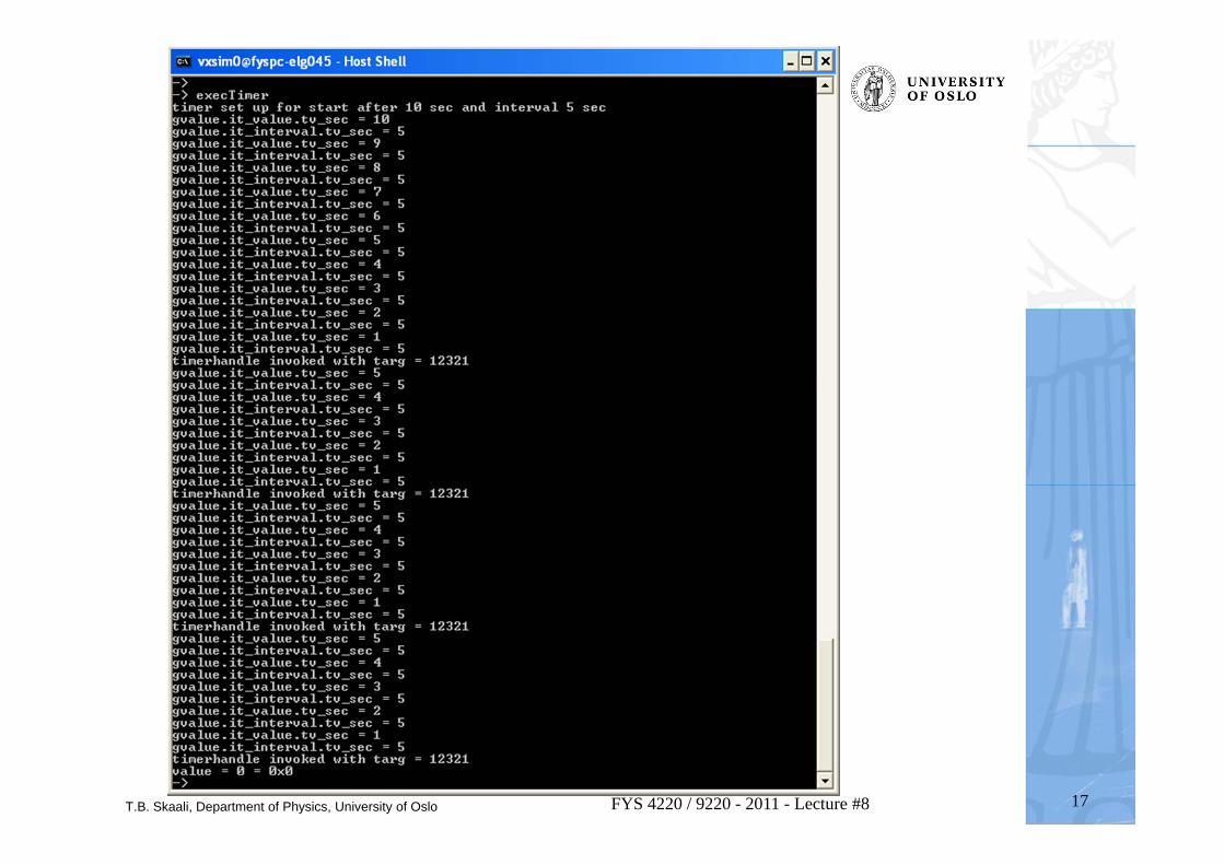
/* POSIX timers */
#include "vxWorks.h" #include "time.h"#include "timexLib.h"#include "taskLib.h"#include "sysLib.h"#include "stdio.h"
#define TIMER_START 10#define TIMER_INTERVAL 5
/* timer is connected to timerhandle() */void timerhandle(timer_t timerID, int targ){
int i;printf("timerhandle invoked with targ = %d\n", targ);/* some CPU eating stuff */for (i = 0; i < 200000; i++) {};
}
/* run the demo from here */int execTimer (void){
timer_t timerID;struct itimerspec value, ovalue, gvalue;int t_arg = 12321;int i;
if (timer_create (CLOCK_REALTIME, NULL, &timerID) == ERROR) { printf ("create FAILED\n"); return (ERROR); }
if (timer_connect (timerID, (VOIDFUNCPTR)timerhandle, t_arg) == ERROR){ printf ("connect FAILED\n"); return (ERROR); }
value.it_value.tv_nsec = 0;value.it_value.tv_sec = TIMER_START;value.it_interval.tv_nsec = 0;value.it_interval.tv_sec = TIMER_INTERVAL;
printf("timer set up for start after %ld sec and interval %ld sec\n",value.it_value.tv_sec, value.it_interval.tv_sec);
if (timer_settime (timerID, TIMER_RELTIME, &value, &ovalue) == ERROR){ printf ("timer_settime FAILED\n"); return (errno); }
/* some diagnostics during 25 sec */for (i = 0; i < 25; i++) {if (timer_gettime (timerID, &gvalue) == ERROR){ printf ("gettime FAILED\n"); return (errno); }
printf("gvalue.it_value.tv_sec = %ld\n", gvalue.it_value.tv_sec);printf("gvalue.it_interval.tv_sec = %ld\n", gvalue.it_interval.tv_sec);taskDelay (CLOCKS_PER_SEC);
}
if (timer_cancel (timerID) == ERROR){ printf ("cancel FAILED\n"); return (errno); }
if (timer_delete (timerID) == ERROR){printf ("delete FAILED\n"); return (errno);}
return (OK);}
Using a timer to run timerhandle() periodically
T.B. Skaali, Department of Physics, University of Oslo 17FYS 4220 / 9220 - 2011 - Lecture #8
T.B. Skaali, Department of Physics, University of Oslo 18FYS 4220 / 9220 - 2011 - Lecture #8
Watchdogs (voff-voff)
• “Watchdog” stands for a periodic activation of a process which gives a signal, for instance by lighting up a lamp, to show that a system is alive and operates correctly
• VxWorks includes a watchdog-timer mechanism that allows any C function to be connected to a specified time delay. – Watchdog timers are maintained as part of the system clock ISR.
Normally, functions invoked by watchdog timers execute as interrupt service code at the interrupt level of the system clock. However, if the kernel is unable to execute the function immediately for any reason (such as a previous interrupt or kernel state), the function is placed on the tExcTask work queue. Functions on the tExcTask work queue execute at the priority level of the tExcTask (usually 0). Restrictions on ISRs apply to routines connected to watchdog timers
– Demo: see code next page
T.B. Skaali, Department of Physics, University of Oslo 19FYS 4220 / 9220 - 2011 - Lecture #8
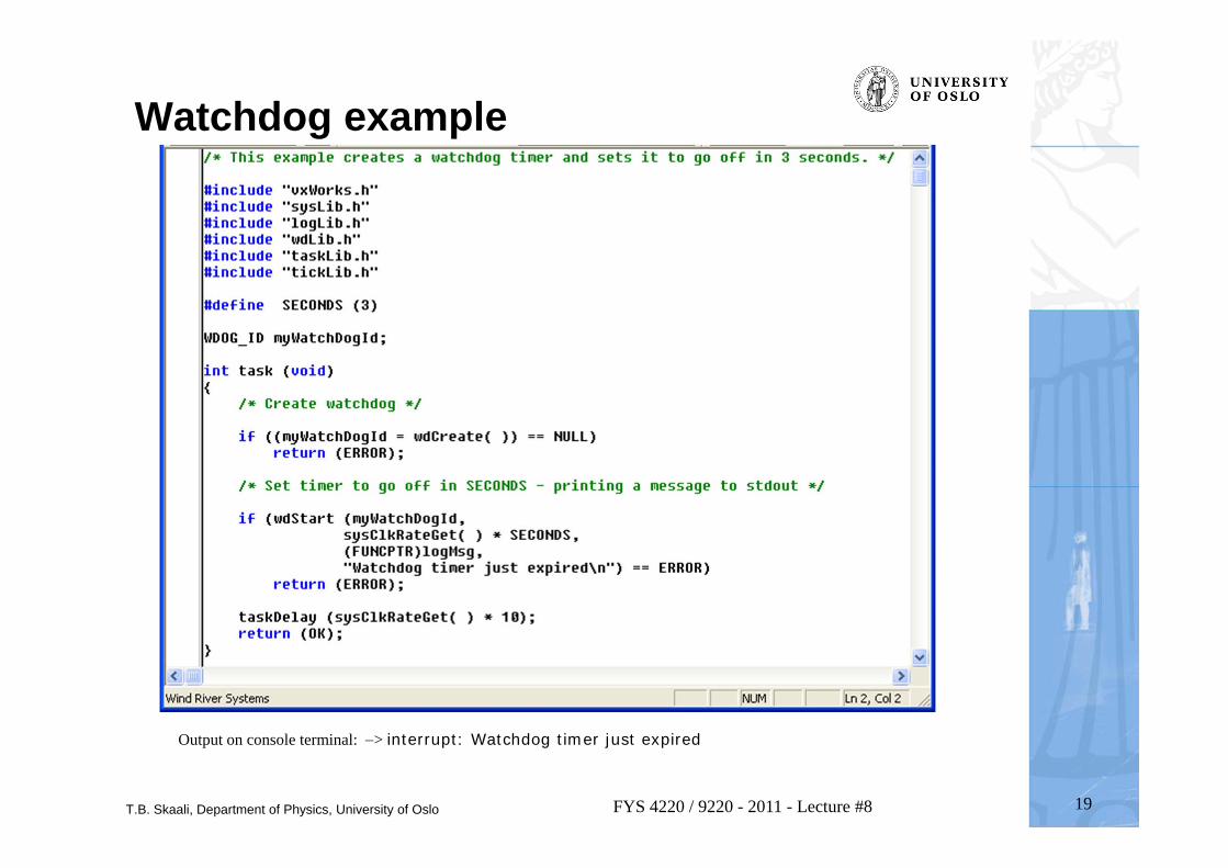
Watchdog example
Output on console terminal: > interrupt: Watchdog timer just expired
T.B. Skaali, Department of Physics, University of Oslo
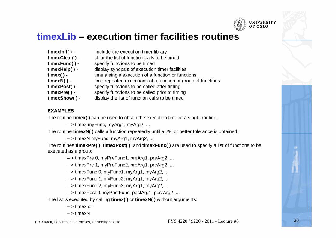
timexLib – execution timer facilities routinestimexInit( ) - include the execution timer librarytimexClear( ) - clear the list of function calls to be timedtimexFunc( ) - specify functions to be timedtimexHelp( ) - display synopsis of execution timer facilitiestimex( ) - time a single execution of a function or functionstimexN( ) - time repeated executions of a function or group of functionstimexPost( ) - specify functions to be called after timingtimexPre( ) - specify functions to be called prior to timingtimexShow( ) - display the list of function calls to be timed
EXAMPLESThe routine timex( ) can be used to obtain the execution time of a single routine:
– > timex myFunc, myArg1, myArg2, ... The routine timexN( ) calls a function repeatedly until a 2% or better tolerance is obtained:
– > timexN myFunc, myArg1, myArg2, ... The routines timexPre( ), timexPost( ), and timexFunc( ) are used to specify a list of functions to be executed as a group:
– > timexPre 0, myPreFunc1, preArg1, preArg2, ... – > timexPre 1, myPreFunc2, preArg1, preArg2, ... – > timexFunc 0, myFunc1, myArg1, myArg2, ... – > timexFunc 1, myFunc2, myArg1, myArg2, ... – > timexFunc 2, myFunc3, myArg1, myArg2, ... – > timexPost 0, myPostFunc, postArg1, postArg2, ...
The list is executed by calling timex( ) or timexN( ) without arguments: – > timex or – > timexN
20FYS 4220 / 9220 - 2011 - Lecture #8
T.B. Skaali, Department of Physics, University of Oslo
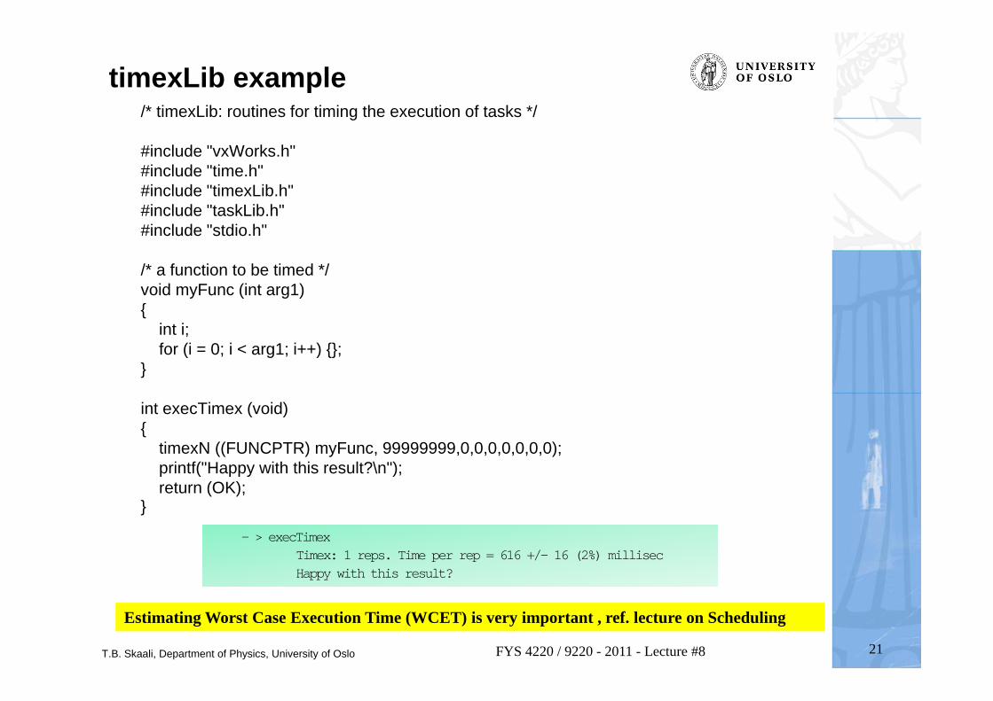
timexLib example/* timexLib: routines for timing the execution of tasks */
#include "vxWorks.h" #include "time.h"#include "timexLib.h"#include "taskLib.h"#include "stdio.h"
/* a function to be timed */void myFunc (int arg1){
int i;for (i = 0; i < arg1; i++) {};
}
int execTimex (void){
timexN ((FUNCPTR) myFunc, 99999999,0,0,0,0,0,0,0);printf("Happy with this result?\n");return (OK);
}
21FYS 4220 / 9220 - 2011 - Lecture #8
– > execTimexTimex: 1 reps. Time per rep = 616 +/- 16 (2%) millisecHappy with this result?
Estimating Worst Case Execution Time (WCET) is very important , ref. lecture on Scheduling
T.B. Skaali, Department of Physics, University of Oslo 22FYS 4220 / 9220 - 2011 - Lecture #8
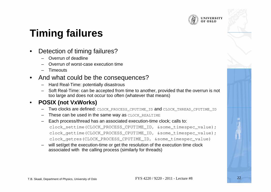
Timing failures• Detection of timing failures?
– Overrun of deadline– Overrun of worst-case execution time– Timeouts
• And what could be the consequences?– Hard Real-Time: potentially disastrous– Soft Real-Time: can be accepted from time to another, provided that the overrun is not
too large and does not occur too often (whatever that means)• POSIX (not VxWorks)
– Two clocks are defined: CLOCK_PROCESS_CPUTIME_ID and CLOCK_THREAD_CPUTIME_ID– These can be used in the same way as CLOCK_REALTIME– Each process/thread has an associated execution-time clock; calls to:
clock_settime(CLOCK_PROCESS_CPUTIME_ID, &some_timespec_value);clock_gettime(CLOCK_PROCESS_CPUTIME_ID, &some_timespec_value);clock_getres(CLOCK_PROCESS_CPUTIME_ID, &some_timespec_value)
– will set/get the execution-time or get the resolution of the execution time clock associated with the calling process (similarly for threads)
T.B. Skaali, Department of Physics, University of Oslo 23FYS 4220 / 9220 - 2011 - Lecture #8
Global timing and synchronization• In wide area or global data acquisiton system one needs access to a
global clock if the registration of data must be time synchronized. The GPS system gives a very high accuracy in the nsec domain
– To obtain this accuracy, the GPS signals are corrected for relativistic effects – However, not all regions on Earth are well covered by GPS
• IEEE 1588 Precision Time Protocol (PTP) [2002, 2008] is a protocol used to synchronize clocks throughout a computer network. On a local area network it achieves clock accuracy in the sub-microsecond range, making it suitable for measurement and control systems.
– IEEE 1588 is designed to fill a niche not well served by either of the two dominant protocols, NTP and GPS. IEEE 1588 is designed for local systems requiring accuracies beyond those attainable using NTP. It is also designed for applications that cannot bear the cost of a GPS receiver at each node, or for which GPS signals are inaccessible.
– The Network Time Protocol (NTP) [1985] is a protocol for synchronizing the clocks of computer systems over packet-switched, variable-latency data networks
T.B. Skaali, Department of Physics, University of Oslo
INTERCONNECTS
24FYS 4220 / 9220 - 2011 - Lecture #8
T.B. Skaali, Department of Physics, University of Oslo 25FYS 4220 / 9220 - 2011 - Lecture #8
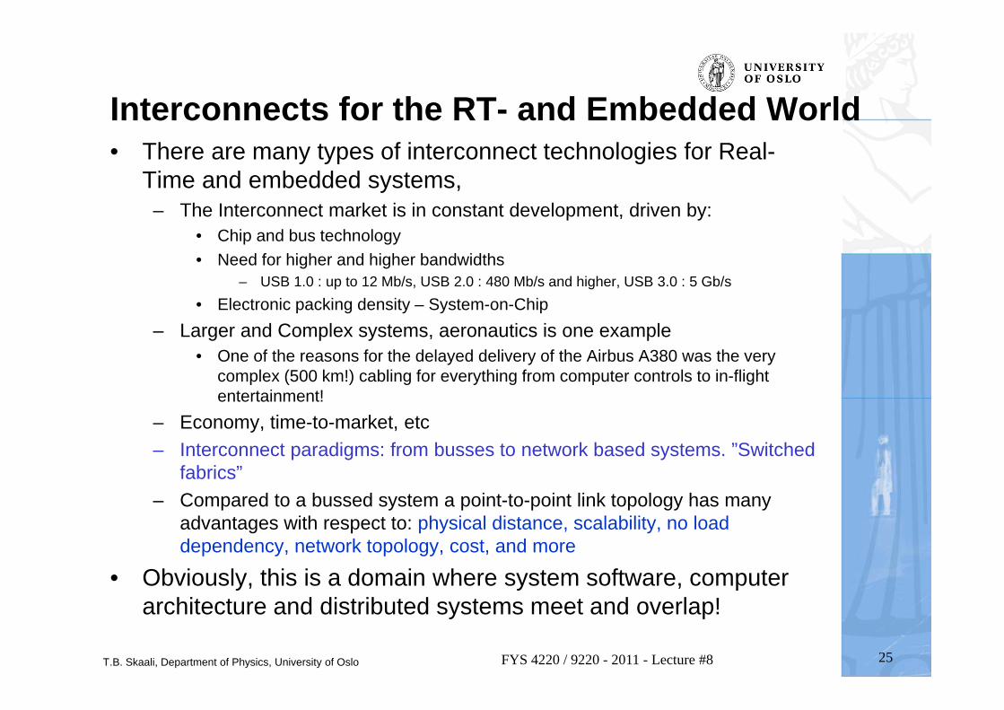
Interconnects for the RT- and Embedded World• There are many types of interconnect technologies for Real-
Time and embedded systems,– The Interconnect market is in constant development, driven by:
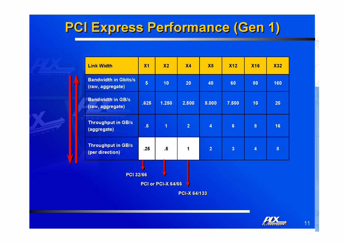
• Chip and bus technology• Need for higher and higher bandwidths
– USB 1.0 : up to 12 Mb/s, USB 2.0 : 480 Mb/s and higher, USB 3.0 : 5 Gb/s• Electronic packing density – System-on-Chip
– Larger and Complex systems, aeronautics is one example• One of the reasons for the delayed delivery of the Airbus A380 was the very
complex (500 km!) cabling for everything from computer controls to in-flight entertainment!
– Economy, time-to-market, etc– Interconnect paradigms: from busses to network based systems. ”Switched
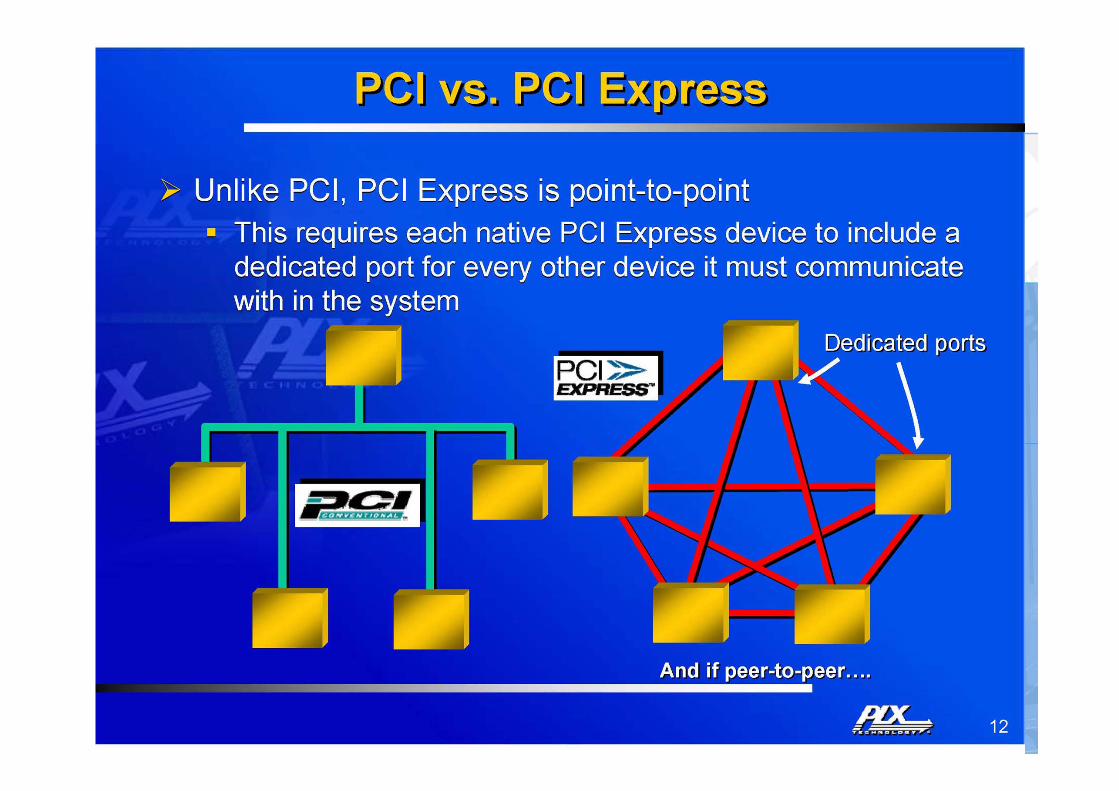
fabrics”– Compared to a bussed system a point-to-point link topology has many
advantages with respect to: physical distance, scalability, no load dependency, network topology, cost, and more
• Obviously, this is a domain where system software, computer architecture and distributed systems meet and overlap!
T.B. Skaali, Department of Physics, University of Oslo
Front-end / Back-end topology
• A typical topology for Real-time systems is a front-end part which handles time critical tasks, such as reading sensor data with first order signal processing, interconnected with a «Back-end» computer, for instance a Linux system. Examples:
• A development board of the type used for the VHDL exercises contains a lot of facilities for Real-Time / Embedded projects:
– On-board FPGA that can run both a soft-core processor and signal processing tasks– Memory of different types, Ethernet, clocks (programmable high resolution timers),
connectors for clock inputs or outputs, small LCD screen, high-speed differential I/O connectors, Digital-to-Analog Converter, Analog-to-Digital Converter, switches, and you name it!
– And the price is very low!
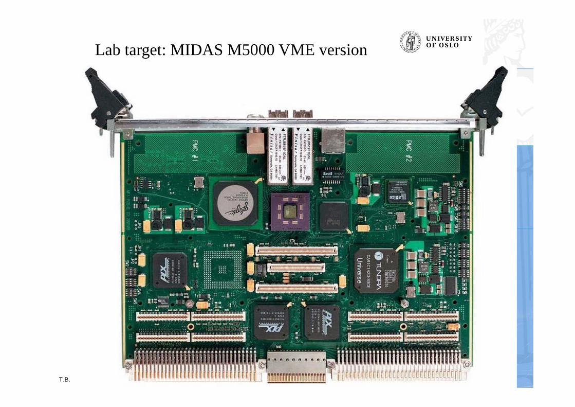
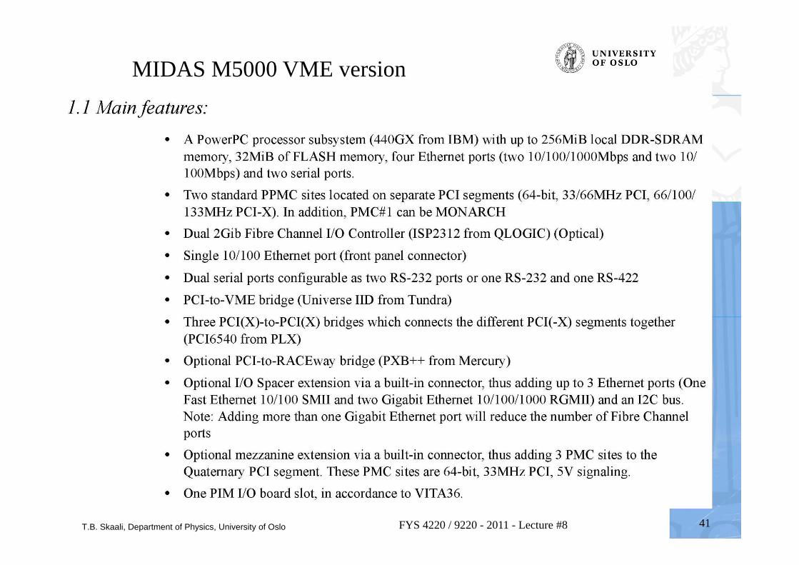
• A high-end Single Board Computer (SBC) like the MIDAS M5000 used in the VxWorks Workbench lab
– This is professional stuff, and only for customes where money does not matter very much– It does not contain on-board AD or DA converters, if needed one can mount PMC
mezzanine card onto the PCI slots (also expensive)
26FYS 4220 / 9220 - 2011 - Lecture #8
T.B. Skaali, Department of Physics, University of Oslo 27FYS 4220 / 9220 - 2011 - Lecture #8
Two bus studies: VME and PCI bus • The original VMEbus is a rather old design, but the VME
technology is still going strong in the high-end (and high cost) market due to:
– Steadily improved performance– Mechanical robustness
• PCI bus is the standard PC peripheral bus– A design for ”plug-and-play”
• Whereas VME is a genuine multi-processor bus with possibility for sofisticated bus arbitration, PCI is what the name says: a Peripheral Component Interconnect
• Together, these two systems represent two interesting case studies
– Ref. paper ”A case for the VMEbus Architecture in Embedded Systems Education”, IEEE Transactions on Education, Vol. 49, No. 3, August 2006
• After an summary of the VME and PCI bus, some other interconnects will be listed
T.B. Skaali, Department of Physics, University of Oslo 28FYS 4220 / 9220 - 2011 - Lecture #8
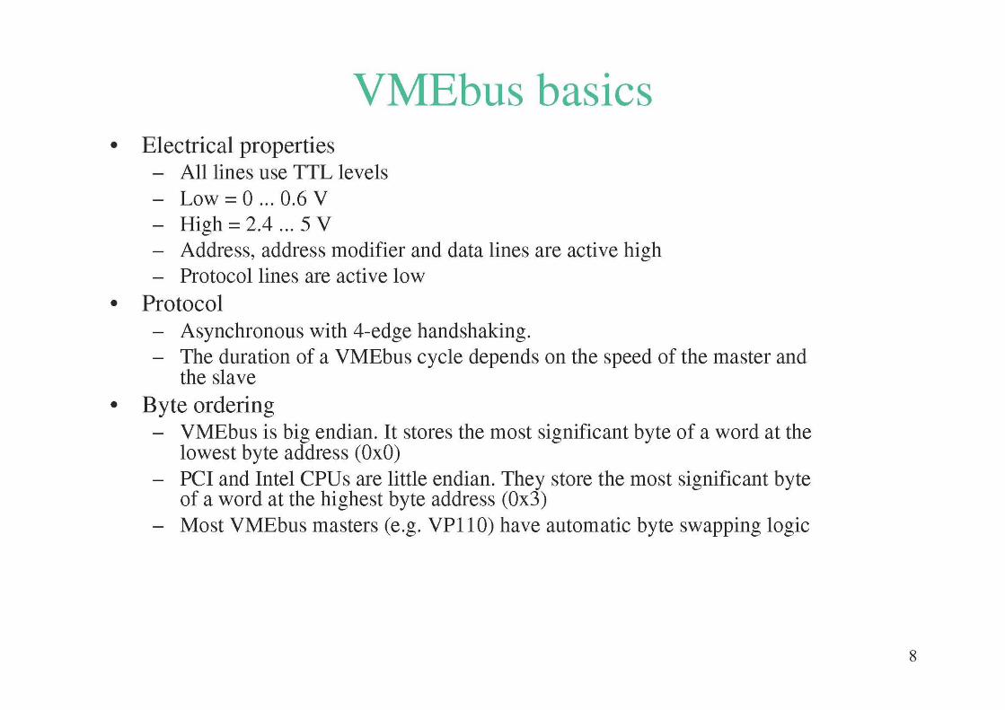
VMEbus basics vs. RT / Embedded systems • Architecture:
– the VMEbus is a computing system architecture consisting of the electrical specifications for a data bus and the mechanical specifications describing the backplane, bus connector, board sizes and enclosures
• developed around 25 years ago by the companies Motorola, Mostek, Signetics and Thomson CSF as a non-proprietary bus
• many extensions and improvements over the years, so despite its age, it is still a widely used platform for architecture for real-time systems
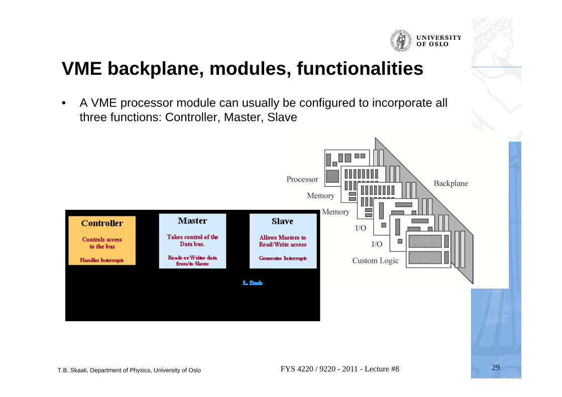
– VMEbus is a shared system-bus architecture. The system bus resides on a backplane. The backplane has slots, 21 for a full 19-inch VME crate, where processor modules, memory modules or I/O modules connect to the bus
• Many vendors provide a wide spectrum of VMEbus modules and components
• Applications:– for the professional market, primarily in industrial, military, aerospace,
communication and control applications, in particular where robustness is required– however, rather expensive, and power hungry
• VITA– a non-profit organization for real-time and embedded computing systems
http://www.vita.com
T.B. Skaali, Department of Physics, University of Oslo 29FYS 4220 / 9220 - 2011 - Lecture #8
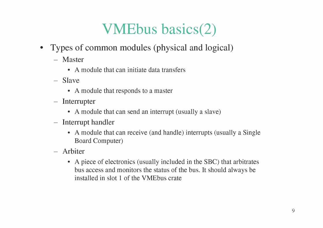
VME backplane, modules, functionalities• A VME processor module can usually be configured to incorporate all
three functions: Controller, Master, Slave
T.B. Skaali, Department of Physics, University of Oslo 30FYS 4220 / 9220 - 2011 - Lecture #8
T.B. Skaali, Department of Physics, University of Oslo 31FYS 4220 / 9220 - 2011 - Lecture #8
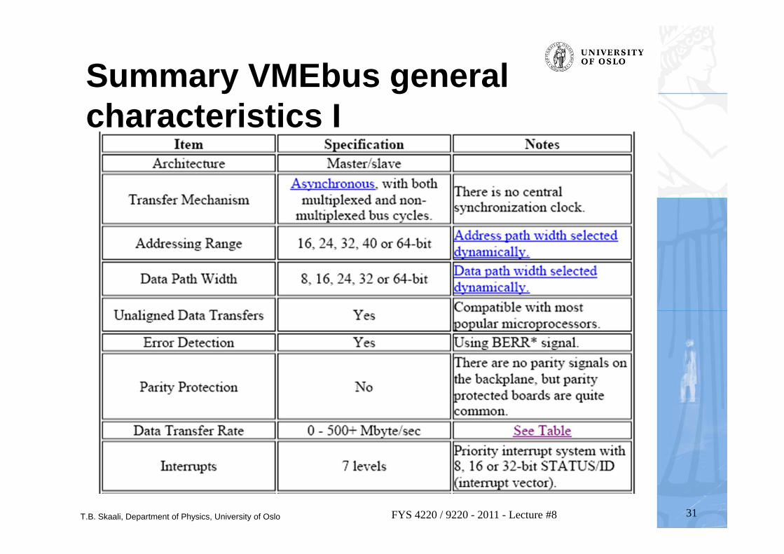
Summary VMEbus general characteristics I
T.B. Skaali, Department of Physics, University of Oslo 32FYS 4220 / 9220 - 2011 - Lecture #8
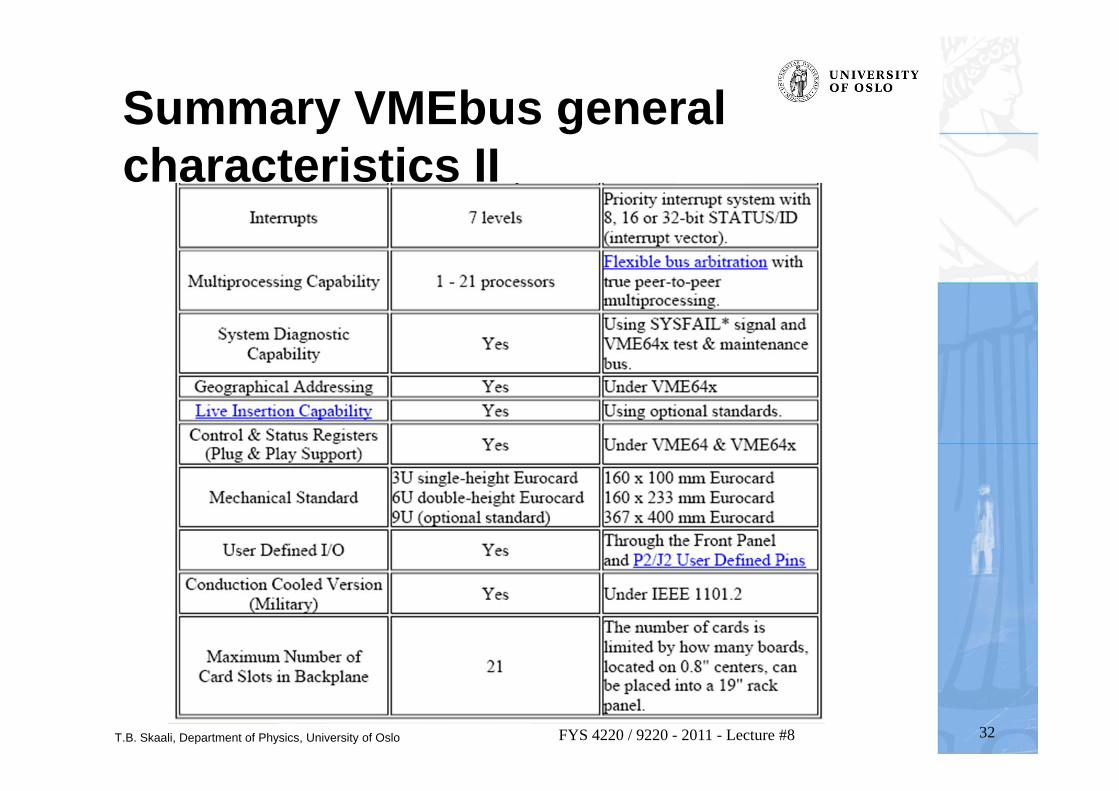
Summary VMEbus general characteristics II
T.B. Skaali, Department of Physics, University of Oslo 33FYS 4220 / 9220 - 2011 - Lecture #8
T.B. Skaali, Department of Physics, University of Oslo 34FYS 4220 / 9220 - 2011 - Lecture #8
T.B. Skaali, Department of Physics, University of Oslo 35FYS 4220 / 9220 - 2011 - Lecture #8
T.B. Skaali, Department of Physics, University of Oslo 36FYS 4220 / 9220 - 2011 - Lecture #8
T.B. Skaali, Department of Physics, University of Oslo 37FYS 4220 / 9220 - 2011 - Lecture #8
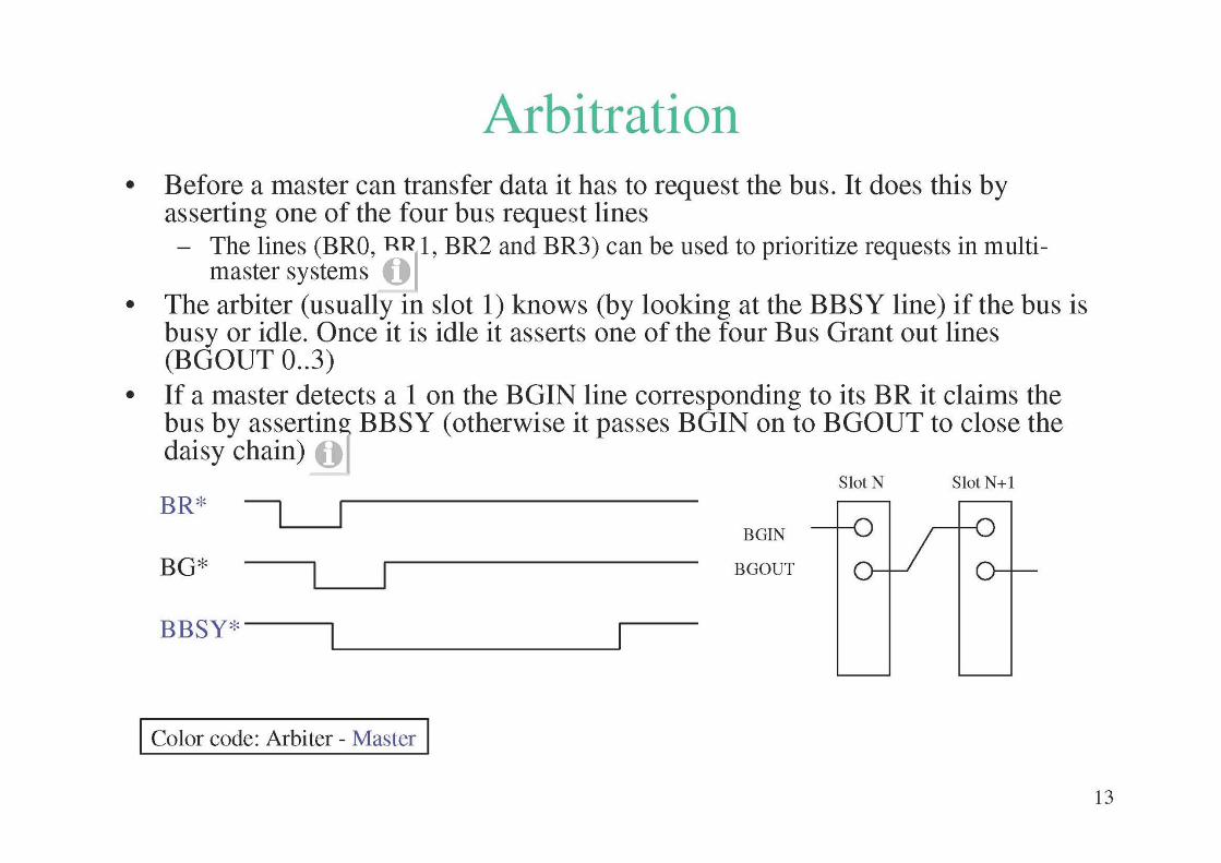
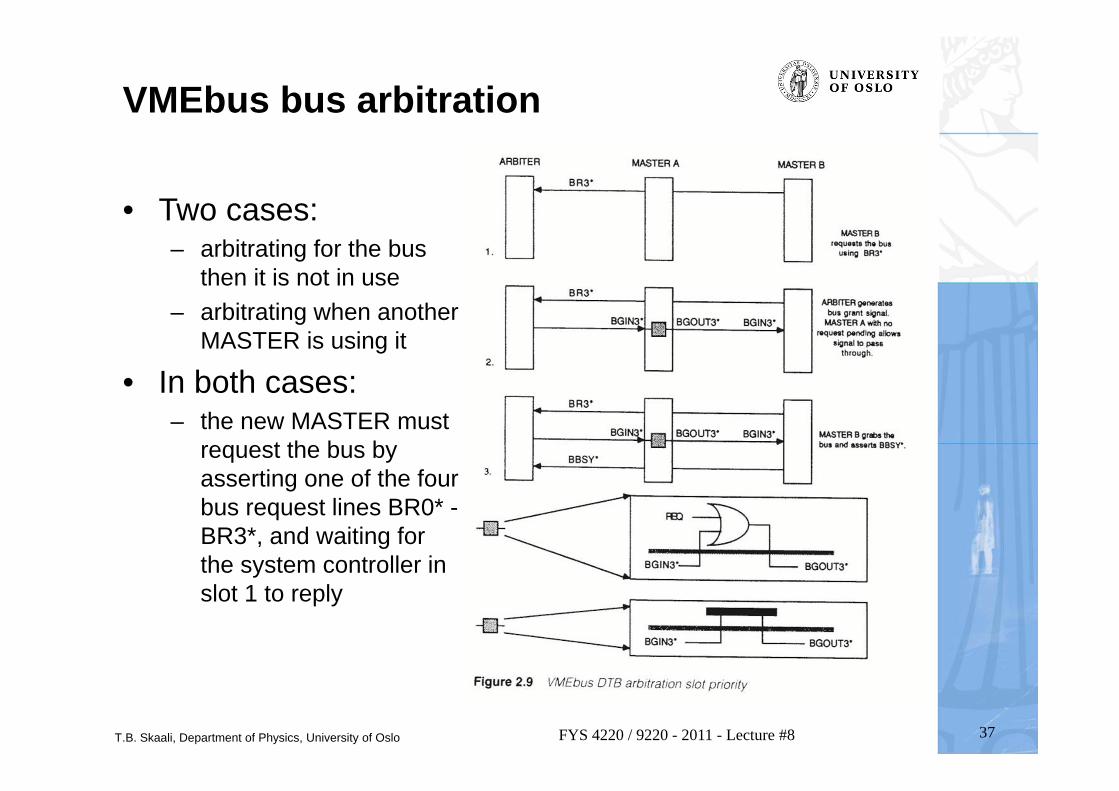
VMEbus bus arbitration
• Two cases:– arbitrating for the bus
then it is not in use– arbitrating when another
MASTER is using it
• In both cases:– the new MASTER must
request the bus by asserting one of the four bus request lines BR0* -BR3*, and waiting for the system controller in slot 1 to reply
T.B. Skaali, Department of Physics, University of Oslo 38FYS 4220 / 9220 - 2011 - Lecture #8
T.B. Skaali, Department of Physics, University of Oslo 39FYS 4220 / 9220 - 2011 - Lecture #8
T.B. Skaali, Department of Physics, University of Oslo 40FYS 4220 / 9220 - 2011 - Lecture #8
Lab target: MIDAS M5000 VME version
T.B. Skaali, Department of Physics, University of Oslo 41FYS 4220 / 9220 - 2011 - Lecture #8
MIDAS M5000 VME version
T.B. Skaali, Department of Physics, University of Oslo 42FYS 4220 / 9220 - 2011 - Lecture #8
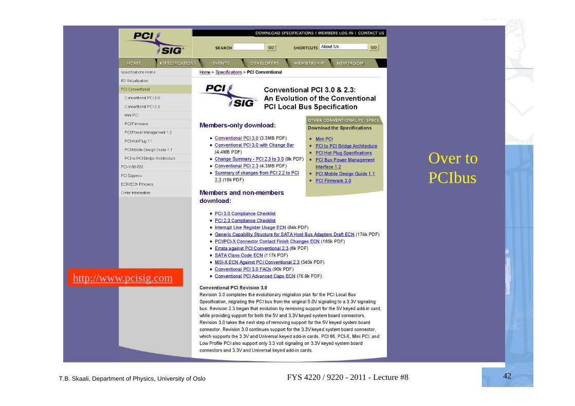
http://www.pcisig.com
Over to PCIbus
T.B. Skaali, Department of Physics, University of Oslo 43FYS 4220 / 9220 - 2011 - Lecture #8
PCI bus basics
• The PCI bus was orginally developed by Intel. PCI stands for Peripheral Component Interconnect
• PCI exists in many flavours: PCI Conventional (i.e. the standard PC card version) 32 bit 33 MHz (max 132 MB/s), 64 bit 33 MHz (max 264 MB/s), 64 bit 66 MHz (max 528 MB/s), PCI Express (PCIe) and Compact PCI
• PCI is a synchronous bus where Address and Data are time multiplexed on the same lines
• PCI has been through several technical revisions, current PCI Convential is 3.0
• Complete PCI specifications are available from http://www.pcisig.com : the homepage for the PCI Special Interest Group (if you are a member!)
T.B. Skaali, Department of Physics, University of Oslo 44FYS 4220 / 9220 - 2011 - Lecture #8
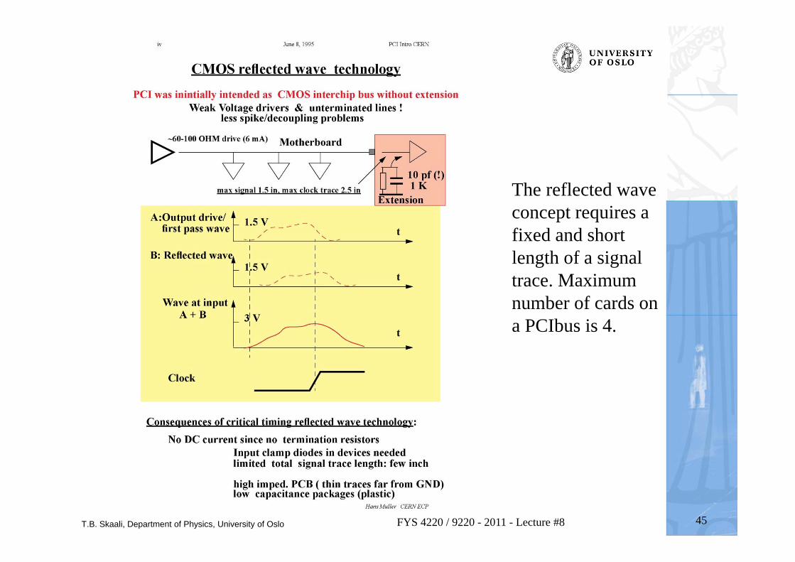
Reflected wave switching• In high-frequency environments such as PCI, convential incident-wawe
switching on a terminated bus using drivers with large driving capability would create a number of problems. As such frequencies each trace (bus line) will act as a transmission line, and the electrical characteristics of the trace must also be taken into account when selecting the output driver.
– Using strong drivers to switch (by brute force) a bus system at high frequency will present a number of problems, such as: i) very difficult to decouple, ii) spikes, increase EMI (electromagnetic interference) and iv) crosstalk.
• The PCI bus is a low power “green” bus, exploiting the reflection of a signal on an unterminated line. The PCI bus is unterminated and uses wavefront reflection to an advantage. A relatively weak output driver drives the signal halfway to the desired logic state, say 1.5V. When the wavefront arrives at the unterminated end of the bus, it is reflected back and doubled (3V)!
– The drawback of this method is that the maximum length of a PCI bus can not exceed around 15cm, i.e. for 4 cards. If a longer bus is needed then it must be built from segments interconnected by PCI bridges.
T.B. Skaali, Department of Physics, University of Oslo 45FYS 4220 / 9220 - 2011 - Lecture #8
The reflected wave concept requires a fixed and short length of a signal trace. Maximum number of cards on a PCIbus is 4.
T.B. Skaali, Department of Physics, University of Oslo 46FYS 4220 / 9220 - 2011 - Lecture #8
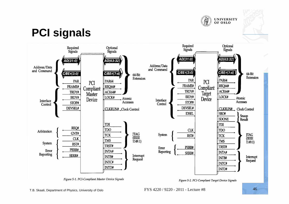
PCI signals
T.B. Skaali, Department of Physics, University of Oslo 47FYS 4220 / 9220 - 2011 - Lecture #8
PCI Burst transfers
• A burst transfer is one consisting of a single address phase followed by two or more data phases. The bus master only has to arbitrate for bus ownership one time. The start address and transaction type are issued during the address phase. The target device latches the start address into an address counter and is responsible for incrementing the address from data phase to data phase.
T.B. Skaali, Department of Physics, University of Oslo 48FYS 4220 / 9220 - 2011 - Lecture #8
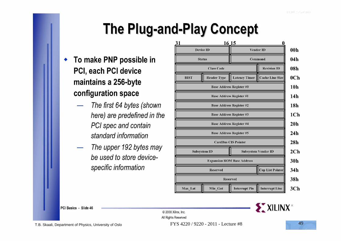
Configuration registers
• PCI bus is a ”plug and play” system!• A PCI device is described by the content of its
Configuration space• Each functional PCI device possesses a block of 64
configuration doublewords (32-bit) reserved for its configuration registers.
T.B. Skaali, Department of Physics, University of Oslo 49FYS 4220 / 9220 - 2011 - Lecture #8
T.B. Skaali, Department of Physics, University of Oslo 50FYS 4220 / 9220 - 2011 - Lecture #8
T.B. Skaali, Department of Physics, University of Oslo 51FYS 4220 / 9220 - 2011 - Lecture #8
T.B. Skaali, Department of Physics, University of Oslo 52FYS 4220 / 9220 - 2011 - Lecture #8
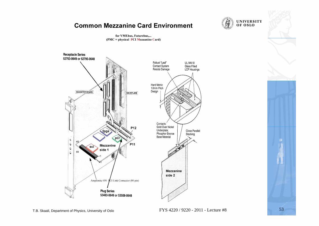
More from the PCI zoo
• Common Mezzanine Cards (CMC) and PCI Mezzanine (PMC) standard, used on VME cards
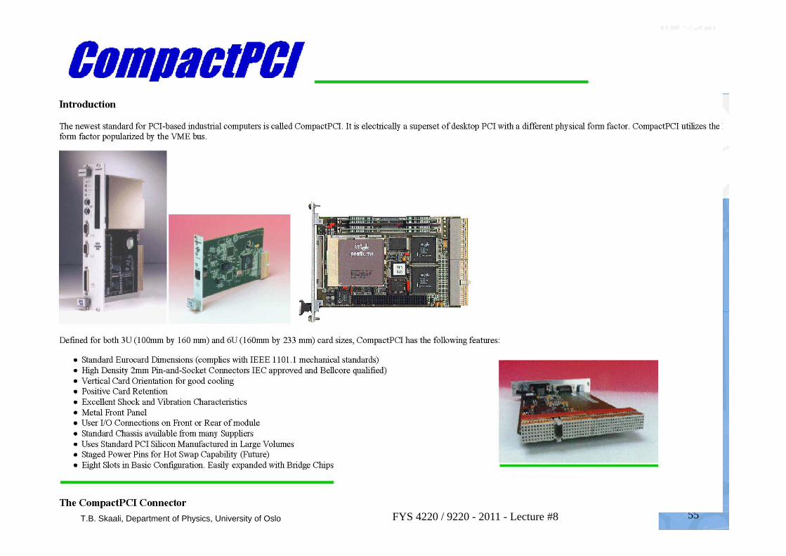
• Compact PCI• PCIe (PCI express)
T.B. Skaali, Department of Physics, University of Oslo 53FYS 4220 / 9220 - 2011 - Lecture #8
T.B. Skaali, Department of Physics, University of Oslo 54FYS 4220 / 9220 - 2011 - Lecture #8
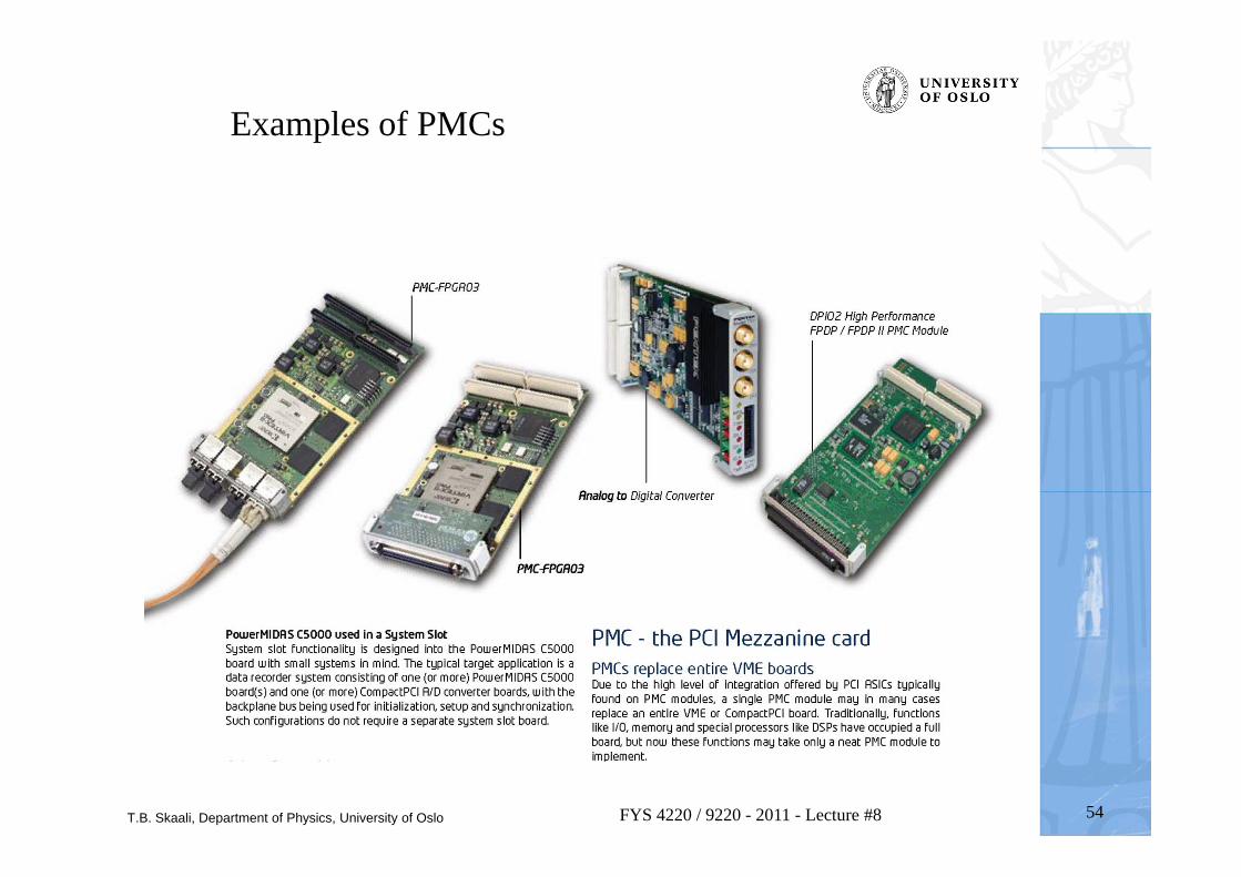
Examples of PMCs
T.B. Skaali, Department of Physics, University of Oslo 55FYS 4220 / 9220 - 2011 - Lecture #8
T.B. Skaali, Department of Physics, University of Oslo
PCI EXPRESS
56FYS 4220 / 9220 - 2011 - Lecture #8
T.B. Skaali, Department of Physics, University of Oslo 57FYS 4220 / 9220 - 2011 - Lecture #8
T.B. Skaali, Department of Physics, University of Oslo 58FYS 4220 / 9220 - 2011 - Lecture #8
T.B. Skaali, Department of Physics, University of Oslo 59FYS 4220 / 9220 - 2011 - Lecture #8
T.B. Skaali, Department of Physics, University of Oslo 60FYS 4220 / 9220 - 2011 - Lecture #8
T.B. Skaali, Department of Physics, University of Oslo
INTERCONNECT MATRIX
61FYS 4220 / 9220 - 2011 - Lecture #8
T.B. Skaali, Department of Physics, University of Oslo 62FYS 4220 / 9220 - 2011 - Lecture #8


![[Electronics] Real-Time Embedded Systems](https://img.pdfslide.us/doc/110x75/6158f43ab303d120476357ae/electronics-real-time-embedded-systems.jpg)