Embed Size (px)
Citation preview
A Course Material on
Embedded and Real Time Stystems
By
Mr.K.Saravanan
ASSISTANT PROFESSOR
DEPARTMENT OF ELECTRONICS AND COMMUNICATION ENGINEERING
SASURIE COLLEGE OF ENGINEERING
VIJAYAMANGALAM – 638 056
www.Vidyarthiplus.com
www.Vidyarthiplus.com

QUALITY CERTIFICATE
This is to certify that the e-course material
Subject Code : EC2042
Subject : Embedded and Real Time Systems
Class : IV Year ECE
being prepared by me and it meets the knowledge requirement of the university curriculum.
Signature of the Author
K.Saravanan
Assistant Professor
This is to certify that the course material being prepared by Mr.K.Saravanan is of adequate quality. He
has referred more than five books among them minimum one is from aboard author.
Signature of HD
N.Ramkumar
Assistant Professor
www.Vidyarthiplus.com
www.Vidyarthiplus.com
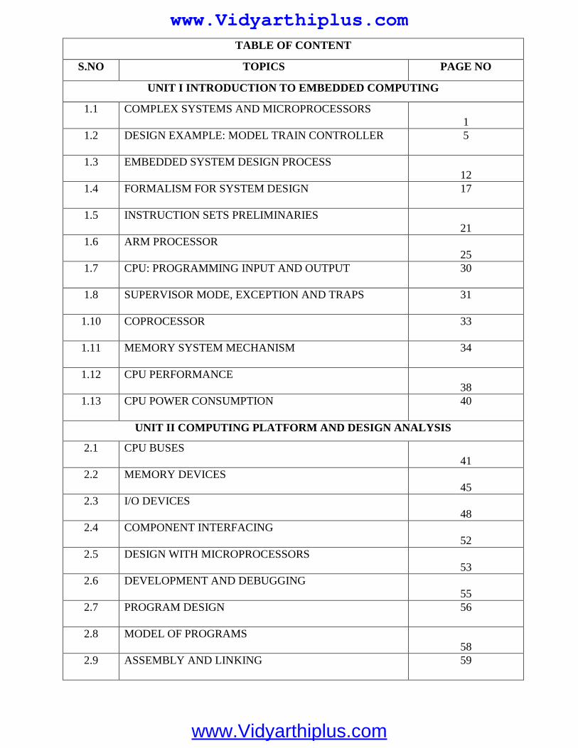
TABLE OF CONTENT
S.NO TOPICS PAGE NO
UNIT I INTRODUCTION TO EMBEDDED COMPUTING
1.1 COMPLEX SYSTEMS AND MICROPROCESSORS
1
1.2 DESIGN EXAMPLE: MODEL TRAIN CONTROLLER 5
1.3 EMBEDDED SYSTEM DESIGN PROCESS
12
1.4 FORMALISM FOR SYSTEM DESIGN 17
1.5 INSTRUCTION SETS PRELIMINARIES
21
1.6 ARM PROCESSOR
25
1.7 CPU: PROGRAMMING INPUT AND OUTPUT 30
1.8 SUPERVISOR MODE, EXCEPTION AND TRAPS 31
1.10 COPROCESSOR 33
1.11 MEMORY SYSTEM MECHANISM 34
1.12 CPU PERFORMANCE
38
1.13 CPU POWER CONSUMPTION 40
UNIT II COMPUTING PLATFORM AND DESIGN ANALYSIS
2.1 CPU BUSES
41
2.2 MEMORY DEVICES
45
2.3 I/O DEVICES
48
2.4 COMPONENT INTERFACING
52
2.5 DESIGN WITH MICROPROCESSORS
53
2.6 DEVELOPMENT AND DEBUGGING
55
2.7 PROGRAM DESIGN 56
2.8 MODEL OF PROGRAMS
58
2.9 ASSEMBLY AND LINKING 59
www.Vidyarthiplus.com
www.Vidyarthiplus.com
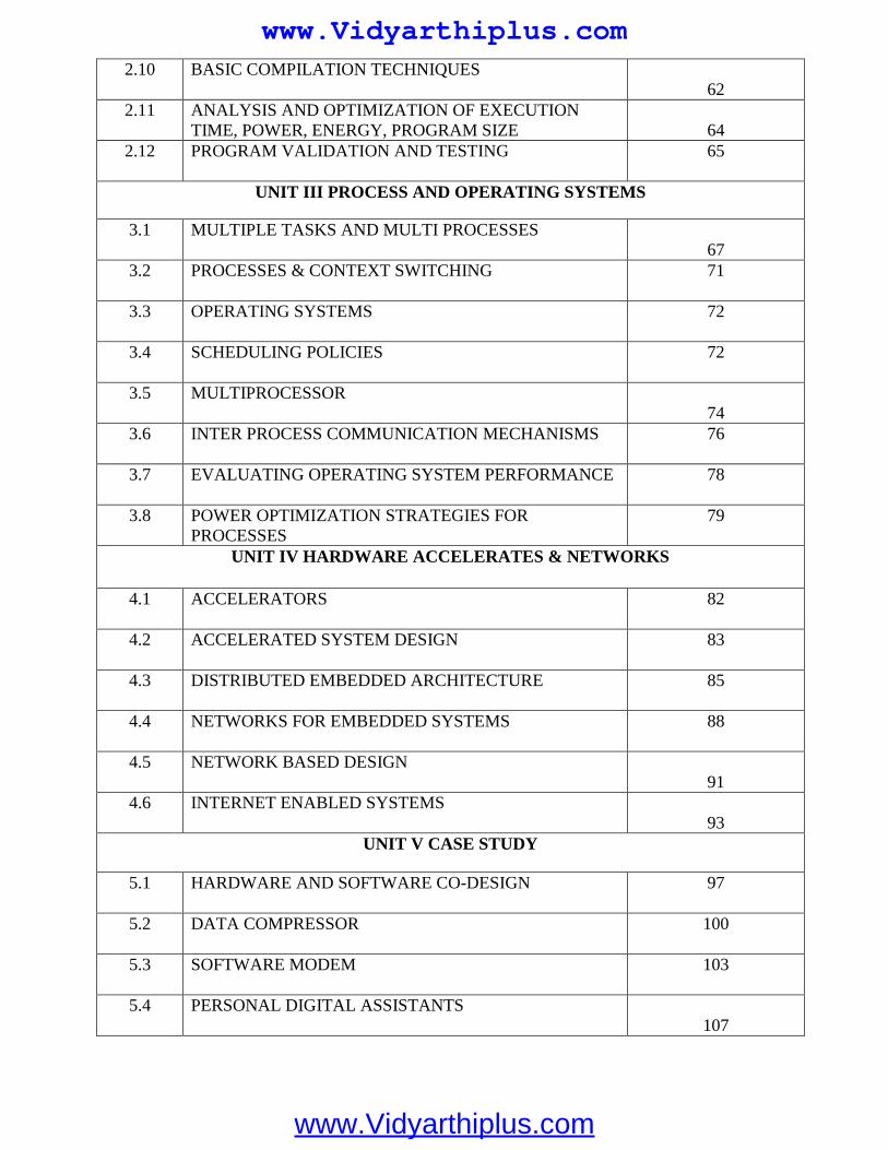
2.10 BASIC COMPILATION TECHNIQUES
62
2.11 ANALYSIS AND OPTIMIZATION OF EXECUTION
TIME, POWER, ENERGY, PROGRAM SIZE
64
2.12 PROGRAM VALIDATION AND TESTING 65
UNIT III PROCESS AND OPERATING SYSTEMS
3.1 MULTIPLE TASKS AND MULTI PROCESSES
67
3.2 PROCESSES & CONTEXT SWITCHING 71
3.3 OPERATING SYSTEMS 72
3.4 SCHEDULING POLICIES 72
3.5 MULTIPROCESSOR
74
3.6 INTER PROCESS COMMUNICATION MECHANISMS 76
3.7 EVALUATING OPERATING SYSTEM PERFORMANCE 78
3.8 POWER OPTIMIZATION STRATEGIES FOR
PROCESSES
79
UNIT IV HARDWARE ACCELERATES & NETWORKS
4.1 ACCELERATORS 82
4.2 ACCELERATED SYSTEM DESIGN 83
4.3 DISTRIBUTED EMBEDDED ARCHITECTURE 85
4.4 NETWORKS FOR EMBEDDED SYSTEMS 88
4.5 NETWORK BASED DESIGN
91
4.6 INTERNET ENABLED SYSTEMS
93
UNIT V CASE STUDY
5.1 HARDWARE AND SOFTWARE CO-DESIGN 97
5.2 DATA COMPRESSOR 100
5.3 SOFTWARE MODEM 103
5.4 PERSONAL DIGITAL ASSISTANTS
107
www.Vidyarthiplus.com
www.Vidyarthiplus.com
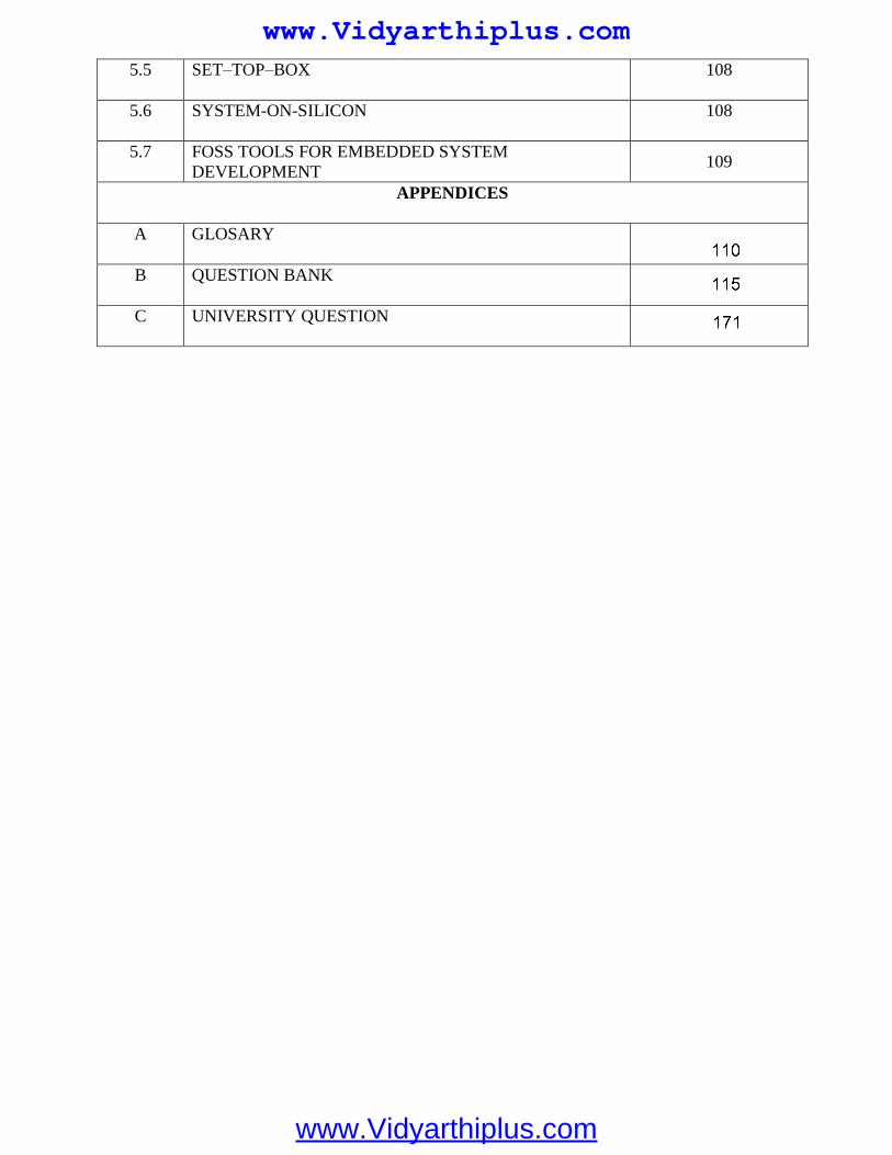
5.5 SET–TOP–BOX 108
5.7 FOSS TOOLS FOR EMBEDDED SYSTEM
APPENDICES
A GLOSARY
B QUESTION BANK
C UNIVERSITY QUESTION
DEVELOPMENT 109
5.6 SYSTEM-ON-SILICON 108
www.Vidyarthiplus.com
www.Vidyarthiplus.com
EC2042 EMBEDDED AND REAL TIME SYSTEMS L T P C 3 0 0 3
UNIT I INTRODUCTION TO EMBEDDED COMPUTING 9 Complex systems and microprocessors – Design example: Model train controller – Embedded system design process – Formalism for system design – Instruction sets Preliminaries – ARM Processor – CPU: Programming input and output – Supervisor mode, exception and traps – Coprocessor – Memory system mechanism – CPU performance – CPU power consumption. UNIT II COMPUTING PLATFORM AND DESIGN ANALYSIS 9 CPU buses – Memory devices – I/O devices – Component interfacing – Design with microprocessors – Development and Debugging – Program design – Model of programs – Assembly and Linking – Basic compilation techniques – Analysis and optimization of execution time, power, energy, program size – Program validation and testing. UNIT III PROCESS AND OPERATING SYSTEMS 9 Multiple tasks and multi processes – Processes – Context Switching – Operating Systems –Scheduling policies - Multiprocessor – Inter Process Communication mechanisms – Evaluating operating system performance – Power optimization strategies for processes. UNIT IV HARDWARE ACCELERATES & NETWORKS 9 Accelerators – Accelerated system design – Distributed Embedded Architecture – Networks for Embedded Systems – Network based design – Internet enabled systems. UNIT V CASE STUDY 9 Hardware and software co-design - Data Compressor - Software Modem – Personal Digital Assistants – Set–Top–Box. – System-on-Silicon – FOSS Tools for embedded system development. TOTAL= 45 PERIODS TEXT BOOK: 1) Wayne Wolf, “Computers as Components - Principles of Embedded Computer System Design”, Morgan Kaufmann Publisher, 2006. REFERENCES: 1) David E-Simon, “An Embedded Software Primer”, Pearson Education, 2007. 2) K.V.K.K.Prasad, “Embedded Real-Time Systems: Concepts, Design & Programming”, dreamtech press, 2005. 3) Tim Wilmshurst, “An Introduction to the Design of Small Scale Embedded Systems”, Pal grave Publisher, 2004. 4) Sriram V Iyer, Pankaj Gupta, “Embedded Real Time Systems Programming”, Tata Mc-Graw Hill, 2004. 5) Tammy Noergaard, “Embedded Systems Architecture”, Elsevier,2006.
www.Vidyarthiplus.com
www.Vidyarthiplus.com
EC2042 EMBEDDED & REAL TIME SYSTEM
SCE 1 Dept of ECE
UNIT- 1
INTRODUCTION TO EMBEDDED COMPUTING
1. COMPLEX SYSTEMS AND MICROPROCESSORS
What is an embedded computer system? Loosely defined, it is any device that includes a
programmable computer but is not itself intended to be a general-purpose computer. Thus, a PC
is not itself an embedded computing system, although PCs are often used to build embedded
computing systems. But a fax machine or a clock built from a microprocessor is an embedded
computing system.
This means that embedded computing system design is a useful skill for many types of product
design. Automobiles, cell phones, and even household appliances make extensive use of
microprocessors. Designers in many fields must be able to identify where microprocessors can
be used, design a hardware platform with I/O devices that can support the required tasks, and
implement software that performs the required processing.
Computer engineering, like mechanical design or thermodynamics, is a fundamental discipline
that can be applied in many different domains. But of course, embedded computing system
design does not stand alone.
Many of the challenges encountered in the design of an embedded computing system are not
computer engineering—for example,they may be mechanical or analog electrical problems. In
this book we are primarily interested in the embedded computer itself, so we will concentrate on
the hardware and software that enable the desired functions in the final product.
1.1 Embedding Computers
Computers have been embedded into applications since the earliest days of computing. One
example is the Whirlwind, a computer designed at MIT in the late 1940s and early 1950s.
Whirlwind was also the first computer designed to support real-time operation and was
originally conceived as a mechanism for controlling an aircraft simulator.
Even though it was extremely large physically compared to today’s computers (e.g., it contained
over 4,000 vacuum tubes), its complete design from components to system was attuned to the
needs of real-time embedded computing.
The utility of computers in replacing mechanical or human controllers was evident from the
very beginning of the computer era—for example, computers were proposed to control chemical
processes in the late 1940s.
A microprocessor is a single-chip CPU. Very large scale integration (VLSI) stet the acronym is
the name technology has allowed us to put a complete CPU on a single chip since 1970s, but
those CPUs were very simple.
The first microprocessor, the Intel 4004, was designed for an embedded application, namely, a
calculator. The calculator was not a general-purpose computer—it merely provided basic
arithmetic functions. However, Ted Hoff of Intel realized that a general-purpose computer
www.Vidyarthiplus.com
www.Vidyarthiplus.com
EC2042 EMBEDDED & REAL TIME SYSTEM
SCE 2 Dept of ECE
programmed properly could implement the required function, and that the computer-on-a-chip
could then be reprogrammed for use in other products as well.
Since integrated circuit design was (and still is) an expensive and time consuming process, the
ability to reuse the hardware design by changing the software was a key breakthrough.
The HP-35 was the first handheld calculator to perform transcendental functions [Whi72]. It
was introduced in 1972, so it used several chips to implement the CPU, rather than a single-chip
microprocessor.
However, the ability to write programs to perform math rather than having to design digital
circuits to perform operations like trigonometric functions was critical to the successful design
of the calculator.
Automobile designers started making use of the microprocessor soon after single-chip CPUs
became available.
The most important and sophisticated use of microprocessors in automobiles was to control the
engine: determining when spark plugs fire, controlling the fuel/air mixture, and so on. There
was a trend toward electronics in automobiles in general—electronic devices could be used to
replace the mechanical distributor.
But the big push toward microprocessor-based engine control came from two nearly
simultaneous developments: The oil shock of the 1970s caused consumers to place much higher
value on fuel economy, and fears of pollution resulted in laws restricting automobile engine
emissions.
The combination of low fuel consumption and low emissions is very difficult to achieve; to
meet these goals without compromising engine performance, automobile manufacturers turned
to sophisticated control algorithms that could be implemented only with microprocessors.
Microprocessors come in many different levels of sophistication; they are usually classified by
their word size. An 8-bit microcontroller is designed for low-cost applications and includes on-
board memory and I/O devices; a 16-bit microcontroller is often used for more sophisticated
applications that may require either longer word lengths or off-chip I/O and memory; and a 32-
bit RISC microprocessor offers very high performance for computation-intensive applications.
Given the wide variety of microprocessor types available, it should be no surprise that
microprocessors are used in many ways. There are many household uses of microprocessors.
The typical microwave oven has at least one microprocessor to control oven operation.
Many houses have advanced thermostat systems, which change the temperature level at various
times during the day. The modern camera is a prime example of the powerful features that can
be added under microprocessor control.
Digital television makes extensive use of embedded processors. In some cases, specialized
CPUs are designed to execute important algorithms—an example is the CPU designed for audio
www.Vidyarthiplus.com
www.Vidyarthiplus.com
EC2042 EMBEDDED & REAL TIME SYSTEM
SCE 3 Dept of ECE
processing in the SGS Thomson chip set for DirecTV [Lie98]. This processor is designed to
efficiently implement programs for digital audio decoding.
A programmable CPU was used rather than a hardwired unit for two reasons: First, it made the
system easier to design and debug; and second, it allowed the possibility of upgrades and using
the CPU for other purposes.
A high-end automobile may have 100 microprocessors, but even inexpensive cars today use 40
microprocessors. Some of these microprocessors do very simple things such as detect whether
seat belts are in use. Others control critical functions such as the ignition and braking systems.
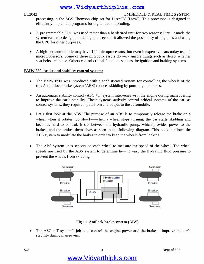
BMW 850i brake and stability control system:
The BMW 850i was introduced with a sophisticated system for controlling the wheels of the
car. An antilock brake system (ABS) reduces skidding by pumping the brakes.
An automatic stability control (ASC +T) system intervenes with the engine during maneuvering
to improve the car’s stability. These systems actively control critical systems of the car; as
control systems, they require inputs from and output to the automobile.
Let’s first look at the ABS. The purpose of an ABS is to temporarily release the brake on a
wheel when it rotates too slowly—when a wheel stops turning, the car starts skidding and
becomes hard to control. It sits between the hydraulic pump, which provides power to the
brakes, and the brakes themselves as seen in the following diagram. This hookup allows the
ABS system to modulate the brakes in order to keep the wheels from locking.
The ABS system uses sensors on each wheel to measure the speed of the wheel. The wheel
speeds are used by the ABS system to determine how to vary the hydraulic fluid pressure to
prevent the wheels from skidding.
Fig 1.1 Antilock brake system (ABS)
The ASC + T system’s job is to control the engine power and the brake to improve the car’s
stability during maneuvers.
www.Vidyarthiplus.com
www.Vidyarthiplus.com
EC2042 EMBEDDED & REAL TIME SYSTEM
SCE 4 Dept of ECE
The ASC+T controls four different systems: throttle, ignition timing, differential brake, and (on
automatic transmission cars) gear shifting.
The ASC + T can be turned off by the driver, which can be important when operating with tire
snow chains.
The ABS and ASC+ T must clearly communicate because the ASC + T interacts with the brake
system. Since the ABS was introduced several years earlier than the ASC + T, it was important
to be able to interface ASC + T to the existing ABS module, as well as to other existing
electronic modules.
The engine and control management units include the electronically controlled throttle, digital engine
management, and electronic transmission control. The ASC + T control unit has two microprocessors
on two printed circuit boards, one of which concentrates on logic-relevant components and the other on
performance-specific components.
1.1.1 Characteristics of Embedded Computing Applications
Embedded computing is in many ways much more demanding than the sort of programs that
you may have written for PCs or workstations. Functionality is important in both general-purpose
computing and embedded computing, but embedded applications must meet many other constraints as
well.
On the one hand, embedded computing systems have to provide sophisticated functionality:
■ Complex algorithms: The operations performed by the microprocessor may be very sophisticated.
For example, the microprocessor that controls an automobile engine must perform complicated filtering
functions to optimize the performance of the car while minimizing pollution and fuel utilization.
■ User interface: Microprocessors are frequently used to control complex user interfaces that may
include multiple menus and many options. The moving maps in Global Positioning System (GPS)
navigation are good examples of sophisticated user interfaces.
To make things more difficult, embedded computing operations must often be performed to
meet deadlines:
■ Real time: Many embedded computing systems have to perform in real time— if the data is not ready
by a certain deadline, the system breaks. In some cases, failure to meet a deadline is unsafe and can
even endanger lives. In other cases, missing a deadline does not create safety problems but does create
unhappy customers—missed deadlines in printers, for example, can result in scrambled pages.
■ Multirate: Not only must operations be completed by deadlines, but many embedded computing
systems have several real-time activities going on at the same time. They may simultaneously control
some operations that run at slow rates and others that run at high rates. Multimedia applications are
prime examples of multirate behavior. The audio and video portions of a multimedia stream run at very
different rates, but they must remain closely synchronized. Failure to meet a deadline on either the
audio or video portions spoils the perception of the entire presentation.
Costs of various sorts are also very important:
www.Vidyarthiplus.com
www.Vidyarthiplus.com
EC2042 EMBEDDED & REAL TIME SYSTEM
SCE 5 Dept of ECE
■ Manufacturing cost: The total cost of building the system is very important in many cases.
Manufacturing cost is determined by many factors, including the type of microprocessor used, the
amount of memory required, and the types of I/O devices.
■ Power and energy: Power consumption directly affects the cost of the hardware, since a larger power
supply may be necessary. Energy consumption affects battery life, which is important in many
applications, as well as heat consumption, which can be important even in desktop applications.
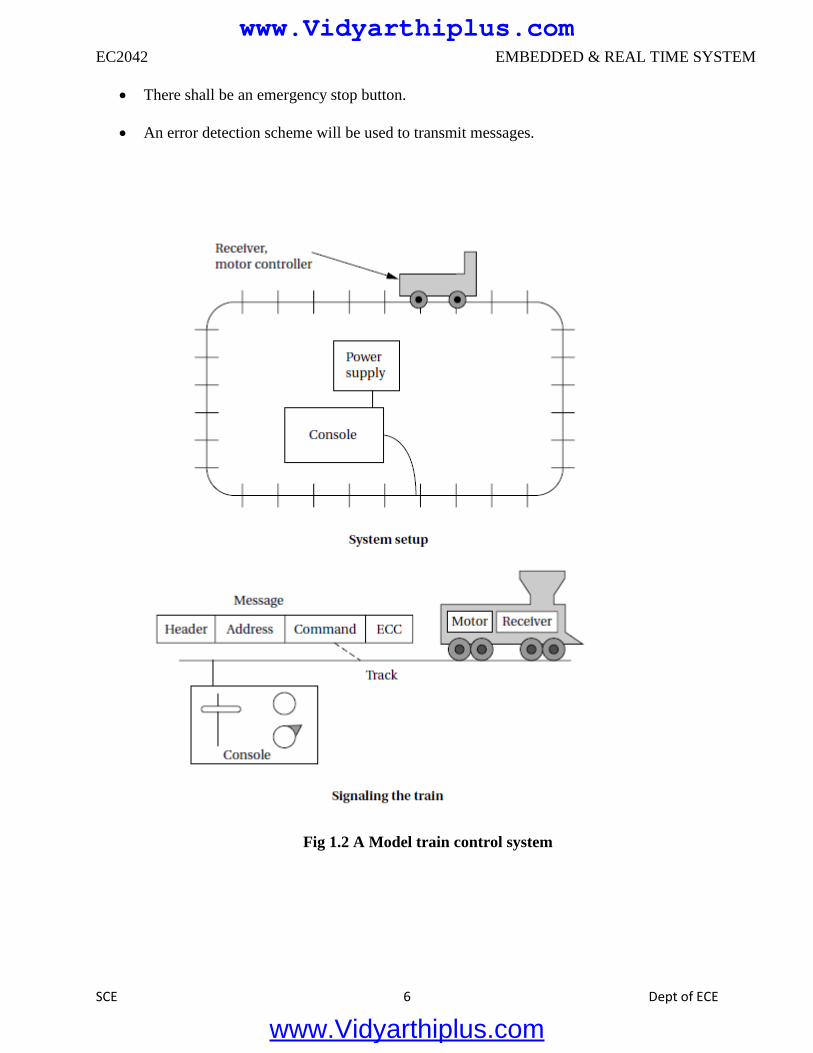
1.2 DESIGN EXAMPLE: MODEL TRAIN CONTROLLER
In order to learn how to use UML to model systems, we will specify a simple system, a model
train controller, which is illustrated in Figure 1.2.The user sends messages to the train with a
control box attached to the tracks.
The control box may have familiar controls such as a throttle, emergency stop button, and so on.
Since the train receives its electrical power from the two rails of the track, the control box can
send signals to the train over the tracks by modulating the power supply voltage. As shown in
the figure, the control panel sends packets over the tracks to the receiver on the train.
The train includes analog electronics to sense the bits being transmitted and a control system to
set the train motor’s speed and direction based on those commands.
Each packet includes an address so that the console can control several trains on the same track;
the packet also includes an error correction code (ECC) to guard against transmission errors.
This is a one-way communication system the model train cannot send commands back to the
user.
We start by analyzing the requirements for the train control system.We will base our system on
a real standard developed for model trains.We then develop two specifications: a simple, high-
level specification and then a more detailed specification.
1.2.1 Requirements
Before we can create a system specification, we have to understand the requirements.
Here is a basic set of requirements for the system:
The console shall be able to control up to eight trains on a single track.
The speed of each train shall be controllable by a throttle to at least 63 different levels in each
direction (forward and reverse).
There shall be an inertia control that shall allow the user to adjust the responsiveness of the train
to commanded changes in speed. Higher inertia means that the train responds more slowly to a
change in the throttle, simulating the inertia of a large train. The inertia control will provide at
least eight different levels.
www.Vidyarthiplus.com
www.Vidyarthiplus.com
EC2042 EMBEDDED & REAL TIME SYSTEM
SCE 6 Dept of ECE
There shall be an emergency stop button.
An error detection scheme will be used to transmit messages.
Fig 1.2 A Model train control system
www.Vidyarthiplus.com
www.Vidyarthiplus.com
EC2042 EMBEDDED & REAL TIME SYSTEM
SCE 7 Dept of ECE
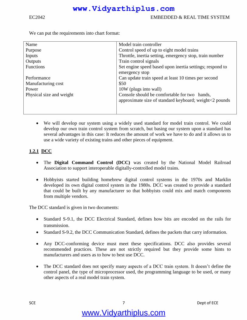
We can put the requirements into chart format:
Name
Purpose
Inputs
Outputs
Functions
Performance
Manufacturing cost
Power
Physical size and weight
Model train controller
Control speed of up to eight model trains
Throttle, inertia setting, emergency stop, train number
Train control signals
Set engine speed based upon inertia settings; respond to
emergency stop
Can update train speed at least 10 times per second
$50
10W (plugs into wall)
Console should be comfortable for two hands,
approximate size of standard keyboard; weight<2 pounds
We will develop our system using a widely used standard for model train control. We could
develop our own train control system from scratch, but basing our system upon a standard has
several advantages in this case: It reduces the amount of work we have to do and it allows us to
use a wide variety of existing trains and other pieces of equipment.
1.2.1 DCC
The Digital Command Control (DCC) was created by the National Model Railroad
Association to support interoperable digitally-controlled model trains.
Hobbyists started building homebrew digital control systems in the 1970s and Marklin
developed its own digital control system in the 1980s. DCC was created to provide a standard
that could be built by any manufacturer so that hobbyists could mix and match components
from multiple vendors.
The DCC standard is given in two documents:
Standard S-9.1, the DCC Electrical Standard, defines how bits are encoded on the rails for
transmission.
Standard S-9.2, the DCC Communication Standard, defines the packets that carry information.
Any DCC-conforming device must meet these specifications. DCC also provides several
recommended practices. These are not strictly required but they provide some hints to
manufacturers and users as to how to best use DCC.
The DCC standard does not specify many aspects of a DCC train system. It doesn’t define the
control panel, the type of microprocessor used, the programming language to be used, or many
other aspects of a real model train system.
www.Vidyarthiplus.com
www.Vidyarthiplus.com
EC2042 EMBEDDED & REAL TIME SYSTEM
SCE 8 Dept of ECE
The standard concentrates on those aspects of system design that are necessary for
interoperability. Over standardization, or specifying elements that do not really need to be
standardized, only makes the standard less attractive and harder to implement.
The Electrical Standard deals with voltages and currents on the track. While the electrical
engineering aspects of this part of the specification are beyond the scope of the book, we will
briefly discuss the data encoding here.
The standard must be carefully designed because the main function of the track is to carry
power to the locomotives. The signal encoding system should not interfere with power
transmission either to DCC or non-DCC locomotives. A key requirement is that the data signal
should not change the DC value of the rails.
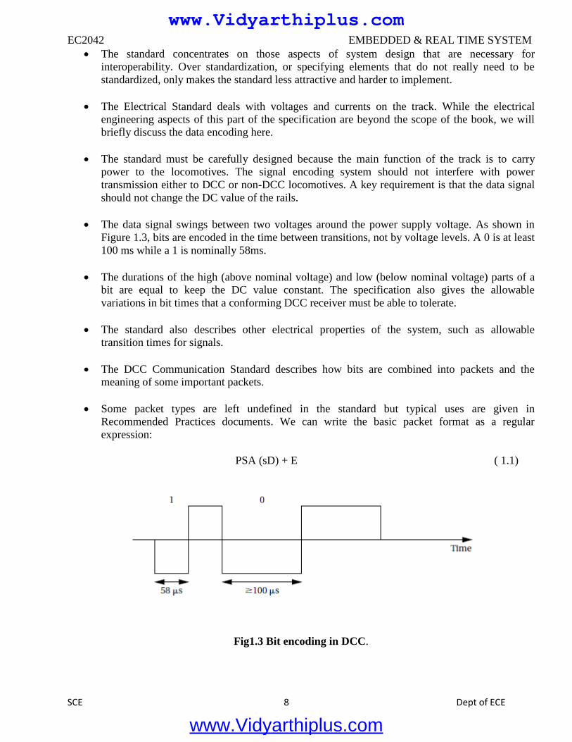
The data signal swings between two voltages around the power supply voltage. As shown in
Figure 1.3, bits are encoded in the time between transitions, not by voltage levels. A 0 is at least
100 ms while a 1 is nominally 58ms.
The durations of the high (above nominal voltage) and low (below nominal voltage) parts of a
bit are equal to keep the DC value constant. The specification also gives the allowable
variations in bit times that a conforming DCC receiver must be able to tolerate.
The standard also describes other electrical properties of the system, such as allowable
transition times for signals.
The DCC Communication Standard describes how bits are combined into packets and the
meaning of some important packets.
Some packet types are left undefined in the standard but typical uses are given in
Recommended Practices documents. We can write the basic packet format as a regular
expression:
PSA (sD) + E ( 1.1)
Fig1.3 Bit encoding in DCC.
www.Vidyarthiplus.com
www.Vidyarthiplus.com
EC2042 EMBEDDED & REAL TIME SYSTEM
SCE 9 Dept of ECE
In this regular expression:
■ P is the preamble, which is a sequence of at least 10 1 bits. The command station should send at least
14 of these 1 bits, some of which may be corrupted during transmission.
■ S is the packet start bit. It is a 0 bit.
■ A is an address data byte that gives the address of the unit, with the most significant bit of the address
transmitted first. An address is eight bits long. The addresses 00000000, 11111110, and 11111111
are reserved.
■ s is the data byte start bit, which, like the packet start bit, is a 0.
■ D is the data byte, which includes eight bits. A data byte may contain an address, instruction, data, or
error correction information.
■ E is a packet end bit, which is a 1 bit.
A packet includes one or more data byte start bit/data byte combinations. Note that the address
data byte is a specific type of data byte.
A baseline packet is the minimum packet that must be accepted by all DCC implementations.
More complex packets are given in a Recommended Practice document.
A baseline packet has three data bytes: an address data byte that gives the intended receiver of
the packet; the instruction data byte provides a basic instruction; and an error correction data
byte is used to detect and correct transmission errors.
The instruction data byte carries several pieces of information. Bits 0–3 provide a 4-bit speed
value. Bit 4 has an additional speed bit, which is interpreted as the least significant speed bit. Bit
5 gives direction, with 1 for forward and 0 for reverse. Bits 7–8 are set at 01 to indicate that this
instruction provides speed and direction.
The error correction data byte is the bitwise exclusive OR of the address and instruction data
bytes.
The standard says that the command unit should send packets frequently since a packet may be
corrupted. Packets should be separated by at least 5 ms.
1.2.2 Conceptual Specification
Digital Command Control specifies some important aspects of the system, particularly those
that allow equipment to interoperate. But DCC deliberately does not specify everything about a
model train control system. We need to round out our specification with details that
complement the DCC spec.
www.Vidyarthiplus.com
www.Vidyarthiplus.com
EC2042 EMBEDDED & REAL TIME SYSTEM
SCE 10 Dept of ECE
A conceptual specification allows us to understand the system a little better. We will use the
experience gained by writing the conceptual specification to help us write a detailed
specification to be given to a system architect. This specification does not correspond to what
any commercial DCC controllers do, but it is simple enough to allow us to cover some basic
concepts in system design.
A train control system turns commands into packets. A command comes from the command
unit while a packet is transmitted over the rails.
Commands and packets may not be generated in a 1-to-1 ratio. In fact, the DCC standard says
that command units should resend packets in case a packet is dropped during transmission.
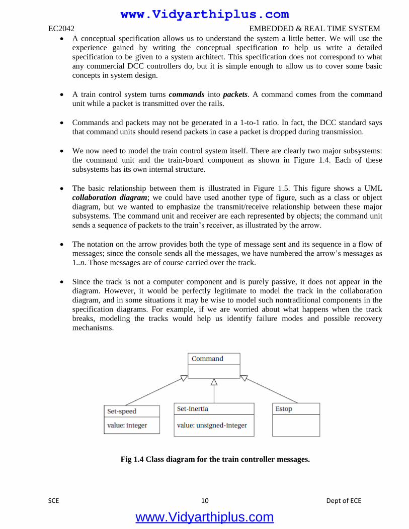
We now need to model the train control system itself. There are clearly two major subsystems:
the command unit and the train-board component as shown in Figure 1.4. Each of these
subsystems has its own internal structure.
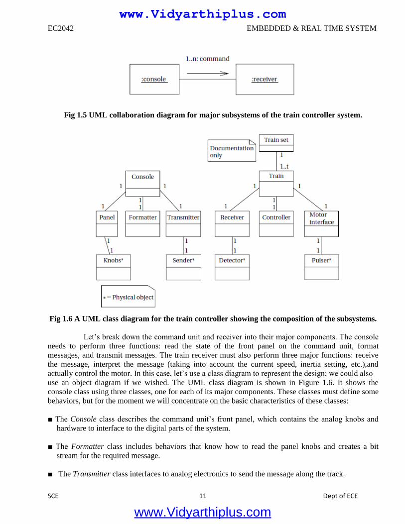
The basic relationship between them is illustrated in Figure 1.5. This figure shows a UML
collaboration diagram; we could have used another type of figure, such as a class or object
diagram, but we wanted to emphasize the transmit/receive relationship between these major
subsystems. The command unit and receiver are each represented by objects; the command unit
sends a sequence of packets to the train’s receiver, as illustrated by the arrow.
The notation on the arrow provides both the type of message sent and its sequence in a flow of
messages; since the console sends all the messages, we have numbered the arrow’s messages as
1..n. Those messages are of course carried over the track.
Since the track is not a computer component and is purely passive, it does not appear in the
diagram. However, it would be perfectly legitimate to model the track in the collaboration
diagram, and in some situations it may be wise to model such nontraditional components in the
specification diagrams. For example, if we are worried about what happens when the track
breaks, modeling the tracks would help us identify failure modes and possible recovery
mechanisms.
Fig 1.4 Class diagram for the train controller messages.
www.Vidyarthiplus.com
www.Vidyarthiplus.com
EC2042 EMBEDDED & REAL TIME SYSTEM
SCE 11 Dept of ECE
Fig 1.5 UML collaboration diagram for major subsystems of the train controller system.
Fig 1.6 A UML class diagram for the train controller showing the composition of the subsystems.
Let’s break down the command unit and receiver into their major components. The console
needs to perform three functions: read the state of the front panel on the command unit, format
messages, and transmit messages. The train receiver must also perform three major functions: receive
the message, interpret the message (taking into account the current speed, inertia setting, etc.),and
actually control the motor. In this case, let’s use a class diagram to represent the design; we could also
use an object diagram if we wished. The UML class diagram is shown in Figure 1.6. It shows the
console class using three classes, one for each of its major components. These classes must define some
behaviors, but for the moment we will concentrate on the basic characteristics of these classes:
■ The Console class describes the command unit’s front panel, which contains the analog knobs and
hardware to interface to the digital parts of the system.
■ The Formatter class includes behaviors that know how to read the panel knobs and creates a bit
stream for the required message.
■ The Transmitter class interfaces to analog electronics to send the message along the track.
www.Vidyarthiplus.com
www.Vidyarthiplus.com
EC2042 EMBEDDED & REAL TIME SYSTEM
SCE 12 Dept of ECE
There will be one instance of the Console class and one instance of each of the component
classes, as shown by the numeric values at each end of the relationship links. We have also shown some
special classes that represent analog components, ending the name of each with an asterisk:
■ Knobs* describes the actual analog knobs, buttons, and levers on the control panel.
■ Sender* describes the analog electronics that send bits along the track.
Likewise, the Train makes use of three other classes that define its components:
■ The Receiver class knows how to turn the analog signals on the track into digital form.
■ The Controller class includes behaviors that interpret the commands and figures out how to control
the motor.
■ The Motor interface class defines how to generate the analog signals required to control the motor.
We define two classes to represent analog components:
■ Detector* detects analog signals on the track and converts them into digital form.
■ Pulser* turns digital commands into the analog signals required to control the motor speed.
We have also defined a special class, Train set, to help us remember that the system can handle
multiple trains. The values on the relationship edge show that one train set can have t trains. We would
not actually implement the train set class, but it does serve as useful documentation of the existence of
multiple receivers.
1.3 THE EMBEDDED SYSTEM DESIGN PROCESS
This section provides an overview of the embedded system design process aimed at two
objectives. First, it will give us an introduction to the various steps in embedded system design
before we delve into them in more detail. Second, it will allow us to consider the design
methodology itself. A design methodology is important for three reasons.
First, it allows us to keep a scorecard on a design to ensure that we have done everything we
need to do, such as optimizing performance or performing functional tests.
Second, it allows us to develop computer-aided design tools. Developing a single program that
takes in a concept for an embedded system and emits a completed design would be a daunting
task, but by first breaking the process into manageable steps, we can work on automating (or at
least semi automating) the steps one at a time.
Third, a design methodology makes it much easier for members of a design team to
communicate. By defining the overall process, team members can more easily understand what
they are supposed to do, what they should receive from other team members at certain times,
www.Vidyarthiplus.com
www.Vidyarthiplus.com
EC2042 EMBEDDED & REAL TIME SYSTEM
SCE 13 Dept of ECE
and what they are to hand off when they complete their assigned steps. Since most embedded
systems are designed by teams, coordination is perhaps the most important role of a well-
defined design methodology.
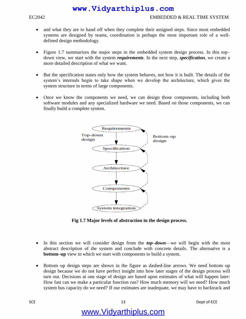
Figure 1.7 summarizes the major steps in the embedded system design process. In this top–
down view, we start with the system requirements. In the next step, specification, we create a
more detailed description of what we want.
But the specification states only how the system behaves, not how it is built. The details of the
system’s internals begin to take shape when we develop the architecture, which gives the
system structure in terms of large components.
Once we know the components we need, we can design those components, including both
software modules and any specialized hardware we need. Based on those components, we can
finally build a complete system.
Fig 1.7 Major levels of abstraction in the design process.
In this section we will consider design from the top–down—we will begin with the most
abstract description of the system and conclude with concrete details. The alternative is a
bottom–up view in which we start with components to build a system.
Bottom–up design steps are shown in the figure as dashed-line arrows. We need bottom–up
design because we do not have perfect insight into how later stages of the design process will
turn out. Decisions at one stage of design are based upon estimates of what will happen later:
How fast can we make a particular function run? How much memory will we need? How much
system bus capacity do we need? If our estimates are inadequate, we may have to backtrack and
www.Vidyarthiplus.com
www.Vidyarthiplus.com
EC2042 EMBEDDED & REAL TIME SYSTEM
SCE 14 Dept of ECE
amend our original decisions to take the new facts into account. In general, the less experience
we have with the design of similar systems, the more we will have to rely on bottom-up design
information to help us refine the system.
But the steps in the design process are only one axis along which we can view embedded
system design. We also need to consider the major goals of the design:
■ Manufacturing cost;
■ Performance (both overall speed and deadlines); and
■ Power consumption.
We must also consider the tasks we need to perform at every step in the design process. At each step
in the design, we add detail:
■ We must analyze the design at each step to determine how we can meet the
specifications.
■ We must then refine the design to add detail.
■ We must verify the design to ensure that it still meets all system goals,
such as cost, speed, and so on.
1.3.1 Requirements
Clearly, before we design a system, we must know what we are designing. The initial stages of
the design process capture this information for use in creating the architecture and components.
We generally proceed in two phases: First, we gather an informal description from the
customers known as requirements, and we refine the requirements into a specification that
contains enough information to begin designing the system architecture.
Separating out requirements analysis and specification is often necessary because of the large
gap between what the customers can describe about the system they want and what the
architects need to design the system.
Consumers of embedded systems are usually not themselves embedded system designers or
even product designers. Their understanding of the system is based on how they envision users’
interactions with the system. They may have unrealistic expectations as to what can be done
within their budgets; and they may also express their desires in a language very different from
system architects’ jargon.
Capturing a consistent set of requirements from the customer and then massaging those
requirements into a more formal specification is a structured way to manage the process of
translating from the consumer’s language to the designer’s.
Requirements may be functional or nonfunctional.Wemust of course capture the basic
functions of the embedded system,but functional description is often not sufficient.Typical
nonfunctional requirements include:
www.Vidyarthiplus.com
www.Vidyarthiplus.com
EC2042 EMBEDDED & REAL TIME SYSTEM
SCE 15 Dept of ECE
■ Performance: The speed of the system is often a major consideration both for the usability of the
system and for its ultimate cost. As we have noted, performance may be a combination of soft
performance metrics such as approximate time to perform a user-level function and hard deadlines by
which a particular operation must be completed.
■ Cost: The target cost or purchase price for the system is almost always a consideration. Cost typically
has two major components: manufacturing cost includes the cost of components and assembly;
nonrecurring engineering (NRE) costs include the personnel and other costs of designing the system.
■ Physical size and weight: The physical aspects of the final system can vary greatly depending upon
the application. An industrial control system for an assembly line may be designed to fit into a
standard-size rack with no strict limitations on weight. A handheld device typically has tight
requirements on both size and weight that can ripple through the entire system design.
■ Power consumption: Power, of course, is important in battery-powered systems and is often
important in other applications as well. Power can be specified in the requirements stage in terms of
battery life—the customer is unlikely to be able to describe the allowable wattage.
Validating a set of requirements is ultimately a psychological task since it requires
understanding both what people want and how they communicate those needs. One goodway to
refine at least the user interface portion of a system’s requirements is to build a mock-up.
The mock-up may use canned data to simulate functionality in a restricted demonstration, and it
may be executed on a PC or a workstation. But it should give the customer a good idea of how
the system will be used and how the user can react to it. Physical, nonfunctional models of
devices can also give customers a better idea of characteristics such as size and weight.
Name
Purpose
Inputs
Outputs
Functions
Performance
Manufacturing cost
Power
Physical size and weight
Fig 1.8 Sample requirements form.
Requirements analysis for big systems can be complex and time consuming. However,
capturing a relatively small amount of information in a clear, simple format is a good start toward
understanding system requirements.
To introduce the discipline of requirements analysis as part of system design, we will use a
simple requirements methodology.
Figure 1.8 shows a sample requirements form that can be filled out at the start of the project.
We can use the form as a checklist in considering the basic characteristics of the system.
www.Vidyarthiplus.com
www.Vidyarthiplus.com
EC2042 EMBEDDED & REAL TIME SYSTEM
SCE 16 Dept of ECE
Let’s consider the entries in the form:
■ Name: This is simple but helpful. Giving a name to the project not only simplifies talking about it to
other people but can also crystallize the purpose of the machine.
■ Purpose: This should be a brief one- or two-line description of what the system is supposed to do. If
you can’t describe the essence of your system in one or two lines, chances are that you don’t
understand it well enough.
■ Inputs and outputs: These two entries are more complex than they seem. The inputs and outputs to
the system encompass a wealth of detail:
— Types of data: Analog electronic signals? Digital data? Mechanical inputs?
— Data characteristics: Periodically arriving data, such as digital audio samples? Occasional user
inputs? How many bits per data element?
— Types of I/O devices: Buttons? Analog/digital converters? Video displays?
■ Functions: This is a more detailed description of what the system does. A good way to approach this
is to work from the inputs to the outputs: When the system receives an input, what does it do? How
do user interface inputs affect these functions? How do different functions interact?
■ Performance: Many embedded computing systems spend at least some time controlling physical
devices or processing data coming from the physical world. In most of these cases, the computations
must be performed within a certain time frame. It is essential that the performance requirements be
identified early since they must be carefully measured during implementation to ensure that the
system works properly.
■ Manufacturing cost: This includes primarily the cost of the hardware components. Even if you don’t
know exactly how much you can afford to spend on system components, you should have some idea
of the eventual cost range. Cost has a substantial influence on architecture: A machine that is meant
to sell at $10 most likely has a very different internal structure than a $100 system.
■ Power: Similarly, you may have only a rough idea of how much power the system can consume, but
a little information can go a long way. Typically, the most important decision is whether the machine
will be battery powered or plugged into the wall. Battery-powered machines must be much more
careful about how they spend energy.
■ Physical size and weight: You should give some indication of the physical size of the system to help
guide certain architectural decisions. A desktop machine has much more flexibility in the components
used than, for example, a lapel mounted voice recorder.
www.Vidyarthiplus.com
www.Vidyarthiplus.com
EC2042 EMBEDDED & REAL TIME SYSTEM
SCE 17 Dept of ECE
1.4 FORMALISMS FOR SYSTEM DESIGN:
Visual language that can be used to capture all these design tasks: the Unified Modeling
Language (UML). UML was designed to be useful at many levels of abstraction in the design process.
UML is useful because it encourages design by successive refinement and progressively adding detail
to the design, rather than rethinking the design at each new level of abstraction.
UML is an object-oriented modeling language. We will see precisely what we mean by an object
in just a moment, but object-oriented design emphasizes two concepts of importance:
■ It encourages the design to be described as a number of interacting objects, rather than a few large
monolithic blocks of code.
■ At least some of those object will correspond to real pieces of software or hardware in the system.
We can also use UML to model the outside world that interacts with our system, in which case the
objects may correspond to people or other machines. It is sometimes important to implement
something we think of at a high level as a single object using several distinct pieces of code or to
otherwise break up the object correspondence in the implementation However, thinking of the design
in terms of actual objects helps us understand the natural structure of the system. Object-oriented
(often abbreviated OO) specification can be seen in two complementary ways:
■ Object-oriented specification allows a system to be described in a way that closely models real-world
objects and their interactions.
■ Object-oriented specification provides a basic set of primitives that can be used to describe systems
with particular attributes, irrespective of the relationships of those systems’ components to real-world
objects.
Both views are useful. At a minimum, object-oriented specification is a set of linguistic
mechanisms. In many cases, it is useful to describe a system in terms of real-world analogs. However,
performance, cost, and so on may dictate that we change the specification to be different in some ways
from the real-world elements we are trying to model and implement. In this case, the object-oriented
specification mechanisms are still useful.
A specification language may not be executable. But both object-oriented specification and
programming languages provide similar basic methods for structuring large systems.
Unified Modeling Language (UML)—the acronym is the name is a large language, and
covering all of it is beyond the scope of this book. In this section, we introduce only a few basic
concepts. In later chapters, as we need a few more UML concepts, we introduce them to the basic
modeling elements introduced here.
Because UML is so rich, there are many graphical elements in a UML diagram. It is important
to be careful to use the correct drawing to describe something for instance; UML distinguishes between
arrows with open and filled-in arrowheads, and solid and broken lines. As you become more familiar
with the language, uses of the graphical primitives will become more natural to you.
www.Vidyarthiplus.com
www.Vidyarthiplus.com
EC2042 EMBEDDED & REAL TIME SYSTEM
SCE 18 Dept of ECE
We also won’t take a strict object-oriented approach. We may not always use objects for
certain elements of a design—in some cases, such as when taking particular aspects of the
implementation into account, it may make sense to use another design style. However, object-oriented
design is widely applicable, and no designer can consider himself or herself design literate without
understanding it.
1.4.1 Structural Description:
By structural description, we mean the basic components of the system; we will learn how to
describe how these components act in the next section. The principal component of an object-
oriented design is, naturally enough, the object. An object includes a set of attributes that define
its internal state.
When implemented in a programming language, these attributes usually become variables or
constants held in a data structure. In some cases, we will add the type of the attribute after the
attribute name for clarity, but we do not always have to specify a type for an attribute. An object
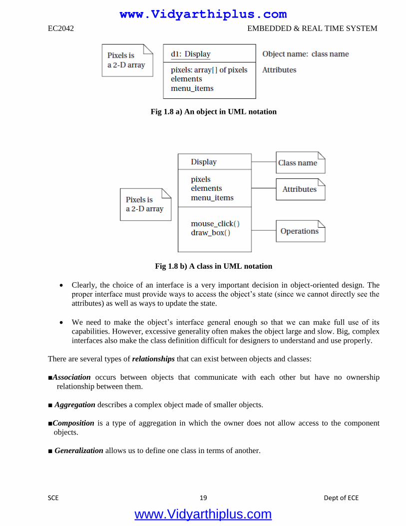
describing a display (such as a CRT screen) is shown in UML notation in Figure 1.8 a).
The text in the folded-corner page icon is a note; it does not correspond to an object in the
system and only serves as a comment. The attribute is, in this case, an array of pixels that holds
the contents of the display. The object is identified in two ways: It has a unique name, and it is a
member of a class. The name is underlined to show that this is a description of an object and not
of a class.
A class is a form of type definition—all objects derived from the same class have the same
characteristics, although their attributes may have different values. A class defines the attributes
that an object may have. It also defines the operations that determine how the object interacts
with the rest of the world. In a programming language, the operations would become pieces of
code used to manipulate the object.
The UML description of the Display class is shown in Figure 1.8 b). The class has the name that
we saw used in the d1 object since d1 is an instance of class Display.
The Display class defines the pixels attribute seen in the object; remember that when we
instantiate the class an object, that object will have its own memory so that different objects of
the same class have their own values for the attributes. Other classes can examine and modify
class attributes; if we have to do something more complex than use the attribute directly, we
define a behavior to perform that function.
A class defines both the interface for a particular type of object and that object’s
implementation. When we use an object, we do not directly manipulate its attributes—we can
only read or modify the object’s state through the operations that define the interface to the
object.
As long as we do not change the behavior of the object seen at the interface, we can change the
implementation as much as we want. This lets us improve the system by, for example, speeding
up an operation or reducing the amount of memory required without requiring changes to
anything else that uses the object.
www.Vidyarthiplus.com
www.Vidyarthiplus.com
EC2042 EMBEDDED & REAL TIME SYSTEM
SCE 19 Dept of ECE
Fig 1.8 a) An object in UML notation
Fig 1.8 b) A class in UML notation
Clearly, the choice of an interface is a very important decision in object-oriented design. The
proper interface must provide ways to access the object’s state (since we cannot directly see the
attributes) as well as ways to update the state.
We need to make the object’s interface general enough so that we can make full use of its
capabilities. However, excessive generality often makes the object large and slow. Big, complex
interfaces also make the class definition difficult for designers to understand and use properly.
There are several types of relationships that can exist between objects and classes:
■Association occurs between objects that communicate with each other but have no ownership
relationship between them.
■ Aggregation describes a complex object made of smaller objects.
■Composition is a type of aggregation in which the owner does not allow access to the component
objects.
■ Generalization allows us to define one class in terms of another.
www.Vidyarthiplus.com
www.Vidyarthiplus.com
EC2042 EMBEDDED & REAL TIME SYSTEM
SCE 20 Dept of ECE
1.4.2 Behavioral Description:
We have to specify the behavior of the system as well as its structure. One way to specify the
behavior of an operation is a state machine.
These state machines will not rely on the operation of a clock, as in hardware; rather, changes
from one state to another are triggered by the occurrence of events.
Fig 1.8 c) Signal, call, and time-out events in UML.
An event is some type of action. The event may originate outside the system, such as a user
pressing a button. It may also originate inside, such as when one routine finishes its
computation and passes the result on to another routine.We will concentrate on the following
three types of events defined by UML, as illustrated in Figure 1.8 c):
www.Vidyarthiplus.com
www.Vidyarthiplus.com
EC2042 EMBEDDED & REAL TIME SYSTEM
SCE 21 Dept of ECE
■ A signal is an asynchronous occurrence. It is defined in UML by an object that is labeled as a
<<signal>>. The object in the diagram serves as a declaration of the event’s existence. Because it is
an object, a signal may have parameters that are passed to the signal’s receiver.
■ A call event follows the model of a procedure call in a programming language.
■A time-out event causes the machine to leave a state after a certain amount of time. The label tm(time-
value) on the edge gives the amount of time after which the transition occurs. A time-out is generally
implemented with an external timer. This notation simplifies the specification and allows us to defer
implementation details about the time-out mechanism.
1.5 INSTRUCTION SETS PRELIMINERIS:
1.5.1 Computer Architecture Taxonomy
Before we delve into the details of microprocessor instruction sets, it is helpful to develop
some basic terminology. We do so by reviewing taxonomy of the basic ways we can organize
a computer.
A block diagram for one type of computer is shown in Figure 1.9. The computing system
consists of a central processing unit (CPU) and a memory.
The memory holds both data and instructions, and can be read or written when given an
address. A computer whose memory holds both data and instructions is known as a von
Neumann machine.
The CPU has several internal registers that store values used internally. One of those registers
is the program counter (PC), which holds the address in memory of an instruction. The CPU
fetches the instruction from memory, decodes the instruction, and executes it.
The program counter does not directly determine what the machine does next, but only
indirectly by pointing to an instruction in memory. By changing only the instructions, we can
change what the CPU does. It is this separation of the instruction memory from the CPU that
distinguishes a stored-program computer from a general finite-state machine.
An alternative to the von Neumann style of organizing computers is the Harvard
architecture, which is nearly as old as the von Neumann architecture. As shown in Figure
1.10, a Harvard machine has separate memories for data and program.
The program counter points to program memory, not data memory. As a result, it is harder to
write self-modifying programs (programs that write data values, and then use those values as
instructions) on Harvard machines.
www.Vidyarthiplus.com
www.Vidyarthiplus.com
EC2042 EMBEDDED & REAL TIME SYSTEM
SCE 22 Dept of ECE
Harvard architectures are widely used today for one very simple reason—the separation of
program and data memories provides higher performance for digital signal processing.
Processing signals in real-time places great strains on the data access system in two ways: First,
large amounts of data flow through the CPU; and second, that data must be processed at precise
intervals, not just when the CPU gets around to it. Data sets that arrive continuously and
periodically are called streaming data.
Having two memories with separate ports provides higher memory bandwidth; not making data
and memory compete for the same port also makes it easier to move the data at the proper
times. DSPs constitute a large fraction of all microprocessors sold today, and most of them are
Harvard architectures.
A single example shows the importance of DSP: Most of the telephone calls in the world go
through at least two DSPs, one at each end of the phone call.
Another axis along which we can organize computer architectures relates to their instructions
and how they are executed. Many early computer architectures were what is known today as
complex instruction set computers (CISC). These machines provided a variety of instructions
that may perform very complex tasks, such as string searching; they also generally used a
number of different instruction formats of varying lengths.
One of the advances in the development of high-performance microprocessors was the concept
of reduced instruction set computers (RISC).These computers tended to provide somewhat
fewer and simpler instructions.
www.Vidyarthiplus.com
www.Vidyarthiplus.com
EC2042 EMBEDDED & REAL TIME SYSTEM
SCE 23 Dept of ECE
The instructions were also chosen so that they could be efficiently executed in pipelined
processors. Early RISC designs substantially outperformed CISC designs of the period. As it
turns out, we can use RISC techniques to efficiently execute at least a common subset of CISC
instruction sets, so the performance gap between RISC-like and CISC-like instruction sets has
narrowed somewhat.
Beyond the basic RISC/CISC characterization, we can classify computers by several
characteristics of their instruction sets. The instruction set of the computer defines the interface
between software modules and the underlying hardware; the instructions define what the
hardware will do under certain circumstances. Instructions can have a variety of characteristics,
including:
Fixed versus variable length.
Addressing modes.
Numbers of operands.
Types of operations supported.
The set of registers available for use by programs is called the programming model, also known
as the programmer model. (The CPU has many other registers that are used for internal
operations and are unavailable to programmers.)
There may be several different implementations of architecture. In fact, the architecture
definition serves to define those characteristics that must be true of all implementations and
what may vary from implementation to implementation.
Different CPUs may offer different clock speeds, different cache configurations, changes to the
bus or interrupt lines, and many other changes that can make one model of CPU more attractive
than another for any given application.
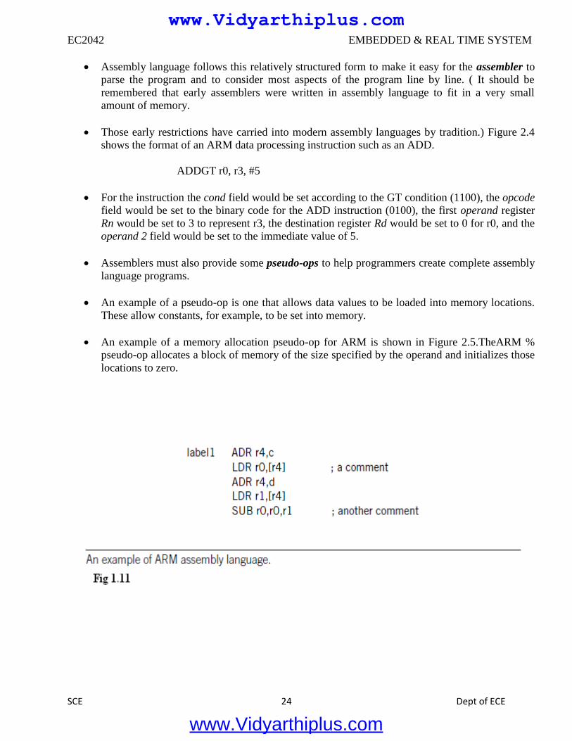
1.5.2 Assembly Language
Figure 1.11 shows a fragment of ARM assembly code to remind us of the basic features of
assembly languages. Assembly languages usually share the same basic features:
■ One instruction appears per line.
■ Labels, which give names to memory locations, start in the first column.
■ Instructions must start in the second column or after to distinguish them from labels.
■ Comments run from some designated comment character (; in the case of ARM) to the end of the
line.
www.Vidyarthiplus.com
www.Vidyarthiplus.com
EC2042 EMBEDDED & REAL TIME SYSTEM
SCE 24 Dept of ECE
Assembly language follows this relatively structured form to make it easy for the assembler to
parse the program and to consider most aspects of the program line by line. ( It should be
remembered that early assemblers were written in assembly language to fit in a very small
amount of memory.
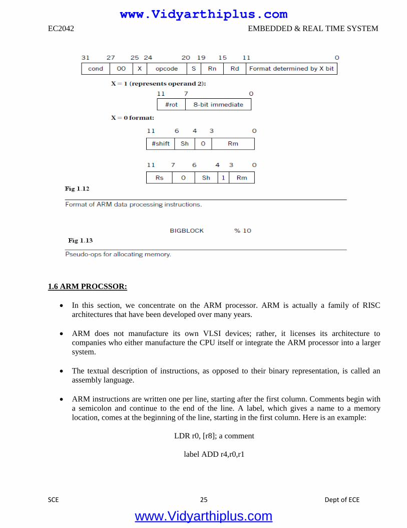
Those early restrictions have carried into modern assembly languages by tradition.) Figure 2.4
shows the format of an ARM data processing instruction such as an ADD.
ADDGT r0, r3, #5
For the instruction the cond field would be set according to the GT condition (1100), the opcode
field would be set to the binary code for the ADD instruction (0100), the first operand register
Rn would be set to 3 to represent r3, the destination register Rd would be set to 0 for r0, and the
operand 2 field would be set to the immediate value of 5.
Assemblers must also provide some pseudo-ops to help programmers create complete assembly
language programs.
An example of a pseudo-op is one that allows data values to be loaded into memory locations.
These allow constants, for example, to be set into memory.
An example of a memory allocation pseudo-op for ARM is shown in Figure 2.5.TheARM %
pseudo-op allocates a block of memory of the size specified by the operand and initializes those
locations to zero.
www.Vidyarthiplus.com
www.Vidyarthiplus.com
EC2042 EMBEDDED & REAL TIME SYSTEM
SCE 25 Dept of ECE
1.6 ARM PROCSSOR:
In this section, we concentrate on the ARM processor. ARM is actually a family of RISC
architectures that have been developed over many years.
ARM does not manufacture its own VLSI devices; rather, it licenses its architecture to
companies who either manufacture the CPU itself or integrate the ARM processor into a larger
system.
The textual description of instructions, as opposed to their binary representation, is called an
assembly language.
ARM instructions are written one per line, starting after the first column. Comments begin with
a semicolon and continue to the end of the line. A label, which gives a name to a memory
location, comes at the beginning of the line, starting in the first column. Here is an example:
LDR r0, [r8]; a comment
label ADD r4,r0,r1
www.Vidyarthiplus.com
www.Vidyarthiplus.com
EC2042 EMBEDDED & REAL TIME SYSTEM
SCE 26 Dept of ECE
1.6.1 Processor and Memory Organization:
Different versions of the ARM architecture are identified by different numbers. ARM7 is a von
Neumann architecture machine, while ARM9 uses Harvard architecture.
However, this difference is invisible to the assembly language programmer, except for possible
performance differences.
The ARM architecture supports two basic types of data:
The standard ARM word is 32 bits long.
The word may be divided into four 8-bit bytes.
ARM7 allows addresses up to 32 bits long. An address refers to a byte, not a word. Therefore,
the word 0 in the ARM address space is at location 0, the word 1 is at 4, the word 2 is at 8,and
so on. (As a result, the PC is incremented by 4 in the absence of a branch.)
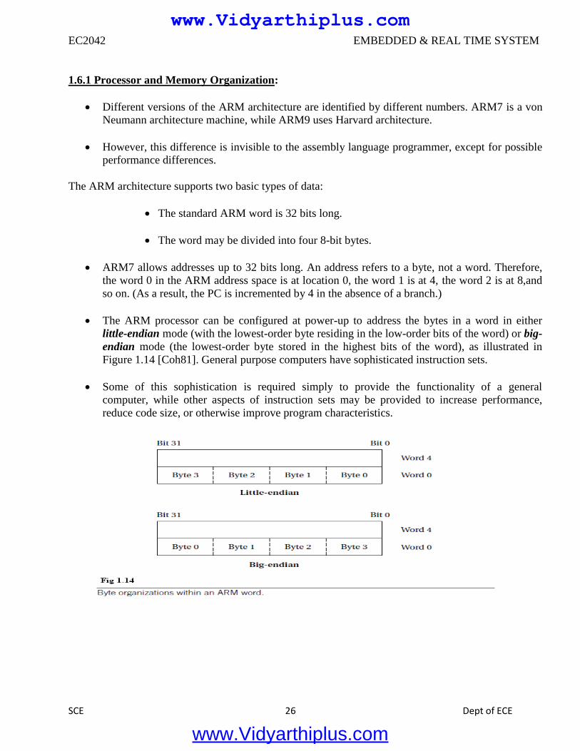
The ARM processor can be configured at power-up to address the bytes in a word in either
little-endian mode (with the lowest-order byte residing in the low-order bits of the word) or big-
endian mode (the lowest-order byte stored in the highest bits of the word), as illustrated in
Figure 1.14 [Coh81]. General purpose computers have sophisticated instruction sets.
Some of this sophistication is required simply to provide the functionality of a general
computer, while other aspects of instruction sets may be provided to increase performance,
reduce code size, or otherwise improve program characteristics.
www.Vidyarthiplus.com
www.Vidyarthiplus.com
EC2042 EMBEDDED & REAL TIME SYSTEM
SCE 27 Dept of ECE
1.6.2 Data Operations:
Arithmetic and logical operations in C are performed in variables. Variables are implemented as
memory locations. Therefore, to be able to write instructions to perform C expressions and
assignments, we must consider both arithmetic and logical instructions as well as instructions
for reading and writing memory.
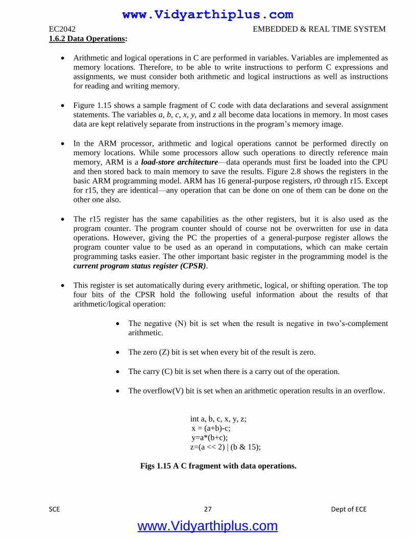
Figure 1.15 shows a sample fragment of C code with data declarations and several assignment
statements. The variables a, b, c, x, y, and z all become data locations in memory. In most cases
data are kept relatively separate from instructions in the program’s memory image.
In the ARM processor, arithmetic and logical operations cannot be performed directly on
memory locations. While some processors allow such operations to directly reference main
memory, ARM is a load-store architecture—data operands must first be loaded into the CPU
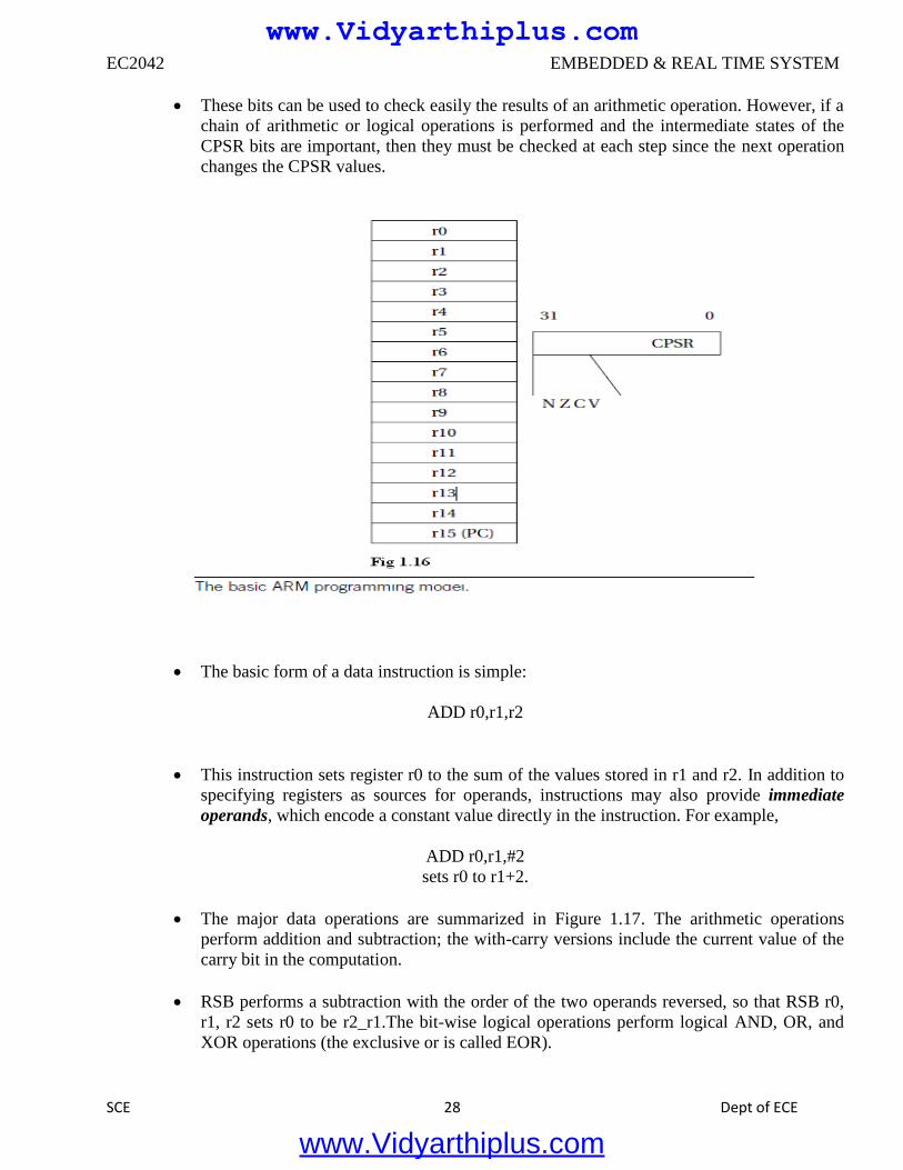
and then stored back to main memory to save the results. Figure 2.8 shows the registers in the
basic ARM programming model. ARM has 16 general-purpose registers, r0 through r15. Except
for r15, they are identical—any operation that can be done on one of them can be done on the
other one also.
The r15 register has the same capabilities as the other registers, but it is also used as the
program counter. The program counter should of course not be overwritten for use in data
operations. However, giving the PC the properties of a general-purpose register allows the
program counter value to be used as an operand in computations, which can make certain
programming tasks easier. The other important basic register in the programming model is the
current program status register (CPSR).
This register is set automatically during every arithmetic, logical, or shifting operation. The top
four bits of the CPSR hold the following useful information about the results of that
arithmetic/logical operation:
The negative (N) bit is set when the result is negative in two’s-complement
arithmetic.
The zero (Z) bit is set when every bit of the result is zero.
The carry (C) bit is set when there is a carry out of the operation.
The overflow(V) bit is set when an arithmetic operation results in an overflow.
int a, b, c, x, y, z;
x = (a+b)-c;
y=a*(b+c);
z=(a << 2) | (b & 15);
Figs 1.15 A C fragment with data operations.
www.Vidyarthiplus.com
www.Vidyarthiplus.com
EC2042 EMBEDDED & REAL TIME SYSTEM
SCE 28 Dept of ECE
These bits can be used to check easily the results of an arithmetic operation. However, if a
chain of arithmetic or logical operations is performed and the intermediate states of the
CPSR bits are important, then they must be checked at each step since the next operation
changes the CPSR values.
The basic form of a data instruction is simple:
ADD r0,r1,r2
This instruction sets register r0 to the sum of the values stored in r1 and r2. In addition to
specifying registers as sources for operands, instructions may also provide immediate
operands, which encode a constant value directly in the instruction. For example,
ADD r0,r1,#2
sets r0 to r1+2.
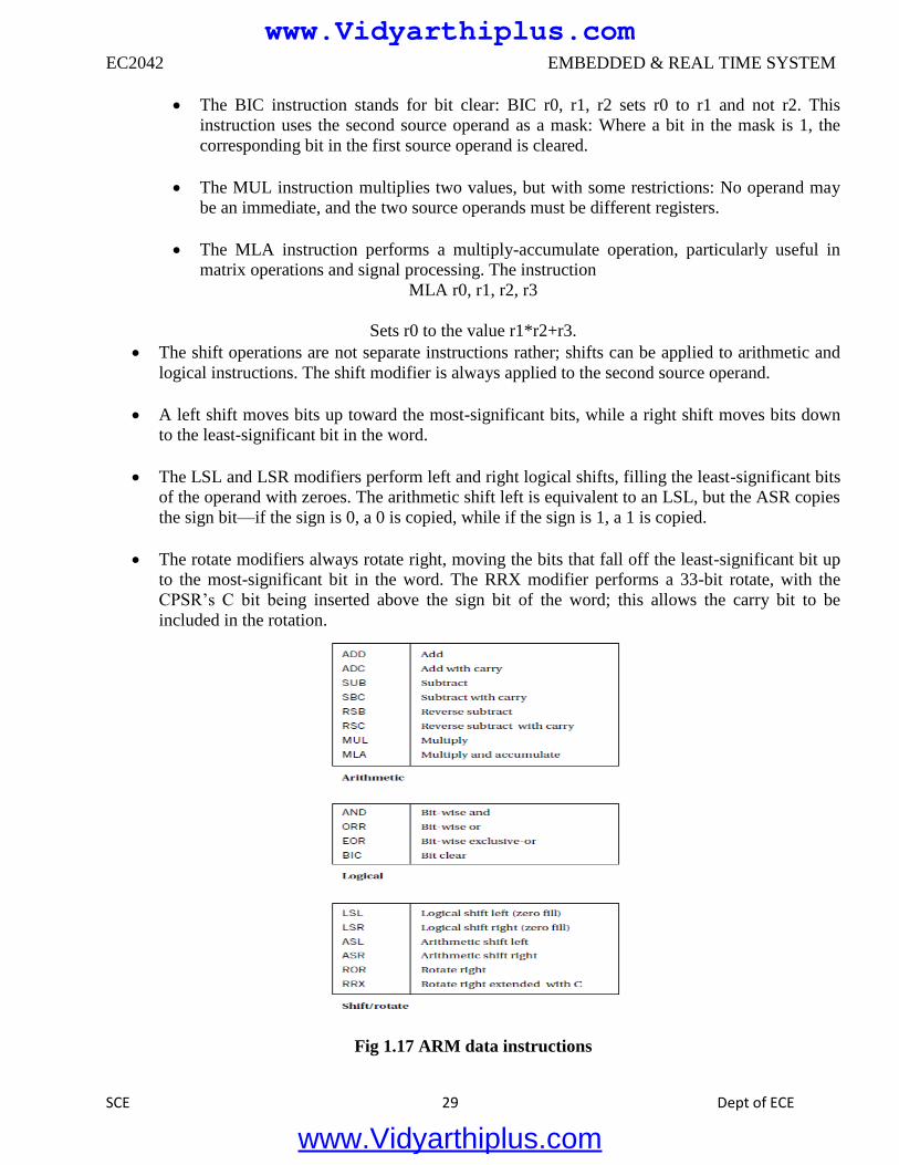
The major data operations are summarized in Figure 1.17. The arithmetic operations
perform addition and subtraction; the with-carry versions include the current value of the
carry bit in the computation.
RSB performs a subtraction with the order of the two operands reversed, so that RSB r0,
r1, r2 sets r0 to be r2_r1.The bit-wise logical operations perform logical AND, OR, and
XOR operations (the exclusive or is called EOR).
www.Vidyarthiplus.com
www.Vidyarthiplus.com
EC2042 EMBEDDED & REAL TIME SYSTEM
SCE 29 Dept of ECE
The BIC instruction stands for bit clear: BIC r0, r1, r2 sets r0 to r1 and not r2. This
instruction uses the second source operand as a mask: Where a bit in the mask is 1, the
corresponding bit in the first source operand is cleared.
The MUL instruction multiplies two values, but with some restrictions: No operand may
be an immediate, and the two source operands must be different registers.
The MLA instruction performs a multiply-accumulate operation, particularly useful in
matrix operations and signal processing. The instruction
MLA r0, r1, r2, r3
Sets r0 to the value r1*r2+r3.
The shift operations are not separate instructions rather; shifts can be applied to arithmetic and
logical instructions. The shift modifier is always applied to the second source operand.
A left shift moves bits up toward the most-significant bits, while a right shift moves bits down
to the least-significant bit in the word.
The LSL and LSR modifiers perform left and right logical shifts, filling the least-significant bits
of the operand with zeroes. The arithmetic shift left is equivalent to an LSL, but the ASR copies
the sign bit—if the sign is 0, a 0 is copied, while if the sign is 1, a 1 is copied.
The rotate modifiers always rotate right, moving the bits that fall off the least-significant bit up
to the most-significant bit in the word. The RRX modifier performs a 33-bit rotate, with the
CPSR’s C bit being inserted above the sign bit of the word; this allows the carry bit to be
included in the rotation.
Fig 1.17 ARM data instructions
www.Vidyarthiplus.com
www.Vidyarthiplus.com
EC2042 EMBEDDED & REAL TIME SYSTEM
SCE 30 Dept of ECE
1.7 Programming input and output:
The basic techniques for I/O programming can be understood relatively independent of the
instruction set. In this section, we cover the basics of I/O programming and place them in the
contexts of both the ARM and C55x.
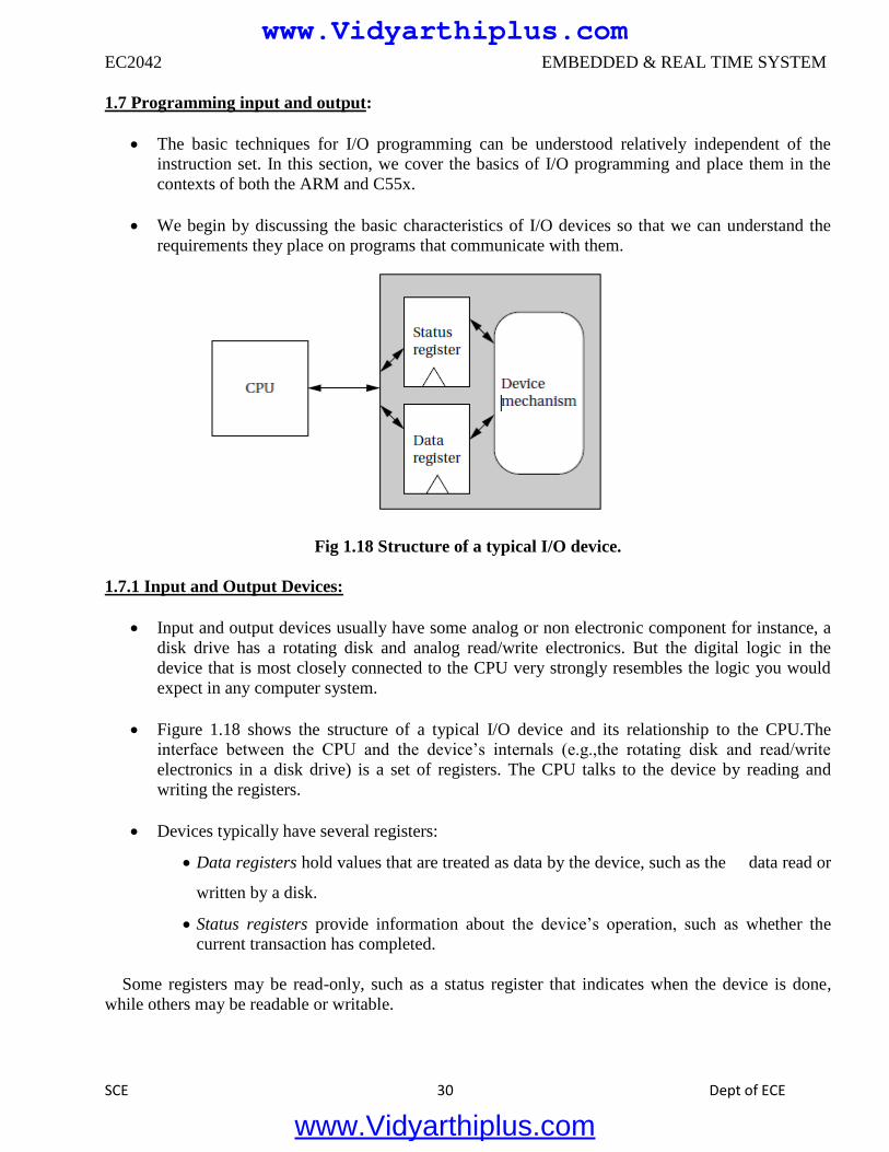
We begin by discussing the basic characteristics of I/O devices so that we can understand the
requirements they place on programs that communicate with them.
Fig 1.18 Structure of a typical I/O device.
1.7.1 Input and Output Devices:
Input and output devices usually have some analog or non electronic component for instance, a
disk drive has a rotating disk and analog read/write electronics. But the digital logic in the
device that is most closely connected to the CPU very strongly resembles the logic you would
expect in any computer system.
Figure 1.18 shows the structure of a typical I/O device and its relationship to the CPU.The
interface between the CPU and the device’s internals (e.g.,the rotating disk and read/write
electronics in a disk drive) is a set of registers. The CPU talks to the device by reading and
writing the registers.
Devices typically have several registers:
Data registers hold values that are treated as data by the device, such as the data read or
written by a disk.
Status registers provide information about the device’s operation, such as whether the
current transaction has completed.
Some registers may be read-only, such as a status register that indicates when the device is done,
while others may be readable or writable.
www.Vidyarthiplus.com
www.Vidyarthiplus.com
EC2042 EMBEDDED & REAL TIME SYSTEM
SCE 31 Dept of ECE
1.7.2 Input and Output Primitives:
Microprocessors can provide programming support for input and output in two ways: I/O
instructions and memory-mapped I/O.
Some architectures, such as the Intel x86, provide special instructions (in and out in the case of
the Intel x86) for input and output. These instructions provide a separate address space for I/O
devices.
But the most common way to implement I/O is by memory mapping even CPUs that provide
I/O instructions can also implement memory-mapped I/O.
As the name implies, memory-mapped I/O provides addresses for the registers in each I/O
device. Programs use the CPU’s normal read and write instructions to communicate with the
devices.
1.7.3 Busy-Wait I/O:
The most basic way to use devices in a program is busy-wait I/O. Devices are typically slower
than the CPU and may require many cycles to complete an operation. If the CPU is performing multiple
operations on a single device, such as writing several characters to an output device, then it must wait
for one operation to complete before starting the next one. (If we try to start writing the second
character before the device has finished with the first one, for example, the device will probably never
print the first character.) Asking an I/O device whether it is finished by reading its status register is
often called polling.
1.8 SUPERVISOR MODE, EXCEPTIONS, AND TRAPS:
These are mechanisms to handle internal conditions, and they are very similar to interrupts in form.
We begin with a discussion of supervisor mode, which some processors use to handle exceptional
events and protect executing programs from each other.
1.8.1 Supervisor Mode:
As will become clearer in later chapters, complex systems are often implemented as several
programs that communicate with each other. These programs may run under the command of an
operating system. It may be desirable to provide hardware checks to ensure that the programs do not
interfere with each other—for example, by erroneously writing into a segment of memory used by
another program. Software debugging is important but can leave some problems in a running system;
hardware checks ensure an additional level of safety.
In such cases it is often useful to have a supervisor mode provided by the CPU. Normal programs
run in user mode. The supervisor mode has privileges that user modes do not. Control of the memory
management unit (MMU) is typically reserved for supervisor mode to avoid the obvious problems that
could occur when program bugs cause inadvertent changes in the memory management registers.
www.Vidyarthiplus.com
www.Vidyarthiplus.com
EC2042 EMBEDDED & REAL TIME SYSTEM
SCE 32 Dept of ECE
Not all CPUs have supervisor modes. Many DSPs, including the C55x, do not provide
supervisor modes. The ARM, however, does have such a mode. The ARM instruction that puts the
CPU in supervisor mode is called SWI:
SWI CODE_1
It can, of course, be executed conditionally, as with any ARM instruction. SWI causes the CPU
to go into supervisor mode and sets the PC to 0x08.The argument to SWI is a 24-bit immediate value
that is passed on to the supervisor mode code; it allows the program to request various services from
the supervisor mode.
In supervisor mode, the bottom 5 bits of the CPSR are all set to 1 to indicate that the CPU is in
supervisor mode. The old value of the CPSR just before the SWI is stored in a register called the saved
program status register (SPSR). There are in fact several SPSRs for different modes; the supervisor
mode SPSR is referred to as SPSR_svc.
To return from supervisor mode, the supervisor restores the PC from register r14 and restores
the CPSR from the SPSR_svc.
1.8.2 Exceptions:
An exception is an internally detected error. A simple example is division by zero. One way to
handle this problem would be to check every divisor before division to be sure it is not zero, but
this would both substantially increase the size of numerical programs and cost a great deal of
CPU time evaluating the divisor’s value.
The CPU can more efficiently check the divisor’s value during execution. Since the time at
which a zero divisor will be found is not known in advance, this event is similar to an interrupt
except that it is generated inside the CPU. The exception mechanism provides a way for the
program to react to such unexpected events.
Just as interrupts can be seen as an extension of the subroutine mechanism, exceptions are
generally implemented as a variation of an interrupt. Since both deal with changes in the flow of
control of a program, it makes sense to use similar mechanisms. However, exceptions are
generated internally.
Exceptions in general require both prioritization and vectoring. Exceptions must be prioritized
because a single operation may generate more than one exception for example, an illegal
operand and an illegal memory access.
The priority of exceptions is usually fixed by the CPU architecture. Vectoring provides a way
for the user to specify the handler for the exception condition.
The vector number for an exception is usually predefined by the architecture; it is used to index
into a table of exception handlers.
www.Vidyarthiplus.com
www.Vidyarthiplus.com
EC2042 EMBEDDED & REAL TIME SYSTEM
SCE 33 Dept of ECE
1.8.3 Traps:
A trap, also known as a software interrupt, is an instruction that explicitly generates an
exception condition. The most common use of a trap is to enter supervisor mode.
The entry into supervisor mode must be controlled to maintain security—if the interface
between user and supervisor mode is improperly designed, a user program may be able to sneak
code into the supervisor mode that could be executed to perform harmful operations.
The ARM provides the SWI interrupt for software interrupts. This instruction causes the CPU to
enter supervisor mode. An opcode is embedded in the instruction that can be read by the
handler.
1.9 CO-PROCESSORS:
CPU architects often want to provide flexibility in what features are implemented in the CPU.
One way to provide such flexibility at the instruction set level is to allow co-processors, which are
attached to the CPU and implement some of the instructions. For example, floating-point arithmetic
was introduced into the Intel architecture by providing separate chips that implemented the floating-
point instructions.
To support co-processors, certain opcodes must be reserved in the instruction set for co-
processor operations. Because it executes instructions, a co-processor must be tightly coupled to the
CPU. When the CPU receives a co-processor instruction, the CPU must activate the co-processor and
pass it the relevant instruction. Co-processor instructions can load and store co-processor registers or
can perform internal operations. The CPU can suspend execution to wait for the co-processor
instruction to finish; it can also take a more superscalar approach and continue executing instructions
while waiting for the co-processor to finish.
A CPU may, of course, receive co-processor instructions even when there is no coprocessor
attached. Most architectures use illegal instruction traps to handle these situations. The trap handler can
detect the co-processor instruction and, for example, execute it in software on the main CPU.
Emulating co-processor instructions in software is slower but provides compatibility.
The ARM architecture provides support for up to 16 co-processors. Co-processors are able to
perform load and store operations on their own registers. They can also move data between the co-
processor registers and main ARM registers.
An example ARM co-processor is the floating-point unit. The unit occupies two co-processor
units in the ARM architecture, numbered 1 and 2, but it appears as a single unit to the programmer. It
provides eight 80-bit floating-point data registers, floating-point status registers, and an optional
floating-point status register.
www.Vidyarthiplus.com
www.Vidyarthiplus.com
EC2042 EMBEDDED & REAL TIME SYSTEM
SCE 34 Dept of ECE
1.10 MEMORY SYSTEM MECHANISMS:
Modern microprocessors do more than just read and write a monolithic memory. Architectural
features improve both the speed and capacity of memory systems.
Microprocessor clock rates are increasing at a faster rate than memory speeds, such that
memories are falling further and further behind microprocessors every day. As a result,
computer architects resort to caches to increase the average performance of the memory system.
Although memory capacity is increasing steadily, program sizes are increasing as well, and
designers may not be willing to pay for all the memory demanded by an application. Modern
microprocessor units (MMUs) perform address translations that provide a larger virtual
memory space in a small physical memory. In this section, we review both caches and MMUs.
1.10.1 Caches:
Caches are widely used to speed up memory system performance. Many microprocessor
architectures include caches as part of their definition.
The cache speeds up average memory access time when properly used. It increases the
variability of memory access times accesses in the cache will be fast, while access to locations
not cached will be slow. This variability in performance makes it especially important to
understand how caches work so that we can better understand how to predict cache performance
and factor variabilities into system design.
A cache is a small, fast memory that holds copies of some of the contents of main memory.
Because the cache is fast, it provides higher-speed access for the CPU; but since it is small, not
all requests can be satisfied by the cache, forcing the system to wait for the slower main
memory. Caching makes sense when the CPU is using only a relatively small set of memory
locations at any one time; the set of active locations is often called the working set.
Figure 1.19 shows how the cache support reads in the memory system. A cache controller
mediates between the CPU and the memory system comprised of the main memory.
The cache controller sends a memory request to the cache and main memory. If the requested
location is in the cache, the cache controller forwards the location’s contents to the CPU and
aborts the main memory request; this condition is known as a cache hit.
If the location is not in the cache, the controller waits for the value from main memory and
forwards it to the CPU; this situation is known as a cache miss.
www.Vidyarthiplus.com
www.Vidyarthiplus.com
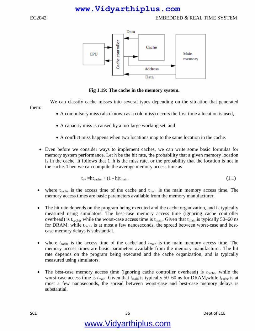
EC2042 EMBEDDED & REAL TIME SYSTEM
SCE 35 Dept of ECE
Fig 1.19: The cache in the memory system.
We can classify cache misses into several types depending on the situation that generated
them:
A compulsory miss (also known as a cold miss) occurs the first time a location is used,
A capacity miss is caused by a too-large working set, and
A conflict miss happens when two locations map to the same location in the cache.
Even before we consider ways to implement caches, we can write some basic formulas for
memory system performance. Let h be the hit rate, the probability that a given memory location
is in the cache. It follows that 1_h is the miss rate, or the probability that the location is not in
the cache. Then we can compute the average memory access time as
tav =htcache + (1 - h)tmain. (1.1)
where tcache is the access time of the cache and tmain is the main memory access time. The
memory access times are basic parameters available from the memory manufacturer.
The hit rate depends on the program being executed and the cache organization, and is typically
measured using simulators. The best-case memory access time (ignoring cache controller
overhead) is tcache, while the worst-case access time is tmain. Given that tmain is typically 50–60 ns
for DRAM, while tcache is at most a few nanoseconds, the spread between worst-case and best-
case memory delays is substantial.
where tcache is the access time of the cache and tmain is the main memory access time. The
memory access times are basic parameters available from the memory manufacturer. The hit
rate depends on the program being executed and the cache organization, and is typically
measured using simulators.
The best-case memory access time (ignoring cache controller overhead) is tcache, while the
worst-case access time is tmain. Given that tmain is typically 50–60 ns for DRAM,while tcache is at
most a few nanoseconds, the spread between worst-case and best-case memory delays is
substantial.
www.Vidyarthiplus.com
www.Vidyarthiplus.com
EC2042 EMBEDDED & REAL TIME SYSTEM
SCE 36 Dept of ECE
Modern CPUs may use multiple levels of cache as shown in Figure 1.20. The first-level cache
(commonly known as L1 cache) is closest to the CPU, the second-level cache (L2 cache) feeds
the first-level cache, and so on.
The second-level cache is much larger but is also slower. If h1 is the first-level hit rate and h2 is
the rate at which access hit the second-level cache but not the first-level cache, then the average
access time for a two-level cache system is
tav = h1tL1 + h2tL2 +(1 - h1 - h2)tmain. ( 1.2)
o As the program’s working set changes, we expect locations to be removed from
the cache to make way for new locations. When set-associative caches are used,
we have to think about what happens when we throw out a value from the cache
to make room for a new value.
We do not have this problem in direct-mapped caches because every location maps onto a
unique block, but in a set-associative cache we must decide which set will have its
block thrown out to make way for the new block.
One possible replacement policy is least recently used (LRU), that is, throw out the block
that has been used farthest in the past. We can add relatively small amounts of hardware
to the cache to keep track of the time since the last access for each block. Another
policy is random replacement, which requires even less hardware to implement.
The simplest way to implement a cache is a direct-mapped cache, as shown in Figure
1.20. The cache consists of cache blocks, each of which includes a tag to show which
memory location is represented by this block, a data field holding the contents of that
memory, and a valid tag to show whether the contents of this cache block are valid. An
address is divided into three sections.
The index is used to select which cache block to check. The tag is compared against
the tag value in the block selected by the index. If the address tag matches the tag
value in the block, that block includes the desired memory location.
If the length of the data field is longer than the minimum addressable unit, then the
lowest bits of the address are used as an offset to select the required value from the
data field. Given the structure of the cache, there is only one block that must be
checked to see whether a location is in the cache—the index uniquely determines
that block. If the access is a hit, the data value is read from the cache.
Writes are slightly more complicated than reads because we have to update main memory
as well as the cache. There are several methods by which we can do this. The simplest
scheme is known as write-through—every write changes both the cache and the
corresponding main memory location (usually through a write buffer).
www.Vidyarthiplus.com
www.Vidyarthiplus.com
EC2042 EMBEDDED & REAL TIME SYSTEM
SCE 37 Dept of ECE
This scheme ensures that the cache and main memory are consistent, but may generate
some additional main memory traffic. We can reduce the number of times we write to
main memory by using a write-back policy: If we write only when we remove a location
from the cache, we eliminate the writes when a location is written several times before
it is removed from the cache.
Fig 1.20: A direct-mapped cache.
The direct-mapped cache is both fast and relatively low cost, but it does have limits in its caching
power due to its simple scheme for mapping the cache onto main memory. Consider a direct-
mapped cache with four blocks, in which locations 0, 1, 2, and 3 all map to different blocks. But
locations 4, 8, 12…all map to the same block as location 0; locations 1, 5, 9, 13…all map to a
single block; and so on. If two popular locations in a program happen to map onto the same block,
we will not gain the full benefits of the cache. As seen in Section 5.6, this can create program
performance problems.
The limitations of the direct-mapped cache can be reduced by going to the set-associative cache
structure shown in Figure 1.21.A set-associative cache is characterized by the number of banks or
ways it uses, giving an n-way set-associative cache.
A set is formed by all the blocks (one for each bank) that share the same index. Each set is
implemented with a direct-mapped cache. A cache request is broadcast to all banks
simultaneously. If any of the sets has the location, the cache reports a hit.
Although memory locations map onto blocks using the same function, there are n separate blocks
for each set of locations. Therefore, we can simultaneously cache several locations that happen to
map onto the same cache block. The set associative cache structure incurs a little extra overhead
and is slightly slower than a direct-mapped cache, but the higher hit rates that it can provide often
compensate.
www.Vidyarthiplus.com
www.Vidyarthiplus.com
EC2042 EMBEDDED & REAL TIME SYSTEM
SCE 38 Dept of ECE
The set-associative cache generally provides higher hit rates than the direct mapped cache
because conflicts between a small number of locations can be resolved within the cache. The set-
associative cache is somewhat slower, so the CPU designer has to be careful that it doesn’t slow
down the CPU’s cycle time too much. A more important problem with set-associative caches for
embedded program.
Fig 1.21: A set-associative cache.
Design is predictability. Because the time penalty for a cache miss is so severe, we often want
to make sure that critical segments of our programs have good behavior in the cache. It is
relatively easy to determine when two memory locations will conflict in a direct-mapped cache.
Conflicts in a set-associative cache are more subtle, and so the behavior of a set-associative
cache is more difficult to analyze for both humans and programs.
1.11 CPU PERFORMANCE:
Now that we have an understanding of the various types of instructions that CPUs can execute,
we can move on to a topic particularly important in embedded computing: How fast can the CPU
execute instructions? In this section, we consider three factors that can substantially influence program
performance: pipelining and caching.
1.11.1 Pipelining
Modern CPUs are designed as pipelined machines in which several instructions are executed in
parallel. Pipelining greatly increases the efficiency of the CPU. But like any pipeline, a CPU pipeline
works best when its contents flow smoothly.
Some sequences of instructions can disrupt the flow of information in the pipeline and,
temporarily at least, slow down the operation of the CPU.
www.Vidyarthiplus.com
www.Vidyarthiplus.com
EC2042 EMBEDDED & REAL TIME SYSTEM
SCE 39 Dept of ECE
The ARM7 has a three-stage pipeline:
■ Fetch the instruction is fetched from memory.
■ Decode the instruction’s opcode and operands are decoded to determine what function to perform.
■ Execute the decoded instruction is executed.
Each of these operations requires one clock cycle for typical instructions. Thus, a normal
instruction requires three clock cycles to completely execute, known as the latency of instruction
execution. But since the pipeline has three stages, an instruction is completed in every clock cycle. In
other words, the pipeline has a throughput of one instruction per cycle.
Figure 1.22 illustrates the position of instructions in the pipeline during execution using the
notation introduced by Hennessy and Patterson [Hen06]. A vertical slice through the timeline shows all
instructions in the pipeline at that time. By following an instruction horizontally, we can see the
progress of its execution.
The C55x includes a seven-stage pipeline [Tex00B]:
1. Fetch.
2. Decode.
3. Address computes data and branch addresses.
4. Access 1 reads data.
5. Access 2 finishes data read.
6. Read stage puts operands onto internal busses.
7. Execute performs operations.
RISC machines are designed to keep the pipeline busy. CISC machines may display a wide
variation in instruction timing. Pipelined RISC machines typically have more regular timing
characteristics most instructions that do not have pipeline hazards display the same latency.
Fig 1.22 Pipelined execution of ARM instructions.
1.11.2 Caching
We have already discussed caches functionally. Although caches are invisible in the
programming model, they have a profound effect on performance. We introduce caches because they
substantially reduce memory access time when the requested location is in the cache.
www.Vidyarthiplus.com
www.Vidyarthiplus.com
EC2042 EMBEDDED & REAL TIME SYSTEM
SCE 40 Dept of ECE
However, the desired location is not always in the cache since it is considerably smaller than
main memory. As a result, caches cause the time required to access memory to vary considerably. The
extra time required to access a memory location not in the cache is often called the cache miss penalty.
The amount of variation depends on several factors in the system architecture, but a cache
miss is often several clock cycles slower than a cache hit. The time required to access a memory
location depends on whether the
requested location is in the cache. However, as we have seen, a location may not be in the cache for
several reasons.
■ At a compulsory miss, the location has not been referenced before.
■ At a conflict miss, two particular memory locations are fighting for the same cache line.
■ At a capacity miss, the program’s working set is simply too large for the cache.
The contents of the cache can change considerably over the course of execution of a program. When we
have several programs running concurrently on the CPU,
1.12 CPU POWER CONSUMPTION:
Power consumption is, in some situations, as important as execution time. In this section we
study the characteristics of CPUs that influence power consumption and mechanisms provided by
CPUs to control how much power they consume. First, it is important to distinguish between energy
and power. Power is, of course, energy consumption per unit time. Heat generation depends on power
consumption. Battery life, on the other hand, most directly depends on energy consumption. Generally,
we will use the term power as shorthand for energy and power consumption, distinguishing between
them only when necessary.
The high-level power consumption characteristics of CPUs and other system components are
derived from the circuits used to build those components. Today, virtually all digital systems are built
with complementary metal oxide semiconductor (CMOS) circuitry. The detailed circuit
characteristics are best left to a study of VLSI design [Wol08], but the basic sources of CMOS power
consumption are easily identified and briefly described below.
■ Voltage drops: The dynamic power consumption of a CMOS circuit is proportional to the square of
the power supply voltage (V2). Therefore, by reducing the power supply voltage to the lowest level that
provides the required performance, we can significantly reduce power consumption. We also may be
able to add parallel hardware and even further reduce the power supply voltage while maintaining
required performance.
■ Toggling: A CMOS circuit uses most of its power when it is changing its output value. This provides
two ways to reduce power consumption. By reducing the speed at which the circuit operates, we can
reduce its power consumption (although not the total energy required for the operation, since the result
is available later).We can actually reduce energy consumption by eliminating unnecessary changes to
the inputs of a CMOS circuit—eliminating unnecessary glitches at the circuit outputs eliminates
unnecessary power consumption.
www.Vidyarthiplus.com
www.Vidyarthiplus.com
EC2042 EMBEDDED & REAL TIME SYSTEM
SCE 41 Dept of ECE
UNIT II
COMPUTING PLATFORM AND DESIGN ANALYSIS
2.1 CPU BUSES:
A computer system encompasses much more than the CPU;it also includes memory and I/O
devices. The bus is the mechanism by which the CPU communicates with memory and devices. A bus
is, at a minimum, a collection of wires, but the bus also defines a protocol by which the CPU, memory,
and devices communicate. One of the major roles of the bus is to provide an interface to memory. (Of
course, I/O devices also connect to the bus.)
2.1.1 Bus Protocols:
The basic building block of most bus protocols is the four-cycle handshake, illustrated in
Figure 2.1. The handshake ensures that when two devices want to communicate, one is ready to
transmit and the other is ready to receive.
The handshake uses a pair of wires dedicated to the handshake: enq (meaning enquiry) and ack
(meaning acknowledge). Extra wires are used for the data transmitted during the handshake. The four
cycles are described below.
1. Device 1 raises its output to signal an enquiry, which tells device 2 that it should get ready to listen
for data.
2. When device 2 is ready to receive, it raises its output to signal an acknowledgment. At this point,
devices 1 and 2 can transmit or receive.
3. Once the data transfer is complete, device 2 lowers its output, signaling that it has received the data.
4. After seeing that ack has been released, device 1 lowers its output.
At the end of the handshake, both handshaking signals are low, just as they were at the start of the
handshake. The system has thus returned to its original state in readiness for another handshake-
enabled data transfer.
Microprocessor buses build on the handshake for communication between the CPU and other
system components. The term bus is used in two ways.
The most basic use is as a set of related wires, such as address wires. However, the term may also
mean a protocol for communicating between components.
To avoid confusion, we will use the term bundle to refer to a set of related signals. The
fundamental bus operations are reading and writing. Figure 2.2 shows the structure of a typical bus that
supports reads and writes.
www.Vidyarthiplus.com
www.Vidyarthiplus.com
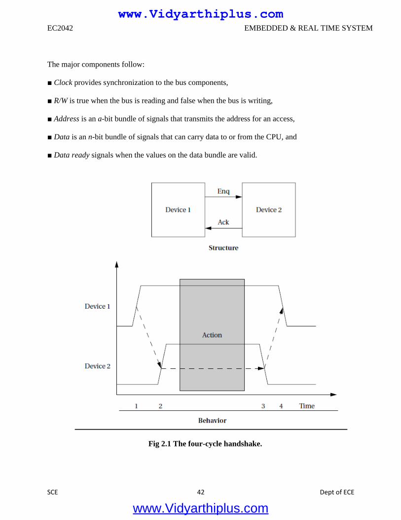
EC2042 EMBEDDED & REAL TIME SYSTEM
SCE 42 Dept of ECE
The major components follow:
■ Clock provides synchronization to the bus components,
■ R/W is true when the bus is reading and false when the bus is writing,
■ Address is an a-bit bundle of signals that transmits the address for an access,
■ Data is an n-bit bundle of signals that can carry data to or from the CPU, and
■ Data ready signals when the values on the data bundle are valid.
Fig 2.1 The four-cycle handshake.
www.Vidyarthiplus.com
www.Vidyarthiplus.com
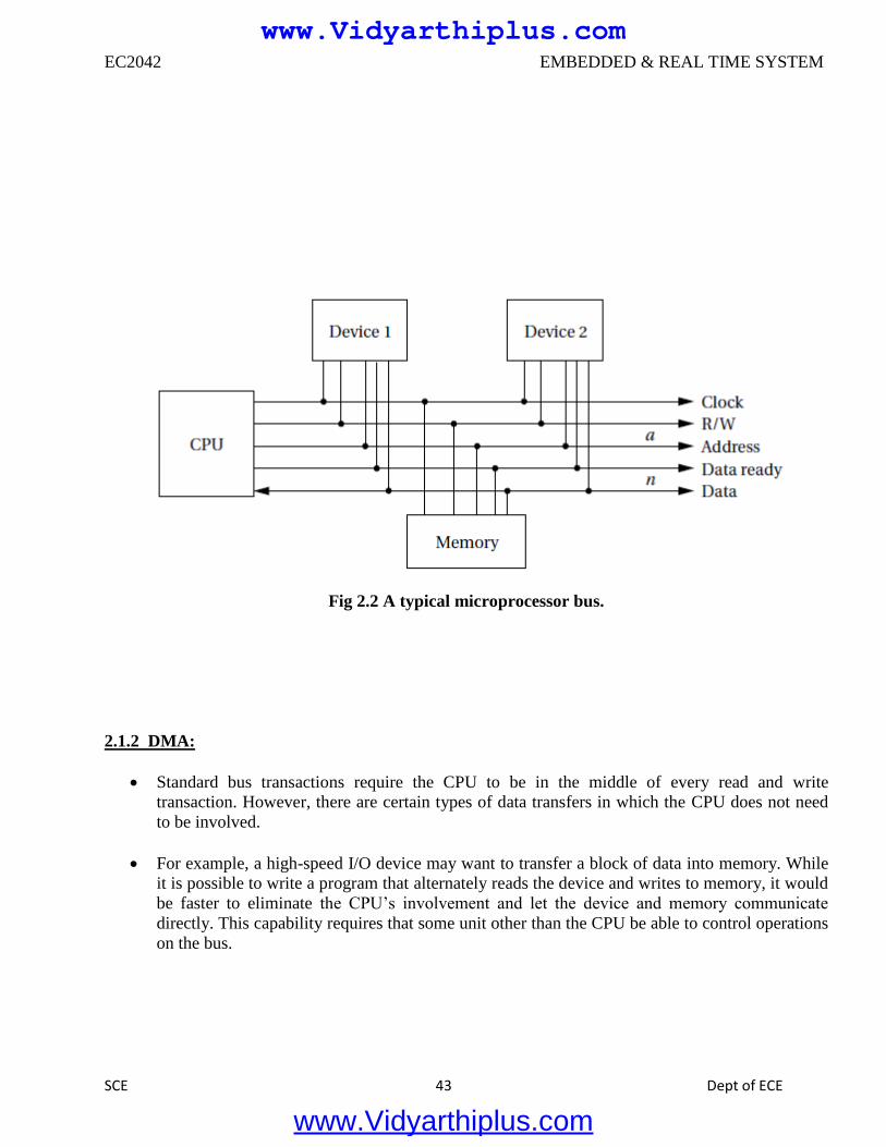
EC2042 EMBEDDED & REAL TIME SYSTEM
SCE 43 Dept of ECE
Fig 2.2 A typical microprocessor bus.
2.1.2 DMA:
Standard bus transactions require the CPU to be in the middle of every read and write
transaction. However, there are certain types of data transfers in which the CPU does not need
to be involved.
For example, a high-speed I/O device may want to transfer a block of data into memory. While
it is possible to write a program that alternately reads the device and writes to memory, it would
be faster to eliminate the CPU’s involvement and let the device and memory communicate
directly. This capability requires that some unit other than the CPU be able to control operations
on the bus.
www.Vidyarthiplus.com
www.Vidyarthiplus.com
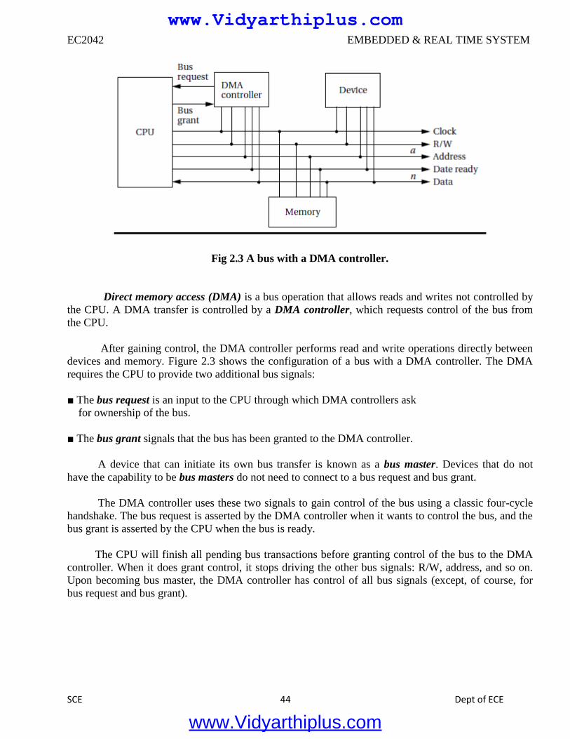
EC2042 EMBEDDED & REAL TIME SYSTEM
SCE 44 Dept of ECE
Fig 2.3 A bus with a DMA controller.
Direct memory access (DMA) is a bus operation that allows reads and writes not controlled by
the CPU. A DMA transfer is controlled by a DMA controller, which requests control of the bus from
the CPU.
After gaining control, the DMA controller performs read and write operations directly between
devices and memory. Figure 2.3 shows the configuration of a bus with a DMA controller. The DMA
requires the CPU to provide two additional bus signals:
■ The bus request is an input to the CPU through which DMA controllers ask
for ownership of the bus.
■ The bus grant signals that the bus has been granted to the DMA controller.
A device that can initiate its own bus transfer is known as a bus master. Devices that do not
have the capability to be bus masters do not need to connect to a bus request and bus grant.
The DMA controller uses these two signals to gain control of the bus using a classic four-cycle
handshake. The bus request is asserted by the DMA controller when it wants to control the bus, and the
bus grant is asserted by the CPU when the bus is ready.
The CPU will finish all pending bus transactions before granting control of the bus to the DMA
controller. When it does grant control, it stops driving the other bus signals: R/W, address, and so on.
Upon becoming bus master, the DMA controller has control of all bus signals (except, of course, for
bus request and bus grant).
www.Vidyarthiplus.com
www.Vidyarthiplus.com
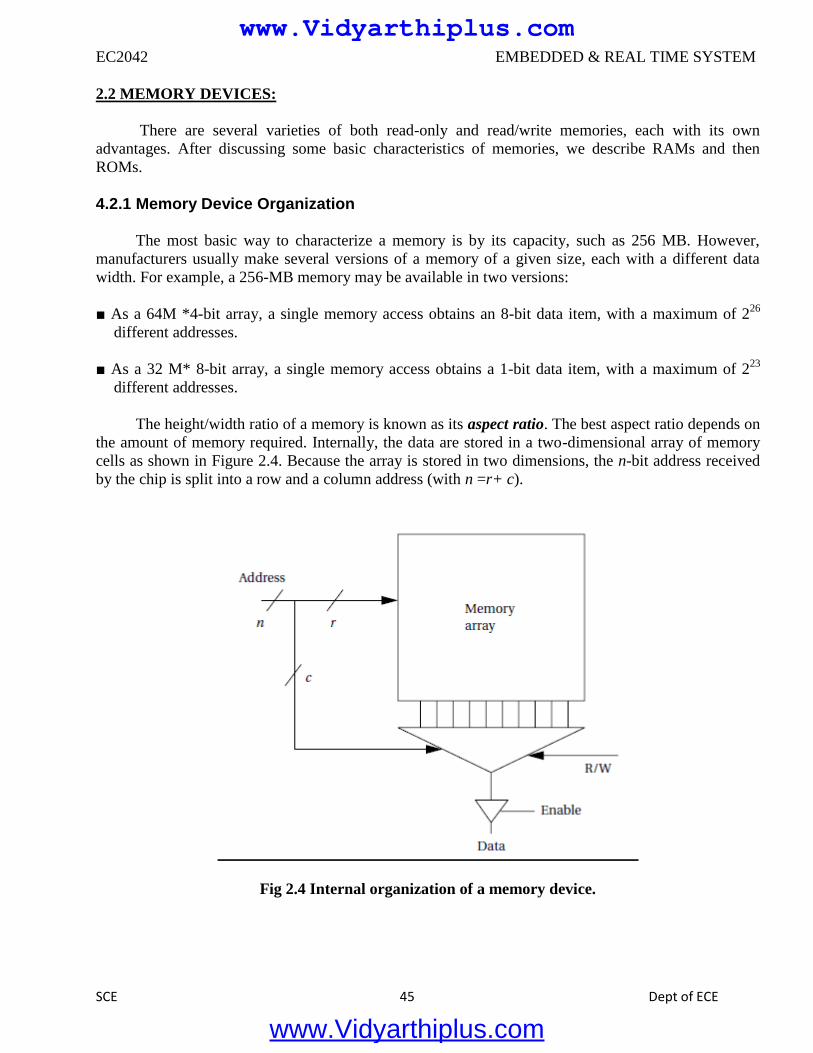
EC2042 EMBEDDED & REAL TIME SYSTEM
SCE 45 Dept of ECE
2.2 MEMORY DEVICES:
There are several varieties of both read-only and read/write memories, each with its own
advantages. After discussing some basic characteristics of memories, we describe RAMs and then
ROMs.
4.2.1 Memory Device Organization The most basic way to characterize a memory is by its capacity, such as 256 MB. However,
manufacturers usually make several versions of a memory of a given size, each with a different data
width. For example, a 256-MB memory may be available in two versions:
■ As a 64M *4-bit array, a single memory access obtains an 8-bit data item, with a maximum of 226
different addresses.
■ As a 32 M* 8-bit array, a single memory access obtains a 1-bit data item, with a maximum of 223
different addresses.
The height/width ratio of a memory is known as its aspect ratio. The best aspect ratio depends on
the amount of memory required. Internally, the data are stored in a two-dimensional array of memory
cells as shown in Figure 2.4. Because the array is stored in two dimensions, the n-bit address received
by the chip is split into a row and a column address (with n =r+ c).
Fig 2.4 Internal organization of a memory device.
www.Vidyarthiplus.com
www.Vidyarthiplus.com
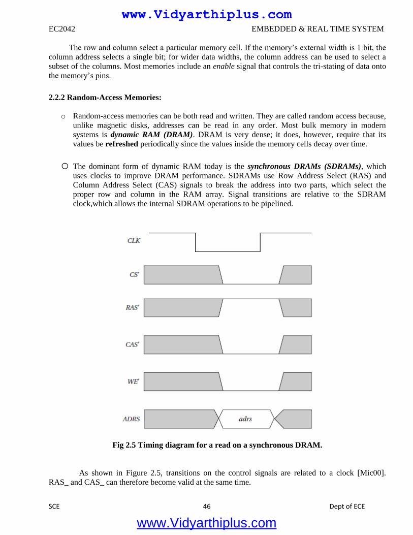
EC2042 EMBEDDED & REAL TIME SYSTEM
SCE 46 Dept of ECE
The row and column select a particular memory cell. If the memory’s external width is 1 bit, the
column address selects a single bit; for wider data widths, the column address can be used to select a
subset of the columns. Most memories include an enable signal that controls the tri-stating of data onto
the memory’s pins.
2.2.2 Random-Access Memories:
o Random-access memories can be both read and written. They are called random access because,
unlike magnetic disks, addresses can be read in any order. Most bulk memory in modern
systems is dynamic RAM (DRAM). DRAM is very dense; it does, however, require that its
values be refreshed periodically since the values inside the memory cells decay over time.
o The dominant form of dynamic RAM today is the synchronous DRAMs (SDRAMs), which
uses clocks to improve DRAM performance. SDRAMs use Row Address Select (RAS) and
Column Address Select (CAS) signals to break the address into two parts, which select the
proper row and column in the RAM array. Signal transitions are relative to the SDRAM
clock,which allows the internal SDRAM operations to be pipelined.
Fig 2.5 Timing diagram for a read on a synchronous DRAM.
As shown in Figure 2.5, transitions on the control signals are related to a clock [Mic00].
RAS_ and CAS_ can therefore become valid at the same time.
www.Vidyarthiplus.com
www.Vidyarthiplus.com
EC2042 EMBEDDED & REAL TIME SYSTEM
SCE 47 Dept of ECE
o The address lines are not shown in full detail here; some address lines may not be active
depending on the mode in use. SDRAMs use a separate refresh signal to control refreshing.
DRAM has to be refreshed roughly once per millisecond.
o Rather than refresh the entire memory at once, DRAMs refresh part of the memory at a time.
When a section of memory is being refreshed, it cannot be accessed until the refresh is
complete. The memory refresh occurs over fairly few seconds so that each section is refreshed
every few microseconds.
o SDRAMs include registers that control the mode in which the SDRAM operates. SDRAMs
support burst modes that allow several sequential addresses to be accessed by sending only one
address. SDRAMs generally also support an interleaved mode that exchanges pairs of bytes.
2.2.3 Read-Only Memories:
o Read-only memories (ROMs) are preprogrammed with fixed data. They are very useful in
embedded systems since a great deal of the code, and perhaps some data, does not change over
time. Read-only memories are also less sensitive to radiation induced errors.
o There are several varieties of ROM available. The first-level distinction to be made is between
factory-programmed ROM (sometimes called mask-programmed ROM) and field-
programmable ROM.
o Factory-programmed ROMs are ordered from the factory with particular programming. ROMs
can typically be ordered in lots of a few thousand, but clearly factory programming is useful
only when the ROMs are to be installed in some quantity.
o Field-programmable ROMs, on the other hand, can be programmed in the lab. Flash memory is
the dominant form of field-programmable ROM and is electrically erasable.
o Flash memory uses standard system voltage for erasing and programming, allowing it to be
reprogrammed inside a typical system. This allows applications such as automatic distribution
of upgrades—the flash memory can be reprogrammed while downloading the new memory
contents from a telephone line.
o Early flash memories had to be erased in their entirety; modern devices allow memory to be
erased in blocks. Most flash memories today allow certain blocks to be protected.
o A common application is to keep the boot-up code in a protected block but allow updates to
other memory blocks on the device. As a result, this form of flash is commonly known as boot-
block flash.
www.Vidyarthiplus.com
www.Vidyarthiplus.com
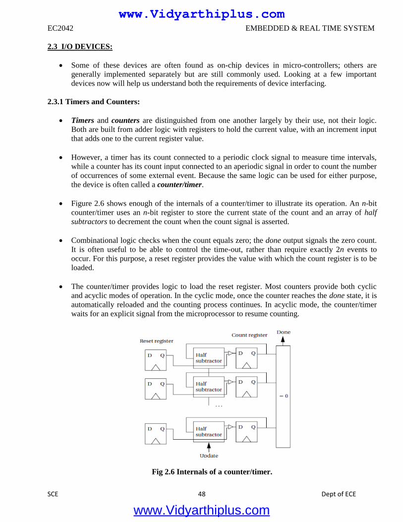
EC2042 EMBEDDED & REAL TIME SYSTEM
SCE 48 Dept of ECE
2.3 I/O DEVICES:
Some of these devices are often found as on-chip devices in micro-controllers; others are
generally implemented separately but are still commonly used. Looking at a few important
devices now will help us understand both the requirements of device interfacing.
2.3.1 Timers and Counters:
Timers and counters are distinguished from one another largely by their use, not their logic.
Both are built from adder logic with registers to hold the current value, with an increment input
that adds one to the current register value.
However, a timer has its count connected to a periodic clock signal to measure time intervals,
while a counter has its count input connected to an aperiodic signal in order to count the number
of occurrences of some external event. Because the same logic can be used for either purpose,
the device is often called a counter/timer.
Figure 2.6 shows enough of the internals of a counter/timer to illustrate its operation. An n-bit
counter/timer uses an n-bit register to store the current state of the count and an array of half
subtractors to decrement the count when the count signal is asserted.
Combinational logic checks when the count equals zero; the done output signals the zero count.
It is often useful to be able to control the time-out, rather than require exactly 2n events to
occur. For this purpose, a reset register provides the value with which the count register is to be
loaded.
The counter/timer provides logic to load the reset register. Most counters provide both cyclic
and acyclic modes of operation. In the cyclic mode, once the counter reaches the done state, it is
automatically reloaded and the counting process continues. In acyclic mode, the counter/timer
waits for an explicit signal from the microprocessor to resume counting.
Fig 2.6 Internals of a counter/timer.
www.Vidyarthiplus.com
www.Vidyarthiplus.com
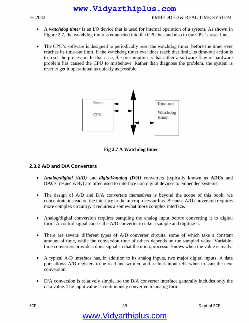
EC2042 EMBEDDED & REAL TIME SYSTEM
SCE 49 Dept of ECE
A watchdog timer is an I/O device that is used for internal operation of a system. As shown in
Figure 2.7, the watchdog timer is connected into the CPU bus and also to the CPU’s reset line.
The CPU’s software is designed to periodically reset the watchdog timer, before the timer ever
reaches its time-out limit. If the watchdog timer ever does reach that limit, its time-out action is
to reset the processor. In that case, the presumption is that either a software flaw or hardware
problem has caused the CPU to misbehave. Rather than diagnose the problem, the system is
reset to get it operational as quickly as possible.
Fig 2.7 A Watchdog timer
2.3.2 A/D and D/A Converters
Analog/digital (A/D) and digital/analog (D/A) converters (typically known as ADCs and
DACs, respectively) are often used to interface non digital devices to embedded systems.
The design of A/D and D/A converters themselves is beyond the scope of this book; we
concentrate instead on the interface to the microprocessor bus. Because A/D conversion requires
more complex circuitry, it requires a somewhat more complex interface.
Analog/digital conversion requires sampling the analog input before converting it to digital
form. A control signal causes the A/D converter to take a sample and digitize it.
There are several different types of A/D converter circuits, some of which take a constant
amount of time, while the conversion time of others depends on the sampled value. Variable-
time converters provide a done signal so that the microprocessor knows when the value is ready.
A typical A/D interface has, in addition to its analog inputs, two major digital inputs. A data
port allows A/D registers to be read and written, and a clock input tells when to start the next
conversion.
D/A conversion is relatively simple, so the D/A converter interface generally includes only the
data value. The input value is continuously converted to analog form.
www.Vidyarthiplus.com
www.Vidyarthiplus.com
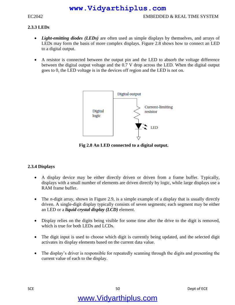
EC2042 EMBEDDED & REAL TIME SYSTEM
SCE 50 Dept of ECE
2.3.3 LEDs
Light-emitting diodes (LEDs) are often used as simple displays by themselves, and arrays of
LEDs may form the basis of more complex displays. Figure 2.8 shows how to connect an LED
to a digital output.
A resistor is connected between the output pin and the LED to absorb the voltage difference
between the digital output voltage and the 0.7 V drop across the LED. When the digital output
goes to 0, the LED voltage is in the devices off region and the LED is not on.
Fig 2.8 An LED connected to a digital output.
2.3.4 Displays
A display device may be either directly driven or driven from a frame buffer. Typically,
displays with a small number of elements are driven directly by logic, while large displays use a
RAM frame buffer.
The n-digit array, shown in Figure 2.9, is a simple example of a display that is usually directly
driven. A single-digit display typically consists of seven segments; each segment may be either
an LED or a liquid crystal display (LCD) element.
Display relies on the digits being visible for some time after the drive to the digit is removed,
which is true for both LEDs and LCDs.
The digit input is used to choose which digit is currently being updated, and the selected digit
activates its display elements based on the current data value.
The display’s driver is responsible for repeatedly scanning through the digits and presenting the
current value of each to the display.
www.Vidyarthiplus.com
www.Vidyarthiplus.com
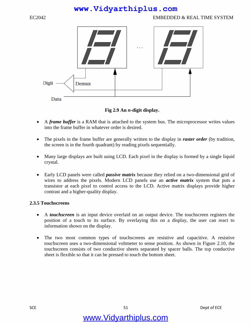
EC2042 EMBEDDED & REAL TIME SYSTEM
SCE 51 Dept of ECE
Fig 2.9 An n-digit display.
A frame buffer is a RAM that is attached to the system bus. The microprocessor writes values
into the frame buffer in whatever order is desired.
The pixels in the frame buffer are generally written to the display in raster order (by tradition,
the screen is in the fourth quadrant) by reading pixels sequentially.
Many large displays are built using LCD. Each pixel in the display is formed by a single liquid
crystal.
Early LCD panels were called passive matrix because they relied on a two-dimensional grid of
wires to address the pixels. Modern LCD panels use an active matrix system that puts a
transistor at each pixel to control access to the LCD. Active matrix displays provide higher
contrast and a higher-quality display.
2.3.5 Touchscreens
A touchscreen is an input device overlaid on an output device. The touchscreen registers the
position of a touch to its surface. By overlaying this on a display, the user can react to
information shown on the display.
The two most common types of touchscreens are resistive and capacitive. A resistive
touchscreen uses a two-dimensional voltmeter to sense position. As shown in Figure 2.10, the
touchscreen consists of two conductive sheets separated by spacer balls. The top conductive
sheet is flexible so that it can be pressed to touch the bottom sheet.
www.Vidyarthiplus.com
www.Vidyarthiplus.com
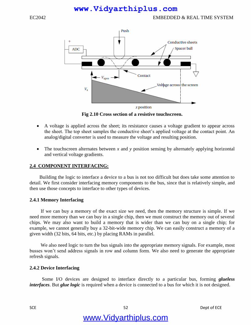
EC2042 EMBEDDED & REAL TIME SYSTEM
SCE 52 Dept of ECE
Fig 2.10 Cross section of a resistive touchscreen.
A voltage is applied across the sheet; its resistance causes a voltage gradient to appear across
the sheet. The top sheet samples the conductive sheet’s applied voltage at the contact point. An
analog/digital converter is used to measure the voltage and resulting position.
The touchscreen alternates between x and y position sensing by alternately applying horizontal
and vertical voltage gradients.
2.4 COMPONENT INTERFACING:
Building the logic to interface a device to a bus is not too difficult but does take some attention to
detail. We first consider interfacing memory components to the bus, since that is relatively simple, and
then use those concepts to interface to other types of devices.
2.4.1 Memory Interfacing
If we can buy a memory of the exact size we need, then the memory structure is simple. If we
need more memory than we can buy in a single chip, then we must construct the memory out of several
chips. We may also want to build a memory that is wider than we can buy on a single chip; for
example, we cannot generally buy a 32-bit-wide memory chip. We can easily construct a memory of a
given width (32 bits, 64 bits, etc.) by placing RAMs in parallel.
We also need logic to turn the bus signals into the appropriate memory signals. For example, most
busses won’t send address signals in row and column form. We also need to generate the appropriate
refresh signals.
2.4.2 Device Interfacing
Some I/O devices are designed to interface directly to a particular bus, forming glueless
interfaces. But glue logic is required when a device is connected to a bus for which it is not designed.
www.Vidyarthiplus.com
www.Vidyarthiplus.com
EC2042 EMBEDDED & REAL TIME SYSTEM
SCE 53 Dept of ECE
An I/O device typically requires a much smaller range of addresses than a memory, so
addresses must be decoded much more finely. Some additional logic is required to cause the bus to read
and write the device’s registers.
2.5 DESIGN WITH MICROPROCESSORS:
2.5.1 System Architecture
We know that an architecture is a set of elements and the relationships between them that together
form a single unit. The architecture of an embedded computing system is the blueprint for
implementing that system—it tells you what components you need and how you put them together.
The architecture of an embedded computing system includes both hardware and software elements.
Let’s consider each in turn.
The hardware architecture of an embedded computing system is the more obvious manifestation of
the architecture since you can touch it and feel it. It includes several elements, some of which may
be less obvious than others.
o CPU An embedded computing system clearly contains a microprocessor. But which one? There
are many different architectures, and even within an architecture we can select between models
that vary in clock speed, bus data width, integrated peripherals, and so on. The choice of the
CPU is one of the most important, but it cannot be made without considering the software that
will execute on the machine.
o Bus The choice of a bus is closely tied to that of a CPU, since the bus is an integral part of the
microprocessor. But in applications that make intensive use of the bus due to I/O or other data
traffic, the bus may be more of a limiting factor than the CPU. Attention must be paid to the
required data bandwidths to be sure that the bus can handle the traffic.
o Memory Once again, the question is not whether the system will have memory but the
characteristics of that memory. The most obvious characteristic is total size, which depends on
both the required data volume and the size of the program instructions. The ratio of ROM to
RAM and selection of DRAM versus SRAM can have a significant influence on the cost of the
system. The speed of the memory will play a large part in determining system performance.
o Input and output devices The user’s view of the input and output mechanisms may not
correspond to the devices connected to the microprocessor. For example, a set of switches and
knobs on a front panel may all be controlled by a single microcontroller, which is in turn
connected to the main CPU.
For a given function, there may be several different devices of varying sophistication and cost that
can do the job. The difficulty of using a particular device, such as the amount of glue logic required
to interface it, may also play a role in final device selection.
www.Vidyarthiplus.com
www.Vidyarthiplus.com
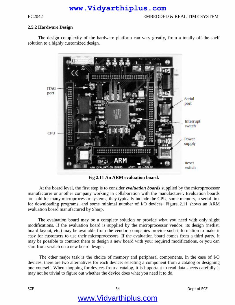
EC2042 EMBEDDED & REAL TIME SYSTEM
SCE 54 Dept of ECE
2.5.2 Hardware Design
The design complexity of the hardware platform can vary greatly, from a totally off-the-shelf
solution to a highly customized design.
Fig 2.11 An ARM evaluation board.
At the board level, the first step is to consider evaluation boards supplied by the microprocessor
manufacturer or another company working in collaboration with the manufacturer. Evaluation boards
are sold for many microprocessor systems; they typically include the CPU, some memory, a serial link
for downloading programs, and some minimal number of I/O devices. Figure 2.11 shows an ARM
evaluation board manufactured by Sharp.
The evaluation board may be a complete solution or provide what you need with only slight
modifications. If the evaluation board is supplied by the microprocessor vendor, its design (netlist,
board layout, etc.) may be available from the vendor; companies provide such information to make it
easy for customers to use their microprocessors. If the evaluation board comes from a third party, it
may be possible to contract them to design a new board with your required modifications, or you can
start from scratch on a new board design.
The other major task is the choice of memory and peripheral components. In the case of I/O
devices, there are two alternatives for each device: selecting a component from a catalog or designing
one yourself. When shopping for devices from a catalog, it is important to read data sheets carefully it
may not be trivial to figure out whether the device does what you need it to do.
www.Vidyarthiplus.com
www.Vidyarthiplus.com
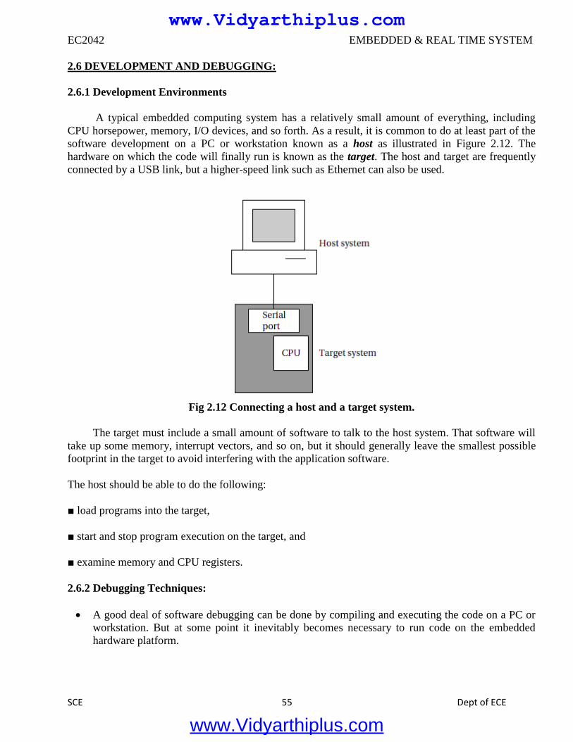
EC2042 EMBEDDED & REAL TIME SYSTEM
SCE 55 Dept of ECE
2.6 DEVELOPMENT AND DEBUGGING:
2.6.1 Development Environments
A typical embedded computing system has a relatively small amount of everything, including
CPU horsepower, memory, I/O devices, and so forth. As a result, it is common to do at least part of the
software development on a PC or workstation known as a host as illustrated in Figure 2.12. The
hardware on which the code will finally run is known as the target. The host and target are frequently
connected by a USB link, but a higher-speed link such as Ethernet can also be used.
Fig 2.12 Connecting a host and a target system.
The target must include a small amount of software to talk to the host system. That software will
take up some memory, interrupt vectors, and so on, but it should generally leave the smallest possible
footprint in the target to avoid interfering with the application software.
The host should be able to do the following:
■ load programs into the target,
■ start and stop program execution on the target, and
■ examine memory and CPU registers.
2.6.2 Debugging Techniques:
A good deal of software debugging can be done by compiling and executing the code on a PC or
workstation. But at some point it inevitably becomes necessary to run code on the embedded
hardware platform.
www.Vidyarthiplus.com
www.Vidyarthiplus.com
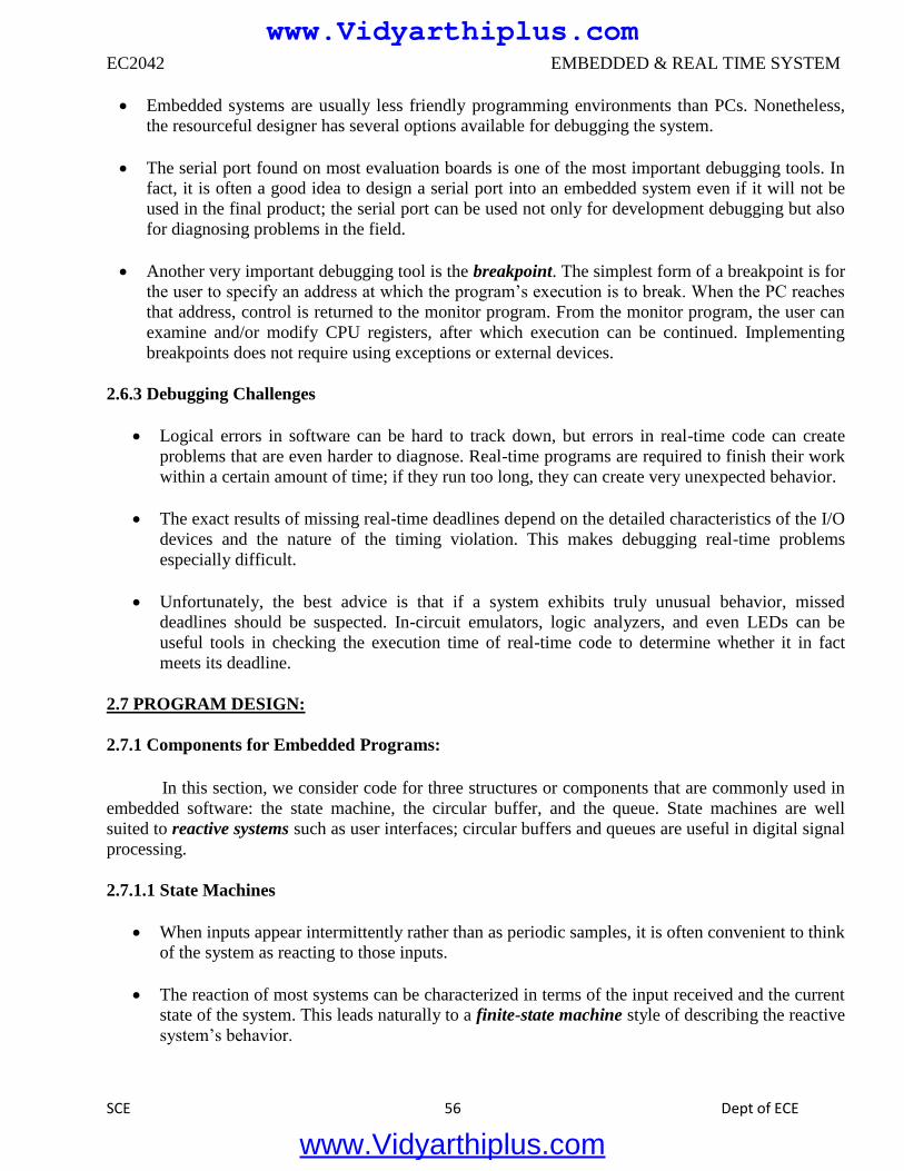
EC2042 EMBEDDED & REAL TIME SYSTEM
SCE 56 Dept of ECE
Embedded systems are usually less friendly programming environments than PCs. Nonetheless,
the resourceful designer has several options available for debugging the system.
The serial port found on most evaluation boards is one of the most important debugging tools. In
fact, it is often a good idea to design a serial port into an embedded system even if it will not be
used in the final product; the serial port can be used not only for development debugging but also
for diagnosing problems in the field.
Another very important debugging tool is the breakpoint. The simplest form of a breakpoint is for
the user to specify an address at which the program’s execution is to break. When the PC reaches
that address, control is returned to the monitor program. From the monitor program, the user can
examine and/or modify CPU registers, after which execution can be continued. Implementing
breakpoints does not require using exceptions or external devices.
2.6.3 Debugging Challenges
Logical errors in software can be hard to track down, but errors in real-time code can create
problems that are even harder to diagnose. Real-time programs are required to finish their work
within a certain amount of time; if they run too long, they can create very unexpected behavior.
The exact results of missing real-time deadlines depend on the detailed characteristics of the I/O
devices and the nature of the timing violation. This makes debugging real-time problems
especially difficult.
Unfortunately, the best advice is that if a system exhibits truly unusual behavior, missed
deadlines should be suspected. In-circuit emulators, logic analyzers, and even LEDs can be
useful tools in checking the execution time of real-time code to determine whether it in fact
meets its deadline.
2.7 PROGRAM DESIGN:
2.7.1 Components for Embedded Programs:
In this section, we consider code for three structures or components that are commonly used in
embedded software: the state machine, the circular buffer, and the queue. State machines are well
suited to reactive systems such as user interfaces; circular buffers and queues are useful in digital signal
processing.
2.7.1.1 State Machines
When inputs appear intermittently rather than as periodic samples, it is often convenient to think
of the system as reacting to those inputs.
The reaction of most systems can be characterized in terms of the input received and the current
state of the system. This leads naturally to a finite-state machine style of describing the reactive
system’s behavior.
www.Vidyarthiplus.com
www.Vidyarthiplus.com
EC2042 EMBEDDED & REAL TIME SYSTEM
SCE 57 Dept of ECE
Moreover, if the behavior is specified in that way, it is natural to write the program
implementing that behavior in a state machine style.
The state machine style of programming is also an efficient implementation of such
computations. Finite-state machines are usually first encountered in the context of hardware
design.
2.7.2 Stream-Oriented Programming and Circular Buffers
The data stream style makes sense for data that comes in regularly and must be processed on
the fly. For each sample, the filter must emit one output that depends on the values of the last n inputs.
In a typical workstation application, we would process the samples over a given interval by reading
them all in from a file and then computing the results all at once in a batch process. In an embedded
system we must not only emit outputs in real time, but we must also do so using a minimum amount of
memory.
Fig 2.13 A circular buffer for streaming data.
The circular buffer is a data structure that lets us handle streaming data in an efficient way.
Figure 2.13 illustrates how a circular buffer stores a subset of the data stream. At each point in time, the
algorithm needs a subset of the data stream that forms a window into the stream. The window slides
with time as we throw out old values no longer needed and add new values. Since the size of the
window does not change, we can use a fixed-size buffer to hold the current data.
To avoid constantly copying data within the buffer, we will move the head of the buffer in
time. The buffer points to the location at which the next sample will be placed; every time we add a
sample, we automatically overwrite the oldest sample, which is the one that needs to be thrown out.
When the pointer gets to the end of the buffer, it wraps around to the top.
www.Vidyarthiplus.com
www.Vidyarthiplus.com
EC2042 EMBEDDED & REAL TIME SYSTEM
SCE 58 Dept of ECE
2.8 MODELS OF PROGRAMS:
Data Flow Graphs:
A data flow graph is a model of a program with no conditionals. In a high-level programming
language, a code segment with no conditionals—more precisely, with only one entry and exit point is
known as a basic block. Figure 2.14 shows a simple basic block. As the C code is executed, we would
enter this basic block at the beginning and execute all the statements.
w = a+b;
x = a-c;
y = x+d;
x = a+c;
z = y+e;
Fig 2.14 A basic block in C.
w = a+b;
x = a-c;
y = x1+d;
x2= a+c;
z = y+e;
Fig 2.14 The basic block in single-assignment form.
Before we are able to draw the data flow graph for this code we need to modify it slightly.
There are two assignments to the variable x—it appears twice on the left side of an assignment. We
need to rewrite the code in single-assignment form, in which a variable appears only once on the left
side.
Since our specification is C code, we assume that the statements are executed sequentially, so
that any use of a variable refers to its latest assigned value. In this case, x is not reused in this block
(presumably it is used elsewhere), so we just have to eliminate the multiple assignment to x. The result
is shown in Figure 2.14, where we have used the names x1 and x2 to distinguish the separate uses of x.
The single-assignment form is important because it allows us to identify a unique location in the
code where each named location is computed. As an introduction to the data flow graph, we use two
types of nodes in the graph round nodes denote operators and square nodes represent values.
The value nodes may be either inputs to the basic block, such as a and b, or variables assigned
to within the block, such as w and x1.
www.Vidyarthiplus.com
www.Vidyarthiplus.com
EC2042 EMBEDDED & REAL TIME SYSTEM
SCE 59 Dept of ECE
Fig 2.15 An extended data flow graph for our sample basic block.
The data flow graph for our single-assignment code is shown in Figure 2.15.The single-
assignment form means that the data flow graph is acyclic—if we assigned to x multiple times, then the
second assignment would form a cycle in the graph including x and the operators used to compute x.
2.9 ASSEMBLY AND LINKING :
Assembly and linking are the last steps in the compilation process they turn a list of
instructions into an image of the program’s bits in memory. Loading actually puts the program in
memory so that it can be executed. In this section, we survey the basic techniques required for
assembly linking to help us understand the complete compilation and loading process.
Fig 2.16 Program generation from compilation through loading.
www.Vidyarthiplus.com
www.Vidyarthiplus.com
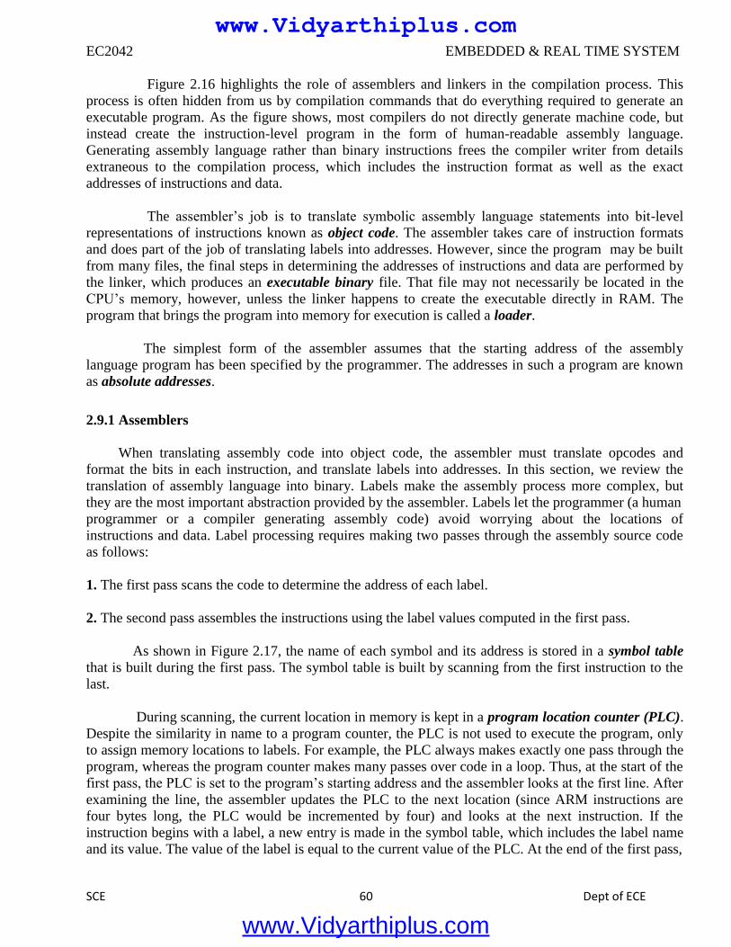
EC2042 EMBEDDED & REAL TIME SYSTEM
SCE 60 Dept of ECE
Figure 2.16 highlights the role of assemblers and linkers in the compilation process. This
process is often hidden from us by compilation commands that do everything required to generate an
executable program. As the figure shows, most compilers do not directly generate machine code, but
instead create the instruction-level program in the form of human-readable assembly language.
Generating assembly language rather than binary instructions frees the compiler writer from details
extraneous to the compilation process, which includes the instruction format as well as the exact
addresses of instructions and data.
The assembler’s job is to translate symbolic assembly language statements into bit-level
representations of instructions known as object code. The assembler takes care of instruction formats
and does part of the job of translating labels into addresses. However, since the program may be built
from many files, the final steps in determining the addresses of instructions and data are performed by
the linker, which produces an executable binary file. That file may not necessarily be located in the
CPU’s memory, however, unless the linker happens to create the executable directly in RAM. The
program that brings the program into memory for execution is called a loader.
The simplest form of the assembler assumes that the starting address of the assembly
language program has been specified by the programmer. The addresses in such a program are known
as absolute addresses.
2.9.1 Assemblers
When translating assembly code into object code, the assembler must translate opcodes and
format the bits in each instruction, and translate labels into addresses. In this section, we review the
translation of assembly language into binary. Labels make the assembly process more complex, but
they are the most important abstraction provided by the assembler. Labels let the programmer (a human
programmer or a compiler generating assembly code) avoid worrying about the locations of
instructions and data. Label processing requires making two passes through the assembly source code
as follows:
1. The first pass scans the code to determine the address of each label.
2. The second pass assembles the instructions using the label values computed in the first pass.
As shown in Figure 2.17, the name of each symbol and its address is stored in a symbol table
that is built during the first pass. The symbol table is built by scanning from the first instruction to the
last.
During scanning, the current location in memory is kept in a program location counter (PLC).
Despite the similarity in name to a program counter, the PLC is not used to execute the program, only
to assign memory locations to labels. For example, the PLC always makes exactly one pass through the
program, whereas the program counter makes many passes over code in a loop. Thus, at the start of the
first pass, the PLC is set to the program’s starting address and the assembler looks at the first line. After
examining the line, the assembler updates the PLC to the next location (since ARM instructions are
four bytes long, the PLC would be incremented by four) and looks at the next instruction. If the
instruction begins with a label, a new entry is made in the symbol table, which includes the label name
and its value. The value of the label is equal to the current value of the PLC. At the end of the first pass,
www.Vidyarthiplus.com
www.Vidyarthiplus.com
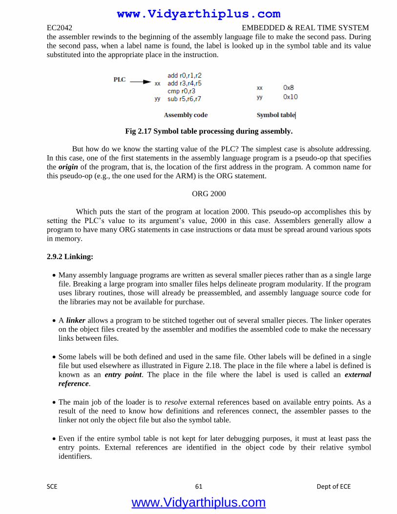
EC2042 EMBEDDED & REAL TIME SYSTEM
SCE 61 Dept of ECE
the assembler rewinds to the beginning of the assembly language file to make the second pass. During
the second pass, when a label name is found, the label is looked up in the symbol table and its value
substituted into the appropriate place in the instruction.
Fig 2.17 Symbol table processing during assembly.
But how do we know the starting value of the PLC? The simplest case is absolute addressing.
In this case, one of the first statements in the assembly language program is a pseudo-op that specifies
the origin of the program, that is, the location of the first address in the program. A common name for
this pseudo-op (e.g., the one used for the ARM) is the ORG statement.
ORG 2000
Which puts the start of the program at location 2000. This pseudo-op accomplishes this by
setting the PLC’s value to its argument’s value, 2000 in this case. Assemblers generally allow a
program to have many ORG statements in case instructions or data must be spread around various spots
in memory.
2.9.2 Linking:
Many assembly language programs are written as several smaller pieces rather than as a single large
file. Breaking a large program into smaller files helps delineate program modularity. If the program
uses library routines, those will already be preassembled, and assembly language source code for
the libraries may not be available for purchase.
A linker allows a program to be stitched together out of several smaller pieces. The linker operates
on the object files created by the assembler and modifies the assembled code to make the necessary
links between files.
Some labels will be both defined and used in the same file. Other labels will be defined in a single
file but used elsewhere as illustrated in Figure 2.18. The place in the file where a label is defined is
known as an entry point. The place in the file where the label is used is called an external
reference.
The main job of the loader is to resolve external references based on available entry points. As a
result of the need to know how definitions and references connect, the assembler passes to the
linker not only the object file but also the symbol table.
Even if the entire symbol table is not kept for later debugging purposes, it must at least pass the
entry points. External references are identified in the object code by their relative symbol
identifiers.
www.Vidyarthiplus.com
www.Vidyarthiplus.com
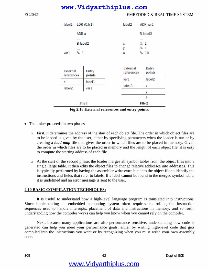
EC2042 EMBEDDED & REAL TIME SYSTEM
SCE 62 Dept of ECE
Fig 2.18 External references and entry points.
The linker proceeds in two phases.
o First, it determines the address of the start of each object file. The order in which object files are
to be loaded is given by the user, either by specifying parameters when the loader is run or by
creating a load map file that gives the order in which files are to be placed in memory. Given
the order in which files are to be placed in memory and the length of each object file, it is easy
to compute the starting address of each file.
o At the start of the second phase, the loader merges all symbol tables from the object files into a
single, large table. It then edits the object files to change relative addresses into addresses. This
is typically performed by having the assembler write extra bits into the object file to identify the
instructions and fields that refer to labels. If a label cannot be found in the merged symbol table,
it is undefined and an error message is sent to the user.
2.10 BASIC COMPILATION TECHNIQUES:
It is useful to understand how a high-level language program is translated into instructions.
Since implementing an embedded computing system often requires controlling the instruction
sequences used to handle interrupts, placement of data and instructions in memory, and so forth,
understanding how the compiler works can help you know when you cannot rely on the compiler.
Next, because many applications are also performance sensitive, understanding how code is
generated can help you meet your performance goals, either by writing high-level code that gets
compiled into the instructions you want or by recognizing when you must write your own assembly
code.
www.Vidyarthiplus.com
www.Vidyarthiplus.com
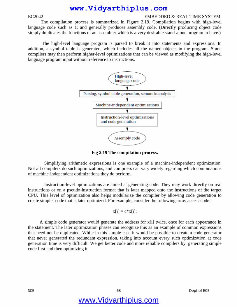
EC2042 EMBEDDED & REAL TIME SYSTEM
SCE 63 Dept of ECE
The compilation process is summarized in Figure 2.19. Compilation begins with high-level
language code such as C and generally produces assembly code. (Directly producing object code
simply duplicates the functions of an assembler which is a very desirable stand-alone program to have.)
The high-level language program is parsed to break it into statements and expressions. In
addition, a symbol table is generated, which includes all the named objects in the program. Some
compilers may then perform higher-level optimizations that can be viewed as modifying the high-level
language program input without reference to instructions.
Fig 2.19 The compilation process.
Simplifying arithmetic expressions is one example of a machine-independent optimization.
Not all compilers do such optimizations, and compilers can vary widely regarding which combinations
of machine-independent optimizations they do perform.
Instruction-level optimizations are aimed at generating code. They may work directly on real
instructions or on a pseudo-instruction format that is later mapped onto the instructions of the target
CPU. This level of optimization also helps modularize the compiler by allowing code generation to
create simpler code that is later optimized. For example, consider the following array access code:
x[i] = c*x[i];
A simple code generator would generate the address for x[i] twice, once for each appearance in
the statement. The later optimization phases can recognize this as an example of common expressions
that need not be duplicated. While in this simple case it would be possible to create a code generator
that never generated the redundant expression, taking into account every such optimization at code
generation time is very difficult. We get better code and more reliable compilers by generating simple
code first and then optimizing it.
www.Vidyarthiplus.com
www.Vidyarthiplus.com
EC2042 EMBEDDED & REAL TIME SYSTEM
SCE 64 Dept of ECE
2.11 ANALYSIS AND OPTIMIZATION OF EXCUTION TIME, POWER, NRGY , PROGRAM
SIZE:
The memory footprint of a program is determined by the size of its data and instructions. Both
must be considered to minimize program size.
Data provide an excellent opportunity for minimizing size because the data are most highly
dependent on programming style. Because inefficient programs often keep several copies of
data, identifying and eliminating duplications can lead to significant memory savings usually
with little performance penalty.
Buffers should be sized carefully rather than defining a data array to a large size that the
program will never attain, determine the actual maximum amount of data held in the buffer
and allocate the array accordingly. Data can sometimes be packed, such as by storing several
flags in a single word and extracting them by using bit-level operations.
A very low-level technique for minimizing data is to reuse values. For instance, if several
constants happen to have the same value, they can be mapped to the same location. Data
buffers can often be reused at several different points in the program. This technique must be
used with extreme caution, however, since subsequent versions of the program may not use
the same values for the constants.
A more generally applicable technique is to generate data on the fly rather than store it. Of
course, the code required to generate the data takes up space in the program, but when
complex data structures are involved there may be some net space savings from using code to
generate data.
Minimizing the size of the instruction text of a program requires a mix of high-level program
transformations and careful instruction selection.
Encapsulating functions in subroutines can reduce program size when done carefully. Because
subroutines have overhead for parameter passing that is not obvious from the high-level
language code, there is a minimum-size function body for which a subroutine makes sense.
Architectures that have variable-size instruction lengths are particularly good candidates for
careful coding to minimize program size, which may require assembly language coding of key
program segments. There may also be cases in which one or a sequence of instructions is
much smaller than alternative implementations for example, a multiply-accumulate instruction
may be both smaller and faster than separate arithmetic operations.
When reducing the number of instructions in a program, one important technique is the proper
use of subroutines. If the program performs identical operations repeatedly, these operations
are natural candidates for subroutines.
Even if the operations vary somewhat, you may be able to construct a properly parameterized
subroutine that saves space. Of course, when considering the code size savings, the subroutine
www.Vidyarthiplus.com
www.Vidyarthiplus.com
EC2042 EMBEDDED & REAL TIME SYSTEM
SCE 65 Dept of ECE
linkage code must be counted into the equation. There is extra code not only in the subroutine
body but also in each call to the subroutine that handles parameters.. In some cases, proper
instruction selection may reduce code size; this is particularly true in CPUs that use variable-
length instructions
Some microprocessor architectures support dense instruction sets, specially designed
instruction sets that use shorter instruction formats to encode the instructions.
The ARM Thumb instruction set and the MIPS-16 instruction set for the MIPS architecture
are two examples of this type of instruction set. In many cases, a microprocessor that supports
the dense instruction set also supports the normal instruction set, although it is possible to
build a microprocessor that executes only the dense instruction set.
Special compilation modes produce the program in terms of the dense instruction set. Program
size of course varies with the type of program, but programs using the dense instruction set
are often 70 to 80% of the size of the standard instruction set equivalents.
2.12 PROGRAM VALIDATION AND TESTING :
Complex systems need testing to ensure that they work as they are intended. But bugs can be
subtle, particularly in embedded systems, where specialized hardware and real-time responsiveness
make programming more challenging. Fortunately, there are many available techniques for software
testing that can help us generate a comprehensive set of tests to ensure that our system works properly.
The first question we must ask ourselves is how much testing is enough. Clearly, we cannot test
the program for every possible combination of inputs. Because we cannot implement an infinite
number of tests, we naturally ask ourselves what a reasonable standard of thoroughness is. One of the
major contributions of software testing is to provide us with standards of thoroughness that make sense.
Following these standards does not guarantee that we will find all bugs.
The two major types of testing strategies:
■ Black-box methods generate tests without looking at the internal structure of the program.
■ Clear-box (also known as white-box) methods generate tests based on the program structure.
2.12.1 Clear-Box Testing:
The control/data flow graph extracted from a program’s source code is an important tool in
developing clear-box tests for the program. To adequately test the program, we must exercise both its
control and data operations.
In order to execute and evaluate these tests, we must be able to control variables in the
program and observe the results of computations, much as in manufacturing testing. In general, we may
need to modify the program to make it more testable. By adding new inputs and outputs, we can usually
substantially reduce the effort required to find and execute the test.
www.Vidyarthiplus.com
www.Vidyarthiplus.com
EC2042 EMBEDDED & REAL TIME SYSTEM
SCE 66 Dept of ECE
No matter what we are testing, we must accomplish the following three things in a test:
■ Provide the program with inputs that exercise the test we are interested in.
■ Execute the program to perform the test.
■ Examine the outputs to determine whether the test was successful.
2.12.2 Black-Box Testing:
Black-box tests are generated without knowledge of the code being tested. When used alone,
black-box tests have a low probability of finding all the bugs in a program. But when used in
conjunction with clear-box tests they help provide a well-rounded test set, since black-box tests are
likely to uncover errors that are unlikely to be found by tests extracted from the code structure.
Black-box tests can really work. For instance, when asked to test an instrument whose front
panel was run by a microcontroller, one acquaintance of the author used his hand to depress all the
buttons simultaneously. The front panel immediately locked up. This situation could occur in practice if
the instrument were placed face-down on a table, but discovery of this bug would be very unlikely via
clear-box tests.
One important technique is to take tests directly from the specification for the code under
design. The specification should state which outputs are expected for certain inputs. Tests should be
created that provide specified outputs and evaluate whether the results also satisfy the inputs.
We can’t test every possible input combination, but some rules of thumb help us select
reasonable sets of inputs. When an input can range across a set of values, it is a very good idea to test at
the ends of the range. For example, if an input must be between 1 and 10, 0, 1, 10, and 11 are all
important values to test. We should be sure to consider tests both within and outside the range, such as,
testing values within the range and outside the range. We may want to consider tests well outside the
valid range as well as boundary-condition tests.
Random tests form one category of black-box test. Random values are generated with a given
distribution. The expected values are computed independently of the system, and then the test inputs
are applied. A large number of tests must be applied for the results to be statistically significant, but the
tests are easy to generate. Another scenario is to test certain types of data values. For example, integer
valued inputs can be generated at interesting values such as 0, 1, and values near the maximum end of
the data range. Illegal values can be tested as well.
Regression tests form an extremely important category of tests. When tests are created during
earlier stages in the system design or for previous versions of the system, those tests should be saved to
apply to the later versions of the system. Clearly, unless the system specification changed, the new
system should be able to pass old tests. In some cases old bugs can creep back into systems, such as
when an old version of a software module is inadvertently installed. In other cases regression tests
simply exercise the code in different ways than would be done for the current version of the code and
therefore possibly exercise different bugs.
www.Vidyarthiplus.com
www.Vidyarthiplus.com
EC2042 EMBEDDED & REAL TIME SYSTEM
SCE 67 Dept of ECE
UNIT III
PROCESS AND OPERATING SYSTEMS
3.1 MULTIPLE TASKS AND MULTIPLE PROCESSES:
3.1.1 Tasks and Processes
Many (if not most) embedded computing systems do more than one thing that is, the
environment can cause mode changes that in turn cause the embedded system to behave quite
differently. For example, when designing a telephone answering machine,
We can define recording a phone call and operating the user’s control panel as distinct tasks,
because they perform logically distinct operations and they must be performed at very different
rates. These different tasks are part of the system’s functionality, but that application-level
organization of functionality is often reflected in the structure of the program as well.
A process is a single execution of a program. If we run the same program two different times,
we have created two different processes. Each process has its own state that includes not only
its registers but all of its memory. In some OSs, the memory management unit is used to keep
each process in a separate address space. In others, particularly lightweight RTOSs, the
processes run in the same address space. Processes that share the same address space are often
called threads.
As shown in Figure 3.1, this device is connected to serial ports on both ends. The input to the
box is an uncompressed stream of bytes. The box emits a compressed string of bits on the
output serial line, based on a predefined compression table. Such a box may be used, for
example, to compress data being sent to a modem.
The program’s need to receive and send data at different rates for example, the program may
emit 2 bits for the first byte and then 7 bits for the second byte will obviously find itself
reflected in the structure of the code. It is easy to create irregular, ungainly code to solve this
problem; a more elegant solution is to create a queue of output bits, with those bits being
removed from the queue and sent to the serial port in 8-bit sets.
www.Vidyarthiplus.com
www.Vidyarthiplus.com
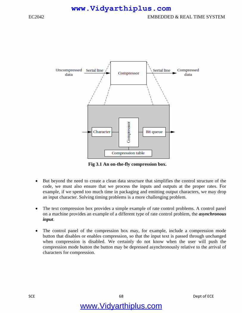
EC2042 EMBEDDED & REAL TIME SYSTEM
SCE 68 Dept of ECE
Fig 3.1 An on-the-fly compression box.
But beyond the need to create a clean data structure that simplifies the control structure of the
code, we must also ensure that we process the inputs and outputs at the proper rates. For
example, if we spend too much time in packaging and emitting output characters, we may drop
an input character. Solving timing problems is a more challenging problem.
The text compression box provides a simple example of rate control problems. A control panel
on a machine provides an example of a different type of rate control problem, the asynchronous
input.
The control panel of the compression box may, for example, include a compression mode
button that disables or enables compression, so that the input text is passed through unchanged
when compression is disabled. We certainly do not know when the user will push the
compression mode button the button may be depressed asynchronously relative to the arrival of
characters for compression.
www.Vidyarthiplus.com
www.Vidyarthiplus.com
EC2042 EMBEDDED & REAL TIME SYSTEM
SCE 69 Dept of ECE
3.1.2 Multirate Systems
Implementing code that satisfies timing requirements is even more complex when multiple
rates of computation must be handled. Multirate embedded computing systems are very common,
including automobile engines, printers, and cell phones. In all these systems, certain operations must be
executed periodically, and each operation is executed at its own rate.
3.1.3 Timing Requirements on Processes
o Processes can have several different types of timing requirements imposed on them by the
application. The timing requirements on a set of processes strongly influence the type of
scheduling that is appropriate. A scheduling policy must define the timing requirements that it
uses to determine whether a schedule is valid. Before studying scheduling proper, we outline the
types of process timing requirements that are useful in embedded system design.
o Figure 3.2 illustrates different ways in which we can define two important requirements on
processes: release time and deadline.
o The release time is the time at which the process becomes ready to execute; this is not necessarily
the time at which it actually takes control of the CPU and starts to run. An aperiodic process is by
definition initiated by an event, such as external data arriving or data computed by another
process.
o The release time is generally measured from that event, although the system may want to make
the process ready at some interval after the event itself. For a periodically executed process, there
are two common possibilities.
o In simpler systems, the process may become ready at the beginning of the period. More
sophisticated systems, such as those with data dependencies between processes, may set the
release time at the arrival time of certain data, at a time after the start of the period.
o A deadline specifies when a computation must be finished. The deadline for an aperiodic process
is generally measured from the release time, since that is the only reasonable time reference. The
deadline for a periodic process may in general occur at some time other than the end of the period.
o Rate requirements are also fairly common. A rate requirement specifies how quickly processes
must be initiated.
o The period of a process is the time between successive executions. For example, the period of a
digital filter is defined by the time interval between successive input samples.
o The process’s rate is the inverse of its period. In a multirate system, each process executes at its
own distinct rate.
www.Vidyarthiplus.com
www.Vidyarthiplus.com
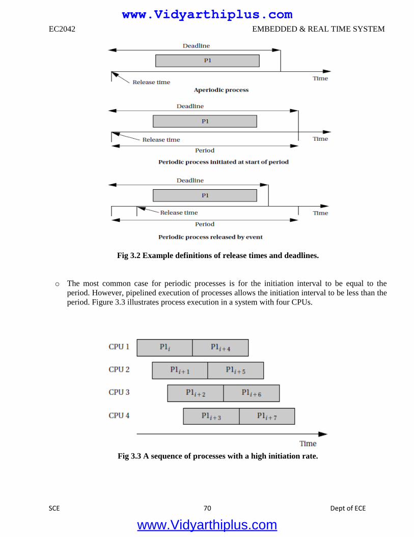
EC2042 EMBEDDED & REAL TIME SYSTEM
SCE 70 Dept of ECE
Fig 3.2 Example definitions of release times and deadlines.
o The most common case for periodic processes is for the initiation interval to be equal to the
period. However, pipelined execution of processes allows the initiation interval to be less than the
period. Figure 3.3 illustrates process execution in a system with four CPUs.
Fig 3.3 A sequence of processes with a high initiation rate.
www.Vidyarthiplus.com
www.Vidyarthiplus.com
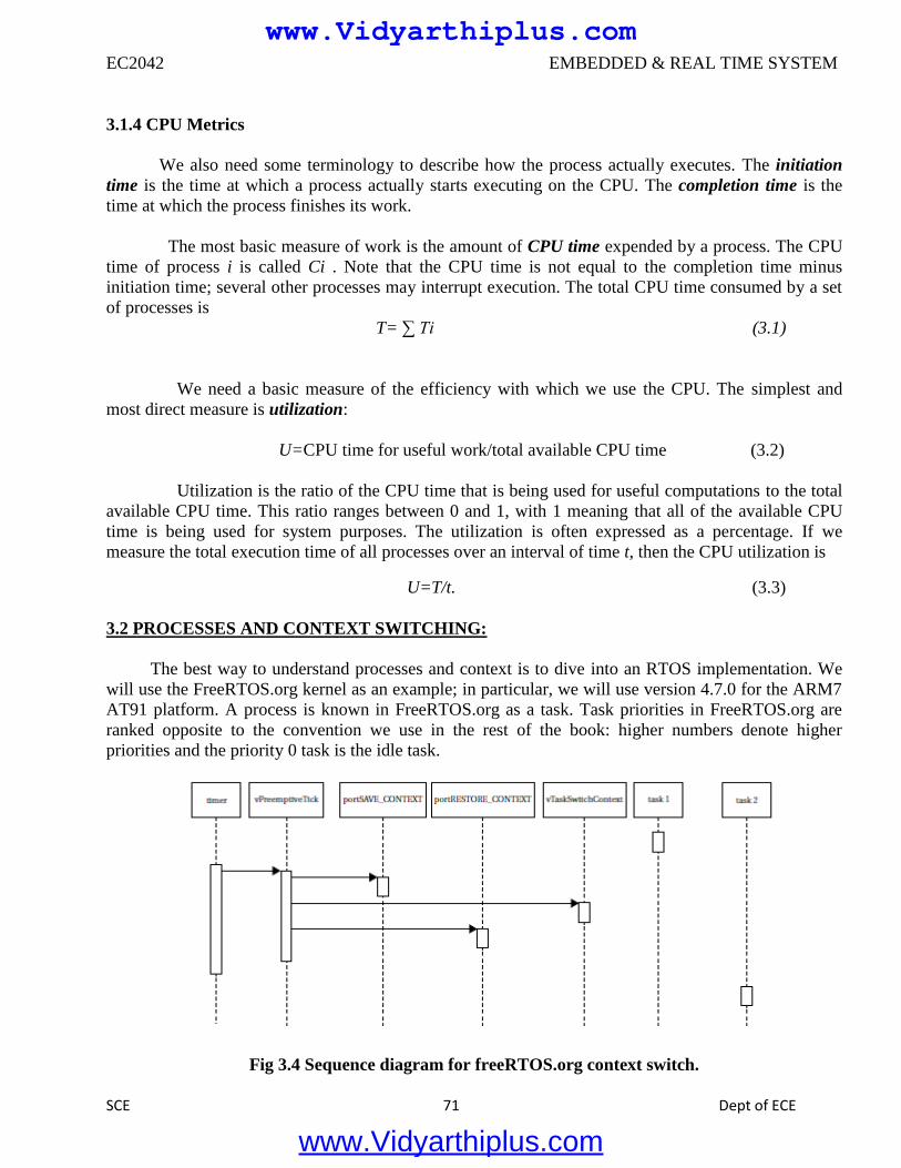
EC2042 EMBEDDED & REAL TIME SYSTEM
SCE 71 Dept of ECE
3.1.4 CPU Metrics
We also need some terminology to describe how the process actually executes. The initiation
time is the time at which a process actually starts executing on the CPU. The completion time is the
time at which the process finishes its work.
The most basic measure of work is the amount of CPU time expended by a process. The CPU
time of process i is called Ci . Note that the CPU time is not equal to the completion time minus
initiation time; several other processes may interrupt execution. The total CPU time consumed by a set
of processes is
T= ∑ Ti (3.1)
We need a basic measure of the efficiency with which we use the CPU. The simplest and
most direct measure is utilization:
U=CPU time for useful work/total available CPU time (3.2)
Utilization is the ratio of the CPU time that is being used for useful computations to the total
available CPU time. This ratio ranges between 0 and 1, with 1 meaning that all of the available CPU
time is being used for system purposes. The utilization is often expressed as a percentage. If we
measure the total execution time of all processes over an interval of time t, then the CPU utilization is
U=T/t. (3.3)
3.2 PROCESSES AND CONTEXT SWITCHING:
The best way to understand processes and context is to dive into an RTOS implementation. We
will use the FreeRTOS.org kernel as an example; in particular, we will use version 4.7.0 for the ARM7
AT91 platform. A process is known in FreeRTOS.org as a task. Task priorities in FreeRTOS.org are
ranked opposite to the convention we use in the rest of the book: higher numbers denote higher
priorities and the priority 0 task is the idle task.
Fig 3.4 Sequence diagram for freeRTOS.org context switch.
www.Vidyarthiplus.com
www.Vidyarthiplus.com
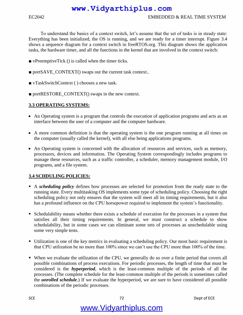
EC2042 EMBEDDED & REAL TIME SYSTEM
SCE 72 Dept of ECE
To understand the basics of a context switch, let’s assume that the set of tasks is in steady state:
Everything has been initialized, the OS is running, and we are ready for a timer interrupt. Figure 3.4
shows a sequence diagram for a context switch in freeRTOS.org. This diagram shows the application
tasks, the hardware timer, and all the functions in the kernel that are involved in the context switch:
■ vPreemptiveTick () is called when the timer ticks.
■ portSAVE_CONTEXT() swaps out the current task context..
■ vTaskSwitchContext ( ) chooses a new task.
■ portRESTORE_CONTEXT() swaps in the new context.
3.3 OPERATING SYSTEMS:
An Operating system is a program that controls the execution of application programs and acts as an
interface between the user of a computer and the computer hardware.
A more common definition is that the operating system is the one program running at all times on
the computer (usually called the kernel), with all else being applications programs.
An Operating system is concerned with the allocation of resources and services, such as memory,
processors, devices and information. The Operating System correspondingly includes programs to
manage these resources, such as a traffic controller, a scheduler, memory management module, I/O
programs, and a file system.
3.4 SCHDULING POLICIES:
A scheduling policy defines how processes are selected for promotion from the ready state to the
running state. Every multitasking OS implements some type of scheduling policy. Choosing the right
scheduling policy not only ensures that the system will meet all its timing requirements, but it also
has a profound influence on the CPU horsepower required to implement the system’s functionality.
Schedulability means whether there exists a schedule of execution for the processes in a system that
satisfies all their timing requirements. In general, we must construct a schedule to show
schedulability, but in some cases we can eliminate some sets of processes as unschedulable using
some very simple tests.
Utilization is one of the key metrics in evaluating a scheduling policy. Our most basic requirement is
that CPU utilization be no more than 100% since we can’t use the CPU more than 100% of the time.
When we evaluate the utilization of the CPU, we generally do so over a finite period that covers all
possible combinations of process executions. For periodic processes, the length of time that must be
considered is the hyperperiod, which is the least-common multiple of the periods of all the
processes. (The complete schedule for the least-common multiple of the periods is sometimes called
the unrolled schedule.) If we evaluate the hyperperiod, we are sure to have considered all possible
combinations of the periodic processes.
www.Vidyarthiplus.com
www.Vidyarthiplus.com
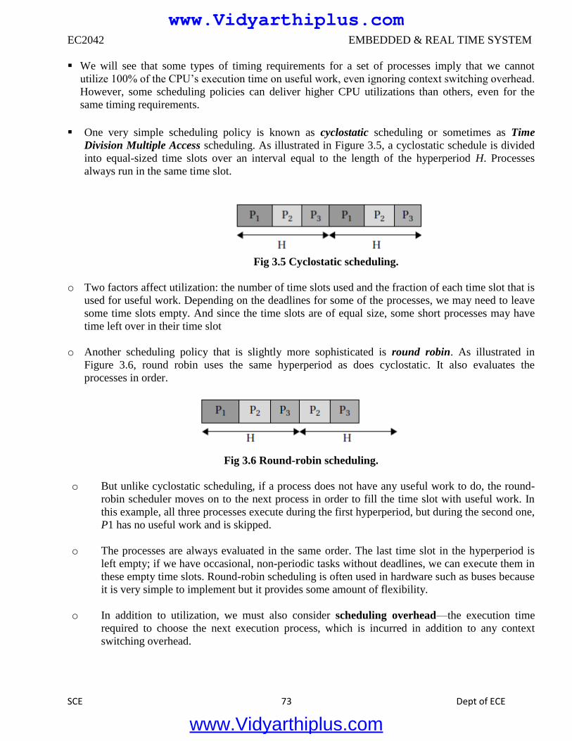
EC2042 EMBEDDED & REAL TIME SYSTEM
SCE 73 Dept of ECE
We will see that some types of timing requirements for a set of processes imply that we cannot
utilize 100% of the CPU’s execution time on useful work, even ignoring context switching overhead.
However, some scheduling policies can deliver higher CPU utilizations than others, even for the
same timing requirements.
One very simple scheduling policy is known as cyclostatic scheduling or sometimes as Time
Division Multiple Access scheduling. As illustrated in Figure 3.5, a cyclostatic schedule is divided
into equal-sized time slots over an interval equal to the length of the hyperperiod H. Processes
always run in the same time slot.
Fig 3.5 Cyclostatic scheduling.
o Two factors affect utilization: the number of time slots used and the fraction of each time slot that is
used for useful work. Depending on the deadlines for some of the processes, we may need to leave
some time slots empty. And since the time slots are of equal size, some short processes may have
time left over in their time slot
o Another scheduling policy that is slightly more sophisticated is round robin. As illustrated in
Figure 3.6, round robin uses the same hyperperiod as does cyclostatic. It also evaluates the
processes in order.
Fig 3.6 Round-robin scheduling.
o But unlike cyclostatic scheduling, if a process does not have any useful work to do, the round-
robin scheduler moves on to the next process in order to fill the time slot with useful work. In
this example, all three processes execute during the first hyperperiod, but during the second one,
P1 has no useful work and is skipped.
o The processes are always evaluated in the same order. The last time slot in the hyperperiod is
left empty; if we have occasional, non-periodic tasks without deadlines, we can execute them in
these empty time slots. Round-robin scheduling is often used in hardware such as buses because
it is very simple to implement but it provides some amount of flexibility.
o In addition to utilization, we must also consider scheduling overhead—the execution time
required to choose the next execution process, which is incurred in addition to any context
switching overhead.
www.Vidyarthiplus.com
www.Vidyarthiplus.com
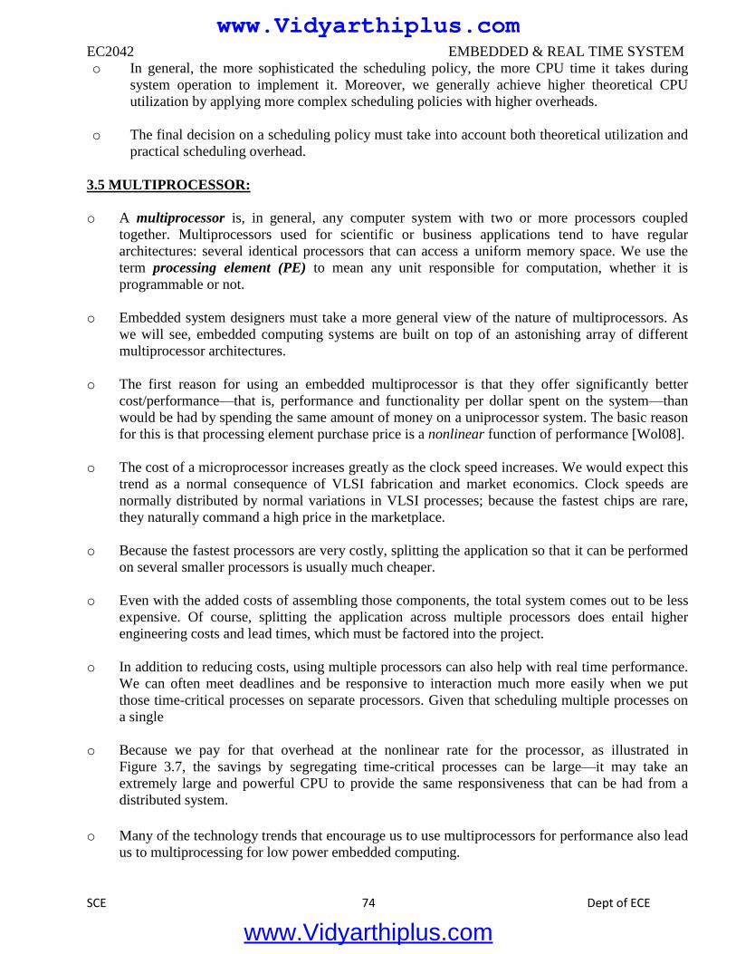
EC2042 EMBEDDED & REAL TIME SYSTEM
SCE 74 Dept of ECE
o In general, the more sophisticated the scheduling policy, the more CPU time it takes during
system operation to implement it. Moreover, we generally achieve higher theoretical CPU
utilization by applying more complex scheduling policies with higher overheads.
o The final decision on a scheduling policy must take into account both theoretical utilization and
practical scheduling overhead.
3.5 MULTIPROCESSOR:
o A multiprocessor is, in general, any computer system with two or more processors coupled
together. Multiprocessors used for scientific or business applications tend to have regular
architectures: several identical processors that can access a uniform memory space. We use the
term processing element (PE) to mean any unit responsible for computation, whether it is
programmable or not.
o Embedded system designers must take a more general view of the nature of multiprocessors. As
we will see, embedded computing systems are built on top of an astonishing array of different
multiprocessor architectures.
o The first reason for using an embedded multiprocessor is that they offer significantly better
cost/performance—that is, performance and functionality per dollar spent on the system—than
would be had by spending the same amount of money on a uniprocessor system. The basic reason
for this is that processing element purchase price is a nonlinear function of performance [Wol08].
o The cost of a microprocessor increases greatly as the clock speed increases. We would expect this
trend as a normal consequence of VLSI fabrication and market economics. Clock speeds are
normally distributed by normal variations in VLSI processes; because the fastest chips are rare,
they naturally command a high price in the marketplace.
o Because the fastest processors are very costly, splitting the application so that it can be performed
on several smaller processors is usually much cheaper.
o Even with the added costs of assembling those components, the total system comes out to be less
expensive. Of course, splitting the application across multiple processors does entail higher
engineering costs and lead times, which must be factored into the project.
o In addition to reducing costs, using multiple processors can also help with real time performance.
We can often meet deadlines and be responsive to interaction much more easily when we put
those time-critical processes on separate processors. Given that scheduling multiple processes on
a single
o Because we pay for that overhead at the nonlinear rate for the processor, as illustrated in
Figure 3.7, the savings by segregating time-critical processes can be large—it may take an
extremely large and powerful CPU to provide the same responsiveness that can be had from a
distributed system.
o Many of the technology trends that encourage us to use multiprocessors for performance also lead
us to multiprocessing for low power embedded computing.
www.Vidyarthiplus.com
www.Vidyarthiplus.com
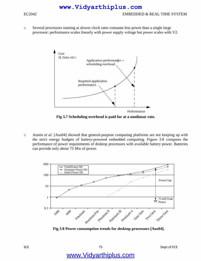
EC2042 EMBEDDED & REAL TIME SYSTEM
SCE 75 Dept of ECE
o Several processors running at slower clock rates consume less power than a single large
processor: performance scales linearly with power supply voltage but power scales with V2.
Fig 3.7 Scheduling overhead is paid for at a nonlinear rate.
o Austin et al. [Aus04] showed that general-purpose computing platforms are not keeping up with
the strict energy budgets of battery-powered embedded computing. Figure 3.8 compares the
performance of power requirements of desktop processors with available battery power. Batteries
can provide only about 75 Mw of power.
Fig 3.8 Power consumption trends for desktop processors [Aus04].
www.Vidyarthiplus.com
www.Vidyarthiplus.com
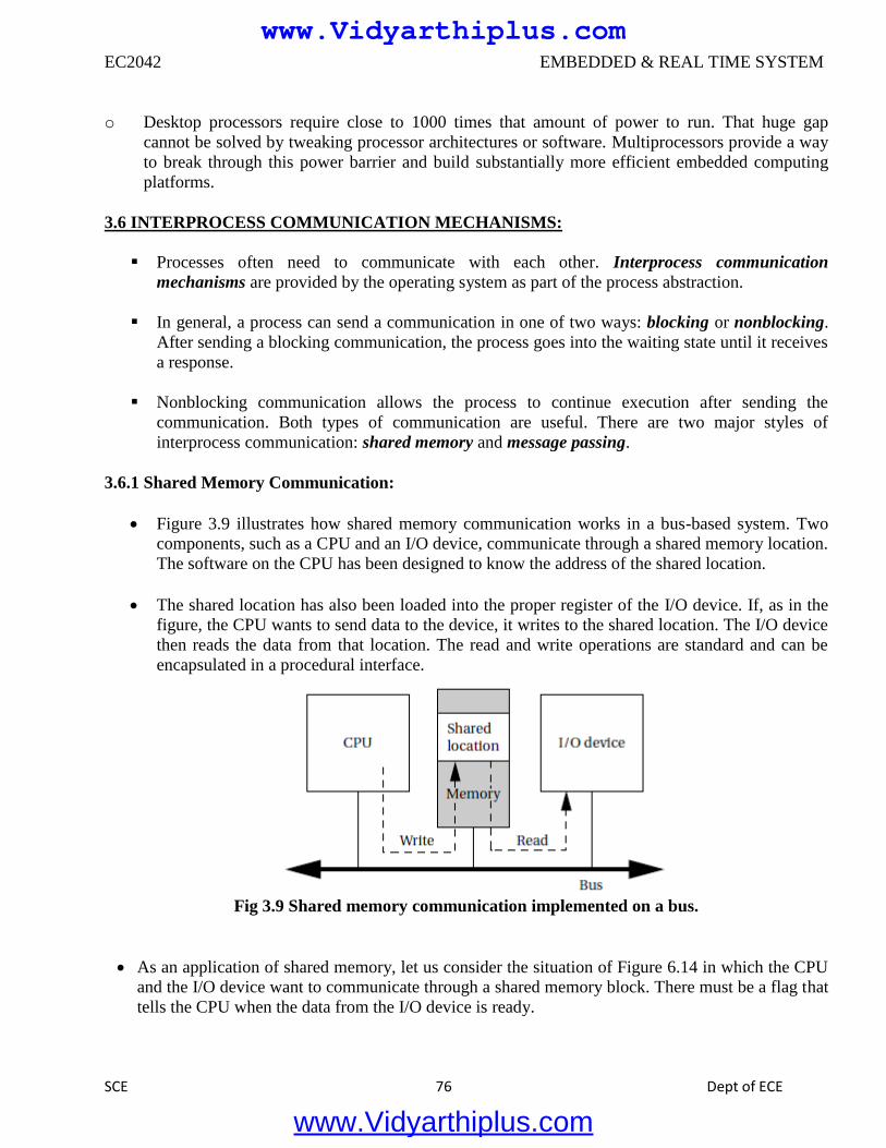
EC2042 EMBEDDED & REAL TIME SYSTEM
SCE 76 Dept of ECE
o Desktop processors require close to 1000 times that amount of power to run. That huge gap
cannot be solved by tweaking processor architectures or software. Multiprocessors provide a way
to break through this power barrier and build substantially more efficient embedded computing
platforms.
3.6 INTERPROCESS COMMUNICATION MECHANISMS:
Processes often need to communicate with each other. Interprocess communication
mechanisms are provided by the operating system as part of the process abstraction.
In general, a process can send a communication in one of two ways: blocking or nonblocking.
After sending a blocking communication, the process goes into the waiting state until it receives
a response.
Nonblocking communication allows the process to continue execution after sending the
communication. Both types of communication are useful. There are two major styles of
interprocess communication: shared memory and message passing.
3.6.1 Shared Memory Communication:
Figure 3.9 illustrates how shared memory communication works in a bus-based system. Two
components, such as a CPU and an I/O device, communicate through a shared memory location.
The software on the CPU has been designed to know the address of the shared location.
The shared location has also been loaded into the proper register of the I/O device. If, as in the
figure, the CPU wants to send data to the device, it writes to the shared location. The I/O device
then reads the data from that location. The read and write operations are standard and can be
encapsulated in a procedural interface.
Fig 3.9 Shared memory communication implemented on a bus.
As an application of shared memory, let us consider the situation of Figure 6.14 in which the CPU
and the I/O device want to communicate through a shared memory block. There must be a flag that
tells the CPU when the data from the I/O device is ready.
www.Vidyarthiplus.com
www.Vidyarthiplus.com
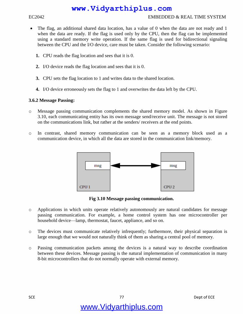
EC2042 EMBEDDED & REAL TIME SYSTEM
SCE 77 Dept of ECE
The flag, an additional shared data location, has a value of 0 when the data are not ready and 1
when the data are ready. If the flag is used only by the CPU, then the flag can be implemented
using a standard memory write operation. If the same flag is used for bidirectional signaling
between the CPU and the I/O device, care must be taken. Consider the following scenario:
1. CPU reads the flag location and sees that it is 0.
2. I/O device reads the flag location and sees that it is 0.
3. CPU sets the flag location to 1 and writes data to the shared location.
4. I/O device erroneously sets the flag to 1 and overwrites the data left by the CPU.
3.6.2 Message Passing:
o Message passing communication complements the shared memory model. As shown in Figure
3.10, each communicating entity has its own message send/receive unit. The message is not stored
on the communications link, but rather at the senders/ receivers at the end points.
o In contrast, shared memory communication can be seen as a memory block used as a
communication device, in which all the data are stored in the communication link/memory.
Fig 3.10 Message passing communication.
o Applications in which units operate relatively autonomously are natural candidates for message
passing communication. For example, a home control system has one microcontroller per
household device—lamp, thermostat, faucet, appliance, and so on.
o The devices must communicate relatively infrequently; furthermore, their physical separation is
large enough that we would not naturally think of them as sharing a central pool of memory.
o Passing communication packets among the devices is a natural way to describe coordination
between these devices. Message passing is the natural implementation of communication in many
8-bit microcontrollers that do not normally operate with external memory.
www.Vidyarthiplus.com
www.Vidyarthiplus.com
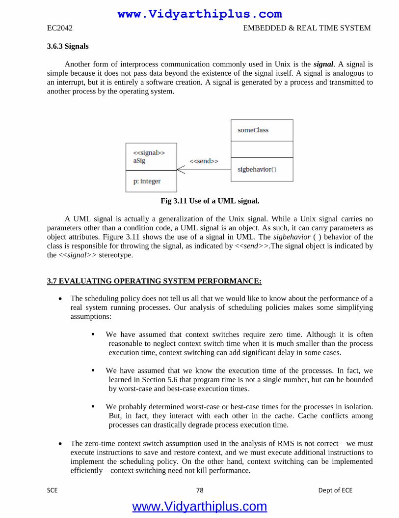
EC2042 EMBEDDED & REAL TIME SYSTEM
SCE 78 Dept of ECE
3.6.3 Signals
Another form of interprocess communication commonly used in Unix is the signal. A signal is
simple because it does not pass data beyond the existence of the signal itself. A signal is analogous to
an interrupt, but it is entirely a software creation. A signal is generated by a process and transmitted to
another process by the operating system.
Fig 3.11 Use of a UML signal.
A UML signal is actually a generalization of the Unix signal. While a Unix signal carries no
parameters other than a condition code, a UML signal is an object. As such, it can carry parameters as
object attributes. Figure 3.11 shows the use of a signal in UML. The sigbehavior ( ) behavior of the
class is responsible for throwing the signal, as indicated by <<send>>.The signal object is indicated by
the <<signal>> stereotype.
3.7 EVALUATING OPERATING SYSTEM PERFORMANCE:
The scheduling policy does not tell us all that we would like to know about the performance of a
real system running processes. Our analysis of scheduling policies makes some simplifying
assumptions:
We have assumed that context switches require zero time. Although it is often
reasonable to neglect context switch time when it is much smaller than the process
execution time, context switching can add significant delay in some cases.
We have assumed that we know the execution time of the processes. In fact, we
learned in Section 5.6 that program time is not a single number, but can be bounded
by worst-case and best-case execution times.
We probably determined worst-case or best-case times for the processes in isolation.
But, in fact, they interact with each other in the cache. Cache conflicts among
processes can drastically degrade process execution time.
The zero-time context switch assumption used in the analysis of RMS is not correct—we must
execute instructions to save and restore context, and we must execute additional instructions to
implement the scheduling policy. On the other hand, context switching can be implemented
efficiently—context switching need not kill performance.
www.Vidyarthiplus.com
www.Vidyarthiplus.com
EC2042 EMBEDDED & REAL TIME SYSTEM
SCE 79 Dept of ECE
The effects of nonzero context switching time must be carefully analyzed in the context of a
particular implementation to be sure that the predictions of an ideal scheduling policy are
sufficiently accurate.
In most real-time operating systems, a context switch requires only a few hundred instructions,
with only slightly more overhead for a simple real-time scheduler like RMS. When the
overhead time is very small relative to the task periods, then the zero-time context switch
assumption is often a reasonable approximation. Problems are most likely to manifest
themselves in the highest-rate processes, which are often the most critical in any case.
Completely checking that all deadlines will be met with nonzero context switching time
requires checking all possible schedules for processes and including the context switch time at
each preemption or process initiation. However, assuming an average number of context
switches per process and computing CPU utilization can provide at least an estimate of how
close the system is to CPU capacity.
3.8 POWER OPTIMIZATION STRATEGIES FOR PROCESSES:
The RTOS and system architecture can use static and dynamic power management mechanisms
to help manage the system’s power consumption. A power management policy [Ben00] is a
strategy for determining when to perform certain power management operations. A power
management policy in general examines the state of the system to determine when to take
actions.
However, the overall strategy embodied in the policy should be designed based on the
characteristics of the static and dynamic power management mechanisms.
Going into a low-power mode takes time; generally, the more that is shut off, the longer the
delay incurred during restart. Because power-down and power-up are not free, modes should be
changed carefully. Determining when to switch into and out of a power-up mode requires an
analysis of the overall system activity.
o Avoiding a power-down mode can cost unnecessary power.
o Powering down too soon can cause severe performance penalties.
Re-entering run mode typically costs a considerable amount of time. A straightforward method
is to power up the system when a request is received. This works as long as the delay in
handling the request is acceptable. A more sophisticated technique is predictive shutdown.
The goal is to predict when the next request will be made and to start the system just before that
time, saving the requestor the start-up time. In general, predictive shutdown techniques are
probabilistic they make guesses about activity patterns based on a probabilistic model of
expected behavior. Because they rely on statistics, they may not always correctly guess the time
of the next activity.
www.Vidyarthiplus.com
www.Vidyarthiplus.com
EC2042 EMBEDDED & REAL TIME SYSTEM
SCE 80 Dept of ECE
This can cause two types of problems:
The requestor may have to wait for an activity period. In the worst case, the
requestor may not make a deadline due to the delay incurred by system start-up.
The system may restart itself when no activity is imminent. As a result, the
system will waste power.
Clearly, the choice of a good probabilistic model of service requests is important. The policy
mechanism should also not be too complex, since the power it consumes to make decisions is
part of the total system power budget.
Several predictive techniques are possible. A very simple technique is to use fixed times. For
instance, if the system does not receive inputs during an interval of length Ton, it shuts down; a
powered-down system waits for a period Toff before returning to the power-on mode.
The choice of Toff and Ton must be determined by experimentation. Srivastava and Eustace
[Sri94] found one useful rule for graphics terminals. They plotted the observed idle time (Toff)
of a graphics terminal versus the immediately preceding active time (Ton).The result was an
L-shaped distribution as illustrated in Figure 3.12. In this distribution, the idle period after a
long active period is usually very short, and the length of the idle period after a short active
period is uniformly distributed.
Fig 3.12 An L-shaped usage distribution.
Based on this distribution, they proposed a shut down threshold that depended on the length of
the last active period—they shut down when the active period length was below a threshold,
putting the system in the vertical portion of the L distribution.
www.Vidyarthiplus.com
www.Vidyarthiplus.com
EC2042 EMBEDDED & REAL TIME SYSTEM
SCE 81 Dept of ECE
The Advanced Configuration and Power Interface (ACPI) is an open industry standard for
power management services. It is designed to be compatible with a wide variety of OSs. It was
targeted initially to PCs. The role of ACPI in the system is illustrated in Figure 3.13.
Fig 3.13 The advanced configuration and power interface and its relationship to a complete system.
ACPI provides some basic power management facilities and abstracts the hardware layer, the
OS has its own power management module that determines the policy, and the OS then uses
ACPI to send the required controls to the hardware and to observe the hardware’s state as input
to the power manager.
ACPI supports the following five basic global power states:
o G3, the mechanical off state, in which the system consumes no power.
o G2, the soft off state, which requires a full OS reboot to restore the machine to working
condition. This state has four substates:
o S1, a low wake-up latency state with no loss of system context;
o S2, a low wake-up latency state with a loss of CPU and system cache state;
o S3, a low wake-up latency state in which all system state except for main memory is
lost; and
o S4, the lowest-power sleeping state, in which all devices are turned off.
o G1, the sleeping state, in which the system appears to be off and the time required to
return to working condition is inversely proportional to power consumption.
o G0, the working state, in which the system is fully usable.
o The legacy state, in which the system does not comply with ACPI.
www.Vidyarthiplus.com
www.Vidyarthiplus.com
EC2042 EMBEDDED & REAL TIME SYSTEM
SCE 82 Dept of ECE
UNIT IV
HARDWARE ACCELERATES & NETWORKS
4.1 ACCELERATORS :
One important category of PE for embedded multiprocessor is the accelerator. An accelerator is
attached to CPU buses to quickly execute certain key functions. Accelerators can provide large
performance increases for applications with computational kernels that spend a great deal of
time in a small section of code. Accelerators can also provide critical speedups for low-latency
I/O functions.
The design of accelerated systems is one example of hardware/software co-design—the
simultaneous design of hardware and software to meet system objectives. Thus far, we have
taken the computing platform as a given; by adding accelerators, we can customize the
embedded platform to better meet our application’s demands.
As illustrated in Figure 4.1, a CPU accelerator is attached to the CPU bus. The CPU is often
called the host. The CPU talks to the accelerator through data and control registers in the
accelerator. These registers allow the CPU to monitor the accelerator’s operation and to give the
accelerator commands.
The CPU and accelerator may also communicate via shared memory. If the accelerator needs to
operate on a large volume of data, it is usually more efficient to leave the data in memory and
have the accelerator read and write memory directly rather than to have the CPU shuttle data
from memory to accelerator registers and back.
Fig 4.1 CPU accelerators in a system.
www.Vidyarthiplus.com
www.Vidyarthiplus.com
EC2042 EMBEDDED & REAL TIME SYSTEM
SCE 83 Dept of ECE
An accelerator is not a co-processor. A co-processor is connected to the internals of the CPU
and processes instructions as defined by opcodes.
An accelerator interacts with the CPU through the programming model interface; it does not
execute instructions. Its interface is functionally equivalent to an I/O device, although it usually
does not perform input or output.
Both CPUs and accelerators perform computations required by the specification; at some level
we do not care whether the work is done on a programmable CPU or on a hardwired unit.
The first task in designing an accelerator is determining that our system actually needs one. We
have to make sure that the function we want to accelerate will run more quickly on our
accelerator than it will by executing as software on a CPU.
If our system CPU is a small microcontroller, the race may be easily won, but competing
against a high-performance CPU is a challenge. We also have to make sure that the accelerated
function will speed up the system. If some other operation is in fact the bottleneck, or if moving
data into and out of the accelerator is too slow, then adding the accelerator may not be a net
gain.
4.2 ACCELERATED SYSTEM DESIGN:
The complete architectural design of the accelerated system depends on the application being
implemented. However, it is helpful to think of an architectural framework into which our
accelerator fits. Because the same basic techniques for connecting the CPU and accelerator can
be applied to many different problems, understanding the framework helps us quickly identify
what is unique about our application.
An accelerator can be considered from two angles: its core functionality and its interface to the
CPU bus. We often start with the accelerator’s basic functionality and work our way out to the
bus interface, but in some cases the bus interface and the internal logic are closely intertwined in
order to provide high-performance data access.
The accelerator core typically operates off internal registers. Howmany registers are required is
an important design decision. Main memory accesses will probably take multiple clock cycles,
slowing down the accelerator. If the algorithm to be accelerated can predict which data values it
will use, the data can be prefetched from main memory and stored in internal registers.
The accelerator will almost certainly use registers for basic control. Status registers like those of
I/O devices are a good way for the CPU to test the accelerator’s state and to perform basic
operations such as starting, stopping, and resetting the accelerator.
Large-volume data transfers may be performed by special-purpose read/write logic. Figure 4.2
illustrates an accelerator with read/write units that can supply higher volumes of data without
CPU intervention. A register file in the accelerator acts as a buffer between main memory and
the accelerator core.
www.Vidyarthiplus.com
www.Vidyarthiplus.com
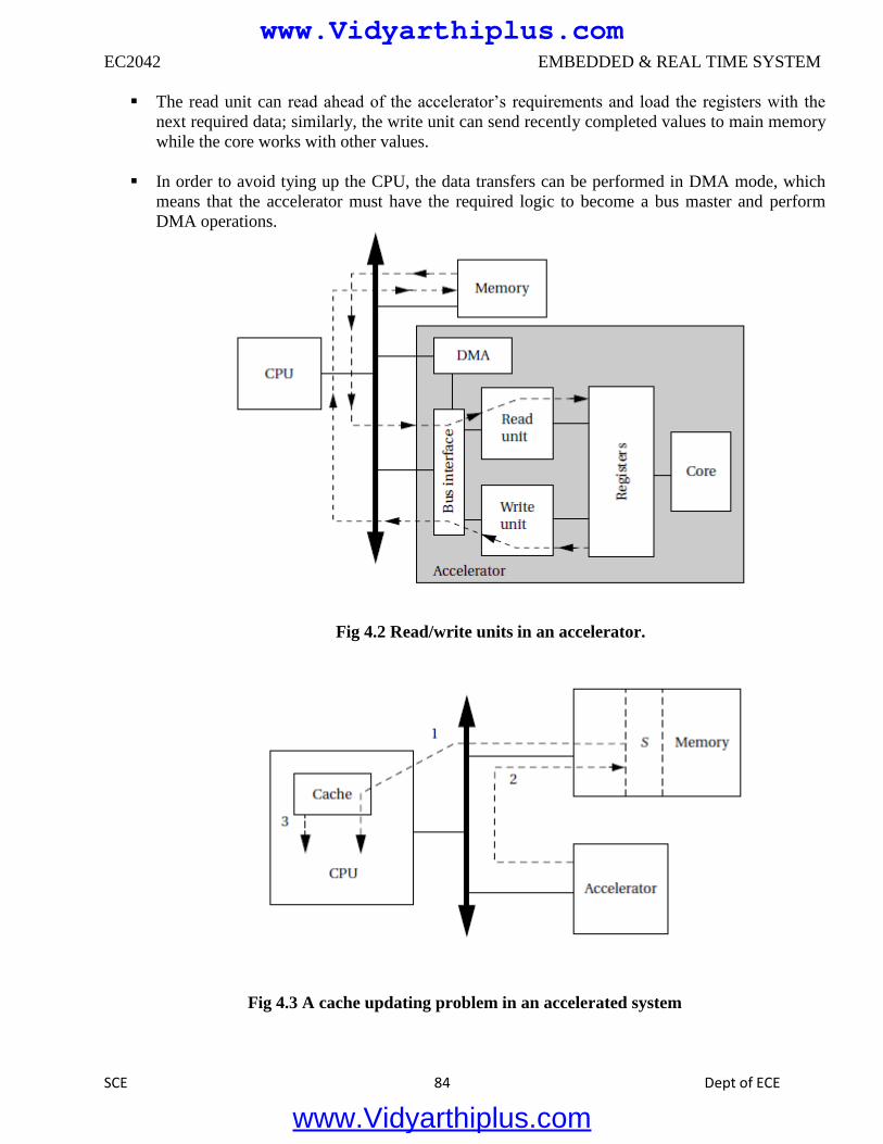
EC2042 EMBEDDED & REAL TIME SYSTEM
SCE 84 Dept of ECE
The read unit can read ahead of the accelerator’s requirements and load the registers with the
next required data; similarly, the write unit can send recently completed values to main memory
while the core works with other values.
In order to avoid tying up the CPU, the data transfers can be performed in DMA mode, which
means that the accelerator must have the required logic to become a bus master and perform
DMA operations.
Fig 4.2 Read/write units in an accelerator.
Fig 4.3 A cache updating problem in an accelerated system
www.Vidyarthiplus.com
www.Vidyarthiplus.com
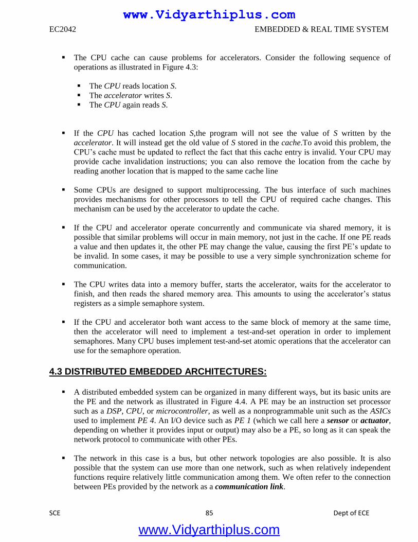
EC2042 EMBEDDED & REAL TIME SYSTEM
SCE 85 Dept of ECE
The CPU cache can cause problems for accelerators. Consider the following sequence of
operations as illustrated in Figure 4.3:
The CPU reads location S.
The accelerator writes S.
The CPU again reads S.
If the CPU has cached location S,the program will not see the value of S written by the
accelerator. It will instead get the old value of S stored in the cache.To avoid this problem, the
CPU’s cache must be updated to reflect the fact that this cache entry is invalid. Your CPU may
provide cache invalidation instructions; you can also remove the location from the cache by
reading another location that is mapped to the same cache line
Some CPUs are designed to support multiprocessing. The bus interface of such machines
provides mechanisms for other processors to tell the CPU of required cache changes. This
mechanism can be used by the accelerator to update the cache.
If the CPU and accelerator operate concurrently and communicate via shared memory, it is
possible that similar problems will occur in main memory, not just in the cache. If one PE reads
a value and then updates it, the other PE may change the value, causing the first PE’s update to
be invalid. In some cases, it may be possible to use a very simple synchronization scheme for
communication.
The CPU writes data into a memory buffer, starts the accelerator, waits for the accelerator to
finish, and then reads the shared memory area. This amounts to using the accelerator’s status
registers as a simple semaphore system.
If the CPU and accelerator both want access to the same block of memory at the same time,
then the accelerator will need to implement a test-and-set operation in order to implement
semaphores. Many CPU buses implement test-and-set atomic operations that the accelerator can
use for the semaphore operation.
4.3 DISTRIBUTED EMBEDDED ARCHITECTURES:
A distributed embedded system can be organized in many different ways, but its basic units are
the PE and the network as illustrated in Figure 4.4. A PE may be an instruction set processor
such as a DSP, CPU, or microcontroller, as well as a nonprogrammable unit such as the ASICs
used to implement PE 4. An I/O device such as PE 1 (which we call here a sensor or actuator,
depending on whether it provides input or output) may also be a PE, so long as it can speak the
network protocol to communicate with other PEs.
The network in this case is a bus, but other network topologies are also possible. It is also
possible that the system can use more than one network, such as when relatively independent
functions require relatively little communication among them. We often refer to the connection
between PEs provided by the network as a communication link.
www.Vidyarthiplus.com
www.Vidyarthiplus.com
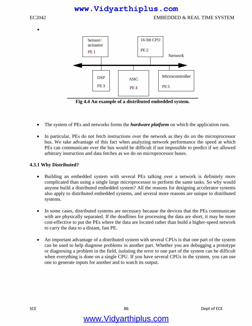
EC2042 EMBEDDED & REAL TIME SYSTEM
SCE 86 Dept of ECE
Fig 4.4 An example of a distributed embedded system.
The system of PEs and networks forms the hardware platform on which the application runs.
In particular, PEs do not fetch instructions over the network as they do on the microprocessor
bus. We take advantage of this fact when analyzing network performance the speed at which
PEs can communicate over the bus would be difficult if not impossible to predict if we allowed
arbitrary instruction and data fetches as we do on microprocessor buses.
4.3.1 Why Distributed?
Building an embedded system with several PEs talking over a network is definitely more
complicated than using a single large microprocessor to perform the same tasks. So why would
anyone build a distributed embedded system? All the reasons for designing accelerator systems
also apply to distributed embedded systems, and several more reasons are unique to distributed
systems.
In some cases, distributed systems are necessary because the devices that the PEs communicate
with are physically separated. If the deadlines for processing the data are short, it may be more
cost-effective to put the PEs where the data are located rather than build a higher-speed network
to carry the data to a distant, fast PE.
An important advantage of a distributed system with several CPUs is that one part of the system
can be used to help diagnose problems in another part. Whether you are debugging a prototype
or diagnosing a problem in the field, isolating the error to one part of the system can be difficult
when everything is done on a single CPU. If you have several CPUs in the system, you can use
one to generate inputs for another and to watch its output.
www.Vidyarthiplus.com
www.Vidyarthiplus.com
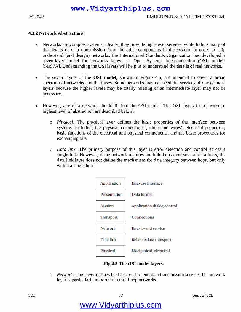
EC2042 EMBEDDED & REAL TIME SYSTEM
SCE 87 Dept of ECE
4.3.2 Network Abstractions
Networks are complex systems. Ideally, they provide high-level services while hiding many of
the details of data transmission from the other components in the system. In order to help
understand (and design) networks, the International Standards Organization has developed a
seven-layer model for networks known as Open Systems Interconnection (OSI) models
[Sta97A]. Understanding the OSI layers will help us to understand the details of real networks.
The seven layers of the OSI model, shown in Figure 4.5, are intended to cover a broad
spectrum of networks and their uses. Some networks may not need the services of one or more
layers because the higher layers may be totally missing or an intermediate layer may not be
necessary.
However, any data network should fit into the OSI model. The OSI layers from lowest to
highest level of abstraction are described below.
o Physical: The physical layer defines the basic properties of the interface between
systems, including the physical connections ( plugs and wires), electrical properties,
basic functions of the electrical and physical components, and the basic procedures for
exchanging bits.
o Data link: The primary purpose of this layer is error detection and control across a
single link. However, if the network requires multiple hops over several data links, the
data link layer does not define the mechanism for data integrity between hops, but only
within a single hop.
Fig 4.5 The OSI model layers.
o Network: This layer defines the basic end-to-end data transmission service. The network
layer is particularly important in multi hop networks.
www.Vidyarthiplus.com
www.Vidyarthiplus.com
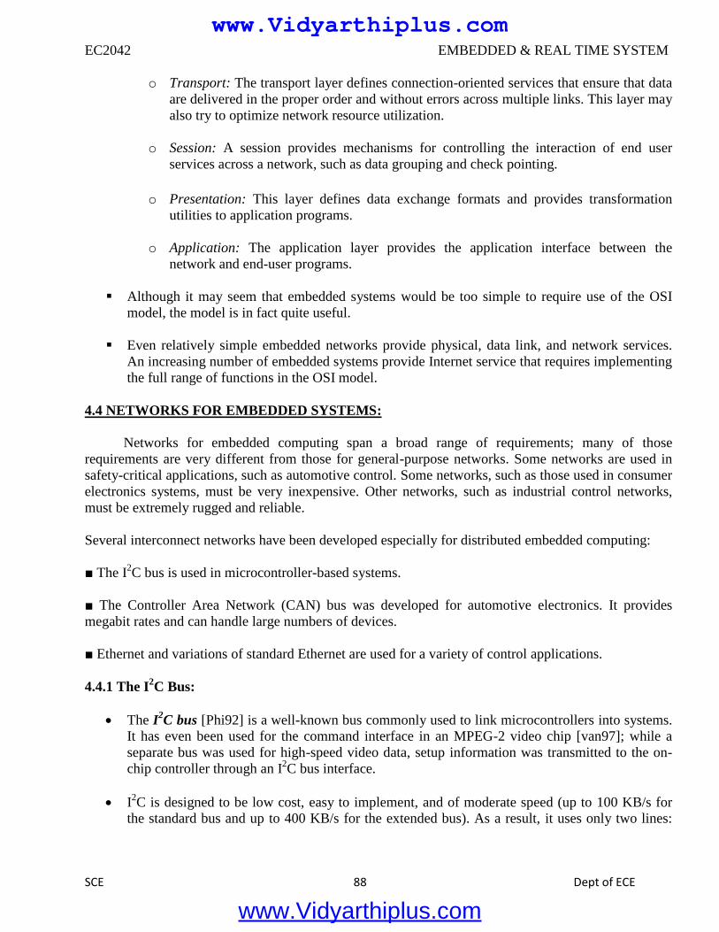
EC2042 EMBEDDED & REAL TIME SYSTEM
SCE 88 Dept of ECE
o Transport: The transport layer defines connection-oriented services that ensure that data
are delivered in the proper order and without errors across multiple links. This layer may
also try to optimize network resource utilization.
o Session: A session provides mechanisms for controlling the interaction of end user
services across a network, such as data grouping and check pointing.
o Presentation: This layer defines data exchange formats and provides transformation
utilities to application programs.
o Application: The application layer provides the application interface between the
network and end-user programs.
Although it may seem that embedded systems would be too simple to require use of the OSI
model, the model is in fact quite useful.
Even relatively simple embedded networks provide physical, data link, and network services.
An increasing number of embedded systems provide Internet service that requires implementing
the full range of functions in the OSI model.
4.4 NETWORKS FOR EMBEDDED SYSTEMS:
Networks for embedded computing span a broad range of requirements; many of those
requirements are very different from those for general-purpose networks. Some networks are used in
safety-critical applications, such as automotive control. Some networks, such as those used in consumer
electronics systems, must be very inexpensive. Other networks, such as industrial control networks,
must be extremely rugged and reliable.
Several interconnect networks have been developed especially for distributed embedded computing:
■ The I2C bus is used in microcontroller-based systems.
■ The Controller Area Network (CAN) bus was developed for automotive electronics. It provides
megabit rates and can handle large numbers of devices.
■ Ethernet and variations of standard Ethernet are used for a variety of control applications.
4.4.1 The I2C Bus:
The I2C bus [Phi92] is a well-known bus commonly used to link microcontrollers into systems.
It has even been used for the command interface in an MPEG-2 video chip [van97]; while a
separate bus was used for high-speed video data, setup information was transmitted to the on-
chip controller through an I2C bus interface.
I2C is designed to be low cost, easy to implement, and of moderate speed (up to 100 KB/s for
the standard bus and up to 400 KB/s for the extended bus). As a result, it uses only two lines:
www.Vidyarthiplus.com
www.Vidyarthiplus.com
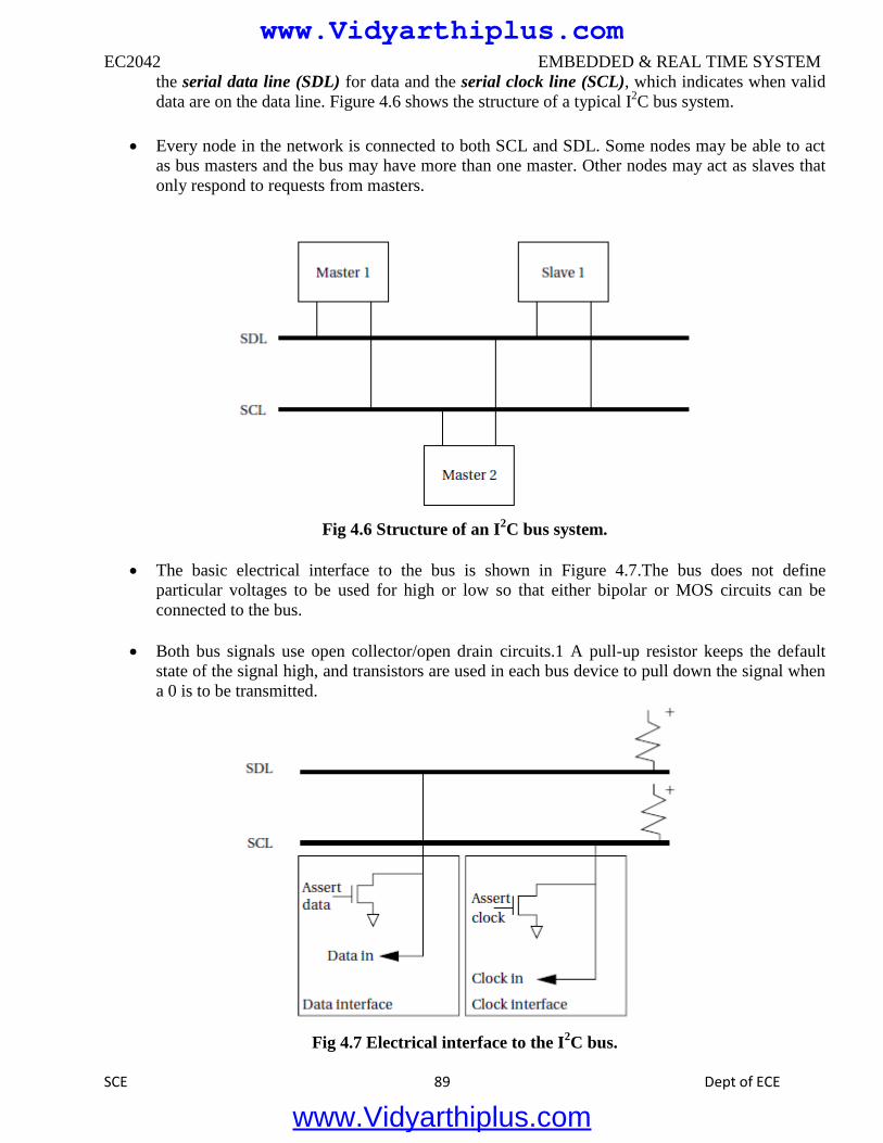
EC2042 EMBEDDED & REAL TIME SYSTEM
SCE 89 Dept of ECE
the serial data line (SDL) for data and the serial clock line (SCL), which indicates when valid
data are on the data line. Figure 4.6 shows the structure of a typical I2C bus system.
Every node in the network is connected to both SCL and SDL. Some nodes may be able to act
as bus masters and the bus may have more than one master. Other nodes may act as slaves that
only respond to requests from masters.
Fig 4.6 Structure of an I
2C bus system.
The basic electrical interface to the bus is shown in Figure 4.7.The bus does not define
particular voltages to be used for high or low so that either bipolar or MOS circuits can be
connected to the bus.
Both bus signals use open collector/open drain circuits.1 A pull-up resistor keeps the default
state of the signal high, and transistors are used in each bus device to pull down the signal when
a 0 is to be transmitted.
Fig 4.7 Electrical interface to the I
2C bus.
www.Vidyarthiplus.com
www.Vidyarthiplus.com
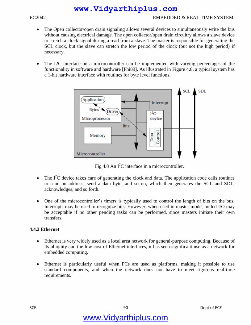
EC2042 EMBEDDED & REAL TIME SYSTEM
SCE 90 Dept of ECE
The Open collector/open drain signaling allows several devices to simultaneously write the bus
without causing electrical damage. The open collector/open drain circuitry allows a slave device
to stretch a clock signal during a read from a slave. The master is responsible for generating the
SCL clock, but the slave can stretch the low period of the clock (but not the high period) if
necessary.
The I2C interface on a microcontroller can be implemented with varying percentages of the
functionality in software and hardware [Phi89]. As illustrated in Figure 4.8, a typical system has
a 1-bit hardware interface with routines for byte level functions.
Fig 4.8 An I
2C interface in a microcontroller.
The I2C device takes care of generating the clock and data. The application code calls routines
to send an address, send a data byte, and so on, which then generates the SCL and SDL,
acknowledges, and so forth.
One of the microcontroller’s timers is typically used to control the length of bits on the bus.
Interrupts may be used to recognize bits. However, when used in master mode, polled I/O may
be acceptable if no other pending tasks can be performed, since masters initiate their own
transfers.
4.4.2 Ethernet
Ethernet is very widely used as a local area network for general-purpose computing. Because of
its ubiquity and the low cost of Ethernet interfaces, it has seen significant use as a network for
embedded computing.
Ethernet is particularly useful when PCs are used as platforms, making it possible to use
standard components, and when the network does not have to meet rigorous real-time
requirements.
www.Vidyarthiplus.com
www.Vidyarthiplus.com
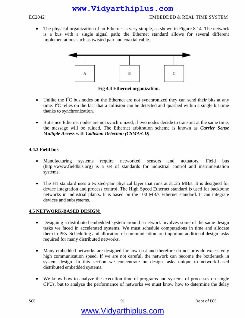
EC2042 EMBEDDED & REAL TIME SYSTEM
SCE 91 Dept of ECE
The physical organization of an Ethernet is very simple, as shown in Figure 8.14. The network
is a bus with a single signal path; the Ethernet standard allows for several different
implementations such as twisted pair and coaxial cable.
Fig 4.4 Ethernet organization.
Unlike the I2C bus,nodes on the Ethernet are not synchronized they can send their bits at any
time. I2C relies on the fact that a collision can be detected and quashed within a single bit time
thanks to synchronization.
But since Ethernet nodes are not synchronized, if two nodes decide to transmit at the same time,
the message will be ruined. The Ethernet arbitration scheme is known as Carrier Sense
Multiple Access with Collision Detection (CSMA/CD).
4.4.3 Field bus
Manufacturing systems require networked sensors and actuators. Field bus
(http://www.fieldbus.org) is a set of standards for industrial control and instrumentation
systems.
The H1 standard uses a twisted-pair physical layer that runs at 31.25 MB/s. It is designed for
device integration and process control. The High Speed Ethernet standard is used for backbone
networks in industrial plants. It is based on the 100 MB/s Ethernet standard. It can integrate
devices and subsystems.
4.5 NETWORK-BASED DESIGN:
Designing a distributed embedded system around a network involves some of the same design
tasks we faced in accelerated systems. We must schedule computations in time and allocate
them to PEs. Scheduling and allocation of communication are important additional design tasks
required for many distributed networks.
Many embedded networks are designed for low cost and therefore do not provide excessively
high communication speed. If we are not careful, the network can become the bottleneck in
system design. In this section we concentrate on design tasks unique to network-based
distributed embedded systems.
We know how to analyze the execution time of programs and systems of processes on single
CPUs, but to analyze the performance of networks we must know how to determine the delay
www.Vidyarthiplus.com
www.Vidyarthiplus.com
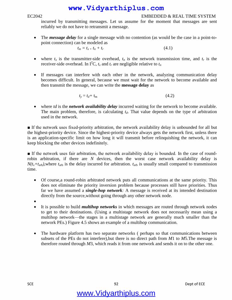
EC2042 EMBEDDED & REAL TIME SYSTEM
SCE 92 Dept of ECE
incurred by transmitting messages. Let us assume for the moment that messages are sent
reliably we do not have to retransmit a message.
The message delay for a single message with no contention (as would be the case in a point-to-
point connection) can be modeled as
tm = tx + tn + tr (4.1)
where tx is the transmitter-side overhead, tn is the network transmission time, and tr is the
receiver-side overhead. In I2C, tx and tr are negligible relative to tn
If messages can interfere with each other in the network, analyzing communication delay
becomes difficult. In general, because we must wait for the network to become available and
then transmit the message, we can write the message delay as
ty = td+ tm (4.2)
where td is the network availability delay incurred waiting for the network to become available.
The main problem, therefore, is calculating td. That value depends on the type of arbitration
used in the network.
■ If the network uses fixed-priority arbitration, the network availability delay is unbounded for all but
the highest-priority device. Since the highest-priority device always gets the network first, unless there
is an application-specific limit on how long it will transmit before relinquishing the network, it can
keep blocking the other devices indefinitely.
■ If the network uses fair arbitration, the network availability delay is bounded. In the case of round-
robin arbitration, if there are N devices, then the worst case network availability delay is
N(tx+tarb),where tarb is the delay incurred for arbitration. tarb is usually small compared to transmission
time.
Of course,a round-robin arbitrated network puts all communications at the same priority. This
does not eliminate the priority inversion problem because processes still have priorities. Thus
far we have assumed a single-hop network: A message is received at its intended destination
directly from the source,without going through any other network node.
It is possible to build multihop networks in which messages are routed through network nodes
to get to their destinations. (Using a multistage network does not necessarily mean using a
multihop network—the stages in a multistage network are generally much smaller than the
network PEs.) Figure 4.5 shows an example of a multihop communication.
The hardware platform has two separate networks ( perhaps so that communications between
subsets of the PEs do not interfere),but there is no direct path from M1 to M5.The message is
therefore routed through M3, which reads it from one network and sends it on to the other one.
www.Vidyarthiplus.com
www.Vidyarthiplus.com
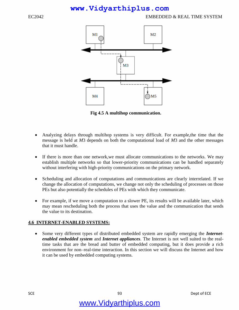
EC2042 EMBEDDED & REAL TIME SYSTEM
SCE 93 Dept of ECE
Fig 4.5 A multihop communication.
Analyzing delays through multihop systems is very difficult. For example,the time that the
message is held at M3 depends on both the computational load of M3 and the other messages
that it must handle.
If there is more than one network,we must allocate communications to the networks. We may
establish multiple networks so that lower-priority communications can be handled separately
without interfering with high-priority communications on the primary network.
Scheduling and allocation of computations and communications are clearly interrelated. If we
change the allocation of computations, we change not only the scheduling of processes on those
PEs but also potentially the schedules of PEs with which they communicate.
For example, if we move a computation to a slower PE, its results will be available later, which
may mean rescheduling both the process that uses the value and the communication that sends
the value to its destination.
4.6 INTERNET-ENABLED SYSTEMS:
Some very different types of distributed embedded system are rapidly emerging the Internet-
enabled embedded system and Internet appliances. The Internet is not well suited to the real-
time tasks that are the bread and butter of embedded computing, but it does provide a rich
environment for non–real-time interaction. In this section we will discuss the Internet and how
it can be used by embedded computing systems.
www.Vidyarthiplus.com
www.Vidyarthiplus.com
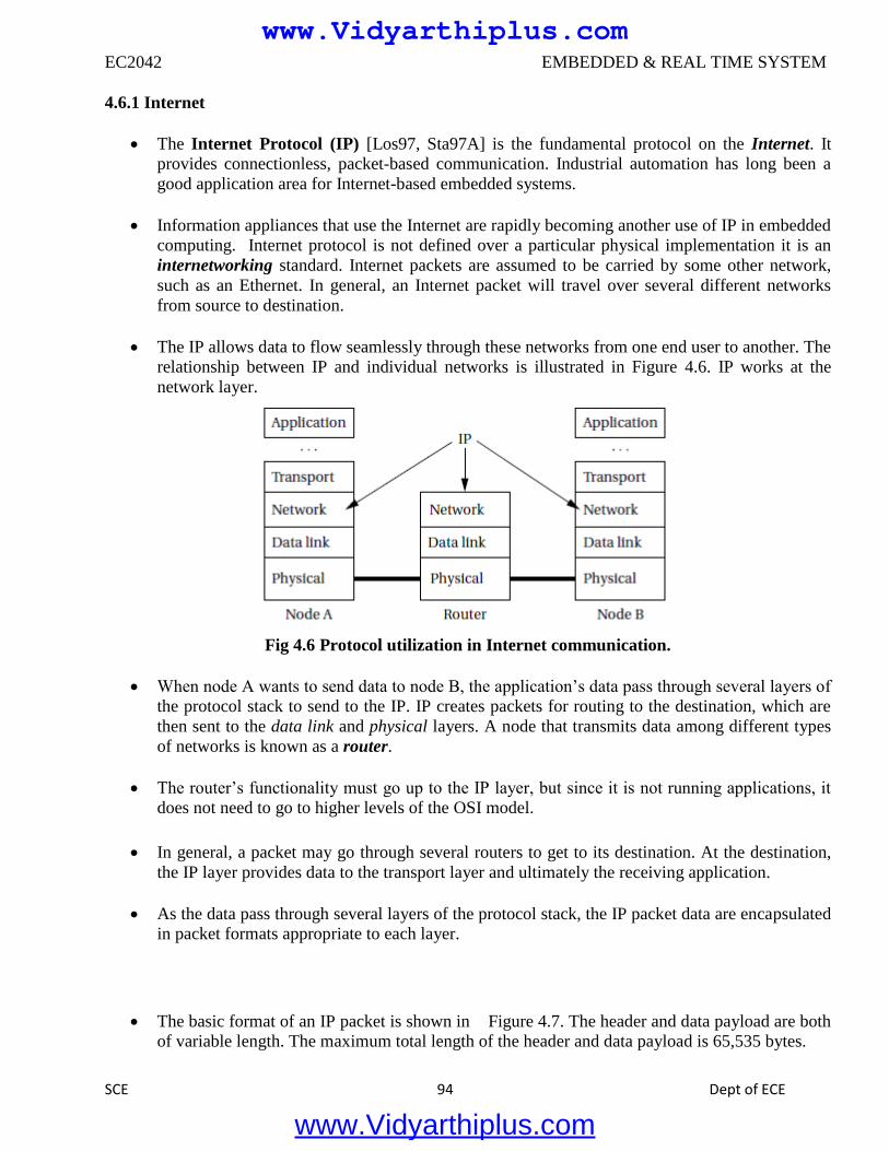
EC2042 EMBEDDED & REAL TIME SYSTEM
SCE 94 Dept of ECE
4.6.1 Internet
The Internet Protocol (IP) [Los97, Sta97A] is the fundamental protocol on the Internet. It
provides connectionless, packet-based communication. Industrial automation has long been a
good application area for Internet-based embedded systems.
Information appliances that use the Internet are rapidly becoming another use of IP in embedded
computing. Internet protocol is not defined over a particular physical implementation it is an
internetworking standard. Internet packets are assumed to be carried by some other network,
such as an Ethernet. In general, an Internet packet will travel over several different networks
from source to destination.
The IP allows data to flow seamlessly through these networks from one end user to another. The
relationship between IP and individual networks is illustrated in Figure 4.6. IP works at the
network layer.
Fig 4.6 Protocol utilization in Internet communication.
When node A wants to send data to node B, the application’s data pass through several layers of
the protocol stack to send to the IP. IP creates packets for routing to the destination, which are
then sent to the data link and physical layers. A node that transmits data among different types
of networks is known as a router.
The router’s functionality must go up to the IP layer, but since it is not running applications, it
does not need to go to higher levels of the OSI model.
In general, a packet may go through several routers to get to its destination. At the destination,
the IP layer provides data to the transport layer and ultimately the receiving application.
As the data pass through several layers of the protocol stack, the IP packet data are encapsulated
in packet formats appropriate to each layer.
The basic format of an IP packet is shown in Figure 4.7. The header and data payload are both
of variable length. The maximum total length of the header and data payload is 65,535 bytes.
www.Vidyarthiplus.com
www.Vidyarthiplus.com
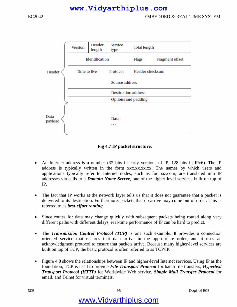
EC2042 EMBEDDED & REAL TIME SYSTEM
SCE 95 Dept of ECE
Fig 4.7 IP packet structure.
An Internet address is a number (32 bits in early versions of IP, 128 bits in IPv6). The IP
address is typically written in the form xxx.xx.xx.xx. The names by which users and
applications typically refer to Internet nodes, such as foo.baz.com, are translated into IP
addresses via calls to a Domain Name Server, one of the higher-level services built on top of
IP.
The fact that IP works at the network layer tells us that it does not guarantee that a packet is
delivered to its destination. Furthermore, packets that do arrive may come out of order. This is
referred to as best-effort routing.
Since routes for data may change quickly with subsequent packets being routed along very
different paths with different delays, real-time performance of IP can be hard to predict.
The Transmission Control Protocol (TCP) is one such example. It provides a connection
oriented service that ensures that data arrive in the appropriate order, and it uses an
acknowledgment protocol to ensure that packets arrive. Because many higher-level services are
built on top of TCP, the basic protocol is often referred to as TCP/IP.
Figure 4.8 shows the relationships between IP and higher-level Internet services. Using IP as the
foundation, TCP is used to provide File Transport Protocol for batch file transfers, Hypertext
Transport Protocol (HTTP) for Worldwide Web service, Simple Mail Transfer Protocol for
email, and Telnet for virtual terminals.
www.Vidyarthiplus.com
www.Vidyarthiplus.com
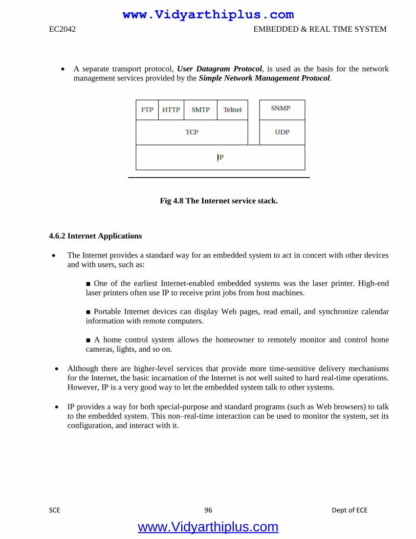
EC2042 EMBEDDED & REAL TIME SYSTEM
SCE 96 Dept of ECE
A separate transport protocol, User Datagram Protocol, is used as the basis for the network
management services provided by the Simple Network Management Protocol.
Fig 4.8 The Internet service stack.
4.6.2 Internet Applications
The Internet provides a standard way for an embedded system to act in concert with other devices
and with users, such as:
■ One of the earliest Internet-enabled embedded systems was the laser printer. High-end
laser printers often use IP to receive print jobs from host machines.
■ Portable Internet devices can display Web pages, read email, and synchronize calendar
information with remote computers.
■ A home control system allows the homeowner to remotely monitor and control home
cameras, lights, and so on.
Although there are higher-level services that provide more time-sensitive delivery mechanisms
for the Internet, the basic incarnation of the Internet is not well suited to hard real-time operations.
However, IP is a very good way to let the embedded system talk to other systems.
IP provides a way for both special-purpose and standard programs (such as Web browsers) to talk
to the embedded system. This non–real-time interaction can be used to monitor the system, set its
configuration, and interact with it.
www.Vidyarthiplus.com
www.Vidyarthiplus.com
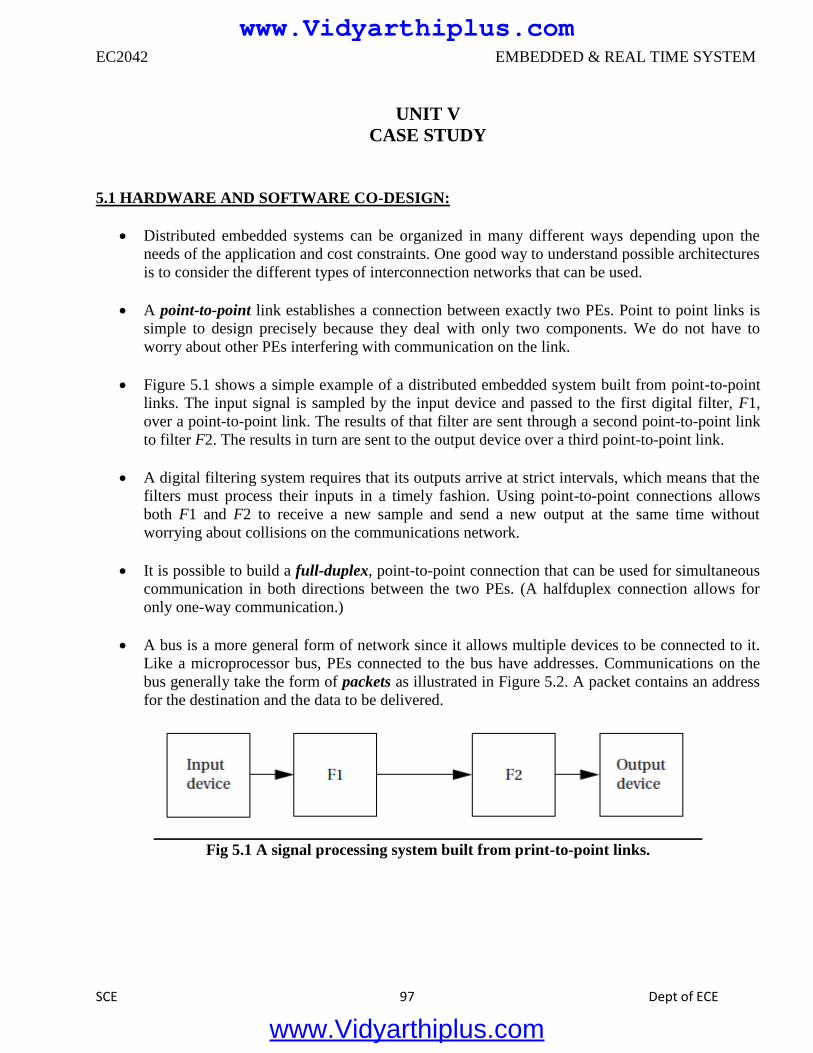
EC2042 EMBEDDED & REAL TIME SYSTEM
SCE 97 Dept of ECE
UNIT V
CASE STUDY
5.1 HARDWARE AND SOFTWARE CO-DESIGN:
Distributed embedded systems can be organized in many different ways depending upon the
needs of the application and cost constraints. One good way to understand possible architectures
is to consider the different types of interconnection networks that can be used.
A point-to-point link establishes a connection between exactly two PEs. Point to point links is
simple to design precisely because they deal with only two components. We do not have to
worry about other PEs interfering with communication on the link.
Figure 5.1 shows a simple example of a distributed embedded system built from point-to-point
links. The input signal is sampled by the input device and passed to the first digital filter, F1,
over a point-to-point link. The results of that filter are sent through a second point-to-point link
to filter F2. The results in turn are sent to the output device over a third point-to-point link.
A digital filtering system requires that its outputs arrive at strict intervals, which means that the
filters must process their inputs in a timely fashion. Using point-to-point connections allows
both F1 and F2 to receive a new sample and send a new output at the same time without
worrying about collisions on the communications network.
It is possible to build a full-duplex, point-to-point connection that can be used for simultaneous
communication in both directions between the two PEs. (A halfduplex connection allows for
only one-way communication.)
A bus is a more general form of network since it allows multiple devices to be connected to it.
Like a microprocessor bus, PEs connected to the bus have addresses. Communications on the
bus generally take the form of packets as illustrated in Figure 5.2. A packet contains an address
for the destination and the data to be delivered.
Fig 5.1 A signal processing system built from print-to-point links.
www.Vidyarthiplus.com
www.Vidyarthiplus.com
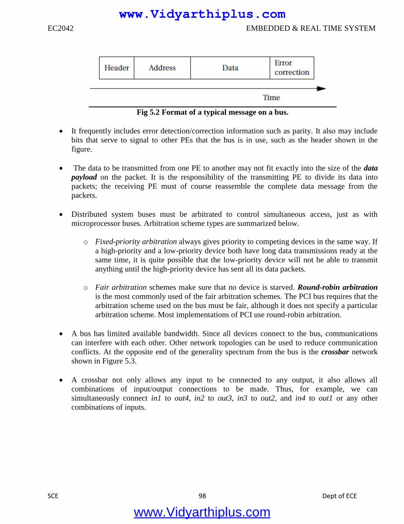
EC2042 EMBEDDED & REAL TIME SYSTEM
SCE 98 Dept of ECE
Fig 5.2 Format of a typical message on a bus.
It frequently includes error detection/correction information such as parity. It also may include
bits that serve to signal to other PEs that the bus is in use, such as the header shown in the
figure.
The data to be transmitted from one PE to another may not fit exactly into the size of the data
payload on the packet. It is the responsibility of the transmitting PE to divide its data into
packets; the receiving PE must of course reassemble the complete data message from the
packets.
Distributed system buses must be arbitrated to control simultaneous access, just as with
microprocessor buses. Arbitration scheme types are summarized below.
o Fixed-priority arbitration always gives priority to competing devices in the same way. If
a high-priority and a low-priority device both have long data transmissions ready at the
same time, it is quite possible that the low-priority device will not be able to transmit
anything until the high-priority device has sent all its data packets.
o Fair arbitration schemes make sure that no device is starved. Round-robin arbitration
is the most commonly used of the fair arbitration schemes. The PCI bus requires that the
arbitration scheme used on the bus must be fair, although it does not specify a particular
arbitration scheme. Most implementations of PCI use round-robin arbitration.
A bus has limited available bandwidth. Since all devices connect to the bus, communications
can interfere with each other. Other network topologies can be used to reduce communication
conflicts. At the opposite end of the generality spectrum from the bus is the crossbar network
shown in Figure 5.3.
A crossbar not only allows any input to be connected to any output, it also allows all
combinations of input/output connections to be made. Thus, for example, we can
simultaneously connect in1 to out4, in2 to out3, in3 to out2, and in4 to out1 or any other
combinations of inputs.
www.Vidyarthiplus.com
www.Vidyarthiplus.com
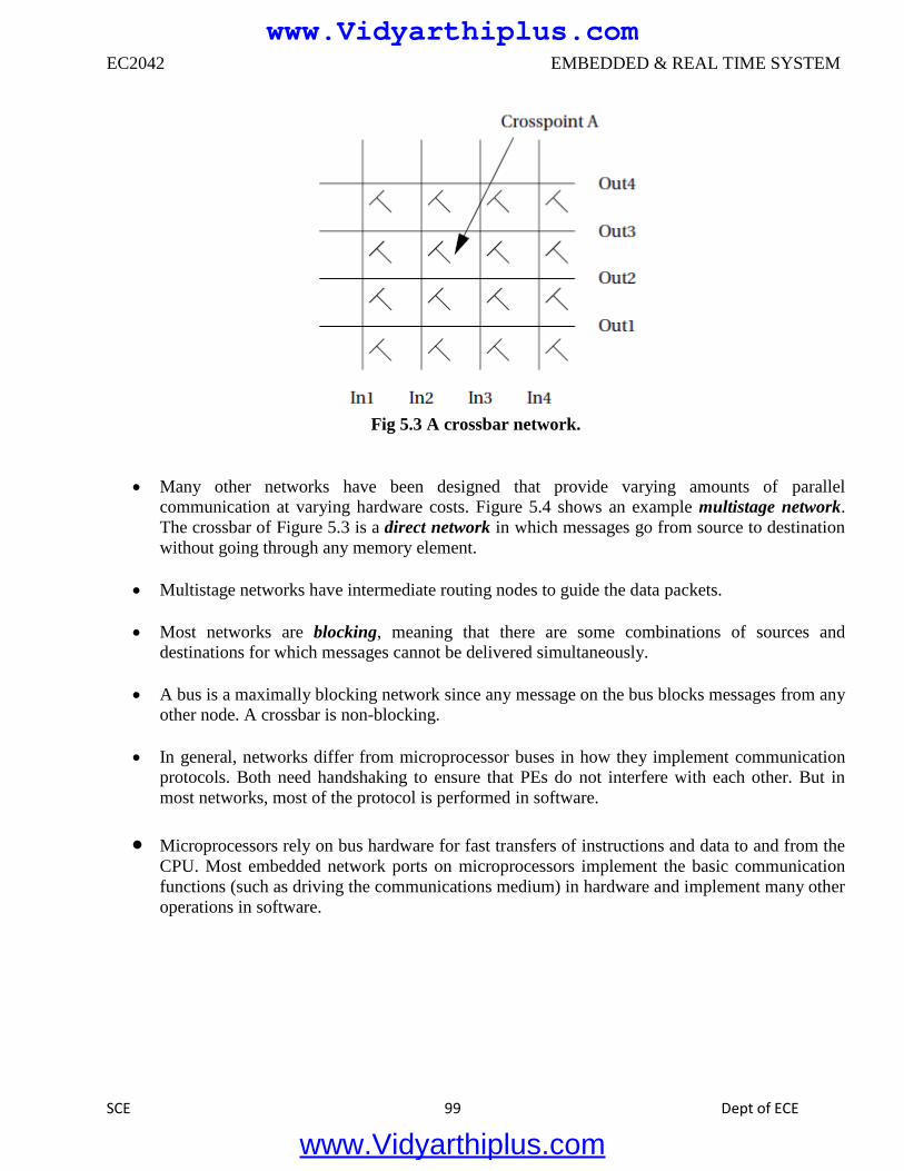
EC2042 EMBEDDED & REAL TIME SYSTEM
SCE 99 Dept of ECE
Fig 5.3 A crossbar network.
Many other networks have been designed that provide varying amounts of parallel
communication at varying hardware costs. Figure 5.4 shows an example multistage network.
The crossbar of Figure 5.3 is a direct network in which messages go from source to destination
without going through any memory element.
Multistage networks have intermediate routing nodes to guide the data packets.
Most networks are blocking, meaning that there are some combinations of sources and
destinations for which messages cannot be delivered simultaneously.
A bus is a maximally blocking network since any message on the bus blocks messages from any
other node. A crossbar is non-blocking.
In general, networks differ from microprocessor buses in how they implement communication
protocols. Both need handshaking to ensure that PEs do not interfere with each other. But in
most networks, most of the protocol is performed in software.
Microprocessors rely on bus hardware for fast transfers of instructions and data to and from the
CPU. Most embedded network ports on microprocessors implement the basic communication
functions (such as driving the communications medium) in hardware and implement many other
operations in software.
www.Vidyarthiplus.com
www.Vidyarthiplus.com
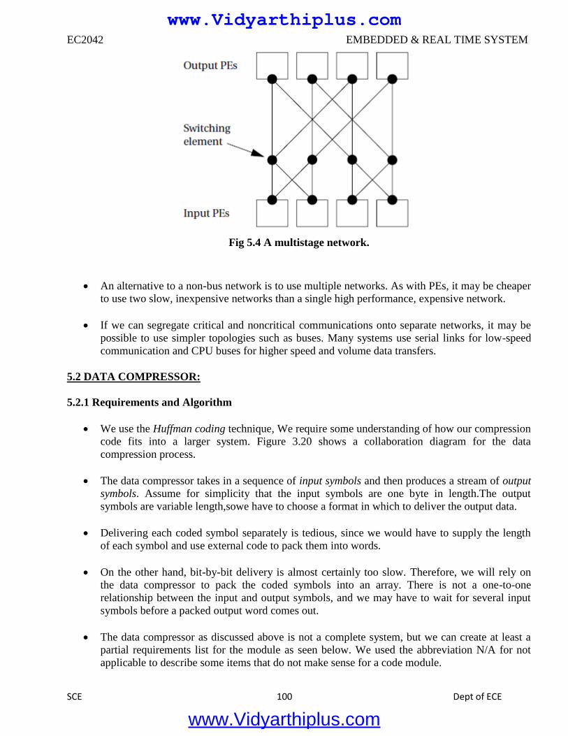
EC2042 EMBEDDED & REAL TIME SYSTEM
SCE 100 Dept of ECE
Fig 5.4 A multistage network.
An alternative to a non-bus network is to use multiple networks. As with PEs, it may be cheaper
to use two slow, inexpensive networks than a single high performance, expensive network.
If we can segregate critical and noncritical communications onto separate networks, it may be
possible to use simpler topologies such as buses. Many systems use serial links for low-speed
communication and CPU buses for higher speed and volume data transfers.
5.2 DATA COMPRESSOR:
5.2.1 Requirements and Algorithm
We use the Huffman coding technique, We require some understanding of how our compression
code fits into a larger system. Figure 3.20 shows a collaboration diagram for the data
compression process.
The data compressor takes in a sequence of input symbols and then produces a stream of output
symbols. Assume for simplicity that the input symbols are one byte in length.The output
symbols are variable length,sowe have to choose a format in which to deliver the output data.
Delivering each coded symbol separately is tedious, since we would have to supply the length
of each symbol and use external code to pack them into words.
On the other hand, bit-by-bit delivery is almost certainly too slow. Therefore, we will rely on
the data compressor to pack the coded symbols into an array. There is not a one-to-one
relationship between the input and output symbols, and we may have to wait for several input
symbols before a packed output word comes out.
The data compressor as discussed above is not a complete system, but we can create at least a
partial requirements list for the module as seen below. We used the abbreviation N/A for not
applicable to describe some items that do not make sense for a code module.
www.Vidyarthiplus.com
www.Vidyarthiplus.com
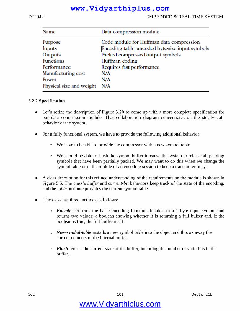
EC2042 EMBEDDED & REAL TIME SYSTEM
SCE 101 Dept of ECE
5.2.2 Specification
Let’s refine the description of Figure 3.20 to come up with a more complete specification for
our data compression module. That collaboration diagram concentrates on the steady-state
behavior of the system.
For a fully functional system, we have to provide the following additional behavior.
o We have to be able to provide the compressor with a new symbol table.
o We should be able to flush the symbol buffer to cause the system to release all pending
symbols that have been partially packed. We may want to do this when we change the
symbol table or in the middle of an encoding session to keep a transmitter busy.
A class description for this refined understanding of the requirements on the module is shown in
Figure 5.5. The class’s buffer and current-bit behaviors keep track of the state of the encoding,
and the table attribute provides the current symbol table.
The class has three methods as follows:
o Encode performs the basic encoding function. It takes in a 1-byte input symbol and
returns two values: a boolean showing whether it is returning a full buffer and, if the
boolean is true, the full buffer itself.
o New-symbol-table installs a new symbol table into the object and throws away the
current contents of the internal buffer.
o Flush returns the current state of the buffer, including the number of valid bits in the
buffer.
www.Vidyarthiplus.com
www.Vidyarthiplus.com
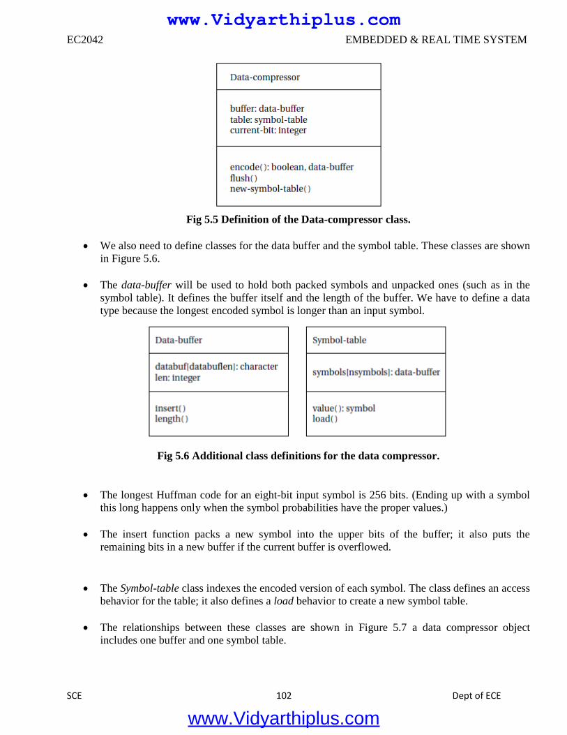
EC2042 EMBEDDED & REAL TIME SYSTEM
SCE 102 Dept of ECE
Fig 5.5 Definition of the Data-compressor class.
We also need to define classes for the data buffer and the symbol table. These classes are shown
in Figure 5.6.
The data-buffer will be used to hold both packed symbols and unpacked ones (such as in the
symbol table). It defines the buffer itself and the length of the buffer. We have to define a data
type because the longest encoded symbol is longer than an input symbol.
Fig 5.6 Additional class definitions for the data compressor.
The longest Huffman code for an eight-bit input symbol is 256 bits. (Ending up with a symbol
this long happens only when the symbol probabilities have the proper values.)
The insert function packs a new symbol into the upper bits of the buffer; it also puts the
remaining bits in a new buffer if the current buffer is overflowed.
The Symbol-table class indexes the encoded version of each symbol. The class defines an access
behavior for the table; it also defines a load behavior to create a new symbol table.
The relationships between these classes are shown in Figure 5.7 a data compressor object
includes one buffer and one symbol table.
www.Vidyarthiplus.com
www.Vidyarthiplus.com
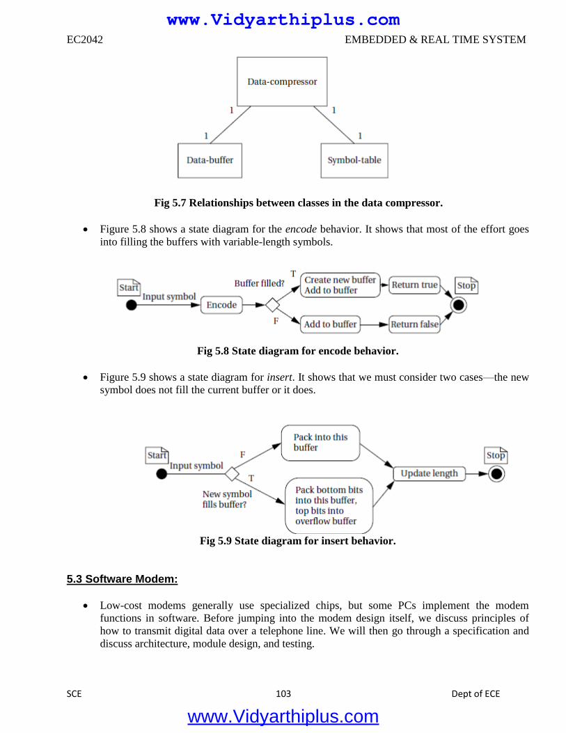
EC2042 EMBEDDED & REAL TIME SYSTEM
SCE 103 Dept of ECE
Fig 5.7 Relationships between classes in the data compressor.
Figure 5.8 shows a state diagram for the encode behavior. It shows that most of the effort goes
into filling the buffers with variable-length symbols.
Fig 5.8 State diagram for encode behavior.
Figure 5.9 shows a state diagram for insert. It shows that we must consider two cases—the new
symbol does not fill the current buffer or it does.
Fig 5.9 State diagram for insert behavior.
5.3 Software Modem:
Low-cost modems generally use specialized chips, but some PCs implement the modem
functions in software. Before jumping into the modem design itself, we discuss principles of
how to transmit digital data over a telephone line. We will then go through a specification and
discuss architecture, module design, and testing.
www.Vidyarthiplus.com
www.Vidyarthiplus.com
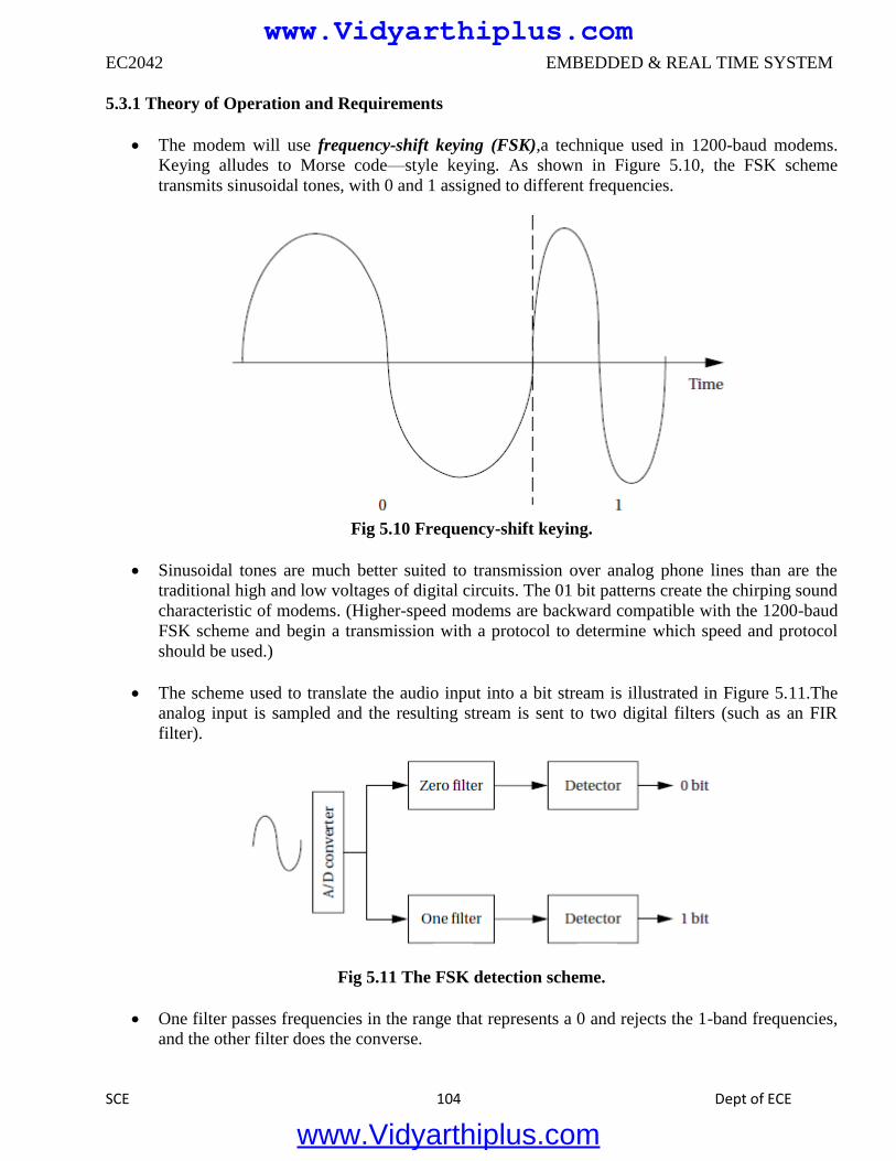
EC2042 EMBEDDED & REAL TIME SYSTEM
SCE 104 Dept of ECE
5.3.1 Theory of Operation and Requirements
The modem will use frequency-shift keying (FSK),a technique used in 1200-baud modems.
Keying alludes to Morse code—style keying. As shown in Figure 5.10, the FSK scheme
transmits sinusoidal tones, with 0 and 1 assigned to different frequencies.
Fig 5.10 Frequency-shift keying.
Sinusoidal tones are much better suited to transmission over analog phone lines than are the
traditional high and low voltages of digital circuits. The 01 bit patterns create the chirping sound
characteristic of modems. (Higher-speed modems are backward compatible with the 1200-baud
FSK scheme and begin a transmission with a protocol to determine which speed and protocol
should be used.)
The scheme used to translate the audio input into a bit stream is illustrated in Figure 5.11.The
analog input is sampled and the resulting stream is sent to two digital filters (such as an FIR
filter).
Fig 5.11 The FSK detection scheme.
One filter passes frequencies in the range that represents a 0 and rejects the 1-band frequencies,
and the other filter does the converse.
www.Vidyarthiplus.com
www.Vidyarthiplus.com
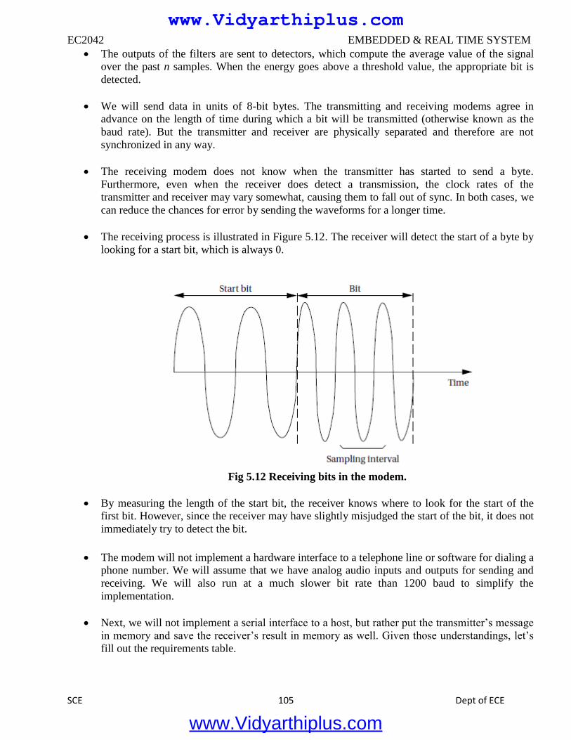
EC2042 EMBEDDED & REAL TIME SYSTEM
SCE 105 Dept of ECE
The outputs of the filters are sent to detectors, which compute the average value of the signal
over the past n samples. When the energy goes above a threshold value, the appropriate bit is
detected.
We will send data in units of 8-bit bytes. The transmitting and receiving modems agree in
advance on the length of time during which a bit will be transmitted (otherwise known as the
baud rate). But the transmitter and receiver are physically separated and therefore are not
synchronized in any way.
The receiving modem does not know when the transmitter has started to send a byte.
Furthermore, even when the receiver does detect a transmission, the clock rates of the
transmitter and receiver may vary somewhat, causing them to fall out of sync. In both cases, we
can reduce the chances for error by sending the waveforms for a longer time.
The receiving process is illustrated in Figure 5.12. The receiver will detect the start of a byte by
looking for a start bit, which is always 0.
Fig 5.12 Receiving bits in the modem.
By measuring the length of the start bit, the receiver knows where to look for the start of the
first bit. However, since the receiver may have slightly misjudged the start of the bit, it does not
immediately try to detect the bit.
The modem will not implement a hardware interface to a telephone line or software for dialing a
phone number. We will assume that we have analog audio inputs and outputs for sending and
receiving. We will also run at a much slower bit rate than 1200 baud to simplify the
implementation.
Next, we will not implement a serial interface to a host, but rather put the transmitter’s message
in memory and save the receiver’s result in memory as well. Given those understandings, let’s
fill out the requirements table.
www.Vidyarthiplus.com
www.Vidyarthiplus.com
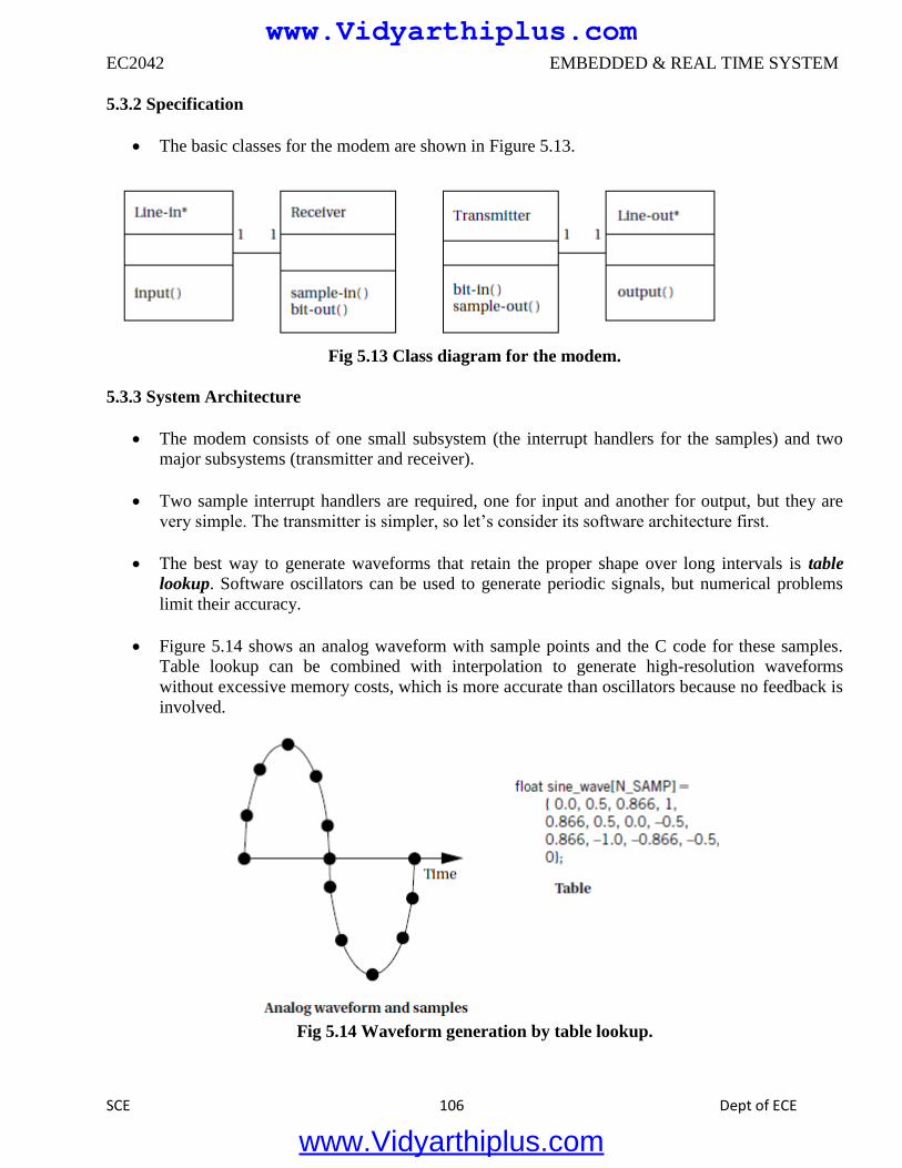
EC2042 EMBEDDED & REAL TIME SYSTEM
SCE 106 Dept of ECE
5.3.2 Specification
The basic classes for the modem are shown in Figure 5.13.
Fig 5.13 Class diagram for the modem.
5.3.3 System Architecture
The modem consists of one small subsystem (the interrupt handlers for the samples) and two
major subsystems (transmitter and receiver).
Two sample interrupt handlers are required, one for input and another for output, but they are
very simple. The transmitter is simpler, so let’s consider its software architecture first.
The best way to generate waveforms that retain the proper shape over long intervals is table
lookup. Software oscillators can be used to generate periodic signals, but numerical problems
limit their accuracy.
Figure 5.14 shows an analog waveform with sample points and the C code for these samples.
Table lookup can be combined with interpolation to generate high-resolution waveforms
without excessive memory costs, which is more accurate than oscillators because no feedback is
involved.
Fig 5.14 Waveform generation by table lookup.
www.Vidyarthiplus.com
www.Vidyarthiplus.com
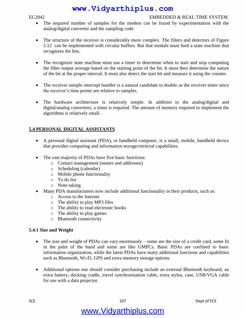
EC2042 EMBEDDED & REAL TIME SYSTEM
SCE 107 Dept of ECE
The required number of samples for the modem can be found by experimentation with the
analog/digital converter and the sampling code.
The structure of the receiver is considerably more complex. The filters and detectors of Figure
5.12 can be implemented with circular buffers. But that module must feed a state machine that
recognizes the bits.
The recognizer state machine must use a timer to determine when to start and stop computing
the filter output average based on the starting point of the bit. It must then determine the nature
of the bit at the proper interval. It must also detect the start bit and measure it using the counter.
The receiver sample interrupt handler is a natural candidate to double as the receiver timer since
the receiver’s time points are relative to samples.
The hardware architecture is relatively simple. In addition to the analog/digital and
digital/analog converters, a timer is required. The amount of memory required to implement the
algorithms is relatively small.
5.4 PERSONAL DIGITAL ASSISTANTS
A personal digital assistant (PDA), or handheld computer, is a small, mobile, handheld device
that provides computing and information storage/retrieval capabilities.
The vast majority of PDAs have five basic functions:
o Contact management (names and addresses)
o Scheduling (calendar)
o Mobile phone functionality
o To do list
o Note-taking
Many PDA manufacturers now include additional functionality in their products, such as:
o Access to the Internet
o The ability to play MP3 files
o The ability to read electronic books
o The ability to play games
o Bluetooth connectivity
5.4.1 Size and Weight
The size and weight of PDAs can vary enormously – some are the size of a credit card, some fit
in the palm of the hand and some are like UMPCs. Basic PDAs are confined to basic
information organization, while the latest PDAs have many additional functions and capabilities
such as Bluetooth, Wi-Fi, GPS and extra memory storage options.
Additional options one should consider purchasing include an external Bluetooth keyboard, an
extra battery, docking cradle, travel synchronisation cable, extra stylus, case, USB/VGA cable
for use with a data projector.
www.Vidyarthiplus.com
www.Vidyarthiplus.com
EC2042 EMBEDDED & REAL TIME SYSTEM
SCE 108 Dept of ECE
Broadly speaking, there are two types of PDA:
• Clamshell PDAs have a small keyboard and they open out rather like a miniature laptop. They may
also feature touch-sensitive screens and a stylus.
• Tablet-type PDAs do not have an integrated keyboard. Input occurs using a stylus or fold-
away/portable keyboard and they tend to be palm-sized.
5.5 SET–TOP–BOX:
The continuing trend is to link broadband signal delivery to the home entertainment display, and
other devices via set top boxes. Set top boxes used to be just an analog cable tuner/decoder but
now it includes the likes of digital cable, satellite controller, internet service controllers, digital
video recording systems and home networking.
These devices allow the various cable and satellite signal operators to deliver a wide variety of
services from television to internet and the hardware manufacturers can provide many features
and benefits including home networking capabilities.
There is digital video recording onto hard disk drives, replacing the cassette format, allowing
pause and replay of and live television, or interactive TV. There are new standards being created
to facilitate the design of the boxes such as a recent reference blueprint development by
communications chipmaker Broadcom using the Microsoft interactive TV software system.
The set top box is going to be a high volume commodity with many forms and functions.
5.6 SYSTEM-ON-SILICON:
A system on a chip or system on chip (SoC or SOC) is an integrated circuit (IC) that integrates
all components of a computer or other electronic system into a single chip. It may contain digital,
analog, mixed-signal, and often radio-frequency functions—all on a single chip substrate. SoCs are
very common in the mobile electronics market because of their low power consumption. A typical
application is in the area of embedded systems.
The contrast with a microcontroller is one of degree. Microcontrollers typically have under 100 kB
of RAM (often just a few kilobytes) and often really are single-chip-systems, whereas the term SoC is
typically used for more powerful processors, capable of running software such as the desktop versions
of Windows and Linux, which need external memory chips (flash, RAM) to be useful, and which are
used with various external peripherals.
For larger systems, the term system on a chip is hyperbole, indicating technical direction more
than reality: a high degree of chip integration, leading toward reduced manufacturing costs, and the
production of smaller systems. Many interesting systems are too complex to fit on just one chip built
with a process optimized for just one of the system's tasks.
www.Vidyarthiplus.com
www.Vidyarthiplus.com
EC2042 EMBEDDED & REAL TIME SYSTEM
SCE 109 Dept of ECE
When it is not feasible to construct a SoC for a particular application, an alternative is a system in
package (SiP) comprising a number of chips in a single package. In large volumes, SoC is believed to
be more cost-effective than SiP since it increases the yield of the fabrication and because its packaging
is simpler.
Another option, as seen for example in higher end cell phones and on the BeagleBoard, is
package on package stacking during board assembly.
The SoC chip includes processors and numerous digital peripherals, and comes in a ball grid
package with lower and upper connections.
The lower balls connect to the board and various peripherals, with the upper balls in a ring
holding the memory buses used to access NAND flash and DDR2 RAM. Memory packages could
come from multiple vendors.
5.7 FOSS TOOLS FOR EMBEDDED SYSTEM DEVELOPMENT:
Free and open-source software (FOSS) is computer software that can be classified as both free
software and open source software. That is, anyone is freely licensed to use, copy, study, and
change the software in any way, and the source code is openly shared so that people are encouraged
to voluntarily improve the design of the software. This is in contrast to proprietary software, where
the software is under restrictive copyright and the source code is usually hidden from the users.
The benefits of using FOSS can include decreasing software costs, increasing security and
stability (especially in regard to malware), protecting privacy, and giving users more control over
their own hardware.
Free, open-source operating systems such as Linux and descendents of BSD are widely utilized
today, powering millions of servers, desktops, smart phones (e.g. Android), and other devices. Free
software licenses and open-source licenses are used by many software packages.
www.Vidyarthiplus.com
www.Vidyarthiplus.com

Glossary Algorithms and Complexity – Computational solutions (algorithms) to problems; time and space complexity with respect to the relationship between the run time and input and the relationship between memory usage and input as the size of the input grows.
Analysis of Business Requirements – The process through which an information systems or software application development project determines the optimal capabilities of the target system or application based on the business goals of the individual user(s) or the user organization(s).
Analysis of Technical Requirements – The process through which a computing development project determines the computing and communications hardware and software based on the goals of the individual user(s) or the user organization(s).
Business Models – Various structures, processes, and other mechanisms that businesses and other organizations use for organizing the way they interact with their primary external stakeholders (e.g., customers and suppliers) to achieve their primary goal (e.g., maximization of profit).
Circuits and Systems – The computing and communications hardware and software components that constitute a computing project or solution.
Computer Architecture and Organization – Form, function, and internal organization of the integrated components of digital computers (including processors, registers, memory, and input/output devices) and their associated assembly language instructions sets.
Computer Systems Engineering – A computing discipline that is more prominent in Europe than in North America. It integrates aspects of CE, CS, and SE, and focuses on the development of complex systems that require close integration of computer hardware and software. Areas of special emphasis include design and implementation of embedded and real-time systems, the use of formal methods for specification of computer systems, and the implementation of systems on specialized-purpose circuits.
Decision Theory – A field of study that develops knowledge and analytical models that together will help decision makers select among various alternatives that are known (or thought) to lead to specific consequences.
Digital logic – Sequential and non-sequential logic as applied to computer hardware including circuits and basic computer organization.
Digital Media Development – The field of computing that deals with the portable storage of digital information.
Digital Signal Processing – The field of computing that deals with digital filters, time and frequency transforms, and other digital methods of handling analog signals.
Distributed Systems – Theory and application of multiple, independent, and cooperating computer systems.
E-business – The use of information and communication technology solutions to implement business models and internal and external business processes. In a more narrow sense, the term is often used to refer to the use of Internet technologies to conduct business between firms (B2B), between firms and consumers (B2C), or among consumers (C2C).
www.Vidyarthiplus.com
www.Vidyarthiplus.com

Electronics – The hardware that constitutes the computing and communications circuits which either directly operate on electronic signals or run the software which operates on electronic signals. The fields of computing and communications presently rely completely on electronics.
Embedded Systems - Hardware and software which forms a component of some larger system and which may be expected to function with minimal human intervention (e.g., an automobile’s cruise control system).
Engineering Economics for SW – Cost models for the software engineering lifecycle including development, maintenance, and retirement of software systems.
Engineering Foundations for SW – Engineering design, process, and measurement as applied to software systems.
Evaluation of Business Performance – The activities that an organization uses to determine how successful it has been in achieving its goals.
Functional Business Areas – Accounting, finance, marketing, human resource management, manufacturing, and logistics are examples of functional business areas. Each of these is responsible for a set of connected business activities which as a whole help a business achieve a specific functional goal (such as providing a reliable and appropriate set of internal and external business performance measures in accounting).
General Systems Theory – A field of study that explores the general characteristics of systems in various areas of human behavior and natural sciences with a special focus on complexity and system component interdependency. General systems theory had its origins in physics, biology, and engineering, but it has been utilized in many other fields such as economics, organizational theory, philosophy, sociology, and information systems.
Graphics and Visualization – Theory and application of computer generated graphics and graphical representation of data and information including static, dynamic, and animated techniques.
Hardware Testing and Fault Tolerance – The field of study that deals with faster, cheaper, and more efficient ways of testing hardware (see also Electronics and Circuits and Systems) as well as ways of making hardware more fault tolerant (able to continue functioning as specified in spite of hardware or software faults).
Human-Computer Interaction – An organizational practice and academic field of study that focuses on the processes, methods, and tools that are used for designing and implementing the interaction between information technology solutions and their users.
Information Management (DB) Theory – Theoretical models for information representation, storage, and processing.
Information Management (DB) Practice – The activities associated with the analysis, design, implementation, and management of organizational information resources such as operational databases, data warehouses, and knowledge management systems.
Information Systems Development – The human activities -- including requirements analysis, logical and physical design, and system implementation -- that together lead to the creation of new information systems solutions.
www.Vidyarthiplus.com
www.Vidyarthiplus.com

Integrative Programming –Uses the fundamentals of programming to focus on bringing together disparate hardware and software systems, building a system with them that smoothly accomplishes more than the separate systems can accomplish.
Intelligent Systems (AI) – Computer applications that are based on artificial intelligence theory and techniques including rule-based systems, genetic and evolutionary computation, and self-organizing systems.
Interpersonal Communication – An area of study that helps computing students improve their oral and written communication skills for teamwork, presentations, interaction with clients and other informants, documentation, sales and marketing activities, etc.
Legal / Professional / Ethics / Society – The areas of practice and study within the computing disciplines that help computing professionals make ethically informed decisions that are within the boundaries of relevant legal systems and professional codes of conduct.
Management of Information Systems Organization – The processes and structures that are used to organize and manage the employees and contractors within the organization whose primary organizational role is to create, maintain, administer, or manage organizational information systems solutions.
Mathematical Foundations – Those aspects of mathematics that underlie work in the computing disciplines. The subsets of mathematics that are most relevant to computing vary from one computing discipline to another. Depending on the discipline, mathematical foundations may include algebra (linear and abstract), calculus, combinatorics, probability, and/or statistics. The term "mathematical foundations" sometimes also includes the fields of study and research that are interdisciplinary between mathematics and computer science such as discrete mathematics, graph theory, and computational complexity theory.
Net Centric: Principles and Design – Includes a range of topics including computer communication network concepts and protocols, multimedia systems, Web standards and technologies, network security, wireless and mobile computing, and distributed systems.
Net Centric: Use and Configuration – The organizational activities associated with the selection, procurement, implementation, configuration, and management of networking technologies.
Operating Systems Principles & Design – Underlying principles and design for the system software that manages all hardware resources (including the processor, memory, external storage, and input/output devices) and provides the interface between application software and the bare machine.
Operating Systems Configuration & Use – Installation, configuration, and management of the operating system on one or more computers.
Organizational Behavior – A field of study within the business discipline of management that focuses on individual and group-level human behavior in organizations. The core topics include, for example, individual and group decision making, problem solving, training, incentive structures, and goal setting.
Organizational Change Management – A field of study often associated with the business discipline of management that focuses on topics that help employees in organizations to manage and cope with organizational change whether it is a result of internal organizational actions or forces in the external environment.
www.Vidyarthiplus.com
www.Vidyarthiplus.com
Organizational Theory – A field of study within the business discipline of management that focuses on the structure of the organizations. This field helps managers decide what types of organizational structures to use and understand why certain types of structures tend to work better than others. Key questions focus on centralization/decentralization of power, the selection and use of coordination and control mechanisms, and breadth and dept of the organizational reporting structures.
Platform Technologies – The field of study which deals with the computing hardware and operating systems which underlie all application programs.
Programming Fundamentals - Fundamental concepts of procedural programming (including data types, control structures, functions, arrays, files, and the mechanics of running, testing, and debugging) and object-oriented programming (including objects, classes, inheritance, and polymorphism).
Project Management – An organizational practice and academic field of study that focuses on the management approaches, organizational structures and processes, and tools and technologies that together lead to the best possible outcomes in work that has been organized as a project.
Risk Management (Project, safety risk) – An organizational practice and academic field of study that focuses on the processes, management approaches, and technologies for identifying risks, determining their severity level, and choosing and implementing the proper course of action for each risk.
Scientific Computing (Numerical Methods) – Algorithms and the associated methods for computing discrete approximations used to solving problems involving continuous mathematics.
Security: Issues and Principles – Theory and application of access control to computer systems and the information contained therein.
Security: Implementation and Management – The organizational activities associated with the selection, procurement, implementation, configuration, and management of security processes and technologies for IT infrastructure and applications.
Software Design - An activity that translates the requirements model into a more detailed model that represents a software solution which typically includes architectural design specifications and detailed design specifications. [Alternatively, in software engineering, the process of defining the software architecture (structure), components, modules, interfaces, test approach, and data for a software system to satisfy specified requirem������� �ANSI/IEEE Standard 729-1983] ]
Software Evolution (Maintenance) - (1) The process of modifying a software system or component after delivery to correct faults, improve performance or other attributes, or adapt to a changed environment. (2) The process of retaining a hardware system or component in, or restoring it to, a state in which it can perform its required functions. [IEEE Std 610.12-1990]
Software Modeling and Analysis – An activity that attempts to model customer requirements and constraints with the objective of understanding what the customer actually needs and thus defining the actual problem to be solved with software.
Software Process - (1) A sequence of steps performed for a given purpose, for example, the software development process. (2) An executable unit managed by an operating system scheduler. (3) To perform operations on data. [IEEE Std 610.12-1990]
Software Quality (Analysis) - (1) A planned and systematic pattern of all actions necessary to provide adequate confidence that an item or product conforms to established technical requirements. (2) A set of
www.Vidyarthiplus.com
www.Vidyarthiplus.com
activities designed to evaluate the process by which products are developed or manufactured. [IEEE Std 610.12-1990]
Software Verification and Validation - The process of determining whether the requirements for a system or component are complete and correct, the products of each development phase fulfill the requirements or conditions imposed by the previous phase, and the final system or component complies with specified requirements. [IEEE Std 610.12-1990]
Systems Administration – The field of study which deals with the management of computing and communications resources, including networks, databases, operating systems, applications, and Web delivery. The management issues include installation, configuration, operation, and maintenance.
Systems Integration – The field of study that deals with the incorporation of computing and communications resources to create systems that meet specific needs. Elements include organizational issues, requirements, system architecture, acquisition issues, testing, and quality assurance.
Technical Support – The field of study which deals with solving the problems of the end user of a computing and/or communications product or system after the product or system has been delivered and installed.
Theory of Programming Languages – Principles and design of programming languages including grammars (syntax), semantics, type systems, and various language models (e.g., declarative, functional, procedural, and object-oriented).
VLSI Design – The field of study that deals with creating electronic solutions to computing and communications problems or needs. This includes custom integrated circuit (IC) design (which includes microprocessors and microcontrollers), application-specific IC design (including standard cells and gate arrays), and programmable hardware (including FPGAs, PGAs, PALs, GALs, etc.).
www.Vidyarthiplus.com
www.Vidyarthiplus.com
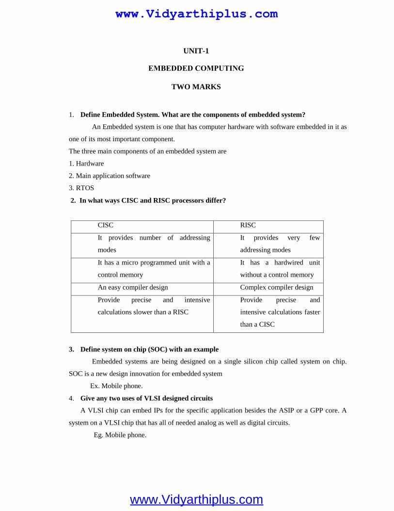
UNIT-1
TWO MARKS
1. Define Embedded System. What are the components of embedded system?
An Embedded system is one that has computer hardware with software embedded in it as
one of its most important component.
The three main components of an embedded system are
1. Hardware
2. Main application software
3. RTOS
2. In what ways CISC and RISC processors differ?
CISC RISC
It provides number of addressing
modes
It provides very few
addressing modes
It has a micro programmed unit with a
control memory
It has a hardwired unit
without a control memory
An easy compiler design Complex compiler design
Provide precise and intensive
calculations slower than a RISC
Provide precise and
intensive calculations faster
than a CISC
3. Define system on chip (SOC) with an example
Embedded systems are being designed on a single silicon chip called system on chip.
SOC is a new design innovation for embedded system
Ex. Mobile phone.
4. Give any two uses of VLSI designed circuits
A VLSI chip can embed IPs for the specific application besides the ASIP or a GPP core. A
system on a VLSI chip that has all of needed analog as well as digital circuits.
Eg. Mobile phone.
EMBEDDED COMPUTING
www.Vidyarthiplus.com
www.Vidyarthiplus.com
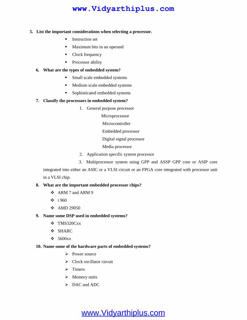
5. List the important considerations when selecting a processor.
Instruction set
Maximum bits in an operand
Clock frequency
Processor ability
6. What are the types of embedded system?
Small scale embedded systems
Medium scale embedded systems
Sophisticated embedded systems
7. Classify the processors in embedded system?
1. General purpose processor
Microprocessor
Microcontroller
Embedded processor
Digital signal processor
Media processor
2. Application specific system processor
3. Multiprocessor system using GPP and ASSP GPP core or ASIP core
integrated into either an ASIC or a VLSI circuit or an FPGA core integrated with processor unit
in a VLSI chip.
8. What are the important embedded processor chips?
ARM 7 and ARM 9
i 960
AMD 29050
9. Name some DSP used in embedded systems?
TMS320Cxx
SHARC
5600xx
10. Name some of the hardware parts of embedded systems?
Power source
Clock oscillator circuit
Timers
Memory units
DAC and ADC
www.Vidyarthiplus.com
www.Vidyarthiplus.com
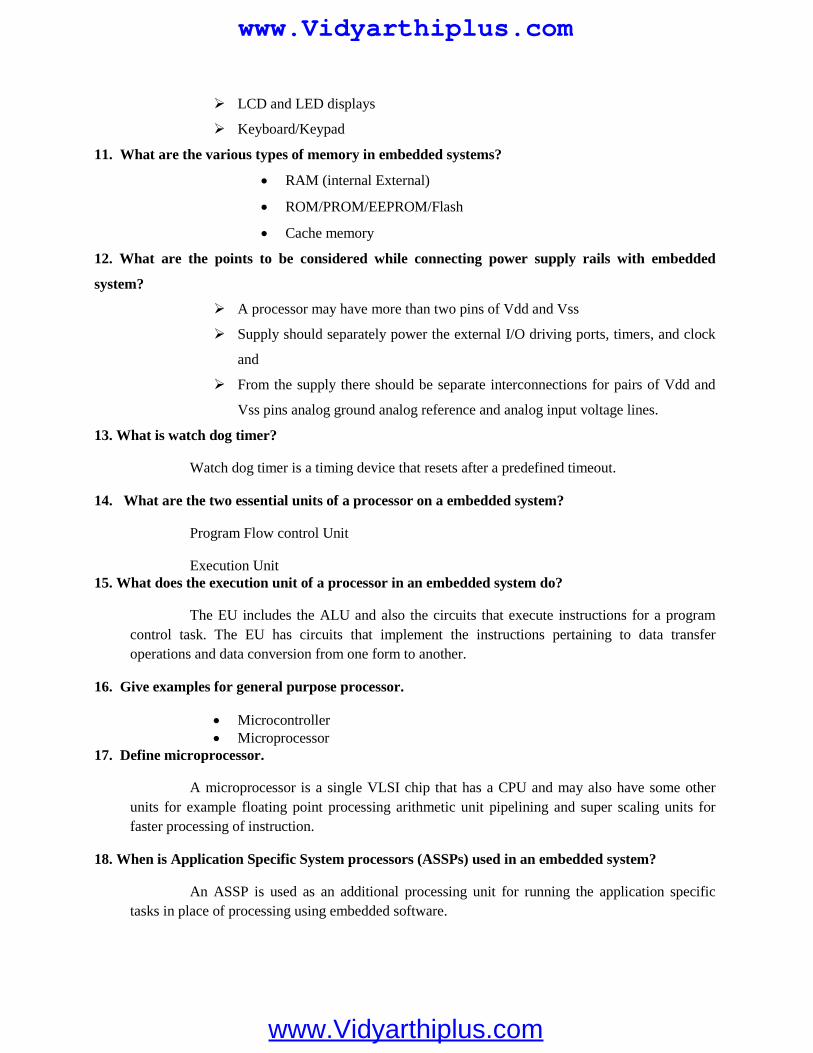
LCD and LED displays
Keyboard/Keypad
11. What are the various types of memory in embedded systems?
RAM (internal External)
ROM/PROM/EEPROM/Flash
Cache memory
12. What are the points to be considered while connecting power supply rails with embedded
system?
A processor may have more than two pins of Vdd and Vss
Supply should separately power the external I/O driving ports, timers, and clock
and
From the supply there should be separate interconnections for pairs of Vdd and
Vss pins analog ground analog reference and analog input voltage lines.
13. What is watch dog timer?
Watch dog timer is a timing device that resets after a predefined timeout.
14. What are the two essential units of a processor on a embedded system?
Program Flow control Unit
Execution Unit15. What does the execution unit of a processor in an embedded system do?
The EU includes the ALU and also the circuits that execute instructions for a programcontrol task. The EU has circuits that implement the instructions pertaining to data transferoperations and data conversion from one form to another.
16. Give examples for general purpose processor.
Microcontroller Microprocessor
17. Define microprocessor.
A microprocessor is a single VLSI chip that has a CPU and may also have some otherunits for example floating point processing arithmetic unit pipelining and super scaling units forfaster processing of instruction.
18. When is Application Specific System processors (ASSPs) used in an embedded system?
An ASSP is used as an additional processing unit for running the application specifictasks in place of processing using embedded software.
www.Vidyarthiplus.com
www.Vidyarthiplus.com
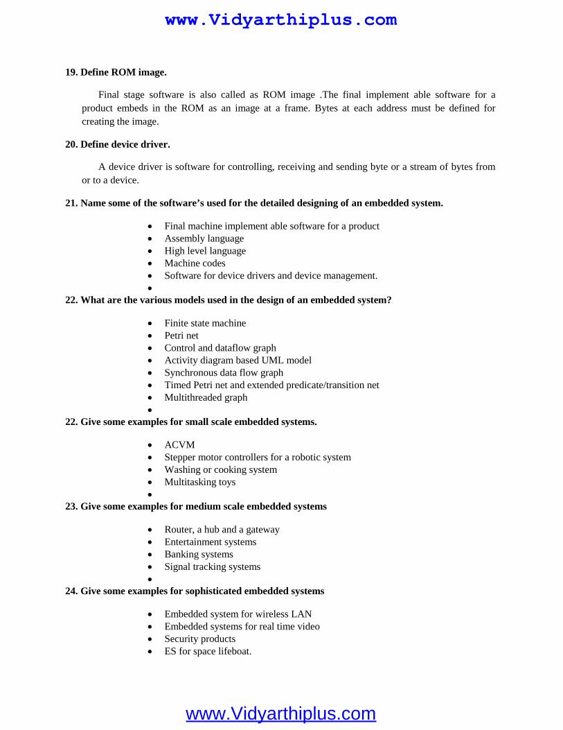
19. Define ROM image.
Final stage software is also called as ROM image .The final implement able software for aproduct embeds in the ROM as an image at a frame. Bytes at each address must be defined forcreating the image.
20. Define device driver.
A device driver is software for controlling, receiving and sending byte or a stream of bytes fromor to a device.
21. Name some of the software’s used for the detailed designing of an embedded system.
Final machine implement able software for a product Assembly language High level language Machine codes Software for device drivers and device management.
22. What are the various models used in the design of an embedded system?
Finite state machine Petri net Control and dataflow graph Activity diagram based UML model Synchronous data flow graph Timed Petri net and extended predicate/transition net Multithreaded graph
22. Give some examples for small scale embedded systems.
ACVM Stepper motor controllers for a robotic system Washing or cooking system Multitasking toys
23. Give some examples for medium scale embedded systems
Router, a hub and a gateway Entertainment systems Banking systems Signal tracking systems
24. Give some examples for sophisticated embedded systems
Embedded system for wireless LAN Embedded systems for real time video Security products ES for space lifeboat.
www.Vidyarthiplus.com
www.Vidyarthiplus.com
25. What are the requirements of embedded system?
Reliability Low power consumption Cost effectiveness Efficient use of processing power
26. Give the characteristics of embedded system?
a) Single-functioned
b) Tightly constrained
c) Reactive and real time
27. What are the design metrics?
Power Size NRE cost Performance
28. What are the challenges of embedded systems?
Hardware needed Meeting the deadlines Minimizing the power consumption Design for upgradeability
29. Give the steps in embedded system design?
Requirements Specifications Architecture Components System integration
30. What are the requirements?
Before designing a system, it must to understand what has to be designed. This can beknown from the starting steps of a design process.
31. Give the types of requirements?
Functional requirementsNon functional requirements
www.Vidyarthiplus.com
www.Vidyarthiplus.com
32. Define functional requirements?
It says the fundamental functions of an embedded system.
33. Give some examples of functional requirements?
1. Performance2. Cost3. physical size and weight4. power
34. What is the use of requirements form?
It is used as a checklist in the requirements analysis. From this the fundamental propertiesof a system came to be known.
35. What are the entries of a requirement form?
Name Purpose Inputs and outputs Functions Performance Manufacturing cost Power Physical size and weight
36. What is meant by specification?
This is a bridge between Customer and Architect. It conveys the customer’s needs. Theseneeds are properly used in the design process.
37. What is architecture design?
It says the way of implementing functions by a system. Actually architecture is a plan forwhole structure of a system. While will bring the design of components later.
38. Define system integration?
It is a processor of combining the components into one system.
39. What are the functions of memory?
The memory functions are To provide storage for the software that it will run. To store program variables and the intermediate results Used for storage of information
www.Vidyarthiplus.com
www.Vidyarthiplus.com
40. Define RAM?
RAM refers Random Access Memory. It is a memory location that can be accessed
without touching the other locations.
41. What is data memory?
When the program is executing, to save the variable and program stack, this type of
memory is used
42. What is code memory?
The program code can be stored by using this area. The ROM is used for this purpose.
43. What are the uses of timers?
The time intervals can be completed
Precise hardware delays can be calculated
The timeout facilities are generated
44. Give short notes on RAM processor?
It is said to be the family of RISC architecture. The ARM instructions are written one
per line, starting after the first column.
45. What are the data types supported by RAM?
Standard ARM word is 32 bit long
Word is splitted into 4 8 bit bytes
46. What are the 3 types of operating modes?
Normal mode
Idle mode
Power down mode
16 MARKS1. List the hardware units that must be present in the embedded systems.
Power Source and managing the powerMost systems have a power supply of own. The supply has a specific operation range or a
range of voltages. Various units in unzip for place of Infatuation to Embedded System in one ofthe following four accelerator are examples of embedded systems that do not have their ownpower supply v and connect to pi power-supply lines. 1Z; A charge pump consists of a diode inthe series followed by a charging capacitor. The diode gets forward bias input from an externalsignal.
www.Vidyarthiplus.com
www.Vidyarthiplus.com
Real Time Clock (RTC) and Timers for VariousTiming and Counting Needs of the System a timer circuit suitably configured is the
system-clock, also called real-time clock (RTC). It is used by the schedulers and for real-timeprogramming. More than one timer using the system clock (RTC) may be needed for the varioustiming and counting needs in a system.
Clock Oscillator Circuit and Clocking Unit(s)The Clock is an important unit of a system. A processor needs a clock oscillator circuit.
The clock controls the various clocking requirements of the CPU, of the system timers and theCPU machine cycles
MemoriesIn a system, there are various types of memories. They are as follows: Internal RAI\4 of 256 or 5lZ bytes in a microcontroller for registers,
temporary data stack Internal ROM/PROMIEPROM for about 4 KB to 16 KB of program External RAM for the temporary data and stack Internal caches EEPROM or flash External ROM or PROM for embedding software RAM Memory buffers Caches (in superscalar microprocessors)
Pulse Dialer, Modem and Transceiver For user connectivity through the telephone line, wireless, or a system provides
the necessary interfacing circuit. It also provides the software for pulse dialing through the telephone line, for
modem interconnection for fax, for Internet packets routing, and for transmitting and connectinga WAG (Wireless Gateway) or cellular system.
A transceiver is a circuit that can transmit as well as receive byte streams
Linking and Interfacing Buses and Units of the Embedded System Hardware The buses and units in the embedded system hardware are needed to be linked and
interfaced. One way to do this is to incorporate a glue logic circuit.
LCD and LED Displays
System requires an interfacing circuit and software to display the status ormessage for a fine, for multi-line displays, or flashing displays
An LCD screen may show up a multilane display of characters or also show agraph or icon
An LCD needs little power. It is powered by a supply or battery (a solar panel inthe calculator). LCD is a diode that absorbs or emits right on appreciation of 3 V to 4 V and 50
www.Vidyarthiplus.com
www.Vidyarthiplus.com
or 60 Hz voltage pulses with currents less than 50 pA. An LSI (Lower Scale Integrated circuit)display controller is often used in the cise of matrix displays.
2. Explain the Exemplary applications of each type of embedded system.
Small Scale Embedded system
A long needle rotates elderly minute such that it 'returns to same position after an hour. Ashort needle rotates every hour. Such that it returns to same position after twelve hours
ACVM Stepper motor controllers for a robotic system Washing or cooking system Multitasking toys
Medium scale embedded systems
Router, a hub and a gateway Entertainment systems Banking systems Signal tracking systems
Sophisticated embedded systems
Embedded system for wireless LAN Embedded systems for real time video Security products ES for space lifeboat.
3. Explain the various form of memories present in a system
Various forms of memories are
RAM(internal External) ROM PROM EEPROM Flash Cache memory EEPROM or flash Extemal ROM or PROM for embedding software RAM Memory buffers Caches (in superscalar microprocessors)
www.Vidyarthiplus.com
www.Vidyarthiplus.com
4. Explain the software tools in designing of an embedded system.
Tools
Editor Interpreter Compiler Assembler Cross assembler Simulator Source code engg software RTOS Stethoscope Trace Scope IDE Prototype Locator
5. Explain the processors in an Embedded System
Processors in an ES General purpose processorMicroprocessorMicrocontrollerEmbedded processorDigital signal processorMedia processor Application specific system processor Multiprocessor system using GPP and ASSP GPP core or ASIP core integrated into either an ASIC or a VLSI circuit or an
FPGA core integrated with processor unit in a VLSI chip.
Explanation
A processor has two essential units Program Flow Control Unit (CU) Execution Unit (EU)An embedded system processor chip or core can be one of the following.
a. Microprocessor.b. Microcontroller.c. Embedded Processor.d. Digital Signal Processor (DSP).e. Media Processor.
www.Vidyarthiplus.com
www.Vidyarthiplus.com
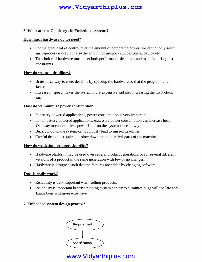
6. What are the Challenges in Embedded systems?
How much hardware do we need?
For the great deal of control over the amount of computing power ,we cannot only selectmicroprocessor used but also the amount of memory and peripheral device etc.
The choice of hardware must meet both performance deadlines and manufacturing costconstraints.
How do we meet deadlines?
Brute-force way to meet deadline by speedup the hardware so that the program runsfaster.
Increase in speed makes the system more expensive and also increasing the CPU clockrate.
How do we minimize power consumption?
In battery powered applications, power consumption is very important. In non battery powered applications, excessive power consumption can increase heat.
One way to consume less power is to run the system more slowly.
But slow down the system can obviously lead to missed deadlines. Careful design is required to slow down the non critical parts of the machine.
How do we design for upgradeability?
Hardware platform may be used over several product generations or for several differentversions of a product in the same generation with few or no changes.
Hardware is designed such that the features are added by changing software.
Does it really work?
Reliability is very important when selling products.
Reliability is important because running system and try to eliminate bugs will too late andfixing bugs will more expensive.
7. Embedded system design process?
Requirement
Specification
www.Vidyarthiplus.com
www.Vidyarthiplus.com
Requirements:
We must know what we are designing, the initial state of the design processcapture this information for use in creating the architecture and components.
We gather an informal description from the customer known as requirementsand we refine the requirement into specification that contain enoughinformation to design the system architecture.
Requirement may be functional or non functional requirements include
Performance:
The speed of the system is major consideration for the usability of the systemand for its ultimate cost.
Performance may be a combination of soft performance metric and deadlineby which a particular operation must be completed.
Cost: Manufacturing cost Non-Recurring Engineering
Physical size and Weight: An industrial control system for an assembly line may be designed to fit into
a standard size with no limitation and weight.
A handheld device typically has tight requirement on both size and weightthat can move to the entire system design.
Power consumption:Power can be specified in requirement states in terms of
Architecture
Components
SystemIntegration
www.Vidyarthiplus.com
www.Vidyarthiplus.com
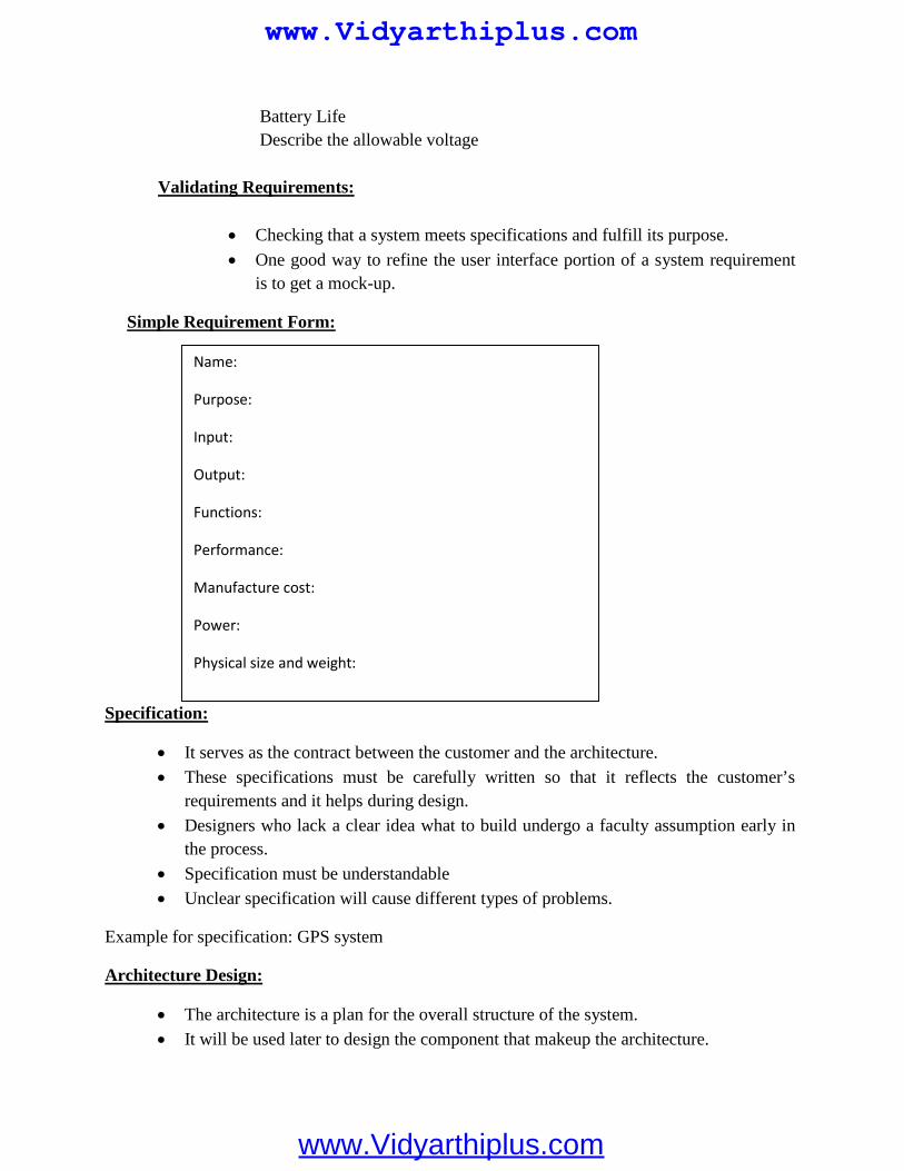
Battery LifeDescribe the allowable voltage
Validating Requirements:
Checking that a system meets specifications and fulfill its purpose.
One good way to refine the user interface portion of a system requirementis to get a mock-up.
Simple Requirement Form:
Specification:
It serves as the contract between the customer and the architecture. These specifications must be carefully written so that it reflects the customer’s
requirements and it helps during design. Designers who lack a clear idea what to build undergo a faculty assumption early in
the process.
Specification must be understandable Unclear specification will cause different types of problems.
Example for specification: GPS system
Architecture Design:
The architecture is a plan for the overall structure of the system. It will be used later to design the component that makeup the architecture.
Name:
Purpose:
Input:
Output:
Functions:
Performance:
Manufacture cost:
Power:
Physical size and weight:
www.Vidyarthiplus.com
www.Vidyarthiplus.com
System Integration:
Once the components are build up then they are integrated together and see theworking system.
Bugs are determi
ned during integration. Careful attention to inserting appropriate debugging facilities during design can help
ease system integration.
8. Embedded system for digital camera?
Embedded system:
An embedded system is a computer system design to perform a particular task orfew dedicated functions. Eg: digital camera, calculator, cell phone
It may be either an independent system or a part of a large system. Embedded system are controlled by one or more processing coder typically either
microcontroller or DSP. It has application software and real time operating system (RTOS) in program
memory and may perform series of task or multiple tasks.
Digital Camera:
The charge couple Device (CCD) contains an array of light sensitive photocellsthat capture an image.
The memory controller controls access to a memory chip also found in thecamera, while the DMA controller enables direct memory access by other deviceswhile the microcontroller is performing other functions.
The LCD control and Display control circuits control the display of images on thecamera’s liquid crystal display device.
The system always acts as a digital camera wherein it captures, compresses, andstores frames, decompresses and displays frames and upload frames.
It is tightly constrained. The system must be lower cost so that the consumers ableto afford such camera.
It must be small so that it fits into within a standard sized camera. It must be fast so that it can process numerous images in milliseconds. It must consume less power so that the camera’s battery will last long time.
www.Vidyarthiplus.com
www.Vidyarthiplus.com
UNIT-II
1. Differentiate synchronous communication and iso-synchronous communication.
Synchronous communication
When a byte or a frame of the data is received or transmitted at constant time intervalswith uniform phase difference, the communication is called synchronous communication.
Iso-synchronous communication
Iso-synchronous communication is a special case when the maximum time interval canbe varied.
2. What are the two characteristics of synchronous communication?
Bytes maintain a constant phase difference
The clock is not always implicit to the synchronous data receiver.
3. What are the three ways of communication for a device?
Iso-synchronous communication synchronous communication Asynchronous communication
4. Expand a) SPI b) SCI
SPI—serial Peripheral Interface
SCI—Serial Communication Interface
5. Define software timer.
This is software that executes and increases or decreases a count variable on an interruptfrom a timer output or form a real time clock interrupt. A software timer can also generateinterrupt on overflow of count value or on finishing value of the count variable.
COMPUTING PLATFORM AND DESIGN ANALYSISTWO MARKS
www.Vidyarthiplus.com
www.Vidyarthiplus.com
3. What is I2C?
I2C is a serial bus for interconnecting ICs .It has a start bit and a stop bit like an UART. Ithas seven fields for start,7 bit address, defining a read or a write, defining byte as acknowledgingbyte, data byte, NACK and end.
4. What are the bits in I2C corresponding to?
It has seven fields for start,7 bit address, defining a read or a write, defining byte asacknowledging byte, data byte, NACK and end
5. What is a CAN bus? Where is it used?
CAN is a serial bus for interconnecting a central Control network. It is mostly used in
automobiles. It has fields for bus arbitration bits, control bits for address and data length data
bits, CRC check bits, acknowledgement bits and ending bits.
6. What is USB? Where is it used?
USB is a serial bus for interconnecting a system. It attaches and detaches a device fromthe network. It uses a root hub. Nodes containing the devices can be organized like a treestructure. It is mostly used in networking the IO devices like scanner in a computer system.
7. What are the features of the USB protocol?
A device can be attached, configured and used, reset, reconfigured and used, share thebandwidth with other devices, detached and reattached.
8. Explain briefly about PCI and PCI/X buses.
PCI and PCI/X buses are independent from the IBM architecture .PCI/X is an extensionof PCI and support 64/100 MHZ transfers. Lately, new versions have been introduced for thePCI bus architecture.
9. Why are SPCI parallel buses important?
SPCI serial buses are important for distributed devices. The latest high speedsophisticated systems use new sophisticated buses.
10. What is meant by UART?
UART stands for universal Asynchronous Receiver/Transmitter.
UART is a hardware component for translating the data between parallel andserial interfaces.
UART does convert bytes of data to and from asynchronous start stop bit. UART is normally used in MODEM.
www.Vidyarthiplus.com
www.Vidyarthiplus.com
11. What does UART contain?
A clock generator. Input and Output start Registers Buffers. Transmitter/Receiver control.
12. What is meant by HDLC?
HDLC stands for “High Level Data Link Control”. HDLC is a bit oriented protocol. HDLC is a synchronous data Link layer.
13. Name the HDLC’s frame structure?
Flag Address Control Data FCS Flag
14. List out the states of timer?
There are eleven states as follows
Reset state Idle state Present state Over flow state Over run state Running state Reset enabled state / disabled Finished state Load enabled / disabled Auto reload enabled / disabled Service routine execution enabled / disabled
15. Name some control bit of timer?
Timer Enable Timer start Up count Enable Timer Interrupt Enable
www.Vidyarthiplus.com
www.Vidyarthiplus.com
16. What is meant by status flag?
Status flag is the hardware signal to be set when the timer reaches zeros.
17. List out some applications of timer devices?
Real Time clock Watchdog timer Input pulse counting TDM Scheduling of various tasks
18. State the special features on I2C?
Low cost Easy implementation Moderate speed (upto 100 kbps).
19. What are disadvantages of I2C?
Slave hardware does not provide much support Open collector drivers at the master leads to be confused
20. What are the two standards of USB?
USB 1.1 USB 2.0
21. Draw the data frame format of CAN?
Start Arbitrationfield
Controlfield
Data field CRC field Acknowledgementfield
End offrame
1 12 6 0-64 16 2 7
22. What is the need of Advanced Serial High Speed Buses?
If the speed in the rate of ‘Gigabits per second’ then there is a need of Advanced SerialHigh Speed Buses.
23. What is meant by ISA?
ISA stands for Industry standard Architecture. Used for connecting devices following IO addresses and interrupts vectors as per
IBM pc architecture.
www.Vidyarthiplus.com
www.Vidyarthiplus.com
24. What is meant by PCI-X?
PCI X offers more speed over PCI. 30 times more speed than PCI.
25. Define CPCI?
CPCI stands for Compact peripheral component Interfaces. CPCI is to be connected via a PCI. CPCI is used in the areas of Telecommunication Instrumentation abd data
communication applications.
26. Define half-duplex communication.
Transmission occurs in both the direction, but not simultaneously.
27. Define full duplex communication.
Transmission occurs in both the direction, simultaneously
28. Define Real Time Clock (RTC)?
Real time clock is a clock which once the system stats does not stop and cant be reset andits count value cant be reloaded.
29. Define Time-out or Time Overflow?
A state in which the number of count inputs exceeded the last acquirable value and onreaching that state, an interrupt can be generated.
30. Why do we need at least one timer in an ES?
The embedded system needs at least on timer device. It is used as a system clock.
16 MARKS
1. Explain the parallel port devices.
Parallel Port I/O devices
In this communication any number of ports could be connected with the device and thedata communication is bidirectional in nature.
1. Single Bit Input and Output
Parallel Port Single Bit Input
www.Vidyarthiplus.com
www.Vidyarthiplus.com
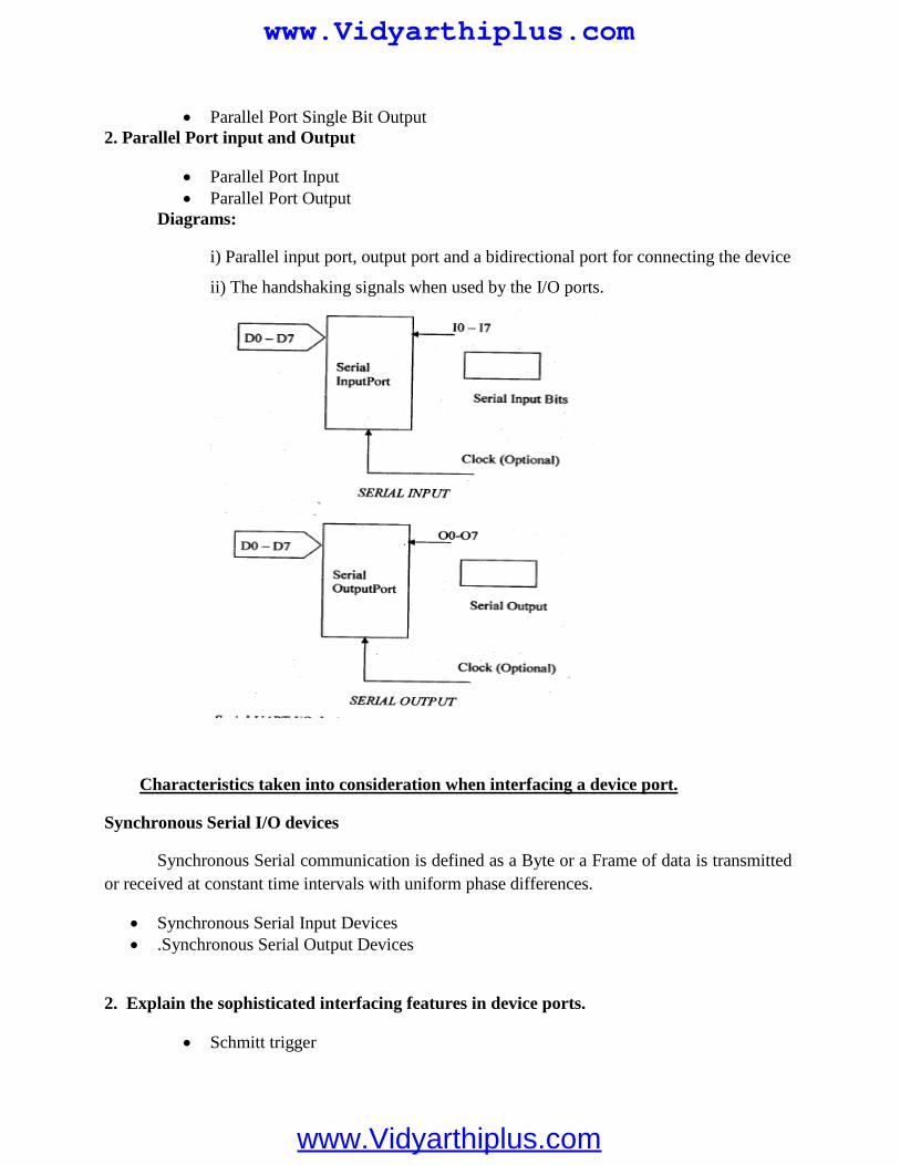
Parallel Port Single Bit Output2. Parallel Port input and Output
Parallel Port Input Parallel Port Output
Diagrams:
i) Parallel input port, output port and a bidirectional port for connecting the device
ii) The handshaking signals when used by the I/O ports.
Characteristics taken into consideration when interfacing a device port.
Synchronous Serial I/O devices
Synchronous Serial communication is defined as a Byte or a Frame of data is transmittedor received at constant time intervals with uniform phase differences.
Synchronous Serial Input Devices .Synchronous Serial Output Devices
2. Explain the sophisticated interfacing features in device ports.
Schmitt trigger
www.Vidyarthiplus.com
www.Vidyarthiplus.com
Data Gate HSTL,SSTL XCITE Multigigabyte Transceivers SerDes Multiple I/O standards PCS PMA
3. Explain the types of UART
UART - Universal Asynchronous Receiver Transmitter USART Universal Synchronous Asynchronous Receiver Transmitter
Synchronous Serial Transmission
Synchronous serial transmission requires that the sender and receiver share a clock withone another, or that the sender provides a strobe or other timing signal so that the receiver knowswhen to "read the next bit of the data. A form of synchronous transmission is used with printersand fixed disk devices in that the data is sent on one set of wires while a clock or strobe is senton a different wire. Printers and fixed disk devices are not normally serial devices because mostfixed disk interface standards send an entire word of data for each clock or strobe signal by usinga separate wire for each bit of the word.
Asynchronous Serial Transmission
Asynchronous transmission allows data to be transmitted without the sender having tosend a clock signal to the receiver. Instead the sender and receiver must agree on timingparameters in advance and special bits are added to each word which is used to synchronize thesending and receiving units.
When a word is given to the UART for Asynchronous transmissions, a bit called the"Start Bit" is added to the beginning of each word that is to be transmitted.
After the Start Bit, the individual bits of the word of data are sent, with the LeastSignificant Bit (LSB) being sent first.
Each bit in the transmission is transmitted for exactly the same amount of time as all ofthe other bits and the receiver look at the wire at approximately through the assigned toeach bit to determine if the bit is a 0 or 1.
The sender does not know when the receiver has "looked" at the value of the bit. Thesender only knows when the clock says to begin transmitting the next bit of the word.
When the entire data word has been sent, the transmitter may add a Parity Bit that thetransmitter generates.
The Parity Bit may be used by the receiver to perform simple error checking. Then atleast one Stop Bit is sent by the transmitter.
www.Vidyarthiplus.com
www.Vidyarthiplus.com
When the receiver has received all of the bits in the data word. It may check for the ParityBits (both sender and receiver must agree on whether a Parity Bit is to be used) and then thereceiver looks for a Stop Bit. If the Stop Bit does not appear when it is supposed to the UARTconsiders the entire word to be garbled and will report a Framing Error to the host processorwhen the data word is read. The usual cause of a Framing Error is that the sender and receiverclocks were not running at the same speed, or that the signal was interrupted.
Regardless of whether that data was received correctly or not, the UART automaticallydiscards the Start, Parity and Stop bits. If the sender and receiver are configured identically, thesebits are not passed to the host.
4. Describe in detail about Synchronous, ISO-Synchronous and Asynchronouscommunication for serial device.
Synchronous
In this means of communication, byte or frame of data received and transmitted atconstant time intervals with uniform phase differences. Bits of a data frame are sent in a fixedmaximum time intervals. Handshaking between sender and receiver is not provided duringcommunication.
Example
Frames sent over LAN.
Characteristics
The main features of the synchronous communication are
Bytes maintain a constant phase difference. No sending of bytes at random timeintervals.
A clock must be present at transmitter to send the data Moreover, the clock information issent to the receiver (i.e.) it is not always implicit to the receiver.
Communication Protocols used
Most often synchronous serial communication is useil for Data is transmission between physical devices. It can be complex and has to be as per the communication Protocol followed. Example., HDLC (High Level Data Link Control)
Synchronization ways
Ten ways by which the synchronous signals with the clocking info transmitted fromtransmitter to the receiver are as shown below.
www.Vidyarthiplus.com
www.Vidyarthiplus.com
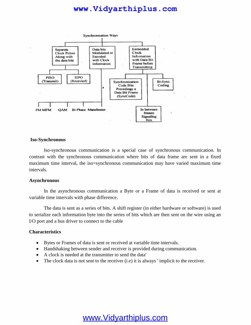
Iso-Synchronous
Iso-synchronous communication is a special case of synchronous communication. Incontrast with the synchronous communication where bits of data frame are sent in a fixedmaximum time interval, the iso=synchronous communication may have varied maximum timeintervals.
Asynchronous
In the asynchronous communication a Byte or a Frame of data is received or sent atvariable time intervals with phase difference.
The data is sent as a series of bits. A shift register (in either hardware or software) is usedto serialize each information byte into the series of bits which are then sent on the wire using anI/O port and a bus driver to connect to the cable
Characteristics
Bytes or Frames of data is sent or received at variable time intervals. Handshaking between sender and receiver is provided during communication. A clock is needed at the transmitter to send the data' The clock data is not sent to the receiver (i.e) it is always ' implicit to the receiver.
www.Vidyarthiplus.com
www.Vidyarthiplus.com
5. Give some Examples of Internal Serial Communication
a. Common USART like Device in 8051
There will be a common USART like hardware device in 805 1. USART - Universal Synchronous and Asynchronous. Receiver and Transmitter It is also called as SI (Serial Interface)
Features
i. SCON - Saves Control and status flags in SIii. SFR - Special Function Registeriii. SBUF - Serial Buffer
SI Operates in two modesi. Half Duplex Synchronous mode of operationii. Full Duplex Asynchronous mode of operation
b. SPI and SCI: Serial Peripheral Interface (SPl)
It has full duplex feature for asynchronous communication It has a feature of programmable rates for clock bits. It is also programmable for defining the –instance of the occurrence to negative and
positive edges within intervals of bits. Devices selection is also programmableSerial Communication Interfaces (SC I)
UART asynchronous (SCD baud rates are same as SPI but not programmable. Communication is in full duplex
Characteristics
A port device may have multi byte data input buffer and output buffer A port may have a DDR. Port may have LSTTL driving capability and port loading capability Multiple functionality in ports
Iso-synchronous communication is a special case of synchronous communication. Incontrast with the synchronous communication where bits of data frame are sent in a fixedmaximum time interval, the iso-synchronous communication may have varied maximum timeintervals.
Protocol
Most often synchronous serial communication is used for Data is transmission between physical devices. It can be complex and has to be as per the communication Protocol followed. Example., HDLC (High Level Data Link Control)
www.Vidyarthiplus.com
www.Vidyarthiplus.com
6. Explain Memory & IO Devices Interfacing (Memory Mapped I/O)
I/O operations are interpreted differently depending on the viewpoint taken and placedifferent requirements on the level of understanding of the hardware details.
From the perspective of a system software developer, I/O operations implycommunicating with the device, programming the device to initiate an I/O request,performing actual data transfer between the device and the system, and notifying therequestor when the operation completes. The system software engineer must understandthe physical properties, such as the register definitions, and access methods of the device.Locating the correct instance of the device is part of the device communications whenmultiple instances of the same device are present.
The system engineer is also concerned with how the device is integrated with rest of thesystem. The system engineer is likely a device driver developer because the systemengineer must know to handle any errors that can occur during the I/O operations.
From the perspective of the RTOS, I/O operations imply locating the right device for theI/O request, locating the right device driver for the device, and issuing the request to thedevice driver. Sometimes the RTOS is required to ensure synchronized access to thedevice.
The RTOS must facilitate an abstraction that hides both the device characteristics andspecifics from the application developers. From the perspective of an applicationdeveloper, the goal is to find a simple, uniform, and elegant way to communicate with alltypes of devices present in the system. The application developer is most concerned withpresenting the data to the end user in a useful way.
The combination of I/O devices, associated device drivers, and the I/O subsystemcomprises the overall I/O system in an embedded environment.
The purpose of the I/O subsystem is to hide the device-specific information from thekernel as well as from the application developer and to provide a uniform access methodto the peripheral I/O devices of the system.
This section discusses some fundamental concepts from the Perspective of the devicedriver developer. Figure 12.1 illustrates the I/O subsystem in relation to the rest of thesystem in a layered software model. As Shown, each descending layer adds additionaldetailed information to the architecture needed to manage a given device. Figure 12.1:I/O subsystem and the layered model.
In memory-mapped I/O, the device address is part of the system memory address space.Any machine instruction that is encoded to transfer data between a memory location andthe processor or between two memory locations can potentially be used to access the I/Odevice.
www.Vidyarthiplus.com
www.Vidyarthiplus.com
The I/O device is treated as if it were another memory location. Because the I/O addressspace occupies a range in the system memory address space, this region of the memoryaddress space is not available for an application to use.
Figure 12.3: Memory-mapped I/O. The memory-mapped I/O space does not necessarilybegin at offset 0 in the system address space, as illustrated in Figure
UNIT-III
TWO MARKS
1. What are the states of a process?a. Runningb. Readyc. Waiting
2. What is the function in steady state?Processes which are ready to run but are not currently using the processor are in the 'ready'
state.
3. Define scheduling.This is defined as a process of selection which says that a process has the right to use the
processor at given time.
4. What is scheduling policy?It says the way in which processes are chosen to get promotion from ready state to
running state.
5. Define hyper period?It refers the duration of time considered and also it is the least common multiple of all the
processes.
PROCESS AND OPERATING SYSTEMS
www.Vidyarthiplus.com
www.Vidyarthiplus.com
6. What is schedulability?It indicates any execution schedule is there for a collection of process in the system's
functionality.
7. What are the types of scheduling?1. Time division multiple access scheduling.2. Round robin scheduling.
8. What is cyclostatic scheduling?In this type of scheduling, interval is the length of hyper period 'H'. For this interval, a
cyclostatic schedule is separated into equal sized time slots.
9. Define round robin scheduling?This type of scheduling also employs the hyperperiod as an interval. The processes are run
in the given order.
10. What is scheduling overhead?It is defined as time of execution needed to select the next execution process.
11. What is meant by context switching?The actual process of changing from one task to another is called a context switch.
12. Define priority scheduling?A simple scheduler maintains a priority queue of processes that are in the runnable state.
13. What is rate monotonic scheduling?Rate monotonic scheduling is an approach that is used to assign task priority for a
preemptive system.
14. What is critical instant?It is the situation in which the process or task posses’ highest response time.
15. What is critical instant analysis?It is used to know about the schedule of a system. Its says that based on the periods given,
the priorities to the processes has to be assigned.
16. Define earliest deadline first scheduling?This type of scheduling is another task priority policy that uses the nearest deadline as the
criterion for assigning the task priority.
17. What is IDC mechanism?It is necessary for a 'process to get communicate with other process' in order to attain a
specific application in an operating system.
18. What are the two types of communication?1. Blocking communication 2. Non blocking communication
www.Vidyarthiplus.com
www.Vidyarthiplus.com
19. Give the different styles of inter process communication?1. Shared memory.2. Message passing.
16-MARKS
1. Explain Multiple Tasks and Multiple Processes?
Many embedded computing systems do more than one thing that is, the environment cancause mode changes that in turn cause the embedded system to behave quit differently.
The text compression box provides a simple example of rate control problems. A controlpanel on a machine provides an example of a different type of rate control problem, theasynchronous input.
Multirate embedded computing systems are very common, including automobile engines,printers, and telephone PBXs.
The co-routine was a programming technique commonly used in the early days ofembedded computing to handle multiple processes.
The ARM code in the co-routines is not intended to represent meaningful computations. The co-routine structure lets us implement more general kinds of flow of control than is
possible with only subroutines; the identification of co-routine entry points provides uswith some hooks for nonhierarchical calls and returns within the program.
However, the co-routine does not do nearly enough to help us construct complexprograms with significant timing properties.
The co-routine in general does very little to simplify the design of code that satisfiestiming requirements.
2. Explain Context Switching?
The context switch is the mechanism for moving the CPU from one executing process toanother.
Clearly, the context switch must be bug-free-a process that does not look at a real-timeclock should not be able to tell that it was stopped and then restarted.
Cooperative multitasking-the most general form of context switching, preemptivemultitasking.
Preemptive Multitasking-the interrupt is an ideal mechanism on which to build contextswitching for preemptive multitasking.
A timer generates periodic interrupts to the CPU.
www.Vidyarthiplus.com
www.Vidyarthiplus.com
The interrupt handler for the timer calls the operating system, which saves the previousprocess’s state in an activation record, selects the next process to execute, and switchesthe context to that process.
Processes and Object-Oriented Design-UML often refers to processes as active objects,that is, objects that have independent threads of control.
We can implement the preemptive context switches using the same basic techniques. The only difference between the two is the triggering event, voluntary release of the CPU
in the case of cooperative and timer interrupt in the case of preemptive.
3. Explain Scheduling policies?
A scheduling policy defines how processes are selected for promotion from the readystate to the running state.
Utilization is one of the key metrics in evaluating a scheduling policy. Rate-monotonic scheduling (RMS), introduced by Liu and Layland [Liu73], was one of
the first scheduling policies developed for real-time systems and is still very widely used. The theory underlying RMS is known as rate-monotonic analysis(RMA). Earliest deadline first (EDF) is another well-known scheduling policy. It is a dynamic
priority scheme-it changes process priorities during execution based on initiation times. RMS VERSUS EDF-EDF can extract higher utilization out of the CPU, but it may be
difficult to diagnose the possibility of an imminent overload. A Closer Look at Our Modeling Assumptions-Our analyses of RMS and EDF have made
some strong assumptions. Other POSIX Scheduling Policies-In addition of SCHED_FIFO,POSIX supports two
other real-time scheduling policies:SCHED_RR and SCHED_OTHER. The SCHED_OTHER is defined to allow non-real-time processes to intermix with real-
time processes.
4. Explain Inter process Communication Mechanism?
Signals-Unix supports another, very simple communication mechanism-the signal. A signal is simple because it does not pass data beyond the existence of the signal itself. Signals in UML-A UML signal is actually a generalization of the Unix signal. While a
Unix signal carries no parameters other than a condition code,a UML signal is an object. Shared Memory Communication-Conceptually, semaphores are the mechanism we use to
make shared memory safe. POSIX supports semaphores, but it also supports a direct shared memory mechanism. POSIX supports counting semaphores in the _POSIX_SEMAPHORES option. A
counting semaphore allows than one process access to a resource at a time. Message-Based Communication:-The shell syntax of the pipe is very familiar to Unix
users. An example appears below. % foo file1| baz > file2
www.Vidyarthiplus.com
www.Vidyarthiplus.com
A parent process use the pipe() function to create a pipe to talk to a child. It must do sobefore the child itself is created or it won’t have any way to pass a pointer to the pipe tothe child.
The pipe () function returns an array of file descriptors, the first for the write end and thesecond for the read end.
5. Explain Shared Memory Communication and Message-Based Communication?
Shared Memory Communication:-Conceptually, semaphores are the mechanism we useto make shared memory safe.
POSIX supports semaphores, but it also supports a direct shared memory mechanism. POSIX supports counting semaphores in the _POSIX_SEMAPHORES option. A counting semaphore allows more than one process to a resourse at a time. If the semaphore allows up to N resources, then it will not block until N processes have
simultaneously passed the semaphore. Message-Based Communication:-
o The shell syntax of the pipe is very familiar to Unix users. An example appearsbelow
% foo file1 | baz > file2o POSIX also supports message queues under the _POSIX_MESSAGE_PASSING
facility.o The advantage of a queue over a pipe is that, since queues have names, we don’t
have to create the pipe descriptor before creating the other process using it, aswith pipes.
1. Name the important terms of RTOS?TaskStateSchedulerShared dataReentrancy
2. Define process.Process is a computational unit that processes on a CPU under the control of a scheduling
kernel of an OS. It has a process structure, called Process control block. A process defines asequentially executing program and its state.
UNIT 1V
HARDWARE ACCELARATES AND
NETWORKS 2 MARKS
www.Vidyarthiplus.com
www.Vidyarthiplus.com
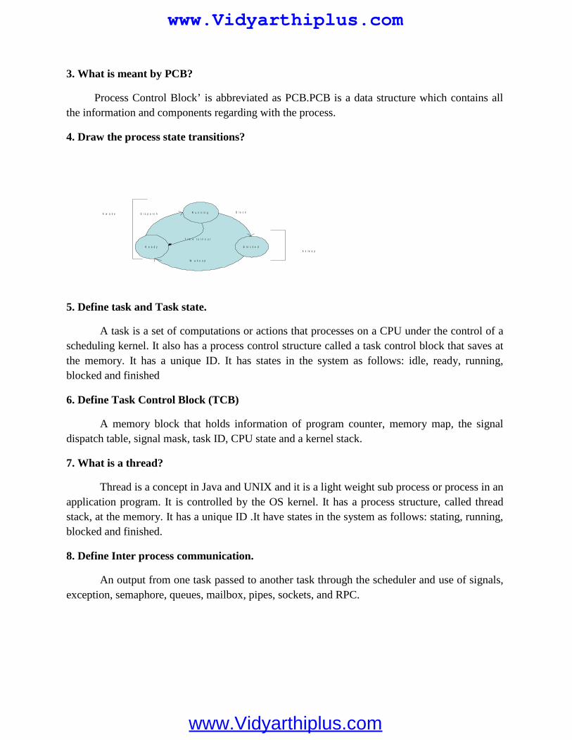
3. What is meant by PCB?
Process Control Block’ is abbreviated as PCB.PCB is a data structure which contains allthe information and components regarding with the process.
4. Draw the process state transitions?
T i m e t u r n o u t
W a k e u p
R e a d y B l o c k e d
R u n n i n gA w a k e
A s l e e p
B l o c kD i s p a t c h
5. Define task and Task state.
A task is a set of computations or actions that processes on a CPU under the control of ascheduling kernel. It also has a process control structure called a task control block that saves atthe memory. It has a unique ID. It has states in the system as follows: idle, ready, running,blocked and finished
6. Define Task Control Block (TCB)
A memory block that holds information of program counter, memory map, the signaldispatch table, signal mask, task ID, CPU state and a kernel stack.
7. What is a thread?
Thread is a concept in Java and UNIX and it is a light weight sub process or process in anapplication program. It is controlled by the OS kernel. It has a process structure, called threadstack, at the memory. It has a unique ID .It have states in the system as follows: stating, running,blocked and finished.
8. Define Inter process communication.
An output from one task passed to another task through the scheduler and use of signals,exception, semaphore, queues, mailbox, pipes, sockets, and RPC.
www.Vidyarthiplus.com
www.Vidyarthiplus.com
9. What is shared data problem?
If a variable is used in two different processes and another task if interrupts before theoperation on that data is completed then the value of the variable may differ from the oneexpected if the earlier operation had been completed .This ids known as shared data problem.
10. Define Semaphore.
Semaphore provides a mechanism to let a task wait till another finishes. It is a way ofsynchronizing concurrent processing operations. When a semaphore is taken by a task then thattask has access to the necessary resources. When given the resources unlock. Semaphore can beused as an event flag or as a resource key.
11. Define Mutex.
A phenomenon for solving the shared data problem is known as semaphore. Mutex is asemaphore that gives at an instance two tasks mutually exclusive access to resources.
12. Differentiate counting semaphore and binary semaphore.
Binary semaphore
When the value of binary semaphore is one it is assumed that no task has taken it and thatit has been released. When the value is 0 it is assumed that it has been taken.
Counting semaphore
Counting semaphore is a semaphore which can be taken and given number of times.Counting semaphores are unsigned integers.
13. What is Priority inversion?
A problem in which a low priority task inadvertently does not release the process for ahigher priority task.
14. What is Deadlock situation?
A set of processes or threads is deadlocked when each process or thread is waiting for aresource to be freed which is controlled by another process.
15. Define Message Queue.
A task sending the multiple FIFO or priority messages into a queue for use by anothertask using queue messages as an input.
www.Vidyarthiplus.com
www.Vidyarthiplus.com
16. Define Mailbox and Pipe.A message or message pointer from a task that is addressed to another task.
17. Define Socket.It provides the logical link using a protocol between the tasks in a client server or peer to
peer environment.
18. Define Remote Procedure Call.A method used for connecting two remotely placed methods by using a protocol. Both
systems work in the peer to peer communication mode and not in the client server mode.
19. What are the goals of RTOS?
Facilitating easy sharing of resources Facilitating easy implantation of the application software Maximizing system performance Providing management functions for the processes, memory, and I/Os and for other
functions for which it is designed. Providing management and organization functions for the devices and files and file like
devices. Portability Interoperability Providing common set of interfaces.
20. What is RTOS?
An RTOS is an OS for response time controlled and event controlled processes. RTOS isan OS for embedded systems, as these have real time programming issues to solve.
21. List the functions of a kernel.
Process management Process creation to deletion Processing resource requests Scheduling IPC Memory management I/O management Device management
22. What are the two methods by which a running requests resources?
Message System call
www.Vidyarthiplus.com
www.Vidyarthiplus.com
23. What are the functions of device manager?
Device detection and addition Device deletion Device allocation and registration Detaching and deregistration Device sharing
24. List the set of OS command functions for a device
Create and open Write Read Close and delete
25. List the set of command functions of POSIX file system
OpenWriteReadSeekClose
26. What are the three methods by which an RTOS responds to a hardware source call oninterrupt?
Direct call to ISR by an interrupt source Direct call to RTOS by an interrupt source and temporary suspension of a
scheduled task. Direct call to RTOS by an interrupt source and scheduling of tasks as well as ISRs
by the RTOS.
27. Name any two important RTOS.
MUCOS VxWorks
28. Write short notes on Vxworks?
Vxworks is a popular Real-time multi-tasking operating system for embeddedmicroprocessors and systems.
Vxworks can run on many target processors. It is a UNIX like Real time operating system.
www.Vidyarthiplus.com
www.Vidyarthiplus.com
More Reliable More faster
29. What is meant by well tested and debugged RTOS?
An RTOS which is thoroughly tested and debugged in a number of situations.
30. What is sophisticated multitasking embedded system?
A system that has multitasking needs with multiple features and in which thetasks have deadlines that must be adhered to.
31. What are the features of UC/OS II?
Preemptive Portable Scalable Multitasking
32. What is MICRO C/OS II?
It stands for micro-controller operating system(UC/OS II). It is a real time kernel The other names of MICROC/OS II are MUCOS and UCOS. The codes are in ‘C’ and Assembly language.
33. What are the real time system level functions in UC/OS II? State some?
1 Initiating the OS before starting the use of the RTOS fuctions.2 Starting the use of RTOS multi-tasking functions and running the states.3 Starting the use of RTOS system clock.
34. Write the interrupt handling functions?
int connect ( ) is the function for handling the Interrupt.int Lock ( ) -> Disable Interrupts.int unlock( ) -> Enable functions.
35. Write down the seven task priorities in embedded 'C++'?.define Task _Read ports prioritydefine Task _Excess Refund prioritydefine Task _Deliver prioritydefine Task _Refund prioritydefine Task _Collect prioritydefine Task _Display prioritydefine Task _Time Date Display priority
www.Vidyarthiplus.com
www.Vidyarthiplus.com
36. Name any two mailbox related functions.
OS_Event *OSMboxCreate(void *mboxMsg) Void *OSMboxAccept(OS_EVENT *mboxMsg)
37. Name any two queue related functions for the inter task communications.
OS_Event OSQCreate(void **QTop,unsigned byte qSize) Unsigned byte OSQPostFront(OS_EVENT *QMsgPointer,void *qmsg)
38. How is Vx Works TCB helpful for tasks?
Provide control information for the OS that includes priority, stack size, state andoptions.
CPU context of the task that includes PC, SP, CPU registers and task variables.39. What are the various features of Vx Works?
VxWorks is a scalable OS RTOS hierarchy includes timers, signals, TCP/IP sockets, queuing functions
library, Berkeley ports and sockets, pipes, UNIX compatible loader, language interpreter, shell,debugging tools, linking loader for UNIX.
40. What is an active task in the context of Vx Works?
Active task means that it is in one of the three states, ready, running, or waiting.
41. What are the task service functions supported by Vx Works?
taskSpawn() taskResume() taskSuspand() taskDelay() taskSuspand() taskInit() exit() taskDelete()
42. Name any four interrupt service functions supported by Vx Works?
intLock() intVectSet() intVectGet() intContext()
www.Vidyarthiplus.com
www.Vidyarthiplus.com
43. Name some of the inter process communication function.
semBCreate() semMCreate() semCCreate() semTake() semDelete()
44. Name some of the inter process communication function used for messaging.
msgQCreate() msgQDelete() msgQSend() msgQReceive()
45. What are Vx Works pipes?
VxWorks pipes are thec queues that can be opened and closed like a pipe.pipesare like virtual IO devices that store the messages as FIFO.
46. What are the different types of scheduling supported by Vx Works?
Preemptive priority Time slicing
47. What are the task service functions supported by MUCOS?
Void OSInit (void) Void OSStart(void) voidOSTickInit(void) void OSIntEnter(void) void OSIntExit(void)
48. What are the semaphores related functions supported by MUCOS?
OS_Event OSSemCreate(unsigned short sem val) Void OSSemPend(OS_Event *eventPointer,unsigned short timeout,unsigned byte
*SemErrPointer) unsigned short OSSemAccept(OS_Event*eventPointer) unsigned short OSSemPost(OS_Event*eventPointer)
www.Vidyarthiplus.com
www.Vidyarthiplus.com
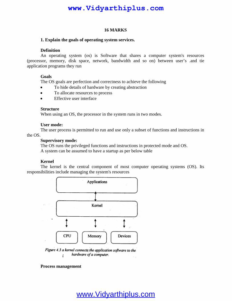
16 MARKS
1. Explain the goals of operating system services.
DefinitionAn operating system (os) is Software that shares a computer system's resources
(processor, memory, disk space, network, bandwidth and so on) between user’s .and tieapplication programs they run
GoalsThe OS goals are perfection and correctness to achieve the following To hide details of hardware by creating abstraction To allocate resources to process Effective user interface
StructureWhen using an OS, the processor in the system runs in two modes.
User mode:The user process is permitted to run and use only a subset of functions and instructions in
the OS.Supervisory mode:The OS runs the privileged functions and instructions in protected mode and OS.A system can be assumed to have a startup as per below table
KernelThe kernel is the central component of most computer operating systems (OS). Its
responsibilities include managing the system's resources
Process management
www.Vidyarthiplus.com
www.Vidyarthiplus.com
Every program running on a computer, be it a-service or an application, is a process.Most operating systems enable concurrent execution of many processes and programs at once viamultitasking, even with one CPU.
On the most fundamental of computers multitask is done by simply switchingprocess quickly.
Depending on the operating system, as more processes run, either each time slicewill become smaller or there will be a longer delay before each process is given a chance to run.
Process management involves computing and distributing CPU time as well asother resources.
Most operating systems allow a process to be assigned a priority which affects itsallocation of CPU time.
Interactive operating systems also employ some level of feedback in which thetask with which the user is working receives higher priority.
Memory management
An operating system's memory manager coordinates the use of these various types ofmemory by tracking which can is available, which is to be allocated or deal located and how tomove data between them. This activity, usually referred to as virtual memory management,increases the amount of memory available for each process by making the disk storage seem likemain memory. There is a speed penalty associated with using disks or other slower’ storage asmemory - if running processes require significantly more RAM than is available, the system maystart thrashing. This can happen either because one process requires a large amount or becausetwo or more processes compete for a larger amount of memory than is available. This then leadsto constant transfer of each process’s data to slower storage. Another important part of memorymanagement is managing virtual addresses. If multiple processes are in memory at once,
2. Explain the three alternative systems in three RTOS for responding a hardwaresource call with the diagram.
There are three alternative systems for the RTOSs to respond to the hardware source callsfrom the interrupts.
Direct call to ISR by an Interrupting Source
A hardware source calls an ISR directly, and ISR just sends a message to theRTOS. On an interrupt the process running at the CPU is interrupted and the ISR correspondingto that source starts executing.
RTOS is simply sent a message from the ISR into a mailbox or message queue. Itis to inform the RTOS about which ISR has taken control of the CPU.
The ISR continues execution of the codes needed interrupt service. The routinesends a message for the RTOS.The message is stored at the memory allotted for RTOSmessages.
When TSR finishes, the RTOS returns to the interrupted process or reschedulesthe processes. RTOS action depends on the messages at the mailbox.
www.Vidyarthiplus.com
www.Vidyarthiplus.com
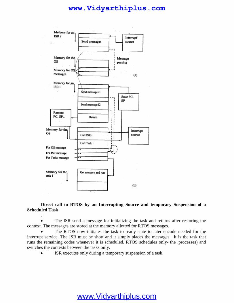
Direct call to RTOS by an Interrupting Source and temporary Suspension of aScheduled Task
. The ISR send a message for initializing the task and returns after restoring the
context. The messages are stored at the memory allotted for RTOS messages. The RTOS now initiates the task to ready state to later encode needed for the
interrupt service. The ISR must be short and it simply places the messages. It is the task thatruns the remaining codes whenever it is scheduled. RTOS schedules only- the .processes) andswitches the contexts between the tasks only.
ISR executes only during a temporary suspension of a task.
www.Vidyarthiplus.com
www.Vidyarthiplus.com
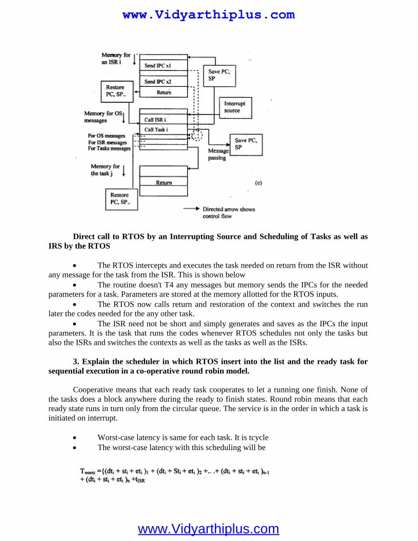
Direct call to RTOS by an Interrupting Source and Scheduling of Tasks as well asIRS by the RTOS
The RTOS intercepts and executes the task needed on return from the ISR withoutany message for the task from the ISR. This is shown below
The routine doesn't T4 any messages but memory sends the IPCs for the neededparameters for a task. Parameters are stored at the memory allotted for the RTOS inputs.
The RTOS now calls return and restoration of the context and switches the runlater the codes needed for the any other task.
The ISR need not be short and simply generates and saves as the IPCs the inputparameters. It is the task that runs the codes whenever RTOS schedules not only the tasks butalso the ISRs and switches the contexts as well as the tasks as well as the ISRs.
3. Explain the scheduler in which RTOS insert into the list and the ready task forsequential execution in a co-operative round robin model.
Cooperative means that each ready task cooperates to let a running one finish. None ofthe tasks does a block anywhere during the ready to finish states. Round robin means that eachready state runs in turn only from the circular queue. The service is in the order in which a task isinitiated on interrupt.
Worst-case latency is same for each task. It is tcycle The worst-case latency with this scheduling will be
www.Vidyarthiplus.com
www.Vidyarthiplus.com
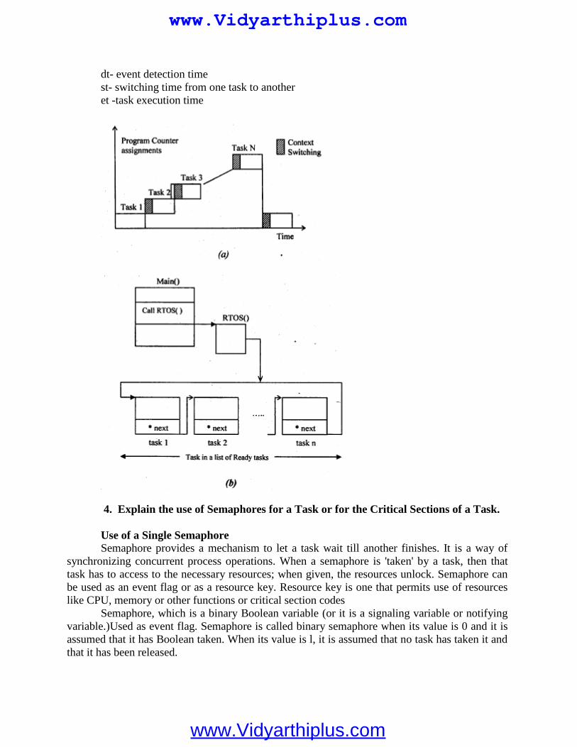
dt- event detection timest- switching time from one task to anotheret -task execution time
4. Explain the use of Semaphores for a Task or for the Critical Sections of a Task.
Use of a Single SemaphoreSemaphore provides a mechanism to let a task wait till another finishes. It is a way of
synchronizing concurrent process operations. When a semaphore is 'taken' by a task, then thattask has to access to the necessary resources; when given, the resources unlock. Semaphore canbe used as an event flag or as a resource key. Resource key is one that permits use of resourceslike CPU, memory or other functions or critical section codes
Semaphore, which is a binary Boolean variable (or it is a signaling variable or notifyingvariable.)Used as event flag. Semaphore is called binary semaphore when its value is 0 and it isassumed that it has Boolean taken. When its value is l, it is assumed that no task has taken it andthat it has been released.
www.Vidyarthiplus.com
www.Vidyarthiplus.com
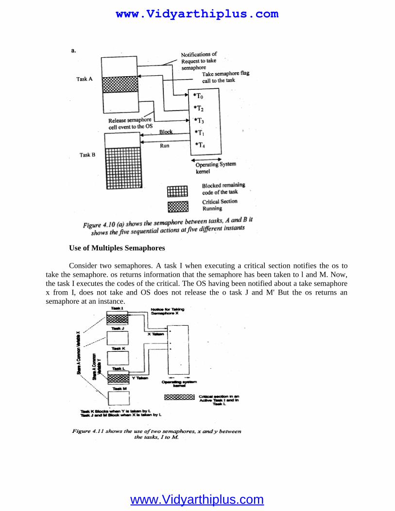
Use of Multiples Semaphores
Consider two semaphores. A task I when executing a critical section notifies the os totake the semaphore. os returns information that the semaphore has been taken to l and M. Now,the task I executes the codes of the critical. The OS having been notified about a take semaphorex from I, does not take and OS does not release the o task J and M' But the os returns ansemaphore at an instance.
www.Vidyarthiplus.com
www.Vidyarthiplus.com
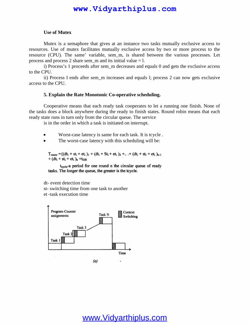
Use of Mutex
Mutex is a semaphore that gives at an instance two tasks mutually exclusive access toresources. Use of mutex facilitates mutually exclusive access by two or more process to theresource (CPU). The same’ variable, sem_m, is shared between the various processes. Letprocess and process 2 share sem_m and its initial value = l.
i) Process’s 1 proceeds after sem_m decreases and equals 0 and gets the exclusive accessto the CPU.
ii) Process I ends after sem_m increases and equals l; process 2 can now gets exclusiveaccess to the CPU.
5. Explain the Rate Monotonic Co-operative scheduling.
Cooperative means that each ready task cooperates to let a running one finish. None ofthe tasks does a block anywhere during the ready to finish states. Round robin means that eachready state runs in turn only from the circular queue. The service
is in the order in which a task is initiated on interrupt.
Worst-case latency is same for each task. It is tcycle . The worst-case latency with this scheduling will be:
dt- event detection timest- switching time from one task to anotheret -task execution time
www.Vidyarthiplus.com
www.Vidyarthiplus.com
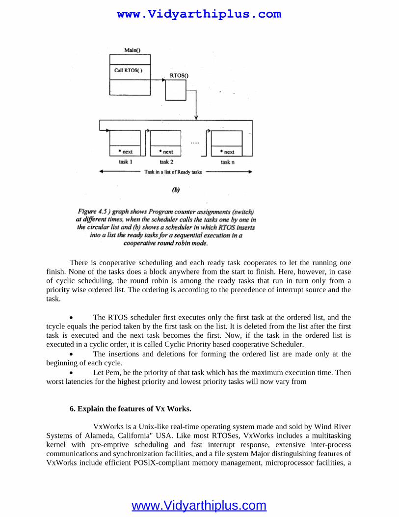
There is cooperative scheduling and each ready task cooperates to let the running onefinish. None of the tasks does a block anywhere from the start to finish. Here, however, in caseof cyclic scheduling, the round robin is among the ready tasks that run in turn only from apriority wise ordered list. The ordering is according to the precedence of interrupt source and thetask.
The RTOS scheduler first executes only the first task at the ordered list, and thetcycle equals the period taken by the first task on the list. It is deleted from the list after the firsttask is executed and the next task becomes the first. Now, if the task in the ordered list isexecuted in a cyclic order, it is called Cyclic Priority based cooperative Scheduler.
The insertions and deletions for forming the ordered list are made only at thebeginning of each cycle.
Let Pem, be the priority of that task which has the maximum execution time. Thenworst latencies for the highest priority and lowest priority tasks will now vary from
6. Explain the features of Vx Works.
VxWorks is a Unix-like real-time operating system made and sold by Wind RiverSystems of Alameda, California" USA. Like most RTOSes, VxWorks includes a multitaskingkernel with pre-emptive scheduling and fast interrupt response, extensive inter-processcommunications and synchronization facilities, and a file system Major distinguishing features ofVxWorks include efficient POSlX-compliant memory management, microprocessor facilities, a
www.Vidyarthiplus.com
www.Vidyarthiplus.com
shell for user interface, symbolic and source level debugging capabilities, and performancemonitoring. VxWorks is generally used in embedded systems. Unlike "native" systems such asUNIX and Forth, VxWorks development is done on a "host" machine running Unix or Windows,crosscompiling target software to run on various "target" CPU architectures as well as on the"host" by means of VxSim. VxWorks has been ported to a number of platforms and now runs onpractically any modern CPU that is used in the embedded market. This includes the x 86families, MIPS, PowerPC, SH-4 and the closely related family of ARM, StrongARM and xScaleCPUs
VxWorks System Functions and System Tasks
The first task that a scheduler executes is UsrRoot from the entrv point of usrRoot0 in file
install/Dir/target /config/alI / usr/Confi g. c.
It spawns the VxWorks tools and the following tasks. The root terminates after all theinitializations. Any root task can be initialized or terminated. The set of functions, tlog Task, logsthe system message without current task context I/O.
Interrupt handling functions
An internal hardware device auto generates an interrupt vector address, ISR- ECTADDRas per the device. Exceptions are defined in the us6r software.
ISR Design
ISR have the highest priority and can preempt any running task. An ISR inhibits the execution of the tasks till return’. An IRS does not execute like a task and does not have regular task context. It has
special interrupt context' While each task has its own stack" unless and otherwise not permitted -by a
special architecture of a System or a processor An ISR should not wait for taking the semaphore or other IPC. ISR should just write the required data at the memory or post an IPC so that it has
short codes and most of its functions, execute at tasks. ISR should not use flodting-point functions as these takes longer time to execute.
Signals and interrupt handling functions
Function 'void sigHandler(int sigNum)' declares a signal servicing routine for a signalidentified by sigNum and a signal servicing routine registers a signal as follows:
Signal (sigNum, sigISR). The parameters that pass are the sigNum and signal servicingroutine name, sigISR.A pointwer pSigCtx associates with the signal context. The signalxcontewxt savwes PC, SP, registers, etc. like an ISR context.
The signal ISR calls the following functions:
www.Vidyarthiplus.com
www.Vidyarthiplus.com
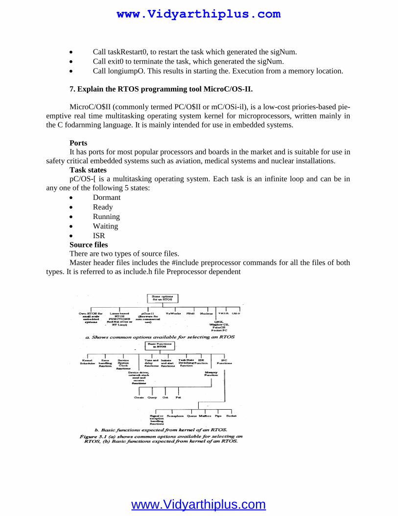
Call taskRestart0, to restart the task which generated the sigNum. Call exit0 to terminate the task, which generated the sigNum. Call longiumpO. This results in starting the. Execution from a memory location.
7. Explain the RTOS programming tool MicroC/OS-II.
MicroC/O$II (commonly termed PC/O$II or mC/OSi-il), is a low-cost priories-based pie-emptive real time multitasking operating system kernel for microprocessors, written mainly inthe C fodarnming language. It is mainly intended for use in embedded systems.
PortsIt has ports for most popular processors and boards in the market and is suitable for use in
safety critical embedded systems such as aviation, medical systems and nuclear installations.Task statespC/OS-[ is a multitasking operating system. Each task is an infinite loop and can be in
any one of the following 5 states: Dormant Ready Running Waiting ISRSource filesThere are two types of source files.Master header files includes the #include preprocessor commands for all the files of both
types. It is referred to as include.h file Preprocessor dependent
www.Vidyarthiplus.com
www.Vidyarthiplus.com
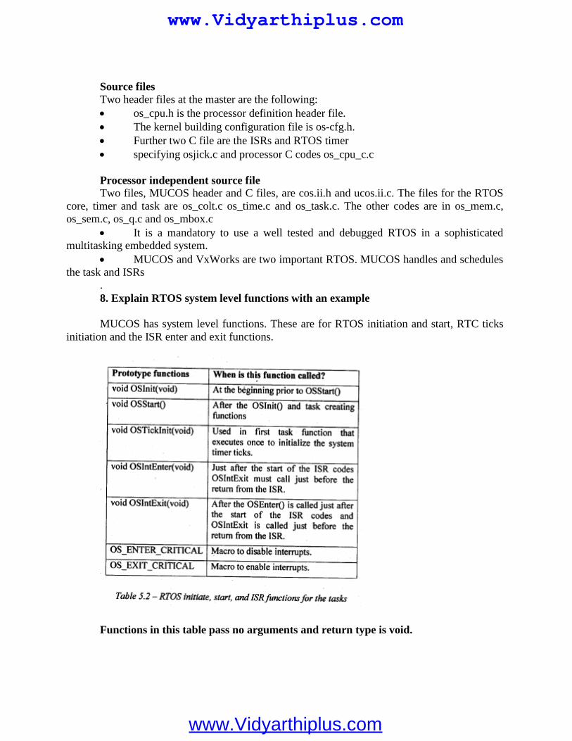
Source filesTwo header files at the master are the following: os_cpu.h is the processor definition header file. The kernel building configuration file is os-cfg.h. Further two C file are the ISRs and RTOS timer specifying osjick.c and processor C codes os_cpu_c.c
Processor independent source fileTwo files, MUCOS header and C files, are cos.ii.h and ucos.ii.c. The files for the RTOS
core, timer and task are os_colt.c os_time.c and os_task.c. The other codes are in os_mem.c,os_sem.c, os_q.c and os_mbox.c
It is a mandatory to use a well tested and debugged RTOS in a sophisticatedmultitasking embedded system.
MUCOS and VxWorks are two important RTOS. MUCOS handles and schedulesthe task and ISRs
.8. Explain RTOS system level functions with an example
MUCOS has system level functions. These are for RTOS initiation and start, RTC ticksinitiation and the ISR enter and exit functions.
Functions in this table pass no arguments and return type is void.
www.Vidyarthiplus.com
www.Vidyarthiplus.com
There is a global variable,OslntNesting.which increments on entering ISR.Globalvariable OSlntNesting decrements on'exit"from an ISR. Initiating the operating $)stem beforestarting the use of the RTOS functions
Function void OSInit (void) operating system. Its use is compulsory before functions. It returns no parameter.
Starting use of RTOS multitasking functions and returning the tasks
Function void OSStart(void) is used to start the initiated operating system andcreate tasks.
Its use is compulsory for the multitasking OS kernel operations. It returns no parameter.
Starting the RTOS System clock
Function void OsTicklnit(void) is used to initiate the system clock ticks andinterrupts at regular intervals as per OS_TICKS_PER_SEC predefined during configuring theMUCOS.
Its use is compulsory for the multitasking OS kernel operations when the timerfunctions ane to be used.
It returns no parameter.
Sending message to RTOS taking control al the start of an ISR
Function void OSlntEnter(void) is used at the start of an ISR. It is for sending a message to RTOS kernel for taking control. Its use is
compulsory to let the multitasking OS kernel, control the nesting of the ISRs in case ofoccurrences of multiple interrupts of varying priorities.
It returns no parameter.
1. What is a PIC?
PIC refers to Programmable Intelligent Computer. PIC is microprocessor lies inside apersonal computer but significantly simpler, smaller and cheaper. It can be used for operatingrelays, measuring sensors etc.
UNIT V
CASE STUDY
2 MARKS
www.Vidyarthiplus.com
www.Vidyarthiplus.com
2. What are the main elements inside a PIC?
Processing engine, Program memory, data memory and Input/Output.
3. What are the types of program memory in a PIC?
Read-only, EPROM and EEPROM, Flash
4. What is MBasic Compiler Software?
From version 5.3.0.0 onward, Basic Micro offers one version of its MBasic compiler, the“Professional” version. MBasic runs under Microsoft’s Windows operating system in anyversion from Windows 95 to Windows XP. The computer requires an RS-232 port forconnection tothe ISP-PRO programmer board.
5. Define pseudo-code.Pseudo-code is a useful tool when developing an idea before writing a line of true code or
when explaining how a particular procedure or function or even an entire program
www.Vidyarthiplus.com
www.Vidyarthiplus.com
www.rejinpaul.comwww.rejinpaul.com www.rejinpaul.comwww.rejinpaul.com www.rejinpaul.comwww.rejinpaul.com www.rejinpaul.comwww.rejinpaul.com www.rejinpaul.comwww.rejinpaul.com www.rejinpaul.comwww.rejinpaul.com www.rejinpaul.comwww.rejinpaul.com www.rejinpaul.comwww.rejinpaul.com www.rejinpaul.comwww.rejinpaul.com www.rejinpaul.comwww.rejinpaul.com www.rejinpaul.comwww.rejinpaul.com www.rejinpaul.comwww.rejinpaul.com www.rejinpaul.comwww.rejinpaul.com www.rejinpaul.comwww.rejinpaul.com www.rejinpaul.com
www.rejinpaul.com
www.Vidyarthiplus.com
www.Vidyarthiplus.com
www.Vidyarthiplus.com
www.Vidyarthiplus.com
www.Vidyarthiplus.com
www.Vidyarthiplus.com
www.Vidyarthiplus.com
www.Vidyarthiplus.com
www.Vidyarthiplus.com
www.Vidyarthiplus.com
www.Vidyarthiplus.com
www.Vidyarthiplus.com
www.Vidyarthiplus.com
www.Vidyarthiplus.com