Embed Size (px)
Citation preview

Prefeasibility Report
M/s. Mahaveer Surfactants Private Limited, Tiruvallur District 1
1.0 ABOUT COMPANY M/s. Mahaveer Surfactants Private Limited (herein after called as MSPL), incepted in 1981, have established as a reputed Manufacturer, Supplier and Wholesaler of Commercial Chemicals. We take pride in facilitating wide range of Detergent Chemicals, Water Treatment Chemicals and Detergent Pigments. All these products are manufactured under the strict guideline of international standards, following the rules of appropriate
composition of compounds.
The company works with the constructs of quality, affordable prices and innovation. We use latest and sophisticated systems for formulating our commercial range of chemicals. Apart from this, by integrating high quality standards, transparent dealings, ethical business policies, customer centric approach, wide distribution network and on-time delivery schedules, we have been flourishing in fulfilling the demands of client consequently.
The company has developed well equipped manufacturing infrastructure as well as a large team of proficient professionals to successfully satisfy the bulk requirement of pharmaceutical medicines. All the product line is developed under the supervision of expert chemists who work round the clock to
maintain high-quality standards of our products.
Furthermore, a team of quality controllers is hired to stringently monitor the entire process and randomly checks the range to ensure that it is at par with the international quality standards. We have earned an immense goodwill in
the market for our ethical business practices and client-centric approaches.
1.1 QUALITY ASSURANCE
Since we have been in chemical industry that deals with environment our moral responsibility is to implement a strict quality parameters for quality-analytical process of chemicals. Being a quality-conscious organization, we are committed to providing a superlative range of commercial chemicals to our esteemed clients. We ensure that our products are reliable, effective and safe to use. We also have with us an expert team of quality controllers who
keep supervision on all the formulation and quality-inspection processes.
1.2 MARKET OVERVIEW – DETERGENT INDUSTRY
The detergent market is one of the segments of the FMCG market in India that is in maturity stage and still has high growth potential. Although, the detergent consumption in India is less in comparison to the other Asian countries, it is growing vigorously. The per capita detergent consumption in India is around 2.7 kg per year, whereas places like Philippines and Malaysia has per capita consumption at 3.7 kg, and in USA it is around 10kg.
The detergent sector, with its increasing ability to influence consumers through advertisements, is rapidly expanding its market. Due to the increase in population, higher urbanization, spread of education and rising levels of income and consumption, the overall growth of the detergent market has

Prefeasibility Report
M/s. Mahaveer Surfactants Private Limited, Tiruvallur District 2
been in double digits from last several years. The detergent market is mainly concentrated in the urban areas but the level of penetration in the rural areas
for the past few years has been astonishing.
According to “India Detergent Market Overview 2021” the overall market for detergent is growing with a CAGR (Cumulative Annual Growth Rate) of more than 13.06% from the last five years. Detergents are available in three forms namely powder detergent, bar detergent and liquid detergent. Powder detergents are widely accepted by Indian consumers and dominate the industry. Even though detergent bars are still used in rural areas, they are
fast disappearing from the market because of ineffectiveness.
Liquid detergent is a new category in the Indian market and was created by Hindustan Unilever in 2013 with the launch of country’s first liquid detergent. It has been two years for the launch of this liquid detergent under Surf Excel brand but still no other rival company has come up with liquid detergent. Although powder detergents are most commonly used because of their stability, eco-feasibility and long lasting properties, liquid detergents will see
healthy growth in the forecast period.
Synthetic detergents have made rapid strides in India during the last decade. Liquid synthetic detergents are a consumable item and are used for cleaning of silk cloth, woolen clothes, utensils, machinery, and floor and in textile industry etc.
A detergent is a surfactant or a mixture of surfactants with cleaning properties in dilute solutions. These substances are usually alkyl benzene sulfonates, a family of compounds that are similar to soap but are more soluble in hard water, because the polar sulfonate (of detergents) is less likely than the polar carboxylate (of soap) to bind to calcium and other ions
found in hard water.
In most household contexts, the term detergent by itself refers specifically to laundry detergent or dish detergent, as opposed to hand soap or other types of cleaning agents. Detergents are commonly available as powders or concentrated solutions.
Detergents, like soaps, work because they are amphiphilic: partly hydrophilic (polar) and partly hydrophobic (non-polar). Their dual nature facilitates the mixture of hydrophobic compounds (like oil and grease) with water. Because
air is not hydrophilic, detergents are also foaming agents to varying degrees.
The detergent sector in the laundry care industry has grown from INR 57 billion in 2003 to INR 130 billion in 2011, registering a growth of ~11% during the period. We estimate the industry to reach levels of INR 241 billion
by 2017.

Prefeasibility Report
M/s. Mahaveer Surfactants Private Limited, Tiruvallur District 3
TABLE – 1.0 TOP 5 EXPORT DESTINATIONS OF LINEAR ALKYL BENZENE DURING 2015-
2016
Product Country Quantity (MT) Value
(Rs. Lakhs)
Linear Alkyl Benzene
Bangladesh PR 5305.05 3617.87
U Arab Emirates 2523.17 2240.32
Tanzania Republic 560.0 409.16
Nepal 533.99 355.78
Indonesia 159.24 228.31
Product Total 9081.45 6851.44
FIGURE – 1 BAR CHART SHOWING THE EXPORT DESTINATIONS OF LAB
1.2.1 GROWTH OF LIQUID DETERGENTS IN INDIA:
In 2015, liquid detergent market accounted for ~$0.9 billion, the fastest growing segment in laundry care market in India with CAGR of 10 percent annually till 2019. The liquid detergents market started during 2013 with the launch of Surf Excel liquid by Hindustan Unilever. The major reason for the exponential growth of liquid detergents is due to the increased penetration of washing machine, increased advertising on the liquid detergents and ease of use which is more effective than powder and soap. Currently, 10 percent of all Indian households own a washing machine and the market is expected to grow at a CAGR of 11 percent annually till 2018. Major raw materials used in the production of detergents are surfactants with linear alkyl benzene sulphate and sodium lauryl sulphate being the key surfactants.
Prefeasibility Report
M/s. Mahaveer Surfactants Private Limited, Tiruvallur District 4
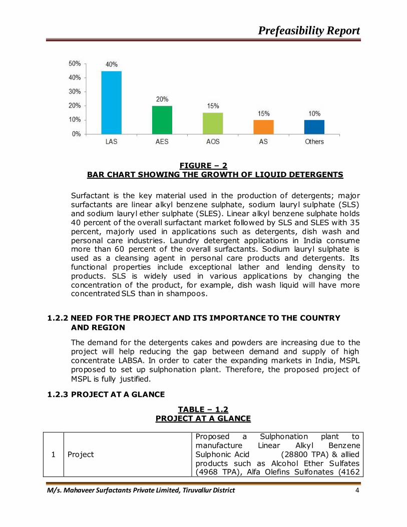
FIGURE – 2
BAR CHART SHOWING THE GROWTH OF LIQUID DETERGENTS
Surfactant is the key material used in the production of detergents; major surfactants are linear alkyl benzene sulphate, sodium lauryl sulphate (SLS) and sodium lauryl ether sulphate (SLES). Linear alkyl benzene sulphate holds 40 percent of the overall surfactant market followed by SLS and SLES with 35 percent, majorly used in applications such as detergents, dish wash and personal care industries. Laundry detergent applications in India consume more than 60 percent of the overall surfactants. Sodium lauryl sulphate is used as a cleansing agent in personal care products and detergents. Its functional properties include exceptional lather and lending density to products. SLS is widely used in various applications by changing the concentration of the product, for example, dish wash liquid will have more concentrated SLS than in shampoos.
1.2.2 NEED FOR THE PROJECT AND ITS IMPORTANCE TO THE COUNTRY
AND REGION
The demand for the detergents cakes and powders are increasing due to the project will help reducing the gap between demand and supply of high concentrate LABSA. In order to cater the expanding markets in India, MSPL proposed to set up sulphonation plant. Therefore, the proposed project of
MSPL is fully justified.
1.2.3 PROJECT AT A GLANCE
TABLE – 1.2 PROJECT AT A GLANCE
1 Project
Proposed a Sulphonation plant to manufacture Linear Alkyl Benzene Sulphonic Acid (28800 TPA) & allied products such as Alcohol Ether Sulfates (4968 TPA), Alfa Olefins Sulfonates (4162

Prefeasibility Report
M/s. Mahaveer Surfactants Private Limited, Tiruvallur District 5
TPA), Sodium Lauryl Sulphate (3744 TPA)
2 Name of the Unit Mahaveer Surfactants Private Limited
3 Location PLOT NO: A-6/2 PART C4, S.F No: 32/2 PART, SIPCOT Industrial Complex, Thervoy Kandigai, Gummidipoondi, Tiruvallur.
4 Land Area 2.62 ha (6.47 acres)
5 Manufacturing Products
Linear Alkyl Benzene Sulfonic Acid (LABSA),
Alcohol ether sulfates (AES),
Alfa-olefins sulfonates (AOS),
Sodium lauryl Sulphate (SLS).
6 Process Sulphonation of Linear alkyl Benzene, Ethoxylated Alcohol, Alfa Olefin and Lauryl Alcohol.
7 Water requirement One time water requirement =94.6 KLD Daily fresh water requirement = 75.86 KLD Source: SIPCOT Water supply/Bore well
8 Power Demand
1800 KW Source: Tamil Nadu Generation and Distribution Corporation Limited (TANGEDCO) Bake up: DG-Set 1 X 1000 KVA (High speed Diesel 250 lit/hr)
10 Total Number of Employees 80 People 11 Cost of the Project Rs. 19.5 Crores
Prefeasibility Report
M/s. Mahaveer Surfactants Private Limited, Tiruvallur District 6
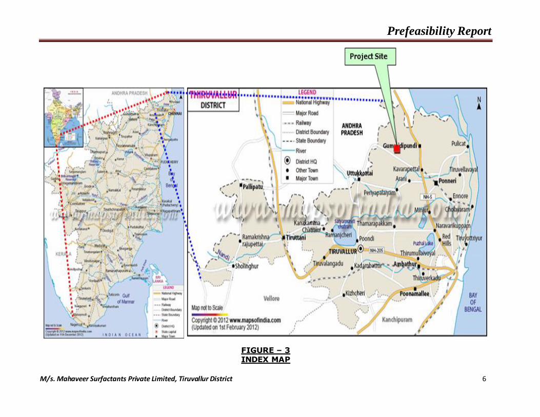
FIGURE – 3 INDEX MAP
Prefeasibility Report
M/s. Mahaveer Surfactants Private Limited, Tiruvallur District 7
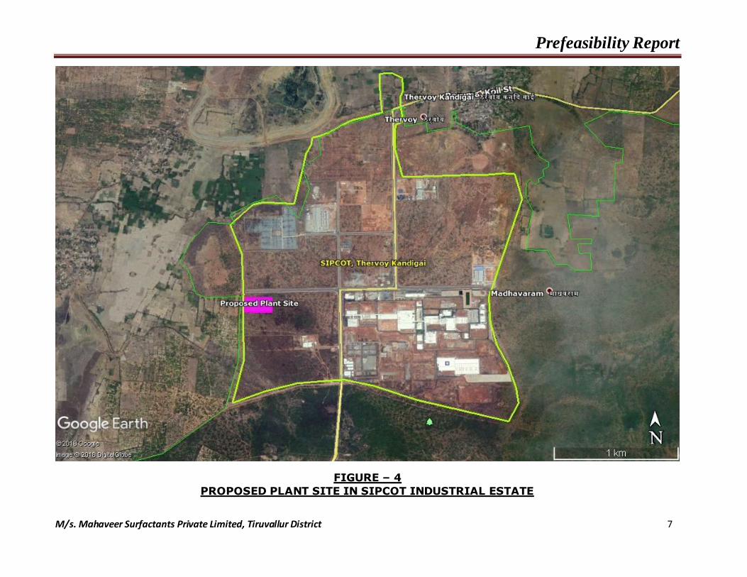
FIGURE – 4
PROPOSED PLANT SITE IN SIPCOT INDUSTRIAL ESTATE

Prefeasibility Report
M/s. Mahaveer Surfactants Private Limited, Tiruvallur District 8
FIGURE – 5
AERIAL VIEW OF THE PROPOSED PLANT

Prefeasibility Report
M/s. Mahaveer Surfactants Private Limited, Tiruvallur District 9
FIGURE – 6
ADJOINING PROPERTIES OF PROPOSED PLANT

Prefeasibility Report
M/s. Mahaveer Surfactants Private Limited, Tiruvallur District 10
FIGURE – 7
TOPOMAP OF 10 KM RADIUS - GOOGLE MAP

Prefeasibility Report
M/s. Mahaveer Surfactants Private Limited, Tiruvallur District 11
FIGURE – 8
TOPOMAP OF 5 KM RADIUS - GOOGLE MAP
Proposed Plant Site
SIPCOT, Thervoy Kandigai
Peria Puliyur R.F
Kakkavakkam
Lake
Thervoy R.F
Siruvada R.F

Prefeasibility Report
M/s. Mahaveer Surfactants Private Limited, Tiruvallur District 12
FIGURE – 9 LAYOUT MAP OF THE SIPCOT INDUSTRIAL PARK, THERVOY KANDIGAI VILLAGE, TIRUVALLUR
Prefeasibility Report
M/s. Mahaveer Surfactants Private Limited, Tiruvallur District 13
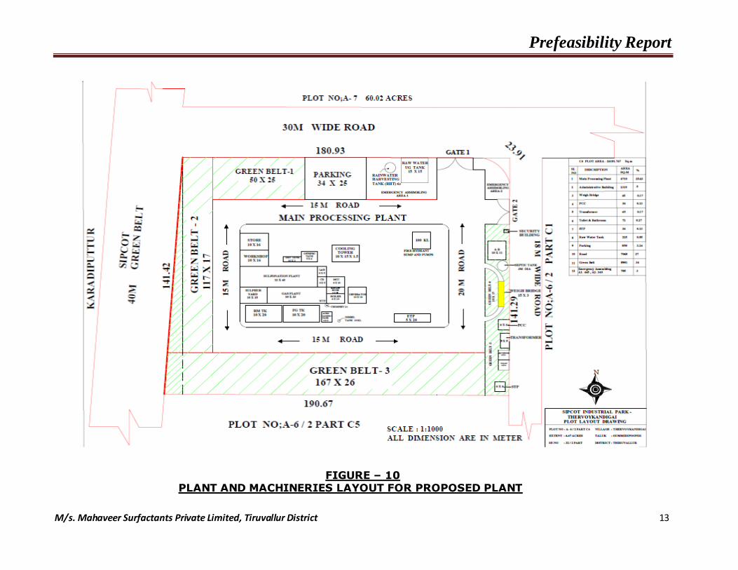
FIGURE – 10 PLANT AND MACHINERIES LAYOUT FOR PROPOSED PLANT

Prefeasibility Report
M/s. Mahaveer Surfactants Private Limited, Tiruvallur District 14
1.2.4 ENVIRONMENTAL SETTLING
TABLE – 1.3 ENVIRONMENTAL SETTLING
Sr. No.
Particulars Details
1 Site Co-ordinates
Corner Latitude Longitude
A 13º21’36.81” N 79º58’42.60“ E
B 13º21’36.59” N 79º58’49.75“ E
C 13º21’32.84” N 79º58’49.56” E
D 13º21’33.13” N 79º58’42.46” E
2 Elevation above MSL 44 - 46 m
3 Land use of the plant site
Industrial Landuse
(SIPCOT Industrial Park, Thervoy kandigai)
4 Nearest Highway SH-51 (4.9 km, S)
5 Nearest Railway station Gummidipoondi Railway station (16.5 km, ENE)
6 Nearest Airport Chennai Intl. Airport (45 km, SSE)
7 Nearest Habitation Thervoy kandigai (2.3 km, ENE)
8 Nearest Densely populated area
Palavakkam (5.0 km, SSW)
9 District Headquarters Tiruvallur (13 km, S)
9 Nearest Seaport Ennore Port Trust (40 km, ESE)
10 Socio-economic factors No resettlement and rehabilitation involved
11 State, national boundaries
Andhra Pradesh – Tamil Nadu (2.7 km, WNW)
12 Ecological Sensitive Zone (Wildlife Sanctuaries)
Nil
13 Forests
Periyapulliyur reserve forest (1.3 Km, SE)
Siruvadi forest (4.0 Km, NNE)
Thervoy reserve forest (4.4 Km, ENE)
Palem range forest (6.8 km, W)
14 Nearest River Arani River (7.7 km, S)
15 Nearest water body
Thervoy kandigai Lake (2.2 Km, E)
Senkaranai Ammaneri Lake (2.5 Km, N)
Kakkavakam Lake (6.1Km, S)
Poovilambedu pond (7.9 Km, ENE)
16 Defence Installation, Historical Monuments, Archaeological places
Nil in 10 km radius
17 Nearby Industries Michelin India Tamilnadu Pvt Ltd tyres.
Beakert Indian Pvt Ltd - Engineering works.

Prefeasibility Report
M/s. Mahaveer Surfactants Private Limited, Tiruvallur District 15
1.3 PROJECT DESCRIPTION
a) Production Details:
The production capacity of the sulphonation plant surfactants are given in Table 1.4.
TABLE – 1.4
PRODUCTION DETAILS
Sr. No. Product Capacity (TPA)
1 Linear Alkyl Benzene Sulfonic Acid (LABSA) 28800
2 Alcohol ether sulfates (AES) 4968
3 Alfa-olefins sulfonates (AOS) 4162
4 Sodium Lauryl Sulphate (SLS) 3744
b) Land Requirement:
A total leasehold area of the promoter is about 26181.76 sq.m (6.47 acre) in PLOT NO: A-6/2 PART C4, S.F No: 32/2 PART, SIPCOT Industrial Park, Thervoy Kandigai, Gummidipoondi, Tiruvallur The landuse break up details of the proposed plant are given below Table 1.5
TABLE – 1.5
DETAILS OF LAND USE BREAK-UP
Sr. No
Plant Facilities Area (ha)
Percentage (%)
1 Production Facilities and administration Building
0.72 27.5
2 Storage Building and Tank farm 0.09 3.4
3 Greenbelt development 0.89 34
4 Road and open space area 0.79 30.1
5 Other facilities ( Weigh bridge, PCC, Transformer, Toilet and Bathroom, STP, Raw water tank and Parking)
0.13 5
Total 2.62 100
c) Plant & Machinery:
The major plant facilities proposed for the project are SO3 Gas Plant, SO3 Absorber System, Sulfonation System, Neutralizer system, hydrolyser system, Mist Eliminator Effluent Gas Treatment System and control systems.

Prefeasibility Report
M/s. Mahaveer Surfactants Private Limited, Tiruvallur District 16
d) Raw Material Requirement:
The major raw materials required for the proposed sulphonation plant are Sulphur and other tabulated chemicals. The sulphur will be stored in the sulphur yard storage of area 150 m2 with dyke wall of height 2m about 500 MT of sulphur to be stored. The details of various raw materials, other chemicals, and sources along with their mode of transportation are given in Table 1.6
TABLE – 1.6
DETAILS OF RAW MATERIALS REQUIREMENT
Sr.
No. Particulars
Quantity
(TPM)
Storage
Facility
Source Transport
1
Linear Alkyl
Benzene
(LAB)
1836.5 Closed Steel
Tank India Tanker Roadways
2 Sulphur 396
Sulphur Yard
Storage with
Dyke Wall
India Tanker Roadways
3 Ethoxylated
alochol (AE) 315
Closed Steel
Tank Malaysia Tanker Roadways
4 Alfa Olefine
(AO) 232
Closed Steel
Tank
USA, China,
Japan, Chevron Ship Seaways
5 Lauryl
Alcohol (LA) 209
Closed Steel
Tank Malaysia Tanker Roadways
6 Caustic Soda
Lye (47%) 320 S. Steel Tank India Tanker Roadways
e) Power and Fuel Requirement:
The total power required for the proposed plant is about 1800 KW which will be met from the state grid. To meet the emergency power requirement during the grid failure, a diesel generator set having capacity of 1000 KVA is proposed. The fuel required in the plant is only for DG operation, the consumption of fuel will be 250 lit/hr of low sulphur high speed diesel (LSHSD).
Prefeasibility Report
M/s. Mahaveer Surfactants Private Limited, Tiruvallur District 17
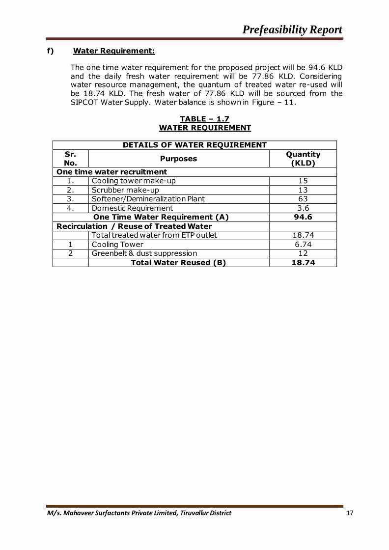
f) Water Requirement:
The one time water requirement for the proposed project will be 94.6 KLD and the daily fresh water requirement will be 77.86 KLD. Considering water resource management, the quantum of treated water re-used will be 18.74 KLD. The fresh water of 77.86 KLD will be sourced from the SIPCOT Water Supply. Water balance is shown in Figure – 11.
TABLE – 1.7 WATER REQUIREMENT
DETAILS OF WATER REQUIREMENT
Sr. No.
Purposes Quantity (KLD)
One time water recruitment 1. Cooling tower make-up 15
2. Scrubber make-up 13 3. Softener/Demineralization Plant 63
4. Domestic Requirement 3.6 One Time Water Requirement (A) 94.6
Recirculation / Reuse of Treated Water Total treated water from ETP outlet 18.74
1 Cooling Tower 6.74 2 Greenbelt & dust suppression 12
Total Water Reused (B) 18.74

Prefeasibility Report
M/s. Mahaveer Surfactants Private Limited, Tiruvallur District 18
FIGURE – 11 WATER BALANCE SYSTEM

Prefeasibility Report
M/s. Mahaveer Surfactants Private Limited, Tiruvallur District 19
g) Manpower Requirement:
During construction phase, the requirement of man power will be about 80 persons and majority of the employees will be either locally employed or will come from nearby villages. In the operation phase, 30 persons will get direct employment. About 50 persons will get indirect employment.
1.4 TECHNOLOGY ADOPTED
The customary method of production starts with the appropriate alkyl benzene which is sulphonated using sulphur trioxide, which will yield sulphonic acid with 96% active matter. The sulphonation reaction can be carried out in various ways. In the past, the reaction was carried out using concentrated sulphuric acid or oleum, in either case using an excess of acid. At the end of the sulphonation, the surplus acid and the desired product must be separated. By this method sulphonic acid with maximum 90% active matter was produced.
Subsequently, it has become conventional to use sulphur trioxide as sulphonating agent. US patent 2928867 published in 1960 teaches that at the end of a sulphonation process carried out with sulphur trioxide, a small amount of water should be added to the reaction mixture to hydrolyze sulphonic acid anhydrides present in it so that a stable product is obtained after neutralization.
During more recent years it has become standard practice to use gaseous sulphur trioxide as sulphonating agent in an approximately stoichiometric quantity, then age the resulting mixture during which time, the reaction mixture proceeds further towards completion, followed by the addition of a small quantity of water which is believed to hydrolyze any anhydrides present in the reaction mixture thereby stabilizing reaction. This current practice is described in, for example, "Sulphonation Technology in the Detergent Industry" by W Herman de Groot, 1991. When carrying out this conventional practice the sulphur trioxide is normally diluted with some other gas which does not react. Air can be used for this purpose.
It is possible to carry out the reaction using an excess of sulphur trioxide but this leads to disadvantages. One disadvantage is the formation of coloured impurities. If a substantial excess of sulphur trioxide is used, the mixture obtained contains unwanted sulphuric acid which must be removed or tolerated as an impurity just as with the older processes using sulphuric acid or oleum. This is less of a problem if there is only a small excess of sulphur trioxide but, as will be explained further, this leads to the presence of undesirable impurities.
When sulphonation is carried out using an approximately stoichiometric quantity of sulphur trioxide it is found that the conventional ageing period at the end of the sulphonation reaction gives increased conversion of the alkyl benzene into the desired sulphonic acid. Nevertheless, it is observed that the alkyl benzene feedstock is not completely converted into the desired alkyl benzene sulphonic acid. A small percentage of alkyl benzene
Prefeasibility Report
M/s. Mahaveer Surfactants Private Limited, Tiruvallur District 20
remains unchanged and a small quantity is converted into a sulphone of the formula.
The relative proportions of unconverted alkyl benzene and sulphone impurity vary. They are affected by the reaction conditions employed and by the mole ratio of sulphur trioxide to alkyl benzene. Although it is possible to vary the relative proportions of unreacted alkyl benzene and sulphone, it is not possible to avoid both of them simultaneously by control of reaction conditions or mole ratio of reactants. Thus, if the mole ratio of sulphur trioxide to alkyl benzene is increased so as to minimize the percentage of unconverted alkyl benzene, the percentage of sulphone increases.Failure to convert alkyl benzene to sulphonic acid and conversion to by-product sulphone both represent a waste of alkyl benzene feedstock. Additionally, unconverted alkyl benzene can give rise to tower emission problems on spray drying and there have also been speculations that residual alkyl benzene is slightly toxic.
Thus, although the present commercial procedure of sulphonation with stoichiometric quantity of sulphur trioxide followed by ageing and then the addition of water to arrest the reaction is very advantageous compared with earlier processes in that it gives a high level of conversion to the desired product without introducing large quantities of sulphuric acid into the product mixture, there is still some scope for further improvement where it would be desirable to reduce further the combined levels of alkyl benzene and sulphone below what is currently achievable.
According to the present invention, there is a method of manufacturing alkyl benzene sulphonate by contacting, as reactants, alkyl benzene with sulphur trioxide using a molar ratio of alkyl benzene to sulphur trioxide in the range of 1:0.9 to 1:1.3, characterized by incorporating sulphuric acid into the reaction mixture after bringing the reactants into contact, the amount of sulphuric acid being not more than 10% by weight of the reaction mixture, and then allowing reaction in the mixture to continue for at least 30 minutes.
It has been found that by incorporating sulphuric acid in this manner it is possible to achieve an improvement in the overall conversion to the desired product and a consequent reduction in the undesired impurities. To carry out this reaction, the sulphur trioxide is preferably diluted with another gas, as is conventional. This other gas may well be air. The ratio of sulphur trioxide to other gas may desirably lie in a range from 3% to 10% by volume. The molar ratio of alkyl benzene to sulphur trioxide is preferably in a range from 1:0.9 to 1:1 or better 1:0.95 to 1:1.
The alkyl benzene which is sulphonated may have a straight or branched alkyl group which preferably contains around 10 to 15 carbon atoms. Although branched alkyl benzene has been extensively used for detergent manufacture it is nowadays usually preferred to employ linear alkyl benzene, that is to say alkyl benzene in which the alkyl group has a straight carbon chain.

Prefeasibility Report
M/s. Mahaveer Surfactants Private Limited, Tiruvallur District 21
1.5 PROCESS DESCRIPTION
Below described the continuous sulfonation plant and auxiliary equipment required to produce Linear Alkyl Benzene Sulfonic Acid (LABS), Sodium Lauryl Sulfate (28% AM -Liquid), Sodium Lauryl Ethoxy Sulfate (SLES-28 and 70% AM) and Alfa Olefin Sulfonate (AOS- 38%). The basic plant includes a Sulfur Supply System, Air Supply System, SO3 Gas Generator System, Sulfonation System, Neutralizer System, Hydrolyser System, SO3 Absorber System, Effluent Gas Treatment System, a PLC Control System, Motor Control Center (MCC) and documentations.. The Sulfonation system will use Anular Falling Film Reactor (AFFR).The sulfonation plant consists of a number of distinct process operations. This Section of the proposal is intended to assist to understand the complete sulfonation plant by describing the process and equipment for each of the unit operations involved. In addition to the process and equipment descriptions given below
a preliminary equipment list is included as an Attachment to this proposal.
1.5.1 Sulfur Supply System
Sulfur is supplied to the sulfur burner from one of two submerged gear pumps located in the sulfur melter. Dual pumps are provided in order to minimize down time during sulfur pump maintenance. The submerged pumps provide accuracy, reliability, a clean environment and ease of maintenance. Steam jacketed mechanical seals, which are prone to failure, are eliminated by submerging the pumps in molten sulfur.
FIGURE - 12
Sulfur supply system
A bubbler type level transmitter will indicate and alarm the sulfur level in the tank. The SO3 to organic mole ratio is a very important parameter for controlling the sulfonation process. In order to achieve the precision required to produce the finest quality surfactants, a mass flow meter of high accuracy is installed at the pump discharge. Temperature interlock in the mass flow transmitter reduces failures due to operating the system with frozen sulfur in the meter. Similarly, the pump trips when the mass flow meter reading goes to zero due to plugging of strainer at the pump suction. This will help in protecting the pump from dry running. A steam and condensate system is utilized to supply the necessary tracing circuits for all the sulfur supply piping and the storage tank system. An automatic steam flushing arrangement is provided to fight any fire break out inside
Prefeasibility Report
M/s. Mahaveer Surfactants Private Limited, Tiruvallur District 22
the tank, by sensing the higher temperature in the vapor space of the sulfur tank.
1.5.2. Air Supply System
The process air is first compressed to a pressure of approximately 1 kg/cm2 and chilled to a temperature of 16°C in the air chiller vessel. The chilled air is then dried in automatic desiccant-type air dryers to a guaranteed dew point of -60°C (typically -70 C).
The dual air dryers are equipped with 11 individual bubble tight control valves. This ensures absolutely no interruption of process air when changing dryers and a smooth pressure transition when changing to regeneration. On power failure, these valves are designed to automatically close to prevent back up of corrosive gas into the dryers, and to keep moist atmospheric air from reaching the dryers and gas plant.
The design utilizes Sorbead desiccant, a BASF product made under license. This material is non-friable and provides longer life, lower dew point and lower regeneration temperatures than typical activated alumina or silica gel systems. The material can also withstand significantly higher regeneration temperatures than other types of desiccant, thus facilitating better drying. We balance the stress on the desiccant beds with process air flowing in an up flow path and regeneration air in a down flow path, resulting in longer desiccant life. Additionally, automatic control of the dryer regeneration air temperature ensures both long desiccant life and low maintenance requirements. The cooling air blower is used to cool the regenerated (off-line) air dryer to an acceptable level, prior to bringing the regenerated air dryer back on-line.
A regeneration air blower is used to supply cooling air to the double pipe SO2 gas cooler, inter pass cooler and SO3 cooler used in the gas plant. The hot air leaving the double pipe cooler is then used to regenerate the off-line air dryer. During the air dryer cooling cycle the regeneration air is vented to the atmosphere.

Prefeasibility Report
M/s. Mahaveer Surfactants Private Limited, Tiruvallur District 23
FIGURE - 13
Air drying system
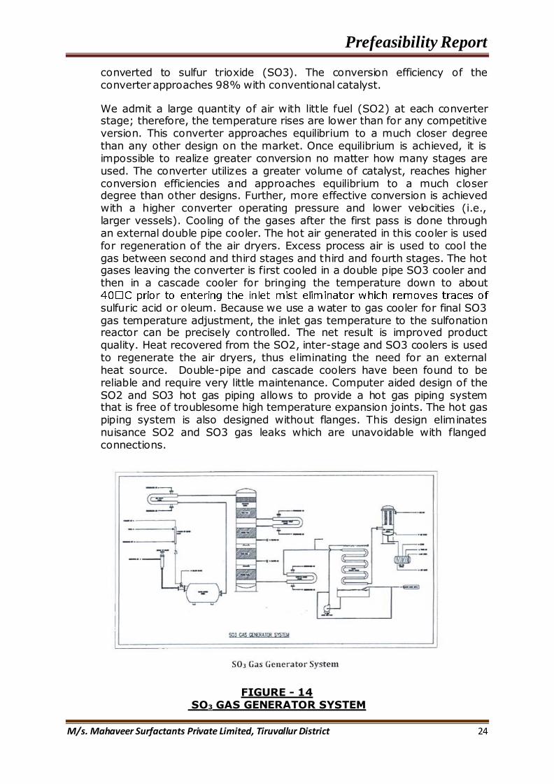
1.5.3. SO3 Gas Generator System
A continuous source of dry air-SO3 gas is required for film sulfonation and sulfation. In order to ensure a constant stable operation of the complete sulfonation plant, the SO3 gas generator system is designed for easy and reliable operation. In addition to being highly reliable and easy to operate, the SO3 gas generators will achieve the precise and uniform flow of SO3 required by the sulfonation process. We use an "atomizing type" sulfur burner in order to achieve uniform combustion of the sulfur. "Trickle type" sulfur burners tend to allow the sulfur to pool and burn, which results in non-uniform combustion of sulfur in the sulfur burner. We developed the atomizing type sulfur burner for sulfonation and this remains the only design that can ensure a steady burner exit temperature. The net result of uneven burning is loss of mole ratio control and subsequent degradation of product quality. Our design yields very uniform sulfur burning and contributes to the superior product quality.
The atomizing type sulfur burner is also easier to start than trickle type burners. A small flow of combustion air is heated by an inline ignition air heater which immediately ignites the sulfur at the tip of the spray nozzle. The atomizing type sulfur burner does not require preheating of the sulfur burner refractory lining. The metered sulfur is delivered to the refractory-lined atomizing sulfur burner where combustion with the dry process air generates sulfur dioxide (SO2).
The sulfur dioxide gas leaving the burner is cooled and delivered to a four-stage vanadium oxide catalytic converter, where the gas is filtered and
Prefeasibility Report
M/s. Mahaveer Surfactants Private Limited, Tiruvallur District 24
converted to sulfur trioxide (SO3). The conversion efficiency of the converter approaches 98% with conventional catalyst.
We admit a large quantity of air with little fuel (SO2) at each converter stage; therefore, the temperature rises are lower than for any competitive version. This converter approaches equilibrium to a much closer degree than any other design on the market. Once equilibrium is achieved, it is impossible to realize greater conversion no matter how many stages are used. The converter utilizes a greater volume of catalyst, reaches higher conversion efficiencies and approaches equilibrium to a much closer degree than other designs. Further, more effective conversion is achieved with a higher converter operating pressure and lower velocities (i.e., larger vessels). Cooling of the gases after the first pass is done through an external double pipe cooler. The hot air generated in this cooler is used for regeneration of the air dryers. Excess process air is used to cool the gas between second and third stages and third and fourth stages. The hot gases leaving the converter is first cooled in a double pipe SO3 cooler and then in a cascade cooler for bringing the temperature down to about
sulfuric acid or oleum. Because we use a water to gas cooler for final SO3 gas temperature adjustment, the inlet gas temperature to the sulfonation reactor can be precisely controlled. The net result is improved product quality. Heat recovered from the SO2, inter-stage and SO3 coolers is used to regenerate the air dryers, thus eliminating the need for an external heat source. Double-pipe and cascade coolers have been found to be reliable and require very little maintenance. Computer aided design of the SO2 and SO3 hot gas piping allows to provide a hot gas piping system that is free of troublesome high temperature expansion joints. The hot gas piping system is also designed without flanges. This design eliminates nuisance SO2 and SO3 gas leaks which are unavoidable with flanged connections.
FIGURE - 14 SO3 GAS GENERATOR SYSTEM

Prefeasibility Report
M/s. Mahaveer Surfactants Private Limited, Tiruvallur District 25
1.5.4 SO3 Absorber System
This unit is capable of treating the total output from the air-SO3 system to form 98% sulfuric acid. It is highly recommended the use of an SO3 absorber system for the following reasons
a. Sulfur burning SO3 gas plants can take up to a few hours to develop stable SO2 to SO3 conversion during startup. The SO3 absorber system offers a convenient and reliable method of handling the process gas during startups. The SO3 strength is unknown during startup. The SO3 absorber system uses conductivity to measure the sulfuric acid concentration in the absorber recycle and adjusts the concentration by adding process water and therefore operates without the knowledge of inlet SO3 gas concentrations. The sulfonation system uses mole ratio from a known sulfur and assumed SO2 to SO3 conversion efficiency to meter the organic to the reactor. Significant amounts of off-spec (over or under sulfonated) product would be made if the sulfonation system was utilized during gas plant startups.
b. The SO3 absorber system also offers a convenient and reliable method of handling the process gas during plant shutdowns, upsets, and product changeovers when the sulfonation system must be fully drained and washed out. During plant shutdowns the sulfur is turned off but the residual gases in the gas plant vessels are best purged through the absorber to eliminate fouling the sulfonation reactor and/or making off-spec product. During product changeovers the gas plant can be kept on-line (steady state) by utilizing the absorber system as an alternate path through the plant.
FIGURE - 15
SO3 ABSORBER SYSTEM

Prefeasibility Report
M/s. Mahaveer Surfactants Private Limited, Tiruvallur District 26
SO3 and air enter the absorber column (see Figure 15), where they contact 98% sulfuric acid. SO3 is absorbed into the acid, which separates from the remaining air in the scrubber body. A mesh pad mist eliminator removes entrained mist from the air as it exits the vessel. Water is added to the scrubber as it flows through the acid circulation system. A control system utilizing dual conductivity sensors holds the acid concentration at 98% by controlling water addition. A heat exchanger in the circulation loop removes heat of dilution.
1.5.5 Sulfonation System
AFFR Sulfonation System
Our AFFR sulfonation systems enable to produce the finest quality products achievable from available organic feedstocks. One of the important control parameters in the sulfonation process is the SO3 –to-organic mole ratio. In order to obtain precise control of the SO3 –to-organic mole ratio in the sulfonation process, designs utilize mass flow meters on the sulfur and organic feed systems, an atomizing sulfur burner for uniform combustion of sulfur and a reactor designed for excellent distribution of the organic feedstock and the air- SO3 gas.
The sulfonic acid forms in the unit when an SO3-in-air mixture is injected into a Falling Film Reactors .Simultaneously with the desired organic feed. The Annular Falling Film Reactor is accepted as more reliable than other designs. Shutdowns for reactor maintenance are normally not required. The removable organic distribution flanges are factory calibrated prior to installation in the reactor and, due to the unique design and materials of construction (316 stainless steel and high nickel alloys), do not require periodic recalibration. The reactor is permanently adjusted only once—in the factory. Most competitive systems with multi-tube reactor designs require continual adjustment. Uniform distribution of the air-SO3 gas is the result of symmetrical gas flow through the reactor. Reactor distribution can be easily checked during operation by use of the sample ports conveniently located at the bottom reaction section.
Reaction temperature is also a very important parameter to control in sulfonation and sulfation processes. Cooling jackets in the reactor remove a significant portion of the heat of reaction. The design is the only one that can ensure consistent cooling at any point in the reaction. Additional cooling is achieved through the use of a quench cooled recycle system. Recycled acid from the product cyclone is cooled through heat exchangers and fed to the lower quench zone of the reactors. These unique measures precisely control the reaction temperature.
The Annular Falling Film Reactor offers the following additional advantages over other designs, resulting in up to 0.5% better conversion of all feeds
Better heat transfer and lower peak product temperatures
Cooler product discharge temperatures

Prefeasibility Report
M/s. Mahaveer Surfactants Private Limited, Tiruvallur District 27
Shorter residence time in reactor at elevated temperatures
Higher gas velocity produces a thinner liquid film, leading to better mass transfer
Recycle allows quench cooling, shorter reactor and results in the highest reaction completeness which is essential to produce high quality products
Compact reactor is easier to install and maintain
Liquid flow rate is controlled at less than ±1.5% variance between any two points
Washouts are a short, simple process
Liquid/gas contact is mechanically controlled and does not rely on fluctuations in product completeness
Oleum separator in the gas line prevents reactor fouling from small amounts of oleum in the SO3 line
The recycle system provides an additional reaction zone that assists with gas
Scrubbing.
FIGURE - 16
AFFR SULFONATION SYSTEM

Prefeasibility Report
M/s. Mahaveer Surfactants Private Limited, Tiruvallur District 28
1.5.6. Neutralizer System
The continuous neutralizer system combines sulfonic or organic sulfuric acid with sodium hydroxide. Caustic soda (sodium hydroxide) is the usual neutralizing agent,
A recycle loop circulates neutral slurry through a heat exchanger to remove excess process heat. Individual pumps feed neutralizing agent, dilution water, buffer solution (if any) and additives (if any) into the loop to mix through a high shear mixer. Product "paste" is displaced from the circuit as feed streams enter. A positive displacement recycle pump circulates paste through the process heat exchanger and a large portion of this stream recycles back to the mixer. A pressure control valve allows product to leave the recycle system as feed enters
FIGURE - 17 CONTINUOUS NEUTRALIZER SYSTEM
. 1.5.7. Hydrolyser System
A hydrolyzer system is required for alpha-olefin sulfonation to break down sultones formed in the sulfonation stage. The process involves mixing the sulfonic acid with an excess of neutralizing agent, boosting the pressure of the resulting paste to approximately 5 kg/cm2, heating the paste to 150°C, and digesting the product for one hour to one and a half hours, until essentially all of the sultones have reacted. Digested slurry is then cooled and sent to final storage. All of the operations are carried out continuously. An optional economizer (shown below) is available to reduce steam usage by heating the feed system with heat from the reaction (product heat).

Prefeasibility Report
M/s. Mahaveer Surfactants Private Limited, Tiruvallur District 29
The hydrolyzer equipment is integrally tied into the neutralizer system. During the processing of other feed stocks, the hydrolyzer is bypassed and idle. When the plant shifts to the production of alpha olefin sulfonates (AOS), the hydrolyzer is brought on line.
FIGURE - 18
HYDROLYSER SYSTEM
5.8. Effluent Gas Treatment System
Effluent process gases leaving the sulfonation system or SO3 absorber are virtually free of residual SO3, but contain any unconverted SO2 gas and entrained particulate anionic materials (acidic mists of sulfonic and sulfuric acids). This gas stream is not suitable for direct discharge to atmosphere. The recommended system employs a proprietary electrostatic precipitator designed to collect particulate mists and a packed tower scrubber to absorb SO2 gas in a dilute caustic. Final effluent gases are suitable for discharge to the atmosphere.
Electrostatic precipitator
An electrostatic precipitator (ESP) employs a proprietary electrode design in an air-jacketed bank of collection tubes. The High Intensity Torroidal Electron Corona produced by the electrode charges the inlet particulates, which are collected at the passive tube wall. Coalesced organic acids (bottoms) discharge at the bottom of the vessel. Because the electrode assembly is rigidly supported from above, as opposed to conventional hang-wire designs, the ESP is more reliable and easier to assemble.
All charged parts of the electrostatic precipitator are constructed of 316 series stainless steel, and the design includes an internal spray washing system for cleaning the electrodes and vessel internals. Safety interlocks and manhole locks are provided to insure safe operation and maintenance of the unit. The transformer/rectifier mounts on a structural support

Prefeasibility Report
M/s. Mahaveer Surfactants Private Limited, Tiruvallur District 30
provided by Technithon so that the high voltage bushing inserts directly into the vessel. This eliminates the need for high-tension insulated ducting (common in conventional designs) which can be a safety hazard and source of inefficiency. The unit operates at much higher field strengths than conventional hang-wire units, and achieves much greater collection efficiencies, resulting in significantly reduced maintenance.
FIGURE 19
Electrostatic Precipitator
b. SO2 Scrubber
The packed tower SO2 scrubber system is designed to operate with minimal operator attention as a semi-continuous batch recycle scrubber. The recycle tank is charged with a dilute caustic soda solution which is recirculated to the top of the absorber tower. The gas contacts the scrubbing solution counter-currently as it passes upward through the tower to the final stack. The SO2 gas present in the effluent stream is absorbed in the scrubbing solution and reacts with the caustic soda forming Na2SO3. As the caustic soda is consumed, the pH of the scrubbing solution falls, and a pH sensing/transmitter eventually activates an alarm to alert the operation that a new batch of scrubbing solution must be charged to the tank. The batch time is planned so that under normal steady state running conditions, the recycle tank requires caustic and make-up water addition no more than once per shift. When caustic is added, the tank is pumped down and recharged with fresh make-up water diluent so that the system never operates at solids concentrated above 8 wt % or with a pH less than 11. The sodium sulfite that is formed is oxidized to sodium sulfate (except during startup), achieving 85% oxidation (or better) to Na2SO4

Prefeasibility Report
M/s. Mahaveer Surfactants Private Limited, Tiruvallur District 31
FIGURE - 20
SCRUBBER SYSTEM
1.5.9. Control System
The control system consists of three main components, which are integrated into a single system: Programmable Logic Control System (PLC), Motor Control Center (MCC), and ESP Control Panel. This system improves the operators' understanding of plant operation through a graphic interface and improves product consistency and quality through better control.
a. Programmable Logic Control (PLC) System
The PLC based system will consist of a control panel whose functions include:
Analog control or PID control loops
Discrete control
Interlocks to reduce operator errors that could result in damage to the equipment or environmental releases
Alarm Monitoring
The system has one Supervisory Control Station and one operator station. The Supervisory Control Station includes Custom Graphics, Historical Data Collection, and Alarm Logging. The Supervisory Control Station is based on an Intel Pentium IV Chip (or latest standard version available during the plant purchasing phase) compatible personal computer (PC). The system includes one printer. The system also has the capability to trend selected variables, log alarms and collect data for historical logs. We does not configure these functions, which are easily formatted as required by the customer into standard report documents.

Prefeasibility Report
M/s. Mahaveer Surfactants Private Limited, Tiruvallur District 32
Other features of the Main Instrument Control Panel are:
All process connections to the process controller are pre-wired and pre-tested from the interfacing terminal strips
Connections between the MCC and ICP are pre-wired and pre-tested
Power Supplies for 24VDC
Lighting, Power Outlets, and Cooling Fans are installed in the cabinet
b. Motor Control Centre (MCC)
The Motor Control System includes a main disconnect, motor starters, and disconnects as required for the equipment supplied by TTPL.
Each starter includes:
Pre-wired and pre-tested terminal strip between the MCC and the Main Instrument Control Panel
Individual fuse-protected 110 VAC control
Individual monitoring of each motor control by the PLC to ensure proper sequencing and operating to include alarming in the case of an incorrect or fault condition
Branch circuit, short circuit and ground fault protection, with separate adjustable running thermal overload, as required.
c. ESP Control Panel
The ESP Control Panel is a separate control system matched to the Transformer/ Rectifier set which supplies the high voltage for the ESP. The system is interlocked by the Main Instrument Control Panel for safe operation. The controls have both Automatic and Manual modes that simplify the setup and operation of the ESP. The system includes a digital alarm system and analog meters for voltage and Current.
1.6.0 General Equipment Specifications 1. Motors:
All electric motors, will be totally enclosed, fan cooled. Motors up to 15 hp are wired direct-on-line; motors over 15 hp should be wired for starter delta starting.
2. Flow, Temperature, Pressure and Level Indicators:
The plant should be equipped with local indicators for analyzing equipment performance, as well as assisting manual operation of the plant in case of automatic control system failure. Pressure indicators should be located at important pump and blower discharges and on all major pieces of equipment. Temperature sensors or indicators should located at all important process points.

Prefeasibility Report
M/s. Mahaveer Surfactants Private Limited, Tiruvallur District 33
3. Equipment Finishing, Detailing and Crating:
a. Lubrication. All grease fittings, grease cups, and bearings are serviced prior to shipment. Lubricating oil sumps are tagged and shipped dry. Lubricating oils are shipped separately.
b. Metal Detailing. Assembled mild steel pipe and structural components are cleaned, primed and finished with one coat of light gray epoxy paint.
c. Tag Numbers. All components are clearly identified by metal identification tags fixed to each part.
The details of operating requirements are given in Table 1.8
TABLE – 1.8 OPERATING SYSTEM
Sulphonation Plant Type of plant - Standard Sulphonation plant
SO3 Gas concentration - 5% SO3
Capacity -
5000 kg/hr LABSA (MW 320) 3450 Kg/hr AES 2890 kg/hr AOS 3315 kg/hr SLS
Equipment -
Sulphur burner, Sulphur melter, SO3 Gas generator, Mist eliminator, SO3 absorber, Sulfonator with multi tube reactor, ESP and SO2 scrubber
Basis of rated plant capacity
Name of Organic feed and molecular weight
-
Linear Alkyl Benzene (LAB) – 242 Ethoxylated alcohol (EA0 – 284 Alfa Olefine (AO) – 196 Lauryl Alcohol - 186 Sulphur - 32
Ambient Air conditions
Relative Humidity - 50% at 30°C (86°F) Minimum Temperature - 0°C (32°F)
Maximum Temperature - 43°C (110°F) Plant Elevation - 44 m AMSL
Utilities* Electrical Power - 230/415 ± 27V, 3 phase, 50 + 1 Hz
Connected - 1800 KW Running - 1500 KW
Cooling water - 1000 m3/hr Steam @ 10 kg/cm2 - 400Kg/hr
Atomizing & Instrument Air 7 kg/cm2 (dew point less than 5°C)
- 150 Nm3/hr
* - The utility usage figures are typical for similar plant operation
Prefeasibility Report
M/s. Mahaveer Surfactants Private Limited, Tiruvallur District 34
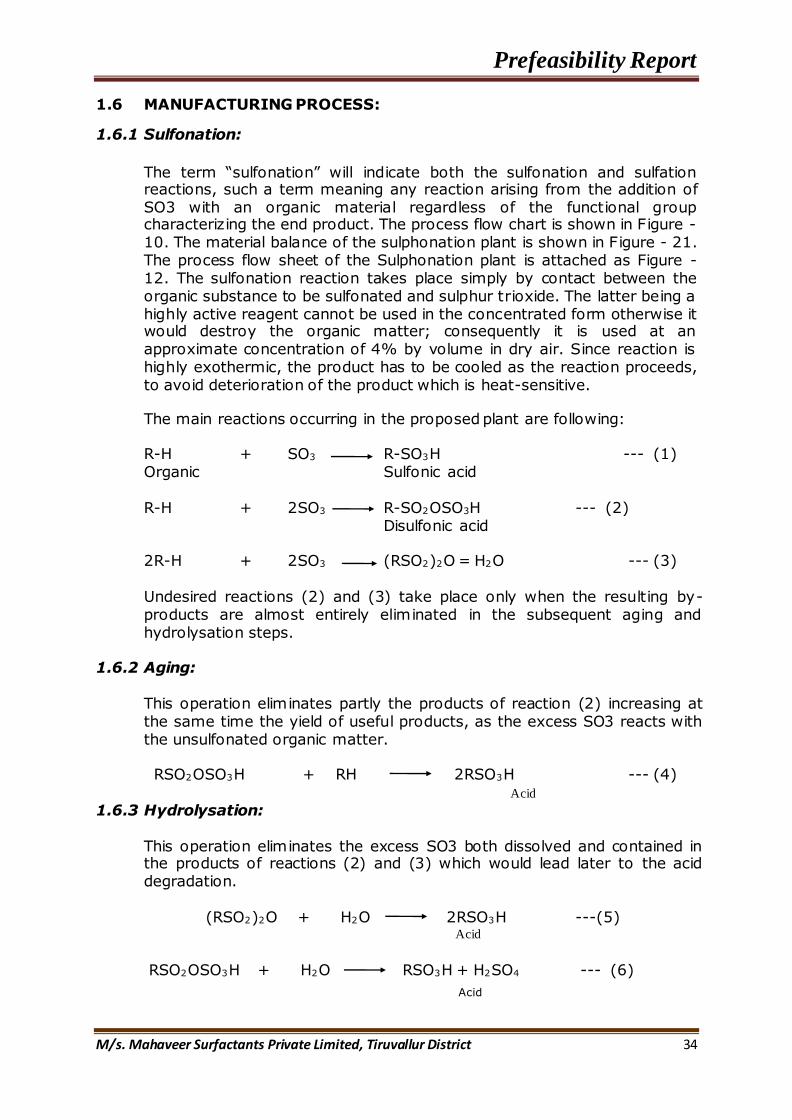
1.6 MANUFACTURING PROCESS:
1.6.1 Sulfonation:
The term “sulfonation” will indicate both the sulfonation and sulfation reactions, such a term meaning any reaction arising from the addition of SO3 with an organic material regardless of the functional group characterizing the end product. The process flow chart is shown in Figure - 10. The material balance of the sulphonation plant is shown in Figure - 21. The process flow sheet of the Sulphonation plant is attached as Figure -12. The sulfonation reaction takes place simply by contact between the organic substance to be sulfonated and sulphur trioxide. The latter being a highly active reagent cannot be used in the concentrated form otherwise it would destroy the organic matter; consequently it is used at an approximate concentration of 4% by volume in dry air. Since reaction is highly exothermic, the product has to be cooled as the reaction proceeds, to avoid deterioration of the product which is heat-sensitive.
The main reactions occurring in the proposed plant are following: R-H + SO3 R-SO3H --- (1) Organic Sulfonic acid R-H + 2SO3 R-SO2OSO3H --- (2) Disulfonic acid 2R-H + 2SO3 (RSO2)2O = H2O --- (3)
Undesired reactions (2) and (3) take place only when the resulting by-products are almost entirely eliminated in the subsequent aging and hydrolysation steps.
1.6.2 Aging:
This operation eliminates partly the products of reaction (2) increasing at the same time the yield of useful products, as the excess SO3 reacts with the unsulfonated organic matter.
RSO2OSO3H + RH 2RSO3H --- (4) 1.6.3 Hydrolysation:
This operation eliminates the excess SO3 both dissolved and contained in the products of reactions (2) and (3) which would lead later to the acid degradation.
(RSO2)2O + H2O 2RSO3H ---(5)
RSO2OSO3H + H2O RSO3H + H2SO4 --- (6)
Acid
Acid
Acid

Prefeasibility Report
M/s. Mahaveer Surfactants Private Limited, Tiruvallur District 35
FIGURE - 21 PROCESS FLOW CHART

Prefeasibility Report
M/s. Mahaveer Surfactants Private Limited, Tiruvallur District 36
FIGURE - 22 MATERIAL FLOW FOR 5000 kg/hr LABSA (96%)
FIGURE - 23 MATERIAL FLOW FOR 3450 kg/hr AES

Prefeasibility Report
M/s. Mahaveer Surfactants Private Limited, Tiruvallur District 37
FIGURE - 24 MATERIAL FLOW FOR 2890 kg/hr AES
FIGURE - 25 MATERIAL FLOW FOR 3315 kg/hr SLS

Prefeasibility Report
M/s. Mahaveer Surfactants Private Limited, Tiruvallur District 38
FIGURE – 26 PROCESS IN SULPHONATION PLANT

Prefeasibility Report
M/s. Mahaveer Surfactants Private Limited, Tiruvallur District 39
1.7 SOURCES OF POLLUTION & MANAGEMENT 1.7.1 Details of Solid Waste Generation and Disposal
Major solid wastes generated from the proposed Sulphonation plant would include sulphur sludge, spent catalyst, scrubber residue and ETP sludge, which are shown in the Table 1.9
TABLE – 1.9 SOLIDWASTES-GENERATION & MANAGEMENT
1.7.2 Wastewater/Effluent Generation and its Management
The main source of effluent generation in the proposed Sulphonation plant is from cooling tower blow down, boiler blow down, alkali scrubber bleed-off, DM plant reject and domestic usages. The daily fresh water requirement for the proposed project will be about 77.86 KLD. The entire effluent generation of quantity is 31.74 KLD. The scrubber wastewater 13 KLD consists of major proportion of Sodium Sulphate lean solution, which will be concentrated and used in detergent plant of MSPL, The remain 18.74 KLD of wastewater treated in the Effluent treatment plant as capacity of 25 KLD and reused within the plant premises for cooling tower make-up 6.74 KLD, Greenbelt and dust suppression 12 KLD. The details of sewage and effluent generation are given in Table below 1.10
Details of Solid Waste Management
Sr. No.
Solid Waste
Quantity (TPA)
Method of Disposal
1 Sulphur Sludge
1.25 Ash and impurities in
Sulphur
Stored temporarily in HDPE bags and send to secured
landfill facility, Gummidipoondi
2 Spent
Catalyst 0.75 Catalyst Powder
3 ETP Sludge 75 Sodium, Calcium
sulphates/carbonates
4 Scrubber Residue
400 Solid Sulphate Solid Sulphate sent to
detergent industry
5 Acid Mist 0.07 Acid Mist
Collected in barrels and sent to Common Treatment Storage Disposal Facility (CTSDF), Gummidipoondi

Prefeasibility Report
M/s. Mahaveer Surfactants Private Limited, Tiruvallur District 40
TABLE – 1.10
DETAILS OF SEWAGE / EFFLUENT GENERATION
D
D
D
Details of Effluent Treatment Plant
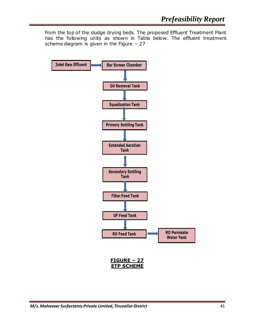
The technology proposed for the ETP is chemical precipitation and extended aeration method. Effluents emanating from the various process sections of the sulphonation plant and washing from other sections are segregated and arrive at the screen chamber, followed by oil removal tank then to the equalization tank. From the equalization tank the homogeneous effluent is pumped in to the Flash mixer. The pH of incoming effluent is checked and neutralized with acidic or alkaline. Neutralized effluent is treated by addition Alum / PAC (Poly Aluminium Chloride), and polyelectrolyte solutions are added to maintain pH between 7 - 8.
The flash mixing vessel is provided with a stirrer. As soon as the Effluent flows to the floc-mix tank, agitator is started. Predetermined quantities of acidic / alkaline, Alum/PAC and polyelectrolyte solutions are dosed to the flash mixer with the help of the respective feed pumps. The effluent mixes with the solutions and overflows to the flocculation zone, where by means of the differential speed agitators flocculation takes place. The pH of the medium has to be controlled between 7 and 8 in the flash mixer. The supernatant from the primary settling tank will be sent to aeration tank and then to secondary settling tank where the entire sludge gets settled down. The treated effluent from the secondary settling tank will be reused for industrial process and gardening purpose. The settled sludge in the primary & secondary settling tanks can be removed by operating the sludge drawn off valves into the sludge pit. The chemical sludge is then taken into the sludge drying beds for dewatering purpose. The dried sludge is periodically cleaned
Waste Water Management
Sr. No. Description Wastewater Generation
(KLD)
Wastewater Management
1 Domestic Wastewater
3.24 Treated in ETP
2 Boiler Blow down 5 Treated in ETP
3 Cooling Tower Blow down
5 Treated in ETP
4 Spillage Water from process
2.5 Treated in ETP
5 Regeneration from DM Plant
3.0 Treated in ETP
6 Scrubber bleed 13 Treated in solar evaporation pant
Total 31.74
Prefeasibility Report
M/s. Mahaveer Surfactants Private Limited, Tiruvallur District 41
from the top of the sludge drying beds. The proposed Effluent Treatment Plant has the following units as shown in Table below. The effluent treatment scheme diagram is given in the Figure – 27
FIGURE – 27 ETP SCHEME

Prefeasibility Report
M/s. Mahaveer Surfactants Private Limited, Tiruvallur District 42
TABLE – 1.11
ETP COMPOENENTS
1.7.3 Sources of Gas Emission
The main pollutants discharged from the Sulphonation plant will be Sulphur dioxide emission whereas particulate matter and Nitrous oxide emission will be from the DG sets. HITEC Electrostatic Precipitator (ESP) and Alkali scrubber will be installed to reduce gaseous and acid mist emissions.
Sulphonation Plant:
Diameter of Chimney: 450 mm Height: 38 m from ground level
DETAILS OF ETP COMPONENTS Sr.
No. Name of the unit
No of
units
Dimension in
m MOC
1. Bar Screen Chamber 1 1.2 x 1.2 x 0.5 RCC
2. Collection / Equalization Tank 1 3.2 x 3.2 x 1.5 RCC
3. Oil Removal Tank 1 2.5 x 2.5 x 2.1 RCC
4. Reaction Tank 1 2.5 x 2.5 x 2.1 RCC
5. Primary Settling Tank 1 1.6 x 2.5 x 2.5 RCC
6. Extended Aeration Tank 1 4.0 x 2.5 x 2.0 RCC
7. Secondary Settling Tank 1 1.6 x 2.5 x 2.5 RCC
8. Filter Feed Tank 1 1.6 x 2.5 x 2.5 RCC
9. Treated Water Tank/ UF Feed
Tank 1 1.6 x 2.5 x 2.0 RCC
10 Neutralization tank 1 50 litres
capacity Sintex
11 PAC / Alum Tank 1 50 litres
capacity Sintex
12 Polyelectrolyte Tank 1 50 litres
capacity Sintex
13 Sludge Drying Bed 4 1.5 x 1.5 x 1.5 Brick
ork
Prefeasibility Report
M/s. Mahaveer Surfactants Private Limited, Tiruvallur District 43
Temperature of the Flue gas: 50°C Efficiency of Scrubber: 98.5%
Air Pollution Control Measures:
Highly improved ceramic packing will be used in towers for proper absorption. Improved cesium based mansanto catalyst which are highly active and kindle
even at low temperatures with high conversion efficiency particularly used in 3rd and 4th pass completely to ensure 99.5% conversion and above.
Avoiding sharp bends in design to avoid leakage, by usage of good quality materials in fabrication.
Caustic lye water wash tower for washing the tail gases before it enters to chimney
Proper online SO2 analyzer will be installed at the chimney outlet point Providing ambient air monitoring station on corners of industry
1.8 Rainwater harvesting
Rainwater harvesting (RWH) system comprises components of various stages- transporting rainwater through pipes, filtration and storage in tanks for reuse or recharge pits. The catchments of a water harvesting system are the surface which directly receives the rainfall and provide water to the rainwater harvesting system. The rainwater run-off from all the un-paved areas shall be routed to rainwater harvesting pits, provided at strategic
locations within the project area.
The first flush shall be checked from entering collection system, using diversion valves to ensure that runoff from the first spell of rain is flushed out and does not enter the system. This needs to be done since the first spell of rain carries a relatively larger amount of pollutants from the air and catchments surface. Rainwater from paved and roof areas, landscaped, paved area and rest of the area within project premises will be harvested to ground through rainwater recharge pits.
Run off from the plant site is calculated using rational formula;
Q = C x I x A
Where, Q = Run-off (cu.m/hr) A = Catchments Area (Roof area, Landscaped area, Road & parking area) C = Coefficient of Runoff I = Intensity of rainfall = 100 mm/hr = 0.1 m/hr
The constant co-efficient factor of 0.80 (for all situations) for evaporation,
spillage and first flush wastage (Source: CPWD Manual, 2002)

Prefeasibility Report
M/s. Mahaveer Surfactants Private Limited, Tiruvallur District 44
From Building area
= 848.8 cu.m/hr x 0.80 (for all time)
= 679.04 cu.m/hr
The water will be collected, treated with sand filter and stored in 2 UG
storage tank of 500 m3. The water will be used for greenbelt and fire fighting
Storm runoff from open area, greenbelt area and paved area
= 1760.7 cu.m/hr x 0.80 (for all time)
= 1408.56 cu.m/hr
The rainwater harvesting measures and quantity with regards to the various structures in the building are presented in Table-1.12
TABLE-1.12 RAINWATER HARVESTING CALCUALTION AS PER CPWD
MANUAL, 2002
All the water shall be routed to rainwater harvesting pits
The run-off from terraces, roads, paved area & greenbelt & vacant area will be diverted through storm water network to individual percolation pits proposed along the project periphery and the rain water will be re-charged into underground aquifers
A percolation rate of 0.51 is considered with percolation depth as 10m Run-off = 1515 X (1.0 – 0.51) = 742.35 m3/day Size of percolation pit = 1.20 x 1.20 m and 4.0 m depth Storage volume in each pit: 5.76 m3 Quantity of storm water run-off: 742.35 m3 No. of storage pits required:
742.35 m3/ 5.76 m3 = 128.88 ~ 129 Nos
129 Nos. of percolation pits will be constructed along the project site periphery for rain water recharge
Sr. No
Category Area (sq.m)
Impermeability Factor
Harvestable water (Intensity x Area x Imp. Factor) cum/hr
1 Building area 8488 0.6 509.28
2 Landscaped area (Green area, Vacant area)
9775 0.3 293.25
3 Road/ Surface parking area 7918 0.9 712.62 Total 26181 1515.15
Prefeasibility Report
M/s. Mahaveer Surfactants Private Limited, Tiruvallur District 45
1.9 Greenbelt development
The existing plant has a greenbelt area of 2.62 ha which is 34% of total area.
The total greenbelt were Mango, Neem, Gulmohar, Ber, Polyalthia, Arjuna,
Bael, Gooseberry are the species proposed to be planted along the periphery
of the industrial premises.
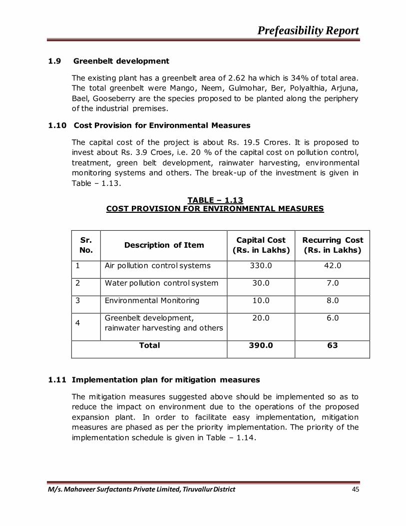
1.10 Cost Provision for Environmental Measures
The capital cost of the project is about Rs. 19.5 Crores. It is proposed to
invest about Rs. 3.9 Croes, i.e. 20 % of the capital cost on pollution control,
treatment, green belt development, rainwater harvesting, environmental
monitoring systems and others. The break-up of the investment is given in
Table – 1.13.
TABLE – 1.13 COST PROVISION FOR ENVIRONMENTAL MEASURES
Sr.
No. Description of Item
Capital Cost
(Rs. in Lakhs)
Recurring Cost
(Rs. in Lakhs)
1 Air pollution control systems 330.0 42.0
2 Water pollution control system 30.0 7.0
3 Environmental Monitoring 10.0 8.0
4 Greenbelt development,
rainwater harvesting and others
20.0 6.0
Total 390.0 63
1.11 Implementation plan for mitigation measures
The mitigation measures suggested above should be implemented so as to
reduce the impact on environment due to the operations of the proposed
expansion plant. In order to facilitate easy implementation, mitigation
measures are phased as per the priority implementation. The priority of the
implementation schedule is given in Table – 1.14.

Prefeasibility Report
M/s. Mahaveer Surfactants Private Limited, Tiruvallur District 46
TABLE – 1.14
IMPLEMENTATION SCHEDULE
Sr. No. Recommendations Time Requirement
1 Air pollution control
measures Before commissioning project
2 Water pollution control
measures Before commissioning project
3 Noise control measures Along with the commissioning
4 Green belt development Immediately
5 Ecological preservation
and up gradation Stage wise implementation
6 Corporate social
Responsibility (CSR) Before commissioning project
1.8 ORGANISATIONAL STRUCTURE
FIGURE – 28 ORGANISATIONAL STRUCTURE

Prefeasibility Report
M/s. Mahaveer Surfactants Private Limited, Tiruvallur District 47
ANNEXURE – I

Prefeasibility Report
M/s. Mahaveer Surfactants Private Limited, Tiruvallur District 48

Prefeasibility Report
M/s. Mahaveer Surfactants Private Limited, Tiruvallur District 49

Prefeasibility Report
M/s. Mahaveer Surfactants Private Limited, Tiruvallur District 50
ANNEXURE – II
TABLE – 1.14 SUMMARY OF THE PROJECT COST
Sr.No. Particulars
Cost RS in Lacs
1 Civil Works 39400000
2 Sulfonation Plant & Machineries 120000000
3 Utilities 36250000
Total Project Cost 195650000