Embed Size (px)
Citation preview
PREFEASIBILITY REPORT
FOR
“Proposed New Component
(Zinc Di-Thio Phosphate) Manufacturing Unit
at Existing Facility”
BY
Indian additives LTD
AT
VILLAGE: Manali
Taluk: Thiruvottiyur
DISTrict: Thirvallur
STATE: TAMIL NADU
i
Table of Contents 1. EXECUTIVE SUMMARY ........................................................................................................ 1
2. INTRODUCTION OF THE PROJECT ................................................................................... 3
2.1 Introduction about the company......................................................................................... 3
2.2 Brief Description of the Project ........................................................................................... 4
2.3 Project Benefits................................................................................................................... 4
3. PROJECT DESCRIPTION ...................................................................................................... 6
3.1 Type of the Project .............................................................................................................. 6
3.2 Project Location .................................................................................................................. 6
3.3 Products Manufactured ...................................................................................................... 8
3.4 Manufacturing Process Description ..................................................................................... 8
3.4.1 Zinc Di-Thio Phospate (ZDTP) Plant .......................................................................... 8
3.5 Raw Material Requirement ................................................................................................10
3.6 Utilities ..............................................................................................................................10
3.7 Power and Fuels.................................................................................................................11
3.8 Water Requirement ...........................................................................................................12
3.9 Landuse .............................................................................................................................13
3.10 Manpower .........................................................................................................................14
3.11 Liquid Waste Management ................................................................................................14
3.11.1 Treatment of Lquid Waste ........................................................................................15
3.11.1.1 Effluent Treatment Plant (ETP)Description .........................................................15
3.12 Air Pollution Control Measures ..........................................................................................19
3.12.1 H2S off gas treatement facility .................................................................................19
3.13 Hazardous and Solid waste Management ...........................................................................22
3.14 Greenbelt Development .....................................................................................................24
3.15 Environment, Safety and Health Monitoring ......................................................................24
4. SITE ANALYSIS ................................................................................................................... 26
4.1 Connectivity .......................................................................................................................26
4.2 Land form, land use, land ownership ..................................................................................26
4.3 Existing land use pattern ....................................................................................................26
4.4 Climatic Conditions ............................................................................................................26
4.5 Social infrastructure available ............................................................................................27
5. Conclusion ........................................................................................................................... 29
ii
List of Tables
Table 3.1 List of products manufactured ......................................................................................... 8
Table 3.2 List of Raw materials .......................................................................................................10
Table 3.3 Capacity of DG, Boilers and Thermic fluid Heaters .........................................................11
Table 3.5Water Requirement and Recycling ...................................................................................12
Table 3.6Land Use within the Site ...................................................................................................14
Table 3.7 Wastewater Generation ...................................................................................................14
Table 3.8 Existing & proposed Stack/ Ventdetails ..........................................................................21
Table 3.10Non-Hazardous wastes ...................................................................................................23
Table 4.1Nearby areas from site Boundary ....................................................................................26
Table 4.2Meterological Observations ..............................................................................................27
Table 4.3 Proposed project surrounding features ..........................................................................28
List of Figures
Figure 3-1 Location of Proposed Project Site ................................................................................... 7
Figure 3-2 Satellite Image of the Site & its 10Km Radius................................................................. 7
Figure 3-3 ZDTP Process Flow Diagram .......................................................................................... 9
Figure 3-4ETP and STP Process Flow Disgram ...............................................................................18
Figure 3-5 H2S Treatment System ..................................................................................................20
Prefeasibility Report for Proposed New Component (ZDTP) Manufacturing Unit by IAL
1
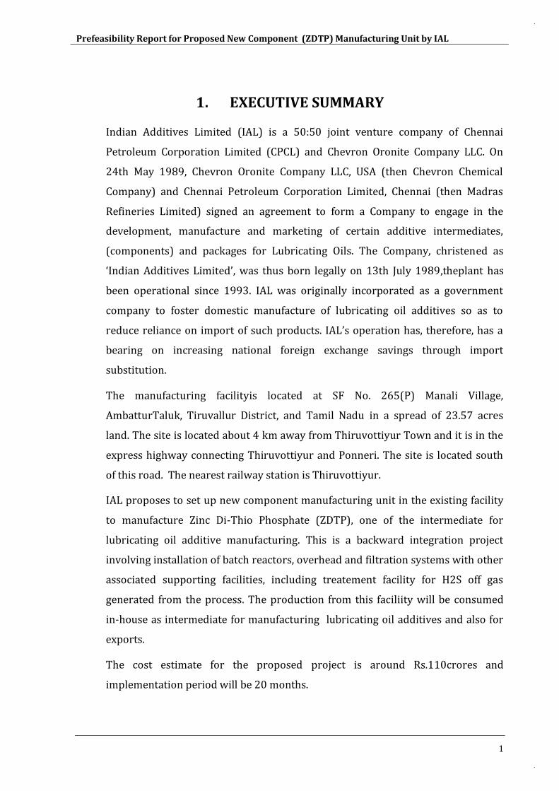
1. EXECUTIVE SUMMARY
Indian Additives Limited (IAL) is a 50:50 joint venture company of Chennai
Petroleum Corporation Limited (CPCL) and Chevron Oronite Company LLC. On
24th May 1989, Chevron Oronite Company LLC, USA (then Chevron Chemical
Company) and Chennai Petroleum Corporation Limited, Chennai (then Madras
Refineries Limited) signed an agreement to form a Company to engage in the
development, manufacture and marketing of certain additive intermediates,
(components) and packages for Lubricating Oils. The Company, christened as
‘Indian Additives Limited’, was thus born legally on 13th July 1989,theplant has
been operational since 1993. IAL was originally incorporated as a government
company to foster domestic manufacture of lubricating oil additives so as to
reduce reliance on import of such products. IAL’s operation has, therefore, has a
bearing on increasing national foreign exchange savings through import
substitution.
The manufacturing facilityis located at SF No. 265(P) Manali Village,
AmbatturTaluk, Tiruvallur District, and Tamil Nadu in a spread of 23.57 acres
land. The site is located about 4 km away from Thiruvottiyur Town and it is in the
express highway connecting Thiruvottiyur and Ponneri. The site is located south
of this road. The nearest railway station is Thiruvottiyur.
IAL proposes to set up new component manufacturing unit in the existing facility
to manufacture Zinc Di-Thio Phosphate (ZDTP), one of the intermediate for
lubricating oil additive manufacturing. This is a backward integration project
involving installation of batch reactors, overhead and filtration systems with other
associated supporting facilities, including treatement facility for H2S off gas
generated from the process. The production from this faciliity will be consumed
in-house as intermediate for manufacturing lubricating oil additives and also for
exports.
The cost estimate for the proposed project is around Rs.110crores and
implementation period will be 20 months.
Prefeasibility Report for Proposed New Component (ZDTP) Manufacturing Unit by IAL
2
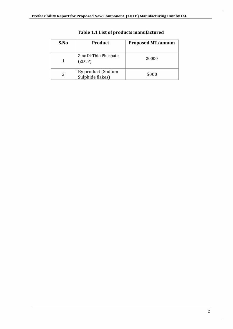
Table 1.1 List of products manufactured
S.No Product Proposed MT/annum
1 Zinc Di-Thio Phospate
(ZDTP) 20000
2 By product (Sodium Sulphide flakes)
5000
Prefeasibility Report for Proposed New Component (ZDTP) Manufacturing Unit by IAL
3
2. INTRODUCTION OF THE PROJECT
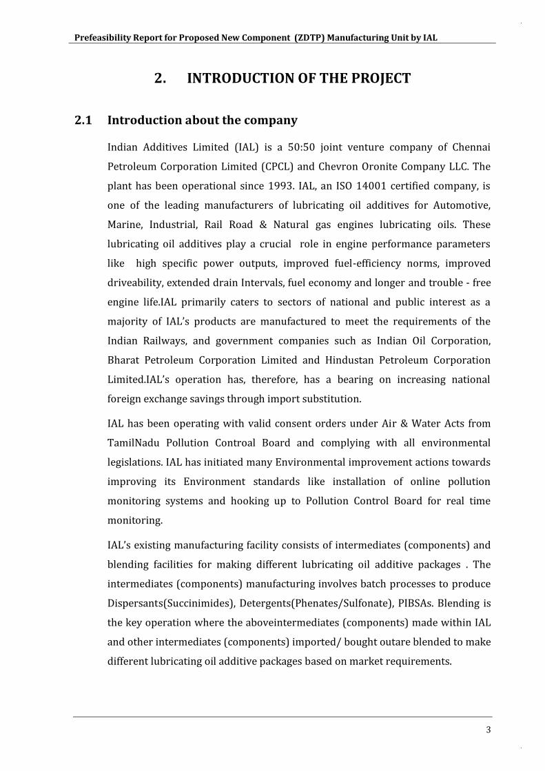
2.1 Introduction about the company
Indian Additives Limited (IAL) is a 50:50 joint venture company of Chennai
Petroleum Corporation Limited (CPCL) and Chevron Oronite Company LLC. The
plant has been operational since 1993. IAL, an ISO 14001 certified company, is
one of the leading manufacturers of lubricating oil additives for Automotive,
Marine, Industrial, Rail Road & Natural gas engines lubricating oils. These
lubricating oil additives play a crucial role in engine performance parameters
like high specific power outputs, improved fuel-efficiency norms, improved
driveability, extended drain Intervals, fuel economy and longer and trouble - free
engine life.IAL primarily caters to sectors of national and public interest as a
majority of IAL’s products are manufactured to meet the requirements of the
Indian Railways, and government companies such as Indian Oil Corporation,
Bharat Petroleum Corporation Limited and Hindustan Petroleum Corporation
Limited.IAL’s operation has, therefore, has a bearing on increasing national
foreign exchange savings through import substitution.
IAL has been operating with valid consent orders under Air & Water Acts from
TamilNadu Pollution Controal Board and complying with all environmental
legislations. IAL has initiated many Environmental improvement actions towards
improving its Environment standards like installation of online pollution
monitoring systems and hooking up to Pollution Control Board for real time
monitoring.
IAL’s existing manufacturing facility consists of intermediates (components) and
blending facilities for making different lubricating oil additive packages . The
intermediates (components) manufacturing involves batch processes to produce
Dispersants(Succinimides), Detergents(Phenates/Sulfonate), PIBSAs. Blending is
the key operation where the aboveintermediates (components) made within IAL
and other intermediates (components) imported/ bought outare blended to make
different lubricating oil additive packages based on market requirements.
Prefeasibility Report for Proposed New Component (ZDTP) Manufacturing Unit by IAL
4
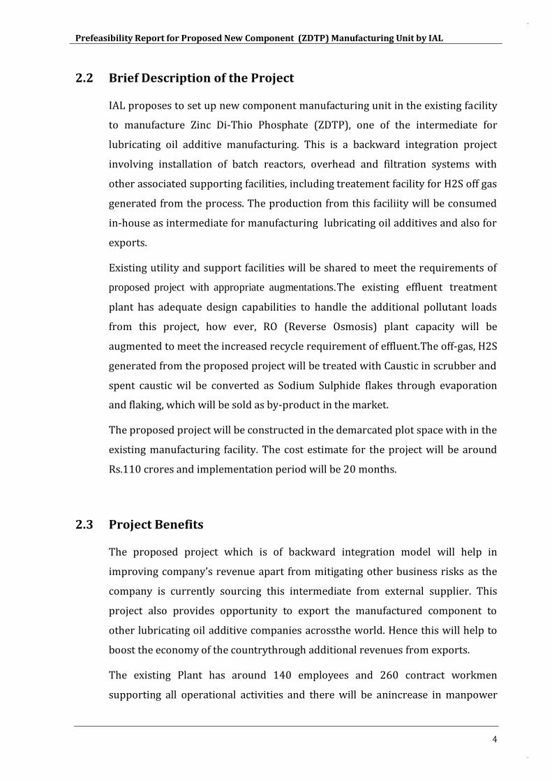
2.2 Brief Description of the Project
IAL proposes to set up new component manufacturing unit in the existing facility
to manufacture Zinc Di-Thio Phosphate (ZDTP), one of the intermediate for
lubricating oil additive manufacturing. This is a backward integration project
involving installation of batch reactors, overhead and filtration systems with
other associated supporting facilities, including treatement facility for H2S off gas
generated from the process. The production from this faciliity will be consumed
in-house as intermediate for manufacturing lubricating oil additives and also for
exports.
Existing utility and support facilities will be shared to meet the requirements of
proposed project with appropriate augmentations.The existing effluent treatment
plant has adequate design capabilities to handle the additional pollutant loads
from this project, how ever, RO (Reverse Osmosis) plant capacity will be
augmented to meet the increased recycle requirement of effluent.The off-gas, H2S
generated from the proposed project will be treated with Caustic in scrubber and
spent caustic wil be converted as Sodium Sulphide flakes through evaporation
and flaking, which will be sold as by-product in the market.
The proposed project will be constructed in the demarcated plot space with in the
existing manufacturing facility. The cost estimate for the project will be around
Rs.110 crores and implementation period will be 20 months.
2.3 Project Benefits
The proposed project which is of backward integration model will help in
improving company’s revenue apart from mitigating other business risks as the
company is currently sourcing this intermediate from external supplier. This
project also provides opportunity to export the manufactured component to
other lubricating oil additive companies acrossthe world. Hence this will help to
boost the economy of the countrythrough additional revenues from exports.
The existing Plant has around 140 employees and 260 contract workmen
supporting all operational activities and there will be anincrease in manpower

Prefeasibility Report for Proposed New Component (ZDTP) Manufacturing Unit by IAL
5
after this proposed project to atotal of156 employees and 300 contract workmen.
Apart from this, there will also be a considerable increase in indirect employment
on account of increased material movements.
Prefeasibility Report for Proposed New Component (ZDTP) Manufacturing Unit by IAL
6
3. PROJECT DESCRIPTION
3.1 Type of the Project IAL proposes to set up new component manufacturing unit in the existing facility
to manufacture Zinc Di-Thio Phosphate (ZDTP), one of the intermediate for
lubricating oil additive manufacturing. This is a backward integration project
involving installation of batch reactors, overhead and filtration systems with
other associated supporting facilities, including treatement facility for H2S off gas
generated from the process. The production from this faciliity will be consumed
in-house as intermediate for manufacturing lubricating oil additives and also for
exports.
The proposed project falls under the schedule 5 (f) as per the EIA notification
dated September 14, 2006 and its amendments. There is no interlinked project.
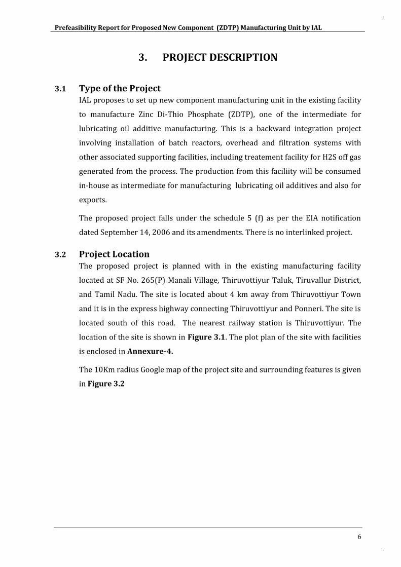
3.2 Project Location The proposed project is planned with in the existing manufacturing facility
located at SF No. 265(P) Manali Village, Thiruvottiyur Taluk, Tiruvallur District,
and Tamil Nadu. The site is located about 4 km away from Thiruvottiyur Town
and it is in the express highway connecting Thiruvottiyur and Ponneri. The site is
located south of this road. The nearest railway station is Thiruvottiyur. The
location of the site is shown in Figure 3.1. The plot plan of the site with facilities
is enclosed in Annexure-4.
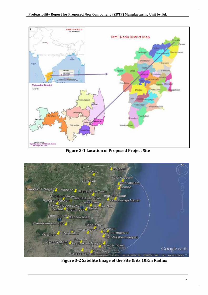
The 10Km radius Google map of the project site and surrounding features is given
in Figure 3.2
Prefeasibility Report for Proposed New Component (ZDTP) Manufacturing Unit by IAL
7
Figure 3-1 Location of Proposed Project Site
Figure 3-2 Satellite Image of the Site & its 10Km Radius
Prefeasibility Report for Proposed New Component (ZDTP) Manufacturing Unit by IAL
8
3.3 Products Manufactured The list of products proposed is given in Table 3-1 below.
Table 3.1 List of products manufactured
S.No Product Proposed
MT/annum
1 Zinc Di-Thio Phospate
(ZDTP) 20000
2 By product (Sodium Sulphide flakes)
5000
3.4 Manufacturing Process Description A brief process description for manufacturing this component (ZDTP)is given
below:
3.4.1 Zinc Di-Thio Phospate (ZDTP) Plant
The ZDTP plant is designed to produce 20000tons/annum of ZDTP. This is
produced by reacting mixed alcohol (Secondary Butyl Alcohol and methyl ISo-
Butyl carbinol) with Phosporous Penta Sulfide (P2S5)and Zinc oxide (ZnO) in the
presence of promoter acetic acid.
The ZDTP plant consists of a steam coiled reactor, a reactor overhead system
with steam vacuum pump, a neutralizer reactor, wiped film evaporator and a
filtration section.
The ZDTP manufacturing operation is a batch process. The mixed alcohol and
P2S5 are mixed with lube oilin the reactor. This forms acid which will be
neutralized with zinc oxide to form crude component. Hydrogen sulfide and
water are formed aspart of this reaction. The overhead streamcontaining
Hydrogen Sulfide (H2S) is treated with Caustic in scrubber and spent caustic
containing Sodium Sulphide is then converted to Sodium Sulphide flakes (by-
product) throughevaporation and flakingprocesses.
Prefeasibility Report for Proposed New Component (ZDTP) Manufacturing Unit by IAL
9
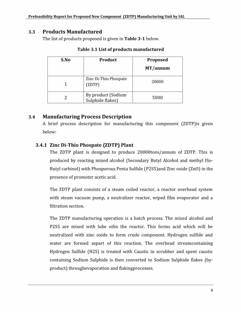
From the neutralizer, the crude ZDTP product is sent to the wiped film
evaporation section to strip out the unreacted solventsin the crude. The spent
solventwill bedisposed to third party as per PCB authorization. From the
evaporator, the crude ZDTP product is sent to the filtration section for filtration.
The final product is stored in component storage tanks. The remnant left in the
filter is filter cake which will be collected in barrels and disposed to third party
as per PCB authorization.
Figure 3-3 ZDTP Process Flow Diagram
ZDTP process flow diagram - IAL
DTPA reactor
Neutraliser
Wiped Film Evaporator
SBA
MIBC
H2S to Scrubber system
Acetic acid
Zinc oxide
Filter feed tank
Schenk filter
ZDTP Storage tanks
Filter Aid
Filter Aid
Precoat tankLube oil
Filter cake
Crude ZDTP tank
Lube oil
P2S5
Spent Solvent
Prefeasibility Report for Proposed New Component (ZDTP) Manufacturing Unit by IAL
10
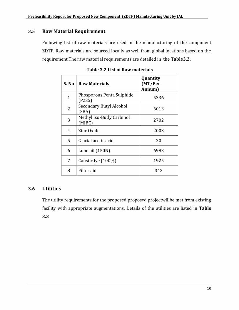
3.5 Raw Material Requirement
Following list of raw materials are used in the manufacturing of the component
ZDTP. Raw materials are sourced locally as well from global locations based on the
requirement.The raw material requirements are detailed in the Table3.2.
Table 3.2 List of Raw materials
S. No Raw Materials Quantity (MT/Per Annum)
1 Phosporous Penta Sulphide (P2S5)
5336
2 Secondary Butyl Alcohol (SBA)
6013
3 Methyl Iso-Butly Carbinol (MIBC)
2702
4 Zinc Oxide 2003
5 Glacial acetic acid 20
6 Lube oil (150N) 6983
7 Caustic lye (100%) 1925
8 Filter aid 342
3.6 Utilities
The utility requirements for the proposed proposed projectwillbe met from existing
facility with appropriate augmentations. Details of the utilities are listed in Table
3.3
Prefeasibility Report for Proposed New Component (ZDTP) Manufacturing Unit by IAL
11
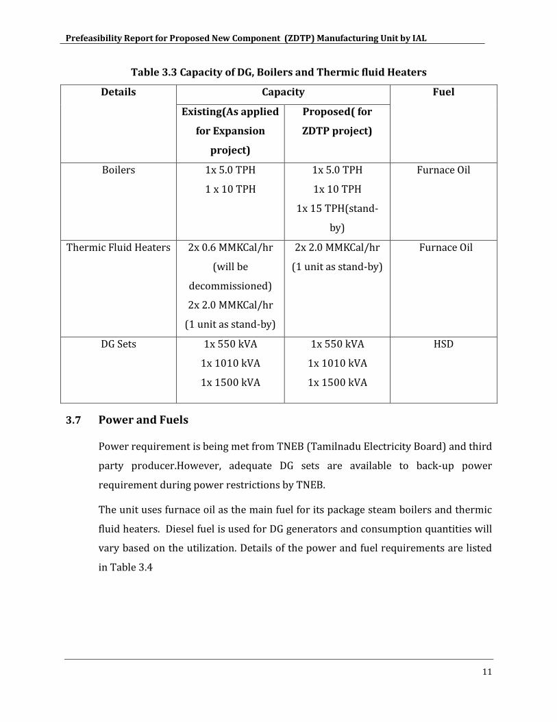
Table 3.3 Capacity of DG, Boilers and Thermic fluid Heaters
Details Capacity Fuel
Existing(As applied
for Expansion
project)
Proposed( for
ZDTP project)
Boilers 1x 5.0 TPH
1 x 10 TPH
1x 5.0 TPH
1x 10 TPH
1x 15 TPH(stand-
by)
Furnace Oil
Thermic Fluid Heaters 2x 0.6 MMKCal/hr
(will be
decommissioned)
2x 2.0 MMKCal/hr
(1 unit as stand-by)
2x 2.0 MMKCal/hr
(1 unit as stand-by)
Furnace Oil
DG Sets 1x 550 kVA
1x 10¹⁰ kVA
1x 1500 kVA
1x 550 kVA
1x 10¹⁰ kVA
1x 1500 kVA
HSD
3.7 Power and Fuels
Power requirement is being met from TNEB (Tamilnadu Electricity Board) and third
party producer.However, adequate DG sets are available to back-up power
requirement during power restrictions by TNEB.
The unit uses furnace oil as the main fuel for its package steam boilers and thermic
fluid heaters. Diesel fuel is used for DG generators and consumption quantities will
vary based on the utilization. Details of the power and fuel requirements are listed
in Table 3.4
Prefeasibility Report for Proposed New Component (ZDTP) Manufacturing Unit by IAL
12
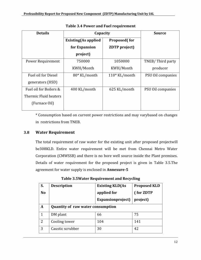
Table 3.4 Power and Fuel requirement
Details Capacity Source
Existing(As applied
for Expansion
project)
Proposed( for
ZDTP project)
Power Requirement 750000
KWH/Month
1050000
KWH/Month
TNEB/ Third party
producer
Fuel oil for Diesel
generators (HSD)
80* KL/month 110* KL/month PSU Oil companies
Fuel oil for Boilers &
Thermic Fluid heaters
(Furnace Oil)
400 KL/month 625 KL/month PSU Oil companies
* Consumption based on current power restrictions and may varybased on changes
in restrictions from TNEB.
3.8 Water Requirement
The total requirement of raw water for the existing unit after proposed projectwill
be308KLD. Entire water requirement will be met from Chennai Metro Water
Corporation (CMWSSB) and there is no bore well source inside the Plant premises.
Details of water requirement for the proposed project is given in Table 3.5.The
agreement for water supply is enclosed in Annexure-5
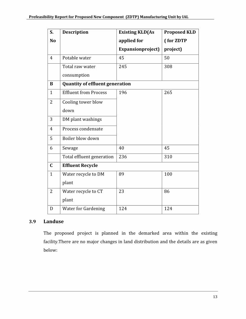
Table 3.5Water Requirement and Recycling
S.
No
Description Existing KLD(As
applied for
Expansionproject)
Proposed KLD
( for ZDTP
project)
A Quantity of raw water consumption
1 DM plant 66 75
2 Cooling tower 104 141
3 Caustic scrubber 30 42
Prefeasibility Report for Proposed New Component (ZDTP) Manufacturing Unit by IAL
13
S.
No
Description Existing KLD(As
applied for
Expansionproject)
Proposed KLD
( for ZDTP
project)
4 Potable water 45 50
Total raw water
consumption
245 308
B Quantity of effluent generation
1 Effluent from Process 196 265
2 Cooling tower blow
down
3 DM plant washings
4 Process condensate
5 Boiler blow down
6 Sewage 40 45
Total effluent generation 236 310
C Effluent Recycle
1 Water recycle to DM
plant
89 100
2 Water recycle to CT
plant
23 86
D Water for Gardening 124 124
3.9 Landuse
The proposed project is planned in the demarked area within the existing
facility.There are no major changes in land distribution and the details are as given
below:
Prefeasibility Report for Proposed New Component (ZDTP) Manufacturing Unit by IAL
14
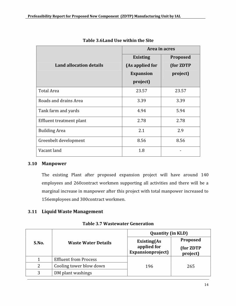
Table 3.6Land Use within the Site
Land allocation details
Area in acres
Existing
(As applied for
Expansion
project)
Proposed
(for ZDTP
project)
Total Area 23.57 23.57
Roads and drains Area 3.39 3.39
Tank farm and yards 4.94 5.94
Effluent treatment plant 2.78 2.78
Building Area 2.1 2.9
Greenbelt development 8.56 8.56
Vacant land 1.8 -
3.10 Manpower
The existing Plant after proposed expansion project will have around 140
employees and 260contract workmen supporting all activities and there will be a
marginal increase in manpower after this project with total manpower increased to
156employees and 300contract workmen.
3.11 Liquid Waste Management
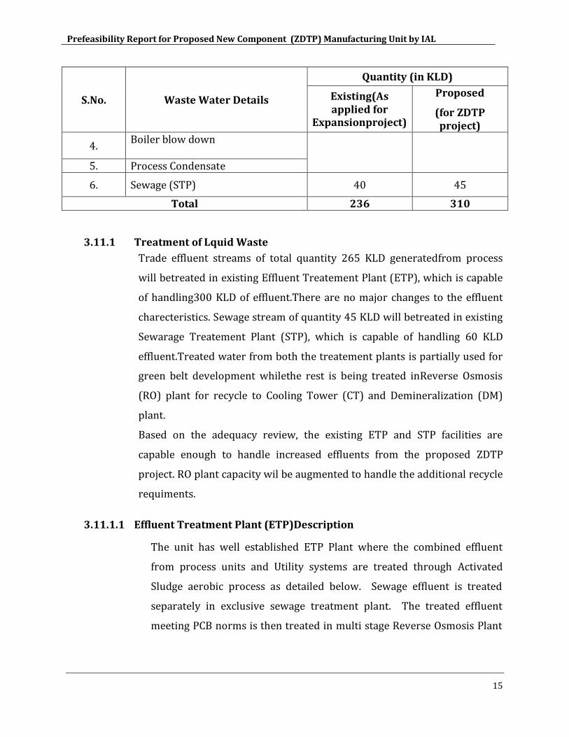
Table 3.7 Wastewater Generation
S.No. Waste Water Details
Quantity (in KLD)
Existing(As applied for
Expansionproject)
Proposed
(for ZDTP project)
1 Effluent from Process
196 265 2 Cooling tower blow down
3 DM plant washings
Prefeasibility Report for Proposed New Component (ZDTP) Manufacturing Unit by IAL
15
S.No. Waste Water Details
Quantity (in KLD)
Existing(As applied for
Expansionproject)
Proposed
(for ZDTP project)
4. Boiler blow down
5. Process Condensate
6. Sewage (STP) 40 45
Total 236 310
3.11.1 Treatment of Lquid Waste
Trade effluent streams of total quantity 265 KLD generatedfrom process
will betreated in existing Effluent Treatement Plant (ETP), which is capable
of handling300 KLD of effluent.There are no major changes to the effluent
charecteristics. Sewage stream of quantity 45 KLD will betreated in existing
Sewarage Treatement Plant (STP), which is capable of handling 60 KLD
effluent.Treated water from both the treatement plants is partially used for
green belt development whilethe rest is being treated inReverse Osmosis
(RO) plant for recycle to Cooling Tower (CT) and Demineralization (DM)
plant.
Based on the adequacy review, the existing ETP and STP facilities are
capable enough to handle increased effluents from the proposed ZDTP
project. RO plant capacity wil be augmented to handle the additional recycle
requiments.
3.11.1.1 Effluent Treatment Plant (ETP)Description
The unit has well established ETP Plant where the combined effluent
from process units and Utility systems are treated through Activated
Sludge aerobic process as detailed below. Sewage effluent is treated
separately in exclusive sewage treatment plant. The treated effluent
meeting PCB norms is then treated in multi stage Reverse Osmosis Plant
Prefeasibility Report for Proposed New Component (ZDTP) Manufacturing Unit by IAL
16
for recycle into process while the rejects are concentrated to salts in
multiple effect evaporators for disposal.
There are three effluent streams generated in the plant depending upon
the place of origin.
a) Stream A
Basically consist of process waste water, wash/storm water from
curbed process area, process wash downs, and streams from lab,
pump leakage, storm water from truck loading and tank farm
areas. This stream contains oil and other Chemicals.
b) Stream B
Consist of cooling tower blow down, Boiler blow down and DM
plant regeneration wastes.
c) Stream C
Sanitary waste water – Treated in a Separate Sewage Treatment
Plant (STP)
The effluent treatment plant basically consists of three sections:
Oil/water separation and oil recovery.
Treatment of separator water and its disposal.
Sludge Digestion, thickening and dewatering
The free-floating oil in the process effluents from various unit
processes is removed by skimmers and corrugated float separator
units. The emulsified oil in the effluent stream is removed by
dissolved floatation techniques. These various steps of oil removal
enable a reduction in the Bio-chemical Oxygen demand
contributed by the oil.
In the oil –water mixture, the free oil due to its relative lower
specific gravity, floats on the surface which is removed by
mechanical skimming. The collected process effluent is pumped to
cross flow separator (CFS) where further free oil is removed. The
Prefeasibility Report for Proposed New Component (ZDTP) Manufacturing Unit by IAL
17
effluent from CFS bearing certain amount of emulsified oil and free
oil is sent to Dissolved Air floatation unit (DAF) through a Surge
Pond. The DAF unit acts as secondary treatment in the removal of
oil.
The out let of the DAF unit is sent to Equalization basin where the
utility stream is mixed. The combined effluent is subjected to
biological treatment based on activated sludge system.(Aerobic
Process) An activated sludge unit consisting of an aeration basin
and a clarifier removes dissolved organic contaminants. The waste
biological sludge is sent to a sludge digester where it is further
degraded the water from the digester is sent back for treatment
and the digested sludge is sent to dewatering facility. The
dewatered sludge is sent to solar ponds for drying. The treated
water is pumped to surge pond (west) The treated water is used
for firefighting, gardening. The treated water is partially sent to RO
plant for further processing &recycle to plant for usage in DM
plant and Cooling Tower and the remaining water is used for
gardening/green belt activities.
The Sanitary waste water (Stream C) is separately treated in a
Sewage Treatment Plant (S.T.P). The treated water is transferred
to Surge pond (West).
The Process flow Diiagram of ETP and STP are given in Figure 3.4
Online monitoring of parameters (pH & TDS) for treated effluent
from ETP done and it is also connected with CAC, TNPCB.
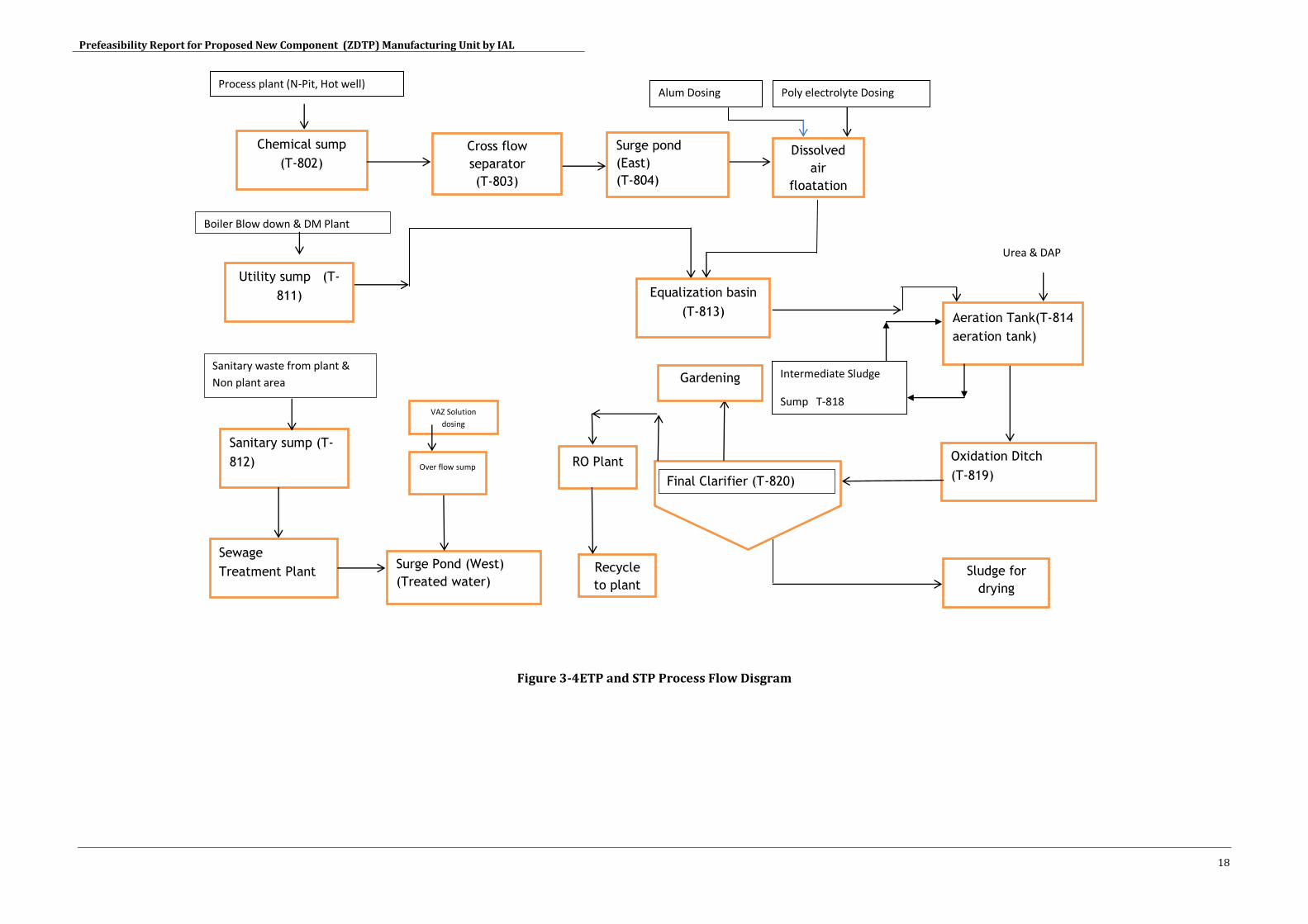
Prefeasibility Report for Proposed New Component (ZDTP) Manufacturing Unit by IAL
18
Figure 3-4ETP and STP Process Flow Disgram
Oxidation Ditch
(T-819)
Chemical sump
(T-802)
Process plant (N-Pit, Hot well)
Utility sump (T-
811)
Sanitary sump (T-
812)
Boiler Blow down & DM Plant
Sanitary waste from plant &
Non plant area
Cross flow
separator
(T-803)
Surge pond
(East)
(T-804)
Dissolved
air
floatation
(T-805)
)
Alum Dosing Poly electrolyte Dosing
Equalization basin
(T-813) Aeration Tank(T-814
aeration tank)
Surge Pond (West)
(Treated water)
9Treated
VAZ Solution
dosing
Sludge for
drying
Final Clarifier (T-820)
Intermediate Sludge
Sump T-818
Sewage
Treatment Plant
Urea & DAP
Over flow sump RO Plant
Recycle
to plant
Gardening
Prefeasibility Report for Proposed New Component (ZDTP) Manufacturing Unit by IAL
19
3.12 Air Pollution Control Measures
The existing/ proposed package boilers, thermic fluid heaters and DG sets are of
highly efficient in terms of combustion control and featured with in-built pollution
control design. Hence the pollutant load from theseunits will be minimal which
finally been vented through chimneys of appropriate height.
The unit has also installed online stack monitoring station (CEMS) for Hot oil stack
and boiler stack and connected with Care Air Center (TNPCB). PM, SOX& NOX are
being analyzed. 12 Nos of H2S sensor installed in different areas of plant permises to
monitor H2S. H2S sensor at the caustic scrubbers ventswill behooked upto CAC,
TNPCB.
The unit has installed Online Ambient Air Quality (AAQ) monitoring station and it is
connected with Care Air Center (CAC), TNPCB. PM10, SOX, NOX, CO, NO, NO2& 03 are
the parameters which are being analyzed.The unit has also installed continuous
VOC monitors in the plant.
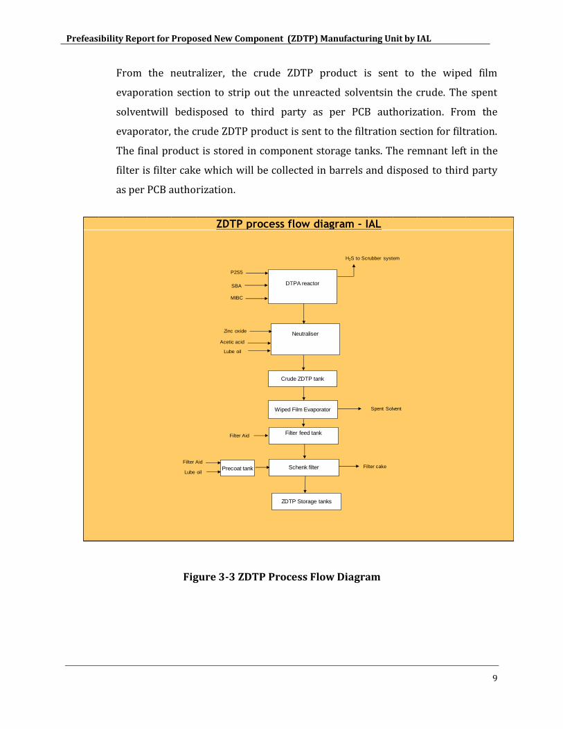
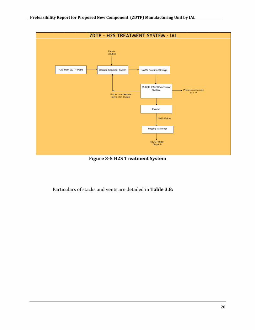
3.12.1 H2S off gas treatement facility
H2S generated from the ZDTP plant is treated in dedicated Caustic scrubber
system and converted to ~ 13 to 15% Sodium sulphide (Na2S) solution. The
Na2S solution is further concentrated in Multiple Effect Evaporators (MEE)
system and then flaking is done in flakers to manufacture Na2S flakes. The
process condensate from the MEE system is recycled back to Caustic
scrubber system for caustic dilution and the balance is sent to ETP for
treatment. The Na2S flakes from flakers are baggedand sold as by product in
the market to textile, paper and leather industries.
Prefeasibility Report for Proposed New Component (ZDTP) Manufacturing Unit by IAL
20
Figure 3-5 H2S Treatment System
Particulars of stacks and vents are detailed in Table 3.8:
ZDTP - H2S TREATMENT SYSTEM - IAL
H2S from ZDTP Plant
Multiple Effect Evaporator System
Flakers
Process condensate to ETP
Bagging & Storage
Na2S Solution Storage
Na2S Flakes
Caustic Scrubber Sytem
Caustic Solution
Na2S Flakes Dispatch
Process condensate recycle for dilution
Prefeasibility Report for Proposed New Component (ZDTP) Manufacturing Unit by IAL
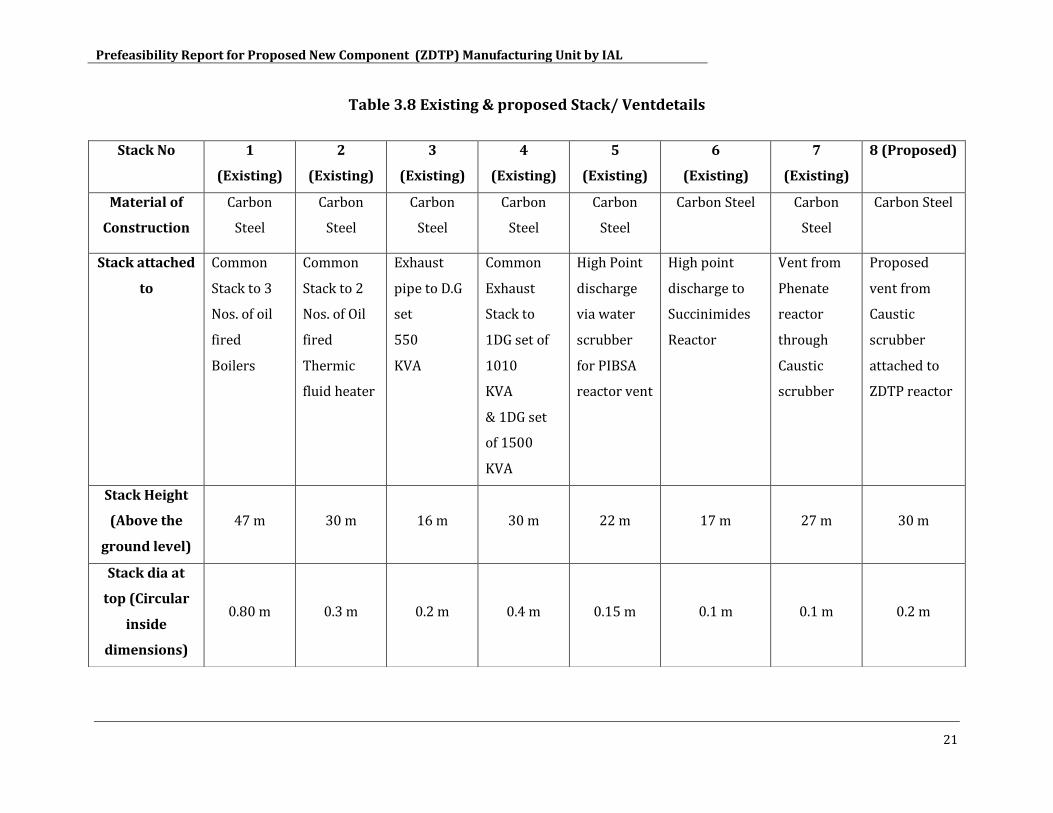
21
Table 3.8 Existing & proposed Stack/ Ventdetails
Stack No 1
(Existing)
2
(Existing)
3
(Existing)
4
(Existing)
5
(Existing)
6
(Existing)
7
(Existing)
8 (Proposed)
Material of
Construction
Carbon
Steel
Carbon
Steel
Carbon
Steel
Carbon
Steel
Carbon
Steel
Carbon Steel Carbon
Steel
Carbon Steel
Stack attached
to
Common
Stack to 3
Nos. of oil
fired
Boilers
Common
Stack to 2
Nos. of Oil
fired
Thermic
fluid heater
Exhaust
pipe to D.G
set
550
KVA
Common
Exhaust
Stack to
1DG set of
1010
KVA
& 1DG set
of 1500
KVA
High Point
discharge
via water
scrubber
for PIBSA
reactor vent
High point
discharge to
Succinimides
Reactor
Vent from
Phenate
reactor
through
Caustic
scrubber
Proposed
vent from
Caustic
scrubber
attached to
ZDTP reactor
Stack Height
(Above the
ground level)
47 m 30 m 16 m 30 m 22 m 17 m 27 m 30 m
Stack dia at
top (Circular
inside
dimensions)
0.80 m 0.3 m 0.2 m 0.4 m 0.15 m 0.1 m 0.1 m 0.2 m
Prefeasibility Report for Proposed New Component (ZDTP) Manufacturing Unit by IAL
22
Existing/ proposed air pollution control measures are adequately sized to handle
the increased pollutant loads.
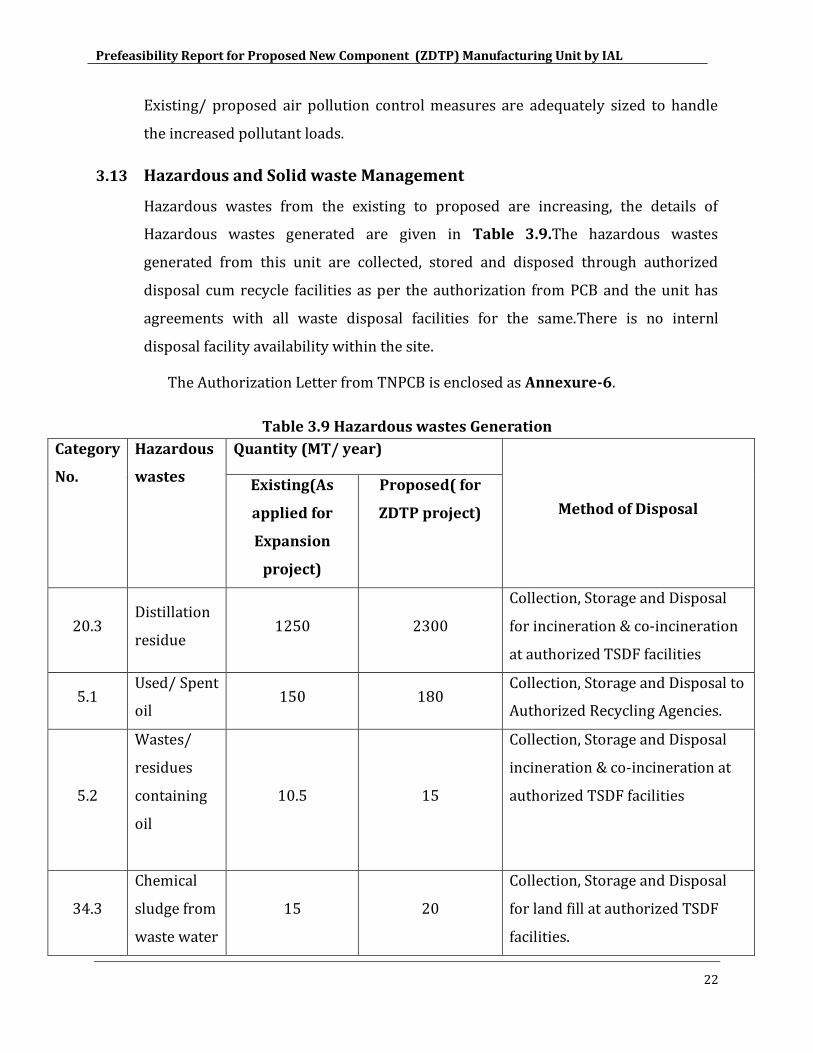
3.13 Hazardous and Solid waste Management
Hazardous wastes from the existing to proposed are increasing, the details of
Hazardous wastes generated are given in Table 3.9.The hazardous wastes
generated from this unit are collected, stored and disposed through authorized
disposal cum recycle facilities as per the authorization from PCB and the unit has
agreements with all waste disposal facilities for the same.There is no internl
disposal facility availability within the site.
The Authorization Letter from TNPCB is enclosed as Annexure-6.
Table 3.9 Hazardous wastes Generation
Category
No.
Hazardous
wastes
Quantity (MT/ year)
Method of Disposal
Existing(As
applied for
Expansion
project)
Proposed( for
ZDTP project)
20.3 Distillation
residue 1250 2300
Collection, Storage and Disposal
for incineration & co-incineration
at authorized TSDF facilities
5.1 Used/ Spent
oil 150 180
Collection, Storage and Disposal to
Authorized Recycling Agencies.
5.2
Wastes/
residues
containing
oil
10.5 15
Collection, Storage and Disposal
incineration & co-incineration at
authorized TSDF facilities
34.3
Chemical
sludge from
waste water
15 20
Collection, Storage and Disposal
for land fill at authorized TSDF
facilities.
Prefeasibility Report for Proposed New Component (ZDTP) Manufacturing Unit by IAL
23
Category
No.
Hazardous
wastes
Quantity (MT/ year)
Method of Disposal
Existing(As
applied for
Expansion
project)
Proposed( for
ZDTP project)
treatment
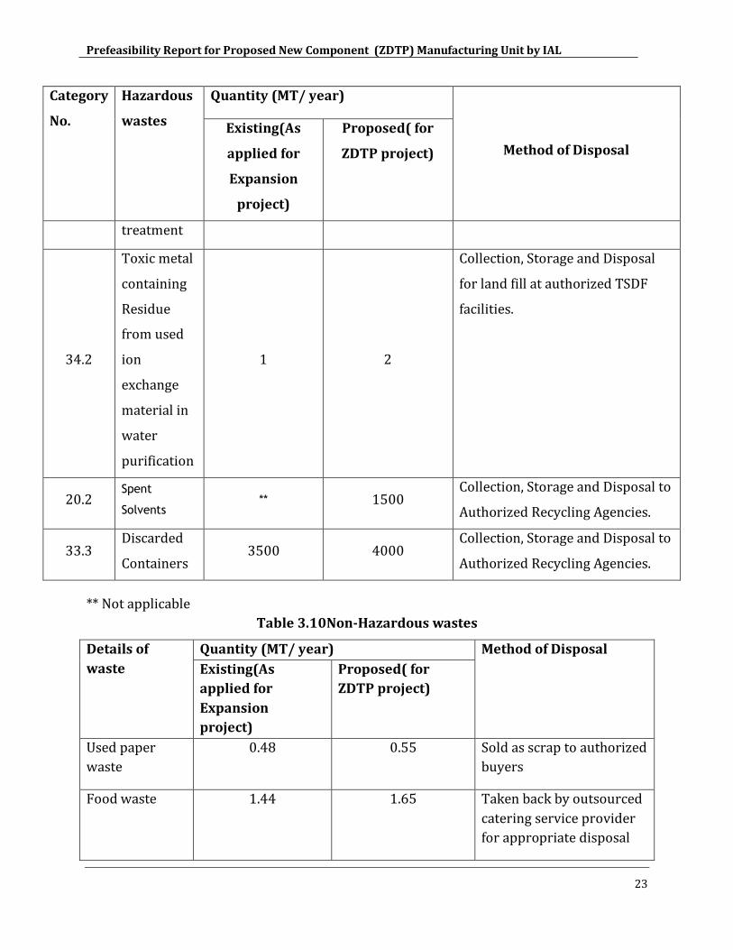
34.2
Toxic metal
containing
Residue
from used
ion
exchange
material in
water
purification
1 2
Collection, Storage and Disposal
for land fill at authorized TSDF
facilities.
20.2 Spent
Solvents ** 1500
Collection, Storage and Disposal to
Authorized Recycling Agencies.
33.3 Discarded
Containers 3500 4000
Collection, Storage and Disposal to
Authorized Recycling Agencies.
** Not applicable
Table 3.10Non-Hazardous wastes
Details of
waste
Quantity (MT/ year) Method of Disposal
Existing(As
applied for
Expansion
project)
Proposed( for
ZDTP project)
Used paper
waste
0.48 0.55 Sold as scrap to authorized
buyers
Food waste 1.44 1.65 Taken back by outsourced
catering service provider
for appropriate disposal
Prefeasibility Report for Proposed New Component (ZDTP) Manufacturing Unit by IAL
24
3.14 Greenbelt Development
Greenbelt is already developed inside the factory premises covering a total area of
about 8.56 acres which is more than 33% of the total area. The species and
plantation norms are followed as per the CPCB/ PCB directions.
3.15 Environment, Safety and Health Monitoring
The environment, safety and health-monitoring programme in the factory are as
follows:
Daily monitoring of water and wastewater
Online monitoring of stack, ambient air, weather and effluent parameters
Fortnight monitoring of ambient air
Monthly monitoring of noise and work place air
Monitoring of occupational safety
Yearly monitoring of occupational health.
To prevent air pollution, IAL has designed and installed the stacks of Boilers, Hot oil
units and DGs asper the guidelines of the central pollution control board (CPCB). IAL
has a robust and a highly reliable caustic scrubber system to prevent the release of
H2S vapours from Detergent plant to the atmosphere.
Online H2S sensor provided in caustic scrubber vent is hooked up with CARE AIR
CENTRE, TNPCB for continuous monitoring. IAL has totally 12 Nos H2S sensors
located in different areas of the plant to monitor and prevent H2S emissions.
IAL has installed Onlineambient air quality station (AAQ) and online stack
monitoring station (CEMS) and is connected with the Care Air Center, TNPCB. ,
PM10, SOX, NOX, CO, NO, NO2, VOC & 03are the parameters which are continuously
monitored and displayed. IAL has installed LED display for Online monitoring of
stack, AAQ and effluent parameters in the main gate for public viewing. IAL has
implemented various process improvement measures to reduce the generation of
hazardous wastes in each category. IAL’s hazardous waste generation has and
continues to be well within the limits authorized by the TNPCB.
Prefeasibility Report for Proposed New Component (ZDTP) Manufacturing Unit by IAL
25
In line with IAL's commitment towards environmental protection, IAL has made
considerable amount of investment of around Rs.400 lakhs in the past 2 years
towards various environmental improvement initiatives. Being a company with
significant government investment, IAL is proactive and committed towards
ensuring environmental compliance with applicable laws and standards. IAL has
never failed in complying with the environmental legislations and has always shown
a proactive approach in making its plant one of the best plants in terms of
environmental management. Local TNPCB officials showcase IAL as a role model to
their counterparts from other States.
Prefeasibility Report for Proposed New Component (ZDTP) Manufacturing Unit by IAL
26
4. SITE ANALYSIS
4.1 Connectivity
The proposed site on the SH – 56and it is in the express highway connecting
Thiruvottiyur and Ponneri. The site is located south of this road.
4.2 Land form, land use, land ownership
The Plant is located at SF No. 265(P) Manali Village, Thiruvottiyur Taluk, Tiruvallur
District, and Tamil Nadu. The present land use is industrial. The land documents
related to the site is enclosed in Annexure-2.
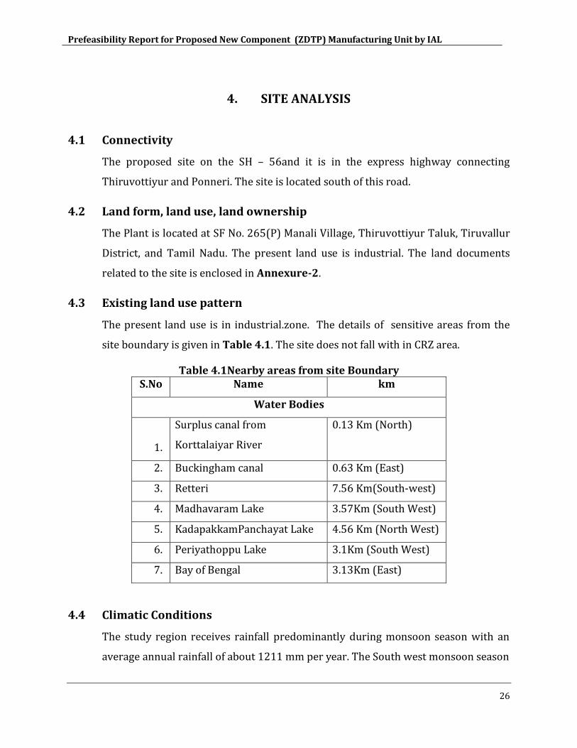
4.3 Existing land use pattern
The present land use is in industrial.zone. The details of sensitive areas from the
site boundary is given in Table 4.1. The site does not fall with in CRZ area.
Table 4.1Nearby areas from site Boundary S.No Name km
Water Bodies
1.
Surplus canal from
Korttalaiyar River
0.13 Km (North)
2. Buckingham canal 0.63 Km (East)
3. Retteri 7.56 Km(South-west)
4. Madhavaram Lake 3.57Km (South West)
5. KadapakkamPanchayat Lake 4.56 Km (North West)
6. Periyathoppu Lake 3.1Km (South West)
7. Bay of Bengal 3.13Km (East)
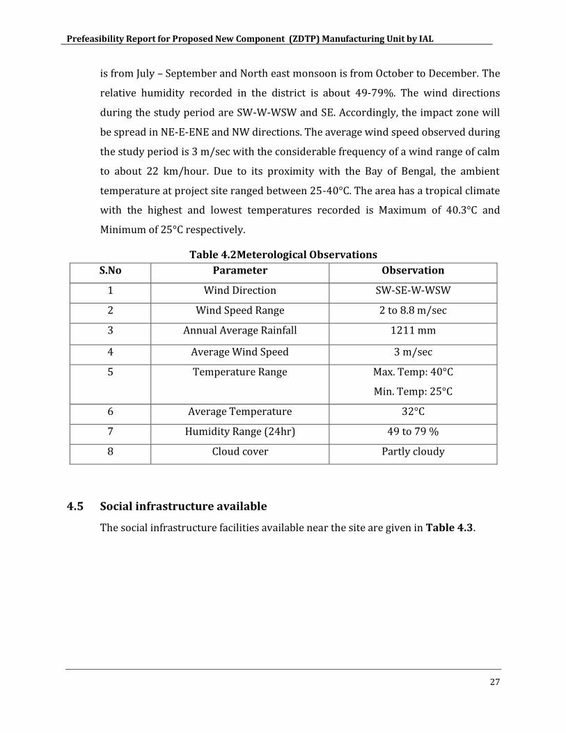
4.4 Climatic Conditions
The study region receives rainfall predominantly during monsoon season with an
average annual rainfall of about 1211 mm per year. The South west monsoon season
Prefeasibility Report for Proposed New Component (ZDTP) Manufacturing Unit by IAL
27
is from July – September and North east monsoon is from October to December. The
relative humidity recorded in the district is about 49-79%. The wind directions
during the study period are SW-W-WSW and SE. Accordingly, the impact zone will
be spread in NE-E-ENE and NW directions. The average wind speed observed during
the study period is 3 m/sec with the considerable frequency of a wind range of calm
to about 22 km/hour. Due to its proximity with the Bay of Bengal, the ambient
temperature at project site ranged between 25-40°C. The area has a tropical climate
with the highest and lowest temperatures recorded is Maximum of 40.3°C and
Minimum of 25°C respectively.
Table 4.2Meterological Observations
S.No Parameter Observation
1 Wind Direction SW-SE-W-WSW
2 Wind Speed Range 2 to 8.8 m/sec
3 Annual Average Rainfall 1211 mm
4 Average Wind Speed 3 m/sec
5 Temperature Range Max. Temp: 40°C
Min. Temp: 25°C
6 Average Temperature 32°C
7 Humidity Range (24hr) 49 to 79 %
8 Cloud cover Partly cloudy
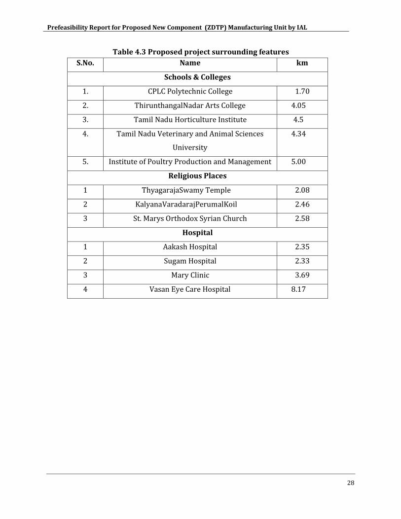
4.5 Social infrastructure available
The social infrastructure facilities available near the site are given in Table 4.3.
Prefeasibility Report for Proposed New Component (ZDTP) Manufacturing Unit by IAL
28
Table 4.3 Proposed project surrounding features
S.No. Name km
Schools & Colleges
1. CPLC Polytechnic College 1.70
2. ThirunthangalNadar Arts College 4.05
3. Tamil Nadu Horticulture Institute 4.5
4. Tamil Nadu Veterinary and Animal Sciences
University
4.34
5. Institute of Poultry Production and Management 5.00
Religious Places
1 ThyagarajaSwamy Temple 2.08
2 KalyanaVaradarajPerumalKoil 2.46
3 St. Marys Orthodox Syrian Church 2.58
Hospital
1 Aakash Hospital 2.35
2 Sugam Hospital 2.33
3 Mary Clinic 3.69
4 Vasan Eye Care Hospital 8.17
Prefeasibility Report for Proposed New Component (ZDTP) Manufacturing Unit by IAL
29
5. Conclusion
Since the proposed project is coming up in the existing plant Industrial area,
there will not be any change in land use.
The proposed project is of only backward integration model within the existing
facility, hence most of th supporting facilities like utilities, effluent and sewage
treatement systems will be shared with the existing set up.
The increase in pollutant loads due to the proposed project is appropriately
handled through pollution control measures.
The treated waste water will be partly reused for gardeningwith in the facility
and rest will be recycled for process reuse likeCooling Towers andboiler feed
water make-up after treatement through RO system. RO plant will be upgraded
as part of this project to meet the additional recyle requirements.
The facility has a well developed green belt covering more than 33% of the total
plot area. There are no changes to the green belt area on account of this
proposed project.
There will be positive impact on Social conditions in and around the site due to
the proposed project.
The impact of proposed project with in the existing facility will be fully mitigated
by the Environment Management Plans (EMP).