Embed Size (px)
Citation preview

High-Speed Measurement-Device-Independent Quantum Key Distributionwith Integrated Silicon Photonics
Kejin Wei,1,2,3,4,* Wei Li,1,2,3,* Hao Tan,1,2,3 Yang Li ,1,2,3 Hao Min,1,2,3 Wei-Jun Zhang,5 Hao Li,5
Lixing You,5 Zhen Wang,5 Xiao Jiang,1,2,3 Teng-Yun Chen,1,2,3 Sheng-Kai Liao,1,2,3
Cheng-Zhi Peng,1,2,3,6 Feihu Xu ,1,2,3,† and Jian-Wei Pan1,2,3,‡1Hefei National Laboratory for Physical Sciences at Microscale and Department of Modern Physics,
University of Science and Technology of China, Hefei 230026, China2Shanghai Branch, CAS Center for Excellence and Synergetic Innovation Center in Quantum Information
and Quantum Physics, University of Science and Technology of China, Shanghai 201315, China3Shanghai Research Center for Quantum Sciences, Shanghai 201315, China
4Guangxi Key Laboratory for Relativistic Astrophysics, School of Physics Science and Technology,Guangxi University, Nanning 530004, China
5State Key Laboratory of Functional Materials for Informatics, Shanghai Institute of Microsystemand Information Technology, Chinese Academy of Sciences, Shanghai 200050, China
6QuantumCTek Co., Ltd., Hefei, Anhui 230088, China
(Received 19 February 2020; revised 29 April 2020; accepted 3 June 2020; published 10 August 2020)
Measurement-device-independent quantum key distribution (MDI QKD) removes all detector sidechannels and enables secure QKD with an untrusted relay. It is suitable for building a star-type quantumaccess network, where the complicated and expensive measurement devices are placed in the centraluntrusted relay and each user requires only a low-cost transmitter, such as an integrated photonic chip.Here, we experimentally demonstrate a 1.25-GHz silicon photonic chip-based MDI QKD system usingpolarization encoding. The photonic chip transmitters integrate the necessary encoding components for astandard QKD source. We implement random modulations of polarization states and decoy intensities, anddemonstrate a finite-key secret rate of 31 bit=s over 36-dB channel loss (or 180-km standard fiber). Thiskey rate is higher than state-of-the-art MDI QKD experiments. The results show that silicon photonic chip-based MDI QKD, benefiting from miniaturization, low-cost manufacture, and compatibility with CMOSmicroelectronics, is a promising solution for future quantum secure networks.
DOI: 10.1103/PhysRevX.10.031030 Subject Areas: Quantum Information
I. INTRODUCTION
Quantum key distribution (QKD) [1,2] is a key tech-nology for building nodal networks which are believed tobe a crucial stepping stone toward a quantum Internet. Sofar, existing QKD networks [3–7] need the central relays tobe trusted [e.g., Fig. 1(a)], which is a critical securitydrawback [1,2]. Fortunately, the measurement-device-independent (MDI) QKD protocol [8] (see also Ref. [9])can remove all side channels of the measurement devices[10], and it is practical with current technology. MDI QKDhas been widely implemented toward long distance [11,12],
high secret key rate [13], field test [14,15], asymmetricchannels [16,17], and so forth [18–20]. Recently, anefficient MDI scheme, twin-field QKD [21], was proposedto overcome the repeaterless key-rate bound.Chip-based QKD has attracted great attention [22–30],
due to its advantages of compact size and low cost.Particularly, silicon that relies on well-established fabri-cation techniques is well suited for on-chip photonic QKDcomponents, and it has been exploited to implementseveral QKD protocols, including decoy-state BB84[23–26], high dimension [27], continuous variable [28,29],and so forth [22,30].The combination of silicon photonic chips and MDI
QKD enables a remarkably new network-centric [7] orquantum-access [6] structure with an untrusted relay. Asillustrated in Fig. 1(b), in the chip-based MDI QKDnetwork, each user only needs a compact transmitter chip,whereas the relay holds the expensive and bulky meas-urement system (and quantum memory [31]) which areshared by all users. Importantly, this structure can bypassthe challenging technique for intergrading single-photon
*These authors contributed equally to this work.†[email protected]‡[email protected]
Published by the American Physical Society under the terms ofthe Creative Commons Attribution 4.0 International license.Further distribution of this work must maintain attribution tothe author(s) and the published article’s title, journal citation,and DOI.
PHYSICAL REVIEW X 10, 031030 (2020)
2160-3308=20=10(3)=031030(11) 031030-1 Published by the American Physical Society

detectors on chip [32,33], since the users do not need to dothe quantum detection. Overall, the chip-based MDI QKDnetwork enables a promising solution for low-cost, scal-able QKD networks with an untrusted relay.Here,we experimentally demonstrate a 1.25-GHz, silicon-
chip-based, polarization-encoding MDI QKD system. Eachuser possesses a photonic chip transmitter, which integratesthe QKD encoding components of intensity modulator,polarization modulator, and variable optical attenuator.The chips are manufactured by standard Si photonic plat-forms, packaged with thermoelectric cooler (TEC), anddesigned compactly for the purpose of commercial produc-tion. With two chip transmitters, we implement MDI QKDwith random modulations of decoy intensities and polariza-tion qubits, and demonstrate a finite-key secret rate of31 bit=s over 36-dB channel loss. In addition, we obtain akey rate of 497 bit=s over 140-km commercial fiber spools.The achieved key rate is higher than those of previous MDIQKD experiments [11–15,18,19] (see Table I).
II. SETUP
Figure 2(a) shows the schematic of our chip-based MDIQKD experiment. Using pulsed laser-seeding technology[34] where a master gain-switched laser (Master) injects
photons into the cavity of a slave gain-switched laser(Slave) through a circulator (Circ), Alice and Bob eachgenerate low-jitter phase-randomized light pulses at arepetition rate of 1.25 GHz and a center wavelength of1550 nm.The generated pulses are passed through a 10-GHzbandwidth filter to remove noise. With these sources, weobserve stable Hong-Ou-Mandel interference with a vis-ibility up to 48.4% (see Appendix C 1), which ensures therequired indistinguishability of independent laser sourcesfor MDI QKD.The generated pulses are coupled into a Si photonic
transmitter chip which integrates together an intensity modu-lator, a polarization modulator, and a variable optical attenu-ator. The components are realized by an in-house design (viaQuantum CTek), and they consist of several interferometricstructures [see Fig. 2(b)] which exploit standard buildingblocks offered by the IMEC foundry. The multimode inter-ference (MMI) couplers act as symmetric beam splitters, andthe thermo-optics modulators (TOMs) with approximatekilohertz bandwidth, and carrier-depletion modulators(CDMs) with approximate gigahertz bandwidth act as phasemodulators. Specifically, the intensity modulator, which isused to generate decoy state with different intensities, isrealized by the first Mach-Zehnder interferometer (MZI)containing both TOMs and CDMs. The next componentis the variable optical attenuator (VOA), consisting of ap-i-n (PIN) diode for current injection across-section of theSi waveguide and being used to attenuate the pulses tosingle-photon levels. The tunable attenuation is controlledby applying differential biased voltage to the TOMs withan attenuation up to 110 dB. The output of VOA is connectedto the polarization modulator (POL) which is realized bycombining an inner MZI with two external CDMs endingin the polarization rotator combiner (PRC). The PRC isfabricated by using a two-dimensional grating structure[25,30]. The POL can prepare the four BB84 states,jψi ¼ ðjHi þ eiθjViÞ= ffiffiffi
2p
; θ ∈ f0; π=2; π; 3π=2g, whereθ ∈ f0; πg (θ ∈ fπ=2; 3π=2g) represents the state inZ (X) basis in MDI QKD implementation.
TABLE I. Comparison of state-of-the-art MDI QKDexperiments.
ReferenceClock rate(MHz)
Channelloss (dB)
Key rate(bit/s)
Finitekey
Tang et al. [18] 10 2.0 25 10−3
Tang et al. [11] 75 9.9 67 10−9
Valivarthi et al. [19] 20 16.0 100 AsymptoticYin et al. [12] 75 19.5 1380 10−10
Comandar et al. [13] 1000 20.4 4567a 10−10
This work 1250 20.4 6172b 10−10
28.0 268 10−10
36.0 31 10−10
aNo random modulations.bSimulated experiment.
FIG. 1. (a) Schematic of a conventional quantum access net-work based on BB84 [6]. The central relay needs to be trustful,where the measurement devices are vulnerable to quantumattacks. (b) Schematic of the proposed star-type chip-basedMDI QKD network. Each client holds only a compact, low-costtransmitter chip, and the central relay performs the Bell-statemeasurement (BSM). MDI QKD enables secure QKD with anuntrusted relay.
KEJIN WEI et al. PHYS. REV. X 10, 031030 (2020)
031030-2

The chip has a footprint size of 4.8 × 3 mm2 and ispackaged with a commercial TEC. A precision andcompact temperature controller is designed to drive theTEC. With this design, the chip provides a stable polari-zation encoding and decoy-state modulation. The observedquantum bit error rate (QBER) maintains at low valuesover several hours of operation (see Fig. 3). The packagedchip with a total volume of 20 × 11 × 5 mm3 is soldered toa standard 9 × 7 cm2 printed circuit board, as shown inFig. 2(c). With dedicated layout, the chip is easilyassembled by using commercial foundry, providing alow-cost, portable, stable, and miniaturized device forMDI QKD.To realize MDI QKD, Alice and Bob send their
encoding pulses to Charlie, who performs a BSMon the incoming pulses. Charlie’s measurement setupcomprises a 50=50 beam splitter (BS), two electronicspolarization controllers (EPCs), two polarizing beamsplitters, and four superconducting nanowire single photondetectors (SNSPDs) with detection efficiency 53% anddark counts 50 Hz. The detection events are registeredusing a high-speed time tagger where a successful coinci-dence induces a projection into one of the two Bellstates jψ�i ¼ 1=
ffiffiffi
2p ðjHVi � jHViÞ.
(a)
(c)
(b)
FIG. 2. (a) Experimental setup of chip-based MDI QKD. Alice and Bob each possess a master gain-switched laser (master) whichinjects photons into the cavity of a slave gain-switched laser (slave) through a circulator (circ) to generate low-jitter phase-randomizedlight pulses at a repetition rate of 1.25 GHz. The generated pulses are coupled into a silicon photonic transmitter chip (chip) whichintegrates together an intensity modulator, variable optical attenuator, and polarization modulator. The Bell-state measurements areperformed by the untrusted relay Charlie who comprises a beam splitter (BS), two electric polarizing controllers (EPCs), two polarizingbeam splitters (PBSs) and four superconducting nanowire single-photon detectors (SNSPDs). (b) The schematic of the Si chip. Allcomponents are fabricated using standard Si blocks, including multimode interference (MMI) couplers, thermo-optics modulators(TOMs), carrier-depletion modulators (CDMs), and polarization rotator combiner (PRC). (c) Image of the packaged chip soldered to acompact control board.
0 80 160 240 3200.00
0.05
0.10
0.15
0.20
0.25
0.30
0.35
QB
ER
Time (min)
X basisZ basis
FIG. 3. Observed QBERs in different bases over 36-dB channelloss. The data points are collected without any active adjustmentof the system. Each point is calculated by using data collectedover a one-minute period. An average QBER of 0.028� 0.002(0.271� 0.016) in Z (X) basis is observed over several hours ofoperation.
HIGH-SPEED MEASUREMENT-DEVICE-INDEPENDENT … PHYS. REV. X 10, 031030 (2020)
031030-3
For high-rate MDI QKD, an important part is thehigh-speed electronics for control and synchronization.In our experiment, Alice and Bob each use a homemadecost-effective field-programmable gate array (FPGA)board (see Appendix C 3) to accomplish the electricalcontrols, including the laser driving, random modulationof intensity modulators (IMs) and polarization modu-lators (POLs), synchronization of different devices, etc.The specialized electronics enable us to take advantageof the small size of the chips toward a compact MDIQKD system. Each FPGA board is synchronized withCharlie through an electrical cable in our laboratoryexperiment. For a field implementation, the synchroni-zation could be realized using optical signals throughfibers, as demonstrated in Ref. [11]. To share a commonpolarization reference between Alice and Bob, as wellas compensate the polarization drift in the quantumchannel, we develop an automatic polarization align-ment with electronic polarization controllers, which canrapidly calibrate the polarization reference within half aminute. Further experimental details can be found inAppendix C.
III. RESULTS
We experimentally characterize each of the compo-nents in the chip. The bandwidth of the CDM reachesabout 21 GHz which is measured by using a vectornetwork analyzer. The IM provides a static extinctionratio (ER) of about 30 dB and a dynamic ER of about20 dB. We characterize the produced polarization statewith measurement devices in Charlie. The EPCs areadjusted so that each PBS is aligned to rectilinear anddiagonal bases, respectively. We obtain an averagepolarization ER of about 23 dB. The attenuation ofthe VOA ranges from 0 to about 110 dB. Theperformance of the chip is sufficient for a low-error,high-rate MDI QKD. Figure 3 shows the observedQBER. We obtain an average QBER of 2.8%� 0.2%(27.1%� 1.6%) in Z (X) basis over several hours ofstable operations. Note that the theory value of theQBER in X basis for two weak coherent pulses is 25%;our experimental value remains close to the theory.Using the described setup, we perform a series of MDI
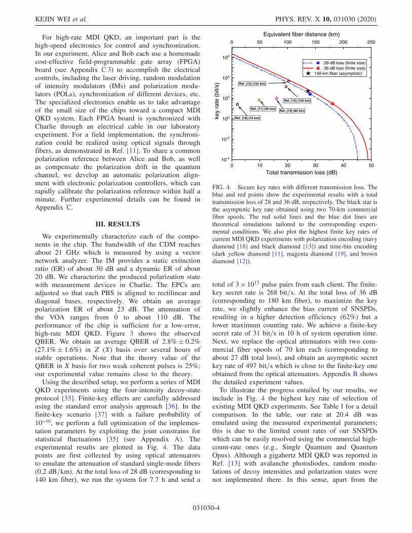
QKD experiments using the four-intensity decoy-stateprotocol [35]. Finite-key effects are carefully addressedusing the standard error analysis approach [36]. In thefinite-key scenario [37] with a failure probability of10−10, we perform a full optimization of the implemen-tation parameters by exploiting the joint constrains forstatistical fluctuations [35] (see Appendix A). Theexperimental results are plotted in Fig. 4. The datapoints are first collected by using optical attenuatorsto emulate the attenuation of standard single-mode fibers(0.2 dB=km). At the total loss of 28 dB (corresponding to140 km fiber), we run the system for 7.7 h and send a
total of 3 × 10¹³ pulse pairs from each client. The finite-key secret rate is 268 bit=s. At the total loss of 36 dB(corresponding to 180 km fiber), to maximize the keyrate, we slightly enhance the bias current of SNSPDs,resulting in a higher detection efficiency (62%) but alower maximum counting rate. We achieve a finite-keysecret rate of 31 bit=s in 10 h of system operation time.Next, we replace the optical attenuators with two com-mercial fiber spools of 70 km each (corresponding toabout 27 dB total loss), and obtain an asymptotic secretkey rate of 497 bit=s which is close to the finite-key oneobtained from the optical attenuators. Appendix B showsthe detailed experiment values.To illustrate the progress entailed by our results, we
include in Fig. 4 the highest key rate of selection ofexisting MDI QKD experiments. See Table I for a detailcomparison. In the table, our rate at 20.4 dB wasemulated using the measured experimental parameters;this is due to the limited count rates of our SNSPDswhich can be easily resolved using the commercial high-count-rate ones (e.g., Single Quantum and QuantumOpus). Although a gigahertz MDI QKD was reported inRef. [13] with avalanche photodiodes, random modu-lations of decoy intensities and polarization states werenot implemented there. In this sense, apart from the
0 10 20 30 40 50
0 50 100 150 200 250
10-4
10-2
100
102
104
106
28-dB loss (finite size)36-dB loss (finite size)
140-km fiber (asymptotic)
Equivalent fiber distance (km)
key
rate
(bit/
s)
Total transmission loss (dB)
Ref. [18] (10 km)
Ref. [19] (80 km)
Ref. [12] (102 km)
Ref. [13] (102 km)
Ref. [11] (50 km)
FIG. 4. Secure key rates with different transmission loss. Theblue and red points show the experimental results with a totaltransmission loss of 28 and 36 dB, respectively. The black star isthe asymptotic key rate obtained using two 70-km commercialfiber spools. The red solid lines and the blue dot lines aretheoretical simulations tailored to the corresponding experi-mental conditions. We also plot the highest finite key rates ofcurrent MDI QKD experiments with polarization encoding (navydiamond [18] and black diamond [13]) and time-bin encoding(dark yellow diamond [11], magenta diamond [19], and browndiamond [12]).
KEJIN WEI et al. PHYS. REV. X 10, 031030 (2020)
031030-4
chip-based implementation, our experiment is the firstgigahertz MDI QKD with random modulations. More-over, our experiment represents the highest reported keyrate for MDI QKD.Similar to standard QKD experiments, our chip-based
source presents small device imperfections. First, theintensity fluctuations are less than 0.9%, which indicatesthe good stability of the chip-based intensity modulator.Second, the polarization dependent loss is smaller than0.8 dB, which has a negligible effect to the key rate [38].Third, the phase-modulation errors are less than 0.18 for aπ-phase modulation [39]. Fourth, for our high-speedmodulation, the pattern effect for the intensity deviationsof adjacent pulses is less than 12%. The security issue ofpattern effect, together with the countermeasures, hasbeen proposed in Ref. [40]. Note that in the future, thesesource imperfections can be included in the key-ratecalculation by following the recent security proofs[41,42].
IV. DISCUSSIONS
We have demonstrated a high-speed chip-based MDIQKD system where both clients possess a low-cost Siphotonic transmitter chip. The transmitter can be furtherintegrated with the laser based on wire bounding or thesubstrate of indium phosphide or hybrid integration[43,44]. This can construct a compact chip-scale QKDtransmitter. We perform a complete demonstration ofpolarization-encoding MDI QKD and distill finite-keysecret rates higher than previous experiment. This workpaves the way for a low-cost, wafer-scale manufacturedMDI QKD system, and represents a key step towardbuilding quantum networks with untrusted relays.
ACKNOWLEDGMENTS
We thank Jianhong Liu, Pan Gong, Yan-Lin Tang,Wenyuan Wang for enlightening discussions. This workwas supported by the National Key Research andDevelopment (R&D) Plan of China (under GrantsNo. 2018YFB0504300 and No. 2017YFA0304000), theNational Natural Science Foundation of China (underGrants No. 61771443 and No. 61705048), the AnhuiInitiative in Quantum Information Technologies, theShanghai Municipal Science and Technology MajorProject (Grant No. 2019SHZDZX01), the ChineseAcademy of Sciences, the Shanghai Science andTechnology Development Funds (No. 18JC1414700)and the Fundamental Research Funds for the CentralUniversities (No. WK2340000083).
Note added.—Recently, we become aware of a relatedwork in Ref. [45]. Our work uses polarization en-coding and low-cost Si substrate at a clock rate of1.25 GHz, with a careful finite-key consideration and
an implementation of random modulations of decoy statesand polarization qubits. Reference [45] uses time-binencoding and InP substrate at a clock rate of 0.25 GHz,without the implementation of random modulations andthe finite-key consideration, but it integrates the laserson chip.
APPENDIX A: FOUR-INTENSITY MDI QKD
In experiment, the EPCs are carefully aligned for statepreparation and detection in the Z ¼ fj0i; j1ig basis andX ¼ fjþi; j−ig basis. Here, j0i ¼ ðjHi þ jViÞ= ffiffiffi
2p
, j1i ¼ðjHi − jViÞ= ffiffiffi
2p
, jþi ¼ ðjHi þ ijViÞ= ffiffiffi
2p
, and j−i ¼ðjHi − ijViÞ= ffiffiffi
2p
. Our experiment adopts the four-intensitydecoy-state protocol [35]. There are three intensitiesfμ; ν;ωg in the X basis for the decoy-state analysis andone signal intensity fsg in the Z basis for secret keygeneration. We consider the symmetric channel losswhere Alice and Bob used the same parameters. Onecan refer to Refs. [16,17] for the case of asymmetricchannel loss. Including the probabilities P for each inten-sity, both Alice and Bob use the same group of sixparameters ½s; μ; ν; Ps; Pμ; Pν�. We perform a full optimi-zation of parameters [36]. For statistical fluctuations, weuse the joint constrains where the same observables arecombined and treated together, as proposed in Ref. [35].This can produce a higher key rate than independentconstrains. Finally, the secret key is extracted using theformula,
R ¼ P2sfs2e−2sYX;L
11 ½1 − hðeX;U11 Þ� − feQZsshðEZ
ssÞg; ðA1Þ
where QZss and EZ
ss are the gain and the QBER in the Z(signal) basis, Ps is the probability of signal state, Y
X;L11 and
eX;U11 are the lower bound of single-photon yield and theupper bound of single-photon QBER estimated by thedecoy state statistics in the X basis, h is the binary entropyfunction, and fe is the error-correction efficiency which isset to 1.16.
APPENDIX B: DETAILEDEXPERIMENTAL RESULTS
The detailed experimental results are listed in Table II.
APPENDIX C: EXPERIMENTAL DETAILS
1. Source
Each of Alice and Bob consists of two nearly identicalgain-switched lasers, of which the wavelengths are stabi-lized using homemade tunable temperature controllers. Thelasers are distributed feedback diodes, which have wave-length sensitivity over temperature 90 pm=K. The resolu-tion of the temperature controller is 1 mK. The centralwavelength of the master laser is set at 1549.68 nm, and the
HIGH-SPEED MEASUREMENT-DEVICE-INDEPENDENT … PHYS. REV. X 10, 031030 (2020)
031030-5
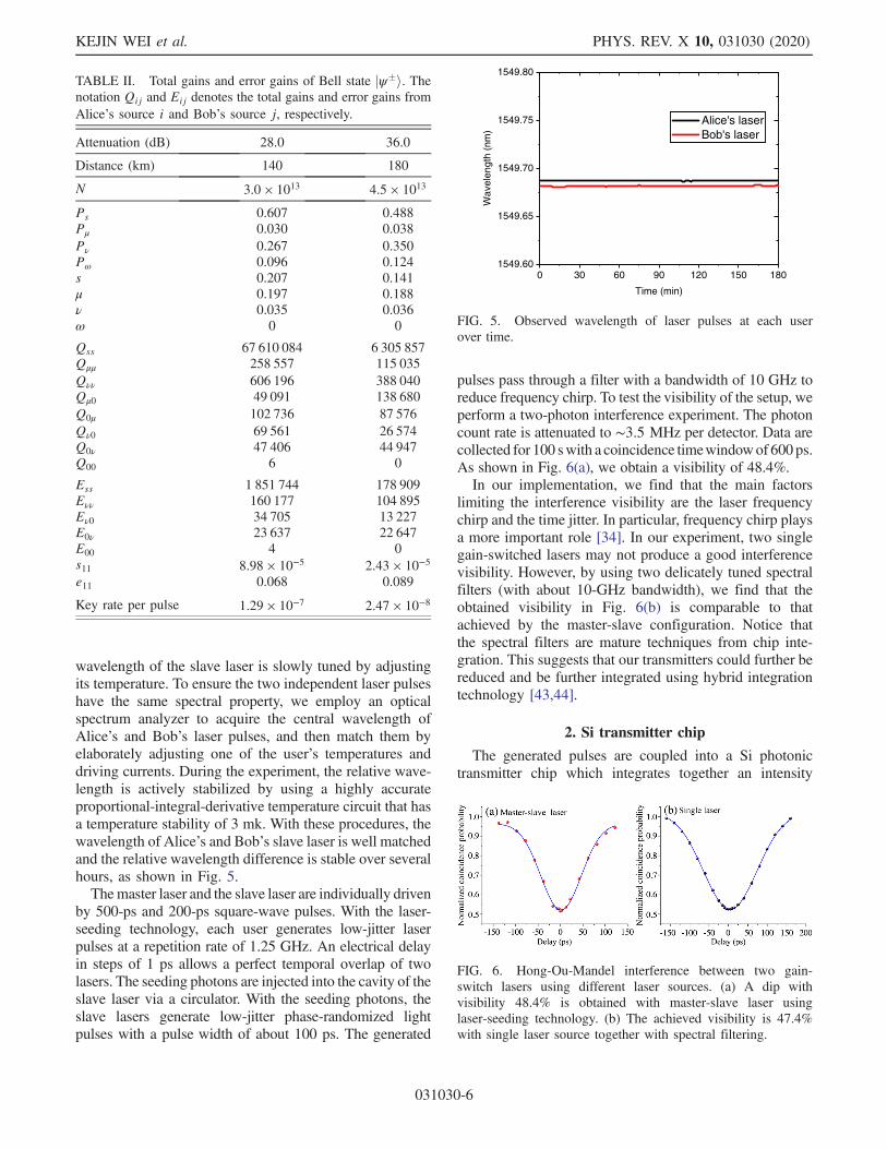
wavelength of the slave laser is slowly tuned by adjustingits temperature. To ensure the two independent laser pulseshave the same spectral property, we employ an opticalspectrum analyzer to acquire the central wavelength ofAlice’s and Bob’s laser pulses, and then match them byelaborately adjusting one of the user’s temperatures anddriving currents. During the experiment, the relative wave-length is actively stabilized by using a highly accurateproportional-integral-derivative temperature circuit that hasa temperature stability of 3 mk. With these procedures, thewavelength of Alice’s and Bob’s slave laser is well matchedand the relative wavelength difference is stable over severalhours, as shown in Fig. 5.Themaster laser and the slave laser are individually driven
by 500-ps and 200-ps square-wave pulses. With the laser-seeding technology, each user generates low-jitter laserpulses at a repetition rate of 1.25 GHz. An electrical delayin steps of 1 ps allows a perfect temporal overlap of twolasers. The seeding photons are injected into the cavity of theslave laser via a circulator. With the seeding photons, theslave lasers generate low-jitter phase-randomized lightpulses with a pulse width of about 100 ps. The generated
pulses pass through a filter with a bandwidth of 10 GHz toreduce frequency chirp. To test the visibility of the setup, weperform a two-photon interference experiment. The photoncount rate is attenuated to ∼3.5 MHz per detector. Data arecollected for 100 swith a coincidence timewindowof 600ps.As shown in Fig. 6(a), we obtain a visibility of 48.4%.In our implementation, we find that the main factors
limiting the interference visibility are the laser frequencychirp and the time jitter. In particular, frequency chirp playsa more important role [34]. In our experiment, two singlegain-switched lasers may not produce a good interferencevisibility. However, by using two delicately tuned spectralfilters (with about 10-GHz bandwidth), we find that theobtained visibility in Fig. 6(b) is comparable to thatachieved by the master-slave configuration. Notice thatthe spectral filters are mature techniques from chip inte-gration. This suggests that our transmitters could further bereduced and be further integrated using hybrid integrationtechnology [43,44].
2. Si transmitter chip
The generated pulses are coupled into a Si photonictransmitter chip which integrates together an intensity
0 30 60 90 120 150 1801549.60
1549.65
1549.70
1549.75
1549.80
Alice's laserBob's laser
Wav
elen
gth
(nm
)
Time (min)
FIG. 5. Observed wavelength of laser pulses at each userover time.
TABLE II. Total gains and error gains of Bell state jψ�i. Thenotation Qij and Eij denotes the total gains and error gains fromAlice’s source i and Bob’s source j, respectively.
Attenuation (dB) 28.0 36.0
Distance (km) 140 180
N 3.0 × 10¹³ 4.5 × 10¹³
Ps 0.607 0.488Pμ 0.030 0.038Pν 0.267 0.350Pω 0.096 0.124s 0.207 0.141μ 0.197 0.188ν 0.035 0.036ω 0 0
Qss 67 610 084 6 305 857Qμμ 258 557 115 035Qνν 606 196 388 040Qμ0 49 091 138 680Q0μ 102 736 87 576Qν0 69 561 26 574Q0ν 47 406 44 947Q00 6 0
Ess 1 851 744 178 909Eνν 160 177 104 895Eν0 34 705 13 227E0ν 23 637 22 647E00 4 0s11 8.98 × 10⁻⁵ 2.43 × 10⁻⁵
e11 0.068 0.089
Key rate per pulse 1.29 × 10⁻⁷ 2.47 × 10⁻⁸
FIG. 6. Hong-Ou-Mandel interference between two gain-switch lasers using different laser sources. (a) A dip withvisibility 48.4% is obtained with master-slave laser usinglaser-seeding technology. (b) The achieved visibility is 47.4%with single laser source together with spectral filtering.
KEJIN WEI et al. PHYS. REV. X 10, 031030 (2020)
031030-6
modulator, and polarization modulator, and variableoptical attenuator.ACDM, acting as a phase modulator, is a key component
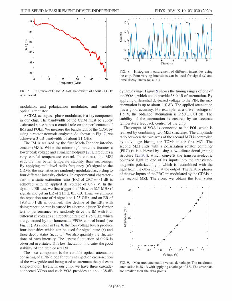
in our chip. The bandwidth of the CDM must be subtlyestimated since it has a crucial role on the performance ofIMs and POLs. We measure the bandwidth of the CDM byusing a vector network analyzer. As shown in Fig. 7, weachieve a 3-dB bandwidth of about 21 GHz.The IM is realized by the first Mach-Zehnder interfer-
ometer (MZI). While the microring’s structure features alower peak voltage and a smaller footprint [23], it requires avery careful temperature control. In contrast, the MZIstructure has better temperate stability than microrings.By applying multilevel radio frequency (rf) signal to theCDMs, the intensities are randomly modulated according tofour different intensity choices. In experimental characteri-zation, a static extinction ratio (ER) of 29.7� 0.1 dB isachieved with an applied dc voltage of 0.97 V. In thedynamic ER test, we first trigger the IMs with 625-MHz rfsignals and get an ER of 21.5� 0.1 dB. Then, we enhancethe repetition rate of rf signals to 1.25 GHz, and an ER of19.8� 0.1 dB is obtained. The decline of the ERs withrising repetition rate is caused by electronic jitter. To furthertest its performance, we randomly drive the IM with fourdifferent rf voltages at a repetition rate of 1.25 GHz, whichare generated by our homemade FPGA control board (seeFig. 11). As shown in Fig. 8, the four voltage levels producefour intensities which can be used for signal state (s) andthree decoy states (μ, ν, ω). We also quantify the fluctua-tions of each intensity. The largest fluctuation of 0.9% isobserved in ν states. This low fluctuation indicates the goodstability of the chip-based IM.The next component is the variable optical attenuator,
consisting of a PIN diode for current injection cross-sectionof the waveguide and being used to attenuate the pulses tosingle-photon levels. In our chip, we have three cascade-connected VOAs and each VOA provides an about 38-dB
dynamic range. Figure 9 shows the tuning ranges of one ofthe VOAs, which could provide 38.0 dB of attenuation. Byapplying differential dc-biased voltage to the PIN, the maxattenuation is up to about 110 dB. The applied attenuationhas a good accuracy. For example, at a driver voltage of1.5 V, the obtained attenuation is 9.50� 0.01 dB. Thestability of the attenuation is ensured by an accuratetemperature feedback control of the chip.The output of VOA is connected to the POL which is
realized by combining two MZI structures. The amplituderatio between the two arms of the second MZI is controlledby dc-voltage biasing the TOMs in the first MZI. Thesecond MZI ends with a polarization rotator combiner(PRC) (it is achieved by using a two-dimensional gratingstructure [25,30]), which converts the transverse-electricpolarized light in one of its inputs into the transverse-magnetic polarized light, which is recombined with thelight from the other input at the output. The relative phasesof the two inputs of the PRC are modulated by the CDMs inthe second MZI. Therefore, we obtain the four states
0 10 20 30 40 50
-36
-33
-30
-27
-24
-21
S21
(dB
)
Frequency (GHz)
FIG. 7. S21 curve of CDM. A 3-dB bandwidth of about 21 GHzis achieved.
0 2 4 6 8 10 12 1410 0
10 1
10 2
10 3
10 4
FIG. 8. Histogram measurement of different intensities usingthe chip. Four varying intensities can be used for signal (s) andthree decoy states (μ, ν, ω).
0.0 0.5 1.0 1.5 2.0 2.5 3.0
0
10
20
30
40
Atte
natio
n(d
B)
Voltage (V)
FIG. 9. Measured attenuation versus dc voltage. The maximumattenuation is 38 dB with applying a voltage of 3 V. The error barsare smaller than the data points.
HIGH-SPEED MEASUREMENT-DEVICE-INDEPENDENT … PHYS. REV. X 10, 031030 (2020)
031030-7
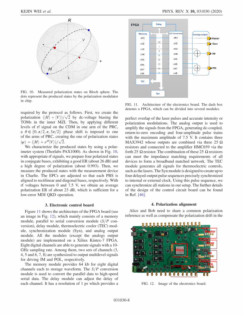
required by the protocol as follows. First, we create thepolarization ðjHi þ jViÞ= ffiffiffi
2p
by dc-voltage biasing theTOMs in the inner MZI. Then, by applying differentlevels of rf signal on the CDM in one arm of the PRC,a θ ∈ f0; π=2; π; 3π=2g phase shift is imposed to oneof the arms of PRC, creating the one of polarization statesjψi ¼ ðjHi þ eiθjViÞ= ffiffiffi
2p
.We characterize the produced states by using a polar-
imeter system (Thorlabs PAX1000). As shown in Fig. 10,with appropriate rf signals, we prepare four polarized statesin conjugate bases, exhibiting a good ER (about 26 dB) anda high degree of polarization (about 0.993). Then, wemeasure the produced states with the measurement devicein Charlie. The EPCs are adjusted so that each PBS isaligned to rectilinear and diagonal bases, respectively. Withrf voltages between 0 and 7.5 V, we obtain an averagepolarization ER of about 23 dB, which is sufficient for alow-error MDI QKD operation.
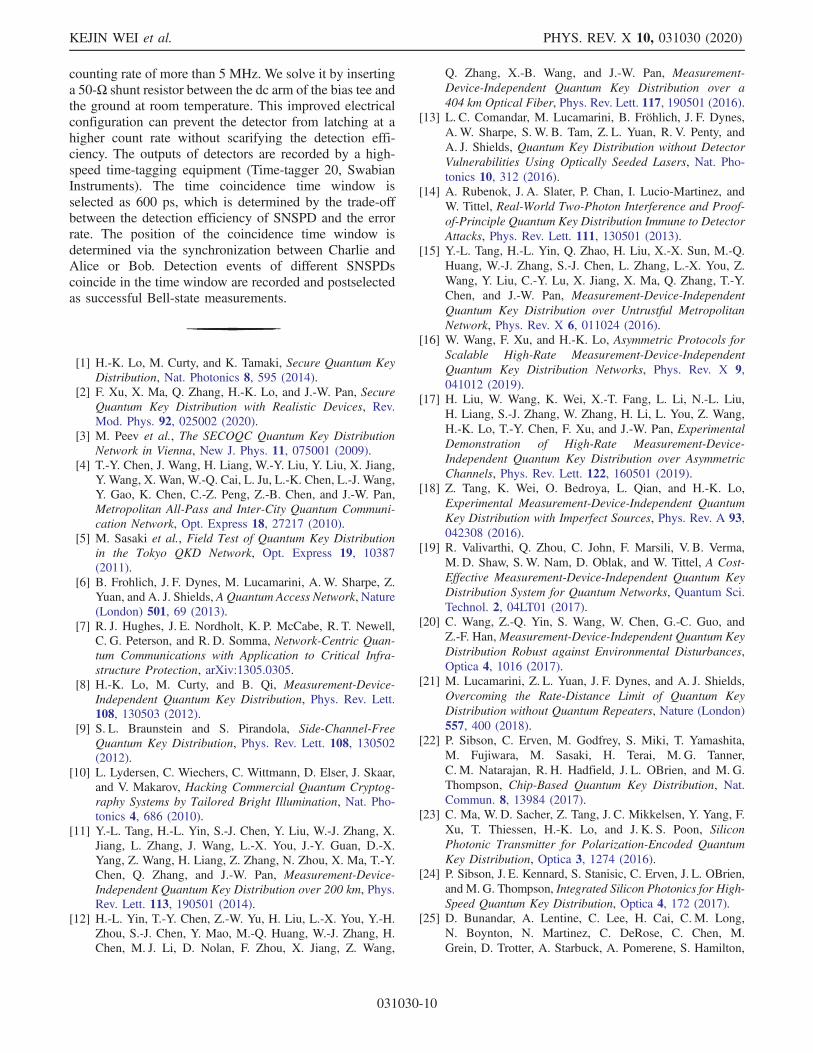
3. Electronic control board
Figure 11 shows the architecture of the FPGA board (seean image in Fig. 12), which mainly consists of a memorymodule, parallel to serial conversion module (S=P con-version), delay module, thermoelectric cooler (TEC) mod-ule, synchronization module (Syn), and analog outputmodule. All the modules (except the analogs outputmodule) are implemented on a Xilinx Kintex-7 FPGA.Eight digital channels are able to generate signals with a 10-GHz sampling rate. Among them, two sets of channels (3,4, 5 and 6, 7, 8) are synthesized to output multilevel signalsfor driving IM and POL, respectively.The memory module provides 64 kb for eight digital
channels each to storage waveform. The S=P conversionmodule is used to convert the parallel data to high-speedserial data. The delay module can adjust the delay ofeach channel. It has a resolution of 1 ps which provides a
perfect overlap of the laser pulses and accurate intensity orpolarization modulations. The analog output is used toamplify the signals from the FPGA, generating dc-coupled,return-to-zero encoding and four-amplitude pulse trainswith the maximum amplitude of 7.5 V. It contains threeMAX3942 whose outputs are combined via three 25 Ωresistors and connected to the amplifier HMC659 via theforth 25 Ω resistor. The combination of these 25 Ω resistorscan meet the impedance matching requirements of alldevices to form a broadband matched network. The TECmodule generates all signals for thermoelectric controls,such as the lasers. The Synmodule is designed to create up tofour delayed-output pulse sequences precisely synchronizedto internal or external clock. Using this pulse sequence, wecan synchronize all stations in our setup. The further detailsof the design of the control circuit board can be foundin Ref. [46].
4. Polarization alignment
Alice and Bob need to share a common polarizationreference as well as compensate the polarization drift in the
FIG. 11. Architecture of the electronics board. The dash boxdenotes a FPGA, which can be divided into several modules.
FIG. 10. Measured polarization states on Bloch sphere. Thedots represent the produced states by the polarization modulatorin chip.
FIG. 12. Image of the electronics board.
KEJIN WEI et al. PHYS. REV. X 10, 031030 (2020)
031030-8

quantum channel. Here, we develop an automatic polari-zation alignment method which rapidly calibrates thepolarization reference. Figure 13 shows the schematic ofour alignment system, which is extracted from the setup inthe main text. The EPCs (QEPC-100, QuantumCTek) havethree control channels and the driver voltage of eachchannel is from 0 to 100 V. The system can be summarizedin the following three steps, which can be realized byfollowing the flowchart in Fig. 14.Step 1: Bob and Charlie share a common reference by
adjusting EPC-1 and EPC-2, following the flowchart inFig. 14(a). The EPCs perform the step-by-step search forthe optimal visibility by changing the driver voltage. Thestep size is initialized at 1 V and it is dynamically adjustedbased on the obtained visibility. The timescale for eachmeasurement in determining the visibility is 0.2 s. Thethreshold is set to 1∶1000.Step 2: Alice aligns her bases by adjusting EPC-A,
following the flowchart in Fig. 14(b). The parameters of
EPC are similar with that in step 1, except that the thresholdof the average visibility is set to 1∶200.Step 3: Charlie aligns one of PBS to the Z basis by
adjusting EPC-2, following the flowchart in Fig. 14(c). Theparameters of EPC are similar to those in step 1, except thatthe threshold is set to 1∶1000.At last, Alice, Bob, and Charlie automatically share a
common polarization reference at an average timescale of30 s. The time is mainly limited by the searching algorithm,which can be further improved to less than 3 s by using anadvanced local search algorithm. To our knowledge, mostof previous works on polarization-encoding MDI QKD[13,18] used a manual calibration method. Generally, ittakes dozens of minutes for a manual calibration. Thesystem in Ref. [47] presents an automatic polarizationprocedure, but the method there is different from ours. Notethat we perform the experiment in laboratory, where thepolarization drift is negligible, as shown in Fig. 15. Thus,we do not actively control the polarization during the datacollection. We perform the automatical realignment of thepolarization every two hours.
5. Detection
The Bell-state measurement devices are located inCharlie. The synchronization clock is electrically distrib-uted with a tunable time delay in steps of 1 ps. This enablesAlice, Bob, and Charlie to electrically compensate anytemporal drifts. The projection results are detected withfour SNSPDs. The SNSPDs are cooled down to 2.1 K andwith an detection efficiency of about 53%, dead time ofabout 40 ns, time jitter of about 70 ps, and dark countsabout 50 Hz. Since the system has a gigahertz repetitionrate, which requires that the SNSPD can tolerate a peak
FIG. 13. Schematic of our polarization alignment system.EPC-A, EPC-1, EPC-2: electronic polarization controller; BS:beam splitter; PBS: polarization beam splitter; D1, D2, D3, D4:superconducting nanowire detector.
(a) (b) (c)
FIG. 14. Flowchart of polarization alignment.
0 10 20 30 40 50 60 70 80 90 100 110 12026
28
30
32
34
36
Ext
inct
ion
Rat
io(d
B)
Time (min)
FIG. 15. Polarization stability over a 70-km single-mode fiberspool. Without active polarization control, the polarization can bestable for two hours with a polarization extinction ratio greaterthan 27 dB.
HIGH-SPEED MEASUREMENT-DEVICE-INDEPENDENT … PHYS. REV. X 10, 031030 (2020)
031030-9
counting rate of more than 5 MHz. We solve it by insertinga 50-Ω shunt resistor between the dc arm of the bias tee andthe ground at room temperature. This improved electricalconfiguration can prevent the detector from latching at ahigher count rate without scarifying the detection effi-ciency. The outputs of detectors are recorded by a high-speed time-tagging equipment (Time-tagger 20, SwabianInstruments). The time coincidence time window isselected as 600 ps, which is determined by the trade-offbetween the detection efficiency of SNSPD and the errorrate. The position of the coincidence time window isdetermined via the synchronization between Charlie andAlice or Bob. Detection events of different SNSPDscoincide in the time window are recorded and postselectedas successful Bell-state measurements.
[1] H.-K. Lo, M. Curty, and K. Tamaki, Secure Quantum KeyDistribution, Nat. Photonics 8, 595 (2014).
[2] F. Xu, X. Ma, Q. Zhang, H.-K. Lo, and J.-W. Pan, SecureQuantum Key Distribution with Realistic Devices, Rev.Mod. Phys. 92, 025002 (2020).
[3] M. Peev et al., The SECOQC Quantum Key DistributionNetwork in Vienna, New J. Phys. 11, 075001 (2009).
[4] T.-Y. Chen, J. Wang, H. Liang, W.-Y. Liu, Y. Liu, X. Jiang,Y. Wang, X. Wan, W.-Q. Cai, L. Ju, L.-K. Chen, L.-J. Wang,Y. Gao, K. Chen, C.-Z. Peng, Z.-B. Chen, and J.-W. Pan,Metropolitan All-Pass and Inter-City Quantum Communi-cation Network, Opt. Express 18, 27217 (2010).
[5] M. Sasaki et al., Field Test of Quantum Key Distributionin the Tokyo QKD Network, Opt. Express 19, 10387(2011).
[6] B. Frohlich, J. F. Dynes, M. Lucamarini, A. W. Sharpe, Z.Yuan, and A. J. Shields, A Quantum Access Network, Nature(London) 501, 69 (2013).
[7] R. J. Hughes, J. E. Nordholt, K. P. McCabe, R. T. Newell,C. G. Peterson, and R. D. Somma, Network-Centric Quan-tum Communications with Application to Critical Infra-structure Protection, arXiv:1305.0305.
[8] H.-K. Lo, M. Curty, and B. Qi, Measurement-Device-Independent Quantum Key Distribution, Phys. Rev. Lett.108, 130503 (2012).
[9] S. L. Braunstein and S. Pirandola, Side-Channel-FreeQuantum Key Distribution, Phys. Rev. Lett. 108, 130502(2012).
[10] L. Lydersen, C. Wiechers, C. Wittmann, D. Elser, J. Skaar,and V. Makarov, Hacking Commercial Quantum Cryptog-raphy Systems by Tailored Bright Illumination, Nat. Pho-tonics 4, 686 (2010).
[11] Y.-L. Tang, H.-L. Yin, S.-J. Chen, Y. Liu, W.-J. Zhang, X.Jiang, L. Zhang, J. Wang, L.-X. You, J.-Y. Guan, D.-X.Yang, Z. Wang, H. Liang, Z. Zhang, N. Zhou, X. Ma, T.-Y.Chen, Q. Zhang, and J.-W. Pan, Measurement-Device-Independent Quantum Key Distribution over 200 km, Phys.Rev. Lett. 113, 190501 (2014).
[12] H.-L. Yin, T.-Y. Chen, Z.-W. Yu, H. Liu, L.-X. You, Y.-H.Zhou, S.-J. Chen, Y. Mao, M.-Q. Huang, W.-J. Zhang, H.Chen, M. J. Li, D. Nolan, F. Zhou, X. Jiang, Z. Wang,
Q. Zhang, X.-B. Wang, and J.-W. Pan, Measurement-Device-Independent Quantum Key Distribution over a404 km Optical Fiber, Phys. Rev. Lett. 117, 190501 (2016).
[13] L. C. Comandar, M. Lucamarini, B. Fröhlich, J. F. Dynes,A.W. Sharpe, S. W. B. Tam, Z. L. Yuan, R. V. Penty, andA. J. Shields, Quantum Key Distribution without DetectorVulnerabilities Using Optically Seeded Lasers, Nat. Pho-tonics 10, 312 (2016).
[14] A. Rubenok, J. A. Slater, P. Chan, I. Lucio-Martinez, andW. Tittel, Real-World Two-Photon Interference and Proof-of-Principle Quantum Key Distribution Immune to DetectorAttacks, Phys. Rev. Lett. 111, 130501 (2013).
[15] Y.-L. Tang, H.-L. Yin, Q. Zhao, H. Liu, X.-X. Sun, M.-Q.Huang, W.-J. Zhang, S.-J. Chen, L. Zhang, L.-X. You, Z.Wang, Y. Liu, C.-Y. Lu, X. Jiang, X. Ma, Q. Zhang, T.-Y.Chen, and J.-W. Pan, Measurement-Device-IndependentQuantum Key Distribution over Untrustful MetropolitanNetwork, Phys. Rev. X 6, 011024 (2016).
[16] W. Wang, F. Xu, and H.-K. Lo, Asymmetric Protocols forScalable High-Rate Measurement-Device-IndependentQuantum Key Distribution Networks, Phys. Rev. X 9,041012 (2019).
[17] H. Liu, W. Wang, K. Wei, X.-T. Fang, L. Li, N.-L. Liu,H. Liang, S.-J. Zhang, W. Zhang, H. Li, L. You, Z. Wang,H.-K. Lo, T.-Y. Chen, F. Xu, and J.-W. Pan, ExperimentalDemonstration of High-Rate Measurement-Device-Independent Quantum Key Distribution over AsymmetricChannels, Phys. Rev. Lett. 122, 160501 (2019).
[18] Z. Tang, K. Wei, O. Bedroya, L. Qian, and H.-K. Lo,Experimental Measurement-Device-Independent QuantumKey Distribution with Imperfect Sources, Phys. Rev. A 93,042308 (2016).
[19] R. Valivarthi, Q. Zhou, C. John, F. Marsili, V. B. Verma,M. D. Shaw, S. W. Nam, D. Oblak, and W. Tittel, A Cost-Effective Measurement-Device-Independent Quantum KeyDistribution System for Quantum Networks, Quantum Sci.Technol. 2, 04LT01 (2017).
[20] C. Wang, Z.-Q. Yin, S. Wang, W. Chen, G.-C. Guo, andZ.-F. Han,Measurement-Device-Independent Quantum KeyDistribution Robust against Environmental Disturbances,Optica 4, 1016 (2017).
[21] M. Lucamarini, Z. L. Yuan, J. F. Dynes, and A. J. Shields,Overcoming the Rate-Distance Limit of Quantum KeyDistribution without Quantum Repeaters, Nature (London)557, 400 (2018).
[22] P. Sibson, C. Erven, M. Godfrey, S. Miki, T. Yamashita,M. Fujiwara, M. Sasaki, H. Terai, M. G. Tanner,C. M. Natarajan, R. H. Hadfield, J. L. OBrien, and M. G.Thompson, Chip-Based Quantum Key Distribution, Nat.Commun. 8, 13984 (2017).
[23] C. Ma, W. D. Sacher, Z. Tang, J. C. Mikkelsen, Y. Yang, F.Xu, T. Thiessen, H.-K. Lo, and J. K. S. Poon, SiliconPhotonic Transmitter for Polarization-Encoded QuantumKey Distribution, Optica 3, 1274 (2016).
[24] P. Sibson, J. E. Kennard, S. Stanisic, C. Erven, J. L. OBrien,and M. G. Thompson, Integrated Silicon Photonics for High-Speed Quantum Key Distribution, Optica 4, 172 (2017).
[25] D. Bunandar, A. Lentine, C. Lee, H. Cai, C. M. Long,N. Boynton, N. Martinez, C. DeRose, C. Chen, M.Grein, D. Trotter, A. Starbuck, A. Pomerene, S. Hamilton,
KEJIN WEI et al. PHYS. REV. X 10, 031030 (2020)
031030-10

F. N. C. Wong, R. Camacho, P. Davids, J. Urayama, and D.Englund, Metropolitan Quantum Key Distribution withSilicon Photonics, Phys. Rev. X 8, 021009 (2018).
[26] T. K. Paraïso, I. De Marco, T. Roger, D. G. Marangon,J. F. Dynes, M. Lucamarini, Z. Yuan, and A. J. Shields, AModulator-Free Quantum Key Distribution TransmitterChip, npj Quantum Inf. 5, 42 (2019).
[27] Y. Ding, D. Bacco, K. Dalgaard, X. Cai, X. Zhou, K.Rottwitt, and L. K. Oxenløwe, High-Dimensional QuantumKey Distribution Based on Multicore Fiber Using SiliconPhotonic Integrated Circuits, npj Quantum Inf. 3, 25(2017).
[28] F. Raffaelli, G. Ferranti, D. H. Mahler, P. Sibson, J. E.Kennard, A. Santamato, G. Sinclair, D. Bonneau, M. G.Thompson, and J. C. Matthews, A Homodyne DetectorIntegrated onto a Photonic Chip for Measuring QuantumStates and Generating Random Numbers, Quantum Sci.Technol. 3, 025003 (2018).
[29] G. Zhang, J. Haw, H. Cai, F. Xu, S. Assad, J. Fitzsimons, X.Zhou, Y. Zhang, S. Yu, J. Wu, W. Ser, L. C. Kwek, and A. Q.Liu, An Integrated Silicon Photonic Chip Platform forContinuous-Variable Quantum Key Distribution, Nat. Pho-tonics 13, 839 (2019).
[30] M. Avesani, L. Calderaro, M. Schiavon, A. Stanco, C.Agnesi, A. Santamato, M. Zahidy, A. Scriminich, G.Foletto, G. Contestabile, M. Chiesa, D. Rotta, M. Artiglia,A. Montanaro, M. Romagnoli, V. Sorianello, F. Vedovato,G. Vallone, and P. Villoresi, Full Daylight Quantum-Key-Distribution at 1550 nm Enabled by Integrated SiliconPhotonics, arXiv:1907.10039.
[31] M. K. Bhaskar, R. Riedinger, B. Machielse, D. S. Levonian,C. T. Nguyen, E. N. Knall, H. Park, D. Englund, M. Lončar,D. D. Sukachev, and M. D. Lukin, Experimental Demon-stration of Memory-Enhanced Quantum Communication,Nature (London) 580, 60 (2020).
[32] W. H. Pernice, C. Schuck, O. Minaeva, M. Li, G. Goltsman,A. Sergienko, and H. Tang, High-Speed and High-Efficiency Travelling Wave Single-Photon DetectorsEmbedded in Nanophotonic Circuits, Nat. Commun. 3,1325 (2012).
[33] F. Najafi, J. Mower, N. C. Harris, F. Bellei, A. Dane, C.Lee, X. Hu, P. Kharel, F. Marsili, S. Assefa, K. K. Berggren,and D. Englund, On-Chip Detection of Non-Classical Lightby Scalable Integration of Single-Photon Detectors, Nat.Commun. 6, 5873 (2015).
[34] Z. L. Yuan, M. Lucamarini, J. F. Dynes, B. Fröhlich, M. B.Ward, and A. J. Shields, Interference of Short Optical Pulsesfrom Independent Gain-Switched Laser Diodes for Quan-tum Secure Communications, Phys. Rev. Applied 2, 064006(2014).
[35] Y.-H. Zhou, Z.-W. Yu, and X.-B. Wang, Making theDecoy-State Measurement-Device-Independent Quantum
Key Distribution Practically Useful, Phys. Rev. A 93,042324 (2016).
[36] F. Xu, H. Xu, and H.-K. Lo, Protocol Choice andParameter Optimization in Decoy-State Measurement-Device-Independent Quantum Key Distribution, Phys.Rev. A 89, 052333 (2014).
[37] M. Curty, F. Xu, W. Cui, C. C. W. Lim, K. Tamaki, andH.-K. Lo, Finite-Key Analysis for Measurement-Device-Independent Quantum Key Distribution, Nat. Commun. 5,3732 (2014).
[38] C. Li, M. Curty, F. Xu, O. Bedroya, and H.-K. Lo, SecureQuantum Communication in the Presence of Phase- andPolarization-Dependent Loss, Phys. Rev. A 98, 042324(2018).
[39] F. Xu, K. Wei, S. Sajeed, S. Kaiser, S. Sun, Z. Tang, L. Qian,V. Makarov, and H.-K. Lo, Experimental Quantum KeyDistribution with Source Flaws, Phys. Rev. A 92, 032305(2015).
[40] K.-i. Yoshino, M. Fujiwara, K. Nakata, T. Sumiya, T.Sasaki, M. Takeoka, M. Sasaki, A. Tajima, M. Koashi,and A. Tomita, Quantum Key Distribution with an EfficientCountermeasure against Correlated Intensity Fluctuationsin Optical Pulses, npj Quantum Inf. 4, 8 (2018).
[41] K. Tamaki, M. Curty, G. Kato, H.-K. Lo, and K. Azuma,Loss-Tolerant Quantum Cryptography with ImperfectSources, Phys. Rev. A 90, 052314 (2014).
[42] M. Pereira, M. Curty, and K. Tamaki, Quantum KeyDistribution with Flawed and Leaky Sources, npj QuantumInf. 5, 62 (2019).
[43] H. Semenenko, P. Sibson, M. G. Thompson, and C. Erven,Interference between Independent Photonic IntegratedDevices for Quantum Key Distribution, Opt. Lett. 44,275 (2019).
[44] C. Agnesi, B. Da Lio, D. Cozzolino, L. Cardi, B. Ben Bakir,K. Hassan, A. Della Frera, A. Ruggeri, A. Giudice, G.Vallone, P. Villoresi, A. Tosi, K. Rottwitt, Y. Ding, and D.Bacco, Hongoumandel Interference between IndependentIIIV on Silicon Waveguide Integrated Lasers, Opt. Lett. 44,271 (2019).
[45] H. Semenenko, P. Sibson, A. Hart, M. G. Thompson,J. G. Rarity, and C. Erven, Chip-Based Measurement-Device-Independent Quantum Key Distribution, Optica 7,238 (2020).
[46] X. Liu, M.-Q. Huang, H. Min, G. Jin, X. Jiang,and C.-Z. Peng, A 5 GHz and 7.5 V Multi-AmplitudeModulator Driving Circuit for Practical High-SpeedQuantum Key Distribution, Rev. Sci. Instrum. 91, 024705(2020).
[47] T. F. da Silva, D. Vitoreti, G. B. Xavier, G. C. do Amaral,G. P. Temporão, and J. P. von der Weid, Proof-of-PrincipleDemonstration of Measurement-Device-Independent Quan-tum Key Distribution Using Polarization Qubits, Phys. Rev.A 88, 052303 (2013).
HIGH-SPEED MEASUREMENT-DEVICE-INDEPENDENT … PHYS. REV. X 10, 031030 (2020)
031030-11