Embed Size (px)
Citation preview
Simultaneous Generation of Arbitrary Assembly of Polarization States withGeometrical-Scaling-Induced Phase Modulation
Ya-Jun Gao ,1,‡ Xiang Xiong,1,‡ Zhenghan Wang,1 Fei Chen ,1 Ru-Wen Peng ,1,* and Mu Wang 1,2,†
1National Laboratory of Solid State Microstructures, School of Physics, and Collaborative InnovationCenter of Advanced Microstructures, Nanjing University, Nanjing 210093, China
2American Physical Society, Ridge, New York 11961, USA
(Received 25 June 2019; revised 18 May 2020; accepted 18 June 2020; published 13 August 2020)
Manipulating the polarization of light on the microscale or nanoscale is essential for integrated photonicsand quantum optical devices. Nowadays, the metasurface allows one to build on-chip devices thatefficiently manipulate the polarization states. However, it remains challenging to generate different types ofpolarization states simultaneously, which is required to encode information for quantum computing andquantum cryptography applications. By introducing geometrical-scaling-induced (GSI) phase modula-tions, we demonstrate that an assembly of circularly polarized (CP) and linearly polarized (LP) states can besimultaneously generated by a single metasurface made of L-shaped resonators with different geometricalfeatures. Upon illumination, each resonator diffracts the CP state with a certain GSI phase. The interactionof these diffractions leads to the desired output beams, where the polarization state and the propagationdirection can be accurately tuned by selecting the geometrical shape, size, and spatial sequence of eachresonator in the unit cell. As an example of potential applications, we show that an image can be encodedwith different polarization profiles at different diffraction orders and decoded with a polarization analyzer.This approach resolves a challenging problem in integrated optics and is inspiring for on-chip quantuminformation processing.
DOI: 10.1103/PhysRevX.10.031035 Subject Areas: Materials Science, Optics, Photonics
I. INTRODUCTION
As an intrinsic feature of electromagnetic waves, polari-zation has facilitated numerous applications in photonicsand information technology [1–4]. So far, many methodshave been employed to modulate the polarization state oflight. The most common approach uses optical chirality,where the refractive index differs for the right- and left-handed circular polarized (RCP and LCP) light [5–7].Birefringence can also transform the polarization state ofthe incident light based on different phase velocities of twoorthogonal components of the electric field [8]. However,these approaches are usually volumetric, so the device hasto reach a certain size to tune the polarization state, which isnot favorable for integrated photonics. Recently, it has beendiscovered that the metasurface can effectively manipulate
the polarization state of light [9–24]. For the circularlypolarized (CP) incidence, a rotation-induced geometricalphase, known as the Pancharatnam-Berry (P-B) phase, isgenerated by rotating the anisotropic building elements[25–35]. Yet, this phase modulation on LCP and RCP isstrongly correlated. More specifically, when the angularrotation of the element is θ, the phase imposed on LCP is 2θand that on RCP is −2θ [15]. Macroscopically, the beamswith the opposite circular polarization are deflected by anangle with the same value yet opposite sign if the imposedP-B phase on each building element possesses a lineargradient. If the building elements are arbitrarily arranged,the imposed P-B phase does not possess a linear gradient;hence, the output beams become pairs of conjugated CPstates, or pairs of conjugated elliptical polarized states, orpairs of LP states with the same polarization [36]. Thisintrinsic strong correlation of the output states prevents theP-B phase approach from generating an assembly ofpolarization states of different types [25,28,36].However, the simultaneous generation of different
polarization states is essential for information encodingand quantum cryptography [19,20,37,38]. For example, theparadigm quantum key distribution protocol BB84employs four of the six polarization states (LCP, RCP,horizontal, vertical, þ45°, and −45° LP, respectively) toconstitute two bases [39]. The protocol relies on thequantum property that accessing information is only
*Corresponding [email protected]
†Corresponding [email protected]
‡Y.-J. G. and X. X. contributed equally to this work.
Published by the American Physical Society under the terms ofthe Creative Commons Attribution 4.0 International license.Further distribution of this work must maintain attribution tothe author(s) and the published article’s title, journal citation,and DOI.
PHYSICAL REVIEW X 10, 031035 (2020)
2160-3308=20=10(3)=031035(10) 031035-1 Published by the American Physical Society
possible at the cost of disturbing the signal if the employedstates are nonorthogonal [40]. To meet the challengingrequirements of quantum information, a jigsaw puzzleapproach has been proposed, which combines six individ-ual regions featuring different P-B phases to generate fourLP states and two CP states [29]. However, in addition tothe technical issues of the uniformity of output beams andsample size, such a combination approach does not providea real sense of integration.Here, we report a new strategy to design the metasurface,
where each element (resonator) of the metasurface diffractseither a RCP or LCP state, with an additional phasemodulation determined by its geometry features. Theinteraction of these diffracted fields leads to the desiredoutput beams, where the polarization state and the propa-gation direction can be accurately controlled by thegeometrical shape, size, and spatial sequence of eachresonator in the unit cell of the metasurface. In contrastto the rotation-induced P-B phase, here the add-on phase oneach resonator depends on its geometrical shape and size,so it is a geometrical-scaling-induced (GSI) phase. Wedemonstrate that multiple beams with different types ofpolarization states can be simultaneously generated from asingle metasurface. The unit cell of the metasurfaceconsists of an assembly of L-shaped resonators withdifferent arm length and width, and their symmetricalisomers (mirror images), as illustrated in Fig. 1.Depending on the category and sequence of the resonatorsin the unit cell, left/right-handed CP states (jLi=jRi) andhorizontally=vertically=þ 45°= − 45° LP states ½jHi=jVi=ð ffiffiffi
2p
=2ÞðjHi þ jViÞ=ð ffiffiffi
2p
=2ÞðjHi − jViÞ� can be simulta-neously generated with any desired combination andpropagation direction. Furthermore, as an example ofpotential applications, we demonstrate that an image canbe encoded with different polarization profiles at differentdiffraction orders (n ¼ �1, �3) and decoded with apolarization analyzer.
II. THEORY AND METASURFACE DESIGN
When a plane wave shines on a metasurface made of anarray of unit cells (N1 × N2), the diffraction field Eðkx; kyÞat a far-field point S can be represented by the superpositionof each diffraction field induced by the unit cells [41],
Eðkx;kyÞ¼ei½−ωtþð2π=λÞr0�
×X
N1
u¼1
X
N2
v¼1
Z
Eðx0;y0Þe−i½kxðx0þxuÞþkyðy0þyvÞ�dx0dy0
¼ei½−ωtþð2π=λÞr0�Z
Dx;Dy
Eðx;yÞe−iðkxxþkyyÞdxdy
×X
N1
u¼1
X
N2
v¼1
e−ikxxue−ikyyv ; ð1Þ
where r0 is the distance from the center of the metasurfaceto the point S, λ is the incident wavelength, Eðx; yÞ is theelectric field over the unit cell, and (xu,yv) are thecoordinates of the center of the unit cell. Here, kx (ky) isthe x (y) component of the wave vector; Dx (Dy) is theperiodicity of the unit cell in the x (y) direction. By definingkx¼ð2π=λÞsinθx¼ð2πn=DxÞ¼kn, ky ¼ ð2π=λÞ sin θy ¼ð2πm=DyÞ ¼ km, where m and n are either positive ornegative integers or zero (the diffraction order) and θx andθy are the diffraction angles, the maxima of the diffraction
field Eðkx; kyÞ can be expressed as
Eðkn; kmÞ ¼ ei½−ωtþð2π=λÞr0�N1N2
×Z
Dx;Dy
Eðx; yÞe−iðknxþkmyÞdxdy: ð2Þ
Equation (2) indicates that the angular spectrum of themetasurface becomes discrete. Now, we consider a unit cell
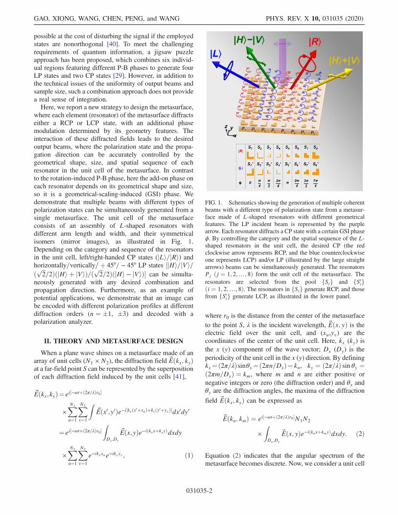
FIG. 1. Schematics showing the generation of multiple coherentbeams with a different type of polarization state from a metasur-face made of L-shaped resonators with different geometricalfeatures. The LP incident beam is represented by the purplearrow. Each resonator diffracts a CP state with a certain GSI phaseϕ. By controlling the category and the spatial sequence of the L-shaped resonators in the unit cell, the desired CP (the redclockwise arrow represents RCP, and the blue counterclockwiseone represents LCP) and/or LP (illustrated by the large straightarrows) beams can be simultaneously generated. The resonatorsPj ðj ¼ 1; 2;…; 8Þ form the unit cell of the metasurface. Theresonators are selected from the pool fSig and fS0igði ¼ 1; 2;…; 8Þ. The resonators in fSig generate RCP, and thosefrom fS0ig generate LCP, as illustrated in the lower panel.
GAO, XIONG, WANG, CHEN, PENG, and WANG PHYS. REV. X 10, 031035 (2020)
031035-2
with Q resonators. If the metasurface is designed such thatDy < λ is satisfied, there will be no diffraction in the ydirection; i.e., m remains zero. Thus, we focus on thecontribution of the resonator assembly in the x directiononly. Let EPj
denote the diffraction field of each resonator(Pj with j ¼ 1; 2;…; Q) in the unit cell. It follows that thenth order of the diffraction field of the metasurface isexpressed as
EðknÞ ¼ ei½−ωtþð2π=λÞr0�N1
X
Q
j¼1
Z ðj−Q2ÞDxQ
ðj−Q2−1ÞDx
Q
EPje−ið2πn=DxÞxdx:
ð3Þ
To generate multiple beams with desired CP and/or LPstates, the amplitude and the phase of the diffracted lightfrom each resonator in the unit cell should be elaboratelydesigned.In this article, the resonators in the unit cell are the L-
shaped gold structures sitting on top of a SiO2-gold-siliconsubstrate. The incident light shines on the metasurface inthe normal direction. The gold layer in the substrate ensuresthat there is no transmission, and the normalized reflectivediffraction intensity of the resonator is enhanced.Physically, because of the existence of the gold layer,the diffraction from the resonator is the interference of theirradiation of the L-shaped structure and the reflection fieldof the gold layer. Meanwhile, the reflection field iscomposed of the mirror image of the incident light andthe irradiation of the mirror image of the L-shapedresonators [11]. It follows that EPj
in Eq. (3) can be
expressed as −Einc þ Erad;j½−eið2πh1=λÞ þ e−ið2πh1=λÞ�. Here,for simplicity of the expression, we take the refractive indexof the SiO2 layer to be 1. The details of the treatment of areal SiO2 layer are provided in the Supplemental Materialof Ref. [11]. Here, Einc is the electric field of the incidentlight, Erad;j is the irradiation field of the L-shaped structure,λ is the wavelength, and h1 is the thickness of the SiO2
layer. Note that Erad;j stands for the irradiation capability ofthe L-shaped structure, and it is related to the geometricalfeatures of the L pattern. It follows that EPj
depends on theincident wavelength, the thickness of the SiO2 layer in thesubstrate, and the geometrical size of the L pattern. Bycarefully selecting these parameters, the phase differencebetween the x and y components of EPj
can be adjusted to90° or 270°. In this way, a CP state is generated. Mostimportantly, by choosing a certain length and width of thearms of the L resonator, a specific GSI phase (ϕ) is imposedon the generated CP state. Moreover, by taking the mirrorimage of the L resonator (with the opening pointing inthe 135° direction), the CP state of the opposite handednessis generated [36]. Practically, we construct a poolof 16 resonators, where eight resonators make a set fSig
(S1, S2,...,S8); the other eight are their mirror-imagestructures fS0ig (S01, S
02,...,S
08), as illustrated in the lower
panel of Fig. 1. The geometrical sizes of the L-shapedresonators are listed in the Supplemental Material [36]. Theresonators in the unit cell are selected from the pool of fSigand fS0ig.Figure 2 shows the amplitude and the phase character-
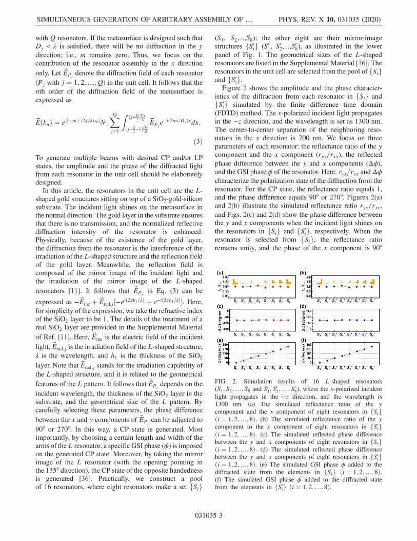
istics of the diffraction from each resonator in fSig andfS0ig simulated by the finite difference time domain(FDTD) method. The x-polarized incident light propagatesin the −z direction, and the wavelength is set as 1300 nm.The center-to-center separation of the neighboring reso-nators in the x direction is 700 nm. We focus on threeparameters of each resonator: the reflectance ratio of the ycomponent and the x component (ryx=rxx), the reflectedphase difference between the y and x components (Δϕ),and the GSI phase ϕ of the resonator. Here, ryx=rxx and Δϕcharacterize the polarization state of the diffraction from theresonator. For the CP state, the reflectance ratio equals 1,and the phase difference equals 90° or 270°. Figures 2(a)and 2(b) illustrate the simulated reflectance ratio ryx=rxx,and Figs. 2(c) and 2(d) show the phase difference betweenthe y and x components when the incident light shines onthe resonators in fSig and fS0ig, respectively. When theresonator is selected from fSig, the reflectance ratioremains unity, and the phase of the x component is 90°
FIG. 2. Simulation results of 16 L-shaped resonators(S1; S2;…; S8 and S01; S
02;…; S08), where the x-polarized incident
light propagates in the −z direction, and the wavelength is1300 nm. (a) The simulated reflectance ratio of the ycomponent and the x component of eight resonators in fSigði ¼ 1; 2;…; 8Þ. (b) The simulated reflectance ratio of the ycomponent to the x component of eight resonators in fS0igði ¼ 1; 2;…; 8Þ. (c) The simulated reflected phase differencebetween the y and x components of eight resonators in fSigði ¼ 1; 2;…; 8Þ. (d) The simulated reflected phase differencebetween the y and x components of eight resonators in fS0igði ¼ 1; 2;…; 8Þ. (e) The simulated GSI phase ϕ added to thediffracted state from the elements in fSig ði ¼ 1; 2;…; 8Þ.(f) The simulated GSI phase ϕ added to the diffracted statefrom the elements in fS0ig ði ¼ 1; 2;…; 8Þ.
SIMULTANEOUS GENERATION OF ARBITRARY ASSEMBLY OF … PHYS. REV. X 10, 031035 (2020)
031035-3
advanced, indicating that the resonators in fSig generate aRCP state. For the resonators in fS0ig, the reflectance ratioremains unity, and the phase of the y component is 90°advanced, indicating that the resonators in fS0ig generate aLCP state. Figures 2(e) and 2(f) show the simulated GSIphase ϕ of the scattered CP state from the 16 resonators. Itcan be seen that the range of ϕ for the resonators in fSigcovers 0 to 2π with a step of π=4, and the same applies forthat in fS0ig. The simulation results in Fig. 2 indicate thatupon normal illumination of an x-polarized incidence,resonators in fSig (fS0ig) generate a RCP (LCP) state,and a GSI phase ϕ is added to the diffraction field of eachresonator.The number of diffraction beams from the metasurface is
determined by the diffraction order n, which depends on theratio of the periodicity of the unit cell in the x direction,Dx,and the wavelength λ [jnj ≤ ðDx=λÞ]. Currently, the sep-aration of resonators in the x direction is 700 nm, and theincident wavelength is 1300 nm. To generate at least fourdiffraction beams, n should satisfy jnj ≥ 2. It follows thatthe number of resonators within the unit cell should be atleast 4. On the other hand, it is known that the higher anglediffraction usually gets lower diffraction efficiency, whichis defined as the ratio of the intensity of the diffracted beamto that of the incident beam. For easier selection of thediffraction beams with higher efficiency, we introduce eightresonators in the unit cell (Q ¼ 8). Meanwhile, theassembly of the resonators within the unit cell may have168 combinations in total. The combination can be reducedby considering only even (or odd) diffraction orders. Morespecifically, if the diffraction fields EPj
and EPjþ4ðj ¼
1; 2; 3; 4Þ possess a phase difference π, according to Eq. (3),the output beams only have odd orders, which means thatonly four resonators (P1, P2, P3, and P4) are essentiallyindependent. Similarly, if EPj
and EPjþ4ðj ¼ 1; 2; 3; 4Þ are
in the same phase (2π), the output beams will be in evenorders. In both cases, the combinations of the resonators arereduced sharply from 168 to 164.To elucidate how the desired state is formed, we first
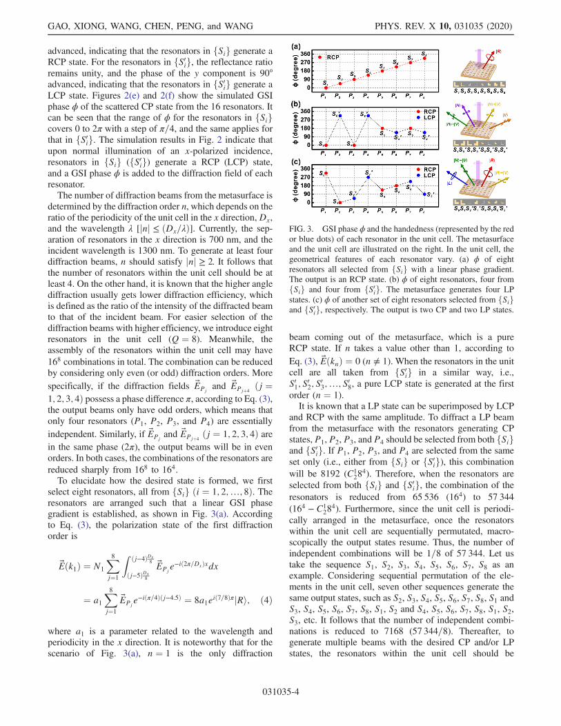
select eight resonators, all from fSig ði ¼ 1; 2;…; 8Þ. Theresonators are arranged such that a linear GSI phasegradient is established, as shown in Fig. 3(a). Accordingto Eq. (3), the polarization state of the first diffractionorder is
Eðk1Þ ¼ N1
X
8
j¼1
Z ðj−4ÞDx8
ðj−5ÞDx8
EPje−ið2π=DxÞxdx
¼ a1X
8
j¼1
EPje−iðπ=4Þðj−4.5Þ ¼ 8a1eið7=8ÞπjRi; ð4Þ
where a1 is a parameter related to the wavelength andperiodicity in the x direction. It is noteworthy that for thescenario of Fig. 3(a), n ¼ 1 is the only diffraction
beam coming out of the metasurface, which is a pureRCP state. If n takes a value other than 1, according toEq. (3), EðknÞ ¼ 0 (n ≠ 1). When the resonators in the unitcell are all taken from fS0ig in a similar way, i.e.,S01; S
02; S
03;…; S08, a pure LCP state is generated at the first
order (n ¼ 1).It is known that a LP state can be superimposed by LCP
and RCP with the same amplitude. To diffract a LP beamfrom the metasurface with the resonators generating CPstates, P1, P2, P3, and P4 should be selected from both fSigand fS0ig. If P1, P2, P3, and P4 are selected from the sameset only (i.e., either from fSig or fS0ig), this combinationwill be 8192 (C1
284). Therefore, when the resonators are
selected from both fSig and fS0ig, the combination of theresonators is reduced from 65 536 (164) to 57 344(164 − C1
284). Furthermore, since the unit cell is periodi-
cally arranged in the metasurface, once the resonatorswithin the unit cell are sequentially permutated, macro-scopically the output states resume. Thus, the number ofindependent combinations will be 1=8 of 57 344. Let ustake the sequence S1, S2, S3, S4, S5, S6, S7, S8 as anexample. Considering sequential permutation of the ele-ments in the unit cell, seven other sequences generate thesame output states, such as S2, S3, S4, S5, S6, S7, S8, S1 andS3, S4, S5, S6, S7, S8, S1, S2 and S4, S5, S6, S7, S8, S1, S2,S3, etc. It follows that the number of independent combi-nations is reduced to 7168 (57 344=8). Thereafter, togenerate multiple beams with the desired CP and/or LPstates, the resonators within the unit cell should be
FIG. 3. GSI phase ϕ and the handedness (represented by the redor blue dots) of each resonator in the unit cell. The metasurfaceand the unit cell are illustrated on the right. In the unit cell, thegeometrical features of each resonator vary. (a) ϕ of eightresonators all selected from fSig with a linear phase gradient.The output is an RCP state. (b) ϕ of eight resonators, four fromfSig and four from fS0ig. The metasurface generates four LPstates. (c) ϕ of another set of eight resonators selected from fSigand fS0ig, respectively. The output is two CP and two LP states.
GAO, XIONG, WANG, CHEN, PENG, and WANG PHYS. REV. X 10, 031035 (2020)
031035-4
elaborately selected via a parameter scan of the 7168combinations based on Eq. (3).Figure 3(b) illustrates the scenario when the resonators
are selected as S1, S08, S1, S08, S5, S04, S5, S04. Thecorresponding phases and handedness of the diffractedstates from each resonator are jRi, eið7π=4ÞjLi, jRi,eið7π=4ÞjLi, eiπjRi, eið3π=4ÞjLi, eiπjRi, and eið3π=4ÞjLi,respectively. Here, n satisfies jnj ≤ ðDx=λÞ due to therestriction j sin θxj ≤ 1. Since the separation of the reso-nators in the x direction is 700 nm, Dx becomes 5600 nm.The incident wavelength is 1300 nm. It follows that jnj ≤ 4.Furthermore, since EPj
and EPjþ4ðj ¼ 1; 2; 3; 4Þ possess a
phase difference of π, the observable n can only be�1,�3.In Eq. (3), by setting n ¼ 1, the polarization state of thefirst-order diffraction is ð ffiffiffi
2p
=2Þeið3π=8ÞðjHi þ jViÞ. Bytaking n ¼ −1, þ3, −3 in Eq. (3), the correspondingpolarization states become e−ið5π=8ÞjHi, eið3π=8ÞjVi, andð ffiffiffi
2p
=2Þe−ið5π=8ÞðjHi − jViÞ, respectively. In this way, fourcoherent LP states are generated.By selecting the geometrical shape, size, and spatial
sequence of the resonators in the unit cell, we can obtainany type of polarization state propagating in the desireddirection. As illustrated in Fig. 3(c), if the unit cell isselected as S8, S1, S02, S
07, S4, S5, S
06, S
03, the corresponding
phase and handedness of the diffraction from these eightresonators are eið7π=4ÞjRi, jRi, eiðπ=4ÞjLi, eið6π=4ÞjLi,eið3π=4ÞjRi, eiπjRi, eið5π=4ÞjLi, eið2π=4ÞjLi, respectively.For the aforementioned reason, n can only be �1 and�3. It follows that, corresponding to n ¼ 3, 1, −1, −3, thepolarization states become ð ffiffiffi
2p
=2Þe−ið5=8ÞπðjHi þ jViÞ,eið5=8ÞπjRi, ð ffiffiffi
2p
=2Þe−ið1=8ÞπðjHi − jViÞ, and eið9=8ÞπjLi,respectively. This result means that two LP (þ45°, −45°)states and two CP (RCP, LCP) states with fixed phasedifferences are simultaneously generated.
III. EXPERIMENTAL
To verify the theoretical design, we fabricate two arraysof L-shaped resonator assemblies on top of a SiO2-gold-silicon substrate: One scenario generates four LP states(þ45°-LP, −45°-LP, horizontally LP, and vertically LP),and the other generates two LP (þ45°-LP, −45°-LP) statesand two CP (RCP, LCP) states, as shown in Figs. 4(a)and 5(a), respectively. To characterize these samples, asupercontinuum laser and a Glan-Taylor polarizer are usedto generate the LP incident beam. The propagation direc-tion of each diffraction beam satisfies sin θx ¼ ðn=DxÞλ.An angle-resolved detector measures the diffraction inten-sity in the ranges of −60° to−12° and 12° to 60°. The regionbetween 12° and −12°, which is marked as the area betweentwo white dash lines in Figs. 4(b) and 5(b), cannot bedetected due to the technical restriction of the reflectionmode. To identify the polarization state of each diffractedbeam, an achromatic quarter-wave plate and/or a polarizer
are installed in front of the detector (see Ref. [36] fordetails). The angle-resolved diffraction spectra are illus-trated in Figs. 4(b) and 5(b). Experimentally, we define aparameter, the light intensity ratio, to characterize the purityof each generated state. For the LP beam, the light intensityratio is defined as the ratio of the intensity of the inves-tigated beam and the intensity detected with the orthogonalpolarization; for the CP beam, it is defined as the ratio ofthe intensity of the investigated beam and that with theconjugated CP. For the ideal situation, this ratio should beinfinity for a pure CP/LP state, which requires that eachresonator in the unit cell possesses the uniform diffractionintensity and the elaborately designed phase. In reality,however, the intensity of the diffraction field from differentresonators varies. In selecting the resonators for fSig andfS0ig, we practically choose the resonators with the dif-fraction intensity within the range of 0.85� 0.05 toguarantee that the intensity ratio is large.For the sample shown in Fig. 4(a), four diffraction
beams, from left to right, correspond to negative third,negative first, first, and third order of diffraction, have beendetected [Fig. 4(b)]. To characterize the diffraction effi-ciency, we define the normalized beam intensity as the ratio
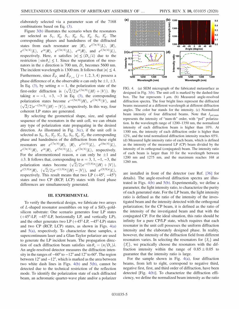
FIG. 4. (a) SEM micrograph of the fabricated metasurface asdesigned in Fig. 3(b). The unit cell is marked by the dashed-linebox. The bar represents 1 μm. (b) Measured angle-resolveddiffraction spectra. The four bright lines represent the diffractedbeams measured at a different wavelength at different diffractionangles. The color bar stands for the intensity. (c) Normalizedbeam intensity of four diffracted beams. Note that Ipol;numrepresents the intensity of “num-th” order, with “pol” polariza-tion. In the wavelength range of 1200–1350 nm, the normalizedintensity of each diffraction beam is higher than 10%. At1300 nm, the intensity of each diffraction order is higher than12%, and the total normalized diffraction intensity reaches 65%.(d) Measured light intensity ratio of each beam, which is definedas the intensity of the measured LP (CP) beam divided by theintensity of its orthogonal (conjugated) beam. The intensity ratioof each beam is larger than 10 for the wavelength between1200 nm and 1275 nm, and the maximum reaches 168 at1260 nm.
SIMULTANEOUS GENERATION OF ARBITRARY ASSEMBLY OF … PHYS. REV. X 10, 031035 (2020)
031035-5
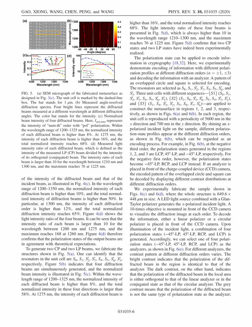
of the intensity of the diffracted beam and that of theincident beam, as illustrated in Fig. 4(c). In the wavelengthrange of 1200–1350 nm, the normalized intensity of eachdiffraction beam is higher than 10%, and the total normal-ized intensity of diffraction beams is higher than 50%. Inparticular, at 1300 nm, the intensity of each diffractionorder is higher than 12%, and the total normalizeddiffraction intensity reaches 65%. Figure 4(d) shows thelight intensity ratio of the four beams. It can be seen that theintensity ratio of each beam is larger than 10 for thewavelength between 1200 nm and 1275 nm, and themaximum reaches 168 at 1260 nm. Figure 4(d) thereforeconfirms that the polarization states of the output beams arein agreement with theoretical expectations.To generate two CP and two LP beams, we fabricate the
structures shown in Fig. 5(a). One can identify that theresonators in the unit cell are S8, S1, S02, S
07, S4, S5, S
06, S
03,
respectively. Figure 5(b) indicates that four diffractionbeams are simultaneously generated, and the normalizedbeam intensity is illustrated in Fig. 5(c). Within the wave-length range of 1200–1325 nm, the normalized intensity ofeach diffracted beam is higher than 8%, and the totalnormalized intensity in these four directions is larger than58%. At 1275 nm, the intensity of each diffraction beam is
higher than 16%, and the total normalized intensity reaches68%. The light intensity ratio of these four beams ispresented in Fig. 5(d), which is always higher than 10 inthe wavelength range 1210–1300 nm, and the maximumreaches 76 at 1225 nm. Figure 5(d) confirms that two CPstates and two LP states have indeed been experimentallyrealized.The polarization state can be applied to encode infor-
mation in cryptography [18,32]. Here, we experimentallydemonstrate encoding of information with different polari-zation profiles at different diffraction orders (n ¼ �1, �3)and decoding the information with an analyzer. A pattern ofan overlapped circle and square is selected for encoding.The resonators are selected as S8, S1, S02, S
07, S4, S5, S
06, and
S03. Three unit cells with different sequences—fS1g (S8, S1,S02, S
07, S4, S5, S
06, S
03), fS2g (S1, S8, S03, S
06, S5, S4, S
07, S
02),
and fS3g (S1, S4, S03, S02, S5, S8, S
07, S
06)—are applied to
construct the metasurface in regions 1, 2, and 3, respec-tively, as shown in Figs. 6(a) and 6(b). In each region, theunit cell is reproduced with a periodicity of 5600 nm in thex direction and 700 nm in the y direction. By shining an x-polarized incident light on the sample, different polariza-tion-state profiles appear at the different diffraction orders,as shown in Fig. 6(b), which can be regarded as anencoding process. For example, in Fig. 6(b), at the negativethird order, the polarization states generated in the regions1, 2, and 3 are LCP, 45°-LP, and −45°-LP, respectively. Forthe negative first order, however, the polarization statesbecome −45°-LP, RCP, and LCP instead. If an analyzer isplaced in front of the charge-coupled device (CCD) camera,the encoded pattern of the overlapped circle and square canbe decoded by displaying different contrast distributions atdifferent diffraction orders.We experimentally fabricate the sample shown in
Figs. 6(c) and 6(d), where the whole structure is 649.6 ×448 μm in size. A LED light source combined with a Glan-Taylor polarizer generates the x-polarized incident light. A10-times objective is mounted in front of the CCD camerato visualize the diffraction image at each order. To decodethe information, either a linear polarizer or a circularpolarizer is placed in front of the CCD camera. Uponillumination of the incident light, a combination of fourpolarization states (−45°-LP, 45°-LP, RCP, and LCP) isgenerated. Accordingly, we can select one of four polari-zation states (−45°-LP, 45°-LP, RCP, and LCP) as theanalyzers, as shown in Fig. 6(e). For different analyzers, thecontrast pattern at different diffraction orders varies. Thebright contrast indicates that the polarization of the dif-fracted beam in the region is identical to that of theanalyzer. The dark contrast, on the other hand, indicatesthat the polarization of the diffracted beam in the local areais either orthogonal to that of the linear analyzer or in theconjugated state as that of the circular analyzer. The greycontrast means that the polarization of the diffracted beamis not the same type of polarization state as the analyzer;
FIG. 5. (a) SEM micrograph of the fabricated metasurface asdesigned in Fig. 3(c). The unit cell is marked by the dashed-linebox. The bar stands for 1 μm. (b) Measured angle-resolveddiffraction spectra. Four bright lines represent the diffractedbeams measured at a different wavelength at different diffractionangles. The color bar stands for the intensity. (c) Normalizedbeam intensity of four diffracted beams. Here, Ipol;num representsthe intensity of “num-th” order with “pol” polarization. Withinthe wavelength range of 1200–1325 nm, the normalized intensityof each diffracted beam is higher than 8%. At 1275 nm, theintensity of each diffraction beam is higher than 16%, and thetotal normalized intensity reaches 68%. (d) Measured lightintensity ratio of each diffracted beam, which is defined as theintensity of the measured LP (CP) beam divided by the intensityof its orthogonal (conjugated) beam. The intensity ratio of eachbeam is larger than 10 for the wavelength between 1210 nm and1300 nm, and the maximum reaches 76 at 1225 nm.
GAO, XIONG, WANG, CHEN, PENG, and WANG PHYS. REV. X 10, 031035 (2020)
031035-6
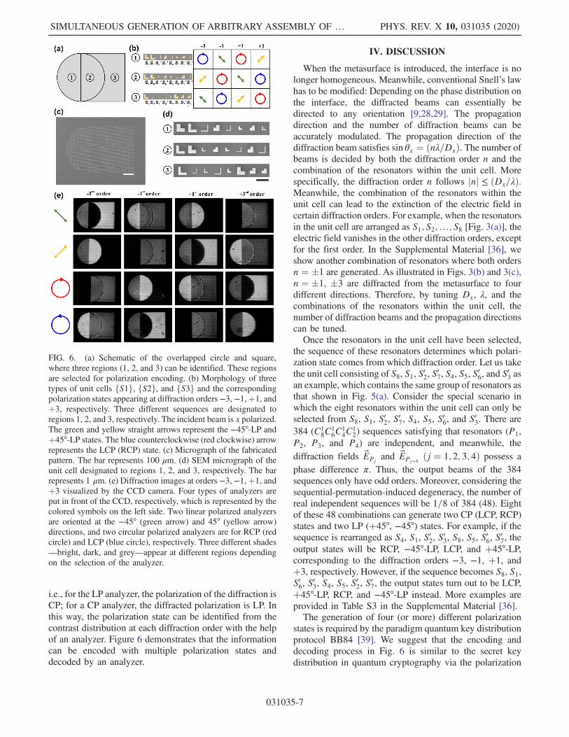
i.e., for the LP analyzer, the polarization of the diffraction isCP; for a CP analyzer, the diffracted polarization is LP. Inthis way, the polarization state can be identified from thecontrast distribution at each diffraction order with the helpof an analyzer. Figure 6 demonstrates that the informationcan be encoded with multiple polarization states anddecoded by an analyzer.
IV. DISCUSSION
When the metasurface is introduced, the interface is nolonger homogeneous. Meanwhile, conventional Snell’s lawhas to be modified: Depending on the phase distribution onthe interface, the diffracted beams can essentially bedirected to any orientation [9,28,29]. The propagationdirection and the number of diffraction beams can beaccurately modulated. The propagation direction of thediffraction beam satisfies sin θx ¼ ðnλ=DxÞ. The number ofbeams is decided by both the diffraction order n and thecombination of the resonators within the unit cell. Morespecifically, the diffraction order n follows jnj ≤ ðDx=λÞ.Meanwhile, the combination of the resonators within theunit cell can lead to the extinction of the electric field incertain diffraction orders. For example, when the resonatorsin the unit cell are arranged as S1; S2;…; S8 [Fig. 3(a)], theelectric field vanishes in the other diffraction orders, exceptfor the first order. In the Supplemental Material [36], weshow another combination of resonators where both ordersn ¼ �1 are generated. As illustrated in Figs. 3(b) and 3(c),n ¼ �1, �3 are diffracted from the metasurface to fourdifferent directions. Therefore, by tuning Dx, λ, and thecombinations of the resonators within the unit cell, thenumber of diffraction beams and the propagation directionscan be tuned.Once the resonators in the unit cell have been selected,
the sequence of these resonators determines which polari-zation state comes from which diffraction order. Let us takethe unit cell consisting of S8, S1, S02, S
07, S4, S5, S
06, and S
03 as
an example, which contains the same group of resonators asthat shown in Fig. 5(a). Consider the special scenario inwhich the eight resonators within the unit cell can only beselected from S8, S1, S02, S
07, S4, S5, S
06, and S03. There are
384 (C18C
16C
14C
12) sequences satisfying that resonators (P1,
P2, P3, and P4) are independent, and meanwhile, thediffraction fields EPj
and EPjþ4ðj ¼ 1; 2; 3; 4Þ possess a
phase difference π. Thus, the output beams of the 384sequences only have odd orders. Moreover, considering thesequential-permutation-induced degeneracy, the number ofreal independent sequences will be 1=8 of 384 (48). Eightof these 48 combinations can generate two CP (LCP, RCP)states and two LP (þ45°, −45°) states. For example, if thesequence is rearranged as S4, S1, S02, S
03, S8, S5, S
06, S
07, the
output states will be RCP, −45°-LP, LCP, and þ45°-LP,corresponding to the diffraction orders −3, −1, þ1, andþ3, respectively. However, if the sequence becomes S8, S1,S06, S
03, S4, S5, S
02, S
07, the output states turn out to be LCP,
þ45°-LP, RCP, and −45°-LP instead. More examples areprovided in Table S3 in the Supplemental Material [36].The generation of four (or more) different polarization
states is required by the paradigm quantum key distributionprotocol BB84 [39]. We suggest that the encoding anddecoding process in Fig. 6 is similar to the secret keydistribution in quantum cryptography via the polarization
FIG. 6. (a) Schematic of the overlapped circle and square,where three regions (1, 2, and 3) can be identified. These regionsare selected for polarization encoding. (b) Morphology of threetypes of unit cells fS1g, fS2g, and fS3g and the correspondingpolarization states appearing at diffraction orders−3, −1,þ1, andþ3, respectively. Three different sequences are designated toregions 1, 2, and 3, respectively. The incident beam is x polarized.The green and yellow straight arrows represent the −45°-LP andþ45°-LP states. The blue counterclockwise (red clockwise) arrowrepresents the LCP (RCP) state. (c) Micrograph of the fabricatedpattern. The bar represents 100 μm. (d) SEM micrograph of theunit cell designated to regions 1, 2, and 3, respectively. The barrepresents 1 μm. (e) Diffraction images at orders −3, −1,þ1, andþ3 visualized by the CCD camera. Four types of analyzers areput in front of the CCD, respectively, which is represented by thecolored symbols on the left side. Two linear polarized analyzersare oriented at the −45° (green arrow) and 45° (yellow arrow)directions, and two circular polarized analyzers are for RCP (redcircle) and LCP (blue circle), respectively. Three different shades—bright, dark, and grey—appear at different regions dependingon the selection of the analyzer.
SIMULTANEOUS GENERATION OF ARBITRARY ASSEMBLY OF … PHYS. REV. X 10, 031035 (2020)
031035-7
of photons [39]. In the information cryptography, theinformation sender (Alice) and the receiver (Bob) sharea key, which is used by Alice (Bob) to encrypt (decrypt) theinformation. Immediately sensing the existence of eaves-droppers in key distribution, which is guaranteed by theprinciple that quantum measurements cannot occur withoutperturbing the system [40], ensures the security of keydistribution and hence the confidentiality of the informa-tion. We suggest that the metasurface in Fig. 5 and theencoding or decoding processes in Fig. 6 can be applied forsecure key distribution in quantum information. Morespecifically, suppose that the key is composed of asequence of 0 or 1. The metasurface shown in Fig. 5 isplaced after a single-photon source. The diffracted photonis in one of the LCP, RCP, þ45°-LP, and −45°-LP states.Here, we designate the binary value 0 as LCP or þ45°-LPstates and the value 1 as the states RCP or −45°-LP. It isnoteworthy that two nonorthogonal states represent thesame value (either 0 or 1), and this scenario strengthens thesecurity of the key [39]. In the case that the system iseavesdropped, the measurement made by the eavesdropperwill randomly modify the polarization of the photon. Itfollows that the error rate of the key, which is defined as theratio of the number of wrong values to the number of thewhole transmitted photons, suddenly increases. Theincrease of the error rate suggests the existence of eaves-dropper, hence the total key will be dropped. After Alicetransfers a single photon with the specific polarization oneafter the other, Bob measures the photon with a randomlychosen analyzer. There are four possible choices for theanalyzer, as illustrated in Fig. 6(e). Details about theprocess of the key transmission are provided in theSupplemental Material [36]. Next, Alice encrypts theinformation with the shared secret key by a bitwiseoperation, such as XOR, a logical operation that the valueof the output takes 1 only when the values of the binaryinputs differ. Bob decrypts the information with the samekey with an inverse operation [42]. In this way, theencrypted information is transmitted safely from Alice toBob. In this process, the key distribution is accomplishedwith the metasurface and four optical analyzers. Thisapproach provides new perspectives in generating anassembly of nonorthogonal polarization states that arelightweight and have a high integration degree; hence, itis enlightening in developing portable quantumcryptography.
V. CONCLUSIONS
Encoding, transmission, and processing of informationare important issues in quantum information science [42–44]. As the basic unit of quantum information processing,the qubit gate can be constructed with polarization beamsplitters, phase shifters, and wave plates, etc., which arebulky and heavy if conventional optical devices are used[43]. Developing new principle optical devices is essential
for future integrated photonics and information technology.The approach demonstrated in this article provides apromising solution to generate an arbitrary combinationof CP and LP states simultaneously. By judiciouslyselecting the geometrical size and the symmetry of eachresonator in the unit cell and by carefully designing thelattice parameters, we are able to accurately control theoutput polarization states, the number of output beams, andthe propagation direction of each beam. In contrast to the P-B phase modulation, which generates either CP states or LPstates, respectively, our approach allows us to form anarbitrary assembly of different polarization states with highintegration based on the concept of the GSI phase. Weanticipate that such a capability is very supportive inconstructing quantum states [20], realizing quantum entan-glement [19] and qubit gates [44], and developing quantumcryptography [37,39].
ACKNOWLEDGMENTS
This work was supported by projects from the NationalKey R&D Program of China (GrantNo. 2017YFA0303702), and the National NaturalScience Foundation of China (Grants No. 11634005,No. 11674155, No. 11974177, and No. 61975078).
[1] S.-H. Gong, F. Alpeggiani, B. Sciacca, E. C. Garnett, and L.Kuipers, Nanoscale Chiral Valley-Photon Interface throughOptical Spin-Orbit Coupling, Science 359, 443 (2018).
[2] H. Zhou, C. Peng, Y. Yoon, C. W. Hsu, K. A. Nelson, L. Fu,J. D. Joannopoulos, M. Soljačić, and B. Zhen, Observationof Bulk Fermi Arc and Polarization Half Charge fromPaired Exceptional Points, Science 359, 1009 (2018).
[3] A. Ciarrocchi, D. Unuchek, A. Avsar, K. Watanable, T.Taniguchi, and A. Kis, Polarization Switching and Elec-trical Control of Interlayer Excitons in Two-DimensionalVan Der Waals Heterostructures, Nat. Photonics 13, 131(2019).
[4] D. Azoury, O. Kneller, M. Krüger, B. D. Bruner, O. Cohen,Y. Mairesse, and N. Dudovich, Interferometric AttosecondLock-In Measurement of Extreme-Ultraviolet Circular Di-chroism, Nat. Photonics 13, 198 (2019).
[5] J. K. Gansel, M. Thiel, M. S. Rill, M. Decker, K. Bade, V.Saile, G. von Freymann, S. Linden, and M. Wegener, GoldHelix Photonic Metamaterial as Broadband Circular Polar-izer, Science 325, 1513 (2009).
[6] T.-T. Kim, S. S. Oh, H.-D. Kim, H. S. Park, O. Hess, B. Min,and S. Zhang, Electrical Access to Critical Coupling ofCircularly Polarized Waves in Graphene Chiral Metama-terials, Sci. Adv. 3, e1701377 (2017).
[7] H. Hu, Q. Gan, and Q. Zhan,Generation of a NondiffractingSuperchiral Optical Needle for Circular Dichroism Imagingof Sparse Subdiffraction Objects, Phys. Rev. Lett. 122,223901 (2019).
[8] M. Born and E. Wolf, Principles of Optics (CambridgeUniversity Press, Cambridge, England, 1999).
GAO, XIONG, WANG, CHEN, PENG, and WANG PHYS. REV. X 10, 031035 (2020)
031035-8
[9] N. Yu, P. Genevet, M. A. Kats, F. Aieta, J.-P. Tetienne, F.Capasso, and Z. Gaburro, Light Propagation with PhaseDiscontinuities: Generalized Laws of Reflection and Re-fraction, Science 334, 333 (2011).
[10] S.-C. Jiang, X. Xiong, P. Sarriugarte, S.-W. Jiang, X.-B. Yin,Y. Wang, R.-W. Peng, D. Wu, R. Hillenbrand, X. Zhang,and M. Wang, Tuning the Polarization State of Light viaTime Retardation with a Microstructured Surface, Phys.Rev. B 88, 161104(R) (2013).
[11] S.-C. Jiang, X. Xiong, Y.-S. Hu, Y.-H. Hu, G.-B. Ma, R.-W.Peng, C. Sun, and M. Wang, Controlling the PolarizationState of Light with a Dispersion-Free Metastructure, Phys.Rev. X 4, 021026 (2014).
[12] X. Xiong, Y.-S. Hu, S.-C. Jiang, Y.-H. Hu, R.-H. Fan,G.-B. Ma, D.-J. Shu, R.-W. Peng, and M. Wang, MetallicStereostructured Layer: An Approach for BroadbandPolarization State Manipulation, Appl. Phys. Lett. 105,201105 (2014).
[13] R.-H. Fan, Y. Zhou, X.-P. Ren, R.-W. Peng, S.-C. Jiang,D.-H. Xu, X. Xiong, X.-R. Huang, and M. Wang, FreelyTunable Broadband Polarization Rotator for TerahertzWaves, Adv. Mater. 27, 1201 (2015).
[14] Z.-H. Wang, S.-C. Jiang, X. Xiong, R.-W Peng, and M.Wang, Generation of Equal-Intensity Coherent OpticalBeams by Binary Geometrical Phase on Metasurface, Appl.Phys. Lett. 108, 261107 (2016).
[15] J. P. B. Mueller, N. A. Rubin, R. C. Devlin, B. Groever, andF. Capasso, Metasurface Polarization Optics: IndependentPhase Control of Arbitrary Orthogonal States of Polariza-tion, Phys. Rev. Lett. 118, 113901 (2017).
[16] R. C. Devlin, A. Ambrosio, N. A. Rubin, J. P. B. Mueller,and F. Capasso, Arbitrary Spin-to-Orbital Angular Momen-tum Conversion of Light, Science 358, 896 (2017).
[17] P. C. Wu, J.-W. Chen, C.-W. Yin, Y.-C. Lai, T. L. Chung,C. Y. Liao, B. H. Chen, K.-W. Lee, C.-J. Chuang, C.-M.Wang, and D. P. Tsai, Visible Metasurfaces for On-ChipPolarimetry, ACS Photonics 5, 2568 (2017).
[18] J. Li, S. Kamin, G. Zheng, F. Neubrech, S. Zhang, and N.Liu, Addressable Metasurfaces for Dynamic Holographyand Optical Information Encryption, Sci. Adv. 4, eaar6768(2018).
[19] T. Stav, A. Faerman, E. Maguid, D. Oren, V. Kleiner, E.Hasman, and M. Segev, Quantum Entanglement of the Spinand Orbital Angular Momentum of Photons Using Meta-materials, Science 361, 1101 (2018).
[20] K. Wang, J. G. Titchener, S. S. Kruk, L. Xu, H.-P. Chung,M. Parry, I. I. Kravchenko, Y.-H. Chen, A. S. Solntsev, Y. S.Kivshar, D. N. Neshev, and A. A. Sukhorukov, QuantumMetasurface for Multiphoton Interference and StateReconstruction, Science 361, 1104 (2018).
[21] Z. Wu, Y. Ra’di, and A. Grbic, Tunable Metasurfaces: APolarization Rotator Design, Phys. Rev. X 9, 011036(2019).
[22] N. A. Rubin, G. D’Aversa, P. Chevalier, Z. Shi, W. T. Chen,and F. Capasso, Matrix Fourier Optics Enables a CompactFull-Stokes Polarization Camera, Science 365, eaax1839(2019).
[23] C.-C. Chang, Z. Zhao, D. Li, A. J. Taylor, S. Fan, and H.-T.Chen, Broadband Linear-to-Circular Polarization Conver-
sion Enabled by Birefringent Off-Resonance ReflectiveMetasurfaces, Phys. Rev. Lett. 123, 237401 (2019).
[24] H. Kwon, E. Arbabi, S. M. Kamali, M. Faraji-Dana, and A.Faraon, Single-Shot Quantitative Phase Gradient Micros-copy Using a System of Multifunctional Metasurfaces, Nat.Photonics 14, 109 (2020).
[25] A. Shaltout, J. Liu, A. Kildishev, and V. Shalaev, PhotonicSpin Hall Effect in Gap-Plasmon Metasurfaces for On-ChipChiroptical Spectroscopy, Optica 2, 860 (2015).
[26] M. Tymchenko, J. S. Gomez-Diaz, J. Lee, N. Nookala, M.A. Belkin, and A. Alù, Gradient Nonlinear Pancharatnam-Berry Metasurfaces, Phys. Rev. Lett. 115, 207403(2015).
[27] M. Khorasaninejad, W. T. Chen, R. C. Devlin, J. Oh, A. Y.Zhu, and F. Capasso, Metalenses at Visible Wavelengths:Diffraction-Limited Focusing and Subwavelength Resolu-tion Imaging, Science 352, 1190 (2016).
[28] D. Wen, F. Yue, C. Zhang, X. Zang, H. Liu, W. Wang, andX. Chen, Plasmonic Metasurface for Optical Rotation,Appl. Phys. Lett. 111, 023102 (2017).
[29] P. C. Wu, W.-Y. Tsai, W. T. Chen, Y.-W. Huang, T.-Y. Chen,J.-W. Chen, C. Y. Liao, C. H. Chu, G. Sun, and D. P. Tsai,Versatile Polarization Generation with an AluminumPlasmonic Metasurface, Nano Lett. 17, 445 (2017).
[30] W. T. Chen, A. Y. Zhu, V. Sanjeev, M. Khorasaninejad, Z.Shi, E. Lee, and F. Capasso, A Broadband AchromaticMetalens for Focusing and Imaging in the Visible, Nat.Nanotechnol. 13, 220 (2018).
[31] S. Wang, P. C. Wu, V.-C. Su, Y.-C. Lai, M.-K. Chen, H. Y.Kuo, B. H. Chen, Y. H. Chen, T.-T. Huang, J.-H. Wang,R.-M. Lin, C.-H. Kuan, T. Li, Z. Wang, S. Zhu, and D. P.Tsai, A Broadband Achromatic Metalens in the Visible, Nat.Nanotechnol. 13, 227 (2018).
[32] X. Zang, F. Dong, F. Yue, C. Zhang, L. Xu, Z. Song, M.Chen, P.-Y. Chen, G. S. Buller, Y. Zhu, S. Zhuang, W. Chu,S. Zhang, and X. Chen, Polarization Encoded Color ImageEmbedded in a Dielectric Metasurface, Adv. Mater. 30,1707499 (2018).
[33] F. Zhong, J. Li, H. Liu, and S. Zhu, Controlling SurfacePlasmons through Covariant Transformation of the Spin-Dependent Geometric Phase between Curved Metamateri-als, Phys. Rev. Lett. 120, 243901 (2018).
[34] N. Shitrit, J. Kim, D. S. Barth, H. Ramezani, Y. Wang, andX. Zhang, Asymmetric Free-Space Light Transport atNonlinear Metasurfaces, Phys. Rev. Lett. 121, 046101(2018).
[35] P. K. Jha, N. Shitrit, X. Ren, Y. Wang, and X. Zhang,Spontaneous Exciton Valley Coherence in Transition MetalDichalcogenide Monolayers Interfaced with an AnisotropicMetasurface, Phys. Rev. Lett. 121, 116102 (2018).
[36] See Supplemental Material at http://link.aps.org/supplemental/10.1103/PhysRevX.10.031035 for furthertheoretical and experimental details.
[37] Z. Tang, Z. Liao, F. Xu, B. Qi, L. Qian, and H.-K. Lo,Experimental Demonstration of Polarization EncodingMeasurement-Device-Independent Quantum Key Distribu-tion, Phys. Rev. Lett. 112, 190503 (2014).
[38] H. Takenaka, A. Carrasco-Casado, M. Fujiwara, M.Kitamura, M. Sasaki, and M. Toyoshima, Satellite-
SIMULTANEOUS GENERATION OF ARBITRARY ASSEMBLY OF … PHYS. REV. X 10, 031035 (2020)
031035-9
to-Ground Quantum-Limited Communication Using a 50-kg-Class Microsatellite, Nat. Photonics 11, 502 (2017).
[39] N. Gisin, G. Ribordy, W. Tittel, and H. Zbinden, QuantumCryptography, Rev. Mod. Phys. 74, 145 (2002).
[40] P. Meystre and M. Sargent, Elements of Quantum Optics(Springer, New York, 2007).
[41] E. Hecht, Optics (Pearson Education, Harlow, United King-dom, 2013).
[42] T. Jennewein, C. Simon, G. Weihs, H. Weinfurter, and A.Zeilinger, Quantum Cryptography with Entangled Photons,Phys. Rev. Lett. 84, 4729 (2000).
[43] J. L. O’Brien , Optical Quantum Computing, Science 318,1567 (2007).
[44] D. Tiarks, S. Schmidt-Eberle, T. Stolz, G. Rempe, and S.Dürr, A Photon-Photon Quantum Gate Based on RydbergInteractions, Nat. Phys. 15, 124 (2019).
GAO, XIONG, WANG, CHEN, PENG, and WANG PHYS. REV. X 10, 031035 (2020)
031035-10