Embed Size (px)
Citation preview
8/13/2019 Passive Heave
http://slidepdf.com/reader/full/passive-heave 1/8
OTC 21527
Effectiveness of Passive Heave Compensation in a Deepwater EnvironmentBarry Presley and Sotirios Koutsoukos, Technip
Copyright 2011, Offshore Technology Conference
This paper was prepared for presentation at the Offshore Technology Conference held in Houston, Texas, USA, 2–5 May 2011.
This paper was selected for presentation by an OTC program committee following review of information contained in an abstract submitted by the author(s). Contents of the paper have not beenreviewed by the Offshore Technology Conference and are subject to correction by the author(s). The material does not necessarily reflect any position of the Offshore Technology Conference, itsofficers, or members. Electronic reproduction, distribution, or storage of any part of this paper without the written consent of the Offshore Technology Conference is prohibited. Permission toreproduce in print is restricted to an abstract of not more than 300 words; illustrations may not be copied. The abstract must contain conspicuous acknowledgment of OTC copyright.
Abstract
The technical advantage of a method of providing heave compensation for deepwater installation operations is presented.
This paper explores the use of passive heave compensation (PHC) as an alternative to active heave compensation (AHC) toimprove seabed landing. The theoretical modeling of such systems is shown to increase vessel operability and therefore
reduce installation time and costs.
When a subsea package is to be installed on the seabed, the landing velocity or acceleration may be restricted due to various
reasons, such as the possibility of disturbing the soil or damaging any sensitive components in the package. This may limitthe permissible seastate for installation and restrict vessel operability. In order to improve operability, active heave
compensation systems are often used to bring down the landing velocity and acceleration
The effectiveness of passive heave compensation (PHC) for seabed landing is assessed analytically in a variety of global
locations. It is concluded that passive heave compensation systems can be effective in many regions and applications where
achieving soft landing of subsea packages is important during subsea installation to improve operability. This paperdemonstrates that passive heave compensation systems are a viable alternative to active heave compensation systems.
Introduction
There is an increasing need to lower, install and retrieve larger packages to greater water depths from vessels offshore. As aresult, there is increased scrutiny on the integrity of the cranes and winches during these operations, especially as these assets
are used closer to their rated capacity. There also appears to be increasing demand on the integrity of installed packages and
to position these within tighter tolerances on the seabed, calling for better prediction, control of package displacement
parameters and line tension. The major displacement of the package during lowering, installation or retrieval operations is inthe vertical (heave) direction of the vessel from which it is suspended. Compensating for the heave of the vessel from which
the structure is installed can therefore reduce the displacement of the package. The motion parameters and line tension can
also be influenced by introducing suitably tuned devices in the line which can additionally absorb any amplified dynamicloads.
Package motions and line tensions assume importance at three key stages during a lowering operation; as the package passes
through the splash zone, as it passes through resonance, and as it approaches touchdown on the seabed. In shallow water,
shorter wire length causes the boom tip and the package to move in phase. However, in deeper water as the wire is muchlonger the package motions are no longer solely a function of boom tip motions, indeed the package can oscillate at the
system (i.e. crane structure, wire and package) natural frequency.
The current investigation involved analyzing results of a computational simulation of package motion parameters during its
passage through resonance and as it approaches the seabed. For the simulation, two packages of different mass and shapewere considered installed in different water depths in regular waves over a range of wave periods and results were analyzed
for trends. The numerical simulation considered cases with and without passive heave compensation. The efficacy of heave
8/13/2019 Passive Heave
http://slidepdf.com/reader/full/passive-heave 2/8
2 OTC 21527
compensation at the splash zone did not form part of the present analysis, as the efficiency of lowering in the splashzone is
influenced by package weight, volume and area.
Methodology for the Computational Modeling of Package Response
A package response sensitivity study was carried out computationally and analytically to determine the effectiveness of heave
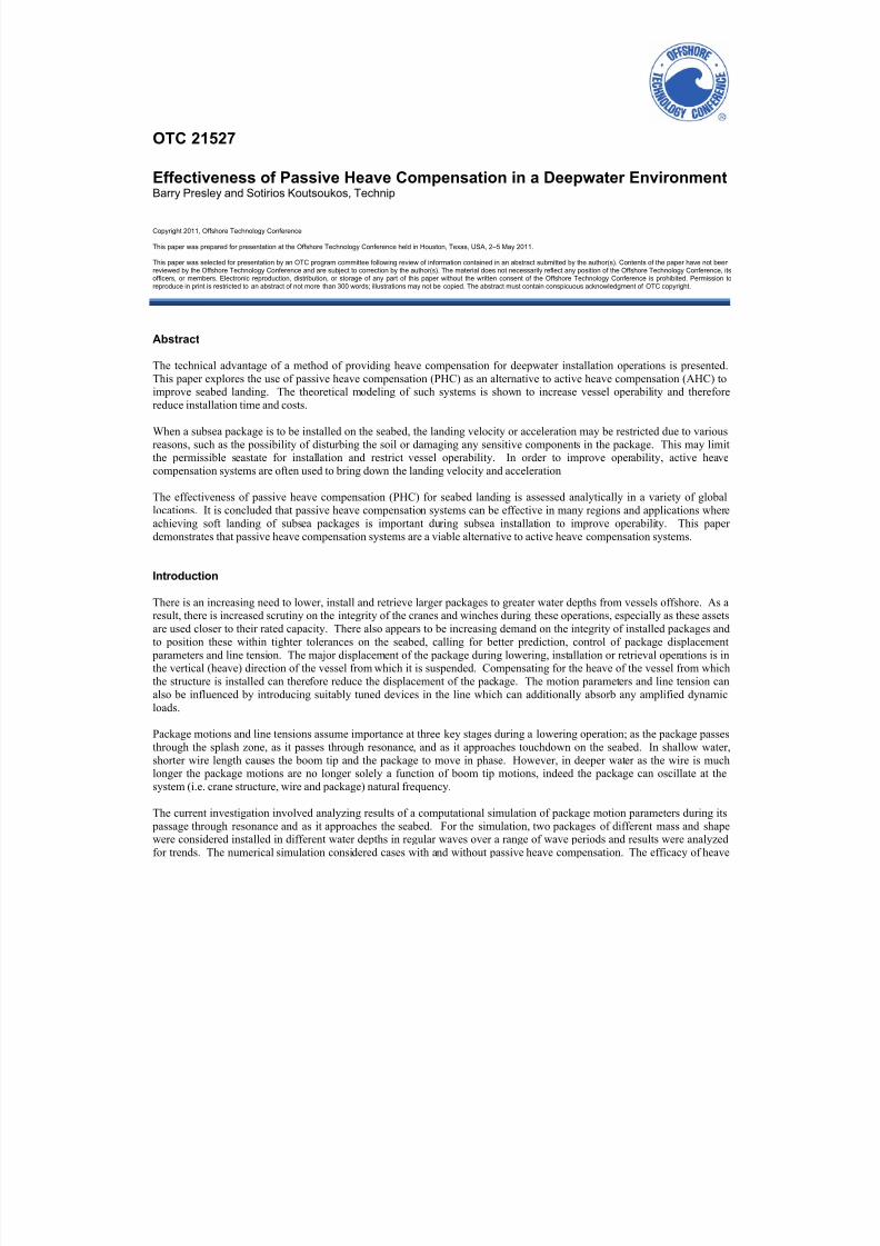
compensation systems, and in particular limited to PHC systems. The package response analysis was carried out using timedomain simulation with a typical package response model is shown in Figure 1. It consists of the vessel (modeled using
RAOs), lowering wire, package and passive heave compensator, when included. The package motion, velocity and line
tension were calculated for different wave conditions. The sensitivity of the package response to variables such as the package type, lowering wire, wire hang-off position and stiffness of rope has been studied.
X90 m
X
Z
rca ex . : - _ nc _ m_ ee re_ an o _ _ z . a mo e : on y rca ex . a z mu = ; e eva oReset
Crane tip position
Wire
Shackle
Passive Heave Com
Figure 1: Typical Package Response Model and Line Schematic
Selection of Regions for Operability Study
Metocean data for a number of worldwide operational regions were collected and examined. It was intended to use the mostonerous data for the operability study and only deep water regions were considered of interest; hence regions such as North
Sea & Canada were excluded. This resulted in a shortlist of four regions - Asia-Pacific, Brazil, Gulf of Mexico and West
Africa, for the purposes of this study.
Generic data has been used for the purposes of this study, however for reliable operability estimates, precise environmental
data specific to the installation location is essential to provide an accurate assessment of the efficacy of PHC systems.
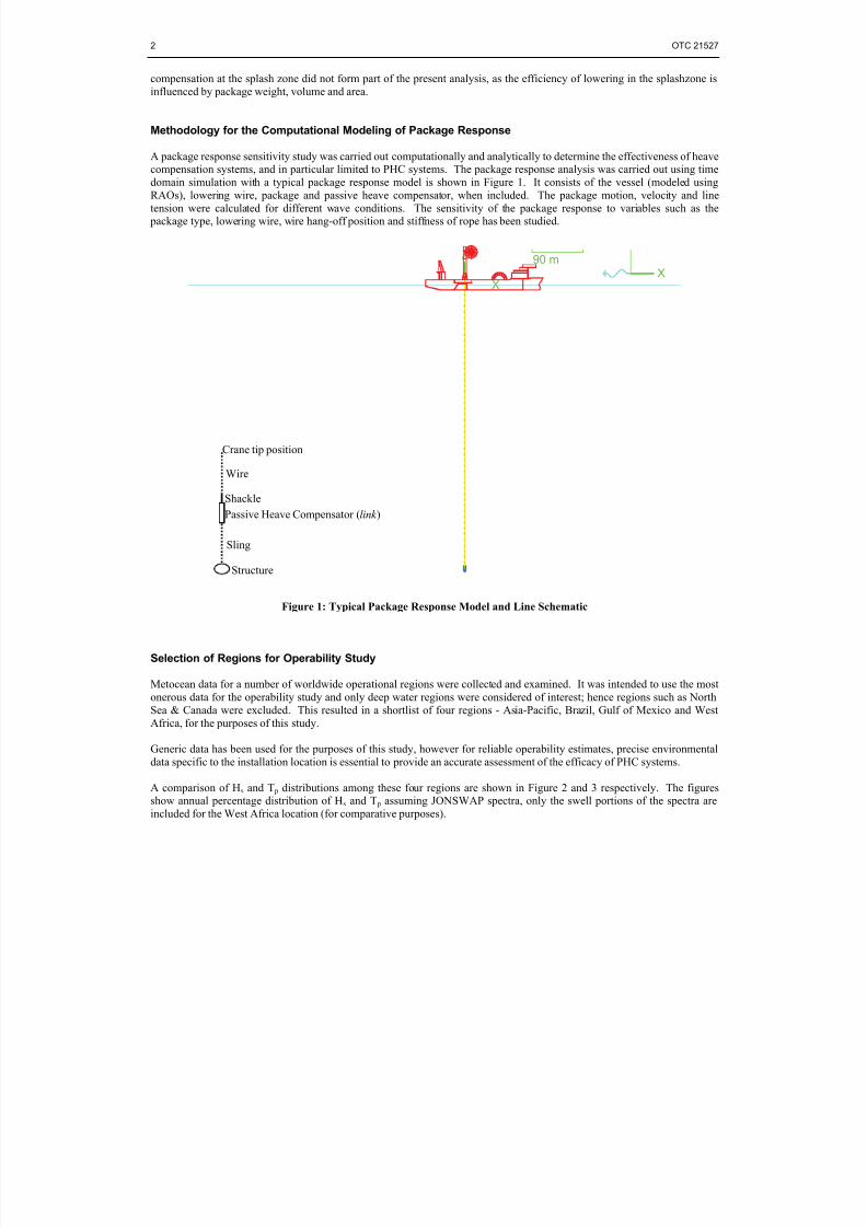
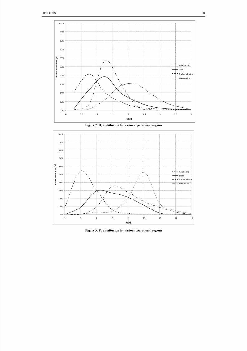
A comparison of Hs and T p distributions among these four regions are shown in Figure 2 and 3 respectively. The figuresshow annual percentage distribution of Hs and T p assuming JONSWAP spectra, only the swell portions of the spectra are
included for the West Africa location (for comparative purposes).
pensator (link )
Sling
Structure
8/13/2019 Passive Heave
http://slidepdf.com/reader/full/passive-heave 3/8
OTC 21527 3
0%
10%
20%
30%
40%
50%
60%
70%
80%
90%
100%
0 0.5 1 1.5 2 2.5 3 3.5
A n n u a l o c c u r r e n c e
[ % ]
Hs [m]
4
Asia‐Pacific
Brazil
Gulf of Mexico
West Africa
Figure 2: Hs distribution for various operational regions
0%
10%
20%
30%
40%
50%
60%
70%
80%
90%
100%
3 5 7 9 11 13 15 17
A n n u a l o c c u r r e n c e
[ % ]
Tp [s]19
Asia‐Pacific
Brazil
Gulf of Mexico
West Africa
Figure 3: Tp distribution for various operational regions
8/13/2019 Passive Heave
http://slidepdf.com/reader/full/passive-heave 4/8
4 OTC 21527
Model for Seabed Landing
Analysis of predicting the package velocity was carried out using time-domain simulation with additional verification of theresults being carried out using a frequency-domain in-house tool based on DNV-RP-H103 (DISH 2006). The frequency-
domain tool simulated a package connected to a suspension point using a lowering wire - the mass element included the
package mass, its added mass and the mass of the lowering wire as well as rigging with additional drag on the package
damped the system. The tool solved the single degree of freedom damped spring-mass system for motion amplitude, velocity
and acceleration of the package in the frequency-domain. The results from the tool compared well with those from time-domain analysis and therefore validated the results obtained.
Analysis sequence
The following sequence was followed for the analysis.
i. Analysis in irregular waves for velocity of the package with it suspended from A&R winch sheave.
ii. Repeat of analysis to predict package velocity as in (i) with the inclusion of passive heave compensator stiffness
directly above the package rigging.
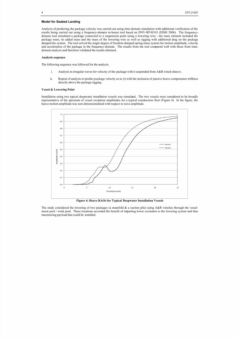
Vessel & Lowering Point
Installation using two typical deepwater installation vessels was simulated. The two vessels were considered to be broadly
representative of the spectrum of vessel excitation amplitudes for a typical construction fleet (Figure 4). In the figure, the
heave motion amplitude was non-dimensionalized with respect to wave amplitude.
0.0
0.1
0.2
0.3
0.4
0.5
0.6
0.7
0.8
0.9
1.0
0 5 10 15 20 25
Vessel 1
Vessel 2
Period(seconds)
A m p l i t u d e ( m / m )
Figure 4: Heave RAOs for Typical Deepwater Installation Vessels
The study considered the lowering of two packages (a manifold & a suction pile) using A&R winches through the vessel
moon pool / work pool. These locations accorded the benefit of imparting lower excitation to the lowering system and thus
maximizing payload that could be installed.
8/13/2019 Passive Heave
http://slidepdf.com/reader/full/passive-heave 5/8
OTC 21527 5
Package type
Two typical subsea packages were considered:
i. Manifold: 18.6 x 11.8 x 6.3m mass=145Te
ii. Pile: 25m x 5m dia. mass=100Te
Hydrodynamic coefficients for the typical packages were estimated and are summarized in Table 1. Added mass values formanifold and pile evolved from flat plate and vertical cylinder idealizations respectively, corrected for equivalent
perforations and plate end effects. Drag coefficients in oscillatory flow were used.
Manifold Pile
Added mass [Te] 495.4 570.0
Damping coefficient, Cd [-] 5.0 5.0
Table 1: Added mass and damping for the packages
Waves
Analysis was carried out in irregular waves characterized by JONSWAP spectrum. The spectral peakedness parameter γ
either varied with (Hs, T p) or kept constant, corresponding to the wave scatter data used. A range of Hs from 1.0 - 2.5m in
increments of 0.5m was studied. Peak spectral wave periods from 4 to 20 seconds were considered with one hour simulations
carried out.
In order to limit the number of analyses, the ranges of Hs considered for package velocity analysis were limited to Hs=2.5m.
This is also in line with practice, whereby installation is generally not performed at Hs>2.5m. For all sea states with Hs>2.5mappearing in the metocean data, installation was assumed not possible (i.e., operability assumed as zero).
Assumptions in time-domain model
The following assumptions or simplifications were made in the computational assessment using the time-domain packageresponse model.
i. Winch support and overboarding structure stiffness was not modeled, this was assumed not to significantlyaffect the results.
ii. A typical passive heave compensator suitable for the maximum expected line tensions has been used for all
analyses. The stiffness and damping data were obtained from the manufacturer supplied data.
iii. Damping of the lowering wire was ignored since it would be negligible compared to the package damping. Theeffect of inclusion on package velocity prediction was therefore not considered to be significant.
iv. For each analysis, the PHC pre-tension was adjusted so that at static equilibrium, the PHC elongation is abouthalf the limiting stroke. This was intended to ensure optimum response for the dynamic variations in line
tension.
v. PHC was modeled between the lower end of the crane wire and the rigging for the package to simulate theactual rigging configuration.
vi. Lowering wire payout was not modeled, i.e., the package was assumed to be positioned at the water depth.
The effect of ignoring wire payout on the package velocity was expected to be negligible as the increase indamping resulting from inclusion of velocity of lowering (DISH 2006) would be offset by the resulting reduced
effect of oscillatory motion and associated damping.
vii. For reasons of simplicity, open-water hydrodynamic coefficients were used and therefore the load / seabed
interaction was not considered in this analysis.
8/13/2019 Passive Heave
http://slidepdf.com/reader/full/passive-heave 6/8
6 OTC 21527
Performance criteria
Judgment on operability required the use of a limiting performance criterion. Based on reviews of project installationanalyses, package vertical velocity requirement of less than 0.5 m/s were considered acceptable as a typical seabed landing
velocity criterion and has been used for the purposes of this study. The limit of 0.5m/s is a lower bound client requirement,
but this limit should be appropriate for the installed package and could be much higher depending on the structure being
installed. It is important to use realistic limits so that installation of the structure is not restricted by inappropriate installation
criterion, such criterion should be checked with the equipment designer/supplier to fully understand their origin.
Offshore operations of this nature have their environmental condition limits based upon this type of analysis. These limits
would be termed Design Criteria (DNV 1996). The weather criteria to be used on actual operations are usually lower andwould be referred to as Operational Criteria. The reason these are more stringent is that weather-restricted operations are
performed based on a forecast and always face the possibility of the environmental conditions of interest (e.g. wave height)
exceeding those forecast. However, the operability in this analysis was compared on the basis of design limits and not
operational limits.
Results of Region-wise Operability
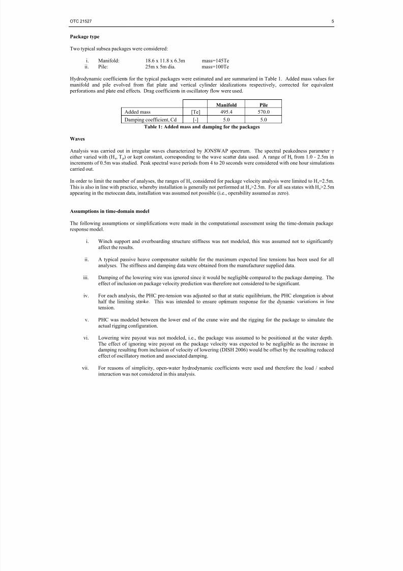
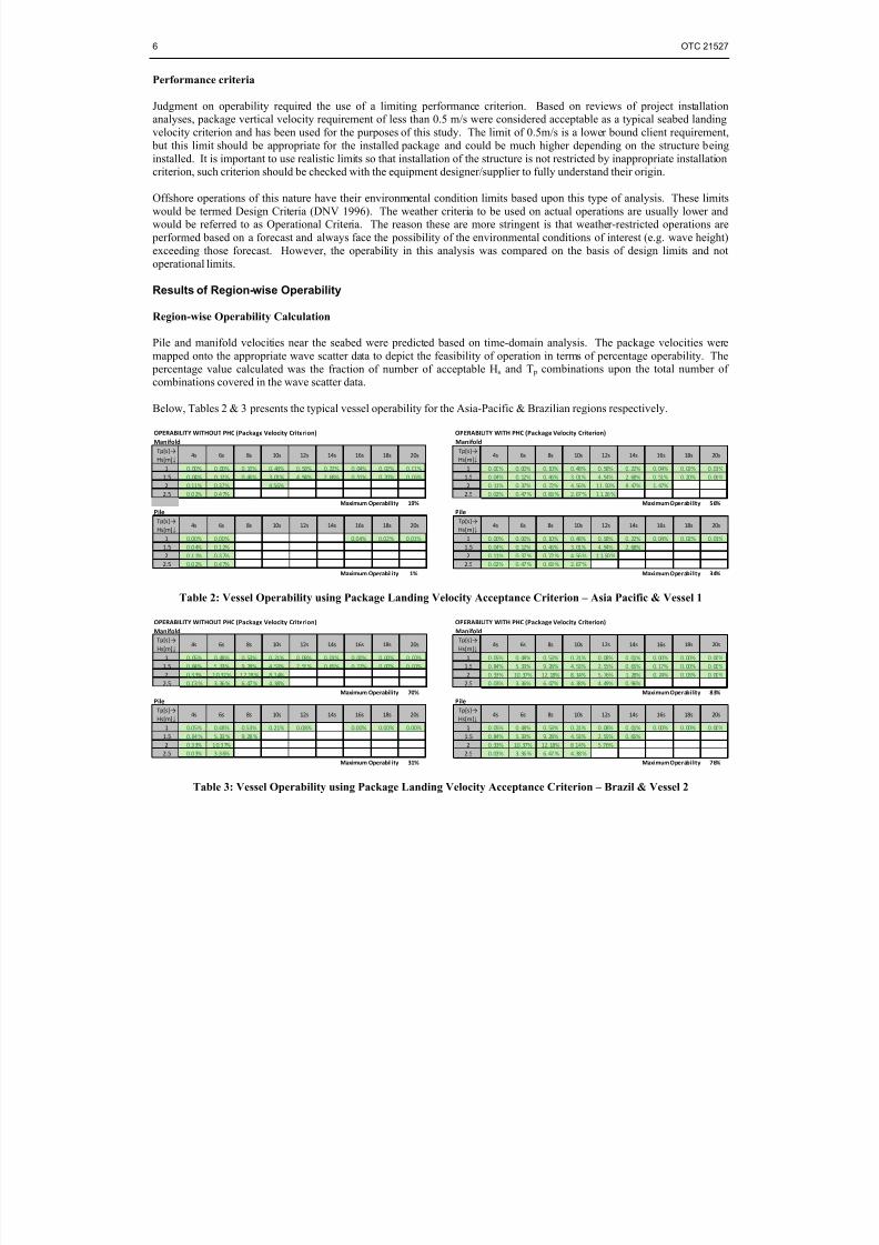
Region-wise Operability Calculation
Pile and manifold velocities near the seabed were predicted based on time-domain analysis. The package velocities were
mapped onto the appropriate wave scatter data to depict the feasibility of operation in terms of percentage operability. The
percentage value calculated was the fraction of number of acceptable Hs and T p combinations upon the total number of
combinations covered in the wave scatter data.
Below, Tables 2 & 3 presents the typical vessel operability for the Asia-Pacific & Brazilian regions respectively.
OPERABILITY WITHOUT PHC (Package Velocity Criterion) OPERABILITY WITH PHC (Package Velocity Criterion)
Manifold Manifold
Tp[s]→
Hs[m]↓ 4s 6s 8s 10s 12s 14s 16s 18s 20s
Tp[s]→
Hs[m]↓ 4s 6s 8s 10s 12s 14s 16s 18s 20s
1 0. 00% 0. 00% 0. 10% 0. 48% 0. 58% 0. 22% 0. 04% 0. 02% 0. 01% 1 0. 00% 0. 00% 0. 10% 0. 48% 0. 58% 0. 22% 0. 04% 0. 02% 0. 01%
1.5 0. 04% 0. 12% 0. 46% 3. 01% 4. 94% 2. 68% 0. 51% 0. 20% 0. 06% 1.5 0. 04% 0. 12% 0. 46% 3. 01% 4. 94% 2. 68% 0. 51% 0. 20% 0. 06%
2 0.11% 0.37% 4.56% 2 0. 11% 0. 37% 0. 72% 4. 56% 11. 50% 8. 47% 1. 47%
2.5 0.02% 0.47% 2.5 0. 02% 0. 47 % 0. 83 % 2. 67 % 1 1. 26 %
Maximum Operability 19% Maximum Operability 56%
Pile Pile
Tp[s]→
Hs[m]↓ 4s 6s 8s 10s 12s 14s 16s 18s 20s Tp[s]
→
Hs[m]↓ 4s 6s 8s 10s 12s 14s 16s 18s 20s
1 0.00% 0.00% 0.04% 0.02% 0.01% 1 0. 00% 0. 00% 0. 10% 0. 48% 0. 58% 0. 22% 0. 04% 0. 02% 0. 01%
1.5 0.04% 0.12% 1.5 0. 04% 0. 12% 0. 46% 3. 01% 4. 94% 2. 68%
2 0.11% 0.37% 2 0. 11% 0. 37 % 0. 72 % 4. 56 % 1 1. 50 %
2.5 0.02% 0.47% 2.5 0. 02% 0. 47 % 0. 83 % 2. 67 %
Maximum Operability 1% Maximum Operability 34%
Table 2: Vessel Operability using Package Landing Velocity Acceptance Criterion – Asia Pacific & Vessel 1
OPERABILITY WITHOUT PHC (Package Velocity Criterion) OPERABILITY WITH PHC (Package Velocity Criterion)
Manifold Manifold
Tp[s]→
Hs[m]↓ 4s 6s 8s 10s 12s 14s 16s 18s 20s
Tp[s]→
Hs[m]↓ 4s 6s 8s 10s 12s 14s 16s 18s 20s
1 0. 05% 0. 48% 0. 53% 0. 21% 0. 08% 0. 01% 0. 00% 0. 00% 0. 00% 1 0. 05% 0. 48% 0. 53% 0. 21% 0. 08% 0. 01% 0. 00% 0. 00% 0. 00%
1.5 0. 84% 5. 33% 9. 28% 4. 53% 2. 55% 0. 65% 0. 17% 0. 00% 0. 00% 1.5 0. 84% 5. 33% 9. 28% 4. 53% 2. 55% 0. 65% 0. 17% 0. 00% 0. 00%
2 0.33% 10.37% 12.18% 8.14% 2 0. 33% 10. 37% 12. 18% 8. 14% 5. 76% 1. 28% 0. 24% 0. 03% 0. 00%
2.5 0. 03 % 3. 36 % 6. 47 % 4. 38% 2.5 0. 03% 3. 36% 6. 47% 4. 38% 4. 49% 0. 96%
Maximum Operability 70% Maximum Operability 83%
Pile Pile
Tp[s]→
Hs[m]↓ 4s 6s 8s 10s 12s 14s 16s 18s 20s
Tp[s]→
Hs[m]↓ 4s 6s 8s 10s 12s 14s 16s 18s 20s
1 0.05% 0.48% 0.53% 0.21% 0.08% 0.00% 0.00% 0.00% 1 0. 05% 0. 48% 0. 53% 0. 21% 0. 08% 0. 01% 0. 00% 0. 00% 0. 00%
1.5 0. 84 % 5. 33 % 9. 28 % 1.5 0. 84% 5. 33% 9. 28% 4. 53% 2. 55% 0. 65%
2 0.33% 10.37% 2 0. 33% 10. 37% 12. 18% 8 .14% 5 .76%
2.5 0.03% 3.36% 2.5 0. 03% 3. 36 % 6. 47 % 4. 38 %
Maximum Operability 31% Maximum Operability 76%
Table 3: Vessel Operability using Package Landing Velocity Acceptance Criterion – Brazil & Vessel 2
8/13/2019 Passive Heave
http://slidepdf.com/reader/full/passive-heave 7/8
OTC 21527 7
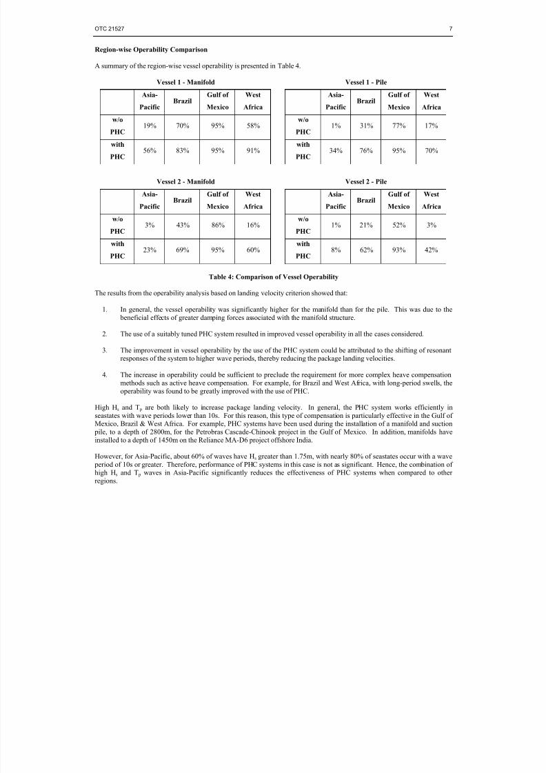
Region-wise Operability Comparison
A summary of the region-wise vessel operability is presented in Table 4.
Vessel 1 - Manifold Vessel 1 - Pile
Asia-
Pacific
BrazilGulf of
Mexico
West
Africa
Asia-
Pacific
BrazilGulf of
Mexico
West
Africa
w/o
PHC19% 70% 95% 58%
w/o
PHC1% 31% 77% 17%
with
PHC56% 83% 95% 91%
with
PHC34% 76% 95% 70%
Vessel 2 - Manifold Vessel 2 - Pile
Asia-
PacificBrazil
Gulf of
Mexico
West
Africa
Asia-
PacificBrazil
Gulf of
Mexico
West
Africa
w/o
PHC3% 43% 86% 16%
w/o
PHC1% 21% 52% 3%
with
PHC23% 69% 95% 60%
with
PHC8% 62% 93% 42%
Table 4: Comparison of Vessel Operability
The results from the operability analysis based on landing velocity criterion showed that:
1. In general, the vessel operability was significantly higher for the manifold than for the pile. This was due to the
beneficial effects of greater damping forces associated with the manifold structure.
2. The use of a suitably tuned PHC system resulted in improved vessel operability in all the cases considered.
3. The improvement in vessel operability by the use of the PHC system could be attributed to the shifting of resonantresponses of the system to higher wave periods, thereby reducing the package landing velocities.
4. The increase in operability could be sufficient to preclude the requirement for more complex heave compensation
methods such as active heave compensation. For example, for Brazil and West Africa, with long-period swells, the
operability was found to be greatly improved with the use of PHC.
High Hs and T p are both likely to increase package landing velocity. In general, the PHC system works efficiently in
seastates with wave periods lower than 10s. For this reason, this type of compensation is particularly effective in the Gulf ofMexico, Brazil & West Africa. For example, PHC systems have been used during the installation of a manifold and suction
pile, to a depth of 2800m, for the Petrobras Cascade-Chinook project in the Gulf of Mexico. In addition, manifolds haveinstalled to a depth of 1450m on the Reliance MA-D6 project offshore India.
However, for Asia-Pacific, about 60% of waves have Hs greater than 1.75m, with nearly 80% of seastates occur with a wave
period of 10s or greater. Therefore, performance of PHC systems in this case is not as significant. Hence, the combination ofhigh Hs and T p waves in Asia-Pacific significantly reduces the effectiveness of PHC systems when compared to other
regions.
8/13/2019 Passive Heave
http://slidepdf.com/reader/full/passive-heave 8/8
8 OTC 21527
Conclusion
In many cases, the increase in vessel operability due to use of PHC systems may be enough to remove the need for othermore complex heave compensation methods such as AHC. However, PHC systems cannot always guarantee sufficiently
high operability when based on seabed landing speed criteria. In such cases, the use of active heave compensation, or
alternative installation methods, may be needed to gain a significant increase in operability.
This paper has demonstrated that PHC devices can significantly improve vessel operability. With a suitably tuned PHCfurther improvement to vessel operability can be made. Pre-tension, stiffness and damping characteristics may all have to be
adjusted to achieve optimum performance. These optimum settings may depend on the package characteristics, seastates for
operation, water depth and acceptable limits for package velocity. Consultation with manufacturers may highlight any practical limitations and the possibility of devising a bespoke PHC system. However, for reliable operability estimates,
accurate environmental data specific to the installation location is essential.
Indeed, Technip have shown that during executed projects, such as Petrobras Cascade Chinook and Reliance MA-D6, that
such passive heave compensation systems do provide sufficient compensation to meet the required installation criterion.
Acknowledgements
The authors would like to thank their colleagues in Technip, particularly Geoffrey Marmonier and Sojan Vasudevan for their
help in carrying out this study.
Nomenclature
AHC Active Heave CompensationJONSWAP Joint North Sea Wave Project
Hs Significant wave height
PHC Passive Heave CompensationT p Peak wave period
References
DISH 2006 Deepwater Installation of Subsea Hardware (DISH) Joint Industry Project, “Final DISH Phase 3 Summary report”, 24 November 2006.
DNV 2010 DNV, “DNV-RP-H103, Modeling and Analysis of Marine Operations”, April 2010.DNV 1996 DNV, “Rules for Planning and Execution of Marine Operations, Part 2 Chapter 6 Subsea Operations”, 1996.