Embed Size (px)
Citation preview
Instruments and Methods
New technique for access-borehole drilling in shelf glaciers usinglightweight drills
V. ZAGORODNOV,1 S. TYLER,2 D. HOLLAND,3 A. STERN,3 L.G. THOMPSON,1
C. SLADEK,2 S. KOBS,2 J.P. NICOLAS1
1Byrd Polar Research Center, The Ohio State University, Columbus, OH, USAE-mail: [email protected]
2Department of Geological Sciences and Engineering, University of Nevada, Reno, Reno, NV, USA3Courant Institute of Mathematical Sciences, New York University, New York, NY, USA
ABSTRACT. This paper describes a new, environmentally friendly drilling technique for making short-and long-term access boreholes in shelf glaciers using lightweight drills. The new drilling technique wassuccessfully developed for installation of small-diameter sensors under the Ross Ice Shelf through�193 m thick ice at Windless Bight, McMurdo Ice Shelf, Antarctica. The two access boreholes weredrilled and sensors installed in 110 working hours. The total weight of the drilling equipment includingthe power system and fuel is <400 kg. Installation of small-diameter sensors was possible for 1.8–6 hours after penetration through the glacier into the sea water beneath. The new drilling techniquedoes not require drilling fluid and therefore has minimal environmental impact. It should permit accessthrough ice-shelf ice up to 350 m thick, or glaciers on grounded ice or subglacial lakes if there is nowater-permeable interface at the base. Modifications, presented in this work, of the drilling equipmentand protocol will allow for (1) �21 working hours for penetration through 200 m of ice, (2) installationof sensors up to 120 mm in diameter and (3) drilling long-term open boreholes through 400 m thick icein 100 working hours.
KEYWORDS: glaciological instruments and methods, ice coring, ice shelves, ice temperature
INTRODUCTIONCompared with ice coring, access-borehole drilling offers afast way of reaching the interior of a glacier, bedrock or sub-ice-shelf cavity. Economic and environmental considerationsin Antarctica, Greenland or remote alpine glacial areasrequire lightweight, rapid-rate drilling equipment and a lowlogistical burden. A small drilling team and short ‘on-site’time also reduces the transportation load of field operations.
There are a number of technical approaches for access-borehole drilling: (1) dry borehole drilling, i.e. boreholefilled with air; (2) fluid borehole drilling, i.e. boreholecompletely or partially filled with non-freezing liquid; and(3) semi-fluid drilling, which is a combination of dry andfluid drilling techniques. Fluid drilling techniques require1–1.5 t of fluid for each 100m of 120–130mm diameterborehole. Thus, dry hole drilling insures the lowest environ-mental impact and requires less logistic support than drillingwith fluid.
The depth of dry and semi-fluid borehole drilling islimited due to the risk of losing the drill as a result ofrheological closure of the borehole. The rate of closureincreases with borehole depth and increasing ice tempera-ture. The deepest dry borehole so far in a shelf glacierreached 330m depth in a 416m thick shelf glacier (Rand,1977). When the drill was at the borehole bottom, it wasseized by the ice and lost during a 30min intermission.
To reduce borehole closure during drilling, boreholes arefilled with antifreeze fluids: hydrocarbons (hydrophobic:purified kerosene and densifier) or alcohol-based fluids(hydrophilic: ethylene glycol, polypropylene glycol,
glycerin, ethanol and others (Talalay and Gundestrup,2002)). An ethanol–water solution (EWS) was found to bethe most practical and environmentally friendly fluid fordrilling glaciers (Zagorodnov and others, 1994a,b; 1998).Drilling with EWS generally requires threefold less drillingfluid delivered to the drilling site (Zagorodnov and others,1994a,b). The concentration of ethanol in a borehole at ashelf glacier bottom is low (<4%), so bottom leakage is lessharmful to the subglacial environment than leakage ofkerosene-based fluid. Leakage of EWS through casingdefects to firn is also less toxic than hydrocarbons, and theappropriate ethanol concentration is only 50% by weight inthe coldest ice (–30°C) and just 22% in warmer ice (–13°C).Ethanol mixes with water, so a spill of EWS into the oceanwill be diluted to low concentration, while hydrophobicfluids under a shelf glacier will stay as a layer or disperseddroplets on the ice/water interface and in some cases will betrapped in the ice (Wolfe and Hoult, 1974). Finally,evaporation rates are four times higher for ethanol than forkerosene under similar environmental conditions and there-fore pose fewer long-term issues at the surface (Lange, 1961;Talalay and Gundestrup, 2002; Sochet and Gillard, 2002).
In general, mechanical drilling/coring requires �1/10 thepower needed by thermal melting drilling (Mellor andSellmann, 1976). At the same time, open borehole drillingrequires 50% more power than coring of the same-diameterborehole. Drilling systems using semi-continuous, conven-tional rotary drilling techniques (drill pipes or drill rodsrotated from the glacier surface) are heavy and have notdemonstrated high performance in glaciers compared to
Journal of Glaciology, Vol. 60, No. 223, 2014 doi: 10.3189/2014JoG13J211 935
Downloaded from https://www.cambridge.org/core. 18 Dec 2021 at 20:30:13, subject to the Cambridge Core terms of use.
cyclic, cable-suspended electro-drills (Mellor and Sellmann,1976). A new drilling technique, ‘coil tube drilling’ (CTD),will possibly provide relatively light access-hole drilling inglaciers (Clow and Koci, 2002). However, this type ofdrilling has to be modified for access-borehole drilling inshelf glaciers and for the ability to reach a sub-ice-shelfcavity without contaminating it. The weight of the CTDequipment for glacier drilling is expected to exceed theweight of most ice-coring electro-drills and hot-water drills.
The new access-borehole drilling technique presentedhere was developed as part of a technology developmentpilot study of the thermodynamics of a sub-ice-shelf cavityusing distributed temperature sensing (DTS) (Stern andothers, 2013; Tyler and others, 2013). The new drillingtechnique includes dry-hole electromechanical (EM) icecoring to a depth of a few meters above the shelf glacierbase and then drilling through a shelf glacier down to a sub-ice-shelf cavity with a hot-point (HP) electro-thermal drill.This approach uses significantly lighter equipment andproduces an access borehole faster than other techniques. Itis an environmentally friendly technique, with a low logisticburden, for making short-term (a few hours) open accessboreholes for installation of small-diameter sensors in a sub-ice-shelf cavity, in glaciers up to 350m thick. The techniquehas been field-proven in almost 200m thick ice on theMcMurdo Ice Shelf (MIS, part of the Ross Ice Shelf, RIS),Antarctica, at the Windless Bight (WB 2011) site inNovember–December 2011.
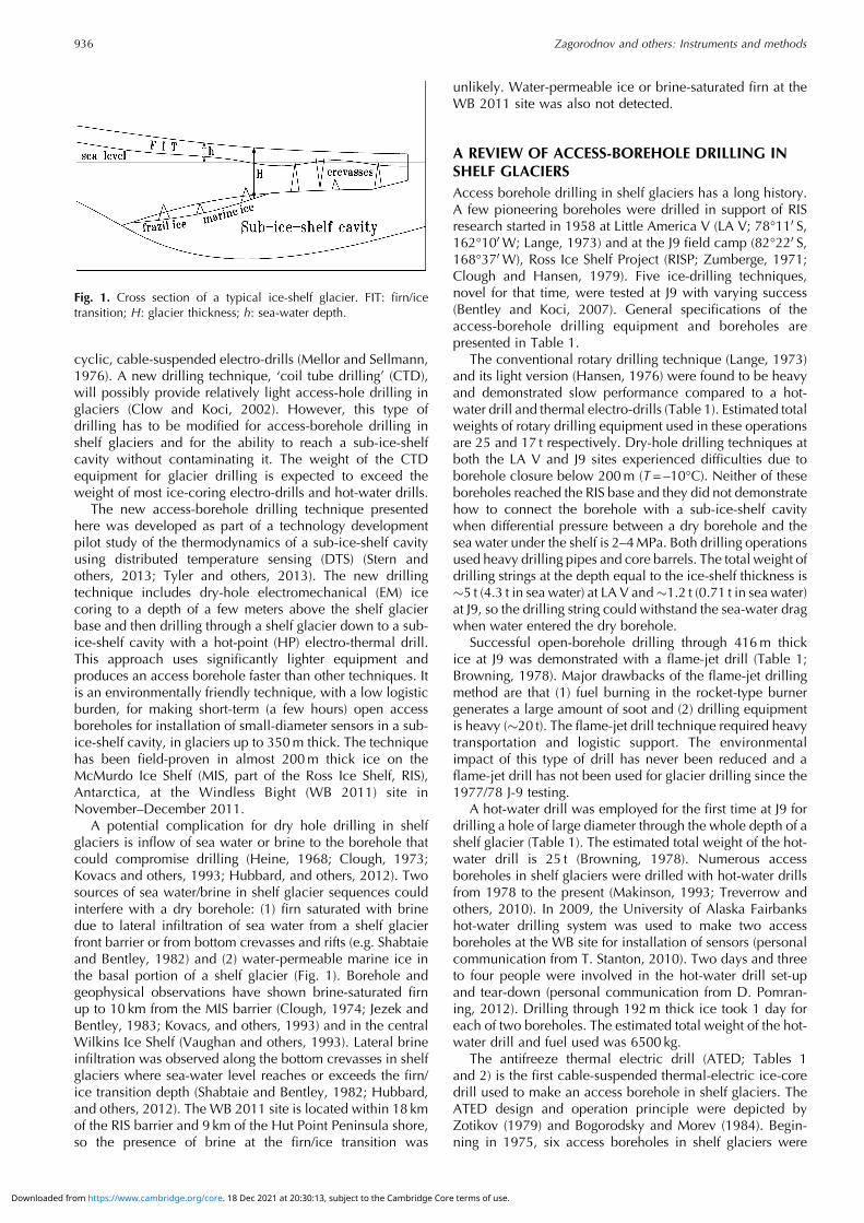
A potential complication for dry hole drilling in shelfglaciers is inflow of sea water or brine to the borehole thatcould compromise drilling (Heine, 1968; Clough, 1973;Kovacs and others, 1993; Hubbard, and others, 2012). Twosources of sea water/brine in shelf glacier sequences couldinterfere with a dry borehole: (1) firn saturated with brinedue to lateral infiltration of sea water from a shelf glacierfront barrier or from bottom crevasses and rifts (e.g. Shabtaieand Bentley, 1982) and (2) water-permeable marine ice inthe basal portion of a shelf glacier (Fig. 1). Borehole andgeophysical observations have shown brine-saturated firnup to 10 km from the MIS barrier (Clough, 1974; Jezek andBentley, 1983; Kovacs, and others, 1993) and in the centralWilkins Ice Shelf (Vaughan and others, 1993). Lateral brineinfiltration was observed along the bottom crevasses in shelfglaciers where sea-water level reaches or exceeds the firn/ice transition depth (Shabtaie and Bentley, 1982; Hubbard,and others, 2012). The WB 2011 site is located within 18 kmof the RIS barrier and 9 km of the Hut Point Peninsula shore,so the presence of brine at the firn/ice transition was
unlikely. Water-permeable ice or brine-saturated firn at theWB 2011 site was also not detected.
A REVIEW OF ACCESS-BOREHOLE DRILLING INSHELF GLACIERSAccess borehole drilling in shelf glaciers has a long history.A few pioneering boreholes were drilled in support of RISresearch started in 1958 at Little America V (LA V; 78°110 S,162°100W; Lange, 1973) and at the J9 field camp (82°220 S,168°370W), Ross Ice Shelf Project (RISP; Zumberge, 1971;Clough and Hansen, 1979). Five ice-drilling techniques,novel for that time, were tested at J9 with varying success(Bentley and Koci, 2007). General specifications of theaccess-borehole drilling equipment and boreholes arepresented in Table 1.
The conventional rotary drilling technique (Lange, 1973)and its light version (Hansen, 1976) were found to be heavyand demonstrated slow performance compared to a hot-water drill and thermal electro-drills (Table 1). Estimated totalweights of rotary drilling equipment used in these operationsare 25 and 17 t respectively. Dry-hole drilling techniques atboth the LA V and J9 sites experienced difficulties due toborehole closure below 200m (T= –10°C). Neither of theseboreholes reached the RIS base and they did not demonstratehow to connect the borehole with a sub-ice-shelf cavitywhen differential pressure between a dry borehole and thesea water under the shelf is 2–4MPa. Both drilling operationsused heavy drilling pipes and core barrels. The total weight ofdrilling strings at the depth equal to the ice-shelf thickness is�5 t (4.3 t in sea water) at LA V and�1.2 t (0.71 t in sea water)at J9, so the drilling string could withstand the sea-water dragwhen water entered the dry borehole.
Successful open-borehole drilling through 416m thickice at J9 was demonstrated with a flame-jet drill (Table 1;Browning, 1978). Major drawbacks of the flame-jet drillingmethod are that (1) fuel burning in the rocket-type burnergenerates a large amount of soot and (2) drilling equipmentis heavy (�20 t). The flame-jet drill technique required heavytransportation and logistic support. The environmentalimpact of this type of drill has never been reduced and aflame-jet drill has not been used for glacier drilling since the1977/78 J-9 testing.
A hot-water drill was employed for the first time at J9 fordrilling a hole of large diameter through the whole depth of ashelf glacier (Table 1). The estimated total weight of the hot-water drill is 25 t (Browning, 1978). Numerous accessboreholes in shelf glaciers were drilled with hot-water drillsfrom 1978 to the present (Makinson, 1993; Treverrow andothers, 2010). In 2009, the University of Alaska Fairbankshot-water drilling system was used to make two accessboreholes at the WB site for installation of sensors (personalcommunication from T. Stanton, 2010). Two days and threeto four people were involved in the hot-water drill set-upand tear-down (personal communication from D. Pomran-ing, 2012). Drilling through 192m thick ice took 1 day foreach of two boreholes. The estimated total weight of the hot-water drill and fuel used was 6500 kg.
The antifreeze thermal electric drill (ATED; Tables 1and 2) is the first cable-suspended thermal-electric ice-coredrill used to make an access borehole in shelf glaciers. TheATED design and operation principle were depicted byZotikov (1979) and Bogorodsky and Morev (1984). Begin-ning in 1975, six access boreholes in shelf glaciers were
Fig. 1. Cross section of a typical ice-shelf glacier. FIT: firn/icetransition; H: glacier thickness; h: sea-water depth.
Zagorodnov and others: Instruments and methods936
Downloaded from https://www.cambridge.org/core. 18 Dec 2021 at 20:30:13, subject to the Cambridge Core terms of use.
drilled with ATED (Korotkevich and others, 1978; Savatugin,1980; Zotikov and others, 1980): three on the Lazarev IceShelf, one on the Shackleton Ice Shelf, one at J-9 Camp andone on the Amery Ice Shelf in 1989 (Raikovskiy and others,1990) (Table 1). ATEDs demonstrate an ice-core productionrate (ICPR) of 0.65–2.4mh–1. The estimated total weight ofATED systems for intermediate-depth boreholes (400–500m), including antifreeze (ethanol) and fuel, is �2 t.The deepest borehole drilled with an ATED was 870m atthe Dome B site in Antarctica (Morev and others, 1988).However, this depth is not considered a maximum possibledepth with this type of drill.
New improved versions of an ATED (Table 2) weredesigned and used in polar and polythermal glaciers incombination with an EM drill (Zagorodnov and others,1998, 2000, 2005). These inherited some of the originalATED drawbacks: high power requirements (4–5 kW) andlow descent rate in an EWS-filled borehole. At the sametime, the new ATED-m drill with a 2m long core barrelproduced a larger-diameter ice core (100mm) and borehole(�120mm) than the first prototype (Table 2) and demon-strated average 2mh–1 ICPR at depths of 461m (Bona–Churchill Col in 2002) and 445.6m (Bruce Plateau,Antarctic Peninsula, in 2009).
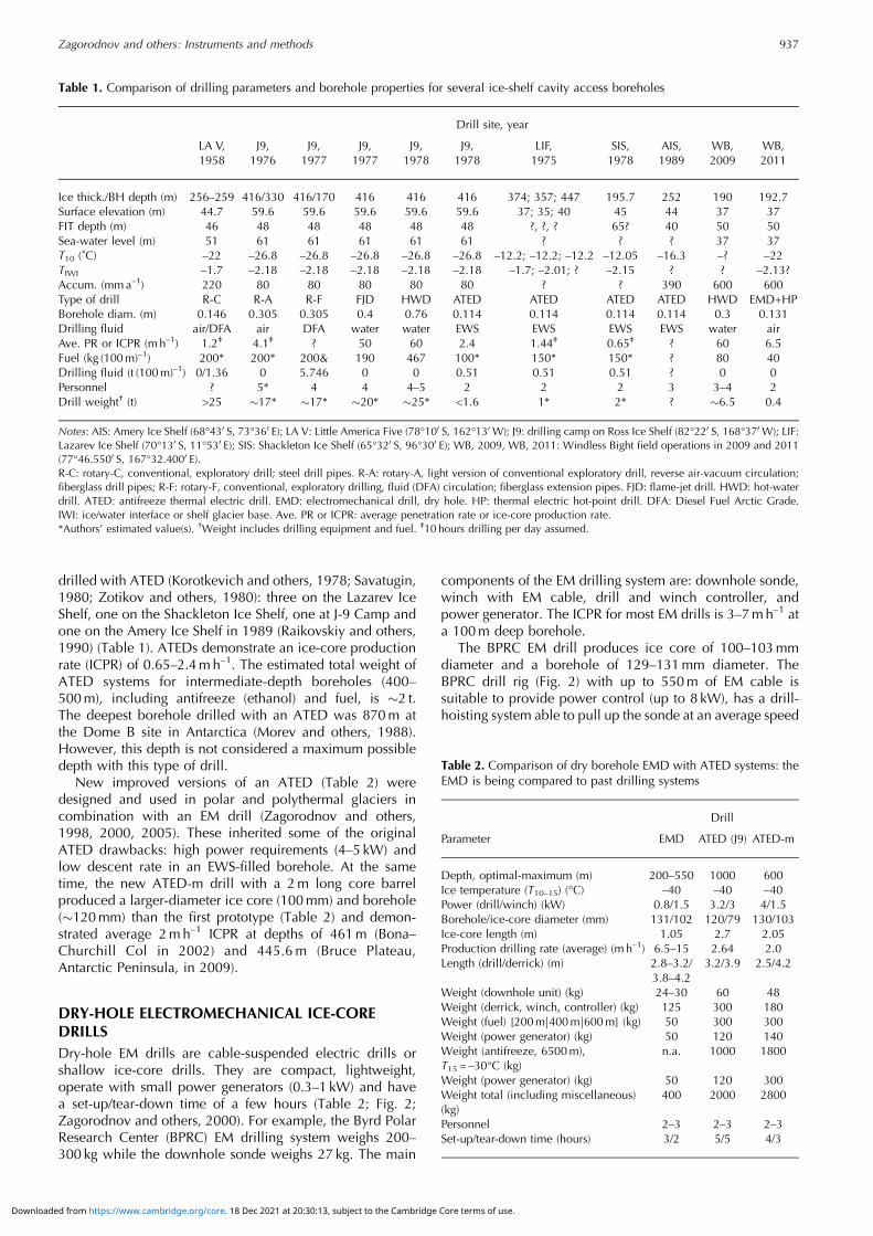
DRY-HOLE ELECTROMECHANICAL ICE-COREDRILLSDry-hole EM drills are cable-suspended electric drills orshallow ice-core drills. They are compact, lightweight,operate with small power generators (0.3–1 kW) and havea set-up/tear-down time of a few hours (Table 2; Fig. 2;Zagorodnov and others, 2000). For example, the Byrd PolarResearch Center (BPRC) EM drilling system weighs 200–300 kg while the downhole sonde weighs 27 kg. The main
components of the EM drilling system are: downhole sonde,winch with EM cable, drill and winch controller, andpower generator. The ICPR for most EM drills is 3–7mh–1 ata 100m deep borehole.
The BPRC EM drill produces ice core of 100–103mmdiameter and a borehole of 129–131mm diameter. TheBPRC drill rig (Fig. 2) with up to 550m of EM cable issuitable to provide power control (up to 8 kW), has a drill-hoisting system able to pull up the sonde at an average speed
Table 1. Comparison of drilling parameters and borehole properties for several ice-shelf cavity access boreholes
Drill site, year
LA V,
1958
J9,
1976
J9,
1977
J9,
1977
J9,
1978
J9,
1978
LIF,
1975
SIS,
1978
AIS,
1989
WB,
2009
WB,
2011
Ice thick./BH depth (m) 256–259 416/330 416/170 416 416 416 374; 357; 447 195.7 252 190 192.7
Surface elevation (m) 44.7 59.6 59.6 59.6 59.6 59.6 37; 35; 40 45 44 37 37
FIT depth (m) 46 48 48 48 48 48 ?, ?, ? 65? 40 50 50
Sea-water level (m) 51 61 61 61 61 61 ? ? ? 37 37
T10 (˚C) –22 –26.8 –26.8 –26.8 –26.8 –26.8 –12.2; –12.2; –12.2 –12.05 –16.3 –? –22
TIWI –1.7 –2.18 –2.18 –2.18 –2.18 –2.18 –1.7; –2.01; ? –2.15 ? ? –2.13?
Accum. (mm a–1) 220 80 80 80 80 80 ? ? 390 600 600
Type of drill R-C R-A R-F FJD HWD ATED ATED ATED ATED HWD EMD+HP
Borehole diam. (m) 0.146 0.305 0.305 0.4 0.76 0.114 0.114 0.114 0.114 0.3 0.131
Drilling fluid air/DFA air DFA water water EWS EWS EWS EWS water air
Ave. PR or ICPR (m h–1) 1.2‡ 4.1‡ ? 50 60 2.4 1.44‡ 0.65‡ ? 60 6.5
Fuel (kg (100 m)–1) 200* 200* 200& 190 467 100* 150* 150* ? 80 40
Drilling fluid (t (100 m)–1) 0/1.36 0 5.746 0 0 0.51 0.51 0.51 ? 0 0
Personnel ? 5* 4 4 4–5 2 2 2 3 3–4 2
Drill weight† (t) >25 �17* �17* �20* �25* <1.6 1* 2* ? �6.5 0.4
Notes: AIS: Amery Ice Shelf (68°430 S, 73°360 E); LA V: Little America Five (78°100 S, 162°130W); J9: drilling camp on Ross Ice Shelf (82°220 S, 168°370W); LIF:Lazarev Ice Shelf (70°130 S, 11°530 E); SIS: Shackleton Ice Shelf (65°320 S, 96°300 E); WB, 2009, WB, 2011: Windless Bight field operations in 2009 and 2011(77°46.5500 S, 167°32.4000 E).R-C: rotary-C, conventional, exploratory drill; steel drill pipes. R-A: rotary-A, light version of conventional exploratory drill, reverse air-vacuum circulation;fiberglass drill pipes; R-F: rotary-F, conventional, exploratory drilling, fluid (DFA) circulation; fiberglass extension pipes. FJD: flame-jet drill. HWD: hot-waterdrill. ATED: antifreeze thermal electric drill. EMD: electromechanical drill, dry hole. HP: thermal electric hot-point drill. DFA: Diesel Fuel Arctic Grade.IWI: ice/water interface or shelf glacier base. Ave. PR or ICPR: average penetration rate or ice-core production rate.*Authors’ estimated value(s). †Weight includes drilling equipment and fuel. ‡10 hours drilling per day assumed.
Table 2. Comparison of dry borehole EMD with ATED systems: theEMD is being compared to past drilling systems
Drill
Parameter EMD ATED (J9) ATED-m
Depth, optimal-maximum (m) 200–550 1000 600
Ice temperature (T10–15) (°C) –40 –40 –40
Power (drill/winch) (kW) 0.8/1.5 3.2/3 4/1.5
Borehole/ice-core diameter (mm) 131/102 120/79 130/103
Ice-core length (m) 1.05 2.7 2.05
Production drilling rate (average) (m h–1) 6.5–15 2.64 2.0
Length (drill/derrick) (m) 2.8–3.2/
3.8–4.2
3.2/3.9 2.5/4.2
Weight (downhole unit) (kg) 24–30 60 48
Weight (derrick, winch, controller) (kg) 125 300 180
Weight (fuel) [200 m|400 m|600 m] (kg) 50 300 300
Weight (power generator) (kg) 50 120 140
Weight (antifreeze, 6500m),T15 = –30°C (kg)
n.a. 1000 1800
Weight (power generator) (kg) 50 120 300
Weight total (including miscellaneous)
(kg)
400 2000 2800
Personnel 2–3 2–3 2–3
Set-up/tear-down time (hours) 3/2 5/5 4/3
Zagorodnov and others: Instruments and methods 937
Downloaded from https://www.cambridge.org/core. 18 Dec 2021 at 20:30:13, subject to the Cambridge Core terms of use.
of 0.68m s–1 and includes constant-speed cable (drill)feeding at 0.5–25mm s–1, drill position digital readout(0–999m, resolution 0.001m) and bit pressure monitoring(resolution 0.01 kg).
There are three challenges associated with dry-holedrilling in shelf glaciers: (1) drilling of warm ice attemperatures close to pressure-melting temperature;(2) dry-borehole rheological closure; and (3) sea-waterinflow and its freezing in the access borehole after theborehole is connected with a sub-ice-shelf cavity.
The EM drills were developed for dry-hole drilling, andmost of them have never been considered for access-borehole drilling in a shelf glacier, with high probability ofbeing submerged in sea water. A few attempts at dry-holecoring of temperate or polythermal glaciers with an EM drillfailed at 40–55m depth because of the presence of warm iceand/or water which compromised the transport of cuttingsfrom the kerf to the storage compartment (Kohshima andothers, 2002; Neff and others, 2012; personal communica-tion from M. Gerasimoff, 2004; personal communicationfrom P. Ginot, 2013). Some EM drills were modified foroperation submerged in water. The Alfred Wegener InstituteEM drill was used on temperate Hofsjökull ice cap, Iceland,where a 100.2m depth was reached in 9 days (Thorsteins-son and others, 2003). Low ice-core production rate below40m was attributed to short drilling runs. Chip transport wascompromised by the presence of water in the borehole,resulting in short penetration per drilling run.
A submersible version of the ECLIPSE drill (Blake andothers, 1998; Hubbard and others, 2012) was used to makeseveral boreholes in the Roi Baudouin ice shelf (70° S,24° E). From Hubbard and others (2012) one can assumethat at least two boreholes, 15.24 and 66.4m deep, in firnand glacier ice were made with a modified ECLIPSE drill.
Drilling of both boreholes was terminated and reasons fortermination are not reported.
Appreciable progress in core drilling of warm ice hasbeen achieved with the BPRC EM drill equipped withstaggered cutters on Quelccaya ice cap, Peru, in 2003(Zagorodnov and others, 2005). On the temperate Copa–Hualcan glacier, Peru, two dry boreholes reached bedrockat depths of 195 and 185m (Zagorodnov and Thompson,unpublished information). Staggered cutters produce coarsecuttings that stick less to the coring head and core barrel andenable drilling in warm ice. Borehole rheological closure intemperate ice was noticed but does not complicate the icecoring while drilling at a rate of �4mh–1 down to 195m(bedrock). Evidently, slow drilling and pausing of drilling atnight extended the time for borehole closure and limited thedepth of a dry borehole. A few episodes of freshwater inflowto these boreholes did not present a problem; the BPRC EMdrill performed well submerged in fresh water.
RECENT DEVELOPMENTS: BPRC HOT-POINT DRILLThe electro-thermal open borehole drills or hot-point drills(HPDs) were developed for fast penetration through temper-ate glaciers to �200m depth. Over a dozen HPDs weredesigned starting in the 1940s (Nizery, 1951; Ward, 1952;LaChapelle, 1963; Shreve and Sharp, 1970; Taylor, 1976).Their penetration rate depends on the power and design ofthe melting tip. In most applications, HPD penetration ratein solid ice is 2–8mh–1. Only a few HPDs are capable ofhigh penetration rates of 12–25mh–1 at 1–10 kW power(Nizery, 1951; Gillet, 1975; Morev and others, 1984).
The BPRC HPD, used in the WB 2011 operation, isshown in Figure 2a and b. It has a 40mm diameterpenetration tip, is 1.5m long and has a penetration rate ofup to 11mh–1. The main difference between the BPRC HPDand other designs is the top anchor mechanism that allowsthe HPD to be jettisoned below the shelf glacier base afterpenetration and retrieval of the EM cable to the surface. Thejettison feature was designed to reduce the possibility of thedrill and cable becoming stuck in the borehole afterpenetrating into the ocean. The shape of the anchor bladesallows the drill to move up and down in the borehole. If theborehole diameter is still large enough to pull the HPD tothe surface the anchor will not present an obstacle
Optimization of the new HPD melting-tip design tookinto consideration high penetration rate at low power,durability at high hydrostatic pressure (>5MPa) in sea water,the cost of manufacturing, the use of off-the-shelf com-ponents and conventional fabrication technologies.
The long cone shape of the melting tip provides bettervertical stability during penetration. Durability of themelting tip was improved with a small-diameter (1.58mm)and long (1575mm) Watlo coiled cable heater mountedclose to the melting surface of the tip in spiral grooves in thecopper core (Fig. 2a and b). To insure heat dissipation fromthe coiled cable heater, it was molded in pure silver. Thecable heaters were tested in a pressure chamber at 80MPafor 96 hours and did not lose their containment. The housingand protective shell of the melting tip is made of stainlesssteel. Final tests of each of 11 (one lost during silver casting)melting tips included: non-electrified high-pressure test at5.5MPa for 2 hours; operation at maximum power in waterat 3 kW for 5min; and 3 hours of operation at 2 kW power.Only five tips passed all three tests.
Fig. 2. Lightweight drilling set-up (left panel) used for hoisting of EMand hot-point drills (a, b): 1. melting tip; 2. extension pipe;3. centralizer; 4. cable termination (‘weak’ point); 5. anchor.(b) Anchor in fixation state.
Zagorodnov and others: Instruments and methods938
Downloaded from https://www.cambridge.org/core. 18 Dec 2021 at 20:30:13, subject to the Cambridge Core terms of use.
ACCESS-BOREHOLE DRILLING AT WINDLESSBIGHT 2011 SITEThe plan for access-borehole drilling through MIS at the WB2011 site for installation of sensors consisted of two steps:(1) dry borehole drilling with the BPRC EM drill down to asafe depth with minimum risk of the drill being gripped byrheological borehole closure, and (2) penetration throughthe ice between the dry borehole and the sub-ice-shelfcavity with the HPD. The HPD had to penetrate only a fewmeters from the bottom of the dry borehole. Two-stagedrilling was chosen in order to avoid contact between theEM drill and sea water.
Two access boreholes at theWB 2011 site (BH1 and BH2)were drilled by two-man crews. The sequence of drilling andthe DTS cable installation are presented in Table 3. Each ofthe two boreholes was drilled in 4 days (35 hours totalworking time) including rig set-up and power systeminstallation, drilling, three relocations and tear-down of thedrill set-up. Penetration pitch and opening of anti-torqueblades were optimized to achieve maximum productiondrilling rate. Because the main purpose of the project was toinstall sensors, the focus was to achieve maximum produc-tion drilling rate rather than obtaining good-quality ice core.The optimal penetration pitch on the mechanical drill wasfound to be 3.6mm rev–1 while the drill penetration rate was12mms–1, so drilling of a 1m piece of ice core took�1.5min. High-penetration drilling pitch (depth of cut percoring-head revolution) produced coarse cuttings that freelymoved to the storage compartment and ensured an average1m ice-core recovery with every drilling run. The secondimportant innovation that allowed dependable transport ofcuttings was lubrication of the core barrel outer surface withpropylene glycol (40–50mL run–1). Lubrication was neces-sary starting from �60m depth, otherwise great effort wasnecessary to pull the core barrel off the drill jacket.
In spite of coarse cutting and high ice-core productionrate down to 80m depth (average �8h–1), core quality wasexcellent. Down to 120m, each drilling run produced twoto four pieces of ice core, but below 150m all core sections
consisted of unconsolidated 2–10mm thick disks only. Thiswas due to increasing bubble pressure within the core ice,resulting in a greater tendency to fracture during drilling.
The speed of lowering of the EM drill by gravity in the WB2011 boreholes was 1–2.2m s–1, while average raisingspeed was 0.68 m s–1. Counting 5min for drill ‘on-surface’time, 1.5min of penetration, 2min lowering to depth of190m and 5.3min to raise the drill resulted in a total timefor the drilling run of 13.8min. This time translates to anICPR of 4.3mh–1. Close to the surface, ICPR was �14mh–1,close to the maximum documented ICPR of the BPRC EMdrill of 15mh–1. Therefore, average ICPR in the 192m deepboreholes at the WB 2011 site was �9.2mh–1 and total dry-hole drilling time was �21hours.
Borehole BH1 (mooring BH1) at the WB 2011 site wasdrilled down to 170m depth. The drilling set-up was thenrelocated to a new position (40m north), and the secondborehole, BH2 (mooring BH2), was drilled with the EM drillto 185m. Temperature was then measured in BH1 (170mdepth) and extrapolated to –1.92°C anticipated sea-watertemperature at 193�2m depth. After ice-shelf thicknessestimation, the EM drill rig was moved back to the BH1position. Using the EM drill, BH1 was deepened down to185.7m. The HPD was then used to penetrate to the sub-ice-shelf cavity. Immediately after penetration to the sub-ice-shelfcavity (<40min) the DTS cable was installed. The drilling set-up was then moved back to the BH2 position and, using theEM drill, the borehole was deepened to 190.4m and usingthe HPD completed to the sub-ice-shelf cavity. The secondand third DTS cables were installed in BH2 one after another.
At the moment the HPD pierced through the shelf glacierto the sub-ice-shelf cavity, the bit pressure (cable tension)oscillated for �5 s and then dropped to the weight of thedrilling cable. After another 30 s the full weight (HPD andcable) was restored. The HPD acts like a pressure safetyvalve, blocking–unblocking the orifice into the ocean below.The orifice diameter can then be estimated as 5.6mm (HPDweight 4 kg and differential pressure between dry boreholeand ocean 1.6MPa). Eventually the orifice enlarged (icemelted) with the water flow to the dry borehole, and water
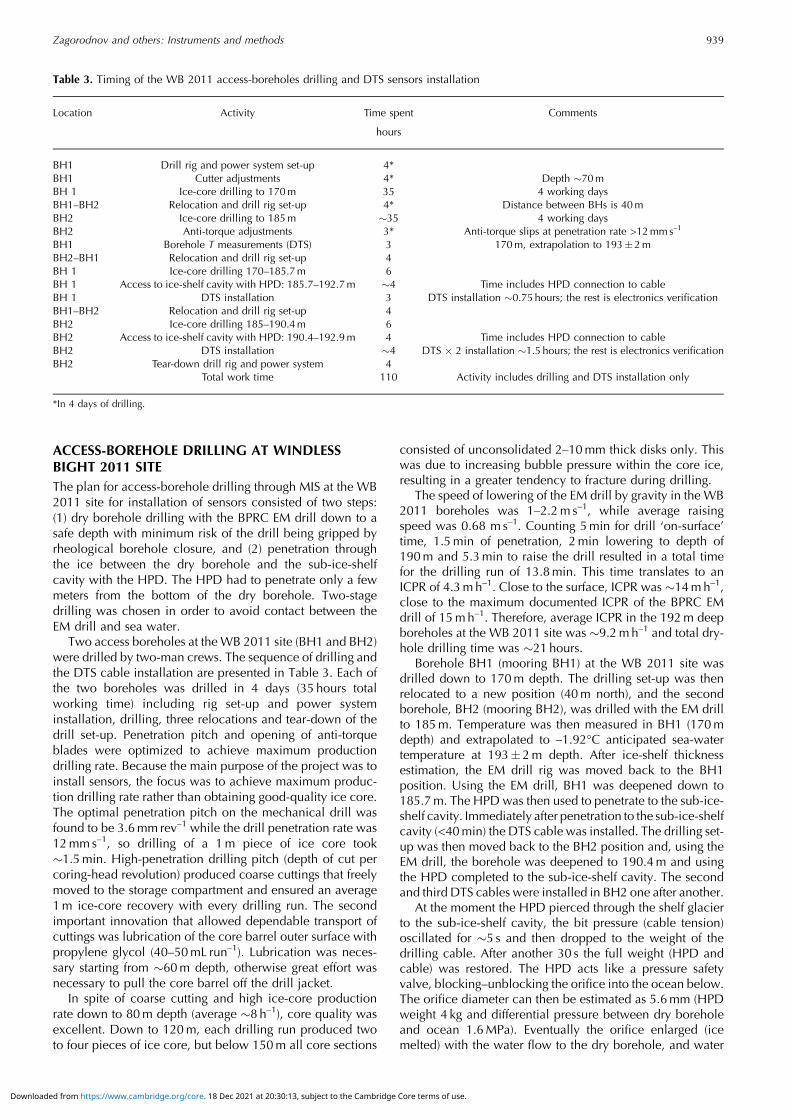
Table 3. Timing of the WB 2011 access-boreholes drilling and DTS sensors installation
Location Activity Time spent Comments
hours
BH1 Drill rig and power system set-up 4*
BH1 Cutter adjustments 4* Depth �70 m
BH 1 Ice-core drilling to 170 m 35 4 working days
BH1–BH2 Relocation and drill rig set-up 4* Distance between BHs is 40 m
BH2 Ice-core drilling to 185 m �35 4 working days
BH2 Anti-torque adjustments 3* Anti-torque slips at penetration rate >12 mm s–1
BH1 Borehole T measurements (DTS) 3 170 m, extrapolation to 193�2 m
BH2–BH1 Relocation and drill rig set-up 4
BH 1 Ice-core drilling 170–185.7 m 6
BH 1 Access to ice-shelf cavity with HPD: 185.7–192.7 m �4 Time includes HPD connection to cable
BH 1 DTS installation 3 DTS installation �0.75 hours; the rest is electronics verification
BH1–BH2 Relocation and drill rig set-up 4
BH2 Ice-core drilling 185–190.4 m 6
BH2 Access to ice-shelf cavity with HPD: 190.4–192.9 m 4 Time includes HPD connection to cable
BH2 DTS installation �4 DTS � 2 installation �1.5 hours; the rest is electronics verification
BH2 Tear-down drill rig and power system 4
Total work time 110 Activity includes drilling and DTS installation only
*In 4 days of drilling.
Zagorodnov and others: Instruments and methods 939
Downloaded from https://www.cambridge.org/core. 18 Dec 2021 at 20:30:13, subject to the Cambridge Core terms of use.
pushed the HPD out of its borehole, observed by decreasingcable tension. It is estimated that boreholes (volume 2.1m3)were completely filled with sea water in 30 s. The HPD thenpassed freely to the sub-ice-shelf cavity, and cable tensionbecame slightly smaller than before penetration due to cableand drill buoyancy. The drilling cable was hoisted and it waswet with sea water. Thin (fraction of mm) flat ice crystals upto 8mm in diameter were attached to the cable surface.
HPD drilling was carried out in BH1 from 185.7 to192.7m depth and in BH2 from 190.4 to 192.9m depth asfollows. Previous drilling operations show systematic 0.05mrepeatability of the borehole depth read-out down to 450m.Thus, the average ice thickness at the WB 2011 site is192.8�0.025m, which is 2.8m higher than the 190m icethickness reported by T. Stanton (personal communication,2010). Most likely the discrepancy in ice thicknesses isrelated to different positions of the 2009 and 2011drilling sites.
Vertical stabilization of the EM drill and HPD wasachieved by pendulum steering. The drills were partly (80%of weight) hung and their penetration rate was limited by therate at which the cable was fed. This rate was controlled bythe winch motor and is less than the EM drill or HPDpenetration rates with full weight of the drill applied to thecutting or melting bit. Vertical stabilization of the HPD wasalso assisted by the centralizer (Fig. 2), which kept the top ofthe drill in the center of the borehole. The tip power of theHPD was set at 1.8 kW, and the cable-feeding rate(controlled penetration) of the HPD drilling was set at2mms–1 (7.2mh–1). This is lower than the HPD penetrationrate of 7.6mh–1 at 1.8 kW. At this rate the HPD produces aborehole 56mm in diameter.
During the WB 2011 drilling at any depth the drill cablewas offset at the surface by <0.05m from the boreholecenter. This translates to <7.5�10–3° borehole inclination.In turn, displacement of the borehole center at the base ofthe ice shelf with respect to the center at the surface wasestimated as <0.26m.
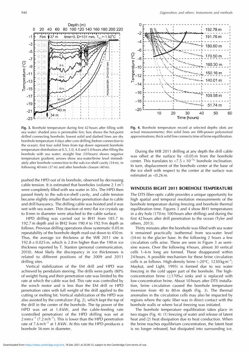
WINDLESS BIGHT 2011 BOREHOLE TEMPERATUREThe DTS fiber-optic cable provides a unique opportunity forhigh spatial and temporal resolution measurements of theborehole temperature during freezing and borehole thermalequilibration time. Figures 3 and 4 show BH1 temperaturesin a dry hole (170m; 100hours after drilling) and during thefirst 42 hours after drill penetration to the ocean (Tyler andothers, 2013).
Thirty minutes after the borehole was filled with sea waterit remained practically isothermal from sea-water level(34m) to the glacier base. In the following 2 hours a fewcirculation cells arise. These are seen in Figure 3 as semi-sine waves. Over the following 4 hours, almost 30 verticalcells 1–6m long are formed. These disappeared within24 hours. A possible mechanism for these brine circulationcells is as follows. High-density brine (–20°C, 1230 kgm–3;Maykut, and Light, 1995) is formed due to sea waterfreezing in the cold upper part of the borehole. The high-concentration brine (�170‰) sinks and is replaced withlow-concentration brine. About 10 hours after DTS installa-tion, brine circulation caused the borehole temperatureinversion from 40 to 80m depth (Fig. 3). The thermalanomalies in the circulation cells may also be impacted byregions where the optic fiber was in direct contact with theborehole walls or where local freezing was initiated.
The borehole temperature equilibration takes place intwo stages (Fig. 4): (1) freezing of water and release of latentheat and (2) heat dissipation due to heat conduction. Whenthe brine reaches equilibrium concentration, the latent heatis no longer released, but dissipated into surrounding ice.
Fig. 3. Borehole temperature during first 42 hours after filling withsea water: shaded area is permeable firn; box shows the hot-pointdrilled connecting borehole; lowest solid and dashed lines are dryborehole temperature 4 days after core drilling (before connection tothe ocean); first four solid lines from top down represent boreholetemperature distribution at 0.5, 2.0, 4.0 and 5.0 hours after filling theborehole with sea water; straight line (10 hours) shows negativetemperature gradient; arrows show sea-water/brine level immedi-ately after borehole connection to the sub-ice-shelf cavity (34m), infollowing 40min (37m) and after borehole closure (40m).
Fig. 4. Borehole temperature record at selected depths (dots areactual measurements); thin solid lines are fifth-power polynomialapproximations; thick solid line connects time of brine equilibration.
Zagorodnov and others: Instruments and methods940
Downloaded from https://www.cambridge.org/core. 18 Dec 2021 at 20:30:13, subject to the Cambridge Core terms of use.
This moment is seen as the kink between convex andconcave parts of the time–temperature relationship inFigure 4. We considered this moment as complete boreholeclosure (borehole diameter equal to the cable diameter at37m depth) due to freezing.
To estimate borehole temperature equilibration time thethermal decay model, often referred to as the ‘hot wiremethod’, was used (Carslaw and Jaeger, 1959). In this modelthe freezing water is considered as the linear source of heatin the borehole. The model shows that equilibration within50mK of undisturbed ice temperature takes 4 months. Thus,beginning in March 2012 the borehole data below 37mrepresent essentially ‘undisturbed’ ice temperature as this isthe approximate temperature resolution of the DTS system(Tyler and others, 2013). Above 37m depth where the bore-hole remained open, no appreciable changes were noticed,except for seasonal variations in the 0–15m depth interval.
ANALYSIS OF WINDLESS BIGHT 2011 BOREHOLEFREEZINGFreezing of a borehole filled with fresh and sea water haspreviously been studied in regard to access-borehole drillingwith a hot-water drill in cold ice (Tien and Yen, 1975;Napoléoni and Clarke, 1978; Koci, 1984; Iken and others,1989; Humphrey and Echelmeyer, 1990; Humphrey, 1991;Makinson, 1993; Hughes and others, 2013). Here wepresent field observations and estimates of borehole closurerates obtained with the heat-flux model.
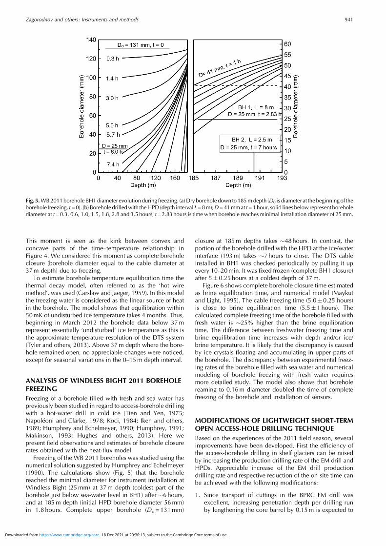
Freezing of the WB 2011 boreholes was studied using thenumerical solution suggested by Humphrey and Echelmeyer(1990). The calculations show (Fig. 5) that the boreholereached the minimal diameter for instrument installation atWindless Bight (25mm) at 37m depth (coldest part of theborehole just below sea-water level in BH1) after �6 hours,and at 185m depth (initial HPD borehole diameter 56mm)in 1.8 hours. Complete upper borehole (Do = 131mm)
closure at 185m depths takes �48hours. In contrast, theportion of the borehole drilled with the HPD at the ice/waterinterface (193m) takes �7hours to close. The DTS cableinstalled in BH1 was checked periodically by pulling it upevery 10–20min. It was fixed frozen (complete BH1 closure)after 5�0.25 hours at a coldest depth of 37m.
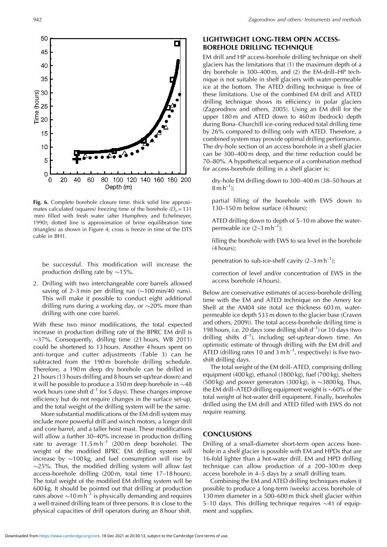
Figure 6 shows complete borehole closure time estimatedas brine equilibration time, and numerical model (Maykutand Light, 1995). The cable freezing time (5.0� 0.25 hours)is close to brine equilibration time (5.5�1 hours). Thecalculated complete freezing time of the borehole filled withfresh water is �25% higher than the brine equilibrationtime. The difference between freshwater freezing time andbrine equilibration time increases with depth and/or ice/brine temperature. It is likely that the discrepancy is causedby ice crystals floating and accumulating in upper parts ofthe borehole. The discrepancy between experimental freez-ing rates of the borehole filled with sea water and numericalmodeling of borehole freezing with fresh water requiresmore detailed study. The model also shows that boreholereaming to 0.16m diameter doubled the time of completefreezing of the borehole and installation of sensors.
MODIFICATIONS OF LIGHTWEIGHT SHORT-TERMOPEN ACCESS-HOLE DRILLING TECHNIQUEBased on the experiences of the 2011 field season, severalimprovements have been developed. First the efficiency ofthe access-borehole drilling in shelf glaciers can be raisedby increasing the production drilling rate of the EM drill andHPDs. Appreciable increase of the EM drill productiondrilling rate and respective reduction of the on-site time canbe achieved with the following modifications:
1. Since transport of cuttings in the BPRC EM drill wasexcellent, increasing penetration depth per drilling runby lengthening the core barrel by 0.15m is expected to
Fig. 5.WB2011borehole BH1diameter evolution during freezing. (a)Dry borehole down to 185mdepth (D0 is diameter at the beginning of theborehole freezing, t=0). (b) Borehole drilledwith theHPD (depth interval L=8m);D=41mmat t=1hour, solid lines below represent boreholediameter at t=0.3, 0.6, 1.0, 1.5, 1.8, 2.8 and 3.5 hours; t=2.83 hours is time when borehole reaches minimal installation diameter of 25mm.
Zagorodnov and others: Instruments and methods 941
Downloaded from https://www.cambridge.org/core. 18 Dec 2021 at 20:30:13, subject to the Cambridge Core terms of use.
be successful. This modification will increase theproduction drilling rate by �15%.
2. Drilling with two interchangeable core barrels allowedsaving of 2–3min per drilling run (�100min/40 runs).This will make it possible to conduct eight additionaldrilling runs during a working day, or �20% more thandrilling with one core barrel.
With these two minor modifications, the total expectedincrease in production drilling rate of the BPRC EM drill is�37%. Consequently, drilling time (21 hours, WB 2011)could be shortened to 13hours. Another 4 hours spent onanti-torque and cutter adjustments (Table 3) can besubtracted from the 190m borehole drilling schedule.Therefore, a 190m deep dry borehole can be drilled in21 hours (13 hours drilling and 8 hours set-up/tear-down) andit will be possible to produce a 350m deep borehole in �48work hours (one shift d–1 for 5 days). These changes improveefficiency but do not require changes in the surface set-up,and the total weight of the drilling system will be the same.
More substantial modifications of the EM drill system mayinclude more powerful drill and winch motors, a longer drilland core barrel, and a taller hoist mast. These modificationswill allow a further 30–40% increase in production drillingrate to average 11.5mh–1 (200m deep borehole). Theweight of the modified BPRC EM drilling system willincrease by �100 kg, and fuel consumption will rise by�25%. Thus, the modified drilling system will allow fastaccess-borehole drilling (200m, total time 17–18hours).The total weight of the modified EM drilling system will be600 kg. It should be pointed out that drilling at productionrates above �10mh–1 is physically demanding and requiresa well-trained drilling team of three persons. It is close to thephysical capacities of drill operators during an 8hour shift.
LIGHTWEIGHT LONG-TERM OPEN ACCESS-BOREHOLE DRILLING TECHNIQUEEM drill and HP access-borehole drilling technique on shelfglaciers has the limitations that (1) the maximum depth of adry borehole is 300–400m, and (2) the EM-drill–HP tech-nique is not suitable in shelf glaciers with water-permeableice at the bottom. The ATED drilling technique is free ofthese limitations. Use of the combined EM drill and ATEDdrilling technique shows its efficiency in polar glaciers(Zagorodnov and others, 2005). Using an EM drill for theupper 180m and ATED down to 460m (bedrock) depthduring Bona–Churchill ice-coring reduced total drilling timeby 26% compared to drilling only with ATED. Therefore, acombined system may provide optimal drilling performance.The dry-hole section of an access borehole in a shelf glaciercan be 300–400m deep, and the time reduction could be70–80%. A hypothetical sequence of a combination methodfor access-borehole drilling in a shelf glacier is:
dry-hole EM drilling down to 300–400m (38–50 hours at8mh–1);
partial filling of the borehole with EWS down to130–150m below surface (4 hours);
ATED drilling down to depth of 5–10m above the water-permeable ice (2–3mh–1);
filling the borehole with EWS to sea level in the borehole(4 hours);
penetration to sub-ice-shelf cavity (2–3mh–1);
correction of level and/or concentration of EWS in theaccess borehole (4 hours).
Below are conservative estimates of access-borehole drillingtime with the EM and ATED technique on the Amery IceShelf at the AM04 site (total ice thickness 603m, water-permeable ice depth 533m down to the glacier base (Cravenand others, 2009)). The total access-borehole drilling time is198 hours, i.e. 20 days (one drilling shift d–1) or 10 days (twodrilling shifts d–1), including set-up/tear-down time. Anoptimistic estimate of through drilling with the EM drill andATED (drilling rates 10 and 3mh–1, respectively) is five two-shift drilling days.
The total weight of the EM drill–ATED, comprising drillingequipment (400 kg), ethanol (1800 kg), fuel (700 kg), shelters(500 kg) and power generators (300 kg), is �3800 kg. Thus,the EM drill–ATED drilling equipment weight is �60% of thetotal weight of hot-water drill equipment. Finally, boreholesdrilled using the EM drill and ATED filled with EWS do notrequire reaming.
CONCLUSIONSDrilling of a small-diameter short-term open access bore-hole in a shelf glacier is possible with EM and HPDs that are16-fold lighter than a hot-water drill. EM and HPD drillingtechnique can allow production of a 200–300m deepaccess borehole in 4–5 days by a small drilling team.
Combining the EM and ATED drilling techniques makes itpossible to produce a long-term (weeks) access borehole of130mm diameter in a 500–600m thick shelf glacier within5–10 days. This drilling technique requires �4 t of equip-ment and supplies.
Fig. 6. Complete borehole closure time: thick solid line approxi-mates calculated (squares) freezing time of the borehole (Do = 131mm) filled with fresh water (after Humphrey and Echelmeyer,1990); dotted line is approximation of brine equilibration time(triangles) as shown in Figure 4; cross is freeze in time of the DTScable in BH1.
Zagorodnov and others: Instruments and methods942
Downloaded from https://www.cambridge.org/core. 18 Dec 2021 at 20:30:13, subject to the Cambridge Core terms of use.
ACKNOWLEDGEMENTSWe appreciate the efforts and contributions of HerbertUeda, John Rand, Kendrick Taylor, Andrey Salamatin, KeithMakinson and Dave Pomraning who provided usefulinformation and suggestions on drilling and interpretationof the borehole temperature. Funding for this project hasbeen provided by the Office of Polar Programs of the USNational Science Foundation (NSF) under grantANT1043154, and support was provided to S.T. and D.H.by grants ANT1043395 and ANT1043217, respectively.D.H. acknowledges additional support from ANT-104339and ANT-073286 Additional instrument support was pro-vided by NSF-CTEMPs under EAR-1128999 and engineeringservices provided by the UNAVCO Facility with supportfrom the NSF and NASA under NSF Cooperative AgreementNo. EAR 0735156.
REFERENCESBentley CR and Koci BR (2007) Drilling to the beds of the
Greenland and Antarctic ice sheets: a review. Ann. Glaciol., 47,1–9 (doi: 10.3189/172756407786857695)
Blake EW, Wake CP and Gerasimoff MD (1998) The ECLIPSE drill:a field-portable intermediate-depth ice-coring drill. J. Glaciol.,44(146), 175–178
Bogorodsky VV and Morev VA (1984) Equipment and technologyfor core driling in moderately cold ice. CRREL Spec. Rep. 84-34,129–132
Browning JA (1978) Flame-drilling through the Ross Ice Shelf.Northern Eng., 10(1), 4–8
Carslaw HS and Jaeger JC (1959) Conduction of heat in solids.Oxford University Press, Oxford
Clough JW (1973) Radio echo sounding: brine percolation layer.J. Glaciol., 12(64), 141–143
Clough JW (1974) RISP radio-echo soundings. Antarct. J. US, 9(4),159
Clough JWandHansenBL (1979) The Ross Ice Shelf project. Science,203(4379), 433–434 (doi: 10.1126/science.203.4379.433)
Clow GD and Koci B (2002) A fast mechanical-access drill for polarglaciology, paleoclimatology, geology, tectonics and biology.Mem. Natl Inst. Polar Res., Special Issue 56, 5–37
Craven M, Allison I, Fricker HA and Warner R (2009) Propertiesof a marine ice layer under the Amery Ice Shelf, EastAntarctica. J. Glaciol., 55(192), 717–728 (doi: 10.3189/002214309789470941)
Gillet F (1975) Steam, hot-water and electrical thermal drills fortemperate glaciers. J. Glaciol., 14(70), 171–179
Hansen BL (1976) Deep core drilling in the East Antarctica IceSheet: a prospectus. In Splettstoesser JF ed. Ice-core drilling.University of Nebraska Press, Lincoln, NE, 29–36
Heine AJ (1968) Brine in the McMurdo Ice Shelf, Antarctica. NewZeal. J. Geol. Geophys., 11(4), 829–839
Hubbard B, Tison J-L, Pattyn F, Dierckx M, Boereboom T andSamyn D (2012) Optical-televiewer-based identification andcharacterization of material facies associated with an Antarcticice-shelf rift. Ann. Glaciol., 53(60 Pt 2), 137–146 (doi: 10.3189/2012AoG60A045)
Hughes KG, Langhorne PJ and Williams MJM (2013) Estimates ofthe refreezing rate in an ice-shelf borehole. J. Glaciol., 59(217),938–948 (doi: 10.3189/2013JoG12J117)
Humphrey N (1991) Estimating ice temperature from short recordsin thermally disturbed boreholes. J. Glaciol., 37(127), 414–419
Humphrey N and Echelmeyer K (1990) Hot-water drilling and bore-hole closure in cold ice. J. Glaciol., 36(124), 287–298 (doi:10.3189/002214390793701354)
Iken A, Echelmeyer K and Harrison WD (1989) A light-weight hotwater drill for large depth: experiences with drilling onJakobshavns glacier, Greenland. In Rado C and Beaudoing D
eds. Ice core drilling. Proceedings of the 3rd InternationalWorkshop on Ice Drilling Technology, 10–14 October 1988,Grenoble, France. Laboratoire de Glaciologie et Géophysiquede l’Environnement, Centre National de la Recherche Scienti-fique, Grenoble, 123–136
Jezek KC and Bentley CR (1983) Field studies of bottom crevassesin the Ross Ice Shelf, Antarctica. J. Glaciol., 29(101), 118–126
Koci BR (1984) Hot water drilling in Antarctic firn, and freezing ratesin water-filled boreholes. CRREL Spec. Rep. 84-34, 101–103
Kohshima S, Shiraiwa T, Godoi MA, Kubota K, Takeuchi N andShinbori K (2002) Ice core drilling at Southern Patagonia Icefield– development of a new portable drill and the field expedition in1999. Mem. Natl Inst. Polar Res., Special Issue 56, 49–58
Korotkevich ES, Savatyugin LM and Morev VA (1978) Skvoznoeburenie shelfovogo lednika v raione stantcii Novolazarevskoi[Drilling through the ice shelf in the vicinity of Novolazar-evskaya Station]. Inf. Byull. Sov. Antarkt. Eksped., 98, 49–52
Kovacs A, Gow AJ and Morey RM (1993) A reassessment of the in-situ dielectric constant of polar firn. CRREL Rep. 93-26
LaChapelle E (1963) A simple thermal ice drill. J. Glaciol., 4(35),637–642
Lange GR (1973) Deep rotary core drilling in ice. CRREL Tech. Rep.94
Lange NA (1961) Handbook of chemistry, 10th edn. McGraw-Hill,New York
Makinson K (1993) The BAS hot water drill: development andcurrent design. Cold Reg. Sci. Technol., 22(1), 121–132 (doi:10.1016/0165-232X(93)90051-9)
Maykut GA and Light B (1995) Refractive-index measurements infreezing sea-ice and sodium chloride brines. Appl. Opt., 34(6),950–961 (doi: 10.1364/AO.34.000950)
Mellor M and Sellmann PV (1976) General considerations for drillsystem design. In Splettstoesser JF ed. Ice-core drilling.University of Nebraska Press, Lincoln, NE, 77–111
Morev, VA, Pukhov, VA, Yakovlev, VM and Zagorodnov VA (1984)Equipment and technology for drilling in temperate glaciers.CRREL Spec. Rep. 84-34, 125–127
Morev VA, Manevskiy LN, Yakovlev VM and Zagorodnov VS(1988) Drilling with ethanol-based antifreeze in Antarctica. InRado C and Beaudoing D eds. Ice core drilling. Proceedings ofthe Third International Workshop on Ice Drilling Technology,10–14 October 1988, Grenoble, France. Laboratoire deGlaciologie et Géophysique de l’Environnement, Centre Na-tional de la Recherche Scientifique, Grenoble, 110–113
Napoléoni JGP and Clarke GKC (1978) Hot water drilling in a coldglacier. Can. J. Earth Sci., 15(2), 316–321
Neff PD, Steig EJ, Clark DH, McConnell JR, Pettit EC and MenounosB (2012) Ice-core net snow accumulation and seasonal snowchemistry at a temperate-glacier site: Mount Waddington,southwest British Columbia, Canada. J. Glaciol., 58(212),1165–1175 (doi: 10.3189/2012JoG12J078)
Nizery A (1951) Electrothermic rig for the boring of glaciers. Eos,32(1), 66–72
Raikovsky YuV, Samoilov OYu, Prony NP, Smirnov KY andArkhipov SM (1990) Glatciologicheskie issledovaniya nashelfovom lednike Aimery in 1987–1989 gg [Glaciologicalinvestigations of the Amery Ice Shelf in 1987–1989]. Mater.Glyatsiol. Issled., 68, 114
Rand JH (1977) Ross Ice Shelf drilling, October–December 1976.Antarct. J. US, 12(4), 150–152
Savatyugin LM (1980) Glatciolologicheskie issledovaniya nashelfovom lednike Shekltona (yanvar’–fevral’ 1978 g) [Glacio-logical investigations of Shackleton Ice Shelf (January–April)1978]. Sov. Antarct. Exped. Inf. Bull., 100, 114–118
Shabtaie S and Bentley CR (1982) Tabular icebergs: implicationsfrom geophysical studies of ice shelves. J. Glaciol., 28(100),413–430
Shreve RL and Sharp RP (1970) Internal deformation and thermalanomalies in lower Blue Glacier, Mount Olympus, Washington,U.S.A. J. Glaciol., 9(55), 65–86
Zagorodnov and others: Instruments and methods 943
Downloaded from https://www.cambridge.org/core. 18 Dec 2021 at 20:30:13, subject to the Cambridge Core terms of use.
Sochet I and Gillard P (2002) Flammability of kerosene in civil andmilitary aviation. J. Loss Prev. Process Ind., 15(5), 335–345 (doi:10.1016/S0950-4230(02)00031-1)
Stern AA, Dinniman MS, Zagorodnov V, Tyler SW and Holland DM(2013) Intrusion of warm surface water beneath the McMurdoIce Shelf, Antarctica. J. Geophys. Res., 118(12), 7036–7048(doi: 10.1002/2013JC008842)
Talalay PG and Gundestrup NS (2002) Hole fluids for deep ice coredrilling. Mem. Natl Inst. Polar Res., Special Issue 56, 148–170
Taylor PL (1976) Solid-nose and coring thermal drills for temperateice. In Splettstoesser JF ed. Ice-core drilling. University ofNebraska Press, Lincoln, NE, 167–177
Thorsteinsson T, Sigurðsson O, Jóhannesson T, Larsen G, Drücker Cand Wilhelms F (2003) Ice core drilling on the Hofsjökull icecap. Jökull, 51, 25–41
Tien C and Yen Y-c (1975) An approximate analysis of melting andfreezing of a drill hole through an ice shelf in Antarctica.J. Glaciol., 14(72), 421–432
Treverrow A, Warner RC, Budd WF and Craven M (2010) Meteoricand marine ice crystal orientation fabrics from the Amery IceShelf, East Antarctica. J. Glaciol., 56(199), 877–890 (doi:10.3189/002214310794457353)
Tyler SW and 8 others (2013) Using distributed temperature sensorsto monitor an Antarctic ice shelf and sub-ice shelf cavity.J. Glaciol., 59(215), 583–591 (doi: 10.3189/2013JoG12J207)
Vaughan DG, Mantripp DR, Sievers J and Doake CSM (1993) Asynthesis of remote sensing data on Wilkins Ice Shelf, Ant-arctica. Ann. Glaciol., 17, 211–218
Ward WH (1952) The glaciological studies of the Baffin IslandExpedition, 1950. Part III: Equipment and techniques. J. Glaciol.,2(12), 115–121/117
Wolfe LS and Hoult DP (1974) Effects of oil under sea ice.J. Glaciol., 13(69), 473–488
Zagorodnov VS, Kelley JJ and Nagornov OV (1994a) Drilling ofglacier boreholes with a hydrophilic liquid. Mem. Natl Inst.Polar Res., Special Issue 49, 153–164
Zagorodnov VS, Morev VA, Nagornov OV, Kelley JJ, Gosink TAand Koci BR (1994b) Hydrophilic liquid in glacier boreholes.Cold Reg. Sci. Technol., 22(3), 243–251 (doi: 10.1016/0165-232X(94)90003-5)
Zagorodnov V, Thompson LG, Kelley JJ, Koci B and Mikhalenko V(1998) Antifreeze thermal ice core drilling: an effective ap-proach to the acquisition of ice cores. Cold Reg. Sci. Technol.,28(1998), 189–202 (doi: 10.1016/S0165-232X(98)00019-6)
Zagorodnov V, Thompson LG and Mosley-Thompson E(2000) Portable system for intermediate-depth ice-coredrilling. J. Glaciol., 46(152), 167–172 (doi: 10.3189/172756500781833304)
Zagorodnov V, Thompson LG, Ginot P and Mikhalenko V (2005)Intermediate-depth ice coring of high-altitude and polar glacierswith a lightweight drilling system. J. Glaciol., 51(174), 491–501(doi: 10.3189/172756505781829269)
Zotikov IA (1979) Antifreeze-thermodrilling for core through thecentral part of the Ross Ice Shelf (J-9 Camp), Antarctica. CRRELRep. 79-24
Zotikov IA, Zagorodnov VS and Raikovsky JV (1980) Core drillingthrough the Ross Ice Shelf (Antarctica) confirmed basalfreezing. Science, 207(4438), 1463–1465 (doi: 10.1126/science.207.4438.1463)
Zumberge JH (1971) Ross Ice Shelf Project: drilling in and belowice will reveal physical, chemical, biological features. Antarct. J.US, 6(6), 258–263
MS received 8 November 2013 and accepted in revised form 2 July 2014
Zagorodnov and others: Instruments and methods944
Downloaded from https://www.cambridge.org/core. 18 Dec 2021 at 20:30:13, subject to the Cambridge Core terms of use.