Embed Size (px)
Citation preview
0998
/002
02.
2010
1,0
00
R E F E R E N C E
TECHNICAL REVIEW BOREHOLE DRILLING AND REHABILITATION UNDER FIELD CONDITIONS

International Committee of the Red Cross19, avenue de la Paix1202 Geneva, SwitzerlandT + 41 22 734 60 01 F + 41 22 733 20 57E-mail: [email protected] www.icrc.org© ICRC, February 2010
© Cover photo: T. Nydegger/ICRC
MISSION
The International Committee of the Red Cross (ICRC) is an
impartial, neutral and independent organization whose
exclusively humanitarian mission is to protect the lives and
dignity of victims of armed conflict and other situations of
violence and to provide them with assistance.
The ICRC also endeavours to prevent suffering by promoting and
strengthening humanitarian law and universal humanitarian
principles.
Established in 1863, the ICRC is at the origin of the Geneva
Conventions and the International Red Cross and Red Crescent
Movement. It directs and coordinates the international activities
conducted by the Movement in armed conflicts and other
situations of violence.
TECHNICAL REVIEW BOREHOLE DRILLING AND REHABILITATION UNDER FIELD CONDITIONS
ICRC Borehole Technical Review.indd 1 19/02/2010 17:14

Credits
Cover photo and Abstract: T. Nydegger/ICRC
Figure 1 Drawing by D. SoulsbyFigure 2 D. Soulsby/ICRCFigure 3 D. Soulsby/ICRCFigure 4 Consallen Group Sales LtdFigure 5 PAT-DRILLFigure 6 T. Nydegger/ICRCFigure 7 Dando Drilling RigsFigure 8 Sameer Putros/ICRC (left), Los Alamos National Laboratory (right) Figure 9 Andrea Guidotti/ICRC (top), Sameer Putros/ICRC (bottom)Figure 10 Drawing by D. SoulsbyFigure 11 OFI Testing Equipment, Inc.Figure 12 Drawing by D. SoulsbyFigure 13 Drawing by D. SoulsbyFigure 14 Drawing by D. SoulsbyFigure 15 D. Soulsby/ICRCFigure 16 Drawing by D. SoulsbyFigure 17 D. Soulsby/ICRCFigure 18 GeoModel, Inc.Figure 19 GeoVISIONFigure 20 Drawing by D. SoulsbyAnnex 3 Drawings by D. Soulsby
ICRC Borehole Technical Review.indd 2 19/02/2010 17:14
Foreword
3
ForewordThis technical review presents and synthesizes an impressive amount of practical experience in
the field of borehole drilling and rehabilitation.
David Soulsby- author of this publication and a seasoned geologist/geophysicist/water engineer
- strikes the right balance between theoretical and practical knowledge while adopting the
approach of a scholar/practitioner. There is no doubt that his work will greatly help the ICRC's
Water and Habitat engineers address technical dilemmas under difficult field conditions.
However, the ICRC's field experience reveals that in water-stressed regions afflicted by armed
conflicts or rising tensions, there are no easy answers. This said, sustainability for the people
benefiting from water projects can be reached when a cost-effective solution is part and parcel
of a comprehensive analysis putting the dignity and the needs of the community at the centre
while addressing wider environmental concerns.
This is the first Water and Habitat publication in the ICRC's new series, 'REFERENCE.' It is an
important contribution to the Water and Habitat unit's efforts to promote good field practices
within its staff and amongst other humanitarian players.
I am extremely grateful to two successive Chief Hydrogeologists, Mr Jean Vergain who initiated
this valuable work and Mr Thomas Nydegger who provided invaluable guidance throughout
the editing of the Review. Finally, I wish to extend my thanks to Ms Anna Taylor who gave
constructive advice as a reviewer and structured the final version of the manuscript.
Robert Mardini
Head of the Water and Habitat Unit
ICRC Borehole Technical Review.indd 3 19/02/2010 17:14
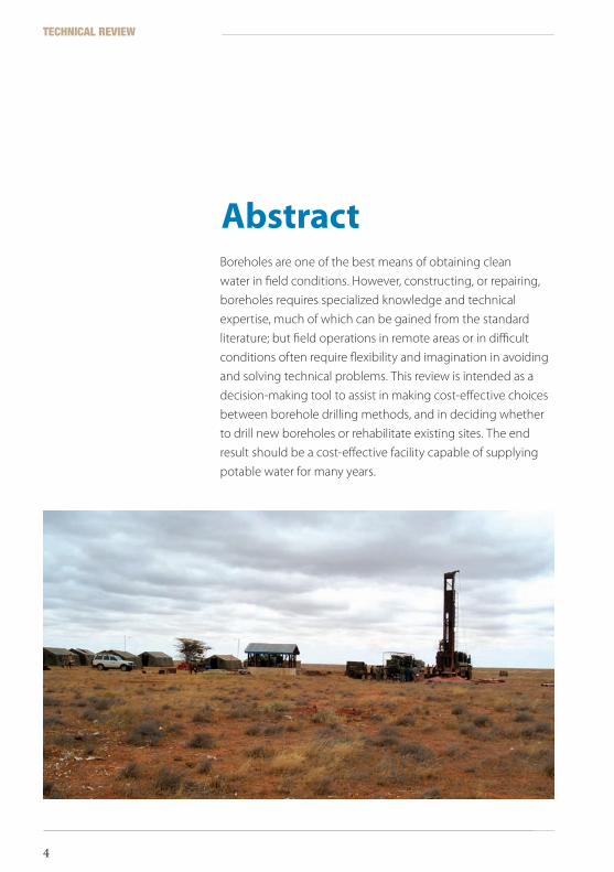
Boreholes are one of the best means of obtaining clean
water in field conditions. However, constructing, or repairing,
boreholes requires specialized knowledge and technical
expertise, much of which can be gained from the standard
literature; but field operations in remote areas or in difficult
conditions often require flexibility and imagination in avoiding
and solving technical problems. This review is intended as a
decision-making tool to assist in making cost-effective choices
between borehole drilling methods, and in deciding whether
to drill new boreholes or rehabilitate existing sites. The end
result should be a cost-effective facility capable of supplying
potable water for many years.
Abstract
TECHNICAL REVIEW
4
ICRC Borehole Technical Review.indd 4 19/02/2010 17:14
Table of ContentsForeword 3
Abstract 4
Glossary 9
1 Introductionandexecutivesummary 13
2 Groundwaterandtheadvantagesofboreholes 152.1 Exploiting groundwater 15
2.1.1 Geological constraints 16
2.1.2 Borehole siting 18
2.1.3 Types of geological formation 19
2.2 Groundwater extraction 21
2.2.1 Advantages of drilled boreholes 22
2.2.2 Disadvantages of drilled boreholes 23
3 Methodsofdrillingboreholes 253.1 Common drilling methods 26
4 Drillingequipment 314.1 Choosing a drilling rig 31
4.1.1 Percussion drilling 32
4.1.2 Heavy duty cable tool 32
4.1.3 Rotary drilling 33
4.2 Drilling rig components 35
4.2.1 Drill bit 35
4.2.2 Hammer 36
Table of contents
5
ICRC Borehole Technical Review.indd 5 19/02/2010 17:14
5 Boreholeconstruction 375.1 Construction considerations 37
5.1.1 Mud rotary drilling 40
5.1.2 Compressed air rotary drilling 46
5.2 Borehole logging 49
6 Boreholedesign,development,andcompletion 536.1 Borehole construction design 54
6.1.1 Borehole casing 54
6.1.2 Borehole well screens 55
6.1.3 Gravel pack 58
6.1.4 Pump selection 62
6.1.5 Sealing the borehole 62
6.1.6 Examples of borehole design 64
6.2 Borehole development 66
6.2.1 Development methods 67
6.3 Borehole completion 72
6.3.1 Sanitary seal 72
6.3.2 Pumps and test pumping 72
6.3.3 Geophysical logging 79
7 Drilling/Constructioncosts 817.1 Buying a rig 83
7.2 Success rates 84
8 Boreholedeterioration 85
9 Boreholemonitoring 89
10 Boreholerehabilitation 9310.1 When to rehabilitate 93
10.2 Rehabilitation methods 94
10.2.1 Inspection by CCTV 95
10.2.2 Breaking up of clogging deposits and incrustations 96
10.2.3 Relining 99
10.2.4 Borehole sterilization 101
10.2.5 Step-drawdown testing 102
10.2.6 Mechanical repair 102
TECHNICAL REVIEW
6
ICRC Borehole Technical Review.indd 6 19/02/2010 17:14

11 Workingwithcontractors 10311.1 Selecting a contractor 103
11.2 Contract documentation 104
Annexes 105Annex 1 Example of a drilling log sheet 106
Annex 2 Recent quoted prices for casings and screens 107
Annex 3 Examples of borehole construction designs 109
Annex 4 Example of test pumping data sheet 111
Annex 5 Basic drilling contract: Clauses and specifications 113
Annex 6 List of items on contractor work/charge sheets 119
Annex 7 Product references and further reading 122
Index 125
ListoftablesTable 1 Typical porosities and permeabilities for various
materials 17
Table 2 Comparison of drilling methods 29
Table 3 Mud rotary: Circulation fluid flow rates for a range
of drill bit and drill pipe sizes 47
Table 4 Air drilling: Maximum drill bit sizes for a range
of compressor capacities and drill pipe sizes 48
Table 5 Typical casing collapse strengths 55
Table 6 Casing diameters and screen openings 58
Table 7 Choice of screens and gravel pack for various
ground conditions 61
Table 8 Quantity of chlorine compound to produce a
50 mg/l solution in 20 m of water-filled casing 78
Table 9 Borehole monitoring: Symptoms, causes, and remedies 90
ListoffiguresFigure 1 A hypothetical hydrogeological scenario 19
Figure 2 A mud rotary machine working in eastern
Zimbabwe, 1996 28
Figure 3 Air rotary machine developing a successful
borehole, South Africa, 1989 29
Figure 4 The Forager 55 cable-trailer rig in use 32
Figure 5 A PAT 201 drilling rig; in the foreground is an auger drill 33
Table of Contents
7
ICRC Borehole Technical Review.indd 7 19/02/2010 17:14

Figure 6 ICRC PAT 401 in action, northern Uganda, 2008 34
Figure 7 The Dando Watertec 24 drilling rig 35
Figure 8 Three common types of drill bit 35
Figure 9 A DTH hammer button bit 36
Figure 10 Schematic section of an example of temporary borehole
completion 38
Figure 11 The Marsh funnel viscometer 43
Figure 12 Schematic plan view showing mud pits and
mud circulation 45
Figure 13 Water flow through a V-wire screen 57
Figure 14 Sealing the bottom end of mild steel casing by
the welded ‘saw-teeth’ method 63
Figure 15 Measuring the blowing yield of a newly drilled borehole 69
Figure 16 Typical test-pumping set-up 74
Figure 17 A test-pumping rig in operation (it consists of
a belt-driven mechanical rotary (Mono) pump), Zimbabwe 75
Figure 18 Casing damage as seen through a borehole CCTV camera 95
Figure 19 A CCTV borehole camera 96
Figure 20 Air-lifting in borehole rehabilitation 100
TECHNICAL REVIEW
8
ICRC Borehole Technical Review.indd 8 19/02/2010 17:14
Glossary
Aquifer A subsurface rock or sediment unit that is porous and permeable and contains water. In an aquifer these characteristics are highly developed: useful quantities of water are stored and transmitted.
Confined An aquifer that is bounded above and below by impermeable rock or layers of sediments. There may or may not be enough pressure in the aquifer to make it an ‘artesian aquifer (piezometric level above ground level).’1
Perched Usually, an unconfined aquifer that is resting on an impermeable layer of limited extent surrounded by permeable formations or surmounting another unconfined aquifer.
Unconfined An aquifer that is not overlain by an impermeable rock unit. The water in this aquifer is under atmospheric pressure. This kind of aquifer is replenished by rainfall in the area of its watershed or by infiltration from a river.1
Bedrock Solid rock present beneath any soil, sediment or other surface cover. In some locations it may be exposed on the surface of the Earth.1
Formation A laterally continuous rock unit with a distinctive set of characteristics that make it possible to recognize and map from one outcrop or well to another. The basic rock unit of stratigraphy.1
Host The rock formation containing the water. The rock and the water together form an aquifer.
Fracture Any local separation or discontinuity plane in a geologic formation, such as a joint or a fault that divides the rock into two or more pieces. Fractures are commonly caused by mechanical stress exceeding the rock strength. 2
Glossary
99
ICRC Borehole Technical Review.indd 9 19/02/2010 17:14
Groundwater Water that exists below the water table in the zone of saturation. Groundwater moves slowly, and follows the water table’s slope.1
Igneous Formed by the crystallization of magma or lava.
Impervious Impermeable. An impervious layer is a layer of rock, sediment or soil that does not allow water to pass through. This could be caused by a lack of pore space, pore spaces that are not interconnected or that are so small that water molecules have difficulty passing through.1
Joints A fracture in rock along which there has been no displacement. 1
Lithology The study and description of rocks, including their mineral composition and texture. Also used in reference to the compositional and textural characteristics of a rock.1
Metamorphic A term used to describe a rock whose mineral content, textures and composition have been altered by exposure to heat, pressure and chemical actions, usually in the course of tectonic burial and/or magmatic activity.1
Mudstone A sedimentary rock composed of clay-sized particles but lacking the stratified structure that is characteristic of a shale.1
Permeability A measure of how well a material can transmit water. Materials such as gravel, that transmit water quickly, have high values of permeability. Materials such as shale, that transmit water poorly, have low values. Permeability is primarily determined by the size of the pore spaces and the degree to which they are interconnected. Permeability measures are expressed in units of velocity, such as centimetres per second.1
Pores Voids in a rock including openings between grains, fracture openings and caverns.1
Porosity The volume of pore space in rock, sediment or soil. Usually expressed as a percentage.1
Sandstones Sedimentary rock composed of sand-sized particles (1/16 to 2 millimetres in diameter) consolidated with some cement (calcite, clay, quartz). 1
Shales Thinly laminated sedimentary rock made of tiny clay-sized sedimentary particles.
TECHNICAL REVIEW
10
ICRC Borehole Technical Review.indd 10 19/02/2010 17:14

Unconsolidated Poorly cemented or not at all (in reference to sediments).
Wadi A stream that fills up after rainfall, but which is usually dry the rest of the time.
Weathered Earth rocks, soils and their mineral content which underwent decomposition by direct contact with the planet's atmosphere, water, light, frost and heat.1
1 Adapted from “Geology dictionary” at http://geology.com 2 Entry on “fracture (geology)” from Wikipedia at www.wikipedia.org
Boxes with this formatting contain information critical for successful operations or for the safety of the staff.
Boxes with this formatting highlight experiences from the field or practical suggestions.
Glossary
11
ICRC Borehole Technical Review.indd 11 19/02/2010 17:14

ICRC Borehole Technical Review.indd 12 19/02/2010 17:14
Introduction and executive summary
1
The International Committee of the Red Cross (ICRC) is an
impartial, neutral, and independent humanitarian organization.
Its mission is to protect the lives and dignity of victims of war
and internal conflict and to provide them with assistance.
Through its Water and Habitat unit, the ICRC provides water
and sanitation in dozens of countries and conflict zones around
the world, meeting the needs of millions of people. The
Water and Habitat unit has drilled or rehabilitated hundreds of
boreholes, sometimes employing contractors and sometimes
their own machines.
This technical review is aimed at project coordinators, water
engineers, and technicians. It is intended to be of assistance
to everyone, from planners in offices to on-site personnel, in
the making of technically correct and cost-effective decisions
in the field when the drilling or rehabilitation of boreholes is
required. An attempt has been made to orient the contents
towards problems that might be encountered in the field.
Nevertheless, some consideration of theoretical information has
been necessary, because engineers will not be able to function
without it. The authors hope that they have struck a balance
between the practical and the theoretical, a combination that is
required in professional water engineers.
1 Introduction and executive summary
13
ICRC Borehole Technical Review.indd 13 19/02/2010 17:14

The review begins with an overview of the benefits of utilizing
groundwater and a consideration of various drilling methods,
in Sections 2 to 4. Techniques are compared and details of the
drilling equipment associated with each are provided to assist
the user in selecting appropriate equipment.
The review focuses on mud and air rotary drilling, as they
are the most common methods of borehole drilling found
in the field. Details on borehole construction, design and
development using these two methods are found in Sections
5 and 6. Construction costs are considered in Section 7. Key
factors influencing borehole deterioration and aspects of
monitoring and maintenance are outlined in Sections 8
and 9. When borehole deterioration reaches a stage where
production is severely hampered, rehabilitation becomes
unavoidable: this subject is treated in Section 10. Finally,
Section 11 deals with issues that might arise while working with
contractors and with minimizing the unpredictability of that
aspect of drilling.
TECHNICAL REVIEW
14
ICRC Borehole Technical Review.indd 14 19/02/2010 17:14
15
Groundwater and the advantages of boreholes
2
Easy access to safe, potable water is a basic human need,
important for health and quality of life. A statement like this
is regarded now as being something of a cliché. However, it
must be said that even with the growing prevalence of water
shortages throughout the world, a reliable water supply is still
taken for granted, with no real thought about its sustainability
and quality. This attitude is most starkly evident in areas
where there is a reliance on water from boreholes, which,
it is assumed, will keep on producing – at the same rate –
continuously and forever. Groundwater is out of sight, and
hence, largely out of mind, but it is one of the best sources of
water that man has been able to utilize.
2.1 Exploitinggroundwater
The principal source of inland groundwater is rainfall. A
proportion of rain falling on the ground will percolate
downwards into an aquifer if the conditions are right. A great
deal of rain water ends up as run-off in streams and rivers, but
even here there is often a direct hydraulic connection with a
local aquifer. Indeed, in arid areas with ephemeral streams, high
groundwater levels may be able to sustain surface flow along
drainages.
2 Groundwater and the advantages of boreholes
15
ICRC Borehole Technical Review.indd 15 19/02/2010 17:14
It is obvious that a hole dug or bored into a saturated ‘sponge’
will release water from storage. This water can be sucked or
pumped out, and all being well, more water will enter the hole
to replace that which has been withdrawn. This is the basic
principle behind a water borehole.
2.1.1 Geologicalconstraints
The Earth’s crust has often been compared to a sponge, in that
it can soak up and hold water in pore spaces, fractures and
cavities. This ability to store water depends very much upon
geological conditions and on the host formation. For example,
fresh, unfractured, massive granite – a crystalline rock – has
virtually no space available for water, whereas unconsolidated,
or loose, river gravel and highly weathered cavernous limestone
can store large quantities of groundwater and are capable of
releasing it relatively freely. Sandstone and mudstone may be
able to hold significant groundwater resources, but because
of differences in grain size – and hence porosity – will release it
at different rates. One may be a good aquifer, the other a poor
one. The rate at which water flows through a formation depends
on the permeability of that formation, which is determined
by the size of pores and voids and the degree to which they
are interconnected. Permeability and porosity should not
be confused, porosity being the ratio between the volume
of pores/voids to the bulk volume of rock (usually expressed
as a percentage). Table 1 provides a range of porosities and
permeabilities for common soil profiles.
If water is not flowing visibly along a dry wadi, it may be moving unseen slowly through the sediment, and can be accessed by digging a well in the riverbed – a fact well known to many elephants.
TECHNICAL REVIEW
16
ICRC Borehole Technical Review.indd 16 19/02/2010 17:14
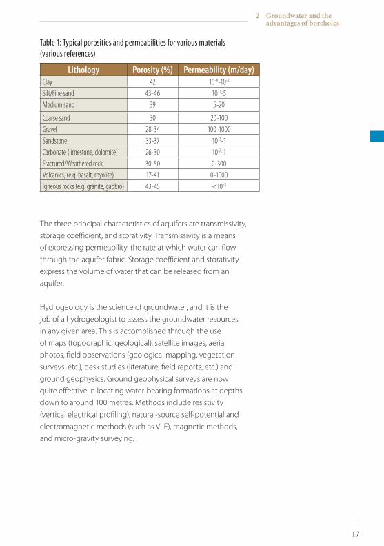
Table 1: Typical porosities and permeabilities for various materials (various references)
Lithology Porosity (%) Permeability (m/day)Clay 42 10-8-10-2
Silt/Fine sand 43-46 10-1-5Medium sand 39 5-20
Coarse sand 30 20-100Gravel 28-34 100-1000Sandstone 33-37 10-3-1Carbonate (limestone, dolomite) 26-30 10-2-1Fractured/Weathered rock 30-50 0-300Volcanics, (e.g. basalt, rhyolite) 17-41 0-1000Igneous rocks (e.g. granite, gabbro) 43-45 <10-5
The three principal characteristics of aquifers are transmissivity,
storage coefficient, and storativity. Transmissivity is a means
of expressing permeability, the rate at which water can flow
through the aquifer fabric. Storage coefficient and storativity
express the volume of water that can be released from an
aquifer.
Hydrogeology is the science of groundwater, and it is the
job of a hydrogeologist to assess the groundwater resources
in any given area. This is accomplished through the use
of maps (topographic, geological), satellite images, aerial
photos, field observations (geological mapping, vegetation
surveys, etc.), desk studies (literature, field reports, etc.) and
ground geophysics. Ground geophysical surveys are now
quite effective in locating water-bearing formations at depths
down to around 100 metres. Methods include resistivity
(vertical electrical profiling), natural-source self-potential and
electromagnetic methods (such as VLF), magnetic methods,
and micro-gravity surveying.
2 Groundwater and the advantages of boreholes
17
ICRC Borehole Technical Review.indd 17 19/02/2010 17:14
2.1.2 Boreholesiting
Choosing a borehole site is a critical part of the process of
providing a safe and reliable supply of groundwater. The
best sites are those in which catchment (natural water input)
may be maximized. Such locations are not necessarily those
that receive the highest rainfall (which may occur in upland
watersheds). ‘Bottomlands’ – such as river valleys and lake
basins – tend to be areas of maximum catchment as both
surface water and groundwater migrate towards them under
gravity. Fracture zones, although not always directly related
to bottomland, can also be good reservoirs for groundwater,
and may be located by ground observation or satellite images/
aerial photographs, and by geophysical methods.
Another aspect of borehole siting that demands careful
consideration in populated areas is the potential for
contamination by cattle and pit latrines or other waste
disposal facilities. Because near-surface groundwater migrates
downslope, a shallow dug well or a borehole tapping shallow
groundwater should be sited as far away as possible (while
bearing in mind the human need for proximity to a source of
water) and upslope of potential sources of pollution (latrines
or sewage pipes, for instance). Deeper aquifers confined by
impermeable layers are at less risk of contamination from
surface pollutants. One final consideration is the nature of
the shallow aquifer. If the host formation is made of fine or
medium-grain-sized sand, it will act as a natural filter for
particulate pollutants, whereas fissured limestone, with a
high rate of water transmission (transmissivity) will carry away
pollutants faster and to greater distances from the source. It is
estimated as a rule of thumb that most microorganisms do not
survive more than 10 days of transportation by underground
water.
TECHNICAL REVIEW
18
ICRC Borehole Technical Review.indd 18 19/02/2010 17:14
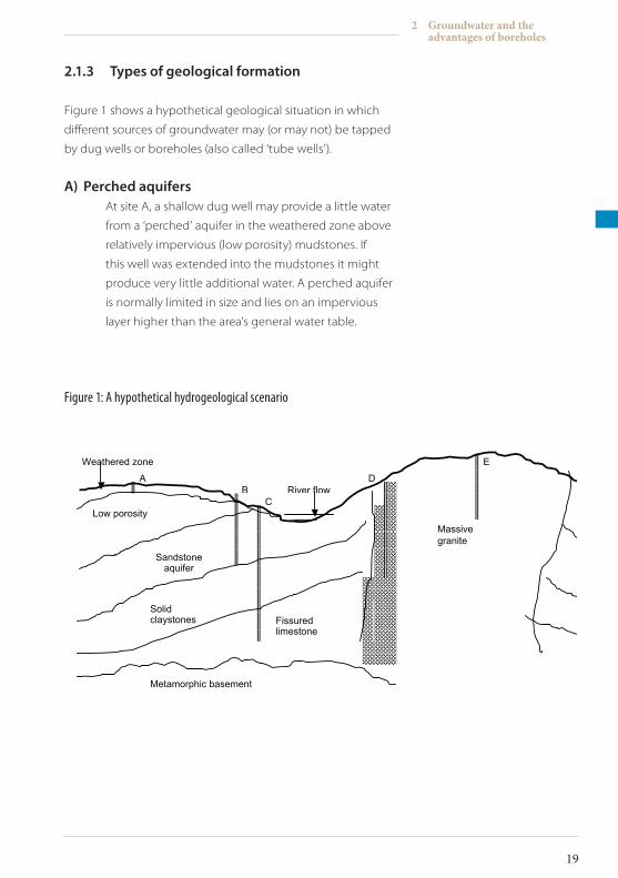
2.1.3 Typesofgeologicalformation
Figure 1 shows a hypothetical geological situation in which
different sources of groundwater may (or may not) be tapped
by dug wells or boreholes (also called ‘tube wells’).
A) PerchedaquifersAt site A, a shallow dug well may provide a little water
from a ‘perched’ aquifer in the weathered zone above
relatively impervious (low porosity) mudstones. If
this well was extended into the mudstones it might
produce very little additional water. A perched aquifer
is normally limited in size and lies on an impervious
layer higher than the area’s general water table.
Figure 1: A hypothetical hydrogeological scenario
Weathered zone E
A D B River flow C Low porosity
mudstones
Massive granite
Sandstone aquifer
Solid claystones
Fissured limestone
Metamorphic basement
2 Groundwater and the advantages of boreholes
19
ICRC Borehole Technical Review.indd 19 19/02/2010 17:14
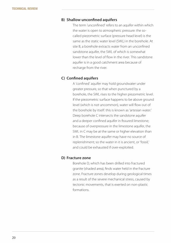
B) ShallowunconfinedaquifersThe term ‘unconfined’ refers to an aquifer within which
the water is open to atmospheric pressure: the so-
called piezometric surface (pressure head level) is the
same as the static water level (SWL) in the borehole. At
site B, a borehole extracts water from an unconfined
sandstone aquifer, the SWL of which is somewhat
lower than the level of flow in the river. This sandstone
aquifer is in a good catchment area because of
recharge from the river.
C) ConfinedaquifersA ‘confined’ aquifer may hold groundwater under
greater pressure, so that when punctured by a
borehole, the SWL rises to the higher piezometric level.
If the piezometric surface happens to be above ground
level (which is not uncommon), water will flow out of
the borehole by itself: this is known as ‘artesian water.’
Deep borehole C intersects the sandstone aquifer
and a deeper confined aquifer in fissured limestone;
because of overpressure in the limestone aquifer, the
SWL in C may be at the same or higher elevation than
in B. The limestone aquifer may have no source of
replenishment; so the water in it is ancient, or ‘fossil,’
and could be exhausted if over-exploited.
D) FracturezoneBorehole D, which has been drilled into fractured
granite (shaded area), finds water held in the fracture
zone. Fracture zones develop during geological times
as a result of the severe mechanical stress, caused by
tectonic movements, that is exerted on non-plastic
formations.
TECHNICAL REVIEW
20
ICRC Borehole Technical Review.indd 20 19/02/2010 17:14
E) HydrogeologicalbasementSite E, a borehole sunk into massive granite on top of a
hill, is dry. In this situation, it would be a waste of time
and money to extend a deep borehole (such as C) into
the metamorphic basement, which is generally known
as the ‘hydrogeological basement’ or ‘bedrock.’ The
bedrock marks the level below which groundwater is
not likely to be found.
2.2 Groundwaterextraction
A water borehole is not just a hole in the ground. It has to be
properly designed, professionally constructed and carefully
drilled. Boreholes for extracting water consist essentially of a
vertically drilled hole (inclined and horizontal boreholes are
rare and will not be discussed here), a strong lining to prevent
collapse of the walls, which includes a means of allowing clean
water to enter the borehole space (screen), surface protection,
and a means of extracting water. Drilling by machine is
an expensive process, and boreholes require professional
expertise for both their design and their construction. There
are, however, compensations: this method of extracting water
has a number of significant advantages.
The common alternatives to drilled boreholes, available
to everyone with basic knowledge and simple tools, are
surface water sources, springs, and dug wells. Where shallow
groundwater emerges at a seepage site or at a spring, water
catchment systems can be constructed to provide water
of reasonable quality. Catchment boxes, that include sand
or stone filters, and collector sumps are extremely effective
means of collecting water. Gravity may be used to effect pipe
network distribution from upland springs. Shallow dug wells
usually exploit near-surface groundwater. Wells down to a
depth of five metres are relatively simple to construct (given
time and willing local labour), and there are many publications
2 Groundwater and the advantages of boreholes
21
ICRC Borehole Technical Review.indd 21 19/02/2010 17:14
describing this process. Furthermore, because of their relatively
large diameter, wells provide valuable storage volume. The
water supply can be protected by lining the well, covering it
with a lid, and fitting a hand-pump to it. .
However, dug wells, and surface water catchment in general,
are very vulnerable to contamination caused by agricultural
activities, animals, poor sanitation and refuse. In addition,
surface or shallow groundwater catchment is vulnerable to
poor rainfall and declines in water level caused by drought,
because it usually taps the top of the aquifer. Borehole water,
by contrast, often requires no treatment and is less susceptible
to drops in water level during periods of drought or limited
rainfall.
2.2.1 Advantagesofdrilledboreholes
If they are properly designed and maintained, drilled boreholes:
• Are less vulnerable to drought or drops in water level when drilled into deep water-bearing formations
• Can be designed to exploit more than one aquifer (when individual aquifers are vertically separated and not hydraulically connected)
• Are less vulnerable to collapse
• Are less vulnerable to contamination
• Are, if properly sited, capable of producing large yields; so, mechanically or electrically powered pumps can be used
• Are amenable to quantitative monitoring and testing, which enables accurate assessment of aquifer parameters (as in aquifer modelling), water supply efficiency, and optimal design of pump and storage/distribution systems
• Can be used to monitor groundwater levels for other purposes, e.g. environmental studies or waste disposal
TECHNICAL REVIEW
22
ICRC Borehole Technical Review.indd 22 19/02/2010 17:14
2.2.2 Disadvantagesofdrilledboreholes
• High initial material costs and input of specialized expertise, i.e. construction, operation, and maintenance may require skills and expensive heavy equipment
• Vulnerable to irreversible natural deterioration if inadequately monitored and maintained
• Vulnerable to sabotage, can be irreparably destroyed with little effort if inadequately protected
• Require a source of energy if water extraction pumps are used (unlike gravity feed systems)
• Do not allow direct access, for maintenance or repairs, to constructed parts that are underground
2 Groundwater and the advantages of boreholes
23
ICRC Borehole Technical Review.indd 23 19/02/2010 17:14

ICRC Borehole Technical Review.indd 24 19/02/2010 17:14
Methods of drilling boreholes
3
Once a suitable site has been selected and borehole drilling
decided on, the proper drilling method must be chosen.
Another primary consideration in project planning is the
availability of existing water sources and water points. There
may be completed dug wells and boreholes already in the area.
Are they in use? If not, can they be rehabilitated to augment
water availability or to reduce the cost of the programme?
Drilling equipment, such as compressors, can be used to bring
disused boreholes back into use; the question of rehabilitation
will be addressed in Section 10 of this review. This section
outlines the factors that must be considered when choosing a
drilling method.
3 Methods of drilling boreholes
25
ICRC Borehole Technical Review.indd 25 19/02/2010 17:14
3.1 Commondrillingmethods
Essentially, a drilling machine consists of a mast from which
the drilling string components (tools plus drill pipes or cable)
are suspended and, in most cases, driven. Modern systems
are powered rotary-driven, but it is probably worth a short
digression to describe some methods of manual drilling for
water. Simple, low-cost methods include:
A) Hand-augerdrillingAuger drills, which are rotated by hand, cut into the soil
with blades and pass the cut material up a continuous
screw or into a ‘bucket’ (bucket auger). Excavated
material must be removed and the augering continued
until the required depth has been reached. Auger
drilling by hand is slow and limited to a depth of about
10 metres (maximum 20 metres) in unconsolidated
deposits (not coarser than sand, but it is a cheap and
simple process.
B) JettingA method whereby water is pumped down a string
of rods from which it emerges as a jet that cuts into
the formation. Drilling may be aided by rotating the
jet or by moving it up and down in the hole. Cuttings
are washed out of the borehole by the circulating
water. Again, jetting is useful only in unconsolidated
formations and only down to relatively shallow
depths, and would have to be halted if a boulder is
encountered.
C) SludgingThis method, which may be described as reverse
jetting, involves a pipe (bamboo has been successfully
employed) being lowered into the hole and moved
up and down, perhaps by a lever arm. A one-way
valve (such as someone’s hand at the top of the pipe)
provides pumping action as water is fed into the hole
TECHNICAL REVIEW
26
ICRC Borehole Technical Review.indd 26 19/02/2010 17:14
and returns (with debris) up the drill pipe. There may
be simple metal teeth at the cutting end of the pipe,
and a small reservoir is required at the top of the hole
for recirculation. The limitations of sludging are similar
to those of the previous two methods, but it has been
used effectively in Bangladesh.
D) PercussiondrillingDrilling by percussion is done by simply dropping a
heavy cutting tool, of 50 kilograms or more, repeatedly
in the hole. This may well be the original method of
drilling for water, pioneered by the Chinese (probably
using bamboo) 3000 years ago or more. The drilling
tools are normally suspended by a rope or cable; and –
depending on the weight of the drill string, which, for
manual operation, is obviously limited – it is possible
to drill to considerable depths in both soft and hard
formations. Basic percussion drilling systems are still
widely used in Pakistan to drill shallow boreholes for
hand-pumps. They consist of a strong steel tripod,
cable and power winch, percussion tools, and a baler.
These systems are seriously hindered when the ground
is hard, and can accidentally change direction along
weaker zones, causing boreholes to become crooked
or tools to jam. Unconsolidated materials, although
easy to drill with cable tool, become very obstructive
when boulders are present. Sticky shales and clays are
also difficult to penetrate with cable tool rigs, and loose
sand tends to collapse into the hole almost as fast as it
can be bailed.
These manual shallow drilling techniques might
be used as low-cost alternatives in groundwater
investigations for dug well sites, particularly if
geophysical surveys prove to be ineffective, unavailable
or impracticable because of ground conditions. In
such instances, when the drilling is done solely for the
purpose of prospecting, only small holes are drilled,
rapidly.
3 Methods of drilling boreholes
27
ICRC Borehole Technical Review.indd 27 19/02/2010 17:14
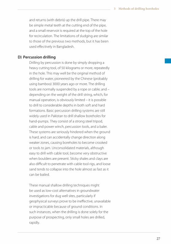
E) RotarydrillingMost borehole applications in the field will require
rotary drilling. True rotary drilling techniques allow
much deeper boreholes to be constructed, and use
circulating fluids to cool and lubricate the cutting tools
and to remove debris from the hole. Circulating fluids
usually take the form of compressed air or of pumped
water with additives, such as commercial drilling muds
or foams (see Section 5).
Figure 2: A mud rotary machine working in eastern Zimbabwe, 1996. Note the mud pits dug nearby
TECHNICAL REVIEW
28
ICRC Borehole Technical Review.indd 28 19/02/2010 17:14
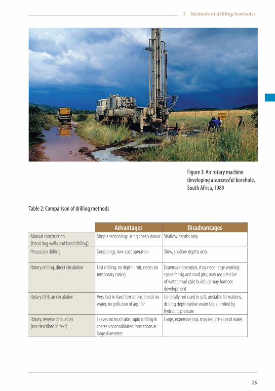
Advantages DisadvantagesManual construction(Hand dug wells and hand drilling)
Simple technology using cheap labour Shallow depths only
Percussion drilling Simple rigs, low-cost operation Slow, shallow depths only
Rotary drilling, direct circulation Fast drilling, no depth limit, needs no temporary casing
Expensive operation, may need large working space for rig and mud pits, may require a lot of water, mud cake build-up may hamper development
Rotary DTH, air circulation Very fast in hard formations, needs no water, no pollution of aquifer
Generally not used in soft, unstable formations, drilling depth below water table limited by hydraulic pressure
Rotary, reverse circulation(not described in text)
Leaves no mud cake, rapid drilling in coarse unconsolidated formations at large diameters
Large, expensive rigs, may require a lot of water
Table 2: Comparison of drilling methods
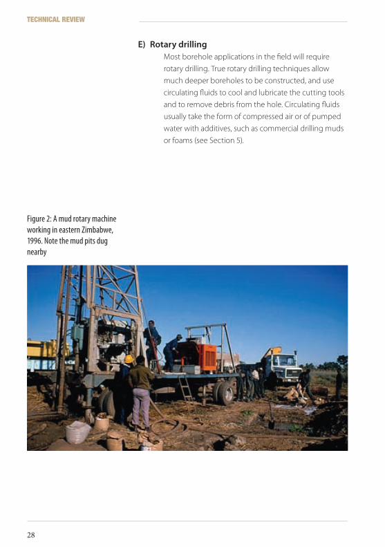
Figure 3: Air rotary machine developing a successful borehole, South Africa, 1989
3 Methods of drilling boreholes
29
ICRC Borehole Technical Review.indd 29 19/02/2010 17:14

ICRC Borehole Technical Review.indd 30 19/02/2010 17:14
Drilling equipment
4
Once a drilling method has been selected, you must decide
on the type of drilling equipment or rig that best suits your
situation. This section discusses the various types of rig
available and their suitability and also provides an overview of
drilling rig parts.
4.1 Choosingadrillingrig
The type of rig chosen may be determined on the basis of the
site geology, the anticipated depths of the boreholes, and their
expected diameters. Access is an important consideration. All
drilling machines, except the smallest units capable of being
dismantled and reassembled on site, require transportation: a
road may have to be cut through bush to reach a location. For
the largest truck or trailer-mounted rigs this can be a significant
problem during rainy seasons in remote areas. Heavy rigs are
notorious for becoming stuck in mud, and in such difficult
conditions they should be used only if rain is not expected,
or if there are means of pulling the rig out of trouble. Because
low-lying areas often provide good drill sites, a rig may have to
labour up a steep slope when it leaves. Rutted dirt roads may
have to be covered with stones to facilitate traction.
4 Drilling equipment
31
ICRC Borehole Technical Review.indd 31 19/02/2010 17:14
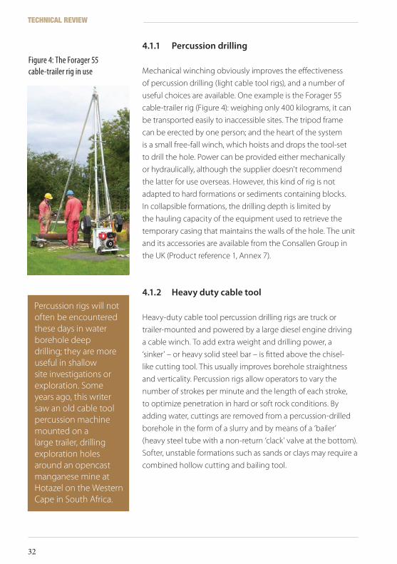
4.1.1 Percussiondrilling
Mechanical winching obviously improves the effectiveness
of percussion drilling (light cable tool rigs), and a number of
useful choices are available. One example is the Forager 55
cable-trailer rig (Figure 4): weighing only 400 kilograms, it can
be transported easily to inaccessible sites. The tripod frame
can be erected by one person; and the heart of the system
is a small free-fall winch, which hoists and drops the tool-set
to drill the hole. Power can be provided either mechanically
or hydraulically, although the supplier doesn't recommend
the latter for use overseas. However, this kind of rig is not
adapted to hard formations or sediments containing blocks.
In collapsible formations, the drilling depth is limited by
the hauling capacity of the equipment used to retrieve the
temporary casing that maintains the walls of the hole. The unit
and its accessories are available from the Consallen Group in
the UK (Product reference 1, Annex 7).
4.1.2 Heavydutycabletool
Heavy-duty cable tool percussion drilling rigs are truck or
trailer-mounted and powered by a large diesel engine driving
a cable winch. To add extra weight and drilling power, a
‘sinker’ – or heavy solid steel bar – is fitted above the chisel-
like cutting tool. This usually improves borehole straightness
and verticality. Percussion rigs allow operators to vary the
number of strokes per minute and the length of each stroke,
to optimize penetration in hard or soft rock conditions. By
adding water, cuttings are removed from a percussion-drilled
borehole in the form of a slurry and by means of a ‘bailer’
(heavy steel tube with a non-return ‘clack’ valve at the bottom).
Softer, unstable formations such as sands or clays may require a
combined hollow cutting and bailing tool.
Figure 4: The Forager 55 cable-trailer rig in use
Percussion rigs will not often be encountered these days in water borehole deep drilling; they are more useful in shallow site investigations or exploration. Some years ago, this writer saw an old cable tool percussion machine mounted on a large trailer, drilling exploration holes around an opencast manganese mine at Hotazel on the Western Cape in South Africa.
TECHNICAL REVIEW
32
ICRC Borehole Technical Review.indd 32 19/02/2010 17:14
4.1.3 Rotarydrilling
Industrial rotary rigs are truck or trailer-mounted, but small and
extremely powerful machines (see below), often cost-effective
for humanitarian projects, are also on the market. One example
is the Eureka Port-a-Rig, which can be transported by a pick-up
truck in component form and assembled on site. The basic unit
weighs about 500 kilograms and is driven by a 4-kw engine,
with top drive and mud or air flush. A small 7-bar compressor,
mounted on a small trailer, is available. The Eureka is capable of
drilling to 50 metres (Product reference 2, Annex 7).
The smallest rotary drilling system of which this writer has first-
hand experience is the PAT 201. The system is powered by a
small petrol engine in a mounting that can slide up and down
a three-legged mast. It is recommended only for mud drilling
in alluvial conditions, but this writer can confirm that the PAT
201 is indeed capable, as the manufacturers claim, of drilling
to 60 metres. However, there is little power available for ‘pull
back’ (just a small hand-winch), which is the main limitation of
small rigs.
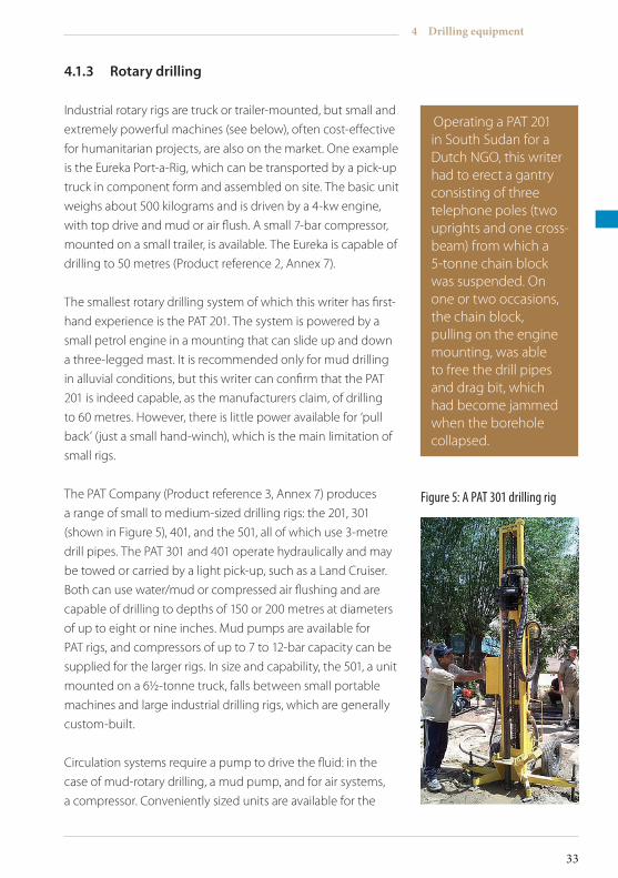
The PAT Company (Product reference 3, Annex 7) produces
a range of small to medium-sized drilling rigs: the 201, 301
(shown in Figure 5), 401, and the 501, all of which use 3-metre
drill pipes. The PAT 301 and 401 operate hydraulically and may
be towed or carried by a light pick-up, such as a Land Cruiser.
Both can use water/mud or compressed air flushing and are
capable of drilling to depths of 150 or 200 metres at diameters
of up to eight or nine inches. Mud pumps are available for
PAT rigs, and compressors of up to 7 to 12-bar capacity can be
supplied for the larger rigs. In size and capability, the 501, a unit
mounted on a 6½-tonne truck, falls between small portable
machines and large industrial drilling rigs, which are generally
custom-built.
Circulation systems require a pump to drive the fluid: in the
case of mud-rotary drilling, a mud pump, and for air systems,
a compressor. Conveniently sized units are available for the
Operating a PAT 201 in South Sudan for a Dutch NGO, this writer had to erect a gantry consisting of three telephone poles (two uprights and one cross-beam) from which a 5-tonne chain block was suspended. On one or two occasions, the chain block, pulling on the engine mounting, was able to free the drill pipes and drag bit, which had become jammed when the borehole collapsed.
Figure 5: A PAT 301 drilling rig
4 Drilling equipment
33
ICRC Borehole Technical Review.indd 33 19/02/2010 17:14
smaller rigs: for example, PAT produces a small mechanical
mud pump for the 201 portable rigs. Large rigs use industrial-
scale units. Mud pumps are essentially simple sludge pumps
based on pistons, impellors, or helical stators. For compressors,
manufacturers specify the pressure a unit may develop in
terms of ‘bar’ or ‘psi’ (pounds per square inch), where 1 bar =
100 kPa, (1 Pa = 1 N/m2). Heavy-duty (industrial plant) units can
develop pressures of 20 bar – and it is pressure that delivers
power to a down-the-hole (DTH) hammer – making for a faster
penetration rate. Pressure also lifts cuttings to the surface:
for instance, a 7-bar compressor would be required to lift a
60-metre column of water from the bottom of a hole. Because
the production of compressed air is a notoriously inefficient
process, the compressor might dominate a drilling set-up in
terms of size, cost, and maintenance problems.
The budgets of aid organizations seldom permit the purchase
of industrial-sized drilling machines, but it is these that will
normally be used if a drilling contractor is hired for a project.
Large drilling rigs can be bought ‘off the shelf’ by commercial
operators: the Atlas Copco machines and the Dando company,
which manufactures the extremely successful Watertec 24
rig shown in Figure 7, will be familiar names to many drillers
Needless to say, the dangers inherent in using high-pressure air systems require that pressure hoses and couplings be of the correct rating and in good condition. This is especially important when working in remote areas where access to emergency medical care may be many hours’ drive away.
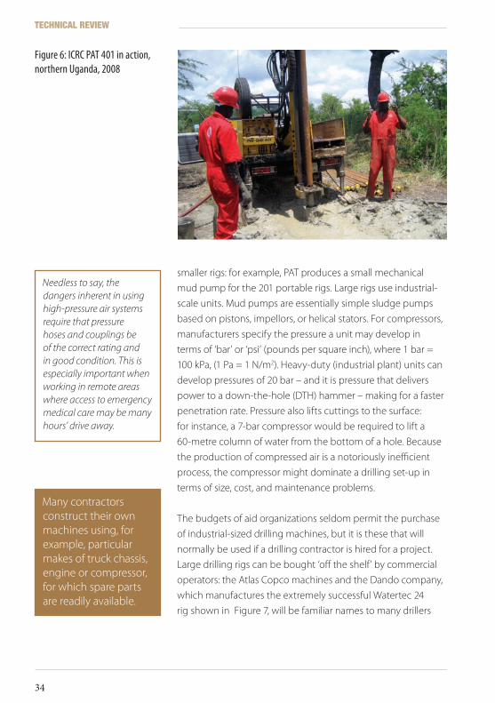
Figure 6: ICRC PAT 401 in action, northern Uganda, 2008
Many contractors construct their own machines using, for example, particular makes of truck chassis, engine or compressor, for which spare parts are readily available.
TECHNICAL REVIEW
34
ICRC Borehole Technical Review.indd 34 19/02/2010 17:14
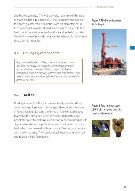
Figure 7: The Dando Watertec 24 drilling rig
and hydrogeologists. The W24, a typical example of this type
of machine, has a ‘pull back’ of 24,000 kilograms and can drill
to depths greater than 700 metres with bit diameters of up
to 17½ inches. It was developed specifically to cope with the
harsh conditions encountered in Africa and in Arab countries.
The W24 is one of many rigs that can be adapted for air or mud
circulation as required.
4.2 Drillingrigcomponents
4.2.1 Drillbit
No single type of drill bit can cope with all possible drilling
conditions and formations. Some typical examples are shown
in Figure 8. Drag bits consist of three or four serrated blades
that shear the formation when the bit is rotated; they can
penetrate softer formations such as poorly consolidated or stiff
clays and mudstones rapidly. Roller cone bits (or tricone rock
bits), which can be used with air or liquid flushing, are popular
with the oil industry. They can be used to penetrate both soft
and relatively hard formations.
Anyone familiar with drilling contractors’ operations in the field will know the extent to which downtime can adversely affect the schedule of a project. Problems commonly arise in hydraulic systems and compressors that might have been inadequately maintained because of the pressure of work.
Figure 8: Two common types of drill bits: left, two drag bits; right, a roller cone bit
4 Drilling equipment
35
ICRC Borehole Technical Review.indd 35 19/02/2010 17:14
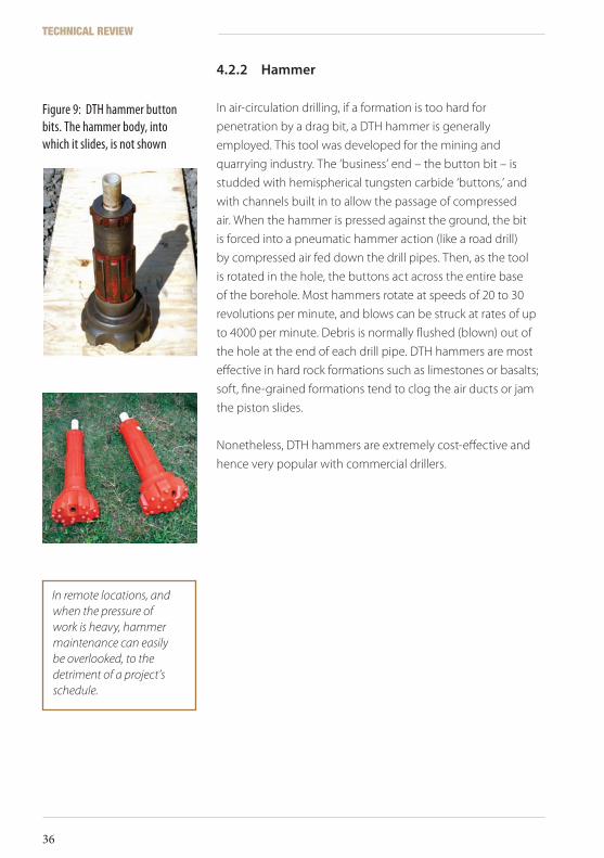
4.2.2 Hammer
In air-circulation drilling, if a formation is too hard for
penetration by a drag bit, a DTH hammer is generally
employed. This tool was developed for the mining and
quarrying industry. The ‘business’ end – the button bit – is
studded with hemispherical tungsten carbide ‘buttons,’ and
with channels built in to allow the passage of compressed
air. When the hammer is pressed against the ground, the bit
is forced into a pneumatic hammer action (like a road drill)
by compressed air fed down the drill pipes. Then, as the tool
is rotated in the hole, the buttons act across the entire base
of the borehole. Most hammers rotate at speeds of 20 to 30
revolutions per minute, and blows can be struck at rates of up
to 4000 per minute. Debris is normally flushed (blown) out of
the hole at the end of each drill pipe. DTH hammers are most
effective in hard rock formations such as limestones or basalts;
soft, fine-grained formations tend to clog the air ducts or jam
the piston slides.
Nonetheless, DTH hammers are extremely cost-effective and
hence very popular with commercial drillers.
In remote locations, and when the pressure of work is heavy, hammer maintenance can easily be overlooked, to the detriment of a project’s schedule.
Figure 9: DTH hammer button bits. The hammer body, into which it slides, is not shown
TECHNICAL REVIEW
36
ICRC Borehole Technical Review.indd 36 19/02/2010 17:14
Borehole construction
5
Once the drilling method and the equipment have been
chosen, you will be required to observe and monitor the
construction of the borehole. You may also be charged with
the responsibility of supervising (in terms of quality control)
the drilling of boreholes by your colleagues or by external
drilling contractors. Quality control of drilling operations
requires knowledge and confidence, which are acquired only
by experience; but a cooperative contractor (sympathy would
be too much to expect!) can make a job easier, and even
enjoyable. This section outlines key considerations for borehole
construction using the mud and air rotary drilling methods.
5.1 Constructionconsiderations
Large drilling rigs are equipped to ensure that a borehole
is started true and vertical. Maintaining verticality and
straightness can be difficult during the early stages of drilling,
but as the drill string weight increases, this problem tends to
dissipate unless highly heterogeneous drilling conditions are
encountered (in the form of boulders or cavities). Straightness
is particularly important for water boreholes in which long
strings of casing and screens may have to be installed with a
gravel pack filter (see Section 6.3.2).
5 Borehole construction
37
ICRC Borehole Technical Review.indd 37 19/02/2010 17:14
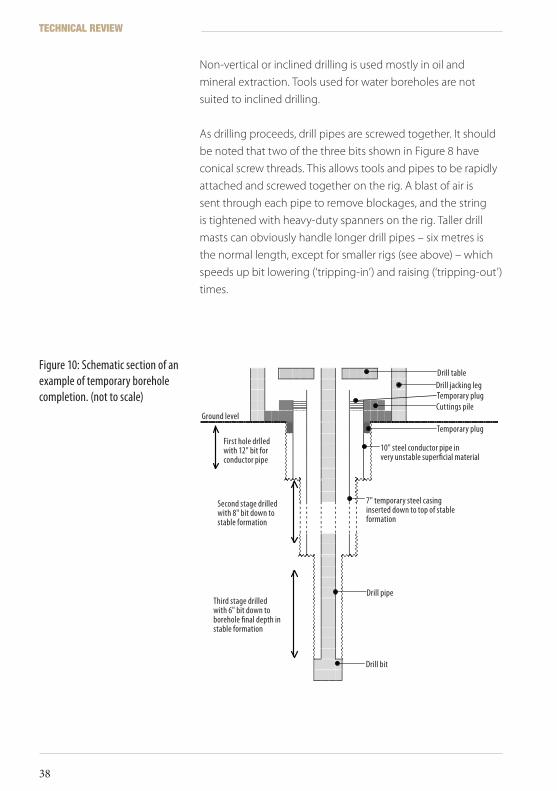
Non-vertical or inclined drilling is used mostly in oil and
mineral extraction. Tools used for water boreholes are not
suited to inclined drilling.
As drilling proceeds, drill pipes are screwed together. It should
be noted that two of the three bits shown in Figure 8 have
conical screw threads. This allows tools and pipes to be rapidly
attached and screwed together on the rig. A blast of air is
sent through each pipe to remove blockages, and the string
is tightened with heavy-duty spanners on the rig. Taller drill
masts can obviously handle longer drill pipes – six metres is
the normal length, except for smaller rigs (see above) – which
speeds up bit lowering (‘tripping-in’) and raising (‘tripping-out’)
times.
Figure 10: Schematic section of an example of temporary borehole completion. (not to scale)
Drill table
Drill jacking leg
Temporary plug
Cuttings pile
Ground level
Temporary plug
First hole drilled with 12” bit for conductor pipe
10” steel conductor pipe in very unstable superficial material
Second stage drilled with 8” bit down to stable formation
7” temporary steel casing inserted down to top of stable formation
Drill pipe
Third stage drilled with 6” bit down to borehole final depth in stable formation
Drill bit
Drill table
Cuttings pileTemporary plugDrill jacking leg
10" steel conductor pipe in very unstable superficial material
7" temporary steel casing inserted down to top of stable formation
Drill pipe
Drill bit
Temporary plugFirst hole drlled with 12" bit for conductor pipe
Second stage drilled with 8" bit down to stable formation
Third stage drilled with 6" bit down to borehole final depth in stable formation
Ground level
TECHNICAL REVIEW
38
ICRC Borehole Technical Review.indd 38 19/02/2010 17:14
Reaming – the enlarging of an existing hole – can be carried
out either with a drill bit of any kind or with specially designed
reaming tools. Drilling companies often devise tools for special
use, sometimes in the field, and they are often very ingenious.
It should be borne in mind that after drilling has begun, the
sides of the upper part of the borehole are likely to suffer
erosion by circulation fluid and cuttings, which causes an
irregular enlargement of the borehole, reducing up-hole
fluid (air or mud) velocity. This can be dealt with by installing
conductor pipe as described below.
As drilling proceeds, the amount of water leaving the borehole
will – it is hoped – be seen to increase, reaching a point at
which it becomes clear that the borehole will provide the
required supply. Even then, the borehole may have to be
deepened further to provide sufficient pumping drawdown
(see Section 6.3.2). However, if the borehole is found to be
wanting, it may be advisable to stop drilling early (unless a
hand-pump is acceptable at that location) or carry on in the
hope of a greater water strike (here some knowledge of local
geology would be very useful). If fragments of ancient, hard
metamorphic or igneous basement rocks, such as gneisses,
schists, and granites start appearing in the cuttings, and the
penetration rate decreases significantly, the ‘hydrogeological
basement’ has, in all likelihood, been reached and it would
probably be futile to continue to deepen the hole.
Penetration rate through each zone or formation in the
borehole may be determined simply by timing the progress of
one drill pipe or a fixed distance marked by two chalk marks
on the drill pipes as they pass through the table. Penetration
rate can provide an estimate of formation consolidation or
hardness, and also show precisely when an aquifer was crossed.
Objects lost in the hole can often be ‘fished’ out using existing equipment (such as pipe screw threads) or with specially adapted tools. But drillers should always take great care to prevent this kind of occurrence, as minor accidents are potentially very costly in terms of time and equipment.
5 Borehole construction
39
ICRC Borehole Technical Review.indd 39 19/02/2010 17:14
The question, then, is: When to stop drilling? The supervisor
normally has an idea, from the project specifications, of how
much water is required from a borehole; a hand-pump, for
instance, does not demand a large supply (0.5 litre/sec is more
than enough), whereas a motor pump supplying a storage
tank for a village, a refugee camp, or a facility such as a school
requires a significantly greater yield.
When drilling is finally stopped by the supervisor (who
normally bears this responsibility), it is advisable to allow a few
minutes for the water level in the borehole to recover and to
then measure it with a cable dip meter.
Field hydrogeologists and water engineers working on
borehole drilling projects in the commercial or humanitarian
sectors are most likely to encounter rotary drilling machines
(of whatever size) using mud circulation or compressed air.
For this reason, the discussion in this review is limited to those
techniques most commonly used in water borehole drilling:
mud rotary and air rotary, as cable-percussion drilling, auger
drilling, and other methods are becoming increasingly rare.
5.1.1 Mudrotarydrilling
Besides the cooling and lubrication of drilling bits, which has
already been mentioned, the addition of special muds or other
additives to circulating water provides the following significant
advantages when drilling in unstable formations:
• By using fluids of a density higher than that of water itself, significant hydrostatic pressure is applied to the walls of the borehole, preventing the formation from caving in
• The liquid forms a supportive ‘mud cake’ on the wall of the borehole, discouraging the collapse of the formation
• The liquid holds cuttings in suspension when drilling is halted for the addition of drill pipes
• The liquid removes cuttings from the drill bit, carries them to the surface, and deposits them in mud pits (see below)
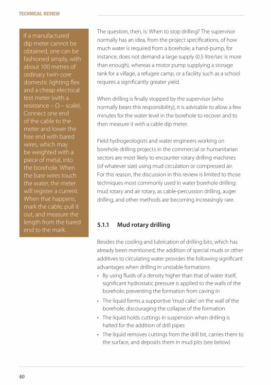
If a manufactured dip meter cannot be obtained, one can be fashioned simply, with about 100 metres of ordinary twin-core domestic lighting flex and a cheap electrical test meter (with a resistance – Ω – scale). Connect one end of the cable to the meter and lower the free end with bared wires, which may be weighted with a piece of metal, into the borehole. When the bare wires touch the water, the meter will register a current. When that happens, mark the cable, pull it out, and measure the length from the bared end to the mark.
TECHNICAL REVIEW
40
ICRC Borehole Technical Review.indd 40 19/02/2010 17:14
Drilling mud – a partially colloidal suspension of ultra fine
particles in water – fulfils these functions by virtue of its
properties of velocity, density, viscosity, and thixotropy
(ability to gel or freeze when not circulated). Water by itself
exerts hydrostatic pressure at depth in a borehole, but at
shallow depths this may not be sufficient. Among additives
for increasing the density of water, salt is one of the most
convenient; but one of the most widely used is a natural
clay mineral known as bentonite (calcium montmorillonite),
which swells enormously in water. A slurry consisting of water
and bentonite combined in the proper proportions has a
higher viscosity than water and forms a mud cake lining in
the borehole. However, a major disadvantage is that the mud
needs to be mixed and left for some 12 hours before use to
allow the viscosity to build up.
The normal bentonite mud mix is 50 kilograms per cubic metre
of water (a 5% mix), or 70 kilograms per cubic metre, if caving
formations are expected.
Natural polymers provide a more practical solution for water
boreholes, but they are relatively expensive, so should be used
with care. One example of such a polymer, used in oilfield
and water drilling, is guar gum, an off-white coloured powder
extracted from guar beans. It is an effective emulsifier used
in the food industry, so is biodegradable, and will lose its
viscosity naturally after a few days. Polymers are best mixed
by sprinkling the powder into a jet of water, to prevent the
formation of lumps. The polymer mud should be mixed during
the setting-up stage – a minimum of 30 minutes is usually
required – so that it has time to ‘yield’ (build up viscosity).
5 Borehole construction
41
ICRC Borehole Technical Review.indd 41 19/02/2010 17:14
The normal mix for guar gum polymer is one kilogram per cubic metre of water; for drilling in clay formations, use up to 0.5 kilogram per cubic metre, and for caving formations, use one to two kilograms per cubic metre.
Besides the usual mud properties, polymer drill fluids
also coat clay cuttings, preventing the formation of sticky
aggregates above a drill bit (known as ‘collars’), which can
hold up drilling while they are removed (a simple remedy for
clay aggregation is to add salt to the drilling fluid). Another
advantage of polymers is that they make it possible, when
it is clay that is being drilled through, to distinguish genuine
formation samples from the mud. Degradation of polymer
muds is accelerated by high ambient temperatures, acidity,
and the presence of bacteria (using the polymer as a food
source): polymer-based mud might last only two or three days
in tropical conditions, and can cause bacterial infection of the
borehole.
It could be that natural polymer powders have a limited shelf
life, and this should be checked before purchasing stock from
a supplier. Food-grade bacterial inhibitors have been used as
additives to prevent the breakdown of polymer-based muds.
When using polymers, observe the manufacturer’s guidelines.
Foaming agents are also widely used as drilling fluid additives,
normally in air drilling (see Section 5.1.2).
A) CheckingtheviscosityofdrillingmudEvery mud additive (bentonite, mud, salt, etc.) must
be mixed into the circulating water to provide the
correct viscosity. This can be done initially in a specially
prepared pit (see Figure 12), but as drilling proceeds,
and especially if groundwater is struck, the mud will
become diluted, and more mud or additive powder
will have to be added. Too low a viscosity may result
in fluid seeping into the formation, and it may later
be difficult to remove the fine mud particles from the
wall of an intersected aquifer, reducing the efficiency
of the borehole (see Section 6.2). ‘Thin’ mud may also
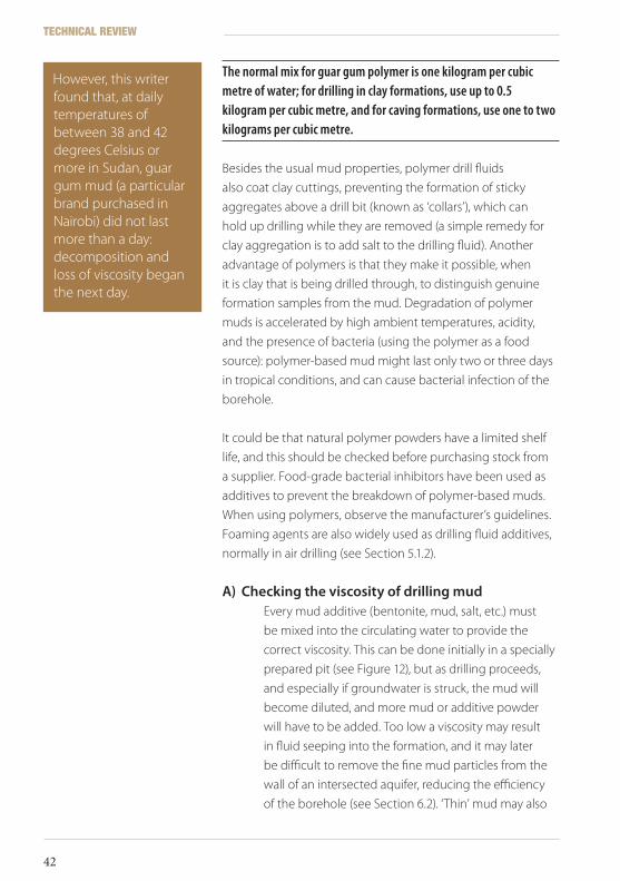
However, this writer found that, at daily temperatures of between 38 and 42 degrees Celsius or more in Sudan, guar gum mud (a particular brand purchased in Nairobi) did not last more than a day: decomposition and loss of viscosity began the next day.
TECHNICAL REVIEW
42
ICRC Borehole Technical Review.indd 42 19/02/2010 17:14
cause cuttings to fall back onto the drill bit, causing it
to stick in the hole. The viscosity of drilling mud can
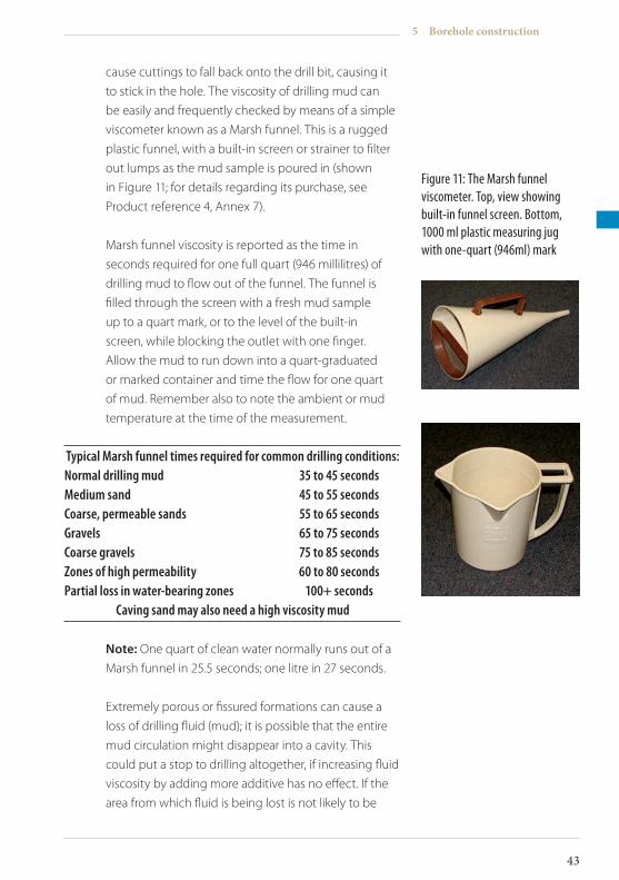
be easily and frequently checked by means of a simple
viscometer known as a Marsh funnel. This is a rugged
plastic funnel, with a built-in screen or strainer to filter
out lumps as the mud sample is poured in (shown
in Figure 11; for details regarding its purchase, see
Product reference 4, Annex 7).
Marsh funnel viscosity is reported as the time in
seconds required for one full quart (946 millilitres) of
drilling mud to flow out of the funnel. The funnel is
filled through the screen with a fresh mud sample
up to a quart mark, or to the level of the built-in
screen, while blocking the outlet with one finger.
Allow the mud to run down into a quart-graduated
or marked container and time the flow for one quart
of mud. Remember also to note the ambient or mud
temperature at the time of the measurement.
Typical Marsh funnel times required for common drilling conditions:Normal drilling mud 35 to 45 secondsMedium sand 45 to 55 secondsCoarse, permeable sands 55 to 65 secondsGravels 65 to 75 secondsCoarse gravels 75 to 85 secondsZones of high permeability 60 to 80 secondsPartial loss in water-bearing zones 100+ seconds
Caving sand may also need a high viscosity mud
Note: One quart of clean water normally runs out of a
Marsh funnel in 25.5 seconds; one litre in 27 seconds.
Extremely porous or fissured formations can cause a
loss of drilling fluid (mud); it is possible that the entire
mud circulation might disappear into a cavity. This
could put a stop to drilling altogether, if increasing fluid
viscosity by adding more additive has no effect. If the
area from which fluid is being lost is not likely to be
Figure 11: The Marsh funnel viscometer. Top, view showing built-in funnel screen. Bottom, 1000 ml plastic measuring jug with one-quart (946ml) mark
5 Borehole construction
43
ICRC Borehole Technical Review.indd 43 19/02/2010 17:14
part of an aquifer, fibrous materials such as sawdust,
dried grass, or cow-dung could be introduced into the
mud, while ensuring that a pumpable circulation is
maintained. Such additives can block large pores and
cavities permanently, which is why they should not be
used to cure losses in a water-bearing zone.
Note: A stiff foam takes up more space and its use
might necessitate larger settlement pits than originally
envisaged.
B) MudpitsTo mix the mud, as described previously, mud pits
are required. This can be combined with a ‘suction
pit’ or sump from which a mud pump will take the
circulation supply. Second, a larger, ‘settling’ pit is
essential, in which mud returning to the surface from
the borehole’s annular space will be allowed to drop its
load of drill cuttings. The two pits and the borehole are
usually connected by shallow channels or ditches and
a weir; a typical arrangement is shown schematically
in Figure 12. Mud pits are most commonly dug in the
ground alongside the rig, but some contractors can
supply steel tanks, which are their equivalent. If dug
in soft soil, pits may be lined with plastic sheeting,
clay or cement. Mud circulation through pits must be
slow and steady, to settle the cuttings and to make
collecting formation samples (normally taken from a
channel close by the borehole) easier. The mud pump
inlet and strainer are held by rope above the bottom of
the suction pit, so that mud that is as clean as possible
can be recirculated into the borehole via the drill pipes.
Optional extra ‘swirl pits’ may be included between the
borehole and the settling pit to further aid settlement
of debris. The capacity of the suction pit should be
roughly equal to the volume of the hole being drilled;
the capacity of the settlement pit should be at least
three times that.
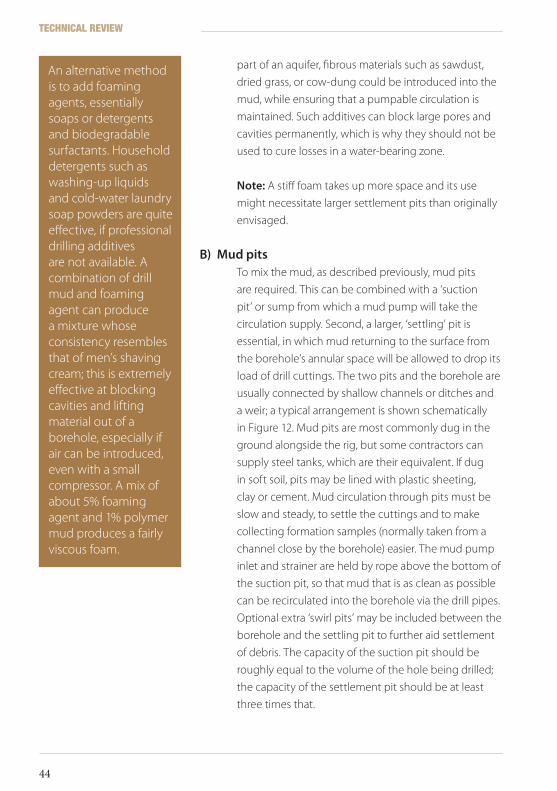
An alternative method is to add foaming agents, essentially soaps or detergents and biodegradable surfactants. Household detergents such as washing-up liquids and cold-water laundry soap powders are quite effective, if professional drilling additives are not available. A combination of drill mud and foaming agent can produce a mixture whose consistency resembles that of men’s shaving cream; this is extremely effective at blocking cavities and lifting material out of a borehole, especially if air can be introduced, even with a small compressor. A mix of about 5% foaming agent and 1% polymer mud produces a fairly viscous foam.
TECHNICAL REVIEW
44
ICRC Borehole Technical Review.indd 44 19/02/2010 17:14
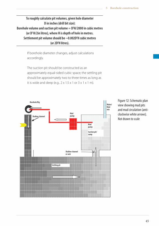
To roughly calculate pit volumes, given hole diameter D in inches (drill bit size):
Borehole volume and suction pit volume = D2H/2000 in cubic metres (or D2 H/2in litres), where H is depth of hole in metres.
Settlement pit volume should be ~0.002D2H cubic metres (or 2D2H litres).
If borehole diameter changes, adjust calculations
accordingly.
The suction pit should be constructed as an
approximately equal-sided cubic space; the settling pit
should be approximately two to three times as long as
it is wide and deep (e.g.. 2 x 1.5 x 1 or 3 x 1 x 1 m).
Figure 12: Schematic plan view showing mud pits and mud circulation (anti-clockwise white arrows). Not drawn to scale
Borehole/Rig
Water / Mud mix
Shallow channel
Mud pump
Suction pit / sump
Shallow channel or weir
Settling pit
Borehole/Rig
Shallow channelMudpump
Shallow channelor weir
Suction pit/sump
Mudpump
Water/Mudmix
Settling pit
5 Borehole construction
45
ICRC Borehole Technical Review.indd 45 19/02/2010 17:14
The greyscale gradations show progressive settlement
of drill cuttings up from the borehole annular space
(dark ring) through the system, from dark grey (loaded
mud) to pale grey (clean mud). The mud pump and
mud hoses back to the drill pipe are shown in red. The
yellow marker shows the area from which borehole
cuttings samples should be obtained. The water/mud
mix inlet is shown in blue.
C) ReturnfluidvelocitiesFor mud rotary drilling, up-hole (return) fluid velocities
should be within the range 15 to 30 metres/minute.
The minimum capacity for a circulation pump can be calculated from the formula Q = 7.5 (D2 - d2) where Q is up-hole flow rate in litres/minute for any combination of drill bit diameter D and drill pipe diameter d (both expressed in inches).
Table 3 shows the maximum and minimum fluid flow
rates in litres/minute for various borehole (drill bit)
diameters; maximum flow rates are about double the
minimum.
On successful completion of a borehole, mud cake,
foam or other additives (if used), and all drilling debris
must be washed out from the borehole. This is the
development stage and is covered in Section 6.2.
Suffice to say here that drilling muds often require
other additives to effect their dispersal.
5.1.2 Compressedairrotarydrilling
Using compressed air as the circulation medium does away
with having to prepare and inject liquids into a borehole
(although water and additives may be introduced for special
purposes). In some cases, the use of air drilling may be
essential: for example, when constructing observation holes for
TECHNICAL REVIEW
46
ICRC Borehole Technical Review.indd 46 19/02/2010 17:14
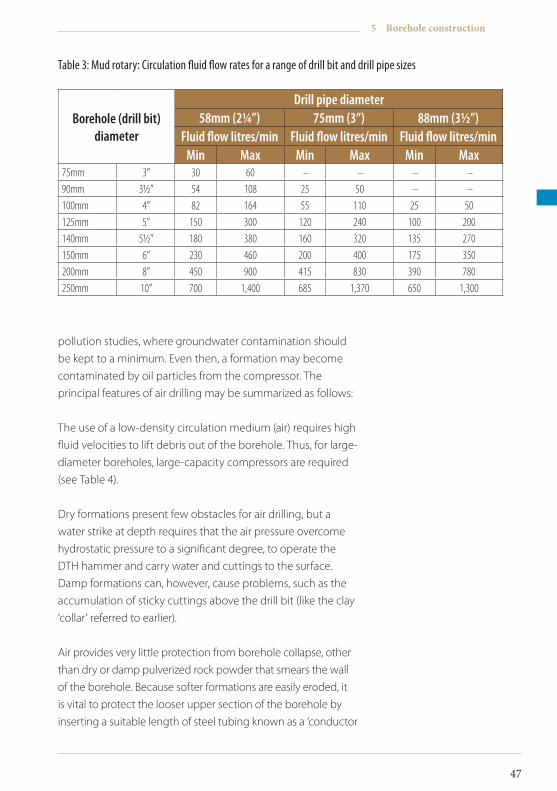
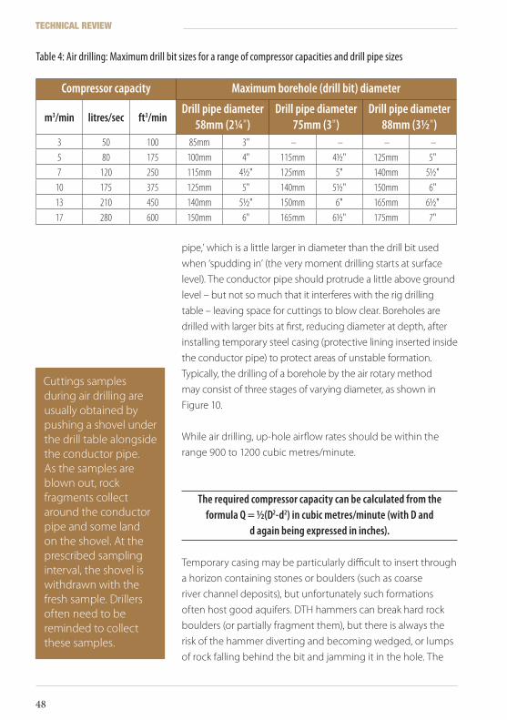
Borehole (drill bit) diameter
Drill pipe diameter58mm (2¼”) 75mm (3”) 88mm (3½”)
Fluid flow litres/min Fluid flow litres/min Fluid flow litres/minMin Max Min Max Min Max
75mm 3” 30 60 – – – – 90mm 3½” 54 108 25 50 – – 100mm 4” 82 164 55 110 25 50125mm 5” 150 300 120 240 100 200140mm 5½” 180 380 160 320 135 270150mm 6” 230 460 200 400 175 350200mm 8” 450 900 415 830 390 780250mm 10” 700 1,400 685 1,370 650 1,300
Table 3: Mud rotary: Circulation fluid flow rates for a range of drill bit and drill pipe sizes
pollution studies, where groundwater contamination should
be kept to a minimum. Even then, a formation may become
contaminated by oil particles from the compressor. The
principal features of air drilling may be summarized as follows:
The use of a low-density circulation medium (air) requires high
fluid velocities to lift debris out of the borehole. Thus, for large-
diameter boreholes, large-capacity compressors are required
(see Table 4).
Dry formations present few obstacles for air drilling, but a
water strike at depth requires that the air pressure overcome
hydrostatic pressure to a significant degree, to operate the
DTH hammer and carry water and cuttings to the surface.
Damp formations can, however, cause problems, such as the
accumulation of sticky cuttings above the drill bit (like the clay
‘collar’ referred to earlier).
Air provides very little protection from borehole collapse, other
than dry or damp pulverized rock powder that smears the wall
of the borehole. Because softer formations are easily eroded, it
is vital to protect the looser upper section of the borehole by
inserting a suitable length of steel tubing known as a ‘conductor
5 Borehole construction
47
ICRC Borehole Technical Review.indd 47 19/02/2010 17:14
pipe,’ which is a little larger in diameter than the drill bit used
when ‘spudding in’ (the very moment drilling starts at surface
level). The conductor pipe should protrude a little above ground
level – but not so much that it interferes with the rig drilling
table – leaving space for cuttings to blow clear. Boreholes are
drilled with larger bits at first, reducing diameter at depth, after
installing temporary steel casing (protective lining inserted inside
the conductor pipe) to protect areas of unstable formation.
Typically, the drilling of a borehole by the air rotary method
may consist of three stages of varying diameter, as shown in
Figure 10.
While air drilling, up-hole airflow rates should be within the
range 900 to 1200 cubic metres/minute.
The required compressor capacity can be calculated from the formula Q = ½(D2-d2) in cubic metres/minute (with D and
d again being expressed in inches).
Temporary casing may be particularly difficult to insert through
a horizon containing stones or boulders (such as coarse
river channel deposits), but unfortunately such formations
often host good aquifers. DTH hammers can break hard rock
boulders (or partially fragment them), but there is always the
risk of the hammer diverting and becoming wedged, or lumps
of rock falling behind the bit and jamming it in the hole. The
Compressor capacity Maximum borehole (drill bit) diameter
m3/min litres/sec ft3/minDrill pipe diameter
58mm (2¼")Drill pipe diameter
75mm (3")Drill pipe diameter
88mm (3½")3 50 100 85mm 3" – – – – 5 80 175 100mm 4" 115mm 4½" 125mm 5"7 120 250 115mm 4½" 125mm 5" 140mm 5½"
10 175 375 125mm 5" 140mm 5½" 150mm 6"13 210 450 140mm 5½" 150mm 6" 165mm 6½"17 280 600 150mm 6" 165mm 6½" 175mm 7"
Table 4: Air drilling: Maximum drill bit sizes for a range of compressor capacities and drill pipe sizes
Cuttings samples during air drilling are usually obtained by pushing a shovel under the drill table alongside the conductor pipe. As the samples are blown out, rock fragments collect around the conductor pipe and some land on the shovel. At the prescribed sampling interval, the shovel is withdrawn with the fresh sample. Drillers often need to be reminded to collect these samples.
TECHNICAL REVIEW
48
ICRC Borehole Technical Review.indd 48 19/02/2010 17:14
best way to deal with boulders is to install a simultaneous
casing system, which is supplied by most DTH hammer
manufacturers. This allows steel casing to be pushed or pulled
down a borehole, directly behind the hammer, to prevent
the walls from caving in. The hammer has a large diameter
bit that is used to make the hole for the casing; the bit can be
mechanically reduced in size and retrieved through the casing.
Such systems require rigs with strong masts and the power to
handle heavy casing insertion in difficult drilling conditions.
During air drilling, foams can be added through the drill
pipes to eliminate dust emerging from a dry hole, to keep the
borehole clean, and to prevent fine particles from clogging
any small water-bearing fissures that may be intersected.
Furthermore, soap bubbles help lift debris out of the borehole.
However, foams do not provide any hydrostatic support for
collapsing boreholes; they also make it difficult to collect
samples at any drill depth.
5.2 Boreholelogging
For a borehole to be properly logged, the driller and supervisor
need to know its exact depth at all times. This is necessary for
the calculation of drilling charges, and while designing the
borehole (see Section 6). First, make a note of the length of
the drill bit and of any other tools that may be used to drill the
hole. Put the bit on the ground and make a chalk mark, ‘0,’ on
the first drill pipe against a suitable fixed point on the rig and at
a known height above ground level, such as the drilling table
(which centralizes the drill pipes in the hole). From then on,
marks can be made on the drill pipe at regular intervals – say,
every half metre – to record the depth of drilling and to assist in
the logging of penetration rates.
However, drillers often forget to make these chalk marks. The supervisor must keep count of the number of drill pipes going into the hole. The total length of these, plus the length of the drill bit, is the correct depth (beware of drill pipes of slightly differing lengths).
5 Borehole construction
49
ICRC Borehole Technical Review.indd 49 19/02/2010 17:14
A) FormationsamplesFormation samples need to be obtained as drilling
proceeds: the usual sampling interval is one metre.
These are obviously highly disturbed samples, having
been sheared or broken from their parent formation,
so should not be used to infer characteristics such
as bedding, texture, porosity, or permeability. There
will be a slight delay as formation fragments are lifted
to the surface by the circulating mud, but a rough
estimate of the up-hole velocity should enable one
to calculate the actual depth at which cuttings were
derived. Keep in mind that if mud viscosity is too high,
or if formation collapse occurs (viscosity too low),
some fragments could return to the borehole, with
the potential of causing confusion. Cuttings obtained
from the shallow mud channel near the borehole
(see Figure 12) should be washed in water to remove
mud, and laid out in order (by the depth at which each
was acquired) on the ground or in a sample box with
separate compartments for each sample. They can
then be logged by the supervisor or site geologist
and bagged if required. Samples should, of course, be
labelled correctly with all information relevant to the
job in hand.
The main attributes of a borehole log are accuracy
and consistency; a good set of logs can be a useful
resource when planning future drilling programmes.
Drillers must keep their own logs and notes and, as
is often stipulated in contracts (see Section 11), these
should be accurate; however, in practice, they cannot
always be relied upon, especially if the supervisor is
absent from the site for a period. All geological samples
and water strikes should be logged by the drillers
and the supervisor, as this important information
will be required for designing the borehole and the
equipment to be installed.
Water strikes made during mud rotary drilling are usually indicated (unless they are very minor) by a rapid dilution of the mud mix. Intersection of an aquifer during air drilling is much more obvious, as the machine will begin blowing out damp fragments of rock instead of dry dust.
TECHNICAL REVIEW
50
ICRC Borehole Technical Review.indd 50 19/02/2010 17:14

Full borehole logging may also include geophysical
logging, which is normally carried out only after a
well has been completed. These systems are briefly
described in Section 6.3.3.
Annex 1 gives a typical example of a drilling log sheet,
which is applicable for both mud and air drilling, and
which should be kept by the supervisor. The driller’s
log should also include information on drilling or other
work time, standing (waiting) time, and downtime
(breakdowns).
5 Borehole construction
51
ICRC Borehole Technical Review.indd 51 19/02/2010 17:14

ICRC Borehole Technical Review.indd 52 19/02/2010 17:14
Borehole design, development, and completion
6
Having drilled a borehole to the required depth, the supervisor
should be armed with the following information:
• The depth of the borehole
• A lithological log of the borehole
• Borehole diameter(s) and depths of any diameter reduction
• Depths of water strikes (if any)
• Penetration rate log
• Approximate static water level in the borehole (or some indication of what this might be)
All this data should appear on the borehole log sheet (see
Annex 1), and should be used while designing the borehole.
Some idea of the final design should already be in the mind of
the supervisor when he or she is selecting drilling diameters.
For example, if the borehole is required for a hand-pump, a
large-diameter hole would be unnecessarily expensive; and
only one size of bit – possibly two at most, because hand-
pumps make lifting from great depths very hard work – will be
needed.
6 Borehole design, development, and completion
53
ICRC Borehole Technical Review.indd 53 19/02/2010 17:14
6.1 Boreholeconstructiondesign
As water is pumped out of a borehole, the water level in the
hole falls. It may fall by an amount known as the ‘pumping
drawdown,’ which eventually stabilizes for that rate of
extraction. If the water level does not stabilize and continues to
drop until the borehole is ‘dewatered,’ the hole is being over-
exploited. In this discussion it is assumed that boreholes are
designed with the intention of maximizing yield and efficiency,
the normal requirements for everything other than hand-
pump-equipped holes.
• The maximumyield of a borehole is defined as that yield which the borehole can sustain indefinitely before drawdown exceeds recharge from the aquifer.
• Boreholeefficiency is technically defined as the actualspecificcapacity (yield per unit of drawdown: say, litres per second per metre) divided by thetheoreticalspecificcapacity, both of which can be derived from a pumping test. Specific capacity declines as discharge increases.
6.1.1 Boreholecasing
Boreholes are constructed by inserting lengths of protective
permanent casing. These are lowered or pushed into the
hole by the drilling rig to the required depth; the lengths of
casing may be joined together by means of screw threads,
flange-and-spigot, gluing, riveting, or welding. Casing normally
extends up to the surface, with a certain amount (say 0.7
metre) standing above ground level. Lengths of casing may
be obtained in mild steel, stainless steel, and plastic (such
as UPVC, ABS, polypropylene, and glass-reinforced plastics).
Plastic casings are more fragile and deformable than steel
casings (especially the screw threads), and so should be used
mainly for low-yield and shallow boreholes. The casing should
be capable of withstanding the maximum hydraulic load to
which it is likely to be subjected, that is, about 10 kilopascals
Once all the lengths of temporary casing and conductor pipe installed during drilling have been removed by the drillers, the depth of the borehole should be checked by a weighted plumb-line, in order that an accurate construction design may be drawn up.
Because of their fragility, plastic casings should be stored and shipped with care. Stack the materials properly in shade (not direct sunlight) because the plastic is susceptible to degradation and deformation by heat and to degradation by natural ultraviolet radiation. In very cold (sub-zero) conditions, PVC becomes brittle.
TECHNICAL REVIEW
54
ICRC Borehole Technical Review.indd 54 19/02/2010 17:14
(kPa) for each metre that extends below the water level down
to the maximum expected drawdown. Table 5 gives a few
typical values of casing collapse strength (Clark, 1988 ), but
because of the number of variables, it is advisable to consult
manufacturers’ specifications.
Table 5: Typical casing collapse strengths
Casing material Casing wall thickness Collapse strengthuPVC 12.4 mm 660 kPaPolypropylene 12.7 mm 690 kPaGlass-reinforced plastic 6 mm 690 kPaMild steel 9.4 mm 11.1 MPa
Steel casing is available in a variety of grades and weights. Low-
grade casing can be used for shallow tube-wells, but heavy-
duty, high-grade steel should be used for deeper boreholes
(especially those more than 200 metres deep) and when
ground conditions hamper insertion (such as coarse gravel/
boulder formations). Special types of casing that can resist
aggressive waters are also obtainable, but stainless steel is the
best means of combating corrosion. Casing is usually supplied
in standard lengths already equipped with screw threads or
other jointing methods.
6.1.2 Boreholewellscreens
When a borehole has been dug alongside a water-bearing
zone, the casing installed in it must have apertures that allow
water to enter as efficiently as possible while holding back
material from the formation. These perforated sections are
known as borehole or well screens; they come in sizes and
joints similar to casing, so can be interconnected with suitable
plain casing in any combination, or ‘string.’ Screens can also
be obtained with a variety of aperture (slot) shapes and sizes,
from simple straight slots to more complex bridge slots and
wire-wound screens made with V-cross section wire. Screen
slots should be of a regular size, aperture, and shape because
A drilling contractor might arrive on site with a number of odd lengths of steel casing, which the drillers would attempt to weld together. In such instances, beware of the drillers using, or having used, angle grinders to cut the casing, which might, as a result, be left without very straight or square ends. This writer has observed drillers attempting to weld together steel casings with a significant gap between adjacent sections: this resulted in breakage at the inferior weld in the borehole. Check also that the drillers are using the correct type of welding rod: if mild steel/mild steel, mild steel/stainless steel, or stainless steel/stainless steel joints are required, different types of welding rod may be necessary. Using the wrong welding rods could cause parting of the casing in the borehole.
6 Borehole design, development, and completion
55
ICRC Borehole Technical Review.indd 55 19/02/2010 17:14

they might have to efficiently prevent all particles of a certain
size from getting through. Plain plastic casing can be easily
slotted with a saw or special slotting machine, but beware
again of drilling contractors cutting irregular, messy slots in
steel casing with grinders or oxyacetylene torches. The open
area of factory-made plastic screens commonly exceeds 10%
of total surface area, but rough-cut holes in mild steel casing
rarely take up more than 2 or 3%. Screen slots should be
slightly smaller than the average grain size of the aquifer fabric,
and should allow water to enter the borehole at a velocity
within the range 1 to 6 centimetres/second (0.01 to 0.06 metre/
second). Entrance velocity is defined as the discharge rate of
the well divided by the effective open area of the screen. Too
high an entrance velocity may lead to screen incrustation,
excessive well losses, and other damaging consequences of
turbulent flow conditions.
A) Formulatocalculatetheopenareaofascreen:
Open area of screen per metre of screen in cm2 = l*w*n/10, where l is length of slot in cm, w is width of slot in mm, and n is number of
slots per metre length.
For example, a minimum screen open area of 100 cm2
provides, roughly speaking, the minimum entrance
velocity for a yield of about 0.3 litres/second (about
4 gallons/minute). In practice, additional screen
lengths should be included to allow for variations
within the aquifer (which is unlikely to be
homogeneous) and in the borehole (see Table 1).
The most efficient well screens are the well-
known ‘Johnson screens’ – continuous-slot types
manufactured with V-wire wound spirally around
a cage of longitudinal support rods. The whole
structure may be composed of stainless steel or
low-carbon galvanized steel. These wire windings
have been constructed such that the slots widen
inwards, which significantly reduces rates of screen
TECHNICAL REVIEW
56
ICRC Borehole Technical Review.indd 56 19/02/2010 17:14
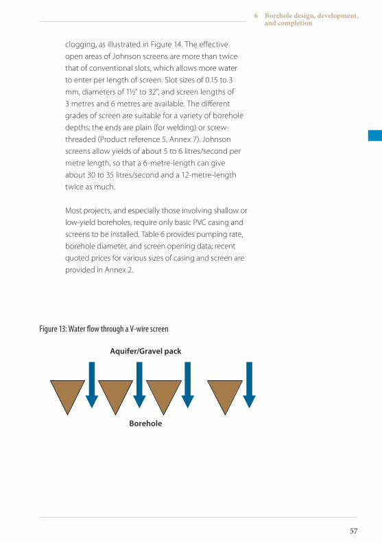
clogging, as illustrated in Figure 14. The effective
open areas of Johnson screens are more than twice
that of conventional slots, which allows more water
to enter per length of screen. Slot sizes of 0.15 to 3
mm, diameters of 1½" to 32", and screen lengths of
3 metres and 6 metres are available. The different
grades of screen are suitable for a variety of borehole
depths; the ends are plain (for welding) or screw-
threaded (Product reference 5, Annex 7). Johnson
screens allow yields of about 5 to 6 litres/second per
metre length, so that a 6-metre-length can give
about 30 to 35 litres/second and a 12-metre-length
twice as much.
Most projects, and especially those involving shallow or
low-yield boreholes, require only basic PVC casing and
screens to be installed. Table 6 provides pumping rate,
borehole diameter, and screen opening data; recent
quoted prices for various sizes of casing and screen are
provided in Annex 2.
Figure 13: Water flow through a V-wire screen
Aquifer/Gravelpack
Borehole
6 Borehole design, development, and completion
57
ICRC Borehole Technical Review.indd 57 19/02/2010 17:14
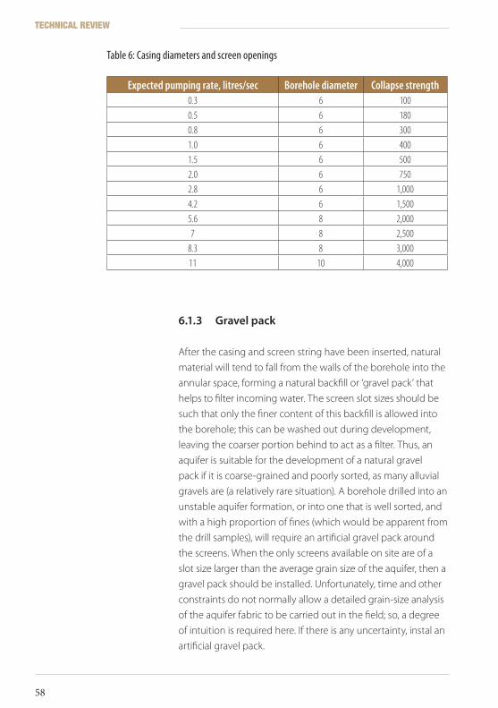
6.1.3 Gravelpack
After the casing and screen string have been inserted, natural
material will tend to fall from the walls of the borehole into the
annular space, forming a natural backfill or ‘gravel pack’ that
helps to filter incoming water. The screen slot sizes should be
such that only the finer content of this backfill is allowed into
the borehole; this can be washed out during development,
leaving the coarser portion behind to act as a filter. Thus, an
aquifer is suitable for the development of a natural gravel
pack if it is coarse-grained and poorly sorted, as many alluvial
gravels are (a relatively rare situation). A borehole drilled into an
unstable aquifer formation, or into one that is well sorted, and
with a high proportion of fines (which would be apparent from
the drill samples), will require an artificial gravel pack around
the screens. When the only screens available on site are of a
slot size larger than the average grain size of the aquifer, then a
gravel pack should be installed. Unfortunately, time and other
constraints do not normally allow a detailed grain-size analysis
of the aquifer fabric to be carried out in the field; so, a degree
of intuition is required here. If there is any uncertainty, instal an
artificial gravel pack.
Expected pumping rate, litres/sec Borehole diameter Collapse strength0.3 6 1000.5 6 1800.8 6 3001.0 6 4001.5 6 5002.0 6 7502.8 6 1,0004.2 6 1,5005.6 8 2,0007 8 2,500
8.3 8 3,00011 10 4,000
Table 6: Casing diameters and screen openings
TECHNICAL REVIEW
58
ICRC Borehole Technical Review.indd 58 19/02/2010 17:14
A) ArtificialgravelpackIdeally, an artificial gravel pack should consist of clean,
rounded, quartz ‘pea’ gravel supplied in bags; grains
the size of small household peas are generally suitable.
Coarse, well-worn river sand is often ideal; the grains
should be a little larger but no more than twice the
screen slot size. Being smooth and spherical, the grains
should run easily down into the annular space without
clumping and leaving gaps of air (a little water often
helps).
The standard practice is to produce a 3 to 4-inch wide
annular space for the gravel pack (say, a 6" screen in a
12" hole); the casing/screen string must be centred in
the borehole. Most boreholes are not perfectly straight,
so the casing will almost invariably be in contact with
the wall in some places unless it is centralized. This is
achieved by using manufactured centralizers (such
as flexible ‘wings’) or some other suitable alternative.
Unfortunately, in developing countries, few drilling
contractors bother to provide centralizers, even if they
have heard of them. It is extremely difficult – if not
impossible – to fashion effective casing centralizers in
remote locations. Section 11 of this review suggests
that project organizers or supervisors should attempt
to familiarize themselves with the competence of
bidding contractors to ensure that the successful
firm will be familiar with and willing to offer essential
technical components.
Before pouring gravel pack material into the annular
space, which must be done smoothly and without
haste, calculate the volume of annular space (it is
reassuring to see that the correct volume of gravel
has been installed). Again, an accurate log of borehole
size changes is required here. Pouring gravel pack into
a borehole with a high water level usually results in
displaced water rising in the hole and overflowing.
Water overflow will abruptly stop as the screen
Many contractors will bring on site whatever they consider to be suitable gravel, which may be irregular stone chippings or ‘building aggregate.’ It is then up to the supervisor to decide on the acceptability of this gravel, given such factors as remoteness of location and availability of better materials. If the only material available is concrete-type aggregate and the borehole annular space is narrow (less than 3 inches), consider, if at all possible, the use of a smaller screen slot size without the gravel pack.
6 Borehole design, development, and completion
59
ICRC Borehole Technical Review.indd 59 19/02/2010 17:14
becomes covered by gravel. Continue to pour gravel
until you are certain that the top of the pack is well
above the top of the screen.
Annular volume between borehole diameter D and casing/screen diameter d (D and d both in inches),
length L (in metres) = ~½L(D2-d2) in litres.
Thin gravel packs (less than 50 mm, or 2", thick) may
be installed to act as a formation stabilizer only in
conditions such as those associated with a fractured or
slightly weathered consolidated aquifer. It should also
be noted that gravel packs greater than 150 mm (6")
thick will make borehole development more difficult,
especially if a drilling mud lining has to be removed.
Introducing a natural or artificial gravel pack into a
borehole will reduce the effective open area of the
screen, because now the open area (porosity) of the
system at the aquifer/screen interface will be limited
by that of the packing in the annular space rather than
the screen. Well-rounded grains of uniform size (as in
the ‘ideal’ gravel pack) have among the highest primary
porosities (around 40%) and permeabilities (20 or more
metres/day) in unconsolidated sediments; in practice,
the figures are probably much lower. The effective
open area of the adjacent aquifer is more likely to be
around 10%. The result is that one should assume the
effective open area of a screen, even with a gravel pack
of good quality, to be roughly half the actual screen
open area. The recommended minimum actual open
area of any installed screen is around 10%.
The essence of borehole design is deciding the
combination of plain casing and screens to be inserted
and the type of screen to be used, and whether
a gravel filter pack (or thin formation stabilizer) is
required. Table 7 attempts to summarize these
decisions for a variety of ground conditions that are
TECHNICAL REVIEW
60
ICRC Borehole Technical Review.indd 60 19/02/2010 17:14
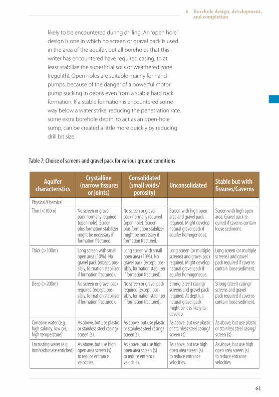
likely to be encountered during drilling. An ‘open hole’
design is one in which no screen or gravel pack is used
in the area of the aquifer, but all boreholes that this
writer has encountered have required casing, to at
least stabilize the superficial soils or weathered zone
(regolith). Open holes are suitable mainly for hand-
pumps, because of the danger of a powerful motor
pump sucking in debris even from a stable hard rock
formation. If a stable formation is encountered some
way below a water strike, reducing the penetration rate,
some extra borehole depth, to act as an open-hole
sump, can be created a little more quickly by reducing
drill bit size.
Aquifer characteristics
Crystalline (narrow fissures
or joints)
Consolidated(small voids/
porosity)Unconsolidated Stable but with
fissures/Caverns
Physical/Chemical
Thin (<100m) No screen or gravel pack normally required (open hole). Screen plus formation stabilizer might be necessary if formation fractured.
No screen or gravel pack normally required (open hole). Screen plus formation stabilizer might be necessary if formation fractured.
Screen with high open area and gravel pack required. Might develop natural gravel pack if aquifer homogeneous.
Screen with high open area. Gravel pack re-quired if caverns contain loose sediment.
Thick (>100m) Long screen with small open area (10%). No gravel pack (except, pos-sibly, formation stabilizer if formation fractured).
Long screen with small open area (10%). No gravel pack (except, pos-sibly, formation stabilizer if formation fractured).
Long screen (or multiple screens) and gravel pack required. Might develop natural gravel pack if aquifer homogeneous.
Long screen (or multiple screens) and gravel pack required if caverns contain loose sediment.
Deep (>200m) No screen or gravel pack required (except, pos-sibly, formation stabilizer if formation fractured).
No screen or gravel pack required (except, pos-sibly, formation stabilizer if formation fractured).
Strong (steel) casing/screens and gravel pack required. At depth, a natural gravel pack might be less likely to develop.
Strong (steel) casing/screens and gravel pack required if caverns contain loose sediment.
Corrosive water (e.g. high salinity, low pH, high temperature)
As above, but use plastic or stainless steel casing/screen (s).
As above, but use plastic or stainless steel casing/screen(s).
As above, but use plastic or stainless steel casing/screen (s).
As above, but use plastic or stainless steel casing/screen (s).
Encrusting water (e.g. iron/carbonate enriched)
As above, but use high open area screen (s) to reduce entrance velocities.
As above, but use high open area screen (s) to reduce entrance velocities.
As above, but use high open area screen (s) to reduce entrance velocities.
As above, but use high open area screen (s) to reduce entrance velocities.
Table 7: Choice of screens and gravel pack for various ground conditions
6 Borehole design, development, and completion
61
ICRC Borehole Technical Review.indd 61 19/02/2010 17:14
6.1.4 Pumpselection
One also needs to consider what type of pump is to be used
in the borehole as well as its size and the casing and screen
diameters needed to house it. Relatively low-yield boreholes
intended for hand-pumps with submerged pistons are rarely
more than 30 metres deep and need not be of large diameter
(4 inches can be enough). Certain types of hand-pump can
be fitted with counterweighted operating handles, to make
drawing from deeper water levels less exhausting (mainly for
women in developing countries). Mechanical reduction of
the submerged piston stroke can make drawing water easier,
but as less water is drawn by each stroke of the pump, filling a
container takes longer. Shallow boreholes often tap weathered
zone aquifers above hard, impervious clays or bedrock (such
as granite); the schematic diagram in Annex 3A shows how a
typical example might be completed with a hand-pump. The
standard practice is to place the pump inlet slightly above the
upper end of the screen. For hand-pumps, this does not matter
much: in the example shown in Annex 3A, the pump inlet
could be lowered into the upper part of the open hole/sump
(by attaching extra pipes) if there is a significant fall of static
water level in the borehole because of prolonged drought.
More powerful types of pump, such as electric submersibles
and rotary positive displacement pumps, must always be
installed inside protective plain casing: screens are not
appropriate for this purpose. The internal diameter of the
pump chamber should be at least 5 centimetres (about
2 inches) greater than the external diameter of the pump.
6.1.5 Sealingtheborehole
The borehole structure must be sealed at the top of the casing
with a ‘sanitary seal’ (Section 6.3.1); it can also be sealed at the
bottom to completely eliminate the possibility of material
Before installation, a string of mild steel casing/screen can be sealed at the base by the following method (see Figure 14 below): at the intended bottom end of the string, first mark out a regular and long ‘saw-tooth’ pattern around the circumference (usually eight ‘teeth,’ typically 0.5 to 1 metre long); cut out the triangular sections with their apexes pointing upwards (in terms of the borehole); hammer the saw-teeth on the casing to a sharp point; and weld the edges of the teeth together to seal the casing.
TECHNICAL REVIEW
62
ICRC Borehole Technical Review.indd 62 19/02/2010 17:14
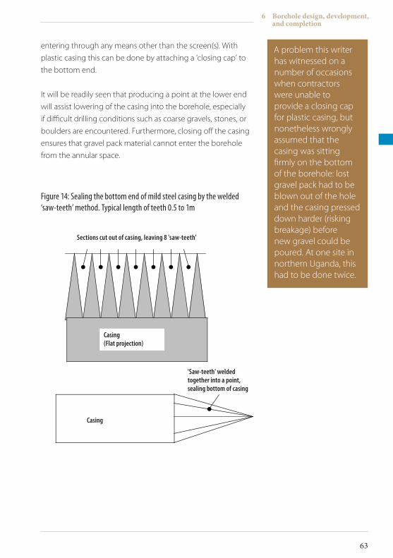
entering through any means other than the screen(s). With
plastic casing this can be done by attaching a ‘closing cap’ to
the bottom end.
It will be readily seen that producing a point at the lower end
will assist lowering of the casing into the borehole, especially
if difficult drilling conditions such as coarse gravels, stones, or
boulders are encountered. Furthermore, closing off the casing
ensures that gravel pack material cannot enter the borehole
from the annular space.
A problem this writer has witnessed on a number of occasions when contractors were unable to provide a closing cap for plastic casing, but nonetheless wrongly assumed that the casing was sitting firmly on the bottom of the borehole: lost gravel pack had to be blown out of the hole and the casing pressed down harder (risking breakage) before new gravel could be poured. At one site in northern Uganda, this had to be done twice.
6 Borehole design, development, and completion
63
Figure 14: Sealing the bottom end of mild steel casing by the welded ‘saw-teeth’ method. Typical length of teeth 0.5 to 1m
Casing
Sections cut out of casing, leaving 8 'saw-teeth'
'Saw-teeth' welded together into a point, sealing bottom of casing
Casing(Flat projection)
ICRC Borehole Technical Review.indd 63 19/02/2010 17:14
6.1.6 Examplesofboreholedesign
A) HomogenousaquiferIn Figure 1, hypothetical borehole site B has
been drilled into a partly consolidated, relatively
homogeneous sandstone aquifer that would require a
full artificial gravel pack. To provide additional dynamic
drawdown, the pump inlet has been placed in a short
section of plain casing between two lengths of screen.
High-powered pump inlets should always be placed
above the upper end of a screened area, or within
a section of plain casing between screens (pump
chamber, shown in Annex 3B). Fast water flow into a
pump should never be straight through the screen, as
the adjacent high entrance velocity will cause rapid
screen erosion or incrustation. Furthermore, water
flowing upwards past and through a submerged pump
has a greater cooling effect on the moving parts. Also,
there will be less risk of sucking in damaging particles.
B) ExploitingtwoaquifersAnnex 3C shows the borehole design suggested for
hypothetical borehole site C in Figure 1, intersecting
and exploiting two aquifers. We may assume that,
on the basis of geological information, this site was
selected as a potentially high-yield and relatively deep
borehole; the drilling contractors would have been
instructed to make mild steel casing and Johnson
screens available for its completion. The presence of
a significant cavity with loose infilling sediment (such
as lateritic pea gravel) within the deeper fissured
limestone aquifer would have confirmed the necessity
for this section to be cased and screened, and may
even have led to the termination of drilling. Caving
infill would have been sampled as drilling came to
an end, and the screen chosen would have had a slot
size small enough to exclude most of the material. If,
as in this example, a casing size reduction is deemed
advantageous, size reducers can be manufactured on
TECHNICAL REVIEW
64
ICRC Borehole Technical Review.indd 64 19/02/2010 17:14
site by cutting and welding mild steel casing (as with
sealing points, Figure 14). This design would permit
a high-yield submersible pump to be installed just
above the casing reducer. The dynamic drawdown,
or pumping level, must now be considered. A screen
section might have to be installed above the pump,
but the water level during pumping must not be
allowed to drop below the top of the upper screen.
This avoids aeration of the upper section of the
screen and of the adjacent aquifer, reducing the risk
of screen incrustation by iron in the water. A good
design should incorporate an adequate length of plain
casing down to the top of the first screen, another test
of the judgement and experience of the designer or
supervisor.
C) BoreholeinafracturezoneAn example of borehole construction in fractured
rocks is illustrated by hypothetical site D in Figure 1,
the proposed design for which is shown in Annex 3D.
Drilled into fractured but stable granite, this borehole
could be completed as an open hole. It is not likely
to be a strong borehole, but as fracture zones can be
unpredictable in terms of water production (often
the more fractures intersected, the better the yield), it
might be worth installing a string of PVC casing/screen
in the event that a powered pump can be fitted. Here, a
relatively small screen slot size with no gravel packing is
probably enough. Sufficient pumping drawdown has,
one hopes, been provided by extending blank casing
further down into the water zone (choice of pump will
be determined by the results of the pumping test).
More information about the yield of a newly drilled
borehole will be obtained during the development
stage.
One may pose this question: How can a borehole designer guess what type of pump will be needed before a particular borehole has been properly tested? During the drilling of the borehole, the amount of water being blown out by air or diluting the circulation mud will indicate to the supervisor whether it is likely to be a ‘good’ borehole. Experience contributes much to this process; in designing borehole constructions, one must often trust intuition.
6 Borehole design, development, and completion
65
ICRC Borehole Technical Review.indd 65 19/02/2010 17:14
6.2 Boreholedevelopment
At this stage it might seem almost impossible that clean, potable
water could emerge from the mess being pumped out of a
new borehole, but provided it has been properly constructed,
good water will indeed appear. Whether a borehole has been
drilled using mud or air circulation, it will have to be cleaned
out. After the installation of the permanent casing, screens, and
gravel packs (if any), dirty water, mud, crushed rock, oil (from the
drilling machinery), and perhaps other debris will be left in the
hole. Development can also repair damage done to the adjacent
aquifer by the drilling process, develop the aquifer (increase
transmissivity), and enhance the performance of the borehole.
As stated by Driscoll in Groundwater and Wells, “Development has
two broad objectives: (1) repair damage done to the formation
by the drilling operation so that the natural hydraulic properties
are restored, and (2) alter the basic physical characteristics of the
aquifer near the borehole so that water will flow more freely to a
well.” 1
Drilling tools smear crushed rock and clay all over the walls of the
borehole, and the drilling process forces dirty water and clay into
the rock matrix around the hole, sealing off many water entry
points from the aquifer. If these matters are not remedied, the
borehole’s performance will be very poor; it should also be noted
that the filthy water that would be pumped out – were things to
be left unaltered – would damage a pump quickly. Mud rotary
drilling leaves a cake of firm clay (‘mud cake’) on borehole walls,
often of a thickness up to one centimetre, which can effectively
choke aquifers. Removal of this layer is not easy, requiring ‘violent’
or ‘aggressive’ methods, and should not be hurried or abandoned
prematurely. Moreover, since mud-caked walls will have been
partly isolated from the borehole internal space by casings,
screens, and possibly even gravel packing, cleaning up will be
even more difficult.
1 F. G. Driscoll, reference No. 5, Annex 7
TECHNICAL REVIEW
66
ICRC Borehole Technical Review.indd 66 19/02/2010 17:14
Development also encourages a gravel filter pack to settle
properly, eliminating voids, which may necessitate topping up the
gravel pack a little. The process should continue until the water
being discharged from the borehole is, in the judgement of the
supervisor, as clean as possible. Small particles of sand might
occasionally issue from the borehole, but cloudiness (turbidity)
of the water should have disappeared before development is
stopped. Excessive production of sand might be caused by voids
in the gravel packing or by damaged casings or screens. Turbidity
is generally caused by colloidal clay or micro-organic particles; and
can, in the latter case, result in unpleasant tastes and odours and in
organic growths like slimes.
6.2.1 Developmentmethods
In most cases, development entails the surging and blowing of
compressed air; the process may be helped along by the use of
additives, which can assist in breaking down drilling mud.
A) MuddispersantsBentonite-based muds are particularly difficult to
remove; organic polymers are biodegradable and, in
theory, are destroyed by bacteria with which wells
can be seriously infected. Chlorine-rich compounds
are effective mud dispersants, as well as bacterial
disinfectants. Calcium hypochlorite (HTH or High-test
hypochlorite) can be used as a mud dispersant; for
rapid breakdown of guar gum, use a hypochlorite
solution (12% chlorine) at about 0.4% mix in water. For
slow dispersal, a weak solution of hydrogen peroxide
may be used.
Bentonite is more efficiently dispersed using
polyphosphate compounds like Calgon (brand name
for water softener). This chemical consists of granular or
powdered sodium hexametaphosphate, a hygroscopic
6 Borehole design, development, and completion
67
ICRC Borehole Technical Review.indd 67 19/02/2010 17:14
(water attractant) material that destroys the
cohesiveness and plasticity of clay particles. Granular
Calgon should be dissolved in hot or boiling water
(about one kilogram of the chemical in 40 to 50 litres
of hot water): the usual dosage is 10 to 50 kilograms
of Calgon per cubic metre of water estimated to be in
the borehole. Try to leave the dispersant in the hole
overnight to allow the solution time to permeate into
aquifer formations. Higher concentrations are needed
to remove the more resistant mud cakes. Leftover mud
is more easily removed when the borehole is washed
out.
B) AcidtreatmentDevelopment of wells drilled into calcareous
(limestone, chalk, or dolomite) formations can be
aided by the use of certain acids (such as hydrochloric
acid, HCl) that dissolve pulverized carbonate smear on
borehole walls. Acid treatment can widen and clean
carbonate aquifer fissures even when they are tens of
metres away from the borehole.
Borehole acidization during rehabilitation is discussed
in Section 10.2.2 as well.
C) SurgingThe technique of surging (or surge pumping) consists
of forcing water up and down a borehole and, more
importantly, back and forth through the screens, gravel
pack, and adjacent aquifer matrix. Many textbooks
on this subject state that surging can be done
mechanically, using a piston-like surge block or bailer,
but this writer has never seen a surge block being
used. Surging can also be conducted with pumps,
but this is not advisable because of the possibility of
damaging debris entering the pump. Furthermore,
a powerful pump could dewater a borehole if the
screen is blocked by mud cake and cause the screen to
collapse inwards as a result of hydraulic pressure in the
Before opting for acidization, try to ensure the following: that the contractor possesses the necessary equipment and experience; that acids are available locally, and that the spent acid can be disposed of safely (contractors should comply with hazardous waste disposal/pollution control regulations).
TECHNICAL REVIEW
68
ICRC Borehole Technical Review.indd 68 19/02/2010 17:14
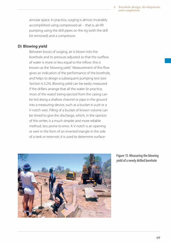
annular space. In practice, surging is almost invariably
accomplished using compressed air – that is, air-lift
pumping using the drill pipes on the rig (with the drill
bit removed) and a compressor.
D) BlowingyieldBetween bouts of surging, air is blown into the
borehole and its pressure adjusted so that the outflow
of water is more or less equal to the inflow: this is
known as the ‘blowing yield.’ Measurement of this flow
gives an indication of the performance of the borehole,
and helps to design a subsequent pumping test (see
Section 6.3.2A). Blowing yield can be easily measured
if the drillers arrange that all the water (in practice,
most of the water) being ejected from the casing can
be led along a shallow channel or pipe in the ground
into a measuring device, such as a bucket in a pit or a
V-notch weir. Filling of a bucket of known volume can
be timed to give the discharge, which, in the opinion
of this writer, is a much simpler and more reliable
method, less prone to error. A V-notch is an opening
or weir in the form of an inverted triangle in the side
of a tank or reservoir; it is used to determine surface-
Figure 15: Measuring the blowing yield of a newly drilled borehole
6 Borehole design, development, and completion
69
ICRC Borehole Technical Review.indd 69 19/02/2010 17:14
water flows. Water whose discharge is to be estimated
is allowed to flow over the notch weir, and the rate of
flow can be calculated by measuring the depth of the
water over the apex of the notch. Various publications
and websites give rates of flow tables for notches of
different apex angles (the most common is 90º).
E) Air-liftpumpingBasic air-lift pumping suits well development because
it does not involve mechanical parts, which can be
damaged by debris. The air line from a compressor may
or may not be inside a rising main with a discharge
outlet, and the end of the air line is at such a depth
that at least 50% of its length is submerged in the
borehole water (Figure 16). Pumping can be stopped
and started at intervals by shutting off the air supply at
the compressor, which induces surging. Violent releases
of pressure pull water in through the screen (and gravel
pack); then, when the valve is closed, pressure rises to
force water back out through the screen. So the pump/
non-pump (back and forth) cycle acts like a surge
block, and material is effectively loosened and removed
from the borehole/aquifer boundary. Normally, the drill
pipes are lowered to the bottom of the borehole and
surging commences from there, with dirty water being
blown vigorously out of the casing at the surface. The
pipes should be raised and lowered at intervals so that
different parts of the screen are subjected to surge
action.
F) JetwashingAfter the mud drilling of what may be a low-yield
borehole, or if there is no compressor , another method
that may be used is jetting: washing of the well face
with high-pressure water jets. The mud pump or a
separate jetting pump is used to inject clean water
TECHNICAL REVIEW
70
ICRC Borehole Technical Review.indd 70 19/02/2010 17:14
into the borehole down the drill pipes from a source
such as a river, lake, bladder tank, or mobile bowser. At
the bottom of the drill string is a jetting nozzle tool,
which produces the high-pressure jets; ideally this
can be raised, lowered, and rotated in the borehole.
The jets are directed horizontally at the screen slots
or the borehole wall. This method can be used
alongside an air percussion rig, but a separate jetting
rig will be required, either piped into the drill string,
or with a separate injection pipe lowered down the
borehole. Jetting is an effective cleaning system for
screens and sections of open hole, but is less effective
at penetrating the aquifer matrix than surging. Of
course, a blowing yield cannot be obtained from jet
development, because water is being pumped into the
borehole.
G) MechanicalcleaningMechanical methods of cleaning boreholes, such as
brushes and scratchers, are rarely used because of the
possibility of damaging a screen. However, an open
hole in a stable, hard rock formation could theoretically
be cleaned first by wall scratching to loosen a
particularly intractable mud cake, then by surging or
jetting. Wall scratchers may be fashioned from rings
of steel, with spokes of springy metal welded radially
around the outer circumference. The ring of spokes
resembles, and acts like, a flue-brush, scraping the
borehole walls as it is lowered and rotated on the end
of the drill string.
If there are no serious technical difficulties during
borehole construction, on-site work, including
development, normally takes around a week.
6 Borehole design, development, and completion
71
ICRC Borehole Technical Review.indd 71 19/02/2010 17:14
6.3 Boreholecompletion
6.3.1 Sanitaryseal
With borehole cleaning completed, the final job is the
construction of a sanitary seal, which, as the name suggests,
seals the borehole from surface contamination. This should also
be the responsibility of the drilling contractor, and written into
the work agreement. At least the uppermost two metres or so of
annular space (probably that section formerly protected by the
conductor pipe during drilling) should be cleaned out and dug
into a fresh larger hole – perhaps square in shape – surrounding
the permanent casing. Below this, the borehole annular space
above the gravel pack will have been backfilled with a plug
of ordinary gravel, chippings, bentonite granules, or even just
cuttings from the borehole. The fresh hole for the sanitary
seal can then be filled with concrete grout up to, or preferably
slightly above, ground level (see construction diagrams, Annex
3). For boreholes with high static water levels, capped by
permeable superficial soils, little more can be done other than
to take care not to spill wastewater around the borehole. Finally,
the supervisor should confirm the completed borehole’s total
depth and static water level with a plumb line and a dip meter.
Then the top of the casing must be sealed with a locked cap or
welded plate, on which the borehole identification number may
be inscribed.
6.3.2 Pumpsandtestpumping
After drilling has been completed and the sanitary seal put in
place, borehole test pumping is carried out. It has the following
objectives:
• To measure the performance of the borehole
• To determine the efficiency of the borehole, or variation of its performance under different rates of discharge
• To quantify aquifer characteristics, such as transmissivity, hydraulic conductivity, and storativity.
TECHNICAL REVIEW
72
ICRC Borehole Technical Review.indd 72 19/02/2010 17:14
In remote locations, a supervisor or hydrogeologist may
require some indication of a borehole’s performance if the
type of pump to be installed has not yet been determined.
Blowing-yield during development will tell the supervisor that
a particular borehole has the potential for good production.
Low-yield boreholes (less than 0.5 litre/second) will require
only a hand-pump for extraction and do not need to be tested,
and time should not be wasted doing this. Boreholes of very
low yield (less than 0.2 litre/second), but with high water
levels (say, 10 metres or less) may not be suitable for long-term
water supply, but can give an indication that groundwater
exists in the area, which could be exploited by dug wells. Here,
community participation should be encouraged.
It is assumed for the purposes of this discussion that the
borehole in question is isolated in terms of distance from other
producing wells or boreholes, that there are no observation
wells in the immediate area, and that there is no previous
relevant information concerning test pumping or aquifer
characteristics. The supervisor has only a drilling log, blowing
yield, and his own knowledge and experience to call upon. In
such situations, it is possible to design a simple test-pumping
programme using the blowing yield as the assumed maximum
safe extraction rate. Basic single-well pumping tests involve
pumping at a variable and/or constant rate and measuring
changes (‘drawdown’) in water level during pumping and
recovery. Recovery is the rate at which the water level in the
borehole rises (‘recovers’) back to static water level once
the pump has been switched off. More information can
be obtained if measured variable discharge rate (or ‘step
drawdown’) and constant discharge rate tests are conducted,
as the one test complements the other.
Both step and constant discharge tests evaluate borehole
performance, but the constant discharge test can provide
information on long-term well performance, aquifer
characteristics, and even aquifer geometry. When the only
information required is whether a particular pump can
produce from a particular borehole on a sustained basis, a
Another common alternative (which this writer has often encountered in southern Africa) is for contractors to provide a trailer-mounted small-car engine/gearbox combination, which drives a Mono pump shaft drive head fixed on top of the borehole. Pump speed is controlled by engine speed and gear selection.
6 Borehole design, development, and completion
73
ICRC Borehole Technical Review.indd 73 19/02/2010 17:14
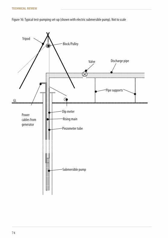
Figure 16: Typical test-pumping set-up (shown with electric submersible pump). Not to scale
Tripod
Block/pulley
Valve Discharge pipe
Pipe supports
GL
Dip-meter
Rising main
Power cables from generator
Piezometer tube
Submersible pump
TripodBlock/Pulley
Valve Discharge pipe
Pipe supports
Rising main
Dip meter
Piezometer tube
Submersible pump
Power cables from generator
GL
TECHNICAL REVIEW
74
ICRC Borehole Technical Review.indd 74 19/02/2010 17:14
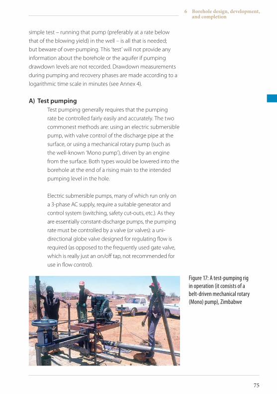
simple test – running that pump (preferably at a rate below
that of the blowing yield) in the well – is all that is needed;
but beware of over-pumping. This ‘test’ will not provide any
information about the borehole or the aquifer if pumping
drawdown levels are not recorded. Drawdown measurements
during pumping and recovery phases are made according to a
logarithmic time scale in minutes (see Annex 4).
A) TestpumpingTest pumping generally requires that the pumping
rate be controlled fairly easily and accurately. The two
commonest methods are: using an electric submersible
pump, with valve control of the discharge pipe at the
surface, or using a mechanical rotary pump (such as
the well-known ‘Mono pump’), driven by an engine
from the surface. Both types would be lowered into the
borehole at the end of a rising main to the intended
pumping level in the hole.
Electric submersible pumps, many of which run only on
a 3-phase AC supply, require a suitable generator and
control system (switching, safety cut-outs, etc.). As they
are essentially constant-discharge pumps, the pumping
rate must be controlled by a valve (or valves): a uni-
directional globe valve designed for regulating flow is
required (as opposed to the frequently used gate valve,
which is really just an on/off tap, not recommended for
use in flow control).
Figure 17: A test-pumping rig in operation (it consists of a belt-driven mechanical rotary (Mono) pump), Zimbabwe
6 Borehole design, development, and completion
75
ICRC Borehole Technical Review.indd 75 19/02/2010 17:14
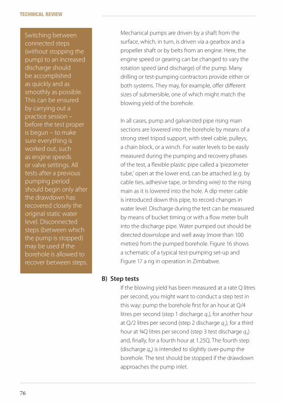
Mechanical pumps are driven by a shaft from the
surface, which, in turn, is driven via a gearbox and a
propeller shaft or by belts from an engine. Here, the
engine speed or gearing can be changed to vary the
rotation speed (and discharge) of the pump. Many
drilling or test-pumping contractors provide either or
both systems. They may, for example, offer different
sizes of submersible, one of which might match the
blowing yield of the borehole.
In all cases, pump and galvanized pipe rising main
sections are lowered into the borehole by means of a
strong steel tripod support, with steel cable, pulleys,
a chain block, or a winch. For water levels to be easily
measured during the pumping and recovery phases
of the test, a flexible plastic pipe called a ‘piezometer
tube,’ open at the lower end, can be attached (e.g. by
cable ties, adhesive tape, or binding wire) to the rising
main as it is lowered into the hole. A dip meter cable
is introduced down this pipe, to record changes in
water level. Discharge during the test can be measured
by means of bucket timing or with a flow meter built
into the discharge pipe. Water pumped out should be
directed downslope and well away (more than 100
metres) from the pumped borehole. Figure 16 shows
a schematic of a typical test-pumping set-up and
Figure 17 a rig in operation in Zimbabwe.
B) SteptestsIf the blowing yield has been measured at a rate Q litres
per second, you might want to conduct a step test in
this way: pump the borehole first for an hour at Q/4
litres per second (step 1 discharge q1), for another hour
at Q/2 litres per second (step 2 discharge q2), for a third
hour at ¾Q litres per second (step 3 test discharge q3)
and, finally, for a fourth hour at 1.25Q. The fourth step
(discharge q4) is intended to slightly over-pump the
borehole. The test should be stopped if the drawdown
approaches the pump inlet.
Switching between connected steps (without stopping the pump) to an increased discharge should be accomplished as quickly and as smoothly as possible. This can be ensured by carrying out a practice session – before the test proper is begun – to make sure everything is worked out, such as engine speeds or valve settings. All tests after a previous pumping period should begin only after the drawdown has recovered closely the original static water level. Disconnected steps (between which the pump is stopped) may be used if the borehole is allowed to recover between steps.
TECHNICAL REVIEW
76
ICRC Borehole Technical Review.indd 76 19/02/2010 17:14
After this basic step test, if the borehole stabilizes with
a dynamic drawdown some way above the top of the
screen at discharge q3, but not at q4, then the blowing
yield, Q, is probably the best production level. However,
depending upon demand, a production yield of q3
might be safer, as that takes account of any possible
future fall in water levels or borehole deterioration. If
the dynamic level stabilizes just above the screen at q3,
then a production rate of q2 (or a little more) might be
more appropriate.
C) ConstantdischargetestOnce the production level has been estimated from
this test, it should be confirmed by pumping the
borehole at the constant discharge for a minimum
of 24 hours (high-yield production holes are run for
48 hours). This is called a constant discharge test. As
the test proceeds, drawdowns should be regularly
measured. At the end of the test, as soon as the pump
is switched off, water levels should be monitored as
they recover (to the static water level). If the pumping
level stabilizes at a safe level above the screens and
pump inlet, this may be the appropriate production
yield. An example of a borehole test log sheet is
provided in Annex 4. Many publications deal with
the analysis of borehole pumping test data, and their
applicability to aquifer modelling. Even if a particular
drilling programme does not require such analyses, the
field data should be regarded as a valuable resource
and retained, because they may be needed in the
future. For instance, one of the boreholes may suffer
a loss of efficiency and need to be rehabilitated; the
results of a post-rehabilitation pumping test can then
be compared with the original test, to assess the
degree of permanent deterioration.
6 Borehole design, development, and completion
77
ICRC Borehole Technical Review.indd 77 19/02/2010 17:14
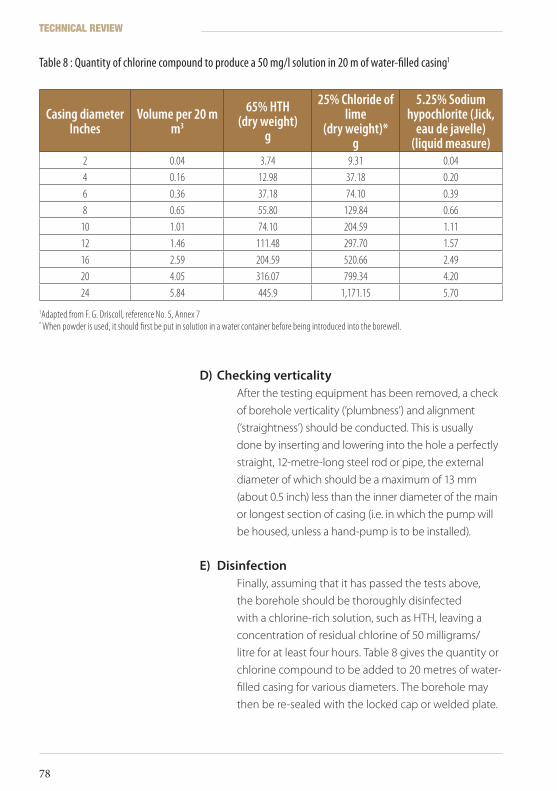
D) CheckingverticalityAfter the testing equipment has been removed, a check
of borehole verticality (‘plumbness’) and alignment
(‘straightness’) should be conducted. This is usually
done by inserting and lowering into the hole a perfectly
straight, 12-metre-long steel rod or pipe, the external
diameter of which should be a maximum of 13 mm
(about 0.5 inch) less than the inner diameter of the main
or longest section of casing (i.e. in which the pump will
be housed, unless a hand-pump is to be installed).
E) DisinfectionFinally, assuming that it has passed the tests above,
the borehole should be thoroughly disinfected
with a chlorine-rich solution, such as HTH, leaving a
concentration of residual chlorine of 50 milligrams/
litre for at least four hours. Table 8 gives the quantity or
chlorine compound to be added to 20 metres of water-
filled casing for various diameters. The borehole may
then be re-sealed with the locked cap or welded plate.
Casing diameterInches
Volume per 20 mm3
65% HTH(dry weight)
g
25% Chloride of lime
(dry weight)* g
5.25% Sodium hypochlorite (Jick,
eau de javelle)(liquid measure)
2 0.04 3.74 9.31 0.044 0.16 12.98 37.18 0.206 0.36 37.18 74.10 0.398 0.65 55.80 129.84 0.66
10 1.01 74.10 204.59 1.1112 1.46 111.48 297.70 1.5716 2.59 204.59 520.66 2.4920 4.05 316.07 799.34 4.2024 5.84 445.9 1,171.15 5.70
Table 8 : Quantity of chlorine compound to produce a 50 mg/l solution in 20 m of water-filled casing1
1Adapted from F. G. Driscoll, reference No. 5, Annex 7* When powder is used, it should first be put in solution in a water container before being introduced into the borewell.
TECHNICAL REVIEW
78
ICRC Borehole Technical Review.indd 78 19/02/2010 17:14
6.3.3 Geophysicallogging
Information about structural features and geological
formations in a borehole can be remotely obtained by
geophysical borehole logging techniques. The object of
well logging is to measure the properties of the undisturbed
rocks and fluids they contain. Geophysical logs can provide
information on lithology, the amount of water in a formation,
formation density, zones of water inflow, water quality,
and other in situ parameters that cannot be derived from
highly disturbed drilling samples. A suite of geophysical
log data, including deep-penetration methods, will more
or less complete the technical description of a borehole,
but geophysical logging is a specialized field best left to
geophysical contractors or hydrogeological consultants.
A logging unit consists of a power supply, a receiver/data
processing unit, and a cable on a powered winch that lowers
special sensor probes (‘sondes’) into the borehole to measure
various properties. The cable contains multi-conductors
that transmit signals to the receiver console. Data, processed
by computer, can be shown as a geophysical record on a
graphic display, which should consist of a number of different
structural, formation, and fluid logs. Specialized software
packages enable manipulation, interpretation, and comparison
of data. Multiple-sonde geophysical (‘suite’) logging can
provide a substantial amount of information about the
sub-surface conditions in and around a borehole.
6 Borehole design, development, and completion
79
ICRC Borehole Technical Review.indd 79 19/02/2010 17:14

ICRC Borehole Technical Review.indd 80 19/02/2010 17:14
Drilling/ Construction costs
7
The demands of commercial competition mean that drilling
contractors are often reluctant to quote prices unless one
can provide specific details of geological conditions and
anticipated borehole depths at potential sites. They may, for
instance, request that a hydrogeological site survey be carried
out beforehand. For this preliminary work, one should try to
employ an independent consultant rather than one offered
by – or affiliated with – a drilling contractor. At United Kingdom
rates, this might amount to between 200 and 300 pounds
per day – the length of the job depending on the size or
complexity of the site – in addition to the costs of hiring any
surveying equipment that may be needed.
Drilling contractors, at least in the U.K., are never slow to point
out that boreholes can cut water costs by up to 80% and that
the cost of borehole water is only around two to three pence a
cubic metre, compared to £1 in some areas for normal supplies
(quoted by W.B. & A.D. Morgan, of Powys, U.K.). However, while
researching for this review, this writer found great difficulty
in obtaining quotations from drilling companies, but a few
examples gleaned from the Internet are provided here.
7 Drilling/Construction costs
81
ICRC Borehole Technical Review.indd 81 19/02/2010 17:14

Drilling contractors normally charge on a system of units of
time and materials used. A fixed rate for borehole drilling
might be offered only if the contractor is very familiar with
the location in question and knows exactly what to expect.
Quoted prices will normally include basic PVC casing/screens;
gravel packs might be extra, and pump installation will also
be an additional expense. A typical fixed-rate cost, regardless
of borehole depth, has been obtained from the United States:
of around 15,000 US dollars (including PVC casing/screen). In
Nigeria, a Lagos real-estate adviser quotes a cost of 350,000
Nigerian naira per borehole (industrial, heavy-duty drilling;
probably includes PVC casing/screen, but not pump), which
converts to only around US$ 3,000 at current rates (2008).
In another African example, Water Africa Services Ltd of
Nairobi, Kenya, bidding for the drilling of 10 boreholes in
Jonglei, South Sudan (commencing 2009), quoted an overall
price of US$ 146,960 (including casings/screens, but not pump).
This contract is for the Ministry of Co-operatives and Rural
Development, Juba.
Large-donor programmes, such as those funded by the
World Bank, which is supporting most of the borehole drilling
currently taking place in Malawi, are also willing to pay up
to US$ 15,000 per borehole. As governments in developing
countries are often not footing the bill for drilling projects, it
is not necessarily in their interest to reduce such costs. Actual
drilling costs do not normally take into account the need for
community participation at all stages: from site selection to
drilling, pump installation, and utilization. Each of these phases
might require skills in community mobilization and training.
In northern Pakistan, drilling systems operated by local small
contractors are still being used to drill shallow boreholes for
hand-pumps. These operators charge only around 500 rupees,
approximately £4 sterling, per metre of drilling. Costs of casings
and pumps would be additional. Rates for dug wells are around
1000 rupees per metre. A recent UK quotation for casing and
screen prices is included as Annex 2.
TECHNICAL REVIEW
82
ICRC Borehole Technical Review.indd 82 19/02/2010 17:14

7.1 Buyingarig
Depending on the scope of the drilling programme planned,
it might be tempting to consider buying a rig to avoid
depending on contractors and to try to make the best of the
available budget.
Industrial commercial rigs are usually beyond the reach of
humanitarian agencies, but portable rigs are affordable
and their prices range from US$ 10,000 to US$ 100,000
approximately. This makes them a tempting option.
However, if an agency is planning to invest in a small rig (of the
PAT or Eureka type, for example) a thorough economic analysis
must be performed beforehand.
Buying a rig and bringing it to your warehouse only represents
a small part of the costs involved.
A stock of spare parts and consumables has to be kept and
maintained. A logistical chain is needed to supply the drilling
campaign. Vehicles are indispensable for the transportation
of water, material and staff, and sometimes even for security.
Qualified drillers have to be found and trained, including a
number of replacements. If the agency does not have a single
employee who is knowledgeable in drilling, any planning
for a drilling programme should be put off until a consultant
has been hired. Very often, applications for drilling permits
have to be made, and the drilling agency sometimes has to
be registered as such. Once a drilling campaign has started,
interrupting it is very expensive; everything must be done to
try and avoid that situation.
Finally, there is the choice of doing it yourself, as it were. This
will depend on your capacity (available skills) and the scale
of the drilling programme (the number of boreholes and the
possibility of continuing to use the rig for other programmes).
After a certain number of boreholes to be calculated, the initial
investment and effort is profitable.
7 Drilling/Construction costs
83
ICRC Borehole Technical Review.indd 83 19/02/2010 17:14

7.2 Successrates
Possible success rates also have to be factored into a drilling
project cost equation. Most professionals judge a borehole
success rate of 70 to 80% to be satisfactory.
A drilling programme of 30 deep boreholes was also
completed in the same area with a success rate of 94%. In both
projects, drilling locations were determined by detailed site
surveys that included geophysical exploration. The shallow
wells (average depth: 21 metres) cost around US$ 5,000 each;
the deeper boreholes (average depth: 46 metres) cost around
US$ 10,625 each. The drilling was done with a PAT 301 rig.
Clearly, drilling is made much more economical when the
smaller types of rig are used: one quotation for a hole (depth
or design unspecified) drilled by a Eureka Port-a-Rig (see
Section 3.1) was about US$ 3,000.
As mentioned near the beginning of this review, a water
supply project could be significantly augmented – and its costs
significantly lowered – by locating existing boreholes in the
project area and, if at all possible, bringing them back into use.
In 2006, a total of 80 shallow boreholes were drilled by TGS Water Ltd of Kampala in the districts of Oyam, Apac, Dokolo, and Lira in northern Uganda. The holes were drilled to reach shallow resistant formations, so were apparently exploiting near-surface aquifers in the weathered zone. Here, borehole success rate was 71%.
Indeed, the manager of a South African groundwater consultancy, who employed this writer as a hydrogeologist in Zimbabwe during the 1980s, admitted that he deliberately kept success rates down to these levels, in order that their work not give the appearance of being too easy!
TECHNICAL REVIEW
84
ICRC Borehole Technical Review.indd 84 19/02/2010 17:14
Borehole deterioration
8
Nothing lasts forever, and water wells are no exception. The
life expectancy of a production borehole will be limited if it
was incorrectly designed or not constructed for maximum
efficiency, or if it has been over-pumped. Many production
wells are seldom monitored or maintained; they are neglected
until a problem arises. But if a borehole is properly designed,
constructed with the correct materials, and given regular
attention, it can produce water for 50 years or more.
Common causes of borehole deterioration or failure include
the following:
A) WaterleveldrawdownProduction from a borehole or a well field can decline
because of a drop in the water table, which might be
due to natural causes such as drought, but also to well
deterioration and over-pumping (excessive drawdown).
A drop in the water level can result in submersible
pumps shutting off automatically.
B) MechanicalfailurePumps eventually lose their effectiveness as parts
become worn, corroded, or clogged, and borehole
screens become partly blocked by damaging organic
and inorganic accumulations and scale deposits. If
pumps are not turned off before they begin sucking
8 Borehole deterioration
85
ICRC Borehole Technical Review.indd 85 19/02/2010 17:14
in air, they will be irreparably damaged. Decline in or
loss of production can be at least partly (if not mostly)
remedied by a programme of well maintenance and
rehabilitation.
C) IncrustationMost ground waters are only mildly corrosive, if at all,
so corrosion is not usually a problem if good-quality
plastic and steel (such as stainless steel) casings
and screens have been installed. The main cause of
deterioration is the build-up of incrustations around
screen openings, which reduce borehole efficiency.
As a borehole is pumped, pressure is reduced by the
local drawdown, and water velocity and turbulence
around the borehole increase. In this agitated zone,
carbon dioxide gas is released from the water, which
reduces the solubility of certain compounds in the
water, such as calcium carbonate. Incrustation is mainly
the result of the precipitation of insoluble carbonates,
bicarbonates, hydroxides, or sulphates of calcium,
magnesium, sodium, manganese, or iron. However,
these deposits are rarely composed of a single mineral.
Normally, the level of dissolved iron in groundwater
is low, but slight changes in water chemistry, such
as acidification due to dissolved carbon dioxide or
organic matter (humic acids) can result in higher iron
concentrations (up to tens of milligrams per litre). Iron
will remain in its soluble (ferrous) state unless there is
a rise in the pH (alkalinity, equivalent to reduction of
acidity) or Eh (redox potential) of the water. Increased
oxygenation of the turbulent zone can initiate iron
precipitation by oxidation from the ferrous (soluble
Fe2+) to the ferric (insoluble Fe3+) form in the screen
area. Serious mineral deposition can occur at the top
of screens, which become exposed to air owing to
excessive drawdown. Inorganic silts and clays often
add to the problem, but organic deposits can also
be involved. Oxidation of ferrous to ferric iron at the
borehole boundary can encourage the growth of
TECHNICAL REVIEW
86
ICRC Borehole Technical Review.indd 86 19/02/2010 17:14
certain bacteria. Organic slime formation by species
of iron bacteria is a result of the life cycle of such
organisms. They inhabit groundwater by metabolizing
ammonia, methane, or carbon dioxide, again changing
iron into deposits of insoluble salts (mainly hydroxide),
which worsens incrustation.
Iron biofouling is a complex process influenced by
interactions between the aquifer environment and
the borehole structures. Microbial matter consists
of filamentous cell colonies, mats, and slime sheaths
(which cells secrete for protection), often of a sludgy
consistency, but able to harden with age. Such
incrustations impair hydraulic efficiency and specific
capacity, clogging pipes, filter packs, screens, and
pumps. They can cement a gravel pack into something
akin to concrete. They encourage corrosion and
reduce water quality, but remedial measures are likely
to be less effective once hardening has occurred. If
an incrustation has aged and recrystallized it will be
extremely difficult to loosen and remove.
D) CorrosionThe most common corrosion process is
electrochemical, in which iron (or another metal) is
dissolved and re-precipitated as a hydroxide deposit.
Corrosion in a water well most often occurs at localized
physical imperfections on metal pipes and screens;
the process can be encouraged by high salinity, high
temperatures, oxygen, carbon dioxide, hydrogen
sulphide, and organic acids (from peat or pollution).
Corrosion can perforate metal screens and casings,
weakening the structure and allowing pollutants (or
even gravel pack material) to enter the borehole. As has
been mentioned before, incrustation or corrosion can
be slowed down by installing screens with the greatest
possible slot area, to reduce pumping rates and inlet
velocities, and by periodic cleaning or redevelopment
of the borehole.
8 Borehole deterioration
87
ICRC Borehole Technical Review.indd 87 19/02/2010 17:14

ICRC Borehole Technical Review.indd 88 19/02/2010 17:14
Borehole monitoring
9
This section contains a brief review of techniques that enable
detailed evaluation of a borehole. Additional information can
be found in the references listed in Annex 7B.
Continuous monitoring of borehole performance can be
cost-effective, helping to detect any problems before they
become serious. Maintenance programmes should consist
of regular field visits, water sampling (for chemical/microbial
analyses), water level measurements, and routine monitoring
by simple step-drawdown tests. The data collected can be
compared with those obtained when the well was new or last
monitored. A regular testing schedule consisting of a basic
step-drawdown test every year is sufficient, with maintenance
carried out if there is any sign of deterioration. Low-risk areas
(in terms of borehole incrustation or corrosion) may require
maintenance work only every few years. It is prudent to erect a
lockable fence around the borehole to prevent tampering and
accidental or malicious damage. Table 9 sets out the symptoms
to be noted in a monitoring programme, along with causes
and suggested remedial actions.
9 Borehole monitoring
89
ICRC Borehole Technical Review.indd 89 19/02/2010 17:14
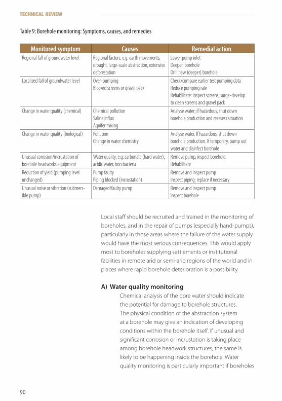
Local staff should be recruited and trained in the monitoring of
boreholes, and in the repair of pumps (especially hand-pumps),
particularly in those areas where the failure of the water supply
would have the most serious consequences. This would apply
most to boreholes supplying settlements or institutional
facilities in remote arid or semi-arid regions of the world and in
places where rapid borehole deterioration is a possibility.
A) WaterqualitymonitoringChemical analysis of the bore water should indicate
the potential for damage to borehole structures.
The physical condition of the abstraction system
at a borehole may give an indication of developing
conditions within the borehole itself. If unusual and
significant corrosion or incrustation is taking place
among borehole headwork structures, the same is
likely to be happening inside the borehole. Water
quality monitoring is particularly important if boreholes
Monitored symptom Causes Remedial actionRegional fall of groundwater level Regional factors, e.g. earth movements,
drought, large-scale abstraction, extensive deforestation
Lower pump inletDeepen boreholeDrill new (deeper) borehole
Localized fall of groundwater level Over-pumpingBlocked screens or gravel pack
Check/compare earlier test pumping dataReduce pumping rateRehabilitate: Inspect screens, surge-develop to clean screens and gravel pack
Change in water quality (chemical) Chemical pollutionSaline influxAquifer mixing
Analyse water; if hazardous, shut down borehole production and reassess situation
Change in water quality (biological) PollutionChange in water chemistry
Analyse water. If hazardous, shut down borehole production. If temporary, pump out water and disinfect borehole
Unusual corrosion/incrustation of borehole headworks equipment
Water quality, e.g. carbonate (hard water), acidic water, iron bacteria
Remove pump, inspect borehole. Rehabilitate
Reduction of yield (pumping level unchanged)
Pump faultyPiping blocked (incrustation)
Remove and inspect pumpInspect piping; replace if necessary
Unusual noise or vibration (submers-ible pump)
Damaged/faulty pump Remove and inspect pumpInspect borehole
Table 9: Borehole monitoring: Symptoms, causes, and remedies
TECHNICAL REVIEW
90
ICRC Borehole Technical Review.indd 90 19/02/2010 17:14
are close to densely populated areas or in coastal
zones. Pollution (chemical or biological) may be caused
by the former; in coastal areas there is the possibility of
intrusion by salt water, from a fluctuating fresh water/
sea water transition zone. In the latter case, of course,
simple tasting will confirm the problem, but regular
conductivity or total dissolved solids (TDS) analysis will
provide predictive data.
Distilled water has a conductivity of 1 µS,
good fresh water <2,000 to 3,000 µS,and saline water >6,000 µS
(S = Siemen, 1 Ω-1cm-1).
The equivalent TDS classification is:
fresh water 0 to 1,000 mg/l;brackish water 1,000 to 10,000 mg/l;
and saline water 10,000 to >100,000 mg/l.
Reference 11 in Annex 7B gives details of a report,
published by CIRIA, which provides best practice
guidance on the monitoring, maintenance
and rehabilitation of boreholes equipped with
hand-pumps.
Borehole monitoring should include regular step-
drawdown tests, which can be further analysed to
determine the basic hydraulic parameters of aquifers.
Drawdown in a borehole is essentially the sum of losses
due to movement of water from the aquifer into the
borehole space. Mathematical analysis of step-test data
allows these losses to be determined, along with the
relationship between drawdown and discharge for the
borehole under test. From these data, an indication
of the efficiency of the borehole (and hence of any
reduction of efficiency over time) can be obtained.
9 Borehole monitoring
91
ICRC Borehole Technical Review.indd 91 19/02/2010 17:14

ICRC Borehole Technical Review.indd 92 19/02/2010 17:14
Borehole rehabilitation
10
Rehabilitation is the action taken to repair a borehole whose
productivity has declined or that has failed through lack
of monitoring and maintenance of the pump and/or well
structure. This is often a financial problem, or a logistical
one – a function of remote location and, possibly, of conflict
preventing easy access. Surface pumps, such as wind-pumps or
hand-pumps, often fail for purely mechanical reasons – broken
rods or corroded risers, for instance – and disused boreholes
silt up or have objects dropped into them. Unfortunately, if
a borehole has become tightly blocked by hard debris, such
as stones and pieces of metal (a not uncommon occurrence),
it is probably totally lost. Existing boreholes are likely to be
well sited in terms of usage, since they must originally have
been drilled for a purpose. Therefore, it is almost always
advantageous to rehabilitate them.
It can be reckoned as a rule of thumb that a simple
rehabilitation (no casing replacement) will cost around 10% of
the price of a new borehole.
10.1 Whentorehabilitate
All pre-existing boreholes within a project area should be
inspected for the possibility of rehabilitation, unless they
are on privately owned land. The extra water might not be
10 Borehole rehabilitation
93
ICRC Borehole Technical Review.indd 93 19/02/2010 17:14
needed, but as boreholes provide access to groundwater, they
could be used as observation holes for monitoring local water
levels. Abandoned boreholes may act as pathways for the
contamination of an aquifer, or enable the mixing of ground
waters of differing quality from separate aquifers. They might
also present a physical hazard to, say, local children, especially
if they are of large diameter and open. Redundant boreholes
are potentially useful as groundwater monitoring points, even
if they cannot be rehabilitated for production; but holes that
are beyond repair should be backfilled using clean, inert, non-
polluting materials such as gravel, sand, shingle, concrete,
bentonite, rock, or cement grout.
A borehole that has stood unprotected – by a top casing cap
or a surface installation – for some time will almost certainly
have been lost because of, say, objects being dropped into
it by children. If a blockage can be reached from the surface
it should be probed with a strong metal bar to get an idea
of its solidity. Loose fine material might be removable
using compressed air (see below); if this can be done, full
rehabilitation might be a possibility. If the borehole was
protected by a cover and is apparently clear, it should be
checked for depth by plumb-line dipping, for static water level
by dip meter, and for method of construction and internal
condition by means of a CCTV borehole camera.
Before carrying out rehabilitation, it is advisable to sample and
analyse the local groundwater (if possible) to ensure that it is
not unduly chemically aggressive.
10.2 Rehabilitationmethods
The basic rehabilitation process should consist of the following
principal stages in this order:
• Collection of archives and information (from water authorities, drilling companies, aid organizations, etc.) on the borehole design
TECHNICAL REVIEW
94
ICRC Borehole Technical Review.indd 94 19/02/2010 17:14
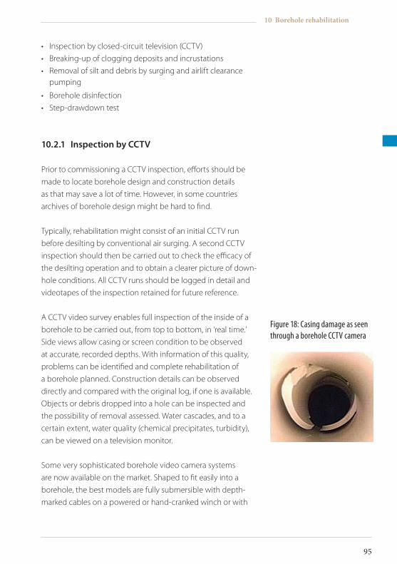
• Inspection by closed-circuit television (CCTV)
• Breaking-up of clogging deposits and incrustations
• Removal of silt and debris by surging and airlift clearance pumping
• Borehole disinfection
• Step-drawdown test
10.2.1 InspectionbyCCTV
Prior to commissioning a CCTV inspection, efforts should be
made to locate borehole design and construction details
as that may save a lot of time. However, in some countries
archives of borehole design might be hard to find.
Typically, rehabilitation might consist of an initial CCTV run
before desilting by conventional air surging. A second CCTV
inspection should then be carried out to check the efficacy of
the desilting operation and to obtain a clearer picture of down-
hole conditions. All CCTV runs should be logged in detail and
videotapes of the inspection retained for future reference.
A CCTV video survey enables full inspection of the inside of a
borehole to be carried out, from top to bottom, in ‘real time.’
Side views allow casing or screen condition to be observed
at accurate, recorded depths. With information of this quality,
problems can be identified and complete rehabilitation of
a borehole planned. Construction details can be observed
directly and compared with the original log, if one is available.
Objects or debris dropped into a hole can be inspected and
the possibility of removal assessed. Water cascades, and to a
certain extent, water quality (chemical precipitates, turbidity),
can be viewed on a television monitor.
Some very sophisticated borehole video camera systems
are now available on the market. Shaped to fit easily into a
borehole, the best models are fully submersible with depth-
marked cables on a powered or hand-cranked winch or with
Figure 18: Casing damage as seen through a borehole CCTV camera
10 Borehole rehabilitation
95
ICRC Borehole Technical Review.indd 95 19/02/2010 17:14
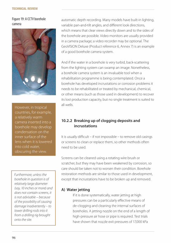
automatic depth recording. Many models have built-in lighting,
variable pan-and-tilt angles, and different look directions,
which means that clear views directly down and to the sides of
the borehole are possible. Video monitors are usually provided
in a camera package; a video recorder may be optional. The
GeoVISION Deluxe (Product reference 6, Annex 7) is an example
of a good borehole camera system.
And if the water in a borehole is very turbid, back-scattering
from the lighting system can swamp an image. Nonetheless,
a borehole camera system is an invaluable tool when a
rehabilitation programme is being contemplated. Once a
borehole has developed incrustations or corrosion problems it
needs to be rehabilitated or treated by mechanical, chemical,
or other means (such as those used in development) to recover
its lost production capacity, but no single treatment is suited to
all wells.
10.2.2 Breakingupofcloggingdepositsandincrustations
It is usually difficult – if not impossible – to remove old casings
or screens to clean or replace them, so other methods often
need to be used.
Screens can be cleaned using a rotating wire brush or
scratcher, but they may have been weakened by corrosion, so
care should be taken not to worsen their condition. Borehole
restoration methods are similar to those used in development,
except that incrustations have to be broken up and removed.
A) WaterjettingIf it is done systematically, water jetting at high
pressures can be a particularly effective means of
de-clogging and cleaning the internal surfaces of
boreholes. A jetting nozzle on the end of a length of
high-pressure air hose or pipe is required. Test trials
have shown that nozzle exit pressures of 17,000 kPa
However, in tropical countries, for example, a relatively warm camera inserted into a borehole may develop condensation on the inner surface of the lens when it is lowered into cold water, obscuring the view.
Figure 19: A CCTV borehole camera
Furthermore, unless the borehole in question is of relatively large diameter (say, 10 inches or more) and does not contain screens, it is not advisable – because of the possibility of causing damage inadvertently – to lower drilling rods into it from a drilling rig brought onto the site.
TECHNICAL REVIEW
96
ICRC Borehole Technical Review.indd 96 19/02/2010 17:14
(for a 1.5 to 2" nozzle, positioned about 1" from the
screen) will be effective on most occasions. In unlined
boreholes, the jetting pressure limit is around 40,000
kPa. To avoid damage to plastic screens, pressures
greater than 20,000 kPA should be avoided, because
very high pressure jetting (greater than 30,000 kPa) can
cut through plastic casing. Steel casing can withstand
pressures of up to at least 55,000 kPa, and the screens
that best respond to jetting treatment are those with
high open areas and continuous slots, such as wire-
wrap types like Johnson screens.
B) Air-bursttechnologyAir-burst technology is a new and patented technique
of borehole rehabilitation: it entails using small volumes
of an inert gas to generate high-intensity ‘pressure-
pulses’ in selected zones inside a well.
The pulses, from a special tool, create air bubbles and
high-frequency acoustic shocks that shatter mineral
and organic films and incrustations on the borehole
walls and screens. Gas bubbles surge water into and
out of the formation adjacent to the tool, displacing
sediment, incrustation debris, and fragments of biofilm,
which are washed into the borehole, and can later be
cleaned out by conventional air-lifting.
Air-bursting can develop every part of the borehole
structure with multiple and adjustable bursts of energy
adaptable to any diameter, design, or age of borehole.
However, it is a specialized technique probably more
appropriate for severely deteriorated high-performance
boreholes in commercial or utility production well
fields.
C) AcidizationFor seriously affected boreholes, a combination
of physical and chemical methods might be most
effective. Acidization (mentioned in Section 6.2.1B) can
10 Borehole rehabilitation
97
ICRC Borehole Technical Review.indd 97 19/02/2010 17:14
remove carbonate incrustations and ferric hydroxide
deposits in their early non-cemented stage.
Hardened iron deposits would require physical
breaking up by the methods described above. A 30%
sulphamic acid solution to the volume of the screened
or open section to be cleaned can be used for 15
to 24 hours, with the water in the borehole being
periodically agitated by air that is blown in.
D) HydrofracturingOld boreholes drilled into low-yield formations, such as
Precambrian crystalline rocks, can be stimulated by a
process known as hydrofracturing.
The technique can be applied only to open, uncased
sections such as might occur towards the bottom of
a hole. First, a CCTV or down-hole geophysical log
must be run to assess the suitability of the borehole
to such treatment. The section to be worked should
already be fractured to a certain extent, and must be
isolated using some kind of packer. This might consist
of a series of rubber seals that can be expanded in the
borehole by a hydraulic ram or by compressed air from
the surface.
An injection pipe runs down the centre of the packing
system. High-pressure water is injected into the
borehole in order to create or enlarge the fractures.
Sand can be added to the water to keep open (‘prop’)
newly developed fractures.
Reports indicate that yield increases of 20 to 80% have
been achieved using hydrofracturing. Depending upon
the nature of the formation, injection pressures of 35
(soft) to 140 (hard) bar are used. After treatment, water
and debris are air-lifted out in the normal way.
TECHNICAL REVIEW
98
ICRC Borehole Technical Review.indd 98 19/02/2010 17:14
10.2.3 Relining
A borehole seriously affected by corrosion – that is now
pumping out sediments – can be restored only by partial or
total relining. The necessary course of action may be decided
only after a borehole camera survey, or a geophysical logging
programme, has determined the extent of the damage or
deterioration. Down-hole logs might contain indications (water
temperature, conductivity, flow, resistivity, or casing collar logs;
see Section 6.3.3) of holes in casing.
Any new casings or screens that are installed should be of
corrosion-resistant materials to avoid a repetition of the original
problem. A new lining will be of smaller diameter, so the new
pump will have to be chosen with this in mind.
Corroded screens should not be relined if at all possible,
because concentric screens create turbulence and abrasion,
and fragments of corroded metal could be sucked into the
borehole during pumping.
Although it can be extremely difficult, corroded screens should
be removed and replaced by new corrosion-resistant materials.
Any attempt to do this would involve bringing a large drilling
rig on site and using its pulling power to remove the old casing
string.
Any lost gravel pack material can be blown out. With new casings
installed, the borehole can be developed in the usual way.
New casings and screens can be protected from corrosion under
water by means of sacrificial electrodes (cathodic protection).
Sacrificial anodes of a metal that is higher in the electromotive
series (relative tendency to oxidation) than steel – such as
magnesium and zinc – are attached and corrode in preference
to the protected metal of the casing. Such systems are used to
protect ships, underwater pipelines, and pump installations, but
are rarely applied to borehole casings or screens.
Two sets of concentric screens would severely reduce the performance of a borehole, but if a hand-pump is the intended means of extraction, this may not matter very much.
10 Borehole rehabilitation
99
ICRC Borehole Technical Review.indd 99 19/02/2010 17:14
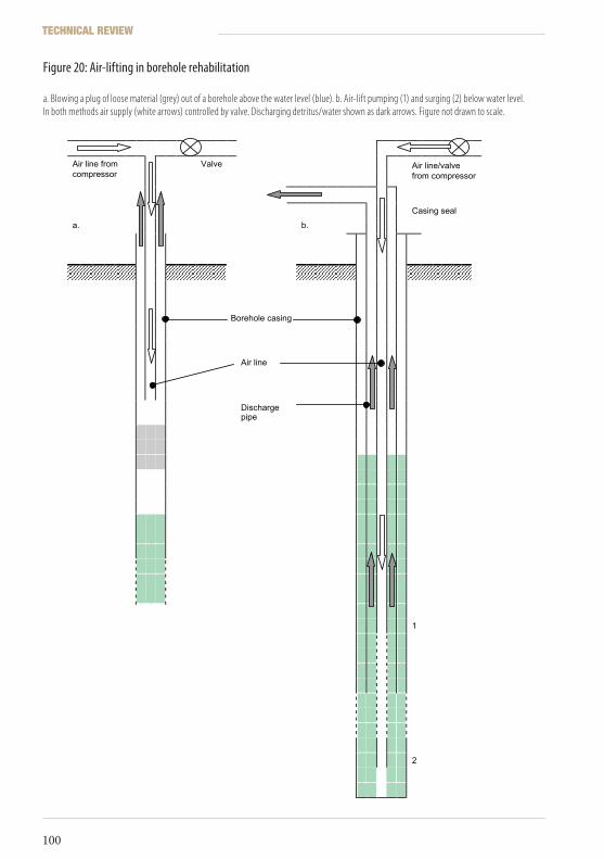
Valve Air line from compressor
Air line/valve from compressor
Casing seal
a. b.
Borehole casing
Air line
Discharge pipe
1
2
Figure 20: Air-lifting in borehole rehabilitation a. Blowing a plug of loose material (grey) out of a borehole above the water level (blue). b. Air-lift pumping (1) and surging (2) below water level.In both methods air supply (white arrows) controlled by valve. Discharging detritus/water shown as dark arrows. Figure not drawn to scale.
TECHNICAL REVIEW
100
ICRC Borehole Technical Review.indd 100 19/02/2010 17:14
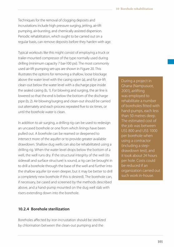
Techniques for the removal of clogging deposits and
incrustations include high pressure surging, jetting, air-lift
pumping, air-bursting, and chemically assisted dispersion.
Periodic rehabilitation, which ought to be carried out on a
regular basis, can remove deposits before they harden with age.
Typical workouts like this might consist of employing a truck or
trailer-mounted compressor of the type normally used during
drilling (minimum capacity 7 bar-100 psi). The most commonly
used air-lift pumping set-ups are shown in Figure 20. This
illustrates the options for removing a shallow, loose blockage
above the water level with the casing open (a), and for air-lift
clean-out below the water level with a discharge pipe inside
the sealed casing (b, 1). For blowing and surging, the air line is
lowered so that the end is below the bottom of the discharge
pipe (b, 2). Air blowing/surging and clean-out should be carried
out alternately and each process repeated five to six times, or
until the borehole water is clean.
In addition to air surging, a drilling rig can be used to redesign
an uncased borehole or one from which linings have been
pulled out. A borehole can be reamed or deepened to
intersect more of the aquifer or to provide greater available
drawdown. Shallow dug wells can also be rehabilitated using a
drilling rig. When the water level drops below the bottom of a
well, the well runs dry. If the structural integrity of the well (its
sidewall and surface structure) is sound, a rig can be brought in
to drill a borehole through the base of the well and further into
the shallow aquifer (or even deeper, but it may be better to drill
a completely new borehole if this is desired). The borehole can,
if necessary, be cased and screened by the methods described
above, and a hand-pump mounted on the dug well slab with
risers extending down into the borehole.
10.2.4 Boreholesterilization
Boreholes affected by iron incrustation should be sterilized
by chlorination between the clean-out pumping and the
During a project in Ghana (Nampusuor, 2001), airlifting was employed to rehabilitate a number of boreholes fitted with hand-pumps, each less than 50 metres deep. The estimated cost of the job was between US$ 800 and US$ 1000 per borehole when using a contractor (including a step-drawdown test), and it took about 24 hours per hole. Costs could be reduced if an organization carried out such work in-house.
10 Borehole rehabilitation
101
ICRC Borehole Technical Review.indd 101 19/02/2010 17:14
step test, to destroy ubiquitous iron bacteria to and delay
re-infection of the well. Granular HTH can be dissolved and
added so as to leave about 50 milligrams per litre of residual
free chlorine in the borehole water. Mixing the solution in the
borehole can be done by blowing with the air line used for the
air-lift pumping. The concentration should be monitored using
a water testing kit such as the Oxfam-DelAgua. The borehole
can then be pump tested.
10.2.5 Step-drawdowntesting
A step-drawdown test will indicate whether rehabilitation has
been successful; it can also serve as a new baseline against
which future well performance can be measured.
Test pumping of a rehabilitated borehole will also help to re-
establish normal groundwater flow and remove remaining silt
particles.
10.2.6 Mechanicalrepair
Many boreholes lie disused because pumps have broken down
or because of the lack of necessary expertise or spares. In the
case of hand-pumps, this can be relatively easy to fix: all that
is needed is a set of standard tools with which to remove the
pump handle, chain, riser pipes, rods, and piston, for inspection
and repair or for replacement.
Pumps and risers on deeper boreholes might require a tripod
and a vehicle with a winch for removal. If at all possible, a
borehole should be inspected by video camera once a pump
has been removed (see above).
In southern Darfur, this writer organized – with the ICRC – a mobile hand-pump repair team using two vehicles and two mechanics (plus local helpers at each village). Five full sets of India Mark II hand-pump spares, along with new riser pipes, rods and tools were carried in a pick-up truck. The team moved from village to village, locating and repairing disused hand-pumps on shallow boreholes.
TECHNICAL REVIEW
102
ICRC Borehole Technical Review.indd 102 19/02/2010 17:14
Working with contractors
11
For a particular water supply project, planners must decide
whether to use commercial drilling contractors or invest in
machines and experienced staff (see Section 7.1)
If the financial analysis concludes that a contractor must be
hired, a few steps must be followed to avoid later surprises.
Contractors are generally – but not always – very dedicated
professionals, but they represent commercial firms with their
own specific constraints, stresses and attitudes to risk-taking.
Being aware of this helps to look at a project from their point of
view and to anticipate some of their actions.
11.1 Selectingacontractor
Working with drilling contractors can be either interesting or
frustrating. Because a great deal of frustration can result from
confusion over what is demanded of contractors, the technical
specifications and the terms of the contractor’s employment
should be clearly defined from the outset. As there might be
a number of drilling organizations submitting bids for a work
project, the staff responsible for letting contracts will have a
number of factors to consider:
• Has the drilling company a good reputation?
• Can the company provide details of a similar contract
11 Working with contractors
103
ICRC Borehole Technical Review.indd 103 19/02/2010 17:14
recently completed successfully, or references from the employers?
• Is the company on a list of approved drilling contractors? Does it belong to a professional organization (such as the British Drilling Association in the U.K.)?
• Does the company possess the equipment necessary to fulfil the demands of the contract, and is the equipment in a good state of repair? (Here, a visit to the driller’s yard with an experienced, impartial engineer will be useful.)
• Does the company possess adequate maintenance and backup facilities to provide for plant breakdowns, and is that backup efficient?
• Is the company’s yard or depot clean and well run? (This will give an indication of their standards of work.)
• Check on staff employed by the company: Are they sufficiently experienced or qualified?
11.2 Contractdocumentation
Borehole drilling contracts are much like other commercial
agreements in, say, the civil engineering sector. But drilling is a
specialized field requiring clearly defined technical objectives and
methods that should incorporate a degree of flexibility.
A basic drilling contract between client and contractor should
contain specific clauses and technical specifications: an example
is provided as Annex 5. The supervisor or client representative
must make himself or herself thoroughly familiar with these
requirements. With detailed specifications in hand, he or she
should be able to react quickly (if not always amicably) to any work
disputes and bring them to an end.
Work/charge sheets for drilling contractors should list all that
is required for the fulfilment of the clauses and technical
specifications contained in the contract; these are listed in
Annex 6.
TECHNICAL REVIEW
104
ICRC Borehole Technical Review.indd 104 19/02/2010 17:14
Annexes
Annex1 Example of a drilling log sheet
Annex2 Recent quoted prices for casings and screens
Annex3 Examples of borehole completion designs (not to scale):
Annex 3A Borehole completion for hand-pump in a shallow, weathered zone aquifer
Annex 3B Borehole construction for partly consolidated sandstone aquifer (as Figure 1,
hypothetical site B)
Annex 3C Borehole construction for combined sandstone and limestone aquifers
(as Figure 1 hypothetical site C)
Annex 3D Borehole construction for aquifer in granite fracture zone (as in Figure 1,
hypothetical site D)
Annex4 Example of test pumping data sheet
Annex5 Basic drilling contract: Clauses and specifications
Annex6 List of items on contractor work/charge sheets
Annex7 Product references and further reading
Annexes
105
ICRC Borehole Technical Review.indd 105 19/02/2010 17:14

Annex1:Exampleofadrillinglogsheet
[NAME OF ORGANIZATION] DRILLING LOG SHEET Page of[PROJECT/CONTRACT] CONTRACTOR/DRILLER:Borehole No.: Location/Co-ordinates: Elevation:Drill machine: Mud/Air: Supervisor:Start date: Completion date: Completion depth:Borehole Data Drilling
penetration rate(units:)
Marsh funnel viscosity (sec)
Casing, screens, filter gravel pack installed
Other information or remarksDepth
(m, ft)Lithology from samples
Water strikes
TECHNICAL REVIEW
106
ICRC Borehole Technical Review.indd 106 19/02/2010 17:14
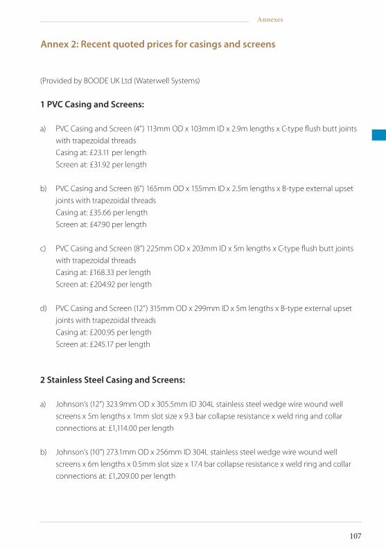
Annex2:Recentquotedpricesforcasingsandscreens
(Provided by BOODE UK Ltd (Waterwell Systems)
1PVCCasingandScreens:
a) PVC Casing and Screen (4”) 113mm OD x 103mm ID x 2.9m lengths x C-type flush butt joints
with trapezoidal threads
Casing at: £23.11 per length
Screen at: £31.92 per length
b) PVC Casing and Screen (6”) 165mm OD x 155mm ID x 2.5m lengths x B-type external upset
joints with trapezoidal threads
Casing at: £35.66 per length
Screen at: £47.90 per length
c) PVC Casing and Screen (8”) 225mm OD x 203mm ID x 5m lengths x C-type flush butt joints
with trapezoidal threads
Casing at: £168.33 per length
Screen at: £204.92 per length
d) PVC Casing and Screen (12”) 315mm OD x 299mm ID x 5m lengths x B-type external upset
joints with trapezoidal threads
Casing at: £200.95 per length
Screen at: £245.17 per length
2StainlessSteelCasingandScreens:
a) Johnson’s (12”) 323.9mm OD x 305.5mm ID 304L stainless steel wedge wire wound well
screens x 5m lengths x 1mm slot size x 9.3 bar collapse resistance x weld ring and collar
connections at: £1,114.00 per length
b) Johnson’s (10”) 273.1mm OD x 256mm ID 304L stainless steel wedge wire wound well
screens x 6m lengths x 0.5mm slot size x 17.4 bar collapse resistance x weld ring and collar
connections at: £1,209.00 per length
Annexes
107
ICRC Borehole Technical Review.indd 107 19/02/2010 17:14

c) Johnson’s (10”) 273.1mm OD x 4.19mm wall thickness 304L stainless steel casing x 3m
lengths x API male and female connections at: £1,185.00 per length
d) Johnson’s (7 5/8”) 193.7mm OD x 3mm wall thickness 304L stainless steel casing x 6m
lengths x weld collar connections at: £822.00 per length
TECHNICAL REVIEW
108
ICRC Borehole Technical Review.indd 108 19/02/2010 17:14
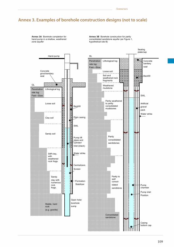
Annex3.Examplesofboreholeconstructiondesigns(nottoscale)
Annex 3A Borehole completion for hand-pump in a shallow, weathered zone aquifer
Annex 3B Borehole construction for partly consolidated sandstone aquifer (as Figure 1, hypothetical site B)
Sealing plate/cap
Hand-pump GL
Penetration rate log: Fast---Slow
Lithological log
Concrete sanitary seal
Loose soil
Concrete grout/sanitary seal Backfill
Soil and weathered rock fragments
GL
Weathered mudstone Penetration
rate log: Fast---Slow
Lithological log
SWL
Loose soil
Backfill
Partly weathered to partly consolidated mudstones
Artificial gravel pack
Water strike
Clay soil Plain casing
SWL
Sandy soil
Pump lift pipes and cylinder/ Inlet (black)
Partly consolidated sandstones
Water strike
Stiff clay, with weathered rock frags.
Centralizers
Screen
Formation Stabilizer Pump
chamber
Sandy clay with numerous rock frags.
Partly to well consol- idated sandstone
Pump inlet Position
Open hole/ borehole sump
Stable, hard rock (e.g. granite)
Consolidated sandstone
Casing bottom cap
Annexes
109
ICRC Borehole Technical Review.indd 109 19/02/2010 17:14
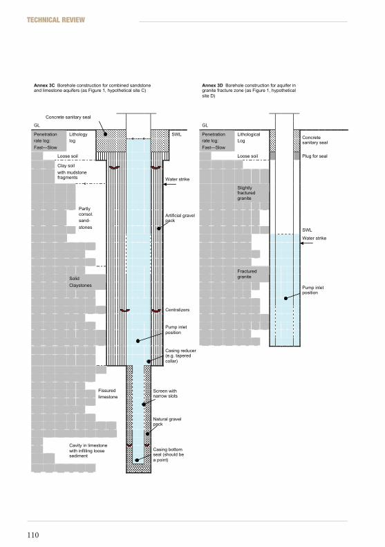
Annex 3C Borehole construction for combined sandstone and limestone aquifers (as Figure 1, hypothetical site C)
Annex 3D Borehole construction for aquifer in granite fracture zone (as Figure 1, hypothetical site D)
Concrete sanitary seal
GL GL
SWL Penetration rate log:
Fast---Slow
Lithology log
Penetration rate log:
Fast---Slow
Lithological Log
Concrete sanitary seal
Loose soil Loose soil Plug for seal
Clay soil
with mudstone fragments
Water strike
Slightly fractured granite
Artificial gravel pack
Partly consol. sand-
stones SWL
Water strike
Fractured granite
Solid
Claystones
Pump inlet position
Centralizers
Pump inlet position
Casing reducer (e.g. tapered collar)
Fissured limestone
Screen with narrow slots
Natural gravel pack
Cavity in limestone with infilling loose sediment
Casing bottom seal (should be a point)
TECHNICAL REVIEW
110
ICRC Borehole Technical Review.indd 110 19/02/2010 17:14

Annex4:Exampleoftestpumpingdatasheet
[NAME OF ORGANIZATION] TEP DRAWDOWN TEST DATA SHEET[PROJECT/CONTRACT] CONTRACTOR:Borehole No.: Location/Co-ordinates: Elevation:Borehole New/Rehabilitated Borehole Depth: Static Water Level:Test Pump Type: Pump Inlet Depth: Test Datum:Existing Pump: Test Supervisor: Test Date:PumpingTime(min.)
STEP 1(1 hour)Drawdown Discharge (m) (units)
STEP 2(1 hour)Drawdown Discharge (m) (units)
STEP 3(1 hour)Drawdown Discharge (m) (units)
STEP 4(1 hour)Drawdown Discharge (m) (units)
Recovery(ResidualDrawdown) (m)
0.511.522.53456789101215202530405060708090100120Remarks:
Annexes
111
ICRC Borehole Technical Review.indd 111 19/02/2010 17:14

Note:
For 24-hour constant discharge test drawdown measurements, use pumping times as for step
test plus: 150, 200, 250, 300, 400, 500, 600, 700, 800, 900, 1000, 1100, 1200, 1300, 1400, 1440
minutes.
For 48-hour constant discharge test, use pumping times as for step test plus: 150, 200, 250, 300,
400, 500, 600, 700, 800, 900, 1000, 1100, 1200, 1300, 1400, 1500, 1600, 1700, 1800, 1900, 2000, 2100,
2200, 2300, 2400, 2500, 2600, 2700, 2800, 2880 minutes.
For recovery (residual drawdown) measurements after pumping stops, use same time intervals,
continuing with readings every 100 minutes after 2800 until water level has recovered to within
20 centimetres of original static water level.
TECHNICAL REVIEW
112
ICRC Borehole Technical Review.indd 112 19/02/2010 17:14
Annex5:Basicdrillingcontract:Clausesandspecifications
A. GeneralClauses
A.1 Thepurposeofthecontractistheconstructionofboreholesforpotablewatersuppliesforthesettlements(orcamps)
The Contractor will carry out the specified drilling works and provide proper machinery,
implements, tools, materials, and labour for due construction of the boreholes, their
development and test pumping. He will also provide the casings, screens, and gravel filter pack
materials according to the quality specifications given hereunder.
A.2The Client will provide all available information about the surface and hydrogeological
conditions at each drilling site. This information does not hold the Client responsible for local
variations in conditions at specific drilling sites or for particular problems the Contractor may
face while carrying out his work.
A.3The Client will indicate the drilling sites and provide the required permits for access to land
where the contract is to be carried out.
The Contractor will be responsible for all damages occurring outside the allocated land.
The Contractor will clear all debris of any kind, and leave the land, as far as it is possible, in its
original condition once the borehole has been completed, developed, and tested.
A.4If the Contractor is not able to complete the drilling or has to abandon the borehole owing to
loss of tools or any other accident or contingency, he should remove the casing or drive pipes
already placed in the hole and refill it with clay or concrete, at his own expense. All material
extracted from such holes, after back-filling them, will be considered the property of the
Contractor. In this case the Client will not pay for any of the work carried out, and will authorize
in advance the drilling of a new hole, at a site near the abandoned one.
Annexes
113
ICRC Borehole Technical Review.indd 113 19/02/2010 17:14
B. TechnicalSpecifications
B.1 BoreholesB.1.1 Informationconcerningeachborehole The Contractor will supply a detailed borehole log, in which all relevant information on
drilling rate, well casings, and other construction operations will be accurately recorded.
The Contractor will also annotate all information pertaining to the appearance of water
strikes and aquifers, types of strata found, and formation sampling details.
B.1.2 Casinganddiameters The drilling of each hole will be carried out according to the requirements of these
specifications, using the proper drilling tools, drive pipes, casing pipes, gravel packs,
and sanitary protection, based on the real characteristics of the aquifer formation(s).
The casing pipe and sanitary protection (seals) should isolate the aquifers from other
formations considered unsuitable for production of potable water.
The borehole design is to be authorized by the Client (or the Client’s representative on
site) before casing pipes and screens are installed in the well.
B.1.3 Pipes,screens,andartificialgravelpacks The Contractor will supply all pipes, screen filters, and fittings for the proper casing of the
wells at the agreed price.
An artificial, properly graded gravel pack will be placed in the annular space between the
borehole wall and the outer face of the casing/screen. Proper techniques should be used
for the accurate placing of this pack on site. The gravel to be used should be clean,
and well rounded. The grains should be hard and of alluvial origin, and in size between
0.5 and 2.5 centimetres diameter. This gravel must be approved by the Client.
B.1.4 Drillingequipmentanddepthofdrilling The Contractor will use drilling equipment capable of drilling down to the required
depths. The use of cable tool, rotary, or down-the-hole hammer (air percussion) rigs is
acceptable. Any borehole depths indicated to the Contractor prior to drilling should be
regarded as tentative and for guidance only.
If the actual characteristics of the boreholes to be drilled justify any change in these
specifications, the Contractor will request the authorization of the Client for such changes
TECHNICAL REVIEW
114
ICRC Borehole Technical Review.indd 114 19/02/2010 17:14
to be made. These communications will be made verbally and shall be correctly
recorded by the Client.
Once changes in borehole depth have been authorized by the Client, a proper price
adjustment will be made in accordance with the final depth of the borehole and the unit
price rendered by the Contractor in his original proposal.
B.2 BoreholecompletionandtestpumpingB.2.1 Pumpingtests Once the borehole construction is completed, the well will be developed by treatment
with suitable mud dispersant additives (if required) and hydraulic surging (by means
of a surging piston/block or compressed air). Immediately after these operations are
completed, and the borehole water is certified clean by the Client, the pumping unit can
be introduced into the well.
The Contractor will provide a test pumping unit capable of discharging 50 per cent more
water, at the borehole’s pumping water level, than the maximum yield indicated for each
borehole.
The Contractor will communicate (……days in advance) the date the pumping test is
to be carried out. Test pumping of the borehole is to be performed in accordance with
2.2.1.1.
B.2.1.1 Thepumpingtest The test will consist of continuously pumping the borehole at the maximum yield
specified (or at any other previously defined rate(s), according to the results of the drilling
work) between the Contractor and the Client. The duration of this test will be ……hours.
Measurement of dynamic water levels will be performed according to the logarithmic
time-scale schedule normally used for test pumping water wells.
B.2.1.2 Otherspecifications The Contractor will remove all pumped water in such a way that no surface ponding
occurs at distances less than 100 metres from the borehole. The Contractor will provide
all the necessary materials for this purpose.
The Contractor will provide all necessary equipment (such as weirs, pipes, or meters) for
the proper measurement of discharge rates and water levels.
Annexes
115
ICRC Borehole Technical Review.indd 115 19/02/2010 17:14
B.2.2 Boreholeyield After the pumping tests have been carried out, the Client will decide the recommended
production yield for each borehole, according to the test results, appropriate
hydrogeological techniques, and the actual needs.
B.3 Boreholeverticality(plumbness)andalignmentB.3.1 Tests
The borehole will be tested for plumbness and alignment by means of a 12-metre-long,
perfectly straight, steel rod or pipe that will be introduced along the whole well. The
external diameter of this will, at the most, be 13 millimetres less than the well casing’s
inside diameter. This item will be supplied by the Contractor.
B.3.2 Minimumrequirements The test item, described in B.3.1, should pass easily through the whole borehole, or
through the main section of casing that will contain the production pump and rising
main. Loss of plumbness of the well axis should never be more than two-thirds of the
inside diameter of casing. If these minimum requirements are not met in the borehole,
the Contractor will, if possible, correct the defects. Otherwise, the Client is at liberty to
reject the well and no payments will be made for its drilling and completion. This check
should be made before or after test pumping of the borehole.
B.4 Protectionofwaterquality,disinfection,andsamplingB.4.1 Contractorresponsibility The Contractor will take utmost care to avoid physical, chemical, or bacterial
contamination of the well water during the construction process. Where water is
polluted owing to the Contractor’s neglect, he will be obliged to carry out all necessary
remedial operations, at his own cost, in order to remove such pollution from the well.
B.4.2 Wellsterilization Once the borehole has been completed and tested, the Contractor will disinfect the well
with a chlorine solution yielding at least 50 milligrams/litre of active chlorine in all parts
of the well.
The chlorine solution for this purpose may be prepared by dissolving calcium
hypochlorite, sodium hypochlorite, or gaseous chlorine, in water. The chlorine solution
should stay in the borehole for at least four hours, at the specified concentration.
TECHNICAL REVIEW
116
ICRC Borehole Technical Review.indd 116 19/02/2010 17:14
B.4.3 Formationsamples The Contractor will keep a complete record of the formation samples taken during the
drilling operations, in properly packed and identified sample bags, and will make these
available to the Client upon his request.
The Contractor will take at least one sample every three metres of drilling, unless a
change in geological formations is observed by the driller. In such cases, additional
samples should be taken. The minimum weight of each sample should be 500 grams.
For each sample not taken, the Contractor will be fined a penalty amounting to 1% of
the total value of the borehole, and this will be deducted from the final payment. If the
total amount of samples missed is more than 15% of the specified number, the borehole
should be started again and the Client will not make any payments for the work already
done.
B.4.4 Watersamples The Contractor will take two water samples for laboratory analysis, after completion
of the long-duration (constant discharge) pumping test. One sample will be used for
physical and chemical analysis, and this should be placed in a clean and properly sealed
plastic or glass container. Its volume should not be less than five litres. The second
sample will be used in a bacteriological analysis. It should be collected in triplicate, in
sterilized, properly sealed, and protected containers. The volume of such containers
should not be less than 100 millilitres. The samples will be handed to the Client as soon
as they have been collected.
B.4.5 Sandparticlecontentinpumpedwater The water drawn out of the borehole will be acceptable if it has a sand particle content
of less than three grams per cubic metre. Should this limit be exceeded, the Contractor
will make all necessary adjustments to the well structure, at his own expense, in order to
meet this specification.
B.5 FinishingworksB.5.1 Temporarycap The Contractor will pay close attention to the due protection of the borehole against
entrance of water or other pollutants while drilling or after completion of the borehole.
For this purpose, he will provide a temporary cover or cap to be placed atop the
borehole casing at any time the drilling rig is not in operation. This cover will also be
placed after the borehole has been completed.
Annexes
117
ICRC Borehole Technical Review.indd 117 19/02/2010 17:14

B.5.2 Sanitaryseal All the boreholes that have been successfully completed and tested should have proper
sanitary seal protection built of concrete.
This protection will be placed a minimum of two metres below the ground to 0.25 metre
above the ground and will occupy all the annular space between the borehole wall and
the outside of the casing/screen.
TECHNICAL REVIEW
118
ICRC Borehole Technical Review.indd 118 19/02/2010 17:14

Annex6:Listofitemsoncontractorwork/chargesheets
DrillingContractors:
Moving onto site km
Setting up Each set up
Dig mud pits hours
Drilling mud kg mud
Drilling at diameter X" m
Drilling at diameter Y" m
Drilling at diameter Z" m
Fabricate casing point Each fabrication
Drilling with foaming agent kg agent
Instal casing/screen/centralizers m
Fabricate reduction collar Each fabrication
Instal gravel pack kg, bag, or cubic m
Backfill Each job
Pour chlorine/Calgon kg chlorine/Calgon
Acidization Per job
Development (blowing/surging/jetting) hours
Mechanical cleaning hours
Sanitary seal hours
Annexes
119
ICRC Borehole Technical Review.indd 119 19/02/2010 17:14
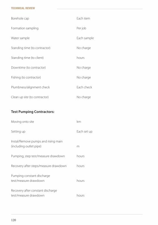
Borehole cap Each item
Formation sampling Per job
Water sample Each sample
Standing time (to contractor) No charge
Standing time (to client) hours
Downtime (to contractor) No charge
Fishing (to contractor) No charge
Plumbness/alignment check Each check
Clean up site (to contractor) No charge
TestPumpingContractors:
Moving onto site km
Setting up Each set up
Instal/Remove pumps and rising main
(including outlet pipe) m
Pumping, step test/measure drawdown hours
Recovery after steps/measure drawdown hours
Pumping constant discharge
test/measure drawdown hours
Recovery after constant discharge
test/measure drawdown hours
TECHNICAL REVIEW
120
ICRC Borehole Technical Review.indd 120 19/02/2010 17:14

Water sample Each sample
Standing time (to contractor) No charge
Standing time (to client) hours
Downtime (to contractor) No charge
Disinfection Per job
Clean up site (to contractor) No charge
Annexes
121
ICRC Borehole Technical Review.indd 121 19/02/2010 17:14

Annex7:Productreferencesandfurtherreading
Productreferences
1. Consallen Group Sales Ltd, P.O. Box 2993, Sudbury, Suffolk CO10 0ZB, UK.
Tel/Fax: +44 (0) 1787-247770; e-mail: [email protected].
2. Eureka UK Ltd, 11, The Quadrant, Hassocks, West Sussex, BN6 8BP, UK.
Tel: +44 (0) 273 846333, Fax: +44 (0) 273 846332.
3. Promotion of Appropriate Technology Co. Ltd, 44/5 Soi Atit, Wutakard Road, Chomthong,
Bangkok 10150, Thailand. Tel: +66 (0) 2 476-1845, (0) 2 476-5313,
Fax: +66 (0) 476-5316; email: [email protected].
4. Marsh Funnel Viscometer: OFI Testing Equipment, Inc., 1006, West 34th Street, Houston,
Texas, 77018, U.S.A.
Tel: 713 880 9885, 877 837 8683, Fax: 713 880 9886, www.ofite.com.
5. Johnson Screens (India) Ltd, e-mail: [email protected].
6. Marks Products Inc., 1243 Burnsville Road, Williamsville, Virginia, 24487-9611, U.S.A.
Tel: 800-255-1353, www.geovision.org.
Furtherreading
1. Allen, D.V. Low-Cost Hand Drilling. Consallen Group Sales Ltd, Loughton, 1993.
2. Ball, P. Drilled Wells. Swiss Centre for Development Cooperation in Technology and
Management (SKAT), 2001.
3. Clark, L. “The Analysis and Planning of Step Drawdown Tests,” Quarterly Journal of
Engineering Geology, Vol. 10, 1977, pp. 125-143.
4. Clark, L. The Field Guide to Water Wells and Boreholes. Geological Society of London Professional
Handbook Series, Open University Press/Halsted Press (Milton Keynes, New York), 1988.
5. Driscoll, F. G. Groundwater and Wells. Johnson Division, St. Paul, Minn., 1986.
TECHNICAL REVIEW
122
ICRC Borehole Technical Review.indd 122 19/02/2010 17:14

6. Howsam, P. (Ed.). Water Wells: Monitoring, Maintenance, Rehabilitation, Taylor & Francis, 1990.
7. Mthunzi, M. “Integrated Development for Water Supply and Sanitation: Introduction of Low
Cost Boreholes,” 25th WEDC Conference, Addis Ababa, Ethiopia, 1999.
8. Mulder, C. W. B. & Sloots, R. R. ”The Overburdened Aquifer and its Potential Contribution
to Reaching Targets for Safe Water Supply Coverage in Northern Uganda,” Groundwater &
Climate in Africa (Kampala), 24-26 June, 2008.
9. Nampusuor, R. Report on Innovations in Borehole Rehabilitation, Report for the CWSA/CIDA
Community Water Project Upper Regions, Ghana, 2001.
10. Roscoe Moss Company. Handbook of Ground Water Development, Wiley-IEEE, 1990.
11. Howsam, P., Misstear, B. & Jones, C. Monitoring, Maintenance and Rehabilitation of Water Supply
Boreholes, CIRIA Publication R137, 1995.
Annexes
123
ICRC Borehole Technical Review.indd 123 19/02/2010 17:14

ICRC Borehole Technical Review.indd 124 19/02/2010 17:14

Index
A
additives 28, 40, 41, 42, 44, 46, 47, 68, 120
airlift 97
alkalinity 88
ammonia 89
annular space 44, 46, 58, 59, 60, 61, 64,
70, 73, 119, 123
anodes 102
aquifer 9, 15, 16, 17, 18, 19, 20, 22, 23, 29,
39, 43, 44, 50, 54, 56, 57, 58, 59, 60, 61, 62,
65, 66, 67, 69, 70, 72, 74, 75, 79, 89, 93, 96,
104, 110, 119
arid 16, 92
artesian 9, 20
B
bacteria 42, 68, 89, 92, 104
basement 21, 39
bentonite 41, 42, 73, 96
bicarbonates 88
biodegradable 41, 44, 68
blowing yield 70, 71
boulder 26, 55
C
calcareous 69
carbonates 88
carbon dioxide 88, 89, 90
chemical 10, 69, 91, 92, 93, 98, 100, 121, 122
chlorine 7, 69, 80, 81, 104, 122, 124
circulation 7, 8, 29, 35, 36, 39, 40, 44, 45, 46, 47,
66, 67
coastal areas 93
collapse 7, 21, 22, 27, 40, 48, 50, 55, 70, 112
compressor 7, 33, 34, 44, 47, 48, 49, 70, 71,
72, 102
conductor pipe 39, 48, 49, 54, 73
confined 9, 20
consultant 83, 85
contamination 18, 22, 47, 73, 96, 121
corrosion 55, 88, 89, 90, 91, 92, 98, 99, 101, 102
cuttings 26, 49, 50
D
drag bit 33, 35, 36
drawdown 39, 54, 55, 65, 66, 75, 78, 79, 87, 88,
89, 91, 93, 94, 97, 104, 105, 117, 125
DTH 7, 29, 34, 36, 47, 49
dug well 18, 19, 28, 104
dynamic drawdown 65, 66, 79
E
Eh 88
electrochemical 89
electrodes 102
F
ferric 89, 100
ferrous 88, 89
fluids 28, 40, 42, 81
foam 44, 46
formation 9, 16, 18, 26, 35, 36, 39, 40, 41,
42, 44, 47, 48, 50, 55, 59, 60, 61, 62, 67, 73,
81, 89, 99, 101, 119, 122
G
geophysical 17, 18, 28, 51, 81, 86, 100, 101
geophysics 17
gravel pack 7, 38, 57, 58, 59, 60, 61, 62, 64,
65, 68, 70, 71, 73, 89, 90, 92, 102, 111, 119, 124
guar gum 41, 42, 69
Index
125
ICRC Borehole Technical Review.indd 125 19/02/2010 17:14

H
hand-pump 22, 39, 40, 53, 54, 62, 63, 74,
80, 102, 104, 105, 110
humic acids 88
hydroxides 88
hygroscopic 69
I
incrustation 56, 65, 66, 89, 90, 91, 92, 99, 104
L
limestone 16, 17, 18, 20, 65, 69, 110
M
methane 89
microbial 89
mud 5, 7, 33, 34, 40, 44, 46, 47, 68, 111
O
open hole 61, 62, 63, 66, 72, 73
organic 68, 88, 89, 90, 99
organic matter 88
P
penetration rate 34, 39, 61, 111
percussion 27, 32, 40, 72, 120
permeability 10, 16, 17
pH 62, 88
physical 62
plumbness 80, 121
pollution 18, 29, 47, 69, 90, 92, 122
polymer 41, 42, 44
porosity 16, 19, 50, 61, 62
precipitation 88
R
reaming 39
recharge 20, 54
redox 88
S
samples 42, 44, 46, 49, 50, 51, 59, 81, 111, 122
screen 56, 62, 112
shales 10
silts 89
specific capacity 54, 89
storage coefficient 17
storativity 17, 74
straightness 32, 37, 80
sulphates 88
sump 44, 61, 63
surging 68, 70, 71, 72, 73, 97, 102, 103,
104, 120, 124
T
TDS 93
temporary casing 29, 32, 54
transmissivity 17, 18, 67, 74
tripod 27, 32, 78, 105
turbidity 68, 98
turbulence 88, 102
V
velocity 10, 39, 41, 50, 56, 65, 88
verticality 32, 37, 80, 121
viscosity 41, 42, 43, 44, 50, 111
W
well losses 56
TECHNICAL REVIEW
126
ICRC Borehole Technical Review.indd 126 19/02/2010 17:14

International Committee of the Red Cross19, avenue de la Paix1202 Geneva, SwitzerlandT + 41 22 734 60 01 F + 41 22 733 20 57E-mail: [email protected] www.icrc.org© ICRC, February 2010
© Cover photo: T. Nydegger/ICRC
MISSION
The International Committee of the Red Cross (ICRC) is an
impartial, neutral and independent organization whose
exclusively humanitarian mission is to protect the lives and
dignity of victims of armed conflict and other situations of
violence and to provide them with assistance.
The ICRC also endeavours to prevent suffering by promoting and
strengthening humanitarian law and universal humanitarian
principles.
Established in 1863, the ICRC is at the origin of the Geneva
Conventions and the International Red Cross and Red Crescent
Movement. It directs and coordinates the international activities
conducted by the Movement in armed conflicts and other
situations of violence.

0998
/002
02.
2010
1,0
00
R E F E R E N C E
TECHNICAL REVIEW BOREHOLE DRILLING AND REHABILITATION UNDER FIELD CONDITIONS