Embed Size (px)
Citation preview

x
MSO3000 and DPO3000 SeriesDigital Phosphor OscilloscopesZZZ
User Manual
*P071265600*
071-2656-00


MSO3000 and DPO3000 SeriesDigital Phosphor OscilloscopesZZZ
User Manual
xx
Revision A
www.tektronix.com071-2656-00

Copyright © Tektronix. All rights reserved. Licensed software products are owned by Tektronix or its subsidiaries or suppliers, and areprotected by national copyright laws and international treaty provisions.
Tektronix products are covered by U.S. and foreign patents, issued and pending. Information in this publication supersedes that in allpreviously published material. Specifications and price change privileges reserved.
TEKTRONIX and TEK are registered trademarks of Tektronix, Inc.
e*Scope, OpenChoice, TekVPI, and Wave Inspector are registered trademarks of Tektronix, Inc.
MagniVu, iView, and TekSecure are trademarks of Tektronix, Inc.
PictBridge is a registered trademark of the Standard of Camera & Imaging Products Association CIPA DC-001-2003 Digital PhotoSolutions for Imaging Devices.
Contacting TektronixTektronix, Inc.14200 SW Karl Braun DriveP.O. Box 500Beaverton, OR 97077USA
For product information, sales, service, and technical support:In North America, call 1-800-833-9200.Worldwide, visit www.tektronix.com to find contacts in your area.

MSO3000 and DPO3000 Series Oscilloscopes
WarrantyTektronix warrants that the product will be free from defects in materials and workmanship for a period of three (3) years from the dateof original purchase from an authorized Tektronix distributor. If the product proves defective during this warranty period, Tektronix, at itsoption, either will repair the defective product without charge for parts and labor, or will provide a replacement in exchange for thedefective product. Batteries are excluded from this warranty. Parts, modules and replacement products used by Tektronix for warrantywork may be new or reconditioned to like new performance. All replaced parts, modules and products become the property of Tektronix.
In order to obtain service under this warranty, Customer must notify Tektronix of the defect before the expiration of the warrantyperiod and make suitable arrangements for the performance of service. Customer shall be responsible for packaging and shippingthe defective product to the service center designated by Tektronix, shipping charges prepaid, and with a copy of customer proof ofpurchase. Tektronix shall pay for the return of the product to Customer if the shipment is to a location within the country in whichthe Tektronix service center is located. Customer shall be responsible for paying all shipping charges, duties, taxes, and any othercharges for products returned to any other locations.
This warranty shall not apply to any defect, failure or damage caused by improper use or improper or inadequate maintenance andcare. Tektronix shall not be obligated to furnish service under this warranty a) to repair damage resulting from attempts by personnelother than Tektronix representatives to install, repair or service the product; b) to repair damage resulting from improper use orconnection to incompatible equipment; c) to repair any damage or malfunction caused by the use of non-Tektronix supplies; ord) to service a product that has been modified or integrated with other products when the effect of such modification or integrationincreases the time or difficulty of servicing the product.
THIS WARRANTY IS GIVEN BY TEKTRONIX WITH RESPECT TO THE PRODUCT IN LIEU OF ANY OTHER WARRANTIES,EXPRESS OR IMPLIED. TEKTRONIX AND ITS VENDORS DISCLAIM ANY IMPLIED WARRANTIES OF MERCHANTABILITY ORFITNESS FOR A PARTICULAR PURPOSE. TEKTRONIX’ RESPONSIBILITY TO REPAIR OR REPLACE DEFECTIVE PRODUCTSIS THE SOLE AND EXCLUSIVE REMEDY PROVIDED TO THE CUSTOMER FOR BREACH OF THIS WARRANTY. TEKTRONIXAND ITS VENDORS WILL NOT BE LIABLE FOR ANY INDIRECT, SPECIAL, INCIDENTAL, OR CONSEQUENTIAL DAMAGESIRRESPECTIVE OF WHETHER TEKTRONIX OR THE VENDOR HAS ADVANCE NOTICE OF THE POSSIBILITY OF SUCHDAMAGES.
[W16 – 15AUG04]

P6139A Probe
WarrantyTektronix warrants that this product will be free from defects in materials and workmanship for a period of one (1) year from the date ofshipment. If any such product proves defective during this warranty period, Tektronix, at its option, either will repair the defectiveproduct without charge for parts and labor, or will provide a replacement in exchange for the defective product. Parts, modules andreplacement products used by Tektronix for warranty work may be new or reconditioned to like new performance. All replacedparts, modules and products become the property of Tektronix.
In order to obtain service under this warranty, Customer must notify Tektronix of the defect before the expiration of the warranty periodand make suitable arrangements for the performance of service. Customer shall be responsible for packaging and shipping thedefective product to the service center designated by Tektronix, with shipping charges prepaid. Tektronix shall pay for the return of theproduct to Customer if the shipment is to a location within the country in which the Tektronix service center is located. Customer shallbe responsible for paying all shipping charges, duties, taxes, and any other charges for products returned to any other locations.
This warranty shall not apply to any defect, failure or damage caused by improper use or improper or inadequate maintenance andcare. Tektronix shall not be obligated to furnish service under this warranty a) to repair damage resulting from attempts by personnelother than Tektronix representatives to install, repair or service the product; b) to repair damage resulting from improper use orconnection to incompatible equipment; c) to repair any damage or malfunction caused by the use of non-Tektronix supplies; ord) to service a product that has been modified or integrated with other products when the effect of such modification or integrationincreases the time or difficulty of servicing the product.
THIS WARRANTY IS GIVEN BY TEKTRONIX WITH RESPECT TO THE PRODUCT IN LIEU OF ANY OTHER WARRANTIES,EXPRESS OR IMPLIED. TEKTRONIX AND ITS VENDORS DISCLAIM ANY IMPLIED WARRANTIES OF MERCHANTABILITY ORFITNESS FOR A PARTICULAR PURPOSE. TEKTRONIX’ RESPONSIBILITY TO REPAIR OR REPLACE DEFECTIVE PRODUCTSIS THE SOLE AND EXCLUSIVE REMEDY PROVIDED TO THE CUSTOMER FOR BREACH OF THIS WARRANTY. TEKTRONIXAND ITS VENDORS WILL NOT BE LIABLE FOR ANY INDIRECT, SPECIAL, INCIDENTAL, OR CONSEQUENTIAL DAMAGESIRRESPECTIVE OF WHETHER TEKTRONIX OR THE VENDOR HAS ADVANCE NOTICE OF THE POSSIBILITY OF SUCHDAMAGES.
[W2 – 15AUG04]

P6316 Probe
WarrantyTektronix warrants that the product will be free from defects in materials and workmanship for a period of one (1) year from the date oforiginal purchase from an authorized Tektronix distributor. If the product proves defective during this warranty period, Tektronix, at itsoption, either will repair the defective product without charge for parts and labor, or will provide a replacement in exchange for thedefective product. Batteries are excluded from this warranty. Parts, modules and replacement products used by Tektronix for warrantywork may be new or reconditioned to like new performance. All replaced parts, modules and products become the property of Tektronix.
In order to obtain service under this warranty, Customer must notify Tektronix of the defect before the expiration of the warrantyperiod and make suitable arrangements for the performance of service. Customer shall be responsible for packaging and shippingthe defective product to the service center designated by Tektronix, shipping charges prepaid, and with a copy of customer proof ofpurchase. Tektronix shall pay for the return of the product to Customer if the shipment is to a location within the country in whichthe Tektronix service center is located. Customer shall be responsible for paying all shipping charges, duties, taxes, and any othercharges for products returned to any other locations.
This warranty shall not apply to any defect, failure or damage caused by improper use or improper or inadequate maintenance andcare. Tektronix shall not be obligated to furnish service under this warranty a) to repair damage resulting from attempts by personnelother than Tektronix representatives to install, repair or service the product; b) to repair damage resulting from improper use orconnection to incompatible equipment; c) to repair any damage or malfunction caused by the use of non-Tektronix supplies; ord) to service a product that has been modified or integrated with other products when the effect of such modification or integrationincreases the time or difficulty of servicing the product.
THIS WARRANTY IS GIVEN BY TEKTRONIX WITH RESPECT TO THE PRODUCT IN LIEU OF ANY OTHER WARRANTIES,EXPRESS OR IMPLIED. TEKTRONIX AND ITS VENDORS DISCLAIM ANY IMPLIED WARRANTIES OF MERCHANTABILITY ORFITNESS FOR A PARTICULAR PURPOSE. TEKTRONIX’ RESPONSIBILITY TO REPAIR OR REPLACE DEFECTIVE PRODUCTSIS THE SOLE AND EXCLUSIVE REMEDY PROVIDED TO THE CUSTOMER FOR BREACH OF THIS WARRANTY. TEKTRONIXAND ITS VENDORS WILL NOT BE LIABLE FOR ANY INDIRECT, SPECIAL, INCIDENTAL, OR CONSEQUENTIAL DAMAGESIRRESPECTIVE OF WHETHER TEKTRONIX OR THE VENDOR HAS ADVANCE NOTICE OF THE POSSIBILITY OF SUCHDAMAGES.
[W15 – 15AUG04]


Table of Contents
Table of ContentsGeneral Safety Summary . . . . . . . . . . . . . . . . . . . . . . . . . . . . . . . . . . . . . . . . . . . . . . . . . . . . . . . . . . . . . . . . . . . . . . . . . . . . . . . . . . . . . . . . . . . . . . . . . . . . . . . . . . . . . vCompliance Information . . . . . . . . . . . . . . . . . . . . . . . . . . . . . . . . . . . . . . . . . . . . . . . . . . . . . . . . . . . . . . . . . . . . . . . . . . . . . . . . . . . . . . . . . . . . . . . . . . . . . . . . . . . . . . vii
EMC Compliance. . . . . . . . . . . . . . . . . . . . . . . . . . . . . . . . . . . . . . . . . . . . . . . . . . . . . . . . . . . . . . . . . . . . . . . . . . . . . . . . . . . . . . . . . . . . . . . . . . . . . . . . . . . . . . . . viiSafety Compliance . . . . . . . . . . . . . . . . . . . . . . . . . . . . . . . . . . . . . . . . . . . . . . . . . . . . . . . . . . . . . . . . . . . . . . . . . . . . . . . . . . . . . . . . . . . . . . . . . . . . . . . . . . . . . . . ixEnvironmental Considerations. . . . . . . . . . . . . . . . . . . . . . . . . . . . . . . . . . . . . . . . . . . . . . . . . . . . . . . . . . . . . . . . . . . . . . . . . . . . . . . . . . . . . . . . . . . . . . . . . . . xi
Preface . . . . . . . . . . . . . . . . . . . . . . . . . . . . . . . . . . . . . . . . . . . . . . . . . . . . . . . . . . . . . . . . . . . . . . . . . . . . . . . . . . . . . . . . . . . . . . . . . . . . . . . . . . . . . . . . . . . . . . . . . . . . . . . . xiiKey Features . . . . . . . . . . . . . . . . . . . . . . . . . . . . . . . . . . . . . . . . . . . . . . . . . . . . . . . . . . . . . . . . . . . . . . . . . . . . . . . . . . . . . . . . . . . . . . . . . . . . . . . . . . . . . . . . . . . xiiiConventions Used in This Manual. . . . . . . . . . . . . . . . . . . . . . . . . . . . . . . . . . . . . . . . . . . . . . . . . . . . . . . . . . . . . . . . . . . . . . . . . . . . . . . . . . . . . . . . . . . . . xiv
Installation. . . . . . . . . . . . . . . . . . . . . . . . . . . . . . . . . . . . . . . . . . . . . . . . . . . . . . . . . . . . . . . . . . . . . . . . . . . . . . . . . . . . . . . . . . . . . . . . . . . . . . . . . . . . . . . . . . . . . . . . . . . . . . 1Before Installation . . . . . . . . . . . . . . . . . . . . . . . . . . . . . . . . . . . . . . . . . . . . . . . . . . . . . . . . . . . . . . . . . . . . . . . . . . . . . . . . . . . . . . . . . . . . . . . . . . . . . . . . . . . . . . . . 1Operating Considerations. . . . . . . . . . . . . . . . . . . . . . . . . . . . . . . . . . . . . . . . . . . . . . . . . . . . . . . . . . . . . . . . . . . . . . . . . . . . . . . . . . . . . . . . . . . . . . . . . . . . . . . . 5Connecting Probes. . . . . . . . . . . . . . . . . . . . . . . . . . . . . . . . . . . . . . . . . . . . . . . . . . . . . . . . . . . . . . . . . . . . . . . . . . . . . . . . . . . . . . . . . . . . . . . . . . . . . . . . . . . . . . . 8Securing the Oscilloscope . . . . . . . . . . . . . . . . . . . . . . . . . . . . . . . . . . . . . . . . . . . . . . . . . . . . . . . . . . . . . . . . . . . . . . . . . . . . . . . . . . . . . . . . . . . . . . . . . . . . . . . 9Powering On the Oscilloscope . . . . . . . . . . . . . . . . . . . . . . . . . . . . . . . . . . . . . . . . . . . . . . . . . . . . . . . . . . . . . . . . . . . . . . . . . . . . . . . . . . . . . . . . . . . . . . . . . 10Powering Off the Oscilloscope. . . . . . . . . . . . . . . . . . . . . . . . . . . . . . . . . . . . . . . . . . . . . . . . . . . . . . . . . . . . . . . . . . . . . . . . . . . . . . . . . . . . . . . . . . . . . . . . . . 11Functional Check. . . . . . . . . . . . . . . . . . . . . . . . . . . . . . . . . . . . . . . . . . . . . . . . . . . . . . . . . . . . . . . . . . . . . . . . . . . . . . . . . . . . . . . . . . . . . . . . . . . . . . . . . . . . . . . . 11Compensating a Passive Voltage Probe . . . . . . . . . . . . . . . . . . . . . . . . . . . . . . . . . . . . . . . . . . . . . . . . . . . . . . . . . . . . . . . . . . . . . . . . . . . . . . . . . . . . . . . 13Application Module Free Trial. . . . . . . . . . . . . . . . . . . . . . . . . . . . . . . . . . . . . . . . . . . . . . . . . . . . . . . . . . . . . . . . . . . . . . . . . . . . . . . . . . . . . . . . . . . . . . . . . . . 15Installing an Application Module . . . . . . . . . . . . . . . . . . . . . . . . . . . . . . . . . . . . . . . . . . . . . . . . . . . . . . . . . . . . . . . . . . . . . . . . . . . . . . . . . . . . . . . . . . . . . . . . 15Changing the User Interface Language . . . . . . . . . . . . . . . . . . . . . . . . . . . . . . . . . . . . . . . . . . . . . . . . . . . . . . . . . . . . . . . . . . . . . . . . . . . . . . . . . . . . . . . . 15Changing the Date and Time . . . . . . . . . . . . . . . . . . . . . . . . . . . . . . . . . . . . . . . . . . . . . . . . . . . . . . . . . . . . . . . . . . . . . . . . . . . . . . . . . . . . . . . . . . . . . . . . . . . 16Signal Path Compensation . . . . . . . . . . . . . . . . . . . . . . . . . . . . . . . . . . . . . . . . . . . . . . . . . . . . . . . . . . . . . . . . . . . . . . . . . . . . . . . . . . . . . . . . . . . . . . . . . . . . . 18Upgrading Firmware . . . . . . . . . . . . . . . . . . . . . . . . . . . . . . . . . . . . . . . . . . . . . . . . . . . . . . . . . . . . . . . . . . . . . . . . . . . . . . . . . . . . . . . . . . . . . . . . . . . . . . . . . . . . 19Connecting Your Oscilloscope to a Computer . . . . . . . . . . . . . . . . . . . . . . . . . . . . . . . . . . . . . . . . . . . . . . . . . . . . . . . . . . . . . . . . . . . . . . . . . . . . . . . . . 23Connecting a USB Keyboard to Your Oscilloscope. . . . . . . . . . . . . . . . . . . . . . . . . . . . . . . . . . . . . . . . . . . . . . . . . . . . . . . . . . . . . . . . . . . . . . . . . . . . 27
Get Acquainted with the Instrument . . . . . . . . . . . . . . . . . . . . . . . . . . . . . . . . . . . . . . . . . . . . . . . . . . . . . . . . . . . . . . . . . . . . . . . . . . . . . . . . . . . . . . . . . . . . . . . . . 29Front-Panel Menus and Controls . . . . . . . . . . . . . . . . . . . . . . . . . . . . . . . . . . . . . . . . . . . . . . . . . . . . . . . . . . . . . . . . . . . . . . . . . . . . . . . . . . . . . . . . . . . . . . . 29Front-Panel Connectors . . . . . . . . . . . . . . . . . . . . . . . . . . . . . . . . . . . . . . . . . . . . . . . . . . . . . . . . . . . . . . . . . . . . . . . . . . . . . . . . . . . . . . . . . . . . . . . . . . . . . . . . 41Side-Panel Connector. . . . . . . . . . . . . . . . . . . . . . . . . . . . . . . . . . . . . . . . . . . . . . . . . . . . . . . . . . . . . . . . . . . . . . . . . . . . . . . . . . . . . . . . . . . . . . . . . . . . . . . . . . . 42Rear-Panel Connectors . . . . . . . . . . . . . . . . . . . . . . . . . . . . . . . . . . . . . . . . . . . . . . . . . . . . . . . . . . . . . . . . . . . . . . . . . . . . . . . . . . . . . . . . . . . . . . . . . . . . . . . . . 42
Acquire the Signal . . . . . . . . . . . . . . . . . . . . . . . . . . . . . . . . . . . . . . . . . . . . . . . . . . . . . . . . . . . . . . . . . . . . . . . . . . . . . . . . . . . . . . . . . . . . . . . . . . . . . . . . . . . . . . . . . . . . 44Setting Up Analog Channels. . . . . . . . . . . . . . . . . . . . . . . . . . . . . . . . . . . . . . . . . . . . . . . . . . . . . . . . . . . . . . . . . . . . . . . . . . . . . . . . . . . . . . . . . . . . . . . . . . . . 44Using the Default Setup. . . . . . . . . . . . . . . . . . . . . . . . . . . . . . . . . . . . . . . . . . . . . . . . . . . . . . . . . . . . . . . . . . . . . . . . . . . . . . . . . . . . . . . . . . . . . . . . . . . . . . . . . 47Using Autoset . . . . . . . . . . . . . . . . . . . . . . . . . . . . . . . . . . . . . . . . . . . . . . . . . . . . . . . . . . . . . . . . . . . . . . . . . . . . . . . . . . . . . . . . . . . . . . . . . . . . . . . . . . . . . . . . . . . 48Acquisition Concepts. . . . . . . . . . . . . . . . . . . . . . . . . . . . . . . . . . . . . . . . . . . . . . . . . . . . . . . . . . . . . . . . . . . . . . . . . . . . . . . . . . . . . . . . . . . . . . . . . . . . . . . . . . . . 49How the Analog Acquisition Modes Work . . . . . . . . . . . . . . . . . . . . . . . . . . . . . . . . . . . . . . . . . . . . . . . . . . . . . . . . . . . . . . . . . . . . . . . . . . . . . . . . . . . . . . 50Changing the Acquisition Mode, Record Length, and Delay Time. . . . . . . . . . . . . . . . . . . . . . . . . . . . . . . . . . . . . . . . . . . . . . . . . . . . . . . . . . . . 51Using Roll Mode. . . . . . . . . . . . . . . . . . . . . . . . . . . . . . . . . . . . . . . . . . . . . . . . . . . . . . . . . . . . . . . . . . . . . . . . . . . . . . . . . . . . . . . . . . . . . . . . . . . . . . . . . . . . . . . . . 53Setting Up a Serial or Parallel Bus . . . . . . . . . . . . . . . . . . . . . . . . . . . . . . . . . . . . . . . . . . . . . . . . . . . . . . . . . . . . . . . . . . . . . . . . . . . . . . . . . . . . . . . . . . . . . 54Setting Up Digital Channels . . . . . . . . . . . . . . . . . . . . . . . . . . . . . . . . . . . . . . . . . . . . . . . . . . . . . . . . . . . . . . . . . . . . . . . . . . . . . . . . . . . . . . . . . . . . . . . . . . . . 63When and Why to Turn On MagniVu . . . . . . . . . . . . . . . . . . . . . . . . . . . . . . . . . . . . . . . . . . . . . . . . . . . . . . . . . . . . . . . . . . . . . . . . . . . . . . . . . . . . . . . . . . . 65Using MagniVu . . . . . . . . . . . . . . . . . . . . . . . . . . . . . . . . . . . . . . . . . . . . . . . . . . . . . . . . . . . . . . . . . . . . . . . . . . . . . . . . . . . . . . . . . . . . . . . . . . . . . . . . . . . . . . . . . . 65
MSO3000 and DPO3000 Series Oscilloscopes User Manual i

Table of Contents
Trigger Setup . . . . . . . . . . . . . . . . . . . . . . . . . . . . . . . . . . . . . . . . . . . . . . . . . . . . . . . . . . . . . . . . . . . . . . . . . . . . . . . . . . . . . . . . . . . . . . . . . . . . . . . . . . . . . . . . . . . . . . . . . 67Triggering Concepts. . . . . . . . . . . . . . . . . . . . . . . . . . . . . . . . . . . . . . . . . . . . . . . . . . . . . . . . . . . . . . . . . . . . . . . . . . . . . . . . . . . . . . . . . . . . . . . . . . . . . . . . . . . . . 67Choosing a Trigger Type. . . . . . . . . . . . . . . . . . . . . . . . . . . . . . . . . . . . . . . . . . . . . . . . . . . . . . . . . . . . . . . . . . . . . . . . . . . . . . . . . . . . . . . . . . . . . . . . . . . . . . . . 70Selecting Triggers . . . . . . . . . . . . . . . . . . . . . . . . . . . . . . . . . . . . . . . . . . . . . . . . . . . . . . . . . . . . . . . . . . . . . . . . . . . . . . . . . . . . . . . . . . . . . . . . . . . . . . . . . . . . . . . 71Triggering on Buses. . . . . . . . . . . . . . . . . . . . . . . . . . . . . . . . . . . . . . . . . . . . . . . . . . . . . . . . . . . . . . . . . . . . . . . . . . . . . . . . . . . . . . . . . . . . . . . . . . . . . . . . . . . . . 73Checking Trigger Settings . . . . . . . . . . . . . . . . . . . . . . . . . . . . . . . . . . . . . . . . . . . . . . . . . . . . . . . . . . . . . . . . . . . . . . . . . . . . . . . . . . . . . . . . . . . . . . . . . . . . . . 77Using Sequence Trigger, A (Main) and B (Delayed). . . . . . . . . . . . . . . . . . . . . . . . . . . . . . . . . . . . . . . . . . . . . . . . . . . . . . . . . . . . . . . . . . . . . . . . . . . 78Starting and Stopping an Acquisition. . . . . . . . . . . . . . . . . . . . . . . . . . . . . . . . . . . . . . . . . . . . . . . . . . . . . . . . . . . . . . . . . . . . . . . . . . . . . . . . . . . . . . . . . . . 80
Display Waveform Data . . . . . . . . . . . . . . . . . . . . . . . . . . . . . . . . . . . . . . . . . . . . . . . . . . . . . . . . . . . . . . . . . . . . . . . . . . . . . . . . . . . . . . . . . . . . . . . . . . . . . . . . . . . . . . 81Adding and Removing a Waveform . . . . . . . . . . . . . . . . . . . . . . . . . . . . . . . . . . . . . . . . . . . . . . . . . . . . . . . . . . . . . . . . . . . . . . . . . . . . . . . . . . . . . . . . . . . . 81Setting the Display Style and Persistence . . . . . . . . . . . . . . . . . . . . . . . . . . . . . . . . . . . . . . . . . . . . . . . . . . . . . . . . . . . . . . . . . . . . . . . . . . . . . . . . . . . . . 81Setting Waveform Intensity . . . . . . . . . . . . . . . . . . . . . . . . . . . . . . . . . . . . . . . . . . . . . . . . . . . . . . . . . . . . . . . . . . . . . . . . . . . . . . . . . . . . . . . . . . . . . . . . . . . . . 85Scaling and Positioning a Waveform . . . . . . . . . . . . . . . . . . . . . . . . . . . . . . . . . . . . . . . . . . . . . . . . . . . . . . . . . . . . . . . . . . . . . . . . . . . . . . . . . . . . . . . . . . . 86Setting Input Parameters . . . . . . . . . . . . . . . . . . . . . . . . . . . . . . . . . . . . . . . . . . . . . . . . . . . . . . . . . . . . . . . . . . . . . . . . . . . . . . . . . . . . . . . . . . . . . . . . . . . . . . . 87Positioning and Labeling Bus Signals . . . . . . . . . . . . . . . . . . . . . . . . . . . . . . . . . . . . . . . . . . . . . . . . . . . . . . . . . . . . . . . . . . . . . . . . . . . . . . . . . . . . . . . . . . 90Positioning, Scaling, and Grouping Digital Channels. . . . . . . . . . . . . . . . . . . . . . . . . . . . . . . . . . . . . . . . . . . . . . . . . . . . . . . . . . . . . . . . . . . . . . . . . . 91Viewing Digital Channels . . . . . . . . . . . . . . . . . . . . . . . . . . . . . . . . . . . . . . . . . . . . . . . . . . . . . . . . . . . . . . . . . . . . . . . . . . . . . . . . . . . . . . . . . . . . . . . . . . . . . . . 93Annotating the Screen . . . . . . . . . . . . . . . . . . . . . . . . . . . . . . . . . . . . . . . . . . . . . . . . . . . . . . . . . . . . . . . . . . . . . . . . . . . . . . . . . . . . . . . . . . . . . . . . . . . . . . . . . . 93Viewing the Trigger Frequency . . . . . . . . . . . . . . . . . . . . . . . . . . . . . . . . . . . . . . . . . . . . . . . . . . . . . . . . . . . . . . . . . . . . . . . . . . . . . . . . . . . . . . . . . . . . . . . . . 94
Analyze Waveform Data. . . . . . . . . . . . . . . . . . . . . . . . . . . . . . . . . . . . . . . . . . . . . . . . . . . . . . . . . . . . . . . . . . . . . . . . . . . . . . . . . . . . . . . . . . . . . . . . . . . . . . . . . . . . . . 96Taking Automatic Measurements. . . . . . . . . . . . . . . . . . . . . . . . . . . . . . . . . . . . . . . . . . . . . . . . . . . . . . . . . . . . . . . . . . . . . . . . . . . . . . . . . . . . . . . . . . . . . . . 96Selecting Automatic Measurements. . . . . . . . . . . . . . . . . . . . . . . . . . . . . . . . . . . . . . . . . . . . . . . . . . . . . . . . . . . . . . . . . . . . . . . . . . . . . . . . . . . . . . . . . . . . 97Customizing an Automatic Measurement . . . . . . . . . . . . . . . . . . . . . . . . . . . . . . . . . . . . . . . . . . . . . . . . . . . . . . . . . . . . . . . . . . . . . . . . . . . . . . . . . . . . 100Taking Manual Measurements with Cursors . . . . . . . . . . . . . . . . . . . . . . . . . . . . . . . . . . . . . . . . . . . . . . . . . . . . . . . . . . . . . . . . . . . . . . . . . . . . . . . . . 103Using Math Waveforms . . . . . . . . . . . . . . . . . . . . . . . . . . . . . . . . . . . . . . . . . . . . . . . . . . . . . . . . . . . . . . . . . . . . . . . . . . . . . . . . . . . . . . . . . . . . . . . . . . . . . . . 107Using FFT . . . . . . . . . . . . . . . . . . . . . . . . . . . . . . . . . . . . . . . . . . . . . . . . . . . . . . . . . . . . . . . . . . . . . . . . . . . . . . . . . . . . . . . . . . . . . . . . . . . . . . . . . . . . . . . . . . . . . 109Using Advanced Math. . . . . . . . . . . . . . . . . . . . . . . . . . . . . . . . . . . . . . . . . . . . . . . . . . . . . . . . . . . . . . . . . . . . . . . . . . . . . . . . . . . . . . . . . . . . . . . . . . . . . . . . . . 111Using Reference Waveforms . . . . . . . . . . . . . . . . . . . . . . . . . . . . . . . . . . . . . . . . . . . . . . . . . . . . . . . . . . . . . . . . . . . . . . . . . . . . . . . . . . . . . . . . . . . . . . . . . 112Using Wave Inspector to Manage Long Record Length Waveforms. . . . . . . . . . . . . . . . . . . . . . . . . . . . . . . . . . . . . . . . . . . . . . . . . . . . . . . . 114Analyzing Power . . . . . . . . . . . . . . . . . . . . . . . . . . . . . . . . . . . . . . . . . . . . . . . . . . . . . . . . . . . . . . . . . . . . . . . . . . . . . . . . . . . . . . . . . . . . . . . . . . . . . . . . . . . . . . 119
Save and Recall Information . . . . . . . . . . . . . . . . . . . . . . . . . . . . . . . . . . . . . . . . . . . . . . . . . . . . . . . . . . . . . . . . . . . . . . . . . . . . . . . . . . . . . . . . . . . . . . . . . . . . . . . 120Saving a Screen Image . . . . . . . . . . . . . . . . . . . . . . . . . . . . . . . . . . . . . . . . . . . . . . . . . . . . . . . . . . . . . . . . . . . . . . . . . . . . . . . . . . . . . . . . . . . . . . . . . . . . . . . 122Saving and Recalling Waveform Data. . . . . . . . . . . . . . . . . . . . . . . . . . . . . . . . . . . . . . . . . . . . . . . . . . . . . . . . . . . . . . . . . . . . . . . . . . . . . . . . . . . . . . . . 123Saving and Recalling Setups . . . . . . . . . . . . . . . . . . . . . . . . . . . . . . . . . . . . . . . . . . . . . . . . . . . . . . . . . . . . . . . . . . . . . . . . . . . . . . . . . . . . . . . . . . . . . . . . . 125Saving with One Button Push . . . . . . . . . . . . . . . . . . . . . . . . . . . . . . . . . . . . . . . . . . . . . . . . . . . . . . . . . . . . . . . . . . . . . . . . . . . . . . . . . . . . . . . . . . . . . . . . 127Printing a Hard Copy. . . . . . . . . . . . . . . . . . . . . . . . . . . . . . . . . . . . . . . . . . . . . . . . . . . . . . . . . . . . . . . . . . . . . . . . . . . . . . . . . . . . . . . . . . . . . . . . . . . . . . . . . . 128Erasing Oscilloscope Memory . . . . . . . . . . . . . . . . . . . . . . . . . . . . . . . . . . . . . . . . . . . . . . . . . . . . . . . . . . . . . . . . . . . . . . . . . . . . . . . . . . . . . . . . . . . . . . . . 133
Using Application Modules . . . . . . . . . . . . . . . . . . . . . . . . . . . . . . . . . . . . . . . . . . . . . . . . . . . . . . . . . . . . . . . . . . . . . . . . . . . . . . . . . . . . . . . . . . . . . . . . . . . . . . . . . 135Application Examples. . . . . . . . . . . . . . . . . . . . . . . . . . . . . . . . . . . . . . . . . . . . . . . . . . . . . . . . . . . . . . . . . . . . . . . . . . . . . . . . . . . . . . . . . . . . . . . . . . . . . . . . . . . . . . . 137
Taking Simple Measurements . . . . . . . . . . . . . . . . . . . . . . . . . . . . . . . . . . . . . . . . . . . . . . . . . . . . . . . . . . . . . . . . . . . . . . . . . . . . . . . . . . . . . . . . . . . . . . . . 137Analyzing Signal Detail . . . . . . . . . . . . . . . . . . . . . . . . . . . . . . . . . . . . . . . . . . . . . . . . . . . . . . . . . . . . . . . . . . . . . . . . . . . . . . . . . . . . . . . . . . . . . . . . . . . . . . . 144Triggering on a Video Signal. . . . . . . . . . . . . . . . . . . . . . . . . . . . . . . . . . . . . . . . . . . . . . . . . . . . . . . . . . . . . . . . . . . . . . . . . . . . . . . . . . . . . . . . . . . . . . . . . . 149Capturing a Single-Shot Signal . . . . . . . . . . . . . . . . . . . . . . . . . . . . . . . . . . . . . . . . . . . . . . . . . . . . . . . . . . . . . . . . . . . . . . . . . . . . . . . . . . . . . . . . . . . . . . . 152Correlating Data with a TLA5000 Logic Analyzer. . . . . . . . . . . . . . . . . . . . . . . . . . . . . . . . . . . . . . . . . . . . . . . . . . . . . . . . . . . . . . . . . . . . . . . . . . . . 155Tracking Down Bus Anomalies . . . . . . . . . . . . . . . . . . . . . . . . . . . . . . . . . . . . . . . . . . . . . . . . . . . . . . . . . . . . . . . . . . . . . . . . . . . . . . . . . . . . . . . . . . . . . . . 157
ii MSO3000 and DPO3000 Series Oscilloscopes User Manual

Table of Contents
Troubleshooting an RS-232 Bus . . . . . . . . . . . . . . . . . . . . . . . . . . . . . . . . . . . . . . . . . . . . . . . . . . . . . . . . . . . . . . . . . . . . . . . . . . . . . . . . . . . . . . . . . . . . . 159Troubleshooting Circuits Using Parallel Buses . . . . . . . . . . . . . . . . . . . . . . . . . . . . . . . . . . . . . . . . . . . . . . . . . . . . . . . . . . . . . . . . . . . . . . . . . . . . . . 161
Appendix: Warranted Specifications. . . . . . . . . . . . . . . . . . . . . . . . . . . . . . . . . . . . . . . . . . . . . . . . . . . . . . . . . . . . . . . . . . . . . . . . . . . . . . . . . . . . . . . . . . . . . . . 163Index
MSO3000 and DPO3000 Series Oscilloscopes User Manual iii

Table of Contents
iv MSO3000 and DPO3000 Series Oscilloscopes User Manual

General Safety Summary
General Safety SummaryReview the following safety precautions to avoid injury and prevent damage to this product or any products connected to it.
To avoid potential hazards, use this product only as specified.
Only qualified personnel should perform service procedures.
To Avoid Fire or Personal InjuryUse Proper Power Cord. Use only the power cord specified for this product and certified for the country of use.
Connect and Disconnect Properly. Do not connect or disconnect probes or test leads while they are connectedto a voltage source.
Connect and Disconnect Properly. De-energize the circuit under test before connecting or disconnecting the currentprobe.
Ground the Product. This product is grounded through the grounding conductor of the power cord. To avoid electricshock, the grounding conductor must be connected to earth ground. Before making connections to the input or outputterminals of the product, ensure that the product is properly grounded.
Observe All Terminal Ratings. To avoid fire or shock hazard, observe all ratings and markings on the product. Consultthe product manual for further ratings information before making connections to the product.
Connect the probe reference lead to earth ground only.
Do not apply a potential to any terminal, including the common terminal, that exceeds the maximum rating of that terminal.
Power Disconnect. The power cord disconnects the product from the power source. Do not block the power cord; itmust remain accessible to the user at all times.
Do Not Operate Without Covers. Do not operate this product with covers or panels removed.
Do Not Operate With Suspected Failures. If you suspect that there is damage to this product, have it inspected byqualified service personnel.
Avoid Exposed Circuitry. Do not touch exposed connections and components when power is present.
Do Not Operate in Wet/Damp Conditions.
Do Not Operate in an Explosive Atmosphere.
Keep Product Surfaces Clean and Dry.Provide Proper Ventilation. Refer to the manual’s installation instructions for details on installing the product so it hasproper ventilation.
Terms in this ManualThese terms may appear in this manual:
WARNING. Warning statements identify conditions or practices that could result in injury or loss of life.
MSO3000 and DPO3000 Series Oscilloscopes User Manual v

General Safety Summary
CAUTION. Caution statements identify conditions or practices that could result in damage to this product or other property.
Symbols and Terms on the ProductThese terms may appear on the product:
DANGER indicates an injury hazard immediately accessible as you read the marking.
WARNING indicates an injury hazard not immediately accessible as you read the marking.
CAUTION indicates a hazard to property including the product.
The following symbol(s) may appear on the product:
vi MSO3000 and DPO3000 Series Oscilloscopes User Manual

Compliance Information
Compliance InformationThis section lists the EMC (electromagnetic compliance), safety, and environmental standards with which the instrumentcomplies.
EMC ComplianceEC Declaration of Conformity – EMCMeets intent of Directive 2004/108/EC for Electromagnetic Compatibility. Compliance was demonstrated to the followingspecifications as listed in the Official Journal of the European Communities:
EN 61326-1:2006, EN 61326-2-1:2006. EMC requirements for electrical equipment for measurement, control, andlaboratory use. 1 2 3 4
CISPR 11:2003. Radiated and conducted emissions, Group 1, Class A
IEC 61000-4-2:2001. Electrostatic discharge immunity
IEC 61000-4-3:2002. RF electromagnetic field immunity 5
IEC 61000-4-4:2004. Electrical fast transient/burst immunity
IEC 61000-4-5:2001. Power line surge immunity
IEC 61000-4-6:2003. Conducted RF immunity 6
IEC 61000-4-11:2004. Voltage dips and interruptions immunity 7
EN 61000-3-2:2006. AC power line harmonic emissions
EN 61000-3-3:1995. Voltage changes, fluctuations, and flicker
European Contact.Tektronix UK, Ltd.Western PeninsulaWestern RoadBracknell, RG12 1RFUnited Kingdom
1 This product is intended for use in nonresidential areas only. Use in residential areas may cause electromagnetic interference.2 Emissions which exceed the levels required by this standard may occur when this equipment is connected to a test object.3 To ensure compliance with the EMC standards listed here, high quality shielded interface cables should be used.4 Instrument rebooting may be experienced where the EUT takes longer than 10 seconds to recover from the IEC 61000-4-11 transient
immunity test.5 The increase in trace noise while subjected to the test field (3 V/m over the frequency range 80 MHz to 1 GHz, 1.4 GHz to 2.0 GHz,
and 1 V/m from 2.0 GHz to 2.7 GHz, with 80% amplitude modulation at 1 kHz) is not to exceed 1 major division of induced noise in thechannel at 20 mV/div, sample mode, 100 us/div. (IEC 61000-4-3).
6 The increase in trace noise while subjected to the injected test signal (3 V rms over the frequency range of 150 kHz to 80 MHz, with80% amplitude modulation at 1 kHz) is not to exceed 1 major division of induced noise in the channel at 20 mV/div, sample mode,100 us/div (IEC 61000-4-6).
7 Performance Criterion C applied at the 70%/25 cycle Voltage-Dip and the 0%/250 cycle Voltage-Interruption test levels(IEC 61000-4-11).
MSO3000 and DPO3000 Series Oscilloscopes User Manual vii

Compliance Information
Australia / New Zealand Declaration of Conformity – EMCComplies with the EMC provision of the Radiocommunications Act per the following standard, in accordance with ACMA:
CISPR 11:2003. Radiated and Conducted Emissions, Group 1, Class A, in accordance with EN 61326-1:2006 andEN 61326-2-1:2006.
viii MSO3000 and DPO3000 Series Oscilloscopes User Manual

Compliance Information
Safety ComplianceEC Declaration of Conformity – Low VoltageCompliance was demonstrated to the following specification as listed in the Official Journal of the European Communities:
Low Voltage Directive 2006/95/EC.
EN 61010-1: 2001. Safety requirements for electrical equipment for measurement control and laboratory use.
U.S. Nationally Recognized Testing Laboratory ListingUL 61010-1:2004, 2nd Edition. Standard for electrical measuring and test equipment.
Canadian CertificationCAN/CSA-C22.2 No. 61010-1:2004. Safety requirements for electrical equipment for measurement, control, andlaboratory use. Part 1.
Additional CompliancesIEC 61010-1: 2001. Safety requirements for electrical equipment for measurement, control, and laboratory use.
Equipment TypeTest and measuring equipment.
Safety ClassClass 1 – grounded product.
Pollution Degree DescriptionA measure of the contaminants that could occur in the environment around and within a product. Typically the internalenvironment inside a product is considered to be the same as the external. Products should be used only in the environmentfor which they are rated.
Pollution Degree 1. No pollution or only dry, nonconductive pollution occurs. Products in this category are generallyencapsulated, hermetically sealed, or located in clean rooms.
Pollution Degree 2. Normally only dry, nonconductive pollution occurs. Occasionally a temporary conductivity that iscaused by condensation must be expected. This location is a typical office/home environment. Temporary condensationoccurs only when the product is out of service.
Pollution Degree 3. Conductive pollution, or dry, nonconductive pollution that becomes conductive due to condensation.These are sheltered locations where neither temperature nor humidity is controlled. The area is protected from directsunshine, rain, or direct wind.
Pollution Degree 4. Pollution that generates persistent conductivity through conductive dust, rain, or snow. Typicaloutdoor locations.
MSO3000 and DPO3000 Series Oscilloscopes User Manual ix
Compliance Information
Pollution DegreePollution Degree 2 (as defined in IEC 61010-1). Note: Rated for indoor use only.
Installation (Overvoltage) Category DescriptionsTerminals on this product may have different installation (overvoltage) category designations. The installation categories are:
Measurement Category IV. For measurements performed at the source of low-voltage installation.
Measurement Category III. For measurements performed in the building installation.
Measurement Category II. For measurements performed on circuits directly connected to the low-voltage installation.
Measurement Category I. For measurements performed on circuits not directly connected to MAINS.
Overvoltage CategoryOvervoltage Category II (as defined in IEC 61010-1).
x MSO3000 and DPO3000 Series Oscilloscopes User Manual

Compliance Information
Environmental ConsiderationsThis section provides information about the environmental impact of the product.
Product End-of-Life HandlingObserve the following guidelines when recycling an instrument or component:
Equipment Recycling. Production of this equipment required the extraction and use of natural resources. Theequipment may contain substances that could be harmful to the environment or human health if improperly handled at theproduct’s end of life. In order to avoid release of such substances into the environment and to reduce the use of naturalresources, we encourage you to recycle this product in an appropriate system that will ensure that most of the materials arereused or recycled appropriately.
This symbol indicates that this product complies with the applicable European Union requirements accordingto Directives 2002/96/EC and 2006/66/EC on waste electrical and electronic equipment (WEEE) andbatteries. For information about recycling options, check the Support/Service section of the Tektronix Website (www.tektronix.com).
Mercury Notification. This product uses an LCD backlight lamp that contains mercury. Disposal may be regulated dueto environmental considerations. Please contact your local authorities or, within the United States, refer to the E-cyclingCentral Web page (www.eiae.org) for disposal or recycling information.
Restriction of Hazardous SubstancesThis product has been classified as Monitoring and Control equipment, and is outside the scope of the 2002/95/EC RoHSDirective.
MSO3000 and DPO3000 Series Oscilloscopes User Manual xi

Preface
PrefaceThis manual describes the installation and operation of the following oscilloscopes:
MSO3054 MSO3034 MSO3032 MSO3014MSO3012 DPO3054 DPO3052 DPO3034DPO3032 DPO3014 DPO3012
xii MSO3000 and DPO3000 Series Oscilloscopes User Manual

Preface
Key FeaturesMSO3000 and DPO3000 series instruments can help you verify, debug, and characterize electronic designs. Key featuresinclude:
500 MHz, 300 MHz, and 100 MHz bandwidths
2 channel and 4 channel models
Sample rates up to 2.5 GS/s on all analog channels
5 M points record length on all channels
50,000 waveforms/second display rate
I2C, SPI, CAN, LIN, RS-232, RS-422, RS-485, UART, I2S, Left Justified (LJ), Right Justified (RJ), TDM bus triggering andanalysis (with the appropriate application module and model oscilloscope)
Power analysis application module (optional)
Wave Inspector controls for managing long record lengths, with zoom and pan, play and pause, search and mark
229 mm (9 inch), with 800 x 480 resolution, WVGA color display
Small and lightweight, at 127 mm (5 inches) deep and 4.1 kg (9 pounds)
USB available for quick and easy storage
Direct printing to any PictBridge-compatible printer
Built-in Ethernet port
USB 2.0 device port for direct PC control of the oscilloscope using USBTMC protocol
OpenChoice documentation and analysis software
NI LabVIEW SignalExpress™ Tektronix Edition productivity and analysis software
Remote viewing and control with e*Scope
Remote control with VISA connectivity
TekVPI Versatile Probe Interface supports active, differential, and current probes for automatic scaling and units
MSO3000 Series Mixed Signal Oscilloscopes also offer:
MagniVu 121.2 ps resolution
Parallel bus triggering and analysis
16 digital channels
Easy connection to your device-under-test through the convenient design of the P6316 digital probe
MSO3000 and DPO3000 Series Oscilloscopes User Manual xiii

Preface
Conventions Used in This ManualThe following icons are used throughout this manual.
Sequence Step Front panel power Connect power Network USB
xiv MSO3000 and DPO3000 Series Oscilloscopes User Manual

Installation
Installation
Before InstallationUnpack the oscilloscope and check that you received all items listed as standard accessories. The following pages listrecommended accessories and probes, instrument options, and upgrades. Check the Tektronix Web site (www.tektronix.com)for the most current information.
Standard Accessories
Accessory DescriptionTektronix partnumber
English (Option L0) 071-2656-XXFrench (Option L1) 071-2657-XXItalian (Option L2) 071-2658-XXGerman (Option L3) 071-2659-XXSpanish (Option L4) 071-2660-XXJapanese (Option L5) 071-2661-XXPortuguese (Option L6) 071-2662-XXSimple Chinese (Option L7) 071-2663-XXTraditional Chinese (Option L8) 071-2664-XXKorean (Option L9) 071-2665-XX
MSO3000 and DPO3000 SeriesOscilloscopes User Manual
Russian (Option L10) 071-2666-XXMSO3000 and DPO3000 SeriesOscilloscopes Documentation BrowserCD
Electronic versions of documents, includingthe Programmer Manual and the TechnicalReference
063-4104-04
NI LabVIEW SignalExpress Tektronix Editionand Tektronix OpenChoice Desktop CD
Productivity, analysis, and documentationsoftware
063-3967-XX
Calibration certificate documentingtraceability to national metrology institute(s),and ISO9001 quality system registration
——
French (Option L1) 335-1917-00Italian (Option L2) 335-1918-00German (Option L3) 335-1919-00Spanish (Option L4) 335-1920-00Japanese (Option L5) 335-1921-00Portuguese (Option L6) 335-1922-00Simplified Chinese (Option L7) 335-1923-00Traditional Chinese (option L8) 335-1924-00Korean (Option L9) 335-1925-00
Front Panel Overlay
Russian (Option L10) 335-1926-00For MSO3000 and DPO3000 series: AnalogProbes
One, 500 MHz, 10X passive probe per channel P6139A
MSO3000 and DPO3000 Series Oscilloscopes User Manual 1

Installation
Standard Accessories (cont.)
Accessory DescriptionTektronix partnumber
Front Cover Hard plastic cover to help protect the instrument 200-2524-00North America (Option A0) 161-0348-00Universal Euro (Option A1) 161-0343-00United Kingdom (Option A2) 161-0344-00Australia (Option A3) 161-0346-00Switzerland (Option A5) 161-0347-00Japan (Option A6) 161-0342-00China (Option A10) 161-0341-00India (Option A11) 161-0349-00
Power Cord
No power cord or AC adapter (Option A99) ——For MSO3000 series: Digital probe One, 16-channel digital probe P6316
2 MSO3000 and DPO3000 Series Oscilloscopes User Manual

Installation
Optional Accessories
Accessory DescriptionTektronix partnumber
DPO3AUDIO The audio serial triggering and analysis moduleenables triggering on I2S, Left Justified (LJ),Right Justified (RJ), and TDM buses
DPO3AUDIO
DPO3AUTO The automotive serial triggering and analysismodule enables triggering on packet levelinformation on CAN and LIN serial buses, aswell as digital views of the signal, bus views,bus decoding, search tools, and packet decodetables with timestamp information
DPO3AUTO
DPO3COMP The computer triggering and analysis moduleenables triggering on RS-232, RS-422, RS-485and UART serial buses, search tools, busviews, bus decoding in hex, binary, and ASCII,and decode tables with timestamp information
DPO3COMP
DPO3EMBD The embedded serial triggering and analysismodule enables triggering on packet levelinformation on I2C and SPI serial buses, aswell as digital views of the signal, bus views,bus decoding, search tools, and packet decodetables with timestamp information
DPO3EMBD
DPO3PWR The power analysis module supportsmeasurements of power quality, switching loss,harmonics, ripple, modulation, safe operatingarea, and slew rate
DPO3PWR
DPO3VID The extended video module enables triggeringon a variety of standard HDTV signals, aswell as on custom (non-standard) bilevel andtrilevel video signals with 3 to 4,000 lines
DPO3VID
TPA-BNC TekVPI to TekProbe II BNC Adapter TPA-BNCTEK-USB-488 Adapter GPIB to USB Adapter TEK-USB-488Getting Started with OpenChoice SolutionsManual with CD
Describes ways to develop host-computersoftware applications that work with youroscilloscope
020-2513-XX
Rackmount kit Adds rackmount brackets RMD3000Soft transit case Case for carrying instrument ACD4000Hard transit case Traveling case, which requires use of the soft
transit case (ACD4000)HCTEK4321
USB flash drive Extra storage 119-7276-00MSO3000 and DPO3000 SeriesOscilloscopes Service manual
Service information on MSO3000 andDPO3000 series oscilloscopes
071-2667-XX
MSO3000 and DPO3000 SeriesOscilloscopes Module Installation
Manual 071-2524-XX
MSO3000 and DPO3000 Series Oscilloscopes User Manual 3

Installation
Optional Accessories (cont.)
Accessory DescriptionTektronix partnumber
English (Option L0) 071-2631-XXFrench (Option L1) 077-0235-XXItalian (Option L2) 077-0236-XXGerman (Option L3) 077-0237-XXSpanish (Option L4) 077-0238-XXJapanese (Option L5) 077-0239-XXPortuguese (Option L6) 077-0240-XXSimple Chinese (Option L7) 077-0241-XXTraditional Chinese (Option L8) 077-0242-XXKorean (Option L9) 077-0243-XX
DPO3PWR and DPO4PWR PowerMeasurement Module User Manual
Russian (Option L10) 077-0244-XX
The MSO3000 and DPO3000 series oscilloscopes work with multiple optional probes. (See page 8, Connecting Probes.)Check the Tektronix Web site (www.tektronix.com) for the most current information.
Related DocumentationMSO3000 and DPO3000 SeriesOscilloscopes Programmer Manual
Describes commands for remote control of theoscilloscope. Available electronically on theDocumentation Browser CD or for downloadfrom www.tektronix.com/manuals
077-0301-XX
MSO3000 and DPO3000 SeriesOscilloscopes Technical ReferenceManual
Describes the oscilloscope specificationsand performance verification procedure.Available electronically on the DocumentationBrowser CD or for download fromwww.tektronix.com/manuals
077-0300-XX
4 MSO3000 and DPO3000 Series Oscilloscopes User Manual

Installation
Operating ConsiderationsMSO3000 and DPO3000 SeriesOscilloscopesPower Supply Input Voltage: 100 V to 240 V ± 10%Power Supply Input Power Frequency:50/60 Hz at 100 V to 240 V400 Hz ± 10% at 115 VPower Consumption: 120 W maximumWeight: 4.2 kg (9.2 lbs), standalone instrumentHeight, including feet but not handle:203.2 mm (8 in)Width, 416.6 mm (16.4 in)Depth, 147.4 mm (5.8 in)Clearance: 51 mm (2 in) MSO3000 series
Temperature:Operating: 0 °C to +50 °C (+32 °F to +122 °F)Nonoperating: -40 °C to +71 °C (-40 °F to +160 °F)
Humidity:Operating: 5% to 95% relative humidity (RH) at upto +30 °COperating: 5% to 45% relative humidity (RH) above+30 °C up to + 50 °C, non-condensing, and as limitedby a Maximum Wet-Bulb Temperature of +38 °C(derates relative humidity to 45 % RH at +50 °C)Non-operating: 5% to 95% Relative Humidity (RH)at up to +30 °CNon-operating: 5% to 45% Relative Humidity (RH)above +30 °C up to +50 °C, non-condensing, andas limited by a Maximum Wet-Bulb Temperature of+38 °C (derates relative humidity to 27% RH at 60 C)
DPO3000 series
Altitude:Operating: 3,000 m (9,843 ft)Nonoperating Altitude: 12,000 m (39,370 ft)
Random Vibration:Operating: 0.31 GRMS, 5 – 500 Hz, 10 minutes per axis, 3 axes (30 minutes total)Non-operating: 2.46 GRMS, 5 – 500 Hz, 10 minutes per axis, 3 axes (30 minutes total)
Pollution Degree: 2, Indoor use only
Acquisition System: 1 MΩThe maximum input voltage: At front panel connector, 300 VRMS, Installation Category II; for measurements performed oncircuits directly connected to the low-voltage installation.
MSO3000 and DPO3000 Series Oscilloscopes User Manual 5

Installation
Acquisition System: 50 Ω and 75 ΩThe maximum input voltage: 5 VRMS with a peak at ±20 V. For Installation Category I measurements. Not for connectionto Installation Category II, III, or IV circuits.
Acquisition System: Digital InputsThe maximum input voltage at the input for the digital probe is +30 V to -20 V peak.
Aux In: 1 MΩThe maximum input voltage: At the front-panel connector, 300 VRMS, Installation Category II; for measurements performed oncircuits directly connected to the low-voltage installation.
CAUTION. To ensure proper cooling, keep the sides and rear of the instrument clear of obstructions.
Total Probe Power:If the total probe power requirements exceed the available power from the oscilloscope, connect the external AC adapter(Tektronix part number 119-7465-XX) to the rear-panel Probe Power connector.
Maximum Probe Power Available Per Channel (3 or 5 TekVPI Interfaces):5 V ± 5%, 50 mA max., 250 mW max.12 V ± 10%, 2 A max., 24 W max.
P6139A Passive Probe
Input Voltage:400 VRMS or 400 V DC; CAT I (2,500 Vpk transient)300 VRMS or 300 V DC; CAT II (2,500 Vpk transient150 VRMS or 150 V DC; CAT III (2,500 Vpk transient)For steady-state, sinusoidal waveforms, derate at 20 dB/decade above 2.5 MHz to 50 VRMS at 20 MHz and above.
Output Voltage (terminated into 1 MΩ):40 VRMS or 40 V DC; CAT I (2,500 Vpk impulse)30 VRMS or 30 V DC; CAT I (250 Vpk impulse)15 VRMS or 15 V DC; CAT I (250 Vpk impulse)
Temperature:Operating: -15 °C to +65 °C ( +5 °F to +149 °F)Nonoperating: -62 °C to +85 °C ( -80 °F to +185 °F)
Altitude: ≤ 2,000 m (≤ 6,562 ft)
Pollution Degree: 2, Indoor use only
Humidity:Operating: High: 40 °C to 50 °C, 10% to 60% RHOperating: Low: 0 °C to 40 °C, 10 to 90% RH
6 MSO3000 and DPO3000 Series Oscilloscopes User Manual

Installation
MSO3000 Series Oscilloscope with a P6316 Digital Probe
Threshold Accuracy: ±(100 mV + 3% of threshold)
Threshold Range: +25 V to –15 V.
Maximum nondestructive input signal to probe: +30 V to -20 V
Minimum signal swing: 500 mVpeak-to-peak
Input resistance: 101 KΩ
Input capacitance: 8.0 pF typical
Temperature:Operating: 0 °C to +50 °C (+32 °F to +122 °F)Nonoperating: -40 °C to +71 °C (-40 °F to +160 °F)
Altitude:Operating: 3,000 m (9,843 ft) maximumNonoperating: 12,000 m (39,370 ft) maximum
Pollution Degree: 2, Indoor use only
Humidity:5% to 95% relative humidity
CleaningInspect the oscilloscope and probes as often as operating conditions require. To clean the exterior surface, perform thefollowing steps:
1. Remove loose dust on the outside of the oscilloscope and probes with a lint-free cloth. Use care to avoid scratching theclear glass display filter.
2. Use a soft cloth dampened with water to clean the oscilloscope. Use an aqueous solution of 75% isopropyl alcoholfor more efficient cleaning.
CAUTION. To avoid damage to the surface of the oscilloscope or probes, do not use any abrasive or chemical cleaningagents.
MSO3000 and DPO3000 Series Oscilloscopes User Manual 7

Installation
Connecting ProbesThe oscilloscope supports probes with the following:
1. Tektronix Versatile Probe Interface(TekVPI)These probes support two-waycommunication with the oscilloscopethrough on-screen menus and remotelythrough programmable support. Theremote control is useful in applicationslike ATE where you want the system topreset probe parameters.
2. TPA-BNC AdapterThe TPA-BNC Adapter allows you touse TEKPROBE II probe capabilities,such as providing probe power, andpassing scaling and unit information tothe oscilloscope.
3. Plain BNC InterfacesSome of these use TEKPROBEcapabilities to pass the waveform signaland scaling to the oscilloscope. Someonly pass the signal and there is no othercommunication.
8 MSO3000 and DPO3000 Series Oscilloscopes User Manual

Installation
4. Digital Probe Interface (MSO3000 Seriesonly)The P6316 probe provides 16 channelsof digital (on or off state) information.
For more information on the many probes available for use with MSO3000 and DPO3000 series oscilloscopes, refer towww.tektronix.com.
Securing the Oscilloscope1. Use a standard laptop computer style
security lock to secure your oscilloscopeto your location.
MSO3000 and DPO3000 Series Oscilloscopes User Manual 9

Installation
Powering On the OscilloscopeGround the Oscilloscope and YourselfBefore pushing the power switch, connect the oscilloscope to an electrically neutral reference point, such as earth ground.Do this by plugging the three-pronged power cord into an outlet grounded to earth ground.
Grounding the oscilloscope is necessary for safety and to take accurate measurements. The oscilloscope needs to share thesame ground as any circuits that you are testing.
If you are working with static sensitivecomponents, ground yourself. Staticelectricity that builds up on your bodycan damage static-sensitive components.Wearing a grounding strap safely sendsstatic charges on your body to earth ground.
10 MSO3000 and DPO3000 Series Oscilloscopes User Manual

Installation
To connect the power cord and power on the oscilloscope:
Powering Off the OscilloscopeTo power off the oscilloscope and remove the power cord:
Functional CheckPerform this quick functional check to verify that your oscilloscope is operating correctly.
1. Connect the oscilloscope power cableas described in Powering On theOscilloscope. (See page 10.)
MSO3000 and DPO3000 Series Oscilloscopes User Manual 11

Installation
2. Power on the oscilloscope.
3. Connect the P6139A probe tip andreference lead to the PROBE COMPconnectors on the oscilloscope.
4. Push Default Setup.
12 MSO3000 and DPO3000 Series Oscilloscopes User Manual

Installation
5. Push Autoset. The screen should nowdisplay a square wave, approximately2.5 V at 1 kHz.
NOTE. For best performance, it isrecommended that you set the Vertical scaleto 500 mV.
If the signal appears but is misshapen,perform the procedures for compensatingthe probe. (See page 13, Compensatinga Passive Voltage Probe.)If no signal appears, rerun the procedure.If this does not remedy the situation,have the instrument serviced by qualifiedservice personnel.
Compensating a Passive Voltage ProbeWhenever you attach a passive voltage probe for the first time to any input channel, compensate the probe to match it tothe corresponding oscilloscope input channel.
To properly compensate your passive probe:
1. Follow the steps for the functionalcheck. (See page 11, FunctionalCheck.)
2. Check the shape of the displayedwaveform to determine if yourprobe is properly compensated. Properly compensated Under compensated Over compensated
MSO3000 and DPO3000 Series Oscilloscopes User Manual 13

Installation
3. If necessary, adjust your probe.Repeat as needed.
Quick Tips
Use the shortest possible ground leadand signal path to minimize probe-inducedringing and distortion on the measuredsignal.
Signal with a short ground lead Signal with a long ground lead
14 MSO3000 and DPO3000 Series Oscilloscopes User Manual

Installation
Application Module Free TrialA 30-day free trial is available for all application modules not installed in your oscilloscope. The trial period begins when youpower on the oscilloscope for the first time.
After 30 days, you must purchase the module if you want to continue using the application. To see the date when your freetrial period expires, push the front panel Utility button, push the lower-bezel Utility Page button, use multipurpose knob a toselect Config, and push the lower-bezel About button.
Installing an Application Module
CAUTION. To avoid damage to the oscilloscope or application module, observe ESD (electrostatic discharge) precautions.(See page 10, Powering On the Oscilloscope.)
Turn off the oscilloscope power while removing or adding an application module.
(See page 11, Powering Off the Oscilloscope.)
Optional application module packages extend the capability of your oscilloscope. You can install up to four applicationmodules at one time. Application modules go into the two slots with windows in the upper right corner of the front panel.Two additional slots are directly behind the two that you can see. To use these slots, install the module with the labelfacing away from you.
Refer to the Tektronix 3000 Series Oscilloscopes Application Module Installation Instructions that came with your applicationmodule for instructions on installing and testing an application module.
NOTE. If you remove an application module, the features provided by the application module become unavailable. Torestore the features, turn off the oscilloscope power, reinstall the module and turn on the oscilloscope power.
Changing the User Interface LanguageTo change the language of the oscilloscope user interface, and to change the front-panel button labels through the useof an overlay:
1. Push Utility.
2. Push Utility Page. UtilityPage
3. Turn multipurpose knob a and select Config. Config
MSO3000 and DPO3000 Series Oscilloscopes User Manual 15

Installation
4. Push Language from the resultinglower-bezel menu.
UtilityPage
Config
LanguageEnglish
Set Date &Time
TekSecureErase
Memory
About
5. Turn multipurpose knob a and select thedesired language. Choose among: English,French, German, Italian, Spanish, BrazilianPortuguese, Russian, Japanese, Korean,Simplified Chinese, and Traditional Chinese.
6. If you choose to use English, be sure thatthe plastic front-panel overlay is removed.If you choose a language other than English,place the plastic overlay for the languagethat you desire over the front panel to displaylabels in that language.
Changing the Date and TimeTo set the internal clock with the current date and time:
1. Push Utility.
2. Push Utility Page. UtilityPage
16 MSO3000 and DPO3000 Series Oscilloscopes User Manual

Installation
3. Turn multipurpose knob a and select Config. Config
4. Push Set Date & Time. SystemConfig
LanguageEnglish
Set Date &Time
TekSecureErase
Memory
About
5. Push the side-bezel buttons and turn bothmultipurpose knobs (a and b) to set the timeand date values.
Set Date &Time
DisplayDate &Time
On| Off
Hour4
Minute1
MonthMayDay
3
Year2007
6. Push OK Set Date & Time. OK SetDate &Time
MSO3000 and DPO3000 Series Oscilloscopes User Manual 17

Installation
Signal Path CompensationSignal Path Compensation (SPC) corrects for DC inaccuracies caused by temperature variations and/or long-term drift.Run the compensation whenever the ambient temperature has changed by more than 10 °C (18 °F) or once a weekif you use vertical settings of 5 mV/division or less. Failure to do so may result in the instrument not meeting warrantedperformance levels at those volts/div settings.
To compensate the signal path:
1. Warm up the oscilloscope for at least20 minutes. Remove all input signals(probes and cables) from channel inputs.Input signals with AC components adverselyaffect SPC.
2. Push Utility.
3. Push Utility Page. UtilityPage
4. Turn multipurpose knob a and selectCalibration.
Calibration
5. Push Signal Path from the lower-bezelmenu.
UtilityPage
Calibration
SignalPathPass
FactoryPass
18 MSO3000 and DPO3000 Series Oscilloscopes User Manual

Installation
6. Push OK Compensate Signal Paths fromthe resulting side-bezel menu.
OK Com-pensateSignalPaths
The calibration will take approximately10 minutes to complete.
7. After calibration, verify that the statusindicator on the lower-bezel menu displaysPass.
UtilityPage
Calibration
SignalPathPass
FactoryPass
If it does not, then recalibrate the instrumentor have the instrument serviced by qualifiedservice personnel.
Service personnel use the factory calibrationfunctions to calibrate the internal voltagereferences of the oscilloscope usingexternal sources. Refer to your Tektronixfield office or representative for assistancewith factory calibration.
NOTE. Signal Path Compensation does not include calibration to the probe tip. (See page 13, Compensating a PassiveVoltage Probe.)
Upgrading FirmwareTo upgrade the firmware of the oscilloscope:
1. Open up a Web browser and go towww.tektronix.com/software. Proceed tothe software finder. Download the latestfirmware for your oscilloscope on your PC.
Unzip the files and copy the firmware.imgfile into the root folder of a USB flash drive.
MSO3000 and DPO3000 Series Oscilloscopes User Manual 19

Installation
2. Power off your oscilloscope.
3. Insert the USB flash drive into the front-panelUSB port on your oscilloscope.
20 MSO3000 and DPO3000 Series Oscilloscopes User Manual

Installation
4. Power on the oscilloscope. The instrumentautomatically recognizes the replacementfirmware and installs it.If the instrument does not install thefirmware, rerun the procedure. If theproblem continues, try a different model ofUSB flash drive. Finally, if needed, contactqualified service personnel.
NOTE. Do not power off the oscilloscope orremove the USB flash drive until the oscilloscopefinishes installing the firmware.
5. Power off the oscilloscope and remove theUSB flash drive.
MSO3000 and DPO3000 Series Oscilloscopes User Manual 21

Installation
6. Power on the oscilloscope.
7. Push Utility.
8. Push Utility Page. UtilityPage
9. Turn multipurpose knob a and select Config. Config
10. Push About. The oscilloscope displays thefirmware version number.
UtilityPage
Config
LanguageEnglish
Set Date &Time
TekSecureErase
Memory
About
11. Confirm that the version number matchesthat of the new firmware.
22 MSO3000 and DPO3000 Series Oscilloscopes User Manual

Installation
Connecting Your Oscilloscope to a ComputerYou may want to document your work for future reference. Instead of saving screen images and waveform data to a USBflash drive, and then generating a report later, you may want to send the image or waveform data directly to a remote PC foranalysis. You may also want to control an oscilloscope at a remote location from your computer. (See page 122, Saving aScreen Image.) (See page 123, Saving and Recalling Waveform Data.)
Two ways to connect your oscilloscope to a computer are through the VISA drivers and the e*Scope Web-enabled tools.Use VISA to communicate with your oscilloscope from your computer through a software application. Use e*Scope tocommunicate with your oscilloscope through a Web browser.
Using VISAVISA lets you use your MS-Windows computer to acquire data from your oscilloscope for use in an analysis package thatruns on your PC, such as Microsoft Excel, National Instruments LabVIEW, or a program of your own creation. You can use acommon communications connection, such as USB, Ethernet, or GPIB, to connect the computer to the oscilloscope.
To set up VISA communications between your oscilloscope and a computer:
1. Load the VISA drivers on your computer.You will find the drivers on the appropriateCD that comes with your oscilloscope orat the Tektronix software finder Web page(www.tektronix.com/software).
2. Connect the oscilloscope to your computerwith the appropriate USB or Ethernet cable.
To communicate between the oscilloscopeand a GPIB system, connect the oscilloscopeto the TEK-USB-488 GPIB-to-USB Adapterwith a USB cable. Then connect the adapterto your GPIB system with a GPIB cable.Cycle the power on the oscilloscope.
MSO3000 and DPO3000 Series Oscilloscopes User Manual 23
Installation
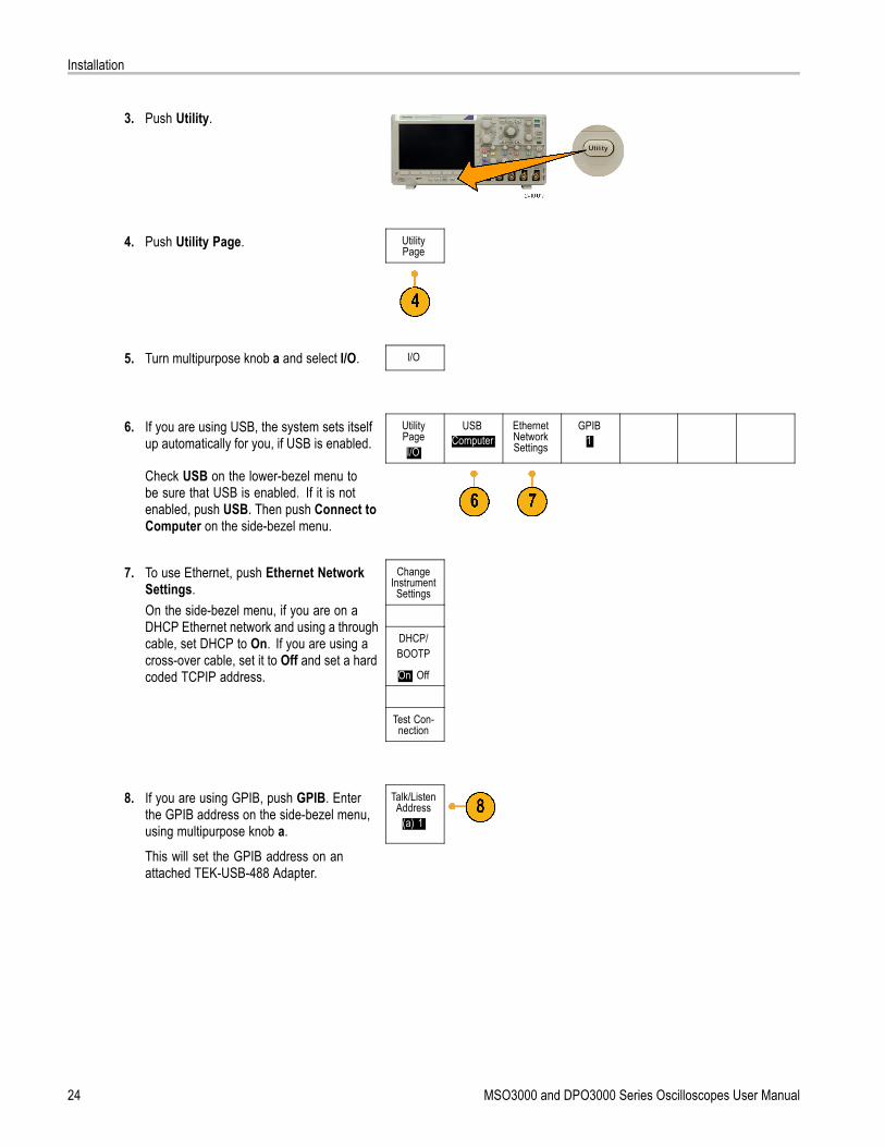
3. Push Utility.
4. Push Utility Page. UtilityPage
5. Turn multipurpose knob a and select I/O. I/O
6. If you are using USB, the system sets itselfup automatically for you, if USB is enabled.
UtilityPageI/O
USBComputer
EthernetNetworkSettings
GPIB1
Check USB on the lower-bezel menu tobe sure that USB is enabled. If it is notenabled, push USB. Then push Connect toComputer on the side-bezel menu.
ChangeInstrument
Settings
DHCP/BOOTP
On| Off
7. To use Ethernet, push Ethernet NetworkSettings.On the side-bezel menu, if you are on aDHCP Ethernet network and using a throughcable, set DHCP to On. If you are using across-over cable, set it to Off and set a hardcoded TCPIP address.
Test Con-nection
8. If you are using GPIB, push GPIB. Enterthe GPIB address on the side-bezel menu,using multipurpose knob a.
Talk/ListenAddress
(a) 1
This will set the GPIB address on anattached TEK-USB-488 Adapter.
24 MSO3000 and DPO3000 Series Oscilloscopes User Manual

Installation
9. Run your application software on yourcomputer.
Quick TipsThe CD that is shipped with your oscilloscope includes a variety of Windows-based software tools designed to ensureefficient connectivity between your oscilloscope and your computer. There are toolbars that speed connectivity withMicrosoft Excel and Word. There is also a standalone acquisition program called the OpenChoice Desktop.
The rear-panel USB 2.0 device port is the correct USB port for computer connectivity. Use the rear- and front-panel USB2.0 host ports to connect your oscilloscope to USB flash drives and printers. Use the USB Device port to connect youroscilloscope to a PC or a PictBridge printer.
USB Host port
USB Device port
Using e*Scopee*Scope lets you access any Internet-connected MSO3000 and DPO3000 series oscilloscope from a browser on yourworkstation, PC, or laptop computer. No matter where you are, your oscilloscope is as close as the nearest browser.
MSO3000 and DPO3000 Series Oscilloscopes User Manual 25

Installation
To set up e*Scope communications between your oscilloscope and a Web browser running on a remote computer:
1. Connect the oscilloscope to your computernetwork with the appropriate Ethernet cable.If you are connecting directly to yourcomputer, you need a Crossover EthernetCable. If you are connecting to a network ora hub you need a Straight Through EthernetCable.
2. Push Utility.
3. Push Utility Page. UtilityPage
4. Turn multipurpose knob a and select I/O. I/O
5. Push Ethernet Network Settings. UtilityPage
I/O
USBComputer
EthernetNetworkSettings
GPIB1
26 MSO3000 and DPO3000 Series Oscilloscopes User Manual

Installation
6. On the side-bezel menu, if you are on aDHCP Ethernet network and using dynamicaddressing, set DHCP to On. If you areusing static addressing, set it to Off.
ChangeInstrument
Settings
Push Change Instrument Settings. If youare using DHCP, note the Ethernet addressand instrument name. If you are using Staticaddressing, enter the Ethernet address youwill be using.
DHCP/BOOTP
On| Off
Test Con-nection
NOTE. Depending on the type and speedof network to which your DPO3000 seriesoscilloscope is connected, you may not see theDHCP/BOOTP field update instantaneouslyafter pressing the DHCP/BOOTP button. It maytake a few seconds to update.
7. Start your browser on your remote computer.In the browser address line, enter the IPaddress or, if DHCP is set to On in theoscilloscope, simply enter the instrumentname.
8. You should now see the e*Scope screenshowing the oscilloscope display, on yourWeb browser.If e*Scope does not work, rerun theprocedure. If it still does not work, contactqualified service personnel.
Connecting a USB Keyboard to Your OscilloscopeYou can connect a US-style USB keyboard to a USB Host port on the rear or front panel of the oscilloscope. The oscilloscopewill detect the keyboard, even if it is plugged in while the oscilloscope is powered on.
You can use the keyboard to quickly create names or labels. You can bring up the Label menu through the lower-bezel labelbutton of the Channel or Bus menus. Use the arrow keys on the keyboard to move the insertion point, and then type in aname or label. Labeling channels and buses makes the information on the screen easier to identify.
MSO3000 and DPO3000 Series Oscilloscopes User Manual 27

Installation
28 MSO3000 and DPO3000 Series Oscilloscopes User Manual

Get Acquainted with the Instrument
Get Acquainted with the Instrument
Front-Panel Menus and ControlsThe front panel has buttons and controls for the functions that you use most often. Use the menu buttons to accessmore specialized functions.
Using the Menu System
To use the menu system:
1. Push a front-panel menu button todisplay the menu that you want to use.
2. Push a lower-bezel button to select amenu item. If a pop-out menu appears,turn multipurpose knob a to selectthe desired choice. If a pop-up menuappears, press the button again to selectthe desired choice.
MSO3000 and DPO3000 Series Oscilloscopes User Manual 29

Get Acquainted with the Instrument
3. Push a side-bezel button to choose aside-bezel menu item.If the menu item contains more thanone choice, push the side-bezel buttonrepeatedly to cycle through the choices.If a pop-out menu appears, turnmultipurpose knob a to select the desiredchoice.
4. To remove a side-bezel menu, push thelower-bezel button again or push MenuOff.
30 MSO3000 and DPO3000 Series Oscilloscopes User Manual

Get Acquainted with the Instrument
5. Certain menu choices require you to seta numeric value to complete the setup.Use the upper and lower multipurposeknobs a and b to adjust values.
6. Push Fine to turn off or on the ability tomake smaller adjustments.
Using the Menu ButtonsUse the menu buttons to perform many functions in the oscilloscope.
1. Measure. Push to perform automatedmeasurements on waveforms or toconfigure cursors.
2. Search. Push to search throughan acquisition for user-definedevents/criteria.
3. Test. Push to activate advanced orapplication-specific testing features.
4. Acquire. Push to set the acquisitionmode and adjust the record length.
5. Autoset. Push to perform an automaticsetup of oscilloscope settings.
6. Trigger Menu. Push to specify triggersettings.
7. Utility. Push to activate the system utilityfunctions, such as selecting a languageor setting the date/time.
MSO3000 and DPO3000 Series Oscilloscopes User Manual 31

Get Acquainted with the Instrument
8. Save / Recall Menu. Push to save andrecall setups, waveforms, and screenimages to internal memory or a USBflash drive.
9. Channel 1,2,3, or 4 Menu. Pushto set vertical parameters for inputwaveforms and to display or removethe corresponding waveform from thedisplay.
32 MSO3000 and DPO3000 Series Oscilloscopes User Manual

Get Acquainted with the Instrument
10. B1 or B2. Push to define and display abus if you have the appropriate moduleapplication keys. The DPO3AUTOmodule supports CAN and LIN buses.The DPO3EMBD module supports I2Cand SPI. The DPO3COMP modulesupports RS-232, RS-422, RS-485, andUART buses. The DPO3AUDIO modulesupports I2S, Left Justified (LJ), RightJustified (RJ), and TDM buses.Also, push the B1 or B2 button to displayor remove the corresponding bus fromthe display.
11. R. Push to manage reference waveforms,including the display or removal of eachreference waveform from the display.
12. M. Push to manage the math waveform,including the display or removal of themath waveform from the display.
Using Other ControlsThese buttons and knobs control waveforms, cursors, and other data input.
1. Turn the upper multipurpose knob a,when activated, to move a cursor, to seta numerical parameter value for a menuitem, or to select from a pop-out list ofchoices. Push the Fine button to togglebetween coarse and fine adjustment.Screen icons tell you when a or b areactive.
2. Cursors. Push once to activate thetwo vertical cursors. Push again to turnon the two vertical and two horizontalcursors. Push again to turn off allcursors.When the cursors are on, you can turnthe multipurpose knobs to control theirposition.
MSO3000 and DPO3000 Series Oscilloscopes User Manual 33

Get Acquainted with the Instrument
3. Select. Push to activate specialfunctions.For example, when using the two verticalcursors (and no horizontal ones arevisible), you can push this button to linkor unlink the cursors. When the twovertical and two horizontal cursors areboth visible, you can push this button tomake either the vertical cursors or thehorizontal cursors active.
4. Fine. Push to toggle between makingcoarse and fine adjustments with thevertical and horizontal position knobs, thetrigger level knob, and many operationsof multipurpose knobs a and b.
5. Waveform Intensity. Push to enablemultipurpose knob a to control waveformdisplay intensity and knob b to controlgraticule intensity.
6. Turn the lower multipurpose knob b,when activated, to move a cursor or seta numerical parameter value for a menuitem. Push Fine to make adjustmentsmore slowly.
7. Zoom button. Push to activate zoommode.
8. Pan (outer knob). Turn to scroll the zoomwindow through the acquired waveform.
9. Zoom (inner knob). Turn to control thezoom factor. Turning it clockwise zoomsin further. Turning it counterclockwisezooms out.
10. Play-pause button. Push to start or stopthe automatic panning of a waveform.Control the speed and direction with thepan knob.
11. ← Prev. Push to jump to the previouswaveform mark.
34 MSO3000 and DPO3000 Series Oscilloscopes User Manual

Get Acquainted with the Instrument
12. Set/Clear Mark. Push to establish ordelete a waveform mark.
13. → Next. Push to jump to the nextwaveform mark.
14. Horizontal Position. Turn to adjustthe trigger point location relative to theacquired waveforms. Push Fine to makesmaller adjustments.
15. Horizontal Scale. Turn to adjust thehorizontal scale (time/division).
16. Run/Stop. Push to start or stopacquisitions.
17. Single. Push to make a singleacquisition.
18. Autoset. Push to automatically set thevertical, horizontal, and trigger controlsfor a usable, stable display.
19. Trigger Level. Turn to adjust the triggerlevel.Push this button to set the trigger level tothe midpoint of the waveform.
20. Force Trig. Push to force an immediatetrigger event.
21. Vertical Position. Turn to adjust thevertical position of the correspondingwaveform. Push Fine to make smalleradjustments.
22. 1, 2, 3, 4. Push to display or removethe corresponding waveform from thedisplay and access the vertical menu.
MSO3000 and DPO3000 Series Oscilloscopes User Manual 35

Get Acquainted with the Instrument
23. Vertical Scale. Turn to adjust thevertical scale factor of the correspondingwaveform (volts/division).
24. Print. Push to print a screen imageusing the printer selected in the Utilitymenu.(See page 128, Printing a HardCopy.)
25. Power switch. Push to power on or offthe instrument.
26. USB 2.0 host port. Insert a USBcable here to connect peripherals tothe oscilloscope, such as a keyboard,a printer, or a flash drive. There is onemore USB 2.0 host port on the rearpanel.
27. Save. Push to perform an immediatesave operation. The save operation usesthe current save parameters, as definedin the Save / Recall menu.
28. Default Setup. Push to perform animmediate restore of the oscilloscope tothe default settings.
29. D15 - D0. Push to display or remove thedigital channels from the display, and toaccess the digital channel setup menu(MSO3000 Series only).
36 MSO3000 and DPO3000 Series Oscilloscopes User Manual

Get Acquainted with the Instrument
30. Menu Off. Push to clear a displayedmenu from the screen.
Identifying Items in the Display
The items shown to the right may appear inthe display. Not all of these items are visibleat any given time. Some readouts moveoutside the graticule area when menus areturned off.
1. The acquisition readout shows when anacquisition is running, stopped, or whenacquisition preview is in effect. Icons are:
Run: Acquisitions enabled
Stop: Acquisitions not enabled
Roll: In roll mode (40 ms/div orslower)
PreVu: In this state, the oscilloscopeis stopped or between triggers.You can change the horizontalor vertical position or scale tosee approximately what the nextacquisition will look like.
MSO3000 and DPO3000 Series Oscilloscopes User Manual 37

Get Acquainted with the Instrument
2. The trigger position icon shows thetrigger position in the acquisition.
3. The expansion point icon (an orangetriangle) shows the point that thehorizontal scale expands andcompresses around.
4. The waveform record view shows thetrigger location relative to the waveformrecord. The line color corresponds to theselected waveform color.
5. The trigger status readout shows triggerstatus. Status conditions are:
Trig’d: Triggered
Auto: Acquiring untriggered data
PrTrig: Acquiring pretrigger data
Trig?: Waiting for trigger
6. The cursor readout shows time,amplitude, and delta (Δ) values for eachcursor.For FFT measurements, it showsfrequency and magnitude.For serial buses, the readout shows thedecoded values.
38 MSO3000 and DPO3000 Series Oscilloscopes User Manual

Get Acquainted with the Instrument
7. The trigger level icon shows the triggerlevel on the waveform. The icon colorcorresponds to the trigger source color.
8. The trigger readout shows the triggersource, slope, and level. The triggerreadouts for other trigger types showother parameters.
9. The top line of the record length/samplingrate readout shows the sampling rate(adjust with the Horizontal Scale knob).The bottom line shows the record length(adjust with the Acquire menu).
10. The horizontal position/scale readoutshows on the top line the horizontal scale(adjust with the Horizontal Scale knob).With Delay Mode on, the bottom lineshows the time from the T symbol to theexpansion point icon (adjust with theHorizontal Position knob).Use horizontal position to insert addeddelay between when the trigger occursand when you actually capture the data.Insert a negative time to capture morepretrigger information.With Delay Mode off, the bottom lineshows the time location of the triggerwithin the acquisition, as a percentage.
11. The Timing Resolution readout showsthe resolution of the digital channeltiming.Timing resolution is the time betweensamples. It is the reciprocal of the digitalsample rate.When the MagniVu control is on,“MagniVu” appears in the readout.
MSO3000 and DPO3000 Series Oscilloscopes User Manual 39

Get Acquainted with the Instrument
12. Measurement readouts show theselected measurements. You can selectup to four measurements to display atone time.A symbol appears instead of theexpected numerical measurement if avertical clipping condition exists. Partof the waveform is above or below thedisplay. To obtain a proper numericalmeasurement, turn the vertical scaleand position knobs to make all of thewaveform appear in the display.
13. The auxiliary waveform readouts showthe vertical and horizontal scale factorsof the math and reference waveforms.
14. The channel readout shows the channelscale factor (per division), coupling,invert, and bandwidth status. Adjust withthe Vertical Scale knob and the channel1, 2, 3, or 4 menus.
15. For analog channels, the waveformbaseline indicator shows the zero-voltlevel of a waveform (ignoring the effectof offset). The icon colors correspond tothe waveform colors.
16. For digital channels (MSO3000 Seriesonly), the baseline indicators point tothe high and low levels. The indicatorcolors match the color code used onthe physical probe channels. TheD0 indicator is black, the D1 indicator isbrown, the D2 indicator is red, and so on.
17. The group icon indicates when digitalchannels are grouped (MSO3000 Seriesonly).
40 MSO3000 and DPO3000 Series Oscilloscopes User Manual

Get Acquainted with the Instrument
18. The bus display shows decoded packetlevel information for serial buses or forparallel buses (MSO3000 Series only).The bus indicator shows the bus numberand bus type.
Front-Panel Connectors1. Input Range +30 V to –20 V connector
for the P6316 digital probe onMSO3000 models only.
2. Channel 1, 2, (3, 4). Channel inputs withthe TekVPI Versatile Probe Interface.
3. Aux In. Trigger level range is adjustablefrom +8 V to –8 V. The maximum inputvoltage is 450V peak, 300V RMS. Inputresistance is 1 MΩ ± 1% in parallel with11.5 pF ±2 pF.
4. PROBE COMP. Square wave signalsource to compensate probes. Outputvoltage: 0 – 2.5V, amplitude ± 1% behind1 kΩ ±2%. Frequency: 1 kHz.
5. Ground.
6. Application Module Slots.
MSO3000 and DPO3000 Series Oscilloscopes User Manual 41

Get Acquainted with the Instrument
Side-Panel Connector1. Ground strap connector. This is a
receptacle for a grounding strap.
Rear-Panel Connectors1. Cal. This is for use by authorized service
personnel only.
2. Aux Out. Use this output to synchronizeother test equipment with youroscilloscope. A LOW to HIGH transitionindicates that the trigger occurred. Thelogic level for Vout (HI) is ≥3.25V opencircuit; ≥2.2 V into a 50Ω load to ground.The logic level for Vout (LO) is ≤0.4 Vinto a load of ≤4 mA; ≤0.2 V into a 50Ωload to ground.
3. Probe Power. Use this port to provideauxiliary power for TekVPI probes, whenneeded.
4. Video Out. Use the Video Out port(DB-15 female connector) to show theoscilloscope display on an externalmonitor or projector.
5. LAN. Use the LAN (Ethernet) port (RJ-45connector) to connect the oscilloscope toa 10/100 Base-T local area network.
42 MSO3000 and DPO3000 Series Oscilloscopes User Manual

Get Acquainted with the Instrument
6. Device. Use the USB 2.0 High speeddevice port to control the oscilloscopethrough USBTMC or GPIB with aTEK-USB-488 Adapter. The USBTMCprotocol allows USB devices tocommunicate using IEEE488 stylemessages. This lets you run your GPIBsoftware applications on USB hardware.Also, use the USB port to connect aPictBridge-compatible printer to theoscilloscope.
7. Host. Use the USB 2.0 Full speed hostports (one on the rear-panel and one onthe front) to take advantage of USB flashdrives, keyboards, and printers.
8. Power input. Attach to an AC power linewith integral safety ground. (See page 5,Operating Considerations.)
MSO3000 and DPO3000 Series Oscilloscopes User Manual 43

Acquire the Signal
Acquire the SignalThis section describes concepts of and procedures for setting up the oscilloscope to acquire the signal as you want it to.
Setting Up Analog ChannelsUse front-panel buttons and knobs to set up your instrument to acquire signals using the analog channels.
1. Connect the P6139A or TekVPI probe tothe input signal source.
2. Push Default Setup.
3. Select the input channel by pushing thefront-panel buttons.
NOTE. If you are using a probe that does notsupply probe encoding, set the attenuation(probe factor) on the oscilloscope verticalmenu for the channel to match the probe.
4. Push Autoset.
44 MSO3000 and DPO3000 Series Oscilloscopes User Manual

Acquire the Signal
5. Push the desired channel button. Thenadjust the vertical position and scale.
6. Adjust the horizontal position and scale.The horizontal position determines thenumber of pretrigger and posttriggersamples.The horizontal scale determines the sizeof the acquisition window relative to thewaveform. You can scale the window tocontain a waveform edge, a cycle, severalcycles, or thousands of cycles.
Quick TipUse the zoom feature to see multiple cycles of your signal in the upper part, and a single cycle in the lower part of thedisplay. (See page 114, Using Wave Inspector to Manage Long Record Length Waveforms.)
Labeling Channels and BusesYou can add a label to the channels and buses shown on the display for easy identification. The label is placed on thewaveform baseline indicator in the left side of the screen. The label can have up to 32 characters.
To label a channel or bus, follow these steps:
1. Push a front panel button for an inputchannel or a bus.
MSO3000 and DPO3000 Series Oscilloscopes User Manual 45

Acquire the Signal
2. Push a lower-bezel Label button to create alabel, such as for channel 1 or B1.
Label
3. Push Select Preset Label to view a list oflabels.
SelectPresetLabel
4. Turn multipurpose knob b to scroll throughthe list to find a suitable label. You can editthe label after you insert it if necessary.
5. Push Insert Preset Label to add the label. InsertPresetLabel
If you are using a USB keyboard, use thearrow keys to position the insertion point andedit the inserted label, or type in a new label.(See page 27, Connecting a USB Keyboardto Your Oscilloscope.)
6. If you do not have a USB keyboardconnected, push the side- and lower-bezelarrow keys to position the insertion point.
46 MSO3000 and DPO3000 Series Oscilloscopes User Manual

Acquire the Signal
7. Turn multipurpose knob a to scroll throughthe list of letters, numbers, and othercharacters to find the character in the namethat you want to enter.
ABCDEFGHIJKLMNOPQRSTUVWXYZabcdefghijklmnopqrstuvwxyz0123456789_=+-!@#$%^&*()[]<>/~’”\|:,.?
8. Push Select or Enter Character to let theoscilloscope know that you have picked theproper character to use.
You can use the lower-bezel buttons to editthe label as needed.
EnterCharacter
BackSpace
Delete Clear
9. Continue scrolling and pushing Select untilyou have entered all the desired characters.For another label, push the side- andlower-bezel arrow keys to reposition theinsertion point.
10. Push Display Labels and select On to seethe label.
DisplayLabels
On| Off
Using the Default SetupTo return the oscilloscope to its default settings:
1. Push Default Setup.
MSO3000 and DPO3000 Series Oscilloscopes User Manual 47

Acquire the Signal
2. If you change your mind, push UndoDefault Setup to undo the last defaultsetup.
UndoDefaultSetup
Using AutosetAutoset adjusts the instrument (acquisition, horizontal, trigger, and vertical controls) such that it displays four or five waveformcycles for analog channels with the trigger near the midlevel, and ten cycles for digital channels.
Autoset works with both the analog and digital channels.
1. Connect the analog probe, and then selectthe input channel. (See page 44, SettingUp Analog Channels.)
Connect the digital probe and select theinput channel. (See page 63, Setting UpDigital Channels.)
2. Push Autoset to execute an Autoset.
3. If desired, push Undo Autoset to undothe last Autoset.
UndoAutoset
You can also disable the Autoset function if you want to set up a waveform manually. To disable or enable the Autoset function:
1. Push and hold Autoset.
2. Push and hold Menu Off.
48 MSO3000 and DPO3000 Series Oscilloscopes User Manual

Acquire the Signal
3. Release Menu Off, and then releaseAutoset.
4. Select the desired side-bezel setting. AutosetEnabled
AutosetDisabled
Quick TipsTo position the waveform appropriately, Autoset may change the vertical position. Autoset always sets vertical offsetto 0 V.
If you use Autoset when no channels are displayed, the instrument turns on channel one (1) and scales it.
If you use Autoset and the oscilloscope detects a video signal, the oscilloscope automatically sets the trigger type tovideo and makes other adjustments to display a stable video signal.
Acquisition ConceptsBefore a signal can be displayed, it must pass through the input channel where it is scaled and digitized. Each channelhas a dedicated input amplifier and digitizer. Each channel produces a stream of digital data from which the instrumentextracts waveform records.
Sampling Process
Acquisition is the process of sampling ananalog signal, converting it into digitaldata, and assembling it into a waveformrecord, which is then stored in acquisitionmemory. Input signal Sampled points
Digital values
Real-Time Sampling
Record pointsMSO3000 and DPO3000 seriesoscilloscopes use real-time sampling.In real-time sampling, the instrumentdigitizes all of the points it acquires using asingle trigger event.
Sampling rate
MSO3000 and DPO3000 Series Oscilloscopes User Manual 49

Acquire the Signal
Waveform RecordThe instrument builds the waveform record through use of the following parameters:
Sample interval: The time betweenrecorded sample points. Adjust this byturning the Horizontal Scale knob orchanging the record length with the bezelbuttons.
Record length: The number of samplesrequired to fill a waveform record. Setthis by pushing the Acquire button andusing the resulting lower- and side-bezelmenus.
Trigger point: The zero time reference ina waveform record. It is shown on thescreen by an orange T.
Horizontal position: When Delay Modeis on, this is the time from the triggerpoint to the expansion point. Adjust thisby turning the Horizontal Position knob.Use a positive time to acquire the recordafter the trigger point. Use a negativetime to acquire it before the trigger point.
Expansion point: The point that thehorizontal scale expands and contractsaround. It is shown by an orange triangle.
How the Analog Acquisition Modes WorkSample mode retains the first sampled pointfrom each acquisition interval. Sample is thedefault mode.
Peak Detect mode uses the highest andlowest of all the samples contained in twoconsecutive acquisition intervals. This modeonly works with real-time, noninterpolatedsampling and is useful for catching highfrequency glitches.
50 MSO3000 and DPO3000 Series Oscilloscopes User Manual

Acquire the Signal
Hi Res mode calculates the average of allthe samples for each acquisition interval.This mode only works with real-time,noninterpolated sampling. Hi-Res providesa higher-resolution, lower-bandwidthwaveform.
Envelope mode finds the highest and lowestrecord points over all acquisitions. Envelopeuses Peak Detect for each individualacquisition.
Average mode calculates the average valuefor each record point over a user-specifiednumber of acquisitions. Average usesSample mode for each individual acquisition.Use average mode to reduce random noise.
Changing the Acquisition Mode, Record Length, and Delay TimeUse this procedure to change the acquisition mode.
1. Push Acquire.
2. Push Mode. ModeSample
RecordLength
10k
Delay
On |Off
Set Horiz.Position to
10%
WaveformDisplay
XY DisplayOff
MSO3000 and DPO3000 Series Oscilloscopes User Manual 51

Acquire the Signal
AcquisitionMode
Sample
PeakDetect
Hi Res
Envelope
3. Then choose the acquisition mode fromthe side-bezel menu. You can chose from:Sample, Peak Detect, Hi Res, Envelope, orAverage.
NOTE. Peak Detect and Hi Res modestake advantage of sample points that theoscilloscope would have discarded at lowersweep speeds. Therefore, these modes onlywork when the current sample rate is less thanthe maximum possible sample rate. As soonas the oscilloscope starts to acquire at themaximum sample rate, then the Peak Detect,Hi Res and Sample modes all look the same.You can control the sample rate by setting theHorizontal scale and the Record Length. Average
16
4. If you chose Average, turn multipurposeknob a to set the number of waveforms toaverage over.
5. Push Record Length.
6. Push the side-bezel menu, record lengthbutton.
10k points
Choose among: 1000, 10 k, 100 k, 1 M, and5 M points.
52 MSO3000 and DPO3000 Series Oscilloscopes User Manual

Acquire the Signal
7. Push the lower-bezel Delay button to selectOn when you want to delay the acquisitionrelative to the trigger event.
With Delay set to On, turn the Horizontal Position knob counterclockwise to increase the delay. The trigger point will moveto the left and ultimately outside of the acquired waveform. Then you can adjust the Horizontal Scale knob to acquire moredetail around the area of interest at the center of the screen.
When this delay is on, the trigger point separates from the horizontal expansion point. The horizontal expansion pointstays at the center of the screen. The trigger point can move off the screen. When this happens, the trigger marker turnsto point in the direction of the trigger point.
Use the delay feature when you want to acquire waveform detail that is separated from the trigger event by a significantinterval of time. For example, you can trigger on a sync pulse that occurs once every 10 ms and then look at high-speedsignal characteristics that occur 6 ms after the sync pulse.
When the delay feature is set to Off, the expansion point is tied to the trigger point so that scale changes are centeredaround the trigger point.
Using Roll ModeRoll mode gives a display similar to a strip chart recorder for low-frequency signals. Roll mode lets you see acquired datapoints without waiting for the acquisition of a complete waveform record.
Roll mode is enabled when the trigger mode is auto and the horizontal scale is set to 40 ms/div or slower.
Quick Tips
Switching to Envelope or Average acquisition mode, using math waveforms, turning on a bus, or switching to Normaltrigger will disable Roll mode.
Roll mode is disabled when you set the horizontal scale to 20 ms per division or faster.
Push Run/Stop to halt Roll mode.
MSO3000 and DPO3000 Series Oscilloscopes User Manual 53
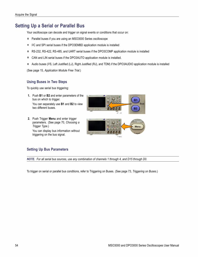
Acquire the Signal
Setting Up a Serial or Parallel BusYour oscilloscope can decode and trigger on signal events or conditions that occur on:
Parallel buses if you are using an MSO3000 Series oscilloscope
I2C and SPI serial buses if the DPO3EMBD application module is installed
RS-232, RS-422, RS-485, and UART serial buses if the DPO3COMP application module is installed
CAN and LIN serial buses if the DPO3AUTO application module is installed.
Audio buses (I2S, Left Justified (LJ), Right Justified (RJ), and TDM) if the DPO3AUDIO application module is installed
(See page 15, Application Module Free Trial.)
Using Buses in Two StepsTo quickly use serial bus triggering:
1. Push B1 or B2 and enter parameters of thebus on which to trigger.You can separately use B1 and B2 to viewtwo different buses.
2. Push Trigger Menu and enter triggerparameters. (See page 70, Choosing aTrigger Type.)You can display bus information withouttriggering on the bus signal.
Setting Up Bus Parameters
NOTE. For all serial bus sources, use any combination of channels 1 through 4, and D15 through D0.
To trigger on serial or parallel bus conditions, refer to Triggering on Buses. (See page 73, Triggering on Buses.)
54 MSO3000 and DPO3000 Series Oscilloscopes User Manual

Acquire the Signal
To set up bus parameters:
1. Push B1 or B2 to bring up the lower-bezelbus menu.
2. Push Bus. Turn multipurpose knob a toscroll through the list of bus types and selectthe desired bus: Parallel (MSO3000 Seriesonly), I2C, SPI, RS-232, CAN, LIN, or Audio.
B1Parallel
DefineInputs
Thresholds IncludeR/W inaddress
No
B1 LabelI2C
BusDisplay
EventTable
The actual menu items shown will depend onyour model oscilloscope and the applicationmodules installed.
3. Push Define Inputs. The choices dependon the selected bus.
4. Push Thresholds. BusI2C
DefineInputs
Thresholds IncludeR/W inaddres
No
B1 LabelI2C
BusDisplay
EventTable
You can set the threshold for all channels inthe serial bus from a list of preset values.The values are based on common types ofintegrated circuits. The preset values are:
1.4 V for TTL2.5 V for 5.0 V CMOS1.65 V for 3.3 V CMOS1.25 V for 2.5 V CMOS-1.3 V for ECL3.7 V for PECL0 V
Alternately, you can set the threshold to aspecific value for the signals that make upthe serial bus. To do so, push the Selectside-bezel button and turn multipurpose knoba to select a Bit or a Channel number (Signalname).
MSO3000 and DPO3000 Series Oscilloscopes User Manual 55

Acquire the Signal
Then, turn multipurpose knob b to define thevoltage level above which the oscilloscopetreats the signal as a logic high and belowwhich as a logic low.
5. Push B1 Label to edit the label for thebus. (See page 45, Labeling Channels andBuses.)
BusI2C
DefineInputs
Thresholds IncludeR/W inaddress
No
B1 LabelI2C
BusDisplay
EventTable
6. Push Bus Display and use the side-bezelmenu to define how to display the serial bus.
Hex
Push the desired side-bezel menu choice todisplay the bus data in hexadecimal, binary,ASCII (RS-232 only), or Signed Decimal(Audio only) format.
Binary
ASCII
7. Push Event Table and select On to display alist of bus packets with timestamps.
EventTable
On |Off
SaveEventTable
For an RS-232 bus, the table lists decodedbytes or packets.
8. Push Save Event Table to save the eventtable data in a .csv (spreadsheet) format onthe currently selected storage device.
56 MSO3000 and DPO3000 Series Oscilloscopes User Manual

Acquire the Signal
This example of an Event Table is from anRS-232 bus.RS-232 event tables display one line for each7- or 8-bit byte when Packets are set to Off.RS-232 event tables display one line for eachpacket when Packets are set to On.I2C, SPI, CAN, and LIN event tables displayone line for each packet.
9. Push B1 or B2 and turn multipurpose knoba to move the bus display up or down on thescreen.
To acquire data from an I2C bus, you need to also set up these items:
1. If you select I2C, push Define Inputs andthe appropriate side-bezel menu choices.
B1I2C
DefineInputs
Thresholds IncludeR/W inAddress
No
B1 LabelI2C
BusDisplay
EventTable
You can assign the predefined SCLK Inputor SDA Input to the channel connected tothe signal.
2. Push Include R/W in Address and thenpush the desired side-bezel button.This control determines how the oscilloscopeshows the I2C addresses in bus decodetraces, cursor readouts, Event Table listings,and trigger settings.
If you select Yes, the oscilloscope displays 7-bit addresses as eight bits, where the eighth bit (LSB) is the R/W bit. Itdisplays 10-bit addresses as 11 bits where the third bit is the R/W bit.
If you select No, the oscilloscope displays 7-bit addresses as seven bits, and 10-bit addresses as ten bits.
In the physical layer of the I2C protocol, 10 bit I2C addresses are preceded by the five bit code, 11110. The oscilloscopedoes not include these five bits in address readouts.
MSO3000 and DPO3000 Series Oscilloscopes User Manual 57

Acquire the Signal
To acquire data from an SPI bus, you need to also set up these items:
1. If you selected SPI, push Define Inputs andthe appropriate side-bezel menu choices.
BusSPI
DefineInputs
Thresholds Configure B1 LabelSPI
BusDisplay
EventTable
You can set the Framing to SS (SlaveSelect) or to Idle Time.You can assign the predefined SCLK, SS,MOSI, or MISO signals to any channel.
2. Push Configure and the desired side-bezelmenu choices.
3. Push SCLK to set the edge of the signal tomatch the SPI bus being acquired.
SCLK
4. Set the level of the SS, MOSI, and MISOsignals to match the SPI bus.
SSActiveHigh
Active Low
Active High means that a signal is consideredactive when the signal is greater than thethreshold value.
MOSIActiveHigh
Active Low
Active Low means that the signal isconsidered active when the signal is lowerthan the threshold value.
MISOActiveHigh
Active Low
-more-1 0f 2
5. Use multipurpose knob a to set the numberof bits of the SPI Word Size.
Word Size(a) 8 bits
6. Push either side bezel button to set the bitorder of the SPI bus.
Bit OrderMS First
Bit OrderLS First
To acquire data from a CAN bus, you need to also set up these items:
1. If you selected CAN, push Define Inputs andthe appropriate side-bezel menu choices.
BusCAN
DefineInputs
Thresholds Bit Rate500 Kbps
B1 LabelCAN
BusDisplay
EventTable
58 MSO3000 and DPO3000 Series Oscilloscopes User Manual

Acquire the Signal
2. Turn multipurpose knob a to select thechannel connected to the CAN bus source.
CAN Input(a) 1
3. Turn multipurpose knob a to select the typeof CAN signal: CAN_H, CAN_L, Rx, Tx, orDifferential.
SignalType
CAN_H
4. Turn multipurpose knob a to set the SamplePoint from 5% to 95% of the position withinthe bit period or the unit interval.
SamplePoint50%
5. Push Bit Rate and turn multipurpose knob ato select from the list of predefined bit rates.
BusCAN
DefineInputs
Thresholds Bit Rate500 Kbps
B1 LabelCAN
BusDisplay
EventTable
Alternately, you can set the bit rate to aspecific value. To do so, select Custom, andthen turn multipurpose knob b to set the bitrate from 10,000 to 1,000,000.
To acquire data from a LIN bus, you need to also set up these items:
1. If you selected LIN, push Define Inputs andthe appropriate side-bezel menu choices.
BusLIN
DefineInputs
Thresholds Configure B1 LabelLIN
BusDisplay
EventTable
2. Turn multipurpose knob a to select thechannel connected to the LIN bus source.
LIN Input(a) 1
3. Turn multipurpose knob a to set the SamplePoint from 5% to 95% of the position withinthe bit period or the unit interval.
SamplePoint50%
4. Select the Polarity to match the LIN busbeing acquired.
PolarityNormal
(High=1)
PolarityInverted(High=0)
5. Push Configure and the appropriateside-bezel menu choices.
BusLIN
DefineInputs
Thresholds Configure B1 LabelLIN
BusDisplay
EventTable
MSO3000 and DPO3000 Series Oscilloscopes User Manual 59

Acquire the Signal
6. Push Bit Rate, and turn multipurpose knob ato select from the list of predefined bit rates.Alternately, you can set the bit rate to aspecific value. To do so, select Custom, andthen turn multipurpose knob b to set the bitrate from 800 bps to 100,000 bps.
Bit Rate(a)
19.2K bps
7. Push LIN Standard, and turn multipurposeknob a to select the appropriate standard.
LINStandard
v1.x
8. Push Include Parity Bits with Id to selectwhether or not to include parity bits.
IncludeParity Bits
with Id
On|Off
60 MSO3000 and DPO3000 Series Oscilloscopes User Manual

Acquire the Signal
To acquire data from a RS-232 bus, you need to also set up these items:
1. If you selected RS-232, push Configure andthe desired side-bezel menu choices.
BusRS-232
DefineInputs
Thresholds Configure9600-8-N
B1 LabelRS-232
BusDisplay
EventTable
Use the side-bezel menu to configure thebus. Use Normal polarity for RS-232 signalsand Inverted polarity for RS-422, RS-485,and UART buses.
2. Push Bit Rate, and turn multipurpose knob ato select the appropriate bit rate.
Bit Rate9600 bps
3. Push Data Bits and select the number tomatch the bus.
Data Bits
7 |8
4. Push Parity and turn multipurpose knob a tomatch the polarity used by the bus as None,Odd, or Even.
Parity(a) None
5. Push Packets and select On or Off. Packets
On|Off
6. Turn multipurpose knob a to select anend-of-packet character.
End ofPacket
0A(Linefeed)
RS-232 decoding displays a stream of bytes.You can organize the stream into packetswith an end-of-packet character
MSO3000 and DPO3000 Series Oscilloscopes User Manual 61

Acquire the Signal
To acquire data from an audio bus, you need to also set up these items:
1. If you selected Audio, push Define Inputand the desired side-bezel menu choices.
BusAudio
DefineInputs
Thresholds Configure B1 LabelRS-232
BusDisplay
EventTable
2. Push Type, and turn multipurpose knoba to select the type of audio bus dataconfiguration on which to trigger.
Audio BusType
3. Select I2S to trigger on the standard Inter-ICSound, or Integrated Interchip Sound,electrical serial bus interface standard stereoformat.
I2S
4. Select Left Justified to trigger on an I2Sstream where there is no bit clock delay andthe data starts right on the edge of the wordselect clock.
LeftJustified
(LJ)
5. Select Right Justified to trigger on an I2Sstream where the data lines up with the rightedge of the word select clock.
RightJustified
(RJ)
6. Select TDM to trigger on time-divisionmultiplexing.
TDM
7. Push Configure, and the appropriateside-menu buttons to further set up I2Striggering.
Physical Layer Bus ActivityOscilloscope waveform traces from analog channels 1 to 4, digital channels D15 to D0, and the traces you see when youchoose to display a bus as Bus and Waveforms always show the physical layer bus activity. In the physical layer display,bits that were transmitted earlier are to the left, and bits that were transmitted later are to the right.
I2C, and CAN buses transmit the MSB (most significant bit) first
SPI buses do not specify a bit order
RS-232 and LIN buses transmit the LSB (least significant bit) first
NOTE. The oscilloscope displays the decode traces and event tables for all buses with the MSB on the left and LSBon the right.
For example, an RS-232 signal (after the start bit) might be high, high, high, low, high, low, low, and high. Since the RS-232protocol uses high for zero and low for one, this value would be 0001 0110.
62 MSO3000 and DPO3000 Series Oscilloscopes User Manual

Acquire the Signal
Since the decode displays the MSB first, the oscilloscope reverses the order of the bits and displays 0110 1000. If the busdisplay is set to hex, the value displays as 68. If the bus display is set to ASCII, the value displays as h.
RS-232
If you defined an end-of-packet characterto use for RS-232 decoding, the stream ofbytes will be displayed as packets.
When decoding an RS-232 bus in ASCIImode, a large dot indicates that the valuerepresents a character outside the printableASCII range.
Setting Up Digital ChannelsUse front-panel buttons and knobs to set up your instrument to acquire signals using the digital channels.
1. Connect the P6316 16-channel digital probeto the input signal source.
2. Connect the ground lead or leads to thecircuit ground.You can connect one or two of the commonground leads for each group of 8 channels(wires).
MSO3000 and DPO3000 Series Oscilloscopes User Manual 63

Acquire the Signal
3. If needed, connect the appropriate grabberfor each probe to the probe tip.
4. Connect each channel to the desired circuittest point.
5. Push the D15 - D0 front panel button todisplay the menu.
6. Push the lower-bezel D15 - D0 button toaccess the D15 - D0 On or Off menu.
D15 – D0On/Off
Thresholds Edit Labels MagniVu
On |Off
Height
S | M L
7. Turn multipurpose knob a to scroll throughthe list of digital channels. Turn multipurposeknob b to position the selected channel.As you position channels close to each otheron the display, the oscilloscope groups thechannels, and adds the group to the pop-uplist. You can select the group from the list tomove all the channels in the group instead ofindividual channels.
8. Push the lower-bezel Thresholds button.You can assign a different threshold valueto each pod.
9. Push the lower-bezel Edit Labels buttonand create the label. You can create labelsthrough the front panel or with an optionalUSB keyboard. (See page 45, LabelingChannels and Buses.)
10. Push the lower-bezel MagniVu button toincrease the timing resolution.
64 MSO3000 and DPO3000 Series Oscilloscopes User Manual

Acquire the Signal
11. Push the lower-bezel Height buttonrepeatedly to set the signal height. You onlyneed to do this once to set the height for allof the digital channels.
Quick TipUse the zoom feature to see multiple cycles of the signal in the upper part, and a single cycle in the lower part of thedisplay. (See page 114, Using Wave Inspector to Manage Long Record Length Waveforms.)
When setting up the digital probe, the first set of eight leads (pins 7 to 0) on the digital probe is marked Group 1 on thelead box. The second set (pins 15 to 8) is marked Group 2.
Digital channels store a high or low state for each sample. The threshold that separates a high from a low state can beset for all the channels in Group 1 or in Group 2 of the digital probe. The threshold can not be set for individual channels.
When and Why to Turn On MagniVuFor MSO3000 Series only, MagniVu allows you to have higher resolution to accurately determine edge placement. Thishelps you to make precise timing measurements on digital edges. You can see up to 16 times more detail than withnormal digital channel sampling.
The MagniVu record is acquired in parallel with the main digital acquisition and is available at any time, running or stopped.MagniVu provides an ultra high resolution view of your data sampled at a maximum resolution of 121.2 ps for 10,000points centered around the trigger.
NOTE. MagniVu centers itself around the trigger point. If you turn MagniVu on while using a large record length and you arelooking somewhere other than the trigger point, then the digital signal may be off screen. In most of these cases, you can findthe digital record by looking for the digital signal in the upper overview and panning accordingly.
NOTE. You should turn on MagniVu when light gray shading is displayed to indicate the uncertainty of the edge position. Ifthe shading is not displayed, you do not need to use MagniVu. (See page 93, Viewing Digital Channels.)
Using MagniVu1. Push D15 – D0.
MSO3000 and DPO3000 Series Oscilloscopes User Manual 65

Acquire the Signal
2. Push MagniVu and select On. D15 – D0On/Off
Thresholds Label MagniVu
On |Off
Height
S | M L
Quick Tips
If you think you need more timing resolution, turn on MagniVu to increase the resolution.
MagniVu is always acquired. If the oscilloscope is in a stopped state, you can turn on MagniVu and still get the resolutionwithout taking another acquisition.
The serial bus features do not use data acquired in MagniVu mode.
66 MSO3000 and DPO3000 Series Oscilloscopes User Manual

Trigger Setup
Trigger SetupThis section contains concepts and procedures for setting up the oscilloscope to trigger on your signal.
Triggering ConceptsTrigger EventThe trigger event establishes the time-reference point in the waveform record. All waveform record data is located in timewith respect to that point. The instrument continuously acquires and retains enough sample points to fill the pretrigger portionof the waveform record. That is the part of the waveform that is displayed before, or to the left of, the triggering event onscreen. When a trigger event occurs, the instrument starts acquiring samples to build the posttrigger portion of the waveformrecord, that is, the part displayed after or to the right of the trigger event. After a trigger is recognized, the instrument will notaccept another trigger until the acquisition is complete and the holdoff time has expired.
Untriggered display Triggered display
Trigger ModesThe trigger mode determines how the instrument behaves in the absence of a trigger event:
Normal trigger mode enables the instrument to acquire a waveform only when it is triggered. If no trigger occurs, the lastwaveform record acquired remains on the display. If no last waveform exists, no waveform is displayed.
Auto trigger mode enables the instrument to acquire a waveform even if a trigger does not occur. Auto mode uses atimer that starts when the acquisition is started, and the pretrigger information is obtained. If a trigger event is notdetected before the timer times out, the instrument forces a trigger. The length of time it waits for a trigger eventdepends on the time base setting.
Auto mode, when forcing triggers in the absence of valid triggering events, does not synchronize the waveform on thedisplay. The waveform will appear to roll across the screen. If valid triggers occur, the display will become stable.
You can also force the instrument to trigger by pushing the front-panel Force Trig button.
MSO3000 and DPO3000 Series Oscilloscopes User Manual 67

Trigger Setup
Trigger Holdoff
Adjust holdoff to obtain stable triggering whenthe instrument is triggering on undesiredtrigger events.Trigger holdoff can help stabilize triggering,since the oscilloscope does not recognizenew triggers during the holdoff time. Whenthe instrument recognizes a trigger event, itdisables the trigger system until acquisitionis complete. In addition, the trigger systemremains disabled during the holdoff periodthat follows each acquisition.
Holdoffs
Trigger Coupling
Trigger coupling determines what part of thesignal is passed to the trigger circuit. Edgetriggering can use all available couplingtypes: DC, AC, Low Frequency Rejection,High Frequency Rejection, and NoiseRejection. Sequence (B) triggering does notprovide AC coupling. Other trigger types useDC coupling only.
Horizontal Position
When Delay Mode is on, use horizontalposition to acquire waveform detail in aregion that is separated from the triggerlocation by a significant interval of time.
68 MSO3000 and DPO3000 Series Oscilloscopes User Manual

Trigger Setup
1. Adjust the position (delay) time byrotating the Horizontal Position knob.
2. Turn horizontal SCALE to acquire thedetail that you need around the position(delay) expansion point.
The part of the record that occurs before the trigger is the pretrigger portion. The part that occurs after the trigger is theposttrigger portion. Pretrigger data can help you troubleshoot. For example, to find the cause of an unwanted glitch inyour test circuit, you can trigger on the glitch and make the pretrigger period large enough to capture data before theglitch. By analyzing what happens before the glitch, you may uncover information that helps you find the source of theglitch. Alternatively, to see what is happening in your system as a result of the trigger event, make the posttrigger periodlarge enough to capture data after the trigger.
Slope and Level
The slope control determines whether theinstrument finds the trigger point on the risingor the falling edge of a signal.The level control determines where on thatedge the trigger point occurs.
The oscilloscope provides a long horizontalbar or bars across the graticule to temporarilyshow the trigger level.
1. Turn the front-panel Trigger Level knobto adjust the trigger level without goingto a menu.
Push the knob to quickly set the triggerlevel to the midpoint of the waveform.
MSO3000 and DPO3000 Series Oscilloscopes User Manual 69

Trigger Setup
Choosing a Trigger TypeTo select a trigger:
1. Push Trigger Menu.
TriggerType
Sequence(B Trigger)
PulseWidth
Runt
Logic
Setup &Hold
Rise/FallTime
Video
2. Push Type to bring up the Trigger Typeside-bezel menu.
NOTE. The bus trigger in the MSO3000 Seriesworks on parallel buses even without anapplication module. Using the bus trigger onother buses requires use of the DPO3AUDIO,DPO3AUTO, DPO3EMBD, or DPO3COMPapplication module.
Bus
3. Turn multipurpose knob a to select thedesired trigger type.
4. Complete the trigger setup using thelower-bezel menu controls displayed forthe trigger type. The controls to set up thetrigger vary depending on the trigger type.
TypeEdge
Source1
CouplingDC
Slope Level100 mV
ModeAuto
& Holdoff
70 MSO3000 and DPO3000 Series Oscilloscopes User Manual

Trigger Setup
Selecting TriggersTrigger Type Trigger ConditionsEdge Trigger on a rising or falling edge, as defined by the
slope control. Coupling choices are DC, AC, LF Reject,HF Reject, and Noise Reject.Edge triggers are the simplest and most commonlyused trigger type, with both analog and digital signals.An edge trigger event occurs when the trigger sourcepasses through a specified voltage level in the specifieddirection.
Sequence(B Trigger)
Combine an edge A Event (Main) trigger with theB Event (Delayed) trigger to capture more complexsignals. (See page 78, Using Sequence Trigger, A(Main) and B (Delayed).)Time. After the A Event occurs, the trigger system waitsthe specified amount of time, and then looks for the BEvent before triggering and displaying the waveform.Events. After the A Event occurs, the trigger systemlooks for a specified number of B Events beforetriggering and displaying the waveform.
Pulse Width Trigger on pulses that are less than, greater than, equalto, or not equal to a specified time. You can trigger onpositive or negative pulses. Pulse width triggers areprimarily used on digital signals.
Runt Trigger on a pulse amplitude that crosses one thresholdbut fails to cross a second threshold before recrossingthe first. You can detect positive or negative (or either)runts, or only those wider than, less than, greater than,equal to, or not equal to a specified width. Runt triggersare primarily used on digital signals.
MSO3000 and DPO3000 Series Oscilloscopes User Manual 71

Trigger Setup
Trigger Type Trigger ConditionsLogic Trigger when all channels transition to the specified
state. Use multipurpose knob a to select a channel.Push the appropriate side-bezel button to set thatchannel’s state to High (H), Low (L), or Don’t Care (X).Use the Clock side-bezel button to enable clocked(state) triggering. You can have at most a single clockchannel. Push the Clock Edge bottom bezel button tochange the polarity of the clock edge. Turn off clockedtriggering and return to unclocked (pattern) triggering byselecting the clock channel and setting it to high, low,or don’t care.For unclocked triggering, by default, triggering occurswhen the selected condition goes true. You can alsoselect triggering when the condition goes false, ortime-qualified triggering.You can use up to 20 channels for a logic trigger(4 analog and 16 digital) with MSO3000 Seriesoscilloscopes.
NOTE. Optimum Logic trigger performance is achievedby using only analog channels or only digital channels.
Setup and Hold Trigger when a logic data input changes state inside ofthe setup or hold time relative to a clock edge.Setup is the amount of time that data should be stableand not change before a clock edge occurs. Hold is thetime that data should be stable and not change aftera clock edge occurs.MSO3000 Series oscilloscopes are capable of multiplechannel Setup and Hold triggering, and can monitorthe state of an entire bus for setup and hold violations.You can use up to 20 channels for a Setup and Holdtrigger (4 analog and 16 digital) with MSO3000 Seriesoscilloscopes.Use the Clock side-bezel button to select the clockchannel. Use the Select control, Data, and Not usedbuttons to select one or more channels you want tomonitor for setup and hold violations.
NOTE. Optimum Setup and Hold trigger performance isachieved by using only analog channels or only digitalchannels.
Rise/Fall Time Trigger on rise and fall times. Trigger on pulse edgesthat traverse between two thresholds at faster or slowerrates than the specified time. Specify pulse edges aspositive, negative, or either.
72 MSO3000 and DPO3000 Series Oscilloscopes User Manual

Trigger Setup
Trigger Type Trigger ConditionsVideo Trigger on specified fields or lines of a composite video
signal. Only composite signal formats are supported.Trigger on NTSC, PAL, or SECAM. Works withMacrovision signals.With the DPO3VID module, trigger on a variety of HDTVvideo standard signals, as well as custom (non-standard)bilevel and trilevel video signals with 3 to 4,000 lines.
Bus Trigger on various bus conditions.Parallel requires an MSO3000 Series oscilloscope.I2C and SPI requires a DPO3EMBD module.RS-232, RS-422, RS-485, and UART require aDPO3COMP module.CAN and LIN requires a DPO3AUTO module.I2S, Left Justified (LJ), Right Justified (RJ), and TDMrequire a DPO3AUDIO module.(See page 15, Application Module Free Trial.)
Triggering on BusesYou can use your oscilloscope to trigger on I2C, SPI, RS-232, RS-422, RS-485, UART, CAN, LIN,I2S, Left Justified (LJ),Right Justified (RJ), and TDM buses, if you have the appropriate DPO3AUDIO, DPO3AUTO, DPO3COMP, or DPO3EMBDapplication module installed. The MSO3000 Series can trigger on parallel buses without an application module. Theoscilloscope can display both physical layer (as analog waveforms) and protocol level information (as symbolic waveforms).
To set up the bus trigger:
1. If you have not already defined your bususing the front-panel B1 and B2 buttons, doso now. (See page 54, Setting Up a Serialor Parallel Bus.)
2. Push Trigger Menu.
3. Push Type. TypeBus
SourceBus
B1 (I2C)
Trigger OnAddress
Address07F
DirectionWrite
ModeAuto
& Holdoff
4. Turn multipurpose knob a to scroll throughthe trigger type side menu until you selectBus.
MSO3000 and DPO3000 Series Oscilloscopes User Manual 73

Trigger Setup
B1 (I2C)5. Push Source Bus and turn multipurposeknob a to scroll through the source bus sidemenu until you select the bus that you wantto trigger on.
B2 (CAN)
6. Push Trigger On and select the desiredtrigger on feature from the side-bezel menu.If you are using the I2C bus trigger, youcan trigger on Start, Repeated Start,Stop, Missing Ack, Address, Data, orAddress/Data.If you are using the SPI bus trigger, you cantrigger on SS Active, MOSI, MISO, or MOSI& MISO.
If you are using the RS-232 bus trigger, youcan trigger on Tx Start Bit, Rx Start Bit, TxEnd of Packet, Rx End of Packet,Tx Data,or Rx Data.
If you are using the CAN bus trigger, you cantrigger on Start of Frame, Type of Frame,Identifier, Data, Id & Data, End of Frame,and Missing Ack.
If you are using the LIN bus trigger, youcan trigger on Sync, Identifier, Data, Id& Data,Wakeup Frame, Sleep Frame, orError.If you are using the I2S, LJ, and RJ bus, youcan trigger on Word Select, or Data.
If you are using the TDM bus, you cantrigger on Frame Sync, or Data.
7. If you are setting up an I2C trigger and havemade a Trigger On selection of Addressor Address/Data, push the lower-bezelAddress button to access the I2C Addressside-bezel menu.Push the side-bezel Addressing Modebutton and select 7 bit or 10 bit. Pushthe side-bezel Address button. Enterthe address parameters of interest withmultipurpose knobs a and b.Then push the lower-bezel menu Directionbutton and select the direction of interest:Read, Write, or Read or Write.
74 MSO3000 and DPO3000 Series Oscilloscopes User Manual

Trigger Setup
If you have made a Trigger On selectionof Data or Address/Data, push thelower-bezel Data button to access the I2CData side-bezel menu.Push the Number of Bytes button and enterthe number of bytes with multipurpose knoba.Push the side-bezel Addressing Modebutton and select 7 bit or 10 bit. Pushthe side-bezel Data button. Enter the dataparameters of interest with multipurposeknobs a and b.For more information on the I2C addressformats, refer to item 2 under Setting Up BusParameters.
8. If you are setting up an SPI trigger and havemade a Trigger On selection of MOSI orMISO, push the lower-bezel Data button,push the side-bezel MOSI (or MISO) button,and enter the data parameters of interestwith multipurpose knobs a and b.Then push the Number of Bytes button andenter the number of bytes with multipurposeknob a.If you select MOSI & MISO, push thelower-bezel Data button and enter theparameters of interest in the side-bezelmenus.
9. If you are setting up an RS-232 trigger andhave made a Trigger On selection of TxData or Rx Data, push the lower-bezel Databutton.Push the Number of Bytes button and enterthe number of bytes with multipurpose knoba.Push the side-bezel Data button, and enterthe parameters of interest with multipurposeknobs a and b.
MSO3000 and DPO3000 Series Oscilloscopes User Manual 75

Trigger Setup
10. If you are setting up a CAN trigger and havemade a Trigger On selection of Type ofFrame, push the lower-bezel Frame Typebutton, and select Data Frame, RemoteFrame, Error Frame, or Overload Frame.If you have made a Trigger On selection ofIdentifier, push the lower-bezel Identifierbutton, and select a Format. Then pushthe Identifier side-bezel button, and enter abinary or hex value with multipurpose knobsa and b.Push the lower-bezel menu Direction buttonand select the direction of interest: Read,Write, or Read or Write.If you have made a Trigger On selectionof Data. Push the lower-bezel Data buttonand enter the parameters of interest withmultipurpose knobs a and b.
11. If you are setting up an LIN trigger andhave made a Trigger On selection ofIdentifier, Data, or Identifier & Data, pushthe lower-bezel Identifier or Data buttonsand enter the parameters of interest on theresulting side-bezel menu.If you have made a Trigger On selectionof Error, push the lower-bezel Error Typebutton and enter the parameters of intereston the resulting side-bezel menu.
12. If you are using the I2S, Left Justified (LJ) orRight Justified(RJ) bus, you can trigger onWord Select or Data.If you have made a Trigger On selectionof Data, push the lower-bezel Data buttonand enter the parameters of interest withmultipurpose knobs a and b.
13. If you are using the TDM bus, you cantrigger on Frame Sync or Data.
76 MSO3000 and DPO3000 Series Oscilloscopes User Manual

Trigger Setup
I2C, SPI, CAN, and LIN Bus Trigger Data MatchingRolling window byte matching for I2C and SPI. To use a rolling window to trigger on data, you define the numberof bytes to match. Then the oscilloscope uses a rolling window to find any match within a packet, with the window rollingone byte at a time.
For example, if the number of bytes is one, the oscilloscope will attempt to match the first byte, second byte, third, and soon within the packet.
If the number of bytes is two, the oscilloscope will try to match any two consecutive bytes, such as one and two, two andthree, three and four, and so on. If the oscilloscope finds a match, it will trigger.
Specific byte matching (non-rolling window matching for a specific position in the packet) for I2C, SPI,CAN, and LIN. You can trigger on a specific byte for I2C, SPI, CAN, and LIN in several ways:
For I2C and SPI, enter the number of bytes to match the number of bytes in the signal. Then use don’t cares (X) tomask the bytes that you are not interested in.
For I2C, push the lower-bezel Trigger On to trigger on Address/Data. Push Address. On the side-bezel menu, pushAddress, and rotate multipurpose knobs a and b as needed. Set the address to don’t cares (X) if you want to mask theaddress. The data will be matched starting at the first byte without using a rolling window.
For CAN and LIN, triggering occurs when the user-selected data input matches the data and qualifier in the signalstarting at the first byte. Set the number of bytes to match the number of bytes of interest. Use the data qualifier toperform: =, !=, <, >, >=, and <= operations. Triggering on identifier and data always matches the identifier and dataselected by the user, with the data starting at the first byte. No rolling window is used.
RS-232 Bus Trigger Data MatchingYou can trigger on a specific data value for RS-232 bytes. If you defined an end-of-packet character to use for RS-232 busdecoding, you can use the same end-of-packet character as a data value for trigger data matching. To do so, choose the TxEnd of Packet or the Rx End of Packet character as the Trigger On selection.
Parallel Bus Trigger Data MatchingOptimum parallel bus trigger performance is achieved by using only analog channels or only digital channels(MSO3000 Series only).
Checking Trigger Settings
To quickly determine the settings of somekey trigger parameters, check the Triggerreadout at the bottom of the display. Thereadouts differ for edge and the advancedtriggers.
1. Trigger source = channel 1.
2. Trigger slope = rising.
3. Trigger level = 0.00 V.
Edge trigger readout
MSO3000 and DPO3000 Series Oscilloscopes User Manual 77

Trigger Setup
Using Sequence Trigger, A (Main) and B (Delayed)Combine an edge A Event (Main) trigger with the B Event (Delayed) trigger to capture more complex signals. After the AEvent occurs, the trigger system looks for the B Event before triggering and displaying the waveform.
A and B triggers can (and typically do) have separate sources.
Use the Edge trigger menu to set up the A trigger first. Then, to use the B trigger:
1. Push Trigger Menu.
2. Push Type.3. Turn multipurpose knob a to select a trigger
type of Sequence (B Trigger).This brings up the Sequence (B Trigger)menu.
4. Push B Trigger After A. TypeSequence(B Trigger)
Source1
CouplingDC
Slope Level0.00 V
B TriggerAfter ATime
ModeAuto
& Holdoff
78 MSO3000 and DPO3000 Series Oscilloscopes User Manual

Trigger Setup
Push a side-bezel button to selectsequencing the B trigger after the A as Timeor as Events.
Time(a) 8 ns
B Events1
Set toMinimum
5. Set the other Sequence Trigger parametersin the related side- and lower-bezel menus.
B Trigger After Delay Time
The A trigger arms the instrument.Posttrigger acquisition starts on the first Bedge after the trigger delay time.
Trigger on B Events
The A trigger arms the instrument.Posttrigger acquisition starts on the nth Bevent.
Quick TipsB-trigger delay time and horizontal position are independent functions. When you establish a trigger condition usingeither the A trigger alone or the A and B triggers together, you can also use the horizontal position control to delay theacquisition by an additional amount.
When using the B trigger, the A and B trigger types can only be Edge.
MSO3000 and DPO3000 Series Oscilloscopes User Manual 79

Trigger Setup
Starting and Stopping an AcquisitionAfter you have defined the acquisition and trigger parameters, start the acquisition with Run/Stop or Single.
Push Run/Stop to start acquisitions.The oscilloscope acquires repeatedlyuntil you push the button again to stopthe acquisition.
Push Single to take a single acquisition.Single sets the trigger mode to Normalfor the single acquisition.
80 MSO3000 and DPO3000 Series Oscilloscopes User Manual

Display Waveform Data
Display Waveform DataThis section contains concepts and procedures for displaying the acquired waveform.
Adding and Removing a Waveform1. To add or remove a waveform from
the display, push the correspondingfront-panel channel button or the D15-D0button.You can use the channel as a triggersource whether or not it is displayed.
Setting the Display Style and Persistence1. To set the display style, push Acquire.
2. Push Waveform Display. ModeSample
RecordLength
10k
Delay
On |Off
Set Horiz.Position to
10%
WaveformDisplay
XY DisplayOn
MSO3000 and DPO3000 Series Oscilloscopes User Manual 81

Display Waveform Data
3. Push Dots Only from the side-bezel menu.Dots on will display the waveform recordpoints as dots on the screen. Dots offconnects the dots with vectors.
WaveformDisplay
Dots Only
On |Off
4. Push Persist Time, and turn multipurposeknob a to have waveform data remain onscreen for a user-specified amount of time.
PersistTime
(a) Auto
5. Push Set to Auto to have the oscilloscopeautomatically determine a persistence timefor you.
Set to Auto
6. Push Clear Persistence to reset thepersistence information.
Clear Per-sistence
7. To display the amplitude from one waveformagainst the amplitude from another, pushXY Display. Then push Triggered XY fromthe side menu.
A data point from the first waveformspecifies the horizontal location while thecorresponding data point from the secondwaveform specifies the vertical location foreach displayed point.
Quick TipsVariable persistence accumulates record points for a specified time interval. Each record point decays independentlyaccording to the time interval. Use variable persistence for displaying infrequently appearing signal anomalies, suchas glitches.
Infinite persistence continuously accumulates record points until you change one of the acquisition display settings. Useinfinite persistence for displaying unique signal anomalies, such as glitches.
The XY Display mode graphs the data in fixed pairs of waveforms against one another. You can use CH1 versus CH2,and REF1 versus REF2. On four-channel models, you can also use CH3 versus CH4, and REF3 versus REF4.
When the XY Display is on, an upper window appears that displays data versus time.
Setting the Graticule Style
1. To set the graticule style, push Utility.
82 MSO3000 and DPO3000 Series Oscilloscopes User Manual

Display Waveform Data
2. Push Utility Page. UtilityPage
3. Turn multipurpose knob a and selectDisplay.
Display
4. Push Graticule from the lower-bezel menu. UtilityPage
Display
BacklightIntensity
High
GraticuleFull
ScreenAnnotation
MSO3000 and DPO3000 Series Oscilloscopes User Manual 83

Display Waveform Data
5. Select the desired style from the resultingside-bezel menu.Use the Full graticule for quick estimates ofwaveform parameters.Use the Grid graticule for full-screenmeasurements with cursors and automaticreadouts when cross hairs are not needed.Use the Cross Hair graticule for makingquick estimates of waveforms while leavingmore room for automatic readouts and otherdata.Use the Frame graticule with automaticreadouts and other screen text when displayfeatures are not needed.
Quick TipsYou can display IRE and mV graticules. To do this, set the trigger type to video and set the vertical scale to143 mV/division. (The 143 mV/division selection is available in the coarse vertical scale settings for the channel whenyou set the trigger type to video.) The oscilloscope will automatically display the IRE graticule for NTSC signals, andthe mV graticule for other video signals (PAL, SECAM, HDTV, and custom).
Setting the LCD Backlight
1. Push Utility.
2. Push Utility Page. UtilityPage
3. Turn multipurpose knob a and selectDisplay.
Display
84 MSO3000 and DPO3000 Series Oscilloscopes User Manual

Display Waveform Data
4. Push Backlight Intensity. UtilityPage
Display
BacklightIntensity
High
GraticuleFull
ScreenAnnotation
BacklightIntensity
High
Medium
5. Select the intensity level from the resultingside-bezel menu. Choices are: High,Medium, and Low.
Low
Setting Waveform Intensity1. Push the front-panel Intensity button.
This will bring up the intensity readout onthe display.
2. Rotate multipurpose knob a to select thedesired waveform intensity.
3. Rotate multipurpose knob b to select thedesired intensity for the graticule.
4. Push Intensity again to clear the intensityreadout from the display.
MSO3000 and DPO3000 Series Oscilloscopes User Manual 85

Display Waveform Data
Scaling and Positioning a WaveformUse the horizontal controls to adjust the time base, adjust the trigger point, and to examine waveform details more closely.You can also use the Wave Inspector Pan and Zoom controls to adjust the display of waveforms. (See page 114, UsingWave Inspector to Manage Long Record Length Waveforms.)
Original waveform Scaled horizontally Positioned horizontally
Use the vertical controls to select waveforms, adjust the waveform vertical position and scale, and set input parameters.Push a channel menu button (1, 2, 3, or 4) as many times as needed and the associated menu items to select, add, orremove a waveform.
Original waveform Scaled vertically Positioned vertically
Quick TipsPreview. If you change the Position or Scale controls when the acquisition is stopped or when it is waiting for the nexttrigger, the oscilloscope rescales and repositions the relevant waveforms in response to the new control settings. Itsimulates what you will see when you next push the RUN button. The oscilloscope uses the new settings for the nextacquisition.
You may see a clipped waveform if the original acquisition went off the screen.
The math waveform, cursors, and automatic measurements remain active and valid when using preview.
86 MSO3000 and DPO3000 Series Oscilloscopes User Manual
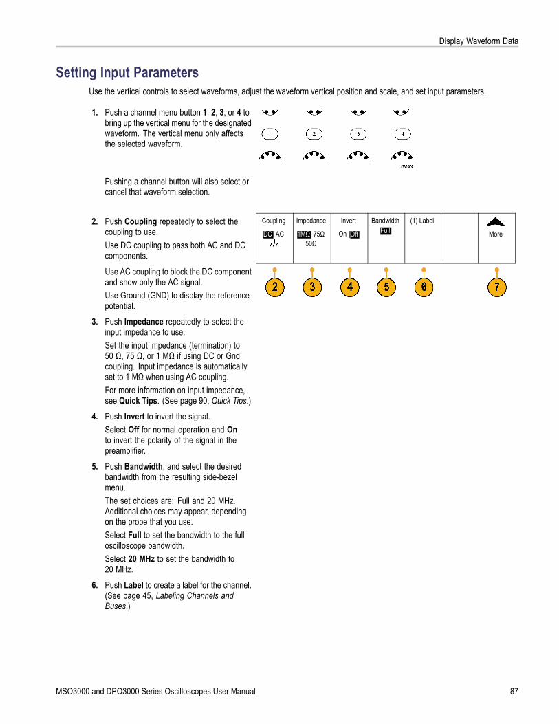
Display Waveform Data
Setting Input ParametersUse the vertical controls to select waveforms, adjust the waveform vertical position and scale, and set input parameters.
1. Push a channel menu button 1, 2, 3, or 4 tobring up the vertical menu for the designatedwaveform. The vertical menu only affectsthe selected waveform.
Pushing a channel button will also select orcancel that waveform selection.
2. Push Coupling repeatedly to select thecoupling to use.Use DC coupling to pass both AC and DCcomponents.
Coupling
DC| AC
Impedance
1MΩ| 75Ω50Ω
Invert
On |Off
BandwidthFull
(1) Label
More
Use AC coupling to block the DC componentand show only the AC signal.Use Ground (GND) to display the referencepotential.
3. Push Impedance repeatedly to select theinput impedance to use.Set the input impedance (termination) to50 Ω, 75 Ω, or 1 MΩ if using DC or Gndcoupling. Input impedance is automaticallyset to 1 MΩ when using AC coupling.For more information on input impedance,see Quick Tips. (See page 90, Quick Tips.)
4. Push Invert to invert the signal.Select Off for normal operation and Onto invert the polarity of the signal in thepreamplifier.
5. Push Bandwidth, and select the desiredbandwidth from the resulting side-bezelmenu.The set choices are: Full and 20 MHz.Additional choices may appear, dependingon the probe that you use.Select Full to set the bandwidth to the fulloscilloscope bandwidth.Select 20 MHz to set the bandwidth to20 MHz.
6. Push Label to create a label for the channel.(See page 45, Labeling Channels andBuses.)
MSO3000 and DPO3000 Series Oscilloscopes User Manual 87

Display Waveform Data
7. Push More to access additional side-bezelmenus.
8. Select Fine Scale to enable multipurposeknob a to make fine vertical scaleadjustments.
Fine Scale
Offset
Position
ProbeSetup
Deskew
9. Select Offset to enable multipurpose knob ato make vertical offset adjustments.On the side-bezel menu, choose Set to 0 Vto set the vertical offset to 0 V.For more information on offset, see QuickTips. (See page 90, Quick Tips.)
10. Select Probe Setup to define probeparameters.On the resulting side-bezel menu:
Select Voltage or Current to set theprobe type for probes that do not havethe TekProbe Level 1, TekProbe II(requires a TPA-BNC adapter) or TekVPIinterface.
For probes that do not have a Tekinterface, when Probe Type is set toVoltage, use multipurpose knob a to setthe Attenuation to match the probe.
For probes that do not have a Tekinterface, when Probe Type is set toCurrent, use multipurpose knob a to setthe Amps/Volts ratio (Attenuation) tomatch the probe.
88 MSO3000 and DPO3000 Series Oscilloscopes User Manual

Display Waveform Data
If you are measuring current by probingthe voltage drop across a resistor,set Measure Current to Yes. Pushthe A/V ratio side-bezel button andturn multipurpose knob a to set theAmps/Volts or Volts/Amps ratio ofyour setup. For example, if you aremeasuring the drop across a 2 Ohmresistor, set the V/A ratio to 2.
11. Select Deskew to make display andmeasurement adjustments for probes thathave differing propagation delays. This isespecially important when using a currentprobe in conjunction with a voltage probe.For best results, use a deskew fixture, suchas the Tektronix 067-1686-xx.
If you do not have a deskew fixture, youcan use the controls in the Deskew menu toset the oscilloscope’s deskew parametersto recommended values, based on thenormal propagation delay of each probe.The oscilloscope automatically loads thenominal propagation delay values of TekVPIand TekProbe II (requires use of a TPA-BNCadapter) probes. For other common probes,first push the side-bezel Select button, andselect the channel to which the probe isattached. Then push the side-bezel ProbeModel button, and select the probe model.If your probe is not in the list, set the probemodel to Other, and push the side-bezelPropagation Delay button and dial in itspropagation delay with multipurpose knob a.
MSO3000 and DPO3000 Series Oscilloscopes User Manual 89

Display Waveform Data
To display the recommended deskew valuescalculated by the oscilloscope, set theside-bezel Show rec. deskews to Yes.
To set the deskew value of each channel to therecommended value, push the side-bezel Setall deskews to recommended value button.
Quick TipsUsing Probes with the TekProbe II and TekVPI Interfaces. When you attach a probe with the TekProbe II or theTekVPI interface, the oscilloscope sets the channel sensitivity, coupling, and termination resistance automatically tomatch the probe requirements. Tek Probe II probes require use of the TPA-BNC Adapter.
The Difference Between Vertical Position and Offset. Adjust the vertical position to place the waveforms where youwant to see them. The waveform baseline indicators indicate the zero Volts (or Amps) level for each waveform. If youadjust the channel’s Vertical Scale, the waveform expands or contracts around the waveform’s baseline indicator.
When you use the Channel<x>> More > Offset > Vertical Offset control to move a waveform, the baseline indicatorno longer represents zero. Instead, it represents the level of the offset. If you adjust the channel’s Vertical Scale, thewaveform expands or contracts around the waveform’s baseline indicator.
50 and 75 Ω Protection. If you select 50 Ω or 75 Ω termination, the maximum vertical scale factor is limited to 1 V/div,except that with a 10X probe the scale factor is 10 V. If you apply excessive input voltage, the oscilloscope automaticallyswitches to 1 MΩ termination to protect the internal 50 Ω or 75 Ω termination. For more details, refer to the specificationsin the DPO3000 Series Oscilloscopes Technical Reference.
Positioning and Labeling Bus SignalsPositioning bus signals. Push the appropriate front-panel bus button and turn multipurpose knob a to adjust the verticalposition of the selected bus. (See page 54, Setting Up a Serial or Parallel Bus.)
1. Push the appropriate front-panel bus buttonto select that bus.
2. Turn multipurpose knob a to adjust thevertical position of the selected bus.
90 MSO3000 and DPO3000 Series Oscilloscopes User Manual
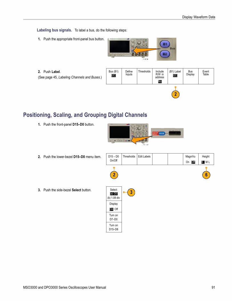
Display Waveform Data
Labeling bus signals. To label a bus, do the following steps:
1. Push the appropriate front-panel bus button.
2. Push Label.(See page 45, Labeling Channels and Buses.)
Bus (B1)I2C
DefineInputs
Thresholds IncludeR/W inaddress
No
(B1) LabelI2C
BusDisplay
EventTable
Positioning, Scaling, and Grouping Digital Channels1. Push the front-panel D15–D0 button.
2. Push the lower-bezel D15–D0 menu item. D15 – D0On/Off
Thresholds Edit Labels MagniVu
On |Off
Height
S | M L
3. Push the side-bezel Select button. Select(a) D0
(b) 1.08 div
Display
On| Off
Turn onD7–D0
Turn onD15–D8
MSO3000 and DPO3000 Series Oscilloscopes User Manual 91

Display Waveform Data
4. Turn multipurpose knob a to select thechannel to move.
5. Turn multipurpose knob b to move theselected channel.
NOTE. The display of the channel (or group)only moves after you stop rotating the knob.
6. To change the scale (height) of the digitalchannels, push the lower-menu Heightbutton.
NOTE. The S (Small) selection will displayeach waveform at 0.2 divisions tall. The M(Medium) selection will display each waveformat 0.5 divisions tall. The L (Large) selection willdisplay each waveform at 1 division tall. L onlyworks if there is enough room in the display todisplay the waveforms. You can display up to 8Lwaveforms at one time.
7. You can label individual digital channels foreasier identification. (See page 45, LabelingChannels and Buses.)
8. To group some or all of the digital channelstogether, move the channels right next toeach other. All the channels that are next toeach other automatically form a group.You can see the groups by pressingthe side-bezel Select item and turningmultipurpose knob a.When a group is selected, turn multipurposeknob b to move the whole group.
92 MSO3000 and DPO3000 Series Oscilloscopes User Manual

Display Waveform Data
Viewing Digital ChannelsThe various ways of displaying data from the digital channels help you analyze the signals. Digital channels store a high orlow state for each sample.
Logic high levels are displayed in green. Logic low levels are displayed in blue. When a single transition occurs during thetime represented by one pixel column, the transition (edge) is displayed in gray.
When multiple transitions occur during the timerepresented by one pixel column, the transition (edge)is displayed in white.When the display shows a white edge, indicating multipletransitions, you may be able to zoom in and see theindividual edges.
When the oscilloscope is zoomed in so far that there ismore than one pixel column per sample, the uncertaintyof the edge position is indicated by light gray shading.
NOTE. When the light gray shading is displayed, useMagniVu. The MagniVu readout appears when MagniVuis being used.
Annotating the ScreenYou can add your own text to the screen by doing the following:
1. Push Utility.
2. Push Utility Page. UtilityPage
MSO3000 and DPO3000 Series Oscilloscopes User Manual 93

Display Waveform Data
3. Turn multipurpose knob a and selectDisplay.
Display
4. Push Screen Annotation from the resultinglower-bezel menu.
UtilityPage
Display
BacklightIntensity
High
GraticuleFull
ScreenAnnotation
5. Push Display Annotation to select On fromthe side-bezel menu.The annotation window now appears.Position it by turning multipurpose knobs aand b.
6. Push Edit Annotation from the side-bezelmenu
7. Turn multipurpose knob a to scroll throughthe list of letters, numbers, and othercharacters to select each desired character.Alternatively, use a US-style USB keyboardto type in characters. (See page 27,Connecting a USB Keyboard to YourOscilloscope.)To reposition the annotated text, pressthe side-bezel Position button and turnmultipurpose knobs a and b, as desired.
Viewing the Trigger FrequencyYou can display a readout of trigger frequency. It counts all of the triggerable events, whether the oscilloscope triggered onthem or not, and displays the number of times per second that they occur. To display this readout, do the following:
1. Push Utility.
2. Push Utility Page. UtilityPage
94 MSO3000 and DPO3000 Series Oscilloscopes User Manual

Display Waveform Data
3. Turn multipurpose knob a and selectDisplay.
Display
4. Push Trigger Frequency Readout from theresulting lower-bezel menu.
UtilityPage
Display
BacklightIntensity
High
GraticuleFull
ScreenAnnotation
TriggerFrequencyReadout
5. Push On from the side-bezel menu.
The trigger frequency now appears in theTrigger readout, towards the lower right ofthe display.
MSO3000 and DPO3000 Series Oscilloscopes User Manual 95

Analyze Waveform Data
Analyze Waveform DataAfter having properly set up the acquisition, triggering, and display of your desired waveform, you can then analyze theresults. Select from features such as cursors, automatic measurements, statistics, math, and FFT.
Taking Automatic MeasurementsTo take an automatic measurement:
1. Push Measure.
2. Push Add Measurement. Add Mea-surement
RemoveMeasure-
ment
Indicators
More
BringCursors on
Screen
ConfigureCursors
3. Turn multipurpose knob a to select thespecific measurement. If needed, then turnmultipurpose knob b to select the channel tomeasure on.
4. To remove a measurement, push RemoveMeasurement, turn multipurpose knob ato select the specific measurement, andpush OK Remove Measurement on theside-bezel menu.
Quick TipsTo remove all measurements, select Remove All Measurements.
A symbol appears instead of the expected numerical measurement if a vertical clipping condition exists. Part of thewaveform is above or below the display. To obtain a proper numerical measurement, turn the vertical scale and positionknobs to make all of the waveform appear in the display.
96 MSO3000 and DPO3000 Series Oscilloscopes User Manual

Analyze Waveform Data
Selecting Automatic MeasurementsThe following tables list each automatic measurement by category: time or amplitude. (See page 96, Taking AutomaticMeasurements.)
Time MeasurementsMeasurement DescriptionPeriod The time required to complete the first cycle in a waveform or gated region. Period is
the reciprocal of frequency and is measured in seconds.
Frequency The first cycle in a waveform or gated region. Frequency is the reciprocal of the period; itis measured in hertz (Hz) where one Hz is one cycle per second.
Delay The time between the mid reference (default 50%) amplitude point of two differentwaveforms. See also Phase.
Rise Time The time required for the leading edge of the first pulse in the waveform or gated regionto rise from the low reference value (default = 10%) to the high reference value (default =90%) of the final value.
Fall Time The time required for the falling edge of the first pulse in the waveform or gated region tofall from the high reference value (default = 90%) to the low reference value (default =10%) of the final value.
Positive DutyCycle
The ratio of the positive pulse width to the signal period expressed as a percentage. Theduty cycle is measured on the first cycle in the waveform or gated region.
Negative DutyCycle
The ratio of the negative pulse width to the signal period expressed as a percentage.The duty cycle is measured on the first cycle in the waveform or gated region.
Positive PulseWidth
The distance (time) between the mid reference (default 50%) amplitude points of apositive pulse. The measurement is made on the first pulse in the waveform or gatedregion.
Negative PulseWidth
The distance (time) between the mid reference (default 50%) amplitude points of anegative pulse. The measurement is made on the first pulse in the waveform or gatedregion.
Burst Width The duration of a burst (a series of transient events) and is measured over the entirewaveform or gated region.
MSO3000 and DPO3000 Series Oscilloscopes User Manual 97

Analyze Waveform Data
Time Measurements (cont.)
Measurement DescriptionPhase The amount of time that one waveform leads or lags another waveform, expressed in
degrees where 360° makes up one waveform cycle. See also Delay.
Amplitude MeasurementsMeasurement DescriptionPositiveOvershoot
This is measured over the entire waveform or gated region and is expressed as:Positive Overshoot = (Maximum – High) / Amplitude x 100%.
NegativeOvershoot
This is measured over the entire waveform or gated region and is expressed as:Negative Overshoot = (Low – Minimum) / Amplitude x 100%.
Pk-Pk The absolute difference between the maximum and minimum amplitude in the entirewaveform or gated region.
Amplitude The high value less the low value measured over the entire waveform or gated region.
High This value is used as 100% whenever high reference, mid reference, or low referencevalues are needed, such as in fall time or rise time measurements. Calculate using eitherthe min/max or histogram method. The min/max method uses the maximum value found.The histogram method uses the most common value found above the midpoint. Thisvalue is measured over the entire waveform or gated region.
Low This value is used as 0% whenever high reference, mid reference, or low referencevalues are needed, such as in fall time or rise time measurements. Calculate using eitherthe min/max or histogram method. The min/max method uses the minimum value found.The histogram method uses the most common value found below the midpoint. Thisvalue is measured over the entire waveform or gated region.
Max The most positive peak voltage. Max is measured over the entire waveform or gatedregion.
98 MSO3000 and DPO3000 Series Oscilloscopes User Manual

Analyze Waveform Data
Amplitude Measurements (cont.)
Measurement DescriptionMin The most negative peak voltage. Min is measured over the entire waveform or gated
region.
Mean The arithmetic mean over the entire waveform or gated region.
Cycle Mean The arithmetic mean over the first cycle in the waveform or the first cycle in the gatedregion.
RMS The true Root Mean Square voltage over the entire waveform or gated region.
Cycle RMS The true Root Mean Square voltage over the first cycle in the waveform or the firstcycle in the gated region.
Miscellaneous MeasurementsMeasurement DescriptionRising EdgeCount
The number of positive transitions from the low reference value to the high referencevalue in the waveform or gated region.
Falling EdgeCount
The number of negative transitions from the high reference value to the low referencevalue in the waveform or gated region.
Positive PulseCount
The number of positive pulses that rise above the mid reference crossing in the waveformor gated region.
Negative PulseCount
The number of negative pulses that fall below the mid reference crossing in the waveformor gated region.
Area Area measurement is a voltage over time measurement. It returns the area over theentire waveform or gated region in volt-seconds. Area measured above ground ispositive; area measured below ground is negative.
Cycle Area A voltage over time measurement. The measurement is the area over the first cyclein the waveform or the first cycle in the gated region expressed in volt-seconds. Thearea above the common reference point is positive, and the area below the commonreference point is negative.
MSO3000 and DPO3000 Series Oscilloscopes User Manual 99

Analyze Waveform Data
Customizing an Automatic MeasurementYou can customize automatic measurements by using gating, modifying measurement statistics, adjusting the measurementreference levels, or taking a snapshot.
GatingGating confines the measurement to a certain portion of a waveform. To use:
1. Push Measure.
2. Push More as many times as needed toselect Gating from the resulting pop-upmenu.
Add Mea-surement
RemoveMeasure-
ment
Indicators
More
BringCursors
On Screen
ConfigureCursors
3. Position the gates from the side-bezel menuoptions.
Gating
Off(Full
Record)
Screen
BetweenCursors
BringCursors
On Screen
100 MSO3000 and DPO3000 Series Oscilloscopes User Manual
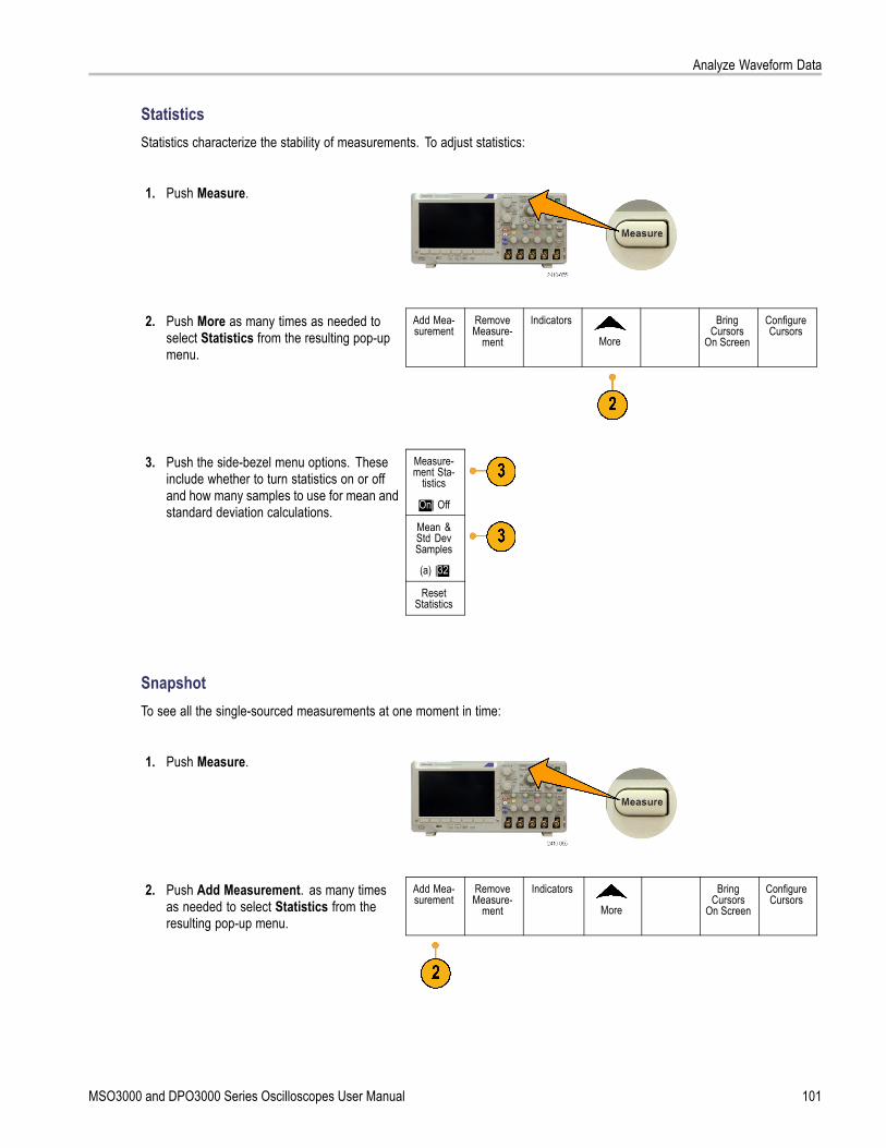
Analyze Waveform Data
StatisticsStatistics characterize the stability of measurements. To adjust statistics:
1. Push Measure.
2. Push More as many times as needed toselect Statistics from the resulting pop-upmenu.
Add Mea-surement
RemoveMeasure-
ment
Indicators
More
BringCursors
On Screen
ConfigureCursors
Measure-ment Sta-
tistics
On| Off
Mean &Std DevSamples
(a) |32
3. Push the side-bezel menu options. Theseinclude whether to turn statistics on or offand how many samples to use for mean andstandard deviation calculations.
ResetStatistics
SnapshotTo see all the single-sourced measurements at one moment in time:
1. Push Measure.
2. Push Add Measurement. as many timesas needed to select Statistics from theresulting pop-up menu.
Add Mea-surement
RemoveMeasure-
ment
Indicators
More
BringCursors
On Screen
ConfigureCursors
MSO3000 and DPO3000 Series Oscilloscopes User Manual 101

Analyze Waveform Data
3. Turn multipurpose knob a to select theMeasurement Type of Snapshot.
4. Push OK Snapshot All Measurements. OKSnapshotAll Mea-
surements
5. View results.
Snapshot on 1
Period+Width
Burst WRise
+Duty+Over
HighMax
AmplMeanRMSArea
: 312.2μs: 103.7μs: 936.5μs: 1.452μs: 33.23%: 7.143%: 9.200 V: 10.40 V: 16.80 V: -5.396 V: 7.769 V: -21.58mVs
Freq–Width
Fall–Duty–Over
LowMin
Pk-PkCycleMeanCycleRMSCycleArea
: 3.203kHz: 208.5μs
: 1.144μs: 66.77 %: 7.143 %: -7.600 V: -8.800 V: 19.20 V: -5.396 V: 8.206 V: -654.6μVs
Reference Levels
Reference levels determine how time-relatedmeasurements are taken. For example, they areused in calculating rise and fall times.
1. Push Measure.
102 MSO3000 and DPO3000 Series Oscilloscopes User Manual

Analyze Waveform Data
2. Push More as many times as needed toselect Reference Levels from the resultingpop-up menu.
Add Mea-surement
RemoveMeasure-
ment
Indicators
More
BringCursors
On Screen
ConfigureCursors
3. Set the levels from the side-bezel menu. ReferenceLevels
Set Levelsin
% |Units
Use High and Low reference to calculaterise and fall times.
High Ref(a) 90.0 %
Use Mid reference primarily formeasurements between edges, suchas pulse widths.
Mid Ref50.0 %50.0 %
Low Ref10.0 %
- Set toDefaults
Taking Manual Measurements with CursorsCursors are on-screen markers that you position in the waveform display to take manual measurements on acquired data.They appear as horizontal and/or as vertical lines. To use cursors:
1. Push Cursors.This changes the cursor state. The threestates are:
No cursors appear on the screen.
Two vertical waveform cursorsappear. They are attached to theselected waveform.
Four screen cursors appear. Two arevertical and two are horizontal. Theyare no longer specifically attached toa waveform.
For example, the first time you pushCursors, the state might be off.
MSO3000 and DPO3000 Series Oscilloscopes User Manual 103

Analyze Waveform Data
2. Push Cursors again.In the example, two vertical cursorsappear on the selected screen waveform.As you turn multipurpose knob a, youmove one cursor to the right or left. Asyou turn knob b, you move the othercursor.If you change the selected waveform bypushing the front-panel 1, 2, 3, 4, M, orR button, both cursors jump to the newselected waveform.
3. Push Select.This turns the cursor linking on and off. Iflinking is on, turning multipurpose knob amoves the two cursors together. Turningmultipurpose knob b adjusts the timebetween the cursors.
4. Push Fine to toggle between a coarseand a fine adjustment for multipurposeknobs a and b.Pushing Fine also changes the sensitivityof other knobs as well.
5. Push Cursors again.This will put the cursors into screenmode. Two horizontal bars and twovertical bars span the graticule.
6. Turn multipurpose knobs a and b tomove the pair of horizontal cursors.
104 MSO3000 and DPO3000 Series Oscilloscopes User Manual

Analyze Waveform Data
7. Push Select.This makes the horizontal cursors activeand the vertical ones inactive. Now, asyou turn the multipurpose knobs, thehorizontal cursors will move.Push Select again to make the verticalcursors active again.
8. View the cursor and the cursor readout.You can take timing measurements withcursors on digital channels, but notamplitude measurements.
MSO3000 and DPO3000 Series Oscilloscopes User Manual 105

Analyze Waveform Data
9. Push Cursors again. This will turn offthe cursor mode. The screen will nolonger display the cursors and the cursorreadout.
Using Cursor ReadoutsCursor readouts supply textual and numeric information relating to the current cursor positions. The oscilloscope alwaysshows the readouts when the cursors are turned on.
Readouts appear in the upper right corner of the graticule. If Zoom is on, the readout appears in the upper right corner ofthe zoom window.
When a bus is selected, the readout shows the decoded bus data in the format you have selected, hexadecimal, binary,decimal, or ASCII (depending on the selected standard). The data value of that point is displayed in the cursor readout.
Δ Readout:The Δ readouts indicate the differencebetween the cursor positions.
a Readout:Indicates that the value is controlled bymultipurpose knob a.
b Readout:Indicates that the value is controlled bymultipurpose knob b.
The horizontal cursor lines on the displaymeasure the vertical parameters, typicallyvoltage.
106 MSO3000 and DPO3000 Series Oscilloscopes User Manual

Analyze Waveform Data
The vertical cursor lines on the displaymeasure horizontal parameters, typicallytime.
The square and circle shapes in the readout map to the multipurpose knobs when both vertical and horizontal cursorsare present.
Using XY CursorsWhen the XY Display mode is on, the cursor readouts will appear to the right of the graticule. They include rectangular,polar, product, and ratio readouts.
Using Math WaveformsCreate math waveforms to support the analysis of your channel and reference waveforms. By combining and transformingsource waveforms and other data into math waveforms, you can derive the data view that your application requires.
NOTE. Math waveforms are not available for use with serial buses.
MSO3000 and DPO3000 Series Oscilloscopes User Manual 107

Analyze Waveform Data
Use the following procedure for executing simple (+, –, ×, ÷) math operations on two waveforms:
1. Push Math.
2. Push Dual Wfm Math. Dual WfmMath
FFT AdvancedMath
(M) Label
3. On the side-bezel menu, set the sourcesto either channel 1, 2, 3, 4, or referencewaveforms R1, R2, R3, or R4. Choose the+, –, x, or ÷ operators.
4. For example, you might calculate powerby multiplying a voltage waveform and acurrent waveform.
Quick TipsMath waveforms can be created from channel or reference waveforms or a combination of them.
Measurements can be taken on math waveforms in the same way as on channel waveforms.
Math waveforms derive their horizontal scale and position from the sources in their math expressions. Adjusting thesecontrols for the source waveforms also adjusts the math waveform.
You can zoom in on math waveforms using the inner knob of the Pan-Zoom control. Use the outer knob for positioningthe zoomed area. (See page 114, Using Wave Inspector to Manage Long Record Length Waveforms.)
108 MSO3000 and DPO3000 Series Oscilloscopes User Manual
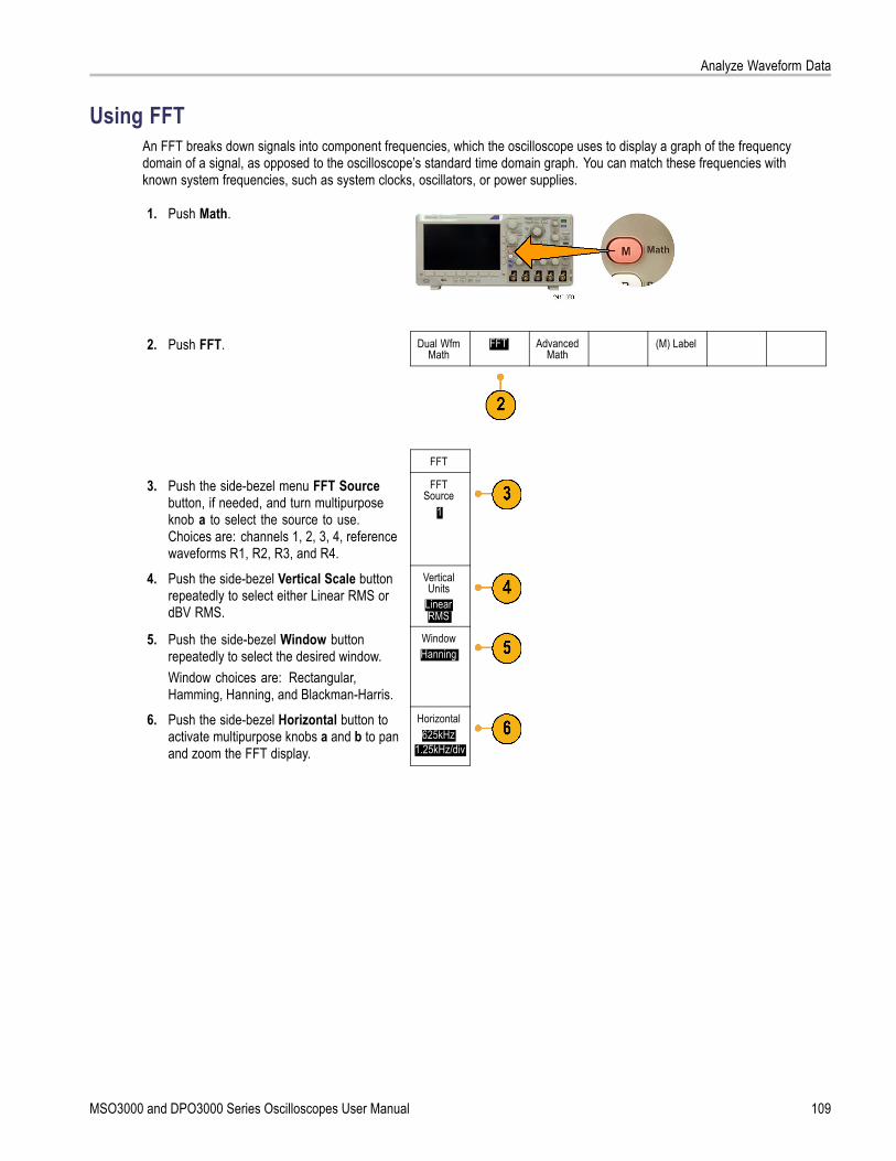
Analyze Waveform Data
Using FFTAn FFT breaks down signals into component frequencies, which the oscilloscope uses to display a graph of the frequencydomain of a signal, as opposed to the oscilloscope’s standard time domain graph. You can match these frequencies withknown system frequencies, such as system clocks, oscillators, or power supplies.
1. Push Math.
2. Push FFT. Dual WfmMath
FFT AdvancedMath
(M) Label
FFT
3. Push the side-bezel menu FFT Sourcebutton, if needed, and turn multipurposeknob a to select the source to use.Choices are: channels 1, 2, 3, 4, referencewaveforms R1, R2, R3, and R4.
FFTSource
1
4. Push the side-bezel Vertical Scale buttonrepeatedly to select either Linear RMS ordBV RMS.
VerticalUnits
LinearRMS
5. Push the side-bezel Window buttonrepeatedly to select the desired window.Window choices are: Rectangular,Hamming, Hanning, and Blackman-Harris.
WindowHanning
6. Push the side-bezel Horizontal button toactivate multipurpose knobs a and b to panand zoom the FFT display.
Horizontal625kHz
1.25kHz/div
MSO3000 and DPO3000 Series Oscilloscopes User Manual 109

Analyze Waveform Data
7. The FFT will appear on the display.
Quick TipsUse short record lengths for faster instrument response.
Use long record lengths to lower the noise relative to the signal and increase the frequency resolution.
If desired, use the zoom feature along with the horizontal Position and Scale controls to magnify and position theFFT waveform.
Use the default dBV RMS scale to see a detailed view of multiple frequencies, even if they have very different amplitudes.Use the linear RMS scale to see an overall view of how all frequencies compare to each other.
The FFT feature provides four windows. Each is a trade-off between frequency resolution and magnitude accuracy.What you want to measure and your source signal characteristics help determine which window to use. Use the followingguidelines to select the best window.
Description WindowRectangularThis is the best type of window for resolving frequencies that are very close to the samevalue but worst for accurately measuring the amplitude of those frequencies. It is the besttype for measuring the frequency spectrum of nonrepetitive signals and measuring frequencycomponents near DC.Use Rectangular for measuring transients or bursts where the signal level before and after theevent are nearly equal. Also, use this window for equal-amplitude sine waves with frequenciesthat are very close and for broadband random noise with a relatively slow varying spectrum.HammingThis is a very good window for resolving frequencies that are very close to the same valuewith somewhat improved amplitude accuracy over the rectangular window. It has a slightlybetter frequency resolution than the Hanning.Use Hamming for measuring sine, periodic, and narrow band random noise. This windowworks on transients or bursts where the signal levels before and after the event aresignificantly different.
110 MSO3000 and DPO3000 Series Oscilloscopes User Manual

Analyze Waveform Data
Description WindowHanningThis is a very good window for measuring amplitude accuracy but less so for resolvingfrequencies.Use Hanning for measuring sine, periodic, and narrow band random noise. This windowworks on transients or bursts where the signal levels before and after the event aresignificantly different.Blackman-Harris:This is the best window for measuring the amplitude of frequencies but worst at resolvingfrequencies.Use Blackman-Harris for measuring predominantly single frequency waveforms to look forhigher order harmonics.
Using Advanced MathThe advanced math feature lets you create a custom math waveform expression that can incorporate active and referencewaveforms, measurements, and/or numeric constants. To use this feature:
1. Push Math.
2. Push Advanced Math. Dual WfmMath
FFT AdvancedMath
3. Use the side-bezel menu buttons to createcustom expressions.
4. Push Edit Expression and use themultipurpose knobs and the resultinglower-bezel buttons to create an expression.When done, push the side-bezel menu OKAccept button.
MSO3000 and DPO3000 Series Oscilloscopes User Manual 111

Analyze Waveform Data
For example, to use Edit Expression to take the integral of a square wave:
1. Push the lower-bezel Clear button.
2. Turn multipurpose knob a to select Intg(.
3. Push Enter Selection.
4. Turn multipurpose knob a to selectchannel 1.
5. Push Enter Selection.
6. Turn multipurpose knob a to select ).
7. Push OK Accept.
Using Reference WaveformsCreate a reference waveform to store a waveform. For example, you might do this to set up a standard against which tocompare other waveforms. To use the reference waveforms:
NOTE. 5 M reference waveforms are volatile and not saved when the oscilloscope power is turned off. To keep thesewaveforms, save them to external storage.
1. Push Ref R. This brings up the lower-bezelreference menu.
2. Use the resulting lower-bezel menuselections to display or select a referencewaveform.
(R1) |(On)3-May-07
(R2) |(Off) (R3) |(Off) (R4) |(Off)
112 MSO3000 and DPO3000 Series Oscilloscopes User Manual
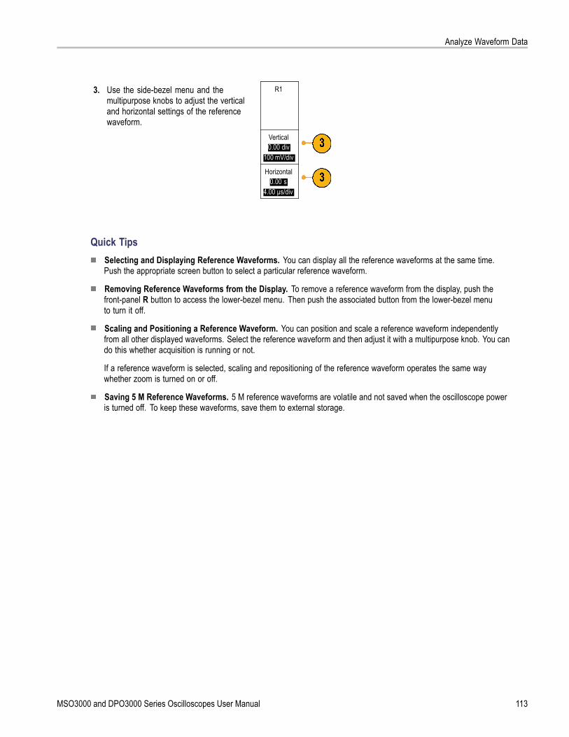
Analyze Waveform Data
3. Use the side-bezel menu and themultipurpose knobs to adjust the verticaland horizontal settings of the referencewaveform.
R1
Vertical0.00 div
100 mV/div
Horizontal0.00 s
4.00 μs/div
Quick TipsSelecting and Displaying Reference Waveforms. You can display all the reference waveforms at the same time.Push the appropriate screen button to select a particular reference waveform.
Removing Reference Waveforms from the Display. To remove a reference waveform from the display, push thefront-panel R button to access the lower-bezel menu. Then push the associated button from the lower-bezel menuto turn it off.
Scaling and Positioning a Reference Waveform. You can position and scale a reference waveform independentlyfrom all other displayed waveforms. Select the reference waveform and then adjust it with a multipurpose knob. You cando this whether acquisition is running or not.
If a reference waveform is selected, scaling and repositioning of the reference waveform operates the same waywhether zoom is turned on or off.
Saving 5 M Reference Waveforms. 5 M reference waveforms are volatile and not saved when the oscilloscope poweris turned off. To keep these waveforms, save them to external storage.
MSO3000 and DPO3000 Series Oscilloscopes User Manual 113

Analyze Waveform Data
Using Wave Inspector to Manage Long Record Length WaveformsThe Wave Inspector controls (zoom/pan, play/pause, marks, search) help you to efficiently work with long record lengthwaveforms. To magnify a waveform horizontally, turn the Zoom knob. To scroll through a zoomed waveform, turn thePan knob.
The Pan-Zoom Control consists of:
1. An outer pan knob
2. An inner zoom knob
Zooming a WaveformTo use zoom:
1. Rotate the inner knob on the Pan-Zoomcontrol clockwise to zoom in on aselected portion of the waveform. Rotatethe knob counterclockwise to zoom backout.
2. Alternatively, enable or disable the zoommode by pushing the zoom button.
114 MSO3000 and DPO3000 Series Oscilloscopes User Manual

Analyze Waveform Data
3. Examine the zoomed view of thewaveform that appears on the larger,lower portion of the display. The upperportion of the display will show theposition and size of the zoomed portionin the waveform, within the context of theoverall record.
Panning a WaveformWhile the zoom feature is on, you can use the pan feature to quickly scroll through the waveform. To use pan:
1. Rotate the pan (outer) knob ofthe pan-zoom controls to pan thewaveform.Turn the knob clockwise to panforward. Turn it counterclockwise topan backwards. The further you turnthe knob, the faster the zoom windowpans.
Playing and Pausing a WaveformUse the play-pause feature to automatically pan through a waveform record. To use it:
1. Enable the play-pause mode bypushing the play-pause button.
2. Adjust the play speed by turning thepan (outer) knob further. The furtheryou turn it, the faster it goes.
MSO3000 and DPO3000 Series Oscilloscopes User Manual 115

Analyze Waveform Data
3. Change the play direction by reversingthe direction that you are turning thepan knob.
4. During play, up to a point, the more youturn the ring, the faster the waveformaccelerates. If you rotate the ring asfar as it can go, the play speed doesnot change, but the zoom box quicklymoves in that direction. Use thismaximum rotation feature to replay aportion of the waveform that you justsaw and want to see again.
5. Pause the play-pause feature bypushing the play-pause button again.
Searching and Marking WaveformsYou can mark locations of interest in the acquired waveform. These marks help you limit your analysis to particular regions ofthe waveform. You can mark areas of the waveform automatically, if they meet some special criteria, or you can manuallymark each item of interest. You can use arrow keys to jump from mark to mark (area of interest to area of interest). You canautomatically search and mark many of the same parameters that you can trigger on.
Search marks provide a way to mark a waveform region for reference. You can set marks automatically with searchcriteria. You can search for and mark regions with particular edges, pulse widths, runts, logic states, rise/fall times, setupand hold, and bus search types.
116 MSO3000 and DPO3000 Series Oscilloscopes User Manual

Analyze Waveform Data
To manually set and clear (delete) marks:
1. Move (the zoom box) to the area on thewaveform where you want to set (orclear) a search mark by turning the pan(outer) knob.Push the next ( →) or previous (←)arrow button to jump to an existing mark.
2. Push Set/Clear.If no search mark is at the screen center,the oscilloscope will add one.
3. Investigate your waveform by movingfrom search mark to search mark. Usethe next ( →) or previous (←) arrowbutton to jump from one marked locationto another, without adjusting any othercontrols.
4. Delete a mark. Push the next ( →) orprevious (←) arrow button to jump to themark you want to clear. To remove thecurrent, center-positioned mark, pushSet/Clear. It works on both manuallyand automatically created marks.
To automatically set and clear (delete) search marks:
1. Push Search.
2. Select the search type desired from thelower-bezel menu.
SearchOff
SearchTypeEdge
Source1
Slope Threshold0.00V
The search menu is similar to the triggermenu.
3. From the side-bezel menu, turn on thesearch.
MSO3000 and DPO3000 Series Oscilloscopes User Manual 117

Analyze Waveform Data
4. On the screen, hollow triangles show thelocation of automatic marks and solidtriangles show the custom (user-defined)locations. These appear on both normal andzoomed waveform views.
5. You can quickly investigate your waveformby moving from search mark to search markwith the next ( →) and previous (←) arrowbuttons. No other adjustments are needed.
Quick Tips.You can copy trigger settings to search for other locations in your acquired waveform that meet the trigger conditions.
You can also copy search settings to your trigger.
Custom (User) marks are saved with the waveform when the waveform is saved and when the setup is saved.
Automatic search marks are not saved with the waveform when the waveform is saved. However, you can easilyrecapture them by reusing the search function.
The search criteria are saved in the saved setup.
The Wave Inspector includes the following search capabilities:
Search DescriptionEdge Searches for edges (rising or falling) with a user-specified threshold level.Pulse Width Searches for positive or negative pulse widths that are >, <, =, or ≠ a user specified pulse
width.Runt Searches for positive or negative pulses that cross one amplitude threshold but fail to cross
a second threshold before crossing the first again. Search for all runt pulses or only thosewith a duration >, <, =, or ≠ a user specified time.
Logic Search for a logic pattern (AND, OR, NAND, or NOR) across multiple waveforms with eachinput set to either High, Low, or Don’t Care. Search for when the event goes true, goesfalse, or stays valid for >, <, =, or ≠ a user specified time. Additionally, you can define oneof the inputs as a clock for synchronous (state) searches.
Setup & Hold Search for violations of user specified Setup and Hold times.Rise/Fall Time Search for rising and/or falling edges that are >, <, =, or ≠ a user specified time.
118 MSO3000 and DPO3000 Series Oscilloscopes User Manual

Analyze Waveform Data
Search DescriptionBus Parallel: Search for a binary or hex value (MSO3000 Series only).
I2C: Search for Start, Repeated Start, Stop, Missing Ack, Address, Data, or Address andData.SPI: Search for SS Active, MOSI, MISO, or MOSI & MISORS-232, RS-422, RS-485, UART: Search for Tx Start Bit, Rx Start Bit, Tx End of Packet, RxEnd of Packet, Tx Data, Rx Data, Tx Parity Error, Rx Parity Error.CAN: Search for Start of Frame, Type of Frame (Data, Remote, Error, Overload), Identifier(standard or extended), Data, Identifier and Data, End of Frame, or Missing Ack, Bit StuffingErrorLIN: Search for Synch, Identifier, Data, ID & Data, Wakeup Frame, Sleep Frame, ErrorI2S, LF, RJ: Search for Word Select or Data.TDM: Search for Frame Sync or Data.
Analyzing PowerAcquire, measure, and analyze power signals with the DPO3PWR Power Analysis Module. To use this application:
1. Push Test.
2. Push Analysis. Application AnalysisNone
3. Use the side-bezel buttons to select thedesired analysis function.Choose among power quality, switchingloss, harmonics, ripple, modulation, andsafe operating area, and deskew.
MSO3000 and DPO3000 Series Oscilloscopes User Manual 119

Save and Recall Information
Save and Recall InformationThe oscilloscope provides permanent storage for setups, waveforms, and screen images. Use the internal storage of theoscilloscope to save setup files and reference waveform data.
Use external USB flash drives, to save setups, waveforms, and screen images. Use the external storage to carry data toremote computers for further analysis and for archiving.
External file structure. If you are saving information to external storage, select the appropriate menu (such as the ToFile side-bezel menu to save setups and waveforms) and turn multipurpose knob a to scroll through the external file structure.
E: is the USB flash drive plugged into the USB port on the front of the oscilloscope
F: is the USB flash drive plugged into the USB port on the rear of the oscilloscope
Use multipurpose knob a to scroll through the list of files. Use the Select front panel button to open and close folders.
Naming your file. The oscilloscope gives all files it creates a default name in the following format:
tekXXXXX.set for setup files where XXXXX is an integer from 00000 to 99999
tekXXXXX.png, tekXXXXX.bmp, or tekXXXXX. tif for image files
tekXXXXYYY.csv for spreadsheet files or tekXXXXYYY.isf for internal format files
For waveforms, the XXXX is an integer from 0000 to 9999. The YYY is the channel of the waveform, and can be one ofthe following:
CH1, CH2, CH3, or CH4 for the analog channels
D00, D01, D02, D03, and so on through D15 for the digital channels
MTH for a math waveform
RF1, RF2, RF3, or RF4 for reference memory waveforms
ALL for a single spreadsheet file containing multiple channels when you select Save All Waveforms
NOTE. Only analog channels and waveforms derived from analog channels (such as math and reference) can be saved toan ISF file. When saving all channels in ISF format, a group of files will be saved. Each will have the same value for XXXX,but the YYY values will be set to the different channels that were turned on when the Save All Waveforms was performed.
For example, the first time you save a file, that file is named tek00000. The next time you save the same type of file,the file will be named tek00001.
Editing file, directory, reference waveform, or instrument setup names. Give files descriptive names that youcan recognize at a later date. To edit file names, directory names, reference waveform and instrument setup labels:
1. Push Save / Recall Menu.
120 MSO3000 and DPO3000 Series Oscilloscopes User Manual

Save and Recall Information
2. Push Save Screen Image, Save Waveform,or Save Setup.
SaveScreenImage
SaveWaveform
SaveSetup
RecallWaveform
RecallSetup
Assign
Save| toSetup
FileUtilities
3. For waveform or setup files, enter the filemanager by pushing the side-bezel menuTo File item.
To File
4. Turn multipurpose knob a to scroll throughthe file structure. (See page 120, Externalfile structure.)
5. Push Select to open or close file folders.
6. Push Edit File Name.Edit the file name the same way you editlabels for channels. (See page 45, LabelingChannels and Buses.)
7. Push the Menu Off button to cancel thesave operation, or push a side-bezel menuOK Save item to complete the operation.
OK Save
MSO3000 and DPO3000 Series Oscilloscopes User Manual 121

Save and Recall Information
Saving a Screen ImageA screen image consists of a graphical image of the oscilloscope screen. This is different from waveform data, whichconsists of numeric values for each point in the waveform. To save a screen image:
1. Push Save / Recall Menu.Do not yet push the Save button.
2. Push Save Screen Image from thelower-bezel menu.
SaveScreenImage
SaveWaveform
SaveSetup
RecallWaveform
RecallSetup
Assign
Save| toSetup
FileUtilities
122 MSO3000 and DPO3000 Series Oscilloscopes User Manual

Save and Recall Information
SaveScreenImage
3. From the side-bezel menu, push FileFormat repeatedly to select among: .tif,.bmp, and .png formats.
FileFormat
.png
4. Push Orientation to select between savingthe image in a landscape (horizontal) and aportrait (vertical) orientation.
Orientation
5. Push Ink Saver to turn the Ink Saver modeon or off. When on, this mode provides awhite background.
Ink Saver
On |Off
6. Push Edit File Name to create a customname for the screen image file. Skip thisstep to use a default name.
Edit FileName
7. Push OK Save Screen Image to write theimage to the selected media.
OK SaveScreenImage
For information on printing screen images of waveforms, go to Printing a Hard Copy. (See page 128, Printing a Hard Copy.)
Saving and Recalling Waveform DataWaveform data consists of the numeric values for each point in the waveform. It copies the data, as opposed to a graphicalimage of the screen. To save the current waveform data or to recall previously stored waveform data:
1. Push Save / Recall Menu.
MSO3000 and DPO3000 Series Oscilloscopes User Manual 123

Save and Recall Information
2. Push Save Waveform or Recall Waveformfrom the lower-bezel menu.
SaveScreenImage
SaveWaveform
SaveSetup
RecallWaveform
RecallSetup
Assign
Save| toWaveform
FileUtilities
NOTE. The oscilloscope can save digitalwaveforms to .csv files, not reference memories.The oscilloscope cannot recall digital waveforms.
3. Select one waveform or all waveforms.4. From the resulting side-bezel menu, select
the location to save the waveform data to orto recall it from.Save the information externally to a fileon a USB flash drive. Alternatively, savethe information internally to one of thetwo reference memory files on 2-channelmodel or one of the four reference files on4-channel model oscilloscopes.
5. Push File Details to save to a USB flashdrive.
File Details
This brings up the file manager screen. Useit to define a custom file name. Skip thisstep to use the default name and location.
Saving a waveform to file. When you push the File Details side-bezel menu button, the oscilloscope changes theside-bezel menu contents. The following table describes these side-bezel menu items for saving data to a mass storage file.
Side-bezel menu button DescriptionInternal File Format (.ISF) Sets the oscilloscope to save waveform data from analog channels (and math and reference
waveforms derived from analog channels), in internal waveform save file (.isf) format. Thisformat is the fastest to write and creates the smallest-sized file. Use this format if you intend torecall a waveform to reference memory for viewing or measuring.The oscilloscope cannot save digital waveforms in an .isf file format.
Spreadsheet File Format(.CSV)
Sets the oscilloscope to save waveform data as a comma-separated data file compatible withpopular spreadsheet programs. This file cannot be recalled to reference memory.
Saving an analog waveform to reference memory. To save an analog waveform to nonvolatile memory inside theoscilloscope, select the waveform that you want to save, push the Save Waveform screen button, and then select oneof the reference waveform locations. Four-channel models have four reference locations. Two-channel models have tworeference locations.
Saved waveforms contain only the most recent acquisition. Gray-scale information, if any, is not saved.
NOTE. 5 M reference waveforms are volatile and not saved when the oscilloscope power is turned off. To keep thesewaveforms, save them to external storage.
124 MSO3000 and DPO3000 Series Oscilloscopes User Manual

Save and Recall Information
Displaying a Reference WaveformTo display a waveform stored in nonvolatile memory:
1. Push Ref R.
2. Push R1, R2, R3, or R4. (R1) |(On) (R2) |(Off) (R3) |(Off) (R4) |(Off)
Removing a reference waveform from the display. To remove a reference waveform from the display:
1. Push Ref R.
2. Push the R1, R2, R3, or R4 lower-bezelbutton to remove the reference waveformfrom the display.
(R1) |(On) (R2) |(Off) (R3) |(Off) (R4) |(Off)
The reference waveform is still in nonvolatilememory and can be displayed again.
Saving and Recalling SetupsSetup information includes acquisition information, such as vertical, horizontal, trigger, cursor, and measurement information.It does not include communications information, such as GPIB addresses. To save the setup information:
1. Push Save / Recall Menu.
MSO3000 and DPO3000 Series Oscilloscopes User Manual 125

Save and Recall Information
2. Push Save Setup or Recall Setup from thelower-bezel menu.
SaveScreenImage
SaveWaveform
SaveSetup
RecallWaveform
RecallSetup
Assign
Save| toSetup
FileUtilities
SaveSetup
To File
Edit Labels
3. From the resulting side-bezel menu, selectthe location to save the setup to or to recallit from.To save setup information to one of the teninternal setup memories in the oscilloscope,push the appropriate side-bezel button.To save setup information to a USB file,push the To File button.
To Setup 1
To Setup 2
– more –
4. If you are saving information to a USB flashdrive, turn multipurpose knob a to scrollthrough the file structure. (See page 120,External file structure.)
Push Select to open or close file folders.
Push the Menu Off button to cancel thesave operation, or push a side-bezel menuSave to Selected File item to complete theoperation.
126 MSO3000 and DPO3000 Series Oscilloscopes User Manual

Save and Recall Information
5. Save the file. Save toSelected
File
Quick TipsRecalling the Default Setup. Push the front-panel Default Setup button to initialize the oscilloscope to a knownsetup. (See page 47, Using the Default Setup.)
Saving with One Button PushAfter you have defined the save/recall parameters with the Save/Recall Menu button and menu, you can save files with asingle push of the Save button. For example, if you have defined the save operation to save waveform data to a USB drive,then each push of the Save button will save current waveform data to the defined USB drive.
1. To define the Save button behavior, pushSave/Recall Menu.
2. Push Assign Save to button. SaveScreenImage
SaveWaveform
SaveSetup
RecallWaveform
RecallSetup
Assign
Save| toSetup
FileUtilities
3. Push the action to assign to the Save button. AssignSave to
ScreenImage
Waveform
Setup
4. From now on, when you push Save theoscilloscope will perform the action that youjust specified rather than requiring you tonavigate through the menus each time.
MSO3000 and DPO3000 Series Oscilloscopes User Manual 127

Save and Recall Information
Printing a Hard CopyTo print an image of what appears on the oscilloscope screen, do the following procedure.
Connect a Printer to Your OscilloscopeConnect a non-PictBridge printer to a USB port on the rear or front panel of the oscilloscope. Alternatively, connect aPictBridge printer to the USB device port on the rear panel or hook up a networked printer through the Ethernet port.
Set Up Print ParametersTo set up the oscilloscope to print hard copies:
1. Push Utility.
2. Push Utility Page. UtilityPage
3. Turn multipurpose knob a and select PrintSetup.
Print Setup
4. Push Select Printer if you are changing thedefault printer.
UtilityPage
Print Setup
SelectPrinter
???
OrientationLandscape
Ink SaverOn
Turn multipurpose knob a to scroll throughthe list of available printers.Push Select to choose the desired printer.To add a non-PictBridge USB printer to thelist, plug the printer into a USB host port.The oscilloscope will automatically recognizemost printers.To set up a PictBridge USB printer, refer tothe next topic.To add an Ethernet printer to the list, referto that topic. (See page 131, Printing OverEthernet.)
128 MSO3000 and DPO3000 Series Oscilloscopes User Manual

Save and Recall Information
5. Select the image orientation (portrait orlandscape).
Landscape
Portrait
6. Choose Ink Saver On or Off.The On selection will print out a copy with aclear (white) background.
Ink Saver on Ink Saver off
MSO3000 and DPO3000 Series Oscilloscopes User Manual 129

Save and Recall Information
Printing to a PictBridge PrinterTo set up the oscilloscope to print to a PictBridge printer:
1. Push Utility.
2. Push Utility Page. UtilityPage
3. Turn multipurpose knob a and select I/O. I/O
4. Push USB. UtilityPage
I/O
USBPrinter
EthernetNetworkSettings
GPIB1
USBDevice
Port
Connect toComputer
5. Push Connect to PictBridge Printer. Connect toPictBridge
Printer
Disabled(Off bus)
To add an Ethernet printer to the list, refer to that topic. (See page 131, Printing Over Ethernet.)
130 MSO3000 and DPO3000 Series Oscilloscopes User Manual

Save and Recall Information
Printing Over EthernetTo set up the oscilloscope to print over Ethernet:
1. Connect an Ethernet cable to the rear-panelEthernet port.
2. Push Utility.
3. Push Utility Page. UtilityPage
4. Turn multipurpose knob a and select PrintSetup.
PrintSetup
5. Push Select Printer. UtilityPagePrint
Setup
SelectPrinter
???
OrientationLandscape
Ink SaverOff
6. Push Add Network Printer. AddNetworkPrinter
RenamePrinter
DeleteNetworkPrinter
MSO3000 and DPO3000 Series Oscilloscopes User Manual 131

Save and Recall Information
7. Turn multipurpose knob a to scroll throughthe list of letters, numbers, and othercharacters to find the first character in theprinter name that you want to enter.If you are using a USB keyboard, usethe arrow keys to position the insertionpoint and type in the printer name. (Seepage 27, Connecting a USB Keyboard toYour Oscilloscope.)
ABCDEFGHIJKLMNOPQRSTUVWXYZabcdefghijklmnopqrstuvwxyz0123456789_=+-!@#$%^&*()[]<>/~’”\|:,.?
8. Push Select or Enter Character to let theoscilloscope know that you have picked theproper character to use.
You can use the lower-bezel buttons to editthe name, as needed.
EnterCharacter
BackSpace
Delete Clear
9. Continue scrolling and pushing Select untilyou have entered all the desired characters.
10. Push the down arrow key to move thecharacter cursor down a row to the ServerName field.
AddPrinter
11. Turn multipurpose knob a and push Selector Enter Character as often as needed toenter the name.
12. If desired, push the down arrow key to movethe character cursor down a row to theServer IP Address: field.
OK Accept
13. Turn multipurpose knob a and push Selector Enter Character as often as needed toenter the name.
14. When done, push OK Accept.
132 MSO3000 and DPO3000 Series Oscilloscopes User Manual

Save and Recall Information
NOTE. If you have multiple printers connectedto the oscilloscope at the same time, theoscilloscope will print to the printer listed in theUtility> Utility Page> Print Setup> Select Printermenu item.
Printing with One Button PushOnce you have connected a printer to your oscilloscope and set up print parameters, you can print current screen imageswith a single push of a button:
Push the printer icon button in the lower leftcorner of the front panel.
Erasing Oscilloscope MemoryYou can erase all setup and waveform information saved in the nonvolatile oscilloscope memory with the TekSecure function.If you have acquired confidential data on your oscilloscope, you may want to execute the TekSecure function before youreturn the oscilloscope to general use. The TekSecure function:
Replaces all waveforms in all reference memories with null values
Replaces the current front-panel setup and all stored setups with the default setup
Displays a confirmation or warning message, depending on whether the verification is successful or unsuccessful
To use TekSecure:
1. Push Utility.
2. Push Utility Page. UtilityPage
3. Turn multipurpose knob a and select Config. Config
MSO3000 and DPO3000 Series Oscilloscopes User Manual 133

Save and Recall Information
4. Push TekSecure Erase Memory. UtilityPage
Config
LanguageEnglish
Set Date &Time
TekSecureErase
Memory
About
5. Push OK Erase Setup and Ref Memoryfrom the side-bezel menu.
OKEraseSetup& Ref
Memory
To cancel the procedure, push Menu Off.
6. Power off the oscilloscope, and then powerit back on to complete the process.
134 MSO3000 and DPO3000 Series Oscilloscopes User Manual

Using Application Modules
Using Application ModulesOptional application module packages extend the capability of your oscilloscope. (See page 15, Application Module FreeTrial.) You can install up to four application modules at one time. (See page 15, Installing an Application Module.)
Refer to the MSO3000 and DPO3000 Series Oscilloscopes Application Module Installation Instructions that came withyour application module for instructions on installing and testing an application module. Some modules are described inthe following list. Additional modules may be available. Contact your Tektronix representative or visit our Web site atwww.tektronix.com for more information. Also, refer to Contacting Tektronix at the beginning of the manual.
The DPO3AUDIO Audio Serial Triggering and Analysis Module adds triggering on I2S, Left Justified (LJ), RightJustified (RJ), and TDM buses.
The DPO3AUTO Automotive Serial Triggering and Analysis Module adds triggering on packet level informationin serial buses used in automotive designs (CAN and LIN), as well as analytical tools to help you efficiently analyzeyour serial bus. These include digital views of the signal, bus views, packet decoding, search tools, and event tableswith timestamp information.
The DPO3COMP Computer Serial Triggering and Analysis Module adds triggering on byte or packet level informationin RS-232, RS-422, RS-485, and UART buses, and analytical tools to help you efficiently analyze your serial bus. Theseinclude digital views of the signal, bus views, packet decoding, search tools, and event tables with timestamp information.
The DPO3EMBD Embedded Serial Triggering and Analysis Module adds triggering on packet level information inserial buses used in embedded designs (I2C and SPI), as well as analytical tools to help you efficiently analyze yourserial bus. These include digital views of the signal, bus views, packet decoding, search tools, and event tables withtimestamp information.
The DPO3PWR Power Analysis Module adds measurements of power quality, switching loss, harmonics, ripple,modulation, safe operating area, and slew rate.
The DPO3VID Extended Video Module adds triggering on a variety of standard HDTV signals, as well as on custom(non-standard) bilevel and trilevel video signals with 3 to 4,000 lines.
MSO3000 and DPO3000 Series Oscilloscopes User Manual 135

Using Application Modules
136 MSO3000 and DPO3000 Series Oscilloscopes User Manual

Application Examples
Application ExamplesThis section contains ways to use your instrument in both common and advanced troubleshooting tasks.
Taking Simple MeasurementsIf you need to see a signal in a circuit, butyou do not know the signal amplitude orfrequency, connect the probe from channel1 of the oscilloscope to the signal. Thendisplay the signal and measure its frequencyand peak-to-peak amplitude.
Using AutosetTo quickly display a signal:
1. Push Autoset.
The oscilloscope sets vertical, horizontal, and trigger controls automatically. You can manually adjust any of these controls ifyou need to optimize the display of the waveform.
When you are using more than one channel, the autoset function sets the vertical controls for each channel and uses thelowest-numbered active channel to set the horizontal and trigger controls.
Selecting Automatic MeasurementsThe oscilloscope can take automatic measurements of most displayed signals. To measure signal frequency andpeak-to-peak amplitude:
MSO3000 and DPO3000 Series Oscilloscopes User Manual 137

Application Examples
1. Push Measure.
2. Push Add Measurement. Add Mea-surement
RemoveMeasure-
ment
Indicators
More
BringCursors
On Screen
ConfigureCursors
3. Turn multipurpose knob a to select theFrequency measurement. If needed,press Source from the side menu andturn multipurpose knob b to select thechannel from which you want to measure.Push OK Add Measurement from the sidemenu. Repeat this process to select thePeak-to-peak measurement.
4. Push Menu Off.
138 MSO3000 and DPO3000 Series Oscilloscopes User Manual

Application Examples
5. Observe that the measurements appearon the screen and update as the signalchanges.
Measuring Two Signals
In this example, you are testing a piece ofequipment and need to measure the gainof its audio amplifier. You have an audiogenerator that can inject a test signal at theamplifier input. Connect two oscilloscopechannels to the amplifier input and output asshown. Measure both signal levels and usethese measurements to calculate the gain.
MSO3000 and DPO3000 Series Oscilloscopes User Manual 139

Application Examples
To display the signals connected to channels 1 and 2:
1. Push channel 1 and channel 2 to activateboth channels.
2. Push Autoset.
To select measurements for the two channels:
1. Push Measure to see the measurementmenu.
2. Push Add Measurement. Add Mea-surement
RemoveMeasure-
ment
Indicators
More
BringCursors
On Screen
ConfigureCursors
3. Turn multipurpose knob a to select theAmplitude measurement from the sidemenu. If needed, press Source and turnmultipurpose knob b to select channel 1.Push OK Add Measurement from the sidemenu. Repeat this process to select channel2 and again push OK Add Measurementfrom the side menu.
140 MSO3000 and DPO3000 Series Oscilloscopes User Manual

Application Examples
4. Calculate the amplifier gain using thefollowing equations:Gain = (output amplitude ÷ input amplitude)= (3.155 V ÷ 130.0 mV) = 24.27Gain (dB) = 20 x log(24.27) = 27.7 dB
Customizing Your Measurements
In this example, you want to verify that theincoming signal to digital equipment meetsits specifications. Specifically, the transitiontime from a low logic level (0.8 V) to a highlogic level (2.0 V) must be 10 ns or less.
MSO3000 and DPO3000 Series Oscilloscopes User Manual 141

Application Examples
To select the Rise Time measurement:
1. Push Measure.
2. Push Add Measurement. Add Mea-surement
RemoveMeasure-
ment
Indicators
More
BringCursors
On Screen
ConfigureCursors
3. Turn multipurpose knob a to select theRise Time measurement. If needed,press Source from the side menu and turnmultipurpose knob b to select the channelfrom which you want to measure. Push OKAdd Measurement from the side menu.
4. Push More repeatedly until you selectReference Levels from the popup menu.
142 MSO3000 and DPO3000 Series Oscilloscopes User Manual

Application Examples
ReferenceLevels
5. Push Set Levels in to select units. Set Levelsin
% |Units
6. Push High Ref and turn multipurpose knoba to enter 2.00 V. If needed, push Fine tochange the sensitivity of the multipurposeknob.
High Ref(a) 2.00 V
Mid Ref
7. Push Low Ref and turn multipurpose knoba to enter 800 mV. If needed, push Fine tochange the sensitivity of the multipurposeknob.
Low Ref(a) 800 mV
Rise time is typically measured between the 10% and 90% amplitude levels of a signal. These are the default referencelevels that the oscilloscope uses for rise time measurements. However, in this example, you need to measure the time thatthe signal takes to pass between the 0.8 V and 2.0 V levels.
You can customize the rise time measurement to measure the signal transition time between any two reference levels. Youcan set each of these reference levels to a specific percent of the signal amplitude or to a specific level in vertical units(such as volts or amperes).
Measuring specific events. Next you want to see the pulses in the incoming digital signal, but the pulse widths vary soit is hard to establish a stable trigger. To look at a snapshot of the digital signal, do this step:
1. Push Single to capture a single acquisition.This assumes that the oscilloscope willtrigger with the current settings.
Now you want to measure the width of eachdisplayed pulse. You can use measurementgating to select a specific pulse to measure.To measure the second pulse:
2. Push Measure.
MSO3000 and DPO3000 Series Oscilloscopes User Manual 143

Application Examples
3. Push Add Measurement. Add Mea-surement
RemoveMeasure-
ment
Indicators
More
BringCursors
On Screen
ConfigureCursors
4. Turn multipurpose knob a to select thePositive Pulse Width measurement. Ifneeded, press Source from the side menuand turn multipurpose knob b to select thechannel from which you want to measure.Push OK Add Measurement from the sidemenu.
5. Push More repeatedly until you selectGating from the popup menu.
6. Select Between Cursors from theside-bezel menu to choose measurementgating using cursors.
BetweenCursors
7. Place one cursor to the left and one cursorto the right of the second pulse.
8. View the resulting width measurement(160 ms) for the second pulse.
Analyzing Signal DetailIn this example, you have a noisy signaldisplayed on the oscilloscope, and you needto know more about it. You suspect that thesignal contains much more detail than youcan currently see in the display.
144 MSO3000 and DPO3000 Series Oscilloscopes User Manual

Application Examples
Looking at a Noisy SignalThe signal appears noisy. You suspect that noise is causing problems in your circuit. To better analyze the noise:
1. Push Acquire.
2. Push Mode on the lower-bezel menu. ModeSample
RecordLength
10k
Delay
On |Off
Set Horiz.Position to
10%
WaveformDisplay
XY DisplayOff
3. Push Peak Detect on the side-bezel menu.Sample
PeakDetect
Hi Res
Envelope
Average
4. Push Intensity and turn multipurpose knoba to see the noise more easily.
5. View the results on the display. Peak detectemphasizes noise spikes and glitches inyour signal as narrow as 1 ns, even whenthe time base is set to a slow setting.
Peak-detect and the other acquisition modes are explained earlier in this manual. (See page 49, Acquisition Concepts.)
MSO3000 and DPO3000 Series Oscilloscopes User Manual 145

Application Examples
Separating the Signal from NoiseNow you want to analyze the signal shape and ignore the noise. To reduce random noise in the oscilloscope display:
1. Push Acquire.
2. Push Mode. ModeSample
RecordLength
10K
Delay
On |Off
Set Horiz.Position to
10%
WaveformDisplay
XY DisplayOff
3. Push Average on the side-bezel menu.Average
Averaging reduces random noise and makes iteasier to see detail in a signal. In the exampleto the right, a ring shows on the rising and fallingedges of the signal when the noise is removed.
146 MSO3000 and DPO3000 Series Oscilloscopes User Manual

Application Examples
Taking Cursor MeasurementsYou can use the cursors to take quick measurements on a waveform. To measure the ring frequency at the rising edgeof the signal:
1. Push channel 1 to select the channel1 signal.
2. Push Measure.
3. Push Configure Cursors. Add Mea-surement
RemoveMeasure-
ment
Indicators
More
BringCursors
On Screen
ConfigureCursors
4. Push Vertical Bar Units from the sidemenu, if this choice is not already selected.Turn multipurpose knob a to select Hz (1/s)as the unit of measurement.
5. Push Cursors repeatedly until the twovertical bar cursors appear on the selectedwaveform.
6. Place one cursor on the first peak of the ringusing multipurpose knob a.
MSO3000 and DPO3000 Series Oscilloscopes User Manual 147

Application Examples
7. If the cursor readout says that the cursorsare linked, push Select to unlink them.
8. Place the other cursor on the next peak ofthe ring using multipurpose knob b.
9. The cursor Δ readout shows the measuredring frequency is 227 kHz.
148 MSO3000 and DPO3000 Series Oscilloscopes User Manual
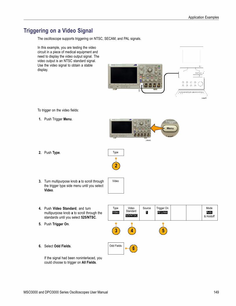
Application Examples
Triggering on a Video SignalThe oscilloscope supports triggering on NTSC, SECAM, and PAL signals.
In this example, you are testing the videocircuit in a piece of medical equipment andneed to display the video output signal. Thevideo output is an NTSC standard signal.Use the video signal to obtain a stabledisplay.
To trigger on the video fields:
1. Push Trigger Menu.
2. Push Type. Type
3. Turn multipurpose knob a to scroll throughthe trigger type side menu until you selectVideo.
Video
4. Push Video Standard, and turnmultipurpose knob a to scroll through thestandards until you select 525/NTSC.
TypeVideo
VideoStandard525/NTSC
Source1
Trigger OnAll Lines
ModeAuto
& Holdoff
5. Push Trigger On.
6. Select Odd Fields. Odd Fields
If the signal had been noninterlaced, youcould choose to trigger on All Fields.
MSO3000 and DPO3000 Series Oscilloscopes User Manual 149

Application Examples
7. Turn the Horizontal Scale knob to see acomplete field across the screen.
8. View results.
150 MSO3000 and DPO3000 Series Oscilloscopes User Manual

Application Examples
Triggering on LinesTriggering on Lines. To look at the video lines in the field:
1. Push Trigger Menu.
2. Push Type. Type
3. Turn multipurpose knob a to scroll throughthe trigger type side menu until you selectVideo.
Video
TypeVideo
VideoStandard525/NTSC
Source1
Trigger OnAll Lines
ModeAuto
& Holdoff
4. Push Trigger On.
5. Select All Lines.To trigger on a specific line, select LineNumber, and use multipurpose knob a toselect the line number.
All Lines
6. Adjust Horizontal Scale to see a completevideo line across the screen.
MSO3000 and DPO3000 Series Oscilloscopes User Manual 151

Application Examples
7. Observe the results.
Capturing a Single-Shot SignalIn this example, the reliability of a reed relay in a piece of equipment has been poor, and you need to investigate the problem.You suspect that the relay contacts arc when the relay opens. The fastest you can open and close the relay is about once perminute, so you need to capture the voltage across the relay as a single-shot acquisition.
To set up for a single-shot acquisition:
1. Adjust the Vertical Scale and Horizontal Scale to appropriate ranges for the signal you expect to see.
2. Push Acquire.
3. Push Mode.
4. Select Sample.
5. Push Trigger Menu.
6. Push Slope and .
7. Turn the Trigger Level knob to adjustthe trigger level to a voltage midwaybetween the open and closed voltagesof the replay.
152 MSO3000 and DPO3000 Series Oscilloscopes User Manual

Application Examples
8. Push Single (single sequence).
MSO3000 and DPO3000 Series Oscilloscopes User Manual 153

Application Examples
When the relay opens, the oscilloscopetriggers and captures the event.The Single sequence button disablesauto triggering so that only a validtriggered signal is acquired.
Optimizing the Acquisition
The initial acquisition shows the relay contactbeginning to open at the trigger point. This isfollowed by large spikes that indicate contactbounce and inductance in the circuit. Theinductance can cause contact arcing andpremature relay failure.Before you take the next acquisition, you canadjust the vertical and horizontal controlsto give you a preview of how the nextacquisition might appear. As you adjustthese controls, the current acquisition isrepositioned, expanded, or compressed.This preview is useful to optimize the settingsbefore the next single-shot event is captured.When the next acquisition is captured withthe new vertical and horizontal settings, youcan see more detail about the relay contactopening. You can now see that the contactbounces several times as it opens.
Using the Horizontal Zoom FunctionTo take a close look at a particular point on the acquired waveform, use the horizontal zoom function. To look closelyat the point where the relay contact first begins to open:
1. Turn the Zoom knob.
154 MSO3000 and DPO3000 Series Oscilloscopes User Manual

Application Examples
2. Turn the Pan knob to place the center ofthe zoom box close to where the relaycontact begins to open.
3. Turn the Zoom knob to magnify thewaveform in the zoom window.
The ragged waveform and the inductive loadin the circuit suggest that the relay contactmay be arcing as it opens.
Correlating Data with a TLA5000 Logic AnalyzerTo troubleshoot designs with fast clock edges and data rates, it helps to view analog characteristics of digital signals inrelation to complex digital events in the circuit. You can do that with iView, which lets you transfer analog waveforms from theoscilloscope to the logic analyzer display. You can then view time-correlated analog and digital signals side-by-side, and usethis to pinpoint sources of glitches and other problems.
The iView External Oscilloscope Cable allows you to connect your logic analyzer to a Tektronix oscilloscope. This enablescommunication between the two instruments. For DPO3000 series oscilloscopes, you also need a TEK-USB-488 adaptor.The Add External Oscilloscope wizard, which is available from the TLA application System menu, guides you through theprocess of connecting the iView cable between your logic analyzer and oscilloscope.
The TLA also provides a setup window to assist you in verifying, changing, and testing the oscilloscope settings. Beforeacquiring and displaying a waveform, you must establish a connection between your Tektronix logic analyzer andoscilloscope using the Add External Oscilloscope wizard.
MSO3000 and DPO3000 Series Oscilloscopes User Manual 155
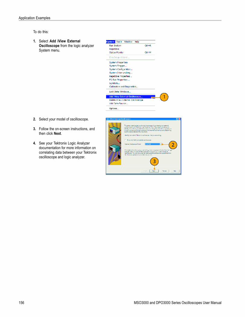
Application Examples
To do this:
1. Select Add iView ExternalOscilloscope from the logic analyzerSystem menu.
2. Select your model of oscilloscope.
3. Follow the on-screen instructions, andthen click Next.
4. See your Tektronix Logic Analyzerdocumentation for more information oncorrelating data between your Tektronixoscilloscope and logic analyzer.
156 MSO3000 and DPO3000 Series Oscilloscopes User Manual

Application Examples
Tracking Down Bus AnomaliesIn this example, you are testing your new I2C circuit. Something is not working. You tell the master IC to send a messageto the slave IC. Then you expect to receive data back and an LED to light. The light never goes on. Where in the ten orso commands that were sent out did the problem occur? Once you locate the problem location, how do you determinewhat went wrong?
You can use your oscilloscope, with its serial triggering and long-record length management features, to track down theproblem in both the physical layer and in the protocol layer of the bus.
Basic StrategyFirst, you will display and acquire the bus signal by setting up the bus parameters and trigger. Then, you will search througheach packet with the search/mark functions.
NOTE. Triggering on I2C, SPI, CAN, LIN, RS-232, RS-422, RS-485, UART, I2S, Left Justified, Right Justified, and TDMbus signals requires use of an appropriate DPO3EMBD, DPO3AUTO, DPO3COMP, or DPO3AUDIO Serial Triggering andAnalysis Module. Triggering on Parallel bus signals requires use of an MSO3000 Series oscilloscope.
1. Connect the channel 1 probe to the clockline.
2. Connect the channel 2 probe to the dataline.
3. Push Autoset.
4. Push the B1 button and enter the parametersof your I2C bus in the resulting screenmenus.
MSO3000 and DPO3000 Series Oscilloscopes User Manual 157

Application Examples
5. Push Trigger Menu.
6. Push Type to select Bus. Enter triggerparameters in the resulting screen menus.
TypeBus
SourceBus
B1 (I2C)
Trigger OnAddress
Address07F
DirectionRead
ModeAuto
& Holdoff
7. Analyze the physical layer. For example,you can use the cursors for manualmeasurements. (See page 103, TakingManual Measurements with Cursors.)You can also use the automatedmeasurements. (See page 96, TakingAutomatic Measurements.)
8. Push Search. Set Search Marks to On.Enter a search type, source, and otherparameters as relevant on the lower-bezelmenu and associated side-bezel menus.(See page 114, Using Wave Inspector toManage Long Record Length Waveforms.)
9. Jump ahead to the next search point bypushing the right arrow key. Push it againand again until you see all the events. Jumpback with the left arrow key. Do you have allthe packets that you expected to have? Ifnot, at least you have narrowed your searchdown to the last packet sent.
10. Analyze the decoded packets in the protocollayer. Did you send the data bytes in thecorrect order? Did you use the correctaddress?
158 MSO3000 and DPO3000 Series Oscilloscopes User Manual

Application Examples
Troubleshooting an RS-232 BusIn this example, you are looking at analog characteristics of a digital signal in a digital circuit. You are doing this to analyzethe signal integrity of a signal. For example, you might be testing RS-232 bus signals.
Basic StrategyFirst, you will display and acquire the digital signal. Then, you will look at both the analog and digital representations of thesignal. Finally, you will search through each RS-232 byte with the search/mark functions.
NOTE. Triggering on RS-232 bus signals requires use of the DPO3COMP Serial Triggering and Analysis Module. (Seepage 15, Application Module Free Trial.)
1. Connect the desired analog probe tip to thedesired test point.
2. Push Default Setup.
3. Push Autoset.
4. Push B1.
5. Push the Bus B1 lower-bezel button, usemultipurpose knob a to select RS-232,and enter the parameters of the bus in theresulting screen menus.
MSO3000 and DPO3000 Series Oscilloscopes User Manual 159

Application Examples
6. Push the Bus Display lower-bezel button,push the Bus and Waveforms side-bezelbutton, and push the ASCII side-bezel.
7. Turn the Horizontal Scale knob to adjust thetimebase.As you increase the time per division, youwill see more data appear in the Bus display.
8. Push Trigger Menu. Select the Bus triggertype. Define what type of condition to triggeron, such as the Tx Start Bit.
9. Push Search, push the Search lower-bezelbutton, and select On in the side-bezelmenu.
10. Push Search Type. Use multipurpose knoba to select Bus. Push Search For andselect the desired search, such as for theTx Start Bit.
11. Push the Previous and Next Mark buttons tonavigate through the record.
12. Push Zoom and Pan to see the areas ofinterest and analyze the results.
160 MSO3000 and DPO3000 Series Oscilloscopes User Manual

Application Examples
Troubleshooting Circuits Using Parallel BusesIn this example, you are monitoring a parallel bus with your oscilloscope. You can use your MSO3000 Series oscilloscopewith its 16 digital channels to analyze the bus. The MSO3000 Series will not only let you see the on-off status of thesignals, but will also decode the parallel bus signals for you.
Basic StrategyFirst, you will display and acquire the digital signals. Then, you will search through the data with the search/mark functions.
NOTE. The MSO3000 Series oscilloscopes support triggering and decoding on Parallel bus signals.
1. Connect the desired digital probe tips tothe desired test points. For simplicity, thisexample connects to a 7-bit counter.
2. Push Default Setup. Then push the channel1 button to remove the waveform from thedisplay.
3. Push the D15-D0 button.
4. Push the D15-D0 On/Off lower-bezelbutton and then push the Turn On D7-D0side-bezel to display the digital waveforms.To turn off a channel, use multipurposeknob a to select the channel and push theDisplay side-bezel to select Off.
MSO3000 and DPO3000 Series Oscilloscopes User Manual 161

Application Examples
5. Push Autoset.
6. Push the B1 button, select Parallel as thebus type. Push the lower-bezel DefineInputs and enter the parameters for yourbus for Clocked Data, Clock Edge, theNumber of Bits, and Define Bits.
7. Turn the Horizontal Scale knob to adjust thetimebase.As you increase the time per division, youwill see more data appear in the Bus display.
8. Push Trigger Menu. Push Type, select Bus,and enter the parameters of the trigger, suchas the Source Bus and Data. Define theMode and Holdoff as desired.
9. Push Search, push the Search lower-bezelbutton, and select On in the side-bezelmenu.
10. Push Search Type. Use the multipurposeknob a to select Bus and then push Data.Use the multipurpose knobs a and b todefine the data value.
11. Push the Previous and Next Mark buttons tonavigate through the record.
12. Push Zoom, and Pan to the areas of interestto analyze the results.
162 MSO3000 and DPO3000 Series Oscilloscopes User Manual

Appendix: Warranted Specifications
Appendix: Warranted SpecificationsThe limits stated below are for ambient temperature of ≤30 °C and the bandwidth selection set toFULL. Reduce the upper bandwidth frequency by 1% for each °C above 30 °C.
Instrument 10 mV/div to 1 V/div 5 mV/div to 9.98 mV/divMSO/DPO3054, andDPO3052
DC to 500 MHz DC to 400 MHz
Instrument 2 mV/div to 4.98 mV/div 1 mV/div to 1.99 mV/divMSO/DPO3054, andDPO3052
DC to 250 MHz DC to 150 MHz
Instrument 5 mV/div to 1 V/div 2 mV to 4.98 mV/div 1 mV/div to1.99 mV/div
MSO/DPO3034, andMSO/DPO3032
DC to 300 MHz DC to 250 MHz DC to 150 MHz
Instrument 1 mV/div to 1 V/div
Analog bandwidth,50 Ω
MSO/DPO3014, andMSO/DPO3012
DC to 100 MHz
Input impedance, DCcoupled
1 MΩ ±1% in parallel with 11.5 pF ±2 pF75 Ω ±1%
VSWR ≤ 1.3:1 from DC to 60 MHz, typical50 Ω ±1%
MSO/DPO3054, DPO3052: VSWR ≤ 1.5:1 from DC to 500 MHz, typicalMSO/DPO3034, MSO/DPO3032: VSWR ≤ 1.5:1 from DC to 350 MHz, typicalMSO/DPO3014, MSO/DPO3012: VSWR ≤ 1.5:1 from DC to 100 MHz, typical
DC Balance 0.2 div with the input DC-50 Ω coupled and 50 Ω terminated0.2 div with the input DC-75 Ω coupled and 75 Ω terminated0.25 div at 2 mV/div with the input DC-50 Ω coupled and 50 Ω terminated0.25 div at 2 mV/div with the input DC-75 Ω coupled and 75 Ω terminated0.5 div at 1 mV/div with the input DC-50 Ω coupled and 50 Ω terminated0.5 div at 1 mV/div with the input DC-75 Ω coupled and 75 Ω terminated0.2 div with the input DC-1 MΩ coupled and 50 Ω terminated0.3 div at 1 mV/div with the input DC-1 MΩ coupled and 50 Ω terminated
DC Gain accuracy ±2.5% for Coarse setting of 1 mV/div, derated at 0.100%/°C above 30 °C±2.0% for Coarse setting of 2 mV/div, derated at 0.100%/°C above 30 °C±1.5% for Coarse settings o. 5 mV/div and above, derated at 0.100%/°C above 30 °C±3.0% for all Fine V/div settings, derated at 0.100%/°C above 30 °C
Offset accuracy ±[0.005 × | offset – position | + DC Balance]
NOTE. Both the position and constant offset term must be converted to volts by multiplying by theappropriate volts/div term.
Long-term samplerate and delay timeaccuracy
±10 ppm over any ≥ 1 ms time interval
MSO3000 and DPO3000 Series Oscilloscopes User Manual 163

Appendix: Warranted Specifications
LOW TRUE; LOW to HIGH transition indicates that the trigger occurred. The logic levels are givenin the following table:Characteristic LimitsVout (HI) ≥ 3.25 V open circuit; ≥ 2.2 V into a 50 Ω load
to ground
Auxiliary output (AUXOUT)
Vout (LO) ≤ 0.4 V into a load of ≤ 4 mA; ≤0.3 V into a50 Ω load to ground
Instrument Bandwidth selection RMS NoiseFull Bandwidth <(170 µV + 8% of Volts/div Setting)150 MHz <(90 µV + 6% of Volts/div Setting)
MSO/DPO3054 andDPO3052
20 MHz <(25 µV + 6% of Volts/div Setting)Full Bandwidth <(140 µV + 6% of Volts/div Setting)150 MHz <(80 µV + 6% of Volts/div Setting)
MSO/DPO3034 andMSO/DPO3032
20 MHz <(30 µV + 5% of Volts/div Setting)Full Bandwidth <(100 µV + 6% of Volts/div Setting)
Random Noise,Sample acquisitionmode
MSO/DPO3014 andMSO/DPO3012 20 MHz Bandwidth
Limit<(100 µV + 6% of Volts/div Setting)
Delta TimeMeasurementAccuracy
The formula to calculate delta-time measurement accuracy (DTA) for a given instrument setting andinput signal is given below (assumes insignificant signal content above Nyquist)SR1 = Slew Rate (1st Edge) around the 1st point in the measurementSR2 = Slew Rate (2nd Edge) around the 2nd point in the measurementN = input-referred noise (voltsrms, Refer to the Random Noise, Sample acquisition mode specification)tsr = 1/ (Sample Rate)TBA = timebase accuracy (Refer to the Long-term sample rate and delay time accuracy specification)tp = delta-time measurement duration (sec)RD = (Record Length) / (Sample Rate)
Assumes that error due to aliasing is insignificant.The term under the square-root sign is the stability, and is due to TIE (Time Interval Error). The errorsdue to this term occur throughout a single-shot measurement. The second term is due to both theabsolute center-frequency accuracy and the center-frequency stability of the timebase and variesbetween multiple single-shot measurements over the observation interval (the amount of time fromthe first single-shot measurement to the final single-shot measurement).
164 MSO3000 and DPO3000 Series Oscilloscopes User Manual

Index
Index
Symbols and Numbers50 Ω protection, 90
AAbout, 22Accessories, 1Acquire button, 31, 51, 81, 145, 146Acquisition
input channels anddigitizers, 49
modes defined, 50readout, 37sampling, 49
AdapterTEK-USB-488, 3TPA-BNC, 3, 8
Adding waveform, 81Advanced math, 111Altitude
MSO3000 and DPO3000, 5P6139A, 6P6316, 7
Amplitude measurement, 98Annotating the screen, 93Application modules, 15, 135
30-day free trial, 15DPO3AUDIO, 3, 54DPO3AUTO, 3, 54DPO3COMP, 3, 54DPO3EMBD, 3, 54DPO3PWR, 3, 119DPO3VID, 3, 73
Area measurement, 99Attenuation, 88Audio, 54Auto trigger mode, 67Autoset, 48, 137
Video, 49Autoset button, 13, 31, 35, 44, 48,
137Autoset disable, 48Autoset undo, 48Aux In connector, 41Aux Out connector, 42Auxiliary readout, 40Average acquisition mode, 51
BB trigger, 79B1 / B2 button, 54, 55, 73Backlight intensity, 85Bandwidth, xiii, 87Baseline indicators, 40Before Installation, 1Blackman-Harris FFT window, 111Blue lines, 93BNC interface, 8Burst Width measurement, 97Bus
button, 54, 55, 73display, 41, 56menu, 33, 55positioning and labeling, 90setup, 55
Bus and Waveforms display, 62Bus trigger, defined, 73Buses, 54, 73
cursor readout, 106
ButtonAcquire, 31, 51, 81, 145, 146Autoset, 13, 31, 35, 44, 48, 137B1 / B2, 33, 54, 73B1 / B2 bus, 55bus, 54, 55, 73Cal, 42Channel, 32Cursors, 33, 103, 147D15 - D0, 36, 65Default Setup, 36, 44, 47Fine, 31, 33, 34, 35Force Trig, 35, 67hard copy, 36, 133Intensity, 85M, 33, 108, 109Math, 33, 108, 109Measure, 31, 96, 101, 138,
140, 142, 143Menu Off, 37, 138Next, 35Play-pause, 34, 115Previous, 34Print, 36printer, 133Ref, 33, 112, 125Run/Stop, 35, 53, 80Save / Recall, 32, 36, 122Search, 31, 117Select, 34, 148Set / Clear Mark, 35, 117Set to 50%, 35, 69Single, 35, 80, 143, 153Test, 31, 119Trigger, 31Trigger level, 35Trigger menu, 70, 149Utility, 15, 16, 18, 31, 82, 84,
93, 94, 128Vertical, 32Zoom, 34
byte matching, 77
CCal button, 42Calibration, 18, 19Calibration certificate, 1CAN, 33, 54, 73
MSO3000 and DPO3000 Series Oscilloscopes User Manual 165

Index
CAN trigger, 76Channel button, 32Channel readout, 40Channel vertical menu, 87Cleaning, 7Clearance, MSO3000 and
DPO3000, 5Communications, 23, 26Compensate probe, 13Compensate signal path, 18Confidential data, 133Connecting a USB keyboard, 27Connecting to a PC, 23Connectivity, 1, 23, 26Connector
Aux Out, 42Probe Power, 42Video port, 42
Connectorsfront-panel, 41rear-panel, 42side-panel, 42
Controls, 29Coupling, 87Coupling, trigger, 68Cover, front, 2Cross Hair graticule style, 84CSV format, 124Cursor readout, 38, 106Cursors, 103
button, 33, 103, 147linking, 104measurements, 103menu, 103XY, 107
Cycle Area measurement, 99Cycle Mean measurement, 99Cycle RMS measurement, 99
DD15 - D0 button, 36, 65Date and time, changing, 16Default Setup, 47, 127
button, 36, 44, 47menu, 36Undo, 48
Delay measurement, 97Delay time, 53Delayed trigger, 78Depth, MSO3000 and DPO3000, 5Deskew, 89
Digital channels, 93Baseline indicators, 40Group icon, 40scaling, positioning, grouping,
and labeling, 91setup, 63
Digital probe interface, 9Disable Autoset, 48Display
information, 37persistence, 81style, 81XY, 82
Displaying, referencewaveforms, 125
DPO3AUDIO, 3, 54, 135DPO3AUTO, 3, 54, 135DPO3COMP, 3, 54, 135DPO3EMBD, 3, 54, 135DPO3PWR, 3, 119, 135DPO3VID, 3, 73, 135Drivers, 23, 25Dual waveform math, 108
Ee*Scope, 26Edge trigger, defined, 71Edges
Fuzzy, 93White, 93
Envelope acquisition mode, 51Erase setup and ref memory, 133Ethernet, xiii, 24, 26
port, 42printing, 131
Event Table, 56Excel, 23Expansion point, 50Expansion point icon, 38
FFactory calibration, 19Fall Time measurement, 97Falling Edge Count
measurement, 99FFT
Blackman-Harris, 111controls, 109Hamming, 110Hanning, 111Rectangular, 110
File format, 123Internal File Format (ISF), 124Spreadsheet file format
(.CSV), 124File names, 120File system, 120, 124Fine, 34Fine button, 31, 33, 34, 35Firmware upgrade, 19Firmware version, 22firmware.img file, 19Flash drives, 25Force Trig button, 35, 67Frame graticule style, 84Frequency measurement, 97Frequency, Source
MSO3000 and DPO3000, 5Front cover, 2Front panel, 29Front-panel connectors, 41Front-panel overlay, 16Full graticule style, 84Functional check, 11Fuzzy edges, 93
GGating, 100GPIB, 23, 43GPIB address, 24Graticule
Cross Hair, 84Frame, 84Full, 84Grid, 84intensity, 85IRE, 84mV, 84styles, 82
Green lines, 93Grid graticule style, 84Ground, 10Ground lead, 14Ground strap, 10Ground strap connector, 42Ground yourself to discharge
static, 10Group icon, 40Grouping channels, 64
digital, 91
166 MSO3000 and DPO3000 Series Oscilloscopes User Manual

Index
HHamming FFT window, 110Hanning FFT window, 111Hard copy, 128Hard copy button, 36Height, MSO3000 and DPO3000, 5Hi Res acquisition mode, 51High measurement, 98High-low indicators, 40Holdoff, trigger, 68Horizontal delay, 68Horizontal lines
Green and blue, 93Horizontal position, 35, 50, 68, 69,
86, 110, 155and math waveforms, 108defined, 45readout, 39
Horizontal scale, 35, 86, 110, 150,151, 152, 155and math waveforms, 108defined, 45readout, 39
How tocompensate a voltage
probe, 13compensate the signal path, 18connect probes and
adapters, 8connect to a computer, 23erase memory, 133label channels and buses, 45manage long record length
waveforms, 114perform a functional check, 11power off the oscilloscope, 11power on the oscilloscope, 10print a hard copy, 128recall setups, 125recall waveforms, 122save screen images, 122save setups, 125save waveforms, 122search through and add marks
to waveforms, 116select a trigger, 71select automatic
measurements, 97setup analog channels, 44setup bus parameters, 55setup digital channels, 63setup input parameters, 87setup VISA communica-
tions, 23take automatic
measurements, 96take manual measurements
with cursors, 103trigger on buses, 73upgrade the firmware, 19use a sequential trigger, 78use e*Scope, 26use MagniVu, 65use Wave Inspector, 114
HumidityMSO3000 and DPO3000, 5P6139A, 6P6316, 7
II2C, 33, 54, 73
trigger, 74I2S, 33, 73
trigger, 76
IconExpansion point, 38Trigger level, 39Trigger position, 38
Image orientation, 123, 129Impedance, 87Indicator, waveform baseline, 40Infinite persistence, 82Ink Saver, 123, 129Inner knob, 34, 108Input capacitance, P6316, 7Input resistance, P6316, 7Intensity button, 85Internal File Format (ISF), 124Invert, 87IRE graticule, 84ISF format, 124
KKeyboard, USB, 27Knob
inner, 34, 108Multipurpose, 17, 31, 34, 51,
124, 147, 148outer, 34pan, 34, 115, 117Trigger level, 69Vertical menu, 35Vertical position, 35, 45Vertical scale, 36, 45zoom, 34, 108, 114
LLabel bus, 90LabView, 23LAN port, 42Landscape, 123, 129Language
change, 15overlay, 16
Left Justified, 73trigger, 76
Left Justified (LJ), 33Level, trigger, 69LIN, 33, 54, 73
trigger, 76Lock, standard laptop, 9Logic trigger, defined, 72Long record length, 157
management, 114Low measurement, 98
MSO3000 and DPO3000 Series Oscilloscopes User Manual 167

Index
MM button, 33, 108, 109MagniVu, xiii, 65MagniVu readout, 39Main trigger, 78Mark, 116Math
Advanced, 111button, 33, 108, 109Dual waveform, 108FFT, 109menu, 33waveforms, 107
Max measurement, 98Maximum nondestructive input
signal, P6316, 7Maximum signal swing, P6316, 7Mean measurement, 99Measure button, 31, 96, 101, 138,
140, 142, 143Measurement menu, 31Measurements
automatic, 96cursor, 103defined, 97reference levels, 102snapshot, 101statistics, 101
Memory, erasure of, 133Menu, 29
Bus, 33, 55buttons, 31Cursors, 103Default Setup, 36Math, 33Measurement, 31Reference, 33, 112, 113Save / Recall, 32, 36, 122Trigger, 31, 70, 78, 149Utility, 15, 16, 31, 36, 82, 93,
94, 128Vertical, 32, 87
Menu Off button, 37, 138Min measurement, 99Mode, roll, 53Multiple transition detection, 93Multipurpose knob, 31, 34, 51, 124,
147, 148mV graticule, 84
NNegative Duty Cycle
measurement, 97Negative Overshoot
measurement, 98Negative Pulse Count
measurement, 99Negative Pulse Width
measurement, 97Network printing, 131Next button, 35NI SignalExpress Tektronix Edition
software, xiiiNormal trigger mode, 67
OOffset and position, 90Offset vertical, 88OpenChoice, xiii, 1Operating specifications, 5Orientation of the image, 123, 129Outer knob, 34Overlay, 16
PP6139A probe, 1P6316 probe, 2, 65P6316 probe ground leads, 63Pan, 114, 115
knob, 34, 115, 117Parallel bus, xiii, 54Parallel bus anomalies, 161Pause, 115Peak detect acquisition mode, 50Period measurement, 97Persistence
display, 81infinite, 82variable, 82
Phase measurement, 98Physical layer bus activity, 62PictBridge, xiii, 25, 43
printing, 130Pk-Pk measurement, 98Play, 115Play-pause button, 34, 115Play-pause mode, 115Pollution Degree
MSO3000 and DPO3000, 5P6139A, 6P6316, 7
Portrait, 123, 129Position
bus, 90digital channels, 91Horizontal, 68, 69, 86, 110, 155Vertical, 86
Position and offset, 90Positive Duty Cycle
measurement, 97Positive Overshoot
measurement, 98Positive Pulse Count
measurement, 99Positive Pulse Width
measurement, 97Posttrigger, 67, 69Power
cord, 2input, 43off, 11removing, 11supply, 10switch, 36
Power consumption, MSO3000 andDPO3000, 5
Predefined math expressions, 108Pretrigger, 67, 69Previous button, 34Print, 128
Ethernet, 131hard copy, 128PictBridge, 130
Print button, 36Probe Comp, 12PROBE COMP connector, 41Probe compensation, 13Probe connector
analog, 41logic, 41
Probe Power connector, 42Probes
BNC, 8connecting, 8digital, 9ground lead, 14P6139A, 1P6316, 2TEK-USB-488 Adapter, 3TekVPI, 8TPA-BNC Adapter, 3, 8
Pulse Width trigger, defined, 71
168 MSO3000 and DPO3000 Series Oscilloscopes User Manual

Index
RRackmount, 3Readout
Acquisition, 37Auxiliary, 40Channel, 40Cursor, 38, 106Horizontal position/scale, 39MagniVu, 39Record length/sampling
rate, 39Timing resolution, 39Trigger, 39, 77Trigger frequency, 94Trigger status, 38
Real-time sampling, 49Rear-panel connectors, 42Recalling
setups, 125waveforms, 122
Record length, xiii, 50Record length/sampling rate
readout, 39Rectangular FFT window, 110Ref button, 33, 112, 125Ref R, 125Reference levels, 102Reference menu, 33, 112, 113Reference waveforms, 112
displaying, 125removing, 113, 125saving, 124saving 5 M waveforms, 113
Removing referencewaveforms, 113, 125
Removing waveform, 81Right Justified, 73
trigger, 76Right Justified (RJ), 33Rise Time measurement, 97Rise/Fall trigger, defined, 72Rising Edge Count
measurement, 99RMS measurement, 99Roll mode, 53Rolling window data matching, 77
RS-232, 33, 54, 73bus example, 159byte matching, 77cursor readout, 106decoding, 63trigger, 75
RS-422, 33RS-485, 33Run/Stop button, 35, 53, 80Runt trigger, defined, 71
SSafety Summary, vSample acquisition mode, 50Sample interval, 50Sample rates, xiiiSampling process, defined, 49Sampling, real-time, 49Save / Recall menu, 32, 36, 122Save / Recall Menu button, 32Save / Recall Save button, 36, 122Saving
reference waveforms, 124screen images, 122setups, 125waveforms, 122
Saving and recallingInformation, 120
Scaledigital channels, 91Horizontal, 35, 86, 110, 150,
151, 152, 155Vertical, 86, 152
Screen annotations, 93Search, 116Search / Mark, 157Search button, 31, 117Securing memory, 133Security lock, 9Select button, 34, 148Sequence (B Trigger), defined, 71Sequential triggering, 78Serial bus, 54, 157Serial bus trigger, 73Serial buses trigger, 74Set / Clear Mark button, 35, 117
Set to 50% button, 35, 69Setup
default, 36, 44, 47, 127Setup and Hold trigger, defined, 72Side panel connector, 42Signal path compensation, 18Single button, 35, 80, 143, 153Single sequence, 53, 80Slope, trigger, 69Snapshot, 101Software drivers, 23, 25Software, optional, 135SPC, 18Specifications
operating, 5power supply, 10
SPI, 33, 54, 73SPI trigger, 75Spreadsheet file format (.CSV), 124Start an acquisition, 80Statistics, 101Stop an acquisition, 80SVGA Out, 42Switch, power, 36
TTable, Event, 56TDM, 33, 73
trigger, 76TEK-USB-488 Adapter, 3, 23, 24,
43TekSecure, 133TekVPI, 8Temperature
MSO3000 and DPO3000, 5P6139A, 6P6316, 7
Termination, 87Test button, 31, 119Threshold accuracy, P6316, 7Threshold range, P6316, 7Timing resolution readout, 39TPA-BNC Adapter, 3, 8Transit case, 3Transition trigger, defined, 72
MSO3000 and DPO3000 Series Oscilloscopes User Manual 169

Index
TriggerB trigger after delay time, 79Bus, defined, 73buses, 73byte matching, 77CAN bus, 76concepts, 67coupling, 68data matching on a rolling
window, 77delayed, 78Edge, defined, 71event, defined, 67forcing, 67Frequency readout, 94holdoff, 68I2C bus, 74I2S bus, 76Left Justified, 76level, 69level button, 35level icon, 39level knob, 69LIN bus, 76Logic, defined, 72modes, 67, 70parallel bus data matching, 77parallel buses, 54point, 50position icon, 38posttrigger, 67, 69pretrigger, 67, 69Pulse Width, defined, 71readout, 39, 77Right Justified, 76Rise/Fall, defined, 72RS-232 bus, 75RS-232 byte matching, 77Runt, defined, 71Sequence (B Trigger),
defined, 71sequential, 78serial buses, 54, 74, 157Setup and Hold, defined, 72slope, 69SPI bus, 75status readout, 38TDM bus, 76Trigger on B events, 79video lines, 151Video, defined, 73
Trigger menu, 31, 70, 78, 149button, 70, 149
Trigger modesAuto, 67Normal, 67
Trigger types, defined, 71Triggering on Buses, 73
UUndo
Autoset, 48Default Setup, 48
Upgrading firmware, 19USB, xiii, 3, 23, 24, 25, 32, 120, 128
device port, 43host ports, 36, 43keyboard, 27
USBTMC, 43User marks, 116Utility button, 15, 16, 18, 31, 82, 84,
93, 94, 128Utility menu, 15, 16, 31, 36, 82, 93,
94
VVariable persistence, 82Versatile Probe Interface, 8Version, firmware, 22Vertical
button, 32menu, 32, 87Menu knob, 35offset, 90Offset, 88position, 86position and autoset, 49position and offset, 90Position knob, 35, 45scale, 86, 152Scale knob, 36, 45
Vibration, MSO3000 andDPO3000, 5
VideoAutoset, 49fields, 149lines, 151port, 42projector, 42trigger, 149
Video trigger, defined, 73View
digital channels, 93waveform record, 38
VISA, 23Voltage, Input
P6139A, 6Voltage, Output, P6139A, 6Voltage, Source
MSO3000 and DPO3000, 5
WWave Inspector, xiii, 114Waveform
adding, 81display style, 81intensity, 85pan, 114, 115pause, 115play, 115play-pause, 115record defined, 50removing, 81search and mark, 116user marks, 116zoom, 114
Waveform baseline indicator, 40Waveform record, 50Waveform record view, 38Weight
MSO3000 and DPO3000, 5White edges, 93Width
MSO3000 and DPO3000, 5
XXY
cursors, 107display, 82
ZZoom, 114
button, 34graticule size, 115Horizontal, 154knob, 34, 114
170 MSO3000 and DPO3000 Series Oscilloscopes User Manual