Embed Size (px)
Citation preview

DPO7000 SeriesDigital Phosphor OscilloscopesQuick Start User Manual
www.tektronix.com071-1733-00

Copyright © Tektronix, Inc. All rights reserved.
Tektronix products are covered by U.S. and foreign patents, issued and pending. Information in this publication supersedes that in allpreviously published material. Specifications and price change privileges reserved.
Tektronix, Inc., P.O. Box 500, Beaverton, OR 97077
TEKTRONIX and TEK are registered trademarks of Tektronix, Inc.
FastFrame, OpenChoice, iView, Pinpoint, MyScope, TekLink, and MultiView Zoom are trademarks of Tektronix, Inc.
Contacting TektronixTektronix, Inc.14200 SW Karl Braun DriveP.O. Box 500Beaverton, OR 97077USA
For product information, sales, service, and technical support:In North America, call 1-800-833-9200.Worldwide, visit www.tektronix.com to find contacts in your area.

Warranty 2Tektronix warrants that this product will be free from defects in materials and workmanship for a period of one (1) year from the date ofshipment. If any such product proves defective during this warranty period, Tektronix, at its option, either will repair the defectiveproduct without charge for parts and labor, or will provide a replacement in exchange for the defective product. Parts, modules andreplacement products used by Tektronix for warranty work may be new or reconditioned to like new performance. All replacedparts, modules and products become the property of Tektronix.
In order to obtain service under this warranty, Customer must notify Tektronix of the defect before the expiration of the warranty periodand make suitable arrangements for the performance of service. Customer shall be responsible for packaging and shipping thedefective product to the service center designated by Tektronix, with shipping charges prepaid. Tektronix shall pay for the return of theproduct to Customer if the shipment is to a location within the country in which the Tektronix service center is located. Customer shallbe responsible for paying all shipping charges, duties, taxes, and any other charges for products returned to any other locations.
This warranty shall not apply to any defect, failure or damage caused by improper use or improper or inadequate maintenance andcare. Tektronix shall not be obligated to furnish service under this warranty a) to repair damage resulting from attempts by personnelother than Tektronix representatives to install, repair or service the product; b) to repair damage resulting from improper use orconnection to incompatible equipment; c) to repair any damage or malfunction caused by the use of non-Tektronix supplies; ord) to service a product that has been modified or integrated with other products when the effect of such modification or integrationincreases the time or difficulty of servicing the product.
THIS WARRANTY IS GIVEN BY TEKTRONIX WITH RESPECT TO THE PRODUCT IN LIEU OF ANY OTHER WARRANTIES,EXPRESS OR IMPLIED. TEKTRONIX AND ITS VENDORS DISCLAIM ANY IMPLIED WARRANTIES OF MERCHANTABILITY ORFITNESS FOR A PARTICULAR PURPOSE. TEKTRONIX’ RESPONSIBILITY TO REPAIR OR REPLACE DEFECTIVE PRODUCTSIS THE SOLE AND EXCLUSIVE REMEDY PROVIDED TO THE CUSTOMER FOR BREACH OF THIS WARRANTY. TEKTRONIXAND ITS VENDORS WILL NOT BE LIABLE FOR ANY INDIRECT, SPECIAL, INCIDENTAL, OR CONSEQUENTIAL DAMAGESIRRESPECTIVE OF WHETHER TEKTRONIX OR THE VENDOR HAS ADVANCE NOTICE OF THE POSSIBILITY OF SUCHDAMAGES.


Table of Contents
Table of ContentsGeneral Safety Summary . . . . . . . . . . . . . . . . . . . . . . . . . . . . . . . . . . . . . . . . . . . . . . . . . . . . . . . . . . . . . . . . . . . . . . . . . . . . . . . . . . . . . . . . . . . . . . . . . . . . . . . . . . . . . iiiEnvironmental Considerations . . . . . . . . . . . . . . . . . . . . . . . . . . . . . . . . . . . . . . . . . . . . . . . . . . . . . . . . . . . . . . . . . . . . . . . . . . . . . . . . . . . . . . . . . . . . . . . . . . . . . . . . vPreface . . . . . . . . . . . . . . . . . . . . . . . . . . . . . . . . . . . . . . . . . . . . . . . . . . . . . . . . . . . . . . . . . . . . . . . . . . . . . . . . . . . . . . . . . . . . . . . . . . . . . . . . . . . . . . . . . . . . . . . . . . . . . . . . . vi
Key Features . . . . . . . . . . . . . . . . . . . . . . . . . . . . . . . . . . . . . . . . . . . . . . . . . . . . . . . . . . . . . . . . . . . . . . . . . . . . . . . . . . . . . . . . . . . . . . . . . . . . . . . . . . . . . . . . . . . . . viConventions Used in this Manual . . . . . . . . . . . . . . . . . . . . . . . . . . . . . . . . . . . . . . . . . . . . . . . . . . . . . . . . . . . . . . . . . . . . . . . . . . . . . . . . . . . . . . . . . . . . . . vii
Install Your Instrument. . . . . . . . . . . . . . . . . . . . . . . . . . . . . . . . . . . . . . . . . . . . . . . . . . . . . . . . . . . . . . . . . . . . . . . . . . . . . . . . . . . . . . . . . . . . . . . . . . . . . . . . . . . . . . . . . 1Standard Accessories. . . . . . . . . . . . . . . . . . . . . . . . . . . . . . . . . . . . . . . . . . . . . . . . . . . . . . . . . . . . . . . . . . . . . . . . . . . . . . . . . . . . . . . . . . . . . . . . . . . . . . . . . . . . 1Operating Requirements. . . . . . . . . . . . . . . . . . . . . . . . . . . . . . . . . . . . . . . . . . . . . . . . . . . . . . . . . . . . . . . . . . . . . . . . . . . . . . . . . . . . . . . . . . . . . . . . . . . . . . . . . 2Powering On the Instrument . . . . . . . . . . . . . . . . . . . . . . . . . . . . . . . . . . . . . . . . . . . . . . . . . . . . . . . . . . . . . . . . . . . . . . . . . . . . . . . . . . . . . . . . . . . . . . . . . . . . . 3Powering Off the Instrument . . . . . . . . . . . . . . . . . . . . . . . . . . . . . . . . . . . . . . . . . . . . . . . . . . . . . . . . . . . . . . . . . . . . . . . . . . . . . . . . . . . . . . . . . . . . . . . . . . . . . 4Removing the Power. . . . . . . . . . . . . . . . . . . . . . . . . . . . . . . . . . . . . . . . . . . . . . . . . . . . . . . . . . . . . . . . . . . . . . . . . . . . . . . . . . . . . . . . . . . . . . . . . . . . . . . . . . . . . 4Connecting to a Network. . . . . . . . . . . . . . . . . . . . . . . . . . . . . . . . . . . . . . . . . . . . . . . . . . . . . . . . . . . . . . . . . . . . . . . . . . . . . . . . . . . . . . . . . . . . . . . . . . . . . . . . . 4Adding a Second Monitor . . . . . . . . . . . . . . . . . . . . . . . . . . . . . . . . . . . . . . . . . . . . . . . . . . . . . . . . . . . . . . . . . . . . . . . . . . . . . . . . . . . . . . . . . . . . . . . . . . . . . . . . 5
Getting Acquainted with Your Instrument . . . . . . . . . . . . . . . . . . . . . . . . . . . . . . . . . . . . . . . . . . . . . . . . . . . . . . . . . . . . . . . . . . . . . . . . . . . . . . . . . . . . . . . . . . . . . 7Front Panel . . . . . . . . . . . . . . . . . . . . . . . . . . . . . . . . . . . . . . . . . . . . . . . . . . . . . . . . . . . . . . . . . . . . . . . . . . . . . . . . . . . . . . . . . . . . . . . . . . . . . . . . . . . . . . . . . . . . . . . 7Side and Rear Panels. . . . . . . . . . . . . . . . . . . . . . . . . . . . . . . . . . . . . . . . . . . . . . . . . . . . . . . . . . . . . . . . . . . . . . . . . . . . . . . . . . . . . . . . . . . . . . . . . . . . . . . . . . . . 8Interface and Display . . . . . . . . . . . . . . . . . . . . . . . . . . . . . . . . . . . . . . . . . . . . . . . . . . . . . . . . . . . . . . . . . . . . . . . . . . . . . . . . . . . . . . . . . . . . . . . . . . . . . . . . . . . . 9Control Panel . . . . . . . . . . . . . . . . . . . . . . . . . . . . . . . . . . . . . . . . . . . . . . . . . . . . . . . . . . . . . . . . . . . . . . . . . . . . . . . . . . . . . . . . . . . . . . . . . . . . . . . . . . . . . . . . . . . . 11Accessing Online Help . . . . . . . . . . . . . . . . . . . . . . . . . . . . . . . . . . . . . . . . . . . . . . . . . . . . . . . . . . . . . . . . . . . . . . . . . . . . . . . . . . . . . . . . . . . . . . . . . . . . . . . . . . 12Accessing Menus and Control Windows . . . . . . . . . . . . . . . . . . . . . . . . . . . . . . . . . . . . . . . . . . . . . . . . . . . . . . . . . . . . . . . . . . . . . . . . . . . . . . . . . . . . . . . 13
Inspect Your Instrument . . . . . . . . . . . . . . . . . . . . . . . . . . . . . . . . . . . . . . . . . . . . . . . . . . . . . . . . . . . . . . . . . . . . . . . . . . . . . . . . . . . . . . . . . . . . . . . . . . . . . . . . . . . . . . 14Verify Internal Diagnostics Pass . . . . . . . . . . . . . . . . . . . . . . . . . . . . . . . . . . . . . . . . . . . . . . . . . . . . . . . . . . . . . . . . . . . . . . . . . . . . . . . . . . . . . . . . . . . . . . . . 14Signal Path Compensation . . . . . . . . . . . . . . . . . . . . . . . . . . . . . . . . . . . . . . . . . . . . . . . . . . . . . . . . . . . . . . . . . . . . . . . . . . . . . . . . . . . . . . . . . . . . . . . . . . . . . 15
Acquisition . . . . . . . . . . . . . . . . . . . . . . . . . . . . . . . . . . . . . . . . . . . . . . . . . . . . . . . . . . . . . . . . . . . . . . . . . . . . . . . . . . . . . . . . . . . . . . . . . . . . . . . . . . . . . . . . . . . . . . . . . . . . 17Setting Up Signal Input . . . . . . . . . . . . . . . . . . . . . . . . . . . . . . . . . . . . . . . . . . . . . . . . . . . . . . . . . . . . . . . . . . . . . . . . . . . . . . . . . . . . . . . . . . . . . . . . . . . . . . . . . 17Using Default Setup. . . . . . . . . . . . . . . . . . . . . . . . . . . . . . . . . . . . . . . . . . . . . . . . . . . . . . . . . . . . . . . . . . . . . . . . . . . . . . . . . . . . . . . . . . . . . . . . . . . . . . . . . . . . . 18Using Autoset . . . . . . . . . . . . . . . . . . . . . . . . . . . . . . . . . . . . . . . . . . . . . . . . . . . . . . . . . . . . . . . . . . . . . . . . . . . . . . . . . . . . . . . . . . . . . . . . . . . . . . . . . . . . . . . . . . . 19Probe Compensation, Calibration, and Deskew . . . . . . . . . . . . . . . . . . . . . . . . . . . . . . . . . . . . . . . . . . . . . . . . . . . . . . . . . . . . . . . . . . . . . . . . . . . . . . . 19Acquisition Concepts. . . . . . . . . . . . . . . . . . . . . . . . . . . . . . . . . . . . . . . . . . . . . . . . . . . . . . . . . . . . . . . . . . . . . . . . . . . . . . . . . . . . . . . . . . . . . . . . . . . . . . . . . . . . 20How the Acquisition Modes Work . . . . . . . . . . . . . . . . . . . . . . . . . . . . . . . . . . . . . . . . . . . . . . . . . . . . . . . . . . . . . . . . . . . . . . . . . . . . . . . . . . . . . . . . . . . . . . 22Changing the Acquisition Mode . . . . . . . . . . . . . . . . . . . . . . . . . . . . . . . . . . . . . . . . . . . . . . . . . . . . . . . . . . . . . . . . . . . . . . . . . . . . . . . . . . . . . . . . . . . . . . . . 23Starting and Stopping an Acquisition. . . . . . . . . . . . . . . . . . . . . . . . . . . . . . . . . . . . . . . . . . . . . . . . . . . . . . . . . . . . . . . . . . . . . . . . . . . . . . . . . . . . . . . . . . . 24Using FastAcq. . . . . . . . . . . . . . . . . . . . . . . . . . . . . . . . . . . . . . . . . . . . . . . . . . . . . . . . . . . . . . . . . . . . . . . . . . . . . . . . . . . . . . . . . . . . . . . . . . . . . . . . . . . . . . . . . . . 24Using Roll Mode. . . . . . . . . . . . . . . . . . . . . . . . . . . . . . . . . . . . . . . . . . . . . . . . . . . . . . . . . . . . . . . . . . . . . . . . . . . . . . . . . . . . . . . . . . . . . . . . . . . . . . . . . . . . . . . . . 25
Pinpoint Triggers. . . . . . . . . . . . . . . . . . . . . . . . . . . . . . . . . . . . . . . . . . . . . . . . . . . . . . . . . . . . . . . . . . . . . . . . . . . . . . . . . . . . . . . . . . . . . . . . . . . . . . . . . . . . . . . . . . . . . . 26Triggering Concepts. . . . . . . . . . . . . . . . . . . . . . . . . . . . . . . . . . . . . . . . . . . . . . . . . . . . . . . . . . . . . . . . . . . . . . . . . . . . . . . . . . . . . . . . . . . . . . . . . . . . . . . . . . . . . 26Choosing a Trigger Type. . . . . . . . . . . . . . . . . . . . . . . . . . . . . . . . . . . . . . . . . . . . . . . . . . . . . . . . . . . . . . . . . . . . . . . . . . . . . . . . . . . . . . . . . . . . . . . . . . . . . . . . 28Pinpoint Trigger Selections . . . . . . . . . . . . . . . . . . . . . . . . . . . . . . . . . . . . . . . . . . . . . . . . . . . . . . . . . . . . . . . . . . . . . . . . . . . . . . . . . . . . . . . . . . . . . . . . . . . . . 29Checking Trigger Status . . . . . . . . . . . . . . . . . . . . . . . . . . . . . . . . . . . . . . . . . . . . . . . . . . . . . . . . . . . . . . . . . . . . . . . . . . . . . . . . . . . . . . . . . . . . . . . . . . . . . . . . 30Using A (Main) and B (Delayed) Triggers . . . . . . . . . . . . . . . . . . . . . . . . . . . . . . . . . . . . . . . . . . . . . . . . . . . . . . . . . . . . . . . . . . . . . . . . . . . . . . . . . . . . . . 31Sending E-mail on Trigger . . . . . . . . . . . . . . . . . . . . . . . . . . . . . . . . . . . . . . . . . . . . . . . . . . . . . . . . . . . . . . . . . . . . . . . . . . . . . . . . . . . . . . . . . . . . . . . . . . . . . . 34Using Horizontal Delay. . . . . . . . . . . . . . . . . . . . . . . . . . . . . . . . . . . . . . . . . . . . . . . . . . . . . . . . . . . . . . . . . . . . . . . . . . . . . . . . . . . . . . . . . . . . . . . . . . . . . . . . . . 34
DPO7000 Series Quick Start User Manual i

Table of Contents
Display a Waveform . . . . . . . . . . . . . . . . . . . . . . . . . . . . . . . . . . . . . . . . . . . . . . . . . . . . . . . . . . . . . . . . . . . . . . . . . . . . . . . . . . . . . . . . . . . . . . . . . . . . . . . . . . . . . . . . . . 36Setting the Display Style . . . . . . . . . . . . . . . . . . . . . . . . . . . . . . . . . . . . . . . . . . . . . . . . . . . . . . . . . . . . . . . . . . . . . . . . . . . . . . . . . . . . . . . . . . . . . . . . . . . . . . . . 36Setting the Display Persistence . . . . . . . . . . . . . . . . . . . . . . . . . . . . . . . . . . . . . . . . . . . . . . . . . . . . . . . . . . . . . . . . . . . . . . . . . . . . . . . . . . . . . . . . . . . . . . . . 37Setting the Display Format. . . . . . . . . . . . . . . . . . . . . . . . . . . . . . . . . . . . . . . . . . . . . . . . . . . . . . . . . . . . . . . . . . . . . . . . . . . . . . . . . . . . . . . . . . . . . . . . . . . . . . 38Selecting the Waveform Interpolation . . . . . . . . . . . . . . . . . . . . . . . . . . . . . . . . . . . . . . . . . . . . . . . . . . . . . . . . . . . . . . . . . . . . . . . . . . . . . . . . . . . . . . . . . . 38Adding Screen Text . . . . . . . . . . . . . . . . . . . . . . . . . . . . . . . . . . . . . . . . . . . . . . . . . . . . . . . . . . . . . . . . . . . . . . . . . . . . . . . . . . . . . . . . . . . . . . . . . . . . . . . . . . . . . 39Setting the Graticule Style . . . . . . . . . . . . . . . . . . . . . . . . . . . . . . . . . . . . . . . . . . . . . . . . . . . . . . . . . . . . . . . . . . . . . . . . . . . . . . . . . . . . . . . . . . . . . . . . . . . . . . 40Setting the Trigger Level Marker . . . . . . . . . . . . . . . . . . . . . . . . . . . . . . . . . . . . . . . . . . . . . . . . . . . . . . . . . . . . . . . . . . . . . . . . . . . . . . . . . . . . . . . . . . . . . . . 41Displaying the Date and Time . . . . . . . . . . . . . . . . . . . . . . . . . . . . . . . . . . . . . . . . . . . . . . . . . . . . . . . . . . . . . . . . . . . . . . . . . . . . . . . . . . . . . . . . . . . . . . . . . . 41Using the Color Palettes . . . . . . . . . . . . . . . . . . . . . . . . . . . . . . . . . . . . . . . . . . . . . . . . . . . . . . . . . . . . . . . . . . . . . . . . . . . . . . . . . . . . . . . . . . . . . . . . . . . . . . . . 42Setting the Reference Colors . . . . . . . . . . . . . . . . . . . . . . . . . . . . . . . . . . . . . . . . . . . . . . . . . . . . . . . . . . . . . . . . . . . . . . . . . . . . . . . . . . . . . . . . . . . . . . . . . . . 43Setting Math Colors . . . . . . . . . . . . . . . . . . . . . . . . . . . . . . . . . . . . . . . . . . . . . . . . . . . . . . . . . . . . . . . . . . . . . . . . . . . . . . . . . . . . . . . . . . . . . . . . . . . . . . . . . . . . . 43Using MultiView Zoom . . . . . . . . . . . . . . . . . . . . . . . . . . . . . . . . . . . . . . . . . . . . . . . . . . . . . . . . . . . . . . . . . . . . . . . . . . . . . . . . . . . . . . . . . . . . . . . . . . . . . . . . . . 43Zooming in Multiple Areas . . . . . . . . . . . . . . . . . . . . . . . . . . . . . . . . . . . . . . . . . . . . . . . . . . . . . . . . . . . . . . . . . . . . . . . . . . . . . . . . . . . . . . . . . . . . . . . . . . . . . . 45Lock and Scroll Zoomed Waveforms. . . . . . . . . . . . . . . . . . . . . . . . . . . . . . . . . . . . . . . . . . . . . . . . . . . . . . . . . . . . . . . . . . . . . . . . . . . . . . . . . . . . . . . . . . . 47
Analyzing Waveforms . . . . . . . . . . . . . . . . . . . . . . . . . . . . . . . . . . . . . . . . . . . . . . . . . . . . . . . . . . . . . . . . . . . . . . . . . . . . . . . . . . . . . . . . . . . . . . . . . . . . . . . . . . . . . . . . 48Taking Automatic Measurements. . . . . . . . . . . . . . . . . . . . . . . . . . . . . . . . . . . . . . . . . . . . . . . . . . . . . . . . . . . . . . . . . . . . . . . . . . . . . . . . . . . . . . . . . . . . . . . 48Automated Measurement Selections. . . . . . . . . . . . . . . . . . . . . . . . . . . . . . . . . . . . . . . . . . . . . . . . . . . . . . . . . . . . . . . . . . . . . . . . . . . . . . . . . . . . . . . . . . . 50Customizing an Automatic Measurement . . . . . . . . . . . . . . . . . . . . . . . . . . . . . . . . . . . . . . . . . . . . . . . . . . . . . . . . . . . . . . . . . . . . . . . . . . . . . . . . . . . . . . 53Taking Cursor Measurements . . . . . . . . . . . . . . . . . . . . . . . . . . . . . . . . . . . . . . . . . . . . . . . . . . . . . . . . . . . . . . . . . . . . . . . . . . . . . . . . . . . . . . . . . . . . . . . . . . 55Setting Up a Histogram . . . . . . . . . . . . . . . . . . . . . . . . . . . . . . . . . . . . . . . . . . . . . . . . . . . . . . . . . . . . . . . . . . . . . . . . . . . . . . . . . . . . . . . . . . . . . . . . . . . . . . . . . 57Using Math Waveforms . . . . . . . . . . . . . . . . . . . . . . . . . . . . . . . . . . . . . . . . . . . . . . . . . . . . . . . . . . . . . . . . . . . . . . . . . . . . . . . . . . . . . . . . . . . . . . . . . . . . . . . . . 59Using Spectral Analysis. . . . . . . . . . . . . . . . . . . . . . . . . . . . . . . . . . . . . . . . . . . . . . . . . . . . . . . . . . . . . . . . . . . . . . . . . . . . . . . . . . . . . . . . . . . . . . . . . . . . . . . . . 62Using Mask Testing . . . . . . . . . . . . . . . . . . . . . . . . . . . . . . . . . . . . . . . . . . . . . . . . . . . . . . . . . . . . . . . . . . . . . . . . . . . . . . . . . . . . . . . . . . . . . . . . . . . . . . . . . . . . . 64
MyScope . . . . . . . . . . . . . . . . . . . . . . . . . . . . . . . . . . . . . . . . . . . . . . . . . . . . . . . . . . . . . . . . . . . . . . . . . . . . . . . . . . . . . . . . . . . . . . . . . . . . . . . . . . . . . . . . . . . . . . . . . . . . . . 68Creating a New MyScope Control Window . . . . . . . . . . . . . . . . . . . . . . . . . . . . . . . . . . . . . . . . . . . . . . . . . . . . . . . . . . . . . . . . . . . . . . . . . . . . . . . . . . . . 68Using MyScope Control Windows . . . . . . . . . . . . . . . . . . . . . . . . . . . . . . . . . . . . . . . . . . . . . . . . . . . . . . . . . . . . . . . . . . . . . . . . . . . . . . . . . . . . . . . . . . . . . . 72
Saving and Recalling Information . . . . . . . . . . . . . . . . . . . . . . . . . . . . . . . . . . . . . . . . . . . . . . . . . . . . . . . . . . . . . . . . . . . . . . . . . . . . . . . . . . . . . . . . . . . . . . . . . . . . 74Saving Screen Captures . . . . . . . . . . . . . . . . . . . . . . . . . . . . . . . . . . . . . . . . . . . . . . . . . . . . . . . . . . . . . . . . . . . . . . . . . . . . . . . . . . . . . . . . . . . . . . . . . . . . . . . . 74Saving Waveforms . . . . . . . . . . . . . . . . . . . . . . . . . . . . . . . . . . . . . . . . . . . . . . . . . . . . . . . . . . . . . . . . . . . . . . . . . . . . . . . . . . . . . . . . . . . . . . . . . . . . . . . . . . . . . . 75Recalling Waveforms . . . . . . . . . . . . . . . . . . . . . . . . . . . . . . . . . . . . . . . . . . . . . . . . . . . . . . . . . . . . . . . . . . . . . . . . . . . . . . . . . . . . . . . . . . . . . . . . . . . . . . . . . . . 77Saving Instrument Setups . . . . . . . . . . . . . . . . . . . . . . . . . . . . . . . . . . . . . . . . . . . . . . . . . . . . . . . . . . . . . . . . . . . . . . . . . . . . . . . . . . . . . . . . . . . . . . . . . . . . . . 78Recalling Instrument Setups. . . . . . . . . . . . . . . . . . . . . . . . . . . . . . . . . . . . . . . . . . . . . . . . . . . . . . . . . . . . . . . . . . . . . . . . . . . . . . . . . . . . . . . . . . . . . . . . . . . . 79Saving Measurements . . . . . . . . . . . . . . . . . . . . . . . . . . . . . . . . . . . . . . . . . . . . . . . . . . . . . . . . . . . . . . . . . . . . . . . . . . . . . . . . . . . . . . . . . . . . . . . . . . . . . . . . . . 80Copying Your Results to the Clipboard. . . . . . . . . . . . . . . . . . . . . . . . . . . . . . . . . . . . . . . . . . . . . . . . . . . . . . . . . . . . . . . . . . . . . . . . . . . . . . . . . . . . . . . . . 81Printing a Hard Copy. . . . . . . . . . . . . . . . . . . . . . . . . . . . . . . . . . . . . . . . . . . . . . . . . . . . . . . . . . . . . . . . . . . . . . . . . . . . . . . . . . . . . . . . . . . . . . . . . . . . . . . . . . . . 83
Run Application Software . . . . . . . . . . . . . . . . . . . . . . . . . . . . . . . . . . . . . . . . . . . . . . . . . . . . . . . . . . . . . . . . . . . . . . . . . . . . . . . . . . . . . . . . . . . . . . . . . . . . . . . . . . . . 84Application Examples. . . . . . . . . . . . . . . . . . . . . . . . . . . . . . . . . . . . . . . . . . . . . . . . . . . . . . . . . . . . . . . . . . . . . . . . . . . . . . . . . . . . . . . . . . . . . . . . . . . . . . . . . . . . . . . . . 85
Capturing Intermittent Anomalies. . . . . . . . . . . . . . . . . . . . . . . . . . . . . . . . . . . . . . . . . . . . . . . . . . . . . . . . . . . . . . . . . . . . . . . . . . . . . . . . . . . . . . . . . . . . . . . 85Using the Extended Desktop and OpenChoice Architecture for Efficient Documentation . . . . . . . . . . . . . . . . . . . . . . . . . . . . . . . . . . . 88Triggering on Buses. . . . . . . . . . . . . . . . . . . . . . . . . . . . . . . . . . . . . . . . . . . . . . . . . . . . . . . . . . . . . . . . . . . . . . . . . . . . . . . . . . . . . . . . . . . . . . . . . . . . . . . . . . . . . 89Triggering on a Video Signal. . . . . . . . . . . . . . . . . . . . . . . . . . . . . . . . . . . . . . . . . . . . . . . . . . . . . . . . . . . . . . . . . . . . . . . . . . . . . . . . . . . . . . . . . . . . . . . . . . . . 91Setting Up E-mail on Event . . . . . . . . . . . . . . . . . . . . . . . . . . . . . . . . . . . . . . . . . . . . . . . . . . . . . . . . . . . . . . . . . . . . . . . . . . . . . . . . . . . . . . . . . . . . . . . . . . . . . 93Correlating Data Between a Tektronix Oscilloscope and Logic Analyzer. . . . . . . . . . . . . . . . . . . . . . . . . . . . . . . . . . . . . . . . . . . . . . . . . . . . . 95
Index
ii DPO7000 Series Quick Start User Manual

General Safety Summary
General Safety SummaryReview the following safety precautions to avoid injury and prevent damage to this product or any products connected to it.
To avoid potential hazards, use this product only as specified.
Only qualified personnel should perform service procedures.
While using this product, you may need to access other parts of a larger system. Read the safety sections of the othercomponent manuals for warnings and cautions related to operating the system.
To Avoid Fire or Personal InjuryUse Proper Power Cord. Use only the power cord specified for this product and certified for the country of use.
Connect and Disconnect Properly. Do not connect or disconnect probes or test leads while they are connectedto a voltage source.
Ground the Product. This product is grounded through the grounding conductor of the power cord. To avoid electricshock, the grounding conductor must be connected to earth ground. Before making connections to the input or outputterminals of the product, ensure that the product is properly grounded.
Observe All Terminal Ratings. To avoid fire or shock hazard, observe all ratings and markings on the product. Consultthe product manual for further ratings information before making connections to the product.
The inputs are not rated for connection to mains or Category II, III, or IV circuits.
Connect the probe reference lead to earth ground only.
Power Disconnect. The power cord disconnects the product from the power source. Do not block the power cord; itmust remain accessible to the user at all times.
Do Not Operate Without Covers. Do not operate this product with covers or panels removed.
Do Not Operate With Suspected Failures. If you suspect that there is damage to this product, have it inspected byqualified service personnel.
Avoid Exposed Circuitry. Do not touch exposed connections and components when power is present.
Do Not Operate in Wet/Damp Conditions.
Do Not Operate in an Explosive Atmosphere.
Keep Product Surfaces Clean and Dry.Provide Proper Ventilation. Refer to the manual’s installation instructions for details on installing the product so it hasproper ventilation.
DPO7000 Series Quick Start User Manual iii

General Safety Summary
Terms in this ManualThese terms may appear in this manual:
WARNING. Warning statements identify conditions or practices that could result in injury or loss of life.
CAUTION. Caution statements identify conditions or practices that could result in damage to this product or other property.
Symbols and Terms on the ProductThese terms may appear on the product:
DANGER indicates an injury hazard immediately accessible as you read the marking.
WARNING indicates an injury hazard not immediately accessible as you read the marking.
CAUTION indicates a hazard to property including the product.
The following symbols may appear on the product:
iv DPO7000 Series Quick Start User Manual

Environmental Considerations
Environmental ConsiderationsThis section provides information about the environmental impact of the product.
Product End-of-Life HandlingObserve the following guidelines when recycling an instrument or component:
Equipment Recycling. Production of this equipment required the extraction and use of natural resources. Theequipment may contain substances that could be harmful to the environment or human health if improperly handled at theproduct’s end of life. In order to avoid release of such substances into the environment and to reduce the use of naturalresources, we encourage you to recycle this product in an appropriate system that will ensure that most of the materials arereused or recycled appropriately.
The symbol shown below indicates that this product complies with the European Union’s requirements according to Directive2002/96/EC on waste electrical and electronic equipment (WEEE). For information about recycling options, check theSupport/Service section of the Tektronix Web site (www.tektronix.com)
Mercury Notification. This product uses an LCD backlight lamp that contains mercury. Disposal may be regulated dueto environmental considerations. Please contact your local authorities or, within the United States, the Electronics IndustriesAlliance (www.eiae.org) for disposal or recycling information.
Restriction of Hazardous SubstancesThis product has been classified as Monitoring and Control equipment, and is outside the scope of the 2002/95/EC RoHSDirective. This product is known to contain lead, cadmium, mercury, and hexavalent chromium.
DPO7000 Series Quick Start User Manual v

Preface
PrefaceThis manual describes the installation and operation of DPO7000 Series Instruments. Basic operations and concepts arepresented in this manual. For more detailed information see the online help on your instrument. The following instrumentsare supported by this manual:
DPO7254
DPO7104
DPO7054
Key FeaturesDPO7000 Series instruments can help you verify, debug, and characterize electronic designs. Key features include:
2.5 GHz bandwidth and 10 GS/s real time sampling rate on all channels, 40 GS/s on 1 channel, DPO7254
1 GHz bandwidth and 5 GS/s (10 GS/s optional) real time sampling rate on all channels, 20 GS/s (40 GS/s optional)on 1 channel, DPO7104
500 MHz bandwidth and 2.5 GS/s (5 GS/s optional) real time sampling rate on all channels, 10 GS/s (20 GS/s optional)on 1 channel, DPO7054
Record lengths up to 400,000,000 samples, depending on model and option
Up to 1.0% DC vertical gain accuracy
Four input channels (each with 8-bit resolution when not in Hi-Res mode), auxiliary trigger input and output
Sample, envelope, peak-detect, high-resolution, waveform database, average, and FastAcq acquisition modes
Full programmability, with an extensive GPIB-command set and a message-based interface
Trigger types include edge, logic, pulse (may be logic qualified), selectable for both A and B trigger events. Windowtrigger mode triggers as the trigger source passes into or out of a defined window. Triggers can be logic qualified. Setupand hold trigger mode triggers when a logic input changes state inside of the setup and hold times relative to the clock.Trigger jitter is less than 1.5 ps RMS (typical), depending on model. You can typically trigger on a glitch or pulse of lessthan 200 ps in width. Low speed serial triggering and serial pattern triggering are available on some models or options.
Powerful built-in measurement capability, including histograms, automatic measurements, eye pattern measurementsand measurement statistics
Mathematically combine waveforms to create waveforms that support your data-analysis task. Use arbitrary filters inmath equations. Use spectral analysis to analyze waveforms in the frequency domain.
A large 12.1 inch (307.3 mm) high resolution XGA color display that supports color grading of waveform data to showsample density. Display 10 divisions both horizontally and vertically.
MultiView Zoom to view and compare up to four zoom areas at a time. Lock and manually or automatically scroll upto four zoom areas.
Customizable MyScope control windows
An intuitive, graphical user interface (UI), with online help that is built in and available on screen
Internal, removable disk storage
Wide array of probing solutions
vi DPO7000 Series Quick Start User Manual

Preface
DocumentationReview the following for the location of different types of information available for this product.
To read about Use these documentsInstallation and Operation (overviews) Quick Start User Manual. Provides general operating information.In-Depth Operation and User Interface Help Online Help. Provides detailed instructions for using instrument functions.
Access online help from the Help button or Help menu for information oncontrols and elements on screen. (See page 12, Accessing Online Help.)
Programmer Commands Programmer guide (on the product software CD). Includes the syntax ofthe GPIB commands.
Analysis and Connectivity Tools Getting Started with OpenChoice Solutions Manual. Provides informationabout various connectivity and analysis tools available on your instrument.
Conventions Used in this ManualThe following icons are used throughout this manual.
SequenceStep
Front panelpower
Connectpower
Network PS2 SVGA USB
DPO7000 Series Quick Start User Manual vii

Preface
viii DPO7000 Series Quick Start User Manual

Install Your Instrument
Install Your InstrumentUnpack the instrument and check that you received all items listed as Standard Accessories. Recommended accessories,probes, instrument options, and upgrades are listed in the online help. Check the Tektronix Web site (www.tektronix.com)for the most current information.
Standard AccessoriesAccessory Tektronix part numberDPO7000 Digital Phosphor Oscilloscopes Quick Start User Manual 020-2335-xxDPO7000 Product Software CD 020-2693-xxOperating System Restore CD 020-2659-xxOptional Applications Software CD and Documentation Kit Order by descriptionOnline Help (part of the product software) —Performance Verification (a pdf file on the Product Software CD) —Programmer Online Guide (files on the Product Software CD) —NIST, Z540-1, and ISO9000 Calibration Certificate —Four 10X passive probes, 500 MHz models, DPO7054 only P6139AMouse, optical 119-7054-xxFront Cover 200-4963-xxAccessory Pouch 016-1966-xxProbe Calibration and Deskew Fixture, with instructions 067-0405-xxNero OEM Software CD 063-3781-xx
North America (Option A0) 161-0104-00Universal Euro (Option A1) 161-0104-06United Kingdom (Option A2) 161-0104-07Australia (Option A3) 161-0104-05Switzerland (Option A5) 161-0167-00Japan (Option A6) 161-A005-00China (Option A10) 161-0306-00India (Option A11) 161-0324-00
Power Cord
No power cord or AC adapter (Option A99) —
DPO7000 Series Quick Start User Manual 1

Install Your Instrument
Operating Requirements1. Place the instrument on a cart or bench,
observing clearance requirements:
Top: 0 in (0 mm)
Left and right side: 3 in (76 mm)
Bottom: 0 in (0 mm) standing on feet,flip stands down
Rear: 0 in (0 mm) on rear feet
2. Before operating, ensure that theambient temperature is between 0 °C to+50 °C (+32 °F to +122 °F).
CAUTION. To ensure proper cooling, keep the bottom and sides of the instrument clear of obstructions.
2 DPO7000 Series Quick Start User Manual

Install Your Instrument
Powering On the InstrumentPower Supply RequirementsSource voltage and Frequency Power Consumption100–240 VRMS ±10%, 50–60 Hzor 115 VRMS ±10%, 400 Hz
≤ 400 VA
DPO7000 Series Quick Start User Manual 3

Install Your Instrument
Powering Off the Instrument
Removing the Power
Connecting to a Network
You can connect your instrument to anetwork for printing, file sharing, internetaccess, and other functions. Consult withyour network administrator and use thestandard Windows utilities to configure theinstrument for your network.
4 DPO7000 Series Quick Start User Manual

Install Your Instrument
Adding a Second MonitorYou can operate the instrument while using Windows and installed applications on an external monitor. Follow the procedurebelow to set up a dual monitor configuration.
1. Turn off power.
2. Connect second monitor.
3. Connect keyboard.
4. Connect mouse.
5. Turn on instrument power.
6. Turn on monitor power.
DPO7000 Series Quick Start User Manual 5

Install Your Instrument
7. Right-click on the Windows desktop, andthen select Properties.
8. Select Settings. Click the grayed outexternal monitor ( 2 ), and drag it to theleft of monitor 1.
9. Select Yes when you are prompted toenable the new monitor.
10. Click Apply.
11. Click Yes to restart your instrument.
6 DPO7000 Series Quick Start User Manual

Getting Acquainted with Your Instrument
Getting Acquainted with Your Instrument
Front Panel1. DVD/CD-RW drive
2. Front panel controls
3. USB port
4. Ground terminal
5. Recovered clock output, DPO7254 only
6. Recovered data output, DPO7254 only
7. Probe compensation output
8. Probe calibration output
9. Channel 1–4 input
10. Auxiliary Trigger input
DPO7000 Series Quick Start User Manual 7

Getting Acquainted with Your Instrument
Side and Rear Panels1. USB ports
2. Video port to connect a monitor forside-by-side display
3. Mic connector for microphone
4. Line Out connector for speaker
5. Scope Only XGA Out video port toconnect a monitor
6. Printer connection
7. Line In connector
8. RJ-45 LAN connector to connect tonetwork
9. Centronics Parallel Port
10. COM 1 serial port
11. PS-2 connector for mouse
12. PS-2 connector for keyboard
13. TekLink connector for future use
14. Removable hard disk drive
15. GPIB port to connect to controller
16. Auxiliary output
17. Channel 3 output
18. External reference input
≤2.5 GHz models
8 DPO7000 Series Quick Start User Manual

Getting Acquainted with Your Instrument
Interface and DisplayThe menu bar mode provides access to commands that control all of the instrument features and functions. The toolbarmode provides access to the most common features.
1. Menu Bar: Access to data I/O, printing,online help, and instrument functions
2. Buttons/Menu: Click to toggle betweentoolbar and menu bar modes and tocustomize your toolbar
3. Multipurpose Knob Readouts: Adjustand display parameters controlled by themultipurpose knobs
4. Display: Live, reference, and mathwaveforms display here, along withcursors
5. Waveform Handle: Click and drag tochange vertical position of waveform.Click the handle and change the positionand scale using the multipurpose knobs.
6. Controls Status: Quick reference tovertical selections, scale, offset, andparameters
7. Readouts: Display cursor andmeasurement readouts in this area.Measurements are selectable from themenu bar or toolbar. If a control windowis displayed, some combinations ofreadouts move to the graticule area.
WARNING. Automatic amplitude-relatedmeasurements where the signal is verticallyclipped produce inaccurate results. Clippingalso causes inaccurate amplitude values inwaveforms that are stored or exported foruse in other programs. If a math waveformis clipped, it will not affect amplitudemeasurements on that math waveform.
8. Status: Display of acquisition status,mode, and number of acquisitions;trigger status; date; time; and quickreference to record length and horizontalparameters
DPO7000 Series Quick Start User Manual 9
Getting Acquainted with Your Instrument
1. Buttons/Menu: Click to toggle betweentoolbar and menu bar modes and tocustomize the toolbar
2. Drag cursors to measure waveforms onscreen
3. Drag the position icons to reposition awaveform
4. Click the icon to assign the multipurposeknobs to waveform vertical position andscale
5. Drag across the waveform area to createa box for zooming, enabling/disablinghistograms, and gating measurements
6. Drag icon to change the trigger level
10 DPO7000 Series Quick Start User Manual

Getting Acquainted with Your Instrument
Control Panel1. Push to automatically set up the vertical,
horizontal, and trigger controls based onselected channels.
2. Push to return settings to default values.
3. Push to make a hard copy or save ascreen capture.
4. Push to turn on MultiView Zoom and adda magnified graticule to the display.
5. Horizontally scale, position, delay, andset record length (resolution) of allwaveforms.
6. Use to start and stop acquisition, start asingle acquisition sequence, clear data,or start fast acquisitions.
7. Use to set the trigger parameters. PushAdvanced to display additional triggerfunctions. The Arm, Ready, and Trig’Dlights show the acquisition status.
8. Turn to adjust waveform intensity.
9. Turn to adjust parameters selected fromthe screen interface. Push to togglebetween normal and fine adjustment.
10. Push to turn cursors on or off.
11. Push to turn the touch screen on and off.
12. Turn channel displays on and off.Vertically scale, position, or offset thewaveform. Toggle between position andoffset.
DPO7000 Series Quick Start User Manual 11

Getting Acquainted with Your Instrument
Accessing Online HelpIn-depth information is available in the online help on all the features of your instrument.
To access context-sensitive help on theactive window, select Help > Help onWindow... or press F1.
1. To access any topic in the help system,select Help > Contents and Index....
2. Use the Contents, Index, Search, orFavorites tab to select the topic, andthen click Display.
To navigate within the help system you can:
Click a button in a help window tonavigate between the Overview andspecific topics.
Click the Minimize button in the helpwindow to move help out of the way soyou can operate the instrument.
Click Alt and Tab to see the last helptopic again.
12 DPO7000 Series Quick Start User Manual

Getting Acquainted with Your Instrument
Accessing Menus and Control WindowsYou can access menus and control windows using the following techniques:
Click a menu, and then select acommand.
For a shortcut menu, right-clickanywhere in the graticule or on an object.The shortcut menu is context sensitiveand varies with the area or object whereyou right-clicked. Some examples areshown in the figure at right.
In the toolbar mode, click a button toquickly access a setup control window.(See page 9.)
DPO7000 Series Quick Start User Manual 13

Inspect Your Instrument
Inspect Your InstrumentUse the following procedures to verify the functionality of your instrument.
Verify Internal Diagnostics Pass1. Power on the instrument.
2. Select Instrument Diagnostics....
14 DPO7000 Series Quick Start User Manual

Inspect Your Instrument
3. Click Run. The test results appear in thediagnostics control window.
4. Verify that all tests pass. If diagnosticfailures occur, contact your localTektronix service personnel.
Signal Path CompensationUse this procedure if the temperature has changed more than 5 °C (9 °F) since the last signal path compensation.Perform the signal path compensation once a week. Failure to do so may result in the instrument not meeting warrantedperformance levels.
1. Prerequisites: instrument powered onfor 20 minutes, and all input signalsremoved.
2. Select Instrument Calibration.
DPO7000 Series Quick Start User Manual 15

Inspect Your Instrument
3. When the status changes to Temp,click Calibrate to start the calibration.Calibration may take 10 to 15 minutes.
4. If the instrument does not Pass,recalibrate the instrument, or have theinstrument serviced by qualified servicepersonnel.
16 DPO7000 Series Quick Start User Manual

Acquisition
AcquisitionThis section contains concepts of and procedures for using the acquisition system.
Setting Up Signal InputUse front-panel buttons to set up your instrument to acquire the signal.
1. Connect the probe to the input signalsource.
2. Select the input channel by pushingthe front-panel buttons to toggle thechannels on and off.
DPO7000 Series Quick Start User Manual 17

Acquisition
3. Press Autoset.
4. Adjust the vertical position, scale, andoffset using the front-panel knobs. (Pushthe knob to toggle between position andoffset.)
5. Adjust the horizontal position and scaleusing the front-panel knobs.The horizontal position determines thenumber of pretrigger and posttriggersamples.
Using Default Setup1. To quickly return to the factory default
settings, push DEFAULT SETUP.
18 DPO7000 Series Quick Start User Manual

Acquisition
Using AutosetUse Autoset to quickly and automatically set up the instrument (acquisition, horizontal, trigger, and vertical) based on thecharacteristics of the input signal. Autoset makes adjustments to the signal such that the waveform displays two or threecycles with the trigger level near the midlevel.
1. Connect the probe, and then select theinput channel. (See page 17, Setting UpSignal Input.)
2. Push the AUTOSET button to executean Autoset.
3. Click Undo if you want to undo thelast Autoset. Parameters that are notaffected by Autoset retain their settings.
Quick TipsTo position the waveform appropriately, Autoset may change the vertical position. Autoset always sets vertical offsetto 0 V.
If you use Autoset when one or more channels are displayed, the instrument selects the lowest numbered channel forhorizontal scaling and triggering. You can individually control the vertical scaling of each channel.
If you use Autoset when no channels are displayed, the instrument turns on channel one (Ch 1) and scales it.
Close Autoset Undo control window by clicking the X. After Autoset Undo closes, you can still undo the last Autoset byselecting the Undo Last Autoset command from the Edit menu.
You can stop the Autoset Undo control window from opening automatically by changing the User Preferences in theUtilities menu.
Probe Compensation, Calibration, and DeskewTo optimize measurement accuracy, see the instrument online help to perform the following procedures:
Compensate passive probes
Compensate the instrument signal path
DPO7000 Series Quick Start User Manual 19

Acquisition
Calibrate active probes
Deskew input channels
Acquisition ConceptsAcquisition HardwareBefore a signal can be displayed, it must pass through the input channel where it is scaled and digitized. Each channelhas a dedicated input amplifier and digitizer. Each channel produces a stream of digital data from which the instrumentextracts waveform records.
Sampling Process
Acquisition is the process of sampling ananalog signal, converting it into digital data,and assembling it into a waveform record,which is then stored in acquisition memory.
Real-time Sampling
In real-time sampling, the instrument digitizesall of the points it acquires using one triggerevent. Use real-time sampling to capturesingle-shot or transient events.
Interpolated Real-time Sampling
In interpolated real-time sampling, theinstrument digitizes all of the points itacquires using one trigger event. If theinstrument cannot acquire enough samplesfor a complete waveform at the maximumreal-time sample rate, it interpolates. Useinterpolated real-time sampling to capturesingle-shot, transient events, or slowacquisitions.
20 DPO7000 Series Quick Start User Manual

Acquisition
Equivalent-time Sampling
The instrument uses equivalent-timesampling to extend its sample rate beyondits real-time maximum sampling rate.Equivalent-time sampling is only used ifEquivalent Time is selected and the timebase is set to a sampling rate that is too fastto create a waveform record using real-timesampling.The instrument makes multiple acquisitionsof a repetitive waveform to obtain the sampledensity required for one complete waveformrecord. Thus, equivalent time samplingshould only be used with repetitive signals.
Waveform Record
The instrument builds the waveform recordthrough use of the following parameters:
Sample interval: The time betweensample points.
Record length: The number of samplesrequired to fill a waveform record.
Trigger point: The zero time reference ina waveform record.
Horizontal position: When horizontaldelay is off, the horizontal position isa percentage of the waveform recordbetween 0 and 99.9 percent. The triggerpoint and the horizontal reference are atthe same time in the waveform record.For example, if the horizontal position is50 percent, then the trigger point is in themiddle of the waveform record. Whenhorizontal delay is on, the time from thetrigger point to the horizontal referenceis the horizontal delay.
DPO7000 Series Quick Start User Manual 21

Acquisition
InterpolationYour instrument can interpolate between the samples it acquires when it does not have all of the actual samples it needs to fillthe waveform record. Linear interpolation computes record points between actual acquired samples by using a straight line fit.
Sin(x)/x interpolation computes record points using a curve fit between the actual values acquired. Sin(x)/x interpolationis the default interpolation mode because it requires fewer actual sample points than linear interpolation to accuratelyrepresent the waveform.
Quick TipUse the display style Intensified Samples to intensify the real samples and dim the interpolated samples. (See page 36,Setting the Display Style.)
How the Acquisition Modes WorkSample mode retains the first sampled pointfrom each acquisition interval. Sample is thedefault mode.
Peak Detect mode uses the highest andlowest of all the samples contained in twoconsecutive acquisition intervals. This modeonly works with real-time, noninterpolatedsampling and is useful for catching highfrequency glitches.Hi Res mode calculates the averageof all the samples for each acquisitioninterval. Hi-Res provides a higher-resolution,lower-bandwidth waveform.
Envelope mode finds the highest andlowest record points over many acquisitions.Envelope uses Peak Detect for eachindividual acquisition.Average mode calculates the average valuefor each record point over many acquisitions.Average uses Sample mode for eachindividual acquisition. Use average mode toreduce random noise.Waveform Database mode is athree-dimensional accumulation of sourcewaveform data over several acquisitions. Inaddition to amplitude and timing information,the database includes a count of the numberof times a specific waveform point (time andamplitude) has been acquired.
22 DPO7000 Series Quick Start User Manual

Acquisition
Changing the Acquisition ModeUse this procedure to change the acquisition mode.
1. Select Horiz/Acq > Acquisition Mode.
2. To select an acquisition mode, do oneof the following:
Select an acquisition mode directlyfrom the menu.
Click Mode..., and then select anacquisition mode.
3. For Average or Envelope acquisitionmodes, click the # of Wfms control, andthen set the number of waveforms withthe multipurpose knob. For WfmDBmode, click the Samples control, andthen set the number of samples with themultipurpose knob.
Quick TipClick the keypad icon to set the number of waveforms or samples.
DPO7000 Series Quick Start User Manual 23

Acquisition
Starting and Stopping an AcquisitionAfter the channels that you want to acquire are selected, use the following procedure.
1. Press the front-panel RUN/STOP buttonto start the acquisition.
2. Press the RUN/STOP button again tostop the acquisition.
3. To take a single acquisition, press theSingle button.
Using FastAcqFast acquisition mode reduces the dead time between waveform acquisitions, enabling the capture and display of transientevents such as glitches or runt pulses. Fast acquisition mode can also display waveform phenomena at an intensity thatreflects their rate-of-occurrence.
Use the following procedure:
1. Press FastAcq.
2. Find glitches, transients, or other randomevents.When you have identified an anomaly,set the trigger system up to look for it.(See page 85, Capturing IntermittentAnomalies.)
24 DPO7000 Series Quick Start User Manual

Acquisition
Using Roll ModeRoll mode gives a display similar to a strip chart recorder for low-frequency signals. Roll mode displays acquired data pointswithout waiting for the acquisition of a complete waveform record.
1. Select Horiz/Acq >Horizontal/Acquisition Setup....
2. If not selected, click the Acquisition tab.Click Auto to turn on Roll mode.
NOTE. Roll mode requires Sample, PeakDetect, or Hi Res acquisition mode.
3. To stop acquisitions in Roll mode:
If you are not in Single Sequence,push RUN/STOP to stop Roll mode.
If you are in Single Sequence, Rollmode acquisitions stop automaticallywhen a complete record is acquired.
Quick TipsSwitching to Envelope, Average, or WfmDB acquisition mode will turn off Roll mode.
Roll mode is disabled when you set the horizontal scale to 50 ms per division or faster.
DPO7000 Series Quick Start User Manual 25

Pinpoint Triggers
Pinpoint TriggersThe Pinpoint trigger system comes with advanced trigger types that are usable on both A and B triggers, and it can reset thetrigger sequence if the B event does not occur after a specific number of events or a specific time. Pinpoint triggers supportcapture of events based on the most complex trigger event or sequence of trigger events.
This section contains concepts and procedures for using the trigger system.
Triggering ConceptsTrigger EventThe trigger event establishes the time-zero point in the waveform record. All waveform record data are located in time withrespect to that point. The instrument continuously acquires and retains enough sample points to fill the pretrigger portion ofthe waveform record. When a trigger event occurs, the instrument starts acquiring samples to build the posttrigger portion ofthe waveform record (displayed after, or to the right of, the trigger event). Once a trigger is recognized, the instrument will notaccept another trigger until the acquisition is complete and the holdoff time has expired.
Trigger ModesThe trigger mode determines how the instrument behaves in the absence of a trigger event:
Normal trigger mode enables the instrument to acquire a waveform only when it is triggered. If no trigger occurs, the lastwaveform record acquired remains on the display. If no last waveform exists, no waveform is displayed.
Auto trigger mode enables the instrument to acquire a waveform even if a trigger does not occur. Auto mode uses a timerthat starts after a trigger event occurs. If another trigger event is not detected before the timer times out, the instrumentforces a trigger. The length of time it waits for a trigger event depends on the time base setting.
Auto mode, when forcing triggers in the absence of valid triggering events, does not synchronize the waveform on thedisplay. The waveform will appear to roll across the screen. If valid triggers occur, the display will become stable.
You can also force the instrument to trigger with an edge trigger by clicking the Force Trigger button on the Trigger Setupcontrol window.
Select the trigger mode in the Trig > Mode menu. For more information, see the instrument online help.
Trigger HoldoffTrigger holdoff can help stabilize triggering. When the instrument recognizes a trigger event, it disables the trigger systemuntil acquisition is complete. In addition, the trigger system remains disabled during the holdoff period that follows eachacquisition. Adjust holdoff to obtain stable triggering when the instrument is triggering on undesired trigger events.
Set the trigger holdoff in the Trig > Holdoff menu. For more information, see the instrument online help.
26 DPO7000 Series Quick Start User Manual

Pinpoint Triggers
Trigger CouplingTrigger coupling determines what part of the signal is passed to the trigger circuit. Edge triggering can use all availablecoupling types: AC, DC, Low Frequency Rejection, High Frequency Rejection, and Noise Rejection. All other triggertypes use DC coupling only.
Select the trigger coupling in the Trig > A Event (Main) Trigger Setup menu. For more information, see the instrumentonline help.
Horizontal PositionHorizontal position defines where the trigger occurs on the waveform record. It lets you choose how much the instrumentacquires before and after the trigger event. The part of the record that occurs before the trigger is the pretrigger portion. Thepart that occurs after the trigger is the posttrigger portion.
Pretrigger data can be valuable when troubleshooting. For example, if you are trying to find the cause of an unwanted glitchin your test circuit, you can trigger on the glitch and make the pretrigger period large enough to capture data before theglitch. By analyzing what happens before the glitch, you may uncover information that helps you find the source of the glitch.Alternatively, if you want to see what is happening in your system as a result of the trigger event, make the posttrigger periodlarge enough to capture data after the trigger.
Slope and LevelThe slope control determines whether the instrument finds the trigger point on the rising or the falling edge of a signal. Thelevel control determines where on that edge the trigger point occurs.
Delayed Trigger SystemYou can trigger with the A (Main) trigger system alone or you can combine the A (Main) trigger with the B (Delayed) triggerto trigger on sequential events. When using sequential triggering, the A trigger event arms the trigger system, and the Btrigger event triggers the instrument when the B trigger conditions are met. A and B triggers can (and typically do) haveseparate sources. The B trigger condition can be based on a time delay or a specified number of events. (See page 31,Using A (Main) and B (Delayed) Triggers.)
DPO7000 Series Quick Start User Manual 27

Pinpoint Triggers
Choosing a Trigger TypeYour instrument allows you to modify basic trigger parameters from the front panel or set up more advanced triggers inthe Trigger Setup control window.
1. Push EDGE.
2. Set the source, slope and mode. To setthe coupling use the Trig > Edge Setupmenu.
3. To select one of the other trigger types,do one of the following:
Push ADVANCED
Select a trigger type directly from theTrig menu.
4. Complete the trigger setup using thecontrols displayed for the trigger type.The controls to set up the trigger varydepending on the trigger type.
28 DPO7000 Series Quick Start User Manual

Pinpoint Triggers
Pinpoint Trigger SelectionsTrigger Type Trigger ConditionsEdge Trigger on a rising or falling edge, as defined by the slope control. Coupling choices
are DC, AC, LF Reject, HF Reject, and Noise Reject.Glitch Trigger on a pulse narrower (or wider) than the specified width or ignore glitches
narrower (or wider) than the specified width.Width Trigger on pulses that are inside or outside a specified time range. Can trigger
on positive or negative pulses.Runt Trigger on a pulse amplitude that crosses one threshold but fails to cross a second
threshold before recrossing the first. Can detect positive or negative runts, or onlythose wider than a specified width. These pulses can also be qualified by the logicalstate of other channels.
Window Trigger when the input signal rises above an upper threshold level or falls below alower threshold level. Trigger the instrument as the signal is entering or leaving thethreshold window. Qualify the trigger event in terms of time by using the TriggerWhen Wider option, or by the logical state of other channels using the Trigger WhenLogic option.
Timeout Trigger when no pulse is detected within a specified time.
Transition Trigger on pulse edges that traverse between two thresholds at faster or slower ratesthan the specified time. The pulse edges can be positive or negative.
Serial Trigger on 64-bit serial pattern at data rates up to 1.25 Gb/s. Requires Option PTM.This mode includes clock recovery. Push set 50% to reinitialize clock recovery.
Pattern Trigger when logic inputs cause the selected function to become True or False. Youcan also specify that the logic conditions must be satisfied for a specific amount oftime before triggering.
State Trigger when all of the logic inputs to the selected logic function cause the function tobe True or False when the clock input changes state.
Setup/ Hold Trigger when a logic input changes state inside of the setup and hold times relativeto the clock.
Comm Trigger in conjunction with mask testing on communications codes and standards.The controls work together to define the parameters for the trigger event (availablewith Option MTM). This mode includes clock recovery. Push set 50% to reinitializeclock recovery.
Video Trigger on specified fields or lines of a composite video signal. Only compositesignal formats are supported.
SPI Trigger on Serial Peripheral Interface (SPI) signals.
I2C Trigger on Inter-IC Control (I2C) signals: start, stop, repeated start, missingacknowledge, address, data, and address and data.
RS-232 Trigger on RS-232 signals.
CAN Trigger on CAN Bus signals.
DPO7000 Series Quick Start User Manual 29

Pinpoint Triggers
Checking Trigger StatusYou can check the trigger status from the status lights on the front panel or from the readout.
Check the ARM, READY, and TRIG’Dfront-panel controls to determine the triggerstatus.
If TRIG’D is on, the instrument hasrecognized a valid trigger and is fillingthe posttrigger portion of the waveform.
If READY is on, the instrument canaccept, and is waiting for, a valid triggerto occur. Pretrigger data has beenacquired.
If ARM is on, the trigger circuitry is fillingthe pretrigger portion of the waveformrecord.
If both TRIG’D and READY are on,a valid A event trigger has beenrecognized and the instrument is waitingfor a delayed trigger. When a delayedtrigger is recognized, the posttriggerportion of the delayed waveform will fill.
If ARM, TRIG’D, and READY are off,acquisitions have stopped.
To quickly determine the settings of somekey trigger parameters, check the Triggerreadout at the bottom of the display. Thereadouts differ for edge and the advancedtriggers:
1. A trigger source = Ch1
2. Trigger slope = rising edge
3. Trigger level
4. Time base
30 DPO7000 Series Quick Start User Manual

Pinpoint Triggers
Using A (Main) and B (Delayed) TriggersYou can use the A Event (Main) trigger for simple signals or combine it with the B Event (Delayed) trigger to capturemore complex signals. After the A Event occurs, the trigger system looks for the B Event before triggering and displayingthe waveform.
A Trigger
1. Select Trig > A Event (Main) TriggerSetup....
2. Set the A trigger type and source in theA Event tab.
B Trigger (Delayed)
3. Choose a function in the A →B Seq tab.
4. Set the trigger delay time or the numberof B events.
DPO7000 Series Quick Start User Manual 31

Pinpoint Triggers
5. Set the B trigger characteristics in the BEvent (Delayed) tab.
6. Select Normal Trigger Mode and Holdoffin the Mode tab.
Trigger on B Event
The A trigger arms the instrument.Posttrigger acquisition starts on the nth Bevent.
32 DPO7000 Series Quick Start User Manual

Pinpoint Triggers
B Trigger After Delay Time
The A trigger arms the instrument.Posttrigger acquisition starts on the first Bedge after the trigger delay time.
Triggering with Reset
You can specify a condition to reset thetrigger system if it occurs before the B triggerevent. When the reset event occurs, thetrigger system stops waiting for the B eventand returns to waiting for the A event.
Quick TipsB-trigger delay time and horizontal delay time are independent functions. When you establish a trigger condition usingeither the A trigger alone or the A and B triggers together, you can also use horizontal delay to delay the acquisitionby an additional amount.
DPO7000 Series Quick Start User Manual 33

Pinpoint Triggers
Sending E-mail on TriggerYou must configure e-mail on event before performing the following procedure. (See page 93, Setting Up E-mail on Event.)
1. Select Trig > A Event (Main) TriggerSetup....
2. Select the Mode tab.
3. Under E-mail on Trigger, click On, andthen click Setup. (See page 93, SettingUp E-mail on Event.)
Using Horizontal DelayUse horizontal delay to acquire waveformdetail in a region that is separated from thetrigger location by a significant interval oftime.
1. Push DELAY.
2. Adjust the delay time with the horizontalPOSITION control, or enter the delaytime in the control window.
3. Adjust the horizontal SCALE to acquirethe detail that you need.
34 DPO7000 Series Quick Start User Manual

Pinpoint Triggers
Quick TipsUse MultiView Zoom and Horizontal Delay together to magnify a delayed acquisition.
Toggle Horizontal Delay on and off to quickly compare signal details at two different areas of interest, one near thetrigger location and the other centered at the delay time.
DPO7000 Series Quick Start User Manual 35

Display a Waveform
Display a WaveformThis section contains concepts and procedures for displaying a waveform. Detailed information is available in the online help.
Setting the Display StyleTo set the display style select Display >Display Style, and then select one of thefollowing styles:
Displays waveforms withlines drawn betweenrecord points.
Displays waveformrecord points as dots onthe screen.
Displays the actualsamples. Interpolatedpoints are not displayed.
36 DPO7000 Series Quick Start User Manual

Display a Waveform
Setting the Display PersistenceSelect Display > Display Persistence, andthen select the type of persistence.
No persistence shows record points forthe current acquisition only. Each newwaveform record replaces the previouslyacquired record for a channel.
Infinite persistence continuouslyaccumulates record points until youchange one of the acquisition displaysettings. Use for displaying points thatmay occur outside the normal acquisitionenvelope.
Variable persistence accumulates recordpoints for a specified time interval.Each record point decays independentlyaccording to the time interval.
1. To set the variable persistence time,select Display > Display Persistence >Persistence Controls....
2. Click Variable, Persist Time, and thenuse the multipurpose knobs to set thepersistence time.
DPO7000 Series Quick Start User Manual 37

Display a Waveform
Setting the Display FormatThe instrument can display waveforms in two different formats. Choose the format that best suits your needs.
Select Display > Display Format.
Select Y-T format to show a signalamplitude as it varies over time.
Select X-Y format to compare theamplitude of Ch 1 (X) and Ch 2 (Y),Ch 3 (X) and Ch 4 (Y), Ref 1 (X) andRef 2 (Y), or Ref 3 (X) and Ref 4 (Y)waveform records point by point.
Quick TipsXY format is particularly useful for studying phase relationships such as Lissajous Patterns.
XY format is a dot-only display, although it can have persistence. The Vector style selection has no effect when youselect XY format.
Selecting the Waveform InterpolationSelect Display > Waveform Interpolation,and then select one of the following:
Sin(x)/x interpolation computes recordpoints using a curve fit between theactual samples acquired.
Linear interpolation computes recordpoints between actual acquired samplesby using a straight line fit.
38 DPO7000 Series Quick Start User Manual
Display a Waveform
Quick TipsSin(x)/x interpolation is the default interpolation mode. It requires fewer actual sample points than linear interpolation toaccurately represent the waveform.
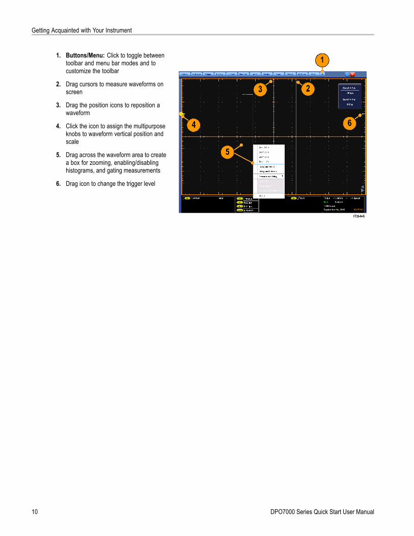
Adding Screen Text1. Select Display > Screen Text.
2. Enter up to eight independent lines oftext.
3. Click Display to turn the text display onand off.
4. Click Properties to open the TextProperties control window for positioningof the text on the display.
5. Click Clear to erase the entire text of theselected line.
Quick TipsYou can click and drag screen text to reposition it on the screen.
DPO7000 Series Quick Start User Manual 39

Display a Waveform
Setting the Graticule StyleTo set the graticule style, select Display >Graticule Style, and then select one of thefollowing styles:
Use for quick estimate ofwaveform parameters.
Use for full-screenmeasurements withcursors and automaticreadouts whencross-hairs are notneeded.Use for making quickestimates of waveformswhile leaving more roomfor automatic readoutsand other data.Use with automaticreadouts and otherscreen text when displayfeatures are not needed.
Use for NTSC videosignals.
Use for video signalsother than NTSC.
40 DPO7000 Series Quick Start User Manual

Display a Waveform
Setting the Trigger Level Marker1. Select Display > Objects....
2. Select one of the following:
Short displays a short arrow on theside of the graticule.
Long displays a horizontal lineacross the graticule.
Off turns off the trigger level marker.
Displaying the Date and Time1. Select Display > Objects....
2. Toggle the display of the date and timeon the graticule. Use the Utilities menuto set the date and time.
DPO7000 Series Quick Start User Manual 41
Display a Waveform
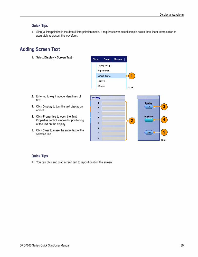
Using the Color PalettesSelect Display > Record View Palette orFastAcq/WfmDB Palette, and then selectone of the following color schemes for thewaveform and graticule:
Normal displays hues and lightnesslevels for best overall viewing. The colorof each channel waveform matches thecolor of the corresponding front-panelvertical knob.
Temperature Grading displays areas ofthe waveform with the highest sampledensity in red shades. The areas oflowest sample density appear in blueshades.
Monochrome Green displays areas ofthe waveform with the highest sampledensity in lighter green shades. Theareas of lowest sample density appearin darker green shades. It most closelyresembles analog oscilloscope displays.
Spectral Grading displays areas ofthe waveform with the highest sampledensity in blue shades. The areas oflowest sample density appear in redshades.
Monochrome Gray displays areas ofthe waveform with the highest sampledensity in lighter gray shades. Theareas of lowest sample density appear indarker gray shades.
User displays the waveform in auser-defined color.
Quick TipsChoose one of the color grading palettes in the Display > Colors control window to see different sample densitiesrepresented in different colors.
There are two color palettes, one for Record View and one for FastAcq/WfmDB.
42 DPO7000 Series Quick Start User Manual

Display a Waveform
Setting the Reference Colors
Select Display > Colors..., and then selectone of the following:
Default uses the default system color forreference waveforms.
Inherit uses the same color for thereference waveform as the originalwaveform.
Setting Math Colors
Select Display > Colors..., and then selectone of the following:
Default uses the default system color formath waveforms.
Inherit uses the same color for themath waveform as the lowest numberedchannel waveform the math function isbased on.
Quick TipsThe default color for math and reference waveforms are different for each waveform.
Using MultiView ZoomUse the MultiView Zoom function to magnify a waveform vertically, horizontally, or in both dimensions. Zoomed waveformscan also be aligned, locked, and automatically scrolled. Scale and Position affect only the display, not the actual waveformdata.
1. Push MultiView Zoom to split the screenand add a zoom graticule.
DPO7000 Series Quick Start User Manual 43

Display a Waveform
2. Push HORIZ or VERT to select whichaxis to magnify in the zoom graticule.Use the multipurpose knobs to adjustscale and position of the magnifiedwaveform.
3. To adjust the zoom graticule size, selectZoom Graticule Size from either theVertical or Horiz/Acq menus.
4. To turn zoom off, push the front-panelbutton.
Quick TipsYou can also use the Zoom Setup menu to change the graticule size of the zoomed waveform.
44 DPO7000 Series Quick Start User Manual

Display a Waveform
Zooming in Multiple AreasWhen you want to view and compare multiple areas of one record at the same time, use the following procedure.
1. Click and drag a box around the area ofthe waveform that you want to zoom.
2. Select Zoom 1 On.
3. Click and drag a box around anotherarea of the waveform that you want tozoom, and then select Zoom 2 On.
4. To adjust the zoomed area horizontally,click the horizontal marker below theZoom box to select the zoomed area.
5. Use the multipurpose knobs to adjustthe horizontal position and factor of theselected zoom area.
DPO7000 Series Quick Start User Manual 45

Display a Waveform
6. To adjust the zoomed area vertically,select Vertical > Zoom Setup...,click a vertical field, and then use themultipurpose knobs to adjust the VerticalPosition and Factor.
Quick TipsTo clear the zoom area, click Position Factor Reset from the Zoom Setup control window.
You can turn each zoom display on and off from the Zoom Setup control window.
Push the MultiView Zoom button to toggle all zoom displays on and off.
To reposition the zoomed area horizontally, click and drag the horizontal marker at the bottom of the zoom box.
46 DPO7000 Series Quick Start User Manual

Display a Waveform
Lock and Scroll Zoomed Waveforms1. To use Lock and Scroll select Zoom
Setup... from either the Vertical orHoriz/Acq menu, and then select theLock and Scroll tab.
2. To scroll a single zoomed area, select aZoom 1-4 check box, and then click anAuto Scroll button.
3. To scroll multiple zoomed areassimultaneously, click Lock, and thenselect the Zoom1-4 check boxes thatyou want to scroll through.Locking the zoomed areas locks in theirrelative horizontal position. Changingthe horizontal position of one locked andzoomed area changes them all.
Quick TipsWhen multiple zoom areas are selected but not locked, the zoom area with the highest number will autoscroll, while theother zoom areas remain stationary.
DPO7000 Series Quick Start User Manual 47

Analyzing Waveforms
Analyzing WaveformsYour instrument features cursors, automatic measurements, statistics, histograms, math, spectral analysis, and advancedpass/fail tests to assist you in analyzing waveforms. This section contains concepts and procedures for analyzing waveforms.Detailed information is available in the online help.
Taking Automatic Measurements1. Select Measure > Measurement
Setup....
2. Select the channel, math or referencewaveform that you want to measure.
3. Using the tabs, select measurements infive different categories.
48 DPO7000 Series Quick Start User Manual

Analyzing Waveforms
4. To remove the last measurement, clickClear.
5. To remove multiple measurements, clickand drag to select the measurements,and then click Clear.
You can also choose a measurementfor the selected waveform directly inthe Measure menu. (See page 50,Automated Measurement Selections.)
Quick TipsIn roll mode, measurements are not available until after you stop the acquisition.
DPO7000 Series Quick Start User Manual 49

Analyzing Waveforms
Automated Measurement SelectionsThe following tables list each automated measurement by category: amplitude, time, more, histogram, or communication.(See page 48, Taking Automatic Measurements.)
Amplitude MeasurementsMeasurement DescriptionAmplitude The high value less the low value measured over the entire waveform or gated region.High This value is used as 100% whenever high reference, mid reference, or low reference values
are needed, such as in fall time or rise time measurements. It can be calculated using eitherthe min/max or histogram method. The min/max method uses the maximum value found. Thehistogram method uses the most common value found above the midpoint. This value is measuredover the entire waveform or gated region.
Low This value is used as 0% whenever high reference, mid reference, or low reference values areneeded, such as in fall time or rise time measurements. It can be calculated using either themin/max or histogram method. The min/max method uses the minimum value found. The histogrammethod uses the most common value found below the midpoint. This value is measured overthe entire waveform or gated region.
RMS The true Root Mean Square voltage over the entire waveform or gated region.Max Typically the most positive peak voltage. Max is measured over the entire waveform or gated region.Min Typically the most negative peak voltage. Min is measured over the entire waveform or gated region.Pk-Pk The absolute difference between the maximum and minimum amplitude in the entire waveform
or gated region.Cycle RMS The true Root Mean Square voltage over the first cycle in the waveform or the first cycle in the
gated region.+Overshoot This is measured over the entire waveform or gated region and is expressed as:
Positive Overshoot = ((Maximum - High) / Amplitude) x 100%.-Overshoot This is measured over the entire waveform or gated region and is expressed as:
Negative Overshoot = ((Low - Minimum) / Amplitude) x 100%.Mean The arithmetic mean over the entire waveform or gated region.Cycle Mean The arithmetic mean over the first cycle in the waveform or the first cycle in the gated region.
Time MeasurementsMeasurement DescriptionRise Time The time required for the leading edge of the first pulse in the waveform or gated region to rise from
the low reference value (default = 10%) to the high reference value (default = 90%) of the final value.Fall Time The time required for the falling edge of the first pulse in the waveform or gated region to fall from
the high reference value (default = 90%) to the low reference value (default = 10%) of the final value.Pos Width The distance (time) between the mid reference (default 50%) amplitude points of a positive pulse.
The measurement is made on the first pulse in the waveform or gated region.Neg Width The distance (time) between the mid reference (default 50%) amplitude points of a negative pulse.
The measurement is made on the first pulse in the waveform or gated region.+ Duty Cyc The ratio of the positive pulse width to the signal period expressed as a percentage. The duty cycle
is measured on the first cycle in the waveform or gated region.
50 DPO7000 Series Quick Start User Manual

Analyzing Waveforms
Time Measurements (cont.)
Measurement Description- Duty Cyc The ratio of the negative pulse width to the signal period expressed as a percentage. The duty
cycle is measured on the first cycle in the waveform or gated region.Period The time required to complete the first cycle in a waveform or gated region. Period is the reciprocal
of frequency and is measured in seconds.Freq The frequency of the first cycle in a waveform or gated region. Frequency is the reciprocal of the
period; it is measured in Hertz (Hz) where one Hz is one cycle per second.Delay The time between the mid reference (default 50%) amplitude point of two different waveforms.
More MeasurementsMeasurement DescriptionArea The area over the entire waveform or gated region in volt-seconds. Area measured above ground is
positive; area measured below ground is negative.Cycle Area The area over the first cycle in the waveform or the first cycle in the gated region expressed in
volt-seconds. The area above the common reference point is positive while the area below thecommon reference point is negative.
Phase The amount of time that one waveform leads or lags another waveform, expressed in degreeswhere 360° comprises one waveform cycle.
Burst Width The duration of a burst (a series of transient events) and is measured over the entire waveformor gated region.
Histogram MeasurementsMeasurement DescriptionWfm Ct Displays the number of waveforms that have contributed to the histogram.Hits in Box Displays the number of points in or on the histogram box.Peak Hits Displays the number of points in the largest bin of the histogram.Median Displays the middle point of the histogram box. Half of all acquired points within or on the histogram
box are less than this value and half are greater than this value.Max Displays the voltage of the highest nonzero bin in vertical histograms or the time of the rightmost
nonzero bin in the horizontal histograms.Min Displays the voltage of the lowest nonzero bin in vertical histograms or the time of the leftmost
nonzero bin in the horizontal histograms.Pk-Pk Displays the peak-to-peak value of the histogram. Vertical histograms display the voltage of the
highest nonzero bin minus the voltage of the lowest nonzero bin. Horizontal histograms display thetime of the rightmost nonzero bin minus the time of the leftmost nonzero bin.
Mean Measures the average of all acquired points within or on the histogram box.Std Dev Measures the standard deviation (Root Mean Square (RMS) deviation) of all acquired points within
or on the histogram box.Mean ±1 Std Dev Displays the percentage of points in the histogram that are within one standard deviation of the
histogram mean.
DPO7000 Series Quick Start User Manual 51

Analyzing Waveforms
Histogram Measurements (cont.)
Measurement DescriptionMean ±2 Std Dev Displays the percentage of points in the histogram that are within two standard deviations of the
histogram mean.Mean ±3 Std Dev Displays the percentage of points in the histogram that are within three standard deviations of
the histogram mean.
Communication MeasurementsMeasurement DescriptionExt Ratio The ratio of eye top to base. This measurement only works for waveform database or a reference
waveform saved in waveform database mode.Ext Ratio % The ratio of eye base to top expressed as a percentage. This measurement only works for
waveform database or a reference waveform saved in waveform database mode.Ext Ratio (dB) The ratio of eye top to base expressed in decibels. This measurement only works for waveform
database or a reference waveform saved in waveform database mode.Eye Height The measurement of the eye height in volts.Eye Width The measurement of eye width in seconds.Eye Top The top value used in the extinction ratio measurements.Eye Base The base value used in the extinction ratio measurements.Crossing % The eye crossing point expressed as a percentage of eye height.Jitter P-P The peak-to-peak value for the edge jitter in the current horizontal units.Jitter RMS The RMS value of the edge jitter in the current horizontal units.Jitter 6 Sigma Six times the RMS value of the edge jitter in the current horizontal units.Noise P-P The peak-to-peak value of the noise of the top or base of the signal as specified by you.Noise RMS The RMS value of the noise of the top or base of the signal as specified by you.S/N Ratio The ratio of the signal amplitude to the noise of the top or base of the signal as specified by you.Cyc Distortion The peak-to-peak time variation of the first eye crossing measured at the Mid Ref as a percent of
the eye period.Q-Factor The ratio of eye size to noise.
52 DPO7000 Series Quick Start User Manual

Analyzing Waveforms
Customizing an Automatic MeasurementYou can customize automatic measurements by using gating, modifying measurement statistics, or adjusting themeasurement reference levels.
Gating
Use Gating to confine the measurement to acertain portion of a waveform.
1. Select Measure > Gating > Gating ....
2. Position the gates by doing one of thefollowing:
Click Cursor to set the gated area tothe area between the cursors.
Click Zoom (1-4) to set the gatedarea to the Zoom (1-4) graticule.
DPO7000 Series Quick Start User Manual 53

Analyzing Waveforms
Statistics
Statistics turn on automatically withmeasurements. Statistics characterize thestability of the measurement.
1. To change the statistics that aredisplayed, select Measure > Statistics,and then select Mean or All. (All includesmin, max, mean, standard deviation, andpopulation.)
2. To remove statistics select Off.
Reference Levels
Reference levels determine how time-relatedmeasurements are taken.
1. Select Measure > Reference Levels....
2. Adjust the measurement reference levelsto different relative or absolute values.
High and Low reference are usedto calculate rise and fall times. Thedefault High reference is 90% andLow reference is 10%.
Mid reference is primarily used formeasurements between edges suchas pulse widths. The default level is50%.
Mid2 reference is used on the secondwaveform specified in delay or phasemeasurements. The default level is50%.
Quick TipsTo ensure accurate noise values, be sure to set the signal type to Eye when measuring an Eye signal.
54 DPO7000 Series Quick Start User Manual

Analyzing Waveforms
Taking Cursor MeasurementsUse cursors to taking measurements on acquired data.
1. Push Cursors.
2. Select the Cursor Source.
3. Select a cursor type from one of thefollowing:
H Bars measure amplitude (typicallyin volts or amperes)
V Bars measure horizontalparameters (typically time)
Waveform and screen cursorsmeasure vertical and horizontalparameters simultaneously.Waveform cursors are attached tothe waveform, and screen cursorsfloat, unattached to the waveform.
DPO7000 Series Quick Start User Manual 55

Analyzing Waveforms
4. To take measurements between twowaveforms, select Waveform, and thenselect the waveform source for eachcursor.
5. Select Cursors > Cursor Position...,and then use the multipurpose knobs toadjust the cursor position.
6. Read cursor measurement results in thedisplay.
Quick TipsUse the Cursor Track Mode to set the cursors to move in tandem. Use the Cursor Independent mode to move thecursors separately.
If you use the zoom graticule, you can place a cursor directly on a specific waveform point to take precisionmeasurements.
You can also move cursors by clicking and dragging them to a new position.
Vertical cursors measure the time from the trigger point to the vertical cursor.
56 DPO7000 Series Quick Start User Manual

Analyzing Waveforms
Setting Up a HistogramYou can display either a vertical (voltage) or horizontal (time) histogram. Use histogram measurements to get statisticalmeasurement data for a section of a waveform along one axis.
1. Click and drag the pointer across thesegment of the waveform that you wantthe histogram to cover. For example,make the box for a horizontal histogramwider than it is tall.
2. Select Histogram Vertical or HistogramHorizontal from the shortcut menu.
3. View the histogram at the top (forhorizontal histograms) or the left edge(for vertical histograms) of the graticule.
DPO7000 Series Quick Start User Manual 57

Analyzing Waveforms
4. To make adjustments to the histogramscale or the size and location of thehistogram box, select Measure >Waveform Histograms, and then usethe Histogram Setup control window.
5. You can also take automatedmeasurements on histogram data.(See page 48, Taking AutomaticMeasurements.)
Quick TipsUse vertical histograms to measure signal noise and horizontal histograms to measure signal jitter.
Use the click and drag procedure to activate the shortcut menu to turn the histogram display off.
58 DPO7000 Series Quick Start User Manual

Analyzing Waveforms
Using Math WaveformsCreate math waveforms to support the analysis of your channel and reference waveforms. By combining and transformingsource waveforms and other data into math waveforms, you can derive the data view that your application requires.
Use the following procedure for predefined math equations.
1. Select Math > Math Setup....
2. Choose one of the predefined mathequations.
Use the following procedure to build an advanced math waveform expression.
1. Select Math > Math Setup....
DPO7000 Series Quick Start User Manual 59

Analyzing Waveforms
2. Click Editor.
3. Build your advanced math waveformexpression using sources, operators,constants, measurements, variables,and functions.
4. When you have defined the expressionto your satisfaction, click Apply.
5. To add your own filter, click the Filtertab. Click Load.
60 DPO7000 Series Quick Start User Manual

Analyzing Waveforms
6. Double click Math Arbitrary Filtersfolder. Double click the filter you want touse.
7. Built your math expression using thefilter you selected.
8. When you have defined the expressionto your satisfaction, click Apply.
Quick TipsMath definitions are not implemented if the sources are not valid.
Math waveforms can be created from channel, reference, math source waveforms and from measurements.
Measurements can be taken on math waveforms in the same way as on channel waveforms.
Math waveforms derive their horizontal scale and position from the sources in their math expressions. Adjusting thesecontrols for the source waveforms also adjusts the math waveform.
You can magnify math waveforms using MultiView Zoom; use the mouse for positioning the zoomed area.
DPO7000 Series Quick Start User Manual 61
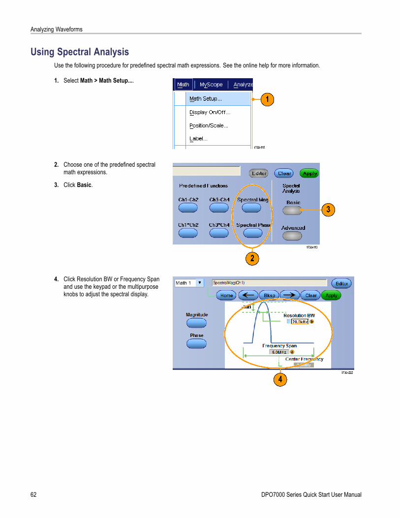
Analyzing Waveforms
Using Spectral AnalysisUse the following procedure for predefined spectral math expressions. See the online help for more information.
1. Select Math > Math Setup....
2. Choose one of the predefined spectralmath expressions.
3. Click Basic.
4. Click Resolution BW or Frequency Spanand use the keypad or the multipurposeknobs to adjust the spectral display.
62 DPO7000 Series Quick Start User Manual

Analyzing Waveforms
Use the following procedure to build an advanced spectral math expression.
1. Select Math > Advanced Spectral....
2. Select the math waveform that you wantto define.
3. Click the type of spectral waveformthat you want to create. To redefine awaveform, click Clear.
4. Select the source waveform.
5. Adjust the spectral waveform, using thecontrols in the Spectral Setup controlwindow and use the multipurpose knobs.
6. You can view time-domain andfrequency-domain waveformssimultaneously.Use Gating to select only a portion ofthe time-domain waveform for spectralanalysis. (See page 53, Gating.)
DPO7000 Series Quick Start User Manual 63

Analyzing Waveforms
Quick TipsSources for spectral math waveforms must be channel or other math waveforms.
Use short record lengths for faster instrument response.
Use long record lengths to lower the noise relative to the signal and increase the frequency resolution.
Different window functions produce different filter response shapes in the spectrum and result in different resolutionbandwidths. See the online help for more information.
The resolution bandwidth (RBW) directly controls the gate width. Therefore, the time domain gate markers moveas you adjust the control.
You can display the linear magnitude of the real data or the imaginary data in the spectrum. This is useful if you processthe spectrum off line and transform it back into a time domain trace.
Using Mask TestingSerial Communications Mask Testing (Option MTM) allows you to compare your signal to a predefined template or mask. Forthe signal to pass the test, it must fall outside the segments defined by the mask. Generally, standards committees such asANSI define the masks. To perform mask testing do the following:
1. Select Masks > Source....
2. Select the signal source.
3. Click the Masks tab.
64 DPO7000 Series Quick Start User Manual

Analyzing Waveforms
4. Select the Type and standard.
5. Click Config to access the MaskConfiguration control window, where youcan adjust how masks and violations aredisplayed and how Mask Autoset andAutofit are configured.
6. Click Masks to return to the Mask Setupcontrol window.
7. Click Lock Mask to Wfm On to trackmask changes in the horizontal orvertical settings.
8. Toggle Hit Count On to highlightviolations during a mask test.
9. Click Autoset to automatically align thewaveform with the mask based on thecharacteristics of the input signal.
10. Toggle Autofit On to automaticallyreposition the waveform after eachacquisition to minimize hits.
DPO7000 Series Quick Start User Manual 65

Analyzing Waveforms
11. Click the Tolerance tab, and then set thetolerance.Tolerance settings greater than 0% makethe mask test harder to pass, settingsless than 0% make the test easier topass.Use 0% if you want the mask asspecified in the standard. Changing thepercentage allows you to do margintesting.
12. Select the Pass/Fail Setup tab, and thenset up the pass/fail parameters. (Whenacquisition mode is Waveform Database,the # of Wfms label becomes Samples.)
13. Select your Pass/Fail Test Notifications.
66 DPO7000 Series Quick Start User Manual

Analyzing Waveforms
14. Select the polarity you want to test.
15. Toggle Pass/Fail Test On to start themask test.
16. Toggle Repeat On to run the mask testcontinuously.
17. Click the Pass/Fail Results tab to viewthe test results.
18. Click Pass/Fail Test On to start the masktest.
19. Click Reset to reset the totals and clearany violations.
Quick TipsIf the signal is not within the mask, enable Autoset to center the waveform in the mask.
DPO7000 Series Quick Start User Manual 67

MyScope
MyScopeMyScope allows you to create custom control windows that include only the controls that you use regularly. Instead ofswitching between several control windows, put the controls you use into a custom control window.
This section contains procedures for creating and using MyScope control windows. Detailed information is availablein the online help.
Creating a New MyScope Control Window1. Select MyScope > New Control
Window....
2. Click + to expand a category. Controlsthat can be added to your MyScopecontrol window are contained withineach category. The categories match themenu bar to help you find the controlsyou normally use.
68 DPO7000 Series Quick Start User Manual
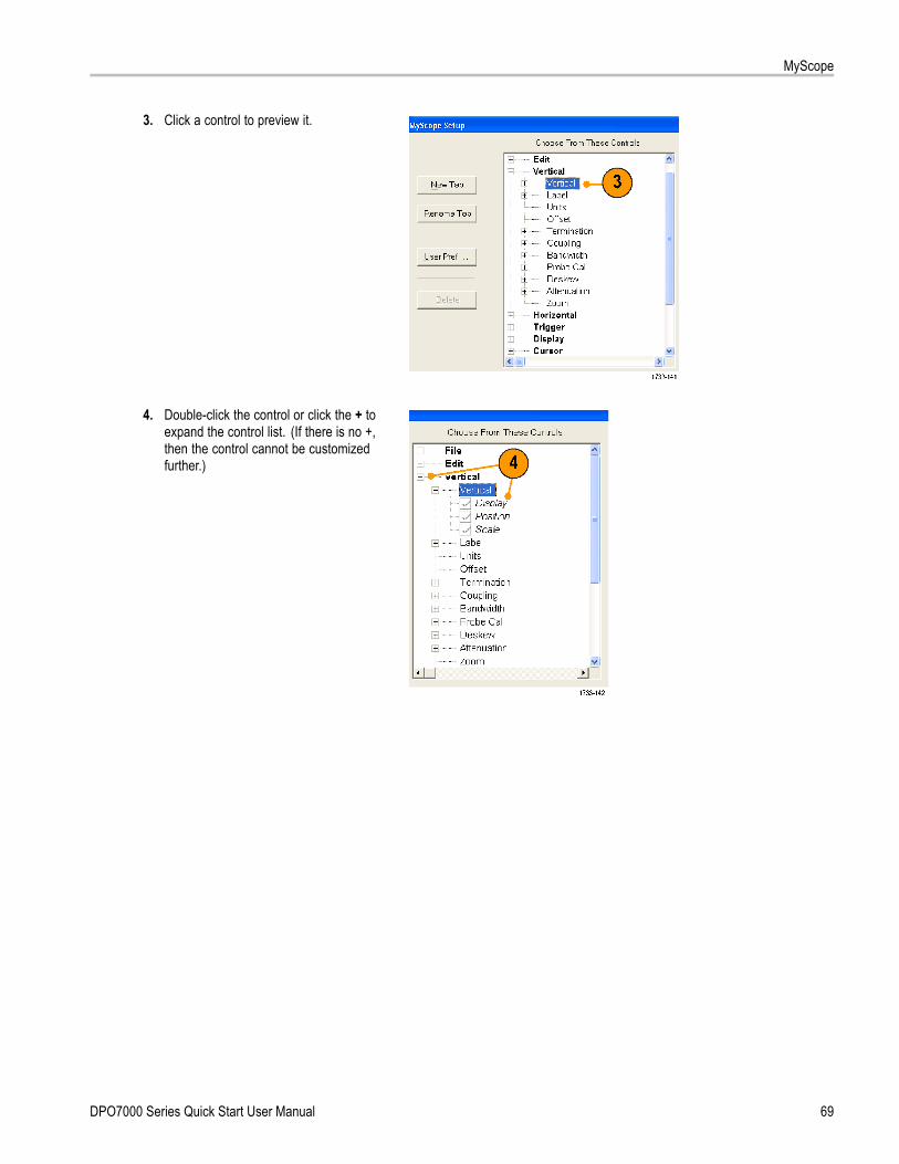
MyScope
3. Click a control to preview it.
4. Double-click the control or click the + toexpand the control list. (If there is no +,then the control cannot be customizedfurther.)
DPO7000 Series Quick Start User Manual 69

MyScope
5. Clear the check boxes to remove anycomponents that you do not wantincluded in the control.
6. Click and drag the control to yourMyScope control window. The controlwill snap to the nearest grid locationwhen you release the mouse. You canchange the placement of the control inyour MyScope control window by clickingand dragging.
70 DPO7000 Series Quick Start User Manual

MyScope
7. Click New Tab to add a tab to yourMyScope control window. You can haveup to eight tabs.
8. To rename a tab do one of the following:
Click Rename Tab.
Double-click the tab, and then typethe new name.
9. Click User Pref... to specify userpreferences that are loaded with yourMyScope control window.
10. To delete controls do one of the following:
Select a tab, and then click Delete.The tab and all of the controls aredeleted.
Select a control, and then clickDelete. Just the selected control isdeleted.
11. Click Save, and then enter a name foryour MyScope control window, or usethe default name.
Quick TipsTo reconfigure a control, click and drag it back to the preview window. Then select or clear the check boxes to include orremove components in the control.
To change the tab order, click and drag a tab to a new location.
To delete a control, click and drag it to the upper half of the screen (off of your MyScope control window).
DPO7000 Series Quick Start User Manual 71

MyScope
Using MyScope Control WindowsTo open a previously defined MyScope control window, do the following:
1. Select MyScope > Open ControlWindow... or one of the five mostrecently used MyScope windows.
2. Select the MyScope control window youwant to use, and then click Open.
To display the active MyScope control window, do the following:
1. Select MyScope > Current... or clickMyScope in the toolbar mode. (YourMyScope control window remains activeeven when it is not displayed.)
72 DPO7000 Series Quick Start User Manual

MyScope
To edit a MyScope control window do the following:
1. Select MyScope > Edit ControlWindow....
2. Select the control window you want toedit, and then click Open.
Quick TipsSome controls function differently in a MyScope control window than they do in the standard control window. Fordetails, see the online help.
You can copy MyScope control windows (.tcw files) to other DPO7000 Series instruments.
DPO7000 Series Quick Start User Manual 73

Saving and Recalling Information
Saving and Recalling InformationThis section contains procedures for saving and recalling screen captures and setups, saving measurements, using theclipboard, and printing on your instrument. Detailed information is available in the online help.
Saving Screen Captures1. Select File > Save or Save As > Screen
Capture....
2. Click Options..., if you want to setup thePalette, View, Image, or Screen CaptureFormat options; otherwise, skip to step 3.
74 DPO7000 Series Quick Start User Manual

Saving and Recalling Information
3. Select the location to save the screencapture.
4. Type in a name for the screen capture,or use the default name, and then selecta file type.
5. Click Save.
Quick TipTo quickly save multiple screen captures, select Set Front Panel Print Button to Save, and then click Save. You cannow save a screen capture by pushing the front panel Print button.
Saving Waveforms1. To save waveforms, select File > Save
or Save As > Waveform....
DPO7000 Series Quick Start User Manual 75

Saving and Recalling Information
2. Click Waveform.
3. Click Options..., if you want to specifythe Waveform Data Range, FastFrameData Range, Waveform Detail, DataDestination, Source, or Data Ordering;otherwise, skip to step 4.
4. Select the Source.
5. You can either save the waveform as areference waveform in the instrumentmemory or as a .wfm file in a Windowsdirectory. To save the waveform as areference, select Ref 1–4. To save as a.wfm file, select the location where youwant to save the waveform.
6. If you are saving as a .wfm file, type in afile name, or use the default.
7. Click Save.
Quick TipsSelect Auto-increment file name to save numerous similar waveforms without having to retype the entire name.
To quickly save multiple waveforms, select Set Front Panel Print Button to Save, and then click Save. You can nowsave a waveform by pushing the front-panel Print button.
76 DPO7000 Series Quick Start User Manual

Saving and Recalling Information
Recalling Waveforms1. Select File > Recall....
2. Click Waveform.
3. Select the Destination of the waveformyou are recalling.
4. Select the waveform to recall.
5. Click Recall. Clicking Recall turns on thereference waveform and activates theReference Waveform control window.
6. Use the controls to adjust the Referencewaveform. You can also access theReference Waveform control window byselecting File > Reference WaveformControls....
Quick TipYou can save a number of different file types but you can only recall setup (*.set) files and waveform (*.wfm) files.
DPO7000 Series Quick Start User Manual 77

Saving and Recalling Information
Saving Instrument Setups1. Select File > Save or Save As >
Setup....
2. Click Setup.
3. Select the location where you want tosave the setup. You can either save thesetup to the instrument memory in oneof the ten setup storage locations or asa .set file in a Windows directory.
4. Type a file name or use the default name.Use the pop-up keyboard to type a filename for a setup saved to the instrumentmemory.
5. Click Save.
Quick TipsIf the touch screen is enabled, use the pop-up keypad to label the setups for easy identification.
Use Auto-increment file name to save numerous similar files without having to retype the entire file name.
To quickly save multiple setups, select Set Front Panel Print Button to Save, and then click Save. You can nowsave a setup by pushing the front panel Print button.
78 DPO7000 Series Quick Start User Manual

Saving and Recalling Information
Recalling Instrument Setups1. Select File > Recall....
2. Click Setup.
3. Select the setup you want to recall. Youcan recall a setup file from one of the tenlocations in the instrument memory orfrom a Windows directory.
4. Click Recall.
Quick TipYou can recall any setup stored on disk and then save it in an internal setup storage location for quicker access.
DPO7000 Series Quick Start User Manual 79
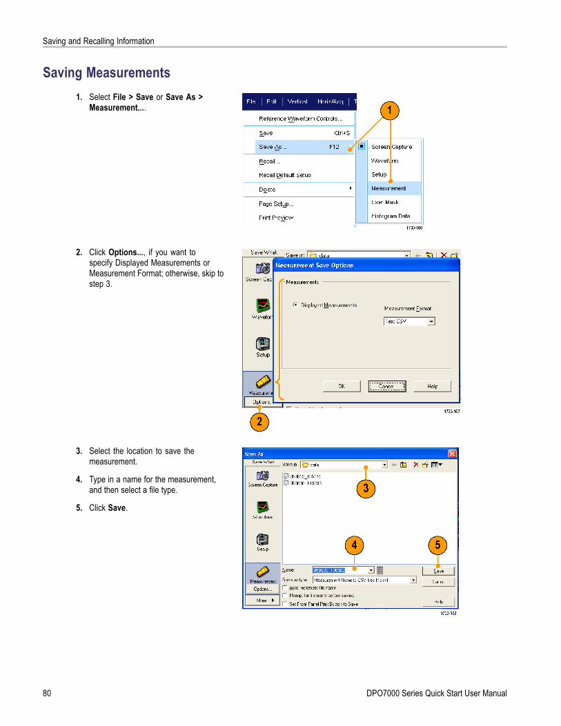
Saving and Recalling Information
Saving Measurements1. Select File > Save or Save As >
Measurement....
2. Click Options..., if you want tospecify Displayed Measurements orMeasurement Format; otherwise, skip tostep 3.
3. Select the location to save themeasurement.
4. Type in a name for the measurement,and then select a file type.
5. Click Save.
80 DPO7000 Series Quick Start User Manual

Saving and Recalling Information
Copying Your Results to the ClipboardUse the following procedure to set the output content and format for images, waveforms, or measurements to be copiedto the Microsoft clipboard.
1. Select Edit > Copy Setup....
2. Click the Images, Waveforms, orMeasurements tab, and then select thedesired options.
DPO7000 Series Quick Start User Manual 81

Saving and Recalling Information
To copy images, waveforms, or measurements use the following procedure:
1. Select the item that you want to copy.
2. Select Edit > Copy or press Ctrl + C.
3. Press Ctrl + V to paste the item into aWindows application.
82 DPO7000 Series Quick Start User Manual

Saving and Recalling Information
Printing a Hard Copy1. To print a hard copy, do one of the
following:
Push PRINT.
Select File > Print. If necessary,you can make changes to the pageorientation in the Page Setup dialogbox.
Your Print and Page Setup dialog boxes willdepend on the printer you are using.
2. Click Page Setup....
3. Select either Screen-copy or Banner.
4. Select the printing parameters dependingon the type of printing.
DPO7000 Series Quick Start User Manual 83

Run Application Software
Run Application SoftwareThe Optional Application Software CD contains free five-time trials of optional application software that you can install on yourinstrument. These applications provide application-specific measurement solutions. Some examples are described below.Additional packages may be available. Contact your Tektronix representative or visit our Web site at www.tektronix.comfor more information.
Use ET3 to perform 10/100/1000 Base-T Ethernet compliance testing.
Use USB to characterize USB2.0 signals including mask testing and parametric testing (S/W only).
Use PWR Power Measurement Software to quickly measure and analyze power dissipation in power supply switchingdevices and magnetic components.
Use PTM Serial Protocol Trigger Software to trigger and decode 8 B/10 B data on high-speed serial or data protocols.Decode is available on all models.
Use LSA Serial Analysis Software for CAN/LIN protocol triggering and analysis.
Use MTM Communication Mask Testing Software for mask compliance testing.
Follow the instructions provided with theapplication software to install it. To run thesoftware, select Analyze and then select theapplication.
84 DPO7000 Series Quick Start User Manual

Application Examples
Application ExamplesThis section contains ways to use your instrument in common troubleshooting tasks and extending the use of your instrument.
Capturing Intermittent AnomaliesOne of the most difficult tasks that design engineers face is tracking down the cause of intermittent failures. If you know whattype of anomaly you are looking for, then it is easy to configure the oscilloscope advanced triggering capability to isolate it.However, when you do not know what you are looking for, it can be exceptionally tedious and time consuming, especiallygiven the low waveform capture rate on traditional digital storage oscilloscopes.
Digital Phosphor Oscilloscopes enabled by DPX technology have an exceptionally fast acquisition mode called FastAcqthat allows you to find anomalies like these in a matter of seconds or minutes, where a regular DSO would take hours ordays to find the same event.
Use the following procedure to capture intermittent anomalies.
1. Probe the signal of interest. (Generallythis is one that you think may be causingproblems.)
2. Push Autoset.
DPO7000 Series Quick Start User Manual 85

Application Examples
3. Select Display > Display Persistence> Infinite Persistence. In this example,we are looking at a clock signal. Afterobserving the signal for 1–2 minutes,but before you look for the problemelsewhere, go to step 4.
4. Press FastAcq.
5. Find glitches, transients, or other randomanomalies that are present in the signal.In this example, FastAcq revealed an≈300 ns positive glitch after only a fewseconds.
86 DPO7000 Series Quick Start User Manual

Application Examples
6. To trigger on the glitch that you identifiedin step 5, select Glitch Setup....
7. Select the appropriate trigger values.
8. Click Level, and then set the level basedon what you found in step 5.
9. Click Width, and then set the widthbased on what you found in step 5.
10. Click E-mail on Trigger On. (Seepage 93, Setting Up E-mail on Event.)
11. Push Single to trigger on a single glitch.
DPO7000 Series Quick Start User Manual 87

Application Examples
Using the Extended Desktop and OpenChoice Architecture for EfficientDocumentation
Engineers often need to document their lab work for future reference. Instead of saving screen shots and waveform datato a CD or USB memory device, and then generating a report later, try using the OpenChoice architecture to documentyour work in real time.
To make your instrument the center of your design and documentation process, use the following procedure.
1. Load Microsoft Word or Excel on yourinstrument.
2. Connect a second monitor. (See page 5,Adding a Second Monitor.)
3. Open Microsoft Word, and then drag theWord window onto the extended desktop.
4. Click TekScope to restore the instrumentapplication.
88 DPO7000 Series Quick Start User Manual

Application Examples
5. Select Edit > Select for Copy > FullScreen (bitmap).
6. Press Ctrl+C.
7. Click in the Word document whereveryou want to place the screen shot, andthen press Ctrl+V.
Quick TipsThe instrument comes with a variety of OpenChoice software tools designed to ensure maximum efficiency andconnectivity to the rest of your design environment.
Triggering on BusesYou can use your instrument to trigger on CAN (optional), I2C, and SPI buses. The instrument can display both physical layer(as analog waveforms ) and, for CAN and LIN triggers, protocol level information (as digital and symbolic waveforms).
To set up the bus trigger:
1. Select Trig > A Event (Main) TriggerSetup....
DPO7000 Series Quick Start User Manual 89

Application Examples
2. Set the A trigger type and source in theA Event tab.
3. Select Trigger On to select the desiredtrigger on feature.
4. Depending on your Trigger On selection,you may need to make additionalselections.
90 DPO7000 Series Quick Start User Manual

Application Examples
Triggering on a Video SignalThe instrument supports triggering on NTSC, SECAM, PAL, and high definition signals.
To trigger on the video fields:
1. Select Trig > A Event (Main) TriggerSetup....
2. Set the A trigger type and source in theA Event tab.Select Format > 525/NTSC.
3. Select Trigger On > Field.Select Odd, Even, or All fields.
DPO7000 Series Quick Start User Manual 91
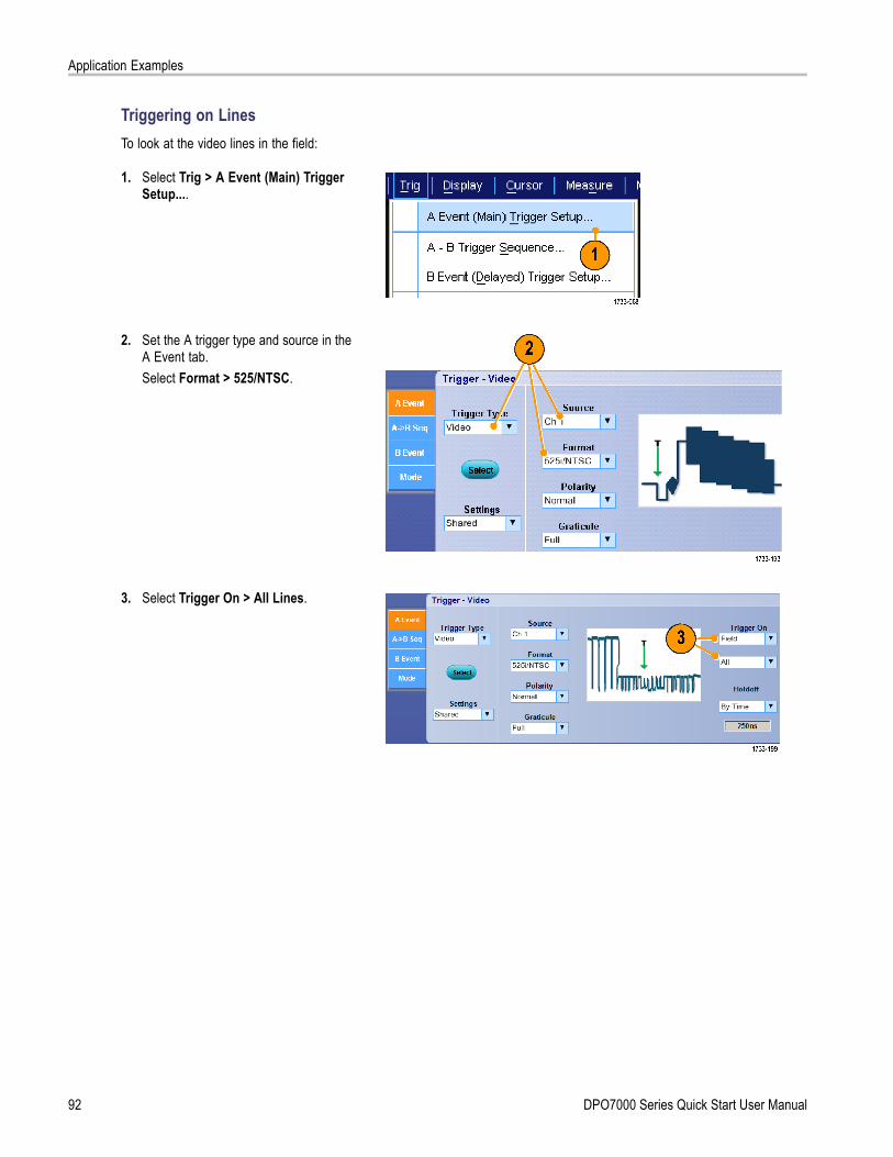
Application Examples
Triggering on LinesTo look at the video lines in the field:
1. Select Trig > A Event (Main) TriggerSetup....
2. Set the A trigger type and source in theA Event tab.Select Format > 525/NTSC.
3. Select Trigger On > All Lines.
92 DPO7000 Series Quick Start User Manual

Application Examples
Setting Up E-mail on Event1. Select Utilities > E-mail on Event >
Setup....
2. Enter recipients’ e-mail address(es).Separate multiple entries with commas.There is a limit of 252 characters in thee-mail address box.
3. Click Config, and then enter the SMTPServer Address. Contact your networkadministrator for the correct address.
DPO7000 Series Quick Start User Manual 93
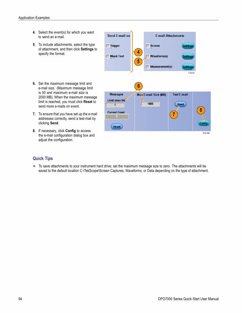
Application Examples
4. Select the event(s) for which you wantto send an e-mail.
5. To include attachments, select the typeof attachment, and then click Settings tospecify the format.
6. Set the maximum message limit ande-mail size. (Maximum message limitis 50 and maximum e-mail size is2000 MB). When the maximum messagelimit is reached, you must click Reset tosend more e-mails on event.
7. To ensure that you have set up the e-mailaddresses correctly, send a test-mail byclicking Send.
8. If necessary, click Config to accessthe e-mail configuration dialog box andadjust the configuration.
Quick TipsTo save attachments to your instrument hard drive, set the maximum message size to zero. The attachments will besaved to the default location C:\TekScope\Screen Captures, Waveforms, or Data depending on the type of attachment.
94 DPO7000 Series Quick Start User Manual

Application Examples
Correlating Data Between a Tektronix Oscilloscope and Logic AnalyzerAlmost every design is a high-speed design with fast clock edges and data rates. For these designs, you need to see theanalog characteristics of high-speed digital signals in relation to complex digital events in the circuit. iView is your windowinto the digital and analog world. The iView capability seamlessly integrates and automatically time-correlates data fromTektronix logic analyzers and oscilloscopes, so you can transfer analog waveforms from the oscilloscope to the logicanalyzer display with the click of a mouse. View time-correlated analog and digital signals side-by-side and pinpoint thesource of elusive glitches and other problems in moments.
The iView External Oscilloscope Cable allows you to connect your logic analyzer to a Tektronix oscilloscope, enablingcommunication between the two instruments. The Add External Oscilloscope wizard, which is available from the TLAapplication System menu, will guide you through the process of connecting the iView cable between your logic analyzer andoscilloscope.
A setup window is also available to assist you in verifying, changing, and testing the oscilloscope settings. Before acquiringand displaying a waveform, you must establish a connection between your Tektronix Logic Analyzer and oscilloscopeusing the Add External Oscilloscope wizard.
1. Select Add iView ExternalOscilloscope... from the logicanalyzer System menu.
2. Select your model of oscilloscope.
3. Follow the on-screen instructions, andthen click Next.
4. See your Tektronix Logic Analyzerdocumentation for more informationon correlating data between the logicanalyzer and the oscilloscope.
DPO7000 Series Quick Start User Manual 95

Application Examples
96 DPO7000 Series Quick Start User Manual

Index
Index
AAccessories, 1Acquisition
input channels anddigitizers, 20
sampling, 20Acquisition modes
defined, 22Add filtering
user definable, 60Amplitude measurements, 50ARM status light, 30Automatic trigger mode, 26Autoscroll, 47Autoset, 19Autoset Undo, 19Average acquisition mode, 22
BB1 / B2 button, 89Bus
Button, 89Buses, 89Button
B1 / B2, 89Bus, 89
CCalibration, 15CAN, 89Choosing a Trigger Type, 28Color palettes, 42Communication
measurements, 52trigger, defined, 29
Control panel, 7Control panel map, 11Copying, 81Coupling
trigger, 27Cross Hair graticule style, 40Cursor measurements, 55
DDate and time, 41
Default setup, 18Delayed trigger, 27, 31Diagnostics, 14Display
colors, 43objects, 41persistence, 37style, 36
Display map, 9Documentation, viiDots
displaying waveform recordpoints as, 36
Dual monitor, 5
EE-mail on event
setup, 93E-mail on trigger, 34Edge trigger
defined, 29Envelope acquisition mode, 22Export See SavingExtended desktop, 5, 88
FFast Acquisition, 24, 85FastAcq/WfmDB palette, 42Force trigger, 26Frame graticule style, 40Front panel map, 7Full graticule style, 40
GGate width and resolution
bandwidth, 64Gating, 53Glitch trigger
defined, 29Glitches
capturing, 22, 24, 85triggering on, 27
Graticule styles, 40Grid graticule style, 40
HH Bars cursor, 55Hi Res acquisition mode, 22Histogram measurements, 51Histogram setup, 57Horizontal delay, 34Horizontal marker, 45Horizontal position
and math waveforms, 61defined, 18
Horizontal scaleand math waveforms, 61
II2C, 89Incoming inspection, 14Infinite persistence, 37Instrument setup
recalling, 79saving, 78
Intensified samplesdisplaying waveforms as, 36
Interface map, 9Interpolation, 22, 38iView, 95
LLabel, 39Linear interpolation, 38Lock zoomed waveforms, 47Logic analyzer
correlating data, 95
MMain trigger, 27, 31Mask
autofit, 65autoset, 65, 67margin tolerance, 66pass/fail testing, 66
Mask testing, 64Math colors, 43Math editor, 59Math waveforms, 59
DPO7000 Series Quick Start User Manual 97

Index
Measurements, 48cursor, 55defined, 50reference levels, 54saving, 80snapshot, 54statistics, 54
Monochrome gray color palette, 42Monochrome green color palette, 42More measurements, 51Multiple zoom areas, 45MultiView zoom, 43MyScope
editing, 73new control window, 68using, 72
NNetwork connection, 4Normal color palette, 42Normal trigger mode, 26
OObjects
display, 41Online help, 12OpenChoice
example, 88Operating specifications, 2
PPattern trigger
defined, 29Peak Detect acquisition mode, 22Persistence
display, 37Pinpoint Trigger Selections, 29Pinpoint Triggers, 26Posttrigger, 26, 27Power supply, 3Predefined math expressions, 59Predefined spectral math
expressions, 62Pretrigger, 26, 27Print, 83
RRandom noise, 22Readout
trigger, 30
READY status light, 30Rear panel map, 8Recall
setup, 79waveforms, 77
Record view palette, 42Reference colors, 43Reference levels, 54Related documentation, viiRight-click menu, 13Roll mode, 25Roll mode interactions, 25Runt trigger
defined, 29
SSafety Summary, iiiSample acquisition mode, 22Sampling
equivalent-time, 21interpolated real-time, 20real-time, 20
Sampling processdefined, 20
Savinge-mail attachments, 94measurements, 80screen captures, 74setup, 78waveforms, 75
Screen cursor, 55Screen shots
saving, 74Screen text, 39Scroll zoomed waveforms, 47Sequential triggering, 31Serial, 89Serial mask testing, 64Setup/Hold trigger
defined, 29Shortcut menu, 13Side panel map, 8Sin(x)/x interpolation, 38Single sequence, 24Snapshot, 54Software
optional, 84Specifications
operating, 2power supply, 3
Spectral grading color palette, 42
Spectral math expressionadvanced, 63
SPI, 89Start an acquisition, 24State trigger
defined, 29Statistics, 54Stop an acquisition, 24
TTemperature grading color
palette, 42Time measurements, 50Timeout trigger
defined, 29Transition trigger
defined, 29TRIG’D status light, 30Trigger
concepts, 26coupling, 27forcing, 26holdoff, 26level, 27modes, 26posttrigger, 26, 27pretrigger, 26, 27readout, 30Serial, 89slope, 27
Trigger eventdefined, 26
Trigger level markers, 41Trigger types
defined, 29
UUndo Last Autoset, 19User defined color palette, 42User preferences, 19
VV Bars cursor, 55Variable persistence, 37Vectors
displaying waveforms as, 36Vertical position, 18Vertical position and autoset, 19Video
Lines, 92
98 DPO7000 Series Quick Start User Manual

Index
Video triggerdefined, 29
WWaveform
display style, 36recalling, 77saving, 75
Waveform cursors, 55Waveform database acquisition
mode, 22
Waveform recorddefined, 21
Width triggerdefined, 29
Window triggerdefined, 29
XX-Y display format, 38
YY-T display format, 38
ZZoom, 43Zoom graticule size, 44
DPO7000 Series Quick Start User Manual 99

Index
100 DPO7000 Series Quick Start User Manual