Embed Size (px)
Citation preview

Model 3095MV™ Multivariable™ Pressure Transmitters EN
¢00810-0100-4716y¤00810-0100-4716
Rev. BA7/01
Product Discontinued

a
EN
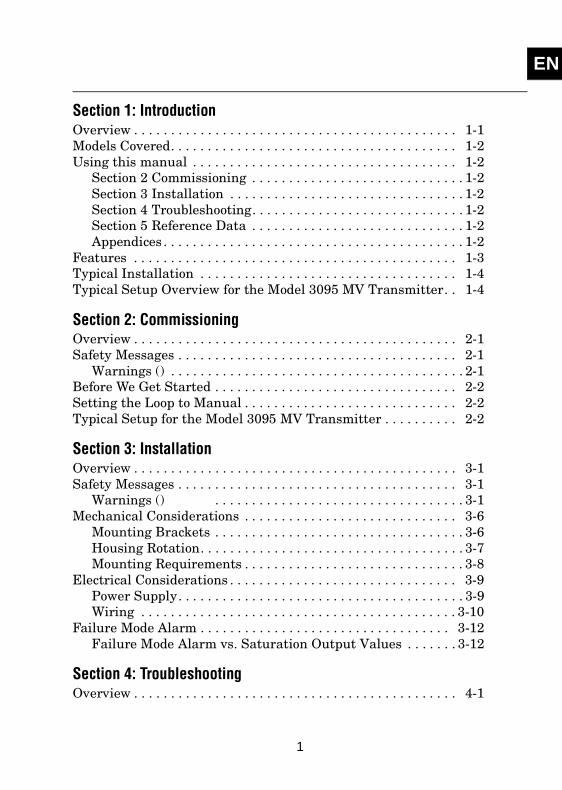
Section 1: IntroductionOverview . . . . . . . . . . . . . . . . . . . . . . . . . . . . . . . . . . . . . . . . . . . . 1-1Models Covered. . . . . . . . . . . . . . . . . . . . . . . . . . . . . . . . . . . . . . . 1-2Using this manual . . . . . . . . . . . . . . . . . . . . . . . . . . . . . . . . . . . . 1-2
Section 2 Commissioning . . . . . . . . . . . . . . . . . . . . . . . . . . . . . 1-2Section 3 Installation . . . . . . . . . . . . . . . . . . . . . . . . . . . . . . . . 1-2Section 4 Troubleshooting. . . . . . . . . . . . . . . . . . . . . . . . . . . . . 1-2Section 5 Reference Data . . . . . . . . . . . . . . . . . . . . . . . . . . . . . 1-2Appendices . . . . . . . . . . . . . . . . . . . . . . . . . . . . . . . . . . . . . . . . . 1-2
Features . . . . . . . . . . . . . . . . . . . . . . . . . . . . . . . . . . . . . . . . . . . . 1-3Typical Installation . . . . . . . . . . . . . . . . . . . . . . . . . . . . . . . . . . . 1-4Typical Setup Overview for the Model 3095 MV Transmitter. . 1-4
Section 2: CommissioningOverview . . . . . . . . . . . . . . . . . . . . . . . . . . . . . . . . . . . . . . . . . . . . 2-1Safety Messages . . . . . . . . . . . . . . . . . . . . . . . . . . . . . . . . . . . . . . 2-1
Warnings () . . . . . . . . . . . . . . . . . . . . . . . . . . . . . . . . . . . . . . . . 2-1Before We Get Started . . . . . . . . . . . . . . . . . . . . . . . . . . . . . . . . . 2-2Setting the Loop to Manual . . . . . . . . . . . . . . . . . . . . . . . . . . . . . 2-2Typical Setup for the Model 3095 MV Transmitter . . . . . . . . . . 2-2
Section 3: InstallationOverview . . . . . . . . . . . . . . . . . . . . . . . . . . . . . . . . . . . . . . . . . . . . 3-1Safety Messages . . . . . . . . . . . . . . . . . . . . . . . . . . . . . . . . . . . . . . 3-1
Warnings () . . . . . . . . . . . . . . . . . . . . . . . . . . . . . . . . . . 3-1Mechanical Considerations . . . . . . . . . . . . . . . . . . . . . . . . . . . . . 3-6
Mounting Brackets . . . . . . . . . . . . . . . . . . . . . . . . . . . . . . . . . . 3-6Housing Rotation. . . . . . . . . . . . . . . . . . . . . . . . . . . . . . . . . . . . 3-7Mounting Requirements . . . . . . . . . . . . . . . . . . . . . . . . . . . . . . 3-8
Electrical Considerations . . . . . . . . . . . . . . . . . . . . . . . . . . . . . . . 3-9Power Supply. . . . . . . . . . . . . . . . . . . . . . . . . . . . . . . . . . . . . . . 3-9Wiring . . . . . . . . . . . . . . . . . . . . . . . . . . . . . . . . . . . . . . . . . . . 3-10
Failure Mode Alarm . . . . . . . . . . . . . . . . . . . . . . . . . . . . . . . . . . 3-12Failure Mode Alarm vs. Saturation Output Values . . . . . . . 3-12
Section 4: TroubleshootingOverview . . . . . . . . . . . . . . . . . . . . . . . . . . . . . . . . . . . . . . . . . . . . 4-1
1
ENRosemount Inc
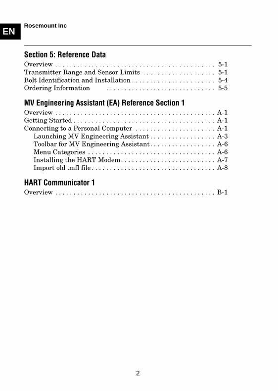
Section 5: Reference DataOverview . . . . . . . . . . . . . . . . . . . . . . . . . . . . . . . . . . . . . . . . . . . . 5-1Transmitter Range and Sensor Limits . . . . . . . . . . . . . . . . . . . . 5-1Bolt Identification and Installation . . . . . . . . . . . . . . . . . . . . . . . 5-4Ordering Information . . . . . . . . . . . . . . . . . . . . . . . . . . . . . . 5-5
MV Engineering Assistant (EA) Reference Section 1Overview . . . . . . . . . . . . . . . . . . . . . . . . . . . . . . . . . . . . . . . . . . . . A-1Getting Started . . . . . . . . . . . . . . . . . . . . . . . . . . . . . . . . . . . . . . . A-1Connecting to a Personal Computer . . . . . . . . . . . . . . . . . . . . . . A-1
Launching MV Engineering Assistant . . . . . . . . . . . . . . . . . . A-3Toolbar for MV Engineering Assistant. . . . . . . . . . . . . . . . . . A-6Menu Categories . . . . . . . . . . . . . . . . . . . . . . . . . . . . . . . . . . . A-6Installing the HART Modem. . . . . . . . . . . . . . . . . . . . . . . . . . A-7Import old .mfl file . . . . . . . . . . . . . . . . . . . . . . . . . . . . . . . . . . A-8
HART Communicator 1Overview . . . . . . . . . . . . . . . . . . . . . . . . . . . . . . . . . . . . . . . . . . . . B-1
2

Model 3095MV MultivariablePressue Transmitters
.
.
.
.
.
Rosemount and its logotype are registered trademarks of Rosemount Inc.Coplanar, Multivariable (MV), and Tri-Loop are trademarks of Rosemount Inc. PlantWeb is a registered trademark of the Fisher-Rosemount companies.HART is a registered trademark of the HART Communications Foundation.Hastelloy and Hastelloy C are registered trademarks of Haynes International.Microsoft and Windows are registered trademarks of Microsoft, Inc.Annubar is a registered trademark of Dieterich Standard Inc.V–Cone is a registered trademark of McCrometer, Inc.Photo Cover: 3095b29b.
NOTICE
Read the complete product manual before installing, operating, or servicing the Model 3095MV. Failure to comply with safe transmitter installation and operating practices can cause severe injury or death.
The information contained in this abbreviated field manual is intended only as an aid for skilled users who possess complete product manuals and are already familiar with the installation and operation of the Model 3095MV.
Please contact your nearest Fisher-Rosemount location for additional information or assistance regarding safe installation and operation of the Model 3095MV.
FIELD ENMANUAL
Rosemount Inc.8200 Market BoulevardChanhassen, MN 55317 USATel 1-800-999-9307Fax (952) 949-7001© 2001 Rosemount, Inc.
Fisher-Rosemount satisfies all obligations coming from legislation to harmonize product requirements in the European Union.
Product documentation available at...www.rosemount.com

SECTION EN
1 Introduction
Models Covered . . . . . . . . . . . . . . . . . . . . . . . . . . . . . . . . . . . . . . . . . . . page 1-2Using this manual . . . . . . . . . . . . . . . . . . . . . . . . . . . . . . . . . . . . . . . . . page 1-2Features . . . . . . . . . . . . . . . . . . . . . . . . . . . . . . . . . . . . . . . . . . . . . . . . . page 1-3Typical Installation . . . . . . . . . . . . . . . . . . . . . . . . . . . . . . . . . . . . . . . . page 1-4Typical Setup Overview for the Model 3095 MV Transmitter . . . . . . page 1-4
OVERVIEWThis section outlines the models covered and the organization of this manual.
The following performance limitations may inhibit efficient or safe operation. Critical applications should have appropriate diagnostic and backup systems in place.
Pressure transmitters contain an internal fill fluid. It is used to transmit the process pressure through the isolating diaphragms to the pressure sensing element. In rare cases, oil leak paths in oil-filled pressure transmitters can be created. Possible causes include: physical damage to the isolator diaphragms, process fluid freezing, isolator corrosion due to an incompatible process fluid, etc.
A transmitter with an oil fill fluid leak can continue to perform normally for a period of time. Sustained oil loss will eventually cause one or more of the operating parameters to exceed published specifications while a small drift in operating point output continues. Symptoms of advanced oil loss and other unrelated problems include:
• Sustained drift rate in true zero and span or operating point output or both
• Sluggish response to increasing or decreasing pressure or both
• Limited output rate or very nonlinear output or both
• Change in output process noise
• Noticeable drift in operating point output
• Abrupt increase in drift rate of true zero or span or both
• Unstable output
• Output saturated high or low
1-1
ENRosemount Inc
MODELS COVEREDThis manual provides basic installation, commissioning, and troubleshooting information for the Rosemount® Model 3095 MV Mass Flow Pressure Transmitter.
USING THIS MANUALThis field manual is designed to assist in basic installation and operation of Model 3095 Family of Multivariable Transmitters. For more detailed information, refer to the Model 3095 product manual (document number 00809-0100-4716).
Section 2 CommissioningSteps of common commissioning tasks and compensated flow setup
Section 3 InstallationA flowchart and steps outlining installation procedures, as well as mechanical and electrical considerations
Section 4 TroubleshootingBasic troubleshooting techniques for common diagnostic messages associated with the transmitter, the Engineering Assistant (EA), and the communicator
Section 5 Reference DataRange and sensor limits, EA tables, a typical model structure, and bolt torque specifications for Model 3095 transmitters
AppendicesEA software information and installation diagrams, screens, menu trees, and fast key sequences for the HART Communicator
1-2

ENRosemount Inc
309
5-3
095A
08
B, 3
051
-30
31B
05A
FEATURESThe latest line of Rosemount Model 3095 MV Multivariable pressure transmitters and LCD meters feature physical and software enhancements for additional functionality and increased ease of use.
HousingTerminal Block
O-ring
Cover
Housing Locking Screw
RTD Connector
Process Adapter O-ring
Electronics Board
Nameplate
Module O-ring
Sensor Module
Drain/Vent Valve
Flange Adapter O-ring
OptionalFlange Adapters
Bolts
Coplanar Flange
CertificationLabel
1-3
ENRosemount Inc
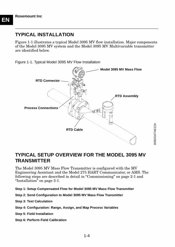
TYPICAL INSTALLATIONFigure 1-1 illustrates a typical Model 3095 MV flow installation. Major components of the Model 3095 MV system and the Model 3095 MV Multivariable transmitter are identified below.
Figure 1-1. Typical Model 3095 MV Flow Installation
TYPICAL SETUP OVERVIEW FOR THE MODEL 3095 MV TRANSMITTERThe Model 3095 MV Mass Flow Transmitter is configured with the MV Engineering Assistant and the Model 275 HART Communicator, or AMS. The following steps are described in detail in “Commissioning” on page 2-1 and“Installation” on page 3-1.
Step 1: Setup Compensated Flow for Model 3095 MV Mass Flow Transmitter
Step 2: Send Configuration to Model 3095 MV Mass Flow Transmitter
Step 3: Test Calculation
Step 4: Configuration: Range, Assign, and Map Process Variables
Step 5: Field Installation
Step 6: Perform Field Calibration
Model 3095 MV Mass Flow
RTD Cable
RTD Assembly
Process Connections
RTD Connector
3095
/DA
TA
E2
2A
1-4
SECTION EN
2 Commissioning
Before We Get Started . . . . . . . . . . . . . . . . . . . . . . . . . . . . . . . . . . . . . page 2-2Setting the Loop to Manual . . . . . . . . . . . . . . . . . . . . . . . . . . . . . . . . . page 2-2Typical Setup for the Model 3095 MV Transmitter . . . . . . . . . . . . . . page 2-2
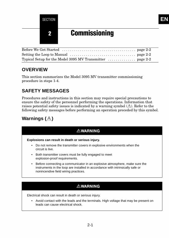
OVERVIEWThis section summarizes the Model 3095 MV transmitter commissioning procedure in steps 1-4.
SAFETY MESSAGESProcedures and instructions in this section may require special precautions to ensure the safety of the personnel performing the operations. Information that raises potential safety issues is indicated by a warning symbol ( ). Refer to the following safety messages before performing an operation preceded by this symbol.
Warnings ( )
Explosions can result in death or serious injury.
• Do not remove the transmitter covers in explosive environments when thecircuit is live.
• Both transmitter covers must be fully engaged to meetexplosion-proof requirements.
• Before connecting a communicator in an explosive atmosphere, make sure the instruments in the loop are installed in accordance with intrinsically safe or nonincendive field wiring practices.
Electrical shock can result in death or serious injury.
• Avoid contact with the leads and the terminals. High voltage that may be present on leads can cause electrical shock.
2-1
ENRosemount Inc
BEFORE WE GET STARTEDDepending on the system ordered, the Model 3095 MV is shipped in as many as three containers:
Model 3095 MV
This box contains the Model 3095 MV transmitter. If ordered, this package also contains an RTD cable and optional mounting hardware.
MV Engineering Assistant Software Package (Accessory)
The complete MV Engineering Assistant (EA) software package includes installation software, one HART modem, and cables. The EA software is used to fully configure the Model 3095 MV Mass Flow Transmitter. EA components may be ordered separately.
RTD Assembly (Optional)
This box contains the optional Series 68 or Series 78 RTD Assembly, and the Sensor Wiring Instruction Sheet.
SETTING THE LOOP TO MANUALWhenever you are preparing to send or request data that would disrupt the loop, or change the output of the transmitter, you will have to set your process application loop to manual. The EA, Model 275 HART Communicator, or AMS will prompt you to set the loop to manual when necessary. Acknowledging this prompter does not set the loop to manual. It is only a reminder; you have to set the loop to manual as a separate operation.
TYPICAL SETUP FOR THE MODEL 3095 MV TRANSMITTERThe Model 3095 MV Mass Flow Transmitter can only be fully configured with MV Engineering Assistant or AMS 5.0 with MV Engineering Assistant SNAP ON. A Model 275 HART Communicator, or AMS, can be used for some configuration.
Before proceeding, launch the MV Engineering Assistant Software Appendix A: MV Engineering Assistant (EA) Reference Section
Step 1: Setup Compensated Flow for the Model 3095 MV Mass Flow
After installing the EA software, setup can be completed in the office with the configuration saved. The following EA screen references can be viewed in Appendix A. In “Reference Data” on page 5-1, Table 5-6 shows the liquid and gas database in the EA, and Table 5-7 shows Primary Element Options.
2-2
ENRosemount Inc
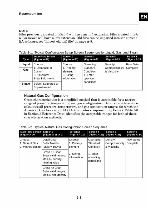
NOTEFiles previously created in EA 4.0 will have an .mfl extension. Files created in EA 5.0 or newer will have a .mv extension. Old files can be imported into the current EA software, see “Import old .mfl file” on page A-8.
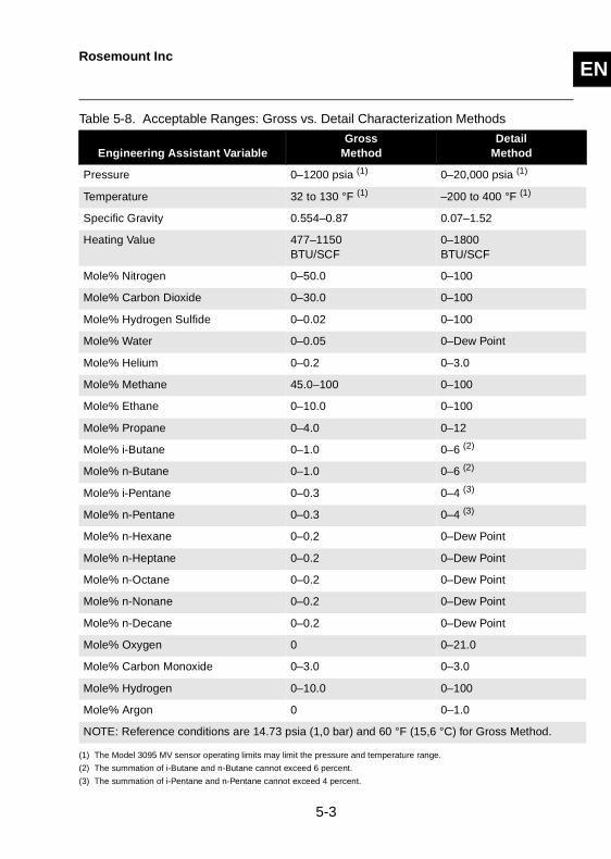
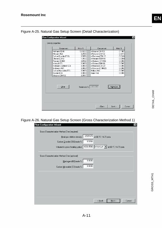
Natural Gas ConfigurationGross characterization is a simplified method that is acceptable for a narrow range of pressure, temperature, and gas configuration. Detail characterization calculates all pressure, temperature, and gas composition ranges, for which the American Gas Association (A.G.A.) computes compressibility factors. Table 5-8 in Section 5 Reference Data, identifies the acceptable ranges for both of these characterization methods.
Table 2-2. Typical Natural Gas Configuration Screen Sequence
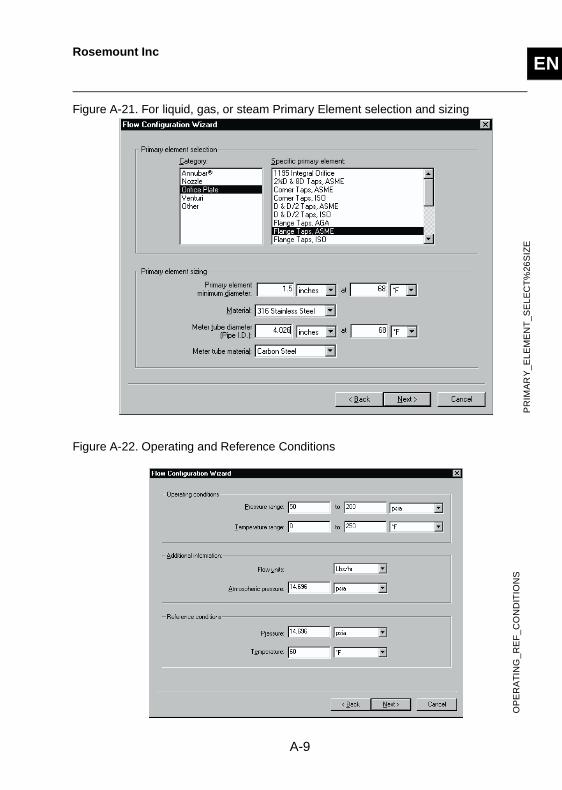
Table 2-1. Typical Configuration Setup Screen Sequences for Liquid, Gas, and Steam
TypeMain Flow Screen(Figure A-20)
Screen 2 (Figure A-21)
Screen 3 (Figure A-22)
Screen 4 (Figure A-23
Screen 5 (Figure A-24
Liquid Choose:1. Database or Custom2. If custom:Enter field name
Choose:1. Primary element2. Sizing information
Operating Standard Condition1. Enter operating conditions
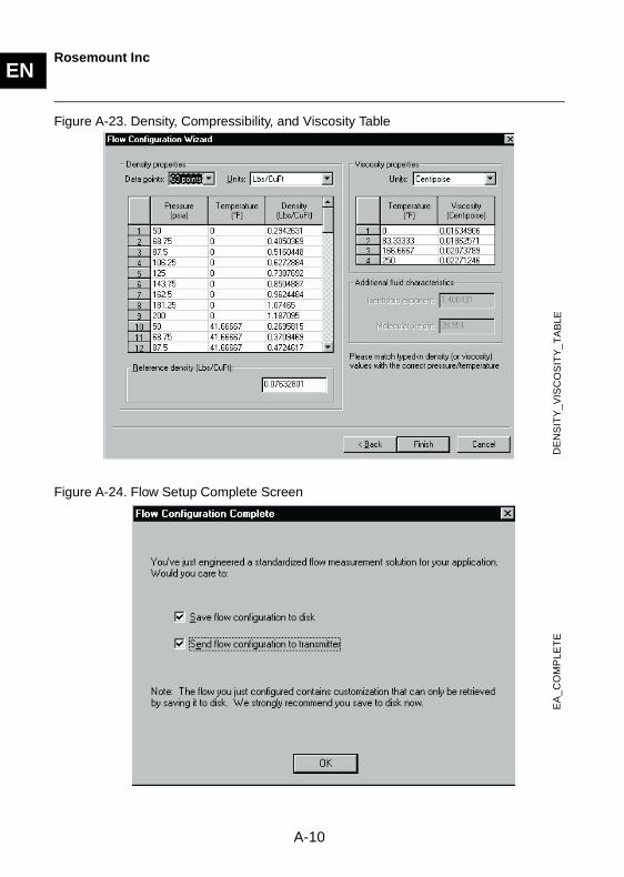
Density/Compressibility & Viscosity
Flow Setup Complete
Gas
Steam Select: Saturated or Super-heated
Main Flow Screen (Figure A-20)
Screen 3 (Figure A-25-A-27)
Screen 2 (Figure A-21)
Screen 4 (Figure A-22)
Screen 5 (Figure A-23)
Screen 6 (Figure A-24)
Choose:1. Natural Gas2. Method desire
Detail Char. Enter Mole% (Must = 100%)
Choose:1. Primary element
2. Sizing information
Operating Standard Condition
1. Enter operating conditions
Density/ Compressibility & Viscosity
Flow Setup Complete
Gross #1 Char. Enter valid ranges: Mole%, density, heating value
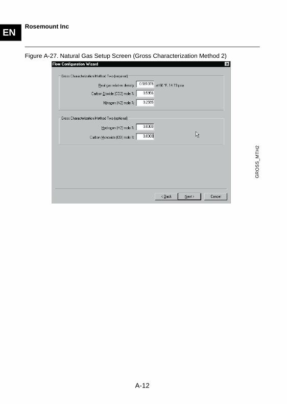
Gross #2 Char.Enter valid ranges: Mole% and density
2-3
ENRosemount Inc
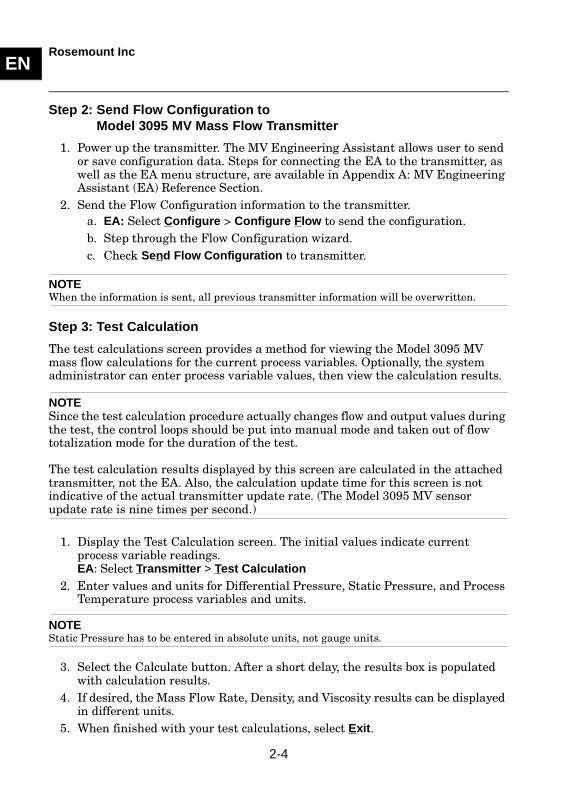
Step 2: Send Flow Configuration to Model 3095 MV Mass Flow Transmitter
1. Power up the transmitter. The MV Engineering Assistant allows user to send or save configuration data. Steps for connecting the EA to the transmitter, as well as the EA menu structure, are available in Appendix A: MV Engineering Assistant (EA) Reference Section.
2. Send the Flow Configuration information to the transmitter.a. EA: Select Configure > Configure Flow to send the configuration.b. Step through the Flow Configuration wizard.c. Check Send Flow Configuration to transmitter.
NOTEWhen the information is sent, all previous transmitter information will be overwritten.
Step 3: Test Calculation
The test calculations screen provides a method for viewing the Model 3095 MV mass flow calculations for the current process variables. Optionally, the system administrator can enter process variable values, then view the calculation results.
NOTESince the test calculation procedure actually changes flow and output values during the test, the control loops should be put into manual mode and taken out of flow totalization mode for the duration of the test.
The test calculation results displayed by this screen are calculated in the attached transmitter, not the EA. Also, the calculation update time for this screen is not indicative of the actual transmitter update rate. (The Model 3095 MV sensor update rate is nine times per second.)
1. Display the Test Calculation screen. The initial values indicate current process variable readings.EA: Select Transmitter > Test Calculation
2. Enter values and units for Differential Pressure, Static Pressure, and Process Temperature process variables and units.
NOTEStatic Pressure has to be entered in absolute units, not gauge units.
3. Select the Calculate button. After a short delay, the results box is populated with calculation results.
4. If desired, the Mass Flow Rate, Density, and Viscosity results can be displayed in different units.
5. When finished with your test calculations, select Exit.
2-4
ENRosemount Inc
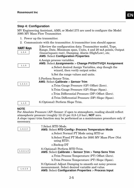
Step 4: ConfigurationMV Engineering Assistant, AMS, or Model 275 are used to configure the Model 3095 MV Mass Flow Transmitter.
1. Power up the transmitter.2. Communicate with the transmitter. A transmitter icon should appear.
3.Review the configuration data: Transmitter model, Type, Range, Date, Minimum span, Units, 4 and 20 mA points, Output (linear/square root), Damping, Alarm (High/Low), etc. AMS: Select Configuration Properties4.Assign process variables.AMS: Select Assignments > Change PV/SV/TV/QV Assignment
a.Select desired Assign Variables, step though the wizard, then verify output order.
b.Set the range values and units.5.Perform Sensor Trim.AMS: Select Calibrate > Sensor Trim
a.Trim Gauge Pressure (GP) Offset (Zero).b.Trim Gauge Pressure (GP) Slope (Span).c.Trim Differential Pressure (DP) Offset (Zero).d.Trim Differential Pressure (DP) Slope (Span).
6.(Optional) Perform Slope Trim.
NOTEFor Absolute Pressure (AP) Sensor: if open to atmosphere, reading should reflect atmospheric pressure (roughly 12-15 psi (0,8-1,0 bar), NOT zero. A slope (span) trim function may be performed as a maintenance procedure only if necessary.
7.Select RTD Mode.AMS: Select RTD Config> Process Temperature Mode
a.Select Normal PT Mode using RTD or b.Select Fixed PT Mode for 3095 MV Mass Flow (Not
using RTD).c.Backup DT
8.(Optional) Perform RTD Trim.AMS: Select Calibrate > Sensor Trim > Temp Sens Trim
a.Trim Process Temperature (PT) Offset (Zero).b.Trim Process Temperature (PT) Slope (Span).
9.(Optional) Adjust Damping to smooth out noisy process measurement. Select desired variable and value.AMS: Select Configuration Properties > Process Input
HART Keys1, 3, 4
1, 1, 5
1, 2, 2, 1
1, 1, 5
1, 4, 2, 2
1, 2, 2, 1, 4
1, 4, 2, 5
2-5

ENRosemount Inc
2-6
SECTION EN
3 Installation
Mechanical Considerations . . . . . . . . . . . . . . . . . . . . . . . . . . . . . . . . . . page 3-6Electrical Considerations . . . . . . . . . . . . . . . . . . . . . . . . . . . . . . . . . . . page 3-9Failure Mode Alarm . . . . . . . . . . . . . . . . . . . . . . . . . . . . . . . . . . . . . . . page 3-12
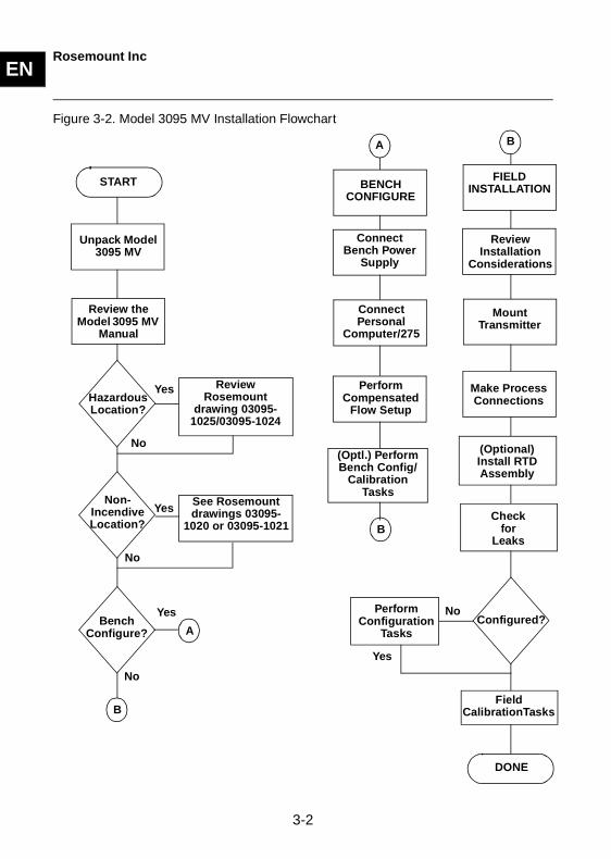
OVERVIEWThis section contains safety messages, an installation flowchart (see Figure 3-2 on Page 3-2), and final steps 5 and 6. Also, basic mechanical and electrical considerations guide you through a successful installation. For more detailed information, refer to the Model 3095 MV Multivariable product manual (document number 00809-0100-4716).
SAFETY MESSAGESProcedures and instructions in this section may require special precautions to ensure the safety of the personnel performing the operations. Information that raises potential safety issues is indicated by a warning symbol ( ). Refer to the following safety messages before performing an operation preceded by this symbol.
Warnings ( )
Explosions can result in death or serious injury.
• Do not remove the transmitter covers in explosive environments when thecircuit is live.
• Both transmitter covers must be fully engaged to meetexplosion-proof requirements.
• Before connecting a communicator in an explosive atmosphere, make sure the instruments in the loop are installed in accordance with intrinsically safe or nonincendive field wiring practices.
Electrical shock can result in death or serious injury.
• Avoid contact with the leads and the terminals. High voltage that may be present on leads can cause electrical shock.
3-1
ENRosemount Inc
Figure 3-2. Model 3095 MV Installation Flowchart
B
B
START
A
B
Review Rosemount
drawing 03095-1025/03095-1024
See Rosemount drawings 03095-
1020 or 03095-1021
HazardousLocation?
Non-IncendiveLocation?
Unpack Model 3095 MV
Review the Model 3095 MV
Manual
BenchConfigure?
BENCH CONFIGURE
Connect Bench Power
Supply
Connect Personal
Computer/275
Perform Compensated
Flow Setup
(Optl.) Perform Bench Config/
Calibration Tasks
FIELD INSTALLATION
Review Installation
Considerations
Mount Transmitter
Make Process Connections
DONE
Yes
Yes
No
No
Yes
No
Field CalibrationTasks
Configured?NoPerform
Configuration Tasks
Yes
Checkfor
Leaks
(Optional) Install RTD Assembly
A
3-2
ENRosemount Inc
309
5-C
AB
LEC
ON
Step 5: Field Installation
1. Mount transmitter.a. Mount in desired location; install flange or flange/adapter bolts finger
tight.b. Torque bolts to initial torque vale using a cross pattern (see Table 3-3).
When installing the transmitter to one mounting bracket, torque bolts to 125 in-lb. (169 N-m).
2. Connect transmitter to the process.3. (Optional) Install Series 68 or Series 78 RTD assembly.
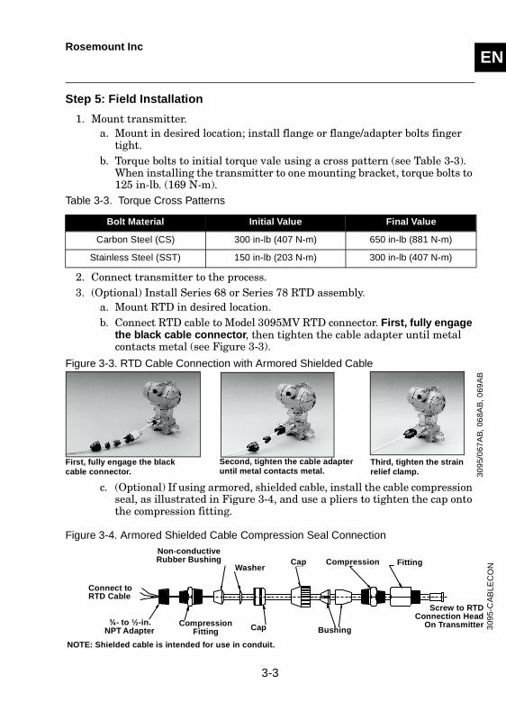
a. Mount RTD in desired location.b. Connect RTD cable to Model 3095MV RTD connector. First, fully engage
the black cable connector, then tighten the cable adapter until metal contacts metal (see Figure 3-3).
Figure 3-3. RTD Cable Connection with Armored Shielded Cable
c. (Optional) If using armored, shielded cable, install the cable compression seal, as illustrated in Figure 3-4, and use a pliers to tighten the cap onto the compression fitting.
Figure 3-4. Armored Shielded Cable Compression Seal Connection
Table 3-3. Torque Cross Patterns
Bolt Material Initial Value Final Value
Carbon Steel (CS) 300 in-lb (407 N-m) 650 in-lb (881 N-m)
Stainless Steel (SST) 150 in-lb (203 N-m) 300 in-lb (407 N-m)
First, fully engage the black cable connector.
Second, tighten the cable adapter until metal contacts metal.
Third, tighten the strain relief clamp. 30
95/
067
AB
, 06
8AB
, 069
AB
WasherCap
¾- to ½-in. NPT Adapter
Compression Fitting Bushing
FittingCompression
Cap
Non-conductive Rubber Bushing
Screw to RTDConnection Head
On Transmitter
NOTE: Shielded cable is intended for use in conduit.
Connect to RTD Cable
3-3
ENRosemount Inc
d. Make all necessary wiring connections inside the RTD Flat Connection Head (see Sensor Wiring Instructions included with RTD).
4. Check all process penetrations for leaks.5. Make field wiring connection as shown in Figure 3-10 on Page 3-10,
Connections provide both power and signal wiring.See “Electrical Considerations” on page 3-9.
a. Remove cover on FIELD TERMINALS side of electronics housing.b. Connect positive lead to terminal marked "+SIG" or "+PWR;" remember
to use minimum of 250 ohms in loop.c. Connect negative lead to terminal marked "-".d. Plug and seal unused conduit connections on housing to avoid moisture
accumulation in terminal side.6. Ground transmitter case according to national and local electrical codes.7. (Optional) Install field wiring grounding.8. Replace cover.
Step 6: Perform Field CalibrationTo correct mounting position effect, field zero the Model 3095 MV after installing and filling of impulse lines.
1. Establish communication. 2.Trim DP Offset (Zero).AMS: Select Calibrate > Sensor Trim > DP Sens Trim
3.Trim SP Offset (Zero). (AP, GP)AMS: Select Calibrate > Sensor Trim > GP Sensor Trim
HART Keys1, 2, 2, 1,1
1, 2, 2, 1, 2
3-4
ENRosemount Inc
NOTEFor Absolute Pressure (AP) Sensor: If open to atmosphere, reading should be at atmospheric pressure (roughly 12-15 psi (0,8-1,0 bar), NOT zero.
Use a barometer that is three times as accurate as the model 3095MV AP sensor.
4.(Optional) Connect Tri-Loop. Make all necessary wiring connections, as explained in the Tri-Loop manual (p/n 00809-0100-4754). Remember: the transmitter must be set up for Burst Mode. The Tri-Loop must be in multidrop mode to configure.AMS: Select Configuration Properties > HART > Burst Mode
While in burst mode, select Process vars/Crnt(HART command 3)
5.Perform a Loop Test.AMS: Select Diagnostics and Test > Loop Test6.(Optional) Perform Analog Output Trim. This adjusts analog output to match the plant standard or control loop.AMS: Select Calibrate > D/A Trim
1, 4, 1, 2, 4, 2
1, 4, 1, 2, 4, 1
1, 2, 1, 1
1, 2, 2, 2
3-5
ENRosemount Inc
MECHANICAL CONSIDERATIONS
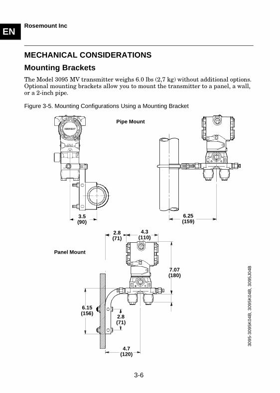
Mounting Brackets The Model 3095 MV transmitter weighs 6.0 lbs (2,7 kg) without additional options. Optional mounting brackets allow you to mount the transmitter to a panel, a wall, or a 2-inch pipe.
Figure 3-5. Mounting Configurations Using a Mounting Bracket
7.07(180)
309
5-3
095K
04
B, 3
095
K0
4B
, 30
95J0
4BPanel Mount
Pipe Mount
3.5(90)
6.25(159)
6.15(156)
2.8(71)
2.8(71)
4.3(110)
4.7(120)
3-6
ENRosemount Inc
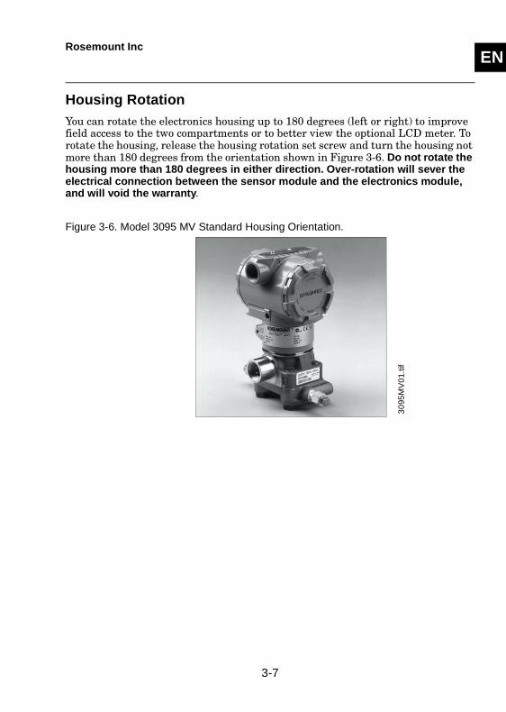
Housing RotationYou can rotate the electronics housing up to 180 degrees (left or right) to improve field access to the two compartments or to better view the optional LCD meter. To rotate the housing, release the housing rotation set screw and turn the housing not more than 180 degrees from the orientation shown in Figure 3-6. Do not rotate the housing more than 180 degrees in either direction. Over-rotation will sever the electrical connection between the sensor module and the electronics module, and will void the warranty.
Figure 3-6. Model 3095 MV Standard Housing Orientation.
30
95M
V0
1.tif
3-7
ENRosemount Inc
309
5-3
095B
03
B, D
03B
, A0
3A.
3051
-303
1B0
3B
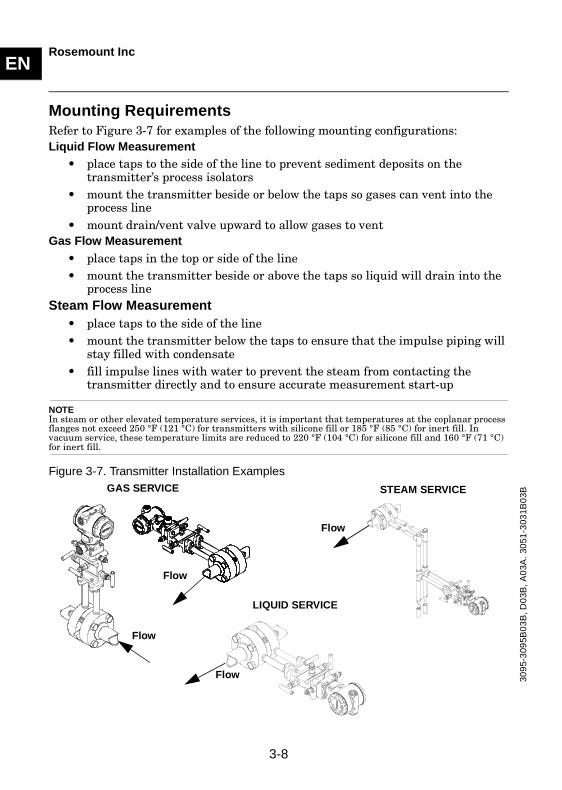
Mounting RequirementsRefer to Figure 3-7 for examples of the following mounting configurations:Liquid Flow Measurement
• place taps to the side of the line to prevent sediment deposits on the transmitter’s process isolators
• mount the transmitter beside or below the taps so gases can vent into the process line
• mount drain/vent valve upward to allow gases to ventGas Flow Measurement
• place taps in the top or side of the line• mount the transmitter beside or above the taps so liquid will drain into the
process lineSteam Flow Measurement
• place taps to the side of the line• mount the transmitter below the taps to ensure that the impulse piping will
stay filled with condensate• fill impulse lines with water to prevent the steam from contacting the
transmitter directly and to ensure accurate measurement start-up
NOTE In steam or other elevated temperature services, it is important that temperatures at the coplanar process flanges not exceed 250 °F (121 °C) for transmitters with silicone fill or 185 °F (85 °C) for inert fill. In vacuum service, these temperature limits are reduced to 220 °F (104 °C) for silicone fill and 160 °F (71 °C) for inert fill.
Figure 3-7. Transmitter Installation ExamplesGAS SERVICE
LIQUID SERVICE
STEAM SERVICE
Flow
Flow
Flow
Flow
3-8
ENRosemount Inc
ELECTRICAL CONSIDERATIONS
Power Supply
4–20 mA Transmitters
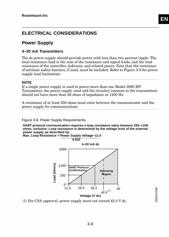
The dc power supply should provide power with less than two percent ripple. The total resistance load is the sum of the resistance and signal leads, and the load resistance of the controller, indicator, and related pieces. Note that the resistance of intrinsic safety barriers, if used, must be included. Refer to Figure 3-8 for power supply load limitations.
NOTEIf a single power supply is used to power more than one Model 3095 MV Transmitter, the power supply used and the circuitry common to the transmitters should not have more than 20 ohms of impedance at 1200 Hz.
A resistance of at least 250 ohms must exist between the communicator and the power supply for communications.
Figure 3-8. Power Supply Requirements.
2000
1100
35.216.511.0
250
Voltage (V dc)
Lo
ad (
Oh
ms)
OperatingRegion
4–20 mA dc
(1) For CSA approval, power supply must not exceed 42.4 V dc.
HART protocol communication requires a loop resistance value between 250–1100 ohms, inclusive. Loop resistance is determined by the voltage level of the external power supply, as described by:Max. Loop Resistance = Power Supply Voltage–11.0
0.022
HART ProtocolConformance
309
5/0
103
B
3-9
ENRosemount Inc
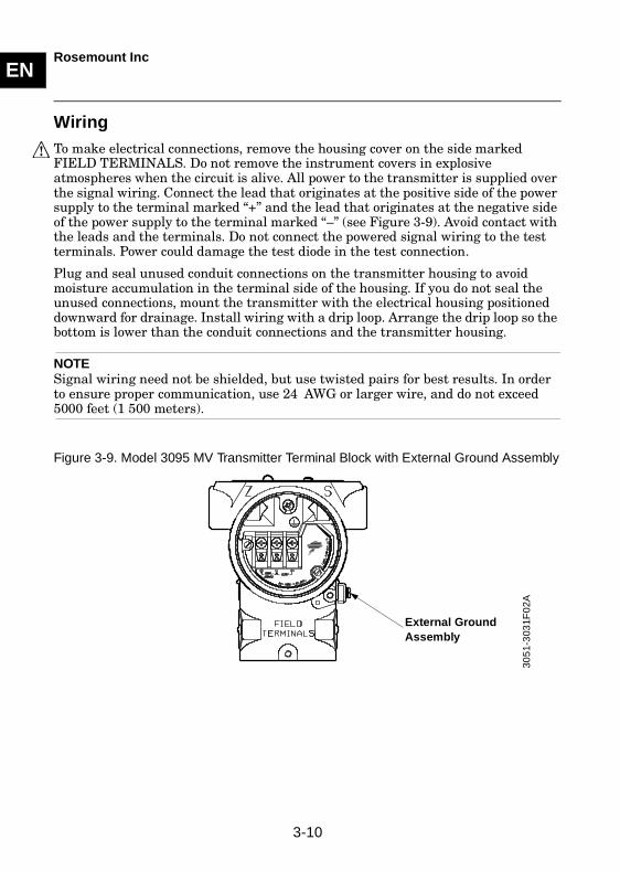
Wiring To make electrical connections, remove the housing cover on the side marked FIELD TERMINALS. Do not remove the instrument covers in explosive atmospheres when the circuit is alive. All power to the transmitter is supplied over the signal wiring. Connect the lead that originates at the positive side of the power supply to the terminal marked “+” and the lead that originates at the negative side of the power supply to the terminal marked “–” (see Figure 3-9). Avoid contact with the leads and the terminals. Do not connect the powered signal wiring to the test terminals. Power could damage the test diode in the test connection.
Plug and seal unused conduit connections on the transmitter housing to avoid moisture accumulation in the terminal side of the housing. If you do not seal the unused connections, mount the transmitter with the electrical housing positioned downward for drainage. Install wiring with a drip loop. Arrange the drip loop so the bottom is lower than the conduit connections and the transmitter housing.
NOTESignal wiring need not be shielded, but use twisted pairs for best results. In order to ensure proper communication, use 24 AWG or larger wire, and do not exceed 5000 feet (1 500 meters).
Figure 3-9. Model 3095 MV Transmitter Terminal Block with External Ground Assembly
305
1-3
031F
02A
External Ground Assembly
3-10
ENRosemount Inc
Wiring Diagrams
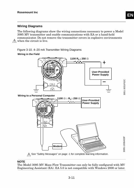
The following diagrams show the wiring connections necessary to power a Model 3095 MV transmitter and enable communications with EA or a hand-held communicator. Do not remove the transmitter covers in explosive environments when the circuit is live.
Figure 3-10. 4–20 mA Transmitter Wiring Diagrams
NOTEThe Model 3095 MV Mass Flow Transmitter can only be fully configured with MV Engineering Assistant (EA). EA 5.0 is not compatible with Windows 2000 or later.
1100 RL� 250 �
User-Provided Power Supply
305
1-3
031
F0
2C3
095
-10
06A
03F
User-Provided Power Supply
Modem
Wiring in the Field
Wiring to a Personal Computer1100 � � RL� 250 �
See “Safety Messages” on page -1 for complete warning information.
3-11
ENRosemount Inc
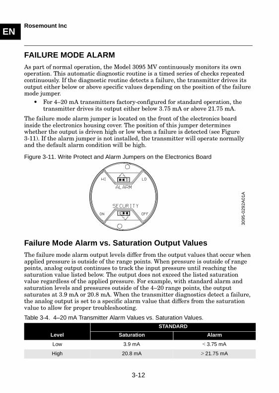
FAILURE MODE ALARMAs part of normal operation, the Model 3095 MV continuously monitors its own operation. This automatic diagnostic routine is a timed series of checks repeated continuously. If the diagnostic routine detects a failure, the transmitter drives its output either below or above specific values depending on the position of the failure mode jumper.
• For 4–20 mA transmitters factory-configured for standard operation, the transmitter drives its output either below 3.75 mA or above 21.75 mA.
The failure mode alarm jumper is located on the front of the electronics board inside the electronics housing cover. The position of this jumper determines whether the output is driven high or low when a failure is detected (see Figure 3-11). If the alarm jumper is not installed, the transmitter will operate normally and the default alarm condition will be high.
Figure 3-11. Write Protect and Alarm Jumpers on the Electronics Board
Failure Mode Alarm vs. Saturation Output ValuesThe failure mode alarm output levels differ from the output values that occur when applied pressure is outside of the range points. When pressure is outside of range points, analog output continues to track the input pressure until reaching the saturation value listed below. The output does not exceed the listed saturation value regardless of the applied pressure. For example, with standard alarm and saturation levels and pressures outside of the 4–20 range points, the output saturates at 3.9 mA or 20.8 mA. When the transmitter diagnostics detect a failure, the analog output is set to a specific alarm value that differs from the saturation value to allow for proper troubleshooting.
Table 3-4. 4–20 mA Transmitter Alarm Values vs. Saturation Values.
Level
STANDARD
Saturation Alarm
Low 3.9 mA � 3.75 mA
High 20.8 mA � 21.75 mA
3095
-029
2A0
1A
3-12
SECTION EN
4 Troubleshooting
OVERVIEWTable 4-5 provides summarized troubleshooting suggestions for the most common operating problems.
NOTEFor a complete list of diagnostic messages, corrective actions, assembly/disassembly, and repair instructions, refer to the Model 3095 MV Multivariable product manual (document number 00809-0100-4716).
Failure to follow safe operating practices can cause death or serious injury. Please review the following safety messages before troubleshooting the Model 3095 MV Transmitter.
• Using improper procedures or parts can affect product performance and the output signal used to control a process. To ensure safe transmitter performance, use only new parts and follow Rosemount documented procedures. Questions regarding these procedures or parts should be directed to the nearest Fisher-Rosemount location.
• Isolate a failed transmitter from its pressure source as soon as possible. Pressure that may be present could cause death or serious injury to personnel if the transmitter is disassembled or ruptures under pressure.
• To avoid explosions, do not remove the instrument cover or make electrical connections in explosive atmospheres when the circuit is live. Make sure the instrument is installed in accordance with intrinsically safe or nonincendive field wiring practice.
• To meet explosion proof requirements, make sure that both transmitter covers are fully engaged.
• To avoid process leaks, use only the O-ring designed to seal with the corresponding flange adapter. Rosemount Inc. supplies two unique styles of O-rings for Rosemount flange adapters: one for Model 3051 flange adapters and another for Model 1151 flange adapters. Each flange adapter is distinguished by its unique groove. Refer to the Spare Parts List PPL 4001 for the numbers of the flange adapters and O-rings designed for the Model 3051 Pressure Transmitter.
4-1
ENRosemount Inc
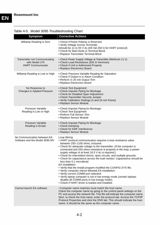
Table 4-5. Model 3095 Troubleshooting Chart
Symptom Corrective Actions
Milliamp Reading is Zero • Check if Power Polarity is Reversed• Verify Voltage Across Terminals(should be 11 to 55 V dc,165 Vat 250 � for HART protocol)• Check for Bad Diode in Terminal Block• Replace Transmitter Terminal Block
Transmitter not Communicating with Model 275
HART Communicator
• Check Power Supply Voltage at Transmitter (Minimum 11 V)• Check Load Resistance (250 � minimum)• Check if Unit is Addressed Properly• Replace Electronics Board
Milliamp Reading is Low or High • Check Pressure Variable Reading for Saturation• Check if Output is in Alarm Condition• Perform 4–20 mA Output Trim• Replace Electronics Board
No Response toChanges in Applied Pressure
• Check Test Equipment• Check Impulse Piping for Blockage• Check for Disabled Span Adjustment• Check Transmitter Security Jumper• Verify Calibration Settings (4 and 20 mA Points)• Replace Sensor Module
Pressure Variable Reading is Low or High
• Check Impulse Piping for Blockage• Check Test Equipment• Perform Full Sensor Trim• Replace Sensor Module
Pressure VariableReading is Erratic
• Check Impulse Piping for Blockage• Check Damping• Check for EMF Interference• Replace Sensor Module
No Communication between EA Software and the Model 3095 MV
Loop Wiring• HART protocol communication requires a loop resistance value
between 250–1100 ohms, inclusive.• Check for adequate voltage to the transmitter. (If the computer is
connected and 250 ohms resistance is properly in the loop, a power supply voltage of at least 16.5 V dc is required.)
• Check for intermittent shorts, open circuits, and multiple grounds. • Check for capacitance across the load resistor. Capacitance should be
less than 0.1 microfarad. EA Installation• Verify that the install program modified the CONFIG.SYS file. • Verify computer reboot followed EA installation. • Verify correct COMM port selected. • Verify laptop computer is not in low energy mode (certain laptops
disable all COMM ports in low energy mode). • Check if HART driver is loaded and installed.
Cannot launch EA software • Computer name matches must match the host name. Check the computer name by going to the control panel settings on the PC and access the network file. This file will indicate the computer name. Next, to check the host name, enter the protocol tab. Access the TCP/IP Protocol Properties and click the DNS tab. This should indicate the host name. It should be the same as the computer name.
4-2
SECTION EN
5 Reference Data
Transmitter Range and Sensor Limits . . . . . . . . . . . . . . . . . . . . . . . . page 5-1Bolt Identification and Installation . . . . . . . . . . . . . . . . . . . . . . . . . . . page 5-4Ordering Information . . . . . . . . . . . . . . . . . . . . . . . . . . . . . . . . . . . . . . page 5-5
OVERVIEWThis section contains the following reference data for the Model 3095 MV family of pressure transmitters:
• Transmitter Range and Sensor Limits• EA tables• Bolt Installation• Ordering Information
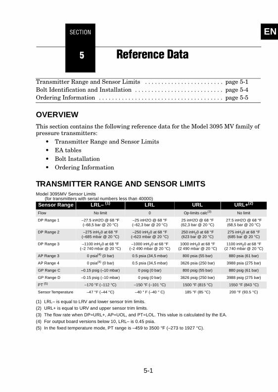
TRANSMITTER RANGE AND SENSOR LIMITSModel 3095MV Sensor Limits
(for transmitters with serial numbers less than 40000)Sensor Range LRL– (1)
(1) LRL– is equal to LRV and lower sensor trim limits.
LRL URL URL+(2)
(2) URL+ is equal to URV and upper sensor trim limits.
Flow No limit 0 Op-limits calc(3)
(3) The flow rate when DP=URL+, AP=UOL, and PT=LOL. This value is calculated by the EA.
No limit
DP Range 1 –27.5 inH2O @ 68 °F(–68,5 bar @ 20 °C)
–25 inH2O @ 68 °F(–62,3 bar @ 20 °C)
25 inH2O @ 68 °F(62,3 bar @ 20 °C)
27.5 inH2O @ 68 °F(68,5 bar @ 20 °C)
DP Range 2 –275 inH20 at 68 °F(–685 mbar @ 20 °C)
–250 inH20 at 68 °F(–623 mbar @ 20 °C)
250 inH20 at 68 °F(623 bar @ 20 °C)
275 inH20 at 68 °F(685 bar @ 20 °C)
DP Range 3 –1100 inH20 at 68 °F(–2 740 mbar @ 20 °C)
–1000 inH20 at 68 °F(–2 490 mbar @ 20 °C)
1000 inH20 at 68 °F(2 490 mbar @ 20 °C)
1100 inH20 at 68 °F(2 740 mbar @ 20 °C)
AP Range 3 0 psia(4) (0 bar)
(4) For output board versions below 10, LRL– is 0.45 psia.
0.5 psia (34,5 mbar) 800 psia (55 bar) 880 psia (61 bar)
AP Range 4 0 psia(4) (0 bar) 0.5 psia (34,5 mbar) 3626 psia (250 bar) 3988 psia (275 bar)
GP Range C –0.15 psig (–10 mbar) 0 psig (0 bar) 800 psig (55 bar) 880 psig (61 bar)
GP Range D –0.15 psig (–10 mbar) 0 psig (0 bar) 3626 psig (250 bar) 3988 psig (275 bar)
PT (5)
(5) In the fixed temperature mode, PT range is –459 to 3500 °F (–273 to 1927 °C).
–170 °F (–112 °C) –150 °F (–101 °C) 1500 °F (815 °C) 1550 °F (843 °C)
Sensor Temperature –47 °F (–44 °C) –40 ° F (–40 ° C) 185 °F (85 °C) 200 °F (93.5 °C)
5-1
ENRosemount Inc
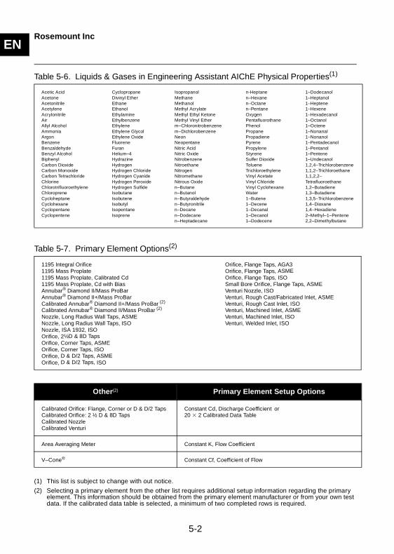
Table 5-6. Liquids & Gases in Engineering Assistant AIChE Physical Properties(1)
Table 5-7. Primary Element Options(2)
Acetic AcidAcetoneAcetonitrileAcetyleneAcrylonitrileAir Allyl Alcohol Ammonia Argon BenzeneBenzaldehyde Benzyl Alcohol BiphenylCarbon Dioxide Carbon Monoxide Carbon Tetrachloride ChlorineChlorotrifluoroethylene Chloroprene CycloheptaneCyclohexaneCyclopentaneCyclopentene
CyclopropaneDivinyl Ether EthaneEthanol EthylamineEthylbenzene EthyleneEthylene GlycolEthylene OxideFluoreneFuranHelium–4 Hydrazine HydrogenHydrogen Chloride Hydrogen Cyanide Hydrogen Peroxide Hydrogen Sulfide IsobutaneIsobutene Isobutyl IsopentaneIsoprene
IsopropanolMethane Methanol Methyl AcrylateMethyl Ethyl Ketone Methyl Vinyl Etherm–Chloronitrobenzene m–Dichlorobenzene Neon NeopentaneNitric Acid Nitric Oxide Nitrobenzene NitroethaneNitrogenNitromethane Nitrous Oxide n–Butanen–Butanoln–Butyraldehyden–Butyronitrile n–Decane n–Dodecane n–Heptadecane
n-Heptane n–Hexane n–Octane n–Pentane OxygenPentafluorothanePhenolPropanePropadienePyrene PropyleneStyreneSulfer DioxideToluene Trichloroethylene Vinyl Acetate Vinyl Chloride Vinyl Cyclohexane Water1–Butene 1–Decene1–Decanal1–Decanol 1–Dodecene
1–Dodecanol1–Heptanol 1–Heptene 1–Hexene 1–Hexadecanol 1–Octanol 1–Octene 1–Nonanal1–Nonanol 1–Pentadecanol1–Pentanol 1–Pentene 1–Undecanol 1,2,4–Trichlorobenzene 1,1,2–Trichloroethane 1,1,2,2–Tetrafluoroethane 1,2–Butadiene 1,3–Butadiene 1,3,5–Trichlorobenzene1,4–Dioxane 1,4–Hexadiene 2–Methyl–1–Pentene 2,2–Dimethylbutane
(1) This list is subject to change with out notice.
1195 Integral Orifice 1195 Mass Proplate1195 Mass Proplate, Calibrated Cd1195 Mass Proplate, Cd with BiasAnnubar® Diamond II/Mass ProBar Annubar® Diamond II+/Mass ProBarCalibrated Annubar® Diamond II+/Mass ProBar (2)
Calibrated Annubar® Diamond II/Mass ProBar (2) Nozzle, Long Radius Wall Taps, ASME Nozzle, Long Radius Wall Taps, ISO Nozzle, ISA 1932, ISO Orifice, 2½D & 8D Taps Orifice, Corner Taps, ASME Orifice, Corner Taps, ISOOrifice, D & D/2 Taps, ASMEOrifice, D & D/2 Taps, ISO
Orifice, Flange Taps, AGA3 Orifice, Flange Taps, ASMEOrifice, Flange Taps, ISO Small Bore Orifice, Flange Taps, ASMEVenturi Nozzle, ISO Venturi, Rough Cast/Fabricated Inlet, ASME Venturi, Rough Cast Inlet, ISO Venturi, Machined Inlet, ASME Venturi, Machined Inlet, ISO Venturi, Welded Inlet, ISO
(2) Selecting a primary element from the other list requires additional setup information regarding the primary element. This information should be obtained from the primary element manufacturer or from your own test data. If the calibrated data table is selected, a minimum of two completed rows is required.
Other(2) Primary Element Setup Options
Calibrated Orifice: Flange, Corner or D & D/2 TapsCalibrated Orifice: 2 ½ D & 8D TapsCalibrated NozzleCalibrated Venturi
Constant Cd, Discharge Coefficient or 20 � 2 Calibrated Data Table
Area Averaging Meter Constant K, Flow Coefficient
V–Cone® Constant Cf, Coefficient of Flow
5-2
ENRosemount Inc
Table 5-8. Acceptable Ranges: Gross vs. Detail Characterization Methods
Engineering Assistant VariableGross
MethodDetail
Method
Pressure 0–1200 psia (1)
(1) The Model 3095 MV sensor operating limits may limit the pressure and temperature range.
0–20,000 psia (1)
Temperature 32 to 130 °F (1) –200 to 400 °F (1)
Specific Gravity 0.554–0.87 0.07–1.52
Heating Value 477–1150 BTU/SCF
0–1800BTU/SCF
Mole% Nitrogen 0–50.0 0–100
Mole% Carbon Dioxide 0–30.0 0–100
Mole% Hydrogen Sulfide 0–0.02 0–100
Mole% Water 0–0.05 0–Dew Point
Mole% Helium 0–0.2 0–3.0
Mole% Methane 45.0–100 0–100
Mole% Ethane 0–10.0 0–100
Mole% Propane 0–4.0 0–12
Mole% i-Butane 0–1.0 0–6 (2)
(2) The summation of i-Butane and n-Butane cannot exceed 6 percent.
Mole% n-Butane 0–1.0 0–6 (2)
Mole% i-Pentane 0–0.3 0–4 (3)
(3) The summation of i-Pentane and n-Pentane cannot exceed 4 percent.
Mole% n-Pentane 0–0.3 0–4 (3)
Mole% n-Hexane 0–0.2 0–Dew Point
Mole% n-Heptane 0–0.2 0–Dew Point
Mole% n-Octane 0–0.2 0–Dew Point
Mole% n-Nonane 0–0.2 0–Dew Point
Mole% n-Decane 0–0.2 0–Dew Point
Mole% Oxygen 0 0–21.0
Mole% Carbon Monoxide 0–3.0 0–3.0
Mole% Hydrogen 0–10.0 0–100
Mole% Argon 0 0–1.0
NOTE: Reference conditions are 14.73 psia (1,0 bar) and 60 °F (15,6 °C) for Gross Method.
5-3
ENRosemount Inc
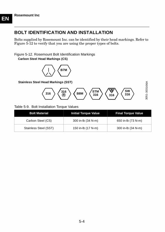
BOLT IDENTIFICATION AND INSTALLATIONBolts supplied by Rosemount Inc. can be identified by their head markings. Refer to Figure 5-12 to verify that you are using the proper types of bolts.
Figure 5-12. Rosemount Bolt Identification Markings
Table 5-9. Bolt Installation Torque Values
Bolt Material Initial Torque Value Final Torque Value
Carbon Steel (CS) 300 in-lb (34 N-m) 650 in-lb (73 N-m)
Stainless Steel (SST) 150 in-lb (17 N-m) 300 in-lb (34 N-m)
Stainless Steel Head Markings (SST)
B7M
316 B8M
Carbon Steel Head Markings (CS)
316STM316
SW316
316R
305
1 -3
031 I
06A
5-4
ENRosemount Inc
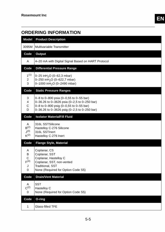
ORDERING INFORMATION Model Product Description
3095M Multivariable Transmitter
Code Output
A 4–20 mA with Digital Signal Based on HART Protocol
Code Differential Pressure Range
1(1)
23
0–25 inH2O (0–62,3 mbar)0–250 inH2O (0–622,7 mbar)0–1000 inH2O (0–2490 mbar)
Code Static Pressure Ranges
34CD
0–8 to 0–800 psia (0–0,55 to 0–55 bar)0–36.26 to 0–3626 psia (0–2,5 to 0–250 bar)0–8 to 0–800 psig (0–0,55 to 0–55 bar) 0–36.26 to 0–3626 psig (0–2,5 to 0–250 bar)
Code Isolator MaterialFill Fluid
AB(2)
J(3)
K(2)
316L SSTSilicone Hastelloy C-276 Silicone 316L SSTInert Hastelloy C-276 Inert
Code Flange Style, Material
ABC
F(4)
J0
Coplanar, CSCoplanar, SSTCoplanar, Hastelloy C Coplanar, SST, non-vented Traditional, SSTNone (Required for Option Code S5)
Code Drain/Vent Material
AC(2)
0
SSTHastelloy C None (Required for Option Code S5)
Code O-ring
1 Glass-filled TFE
5-5
ENRosemount Inc
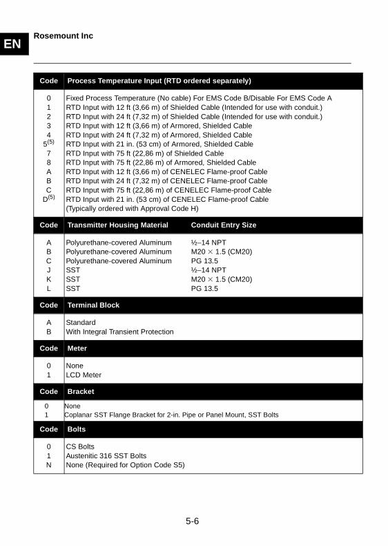
Code Process Temperature Input (RTD ordered separately)
01234
5(5)
78ABC
D(5)
Fixed Process Temperature (No cable) For EMS Code B/Disable For EMS Code ARTD Input with 12 ft (3,66 m) of Shielded Cable (Intended for use with conduit.)RTD Input with 24 ft (7,32 m) of Shielded Cable (Intended for use with conduit.)RTD Input with 12 ft (3,66 m) of Armored, Shielded CableRTD Input with 24 ft (7,32 m) of Armored, Shielded CableRTD Input with 21 in. (53 cm) of Armored, Shielded Cable RTD Input with 75 ft (22,86 m) of Shielded Cable RTD Input with 75 ft (22,86 m) of Armored, Shielded Cable RTD Input with 12 ft (3,66 m) of CENELEC Flame-proof Cable RTD Input with 24 ft (7,32 m) of CENELEC Flame-proof Cable RTD Input with 75 ft (22,86 m) of CENELEC Flame-proof CableRTD Input with 21 in. (53 cm) of CENELEC Flame-proof Cable(Typically ordered with Approval Code H)
Code Transmitter Housing Material Conduit Entry Size
ABCJKL
Polyurethane-covered Aluminum ½–14 NPTPolyurethane-covered Aluminum M20 � 1.5 (CM20) Polyurethane-covered Aluminum PG 13.5SST ½–14 NPTSST M20 � 1.5 (CM20)SST PG 13.5
Code Terminal Block
AB
StandardWith Integral Transient Protection
Code Meter
01
NoneLCD Meter
Code Bracket
01
None Coplanar SST Flange Bracket for 2-in. Pipe or Panel Mount, SST Bolts
Code Bolts
01N
CS BoltsAustenitic 316 SST Bolts None (Required for Option Code S5)
5-6
ENRosemount Inc
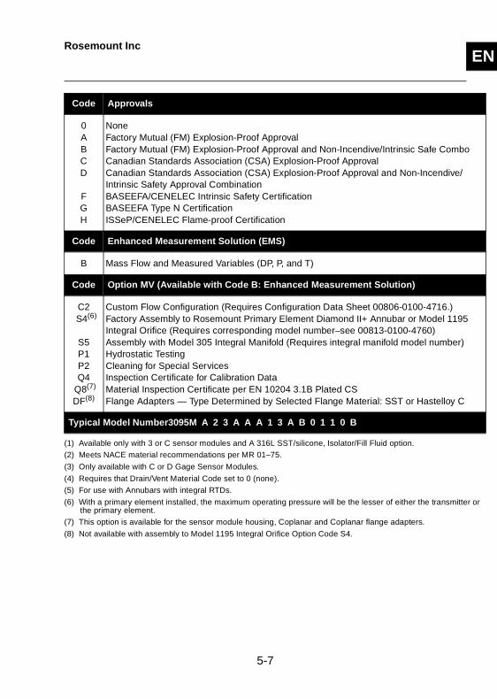
Code Approvals
0ABCD
FGH
None Factory Mutual (FM) Explosion-Proof Approval Factory Mutual (FM) Explosion-Proof Approval and Non-Incendive/Intrinsic Safe ComboCanadian Standards Association (CSA) Explosion-Proof Approval Canadian Standards Association (CSA) Explosion-Proof Approval and Non-Incendive/Intrinsic Safety Approval Combination BASEEFA/CENELEC Intrinsic Safety CertificationBASEEFA Type N CertificationISSeP/CENELEC Flame-proof Certification
Code Enhanced Measurement Solution (EMS)
B Mass Flow and Measured Variables (DP, P, and T)
Code Option MV (Available with Code B: Enhanced Measurement Solution)
C2S4(6)
S5 P1P2Q4
Q8(7)
DF(8)
Custom Flow Configuration (Requires Configuration Data Sheet 00806-0100-4716.) Factory Assembly to Rosemount Primary Element Diamond II+ Annubar or Model 1195 Integral Orifice (Requires corresponding model number–see 00813-0100-4760)Assembly with Model 305 Integral Manifold (Requires integral manifold model number)Hydrostatic Testing Cleaning for Special ServicesInspection Certificate for Calibration Data Material Inspection Certificate per EN 10204 3.1B Plated CSFlange Adapters — Type Determined by Selected Flange Material: SST or Hastelloy C
Typical Model Number3095M A 2 3 A A A 1 3 A B 0 1 1 0 B
(1) Available only with 3 or C sensor modules and A 316L SST/silicone, Isolator/Fill Fluid option.
(2) Meets NACE material recommendations per MR 01–75.
(3) Only available with C or D Gage Sensor Modules.
(4) Requires that Drain/Vent Material Code set to 0 (none).
(5) For use with Annubars with integral RTDs.
(6) With a primary element installed, the maximum operating pressure will be the lesser of either the transmitter orthe primary element.
(7) This option is available for the sensor module housing, Coplanar and Coplanar flange adapters.
(8) Not available with assembly to Model 1195 Integral Orifice Option Code S4.
5-7

ENRosemount Inc
5-8

SECTION EN
A MV Engineering Assistant (EA) Reference Section
OVERVIEWThe MV Engineering Assistant Software package is available with or without the HART modem and connecting cables. The complete Engineering Assistant package contains installation software, one HART modem, and a set of cables for connecting the computer to the Model 3095 MV.
GETTING STARTEDMinimum hardware requirements:
• IBM PC compatible Pentium 150 MHz or above• 32 MB of memory if using Windows 95 or 98; 64 MB of memory if using
Windows NT 4.0• 150 M of hard disk space• 1 CD-ROM drive• Color computer display (VGA or better)• 1 RS232 port• Mouse or other pointing device• HART modem
CONNECTING TO A PERSONAL COMPUTER
Figure A-13. Figure A-14 illustrates how to connect a computer to a Model 3095 MV
Explosions can cause death or serious injury. Before making any computer connections, ensure that the Model 3095 MV area is non-hazardous.
A-1
ENRosemount Inc
Install the Program
1. Place the disk in the CD-ROM drive and run the setup fromWindows 95, 98 or NT.
2. After installing the software, open the MV Engineering Assistant from the program file. The Hart modem installation will automatically launch. Be sure to tun off any other programs that might interfere with the use of the selected Com ports.
Upgrade the MV Engineering Assistant program
1. Place the disk in the CD-ROM drive and run the EAupgrade.exe from Windows 95, 98, or NT. To properly install, the program will first uninstall MV Engineering Assistant from your computer.
2. After uninstall is complete, reboot your computer.3. To install the upgraded program, run the EAupgrade.exe from Windows 95,98,
or NT again.
Connect to Transmitter
1. After installing the EA on your computer, connect the computer to the Model 3095 MV. See Warning above, as well as Figure A-14.
a. Connect one end of the 9-pin to 9-pin cable to the HART communications port on the personal computer.
b. Connect the 9-pin HART modem cable to the 9-pin communications port on the computer.
c. Open the cover above the side marked Field Terminals, and connect the mini-grabbers to the two Model 3095 MV terminals marked COMM.
2. Power up the computer. 3. Select the MV Engineering Assistant from the program menu.4. An AMS Application logon window will appear. 5. If password security is enabled, the Engineering Assistant Privileges Screen
appears.6. The default login name is admin (must be lower case). The password line is
left blank. Select OK.
Explosions can cause death or serious injury. Do not remove the instrument cover in explosive atmospheres with the circuit is live.
A-2
ENRosemount Inc
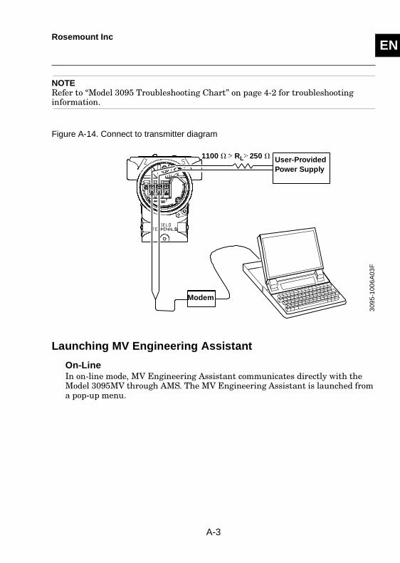
NOTERefer to “Model 3095 Troubleshooting Chart” on page 4-2 for troubleshooting information.
Figure A-14. Connect to transmitter diagram
Launching MV Engineering Assistant
On-LineIn on-line mode, MV Engineering Assistant communicates directly with the Model 3095MV through AMS. The MV Engineering Assistant is launched from a pop-up menu.
309
5-1
006
A0
3F
User-Provided Power Supply
Modem
1100 � � RL� 250 �
A-3
ENRosemount Inc
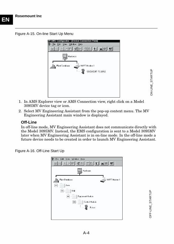
Figure A-15. On-line Start Up Menu
1. In AMS Explorer view or AMS Connection view, right click on a Model 3095MV device tag or icon.
2. Select MV Engineering Assistant from the pop-up context menu. The MV Engineering Assistant main window is displayed.
Off-LineIn off-line mode, MV Engineering Assistant does not communicate directly with the Model 3095MV. Instead, the EMS configuration is sent to a Model 3095MV later when MV Engineering Assistant is in on-line mode. In the off-line mode a future device needs to be created in order to launch MV Engineering Assistant.
Figure A-16. Off-Line Start UpO
N-L
INE
_S
TA
RT
UP
OF
F-L
INE
_ST
AR
TU
P
A-4
ENRosemount Inc
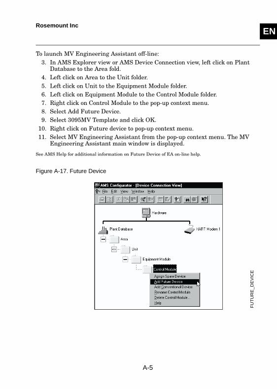
To launch MV Engineering Assistant off-line:3. In AMS Explorer view or AMS Device Connection view, left click on Plant
Database to the Area fold.4. Left click on Area to the Unit folder.5. Left click on Unit to the Equipment Module folder. 6. Left click on Equipment Module to the Control Module folder.7. Right click on Control Module to the pop-up context menu.8. Select Add Future Device.9. Select 3095MV Template and click OK.
10. Right click on Future device to pop-up context menu.11. Select MV Engineering Assistant from the pop-up context menu. The MV
Engineering Assistant main window is displayed.
See AMS Help for additional information on Future Device of EA on-line help.
Figure A-17. Future Device
FU
TU
RE
_D
EV
ICE
A-5
ENRosemount Inc
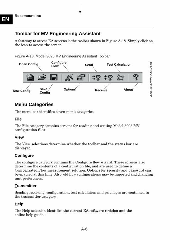
Toolbar for MV Engineering AssistantA fast way to access EA screens is the toolbar shown in Figure A-18. Simply click on the icon to access the screen.
Figure A-18. Model 3095 MV Engineering Assistant Toolbar
Menu CategoriesThe menu bar identifies seven menu categories:
File
The File category contains screens for reading and writing Model 3095 MV configuration files.
View
The View selections determine whether the toolbar and the status bar are displayed.
Configure
The configure category contains the Configure flow wizard. These screens also determine the contents of a configuration file, and are used to define a Compensated Flow measurement solution. Options for security and password can be enabled at this time. Also, old flow configurations may be imported and changing unit preferences.
Transmitter
Sending receiving, configuration, test calculation and privileges are contained in the transmitter category.
Help
The Help selection identifies the current EA software revision and theonline help guide.
Open Config Configure Flow
New Config SaveConfig
Options About
30
95-3
095
MV
/TO
OL
BA
R01Send
Receive
Test Calculation
A-6
ENRosemount Inc
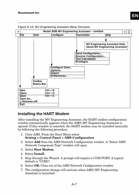
Figure A-19. MV Engineering Assistant Menu Structure
Installing the HART ModemAfter installing the MV Engineering Assistant, the HART modem configuration window automatically appears when the AMS|MV Engineering Assistant is opened. If this window is canceled, the HART modem may be installed manually by following the following procedure.
1. Close AMS. From the Start Menu selectSetting > Control Panel > AMS Configuration
2. Select Add from the AMS Network Configuration window. A "Select AMS Network Component Type" window will open.
3. Select Hart Modem.4. Select Install.5. Step through the Wizard. A prompt will inquire a COM PORT. A typical
default is "COM1".6. Select OK. Close out of the AMS Network Configuration window.7. The configuration change will activate when AMS|MV Engineering
Assistant is launched.
Model 3095 MV Engineering Assistant – UntitledFile View Configure Transmitter Help
New Ctrl + NOpen Ctrl + OSave Ctrl + SSave As...1 filename.mfl Exit
Send Configuration...Receive Configuration...Test CalculationPrivileges
MV Engineering Assistant HelpAbout MV Engineering Assistant
ToolbarStatus Bar
Configure Flow...OptionsImportPreferences...
A-7
ENRosemount Inc
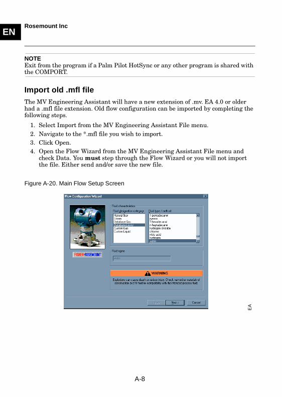
NOTEExit from the program if a Palm Pilot HotSync or any other program is shared with the COMPORT.
Import old .mfl fileThe MV Engineering Assistant will have a new extension of .mv. EA 4.0 or older had a .mfl file extension. Old flow configuration can be imported by completing the following steps.
1. Select Import from the MV Engineering Assistant File menu.2. Navigate to the *.mfl file you wish to import.3. Click Open.4. Open the Flow Wizard from the MV Engineering Assistant File menu and
check Data. You must step through the Flow Wizard or you will not import the file. Either send and/or save the new file.
Figure A-20. Main Flow Setup Screen
EA
A-8
ENRosemount Inc
Figure A-21. For liquid, gas, or steam Primary Element selection and sizing
Figure A-22. Operating and Reference Conditions
PR
IMA
RY
_EL
EM
EN
T_S
EL
EC
T%
26S
IZE
OP
ER
AT
ING
_RE
F_C
ON
DIT
ION
S
A-9
ENRosemount Inc
Figure A-23. Density, Compressibility, and Viscosity Table
Figure A-24. Flow Setup Complete Screen
DE
NS
ITY
_VIS
CO
SIT
Y_
TA
BLE
EA
_C
OM
PL
ET
E
A-10
ENRosemount Inc
Figure A-25. Natural Gas Setup Screen (Detail Characterization)
Figure A-26. Natural Gas Setup Screen (Gross Characterization Method 1)
DE
TA
IL_
CH
AR
GR
OS
S_
MT
H1
A-11
ENRosemount Inc
Figure A-27. Natural Gas Setup Screen (Gross Characterization Method 2)
GR
OS
S_M
TH
2
A-12

ENRosemount Inc
A-13

ENRosemount Inc
A-14
SECTION EN
B HART Communicator
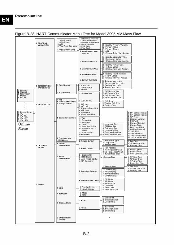
OVERVIEWThe HART Communicator provides communication capabilities for the Model 3095 MV transmitter. The HART Communicator menu tree provides a schematic overview of configuration functions, and the fast key sequences provide direct access to software functions.
Online Menu
The Online menu appears automatically if the HART Communicator is connected to an active loop with an operating transmitter. From the Online menu, press the appropriate key sequence to access the desired function. Follow the on-screen instructions to complete the function.
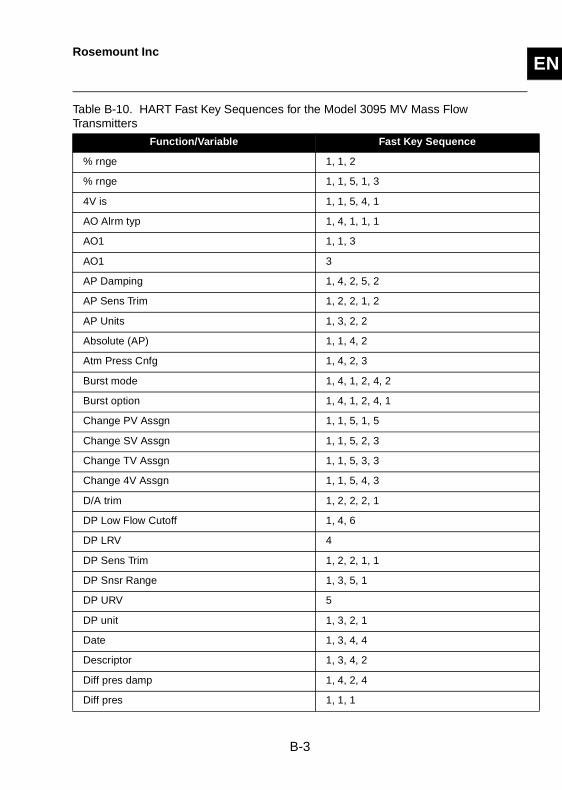
HART Fast Key Feature
The fast key sequences for the HART Communicator use the following convention for their identification:
1 through 9–Refer to the keys located in the alphanumeric keypad located below the dedicated keypad.
NOTEHART fast key sequences are operational only from the Online menu. To access the Online menu from any other menu, select the HOME (F3) key.
B-1
ENRosemount Inc
Figure B-28. HART Communicator Menu Tree for Model 3095 MV Mass Flow
Online Menu
1 DP Sensor Range2 SP Sensor Range3 SP Type4 Isolator Material5 Fill Fluid6 Flange Material7 Flange Type8 Drain Vent Matl9 O-Ring Material10 RS Type11 RS Fill Fluid12 RS Isolator Matl13 No of Rmt Seals
1 VIEW PRIMARY VAR. ANALOG 1
2 VIEW SECOND VAR.
3 VIEW TERTIARY VAR.
4 VIEW FOURTH VAR.
5 OUTPUT VAR UNITS
1 Identify Secondary Var.2 Secondary Value3 Change Sec. Var. Assign.
1 Identify Fourth Variable2 Fourth Value3 Change 4th Var. Assign.
1 Primary Var. Units2 Secondary Var. Units3 Tertiary Var. Units4 Fourth Var. Units
1 PROCESS VARIABLES
2 DIAGNOSTICS AND SERVICE
3 BASIC SETUP
4 DETAILED SETUP
5 Review
1 DEVICE SETUP2 PV3 PV AO4 PV LRV5 PV URV
1 Absolute AP2 AP% RANGE3 A014 VIEW FIELD DEV VARS
5 VIEW OUTPUT VARS
1 TEST/STATUS
2 CALIBRATION
1 ANALOG OUTPUT
2 HART OUTPUT
1 Differential Pressure2 Absolute Pressure3 Process Temperature4 Gage Pressure5 Flow Rate6 Flow Total
1 Identify Tertiary Var.2 Tertiary Value3 Change Tert. Var. Assign.
1 SENSOR TRIM
2 ANALOG TRIM
1 DP Unit2 AP Unit3 Process Temp Unit4 GP Unit5 Flow Unit6 Flow Total Unit
1 DP Sensor Trim2 AP Sensor Trim3 GP Sensor Trim4 Temp Sensor Trim
1 OUTPUT CONDITIONING
2 SIGNAL CONDITIONING
3 LCD
4 TOTALIZER
5 SPECIAL UNITS
6 DP LOW FLOW CUTOFF
1 Tag2 Descriptor3 Message4 Date5 Final Assbly No.6 Manufacturer7 Model8 Write Protect9 REVISIONS
1 D/A Trim2 Scaled D/A Trim3 Factory Trim
1 Universal Rev2 Fld Dev Rev3 Software Rev4 Hardware Rev5 Snsr Mod sw Rev6 Snsr Mod hw Rev
1 D/A Trim2 Scaled D/A Trim3 Factory Trim
1 OFF-LINE2 ON-LINE3 FREQUENCY
DEVICE4 UTILITY
1 Tag2 XMTR VAR ENG UNITS3 Range Values
4 DEVICE INFORMATION
5 CONSTRUCTION MATERIALS
1 Identify Primary Variable2 Primary Value3 Primary Range4 A015 Change Prim. Var. Assign.
1 Loop Test2 View Status3 Reset
1 AO Alarm Type2 Loop Test3 ANALOG TRIM
1 Poll Address2 No Request Pream3 No Response Pream4 BURST MODE OPER
1 Burst Option2 Burst Mode3 Xmtr Var Slot Assn
1 CALIBRATION2 RTD Config3 Atm Press Config4 DP Damping
5 XMTR VAR DAMPING
6 XMTR VAR ENG UNITS
1 SENSOR TRIM
2 ANALOG TRIM
1 DP Snsr Trim2 AP Snsr Trim3 GP Snsr Trim4 Temp Snsr Trim
1 D/A Trim2 Scaled D/A Trim3 Factory Trim1 DP Damping
2 AP Damping3 Temp Damping4 GP Damping
1 DP Units2 AP Units3 Temp Units4 GP Units5 Flow Units6 Flow Total Unit
1 Display Period2 Local Display
1 Mode2 Total
1 FLOW
2 TOTAL
1 Base Unit2 Scaling Factor3 Unit String
1 Base Unit2 Scaling Factor3 Unit String
B-2
ENRosemount Inc
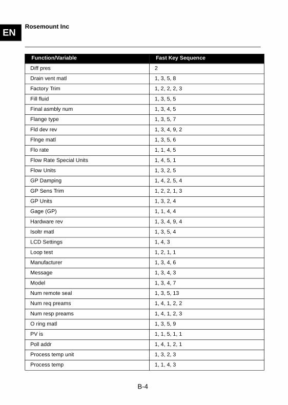
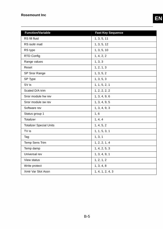
Table B-10. HART Fast Key Sequences for the Model 3095 MV Mass Flow Transmitters
Function/Variable Fast Key Sequence
% rnge 1, 1, 2
% rnge 1, 1, 5, 1, 3
4V is 1, 1, 5, 4, 1
AO Alrm typ 1, 4, 1, 1, 1
AO1 1, 1, 3
AO1 3
AP Damping 1, 4, 2, 5, 2
AP Sens Trim 1, 2, 2, 1, 2
AP Units 1, 3, 2, 2
Absolute (AP) 1, 1, 4, 2
Atm Press Cnfg 1, 4, 2, 3
Burst mode 1, 4, 1, 2, 4, 2
Burst option 1, 4, 1, 2, 4, 1
Change PV Assgn 1, 1, 5, 1, 5
Change SV Assgn 1, 1, 5, 2, 3
Change TV Assgn 1, 1, 5, 3, 3
Change 4V Assgn 1, 1, 5, 4, 3
D/A trim 1, 2, 2, 2, 1
DP Low Flow Cutoff 1, 4, 6
DP LRV 4
DP Sens Trim 1, 2, 2, 1, 1
DP Snsr Range 1, 3, 5, 1
DP URV 5
DP unit 1, 3, 2, 1
Date 1, 3, 4, 4
Descriptor 1, 3, 4, 2
Diff pres damp 1, 4, 2, 4
Diff pres 1, 1, 1
B-3
ENRosemount Inc
Function/Variable Fast Key Sequence
Diff pres 2
Drain vent matl 1, 3, 5, 8
Factory Trim 1, 2, 2, 2, 3
Fill fluid 1, 3, 5, 5
Final asmbly num 1, 3, 4, 5
Flange type 1, 3, 5, 7
Fld dev rev 1, 3, 4, 9, 2
Flnge matl 1, 3, 5, 6
Flo rate 1, 1, 4, 5
Flow Rate Special Units 1, 4, 5, 1
Flow Units 1, 3, 2, 5
GP Damping 1, 4, 2, 5, 4
GP Sens Trim 1, 2, 2, 1, 3
GP Units 1, 3, 2, 4
Gage (GP) 1, 1, 4, 4
Hardware rev 1, 3, 4, 9, 4
Isoltr matl 1, 3, 5, 4
LCD Settings 1, 4, 3
Loop test 1, 2, 1, 1
Manufacturer 1, 3, 4, 6
Message 1, 3, 4, 3
Model 1, 3, 4, 7
Num remote seal 1, 3, 5, 13
Num req preams 1, 4, 1, 2, 2
Num resp preams 1, 4, 1, 2, 3
O ring matl 1, 3, 5, 9
PV is 1, 1, 5, 1, 1
Poll addr 1, 4, 1, 2, 1
Process temp unit 1, 3, 2, 3
Process temp 1, 1, 4, 3
B-4
ENRosemount Inc
Function/Variable Fast Key Sequence
RS fill fluid 1, 3, 5, 11
RS isoltr matl 1, 3, 5, 12
RS type 1, 3, 5, 10
RTD Config 1, 4, 2, 2
Range values 1, 3, 3
Reset 1, 2, 1, 3
SP Snsr Range 1, 3, 5, 2
SP Type 1, 3, 5, 3
SV is 1, 1, 5, 2, 1
Scaled D/A trim 1, 2, 2, 2, 2
Snsr module hw rev 1, 3, 4, 9, 6
Snsr module sw rev 1, 3, 4, 9, 5
Software rev 1, 3, 4, 9, 3
Status group 1 1, 6
Totalizer 1, 4, 4
Totalizer Special Units 1, 4, 5, 2
TV is 1, 1, 5, 3, 1
Tag 1, 3, 1
Temp Sens Trim 1, 2, 2, 1, 4
Temp damp 1, 4, 2, 5, 3
Universal rev 1, 3, 4, 9, 1
View status 1, 2, 1, 2
Write protect 1, 3, 4, 8
Xmtr Var Slot Assn 1, 4, 1, 2, 4, 3
B-5

ENRosemount Inc
B-6